Embed Size (px)
Citation preview

XFEL/SPring-8 BL-TDR Ver. 1.0(English)
XFEL/SPring-8 Beamline Technical Design Report
Ver. 2.0
February, 2010
SPring-8 Joint Project for XFEL
Experimental Facility Group

XFEL/SPring-8 BL-TDR Ver. 1.0(English)
Preface
In 2010, construction of the X-ray Free Electron Laser (XFEL) facility entered the last year of its
5-year plan. The XFEL is one of Japan’s “key technologies of national importance” as specified in
the 3rd Science and Technology Basic Plan. As is customary with this kind of construction, the
project has taken steps towards downstream from upstream. Light sources, beamlines, experimental
devices and relevant utilities which lie downstream from the Accelerator finally began to construct.
At the XFEL Project Head Office, the concept designs for the beamlines and experimental
devices have been led mainly by the Experimental Facility Group. The Project Head Office is
responsible for compiling the achievements and disclosing them in a design report with the
intention of improving the facility by obtaining extensive feedback from affiliate researchers.
Under this policy, we are now publishing the design report. However, we are still in process of
finalizing some details. On another front, we need to continue with order placement during this
fiscal year. Therefore, we intend to hear from a broad range of interested people as early as possible
in order to incorporate their views into future plans.
With great appreciation for all of your past support, we look forward to your continued
collaboration and opinions on the XFEL facility construction plan.
February, 2010 XFEL Project Head Office
Experimental Facility Group Group Director
Tetsuya Ishikawa

XFEL/SPring-8 BL-TDR Ver. 1.0(English)
Authors RIKEN-JASRI XFEL Project Head Office Shunji Goto, Takaki Hatsui, Atsushi Higashiya, Hiroaki Kimura, Togo Kudo, Mitsuru
Nagasono, Yoshinori Nishino, Haruhiko Ohashi, Kenji Tamasaku, Yoshihito Tanaka, Tadashi
Togashi, Hiromitsu Tomizawa, Kensuke Tono, and Makina Yabashi
(Experimental Facility Group)
Sunao Takahashi
(Accelerator Construction Group)
Toru Hara, Hitoshi Tanaka, Takashi Tanaka, and Kazuaki Togawa
(Accelerator Construction Group)
Yukito Furukawa, Tomohiro Matsushita, and Toru Ohata
(Control System Group)
Yoshihiro Asano and Toshiro Itoga
(Safety Design Group)
Editor Makina Yabashi (Experimental Facility Group/ Beamline Construction Team, Team leader)
Tetsuya Ishikawa (Experimental Facility Group, Group director)
Publication RIKEN JASRI XFEL Project Head Office, Experimental Facility Group
1-1-1, Kouto, Sayo-cho, Sayo, Hyogo, 679-5148
e-mail: [email protected]
Publication Date Japanese:First Edition: June 17, 2008
English :First Edition: February 22, 2010
*all rights reserved
XFEL/SPring-8 BL-TDR Ver. 1.0(English)
Contents
1. Summary ・・・・・・・・・・・・・・・・・・・・・・・・・・・・・・・・・・・・・・・・・・・・・・・・・・・・・・・・・・・・ 1
2. Light Source Properties ・・・・・・・・・・・・・・・・・・・・・・・・・・・・・・・・・・・・・・・・・・・・・ 3
2-1. Outline ・・・・・・・・・・・・・・・・・・・・・・・・・・・・・・・・・・・・・・・・・・・・・・・・・・・・・・・・・・・ 3
2-2. Electron Beam Parameters ・・・・・・・・・・・・・・・・・・・・・・・・・・・・・・・・・・・・・・・ 3
2-3. Undulator Parameters ・・・・・・・・・・・・・・・・・・・・・・・・・・・・・・・・・・・・・・・・・・・・・・・ 6
2-4. FEL Radiation Parameters ・・・・・・・・・・・・・・・・・・・・・・・・・・・・・・・・・・・・・・・・・・・ 7
2-5. Spontaneous Radiation ・・・・・・・・・・・・・・・・・・・・・・・・・・・・・・・・・・・・・・・・・・・・・・ 14
3. Guidelines for Beamline Design ・・・・・・・・・・・・・・・・・・・・・・・・・・・・・・・・・・・・・・・・・・・・・ 15
3-1. Outline ・・・・・・・・・・・・・・・・・・・・・・・・・・・・・・・・・・・・・・・・・・・・・・・・・・・・・・・・・・・ 15
3-2. Configuration Plan ・・・・・・・・・・・・・・・・・・・・・・・・・・・・・・・・・・・・・・・・・・・・・・・・ 15
3-3. Optical System ・・・・・・・・・・・・・・・・・・・・・・・・・・・・・・・・・・・・・・・・・・・・・・・・・・・・ 15
3-4. Optical Elements ・・・・・・・・・・・・・・・・・・・・・・・・・・・・・・・・・・・・・・・・・・・・・・・・・・・ 17
3-5. Monitor ・・・・・・・・・・・・・・・・・・・・・・・・・・・・・・・・・・・・・・・・・・・・・・・・・・・・・・・・・ 18
3-6. Radiation Shielding ・・・・・・・・・・・・・・・・・・・・・・・・・・・・・・・・・・・・・・・・・・・・・・ 18
4. Beamline Configuration and Specifications of Components ・・・・・・・・・・・・・・・・・・・・・・ 19
4-1. Outline ・・・・・・・・・・・・・・・・・・・・・・・・・・・・・・・・・・・・・・・・・・・・・・・・・・・・・・・・・・・ 19
4-2. Beamline Arrangement and Shielding Hutches ・・・・・・・・・・・・・・・・・・・・・・・・・・・・ 19
4-3. Front-end (FE) ・・・・・・・・・・・・・・・・・・・・・・・・・・・・・・・・・・・・・・・・・・・・・・・・・・・・・ 21
4-4. Beamline Optics and Transport-Channel ・・・・・・・・・・・・・・・・・・・・・・・・・・・・・・・・・ 24
5. Data Acquisition System (DAQ) ・・・・・・・・・・・・・・・・・・・・・・・・・・・・・・・・・・・・・・・・・ 36
5-1. Data Acquisition System (DAQ) ・・・・・・・・・・・・・・・・・・・・・・・・・・・・・・・・・・・・・・ 36
5-2. X-Ray 2-D Detectors ・・・・・・・・・・・・・・・・・・・・・・・・・・・・・・・・・・・・・・・・・・・・・・・・ 42
6. Civil Engineering: Experimental Facility ・・・・・・・・・・・・・・・・・・・・・・・・・・・・・・・・・・・ 47
6-1. Outline ・・・・・・・・・・・・・・・・・・・・・・・・・・・・・・・・・・・・・・・・・・・・・・・・・・・・・・・・・・ 47
6-2. Experimental Hall ・・・・・・・・・・・・・・・・・・・・・・・・・・・・・・・・・・・・・・・・・・・・・・・・・ 47
6-3. Experimental Preparation Room ・・・・・・・・・・・・・・・・・・・・・・・・・・・・・・・・・・・・・・ 48
6-4. Sample Preparation Room ・・・・・・・・・・・・・・・・・・・・・・・・・・・・・・・・・・・・・・・・・・・ 48
6-5. Carry-in Room ・・・・・・・・・・・・・・・・・・・・・・・・・・・・・・・・・・・・・・・・・・・・・・・・・・・・ 48
6-6. Noise Shielding ・・・・・・・・・・・・・・・・・・・・・・・・・・・・・・・・・・・・・・・・・・・・・・・・・・・ 48
APPENDIX ・・・・・・・・・・・・・・・・・・・・・・・・・・・・・・・・・・・・・・・・・・・・・・・・・・・・・・・・・・・ 52
A1. Dose Estimation for XFEL ・・・・・・・・・・・・・・・・・・・・・・・・・・・・・・・・・・・・・・・・・・・ 52
A2. Estimation of Transmissivity ・・・・・・・・・・・・・・・・・・・・・・・・・・・・・・・・・・・・・・・・・・ 63
A3. Estimation of Scattering Power ・・・・・・・・・・・・・・・・・・・・・・・・・・・・・・・・・・・・・・・・ 71
A4. Revision Record ・・・・・・・・・・・・・・・・・・・・・・・・・・・・・・・・・・・・・・・・・・・・・・・・・・・・ 72

XFEL/SPring-8 BL-TDR Ver. 1.0(English)
1. Summary
The X-ray Free Electron laser (XFEL) is a new x-ray source distinguished by the high-brightness,
high-coherence and short-pulse of the light generated. XFEL facilities are under development in the
US, Europe and Japan [1-1, 1-2, and 1-3]. The XFEL Project Head Office organized by RIKEN and
JASRI is managing the 5-year construction plan, running from 2006 to 2010, at the Japan’s XFEL
SPring-8 campus. The XFEL is composed of an accelerator for generating a electron beam,
undulators for producing XFEL radiation, and beamlines for tailoring XFEL radiation for user
experiments. This report presents a design of the beamline with performance data of the light
source, information which are most important for user experiments.
Historically, advances of synchrotron light sources have stimulated to develop new beamline
technologies. The era of the second-generation synchrotron light source with dedicated storage rings
occurred in the 1970s and 1980s. This period saw the significant development of x-ray
monochromators for quick scan of wavelength with high stability., as well as the adaptation of
ultrahigh vacuum systems for connecting beamlines to storage rings. The era of the third-generation
synchrotron light sources, which combines low-emittance storage rings with undulators, began in the
1990s. The greatest challenge was to develop an optical system for managing high heat loads from
an undulator. Now, the key criteria imposed on XFEL beamlines are “coherence” and “pulse”, which
require speckle-free optical systems that do not degrade coherent wavefronts, and development of
beam handling/detection systems that enable efficient use of isolated high-intensity X-ray pulses. To
achieve these criteria, the XFEL Experimental facility Group led analyses from various perspectives,
this report summarizes the results of those discussions and considerations.
The XFEL facility at SPring-8 will have the capacity to contain 5 beamlines. The first-period
construction plan which completes in 2010 includes two beamlines, an FEL beamline of the hard
X-ray region (BL3), which is a main target of this report, and a broadband beamline (BL1), which
will be presented in the near future.
This document is organized as follows: Chapter 2 summarizes the performance of the light source.
Chapter 3 presents fundamental guidelines for the design of beamlines, and based on this Chapter,
Chapters 4 presents the configuration of beamlines and specifications for each component. Chapter 5
provides specifications for the data acquisition system and the two-dimensional detector required for
this purpose. Chapter 6 presents a description of the civil engineering including the experimental
building. Finally, the Appendix includes information on several independent themes.
1

XFEL/SPring-8 BL-TDR Ver. 1.0(English)
References [1-1] T. Tanaka, & T. Shintake, (Eds) SCSS X-FEL Conceptual Design Report, (RIKEN Harima
Institute, Hyogo, Japan, 2005).
[1-2] J. Arthur et al., “Linac Coherent Light Source (LCLS) Conceptual Design Report”,
SLAC-R593 (Stanford, 2002).
[1-3] M. Altarelli et al. (Eds) XFEL: The European X-Ray Free-Electron Laser, Technical Design
Report. Preprint DESY 2006-097, (DESY Hamburg, 2006).
2

XFEL/SPring-8 BL-TDR Ver. 1.0(English)
2. Light Source Properties 2-1. Outline
This chapter describes XFEL radiation properties with accelerator parameters for the SPring-8
XFEL project.
Our accelerator system uses a thermionic electron gun and a multistage bunch compression
system for generating an electron beam with high density and low emittance. Although this system,
as well as our variable-gap undulators, provide large flexibility for radiation properties, we here
summarize results for typical parameter sets at a electron beam energy EB = 8 GeV. Note that this
chapter treats only single-bunch operation, although the choke-mode C-band accelerating tubes
allow us to perform multi-bunch operations (40 pulse train at a maximum with 4-ns interval),.
B
2-2. Electron Beam Parameters The electron beam parameters are summarized in Table 2-2-1. The time dependencies between
peak current and normalized emittance, energy spread and averaged beam energy are depicted in
Fig.2-2-1, Fig.2-2-2 and Fig.2-2-3, respectively. Simulations were conducted in combination with a
one-dimension PIC code, PARMELA, and ELEGANT.
Table 2-2-1 Electron Beam Parameter
Beam energy (GeV) 8
Peak current (kA) 4.4
Slice emittance 0.77
Slice energy spread 7.1e-5
Total charge (nC) 0.29
Bunch width (fs, FWHM) 55
Beam size at ID exit (um, rms) 35
Repetition rate (Hz) 60 (max) to 1 (min)
3

XFEL/SPring-8 BL-TDR Ver. 1.0(English)
-100 0 1000
1000
2000
3000
4000
0
0.2
0.4
0.6
0.8
Time (fs)
Peak
cur
rent
(A)
Nor
mal
ized
em
ittan
ce(π
mm
.mra
d)
Fig.2-2-1 Time dependences of peak current (left axis) and normalized emittance (right axis)
-100 0 1000
1000
2000
3000
4000
0
0.2
0.4
0.6
0.8
1 [×10-4
Time (fs)
Peak
cur
rent
(A)
Ener
gy sp
read
Fig.2-2-2 Time dependences of peak current (left axis) and energy spread (right axis)
4

XFEL/SPring-8 BL-TDR Ver. 1.0(English)
-100 0 1000
1000
2000
3000
4000
7.94
7.95
7.96
7.97
7.98
Time (fs)
Peak
cur
rent
(A)
Bea
m e
nerg
y (G
eV)
Fig.2-2-3 Time dependences of peak current (left axis) and averaged beam energy (right axis)
5

XFEL/SPring-8 BL-TDR Ver. 1.0(English)
2-3. Undulator Parameters The undulator parameters for BL3 are summarized in Table 2-3-1
Table 2-3-1 Undulator Parameter for BL3
Periodic length, λU (mm) 18
Segment length (m) 5
Number of segments 18
Total periodic number 5000
Maximum deflection parameter, K※1 2.3
25 / 25 Average betatron function, βx / βy (m)
※1: 0
2U
e
eBKm cλ
π= , BB0: Peak magnetic field
6

XFEL/SPring-8 BL-TDR Ver. 1.0(English)
2-4. FEL Radiation Parameters We conducted simulations of FEL radiation parameters using a code SIMPLEX [2-1]. Various
parameters set at a fixed K-value of 2.2 are summarized in Table 2-4-1. In Fig.2-4-1, dependences of
peak power and pulse energy on photon energy are calculated for K-values of 2.2, 1.9, 1.5, and 1.1.
For larger K-values the photon energy decreases (i.e., the wavelength increases) from Eq. 2-4-3. At
the same time, peak power enhances because of increased FEL parameter ρ from Eq. 2-4-1. We also
show the gain curve along the undulator with higher K-values in Fig.2-4-2. For larger K, the pulse
energy reaches saturation more quickly due to smaller gain lengths from Eq. 2-4-2.
Typical time and energy spectrum are shown in Fig. 2-4-3 and Fig. 2-4-4, respectively. The
correlation plot between time and energy is presented in Fig. 2-4-5.
Table 2-4-1 FEL radiation parameters (fundamental radiation)
Electron beam energy (GeV) 8
Repetition rate (Hz) 60 (max) to 1 (min)
UND K value 2.2
FEL parameter ※2 4.4e-4
Saturation length (m) ※3 45
Wavelength (nm) ※4 0.13
Photon energy (keV) 9.9
Bandwidth 9.2e-4
Source size (um, rms) 33
Angular divergence (urad, rms) 0.73
Peak power (GW) 29
Pulse energy (mJ) 0.78
Photons per pulse (phs/pls) 5.0e11
Pulse width (fs, FWHM) 30
Power ratio of higher-order harmonic (2nd:1st) 1.3e-4
Power ratio of higher-order harmonic (3rd:1st) 2.8e-3
※2: ( ) ( )11
2 2 2 33
1 28 16e e e P
n
r n r IF K F Kce
γλ γ λρ
π π βε⎡ ⎤⎡ ⎤
= = ⎢ ⎥⎢ ⎥⎣ ⎦ ⎣ ⎦
1 (Eq. 2-4-1)
( )( )
22 2 2
1 0 12 2 22
4 41 2 1 21 2
K K KF K J JK KK
⎡ ⎤⎛ ⎞ ⎛= −
⎞⎢ ⎥⎜ ⎟ ⎜+ + ⎟⎢ ⎥⎝ ⎠ ⎝+ ⎠⎣ ⎦
2/B eE m cγ = : Lorentz factor
λ: Radiation wavelength
7

XFEL/SPring-8 BL-TDR Ver. 1.0(English)
ne: Density of the e-beam
IP: Peak current of the e-beam
εn: Normalized emittance of the e-beam
β: Average betatron function
※3: 4 3
UgL λ
π ρ= (Eq. 2-4-2)
※4: 2
2 12 2
U Knλλ
γ⎛ ⎞
= +⎜⎝ ⎠
⎟ (Eq. 2-4-3)
n: Order of harmonic
8

XFEL/SPring-8 BL-TDR Ver. 1.0(English)
10 15 20
100
101
102
10-3
10-2
10-1
100
Photon energy (keV)
Peak
pow
er (G
W)
Puls
e en
ergy
(mJ)
K=2.2 1.91.5
1.1
Fig. 2-4-1 Dependences of peak power (left axis) and pulse energy (right axis) on photon energy for
K=2.2, 1.9, 1.5, 1.1.
.
0 50 100
10-5
10-4
10-3
10-2
10-1
100
Distance (m)
Puls
e en
ergy
(mJ/
pls) K=2.2
K=1.9 K=1.5 K=1.1
Fig.2-4-2 Gain curve along undulator with K=2.2, 1.9, 1.5, 1.1.
9

XFEL/SPring-8 BL-TDR Ver. 1.0(English)
-30 -20 -10 0 10 20 300
20
40
60
Time (fs)
Pow
er (G
W)
K=2.2
Fig. 2-4-3 Time spectrum at K=2.2.
10

XFEL/SPring-8 BL-TDR Ver. 1.0(English)
(a)
9700 9710 9720 9730 97400
0.5
1
[×1012]
Photon energy (eV)
K=2.2
Phot
on fl
ux(p
hoto
ns/p
ls/0
.1%
b.w
.)
(b)
11830 11840 11850 11860 118700
1
2
3
4
5[×1011]
Photon energy (eV)
K=1.9
Phot
on fl
ux(p
hoto
ns/p
ls/0
.1%
b.w
.)
11

XFEL/SPring-8 BL-TDR Ver. 1.0(English)
(c)
15630 15640 15650 15660 156700
1
2[×1011]
Photon energy (eV)
K=1.5
Phot
on fl
ux(p
hoto
ns/p
ls/0
.1%
b.w
.)
(d)
20680 20690 20700 20710 20720 20730 207400
1
2
[×109]
Photon energy (eV)
K=1.1
Phot
on fl
ux(p
hoto
ns/p
ls/0
.1%
b.w
.)
Fig. 2-4-4 Energy spectrum for (a)K=2.2, (b) 1.9, (c) 1.5 , and (d) 1.1.
12

XFEL/SPring-8 BL-TDR Ver. 1.0(English)
Fig.2-4-5 Correlation plot between photon energy and time at K=2.2.
13

XFEL/SPring-8 BL-TDR Ver. 1.0(English)
2-5. Spontaneous Radiation Spontaneous radiation parameters are summarized in Table 2-5-1.
Table 2-5-1 Spontaneous radiation parameters
Beam energy (GeV) 8
Max. total charge (nC) 1.5
Max. repetition rate (Hz) 60
UND K value 2.2
Average power (W) 0.57
Power divergence H/V (urad, rms) 71/43
Power density at L=64 m (distance from UND exit) (mW/mm2) 1.5※1
117 Partial power after φ10 mm aperture at L=64 m (mW)
※1 Computed the center of the undulator as a virtual light source
References [2-1] Takashi Tanaka, “FEL simulation code for undulator performance estimation”, Proc. 2004
FEL conf., 435-438 (2004), http://radiant.harima.riken.go.jp/simplex.
14
XFEL/SPring-8 BL-TDR Ver. 1.0(English)
3. Guidelines for Beamline Design 3-1. Outline
XFEL is a new light source which has significant differences from conventional synchrotron
sources. In designing beamlines, it is necessary to introduce new considerations for fully exploiting
the beam characteristics such as perfect transverse coherence, ultrahigh brightness, and femtosecond
pulse duration.
In 2007, the Experimental Facility Group of the Joint Project Team developed a discussion for
setting basic guidelines, prior to the detailed design works. This chapter summarizes essential
policies given at the considerations.
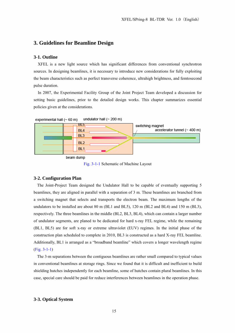
Fig. 3-1-1 Schematic of Machine Layout
3-2. Configuration Plan
The Joint-Project Team designed the Undulator Hall to be capable of eventually supporting 5
beamlines, they are aligned in parallel with a separation of 3 m. These beamlines are branched from
a switching magnet that selects and transports the electron beam. The maximum lengths of the
undulators to be installed are about 80 m (BL1 and BL5), 120 m (BL2 and BL4) and 150 m (BL3),
respectively. The three beamlines in the middle (BL2, BL3, BL4), which can contain a larger number
of undulator segments, are planed to be dedicated for hard x-ray FEL regime, while the remaining
(BL1, BL5) are for soft x-ray or extreme ultraviolet (EUV) regimes. In the initial phase of the
construction plan scheduled to complete in 2010, BL3 is constructed as a hard X-ray FEL beamline.
Additionally, BL1 is arranged as a “broadband beamline” which covers a longer wavelength regime
(Fig. 3-1-1)
The 3-m separations between the contiguous beamlines are rather small compared to typical values
in conventional beamlines at storage rings. Since we found that it is difficult and inefficient to build
shielding hutches independently for each beamline, some of hutches contain plural beamlines. In this
case, special care should be paid for reduce interferences between beamlines in the operation phase.
3-3. Optical System
15

XFEL/SPring-8 BL-TDR Ver. 1.0(English)
(1) Wavelength range
A linac-based light source is able to change electron beam energy without serious difficulties. For
BL3 undulators with a periodic length of 18 mm, the lowest photon energy is about 10 keV with an
electron beam energy of EB=8 GeV, while soft x-rays with a photon energy of 2.5 keV can be
generated with E
B
BB=4 GeV operation. Although BL3 is dedicated mainly for hard x-ray utilization,
the extension to the soft x-ray region expands availability. For this purpose, Beryllium windows, are
used for separating vacuum sections at the hard x-rays beamlines, and are designed to be retractable
from the optical axis. In this case, differential pumping systems are used for keeping vacuum
separation.
For the main optical components, total reflection mirrors (< 15 keV) and a double-crystal
monochromator (DCM, 4-30 keV with Si 111) are prepared. The former are used to transport soft
x-rays to the experimental hutches.(Fig. 3-4-1)
Mirror
Crystal Mono
0 10 20 30
hν (keV) Fig. 3-4-1 Optical Energy Range covered by Optical System
(2) Bandwidth
The bandwidth of XFEL is expected to be ~0.1%, as seen in Sect. 2. Total reflection mirrors work
as a low-pass filter and transport XFEL to experimental hutches without a reduction of bandwidth.
The DCM works as a band-pass filter with a bandwidth of 0.01% with Si 111 reflection. The former
is employed for experiments that require higher photon flux, while the latter is used for applications
that need an accurate control of wavelength.
(3) Harmonic Reduction
FEL radiation contains higher harmonic components with intensities of 0.1% and 1% for second
and third harmonics, respectively, compared to the fundamental radiation. Double mirrors are used
for reduction of component for more than a few orders of magnitude. Two sets of mirrors are
prepared for switching cutoff energies. The first mirror is commonly used, while the second
mirrors (2a, 2b) are switched for each energy. For DCM, the reduction ratio to the fundamental
radiation is less than 1% and 10% for 2nd and 3rd harmonics, respectively.
(4) Fixed-Exit Optical Axis
It is desirable to keep the optical axes of XFEL radiation to be constant, even when, one changes
16

XFEL/SPring-8 BL-TDR Ver. 1.0(English)
the optical devices or alters the photon energy. A fixed-exit design is applied for the DCM, while a
pair of mirrors is employed for the mirror system. The offset between the incident and exit beams
are kept constant for both DCM and the mirrors, the DCM and the mirrors are exclusively
employed. The offset value is determined to be 20mm, by considering the capability for γ-ray
shielding and a moderate distance between mirrors. Note that this value is smaller than the offset
(30 mm) of a standard X-ray beamline at SPring-8. The beam is vertically deflected in order to
prevent loss of diffraction efficiency for DCM (note that FEL is horizontally polarized).
(5) Stability
The beam divergence of the XFEL is approximately 1 urad, which requires extremely high stability
for the optics. A basic strategy for designing the mechanisms of the optical devices is to increase
rigidity, to reduce the number of axes, and to limit the movable range, the temperature should be
highly stabilized. Ion pumps, rather than a combination of scroll and turbo-molecular pumps, are
used for vacuum pumps in normal operation to avoid vibration.
(6) Attenuator
Attenuators required to reduce XFEL intensity for experimental reasons and for alignment purpose.
The transmittance is controlled from 100% to 0.1% with combining attenuators of solid and gas.
Intentional detuning of undulators might be used for further reduction of intensity.
3-4. Optical Elements
(1) Reduction of speckles
XFEL with high spatial coherence requires extremely high quality (surface-figure accuracy and
density homogeneity) for optical elements. After R&Ds at SPring-8, speckle-free quality have been
achieved for total-reflection mirrors and Be-windows. For monochromator crystals, silicon satisfies
the speckle-free quality, while continuative R&D is required for achieving speckle-free diamond
crystals.
(2) Resistivity to high pulse energy
XFEL pulse deposits a high energy within a short time onto optical elements through absorption
processes. Light elements are preferred to avoid melting or ablation. An absorber of light elements
are attached in front of metal materials used for shutters or slits.
(3) Vacuum environment
The optical elements are used within ultrahigh-vacuum and oil-free condition in order to avoid
contamination of particles, which can cause serious radiation damage, to optical elements.
17

XFEL/SPring-8 BL-TDR Ver. 1.0(English)
(4) Cooling requirement
It is estimated that the average powers in spontaneous emission and FEL radiation are 0.6 W and
below 60 mW, respectively, [1012 photons/pls (@10 keV) ➝ 1 mJ/pls ➝ 60 mW] with a
single-bunch operation at a repetition rate of 60 Hz. The former component is further reduced to
below 0.12W with the first collimator (φ10 mm @64 m from ID2 exit) in the front-end section. An
indirect water-cooled system is adopted for cooling of the optical elements. Note that the average
power of the monochromatic X-ray of SPring-8 BL19LXU is about 0.1W. Reconsideration is
required for multi-bunch operation that has a power 40 times greater.
3-5. Monitor (1) Shot-to-shot measurement
Since SASE-FEL starts up from noise, radiation properties such as energy and temporal spectra
change in shot-to-shot. For conducting reliable experiments, it is desired to monitor these properties
in every shot (60 Hz) with a non-destructive method. For commissioning of tuning, we can apply a
destructive-typed monitor with a repetition rate of 1 Hz.
(2) Commissioning
When commissioning, monitors and optics which directly observe the optical axis of the γ-ray may
be temporally required, extra space is prepared upstream of the γ-stopper.
3-6. Radiation Shielding The XFEL beamline is settled at a location downstream to the 8-GeV linac. Here, a rate of γ-rays in
radiation is supposed to be higher than those for SPring-8 beamlines at the 8-GeV storage ring. It is
required for reducing these unwanted contaminations at the front-end section in the Undulator Hall.
The off-axis contaminations are removed with a double collimator at the front-end section. The
separation of on-axis contaminations from XFEL are realized with optical components. Note that
these components as “first scatters” should be regarded as a neutron sources from a viewpoint of
radiation safety, because the photonuclear reaction converts γ-rays to neutrons when interacted with
matters. For shielding neutrons and γ-rays, the optics hutch containing the “first scatters” is made of
concrete with a thickness of 80 cm or larger
18

XFEL/SPring-8 BL-TDR Ver. 1.0(English)
4. Beamline Configuration and Specifications of Components
4-1. Outline This chapter presents the more detailed configuration of the beamline and specifications of the
components, which are designed based on the concepts from the previous chapter.
4-2. Beamline Arrangement and Shielding Hutches Fig. 4-2-1 shows the arrangement of five beamlines in the experimental hall. Optics hutches and
experimental hutches are set up to allow storage of two or more beamlines due to the limited
distance (~3 m) between the adjoining beamlines.
The optical hutches are grouped into OH1 (BL1-2) and OH2 (BL3-5). Thus it will be possible to
renew a beamline of one group while operating a beamline from another group. The lengths of the
optical hutches (the inner size of 17m along the optical axis) are determined based on the beamline
configuration of BL3.
The four experimental hutches are set in tandem. The dimensions are summarized in Table 4-2-1.
Each hutch has sliding doors for equipment entrance, cable ducts, and a movable X-ray stopper,
downstream at the end. Electric power, coolant water, and compressed air are supplied for every
hutch. The beam height in these hutches are 1420 mm, which include an offset value of 20 mm after
the beamline optics in the optics hutch.
The initial phase, all four hutches will serve, BL3., when BL2 and BL4 are allocated, some of these
hutches will be assigned to these beamlines. Therefore it will be possible to perform experiment with
multiple beamlines operating at the same time. Fig. 4-2-2 illustrates one example. EH1 and EH2
belonging to BL4, while EH3 and EH4 are used for BL3 by utilizing shielded beam pipes. BL2 and
other beamlines are transported to an experimental hall of the SPring-8 storage ring.
BL1 and BL5 are supposed to work as soft X-ray or EUV beamlines, which do not require
experimental hutches due to their small penetration powers. The axes of these beamlines are
deflected in the horizontal direction by using optics in the optical hutches, to prevent interference
with BL2 and BL4.
Table 4-2-1 Parameters for the Experimental Hutches
Hutch Size L×W×H (m) Size of Equipment Entrance W×H (m)
EH1 6×7×4 2.5×3
EH2 7×7×4 2.5×3
EH3 7×7×4 3×3
EH4 9×7×5 4×3
19

XFEL/SPring-8 BL-TDR Ver. 1.0(English)
Fig. 4-2-1 Plan of beamline configurations in the experimental hall
20

XFEL/SPring-8 BL-TDR Ver. 1.0(English)
EH1EH2EH3EH4
Laserhutch
BL1
BL2
BL3
BL4
BL5
Beam pipes with radiation shield
Beam pipes with radiation shield
To SPring-8Experimental Hall
Fig. 4-2-2 Beamline operation plan
4-3. Front-end (FE) 4-3-1. Functions
Basic functions of the front-end section are (1) to connect with the section of super-high vacuum
accelerator, (2) to eliminate of unnecessary off-axis emission, (3) to monitor beam properties for
accelerator operation, and (4) to set radiation safety devices.
4-3-2. Arrangement Fig. 4-3-1 presents the arrangement of the front-end components.
4-3-3. Connection Points (1) Upstream: The downstream side flange of the GV below the beam-dump permanent magnet. The
GV itself is not included.. (15,000 mm upstream from the uppermost wall of the undulator building)
(2) Downstream: The downstream side flange of the GV with a beryllium window. The GV is
included. (500 mm downstream from the uppermost wall of the experimental hall.)
4-3-4. Specifications of components (1) Common notes
All components are designed with UHV compatibility. Water-cooling system is not employed due
to the small power of incident radiation,
(2) Main Beam Shutter (MBS)
The MBS, which is composed of an absorber and beam shutter, blocks FEL, spontaneous
radiation, and γ-rays. The beam shutter combines tungsten and stainless steel blocks with thicknesses
of 400 mm. For the absorber, a graphite block with a thickness of 30 mm and a cupper block with a
thickness of 200 mm are used. Note that the former part is required for relieving radiation damage of
FEL.
21

XFEL/SPring-8 BL-TDR Ver. 1.0(English)
(3) Collimator system The collimator system removes off-axis radiation transported to the optical hutch. The system is
composed of two collimators, which are composed of thick blocks of steel with 10-mm beam
apertures.
(4) Front-end Vacuum System The Front-end vacuum system is designed for maintaining an UHV condition, which is directly
connected to the undulators and the accelerators without any vacuum window. The system consists
of gate valves, a Fast Closing Shutter (FCS) System, and exhaustion pumps.
(5) Front-end Common Support Girder Two H-shaped beams are placed on the top of two table supports to make a horizontal and vertical
datum plane. Pre-aligned vacuum components satisfy the precision of the beam axes by simple
installation.
(6) 4-Jaw Slit The 4-jaw slit is used for eliminating off-axis spontaneous radiation. The blades are made of
stainless steel with a thickness of 200 mm. Although this slit is mainly used for cutting off-axis
radiation, graphite absorbers are attached on the upstream side of the metal blades in order to avoid
accidental radiation damage of metals from the XFEL beam.
22

XFEL/SPring-8 BL-TDR Ver. 1.0(English)
Fig. 4-3-1 Schematic of the front-end section
23

XFEL/SPring-8 BL-TDR Ver. 1.0(English)
4-4. Beamline Optics and Transport-Channel 4-4-1. Functions
Basic functions of beamline optics and a transport-channel are (1) to tailor radiation properties, (2)
to diagnose radiation characteristic, (3) to connect vacuum with the front-end and the experimental
station, and (4) to provide safe experimental environment.
4-4-2. Arrangement Fig. 4-4-1 shows the arrangement of the beamline components. A double-crystal monochromator
and a couple of double mirror systems is exclusively utilized for covering wide energy range with
different bandwidths, as shown in Fig. 4-4-2. The height of the BL3 axis from the floor of the
experimental hall is 1400 mm at the entrance of the optics hutch. After the beamline optics of double
mirror or double-crystal monochromator, the +20 mm offset is added.
4-4-3. Connection Points (1) Upstream: The downstream flange of the GV with a beryllium window. The GV itself is not
included. (500 mm downstream from the uppermost wall of the experimental hall.)
(2) Downstream: The GV with a beryllium window in the experimental hutch. The GV is included.
24

XFEL/SPring-8 BL-TDR Ver. 1.0(English)
Fig. 4-4-1 Configuration of beamline optics and transport-channel
25

XFEL/SPring-8 BL-TDR Ver. 1.0(English)
Aモード
Bモード
M1M2aM2b DCM
Cモード
(a)
(b)
(c)
Fig. 4-4-2. Schematic of optics configuration. (a) Double mirror (M1 & M2a) for low-energy use
with large glancing angle; (b) double mirror (M1 & M2b) for high-energy use with small glancing
angle; (c) double-crystal monochromator.
26

XFEL/SPring-8 BL-TDR Ver. 1.0(English)
4-4-4. Specifications of components
(1) Mirror
Total-reflection mirrors are used for rejecting higher-energy components including γ-rays. For
simple transport of XFEL radiation without additional curvature or disturbance of wavefronts, flat
mirrors are employed. The effective reflection area is 350 mm (L) × 20 mm (W). For avoiding
speckles under coherent illumination, the Elastic Emission Machining (EEM) process is applied; the
figure error is reduced to below 2 nm (p-v) over the whole area with a roughness of < 0.2 nm (rms).
The mirrors are made of silicon with a surface coating of light materials in order to avoid radiation
damage. The mirrors are indirectly cooled with water.
Double mirror systems are employed in order to make the output beam parallel to the incident
beam. Two different incident angles (2 mrad or 4 mrad) are selectable to change the cut-off energy.
The calculated mirror reflectivities for B4C and carbon (ρ=2.2 g/cm3) are shown in Fig.4-4-2.
These optical configurations are realized with three mechanical components which control angles
and positions of mirrors. A pair of the first (MR1) and the second (MR2a) mirrors is employed for 4
mrad incidence, while another pair of the first (MR1) and the third (MR2b) is used for 2 mrad
incidence. The offset value between the incident and the exit beam for the mirror system is designed
to be 20 mm in vertical. Thus the distances between mirrors are given by 2.5 m (MR1 to MR 2a) and
5 m (MR1 to MR 2b), respectively.
The axes of the mirror mechanics is schematically shown in Fig. 4-4-3. Ranges and resolutions are
summarized in Table 4-4-2. Alignment of the vertical deflection angle (Rx) and the vertical position
(y) are achieved by the combination of two vertical translation axes. The horizontal translation (x) is
used for changing the irradiation area on the surface or switching coating materials. The mirror
chamber is designed to be UHV compatibility.
Table 4-4-1 Parameters of beamline optics
Mirror a Mirror b DCM
For low energy use For high energy use
Reflection Surface light elements
Diffraction plane Si 111
Incident angle 4 mrad 2 mrad 3.7°~30°
Energy range <7.5 keV <15 keV 4~30 keV
Length of optical elements 400 mm 400 mm 100 mm
along beam axes
Beam acceptance 1.6 mm 0.8 mm >6.4 mm
27

XFEL/SPring-8 BL-TDR Ver. 1.0(English)
(a)
0 10000 20000 300000
0.5
1
Photon energy (eV)
Ref
lect
ivity
B4C 2 mrad 4 mrad C (ρ=2.2) 2 mrad 4 mrad
(b)
0 10000 20000 3000010-710-610-510-410-310-210-1100
Photon energy (eV)
Ref
lect
ivity
B4C 2 mrad 4 mrad C (ρ=2.2) 2 mrad 4 mrad
Fig. 4-4-3 Mirror Reflectivity (a) Linear Scale (b) Log Scale
28

XFEL/SPring-8 BL-TDR Ver. 1.0(English)
z
x
Rz
y
Rx
Fig. 4-4-4 Definition of the Mirror Driving Axes
Table 4-4-2 Axes of mirror mechanics
Axis Purpose Range Resolution
Rx Glancing angle ±17 mrad (±1.0 °) < 0.6 μrad
y Insert/Retract from Optical axis ±5 mm < 0.5 μm
x Switching irradiation area/Coating material ±5 mm < 5 μrad
Rz Tilt adjustment (optionally) ±5 mrad (±0.3 °) < 100 μrad
29
XFEL/SPring-8 BL-TDR Ver. 1.0(English)
(2) Double Crystal Monochromator
Double-crystal monochromator (DCM) is used for improving the energy resolution from ~0.1% of
the original FEL radiation to <0.01% at a specific photon energy. Single-crystal silicon is used for
the optical element. The monochromator is designed to cover a Bragg angle range from 3.7° to 30°,
which corresponds to a photon energy range from 4 to 30 keV with Si 111 diffraction. The number
and the strokes of the mechanical stages are reduced in order to improve stability of the
monochromatic beam and to maintain clean conditions in the vacuum chamber. This reduction is
achieved with the geometry shown in Fig. 4-4-5. The Bragg angle is tuned with a θ-rotation table
which is linked to a stage located outside the vacuum chamber. The fixed-exit condition for the
above Bragg angles range is satisfied with a translation stage for the first-crystal Z1 which changes
the gap ΔZ between the crystals as,
2coshZ
θΔ = , (Eq. 4-4-1)
where h is the offset value. Using the present parameter h=20 mm with 3.7°≤θ≤ 30°, the required
stroke of Z1 is only 1.55 mm. By permitting a small deviation of h around the highest Bragg angle
(i.e., lowest photon energy), the stroke can be further reduced.
This geometry is supported by allowing a change of the beam position on the crystal surface. By
setting the center of θ-rotation axis to the symmetric center of the double crystal, the deviations for
the first and second crystals are given by
11 tan
4 sin 2hX θ
θ⎛ ⎞Δ = +⎜⎝ ⎠
⎟ , (Eq. 4-4-2)
and
21 tan
4 sin 2hX θ
θ⎛ ⎞Δ = −⎜⎝ ⎠
⎟ , (Eq. 4-4-3)
respectively. Required ranges are evaluated to be ~ 70 mm with the given parameters. A crystal
length is set to be 100 mm in order to cover this range.
An angular deviation between the lattice planes of two crystals is controlled with a fine rotation
stage of the first crystal Δθ1. The tilt deviation is tuned with a rotation stage of the second crystal
Ty2.
The crystals are indirectly cooled with water with a temperature control of ±0.1°C. Radiation
damage may be observed in the low energy region. In this case, DCM is used for high-energy x-rays
above ~10 keV.
30

XFEL/SPring-8 BL-TDR Ver. 1.0(English)
30�‹
30�‹
20
10
11.63.
7�‹3.7 �‹
10
100
50
155.320
Fig. 4-4-5 Geometry of DCM. Low angle limit (left); high angle limit (right).
x
Ty2
z
Δθ1
z
x
y
z1
θ
Fig. 4-4-6 Schematic of DCM stages
31

XFEL/SPring-8 BL-TDR Ver. 1.0(English)
Table 4-4-3 Specifications of DCM stages
Axis Purpose Range Resolution
Z (manual) Height adjustment of DCM ±15 mm
X Horizontal translation of DCM normal to the
optical axis
±20 mm 100 um
θ Bragg angle rotation -1° ~30° 1 urad
w encoder
Z1 Adjustment of gap between crystals ±0.5 mm < 10 um
Δθ1 Adjustment of deviation from parallel condition ±0.5° < 0.1 urad
Ty2 Adjustment of tilt angle ±0.5° < 1 urad
(3) Attenuator Attenuators are used for decreasing beam intensity. A speckle-free beam profile is important even
under the strong attenuation. For this purpose, two types of devices are prepared; a gas attenuator
with a differential pumping system continuously tunes the attenuation ratio by controlling a pressure,
while a solid attenuator that consists of silicon wafers with different thicknesses discretely reduces
the beam intensity even to ~10-6.
(4) Radiation shielding devices A Down Stream Shutter (DSS) is used for blocking FEL and other radiation components while
one accesses into the downstream hutches. The shielding block is made of Tungsten. The possible
radiation damage of the block is avoided by attaching a graphite absorber in front of the block.
Furthermore, a damage sensor consisting of a gas cell is inserted between the two materials.
A gamma-ray stopper composed of a thick lead block is used to stop on-axis g-ray components
after the beamline optics. The FEL beam is guided to the downstream components through a
rectangular aperture with a size of 17 (H) × 9 (V) mm. A supplemental shielding plate is placed after
the DCM.
(5) 4-Jaw Slit
A 4-jaw slit is used to eliminate the beam halo and four tantalum blades are independently
controlled with stepping motors.
(6) Vacuum system
The beamline vacuum system is designed to maintain UHV condition with a pressure below 10-6
32

XFEL/SPring-8 BL-TDR Ver. 1.0(English)
Pa. For the optical components such as the mirrors and DCM, a higher vacuum level below 5×10⁻⁸
Pa is maintained.
(7) Screen monitor
Screen monitors are used for monitoring beam profiles and checking beam positions along the
beamline. The beam profile on the fluorescent screen that is tilted to the beam axis is imaged with a
commercially-available CCD camera located outside the vacuum chamber. Our target of the position
accuracy is 10 μm. Different types of screens and an intensity monitor are switched with a
translation stage in order to cover a wide range of intensity. A YAG (Ce) screen is used for detecting
the low intensity region, while a B-doped CVD diamond screen with a thickness of 30 μm is
prepared for monitoring intense FEL radiation. The latter is expected to have a high damage
threshold with a small dose for XFEL radiation. Its linearity has been proven for the high average
flux at a SPring-8 beamline (see Fig. 4-4-7) [4-1]. A PIN photo-diode used as an intensity monitor.
1.E+09
1.E+10
1.E+11
1.E+05 1.E+06 1.E+07 1.E+08 1.E+09
Absorbed dose in diamond [Gy/s]
Pl in
tensi
ty [
a.u.]
Fig. 4-4-7 Photoluminescence intensity vs. absorbed dose in B-doped diamond foil measured with
quasi-monochromatic undulator radiation from BL13XU at SPring-8.
(8) Beam position monitor
Beam position monitors regularly provide beam position and intensity information without
disturbing experiments performed at the downstream experimental hutches. Our target of the
position accuracy is less than 1μm. The x-ray intensities scattered on a thin foil are monitored with
quadrant photodiodes. Shot-to-shot positions of center-of-mass, as well as total intensities, are
determined with simple calculations (Fig. 4-4-8). A calibration for beam intensity is made by
combining a gas monitor detector (GMD) or a calorimeter.
33

XFEL/SPring-8 BL-TDR Ver. 1.0(English)
PIN PD
Beam
Be window
UL UR
DLDR
Scattering
DRDLURULI
DRDLURULDRDLURULKY
DRDLURULDRURDLULKX
y
x
+++=
+++−−+
×=
+++−−+
×=
PIN PD
Beam
Be window
UL UR
DLDR
Scattering
DRDLURULI
DRDLURULDRDLURULKY
DRDLURULDRURDLULKX
y
x
+++=
+++−−+
×=
+++−−+
×=
Thin foil
Fig. 4-4-8 Beam Position Monitor using scattering from a thin foil
(9) Timing Monitor
The timing monitor is used for synchronizing an external laser to the XFEL for conducting
pump-probe measurements. Since both the XFEL and the external lasers have ∼100 fs jitters to the
master oscillator of the accelerator, another kind of accurate timer (post-processing) is inevitably
required for fs-resolution pump-probe measurements. Timing measurements of the externally
synchronized laser will be made using two independent methods: by comparison with either (a) the
timing of the XFEL pulses themselves or (b) the timing of the electron bunches used to produce the
XFEL. Which method to use depends on the type of user experiment to be performed.
(a) Optical Cross-correlation Measurement
The time difference between the XFEL and the external laser is directly determined using, for
example, the transient reflectivity measurement. A post process chamber is installed on the beamline
to make the transient reflectivity measurement using an appropriate reflector, such as GaAs.
(b) Electro-Optical Sampling (EOS) measurement
The time difference between the external laser pulse and the electron bunches producing the XFEL
is determined by an EO effect that occurs in the EO chamber installed in the accelerator. There are
three different methods for determining the time difference: spectrum encoding, time encoding and
space encoding. Here, space encoding is employed because it has a fairly high time resolution while
requiring low laser power. Either ZnTe or GaP is used for the EO crystal. The oscillator output of the
external laser is guided into the EO chamber. For several tens of meters between the oscillator and
the EO chamber, the laser pulses are transferred through the air or directed through an optical fiber.
For the former case, the laser path and the optical components will be covered in order to suppress
34

XFEL/SPring-8 BL-TDR Ver. 1.0(English)
the effects of air fluctuation. For the latter, a non-linear effect in the fiber will be suppressed by
reducing the peak power using a high chirp, if single-mode fiber is employed. Pulse compression
will be applied just before reaching the EO crystal. This design makes the optical system extremely
complicated. Photonics fiber may be used to simplify the optical system.
When using a regenerate amplifier with jitters, the time difference between the oscillator and the
regenerate amplifier outputs should be measured. This process may be skipped when amplification is
made using an OPCPA.
References [4-1] Togo Kudo, Sunao Takahashi, Nobuteru Nariyama, Takeshi Tachibana and Hideo
Kitamura, ”Synchrotron radiation x-ray beam profile monitor using chemical vapor deposition
diamond film”, Rev. Sci. Instrum. 77, 123105 (2006).
35
XFEL/SPring-8 BL-TDR Ver. 1.0(English)
5. Data Acquisition System (DAQ) 5-1. Data Acquisition System (DAQ)
5-1-1. Introduction A SASE XFEL emits X-ray pulses with intensities, ray paths, and timing jitters that vary from pulse
to pulse. This makes data analysis for XFEL experiments more complicated than that of
conventional SR experiments. XFEL users should take the variation of parameters of each pulse into
consideration by referring to the X-ray pulse information when they analyze XFEL data. This can be
accomplished by labeling the shot number, or “tag”, to the experimental data originating from every
XFEL shot. This method of data analysis, although quite common in the high energy physics
community, it is not as familiar to the SR and laser communities. Therefore, sufficient information
should be provided by the facility when considering which system to utilize.
5-1-2. Basic Plan The detectors provided by the XFEL facility to the users are connected to a data acquisition system
(DAQ) system via data acquisition system (DAQ) boards, which places the tag onto each shot data
and send to the storage system, users may also bring their own detector systems. If the user detector
can be connected to the DAQ board, the data will be automatically sent to the facility storage. In the
case where the user instrument is not compatible with the facility DAQ board, the tag will be
provided through a tag generator described below. Technical support for tag handling will be
provided by the facility.
5-1-3. Tag A unique tag number will be allocated to each XFEL pulse. The tag signal provided to users will be
32-bit integer data. The tag-signal together with the pulse date uniquely identifies the pulse used*. It
is recommended that users design their measurement systems which record tag-signals together with
their corresponding date and time.
* 60 Hz operation in 24 hours requires 22.3 bit.
5-1-4. Tag Generator The tag generator consist of a VME board that counts up the in-coming master trigger, delivers
the tag numbers, and outputs two TTL triggers (user triggers) during the user run. The master trigger is provided by TDU (Timing Delay Unit). The schematic diagram is shown in Fig. 5-1-1.
36

XFEL/SPring-8 BL-TDR Ver. 1.0(English)
Fig. 5-1-1 the tag generator and its interfaces.
(1) Counting up of the master trigger
・In the case when users operate the tag generators, the TDU is set to generate the master trigger
15 msec before the XFEL pulse. The tag generator receives master trigger TTL signal
supplied by the TDU and count up the master trigger to calculate the tag. Each tag generator
has its own tag in the memory. By resetting the tag of all the tag generators to a specified
value while the XFEL is shutdown, all the tag generators have identical tag and synchronized.
(2) Delivery of tag number ・User can receive the tag number through Ethernet, parallel IO, or serial IO interface.
・The facility recommendation: how to choose the tag delivery method.
A) If the user instrument can record all the shots at the XFEL repetition rate of the user time,
Ethernet is recommended. Implementation of this method is simpler than the parallel/serial IO
interfaces below.
B) If the user instrument cannot record data for all the shots, i.e. the user’s system misses
some pulse, parallel IO or serial IO is recommended.
・Ethernet interface delivers the initial and the last tag numbers of each user run. Parallel and
serial IO interfaces provide the initial and the last tag numbers as well as the real-time tag
numbers.
(3) Output of user trigger
・The tag generator has two user triggers at TTL level. These are only generated during the user
run. Each trigger has a specific delay time to the master trigger. Each delay time can be
adjusted by user via GUI interface, or Ethernet socket communications.
(4) Start and Stop commands
・Users can send the start/stop commands through Ethernet socket communication, or a TTL
signal via BNC connectors.
(5) Operation
37

XFEL/SPring-8 BL-TDR Ver. 1.0(English)
・ Fig. 5-1-2 shows the operation sequence. A start command should be sent to the tag generator
to initiate a user run. During the user run, user triggers are delivered to the user equipment.
The XFEL pulse can be stopped off during the user run by x-ray shutter. Users can send the
start command by pressing the start button on a GUI interface of a beamline PC, or by sending
start command through Ethernet socket, or set high of TTL level on the start command line.
When a stop command is sent to the tag generator, the user trigger immediately stops and the
user run is terminated. The initial and the last tag numbers are stored in the tag generator’s
memory. These numbers can be obtained by watching the GUI interface, or via Ethernet
socket communications, or parallel I/O.
・Users who need highly accurate time delays to nsec accuracy can use timing signals in the,
NIM and Pecl supplied by the TDU (Timing Delay Unit) installed at the beamlines by the
facility. Tags will be given by using the user trigger from the tag generator as veto signals.
・The user triggers is delayed to the master trigger. Each delay times of the user trigger can be
configured through a GUI on the beamline’s PC, or through socket communications.
・Tag signals will be “0” by reaching at 32-bit. This means that the unique allocation of pulses is
impossible by using only the tag signal. Therefore, users are strongly encouraged to record the
dates and times of their data acquisition. An application of the tag generator is shown in Fig.
5-1-3. Users are strongly encouraged to record the dates and times of their data acquisition
with an accuracy of at least 1 min. The facility will provide time data using an NTP server, so
users are requested to synchronize their system clock with the signal.
Fig. 5-1-2 Timing chart of the tag generator for a user run.
38

XFEL/SPring-8 BL-TDR Ver. 1.0(English)
Fig. 5-1-3 An application communicating with the tag generator
(2) Use of the tag generator from users’ equipment
・When users need only the start and final tag signal, they can obtain them by sending the start
and stop commands.
・Users can use any of the following methods to send start and stop commands:
* through Ethernet using socket communications,
* using a DO board by preparing 2-bit digital data,
* manually from a GUI window available on the beamline PC supplied by the facility.
・Users can use any of the following methods to get the start and the final tag signal:
* through Ethernet using socket communications,
* using a DI board that can process 32-bit×2 parallel digital data,
* manually from a GUI window available on the beamline PC supplied by the facility.
・The users can get the tag signal in real time as a 32-bit digital data through a DI board.
・The following IFs are equipped in the tag generator:
* Ethernet connector for socket communications,
* BNC connectors for inputting start and stop commands (TTL level signals),
* Two 32-bit parallel output for the start tag signal and current tag signal in TTL label (for
which the connector spec. is described in the tag generator manual).
5-1-5. System Configuration 2-D detectors generally sends out large volumes of data. At 60 Hz operations, a 1 Mpixel 2-D
39

XFEL/SPring-8 BL-TDR Ver. 1.0(English)
detector having 2 bytes of data/pixel should have a data transfer rate of 1 Gbps, whereas a 9 Mpixel
detector should have 10 Gbps. The DAQ system has two different outputs: a log output to record all
data, and a monitor output to allow users to make real time evaluation of the experimental results
(Fig. 5-1-5).
(1) Data Transfer for Monitor Output
・Skipping data transfer if necessary.
・The skipping rate can be defined by users.
・The data for the monitor should be the same when referred to multiply. This is assured, e.g., by
producing tag signals with the first digit “0” at 6 Hz when a skipping rate of 10 is designated
at 60 Hz operation.
・The output from each monitor will be available to many PCs.
・Monitor outputs will be asynchronous to maintain real-time operations.
(2) GUI for Monitor Output
・Time-series data for 0-D and 1-D detectors, and image data for 2-D detectors will be displayed.
・Monitor data can be saved to files.
・Data analysis can be processed with the data analysis libraries.
・The data analysis libraries contain both standard and user-optional libraries. The standard
library provides the tools to give a standard deviation, peak position, median position and total
signals of a time-series data, as well as display the results.
・The detailed spec for the libraries is TBD.
(3) Log Output
・All data will be saved with the corresponding tag signal.
・Metadata such as the experiment date, the user’s run number, the experiment proposer’s name
and comments can also be saved.
・The detailed spec for the Log Output is TBD.
(4) GUI for Log Output
・Can download the Log, and display the Metadata as well as the simplified data.
・Can perform data analysis for all or a part of the data using the data analysis libraries.
40

XFEL/SPring-8 BL-TDR Ver. 1.0(English)
Fig. 5-1-5 DAQ System Configuration
5-1-6. Detectors and DAQ boards The DAQ system takes care of the following detectors and IF boards:
(1) 0-D detector
・A medium speed 24 bit ADC, a high speed 12 bit ADC, and a DIO board are equipped for the
0-D detectors.
・PIN photodiodes will be used for the beam position monitors. The four PINs should all have
similar sensitivity to X-rays.
(2) 1-D detectors
・1-D detectors can be replaced with 2-D detectors, so their introduction for user applications
merits careful consideration. Any of the following may be used for equipment monitors:
・1-D detector for fast energy monitors,
・1-D detector for slow but high-precision energy monitors,
・1-D detector for EO monitors.
(3) 2-D detectors
・Visible CCD cameras
・TV cameras for viewing screen monitors
41

XFEL/SPring-8 BL-TDR Ver. 1.0(English)
・X-ray 2-D detector (see the next section)
・The user’s camera can be connected to the DAQ system if necessary (with permission from the
facility). The recommended interface for the 2-D detector is the Cameralink up to the base
configuration.
5-1-7. Visible CCD Camera The visible CCD camera should be more than 60 fps (frame per second) and externally
triggerable. The interface should be the Cameralink. The camera selected should be applicable for a
wide variety of potential applications including the user’s experiments. The spec should be the same
as that for the beamline monitors.
5-1-8. Data Storage ・Data should be saved in the data storage device.
・The data transfer and storage for the detectors composed of multiple element modules will be
made by using multiple PC servers. This configuration allows the transfer speed and the
saving speed to be maintained by adjusting the number of servers and data storage devices.
This simplifies any future expansion required.
・Users should transfer their data to personal devices after completing their experiments.
・The data on the facility storage devices will be discarded after approximately 3 months.
・The unique run-number should be recorded for each measurement run.
・The data is accessible by users via the internet.
5-2. X-Ray 2-D Detectors 5-2-1. Introduction
Users can use X-ray 2-D detectors developed by the facility. XFEL has quite different
characteristics from other existing sources, accordingly, the 2-D detectors for XFELs should have
unique performance optimized for XFEL applications.
5-2-2. Outline of the required specifications
The following two features of XFEL applications are important from the viewpoint of the detector
development:
(requirement 1) Data acquisition should be made pulse by pulse.
(requirement 2) The total power in one pulse is extremely higher than that of SR. This makes the
photon number incident on one pixel of the detector capable of increasing from
approximately a few to 106.
Requirement 1 indicates that the DAQ system should have an image capture rate of 60 fps (frames
per second) synchronizing to a 60 Hz operation of the XFEL. In addition, the sensor should not
42

XFEL/SPring-8 BL-TDR Ver. 1.0(English)
produce long-life afterimages in order to avoid the mixing of multiple frame data.
To fulfill requirement 2, some processes degrading the linearity of the sensor response can occur
when extremely intense X-rays impinge on the detector. This process has not been investigated, to
our knowledge, additional R&D will be necessary.
Conventionally, 2-D X-ray detectors combining the fluorescence screen with a CCD detector have
been widely used in many SR facilities. X-ray photons are converted to visible fluorescence photons
in the screen and then imaged with CCD detector having higher sensitivity in the visible range.
However, they are problematic for use at XFEL beamlines because they are easily damaged with
radiation, and have strong afterimages. On the other hand, direct X-ray detection with Si
semiconductor detectors utilizes the electron-hole pair creation in the photodiode when X-rays are
absorbed. Electrons and holes drift to opposite directions in the photodiode, and eventually
converted to voltage signal inside the detecting device. The voltage signal will be converted to a
digital signal using an analogue-to-digital converter (ADC).
One way to fulfill requirement 1 is to accelerate the detection process. However, aggressive-force
acceleration will result in noise increase. A better solution may be to adopt parallel readings to make
the total throughput faster.
Even experts in detector technology have never found a solution to satisfy requirement 2. There is
a report suggesting that the maximum detectable 10 keV X-ray intensity for Si detector is
approximately 2,500 photons in a 50 × 50 μm2 pixel. If 106 X-ray photons are uniformly absorbed
in a pixel with the volume of 100 × 50 × 50 um3,the carrier density reaches 1016 e/cm3, which
corresponds to the doping density of typical photodiodes. Therefore, the device would not work
normally because the electric field of the depletion layer would be screened by carriers produced by
X-ray absorption. Preliminary tests (unpublished) showed the effect became noticeable when 2,500
X-ray photons of 10 keV were absorbed in a 50 × 50 um2 pixel,resulting in deterioration of the
spatial resolution (point spread function) of the 2-D detectors due to changes in the detector
response.
5-2-3. Development Strategy There are many different requirements for the detectors. No existing detector can fulfill all the
requirements, nor can commercially available sensor devices. Therefore, new sensor, driving and
read-out circuits should be developed. In selecting the detector system, an imaging speed of 60 fps
should be indispensable, and a Full Well Capacity should be highly prioritized. Large size detectors
will be built using modular construction. However, leaving blind areas between modules is believed
to be crucially important for such applications as coherent X-ray diffractive imaging. The size of the
allowable blind areas will be specified when the estimation is made.
Currently, two detector systems are under development. One of these is a multi-port
charge-coupled device detector (MPCCD) which is described below. This development project is
43
XFEL/SPring-8 BL-TDR Ver. 1.0(English)
classified as Stable Detector program where the project top priority is the timeline; the detector
should work at the time of XFEL lasing. The other detector is based on silicon-on-insulator
technology managed as Advanced Detector program aiming at higher performance with lower cost.
5-2-4. Stable System: MPCCD Detector System (1)Introduction
The multiport CCD detector system is composed of (a) sensor modules, (b) control circuits, (c)
data transfer frontends, and (d) data storage devices. Data buffered in the data transfer frontends will
be transferred to the data storage devices through the gigabit Ethernet.
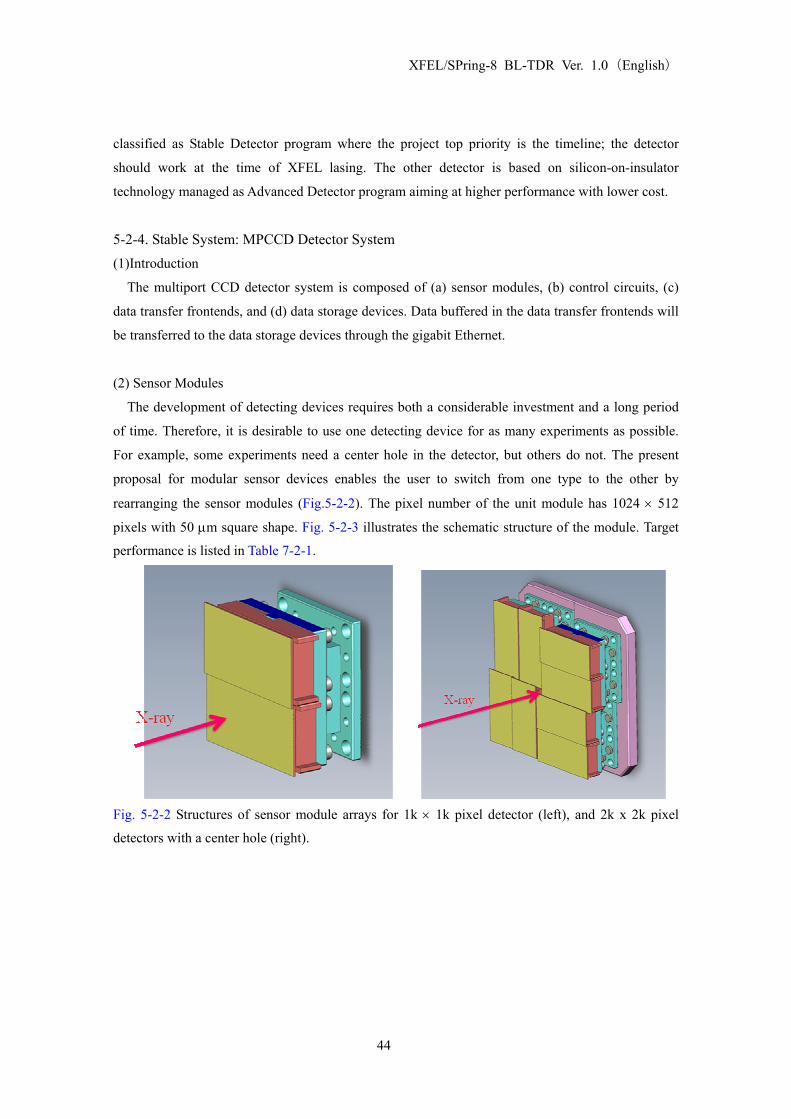
(2) Sensor Modules
The development of detecting devices requires both a considerable investment and a long period
of time. Therefore, it is desirable to use one detecting device for as many experiments as possible.
For example, some experiments need a center hole in the detector, but others do not. The present
proposal for modular sensor devices enables the user to switch from one type to the other by
rearranging the sensor modules (Fig.5-2-2). The pixel number of the unit module has 1024 × 512
pixels with 50 μm square shape. Fig. 5-2-3 illustrates the schematic structure of the module. Target
performance is listed in Table 7-2-1.
Fig. 5-2-2 Structures of sensor module arrays for 1k × 1k pixel detector (left), and 2k x 2k pixel
detectors with a center hole (right).
44

XFEL/SPring-8 BL-TDR Ver. 1.0(English)
Fig.5-2-3 Schematic Structure of the MPCCD sensor module with 8 output readout nodes indicated
as arrows.
45

XFEL/SPring-8 BL-TDR Ver. 1.0(English)
Table 5-2-1 Target Performance of multi-port charge coupled device (MP-CCD) detector
Parameter Target Value Units Comments
Pixel size 50 x 50
100 x 100 μm2
in 2 x 2 binning mode
Operating Temperature 0 ~ -50℃ ℃
Detection Efficiency 80
20 %
6 keV x-rays
12 keV x-rays
System Noise < 0.2
<330
photons
e-
for 6 keV x-rays
Full Well Capacity 5
3100
20
12400
Me-/pixel
photons/pixel
Me-/pixel
photons/pixel
for 6 keV x-rays
in unbinned mode
for 6 keV x-rays
in 2×2 binning mode
Frame Rate > 60 Hz
Dead area width < 300 μm 3 effective pixels in 2x2 binning mode
Tiling Capability 3-side buttable N/A
Radiation Hardness 4×10¹¹ photons/pixel for 12 keV x-ray
46

XFEL/SPring-8 BL-TDR Ver. 1.0(English)
6. Civil Engineering: Experimental Facility 6-1. Outline
This chapter describes a basic plan of the Experimental Facility including the Experimental Hall,
the Preparation Rooms, and the Machine Rooms. This plan was settled by the Joint-Project Team at
the end of January, 2008. Following detailed design works, the construction will begin in March,
2009, and complete in May, 2010.
The following points have been taken into consideration:
(1) The structure of the floor of the Experimental Hall should be designed to avoid subsidence
in the future. Particular attention must be given to reduction of vibration. Note that the
geologic ground condition consists of medium-hard rock with high stability.
(2) The building of the Experimental Hall should be designed to have high stability against
external vibration and temperature fluctuation.
(3) The Preparation Rooms should accommodate basic infrastructure. Attention should be paid
for realizing flexible and multipurpose utilization.
A location map, a floor plan, and a sectional elevation view of the Facility are attached in Fig.
6-1-1, Fig. 6-1-2 and Fig. 6-1-3, respectively. Although the area of the Facility is restricted by the
peripheral road, beamlines can be extended towards the storage ring building through the culverts
under the road.
6-2. Experimental Hall XFEL experiments are conducted in the Experimental Hall, which contains radiation shielding
hutches, beamline components, experimental instruments, and remote control systems.
(1) Size
The Experimental Hall is 56-m long (in the direction of the beam axis) and 31-m wide. Intervals
between XFEL beamlines are 3 m. The distance from the undulator (No. 18) for BL3 to the
partition wall to the Hall is about 73 m.
(2) Floor
The floor of the Experimental Hall is cast with 1.3-m thick concrete. The floor supports a load
of 2 t/m2. A flatness of the floor is controlled within ±10 mm. The floor surface is coated with
an epoxy resin paint to avoid dusts from the floor concrete. The height of the XFEL beam from
the floor level is set to be 1.4 m. In order to avoid vibration, the floor should be separated from
the foundation of the Machine Rooms that contains air-conditioning and water-circulating
machines. Polishing of the floor is considered for utilizing optical benches with air-pad carriers.
(3) Overhead Crane
An overhead crane (max lifting weight of 2.8 t; lifting height of 7 m) is prepared in the Hall.
(4) Carry-in Entrance
The carry-in entrance with a size of 4 m × 4 m is settled on the south side of the Experimental
47

XFEL/SPring-8 BL-TDR Ver. 1.0(English)
Hall. The entrance door on the north side of the hall is 2-m high and 2-m wide.
(5) Air Conditioning
Temperature in the Experimental Hall is stabilized within ±2 ℃. The roof and walls are
thermally insulated from outside. Vibration caused from the air-conditioning system should be
avoided.
(6) Utility
Electrical switch boards, canisters for coolant water and compressed air, and ports for
air-conditioning are prepared for each beamline. Scrubber can be installed for local exhaustion in
the future.
6-3. Experimental Preparation Room The Experimental Preparation Rooms are used for preparation of experimental instruments. 5
rooms are settled inside the radiation control area next to the Experimental Hall. The size of the
room is 7 m×10 m×3 m (height) with an entrance size of 2 m × 2 m. The floor load is 1 t/m2.
Each room has electrical switch boards, although clean water and an experimental drainage
system are not available.
6-4. Sample Preparation Room The Specimen Preparation Rooms are used for preparation of samples. Outside the radiation
control area, 5 rooms are settled on the second floor of the Facility. The size of the room is 7 m×10
m×3 m (height) with an entrance size of 2 m×2 m . The floor load is 0.5 t/m2.
Each room has electrical switch boards. Some of rooms provide clean water and experimental
drainage systems.
6-5. Carry-in Room The carry-in room is settled as a buffer room for transporting experimental instruments from/to
the Experimental Hall. This room is located outside the radiation control area. The size of the
carrying room is 14 m×7 m×5 m (height) with a floor load of 2 t/m2. The size of the entrance is 4
m×4 m. The overhead crane is not available.
6-6. Noise Shielding Special attention should be paid for designing signal grounds at the Experimental Hall in order to
suppress EMC and AC-line noises.
48

XFEL/SPring-8 BL-TDR Ver. 1.0(English)
Fig. 6-1-1 XFEL Experimental Facility - floor plan.
49

XFEL/SPring-8 BL-TDR Ver. 1.0(English)
Fig. 6-1-2 XFEL Experimental Facility - sectional elevation view
50

XFEL/SPring-8 BL-TDR Ver. 1.0(English)
Fig. 6-1-3 XFEL Experimental Facility - sectional elevation view
51

XFEL/SPring-8 BL-TDR Ver. 1.0(English)
APPENDIX
A1. Dose Estimation for XFEL
A1-1. Introduction The irradiation tolerance of optical elements for XFEL is a critical issue because the pulse-energy
of XFEL within short periods is extremely high. The optical elements to be used in the first beamline
will be classified according to their purpose as follows:
Table A1-1-1 Optical Elements
Classification Candidate Materials Distance from the
source, L (m)
(A) Beam stopper
(Shutters, collimators)
Combination of light and heavy
materials
75 ~ 150
(B) Vacuum windows Be or diamond crystals 75 ~ 150
(C) Monochromator crystals Si or diamond crystals 100 ~ 150
(D) Total reflection mirrors Light elements 100 ~ 150
Tolerance estimations were made by comparing the absorbed XFEL energy in a material expressed
as absorption energy per constituting atoms (unit: eV/atom) with the materials’ threshold energy for
melting. Evaluations were made using conventional absorption coefficients for (A), (B), and (C), and
an incident-angle-dependent absorption coefficient with extinction correction for (D).
A1-2. Light Source Parameters (subject to change according to the progress of machine
development)
Photon numbers per SASE pulse, NP, beam size, σ, and beam divergence, σ’ were calculated using
SIMPLEX code. The photon number came from the SIMPLEX panel display, while the beam size
and divergence were calculated using a simulation. Dependence on the photon energy, EP, was
calculated by changing the electron beam energy, EB, from 2 to 8 GeV for EB P < 10 keV with a fixed
K-value of the undulator (#1-#7). For EP > 10 keV, it was calculated by changing the K-value with
fixed electron beam energy of EBB= 8 GeV (#7-#9). The following beam parameters were also used
for the calculation:
Normalized emittance : 1 πmm.mrad
Energy Spread : 1E-4
Peak Current : 3 kA
52

XFEL/SPring-8 BL-TDR Ver. 1.0(English)
Charges/Pulse : 0.2 nC (67 fs full-width rectangular pulse)
Undulator Periods : 1.8 cm
Undulator Length : 5 m (1 segment)
Average βx, βy : 26 m
The resulting values for NP, σ, and σ’ are shown in the following table. The last column lists the ratio
between the emittance and the wavelength:
R = σ σ’/(λ/4π) (Eq. A1-2-1)
Although Gaussian diffraction-limited light will result in R = 1, the present calculation produced R
=1.5 as an average value. The photon energy dependences of NP, σ, σ’, and R are shown in Fig.
A1-2-1 to A1-2-3.
Table A1-2-1 Calculated NP,σ, σ’ # EBB
(GeV) K ID segment
number EP
(eV) λ
(nm) NP
(photons/pls)RMS σ (μm)
RMS σ σ’ (μrad)
R = σ σ’/(λ/4π)
1 2 2.18 5 625 1.98 4.90E+12 44.5 5.54 1.562 3 2.18 6 1410 0.882 2.40E+12 30.8 1.89 0.83
3 4 2.18 8 2500 0.495 1.40E+12 43.7 1.44 1.60
4 5 2.18 10 3910 0.317 8.80E+11 42.7 0.957 1.62
5 6 2.18 12 5630 0.22 5.70E+11 36.8 0.721 1.51
6 7 2.18 15 7660 0.162 3.80E+11 37.1 0.512 1.48
7 8 2.18 18 10000 0.124 2.60E+11 35.9 0.412 1.51
8 8 2 18 11255 0.110 1.91E11 27.5 0.443 1.40
9 8 1.754 18 13300 0.093 1.15E+11 21.1 0.399 1.13
The following calculation uses the above listed NP (and its interpolation), and averaged σ values of
#1 through #7, 38.8 um (#8 and #9 do not reach saturation). Divergence σ’ was determined by Eq.
A1-2-1 so that R =1.5 and σ =σave
0 5000 10000 150000
1
2
3
4
5[×1012]
Photon Energy (keV)
Phot
on n
umbe
r (ph
oton
s/pl
s)
Fig. A1-2-1: Photon number per pulse vs. Photon Energy
53

XFEL/SPring-8 BL-TDR Ver. 1.0(English)
0 5000 10000 150000
20
40
60
80
100
0
2
4
6
8
10
Photon Energy (keV)
RM
S be
am si
ze (μ
m)
RM
S be
am d
iver
genc
e (μ
rad)
Fig. A1-2-2 Energy dependence of the beam size and divergence.
The solid lines show spline interpolations.
0 5000 10000 150000
0.5
1
1.5
Photon Energy (keV)
R (=
σσ'/(
λ/4π
))
Diffraction-limited Gaussian beam
Fig. A1-2-3 Energy dependence of the parameter R
A1-3. Conventional Absorption Dose Absorption Dose, D, under conventional absorption condition is estimated by the formula:
22P P
L A
N eE AD
Nμπσ ρ
= (Eq. A1-3-1),
where the following symbols are used for designating the parameters:
μ: absorption coefficient
σL: rms beam size at the sample position, distance L from the source.
A: average atomic weight
ρ: average density
NA: Avogadro’s Number.
54
XFEL/SPring-8 BL-TDR Ver. 1.0(English)
Energy dependence (from 0.5 to 15 keV) of the doses for Be, BB4C, Graphite, Diamond, SiC, Si and
Cu, calculated at a point 100 m downstream from the source are shown in Fig. A1-3-1. The
source-to-sample distance dependence of the doses calculated at a photon energy of 1 keV and 5 keV
is shown in Figs. A1-3-2 and A1-3-3. The calculated results can be summarized as follows:
(1) The melting threshold of Cu can be surpassed at lower energies or near the absorption edge for
an even longer source-to-object distance (L ~ 100 m) (Fig. A1-3-1). Therefore, it is recommended
not to use Cu for the first beam-blocking component.
(2) Lighter materials such as Be, BB4C, Graphite and Diamond can be used immediately downstream
of the light source for higher energy photons (EP = 5 keV) (Fig. A1-3-2). For lower energy photons
(EP = 1 keV), the melting threshold is surpassed immediately downstream from the source, but the
threshold is more than one order of magnitude larger than when the distance is greater than 75 m
(Fig. A1-3-3). These materials are suitable candidates for beam blocking and window materials.
(3) The dose for the crystal monochromators using Si and Diamond crystals placed at L =100 m can
be estimated from Fig. A1-3-1. The margin to the threshold of Si at high energies (EP > 6 keV) is
more than one-order of magnitude, but it is less than one-order of magnitude at lower energy (1.98 ≤
EP < 6 keV, minimum energy is determined by the allowable Si 111 reflection). The maximum dose
around EP ~2 keV is not more than the threshold value. Diamonds have a much greater margin to the
threshold value over the entire energy range (EP ≥ 3.02 keV) covered with 111 reflection.
55

XFEL/SPring-8 BL-TDR Ver. 1.0(English)
0 5000 10000 1500010-4
10-3
10-2
10-1
100
Photon energy (eV)
Dos
e (e
V/a
tom
)
Be B4C Graphite Diamond SiC Si Cu
dashed lines: threshold levels
0
5
10
15
0
200
400
600
800En
ergy
den
sity
(J/c
m2 )
Bea
m si
ze (μ
m)
Fig. A1-3-1 (above) Photon energy dependence of energy density and beam size of SASE FEL,
(below) Photon energy dependence of doses. Both calculations are made for L=100 m.
56

XFEL/SPring-8 BL-TDR Ver. 1.0(English)
0200400600800
Bea
m si
ze(μ
m, S
TD)
0 100 20010-5
10-4
10-3
10-2
10-1
100
Length from undulator exit (m)
Dos
e (e
V/a
tom
)
Be B4C Graphite Diamond SiC Si Cu
dashed lines: threshould level
E=1 keV
Fig. A1-3-2 Distance dependence of the Dose and Beam Size at EP =1 keV
0
100
200
Bea
m si
ze(μ
m, S
TD)
0 100 20010-5
10-4
10-3
10-2
10-1
100
Length from undulator exit (m)
Dos
e (e
V/a
tom
)
Be B4C Graphite Diamond SiC Si Cu
dashed lines: threshould level
E=5 keV
Fig. A1-3-3 Distance dependence of the Dose and Beam Size at EP =5 keV
57

XFEL/SPring-8 BL-TDR Ver. 1.0(English)
A1-4. Dose under Total Reflection Conditions The dose under the total reflection condition is given by Eq. A1-4-1,
( ) ( )2
1 sin2
R P P
L A
N eE A RD
Nμ θ θ
πσ ρ−
= , (Eq. A1-4-1)
where R represents reflectivity, and the incident-angle-dependent absorption coefficient μR (θ) is
expressed as a function of the complex refraction coefficient, n=1-δ+iβ, as
( ) ( )22 22 2 2 4 2Rπ 2μ θ δ θ β
λ= − + + δ θ− . (Eq. A1-4-2)
When the glancing angle, θ, is far above the critical angle, 2δ , Eq. A1-4-1 approximates Eq. A1-3-1.
The calculated results for the glancing-angle dependence of the dose and reflectivity for EP = 10, 5,
and 1 keV for L=100 m are shown in Figs. A1-4-1, A1-4-2, and A1-4-3. The calculated results for
energy dependence of the dose and reflectivity with a fixed glancing angle are shown in Figs. A1-4-4
and A1-4-5. The calculated results for the doses for a fixed length (LM = 50 cm) mirror, where the
glancing angle is varied so that the mirror acceptance θLM is six times the beam size σL are shown in
Fig. A1-4-6.
Mirror materials of Au, Si, SiC and graphite (ρ= 2.2 g/ cm3) were assumed. Surface roughness is not
taken into consideration. The results are summarized as follows:
(1) The dose of the Au mirror surpassed the threshold near the critical angle (Figs. A1-4-1, A1-4-2).
(2) The dose of the Si mirror came nearer to the threshold near the critical angle but did not surpass
it (Figs. A1-4-1 and A1-4-2). When fixed at the glancing angle of θ = 0.1°, the dose was two orders
of magnitude smaller than the threshold (Fig. A1-4-4), and the glancing angle of θ = 0.2° gave the
dose a margin of one order of magnitude (Fig. A1-4-5).
(3) The absorption dose of SiC was similar to that of Si. The higher threshold made a larger margin.
(4) The dose of the graphite was two orders of magnitude less than the threshold even around the
critical angle, because of a smaller absorption rate per atom (Figs. A1-4-1, A1-4-2).
(5) Fig. A1-4-6 shows that the glancing angle q was much smaller than the critical angle when the
condition of θLM = 6σL was maintained for a mirror with LM =50 cm. Accordingly, the dose would
have been at least one order of magnitude smaller than the threshold for all the materials considered
here. Therefore, mirrors with LM =50 cm are able to handle the XFEL beam well under the threshold
even for the bigger beam size at lower energies.
58

XFEL/SPring-8 BL-TDR Ver. 1.0(English)
0 0.2 0.4 0.6 0.8 1
0.2
0.4
0.6
0.8
1
Incident angle (degree)
Ref
lect
ivity
10-5
10-4
10-3
10-2
10-1
100
101
Dos
e (e
V/a
tom
)
Graphite SiC Si Au
dashed lines: threshold level
E=10 keVL=100 m
Fig. A1-4-1 Glancing angle dependence of the dose at EP = 10 keV
0 0.2 0.4 0.6 0.8 1
0.2
0.4
0.6
0.8
1
Incident angle (degree)
Ref
lect
ivity
10-5
10-4
10-3
10-2
10-1
100
101
Dos
e (e
V/a
tom
)
Graphite SiC Si Au
dashed lines: threshold level
E=5 keVL=100 m
Fig. A1-4-2 Glancing angle dependence of the dose at EP = 5 keV
59

XFEL/SPring-8 BL-TDR Ver. 1.0(English)
0 0.2 0.4 0.6 0.8 1
0.2
0.4
0.6
0.8
1
Incident angle (degree)
Ref
lect
ivity
10-5
10-4
10-3
10-2
10-1
100
101
Dos
e (e
V/a
tom
)
Graphite SiC Si Au
dashed lines: threshold levels
E=1 keVL=100 m
Fig. A1-4-3 Glancing angle dependence of the dose at EP = 1 keV
0 5000 10000 150000.9
0.92
0.94
0.96
0.98
1
Photon energy (eV)
Ref
lect
ivity
10-5
10-4
10-3
10-2
10-1
100
Dos
e (e
V/a
tom
)
Graphite SiC Si Au
dashed lines: threshold levels
Fig. A1-4-4 Photon energy dependence of the dose at θ = 0.1°
60

XFEL/SPring-8 BL-TDR Ver. 1.0(English)
0 5000 10000 150000.6
0.7
0.8
0.9
1
Photon energy (eV)
Ref
lect
ivity
10-5
10-4
10-3
10-2
10-1
100
Dos
e (e
V/a
tom
)
Graphite SiC Si Au
dashed lines: threshold levels
L=100 mθ = 0.2 degree
Fig. A1-4-5 Photon energy dependence of the dose at θ = 0.2°
0 2 4 6 8 100
0.1
0.2
0.3
0.4
0.5
0
1
2
3
4
Photon energy (keV)
Inci
dent
ang
le (d
egre
e)
Mirr
or a
ccep
tanc
e (m
m)
10-510-410-310-210-1100
Dos
e (e
V/a
tom
) Graphite SiC Si Au
Fig. A1-4-6 The dose (above), glancing angle (below, left axis) and mirror acceptance (below, right
axis) for a fixed mirror placed at L=100 m with a length of LM =50 cm, when the ratio of the
acceptance and the beam size is fixed at 6 by changing the glancing angle.
61

XFEL/SPring-8 BL-TDR Ver. 1.0(English)
A1-5. Discussion (1) A two-stage structure is necessary for the beam blocking optical component. The material
directly irradiated by the XFEL beam should be made of a light element such as BB4C to prevent
melting and/or evaporation. After attenuating the beam power sufficiently by this light material, the
second-stage, heavier metal element blocks the hard X-rays and/or gamma rays.
(2) Be and diamonds can be used in all energy ranges for vacuum tight windows.
(3) A Si monochromator crystal can be safely used above 6 keV. A Diamond crystal works better for
the lower energy region (3 ~ 6 keV) with respect to radiation doses.
(4) When a total reflection mirror is operated near the critical angle, lighter materials such as SiC
and/or C are preferable. However, with a smaller glancing angle of θ≤0.2°, Si is a good candidate.
The energy dependence of the beam size demands an adjustment to the glancing angle in order not to
miss any part of the beam. A 50 cm mirror made of any material can capture the entire beam without
any problems related to radiation doses.
The results are summarized in the following table(Table A1-5-1).
Table A1-5-1 Radiation tolerance of the optical components
Classification Material Tolerance(1) Beam Blocking (Shutter/Collimator) B4C, SiC, Be, Diamond ◎ Cu × (2) Vacuum windows Be, Diamond ◎ (3) Monochromator crystals Si ○ Diamond ◎ (4) Total Reflection Mirrors Au △ Si ○ SiC ◎ C ◎
Reference:
R. Tatchyn, “LCLS optics: Technological issues and scientific opportunities,” SLAC-PUB 6064,
1993.
R. M. Bionta, “Controlling doses to low Z solids at LCLS,” LCLS note LCLS-TN-00-3, 2000.
M. Yabashi et al, “Optics development for the Japanese XFEL project”, Proc. SPIE 6586, p. 658605.
62

XFEL/SPring-8 BL-TDR Ver. 1.0(English)
A2. Estimation of Transmissivity
A2-1. Introduction The transmissivities of some solid-state and gas-phase materials were estimated in order to discuss
the specification of attenuators.
Transmissivities of X-rays for solid-state and gas-phase (@293K) materials consisting of a single
atomic species are given by the following formula:
( ) ( ) ( )( )
313
m g/cm cmexp 3.394 10
g/mol
f zT
M
λ ρ⎛ ⎞′′⎜ ⎟= − ×⎜ ⎟⎝ ⎠
, (Eq. A2-1-1)
and
( ) ( ) ( )( )4exp 1.395 10 m Pa cmT Pλ ′′= − × × f z , (Eq. A2-1-2)
where f” is the imaginary part of the atomic scattering factor, z the thickness of the attenuator, ρ the
density, M the molar mass, and P the pressure.
63

XFEL/SPring-8 BL-TDR Ver. 1.0(English)
A2-2. Solid Attenuator The following estimations were made for some solid state attenuators:
1. Energy dependence of the attenuator thickness for various transmissivity values, T.
2. Energy dependence of the transmissivity, T, for various attenuator thickness, z.
(1) Be
ρ=1.85 g/cm3, M = 9.012 (g/mol)
It can be used for attenuation of X-rays below 3 keV.
(a)
0 10000 20000 3000010-3
10-2
10-1
100
101
102
103
Photon energy (eV)
Thic
knes
s (m
m)
T=0.001 T=0.01 T=0.1 T=0.9 T=0.99
(b)
0 10000 20000 3000010-7
10-6
10-5
10-4
10-3
10-2
10-1
100
Photon energy (eV)
Tran
smis
sion
z = 0.1 mm z = 1 mm z = 3 mm
Fig. A2-2-1 X-Ray Transmissivity of Be.
64

XFEL/SPring-8 BL-TDR Ver. 1.0(English)
(2) Isotropic Carbon
ρ=1.7 g/cm3, M = 12.0 (g/mol)
10-2 attenuation at 15 keV need thickness of more than 60 mm.
(a)
0 10000 20000 3000010-3
10-2
10-1
100
101
102
103
Photon energy (eV)
Thic
knes
s (m
m)
T=0.001 T=0.01 T=0.1 T=0.9 T=0.99
(b)
0 10000 20000 3000010-7
10-6
10-5
10-4
10-3
10-2
10-1
100
Photon energy (eV)
Tran
smis
sion
z = 5 mm z = 10 mm z = 30 mm z = 100 mm
.
Fig. A2-2-2 X-Ray Transmissivity of Isotropic Carbon
65

XFEL/SPring-8 BL-TDR Ver. 1.0(English)
(3) Si
ρ=2.33 g/cm3, M = 28.1 (g/mol)
Transmissivity for 10 keV X-rays varies from 50% to 0.1% as the thickness varies from 100 μm to
3 mm. The transmissivity at 7 keV and 100 um thick is 10%. A thinner attenuator is required to
produce higher transmissivity. It is difficult to use for small attenuation at less than 5 keV.
(a)
0 10000 20000 3000010-4
10-3
10-2
10-1
100
101
102
Photon energy (eV)
Thic
knes
s (m
m)
T=0.001 T=0.01 T=0.1 T=0.9 T=0.99
(b)
0 10000 20000 3000010-810-710-610-510-410-310-210-1
Photon energy (eV)
Tran
smis
sion
z = 100 um z = 1 mm z = 3 mm
Fig. A2-2-3 X-Ray Transmissivity of Si
66

XFEL/SPring-8 BL-TDR Ver. 1.0(English)
A2-3. Gas Attenuator The following estimations were made for some gas phase attenuators with a fixed thickness of 1 m:
1. Energy dependence of the attenuator pressure, P, for various transmissivity values, T.
2. Energy dependence of the transmissivity, T, for various attenuator pressures, P.
(1) Ar, z =1 m
A pressure range above 0.1 atm corresponds to the transmissivity from 100% to 10% at 7 keV. An
extremely wide attenuation range is given between 3~5 keV.
(a)
0 10000 20000 30000
10-5
10-4
10-3
10-2
10-1
100
101
Photon energy (eV)
Pres
sure
(atm
)
T=0.001 T=0.01 T=0.1 T=0.9 T=0.99
(b)
0 10000 20000 30000
10-5
10-4
10-3
10-2
10-1
100
101
Photon energy (eV)
Tran
smis
sion
P=0.001 atm P=0.01 atm P=0.1 atm P=1 atm
Fig. A2-3-1 X-Ray Transmissivity of Ar
・
67
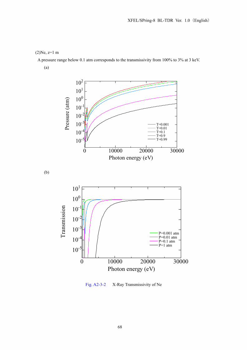
XFEL/SPring-8 BL-TDR Ver. 1.0(English)
(2)Ne, z=1 m
A pressure range below 0.1 atm corresponds to the transmissivity from 100% to 3% at 3 keV.
(a)
0 10000 20000 30000
10-510-410-310-210-1100101102
Photon energy (eV)
Pres
sure
(atm
)
T=0.001 T=0.01 T=0.1 T=0.9 T=0.99
(b)
0 10000 20000 30000
10-5
10-4
10-3
10-2
10-1
100
101
Photon energy (eV)
Tran
smis
sion
P=0.001 atm P=0.01 atm P=0.1 atm P=1 atm
Fig. A2-3-2 X-Ray Transmissivity of Ne
68

XFEL/SPring-8 BL-TDR Ver. 1.0(English)
(3)He, z=1 m
Absorption is negligible for >1 keV photons when the pressure is less than 0.1 atm.
(a)
0 10000 20000 3000010-310-210-1100101102103104105
Photon energy (eV)
Pres
sure
(atm
)
T=0.001 T=0.01 T=0.1 T=0.9 T=0.99
(b)
0 10000 20000 30000
10-5
10-4
10-3
10-2
10-1
100
101
Photon energy (eV)
Tran
smis
sion
P=0.001 atm P=0.01 atm P=0.1 atm P=1 atm
Fig. A2-3-3 X-Ray Transmissivity of He
69

XFEL/SPring-8 BL-TDR Ver. 1.0(English)
A2-4. Summary
0 10000 20000 3000010-3
10-2
10-1
100
101
Photon energy (eV)
Tran
smis
sion
Ne 0.1 m.atm + Be 1 mm Ar 0.1 m.atm Si 0.1 mm Si 1 mm Si 3 mm
Fig. A2-4-1 X-ray transmissivity of various attenuators
A transmissivity control above 0.1% can be performed as follows:
(1) hν< 3 keV: combination of Ne (zP<0.1 m.atm) and Be (z<1 mm),
(2) 3<hν< 5 keV: Ar (zP <0.1 m.atm)
(3) 5<hν< 10 keV: combination of Ar (zP <0.1 m.atm) and Si (100 um<z <1 mm).
(4) 10<hν< 15 keV: combination of Ar (zP <0.1 m.atm) with Si (100 um<z <3 mm).
Fig. A2-4-2 Energy range covered with each attenuator
70

XFEL/SPring-8 BL-TDR Ver. 1.0(English)
A3. Estimation of Scattering Power Scattered intensity of X-rays is given for monatomic solid state materials and gas phase materials at
T=293K by the following equations:
(solid)
( )( )
( ) ( )( ) ( ) ( ) ( ) ( )
( )( ) ( ) ( ) ( )
( )( ) ( ) ( ) ( )
322 2
0
3223 26
32
g/cm 1/molphts/plscm cm
phts/pls g/mol
g/cm6.02 10 7.94 10 cm
g/mol
g/cm0.0478 cm
g/mol
ASe g
g
g
NIz r F x S x P
I M
z F x S x PM
z F x S x PM
ρ
ρ
ρ
−
⎡ ⎤= +⎣ ⎦
⎡ ⎤= × × × × + Δ⎣ ⎦
⎡ ⎤= × + ΔΩ⎣ ⎦
ΔΩ
Ω
(gas)
( )( )
( ) ( )( ) ( ) ( ) ( ) ( )
( ) ( ) ( ) ( )
( ) ( ) ( ) ( )
322 2
0
210 23 26
211
g/cm 1/molphts/plscm cm
phts/pls g/mol
4.11 10 6.02 10 7.94 10 Pa cm
1.96 10 Pa cm
ASe g
g
g
NIz r F x S x P
I M
P z F x S x P
P z F x S x P
ρ
− −
−
⎡ ⎤= +⎣ ⎦
⎡ ⎤= × × × × × + Δ⎣ ⎦⎡ ⎤= × + ΔΩ⎣ ⎦
ΔΩ
Ω
ex1) Be: ρ=1.85 g/cm3, M = 9.012 (g/mol), z=100 um, F(x)^2+S(x) ~ 4, Pg ~ 1,
ΔΩ= 10×10 mm2/(30×30 mm2) = 0.1 sr (placing a detector with 10×10 mm2 detecting area 30 mm
from the scatterer)
( )( )
5
0
ph/pls 1.850.0478 0.01 4 0.1 4 10ph/pls 9.01
SII
−≅ × × × × = ×
ex2) Ar: P=0.1 atm, z=10 cm, F(x)^2+S(x) ~ 10, Pg ~ 1,
ΔΩ = 30x30 mm2/(50x50 mm2)=0.3 sr (placing a detector with □30 mm2 detecting area 50 mm
from the scatterer)
( )( )
11 4 6
0
ph/pls1.96 10 1.02 10 10 10 0.3 6 10
ph/plsSI
I− −≅ × × × × × × = ×
ex3) He: P= 0.1 atm, z=10 cm, F(x)^2+S(x) ~ 2, Pg ~ 1,
ΔΩ = 30x30 mm2/(50x50 mm2) =0.3 sr (placing a detector with a detecting area of 30 mm2 at a
distance of 50 mm from the scatterer)
( )( )
11 4 6
0
ph/pls1.96 10 1.02 10 2 10 0.3 1.2 10
ph/plsSI
I− −≅ × × × × × × = ×
Reference: S. Goto, Thesis, Univ. Tokyo (2000).
71

XFEL/SPring-8 BL-TDR Ver. 1.0(English)
A4. Revision Record
1st version in Japanese: 17 June 2008
1st version in English: February 2010
72