Embed Size (px)
Citation preview
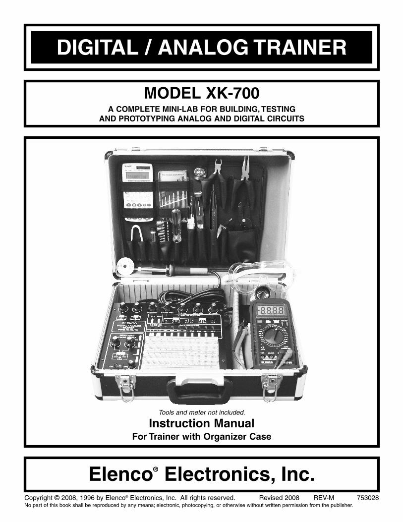
DIGITAL / ANALOG TRAINER
MODEL XK-700A COMPLETE MINI-LAB FOR BUILDING, TESTING
AND PROTOTYPING ANALOG AND DIGITAL CIRCUITS
Instruction ManualFor Trainer with Organizer Case
Tools and meter not included.
Copyright © 2008, 1996 by Elenco® Electronics, Inc. All rights reserved. Revised 2008 REV-M 753028No part of this book shall be reproduced by any means; electronic, photocopying, or otherwise without written permission from the publisher.
Elenco® Electronics, Inc.
-1-
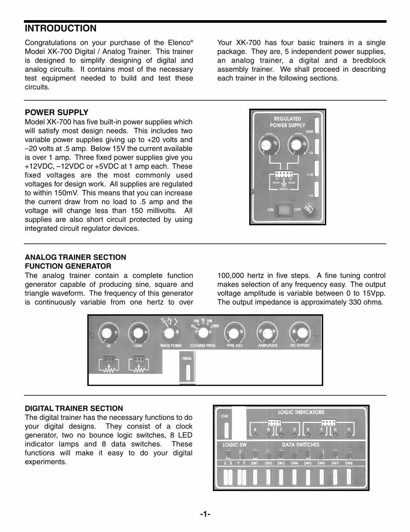
INTRODUCTION
POWER SUPPLYModel XK-700 has five built-in power supplies whichwill satisfy most design needs. This includes twovariable power supplies giving up to +20 volts and–20 volts at .5 amp. Below 15V the current availableis over 1 amp. Three fixed power supplies give you+12VDC, –12VDC or +5VDC at 1 amp each. Thesefixed voltages are the most commonly usedvoltages for design work. All supplies are regulatedto within 150mV. This means that you can increasethe current draw from no load to .5 amp and thevoltage will change less than 150 millivolts. Allsupplies are also short circuit protected by usingintegrated circuit regulator devices.
The analog trainer contain a complete functiongenerator capable of producing sine, square andtriangle waveform. The frequency of this generatoris continuously variable from one hertz to over
100,000 hertz in five steps. A fine tuning controlmakes selection of any frequency easy. The outputvoltage amplitude is variable between 0 to 15Vpp.The output impedance is approximately 330 ohms.
DIGITAL TRAINER SECTIONThe digital trainer has the necessary functions to doyour digital designs. They consist of a clockgenerator, two no bounce logic switches, 8 LEDindicator lamps and 8 data switches. Thesefunctions will make it easy to do your digitalexperiments.
Congratulations on your purchase of the Elenco®
Model XK-700 Digital / Analog Trainer. This traineris designed to simplify designing of digital andanalog circuits. It contains most of the necessarytest equipment needed to build and test thesecircuits.
Your XK-700 has four basic trainers in a singlepackage. They are, 5 independent power supplies,an analog trainer, a digital and a bredblockassembly trainer. We shall proceed in describingeach trainer in the following sections.
ANALOG TRAINER SECTIONFUNCTION GENERATOR
-2-
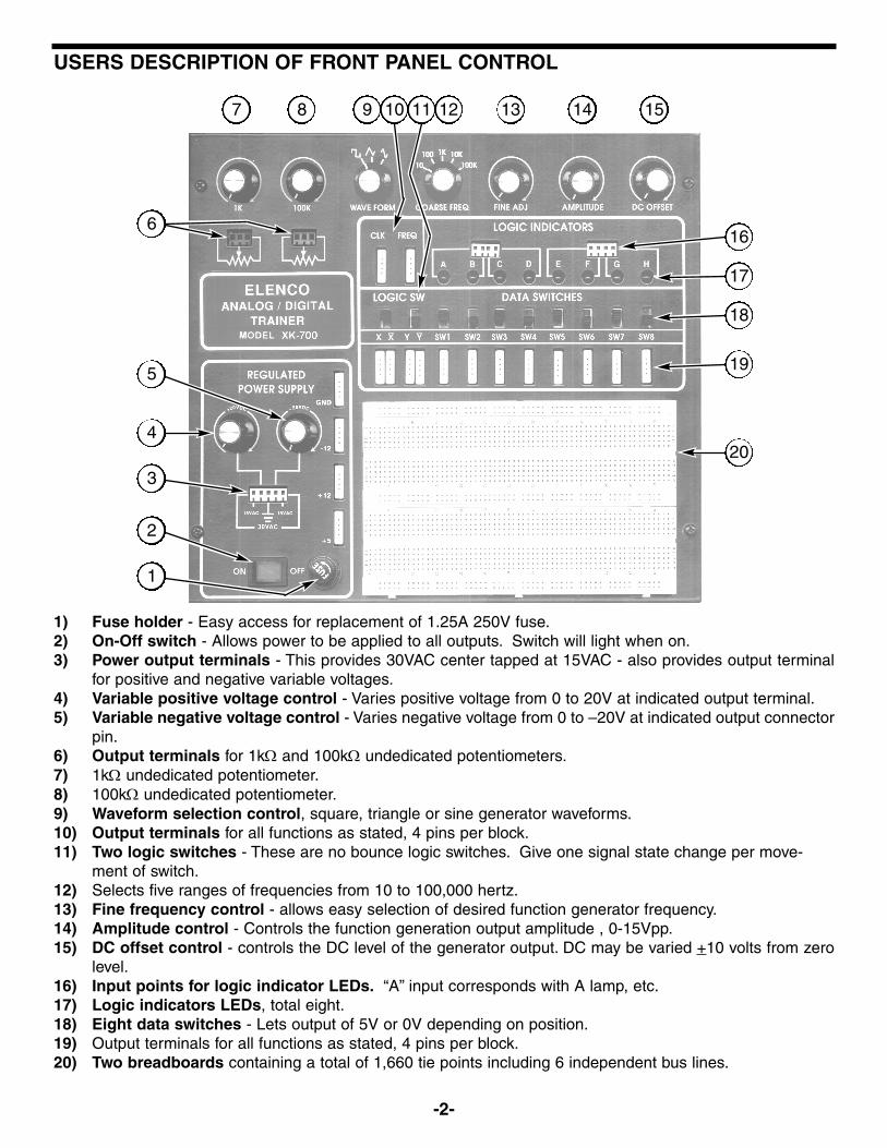
USERS DESCRIPTION OF FRONT PANEL CONTROL
1) Fuse holder - Easy access for replacement of 1.25A 250V fuse.2) On-Off switch - Allows power to be applied to all outputs. Switch will light when on.3) Power output terminals - This provides 30VAC center tapped at 15VAC - also provides output terminal
for positive and negative variable voltages.4) Variable positive voltage control - Varies positive voltage from 0 to 20V at indicated output terminal.5) Variable negative voltage control - Varies negative voltage from 0 to –20V at indicated output connector
pin.6) Output terminals for 1kΩ and 100kΩ undedicated potentiometers.7) 1kΩ undedicated potentiometer.8) 100kΩ undedicated potentiometer.9) Waveform selection control, square, triangle or sine generator waveforms.10) Output terminals for all functions as stated, 4 pins per block.11) Two logic switches - These are no bounce logic switches. Give one signal state change per move-
ment of switch.12) Selects five ranges of frequencies from 10 to 100,000 hertz.13) Fine frequency control - allows easy selection of desired function generator frequency.14) Amplitude control - Controls the function generation output amplitude , 0-15Vpp.15) DC offset control - controls the DC level of the generator output. DC may be varied +10 volts from zero
level.16) Input points for logic indicator LEDs. “A” input corresponds with A lamp, etc.17) Logic indicators LEDs, total eight.18) Eight data switches - Lets output of 5V or 0V depending on position.19) Output terminals for all functions as stated, 4 pins per block.20) Two breadboards containing a total of 1,660 tie points including 6 independent bus lines.
1
2
3
4
5
6
7 8 13 14 15
16
17
18
19
20
1211109
-3-
GENERAL SPECIFICATIONS FOR MODEL XK-700Power Supplies:
• 0V to 20VDC @ 0.5A (0V to 15V @ 1A)
• 0V to –20VDC @ 0.5A (0V to –15V @ 1A)
• +12V + 5% @ 1A
• –12V + 5% @ 1A
• +5V + 5% @ 1A
• 30VAC center-tapped at 15VAC @ 1A.
• Load regulation all DC supplies less than 0.2V no load to 0.5A
• Line regulation all DC supplies less than 0.2V 105 to 135V
• Hum and ripple all DC supplies less than .01V rms
• Short protection all DC supplies-Internal IC thermal cutoff
• Fuse - 1.25A 250V
Function Generator Analog Section:
• Waveforms sine, square, triangle, complimentary square
• Frequency - 1Hz to 100kHz in 5 steps continuously variable
• Fine frequency adjust - 10:1 approximate
• Amplitude variable 0-15Vpp
• Output impedance 330Ω: short protected
• DC offset change + 10V from zero crossing
Digital Section:
• Data switches, eight DPDT, Hi 5V, low 0V
• Logic switches, two no bounce with complimentary output
“On” voltage level 2.8V min., “Off” voltage level 1V max.
Input impedance 100kΩ.
• Eight LED readouts, 100kΩ input impedance
• Clock frequency, 1Hz to 100kHz in 5 steps continuously variable
• Clock amplitude, 5Vpp squarewave
• Clock rise time, better than 100nsec.
Bredboards Section:
• Two bredboards containing 830 tie points each (total 1,660 pins)
• 6 independent power bus lines for common connections
Variable Resistance (undedicated):
• 1kΩ Potentiometer
• 100kΩ Potentiometer
-4-
TESTING THE XK-700 DIGITAL ANALOG TRAINER
The following paragraphs give detailed instructionson testing the digital / analog trainer.
Note that in the XK-700 trainer there are five majorfunctions, (1) Power Supply (2) Logic Indicators (3)Function Generator (4) Logic Switches and (5) DataSwitches. We shall proceed in testing out eachsection. If any test fails, refer to the schematicdiagram and check the wiring and soldering of thesection involved.
POWER SUPPLY TESTINGPlug the trainer into a 120VAC outlet and switch tothe “ON” position (the power switch should light).With a digital voltmeter, measure the voltageoutputs at the power blocks. The +12V shouldmeasure between 11.4 and 12.6 volts. The 5Vsupply should read between 4.75 and 5.25 volts.The –12V supply should read between –11.4 and12.6 volts.
Do not short the 15VAC output to ground.Short the +12V, –12V and +5V supply to ground.They should turn off and recover when the short isremoved. If you have a 25Ω 10 watt resistor, placeit across the output terminal (2 watt resistor willwork, but use it only for a few seconds). The outputof the 12V supply should not change more than 0.20volts. Do the same on the 5V supply using a 10Ω 5watt resistor. Again, the output should not changemore than 0.20 volts. In making this test, thevoltmeter leads should be clipped to the terminaldirectly and no to the load leads. This is to preventerrors due to voltage drop from contact resistance ofthe load.
Check the variable voltage supplies in the samemanner. Set the output voltage between 10-15volts. Place the 25Ω 10 watt resistor across theoutput terminal. The voltage should stay within 0.20volts of the no load voltage.
TESTING THE FUNCTION GENERATORTo test the function generator, you will need anoscilloscope. Connect the scope to the terminalmarked FREQ., and the ground clip to the terminalmarked GND. Adjust the waveform switch to sine,the coarse frequency switch to 1k and the amplitudecontrol to maximum. Your scope should show a sinewave with an output of about 15Vpp. If the sinewaveis clipped on top or bottom, adjust the DC offsetcontrol for the most linear reading. Turn the FINEADJ control and the frequency should vary between100 and 1,000 hertz. Check the other coarsefrequency positions.
Now, check the CLK output terminal. You shouldsee a square wave of about 5Vpp. If the scope is adual trace, connect one input to the CLK and theother FREQ terminal. Set the waveform switch tosquarewave. You will note the two frequencies are180O out of phase. If no scope is available, connecta wire to the CLK terminal and input to “A” of thelogic indicators. Connect another wire to the FREQterminal and input “B”. Set the coarse frequencyswitch to 10 hertz and the fine freq control tominimum position. The two LEDs should blinkalternately.
TESTING THE LOGIC INDICATOR FUNCTIONThere are eight logic indicators which you will bechecking out. Place a wire to the 5V power supplyand touch the “A” logic indicator test pin. The “A”LED should light up. Remove the wire and the LEDshould go out. Do the same for the B, C, D, E, F, Gand H test pins.
-5-
Simplified diagram of positive power supply
120VAC Input 17VAC 20VDC 0V - 20V
RegulatedOutput
Transformer120V to 17V
AC to DCConverter
VoltageRegulator
TESTING THE LOGIC SWITCHESThere are two logic switches and four conditions tobe checked out. Connect a wire from the “X” testpin to the “A” logic indicator test pin. Connectanother from the “X” test pin to the “B” test pin.
Apply power and note that the “A” LED indicatorshould be lit when the logic switch is in the “X”positions and the “B” LED is not lit. Moving the logicswitch to “X” should reverse the indicator LEDs, thatis, the “B” LED should light and the “A” LED not light.Check the Y logic switch in the same manner.
TESTING THE DATA SWITCHESThere are eight data switches to be checked. Theoutput of the switches are at 5V or grounddepending on position. Connect a wire to SW1terminal and the “A” test pin, the “A” LED shouldlight when the switch is placed toward the top case.Repeat the same test on SW2, SW3, SW4, SW5,SW6, SW7 and SW8.
This completes the testing of the trainer.
The XK-700 power supply features two variableoutput voltages and three fixed 12V, –12V and 5V,variable output voltages are 0V to 20V and 0V to–20V at up to 1 ampere maximum current. Allsupplies are regulated to better than .2V whengoing from no load to full load. Varying the input ACvoltage from 105 to 135V will have practically noeffect on the output voltages. This is because of thespecially designed IC circuits used in the XK-700circuits. Severe overloading or even shorting theoutput circuits will not damage the supplies. Specialturn-off circuits in the IC sense the overload andturn off the output.
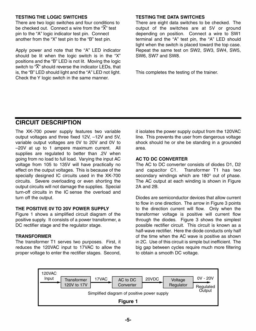
THE POSITIVE 0V TO 20V POWER SUPPLYFigure 1 shows a simplified circuit diagram of thepositive supply. It consists of a power transformer, aDC rectifier stage and the regulator stage.
TRANSFORMERThe transformer T1 serves two purposes. First, itreduces the 120VAC input to 17VAC to allow theproper voltage to enter the rectifier stages. Second,
it isolates the power supply output from the 120VACline. This prevents the user from dangerous voltageshock should he or she be standing in a groundedarea.
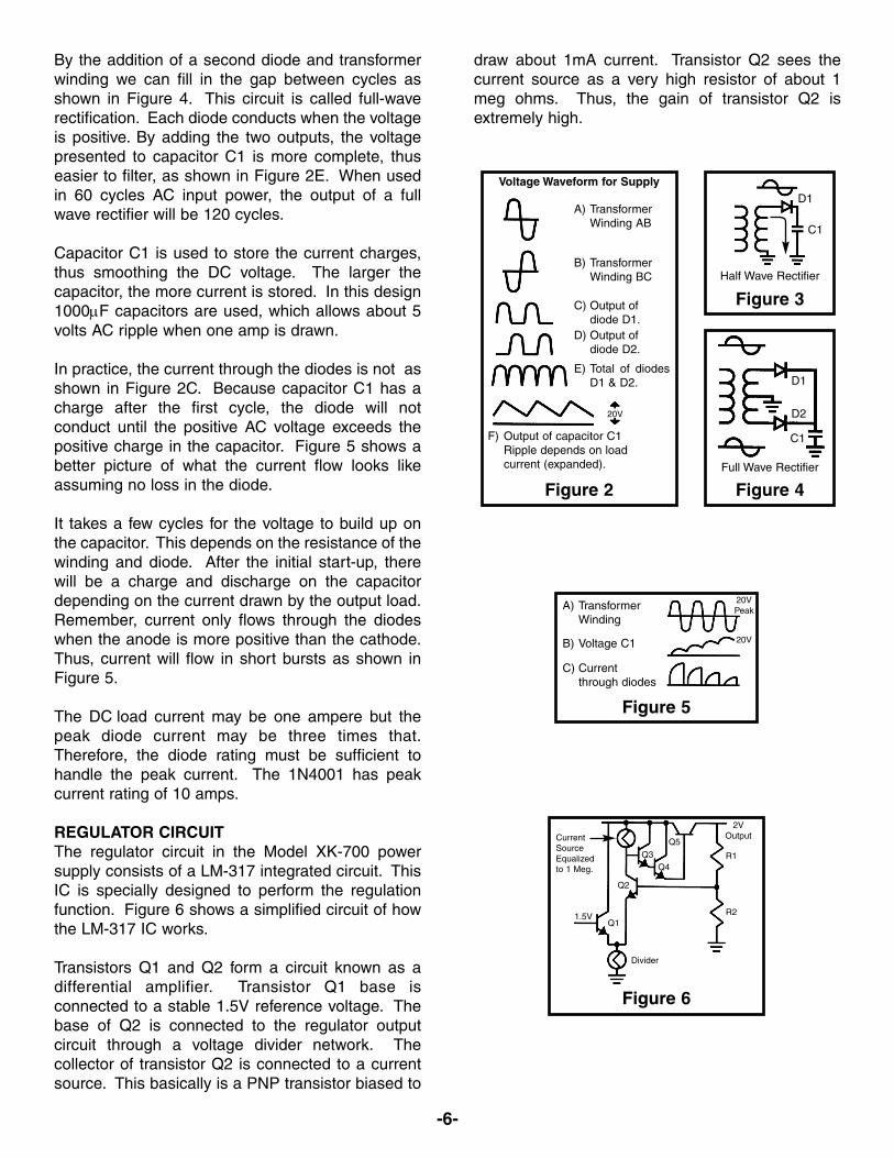
AC TO DC CONVERTERThe AC to DC converter consists of diodes D1, D2and capacitor C1. Transformer T1 has twosecondary windings which are 180O out of phase.The AC output at each winding is shown in Figure2A and 2B.
Diodes are semiconductor devices that allow currentto flow in one direction. The arrow in Figure 3 pointsto the direction current will flow. Only when thetransformer voltage is positive will current flowthrough the diodes. Figure 3 shows the simplestpossible rectifier circuit. This circuit is known as ahalf-wave rectifier. Here the diode conducts only halfof the time when the AC wave is positive as shownin 2C. Use of this circuit is simple but inefficient. Thebig gap between cycles require much more filteringto obtain a smooth DC voltage.
CIRCUIT DESCRIPTION
Figure 1
-6-
By the addition of a second diode and transformerwinding we can fill in the gap between cycles asshown in Figure 4. This circuit is called full-waverectification. Each diode conducts when the voltageis positive. By adding the two outputs, the voltagepresented to capacitor C1 is more complete, thuseasier to filter, as shown in Figure 2E. When usedin 60 cycles AC input power, the output of a fullwave rectifier will be 120 cycles.
Capacitor C1 is used to store the current charges,thus smoothing the DC voltage. The larger thecapacitor, the more current is stored. In this design1000μF capacitors are used, which allows about 5volts AC ripple when one amp is drawn.
In practice, the current through the diodes is not asshown in Figure 2C. Because capacitor C1 has acharge after the first cycle, the diode will notconduct until the positive AC voltage exceeds thepositive charge in the capacitor. Figure 5 shows abetter picture of what the current flow looks likeassuming no loss in the diode.
It takes a few cycles for the voltage to build up onthe capacitor. This depends on the resistance of thewinding and diode. After the initial start-up, therewill be a charge and discharge on the capacitordepending on the current drawn by the output load.Remember, current only flows through the diodeswhen the anode is more positive than the cathode.Thus, current will flow in short bursts as shown inFigure 5.
The DC load current may be one ampere but thepeak diode current may be three times that.Therefore, the diode rating must be sufficient tohandle the peak current. The 1N4001 has peakcurrent rating of 10 amps.
REGULATOR CIRCUITThe regulator circuit in the Model XK-700 powersupply consists of a LM-317 integrated circuit. ThisIC is specially designed to perform the regulationfunction. Figure 6 shows a simplified circuit of howthe LM-317 IC works.
Transistors Q1 and Q2 form a circuit known as adifferential amplifier. Transistor Q1 base isconnected to a stable 1.5V reference voltage. Thebase of Q2 is connected to the regulator outputcircuit through a voltage divider network. Thecollector of transistor Q2 is connected to a currentsource. This basically is a PNP transistor biased to
draw about 1mA current. Transistor Q2 sees thecurrent source as a very high resistor of about 1meg ohms. Thus, the gain of transistor Q2 isextremely high.
A) TransformerWinding
B) Voltage C1
C) Currentthrough diodes
20VPeak
20V
Figure 2
Figure 3
Figure 4
Voltage Waveform for Supply
A) TransformerWinding AB
B) TransformerWinding BC
C) Output ofdiode D1.
D) Output ofdiode D2.
E) Total of diodesD1 & D2.
20V
F) Output of capacitor C1Ripple depends on loadcurrent (expanded).
Half Wave Rectifier
Full Wave Rectifier
2VOutput
R1
R2
Divider
Q1
Q2
1.5V
Q3Q4
Q5CurrentSourceEqualizedto 1 Meg.
Figure 5
Figure 6
D1
D2
C1
C1
D1
-7-
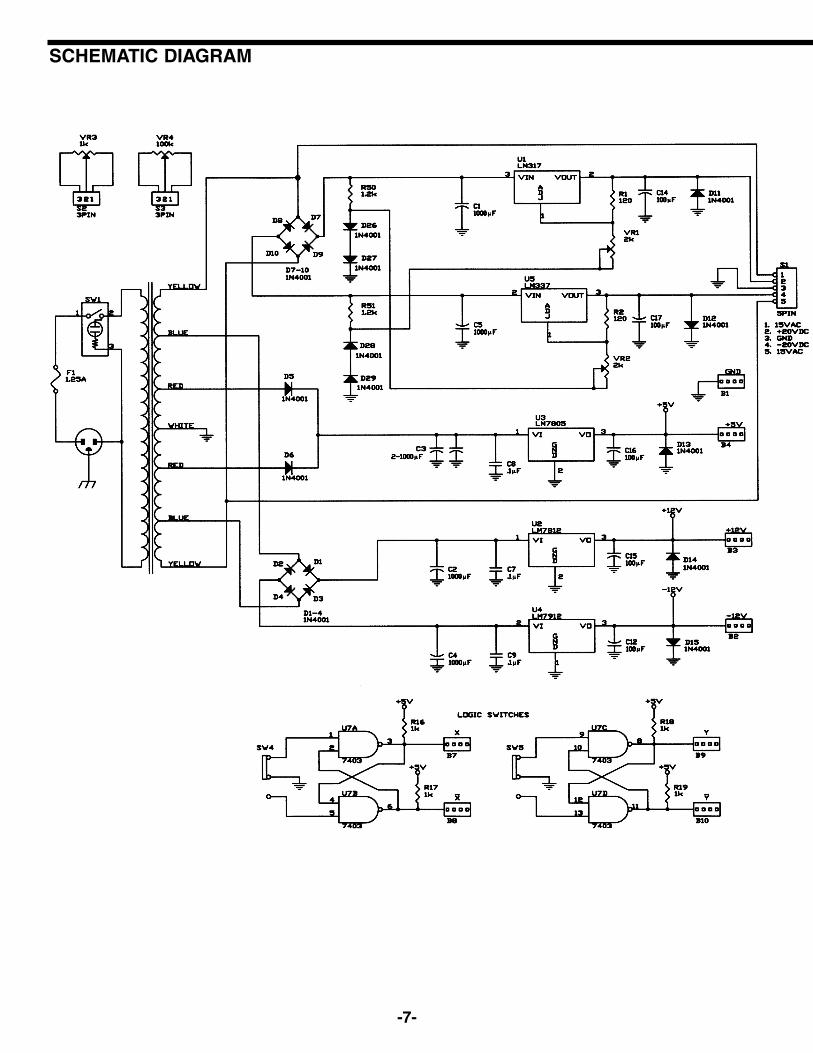
SCHEMATIC DIAGRAM
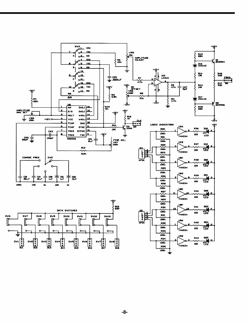
-8-
-9-
Transistor Q5 is called the pass transistor. Itcontrols the current reaching the output. TransistorQ3 and Q4 are emitter followers. Their function is toraise the impedance of the pass transistor. Note thattransistor Q2, Q3, Q4, Q5 and resistor R1 form aclose loop. Also note that the feedback to the baseof Q2 is negative, that is, when the base of Q2 goespositive, the output at emitter Q5 goes negative.Now if the 2V output voltage goes down because ofcurrent drain at the output, the base of Q2 will dropforcing the the collector voltage of Q2 to go higher.This will bring the output voltage back to 2V. This isthe basis of all negative feedback regulators.
Another feature of the LM-317 regulator is to protectthe IC against overload and output shorts. If the ICis overloaded, the junction of an overload transistorwill overheat. A transistor will sense thisoverheating and shut down transistor Q5.
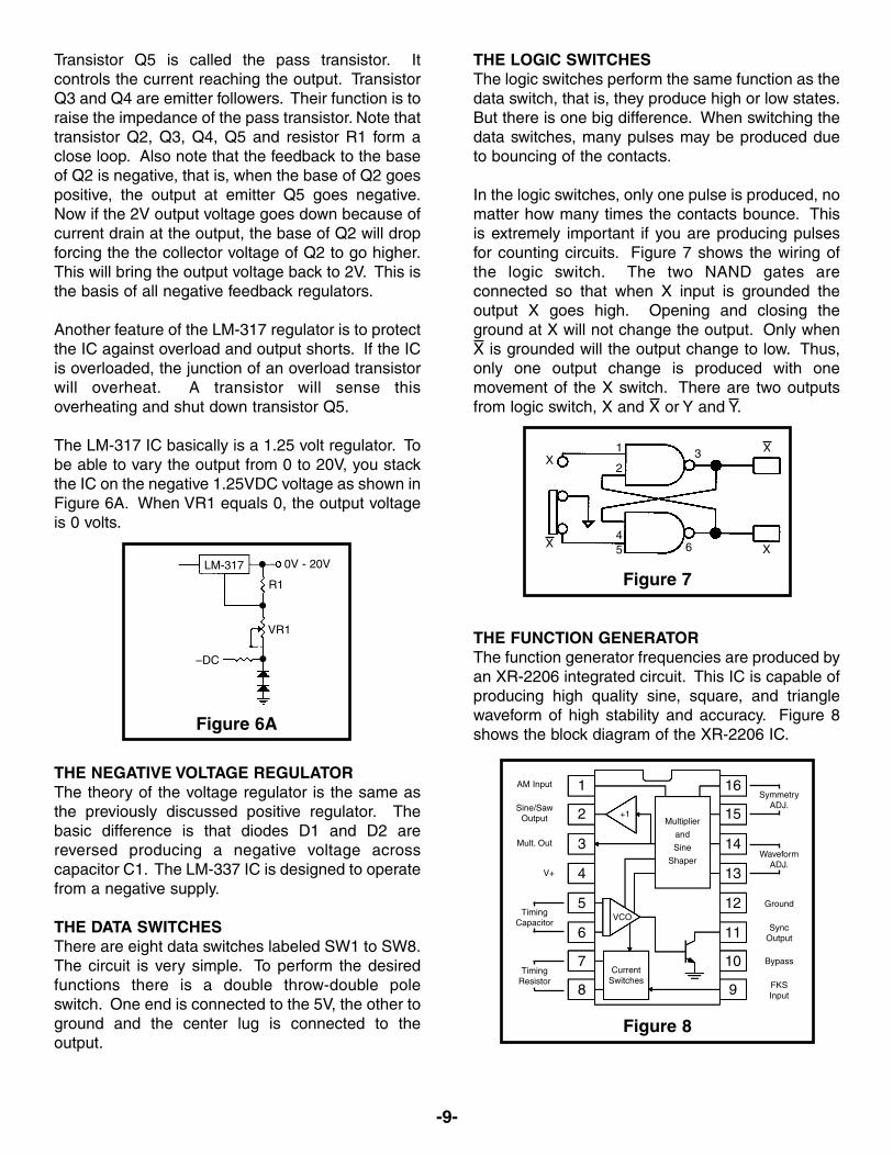
The LM-317 IC basically is a 1.25 volt regulator. Tobe able to vary the output from 0 to 20V, you stackthe IC on the negative 1.25VDC voltage as shown inFigure 6A. When VR1 equals 0, the output voltageis 0 volts.
THE NEGATIVE VOLTAGE REGULATORThe theory of the voltage regulator is the same asthe previously discussed positive regulator. Thebasic difference is that diodes D1 and D2 arereversed producing a negative voltage acrosscapacitor C1. The LM-337 IC is designed to operatefrom a negative supply.
THE DATA SWITCHESThere are eight data switches labeled SW1 to SW8.The circuit is very simple. To perform the desiredfunctions there is a double throw-double poleswitch. One end is connected to the 5V, the other toground and the center lug is connected to theoutput.
THE LOGIC SWITCHESThe logic switches perform the same function as thedata switch, that is, they produce high or low states.But there is one big difference. When switching thedata switches, many pulses may be produced dueto bouncing of the contacts.
In the logic switches, only one pulse is produced, nomatter how many times the contacts bounce. Thisis extremely important if you are producing pulsesfor counting circuits. Figure 7 shows the wiring ofthe logic switch. The two NAND gates areconnected so that when X input is grounded theoutput X goes high. Opening and closing theground at X will not change the output. Only whenX is grounded will the output change to low. Thus,only one output change is produced with onemovement of the X switch. There are two outputsfrom logic switch, X and X or Y and Y.
THE FUNCTION GENERATORThe function generator frequencies are produced byan XR-2206 integrated circuit. This IC is capable ofproducing high quality sine, square, and trianglewaveform of high stability and accuracy. Figure 8shows the block diagram of the XR-2206 IC.
0V - 20V
R1
VR1
LM-317
X
X
X
X654
1
23
1 16
2 15
3 14
4 13
5 12
6 11
7 10
8 9
SymmetryADJ.
WaveformADJ.
Ground
SyncOutput
Bypass
FKSInput
TimingResistor
TimingCapacitor
V+
Mult. Out
Sine/SawOutput
AM Input
+1Multiplier
and
Sine
Shaper
VCO
CurrentSwitches
–DC
Figure 6A
Figure 7
Figure 8
-10-
FUSE REPLACEMENT
1. Turn the trainer off and unplug it from 120VAC power source.
2. Unscrew fuse holder cap and remove fuse.
3. Use only a 1.25A fuse. Larger fuses or other fuse bypass will void thewarranty of the trainer.
4. Place the new fuse into the fuse holder cap and screw it back into the holder.
5. Plug trainer into 120VAC power source and turn the unit on.
The XR-2206 is comprised of four functional blocks,a voltage controlled oscillator (VCO), an analogmultiplier & sine shaper, a unity gain buffer amplifierand a set of current switches.
The VCO actually produces an output frequencyproportional to an input current. Across pins 5 and6, a timing capacitor, is switched on to give 5different ranges of frequencies via COARSE FREQ.switch. On pin 7, the FINE FREQ. ADJ. variableresistor controls the actual frequency output. Thesetwo components form the RC time constants for theoscillator frequency.
The VCO produces a squarewave signal. Thissquarewave is sent to a shaper and converted intoa sine wave.
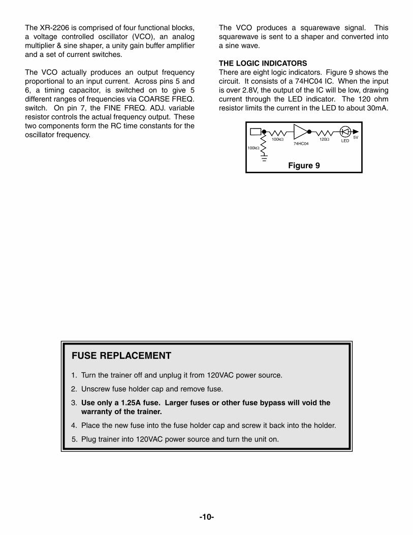
THE LOGIC INDICATORSThere are eight logic indicators. Figure 9 shows thecircuit. It consists of a 74HC04 IC. When the inputis over 2.8V, the output of the IC will be low, drawingcurrent through the LED indicator. The 120 ohmresistor limits the current in the LED to about 30mA.
100kΩ
100kΩ 120Ω74HC04
LED5V
Figure 9
-11-
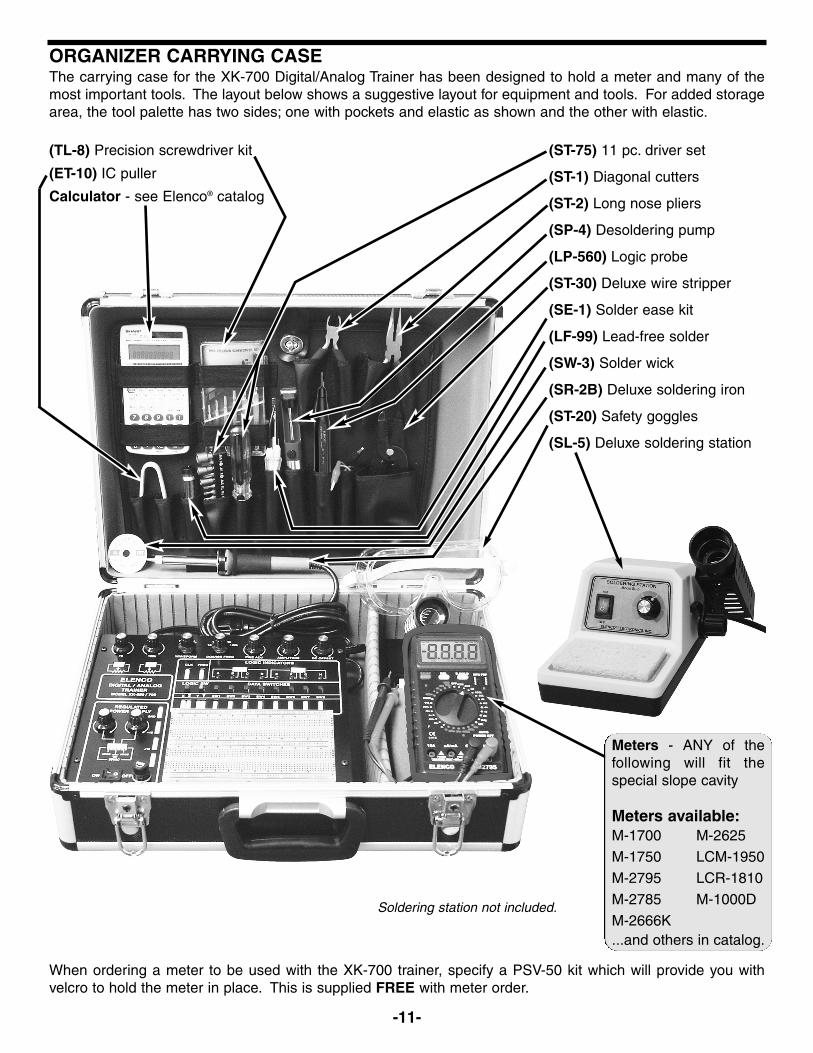
ORGANIZER CARRYING CASEThe carrying case for the XK-700 Digital/Analog Trainer has been designed to hold a meter and many of themost important tools. The layout below shows a suggestive layout for equipment and tools. For added storagearea, the tool palette has two sides; one with pockets and elastic as shown and the other with elastic.
When ordering a meter to be used with the XK-700 trainer, specify a PSV-50 kit which will provide you withvelcro to hold the meter in place. This is supplied FREE with meter order.
(TL-8) Precision screwdriver kit
(ET-10) IC puller
Calculator - see Elenco® catalog
(ST-75) 11 pc. driver set
(ST-1) Diagonal cutters
(ST-2) Long nose pliers
(SP-4) Desoldering pump
(LP-560) Logic probe
(ST-30) Deluxe wire stripper
(SE-1) Solder ease kit
(LF-99) Lead-free solder
(SW-3) Solder wick
(SR-2B) Deluxe soldering iron
(ST-20) Safety goggles
(SL-5) Deluxe soldering station
Meters - ANY of thefollowing will fit thespecial slope cavity
Meters available:
...and others in catalog.
M-1700
M-1750
M-2795
M-2785
M-2666K
M-2625
LCM-1950
LCR-1810
M-1000DSoldering station not included.
-12-
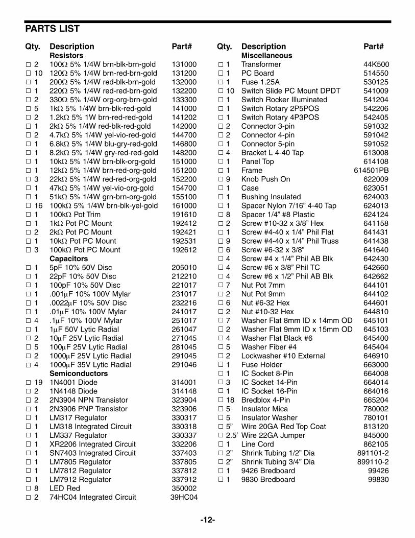
Qty. Description Part#Resistors
2 100Ω 5% 1/4W brn-blk-brn-gold 13100010 120Ω 5% 1/4W brn-red-brn-gold 1312001 200Ω 5% 1/4W red-blk-brn-gold 1320001 220Ω 5% 1/4W red-red-brn-gold 1322002 330Ω 5% 1/4W org-org-brn-gold 1333005 1kΩ 5% 1/4W brn-blk-red-gold 1410002 1.2kΩ 5% 1W brn-red-red-gold 1412021 2kΩ 5% 1/4W red-blk-red-gold 1420002 4.7kΩ 5% 1/4W yel-vio-red-gold 1447001 6.8kΩ 5% 1/4W blu-gry-red-gold 1468001 8.2kΩ 5% 1/4W gry-red-red-gold 1482001 10kΩ 5% 1/4W brn-blk-org-gold 1510001 12kΩ 5% 1/4W brn-red-org-gold 1512003 22kΩ 5% 1/4W red-red-org-gold 1522001 47kΩ 5% 1/4W yel-vio-org-gold 1547001 51kΩ 5% 1/4W grn-brn-org-gold 15510016 100kΩ 5% 1/4W brn-blk-yel-gold 1610001 100kΩ Pot Trim 1916101 1kΩ Pot PC Mount 1924122 2kΩ Pot PC Mount 1924211 10kΩ Pot PC Mount 1925313 100kΩ Pot PC Mount 192612
Capacitors1 5pF 10% 50V Disc 2050101 22pF 10% 50V Disc 2122101 100pF 10% 50V Disc 2210171 .001μF 10% 100V Mylar 2310171 .0022μF 10% 50V Disc 2322161 .01μF 10% 100V Mylar 2410174 .1μF 10% 100V Mylar 2510171 1μF 50V Lytic Radial 2610472 10μF 25V Lytic Radial 2710455 100μF 25V Lytic Radial 2810452 1000μF 25V Lytic Radial 2910454 1000μF 35V Lytic Radial 291046
Semiconductors19 1N4001 Diode 3140012 1N4148 Diode 3141482 2N3904 NPN Transistor 3239041 2N3906 PNP Transistor 3239061 LM317 Regulator 3303171 LM318 Integrated Circuit 3303181 LM337 Regulator 3303371 XR2206 Integrated Circuit 3322061 SN7403 Integrated Circuit 3374031 LM7805 Regulator 3378051 LM7812 Regulator 3378121 LM7912 Regulator 3379128 LED Red 3500022 74HC04 Integrated Circuit 39HC04
Qty. Description Part#Miscellaneous
1 Transformer 44K5001 PC Board 5145501 Fuse 1.25A 53012510 Switch Slide PC Mount DPDT 5410091 Switch Rocker Illuminated 5412041 Switch Rotary 2P5POS 5422061 Switch Rotary 4P3POS 5424052 Connector 3-pin 5910322 Connector 4-pin 5910421 Connector 5-pin 5910524 Bracket L 4-40 Tap 6130081 Panel Top 6141081 Frame 614501PB9 Knob Push On 6220091 Case 6230511 Bushing Insulated 6240031 Spacer Nylon 7/16” 4-40 Tap 6240138 Spacer 1/4” #8 Plastic 6241242 Screw #10-32 x 3/8” Hex 6411581 Screw #4-40 x 1/4” Phil Flat 6414319 Screw #4-40 x 1/4” Phil Truss 6414386 Screw #6-32 x 3/8” 6416404 Screw #4 x 1/4” Phil AB Blk 6424304 Screw #6 x 3/8” Phil TC 6426604 Screw #6 x 1/2” Phil AB Blk 6426627 Nut Pot 7mm 6441012 Nut Pot 9mm 6441026 Nut #6-32 Hex 6446012 Nut #10-32 Hex 6448107 Washer Flat 8mm ID x 14mm OD 6451012 Washer Flat 9mm ID x 15mm OD 6451034 Washer Flat Black #6 6454005 Washer Fiber #4 6454042 Lockwasher #10 External 6469101 Fuse Holder 6630001 IC Socket 8-Pin 6640083 IC Socket 14-Pin 6640141 IC Socket 16-Pin 66401618 Bredblox 4-Pin 6652045 Insulator Mica 7800025 Insulator Washer 7801015” Wire 20GA Red Top Coat 8131202.5’ Wire 22GA Jumper 8450001 Line Cord 8621052” Shrink Tubing 1/2” Dia 891101-22” Shrink Tubing 3/4” Dia 899110-21 9426 Bredboard 994261 9830 Bredboard 99830
PARTS LIST
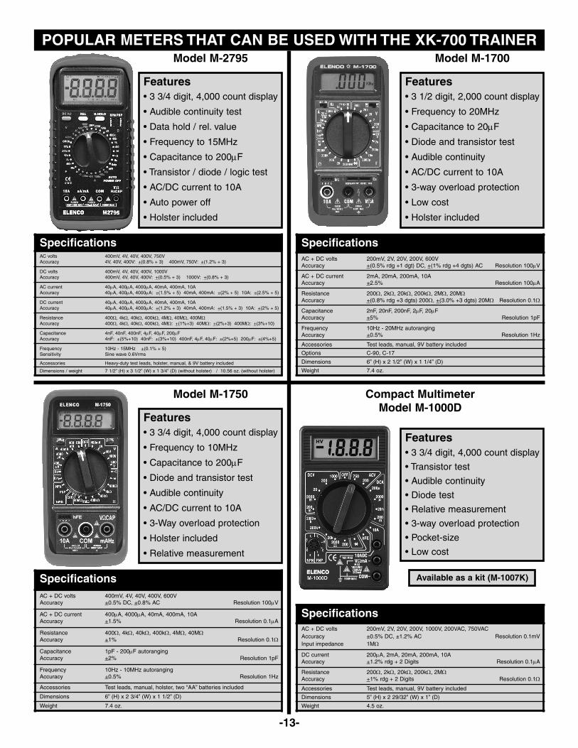
POPULAR METERS THAT CAN BE USED WITH THE XK-700 TRAINER
-13-
SpecificationsAC + DC volts 400mV, 4V, 40V, 400V, 600VAccuracy +0.5% DC, +0.8% AC Resolution 100μV
AC + DC current 400μA, 4000μA, 40mA, 400mA, 10AAccuracy +1.5% Resolution 0.1μA
Resistance 400Ω, 4kΩ, 40kΩ, 400kΩ, 4MΩ, 40MΩAccuracy +1% Resolution 0.1Ω
Capacitance 1pF - 200μF autorangingAccuracy +2% Resolution 1pF
Frequency 10Hz - 10MHz autorangingAccuracy +0.5% Resolution 1Hz
Accessories Test leads, manual, holster, two “AA” batteries included
Dimensions 6” (H) x 2 3/4” (W) x 1 1/2” (D)
Weight 7.4 oz.
• 3 3/4 digit, 4,000 count display
• Frequency to 10MHz
• Capacitance to 200μF
• Diode and transistor test
• Audible continuity
• AC/DC current to 10A
• 3-Way overload protection
• Holster included
• Relative measurement
Features
Model M-1750
Available as a kit (M-1007K)
Compact MultimeterModel M-1000D
SpecificationsAC + DC volts 200mV, 2V, 20V, 200V, 1000V, 200VAC, 750VACAccuracy ±0.5% DC, ±1.2% AC Resolution 0.1mVInput impedance 1MΩ
DC current 200μA, 2mA, 20mA, 200mA, 10AAccuracy +1.2% rdg + 2 Digits Resolution 0.1μA
Resistance 200Ω, 2kΩ, 20kΩ, 200kΩ, 2MΩAccuracy +1% rdg + 2 Digits Resolution 0.1Ω
Accessories Test leads, manual, 9V battery included
Dimensions 5” (H) x 2 29/32” (W) x 1” (D)
Weight 4.5 oz.
• 3 3/4 digit, 4,000 count display
• Transistor test
• Audible continuity
• Diode test
• Relative measurement
• 3-way overload protection
• Pocket-size
• Low cost
Features
SpecificationsAC volts 400mV, 4V, 40V, 400V, 750VAccuracy 4V, 40V, 400V: +(0.8% + 3) 400mV, 750V: +(1.2% + 3)
DC volts 400mV, 4V, 40V, 400V, 1000VAccuracy 400mV, 4V, 40V, 400V: +(0.5% + 3) 1000V: +(0.8% + 3)
AC current 40μA, 400μA, 4000μA, 40mA, 400mA, 10AAccuracy 40μA, 400μA, 4000μA: +(1.5% + 5) 40mA, 400mA: +(2% + 5) 10A: +(2.5% + 5)
DC current 40μA, 400μA, 4000μA, 40mA, 400mA, 10AAccuracy 40μA, 400μA, 4000μA: +(1.2% + 3) 40mA, 400mA: +(1.5% + 3) 10A: +(2% + 5)
Resistance 400Ω, 4kΩ, 40kΩ, 400kΩ, 4MΩ, 40MΩ, 400MΩAccuracy 400Ω, 4kΩ, 40kΩ, 400kΩ, 4MΩ: +(1%+3) 40MΩ: +(2%+3) 400MΩ: +(3%+10)
Capacitance 4nF, 40nF, 400nF, 4μF, 40μF, 200μFAccuracy 4nF: +(5%+10) 40nF: +(3%+10) 400nF, 4μF, 40μF: +(2%+5) 200μF: +(4%+5)
Frequency 10Hz - 15MHz +(0.1% + 5)Sensitivity Sine wave 0.6Vrms
Accessories Heavy-duty test leads, holster, manual, & 9V battery included
Dimensions / weight 7 1/2” (H) x 3 1/2” (W) x 1 3/4” (D) (without holster) / 10.56 oz. (without holster)
• 3 3/4 digit, 4,000 count display
• Audible continuity test
• Data hold / rel. value
• Frequency to 15MHz
• Capacitance to 200μF
• Transistor / diode / logic test
• AC/DC current to 10A
• Auto power off
• Holster included
Features
Model M-2795
SpecificationsAC + DC volts 200mV, 2V, 20V, 200V, 600VAccuracy +(0.5% rdg +1 dgt) DC, +(1% rdg +4 dgts) AC Resolution 100μV
AC + DC current 2mA, 20mA, 200mA, 10AAccuracy +2.5% Resolution 100μA
Resistance 200Ω, 2kΩ, 20kΩ, 200kΩ, 2MΩ, 20MΩAccuracy +(0.8% rdg +3 dgts) 200Ω, +(3.0% +3 dgts) 20MΩ Resolution 0.1Ω
Capacitance 2nF, 20nF, 200nF, 2μF, 20μFAccuracy +5% Resolution 1pF
Frequency 10Hz - 20MHz autorangingAccuracy +0.5% Resolution 1Hz
Accessories Test leads, manual, 9V battery included
Options C-90, C-17
Dimensions 6” (H) x 2 1/2” (W) x 1 1/4” (D)
Weight 7.4 oz.
• 3 1/2 digit, 2,000 count display
• Frequency to 20MHz
• Capacitance to 20μF
• Diode and transistor test
• Audible continuity
• AC/DC current to 10A
• 3-way overload protection
• Low cost
• Holster included
Features
Model M-1700

WARRANTY POLICY
Your XK-700 Digital / Analog Trainer has been tested and conforms to our rigid requirements on performance and durability. It isguaranteed to be free of defects in workmanship, materials and construction for a period of 2 years. If this product should fail duringnormal use within the first 3 months from the date of purchase, Elenco® will repair or replace the unit at no cost. For the remainder of thewarranty period, a nominal service charge is required to cover shipping and handling.
When returning merchandise for repair, please include proof of purchase, a brief letter of explanation of problem and sufficient packingmaterial. Before returning any merchandise, please call our service department at (847) 541-3800 to obtain a return mechandiseauthorization number (RMA).
Elenco® Electronics, Inc. • Service Department150 Carpenter Avenue • Wheeling, IL 60090
-14-

Elenco® Electronics, Inc.150 Carpenter AvenueWheeling, IL 60090
(847) 541-3800Website: www.elenco.com
e-mail: [email protected]


![Xk jkX]] leisure opportunities](https://img.pdfslide.net/doc/110x75/6156f5f7a097e25c764f6a56/xk-jkx-leisure-opportunities.jpg)