Embed Size (px)
Citation preview

4 x 2 or 4 x 4Wheelbase: 156” (3.96m)Width 102” (2.6m)
Frame:48” (1.2m) wide, welded plate design50 ksi material
Gross vehicle axle weight rating:4 x 2 37,600 lb (17,055 kg)4 x 4 42,000 lb (19,051 kg)
Front axles:4 x 2: Meritor Model FG-941, 14,600 lb(6,623 kg) rating4 x 4: Meritor Model MX-19-145, 19,000 lb(8,618 kg) rating, 7.17 ratio
Rear axle:Meritor Model RS23-160, 23,000 lb (10,433kg) rating. 7.17 ratio, single reduction withdriver controlled differential lock.
Suspension:Front: 8 leaf spring with automatic lock-out cylindersRear: Solid mount
Brakes:4 x 2 Front: Meritor “Q” Series Cam-MasterSize: 16.5” x 5” (419 mm x 152 mm)Automatic Slack Adjusters
4 x 4 Front: Meritor “Q” Series Cam-MasterSize: 16.5” x 6” (419 mm x 127 mm)Automatic Slack Adjusters
4 x 4 Rear and 4 x 2 Rear: Meritor “P”Series Cam-Master Size: 16.5” x 7” (419 mm x 178 mm)Automatic Slack Adjusters
Spring brake system incorporatesemergency and parking brakes on the rear axle.
Wheels:Hub piloted disc 10-stud, 11.25” (286 mm)bolt circle.
Tires:4 x 2 and 4 x 4 front: 385/65R22.5 18-plyon/off highway tread4 x 2 and 4 x 4 rear: 11R22.5 16-plyhighway deep tread4 x 4 optional front and rear: 44.5/65R22.5 20-ply on/off highway tread. (Note:44.5/65R22.5 tires are not intended forprolonged highway use at speeds above50 mph.
Steering:Ross, integral hydraulic power steering.Gear type power steering pump. 4-quartpower steering reservoir with filter.
Standard chassis equipment:Halogen headlights, tail lights, back-up lightsand alarm, stoplights, identification lightsfront and rear, directional lights, 4-way hazardlights, and instrument panel lights.Windshield wiper/washer, West Coast stylemirror system with plane and convex mirrors,front and rear tow hooks, desiccant type airdryer with automatic purge valve andthermostatically controlled heater.
PUMPS
Two load-sensing axial piston pumps; 0-65GPM (9-246 L/min) total.
SYSTEM SPECIFICATIONS
Four double acting cylinders• 2 boom hoist: 4.25” ID, 3.0” rod
(108mm x 76mm), 23.4” (594mm) stroke• 1 tool: 4.75” ID, 3.0” rod (121mm x
76mm), 18.9” (480mm) stroke• 1 telescope: 3.5” ID, 2.559” rod (89mm x
65mm), 11’ (3.34 m) stroke
Four hydraulic motorsSwing, 45 Hp (34kW); tilt, 18 Hp (13kW); two remote drive, 65 Hp (48kW) total.
Operating pressuresHoist . . . . . . . . . . . . .4,100 psi (28,268 kPa)Tilt . . . . . . . . . . . . . . .2,050 psi (14,138 kPa)Swing . . . . . . . . . . .3,300 psi (22,759 kPa)Tool . . . . . . . . . . . . . .4,100 psi (28,268 kPa)Telescope . . . . . . . .4,100 psi (28,268 kPa)Remote Propel . . .3,500 psi (24,130 kPa)Pilot system . . . . . . .500 psi (3,448 kPa)
Oil capacityReservoir 50 gallons (189 L), system 65gallons (246 L). Pressurized reservoir withvisual oil level gauges.
Filtration system10 micron return filter with magnet and 100mesh suction strainer in reservoir.
Fin and tube-type oil cooler with thermostatically controlled cooling fan.
Pressure-compensated, load-sensingvalves with circuit reliefs in all circuits.
One-person cab, left-hand mount, isolatedfrom frame on rubber mounts. Acousticallining. Sun visor. Gauges for oil pressure,coolant temperature, air tank pressures, fuel level, voltmeter, speedometer withodometer, tachometer with hour meter.Engine monitor lights. Engine shutdowncontrolled by engine electronics. Indicatorlights and controls for front axleengagement (4 x 4 only) and rear axledifferential lock. Park brake control. Tintedsafety glass. Sliding side windows. Freshair heater and defroster. Dome light. Airsuspension seat with seat belt.
All-weather cab isolated from frame onrubber mounts. Tinted safety glass windows,skylight, acoustical lining, four-way adjustableoperator’s seat, dome light, filtered air heaterand defroster.
The heat source is provided by a fastresponse, closed circuit hydraulic heaterwith 20,000 BTU/Hr. capacity.
Front window slides to overhead storage.Rearview mirrors on right and left sides ofthe machine. Windshield wiper and washer.
Undercarriage powered by upperstructurehydraulics through hydraulic motors andPTOs on transmission. Travel and steeringpedals in upperstructure cab. Diggingbrakes and front axle lockout cylinders setautomatically with travel pedal in neutral.Parking brakes controlled by toggle.
Electrically operated alarms mounted onundercarriage signal remote control move-ment in either direction, reverse movementwhen driven from undercarriage cab.
SPECIFICATIONS
XL 3
10
0
Upperstructure Cab
Hydraulic Remote Control
Undercarriage
Chassis Cab
Hydraulic System
XL 3100H Y D R A U L I C E X C A V A T O R

NOTE: The above loads are in compliance with SAE standard J1097 NOV 88. Theydo not exceed 87% of the hydraulic lifting capacity or 75% of the tipping capacity.
All loads shown are limited by hydraulic lift capacity rather than stability.
The rated lift capacity is based on the machine being equipped with 5,500 lb (2495kg) counterweight, standard boom and no bucket. Adjust the listed rated capacitiesaccording to each bucket as follows:
8035-6019 66” ditching - subtract 775 lb (352 kg)8035-6004 60” ditching - subtract 757 lb (343 kg)8035-6002 36” excavating - subtract 696 lb (316 kg)8035-6006 30” excavating - subtract 639 lb (290 kg)8035-6014 24” excavating - subtract 579 lb (263 kg)8035-6003 30” pavement removal - subtract 992 lb (451 kg)
The load point is located on the bucket pivot point, including load listed formaximum radius.
Do not attempt to lift or hold any load greater than these rated values at specifiedload radii and heights. The weight of slings and any auxiliary devices must bededucted from the rated load to determine the net load that may be lifted.
ATTENTION: All rated loads are based on the machine being stationary and level ona firm supporting surface. For safe working loads, the user must make allowance forhis particular job conditions such as soft or uneven ground, out of level conditions,side loads, hazardous conditions, experience of personnel, etc. The operator and otherpersonnel must fully acquaint themselves with the Operator’s Manual furnished by themanufacturer before operating this machine. Rules for safe operation of equipmentmust be adhered to at all times.
NOTE: Bucket adjustment values are 87% of the actual bucket weights.
LOAD RADIUS
Detroit Diesel OM906 diesel with EGR. 4 cycle, inline 6 cylinder, liquidcooled. Turbo/Charge air aftercooled. Automotive Certified, 2004 EPA/CARBRegulations. Electronic controlled. Vertical canister style lube filter andcentrifugal lube filter attached to engine. Vertical canister style fuel filters,(main and pre-filter) attached to engine. Remote mount primary fuel/waterseparator. Gross Rating: 190HP @ 2300 RPM. 520 ft.lb. Torque @ 1200RPM. Net Rating: 173 HP @ 2300 RPM.
Air Filter: 2-stage dry type with safety element, ejector valve and serviceindicator.
Electrical System: 12 volt, 100 amp alternator with integral voltageregulator. 2 SAE #C31-S 810 CCA batteries.
Cooling System: Fin and tube radiator with fan shroud. 8 blade, 28” diameterfan. Engine charge air cooler mounted in front of radiator. Transmission oilcooler mounted in front of radiator below charge air cooler.
Fuel Tank Capacity: 70 gal (265 L)
Transmission: Eaton Roadranger RTX-14609B, 9-speed FWD, 2-speedreverse. Internal oil pump with external spin-on filter. Transmission oilcooler. Neutral start switch. Input shaft clutch brake. 8-bolt air shifted PTOfor hydraulic pump drive. Dual rear countershaft, air shifted PTO’s forremote propel motors.
Gear Speeds: (with 11R22.5 tires)
* Limit speed to 50 mph with 445/65R22.5 tires.
Clutch: Hydraulic actuated. Spicer Model 107, pull type. 14” dia, 2-plate, organic disc.
Drivelines: Spicer 1760 Series with “Half Round” yokes.
Transfer Case: (4 x 4 only) Meritor Model T-211HD, 1/1 ratio, 3 shaft singlespeed. With air operated front axle disconnect.
GearMPHKm/hr
Lo3.1(4.9)
15.2(8.4)
27.4
(11.9)
310.2(16.4)
414.0(22.5)
520.0(32.2)
628.3(45.3)
739.0(62.7)
8*53.4(85.9)
GearMPHKm/hr
Rev Lo3.4(5.5)
Rev Hi13.1(21.1)
Two hydraulic joysticks (hoist & bucket,telescope & swing), one rocker switch (tilt)control upperstructure. Hydraulic joysticksare mounted on arm pods that areadjustable for individual operator comfortand convenience. Quick change joystickpattern with decals is standard.
Two foot pedals for remote control ofundercarriage steering, travel and diggingbrakes. Rocker switch on control panelselects low speed or high speed remote travel.
Joysticks and pedals are self-centering;when controls are released, power formovement disengages and swing andtravel brakes set automatically.
Engine ControlsKey ignition switch with neutral start andindicator lights for low air, engine status,park brake, travel status, hydraulic filtercondition and hydraulic fluid temperatureand level.
Automatic engine shut down occurs withlow oil pressure or high coolant temperature.
Priority swing circuit with axial piston motor.Planetary transmission. Swing speed: 8 rpm.
Swing brake: Automatic spring-set/hydraulicrelease wet disc parking brake. Dynamicbraking is provided by the hydraulic system.
Upperstructure Controls
Swing
Engine
4x4LOAD POINT
HEIGHT
10' (3m)
5' (1.5m)3410 @ 21' 6"(1545 @ 6.5m)3315 @ 17' 9"(1505 @ 5.4m)
5630(2555)3490(1585)
3725(1690)
4900(2220)
15' (4.6m)2185 @ 10' 1"(990 @ 3.1m)
2085(945)
3615(1640)
20' (6.1m)
15' (4.6m)
10' (3m)
10' (3m) 15' (4.6m) 20' (6.1m) MAXIMUM RADIUS
3375 @ 19' 10"(1530 @ 6.1m)
3275 @ 22' 7"(1485 @ 6.9m)3270 @ 24' 0"(1485 @ 7.3m)
5870(2660)6885(3125)
3965(1800)4465(2025)
AboveGroundLevel
BelowGroundLevel
At Ground Level
5' (1.5m)3315 @ 24' 4"(1505 @ 7.4m)
4615(2090)
7100(3220)6255(2835)
4325(1960)
3375 @ 23' 6"(1530 @ 7.2m)
LOAD RADIUS4x2LOAD POINT
HEIGHT
10' (3m)
5' (1.5m)3410 @ 21' 7"(1545 @ 6.6m)3330 @ 18' 0"(1510 @ 5.5m)
5785(2625)3590(1625)
3760(1705)
4980(2255)
15' (4.6m)2375 @ 11' 1"(1075 @ 3.4m)
2150(975)
3680(1669)
20' (6.1m)
15' (4.6m)
10' (3m)
10' (3m) 15' (4.6m) 20' (6.1m) MAXIMUM RADIUS
3385 @ 19' 7"(1535 @ 6.0m)
3275 @ 22' 6"(1485 @ 6.9m)3270 @ 24' 0"(1485 @ 7.3m)
5800(2630)6840(3100)
3930(1780)4440(2010)
AboveGroundLevel
BelowGroundLevel
At Ground Level
5' (1.5m)3310 @ 24' 4"(1500 @ 7.4m)
4615(2095)
7120(3230)6320(2865)
4350(1970)
3370 @ 23' 7"(1530 @ 7.2m)
GRADALL Model XL 3100 Lift Capacity Over Side or Rear - LB. (KG.)
40
26
28
2828
AQ
BB
BC
BD
BE
BF
AC
AB
BG
AK
AL
8'-0" LEVEL CUTAD
AP
AS
AG
AA
AH
BJ
BH
BA
AF
AP
AV
AW
AU
0
4
6
8
10
12
14
16
18
20
22
24
26
2
2
4
6
8
10
12
14
16
18
20
22
0
4
6
8
10
12
14
16
18
20
22
24
26
2
2
4
6
8
10
12
14
16
18
20
22
24
0246810121416 2 4 6 8 10 12 14 16 18 20 22 24 26 28
0246810121416 2 4 6 8 10 12 14 16 18 20 22 24 26 28 30 32 34 36 38
A
B
C
TWO POSITION BUCKET
A-BUCKET OPEN, LOWER POSITION, FORVERTICAL WALLS OR DEEP EXCAVATINGBUCKET PIVOT 165°
B-BUCKET OPEN, UPPER PIN POSITION, FORMOST APPLICATIONSBUCKET PIVOT 135°
C-BUCKET CLOSED, EITHER POSITION
XL3100 4X4
24"(610mm)EXCAVATING BUCKET
8035-6014
30"(762mm)EXCAVATING BUCKET
8035-6008
36"(914mm)EXCAVATING BUCKET
8035-6002
F
N
C3
V1
C1
AX AX
V2
A1
L
DH
E
A
P
SR
G
B1
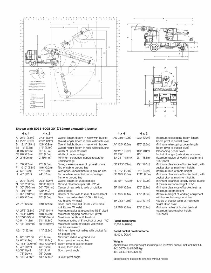
BShown with 8035-6008 30" (762mm) excavating bucket
4 x 4 4 x 2 4 x 4 4 x 2
A 27’3” (8.3m) 27’3” (8.3m) Overall length (boom in rack) with bucketA1 22’7” (6.9m) 22’8” (6.9m) Overall length (boom in rack) without bucketB 12’11” (3.9m) 12’8” (3.9m) Overall height (boom in rack) with bucketB1 11’6” (3.5m) 11’3” (3.4m) Overall height (boom in rack) without bucketC1 8’6” (2.6m) 8’6” (2.6m) Width of upper structureC3 8’6” (2.6m) 8’6” (2.6m) Width of undercarriageD 2” (50mm) 2” (50mm) Minimum clearance, upperstructure to
undercarriageE 7’6” (2.3m) 7’6” (2.3m) Swing clearance, rear of upperstructureF 10’10” (3.3m) 10’6” (3.2m) Top of cab to ground lineG 51” (1.3m) 47” (1.2m) Clearance, upperstructure to ground lineH 48” (1.2m) 44” (1.1m) Top of wheel mounted undercarriage
frame to ground lineL 20’3” (6.2m) 20’3” (6.2m) Overall length of undercarriageN 10” (250mm) 10” (250mm) Ground clearance (per SAE J1234)P 30” (760mm) 30” (760mm) Center of rear axle to axis of rotationR 13’0” (4.0) 13’0” (4.0) Wheel baseS 32” (810mm) 32” (810mm) Center of rear axle to rear of frame (step)V1 6’5” (2.0m) 6’5” (2.0m) Tread, rear axles 4x4 (10:00 x 20 tires),
4x2 (Spoke Wheels)V2 7’1” (2.2m) 6’10” (2.1m) Tread, front axle 4x4 (15:00 x 22.5 tires),
4x2 (Spoke Wheels)AA 27’5” (8.4m) 27’5” (8.4m) Maximum radius at ground line (165° pivot)AB 19’4” (5.9m) 19’8” (6.0m) Maximum digging depth (165° pivot)AC 17’6” (5.3m) 17’10” (5.4m) Maximum depth for 8’ level cutAD 5’11” (1.8m) 5’11” (1.8m) Maximum radius of 8’ level cut at depth “AC”AF 18” (460mm) 18” (460mm) Maximum depth of vertical wall which
can be excavatedAG 11’3” (3.4m) 11’4” (3.5m) Minimum level cut radius with bucket flat
on ground lineAH 6’11” (2.1m) 7’3” (2.2m) Minimum radius at ground lineAK 6’2” (1.9m) 5’11” (1.8m) Boom pivot to ground lineAL 15.3” (390mm) 15.3” (390mm) Boom pivot to axis of rotationAP 46” (1.2m) 46” (1.2m) Bucket tooth radiusAQ 32° Up & 32° Up & Boom pivot angle
75° Down 75° DownAS 135° & 165° 135° & 165° Bucket pivot angle
AU 23’0” (7.0m) 23’0” (7.0m) Maximum telescoping boom length (boom pivot to bucket pivot)
AV 12’0” (3.6m) 12’0” (3.6m) Minimum telescoping boom length (boom pivot to bucket pivot)
AW11’0” (3.3m) 11’0” (3.3m) Telescoping boom travelAX 110° 110° Bucket tilt angle (both sides of center)BA 28’1” (8.6m) 28’1” (8.6m) Maximum radius of working equipment
(165° pivot)BB 23’5” (7.1m) 23’1” (7.0m) Minimum clearance of bucket teeth, with
bucket pivot at maximum heightBC 21’7” (6.6m) 21’3” (6.5m) Maximum bucket tooth heightBD 16’3” (5.0m) 15’11” (4.8m) Minimum clearance of bucket teeth, with
bucket pivot at maximum heightBE 10’11” (3.3m) 10’7” (3.2m) Minimum clearance of fully curled bucket
at maximum boom height (165°)BF 10’6” (3.2m) 10’3” (3.1m) Minimum clearance of bucket teeth at
maximum boom heightBG 13’5” (4.1m) 13’2” (4.0m) Maximum height of working equipment
with bucket below ground lineBH 23’3” (7.1m) 23’3” (7.1m) Radius of bucket teeth at maximum
height (165° pivot)BJ 16’9” (5.1m) 16’9” (5.1m) Minimum radius of bucket teeth at
maximum bucket pivot height (165°pivot)
Rated boom force:18,360 lb (82kN)
Rated bucket breakout force:16,100 lb (72kN)
Weight:Approximate working weight, including 30" (762mm) bucket, fuel tank half full.4x2: 36,734 lb (16,662 kg)4x4: 38,424 lb (17,429 kg)
Specifications subject to change without notice.

8035-6015 8' (2.4m) Grading blade withbolt on edge
8035-5003Fixed thumb grapple
406 Mill Ave. SW, New Philadelphia, Ohio 44663Phone (330) 339-2211 FAX (330) 339-8468www.gradall.com
Certified ISO 9001
Form No. 10502 2/05
Replaces Form No. 10249 Printed in USA
Optional Equipment
Work lights: 2 spotlights on boom cradle, 3 floodlights on cab, 1 floodlight on right front shrouding.
Vandalism protection kit including window covers.
Intake air pre-cleaner.
Exhaust spark arrestor.
Strobe light.
Block heater.
Additional battery.
Air conditioning, either cab.
Tilt steering column.
AM/FM radio installation, either cab.
Auxiliary Hydraulics - Inside hose trough with additional hosing and piping forhydraulic powered attachments.[Maximum pressure 4100 psi (28,268 kPa)Maximum flow 30 GPM (114 L/min)]
Cu.yd. m3
8035-6014 24" (610mm)Excavating bucket .38 .29
8035-6006 30" (762mm)Excavating bucket .57 .43
8035-6002 36" (914mm)Excavating bucket .68 .52
8035-6003 30" (760mm)Pavement removal bucket
Cu.yd. m3
8035-6004 60" (1.5m)Constant radius ditching bucket .80 .61
8035-6019 66" (1.7m)Constant radius ditching bucket .60 .46
It is Gradall Policy to continually improveits products. Therefore designs, materialsand specifications are subject to changewithout notice and without incurring anyliability on units already sold. Units shownmay have optional equipment.
8035-5001 4' (1.2m) Boom extension
8035-6016 Single-tooth ripper
Quick change and reversible bucketsfabricated of steel plate, with high strength,low alloy cutting edges and wear strips.Standard attachments available for widerange of applications. Capacities shownare in heaped cu. yd.
Attachments
8035-5015 Tree Limb Shear Attachment