Embed Size (px)
Citation preview
TOYOTA HIGHLANDER 2008 - XM SATELLITE RADIO Preparation HIGHLANDER HV
Page 1 of 21 pages Issue: F 11/18/08
Part Number: Mounting Kit: PT546-48080 Tuner Assy: 86180-0W031
NOTE: Part number of this accessory may not be the same as the part number shown.
Tuner Assy Kit Contents (86180-0W031) Item # Quantity Reqd. Description
1 1 Tuner Assy, Stereo Component
Mounting Kit Contents (PT546-48080) Item # Quantity Reqd. Description
1 1 Ground Cable 2 1 Wire, to Radio Installation 3 2 Tuner Bracket 4 2 Base Bracket 5 1 Template
(to locate base bracket) 6 2 Cushion A (Butyl) 7 2 Cushion B (Butyl) 8 1 Antenna 9 3 Hardware Bag
10 1 XM Satellite Radio Brochure
Hardware Bag Contents – 1 (PT546-48080) Item # Quantity Reqd. Description
1 4 Nut (M6) 2 4 Screw (M5 × L8)
Hardware Bag Contents – 2 (PT546-48080) Item # Quantity Reqd. Description
1 28 Lock Tie A 2 1 Protective Sheet 3 1 Cushion Tape (cord styling)
Hardware Bag Contents – 3 (PT546-48080) Item # Quantity Reqd. Description
1 1 Ground Plate
2 1 Lock Tie B (to fix antenna cable)
3 6 Sheet Tape (to fix antenna cable)
Additional Items Required For Installation Item # Quantity Reqd. Description
1
Conflicts iPod Interface, Sirius Satellite Radio
Recommended Tools Personal & Vehicle Protection
Notes
Safety Goggles Seat Covers Floor Protectors Special Tools Notes Arch (Carpet) Punch 5/16” Hole Diameter Installation Tools Notes Ratchet Extension Socket 10 mm, 14 mm
Torque Wrench 4.1 N•m (36 lbf•in.): Battery Cable,37 N•m (27 lbf•ft.): Front Seat 10 N·m (7 lbf·ft): Knee air bag ass.
Screw driver Philips #2
Panel Removal Tool e.g. Panel Pry Tool #1 Toyota SST # 00002-06001-01
Masking Tape (2” wide) Mallet Needle-Nose Pliers Side Cutter Special Chemicals Notes Cleaner 3M™ Prep Sol-70
General Applicability
Recommended Sequence of Application Item # Accessory
*Mandatory
Vehicle Service Parts (may be required for reassembly) Item # Quantity Reqd. Description 1 1 Clip P/N 90950-08005
Legend
STOP: Damage to the vehicle may occur. Do not proceed until process has been complied with. OPERATOR SAFETY: Use caution to avoid risk of injury. CAUTION: A process that must be carefully observed in order to reduce the risk of damage to the accessory/vehicle and to ensure a quality installation.TOOLS & EQUIPMENT: Used in Figures calls out the specific tools and equipment recommended for this process. REVISION MARK: This mark highlights a change in installation with respect to previous issue. SAFETY TORQUE: This mark indicates that torque is related to safety.

TOYOTA HIGHLANDER 2008 - XM SATELLITE RADIO Preparation HIGHLANDER HV
Page 2 of 21 pages Issue: F 11/18/08
Parts Description of Tuner Assembly (86180-0W031) Parts Description of Mounting Kit (PT546-48080)
Item # Parts Name Qty 1 Ground Cable 1 2 Wire, to Radio Installation*2 1 3 Tuner Bracket 2 4 Base Bracket 2 5 Template (to locate base bracket) 1 6 Cushion A (Butyl) 2 7 Cushion B (Butyl) 2 8 Nut (M6) 4 9 Screw (M5 × L8) 4
10 Lock Tie A 28 11 Protective Sheet 1 12 Cushion Tape (cord styling) 1
A Antenna 1 B Ground Plate 1 C Lock Tie B (to fix antenna cable) 1
13
D Sheet Tape (to fix antenna cable) 6 *2 In the installation instructions and figures, this is referred to as “Tuner Cable”.
Item # Parts Name Parts No. Qty 1 Tuner Assy, Stereo Component*1 86180-0W030 1
*1: In the installation instructions and figures, this is referred to as “Tuner”.
1
1
6 10
4 3 2
13
8
A
7
D C
9
B
5
12
11

TOYOTA HIGHLANDER 2008 - XM SATELLITE RADIO Procedure HIGHLANDER HV
Page 3 of 21 pages Issue: F 11/18/08
Care must be taken when installing this accessory to ensure damage does not occur to the vehicle. The installation of this accessory should follow approved guidelines to ensure a quality installation.
These guidelines can be found in the “Accessory Installation Practices” document.
This document covers such items as: - • Vehicle Protection (use of covers and blankets, cleaning chemicals, etc.). • Safety (eye protection, rechecking torque procedure, etc.). • Vehicle Disassembly/Reassembly (panel removal, part storage, etc.). • Electrical Component Disassembly/Reassembly (battery disconnection, connector removal, etc.).
Please see your Toyota dealer for a copy of this document.
NOTES Removed Parts: - Place all removed parts on a protected surface.
Connectors: - When disconnecting electrical connectors, do not pull on the wires; pull on the connectors.
Lock Ties: - When using lock ties to secure harness, clip the lock ties after securing them.
Machine Screws: - Start all machine screws by hand.
1. Vehicle Protection
(a) Set parking brake.
(b) On the gasoline engine model, disconnect the negative battery cable of the battery installed on the left side of the engine compartment. (Fig. 1-1)
NOTE: On the hybrid model, disconnect the negative battery cable of the auxiliary battery installed on the right side of the engine compartment. (Fig. 1-2)
(1) Protect the fender before starting.
(2) Do not touch the positive terminal with any tool when disconnecting negative battery cable.
(c) Cover front seat, rear No. 1 seat, interior of vehicle, and center console.
(d) Wait 90 seconds before proceeding to disassemble vehicle.
Fig. 1-2 Hybrid Model
10 mm socket, ratchet, extension
Negative battery cable
Auxiliary battery
Fig. 1-1 Gasoline Engine Model
10 mm socket, ratchet, extension Negative battery cable
Battery
STOP
STOP
STOP
STOP
STOP
STOP
STOP

TOYOTA HIGHLANDER 2008 - XM SATELLITE RADIO Procedure HIGHLANDER HV
Page 4 of 21 pages Issue: F 11/18/08
Claw B
2. Disassembly of Vehicle.
(a) Pull the front driver side scuff plate in the direction of the arrow, and disengage two (2) claws A and eight (8) claws B. (Fig. 2-1)
(b) Remove the front driver side cowl side trim in the following steps.
(1) Remove one (1) plastic nut. (Fig. 2-2)
(2) Pull the front driver side cowl side trim in the direction of the arrow, and disengage one (1) clip and one (1) claw. (Fig. 2-2)
(c) On the power seat model, connect the negative battery cable.
(d) Slide the driver seat forward.
(e) On the power seat model, disconnect the negative battery cable.
(f) Remove the front door opening trim weatherstrip from the vehicle.
(g) Remove the driver side front pillar garnish in the following steps.
(1) Disengage one (1) clip A from the vehicle. (Fig. 2-3)
(2) Pull the front pillar garnish so that the tip of clip B locks in the front pillar garnish hole. (Fig. 2-3)
Fig. 2-3
Panel removal tool Front pillar garnish
Clip A (×1)
Clip B (×1) Clip B
Fig. 2-1
Panel removal tool
121
22
1
Claw A
Claws A (×2)
Scuff PlateClaws B (×8)
Claw B
Fig. 2-2
Panel removal tool
Cowl side trim
Clip (×1)
Claw (×1)
Nut (×1)

TOYOTA HIGHLANDER 2008 - XM SATELLITE RADIO Procedure HIGHLANDER HV
Page 5 of 21 pages Issue: F 11/18/08
(3) Using needle-nose pliers, rotate clip B
90°. (Fig. 2-4)
(4) Pull the front pillar garnish in the direction of the arrow, and disengage three (3) claws. (Fig. 2-5)
(5) If there is damage to clip B, follow steps (6) and (7); otherwise, proceed to step (h).
(6) Remove clip B from vehicle. Perform this step only if there is damage to clip B.
(7) Install a new clip B (P/N 90950-08005) on the front pillar garnish.
(h) In order to prevent scratches, apply masking tape around the instrument panel finish panel lower (shaded areas in the figure) before performing the next step. (Fig. 2-6)
(i) Remove the instrument panel finish panel
lower in the following steps.
(1) Remove two (2) bolts. (Fig. 2-7)
(2) Pull the instrument panel finish panel lower in the direction of the arrow, and disengage ten (10) clips. (Fig. 2-7)
(3) Disconnect electrical connectors.
Fig. 2-7
Clips (× 2)
10 mm socket, ratchet, extension, panel removal tool
Bolts (× 2)
Instrument panel finish panel lower
Clips (×3)
Clips (×5)
Fig. 2-4
Needle nose pliers Clip B
Clip B
Front pillar garnish
Fig. 2-5
Front pillar garnish
Claws (×3)
Fig. 2-6
Masking tape
Instrument panel finish panel lower
STOP

TOYOTA HIGHLANDER 2008 - XM SATELLITE RADIO Procedure HIGHLANDER HV
Page 6 of 21 pages Issue: F 11/18/08
Fig. 2-9 Knee Airbag Assembly
Bolts (x3)
10mm socket
(4) Disengage the hood lock control cable.
(Fig. 2-8)
(5) Remove knee air bag assembly (Fig. 2-9). Torque on reassembly 10 N·m (7 lbf·ft).
(6) Support knee air bag assembly with cardboard box so as to not put stress on cables.
(j) In order to prevent scratches, apply masking tape around the center cluster (shaded areas in the figure) before performing the next step. (Fig. 2-10)
(k) Remove the cap of the shift lock release button. (Fig. 2-11)
(l) Press the shift lock release button and move the shift lever to position D. (Fig. 2-11)
(1) Protect gear shift knob with towel.
Fig. 2-8
Hood lock control cable
1
2
Fig. 2-10
Masking tape
Fig. 2-11
Cap
Shift lock release button
Shift lever Panel removal tool
STOP
STOP
Bolts (x4)

TOYOTA HIGHLANDER 2008 - XM SATELLITE RADIO Procedure HIGHLANDER HV
Page 7 of 21 pages Issue: F 11/18/08
(m) Remove the integration control and panel
in the following steps.
(1) Pull the integration control and panel in the direction of the arrow, and disengage twelve (12) clips and four (4) claws. (Fig. 2-12)
(2) Disconnect electrical connectors.
(n) Pull the instrument cluster center finish
panel in the direction of the arrow, and disengage five (5) clips and two (2) claws. (Fig. 2-13)
(o) Remove the audio head unit in the following steps.
(1) Remove four (4) bolts. (Fig. 2-14)
(2) Pull the audio head unit in the direction of the arrow, and disengage four (4) clips. (Fig. 2-14)
(3) Disconnect electrical connectors.
Fig. 2-12
Panel removal tool
Integration control and panelClaws (×4)
Clips (×12)
Fig. 2-13
Clips (×5) Instrument cluster center finish panel
Claws (×2)
Panel removal tool
Fig. 2-14
Audio head unit 10 mm socket, ratchet, extension
Bolts (×4)Clips (×4)
TOYOTA HIGHLANDER 2008 - XM SATELLITE RADIO Procedure HIGHLANDER HV
Page 8 of 21 pages Issue: F 11/18/08
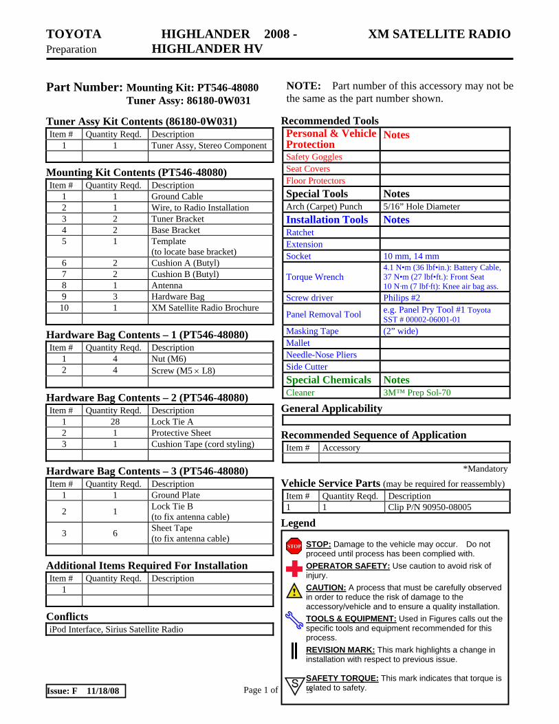
(p) Disassemble the driver seat as follows:
(1) Protect the center console, floor, and rear No. 1 seat area.
(2) On the power seat model, connect the negative battery cable.
(3) Slide the driver seat forward.
(4) Pull the seat track bracket covers on the rear side, and disengage four (4) claws. (Fig. 2-15)
(5) Remove two (2) bolts on the rear side. (Fig. 2-15)
(6) Slide the driver seat rearward.
(7) Pull the seat track bracket covers on the front side, and disengage four (4) claws. (Fig. 2-16)
(8) Remove two (2) bolts on the front side. (Fig. 2-16)
(9) On the power seat model, disconnect the negative battery cable.
(10) Tilt seat back and remove clip under seat. (Fig. 2-17)
3. Route the Tuner Cable
(a) Tilt up the steering wheel to the highest position.
(b) Route the tuner cable from the instrument panel through the center cluster as shown. (Fig. 3-1)
Fig. 3-1
Tuner cable
Fig. 2-16
14 mm socket, ratchet, extension, panel removal tool
Driver seat Claws (×4)
Seat track bracket covers
Bolts (×2)
Fig. 2-17
Panel removal tool
Driver seat
Clip
Connectors
Fig. 2-15
14 mm socket, ratchet, extension, panel removal tool
Seat track bracket covers
Driver seat
Claws (×4)
Bolt
Bolt
STOP

TOYOTA HIGHLANDER 2008 - XM SATELLITE RADIO Procedure HIGHLANDER HV
Page 9 of 21 pages Issue: F 11/18/08
(c) Connect the vehicle wire harness
connector (12-pin) that was connected to the audio head unit to the tuner cable connector. (Fig. 3-2)
NOTE: Some models don’t have the 12-pin connector for the vehicle wire harness.
(d) Secure the tuner cable with three (3) lock ties A. (Fig. 3-3)
NOTE: On the model without the 12-pin connector for the vehicle wire harness, secure the tuner cable as shown in the figure. (Fig. 3-4)
(e) Use a side cutter to cut off the excess lock
ties length.
(f) Apply cushion tape to the connector. (Fig. 3-5)
Fig. 3-5
Cushion tape
Fig. 3-2
Vehicle wire harness
Tuner cable connector
Fig. 3-3
Side cutter
Tuner cable
Lock ties A (×3)
Fig. 3-4
Side cutter
Tuner cable
Lock ties A (×3)

TOYOTA HIGHLANDER 2008 - XM SATELLITE RADIO Procedure HIGHLANDER HV
Page 10 of 21 pages Issue: F 11/18/08
NOTE: On the model without the 12-pin
connector for the vehicle wire harness, apply cushion tape as shown in the figure. (Fig. 3-6)
(g) Secure the tuner cable with two (2) lock ties A. (Fig. 3-7)
(h) Use a side cutter to cut off the excess lock ties length.
(i) Secure the tuner cable with two (2) lock ties A. (Fig. 3-8)
NOTE: Secure the tuner cable behind the vehicle wire harness to avoid interference by the edge of the instrument panel reinforcement tray.
(j) Use a side cutter to cut off the excess lock ties length.
(k) Secure the tuner cable with three (3) lock ties A. (Fig. 3-9)
(l) Use a side cutter to cut off the excess lock ties length.
Fig. 3-9
Side cutter
Lock ties (×3)
Fig. 3-6
Cushion tape
Fig. 3-7
Side cutter
Lock ties A (×2)
Tuner cable
Vehicle wire harness
Fig. 3-8
Side cutter Lock ties (×2)

TOYOTA HIGHLANDER 2008 - XM SATELLITE RADIO Procedure HIGHLANDER HV
Page 11 of 21 pages Issue: F 11/18/08
(m) Secure the tuner cable with two (2) lock
ties A. (Fig. 3-10)
(n) Use a side cutter to cut off the excess lock ties length.
4. Install the Antenna
(a) Clean the ground plate mounting area with 3M™ Prep Sol-70. (Fig. 4-1)
(b) When cleaning with 3M™ Prep Sol-70. (1) Always use a clean (lint-free, scratch
resistant) soft cloth (or wipe), and clean a small area at a time (~ 3 ft. × 3 ft. max.).
(2) Shake cleaner well.
(3) Apply 3M™ Prep Sol-70 to cloth or wipe. Do not spray cleaning solution directly on any vehicle surfaces.
(4) Clean surface thoroughly and wipe dry immediately with a new clean cloth. Do not allow cleaner to air dry.
(c) Remove the release paper from the back of ground plate, and then affix the ground plate according to the edge of the speaker grille. (Fig. 4-1)
Fig. 4-1
Speaker grille VDC approved cleaner
Ground plate
Front
10mm(0.4 in.)
Mold line
Fig. 3-10
Side cutter
Tuner cable
Lock ties A (×2)
STOP
STOP

TOYOTA HIGHLANDER 2008 - XM SATELLITE RADIO Procedure HIGHLANDER HV
Page 12 of 21 pages Issue: F 11/18/08
(d) Remove the release paper from the back of antenna, and then affix the antenna onto the ground plate. (Fig. 4-2)
(1) Once attached, the antenna cannot be easily removed.
(e) Route the antenna cable between the instrument panel and the windshield using the panel removal tool to press the cushions into place. (Fig. 4-3)
NOTE: Route the antenna cable under the part that catches the claws of the front pillar garnish in the instrument panel. (Fig. 4-3)
NOTE: When routing, be careful that the antenna cable does not protrude over the window for confirming the vehicle identification number. (Fig. 4-4)
(f) Route the antenna cable, and then use three (3) sheet tapes to install the antenna cable. (Fig. 4-5)
NOTE: When applying the sheet tapes, be careful not to pull or stress the pipe tube and electrical connector.
Fig. 4-3
Panel removal tool
Antenna cable
Part catching claw
Fig. 4-4
Antenna cable
Vehicle Identification Number
Front
Fig. 4-5
Side cutter
Antenna cable
Sheet tapes (×3)
Pipe tube
Electrical connectors
Fig. 4-2
Antenna
Release paper
Ground plate
TOYOTA HIGHLANDER 2008 - XM SATELLITE RADIO Procedure HIGHLANDER HV
Page 13 of 21 pages Issue: F 11/18/08
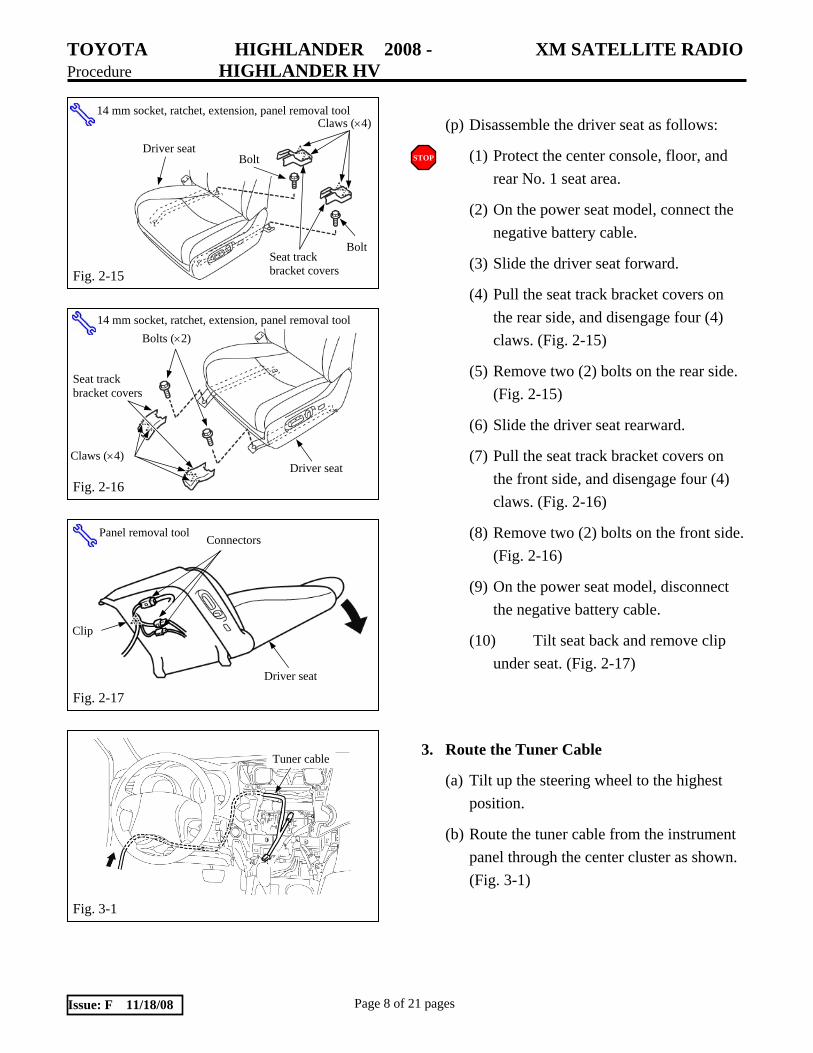
(g) Remove the front door opening trim
weather strip. (Fig. 4-6)
(h) Route the antenna cable, and then use one (1) sheet tape to install the antenna cable. (Fig. 4-6)
(i) Route the antenna cable, and then use two (2) sheet tapes to install the antenna cable. (Fig. 4-7)
5. Install the Ground Cable
(a) Install the spade end of the ground cable onto the ground bolt located in the driver side cowl area. (Fig. 5-1)
(b) Route the tuner cable, the ground cable, and the antenna cable, and then secure them with two (2) lock ties A and one (1) lock tie B. (Fig. 5-2)
(c) Use a side cutter to cut off the excess lock ties length.
Fig. 5-2
Side cutter
Antenna cable
Lock ties A (×2)
Tuner cable
Lock tie B (×1)
Fig. 4-7 Antenna cable
Sheet tapes (×2)
Fig. 4-6
Sheet tape (×1)
Antenna cable
Fig. 5-1
Ground Cable
Ground Bolt

TOYOTA HIGHLANDER 2008 - XM SATELLITE RADIO Procedure HIGHLANDER HV
Page 14 of 21 pages Issue: F 11/18/08
(d) Route the tuner cable, the ground cable,
and the antenna cable, and then secure them with three (3) lock ties A. (Fig. 5-3)
(e) Use a side cutter to cut off the excess lock ties length.
(f) Reassemble the knee air bag assembly to the lower instrument panel.
(g) Put protective sheet on the area as shown in Fig. 5-4.
(h) Peel back the floor carpet and felt.
(1) Carefully disengage the clips of the floor carpet. (Fig. 5-5)
(i) Route the tuner cable, the antenna cable, and the ground cable, and then secure them with two (2) lock ties A. (Fig. 5-6)
(j) Use a side cutter to cut off the excess lock ties length.
Fig. 5-5
Panel removal tool
Clip
Floor carpet
2
Fig. 5-6
Antenna cable
Tuner cable
Lock ties A (×2)
Side cutter
Ground cable
Fig. 5-4
Tuner cable
Protective sheet Tuner cable
Fig. 5-3
Side cutter Tuner cable
Antenna cable LH
Front
Lock ties A (× 3)

TOYOTA HIGHLANDER 2008 - XM SATELLITE RADIO Procedure HIGHLANDER HV
Page 15 of 21 pages Issue: F 11/18/08
(k) Route the tuner cable, the antenna cable,
and the ground cable, and then secure them with one (1) lock tie A. (Fig. 5-7)
(1) Secure the tuner cable with 240 mm (9.4 in.) of length, antenna cable with 330 mm (13.0 in.) of length, and ground cable with 280 mm (11.0 in.) of length, to the wire harness with a lock tie A. (Fig. 5-8)
(l) Use a side cutter to cut off the excess lock tie length.
(m) Route the tuner cable, the antenna cable, and the ground cable, and then secure them with two (2) lock ties A. (Fig. 5-9)
(n) Use a side cutter to cut off the excess lock ties length.
(o) Even out the length of the cables and secure the excess tuner cable, the excess antenna cable, and the excess ground cable with two (2) lock ties A. (Fig. 5-10)
(p) Use a side cutter to cut off the excess lock ties length.
Fig. 5-9
Side cutter
Tuner cable
Antenna cable Ground cable
Lock ties A (×2)
Fig. 5-10
Side cutter
Lock ties A (×2)
Fig. 5-8
Side cutter
Tuner cable 240 mm (9.4 in.)
Ground cable 280 mm (11.0 in.)
Antenna cable 330 mm (13.0 in.)
Fig. 5-7
Ground cable Tuner cable
Side cutter
Antenna cable
Lock tie A (×1)

TOYOTA HIGHLANDER 2008 - XM SATELLITE RADIO Procedure HIGHLANDER HV
Page 16 of 21 pages Issue: F 11/18/08
Fig. 6-1
Cushion B
Base bracket front
Base bracket rear
3M™ Prep Sol-70
LH
Front
15 mm (0.6 in.)
Cushion A with step
Cushion B
Cushion A with step
6. Install the Tuner
(a) Clean the base bracket mounting surface with 3M™ Prep Sol-70 using the method defined in Step 4(b). (Fig. 6-1)
(b) Install two (2) cushions A (butyl) and two (2) cushions B (butyl) onto the bottom of each base bracket. (Fig. 6-1)
(c) Clean the base bracket mounting surface of
the vehicle floor pan with 3M™ Prep Sol-70 using the method defined in Step 4(b). (Fig. 6-2)
(d) Position template (to locate base bracket) under the driver seat as shown. (Fig. 6-2, Fig. 6-3)
(e) Remove the release paper from the four (4) cushions (butyl), and then secure the base brackets over template as shown. (Fig. 6-2)
(f) Remove the template.
(g) Route the tuner cable, the antenna cable, the ground cable, and the seat wire harness through the floor carpet hole; then reinstall the floor carpet. (Fig. 6-4)
Fig. 6-2
Base brackets
Template
LH
Front
3M™ Prep Sol-70
Fig. 6-3
Template
Fig. 6-4
Seat wire harness
Tuner cable
Antenna cable
Ground cable
TOYOTA HIGHLANDER 2008 - XM SATELLITE RADIO Procedure HIGHLANDER HV
Page 17 of 21 pages Issue: F 11/18/08
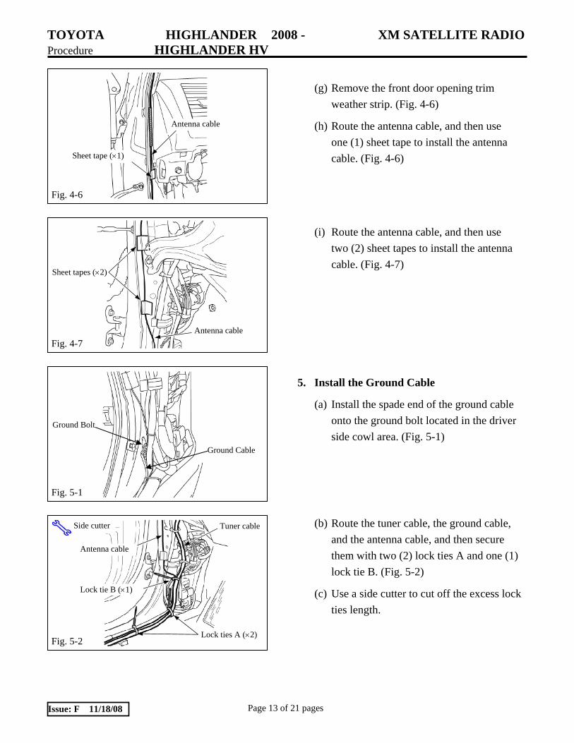
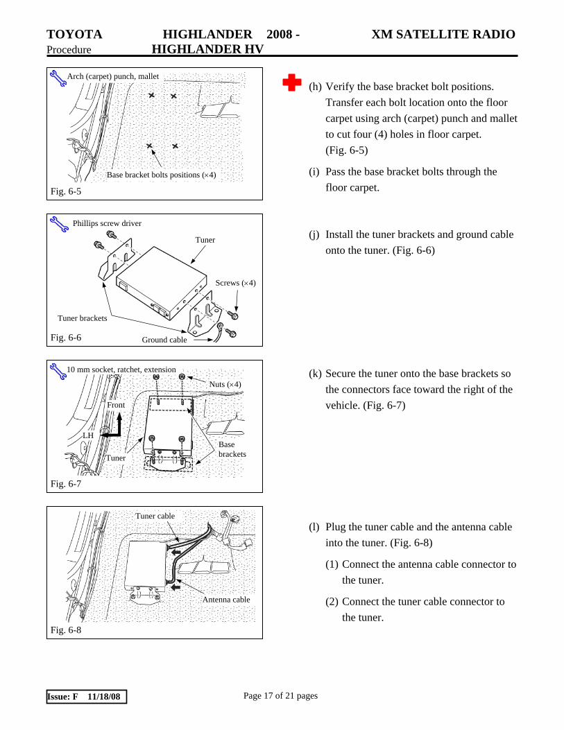
(h) Verify the base bracket bolt positions.
Transfer each bolt location onto the floor carpet using arch (carpet) punch and mallet to cut four (4) holes in floor carpet. (Fig. 6-5)
(i) Pass the base bracket bolts through the floor carpet.
(j) Install the tuner brackets and ground cable onto the tuner. (Fig. 6-6)
(k) Secure the tuner onto the base brackets so the connectors face toward the right of the vehicle. (Fig. 6-7)
(l) Plug the tuner cable and the antenna cable into the tuner. (Fig. 6-8)
(1) Connect the antenna cable connector to the tuner.
(2) Connect the tuner cable connector to the tuner.
Fig. 6-5
Arch (carpet) punch, mallet
Base bracket bolts positions (×4)
Fig. 6-6
Tuner
Tuner brackets
Phillips screw driver
Ground cable
Screws (×4)
Fig. 6-7
10 mm socket, ratchet, extension
LH
Front
Tuner
Nuts (×4)
Base brackets
Fig. 6-8
Antenna cable
Tuner cable

TOYOTA HIGHLANDER 2008 - XM SATELLITE RADIO Procedure HIGHLANDER HV
Page 18 of 21 pages Issue: F 11/18/08
(m) Secure the tuner cable, antenna cable, and ground cable with one (1) lock tie A. (Fig. 6-9)
(n) Use a side cutter to cut off the excess lock ties length.
7. Reinstall the Audio Head Unit
(a) Connect the tuner cable connector and the electrical connectors removed in Step 2(o)(3) into the rear of the audio head unit.
(b) Insert audio head unit into opening and reinstall the four (4) bolts. (Fig. 7-1)
8. In Process Functional Test
(a) On the gasoline engine model, temporarily reconnect the negative battery cable of the battery installed on the left side of the engine compartment.
NOTE: On the hybrid model, temporarily reconnect the negative battery cable of the auxiliary battery installed on the right side of the engine compartment.
(b) Turn the engine/power switch to ON
(ACC).
(c) Press the power button on the audio head unit. Verify that backlighting illuminates.
Fig. 6-9
Side cutter Lock tie A (×1)
Fig. 7-1
10 mm socket, ratchet, extension Audio head unit
Bolts (×4)
Clips (×4)

TOYOTA HIGHLANDER 2008 - XM SATELLITE RADIO Procedure HIGHLANDER HV
Page 19 of 21 pages Issue: F 11/18/08
(d) Press and release the “SAT” button on the
audio head unit.
(1) Verify that a satellite channel is received, or a “NO SIGNAL” message appears on the display.
NOTE: If “ANTENNA” appears (flashing) on the display, then the antenna cable is disconnected from the tuner.
NOTE: If the audio head unit will not tune or
go into satellite mode, then the tuner cable is disconnected from the tuner.
(e) Turn the engine/power switch to OFF.
(f) On the gasoline engine model, disconnect the negative battery cable of the battery installed on the left side of the engine compartment.
NOTE: On the hybrid model, disconnect the negative battery cable of the auxiliary battery installed on the right side of the engine compartment.
9. Complete the Reassembly of Vehicle
(a) Reconnect any disconnected electrical connectors.
(b) Verify the panels fit together properly with no uneven gaps between them.
(c) Reinstall the front seat. (Fig. 9-1)
(1) Reinstall the four (4) bolts loosely, then tighten them in the following order: Front inner side bolt Front outer side bolt Rear inner side bolt Rear outer side bolt
Fig. 9-1
14 mm socket, torque wrench, extension
Driver seat
TOYOTA HIGHLANDER 2008 - XM SATELLITE RADIO Procedure HIGHLANDER HV
Page 20 of 21 pages Issue: F 11/18/08
(2) Tighten bolts to 37 N•m (27 lbf•ft.)
(d) Clean up and remove any trash.
(e) Place the “XM Satellite Radio” owner brochure in the glove box.
(f) Reinstall the knee air bag assembly. 10 N·m (7 lbf·ft).
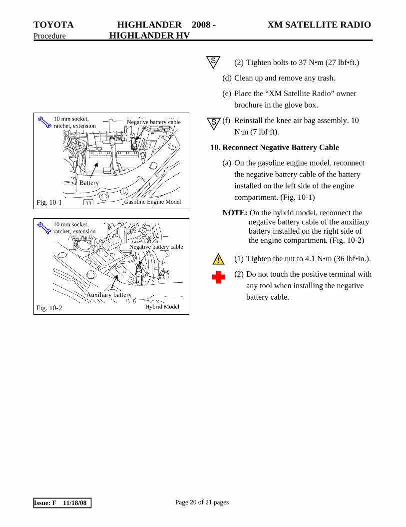
10. Reconnect Negative Battery Cable
(a) On the gasoline engine model, reconnect the negative battery cable of the battery installed on the left side of the engine compartment. (Fig. 10-1)
NOTE: On the hybrid model, reconnect the negative battery cable of the auxiliary battery installed on the right side of the engine compartment. (Fig. 10-2)
(1) Tighten the nut to 4.1 N•m (36 lbf•in.).
(2) Do not touch the positive terminal with any tool when installing the negative battery cable.
Fig. 10-2 Hybrid Model
10 mm socket, ratchet, extension
Negative battery cable
Auxiliary battery
Fig. 10-1 Gasoline Engine Model
10 mm socket, ratchet, extension Negative battery cable
Battery

TOYOTA HIGHLANDER 2008 - XM SATELLITE RADIO HIGHLANDER HV Checklist - these points MUST be checked to ensure a quality installation.
Check: Look For:
Page 21 of 21 pages Issue: F 11/18/08
Accessory Function Checks
Satellite radio
Audio head unit
Navigation system
Vehicle Function Checks
Hazard switch
Navigation
Driver’s seat belt reminder light
Removed seat
Seat lock mechanism
SRS warning light
HVAC (heating ventilation and air conditioning) system
SSP function
Hood lock control cable
Instrument panel finish panel lower functions (Any electrical connector removed in step 2(i)(3). Fig 2-9)
Verify the proper operation of the satellite radio.*
Verify the proper operation of the audio head unit.*
*: Refer to the XM Satellite Radio Brochure and audio head unit owner’s manuals.
Execute DTC check, and confirm there is no error. (Refer to the HIGHLANDER Repair Manual.)
Proper operation of the hazard switch.
Verify that GPS icon appears on NAV display.
Proper operation of the driver’s seat belt reminder light.
Verify the removed seat is securely fastened.
Verify the proper operation of the removed seat lock mechanism.
Verify the SRS warning light illuminates for approximately 6 seconds with the engine/power switch ON, and then goes out.
Proper operation of the air conditioning system.
Verify the radio SSP function is set to "HIGHLANDER" by pressing the "SSP" button on the audio head unit for 5 seconds. (If not, press the volume control and set to "HIGHLANDER".)
Proper operation of the hood lock control cable.
Verify the proper operation of the instrument panel finish panel lower functions.