Embed Size (px)
Citation preview

XMM OPTICAL MONITOR - TELESCOPE STRAYLIGHT BAFFLE DESIGNAND PERFORMANCE SIMULATION
Document Number XMM-OM/MSSL/TC/0012.0l
21 MARCH 1991
Tony Richards, Christina Young
Optical Physics GroupAstrophysics Division
Space Science DepartmentRutherford Appleton Laboratory
Chilton,DidcotOxon OXll OQX.

PREFACE
This report describes how a design for the XMM Optical Monitor's straylightbaffling system was defined and presents the results of simulating its per-formance using the GUERAP III program (Generalised Unwanted Energy RejectionAnalysis Program).
The results of the study indicate that a minimum Earth-avoidance angle ofapproximately 25 degrees is likely to have to apply, if straylight levels areto be maintained at or below that equivalent to 1/6 of a mean Zodiacal lightlevel. Also, the study shows that the design of the front of the telescopebaffle needs to be refined in order to maintain the required straylight atten-uation factor at off-axis angles larger than 60 degrees.
REFERENCES.
'Attenuation Factors for the XMM-OM Baffle', XMM-OM/MSSL/TC/0005.01, 15-Nov-90
Preface ii
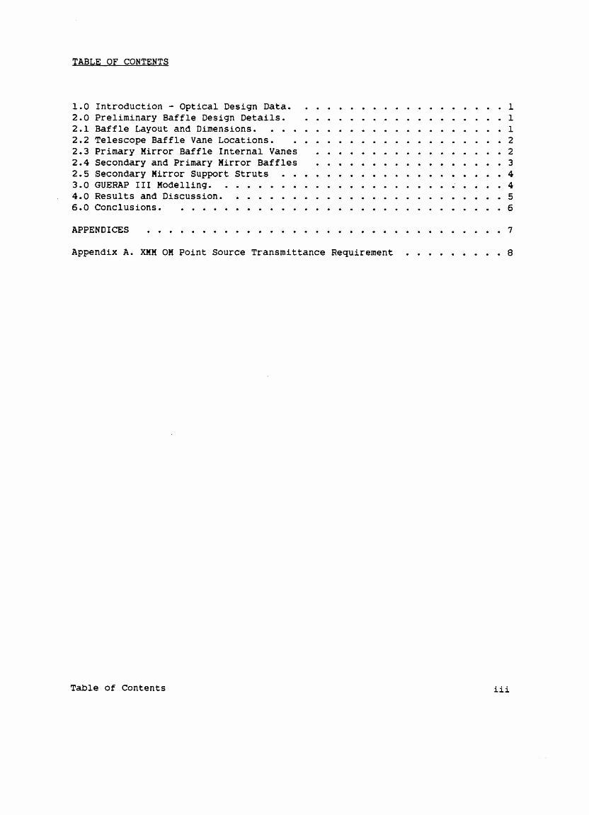
TABLE OF CONTENTS
1.0 Introduction - Optical Design Data. · · · · · · · · · · 12.0 Preliminary Baffle Design Details. 12.1 Baffle Layout and Dimensions. . . . . · · · · · · · · 12.2 Telescope Baffle Vane Locations. · · · · · · 22.3 Primary Mirror Baffle Internal Vanes · · · · · · · · · · · · 22.4 Secondary and Primary Mirror Baffles · · · · · · 32.5 Secondary Mirror support Struts . . . · · · · · · · · · · 43.0 GUERAP III Modelling. · · · · · · · · · · · · 44.0 Results and Discussion. · · · · · · · · · · · · · · · · 56.0 Conclusions. · · · · · · · · · · · · · 6
APPENDICES • • 7
AppendiX A. XMH OM Point Source Transmittance Requirement 8
Table of Contents Hi
KMM OM BAFFLE DESIGN + PERFORMANCE SIMULATION
1.0 INTRODUCTION - OPTICAL DESIGN DATA.
The KKM Optical Monito~ is to be a f/13 Ritchey-Ch~etien telescope designhaving an ape~tu~e = 155 mm, giving a focal length f = 4030 mm. The backfocal length = 249 mm, measu~ed f~om the p~ima~y mi~~o~'s su~face, on-axis.The pa~ticula~ solution specified fo~ this study fo~ the shapes to be followedby the p~ima~y and seconda~y mi~~o~s a~e as follows
P~ima~y Hype~boloid of ~evolution, eccent~icity of hype~bola = 1.007714conic constant =-1.015487
Seconda~y: Hype~boloid of ~evolution, eccent~icity of hype~bola = 1.40585conic constant =-1.976413
(N.B. optical design p~og~ams no~mallY specify the conic constant K in p~efe~-ence to the eccent~icity e, whe~e e**2= - K)
Fo~ the pu~poses of evaluating the st~aylight pe~fo~mance of the system, it isassumed that a detecto~ having diamete~ 35 mm is located at the casseg~ainfocus of the system (this ~ep~esents a composite of the so-called '~ed'- and'blue' detecto~s to be used, the location of the 'blue' detecto~ and the clea~
ape~tu~e ~equi~ed by the focal-~educing optics fo~ the '~ed' detecto~ beingused). Given the 4030 mm effective focal length, this means that the fieldof view defined by the detecto~, which is to be shielded f~om st~aylight, sub-tends an angle of 30 a~cminutes on the sky. Thus the FOV semi-diamete~ is 15a~cminutes, o~ 1/4 deg~ee.
2.0 PRELIMINARY BAFFLE DESIGN DETAILS.
2.1 BAFFLE LAYOUT AND DIMENSIONS.
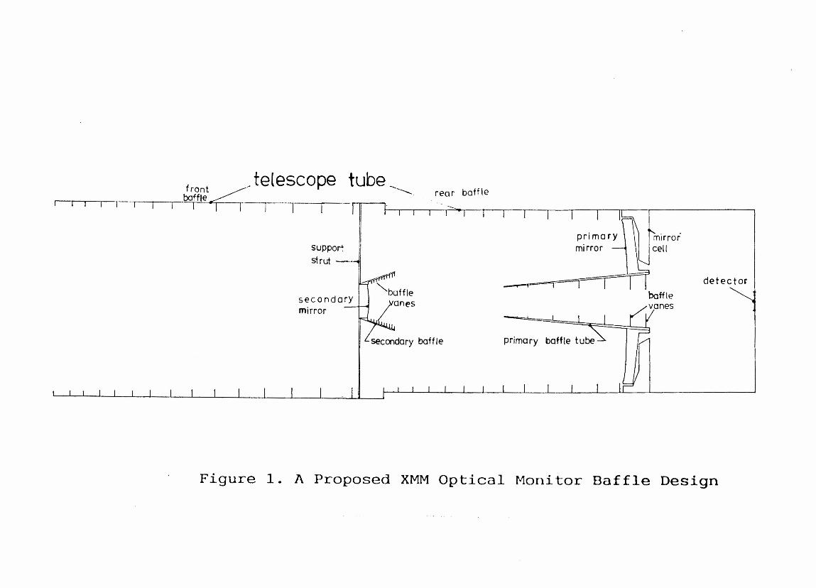
Figu~e 1 shows, to scale, a p~oposed solution to the p~oblem of baffling theOM telescope system. This is to be ~ega~ded as a p~elimina~y design which isto be imp~oved as a ~esult of the p~esent and futu~e studies.
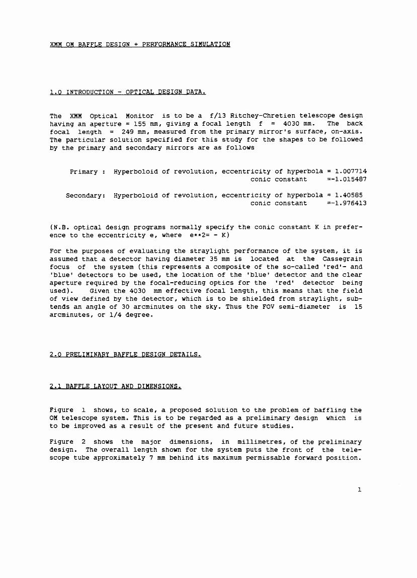
Figu~e 2 shows the majo~ dimensions, in millimet~es, of the p~elimina~ydesign. The ove~all length shown fo~ the system puts the f~ont of the tele-scope tube app~oximately 7 mm behind its maximum pe~missable fo~wa~d position.
1
2.2 TELESCOPE BAFFLE VANE LOCATIONS.
Figure 3 shows how locations were selected for the baffle vanes requiredinside the main telescope tube. In the figure, PI and P2 are diametricallyopposite points on the boundary of the primary mirror aperture. BO, Bl, Bnetc. are points on the internal edges of the baffle vanes. These latterpoints are normally located at least I degree outside the conical envelope ofthe clear, unvignetted, circular field of view at the primary, so that lightscattered from vane edges towards the primary still has to be scatteredthrough I degree before it can enter the FOV of the detector. Since the lat-ter FOV has semi-diameter 1/4 degree, the angle )fShOwn in figure 3 should be1.25 degree at least. In the present design, it has been chosen to be theminimum, 1.25 degrees.
The position for BO is where the line leaving PI at angle ~ to the opticalaxis cuts the plane defining the front of the telescope tube. The positionfor Bl was selected to be where the line from P2 to the point where baffle BOmeets the tube wall cuts the line from PI to the edge BO of the front baffle.The positions for baffles B2,B3 and so on, were selected as shown for thebaffle pair Bn and Bn+l.
Point '0' is a point on the edge of the front vane, diametrically oppositepoint BO. The line from 0 to Bn cuts the telecope wall at WI. The locationof Bn+l is chosen where the line P2->W2 cuts the line Pl->BO such that theposition W2 where the line P2->Bn+l cuts the telescope wall is a specifiedamount (in this case 5 mm) FORWARDS of WI. This 5 mm overlap ensures that theregion of the wall between 2 baffle vanes which can be seen from a point onthe primary mirror CANNOT simultaneously be illuminated DIRECTLY by lightentering through the front aperture of the telescope tube.
By having to have ~ = 1.25 degrees and by locating the front baffle BO at1110 mm forward from the edge of the primary mirror, it can be seen that thetelescope tube inner radius must be at least 188 mm in order to have a reason-able depth available for baffle vanes, if their number is to be kept to a rea-sonable value (figure 2 shows that the radius of the aperture in baffle BOmust be at least 179.2 mm). More vanes means more vane edges, which meansmore edge scatter, so the more depth available for the vanes the better sincethis means fewer vanes required to shield a given tube length.
The telescope tube wall is shown with a 'step' at about 460 mm forwards of theprimary as a concession to possible radial constraints in this area and with aview to mass-saving. However, the 175 mm internal radius shown for the tele-scope tube between this point and the primary is regarded as a minimum con-sistent with minimum baffle vane numbers and maximum baffle vane efficiency.
2.3 PRIMARY MIRROR BAFFLE INTERNAL VANES
The baffle vanes shown inside the primary baffle tube (see figure 1) werelocated in a fashion similar to that used for the main telescope baffle vanes,
2
only this time using points Fl and F2 on the edge of the detecto~ (instead ofpoints Pl and P2) and points on the tip of the conical p~ima~y baffle wall (in place of points BO and 0 ).
2.4 SECONDARY AND PRIMARY MIRROR BAFFLES
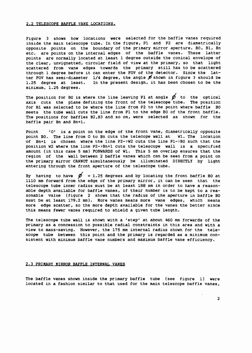
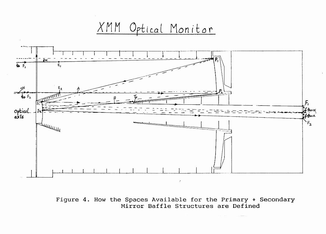
Figure 4 shows what constraints act to define the ~egion which can be occupiedby the primary and secondary mir~o~ baffles. In that figu~e, all dashed linesa~e either the optical axis or define the directions of rays which converge onthe point of intersection of the optical axis with the image plane (the axialimage paint). All continuous lines define rays which, on entering the systemthrough points EI and E2 on the ent~ance ape~ture, converge to diametricallyopposite paints on the edge of the detecto~ area. These latter ~ays se~ve todefine the regions occupied by rays which enter the entrance aperture withinthe angular range defined by the FOY of the detector. In figure 4, the angleo(= 1/4 deg~ee, the FOY semi-diameter. The points A and B mark the furthestextents from the secondary and p~imary mir~o~s of their ~espective baffles, ifno vignetting of the FOY is to be pe~mitted. Again, if no vignetting is to bepermitted, the secondary baffle st~ucture must fit within the volume betweenthe cones of ~evolution formed by rotating lines E2->A and A->Sl about theoptical axis. Similarly, the primary baffle structure must fit within thevolume between cones formed by ~otating lines P2->B and B->FI about theoptical axis (which is the axis of symmetry fo~ the system).
The drive~ fo~ the actual shapes and locations of the prima~y and secondarymirror baffles is the combination of axial and radial location chosen forpoint E2. The design is most sensitive to the RADIAL location of E2, so itmakes sense to specify a reasonable aXial location for E2 (in the present caseit is located in a plane 51 mm f~om the secondary mirro~ su~face) and thenproceed to an optimum choice fo~ the radial location of E2. Once a locationfor E2 is fixed, a subsequent location for point Tp, on the extreme fo~wardinternal tip of the primary baffle cone, can be selected, bearing in mind theknowledge that the tip of the cone cannot be infinitely sharp. The design isthen fixed by ensuring that a value for E2 is selected such that a line fromE2->Tp when continued to the image plane MISSES the detector by a p~eset'safety margin'. For the baffle design shown in figures 1->4, the latte~safety margin was taken = 5 mm. The latter precaution is absolutely essentialin order to ensure that no light can directly reach the detecto~ f~om thespace forwards of the extreme outer edge of the secondary baffle.
The p~esent preliminary design uses a ~adial location for E2 = 56 mm from thetelescope axis and an axial location = 700 mm forward from the image plane.The resulting secondary baffle system creates an obstruction having a diameter= 0.36 times the p~imary aperture (obstruction ratio Q = 0.36). This means athrough-put of 100 *(l-Q)(l+Q) = 87 pe~cent of the full-aperture value. Evenwith no secondary baffle, but with a minimum secondary diameter = 32 mm(obstruction ratio Q= 0.2), the maximum through-put is 100*(1-0.2)*(1+0.2) =96 percent, so the added secondary baffle changes the through-put by 9 per-cent.
3

The shape and size of the baffles depends strongly on the configuration of themirrors and on the size of the field of view that must be free fromvignetting. The present design gives a 30 arcminute diameter unvignetted FOV.Reduction in the diameters of the primary and secondary baffle vanes wouldresult in a loss of off-axis light. Figure 5 shows the appearance of the tipsof the primary and secondary baffles as viewed on the entrance pupil planefrom the object points, in this case at infinity, showing an unvignetted FOVthrough the telescope.
2.5 SECONDARY MIRROR SUPPORT STRUTS
Final structural items which turn out to have a critical impact on thestraylight scatter at smaller off-axis angles are the 4 equispaced struts cho-sen to support the secondary from the telescope tube wall. An idealiseddesign was chosen for these. They were envisaged as being equilateral-triangular in cross-section normal to their length, with a triangle-sidelength = 3 mm. The face making up the base of the triangle is oriented inthe telescope so as to face directly towards the primary mirror. The propor-tion of the cross-section, combined with the struts' location and orientationmeans that neither of the other two faces of each strut can be seen by theprimary mirror, ensuring that light scattered from these surfaces cannot reachthe primary directly.
3.0 GUERAP III MODELLING.
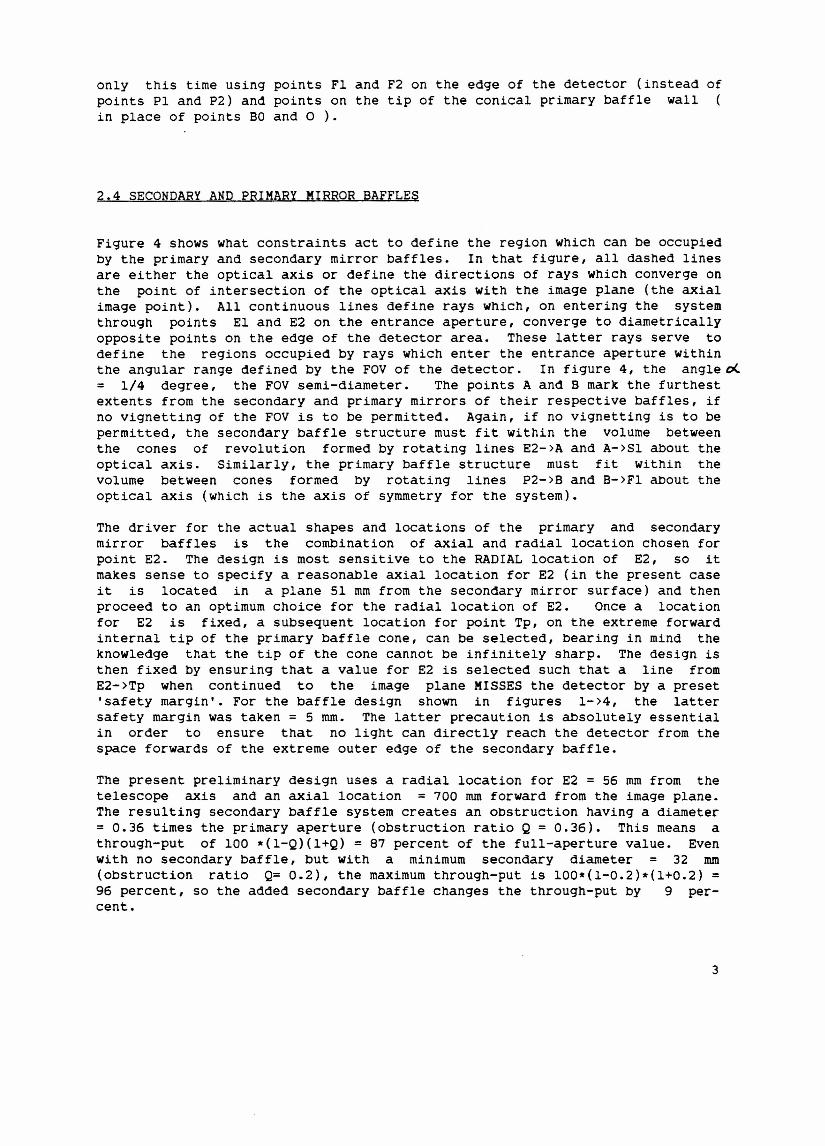
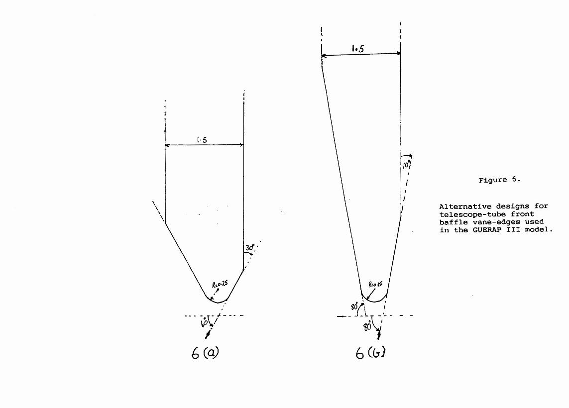
The structure shown in figure 1 was broken down into constituent partsmodellable using planes, cones, cylinders, hyperboloids, toroids etc. and a250-surface model of it created as a data set for running the GUERAP IIIstraylight analysis program on it. Figure 6 shows 2 alternative versions usedto model the edges of the planar baffle vanes. Each version consists of ahyperbolically-profiled tip with a bevel added to one face. All planar bafflevanes are oriented with the bevel side TOWARDS the incoming light.
The details of the technique used to model and run GUERAP III will not begiven here. Suffice it to say that the program produces estimates for the sys-tem 'Attenuation factor' which is just the reCiprocal of the 'POint SourceTransmittance' (PST) as shown in figure 7.
Some details which must be given though, are the optical properties given tothe most important surfaces.
All the internal baffle surfaces, including the baffle vane edges, wereassumed to be given a black absorbing coating with the following properties:
4
Absorption coefficient = .995
Diffuse scatter coefficient = 0.005
The primary and secondary mirror surfaces were assumed to have the followingproperties
specular Reflectivity = 0.99778
Diffuse Reflectivity = 0.00200
Near-specular scatter fraction = 0.00022
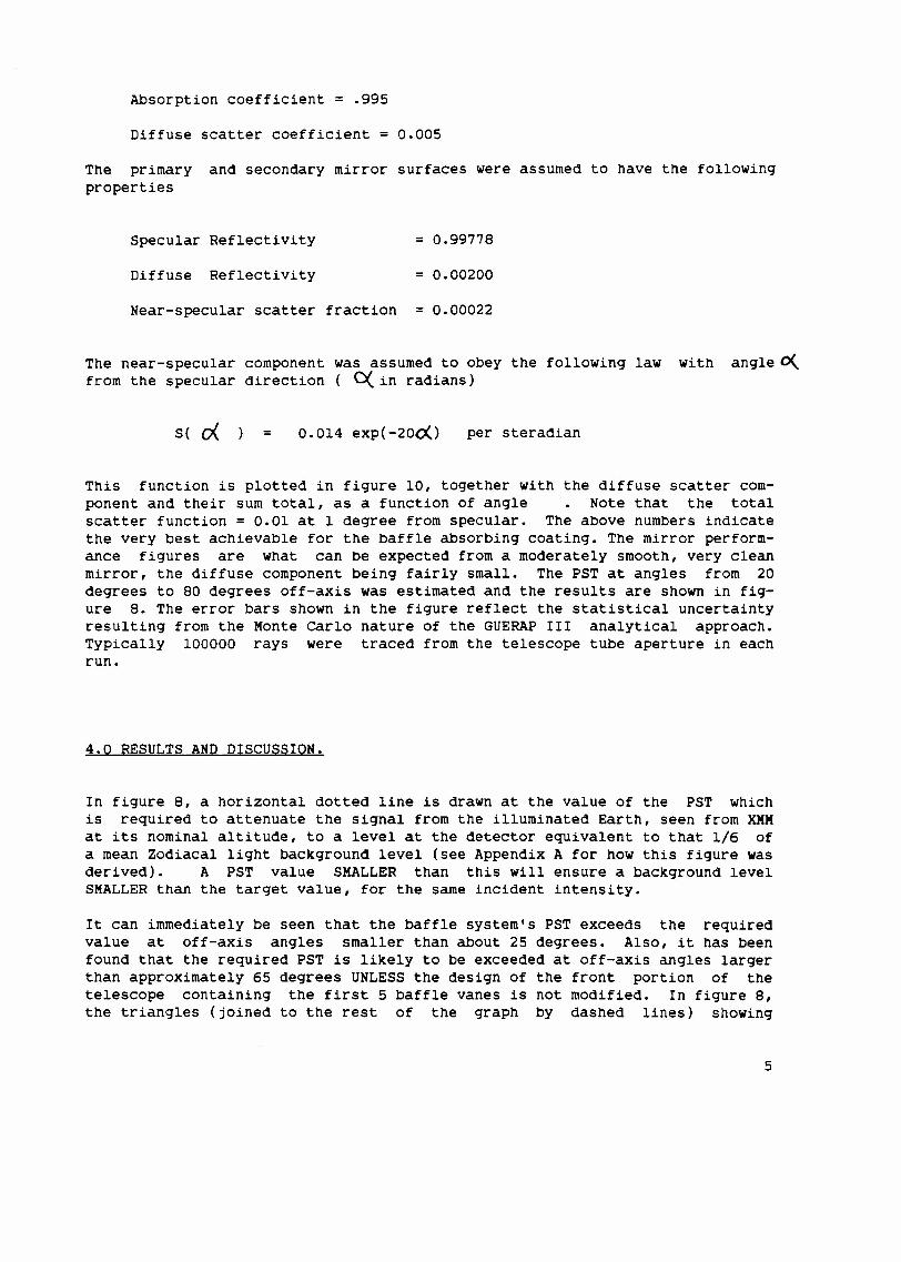
The near-specular component was assumed to obey the following law with angleD(from the specular direction ( C(in radians)
S( 0< = 0.014 exp(-200() per steradian
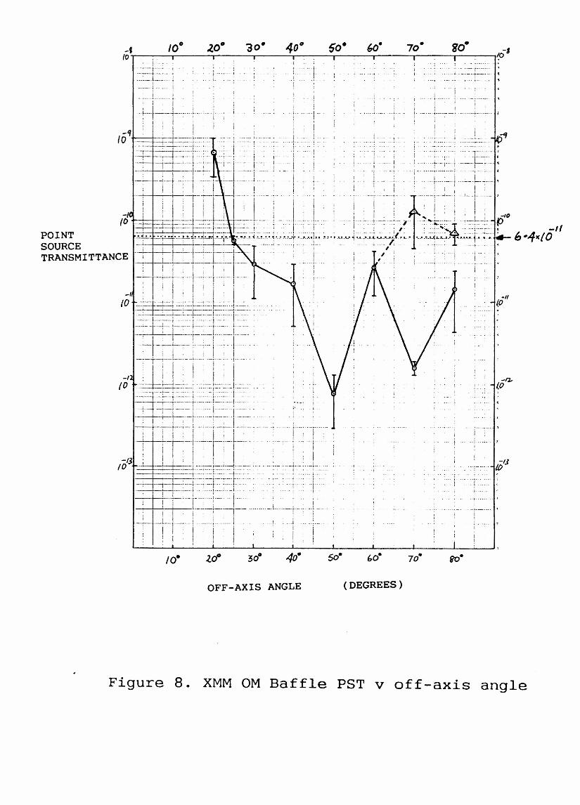
This function is plotted in figure 10, together with the diffuse scatter com-ponent and their sum total, as a function of angle Note that the totalscatter function = 0.01 at 1 degree from specular. The above numbers indicatethe very best achievable for the baffle absorbing coating. The mirror perform-ance figures are what can be expected from a moderately smooth, very cleanmirror, the diffuse component being fairly small. The PST at angles from 20degrees to 80 degrees off-axis was estimated and the results are shown in fig-ure 8. The error bars shown in the figure reflect the statistical uncertaintyresulting from the Monte carlo nature of the GUERAP III analytical approach.Typically 100000 rays were traced from the telescope tube aperture in eachrun.
4.0 RESULTS AND DISCUSSION.
In figure 8, a horizontal dotted line is drawn at the value of the PST whichis required to attenuate the signal from the illuminated Earth, seen from KKMat its nominal altitude, to a level at the detector equivalent to that 1/6 ofa mean Zodiacal light background level (see Appendix A for how this figure wasderived). A PST value SMALLER than this will ensure a background levelSMALLER than the target value, for the same incident intensity.
It can immediately be seen that the baffle system's PST exceeds the requiredvalue at off-axis angles smaller than about 25 degrees. Also, it has beenfound that the required PST is likely to be exceeded at off-axis angles largerthan approximately 65 degrees UNLESS the design of the front portion of thetelescope containing the first 5 baffle vanes is not modified. In figure 8,the triangles (joined to the rest of the graph by dashed lines) showing
5
~esults at off-axis angles 70 and 80 deg~ees we~e obtained using a baffle edgedesign shown in figu~e 6a, whe~eas the LOWER values of PST at the same angleswe~e obtained using the edge-design shown in figu~e 6b. The diffe~ence thatusing design 6b makes is that incident light must ente~ at an angle g~eate~than 80 deg~ees to the axis befo~e it can illuminate the inne~most edge of thevane, f~om whe~e it can scatte~ light di~ectly towa~ds the p~ima~y mi~~o~.With design 6a the incident angle need only exceed 60 deg~ees to p~oduce thesame scatte~ ~oute.
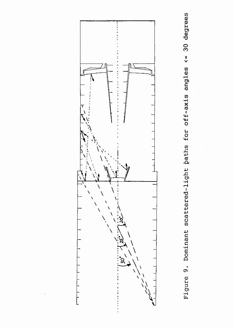
Figu~e 9 allows one to inte~p~et the behaviou~ of the ~esults shown in figu~e8 fo~ angles between 30 and 20 deg~ees off-axis. At 30 deg~ees, light ente~-ing the f~ont of the telescope tube is only just beginning to illuminate those~egions of the telescope wall and those baffle vane su~faces which can scatte~light towa~ds the su~faces of the secondary suppo~t struts which face the pri-ma~y mi~~or. As the angle drops f~om 30 deg to 25 deg, mo~e and mo~e su~facesa~e illuminated which scatter light to the secondary st~ut su~faces, f~omwhich light is subsequently scatte~ed directly into the detecto~'s field ofview and towards the p~imary mi~~o~, eventually to reach the detector viaspecular reflections from both primary and secondary mirror surfaces.
As the angle d~ops further, ~egions of the telescope tube wall and baffle vanesurfaces are eventually illuminated which can scatter light, not just towardsthe secondary support struts, but directly towards the seconda~y mi~~or sur-face (and also secondary baffle internal vane surfaces), whence light can beeventually diffusely scattered directly to the detector.
6.0 CONCLUSIONS.
The following are the main conclusions.
• The required PST is achievable for off-axis angles between app~oximately25 degrees and 80 deg~ees.
• Achievement of the requi~ed PST at off-axis angles f~om 80 deg. to 90deg. will requi~e imp~ovement of the performance of the front section ofthe telescope tube, possibly involving some increase in diameter in o~derto create a short first stage section which can shield the entrance ape~-ture of the main telescope tube, from objects more than 80 deg. off-axis.
• The ~equi~ed PST perfo~mance will only be achieved using the best abso~b-ing coating available for the baffle walls and vane edges and maintainingscrupulously clean prima~y and secondary mi~ror surfaces.
6

APPENDICES
APPENDICES 7
APPENDIX A. XMM OM POINT SOURCE TRANSMITTANCE REOUIREMENT
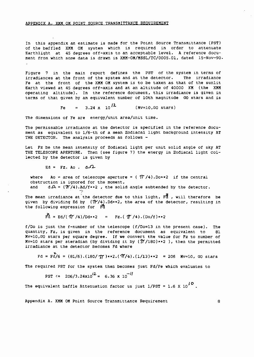
In this appendix an estimate is made for the Point Source Transmittance (PST)of the baffled XMM OM system which is required in order to attenuateEarthlight at 45 degrees off-axis to an acceptable level. A reference docu-ment from which some data is drawn is XMM-OM/MSSL/TC/0005.01, dated 15-Nov-90.
Figure 7 in the main report defines the PST of the system in terms ofirradiances at the front of the system and at the detector. The irradianceFe at the front of the XMM OM system is to be taken as that of the sunlitEarth viewed at 45 degrees off-axis and at an altitude of 40000 KM (the XMMoperating altitude). In the reference document, this irradiance is given interms of that given by an equivalent number of 10th magnitude GO stars and is
Fe = 3.24 x 10/2. (Mv=lO,GO stars)
The dimensions of Fe are energy/unit area/unit time.
The permissable irradiance at the detector is specified in the reference docu-ment as equivalent to 1/6-th of a mean Zodiacal light background intensity ATTHE DETECTOR. The analysis proceeds as follows -
Let Fz be the mean intensity of Zodiacal light per unit solid angle of sky ATTHE TELESCOPE APERTURE. Then (see figure 7) the energy in Zodiacal light col-lected by the detector is given by
Ed = Fz. Ao. d~
where Ao = area of telescope aperture = (1r/4).Do**2 if the centralobstruction is ignored for the moment,and d~ = (?r/4).Ad/f**2 , the solid angle subtended by the detector.
The mean irradiance at the detector due to this light, F~ , will therefore begiven by dividing Ed by (~/4).Dd**2, the area of the detector, resulting inthe following expression for ~
~ = Ed/( 11' /4}/Dd**2 = FZ.( 1r /4}.(Do/f)**2
f/Do is just the f-number of the telescope (f/Do=13 in the present case). Thequantity, FZ, is given in the reference document as equivalent to 81Mv=lO,GO stars per square degree. If we convert the value for Fz to number ofMv=lO stars per steradian (by dividing it by (1r/180)**2 ), then the permittedirradiance at the detector becomes Fd where
~Fd = Fd/6 = (81/6).(l80/7T)**2.('iY/4).(1/13}**2 = 206 Mv=lO, GO stars
The required PST for the system then becomes just Fd/Fe which evaluates to
PST <= 206/3.24XIO/2 = 6.36 x 10⁻¹¹
The equivalent baffle Attenuation factor us just l/PST 10= 1.6 X 10 .
Appendix A. XMM OM Point Source Transmittance Requirement 8
~~~t~- telescope
supportstrut
secondarymirror
tube ''--...rear baffle
pri ma rymirror
detector
bafflevanes
primary
Figure 1. A Proposed XMM Optical Monitor Baffle Design

:er-;
"N
~=~~~~-
•••'0N,:lt. __. J..ll.._---11
1.1')r-
~ •0-r---:...- II
• e:.C
"<::.t
IIII
I
I~I~I II
I'"-.~.-~••rr----"""----
IIIIIII
.: 0 I--I~I
~IIII
IIIIII
II
I ...,oil
~~
-E-c::
c"~
Cf)Co
"~Cf)CQ)E
"~Q
Hoor-)
CO::E
II
N
-~

I
/
II
I
I
-oQ)c.,-f
~Q)oQ)~enCJ)co.,-f+JCOUo....:lCl)cCO>Q)M~~COOJ
Q).0
='E-4
Cl)04oUCJ)Q)MQ)
E-c
~o::c
I/
III
1//1
I /
/1I ./
/ //
I I
I I
I/ /
/ /
I
I
/
•
'.'- , ,'-
" -,,o
XMM 0ptlc.aL Monitor- ••••••.I" i
I I I I I I 1 1 I -.- - - - - - - - - - - --- - - - - - - - .- - - - - ~ ~
~ F,
-t
---io F:z.
Opt:iC4L~r.s
E,
- - - -- -_ .. ~-- - - - ----_ ..
- - - - -- -=- - -.-: :. - -- =- ...--:... ------::-.~ - ~- -~ - -= -=-=-= -:: -=-·7--=.-=-.:.: ~~- __ ---- - ..-
--, I 1 -.l -l- ~
.'
Figure 4. How the Spaces Available for the Primary + SecondaryMirror Baffle Structures are Defined

zoHI-H(J")oCL
Q--.JWHLL
II
0.00 I(O.OO:l)r
10C. ~!1
XMM-OMf\.~. 5
'·5
\
1·5
\,\.
__ fOj~~,~_
6 CG)
~\./- -- -I'
6 (a)
107Figure 6.
Alternative designs fortelescope-tube frontbaffle vane-edges usedin the GUERAP III model.
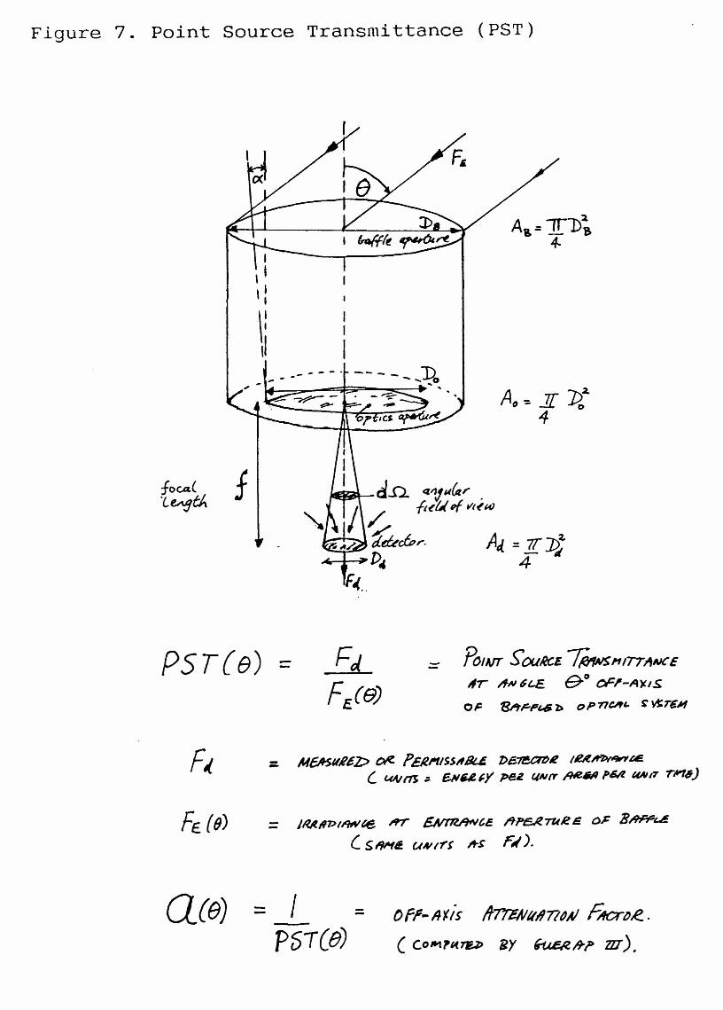
Figure 7. Point Source Transmittance (PST)
PST{e) - Po'AIT S'OUIK.£ ~/'1I77J1NCE
liT AN~t..E. &0 oFI'-AXIS
01= '81'tF-P'-6 l> OP77CAI.. ~ ~T£'"
:: MCASIIR£Z;:> CJIt PEl~/Ss,,8t.4 'P6.~~ IU~&4!L CM/rfS; E.IIu~y pee ClNtr,q£NI pOll UAlIT rll'16)
FE. (e) _ IMII1>II9Nfte. »r ~te /tn:s..teTU~s ()~ B~~(. SI1I¥4. UNlrr If-r F,().
a(e) -- I-PST(e)
OfP-A'Iis ~7'!&NII"71dAl FIICrl)R...
(COIt1~"7U> BY ~/rr za),
~-·--f----· -!
:~:~=r~:':l-- .. _. !---_. ;-
,. !
... ! .. i
I
.j :.::::~~::::...+ ~..L .....
.11(0
--!,
-I)/1)
.... ,
.-. : :1,-- .
go-
OFF-AXIS ANGLE (DEGREES)
Figure 8. XMM OM Baffle PST v off-axis angle
enOJOJ~en
:
OJ
.-o.0(Y')
IIv
\:.....~\
enOJ
~encCO
en·ri~COI
~~o~o
~
CJ).c~CO.~~.cen·ri
~I
'0OJ~OJ~~COoCJ)
~cCOc:·riEoQ
..
\
\ ,\ \ 1\
, x : \\ -d\ \~~\ \ \\:~ \
~\\. \;·0 \\: N") \
~ \
: '\- . \
: \\I '\
I \~
: ~.
•
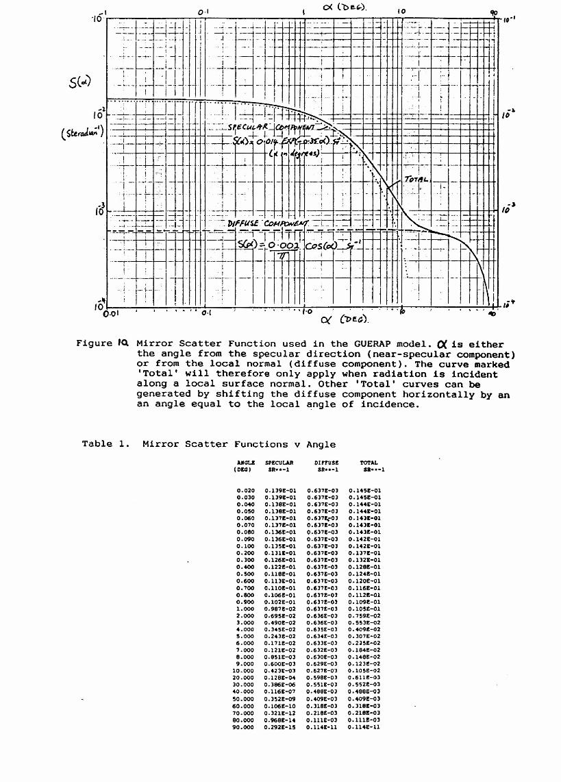
Figure 'Q. Mirror Scatter Function used in the GUERAP model. 0( is eitherthe angle from the specular direction (near-specular component)or from the local normal (diffuse component). The curve marked'Total' will therefore only apply when radiation is incidentalong a local surface normal. Other 'Total' curves can begenerated by shifting the diffuse component horizontally by anan angle equal to the local angle of incidence.
Table l. Mirror Scatter Functions v AngleAJlGt..I SPECULAR DIFFUS£ TO'I'AL
(OEG) 511··-1 511··-1 S.··-l
0.020 0.139£-01 0.6)7£-0) 0.145£-010.0)0 0.139£-01 0.637£-0) 0.145£-010.040 0.138£-01 0.6)7£-0) 0.144£-010.050 0.1)8£-01 0.637E-0) 0.1441:-010.060 0.137£-01 0.637EtO) 0.14)£-010.070 0.1l7!-01 0.6)7£-0) 0.14)£-010.080 O.1315E-Ol 0.6)7£-0) 0.143£-010.090 0.1361:-01 0.6)7£-0) 0.142E-Ol0.100 0.135£-01 0.15)7£-0) 0.142£-010.200 0.1311-01 0.637£-0) 0.1)71:-010.300 0.126£-01 0.637£-0) 0.1321-010.400 0.1221:-01 0.637£-0) 0.1281:-010.500 0.118£-01 0.6371-0) 0.1241:-010.600 0.113£-01 0.637£-0) 0.120E-Ol0.700 0.1101:-01 0.6371:-0) 0.116£-010.800 0.1061:-01 0.637£-0) 0.112£-010.900 0.102£-01 0.637£-0) 0.109£-011.000 0.987!-02 0.6)7£-0) 0.105E-012.000 0.695£-02 0.6)6E-0) 0.759E-023.000 0.4901:-02 0.6)6£-0) 0.553£-024.000 0.345£-02 0.6)5£-0) 0.409£-025.000 0.24)£-02 0.634£-03 0.)07£-026.000 0.1711:-02 0.633£-03 0.2)5£-027.000 0.121E-02 0.632£-0) 0.1841:-028.000 0.8SlE-0) 0.6)0£-0) 0.148£-029.000 0.600£-0) 0.629£-0) 0.12)£-02
10.000 0.423£-0) 0.627£-0) 0.105£-0220.000 0.1281:-04 0.598t-O) 0.6111:-0)30.000 0.386£-06 0.55l!-0) 0.552£-0340.000 0.116£-07 0.488£-0) 0.488£-0)50.000 O.)521:-09 0.409£-0) 0.409£-0)60.000 0.1061:-10 0.1l8t-0) 0.ll81:-0)70.000 0.)21E-12 0.218£-0) 0.218£-03eo.eee 0.9681:-14 0.111£-0) O.llU-OJ90.000 0.292£-15 0.114£-11 0.114£-11