Embed Size (px)
Citation preview
XP2-R – Power and Reverse Power Relay
Manual XP2-R (Revision C)

Woodward Manual XP2-RE
2 DOK-TD-XP2-R, Rev. C
Woodward reserves the right to update any portion of this publication at any time. Information provided by Woodward Governor Company is believed to be correct and reliable. However, no responsibility is assumed by
Woodward unless otherwise expressly undertaken.
© Woodward 1994-2018. All rights reserved.
Manual XP2-RE Woodward
DOK-TD-XP2-R, Rev. C 3
Contents
1. Applications and Features .......................................................................... 4
2. Design ........................................................................................................... 5
3. Function ........................................................................................................ 7 3.1 Measuring Principle ............................................................................................................. 7 3.2 Calculation of the Setting Value at Reverse Power ............................................................ 8
4. Operation and Settings .............................................................................. 10 4.1 Setting of DIP-Switches .................................................................................................... 11 4.2 Setting of the Tripping Values ........................................................................................... 12 4.3 Communication via Serial Interface Adapter XRS1 .......................................................... 13
5. Relay Case and Technical Data ................................................................ 14 5.1 Relay Case ........................................................................................................................ 14 5.2 Technical Data .................................................................................................................. 15
6. Order Form ................................................................................................. 18

Woodward Manual XP2-RE
4 DOK-TD-XP2-R, Rev. C
1. Applications and Features Relay XP2-R of the PROFESSIONAL LINE is a digital relay for reverse power detection of gen.-sets in parallel and active power supervision of power systems. For generators operating in parallel with a mains or another generator, it is imperative to supervise the power direction. If for example the prime mover fails the alternator operates as a motor and drives the prime mover (diesel or turbine). The XP2-R detects the reverse of the power direction and - in case of this error - switches off the alternator. This way, power losses and damages of the prime mover are avoided. When compared to conventional protection equipment all relays of the PROFESSIONAL LINE re-flect the superiority of digital protection technique with the following features:
High measuring accuracy by digital processing
Fault indication via LEDs
Extremely wide operating ranges of the supply volt-age by universal wide range power supply unit
Very fine graded wide setting ranges
Data exchange with process management system by serial interface adapter XRS1 which can be retrofitted
True power measurement by multiplication of current and voltage
Extremely short response time
Adjustment of rated data
Compact design by SMD-technology In addition to this relay XP2-R has the following special features:
Measurement phase-to-neutral or phase-to-phase voltage possible
Tripping times for supervision P and PR adjustable
Manual XP2-RE Woodward
DOK-TD-XP2-R, Rev. C 5
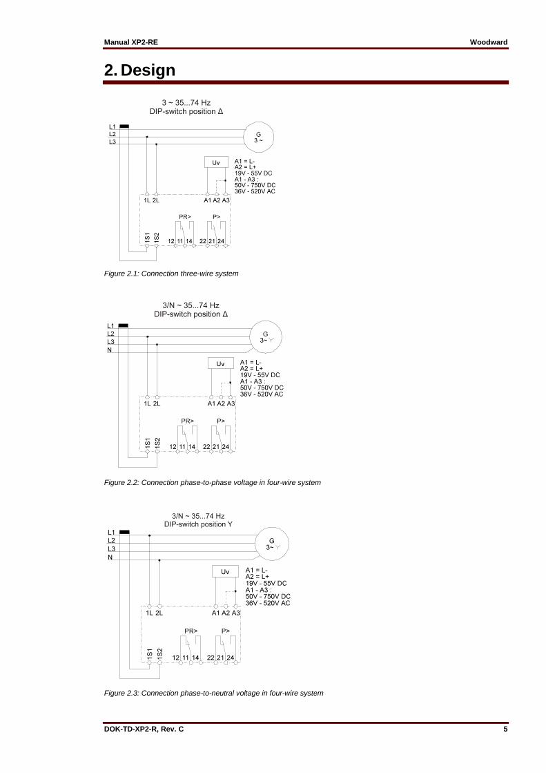
2. Design
Figure 2.1: Connection three-wire system
Figure 2.2: Connection phase-to-phase voltage in four-wire system
Figure 2.3: Connection phase-to-neutral voltage in four-wire system
Woodward Manual XP2-RE
6 DOK-TD-XP2-R, Rev. C
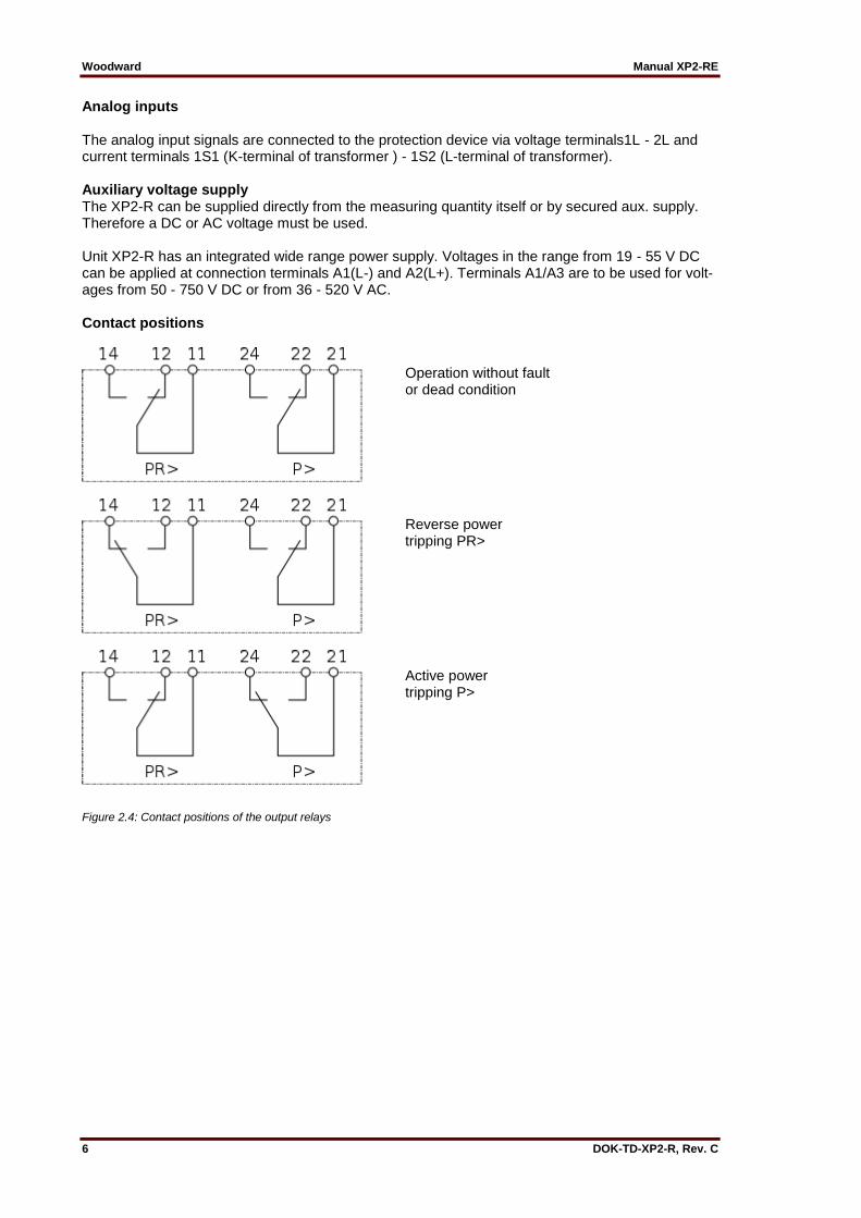
Analog inputs The analog input signals are connected to the protection device via voltage terminals1L - 2L and current terminals 1S1 (K-terminal of transformer ) - 1S2 (L-terminal of transformer). Auxiliary voltage supply The XP2-R can be supplied directly from the measuring quantity itself or by secured aux. supply. Therefore a DC or AC voltage must be used. Unit XP2-R has an integrated wide range power supply. Voltages in the range from 19 - 55 V DC can be applied at connection terminals A1(L-) and A2(L+). Terminals A1/A3 are to be used for volt-ages from 50 - 750 V DC or from 36 - 520 V AC. Contact positions
Operation without fault or dead condition
Reverse power tripping PR>
Active power tripping P>
Figure 2.4: Contact positions of the output relays
Manual XP2-RE Woodward
DOK-TD-XP2-R, Rev. C 7
3. Function The incoming current from the main current transformer of the protected object is converted to a voltage signal in proportion to the current via the input transformer and burden. The noise signals caused by inductive and capacitive coupling are suppressed by an analog R-C filter circuit. The analog voltage signals are fed to the A/D-converter of the microprocessor and transformed to digital signals through Sample- and Hold- circuits. The measuring value detection takes with a sampling frequency of 12 x fn, namely, a sampling rate of 1.66 ms for every measuring quantity at 50 Hz.
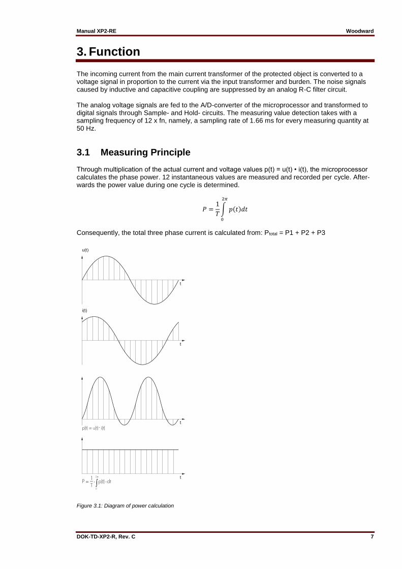
3.1 Measuring Principle Through multiplication of the actual current and voltage values p(t) = u(t) • i(t), the microprocessor calculates the phase power. 12 instantaneous values are measured and recorded per cycle. After-wards the power value during one cycle is determined.
𝑃 =1
𝑇∫ 𝑝(𝑡)𝑑𝑡
2𝜋
0
Consequently, the total three phase current is calculated from: Ptotal = P1 + P2 + P3
Figure 3.1: Diagram of power calculation
Woodward Manual XP2-RE
8 DOK-TD-XP2-R, Rev. C
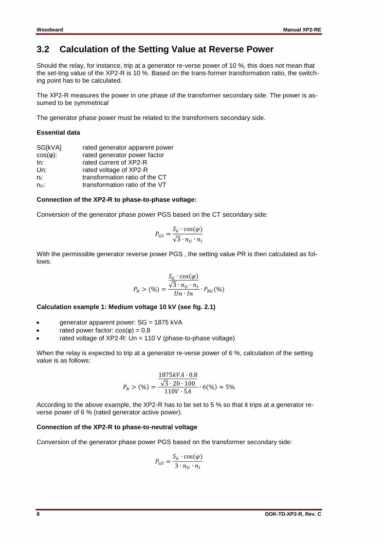
3.2 Calculation of the Setting Value at Reverse Power Should the relay, for instance, trip at a generator re-verse power of 10 %, this does not mean that the set-ting value of the XP2-R is 10 %. Based on the trans-former transformation ratio, the switch-ing point has to be calculated. The XP2-R measures the power in one phase of the transformer secondary side. The power is as-sumed to be symmetrical The generator phase power must be related to the transformers secondary side. Essential data SG[kVA] rated generator apparent power cos(φ): rated generator power factor In: rated current of XP2-R Un: rated voltage of XP2-R nI: transformation ratio of the CT nU: transformation ratio of the VT Connection of the XP2-R to phase-to-phase voltage: Conversion of the generator phase power PGS based on the CT secondary side:
𝑃𝐺𝑆 =𝑆𝐺 ∙ cos(𝜑)
√3 ∙ 𝑛𝑈 ∙ 𝑛𝐼
With the permissible generator reverse power PGS , the setting value PR is then calculated as fol-lows:
𝑃𝑅 > (%) =
𝑆𝐺 ∙ cos(𝜑)
√3 ∙ 𝑛𝑈 ∙ 𝑛𝐼𝑈𝑛 ∙ 𝐼𝑛
∙ 𝑃𝑅𝐺(%)
Calculation example 1: Medium voltage 10 kV (see fig. 2.1)
generator apparent power: SG = 1875 kVA
rated power factor: cos(φ) = 0,8
rated voltage of XP2-R: Un = 110 V (phase-to-phase voltage) When the relay is expected to trip at a generator re-verse power of 6 %, calculation of the setting value is as follows:
𝑃𝑅 > (%) =
1875𝑘𝑉𝐴 ∙ 0.8
√3 ∙ 20 ∙ 100110𝑉 ∙ 5𝐴
∙ 6(%) ≈ 5%
According to the above example, the XP2-R has to be set to 5 % so that it trips at a generator re-verse power of 6 % (rated generator active power). Connection of the XP2-R to phase-to-neutral voltage Conversion of the generator phase power PGS based on the transformer secondary side:
𝑃𝐺𝑆 =𝑆𝐺 ∙ cos(𝜑)
3 ∙ 𝑛𝑈 ∙ 𝑛𝐼

Manual XP2-RE Woodward
DOK-TD-XP2-R, Rev. C 9
With the permissible generator reverse power PGS, the setting value PR is then calculated as fol-lows:
𝑃𝐺𝑆 =𝑆𝐺 ∙ cos(𝜑)
3 ∙ 𝑛𝑈 ∙ 𝑛𝐼
Calculation example 2: Low voltage 400 V, connec-tion to phase voltage (see fig. 2.3)
generator apparent power: SG = 625 kVA
rated power factor: cos(φ) = 0,8
rated current of XP2-R: In = 5 A
rated voltage of XP2-R: Un = 230 V (phase-to-neutral voltage)
transformation ratio of the CT: nI = 1000 A / 5 A
no VT required When the relay is expected to trip at a generator re-verse power PRG of 5 %, calculation of the set-ting value PR> is as follows:
𝑃𝑅 > (%) =
625𝑘𝑉𝐴 ∙ 0,83 ∙ 1 ∙ 200230𝑉 ∙ 5𝐴
∙ 5(%) = 3.6% ≈ 4%
According to the above example, the XP2-R has to be set to 4 % so that it trips at a generator re-verse power of 5 % (rated generator active power).
Woodward Manual XP2-RE
10 DOK-TD-XP2-R, Rev. C
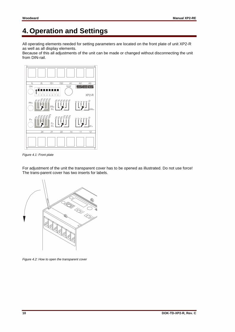
4. Operation and Settings All operating elements needed for setting parameters are located on the front plate of unit XP2-R as well as all display elements. Because of this all adjustments of the unit can be made or changed without disconnecting the unit from DIN-rail.
Figure 4.1: Front plate
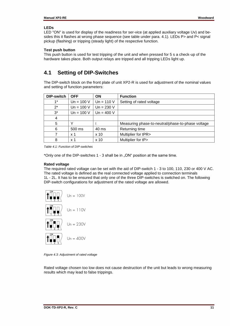
For adjustment of the unit the transparent cover has to be opened as illustrated. Do not use force! The trans-parent cover has two inserts for labels.
Figure 4.2: How to open the transparent cover
Manual XP2-RE Woodward
DOK-TD-XP2-R, Rev. C 11
LEDs LED "ON" is used for display of the readiness for ser-vice (at applied auxiliary voltage Uv) and be-sides this it flashes at wrong phase sequence (see table under para. 4.1). LEDs P> and P< signal pickup (flashing) or tripping (steady light) of the respective function. Test push button This push button is used for test tripping of the unit and when pressed for 5 s a check-up of the hardware takes place. Both output relays are tripped and all tripping LEDs light up.
4.1 Setting of DIP-Switches The DIP-switch block on the front plate of unit XP2-R is used for adjustment of the nominal values and setting of function parameters:
DIP-switch OFF ON Function
1* Un = 100 V Un = 110 V Setting of rated voltage
2* Un = 100 V Un = 230 V
3* Un = 100 V Un = 400 V
4
5 Y Measuring phase-to-neutral/phase-to-phase voltage
6 500 ms 40 ms Returning time
7 x 1 x 10 Multiplier for tPR>
8 x 1 x 10 Multiplier for tP>
Table 4.1: Function of DIP-switches
*Only one of the DIP-switches 1 - 3 shall be in „ON“ position at the same time. Rated voltage The required rated voltage can be set with the aid of DIP-switch 1 - 3 to 100, 110, 230 or 400 V AC. The rated voltage is defined as the real connected voltage applied to connection terminals 1L - 2L. It has to be ensured that only one of the three DIP-switches is switched on. The following DIP-switch configurations for adjustment of the rated voltage are allowed.
Figure 4.3: Adjustment of rated voltage
Rated voltage chosen too low does not cause destruction of the unit but leads to wrong measuring results which may lead to false trippings.
Woodward Manual XP2-RE
12 DOK-TD-XP2-R, Rev. C
Measuring of phase-to-neutral/phase-to-phase volt-age The phase-to-neutral (position „OFF“) or phase-to-phase voltage (position „ON“) can be adjusted by means of switching over the DIP-switch 5. Hysteresis of P> and PR> The hysteresis of both trip elements are fixed to 0.8 % Pn. Example: The chosen rated voltage is 400 V. The rated current is 5 A. 400 V x 5 A x 0.8 % = 16 W hysteresis Returning time If DIP-switch 6 is in ON position, the returning time of P> and PR> is 40 ms. At the same time the tripping values of tPR> and tP> are set to their minimum values irrespectively of their potentiometer setting. This setting is only used together with a XG2 relay as power direction controlled vector surge trip-ping for synchronous motors.
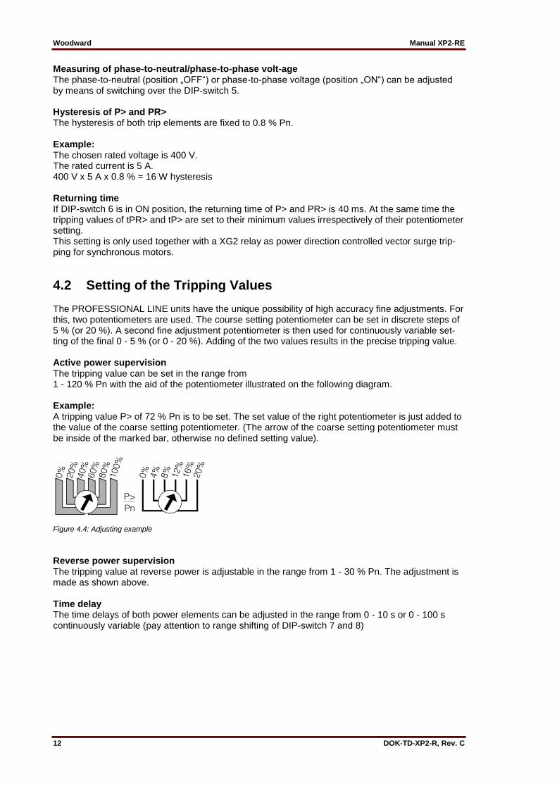
4.2 Setting of the Tripping Values The PROFESSIONAL LINE units have the unique possibility of high accuracy fine adjustments. For this, two potentiometers are used. The course setting potentiometer can be set in discrete steps of 5 % (or 20 %). A second fine adjustment potentiometer is then used for continuously variable set-ting of the final 0 - 5 % (or 0 - 20 %). Adding of the two values results in the precise tripping value. Active power supervision The tripping value can be set in the range from 1 - 120 % Pn with the aid of the potentiometer illustrated on the following diagram. Example: A tripping value P> of 72 % Pn is to be set. The set value of the right potentiometer is just added to the value of the coarse setting potentiometer. (The arrow of the coarse setting potentiometer must be inside of the marked bar, otherwise no defined setting value).
Figure 4.4: Adjusting example
Reverse power supervision The tripping value at reverse power is adjustable in the range from 1 - 30 % Pn. The adjustment is made as shown above. Time delay The time delays of both power elements can be adjusted in the range from 0 - 10 s or 0 - 100 s continuously variable (pay attention to range shifting of DIP-switch 7 and 8)
Manual XP2-RE Woodward
DOK-TD-XP2-R, Rev. C 13
4.3 Communication via Serial Interface Adapter XRS1
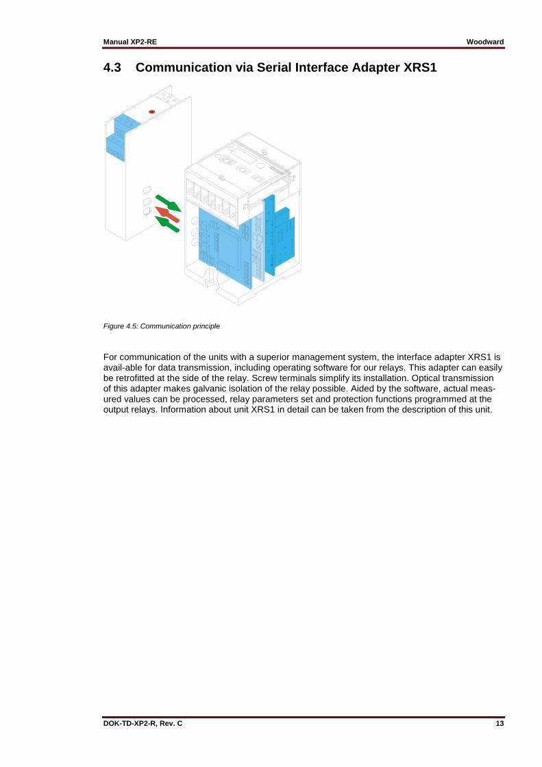
Figure 4.5: Communication principle
For communication of the units with a superior management system, the interface adapter XRS1 is avail-able for data transmission, including operating software for our relays. This adapter can easily be retrofitted at the side of the relay. Screw terminals simplify its installation. Optical transmission of this adapter makes galvanic isolation of the relay possible. Aided by the software, actual meas-ured values can be processed, relay parameters set and protection functions programmed at the output relays. Information about unit XRS1 in detail can be taken from the description of this unit.
Woodward Manual XP2-RE
14 DOK-TD-XP2-R, Rev. C
5. Relay Case and Technical Data
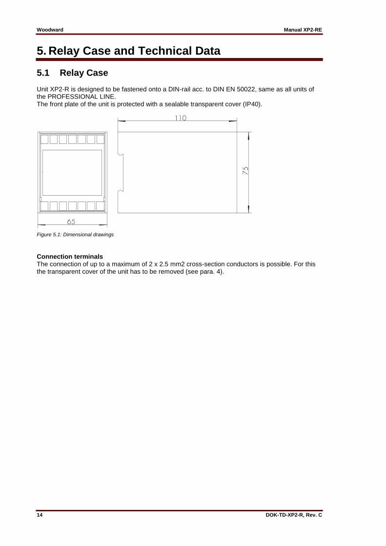
5.1 Relay Case Unit XP2-R is designed to be fastened onto a DIN-rail acc. to DIN EN 50022, same as all units of the PROFESSIONAL LINE. The front plate of the unit is protected with a sealable transparent cover (IP40).
Figure 5.1: Dimensional drawings
Connection terminals The connection of up to a maximum of 2 x 2.5 mm2 cross-section conductors is possible. For this the transparent cover of the unit has to be removed (see para. 4).
Manual XP2-RE Woodward
DOK-TD-XP2-R, Rev. C 15
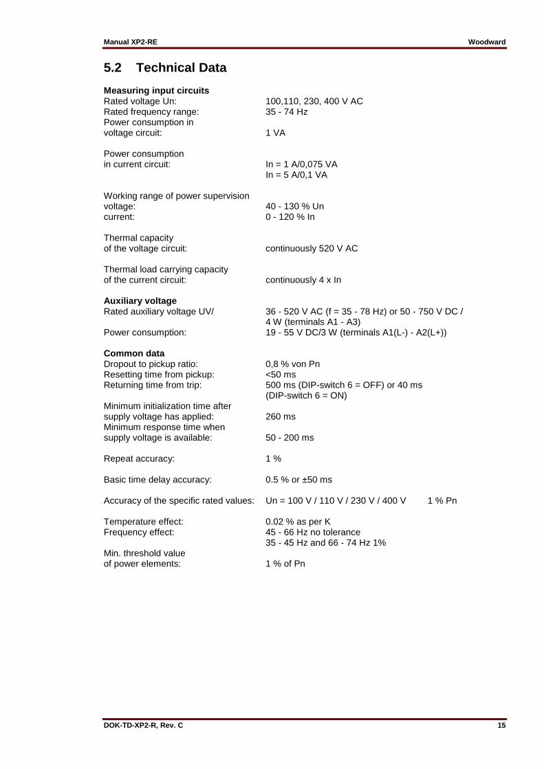
5.2 Technical Data Measuring input circuits Rated voltage Un: 100,110, 230, 400 V AC Rated frequency range: 35 - 74 Hz Power consumption in voltage circuit: 1 VA Power consumption in current circuit: In = 1 A/0,075 VA In = 5 A/0,1 VA Working range of power supervision voltage: 40 - 130 % Un current: 0 - 120 % In Thermal capacity of the voltage circuit: continuously 520 V AC Thermal load carrying capacity of the current circuit: continuously 4 x In Auxiliary voltage Rated auxiliary voltage UV/ 36 - 520 V AC (f = 35 - 78 Hz) or 50 - 750 V DC / 4 W (terminals A1 - A3) Power consumption: 19 - 55 V DC/3 W (terminals A1(L-) - A2(L+)) Common data Dropout to pickup ratio: 0,8 % von Pn Resetting time from pickup: <50 ms Returning time from trip: 500 ms (DIP-switch 6 = OFF) or 40 ms (DIP-switch 6 = ON) Minimum initialization time after supply voltage has applied: 260 ms Minimum response time when supply voltage is available: 50 - 200 ms Repeat accuracy: 1 % Basic time delay accuracy: 0.5 % or ±50 ms Accuracy of the specific rated values: Un = 100 V / 110 V / 230 V / 400 V 1 % Pn Temperature effect: 0.02 % as per K Frequency effect: 45 - 66 Hz no tolerance 35 - 45 Hz and 66 - 74 Hz 1% Min. threshold value of power elements: 1 % of Pn

Woodward Manual XP2-RE
16 DOK-TD-XP2-R, Rev. C
Output relay Number of relays: 2 Contacts: 1 changeover contact for each trip relay Maximum breaking capacity: ohmic 1250 VA / AC resp. 120 W / DC inductive 500VA / AC resp. 75 W / DC Max. rated voltage: 250 V AC 220 V DC ohmic load Imax. = 0,2 A inductive load Imax. = 0,1 A at L/R ≤ 50 ms 24 V DC inductive load Imax. = 5 A Minimum load: 1 W / 1 VA at Umin ≥ 10 V Maximum rated current: 5 A Making current (16ms): 20 A Contact life span: 105 hysteresis at max. breaking capacity Contact material: AgCdO
Manual XP2-RE Woodward
DOK-TD-XP2-R, Rev. C 17
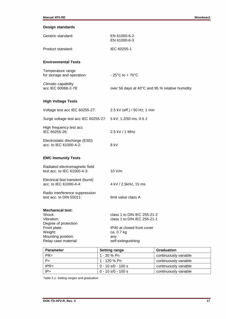
Design standards Generic standard: EN 61000-6-2
EN 61000-6-3 Product standard: IEC 60255-1 Environmental Tests Temperature range for storage and operation: - 25°C to + 70°C Climatic capability acc IEC 60068-2-78: over 56 days at 40°C and 95 % relative humidity High Voltage Tests Voltage test acc IEC 60255-27: 2.5 kV (eff.) / 50 Hz; 1 min Surge voltage test acc IEC 60255-27: 5 kV; 1.2/50 ms, 0.5 J High frequency test acc IEC 60255-26: 2.5 kV / 1 MHz Electrostatic discharge (ESD) acc. to IEC 61000-4-2: 8 kV EMC Immunity Tests Radiated electromagnetic field test acc. to IEC 61000-4-3: 10 V/m Electrical fast transient (burst) acc. to IEC 61000-4-4: 4 kV / 2,5kHz, 15 ms Radio interference suppression test acc. to DIN 55011: limit value class A Mechanical test: Shock: class 1 to DIN IEC 255-21-2 Vibration: class 1 to DIN IEC 255-21-1 Degree of protection Front plate: IP40 at closed front cover Weight: ca. 0.7 kg Mounting position: any Relay case material: self-extinguishing
Parameter Setting range Graduation
PR> 1 - 30 % Pn continuously variable
P> 1 - 120 % Pn continuously variable
tPR> 0 - 10 s/0 - 100 s continuously variable
tP> 0 - 10 s/0 - 100 s continuously variable
Table 5.1: Setting ranges and graduation

Woodward Manual XP2-RE
18 DOK-TD-XP2-R, Rev. C
6. Order Form
Power and reverse power relay XP2-R-
Rated current 1 A 5 A
1
5
Technical data subject to change without notice!
Manual XP2-RE Woodward
DOK-TD-XP2-R, Rev. C 19
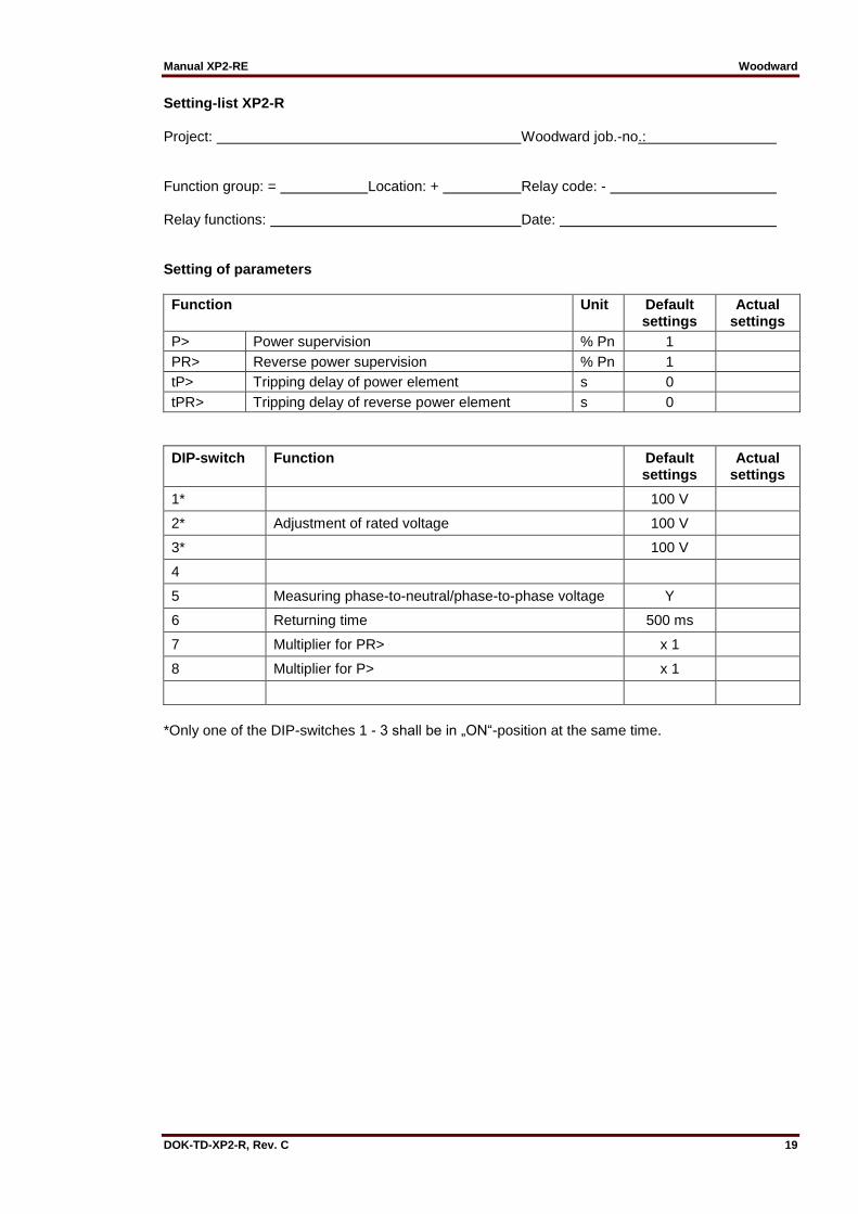
Setting-list XP2-R Project: Woodward job.-no.: Function group: = Location: + Relay code: - Relay functions: Date: Setting of parameters
Function Unit Default settings
Actual settings
P> Power supervision % Pn 1
PR> Reverse power supervision % Pn 1
tP> Tripping delay of power element s 0
tPR> Tripping delay of reverse power element s 0
DIP-switch Function Default settings
Actual settings
1* 100 V
2* Adjustment of rated voltage 100 V
3* 100 V
4
5 Measuring phase-to-neutral/phase-to-phase voltage Y
6 Returning time 500 ms
7 Multiplier for PR> x 1
8 Multiplier for P> x 1
*Only one of the DIP-switches 1 - 3 shall be in „ON“-position at the same time.

Woodward Kempen GmbH
Krefelder Weg 47 • D – 47906 Kempen (Germany)
Postfach 10 07 55 (P.O.Box) • D – 47884 Kempen (Germany)
Phone: +49 (0) 21 52 145 1
Internet
www.woodward.com
Sales
Phone: +49 (0) 21 52 145 331 • Telefax: +49 (0) 21 52 145 354
e-mail: [email protected]
Service
Phone: +49 (0) 21 52 145 600 • Telefax: +49 (0) 21 52 145 455
e-mail: [email protected]