Embed Size (px)
Citation preview
INSTRUCTION MANUAL FOR HELICOPTER
XP93039-CHANNEL COMPUTER RADIO SYSTEM

Table of ContentsGeneral Section
G2
Section 1: Using this manual ....................G-8
Section 2: Features .....................................G-8
R770 Receiver ....................................................G-8R770 (Basic Air and Sailplane Systems) .........................................G-8
R649 Receiver ....................................................G-8R649 (Advanced Air, Basic & Advanced Helicopter Systems) ..............G-8
Section 3: Component Specifications ....G-9
Servo Specifications ..........................................G-9
Transmitter Specifications ...............................G-9
Component Specifications ..............................G-9
Airborne Battery Pack Specifications .....G-10Receiver Specifications .......................... G-10
Airborne Battery Pack ........................... G-10
Charger Specifications ........................... G-10
Battery Charging ..................................... G-11
Transmitter/Receiver ......................................G-11
Transmitter Only .........................................G-11Charger .........................................................G-11
XP9303 Transmitter Features (Front) ................................... G-12
XP9303 Transmitter Features (Rear) .................................... G-13
Battery Cover ..............................................G-13
XP9303 Transmitter Features (Internal) ................................................ G-14
Control Stick Tension Adjustment .............. G-14
Advanced Digital Trims ..................................G-15
Control Stick Length ......................................G-15
Direct Servo Control (DSC) ........................G-16
Why you should use the DSC function: ...............................................G-16
Neckstrap Attachment ...................................G-17
Base Loaded Antenna .....................................G-17
Frequency Notes/Aircraft Only Frequencies ......................................G-17
Aircraft-Only Frequencies ........................G-17Installation Requirements ..............................G-18
Flash Memory ..................................................G-18
Connections: ....................................................G-18
Battery Alarm and Display ............................G-18

Table of ContentsHelicopter Section
G3
HELI - Getting Started – System Menu Basics ....................................H-1
Introduction ....................................................H-1
HELI Programming - Please Read ...................H-1
Access the System Menu ..................................H-2
Model SEL- Model Selection ............................H-2
Copy – Copying The Currently Selected Model To Another Model Memory ..........H-3
Copy (continued) ...............................................H-4
Data Reset-Reset the Model ...........................H-5
Type Select-to Activate the HELI Mode ........H-6
MDL Name-Enter a Name for the Model ...............................................H-6
MODULAT- Select a Modulation Type ...........................................H-7
TRANSFER – Transfer the Model to Another Transmitter or to DataSafe .......................H-8
Transfer a Model from the XP9303 – (Transfer function) – To Send ....................H-8
Transfer a Model to the XP9303 – (Transfer function) – To Receive ..............H-9
Trim Step ........................................................... H-10
HELI - System Menu - Advanced Functions ................................. H-11
Additional Flight Modes 3 and 4 .................. H-11
RUD TRIM: COM – (Flight Mode Trim Options) .................... H-12
Switch Assignments ........................................ H-12
Activate/Deactivate Switches ....................... H-13
Governor Program Activation ..................... H-13
SWASH TYP-Swashplate Type ...................... H-14
Accessing the Swashplate Type Function ... H-14
Function Mode ........................................ H-15
HELI – Function List ....................................... H-15
D/R & EXP – Dual Rate and Exponential ........................................ H-15
Auto Dual Rate ................................................ H-16
REV.SW - Servo Reversing ............................ H-16
Sub Trim ............................................................. H-17
TRVL ADJ. – Travel Adjust .............................. H-18
Swash Mix- CCPM Swashplate Mixing ....... H-19
Variations of CCPM Mixing ...................... H-19CCPM Servo Connection/Channel Numbers ....................................................... H-19
CCPM Exponential (EXP) ............................. H-20
Accessing the Swashplate Mixing Function ........................................................ H-20
THRO HOLD- Throttle Hold ...................... H-21
Accessing the Throttle Hold Function ... H-21Stick Auto- Auto Cut Setting ........................ H-22
Hold Delay ........................................................ H-22
THRO CURV – Throttle Curves ................. H-23
Accessing the Throttle Curve Function . H-24Throttle Trim Lever Function ....................... H-25
Hovering Throttle Lever ................................ H-25
Throttle Curve Exponential ......................... H-26
Accessing the Throttle Curve Exponential Function ................................. H-26
PIT. CURV- Pitch Curves Function .............. H-27
Accessing the Pitch Curve Function ....... H-27Hovering Pitch Lever ...................................... H-28
Example of Throttle Curve and Pitch Curve Settings ............................................. H-28
REVO.MIX- Revo Mix Function: Non Heading Lock Gyros Only ...................................... H-29
Accessing the Revolution Mixing Function ........................................... H-29Setting Up Revolution Mixing ................... H-29
GYRO SENS- Gyro Gain Function ............. H-30
Accessing the Gyro Gain Function ......... H-30Flight Modes/ Recommended Gyro Gain positions ................................... H-30Gyro Remote Gain Connections:
JR G500T and Other .............................. H-31
Remote Gain Gyros ....................................... H-31
Mix-Thro- Cyclic-to-Throttle Mixing ......... H-31
Rudder-to-Throttle Mixing ........................... H-32

Table of ContentsHelicopter Section (continued)
Information Section
G4
Aileron-to-Throttle and Elevator-to-Throttle Mixing ................... H-33
Setting the Desired Flight Modes for Cyclic-to-Throttle Mixing ......................... H-33Accessing the Cyclic-to-Throttle Function ........................................................ H-33
GOVERNOR- Governor Function ............. H-34
Accessing the Governor Function .......... H-34PROG MIX 1-6 – Programmable
Mixes 1 through 6 .................................... H-35
Swashplate Timing Mixes Example: Elevator-to-Aileron (Corrects vertical tracking) ...................................................... H-37
Swashplate Timing Mixes (continued) ........ H-38
Swashplate Timing: Aileron-to-Elevator (Corrects Rolling Maneuvers) ............... H-39
Standard Programmable Mixes – Example: Right Aileron with Positive Pitch ................................................ H-41
Servo Precautions ................................................I-1
General notes .......................................................I-1
Federal Aviation Administration ........................I-2
1. Purpose ..........................................................I-22. Background ....................................................I-23. Operating Standards ...................................I-2Daily Flight Checks ..........................................I-2
Frequency Chart ..................................................I-3
Warranty Information .........................................I-4
Warranty Coverage .........................................I-4Repair Service Directions ..............................I-4Warranty Repairs .............................................I-4Normal Non-Warranty Repairs ...................I-4
Setup Sheet (Aircraft) .........................................I-5
Setup Sheet (Sailplane) ........................................I-6
Setup Sheet (Helicopter) ....................................I-7
Multi-point Mixes – Example: FMOD to Gear Mixing (Retract and other Functions) ............... H-43
Fail Safe- PCM Fail Safe Function ................. H-46
Trainer – Programmable Trainer System ... H-47
XP9303 Used as Master (Instructor) – (Trainer System) .......................................... H-47XP9303 Used as Slave (Student) – (Trainer System) .......................................... H-48
Timer – Timer System ................................... H-49
MONITOR- Servo Monitor .......................... H-50
Sub Trim Usage and Mechanical Advantage ............................ H-51
Dual Rates and Exponential Curves ....... H-52

Section 1: Using this manual
R649 Receiver
R770 Receiver
Section 2: Features
G5
This Manual is divided into three specific sections: Airplane, Sailplane and Helicopter. When writing this manual we employed three distinctly different individuals to write the sections that most pertained to their expertise. The Aircraft section was written by a top notch aerobatic pilot, the Sailplane section by a very experienced sailplane competitor and the Helicopter Section by a member of the 2003 USA F3C team. Each section may read and feel slightly different because of the different personal styles that each of these authors has used.
In this manual you will find the specifications for the radio and its various components and accessories. In addition, guidelines for the installation have been included. Instructions for setting all the functions and programs are presented in the three sections of the manual: Airplane, Helicopter and Sailplane. These features are discussed in the same order that they would normally be needed to set up a typical aircraft, helicopter and 6 servo winged sailplane respectively. An explanation of the use and purpose of each feature is provided, followed by a labeled illustration of its respective LCD display.
A blank data sheet has been included at the end of each section. Once all data has been input for a particular model, it is highly recommended that you record it on a copy of the sheet provided.
The computer-designed, ergonomically-styled transmitter case ensures a comfortable fit in your hands. You will also be introduced to our exclusive “Rolling Selector” on the face of the transmitter for fast and effortless movement through any programming sequence. The ultra-precision control sticks offer adjustable spring tensions and length. The throttle stick offers a ratchet in Airplane/
Sailplane configuration. 30-model memory storage allows programming of all parameters of thirty separate airplanes, helicopters or sailplanes; you can program more than one setup for a single aircraft, allowing you to instantly change the flight characteristics.
R770 (Basic Air and Sailplane Systems)
The R770 is a high-performance PCM single-conversion receiver with 10KHz super narrow band ABC&W circuitry.
A narrow band ceramic filter for high-signal selectivity assists in rejecting cross modulations from other common radio frequencies, such as RC transmitters or local paging systems.
This receiver features Direct Servo Control (DSC) for control of servos without radio frequency output.
The receiver has low current consumption.
The R770’s Slimline design allows it to fit into most model applications.
R649 (Advanced Air, Basic & Advanced Helicopter Systems)
The R649 is a high-performance PCM single-conversion receiver with 10KHz super narrow band ABC&W circuitry.
A narrow band ceramic filter for high-signal selectivity assists in rejecting cross modulations from other common radio frequencies, such as RC transmitters or local paging systems.
This receiver features Direct Servo Control (DSC) for control of servos without radio frequency output.
The receiver has low current consumption.
The R649’s credit card size design allows it to fit into most model applications.

Servo Specifications
Transmitter Specifications
Component Specifications
Section 3: Component Specifications
G6
Type DS811 DS8311 DS368
Torque 54 Oz/In 125 Oz/In 53 Oz/In
Speed .18 .18 .21
Weight 1.44 Oz 1.87 Oz 0.80 Oz
Size (in) (L x W x H) 1.49x0.75x1.52 1.54x0.75x1.36 1.12x0.50x1.17
Ballbearing Yes Yes No
Motor Cored Coreless Cored
Type Airplane Helicopter Sailplane
Model Number NET-N339FS NTE-N339HS NET-N339GS
Encoder 9-channel computer system
RF Module Plug-in Module Plug-in Module Plug-in Module
Modulation PPM/SPCM PPM/SPCM PPM/SPCM
Output Power Approximately 750mw
Current Drain 200ma 200ma 200ma
Power Source 1.2Vx8 Ni-Cd (9.6V) 600Mah
Output Pulse 1000-2000 (1500 neutral)
Type Airplane Helicopter Sailplane
System Name X-9303A(basic/ X-9303H(basic)/ X-9303S
(advanced) (advanced)
Transmitter Body NET-N339FS NTE-N339HS NET-N339GS
Receiver R770(basic)/R649(advanced R649 PCM R770 PCM
Charger NEC-222 NEC-222 NEC-222
Airborne Battery 1100mah 1100mah 600mah
Servos None(basic)/ 4-DS811(basic) 3-DS368
4-DS811(advanced) 4-DS8311(adv)
Accessories Deluxe Switch Deluxe Switch Deluxe Switch
12” Ail Extension 12” Ail Extension 12” Ail Extension
Charge Jack Charge Jack Charge Jack
Servo Accessories Servo Accessories Servo Accessories
Hex Wrench Hex Wrench Hex Wrench
Instruction Manual Instruction Manual Instruction Manual

Receiver Specifications
Charger Specifications
G7
Type 7 Channel SPCM 9 Channel SPCM
Model Number R770 R649
Type 7-ch/SPCM-ABC&W/Micro 9-ch/SPCM-ABC&W
Frequency 72/75/50mhz 72/75/50mhz
Sensitivity(Microseconds) 5 uS Minimum 5 uS Minimum
Selectivity 8KHz/5 dB 8KHz/5 dB
Weight (oz) .75 oz 1.5oz
Receiver Antenna 39” for all aircraft frequencies 39” for all aircraft frequencies
Type Airplane Helicopter Sailplane
Model Number NEC-222 NEC-222 NEC-222
Input Voltage AC 100-120V AC 100-120V AC 100-120V
Output Current 65mAh Tx/150mAh Rx
Charging Time 15 Hours 15 Hours 15 Hours
Airborne Battery PackAirborne Battery Pack Specifications
Type Airplane Helicopter Sailplane
Model Number B1100 B1100 Extra 600
Voltage 4.8V 4.8V 4.8V
Size (in) (L x W x H) 2.24 x 0.63 x 1.70 2.24 x 0.63 x 1.70 2.64 x 1.18 x .70
Weight (oz) 4.9 4.9 2.7

Transmitter/Receiver
Battery Charging
G8
Note: It is imperative that you fully charge both the transmitter and the receiver battery packs prior to each trip to the field. To do so, leave the charger and batteries hooked up overnight (16 hours). The first charge should be approximately 20–24 hours in order to fully charge both battery packs to peak capacity.
The charger supplied with this system is designed to recharge your batteries at a rate of 65mAh for the transmitter and 150mAh for the receiver battery pack.
Transmitter Only
The center pin on all JR® Remote Control Systems is negative. Therefore, the center pin on all JR chargers is negative, not positive. This is different from many other manufacturers’ chargers and radio systems. Beware of improper connections based on “color-coded” wire leads, as they do not apply in this instance. You must make sure that the center pin of your JR transmitter is always connected to the negative voltage for correct polarity hookup.
Important: Please note that the charging polarity of the transmitter and receiver are different.
Charger
The pilot lamps should always be on during the charging operation. If not, check to make sure that both the transmitter and receiver are switched off.
Do not use the charger for equipment other than JR. The charging plug polarity may not be the same. Equipment damage can result.
Do not use other manufacturers’ after-market accessories that plug into the transmitter’s charging jack if you are unsure of compatibility issues with your radio. Seek expert advice to avoid possible damage.
During the charging operation, the charger’s temperature is slightly elevated. This is normal.
CENTERPIN IS
NEGATIVE
OUTSIDE IS POSITIVE
CHARGER PIGTAIL FOR RECEIVER
CHARGER PIGTAIL FOR TRANSMITTER
BLACK TO POSITIVE
RED TO NEGATIVE
RIGHT SIDE OF TRANSMITTER
RED–POSITIVE / BROWN–NEGATIVE / ORANGE–SIGNAL

XP9303 Transmitter Features (Front)
G9
Trainer Button
Gear Switch
Flap Switch
Elevator Dual Rate
Flap Trim
Lever
AUX4/ Rudder Dual
RateAux Trim
Aileron Dual Rate
AUX2
Mix Switch
Lever
Elevator/ Aileron Stick
Throttle/ Rudder Stick
Rudder Trim
Throttle Trim
List Button
Enter Button
Clear Button
Power Switch
Aileron Trim
Elevator Trim
Rolling Selector
LCD Display

XP9303 Transmitter Features (Rear)
G10
Battery CoverCAUTION: THE BATTERY CONNECTION IS KEYED SO THAT IT CAN ONLY
BE PLUGGED IN ONE DIRECTION. DO NOT FORCE

XP9303 Transmitter Features (Internal)
Control Stick Tension Adjustment
G11
Remove the six transmitter back screws as shown on the previous page. Remove the transmitter back, being careful not to cause damage to any components.
Adjust each screw for desired tension (counter-clockwise to loosen stick feel; clockwise to tighten stick feel). When adjusting the throttle ratchet tension, make sure that the adjusting screw does not touch the PC board after adjustment is complete.
ELEVATOR TENSION SCREW
AILERON TENSION SCREW
THROTTLE TENSION SCREW
RUDDER TENSION SCREW

Control Stick Length
G12
Advanced Digital Trims
The XP9303’s digital trims feature the Direct Access display function. While at the Normal display screen, if a trim lever is moved, the screen will automatically change to display the graphic position for the trim being adjusted. The XP9303’s Aileron, Elevator, Throttle and Rudder trim levers feature an audible center trim beep. This is helpful in determining the trim levers center position during flight.
By using the Trim Step Function located in the System Mode, the movement of the ADT trims can be fine tuned as needed to match your specific application
Please also note that unlike conventional mechanical trim levers, when the XP9303 transmitter is in the off position, no changes can be made to the trim values during transportation.
To adjust the stick length, use the 2mm Allen wrench (supplied with your XP9303 transmitter) to unlock the set screw. Turn the wrench counterclockwise to loosen the screw. Then, turn the stick clockwise to shorten or counterclockwise to lengthen. After the control stick length has been adjusted to suit your flying style, tighten the 2mm set screw. If you desire longer sticks, JR® offers a stick (JRPA047) that is approximately one inch longer than standard. This stick, crafted from bar stock aluminum, is available at your local JR dealer.
LOOSEN
TIGHTEN
SET SCREW

Direct Servo Control (DSC)
G13
For proper DSC hook-up and operation:
1. Leave the transmitter power switch in the Off position. The transmitter will not transmit any radio frequency (RF) in this position.
2. Plug the DSC cord (purchased separately, JRPA132) into the DSC port in the rear of the transmitter.
3. The encoder section of the transmitter will now be operational and the LCD display will be lit.
4. Plug the other end of the DSC Cord into the receiver charge receptacle. (You must use a 3-wire switch harness, such as the Deluxe Switch Harness – JRPA001, or a JR Chargeswitch – JRPA004, for the DSC function to work.) Turn the switch harness to the On position.
Note: When you install the charging jack, be sure to hook the charging jack receptacle securely into the switch harness charge cord.
Why you should use the DSC function:
1. The DSC enables you to check the control surfaces of your aircraft without drawing the fully operational 200mAh from your transmitter battery pack. Instead, you will only draw approximately 70mAh when using the DSC function.
2. The DSC function allows you to make final adjustments to your airplane without transmitting any radio signals. Therefore, if another pilot is flying on your frequency, you can still adjust your aircraft and not interfere with the other pilot’s aircraft. This is also a tremendous tool to use in the original setup of your aircraft while still in the workshop. Because of the lower current draw on your transmitter, your working time at the bench will be extended between charges.
Note: This function is for bench-checking your aircraft only.
A�B�
C�
A—Charge Cord/DSC ReceptacleB—Switch Harness LeadC—Charger/DSC Cord
JRPA004 Charge Switch

Neckstrap Attachment
Frequency Notes/Aircraft Only Frequencies
Base Loaded Antenna
G14
The XP9303 transmitter employs a plug-in module for the transmitter. Per FCC regulation, the transmitter crystal in the module should only be changed by a certified technician. Changing of the transmitter crystal by a non-authorized technician could result in a violation of FCC rules.
The XP9303 can transmit in either Pulse Code Modulation (SPCM) or Pulse Position Modulation (PPM, commonly referred to as FM).
Be certain to observe the following guidelines:
An eyelet is provided on the face of the XP9303 transmitter that allows you to connect a Neck Strap (JRPA023). This hook has been positioned so that your transmitter has the best possible balance when you use the neck strap.
An optional base-loaded antenna is available for use with the XP9303 transmitter. It is considerably shorter than the standard antenna. However, the base loaded antenna cannot be collapsed for storage inside the transmitter. You must also use an adapter (JRPA156) to attach the antenna to your XP9303. The Base Loaded Antenna (JRPA155) is made of a flexible coil and is covered with a soft plastic material. Your range will not be affected when using the base loaded antenna.
Do not operate your transmitter when another transmitter is using the same frequency, regardless of whether the second transmitter is PCM, PPM (FM) or AM. You can never operate two transmitters on the same frequency simultaneously without causing interference.
Aircraft-Only Frequencies
JR® Transmitters and receivers are available in 72MHz frequencies in the United States for use with model aircraft. Employing 72MHz frequencies does not require a special operator’s license from the Federal Communications Commission (FCC).
• A chart for all available frequencies is located on page I-3 of this manual.

Installation Requirements
Flash Memory
Connections:
Battery Alarm and Display
G15
It is extremely important that your radio system be correctly installed in your model. Here are a few suggestions for installing your JR® equipment:
1. Wrap the receiver in protective foam rubber that is no less than 3/8 inch thick. Secure the foam to the receiver with #64 rubber bands. This protects the receiver in the event of a crash or a very hard landing.
2. The servos should be mounted using rubber grommets and brass eyelets to isolate them from vibration. Do not over-tighten the mounting screws; this will negate the vibration absorption effect of the rubber grommets. The following diagram will assist you in properly mounting your servo.The brass eyelets are pushed from the bottom up in the rubber grommets. When the servo screw is tightened securely, it provides the proper security as well as the proper vibration isolation for your servo.
3. The servos must be able to move freely over their entire range of travel. Make sure that the control linkages do not bind or impede the movement of any of the servos.
4. Mount all switches away from the engine exhaust and away from any high vibration areas. Make sure the switch operates freely and is able to operate over its full travel.
5. Mount the receiver antenna firmly to the airplane to ensure that it will not become entangled in the propeller or control surfaces.
All preprogrammed data is protected by a flash memory that guards against main transmitter battery failure.
Note Separate drawings for Acro, Sailplane and Helicopter with typical plug order, switch location, and battery pack connections.
When the transmitter voltage drops below 9.0 volts DC, the display flashes “BATT LOW” and an alarm sounds.
If you are flying when this occurs, land immediately.
Servo Mounting Tab
Screw
Rubber Grommet
Brass Eyelet

XP9303 Helicopter – Heli Mode
Heli PROGRAMMING - PLEASE READ
HELI - GETTING STARTED – SYSTEM MENU BASICS
H1
INTRODUCTION
The Heli mode of the XP9303 system is intended for use in model helicopters in all types of Swashplate mixing. It contains a host of advanced features that are easy to set up and use. The features have been designed to assist the pilot in realizing the full potential of the helicopter. These features include but are not limited to:
• Switch Assignments for Specific Channels/Functions
• Flight Modes (up to 6)
• Dual Rates/Exponential (up to 3 settings each for Aileron, Elevator and Rudder)
• Swashplate Type (Normal, 120, 140, and 90 CCPM)
• Adjustable Trim Rates (10 – 100 Trim Steps)
• Built-In Cyclic to Throttle Mixing for Aileron, Elevator, and Rudder
• Special Governor Pre-Program Mix
• Throttle Curves (up to 5) with up to 7 Points
• Pitch Curves (up to 6) with up to 7 Points
• Gyro System (In Flight Gain Selection of up to 3 Gains)
• 6 Programmable Mixes (Includes 2 Multi-Point and 4 Standard Mixes)
• Fail Safe (Hold or Predetermined Positions)
•Trainer System (Selectable Channels for Student Control)
• Timers (Stopwatch, Count-Down, Integrated)
• Servo Monitor (Automatically Renames Channels According to Assignments)
In addition to the numerous features listed above, the XP9303 provides the ability to combine, activate, and deactivate multiple features such as Dual Rates, Gyro Gain, and Governor settings, using the Flight Mode switch. This capability dramatically reduces the pilot’s workload, allowing the pilot to focus more on the task of flying.
Those who are comfortable with programming are still encouraged to continue reading this part of the manual in order to acquire an understanding of the basic XP9303 programming philosophy, functions, and techniques.
The XP9303’s menus and functions are presented here in the order that they should be addressed when setting up a new helicopter. This manual begins with entering the System Menu, selecting a model and activating the HELI Mode, and progresses through the remainder of the System Menu options and then through the individual
functions. The descriptions here are general in nature and serve not only to identify the functions that are available, but why the functions are included in the HELI Mode and when a particular function might be used.
Those who have some experience with computer radios will probably be able to program their helicopter as they read through this section, owing to the fact that the individual functions are generally simple in nature and the XP9303 is a very intuitive system.
Getting started always begins with accessing the SYSTEM Menu. This is where models are selected, the mode is identified, modulation type is indicated, and where other high-level information is collected about the model. It is also used to activate some of the more advanced programming features such as Swashplate Types and Governor Program activation.

ACCESS THE SYSTEM MENU
Model SEL- Model Selection
H2
The first thing to do when setting up a new model is to select a model number to be used. It is best to select an unused model number, however, a number that already contains data for another model may be used so long as
data for that model is no longer required. If the model type is changed before deciding the model number to be used, any programming in this particular model number will be lost.
1. Bring up the SYSTEM Menu by holding down the ENT button while turning the TX on.
1. In the SYSTEM Menu, highlight and select Model SEL using the Selector.
2. Use the Selector to highlight and select the desired model number to be used.
3. Return to the SYSTEM Menu by pressing the LIST button.
INFO-DISP
Model SEL
MDL Name
Type SEL
MDL Reset
MODULAT.
TRANSFER
TRIM STEP
Devic. SEL
SWASH TYP
[SYSTEM M.]
Select�� � 1 GLID� SPCM
� � � 2 ACRO� PPM
MODEL 3� MODEL 3 HELI� SPCM
� � � 4 ACRO� SPCM
� � � 5 GLID� SPCM
[Model SEL]

Copy – Copying The Currently Selected Model To Another Model Memory
H3
The Copy function is part of the Model SEL function covered earlier and allows the contents of the current model memory to be copied into another model memory in the same transmitter. It is not used to transfer the model to another transmitter or to a Data Safe unit – the DATA TRANSFER function provides for these activities.
The Copy function is very valuable because it can provide some insurance against losing programs (helicopter setups) that may have been very time-consuming to create. It is strongly recommended that the Copy function be used to make a backup copy of the model memory for safe keeping after programming for a model has been completed, tested and refined.
Making a backup copy of the model memory protects against losing the original program and also allows one to experiment with the original program, knowing that the original settings can be restored by copying the backup copy back to the original model memory.
1. The model to be copied must be currently selected – see Model SEL description at the beginning of the HELI section.
2. Highlight and select Model SEL in the SYSTEM Menu. Highlight and select Select to obtain the Copy display.
The display shows the currently selected model on top with a down arrow pointing to the lower model memory that the current model will be copied into. The data that is presently in the lower model memory will be entirely replaced by the data in the currently selected model, so be sure that the lower model is either empty or contains data that is no longer required.
Copy
[Model SEL]
MODEL 3 HELI SPCM
MODEL 4 HELI SPCMCOPY
Copy
[Model SEL]
MODEL 3 HELI SPCM
MODEL 4 HELI SPCMCOPY

Copy (continued)
H4
3. Verify that the top model is the model that is to be backed-up and the lower model is empty or contains a model that is no longer required. When satisfied that all is well, press the CLR button on the left side of the display next to COPY. The entire contents of the currently selected model are copied to the lower model on the display and there is now a complete backup of the current model. The upper and lower model memory names are now the same because they are now identical in every regard.
The backup copy can now be used to restore the original at any time by performing the Copy function and reversing the order of models where the backup is copied into the original.
To change the lower model memory that is to receive the copy of the current model, highlight and select the lower model name and number. Then scroll to an unused model memory or a memory that contains data that is no longer required, and select it.
Copy
[Model SEL]
MODEL 3 HELI SPCM
MODEL 3 HELI SPCMMODEL 2 ACRO PPM
MODEL 4 HELI PPM
MODEL 5 ACRO PPM

Data Reset-RESET THE MODEL
H5
When setting up a new model it is important to reset all parameters to their default or factory settings before proceeding with any other programming. This is to ensure that there are no program mixes, trims or other surprises left over from a previous model or programming session.
If you are setting up a model for the first time, you can skip this step and move to the TYPE SELECT function.
1. In the SYSTEM Menu, highlight and select MDL Reset using the Selector.
2. Press the CLR button that is next to RES on the display.
3. Press the lowermost button next to YES on the display to reset all data for this model.
4. Return to the SYSTEM Menu by pressing the LIST button.
[MDL R�eset]
LST
NO
YES
MODEL 3� HELI�SPCM
Are you sure? Y/N

Type Select-TO ACTIVATE THE HELI MODE
MDL Name-ENTER A NAME FOR THE MODEL
H6
1. In the SYSTEM Menu, highlight and select Type SEL using the Selector.
2. Highlight and select HELI using the Selector.
Each model should be given a name to make it easy to identify in the model number list and to identify the current model on the main display screen. The model name appears in the upper right hand corner of the main screen when the TX is switched on.
3. Return to the SYSTEM Menu by pressing the LIST button.
1. In the SYSTEM Menu, highlight and select MDL Name using the Selector.
2. Highlight and select the desired characters to form the model name.
After having selected and reset the desired model number to be programmed, it is time to tell the TX that the Heli Mode is to be used for this helicopter.
3. Return to the SYSTEM Menu by pressing the LIST button.
[Type SEL]�� MODEL 3 HELI
GLID�� ACRO� � HELI
� MODEL 3� HELI <VIGOR 3D> SPCM
[MDL Name]

MODULAT- SELECT A MODULATION TYPE
H7
The XP9303 system supports two types of modulation – SPCM and PPM (FM). The correct modulation type must be selected to match the receiver in the helicopter or the system will not function.
Note: The XP9303 system is not designed for use with “Z” PCM Receivers.
1. In the SYSTEM Menu, highlight and select MODULAT. using the Selector.
2. Highlight and select either SPCM or PPM to match the receiver in the helicopter.
3. Return to the SYSTEM Menu by pressing the LIST button.
[MODULAT.]
MODEL 3� HELI
Modulation
SPCM PPM

TRANSFER A MODEL FROM THE XP9303 – (Transfer function) – To Send
TRANSFER – TRANSFER THE MODEL TO ANOTHER TRANSMITTER OR TO DATASAFE
H8
1. Hold the ENT button while plugging the DSC cord into the back of the transmitter to obtain the SYSTEM Menu.
Plug the other end of the DSC cord into another XP9303 transmitter while holding the ENT button down and prepare that transmitter for Receive as described below. Or, plug the other end of the DSC cord into a DataSafe unit and prepare the DataSafe for Receive.
2. Highlight and select TRANSFER in the SYSTEM Menu to obtain the Transfer display.
3. The model to be transferred must be the currently selected model. If the model to be transferred is not currently selected, see Model SEL in the SYSTEM Menu to select the model to be transferred to another XP9303 or DataSafe unit.
The TRANSFER function can be found in the SYSTEM Menu and is used to copy the contents of a model memory to another XP9303 transmitter or to a DataSafe device on a Personal Computer (PC). It is also used to receive data for a model, either from another PCM XP9303 transmitter or from a DataSafe unit.
4. When the receiving device is ready, press the CLR button next to START on the left side of the display. The data for the currently selected model is transferred to the receiving device.
[TRANSFER]
TRANSMIT
MODEL 3 HELI SPCM
Connect DSC & POWER off

TRANSFER A MODEL TO THE XP9303 – (Transfer function) – To Receive
H9
1. Hold the ENT button while plugging the DSC cord into the back of the transmitter to obtain the SYSTEM Menu. Plug the other end of the DSC cord into another XP9303 transmitter while holding the ENT button and prepare that transmitter for Transmit as described above. Or, plug the other end of the DSC cord into a DataSafe unit and prepare the DataSafe for Transmit.
2. Highlight and select TRANSFER in the SYSTEM Menu to obtain the Transfer display.
3. If RECEIVE is already displayed, continue with the next step. If TRANSMIT is displayed, highlight and select TRANSMIT, changing it to RECEIVE.
4. Select the model memory that is to receive the data by highlighting and selecting the model name/memory number and then scrolling to and selecting the model memory that is to receive the data. Be careful to select an unused model memory or a memory that contains data for a model that is no longer needed because the data in this model memory is going to be replaced by what is transmitted and will be permanently lost.
5. Press the CLR button next to START on the left side of the display. Stand-by appears at the bottom of the display indicating that the XP9303 is ready to receive data. Press start on the transmitting XP9303 or DataSafe unit to begin the data transfer to the XP9303.
[TRANSFER]
RECEIVE
MODEL 4 HELI SPCM
MODEL 3
Connect DSC & POWER off

TRIM STEP
H10
The Trim Step function provides for adjusting the sensitivity of the XP9303 trim levers and switches. It is useful during and after initial trimming of the helicopter in order to trim the helicopter quickly at first, and then to make very precise adjustments to helicopter trim. The digital trims may have a setting of 0–10 with 10 being the coarsest adjustment. When the value is set to 10, there are only 10 trim increments from center to each end. When set to 5, there are 20 trim increments from center to each end. When set to 4, there are 25 increments. When set to 3, there are 34 increments, and when set to 1, there are 100 trim increments! When set to 0 the trim levers cease to function and can no longer be used to change the trim of the helicopter.
When adjusting the digital trims (AILE, ELEV, RUDD, HOVT, HOVP), the total trim travel does not change – only the number of increments (beeps) changes, which makes for finer or coarser trim movements. When adjusting the analog throttle trim, however, the total trim travel is actually reduced when set to less than 100%.
Use a fairly coarse setting, such as the factory default 4, when test flying the helicopter in order to be able to trim it quickly, and then use a finer setting, such as 3–1, for final precision trimming. The exception to this would be for Rudder. Since most Gyros amplify the servo’s travel and sensitivity, a trim value of 1 or 2 for the Rudder trim usually achieves the best results.
1. Highlight and select TRIM STEP in the Devic. SEL display of the SYSTEM menu to acquire the TRIM STEP display.
2. Highlight and select the trim that is to be changed and use the Selector to set a value of 1–10 (1 = finest, 10 = coarsest).
3. Repeat for other trims as desired.
[TRIM STEP]
THRO 100%
AILE� 4
ELEV� 4
RUDD� 4
HOVT� 4
HOVP� 4

HELI - SYSTEM MENU - ADVANCED FUNCTIONS
ADDITIONAL FLIGHT MODES 3 and 4
H11
There are two functions in the SYSTEM Menu that control some of the more advanced features of the XP9303 system. They are the Devic. SEL and Swash Type functions.
The Devic. SEL function is used to activate and deactivate 2 additional Flight Modes; change switch assignments from the system defaults; activate and deactivate switches/channels and to activate/deactivate the Hover Throttle, and Hover Pitch levers, and to Activate/Deactivate the Governor function.
The Swash Type function is used to indicate the Swashplate type (Normal (1 Servo), CCPM 180, 120, 140, and both 3 and 4 servo 90).
Each of the options in these two functions is described below to the extent necessary to determine if they should be used for the helicopter being programmed. More detailed descriptions of these functions can be found later in the HELI section.
The XP9303 is capable of offering the pilot up to 6 separate flight modes. The XP9303 is factory preset to offer the pilot 4 separate Flight Modes (N, 1, 2, H). There are 2 additional forward flight modes, numbered 3 and 4, that can be activated through the Device Select function.
If the additional flight modes are desired, please follow the activation procedure below.
To Activate 2 Additional Flight Modes (Flight Modes 3 and 4)
1. From the SYSTEM Menu highlight and select Devic. SEL by using the Rolling Selector.
2. Highlight and select F.MOD Extra using the Rolling Selector. When selected, five options appear: AIL D/R, ELE D/R, RUD D/R, HOLD SW, and GEAR SW.
Highlight and select the switch that is to be used to access Flight Modes while flying. The example below shows that the GEAR switch has been selected.
Once Flight Modes have been activated, two additional sets of Throttle and Pitch curves numbered 3 and 4 will appear in the Function Mode.
RUD TRIM:COM
GEAR�AUX2�AUX3�AUX4
GEAR�AUX2�AUX3�FMOD
SW� SW� LEV� SW
OUT:�ACT� ACT� ACT� ACT
[Devic. SEL]
F.MOD THRO Pit.
EXTRA HOLD TRIM
INH HOLD PitT
SW LEV
RUD TRIM:COM
GEAR�AUX2�AUX3�AUX4
GEAR�AUX2�AUX3�FMOD
SW� SW� LEV� SW
OUT:�ACT� ACT� ACT� ACT
[Devic. SEL]
F.MOD THRO Pit.
EXTRA HOLD TRIM
INH HOLD PitT
SW LEVINH� � RUD D/R
AIL D/R� HOLD SW
ELE D/R� GEAR SW

RUD TRIM: COM – (Flight Mode Trim Options)
SWITCH ASSIGNMENTS
H12
The Rud Trim function is designed to allow the pilot to choose between 1 set of trim settings for the Rudder channel only in all flight modes (COM) or a separate set of trim settings for each of the flight modes (FM).
The RUD TRIM: COM parameter can be toggled back and forth between COM and FM by pressing the Rolling Selector when COM or FM is highlighted. If left in the COM mode, the digital trim for rudder is Common or shared by the 3 Flight Modes. If FM is selected, the XP9303 keeps track of the digital trims independently for each Flight Mode, which means the pilot can re-trim the rudder using the digital trims for each Flight Mode.
To change one or more switch assignments:
1. From within the Devic.SEL function, use the Selector to highlight and select THRO HOLD, PIT Trim, GEAR, AUX2, AUX3, or AUX4 along the top line of the display.
2. Once a switch is selected, a list of available replacement switches is displayed. Highlight and select the desired switch with the Selector.
The XP9303 provides the ability to change the standard default switch assignments for THRO Hold, PIT Trim, GEAR, AUX2, AUX3, and AUX4. Changing the assignments may be a matter of preference or to help overcome a disability in one hand. In any event, the standard switch assignments may be changed in Devic.SEL function contained in the SYSTEM Menu.
3. Repeat for as many switches as desired.
[Devic. SEL]
F.MOD THRO Pit.
EXTRA HOLD TRIM
INH HOLD PitT
SW LEV
RUD TRIM:FM OUT:�ACT� ACT� ACT� ACT
GEAR�AUX2�AUX3�FMOD
SW� SW� LEV� SW
GEAR�AUX2�AUX3�AUX4
RUD TRIM:COM
GEAR�AUX2�AUX3�AUX4
GEAR�AUX2�AUX3�FMOD
SW� SW� LEV� SW
OUT:�ACT� ACT� ACT� ACT
[Devic. SEL]
F.MOD THRO Pit.
EXTRA HOLD TRIM
INH HOLD PitT
SW LEV
AIL D/R� HOLD SW
ELE D/R� GEAR SW
RUD D/R

ACTIVATE/DEACTIVATE SWITCHES
GOVERNOR PROGRAM ACTIVATION
H13
The XP9303 provides the ability to disable a number of the switches on the transmitter – Pit TRIM, GEAR, AUX2, AUX3, and AUX4. This is very useful when auxiliary channels are used for special or mixing purposes. In this instance, the auxiliary channels are no longer to be operated by their auxiliary switches but rather the program mix selected or transmitter sticks.
1. If PIT TRIM, GEAR, AUX2, AUX3, or AUX4 are to be used as a 2nd primary flight control, then inhibit the corresponding switch by highlighting ACT, along the bottom line of the display and pressing the Selector until INH appears under the switches that are to be turned-off. The example below shows all switches as INH or being turned-off, making them all available to be used as a 2nd channel for a primary flight control.
The XP9303 features a special Governor program that can be activated in the Device Select screen.
The Governor program is designed to be used with most currently available Governor systems, and allows for independent rpm settings for each of the active flight modes.
1. From within the Devic.SEL function use the Selector to highlight and select OUT:ACT located at the bottom of the GEAR column along the bottom line of the display.
2. Press the Selector until the word GOV appears on the display. This indicates that the Governor function has been activated. The Governor program will now be visible in the Function Mode List.
[Devic. SEL]
F.MOD THRO Pit.
EXTRA HOLD TRIM
INH HOLD PitT
SW LEV
OUT:�INH� INH� INH� INH
GEAR�AUX2�AUX3�AUX4
GEAR�AUX2�AUX3�FMOD
SW� SW� LEV� SW
RUD TRIM:COM
[Devic. SEL]
F.MOD THRO Pit.
EXTRA HOLD TRIM
INH HOLD PitT
SW LEV
RUD TRIM:COM
GEAR�AUX2�AUX3�AUX4
GEAR�AUX2�AUX3�FMOD
SW� SW� LEV� SW
OUT:�GOV� INH� INH� INH

SWASH TYP-SWASHPLATE TYPE
Accessing the Swashplate Type Function
H14
1. While pressing the ENT key, switch the transmitter to the ON position to enter the system mode.
2. Roll the Rolling Selector until SWASH TYP is highlighted, then press the Selector to access.
3. Press the Rolling Selector again, and the screen will display the available swashplate types. Move the Selector to highlight the desired swashplate type, and then press the Selector to select.
4. Pressing the CLR key will reset the Swashplate Type to the factory default (Normal) position.
5. To exit the Swashplate Type function, roll the Rolling Selector to highlight LIST, and press.
This concludes the SYSTEM Menu portion of the Heli Mode. Continue with FUNCTION LIST below to complete the Heli setup.
The Swashplate Mixing function enables the XP9303 system to operate many different types of swashplate control systems, including 5 different versions of CCPM.
The Swashplate options are:
1 Servo Non-CCPM, standard mixing type2 Servo/180° CCPM3 Servo/120° CCPM (JR style, most popular)3 Servo/140° CCPM (JR Vigor CS)3 Servo/90° CCPM4 Servo/90° CCPM
[SWASH TYPE]
3servos
140
6ch 2ch
3ch

HELI – FUNCTION LIST
D/R & EXP – DUAL RATE AND EXPONENTIAL
FUNCTION MODE
H15
Once the basic helicopter configuration has been defined in the SYSTEM Menu, the functions found in the FUNCTION LIST are used to complete the setup and then to adjust how the helicopter flies and how it is controlled. The functions are presented below in the order that they appear in the Function List.
The descriptions are general in nature and are intended to provide enough information to decide whether or not to use a function, and what types of selections and settings to make. If more information is required about a particular function please refer to the detailed descriptions of the functions that are included later in the HELI section.
Press the LIST button after the transmitter is powered-up to obtain the FUNCTION LIST.
Dual Rates and Exponential curves can be very effective in setting up a helicopter to have a particular “feel” when performing different types of maneuvers. Just changing D/R andf EXPO values can change the helicopter’s personality, causing the helicopter to take on traits that make certain maneuvers easier for the pilot. At times we may want the helicopter to feel very crisp, such as when performing aerobatics, and then feel softer for other maneuvers such as Hovering, and yet other times when we would like the helicopter to be very crisp but without the tendency to be over-controlled, like in
performing 3D maneuvers. Dual Rates and Exponential curves can be combined to produce these traits for most any helicopter. When programming a Dual Rate and Exponential curve, think about what kind of response is desired from the helicopter. For an in-depth description of D/R and Exponential, please refer to the Dual Rates and Exponential Curves article in the Glossary.
1. Highlight and select D/R & EXP in the FUNC.LIST to obtain the D/R & EXP display. There will be 3 sets of values displayed for each channel – Aileron, Elevator and Rudder.
2. Use the Selector to change between Aileron, Elevator and Rudder. Then use it to set dual rate and exponential values. If exponential has never been used before, try a low positive value like +20. After a while, increase it gradually until the desired feel is obtained. Use only positive (+) percentages unless there is a distinct need to increase control sensitivity.
D/R� EXP
100%� LIN
100%� LIN
100%� LIN
100%� LIN
100%� LIN
100%� LIN
[D/R & EXP] 0
POS-0
POS-1
POS-2
AILE
AUTO
NORM:INH
ST-1:INH
ST-2:INH
HOLD:INH
D/R� EXP
100%� LIN
100%� LIN
100%� LIN
100%� LIN
100%� LIN
100%� LIN
[D/R & EXP] 0
POS-0
POS-1
POS-2
AILE
OUTPUT
Extended Screen

REV.SW - SERVO REVERSING
Auto Dual Rate
H16
Once all servos have been plugged into their proper channels in the receiver, the first thing to check is the direction of travel of each servo. Move all sticks and switches/levers while observing each servo to determine if the servos are moving in the correct directions. Make note of those servos that are not traveling in the correct direction and use the REV.SW function to reverse the direction of travel for these servos.
1. Highlight and select REV.SW in the FUNC.LIST to obtain the servo reversing display.
2. Use the Selector to highlight and select those channels that need to be reversed. Pressing the Selector toggles the channel between Normal and Reverse.
Note: If any of the versions of CCPM have been selected, the 3 CCPM channels will be re-named to CH2, CH3, and CH6, etc. on the display.
The Automatic Dual Rate function allows you the opportunity to change the dual rate and expo values of the elevator, aileron, and rudder by changing the flight mode or throttle hold switch positions.
This feature simplifies the operation of multiple switches during flight.
To access the Auto D/R feature, simple roll the selector to the right until the D/R Expo graph is replaced by the Auto D/R Flight Mode list.
Highlight the Flight Mode to be set for Auto D/R, then press the selector to pick the desired D/R setting to be used for this flight mode. Repeat as necessary to assign D/R positions for each flight mode.
[REV SW.]
THR� AIL� ELE� RUD� GER� PIT� AX2� AX3� AX4
REV.
NORM
[REV SW.]
THR� CH2� CH3� RUD� GER� CH6� ---� AX3� AX4
REV.
NORM

Sub Trim
H17
Sub Trims are intended for relatively minor adjustments to servo linkages and not for major trim adjustments to the helicopter. Using excessive sub trim percentages can cause a loss in servo resolution where the servo reaches its travel limit and stops moving before the control stick is fully deflected. For more information on Sub Trims and linkage setups please refer to the Sub Trim Usage and Mechanical Advantage article contained in the Glossary.
Use Sub Trims to fine-tune the alignment of servo arms. Install servo arms on the servos so that the arms are at 90˚ or perpendicular to the servo case/linkage. As JR® servos feature an odd number of splines on the output shaft, you can rotate and reinstall the arms to try and obtain a better position for the servo arm that will require a lesser amount of sub trim. Now use the Sub Trim function to fine-tune the servo arms that are not quite at 90˚ to the servo case.
1. Highlight and select Sub Trim in the FUNC.LIST to obtain the Sub Trim Display.
Note: If a form of CCPM has been selected, channel naming will vary.
2. Highlight and select the channels where the servo arms are not quite at the desired position. Once a channel is selected, rotate the Selector until the servo arm is at 90˚ to the servo case.
[Sub Trim]
THRO�0� � GEAR�0
AILE�0� � PIT.�0
ELEV�0� � AUX2�0
RUDD�0� � AUX3�0
� � � AUX4�0

TRVL ADJ. – TRAVEL ADJUST
H18
Travel Adjust, sometimes referred to as ATV, is used to adjust how far a servo travels in each direction. After the linkages have been installed and attached to the servos, adjust the amount of servo travel in each direction. For more information on Servo Travel and Mechanical Advantage please refer to the Sub Trim Usage and Mechanical Advantage article contained in the Glossary.
1. Highlight and select TRVL ADJ. in the FUNC.LIST to obtain the Travel Adjust display.
2. Use the Selector to highlight and select each channel and adjust the travel in each direction by rotating the Selector. The direction of travel is changed by moving the stick/switch/lever back and forth.
Note: If a form of CCPM has been selected, channel naming will vary.
[TRVL ADJ.]
THRO H100% L100%� GEAR +
AILE L100% R100%� PIT.
ELEV D100% U100%� AUX2
RUDD L100% R100%� AUX3
� � � AUX4
+100% -100%
H100% L100%
+100% -100%
+100% -100%
+100% -100%

Swash Mix- CCPM SWASHPLATE Mixing
H19
1) Normal (Standard Mechanical Mixing)
This is the most common form of Swashplate Mixing, and uses each of the three servos to move the swashplate individually for pitch, Aileron, and Elevator changes. If one servo (NORM) is selected in the System Mode (Factory Default), the Swashplate Type function will not appear on the LCD screen in this section.
2) 2-servo 180 degrees
2 servos are used to move the swashplate, and are spaced at 180 degrees apart. This is not a very common control system configuration.
3) 3-servo 120 degrees
3 servos are used to move the swashplate, and are spaced at 120 degrees apart. This is the most common form of CCPM, and is found in JR and other brands of helicopters.
4) 3-servo 140 degrees
3 servos are used to move the swashplate, and are spaced at 140 degrees apart. This is a special JR developed form of CCPM, and is found in JR Vigor CS CCPM models.
5) 3-servo 90 degrees
3 servos are used to move the swashplate, and are spaced at 90 degrees apart. This is also not a very common control system configuration.
6) 4-servo 90 degrees
4 servos are used to move the swashplate, and are spaced at 90 degrees apart. This is a very common control system configuration, used predominantly for Scale models like Vario, Graupner, etc.
This section is for those that have activated CCPM Swashplate mixing. If CCPM Mixing has not been activated, skip to Throttle Hold/ThrottleCurves)
Note: The CCPM Swashplate Mixing screen is only displayed when Swashplate types 2s 180, 3s 120, 3s 140, 3s 90 or 4s 90 are selected in the Swashplate type Selection in System Mode.
The CCPM Swashplate Mixing function (Cyclic Collective Pitch Mixing) of the XP9303 is designed to allow the XP9303 to be used in model helicopters that utilize 2-servo (180°), 3-servo (120°), 3-servo (90°) type and 4-servo (90°) swashplate control systems.
The desired swashplate mixing type must first be selected at the Swash Type Selection in System Mode.
Variations of CCPM Mixing
2-servo (180°) Ch 2&6 Aileron Ch 3 Elevator Ch 6 Pitch
3-servo (90°) Ch 2&6 Aileron Ch 3 Elevator Ch 2,3&6 Pitch
3-servo(120°) Ch 2&6 Aileron Ch 2,3&6 Elevator Ch 2,3&6 Pitch
CCPM Servo Connection/Channel Numbers
3-servo (140˚) Ch 2&6 Aileron Ch 2, 3&6 Elevator Ch 2,3&6 Pitch
4-servo (90˚) Ch 2&6 Aileron Ch 3&8 Elevator Ch 2,3,6&8 Pitch
[Swash Mix]
3servos
140o
AILE� 60%
ELEV� 60%
PIT.� 60%
EXP� INH

CCPM Exponential (EXP)
H20
The purpose of this exponential is to remove the non-linear, or rough movement of the swashplate due to the mechanical differential of the servo horn.
This will be a help to change circular movement of servo horn to linear movement. The Exponential function can be turned on and off by highlighting the EXP function with the Rolling Selector, then pressing the Rolling Selector to select INH (Off) or ACT (On).
Accessing the Swashplate Mixing Function
1. Place the transmitter power switch in the ON position.
2. Access the Function Mode by pressing the LIST key.
3. Move the Rolling Selector and highlight Swash Mix. Press the Rolling Selector to access.
4. Move the Rolling Selector until the desired channel to be adjusted is highlighted.
5. Press the Rolling Selector, then rotate left and right to increase/decrease the CCPM Travel values as needed
6. Follow the same procedure for the remaining channels.
7. To exit the Swashplate Type function, move the Rolling Selector to highlight LIST, then press.
[Swash Mix]
3servos
140o
AILE� 60%
ELEV� 60%
PIT.� 60%
EXP� ACT

THRO HOLD- THROTTLE HOLD
H21
The Throttle Hold function is designed to hold the throttle servo in a specific position during an autorotation. This is very useful for practicing autorotation landings. The Throttle Hold switch is located on the top right-rear corner of the transmitter (unless a different switch has been selected in the Device Sel section in the System Mode. In the forward position, Throttle Hold is on; in the rear position Throttle Hold is off.
The proper Throttle Hold value should deliver the proper engine idle rpm for your helicopter. The adjustable range is (-20% – +50%). Once you establish the proper idle trim value for your engine, you can use this value for Throttle Hold as well. To shut the engine off for autorotation, a negative or zero value should be input.
Accessing the Throttle Hold Function
1. Place the transmitter switch in the ON position.
2. Press the List key, then move the Selector until THRO HOLD is displayed. Press the Selector to access.
3. Pressing the Selector will activate (ACT) or inhibit (INH) the Throttle Hold function.
4. Once the Throttle Hold function is activated, the screen will display the current Throttle Hold value.
5. Move the Selector to highlight HOLD Pos, then press. Roll the Selector to increase or decrease the Throttle Hold value to the desired position.
6. To exit the Throttle Hold function, move the Selector to highlight LIST, then press.
[THRO Hold]
ACT
HOLD SW
HOLD Pos.
+14%
STICK AUTO
INH
HOLD DELAY
INH

Stick Auto- Auto Cut Setting
Hold Delay
H22
The Stick Auto setting may be easier to think of as an automatic Throttle cutoff point, since this is the feature that it performs.
This feature allows you to select the throttle stick position in which the throttle hold function can be activated in the Throttle Hold mode. Although the throttle Hold switch is active, when using this feature the throttle will continue to function until the throttle stick is moved below the desired cut position selected by you.
To activate the Stick Auto function, highlight the Stick Auto function with the selector, and press to access. Next, roll the selector to increase/decrease the position of the cutoff point.
The Hold Delay function allows the throttle servos movement to be slowed when switching from Throttle Hold back to a previous Flight Mode. This feature is helpful when practicing Autos. If the autorotation attempt is not going well, when the Throttle Hold switch is released, the throttle will increase more slowly, eliminating any sudden bursts of throttle which could damage the mechanics of the model.
The adjustable range is from 1/10 of a second, up to a full 2 seconds of delay.
To activate the Hold Delay, highlight the Hold Delay function with the selector, and press to access. Next, roll the selector to the desired delay position, and press the selector to store. A good starting value is .75 (3/4) of a second.
[THRO Hold]
ACT
HOLD SW
HOLD Pos.
+14%
STICK AUTO
INH
HOLD DELAY
INH

THRO CURV – THROTTLE CURVES
H23
Note: When the Throttle Hold is activated, and the switch is on, the ‘’HLD“ indication on the LCD will be displayed just under the battery voltage bar.
The XP9303 offers up to five (5) separate throttle curves with up to seven adjustable points per curve. This function allows you to customize the throttle curve and pitch curve together to maximize engine performance at a particular pitch setting. Once the throttle curves are established, each can be activated in flight using the 3-position flight mode switch. If the additional 2 flight modes (numbers 3 and 4) have been activated in the Device Select portion of the system mode, an additional switch will be used to activate these modes.
The flight mode switch offers three selectable ranges:
N=Normal, 1=Stunt 1, and 2=Stunt 2. Optional: 3= Stunt 3, and 4= Stunt 4
The N (Normal) position should be used as the hover throttle curve.
Positions 1 and 2 (Stunt 1 and Stunt 2) should be used for aerobatic maneuvers and forward flight. Optional flight modes 3 and 4 are also designed for use with aerobatic maneuvers and forward flight.
Note: The throttle trim and hovering throttle levers are only operable when the flight mode switch is in the normal position. Thus, in the 1 or 2 positions, these two functions have no effect. Also, adjusting the hovering throttle lever and throttle trim has no effect on the input values of the throttle curve. Each of the five points of the throttle curve are independently adjustable from 0–100%. These five points correspond to the position of the throttle stick.
The transmitter is preset at the factory to the throttle curve as indicated by the solid line in figure 1 above. Individual middle points can be activated and their values increased or decreased to suit your specific needs.
The throttle trim lever position will affect the low-point position as shown when in the Normal mode Throttle Curve.
[THRO CURV] NPoint-L
Point-1
Point-2
Point-3
Point-4
Point-5
Point-H
0.0%
INH
INH
50.0%
INH
INH
100.0%
NORM
EXP OFF
IN� 5
OUT� 5
L 1 2 3 4 5 H
[THRO CURV] NPoint-L
Point-1
Point-2
Point-3
Point-4
Point-5
Point-H
0.0%
INH
INH
50.0%
INH
INH
100.0%
ST-1
EXP OFF
IN� 5
OUT� 5
L 1 2 3 4 5 H
Figure 1: Throttle Curve Normal
Figure 2: Throttle Curve, Stunt 1

Accessing the Throttle Curve Function
H24
Note: In each curve, the factory setting indicates INH for points 1, 2, 4 and 5. These values are 16.5%, 33%, 66.5% and 83.5% respectively if no value changes are made to any other points. If any of the other points have been changed while these points were inhibited, the inhibited points will also change to plot a smooth curve.
If you want to keep this from happening, highlight each point and press the Rolling Selector twice to activate each of the points. Repeat as necessary. The values for each of these points can then be fully adjusted by the Rolling Selector. To inhibit the points, highlight the desired point with the Rolling Selector, press the Rolling Selector to open the point, then press the clear key (CLR) to inhibit.
1. Place the transmitter switch in the ON position.
2. Press the List key simultaneously to enter the Function Mode.
3. Roll the Rolling Selector to highlight the THRO CURV function, then press to access.
Note: The letter/numbers directly to the right of THRO CURV at the top left of the LCD displays the current Flight mode switch position.
Use NORM for hover curves and 1, 2, 3, and 4 (3 and 4 optional) for stunt curves. We will concentrate on the hovering curve during this example.
4. Move the Rolling Selector and highlight the desired throttle point to be adjusted. Press the Rolling Selector to open the point value, then roll the Rolling Selector to increase and decrease the point value.
5. To set curves for flight mode switch position 1, highlight NORM with the Selector, press, then select ST-1 from the drop down box and repeat steps 4 and 5.
6. To set curves for flight mode switch positions 2 through 5, repeat step 6 above.
7. To exit the Throttle Curve function, highlight the LIST with the Selector, and press.
[THRO CURV] NPoint-L
Point-1
Point-2
Point-3
Point-4
Point-5
Point-H
0.0%
INH
INH
50.0%
INH
INH
100.0%
ST-1
EXP OFF
IN� 5
OUT� 5
L 1 2 3 4 5 H
Throttle Curve, Stunt 1

Throttle Trim Lever Function
Hovering Throttle Lever
H25
The throttle trim lever is only active when the flight mode switch is in the normal position. The throttle trim is used to increase or decrease the engine power when the flight mode switch is in the Normal mode. The throttle trim lever has no effect on flight modes 1, 2, 3, 4, or in throttle hold.
Note: Making changes to the throttle trim lever does not change the input values for any of the points on the throttle curve; it merely makes adjustments to the engine idle speed position.
The Hovering Throttle lever increases or decreases the engine output power for the middle three points set for the throttle curve. As shown in the figure below, use of the hovering throttle lever shifts the curve upward or downward parallel with the original curve. Therefore, operation of the hovering throttle knob does not cause any change to the original settings of the throttle curve.
The throttle trim range will affect the throttle curve as shown. The adjustable range of output using the hovering throttle lever is approximately +/-15 points as shown in the diagram below.
Note: The Hovering Throttle has no effect on flight mode switch positions 1 and 2.
[THRO CURV] NPoint-L
Point-1
Point-2
Point-3
Point-4
Point-5
Point-H
0.0%
INH
INH
50.0%
INH
INH
100.0%
NORM
EXP OFF
IN� 5
OUT� 5
L 1 2 3 4 5 H
+15
-15

Throttle Curve Exponential
H26
With the XP9303 system, individual throttle curves are selectable to be either straight (linear) or curved (exponential) setting. With the exponential function on, you will notice that any sharp angles of the throttle curve will become more “rounded” or “smooth”, creating more equal throttle servo movement during the entire curve range.
Accessing the Throttle Curve Exponential Function
1. From the Throttle Curve function, press the Channel key until “EXP” appears at the center of the LCD screen.
2. Highlight the EXP OFF with the Selector. Press the Selector to change the display from OFF to ON.
3. To exit the Throttle Curve function, move the Selector to highlight LIST and press.

PIT. CURV- PITCH CURVES Function
Accessing the Pitch Curve Function
H27
Adjustment of the pitch curve is very similar to the throttle curve adjustment described in the preceding section. A thorough understanding of the Throttle Curve Section will make pitch curve adjustment easier to understand. There are up to six independent types of pitch curves available: Normal, Stunt-1, Stunt-2, Stunt-3, and Stunt-4 (Stunt 3 and 4 optional) and Hold. Each pitch curve contains up to seven adjustable points: L, 1, 2, 3, 4, 5, and H.
Note: The pitch curve for the Throttle Hold function and Stunt Modes 3 and 4 can only be set if these functions have been activated in the System mode previously.
Note: In each curve, the factory setting indicates INH for points 1, 2, 4 and 5. These values are 16.5%, 33%, 66.5% and 83.5% respectively if no value changes are made to any other points. If any of the other points have been changed while these points were inhibited, the inhibited points will also change to plot a smooth curve.
1. Place the transmitter switch in the ON position.
2. Press the LIST key to enter the Function mode.
3. Use the Selector to highlight the PIT. CURV function, and press the Selector to access.
Note: The Letter, numbers directly to the right of PIT. CURV at the top right portion of the LCD is the current flight mode switch position. (N, 1, 2, 3, 4 or H).
Use NORMAL for hover curves and 1 through 4 (3 and 4 optional) for stunt curves. We will concentrate on the hovering curve during this example.
4. Move the Rolling Selector and highlight the desired Pitch point to be adjusted. Press the Rolling Selector to open the point value, then roll the Rolling Selector to increase and decrease the point value.
5. To set curves for flight mode switch position 1, highlight NORM with the Selector, press, then select ST-1 from the drop down box and repeat steps 4 and 5.
6. To set curves for flight mode switch positions 2 through 5, repeat step 6 above.
7. To exit the Pitch Curve function, highlight the LIST with the Selector, and press.
If you want to keep this from happening, highlight each point and press the Rolling Selector twice to activate each of the points. Repeat as necessary. The values for each of these points can then be fully adjusted by the Rolling Selector. To inhibit the points, highlight the desired point with the Rolling Selector, press the Selector to open the point, then press the clear key (CLR) to inhibit.
[PIT. CURV] NPoint-L
Point-1
Point-2
Point-3
Point-4
Point-5
Point-H
0.0%
INH
INH
50.0%
INH
INH
100.0%
NORM
EXP OFF
IN� 5
OUT� 5
L 1 2 3 4 5 H

Hovering Pitch Lever
H28
The Hovering Pitch lever operates in the same manner as the Hovering Throttle knob. It is only operable while the flight mode switch is in the ‘’N’’ (normal) position, and its function is to shift the middle portion of the curve upward or downward.
Example of Throttle Curve and Pitch Curve Settings
An example of throttle curve and pitch curve settings for aerobatic specifications is shown below in the form of graphs. Details of the curves will differ depending on the helicopter specifications. In these examples, the throttle open-close stroke and autorotation pitch stroke are set 0 to 100 to ease your understanding of other curves.
Note: Dotted line indicates Throttle and Pitch curve range/movements using the Hover Throttle and Hover Pitch levers.
1 2 3 4 5L H
1 2 3 4 5L H 1 2 3 4 5L H
1 2 3 4 5L H
1 2 3 4 5L H
0%
50%
100%Pitch
0%
50%
100%Pitch
0%
50%
100%Pitch
0%
50%
100%Throttle
0%
50%
100%Throttle
NormalHover
Stunt 1Aerobatics
ThrottleHold

REVO.MIX- Revo Mix Function: Non Heading Lock Gyros Only
H29
The Revolution Mixing function is designed for use with conventional “Rate” gyros only, and mixes tail rotor with the Throttle and Pitch Curve functions to counteract torque from the main rotor blades. When set up correctly, the helicopter should climb and descend without a tendency to yaw in either direction. Because torque reaction varies with different power settings, it is necessary to vary the tail rotor pitch at the same time. The XP9303 offers two separate revolution mixing programs, with independent up and down mixing for each—one for Flight mode position N and the other for Stunt 1 and Stunt 2 positions. The U (Up) mixing adjusts the tail rotor
compensation for the mid to high throttle setting and the D, or down, mixing adjusts the tail rotor compensation for the mid to low throttle setting. Thus, if you were to move the throttle from the low to high position, the tail rotor servo would move from D through Hover (mid) and to the U setting.
Note: A letter will appear directly to the right of the REVO.MIX on the top of the LCD to indicate the current throttle stick/mix position (U for Up, D for Down).
Accessing the Revolution Mixing Function
1. Place the transmitter switch in the ON position.
2. Press the LIST key to enter the Function Mode.
3. Move the Rolling Selector to highlight the REVO.MIX function, then press the Rolling Selector to access.
4. Move the Rolling Selector to highlight the desired Revo Mix value to be adjusted. Press the Rolling Selector to open the desired value. Rotate the Rolling Selector to increase or decrease the value as needed.
5. Press the CLR key to reset the values to 0% if needed.
6. To exit the Revolution Mixing function, move the Rolling Selector to highlight LIST, and press.
Setting Up Revolution Mixing
Set up the helicopter so that it will hover with the tail rotor trim centered. Establish the helicopter into a stable hover, then steadily increase the throttle to initiate a steady climb. The body of the helicopter will move in the opposite direction to the main rotor rotation. Increase the U, or Up, setting until the helicopter climbs with no tendency to turn. At a safe altitude, close the throttle; the helicopter will descend and the body will turn in the same direction as the main rotor rotation. Increase the D, or down, mix until the helicopter descends with no tendency to turn. Throttle stick movements should be slow, and the initial acceleration and deceleration swings should be ignored.
When throttle is in the hold position (autorotation), revolution and acceleration mixings are off. The Acceleration Mixing function is provided to compensate for the main rotor acceleration (and deceleration) torque. The magnitude and duration of the signal to the tail rotor depends on the rate of the throttle changes. Thus, quick, jerky throttle inputs will yield more noticeable tail compensation.
[REVO.Mix] D
NORM�Up� 10%
� Dn� 10%
STNT�Up� 5%
� Dn� 5%

GYRO SENS- Gyro Gain Function
Accessing the Gyro Gain Function
H30
The XP9303 offers two different types of Gyro Gain Sensitivity Adjustments: manual or automatic. This feature gives the user the choice of selecting gyro sensitivity through the rudder dual rate switch (AUX-2) or automatically through the flight mode switch. The Gyro Gain function allows you to have 2 different gyro gain settings in Manual (RUDD D/R) mode, and 3 separate gain settings in AUTO Mode.
If the manual (RUDD D/R) mode is selected, gain changes are made manually by the pilot using the Rudder D/R switch.
If Auto mode is selected, the Gyro gain is automatically changed by linking directly to the Flight Mode switch.
If you do not intend to use this function, leave this operation at the factory default position (OFF).
1. Place the transmitter switch in the ON position.
2. Press the LIST key to enter the Function mode.
3. Move the Rolling Selector and highlight the GYRO SENS function. Press the Rolling Selector to access.
4. Highlight INH with the Rolling Selector, then press to open the options box. Highlight the desired function type Manual (RUDD D/R) or AUTO, then press the Rolling Selector to select.
5. Move the Rolling Selector to highlight the function to be adjusted.
6. Press the Rolling Selector to select the gain position to be adjusted, then roll the Rolling Selector to increase or decrease the gain values as needed.
7. If AUTO mode has been selected, once the gain values for positions 0, 1, and 2 have been set, move the Rolling Selector to highlight the mode positions (NORM, ST-1, and ST-2), and select the gain position (value) for each mode.
8. To exit the Gyro Gain function, move the Rolling Selector to highlight LIST, and press.
Flight Modes/ Recommended Gyro Gain positions
Normal: 0Stunt 1: 1Stunt 2: 2Hold: 1
[GYRO SENS] 0
Pos.0�50%
Pos.1�50%
Pos.2�50%
NORM:�Pos.0
ST-1:�Pos.0
ST-2:�Pos.0
AUTO
[GYRO SENS] 0
Pos.0�50%
Pos.1�50%
RUDD D/R

Remote Gain Gyros
Gyro Remote Gain Connections: JR G500T and Other
H31
Connect the white connector from the G500T to the AUX2 channel of the receiver, and the black connector to the rudder channel.
Note: This function is designed to be used only with gyros that have in-flight proportional gain adjustment capability. Single and dual rate gyros that use a potentiometer to adjust the gain cannot utilize this function.
The XP9303’s Cyclic-to-Throttle function is designed to correct any under- or over-speeding of the main rotor resulting from load changes placed upon the engine when an Aileron, Elevator, or Rudder control is given.
Mix-Thro- Cyclic-to-Throttle Mixing
The most common use for Cyclic-to-Throttle mixing is for Stunt Modes 1-4, allowing the main rotor RPM to remain consistent throughout aerobatic and 3D maneuvers. It is not necessary to use Cyclic-to-Throttle mixing in Hover (Normal) mode since control inputs are generally small and much less aggressive.
Note: If a Governor will be used for rpm control, it is not necessary to use the Cyclic-to-Throttle Mixing, and all values should be left at the factory default position (0%).
1 ON
2
Black to Rudder
White to AUX2AUX2
AUX1
GEAR
RUDD
ELEV
AILE
THRO
BA
TTNEW ABC&W SYSTEM
7 CHANNEL SPCM RECEIVER
JAPAN REMOTE CONTROL CO., LTDMADE IN MALAYSIA
72 MHz
SSYSTEM
[MIX THRO] L-ON
AILE THRO
SW SEL
L:�� 0%
R:�� 0%
ELEV THRO
SW SEL
D:�� 0%
U:�� 0%
RUDD THRO
SW SEL
L:�� 0%
R:�� 0%

Rudder-to-Throttle Mixing
H32
During 540 stall turns and fast pirouettes, the tail rotor absorbs power and the main rotor rpm decays. This can be compensated for through the use of the RUDDTHRO mix. By adding a throttle value to this mix, when rudder is applied, the throttle is advanced or reduced depending on the desired change in rpm. A good starting value would be +15% for R (right mixing) and -10% for L (left mixing). Final tuning needs to be performed during flight-testing. A + value increases throttle; a – value decreases throttle.
[MIX THRO] L-ON
AILE THRO
SW SEL
L:��20%
R:��20%
ELEV THRO
SW SEL
D:��20%
U:��20%
RUDD THRO
SW SEL
L:��-15%
R:��+15%

Aileron-to-Throttle and Elevator-to-Throttle Mixing
Setting the Desired Flight Modes for Cyclic-to-Throttle Mixing
H33
When doing a roll, flip, or anytime hard-over cyclic is used, the main rotor’s rpm can decay due to increased loads. This can be compensated for through the use of the AILETHRO, and ELEVTHRO mixing. By adding a throttle value to these mixes, when Aileron or Elevator Cyclic control is applied, the throttle is advanced to compensate for the increase in loading to the engine. A good starting value is between 10%–30 % in both directions for both Aileron and Elevator. Final tuning needs to be performed during flight-testing. A + value increases throttle; a – value decreases throttle.
Accessing the Cyclic-to-Throttle Function
1. Place the transmitter switch in the ON position.
2. Press the LIST key to enter the Function mode.
3. Move the Rolling Selector and highlight the MIX-THRO function. Press the Rolling Selector to access.
4. Highlight the desired value to be adjusted with the Rolling Selector, then press to open the options box. Roll the Rolling Selector to adjust the value as needed.
The XP9303 allows you to select the specific Flight modes that the Cyclic-to-Throttle Mixing will be active. The factory default position is ON for all Flight modes, which is not ideal in most cases. As mentioned above, the Cyclic-to-Throttle mix is generally used for Stunt (Flight) modes only, so it will be necessary to select the Cyclic-to-Throttle Mixing for the desired flight modes.
5. Move the Rolling Selector to highlight the SW SEL for each of the Cyclic-to-Throttle Mixes to be used.
6. Press the Rolling Selector to open the Flight Mode options box. Highlight the desired flight mode to be set (NRM, ST1, ST2, ST3, ST4, GER), then press the Rolling Selector to turn the mixing on or off for each of the active flight modes.
7. To exit the Cyclic-to-Throttle function, move the Rolling Selector to highlight LIST, and press.
[MIX THRO] L-ON
AILE THRO
SW SEL
L:��20%
R:��20%
ELEV THRO
SW SEL
D:��20%
U:��20%
RUDD THRO
SW SEL
L:��-15%
R:��+15%
[MIX THRO] L-ON
AILE THRO
SW SEL
L:��10%
R:��12%
ELEV THRO
SW SEL
D:��20%
U:��22%
RUDD THRO
SW SEL
L:��0%
R:��0%
ON NRM ST1 ST2 GERON
OFF

GOVERNOR- GOVERNOR FUNCTION
H34
Note: The GOVERNOR function is only listed/shown in the Function Mode when first activated/selected in the Device Select function in System Mode.
The XP9303’s Governor function is designed to be used with most currently available Governors on the Market. The Governor function allows the Governor rpm values to be set for each of the Active Flight modes, and will automatically change the Governor rpm values as set when the Flight Mode switch is moved through each of the active flight modes.
The value range in the Governor function is +/- 0%–125%, and its values follow the Travel Adjust values exactly. In other words, a desired Travel Adjust value of +55% would also be +55% in the Governor function.
The Governor program, when activated in System Mode, functions through the GEAR channel (Channel 5) of the XP9303. When connecting a Governor to the receiver, the rpm signal lead from the Governor would be connected to the Gear (CH5) channel for proper operation.
Accessing the Governor Function
1. Place the transmitter switch in the ON position.
2. Press the LIST key to enter the Function mode.
3. Move the Selector and highlight the GOVERNOR function. Press the Selector to access.
4. Highlight the desired value to be adjusted with the Selector, and then press to access the value. Roll the Selector to adjust the value as needed.
5. To exit the Governor function, move the Selector to highlight LIST, and press.
Note: Flight Modes ST-3 and ST-4 will only be shown if activated previously in System Mode.
For Governors like the Model Avionics® “Throttle Jockey™,” you would leave the Travel Adjust values for the Gear channel at +/-100%, and you would then set your Governor rpm values from the rpm calculator in the Governor function.
For other brand Governors, you would also leave the Travel Adjust values for the Gear Channel (CH5) at +/-100%. You could then increase the values in the Governor function above +/-100% up to +/-125% to increase the rpm remotely from the preset rpm selected at the Governor.
Note: To turn off the Governor Function for engine tuning, etc. it will be necessary to return the value for the desired flight mode to zero. Remember the value so it can be re-entered after tuning.
[GOVERNOR]
NORM: + 55%
ST-1: + 80%
ST-2: + 85%
ST-3:�+ 0%
ST-4: + 0%
HOLD: + 0%

PROG MIX 1-6 – PROGRAMMABLE MIXES 1 through 6
H35
The XP9303 System provides 4 Standard programmable mixes (PROG.MIX3 through PROG.MIX6) and 2 Multi-Point programmable mixes (PROG.MIX1 & PROG.MIX2). Programmable mixes are used whenever the pilot wants a channel to react or move as a result of providing input to another channel, or to simply cause a channel to move by moving a switch or lever. They are typically used to compensate for deficiencies in helicopter design/setup such as eliminating a pitch to aileron, or pitch to elevator trim change issue when collective is given. They are also used to activate special helicopter functions like Retracts, Landing Lights, etc.
Multi-Point Mixing provides the ability to define a customized “curve” of travel that the Slave channel will follow as it reacts to the Master channel. It is different from Normal Mixing in the sense that Normal Mixing results in a linear movement of the Slave channel in relation to the Master. With Multi-Point Mixing there are 7 points (includes end points) along the travel of the Master channel that can be adjusted to control the action of the Slave channel (more or less travel in the same/opposite direction) and provides the ability to deviate from a linear mixing action.
The channel that receives the original input from the pilot is called the Master channel, while the channel that reacts to the Master is called the Slave channel. Mixing occurs when the pilot provides an input to the Master channel or by moving a stick, switch, or lever. The transmitter automatically generates an input for the Slave channel based on the pilot’s input to the Master channel and the parameters defined in the programmable mixer.
Mixes are programmable, allowing any of the 9 channels to be Master, Slave or both. The mixing parameters are also programmable and include the direction of travel of the Slave channel; the amount of travel for the Slave channel; the Offset (where the mix starts and changes direction) and the switches/levers/sticks that are used to turn a mixer on and off. All of these elements are selectable and adjustable in Programmable Mixes.
Some examples of how programmable mixers might be used include but are certainly not limited to:
• Swashplate Timing: Improves Rolling and Vertical Maneuver tracking
This is a condition when the heli will not roll on its axis (tail boom) correctly, or pulls to the Left or Right during vertical Maneuvers (loops, stall turns, etc.)
Most Helis need and can benefit from this form of mix to improve their overall flight performance. This trick mixing is used by most of the pros to make their models fly more accurately, and in turn, more easily.
2 Separate Mixes are required
Mix 1: Elevator to Aileron (Corrects vertical tracking)
By using a program mix Elevator to Aileron to correct an Vertical pull/ issue, the mix will allow the Aileron servo to move just a little bit in the opposite direction of the out of track direction in order to keep the aircraft from pulling left or right when a vertical maneuver is performed. This standard mixer would designate the Elevator as the Master and the Ailerons as the Slave.
Mix 2: Aileron to Elevator (Corrects Rolling Manauvers)
To add swashplate timing for Rolling maneuvers, a similar mix of Aileron (Master) to Elevator (Slave) would be created additionally. For these types of mixes, you would use Standard Program Mix, numbers 3 through 6.

PROG MIX 1-6 – PROGRAMMABLE MIXES 1 through 6 (continued)
H36
• Eliminate Pitch to Collective Trim Changes (non CCPM only)
This is a condition when the Heli rolls left or right, or pitches fore or aft when a collective input is given. This is commonly caused by a mechanical geometry issue in the design of the servo linkages and mechanical mixers/levers. By using a program mix for Pitch-to-Aileron to correct an Aileron trim change issue, the mix will allow the Aileron servo to move just a little bit in the opposite direction of the out of trim direction in order to keep the helicopter from rolling, while Collective pitch is added or reduced. This standard mixer would designate the Pitch (Collective) as the Master and the Ailerons as the Slave. For this type of Mix, you would use Standard Program Mixes 3 through 6.
• Activating Retractable Gear via the Flight Mode switch
This form of mix would allow you to activate your retractable landing gear via your Flight mode switch. It could be set so that in Normal (Hover) and Throttle Hold (Hold) modes, the retracts would be down, and when you move the Flight Mode switch to positions 1 or 2, the retracts would automatically go up and stay up in these modes until you return to Normal or Throttle Hold. This type of mix reduces the workload on the pilot, so they can be more focused on flying the model. This type of mix would use Multi Point Programmable mixes 1 or 2, and would designate FMOD (Flight Mode switch) as the Master and Gear or another unused auxiliary channel as the slave.
The possibilities are endless and limited only by the imagination.

Swashplate Timing Mixes Example: Elevator-to-Aileron (Corrects vertical tracking)
H37
Perhaps the best way to describe a Programmable Mix is by example. The example below demonstrates a program mix for a heli that pulls or climbs to the left when pulling vertical into a maneuver such as a loop or stall turn. If a mix is set up to provide a couple of degrees of Right aileron when up Elevator is given, the aircraft will then climb vertically with no change in Aileron tracking.
This mix uses the Elevator as the Master and the Aileron as the Slave. The mix can be turned on and off via the Flight Mode switch, so that you can activate the mix only in the flight modes where the trim change is noted, most commonly forward flight modes 1–4 only.
The mix parameters will be selected and set in the following order: Program Mix number (3-6), Master and Slave channels, Mix Position and Flight Mode. This is generally a good sequence to follow when setting up a Programmable Mix. In this situation, the Offset value would remain at 0% (1/2 Stick).
Program Mix Number. Highlight and select one of the Standard Programmable Mixers (PROG.MIX3 - PROG.MIX6) to obtain the first Programmable Mix display. Then press ACT next to CLR or highlight and select INH to obtain the main mix display. The example is using PROG.MIX3.
1. Select Master. All Programmable Mixers default to Elevator as Master and Aileron as the Slave (ELEVAILE). The first ELEV is the Master and the second AILE represents the Slave. Since the Elevator is to be the Master in this example, highlight the first channel with the Selector and select ELEV to the left of the arrow.
2. Select Slave. Highlight and select THRO to the right of the arrow to obtain a list of channels that can be used as the Slave. Highlight and select AILE as the Slave.
3. Select Position and Flight Modes. Move the Selector to highlight each of the active flight modes (NRM, ST1,ST2, ST3, ST4, GER, and then select the mix position (0 or 1) to be used. Since we will set the mix value in position 1, and flight modes where the mix would not be required would be set to the POS 0 mix position (will be left at 0%).
The number will change from 0 to 1 as the switch is moved back and forth. When the number is 0, the mixer is looking at the Pos0 values (not programmed yet) and when it is a 1 it is looking at the Pos1 values (also not programmed yet). For this example, we will assume that this mix will be used in Stunt Modes 1 and 2 only.
[PROG.Mix3] 0
ELEV AILE Pos0 � 0%
Pos0 � 0%
Pos0� +0%
� +5%
Offset
0NRM ST1 ST2 HLD GER
POS1
POS0
[PROG.Mix3] 0
ELEV AILE Pos0 � 0%
Pos0 � 0%
Pos0� +0%
� +5%
Offset
0NRM ST1 ST2 HLD GER
POS1
POS0

Swashplate Timing Mixes (continued)
H38
4. Travel and Direction. Highlight POS 1 with the Selector and Press to access the values. Move the Elevatorstick to the full up position and the lower value next to Pos1 should be highlighted. Set the lower Pos1 parameter to a low negative or positive value (check aileron function for proper direction) to a starting value of between 3% and 5%. This is the amount of deflection of the Aileron (Slave channel) that is to occur when the mixer is turned on and the Elevator is pulled up.
Example: If the model pulls to the left during a loop, you would want to set a value so that when up Elevator is given, the mix would provide a small amount of right Aileron to correct this problem.
If an Elevator-to-Aileron mixing value is also required for Down Elevator, move the Elevator stick to the down position. The upper POS 1 value will then be highlighted and can be adjusted as needed.
5. Offset. Leave the offset value to 0% for this mix, ad 0% will correspond to the center stick position.
6. Verify Proper Mix Operation. Move the Flight Model switch to the Stunt 1 or Stunt 2 positions, and move the elevator stick from center to full up, and from center stick to full down. If the mix is activated and functioning properly, you should see a slight aileron servo movement (easiest to see at the aileron servo arm) when the Elevator stick is moved. Please verify that the Aileron servo is moving in the desired direction to correct the trim problem at this time. Next, switch the Flight Mode switch to the Normal or Throttle Hold positions (set to off in this example), and verify that the mix is being turned off for these desired flight modes.

Swashplate Timing: Aileron-to-Elevator (Corrects Rolling Maneuvers)
H39
This form of mix functions and is set up exactly as we have outlined in the Elevator-to-Aileron Mix section, and allows the helicopter to roll more axial along the Tail Boom of the model by adding a slight amount of Elevator to each direction of Aileron.
Setup Tip: Most helicopters that have a Clockwise Rotation Rotor require a small amout of Up Elevator for right rolls, and a small amount of Down Elevator for left rolls.
Program Mix Number. Highlight and select one of the Standard Programmable Mixers (PROG.MIX3 - PROG.MIX6) to obtain the first Programmable Mix display. Then press ACT next to CLR or highlight and select INH to obtain the main mix display. The example is using PROG.MIX3.
[PROG.Mix3] 0
AILE ELEV Pos0 � +5%
Pos0 � +5%
Pos0� 0%
� 0%
Offset
0NRM ST1 ST2 HLD GER
POS1
POS0

Swashplate Timing: Aileron to Elevator (continued)
H40
1. Select Master. All Programmable Mixers default to Aileron as Master and Elevator as the Slave (AILEELEV). The first AILE is the Master and the second ELEV represents the Slave. Since the Aileron is to be the Master in this example, highlight the first channel with the Selector and select AILE to the left of the arrow.
2. Select Slave. Highlight and select THRO to the right of the arrow to obtain a list of channels that can be used as the Slave. Highlight and select ELEV as the Slave.
3. Select Position and Flight Modes. Move the Selector to highlight each of the active flight modes (NRM, ST1,ST2, ST3, ST4, GER, and then select the mix position (0 or 1) to be used. Since we will set the mix value in position 1, and flight modes where the mix would not be required would be set to the Pos0 mix position (will be left at 0%).
The number will change from 0 to 1 as the switch is moved back and forth. When the number is 0, the mixer is looking at the Pos0 values (not programmed yet) and when it is a 1 it is looking at the Pos1 values (also not programmed yet). For this example, we will assume that this mix will be used in Stunt Modes 1 and 2 only.
4. Travel and Direction. Highlight Pos1 with the Selector and press to access the values. Move the Aileron stick to the full right position and the lower value next to Pos1 should be highlighted. Set the lower Pos1 parameter to a low negative or positive value (check elevator function for proper direction, you want up elevator ) to a starting value of between 3% and 5%. This is the amount of deflection of the Elevator (Slave channel) that is to occur when the mixer is turned on and the Aileron is pushed Right.
Example: If the model ends in a nose high attitude after a right roll, you would want to set a value so that when Right Aileron is given, the mix would provide a small amount of up elevator to correct this problem.
If the model ends in a nose down position after a Left Roll, you would want to set a value so that when Left Aileron is given, the mix would provide a small amount of Down Elevator to correct this problem. The upper Pos1 value will then be highlighted and can be adjusted as needed.
4. Offset. Leave the offset value to 0% for this mix, ad 0% will correspond to the center stick position.
Verify Proper Mix Operation. Move the Flight Model switch to the Stunt 1 or Stunt 2 positions, and move the Aileron stick from center to full Right, and from center stick to full Left. If the mix is activated and functioning properly, you should see a slight Elevator servo movement (easiest to see at the elevator servo arm) when the Aileron stick is moved. Please verify that the Elevator servo is moving in the desired direction to correct the trim problem at this time. Next, switch the Flight Mode switch to the Normal or Throttle Hold positions (set to off in this example), and verify that the mix is being turner off for these desired flight modes.
[PROG.Mix3] 0
AILE ELEV Pos0 � +5%
Pos0 � +5%
Pos0� 0%
� 0%
Offset
0NRM ST1 ST2 HLD GER
POS1
POS0

STANDARD PROGRAMMABLE MIXES – Example: Right Aileron with Positive Pitch
H41
Perhaps the best way to describe a Programmable Mixer is by example. The example below demonstrates a program mix for a heli that pulls or climbs to the left when collective pitch is added. If a mix is set up to provide a couple of degrees of Right aileron when positive pitch is added, the helicopter will then climb vertically with no change in Aileron trim. Once the throttle is advanced below mid stick, the mix would not affect the Aileron trim unless trim in this direction is needed and added to the mix.
This mix uses the Pitch as the Master and the Aileron as the Slave. The mix can be turned on and off via the Flight Mode switch, so that you can activate the mix only in the flight modes where the trim change is noted.
The Mix parameters will be selected and set in the following order: Program Mix number (3–6), Master and Slave channels, Mix Position and Flight Mode. This is generally a good sequence to follow when setting up a Programmable Mix. In this situation, the Offset value would remain at 0% (1/2 Stick). For more information regarding Programmable Mixers please see the detailed descriptions of the functions that are included later in the HELI section.
1. Program Mix Number. Highlight and select one of the Standard Programmable Mixers (PROG.MIX3 - PROG.MIX6) to obtain the first Programmable Mix display. Then press ACT next to CLR or highlight and select INH to obtain the main mix display. The example is using PROG.MIX3.
[PROG.Mix3] 0
PIT. AILE Pos0 + 5%
Pos0 + 3%
Pos0� 0%
� 0%
Offset
0NRM ST1 ST2 ST3 ST4 HLD GER
POS1
POS0

STANDARD PROGRAMMABLE MIXES – Example: Right Aileron with Positive Pitch (continued)
H42
2. Select Master. All Programmable Mixers default to Pitch as Master and Aileron as the Slave (PITAILE). The first PIT is the Master and the 2nd AILE represents the Slave. Since the Pitch is to be the Master in this example, highlight the first channel with the Selector and select PIT to the left of the arrow.
3. Select Slave. Highlight and select THRO to the right of the arrow to obtain a list of channels that can be used as the Slave. Highlight and select AILE as the Slave.
4. Select Position and Flight Modes. Move the Selector to highlight each of the active flight modes (NRM, ST1, ST2, ST3, ST4, GER, and then select the mix position (0 or 1) to be used. Since we will set the mix value in position 0, and flight modes where the mix would not be required would be set to the POS 1 mix position (will be left at 0%).
The number will change from 0 to 1 as the switch is moved back and forth. When the number is 0, the mixer is looking at the Pos0 values (not programmed yet) and when it is a 1 it is looking at the Pos1 values (also not programmed yet). For this example, we will assume that this mix will be used in Stunt Modes 1 and 2 only.
5. Travel and Direction. Highlight Pos0 with the Selector and Press to access the values. Move the throttle stick to the full high position and the upper value next to Pos0 should be highlighted. Set the higher Pos0 parameter to a low negative or positive value (check aileron function for proper direction) to a starting value of between 3% and 5%. This is the amount of deflection of the Aileron (Slave channel) that is to occur when the mixer is turned on and the throttle is moved from center to full throttle.
If an Aileron mixing value is also required for center stick to low Pitch, move the throttle stick to the low position. The lower Pos0 mix value will then be highlighted and can be adjusted as needed.
6. Offset. Leave the offset value to 0% for this mix, and 0% will correspond to the center stick position.
7. Verify Proper Mix Operation. Move the Flight Model switch to the Stunt 1 or Stunt 2 positions, and move the Throttle stick from center to full throttle, and from center stick to low throttle. If the mix is activated and functioning properly, you should see a slight aileron servo movement (easiest to see at the aileron servo arm) when the throttle stick is moved. Please verify that the Aileron servo is moving in the desired direction to correct the trim problem at this time. Next, switch the Flight Mode switch to the Normal or Throttle Hold positions (set to off in this example), and verify that the mix is being turned off for these desired flight modes.
[PROG.Mix3] 0
PIT. AILE Pos0 + 5%
Pos0 + 3%
Pos0� 0%
� 0%
Offset
0NRM ST1 ST2 GER
POS1
POS0

MULTI-POINT MIXES – Example: FMOD to Gear Mixing (Retract and other Functions)
H43
The example below demonstrates a Multi-Point Program Mix for coupling the Retractable Gear function to the Flight Mode switch so that the Gear will automatically move up and down when moving through the Flight modes.
This Multi-Point mix (mixes 1 and 2) will use the FMOD (Flight Mode switch) as the Master and the Gear (or other available auxiliary channels) as the Slave. The mix will be activated with the Flight Mode switch.
The Mix parameters will be selected and set in the following order: Program Mix number (1 or 2), Master and Slave Channels, switch Selection, Set Points Travel/Direction, and Expo. This is generally a good sequence to follow when setting up Multi-Point Programmable Mixers. For more information regarding Multi-Point Programmable Mixers, please see the detailed descriptions of the functions that are included later in the HELI section.
1. Program Mix Number. Highlight and select one of the Multi-Point Programmable Mixers (PROG.MIX1 or PROG.MIX2) to obtain the first Multi-Point Programmable Mix display. Then press ACT next to CLR or highlight and select INH to obtain the main mix display. The example is using PROG.MIX1.
Flight Mode switch in Normal position
2. Select Master. All Programmable Mixers default to Throttle as both the Master and the Slave (THROTHRO). The first THRO is the Master and the second THRO represents the Slave. Highlight and select the first THRO to the left of the arrow to obtain a list of channels and select FMOD as the Master.
3. Select Slave. Highlight and select THRO to the right of the arrow to obtain a list of channels that can be used as the Slave. Highlight and select GEAR as the Slave. Now, if you move the Flight Mode or Throttle Hold switches, you will see the vertical cursor on the screen move to one of the 7 points for each of the flight modes. Point 1 will be Normal, Point 2 will be Stunt 1, Point 3 will be Stunt 2, and Point 6 will be Throttle Hold.
[PROG.Mix1]Point-0
Point-1
Point-2
Point-3
Point-4
Point-5
Point-6
0
+80
-80
-80
INH
INH
+80
FMOD GEAR
SW SELECT
EXP
OFF
IN 17 OUT +800 1 2 3 4 5 6

MULTI-POINT MIXES – FMOD to Gear (continued)
H44
4. Select switch. Scroll down, highlight, and press SW SELECT. The Box will open to display the activated Flight Modes. Move the Selector to highlight each of the Flight Modes, and press to select ON or OFF for the mix in each of the Flight Modes. For this example, the Mix will be set to the ON position for Flight Modes NRM, ST1, ST2, and HLD.
Flight Mode Switch in ST1 Position
Flight Mode Switch in ST2 Position
Flight Mode Switch in Hold Position
[PROG.Mix1]Point-0
Point-1
Point-2
Point-3
Point-4
Point-5
Point-6
0
+80
-80
-80
INH
INH
+80
FMOD GEAR
SW SELECT
EXP
OFF
IN 50 OUT -800 1 2 3 4 5 6
[PROG.Mix1]Point-0
Point-1
Point-2
Point-3
Point-4
Point-5
Point-6
0
+80
-80
-80
INH
INH
+80
FMOD GEAR
SW SELECT
EXP
OFF
IN 100 OUT +800 1 2 3 4 5 6
[PROG.Mix1]Point-0
Point-1
Point-2
Point-3
Point-4
Point-5
Point-6
0
+80
-80
-80
INH
INH
+80
FMOD GEAR
SW SELECT
EXP
OFF
IN 33 OUT -800 1 2 3 4 5 6

MULTI-POINT MIXES – FMOD to Gear (continued)
H45
5. Set Points for Travel and Direction. There are 7 points displayed. A negative value at a point typically indicates a Gear Up movement at that point and a positive value, a Gear Down movement. The direction of travel may be reversed (Up Gear vs. Down Gear) by changing values from negative (-) to positive (+) (moving the point values above and below the 0% line).
Set the points initially to the following values.
Point-0 -0%Point-1 +80% (Normal Mode, Gear Down)Point-2 -80% (Stunt 1, Gear Up)Point-3 -80% (Stunt 2, Gear Up)Point-4 INH (Stunt 3 if Activated)Point-5 INH (Stunt 4 if Activated)Point-6 +80% (Throttle Hold, Gear Down)
7. EXP (Expo). With this mixing example, it is not necessary to activate the Expo option.
8. Verify Operation. Power up the receiver, making sure that the heli is elevated for the first time in case the Gear is functioning in the opposite direction desired. Move the Flight Mode and Throttle Hold switches, and note the position (Up or Down) of the retracts. If the retracts are functioning in the opposite direction desired, then enter the mix again and change the value from a + to a -, or a – to a + as needed and retest.

Fail Safe- PCM Fail Safe Function
H46
Fail Safe is available only when SPCM has been selected as the Modulation Type in the System Menu. Obviously, the receiver must be of the PCM variety, as Fail Safe does not function in the PPM/FM mode.
When interference occurs on the frequency of operation, PCM receivers do not pass the interference on to the servos. Instead, the receiver commands the servos to hold their last good position or to move to a pre-determined position. Both options exist for each channel/servo and the settings are adjustable in the Fail Safe function.
Typically, it is a good idea to designate all channels as HOLD, except for the throttle—it should be commanded to assume a Fail Safe position that corresponds to a position between idle and ¼ throttle. In this configuration the helicopter will continue to do whatever it was doing before the interference occurred, except the throttle will reduce momentarily, alerting you to a potential RF issue. The servos will continue to hold their last position and the throttle will remain at the set Fail Safe position until the interference subsides, at which time normal operation is resumed.
More often than not, the pilot will not realize the system went into Fail Safe except for hearing the throttle momentarily reduce rpm. This is also a good configuration if interference is encountered while the helicopter is on the ground because the throttle will be lowered, reducing the chances of the helicopter causing injury. In the event that the interference does not subside, it is better for the helicopter to crash with the engine at a lower throttle setting than at a higher throttle setting.
1. Access the Fail Safe function by highlighting and selecting Fail Safe in the FUNCTION LIST.
2. Highlight and select THR, moving its indicator from the HOLD position to the F.S. (Fail Safe) position. This instructs the Fail Safe function to move the throttle servo to a pre-determined position when the receiver detects interference.
3. Press the CLR button next to MEMO to the left of the display. This memorizes the throttle position of the engine. Whenever the RX detects interference it will move the throttle to this position. The remainder of the servos will hold their last good position.
Note: If a form of CCPM mixing has been selected, channel naming will vary.
[Fail Safe]�� � � � MODEL 3
THR AIL ELE RUD GER PIT AX2 AX3
F.S.
HOLD
AX4=HOLD
MEMO
Push MEMORY Pos.-168

Trainer – Programmable Trainer System
H47
The XP9303 contains a Trainer System that allows the instructor to transfer some or all of the primary flight control functions (Throttle, Aileron, Elevator and Rudder) to the student. It also allows for indicating if the transmitter (TX) is to be the Master (controlled by the instructor) or Slave (controlled by the student). The Trainer (TRN) switch is used to transfer control to the student when the XP9303 is being used as the Master/Instructor transmitter.
1. Connect the Trainer cord between the Master and Slave transmitters. Turn the power on to the Master transmitter (the Slave TX remains powered off and can even have the module removed).
2. Make sure the Slave TX is in the PPM/FM modulation mode. See MODULAT in the SYSTEM Menu if the Slave TX is a XP9303 or refer to the owner’s manual if the TX is not an XP9303.
3. Highlight and select Trainer in the FUNCTION LIST to obtain the Trainer Display.
4. If the XP9303 is being used as the Master TX (the TX operated by the instructor), select the channel(s) that are to be operated by the Slave TX (TX operated by the student) when the trainer switch is depressed.
XP9303 USED AS MASTER (INSTRUCTOR) – (Trainer System)
When all channel selectors are in the MAST position, NORMAL appears on the display and all 4 channels are transferred to the student when the trainer switch is depressed.
If only certain channels are to be transferred to the student, highlight and select the channels that are to be transferred, moving the indicator for these channels to the SLAV position for these channels. When less than all channels are selected as SLAV, PROGRAM T appears on the display indicating that the Trainer System has been programmed to transfer only selected channels.
The XP9303 is now ready to be used as the Master or instructor TX. Pull the TRN switch forward to transfer control to the student. Control will remain transferred until the TRN switch is released.
[Trainer]
MASTER�� NORMAL T.
ch THRO AILE ELEV RUDD
SLAV
MAST

H48
XP9303 USED AS SLAVE (STUDENT) – (Trainer System)
5. If the XP9303 is to be used as the Slave TX (TX used by the student), be sure that the currently selected model is set to PPM Modulation (see MODULAT in the SYSTEM Menu if the Slave TX is a XP9303).
Highlight and select MASTER and the display will switch to SLAVE. A message will appear instructing to Connect DSC & POWER off. Make sure the TX power switch is in the OFF position and the DSC cord is connected between the 2 transmitters.
The XP9303 is now ready to be used as the Slave or student TX.
[Trainer]
SLAVE�� Connect DSC & POWER off

Timer – Timer System
H49
The XP9303 contains a Timer System that contains two timers. One is an integrated timer that keeps track of total TX-on time for the model and it is displayed on the Main display. The other timer can be configured as a Countdown timer or as a Stopwatch. This timer also appears on the Main display when active and can be started, stopped and reset from the Main display. It is a good idea to use the Countdown timer as a reminder that it is time to land so as not to run out of fuel.
1. To configure the timer as a Countdown timer, highlight and select Timer in the FUNCTION LIST to obtain the Timer display.
Highlight and select INH under TIMER and then select DOWN-T. Use the Selector to set the countdown start time. Once the timer is set, TIM will appear on the Main display in the lower left corner. Pressing the button next to TIM on the Main display starts and stops the timer while pressing the button next to CLR resets the time to the programmed value.
2. To Reset the Integrated Timer, highlight and select the time under INTEG-T and Push [CLR]=0:00 appears on the display. Press the CLR button to the left of the display to reset the integrated timer.
[TIMER]� � � � � MODEL 3
2:27
INTEG-T
TIMER
DOWN-T
10:00
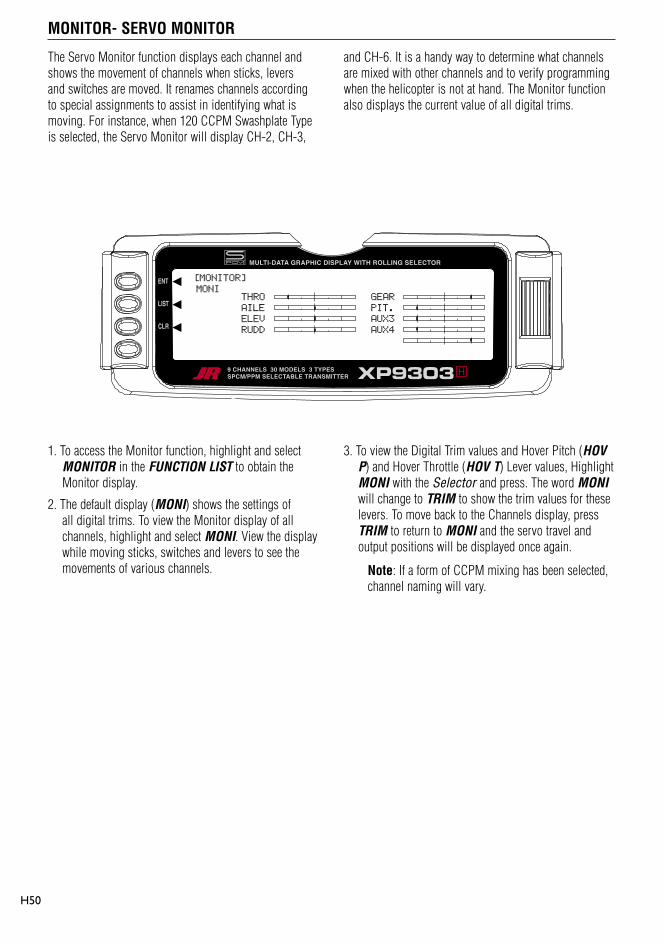
MONITOR- SERVO MONITOR
H50
The Servo Monitor function displays each channel and shows the movement of channels when sticks, levers and switches are moved. It renames channels according to special assignments to assist in identifying what is moving. For instance, when 120 CCPM Swashplate Type is selected, the Servo Monitor will display CH-2, CH-3,
and CH-6. It is a handy way to determine what channels are mixed with other channels and to verify programming when the helicopter is not at hand. The Monitor function also displays the current value of all digital trims.
1. To access the Monitor function, highlight and select MONITOR in the FUNCTION LIST to obtain the Monitor display.
2. The default display (MONI) shows the settings of all digital trims. To view the Monitor display of all channels, highlight and select MONI. View the display while moving sticks, switches and levers to see the movements of various channels.
3. To view the Digital Trim values and Hover Pitch (HOV P) and Hover Throttle (HOV T) Lever values, Highlight MONI with the Selector and press. The word MONI will change to TRIM to show the trim values for these levers. To move back to the Channels display, press TRIM to return to MONI and the servo travel and output positions will be displayed once again.
Note: If a form of CCPM mixing has been selected, channel naming will vary.
[MONITOR]
MONITHRO
AILE
ELEV
RUDD
GEAR
PIT.
AUX3
AUX4

Servo Precautions
General notes
I1
• Do not lubricate servo gears or motors.
• Do not overload retract servos during retracted or extended conditions. Make sure they are able to travel their full deflection. Overloading or stalling a servo can cause excessive current drain.
• Make sure all servos move freely through their rotations and no linkages hang up or bind. A binding control linkage can cause a servo to draw excessive current. A stalled servo can drain a battery pack in a matter of minutes.
• Correct any control surface “buzz” or “flutter” as soon as it is noticed in flight, as this condition can destroy the feedback potentiometer in the servo. It may be extremely dangerous to ignore such “buzz” or “flutter.”
• Use the supplied rubber grommets and brass servo eyelets when mounting your servos. Do not over-tighten the servo mounting screws, as this negates the dampening effect of the rubber grommets.
• Ensure the servo horn is securely fastened to the servo. Use only the JR® servo arm screws provided; the size is different from other manufacturers.
• Discontinue to use servo arms when they become “yellowed” or discolored. Such servo arms may be brittle and can snap at any time, possibly causing the aircraft to crash.
• Check all related mounting screws and linkages frequently. Aircraft often vibrate, causing linkages and screws to loosen.
Radio controlled models are a great source of pleasure. Unfortunately, they can also pose a potential hazard if not operated and maintained properly.
It is imperative to install your radio control system correctly. Additionally, your level of piloting competency must be high enough to ensure that you are able to control your aircraft under all conditions. If you are a newcomer to radio controlled flying, please seek help from an experienced pilot or your local hobby shop.
Safety Do’s and Don’ts for Pilots
• Ensure your batteries have been properly charged prior to initial flight.
• Keep track of the time the system is turned on so you will know how long you can safely operate your system.
• Perform a ground range check prior to the initial flight of the day. See the “Daily Flight Checks Section” for information.
• Check all control surfaces prior to each takeoff.
• Use frequency flags.
• Do not fly your model near spectators, parking areas or any other area that could result in injury to people or damage of property.
• Do not fly during adverse weather conditions. Poor visibility can cause disorientation and loss of control of your aircraft. Strong winds can cause similar problems.
• Do not fly unless your frequency is clear.
Warning: Only one transmitter at a time can operate on a given frequency. If you turn on your transmitter while someone else is operating a model on your frequency, both pilots will lose control of their models. Only one person can use a given frequency at a time. It does not matter if it is AM, FM or PCM—only one frequency at a time.
• Do not point the transmitter antenna directly toward the model. The radiation pattern from the tip of the antenna is inherently low.
• Do not take chances. If at any time during flight you observe any erratic or abnormal operation, and immediately and do not resume flight until the cause of the problem has been ascertained and corrected. Safety can never be taken lightly.

Federal Aviation Administration
Daily Flight Checks
I2
1. Purpose
This advisory outlines safety standards for operations of model aircraft. We encourage voluntary compliance with these standards.
2. Background
Attention has been drawn to the increase in model aircraft operation. There is a need for added caution when operating free flight and radio controlled craft in order to avoid creating a noise nuisance or a potential hazard to full-scale aircraft and persons and/or property on the surface.
3. Operating Standards
Modelers generally are concerned with safety and exercise good judgment when flying model aircraft. However, in the interest of safer skies, we encourage operators of radio controlled and free flight models to comply with the following standards:
a. Exercise vigilance in locating full-scale aircraft (get help if possible) so as not to create a collision hazard.
b. Select an operating site at sufficient distance from populated areas so you do not create a noise problem or a potential hazard.
c. Do not fly higher than 400 feet above the surface.
d. Always operate more than three miles from the boundary of an airport unless you are given permission to be closer by the appropriate air traffic control facility in the case of an airport for which a control zone has been designated or by the airport manager in the case of other airports.
e. Do not hesitate to ask for assistance in complying with these guidelines at the airport traffic control tower or air route traffic control center nearest the site of your proposed operation.
Information Provided By: Director, Air Traffic Service Federal Aviation
Administration, Washington, D.C.
1. Check the battery voltage on both the transmitter and the receiver battery packs. Do not fly below 9.0V on the transmitter or below 4.7V on the receiver. To do so can crash your aircraft.
Note: When you check these batteries, ensure that you have the polarities correct on your expanded scale voltmeter.
2. Check all hardware (linkages, screws, nuts, and bolts) prior to each day’s flight. Be sure that binding does not occur and that all parts are is properly secured.
3. Ensure that all surfaces are moving in the proper manner.
4. Perform a ground range check before each day’s flying session. The range check should be as follows:
• Do not extend the transmitter antenna at this time. Turn the transmitter “on.”
• Turn the model “on.”
• Slowly walk away from the model while moving the control surfaces. The aircraft should function properly at a distance of 60–75 feet.
• For PCM Only: With the throttle fail safe preset to idle, bring the throttle slightly above idle. Walk away until the throttle drops to idle. This will be the distance of the range check.
5. Prior to starting your aircraft, turn off your transmitter, then turn it back on. Do this each time you start your aircraft. If any critical switches are on without your knowledge, the transmitter alarm will warn you at this time.
6. Check that all trim levers are in the proper location.
7. All servo pigtails and switch harness plugs should be secured in the receiver. Make sure that the switch harness moves freely in both directions.

Frequency Chart
I3
Ch.No. Frequency
11 72.010
12 72.030
13 72.050
14 72.070
15 72.090
16 72.110
17 72.130
18 72.150
19 72.170
20 72.190
21 72.210
22 72.230
23 72.250
24 72.270
25 72.290
26 72.310
27 72.330
28 72.350
29 72.370
30 72.390
31 72.410
32 72.430
33 72.450
34 72.470
35 72.490
Low Band 72 MHz
Ch.No. Frequency
36 72.510
37 72.530
38 72.550
39 72.570
40 72.590
41 72.610
42 72.630
43 72.650
44 72.670
45 72.690
46 72.710
47 72.730
48 72.750
49 72.770
50 72.790
51 72.810
52 72.830
53 72.850
54 72.870
55 72.890
56 72.910
57 72.930
58 72.950
59 72.970
60 72.990
High Band 72 MHz
72 MHz requires no special license to operate.
Transmitter Crystal Replacement Notice:
The Federal Communications Commission (FCC) requires that changes in transmitter frequency must be performed only by an authorized service technician (Horizon Service Center).
Any transmitter frequency changes made by a non-certified technician may result in a violation of FCC rules.
Channels 12–14 are not available through JR®.

Warranty Information
I4
Important: Be sure to keep your original dated sales receipt, as you will be required to provide proof-of -purchase date for the equipment to be serviced under warranty.
Warranty Coverage
Your new JR® Remote Control Radio System is warranted to the original purchaser against manufacturer defects in material and workmanship for an unprecedented 3 years from the date of purchase. During this period, Horizon Service Center will repair or replace, at our discretion, any component that is found to be factory defective at no cost to the purchaser. This warranty is limited to the original purchaser of the unit and is not transferable.
This warranty does not apply to any unit that has been improperly installed, mishandled, abused or damaged in a crash, or to any unit that has been repaired or altered by any unauthorized agencies. Under no circumstances will the buyer be entitled to consequential or incidental damages. This limited warranty gives you specific legal rights; you also have other rights, which may vary from state to state. As with all fine electronic equipment, do not subject your radio system to extreme temperatures, humidity or moisture. Do not leave it in direct sunlight for long periods of time.
Repair Service Directions
In the event that your JR radio needs service, please follow the instructions listed below.
1. Check all on/off switches to be sure they are off. This will speed the repair process of checking battery condition.
2. Return your system components only (transmitter, receiver, servos, etc.). Do not return your system installed in a model aircraft, car, boat, etc.
3. Preferably, use the original carton/packaging (molded foam container), or equivalent, to ship your system. Do not use the system carton itself as a shipping carton, you should package the system carton within a sturdy shipping container using additional packing material to safeguard against damage during transit. Include complete name and address information inside the carton, as well as clearly writing it on the outer label/return address area.
4. Include detailed information explaining your operation of the system and problem(s) encountered. Provide an itemized list of equipment enclosed and identify any particular area/function, which may better assist our technicians in addressing your concerns. Within your letter, advise us of the payment method you prefer to use. Horizon Service Center accepts VISA or MasterCard. Please include your card number and expiration date. Date your correspondence, and be sure your complete name and address appear on this enclosure.
5. Include your name, mailing address, and a phone number where you can be reached during the business day.
Warranty Repairs
To receive warranty service, you must include a copy of your original dated sales receipt to verify your proof-of-purchase date. Providing that warranty conditions have been met, your radio will be repaired without charge.
Normal Non-Warranty Repairs
Should your repair cost exceed 50% of the retail purchase cost, you will be provided with an estimate advising you of your options.
Mail your system to:
Horizon Service Center 4105 Fieldstone Road Champaign, IL 61822
Phone: (217) 355-9511

Setup Sheet (Helicopter)
I5
MODEL NO
MODEL NAME
SPOI AIL1 ELEV RUDD AIL2 FLAP AUX2 AUX3
REVERSE SW
SUB TRIM
TRAVELADJUST
FAIL SAFE (SPCM)
AILE ELEV RUDD
DUAL RATE/EXP
0
1
D/R
EXP
D/R
EXP
%
%
%
%
%
%
%
%
%
%
%
%
TRIM OFFSET
DIFFERENTIAL %
NORMREV
NORMREV
NORMREV
NORMREV
NORMREV
NORMREV
NORMREV
NORMREV
+ %
- %
L %
R %
U %
D %
L %
R %
+ %
- %
+ %
- %
L %
R %
U %
D %
PROGRAMMABLEMIX
MIX1
MIX1
MIX1
MIX1
MIX1
MIX1
CHANNEL SW EXP 0 1 2 3 4 5 6
ON/OFF
EXP 0 1 2 3 4 5 6
ON/OFF
+POS -POS OFFSET
ON/OFF
POS0
POS1
POS2
AUTOD/R
ACT INH
ACT INH
ACT INH
AUX2
AUX3
GEAR
INPUTSEL
HOLD PIT INH
ACT INH
ACT INH
ON/OFF
ON/OFF
ON/OFF
ON/OFF
ON/OFF
ON/OFF
N
1
2
N
1
2
3
THROCURVE
PITCHCURVE
NORM
STNT
HOLD
INVT
0
1
%
%
GYROSENS
INH
RUDD D/R
AUTO
%UPNORMAL
REVOMIX
%
%
%
%
STUNT
DOWN
UP
DOWN
HOLD RUDD OFFSET
ACC MIXACT INH
ACT INHPOS
OFFSET
%
%
THRO HOLD

© 2004, Horizon Hobby, Inc. 4105 Fieldstone Road Champaign, IL 61822
(877) 504.0233 www.horizonhobby.com
H7011