Embed Size (px)
Citation preview

XRI1-IE – Combined time overcurrent and earth current relay
Manual XRI1-IE (Revision D)

Woodward Manual XRI1-IE
2 DOK-TD-XRI1-IE, Rev. D
Woodward reserves the right to update any portion of this publication at any time. Information provided by Woodward is believed to be correct and reliable.
However, no responsibility is assumed by Woodward unless otherwise expressly undertaken.
© Woodward 1994–2019

Manual XRI1-IE Woodward
DOK-TD-XRI1-IE, Rev. D 3
Contents
1. Introduction and application ........................................................................................ 5
2. Features and characteristics ....................................................................................... 6
3. Design ............................................................................................................................ 7 3.1 Connections ............................................................................................................................................. 7
3.1.1 Analog input circuits ............................................................................................................................. 7 3.1.2 Blocking input....................................................................................................................................... 7 3.1.3 External reset input .............................................................................................................................. 7 3.1.4 Output relays........................................................................................................................................ 8 3.1.5 Data communication ............................................................................................................................ 8
3.2 Front plate ................................................................................................................................................ 9 3.2.1 Indication and operation elements ....................................................................................................... 9 3.2.2 LEDs .................................................................................................................................................... 9 3.2.3 Display ............................................................................................................................................... 10 3.2.4 Parameter settings (see chapter 6) ................................................................................................... 11
4. Working principle ........................................................................................................ 12 4.1 Analog circuits ....................................................................................................................................... 12 4.2 Digital circuits ......................................................................................................................................... 12 4.3 Earth fault protection .............................................................................................................................. 13
4.3.1 Generator stator earth fault protection ............................................................................................... 13 4.3.2 System earth fault protection ............................................................................................................. 13
4.4 Requirements on the main current transformers ................................................................................... 14
5. General operations and settings ............................................................................... 15 5.1 Push buttons .......................................................................................................................................... 15
5.1.1 Indication of measuring values and fault data ................................................................................... 16 5.2 DIP switches .......................................................................................................................................... 17
5.2.1 Function of the output relays ............................................................................................................. 17 5.3 Reset ...................................................................................................................................................... 17 5.4 Password ............................................................................................................................................... 18
5.4.1 Password programming ..................................................................................................................... 18 5.4.2 Using the password ........................................................................................................................... 18
5.5 Relay setting principle ............................................................................................................................ 19 5.5.1 Setting of default parameters ............................................................................................................. 19 5.5.2 Blocking the protection function ......................................................................................................... 19
5.6 Display of software version and test-TRIP ............................................................................................ 19 5.7 Low/high range of functions blocking and reset .................................................................................... 19
6. Operations and settings ............................................................................................. 20 6.1 Setting procedure .................................................................................................................................. 20
6.1.1 Pickup current for phase overcur-rent element (I>) ........................................................................... 20 6.1.2 Time current characteristics for phase overcurrent element (CHAR I>) ........................................... 20 6.1.3 Trip delay or time multiplier for phase overcurrent element (tI>) ........................................................ 20 6.1.4 Reset setting for inverse time tripping characteristics in the phase current path .............................. 21 6.1.5 Current setting for high set element (I>>) .......................................................................................... 21 6.1.6 Trip delay for high set element (tI>>)................................................................................................... 21 6.1.7 Pickup current for earth fault element (IE>) ........................................................................................ 21 6.1.8 WARN/TRIP changeover ................................................................................................................... 21 6.1.9 Time current characteristics for earth fault element (CHAR IE) ........................................................ 21 6.1.10 Trip delay or time multiplier for earth fault element (tIE>>) .............................................................. 21 6.1.11 Reset mode for inverse time tripping in earth current path ........................................................... 21 6.1.12 Current setting for high set element of earth fault supervision (IE>>) ............................................. 22 6.1.13 Trip delay for high set element of earth fault supervision (tIE>>) .................................................... 22 6.1.14 Nominal frequency ......................................................................................................................... 22 6.1.15 Adjustment of the slave address.................................................................................................... 22 6.1.16 Setting of Baud-rate (applies for Modbus Protocol only) ............................................................... 22 6.1.17 Setting of parity (applies for Modbus Protocol only) ...................................................................... 22 6.1.18 Circuit breaker failure protection tCBFP ........................................................................................... 22 6.1.19 Display of the activation storage (FLSH/NOFL) ............................................................................ 22

Woodward Manual XRI1-IE
4 DOK-TD-XRI1-IE, Rev. D
6.1.20 Blocking the protection functions and assignment of the output relays ........................................ 23 6.2 Setting value calculation ........................................................................................................................ 25
6.2.1 Definite time overcurrent element ...................................................................................................... 25 6.2.2 Inverse time overcurrent element ...................................................................................................... 25
6.3 Indication of measuring and fault values ............................................................................................... 26 6.3.1 Measuring values ............................................................................................................................... 26 6.3.2 Indication of fault data ........................................................................................................................ 26 6.3.3 Fault recorder..................................................................................................................................... 26
6.4 Reset ...................................................................................................................................................... 27
7. Relay testing and commissioning ............................................................................. 28 7.1 Power-On ............................................................................................................................................... 28 7.2 Testing the output relays and LEDs ...................................................................................................... 28 7.3 Checking the set values ......................................................................................................................... 28 7.4 Secondary injection test ......................................................................................................................... 29
7.4.1 Test equipment .................................................................................................................................. 29 7.4.2 Test circuit of XRI1-IE ........................................................................................................................ 29 7.4.3 Checking the input circuits and measured values ............................................................................. 30 7.4.4 Checking the operating and resetting values of the relay ................................................................. 30 7.4.5 Checking the relay operating time ..................................................................................................... 30 7.4.6 Checking the high set element of the relay ....................................................................................... 30 7.4.7 Checking the external blocking and reset functions .......................................................................... 31 7.4.8 Test of the CB failure protection ........................................................................................................ 31
7.5 Primary injection test ............................................................................................................................. 32 7.6 Maintenance .......................................................................................................................................... 32
8. Technical data ............................................................................................................. 33 8.1 Measuring input circuits ......................................................................................................................... 33 8.2 Common data ........................................................................................................................................ 33 8.3 Setting ranges and steps ....................................................................................................................... 34
8.3.1 Time overcurrent protection ............................................................................................................... 34 8.3.2 Earth fault protection .......................................................................................................................... 34 8.3.3 Switch failure protection ..................................................................................................................... 34 8.3.4 Interface parameter ........................................................................................................................... 34 8.3.5 Inverse time overcurrent protection relay .......................................................................................... 35
8.4 Inverse time characteristics ................................................................................................................... 36 8.5 Output relays ......................................................................................................................................... 38 8.6 Power supply ......................................................................................................................................... 38 8.7 Inputs, Blockage and Reset ................................................................................................................... 38 8.8 System data and test specifications ...................................................................................................... 39 8.9 Relay case ............................................................................................................................................. 40
9. Order form ................................................................................................................... 41

Manual XRI1-IE Woodward
DOK-TD-XRI1-IE, Rev. D 5
1. Introduction and application The digital relay type XRI1-IE as time overcurrent protection is designed for the use in electrical machines, lines and grids. The protective functions of XRI1-IE which are implemented in only one device are summarized as follows:
Independent (Definite) time overcurrent relay.
Inverse time overcurrent relay with selectable characteristics.
Two-element earth fault protection with definite or in-verse time characteristics. Furthermore, the relay XRI1-IE can be employed as a back-up protection for distance and differential protective relays.

Woodward Manual XRI1-IE
6 DOK-TD-XRI1-IE, Rev. D
2. Features and characteristics
Digital filtering of the measured values by using discrete Fourier analysis to suppress the high frequence harmonics and DC components induced by faults or system operations
Selectable protective functions between: - definite time overcurrent relay and - inverse time overcurrent relay
Selectable inverse time characteristics according to BS 142 and IEC 255-4: - Normal Inverse (type A) - Very Inverse (type B) - Extremely Inverse (type C)
Reset setting for inverse time characteristics selectable
High set overcurrent unit with instantaneous or de-finite time function.
Two-element (low and high set) overcurrent relay both for phase and earth faults.
Numerical display of setting values, actual measured values and their active, reactive components, memorized fault data, etc.
Blocking e.g. of high set element (e.g. for selective fault detection through minor overcurrent protection units after unsuccessful AR).
Switch failure protection
Storage of tripping values and shut-down times of eight failure events
Free assignment of output relays
Serial data exchange via RS485 interface possible with Woodward RS485-Pro Open Data Protocol or Modbus Protocol
Suppression of indication after an activation (LED flash)

Manual XRI1-IE Woodward
DOK-TD-XRI1-IE, Rev. D 7
3. Design
3.1 Connections
Figure 3.1: Connection diagram XRI1-IE
3.1.1 Analog input circuits The protection unit receives the analog input signals of the phase currents IL1 (1S1-1S2), IL2 (2S1-2S2), IL3 (3S1-3S2), and earth current (1E1-1E2) each via separate input transformers. The constantly detected current measuring values are galvanically decoupled, filtered and finally fed to the analog/digital converter.
3.1.2 Blocking input The blocking functions adjusted before will be blocked if an auxiliary voltage is connected to (terminals) C1/C1L or C1/C1H. (See chapter 6.1.20)
3.1.3 External reset input By applying the aux. voltage C2/C2L or C2/C2H, indication and output relays are reset. (see chapter 6.4)

Woodward Manual XRI1-IE
8 DOK-TD-XRI1-IE, Rev. D
3.1.4 Output relays The XRI1-IE is equipped with 5 output relays.
Output relays 1; 11, 12, 14 and 21, 22, 24
Output relays 2; 31, 32, 34 and 41, 42, 44
Output relays 3; 51, 52, 54
Output relays 4; 61, 62, 64
Signal self supervision 71, 72, 74 All trip and alarm relays are working current relays, the relay for self supervision is an idle current relay. See connection diagram relay outputs. Except the self-supervision, all relays can be assigned to different functions. (see 6.1.20).
3.1.5 Data communication For data communication with a central control system the XRI1-IE relay is provided with a serial interface RS485. Simplified and fast reading and changing of parameters and measuring values can be achieved by HTL/PL-Soft4, which will be provided on request together with the relay. The XRI1-IE can be connected to other units of PROFESSIONAL LINE via interface. If there is more than 1 re-lay in the system, the last relay of the chain has to be provided with a resistor line termination.
Figure 3.2: Connection example with 3 users XR ... as linked device
Figure 3.3: Connection example with 3 users, XR ... as last device

Manual XRI1-IE Woodward
DOK-TD-XRI1-IE, Rev. D 9
3.2 Front plate
3.2.1 Indication and operation elements The front plate of protection relays comprises the following operation and indication elements:
Alphanumerical display (4 Digits)
Push buttons for setting and other operations
LEDs for measured value indication and setting
Figure 3.4: Front plate XRI1-IE
3.2.2 LEDs The LEDs left from the display, L1, L2, L3, E are partially bi-colored, the green indicating measuring, and the red fault indication. The LED marked with letters RS lights up during setting of the slave address of the device for serial data com-munication. The LEDs arranged at the characteristic points on the setting curves support the comfortable setting menu se-lection. In accordance with the display 5 LEDs for phase fault overcurrent indicate the corresponding menu point selected.

Woodward Manual XRI1-IE
10 DOK-TD-XRI1-IE, Rev. D
3.2.3 Display
Function Display shows Pressed push button Corresponding LED
Normal operation WW
Measured operating values Actual measured val-ues,
<SELECT/RESET> one time for each
L1, L2, L3, E
Measuring range overflow max. <SELECT/RESET> L1, L2, L3, E
Setting values: phase (I>; CHAR I>; tI>; I>>; tI>>) earth (IE>; CHAR IE; tIE>; IE>>; tIE>>)
Current settings Trip delay Character-istics
<SELECT/RESET> one time for each parame-ter
I>; CHAR I>; tI>; I>>; tI>>; IE>;CHAR IE; tIE>; IE>>; tIE>>;
Reset setting (only available at inverse time characteris-tics)
0s / 60s <SELECT/RESET><+><-> I>; CHAR I>; tI> IE>; CHAR IE>; tIE>
Switch failure protection tCBFP <SELECT/RESET><+><->
Tripping protection switch failure protection
CBFP After fault tripping
Nominal frequency f=50 / f=60 <SELECT/RESET><+><->
Switch-over LED flash No LED flash
FLSH NOFL <SELECT/RESET><+><->
Blocking of function EXIT <+> until max. setting val-ue
LED of blocked pa-rameter
Slave address of serial interface
1 - 32 <SELECT/RESET><+><-> RS
Baud-Rate 1) 1200-9600 <SELECT/RESET><+><-> RS
Parity-Check 1) even odd no <SELECT/RESET><+><-> RS
Recorded fault data Tripping currents and other fault data
<SELECT/RESET> one time for each phase
L1, L2, L3, E I>, I>>, IE>, IE>>
Save parameter? SAV? <ENTER>
Delete failure memory wait <-><SELECT/RESET>
Enquiry failure memory FLT1; FLT2..... <-><+> L1, L2, L3, E I>, I>>, IE>, IE>>
Save parameter! SAV! <ENTER> for about 3 s
Software version First part (e.g. D01-) Sec. part (e.g. 8.00)
<TRIP> one time for each part
Manual trip TRI? <TRIP> three times
Inquire password PSW? <TRIP><ENTER>
Relay tripped TRIP <TRIP> or after fault trip-ping
Secret password input XXXX <SELECT/RESET><+><-><ENTER>
System reset WW <SELECT/RESET> for about 3 s
Table 3.1: Possible indication messages on the display, 1) only Modbus

Manual XRI1-IE Woodward
DOK-TD-XRI1-IE, Rev. D 11
3.2.4 Parameter settings (see chapter 6)
Device type XRI1-IE
Symbol Function Unit Setting range
I> Pickup value for phase overcurrent ele-ment
X In 0.20...4.0 (EXIT)
CHAR I> Trip characteristic for phase overcurrent element
DEFT; NINV; VINV; EINV
tI> Tripping delay (factor) for phase overcur-rent element
s DEFT 0.03...260 (EXIT) INVS 0.05...10.0 (EXIT)
I>+CHAR I>+tI> Reset Mode for inverse-characteristics s 0s/60s
I>> Pickup value for overcurrent high set el-ement
x In 1.00...40.0 (EXIT)
tI>> Trip delay for overcurrent high set ele-ment
s 0.03...2.00 (EXIT)
IE> Pickup value for earth fault low set ele-ment
x In 0.01...2.00 (EXIT)
Warn/trip Warning/tripping setting Warn/trip
CHAR IE> Tripping characteristic for earth fault overcurrent element
DEFT; NINV; VINV; EINV
tIE> Trip delay (factor) for earth fault low set element
s DEFT 0.03...260 (EXIT) INVS 0.05...10.0 (EXIT)
IE>+CHAR IE>+tIE> Reset modus for AMZ characteristic s 0s/60s
IE>> Pickup value for earth fault high set ele-ment
x In 0.01...15.0 (EXIT)
tIE>> Trip delay for earth fault high set element s 0.03...2.00 (EXIT)
tCBFP Circuit breaker failure protection s 0.10...2.00 (EXIT)
FN Rated frequency Hz 50 Hz/60 Hz
LED Flash LED blinking after excitation Hz FLSH/NOFL
RS Slave address for serial interface 1...32
RS Baud rate der of the serial interface 1) Bd 1200; 2400; 4800; 9600
RS Parity bit of the serial interface 1) Even; odd; no
1) only Modbus protocol
Table 3.2: Parameter values
Additional parameters:
Relay-type XRI1-IE
Blocking mode
Relay parameterizing
Fault recorder
Table 3.3

Woodward Manual XRI1-IE
12 DOK-TD-XRI1-IE, Rev. D
4. Working principle
4.1 Analog circuits The incoming currents from the main current transformers on the protected object are converted to voltage sig-nals in proportion to the currents via the input transformers and burden. The noise signals caused by inductive and capacitive coupling are suppressed by an analog R-C filter circuit. The analog voltage signals are fed to the A/D-converter of the microprocessor and transformed to digital signals through Sample- and Hold-circuits. The analog signals are sampled at 50 Hz (60 Hz) with a sampling frequency of 800 Hz (960 Hz), namely, a sampling rate of 1.25 ms (1.04 ms) for every measuring quantity. (16 scans per period).
4.2 Digital circuits The essential part of the XRI1-IE relay is a powerful microcontroller. All of the operations, from the analog digital conversion to the relay trip decision, are carried out by the microcontroller digitally. The relay program is located in an EPROM (Electrically-Programmable-Read-Only-Memory). With this program the CPU of the microcontrol-ler calculates the three phase currents and ground current in order to detect a possible fault situation in the pro-tected object. For the calculation of the current value an efficient digital filter based on the Fourier Transformation (DFFT - Discrete Fast Fourier Transformation) is applied to sup-press high frequency harmonics and DC components caused by fault-induced transients or other system disturbances. The calculated actual current values are compared with the relay settings. If a phase current exceeds the pickup value, an alarm is given and after the set trip delay has elapsed, the corresponding trip relay is activated. The relay setting values for all parameters are stored in a parameter memory (EEPROM - Electrically Erasable Programmable Read-only Memory), so that the actual relay settings cannot be lost, even if the power supply is interrupted. The microprocessor is supervised by a built-in "watch-dog" timer. In case of a failure the watchdog timer re-sets the microprocessor and gives an alarm signal, via the output relay "self supervision".

Manual XRI1-IE Woodward
DOK-TD-XRI1-IE, Rev. D 13
4.3 Earth fault protection
4.3.1 Generator stator earth fault protection With the generator neutral point earthed as shown in Figure 4.1 the MRI1 picks up only to phase earth faults be-tween the generator and the location of the current transformers supplying the relay. Earth faults beyond the current transformers, i.e. on the consumer or line side, will not be detected.
Figure 4.1: Generator stator earth fault protetion
4.3.2 System earth fault protection With the generator neutral point earthed as shown in Figure 4.2, the MRI1 picks up only to earth faults in the power system connected to the generator. It does not pick up to earth faults on the generator terminals or in generator stator.
Figure 4.2: System earth fault protection

Woodward Manual XRI1-IE
14 DOK-TD-XRI1-IE, Rev. D
4.4 Requirements on the main current transformers The current transformers have to be rated in such a way, that a saturation should not occur within the following operating current ranges: Independent time overcurrent function: K1 = 2 Inverse time overcurrent function: K1 = 20 High-set function: K1 = 1.2 - 1.5 K1 = Current factor related to set value, at which the C.T. is not yet saturated Moreover, the current transformers have to be rated according to the maximum expected short circuit current in the network or in the protected objects. The low power consumption in the current circuit of XRI1-IE, namely <0.2 VA, has a positive effect on the selec-tion of current transformers. It implies that, if an electromechanical relay is replaced by XRI1-IE, a high accuracy limit factor is automatically obtained by using the same current transformer.

Manual XRI1-IE Woodward
DOK-TD-XRI1-IE, Rev. D 15
5. General operations and settings For adjustment of the unit the transparent cover has to be opened as illustrated. Do not use force! The trans-parent cover has two inserts for labels.
Figure 5.1: How to open the transparent cover
5.1 Push buttons Push buttons are used for calling up the parameters to be processed, for selection of measuring parameters to be indicated and for changing and storing the parameters. The individual setting and measuring values can be selected one after another by pressing push button <SELECT/RESET>. This push button is also used for re-setting the display by pressing approx. 3s. Push buttons <+> <-> are used for in-/decrementing of the parameter indicated on the display. They can be pressed step-by-step or continuously. After the selected parameter is set by the <+> <-> push button it may be stored using the <ENTER> push but-ton. Through the push button <ENTER> the set value indicated on the display will be transferred to the internal pa-rameter memory. An unintended or unauthorized change of the selected parameter is avoided by means of a password identification (see 5.4.2). The <TRIP>-push button is used to test the output relay circuits both for tripping and signaling. During normal operation it is also interlocked by means of the pass-word identification.

Woodward Manual XRI1-IE
16 DOK-TD-XRI1-IE, Rev. D
5.1.1 Indication of measuring values and fault data Indication in faultless condition In normal operation the display always shows |WW. After pressing the push button <SELECT/RESET> the dis-play switches cyclically to the next measuring value. After the measuring values had been indicated the set-ting parameters are displayed. Hereby the LEDs in the upper section signalize which measured value is indicated, the LEDs in the lower section signalize which setting parameter is indicated on the display. Longer actuating the push button resets the relay and the display changes into normal operation (|WW). Indication after pickup / tripping All of the faults detected by the relay are indicated on the front plate optically. Here not only the faults are indi-cated but also the faulty phase(s) and the protection function in operation. At pickup the LEDs are flashing, after tripping this changes to continuous light. In tripped condition "TRIP" appears on the display and the LEDs of the operating measuring data light up red together with the LEDs of the tripping parameter. All operating data, which were measured at the moment of tripping, can now be called one after another by pressing push button <SELECT/RESET>. If in this condition setting parameters are to be indicated, push button <ENTER> has to be pressed. The graphic below shows again the difference between the different display modes.
Figure 5.2: Switching over of the display in dependence of the operating mode

Manual XRI1-IE Woodward
DOK-TD-XRI1-IE, Rev. D 17
5.2 DIP switches Behind the front plate of the XRI-IR relay there are four dip switches to preset the following functions:
Password programming
Output relay functions The following table 5.1 shows the position and designation of the code jumpers:
5.2.1 Function of the output relays The alarm relays are activated according to the preset-ting: DIP switch 3 OFF: All output relays will be reset automatically after the fault has been cleared, (e.g. when the fault current is inter-rupted). DIP switch 3 ON: All output relays remains activated and must be reset after fault clearance.
Manually: By pressing push button <SELECT/RESET>
External: By connecting aux. voltage to C2/C2L or C2/C2H
Via RS 485 interface To let the parameter change take effect, the auxiliary voltage has to be switched on and off again after the dip switches are plugged or unplugged.
DIP switches
Function Code jumper position Operation mode
1 Password OFF Normal position
ON Password selection
2 none
3 Reset OFF Output relays will be reset automatically
ON Output relays will be reset manual/external/via software
4 none
Table 5.1: Summary of coding possibilities
5.3 Reset Manual reset By pressing push button <RESET/SELECT> for some time (about 3 s). External reset-input C2/C2L or C2/C2H The external reset input has the same function as the <SELECT/RESET> push button on the front plate. Con-necting auxiliary voltage to this input, the unit can be reset, provided that the fault is removed. Software reset via serial interface RS 485 Software reset has the same function as push button <SELECT/RESET>. Please refer to open data protocol of RS 485 interface named RS485-PRO.

Woodward Manual XRI1-IE
18 DOK-TD-XRI1-IE, Rev. D
5.4 Password
5.4.1 Password programming The XRI1-IE -relay is delivered with the preset password "++++", it can be programmed new with dip switch 1: Switch on dip switch 1. After power on and pressing any push button, the relay XRI1-IE inquires for a new password. The text "PSW?" appears on the display. The new password is entered by any combination of the push buttons <SELECT> <-> <+> <ENTER>. After the new password is given, the dip switch 1 must be switched off.
5.4.2 Using the password Step by step, a new relay setting is made according to the following sequence:
After the present setting value is changed with <+><-> push button, <ENTER> push button should be pressed.
A message "SAV?" appears on the display to inquire if the new setting value is really wanted to be stored.
After pressing the <ENTER> push button again,the password will be inquired by means of the message "PSW?" on the display.
After the password is given correctly, which is prompted by message "SAV!" on the display, the new setting value can be stored by pressing the <ENTER> push button for about 3 seconds.
The new setting value for the selected parameter ap-pears on the display again. A password consists of four push button operations. The pressed push buttons and their sequences define the password. <SELECT/RESET> = S <-> = - <+> = + <ENTER> = E then a password "-E+S" means pressing push buttons according to the following sequence: <-> <ENTER> <+> <SELECT/RESET> After the password is given correctly, parameter setting is permitted for five minutes. This means: For a subse-quent parameter setting, as long as it is made within five minutes after the password input, a renewed password input is not required. Moreover, the valid period for parameter setting is automatically extended to further 5 minutes after each new push button operation. If no push button operation follows within the five minute period after password input, the validity for parameter setting will be suspended. For entering further parameters the password is then called up again. During the validity for parameter set-ting a new set value, after having acknowledged "SAV" two times, is stored by just pressing push button <ENTER> for some time. As to parameter setting via RS 485 interface: see open data protocol.

Manual XRI1-IE Woodward
DOK-TD-XRI1-IE, Rev. D 19
5.5 Relay setting principle By pressing push button <ENTER>, the parameter menu can be called up. By pressing push button <SELECT/RESET> the parameter to be set is reached. The corresponding LED lights up. The actual set value of the selected parameter is indicated on the display. The indicated set value can then be changed by pressing push buttons <+><-> (in-/decrementing) see figure 5.2). The selected set value is stored by pressing push button <ENTER> and by input of the authority code (pass-word) which means the adjustment of the unit is only possible after the password had been put in. (see 5.4.2) After a trip the push button <SELECT/RESET> is re-served for the indication of fault data. Now new parameter setting by means of push button <SELECT/RESET> is only possible by pressing <ENTER> first.
5.5.1 Setting of default parameters Setting of the XRI1-IE default parameters can be done as follows:
switch off the auxiliary voltage supply
press simultaneously push buttons <+><-> and <SELECT/RESET> and
switch on the auxiliary voltage supply again.
5.5.2 Blocking the protection function The blocking function of the XRI1-IE -relays can be set according to requirement. When pressing push buttons <ENTER> and <TRIP> at the same time the blocking mode is entered. (see chapter 6.1.20)
5.6 Display of software version and test-TRIP By pressing push button <TRIP> the first part of the software version is displayed, the second part appears when this push button is pressed again. When push button <TRIP> is pressed repeatedly, the test trip routine starts. By entering the password the display shows "TRI?". After pressing <TRIP> again all output relays will be ener-gized one after the other with a time delay of 1 s. All relays stay energized until manual reset. The protection functions are not affected.
5.7 Low/high range of functions blocking and reset All relays of the HIGH TECH LINE have a wide-range power supply unit allowing to choose a suitable supply voltage. The operating threshold of the blocking and reset inputs, however, has to be defined by taking the sup-ply voltage into account. The following two different operating thresholds can be adjusted:
Low-range threshold UON ≥ 10 V; UOFF ≤ 8 V
High-range threshold UON ≥ 70 V; UOFF ≤ 60 V Connection terminals
Low-range blockage input terminal C1/C1L
Low-range reset input terminal C2/C2L
High-range blockage input terminal C1/C1H
High-range reset input terminal C2/C2H

Woodward Manual XRI1-IE
20 DOK-TD-XRI1-IE, Rev. D
6. Operations and settings
6.1 Setting procedure After push button <SELECT/RESET> has been pressed, always the next measuring value is indicated. Firstly the operating measuring values are indicated and then the setting parameters. By pressing the <ENTER> push but-ton the setting values can directly be called up and changed.
6.1.1 Pickup current for phase overcur-rent element (I>) The setting value for this parameter that appears on the display is related to the nominal current (IN) of the relay. This means: pickup current (Is) = displayed value x nominal current (IN) e.g. displayed value = 1.25 then, Is = 1.25 x IN.
6.1.2 Time current characteristics for phase overcurrent element (CHAR I>) By setting this parameter, one of the following 4 messages appears on the display: DEFT - Definite Time NINV - Normal Inverse (type A) VINV - Very Inverse (type B) EINV - Extremely Inverse (type C) Anyone of these four characteristics can be chosen by using <+> <-> push buttons, and can be stored by using <ENTER> push button.
6.1.3 Trip delay or time multiplier for phase overcurrent element (tI>) Usually, after the characteristic is changed, the time delay or the time multiplier should be changed accordingly. In order to avoid an unsuitable arrangement of relay modes due to carelessness of the operator, the following precautions are taken: After the characteristic setting, the setting process turns to the time delay setting automatically. The LED tI> is going to flash yellow to remind the operator to change the time delay setting accordingly. After pressing the <SELECT> push button, the present time delay setting value is shown on the display. The new setting value can then be changed by using <+> <-> push buttons. If, through a new setting, another relay characteristic other than the old one has been chosen (e.g. from DEFT to NINV), but the time delay setting has not been changed despite the warning from the flashing LED, the relay will be set to the most sensitive time setting value of the selected characteristics after five minutes warning of flashing LED tI>. The most sensitive time setting value means the fastest tripping for the selected relay characteristic. When the time delay or the time multiplier is set out of range (Text "EXIT" appears on the display), the low set element of the overcurrent relay is blocked. The "WARN"-relay will not be blocked.

Manual XRI1-IE Woodward
DOK-TD-XRI1-IE, Rev. D 21
6.1.4 Reset setting for inverse time tripping characteristics in the phase current path To ensure tripping, even with recurring fault pulses shorter than the set trip delay, the reset mode for in-verse time tripping characteristics can be switched over. If the adjustment tRST is set at 60s, the tripping time is only reset after 60s faultless condition. This function is not available if tRST is set to 0. With fault current cease the trip delay is reset immediately and started again at recurring fault current.
6.1.5 Current setting for high set element (I>>) The current setting value of this parameter appearing on the display is related to the nominal current of the re-lay. This means: I>> = displayed value x IN. When the current setting for high set element is set out of range (on display appears "EXIT"), the high set ele-ment of the overcurrent relay is blocked. The high set element can be blocked via terminals C1/C1L or C1/C1H if the corresponding blocking parameter is set to bloc (refer to chapter 6.1.20).
6.1.6 Trip delay for high set element (tI>>) Independent from the chosen tripping characteristic for I>, the high set element I>> has always a definite-time tripping characteristic. An indication value in seconds appears on the display. The setting procedure for forward or backward faults, described in chapter 6.1.3, is also valid for the tripping time of the high set element.
6.1.7 Pickup current for earth fault element (IE>) (Similar to chapter 6.1.1)
6.1.8 WARN/TRIP changeover A detected earth fault can be parameterized as follows: a) "warn" only the alarm relay trips b) "TRIP" the trip relay trips and tripping values are stored.
6.1.9 Time current characteristics for earth fault element (CHAR IE) (Similar to chapter 6.1.2)
6.1.10 Trip delay or time multiplier for earth fault element (tIE>>) (Similar to chapter 6.1.3)
6.1.11 Reset mode for inverse time tripping in earth current path (Similar to chapter 6.1.4)

Woodward Manual XRI1-IE
22 DOK-TD-XRI1-IE, Rev. D
6.1.12 Current setting for high set element of earth fault supervision (IE>>) (Similar to chapter 6.1.5)
6.1.13 Trip delay for high set element of earth fault supervision (tIE>>) (Similar to chapter 6.1.6)
6.1.14 Nominal frequency The adapted FFT-algorithm requires the nominal frequency as a parameter for correct digital sampling and filter-ing of the input currents. By pressing <SELECT> the display shows "f=50" or "f=60". The desired nominal frequency can be adjusted by <+> or <-> and then stored with <ENTER>.
6.1.15 Adjustment of the slave address Pressing push buttons <+> and <-> the slave address can be set in range of 1-32.
6.1.16 Setting of Baud-rate (applies for Modbus Protocol only) Different transmission rates (Baud rate) can be set for data transmission via Modbus protocol. The rate can be changed by push buttons <+> and <-> and saved by pressing <ENTER>.
6.1.17 Setting of parity (applies for Modbus Protocol only) The following three parity settings are possible : • "EVN" = even • "ODD" = odd • "NO" = no parity check The setting can be changed by push buttons <+> and <-> and saved by pressing <ENTER>.
6.1.18 Circuit breaker failure protection tCBFP The CB failure protection is based on supervision of phase currents during tripping events. Only after tripping this protective function becomes active. The test criterion is whether all phase currents are dropped to <1% x IN within the time tCBFP (Circuit Breaker Failure Protection, adjustable between 0.1 - 1.6s). If not all of the phase currents have dropped to <1% x IN within this time, CB failure is detected and the related relay activated. The CB failure protection function is deactivated again as soon as the phase currents have dropped to <1% x IN within tCBFP.
6.1.19 Display of the activation storage (FLSH/NOFL) If after an activation the existing current drops again below the pickup value, e.g. I>, without a trip has been ini-tiated, LED I> signals that an activation has occurred by flashing fast. The LED keeps flashing until it is reset again (push button <RESET>). Flashing can be sup-pressed when the parameter is set to NOFL.

Manual XRI1-IE Woodward
DOK-TD-XRI1-IE, Rev. D 23
6.1.20 Blocking the protection functions and assignment of the output relays Blocking the protection functions: The blocking function of the XRI1-IE can be set according to requirement. By applying the aux. voltage to C1/C1L or C1/C1H, the functions chosen by the user are blocked. Setting of the parameter should be done as follows:
When pressing push buttons <ENTER> and <TRIP> at the same time, message "BLOC" is displayed (i.e. the respective function is blocked) or "NO_B" (i.e. the respective function is not blocked). The LED allocated to the first protection function I> lights yellow.
By pressing push buttons <+> <-> the value displayed can be changed.
The changed value is stored by pressing <ENTER> and entering the password.
By pressing the <SELECT/RESET> push button, any further protection function which can be blocked is displayed.
Thereafter the blocking menu is left by pressing <SELECT/RESET> again.
Function Display LED/Color
I> Overcurrent (Low set) NO_B I> yellow
I>> Overcurrent (High set) BLOC I>> yellow
IE> Earth current 1. element NO_B IE> yellow
IE>> Earth current 2. element NO_B IE>> yellow
tCBFP Circuit breaker failure protection NO_B
Table 6.1: Default settings of blocking functions
Assignment of the output relays: Unit XRI1-IE has five output relays. The fifth output relay is provided as permanent alarm relay for self supervi-sion is normally on. Output relays 1 - 4 are normally off and can be assigned as alarm or tripping relays to the current functions which can either be done by using the push buttons on the front plate or via serial interface RS485. The assignment of the output relays is similar to the setting of parameters, however, only in the assignment mode. The assignment mode can be reached only via the blocking mode. By pressing push button <SELECT/RESET> in blocking mode again, the assignment mode is selected. The relays are assigned as follows: LEDs I>, I>>, IE>, IE>> lights up, when the output relays are assigned as alarm relays. The LEDs tI>, tI>>, tIE>, tIE>> lights up when the output relays are assigned as trip relays. Definition: Alarm relays are activated at pickup. Tripping relays are only activated after elapse of the tripping delay. After the assignment mode has been activated, first LED I> lights up. Now one or several of the four output re-lays can be assigned to current element I> as alarm relays. At the same time the selected alarm relays for fre-quency element 1 are indicated on the display. Indication "1_ _ _" means that output relay 1 is assigned to this current element. When the display shows "_ _ _ _", no alarm relay is assigned to this current element. The as-signment of output relays 1 - 4 to the current elements can be changed by pressing <+> and <-> push buttons. The selected assignment can be stored by pressing push button <ENTER> and subsequent input of the pass-word. By pressing push button <SELECT/RESET>, LED tI> lights up. The output relays can now be assigned to this current element as tripping relays.
Woodward Manual XRI1-IE
24 DOK-TD-XRI1-IE, Rev. D
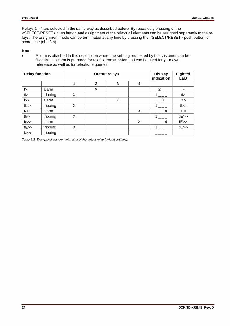
Relays 1 - 4 are selected in the same way as described before. By repeatedly pressing of the <SELECT/RESET> push button and assignment of the relays all elements can be assigned separately to the re-lays. The assignment mode can be terminated at any time by pressing the <SELECT/RESET> push button for some time (abt. 3 s). Note:
A form is attached to this description where the set-ting requested by the customer can be filled-in. This form is prepared for telefax transmission and can be used for your own reference as well as for telephone queries.
Relay function Output relays Display indication
Lighted LED
1 2 3 4
I> alarm X _ 2 _ _ I>
tI> tripping X 1 _ _ _ tI>
I>> alarm X _ _ 3 _ I>>
tI>> tripping X 1 _ _ _ tI>>
IE> alarm X _ _ _ 4 IE>
tIE> tripping X 1 _ _ _ tIE>>
IE>> alarm X _ _ _ 4 IE>>
tIE>> tripping X 1 _ _ _ tIE>>
tCBFP tripping _ _ _ _
Table 6.2: Example of assignment matrix of the output relay (default settings).

Manual XRI1-IE Woodward
DOK-TD-XRI1-IE, Rev. D 25
6.2 Setting value calculation
6.2.1 Definite time overcurrent element Low set element I> The pickup current setting is determined by the load capacity of the protected object and by the smallest fault current within the operating range. The pickup current is usually selected about 20% for power lines, about 50% for transformers and motors above the maximum expected load currents. The delay of the trip signal is selected with consideration to the demand on the selectivity according to system time grading and overload capacity of the protected object. High set element I>> The high set element is normally set to act for near-by faults. A very good protective reach can be achieved if the impedance of the protected object results in a well-defined fault current. In case of a line-transformer combi-nation the setting values of the high set element can even be set for the fault inside the transformer. The time delay for high set element is always independent to the fault current.
6.2.2 Inverse time overcurrent element Beside the selection of the time current characteristic one set value each for the phase current path and earth current path is adjusted. Low set element I> The pickup current is determined according to the maximum expected load current. For example: Current transformer ratio: 400/5A Maximum expected load current: 300A Overload coefficient: 1.2 (assumed) Starting current setting: Is = (300/400) x 1.2 = 0.9 x IN Time multiplier setting The time multiplier setting for inverse time overcurrent is a scale factor for the selected characteristics. The characteristics for two adjacent relays should have a time interval of about 0.3 - 0.4 s. High set element I>> The high set current setting is set as a multiplier of the nominal current. The time delay tI>> is always independ-ent to the fault current.

Woodward Manual XRI1-IE
26 DOK-TD-XRI1-IE, Rev. D
6.3 Indication of measuring and fault values
6.3.1 Measuring values The following measuring quantities can be indicated on the display during normal service:
Apparent current in phase 1 (LED L1 green)
Apparent current in phase 2 (LED L2 green)
Apparent current in phase 3 (LED L3 green)
Apparent earth current (LED E green)
6.3.2 Indication of fault data All faults detected by the relay are indicated on the front plate optically. For this purpose, the four LEDs (L1, L2, L3, E) and the four function LEDs (I>, I>>, IE> and IE>>) are equipped at XRI1-IE . If, for example an overcur-rent occurs, first the LEDs of the corresponding phases will light up. LED I> lights up at the same time. After tripping the LEDs are lit permanently.
6.3.3 Fault recorder When the relay is energized or trips, all fault data and times are stored in a non-volatile memory. The MRI1 is provided with a fault value recorder for max. eight fault occurrences. In the event of additional trippings always the oldest data set is written over. For fault indication not only the trip values are recorded but also the status of LEDs. Fault values are indicated when push buttons <-> or <+> are pressed during normal measuring value indication.
Normal measuring values are selected by pressing the <SELECT/RESET> button.
When then the <-> button is pressed, the latest fault data set is shown. By repeated pressing the <-> button the last but one fault data set is shown etc. For indication of fault data sets abbreviations FLT1, FLT2, FLT3, ... are displayed (FLT1 means the latest fault data set recorded).
By pressing <SELECT/RESET> the fault measuring values can be scrolled.
By pressing <+> it can be scrolled back to a more recent fault data set. At first FLT8, FLT7, ... are always displayed.
When fault recording is indicated (FLT1 etc), the LEDs flash in compliance with the stored trip information, i.e. those LEDs which showed a continuous light when the fault occurred are now blinking to indicate that it is not a current fault. LEDs which were blinking during trip conditions, (element had picked up) just briefly flash.
If the relay is still in trip condition and not yet reset (TRIP is still displayed), no measuring values can be shown.
To delete the trip store, the push button combination <SELECT/RESET> and <-> has to be pressed for about 3 s. The display shows 'wait'.

Manual XRI1-IE Woodward
DOK-TD-XRI1-IE, Rev. D 27
Recorded fault values:
Value displayed Relevant LED
Phase currents L1, L2, L3 in I/In L1, L2, L3
Earth current IE in I/IEn E
C.B. switching time in s 1) C.B.
Expired tripping time of I> in % of tI> 2) I>
Expired tripping time of IE> in % of tIE> 2) IE>
1) C.B. switching time: Time between energizing of the trip output relay and switching of the C.B. (current <1% x IN). 2) Expired tripping time: Time between pickup and release of the low set element.
6.4 Reset Unit XRI1-IE has the following three possibilities to reset the display of the unit as well as the output relay at dip switch position 3=ON. Manual Reset
Pressing the push button <SELECT/RESET> for some time (about 3 s) Electrical Reset
Through applying auxiliary voltage to C2/C2L or C2/C2H Software Reset
The software reset has the same effect as the <SELECT/RESET> push button (see also communication protocol of RS485 interface). The display can only be reset when the pickup is not present anymore (otherwise "TRIP" remains in display). During resetting of the display the parameters are not affected.

Woodward Manual XRI1-IE
28 DOK-TD-XRI1-IE, Rev. D
7. Relay testing and commissioning The test instructions following below help to verify the protection relay performance before or during commis-sioning of the protection system. To avoid a relay damage and to ensure a correct relay operation, be sure that:
the auxiliary power supply rating corresponds to the auxiliary voltage on site.
the rated current and rated voltage of the relay correspond to the plant data on site.
the current transformer circuits and voltage transformer circuits are connected to the relay correctly.
all signal circuits and output relay circuits are connected correctly.
7.1 Power-On NOTE! Prior to switch on the auxiliary power supply, be sure that the auxiliary supply voltage corresponds to the rated data on the type plate. Switch on the auxiliary power supply to the relay and check that the message "WW" appears on the display and the self supervision alarm relay (watchdog) is energized (Contact terminals 71 and 74 closed).
7.2 Testing the output relays and LEDs NOTE! Prior to commencing this test, interrupt the trip circuit to the circuit breaker if tripping is not desired. By pressing the push button <TRIP> once, the display shows the first part of the software version of the relay (e.g. „D08-“). By pressing the push button <TRIP> twice, the display shows the second part of the software ver-sion of the relay (e.g. „4.01“). The software version should be quoted in all correspondence. Pressing the <TRIP> button once more, the display shows "PSW?". Please enter the correct password to proceed with the test. The message "TRI?" will follow. Confirm this message by pressing the push button <TRIP> again. All out-put relays should then be activated and the self supervision alarm relay (watchdog) be deactivated one after another with a time interval of 3 seconds and all LEDs with a delay of 0.5 seconds, with the self-supervision re-lay dropping. Thereafter, reset all output relays back to their normal positions by pressing the push button <SELECT/RESET> (about 3 s).
7.3 Checking the set values By repeatedly pressing the push button <SELECT>, all relay set values may be checked. Set value modification can be done with the push buttons <+><-> and <ENTER>. For detailed information about that, please refer to chapter 6. For a correct relay operation, be sure that the frequency set value (f=50/60) has been selected according to your system frequency (50 or 60 Hz).

Manual XRI1-IE Woodward
DOK-TD-XRI1-IE, Rev. D 29
7.4 Secondary injection test
7.4.1 Test equipment
Ammeter with class 1 or better
Auxiliary power supply with the voltage corresponding to the rated data on the type plate
Single-phase current supply unit (adjustable from 0 to ≥ 4 x In)
Single-phase voltage supply unit (adjustable from 0 to ≥ 1.2 x Un)
Timer to measure the operating time (Accuracy class ≤ ±10 ms)
Switching device
Test leads and tools
7.4.2 Test circuit of XRI1-IE
Figure 7.1: Test circuit
For testing relays one or three phase current test de-vices are required. Figure 7.1 shows an example of a sin-gle phase test circuit with adjustable current energizing the XRI1-IE relay under test.
Woodward Manual XRI1-IE
30 DOK-TD-XRI1-IE, Rev. D
7.4.3 Checking the input circuits and measured values Inject a current in phase 1 (terminals 1S1/1S2), which is less than the relay pickup current set values, and check the measured current on the display by pressing the push button <SELECT>. For a relay with rated cur-rent In = 5 A, for example, a secondary current injection of 1 A should be indicated on the display with about 0.2 (0.2 x In). The current can be also injected into the other current input circuits (Phase 2: terminals 2S1/2S2, Phase 3: terminals 3S1/3S2). Compare the displayed current value with the reading of the ammeter. The deviation must not exceed 3% or 1% In. By using an RMS-metering instrument, a greater deviation may be observed if the test current contains harmonics. Because the XRI1-IE relay measures only the fundamental component of the input signals, the harmonics will be rejected by the internal DFFT-digital filter. Whereas the RMS-metering instrument measures the RMS-value of the input signals.
7.4.4 Checking the operating and resetting values of the relay Inject a current which is less than the relay set values in phase 1 of the relay and gradually increase the current until the relay starts, i.e. at the moment when the LED I> and L1 light up or the alarm output relay I> is activated. Read the operating current indicated by the ammeter. The deviation must not exceed 3% of the set operating value or 1% In. Furthermore, gradually decrease the current until the relay resets, i.e. the alarm output relay I> is de-energized. Check that the resetting current is smaller than 0.97 times the operating current. This procedure has also to be used for the other phases.
7.4.5 Checking the relay operating time To check the relay operating time, a timer must be connected to the trip output relay contact. The timer should be started simultaneously with the current injection in the current input circuit and stopped by the trip relay con-tact. Set the current to a value corresponding to twice the operating value and inject the current instantaneously. The operating time measured by the timer should have a deviation of less than 3% of the set value or ±10 ms (DEFT). Accuracy for inverse time characteristics refer to IEC 255-3. Repeat the test on the other phases or with the inverse time characteristics in the similar manner. In case of inverse time characteristics the injected cur-rent should be selected according to the characteristic curve, e.g. two times IS. The tripping time may be red from the characteristic curve diagram or calculated with the equations given under "technical data". Please observe that during the secondary injection test the test current must be very stable, not deviating more than 1%. Otherwise the test results may be wrong.
7.4.6 Checking the high set element of the relay Set a current above the set operating value of I>>. Inject the current instantaneously and check that the alarm output relay I>> operates. Check the tripping time of the high set element according chapter 7.4.5. Check the accuracy of the operating current setting by gradually increasing the injected current until the I>> el-ement picks up. Read the current value form the am-meter and compare with the desired setting. Repeat the entire test on other phases and earth current input circuits in the same manner. Note ! Where test currents >4 x IN are used, the thermal with-stand capability of the current paths has to be considered (see technical data, chapter 8.1).

Manual XRI1-IE Woodward
DOK-TD-XRI1-IE, Rev. D 31
7.4.7 Checking the external blocking and reset functions The external blocking input inhibits e. g. the function of the high set element of the phase current. To test the blocking function apply auxiliary supply voltage to the external blocking input of the relay (terminals C1/C1L or C1/C1H). The time delay tI> should be set to EXIT for this test. Inject a test current which could cause a high set (I>>) tripping. Observe that there is no trip and alarm for the high set element. Remove the auxiliary supply voltage from the blocking input. Inject a test current to trip the relay (message „TRIP“ on the display). Interrupt the test current and apply auxiliary supply voltage to the external reset input of the relay (terminals C2/C2L or C2/C2H). The display and LED indications should be reset immediately.
7.4.8 Test of the CB failure protection For testing the tripping time a test current of about 2 times the rated current has to be injected. The timer is started upon tripping of the relay of a protection function (I>, I>>) and stopped as soon as the relay for the CB failure protection has picked up. Message "CBFP" is displayed. The tripping time ascertained by the timer should not deviate more than 1% or, at short trip delay, less than 10 ms from the set tripping time. Alternatively, the timer can be started when the aux. voltage and the test current are injected simultaneously. The timer stops when the corresponding output relay for circuit breaker failure protection trips. In this case the previously measured tripping delay (see section 6.4.5) has to be subtracted from the total trip-ping time measured.

Woodward Manual XRI1-IE
32 DOK-TD-XRI1-IE, Rev. D
7.5 Primary injection test Generally, a primary injection test could be carried out in the similar manner as the secondary injection test de-scribed above. With the difference that the protected power system should be, in this case, connected to the in-stalled relays under test „on line“, and the test currents and voltages should be injected to the relay through the current and voltage transformers with the primary side energized. Since the cost and potential hazards are very high for such a test, primary injection tests are usually limited to very important protective relays in the power system. Because of its powerful combined indicating and measuring functions, the XRI1-IE relay may be tested in the manner of a primary injection test without extra expenditure and time consumption. In actual service, for example, the measured current values on the XRI1-IE relay display may be compared phase by phase with the current indications of the am-meter of the switchboard to verify that the relay works and measures correctly. In case of a XRI1-IE relay with directional feature, the active and reactive parts of the measured currents may be checked and the actual power factor may be calculated and compared it with the cosφ -meter indication on the switchboard to verify that the relay is connected to the power system with the cor-rect polarity.
7.6 Maintenance Maintenance testing is generally done on site at regular intervals. These intervals vary among users depending on many factors: e.g. the type of protective relays employed; the importance of the primary equipment being protected; the user's past experience with the relay, etc. For electromechanical or static relays, maintenance testing will be performed at least once a year according to the experiences. For digital relays like XRI1-IE, this interval can be substantially longer. This is because:
the XRI1-IE relays are equipped with very wide self-supervision functions, so that many faults in the relay can be detected and signalized during service. Important: The self-supervision output relay must be connected to a central alarm panel!
the combined measuring functions of XRI1-IE relays enable supervision of the relay functions during service.
the combined TRIP test function of the XRI1-IE relay allows to test the relay output circuits. A testing interval of two years for maintenance will, therefore, be recommended. During a maintenance test, the relay functions including the operating values and relay tripping characteristics as well as the operating times should be tested.

Manual XRI1-IE Woodward
DOK-TD-XRI1-IE, Rev. D 33
8. Technical data
8.1 Measuring input circuits Rated data: Nominal current IN 1A or 5A Nominal voltage UN 100 V, 230 V, 400 V Nominal frequency fN 50 Hz; 60 Hz adjustable Power consumption in current circuit: at IN = 1 A 0.2 VA at IN = 5 A 0.1 VA Power consumption in voltage circuit: < 1 VA Thermal withstand capability in current circuit: dynamic current withstand (half-wave) 250 x IN for 1 s 100 x IN for 10 s 30 x IN continuously 4 x IN
8.2 Common data Dropout to pickup ratio: >97% Returning time : 30 ms Time lag error class index E: ±10 ms Minimum operating time: 30 ms Transient overreach at instantaneous operation: ≤5% Influences on the current measurement Auxiliary voltage: in the range of 0.8 <UH/UHN <1.2 no additional influences can be measured Frequency: in the range of 0.9 < f/fN < 1.1; <0.2%/Hz Harmonics: up to 20% of the third harmonic; <0.08% per percent of the third harmonic up to 20% of the fifth harmonic; <0.07% per percent of the fifth harmonic Influences on delay times: no additional influences can be measured

Woodward Manual XRI1-IE
34 DOK-TD-XRI1-IE, Rev. D
8.3 Setting ranges and steps
8.3.1 Time overcurrent protection
Setting range Step Tolerance
I> 0.2...4.0 x IN (EXIT) 0.01; 0.02; 0.05; 0.1 x IN ±3% from set value or min. ±2% In
tI> 0.03 - 260 s (EXIT) (definite time) 0.01; 0.02; 0.05; 0.1; 0.2; 0.5; 1.0; 2.0; 5.0; 10; 20 s
±3% or ±10 ms
0.05 - 10 (EXIT) (inverse time) 0.01; 0.02; 0.05; 0.1; 0.2 ±5% for NINV and VINV ±7.5% for NINV and EINV
I>> 1...40 x IN (EXIT) 0.1; 0.2; 0.5; 1.0 x IN ±3% from set value or min. ±2% In
tIE>> 0.03...2 s (EXIT) 0.01 s; 0.02 s; 0.05 s ±3% or ±10 ms
8.3.2 Earth fault protection
Setting range Step Tolerance
IE> 0.01...2.0 x IN (EXIT) 0.001; 0.002; 0.005; 0.01; 0.02; 0.05 x IN
±5 % from set value or ±0.3 % IN
tIE> 0.03 - 260 s (EXIT) (definite time) 0.05 – 10 (EXIT) (inverse time)
0.01; 0.02; 0.05; 0.1; 0.2; 0.5; 1.0; 2.0; 5.0; 10; 20 s 0.01; 0.02; 0.05; 0.1; 0.2
±3 % or ±20 ms
IE>> 0.01...15 x IN (EXIT) 0.001; 0.002; 0.005; 0.01; 0.02; 0.05; 0.1; 0.2; 0.5 x IN
±5 % from set value
tIE>> 0.03...2.0 s (EXIT) 0.01 s; 0.02 s; 0.05 s ±3 % or ±20 ms
8.3.3 Switch failure protection
tCBFP 0.1...2.0 s; EXIT 0.01; 0.02; 0.05; 0.1 s ±1% or ±10 ms
8.3.4 Interface parameter
Function Parameter Modbus-Protocol RS485 Open Data Protocol
RS Slave-Address 1 - 32 1 - 32
RS Baud-Rate* 1200, 2400, 4800, 9600 9600 (fixed)
RS Parity* even, odd, no “even Parity” (fixed)
* only Modbus Protocol

Manual XRI1-IE Woodward
DOK-TD-XRI1-IE, Rev. D 35
8.3.5 Inverse time overcurrent protection relay According to IEC 255-4 or BS 142 Normal Inverse (type A)
𝑡 =0.14
(𝐼𝐼𝑆)0.02
− 1
∙ 𝑡𝐼 > [𝑠]
Very Inverse (type B)
𝑡 =13.5
(𝐼𝐼𝑆) − 1
∙ 𝑡𝐼 > [𝑠]
Extremely Inverse (type C)
𝑡 =80
(𝐼𝐼𝑆)2
− 1
∙ 𝑡𝐼 > [𝑠]
Where: t = tripping time tI> = time multiplier I = fault current Is = Starting current

Woodward Manual XRI1-IE
36 DOK-TD-XRI1-IE, Rev. D
8.4 Inverse time characteristics
Figure 8.1: Normal Inverse (type A)
Figure 8.2: Extremely Inverse (type C)
1 2 3 4 5 6 7 8 910 20
I/IS
0.1
1
10
100
1000
t[s]
tI>=
0.05
0.1
0.2
0.3
0.40.50.6
0.81.0
1.4
2.0
3.0
4.0
6.0
8.010.0
1 2 3 4 5 6 7 8 910 20
I/IS
0.01
0.1
1
10
100
1000
t[s]
tI>=
0.050.05 0.10.10.2
0.30.40.50.60.81.0
10.0
1.4
2.0
3.04.0
6.08.0

Manual XRI1-IE Woodward
DOK-TD-XRI1-IE, Rev. D 37
Figure 8.3: Very Inverse (type B)
Figure 8.4: Definite time overcurrent relay
1 2 3 4 5 6 7 8 910 20
I/IS
0.1
1
10
100
1000
t[s]tI>=
0.05
0.1
0.2
0.3
0.40.50.6
0.81.0
10.0
1.4
2.0
3.0
4.0
6.0
8.0
1 10
I/IN
0.01
0.1
1
10
100
t[s]
tI>tI>
I>>I>>
tI>>tI>>
260260
0.030.03
1.01.0 40402.02.0
0.030.03
0.020.02 4.04.0I>I>

Woodward Manual XRI1-IE
38 DOK-TD-XRI1-IE, Rev. D
8.5 Output relays Contacts: 2 relays with 2 changeover contacts; 3 relays with 1 changeover contact The output relays have with the following characteristics: maximum breaking capacity 250 V AC / 1500 VA / continuous current 6 A for DC voltage:
ohmic L/R = 40 ms L/R = 70 ms
300 V DC 0.3 A / 90 W 0.2 A / 63 W 0.18 A / 54 W
250 V DC 0.4 A / 100 W 0.3 A / 70 W 0.15 A / 40 W
110 V DC 0.5 A / 55 W 0.4 A / 40 W 0.2 A / 22 W
60 V DC 0.7 A / 42 W 0.5 A / 30 W 0.3 A / 17 W
24 V DC 6 A / 144 W 4.2 A / 100 W 2.5 A / 60 W
Max. rated making current: 64 A (VDE 0435/0972 and IEC 65/VDE 0860/8.86) Making current: max. 20 A (16 ms) mechanical life span: 30 x 106 operating cycles electrical life span: 2 x 10⁵ operating cycles at 220 V AC / 6 A Contact material: silver cadmium oxide (AgCdO)
8.6 Power supply Auxiliary voltage: 16 - 360 V DC / 16 - 250 V AC Power consumption: standby 3 W operating 5 W The connection terminals are C9, E9. Max. allowed interruption of the auxiliarxy supply without effecting the function of the device: 50 ms
Propper connection of the terminal is essential for the EMC withstand of the relay. Use wires of min. 1.5 mm2.
8.7 Inputs, Blockage and Reset Low-range: For rated voltages 24 V, 48 V, 60 V UON ≥ 10 V UOFF ≤ 8 V Current consumption 1 mA DC at 24 V High-range: For rated voltages 100 V, 110 V, 125 V, 220 V, 230 V UON ≥ 70 V UOFF ≤ 60 V Current consumption 1.5 mA DC at 360 V DC or 11.0 mA AC at 230 V DC Technical data subject to change without notice!

Manual XRI1-IE Woodward
DOK-TD-XRI1-IE, Rev. D 39
8.8 System data and test specifications Design standards: Generic standard: EN 50082-2, EN 50081-1 Product standard: EN 60255-6, IEC 255-4, BS142 Specified ambient service temperature limits in operation: -10°C to +55°C storage: -25°C to +70°C Moisture-carrying capacity class F as per DIN 40040 and per DIN IEC 68, part 2-3: rel. humidity <95% at 40°C for 56 days Insulation test voltage, inputs and outputs between themselves and to the relay frame as per EN 60255-6, IEC 255-5: 2.5 kV (eff.) / 50 Hz.; 1 min. Impulse test voltage, inputs and outputs between themselves and to the relay frame as per EN 60255-6, IEC 255-5: 5 kV; 1.2/50 µs, 0.5 J High frequency interference test voltage, inputs and outputs between themselves and to the relay frame as per EN 60255-6, IEC 255-6: 2.5 kV/1 MHz Electrical discharge (ESD) test as per EN 61000-4-2, IEC 255-22-1: 8 kV air discharge, 6 kV contact discharge Electrical fast transient (Burst) test as per EN 61000-4-8, IEC 255-22-1: 4 kV/2.5 kHz, 15 ms Power frequency magnetic 100 A/m continuously field immunity test: 1000 A/m for 3 s Radiated electromagnetic field disturbance test as per ENV 50140, IEC 255-22-3: electric field strength: 10 V/m Guided radiated electromagnetic field disturbance test as per ENV 50141: electric field strengh: 10 V/m Surge immunity test as per EN 61000-4-5:EN 61000-4-5: 2 kV Radio interference suppression test as per EN 55011: limit value class B Radio interference radiation test as per EN 55011: limit value class B

Woodward Manual XRI1-IE
40 DOK-TD-XRI1-IE, Rev. D
Mechanical test: Shock: Class 1 as per DIN IEC 255 T 21-2 Vibration: Class 1 as per DIN IEC 255 T 21-1 Degree of protection: IP40 Overvoltage class: III Weight: 1.6 kg Relay case material: self-extinguishing Technical data subject to change without notice!
8.9 Relay case Relay XRI1-IE is designed to be fastened onto a DIN-rail acc. to DIN EN 50022, the same as all units of the PROFESSIONAL LINE. The front plate of the relay is protected with a sealable transparent cover (IP40).
Figure 8.5: Dimensional drawing; dimensions in mm
Connection terminals The connection of up to a maximum 2 x 2.5 mm2 cross-section conductors is possible. For this the transparent cover of the unit has to be removed (see chapter 5).
Manual XRI1-IE Woodward
DOK-TD-XRI1-IE, Rev. D 41
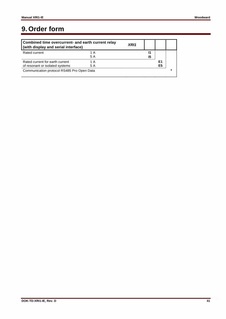
9. Order form
Combined time overcurrent- and earth current relay
(with display and serial interface) XRI1
Rated current 1 A 5 A
I1
I5
Rated current for earth current 1 A of resonant or isolated systems 5 A
E1 E5
Communication protocol RS485 Pro Open Data
*

Woodward Manual XRI1-IE
42 DOK-TD-XRI1-IE, Rev. D
Setting list XRI1-IE Note ! All settings must be checked at site and should the occasion arise, adjusted to the object / item to be protected. Project: Woodward job.-no.: Function group: = Location: + Relay code: - Relay functions: Password: Date: Setting of parameters
Function Unit Default settings
Actual settings
I> Pickup value for phase overcurrent x IN 0.20
CHAR I> Tripping characteristic for phase overcurrent ele-ment
DEFT
tI> Trip delay for phase overcurrent element s 0.03
I>+CHARI>+tI> Reset Mode for inverse characteristics s
I>> Pickup value for overcurrent high set element x IN 1.00
tI>> Trip delay for overcurrent high set element s 0.03
IE> Pickup value for earth fault low set element x IN 0.01
WARN/TRIP Warning/tripping setting TRIP
CHAR IE Tripping characteristic for earth fault overcurrent el-ement
DEFT
tIE> Trip delay for earth fault overcurrent element s 0.03
IE>+CHARIE>+tIE>
Reset mode for inverse characteristics
IE>> Pickup value for earth fault high set element x IN 0.01
tIE>> Trip delay for earth fault high set element s 0.03
tCBFP Circuit breaker failure protection s 0.20
fN Nominal frequency Hz 50
LED Flash LED blinking after excitation FLSH
RS Slave Address of serial interface 1
RS Baud rate of the serial interface * Bd 9600
Parity bit of the serial interface * even
* only Modbus Protocol

Manual XRI1-IE Woodward
DOK-TD-XRI1-IE, Rev. D 43
Setting of code jumpers
DIP-switch
1 2 3 4
Default setting
Actual setting
Default setting
Actual setting
Default setting
Actual setting
Default setting
Actual setting
On No function No function
Off X X
Assignment of the output relays
Function Relay 1 Relay 2 Relay 3 Relay 4
Default setting
Actual setting
Default setting
Actual setting
Default setting
Actual setting
Default setting
Actual setting
I> alarm X
I> tripping X
I>> alarm X
I>> tripping X
IE> alarm X
IE> tripping X
IE>> alarm X
IE>> tripping X
tCBFP
Assignment of the blocking functions
Default settings Actual settings
Function Blocked not blocked blocked not blocked
I> X
I>> X
IE> X
IE>> X
tCBFP X

Woodward Kempen GmbH
Krefelder Weg 47 D – 47906 Kempen (Germany)
Postfach 10 07 55 (P.O.Box) D – 47884 Kempen (Germany)
Phone: +49 (0) 21 52 145 1
Internet
www.woodward.com
Sales
Phone: +49 (0) 21 52 145 216 or 342 Telefax: +49 (0) 21 52 145 354
e-mail: [email protected]
Service
Phone: +49 (0) 21 52 145 614 Telefax: +49 (0) 21 52 145 455
e-mail: [email protected]