Embed Size (px)
Citation preview
XXRRPP7777XXXXEEVVBB--XXCCMM
XXRRPP7777XXXX CCoonnffiigguurraattiioonn MMoodduullee October 2012 Rev. 1.2.0
Exar Corporation www.exar.com 48720 Kato Road, Fremont CA 94538, USA Tel. +1 510 668-7000 – Fax. +1 510 668-7001
GENERAL DESCRIPTION The XRP77XXEVB-XCM (Exar Configuration Module) is a board that is designed to assist in the customer in the programming and bring-up of PowerXR Digital PWM controllers on a customer board. The XCM has a USB connection on the one side for connection to a PC and control through PowerArchitectTM software. On the right opposite side of the XCM is a 10-pin connector which is used to connect to the user’s system board in order to communicate to any of the supported PowerXR ICs.
The XCM includes a uC with on-board flash so that when powered from the system board, it can act as a boot loader to the PowerXR controller.
This board is compatible with the; XRP7704, XRP7708, XRP7740, XRP7713, and XRP7714.
UPDATE – XRP7724 enabled boards with updated firmware. See “Compatibility”, “Using I2C Communication” and “Pass Through Mode”
EEVVAALLUUAATTIIOONN BBOOAARRDD MMAANNUUAALL
FEATURES • USB to I2C Communication for PowerXR
Devices
• Boot Loader Functionality − Avoids programming the NVM until final
configuration known
• Powered by USB or System Board
• Enables Rapid Prototyping
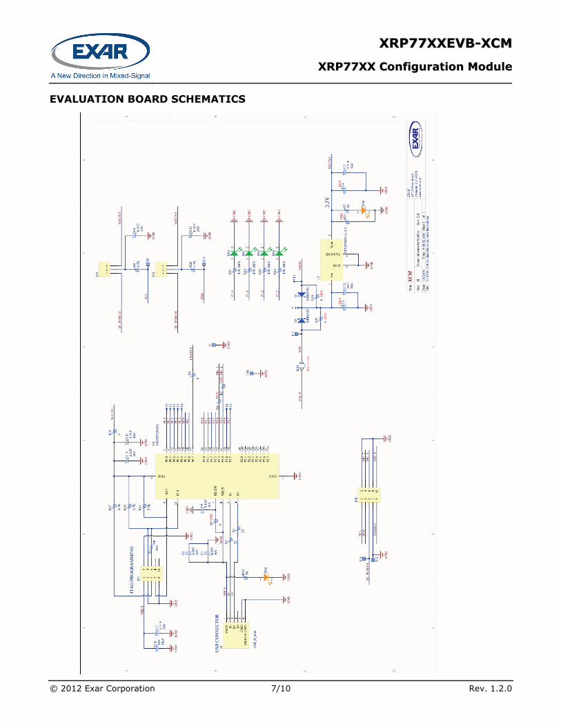
EVALUATION BOARD SCHEMATICS
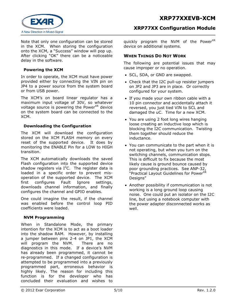
Figure 1: XRP77XXEVB-XCM Evaluation Board Schematics

XXRRPP7777XXXXEEVVBB--XXCCMM
XXRRPP7777XXXX CCoonnffiigguurraattiioonn MMoodduullee
© 2012 Exar Corporation 2/10 Rev. 1.2.0
PIN ASSIGNMENT
Figure 2: XRP77XXEVB-XCM JP4 Pin Assignment
PIN DESCRIPTION
Name Pin Number Description
SCL JP4 PIN1 I2C Clock GND JP4 PIN2 Ground SDA JP4 PIN3 I2C Data
Reserved JP4 PIN4
I2C Power JP4 PIN5 Connect to the preferred IO voltage. Only required when a voltage other than 3.3V is desired.
Reserved JP4 PIN6 GND JP4 PIN7 Ground GND JP4 PIN8 Ground
ENABLE JP4 PIN9 Connects to the EN pin of the XRP77XX. This is an input to the XCM board. VIN JP4 PIN10 Can connect to voltages from 4.5V to 30V
ORDERING INFORMATION
Part Number Description
XRP77XXEVB-XCM Exar Configuration Module
XXRRPP7777XXXXEEVVBB--XXCCMM
XXRRPP7777XXXX CCoonnffiigguurraattiioonn MMoodduullee
© 2012 Exar Corporation 3/10 Rev. 1.2.0
USING THE EVALUATION BOARD
OPERATING ASSUMPTIONS The following are the basic assumptions for the operation of the XCM.
• Only one I2C Master is active at any time on the customer board. The user must ensure that only 1 master is active on the I2C lines at the same time. This could entail Host in Reset, Host communication lines disabled, etc.
• The user must connect the appropriate signals to from the system board to the XCM JP4. At a minimum; SDA, SCL, and GND must be connected.
• VIN and ENABLE must also be connected, if the customer wants the XCM board to operate in “Standalone Mode”.
Using I2C Communication
The XCM has an on board linear regulator to provide power to the uC and provides power to the I2C lines. The internal pull-up resistors are 4.7kohm. By changing the position of the jumpers on JP2 and JP3, the pull-up resistors can be connected to either the 3.3V provided on the XCM or to the I2C Power connected to JP4 Pin 5. In Figure 2 the jumpers are configured to use the on board 3.3V. Moving them to the other position connects the pull-up resistors to the external I2C Power.
IMPORTANT: When using the XCM with XRP7713EVB or XRP7714EVB demo boards, the jumpers should be configured to use the 3.3V provided on the XCM. When using with the XRP7724EVB board, the jumpers should be moved to the other position to use the pull-up resistors already installed on the XRP7724EVB.
If the system board already has pull-up resistors, then the jumpers can simply be removed. This is the most likely scenario for a system intended to interact with the programmable features of the PowerXR device on the system board.
COMMUNICATION WITH THE XCM If the XCM is connected to the PC before starting the PowerArchitectTM software, the software should recognize the presence of the board automatically. If the board is connected after the software is started, the user will need to click on “File”, then “Board Search” for the software to find the board.
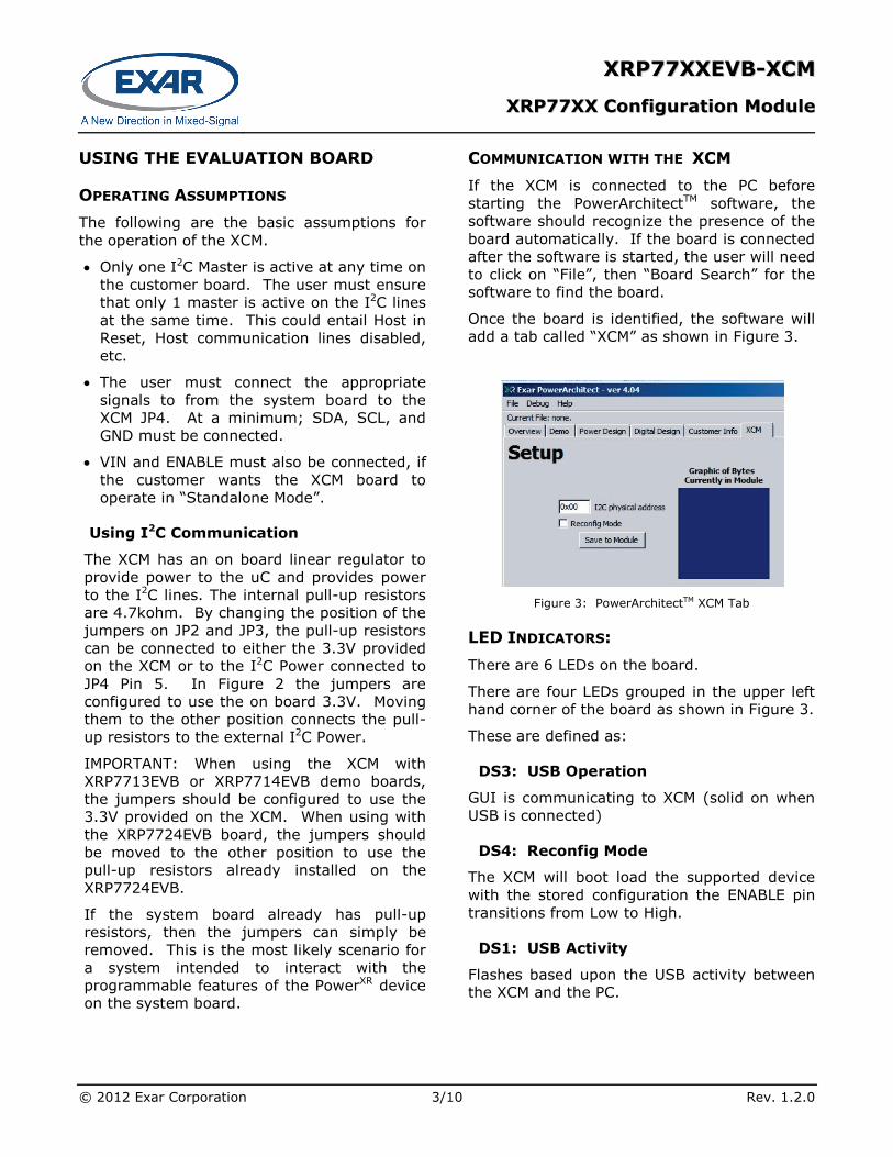
Once the board is identified, the software will add a tab called “XCM” as shown in Figure 3.
Figure 3: PowerArchitectTM XCM Tab
LED INDICATORS: There are 6 LEDs on the board.
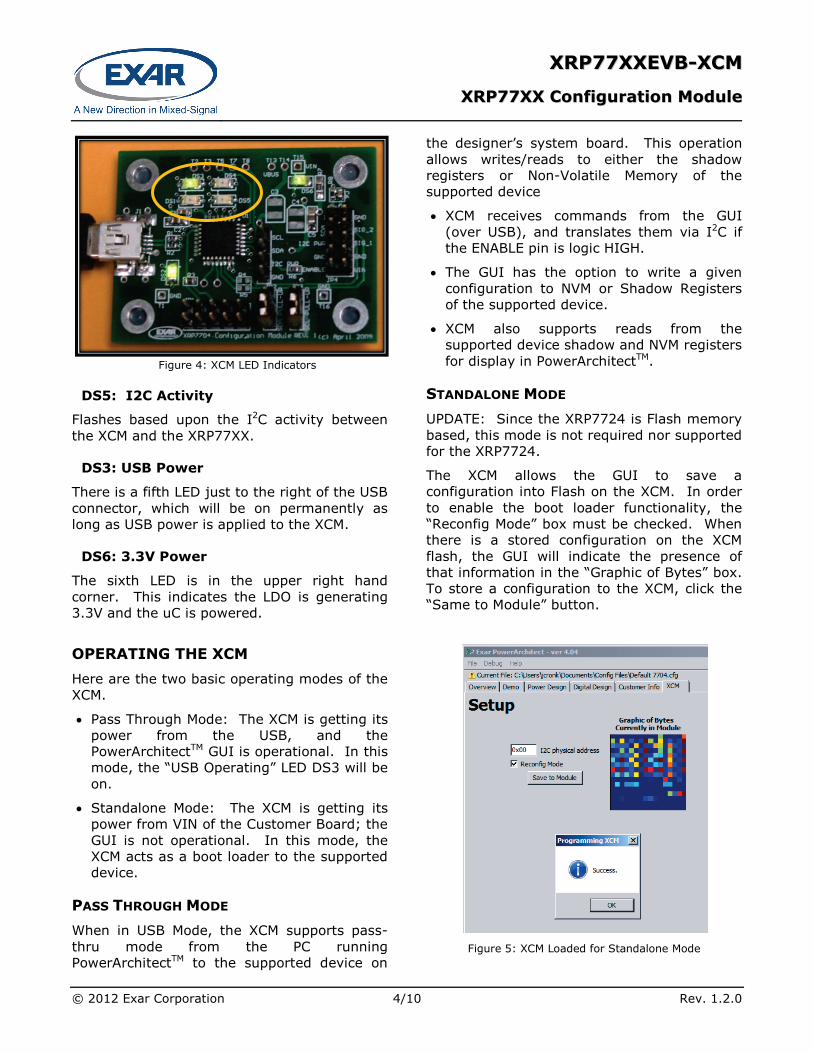
There are four LEDs grouped in the upper left hand corner of the board as shown in Figure 3.
These are defined as:
DS3: USB Operation
GUI is communicating to XCM (solid on when USB is connected)
DS4: Reconfig Mode
The XCM will boot load the supported device with the stored configuration the ENABLE pin transitions from Low to High.
DS1: USB Activity
Flashes based upon the USB activity between the XCM and the PC.
XXRRPP7777XXXXEEVVBB--XXCCMM
XXRRPP7777XXXX CCoonnffiigguurraattiioonn MMoodduullee
© 2012 Exar Corporation 4/10 Rev. 1.2.0
Figure 4: XCM LED Indicators
DS5: I2C Activity
Flashes based upon the I2C activity between the XCM and the XRP77XX.
DS3: USB Power
There is a fifth LED just to the right of the USB connector, which will be on permanently as long as USB power is applied to the XCM.
DS6: 3.3V Power
The sixth LED is in the upper right hand corner. This indicates the LDO is generating 3.3V and the uC is powered.
OPERATING THE XCM Here are the two basic operating modes of the XCM.
• Pass Through Mode: The XCM is getting its power from the USB, and the PowerArchitectTM GUI is operational. In this mode, the “USB Operating” LED DS3 will be on.
• Standalone Mode: The XCM is getting its power from VIN of the Customer Board; the GUI is not operational. In this mode, the XCM acts as a boot loader to the supported device.
PASS THROUGH MODE When in USB Mode, the XCM supports pass-thru mode from the PC running PowerArchitectTM to the supported device on
the designer’s system board. This operation allows writes/reads to either the shadow registers or Non-Volatile Memory of the supported device
• XCM receives commands from the GUI (over USB), and translates them via I2C if the ENABLE pin is logic HIGH.
• The GUI has the option to write a given configuration to NVM or Shadow Registers of the supported device.
• XCM also supports reads from the supported device shadow and NVM registers for display in PowerArchitectTM.
STANDALONE MODE UPDATE: Since the XRP7724 is Flash memory based, this mode is not required nor supported for the XRP7724.
The XCM allows the GUI to save a configuration into Flash on the XCM. In order to enable the boot loader functionality, the “Reconfig Mode” box must be checked. When there is a stored configuration on the XCM flash, the GUI will indicate the presence of that information in the “Graphic of Bytes” box. To store a configuration to the XCM, click the “Same to Module” button.
Figure 5: XCM Loaded for Standalone Mode
XXRRPP7777XXXXEEVVBB--XXCCMM
XXRRPP7777XXXX CCoonnffiigguurraattiioonn MMoodduullee
© 2012 Exar Corporation 5/10 Rev. 1.2.0
Note that only one configuration can be stored in the XCM. When storing the configuration onto the XCM, a “Success” window will pop up. After clicking “OK” there can be a noticeable delay in the software.
Powering the XCM
In order to operate, the XCM must have power provided either by connecting the VIN pin on JP4 to a power source from the system board or from USB power.
The XCM’s on board linear regulator has a maximum input voltage of 30V, so whatever voltage source is powering the PowerXR device on the system board can be connected to the XCM.
Downloading the Configuration
The XCM will download the configuration stored on the XCM FLASH memory on every reset of the supported device. It does by monitoring the ENABLE Pin for a LOW to HIGH transition.
The XCM automatically downloads the saved Flash configuration into the supported device shadow registers via I2C. The register data is loaded in a specific order to prevent mis-operation of the supported device. The XCM first configures Fault Ignore settings, downloads channel information, and finally configures the channel and GPIO enables.
One could imagine the result, if the channel was enabled before the control loop PID coefficients were loaded.
NVM Programming
When in Standalone Mode, the primary intention for the XCM is to act as a boot loader into the shadow RAM. However, by installing a jumper between pins 2-4 on JP1, the XCM will program the NVM. There are no diagnostics in this mode. If a device’s NVM has already been programmed, it cannot be re-programmed. If a changed configuration is attempted to be programmed into a previously programmed part, erroneous behavior is highly likely. The reason for including this function is for the developer who has concluded their evaluation and wishes to
quickly program the NVM of the PowerXR device on additional systems.
WHEN THINGS DO NOT WORK The following are potential issues that may cause improper or no operation.
• SCL, SDA, or GND are swapped.
• Check that the I2C pull-up resister jumpers on JP2 and JP3 are in place. Or correctly configured for your system.
• If you made your own ribbon cable with a 10 pin connector and accidentally attach it reversed, you just tied VIN to SCL and damaged the uC. Time for a new XCM.
• You are using 2 foot long wires hanging loose creating an inductive loop which is blocking the I2C communication. Twisting them together should reduce the inductance.
• You can communicate to the part when it is not operating, but when you turn on the switching channels, communication stops. This is difficult to fix because the most likely cause is ground bounce caused by poor grounding practices. See ANP-32, “Practical Layout Guidelines for PowerXR Designs”
• Another possibility if communication is not working is a long ground loop causing noise. One could put an isolator on the I2C line, but using a notebook computer with the power adapter disconnected works as well.

XXRRPP7777XXXXEEVVBB--XXCCMM
XXRRPP7777XXXX CCoonnffiigguurraattiioonn MMoodduullee
© 2012 Exar Corporation 6/10 Rev. 1.2.0
COMPATIBILITY With the release of the XRP7724 the firmware of the XCM has been updated. This has resulted in a compatibility issue when being used with PowerArchitectTM 4.21 and earlier revisions. XCMs which have updated firmware will be labeled “V62”. If this XCM is first powered by the USB cable and discovered by PowerArchitectTM 4.21, the demo panel may show erroneous information (see Figure 7). However, if the XRP7704/08/40 or XRP7713/4 is first connected to the XCM then powered before connecting the USB cable, normal operation will occur. Future versions of PowerArchitectTM 4.xx will eliminate this compatibility issue.
Figure 7 PowerArchitectTM 4.21 Demo Tab when XRP7724 configured XCM not powered in proper sequence
Figure 6 XCM with updated firmware
XXRRPP7777XXXXEEVVBB--XXCCMM
XXRRPP7777XXXX CCoonnffiigguurraattiioonn MMoodduullee
© 2012 Exar Corporation 7/10 Rev. 1.2.0
EVALUATION BOARD SCHEMATICS
XXRRPP7777XXXXEEVVBB--XXCCMM
XXRRPP7777XXXX CCoonnffiigguurraattiioonn MMoodduullee
© 2012 Exar Corporation 8/10 Rev. 1.2.0
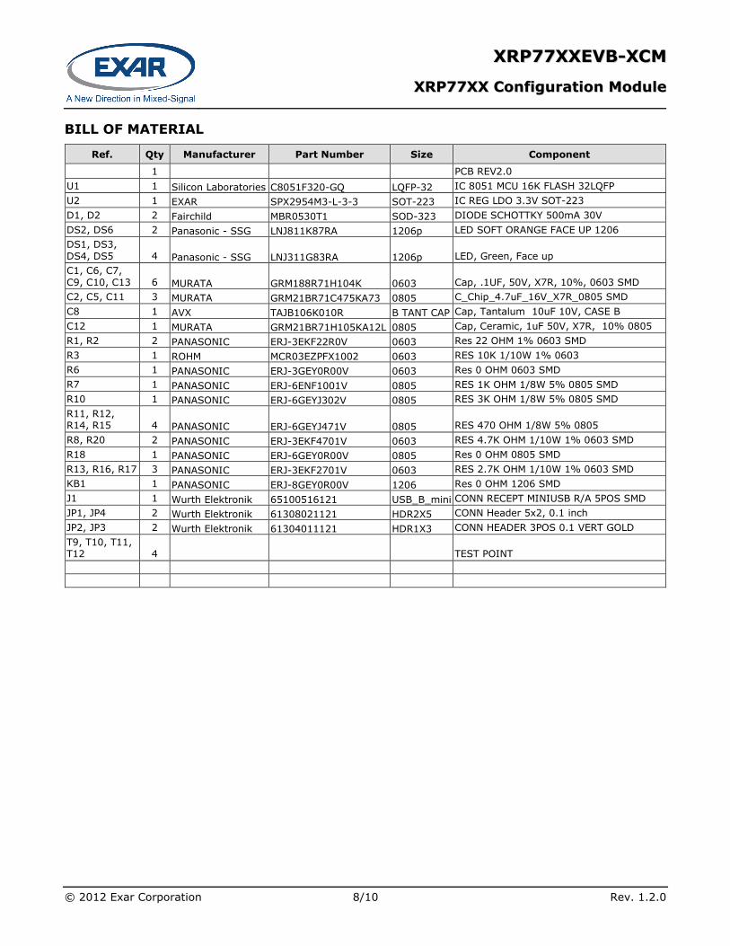
BILL OF MATERIAL
Ref. Qty Manufacturer Part Number Size Component
1 PCB REV2.0 U1 1 Silicon Laboratories C8051F320-GQ LQFP-32 IC 8051 MCU 16K FLASH 32LQFP U2 1 EXAR SPX2954M3-L-3-3 SOT-223 IC REG LDO 3.3V SOT-223 D1, D2 2 Fairchild MBR0530T1 SOD-323 DIODE SCHOTTKY 500mA 30V DS2, DS6 2 Panasonic - SSG LNJ811K87RA 1206p LED SOFT ORANGE FACE UP 1206 DS1, DS3, DS4, DS5 4 Panasonic - SSG LNJ311G83RA 1206p LED, Green, Face up C1, C6, C7, C9, C10, C13 6 MURATA GRM188R71H104K 0603 Cap, .1UF, 50V, X7R, 10%, 0603 SMD C2, C5, C11 3 MURATA GRM21BR71C475KA73 0805 C_Chip_4.7uF_16V_X7R_0805 SMD C8 1 AVX TAJB106K010R B TANT CAP Cap, Tantalum 10uF 10V, CASE B C12 1 MURATA GRM21BR71H105KA12L 0805 Cap, Ceramic, 1uF 50V, X7R, 10% 0805 R1, R2 2 PANASONIC ERJ-3EKF22R0V 0603 Res 22 OHM 1% 0603 SMD R3 1 ROHM MCR03EZPFX1002 0603 RES 10K 1/10W 1% 0603 R6 1 PANASONIC ERJ-3GEY0R00V 0603 Res 0 OHM 0603 SMD R7 1 PANASONIC ERJ-6ENF1001V 0805 RES 1K OHM 1/8W 5% 0805 SMD R10 1 PANASONIC ERJ-6GEYJ302V 0805 RES 3K OHM 1/8W 5% 0805 SMD R11, R12, R14, R15 4 PANASONIC ERJ-6GEYJ471V 0805 RES 470 OHM 1/8W 5% 0805 R8, R20 2 PANASONIC ERJ-3EKF4701V 0603 RES 4.7K OHM 1/10W 1% 0603 SMD R18 1 PANASONIC ERJ-6GEY0R00V 0805 Res 0 OHM 0805 SMD R13, R16, R17 3 PANASONIC ERJ-3EKF2701V 0603 RES 2.7K OHM 1/10W 1% 0603 SMD KB1 1 PANASONIC ERJ-8GEY0R00V 1206 Res 0 OHM 1206 SMD J1 1 Wurth Elektronik 65100516121 USB_B_mini CONN RECEPT MINIUSB R/A 5POS SMD JP1, JP4 2 Wurth Elektronik 61308021121 HDR2X5 CONN Header 5x2, 0.1 inch JP2, JP3 2 Wurth Elektronik 61304011121 HDR1X3 CONN HEADER 3POS 0.1 VERT GOLD T9, T10, T11, T12 4 TEST POINT
XXRRPP7777XXXXEEVVBB--XXCCMM
XXRRPP7777XXXX CCoonnffiigguurraattiioonn MMoodduullee
© 2012 Exar Corporation 9/10 Rev. 1.2.0
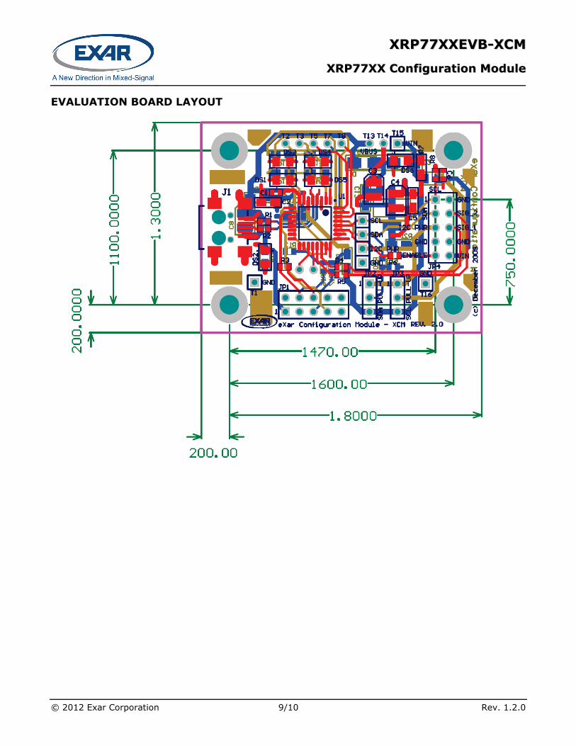
EVALUATION BOARD LAYOUT
XXRRPP7777XXXXEEVVBB--XXCCMM
XXRRPP7777XXXX CCoonnffiigguurraattiioonn MMoodduullee
© 2012 Exar Corporation 10/10 Rev. 1.2.0
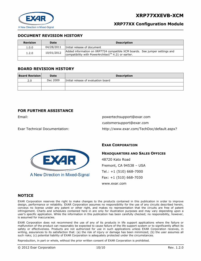
DOCUMENT REVISION HISTORY
Revision Date Description
1.0.0 04/28/2011 Initial release of document
1.2.0 10/01/2012 Added information on XRP7724 compatible XCM boards. See jumper settings and compatibility with PowerArchitectTM 4.21 or earlier.
BOARD REVISION HISTORY
Board Revision Date Description
2.0 Dec 2009 Initial release of evaluation board
FOR FURTHER ASSISTANCE Email: [email protected]
Exar Technical Documentation: http://www.exar.com/TechDoc/default.aspx?
EXAR CORPORATION
HEADQUARTERS AND SALES OFFICES 48720 Kato Road
Fremont, CA 94538 – USA
Tel.: +1 (510) 668-7000
Fax: +1 (510) 668-7030
www.exar.com
NOTICE EXAR Corporation reserves the right to make changes to the products contained in this publication in order to improve design, performance or reliability. EXAR Corporation assumes no responsibility for the use of any circuits described herein, conveys no license under any patent or other right, and makes no representation that the circuits are free of patent infringement. Charts and schedules contained here in are only for illustration purposes and may vary depending upon a user’s specific application. While the information in this publication has been carefully checked; no responsibility, however, is assumed for inaccuracies.
EXAR Corporation does not recommend the use of any of its products in life support applications where the failure or malfunction of the product can reasonably be expected to cause failure of the life support system or to significantly affect its safety or effectiveness. Products are not authorized for use in such applications unless EXAR Corporation receives, in writing, assurances to its satisfaction that: (a) the risk of injury or damage has been minimized; (b) the user assumes all such risks; (c) potential liability of EXAR Corporation is adequately protected under the circumstances.
Reproduction, in part or whole, without the prior written consent of EXAR Corporation is prohibited.