Embed Size (px)
DESCRIPTION
Doc
Citation preview
COPYRIGHT
3GPP2 and its Organizational Partners claim copyright in this document and individual Organizational
Partners may copyright and issue documents or standards publications in individual Organizational
Partner's name based on this document. Requests for reproduction of this document should be directed to
the 3GPP2 Secretariat at [email protected]. Requests to reproduce individual Organizational Partner's
documents should be directed to that Organizational Partner. See www.3gpp2.org for more information.
3GPP2 X.S0011-003-C
Version: 3.0
Version Date: October 2006
cdma2000 Wireless IP Network Standard;
Packet Data Mobility and Resource
Management

X.S0011-003-C v3.0
i
Content 1
1 GLOSSARY AND DEFINITIONS ............................................................................................................2 2
2 REFERENCES ..............................................................................................................................................2 3
3 MOBILITY MANAGEMENT....................................................................................................................2 4
3.1 MOBILITY WITHIN RADIO NETWORK ......................................................................................................2 5
3.2 INTRA PDSN HANDOFF ..............................................................................................................................2 6
3.3 INTER PDSN HANDOFF ..............................................................................................................................3 7
4 P-P INTERFACE..........................................................................................................................................5 8
4.1 ARCHITECTURE ...........................................................................................................................................5 9
4.2 THE P-P INTERFACE PROTOCOL...............................................................................................................5 10
4.2.1 SIGNALING .................................................................................................................................................6 11
4.2.2 BEARER TRANSPORT .................................................................................................................................6 12
4.3 FAST HANDOFF PROCEDURES OVERVIEW ................................................................................................6 13
4.3.1 ACTIVE SERVICE INSTANCES ....................................................................................................................7 14
4.3.2 DORMANT SERVICE INSTANCES................................................................................................................8 15
4.4 DETAILED P–P INTERFACE PROCEDURES................................................................................................9 16
4.4.1 P-P CONNECTION ESTABLISHMENT..........................................................................................................9 17
4.4.2 P-P ESTABLISHMENT CONNECTION FAILURE ........................................................................................10 18
4.4.3 P-P CONNECTION – PERIODIC RE-REGISTRATION .................................................................................11 19
4.4.4 P-P INTERFACE RELEASE PROCEDURES .................................................................................................11 20
4.4.5 P-P FAST HANDOFF COMPLETION ..........................................................................................................12 21
4.5 BICASTING SCENARIOS.............................................................................................................................12 22
4.6 PPP LINK INDICATOR EXTENSION .........................................................................................................15 23
5 RESOURCE MANAGEMENT ................................................................................................................16 24
5.1 SIMPLE IP...................................................................................................................................................16 25
5.2 MOBILE IP .................................................................................................................................................18 26
5.2.1 DYNAMIC AUTHORIZATION EXTENSIONS TO RADIUS.........................................................................18 27
5.2.2 REGISTRATION REVOCATION IN MOBILE IPV4 AT THE PDSN..............................................................19 28
5.2.3 REGISTRATION REVOCATION IN MOBILE IPV4 AT THE HA...................................................................21 29
6 RNRAN PACKET DATA INACTIVITY TIMER ................................................................................23 30
7 RADIO NETWORK REQUIREMENTS ...............................................................................................24 31
7.1 GENERAL....................................................................................................................................................24 32
7.2 R-P INTERFACE REQUIREMENTS ............................................................................................................24 33
7.3 R-P GENERAL HANDOFF CAPABILITIES ................................................................................................24 34
35

X.S0011-003-C v3.0
ii
Figures 1
FIGURE 1 - INTRA PDSN HANDOFF ..................................................................................................................13 2
FIGURE 2 - INTER PDSN, BEGINNING OF FAST HANDOFF..............................................................................13 3
FIGURE 3 - INTRA PDSN, CONTINUATION OF FAST HANDOFF ON TARGET PDSN .....................................14 4
FIGURE 4 - INTER PDSN HANDOFF, CONTINUATION OF FAST HANDOFF BETWEEN TARGET PDSNS .....14 5
6
7

X.S0011-003-C v3.0
iii
Tables 1
TABLE 1. RADIUS DISCONNECT-REQUEST ATTRIBUTES USED FOR 3GPP2 RESOURCE MANAGEMENT 17 2
3

X.S0011-003-C v3.0
General Description 1
General Description 1
This Chapter describes the mechanisms at the PDSN resulting from handoff of an MS from one 2
BS/PCF to another BS/PCF, and which may result in changing the serving PDSN for the MS. This 3
Chapter describes an optional fast handoff capability, which is a low latency, low data loss 4
handoff mechanism between PDSNs. Fast handoff mechanism delays re-negotiation of PPP until 5
the MS becomes dormant at the Target PDSN. This Chapter also describes resource 6
management procedures at the PDSN and the HA that are used following an inter PDSN handoff 7
or under other conditions that require release of resources. Furthermore, a procedure for 8
provisioning the RNRAN with resource management parameters such as RNRAN packet data 9
inactivity timers is specified in this Chapter. 10

X.S0011-003-C v3.0
3. Mobility Management 2
1 Glossary and Definitions 1
See X.S0011-001-C 2
2 References 3
See X.S0011-001-C 4
3 Mobility Management 5
3.1 Mobility Within Radio Network 6
Mobility in the wireless IP network architecture is achieved via handoffs. When a handoff is 7
between PCFs with connectivity to the same PDSN so that the Serving PDSN remains the same 8
before, during, and after handoff, it is called Intra PDSN handoff. When PCFs are connected to 9
different PDSNs, the handoff is termed Inter PDSN handoff. 10
3.2 Intra PDSN Handoff 11
The link layer mobility management function is used to manage the change of the R-PA10 12
session point of attachment while maintaining the PPP session and IP address(es). The R-PA10 13
session point of attachment is the PDSN. When an MS moves from one PCF to another PCF, a 14
new R-P connectionA10 connections between the Target PCF and the Serving PDSN isare 15
established for every packet data service instanceas necessary. 16
PCF to PCF handoff may occur while an MS is in the active or dormant state. The purpose of 17
dormant PCF handoff is to maintain the PPP session while an MS is dormant to minimize the use 18
of airlink resources. 19
The PCF to PCF handoff involves: 20
• PDSN selection. 21
• New R-PA10 session setup. 22
• Previous R-PA10 session tear down. 23
The Target PCF triggers a new R-PA10 session setup. If the PDSN selected is the same Serving 24
PDSN for the MS, then the PDSN triggers a release of the previous R-PA10 session. 25
During a PCF to PCF handoff, the selection of the same PDSN is given priority in order to 26
maintain the existing PPP session between the PDSN and the MS. If a different PDSN is selected 27
and the MS still desires packet data service, then a PDSN to PDSN handoff may be performed 28
(see Section 3.3). The PDSN supports a low latency PCF to PCF handoff by bicasting data to and 29
receiving data from the target and previous PCF while the mobile performs an active handoff. 30
Each PCF is uniquely identified by an Access Network Identifier. At handoff, the new PCF 31
performs PDSN selection and forwards both the Previous Access Network Identification (if 32
available from the RNRAN), and its own Access network Identification to the selected PDSN. If 33
the PDSN recognizes the MSID, it compares the Previous Access Network Identifier if non-zero, 34
to the Stored Access Network Identifier for the call to determine if it has a stale packet data 35
session for the MS. If so, the PDSN performs PPP renegotiation with the MS and Mobile IP re-36
registration, if required.. See PPP establishment procedures in X.S0011-004-C. 37
Detailed requirements and standard procedures for PCF to PCF handoff are described in [4]. 38

X.S0011-003-C v3.0
3. Mobility Management 3
3.3 Inter PDSN Handoff 1
For Simple IP, there is no mobility beyond a PDSN coverage area, unless fast handoff 2
procedures are supported that facilitate the PPP session to be anchored at the Serving PDSN 3
until the MS becomes dormant. 4
Mobile IP provides the IP layer mobility management function that maintains persistent IP 5
addresses across PDSNs. For a Mobile IP based MS to maintain a persistent IP address while 6
moving between PDSNs, the MS re-registers with its HA as per RFC 2002 with extensions as 7
outlined in X.S0011-002-C. 8
For PDSN to PDSN handoff, the MS may be in active or dormant state. For an active state MS, 9
fast handoff may be supported between PDSNs. If fast handoff is supported, the Target PDSN 10
initiates establishment of a P-P session with the Serving PDSN according to the procedures 11
described later in Section 4. If the MS was in dormant state, the MS transitions to active state for 12
the purpose of establishing connectivity with the new PDSN. 13
The PDSN to PDSN link for supporting fast handoff is called the P-P interface. Fast handoff with 14
the P-P interface is used to keep the PPP session anchored when the PDSN to PDSN handoff is 15
performed. This allows the existing PPP session to continue, thereby reducing service 16
interruption time and data loss. The forward traffic received at the Serving PDSN is tunneled 17
through the appropriate P-P connection to the Target PDSN. The Target PDSN then forwards the 18
traffic to the MS over the corresponding R-PA10 connection. The reverse traffic from the MS is 19
tunneled through the P-P interface from the Target PDSN to the Serving PDSN. The Serving 20
PDSN then forwards the traffic to the external network. 21
If fast handoff is not supported, the PDSN to PDSN handoff for Mobile IP involves: 22
• Establishment of a new PPP session; 23
• Detection of a new FA via the Agent Advertisement Message; 24
• Authentication by RADIUS infrastructure; 25
• Registration with the HA. 26
If fast handoff is supported, the PDSN to PDSN handoff for Mobile IP involves: 27
• Establishment of a P-P connection for each associated R-PA10 connection at the 28
Target PDSN and the continuation of the current PPP session on the Serving PDSN; 29
• Establishment of a new PPP session and authentication with the RADIUS 30
infrastructure by the Target PDSN when the MS becomes dormant or the MS 31
renegotiates PPP; 32
• Release of the associated P-P connections while the new PPP session is being 33
established at the Target PDSN; 34
• Detection of a new FA via the Agent Advertisement Message; 35
• Authentication by RADIUS infrastructure; 36
• Registration with the HA. 37
If fast handoff is not supported, the PDSN to PDSN handoff for Simple IP involves: 38
• Establishment of a new PPP session on the Target PDSN. 39
• Authentication by the RADIUS infrastructure. 40
If fast handoff is supported, the PDSN to PDSN handoff for Simple IP involves: 41
• Establishment of a P-P connection for each associated R-PA10 connection at the 42
Target PDSN, and continuation of the current PPP session on the Serving PDSN; 43

X.S0011-003-C v3.0
3. Mobility Management 4
• Establishment of a new PPP session and authentication with the RADIUS 1
infrastructure by the Target PDSN when the MS becomes dormant or the MS 2
renegotiates PPP; 3
• Release of the associated P-P session while the new PPP session is being 4
established at the Target PDSN. 5

X.S0011-003-C v3.0
4. P-P Interface 5
4 P-P Interface 1
4.1 Architecture 2
The network reference model is depicted in X.S0011-001-C. This section describes the 3
functionality for a fast handoff in the context of an inter PDSN handoff. This section provides P-P 4
interface details. See [4] for fast handoff procedures over the R-PA11 interface. 5
With the implementation of the P-P Interface, the following additional functions are provided by 6
the PDSNs during fast handoff: 7
• For every R-PA10 connection at the Target PDSN, there is a corresponding P-P 8
connection. 9
• The Target PDSN is not the end point of PPP at fast handoff. 10
• The Target PDSN provides transparent bi-directional transport of the bearer data 11
stream over the R-PA10 and P-P connections. 12
• The Serving PDSN provides bi-directional transport of the bearer data stream over 13
the P-P connections. 14
• The Target PDSN forwards accounting related airlink records received over an R-15
PA10 connection to the Serving PDSN over the corresponding P-P connection. 16
• The Serving PDSN processes airlink records received over the P-P connection 17
similar to the airlink records received over the R-PA10 connection by creating 18
separate UDRs. 19
• The Target PDSN becomes the Serving PDSN when the MS becomes dormant or 20
the MS initiated PPP renegotiation with the Serving PDSN, in which case The , the 21
Target PDSN shall use the main service instance to carry on PPP negotiation. When 22
the MS closes the PPP session at the Serving PDSN, the Serving PDSN shall 23
release the P-P connections, and the Target PDSN shall release the R-PA10/A11 24
connections. 25
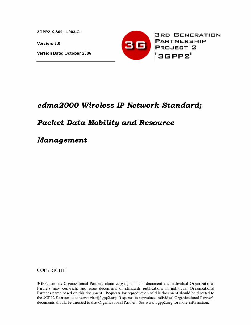
During a fast handoff, either two R-PA10 connections (see Figure 3), or an R-PA10 and P-P 26
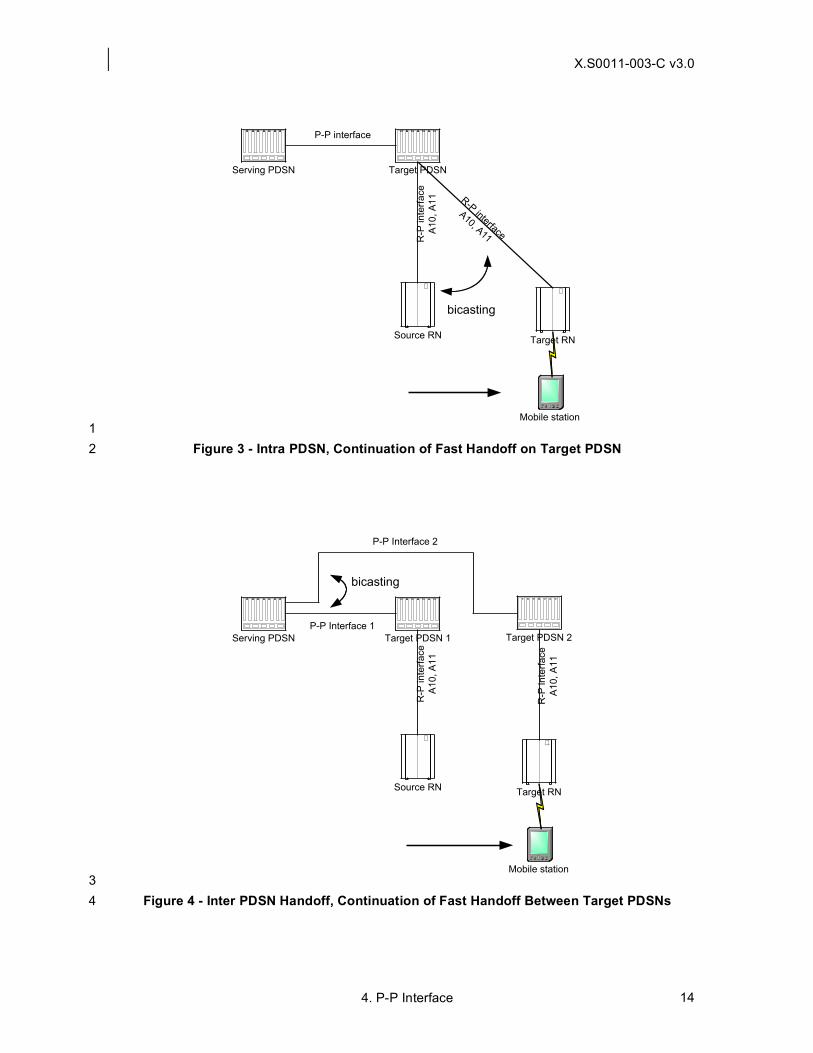
connection (see Figure 2), or two P-P connections (see Figure 4) with the same SR_ID and IMSI 27
may exist momentarily with the same SR_ID and IMSI due to the PDSN bicasting. 28
4.2 The P-P Interface Protocol 29
This section specifies the protocol and messages to be used for signaling for the P-P 30
connections. The P-P Interface protocol is independent of the physical and link layers of the 31
transport media over which the P-P connection(s) is/are to be established. The underlying 32
transport media provides UDP/IP based packet oriented connectivity. 33
There are two components for the P-P Interface: 34
• Signaling: Control messages shall be used for managing the P-P connection(s) 35
between the Serving and the Target PDSNs. 36
• Bearer Transport: GRE frames shall be used for the transport of bearer data frames 37
between Serving and Target PDSNs. 38
The Target PDSN shall initiate establishment of a P-P connection, whereas either the Serving 39
PDSN or the Target PDSN may initiate termination of the connection. Termination of a P-P 40
connection shall follow the procedures for R-PA10 connections as specified in [4] in conjunction 41
with the procedures detailed in this Chapter. Once a P-P connection has been established, the 42
bearer portion of the P-P connection shall use GRE framing [RFC 2784, RFC 2890] for the 43
transport of bearer data frames. There shall be one P-P connection between the Serving PDSN 44

X.S0011-003-C v3.0
4. P-P Interface 6
and the Target PDSN for each R-PA10 connection between the Target PDSN and Target 1
RN.RAN. The GRE payloads in the P-P connection and R-PA10 connection shall be identical for 2
the same connection. 3
4.2.1 Signaling 4
The following messages shall be used for P-P Interface call control and signaling: 5
• P-P Registration-Request. 6
• P-P Registration-Reply. 7
• P-P Registration-Update. 8
• P-P Registration-Acknowledge. 9
• P-P Session Update. 10
• P-P Session Acknowledge. 11
These messages use the same format as R-PA10 connection messages specified in [4], 12
including use of the same UDP port number ’699’. The entire signaling message shall be sent 13
within a single UDP datagram. The source IP address of the P-P Registration-Request, P-P 14
Session-Acknowledge and P-P Registration-Acknowledge messages is set to the Target P-P 15
Address and the destination IP address is set to the Serving P-P Address. The source IP address 16
of the P-P Registration Update, P-P Session-Update and P-P Registration-Reply messages is set 17
to the Serving P-P Address and the destination IP address is set to the Target P-P Address. 18
The initiator of the P-P connection (Target PDSN) shall pick an available source UDP port, and 19
send a P-P Registration-Request message to the desired destination (Serving PDSN) at UDP 20
port ‘699’. The recipient (Serving PDSN) shall send a P-P Registration-Reply message to the 21
initiator’s (Target PDSN) UDP port that initiated the P-P Registration-Request message. The 22
following indicates the setting of the fields within a P-P Registration signaling message: 23
• Care-of address = Target P-P Address (Only included in P-P Registration-Request 24
message, P-P Registration Acknowledge message and P-P Session Update 25
Acknowledge message). 26
• Home Address = 0.0.0.0 (in all messages). 27
• HA Address = Serving P-P Address (in all messages except P-P Registration-28
Acknowledge and P-P Session Update Acknowledge messages). 29
• MN-HA Authentication Extension = This element marks the end of the authenticated 30
data in P-P Registration Request and P-P Registration Reply messages. 31
• Registration Update Authentication Extension = This element marks the end of the 32
authenticated data in P-P Registration Update, P-P Session Update and P-P Session 33
Update Acknowledge messages. 34
The procedures to support fast handoff over the R-PA10/A11 interface are defined in [4]. 35
4.2.2 Bearer Transport 36
The P-P bearer frames shall use the same payload format as used on the R-PA10 interface, 37
specified in [4]. The procedures for selection and use of the GRE key are as outlined in [4]. 38
4.3 Fast Handoff procedures overview 39
The P-P interface shall use the signaling messages defined in section 4.2.1 to manage the P-P 40
connections. The following sections describe the messages and procedures for the P-P interface. 41
In order to obtain packet data services, the MS performs registration with the packet data 42
network. The service instance(s) is/are assigned and an R-PA10 connection(s) is/are established 43

X.S0011-003-C v3.0
4. P-P Interface 7
for each service instance between the Serving RNRAN and the Serving PDSN on behalf of the 1
MS. For multiple service instances, handling of the bearer data streams over the R-PA10 2
connections is determined according to X.S0011-004-C. 3
During the course of the packet data session, the MS moves into the coverage area of a Target 4
RNRAN, resulting in an Intra or Inter PDSN handoff. The following two sections specify the Inter 5
PDSN fast handoff for active and dormant service instances separately. 6
This document assumes that Inter or Intra PDSN handoffs move both active and dormant service 7
instances to the Target RN.RAN. The active and dormant service instances are defined in [4]. 8
4.3.1 Active Service Instances 9
On detection of a condition that a handoff is required, the Source RNRAN initiates handoff 10
procedures with the Target RNRAN (via the MSC). 11
If the Serving PDSN is reachable from the Target RNRAN, the fast handoff is performed as 12
specified in [4], and the Serving PDSN shall release: 13
• Existing R-PA10 connection(s) to the Source RNRAN. 14
• P-P connection(s) associated with the MS1 as a result of a handoff back from the 15
Target PDSN to the Serving PDSN. 16
If the Serving PDSN is not reachable from the Target RNRAN, the Target RNRAN selects a 17
Target PDSN and establishes one R-PA10 connection for each service instance to that PDSN. 18
The R-PA11 Registration-Request message(s) have the 'S' bit set to indicate bicasting of the 19
bearer payloads and contain the Serving P-P Address, the identity of the MS, and an R-PA11 20
Connection Setup Airlink Record. The Target PDSN shall immediately respond with an R-PA11 21
Registration-Reply message that contains the serving P-P address as received in the R-PA11 22
Registration-Request message. For each R-PA10 connection so established, the Target PDSN 23
attempts to establish a P-P connection to the Serving PDSN with the 'S' bit set (to indicate 24
bicasting of the bearer payloads). 25
The Serving PDSN shall use the SR_ID information in conjunction with the mobile identifier to find 26
the link layer context information associated with the service instance. The Serving PDSN 27
determines whether a P-P connection corresponds to the main service instance by checking the 28
SR_ID received in the associated P-P connection setup message for the IMSI. The Serving 29
PDSN shall apply existing link layer context (e.g., compression, PPP, etc.) when sending packets 30
on the P-P connection. 31
If the Serving PDSN accepts the P-P Registration-Request message, and the Serving PDSN 32
determines that the P-P connection carries the main service instance, the Serving PDSN shall 33
return a P-P Registration-Reply message with a PPP Link Indicator Extension (see Section 4.6) 34
that indicates that the P-P connection supports the main service instance. The Serving PDSN 35
shall start to bicast bearer data that is appropriately conditioned according to the link layer control 36
to both the Source RNRAN via the R-PA10 connection and the Target PDSN via the P-P 37
connection (see Figure 2), or to both the previous Target PDSN via the previous P-P connection, 38
and the Target PDSN via the P-P connection (see Figure 4). The Serving PDSN shall bicast until 39
it receives a P-P Registration-Request with the 'S' bit clear. The Target PDSN shall forward 40
bearer data to the Target RNRAN via the R-PA10 connection. 41
Upon successful handoff of a service instance to the Target RNRAN, the Target RNRAN shall 42
deliver the bearer data from the associated R-PA10 connection to the MS. Also, the Target 43
RNRAN sends an R-PA11 Registration-Request message with the ‘S’ bit clear and an Active 44
Start Airlink Record to the Target PDSN. 45
1 In particular, this addresses the case of a new Target PDSN being exactly the same as the
currently Serving PDSN.

X.S0011-003-C v3.0
4. P-P Interface 8
The Target PDSN shall forward the Active Start Airlink Record to the Serving PDSN over the just 1
established P-P connection(s) in a P-P Registration-Request message with the 'S' bit clear. Upon 2
reception of P-P Registration-Request messages with the ‘S’ bit clear, the Serving PDSN shall 3
release the corresponding R-PA10 connections to the Source RNRAN as identified by the SR_ID, 4
or the P-P connections to the previous Target PDSN. 5
The Target and Serving P-P addresses, along with the GRE Key form the unique link layer ID for 6
each P-P connection. With the P-P connection(s) in place, bearer data frames pass over these 7
connection(s) in both directions via GRE framing. In the reverse direction, the Serving PDSN shall 8
accept the P-P frames, process and remove the GRE overhead, and then shall process the GRE 9
payload, as necessary. In the forward direction the Serving PDSN shall encapsulate bearer data 10
frames in GRE. The Target PDSN shall process and remove the GRE overhead before passing 11
the bearer data to the associated R-PA10 connection. On the R-PA10 connection, the Target 12
PDSN shall encapsulate the bearer data frames in GRE and shall forward them to the Target 13
RN.RAN. Thus, the Target PDSN shall provide a transparent bi-directional transport for the 14
bearer data frames between the R-PA10 connection and the P-P connection so that there is a 15
point-to-point link layer connection for each service instance between the MS and the Serving 16
PDSN. 17
The Target PDSN shall maintain the P-P connections by periodically sending P-P Registration-18
Request messages to the Serving PDSN with ‘S’ bit clear. Each P-P connection shall be 19
maintained as long as the corresponding R-PA10 connection exists at the Target PDSN or until 20
such time as the fast handoff is completed according to Section 4.4.5. 21
4.3.2 Dormant Service Instances 22
There are two cases to consider when an MS with dormant service instances moves to an 23
RNRAN in a different packet zone: 24
• Case 1: The MS has one or more dormant service instances and no active service 25
instances. 26
• Case 2: The MS has one or more dormant service instances and one or more active 27
service instances. 28
Case 1: 29
Usual dormant handoff procedures apply and there is no fast handoff. 30
Case 2: 31
The Target RNRAN connects active service instances first as detailed in section 4.3.1. When the 32
Target PDSN receives the R-PA11 Registration-Request messages with the R-PA11 connection 33
Setup Airlink Record for the dormant service instances and the 'S' bit set to ‘0’, from the Target 34
RNRAN, and it determines that there is a fast handoff already in progress for the MS, it shall then 35
establish P-P connections to the Serving PDSN with the ‘S’ bit set to ‘0’ containing the R-PA11 36
connection Setup Airlink Record for each of the new R-PA10 connections. If the Serving PDSN 37
accepts the P-P Registration-Request message, it shall return a P-P Registration-Reply message 38
to the Target PDSN and shall include the PPP Link Indicator Extension (see Section 4.6) if the P-39
P connection supports the main service instance. If the Serving PDSN accepts the P-P 40
Registration-Request message, it shall return a P-P Registration-Reply message without the PPP 41
Link Indicator Extension included if the P-P connection supports an auxiliary service instance. 42
The Serving PDSN shall also release the corresponding R-PA10 connection to the Source 43
RNRAN as identified by the SR_ID, or the P-P connection to the previous Target PDSN. 44
If the Target PDSN receives an A11 Registration-Request with the ‘S’ bit cleared and P-P 45
establishment of any service instance has failed, then the Target PDSN shall accept the request. 46
The Target PDSN shall use the PPP establishment procedures as described in X.S0011-004-C to 47
establish a new PPP session with the MS. 48

X.S0011-003-C v3.0
4. P-P Interface 9
4.4 Detailed P–P Interface Procedures 1
4.4.1 P-P Connection Establishment 2
When a Target PDSN that supports fast handoff receives an R-PA11 Registration-Request from 3
the Target RNRAN that contains a Serving P-P address, it shall establish a P-P connection to the 4
Serving PDSN. To establish a P-P connection the Target PDSN shall send a P-P Registration-5
Request message to the Serving PDSN including the R-PA11 Connection Setup Airlink Record2 6
(as received from the Target RNRAN) and start the timer Tregreq see [4]). If this timer expires, the 7
Target PDSN shall resend the P-P Registration-Request with R-PA11 connection Setup Airlink 8
Record an operator configurable number of times or until an Active Start Airlink Record is 9
received from the Target RN.RAN. In the event any of the P-P connections setup fail, the fast 10
handoff is abandoned and the Target PDSN shall release all P-P connections, if any. The Target 11
PDSN shall negotiate PPP with the MS and shall send its own P-P address to the Target RNRAN 12
as Serving P-P address (see [4]). Negotiation of PPP at the Target PDSN shall be based on the 13
PPP establishment procedures described in X.S0011-004-C. 14
In the P-P Registration-Request message, the Target PDSN shall set the Home Address field to 15
zero, the HA Address field to the Serving P-P address, and the Care-of Address field to the 16
Target P-P address. The Mobile Identifier, SR_ID, and Target PDSN Session Identifier Key shall 17
be included in the Session Specific Extension. The Target PDSN shall assign a Target PDSN 18
Session Identifier Key for the P-P connection. The Target PDSN Session Identifier Key shall be 19
unique within a Target PDSN entity. The ‘S’, ‘T’, and ‘G’ bits shall be set. The Lifetime field shall 20
be set to Tpresetup, whose value is sufficient for the service instance to handoff from the Source 21
RNRAN to the Target RN.RAN. The IP source and destination addresses in the IP header shall 22
be set to the Target P-P and the Serving P-P address, respectively. 23
If the P-P Registration-Request message is acceptable, the Serving PDSN shall update the 24
binding record for the MS by creating an association among the IMSI, SR_ID, the Target PDSN 25
Session Identifier Key, Serving PDSN Session Identifier Key (if asymmetric P-P session identifier 26
keys are supported between the Target PDSN and the Serving PDSN), the Target P-P address, 27
and the Serving P-P address. The Serving PDSN shall indicate to the Target PDSN if the newly 28
established P-P connection is the main service instance by including the PPP Link Indicator 29
Extension with a value of 'main service instance' in a P-P Registration-Reply message to the 30
Target PDSN. 31
The Serving PDSN shall assign a Serving PDSN Session Identifier Key3 for the P-P connection, if 32
asymmetric P-P session identifier keys are supported between the Target and Serving PDSNs. 33
The Serving PDSN Session Identifier Key is unique within a Serving PDSN entity. The Serving 34
PDSN shall return a P-P Registration-Reply message with an accept indication. In the P-P 35
Registration-Reply message, the Serving PDSN sets the MS Home Address field to zeros. The 36
HA Address fields shall be set to the serving P-P address of the Serving PDSN. The Mobile 37
Identifier, SR_ID and Serving PDSN Session Identifier Key shall be included in the Session 38
Specific Extension. The Lifetime field shall be set to Tpresetup (see [4]), whose value is sufficient for 39
the traffic channel to handoff from the Source RNRAN to the Target RN.RAN. The IP source 40
address and the IP destination address in the IP header shall be set to Serving P-P address and 41
the Target P-P address, respectively. 42
On receipt of the P-P Registration-Reply message, the Target PDSN shall create a binding record 43
for the MS by creating an association among the IMSI, SR_ID, the Serving PDSN Session 44
Identifier Key, the Serving P-P Address information, Target PDSN Session Identifier Key, the R-45
PA10 Interface PDSN Session Identifier Key, the Target PCF Session Identifier Key, and the 46
2 Airlink records are sent over the P-P connection by the use of Critical Vendor/Organization
Specific Extension as specified in [4].
3 This is the same as the PDSN Session Identifier Key as defined in [4].

X.S0011-003-C v3.0
4. P-P Interface 10
Target PCF IP address. Bearer data now flows both to the Source RNRAN via the R-PA10 1
connection and to the Target PDSN over the newly established P-P connections, or for the case 2
of a continuing fast handoff, to the previous Target PDSN via the previous P-P connection and to 3
the Target PDSN over the newly established P-P connection. 4
The Target PDSN shall use the SR_ID and the Mobile Identifier to uniquely identify a packet data 5
service instance for a specific MS across RNsRANs and PDSNs. 6
The GRE keys for the P-P session (i.e., the Target PDSN Session Identifier and Serving PDSN 7
Session Identifier) shall be chosen according to [4]. 8
The Target PDSN shall forward the bearer data to the Target RNRAN via the pre-setup R-PA10 9
connection. 10
On successful handoff of the active service instance(s) to the Target RNRAN, the Target RNRAN 11
forwards the Start Airlink Records to the Target PDSN over the pre-setup R-PA11 connection(s), 12
with R-PA10 connection Lifetime set to Trp4 (see [4]) and ‘S’ bit cleared
5. The Target RNRAN also 13
starts periodically re-registering with the Target PDSN before the expiration of the R-PA10 14
connection Lifetime. 15
If the service instance is not handed over to the Target RNRAN, the pre-setup R-PA11 16
connection is automatically released on expiry of timer Tpresetup (see [4])6. Upon R-PA11 17
connection release, the Target PDSN shall release the established P-P connections. 18
If the P-P connection has been established successfully by the time the Active Start Airlink 19
Record is received from the Target RNRAN, the Target PDSN shall forward the Active Start 20
Airlink Record over the P-P connection to the Serving PDSN. 21
On receipt of the R-PA11 Registration-Request message with zero lifetime from the Source 22
RNRAN, or a P-P Registration-Request message with zero lifetime from the previous Target 23
PDSN (i.e., as in Figure 4), the Serving PDSN shall stop transport of the user data stream to the 24
Source RNRAN or previous Target PDSN and release the R-PA10 or P-P connection, 25
respectively. Also, following the reception of the Active Stop Airlink Record the Serving PDSN 26
may release the associated R-PA10 connection with the Source RNRAN, or P-P connection to 27
the previous Target PDSN. The Target PDSN shall also start periodically re-registering with the 28
Serving PDSN before the expiration of the P-P connection Lifetime. On receipt of P-P 29
Registration-Request message with ‘S’ bit not set, the Serving PDSN shall stop transport of the 30
bearer data stream to the Source RNRAN or previous Target PDSN. 31
4.4.2 P-P Establishment Connection Failure 32
Depending on the result code, the Target PDSN may attempt to retry setting up of the P-P 33
connection(s). If the P-P connection(s) cannot be established, the Target PDSN shall abandon P-34
P connection establishment, and shall negotiate PPP with the MS. Negotiation of PPP at the 35
Target PDSN shall be based on the PPP establishment procedures described in X.S0011-004-C. 36
At the time an Active Start Airlink Record is received from the Target RNRAN, if the 37
corresponding P-P connection with the Serving PDSN has not yet been established successfully, 38
the Target PDSN shall fail the fast handoff. It shall initiate release of all P-P connections with the 39
Serving PDSN for this MS, and shall negotiate PPP with the MS. Negotiation of PPP at the Target 40
PDSN shall be based on the PPP establishment procedures described in X.S0011-004-C. 41
4 Trp is the lifetime of the R-PA10 connection with the 'S' bit clear.
5 The Serving and Target RNRAN should take appropriate measures to avoid rapid establishment
and release of the serving PDSN to RN R-PRAN A10 connections in the face of a ping-pong condition in which the MS moves rapidly between the Serving and Target RN.RAN.
6 Tpresetup is the lifetime of the R-PA10 connection with the 'S' bit set and is much shorter than Trp.

X.S0011-003-C v3.0
4. P-P Interface 11
The P-P Registration-Request message may be retransmitted if no P-P Registration-Reply 1
message is received within a configurable time (TRegreq). Setup of a P-P connection is considered 2
to have failed if no P-P Registration-Reply message is received after a configurable number of P-3
P Registration-Request message retransmissions. 4
4.4.3 P-P Connection – Periodic Re-registration 5
The Target PDSN shall periodically refresh the P-P connection with the Serving PDSN by 6
sending a P-P Registration-Request message before P-P connection registration lifetime (Tpp7) 7
expires. The Serving PDSN shall return a P-P Registration-Reply message with an accept 8
indication, including the refreshed Lifetime timer value for the P-P connection. The P-P 9
Registration-Request message may be retransmitted if no P-P Registration-Reply message is 10
received within a configurable time. 11
If no P-P Registration-Replies are received after a configurable number of P-P Registration-12
Request message retransmissions for a P-P connection, the Target PDSN shall negotiate a new 13
PPP session with the MS as per the PPP establishment procedures described in X.S0011-004-14
C.The Serving PDSN shall close the PPP session if there is no P-P or R-PA10 connection 15
supporting the main service instance. 16
4.4.4 P-P Interface Release Procedures 17
This section provides an overview of the P-P interface release procedures. The complete P-P 18
interface release procedures, such as handling of timers, are identical to the R-PA10 connection 19
release procedures found in [4]. 20
The release of P-P connections can be initiated either by the Target PDSN or the Serving PDSN. 21
4.4.4.1 P-P Connection Release – Target PDSN Initiated 22
The Target PDSN shall initiate the release of a P-P connection if the corresponding R-PA10 23
connection has been released, or if the Target PDSN is executing a fast handoff completion as 24
per section 4.4.5). The Target PDSN shall release a P-P connection by sending a P-P 25
Registration-Request message to the Serving PDSN with a lifetime field set to zero. The Target 26
PDSN shall forward any Active Airlink Stop Record received from the Target RNRAN in the P-P 27
Registration-Request message. The Serving PDSN shall remove the binding information for the 28
P-P connection, and returns a P-P Registration-Reply message with a PPP Link Indicator 29
Extension with the appropriate value. On receipt of the P-P Registration-Reply message, the 30
Target PDSN shall remove binding information for the P-P connection and may initiate PPP 31
negotiation on the main service instance to the MS if the value of the PPP Link Indicator 32
Extension is set to one. The Serving PDSN shall release the associated link context and R-PA10 33
connection (if one exists). 34
If the Target PDSN does not receive a P-P Registration-Reply message after sending a 35
configurable number of P-P Registration-Request message retransmissions, the Target PDSN 36
shall remove the binding information for all the P-P connections for the MS. 37
4.4.4.2 P-P Connection Release – Serving PDSN Initiated 38
The Serving PDSN shall initiate the release of a P-P connection if: 39
• the MS returns to an RNRAN that can reach the Serving PDSN, or 40
• if the PPP inactivity timer expires and the MS is not Always On, or 41
• the Serving PDSN closes the PPP session, or 42
7 Tpp is the lifetime of the P-P connection.

X.S0011-003-C v3.0
4. P-P Interface 12
• if the MS renegotiates or closes the PPP session, or 1
• for administrative reasons. 2
The Serving PDSN may initiate release of a P-P connection by sending a P-P Registration-3
Update message to the Target PDSN with a termination indication. When the Serving PDSN 4
releases the P-P connections because the MS closes the PPP session, the Serving PDSN shall 5
indicate to the Target PDSN not to negotiate PPP by including the PPP Link Indicator Extension 6
with a value of 2 (do not negotiate PPP) in a P-P Registration-Reply message to the Target 7
PDSN. When the Serving PDSN releases the P-P connections because the MS renegotiates PPP, 8
the Serving PDSN shall indicate to the Target PDSN to negotiate PPP with a P-P Registration-9
Update message containing a PPP Link Indicator Extension with a value of 1 (negotiate PPP). In 10
this case the Target PDSN shall reuse the existing R-PA10 connections to renegotiate the PPP 11
link with the MS. If the P-P connection is released by the serving PDSN without an indication to 12
negotiate PPP, the Target PDSN shall release the corresponding R-PA10 connection if one 13
exists. In either case, the Target PDSN shall remove the binding information for the P-P 14
connection, and return a P-P Registration-Acknowledge message. The Target PDSN shall send a 15
P-P Registration-Request message with a lifetime of zero containing any accounting related 16
information received from the Target RN.RAN. On receipt of the P-P Registration-Request 17
message, the Serving PDSN shall respond with a P-P Registration-Reply message and remove 18
binding information for the P-P connection along with any associated link context. 19
If the Serving PDSN does not receive a P-P Registration-Acknowledge message after 20
transmitting a configurable number of P-P Registration-Update messages, the Serving PDSN 21
shall remove the binding information for all the P-P connections for the MS. It shall also initiate 22
release of the associated link layer context for the MS and R-PA10 connections if one exists. 23
4.4.5 P-P Fast Handoff Completion 24
At some point in time, all connected service instances on the Target RNRAN go dormant. The 25
Target RNRAN includes an “All Dormant” NVSE in the R-PA11 Registration-Request sent to the 26
Target PDSN when the last service instance goes dormant. This R-PA11 Registration-Request 27
also contains an Active Stop Airlink Record for that last service instance. The Target PDSN shall 28
in turn forward the "All Dormant" NVSE and the Active Stop Airlink Record in the P-P Registration 29
Request to the Serving PDSN. The Target PDSN shall send an LCP Configure-Request to the 30
MS when it receives a P-P Registration-Reply message containing a PPP Link Indicator 31
Extension with a value of 1 (negotiate PPP). 32
Simultaneously, the Target PDSN shall initiate release of the P-P connections with the Serving 33
PDSN for the MS. 34
The Target PDSN becomes the new Serving PDSN after completing a new PPP session 35
negotiation with the MS. The Target PDSN shall update the Target RNRAN with the new Serving 36
P-P Address (i.e., its own P-P address) in the next R-PA11 Registration-Reply message. The 37
new Serving PDSN shall use the stored R-PA11 Connection Setup Airlink Record from the 38
original R-PA10 connection establishment for accounting purposes. 39
4.5 Bicasting Scenarios 40
Bicasting is temporary and starts at the Serving PDSN upon reception of a R-Pan A11 or P-P 41
Registration-Request with the 'S' bit set. Unicast of the payload data resumes at the Serving 42
PDSN upon reception of a R-Pan A11 or P-P Registration-Request with the 'S' bit clear. The 43
following scenarios show bicasting of payload data during fast handoff: 44
1. Intra PDSN (see Figure 1) 45
2. Inter PDSN, start of fast handoff (see Figure 2) 46
3. Intra PDSN, during fast handoff on Target PDSN (see Figure 3) 47

X.S0011-003-C v3.0
4. P-P Interface 13
4. Inter PDSN, during a fast handoff from one Target PDSN to another Target PDSN 1
(see Figure 4). 2
Cases 1 and 3 are specified in [4]. 3
Serving PDSN
Source RN
R-P
inte
rface
A10
, A
11
Target RN
R-P interface
A10, A11
Mobile station
bicasting
4
Figure 1 - Intra PDSN Handoff 5
6
Target PDSNServing PDSN
P-P interface
Source RN
R-P
inte
rface
A10
, A
11
Target RN
R-P
inte
rface
A10
, A
11
Mobile station
bicasting
7
Figure 2 - Inter PDSN, Beginning of Fast Handoff 8
9
10
X.S0011-003-C v3.0
4. P-P Interface 14
Target PDSNServing PDSN
P-P interface
Target RN
R-P interface
A10, A11
Source RN
R-P
inte
rface
A10
, A
11
Mobile station
bicasting
1
Figure 3 - Intra PDSN, Continuation of Fast Handoff on Target PDSN 2
Target PDSN 1Serving PDSN
Target RN
R-P
in
terf
ace
A10, A
11
Source RN
R-P
inte
rface
A10, A
11
Mobile station
bicasting
Target PDSN 2
P-P Interface 2
P-P Interface 1
3
Figure 4 - Inter PDSN Handoff, Continuation of Fast Handoff Between Target PDSNs 4

X.S0011-003-C v3.0
4. P-P Interface 15
4.6 PPP Link Indicator Extension 1
The format of a normal P-P vendor specific extension is as follows: 2
3
1 2 3
0 1 2 3 4 5 6 7 8 9 0 1 2 3 4 5 6 7 8 9 0 1 2 3 4 5 6 7 8 9 0 1
Type Length Reserved
Vendor/Org-ID
Vendor-NVSE-Type Vendor-NVSE-Value
Type: 134 4
Length: 10 5
Vendor/Org-ID: 5535 6
Vendor-NVSE-Type: 16 7
Vendor-NVSE-Value: 8
0: main service instance 9
1: negotiate PPP 10
2: do not negotiate PPP 11
When the NVSE is present and set to zero, it serves simply to indicate the main service instance. 12
When set to one, it indicates that the PPP session is being renegotiated and the Target PDSN 13
should attempt to negotiate PPP by sending an LCP Configure-Request message to the MS over 14
the main service instance. When set to two, it indicates that the PPP session is closed and the 15
Target PDSN shall not attempt to negotiate the PPP session. 16

X.S0011-003-C v3.0
5. Resource Management 16
5 Resource Management 1
Resource management defines the mechanisms to release session related resources at the 2
PDSN and the HA. Resources may be released due to the session being terminated, handoff, the 3
MS becoming unreachable, or for administrative purposes. 4
The following resources are identified: 5
• PPP, R-PA10, and P-P sessions. 6
• Mobile IP bindings. 7
• Header Compression and Header Removal Contexts. 8
• Traffic Flow Templates. 9
• Accounting Usage Data Records. 10
The PDSN shall support both of the following mechanisms: 11
• Dynamic Authorization Extensions to RADIUS [RFC 3576]. 12
• Registration Revocation in Mobile IPv4 [RFC 3543] with the exceptions as indicated 13
in section 5.2.2. 14
The HA shall support both of the following mechanism: 15
• Dynamic Authorization Extensions to RADIUS [RFC 3576]. 16
• Registration Revocation in Mobile IPv4 [RFC 3543]. 17
The RADIUS server shall support the following mechanism: 18
• Dynamic Authorization Extensions to RADIUS [RFC 3576]. 19
While Dynamic Authorization Extensions to RADIUS may be used for both Simple IP and MIP 20
sessions, Registration Revocation in Mobile IPv4 is only used for MIPMIPv4 sessions. 21
The PDSN and the HA shall include in the RADIUS Access-Request message to the Home 22
RADIUS server the 3GPP2 Session Termination Capability (STC) VSA to indicate that they 23
support both Dynamic Authorization Extensions to RADIUS and Registration Revocation in 24
Mobile IPv4 using (STC VSA with value 3) (see X.S0011-005-C). 25
Upon receiving a RADIUS Access-Request message containing the STC VSA with value 3, the 26
Home network shall indicate using the STC VSA in the RADIUS Access-Accept message which 27
resource management mechanism shall be used for the packet data session. The STC VSA is 28
interpreted as a bit mask and may take on the following values: 29
1. Only Dynamic Authorization Extensions to RADIUS is used. 30
2. Only Registration Revocation in Mobile IPv4 is used. 31
3. Both Dynamic Authorization Extensions to RADIUS and Registration 32
Revocation in Mobile IPv4 are used. 33
5.1 Simple IP 34
The PDSN shall include a 3GPP2 STC VSA in the RADIUS Access-Request message to the 35
Home RADIUS server. This attribute shall be set to 3 to indicate that Dynamic Authorization 36
Extensions to RADIUS isare supported by the PDSN. The PDSN shall also include the NAS-37
Identifier attribute containing a Fully Qualified Domain Name (FQDN) for the PDSN in the 38
RADIUS Access-Request message. 39

X.S0011-003-C v3.0
5. Resource Management 17
If the RADIUS Access-Request message does not include8 the STC VSA, the Home RADIUS 1
server shall not perform Dynamic Authorization Extensions to RADIUS procedures with the 2
PDSN. 3
If a RADIUS Access-Request message is received for a user (identified by an NAI and/or IMSI), 4
the Home RADIUS server compares the NAS-Identifier and/or NAS IP address with the stored 5
values (if any). If the received values are different than the stored (non-zero) values, the Home 6
RADIUS server determines that an inter PDSN handoff has occurred, and updates the state 7
information with the received values from the RADIUS Access-Request message. The state 8
information shall include at a minimum the NAS-Identifier, the User-Name (NAI), and may include 9
the NAS IP address, the Framed-IP-Address (MS IP Address), and the Calling-Station ID (IMSI). 10
The Home RADIUS server shall then send to the previous PDSN a RADIUS Disconnect-Request 11
message as per [RFC 3576] to disconnect the user’s PPP session and shall include the 12
DisconnectReason VSA to indicate ‘MS mobility detection’. The RADIUS server shall send a the 13
Disconnect-Request message to the previous PDSN following successful processing of the 14
RADIUS Access-Request message from the new PDSN and sending of a RADIUS Access-15
Accept message to the new PDSN. 16
The RADIUS Disconnect-Request message includes the following attributes: 17
Attributes Type Description
NAS-Identifier M Contains the NAS-Identifier of
the previous PDSN as was
sent in a RADIUS Access-
Request message
Correlation ID O Uniquely identifies the session
to be disconnected.
User-Name M Note 1 Contains the user’s NAI to
disconnect
Framed-IP-Address O May be included to indicate
the MS IP address.
Calling-Station-ID O May be included to indicate
the IMSI.
DisconnectReason O May be included to indicate
that the MS has moved to a
new PDSN area.
Framed-IPv6-Prefix O May be included to indicate
the user IPv6 prefix to
disconnect.
Framed-Interface-ID O May be included to indicate
the user IPv6 Interface ID to
disconnect.
Note 1: If the PDSN receives a RADIUS Disconnect-Request message containing the User-Name attribute 18 without the correlation ID or Framed-IP-Address, the PDSN shall disconnect all packet data sessions 19 associated with the NAI. 20
Table 1. RADIUS Disconnect-Request Attributes used for 3GPP2 Resource Management 21
The RADIUS Disconnect-Request message shall be routed through the RADIUS servers using 22
the NAS-Identifier attribute. Upon receiving the RADIUS Disconnect-Request message, the 23
PDSN verifies that the session exists and responds with a Disconnect-Ack message. 24
8 This may be a PDSN supporting a previous version of this specification.

X.S0011-003-C v3.0
5. Resource Management 18
If the DisconnectReason VSA is included and indicates ‘MS mobility detection’, the PDSN shall 1
close the PPP session without initiating an LCP Terminate-Request to the MS and shall release 2
any R-PA10 and P-P sessions. 3
If the DisconnectReason VSA is not included, and if one or more packet data session is active for 4
the MS, the PDSN shall close the PPP session. In this case, the PDSN shall determine if an LCP 5
Terminate-Request should be sent to the MS. For an Always On session, the PDSN shall send 6
an LCP Terminate-Request to the MS. The PDSN should also send an LCP Terminate-Request 7
to a non-Always On session unless it has previously received the ‘All Dormant Indicator’ NVSE. 8
If the PDSN releases the resources (PPP, R-PA10 and P-P sessions), it shall subsequently send 9
RADIUS Accounting-Request (stop) message(s). The PDSN shall set the Session Continue 10
attribute to 0 (False) in the RADIUS Accounting-Request (Stop) message before sending it to the 11
RADIUS server. 12
If the Home RADIUS server receives a RADIUS Accounting-Request (Stop) message with 13
Session Continue VSA set to ‘False’, the Home RADIUS server shall clear the state information 14
associated with the user and the PDSN that sent the RADIUS Accounting-Request (Stop) with 15
Session Continue VSA set to FALSE. The Home RADIUS server shall not send a RADIUS 16
Disconnect-Request message to that PDSN. 17
If the PDSN receives a RADIUS Disconnect-Request message and determines that session does 18
not exist or that the request cannot be honored, it shall send a Disconnect-NAK message as per 19
[RFC 3576]. 20
5.2 Mobile IP 21
The Home RADIUS server shall use the STC VSA together with the home domain policy and the 22
IPsec policy for the user to determine the session termination mechanism that shall be used for 23
each session. The Home RADIUS server shall not send a RADIUS Disconnect-Request message 24
to the PDSN or the HA if the STC VSA: 25
• is absent9 in the RADIUS Access-Request message or, 26
• indicates support for both mechanisms and the home domain policy allows only 27
Registration Revocation in Mobile IPv4 by the HAs. 28
5.2.1 Dynamic Authorization Extensions to RADIUS 29
The Home IP network shall use Dynamic Authorization Extensions to RADIUS [RFC 3576] for 30
resource management for Mobile IP sessions when both the HA and the PDSN i support both 31
Dynamic Authorization Extensions and Registration Revocation for Mobile IPv4, and the home 32
domain policy indicates that Dynamic Authorization Extensions is preferred. 33
The PDSN shall include in the RADIUS Access-Request message to the Home RADIUS server 34
the 3GPP2 STC VSA with value 3 and the NAS-Identifier attribute containing a Fully Qualified 35
Domain Name (FQDN) for the PDSN and shall be able to process a RADIUS Disconnect-36
Request message from the RADIUS server. A RADIUS Disconnect-Request message may be 37
received by the PDSN during an active PrePaid packet data session (see X.S0011-006-C). 38
The HA shall send a RADIUS Access-Request message to the home RADIUS server upon 39
receiving the initial RRQ for a user and shall include the STC VSA with value 3, a Correlation ID 40
VSA and the NAS-Identifier attribute containing a Fully Qualified Domain Name (FQDN) of the 41
HA. 42
If the Home RADIUS server receives a RADIUS Access-Request message from the PDSN for a 43
user (identified by an NAI and/or IMSI) and containing the STC VSA, it compares the NAS-44
9 This may be a PDSN or an HA supporting a previous version of this specification.

X.S0011-003-C v3.0
5. Resource Management 19
Identifier and/or NAS IP address in the received RADIUS Access-Request message with the 1
stored corresponding values (if any). If the received values are different than the stored (non-zero 2
or null) values, the Home RADIUS server determines that an inter PDSN handoff has occurred, 3
and updates the state information with the received values from the RADIUS Access-Request 4
message. The state information shall include at a minimum the NAS-Identifier, the User-Name 5
(NAI), and may include the NAS IP address, the Framed-IP-Address (MS IP Address), and the 6
Calling-Station ID (IMSI). The Home RADIUS server shall send to the previous PDSN a RADIUS 7
Disconnect-Request message as per [RFC 3576]. The RADIUS Disconnect-Request message 8
should be sent following successful processing of the RADIUS Access-Request message from 9
the new PDSN and sending of a RADIUS Access-Accept message. The RADIUS Disconnect-10
Request message shall include the attributes as defined in Table 1. 11
The RADIUS Disconnect-Request message shall be routed through the RADIUS servers using 12
the NAS-Identifier attribute. Upon receiving the RADIUS Disconnect-Request message, the 13
PDSN verifies that the session exists and responds with a Disconnect-Ack message. If the 14
DisconnectReason VSA is included and indicates ‘MS mobility detection’, the PDSN shall close 15
the PPP session without initiating an LCP Terminate-Request to the MS and shall release any 16
corresponding R-PA10 and P-P sessions. 17
If the DisconnectReason VSA is not included, the PDSN shall perform the following: 18
• If no more than one packet data session is active for the MS, the PDSN shall close 19
the PPP session and shall clear the Mobile IP binding. In this case, the PDSN shall 20
determine if an LCP Terminate-Request should be sent to the MS. For an Always On 21
session, the PDSN shall send an LCP Terminate-Request to the MS. The PDSN 22
should also send an LCP Terminate-Request to a non-Always On session unless it 23
has previously received the ‘All Dormant Indicator’ NVSE. 24
• If the packet data session for which the RADIUS Disconnect-Request message is 25
received is a Mobile IP session and more than one packet data session is active for 26
the MS, the PDSN shall remove the binding associated with the packet data session 27
and shall send a unicast Agent Advertisement to the MS Home Address [RFC2002]. 28
In this Agent Advertisement, the PDSN shall set the B bit and set the sequence 29
number field to zero. 30
If the PDSN releases the resources (e.g. PPP, R-PA10 and P-P sessions, Mobile IP binding), it 31
shall subsequently send RADIUS Accounting-Request (stop) message(s) to the RADIUS server. 32
The PDSN shall set the Session Continue attribute to 0 (False) in the RADIUS Accounting-33
Request (Stop) message before sending it to the RADIUS server. 34
If the Home RADIUS server receives a RADIUS Accounting-Request (Stop) message with 35
Session Continue VSA set to ‘False’, the Home RADIUS server shall clear the state information 36
associated with the user and the PDSN that sent the RADIUS Accounting-Request (Stop) with 37
Session Continue VSA set to FALSE. The Home RADIUS server shall not send a RADIUS 38
Disconnect-Request message to that PDSN. 39
If the PDSN receives a RADIUS Disconnect-Request message and determines that session does 40
not exist or that the request shall not be honored, it shall send a Disconnect-NAK message as per 41
[RFC 3576]. The Home RADIUS server shall send a RADIUS Disconnect-Request message to 42
the HA if it determines that the session shall be terminated at the HA and the HA previously 43
indicated the support for the Dynamic Authorization Extensions to RADIUS capability. 44
5.2.2 Registration Revocation in Mobile IPv4 at the PDSN 45
The PDSN shall support Registration Revocation in Mobile IPv4 per RFC 3543. Upon receiving 46
the initial RRQ from the MS, the PDSN shall send a RADIUS Access-Request message to the 47
Home RADIUS server and shall include the STC VSA and a Correlation ID VSA. The PDSN shall 48
set the STC VSA value to 3. If the RADIUS Access-Accept message includes the STC VSA with 49
value 2 or 3, the PDSN shall use Registration Revocation in Mobile IPv4 for the session. 50

X.S0011-003-C v3.0
5. Resource Management 20
If the RADIUS Access-Accept message includes the STC value with value 1, the PDSN shall not 1
include the Revocation Support Extension in the MIP RRQ message. In this case, the HA shall 2
not include the Revocation Support Extension in the MIP RRP, and both the agents will consider 3
the binding to be not revocable via the Registration Revocation in Mobile IPv4 procedures. 4
A PDSN that is allowed by the Home RADIUS server to participate in registration revocation shall 5
include a Revocation Support Extension in all MIP RRQ messages including MIP Re-registration 6
messages. If the associated MIP RRP also includes a valid Revocation Support Extension, then 7
the PDSN shall follow registration revocation procedures as defined in RFC 3543, and shall 8
consider the associated registration to be revocable. For a registration that is revocable, the 9
PDSN shall send a Registration Revocation message to the HA when the Mobile IP binding is 10
released. 11
If the PDSN receives a RADIUS Access-Accept message, which does not10
contain the STC 12
VSA, the PDSN shall use its local policy to determine if Registration Revocation in Mobile IPv4 13
should be used for the session. 14
Upon reception of a valid Registration Revocation message for a revocable binding, the PDSN 15
shall clear the associated binding and shall send a Registration Revocation Acknowledgement 16
according to RFC 3543. If no other Mobile IP registrations are active on the PPP session 17
associated with the revoked binding then the PDSN shall release the associated PPP, R-PA10 18
and P-P sessions for the revoked registration, in accordance with X.S0011-002-C. 19
If other Mobile IP registrations are active on the PPP session (i.e., multiple Mobile IP sessions), 20
the PDSN may notify the MS of the revoked binding if the I bit is set in the Registration 21
Revocation message received from the HA and the local policy at the PDSN allows notification. If 22
I bit was negotiated by the PDSN and HA for the MIP session and I bit is not set by HA in 23
Registration Revocation message, if the are no other MIP registration active the PDSN shall 24
terminate the PPP, A10 and P-P session for the revoked registration without sending an LCP 25
Terminate Request to the MS 26
The PDSN shall send a Registration Revocation Acknowledgement according to RFC 3543. The 27
PDSN shall send a Registration Revocation Acknowledgement message without processing the 28
request for all Registration Revocation messages when the binding does not exist. 29
The format of a Registration Revocation message shall comply with RFC 3543. For all Mobile 30
IPv4 sessions, the PDSN shall include MN-NAI extension in all Revocation and Revocation 31
Acknowledge messages after the Revocation message header and before the FA-HA 32
Authentication Extension. 33
For all Mobile IP sessions that previously negotiated GRE encapsulation and GRE Key using the 34
GRE Key CVSE, the PDSN shall include GRE Key CVSE with the PDSN-assigned key value in 35
all Revocation and Revocation Acknowledge messages. The GRE Key CVSE must be included 36
before the FA-HA Authentication extension. 37
5.2.2.1 Security of revocation messages 38
A security Association (SA) shall exist between the PDSN and the HA to protect the MIP 39
Registration Revocation messages. The Registration Revocation message shall be protected 40
using an FA-HA Authentication Extension, if a static/pre-configured FA-HA SA exists, or, using 41
IPsec Security Association, or both. See X.S0011-002-C for IPsec SA procedures. 42
If the PDSN does not have a static FA-HA MIP SA or has not established an IPsec SA with the 43
HA at initial MIP RRQ, then Registration Revocation in Mobile IPv4 capability shall not be used, 44
and it shall discard any unprotected Registration Revocation messages that may be received 45
from the HA. 46
10 This is the case of a RADIUS Access-Accept message received from a Home RADIUS server
that supports a previous version of this standard.document.

X.S0011-003-C v3.0
5. Resource Management 21
5.2.3 Registration Revocation in Mobile IPv4 at the HA 1
The HA shall support Registration Revocation in Mobile IPv4 capability [RFC 3543]. Upon 2
receiving the initial RRQ containing the Revocation Support Extension, the HA shall send a 3
RADIUS Access-Request message to the home RADIUS server and shall include the STC VSA 4
and a Correlation ID VSA. The HA shall set the STC VSA value to 3. If the RADIUS Access-5
Accept message includes the STC VSA with value 1, the HA shall not use Registration 6
Revocation in Mobile IPv4 for the session. If the RADIUS Access-Accept message includes the 7
STC VSA with value 2 or 3, the HA shall use Registration Revocation in Mobile IPv4 for the 8
session. 9
When the HA is allowed by the Home RADIUS server to use Registration Revocation in Mobile 10
IPv4 for a session, it shall include a Revocation Support Extension in all MIP RRP for which the 11
associated MIP RRQ contained a valid Revocation Support Extension. A registration for which 12
the HA received a Revocation Support Extension and responded with a subsequent Revocation 13
Support Extension shall be considered revocable by the HA. If the MIP RRQ does not include a 14
Revocation Support Extension, the HA shall not send a Registration Revocation message to that 15
PDSN. 16
If the HA receives a RADIUS Access-Accept message, which does not11
contain the STC VSA, 17
the HA shall use its local policy to determine if Registration Revocation in Mobile IPv4 should be 18
used for the session. 19
For a registration that is revocable, the HA shall send a Registration Revocation message to the 20
PDSN in the following circumstances: 21
• The MIP session is administratively disconnected. In this case, if both the FA and the 22
HA have set the I-bit to 1 in the Revocation Support Extensions, the HA should set 23
the I bit to 1 in the Registration Revocation Message. 24
• MIP handoff to a different PDSN has been detected, and the Registration Request 25
from the new PDSN has the S bit cleared (i.e. the MS is not requesting for 26
simultaneous binding). In this case, the HA shall set the I bit to 0 in the Registration 27
Revocation message to the previous PDSN. 28
The format of a Registration Revocation message sent from the HA to the PDSN shall adhere to 29
that ofcomply with RFC 3543. For all Mobile IP sessions, the HA shall include MN-NAI extension 30
in all Revocation and Revocation Acknowledge messages after the Revocation message header 31
and before the FA-HA Authentication Extension. 32
Upon receiving a valid Registration Revocation message, the HA shall send a Registration 33
Revocation Acknowledgement message to the IP source address of the Registration Revocation 34
message and should free up any resources associated with the former binding and discontinue all 35
Mobile IP services for it12
. 36
For all Mobile IP sessions that previously negotiated GRE encapsulation and GRE Key using the 37
GRE Key CVSE, the HA shall include GRE Key CVSE with the HA-assigned key value in all 38
Revocation and Revocation Acknowledge messages. The GRE Key CVSE must be included 39
before the FA-HA Authentication extension. 40
11 This is the case of a RADIUS Access-Accept message received from a Home RADIUS server
that supports previous version of this standard.document.
12 The HA may choose not to free up resources (e.g., Home Address) and discontinue all Mobile
IP services for that binding based on local policy or other implementation dependent reasons. For example, the HA may be unable to detect and/or prevent potential revocation and registration race condition that may occur during inter PDSN mobility.

X.S0011-003-C v3.0
5. Resource Management 22
5.2.3.1 Security of revocation messages 1
A security Association (SA) shall exist between the PDSN and the HA to protect the MIP 2
Registration Revocation messages. The Registration Revocation message shall be protected 3
using an FA-HA Authentication Extension, if a static/pre-configured FA-HA SA exists, or, using 4
IPsec Security Association, or both. See X.S0011-002-C for IPsec SA procedures. 5
If the HA does not have a static FA-HA MIP SA or an IPsec SA with the PDSN, then Registration 6
Revocation in Mobile IPv4 capability shall not be used, and it shall discard any unprotected 7
Registration Revocation messages that may be received from the PDSN. 8

X.S0011-003-C v3.0
6. RNRAN Packet Data Inactivity Timer 23
6 RNRAN Packet Data Inactivity Timer 1
In the RNRAN, the expiration of the RNRAN PDIT (RNRAN Packet Data Inactivity Timer) is used 2
to trigger the transition of a packet data service instance from the active state to the dormant 3
state. The RNRAN PDIT value may be provisioned in the RADIUS server (Visited RADIUS/Home 4
RADIUS), and provided to the RNRAN via the PDSN, during the user authentication with the 5
RADIUS infrastructure. In this document, one RNRAN PDIT value is provisioned for a user and is 6
sent to the RNRAN over the R-PA10 interface in accordance with [4]. 7
The RNRAN PDIT value may be stored, on a per user basis, at the Home RADIUS server as part 8
of the user profile, in which case it is sent to the PDSN via the Visited RADIUS server in the 9
RADIUS Access-Accept message. The Visited RADIUS server may override the RNRAN PDIT 10
value, based on the local policy, prior to forwarding the RADIUS Access-Accept message to the 11
PDSN. If the RADIUS Access-Accept message received from the Home RADIUS does not 12
contain an RNRAN PDIT VSA13
, the Visited RADIUS server may include an RNRAN PDIT VSA 13
with a value, based on the local policy, prior to forwarding the RADIUS Access-Accept message 14
to the PDSN. 15
If the PDSN supports providing the RNRAN PDIT to the RNRAN, the PDSN shall forward the 16
RNRAN PDIT value to the RNRAN, in accordance with [4]. In this case the PDSN shall also store 17
the RNRAN PDIT value in order to support intra PDSN handoffs. If a user initiates multiple packet 18
data sessions, the PDSN may receive more than one RNRAN PDIT VSA from different home 19
domains. In this case, the largest RNRAN PDIT value received from different home domains is 20
sent from the PDSN to the RN.RAN. This update may happen during an ongoing packet data 21
session when the PDSN receives a new RNRAN PDIT value that is greater than the one 22
previously sent to the RN.RAN. 23
The RNRAN PDIT value is formatted as an optional extension as specified in [4], and is sent to 24
the RNRAN over the R-PA10 interface and the P-P interface.25
13 For example, based on the local policy, the RNRAN PDIT value may be provisioned at the
Visited RADIUS server on a per realm basis, if the packet data traffic models are known for the associated realms. A default RNRAN PDIT value may be provisioned for those realms for which the packet data traffic models are not known.

X.S0011-003-C v3.0
7. Radio Network Requirements 24
7 Radio Access Network Requirements 1
7.1 General 2
The PDSN interfaces to the Radio NetworkRAN only through the R-P A10 interface and there are 3
no RNRAN dependent signaling messages transmitted to the PDSN. However, there are some 4
general requirements placed on the RN:RAN: 5
• Each RNRAN is connected to at least one PDSN. 6
• The RNRAN relays PPP octets between the MS and PDSN. 7
• For octet oriented service options, the RNRAN passes octets between the MS and 8
PDSN without any framing conversion. 9
• The RNRAN establishes an R-P A10 connection for each MS initiated packet data 10
service instance. If the MS initiates multiple service instances, each R-PA10 11
connection is directed to the same PDSN. 12
• The RNRAN terminates the R-PA10 connection if the MS terminates the 13
corresponding packet data service instance with the service inactive indication. 14
• The RNRAN terminates all the R-PA10 connections for the MS if the MS terminates 15
the packet data session with a power down indication. 16
• The RNRAN terminates the R-PA10 connection upon request from the PDSN. 17
• The RNRAN may buffer user data from the PDSN when radio resources are not in 18
place or insufficient to support the flow of data. 19
Note: No changes to the IP version used in the RNRAN are required in order to support IPv6 20
MSs, i.e., the IP version used in the RNRAN (including the R-PA10 interface), shall be 21
independent of the IP version of the packets carried in the PPP Sessions. 22
7.2 R-PA10 Interface Requirements 23
The PDSN and RNRAN shall support the R-P A10/A11 interface defined as A10 and A11 24
interfaces in [4]. 25
In order to support fast handoff, the PDSN and the RNRAN shall support the A10 and A11 26
interfaces defined in [4]. 27
For octet oriented service options, the PDSN shall use sequential numbering in the GRE packet 28
header of packets on the R-PA10 interface, to ensure sequential delivery of packets over the R-29
PA10 interface because: 30
• The PDSN is configured to send GRE packets that contain incomplete PPP frames or 31
multiple PPP frames. 32
• The MS negotiates a header or payload compression algorithm that requires PPP 33
frames to be delivered in sequence. 34
7.3 R-PA10 General Handoff Capabilities 35
These requirements cover the duration of a packet data session and include periods when the 36
RNRAN does not allocate radio resources to the MS (if such a dormant/standby capability is 37
supported by the RNRAN). 38
• The RNRAN has the capability to determine when an MS enters its coverage area. 39
• The RNRAN shall be capable to determine with which PDSN an MS currently has a 40
PPP session, if a PPP session already exists. 41

X.S0011-003-C v3.0
7. Radio Network Requirements 25
• During a packet data session, an MS can move outside the coverage area of one 1
RNRAN into the coverage area of another RN.RAN. If the previous and the new 2
RNRAN have connectivity to the same PDSN, the PDSN completes establishment of 3
the R-PA10 session with the new RNRAN in such a way that the MS maintains the 4
same PPP session. Subsequently, the release of the R-PA10 session will be 5
performed with the previous RNRAN as described in [4]. If the previous and the new 6
RNRAN do not have connectivity to the same PDSN, the new RNRAN establishes a 7
new R-PA10 session to a new PDSN. 8
Specific handoff procedures for the R-PA10 are not called out in this document but can be found 9
in [4]. 10
11


![ProfissãO20antiga 003[1] 001](https://img.pdfslide.net/doc/110x75/559895441a28abcb348b460f/profissao20antiga-0031-001.jpg)