Embed Size (px)
Citation preview

Xtreme/PSU Isolated
User Manual
Connect Tech Inc.
42 Arrow Road
Guelph, Ontario
N1K 1S6
Tel: 519-836-1291
Toll: 800-426-8979 (North America only)
Fax: 519-836-4878
Email: [email protected]
Web: www.connecttech.com
CTIM-00111 - Revision 0.03 - 08/07/2013

Connect Tech Xtreme/PSU Isolated User Manual
Revision 0.03 2
Copyright Notice
The information contained in this document is subject to change without notice. Connect Tech
Inc. shall not be liable for errors contained herein or for incidental consequential damages in
connection with the furnishing, performance, or use of this material. This document contains
proprietary information that is protected by copyright. All rights are reserved. No part of this
document may be photocopied, reproduced, or translated to another language without the prior
written consent of Connect Tech Inc.
Copyright 2013 by Connect Tech Inc.
Trademark Acknowledgment
Connect Tech Inc. acknowledges all trademarks, registered trademarks and/or copyrights
referred to in this document as the property of their respective owners.
Not listing all possible trademarks or copyright acknowledgments does not constitute a lack of
acknowledgment to the rightful owners of the trademarks and copyrights mentioned in this
document.

Connect Tech Xtreme Xtreme/PSU Isolated User Manual
Revision 0.03 3
Table of Contents Copyright Notice............................................................................................................................................................... 2 Trademark Acknowledgment ............................................................................................................................................ 2 Table of Contents .............................................................................................................................................................. 3 Revision History ............................................................................................................................................................... 3 Customer Support Overview ............................................................................................................................................. 4 Contact Information .......................................................................................................................................................... 4 Introduction....................................................................................................................................................................... 5 Detailed Technical Specifications ..................................................................................................................................... 5 Board Diagrams ................................................................................................................................................................ 6 Functional Block Diagram (SP & HP Models) ................................................................................................................. 7 Functional Block Diagram (LP Model) ............................................................................................................................ 7 Example Useage Block Diagram ...................................................................................................................................... 8 Part Number Information .................................................................................................................................................. 9 Hardware Installation .......................................................................................................................................................10 Input Power ......................................................................................................................................................................11
Input Power Diagram ......................................................................................................................... 11 Active Input Power Protection Details .................................................................................................. 12 Input Power Connector Pinout ............................................................................................................ 13 Power Enable (PE) Pin Functionality / Remote ON/OFF ....................................................................... 14
Output Power ...................................................................................................................................................................15 Output Power Connector Pinout (SP PXG10# & HP PXG30# models only) ............................................. 16 Output Power Connector Pinout (LP PXG20# models only) ................................................................... 17
PC/104 Bus Connectors Information ...............................................................................................................................18 PCI-104 Connector Pinout .................................................................................................................. 18 PC/104 Pinout ................................................................................................................................... 19 PCIe/104 (PCI/104-Express Pinout) ..................................................................................................... 20
Deratings Graphs .............................................................................................................................................................21 SP Series - PXG10X ........................................................................................................................... 21 HP Series – PXG30X .......................................................................................................................... 25
Rise-Time Details ............................................................................................................................................................27 Dimensioned Drawings ....................................................................................................................................................28
Revision History Revision Date Change(s)
0.00 10/09/2012 Initial Manual Revision Created
0.01 12/10/2012 Additional Rise-Time and Switching Frequency data added
0.02 05/02/2013 Updated Pinout Diagrams and Tables
0.03 08/07/2013 Updated Ripple and Noise Details

Connect Tech Xtreme/PSU Isolated User Manual
Revision 0.03 4
Customer Support Overview
If you experience difficulties after reading the manual and/or using the product, contact the
Connect Tech Inc. reseller from which you purchased the product. In most cases the reseller can
help you with product installation and difficulties.
In the event that the reseller is unable to resolve your problem, our highly qualified support staff
can assist you. Our support section is available 24 hours a day, 7 days a week on our website at:
www.connecttech.com/sub/support/support.asp. See the contact information section below for
more information on how to contact us directly. Our technical support is always free.
Contact Information
We offer three ways for you to contact us:
Mail/Courier You may contact us by letter at: Connect Tech Inc.
Technical Support
42 Arrow Road, Guelph, ON
Canada N1K 1S6
Email/Internet
You may contact us through the Internet. Our email and URL addresses on the Internet are:
www.connecttech.com
Note:
Please go to the Download Zone or the Knowledge Database in the Support Center on the
Connect Tech Inc. website for product manuals, installation guides, device driver software and
technical tips. Submit your technical support questions to our customer support engineers via
the Support Center on the Connect Tech Inc. website.
Telephone/Facsimile Technical Support representatives are ready to answer your call Monday through Friday, from
8:30 a.m. to 5:00 p.m. Eastern Standard Time. Our numbers for calls are: Telephone: 800-426-8979 (North America only)
Telephone: 519-836-1291 (Live assistance available 8:30 a.m. to 5:00 p.m. EST, Monday to
Friday)
Facsimile: 519-836-4878 (online 24 hours)

Connect Tech Xtreme Xtreme/PSU Isolated User Manual
Revision 0.03 5
Introduction
Connect Tech’s Xtreme/PSU Isolated power supply is a high efficiency, high powered Isolated PC/104
form factor power supply with extended temperature capabilities. Xtreme/PSU Isolated provides isolated
power to on-board terminal block connectors and also directly powers all of the PC/104 family expansion
buses such as PC/104, PC/104-Plus, PCI-104, PCI/104-Express and PCIe/104. The Xtreme/PSU Isolated is
a highly reliable power supply which provides up to 195W of total output power with +3.3V, +5V, and
+12V output voltages. It can be used as a stand-alone power supply to power any other embedded system,
or used directly to power any PC/104 stack or single board computer (SBC). The Xtreme/PSU Isolated
power supply has a wide input voltage range that accepts +9V to +36V DC and is specifically designed for
use in a broad range of rugged applications including military, industrial, and air and ground vehicles.
Xtreme/PSU Isolated power supply can be used in combination with Connect Tech’s stackable CPU and
expansion boards for a total design solution.
Detailed Technical Specifications
Specification Details
Dimensions 3.550” x 3.775” (90mm x 96) PC/104 Compliant
Download 3D Model Files (Click Here) - .step model files
Input Voltage Range +9V to +36V DC
Advanced input protection from spikes, surges, noise, over-voltage and over-
current.
Isolation Up to 2.25kV of galvanic isolation
Output power and GND completely isolated from input power
All PC/104 rail power is also isolated from input power
+5V Output Up to 15A maximum
1% Output regulation accuracy
PXG10X/20X: <125mV p-p ripple/noise at full load. PXG30X: <150mV
Output Current Limiting Protection
Output Overvoltage Protection
Remote ON/OFF control
Switching Frequency: 235kHz
+12V Output Up to 10A maximum
1% Output regulation accuracy
PXG10X: <125mV p-p ripple/noise at full load. PXG30X: <150mV
Output Current Limiting Protection
Output Overvoltage Protection
Remote ON/OFF control
Switching Frequency: 275kHz
+3.3V Up to 20A maximum
1% Output regulation accuracy
<80mV p-p ripple/noise at full load. (all series)
Output Current Limiting Protection
Output Overvoltage Protection
Remote ON/OFF control
Switching Frequency: 250kHz
Operating
Temperature -40 to +85 Degrees Celsius
See derating section for full details on current consumption vs. input voltage.
Warranty and
Support Lifetime Warranty
Free Technical Support

Connect Tech Xtreme/PSU Isolated User Manual
Revision 0.03 6
Board Diagrams
Board Photo
Top View
Side View

Connect Tech Xtreme Xtreme/PSU Isolated User Manual
Revision 0.03 7
Functional Block Diagram (SP & HP Models) Part Numbers: PXG10# and PXG30#
Functional Block Diagram (LP Model) Part Numbers: PXG20#

Connect Tech Xtreme/PSU Isolated User Manual
Revision 0.03 8
Example Useage Block Diagram

Connect Tech Xtreme Xtreme/PSU Isolated User Manual
Revision 0.03 9
Part Number Information
Below is table with a listing of available parts numbers for Xtreme/PSU Isolated family.
Part Number Series +5V Power +12V Power +3.3V Power Bus Connectors
PXG101 SP 15A 6A 5A PC/104-Plus
PXG102 SP 15A 6A 5A PC/104
PXG103 SP 15A 6A 5A PCI-104
PXG104 SP 15A 6A 5A PCIe/104
PXG105 SP 15A 6A 5A PCI/104-Express
PXG106 SP 15A 6A 5A None Installed
PXG107 SP 15A 6A - PC/104-Plus
PXG108 SP 15A 6A - PC/104
PXG109 SP 15A 6A - PCI-104
PXG110 SP 15A 6A - PCIe/104
PXG111 SP 15A 6A - PCI/104-Express
PXG112 SP 15A 6A - None Installed
PXG201 LP 15A - 20A PC/104-Plus
PXG202 LP 15A - 20A PC/104
PXG203 LP 15A - 20A PCI-104
PXG204 LP 15A - 20A PCIe/104
PXG205 LP 15A - 20A PCI/104-Express
PXG206 LP 15A - 20A None Installed
PXG301 HP 15A 10A 5A PC/104-Plus
PXG302 HP 15A 10A 5A PC/104
PXG303 HP 15A 10A 5A PCI-104
PXG304 HP 15A 10A 5A PCIe/104
PXG305 HP 15A 10A 5A PCI/104-Express
PXG306 HP 15A 10A 5A None Installed
PXG307 HP 15A 10A - PC/104-Plus
PXG308 HP 15A 10A - PC/104
PXG309 HP 15A 10A - PCI-104
PXG310 HP 15A 10A - PCIe/104
PXG311 HP 15A 10A - PCI/104-Express
PXG312 HP 15A 10A - None Installed
To order any of these part numbers or to inquire about the other available ordering options please contact
[email protected] for further information.

Connect Tech Xtreme/PSU Isolated User Manual
Revision 0.03 10
Hardware Installation
The Xtreme/PSU Isolated can be installed into a PC/104 type stack to provide power to the stack through
its bus connectors or external power connector. The Xtreme/PSU can also be used as a stand-alone
embedded power supply to provide power to any other piece of equipment of embedded SBC.
To install the Xtreme/PSU in your system please follow these steps:
1. Ensure your DC input power is OFF (+9V to +36V).
2. Install standoffs into system.
3. Insert Xtreme/PSU onto stack (bottom, middle or top) connecting its bus connectors to PC/104, PCI-
104, or PCIe/104.
4. Ensure board is bolted/screwed into stack.
5. Install the appropriate Jumpers on the Xtreme/PSU. (If the PE input pin is NOT used, ensure that the
“Enable Always On” Jumper IS installed.
6. Connect any external power connections to the Xtreme/PSU’s External Power Connector.
7. Connect input power connection to the Xtreme/PSU’s Input Power Connector.
8. Power on input power to power up the system.

Connect Tech Xtreme Xtreme/PSU Isolated User Manual
Revision 0.03 11
Input Power
The Xtreme/PSU Isolated is meant to use any DC input power source in the rage of +9V to +36V DC,
which is ideal for many vehicle or mobile application, but also many industrial power solutions as well.
This input power source will be galvanically isolated from the output rails and free from any noise present
on the input side.
Input Power Diagram
Below is diagram of the flow of the input power on the Xtreme/PSU Isolated. The input power goes
through many protection, safety and isolation components before connecting to the output power supplies.

Connect Tech Xtreme/PSU Isolated User Manual
Revision 0.03 12
Active Input Power Protection Details
The main benefit to using the Xtreme/PSU Isolated protects loads from high voltage input transients. It
regulates the output during an overvoltage event, such as load dump in vehicles, by controlling the gate of
an external N-channel MOSFET. The output is limited to a safe value allowing the loads to continue
functioning.
The Xtreme/PSU Isolated also monitors the voltage drop to protect against overcurrent faults. In either
fault condition, a timer is started inversely proportional to MOSFET stress. If a fault condition persists, the
supply is turned off.
Two precision comparators monitor the input supply for overvoltage (OV) and undervoltage (UV)
conditions. When the potential is below the UV threshold, the external MOSFET is kept off. If the input
supply voltage is above the OV threshold, the MOSFET is not allowed to turn back on. Back-to-back
MOSFETs are used for reverse input protection, reducing voltage drop and power loss.
This input power protection is ideal for applications such as:
Automotive/Avionic Surge Protection
Hot Swap/Live Insertion
Intrinsic Safety Applications

Connect Tech Xtreme Xtreme/PSU Isolated User Manual
Revision 0.03 13
Input Power Connector Pinout
Top View
Side View
Pin Descriptions
Pin Details
1 – VIN+ Positive Input Terminal.
Connect this pin to your main input power source
2 – VIN- Negative Input Terminal.
Connect this pin to your input power source ground/return connection
3 – PE Power Enable
This pin can be used to remotely turn ON or OFF the Xtreme/PSU Isolated
Input Connector
The input power connector on the Xtreme/PSU Isolated is a standard 3-pin 5mm pitch terminal block
connector that mates to a shrouded 5mm screw terminal plug. With your purchase of the Xtreme/PSU you
will have received a mating plug connector, below is a list of plug part numbers that are compatible with
the PSG.
Input Power Connector Plug Compatible Part Numbers
Part Number: 20020003-G031B01LF Manufacturer: FCI
Part Number: 796858-3 Manufacturer: TE Connectivity
Part Number: 1835481 Manufacturer: Phoenix Contact
Part Number: OSTVM037552 Manufacturer: On Shore Technology Inc

Connect Tech Xtreme/PSU Isolated User Manual
Revision 0.03 14
Power Enable (PE) Pin Functionality / Remote ON/OFF
The PE (Power Enable) pin is an isolated active high input pin that can be used to turn the Xtreme/PSU
Isolated’s output rails ON or OFF. This can be useful for a connection to an outside external logic source
or vehicle ignition sense line. Driving the PE pin to a voltage greater than +9V and less than +36V will
turn ON the isolated voltage outputs. Driving the PE pin to ~0V will disable and turn OFF all of the
isolated output voltages.
It is important to note that the PE pin is on the NON-Isolated side of the power supply and should not be
driven or connected to any isolated (clean) sources.
Enable Always On Jumper
When remote ON/OFF functionality is NOT needed, simply install the J2 jumper and the Xtreme/PSU
Isolated will always turn ON it’s isolated output rails whenever power is applied to the VIN+/VIN-
terminals.

Connect Tech Xtreme Xtreme/PSU Isolated User Manual
Revision 0.03 15
Output Power
The Xtreme/PSU is meant to use any DC input power source in the rage of +6V to +36V DC, which is
ideal for many vehicle or mobile application, but also many industrial power solutions as well.
Technical Specifications
The Xtreme/PSU Isolated outputs 3 main voltage rails:
+5V @ up to 10A
+12V @ up to 10A
+3.3V @ up to 20A
All outputs provide:
Current Limiting Protection
Overvoltage Protection
Remote ON/OFF control
Detailed graphs/charts on output power be found in the Detailed Specifications and Graphs section of this
manual.
Below is a breakdown of the various output power series available, please refer to the Part Number
Information section to see a complete breakdown by orderable part number.
Output Connector
The input power connector on the Xtreme/PSU Isolated is a standard 3-pin 5mm pitch terminal block
connector that mates to a shrouded 5mm screw terminal plug. With your purchase of the Xtreme/PSU you
will have received a mating plug connector, below is a list of plug part numbers that are compatible.
Input Power Connector Plug Compatible Part Numbers
Part Number: 20020003-G061B01LF Manufacturer: FCI
Part Number: 796858-6 Manufacturer: TE Connectivity
Part Number: 1835481 Manufacturer: Phoenix Contact
Part Number: OSTVM067552 Manufacturer: On Shore Technology Inc

Connect Tech Xtreme/PSU Isolated User Manual
Revision 0.03 16
Output Power Connector Pinout (SP PXG10# & HP PXG30# models only)
Top View
Side View
Pin Descriptions
Pin Details
1 – +5V +5V Output Pin
2 – GND Ground Pin
3 – +3.3V +3.3V Output Pin
4- GND Ground Pin
5 - +12V +12V Output Pin
6 - GND Ground Pin
Connect Tech Xtreme Xtreme/PSU Isolated User Manual
Revision 0.03 17
Output Power Connector Pinout (LP PXG20# models only)
Top View
Side View
Pin Descriptions
Pin Details
1 – +5V +5V Output Pin
2 – GND Ground Pin
3 – +3.3V +3.3V Output Pin
4- GND Ground Pin
5 - NC No Connect Pin (No output here)
6 - GND Ground Pin

Connect Tech Xtreme/PSU Isolated User Manual
Revision 0.03 18
PC/104 Bus Connectors Information PCI-104 Connector Pinout
Connector P6 is connects to the PCI-104 bus, a full listing of the pinout of the connector is found in the
table below. All connected power rails are shown as well in the table below, any listed “NC” pin will be
just a straight pass-through connection, with no on-board connection.
Connector Location and Pin Orientation
Pinout Table
Pin A B C D
1 GND NC +5V NC
2 VIO* NC NC +5V
3 NC GND NC NC
4 NC NC GND NC
5 GND NC NC GND
6 NC VIO* NC NC
7 NC NC GND NC
8 +3.3V NC NC +3.3V
9 NC GND NC NC
10 GND NC NC NC
11 NC +3.3V NC GND
12 +3.3V NC GND NC
13 NC GND NC +3.3V
14 GND NC +3.3V NC
15 NC NC NC GND
16 NC NC GND NC
17 +3.3V NC NC +3.3V
18 NC GND NC NC
19 NC NC VIO* NC
20 GND NC NC GND
21 NC +5V NC NC
22 +5V NC GND NC
23 NC GND NC VIO*
24 GND NC +5V NC
25 NC VIO* NC GND
26 +5V NC GND NC
27 NC +5V NC GND
28 GND NC +5V NC
29 +12V NC NC NC
30 NC NC NC GND
VIO* = Can be set to +5V via on board jumper
NC** = +3.3V is NOT provided to the bus

Connect Tech Xtreme Xtreme/PSU Isolated User Manual
Revision 0.03 19
PC/104 Pinout
Connector Location and Pin Orientation
Pinout Table
Pin A B C D
1 NC GND NC GND
2 NC NC NC NC
3 NC +5V NC NC
4 NC NC NC NC
5 NC NC NC NC
6 NC NC NC NC
7 NC NC NC NC
8 NC NC NC NC
9 NC +12V NC NC
10 NC NC NC NC
11 NC NC NC NC
12 NC NC NC NC
13 NC NC NC NC
14 NC NC NC NC
15 NC NC NC NC
16 NC NC NC NC
17 NC NC NC +5V
18 NC NC NC NC
19 NC NC NC GND
20 NC NC KEY GND
21 NC NC
22 NC NC
23 NC NC
24 NC NC
25 NC NC
26 NC NC
27 NC NC
28 NC NC
29 NC +5V
30 NC NC
31 NC GND
32 GND GND

Connect Tech Xtreme/PSU Isolated User Manual
Revision 0.03 20
PCIe/104 (PCI/104-Express Pinout)
Connector Location and Pin Orientation
Pinout Table
1 NC NC 2
3 +3.3V +3.3V 4
5 NC NC 6
7 NC NC 8
9 GND GND 10
11 NC NC 12
13 NC NC 14
15 GND GND 16
17 NC NC 18
19 NC NC 20
21 GND GND 22
23 NC NC 24
25 NC NC 26
27 GND GND 28
29 NC NC 30
31 NC NC 32
33 GND GND 34
35 NC NC 36
37 NC NC 38
39 +5V_SB +5V_SB 40
41 NC NC 42
43 NC NC 44
45 NC PWRGOOD 46
47 NC NC 48
49 NC NC 50
51 NC PSON# 52
53 NC NC 54
55 GND GND 56
57 NC NC 58
59 NC NC 60
61 GND GND 62
63 NC NC 64
65 NC NC 66
67 GND GND 68
69 NC NC 70
71 NC NC 72
73 GND GND 74
75 NC NC 76
77 NC NC 78
79 GND GND 80
81 NC NC 82
83 NC NC 84
85 GND GND 86
87 NC NC 88
89 NC NC 90
91 GND GND 92
93 NC NC 94
95 NC NC 96
97 GND GND 98
99 NC NC 100
101 NC NC 102
103 GND GND 104
105 NC NC 106
107 GND GND 108
109 NC NC 110
111 NC NC 112
113 GND GND 114
115 NC NC 116
117 NC NC 118
119 GND GND 120
121 NC NC 122
123 NC NC 124
125 GND GND 126
127 NC NC 128
129 NC NC 130
131 GND GND 132
133 NC NC 134
135 NC NC 136
137 GND GND 138
139 NC NC 140
141 NC NC 142
143 GND GND 144
145 NC NC 146
147 NC NC 148
149 GND GND 150
151 NC NC 152
153 NC NC 154
155 GND GND 156
+5V
+5V
+12V

Connect Tech Xtreme Xtreme/PSU Isolated User Manual
Revision 0.03 21
Deratings Graphs
SP Series - PXG10X
+5V Output

Connect Tech Xtreme/PSU Isolated User Manual
Revision 0.03 22
+12V Output
Connect Tech Xtreme Xtreme/PSU Isolated User Manual
Revision 0.03 23
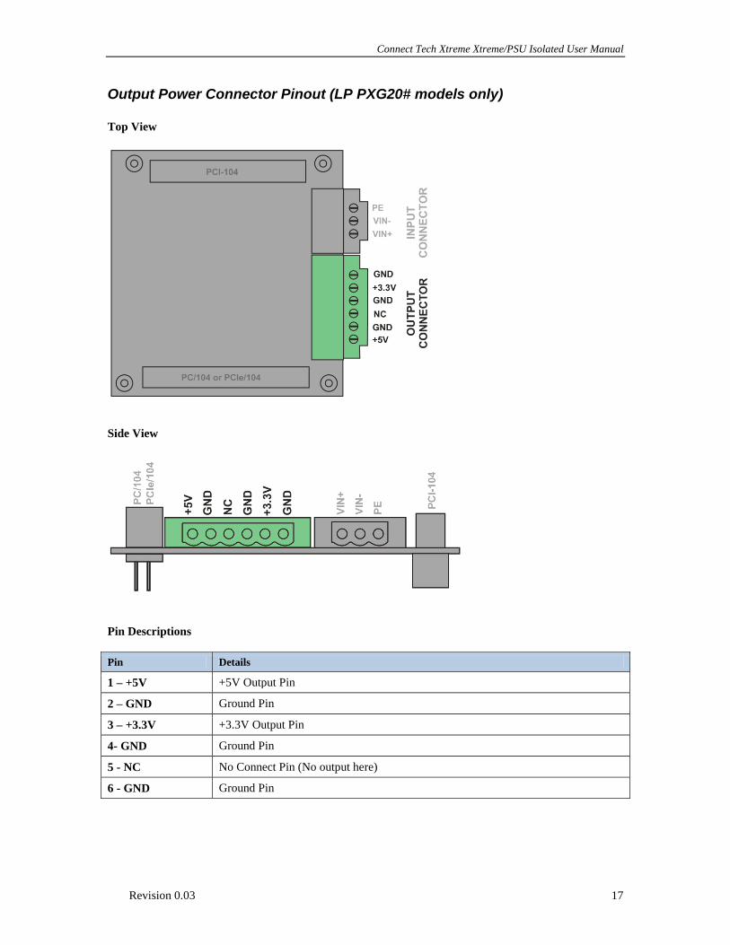
+3.3V Output (Also used for HP series)

Connect Tech Xtreme/PSU Isolated User Manual
Revision 0.03 24
LP Series – (PXG20X)
+3.3V Output

Connect Tech Xtreme Xtreme/PSU Isolated User Manual
Revision 0.03 25
HP Series – PXG30X
+5V Output

Connect Tech Xtreme/PSU Isolated User Manual
Revision 0.03 26
+12V Output

Connect Tech Xtreme Xtreme/PSU Isolated User Manual
Revision 0.03 27
Rise-Time Details
Below is a capture of the 3 output rails after once power has been applied (or the power switch is toggled).
Notice that all power rails on the PXG will be stabilized at approximately 20ms after input power is
applied.

Connect Tech Xtreme/PSU Isolated User Manual
Revision 0.03 28
Dimensioned Drawings
Download 3D Step Model Files Here:
http://www.connecttech.com/ftp/3d_models/PXG00X_3D_MODEL.zip
Dimensions in Millimeters
Dimensions in Inches