Embed Size (px)
Citation preview
XUEQIN HUANG XML-Based Messaging in the JSIM Simulation Environment (Under the Direction of JOHN A. MILLER)
Software reuse and interoperability have long been the Holy Grail of the simulation
community. The current state-of-the-art interoperability standard in simulation is the
High Level Architecture (HLA). HLA is a US DoD mandate and an IEEE standard. It has
generated much interest among simulation researchers and practitioners, but whether it
will gain widespread acceptance by the mainstream simulation community depends on its
ability to support the mainstream approaches and techniques. Jini and XML are two
emerging technologies that will potentially have tremendous impact on the solutions to
the reuse and interoperability problems in the simulation domain. This paper proposes the
use of Jini and XML in building an open and flexible framework for a federated
simulation system. It also presents the design and development of a prototype XML-
based messaging system that is oriented towards our proposed system. A finding of our
research is that Jini and XML may well complement each other in achieving
interoperability between distributed components. Together, they constitute a promising
infrastructure technology for future distributed systems.
INDEX WORDS: HLA, RTI, simulation, federation, federate, interoperability, Java,
JavaBeans, Enterprise JavaBeans, Jini, XML, XML Protocol,
semi-structured data, databases, distributed systems, messaging.
XML-BASED MESSAGING IN THE JSIM SIMULATION ENVIRONMENT
by
XUEQIN HUANG
M.A., INSTITUTE OF INTERNATIONAL RELATIONS, P.R. CHINA, 1995
B.A., JIANGXI NORMAL UNIVERSITY, P.R. CHINA, 1993
A Thesis Submitted to the Graduate Faculty
of The University of Georgia in Partial Fulfillment
of the
Requirements for the Degree
MASTER OF SCIENCE
ATHENS, GEORGIA
2001

2001
Xueqin Huang
All Rights Reserved
XML-BASED MESSAGING IN THE JSIM SIMULATION ENVIRONMENT
by
XUEQIN HUANG
Approved.
Major Professor. Dr. John Miller
Committee. Dr. Robert Robinson Dr. Daniel Everett
Electronic Version Approved. Gordhan L. Patel Dean of the Graduate School The University of Georgia May 2001
iv
ACKNOWLEDGEMENTS
This thesis is an effort of many. It would truly be impossible without the
encouragement and help that so many people have kindly extended to me.
First and foremost, I would like to thank my major professor Dr. John A. Miller
for his patience in guiding me, encouraging me, and bearing with me throughout my
study under him. Dr. Miller first conceived the general framework on which the thesis is
based upon. He also provided invaluable advice on the design and implementation of the
thesis project during the numerous discussions we had together. Busy as he is, he has
always made himself available to answer every question I have ever had. Above all, I feel
very grateful to him for taking extra time and effort growing me individually as well as
academically.
My special thanks go to Dr. Robert Robinson and Dr. Dan Everett for being on
my committee and for opening up new fields of knowledge to me through their classes.
I would also like to thank those professors who have taught me for giving me a
great learning experience, and those people with whom I had the privilege to work with
for helping me and making my stay at UGA much enjoyable. My special thanks go to Dr.
Guoqiang Zhang, Mr. Chris Jones, Dr. Dave Lowenthal, Dr. Krys Kochut, Dr. Suchi
Bhandarkar, and Dr. Don Potter.
My greatest thanks go to my husband, my parents, my sister, and my brother for
their constant love and support. My husband has always been there to love me, encourage
me, support me, and share my tears and laughter, ever since we first met. My family has
always been the magic that makes me dream.
v
TABLE OF CONTENTS
Page
ACKNOWLEDGEMENTS ...............................................................................................iv
LIST OF TABLES ............................................................................................................vii
LIST OF FIGURES..........................................................................................................viii
CHAPTER
1 INTRODUCTION.........................................................................................................1
1.1 Overview of the JSIM Simulation Environment ....................................................1
1.2 Interoperability of Simulation Systems ..................................................................2
1.3 HLA and Its Limitations .........................................................................................3
1.4 A New Perspective with Jini and XML..................................................................4
2 A REVIEW OF MAINSTREAM INTEROPERABILITY TECHNOLOGIES...........6
2.1 Microsoft COM/DCOM .........................................................................................7
2.2 OMG CORBA ........................................................................................................8
2.3 Sun’s Java Family ...................................................................................................8
2.4 XML Technologies ...............................................................................................10
2.5 KQML and KIF ....................................................................................................11
3 FRAMEWORK FOR FEDERATED SIMULATIONS..............................................13
3.1 What Jini Offers....................................................................................................14
3.2 Jini Distributed Event Model Compared with JavaBeans Event Model ..............16
3.3 Publish-Subscribe Eventing in JSIM ....................................................................18
3.4 The Architecture of JSIM .....................................................................................20
4 INTEROPERABLE MESSAGING SERVICES ........................................................23
4.1 Data Interoperability with XML...........................................................................23
4.2 XML Messages in JSIM .......................................................................................26
vi
5 SIMULATION DATA MANAGEMENT..................................................................31
5.1 Managing XML Data............................................................................................32
5.2 Storing JSIM Simulation Data..............................................................................39
5.3 Querying JSIM Database ......................................................................................42
6 SUMMARY AND FUTURE WORK.........................................................................43
BIBLIOGRAPHY .............................................................................................................46
APPENDICES
A The JSIM Packages ....................................................................................................51
B User Guide to JSIM ....................................................................................................53
C XML Background with a Running Example..............................................................66
vii
LIST OF TABLES
TABLE Page
1 Sample domain-specific XML markup languages………………….. 25
2 XML-based meta-data technologies………………………………... 25
3 JSIM events and messages.…………………………………………. 29
4 Tables that can store any type of XML document………………….. 34
5 An XML document stored in relational tables………………….…... 35
6 Storing XML data in databases……………………………………... 39
7 A comparison of HLA-style systems and our proposed JSIM……… 43
8 Core JSIM packages.……………………………………………….. 52
viii
LIST OF FIGURES
FIGURE Page
1 Publish-Subscribe eventing in JSIM…..…………………………… 18
2 JSIM architecture…………………………………………………… 20
3 The Store class………………………………………………….…... 40
4 JSIM database schema………….…………………………………... 41
5 Launching the scenario control window……………………………. 57
6 Connecting to the database…………………………………………. 58
7 Editing model properties……………………………………………. 59
8 Launching the simulation panel…………………………………….. 60
9 Handling simulation results………………………………………… 61
10 Displaying simulation results…………………………………….…. 62
11 Querying JSIM database……………………………………………. 63
12 Displaying query results…………………………………………..… 64
13 A sample model federation ………………………………………… 65
14 An HTML document transformed from XML………….…………... 73
1
CHAPTER 1
INTRODUCTION
1.1 Overview of the JSIM Simulation Environment
Simulation tools and systems have been found very useful and sometimes
indispensable in emulating complex real world systems in their design phase to cut costs,
improve performance, and ensure the success of the end product. For instance, it would
be of great interest to a bank to find out the ideal number of tellers for this bank, such that
the bank can hire the least number of tellers while keeping the waiting time of its
customers at an acceptable amount. Manually testing all combinations would be
impractical, if not impossible. In this case, a simulation tool with automation capabilities
would enable the bank to easily find an optimal solution to their staffing problem. A far
more challenging simulation task, such as the design of a spacecraft, would require even
more powerful simulation abilities, such as the ability to quickly compose a complex
system by reusing previously constructed simulation components.
JSIM (see papers [Nair et al., 1996], [Miller et al., 1997], [Miller et al., 1998],
[Miller et al., 1999], [Miller, 1999a], [Miller, 1999b], [Seila et al., 1999], [Miller et al.,
2000], and [Huang and Miller, 2001]; theses [Nair, 1997], [Zhang, 1997], [Zhao, 1997],
[Ge, 1998], [Xiang, 1999], and [Tao, 2000]) is a component-based simulation and
animation environment implemented in Java. It is an ongoing project designed to
automate those repetitive, time-consuming, and error-prone tasks that are sometimes
manually performed by simulation analysts. Our goal is to build a distributed and
cooperative simulation environment in which separately developed simulations can
collaborate at run time to solve complex simulation tasks.
2
Currently, JSIM supports a point-and-click model designer that can be used to design
simulation models and code-generate model applets and model beans. A model bean is
controlled by a model agent, which specializes in a statistical analysis method. A model
agent can also dynamically adjust the properties of a model, collect statistical results from
the model, and fire an event to a database bean for storing the model parameters, agent
properties, and statistical results into a database. A model bean and a model agent can be
dynamically linked so that statistics on the same model, run with different parameters,
and perhaps associated with different model agents, can be collected in a database and
then compared to find the best scenario for this model [Seila et al., 1999].
Work is under way to make JSIM become truly distributed. For a distributed
simulation system, the biggest challenges lie in interoperability between distributed
simulation components, synchronization of distributed simulation components, exchange
of model and control data, and integration of simulation results stored in different and
perhaps heterogeneous databases. To meet these challenges, it is critical to design and
build a flexible distributed infrastructure and use a standard format for representing the
simulation data.
1.2 Interoperability of Simulation Systems
Software reuse and interoperability have long been the Holy Grail of the simulation
community. Reuse means the repeated use of a software component, together with other
software modules, to compose larger applications without manually changing the code of
the software component. Software reuse is one of the important goals of all object-
oriented design (OOD) methodologies. Interoperability takes software reuse a step further
by allowing separately developed software components to dynamically cooperate with
each other to achieve a common task that is too complex to be achieved by any one of
them working alone.
3
1.3 HLA and Its Limitations
HLA is the current state-of-the-art interoperability standard for federated simulation
systems. It was mandated by the United States Department of Defense (DoD),
standardized by IEEE, and adopted by the NATO countries [Kuhl et al., 1999]. It defines
a software architecture for composing simulation systems from components. The
components are called federates, and the simulation involving several federates is called a
federation. Federates interact with each other through a runtime infrastructure (RTI),
which offers services in six areas, namely federation management, declaration
management, object management, ownership management, time management, and data
distribution management [Kuhl, 2000]. The core interoperability facilities of HLA
include the Interface Specification [DMSO, 1998a] and the Object Model Template
(OMT) Specification [DMSO, 1998b].
HLA is an architecture, not an implementation. An HLA system can be built using
CORBA or other technologies. Sample HLA-style simulation systems include the
Federated Simulations Development Kit (FDK) [Fujimoto, 1998] from Georgia Tech and
the JavaGPSS system [Klein et al., 1998].
Due to its enormous complexity and inherent limitations [Page, 1998], HLA has seen
little implementation effort in the mainstream simulation community. Its low level,
operating system-like conceptual framework as exhibited in the RTI, may not be the best
solution to the problem of allowing independently crafted complex software modules to
inter-operate at run time in a distributed environment. Moreover, its DoD proprietary
OMT Data Interchange Format (DIF) has not been attractive to the mainstream
simulation community.
An earlier effort to implement a subset of the HLA services for JSIM [Tao, 2000]
was accomplished by using Enterprise JavaBeans (EJB) [Thomas et al., 1998] and [Roth,
2000]. However, because of its strict thin-client/thick-server orientation, EJB was not
4
found to be a suitable solution to a federated simulation system [Miller et al., 2000]. This
motivated our search for a new substrate for distributed JSIM.
1.4 A New Perspective with Jini and XML
Whether HLA will gain widespread acceptance by the mainstream simulation
community depends on its ability to support the approaches and techniques of the
mainstream. Two emerging interoperability technologies that are worthy of particular
attention are Jini and XML. In contrast to HLA, Jini considers itself not as a traditional
operating system that knows everything and controls everything, but as a network layer
that provides an object-oriented interface to the computers of the future [Venners, 1999].
Compared with the DoD proprietary OMT DIF, the eXtensible Markup Language (XML)
[Bray et al., 1998] is a universal standard for the exchange of structured data. On top of
that, the many freely and readily available standard XML tools and the close relationship
between XML and the Web make XML a very attractive technology for achieving
interoperability between federated systems.
Jini and XML will potentially have tremendous impact on solving the reuse and
interoperability problems in the simulation domain. An interesting study currently going
on in this area is the NV-Therm project [Kelly, 2001]. NV-Therm is a simulation
component in a much larger simulation system produced by Illgen. Data produced from
NV-Therm is needed by the Jet Propulsion Lab (JPL)’s Engineering and Communications
Infrastructure (ECI) section. The NV-Therm researchers are planning to provide a model
interface that uses Jini to locate and communicate with the proxies for model and
simulation objects at Illgen. The model interface also provides a way for the ECI systems
to interact with the proxies by sharing XML documents over HTTP or IIOP. Other
related studies include [Wilson, 2001] and [Buss, 2000].
This paper attempts to examine the application of these two technologies in the
context of the JSIM simulation environment. We will present the design and
5
implementation of a prototype system, which is the first step towards our vision of
building a fully distributed federated simulation system with Jini and XML.
This paper consists of six chapters. Chapter 2 will give a review of major
mainstream interoperability technologies including Jini and XML. Chapter 3 will
introduce our proposed framework for federated simulation systems and the use of such a
framework in our prototype design and implementation of the JSIM simulation
environment. Chapter 4 will present our approach towards the exchange of simulation
data using the XML-based messaging scheme. Chapter 5 will discuss the management of
JSIM simulation data with XML. In the last chapter, we will point out some contributions
of this work and some opportunities for future research. Readers interested in using JSIM
may download it from the following Web site. http://chief.cs.uga.edu/~jam/jsim
6
CHAPTER 2
A REVIEW OF MAINSTREAM INTEROPERABILITY TECHNOLOGIES
Interoperability refers to the capability to integrate resources from diverse origins
to compose a new system such that the individual resources appear to have been designed
as part of the newly composed system [Bollinger, 2000]. The resources can be data,
software, hardware, people with certain skills, or any entities that can be shared. Here, we
are only interested in data and software interoperability in the area of information
technology.
Generally speaking, data and software interoperability includes low-level
syntactic interoperability and higher-level semantic interoperability. Syntactic
interoperability is usually applied to the exchange of structured/formatted data. It is a
special agreement/standard, among participating parties, over the structure, format,
syntax, and/or types of the data being exchanged. It ensures the exchange of structured or
semi-structured data in a mutually expected format. However, it does not guarantee
meaningful and consistent interpretation of the data among all parties. The latter requires
a much higher level of interoperability – semantic interoperability. This level of
interoperability can be achieved through a shared set of vocabularies or ontologies whose
meaning has been precisely defined and agreed upon by the target community. A major
effort in this area is the Dublin Core Metadata Initiative [Medeiros, 2000].
[Bollinger, 2000] further divides data and software interoperability into several
layers, such as the basic syntax layer, the complex syntax layer, the domain semantics
layer, and the full semantics layer. An example of interoperability that operates at the
basic syntax layer is the IEEE standard formats for text (ASCII) and numeric data. The
complex syntax layer builds on top of the basic syntax layer by adding a software layer
that helps ensure consistent interpretation of the structure and/or type of the data. Such
7
support technologies include CORBA (Common Object Request Broker Architecture)
standards and software, and XML (eXtensible Markup Language) standards and tools. At
the domain semantics layer, interoperability means providing a mechanism to allow
common interpretation of complex domain-specific data among different applications. At
the full semantics layer, interoperability refers to the ability to support sufficient
machine-based understanding of data, and therefore automatic transfer of information
across different domain areas of expertise. In practice, this layer of interoperability can
rarely be achieved.
Here are some of current interoperability technologies.
• Microsoft COM/DCOM and ActiveX
• OMG CORBA
• Sun’s Java family. RMI, JavaBeans, Enterprise JavaBeans, Jini
• XML technologies. XML, DTD, XML Schema, RDF, XML Protocol, WAP
• KQML and KIF
The first four technologies operate on Bollinger’s complex syntax layer. However, it
should be noted that XML is widely believed to be a vital technology that will help
enable a future Semantic Web, though it is unlikely that XML alone can achieve this.
KQML and KIF are languages for agent communication and ontologies, respectively.
Like XML, they are in between the syntax and semantics layers. Next, we will briefly
discuss each of the above technologies.
2.1 Microsoft COM/DCOM
The Microsoft Component Object Model (COM) is a binary-level component
standard for the Microsoft environment. It allows compiled components to call each other
and exchange data with each other, so long as they run under the Windows platform. The
8
Microsoft Distributed Component Object Model (DCOM), previously called “Network
OLE”, is based on the Open Software Foundation’s DCE-RPC specification. It is
essentially a RPC layer on top of COM, which allows software components to
communicate directly over a network. ActiveX controls are the third version of the OLE
controls (OCX). It is a type of COM component that uses COM technologies to provide
interoperability with other types of COM components and services [Microsoft, 2001].
COM/DCOM and ActiveX provide interoperability in the Microsoft environment,
but due to the fact that COM is a binary standard and that it is tightly entrenched in the
Microsoft platform, it is not easy to port COM components to non-Microsoft platforms.
However, with CORBA, it is possible to invoke COM components in their native
environment from a non-Microsoft platform.
2.2 OMG CORBA
The Common Object Request Broker Architecture (CORBA) is an OMG standard
for distributed object computing. It is a middleware that attempts to make distributed
object computing language transparent and platform transparent. CORBA provides
interoperability across programming languages and operating systems through language
bindings between CORBA IDLs and target languages.
2.3 Sun’s Java Family
Sun and its partners have been actively developing high level programming models
based on Java. Examples of such programming models include Remote Method
Invocation, JavaBeans1, Enterprise JavaBeans2, and Jini3.
1 The client-side component model for Java.
2 The server-side component model for Java.
9
The Remote Method Invocation (RMI) is the distributed object-computing model for
the Java programming language. It provides some basic services for managing distributed
objects, and is the foundation on which more sophisticated computing models, such as
EJB and Jini, are constructed. Due to its simplicity, RMI is the best choice for building
distributed Java applications that do not require sophisticated management of distributed
services, or for testing out frameworks for distributed systems. RMI is used in a discrete
event simulation package called SimJava to distribute simulation entities across the
network [Page et al, 1997].
JavaBeans [Javasoft, 1997] [Hamilton, 1997] defines the client-side component
model for the Java platform. A powerful feature of JavaBeans is its capability to visually
customize the properties of compiled components and dynamically link them to compose
a new application.
Enterprise JavaBeans (EJB) is a server-side component model for the Java platform,
which is designed to "enable enterprises to build scalable, secure, multi-platform,
business-critical applications as reusable, server-side components" [Roth, 2000]. EJB
takes the Java paradigm of platform independence a step further to independence from
various legacy infrastructures such as messaging middleware, transaction support,
naming and directory services, object protocols and relational databases. In addition, it
delegates some difficult programming tasks, such as distributed transactions, distributed
object invocation, security, load balancing, and connection pooling, to EJB server and
container providers, simplifying application development and making it a good model for
multi-tier thin-client/thick-services business applications. It could also be very useful for
managing simulation data on the database side.
Unlike EJB, which redefines the current model under which server-side enterprise
business logic is developed and deployed, Jini redefines the current model under which a
client discovers, manages and communicates with the services it requires. The Jini vision
3 The network-computing model for Java.
10
is to turn the network into the client’s computer by supplying the client with a federation
of remote "plug and play" devices and services in a dynamic configuration (the Jini
Federation) that is personalized for each client [Sun Microsystems, 2000a].
In terms of architectural model, Jini supports service-oriented peer-to-peer
communication with variable-size clients and variable-size services. According to Jim
Waldo, Sun’s chief Jini architect, the Jini architecture is based on the idea of federation
rather than central control [Venners, 1999]. To the client, the network is a computer made
up of a federation of devices and services in the form of mobile objects or agents. In Bill
Joy’s words, the Java/Jini layer on which those mobile objects and agents reside can be
called the BIOS (basic input/output system) of a network computer [Venners, 1999].
However, Jini is not intended to be anything like a traditional operating system, which
knows about everything and controls everything. Instead, it is intended to give an object-
oriented interface to the computers of the future.
All these programming models leverage Java’s platform transparency, its simple,
well defined, and well-documented programming models, and its widespread industry
support to provide interoperability across different platforms and enterprises.
2.4 XML Technologies
The eXtensible Markup Language (XML) is a universal format for data exchange
over the Web. Described as the "Second Coming of the Web", XML is an emerging and
rapidly evolving technology that is shaping the Second-Generation Web. It follows the
revolution started by the combination of hypertext and a global Internet [Bosak and Bray,
1999]. The most exciting possibility opened up by XML is the Semantic Web envisioned
by the creators of XML.
Like HTML, XML uses tags to describe data. Unlike HTML tags, which specify the
presentation of data, XML tags can be used to describe the meaning of data. In addition,
XML has an extensible tag set so that users can define their own tags for their data. As a
11
meta-language, XML allows data to be attached with meta-data in the form of XML
Document Type Definition (DTD), XML Schema, and/or XML RDF. A DTD specifies
all the tags used in a class of XML documents and a set of rules governing the structure
of those XML documents. In addition to declaring tags and specifying document
structure, the W3C XML schema also provides data type information, type inheritance,
schema inclusion and import, and XML Namespace support to further facilitate automatic
processing of XML documents. The XML Resource Description Framework (RDF) is
targeted to adding meta-data to Web contents to ensure effective, meaningful, and
automatic retrieval of Web contents. In fact, RDF plus ontology support are deemed to be
an important step towards the future Semantic Web [Berners-Lee, 2000].
2.5 KQML and KIF
The Knowledge Query and Manipulation Language (KQML) is an agent
communication language (ACL) created by a committee of representatives from different
projects to deal with the problem of managing distributed implementations of systems as
part of the ARPA Knowledge Sharing Effort [Finin, et al. 1994]. It is both a message
format and message-handling protocol to support run-time knowledge sharing among co-
operative agents. It supports an extensible set of performatives4 that determines the
“speech acts” KQML-speaking agents are permitted to use (in other words, performatives
are instructions that tell the receiving agents how to respond to the messages containing
the performatives). It also provides a basic architecture for knowledge sharing through a
class of special communication facilitators, which coordinate the interactions among
other agents.
4 Meaning doing things with words, it is originated from the “speech act” theory in modern linguistics
[Smith, 1990]. It is used in KQML messages to specify a request from one agent to another.
12
Surprisingly, KQML does not dictate an exact format for the contents of its
messages. Its content languages could be anything from SQL to the Knowledge
Interchange Format (KIF). The latter was designed to be a common language for
expressing the content of a knowledge base. It is often used for knowledge exchange and
ontology representation.
Needless to say, KQML and KIF can potentially enhance large-scale integration and
interoperability between disparate systems. In fact, our design of the JSIM system has
been partly inspired by the concepts embedded in KQML. A close examination of the
JSIM system design and messaging scheme, as presented in Chapter 3 and 4, would
reveal some resemblance between them. In particular, we have assimilated its
performative concept, its emphasis on providing structure and semantics to messages, and
its decoupling of the communication capability from the functional capability of a
system.
To summarize, interoperability technologies generally operate at syntactic and
semantic levels. Major supporting technologies at the syntactic level include Microsoft
COM/DCOM and ActiveX, OMG CORBA, Sun’s Java technologies, and XML-related
technologies. XML could also help at the semantic level, through XML meta-data
technologies, such as DTD, XML Schema, XML RDF, and/or support of other meta-data
technologies such as ontology mapping. KQML provides some structure and semantics to
its messages. On the other hand, it is not precisely defined and its many communication
schemes are similar to the messaging and eventing schemes directly supported by some
mainstream programming models, such as Jini. Therefore, we have decided to pursue Jini
and XML as an infrastructure for turning JSIM into an environment that supports fully
distributed federated simulations.
13
CHAPTER 3
FRAMEWORK FOR FEDERATED SIMULATIONS
It has always been a great challenge to make separately developed and compiled
simulation components work together on a common task. This may not even be possible
at all without a supporting infrastructure or a well-defined and generally accepted
standard.
As we mentioned earlier, HLA attempts to achieve interoperability between
simulation components through a distributed-operating-system-like framework as
exhibited in its Run Time Interface (RTI) specification. HLA does not specify the means
of communication between simulation components [Buss et al., 1998]. Rather, it leaves
the choice of the communication protocol up to the RTI implementers. This may be a
good design choice in terms of flexibility. On the other hand, it adds to the complexity of
implementing an HLA-compliant simulation component, and creates a potential obstacle
for achieving interoperability between the RTI implementations by different vendors.
HLA compliance dictates that all simulation functionality, or at least all the data that
an HLA federate might expose in any federation, must be documented in its simulation
object model (SOM) in accordance with the HLA object model template (OMT). It also
dictates that the objects and interactions that a federate exposes to others in the federation
must be documented in the federation object model (FOM) in accordance with the OMT.
By providing a common vocabulary for a federation through the FOM and by using OMT
as the common format for exchanging simulation data, HLA aims to ensure semantic
consistency across the federation.
Overall, HLA seems to offer everything needed for interoperability in the simulation
domain. However, it remains a DoD mandate and has yet to be embraced by the general
14
simulation community. This may be traced back to its overly complex rules and
specifications, which make it difficult to implement a truly HLA-compliant system.
Compared with HLA RTI, Jini serves a similar purpose of providing interoperability
among distributed components, yet through a different approach. Unlike RTI, which
attempts to control everything from managing the interactions among distributed
simulation components to managing simulation data exposed by the federates, Jini
provides a framework that supports the broader vision of viewing the network as a
federation of loosely-related services. It sees itself as a network layer that assists
individual services to add themselves to and/or discover other services on the network.
Although Jini provides support for service registration and lookup, reliability of
distributed event delivery, distributed transactions, and secure service access, it was
designed to be simple. In addition, Jini is layered on top of an existing Java technology,
RMI, which makes it much easier to develop Jini-compliant components.
In this chapter, we will explore a new approach for developing federated simulation
systems using Jini. We will first examine what Jini has to offer for federated simulation
systems, especially the Jini distributed event model. We will then present the design and
implementation of our prototype JSIM with the Jini-style publish-subscribe event
mechanism.
3.1 What Jini Offers
A key concept in Jini is service. A Jini service is "an entity that can be used by a
person, a program, or another service" [Sun Microsystems, 2000b]. Under the notion of a
service, Jini unifies everything from the user of a system of Jini technology-enabled
services/devices to the software available on the machines, and to the hardware
components of the machines themselves [Sun Microsystems, 2000c]. Jini systems
provide mechanisms for service construction, lookup, communication, and use in a
distributed system. Services in a Jini system communicate with each other by using a set
15
of interfaces called a "service protocol". A lookup service maps interfaces indicating the
functionality provided by a service to sets of objects, which implement the service. A
lookup service may include other lookup services or contain other forms of lookup
service. A pair of protocols called "discovery" and "join" is used to add a service to a
lookup service.
Jini supports object/code mobility, security, lease-based service access, and
distributed transactions. Jini code mobility is accomplished by using Java RMI as the
underlying protocol for communication between the Jini services. RMI has extended the
traditional notion of remote method call mechanism to allow both data and object to be
moved around a network. Security on service access is ensured through an access control
list. A lease-based service requires the service user and provider to negotiate about the
period of the lease and renew the lease with the lookup service if/when necessary.
Because of its distributed nature, Jini supports transactions through the two-phase commit
protocol as supplied in the Jini Transaction Service interface.
Another attractive feature of Jini is that it provides support for distributed events,
which is a natural extension to the JavaBeans paradigm of event-based communication.
The purpose is to allow an object in one Java Virtual Machine (JVM) to register interest
in the occurrence of some event occurring in an object in some other JVM so as to
receive a notification when an event of that kind occurs [Sun Microsystems, 2000c]. Due
to the fact that event delivery is inherently unreliable in a distributed system, Jini
• allows various degrees of assurance on delivery of a notification,
• supports different policies of scheduling notification, and
• explicitly allows the interposition of objects that will collect, hold, filter, and
forward notifications.
16
3.2 Jini Distributed Event Model Compared with JavaBeans Event Model
The JavaBeans event model is derived from the delegation event model used for user
interface tools such as the AWT or Swing (JFC) in JDK 1.2. In this model, components
communicate through event registration and notification. The entities involved include
events, event generators, and event listeners. Events extend from the java.util.Event class.
Event generators name their event registration and event generating methods by
following certain conventions. For instance, an event registration method is named as
addXXXListener, an event cancellation method is named removeXXXListener, and an
event generating method is named as fireXXXEvent. Event listeners implement listener
interfaces that inherit from java.util.EventListener. Bean builder tools rely on these
naming conventions and interfaces to dynamically generate event adapters to hook up
event generators and event listeners for the specified events.
The JavaBeans event model is based on the assumption that all the components run
in the same JVM on one physical machine, so that event delivery is guaranteed to be fast
and reliable. Hence, in JavaBeans, propagation of event notifications from sources to
listeners is accomplished by method invocations on the target listener objects.
Identification of the type of event notification is achieved by using a different method in
the listener being called for each kind of event. Any state associated with an event
notification is encapsulated in an object that inherits from java.util.EventObject and that
is passed as the only argument of the notification method. Event sources define
registration methods, one for each kind of event in which interest can be registered, by
following the addXXXListener/removeXXXListener design pattern.
The basic event registration and notification mechanism in Jini is similar to that in
JavaBeans, except that distributed event propagation is accomplished by the use of
remote methods and that Jini allows an event registrant to register a third party as the
event recipient. As in JavaBeans, state passed as part of the notification in Jini is
encapsulated in an object that is derived from java.util.EventObject and passed as the sole
17
argument of the notification method. The RemoteEventListener interface also extends the
more basic interface java.util.EventListener.
On the other hand, the Jini event model is based on the assumption that Jini
components will be distributed in different Java Virtual Machines (JVMs) across the
network on different physical machines. Since distributed event delivery is inherently
unreliable and subject to all sorts of network and communication failures, Jini has
incorporated new mechanisms to support distributed events.
First, Jini allows an event registrant to register a third party as the event recipient.
Such a third party object is normally an agent who can guarantee the delivery of the event
to the interested party. Example Jini third party objects include store-and-forward agents,
notification filters (multiplexing/demultiplexing) agents, and notification mailboxes [Sun
Microsystems, 2000a].
Second, Jini uses a uniform signature, notify (RemoteEvent theEvent), which is the
only method included in the RemoteEventListener interface, to notify a listener of the
occurrence of an event. This is designed to support third party objects, which cannot
possibly define a different notification method for each type of event they can handle,
since these third party objects may not know what event types are defined by the
components that use them.
Third, Jini identifies an event by passing an identifier from the source of the
notification to the listener. The combination of the object in which the event occurred and
the identifier uniquely identifies the kind of event. This is necessary since Jini has a
single signature for event notifications.
Fourth, a Jini event object includes a sequence number to handle the situation when
an event is lost, arrives out of order, or is repeatedly delivered.
Fifth, registration of interest in a type of event in Jini is for a renewable period of
time, rather than for a period of time bound by the active cancellation of interest.
18
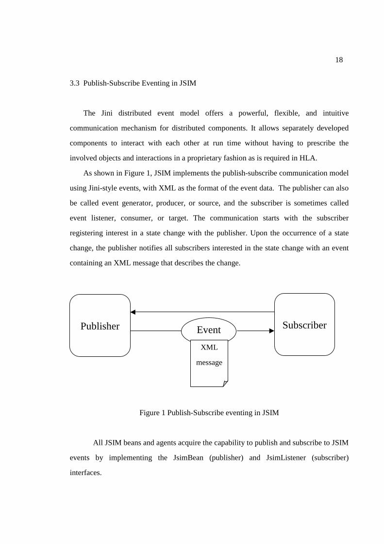
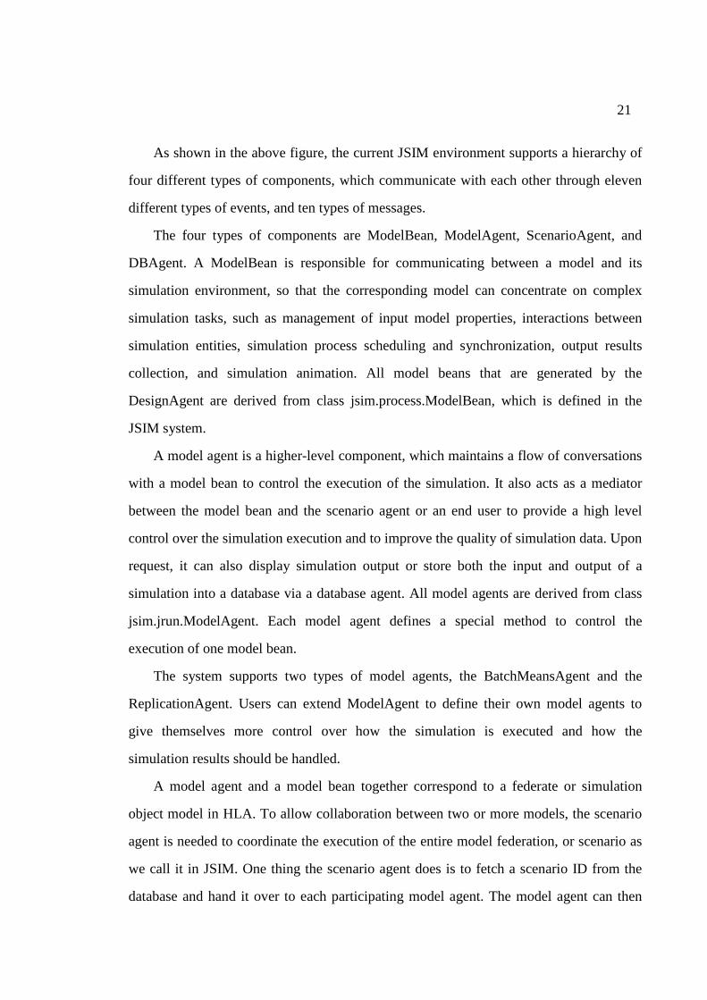
3.3 Publish-Subscribe Eventing in JSIM
The Jini distributed event model offers a powerful, flexible, and intuitive
communication mechanism for distributed components. It allows separately developed
components to interact with each other at run time without having to prescribe the
involved objects and interactions in a proprietary fashion as is required in HLA.
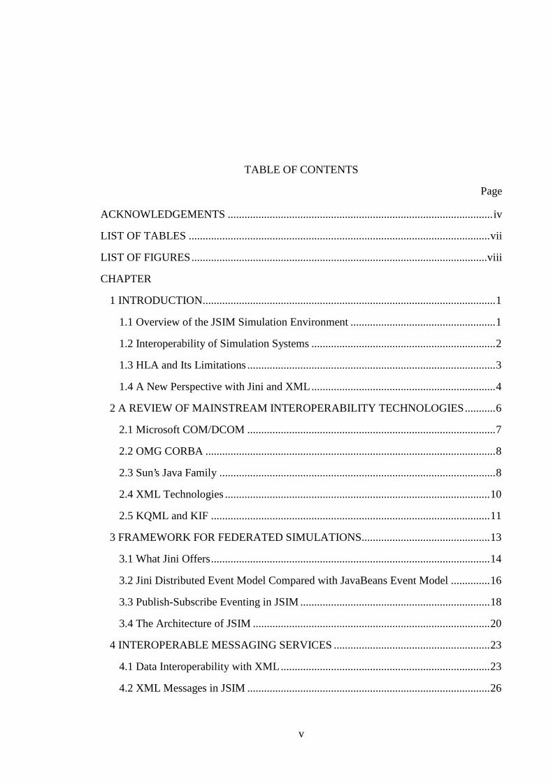
As shown in Figure 1, JSIM implements the publish-subscribe communication model
using Jini-style events, with XML as the format of the event data. The publisher can also
be called event generator, producer, or source, and the subscriber is sometimes called
event listener, consumer, or target. The communication starts with the subscriber
registering interest in a state change with the publisher. Upon the occurrence of a state
change, the publisher notifies all subscribers interested in the state change with an event
containing an XML message that describes the change.
Figure 1 Publish-Subscribe eventing in JSIM
All JSIM beans and agents acquire the capability to publish and subscribe to JSIM
events by implementing the JsimBean (publisher) and JsimListener (subscriber)
interfaces.
Publisher
Subscriber Event XML
message
19
The JsimBean interface contains an addJsimListener method as shown below.
This method allows any JSIM event listener to register interest in state changes within the
JsimBean.
public interface JsimBean extends Serializable { ... /************************************************************** * Adds a JsimListener to an event object registration list. * @param target The target JsimListener to be added */ void addJsimListener (JsimListener target); ...
The JsimListener interface has a single notify() method, which is called by the
event publisher when a state change in the publisher occurs. Below is the JsimListener
interface.
public interface JsimListener extends EventListener, Remote { /************************************************************** * Method to handle JsimEvents. * @param evt The JsimEvent to be processed */ public void notify (JsimEvent evt) throws RemoteException; }; // interface JsimListener
The JsimEvent class is similar to the Jini RemoteEvent interface. It inherits an event
source field and contains an event ID field and an event data object field. The sequence
number field will be used in the future. The event source refers to the source or publisher
of the event. The event ID refers to an event type, which the publisher supports and the
subscriber is interested in.
The beauty of these interfaces is their simplicity. It is straightforward to implement
the JSIM publisher and listener interfaces. In fact, we have a class that implements both
interfaces. By inheriting from an object of that class, any Java object automatically
20
becomes a JSIM component. A third party object can then rely on those interfaces to
dynamically hook up any JSIM component with any other JSIM components. However,
to actively participate in a JSIM-supported simulation federation, a component must be
able to understand and/or fire JSIM events, which we will discuss later.
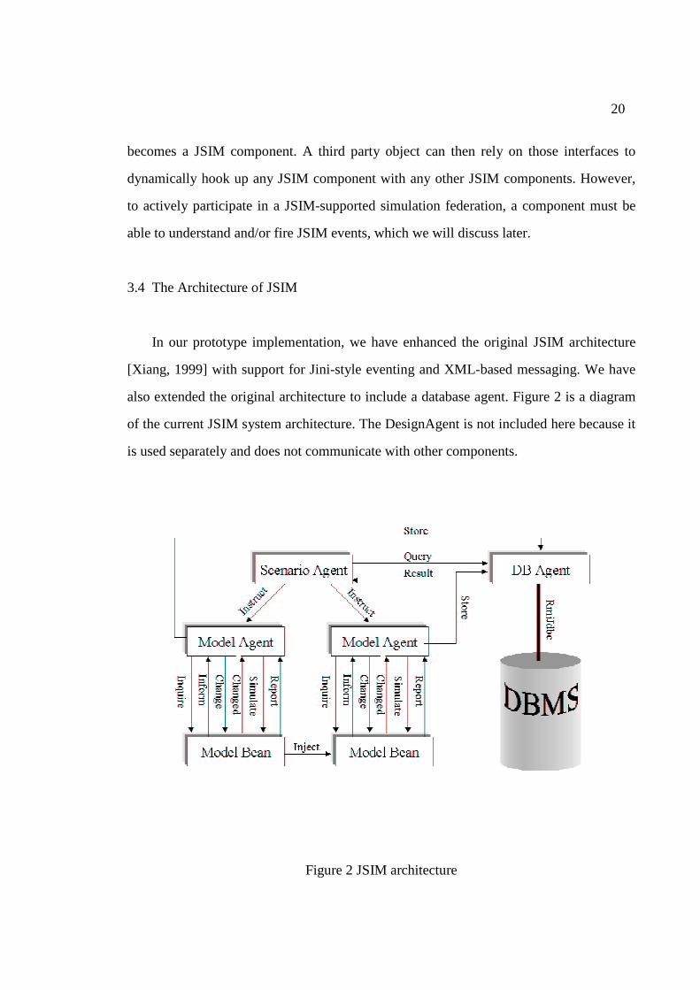
3.4 The Architecture of JSIM
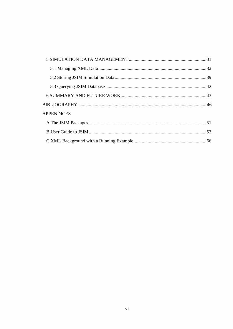
In our prototype implementation, we have enhanced the original JSIM architecture
[Xiang, 1999] with support for Jini-style eventing and XML-based messaging. We have
also extended the original architecture to include a database agent. Figure 2 is a diagram
of the current JSIM system architecture. The DesignAgent is not included here because it
is used separately and does not communicate with other components.
Figure 2 JSIM architecture
21
As shown in the above figure, the current JSIM environment supports a hierarchy of
four different types of components, which communicate with each other through eleven
different types of events, and ten types of messages.
The four types of components are ModelBean, ModelAgent, ScenarioAgent, and
DBAgent. A ModelBean is responsible for communicating between a model and its
simulation environment, so that the corresponding model can concentrate on complex
simulation tasks, such as management of input model properties, interactions between
simulation entities, simulation process scheduling and synchronization, output results
collection, and simulation animation. All model beans that are generated by the
DesignAgent are derived from class jsim.process.ModelBean, which is defined in the
JSIM system.
A model agent is a higher-level component, which maintains a flow of conversations
with a model bean to control the execution of the simulation. It also acts as a mediator
between the model bean and the scenario agent or an end user to provide a high level
control over the simulation execution and to improve the quality of simulation data. Upon
request, it can also display simulation output or store both the input and output of a
simulation into a database via a database agent. All model agents are derived from class
jsim.jrun.ModelAgent. Each model agent defines a special method to control the
execution of one model bean.
The system supports two types of model agents, the BatchMeansAgent and the
ReplicationAgent. Users can extend ModelAgent to define their own model agents to
give themselves more control over how the simulation is executed and how the
simulation results should be handled.
A model agent and a model bean together correspond to a federate or simulation
object model in HLA. To allow collaboration between two or more models, the scenario
agent is needed to coordinate the execution of the entire model federation, or scenario as
we call it in JSIM. One thing the scenario agent does is to fetch a scenario ID from the
database and hand it over to each participating model agent. The model agent can then
22
store all the simulation data generated by the corresponding model together with the
scenario ID, when requested. The scenario ID makes it possible to retrieve the input and
output of all models participating in a federation.
The database agent interacts with the model agents and the scenario agent to help
store and retrieve simulation data. Like other agents, the database agent handles
communication with the outside world. Behind the scene, it calls the DBAccess class to
store and retrieve data from the database.
Following our design goal of more local control/less centralization, and interaction
rather than interdependency, we delegate all simulation tasks to models controlled by the
model agents while leaving the scenario agent the sole task of global coordination.
We also separate the simulation and communication code so that the models are best
at simulation and the beans and agents are best at communication. Moreover, changes to
simulation code should not cause changes to the communication code, and vice versa.
Furthermore, the event communication mechanism provides an ideal framework for
implementing dynamic peer-to-peer communication for components developed without
full prior knowledge about their counterparts.
The system is reasonably extensible, because we have been trying very hard,
throughout our design and implementation, to generalize the common functions at the top
level of the class hierarchies. Developers who wish to extend our system only need to add
a minimum of customization code for their special purposes.
In summary, the peer-to-peer communication model in Jini provides an excellent
conceptual framework for building federated simulation systems. Our prototype
implementation of JSIM using the Jini distributed event model has shown that such a
framework is highly flexible and extensible.
23
CHAPTER 4
INTEROPERABLE MESSAGING SERVICES
Having a communication framework and protocol between the components in a
federated simulation system is certainly important. Yet it would be to no avail if the
simulation components cannot understand each other. Most current simulation systems
use proprietary formats for the exchange of simulation data within the system. This
makes it difficult for such a system to interoperate with other simulation systems. HLA
does provide a specification, called the Object Model Template (OMT), for prescribing
the information contained in the HLA object model for each federate to foster simulation
interoperability and reuse of simulation components. This specification merits due
attention from the simulation community, since it is targeted for the simulation domain.
However, OMT by itself does not help much with the data interoperability problems with
non-HLA style simulation systems.
This chapter explores a new approach to the exchange of simulation data through the
use of XML messages.
4.1 Data Interoperability with XML
As a self-descriptive and text-based format, XML is an excellent choice for
representing data, or even objects, that need to be transported between disparate systems.
In fact, a preliminary specification for XML Messaging has been published as an IETF
Internet Draft to allow "reliable, resilient, secure, tamper resistant, authenticated
exchange of XML or other electronic documents over insecure transport mechanisms"
[Cover, 2000a]. An XML Protocol Working Group was created by W3C on September
13, 2000 to develop technologies that “allow two or more peers to communicate in a
24
distributed environment, using XML as its encapsulation language" [W3C, 2001].
Currently under review are over 20 XML-based protocols [W3C, 2001].
One of the most promising protocols is the Simple Object Access Protocol (SOAP).
Microsoft is considering using SOAP as the underlying communication protocol for
DCOM in all of its future operating systems. SOAP has also won tremendous support
from IBM, Apache, and other industry leaders. However, SOAP by itself only provides a
basic XML-based messaging protocol that underlies other industry-strength XML
messaging frameworks, such as ebXML [ebXML.org, 2001].
As a standard format for data exchange, XML can certainly provide syntactic
interoperability between disparate systems. Technically, syntactic interoperability is
made easier through the self-describing capability of XML, which is made possible by
the XML DTD and the XML Schema standard. A DTD specifies the structure of a class
of XML documents, while XML Schema declarations contain both structure and data
type information about a class of XML documents.
With XML, interoperability at the semantic level is also possible from several
approaches. With the first approach, a common DTD or XML schema can be worked out
for the data that needs to be exchanged in a given domain. This requires a DTD/XML
schema developer to work closely with domain experts to carefully define a set of
semantic tags and the structure of the data in the domain. The resulting DTD/XML
schema should be general-purpose enough to be able to represent most data in that
domain. In addition, it has to be reasonably simple to handle, and relatively flexible to
allow for future extension. It may seem unlikely to get an entire domain to agree on a
single DTD/XML schema. Surprisingly, this approach has already been adopted in some
areas, such as mathematics, chemistry, and biology. Some examples of domain-specific
XML-based languages [Laurent and Biggar, 1999] are shown in Table 1.
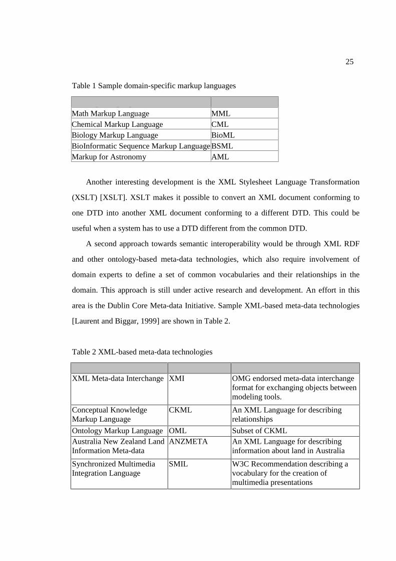
25
Table 1 Sample domain-specific markup languages
Markup Language Abbreviation Math Markup Language MML Chemical Markup Language CML Biology Markup Language BioML BioInformatic Sequence Markup Language BSML Markup for Astronomy AML
Another interesting development is the XML Stylesheet Language Transformation
(XSLT) [XSLT]. XSLT makes it possible to convert an XML document conforming to
one DTD into another XML document conforming to a different DTD. This could be
useful when a system has to use a DTD different from the common DTD.
A second approach towards semantic interoperability would be through XML RDF
and other ontology-based meta-data technologies, which also require involvement of
domain experts to define a set of common vocabularies and their relationships in the
domain. This approach is still under active research and development. An effort in this
area is the Dublin Core Meta-data Initiative. Sample XML-based meta-data technologies
[Laurent and Biggar, 1999] are shown in Table 2.
Table 2 XML-based meta-data technologies
Meta-Data Format Abbreviation Description XML Meta-data Interchange XMI OMG endorsed meta-data interchange
format for exchanging objects between modeling tools.
Conceptual Knowledge Markup Language
CKML An XML Language for describing relationships
Ontology Markup Language OML Subset of CKML Australia New Zealand Land Information Meta-data
ANZMETA An XML Language for describing information about land in Australia
Synchronized Multimedia Integration Language
SMIL W3C Recommendation describing a vocabulary for the creation of multimedia presentations
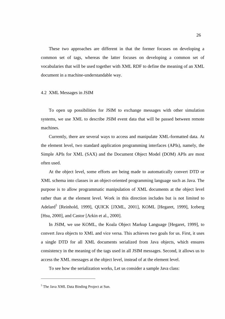
26
These two approaches are different in that the former focuses on developing a
common set of tags, whereas the latter focuses on developing a common set of
vocabularies that will be used together with XML RDF to define the meaning of an XML
document in a machine-understandable way.
4.2 XML Messages in JSIM
To open up possibilities for JSIM to exchange messages with other simulation
systems, we use XML to describe JSIM event data that will be passed between remote
machines.
Currently, there are several ways to access and manipulate XML-formatted data. At
the element level, two standard application programming interfaces (APIs), namely, the
Simple APIs for XML (SAX) and the Document Object Model (DOM) APIs are most
often used.
At the object level, some efforts are being made to automatically convert DTD or
XML schema into classes in an object-oriented programming language such as Java. The
purpose is to allow programmatic manipulation of XML documents at the object level
rather than at the element level. Work in this direction includes but is not limited to
Adelard5 [Reinhold, 1999], QUICK [JXML, 2001], KOML [Hegaret, 1999], Iceberg
[Hsu, 2000], and Castor [Arkin et al., 2000].
In JSIM, we use KOML, the Koala Object Markup Language [Hegaret, 1999], to
convert Java objects to XML and vice versa. This achieves two goals for us. First, it uses
a single DTD for all XML documents serialized from Java objects, which ensures
consistency in the meaning of the tags used in all JSIM messages. Second, it allows us to
access the XML messages at the object level, instead of at the element level.
To see how the serialization works, Let us consider a sample Java class:
5 The Java XML Data Binding Project at Sun.
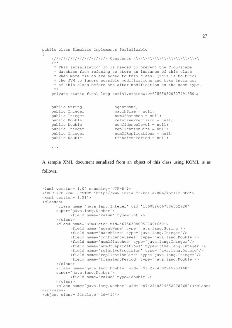
27
public class Simulate implements Serializable { //////////////////////// Constants \\\\\\\\\\\\\\\\\\\\\\\\\\\\ /** * This serialization ID is needed to prevent the Cloudscape * database from refusing to store an instance of this class * when more fields are added to this class. (This is to trick * the JVM to ignore possible modifications and take instances * of this class before and after modification as the same type. */ private static final long serialVersionUID=675650800527491650L; public String agentName; public Integer batchSize = null; public Integer numOfBatches = null; public Double relativePrecision = null; public Double confidenceLevel = null; public Integer replicationSize = null; public Integer numOfReplications = null; public Double transientPeriod = null; ...
A sample XML document serialized from an object of this class using KOML is as
follows.
<?xml version=’1.0’ encoding=’UTF-8’?> <!DOCTYPE koml SYSTEM "http://www.inria.fr/koala/XML/koml12.dtd"> <koml version=’1.21’> <classes>
<class name=’java.lang.Integer’ uid=’1360826667806852920’ super=’java.lang.Number’>
<field name=’value’ type=’int’/> </class> <class name=’Simulate’ uid=’675650800527491650’>
<field name=’agentName’ type=’java.lang.String’/> <field name=’batchSize’ type=’java.lang.Integer’/> <field name=’confidenceLevel’ type=’java.lang.Double’/> <field name=’numOfBatches’ type=’java.lang.Integer’/> <field name=’numOfReplications’ type=’java.lang.Integer’/> <field name=’relativePrecision’ type=’java.lang.Double’/> <field name=’replicationSize’ type=’java.lang.Integer’/> <field name=’transientPeriod’ type=’java.lang.Double’/>
</class> <class name=’java.lang.Double’ uid=’-9172774392245257468’ super=’java.lang.Number’>
<field name=’value’ type=’double’/> </class> <class name=’java.lang.Number’ uid=’-8742448824652078965’></class>
</classes> <object class=’Simulate’ id=’i4’>
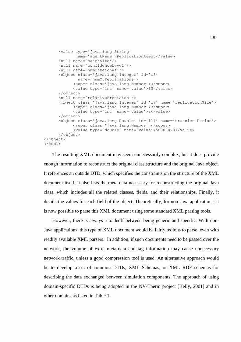
28
<value type=’java.lang.String’ name=’agentName’>ReplicationAgent</value> <null name=’batchSize’/> <null name=’confidenceLevel’/> <null name=’numOfBatches’/> <object class=’java.lang.Integer’ id=’i8’ name=’numOfReplications’>
<super class=’java.lang.Number’></super> <value type=’int’ name=’value’>10</value>
</object> <null name=’relativePrecision’/> <object class=’java.lang.Integer’ id=’i9’ name=’replicationSize’>
<super class=’java.lang.Number’></super> <value type=’int’ name=’value’>2</value>
</object> <object class=’java.lang.Double’ id=’i11’ name=’transientPeriod’>
<super class=’java.lang.Number’></super> <value type=’double’ name=’value’>500000.0</value>
</object> </object> </koml>
The resulting XML document may seem unnecessarily complex, but it does provide
enough information to reconstruct the original class structure and the original Java object.
It references an outside DTD, which specifies the constraints on the structure of the XML
document itself. It also lists the meta-data necessary for reconstructing the original Java
class, which includes all the related classes, fields, and their relationships. Finally, it
details the values for each field of the object. Theoretically, for non-Java applications, it
is now possible to parse this XML document using some standard XML parsing tools.
However, there is always a tradeoff between being generic and specific. With non-
Java applications, this type of XML document would be fairly tedious to parse, even with
readily available XML parsers. In addition, if such documents need to be passed over the
network, the volume of extra meta-data and tag information may cause unnecessary
network traffic, unless a good compression tool is used. An alternative approach would
be to develop a set of common DTDs, XML Schemas, or XML RDF schemas for
describing the data exchanged between simulation components. The approach of using
domain-specific DTDs is being adopted in the NV-Therm project [Kelly, 2001] and in
other domains as listed in Table 1.
29
Since we are using Java, KOML works beautifully with JSIM, though. When a state
change occurs in a JSIM publisher, the publisher constructs a message object with the
corresponding message class, serializes the object into an XML string, places it into a
JsimEvent, and then passes the event as a parameter to the notify() method of the
subscribing JsimListeners. In its notify() method, a subscriber can either extract the event
data by deserializing the message or forward it to other applications for further
processing.
To further enhance semantic support for JSIM messages, we have included in all
message classes a field called performative, which is similar to a performative in the
Knowledge Query and Manipulation Language (KQML). The use of performatives
allows an event receiver to respond to an event in accordance with the context of the
conversation.
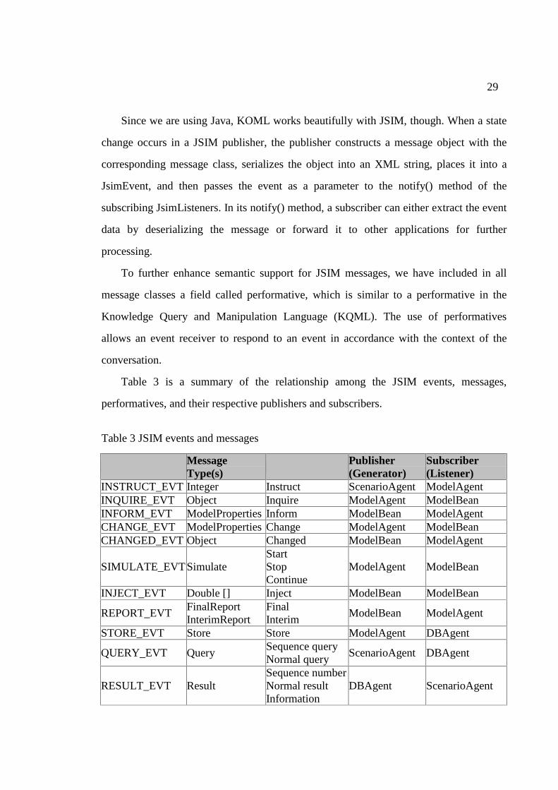
Table 3 is a summary of the relationship among the JSIM events, messages,
performatives, and their respective publishers and subscribers.
Table 3 JSIM events and messages
Event Type Message Type(s)
Performative(s) Publisher (Generator)
Subscriber (Listener)
INSTRUCT_EVT Integer Instruct ScenarioAgent ModelAgent INQUIRE_EVT Object Inquire ModelAgent ModelBean INFORM_EVT ModelProperties Inform ModelBean ModelAgent CHANGE_EVT ModelProperties Change ModelAgent ModelBean CHANGED_EVT Object Changed ModelBean ModelAgent
SIMULATE_EVT Simulate Start Stop Continue
ModelAgent ModelBean
INJECT_EVT Double [] Inject ModelBean ModelBean
REPORT_EVT FinalReport InterimReport
Final Interim
ModelBean ModelAgent
STORE_EVT Store Store ModelAgent DBAgent
QUERY_EVT Query Sequence query Normal query
ScenarioAgent DBAgent
RESULT_EVT Result Sequence number Normal result Information
DBAgent ScenarioAgent

30
By serializing the event objects that encapsulate state change information into a text-
based standard data format using a common DTD, JSIM allows individual simulation
components to understand its messages with consistency and accuracy. It further opens
up the possibility for JSIM to collaborate and exchange simulation data with other
simulation systems.
31
CHAPTER 5
SIMULATION DATA MANAGEMENT
Running a simulation is often a time-consuming process. It is often desirable to store
the input and output of a simulation into a database for later use. Since XML is used to
represent simulation data in JSIM, the management of simulation data in JSIM becomes
an issue of managing XML-formatted data.
The traditional database technologies have been very successful in managing highly
structured data [Abiteboul et al., 2000]. However, the lack of a strict structure with XML
poses a challenge to traditional database management systems, especially relational
databases. How to efficiently store and retrieve XML data has been an active area of
research. It appears that a new breed of database management systems that supports the
storage of XML data in its native form and querying of XML database using a declarative
XML query language is emerging in the research sector as well as the commercial sector.
Examples of such systems include the SODA2 project [Cover, 2000b] and the Tamino
XML Database [Software AG, 2001]. We are also seeing great efforts being made by
traditional database vendors to extend their systems to support XML.
In this chapter, we will study the various approaches towards managing XML data
with current database management technologies. We will also present our design and
implementation of the JSIM database using a lightweight object-relational database
management system.
32
5.1 Managing XML Data
XML is often compared with semi-structured data, a type of self-describing data that
may not conform to a fixed predefined schema [Quass et al., 1995]. Semi-structured data
allows for type and structural heterogeneity, and therefore is different from highly
structured data that is characteristic of relational databases. An example of semi-
structured data model is the Object Exchange Model (OEM) developed by the Stanford
database group for the Tsimmis [Quass, et al., 1995] project. It is claimed to be the de
facto semi-structured data model [Abiteboul, 2000].
Like semi-structured data, XML has a less strict structure than that of relational
databases. An XML document can optionally have a DTD and/or an XML Schema. Both
DTD and XML Schema allow for optional elements. An optional element may be absent
from an XML document yet the document may still conform to the DTD or XML
Schema. This is not the case with relational databases. In a relational database, there must
a value for each attribute of a relation. For those attributes that do not have an applicable
or known value, a null, 0, or empty string must be present.
XML is slightly different from semi-structured data, though. For instance, the child
elements of a given node in the XML data model are ordered, but the order of nodes in
the semi-structured data model is not important.
A flexible and scalable approach to storing XML documents is to use a database
management system (DBMS). We will now consider several approaches using different
types of DBMSs, namely, relational database management systems (RDBMSs), object-
oriented database management systems (OODBMSs), and object-relational database
management systems (ORDBMSs), and native XML database management systems
(XML DBMSs).
To store XML data in relational databases, one has to define a mapping between the
underlying XML data model and a relational data model. The mapping could have
different granularities. At the coarsest level, a class of XML documents can be mapped to
33
one column in a relational table and then stored in text format. This requires run-time
parsing of all the stored XML documents to handle queries on subcomponents of the
XML documents, which is very inefficient.
At the intermediate level, the most frequently queried portion of the XML documents
are mapped to a set of relational tables connected by foreign keys. The less frequently
accessed portion is stored as text in one column. The latter will have to be parsed at run-
time when needed. This will ensure reasonable performance in common cases. This
approach is called hybrid storage. A variant of this apprioach is to map the most
frequently queried portion of the XML documents to a set of tables, but at the same time
store the XML documents in their entirety within a column in a separate table [Sybase,
1999]. To some extent, the mapped portion becomes sort of an index to the XML
documents. This allows for fast retieval of the XML documents in most situations. This
approach is suitable for those applications in which a stored XML document is either
needed in its entirety or not needed at all. For instance, some modeling tools might store a
model in XML format so that, when the model is needed, the modeling tool can retrieve it
immediately. In this case, the hybrid storage variant would be very useful.
At the finest level, all the sub-components of a type of XML document can be
mapped to columns in a set of tables. The mapping can be application-specific, i.e., the
set of tables is customized to reflect the structure of the corresponding XML documents.
The mapping could also be very generic so that the same set of tables can handle all
XML documents [Birbeck, 1998]. For any XML document, reconstruction of the original
tree structure is possible if it is stored in the tables as shown in Table 4.
34
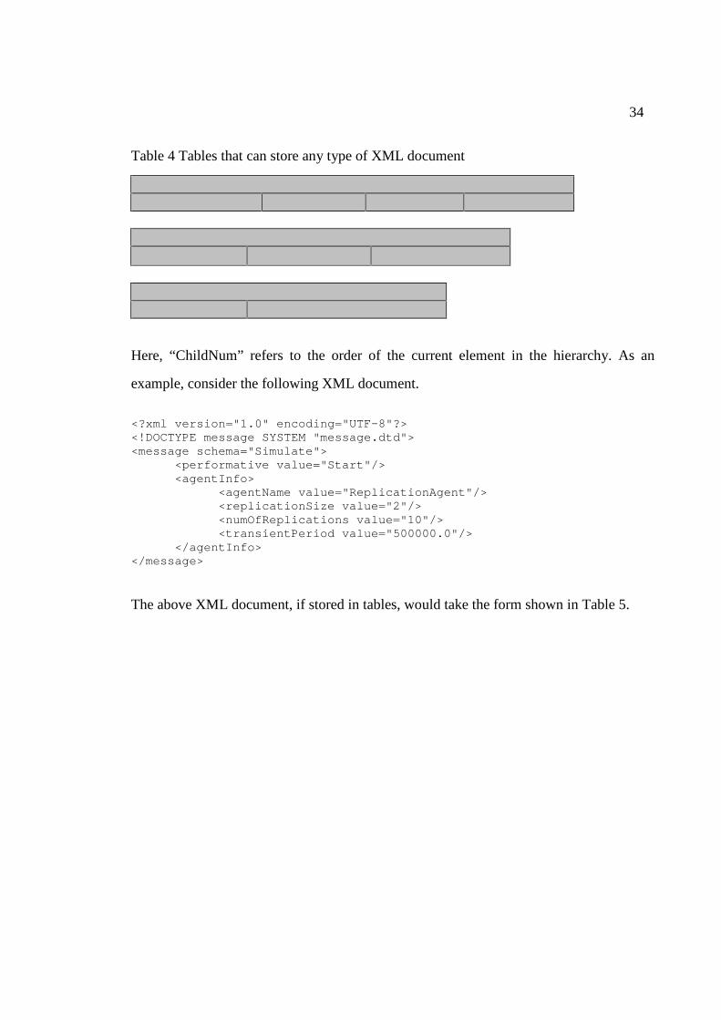
Table 4 Tables that can store any type of XML document
Element ElementName ID Parent ChildNum
Attribute
ElementID Name Value
DataNode ID Value
Here, “ChildNum” refers to the order of the current element in the hierarchy. As an
example, consider the following XML document.
<?xml version="1.0" encoding="UTF-8"?> <!DOCTYPE message SYSTEM "message.dtd"> <message schema="Simulate"> <performative value="Start"/> <agentInfo> <agentName value="ReplicationAgent"/> <replicationSize value="2"/> <numOfReplications value="10"/> <transientPeriod value="500000.0"/> </agentInfo> </message>
The above XML document, if stored in tables, would take the form shown in Table 5.
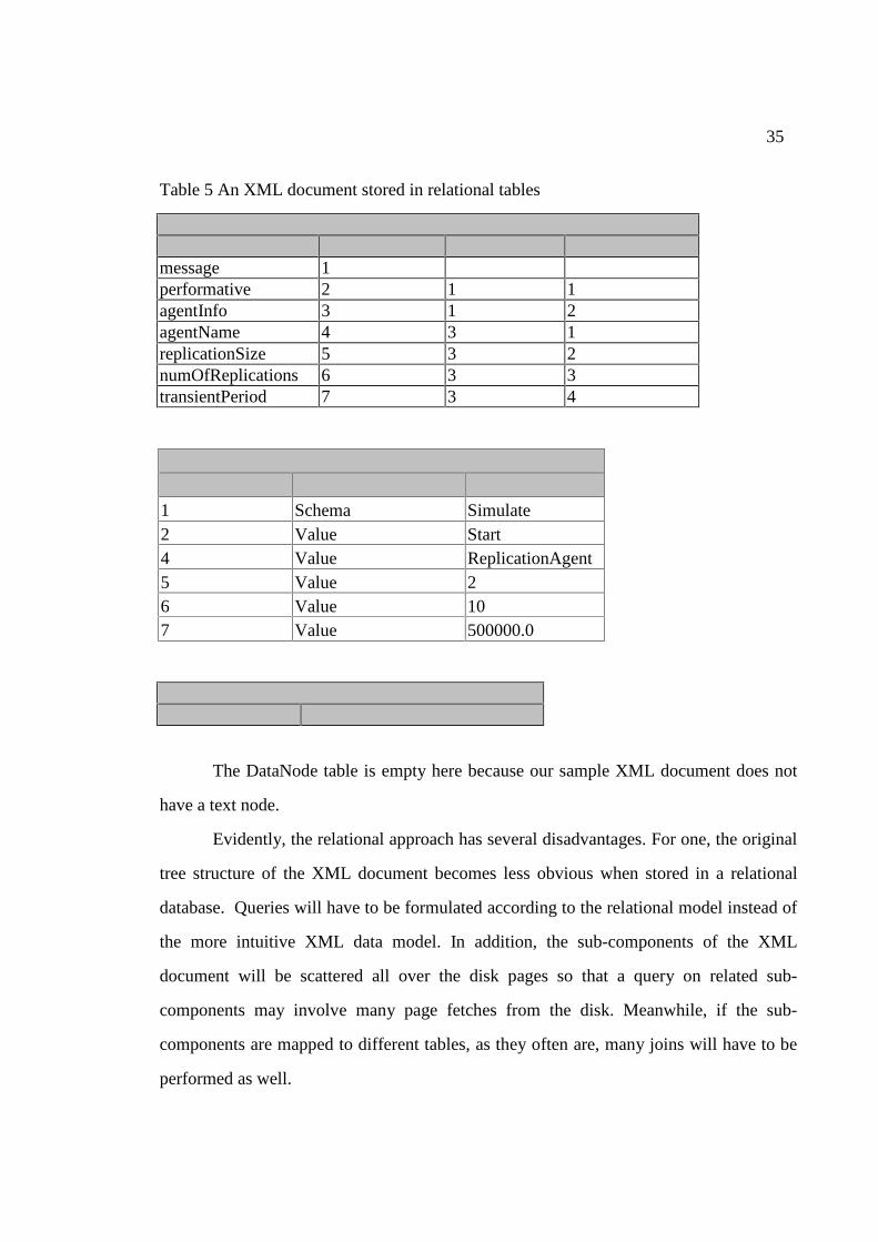
35
Table 5 An XML document stored in relational tables
Element ElementName ID Parent ChildNum message 1 performative 2 1 1 agentInfo 3 1 2 agentName 4 3 1 replicationSize 5 3 2 numOfReplications 6 3 3 transientPeriod 7 3 4
Attribute ElementID Name Value 1 Schema Simulate 2 Value Start 4 Value ReplicationAgent 5 Value 2 6 Value 10 7 Value 500000.0
DataNode ID Value
The DataNode table is empty here because our sample XML document does not
have a text node.
Evidently, the relational approach has several disadvantages. For one, the original
tree structure of the XML document becomes less obvious when stored in a relational
database. Queries will have to be formulated according to the relational model instead of
the more intuitive XML data model. In addition, the sub-components of the XML
document will be scattered all over the disk pages so that a query on related sub-
components may involve many page fetches from the disk. Meanwhile, if the sub-
components are mapped to different tables, as they often are, many joins will have to be
performed as well.
36
Another issue is the handling of null values. As we have discussed before, an
XML document may not strictly conform to a rigid fixed schema. For example, an XML
document may be allowed to have a missing element. However, this is not the case with
relational databases. A tuple in a relation must specify values for all attributes in the
relation. To handle an XML document with a missing element or attribute, either a 0 or a
null value must be specified for that element or attribute. A null could indicate that the
element or attribute does not have a legal value or it has one but the value is currently not
available. This makes it extremely difficult to maintain a consistent interpretation of the
null values in XML documents stored in relational databases.
Typing is also problematic. In the above example, the Value field in the
DataNode table could have integer type or string type. We may declare the Value field to
be of type string and have a separate field indicating which instance value is actually of
type integer. Alternatively, we can have two value fields, one string and the other integer.
In either case, we will have to leave many cells in the value fields blank, which requires
special handling in query processing and which goes against the relational notion of
storage efficiency.
Order also raises concern because relations do not care about order of tuples but
XML documents do care about the order of their elements. Although things can be
worked around, as we did in the above example, care must be taken in formulating or
processing queries. Interested readers may refer to [Bourret, 2000] for extended
discussions about the limitations of using relational database management systems to
store XML documents.
With object-oriented databases, there also needs to be a mapping between the
XML data model and the object data model. However, the mapping would be much
easier because the object model naturally captures the ordering and nesting of collections
of components. Let us consider the DTD for our sample XML document.
<?xml version="1.0" encoding="UTF-8"?> <!ELEMENT message (performative, agentInfo)>
37
<!ATTLIST message schema CDATA #REQUIRED> <!ELEMENT performative EMPTY> <!ATTLIST performative value CDATA #REQUIRED> <!ELEMENT agentInfo (agentName, replicationSize, numOfReplications, transientPeriod)> <!ELEMENT agentName EMPTY> <!ATTLIST agentName value CDATA #REQUIRED> <!ELEMENT replicationSize EMPTY> <!ATTLIST replicationSize value CDATA #REQUIRED> <!ELEMENT numOfReplications EMPTY> <!ATTLIST numOfReplications value CDATA #REQUIRED> <!ELEMENT transientPeriod EMPTY> <!ATTLIST transientPeriod value CDATA #REQUIRED>
According to the DTD, we can create the following classes to store those XML
documents conforming to the DTD.
class Message schema: string,
performative: string, agentInfo: class AgentInfo, class AgentInfo agentName: string, replicationSize: integer, numOfReplications: integer, transientPeriod: double
The mapping is straightforward. For simple or empty nodes, we map them to either string
or integer type; for complex element nodes, we map them to a class or a collection of
classes, depending on the DTD specifications. The type information is useful in
optimizing storage and improving performance. This approach ensures that closely
related sub-components of the XML documents are grouped together and clustered in
nearby disk pages. As a result, fewer page fetches will be needed to answer most queries.
That said, the object-oriented approach might not necessarily outperform the relational
approach, simply because relational databases are well developed. The strong typing
required by a relational database makes it possible to optimize storage, support advanced
indexing and sophisticated queries, and facilitate query processing.
Another approach to storing XML documents is through object-relational database
management systems (ORDBMSs). This type of system has been developed by relational
38
database system vendors to extend their relational systems with object-oriented
capabilities. These systems support all the approaches of storing XML data with
relational databases. In addition, their object-relational features allow one to get both the
performance and scalability of relational databases and ease of use with regard to query
formulation.
Work is also being done in the arena of native XML database management systems.
For instance, SODA26 [Cover, 2000b] is a semi-structured database management system
that supports multiple query languages, including XPath expressions, XQL and XML-
QL, via a set of client libraries. Tamino XML Database is a commercial XML DBMS by
Software AG [Software AG, 2001]. It is the first native XML database, which can store
and process XML data without first converting it to another data format. Thus, it reduces
response time and cuts administrative effort, compared with traditional databases. The
current release of Tamino XML Database supports a declarative XML query language
called X-Query [Chamblin et al., 2001].
This new breed of database systems will distinguish itself from the traditional
relational, object-oriented, and object-relational systems by offering the following
features:
• Hierarchical data model
• Tag and path operations
• Irregular structure, and
• Order/sequence of data elements.
Such a system is likely to make the storing and retrieving of XML data much easier and
more efficient.
6 Stands for Semi-structured Object DAtabase, Version 2.
39
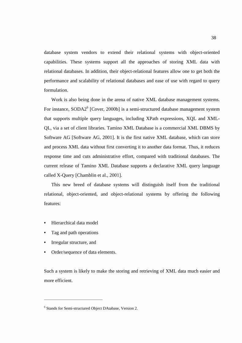
The pros and cons of using the various backends for storing XML data are
summarized in Table 6.
Table 6 Storing XML data in databases
Backend Sample Databases Feasibility Implementation Querying
RDBMS Sybase Adaptive Server
Yes Complex mapping required
Allows SQL queries, some parsing may be necessary
ODBMS Object Store Poet
Yes Mapping required but easy
Allows OQL queries, some parsing may be necessary
ORDBMS Oracle 8I DB2
Yes Mappings required
Allows SQL/SQL3 queries, some parsing may be necessary
XML DBMS
Tamino XML Database SODA2
Yes No mappings needed
Supports a declarative XML query language.
5.2 Storing JSIM Simulation Data
In a previous attempt to implement an XML database for JSIM [Huang et al., 2000],
we used Oracle 8i, an object-relational database. With Oracle 8i and the Oracle’s XML
SQL Utility [Oracle, 2000], one can store XML data in relational tables but create an
object view on top of those tables to allow queries to be formulated according to the
object view. We found it hard to evolve our database schema with this approach, because
it requires two mappings, one from the simulation data to the relational tables, the other
from the relational tables to an object view.
We have implemented the current JSIM database using Cloudscape, which is a small-
foot-print object-relational database implemented in pure Java. With Cloudscape, one can
store Java objects together with relational data in a set of relational tables. This makes it
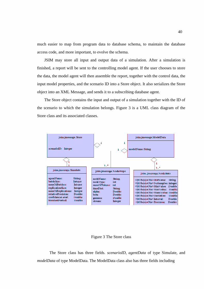
40
much easier to map from program data to database schema, to maintain the database
access code, and more important, to evolve the schema.
JSIM may store all input and output data of a simulation. After a simulation is
finished, a report will be sent to the controlling model agent. If the user chooses to store
the data, the model agent will then assemble the report, together with the control data, the
input model properties, and the scenario ID into a Store object. It also serializes the Store
object into an XML Message, and sends it to a subscribing database agent.
The Store object contains the input and output of a simulation together with the ID of
the scenario to which the simulation belongs. Figure 3 is a UML class diagram of the
Store class and its associated classes.
Figure 3 The Store class
The Store class has three fields. scenarioID, agentData of type Simulate, and
modelData of type ModelData. The ModelData class also has three fields including
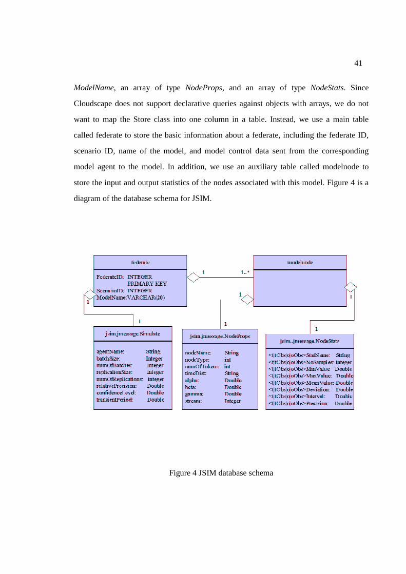
41
ModelName, an array of type NodeProps, and an array of type NodeStats. Since
Cloudscape does not support declarative queries against objects with arrays, we do not
want to map the Store class into one column in a table. Instead, we use a main table
called federate to store the basic information about a federate, including the federate ID,
scenario ID, name of the model, and model control data sent from the corresponding
model agent to the model. In addition, we use an auxiliary table called modelnode to
store the input and output statistics of the nodes associated with this model. Figure 4 is a
diagram of the database schema for JSIM.
Figure 4 JSIM database schema
42
5.3 Querying JSIM Database
A JSIM database can be queried from a scenario agent query panel by entering SQL
statements. Behind the scene, the query is sent to a database agent. If an error occurs, a
Result object, constructed with the performative “information” and an error message, will
be sent back to the scenario agent and displayed to the user. Otherwise, a Result object,
with the performative “normal result” and the query result, will be constructed and sent
back to the scenario agent. In the latter case, the scenario agent will dynamically generate
an XML document and display it. Interested readers please refer to steps 7 and 8 in the
section, “Working with a sample model” in Appendix B, for snapshots of a sample query.
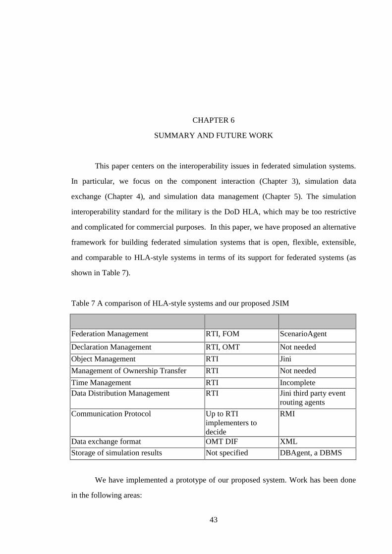
43
CHAPTER 6
SUMMARY AND FUTURE WORK
This paper centers on the interoperability issues in federated simulation systems.
In particular, we focus on the component interaction (Chapter 3), simulation data
exchange (Chapter 4), and simulation data management (Chapter 5). The simulation
interoperability standard for the military is the DoD HLA, which may be too restrictive
and complicated for commercial purposes. In this paper, we have proposed an alternative
framework for building federated simulation systems that is open, flexible, extensible,
and comparable to HLA-style systems in terms of its support for federated systems (as
shown in Table 7).
Table 7 A comparison of HLA-style systems and our proposed JSIM
Support for Federated Simulations HLA-Style Systems Proposed JSIM
Federation Management RTI, FOM ScenarioAgent
Declaration Management RTI, OMT Not needed
Object Management RTI Jini
Management of Ownership Transfer RTI Not needed
Time Management RTI Incomplete Data Distribution Management RTI Jini third party event
routing agents
Communication Protocol Up to RTI implementers to decide
RMI
Data exchange format OMT DIF XML
Storage of simulation results Not specified DBAgent, a DBMS
We have implemented a prototype of our proposed system. Work has been done
in the following areas:
44
• Streamlined the design of model beans to allow automatic code generation of newly
designed model beans. The code generation feature makes JSIM more user friendly,
since it relieves a model designer from writing customization code for each model.
• Made the model agents capable of dynamically adjusting the properties of model
beans at run time through a GUI interface.
• Enhanced the scenario agent to make it a federation coordinator rather than a central
authority for running a federation. Currently, the scenario agent is responsible for
supplying a scenario ID to the participating model agents at the start of a federation.
The scenario ID can be used by the model agents to store the input and output of the
simulation, and later, be used to retrieve all input and output simulation data
generated by each simulation associated with this federation.
• Extended the original JSIM to include a database agent, so that the simulation results
collected after time-consuming simulation runs can be stored, queried, reused, and
thoroughly analyzed for decision-making purposes.
• Selected an embedded object-relational database system, Cloudscape, for the back
end of JSIM. Cloudscape is implemented in pure Java and can store both Java objects
and relational data. This feature makes it possible for us to keep the JSIM schema
simple and easy to evolve.
• Designed the JSIM database to support the storage of the input and output data of a
simulation federation.
• Built a graphical query interface for the JSIM database.
• Implemented Jini-style events and XML-based messages to facilitate the
communication and exchange of simulation data between the JSIM components.
• Supported a GUI-less approach of composing a federation based on a graph
specification. By taking the beans out of a GUI bean builder, the beans can be more
easily distributed. (Since the default bean builder only supports JavaBeans events that
45
live in a single JVM, any attempt to make the beans distributed will end up modifying
the source code of the bean builder, which is time consuming and error prone.)
Overall, this prototype system has laid a very solid foundation upon which our
envisioned federated simulation system can be built. However, it is only our first step
towards our vision of building a fully distributed federated simulation system. Unit and
integration tests have been performed on the XML-based messaging scheme in a single-
machine environment. More work is needed to fully test the distributed events in a
distributed environment. Some opportunities for future research include:
• Develop a common set of DTDs or XML Schema for the different types of messages
exchanged among the scenario agent, the model agents, and the database agent, so
that those messages can be more meaningful and more concise. This may require
writing code to parse those messages, or using Sun’s XML Data Binding APIs
[Reinold, 1999] to process those messages at an object level. A more flexible and
more sophisticated approach would be to use the XML RDF schema to describe the
meaning of the individual messages to achieve semantic interoperability of those
messages.
• Employ third party event routing agents and the event sequence number to guarantee
reliable and orderly delivery of JSIM events.
• Use the Jini transaction management facilities to ensure that all model agents in a
federation either successfully store their simulation results into the database, or
nothing is stored. Otherwise, incomplete simulation results of a federation may be
found in the database.
• Investigate the Jini join/discover protocol to explore the possibility for JSIM to
interact with other simulation systems on the network.
46
BIBLIOGRAPHY
[Abiteboul et al., 2000] Abiteboul, S. Buneman, P, and Suciu, D. (2000). Data on the Web. From Relations to Semi-structured Data and XML. Morgan Kaufmann Publishers. [Apache, 2000] Apache.org. (2000). Xalan-Java version 2.0.0. http://xml.apache.org/xalan-j/ [Arkin et al., 2000] Arkin, A. and Visco, K. (2000). Castor. http://castor.exolab.org/ora-mar-2k/castor.htm [Berners-Lee, 2000] Berners-Lee, T. (2000). XML and the Web, September 6, 2000. http://www.w3.org/2000/Talks/0906-xmlweb-tbl/slide1-6.html [Birbeck, 1998] Birbeck, M. (1998). Re. storing XML documents on relatioanl database XML-L Mailing List. http://listserv.heanet.ie/cgi-bin/wa?A2=ind9812&L=xml-l&F=&S=&P=14771 [Bollinger, 2000] Bollinger, T. (2000). A Guide to Understanding Emerging Interoperability Technologies. Technical paper, Mitre Corporation. July 2000. http://www.mitre.org/support/papers/tech_papers99_00/bollinger_interoperability/bollinger_interop.pdf [Bosak and Bray, 1999] Bosak, J. and Bray, T. (1999). XML and the Second-Generation Web. http://www.sciam.com/1999/0599issue/0599bosak.html [Bray et al., 1998] Bray, T., Paoli, J., and Sperberg-McQueen, C. M. (1998) Extensible Markup Language (XML) 1.0. Technical report, W3C. http://www.w3.org/TR/REC-xml, W3C Recommendation, 10-February-1998. [Burret, 2000] Burret, R. (2000). XML and Databases. http://www.rpbourret.com/xml/XMLAndDatabases.htm [Buss, 2000] Buss, A.H. (2000). Wireless Networks to Support Rapid Decision-Making. Naval Postgraduate School Research Newsletter, pp. 18-23. [Buss et al., 1998] Buss, A.H., Jackson, L. (1998). Distributed Simulation Modeling. A Comparison of HLA, CORBA, and RMI. Proceedings of the 1998 Winter Simulation Conference. [Chamblin et al., 2001] Chamblin, D., Florescu, J., Robie, J., Simeon, J., Stefanescn, M. ed., XQuery. A Query Language for XML. W3C Working Draft, 15 February 2001.
47
[Cover, 2000a] Cover, R. (2000). XML Messaging (IETF). July 2, 2000. http://www.oasis-open.org/cover/xmlMessagingIETF.html [Cover, 2000b] Cover, R. (2000). SODA2 - An XML Semi-structured Database System. http://www.oasis-open.org/cover/soda2.html. [DMSO, 1998b] Defense Modeling And Simulation Office. High Level Architecture Interface Specification, Version 1.3. http://hla.dmso.mil/tech/ifspec.html [DMSO, 1998c] Defense Modeling And Simulation Office. (1998). High Level Architecture Object Model Template Specification, Version 1.3. http://hla.dmso.mil/tech/omtspec.html [ebXML.org, 2001] ebXML Integrates SOAP Into Messaging Services Specification. ebXML.org news. http://www.ebxml.org/news/pr_20010222.htm. [Finin et al., 1994] Finin, T., Fritzen, R., McKay, D., and McEntire, R. (1994). KQML as an Agent Communication Language. Proceedings of the Third International Conference on Information and Knowledge Management (CIKM), ACM Press, November 1994. [Fujimoto, 1998] Fujimoto, R. (1998). Time Management in the Hligh Level Architecture. Simulation, Vol. 71, No. 6, pp. 388-400, December 1998. [Ge, 1998] Ge, Y. (1998). Development of a Web-Based Simulation Environment Using Java Bean. Master Thesis. The University of Georgia. [Hamilton, 1997] Hamilton, C. (Editor). (1997). JavaBeans. http://java.sun.com/beans [Hegaret, 1999] Hegaret, P.L. (1999). http://www-sop.inria.fr/koala/XML/serialization/ [Hsu, 2000] Hsu, C.C. (2000). http://iceberg.sourceforge.net/ [Huang and Miller, 2001] Huang, X. and Miller, J.A. (2001). Building a Web-Based Federated Simulation System with Jini and XML, Proceedings of the 34th Annual Simulation Symposium (ANSS’01), Seattle, Washington. [Huang et al., 2000] Huang, X., Tian, H., and Xu, X. (2000). JSIM Database. A Web- Based Database Application with XML. Proceedings of the 38th Annual Southeast ACM Conference, Clemson, SC. April 2000. [Javasoft, 1997] Javasoft. (1997). Java beans specification 1.0 http://splash.javasoft.com/beans/beans/100A.pdf [JXML, 2001] JXML. (2001). http://jxquick.sourceforge.net/
48
[Kelly, 2001] Kelly, S. (2001). NV-Therm Design. Technical Paper. California Institute of Technology. [Klein et all, 1998] Klein, U., Straßburger, S., and Beikrich, J. (1998). Distributed Simulation with JavaGPSS Based on the High Level Architecture. Proceedings of the 1998 SCS International Conference on Web-Based Modeling and Simulation, ed. P.A. Fishwick, D.R.C. Hill, and R. Smith, pp. 85-90, Society for Computer Simulation International, San Diego, CA. [Kuhl et al., 1999] Kuhl, F., Weatherly, R., and Dahmann, J. (1999). Creating Computer Simulation System. An Introduction to the High Level Architecture. Prentice Hall PTR. [Laurent and Biggar, 1999] Laurent, S. and Biggar, R. (1999). Inside XML DTDs. McGraw-Hill. [Medeiros, 2000] Medeiros, N. (2000). Metadata. Semantics Plus Structure Plus Syntax. OCLC Systems & Services. 2000. 16(2). 54-56. [Microsoft, 2001] Microsoft. (1999) http://www.microsoft.com/com/tech/ [Miller et al., 1997] Miller, J., Nair, R., Zhang, Z., and Zhao, H. (1997). JSIM. A Java-Based Simulation and Animation Environment. Proceedings of the 30th Annual Simulation Symposium, pp. 31-42, Atlanta, Georgia. [Miller et al., 1998] Miller, J., Ge, Y., and Tao, J. (1998). Component-Based Simulation Environments. JSIM as a Case Study Using Java Beans. Proceedings of the 1998 Winter Simulation Conference, pp. 373-381, Washington, DC. [Miller et al., 1999] Miller, J., Seila, A., and Xiang, X. (1999). The JSIM Web-based Simulation Environment. Future Generation Computing System Journal. Special Issue on Web-Based Modeling and Simulation. [Miller, 1999a] Miller. J. (1999). Guest Editorial. Web-Based Simulation and Modeling, IEEE Potentials. Special Issue on Web-Based Simulation and Modeling, Vol., No. (1999) [Miller, 1999b] Miller, J. (1999). Guest Editor, Special Issue on Web-Based Simulation and Modeling, IEEE Potentials Vol. No. (1999). [Miller et al., 2000] Miller, J., Fishwick, P., Benjamin, P., Szymanski, B., and Taylor, B. (2000). Research and Commercial Opportunities in Web-Based Simulation. Panel on WEBSIM’ 2000. [Nair et al., 1996] Nair, R., Miller, J., and Zhang, Z. (1996). A Java-Based Query Driven Simulation Environment. Proceedings of the 1996 Winter Simulation Conference, pp. 786-793, Coronado, California.
49
[Nair, 1997] Nair, R. (1997). JSIM. A Java-Based Query Driven Simulation and Animation Environment. Masters Thesis. The University of Georgia. [Oracle, 2000] Oracle Corporation. (2000). Oracle XML SQL Utility - XSU. http://technet.oracle.com/tech/xml/oracle_xsu/listing.htm [Page et al., 1997] Page, E.H., Moose, R.L., and Griffin, S.P. (1997). Web-Based Simulation in SimJava Using Remote Method Invocation. Proceedings of the 1997 Winter Simulation Conference, S. Andradóttir, K.J. Healy, D.H. Withers, and B.L. Nelson, Eds., pp. 468-474, Atlanta, GA, 7-10 December. [Page, 1998] Page, E.H. (1998). The Rise of Web-Based Simulation. Implications for the High Level Architecture. Proceedings of the 1998 Winter Simulation Conference, D.J. Medeiros, E. Watson, J. Carson and M. Manivannan, Eds., pp. 1663-1668, Washington, DC, 13-16 December 1998. [Quass et al., 1995] Quass, D., Rajaraman, A., Sagiv, Y., Ullman, J.D., and Widom, J. (1995). Querying Semi-structured Heterogeneous Information. Proceedings of the Fourth International Conference on Deductive and Object-Oriented Databases, pp. 319-344, Singapore. [Reinhold, 1999] Reinhold, M. (1999). An XML Data-Binding Facility for the Java Platform. http://java.sun.com/xml/jaxp-docs-1.0.1/docs/bind.pdf [Roth, 2000] Roth, B. (2000). An Introduction to Enterprise Java Beans Technology. http://developer.java.sun.com/developer/technicalArticles/Beans/IntroEJB/index.html [Seila et al., 1999] Seila, A.F. and Miller, J.A. (1999). Scenario Management in Web-Based Simulation. Proceedings of the 1999 Winter Simulation Conference (WSC’99). Phoenix, Arizona. (December 1999) pp. 1430-1437. [Smith, 1990] Smith, B. (1990). Towards a History of Speech Act Theory. Burkhardt, A. ed., Speech Acts, Meanings and Intentions. Critical Approaches to the Philosophy of John R. Searle, Berlin/New York. de Gruyter (1990), 29-61. [Software AG, 2001] http://www.softwareag.com. [Sun Microsystems, 1999] Sun Microsystems. (1999). Jini Distributed Event Specification, v.1.0.1. November 1999. [Sun Microsystems, 2000a] Sun Microsystems. (2000). JavaSpaces Services Specification, v. 1.1. October, 2000. http://www.sun.com/jini/specs/js1_1.pdf [Sun Microsystems, 2000b] Sun Microsystems. (2000). Jini Architecture Specification, v. 1.1. October, 2000. http://www.sun.com/jini/specs/jini1_1.pdf
50
[Sun Microsystems, 2000c] Sun Microsystems. (2000). Jini Technology Core Platform Specification, v. 1.1. October, 2000. http://www.sun.com/jini/specs/core1_1.pdf [Sybase, 1999] Sybase Inc. (1999). Java in Adaptive Server Enterprise. [Tao, 2000] Tao, J. (2000). HLA-Compliant Distributed JSIM. Masters Thesis. The University of Georgia. [Thomas et al., 1998] Thomas, A. and Seybold, P. (1998). Enterprise JavaBeans Technology. http://www.javasoft.com/products/ejb/ [Venners, 1999] Venners, B. The Jini Vision. Java World. (August 1999). http://developer.java.sun.com/developer/technicalArticles/jini/JiniVision/jiniology.html [W3C, 2001] W3C. http://www.w3.org/ [Wilson, 2001] Wilson, L.F. (2001). The ABELs Framework for Linking Distributed Simulations Using Software Agents. Proceedings of the 2001 IASTED Applied Informatics Symposia. [Xiang, 1999] Xiang, X.. (1999). Use of Agents to control the execution of Simulation Components. Masters Thesis. The University of Georgia. [Zhang, 1997] Zhang, Z. (1997). A Java-Based Simulation and Animation Environment. JSIM’s Foundation Library. Masters Thesis. The University of Georgia. [Zhao, 1997] Zhao, H. (1997). A Graphical Designer for JSIM. Masters Thesis. The University of Georgia.
51
APPENDIX A
The JSIM Packages
JSIM consists of a foundation library, a visual model designer, generated models,
model execution control agents, and a database agent. The foundation library contains
classes supporting the execution of a simulation, including queuing, simulation event
scheduling, and some statistic analysis classes. The model designer has automatic code
generation capability. It allows a user to design a simulation model, enter input
parameters for the model, and generate Java code, or store the model in a special format.
The code generated for each model includes a standalone simulation, a Java applet,
and a Java bean, all of which are ready to be compiled and executed without code
modifications. A model applet can execute independently in an applet environment. A
model bean can be customized at run time, and linked with other model beans and model
agents to dynamically compose a new simulation or simulation federation.
Model agents in JSIM are used to control the quality of simulation results. The
scenario control agent is used to coordinate the execution of a federated simulation. The
input and output of each model can be collected by the model agent and sent to the
database agent to be stored.
The core JSIM system consists of the packages shown in Table 8.
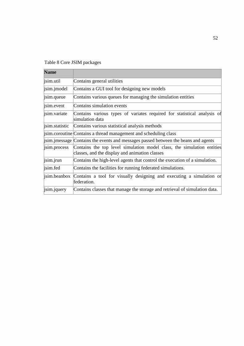
52
Table 8 Core JSIM packages
Name Description
jsim.util Contains general utilities
jsim.jmodel Contains a GUI tool for designing new models
jsim.queue Contains various queues for managing the simulation entities
jsim.event Contains simulation events
jsim.variate Contains various types of variates required for statistical analysis of simulation data
jsim.statistic Contains various statistical analysis methods
jsim.coroutine Contains a thread management and scheduling class
jsim.jmessage Contains the events and messages passed between the beans and agents jsim.process Contains the top level simulation model class, the simulation entities
classes, and the display and animation classes
jsim.jrun Contains the high-level agents that control the execution of a simulation.
jsim.fed Contains the facilities for running federated simulations.
jsim.beanbox Contains a tool for visually designing and executing a simulation or federation.
jsim.jquery Contains classes that manage the storage and retrieval of simulation data.
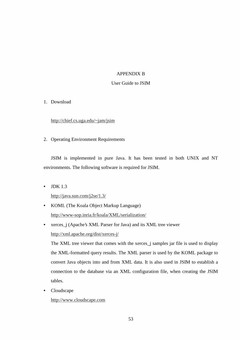
53
APPENDIX B
User Guide to JSIM
1. Download
http://chief.cs.uga.edu/~jam/jsim
2. Operating Environment Requirements
JSIM is implemented in pure Java. It has been tested in both UNIX and NT
environments. The following software is required for JSIM.
• JDK 1.3
http://java.sun.com/j2se/1.3/
• KOML (The Koala Object Markup Language)
http://www-sop.inria.fr/koala/XML/serialization/
• xerces_j (Apache’s XML Parser for Java) and its XML tree viewer
http://xml.apache.org/dist/xerces-j/
The XML tree viewer that comes with the xerces_j samples jar file is used to display
the XML-formatted query results. The XML parser is used by the KOML package to
convert Java objects into and from XML data. It is also used in JSIM to establish a
connection to the database via an XML configuration file, when creating the JSIM
tables.
• Cloudscape
http://www.cloudscape.com
54
Cloudscape is an embedded object-relational database management system
implemented in pure Java. It is needed only if you want to use the database features
of JSIM.
3. Installation Instructions (ON UNIX)
3.1 Install all required software and download jsim.tar.gz to your home directory
3.2 Unzip jsim.tar.gz and extract all files from it
gunzip jsim.tar.gz | tar -xvf –
3.3 Set up your environment variables and CLASSPATH by putting the following lines
in your profile file, such as .cshrc. (You will need cloudscape.jar, RmiJdbc.jar, and
client.jar only if you want to use the database. If you installed those jar files
elsewhere, please adjust everything accordingly.)
setenv JSIM_HOME $HOME/JSIM setenv CLASSPATH ./ setenv CLASSPATH $JSIM_HOME/dep/koml.jar.$CLASSPATH setenv CLASSPATH $JSIM_HOME/dep/xerces.jar.$CLASSPATH setenv CLASSPATH JSIM_HOME/dep/xercesSamples.jar.$CLASSPATH setenv CLASSPATH $JSIM_HOME/dep/client.jar.$CLASSPATH setenv CLASSPATH $JSIM_HOME/dep/cloudscape.jar.$CLASSPATH setenv CLASSPATH $JSIM_HOME/dep/RmiJdbc.jar.$CLASSPATH setenv CLASSPATH $JSIM_HOME/ setenv CLASSPATH ..$CLASSPATH
Please also add the following to your search path.
$JAVA_HOME/bin.$JSIM_HOME/bin
4. Building the JSIM system
cd $JSIM_HOME make
55
Let us assume that you want to use the database feature of JSIM and you use
Cloudscape as your database server. If you choose the RMI-JDBC framework, which is
one of the client-server frameworks supported by Cloudscape, you must run the rmi
server first. A default script for running the rmi database server is included in a file called
"startCS.sh" in the JSIM/jsimdb directory. You need to configure the script according to
your setting, change to the directory where you want your JSIM database to be created,
and run the modified script.
When your database server is up and running, you can modify the configuration file
called "create_jsimschema_config.xml" in the JSIM directory. Then type the following
command to create the JSIM database schema.
java jsim.jquery.CreateJsimSchema
As a result, two tables will be created and a sql script file will be generated. The first
table is a sequence table with only one integer field that will be initialized with a value of
zero. This table stores the next scenarioID value for the SceanrioAgent. Whenever a
request for a scenarioID is requested, the number in the table will be updated. The second
table will be used to store the scenario objects. (We call each execution of a model or
model federation a scenario. The simulation data generated from such a scenario is
encapsulated in an object of type jsim.jquery.Store.) Now, you are ready to experiment
with one of the sample models.
5. Working with a Sample Model
First, change to the directory, JSIM/examples/bank, and build the bank simulation.
cd $JSIM_HOME/examples/bank jmake.sh Bank
To run the model as a standalone application, type
56
java Bank
To turn on the use of XML as the message format, type
java -Djsim.use_xml=true Bank
To dump the XML messages in files, type
java -Djsim.use_xml=true -Djsim.generate_xml_files=true Bank
To run the model as an applet, type
make applet
To run the default model federation as an application, type
make federate
To run the default model federation as an applet, type
make fedApplet
The standalone model application and applet are straightforward to use. Below, we
will briefly walk you through the model federation. Once the model federation is started,
on the scenario window menu bar, click the "Action" menu to bring up a list of menu
items. To run a simulation, select "Start Simulation". A dialog box will pop up to ask you
for database connection information. If you do not want to store the simulation results
into the database later on, just click "Cancel". Otherwise, you will have to enter the
correct information and click "OK". Before the simulation is started, you will be asked to
edit the properties of the model. Click "Apply" after editing. The snapshots in Figures 5-
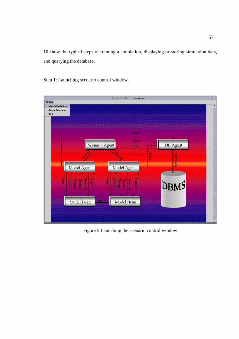
57
10 show the typical steps of running a simulation, displaying or storing simulation data,
and querying the database.
Step 1: Launching scenario control window.
Figure 5 Launching the scenario control window
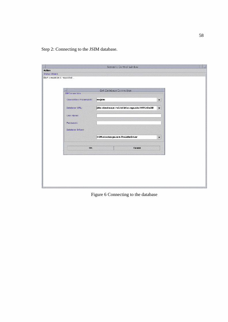
58
Step 2: Connecting to the JSIM database.
Figure 6 Connecting to the database
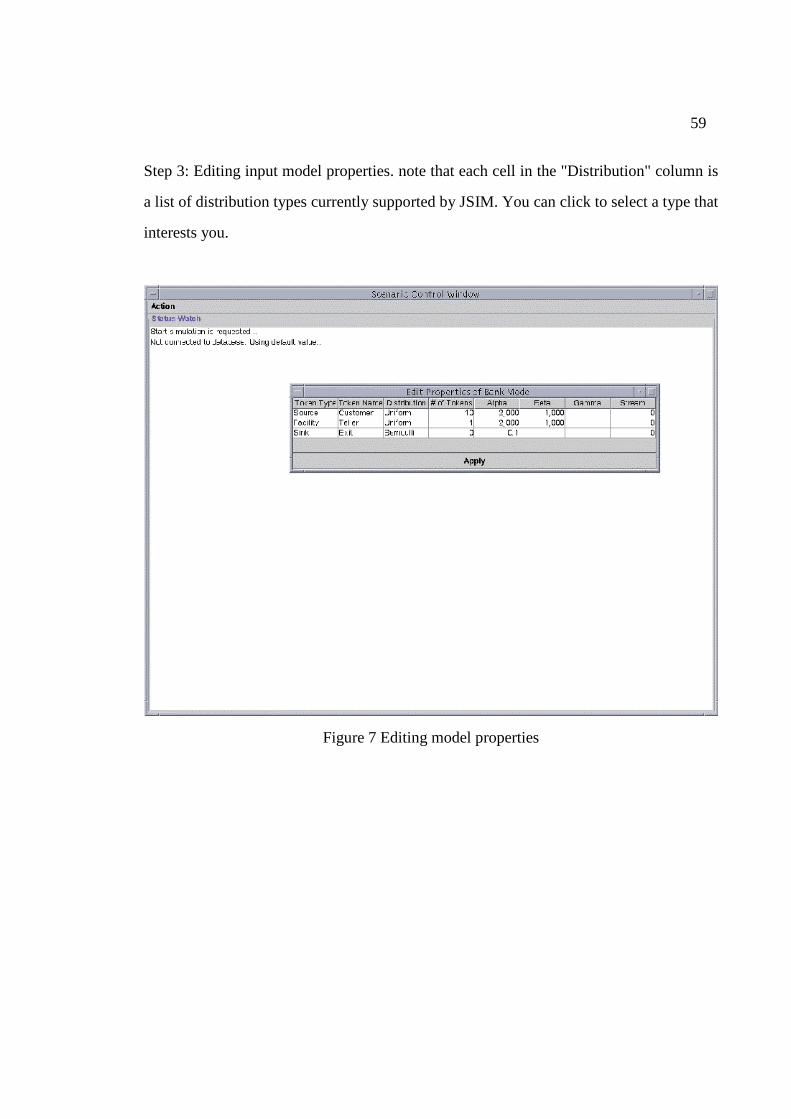
59
Step 3: Editing input model properties. note that each cell in the "Distribution" column is
a list of distribution types currently supported by JSIM. You can click to select a type that
interests you.
Figure 7 Editing model properties
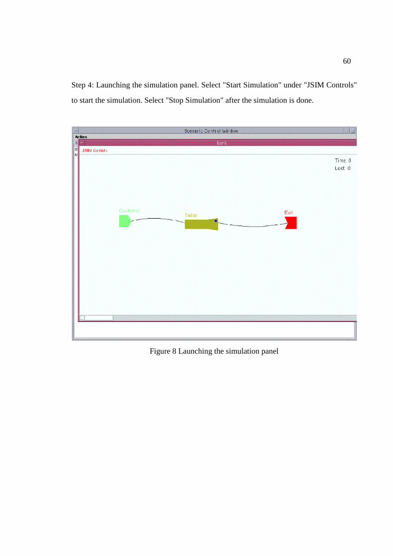
60
Step 4: Launching the simulation panel. Select "Start Simulation" under "JSIM Controls"
to start the simulation. Select "Stop Simulation" after the simulation is done.
Figure 8 Launching the simulation panel
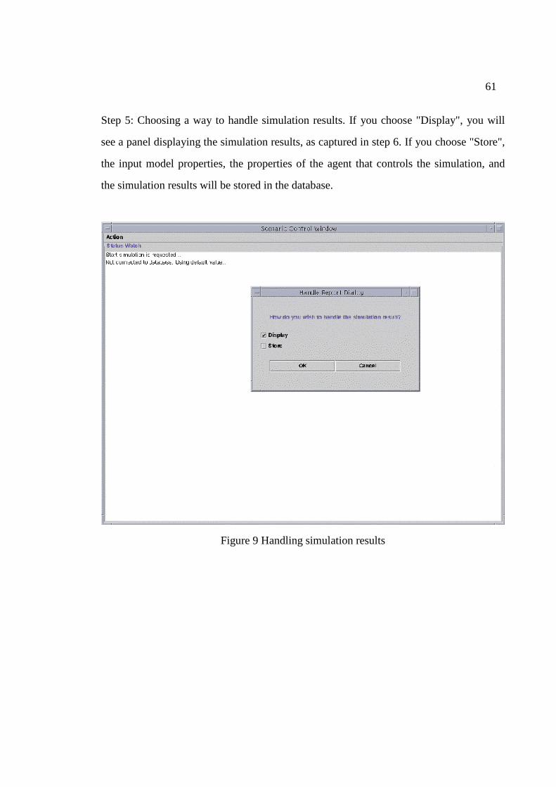
61
Step 5: Choosing a way to handle simulation results. If you choose "Display", you will
see a panel displaying the simulation results, as captured in step 6. If you choose "Store",
the input model properties, the properties of the agent that controls the simulation, and
the simulation results will be stored in the database.
Figure 9 Handling simulation results
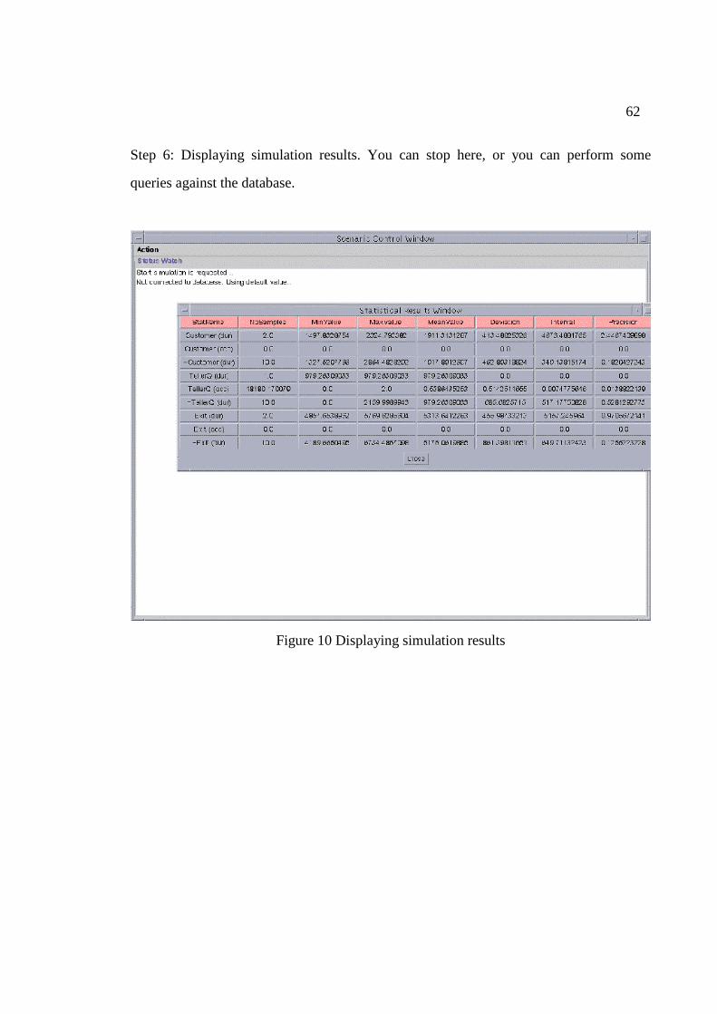
62
Step 6: Displaying simulation results. You can stop here, or you can perform some
queries against the database.
Figure 10 Displaying simulation results
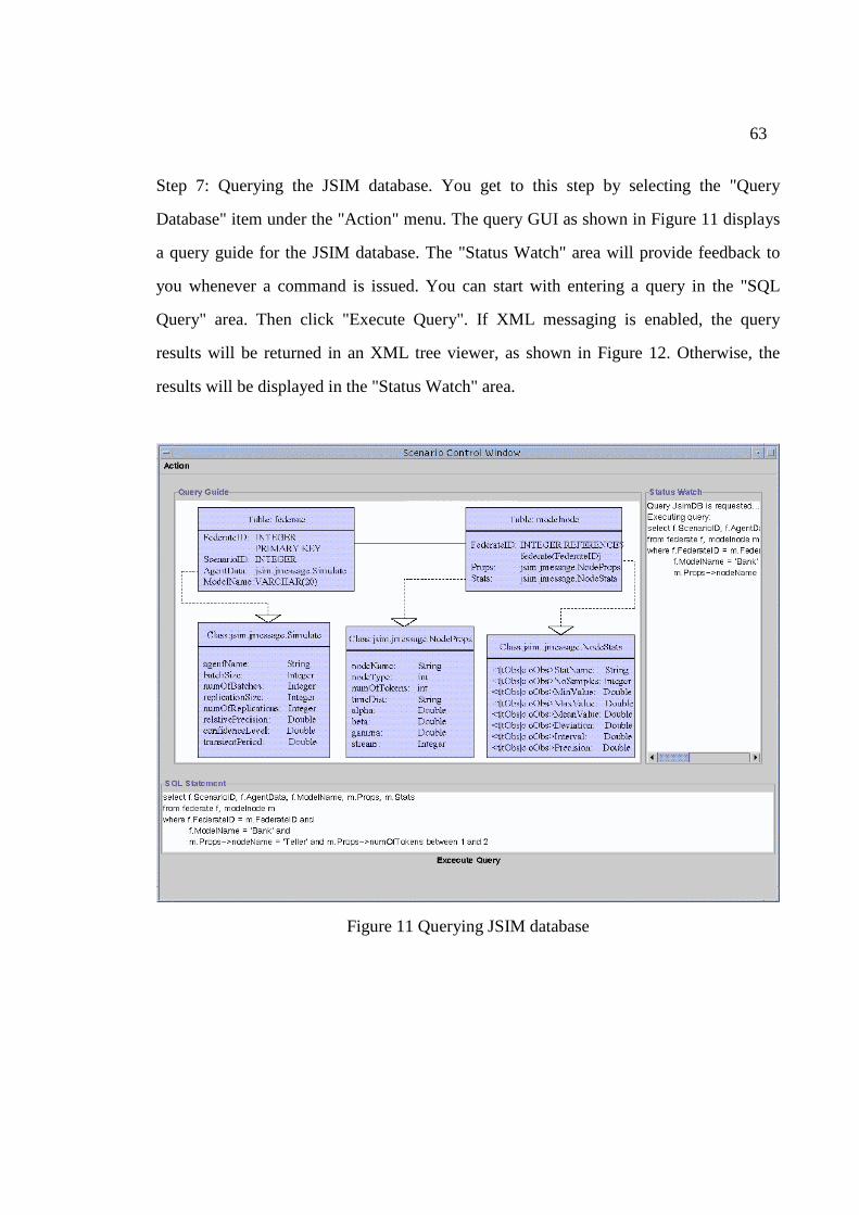
63
Step 7: Querying the JSIM database. You get to this step by selecting the "Query
Database" item under the "Action" menu. The query GUI as shown in Figure 11 displays
a query guide for the JSIM database. The "Status Watch" area will provide feedback to
you whenever a command is issued. You can start with entering a query in the "SQL
Query" area. Then click "Execute Query". If XML messaging is enabled, the query
results will be returned in an XML tree viewer, as shown in Figure 12. Otherwise, the
results will be displayed in the "Status Watch" area.
Figure 11 Querying JSIM database
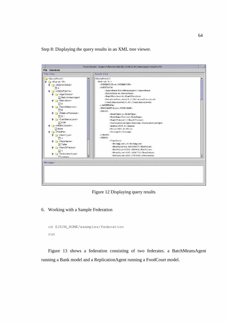
64
Step 8: Displaying the query results in an XML tree viewer.
Figure 12 Displaying query results
6. Working with a Sample Federation
cd $JSIM_HOME/examples/federation
run
Figure 13 shows a federation consisting of two federates. a BatchMeansAgent
running a Bank model and a ReplicationAgent running a FoodCourt model.
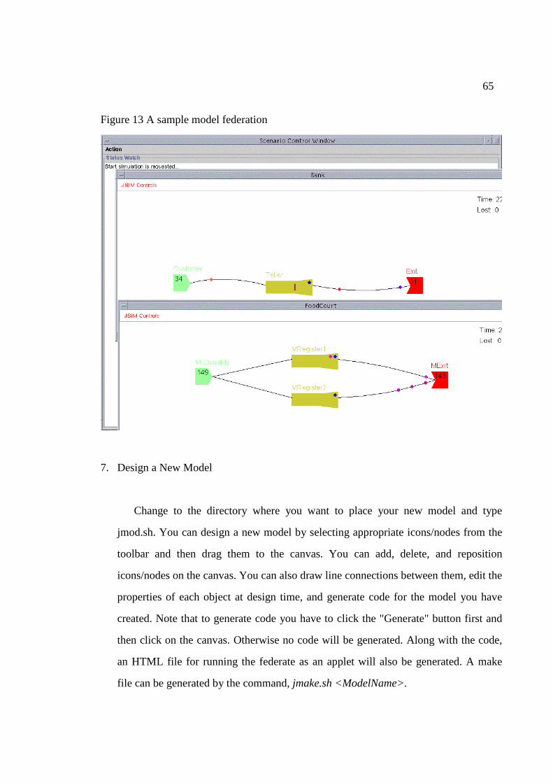
65
Figure 13 A sample model federation
7. Design a New Model
Change to the directory where you want to place your new model and type
jmod.sh. You can design a new model by selecting appropriate icons/nodes from the
toolbar and then drag them to the canvas. You can add, delete, and reposition
icons/nodes on the canvas. You can also draw line connections between them, edit the
properties of each object at design time, and generate code for the model you have
created. Note that to generate code you have to click the "Generate" button first and
then click on the canvas. Otherwise no code will be generated. Along with the code,
an HTML file for running the federate as an applet will also be generated. A make
file can be generated by the command, jmake.sh <ModelName>.
66
APPENDIX C
XML Background with a Running Sample
XML is an effort by the World Wide Web Consortium (W3C) to facilitate data
exchange over the Web. XML is a streamlined subset of SGML (Standard General
Markup Language), which is a powerful yet enormously complex meta-data language.
XML has retained most of the power of SGML, but is far simpler. The design goals of
XML [Bray et al., 1998] are listed below.
• XML shall be straightforwardly usable over the Internet,
• XML shall support a wide variety of applications,
• XML shall be compatible with SGML,
• It shall be easy to write programs which process XML documents,
• The number of optional features in XML is to be kept to the absolute minimum,
ideally zero,
• XML documents should be human-legible and reasonably clear,
• The XML design should be prepared quickly,
• The design of XML shall be formal and concise,
• XML documents shall be easy to create, and
• Terseness in XML markup is of minimal importance.
XML allows for an extensible tag set or user-defined markups. A class of XML
documents can be described through a rule set called Document Type Definition (DTD).
An XML document is said to be a document instance of a DTD, if it has one. On the
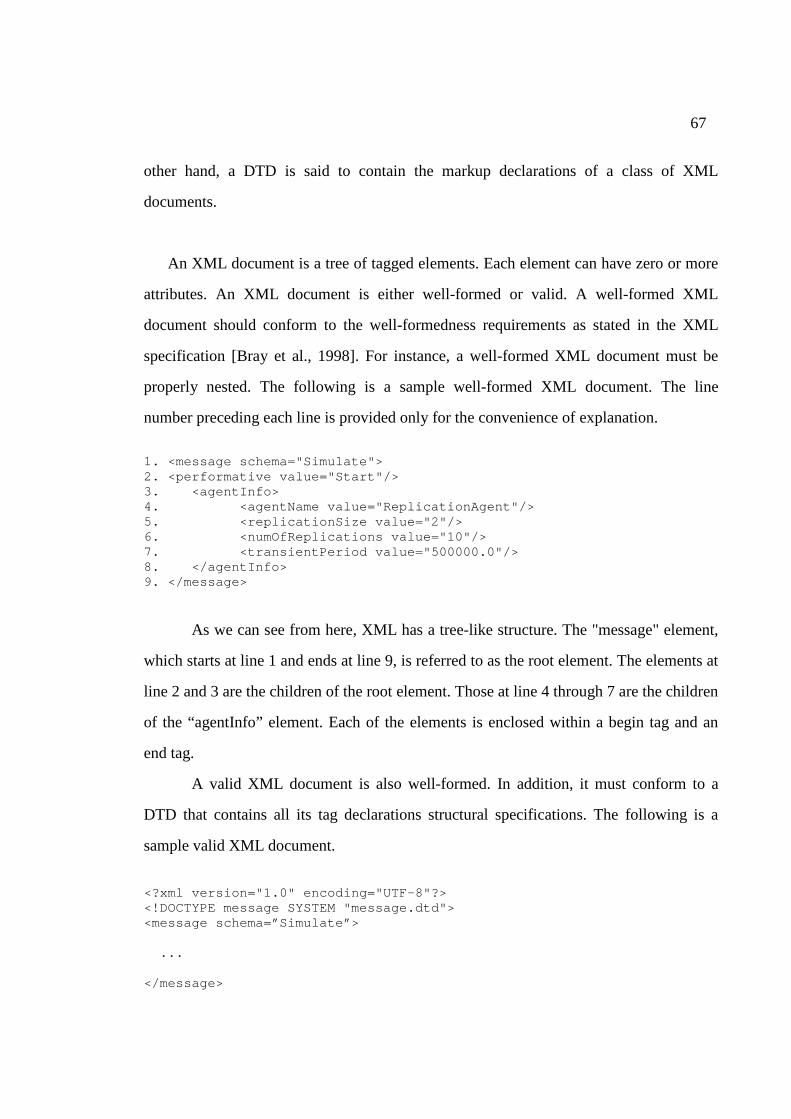
67
other hand, a DTD is said to contain the markup declarations of a class of XML
documents.
An XML document is a tree of tagged elements. Each element can have zero or more
attributes. An XML document is either well-formed or valid. A well-formed XML
document should conform to the well-formedness requirements as stated in the XML
specification [Bray et al., 1998]. For instance, a well-formed XML document must be
properly nested. The following is a sample well-formed XML document. The line
number preceding each line is provided only for the convenience of explanation.
1. <message schema="Simulate"> 2. <performative value="Start"/> 3. <agentInfo> 4. <agentName value="ReplicationAgent"/> 5. <replicationSize value="2"/> 6. <numOfReplications value="10"/> 7. <transientPeriod value="500000.0"/> 8. </agentInfo> 9. </message>
As we can see from here, XML has a tree-like structure. The "message" element,
which starts at line 1 and ends at line 9, is referred to as the root element. The elements at
line 2 and 3 are the children of the root element. Those at line 4 through 7 are the children
of the “agentInfo” element. Each of the elements is enclosed within a begin tag and an
end tag.
A valid XML document is also well-formed. In addition, it must conform to a
DTD that contains all its tag declarations structural specifications. The following is a
sample valid XML document.
<?xml version="1.0" encoding="UTF-8"?> <!DOCTYPE message SYSTEM "message.dtd"> <message schema=”Simulate”> ... </message>
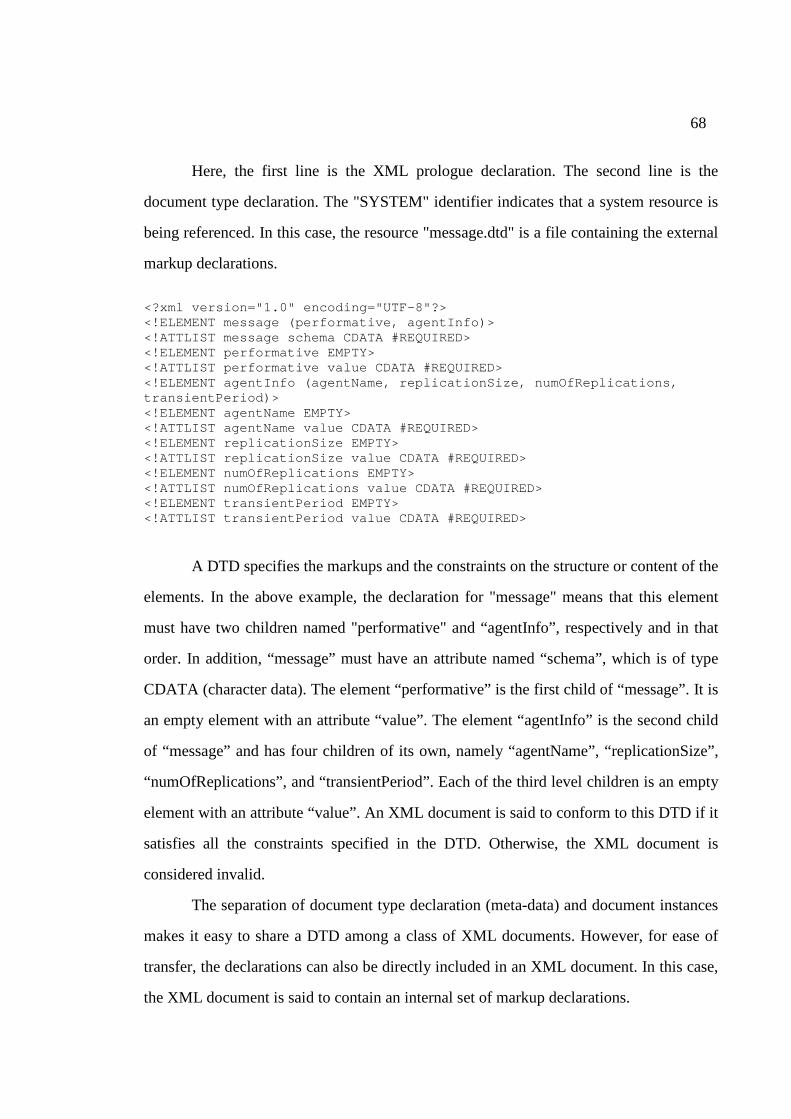
68
Here, the first line is the XML prologue declaration. The second line is the
document type declaration. The "SYSTEM" identifier indicates that a system resource is
being referenced. In this case, the resource "message.dtd" is a file containing the external
markup declarations.
<?xml version="1.0" encoding="UTF-8"?> <!ELEMENT message (performative, agentInfo)> <!ATTLIST message schema CDATA #REQUIRED> <!ELEMENT performative EMPTY> <!ATTLIST performative value CDATA #REQUIRED> <!ELEMENT agentInfo (agentName, replicationSize, numOfReplications, transientPeriod)> <!ELEMENT agentName EMPTY> <!ATTLIST agentName value CDATA #REQUIRED> <!ELEMENT replicationSize EMPTY> <!ATTLIST replicationSize value CDATA #REQUIRED> <!ELEMENT numOfReplications EMPTY> <!ATTLIST numOfReplications value CDATA #REQUIRED> <!ELEMENT transientPeriod EMPTY> <!ATTLIST transientPeriod value CDATA #REQUIRED>
A DTD specifies the markups and the constraints on the structure or content of the
elements. In the above example, the declaration for "message" means that this element
must have two children named "performative" and “agentInfo”, respectively and in that
order. In addition, “message” must have an attribute named “schema”, which is of type
CDATA (character data). The element “performative” is the first child of “message”. It is
an empty element with an attribute “value”. The element “agentInfo” is the second child
of “message” and has four children of its own, namely “agentName”, “replicationSize”,
“numOfReplications”, and “transientPeriod”. Each of the third level children is an empty
element with an attribute “value”. An XML document is said to conform to this DTD if it
satisfies all the constraints specified in the DTD. Otherwise, the XML document is
considered invalid.
The separation of document type declaration (meta-data) and document instances
makes it easy to share a DTD among a class of XML documents. However, for ease of
transfer, the declarations can also be directly included in an XML document. In this case,
the XML document is said to contain an internal set of markup declarations.
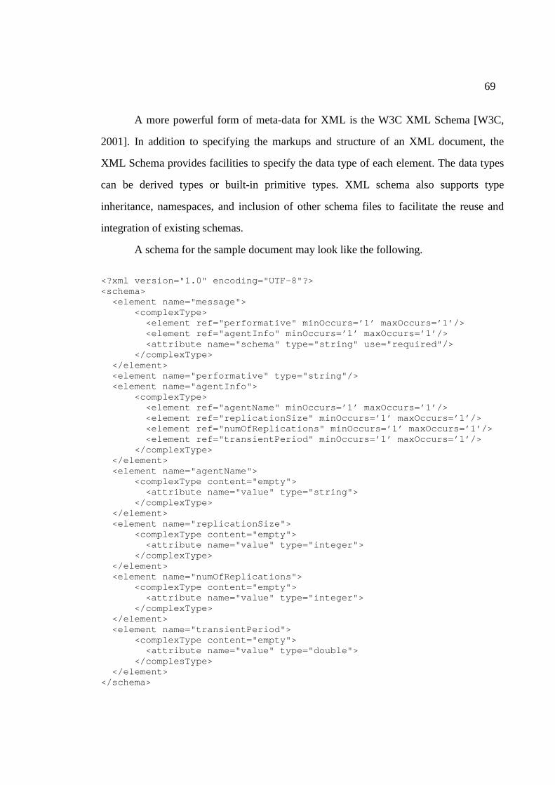
69
A more powerful form of meta-data for XML is the W3C XML Schema [W3C,
2001]. In addition to specifying the markups and structure of an XML document, the
XML Schema provides facilities to specify the data type of each element. The data types
can be derived types or built-in primitive types. XML schema also supports type
inheritance, namespaces, and inclusion of other schema files to facilitate the reuse and
integration of existing schemas.
A schema for the sample document may look like the following.
<?xml version="1.0" encoding="UTF-8"?> <schema> <element name="message"> <complexType> <element ref="performative" minOccurs=’1’ maxOccurs=’1’/> <element ref="agentInfo" minOccurs=’1’ maxOccurs=’1’/> <attribute name="schema" type="string" use="required"/> </complexType> </element> <element name="performative" type="string"/> <element name="agentInfo"> <complexType> <element ref="agentName" minOccurs=’1’ maxOccurs=’1’/> <element ref="replicationSize" minOccurs=’1’ maxOccurs=’1’/> <element ref="numOfReplications" minOccurs=’1’ maxOccurs=’1’/> <element ref="transientPeriod" minOccurs=’1’ maxOccurs=’1’/> </complexType> </element> <element name="agentName"> <complexType content="empty"> <attribute name="value" type="string"> </complexType> </element> <element name="replicationSize"> <complexType content="empty"> <attribute name="value" type="integer"> </complexType> </element> <element name="numOfReplications"> <complexType content="empty"> <attribute name="value" type="integer"> </complexType> </element> <element name="transientPeriod"> <complexType content="empty"> <attribute name="value" type="double"> </complesType> </element> </schema>
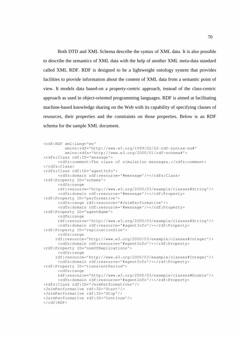
70
Both DTD and XML Schema describe the syntax of XML data. It is also possible
to describe the semantics of XML data with the help of another XML meta-data standard
called XML RDF. RDF is designed to be a lightweight ontology system that provides
facilities to provide information about the content of XML data from a semantic point of
view. It models data based-on a property-centric approach, instead of the class-centric
approach as used in object-oriented programming languages. RDF is aimed at facilitating
machine-based knowledge sharing on the Web with its capability of specifying classes of
resources, their properties and the constraints on those properties. Below is an RDF
schema for the sample XML document.
<rdf:RDF xml:lang="en" xmlns:rdf="http://www.w3.org/1999/02/22-rdf-syntax-ns#" xmlns:rdfs="http://www.w3.org/2000/01/rdf-schema#">
<rdfs:Class rdf:ID="message"> <rdfs:comment>The class of simulation messages.</rdfs:comment>
</rdfs:Class> <rdfs:Class rdf:ID="agentInfo">
<rdfs:domain rdf:resource="#message"/></rdfs:Class> <rdf:Property ID="schema">
<rdfs:range rdf:resource="http://www.w3.org/2000/03/example/classes#String"/> <rdfs:domain rdf:resource="#message"/></rdf:Property>
<rdf:Property ID="performative"> <rdfs:range rdf:resource="#JsimPerformative"/> <rdfs:domain rdf:resource="#message"/></rdf:Property>
<rdf:Property ID="agentName"> <rdfs:range rdf:resource="http://www.w3.org/2000/03/example/classes#String"/> <rdfs:domain rdf:resource="#agentInfo"/></rdf:Property>
<rdf:Property ID="replicationSize"> <rdfs:range
rdf:resource="http://www.w3.org/2000/03/example/classes#Integer"/> <rdfs:domain rdf:resource="#agentInfo"/></rdf:Property>
<rdf:Property ID="numOfReplications"> <rdfs:range
rdf:resource="http://www.w3.org/2000/03/example/classes#Integer"/> <rdfs:domain rdf:resource="#agentInfo"/></rdf:Property>
<rdf:Property ID="transientPeriod"> <rdfs:range rdf:resource="http://www.w3.org/2000/03/example/classes#Double"/> <rdfs:domain rdf:resource="#agentInfo"/></rdf:Property>
<rdfs:Class rdf:ID="JsimPerformatives"/> <JsimPerformative rdf:ID="Start"/> <JsimPerformative rdf:ID="Stop"/> <JsimPerformative rdf:ID="Continue"/> </rdf:RDF>
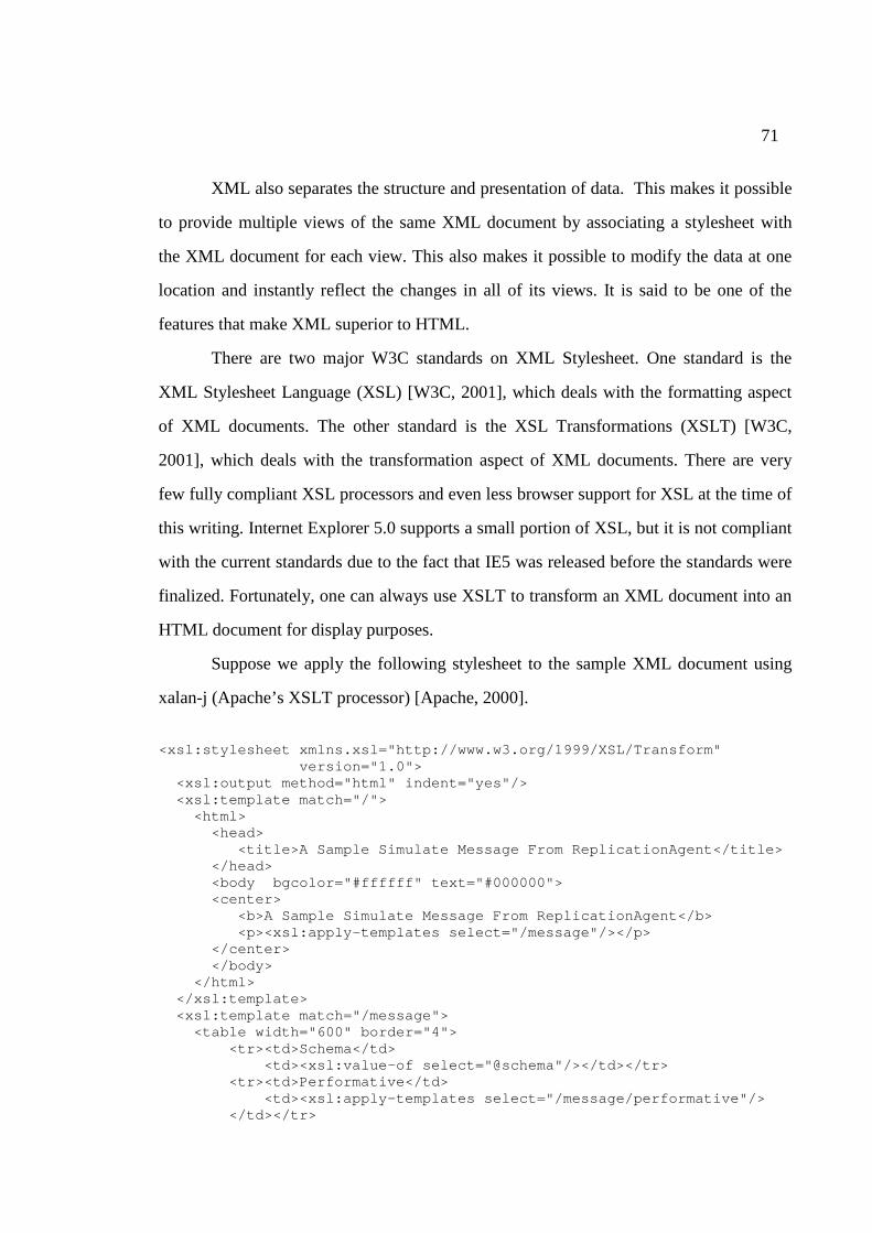
71
XML also separates the structure and presentation of data. This makes it possible
to provide multiple views of the same XML document by associating a stylesheet with
the XML document for each view. This also makes it possible to modify the data at one
location and instantly reflect the changes in all of its views. It is said to be one of the
features that make XML superior to HTML.
There are two major W3C standards on XML Stylesheet. One standard is the
XML Stylesheet Language (XSL) [W3C, 2001], which deals with the formatting aspect
of XML documents. The other standard is the XSL Transformations (XSLT) [W3C,
2001], which deals with the transformation aspect of XML documents. There are very
few fully compliant XSL processors and even less browser support for XSL at the time of
this writing. Internet Explorer 5.0 supports a small portion of XSL, but it is not compliant
with the current standards due to the fact that IE5 was released before the standards were
finalized. Fortunately, one can always use XSLT to transform an XML document into an
HTML document for display purposes.
Suppose we apply the following stylesheet to the sample XML document using
xalan-j (Apache’s XSLT processor) [Apache, 2000].
<xsl:stylesheet xmlns.xsl="http://www.w3.org/1999/XSL/Transform"
version="1.0"> <xsl:output method="html" indent="yes"/> <xsl:template match="/"> <html> <head> <title>A Sample Simulate Message From ReplicationAgent</title> </head> <body bgcolor="#ffffff" text="#000000"> <center> <b>A Sample Simulate Message From ReplicationAgent</b> <p><xsl:apply-templates select="/message"/></p> </center> </body> </html> </xsl:template> <xsl:template match="/message"> <table width="600" border="4"> <tr><td>Schema</td> <td><xsl:value-of select="@schema"/></td></tr> <tr><td>Performative</td> <td><xsl:apply-templates select="/message/performative"/>
</td></tr>
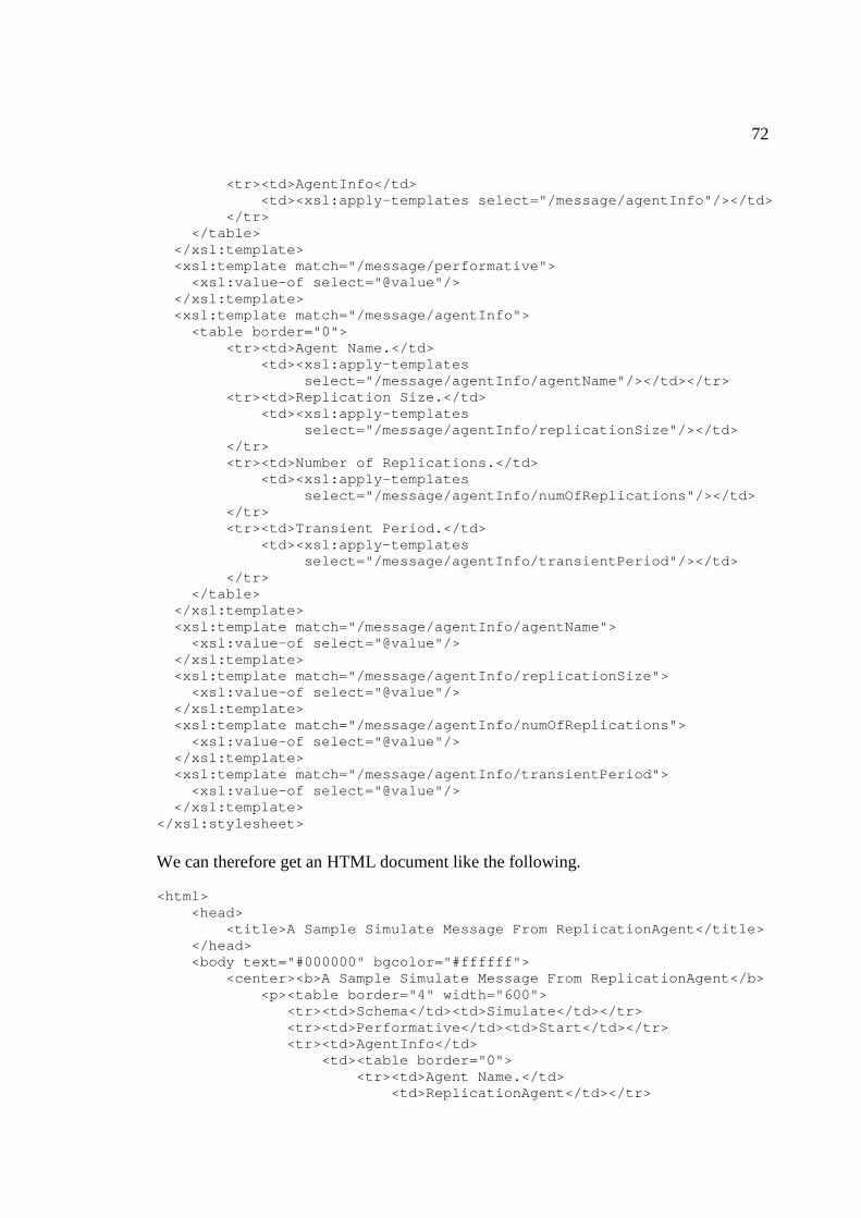
72
<tr><td>AgentInfo</td> <td><xsl:apply-templates select="/message/agentInfo"/></td> </tr> </table> </xsl:template> <xsl:template match="/message/performative"> <xsl:value-of select="@value"/> </xsl:template> <xsl:template match="/message/agentInfo"> <table border="0"> <tr><td>Agent Name.</td> <td><xsl:apply-templates select="/message/agentInfo/agentName"/></td></tr> <tr><td>Replication Size.</td> <td><xsl:apply-templates select="/message/agentInfo/replicationSize"/></td> </tr> <tr><td>Number of Replications.</td> <td><xsl:apply-templates select="/message/agentInfo/numOfReplications"/></td> </tr> <tr><td>Transient Period.</td> <td><xsl:apply-templates select="/message/agentInfo/transientPeriod"/></td> </tr> </table> </xsl:template> <xsl:template match="/message/agentInfo/agentName"> <xsl:value-of select="@value"/> </xsl:template> <xsl:template match="/message/agentInfo/replicationSize"> <xsl:value-of select="@value"/> </xsl:template> <xsl:template match="/message/agentInfo/numOfReplications"> <xsl:value-of select="@value"/> </xsl:template> <xsl:template match="/message/agentInfo/transientPeriod"> <xsl:value-of select="@value"/> </xsl:template> </xsl:stylesheet>
We can therefore get an HTML document like the following. <html> <head> <title>A Sample Simulate Message From ReplicationAgent</title> </head> <body text="#000000" bgcolor="#ffffff"> <center><b>A Sample Simulate Message From ReplicationAgent</b> <p><table border="4" width="600"> <tr><td>Schema</td><td>Simulate</td></tr> <tr><td>Performative</td><td>Start</td></tr> <tr><td>AgentInfo</td>
<td><table border="0"> <tr><td>Agent Name.</td> <td>ReplicationAgent</td></tr>
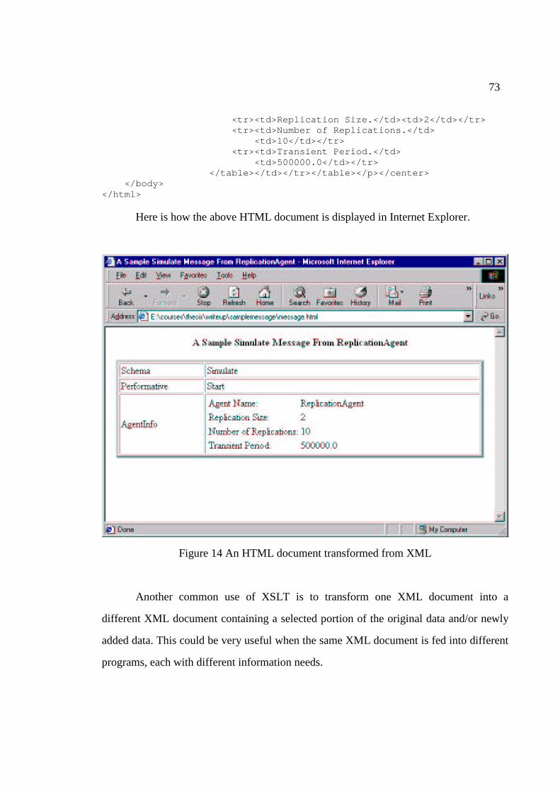
73
<tr><td>Replication Size.</td><td>2</td></tr> <tr><td>Number of Replications.</td> <td>10</td></tr> <tr><td>Transient Period.</td> <td>500000.0</td></tr> </table></td></tr></table></p></center> </body> </html>
Here is how the above HTML document is displayed in Internet Explorer.
Figure 14 An HTML document transformed from XML
Another common use of XSLT is to transform one XML document into a
different XML document containing a selected portion of the original data and/or newly
added data. This could be very useful when the same XML document is fed into different
programs, each with different information needs.

74
With a growing number of XML standards and unprecedented interest in its
potential, there are numerous ways of working with XML documents. For the most recent
and comprehensive listing of XML standards and tools, please visit.
http://www.w3c.org/XML