Embed Size (px)
Citation preview

XV-Z2000 EN
GL
ISH
FR
AN
ÇA
ISE
SPA
ÑO
LP
OR
TU
GU
ÊS
OPERATION MANUALMODE D’EMPLOIMANUAL DE OPERACIONMANUAL DE OPERAÇÃO
PROJECTORPROJECTEURPROYECTORPROJETOR

-1
EN
GL
ISH
Before using the projector, please read this operation manual carefully.
WARNING: High brightness light source. Do not stare into the beam of light, or view directly. Be especiallycareful that children do not stare directly into the beam of light.
WARNING: To reduce the risk of fire or electric shock, do not expose this product torain or moisture.
CAUTION: TO REDUCE THE RISK OF ELECTRIC SHOCK,DO NOT REMOVE COVER.
NO USER-SERVICEABLE PARTS EXCEPT LAMP UNIT.REFER SERVICING TO QUALIFIED SERVICE
PERSONNEL.
The lightning flash with arrowhead symbol,within an equilateral triangle, is intended toalert the user to the presence of uninsulated“dangerous voltage” within the product’senclosure that may be of sufficient magnitudeto constitute a risk or electric shock topersons.
The exclamation point within a triangle isintended to alert the user to the presence ofimportant operating and maintenance(servicing) instructions in the literatureaccompanying the product.
Introduction
CAUTIONRISK OF ELECTRIC SHOCK.DO NOT REMOVE SCREWSEXCEPT SPECIFIED USER
SERVICE SCREW.
See bottom of projector.
IMPORTANTFor your assistance in reporting the loss or theft of yourProjector, please record the Serial Number located onthe bottom of the projector and retain this information.Before recycling the packaging, please ensure that youhave checked the contents of the carton thoroughlyagainst the list of “Supplied accessories” on page 5.
Model No.: XV-Z2000
Serial No.:
There are two important reasons for prompt warranty registration of your new SHARP Projector, usingthe REGISTRATION CARD packed with the projector.
1. WARRANTYThis is to assure that you immediately receive the full benefit of the parts, service and laborwarranty applicable to your purchase.
2. CONSUMER PRODUCT SAFETY ACTTo ensure that you will promptly receive any safety notification of inspection, modification, orrecall that SHARP may be required to give under the 1972 Consumer Product Safety Act, PLEASEREAD CAREFULLY THE IMPORTANT “LIMITED WARRANTY” CLAUSE. U.S.A. ONLY
WARNING: FCC Regulations state that any unauthorized changes or modifications to this equipment notexpressly approved by the manufacturer could void the user’s authority to operate this equip-ment. U.S.A. ONLY
INFORMATIONThis equipment has been tested and found to comply with the limits for a Class B digital device, pursuant to Part15 of the FCC Rules. These limits are designed to provide reasonable protection against harmful interference in aresidential installation. This equipment generates, uses, and can radiate radio frequency energy and, if not installedand used in accordance with the operation manual, may cause harmful interference to radio communications.However, there is no guarantee that interference will not occur in a particular installation. If this equipment doescause harmful interference to radio or television reception, which can be determined by turning the equipment offand on, the user is encouraged to try to correct the interference by one or more of the following measures:• Reorient or relocate the receiving antenna.• Increase the separation between the equipment and the receiver.• Connect the equipment into an outlet on a circuit different from that to which the receiver is connected.• Consult the dealer or an experienced radio/TV technician for help. U.S.A. ONLY

-2
Caution Concerning Lamp ReplacementSee “Replacing the Lamp” on page 56.
LAMP REPLACEMENT WARNING :TURN OFF THE LAMP AND DISCONNECT POWER CORD BEFORE OPENING THIS COVER. HOT SURFACE INSIDE. ALLOW 1 HOUR TO COOL BEFORE REPLACING THE LAMP. REPLACE WITH SAME SHARP LAMP UNIT MODEL AN-K2LP ONLY.HIGH PRESSURE LAMP : RISK OF EXPLOSION. POTENTIAL HAZARD OF GLASS PARTICLES IF LAMP HAS RUPTURED. HANDLE WITH CARE. SEE OPERATION MANUAL.SERVICEMAN-WARNING : USE RADIATION EYE AND SKIN PROTECTION DURING SERVICING.
AVERTISSEMENT CONCERNANT LEREMPLACEMENT DE LA LAMPE :
ETEINDRE LA LAMPE ET DEBRANCHER LE CORDON D’ALIMENTATION AVANT D’OUVRIR LE COUVERCLE. L’INTERIEUR DU BOITIER ETANT EXTREMEMENT CHAUD, ATTENDRE 1 HEURE AVANT DE PROCEDER AU REMPLACEMENT DE LA LAMPE. NE REMPLACER QUE PAR UNE LAMPE SHARP DE MODÈLE AN-K2LP.LAMPE A HAUTE PRESSION : RISQUED’EXPLOSION. DANGER POTENTIEL DE PARTICULES DE VERRE EN CAS D’ECLATEMENT DE LA LAMPE. A MANIPULER AVEC PRECAUTION.SE REPORTER AU MODE D’EMPLOI.AVERTISSEMENT – REPARATEUR : SE PROTEGER LES YEUX ET LA PEAU DES RADIATIONS LORS DES REPARATIONS.
PRODUCT DISPOSALThis projector utilises tin-lead solder, and a pressurised lamp containing a small amount of mercury. Disposal ofthese materials may be regulated due to environmental considerations. For disposal or recycling information,please contact your local authorities or, if you are located in the United States of America, the Electronic IndustriesAlliance: www.eiae.org .
Declaration of ConformitySHARP PROJECTOR, MODEL XV-Z2000This device complies with Part 15 of the FCC rules. Operation is subject to the following conditions: (1) This devicemay not cause harmful interference, and (2) this device must accept any interference received, including interferencethat may cause undesired operation.
Responsible Party:
SHARP ELECTRONICS CORPORATIONSharp Plaza, Mahwah, New Jersey 07430TEL: 1-800-BE-SHARP (1-800-237-4277) U.S.A. ONLY
WARNING:The cooling fan in this projector continues to run for about 90 seconds after the projector enters the standby mode.During normal operation, when putting the projector into standby mode always use the STANDBY button on theprojector or on the remote control. Ensure the cooling fan has stopped before disconnecting the power cord.DURING NORMAL OPERATION, NEVER TURN THE PROJECTOR OFF BY DISCONNECTING THE POWER CORD.FAILURE TO OBSERVE THIS WILL RESULT IN PREMATURE LAMP FAILURE.

Intro
du
ction
-3
WARNING:Some IC chips in this product include confidential and/or trade secret property belonging to Texas Instruments.Therefore you may not copy, modify, adapt, translate, distribute, reverse engineer, reverse assemble or discompilethe contents thereof.
This SHARP projector uses a DMD panel. This very sophisticated panel contains 921,600 pixels micromirrors. Aswith any high technology electronic equipment such as large screen TVs, video systems and video cameras, thereare certain acceptable tolerances that the equipment must conform to.This unit has some inactive pixels within acceptable tolerances which may result in inactive dots on the picturescreen. This will not affect the picture quality or the life expectancy of the unit.
• DLPTM (Digital Light Processing) and DMDTM (Digital Micromirror Device) are trademarks of Texas Instru-ments, Inc.
• Microsoft® and Windows® are registered trademarks of Microsoft Corporation in the United States and/orother countries.
• PC/AT is a registered trademark of International Business Machines Corporation in the United States.• Macintosh® is a registered trademark of Apple Computer, Inc. in the United States and/or other countries.• All other company or product names are trademarks or registered trademarks of their respective companies.

-4
Contents
PreparingSetupSetting Up the Projector .............................. 16
Setting Up the Projector .................................... 16Screen Size and Projection Distance ................ 17Projecting a Reversed Image ............................ 18
ConnectionsConnections ................................................. 19
INPUT Terminals and ConnectableMain Equipment .......................................... 19
Samples of Cables for Connection ............. 20Connecting to Video Equipment ................. 21Connecting to a Computer .......................... 25Controlling the Projector by a Computer ... 27
IntroductionContents.......................................................... 4Accessories .................................................... 5IMPORTANT SAFEGUARDS .......................... 6Part Names and Functions ............................ 9Using the Remote Control ........................... 13
Usable Range .................................................... 13Inserting the Batteries ....................................... 13
Quick StartQuick Start .................................................... 14
UsingBasic OperationTurning the Projector On/Off ....................... 28Image Projection .......................................... 29
Switching the INPUT Mode ............................... 29Adjusting the Focus ........................................... 30Adjusting the Projected Image Size .................. 30Using the Adjustment Feet ................................ 31Keystone Correction .......................................... 32Placement of the Projected Image Using the
Keystone Correction .................................... 33Selecting the Picture Mode ............................... 34Switching the High Brightness / High Contrast
Mode ........................................................... 34Adjusting the Picture Aspect Ratio .................... 34
Useful FeaturesMenu Items ................................................... 36Using the Menu Screen ............................... 38
Menu Selections (Adjustments) ......................... 38Menu Selections (Settings) ................................ 40
Picture Adjustment (“Picture” menu) ........ 42Adjusting the Image .......................................... 42Adjusting the Color Temperature ....................... 42
Gamma Correction Function ............................. 43Emphasising the Contrast ................................. 43Picture Mode Function ....................................... 44Switching the High Brightness/High Contrast
Mode ........................................................... 44Computer Image Adjustment
(“Fine Sync” menu) ................................ 45Adjusting the Computer Image ......................... 45Special Modes Setting ...................................... 45Auto Sync Adjustment ....................................... 46Checking the Input Signal ................................. 46
Using the “Options” Menu ........................... 47Checking the Lamp Life Status ......................... 47Setting On-screen Display ................................. 47Setting the Video System................................... 48Signal Type Setting ............................................ 48Selecting a Background Image ......................... 49Eco Mode .......................................................... 49Auto Power Off Function .................................... 50Selecting the Menu Screen Position .................. 50Selecting the Menu Color .................................. 51
Selecting the On-screen DisplayLanguage and the Projection Mode ...... 52Selecting the On-screen Display Language ..... 52Setting the Projection Mode .............................. 52
ReferenceAppendixMaintenance ................................................. 53Maintenance Indicators ............................... 54Regarding the Lamp .................................... 56
Lamp ................................................................. 56Caution Concerning the Lamp .......................... 56Replacing the Lamp .......................................... 56Removing and Installing the Lamp Unit ............ 57Resetting the Lamp Timer ................................. 58
Connecting Pin Assignments ..................... 59RS-232C Specifications and Command
Settings ................................................... 60PC control .......................................................... 60
Communication conditions ................................ 60Basic format ...................................................... 60Commands ........................................................ 60
Computer Compatibility Chart .................... 61Troubleshooting ........................................... 62For SHARP Assistance (U.S.A. only) ......... 62Specifications ............................................... 63Dimensions ................................................... 64Glossary ........................................................ 65Index .............................................................. 66CONSUMER LIMITED WARRANTY
(VALID IN USA ONLY) ............................. 67LIMITED WARRANTY
(VALID IN CANADA ONLY) ..................... 68

Intro
du
ction
-5
Accessories
Remote controlRRMCGA334WJSA
Two AA size batteries
■ 3 RCA to 15-pin D-sub cable (9'10" (3.0 m)) AN-C3CP2■ DVI to 15-pin D-sub adaptor (7.9" (20 cm)) AN-A1DV■ DVI cable (9'10" (3.0 m)) AN-C3DV■ Lamp unit AN-K2LP
Note
• Some of the optional accessories may not be available depending on the region. Please check with yournearest Authorized SharpVision Service Center or Dealer.
Lens cap (attached)PCAPHA021WJSA
Supplied accessories
Optional accessories
Operation manualTINS-B529WJZZ
Marks Used in This Operation ManualInfo ........Indicates safeguards when using the projector.
Note ........Indicates additional information for setting up and operating the projector.
• In this operation manual, the illustration and the screen display are simplified for explanation, and may differslightly from actual display.
Power cord (6' (1.8 m))QACCDA007WJPZ

-6
1. Read InstructionsAll the safety and operating instructions should be read beforethe product is operated.
2. Retain InstructionsThe safety and operating instructions should be retained forfuture reference.
3. Heed WarningsAll warnings on the product and in the operating instructionsshould be adhered to.
4. Follow InstructionsAll operating and use instructions should be followed.
5. CleaningUnplug this product from the wall outlet before cleaning. Donot use liquid cleaners or aerosol cleaners. Use a damp clothfor cleaning.
6. AttachmentsDo not use attachments not recommended by the productmanufacturer as they may cause hazards.
7. Water and MoistureDo not use this product near water–for example, near a bathtub, wash bowl, kitchen sink, or laundry tub; in a wetbasement; or near a swimming pool; and the like.
8. AccessoriesDo not place this product on an unstable cart, stand, tripod,bracket, or table. The product may fall, causing serious injuryto a child or adult, and serious damage to the product. Useonly with a cart, stand, tripod, bracket, or table recommendedby the manufacturer, or sold with the product. Any mountingof the product should follow the manufacturer’s instructions,and should use a mounting accessory recommended by themanufacturer.
9. TransportationA product and cart combination shouldbe moved with care. Quick stops,excessive force, and uneven surfacesmay cause the product and cartcombination to overturn.
10. VentilationSlots and openings in the cabinet are provided for ventilationto ensure reliable operation of the product and to protect itfrom overheating, and these openings must not be blockedor covered. The openings should never be blocked by placingthe product on a bed, sofa, rug, or other similar surface. Thisproduct should not be placed in a built-in installation such asa bookcase or rack unless proper ventilation is provided orthe manufacturer’s instructions have been adhered to.
11. Power SourcesThis product should be operated only from the type of powersource indicated on the marking label. If you are not sure ofthe type of power supply to your home, consult your productdealer or local power company. For products intended tooperate from battery power, or other sources, refer to theoperating instructions.
12. Grounding or PolarizationThis product is provided with one of the following types ofplugs. If the plug should fail to fit into the power outlet,please contact your electrician.Do not defeat the safety purpose of the plug.
a. Two-wire type (mains) plug.b. Three-wire grounding type (mains) plug with a
grounding terminal.This plug will only fit into a grounding type poweroutlet.
IMPORTANT SAFEGUARDS
13. Power-Cord ProtectionPower-supply cords should be routed so that they are notlikely to be walked on or pinched by items placed upon oragainst them, paying particular attention to cords at plugs,convenience receptacles, and the point where they exit fromthe product.
14. LightningFor added protection for this product during a lightning storm,or when it is left unattended and unused for long periods oftime, unplug it from the wall outlet and disconnect the cablesystem. This will prevent damage to the product due tolightning and power-line surges.
15. OverloadingDo not overload wall outlets, extension cords, or integralconvenience receptacles as this can result in a risk of fire orelectric shock.
16. Object and Liquid EntryNever push objects of any kind into this product throughopenings as they may touch dangerous voltage points orshort-out parts that could result in a fire or electric shock.Never spill liquid of any kind on the product.
17. ServicingDo not attempt to service this product yourself as opening orremoving covers may expose you to dangerous voltage orother hazards. Refer all servicing to qualified servicepersonnel.
18. Damage Requiring ServiceUnplug this product from the wall outlet and refer servicingto qualified service personnel under the following conditions:
a. When the power-supply cord or plug is damaged.b. If liquid has been spilled, or objects have fallen into
the product.c. If the product has been exposed to rain or water.d. If the product does not operate normally by following
the operating instructions. Adjust only those controlsthat are covered by the operating instructions, as animproper adjustment of other controls may result indamage and will often require extensive work by aqualified technician to restore the product to normaloperation.
e. If the product has been dropped or damaged in anyway.
f. When the product exhibits a distinct change inperformance, this indicates a need for service.
19. Replacement PartsWhen replacement parts are required, ensure the servicetechnician has used replacement parts specified by themanufacturer or have the same characteristics as the originalpart. Unauthorized substitutions may result in fire, electricshock, or other hazards.
20. Safety CheckUpon completion of any service or repairs to this product,ask the service technician to perform safety checks todetermine that the product is in proper operating condition.
21. Wall or Ceiling MountingThis product should be mounted to a wall or ceiling only asrecommended by the manufacturer.
22. HeatThis product should be situated away from heat sources suchas radiators, heat registers, stoves, or other products(including amplifiers) that produce heat.
CAUTION: Please read all of these instructions before you operate this product and save theseinstructions for later use.
Electrical energy can perform many useful functions. This product has been engineered and manufactured toassure your personal safety. BUT IMPROPER USE CAN RESULT IN POTENTIAL ELECTRICAL SHOCK ORFIRE HAZARDS. In order not to defeat the safeguards incorporated in this product, observe the following basicrules for its installation, use and servicing.

-7
Intro
du
ction
Ensure that you read the following safeguards whensetting up your projector.Caution concerning the lamp unit■ Potential hazard of glass
particles if lamp ruptures.In case of lamp rupture,contact your nearest Au-thorized SharpVisionService Center or Dealerfor a replacement.See “Replacing the Lamp” on page 56.
Caution concerning the setup of the pro-jector■ For minimal servicing and to maintain high
image quality, SHARP recommends that thisprojector be installed in an area free from hu-midity, dust and cigarette smoke. When theprojector is subjected to these environments,the vents and lens must be cleaned more of-ten. As long as the projector is regularlycleaned, use in these environments will notreduce the overall operation life of the unit.Internal cleaning should only be performedby an Authorized SharpVision Service Cen-ter or Dealer.
Do not set up the projector in places ex-posed to direct sunlight or bright light.■ Position the screen so that it is not in direct
sunlight or room light. Light falling directly onthe screen washes out the colors, makingviewing difficult. Close the curtains and dimthe lights when setting up the screen in asunny or bright room.
The projector may be safely tilted to amaximum angle of 12 degrees.■ Placement should be within ±12 degrees of
horizontal.
Warning about placing the projector ina high position■ When placing the projector in a high posi-
tion, ensure to secure it carefully to avoidpersonal injury caused by the projector fall-ing down.
Do not subject the projector to hard im-pact and/or vibration.■ Take care with the lens so as not to hit or
damage the surface of the lens.
Rest your eyes occasionally.■ Continuously watching the screen for long
hours will cause eye strain. Ensure to occa-sionally rest your eyes.
Avoid locations with extremes of tem-perature.■ The operating temperature of the projector
is from 41°F to 95°F (+5°C to +35°C).■ The storage temperature of the projector is
from –4°F to 140°F (–20°C to +60°C).
Do not block the exhaust and intakevents.■ Allow at least 7 7/8 inches (20 cm) of space
between the exhaust vent and the nearestwall or obstruction.
■ Ensure that the intake vent and the exhaustvent are not obstructed.
■ If the cooling fan becomes obstructed, a pro-tection circuit will automatically put the pro-jector into standby mode to prevent overheatdamage. This does not indicate a malfunc-tion (See pages 54 and 55.). Remove the pro-jector power cord from the wall outlet and waitat least 10 minutes. Place the projector wherethe intake and exhaust vents are not blocked,plug the power cord back in and turn on theprojector. This will return the projector to thenormal operating condition.
-8
Caution regarding usage of the projector■ When using the projector, ensure not to sub-
ject it to hard impact and/or vibration, as thiscan result in damage. Take extra care with thelens. If you are not to use the projector for along time, ensure to unplug the power cordfrom the wall outlet, and disconnect any othercables connected to it.
■ Do not use the projector by holding the lens.■ When you are not to use the projector for a long
time, or storing the projector, ensure to attachthe lens cap to the projector (See page 9.).
■ Do not expose the projector to direct sunlightor near heat sources. The projector maychange color or become deformed.
Other connected equipment■ When connecting a computer or other audio-
visual equipment to the projector, make theconnections AFTER unplugging the powercord of the projector from the AC outlet andturning off the equipment to be connected.
■ Please read the operation manuals of the pro-jector and the equipment to be connected forinstructions on how to make the connections.
Using the projector in other countries■ The power supply voltage and the shape of
the plug may vary depending on the regionor country you are using the projector in.When using the projector overseas, ensureto use an appropriate power cord for the coun-try you are in.
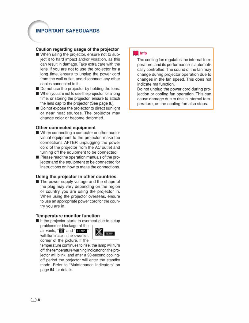
Temperature monitor function■ If the projector starts to overheat due to setup
problems or blockage of theair vents, “ ” and “ ”will illuminate in the lower leftcorner of the picture. If thetemperature continues to rise, the lamp will turnoff, the temperature warning indicator on the pro-jector will blink, and after a 90-second cooling-off period the projector will enter the standbymode. Refer to “Maintenance Indicators” onpage 54 for details.
Info
• The cooling fan regulates the internal tem-perature, and its performance is automati-cally controlled. The sound of the fan maychange during projector operation due tochanges in the fan speed. This does notindicate malfunction.
• Do not unplug the power cord during pro-jection or cooling fan operation. This cancause damage due to rise in internal tem-perature, as the cooling fan also stops.
IMPORTANT SAFEGUARDS

-9
Intro
du
ction
38 Adjustment buttons ('/"/\/|)Select menu items and other settings.
29 INPUT buttonSwitch input mode 1, 2, 3, 4, 5 or DIGITAL.
30
10
5410
54
ZOOM/FOCUS buttonAdjust the projected image size or adjust the focus.
Temperature warning indicator
Lamp indicator
10 Power indicator
31
31
13Remote control sensor
HEIGHT ADJUST button
Front adjustment foot (on the bottom of
the projector)
38MENU buttonDisplay adjustment and
setting screens.
39ENTER buttonSet items selected or
adjusted on the menu.
34UNDO buttonUndo an operation or
returning to the previous display.
28STANDBY buttonPut the projector into standby
mode.
34RESIZE buttonSwitch the picture display
(STRETCH, SIDE BAR, etc.).
28ON buttonTurn the power on.
Projector
Part Names and Functions
• Attaching the lens capPush the lens cap on until it clicksinto position.
• Removing the lens capPull the lens cap directly outward.
Numbers in refer to the main pages in this operation manual where the topic is explained.
Top View
Front View

-10
About the Indicators on the Projector
Power indicatorRed on ... Normal (Standby)Green on ... Normal (Power on)
Temperature warning indicatorOff ... NormalRed on ... The internal temperature is abnormally high.
(See page 54.)
Lamp indicatorGreen on ... NormalGreen blinks ... The lamp is warming up or shutting down.Red on ... The lamp has been shut down abnormally or
needs to be changed. (See page 54.)
Part Names and Functions

-11
Intro
du
ction
Projector (Rear View)
Using the Kensington Lock• This projector has a Kensington Security Standard connector for use with a Kensington MicroSaver Security
System. Refer to the information that came with the system for instructions on how to use it to secure theprojector.
Numbers in refer to the main pages in this operation manual where the topic is explained.
13 Remote control sensor
28 AC socketConnect the supplied Power cord.
11 Kensington Security Standard connector
31
537
Rear adjustment feet
Intake vent
Exhaust ventThe speed and pitch of the cooling fan may change during operation in response to internal temperature changes. This is normal operation and does not indicate a malfunction.
537
21INPUT 2 terminalComponent signals.
Digital input type switch
22INPUT 5/DIGITALterminal
21
22 23
2325 26
25 26
INPUT 1 terminalComponent signals.
24 INPUT 4 terminalConnect video equipment.
24 INPUT 3 terminalConnect video equipment with an S-video terminal.
27 RS-232C terminalControl the projector using a computer.
Terminals Refer to “INPUT Terminals and Connectable Main Equipment” on page 19.

-12
Remote Control
Adjustment buttons('/"/\/|)38
30
MENU buttonDisplay adjustment and setting screens.
38
ON buttonTurn the power on.
28
30 ZOOM/FOCUS buttonAdjust the projected image size or adjusting the focus.
29 INPUT 3 button
29 INPUT 5 button
34
3444
RESIZE buttonSwitch the picture display(STRETCH, SIDE BAR, etc.).
29 DIGITAL INPUT button
PICTURE MODE buttonSelect the picture setting (Memory) stored in “Picture Mode” on the “Picture” menu.
28STANDBY buttonPut the projector into standby
mode.
32KEYSTONE buttonEnter the Keystone
Correction mode.
39ENTER buttonSet items selected or
adjusted on the menu.
34UNDO buttonUndo an operation or returning to
the previous display.
29INPUT 1 button
29INPUT 2 button
29INPUT 4 button
46AUTO SYNC buttonAutomatically adjust images when
connected to a computer.
48RGB/COMP. buttonSwitch the signal type(RGB or Component).
34IRIS buttonSwitch “HIGH BRIGHTNESS
MODE” or “HIGH CONTRAST MODE”.
Numbers in refer to the main pages in this operation manual where the topic is explained.
Note
• All the buttons on the remote control are made of luminous material that is visible in the dark. Visibility willdiminish over time. Exposure to light will recharge the luminous buttons.
Part Names and Functions

-13
Intro
du
ction
Using the Remote Control
Inserting the Batteries
1 Pull down the tab on the coverand remove the cover towardsthe direction of the arrow.
2 Insert the included batteries(two “AA” size).• Insert the batteries making sure the po-
larities correctly match the andmarks inside the battery compartment.
3 Insert the lower tab of the coverinto the opening, and lower thecover until it clicks in place.
Incorrect use of the batteries may cause them to leak or explode. Please follow the precautions below.
Caution• Insert the batteries making sure the polarities correctly match the and marks inside the battery compartment.• Batteries of different types have different properties, therefore do not mix batteries of different types.• Do not mix new and old batteries.
This may shorten the life of new batteries or may cause old batteries to leak.• Remove the batteries from the remote control once they have run out, as leaving them in can cause them to leak.
Battery fluid from leaked batteries is harmful to skin, therefore ensure to first wipe them and then remove them using a cloth.
• The batteries included with this projector may run down in a short period, depending on how they are kept.Ensure to replace them as soon as possible with new batteries.
Usable RangeThe remote control can be used to control theprojector within the ranges shown in theillustration.
Note• The signal from the remote control can be re-
flected off a screen for easy operation. How-ever, the effective distance of the signal maydiffer depending on the screen material.
When using the remote control:• Ensure not to drop, expose to moisture or high
temperature.• The remote control may malfunction under a
fluorescent lamp. In this case, move the pro-jector away from the fluorescent lamp.
Remote control sensor
Remotecontrolsignaltransmitters
Remote control
23' (7 m)30°
30°
30°Front View
Remote control
30°
30°
Remote control sensor
23' (7 m)
Remotecontrolsignaltransmitters
30°
Rear View

-14
Quick Start
3 ON button
8 STNADBY button
4 INPUT button
6 ZOOM/FOCUS button
6 Adjustment buttons ('/"/\/|)
6 HEIGHT ADJUST button
8 STNADBY button
3 ON button
7 KEYSTONE button
6, 7 Adjustment buttons ('/"/\/|)
6 ZOOM/FOCUS button
4 INPUT buttons, DIGITAL INPUT button
Page 16
1. Place the projector facing a screen
Pages 21-28
Page 28
On the remote controlOn the projector
This section shows the basic operation. For details, see the page described below for each step.
Setup and ProjectionConnection of the projector and the video equipment with an S-video terminal is explained as anexample below.
2. Connect the projector to the video equipment and plug thepower cord into the AC socket of the projector
3. Remove the lens cap and turn the projector on
Connect the audio output terminal of the video equipment to the audio inputterminal of the audio equipment using an audio cable.

-15
Qu
ick Start
Page 29
4. Select the INPUT mode
6. Adjust the projector angle, focus and zoom
Select the “INPUT 3” using the INPUT button on the projector or the INPUT 3 button on the remote control.
••••• When pressing on the projector, input mode switches in order of :INPUT 1 INPUT 2 INPUT 3 INPUT 4 INPUT 5 DIGITAL
••••• When using the remote control, press / / / / / to switch the INPUT mode.
On the remotecontrol
On theprojector
""""" On-screen Display
5. Turn the video equipment on and playback
Pages 30, 31
3 Adjust the projector angleusing the HEIGHT ADJUSTbutton.
HEIGHT ADJUSTbutton
1 Adjust the focusOn the remote controlOn the projector
1 Press .
2 Adjust the focus by pressing \ or |.
2 Adjust the projected image size by adjusting zoom.
On the remote controlOn the projector
1 Press .
2 Adjust the zoom by pressing ' or ".
1 Press .
2 Adjust the zoom by pressing ' or ".
1 Press .
2 Adjust the focus by pressing \ or |.
8. Turn the Power offPress the STANDBY button, then press that button again while the confirmation message is displayed, to putthe projector into standby mode.
••••• Unplug the power cord from the AC outlet after the cooling fan stops.Page 28
On the remote controlOn the projector """"" On-screen Display
7. Correct trapezoidal distortion
Horizontal Vertical
Select “H Keystone”or “V Keystone”.
Correcting trapezoidal distortion using the Keystone Correction
Pages 32, 33
Adjust
On the remote control

-16
Setting Up the ProjectorPosition the projector perpendicular to the screen to achieve an optimal image.
Note
• The projector lens should be centered in the middle of the screen. If the horizontal line passing throughthe lens center is not perpendicular to the screen, the image will be distorted, making viewing difficult.
• For an optimal image, position the screen so that it is not in direct sunlight or room light. Light fallingdirectly on the screen washes out the colors, making viewing difficult. Close the curtains and dim the lightswhen setting up the projector in a sunny or bright room.
Standard Setup (Front Projection)■ Place the projector at the required distance from the screen according to the desired picture size. (See
page 17.)
Setting Up the Projector
Indication of the Projection Image Size and Projection Distance
See “Screen Size and Projection Distance” on page 17 for details.Example : When using a wide screen (16:9)
200"
150"
100"80"
60" ProjectionDistance
Center
Picture Size
174" × 98"
131" × 74"87" × 49"70" × 39"
52" × 29"
17' 4" – 26' 0"
(5.29m – 7.95m)
12' 11" – 19' 6"
(3.95m – 5.95m)
8' 7" – 12' 11"
(2.62m – 3.95m)
6' 9" – 10' 4"
(2.08m – 3.15m)
5' 1" – 7' 8"
(1.55m – 2.35m)

-17
Setu
p
H
L
Side View
Screen
Lens center
Screen Size and Projection DistanceThe projection screen size varies according to the distance from the lens of the projector to the screen.Install the projector so that projected images are projected onto the screen at the optimum size by referringto the table below. Use the values in the table as a reference when installing the projector.
Picture (Screen) size Projection distance [L]Diag. [°] Width Height Minimum [L1] Maximum [L2]
200" 174" 98" 17' 4" (5.29 m) 26' 0" (7.95 m) 3 9/32" (8.3 cm)150" 131" 74" 12' 11" (3.95 m) 19' 6" (5.95 m) 2 29/64" (6.2 cm)100" 87" 49" 8' 7" (2.62 m) 12' 11" (3.95 m) 1 21/32" (4.2 cm)80" 70" 39" 6' 9" (2.08 m) 10' 4" (3.15 m) 1 5/16" (3.3 cm)70" 61" 34" 5' 11" (1.82 m) 9' 0" (2.75 m) 1 5/32" (2.9 cm)60" 52" 29" 5' 1" (1.55 m) 7' 8" (2.35 m) 63/64" (2.5 cm)40" 35" 20" 3' 3" (1.01 m) 5' 1" (1.55 m) 43/64" (1.7 cm)
Distance from the bottom of the image tothe lens center [H]
°: Picture size (diag.) (inches)L: Projection distance (ft/m)L1: Minimum projection distance (ft/m)L2: Maximum projection distance (ft/m)H: Distance from the bottom of the image to the lens center (in/cm)
Note
• There may be an error of ± 3% in the above values.
°: Picture size (diag.) (inches)L: Projection distance (ft/m)L1: Minimum projection distance (ft/m)L2: Maximum projection distance (ft/m)H: Distance from the bottom of the image to the lens center (in/cm)
Distance from the bottom of the image tothe lens center [H]
When using a wide screen (16:9):In case of displaying the 16:9 picture on the whole of the 16:9 screen.
When using a normal screen (4:3):In case of setting the 16:9 picture to the full horizontal width of the 4:3 screen.
Picture (Screen) size Projection distance [L]Diag. [°] Width Height Minimum [L1] Maximum [L2]
200" 160" 120" 15' 10" (4.85 m) 23' 11" (7.29 m) 3" (7.62 cm)150" 120" 90" 11' 10" (3.62 m) 17' 10" (5.45 m) 2 17/64" (5.72 cm)100" 80" 60" 7' 10" (2.40 m) 11' 10" (3.62 m) 1 1/2" (3.81 cm)80" 64" 48" 6' 3" (1.91 m) 9' 5" (2.88 m) 1 13/64" (3.05 cm)70" 56" 42" 5' 5" (1.66 m) 8' 3" (2.52 m) 1 1/16" (2.67 cm)60" 48" 36" 4' 7" (1.42 m) 7' 0" (2.15 m) 57/64" (2.29 cm)40" 32" 24" 3' 0" (0.93 m) 4' 7" (1.42 m) 39/64" (1.52 cm)
The formula for picture size and projection distance[Feet/inches] [m/cm]L1 (ft) = (0.02671°–0.05334) / 0.3048 L1 (m) = 0.02671°–0.05334L2 (ft) = (0.03999°–0.05215) / 0.3048 L2 (m) = 0.03999°–0.05215H (in) = 0.04151° / 2.54 H (cm) = 0.04151°
The formula for picture size and projection distance[Feet/inches] [m/cm]L1 (ft) = (0.02452°–0.05334) / 0.3048 L1 (m) = 0.02452°–0.05334L2 (ft) = (0.03671°–0.05215) / 0.3048 L2 (m) = 0.03671°–0.05215H (in) = 0.03810° / 2.54 H (cm) = 0.03810°

-18
Setting Up the Projector
Projecting a Reversed ImageProjection from behind the Screen■ Place a translucent screen between the projector and the audience.■ Reverse the image by setting “Rear” in the “PRJ Mode” menu. (See page 52.)
Projection Using a Mirror■ Place a mirror (normal flat type) in front of the lens.■ When the translucent screen is placed between the mirror and audience, set to “Front” in the “PRJ Mode”
menu. (See page 52.)■ When the mirror is placed on the audience side, set to “Rear” in the “PRJ Mode” menu. (See page 52.)
Info
• When using a mirror, ensure to carefully position both the projector and the mirror so the light does notshine into the eyes of the audience.
Ceiling-mount Setup■ It is recommended that you use the optional Sharp ceiling-mount
bracket for this installation.■ Before mounting the projector, contact your nearest Authorized
SharpVision Service Center or Dealer to obtain the recommendedceiling-mount bracket (commercially available). (AN-CM270 ceil-ing-mount bracket, AN-EP101B extension tube for AN-CM270.)
■ Invert the image by setting “Ceiling + Front” in “PRJ Mode”. Seepage 52 for use of this function.
Translucent screen
Audience
Set to “Front”
AudienceTranslucent screen
Mirror
Set to “Rear”
Audience
Mirror

-19
Co
nn
ection
s
INPUT Terminals and Connectable Main Equipment
INPUT 5/DIGITAL terminalConnecting video equipment with component output terminal (DVD player, DTV decoder, DVD recorder with hard disc, etc.). (See pages 22,23.)Connecting the computer. (See pages 25, 26.)
INPUT 3 terminalConnecting video equipment with S-video output terminal (VCR, DVD player, etc.).(See page 24.)
INPUT 1, 2 terminalConnecting video equipment with component output terminal (DVD player, DTV decoder, DVD recorder with hard disc, etc.). (See page 21.)
INPUT 4 terminalConnecting video equipment without S-video output terminal. (See page 24.)
RS-232C terminalConnecting the computer to control the projector. (See page 27.)
Connections
-20
Terminal on theprojector
INPUT 1, 2
INPUT 1, 2
INPUT 5/DIGITAL
INPUT 5/DIGITAL
INPUT 4
INPUT 4
INPUT 3
INPUT 3
RS-232C
Equipment
Audio-visualequipment
Computer
Computer
Terminal onconnected equipment
Componentvideo output
terminal
Terminalfor using
thededicated
cable
DVI outputterminal
RGB outputterminal
Videooutput
terminal
Terminalfor using
thededicated
cable
S-videooutput
terminal
Terminalfor using
thededicated
cable
RS-232Cterminal
Cable
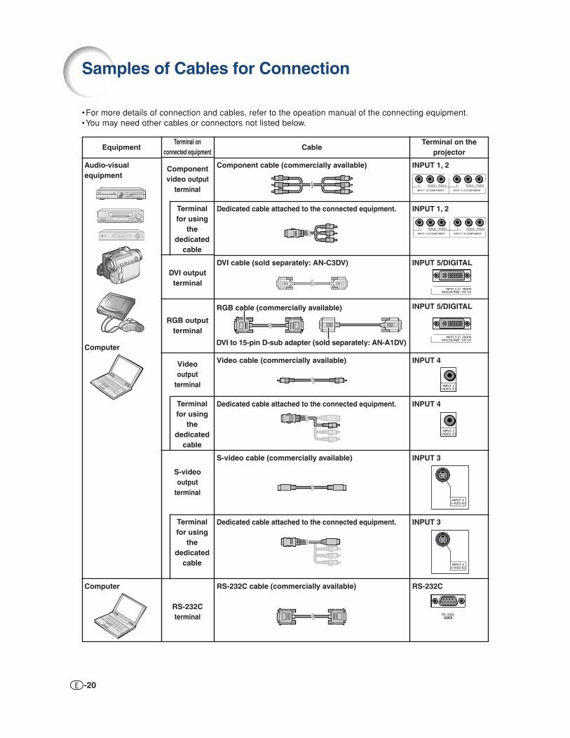
Component cable (commercially available)
Dedicated cable attached to the connected equipment.
DVI cable (sold separately: AN-C3DV)
Video cable (commercially available)
Dedicated cable attached to the connected equipment.
S-video cable (commercially available)
Dedicated cable attached to the connected equipment.
RS-232C cable (commercially available)
Samples of Cables for Connection
•For more details of connection and cables, refer to the opeation manual of the connecting equipment.•You may need other cables or connectors not listed below.
DVI to 15-pin D-sub adapter (sold separately: AN-A1DV)
RGB cable (commercially available)

-21
Co
nn
ection
s
Connecting to Video Equipment
Before connecting, ensure to unplug the power cord of the projector from the AC outlet andturn off the devices to be connected. After making all connections, turn on the projector andthen the other devices.
Ensure to read the operation manuals of the devices to be connected before making connections.
When connecting the component video equipment to the component input terminal on theprojector (INPUT 1 or INPUT 2)
Component cable(commercially available)
INPUT 1 or INPUT 2 terminal
Analog componentoutput terminal DVD Player,etc.
12

-22
When connecting the video equipment with RGB output terminal (INPUT 5)• Before connecting the cable, switch the digital input type switch to “VIDEO”.
INPUT 5 terminal
DVI to 15-pin D-sub adaptor(sold separately: AN-A1DV)
RGB output terminal
RGB cable(commercially available)
DVD Player,etc.
4
3
2
Switch to “VIDEO”1
Connecting to Video Equipment
Note• For this connection, select “RGB” for “Signal Type” on the OSD menu or press on the remote control.
(See page 48.)
When connecting the component video equipment to the DVI input terminal on the projector (INPUT 5)• Before connecting the cable, switch the digital input type switch to “VIDEO”.
Note• For this connection, select “Component” for “Signal Type” on the OSD menu or press on the remote
control. (See page 48.)
INPUT 5 terminal
DVI to 15-pin D-sub adaptor(sold separately: AN-A1DV)
3 RCA to 15-pin D-sub cable(sold separately: AN-C3CP2)
Analog componentoutput terminal DVD Player,etc.
4
3
2
Switch to “VIDEO”1

-23
Co
nn
ection
s
DIGITAL terminal
DVI output terminal
DVI cable(sold separately: AN-C3DV)
Switch to “VIDEO”DVD Player,etc.
2
3
1
Note• Select DIGITAL mode when connecting to video equipment with the digital output terminal. (See page
29.)
When connecting the video equipment with DVI output terminal (DIGITAL INPUT)• Before connecting the cable, switch the digital input type switch to “VIDEO”.

-24
When connecting video equipment with S-video output terminal (INPUT 3)
When connecting video equipment with video output terminal (INPUT 4)
S-video cable(commercially available)
S-video output terminalINPUT 3 terminal
DVD Player,etc.
2
1
INPUT 4 terminal
Video output terminal
Composite video cable(commercially available)
DVD Player,etc.
1
2
Connecting to Video Equipment

-25
Co
nn
ection
s
Connecting to a Computer
Connecting to a computer (INPUT 5)• Before connecting the cable, switch the digital input type switch to “PC”.
RGB output terminal
INPUT 5 terminal
RGB cable (commercially available)
DVI to 15-pin D-sub adaptor(sold separately: AN-A1DV)
Computer
4
3
2
Switch to “PC”1
Note• Refer to “Computer Compatibility Chart” on page 61 for a list of computer signals compatible with the projector. Use
with computer signals other than those listed may cause some of the functions not to work.• When connecting the projector to a computer in this way, select “RGB” for “Signal Type” on the OSD menu or press
on the remote control. (See page 48.)• A Macintosh adaptor may be required for use with some Macintosh computers. Contact your nearest Authorized
SharpVision Service Center or Dealer.• Depending on the computer you are using, an image may not be projected unless the signal output setting of the
computer is switched to the external output. Refer to the computer operation manual for switching the computersignal output settings.
When connecting a computer, ensure that it is the last device to be turned on after all theconnections are made.

-26
Connecting to a computer with DIGITAL RGB output Terminal (DIGITAL)• Before connecting the cable, switch the digital input type switch to “PC”.
INPUT 5 terminal
DVI output terminal
DVI cable(sold separately: AN-C3DV)
Switch to “PC”
Computer
2
3
1
Note• Select DIGITAL mode when connecting to digital output terminal of the computer. (See page 29.)• Before switching “Digital input type switch” and connecting, ensure to unplug the power cord of the pro-
jector from the AC outlet and turn off the computer to be connected. After making all connections, turn onthe projector and then the computer.
“Plug and Play” function■ This projector is compatible with VESA-standard DDC 1/DDC 2B. The projector and a VESA DDC com-
patible computer will communicate their setting requirements, allowing for quick and easy setup.■ Before using the “Plug and Play” function, ensure to turn on the projector first and the connected
computer last.
Note• The DDC “Plug and Play” function of this projector operates only when used in conjunction with a VESA
DDC compatible computer.
Connecting to a Computer
When connecting a computer, ensure that it is the last device to be turned on after all theconnections are made.

-27
Co
nn
ection
s
Controlling the Projector by a Computer
When the RS-232C terminal on the projector is connected to a computer, the computer can be used to controlthe projector and check the status of the projector.
When connecting to a computer using an RS-232C serial control cable
Note• The RS-232C function may not operate if your computer terminal is not correctly set up. Refer to the
operation manual of the computer for details.• See “RS-232C Specifications and Command Settings” on page 60 for details.
Info
• Do not connect the RS-232C cable to a port other than the RS-232C terminal on the computer. This maydamage your computer or projector.
• Do not connect or disconnect an RS-232C serial control cable to or from the computer while it is on. Thismay damage your computer.
21
RS-232C terminal
RS-232C serial control cable (cross type, commercially available)
RS-232C terminal
Computer

-28
Turning the Projector On/Off
Info• English is the factory preset language. If you want to
change the on-screen display to another language,change the language according to the procedure onpage 52.
Lampindicator
Power indicatorSTANDBYbutton
ON button
Lens cap
ON button
STANDBYbutton
▼On-screen Display
Info
• Do not unplug the power cord during projection or cool-ing fan operation. The cooling fan in this projector contin-ues to run for about 90 seconds after the projector entersthe standby mode. This can cause damage due to rise ininternal temperature, as the cooling fan also stops.
Power cord(6' (1.8 m))
SuppliedaccessoryConnecting the Power Cord
Plug the supplied power cord into theAC socket.
Turning the Projector OnBefore performing the steps in this section,connect any equipment that you use with theprojector. (See pages 19-27.)
Remove the lens cap and press on the
projector or on the remote control.• The power indicator illuminates green.• After the lamp indicator illuminates, the projec-
tor is ready to start operation.
Note• The lamp indicator illuminates or blinks, in-
dicating the status of the lamp.Green:The lamp is ready.Blinking green: The lamp is warming up
or shutting down.Red:The lamp is shut down abnormally or
the lamp should be replaced.• When switching on the projector, a slight flicker-
ing of the image may be experienced within thefirst minute after the lamp has been illuminated.This is normal operation as the lamp's controlcircuitry is stabilising the lamp output charac-teristics. This does not indicate malfunction.
• If the projector is put into standby mode andimmediately turned on again, the lamp maytake some time to illuminate.
Turning the Power Off (Put-
ting the Projector into Standby Mode)
1 Press on the projector or on the remote control, then pressthat button again while the confir-mation message is displayed, toput the projector into standbymode.
2 Unplug the power cord from the ACoutlet after the cooling fan stops.

-29
Basic O
peratio
n
Switching the INPUTModeSelect the appropriate input mode for the con-nected equipment.
Press , , , , or onthe remote control to select the inputmode.••••• When pressing on the projector, input mode
switches in order of :INPUT 1 INPUT 2 INPUT 3
INPUT 5 INPUT 4DIGITAL
Note
• When no signal is received, “NO SIGNAL”will be displayed. When a signal that theprojector is not preset to receive is received,“NOT REG.” will be displayed.
• The INPUT mode is not displayed when“OSD Display” of the “Options” menu is setto “ (OFF)”. (See page 47.)
About the INPUT mode
"On-screen Display of INPUT Mode (Example)➝
INPUT 1, 2, 3, 4, 5 and DIGITAL INPUT button
➝➝
Used for projecting imagesfrom equipment connectedto INPUT 1 terminals.
Used for projecting imagesfrom equipment connectedto INPUT 2 terminal.
Used for projecting imagesfrom equipment connectedto INPUT 3 terminal.
Used for projecting imagesfrom equipment connectedto INPUT 4 terminal.
Used for projectingimages from equipmentconnected to INPUT 5terminal.
Used for projectingimages from equipmentwith DVI or RGB outputterminal connected toINPUT 5 terminal.
INPUT 1(Component)
INPUT 2(Component)
INPUT 3(S-Video)
INPUT 4(Video)
INPUT 5(Component/RGB)
DIGITAL
INPUT 1 modeUsingComponent
INPUT 2 modeUsingComponent
INPUT 3 modeUsing S-Video
INPUT 4 modeUsing Video
INPUT 5 mode
Component
RGB
• When switching the component and RGBinput mode, press on the remotecontrol or select “Signal Type” in the“Options” menu.
➝➝
DIGITAL mode
➝
Image Projection

-30
Image Projection
ZOOM/FOCUSbutton
Adjustment buttons('/"/\/|)
Adjustmentbuttons ('/"/\/|)
ZOOM/FOCUSbutton
Adjusting the Focus
1 Press on the remote control.
2 Press \ or | on the remote con-trol to adjust the focus.
Note
• You can also adjust the focus by using and \\\\\ or ||||| on the projector.
Adjusting the Projected Image Size
1 Press on the remote control.
2 Press ' or " on the remote con-trol to adjust the zoom.
Note
• You can also adjust the zoom by using
and ''''' or """"" on the projector.

-31
Basic O
peratio
n
Using the AdjustmentFeetThe height of the projector can be adjustedusing the adjustment feet at the front and rearof the projector when the screen is locatedhigher than the projector, the screen is inclinedor when the installation site is slightly inclined.Install the projector so that it is as perpen-dicular to the screen as possible.
1 Lift the projector to adjust itsheight while pressing theHEIGHT ADJUST button.• The projector is adjustable up to approxi-
mately 12 degrees (6 steps).• When lowering the projector, it may be
difficult to move the front adjustment footbecause the installation surface is diffi-cult to slide. In this case, pull the pro-jector back slightly and adjust its height.
2 Remove your hands from theHEIGHT ADJUST button of theprojector after its height hasbeen finely adjusted.
3 Finely adjust the height and in-clination by turning the rear ad-justment feet.
Note
• When adjusting the projected image position,trapezoidal distortion occurs. In this case, see“Keystone Correction” on page 32.
Info
• Do not press the HEIGHT ADJUST buttonwhen the front adjustment foot comes outwithout firmly holding the projector.
• Do not hold the lens when lifting or lower-ing the projector.
• When lowering the projector, be careful notto get your fingers caught in the area be-tween the adjustment foot and the projector.
Side View
Lenscenter
Top View
Frontadjustment foot
HEIGHT ADJUST button
Rear adjustment feet

-32
"On-screen Display (Keystone Correction mode)
KEYSTONEbutton
UNDObutton
Adjustmentbuttons ('/"/\/|)
Horizontal Keystone Correction
Vertical Keystone Correction
Note
• When adjusting the Keystone setting, the placementrange is changed depending on the input signaltype.
• Keystone correction cannot be applied to On-screenDisplay.
• When Keystone correction is applied, the resolutionof image can be deteriorated to some extent.
• Keystone Correction is also returned to the factorypreset settings by pressing on the remotecontrol.
Keystone CorrectionThis function can be used to adjust the Keystonesettings.
Note
• When the image is projected from a di-rection at an angle, the image becomesdistorted trapezoidally. The function forcorrecting trapezoidal distortion is calledKeystone Correction.
1 Press on the remote controlto enter the Keystone Correctionmode.
2 Press '/" to select “H Keystone”or “V Keystone”.
3 Press \/| to move the mark onthe selected adjustment item tothe desired setting.
Note• Straight lines and the edges of the dis-
played image may appear jagged,when adjusting the Keystone setting.
• When adjusting “H Keystone” and “VKeystone” at the same time, thevalues of adjustable angles for eachsetting become smaller.
• The adjustable value of the “V Key-stone” becomes extremely smallwhen “H Keystone” is made to be themaximum value.
• Keystone correction is disabled whilethe picture mode is set to “SMARTSTRETCH”. (See page 35.)
4 Press .• The on-screen display of the Keystone
Correction mode will disappear.
Description
Horizontally adjusts thekeystone settings.Vertically adjusts the keystonesettings.Returns to the factory presetsettings.
Selectableitems
H Keystone
V Keystone
Reset
Image Projection

-33
Basic O
peratio
n
Placement of the Projected ImageUsing the Keystone CorrectionPlace the projector at a distance from the screen thatallows images to be projected onto the screen by referringto “Screen Size and Projection Distance” on page 17.
: Screen area
Note
• The aspect ratio of the projected image also shiftsslightly when the “H Keystone” and “V Keystone”functions are adjusted simultaneously.
• If you cannot correct trapezoidal distortion withKeystone correction, change the placementposition of the projector.
1 Project the test pattern of theKeystone correction function ontothe screen. Adjust the focus untilthe image on the screen comesinto focus. (See page 30.)
ZOOM/FOCUS
END
ZOOMFOCUS
2 Change the projection angle movingthe projector or using the adjuster toproperly project images onto thescreen. (See page 31).
3 Align the edge of the screen closestto the projector with the test patternby adjusting the zoom and theadjsuter. (See pages 30 and 31.)
ZOOM/FOCUS
END
ZOOMFOCUS
Align
Align
4 Adjust the Keystone function so that thesize of the projected image matches thescreen size. (See page 32.)
5 Align the image on the screen byadjusting the zoom function andthe adjsuter.
ZOOM/FOCUS
END
ZOOMFOCUS
6 Adjust the focus so that the projectedimage is in focus at the center of thescreen. (See page 30.)

-34
Selecting the Picture ModeYou can select the picture setting (Memory)directly stored in “Picture Mode” on the“Picture” menu.
Press on the remote control.• Each time the button is pressed while the display
is on, the picture mode changes in order of:
Memory OFF Memory 1 Memory 2
Memory 5 Memory 4 Memory 3
Note
• This function can also be accessed from theOSD menu (see page 44).
Switching the High Bright-ness / High Contrast ModeThis function controls the quantity of the pro-jected light and the contrast of the image.
Press on the remote control.• Each time the button is pressed while the display is on,
the mode is switched between “HIGH BRIGHTNESSMODE” and “HIGH CONTRAST MODE”.
Note
• This function can also be accessed from theOSD menu (see page 44).
Adjusting the PictureAspect RatioThis function allows you to modify orcustomize the picture display mode to enhancethe input image. Depending on the input signal,you can choose STRETCH, SIDE BAR, SMARTSTRETCH or CINEMA ZOOM image.
Press on the remote control.• Each time is pressed, the picture mode
changes as shown on the next page.• To return to the standard image (“STRETCH”), press
while “RESIZE” is displayed on the screen.
• You can also change the picture display modeby pressing on the projector.
PICTURE MODEbutton
IRIS button
UNDObutton
RESIZEbutton
Image Projection
RESIZE button
UNDO button

-35
Basic O
peratio
n
480I480P576I576PNTSCPAL
SECAM
540P1080I
720P
VGASVGAXGA
Input signalSIDE BAR SMART STRETCH
Output screen imageSTRETCH CINEMA ZOOM
4:3 aspect ratio
Letterbox
16:9 aspect ratio
16:9 aspect ratio
Squeeze
16:9 aspect ratio
4:3 aspect ratio
Note
• “SMART STRETCH” cannot be selected while the Keystone correction (page 32) is being adjusted.• Keystone correction (page 32) is disabled while the picture mode is set to “SMART STRETCH”.• 580I/580P is displayed on the screen when signal 576I/576P is input.• “STRETCH” is fixed when 540P, 720P or 1080I signal is entered.• “SMART STRETCH” cannot be selected while input signal from a computer (VGA, SVGA or XGA) is
entered.

-36
Menu Items
The following shows the items that can be set in the projector.
Note
• “Tint” cannot be used with PAL, SECAM, PAL-M, PAL-N or PAL-60.• “Color”, “Tint”, “Sharp”, “Clock”, “Phase”, “H-Pos”, “V-Pos” and “Auto Sync” cannot be used in the DIGITAL
mode.• “Fine Sync” menu cannot be displayed in the INPUT 3 and INPUT 4 modes.
“Picture” menu
“Fine Sync” menu
Example: Screen for INPUT 1mode
+30-30
+30-30
+30-30
+30-30
+30-30
+30-30
Tint
Color
Sharp
Bright
+30-30Contrast
Red
Blue
Reset
Picture
IRIS High BrightnessHigh Contrast
5500K6500K7500K8500K9300K10500K
Main Menu Sub Menu
CLR Temp
Page 42
Page 42
Page 42
Page 43
Page 43
Page 44
Page 44
*1
*1
*1
*1: Items when selecting INPUT 1, 2, 3, 4 or when inputting component signal through INPUT 5
StandardCinema 1Cinema 2Cinema 3
Gamma Adj.
Bright Boost [ON/OFF]
Picture Mode Memory 1Memory 2Memory 3Memory 4Memory 5Memory OFF
100
3-33-33-33-3
100100100100100
Fine Sync
+15-15
+30-30
+30-30
+30-30Clock
Phase
H-Pos
V-Pos
Reset
Signal Info
Special Modes
Main Menu
Auto Sync [ON/OFF]
Page 45
Page 45
Page 45
Page 46
Page 46
*2
*2
*2
*2: Item when inputting RGB signal through INPUT 5
Example: Screen for INPUT 5(RGB) mode
Example: Screen for INPUT 5(RGB) mode

-37
Usefu
l Featu
res
“Options” menu
“Language” menu
Lamp Timer (Life)Options
Main Menu Sub Menu
OSD Display [ON/OFF]
AutoPALNTSC3.58SECAMNTSC4.43PAL-MPAL-NPAL-60
Video System
Background [Blue/None]
Eco Mode [Eco/Standard]
Auto Power Off [ON/OFF]
CenterUpper RightLower RightUpper LeftLower Left
Menu Position
Page 47
Page 47
Page 47
Page 48
Page 49
Page 49
Page 50
Page 50
Page 51
*1
*2
*1: Item when selecting INPUT 3 or INPUT 4*2: Item when selecting INPUT 5
RGBComponent
Signal Type
Menu Color [Opaque/Translucent]
Page 48
Main Menu
EnglishDeutschEspañolNederlandsFrançaisItalianoSvenskaPortuguês
Language
Page 52
“PRJ Mode” menu
PRJ Mode FrontCeiling+FrontRearCeiling+Rear
Page 52
Main Menu
Example: Screen for INPUT 1mode
Example: Screen for INPUT 4mode
-38
Using the Menu Screen
Menu icons
Adjustmentbuttons ('/"/\/|)
ENTERbutton
MENUbutton
UNDObutton
ENTER button
MENU button
UNDO button
Adjustment buttons('/"/\/|)
Example: “Picture” menu screen forINPUT 1 mode
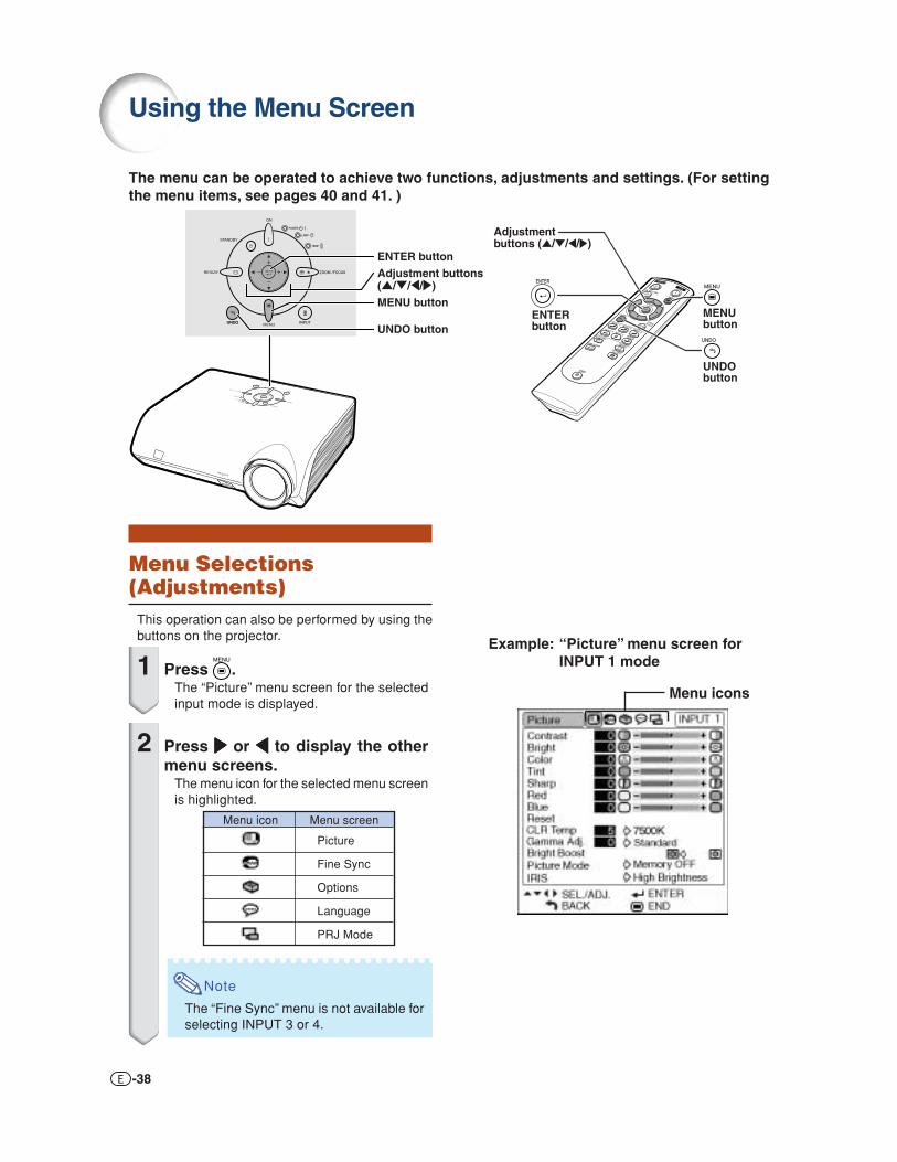
The menu can be operated to achieve two functions, adjustments and settings. (For settingthe menu items, see pages 40 and 41. )
Menu Selections(Adjustments)• This operation can also be performed by using the
buttons on the projector.
1 Press .• The “Picture” menu screen for the selected
input mode is displayed.
2 Press ||||| or \\\\\ to display the othermenu screens.• The menu icon for the selected menu screen
is highlighted.
Note
• The “Fine Sync” menu is not available forselecting INPUT 3 or 4.
Menu icon Menu screen
Picture
Fine Sync
Options
Language
PRJ Mode

Usefu
l Featu
res
-39
3 Press ''''' or """"" to select the item youwant to adjust.• The selected item is highlighted.
(Example: Selecting “Bright”)
To adjust the projectedimage while viewing itPress .• The selected single adjustment item (e.g.
“Bright”) appears on the lower part of thescreen.
• When pressing ' or ", the next item willbe displayed. (e.g. “Bright” is replaced with“Color” by pressing ".)
Note
• Press to return to the previous screen.
4 Press ||||| or \\\\\ to adjust the item se-lected.• The adjustment is stored.
5 Press .• The menu screen will disappear.
Singleadjustmentitems

-40
Adjustmentbuttons ('/"/\/|)
ENTERbutton
MENUbutton
UNDObutton
Menu icons
Example: “Options” menu screen
The menu can be operated to achieve two functions, adjustments and settings. The “setting”item is displayed by or on the menu screen. (For adjusting the menu items, see pages 38
Example: “Picture” menu screen forINPUT 1 mode
Menu Selections (Settings)• This operation can also be performed by using the
buttons on the projector.
1 Press .• The “Picture” menu screen for the selected
input mode is displayed.
2 Press ||||| or \\\\\ to display the othermenu screens.• The menu icon for the selected menu screen
is highlighted.
Note
• The “Fine Sync” menu is not available forselecting INPUT 3 or 4.
Menu icon Menu screen
Picture
Fine Sync
Options
Language
PRJ Mode
and 39.)
Using the Menu Screen

Usefu
l Featu
res
-41
3 Press ''''' or """"" to select the item youwant to set, and then press ||||| to dis-play the sub menu.• The selected item is highlighted.
(Example: Selecting “Menu Position”)
Note
• Press or \ to return to the previousscreen.
• For some items, press \ or | to selectthe icon using “ ”.
4 Press ''''' or """"" to select the settingof the item displayed in the submenu.
5 Press .• The selected item is set.
6 Press .• The menu screen will disappear.

-42
You can adjust the projector’s picture to your preferences using the “Picture” menu.
Picture Adjustment (“Picture” menu)
Adjusting the ImageMenu operation Page 38
Note
• First select “Memory 1-5” or “Memory OFF”when you want to save the “Picture” menu set-tings. See page 44 for details.
Example: “Picture” menu screen forINPUT 1 mode
Description of Adjustment Items
Note
• “Color”, “Tint” and “Sharp” do not appear forRGB input in INPUT 5 mode.
• To reset all adjustment items, select “Reset” onthe “Picture” menu screen and press .
• “Tint” cannot be used with PAL, SECAM, PAL-M, PAL-N or PAL-60.
• “Color”, “Tint” and “Sharp” cannot be used inthe DIGITAL mode.
Selectable itemsContrastBrightColorTintSharpRedBlue
Press \For less contrastFor less brightnessFor less color intensityFor making skin tones purplishFor less sharpnessFor weaker redFor weaker blue
Press |For more contrastFor more brightnessFor more color intensityFor making skin tones greenishFor more sharpnessFor stronger redFor stronger blue
Adjusting the Color TemperatureThis function allows for selecting the desiredcolor temperature. With the lower value selected,the projected image becomes warmer, reddishand incandescent-like while with the highervalue, the image becomes cooler, bluish and fluo-rescent-like.Menu operation Page 40
Example: “Picture” menu screen forINPUT 1 mode
Description of Color Temperature Settings
“CLR Temp” is fine adjusted by following the procedure below.
1 Select “CLR Temp” in the “Picture”menu on the menu screen andpress .• A single menu bar of “CLR Temp” is displayed.
2 Press ''''' or """"" to fine adjust thecolor temperature.• With the lower value selected, the projected
image becomes magenta-tinged. With thehigher value selected, the projected imagebecomes green-tinged.
• Pressing \ or | changes the value of thecolor temperature in the sub menu.
Note• Values on “CLR Temp” are only for general standard purposes.
CLR Temp5500K6500K7500K8500K9300K
10500K
DescriptionThe less the value is set to, the warmer,reddish, incandescent-like the image becomes.
The more the value is set to, the cooler,bluish, fluorescent-like the image becomes.

Usefu
l Featu
res
-43
Gamma Correction FunctionGamma is an image quality enhancement function.Four gamma settings are available to allow fordifferences in the brightness of the room.
Menu operation Page 40
Example: “Picture” menu screen forINPUT 1 mode
Description of Gamma Modes
“Gamma Adj.” is fine adjusted by following theprocedure below.
1 Select “Gamma Adj.” in the “Pic-ture” menu on the menu screen andpress .• A single menu bar of “Gamma Adj.” is displayed.
2 Press ''''' or """"" to fine adjust thegamma correction.• With the lower value selected, the projected
image becomes daker. With the higher valueselected, the projected image becomesbrighter.
• Pressing \ or | changes the value of theGamma in the sub menu.
Selectable ItemsStandard
Cinema 1
Cinema 2
Cinema 3
DescriptionStandard picture without gammacorrectionGives greater depth to darker portionsof images.Brightness is toned down and theimage becomes more balanced.Brighten the darker portions of imagesfor easier viewing in a dimly lit room.
Emphasising the ContrastThis function emphasises the bright portions ofimages to obtain a higher contrast image.
Menu operation Page 40
Example: “Picture” menu screen forINPUT 1 mode
Description of Bright Boost settingsSelectable Items
(ON)
(OFF)
DescriptionFor emphasising the bright portionsof images
For disabling “Bright Boost”

-44
Picture Mode FunctionThis function stores all items set in “Picture”. Fivesettings can be stored separately in “Memory 1”to “Memory 5”. Each stored setting is reassignedto each input mode (INPUT 1 to INPUT 5).Even when the input mode or signal is changed,you can easily select optimal settings from thestored settings.
Menu operation Page 40
Example: “Picture” menu screen forINPUT 1 mode
Select “Picture Mode” on the “Picture” menu andthe memory location where you want to store thesettings. Then adjust the setting items on the“Picture” menu.
If you want to apply the stored settings on the “Pic-
ture” menu, select input mode and then press ,or select “Picture Mode” in the “Picture” menu.If you want to change the stored settings, selectthe memory location for those settings and makesettings on the “Picture” menu.
Picture ModeMemory1-5
MemoryOFF
DescriptionSettings of all items in “Picture” can be storedfor the respective input modes. The storedsettings (Memory 1 to 5) can be selected inany input modes.Besides “Memory 1” to “Memory 5”, othersettings on the “Picture” menu can be storedfor each input mode. The settings stored in“Memory OFF” cannot be applied whenanother input mode is selected.
Switching the High Bright-ness/High Contrast ModeThis function changes the brightness andcontrast of the projected image. It can beoperated using the IRIS button on the remotecontrol.
Menu operation Page 40
Example: “Picture” menu screen forINPUT 1 mode
Description of IRIS Settings
Selectable itemsHigh Brightness
High Contrast
DescriptionHigh brightness is given priority overhigh contrast.High contrast is given priority over highbrightness.
Picture Adjustment (“Picture” menu)

-45
Usefu
l Featu
res
You can adjust the computer image, match the computer display mode, and confirm theinput signal using the “Fine Sync” menu.
Computer Image Adjustment (“Fine Sync” menu)
Adjusting the ComputerImageUse the Fine Sync function in case of irregulari-ties such as vertical stripes or flickering in por-tions of the screen.
Menu operation Page 38
Example: “Fine Sync” menu screen forINPUT 5 (RGB) mode
Description of Adjustment Items
Note
• You can automatically adjust the computer im-age by setting “Auto Sync” on the “Fine Sync”
menu to “ ” (ON) or pressing on the re-mote control. See page 46.
• “Clock”, “Phase”, “H-Pos” and “V-Pos” cannot beused in the DIGITAL mode.
• “Clock” and “Phase” cannot be used in the Com-ponent mode.
• The adjustable area of each item may bechanged according to the input signal.
• To reset all adjustment items, select “Reset” and
press .
Selectable itemsClockPhase
H-Pos
V-Pos
DescriptionAdjusts vertical noise.Adjusts horizontal noise (similar totracking on your VCR).Centers the on-screen image by movingit to the left or right.Centers the on-screen image by movingit up or down.
Special Modes SettingOrdinarily, the type of input signal is detected andthe correct resolution mode is automatically se-lected. However, for some signals, the optimalresolution mode in “Special Modes” on the “FineSync” menu may need to be selected to matchthe computer display mode.
Menu operation Page 40
Example: “Fine Sync” menu screen forINPUT 5 (Component) mode
Note
• If your computer displays patterns which repeatevery other line (horizontal stripes), flickeringmay occur which makes the image hard to see.
• When inputting DTV 1080I signal, select thecorresponding type of signal.
• See “Checking the Input Signal” on the nextpage for information on the currently selectedinput signal.

-46
Auto Sync AdjustmentSelect whether the image is to be synchronizedautomatically when switching the signal with“ON” or “OFF”.
Menu operation Page 40
Example: “Fine Sync” menu screen forINPUT 5 (RGB) mode
Description of Auto Sync Adjustment
Note
• Auto Sync adjustment is also performed bypressing on the remote control.
• The Auto Sync adjustment may take some timeto complete, depending on the image of thecomputer connected to the projector.
• When the optimum image cannot be achievedwith Auto Sync adjustment, use manual adjust-ments. (See page 45.)
• “Auto Sync” cannot be used in the DIGITALmode.
Checking the Input SignalThis function allows you to check the current in-put signal information.
Menu operation Page 40
Example: “Fine Sync” menu screen forINPUT 5 (RGB) mode
Note
• 540P is displayed on the screen when signal1080I is inputted during DVI connection.
Selectable items
(ON)
(OFF)
DescriptionAuto Sync adjustment will occur whenthe projector is turned on or when theinput signals are switched, whenconnected to a computer.Auto Sync adjustment is not automati-cally performed.
Computer Image Adjustment (“Fine Sync” menu)

-47
Usefu
l Featu
res
You can use the “Options” menu to enhance the usage for the projector.
Checking the Lamp LifeStatusYou can confirm the cumulative lamp usage timeand the remaining lamp life (percentage).
Menu operation Page 40
Example: “Options” menu screen forINPUT 1 mode
Description of Lamp Life
Note
• It is recommended that the lamp be changedwhen the remaining lamp life becomes 5%. (Seepage 56.)
• The table above indicates rough estimates in thecase of using only in each mode shown.
• Remaining lamp life changes within the range ofthe values shown depending on the frequency atwhich “Eco Mode” is switched to “ ” (Ecomode) and “ ” (Standard mode). (See page49.)
• The lamp life may vary depending on the usagecondition.
Using the “Options” Menu
Lamp usage condition“Life”
Operated exclusivelyin Eco mode ( )Operated exclusivelyin Standard mode ( )
Remaining lamp life100% 5%
Approx. Approx.3,000 hours 150 hours
Approx. Approx.2,000 hours 100 hours
Setting On-screen DisplayThis function allows you to turn off the on-screenmessages that appear during input select.
Menu operation Page 40
Example: “Options” menu screen forINPUT 1 mode
Description of “OSD Display” SettingsDescription
All On-screen Displays are displayed.
INPUT/AUTO SYNC/ “An invalid button hasbeen pressed.” are not displayed.
Selectable items
(ON)
(OFF)

-48
Setting the Video SystemThe video input system mode is factory presetto “Auto”; however, a clear picture from the con-nected audio-visual equipment may not be re-ceived, depending on the video signal difference.In that case, switch the video signal.
Menu operation Page 40
Example: “Options” menu screen forINPUT 4 mode
Description of Video Systems
Note
• The video signal can only be set in INPUT 3,INPUT 4 mode.
• “Auto” cannot be set for PAL-M and PAL-N in-put signals. Select “PAL-M” or “PAL-N” in “VideoSystem” menu for PAL-M and PAL-N input sig-nals.
DescriptionWhen connected to PAL video equip-ment.When connected to NTSC videoequipment.When connected to SECAM videoequipment.When reproducing NTSC signals in PALvideo equipment.
Selectable items
PAL
NTSC3.58
SECAM
NTSC4.43
Signal Type SettingThis function allows you to select the input sig-nal type RGB or Component for INPUT 5.
Menu operation Page 40
Example: “Options” menu screen forINPUT 5 (RGB) mode
Description of Signal Type SettingsDescription
Set when RGB signals are received.Set when Component signals arereceived.
Selectable itemsRGBComponent
Note
• You can also select “Signal Type” using on the remote control (only INPUT 5).
Using the “Options” Menu
-49
Usefu
l Featu
res
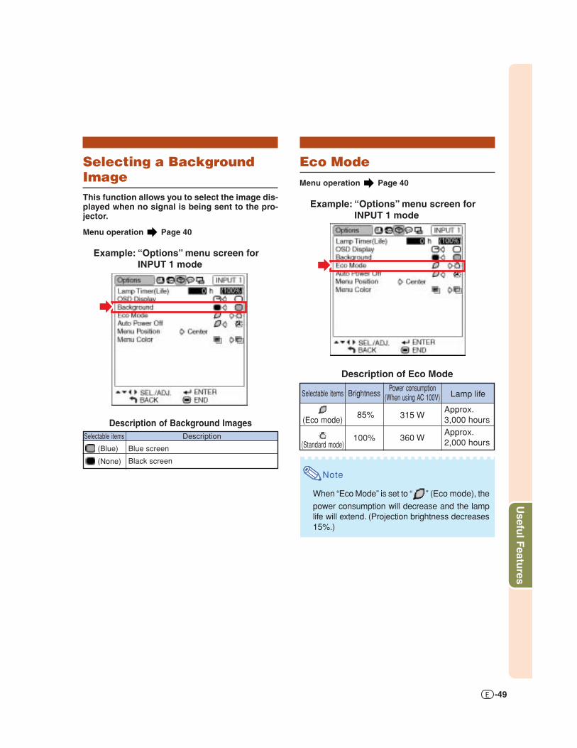
Eco ModeMenu operation Page 40
Example: “Options” menu screen forINPUT 1 mode
Description of Eco Mode
Note
• When “Eco Mode” is set to “ ” (Eco mode), the
power consumption will decrease and the lamplife will extend. (Projection brightness decreases15%.)
Brightness
85%
100%
Selectable items
(Eco mode)
(Standard mode)
Power consumption(When using AC 100V)
315 W
360 W
Lamp life
Approx.3,000 hoursApprox.2,000 hours
Selecting a BackgroundImageThis function allows you to select the image dis-played when no signal is being sent to the pro-jector.
Menu operation Page 40
Example: “Options” menu screen forINPUT 1 mode
Description of Background ImagesSelectable items
(Blue)
(None)
Description
Blue screen
Black screen

-50
Auto Power Off FunctionMenu operation Page 40
Example: “Options” menu screen forINPUT 1 mode
Description of Auto Power Off
Note
• When the Auto Power Off function is set to “ ”(ON), 5 minutes before the projector enters thestandby mode, the message “Enter STANDBYmode in X min.” will appear on the screen toindicate the remaining minutes.
DescriptionThe projector automatically enters thestandby mode when no input signal isdetected for 15 minutes or longer.The Auto Power Off function will bedisabled.
Selectable items
(ON)
(OFF)
Selecting the Menu ScreenPositionThis function allows you to select the desiredposition of the menu screen.
Menu operation Page 40
Example: “Options” menu screen forINPUT 1 mode
Description of Menu Positions
DescriptionDisplayed on the center of the image.Displayed on the upper right of the image.Displayed on the lower right of the image.Displayed on the upper left of the image.Displayed on the lower left of the image.
Selectable itemsCenterUpper RightLower RightUpper LeftLower Left
Center
UpperRight
LowerRight
UpperLeft
LowerLeft
Menu screen
Screen
Position of the Menu Screen which IsDisplayed on the Screen
Using the “Options” Menu

-51
Usefu
l Featu
res
Selecting the Menu ColorThis function allows you to select the color ofthe menu screen.
Menu operation Page 40
Example: “Options” menu screen forINPUT 1 mode
Description of Menu Colors
The menu is displayedopaquely.The menu is displayedtranslucently. The part of themenu on the image becomestransparent.
(Opaque)
(Translucent)
Selectable Items Description

-52
Selecting the On-screenDisplay LanguageThe projector can switch the on-screen displaylanguage among 11 languages: English, German,Spanish, Dutch, French, Italian, Swedish, Portu-guese, Chinese, Korean or Japanese.
Example: “Language” menu screen forINPUT 1 mode
1 Press on the remote control.• The “Picture” menu will be displayed.
2 Press \ or | to select the “Lan-guage” menu icon ( ).• The “Language” menu will be displayed.
3 Press ' or " to select the desired
language, and then press .
• The language you selected will be set asthe on-screen display.
4 Press .• The “Language” menu will disappear.
Note
• This procedure can also be performed by usingthe buttons on the projector.
Selecting the On-screen Display Language and theProjection Mode
Setting the ProjectionModeThis projector is equipped with a reverse/invertimage function that allows you to reverse or in-vert the projected image for various applications.
Menu operation Page 40
Example: “PRJ Mode” menu screen
Description of PRJ Modes
Note
• This function is used for the reversed image andceiling-mount setups. (See page 18.)
DescriptionNormal image
Inverted image
Reversed image
Reversed and inverted image
Selectable itemsFront
Ceiling + Front
Rear
Ceiling + Rear
Front
Rear
Ceiling + Front
Ceiling + Rear
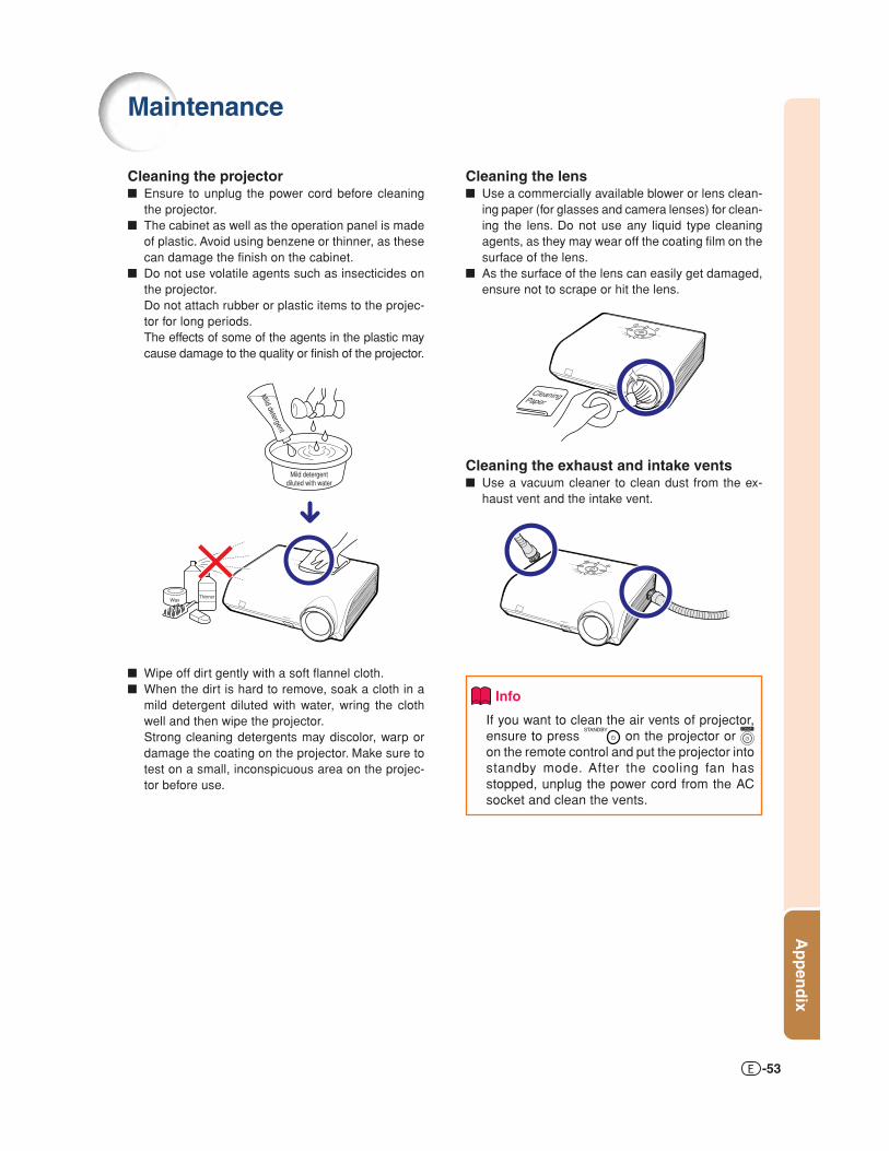
-53
Ap
pen
dix
Cleaning the lens■ Use a commercially available blower or lens clean-
ing paper (for glasses and camera lenses) for clean-ing the lens. Do not use any liquid type cleaningagents, as they may wear off the coating film on thesurface of the lens.
■ As the surface of the lens can easily get damaged,ensure not to scrape or hit the lens.
Cleaning the exhaust and intake vents■ Use a vacuum cleaner to clean dust from the ex-
haust vent and the intake vent.
Info
• If you want to clean the air vents of projector,ensure to press on the projector or on the remote control and put the projector intostandby mode. After the cooling fan hasstopped, unplug the power cord from the ACsocket and clean the vents.
Cleaning the projector■ Ensure to unplug the power cord before cleaning
the projector.■ The cabinet as well as the operation panel is made
of plastic. Avoid using benzene or thinner, as thesecan damage the finish on the cabinet.
■ Do not use volatile agents such as insecticides onthe projector.Do not attach rubber or plastic items to the projec-tor for long periods.The effects of some of the agents in the plastic maycause damage to the quality or finish of the projector.
■ Wipe off dirt gently with a soft flannel cloth.■ When the dirt is hard to remove, soak a cloth in a
mild detergent diluted with water, wring the clothwell and then wipe the projector.Strong cleaning detergents may discolor, warp ordamage the coating on the projector. Make sure totest on a small, inconspicuous area on the projec-tor before use.
Maintenance
CleaningPaper
Mild detergentdiluted with water
WaxThinner
Mild detergent

-54
Power indicatorLamp indicatorTemperature warning indicator
Maintenance Indicators
Maintenance Indicators
■ The warning lights on the projector indicate problems inside the projector.■ If a problem occurs, either the temperature indicator or the lamp indicator will illuminate red, and
the projector will enter the standby mode. After the projector has entered the standby mode, followthe procedures given below.
About the temperature warning indicator
If the temperature inside the projector increases, due to blockage of the air vents, or the setting location,
“ ” will illuminate in the lower left corner of the picture. If the temperature keeps on rising, the lamp will
turn off and the temperature warning indicator will blink, the cooling fan will run for a further 90 seconds, and
then the projector will enter the standby mode. After “ ” appears, ensure to perform the measures
described on page 55.
About the lamp indicator
■ When the remaining lamp life becomes 5% or less, “ ” (yellow) and “Change The Lamp.” will be
displayed on the screen. When the percentage becomes 0%, it will change to “ ” (red), the lamp will
automatically turn off and then the projector will automatically enter the standby mode. At this time,the lamp indicator will illuminate in red.
■ If you try to turn on the projector a fourth time without replacing the lamp, the projector will not turn on.

Ap
pen
dix
-55
Maintenance indicatorProblem Cause Possible solution
Temperaturewarningindicator
Normal Abnormal
Off Red on(Standby)
The internaltemperature isabnormally high.
Abnormal
• Blocked air intake• Relocate the projector to an area
with proper ventilation (see page7).
• Cooling fan break-down
• Internal circuit failure• Clogged air intake
• Take the projector to your nearestAuthorized SharpVision ServiceCenter or Dealer for repair.
• Clean the exhaust and intakevents. (See page 53.)
Lampindicator
Red on(Standby)
The lamp doesnot illuminate.
• Burnt-out lamp• Lamp circuit failure
• Carefully replace the lamp. (Seepage 57.)
• Take the projector to your nearestAuthorized SharpVision ServiceCenter or Dealer for repair.
• Please exercise care whenreplacing the lamp.
Red onTime to changethe lamp.
• Remaining lamp lifebecomes 5% or less.
Green onGreen blinks
when the lampis warming up
or shuttingdown.
Info
• If the temperature warning indicator illuminates and the projector enters the standby mode, check whetherany of the ventilation holes are blocked (page 7) and then try turning the power back on. Wait until theprojector has cooled down completely before plugging in the power cord and turning the power back on.(At least 10 minutes.)
• If the power is turned off for a brief moment due to power outage or some other cause while using theprojector, and the power supply recovers immediately after that, the lamp indicator will illuminate in redand the lamp may not be lit. In this case, unplug the power cord from the AC outlet, replace the powercord in the AC outlet and then turn the power on again.
• Do not unplug the power cord after the projector has entered the standby mode and while the cooling fanis running. The cooling fan runs for about 90 seconds.
The lamp doesnot illuminate. —
• Disconnect the power cord fromthe AC outlet, and then connect itagain.

-56
Lamp■ It is recommended that the lamp (optional: AN-K2LP) be replaced when the remaining lamp life
becomes 5% or less, or when you notice a significant deterioration in the picture and color quality.The lamp life (percentage) can be checked with the on-screen display. See page 47.
■ Purchase a replacement lamp of type AN-K2LP from your place of purchase, nearest AuthorizedSharpVision Service Center or Dealer.
IMPORTANT NOTE TO U.S. CUSTOMERS:The lamp included with this projector is backed by a 90-day parts and labor limited warranty. All serviceof this projector under warranty, including lamp replacement, must be obtained through an AuthorizedSharpVision Service Center or Dealer. For the name of the nearest Authorized SharpVision ServiceCenter or Dealer, please call toll-free: 1-888-GO-SHARP (1-888-467-4277).
Hg LAMP CONTAINS MERCURY For State Lamp Disposal Informationwww.lamprecycle.org or 1-800-BE-SHARP
Caution Concerning the Lamp■ This projector utilizes a pressurized mercury lamp. A loud sound may indicate lamp failure. Lamp
failure can be attributed to numerous sources such as: excessive shock, improper cooling, surfacescratches or deterioration of the lamp due to a lapse of usage time.The period of time up to failure largely varies depending on the individual lamp and/or the conditionand the frequency of use. It is important to note that failure can often result in the bulb cracking.
■ When the lamp replacement indicator and on-screen display icon are illuminated, it is recommendedthat the lamp be replaced with a new one immediately, even if the lamp appears to be operatingnormally.
■ Should the lamp break, the glass particles may spread inside the lamp cage or gas contained in thelamp may be vented into the room from the exhaust vent. Because the gas in this lamp includesmercury, ventilate the room well if the lamp breaks and avoid all exposure to the released gas. Incase of exposure to the gas, consult a doctor as soon as possible.
■ Should the lamp break, there is also a possibility that glass particles may spread inside of theprojector. In such a case, it is recommended you contact your nearest Authorized SharpVisionService Center or Dealer to assure safe operation.
Replacing the Lamp
Caution
• Do not remove the lamp unit from the projector right after use. The lamp will be very hot and may cause burnor injury.
• Wait at least one hour after the power cord is disconnected to allow the surface of the lamp unit to fully coolbefore removing the lamp unit.
■ Carefully change the lamp by following the instructions described in this section. *If you wish, youmay have the lamp replaced at your nearest Authorized SharpVision Service Center or Dealer.
* If the new lamp does not light after replacement, take your projector to the nearest Authorized SharpVisionService Center or Dealer for repair.
Regarding the Lamp
U.S.A. ONLY
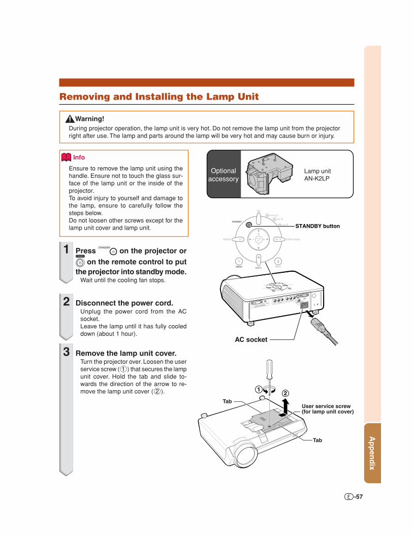
Ap
pen
dix
-57
Info
• Ensure to remove the lamp unit using thehandle. Ensure not to touch the glass sur-face of the lamp unit or the inside of theprojector.
• To avoid injury to yourself and damage tothe lamp, ensure to carefully follow thesteps below.
• Do not loosen other screws except for thelamp unit cover and lamp unit.
1 Press on the projector or on the remote control to put
the projector into standby mode.• Wait until the cooling fan stops.
2 Disconnect the power cord.• Unplug the power cord from the AC
socket.• Leave the lamp until it has fully cooled
down (about 1 hour).
3 Remove the lamp unit cover.• Turn the projector over. Loosen the user
service screw (1) that secures the lampunit cover. Hold the tab and slide to-wards the direction of the arrow to re-move the lamp unit cover (2).
AC socket
STANDBY button
12
User service screw(for lamp unit cover)
Tab
Tab
Removing and Installing the Lamp Unit
Optionalaccessory
Lamp unitAN-K2LP
Warning!• During projector operation, the lamp unit is very hot. Do not remove the lamp unit from the projector
right after use. The lamp and parts around the lamp will be very hot and may cause burn or injury.

-58
4 Remove the lamp unit.• Loosen the two securing screws from
the lamp unit. Hold the lamp unit by thehandle and pull it in the direction of thearrow. At this time, keep the lamp unithorizontal and do not tilt it.
5 Insert the new lamp unit.• Press the lamp unit firmly into the lamp
unit compartment. Fasten the securingscrews.
6 Replace the lamp unit cover.• Align the lamp unit cover and slide it to
close. Then tighten the user servicescrew to secure the lamp unit cover.
Info
• If the lamp unit and lamp unit cover are notcorrectly installed, the power will not turnon, even if the power cord is connected tothe projector.
Resetting the Lamp TimerReset the lamp timer after replacing the lamp.
Info
• Make sure to reset the lamp timer onlywhen replacing the lamp. If you reset thelamp timer and continue to use the samelamp, this may cause the lamp to becomedamaged or explode.
1 Connect the power cord.• Plug the power cord into the AC socket
of the projector.
2 Reset the lamp timer.
• Press , , , \\\\\, and ||||| on the
projector in order, and then press on
the projector.
• “LAMP 0000H” is displayed on the lowerleft of the screen, indicating that the lamptimer is reset.
Regarding the Lamp
Securing screws
Handle
User service screw(for lamp unit cover)
AC socket
\/| buttons
ON button
ENTER button
UNDO button
INPUT button

-59
Ap
pen
dix
Connecting Pin Assignments
RS-232C Port: 9-pin D-sub male connectorPin No. Signal Name I/O Reference
1 Not connected2 RD Receive Data Input Connected to internal circuit3 SD Send Data Output Connected to internal circuit4 Reserved Connected to internal circuit5 SG Signal Ground Connected to internal circuit6 Reserved Connected to internal circuit7 Reserved Connected to internal circuit8 Reserved Connected to internal circuit9 Not connected
DVI-I (INPUT 5) port : 29 pin connector
••••• DVI Digital INPUTPin No. Signal Pin No. Signal
1 T.M.D.S data 2– 16 Hot plug detection2 T.M.D.S data 2+ 17 T.M.D.S data 0–3 T.M.D.S data 2 shield 18 T.M.D.S data 0+4 Not connected 19 T.M.D.S data 0 shield5 Not connected 20 Not connected6 DDC clock 21 Not connected7 DDC data 22 T.M.D.S clock shield8 Not connected 23 T.M.D.S clock+9 T.M.D.S data 1– 24 T.M.D.S clock–10 T.M.D.S data 1+ C1 Not connected11 T.M.D.S data 1 shield C2 Not connected12 Not connected C3 Not connected13 Not connected C4 Not connected14 +5V power C5 Ground15 Ground
••••• DVI Analog RGB InputPin No. Signal Pin No. Signal
1 Not connected 16 Hot plug detection2 Not connected 17 Not connected3 Not connected 18 Not connected4 Not connected 19 Not connected5 Not connected 20 Not connected6 DDC clock 21 Not connected7 DDC data 22 Not connected8 Vertical sync 23 Not connected9 Not connected 24 Not connected
10 Not connected C1 Analog input Red11 Not connected C2 Analog input Green12 Not connected C3 Analog input Blue13 Not connected C4 Horizontal sync14 +5V power C5 Ground15 Ground
••••• DVI Analog Component InputPin No. Signal Pin No. Signal
1 Not connected 16 Not connected2 Not connected 17 Not connected3 Not connected 18 Not connected4 Not connected 19 Not connected5 Not connected 20 Not connected6 Not connected 21 Not connected7 Not connected 22 Not connected8 Not connected 23 Not connected9 Not connected 24 Not connected10 Not connected C1 Analog input PR/CR
11 Not connected C2 Analog input Y12 Not connected C3 Analog input PB/CB
13 Not connected C4 Not connected14 Not connected C5 Ground15 Ground
17
• • • • • • • • • ~ • • • • • • • • •
• • • • ~ • • • •
• • • • ~ • • • •
24
18 23
C3
21
9 16
C1C2C4
C5
87
6789
12345

-60
PC controlA computer can be used to control the projector by connecting an RS-232C cable (null modem, cross type,commercially available) to the projector. (See page 27 for connection.)
Communication conditionsSet the serial port settings of the computer to match that of the table.Signal format: Conforms to RS-232C standard.Baud rate: 9,600 bpsData length: 8 bitsParity bit: NoneStop bit: 1 bitFlow control: None
Basic formatCommands from the computer are sent in the following order: command, parameter, and return code. Afterthe projector processes the command from the computer, it sends a response code to the computer.
Info
• When more than one code is being sent, send each command only after the OK response code for theprevious command from the projector is verified.
• When using the computer control function of the projector, the projector’s operating status cannot be read bythe computer.
CommandsExample:• When power on.
Response code formatNormal response Problem response (communication error or incorrect command)
Command format
RS-232C Specifications and Command Settings
Return code (0DH)C1 C2 C3 C4 P1 P2 P3 P4
Command 4-digit Parameter 4-digit
O K Return code (0DH) E R R Return code (0DH)
Note
• If an underbar (_) appears in the parameter column, enter a space.
^]P O W R _ 1_ _ O K
ProjectorComputer
CONTROL CONTENTS
POWER ON
STANDBY
INPUT 1 (COMPONENT 1)
INPUT 2 (COMPONENT 2)
INPUT 3 (S-VIDEO)
INPUT 4 (VIDEO)
INPUT 5 (RGB/COMPONENT)
DIGITAL MODE
OK OR ERR
OK OR ERR
OK OR ERR
OK OR ERR
OK OR ERR
OK OR ERR
OK OR ERR
OK OR ERR
P
P
I
I
I
I
I
I
O
O
V
V
V
V
V
V
W
W
E
E
E
E
E
E
R
R
D
D
D
D
D
D
_
_
_
_
_
_
_
_
_
_
_
_
_
_
_
_
_
_
_
_
_
_
_
_
1
0
1
2
3
4
5
6BUTT
ONS &
REMO
TE CO
NTRO
L BUT
TONS
COMMAND PARAMETER RETURN

-61
Ap
pen
dix
Note
• This projector may not be able to display images from notebook computers in simultaneous (CRT/LCD)mode. Should this occur, turn off the LCD display on the notebook computer and output the display datain “CRT only” mode. Details on how to change display modes can be found in your notebook computer’soperation manual.
Computer Compatibility Chart
• Horizontal Frequency: 15–70 kHzVertical Frequency: 43–75 HzPixel Clock: 12–80 MHzCompatible with sync on greenXGA compatible in intelligent compression
DTV
Computer
The table below lists signal codes that are compatible with the projector. When the images are distorted orcannot be projected, adjust the output signal of your computer and so forth while referring to the table below.
15.731.533.815.631.345.028.133.828.133.8
480I480P540P576I576P720P1035I1035I1080I1080I
60606050506050605060
Signal Vertical Frequency (Hz)Horizontal Frequency (kHz)
PC/MAC/WS
HorizontalFrequency
(kHz)
VerticalFrequency
(Hz)
VGA
PC
SVGA
XGA
VESAStandard
DVISupport
✔
✔
✔
✔
✔
✔
✔
✔
✔
✔
✔
✔
✔
✔
✔
✔
✔
✔
✔
✔
✔
✔
✔
✔
Resolution
640 × 350
720 × 350
640 × 400
720 × 400
640 × 480
800 × 600
1,024 × 768
Display
Upscale
IntelligentCompression
27.0 60
27.0 60
27.0 60
60
31.5 70
31.5 70
31.5 70
31.5 60
34.7 70
37.9 72
37.5 75
31.4 50
35.1 56
37.9 60
44.5 70
48.1 72
46.9 75
✔
31.5 70
27.0
26.2 50
35.5 43
40.3 50
58.1 72
56.5 70
1,280 × 720— 45.0 60
MAC 16"
PC/MAC 13"
PC/MAC 19"
640 × 480
832 × 624
IntelligentCompression
34.9 67
60.01,024 × 768
VGA
SVGA
✔
✔XGA
48.4 60
75
46.8 75
49.6 75
Upscale

-62
Troubleshooting
Check• Projector power cord is not plugged into the wall outlet.• Power to the external connected devices is off.• The selected input mode is wrong.• Cables are incorrectly connected to the rear panel of the projector.• External output has not been set when connecting notebook computer.• “Contrast” and “Bright” are set to minimum position.• Image adjustments are incorrectly set.(Video Input only)• Video input system is incorrectly set.(INPUT 5)• Input signal type (RGB/Component) is incorrectly set.
• “OSD Display” is set to “ (OFF)”.
• Adjust the focus.• The projection distance exceeds the focus range.(Computer Input only)• Perform “Fine Sync” Adjustments. (“Clock” Adjustment)• Perform “Fine Sync” Adjustments. (“Phase” Adjustment)• Noise may appear depending on the computer.
• If the picture is normal, the sound is due to cabinet shrinkagecaused by room temperature changes. This will not affectoperation or performance.
• See “Maintenance Indicators”.
• When temperature inside the projector increases, the coolingfan runs faster.
• The lamp will eventually need to be changed.The lamp has reached the end of its life. Replace the lamp.
• Change the input signal type.
Problem
On-screen display doesnot appear.
An unusual sound isoccasionally heardfrom the cabinet.
Maintenanceindicator illuminates or
blinks in red.The cooling fanbecomes noisy.
The lamp takes a longtime to turn on.Picture is dark.
Image is green onINPUT 5 Component.
Image is pink (no green)on INPUT 5 RGB.
Page28—29
19-27—4242
48
48
47
3017
4545—
—
54
—
57
48
Color is faded or poor.
Picture is blurred;noise appears.
No picture
This projector is equipped with a microprocessor. Its performance could be adversely affected byincorrect operation or interference. If this should happen, unplug the Unit and plug it in again aftermore than 5 minutes.
If you encounter any problems during setup or operation of this projector, first refer to the“Troubleshooting” section on this page. If this operation manual does not answer your ques-tion, please call toll free 1-877-DTV-SHARP (1-877-388-7427) for further assistance. Or, sendus an e-mail at [email protected] .Our World Wide Web address is http://www.sharpusa.com/ .
For SHARP Assistance (U.S.A. only)

-63
Ap
pen
dix
SpecificationsProduct type
ModelVideo system
Display methodDLP panel
LensProjection lamp
Video input signal
S-video input signal
Component input signal(INPUT 1, 2)
Analog RGB/Digital(INPUT 5/DIGITAL)
Horizontal resolutionPixel clock
Vertical frequencyHorizontal frequency
Computer control signalRated voltageInput current
Rated frequencyPower consumption
Power consumption (standby)Heat dissipation
Operating temperatureStorage temperature
CabinetI/R carrier frequency
Dimensions (approx.)Weight (approx.)
Supplied accessories
Replacement parts
ProjectorXV-Z2000PAL/PAL 60/PAL-M/PAL-N/SECAM/NTSC 3.58/NTSC 4.43DTV 480I/480P/720P/1080ISingle Panel Digital Micromirror Device (DMD™) by Texas InstrumentsPanel size: 0.8"Drive method: Digital Light Processing (DLP™)No. of dots: 921,600 dots (1,280 [H] × 720 [V])1–1.5 × zoom lens, F2.0–2.5 f=21.3–31.6 mm275 W DC lampRCA Connector: VIDEO (INPUT 4), composite video, 1.0 Vp-p, sync negative, 75 Nterminated4-pin Mini DIN connector (INPUT 3)Y (luminance signal): 1.0 Vp-p, sync negative, 75 N terminatedC (chrominance signal): Burst 0.286 Vp-p, 75 N terminatedRCA ConnectorY: 1.0 Vp-p, sync negative, 75 N terminatedPB (CB): 0.7 Vp-p, 75 N terminatedPR (CR): 0.7 Vp-p, 75 N terminated29-pin DVI-I terminal<Digital>Input impedance 50 NInput level 250-1000 mV<Analog>Input impedance 75 NInput level 0.7 Vp-pY: 1.0 Vp-p, sync negative, 75 N terminatedPB (CB): 0.7 Vp-p, 75 N terminatedPR (CR): 0.7 Vp-p, 75 N terminated<Synchronization signal>••••• Separate sync/Composite sync
Input level TTL levelInput impedance 1 KN
••••• Green on syncInput level (Synchronizing input) 0.286 Vp-pInput impedance 75 N
720 TV lines (DTV 720P input)12–80 MHz43–75 Hz15–70 kHz9-pin D-sub connector (RS-232C Port)AC 100–240 V3.65 A (When using AC 100 V)50/60 Hz360 W (When using AC 100 V)6 W (When using AC 100 V)1,350 BTU/hour41°F to 95°F (+5°C to +35°C)–4°F to 140°F (–20°C to +60°C)Plastic38 kHz12 7/32" × 3 33/64" × 11 7/64" (310 (W) × 89 (H) × 282 (D) mm)9.5 lbs. (4.3 kg)Remote control, Two AA size batteries, Power cord, Lens cap (attached on the body),Operation manualLamp unit (Lamp/cage module) (AN-K2LP), Remote control (RRMCGA334WJSA), AAsize batteries, Power cord (QACCDA007WJPZ), Lens cap (PCAPHA021WJSA),Operation manual (TINS-B529WJZZ)
As a part of policy of continuous improvement, SHARP reserves the right to make designand specification changes for product improvement without prior notice. The performancespecification figures indicated are nominal values of production units. There may be somedeviations from these values in individual units.

-64
Dimensions
Units: inches (mm)
Side View Side ViewTop View
Rear View
Front View
Bottom View
M4
M4
M4M4
9 /64
(3.
25)
11 7
/64
(282
)1 /
16 (
1.5)
2 11/64 (55.05)
12 7/32 (310)
1 59 /
64
(48.
5)
3 33 /
64 (
89)
13/6
4 (5
)
2 3/1
6
(55.
5)
3 15/16 (99.95)
5 7/64 (129.5)5 7/64 (129.5)
5 /8
(15.
5)
9 /16
(14
)
4 3/1
6 (1
06.3
) 8 9/3
2 (2
10.3
)
8 7/8
(22
5.3)
1 7/32
(30.9)1 5/32
(29.1)
1 7/32
(30.9)1 3/4
(44.1)

-65
Ap
pen
dix
Glossary
Aspect RatioWidth and height ratio of an image. The normalaspect ratio of a computer and video image is 4:3.There are also wide images with an aspect ratioof 16:9 and 21:9.
Auto SyncOptimizes projected computer images by auto-matically adjusting certain characteristics.
BackgroundInitial setting image projected when no signal isbeing output.
ClockClock adjustment is used to adjust vertical noisewhen clock level is incorrect.
CLR Temp (Color temperature)Function that can be used to adjust the color tem-perature to suit the type of image input to the pro-jector. Decrease the color temperature to createwarmer, reddish images for natural flesh tones,or increase to create cooler, bluish images for abrighter picture.
Composite syncSignal combining horizontal and vertical syncpulses.
DVI (Digital Visual Interface)Display digital interface that also supports analoginterfaces.
Intelligent compression and expansionHigh quality resizing of lower and higher resolu-tion images to fit the projector’s native resolution.
Keystone CorrectionFunction to digitally correct a distorted image whenthe projector is set up at an angle, smoothes outjaggies on keystone images and compresses theimage not only horizontally but vertically keepingthe 16 : 9 aspect ratio.
PhasePhase shift is a timing shift between isomorphicsignals with the same resolution. When phase levelis incorrect, the projected image typically displayshorizontal flicker.
ResizeAllows you to modify or customize the picture dis-play mode to enhance the input image. You can se-lect from four different modes: STRETCH, SIDEBAR, SMART STRETCH and CINEMA ZOOM.
RS-232CFunction to control the projector from the com-puter by using the RS-232C ports on the projec-tor and computer.
StretchMode that stretches the 4:3 image horizontally todisplay it on the wide screen.
GammaImage quality enhancement function that offers aricher image by brightening the darker portionsof the image without altering the brightness of thebrighter portions. You can select from four differ-ent modes: Standard, Cinema 1, Cinema 2 andCinema 3.

-66
Index
AAC socket ............................................................. 28Adjustment buttons .............................................. 38Aspect ratio .......................................................... 35Auto Power Off ..................................................... 50Auto Sync ............................................................. 46AUTO SYNC button ............................................. 46
BBackground .......................................................... 49Blue ...................................................................... 42Bright .................................................................... 42Bright Boost ......................................................... 43
CCeiling+Front ........................................................ 52Ceiling+Rear ........................................................ 52Clock .................................................................... 45CLR Temp (Color Temperature) ........................... 42Color ..................................................................... 42Component terminals ........................................... 21Contrast ................................................................ 42
DDIGITAL INPUT button ......................................... 29DVI ........................................................ 22,23,25,26
EEco Mode ............................................................. 49ENTER button ...................................................... 39Exhaust vent ................................................ 7,11,53
FFine Sync ............................................................. 45Front ..................................................................... 52
GGamma Adj. ......................................................... 43
HHEIGHT ADJUST button ...................................... 31H-Pos ................................................................... 45
IINPUT buttons ...................................................... 29Intake vent ......................................................... 7,53IRIS ................................................................. 34,44IRIS button ........................................................... 34
KKensington Lock .................................................. 11KEYSTONE button ............................................... 32Keystone Correction............................................. 32
LLamp .................................................................... 56Lamp indicator ..................................................... 54Lamp Timer (Life) ................................................. 47Language ............................................................. 52Lens cap................................................................. 9
MMENU button ........................................................ 38Menu Color ........................................................... 51Menu Position....................................................... 50
OON button ............................................................. 28On-screen display language ................................ 52OSD Display ......................................................... 47
PPhase ................................................................... 45Picture .................................................................. 42Picture Mode ........................................................ 44PICTURE MODE button ...................................... 34Power cord ........................................................... 28Power indicator ..................................................... 10PRJ mode ............................................................ 52
RRear ..................................................................... 52Rear adjustment feet ............................................ 31Red....................................................................... 42Remote control ..................................................... 12Remote control sensor ......................................... 13Replacing the lamp .............................................. 56RESIZE button ..................................................... 34RS-232C terminal ................................................ 27
SSharp.................................................................... 42Signal Info ............................................................ 46Signal Type .......................................................... 48Special Modes ..................................................... 45STANDBY button ................................................. 28STRETCH ............................................................ 35S-video input terminal .......................................... 24
TTemperature warning indicator ............................. 54Tint ....................................................................... 42
UUNDO button ........................................................ 34
VVideo input terminal ............................................. 24Video System ....................................................... 48V-Pos.................................................................... 45
ZZOOM/FOCUS button .......................................... 30

-67
Ap
pen
dix
CONSUMER LIMITED WARRANTY
SHARP ELECTRONICS CORPORATION warrants to the first consumer purchaser that this Sharp brand product (the “Product”),when shipped in its original container, will be free from defective workmanship and materials, and agrees that it will, at its option, eitherrepair the defect or replace the defective Product or part thereof with a new or remanufactured equivalent at no charge to the purchaserfor parts or labor for the period(s) set forth below.
This warranty does not apply to any appearance items of the Product nor to the additional excluded item(s) set forth below nor to anyProduct the exterior of which has been damaged or defaced, which has been subjected to improper voltage or other misuse, abnormalservice or handling, or which has been altered or modified in design or construction.
In order to enforce the rights under this limited warranty, the purchaser should follow the steps set forth below and provide proof ofpurchase to the servicer.
The limited warranty described herein is in addition to whatever implied warranties may be granted to purchasers by law. ALL IMPLIEDWARRANTIES INCLUDING THE WARRANTIES OF MERCHANTABILITY AND FITNESS FOR USE ARE LIMITEDTO THE PERIOD(S) FROM THE DATE OF PURCHASE SET FORTH BELOW. Some states do not allow limitations on how long animplied warranty lasts, so the above limitation may not apply to you.
Neither the sales personnel of the seller nor any other person is authorized to make any warranties other than those described herein,or to extend the duration of any warranties beyond the time period described herein on behalf of Sharp.
The warranties described herein shall be the sole and exclusive warranties granted by Sharp and shall be the sole and exclusiveremedy available to the purchaser. Correction of defects, in the manner and for the period of time described herein, shall constitutecomplete fulfillment of all liabilities and responsibilities of Sharp to the purchaser with respect to the Product, and shall constitute fullsatisfaction of all claims, whether based on contract, negligence, strict liability or otherwise. In no event shall Sharp be liable, or in anyway responsible, for any damages or defects in the Product which were caused by repairs or attempted repairs performed by anyoneother than an authorized servicer. Nor shall Sharp be liable or in any way responsible for any incidental or consequential economic orproperty damage. Some states do not allow the exclusion of incidental or consequential damages, so the above exclusion may notapply to you.
THIS WARRANTY GIVES YOU SPECIFIC LEGAL RIGHTS. YOU MAY ALSO HAVE OTHER RIGHTS WHICH VARY FROM STATETO STATE.
Model Specific Section (In-Home Service)
Your Product Model Number & Description:
Warranty Period for this Product:
Additional Item(s) Excluded fromWarranty Coverage (if any):
Where to Obtain Service:
What to do to Obtain Service:
XV-Z2000 Projector(Be sure to have this information available when you need servicefor your Product.)
One (1) year parts and labor from date of purchase except for theProjector Lamp for which the warranty period is ninety (90) daysfrom date of purchase. After the ninety (90) day warranty period onthe Projector Lamp, parts and labor for a lamp replacement are theresponsibility of the consumer.
Cleaning of Optical System and/or replacement of any filter.Labor & materials required to remove and reinstall a suspendedprojector in installations not accessible with a standard (8' step)ladder or ceilings exceeding 12’ in height.Labor & materials required to remove and reinstall a projector incomplex systems including, but not limited to, projectors installedin custom enclosures, projectors connected to third party controland automation systems, and realignment of projectors installed in“mirrored” rear projection enclosures.
From a Sharp Authorized Servicer located in the United States. Tofind the location of the nearest Sharp Authorized Servicer, call Sharptoll free at 1-800-BE-SHARP.Contact your Sharp Authorized Servicer to obtain in-home servicefor this Product. The Servicer will come to your home and ifnecessary to remove the Product for repair at the Servicer’s facility,the Servicer will reinstall it upon completion of repair. Be sure tohave Proof of Purchase available.
VALID IN USA ONLY
TO OBTAIN PRODUCT INFORMATION, CALL 1-877-DTV-SHARP OR VISIT www.sharpusa.com.