Embed Size (px)
Citation preview

Page 51 of 171
possible "Potential Induced Degradation".
xxiv. Reactive Power: The output power factor of the PCU shouldpe of suitable range
to supply or sink reactive power. The PCU shall have internal protection
arrangement against any sustained fault in the feeder line and against lightning in
: %j the feeder line.^; <,t/'p'ju^v. Isolation: The PCU shall have provision for input & output isolation. Each solid-
state electronic device shall have to be protected to ensure long life as well as
smooth functioning of the PCU.
xxvi All inverters/ PCUs shall be three phase using static solid state components. DC
lines shall have suitably rated isolators to allow safe start up and shut down of
the system. Circuit breakers used in the DC lines must be rated suitably.
a.Sinusoidal current modulation with excellent dynamic response.
b.Compact and weather proof housing.
c.Direct use in the outdoors with outdoor housing.y
d.Comprehensive network management functions (including the LVRT and capability
to inject reactive power to the grid).
e.No load loss < 1% of rated power and maximum loss in sleep mode shall be less;-' than 0.05%.
f.Unit wise & integrated Data loggingg.Dedicated Prefab compartment required.for Ethernet for networking.
'"'' h. PCU shall have protection against over current, sync loss, over temperature, DC bus overvoltage, cooling fan failure (if provided), short circuit, lightening, earth fault, surge voltageinduced at output due to external source, power regulation in the event of thermaloverloading,
xxvi It shall have bus communication via interface for integration, remote control via
telephone model or mini web server, integrated protection in. the DC and three
phase system, insulation monitoring of PV array with sequential fault location.
xx\AGround fault detector which is essential for large PV generators in view of
appreciable discharge current with respect to ground.
xxix; The power conditioner must be entirely self-managing and stable in operation. A
•%% self- diagnostic system check should occur on start up. Functions should include
: P a test of key parameters on start up.
xxx; Over voltage protection against atmospheric lightning discharge to the PV array
is required.
xxx. The power conditioner must be entirely self-managing and stable in operation. A
self- diagnostic system check should occur on start up. Functions should include
a test of key parameters on start up.
xxxl Standards and Compliances:^
The Bidder also has to confirm the PCU specifications in the Bid.

a The PCU shall have local LCD (Liquid crystal display) and keypad for system
control, monitoring instantaneous system data, event Ipgs, data logs and changing
Page 52 of 171
xxiii. Display
a.PCU shall confirm to IEC 60068-2 standards for Environmental Testing..i
b.All inverters shall be IEC 61000 compliant for electromagnetic compatibility|harmonics, etc.• ! •
c.All inverters shall be safety rated as per IEC 62109 (1 &2), EN 50178 or equivalent
DIN or UL standard.'
d.Each PCU shall be compliant with IEEE standard 929 - 200 or equivalent. The
Bidder should select the Central inverter as per its own system design so as
to optimize the power output.
+ 10% and-10%
415 Volts & 50 Hz
IEC 61727, VDE 0126 (Consider IECCode for Central Inverter)
Classification of chemically activesubstances: 3C2Classification of chemically activesubstances: 3S2
IP 4X / IP 65 (Indoor/ Outdoor rated)IEC-60068-2 (environmental) j
15% to 95 % non- condensing „ ;
0 to 50 deg C
Less than 3 %
0.8 lag- 0.8 lead
50 Hz +3% to - 5% Hz
> 98% as IEC- 61683(Efficiency) ~fPp •
> 98%, measured as per IEC 61683standard for measuring efficiency.* Inverter No Load / Full Load LossCalculation must be submitted by theBidder.
450 to 800 volts DC (Other equivalenttechnical option is also acceptable). J
Pure Sine wave
800 V DC Extendable up to 1000 Vor1500V
415 Volts +15%/-10% AC / 270 V / Asper design (Other equivalent technicaloption is also acceptable).
>1000KW
As per the design
W^mSmAP^ .:%^^yy| j %j
Voltage Tolerance
Nominal Voltage & Frequency
Grid Specifications
Protection rating (as per IEC-60721-3-3)
Enclosure
Humidity
Ambient dry bulb temperaturerange
Max. THD at rated power
Power Factor
Output frequency
Minimum Efficiency at 100%loadThe rated European efficiency(Euro Eta Efficiency) and peakefficiency
DC voltage range, MPPT
Wave Form
Maximum Input Voltage
Nominal AC Output Voltage
Nomipal AC Output Power
PCU Mounting
.^s:.,PiftfeUfer$;...,y,:.,;;"-; v ^ :i Y^ijijJ
17
16
15
14
13
12
11
10
9
8
7
6
5
4
3
2
1
prMfx^.:
Table 5-2 Detailed Specifications of PCU

if $Fr '" '. set points. Control and read-out should be provided on an indicating panel integral to
the Inverter. Display should be simple and self-explanatory. Display to show all the
relevant parameter relating to PCU operational data and fault condition in form of
front panel meters/ LEDs or two line LCD Display.
b. PCU front panel shall be provided with display (LCD or equivalent) to monitor the
following
•Instantaneous DC power input
•DC input voltage
•DC Current
•Instantaneous active AC power output3
•• •Instantaneous reactive AC power output
•AC voltage ( all the 3 phases and line)
•AC current ( all the 3 phases and line)
•Power Factor
•kWh Produced during entire day
•Total kWh produced during its life time
•Thermal loading (percentage)PCU must be provided with display and also the same has to be made available at the
SCADA monitoring & controlling desk installed in Main Control Room through Universal
Open Protocol of Communication.
xxiv. Documentary Requirements & Inspection.
a The bill of mat^rials associated with PCUs should be clearly indicated while
delivering the equipment.
b. The Contractor shall provide to HPGCL data sheet containing detailed technical
specifications of all the inverters and PCUs. Operation & Maintenance manual
should be furnished by the Bidder before dispatch of PCUs.Note: The HPGCL or its authorized representative reserves the right to inspect the
PCUs/ Inverters at the manufacturer's site prior to dispatch.,
5.2.4 Cables and Wires
i All cables and connectors for use for installation of solar field must be of solar
grade which can withstand harsh environment conditions for 25 years and
X voltages as per latest IEC standards. (Note: IEC standards for DC cables for PV
f. systems is upder development, the cables of 600- 1800 volts DC for outdoor
installations should comply with the draft EN 50618 for service life expectancy of":, 25 years. Other equivalent standards are also acceptable).
L Wires with sufficient ampacity and parameters shall be designed and used so
that maximum voltage-drop at full power from the PV modules to inverter should
•-'-.••""^ be less than 1.5% (including diode voltage drop). PV Modules should be
connected with USE-2/RHW-2 cables array to junction box conductors and
junction box to photovoltaic disconnector with the THHN/THWN-2 sunlight
resistant with 90C wet rated insulation cable (Other equivalent standards are
t' also acceptable). Due consideration shall be made for the de-rating of the cables
with respect to the laying pattern in buried trenches / on cable trays, while sizing
Page 53 of 171

Page 54 of 171
IS: 7098 (PartII)
IEC: 287
IEC: 229
IEC: 540
IEC: 502
IEC: 230
IS: 8130-1984 IEC: 228
Cross-linked polyethylene insulatedPVC sheathed cable for voltage from3.3 KV upto 33 KV.
Calculations of continuous currentrating of cables (100% load factor).
Test on cable over a sheath whichhas special protective functions andare applied by extrusion.
Test methods for insulations andsheaths of electric cables andchords.
Extruded solid dielectric-insulatedpower cables for rated voltage from 1KV upto-30 KV.
Impulse tests on cables andtheir accessories
Conductors of Insulated Cables
7
6
4
3
2
1
RelevintlECRelevant ISSr, Item
Table 5-3 Relevant Codes & Standards for Cable
u
the cables. The Contractor shall provide voltage drop calculations in excel sheet.
All cables shall be supplied in the single largest length to restrict the straight-
through joints to the minimum number. Only terminal cable joints shall be
accepted. No cable joint to join two cable ends shall be accepted. All wires used
on the LT side shall conform to IS and should be of appropriate voltage'grade.
Only copper conductor wires of reputed make shall be used. Straight joint "is onlyV Op';Ct
applicable on 33 kV step up transformer to control room breaker connectivity. ,;abfe1 p h*
All wires used for connecting the modules and array should conform tg^he NEC
standards. Modules should be connected with USE-2/RHW-2 cables array to
junction box conductors and junction box to photovoltaic disconnector with the
THHN/THWN-2 sunlight resistant with 90C wet rated insulation cable (Other
equivalent standards are also acceptable).
All high voltage cables connecting the main junction box/string inverters to the
transformers should be PVC insulated grade conforming to IS 1554 and cables
shall also conform to IEC 60189 for test and measuring the methods.
Irrespective of utilization voltage and current rating all type of power cables shall
be minimum of 1100 V grade PVC insulated conforming to IS 1554 / ISJJ694 forworking voltage less than 150 V control cable shall be of minimum 500 V grade,
;the control and power cable has to be laid separately. All LT XLPE cables shall
confirm to IS: 7098 Part I & II. All HT XLPE Cables (33kV) Shall confirm IS: 7098PART-3 & IEC-60287, IEC-60332 and the Contractor to submit technical data
sheet, Voltage drop calculation, Power Loss Calculation and type test report for
the ^pproval of client / consultants.
\i.The cables shall be adequately insulated for the voltage required and shall be suitably
color coded for the required service. Bending radius for cables shall be as per
manufacturer's recommendations and IS: 1255.
v.
k

:Red and Black
:Red, Yellow and BlueA
:Red, Yellow, Blue and Black
:Green cable with Yellow strips for earthing
shall always be used for neutral.
F.Assembly:
- Two, three or four insulated conductors shall be laid up, filled with non-hygroscopic
material and covered with an additional layer of thermoplastic material.
G.Armour:
Galvanised steel flat strip / round wires applied helically in single layers complete with
Page 55 of 171
E. Core Identification:
two core
Three core
Fjp^^j^core
le core
5.2.5 TECHNICAL SPECIFICATION OF LT XLPE CABLES
-P'\ 7<beneral Constructional Featuresr ',. The medium voltage cables shall be supplied, laid, connected, tested and commissioned'X*
in accordance with the drawings, specifications, relevant Indian Standards
specifications, manufacturer's instructions. The cables shall be delivered at site in
i original drums with manufacturer's name, size, and type, clearly written on the drums.
A.Material:
Medium voltage cable shall be XLPE insulated. PVC sheathed, aluminium or copper
conductor, armoured conforming to IS: 7098 Part I.
B.Type:
;' The cables shall be circular, multi core, annealed copper or aluminium conductor, XLPE
- insulated and PVC sheathed, armoured.
C.Conductor:
Uncoated, annealed copper, of high conductivity upto 4 mm2 size, the conductor shall be4solid and above 4 mm2, conductors shall be concentrically stranded as per IEC:228.
D.Insulation:
XLPE rated 70 c. extruded insulation.
Cable termination for gas insulated I IEC^ 859 'switchgear.
IEC: 230
IEC: 811
IS:10810
IEC: 885(2) -1987 (Part II)
IS: 5831 - 1984
IS: 3975
Impulse test on cables & other
accessories
Common test methods for insulatingand sheathing materials of electriccables.
Methods of test for cables.
Electrical test methods for electriccables partial discharge test.
Mild steel wires, formed wires andtapes for armouring of cables.
PVC insulation & sheath of electricalcables.
14
13
12
11
#r9:
8

C.Conductor Screen:The conductor screen shall consist of an extruded layer of thermosetting semi
conducting qompound which shall be extruded simultaneously with the core insulation.
D.Insulation:
The insulation shall be super clean XLPE compound applied by extrusion and
vulcanized to form a compact homogenous body
E.Insulation Screen:
a.Each insulation have an insulation screen in two parts consisting of:
b.A water barrier tape/ Non-metallic semi-conducting sweUable tape part and a metallic
screen part.v
c.The non-metallic part shall be directly applied upon the insulation of each core and
may consist of an impregnated but nylon/PVC tape or a similar approved material or,
an extruded semi-conducting material extruded simultaneously with the conductor
screen and insulation (triple extrusion).
d.The serhi-conductor shall be readily strippable and must not be bonded in such a
manner that it has to be shaved or scraped to remove.
e.The metallic part shall consist of a copper tape helical applied with a 30% overlap
over the water barrier tape/blocking tape. A binder tape of copper shall be applied
over the copper wire metallic screen.
Page 56 of 171
<B. Semi-Conductor Barrier Tape/Tapes:
The semi-conducting barrier tape/tapes shall be provided over the conductors. " '
covering the assembly of cores.
•For cable size upto 25 Sq. mm. : Armour of 1.4 mm dia G.I. round wire
•For cable size above 25 Sq. mm. Armour of 4 mm wide 0.8 mm thick G.I strip
H. Sheath:The cable shall be rated extruded for XLPE 90 deg.c. Inner sheath shall be extruded
ytype and shall be compatible with the insulation provided for the cables.
Outer sheath shall be of an extruded type layer of suitable PVC material compatible with
the specified ambient temp 50 deg. C and operating temperature of cables. The sheath
shall be resistant to water, ultraviolet radiation, fungus, termite and rodent attacks/The
colour of outer sheath shall be black. Sequential length marking required at every 1.0
meter interval on outer sheath shall be available. The contractor has to furnish
resistance / reactance / capacitances of the cable in the technical datasheet. .
I. Rating:
Up to and including 1100 Volts.
5.2.6 TECHNICAL SPECIFICATION OF HT XLPE CABLESs
General Constructional Features
A. Conductors:
The conductor shall be of circular stranded Aluminium confirming to IS: 8130 & IEC:228.
It shall be clean, reasonably uniform in size & shape smooth & free from harmful defects.
Any other form of conductor may also be accepted if in line with modern trends.
;: ^' <\
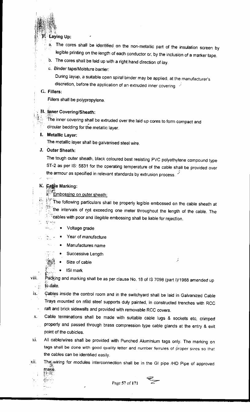
i| f! Laying Up:
a.The cores shall be identified on the non-metallic part of the insulation screen by
legible printing on the length of each conductor or, by the inclusion of a marker tape.
b.The cores shall be laid up with a right hand direction of lay.
c.Binder tape/Moisture barrier:
•During layup, a suitable open spiral binder may be applied, at the manufacturer's
discretion, before the application of an extruded inner covering. ;'
; G. Fillers:
*Fillers shall be polypropylene.
H. Inner Covering/Sheath:
J • The inner covering shall be extruded over the laid up cores to form compact and
circular bedding for the metallic layer.
I. Metallic Layer:
The metallic layer shall be galvanised steel wire.
J. Outer Sheath:
The tough outer sheath, black coloured best resisting PVC polyethylene compound type
ST-2 as per IS: 5831 for the operating temperature of the cable shall be provided over
the armour as specified in relevant standards by extrusion process. y
K. ,̂ajjje Marking:
a. "Embossing on outer sheath:
J" ''^ the following particulars shall be properly legible embossed on the cable sheath at
! the intervals of not exceeding one meter throughout the length of the cable. The
"cables with poor and illegible embossing shall be liable for rejection.
- . •Voltage grade
'^--- •Year of manufacture
•Manufactures name
•Successive Length
^$J? •Size of cable
_._ • ISI mark
viii. Packing and marking shall be as per clause No. 18 of IS 7098 (part l)/1988 amended up
. -- to date.
ix. Cables inside the control room and in the switchyard shall be laid in Galvanized Cable
Trays mounted on mfild steel supports duly painted, in constructed trenches with RCC
- raft and brick sidewalls and provided with removable RCC covers.
x. Cable terminations shall be made with suitable cable lugs & sockets etc, crimped
properly and passed through brass compression type cable glands at the entry & exit
point of the cubicles.
xi. All cable/wires shall be provided with Punched Aluminium tags only. The marking on
tags shall be done with good quality letter and number ferrules of proper sizes so that
the cables can be identified easily.
xij. The wiring for modules interconnection shall be in the Gl pipe /HD Pipe of approved
make.' T "'*'"'
^'• ^~*Page 57 of 171

Page 58 of 171 j^^-
(^,^R/AAAC jumperCrimping type connection2.
Electrolytic grade copper, forged and tinnedFor connectionto
copper terminals,with
crimping facilityto
connect
Aluminum Alloy conforming to designate A6
as per IS 617• For connection to
ACSR/AAAC/ Aluminum
terminal
. Bolted type connection
Material
l The bus-support clamps, spacers, T-connectors and various equipment
connectors shall be supplied as per the enclosed drawings. The material to be
used for these items shall be generally as per the Table 5-4.
i The materials shall be of the best workmanship, and all the sharp edges and
corners shall be rounded off. The thickness of tinning, wherever applicable, shall
be not less than 10 microns. The minimum thickness of pads made of copper
shall be 10 mm and those made out of Aluminium/Aluminium Alloy, shall be 12
mm, unless otherwise indicated in the specifications.
All the clamps and connectors shall be designed to carry a continuous current
not less than 125% of the rated current of the conductor (twin/single as the case
may be)/equipment terminal to which these are to be connected. Temperature
rise of the connector under the above condition shall not be more thari 50% of
the temperature of the main conductor/equipment terminal.
Table 5-4 Clamps & Connectors
Jx.15.2.7 Clamps and Connectors
Data sheets of individual cable sizes (HT & LT) shall be submitted for approval by the
Company. Drum numbers and drum length details shall be submitted with each
consignment.Cable end terminations and joint kits shall comply with the latest version of the relevant
IS standard.The cable ends shall be terminated with adequate size copper lugs and socketsetc,
single/double compression cable glands. Cable glands shall be of robust construction
capable of clamping cable and cable armor (for armored cables) firmly withoUrmjury'tq
insulation. The metallic glands shall be earthed at two locations. Suitable iock"type
crimping lugs shall be used for cable end terminations. Where cables are raising.from
ground, suitable PVC pipe guarding shall be provided for cable raising with sealing of the
guarding P\/C pipe including a suitable clamp.
HT cable termination kits and straight through joints shall be selected as per the cable
specifications. Installation shall be as per the instructions given in the manufacturer's
manual. Heat shrinkable type kits only shall be used for HT and LT cables.
Data sheets of the joints and kits shall be submitted for approval by HPGCLXV11.
XVI.
XV.
XIV.
XIII.
) .̂t. ! I

|fJv;•'" ii!*' k All the fasteners (i.e. nut-bolts, washers, check-nuts, etc.) used in the clamps and
,' :'connectors shall be of non-magnetic stainless steel. The straight bolts shall be
fully threaded^, and the U-bolts shall be threaded up to 30 mm from the ends. For
connectors made out of Aluminium/Aluminium Alloy, the bolts shall be of 12 mm
diameter, and for copper connectors the bolts shall be of 10 mm diameter.
v. The clamps and connectors meant for ACSR and AAAC (525 sq.mm) shall have
the same crimping dimensions. It shall be possible to use the same
clamp/connector for ACSR or AAAC, as would be required, without any
modification/change at site.
^. The length of bolt shall be chosen such that after fully tightening the nut and
check- nut, minimum 5 (five) threads of the bolt shall project outside the
! .! nut/check-nut.
•\l- As an alternative to the various types of clamps and connectors detailed under
2.0 above, the Contractors may offer connectors of Power Fired Wedge Pressure
Technology (PFWPT). However, the same needs to be specified in the Bid.
\A Connectors of PFWPT type shall meet the general requirements for various
connections/joints as indicated in the relevant drawings.
k PFWPT type connectors shall comprise of:
a.Tapered C - shaped spring member
b.Wedge for connecting solid/stranded conductor, along with handle, suitable
for connection between:
•Aluminium & Aluminium
•Copper & Copper
^•Aluminium & Copper
•Aluminium & Al. Alloy
•Copper & Al. Alloy
•Al. Alloy & Al. Alloy
i Components of the PFWPT type connectors shall be made of Aluminium Alloy suitably
heat-treated to ensure that the required Mechanical & Electrical parameters are in line
with ANS 1 specification no. C 119.4-1991. The connectors shall have self-cleaning'
capability during application. The connector shall ensure stabl^r and low contact
resistance under varying load conditions and the thermal cycling effects.
ii. The special tools and tackles required for installation of the PFWPT type connectors
shall be identified in the offer. One set of these bolts and tackles shall be included in the
scope of supply.
m. The Contractor shall furnish the following information in their bill of material:
a.Availability of the PGWT connectors indigenously.
b.Unit rate of each item
c.Not-withstanding anything stated above, the final decision regarding
Page 59 of 171
For connection toElectrolytic grade aluminum
ACSR/AAAC jumper

Page 60 of 171
IS 3639
IS 2026 IEC 76
Fittings & Accessories
Power transformer
2
1
Rele^ant IECR^feviht IS
AC 6onverted by the inverter is transmitted through the appropriate cables from
the Inverter (1 no. of 1.25 MVA each) to appropriately sized power transformer
and from transformer to RMU of the next inverter unit in the loop. (Selection of
Transformer above 1.25 MVA is acceptable if the same technically approved and
not incurring any extra losses.) RMU panel should consist of adequate size
indoor AC bus/ cable, which can handle the current and the voltage safely as per
the relevant, IS standards. RMU panel should he equipped with adequate
protection relays, fuses, annunciations and remote operating and^cghtrollingfacility from the Main Control Room. Relevant national & internationaillcodes! to
be follows :-
Table 5-5 Relevant National & International Code
5.2.9 AC Network
The source of over voltage can be lightning or other atmosphericka^urfcJarice'.
Main aim of over voltage protection is to reduce the over voltage to a tolerable
level before it reaches the PV or other sub-system components as per IS: 2309-
1989 (Reaffirmed - 2005), Edition 3.1 (2006-01).
Necessary foundation / anchoring for holding the lightning conductor in position
to be made after giving due consideration to shadow on PV array, maximum wind
speed and maintenance requirement at site in future.
The lightning conductor shall be earthed through flats and connected to the earth
mats as per applicable Indian Standards with earth pits. Two earth pitsfehall beprovided for each lightening arrestor. Each lightning conductor shall be^itted with
individual earth pit as per required Standards including accessories, and
providing masonry enclosure with cast iron cover plate having locking
arrangement, watering pipe using charcoal or coke and salt as required as per
provisions of IS & Earth Resistance of Lightening System must be less than one
(1)Ohm.
a. If necessary more numbers of lightning conductors may be provided. The
Contractor is also free to provide franklin rod / Early Streamer type of lightning
arrestors on the MMS structure designed in such a way not to cast shadow on the
next raw of solar PV modules. The Contractor to submit necessary calculations
based upon rolling sphere method for the Lightening^protection system.
The Contractor shall submit the drawings and detailed specifications <p^ the PVVi
array lightning protection equipment to HPGCL for approval before installation of
system.
k
"'rG;i5.2.8 Lightening Protection for PV Array
acceptance of the type of clamps and connectors (conventional/PFWPT
type) shall rest with HPGCL'>P-"-',}/
Page 61 of 171
RMU panel shall be provided in Inverter room. It shall have circuit breaker of
suitable rating for connection and disconnection of PCU from grid. The busbar
shall connect the AC distribution board to the transformer. It shall have provision
to measure bus voltage, current and power of the transformer.
Bus-bars shall be of high conductivity Aluminium alloy or Copper of adequate
size. The bus-bars shall be adequately supported by non-hygroscopic, non-
combustible track resistant and high strength type polyester Jibre glass moulded
insulators. Separate supports shall be provided for each phase and neutral
busbar. The bus-bars joints shall be provided with high tensile steel bolts,
bellevelle washers and nuts, so as to ensure good contacts at the joints. The
E bus-bars shall be colour coded as per IS 375.
The Bidder shall submit the detailed specifications of the AC bus and panelin the Bid. '
The RMU panel with thermal over current and earth fault releases. The incomer
shall be selected one size higher than the required rating as per Type 2 selection
chart.
Removable gland plates with gaskets shall be provided in the cable alleys for
glanding the power and control cables. The distance between the gland plate and
the incomer terminals shall not be less than 450 mm.
The Contractor should submit theoretical design calculations and detailed
explanations along with drawings shall be provided and approved by the
Company.
VI
V.
IV.
'„"
IS 1271 IEC 85
IS 3637
IS 2147 IEC 76IS 2026 IEC 76
IS 20650 IEC 144
IS 335 IEC 137
IS 6600 IEC 296
IS 3202 IEC 354
Electrical Insulation
Buchholz Relay
Testing, Tolerances onguaranteed Particulars
Degree of Protection
Bushings
Oil
Loading of Transformer
Climate Proofing
10).>if"""Tip
9
8
7
6
5
41
\'3''
ill1
\PPiP

Page 62 of 171
IEC: 60076 Specifications for Power Transformer[jPart 1 to 5)
Fittings and accessories for power transformerIS: 3639
Bushings for alternating voltage above 1000 VIS: 2099
IS: 2026 (Part Specifications for Power Tr^nsformer
33KV SUBSTATION BLOCK FOR 1QMW ^INFORMATIVE ONLY1
5.2.10 Step-Up Transformer
i The Contractor shall provide the complete turnkey design, supply, erection,
testing and commissioning of transformers and transformer substation to first
step-up the output of the inverter to 33 kV at the location of the inverter; the solar
plant shall be connected to control room. The capacity of the solar ^lant with
provision of rated 33kV Vacuum Circuit Breaker panel with singfe^qutgoihg
connected. Provision of ABT meter will be connected with 33kV VQB-paYiel.
Appropriate size for the 6 MW solar photovoltaic power plant. However, design is
open for selection of any configuration for the PV Plant.
i 3 phase, Oil Filled, 33 kV/, 50 Hz, Power Transformers with rain power rating
1.25 times of the selected inverter rating and associated Switchgear of approved
make should be utilized. 33 KV transformers can be off-load tap change typ^.
The transformers shall be suitable for outdoor installation with 3 phase 50 Hz 33
KV system in which the neutral is effectively earthed and they should be suita^le
for service under fluctuations in supply voltage up to plus 10% to minus 15%.
(Also 10% overloading criteria recommended as, per IS is acceptable.; For
example, if 1000KW inverter is planned then suitable rating of trans|^^|ef:j'^yi{h:S%" PA
0.9 PF & 90% loading will becoming 1234.57 KVA which is near to 1.25;times), ;
General Specifications:
i. Cumulative loss shall be as per IGBC guidelines. All electrical equipment and
installation shall confirm to the latest Indian Electricity Rules as regards safety,
earthing and other essential provisions specified for installation and operation of
electrical plants.
k Relevant national and international standards in this connection are mentioned in
Table 5-6 General Standards for Transformers.i
v. All working parts, insofar as possible, are to be arranged for convenience of
operation, inspection, lubrication and ease of replacement with minimum
downtime. All parts of equipment or of duplicate equipment offered shall be
interchangeable.
vi The/quality of materials of construction and the workmanship- of the finished
products/ components shall be in accordance with the highest standard and
practices adopted for the equipment covered by the specification.
Table 5-6 General Standards for Transformers

Page 63 of 171
air Minus 5 degree
C
Minimum ambienttemperature: (Cooling
medium shall be Air)
Maximum yearly weighted average 40 degree C
ambient temp
Maximum daily average ambient 40 degree C
temp
50 degree Caximum ambient temperature
All items of equipment and materials shall be thoroughly cleaned and painted in
accordance with relevant Indian Standards. The finish paint shall be done with
two coats of epoxy based final paint of colour Shade RAL 7032 of IS:5 for indoorequipment. '
Any fitting or accessories which may not have been specifically mentioned in the
specification but which are usual or necessary in the equipment of similar plant or
for efficient working of the plant shall be deemed to be included in the contract
and shall be provided by the Contractor without extra charges. All plant and
apparatus shall be complete in all details whether such details are mentioned in
the specifications or not.
All equipment shall be designed for operation in tropical humid climate at the
required capacity in an ambient air temperature of 50C. Equipment shall be
suitable for an ambient temperature of 50C. Maximum relative humidity of 100%
shall also be feken into consideration for design of equipment.
The reference ambient temperatures for which the transformers are to bedesigned are as mentioned in Table 5-7.The rating and electrical characteristics of the MV 33 kV Outdoor type
transformer (typical) shall be as mentioned in Table 5-8.
Table 5-7 Reference Weather Conditions for Transformer Design
VL
to 4
Voltage transformer
Serrated lock washers - specification >
Hollow Insulators for use in electrical equipment
Part III - post insulator units for systems greater thaniOOO V
Porcelain insulators for system above 1000 V
Lightning arrestors
Voltage Transformer
Current transformer
Alternating currents disconnectors (isolators) and earthingswitches rating, design, construction, tests etc.
1
1
part
Part
IEC: 1865556562153502544
•3070
3
•3156
4
^2705 Part 14 & IEC: 185
1Part: 9921I—
ISISISIS
ISto
ISto
-to
ISto
i-Jr: -••
• i,*j
1

5.2.11 Instrument Transformer
L The instrument transformers i.e. current and voltage transformers shall be single
Page 64 of 171
LV side - Bus Duct with ^
weather proof enclosure, HVSide -Bushing with enclosure.Bidders can also use LT XLPEaluminum cable instead of bus
duct.
400 phase to earth
5-6%
+ 10 to - 15.0 % (in steps of
1.25%)
DeltaStar
Dy5/Dy11
LV (Output of the Inverter)kVr.m.s.
36 kVr.m.s.
33 kV '?•Three
ONAN50 Hz
Oil immersed
1.25 times the rated poweroutput of Inverter MVA
Ilifetails^ ^::^:: ;:Y;; !
Transformer connections
/'
Minimum Creepage distance at 32
mm/kV
Impedance voltage (%)as per IS2026
On/Off Load taps on H.V. Side(for H.V.Variation)
Cohnections
a) H.V. Winding
b) L.V. winding
Vector Group
Rated voltage on L.V. side
Highest System voltage on H.V. side
Rating voltage H.V. side
No. of phases
Type of coolingFrequency
Type
Continuous kVA ratings
^ Particulars ,:/^...:^.!.' Y yyJ
14
13
12
11
109
8765432
1>r.m
Table 5-8 Rating and electrical characteristics of 33kV Power Transformer
180kmph
60 cms
occur at frequent!intervals
3 months
The atmosphere issubject to fog for twomonth in winter
60 days
Varies from 30 to 50 . "
51.6%
....
Maximum wind speed
Average annual rainfall
Dust storms
Number of months during whichtropical monsoon conditions prevail
" Fog
Average no. of rainy days per annum
Yearly average number of thunder
storms
Maximum relative humidity
CLIMATIC CONDITIONS :
5.8
5.7
5.6
5.5
5.4
5.3
5.2
5.1
5.

Page 65 of 171
170 kVRated lightning impulsewithstand voltage (peakvalue)
70 kVRated min power
frequency withstand
voltage (rms value)
63 kA (Peak) appropriate dynamiccurrent as per design calculations
Rated dynamic current
25 kA for 1 sec or appropriate thermal
current as per design calculations
Rated short time thermalcurrent
Outdoor/indoor(IP 65)Installation
System Neujral Earthing Effective earthedi50 HzRated frequency
36 kV rmsHighest system Voltage(Urn)
Rartipuliars
phase transformer units and shall be supplied with a common marshaling box for
a set of three single phase units. The tank as well as top metallics shall be hot
dip galvanized or painted Grey color as per RAL 9002.I The instrument transformers shall be oil filled hermetically sealed units. The
instrument transformers shall be provided with filling and drain plugs.
i Polarity marks shall indelibly be marked on each instrument' transformer and at
the lead terminals at the associated terminal block The insulators shall have
cantilever strength of more than 500 kg.
5.2,12 Current Transformer
L Current transformers may be either of the bushing type or wound type. The
bushing types are normally accommodated within the transformer bushings and
the wound types are invariably separately mounted. The location of the current
transformer with respect to associated circuit breaker has an important bearing
upon the protection scheme as well as layout of, substation. Current transformer
class and ratio is determined by electrical protection, metering consideration.
L Technical specifications - Current ratings, design, Temperature rise and
testing etc. should be in accordance with IS: 2705 (part I to IV)
Type and Rating
a.'The current transformer should be of outdoor/ indoor type, single phase, oil
immersed, self-cooled and suitable for operation in 3 phase solidly grounded system.
b.Each current transformer should have the following particulars under the site
conditions for the system under design (typical values for 33 kV systems are given).
c.General Parameters: 33kV CT.
d.Each current transformer should have the following particulars under the site
conditions for the system under design (typical values for 33kV system are given).
Table 5-9 General parameters for 33 kV CT/

Page 66 of 171
350 VA
All terminals of'control circuitswired Cabinet up to marshalling
box plus 10 terminals
As per IS 3156/1992
3 kV rms
As perlEC:358
900 phase to earth0.5/3P, IS3156/19921.2 continuous & 1.9 for 30 sec
96% to 102% for protection and99% to 101% for measurement
170 kV
70 kV
Appropriate
Outdoor (IP 65)effective earthed36 kV
^D^^ii:-,,••-•-••• -Y "^ %e
Rated total thermal burden
Number of terminals in control
spare.
Temp, rise over an ambienttemp, of 50 deg. C
One Minute Power frequencyWithstand voltage for
secondary winding
Stray capacitance and strayconductance of LV terminalo<^er entire carrier frequency
range
Minimum Creepage distance at
32 mm/kV
Class of Accuracy
Rated voltage factor
Standard referencerange of
frequencies for which the
accuracy are valid
Rated lightning impulsewithstand voltage (peak value)
Rated min power frequencywithstand voltage (rms value)
System fault level
Installation
System neutral earthing
Highest system voltage (Urn)
- •'" Particulars ^^^^'Ae^PPAPP
15
14
13
12
11
1098
7
6
54321
|Sr.s,
5.2.13 General Parameters of 33 kV VT
The Bidder has to furnish the specifications of 33kV VT with the Bid.
Table 5-10 General parameters for 33 kV VT
Minimum burden required :
I. Metering core - 40 VA
2. Protection core - 10 VA
All terminals of control circuits wired A
up to marshalling box plus 20 terminals
spare
Protection cores - 1 Amp.Metering Core - 1 Am'p
(With Highest Accuracy Class) |
Two (2) with One (1) protection coreand one (1) metering core of accuracy
0.5 class
Class AAs per-IS 2705/1992
900 phase to earth
CT ratio & Rated VABufeen, short timethermal rating .class of
accuracy
Number of terminals inmarshalling box
CT secondary current
Number of cores
Type of insulation
Temperature rise
Minimum Creepagedistance at 32 mm/kV
16
15
14
131211
10

5.2.14 Circuit Breaker
,1 The circuit breakers shall be capable of rapid and smooth interruption of currents
under all conditions completely suppressing all undesirable phenomena even
under the most severe and persistent short circuit conditions-Or when interrupting
small currents or leading or lagging reactive currents. The circuit breakers shall
be 'Restrike-Free' under all operating conditions. The details of any device
!, incorporated to limit or control the rate of rise of restriking voltage across, the
pJ7 circuit breaker contacts shall be stated. The over voltage across, the circuit4*breaker contacts shall be stated. The over voltage caused by circuit breaker
while switching inductive or capacitive loads shall not exceed 2.5 times the
highest phase to neutral voltage. The actual make and break times for the
circuit breakers throughout the ranges of their operating duties shall be stated in
the offer and guaranteed.
L The arc quenching chambers shall have devices to ensure almost uniform
distribution of voltage across the interrupters.
i Appropriate & adequate Capacity 415V AC indoor air Circuit Breaker as per the
IEC 60898 / IEC 62271 - 100 or equivalent Indian Standards along with control
- z circuit and protection relay circuit, fuses, annunciations and remote operating and
controlling facility from the Main Control Room.xf
k Circuit breaker shall be C2/MI class under all duty conditions and shall be
capable of performing their duties without opening resistor. The circuit breaker
shall meet the duty requirement of any type of fault or fault location and shall be
suitable for line charging and dropping when used on 6 kV effectively grounded
or ungrounded systems and perform make and break operations as per the
stipulated duty cycles satisfactorily.
-v. The circuit breaker shall be capable for breaking the steady & transient
magnetizing current corresponding to 33 kV transformers. It shall also be capable
of breaking line charging currents as per IEC- 62271-100 with a voltage factor of
1.4.
yl The rated transient recovery voltage for terminal fault and short line faults shall
be as per IEC: 62271-100.
vi The Bidder shall indicate in the Bid, the noise level of breaker at distance of 50 to
150 m from base of the breaker.
vi The Bidder may note that total break time of the breaker shall not be exceeded
Page 67 of 171
Contractor.Should be provided by theaccuracy.
one for metering with 0.5 class
2 (two) - 1 for protection and
ratedlevel,
voltage factortransformation ratio,Rated Output, insulation
Number of cores
17
•
* * i•I i ;
'p I i

under any duty conditions specified such as with the combined variation of the
trip coil voltage, pneumatic pressure etc. While furnishing the proof of the total*"r I
break time of complete circuit breaker, the Bidder may specifically bring out fee
effect of non- simultaneity between same pole and poles and show how, it is
covered in the guaranteed total break time_,, ^. ,:.. .jit ^1. kl ';<-.
tri:be While furnishing particulars regarding the D.C. component of the circuit breaker,
the jBidder shall note that IEC-62271-100 requires that this value should
correspond to the guaranteed minimum opening time under any condition of
operation.
x The critical current which gives the longest arc duration at lock out pressure of
extinguishing medium and the duration shall be indicated.
>i All the duty requirements specified above shall be'provided with thesup'Rirfof
• r..' - i'adequate test reports.
>i Circuit breaker shall be SF6 / Vacuum type with electrically spring charged
mechanism. The operating mechanism shall be anti-pumping and tfip free (as
per IEC definition) electrically under every method of closing. The mechanism 6f
the breaker shall be such that the position of the breaker is maintained even after
the leakage of operating media and / or gas. The circuit breaker shall be able to
perform the duty cycle without any interruption.
>i Electrical tripping shall be performed by shunt trip coil. Provision shall also be
made for local electrical control. 'Local / remote' selector switch and close & trip
push buttons shall be provided in the breaker central control cabinet. Ramote
located push buttons and indicating lamps shall also be provided. The S^PjS / VCB
coil DC supply through appropriately rated battery bank and charger to be
supplied by the Contractor.
^. Operating mechanism and all accessories shall be in local control cabinet. A
centfal control cabinet for the three poles of the breaker shall be provided along
with supply of necessary tubing, cables, etc.
xv. Mounting and supporting structure for Circuit Breaker. The circuit breakers
should be self-supporting type. However, if necessary for the purpose of
minimum ground clearance the circuit breakers should be mounted on raised
steel structures which should be included in the, scope of supply of circuit
breaker.
xvi Following information and data for design of foundations from the suppli^r of the
circuit breaker be obtained.
a.7 Dead weight per pole for complete circuit breaker.
b.Static bending moments above the feet of each pole and for complete
circuit breaker.;
c.Static shear force at the foot of each pole and for complete circuit
Page 68 of 171

Page 69 of 171
36 kVHighest System VoltageVacuum typeType of circuit breaker
i. General Parameters of Circuit Breaker: General parameters: Outdoor/ Indoor
' ; Vacuum type Circuit Breaker.
fable 5-12 General Parameters for 33KV Vacuum Type Circuit Breakers
M47/1962 Degree of protection provided byenclosures for low voltage switchgear &
control gearor-i
IEC 71 (For oils inCTs)
IS7335/1983 New insulating oils Electrical ClearancesISS-1248/1983 Specification for Ammeters & Voltmeters
Electrical relays for power syste
protectionm
ISS-3231/1986
Methods of testing uniformity of coating ofzinc coated articles
ISS-2633/1964
Bushings for alternating voltages above
1000 VISS-2099/1986ISS-2705/1992 Current Transformers
62271-100-IEC1/2001
General requirements for Circuit breakersfor voltage above 1000 V
ISS-13118/1991
(nfernatlonally
Indian jStar^^ardj
breaker.
d.Maximum height of the steel supporting structure.
e.Maximum diameter of the pole.
f.Maximum horizontal force acting at upper terminal of each pole due to
impact of closing/opening of the circuit breaker.
g.Max. Impact loading in terms of equivalent static load both compression
and upward due to opening/closing of the breakers. It shall be clearly
stated whether these forces shall act simultaneously or at different timing.
h. No. of steel supporting columns provided for mounting the equipment.
i. The above data should represent static reactions for the worst windage or
operation conditions. Circuit breakers whether of self-supporting type or
on raised steel structure should ensure minimum sectional clearance (say
3500 mm for 33 kV).
j. Necessary connecting materials such as clamps, bolts, nuts, washers etc.
and fixing bolts for mounting the equipment on the supporting structures
wherever required should be obtained from the circuit-breaker supplier
xvi Applicable Standards: The materials shall conform in all respects to the relevant
Indian Standard Specifications/ IEC Standards, with latest amendments indicated
below in Table 5-11.
Table 5-11 Applicable Standards for Circuit Breakers

Page 70 of 171
0-0.3 sec. -CO-3 min.
-CO
900 phase to earth
SF6
630A
170kV
70 kVThree (3)50 Hz (+3% to -5%)33kV36 kV
Metal enclosed, compact
module, panel type, IEC
62271-200
/Details .. . Me,
Rated operating duty cycle
Minimum Creepage distance at 32
mm/kV
Insulation Gas
Rated Current Busbar
Rated lightning impulse Withstandvoltage
Rated/minimum power frequencyWithstand voltage
Number of poles
Rated frequency
Rated operating voltage
Highest System Voltage
Type of Ring Main Unit
Particulars ! YSSIy Ac •:.
11
10
9.
8
7
65432
1
Sr.
xixGeneral Parameters of SF6 Insulated Ring Main Unit (RMU):
Table 5-13 General Parameters for 33KV SF6 Type RMU
/indicated by the bidder.Three (3)50 Hz (+3% to -5%)12 kV11 kVVacuum type
Details '
*Oth^r technical parameters will be offeredNumber of polesRated frequency
Rated operating voltage
Highest System Voltage
Type of circuit breakerParticulars
54321Sr.
General Parameters for 11KV Vacuum Type Circuit Breakers
g horizontal
Maximum 140dB at 50mdistance from base of circuit
breaker
As required plus 6NO and 6NCcontacts per pole as spare.
25 kA (rms) for 1 sec.
Single and three phase high fspeed auto reclosing I
As per IEC
0 - 0.3 sec. - CO - 3 min. -
CO
900 phase to earth170 kV
70 kVThree (3)50 Hz (+3% to -5%)33 kV
Seismic acceleration
Noise level
Auxiliary contacts
Maximum fault level
Reclosing
Rated line charging breaking
Rated operating duty cycle
Minimum Creepage distance at 32 mm/kV
Rated lightning impulse Withstand voltage
Rated/minimum power frequency
Withstand voltage
Number of poles
Rated frequency
Rated operating voltage
15
14
1312
1110
987
6543

Page 71 of 171
- >oiCircuit Breaker protection against
•Over Current
•Earth fault>'
cMsIhH Under voltage & over voltage protection
ij;jiv ' • Under frequency & over frequency
•SF6 gas pressure low (where applicable)
•DC supply failure
5.2.15 Protective Relays
I The Solar PV system and the associated power evacuation system
interconnections should be protected as per IEC 61727 Ed.2, norms. Over
current relays, reverse power relays, differential protection relays (For 6 MVA
And Above Transformer Rating) and earth fault relays have to be essentially
provided as per technical requirements. All relay should be numerical type &
should be remote operating and controlling facility from the control room.
40
1250 160063016
2500 40001600
-^a.i-K. -*. •*., .r..: -•^ *. .-...3^~ J1 IK1',': Y>*V> 7*" 7*."Si" •* s>i •'". .?' '-.' '*.'. "..". -..
*i ^f " • ••- "
36
Vojtage
Rated JRfted Short _Oii
Co-ordination of rated voltages, short circuit breaking current and rated normal
current for guidance as per IS 13118 for rated voltage 33 kV and above as
commonly used are as given in Table 5-14
Table 5-14 Circuit Breaker Co-ordination parameters
XX
Maximum 140dB at 50mdistance from base of ,circuit breaker
As required plus 6NOand 6NCcontacts per pole asspare.
21 kA52 kA
21 kA (rms) for 1 sec. Or
appropriate as per design
Single and three phasehigh speed auto reclosing
As per IEC
Noise level
Auxiliary contactsRated Breaking Capacity
Rated Making Capacity
Maximum fault level
Reclosing
Rated line charging breaking
18
171615
14

L The numerical relays shall have RS 485 port for communication.
i The operating voltage of the relays shall be 110 V DC/220 V DC as per batterybank rating.^. • i - •
1 ,;.r ..j
k Detailed Design calculations shall be provided on fault power computatio^sjancj
the philosophy of protective relaying with respect to short circuit kA^f<3ii^o,hg.
Design, drawing and model of protection relay shall be approv^d ;bS^ the
Company/Electricity Authority.
5.2.16 Earthing for PV Array
I The photovoltaic modules, BOS and other components of power plant requires
adequate earthing for protecting against any serious faults as guided by IEC
60364.e.ze.eez
i The earthing system shall be designed with consideration of the earth.resistivity
of the project area. The earth resistivity values shall be measured prior tq
designing the earthing system. Unless otherwise specified, earthing systqpci shallbe in accordance with IS: 3043 and IEEE 80, Indian Electricity Rule^Coc^^s'of
practice and regulations existing in the location where the system is being
installed.7
i The permissible system fault power level at 33 kV also shall be kept in
consideration while designing the earthing system. Each array structure of the
PV yard, LT power system, earthing grid for switchyard ,all electrical equipment
.control room ,PCU, All junction boxes, ACDB& DCDB ,all motors and pumps etc
.shall be grounded properly as per IS 3043 -1987. All metal casing / shielding of
the plant shall be thoroughly grounded in accordanpe with Indian electricity act/
IE Rules.
k. The earthing for array and LT power system shall be made of 3.0 m long 40 mm
diameter perforated Cu/GI/ chemical compound filled, double walled earthing
electrodes including accessories, and providing masonry enclosure with cast iron
cover plate having pad-locking arrangement, chemical compound mix as
required as per provisions of IS: 3043.
v. Necessary provision shall be made for bolted isolating joints of each earthing pit
for periodic checking of earth resistance.
vi Each string/ array and MMS of the plant shall be grounded properly. The array
structures are to be connected to earth pits as per IS standards. Necessary
provision shall be made for bolted isolating joints of each earthing pit for periodic
checking of earth resistance.. :'
vi The complete earthing system shall be mechanically & electrically connected to
provide independent return to earth., !
7vi For each earth pit, a necessary test point shall be provided.
be In compliance to Rule 11 and 61 of Indian Electricity Rules, 1956 (as amended
Page 72 of 171

Page 73 of 171
i Tffeffightning conductor shall be earthed through flats and connected to the earth matsP-eifejfer applicable Indian Standards with earth pits. Each lightning conductor shall be
fitted with individual earth pit as per required Standards including accessories, and
providing masonry enclosure with cast iron cover plate having locking arrangement,
chemical compound as per provisions of IS.
' '2C
,.,,,..' 1")J113
111' 109' 108' 107' 107'85'6443
... "J="X:
' KV" 10^"97"96
"92"91"90
89'72*57 ''36
.^0,cS'l
'so3178
'757372
'71574328
M'06 '̂i*
' lOo"102
101'99
98'97'97
78'5839
JoJOjt
"so'86
85'83'82"8181
"65"4832
.... J.7. ....
'5'76'7169'6665
'64'6351
'3826
'as8688
'80"8889'88"87'87'86'69'5235
7575^5
'75'74"73"72"72'71'7157'42
28
52665758SBS8'57
66'55JS5
44"33^i
'69' 72
74'76'8080'79"79'79'79'63'4731
'65"65"65"65
"65'66"64'64'63"63'51'38
25
*303640
'43"so'so*49"4948>
38'29
19
-160655045201510f6S43 "'2
OPR 60OPR 45US
' OPR 30W(r = 60i
0PR6O• OPR 45r>!
OPR 30;ll(r>.45n
•iOPRSOOPR 46QPR3Q;ljrSOir
Radius ot protection Rp (m)OPR30 OPR45 iOPRSOISr=SiTi)
of protection
hW-fi?B-Protection li/1
rQPR ra^ius
up to date), all non-current carrying metal parts shall be earthed with two
separate and distinct earth continuity conductors to an efficient earth electrode.
x The Contractor should submit the earthing system design caj^ulations along with
the system layout for the Company's approval prior to the installation of the
system
, , ^,>4_ Unless otherwise specified, the earthing system primary and secondary grid
! !,)' 'conductors, equipment connections shall be constructed with galvanized iron flat.
IHowever the^earthing of transformer neutrals, pic and inverter terminals and
electronic earthing shall be provided using copper earthing conductor only.
A Earthing Mesh is to prepared and installed in entire power plant.
5.2.17 Lightening Protection for PV Plant & Earthing
1 The source of over voltage can be lightning or other atmospheric dis^urbance. Main aim
of over voltage protection is to reduce the over voltage to a tolerable level before it
reaches the PV or other sub-system components as per IEC 60099 / IS: 2309 - 1989
(Reaffirmed - 2005), Edition 3.1 (2006-01). Lightening Protection System required for
Splar PV Plant, Inverter Room, and Substation Structure & Control Room within the EPC
!! ; : Scope of work. The intent of specification can be conventional as per IS : 2309 or can be
Early Streamer Emission Type depending upon Area, Protected Equipment & Technical
feasibility. Necessary concrete foundation for holding the lightning conductor in position
to be made after giving due consideration to shadow on PV array, maximum wind speed
arid maintenance requirement at site in future. We recommended going with Early
".".'"• Stream Emission Air Terminal Technology as per NFC 17-102 / IEC 62305-2. Level of
Protection must be defining as per Rolling Sphere Method LPL-i, LPL-II, LPL-III & LPL-IV
where the radius shall be of 20mtr, 30mtr, 45mtr & 60mtr respectively:
1 Rp(h): Protection radius at a given height (h) Rp(h) = V 2rh - h2 + A(2r + A) (for h > 5 m)||r h < 5 m, refer to the table below h : Height of the OPR tip above the surface(s) to be
protected r(m): Standardized striking distance A(m) = 106 .AT (OPR efficiency)

iil If necessary more numbers of lightning conductors may be provided as pertde^ign
calculation' jfr^I^!0^' ^i
7 'iv. The Contractor shall submit the drawings and detailed specifications of the PV array
lightning protection equipment.
v. The design, manufacture, inspection, testing and performance of Lightning Arrester shall
comply with all currently applicable statutes, safety codes, provision of latest Indian
Electricity Act, Indian Electricity Rules and Regulations of Statutory Authorities.
vi Contractor shall provide dedicated two earth pits for Lightening Arrestor as per relevant
IS standard.^ . . ,,~ ^J~ X ' A
'• * I
5.2.18 Isolators cum Earthing Switches, Contacts, Insulators, Busbars\ i ^pPAt ;4 ->{jU'hi"" js7 '^• 4 : i
t This specification covers design, manufacture, testing and supply orrManually
operated 33 KV, 800 Amps Upright mounting type with manually operated withearth switch Isolators. The Isolators and Isolator-cum-Earthing Switched shall
comply with the requirements of the IS: 9921 and IEC: 129 (latest edition) exceptspecified herein. The Insulators shall comply with the requirements of IS.; 2544
and IEC : 168-1988 (latest edition) for 33 kV pole mounted structure wherey©!
required. 33kV pole mounted structure would be supplied, installed and
commissioned by the Contractor wherever required.
I The isolator shall be of the manual operated type with earthing switches and
shall complete with all parts and accessories including insulator oper^ijipg? rqbs|,
mounting attachments, necessary for their efficient operation. The equipment
shafeconfirm in all respect to high standards of engineering Equipment shall
capable of performing in continuous commercial operation up to the suppliers
guarantee in a manner acceptable to the client, The equipment offered shall be
complete with all components necessary for its effective and trouble free
operation along with associated equipments, interlock, protection schemes, etc.
Such components shall be deemed to be within the scope of the Contractor's
supply irrespective of whether those are specifically brought out in this
specification or not. All similar parts particularly removable ones shall be
interchangeable.
iEach pole shall have three Pedestal type of Insulator's stacks. Necessary
arrangements shall be provided for proper alignment of the contacts. Gange
oper^ted links shall be so designed that all phases shall make and break
simultaneously. The design of Isolators and Isolator-cum-Earthing Switches shall
be provided for positive control of blades in all positions with minimum
mechanical stress on the Insulators. Fixed guides shall be so provided that
proper setting of contacts shall be obtained, when a blade is out of alignment
even by 25mm in either direction. All movable parts which may be in current path
shall be shunted by flexible copper conductor of adequate cross-section and
capacity, which shall be furnished under bill of material.• • ,
Page 74 of 171

Tlfe 33 kV triple pole air break isolators are intended to be used primarily for sectionalizing
33 kV UG cable portion of the line with 33 kV overhead portion of the line.
Isolator shall confirm IS: 9921 (Part 1 to 4) & IEC 600 - 129 "alternating current disconnects
(Isolators) and earthing switches", and IS 9921 (Part-I to IV) "Specification for alternating
current disconnects (isolators) and earthing switches for voltages above 1000V"
a.The moving & fixed contacts shall be made of hard drawn electrolytic grade copper
strips and shall be heavy duty self- aligning & high pressure type preferably which
applies pressure to the contact surfaces after the blades are fully closed and release
the pressure before they start to open. High pressure type contacts shall wipe the
Ju, contact surfaces, while opening and closing. The contacts shall be so designed that
1 ''Pp' '^lw'P'n9p action shall not cause securing or abrasion on the contact surfaces. The
s wiping action shall be sufficient to remove oxide film, formed during the operation of
the switches. The pressure shall be developed by rotation of the entire blade.
b.The temperature rise of contacts due to the flow of rated short circuit current for a
period of 3 seconds shall not cause any annealing or welding of contacts.
c.The moving contacts, if provided, shall close first and open last so that no damage is
caused due to arcing whatever to the main contacts. The Successful Bidder shall
give full details of such contacts with necessary drawings.
d.The arcing contacts, if provided shall close first and open last so that no damage is
caused due to arcing whatever to the main contacts. The Contractor shall give full
details of such contacts with necessary drawings.
e.The female contact and its tensioning by spring shall be such that there will, always,
be a positive contact with adequate pressure to give enough contact surface for the
Y passing of current. The springs provided should not go out of alignment or get
entangled with the male contact during operation. The details of springs shall be
furnished on the G.A. drawing.
INSULATORS: The isolator shall be provided with solid core insulators, ^
i. The^e shall be of stacking type to be used. The dimensions and other parameters
unle'ss otherwise specified shall generally conform to IS - 5350-Part-11 & IEC 273.
ii. •. The'cylindricai type post insulators shall be of solid core type, insulators of similar type
shalf be interchange^ble. The mechanical strength class for outdoor cylindrical post
insulators shall be of strength class 6, corresponding mechanical strength in tension,
compression and torsional shall be as per IS : 53550 Part - II. When operated at
maximum system voltage, there shall be no electrical discharge. Shielding rings, if
necessary shall be provided.
iii. The parameters of the insulators required shall conform to IS : 0350 - Part - II - 1973 or
IEC 273.
iv. The ^ylindrical post insulators shall consist of single unit only.iif:Page 75 of 171
••• Ts- '"•••
Condition:


![Atmospheric states associated with the ignition of lightning … · Title: Atmospheric states associated with the ignition of lightning-attributed fires [electronic resource] / Andrew](https://img.pdfslide.net/doc/110x75/5b6081c97f8b9a54488b5479/atmospheric-states-associated-with-the-ignition-of-lightning-title-atmospheric.jpg)