Embed Size (px)
Citation preview
ii
KIRK ROAD/DUNHAM ROAD INTERCONNECT
KANE COUNTY DIVISION OF TRANSPORTATION
PRE-FINAL SUBMITTAL AUG. 25, 2011
FOR: JANUARY 20, 2012 LETTING
IDOT Section No. 10-00403-00-TL
PROJECT NO. CMM-9003(633)
JOB NO. D-91-506-10
CONSULTANT:
Jacobs Engineering 1 North Franklin Suite 500 Chicago, IL 60606
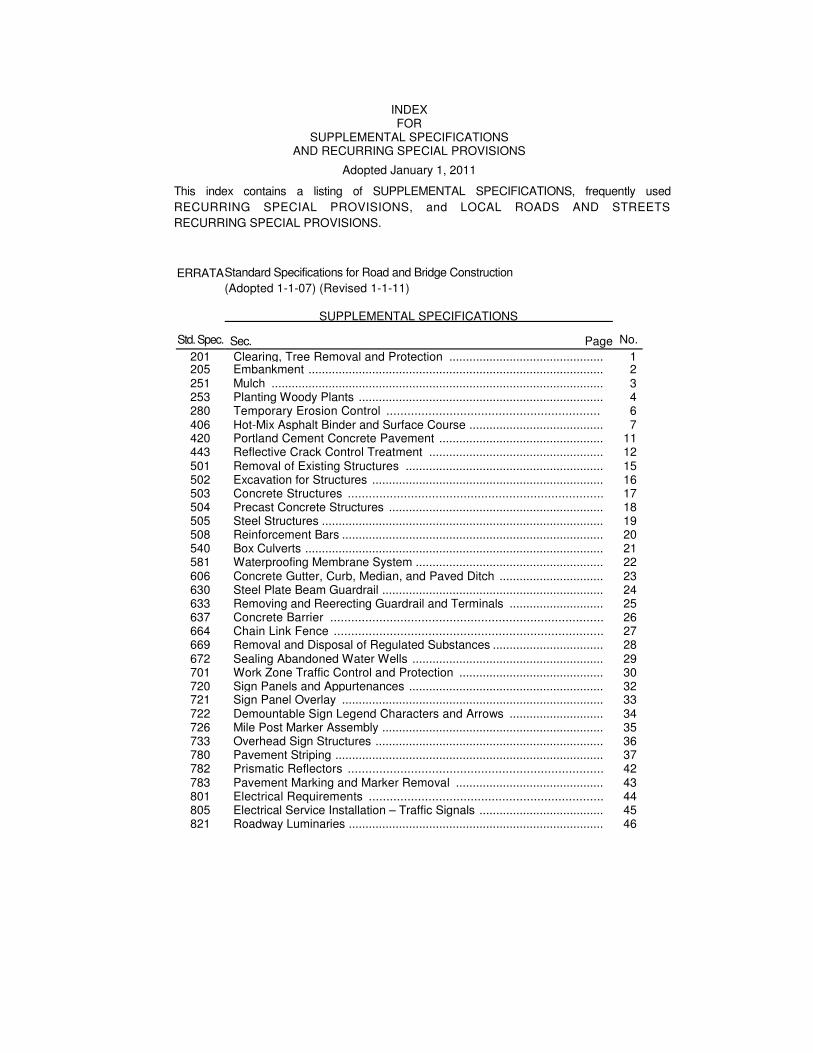
INDEX FOR
SUPPLEMENTAL SPECIFICATIONS AND RECURRING SPECIAL PROVISIONS
Adopted January 1, 2011
This index contains a listing of SUPPLEMENTAL SPECIFICATIONS, frequently used
RECURRING SPECIAL PROVISIONS, and LOCAL ROADS AND STREETS
RECURRING SPECIAL PROVISIONS.
ERRATA
Std. Spec.
Standard Specifications for Road and Bridge Construction
(Adopted 1-1-07) (Revised 1-1-11)
SUPPLEMENTAL SPECIFICATIONS
No. Sec. Page
201 Clearing, Tree Removal and Protection .............................................. 1 205 Embankment ........................................................................................ 2 251 Mulch ................................................................................................... 3 253 Planting Woody Plants ......................................................................... 4 280 Temporary Erosion Control ............................................................. 6 406 Hot-Mix Asphalt Binder and Surface Course ........................................ 7 420 Portland Cement Concrete Pavement ................................................. 11 443 Reflective Crack Control Treatment .................................................... 12 501 Removal of Existing Structures ........................................................... 15 502 Excavation for Structures ..................................................................... 16 503 Concrete Structures ......................................................................... 17 504 Precast Concrete Structures ................................................................ 18 505 Steel Structures .................................................................................... 19 508 Reinforcement Bars .............................................................................. 20 540 Box Culverts ......................................................................................... 21 581 Waterproofing Membrane System ........................................................ 22 606 Concrete Gutter, Curb, Median, and Paved Ditch ............................... 23 630 Steel Plate Beam Guardrail .................................................................. 24 633 Removing and Reerecting Guardrail and Terminals ............................ 25 637 Concrete Barrier .............................................................................. 26 664 Chain Link Fence ............................................................................. 27 669 Removal and Disposal of Regulated Substances ................................. 28 672 Sealing Abandoned Water Wells ......................................................... 29 701 Work Zone Traffic Control and Protection ........................................... 30 720 Sign Panels and Appurtenances .......................................................... 32 721 Sign Panel Overlay .............................................................................. 33 722 Demountable Sign Legend Characters and Arrows ............................ 34 726 Mile Post Marker Assembly .................................................................. 35 733 Overhead Sign Structures .................................................................... 36 780 Pavement Striping ................................................................................ 37 782 Prismatic Reflectors ......................................................................... 42 783 Pavement Marking and Marker Removal ............................................ 43 801 Electrical Requirements ................................................................... 44 805 Electrical Service Installation – Traffic Signals ..................................... 45 821 Roadway Luminaries ............................................................................ 46
iii
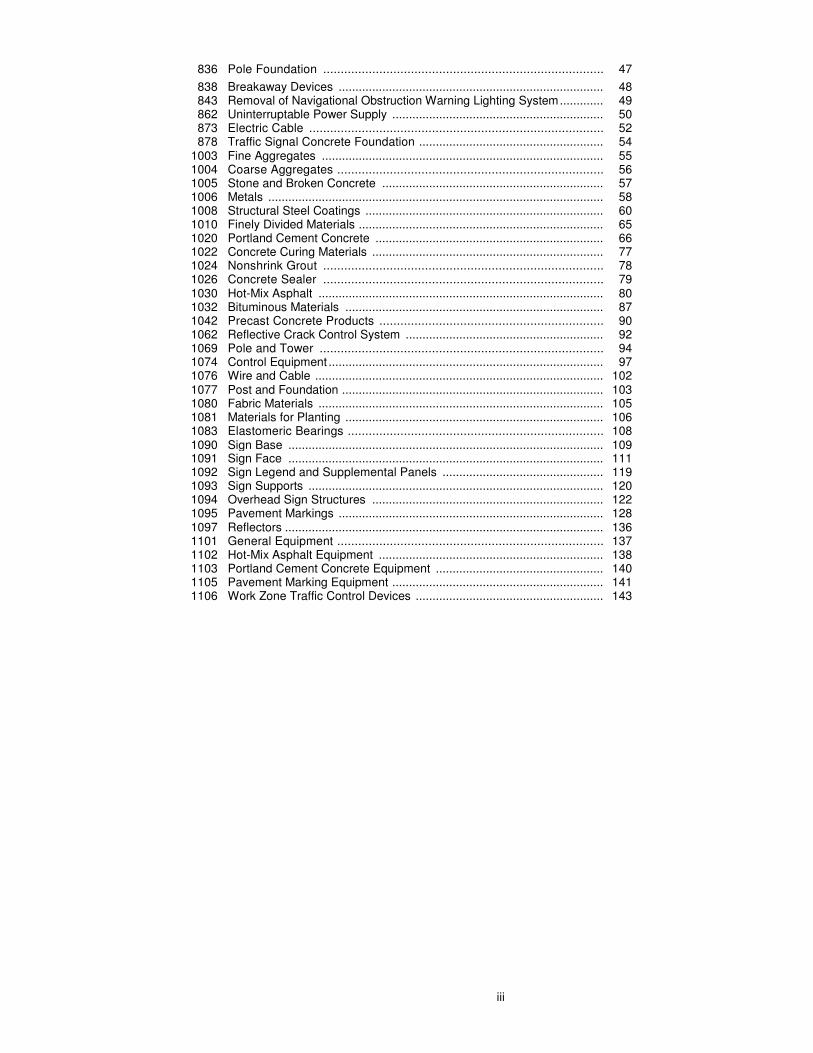
836 Pole Foundation ................................................................................ 47
838 Breakaway Devices ............................................................................... 48 843 Removal of Navigational Obstruction Warning Lighting System ............. 49 862 Uninterruptable Power Supply ............................................................... 50 873 Electric Cable .................................................................................... 52 878 Traffic Signal Concrete Foundation ....................................................... 54
1003 Fine Aggregates .................................................................................... 55 1004 Coarse Aggregates ............................................................................ 56 1005 Stone and Broken Concrete .................................................................. 57 1006 Metals .................................................................................................... 58 1008 Structural Steel Coatings ....................................................................... 60 1010 Finely Divided Materials ......................................................................... 65 1020 Portland Cement Concrete .................................................................... 66 1022 Concrete Curing Materials ..................................................................... 77 1024 Nonshrink Grout ................................................................................ 78 1026 Concrete Sealer ................................................................................ 79 1030 Hot-Mix Asphalt ..................................................................................... 80 1032 Bituminous Materials ............................................................................. 87 1042 Precast Concrete Products ................................................................ 90 1062 Reflective Crack Control System ........................................................... 92 1069 Pole and Tower ................................................................................. 94 1074 Control Equipment .................................................................................. 97 1076 Wire and Cable ...................................................................................... 102 1077 Post and Foundation .............................................................................. 103 1080 Fabric Materials ..................................................................................... 105 1081 Materials for Planting ............................................................................. 106 1083 Elastomeric Bearings ......................................................................... 108 1090 Sign Base .............................................................................................. 109 1091 Sign Face .............................................................................................. 111 1092 Sign Legend and Supplemental Panels ................................................ 119 1093 Sign Supports ........................................................................................ 120 1094 Overhead Sign Structures ..................................................................... 122 1095 Pavement Markings ............................................................................... 128 1097 Reflectors ............................................................................................... 136 1101 General Equipment ............................................................................ 137 1102 Hot-Mix Asphalt Equipment ................................................................... 138 1103 Portland Cement Concrete Equipment .................................................. 140 1105 Pavement Marking Equipment ............................................................... 141 1106 Work Zone Traffic Control Devices ........................................................ 143
i
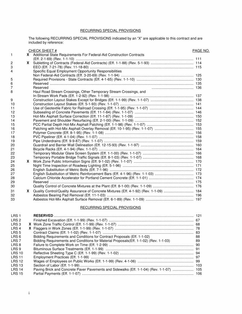
RECURRING SPECIAL PROVISIONS
The following RECURRING SPECIAL PROVISIONS indicated by an “X” are applicable to this contract and are included by reference: CHECK SHEET # PAGE NO.
1 X Additional State Requirements For Federal-Aid Construction Contracts (Eff. 2-1-69) (Rev. 1-1-10) ................................................................................................................................
111
2 X Subletting of Contracts (Federal-Aid Contracts) (Eff. 1-1-88) (Rev. 5-1-93) .........................................................114 3 EEO (Eff. 7-21-78) (Rev. 11-18-80) ......................................................................................................................115 4 Specific Equal Employment Opportunity Responsibilities
Non Federal-Aid Contracts (Eff. 3-20-69) (Rev. 1-1-94) ....................................................................................... 125
5 Required Provisions - State Contracts (Eff. 4-1-65) (Rev. 1-1-10) ................................................................130 6 Reserved ..............................................................................................................................................................135 7 Reserved ........................................................136 8 Haul Road Stream Crossings, Other Temporary Stream Crossings, and
In-Stream Work Pads (Eff. 1-2-92) (Rev. 1-1-98) ................................................................................................ 137
9 Construction Layout Stakes Except for Bridges (Eff. 1-1-99) (Rev. 1-1-07) .........................................................138 10 Construction Layout Stakes (Eff. 5-1-93) (Rev. 1-1-07) ........................................................................................141 11 Use of Geotextile Fabric for Railroad Crossing (Eff. 1-1-95) (Rev. 1-1-07) ..........................................................144 12 Subsealing of Concrete Pavements (Eff. 11-1-84) (Rev. 1-1-07) ................................................................146 13 Hot-Mix Asphalt Surface Correction (Eff. 11-1-87) (Rev. 1-1-09) ................................................................150 14 Pavement and Shoulder Resurfacing (Eff. 2-1-00) (Rev. 1-1-09) ................................................................152 15 PCC Partial Depth Hot-Mix Asphalt Patching (Eff. 1-1-98) (Rev. 1-1-07) .............................................................153 16 Patching with Hot-Mix Asphalt Overlay Removal (Eff. 10-1-95) (Rev. 1-1-07) .....................................................155 17 Polymer Concrete (Eff. 8-1-95) (Rev. 1-1-08) ................................................................................................156 18 PVC Pipeliner (Eff. 4-1-04) (Rev. 1-1-07) ................................................................................................ 158 19 Pipe Underdrains (Eff. 9-9-87) (Rev. 1-1-07) ................................................................................................159 20 Guardrail and Barrier Wall Delineation (Eff. 12-15-93) (Rev. 1-1-97) ................................................................160 21 Bicycle Racks (Eff. 4-1-94) (Rev. 1-1-07) ................................................................................................ 164 22 Temporary Modular Glare Screen System (Eff. 1-1-00) (Rev. 1-1-07) ................................................................166 23 Temporary Portable Bridge Traffic Signals (Eff. 8-1-03) (Rev. 1-1-07) ................................................................168 24 X Work Zone Public Information Signs (Eff. 9-1-02) (Rev. 1-1-07) ................................................................170 25 Night Time Inspection of Roadway Lighting (Eff. 5-1-96) .....................................................................................171 26 English Substitution of Metric Bolts (Eff. 7-1-96) ................................................................................................172 27 English Substitution of Metric Reinforcement Bars (Eff. 4-1-96) (Rev. 1-1-03) .....................................................173 28 Calcium Chloride Accelerator for Portland Cement Concrete (Eff. 1-1-01) ...........................................................174 29 Reserved ..............................................................................................................................................................175 30 Quality Control of Concrete Mixtures at the Plant (Eff. 8-1-00) (Rev. 1-1-09) .......................................................176
31 X Quality Control/Quality Assurance of Concrete Mixtures (Eff. 4-1-92) (Rev. 1-1-09) ................................184 32 Asbestos Bearing Pad Removal (Eff. 11-1-03) ................................................................................................196 33 Asbestos Hot-Mix Asphalt Surface Removal (Eff. 6-1-89) (Rev. 1-1-09) ..............................................................197
RECURRING SPECIAL PROVISIONS
LRS 1 RESERVED ..........................................................................................................................................................121
LRS 2 Finished Excavation (Eff. 1-1-99) (Rev. 1-1-07) ................................................................................................67 LRS 3 X Work Zone Traffic Control (Eff. 1-1-99) (Rev. 1-1-07) ..........................................................................................68 LRS 4 X Flaggers in Work Zones (Eff. 1-1-99) (Rev. 1-1-07) .............................................................................................78 LRS 5 Contract Claims (Eff. 1-1-02) (Rev. 1-1-07) ................................................................................................83 LRS 6 Bidding Requirements and Conditions for Contract Proposals (Eff. 1-1-02) 88 LRS 7 Bidding Requirements and Conditions for Material Proposals(Eff. 1-1-02) (Rev. 1-1-03) 89 LRS 8 Failure to Complete Work on Time (Eff. 1-2-99) ................................................................................................90 LRS 9 Bituminous Surface Treatments (Eff. 1-1-99) ................................................................................................91 LRS 10 Reflective Sheeting Type C (Eff. 1-1-99) (Rev. 1-1-02) ........................................................................................94 LRS 11 Employment Practices (Eff. 1-1-99) .....................................................................................................................97 LRS 12 Wages of Employees on Public Works (Eff. 1-1-99) (Rev. 4-1-06) ................................................................99 LRS 13 Section of Labor (Eff. 1-1-99) ................................................................................................................................103 LRS 14 Paving Brick and Concrete Paver Pavements and Sidewalks (Eff. 1-1-04) (Rev. 1-1-07) ................................105 LRS 15 Partial Payments (Eff. 1-1-07) ..............................................................................................................................106
ii
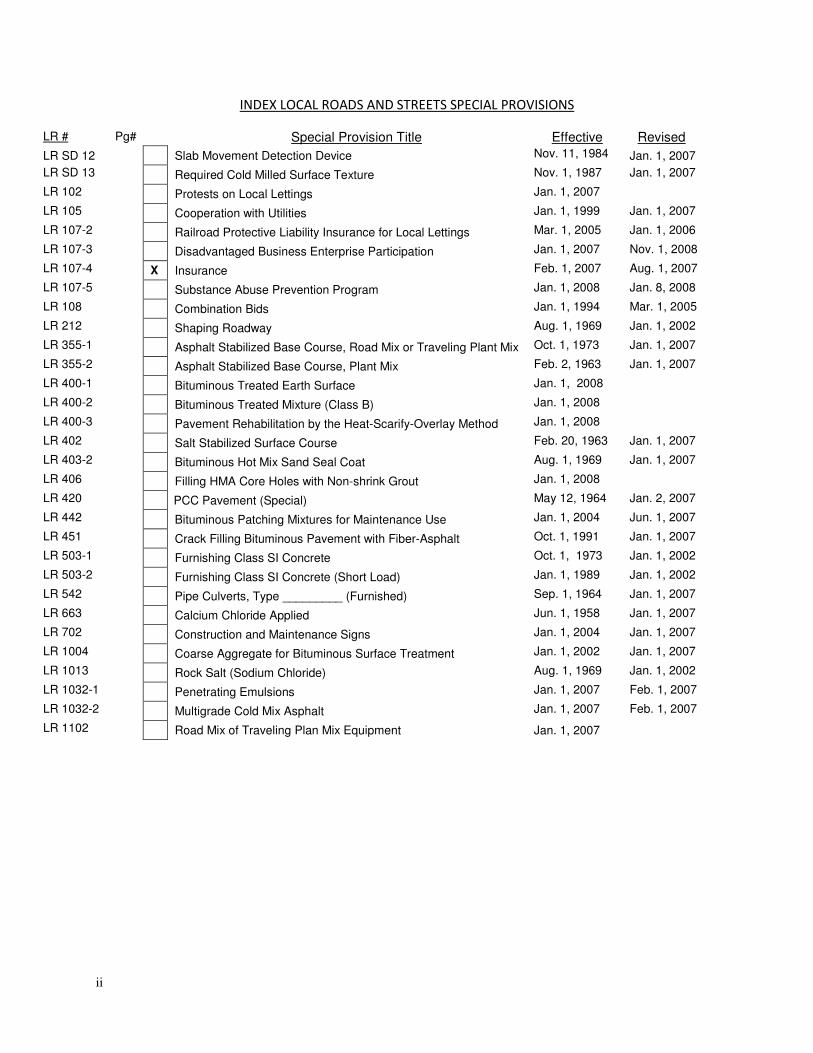
INDEX LOCAL ROADS AND STREETS SPECIAL PROVISIONS
LR # Pg# Special Provision Title Effective Revised
LR SD 12 Slab Movement Detection Device Nov. 11, 1984 Jan. 1, 2007
LR SD 13 Required Cold Milled Surface Texture Nov. 1, 1987 Jan. 1, 2007
LR 102 Protests on Local Lettings Jan. 1, 2007
LR 105 Cooperation with Utilities Jan. 1, 1999 Jan. 1, 2007
LR 107-2 Railroad Protective Liability Insurance for Local Lettings Mar. 1, 2005 Jan. 1, 2006
LR 107-3 Disadvantaged Business Enterprise Participation Jan. 1, 2007 Nov. 1, 2008
LR 107-4 X Insurance Feb. 1, 2007 Aug. 1, 2007
LR 107-5 Substance Abuse Prevention Program Jan. 1, 2008 Jan. 8, 2008
LR 108 Combination Bids Jan. 1, 1994 Mar. 1, 2005
LR 212 Shaping Roadway Aug. 1, 1969 Jan. 1, 2002
LR 355-1 Asphalt Stabilized Base Course, Road Mix or Traveling Plant Mix Oct. 1, 1973 Jan. 1, 2007
LR 355-2 Asphalt Stabilized Base Course, Plant Mix Feb. 2, 1963 Jan. 1, 2007
LR 400-1 Bituminous Treated Earth Surface Jan. 1, 2008
LR 400-2 Bituminous Treated Mixture (Class B) Jan. 1, 2008
LR 400-3 Pavement Rehabilitation by the Heat-Scarify-Overlay Method Jan. 1, 2008
LR 402 Salt Stabilized Surface Course Feb. 20, 1963 Jan. 1, 2007
LR 403-2 Bituminous Hot Mix Sand Seal Coat Aug. 1, 1969 Jan. 1, 2007
LR 406 Filling HMA Core Holes with Non-shrink Grout Jan. 1, 2008
LR 420 PCC Pavement (Special) May 12, 1964 Jan. 2, 2007
LR 442 Bituminous Patching Mixtures for Maintenance Use Jan. 1, 2004 Jun. 1, 2007
LR 451 Crack Filling Bituminous Pavement with Fiber-Asphalt Oct. 1, 1991 Jan. 1, 2007
LR 503-1 Furnishing Class SI Concrete Oct. 1, 1973 Jan. 1, 2002
LR 503-2 Furnishing Class SI Concrete (Short Load) Jan. 1, 1989 Jan. 1, 2002
LR 542 Pipe Culverts, Type _________ (Furnished) Sep. 1, 1964 Jan. 1, 2007
LR 663 Calcium Chloride Applied Jun. 1, 1958 Jan. 1, 2007
LR 702 Construction and Maintenance Signs Jan. 1, 2004 Jan. 1, 2007
LR 1004 Coarse Aggregate for Bituminous Surface Treatment Jan. 1, 2002 Jan. 1, 2007
LR 1013 Rock Salt (Sodium Chloride) Aug. 1, 1969 Jan. 1, 2002
LR 1032-1 Penetrating Emulsions Jan. 1, 2007 Feb. 1, 2007
LR 1032-2 Multigrade Cold Mix Asphalt Jan. 1, 2007 Feb. 1, 2007
LR 1102 Road Mix of Traveling Plan Mix Equipment Jan. 1, 2007
iii
iv
v
vi
TABLE OF CONTENTS
STATE OF ILLINOIS ................................................................................................................................................. 1
SPEICAL PROVISIONS ............................................................................................................................................. 1
LOCATION OF PROJECT .............................................................................................................................................. 1
PROJECT DESCRIPTION .............................................................................................................................................. 1
TRAFFIC CONTROL PLAN ............................................................................................................................................ 2
SPECIAL PROVISIONS ................................................................................................................................................. 3
CLEANING EXISTING CONDUIT .............................................................................................................................. 4
MALFUNCTION MANAGEMENT UNIT ................................................................................................................... 4
MODIFY EXISTING UNINTERRUPTIBLE POWER SUPPLY WITH ETHERNET PORTS ................................................. 5
VIDEO SYSTEM DETECTION PROCESSOR ............................................................................................................... 5
UNINTERRUPTIBLE POWER SUPPLY ...................................................................................................................... 6
FIBER OPTIC CABLE .............................................................................................................................................. 11
REMOVE FIBER OPTIC CABLE FROM CONDUIT.................................................................................................... 12
NETWORK CONFIGURATION ............................................................................................................................... 12
ETHERNET MANAGED SWITCH, TYPE 1 ............................................................................................................... 13
CONFIRMATION BEACON .................................................................................................................................... 14
SAND CUSHION ................................................................................................................................................... 15
FIBER OPTIC TERMINATIONS ............................................................................................................................... 16
VIDEO TRAFFIC MONITORING SYSTEM WITH PTZ CAMERA ............................................................................... 17
TRAFFIC SIGNAL PAINTING .................................................................................................................................. 19
ELECTRICAL CABLE IN CONDUIT, CAT 5, OUTDOOR ............................................................................................ 20
TRAFFIC SIGNAL SPECIFICATIONS ......................................................................................................................... 21
SECTION 720 SIGNING ............................................................................................................................................. 21
MAST ARM SIGN PANELS. ................................................................................................................................... 21
DIVISION 800 ELECTRICAL ........................................................................................................................................ 21
SUBMITTALS. ....................................................................................................................................................... 21
INSPECTION OF ELECTRICAL SYSTEMS. ............................................................................................................... 22
MAINTENANCE AND RESPONSIBILITY. ................................................................................................................ 23
DAMAGE TO TRAFFIC SIGNAL SYSTEM................................................................................................................ 24
TRAFFIC SIGNAL INSPECTION (TURN-ON). .......................................................................................................... 25
RESTORATION OF WORK AREA. .......................................................................................................................... 27
ELECTRIC SERVICE INSTALLATION. ...................................................................................................................... 27
GROUNDING OF TRAFFIC SIGNAL SYSTEMS ........................................................................................................ 29
GROUNDING EXISTING HANDHOLE FRAME AND COVER .................................................................................... 31
COILABLE NON-METALLIC CONDUIT. .................................................................................................................. 31
HANDHOLES. ....................................................................................................................................................... 32
GROUNDING CABLE ............................................................................................................................................ 33
RAILROAD INTERCONNECT CABLE. ..................................................................................................................... 33
FIBER OPTIC TRACER CABLE. ............................................................................................................................... 34
MAINTENANCE OF EXISTING TRAFFIC SIGNAL INSTALLATION. ........................................................................... 34
TRAFFIC ACTUATED CONTROLLER....................................................................................................................... 36
MASTER CONTROLLER. ....................................................................................................................................... 36
vii
FIBER OPTIC CABLE. ............................................................................................................................................. 43
MAST ARM ASSEMBLY AND POLE. ...................................................................................................................... 44
CONCRETE FOUNDATIONS. ................................................................................................................................. 46
SIGNAL HEAD, LED .............................................................................................................................................. 46
SIGNAL HEAD, LED, RETROFIT ............................................................................................................................. 47
PEDESTRIAN SIGNAL HEAD, LED ......................................................................................................................... 47
DETECTOR LOOP ................................................................................................................................................. 48
EMERGENCY VEHICLE PRIORITY SYSTEM. ........................................................................................................... 51
TEMPORARY TRAFFIC SIGNAL INSTALLATION. .................................................................................................... 52
REMOVE EXISTING TRAFFIC SIGNAL EQUIPMENT. .............................................................................................. 58
TRAFFIC SIGNAL PAINTING. ................................................................................................................................. 59
ILLUMINATED STREET NAME SIGN ..................................................................................................................... 60
RE-OPTIMIZE TRAFFIC SIGNAL SYSTEM ............................................................................................................... 61
OPTIMIZE TRAFFIC SIGNAL SYSTEM .................................................................................................................... 63
TEMPORARY TRAFFIC SIGNAL TIMINGS .............................................................................................................. 68
DIVISION 1000 MATERIALS ...................................................................................................................................... 69
PEDESTRIAN PUSH-BUTTON. .............................................................................................................................. 69
CONTROLLER CABINET AND PERIPHERAL EQUIPMENT. ..................................................................................... 69
RAILROAD, FULL-ACTUATED CONTROLLER AND CABINET. ................................................................................. 70
UNINTERRUPTIBLE POWER SUPPLY. ................................................................................................................... 70
ELECTRIC CABLE. ................................................................................................................................................. 73
TRAFFIC SIGNAL POST. ........................................................................................................................................ 73
MAST ARM ASSEMBLY AND POLE. ...................................................................................................................... 73
SIGNAL HEADS. .................................................................................................................................................... 73
SIGNAL HEAD, LIGHT EMITTING DIODE. ............................................................................................................. 74
PEDESTRIAN COUNTDOWN SIGNAL HEAD, LIGHT EMITTING DIODE. ................................................................. 77
SIGNAL HEAD, BACKPLATE. ................................................................................................................................. 79
INDUCTIVE LOOP DETECTOR. .............................................................................................................................. 79
ILLUMINATED SIGN, LIGHT EMITTING DIODE. .................................................................................................... 79
1
STATE OF ILLINOIS
SPEICAL PROVISIONS
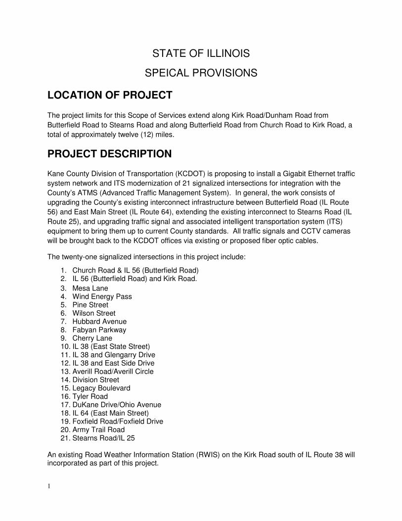
LOCATION OF PROJECT
The project limits for this Scope of Services extend along Kirk Road/Dunham Road from
Butterfield Road to Stearns Road and along Butterfield Road from Church Road to Kirk Road, a
total of approximately twelve (12) miles.
PROJECT DESCRIPTION
Kane County Division of Transportation (KCDOT) is proposing to install a Gigabit Ethernet traffic
system network and ITS modernization of 21 signalized intersections for integration with the
County’s ATMS (Advanced Traffic Management System). In general, the work consists of
upgrading the County’s existing interconnect infrastructure between Butterfield Road (IL Route
56) and East Main Street (IL Route 64), extending the existing interconnect to Stearns Road (IL
Route 25), and upgrading traffic signal and associated intelligent transportation system (ITS)
equipment to bring them up to current County standards. All traffic signals and CCTV cameras
will be brought back to the KCDOT offices via existing or proposed fiber optic cables.
The twenty-one signalized intersections in this project include:
1. Church Road & IL 56 (Butterfield Road) 2. IL 56 (Butterfield Road) and Kirk Road.
3. Mesa Lane 4. Wind Energy Pass 5. Pine Street 6. Wilson Street 7. Hubbard Avenue 8. Fabyan Parkway 9. Cherry Lane 10. IL 38 (East State Street) 11. IL 38 and Glengarry Drive 12. IL 38 and East Side Drive 13. Averill Road/Averill Circle 14. Division Street 15. Legacy Boulevard 16. Tyler Road 17. DuKane Drive/Ohio Avenue 18. IL 64 (East Main Street) 19. Foxfield Road/Foxfield Drive 20. Army Trail Road 21. Stearns Road/IL 25
An existing Road Weather Information Station (RWIS) on the Kirk Road south of IL Route 38 will incorporated as part of this project.
2
TRAFFIC CONTROL PLAN
Traffic Control shall be in accordance with the applicable section of the Standard Specification,
the Specifications, the Illinois Manual on Uniform Traffic Control Devices for Streets and
Highways.” Any special details and Highway Standards contained in the plans, the Traffic
Specifications and the Special Provisions contained herein.
Special attention is called to Articles 107.09, 107.14 and Section 701 of the Standard
Specification and the following Highway Standards, Details, Quality Standard for Work Zone
Traffic Control Devices, Recurring Special Provisions and Special Provisions contained herein,
relating to traffic control.
The Contractor shall contact the Kane County Division of Transportation at least 72 hours in
advance of beginning work.
STANDARDS:
701006-03; 701011-02; 701101-02, 701301-04, 701501-06, 701601-7, 701701-07, 701801-04,
701901-01
DETAILS:
SUPPLMENTAL SPECIFICATIONS:
None
RECURRING SPECIAL PROVISIONS:
See checklists

3
SPECIAL PROVISIONS
The following Special Provisions supplement the “Standard Specifications for Road and Bridge
Construction”, adopted January 1, 2007, the latest edition of the “Manual on Uniform Traffic
Control Devices for Streets and Highways”, and the “Manual of Test Procedures for Materials” in
effect on the date of invitation for bids, the IDOT District 1 Traffic Signal Special Provisions,
National Electrical Code (NEC), National Electrical Manufactures Association (NEMA)
publications for traffic control items, International Municipal Signals Association (IMSA) Official
Wire and Cable Specifications, Institute of Electrical and Electronics Engineers (IEEE), and the
Supplemental Specifications and Recurring Special Provisions indicated on the Check Sheet
included herein which apply to and govern the construction of the fiber interconnect along Kirk
Road and Dunham Road between IL Route 56 (Butterfield Road) and Stearns Road. In the
event of any conflict with any part, or parts, of said Specifications, these Special Provisions shall
take precedence and shall govern. All materials must be new for this project.
These special provisions reference KCDOT central facility:
Kane County Division of Transportation
41W011 Burlington Rd
St. Charles, IL 60175
Mr. Thomas Szabo is the Traffic Manager for KCDOT (630) 208-3139.

4
CLEANING EXISTING CONDUIT
Existing conduit shall be cleaned and swabbed to the satisfaction of the County. The removal of
existing cable will be paid for separately. The quantities listed for this pay item are to be
considered a nominal amount. No work under this pay item shall be commenced without direct
approval by the County or their representative. No payment will be made under this pay item
without prior approval.
Basis of Payment
This work shall be paid for at the contract unit price per foot for CLEANING EXISTING
CONDUIT, which shall be payment in full for cleaning and swabbing existing conduit and
disposing of debris outside the right-of-way. Payment will be made for the measured quantity
performed as agreed to by the contractor and the County.
MALFUNCTION MANAGEMENT UNIT
This pay item shall include all labor, parts, and materials necessary to install a Malfunction Management Unit in an existing controller cabinet. All references to “Conflict Monitor” in Article 1074.03 shall be changed to “Malfunction Management Unit.” Add the following to Article 1074.03 of the Standard Specifications: The Malfunction Management Unit (MMU) shall be an EDI MMU-LEip type or approved
equivalent and shall include a 10/100Mbps Ethernet port.
The MMU shall have two high contrast, large area Liquid Crystal Displays (LCD) that
continuously show full RYG(W) intersection status and a separate graphic LCD that provides a
menu driven user interface to status, signal voltages, configuration, event logs, and the Help
system.
Remote monitoring and communication with the MMU shall be established over the Ethernet
network to the satisfaction of the Engineer.
Basis of Payment:
This item will be paid for at the contract unit price each for MALFUNCTION MANAGEMENT UNIT which price shall be payment in full for furnishing and installing the MMU in an existing controller cabinet as specified. If the MMU is to be installed in a new controller cabinet it shall not be paid for separately but shall be considered included in the cost for the Controller and Cabinet of the type specified.

5
MODIFY EXISTING UNINTERRUPTIBLE POWER SUPPLY WITH ETHERNET PORTS
The Contractor shall furnish and install an Ethernet interface to enable the existing Alpha Novus
or Alpha FXM UPS to be managed on Kane County's Traffic Management System.
The interface for the Alpha Novus UPS shall be a USHA Pro E II interface, manufactured by
Ingrasys Technology Inc., or another interface recommended by Alpha Technologies and
approved by the Engineer.
The interface for the Alpha FXM series UPS shall be the Ethernet/SNMP card, manufactured,
by Alpha Technologies.
This item includes furnishing and installing the interface device as directed by the manufacturer,
complete with all hardware, cables and connections necessary for a complete and fully
functional system.
Basis of Payment
This item will be paid for at the contract unit price each for MODIFY EXISTING CONTROLLER
CABINET, SPECIAL; which price shall be payment in full for furnishing all associated equipment
required, installing and testing the equipment complete and in place, and placing the equipment
in operation to the satisfaction of the Engineer.
VIDEO SYSTEM DETECTION PROCESSOR
This work shall consist of providing a fully operational VIDEO SYSTEM DETECTION
PROCESSOR, which provides video processing (vehicle detection) of four cameras and
MPEG4 and H.264 encoding of the four channels and transmits it via a standard 10/100
Ethernet connection. The VIDEO SYSTEM DETECTION PROCESSOR shall operate at the
extended temperature range of -37 C to +7 4C. It shall be Iteris Vantage Edge 2 machine vision
processor and Iteris EdgeConnect Quad-View remote communications module or engineer
approved equivalent.
This work shall include all wiring required for proper operation of module interfacing with existing
video vehicle detection cameras or interface unit.
Basis of Payment.
The work shall be paid for at the contract unit price Each for VIDEO SYSTEM DETECTION
PROCESSOR, which price shall be payment in full for all hardware, cabling and coordination
necessary to deliver a VIDEO SYSTEM DETECTION PROCESSOR that provides successful
vehicle detection and video transmission and control to the KCDOT central facility.

6
UNINTERRUPTIBLE POWER SUPPLY
Description
This work shall consist of furnishing and installing an uninterruptible power supply (UPS).
The UPS shall have the power capacity to provide normal operation of a signalized intersection
that utilizes all LED type signal head optics, for a minimum of six hours.
The UPS shall include, but not be limited to the following: inverter/charger, power transfer relay,
batteries, battery cabinet, a separate manually operated non-electronic bypass switch, and all
necessary hardware and interconnect wiring according to the plans. The UPS shall provide
reliable emergency power to the traffic signals in the event of a power failure or interruption.
The transfer from utility power to battery power and visa versa shall not interfere with the normal
operation of traffic controller, conflict monitor/malfunction management unit, or any other
peripheral devices within the traffic controller assembly.
The UPS shall be designed for outdoor applications, and shall meet the environmental
requirements of, "NEMA Standards Publication No. TS 2 - Traffic Controller Assemblies", except
as modified herein.
Materials
The UPS shall be line interactive and provide voltage regulation and power conditioning when
utilizing utility power. The UPS shall be sized appropriately for the intersection's normal traffic
signal operating connected load, plus 20 percent (20%). The total connected traffic signal load
shall not exceed the published ratings for the UPS. The UPS shall provide a minimum of six (6)
hours of normal operation run-time for signalized intersections with LED type signal head optics
at 77 of (25°C) (minimum 700 WNA active output capacity, with 90 percent minimum inverter
efficiency) .
The maximum transfer time from loss of utility power to switchover to battery backed inverter
power shall be 65 milliseconds.
The UPS shall be provided with safety locks to prevent improper installation. This protection
shall include a reverse polarity protection and protection against electrical back feed to the utility
service that complies with UL 1778 and CSA C22.2 No. 107.1.3 requirements and safety
standard EN50091-1-1-2 and EN60950. Besides passing Immunity Standards, EN61 000-4-2,
3, 4, 5, 6 and 8 and EN61000-3-2 Standards, the manufacturer's nameplate label shall display
agency approval mark "cCSAus".
The UPS shall· be provided with an SNMP Ethernet port for remote programming and
monitoring, complete with password and remote operation software or browser application.
Additionally, the UPS shall be provided with an RS-232 port for local programming and a LCD
display and local control and monitoring of alarm logging events. The UPS shall be provided
with a minimum of three SPOT relay contacts for user programming of alarms or other controls
for operation. A sixth SPOT relay contact set shall be provided to output the alarms for a
secondary remote alarm system that is programmed by the factory. The relay contacts shall be

7
located on a panel mounted terminal block or locking circular connectors, rated at a minimum
120 V/1 A, and labeled so as to identify each contact according to the plans. Contact closures
shall be energized whenever the unit:
• Switches to battery power. Contact shall be labeled or marked "On Batt".
• Has been connected to battery power for two (2) hours. Contact shall be labeled or
marked "Timer".
• Has 'an inverter/charger failure. Contact shall be labeled or marked "UPS Fail".
Operating temperature for the inverter/charger, power transfer relay, and manual bypass switch
shall be -35 to 165º F.
Both the power transfer relay and manual bypass switch shall be rated at 240 VAC/30 amps,
minimum.
The UPS shall use a temperature-compensated battery charging system. The charging system
shall compensate over a range of 1.4 - 2.2 mV/ºF per cell. The temperature sensor shall be
external to the inverter/charger unit. The temperature sensor shall come with 6.5 ft.of wire.
Batteries shall not be recharged when battery temperature exceeds 122 °F ± 5°F.
The UPS shall bypass the utility line power whenever the utility line voltage is outside of the
following voltage range: 85 VAC to 135 VAC (± 2 VAC).
When utilizing battery power, the UPS output voltage shall be between 110 and 125 VAC, pure
sine wave output, ≤ 3 percent THD, 60 Hz ± 3 Hz.
The UPS shall be compatible with the District's approved traffic .controller assemblies utilizing
NEMA TS 1 or NEMA TS 2 controllers and cabinet components for full time operation.
When the utility line power has been restored at above 90 VAC ± 2 VAC for more than 30
seconds, the UPS shall dropout of battery backup mode and return to utility line mode.
When the utility line power has been restored at below 130 VAC ± 2 VAC for more than 30
seconds, the UPS shall dropout of battery backup mode and return to utility line mode.
The UPS shall be equipped to prevent a malfunction feedback to the cabinet or from feeding
back to the utility service.
In the event of inverter/charger failure, the power transfer relay shall revert to the NC state,
where utility line power is reconnected to the cabinet. In the event of an UPS fault condition, the
UPS shall always revert back to utility line power. Recharge time for the battery, from
"protective low-cutoff' to 80 percent or more of full battery charge capacity, shall not exceed
twenty hours. The manual bypass switch shall be wired to provide power to the UPS when the
switch is set to manual bypass.
When the intersection is in battery backup mode, the UPS shall bypass all internal cabinet
lights, ventilation fans, service receptacles, any lighted street name signs, any automated
enforcement equipment and any other devices directed by the Engineer. Cabinet wiring shall be
designed to exclude traffic video monitoring operation from functioning during power transition
to battery power and shall re-energize normal traffic video monitoring when power is restored to
utility power.

8
As the battery reserve capacity reaches 50 percent, the intersection shall automatically be
placed in all-red flash. The UPS shall allow the controller to automatically resume normal
operation after the power has been restored. The UPS shall log an alarm in the controller for
each time it is activated.
A blue LED indicator light shall be mounted on the front of the traffic signal cabinet or on the
side of the UPS cabinet facing traffic and shall turn on to indicate when the cabinet power has
been disrupted and the UPS is in operation. The light shall be a minimum 1 in. diameter, be
viewable from the driving lanes, and able to be seen from 200 ft away.
All 24 volt and 48 volt systems shall include an external or internal component that monitors
battery charging to ensure that every battery in the string is fully charged. The device shall
compensate for the effects of adding a new battery to an existing battery system by ensuring
that the charge voltage is spread equally across all batteries.
Mounting/Configuration
The inverter/charger unit shall be rack or shelf-mounted.
All interconnect wiring provided between the power transfer relay, manual bypass switch, and
cabinet terminal service block shall be at least 6.5 ft of #10 AWG wire.
Relay contact wiring provided for each set of NO/NC relay contact closure terminals shall be 6.5
ft of #18 AWG wire.
Battery Cabinet
Batteries, inverter/charger and power transfer relay shall be housed in a separate NEMA Type
3R cabinet. The cabinet shall be Aluminum alloy, 5052-H32, O.125-inch thick and have a
natural mill finish.
The door shall open to the entire cabinet, have a neoprene gasket, an Aluminum continuous
piano hinge with stainless steel pin, and a three point locking system. The cabinet shall be
provided with a main door lock which shall operate with a traffic industry conventional No.2 key.
Provisions for padlocking the door shall be provided.
The manually bypass switch shall be installed inside the traffic signal cabinet.
No more than three batteries shall be mounted on individual shelves for a cabinet housing six
batteries and no more than four batteries per shelf for a cabinet housing eight batteries.
A minimum of three shelves shall be provided. Each shelf shall support a load of 132 Ib
minimum.
The battery cabinet housing shall have the following nominal outside dimensions: a width of 25
in., a depth of 16 in., and a height of 41 to 48 in. Clearance between shelves shall be a
minimum of 10 in.

9
The battery cabinet shall be ventilated through the use of louvered vents, filters, and one
thermostatically controlled fan. The cabinet fan shall not be energized when the traffic signals
are on UPS power.
The battery cabinet shall have provisions for an external generator connection. The UPS shall
be provided with a Battery Heater Mat that shall function when power line voltage is present and
temperature ranges indicate the advantage of heating the batteries for enhanced performance,
activating at five degrees Celsius and deactivating at temperatures at or above fifteen degrees
Celsius. The Manual Bypass Switch shall be provided for manual connection or disconnection
and testing. The Automatic Transfer Switch shall automatically transfer the load from line power
to UPS power and back when the incoming line voltage is impaired and then corrected for
proper operation. The battery heater mat shall be sized for the battery array installed.
The UPS with battery cabinet shall come with all bolts, conduits and bushings, gaskets, shelves,
and hardware needed for mounting. A warning sticker shall be placed on the outside of the
cabinet indicating Jhat there is an uninterruptible power supply inside the cabinet.
Maintenance, Displays, Controls, and Diagnostics
The UPS shall include a display and/or meter to indicate current battery charge status and
conditions.
The UPS shall have lightning surge protection compliant with ANSI/IEEE C.62.41.
The UPS shall be equipped with an integral system to prevent battery from destructive
discharge and overcharge.
The UPS hardware and batteries shall be easily replaced without requiring any special tools or
devices.
The UPS shall include a re-settable front-panel event counter display to indicate the number of
times the UPS was activated. The total number of hours the unit has operated on battery power
shall be available from the controller unit or UPS unit.
The UPS shall include tip or kill switch installed in the battery cabinet, which shall completely
disconnect power from the UPS when the switch is manually activated.
The UPS shall incorporate a flanged electric generator inlet for charging the batteries and
operating the UPS. The generator connector shall be male type twist-lock, rated as 15A,
125VAC with a NEMA L5-15P configuration and weatherproof lift cover plate (Hubbell model
HBL4716C or approved equal). Access to the generator inlet shall be from a secured
weatherproof lift cover plate or behind a locked battery cabinet police panel.
The manufacturer shall include two sets of equipment lists, operation and maintenance
manuals, board-level schematic and wiring diagrams of the UPS, and battery data sheets. The
manufacturer shall include any software needed to monitor, diagnose, and operate the UPS.
The manufacturer shall include any required cables to connect the UPS to a laptop computer.

10
Battery System
Individual batteries shall be 12 V type, 65 amp-hour minimum capacity at a 20 hour discharge
rate, and shall be easily replaced and commercially available off the shelf.
The UPS shall consist of an even number of batteries that are capable of maintaining normal
operation of the signalized intersection for a minimum of six (6) hours. Calculations shall be
provided showing the number of batteries of the type supplied that are needed to satisfy this
requirement. A minimum of four batteries shall be provided.
All batteries supplied in the UPS shall be shall be Gel Cell Valve Regulated Lead Acid (VRLA)
type specifically designed for outdoor application using a "Float Service" to provide 100%
runtime capacity without initialization charging. Batteries shall be constructed using Silver Alloy
positive plates and shall have a five year full replacement warranty, non-prorated. Battery
capacity rating at a 20 hour discharge rate shall be 94 Amp Hours, 12 VDC - each battery.
Battery design for the UPS shall be either four or eight units per design application. Batteries
shall be installed and connected to operate at the 48 VDC design. The contractor shall furnish
either the four or eight battery design based on the signalized intersection design and power
requirements for each intersection. Batteries shall be either gel cell or AGM type, deep cycle,
completely sealed, prismatic lead-calcium based, silver alloy, valve regulated lead acid (VRLA)
requiring no maintenance. All batteries in a UPS installation shall be the same type; mixing of
gel cell and AGM types within a UPS installation is not permitted.
The Gel Cell Batteries shall be certified by the manufacturer to operate over a temperature
range of -13 to 160°F.
The batteries shall be provided with appropriate interconnect wiring and corrosion resistant
mounting trays and/or brackets appropriate for the cabinet into which they will be installed.
The UPS shall be provided' with a Battery Charge Maintenance Management System to
equalize charging of batteries with different battery life ratings and to allow adding new batteries
to existing installation sites without changing all existing' batteries at a single time. This
management system shall comply with CSA C22.2 No. 107.1 and UL 1778 Standards for safe
operation of batteries under unattended applications.
Batteries shall indicate maximum recharge data and recharging cycles.
Battery interconnect wiring shall be via a modular harness. Batteries shall be shipped with
positive and negative terminals pre-wired with red and black cabling that terminates into a
typical power-pole style connector. The harness shall be equipped with mating power-pole style
connectors for the batteries and a single, insulated plug-in style connection to the
inverter/charger unit. The harness shall allow batteries to be quickly and easily connected in any
order and shall be keyed and wired to ensure proper polarity and circuit configuration.
Battery terminals shall be covered and insulated so as to prevent accidental shorting.

11
Warranty
The warranty for an uninterruptible power supply (UPS) shall cover a minimum of two years
from date the equipment is placed in operation; however, the batteries of the UPS shall be
warranted for full replacement for a minimum of five years from the date the traffic signal and
UPS are placed into service.
Installation
When a UPS is installed at an existing traffic signal cabinet, the UPS cabinet shall partially rest
on the lip of the existing controller cabinet foundation and be secured to the existing controller
cabinet by means of at least four (4) stainless steel bolts. The UPS cabinet shall be completely
enclosed with the bottom and back constructed of the same material as the cabinet.
When a UPS is installed at a: new signal cabinet and foundation, it shall be mounted as shown
on the plans.
Basis of Payment:
This work will be paid for at the contract unit price per each for UNINTERRUPTIBLE POWER
SUPPLY.
FIBER OPTIC CABLE
Add the following to Article 871.01 of the Standard Specifications:
The Fiber Optic cable shall be installed in conduit or as specified on the plans.
Add the following to Article 872.02 of the Standard Specifications:
The control cabinet distribution enclosure shall be supplied as an incidental item under FIBER
OPTIC TERMINATORS, 6 FIBER, FIBER OPTIC TERMINATORS, 48 FIBER.
Add the following to Article 871.04 of the Standard Specifications:
A nominal six single-mode fibers from each cable shall be terminated with approved optical
connectors at the distribution enclosure. Fibers not being used shall be labeled "spare." Fibers
not attached to the connector panel shall be either spliced through or capped and Sealed as
identified in the plans. A minimum of 13.0 feet (4m) of extra cable length shall be provided for
controller cabinets. The controller cabinet extra cable length shall be coiled and stored as
approved by the Engineer.

12
REMOVE FIBER OPTIC CABLE FROM CONDUIT
An existing fiber optic cable shall be removed, as directed by the Engineer, from a conduit. Cable shall be disposed of outside the right-of-way.
Basis of Payment
This work shall be paid for at the contract unit price per foot for REMOVE FIBER OPTIC CABLE
FROM CONDUIT, which shall be payment in full for cleaning and swabbing existing conduit and
disposing of debris outside the right-of-way. Payment will be made for the measured quantity
performed as agreed to by the contractor and the County.
NETWORK CONFIGURATION
This work shall consist of installing, configuring and provisioning a fully operational Ethernet Metropolitan Area Network (MAN), which provides communication with remote traffic control field devices from the Kane County Division of Transportation (KDOT) traffic office. Field devices include traffic signal controllers, Malfunction Management Units (MMU), Uninterruptable Power Supply (UPS) units, video detection systems and CCTV (PTZ) cameras or other specified ITS field device as shown on the plans. This work shall include configuring Ethernet switches, terminal servers, media converters, and video encoders, assigning IP addresses to field devices, troubleshooting and submitting documentation to KDOT Traffic. The existing KDOT ATMS fiber optic network will serve as the Wide Area Network (WAN) communication backhaul to the KDOT traffic office. This work shall also require coordination with each manufacturer of field end devices, converters, and networking equipment to ensure successful digital video transmissions, serial over- copper, serial-over-fiber, and serial-over-Ethernet communications between the WAN and field devices. Coordination with the ATMS provider is required to determine specific central software requirements for the communications including comm. channels, static IP addresses, port forwarding and TCP ports. The Contractor shall develop a written test plan and submit it to the Engineer and KDOT Traffic for approval. The test plan shall be revised to the satisfaction of the Engineer Traffic for approval. The testing plan shall include systematic procedures with anticipated results that demonstrate that the communication network and its subsystems are fully operational. Approved testing procedures will be performed in the presence of KDOT and Contractor representatives. The testing plan shall include forms listing itemized functional checks of the system with signature placeholders for KDOT and Contractor representatives. The test plan will verify the network performance over the extent of this project. The Contractor shall emulate traffic operations over the network by interfacing a laptop computer with the Type2 Ethernet Switch at Fabyan and Western. From this location, the Contractor will control and exchange data with all ITS and traffic controllers, CCTV cameras, and the RWIS. The computer shall also monitor the UPS components and all other alarms. After satisfactory completion of this work, the existing master controllers shall be returned to KDOT as directed by the Engineer.

13
Basis of Payment
The work shall be paid for at the contract unit price per lump sum for NETWORK CONFIGURATION, which price shall be payment in full for all communication network configuration and coordination necessary to deliver an Ethernet network that provides successful communications between all field devices and the communication backhaul to the KDOT Traffic Office.
ETHERNET MANAGED SWITCH, TYPE 1
This work shall include all materials and work necessary to install an Ethernet Managed Switch,
Type 1 in a traffic signal cabinet. The Type 1 switch shall be a GarretCom 6KQ type or
approved equivalent.
The contractor shall install the Ethernet Managed Switch, Type 1 complete, functional, and
programmed. The Ethernet Managed Switch, Type 1 shall include a configurable, managed
field switch. The switch shall be rated IP52 for environmental protection. The switch shall
contain a mechanism for necessary internal heat dissipation without the use of a dedicated fan.
The Ethernet Managed Switch, Type 1 shall include the following connector types
8 RJ-45 10/100 Communication ports
2 Single-mode 100 base Fiber optic communication ports
2 Single-Mode 1GB base fiber optic communication ports
The switch shall have capacity for future expansion of two additional fiber optic ports. The unit
shall support flash memory software upgrades.
The Ethernet Managed Switch, Type 1 shall include all necessary patch cords, connectors,
power supplies, communication transformers, or auxiliary equipment necessary to complete the
communication circuits at full functional potential.
The contractor shall coordinate with the network administrator governing the fiber optic system
to acquire the necessary IP address assignments. The contractor shall be responsible for all
network programming of the network switches and communicating elements within the traffic
signal cabinet. The network administrator shall be responsible for all network communication
address assignments, network security decisions, and network access protocol.
Basis of Payment
This work shall be paid for at the contract unit price each for ETHERNET MANAGED SWITCH,
TYPE 1, which price shall be payment in full for furnishing and installing an Ethernet Managed
Switch as specified.

14
ETHERNET MANAGED SWITCH, TYPE 2
This work shall include all materials and work necessary to install an Ethernet Managed Switch,
Type 2 in a traffic signal cabinet. The Type 2 switch shall be a GarretCom 6K32 type or
approved equivalent.
The contractor shall install the Ethernet Managed Switch, Type 2 complete, functional, and
programmed. The Ethernet Managed Switch, Type 2 shall include a configurable, managed
field switch. The switch shall be rated IP52 for environmental protection. The switch shall
contain a mechanism for necessary internal heat dissipation without the use of a dedicated fan.
The Ethernet Managed Switch, Type 2 shall include the following connector types
8 RJ-45 10/100 Communication ports
4 Single-mode 100 base fiber optic communication ports
4 Single-Mode 1GB base fiber optic communication ports
The switch shall have capacity for future expansion of two additional single-mode fiber optic
ports and two additional single-mode 1 GB fiber optic ports. The unit shall support flash
memory software upgrades.
The Ethernet Managed Switch, Type 2 shall include all necessary patch cords, connectors,
power supplies, communication transformers, or auxiliary equipment necessary to complete the
communication circuits at full functional potential.
The contractor shall coordinate with the network administrator governing the fiber optic system
to acquire the necessary IP address assignments. The contractor shall be responsible for all
network programming of the network switches and communicating elements within the traffic
signal cabinet. The network administrator shall be responsible for all network communication
address assignments, network security decisions, and network access protocol.
Basis of Payment
This work shall be paid for at the contract unit price each for ETHERNET MANAGED SWITCH,
TYPE 2, which price shall be payment in full for furnishing and installing an Ethernet Managed
Switch as specified.
CONFIRMATION BEACON
Description
This work shall consist of retrofitting an existing emergency vehicle pre-emption confirmation
incandescent beacon with a light emitting diodes (LEDs) confirmation beacon as specified in the
plans.

15
Materials
The Confirmation Beacon shall consist of a 6 watt Par 38 LED flood lamp with a 30 degree light
spread, maximum 6 watt energy consumption at 120V, and a 2,000 hour warranty for each
direction of per-emption.
Basis of Payment
This item shall be paid for at the contract unit price each for CONFIRMATION BEACON, which
price shall be payment in full for furnishing the equipment described above and installing them
in satisfactory operating condition.
SAND CUSHION
Description
This work must consist of excavating and disposing of unsuitable sub-base or subgrade material
from beneath proposed sidewalks and parkways and replacing it with a SAND CUSHION,
VARIABLE DEPTH, as directed by the Commissioner.
General Requirements
If upon removal, to proposed sub-base elevation, of existing sidewalks or parkways, a soft or
unstable sub-base is encountered, this material is to be removed and replaced with SAND
CUSHION, VARIABLE DEPTH. Removal to sub-base elevation of the existing sidewalk or
parkway must not be included in this item but consider incidental to the items of work to which
SIDEWALK REMOVAL pertains.
The SAND CUSHION, VARIABLE DEPTH must be fine aggregate having an FA-2 gradation
conforming to Section 1003 of the Standard Specifications. The SAND CUSHION, VARIABLE
DEPTH must be constructed upon a prepared sub-grade and compacted to 95% of maximum
laboratory density.
Surplus excavated material must not be stockpiled on the jobsite but disposed of in accordance
to Article 202.03.
Method of Measurement:
SAND CUSHION, VARIABLE DEPTH, will be measured in tons.
Basis of Payment:
The work under this item will be paid for at the contract unit price per ton as shown in the
Schedule of Unit Prices for SAND CUSHION, VARIABLE DEPTH, which price will include all
cost for excavation and disposal of the existing sub-base material, furnishing, installing and
compacting the SAND CUSHION, VARIABLE DEPTH.
16
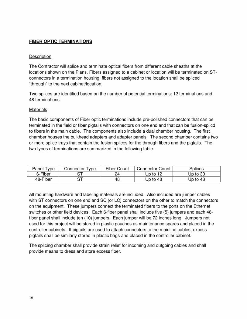
FIBER OPTIC TERMINATIONS
Description
The Contractor will splice and terminate optical fibers from different cable sheaths at the
locations shown on the Plans. Fibers assigned to a cabinet or location will be terminated on ST-
connectors in a termination housing; fibers not assigned to the location shall be spliced
“through” to the next cabinet/location.
Two splices are identified based on the number of potential terminations: 12 terminations and
48 terminations.
Materials
The basic components of Fiber optic terminations include pre-polished connectors that can be
terminated in the field or fiber pigtails with connectors on one end and that can be fusion-splicd
to fibers in the main cable. The components also include a dual chamber housing. The first
chamber houses the bulkhead adapters and adapter panels. The second chamber contains two
or more splice trays that contain the fusion splices for the through fibers and the pigtails. The
two types of terminations are summarized in the following table.
Panel Type Connector Type Fiber Count Connector Count Splices 6-Fiber ST 24 Up to 12 Up to 30 48-Fiber ST 48 Up to 48 Up to 48
All mounting hardware and labeling materials are included. Also included are jumper cables
with ST connectors on one end and SC (or LC) connectors on the other to match the connectors
on the equipment. These jumpers connect the terminated fibers to the ports on the Ethernet
switches or other field devices. Each 6-fiber panel shall include five (5) jumpers and each 48-
fiber panel shall include ten (10) jumpers. Each jumper will be 72 inches long. Jumpers not
used for this project will be stored in plastic pouches as maintenance spares and placed in the
controller cabinets. If pigtails are used to attach connectors to the mainline cables, excess
pigtails shall be similarly stored in plastic bags and placed in the controller cabinet.
The splicing chamber shall provide strain relief for incoming and outgoing cables and shall
provide means to dress and store excess fiber.
17
Construction Requirements
The cables shall be terminated according to the manufacturer's recommended guidelines. The
Contractor shall prepare the cables and fibers in accordance with the termination panel and
cable manufacturers' installation practices. A copy of these practices shall be provided to the
Engineer 21 days prior to splicing operations.
Using a fusion splicer, the Contractor shall optimize the alignment of the fibers and fuse them
together. The Contractor shall recoat the fused fibers and install mechanical protection over
them.
Upon completing all splicing operations for a cable span, the Contractor shall measure the
mean bi-directional loss at each splice using an Optical Time Domain Reflectometer. This loss
shall not exceed 0.1 dB.
The Contractor shall measure the end-to-end attenuation of each fiber, from connector to
connector, using an optical power meter and source. This loss shall be measured at from both
directions and shall not exceed 0.5 dB per installed kilometer of single mode cable. For cables
less than 1.6 km (1 mile), the measured loss should not exceed 2 dB. Measurements shall be
made at both 1300 and 1550 nm for single mode cable.
As directed by the Engineer, the Contractor at no additional cost to the Department shall replace
any cable splice not satisfying the required objectives.
Method of Measurement
Fiber optic termination of the type specified will be measured as each, completely installed and
tested with all fibers spliced, terminated, or dropped as identified in the plans, and the housing
secured to the wall of the controller cabinet or facility.
Basis of Payment
These items shall be paid at the contract unit price each for FIBER OPTIC TERMINATION, 6
FIBER or FIBER OPTIC TERMINATION , 48 FIBER, which shall be payment in full for the
work, complete, as specified herein.
VIDEO TRAFFIC MONITORING SYSTEM WITH PTZ CAMERA
The Contractor shall furnish and install a video surveillance camera system consisting of a special
video camera in a dome, a dome mount to the video monitoring pole, all mounting hardware,
brackets, outdoor rated network cable (to be paid for separately) supplied to the required length
by the video system manufacturer with fast disconnect at the camera mount, video camera
controller and special electronics/cabling for video transmission and pan/tilt/zoom controls, video
controller unit to link all electronic components between the controller unit and the camera dome
to include heater, fan, PTZ camera, video coax, video decoders with video encoding and
decoding software. The video surveillance camera system shall be an AXIS Q6032-E PTZ or
approved equivalent.

18
The camera shall be designed and optimized for roadway video monitoring. The items shall have
a minimum Object Distance: 300mm (wide end), 800mm (tele end), have a minimum
mechanical zoom of thirty-five (35x) and a minimum digital zoom of twelve (12x). The camera,
joystick controller (required for field adjustments and video verification), camera controller and
auxiliary devices necessary for a complete and functional video operation shall be comprised of
hardware as manufactured by Axis or approved equivalent and shall utilize the Diamond control
protocol for pan/tilt/zoom controls. The camera shall be digital with IP port(s) and a built-in
encoder for connection to the central office. A separate encoder shall not be required. The
camera shall provide for 360-degree rotation on the horizontal plane and 180-degree rotation
within the lower hemisphere of the dome.
The Contractor shall install an auxiliary cabinet, DT-ST Series, when the distance between the
camera and traffic controller cabinet exceeds 300 feet. The use of a DT-ST cabinet shall be
considered incidental to the cost of the video traffic monitoring system and no additional
compensation shall be provided for the cabinet, cables, additional fiber optic cable, jumpers, etc.
The Contractor shall furnish and install the video software for decoding and encoding.
This item includes furnishing and installing the video monitoring camera, power injector (if
required), and an auxiliary DT-ST cabinet as shown on the intersection wiring diagrams, box prints
and fiber optic wiring diagram. This item also includes furnishing, installing and testing all auxiliary
cabling, connectors, couplers, in-building hardware and software, jacks, splitters, conversion
adapters, equipment racks, power supplies, power strips, surge suppressors, etc., necessary for a
complete and fully functional system. The cable to be used for connecting the video monitoring
camera to the local Ethernet switch shall be paid for separately under the pay item “Outdoor
Rated Network Cable.”
All mounting platforms, connecting hardware and auxiliary devices to test and operate this system
to the satisfaction of the Engineer shall be incidental to this pay item and no additional
compensation will be allowed.
The contractor shall contact the KDOT Traffic prior to installing the PTZ camera and associated
wiring, to receive final approval on the camera location.
Basis of Payment: This item will be paid for at the contract unit price each for VIDEO TRAFFIC
MONITORING SYSTEM WITH PTZ CAMERA, which price shall be payment in full for furnishing
all associated equipment required, installing the system complete and in place, and placing the
system in operation to the satisfaction of KDOT Traffic.

19
TRAFFIC SIGNAL PAINTING Description
This work shall include surface preparation, powder type painted finish application and
packaging of new aluminum traffic signal controller cabinet. All work associated with applying
the painted finish shall be performed at the manufacturing facility for the pole assembly or post
or at a painting facility approved by the Engineer. Traffic controller cabinet shall be painted the
same color as the pole assemblies and posts, signal mast arm shrouds and post bases.
Surface Preparation.
All weld flux and other contaminates shall be mechanically removed. The traffic controller
cabinet and post assemblies shall be degreased, cleaned, and air dried to assure all moisture is
removed.
Painted Finish.
All galvanized exterior surfaces shall be coated with a urethane or triglycidyl isocyanurate
(TGIC) polyester powder to a dry film thickness of 2.0 mils. Prior to application, the surface shall
be mechanically etched by brush blasting (Ref. SSPC-SP7) and the zinc coated substrate
preheated to 450 ºF for a minimum one (1) hour. The coating shall be electrostatically applied
and cured by elevating the zinc-coated substrate temperature to a minimum of 400 ºF.
The finish paint color shall be one of the manufacturer’s standard colors and shall be as
selected by the local agency responsible for paint costs. The Contractor shall confirm, in writing,
the color selection with the local responsible agency and provide a copy of the approval to the
Engineer and a copy of the approval shall be included in the material catalog submittal.
Painting of mast arms, traffic signal posts, traffic signal heads, pedestrian signal heads is not
included in this pay item.
Prior to shipping, the cabinet shall be wrapped in ultraviolet-inhibiting plastic foam or rubberized
foam. Any damage to the finish after leaving the manufacturer’s facility shall be repaired to the
satisfaction of the Engineer using a method recommended by the manufacturer and approved
by the Engineer. If while at the manufacturer’s facility the finish is damaged, the finish shall be
re-applied at no cost to the contract.
Warranty
The Contractor shall furnish in writing to the Engineer, the paint manufacturer’s standard
warranty and certification that the paint system has been properly applied.
Basis of Payment.
This work shall be paid for at the contract unit price each for PAINT NEW CONTROLLER
CABINET, which shall be payment in full for painting and packaging the controller cabinet,
cabinet door and associated hardware.
20
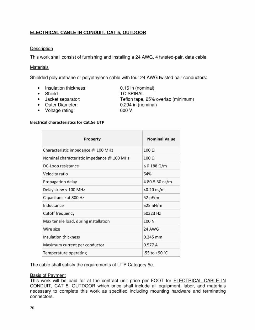
ELECTRICAL CABLE IN CONDUIT, CAT 5, OUTDOOR
Description
This work shall consist of furnishing and installing a 24 AWG, 4 twisted-pair, data cable.
Materials
Shielded polyurethane or polyethylene cable with four 24 AWG twisted pair conductors:
• Insulation thickness: 0.16 in (nominal) • Shield : TC SPIRAL • Jacket separator: Teflon tape, 25% overlap (minimum) • Outer Diameter: 0.294 in (nominal) • Voltage rating: 600 V
Electrical characteristics for Cat.5e UTP
Property Nominal Value
Characteristic impedance @ 100 MHz 100 Ω
Nominal characteristic impedance @ 100 MHz 100 Ω
DC-Loop resistance ≤ 0.188 Ω/m
Velocity ratio 64%
Propagation delay 4.80-5.30 ns/m
Delay skew < 100 MHz <0.20 ns/m
Capacitance at 800 Hz 52 pF/m
Inductance 525 nH/m
Cutoff frequency 50323 Hz
Max tensile load, during installation 100 N
Wire size 24 AWG
Insulation thickness 0.245 mm
Maximum current per conductor 0.577 A
Temperature operating -55 to +90 °C
The cable shall satisfy the requirements of UTP Category 5e. Basis of Payment This work will be paid for at the contract unit price per FOOT for ELECTRICAL CABLE IN CONDUIT, CAT 5, OUTDOOR which price shall include all equipment, labor, and materials necessary to complete this work as specified including mounting hardware and terminating connectors.

21
TRAFFIC SIGNAL SPECIFICATIONS Effective: October 28, 2009
These Traffic Signal Special Provisions and the "District One Standard Traffic Signal Design
Details” supplement the requirements of the State of Illinois “Standard Specifications for Road
and Bridge Construction.” The intent of these Special Provisions is to prescribe the materials
and construction methods commonly used for traffic signal installations. All material furnished
shall be new. The locations and the details of all installations shall be as indicated on the Plans
or as directed by the Engineer. Traffic signal construction and maintenance work shall be
performed by personnel holding IMSA Traffic Signal Technician Level II certification. The work
to be done under this contract consists of furnishing and installing all traffic signal work as
specified in the Plans and as specified herein in a manner acceptable and approved by the
Engineer.
SECTION 720 SIGNING MAST ARM SIGN PANELS. Add the following to Article 720.02 of the Standard Specifications:
Signs attached to poles or posts (such as mast arm signs) shall have mounting brackets and
sign channels which are equal to and completely interchangeable with those used by the District
Sign Shops. Signfix Aluminum Channel Framing System is currently recommended, but other
brands of mounting hardware are acceptable based upon the Department's approval.
DIVISION 800 ELECTRICAL SUBMITTALS. Revise Article 801.05 of the Standard Specifications to read:
The Contractor shall provide:
a. All material approval requests shall be submitted at the preconstruction meeting,
including major traffic signal items listed in the table in Article 801.05..
b. All material or equipment which are similar or identical shall be the product of the
same manufacturer, unless necessary for system continuity. Traffic signal materials
and equipment shall bear the U.L. label whenever such labeling is available.
c. Seven (7) copies of a letter from the Traffic Signal Contractor on company letterhead
listing the contract number or permit number, project location/limits, pay item
description, pay code number, manufacturer’s name and model numbers of the
proposed equipment and stating that the proposed equipment meets all contract
requirements. The letter will be reviewed by the Traffic Design Engineer to
determine whether the equipment to be used is approvable.
22
d. Seven (7) copies of shop drawings for mast arm poles and assemblies, including
combination mast arm poles, are required. A minimum of two (2) copies of all other
material catalog cuts are required. Submittals for equipment and materials shall be
complete. Partial or incomplete submittals will be returned without review.
e. Certain non-standard mast arm poles and assemblies will require additional review
from IDOT’s Central Office. Examples include ornamental/decorative and non-
standard length mast arm pole assemblies. The Contractor shall account for the
additional review time in his schedule.
f. The contract number or permit number, project location/limits and corresponding pay
code number must be on each sheet of the letter, material catalog cuts and mast arm
poles and assemblies drawings.
g. Where certifications and/or warranties are specified, the information submitted for
approval shall include certifications and warranties. Certifications involving
inspections, and/or tests of material shall be complete with all test data, dates, and
times.
h. After the Engineer reviews the submittals for conformance with the design concept of
the project, the Engineer will stamp the drawings indicating their status as
‘Approved’, ‘Approved-As-Noted’, ‘Disapproved’, or ‘Information Only’. Since the
Engineer's review is for conformance with the design concept only, it is the
Contractor's responsibility to coordinate the various items into a working system as
specified. The Contractor shall not be relieved from responsibility for errors or
omissions in the shop, working, layout drawings, or other documents by the
Department's approval thereof. The Contractor must still be in full compliance with
contract and specification requirements.
i. All submitted items reviewed and marked ‘APPROVED AS NOTED’, or
‘DISAPPROVED’ are to be resubmitted in their entirety, unless otherwise indicated
within the submittal comments, with a disposition of previous comments to verify
contract compliance at no additional cost to the contract.
j. Exceptions, Deviations and Substitutions. In general, exceptions to and deviations
from the requirements of the Contract Documents will not be allowed. It is the
Contractor’s responsibility to note any deviations from Contract requirements at the
time of submittal and to make any requests for deviations in writing to the Engineer.
In general, substitutions will not be acceptable. Requests for substitutions must
demonstrate that the proposed substitution is superior to the material or equipment
required by the Contract Documents. No exceptions, deviations or substitutions will
be permitted without the approval of the Engineer.
INSPECTION OF ELECTRICAL SYSTEMS. Add the following to Article 801.10 of the Standard Specifications: (c) All cabinets including temporary traffic signal cabinets shall be assembled by an approved
equipment supplier in District One. The Department reserves the right to request any controller and cabinet to be tested at the equipment supplier facilities prior to field installation, at no extra cost to this contract.
23
MAINTENANCE AND RESPONSIBILITY. Revise Article 801.11 of the Standard Specifications to read: a) Existing traffic signal installations and/or any electrical facilities at all or various locations
may be altered or reconstructed totally or partially as part of the work on this Contract.
The Contractor is hereby advised that all traffic control equipment, presently installed at
these locations, may be the property of the State of Illinois, Department of
Transportation, Division of Highways, County, Private Developer, or the Municipality in
which they are located. Once the Contractor has begun any work on any portion of the
project, all traffic signals within the limits of this contract or those which have the item
"Maintenance of Existing Traffic Signal Installation,” “Temporary Traffic Signal
Installation(s)” and/or “Maintenance of Existing Flashing Beacon Installation,” shall
become the full responsibility of the Contractor. Automatic Traffic Enforcement
equipment is not owned by the State and the Contractor shall not be responsible for
maintaining it during construction. The Contractor shall supply the engineer and the
Department’s Electrical Maintenance Contractor a 24-hour emergency contact name and
telephone number.
b) When the project has a pay item for “Maintenance of Existing Traffic Signal Installation,”
“Temporary Traffic Signal Installation(s)” and/or “Maintenance of Existing Flashing
Beacon Installation,” the Contractor must notify both the Area Traffic Signal Maintenance
and Operations Engineer at (847) 705-4424 and the Department’s Electrical
Maintenance Contractor, of their intent to begin any physical construction work on the
Contract or any portion thereof. This notification must be made a minimum of seven (7)
working days prior to the start of construction to allow sufficient time for inspection of the
existing traffic signal installation(s) and transfer of maintenance to the Contractor. If
work is started prior to an inspection, maintenance of the traffic signal installation(s) will
be transferred to the Contractor without an inspection. The Contractor will become
responsible for repairing or replacing all equipment that is not operating properly or is
damaged at no cost to the owner of the traffic signal. Final repairs or replacement of
damaged equipment must meet the approval of the Engineer prior to or at the time of
final inspection otherwise the traffic signal installation will not be accepted.
c) Contracts such as pavement grinding or patching which result in the destruction of traffic
signal loops do not require maintenance transfer, but require a notification of intent to
work and an inspection. A minimum of seven (7) working days prior to the loop removal,
the Contractor shall notify the Area Traffic Signal Maintenance and Operations Engineer
at (847) 705-4424 and the Department’s Electrical Maintenance Contractor, at which
time arrangements will be made to adjust the traffic controller timing to compensate for
the absence of detection. Damaged Automatic Traffic Enforcement equipment, including
cameras, detectors, or other peripheral equipment, shall be replaced by others, per
Permit agreement, at no cost to the contract. See additional requirements in these
specifications under Inductive Loop Detector.
24
d) The Contractor is advised that the existing and/or temporary traffic signal installation
must remain in operation during all construction stages, except for the most essential
down time. Any shutdown of the traffic signal installation, which exceeds fifteen (15)
minutes, must have prior approval of the Engineer. Approval to shutdown the traffic
signal installation will only be granted during the period extending from 10:00 a.m. to
3:00 p.m. on weekdays. Shutdowns shall not be allowed during inclement weather or
holiday periods.
e) The Contractor shall be fully responsible for the safe and efficient operation of the traffic
signals. Any inquiry, complaint or request by the Department, the Department’s
Electrical Maintenance Contractor or the public, shall be investigated and repairs begun
within one hour. Failure to provide this service will result in liquidated damages of $500
per day per occurrence. In addition, the Department reserves the right to assign any
work not completed within this timeframe to the Electrical Maintenance Contractor. All
costs associated to repair this uncompleted work shall be the responsibility of the
Contractor. Failure to pay these costs to the Electrical Maintenance Contractor within
one month after the incident will result in additional liquidated damages of $500 per
month per occurrence. Unpaid bills will be deducted from the cost of the Contract. The
District’s Electrical Maintenance Contractor may inspect any signalizing device on the
Department’s highway system at any time without notification.
f) Any proposed activity in the vicinity of a highway-rail grade crossing must adhere to the
guidelines set forth in the current edition of the Manual on Uniform Traffic Control
Devices (MUTCD) regarding work in temporary traffic control zones in the vicinity of
highway-rail grade crossings which states that lane restrictions, flagging, or other
operations shall not create conditions where vehicles can be queued across the railroad
tracks. If the queuing of vehicles across the tracks cannot be avoided, a uniformed law
enforcement officer or flagger shall be provided at the crossing to prevent vehicles from
stopping on the tracks, even if automatic warning devices are in place.
DAMAGE TO TRAFFIC SIGNAL SYSTEM. Add the following to Article 801.12(b) of the Standard Specifications to read: Any traffic signal control equipment damaged or not operating properly from any cause
whatsoever shall be repaired with new equipment provided by the Contractor at no additional
cost to the Contract and or owner of the traffic signal system, all as approved by the Engineer.
Final repairs or replacement of damaged equipment must meet the approval of the Engineer
prior to or at the time of final inspection otherwise the traffic signal installation will not be
accepted. Cable splices outside the controller cabinet shall not be allowed.
Automatic Traffic Enforcement equipment, such as Red Light Enforcement cameras, detectors,
and peripheral equipment, damaged or not operating properly from any cause whatsoever, shall
be the responsibility of the municipality or the Automatic Traffic Enforcement company per
Permit agreement.
25
TRAFFIC SIGNAL INSPECTION (TURN-ON). Revise Article 801.15(b) of the Standard Specifications to read: It is the intent to have all electric work completed and equipment field tested by the vendor prior to the Department’s “turn-on” field inspection. If in the event the Engineer determines work is not complete and the inspection will require more than two (2) hours to complete, the inspection shall be canceled and the Contractor will be required to reschedule at another date. The maintenance of the traffic signals will not be accepted until all punch list work is corrected and re-inspected. When the road is open to traffic, except as otherwise provided in Section 850 of the Standard Specifications, the Contractor may request a turn-on and inspection of the completed traffic signal installation at each separate location. This request must be made to the Area Traffic Signal Maintenance and Operations Engineer at (847) 705-4424 a minimum of seven (7) working days prior to the time of the requested inspection. The Department will not grant a field inspection until notification is provided from the Contractor that the equipment has been field tested and the intersection is operating according to Contract requirements. The Department's facsimile number is (847) 705-4089. The Contractor must invite local fire department personnel to the turn-on when Emergency Vehicle Preemption (EVP) is included in the project. When the contract includes the item RE-OPTIMIZE TRAFFIC SIGNAL SYSTEM, OPTIMIZE TRAFFIC SIGNAL SYSTEM, or TEMPORARY TRAFFIC SIGNAL TIMINGS, the Contractor must notify the SCAT Consultant of the turn-on/detour implementation schedule, as well as stage changes and phase changes during construction. The Contractor must have all traffic signal work completed and the electrical service installation connected by the utility company prior to requesting an inspection and turn-on of the traffic signal installation. The Contractor shall be responsible to provide a police officer to direct traffic at the time of testing. The Contractor shall provide a representative from the control equipment vendor’s office to attend the traffic signal inspection for both permanent and temporary traffic signal turn-ons. Upon demonstration that the signals are operating and all work is completed in accordance with the Contract and to the satisfaction of the Engineer, the Engineer will then allow the signals to be placed in continuous operation. The Agency that is responsible for the maintenance of each traffic signal installation will assume the maintenance upon successful completion of this inspection. The District requires the following from the Contractor at traffic signal turn-ons. 1. One set of signal plans of record with field revisions marked in red ink. 2. Written notification from the Contractor and the equipment vendor of satisfactory
field testing. 3. A knowledgeable representative of the controller equipment supplier shall be
required at the traffic signal turn-on. The representative shall be knowledgeable of the cabinet design and controller functions.
4. A copy of the approved material letter. 5. One (1) copy of the operation and service manuals of the signal controller and
associated control equipment. 6. Five (5) copies 11” x 17" (280 mm X 430 mm) of the cabinet wiring diagrams. 7. The controller manufacturer shall supply a printed form, not to exceed 11” x 17” (280
mm X 430 mm) for recording the traffic signal controller’s timings; backup timings;

26
coordination splits, offsets, and cycles; TBC Time of Day, Week and Year Programs; Traffic Responsive Program, Detector Phase Assignment, Type and Detector Switching; and any other functions programmable from the keyboard. The form shall include a location, date, manufacturer’s name, controller model and software version. The form shall be approved by the Engineer and a minimum of three (3) copies must be furnished at each turn-on. The manufacturer must provide all programming information used within the controller at the time of turn-on.
Acceptance of the traffic signal equipment by the Department shall be based upon inspection results at the traffic signal “turn on.” If approved, traffic signal acceptance shall be verbal at the “turn on” inspection followed by written correspondence from the Engineer. The Contractor shall be responsible for all traffic signal equipment and associated maintenance thereof until Departmental acceptance is granted. All equipment and/or parts to keep the traffic signal installation operating shall be furnished by the Contractor. No spare traffic signal equipment is available from the Department. All punch list work shall be completed within two (2) weeks after the final inspection. The Contractor shall notify the Electrical Maintenance Contractor to inspect all punch list work. Failure to meet these time constraints shall result in liquidated damage charges of $500 per month per incident. All cost of work and materials required to comply with the above requirements shall be included in the pay item bid prices, under which the subject materials and signal equipment are paid, and no additional compensation will be allowed. Materials and signal equipment not complying with the above requirements shall be subject to removal and disposal at the Contractor's expense. LOCATING UNDERGROUND FACILITIES. Revise Section 803 to the Standard Specifications to read: If this Contract requires the services of an Electrical Contractor, the Contractor shall be responsible at his/her own expense for locating existing IDOT electrical facilities prior to performing any work. If this Contract does not require the services of an Electrical Contractor, the Contractor may request one free locate for existing IDOT electrical facilities from the District One Electrical Maintenance Contractor prior to the start of any work. Additional requests may be at the expense of the Contractor. The location of underground traffic facilities does not relieve the Contractor of their responsibility to repair any facilities damaged during construction at their expense. The exact location of all utilities shall be field verified by the Contractor before the installation of any components of the traffic signal system. For locations of utilities, locally owned equipment, and leased enforcement camera system facilities, the local Counties or Municipalities may need to be contacted: in the City of Chicago contact Digger at (312) 744-7000 and for all other locations contact J.U.L.I.E. at 1-800-892-0123 or 811.
27
RESTORATION OF WORK AREA. Add the following article to Section 801 of the Standard Specifications: 801.17 Restoration of work area. Restoration of the traffic signal work area shall be included in the related pay items such as foundation, conduit, handhole, trench and backfill, etc. All roadway surfaces such as shoulders, medians, sidewalks, pavement, etc. shall be replaced in kind. All damage to mowed lawns shall be replaced with an approved sod, and all damage to unmowed fields shall be seeded. All brick pavers disturbed in the work area shall be restored to their original configuration or as directed by the Engineer. All damaged brick pavers shall be replaced with a comparable material approved by the Engineer. Restoration of the work area shall be included in the contract without any extra compensation allowed to the Contractor. ELECTRIC SERVICE INSTALLATION. Revise Section 805 of the Standard Specifications to read: Description
This work shall consist of all materials and labor required to install, modify, or extend the electric
service installation. All installations shall meet the requirements of the details in the “District
One Standard Traffic Signal Design Details” and applicable portions of the Specifications.
General.
The electric service installation shall be the electric service disconnecting means and it shall be
identified as suitable for use as service equipment.
The electric utility contact information is noted on the plans and represents the current information at the time of contract preparation. The Contractor must request in writing for service and/or service modification within 10 days of contract award and must follow-up with the electric utility to assure all necessary documents and payment are received by the utility. The Contractor shall forward copies of all correspondence between the contractor and utility company. The service agreement and sketch shall be submitted for signature to the Traffic Program’s engineer. Materials.
a. General. The completed control panel shall be constructed in accordance with UL Std. 508A, Industrial Control Panel, and carry the UL label. Wire terminations shall be UL listed.
b. Enclosures.
1. Pole Mounted Cabinet. The cabinet shall be UL 50, NEMA Type 4X, unfinished single door design, fabricated from minimum 0.080-inch (2.03 mm) thick Type 5052 H-32 aluminum. Seams shall be continuous welded and ground smooth. Stainless steel screws and clamps shall secure the cover and assure a watertight seal. The cover shall be removable by pulling the continuous stainless steel hinge pin. The cabinet shall have an oil-resistant gasket and a lock kit shall be provided with an internal O-ring in the locking mechanism assuring a watertight and dust-tight seal. The cabinet shall be sized to adequately house all required components with extra space for
28
arrangement and termination of wiring. A minimum size of 14-inches (350 mm) high, 9-inches (225 mm) wide and 8-inches (200 mm) in depth is required. The cabinet shall be channel mounted to a wooden utility pole using assemblies recommended by the manufacturer.
2. Ground Mounted Cabinet. The cabinet shall be UL 50, NEMA Type 3R
unfinished single door design with back panel. The cabinet shall be fabricated from Type 5052 H-32 aluminum with the frame and door 0.125-inch (3.175 mm) thick, the top 0.250-inch (6.350 mm) thick and the bottom 0.500-inch (12.70 mm) thick. Seams shall be continuous welded and ground smooth. The door and door opening shall be double flanged. The door shall be approximately 80% of the front surface, with a full length tamperproof stainless steel .075-inch (1.91 mm) thick hinge bolted to the cabinet with stainless steel carriage bolts and nylocks nuts. The locking mechanism shall be slam-latch type with a keyhole cover. The cabinet shall be sized to adequately house all required components with extra space for arrangement and termination of wiring. A minimum size of 40-inches (1000 mm) high, 16-inches (400 mm) wide and 15-inches (375 mm) in depth is required. The cabinet shall be mounted upon a square Type A concrete foundation as indicated on the plans. The foundation is paid for separately.
c. Surge Protector. Overvoltage protection, with LED indicator, shall be provided for
the 120 volt load circuit by the means MOV and thermal fusing technology. The response time shall be <5n seconds and operate within a range of –40C to +85C. The surge protector shall be UL 1449 Listed.
d. Circuit Breakers. Circuit breakers shall be standard UL listed molded case, thermal-
magnetic bolt-on type circuit breakers with trip free indicating handles. 120 volt circuit breakers shall have an interrupting rating of not less than 65,000 rms symmetrical amperes. Unless otherwise indicated, the main disconnect circuit breaker for the traffic signal controller shall be rated 60 amperes, 120 V and the auxiliary circuit breakers shall be rated 10 amperes, 120 V.
e. Fuses, Fuseholders and Power Indicating Light. Fuses shall be small-dimensional
cylindrical fuses of the dual element time-delay type. The fuses shall be rated for 600 V AC and shall have a UL listed interrupting rating of not less than 10,000 rms symmetrical amperes at rated voltage. The power indicating light shall be LED type with a green colored lens and shall be energized when electric utility power is present.
f. Ground and Neutral Bus Bars. A single copper ground and neutral bus bar, mounted
on the equipment panel shall be provided. Ground and neutral conductors shall be separated on the bus bar. Compression lugs, plus 2 spare lugs, shall be sized to accommodate the cables with the heads of the connector screws painted green for ground connections and white for neutral connections.
g. Utility Services Connection. The Contractor shall notify the Utility Company
marketing representative a minimum of 30 working days prior to the anticipated date of hook-up. This 30 day advance notification will begin only after the Utility Company marketing representative has received service charge payments from the Contractor. Prior to contacting the Utility Company marketing representative for service
29
connection, the service installation controller cabinet and cable must be installed for inspection by the Utility Company.
h. Ground Rod. Ground rods shall be copper-clad steel, a minimum of 10 feet (3.0m) in
length, and 3/4 inch (20mm) in diameter. Ground rod resistance measurements to ground shall be 25 ohms or less. If necessary additional rods shall be installed to meet resistance requirements at no additional cost to the contract.
Installation.
a. General. The Contractor shall confirm the orientation of the traffic service installation and its door side with the engineer, prior to installation. All conduit entrances into the service installation shall be sealed with a pliable waterproof material.
b. Pole Mounted. Brackets designed for pole mounting shall be used. All mounting
hardware shall be stainless steel. Mounting height shall be as noted on the plans or as directed by the Engineer.
c. Ground Mounted. The service installation shall be mounted plumb and level on the
foundation and fastened to the anchor bolts with hot-dipped galvanized or stainless steel nuts and washers. The space between the bottom of the enclosure and the top of the foundation shall be caulked at the base with silicone.
Basis of Payment.
The service installation shall be paid for at the contract unit price each for SERVICE INSTALLATION of the type specified which shall be payment in full for furnishing and installing the service installation complete. The CONCRETE FOUNDATION, TYPE A, which includes the ground rod, shall be paid for separately. SERVICE INSTALLATION, POLE MOUNTED shall include the 3/4 inch (20mm) grounding conduit, ground rod, and pole mount assembly. Any charges by the utility companies shall be approved by the engineer and paid for as an addition to the contract according to Article 109.05 of the Standard Specifications. GROUNDING OF TRAFFIC SIGNAL SYSTEMS
Revise Section 806 of the Standard Specifications to read:
General
All traffic signal systems, equipment and appurtenances shall be properly grounded in strict
conformance with the NEC. See IDOT District One Traffic Signal detail plan sheets for additional
information.
The grounding electrode system shall include a ground rod installed with each traffic signal
controller concrete foundation and all mast arm and post concrete foundations. An additional
ground rod will be required at locations were measured resistance exceeds 25 ohms. Ground
rods are included in the applicable concrete foundation or service installation pay item and will not
be paid for separately.
30
Testing shall be according to Article 801.13 (a) (4) and (5).
(a) The grounded conductor (neutral conductor) shall be white color coded. This conductor shall be bonded to the equipment grounding conductor only at the Electric Service Installation. All power cables shall include one neutral conductor of the same size.
(b) The equipment grounding conductor shall be green color coded. The following is in addition to Article 801.04 of the Standard Specifications.
1. Equipment grounding conductors shall be bonded to the grounded conductor (neutral conductor) only at the Electric Service Installation. The equipment grounding conductor is paid for separately and shall be continuous. The Earth shall not be used as the equipment grounding conductor.
2. Equipment grounding conductors shall be bonded, using a Listed grounding connector, to all traffic signal mast arm poles, traffic signal posts, pedestrian posts, pull boxes, handhole frames and covers, conduits, and other metallic enclosures throughout the traffic signal wiring system, except where noted herein. Bonding shall be made with a splice and pigtail connection, using a sized compression type copper sleeve, sealant tape, and heat-shrinkable cap. A Listed electrical joint compound shall be applied to all conductors’ terminations, connector threads and contact points. Conduit grounding bushings shall be installed at all conduit terminations.
3. All metallic and non-metallic raceways containing traffic signal circuit runs shall have a continuous equipment grounding conductor, except raceways containing only detector loop lead-in circuits, circuits under 50 volts and/or fiber optic cable will not be required to include an equipment grounding conductor.
4. Individual conductor splices in handholes shall be soldered and sealed with heat shrink.
When necessary to maintain effective equipment grounding, a full cable heat shrink shall
be provided over individual conductor heat shrinks.
(c) The grounding electrode conductor shall be similar to the equipment grounding conductor in color coding (green) and size. The grounding electrode conductor is used to connect the ground rod to the equipment grounding conductor and is bonded to ground rods via exothermic welding, listed pressure connectors, listed clamps or other approved listed means.

31
GROUNDING EXISTING HANDHOLE FRAME AND COVER Description.
This work shall consist of all materials and labor required to bond the equipment grounding conductor to the existing handhole frame and handhole cover. All installations shall meet the requirements of the details in the “District One Standard Traffic Signal Design Details,” and applicable portions of the Standard Specifications and these specifications.
The equipment grounding conductor shall be bonded to the handhole frame and to the handhole cover. Two (2) ½-inch diameter x 1 ¼-inch long hex-head stainless steel bolts, spaced 1.75-inches apart center-to-center shall be fully welded to the frame and to the cover to accommodate a heavy duty Listed grounding compression terminal (Burndy type YGHA or approved equal). The grounding compression terminal shall be secured to the bolts with stainless steel split-lock washers and nylon-insert locknuts. Welding preparation for the stainless steel bolt hex-head to the frame and to the cover shall include thoroughly cleaning the contact and weldment area of all rust, dirt and contaminates. The Contractor shall assure a solid strong weld. The welds shall be smooth and thoroughly cleaned of flux and spatter. The grounding installation shall not affect the proper seating of the cover when closed. The grounding cable shall be paid for separately. Method of Measurement.
Units measured for payment will be counted on a per handhole basis, regardless of the type of handhole and its location. Basis of Payment.
This work shall be paid for at the contract unit price each for GROUNDING EXISTING HANDHOLE FRAME AND COVER which shall be payment in full for grounding the handhole complete. COILABLE NON-METALLIC CONDUIT. Description.
This work shall consist of furnishing and installing empty coilable non-metallic conduit (CNC) for detector loop raceways.

32
General.
The CNC installation shall be in accordance with Sections 810 and 811 of the Standard Specifications except for the following: Add the following to Article 810.03 of the Standard Specifications: CNC meeting the requirements of NEC Article 353 shall be used for detector loop raceways to the handholes. Add the following to Article 811.03 of the Standard Specifications: On temporary traffic signal installations with detector loops, CNC meeting the requirements of NEC Article 353 shall be used for detector loop raceways from the saw-cut to 10 feet (3m) up the wood pole, unless otherwise shown on the plans Basis of Payment.
All installations of CNC for loop detection shall be included in the contract and not paid for separately. HANDHOLES. Add the following to Section 814 of the Standard Specifications:
All handholes shall be concrete, poured in place, with inside dimensions of 21-1/2 inches
(549mm) minimum. Frames and lid openings shall match this dimension. The cover of the
handhole frame shall be labeled “Traffic Signals" with legible raised letters.
For grounding purposes the handhole frame shall have provisions for a 7/16 inch (15.875mm)
diameter stainless bolt cast into the frame. The covers shall have a stainless steel threaded
stint extended from the eye hook assembly for the purpose of attaching the grounding conductor
to the handhole cover.
The minimum wall thickness for heavy duty hand holes shall be 12 inches (300mm).
All conduits shall enter the handhole at a depth of 30 inches (760mm) except for the conduits for
detector loops when the handhole is less than 5 feet (1.52 m) from the detector loop. All conduit
ends should be sealed with a waterproof sealant to prevent the entrance of contaminants into
the handhole.
Steel cable hooks shall be coated with hot-dipped galvanization in accordance with AASHTO
Specification M111. Hooks shall be a minimum of 1/2 inch (12.7 mm) diameter with two 90
degree bends and extend into the handhole at least 6 inches (150 mm). Hooks shall be placed
a minimum of 12 inches (300 mm) below the lid or lower if additional space is required.

33
GROUNDING CABLE The cable shall meet the requirements of Section 817 of the "Standard Specifications," except
for the following:
Add the following to Article 817.02 (b) of the Standard Specifications:
Unless otherwise noted on the Plans, traffic signal grounding conductor shall be one conductor,
#6 gauge copper, with a green color coded XLP jacket.
The traffic signal grounding conductor shall be bonded, using a Listed grounding connector
(Burndy type KC/K2C, as applicable, or approved equal), to all proposed and existing traffic signal
mast arm poles and traffic/pedestrian signal posts, including push button posts. The grounding
conductor shall be bonded to all proposed and existing pull boxes, handhole frames and covers
and other metallic enclosures throughout the traffic signal wiring system and noted herein and
detailed on the plans. The grounding conductor shall be bonded to conduit terminations using
rated grounding bushings. Bonding to existing handhole frames and covers shall be paid for
separately.
Add the following to Article 817.05 of the Standard Specifications:
Basis of Payment.
Grounding cable shall be measured in place for payment in foot (meter). Payment shall be at the contract unit price for ELECTRIC CABLE IN CONDUIT, GROUNDING, NO. 6, 1C, which price includes all associated labor and material including grounding clamps, splicing, exothermic welds, grounding connectors, conduit grounding bushings, and other hardware. RAILROAD INTERCONNECT CABLE. The cable shall meet the requirements of Section 873 of the Standard Specifications, except for the following: Add to Article 873.02 of the Standard Specifications: The railroad interconnect cable shall be three conductor stranded #14 copper cable in a clear polyester binder, shielded with #36 AWG tinned copper braid with 85% coverage, and insulated with .016” polyethylene (black, blue, red). The jacket shall be black 0.045 PVC or polyethylene. Add the following to Article 873.05 of the Standard Specifications: Basis of Payment.
This work shall be paid for at the contract unit price per foot (meter) for ELECTRIC CABLE IN CONDUIT, RAILROAD, NO. 14 3C, which price shall be payment in full for furnishing, installing, and making all electrical connections in the traffic signal controller cabinet. Connections in the railroad controller cabinet shall be performed by railroad personnel.

34
FIBER OPTIC TRACER CABLE.
The cable shall meet the requirements of Section 817 of the "Standard Specifications," except
for the following:
Add the following to Article 817.03 of the Standard Specifications:
In order to trace the fiber optic cable after installation, the tracer cable shall be installed in the
same conduit as the fiber optic cable in locations shown on the plans. The tracer cable shall be
continuous, extended into the controller cabinet and terminated on a barrier type terminal strip
mounted on the side wall of the controller cabinet. The barrier type terminal strip and tracer
cable shall be clearly marked and identified. All tracer cable splices shall be kept to a minimum
and shall incorporate maximum lengths of cable supplied by the manufacturer. The tracer cable
will be allowed to be spliced at handholes only. The tracer cable splice shall use a Western
Union Splice soldered with resin core flux and shall be soldered using a soldering iron. Blow
torches or other devices which oxidize copper cable shall not be allowed for soldering
operations. All exposed surfaces of the solder shall be smooth. The splice shall be covered
with a black shrink tube meeting UL 224 guidelines, Type V and rated 600v, minimum length 4
inches (100 mm) and with a minimum 1 inch (25 mm) coverage over the XLP insulation,
underwater grade.
Add the following to Article 817.05 of the Standard Specifications: Basis of Payment.
The tracer cable shall be paid for separately as ELECTRIC CABLE IN CONDUIT, TRACER,
NO. 14 1C per foot (meter), which price shall include all associated labor and material for
installation.
MAINTENANCE OF EXISTING TRAFFIC SIGNAL INSTALLATION. Revise Articles 850.02 and 850.03 of the Standard Specifications to read: Procedure.
The energy charges for the operation of the traffic signal installation shall be paid for by others.
Full maintenance responsibility shall start as soon as the Contractor begins any physical work
on the Contract or any portion thereof.
The Contractor shall have electricians with IMSA Level II certification on staff to provide signal
maintenance.
This item shall include maintenance of all traffic signal equipment at the intersection, including
emergency vehicle pre-emption equipment, master controllers, uninterruptible power supply
(UPS and batteries), telephone service installations, communication cables, conduits to
adjacent intersections, and other traffic signal equipment, but shall not include Automatic Traffic
Enforcement equipment, such as Red Light Enforcement cameras, detectors, or peripheral
equipment, not owned by the State.
35
Maintenance.
The maintenance shall be according to MAINTENANCE AND RESPONSIBILITY in Division 800
of these specifications and the following:
The Contractor shall check all controllers every two (2) weeks, which will include visually
inspecting all timing intervals, relays, detectors, and pre-emption equipment to ensure that they
are functioning properly. This item includes, as routine maintenance, all portions of emergency
vehicle pre-emption equipment. The Contractor shall maintain in stock at all times a sufficient
amount of materials and equipment to provide effective temporary and permanent repairs.
The Contractor shall provide immediate corrective action when any part or parts of the system
fail to function properly. Two far side heads facing each approach shall be considered the
minimum acceptable signal operation pending permanent repairs. When repairs at a signalized
intersection require that the controller be disconnected or otherwise removed from normal
operation, and power is available, the Contractor shall place the traffic signal installation on
flashing operation. The signals shall flash RED for all directions unless a different indication has
been specified by the Engineer. The Contractor shall be required to place stop signs (R1-1-36)
at each approach of the intersection as a temporary means of regulating traffic. When the
signals operate in flash, the Contractor shall furnish and equip all their vehicles assigned to the
maintenance of traffic signal installations with a sufficient number of stop signs as specified
herein. The Contractor shall maintain a sufficient number of spare stop signs in stock at all
times to replace stop signs which may be damaged or stolen.
The Contractor shall provide the Engineer with a 24 hour telephone number for the maintenance
of the traffic signal installation and for emergency calls by the Engineer.
Traffic signal equipment which is lost or not returned to the Department for any reason shall be
replaced with new equipment meeting the requirements of the Standard Specifications and
these special provisions.
The Contractor shall respond to all emergency calls from the Department or others within one
hour after notification and provide immediate corrective action. When equipment has been
damaged or becomes faulty beyond repair, the Contractor shall replace it with new and identical
equipment. The cost of furnishing and installing the replaced equipment shall be borne by the
Contractor at no additional charge to the contract. The Contractor may institute action to recover
damages from a responsible third party. If at any time the Contractor fails to perform all work as
specified herein to keep the traffic signal installation in proper operating condition or if the
Engineer cannot contact the Contractor's designated personnel, the Engineer shall have the
State's Electrical Maintenance Contractor perform the maintenance work required. The State's
Electrical Maintenance Contractor shall bill the Contractor for the total cost of the work. The
Contractor shall pay this bill within thirty (30) days of the date of receipt of the invoice or the cost
of such work will be deducted from the amount due the Contractor. The Contractor shall allow
the Electrical Maintenance Contractor to make reviews of the Existing Traffic Signal Installation
that has been transferred to the Contractor for Maintenance.
36
TRAFFIC ACTUATED CONTROLLER. Add the following to Article 857.02 of the Standard Specifications:
Controllers shall be NTCIP compliant NEMA TS2 Type 1, Econolite ASC/3S-1000 or
Eagle/Siemens M50 unless specified otherwise on the plans or elsewhere on these
specifications. Only controllers supplied by one of the District One approved closed loop
equipment manufacturers will be allowed. The controller shall be the most recent model and
software version supplied by the manufacturer at the time of the approval and include the
standard data key. The traffic signal controller shall provide features to inhibit simultaneous
display of a circular yellow ball and a yellow arrow display. Individual load switches shall be
provided for each vehicle, pedestrian, and right turn over lap phase. The controller shall prevent
phases from being skipped during program changes and after all preemption events.
MASTER CONTROLLER. Revise Articles 860.02 - Materials and 860.03 - Installation of the Standard Specifications to
read:
Only controllers supplied by one of the District approved closed loop equipment manufacturers
will be allowed. Only NEMA TS 2 Type 1 Eagle/Siemens and Econolite closed loop systems
shall be supplied. The latest model and software version of master controller shall be supplied.
Functional requirements in addition to those in Section 863 of the Standard Specifications
include:
The system commands shall consist of, as a minimum, six (6) cycle lengths, five (5) offsets,
three (3) splits, and four (4) special functions. The system commands shall also include
commands for free or coordinated operation.
Traffic Responsive operation shall consist of the real time acquisition of system detector data,
data validation, and the scaling of acquired volumes and occupancies in a deterministic fashion
so as to cause the selection and implementation of the most suitable traffic plan.
Upon request by the Engineer, each master shall be delivered with up to three (3) complete sets
of the latest edition of registered remote monitoring software with full manufacture's support.
Each set shall consist of software on CD, DVD, or other suitable media approved by the
Engineer, and a bound set of manuals containing loading and operating instruction. One copy
of the software and support data shall be delivered to the Agency in charge of system operation,
if other than IDOT. One of these two sets will be provided to the Agency Signal Maintenance
Contractor for use in monitoring the system.
The approved manufacturer of equipment shall loan the District one master controller and two
intersection controllers of the most recent models and the newest software version to be used
for instructional purposes in addition to the equipment to be supplied for the Contract.

37
The Contractor shall arrange to install a standard voice-grade dial-up telephone line to the
master controller. This shall be accomplished through the following process utilizing District
One staff. This telephone line may be coupled with a DSL line and a phone filter to isolate the
dial-up line. An E911 address is required.
The cabinet shall be provided with an Outdoor Network Interface for termination of the
telephone service. It shall be mounted to the inside of the cabinet in a location suitable to
provide access for termination of the telephone service at a later date.
Full duplex communication between the master and its local controllers is recommended, but at
this time not required. The data rate shall be 1200 baud minimum and shall be capable of
speeds to 38,400 or above as technology allows. The controller, when installed in an Ethernet
topology, may operate non-serial communications.
The cabinet shall be equipped with a 9600 baud, auto dial/auto answer modem. It shall be a US
robotics 33.6K baud rate or equal.
As soon as practical or within one week after the contract has been awarded, the Contractor
shall contact (via phone) the Administrative Support Manager in the District One Business
Services Section at (847) 705-4011 to request a phone line installation.
A follow-up fax transmittal to the Administrative Support Manager (847-705-4712) with all
required information pertaining to the phone installation is required from the Contractor as soon
as possible or within one week after the initial request has been made. A copy of this fax
transmittal must also be faxed by the Contractor to the Traffic Signal Systems Engineer at (847)
705-4089. The required information to be supplied on the fax shall include (but not limited to): A
street address for the new traffic signal controller (or nearby address); a nearby existing
telephone number; what type of telephone service is needed; the name and number of the
Contractor's employee for the telephone company to contact regarding site work and questions.
The usual time frame for the activation of the phone line is 4-6 weeks after the Business
Services Section has received the Contractor supplied fax. It is, therefore, imperative that the
phone line conduit and pull-string be installed by the Contractor in anticipation of this time
frame. On jobs which include roadway widening in which the conduit cannot be installed until
this widening is completed, the Contractor will be allowed to delay the phone line installation
request to the Business Services Section until a point in time that is 4-6 weeks prior to the
anticipated completion of the traffic signal work. The contractor shall provide the Administrative
Support Manager with an expected installation date considering the 4-6 week processing time.
The telephone line shall be installed and activated one month before the system final inspection.
All costs associated with the telephone line installation and activation (not including the Contract
specified conduit installation between the point of telephone service and the traffic signal
controller cabinet) shall be paid for by the District One Business Services Section (i.e., this will
be an IDOT phone number not a Contractor phone number).

38
UNINTERRUPTIBLE POWER SUPPLY
Description
This work shall consist of furnishing and installing an uninterruptible power supply (UPS).
The UPS shall have the power capacity to provide normal operation of a signalized intersection
that utilizes all LED type signal head optics, for a minimum of six hours.
The UPS shall include, but not be limited to the following: inverter/charger, power transfer relay,
batteries, battery cabinet, a separate manually operated non-electronic bypass switch, and all
necessary hardware and interconnect wiring according to the plans. The UPS shall provide
reliable emergency power to the traffic signals in the event of a power failure or interruption. The
transfer from utility power to battery power and visa versa shall not interfere with the normal
operation of traffic controller, conflict monitor/malfunction management unit, or any other
peripheral devices within the traffic controller assembly.
The UPS shall be designed for outdoor applications, and shall meet the environmental
requirements of, “NEMA Standards Publication No. TS 2 – Traffic Controller Assemblies”,
except as modified herein.
Materials
The UPS shall be line interactive and provide voltage regulation and power conditioning when
utilizing utility power. The UPS shall be sized appropriately for the intersection’s normal traffic
signal operating connected load, plus 20 percent (20%). The total connected traffic signal load
shall not exceed the published ratings for the UPS. The UPS shall provide a minimum of six (6)
hours of normal operation run-time for signalized intersections with LED type signal head optics
at 77 °F (25 °C) (minimum 700 W/VA active output capacity, with 90 percent minimum inverter
efficiency).
The maximum transfer time from loss of utility power to switchover to battery backed inverter
power shall be 65 milliseconds.
The UPS shall be provided with safety locks to prevent improper installation. This protection
shall include a reverse polarity protection and protection against electrical back feed to the utility
service that complies with UL 1778 and CSA C22.2 No. 107.1.3 requirements and safety
standard EN50091-1-1-2 and EN60950. Besides passing Immunity Standards, EN61000-4-2, 3,
4, 5, 6 and 8 and EN61000-3-2 Standards, the manufacturer’s nameplate label shall display
agency approval mark “cCSAus”.
The UPS shall be provided with an SNMP Ethernet port for remote programming and
monitoring, complete with password and remote operation software or browser application.
Additionally, the UPS shall be provided with an RS-232 port for local programming and a LCD
display and local control and monitoring of alarm logging events. The UPS shall be provided

39
with a minimum of three SPDT relay contacts for user programming of alarms or other controls
for operation. A sixth SPDT relay contact set shall be provided to output the alarms for a
secondary remote alarm system that is programmed by the factory. The relay contacts shall be
located on a panel mounted terminal block or locking circular connectors, rated at a minimum
120 V/1 A, and labeled so as to identify each contact according to the plans. Contact closures
shall be energized whenever the unit:
• Switches to battery power. Contact shall be labeled or marked “On Batt”. • Has been connected to battery power for two (2) hours. Contact shall be labeled or
marked “Timer”. • Has an inverter/charger failure. Contact shall be labeled or marked “UPS Fail”.
Operating temperature for the inverter/charger, power transfer relay, and manual bypass switch
shall be -35 to 165 °F.
Both the power transfer relay and manual bypass switch shall be rated at 240 VAC/30 amps,
minimum.
The UPS shall use a temperature-compensated battery charging system. The charging system
shall compensate over a range of 1.4 – 2.2 mV/°F per cell. The temperature sensor shall be
external to the inverter/charger unit. The temperature sensor shall come with 6.5 ft of wire.
Batteries shall not be recharged when battery temperature exceeds 122 °F ± 5 °F .
The UPS shall bypass the utility line power whenever the utility line voltage is outside of the
following voltage range: 85 VAC to 135 VAC (± 2 VAC).
When utilizing battery power, the UPS output voltage shall be between 110 and 125 VAC, pure
sine wave output, ≤ 3 percent THD, 60 Hz ± 3 Hz.
The UPS shall be compatible with the District’s approved traffic controller assemblies utilizing
NEMA TS 1 or NEMA TS 2 controllers and cabinet components for full time operation.
When the utility line power has been restored at above 90 VAC ± 2 VAC for more than 30
seconds, the UPS shall dropout of battery backup mode and return to utility line mode.
When the utility line power has been restored at below 130 VAC ± 2 VAC for more than 30
seconds, the UPS shall dropout of battery backup mode and return to utility line mode.
The UPS shall be equipped to prevent a malfunction feedback to the cabinet or from feeding
back to the utility service.
In the event of inverter/charger failure, the power transfer relay shall revert to the NC state,
where utility line power is reconnected to the cabinet. In the event of an UPS fault condition, the
UPS shall always revert back to utility line power.
Recharge time for the battery, from “protective low-cutoff” to 80 percent or more of full battery
charge capacity, shall not exceed twenty hours.

40
The manual bypass switch shall be wired to provide power to the UPS when the switch is set to
manual bypass.
When the intersection is in battery backup mode, the UPS shall bypass all internal cabinet
lights, ventilation fans, service receptacles, any lighted street name signs, any automated
enforcement equipment and any other devices directed by the Engineer. Cabinet wiring shall be
designed to exclude traffic video monitoring operation from functioning during power transition
to battery power and shall re-energize normal traffic video monitoring when power is restored to
utility power.
As the battery reserve capacity reaches 50 percent, the intersection shall automatically be
placed in all-red flash. The UPS shall allow the controller to automatically resume normal
operation after the power has been restored. The UPS shall log an alarm in the controller for
each time it is activated.
A blue LED indicator light shall be mounted on the front of the traffic signal cabinet or on the
side of the UPS cabinet facing traffic and shall turn on to indicate when the cabinet power has
been disrupted and the UPS is in operation. The light shall be a minimum 1 in. diameter, be
viewable from the driving lanes, and able to be seen from 200 ft away.
All 24 volt and 48 volt systems shall include an external or internal component that monitors
battery charging to ensure that every battery in the string is fully charged. The device shall
compensate for the effects of adding a new battery to an existing battery system by ensuring
that the charge voltage is spread equally across all batteries.
Mounting/Configuration
The inverter/charger unit shall be rack or shelf-mounted.
All interconnect wiring provided between the power transfer relay, manual bypass switch, and
cabinet terminal service block shall be at least 6.5 ft of #10 AWG wire.
Relay contact wiring provided for each set of NO/NC relay contact closure terminals shall be 6.5
ft of #18 AWG wire.
Battery Cabinet
Batteries, inverter/charger and power transfer relay shall be housed in a separate NEMA Type
3R cabinet. The cabinet shall be Aluminum alloy, 5052-H32, 0.125-inch thick and have a
natural mill finish.
The door shall open to the entire cabinet, have a neoprene gasket, an Aluminum continuous
piano hinge with stainless steel pin, and a three point locking system. The cabinet shall be
provided with a main door lock which shall operate with a traffic industry conventional No. 2 key.
Provisions for padlocking the door shall be provided.
The manually bypass switch shall be installed inside the traffic signal cabinet.

41
No more than three batteries shall be mounted on individual shelves for a cabinet housing six
batteries and no more than four batteries per shelf for a cabinet housing eight batteries.
A minimum of three shelves shall be provided. Each shelf shall support a load of 132 lb
minimum.
The battery cabinet housing shall have the following nominal outside dimensions: a width of 25
in., a depth of 16 in., and a height of 41 to 48 in. Clearance between shelves shall be a
minimum of 10 in.
The battery cabinet shall be ventilated through the use of louvered vents, filters, and one
thermostatically controlled fan. The cabinet fan shall not be energized when the traffic signals
are on UPS power.
The battery cabinet shall have provisions for an external generator connection.
The UPS shall be provided with a Battery Heater Mat that shall function when power line voltage
is present and temperature ranges indicate the advantage of heating the batteries for enhanced
performance, activating at five degrees Celsius and deactivating at temperatures at or above
fifteen degrees Celsius. The Manual Bypass Switch shall be provided for manual connection or
disconnection and testing. The Automatic Transfer Switch shall automatically transfer the load
from line power to UPS power and back when the incoming line voltage is impaired and then
corrected for proper operation. The battery heater mat shall be sized for the battery array
installed.
The UPS with battery cabinet shall come with all bolts, conduits and bushings, gaskets, shelves,
and hardware needed for mounting. A warning sticker shall be placed on the outside of the
cabinet indicating that there is an uninterruptible power supply inside the cabinet.
Maintenance, Displays, Controls, and Diagnostics
The UPS shall include a display and/or meter to indicate current battery charge status and
conditions.
The UPS shall have lightning surge protection compliant with IEEE/ANSI C.62.41.
The UPS shall be equipped with an integral system to prevent battery from destructive
discharge and overcharge.
The UPS hardware and batteries shall be easily replaced without requiring any special tools or
devices.
The UPS shall include a re-settable front-panel event counter display to indicate the number of
times the UPS was activated. The total number of hours the unit has operated on battery power
shall be available from the controller unit or UPS unit.
The UPS shall include tip or kill switch installed in the battery cabinet, which shall completely
disconnect power from the UPS when the switch is manually activated.

42
The UPS shall incorporate a flanged electric generator inlet for charging the batteries and
operating the UPS. The generator connector shall be male type, twist-lock, rated as 15A,
125VAC with a NEMA L5-15P configuration and weatherproof lift cover plate (Hubbell model
HBL4716C or approved equal). Access to the generator inlet shall be from a secured
weatherproof lift cover plate or behind a locked battery cabinet police panel.
The manufacturer shall include two sets of equipment lists, operation and maintenance
manuals, board-level schematic and wiring diagrams of the UPS, and battery data sheets. The
manufacturer shall include any software needed to monitor, diagnose, and operate the UPS.
The manufacturer shall include any required cables to connect the UPS to a laptop computer.
Battery System
Individual batteries shall be 12 V type, 65 amp-hour minimum capacity at 20 hours, and shall be
easily replaced and commercially available off the shelf.
The UPS shall consist of an even number of batteries that are capable of maintaining normal
operation of the signalized intersection for a minimum of six (6) hours. Calculations shall be
provided showing the number of batteries of the type supplied that are needed to satisfy this
requirement. A minimum of four batteries shall be provided.
All batteries supplied in the UPS shall be shall be Gel Cell Valve Regulated Lead Acid (VRLA)
type specifically designed for outdoor application using a “Float Service” to provide 100%
runtime capacity without initialization charging. Batteries shall be constructed using Silver Alloy
positive plates and shall have a five year full replacement warranty, non-prorated. Battery
capacity rating at 20 hour shall be 94 Amp Hours, 12 VDC – each battery. Battery design for the
UPS shall be either four or eight units per design application. Batteries shall be installed and
connected to operate at the 48 VDC design. The contractor shall furnish either the four or eight
battery design based on the signalized intersection design and power requirements for each
intersection. either gel cell or AGM type, deep cycle, completely sealed, prismatic lead-calcium
based, silver alloy, valve regulated lead acid (VRLA) requiring no maintenance. All batteries in
a UPS installation shall be the same type; mixing of gel cell and AGM types within a UPS
installation is not permitted.
The Gel Cell Batteries shall be certified by the manufacturer to operate over a temperature
range of -13 to 160 °F
The batteries shall be provided with appropriate interconnect wiring and corrosion resistant
mounting trays and/or brackets appropriate for the cabinet into which they will be installed.
The UPS shall be provided with a Battery Charge Maintenance Management System to
equalize charging of batteries with different battery life ratings and to allow adding new batteries
to existing installation sites without changing all existing batteries at a single time. This
management system shall comply with CSA C22.2 No. 107.1 and UL 1778 Standards for safe
operation of batteries under unattended applications.
Batteries shall indicate maximum recharge data and recharging cycles.

43
Battery interconnect wiring shall be via a modular harness. Batteries shall be shipped with
positive and negative terminals pre-wired with red and black cabling that terminates into a
typical power-pole style connector. The harness shall be equipped with mating power-pole style
connectors for the batteries and a single, insulated plug-in style connection to the
inverter/charger unit. The harness shall allow batteries to be quickly and easily connected in any
order and shall be keyed and wired to ensure proper polarity and circuit configuration.
Battery terminals shall be covered and insulated so as to prevent accidental shorting.
Warranty
The warranty for an uninterruptible power supply (UPS) shall cover a minimum of two years
from date the equipment is placed in operation; however, the batteries of the UPS shall be
warranted for full replacement for a minimum of five years from the date the traffic signal and
UPS are placed into service.
Installation
When a UPS is installed at an existing traffic signal cabinet, the UPS cabinet shall partially rest
on the lip of the existing controller cabinet foundation and be secured to the existing controller
cabinet by means of at least four (4) stainless steel bolts. The UPS cabinet shall be completely
enclosed with the bottom and back constructed of the same material as the cabinet.
When a UPS is installed at a new signal cabinet and foundation, it shall be mounted as shown
on the plans.
Basis of Payment:
This work will be paid for at the contract unit price per each for UNINTERRUPTIBLE POWER
SUPPLY.
FIBER OPTIC CABLE. Add the following to Article 871.01 of the Standard Specifications:
The Fiber Optic cable shall be installed in conduit or as specified on the plans.
Add the following to Article 872.02 of the Standard Specifications:
The control cabinet distribution enclosure shall be CSC FTWO12KST-W/O 12 Port Fiber Wall
Enclosure or an approved equivalent. The fiber optic cable shall provide six fibers per tube for
the amount of fibers called for in the Fiber Optic Cable pay item in the Contract. Fiber Optic
cable may be gel filled or have an approved water blocking tape.
44
Add the following to Article 871.04 of the Standard Specifications:
A minimum of six multimode fibers from each cable shall be terminated with approved
mechanical connectors at the distribution enclosure. Fibers not being used shall be labeled
“spare." Fibers not attached to the distribution enclosure shall be capped and sealed. A
minimum of 13.0 feet (4m) of extra cable length shall be provided for controller cabinets. The
controller cabinet extra cable length shall be stored as directed by the Engineer.
Add the following to Article 871.06 of the Standard Specifications:
The distribution enclosure and all connectors will be included in the cost of the fiber optic cable.
MAST ARM ASSEMBLY AND POLE. Revise Article 877.01 of the Standard Specifications to read: Description.
This work shall consist of furnishing and installing a steel mast arm and assembly and a galvanized steel or extruded aluminum shroud for protection of the base plate. Revise Article 877.03 of the Standard Specifications: Mast arm assembly and pole shall be as follows.
(a) Steel Mast Arm Assembly and Pole and Steel Combination Mast Arm Assembly and
Pole. The steel mast arm assembly and pole and steel combination mast arm assembly and
pole shall consist of a traffic signal mast arm, a luminaire mast arm or davit (for combination
pole only), a pole, and a base, together with anchor rods and other appurtenances. The
configuration of the mast arm assembly, pole, and base shall be according to the details
shown on the plans.
(1) Loading. The mast arm assembly and pole, and combination mast arm assembly
and pole shall be designed for the loading shown on the Highway Standards or
elsewhere on the plans, whichever is greater. The design shall be according to AASHTO
"Standard Specification for Structural Supports for Highway Signs, Luminaries and
Traffic Signals" 1994 Edition for 80 mph (130 km/hr) wind velocity. However, the arm-to-
pole connection for tapered signal and luminaire arms shall be according to the "ring
plate" detail as shown in Figure 11-1(f) of the 2002 Interim, to the AASHTO "Standard
Specification for Structural Supports for Highway Signs, Luminaries and Traffic Signals"
2001 4th Edition.

45
(2) Structural Steel Grade. The mast arm and pole shall be fabricated according to ASTM A 595, Grade A or B, ASTM A 572 Grade 55, or ASTM A 1011 Grade 55 HSLAS Class 2. The base and flange plates shall be of structural steel according to AASHTO M 270 Grade 50 (M 270M Grade 345). Luminaire arms and trussed arms 15 ft (4.5 m) or less shall be fabricated from one steel pipe or tube size according to ASTM A 53 Grade B or ASTM A 500 Grade B or C. All mast arm assemblies, poles, and bases shall be galvanized according to AASHTO M 111.
(3) Fabrication. The design and fabrication of the mast arm assembly, pole, and base shall be according to the requirements of the Standard Specifications for Structural Supports for Highway Signs, Luminaires, and Traffic Signals published by AASHTO. The mast arm and pole may be of single length or sectional design. If section design is used, the overlap shall be at least 150 percent of the maximum diameter of the overlapping section and shall be assembled in the factory.
The manufacturer will be allowed to slot the base plate in which other bolt circles may fit, providing that these slots do not offset the integrity of the pole. Circumferential welds of tapered arms and poles to base plates shall be full penetration welds.
(4) Shop Drawing Approval. The Contractor shall submit detailed drawings showing
design materials, thickness of sections, weld sizes, and anchor rods to the Engineer for approval prior to fabrication. These drawings shall be at least 11 x 17 in. (275 x 425 mm) in size and of adequate quality for microfilming.
(b) Anchor Rods. The anchor rods shall be ASTM F 1554 Grade 105, coated by the hot-dip
galvanizing process according to AASHTO M 232, and shall be threaded a minimum of
7 1/2 in. (185 mm) at one end and have a bend at the other end. The first 12 in. (300 mm) at
the threaded end shall be galvanized. Two nuts, one lock washer, and one flat washer shall
be furnished with each anchor rod. All nuts and washers shall be galvanized.
(c) The galvanized steel or extruded aluminum shroud shall have dimensions similar to those
detailed in the "District One Standard Traffic Signal Design Details." The shroud shall be installed such that it allow air to circulate throughout the mast arm but not allow infestation of insects or other animals, and such that it is not hazardous to probing fingers and feet.
Add the following to Article 877.04 of the Standard Specifications: The shroud shall not be paid for separately but shall be included in the cost of the mast arm assembly and pole.

46
CONCRETE FOUNDATIONS. Add the following to Article 878.03 of the Standard Specifications: All anchor bolts shall be according to Article 1006.09, with all anchor bolts hot dipped galvanized a minimum of 12 in. (300 mm) from the threaded end. Concrete Foundations, Type “A” for Traffic Signal Posts shall provide anchor bolts with the bolt pattern specified within the “District One Standard Traffic Signal Design Details.” All Type “A” foundations shall be a minimum depth of 48 inches (1220 mm). Concrete Foundations, Type “C” for Traffic Signal Cabinets with Uninterruptible Power Supply (UPS) cabinet installations shall be a minimum of 72 inches (1830 mm) long and 31 inches (790 mm) wide. All Type “C” foundations shall be a minimum depth of 48 inches (1220 mm). The concrete apron in front of the Type IV or V cabinet shall be 36 in. x 48 in. x 5 in. (915 mm X 1220 mm X 130 mm). The concrete apron in front of the UPS cabinet shall be 36 in. x 67 in. x 5 in. (915 mm X 1700 mm X 130 mm). Anchor bolts shall provide bolt spacing as required by the manufacturer. Concrete Foundations, Type “D” for Traffic Signal Cabinets shall be a minimum of 48 inches (1220 mm) long and 31 inches (790 mm) wide. All Type “D” foundations shall be a minimum depth of 48 inches (1220 mm). The concrete apron shall be 36 in. x 48 in. x 5 in. (910 mm X 1220 mm X 130 mm). Anchor bolts shall provide bolt spacing as required by the manufacturer. Concrete Foundations, Type “E” for Mast Arm and Combination Mast Arm Poles shall meet the current requirements listed in the Highway Standards. Foundations used for Combination Mast Arm Poles shall provide an extra 2-1/2 inch (65 mm) raceway. No foundation is to be poured until the Resident Engineer gives his/her approval as to the depth of the foundation. SIGNAL HEAD, LED Revise Article 880.02 of the Standard Specifications to read: Materials.
Materials shall be according to SIGNAL HEAD, LED in Division 1000 of these specifications. Add the following to Article 880.04 of the Standard Specifications: Basis of Payment.
The price for SIGNAL HEAD, LED shall be payment in full for furnishing the equipment described above including signal head with LED modules, all mounting hardware, and installing them in satisfactory operating condition.
47
SIGNAL HEAD, LED, RETROFIT Description.
This work shall consist of retrofitting an existing polycarbonate traffic signal head with a traffic signal module, pedestrian signal module, and pedestrian countdown signal module, with light emitting diodes (LEDs) as specified in the plans. Materials.
Materials shall be according to SIGNAL HEAD, LED, and PEDESTRIAN COUNTDOWN SIGNAL HEAD, LED in Divisions 800 and 1000 of these specifications. Add the following to Article 880.04 of the Standard Specifications: Basis of Payment.
This item shall be paid for at the contract unit price each for SIGNAL HEAD, LED, RETROFIT, or PEDESTRIAN SIGNAL HEAD, LED, RETROFIT, for the type and number of polycarbonate signal heads, faces, and sections specified, which price shall be payment in full for furnishing the equipment described above including LED modules, all mounting hardware, and installing them in satisfactory operating condition. The type specified will indicate the number of faces and the method of mounting. PEDESTRIAN SIGNAL HEAD, LED Revise Article 881.01 of the Standard Specifications to read: Description.
This work shall consist of furnishing and installing a pedestrian signal head with light emitting diodes (LED) or pedestrian countdown signal head, with light emitting diodes (LED) of the type specified in the plans. All pedestrian signals at an intersection shall be the same type and have the same display. No mixing of different types of pedestrian traffic signals or displays will be permitted.

48
Revise Article 881.02 of the Standard Specifications to read: Materials.
Materials shall be according to SIGNAL HEAD, LED, and PEDESTRIAN COUNTDOWN SIGNAL HEAD, LED in Divisions 800 and 1000 of these specifications. Add the following to Article 881.03 of the Standard Specifications: (a) Pedestrian Countdown Signal Heads.
(1) Pedestrian Countdown Signal Heads shall not be installed at signalized intersections
where traffic signals and railroad warning devices are interconnected. (2) Pedestrian Countdown Signal Heads shall be 16 inch (406mm) x 18 inch (457mm), for
single units with the housings glossy black polycarbonate. Connecting hardware and mounting brackets shall be polycarbonate (black). A corrosion resistant anti-seize lubricant shall be applied to all metallic mounting bracket joints, and shall be visible to the inspector at the signal turn-on.
(3) Each pedestrian signal LED module shall be fully MUTCD compliant and shall consist of
double overlay message combining full LED symbols of an Upraised Hand and a
Walking Person. “Egg Crate” type sun shields are not permitted. Numerals shall
measure 9 inches (229mm) in height and easily identified from a distance of 120 feet
(36.6m).
Revise Article 881.04 of the Standard Specifications to read: Basis of Payment.
This item shall be paid for at the contract unit price each for PEDESTRIAN SIGNAL HEAD, LED, or PEDESTRIAN COUNTDOWN SIGNAL HEAD, LED, of the type specified and of the particular kind of material when specified, which price shall be payment in full for furnishing the equipment described above including signal head with LED modules, all mounting hardware, and installing them in satisfactory operating condition. The type specified will indicate the number of faces and the method of mounting. DETECTOR LOOP Revise Section 886 of the Standard Specifications to read: Description.
This work shall consist of furnishing and installing a detector loop in the pavement.

49
Procedure.
A minimum of seven (7) working days prior to the Contractor cutting loops, the Contractor shall have the proposed loop locations marked and contact the Area Traffic Signal Maintenance and Operations Engineer (847) 705-4424 to inspect and approve the layout. When preformed detector loops are installed, the Contractor shall have them inspected and approved prior to the pouring of the Portland cement concrete surface, using the same notification process as above. Installation.
Loop detectors shall be installed according to the requirements of the “District One Standard
Traffic Signal Design Details.” Saw-cuts (homeruns on preformed detector loops) from the loop
to the edge of pavement shall be made perpendicular to the edge of pavement when possible in
order to minimize the length of the saw-cut (homerun on preformed detector loops) unless
directed otherwise by the Engineer or as shown on the plan.
The detector loop cable insulation shall be labeled with the cable specifications.
Each loop detector lead-in wire shall be labeled in the handhole using a Panduit PLFIM water
proof tag, or an approved equal, secured to each wire with nylon ties.
Resistance to ground shall be a minimum of 100 mega-ohms under any conditions of weather
or moisture. Inductance shall be more than 50 and less than 700 microhenries. Quality
readings shall be more than 5.
(a) Type I. All loops installed in new asphalt pavement shall be installed in the binder
course and not in the surface course. The edge of pavement, curb and handhole shall be cut with a 1/4 inch (6.3 mm) deep x 4 inches (100 mm) saw cut to mark location of each loop lead-in.
Loop sealant shall be a two-component thixotropic chemically cured polyurethane either Chemque Q-Seal 295, Percol Elastic Cement AC Grade or an approved equal. The sealant shall be installed 1/8 inch (3 mm) below the pavement surface, if installed above the surface the overlap shall be removed immediately. Detector loop measurements shall include the saw cut and the length of the loop lead-in to the edge of pavement. The lead-in wire, including all necessary connections for proper operations, from the edge of pavement to the handhole, shall be included in the price of the detector loop. Unit duct, trench and backfill, and drilling of pavement or handholes shall be included in detector loop quantities.
(b) Preformed. This work shall consist of furnishing and installing a rubberized or
crosslinked polyethylene heat resistant preformed traffic signal loop in accordance with the Standard Specifications, except for the following:
Preformed detector loops shall be installed in new pavement constructed of Portland cement concrete using mounting chairs or tied to re-bar or the preformed detector loops may be placed in the sub-base. Loop lead-ins shall be extended to a temporary protective enclosure near the proposed handhole location. The protective
50
enclosure shall provide sufficient protection from other construction activities and may be buried for additional protection. Handholes shall be placed next to the shoulder or back of curb when preformed detector loops enter the handhole. Non-metallic coilable duct, included in this pay item, shall be used to protect the preformed lead-ins from back of curb to the handhole. Preformed detector loops shall be factory assembled with ends capped and sealed against moisture and other contaminants. Homeruns and interconnects shall be pre-wired and shall be an integral part of the loop assembly. The loop configurations and homerun lengths shall be assembled for the specific application. The loop and homerun shall be constructed using 11/16 inch (17.2 mm) outside diameter (minimum), 3/8 inch (9.5 mm) inside diameter (minimum) Class A oil resistant synthetic cord reinforced hydraulic hose with 250 psi (1,720 kPa) internal pressure rating or a similarly sized XLPE cable jacket. Hose for the loop and homerun assembly shall be one continuous piece. No joints or splices shall be allowed in the hose except where necessary to connect homeruns or interconnects to the loops. This will provide maximum wire protection and loop system strength. Hose tee connections shall be heavy duty high temperature synthetic rubber. The tee shall be of proper size to attach directly to the hose, minimizing glue joints. The tee shall have the same flexible properties as the hose to insure that the whole assembly can conform to pavement movement and shifting without cracking or breaking. For XLPE jacketed preformed loops, all splice connections shall be soldered, sealed, and tested before being sealed in a high impact glass impregnated plastic splice enclosure. The wire used shall be #16 THWN stranded copper. The number of turns in the loop shall be application specific. Homerun wire pairs shall be twisted a minimum of four turns per foot. No wire splices will be allowed in the preformed loop assembly. The loop and homeruns shall be filled and sealed with a flexible sealant to insure complete moisture blockage and further protect the wire. The preformed loops shall be constructed to allow a minimum of 6.5 feet of extra cable in the handhole.
Method of Measurement.
This work will be measured for payment in feet (meters) in place. Type I detector loop will be measured along the sawed slot in the pavement containing the loop and lead-in, rather than the actual length of the wire. Preformed detector loops will be measured along the detector loop and lead-in embedded in the pavement, rather than the actual length of the wire. Basis of Payment.
This work shall be paid for at the contract unit price per foot (meter) for DETECTOR LOOP, TYPE I or PREFORMED DETECTOR LOOP as specified in the plans, which price shall be payment in full for furnishing and installing the detector loop and all related connections for proper operation.

51
EMERGENCY VEHICLE PRIORITY SYSTEM. Revise Section 887 of the Standard Specifications to read: It shall be the Contractor’s responsibility to contact the municipality or fire district to verify the brand of emergency vehicle pre-emption equipment to be installed prior to the contract bidding. The equipment must be completely compatible with all components of the equipment currently in use by the Agency. All new installations shall be equipped with Confirmation Beacons as shown on the "District One Standard Traffic Signal Design Details." The Confirmation Beacon shall consist of a 6 watt Par 38 LED flood lamp with a 30 degree light spread, maximum 6 watt energy consumption at 120V, and a 2,000 hour warranty for each direction of pre-emption. The lamp shall have an adjustable mount with a weatherproof enclosure for cable splicing. All hardware shall be cast aluminum or stainless steel. Holes drilled into signal poles, mast arms, or posts shall require rubber grommets. In order to maintain uniformity between communities, the confirmation beacons shall indicate when the control equipment receives the pre-emption signal. The pre-emption movement shall be signalized by a flashing indication at the rate specified by Section 4D-11 of the “Manual on Uniform Traffic Control Devices,” and other applicable sections of future editions. The stopped pre-empted movements shall be signalized by a continuous indication. All light operated systems shall include security and transit preemption software and operate at a uniform rate of 14.035 Hz ±0.002, or as otherwise required by the Engineer, and provide compatible operation with other light systems currently being operated in the District. Basis of Payment.
The work shall be paid for at the contract unit price each for furnishing and installing LIGHT DETECTOR and LIGHT DETECTOR AMPLIFIER. Furnishing and installing the confirmation beacon shall be included in the cost of the Light Detector. The preemption detector amplifier shall be paid for on a basis of (1) one each per intersection controller and shall provide operation for all movements required in the pre-emption phase sequence.
52
TEMPORARY TRAFFIC SIGNAL INSTALLATION. Revise Section 890 of the Standard Specifications to read: Description.
This work shall consist of furnishing, installing, maintaining, and removing a temporary traffic
signal installation as shown on the plans, including but not limited to temporary signal heads,
emergency vehicle priority systems, interconnect, vehicle detectors, uninterruptible power
supply, and signing. Temporary traffic signal controllers and cabinets interconnected to railroad
traffic control devices shall be new. When temporary traffic signals will be operating within a
county or local agency Traffic Management System, the equipment must be NTCIP compliant
and compatible with the current operating requirements of the Traffic Management System.
General.
Only an approved equipment vendor will be allowed to assemble the temporary traffic signal cabinet. Also, an approved equipment vendor shall assemble and test a temporary railroad traffic signal cabinet. (Refer to the "Inspection of Controller and Cabinet" specification). A representative of the approved control equipment vendor shall be present at the temporary traffic signal turn-on inspection. Construction Requirements.
(a) Controllers. 1. Only controllers supplied by one of the District approved closed loop equipment
manufacturers will be approved for use at temporary signal locations. All controllers used for temporary traffic signals shall be fully actuated NEMA microprocessor based with RS232 data entry ports compatible with existing monitoring software approved by IDOT District 1, installed in NEMA TS2 cabinets with 8 phase back panels, capable of supplying 255 seconds of cycle length and individual phase length settings up to 99 seconds. On projects with one lane open and two way traffic flow, such as bridge deck repairs, the temporary signal controller shall be capable of providing an adjustable all red clearance setting of up to 30 seconds in length. All controllers used for temporary traffic signals shall meet or exceed the requirements of Section 857 of the Standard Specifications with regards to internal time base coordination and preemption. All railroad interconnected temporary controllers and cabinets shall be new and shall satisfy the requirements of Article 857.02 of the Standard Specifications as modified herein.
2. All control equipment for the temporary traffic signal(s) shall be furnished by the
Contractor unless otherwise stated in the plans. On projects with multiple temporary traffic signal installations, all controllers shall be the same manufacturer brand and model number with current software installed.
(b) Cabinets. All temporary traffic signal cabinets shall have a closed bottom made of
aluminum alloy. The bottom shall be sealed along the entire perimeter of the cabinet base to ensure a water, dust and insect-proof seal. The bottom shall provide a
53
minimum of two (2) 4 inch (100 mm) diameter holes to run the electric cables through. The 4 inch (100 mm) diameter holes shall have a bushing installed to protect the electric cables and shall be sealed after the electric cables are installed.
(c) Grounding. Grounding shall be provided for the temporary traffic signal cabinet
meeting or exceeding the applicable portions of the National Electrical Code, Section 807 of the Standard Specifications and shall meet the requirements of the District 1 Traffic Signal Specifications for “Grounding of Traffic Signal Systems.”
(d) Traffic Signal Heads. All traffic signal sections and pedestrian signal sections shall
be 12 inches (300 mm). Traffic signal sections shall be LED with expandable view, unless otherwise approved by the Engineer. The temporary traffic signal heads shall be placed as indicated on the temporary traffic signal plan or as directed by the Engineer. The Contractor shall furnish enough extra cable length to relocate heads to any position on the span wire or at locations illustrated on the plans for construction staging. The temporary traffic signal shall remain in operation during all signal head relocations. Each temporary traffic signal head shall have its own cable from the controller cabinet to the signal head.
(e) Interconnect.
1. Temporary traffic signal interconnect shall be provided using fiber optic cable
or wireless interconnect technology as specified in the plans. The Contractor
may request, in writing, to substitute the fiber optic temporary interconnect
indicated in the contract documents with a wireless interconnect. The
Contractor must provide assurances that the radio device will operate
properly at all times and during all construction staging. If approved for use
by the Engineer, the Contractor shall submit marked-up traffic signal plans
indicating locations of radios and antennas and installation details. If wireless
interconnect is used, and in the opinion of the engineer, it is not viable, or if it
fails during testing or operations, the Contractor shall be responsible for
installing all necessary poles, fiber optic cable, and other infrastructure for
providing temporary fiber optic interconnect at no cost to the contract.
2. The existing system interconnect and phone lines are to be maintained as
part of the Temporary Traffic Signal Installation specified for on the plan. The
interconnect shall be installed into the temporary controller cabinet as per the
notes or details on the plans. All labor and equipment required to install and
maintain the existing interconnect as part of the Temporary Traffic Signal
Installation shall be included in the item Temporary Traffic Signal Installation.
When shown in the plans, temporary traffic signal interconnect equipment
shall be furnished and installed. The temporary traffic signal interconnect
shall maintain interconnect communications throughout the entire signal
system for the duration of the project.
54
3. Temporary wireless interconnect, compete. The radio interconnect system
shall be compatible with Eagle or Econolite controller closed loop systems.
This item shall include all materials, labor and testing to provide the
completely operational closed loop system as shown on the plans. The radio
interconnect system shall include the following components:
a. Rack or Shelf Mounted RS-232 Frequency Hopping Spread Spectrum
(FHSS) Radio
b. Software for Radio Configuration (Configure Frequency and Hopping
Patterns)
c. Antennas (Omni Directional or Yagi Directional)
d. Antenna Cables, LMR400, Low Loss. Max. 100-ft from controller cabinet
to antenna
e. Brackets, Mounting Hardware, and Accessories Required for Installation
f. RS232 Data Cable for Connection from the radio to the local or master
controller
g. All other components required for a fully functional radio interconnect
system
All controller cabinet modifications and other modifications to existing
equipment that are required for the installation of the radio interconnect
system components shall be included in this item.
The radio interconnect system may operate at 900Mhz (902-928) or 2.4 Ghz
depending on the results of a site survey. The telemetry shall have an
acceptable rate of transmission errors, time outs, etc. comparable to that of a
hardwire system.
The proposed master controller and telemetry module shall be configured for
use with the radio interconnect at a minimum rate of 9600 baud.
The radio interconnect system shall include all other components required for
a complete and fully functional telemetry system and shall be installed in
accordance to the manufacturers recommendations.
The following radio equipment is currently approved for use in Region
One/District One: Encom Model 5100 and Intuicom Communicator II.
55
(f) Emergency Vehicle Pre-Emption. All emergency vehicle preemption equipment (light detectors, light detector amplifiers, confirmation beacons, etc.) as shown on the temporary traffic signal plans shall be provided by the Contractor. It shall be the Contractor's responsibility to contact the municipality or fire district to verify the brand of emergency vehicle preemption equipment to be installed prior to the contract bidding. The equipment must be completely compatible with all components of the equipment currently in use by the Agency. All light operated systems shall operate at a uniform rate of 14.035 hz ±0.002, or as otherwise required by the Engineer, and provide compatible operation with other light systems currently being operated in the District. All labor and material required to install and maintain the Emergency Vehicle Preemption installation shall be included in the item Temporary Traffic Signal Installation.
(g) Vehicle Detection. All temporary traffic signal installations shall have vehicular
detection installed as shown on the plans or as directed by the Engineer. Pedestrian push buttons shall be provided for all pedestrian signal heads/phases as shown on the plans or as directed by the Engineer. All approaches shall have vehicular detection provided by vehicle detection system as shown on the plans or as directed by the Engineer. Microwave vehicle sensors or video vehicle detection system shall be approved by IDOT prior to Contractor furnishing and installing. The Contractor shall install, wire, and adjust the alignment of the microwave vehicle sensor or video vehicle detection system in accordance to the manufacturer’s recommendations and requirements. The Contractor shall be responsible for adjusting the alignment of the microwave vehicle sensor or video vehicle detection system for all construction staging changes and for maintaining proper alignment throughout the project. A representative of the approved control equipment vendor shall be present and assist the contractor in setting up and maintaining the microwave vehicle sensor or video vehicle detection system. An in-cabinet video monitor shall be provided with all video vehicle detection systems and shall be included in the item Temporary Traffic Signal Installation.
(h) Uninterruptible Power Supply. When called for in the plans, the UPS cabinet shall be mounted to the temporary traffic signal cabinet and meet the requirements of UNINTERRUPTIBLE POWER SUPPLY in Divisions 800 and 1000 of these specifications.
(i) Signs. All existing street name and intersection regulatory signs shall be removed from existing poles and relocated to the temporary signal span wire. If new mast arm assembly and pole(s) and posts are specified for the permanent signals, the signs shall be relocated to the new equipment at no extra cost.
(j) Energy Charges. The electrical utility energy charges for the operation of the temporary traffic signal installation shall be paid for by others if the installation replaces an existing signal. Otherwise charges shall be paid for under 109.05 of the Standard Specifications.
(k) Maintenance. Maintenance shall meet the requirements of the Standard Specifications and MAINTENANCE OF EXISTING TRAFFIC SIGNAL INSTALLATION in Division 800 of these specifications. Maintenance of temporary signals and of the existing signals shall be included in the cost of the TEMPORARY TRAFFIC SIGNAL INSTALLATION pay item. When temporary traffic signals are to

56
be installed at locations where existing signals are presently operating, the Contractor shall be fully responsible for the maintenance of the existing signal installation as soon as he begins any physical work on the Contract or any portion thereof. In addition, a minimum of seven (7) days prior to assuming maintenance of the existing traffic signal installation(s) under this Contract, the Contractor shall request that the Resident Engineer contact the Bureau of Traffic Operations (847) 705-4424 for an inspection of the installation(s).
(l) Temporary Traffic Signals for Bridge Projects. Temporary Traffic Signals for bridge projects shall follow the State Standards, Standard Specifications, District One Traffic Signal Specifications and any plans for Bridge Temporary Traffic Signals included in the plans. The installation shall meet the Standard Specifications and all other requirements in this TEMPORARY TRAFFIC SIGNAL INSTALLATION specification. In addition all electric cable shall be aerially suspended, at a minimum height of 18 feet (5.5m) on temporary wood poles (Class 5 or better) of 45 feet (13.7 m) minimum height. The signal heads shall be span wire mounted or bracket mounted to the wood pole or as directed by the Engineer. The Controller cabinet shall be mounted to the wood pole as shown in the plans, or as directed by the Engineer. Microwave vehicle sensors or video vehicle detection system may be used in place of detector loops as approved by the Engineer.
(m) Temporary Portable Traffic Signal for Bridge Projects.
1. Unless otherwise directed by the Engineer, temporary portable traffic signals
shall be restricted to use on roadways of less than 8000 ADT that have limited access to electric utility service, shall not be installed on projects where the estimated need exceeds ten (10) weeks, and shall not be in operation during the period of November through March. The Contractor shall replace the temporary portable traffic signals with temporary span wire traffic signals noted herein at no cost to the contract if the bridge project or Engineer requires temporary traffic signals to remain in operation into any part of period of November through March. If, in the opinion of the engineer, the reliability and safety of the temporary portable traffic signal is not similar to that of a temporary span wire traffic signal installation, the Contractor shall replace the temporary portable traffic signals with temporary span wire traffic signals noted herein at no cost to the contract.
2. The controller and LED signal displays shall meet the Standard Specifications
and all other requirements in this TEMPORARY TRAFFIC SIGNAL
INSTALLATION specification.
3. Work shall be according to Article 701.18(b) of the Standard Specifications
except as noted herein.
4. General.
a. The temporary portable bridge traffic signals shall be trailer-mounted
units. The trailer-mounted units shall be set up securely and level. Each
unit shall be self-contained and consist of two signal heads. The left
57
signal head shall be mounted on a mast arm capable of extending over
the travel lane. Each unit shall contain a solar cell system to facilitate
battery charging. There shall be a minimum of 12 days backup reserve
battery supply and the units shall be capable of operating with a 120 V
power supply from a generator or electrical service.
b. All signal heads located over the travel lane shall be mounted at a
minimum height of 17 feet (5m) from the bottom of the signal back plate
to the top of the road surface. All far right signal heads located outside the
travel lane shall be mounted at a minimum height of 8 feet (2.5m) from
the bottom of the signal back plate to the top of the adjacent travel lane
surface.
c. The long all red intervals for the traffic signal controller shall be adjustable
up to 250 seconds in one-second increments.
d. As an alternative to detector loops, temporary portable bridge traffic
signals may be equipped with microwave sensors or other approved
methods of vehicle detection and traffic actuation.
e. All portable traffic signal units shall be interconnected using hardwire
communication cable. Radio communication equipment may be used
only with the approval of the Engineer. If radio communication is used, a
site analysis shall be completed to ensure that there is no interference
present that would affect the traffic signal operation. The radio equipment
shall meet all applicable FCC requirements.
f. The temporary portable bridge traffic signal system shall meet the
physical display and operational requirements of conventional traffic
signals as specified in Part IV and other applicable portions of the
currently adopted version of the Manual on Uniform Traffic Control
Devices (MUTCD) and the Illinois MUTCD. The signal system shall be
designed to continuously operate over an ambient temperature range
between -30 ºF (-34 ºC) and 120 ºF (48 ºC). When not being utilized to
inform and direct traffic, portable signals shall be treated as non-operating
equipment according to Article 701.11.
g. Basis of Payment. This work will be paid for according to Article
701.20(c).

58
Basis of Payment.
This work shall be paid for at the contract unit price each for TEMPORARY TRAFFIC SIGNAL INSTALLATION, TEMPORARY BRIDGE TRAFFIC SIGNAL INSTALLATION, or TEMPORARY PORTABLE BRIDGE TRAFFIC SIGNAL INSTALLATION, the price of which shall include all costs for the modifications required for traffic staging, changes in signal phasing as required in the Contract plans, microwave vehicle sensors, video vehicle detection system, any maintenance or adjustment to the microwave vehicle sensors/video vehicle detection system, all material required, the installation and complete removal of the temporary traffic signal. Each intersection will be paid for separately.
REMOVE EXISTING TRAFFIC SIGNAL EQUIPMENT. Add the following to Article 895.05 of the Standard Specifications:
The traffic signal equipment which is to be removed and is to become the property of the Contractor shall be disposed of outside the right-of-way at the Contractor’s expense. All equipment to be returned to the State shall be delivered by the Contractor to the State's Traffic Signal Maintenance Contractor's main facility. The Contractor shall contact the State's Electrical Maintenance Contractor to schedule an appointment to deliver the equipment. No equipment will be accepted without a prior appointment. All equipment shall be delivered within 30 days of removing it from the traffic signal installation. The Contractor shall provide 5 copies of a list of equipment that is to remain the property of the State, including model and serial numbers, where applicable. The Contractor shall also provide a copy of the Contract plan or special provision showing the quantities and type of equipment. Controllers and peripheral equipment from the same location shall be boxed together (equipment from different locations may not be mixed) and all boxes and controller cabinets shall be clearly marked or labeled with the location from which they were removed. If equipment is not returned with these requirements, it will be rejected by the State's Electrical Maintenance Contractor. The Contractor shall be responsible for the condition of the traffic signal equipment from the time Contractor takes maintenance of the signal installation until the acceptance of a receipt drawn by the State's Electrical Maintenance Contractor indicating the items have been returned in good condition.
The Contractor shall safely store and arrange for pick up or delivery of all equipment to be returned to agencies other than the State. The Contractor shall package the equipment and provide all necessary documentation as stated above.
Traffic signal equipment which is lost or not returned to the Department for any reason shall be replaced with new equipment meeting the requirements of these Specifications at no cost to the contract.
59
TRAFFIC SIGNAL PAINTING. Description.
This work shall include surface preparation, powder type painted finish application and
packaging of new galvanized steel traffic signal mast arm poles and posts assemblies. All work
associated with applying the painted finish shall be performed at the manufacturing facility for
the pole assembly or post or at a painting facility approved by the Engineer. Traffic signal mast
arm shrouds and post bases shall also be painted the same color as the pole assemblies and
posts.
Surface Preparation.
All weld flux and other contaminates shall be mechanically removed. The traffic mast arms and
post assemblies shall be degreased, cleaned, and air dried to assure all moisture is removed.
Painted Finish.
All galvanized exterior surfaces shall be coated with a urethane or triglycidyl isocyanurate
(TGIC) polyester powder to a dry film thickness of 2.0 mils. Prior to application, the surface shall
be mechanically etched by brush blasting (Ref. SSPC-SP7) and the zinc coated substrate
preheated to 450 ºF for a minimum one (1) hour. The coating shall be electrostatically applied
and cured by elevating the zinc-coated substrate temperature to a minimum of 400 ºF.
The finish paint color shall be one of the manufacturer’s standard colors and shall be as
selected by the local agency responsible for paint costs. The Contractor shall confirm, in writing,
the color selection with the local responsible agency and provide a copy of the approval to the
Engineer and a copy of the approval shall be included in the material catalog submittal.
Painting of traffic signal heads, pedestrian signal heads and controller cabinets is not included in
this pay item.
Any damage to the finish after leaving the manufacturer’s facility shall be repaired to the
satisfaction of the Engineer using a method recommended by the manufacturer and approved
by the Engineer. If while at the manufacturer’s facility the finish is damaged, the finish shall be
re-applied at no cost to the contract.
Warranty.
The Contractor shall furnish in writing to the Engineer, the paint manufacturer’s standard
warranty and certification that the paint system has been properly applied.
Packaging.
Prior to shipping, the poles and posts shall be wrapped in ultraviolet-inhibiting plastic foam or
rubberized foam.
60
Basis of Payment.
This work shall be paid for at the contract unit price each for PAINT NEW MAST ARM AND
POLE, UNDER 40 FEET (12.19 METER), PAINT NEW MAST ARM AND POLE, 40 FEET
(12.19 METER) AND OVER, PAINT NEW COMBINATION MAST ARM AND POLE, UNDER 40
FEET (12.19 METER), PAINT NEW COMBINATION MAST ARM AND POLE, 40 FEET (12.19
METER) AND OVER, or PAINT NEW TRAFFIC SIGNAL POST of the length specified, which
shall be payment in full for painting and packaging the traffic signal mast arm poles and posts
described above including all shrouds, bases and appurtenances.
ILLUMINATED STREET NAME SIGN
Description.
This work shall consist of furnishing and installing a LED internally illuminated street name sign.
Materials.
Materials shall be in accordance with ILLUMINATED STREET NAME SIGN in Division 1000 of
these specifications.
Installation.
The sign can be mounted on most steel mast arm poles. Mounting on aluminum mast arm pole
requires supporting structural calculations. Some older or special designed steel mast arm
poles may require structural evaluation to assure that construction of the mast arm pole is
adequate for the proposed additional loading. Structural calculations and other supporting
documentation as determined by the Engineer shall be provided by the contractor for review by
the Department.
The sign shall be located on a steel traffic signal mast arm no further than 8-feet from the center
of the pole to the center of the sign at a height of between 16 to 18-feet above traveled
pavement. Mounting hardware shall be Pelco model SE-5015, or approved equal, utilizing
stainless steel components.
Signs shall be installed such that they are not energized when traffic signals are powered by an
alternate energy source such as a generator or uninterruptible power supply (UPS). The signs
shall be connected to the generator or UPS bypass circuitry.
Basis of Payment.
This work will be paid for at the contract unit price each for ILLUMINATED STREET NAME
SIGN, of the length specified which shall be payment in full for furnishing and installing the LED
internally illuminated street sign, complete with circuitry and mounting hardware including photo
cell, circuit breaker, fusing, relay, connections and cabling as shown on the plans for proper
operation and installation.
61
RE-OPTIMIZE TRAFFIC SIGNAL SYSTEM Description.
This work shall consist of re-optimizing a closed loop traffic signal system according to the
following Levels of work.
LEVEL I applies when improvements are made to an existing signalized intersection within an
existing closed loop traffic signal system. The purpose of this work is to integrate the
improvements to the subject intersection into the signal system while minimizing the impacts to
the existing system operation. This type of work would be commonly associated with the
addition of signal phases, pedestrian phases, or improvements that do not affect the capacity at
an intersection.
LEVEL II applies when improvements are made to an existing signalized intersection within an
existing closed loop traffic signal system and detailed analysis of the intersection operation is
desired by the engineer, or when a new signalized or existing signalized intersection is being
added to an existing system, but optimization of the entire system is not required. The purpose
of this work is to optimize the subject intersection, while integrating it into the existing signal
system with limited impact to the system operations. This item also includes an evaluation of
the overall system operation, including the traffic responsive program.
For the purposes of re-optimization work, an intersection shall include all traffic movements
operated by the subject controller and cabinet.
After the signal improvements are completed, the signal shall be re-optimized as specified by an
approved Consultant who has previous experience in optimizing Closed Loop Traffic Signal
Systems for District One of the Illinois Department of Transportation. The Contractor shall
contact the Traffic Signal Engineer at (847) 705-4424 for a listing of approved Consultants.
Traffic signal system optimization work, including fine-tuning adjustments of the optimized
system, shall follow the requirements stated in the most recent IDOT District 1 SCAT
Guidelines, except as note herein.
A listing of existing signal equipment, interconnect information, phasing data, and timing
patterns may be obtained from the Department, if available and as appropriate. The existing
SCAT Report is available for review at the District One office and if the Consultant provides
blank computer disks, copies of computer simulation files for the existing optimized system and
a timing database that includes intersection displays will be made for the Consultant. The
Consultant shall confer with the Traffic Signal Engineer prior to optimizing the system to
determine if any extraordinary conditions exist that would affect traffic flows in the vicinity of the
system, in which case, the Consultant may be instructed to wait until the conditions return to
normal or to follow specific instructions regarding the optimization.
62
(a) LEVEL I Re-Optimization
1. The following tasks are associated with LEVEL I Re-Optimization.
a. Appropriate signal timings shall be developed for the subject intersection and
existing timings shall be utilized for the rest of the intersections in the system.
b. Proposed signal timing plan for the new or modified intersection(s) shall be
forwarded to IDOT for review prior to implementation.
c. Consultant shall conduct on-site implementation of the timings at the turn-on and
make fine-tuning adjustments to the timings of the subject intersection in the field to
alleviate observed adverse operating conditions and to enhance operations.
2. The following deliverables shall be provided for LEVEL I Re-Optimization.
a. Consultant shall furnish to IDOT a cover letter describing the extent of the re-
optimization work performed.
b. Consultant shall furnish an updated intersection graphic display for the subject
intersection to IDOT and to IDOT’s Traffic Signal Maintenance Contractor.
(b) LEVEL II Re-Optimization
1. In addition to the requirements described in the LEVEL I Re-Optimization above, the
following tasks are associated with LEVEL II Re-Optimization.
a. Traffic counts shall be taken at the subject intersection after the traffic signals are
approved for operation by the Area Traffic Signal Operations Engineer. Manual
turning movement counts shall be conducted from 6:30 a.m. to 9:30 a.m., 11:00 a.m.
to 1:00 p.m., and 3:30 p.m. to 6:30 p.m. on a typical weekday from midday Monday
to midday Friday. The turning movement counts shall identify cars, and single-unit,
multi-unit heavy vehicles, and transit buses.
b. As necessary, the intersections shall be re-addressed and all system detectors
reassigned in the master controller according to the current standard of District One.
c. Traffic responsive program operation shall be evaluated to verify proper pattern
selection and lack of oscillation and a report of the operation shall be provided to
IDOT.
2. The following deliverables shall be provided for LEVEL II Re-Optimization.
a. Consultant shall furnish to IDOT one (1) copy of a technical memorandum for the
optimized system. The technical memorandum shall include the following elements:
(1) Brief description of the project
63
(2) Printed copies of the analysis output from Synchro (or other appropriate,
approved optimization software file)
(3) Printed copies of the traffic counts conducted at the subject intersection
b. Consultant shall furnish to IDOT two (2) CDs for the optimized system. The CDs
shall include the following elements:
(1) Electronic copy of the technical memorandum in PDF format
(2) Revised Synchro files (or other appropriate, approved optimization software
file) including the new signal and the rest of the signals in the closed loop
system
(3) Traffic counts conducted at the subject intersection
(4) New or updated intersection graphic display file for the subject intersection
(5) The CD shall be labeled with the IDOT system number and master location,
as well as the submittal date and the consultant logo. The CD case shall
include a clearly readable label displaying the same information securely
affixed to the side and front.
Basis of Payment.
This work shall be paid for at the contract unit price each for RE-OPTIMIZE TRAFFIC SIGNAL
SYSTEM – LEVEL I or RE-OPTIMIZE TRAFFIC SIGNAL SYSTEM – LEVEL II, which price
shall be payment in full for performing all work described herein per intersection. Following
completion of the timings and submittal of specified deliverables, 100 percent of the bid price
will be paid. Each intersection will be paid for separately.
OPTIMIZE TRAFFIC SIGNAL SYSTEM Description.
This work shall consist of optimizing a closed loop traffic signal system.
OPTIMIZE TRAFFIC SIGNAL SYSTEM applies when a new or existing closed loop traffic signal
system is to be optimized and a formal Signal Coordination and Timing (SCAT) Report is to be
prepared. The purpose of this work is to improve system performance by optimizing traffic
signal timings, developing a time of day program and a traffic responsive program.
After the signal improvements are completed, the signal system shall be optimized as specified
by an approved Consultant who has previous experience in optimizing Closed Loop Traffic
Signal Systems for District One of the Illinois Department of Transportation. The Contractor
shall contact the Traffic Signal Engineer at (847) 705-4424 for a listing of approved Consultants.
Traffic signal system optimization work, including fine-tuning adjustments of the optimized
system, shall follow the requirements stated in the most recent IDOT District 1 SCAT
Guidelines, except as note herein.
64
A listing of existing signal equipment, interconnect information, phasing data, and timing
patterns may be obtained from the Department, if available and as appropriate. The existing
SCAT Report is available for review at the District One office and if the Consultant provides
blank computer disks, copies of computer simulation files for the existing optimized system and
a timing database that includes intersection displays will be made for the Consultant. The
Consultant shall confer with the Traffic Signal Engineer prior to optimizing the system to
determine if any extraordinary conditions exist that would affect traffic flows in the vicinity of the
system, in which case, the Consultant may be instructed to wait until the conditions return to
normal or to follow specific instructions regarding the optimization.
(a) The following tasks are associated with OPTIMIZE TRAFFIC SIGNAL SYSTEM.
1. Appropriate signal timings and offsets shall be developed for each intersection and
appropriate cycle lengths shall be developed for the closed loop signal system.
2. Traffic counts shall be taken at all intersections after the permanent traffic signals are
approved for operation by the Area Traffic Signal Operations Engineer. Manual turning
movement counts shall be conducted from 6:30 a.m. to 9:30 a.m., 11:00 a.m. to 1:00
p.m., and 3:30 p.m. to 6:30 p.m. on a typical weekday from midday Monday to midday
Friday. The turning movement counts shall identify cars, and single-unit and multi-unit
heavy vehicles.
3. As necessary, the intersections shall be re-addressed and all system detectors
reassigned in the master controller according to the current standard of District One.
4. A traffic responsive program shall be developed, which considers both volume and
occupancy. A time-of-day program shall be developed for used as a back-up system.
5. Proposed signal timing plan for the new or modified intersection shall be forwarded to
IDOT for review prior to implementation.
6. Consultant shall conduct on-site implementation of the timings and make fine-tuning
adjustments to the timings in the field to alleviate observed adverse operating conditions
and to enhance operations.
7. Speed and delay studies shall be conducted during each of the count periods along the
system corridor in the field before and after implementation of the proposed timing plans
for comparative evaluations. These studies should utilize specialized electronic timing
and measuring devices.
(b) The following deliverables shall be provided for OPTIMIZE TRAFFIC SIGNAL SYSTEM.
1. Consultant shall furnish to IDOT one (1) copy of a SCAT Report for the optimized
system. The SCAT Report shall include the following elements:

65

66
Cover Page in color showing a System Map
Figures
1. System overview map – showing system number, system schematic map with
numbered system detectors, oversaturated movements, master location, system
phone number, cycle lengths, and date of completion.
2. General location map in color – showing signal system location in the metropolitan
area.
3. Detail system location map in color – showing cross street names and local
controller addresses.
4. Controller sequence – showing controller phase sequence diagrams.
Table of Contents
Tab 1: Final Report
1. Project Overview
2. System and Location Description (Project specific)
3. Methodology
4. Data Collection
5. Data Analysis and Timing Plan Development
6. Implementation
a. Traffic Responsive Programming (Table of TRP vs. TOD Operation)
7. Evaluation
a. Speed and Delay runs
Tab 2. Turning Movement Counts
1. Turning Movement Counts (Showing turning movement counts in the intersection
diagram for each period, including truck percentage)
Tab 3. Synchro Analysis
1. AM: Time-Space diagram in color, followed by intersection Synchro report (Timing
report) summarizing the implemented timings.
2. Midday: same as AM
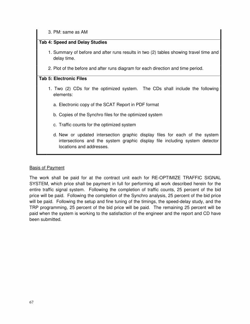
67
3. PM: same as AM
Tab 4: Speed and Delay Studies
1. Summary of before and after runs results in two (2) tables showing travel time and
delay time.
2. Plot of the before and after runs diagram for each direction and time period.
Tab 5: Electronic Files
1. Two (2) CDs for the optimized system. The CDs shall include the following
elements:
a. Electronic copy of the SCAT Report in PDF format
b. Copies of the Synchro files for the optimized system
c. Traffic counts for the optimized system
d. New or updated intersection graphic display files for each of the system
intersections and the system graphic display file including system detector
locations and addresses.
Basis of Payment
The work shall be paid for at the contract unit each for RE-OPTIMIZE TRAFFIC SIGNAL
SYSTEM, which price shall be payment in full for performing all work described herein for the
entire traffic signal system. Following the completion of traffic counts, 25 percent of the bid
price will be paid. Following the completion of the Synchro analysis, 25 percent of the bid price
will be paid. Following the setup and fine tuning of the timings, the speed-delay study, and the
TRP programming, 25 percent of the bid price will be paid. The remaining 25 percent will be
paid when the system is working to the satisfaction of the engineer and the report and CD have
been submitted.
68
TEMPORARY TRAFFIC SIGNAL TIMINGS
Description
This work shall consist of developing and maintaining appropriate traffic signal timings for the
specified intersection for the duration of the temporary signalized condition, as well as impact to
existing traffic signal timings caused by detours or other temporary conditions.
All timings and adjustments necessary for this work shall be performed by an approved
Consultant who has previous experience in optimizing Closed Loop Traffic signal Systems for
District One of the Illinois Department of Transportation. The Contractor shall contact the Traffic
Signal Engineer at (847) 705-4424 for a listing of approved Consultants.
The following tasks are associated with TEMPORARY TRAFFIC SIGNAL TIMINGS.
(a) Consultant shall attend temporary traffic signal inspection (turn-on) and/or detour
meeting and conduct on-site implementation of the traffic signal timings. Make fine-
turning adjustments to the timings in the field to alleviate observed adverse operating
conditions and to enhance operations.
(b) Consultant shall provide monthly observation of traffic signal operations in the field.
(c) Consultant shall provide on-site consultation and adjust timings as necessary for
construction stage changes, temporary traffic signal phase changes, and any other
conditions affecting timing and phasing, including lane closures, detours, and other
construction activities.
(d) Consultant shall make timing adjustments and prepare comment responses as
directed by the Area Traffic Signal Operations Engineer.
Basis of Payment.
The work shall be paid for at the contract unit price each for TEMPORARY TRAFFIC SIGNAL
TIMINGS, which price shall be payment in full for performing all work described herein per
intersection. When the temporary traffic signal installation is turned on and/or detour
implemented, 50 percent of the bid price will be paid. The remaining 50 percent of the bid price
will be paid following the removal of the temporary traffic signal installation and/or detour.
69
DIVISION 1000 MATERIALS PEDESTRIAN PUSH-BUTTON. Revise Article 1074.02 of the Standard Specifications to read:
(a) General. Push-button assemblies shall be ADA compliant, highly vandal resistant, be
pressure activated with minimal movement and cannot be stuck in a closed or constant call position. A red latching LED and audible tone shall be provided for confirmation of an actuation call.
(b) Latching LED. The normal state of the LED shall be off. When the push button is
pressure activated, the LED shall be lighted and remain on until the beginning of the walk phase. The latching relay shall be mounted in the signal cabinet, controlling two pedestrian phases.
(b) Housing. The push-button housing shall be solid 6061 aluminum and powder coated
yellow, unless otherwise noted on the plans. (c) Actuator. The actuator shall be stainless steel with a solid state electronic Piezo
switch rated for a minimum of 20 million cycles with no moving plunger or moving electrical contacts. The operating voltage shall be 12-24 V AC/DC.
(d) Pedestrian Station. Stations shall be designed to be mounted directly to a post, mast
arm pole or wood pole. The station shall be aluminum and will accept a 3-inch round push button assembly and a 9 X 12-inch R10-3e sign with arrow(s) for a count-down pedestrian signal. The pedestrian station size without count-down pedestrian signals shall accommodate a 5 X 7 ¾ -inch R10-3b or R10-3d sign with arrow(s).
(e) Location. Pedestrian push buttons and stations shall be mounted on poles and/or
posts as shown on the plans and shall be fully accessible from a paved or concrete surface. See the District’s Detail sheets for orientation and mounting details.
CONTROLLER CABINET AND PERIPHERAL EQUIPMENT. Add the following to Article 1074.03 of the Standard Specifications:
(a) (6) Cabinets shall be designed for NEMA TS2 Type 1 operation. All cabinets shall be pre-wired for a minimum of eight (8) phases of vehicular, four (4) phases of pedestrian and four (4) phases of overlap operation.
(b) (5) Cabinets – Provide 1/8" (3.2 mm) thick unpainted aluminum alloy 5052-H32.
The surface shall be smooth, free of marks and scratches. All external hardware shall be stainless steel.
(b) (6) Controller Harness – Provide a TS2 Type 2 “A” wired harness in addition to the TS2 Type 1 harness.
(b) (7) Surge Protection – Plug-in type EDCO SHA-1250 or Atlantic/Pacific approved equal.
(b) (8) BIU – Containment screw required.
70
(b) (9) Transfer Relays – Solid state or mechanical flash relays are acceptable. (b) (10) Switch Guards – All switches shall be guarded. (b) (11) Heating – Two (2) porcelain light receptacles with cage protection controlled by
both a wall switch and a thermostat or a thermostatically controlled 150 watt strip heater.
(b) (12) Plan & Wiring Diagrams – 12” x 16” (3.05mm x 4.06mm) moisture sealed container attached to door.
(b) (13) Detector Racks – Fully wired and labeled for four (4) channels of emergency vehicle pre-emption and sixteen channels (16) of vehicular operation.
(b) (14) Field Wiring Labels – All field wiring shall be labeled. (b) (15) Field Wiring Termination – Approved channel lugs required. (b) (16) Power Panel – Provide a nonconductive shield. (b) (17) Circuit Breaker – The circuit breaker shall be sized for the proposed load but
shall not be rated less than 30 amps. (b) (18) Police Door – Provide wiring and termination for plug in manual phase advance
switch. (b) (19) Railroad Pre-Emption Test Switch – Eaton 8830K13 SHA 1250 or equivalent.
RAILROAD, FULL-ACTUATED CONTROLLER AND CABINET. Controller shall comply with Article 1073.01 as amended in these Traffic Signal Special
Provisions.
Controller Cabinet and Peripheral Equipment shall comply with Article 1074.03 as amended in
these Traffic Signal Special Provisions.
Add the following to Articles 1073.01 (c) (2) and 1074.03 (a) (5) (e) of the Standard
Specifications:
Controllers and cabinets shall be new and NEMA TS2 Type 1 design.
A method of monitoring and/or providing redundancy to the railroad preemptor input to the
controller shall be included as a component of the Railroad, Full Actuated Controller and
Cabinet installation and be verified by the traffic signal equipment supplier prior to installation.
Railroad interconnected controllers and cabinets shall be assembled only by an approved traffic
signal equipment supplier. All railroad interconnected (including temporary railroad
interconnect) controllers and cabinets shall be new, built, tested and approved by the controller
equipment vendor, in the vendor's District One facility, prior to field installation. The vendor
shall provide the technical equipment and assistance as required by the Engineer to fully test
this equipment.
UNINTERRUPTIBLE POWER SUPPLY.
Revise Article 1074.04(a)(1) of the Standard Specifications to read:

71
The UPS shall be line interactive and provide voltage regulation and power conditioning
when utilizing utility power. The UPS shall be sized appropriately for the intersection’s
normal traffic signal operating connected load, plus 20 percent (20%). The total connected
traffic signal load shall not exceed the published ratings for the UPS. The UPS shall provide
a minimum of six (6) hours of normal operation run-time for signalized intersections with
LED type signal head optics at 77 °F (25 °C) (minimum 700 W/VA active output capacity,
with 90 percent minimum inverter efficiency).
Revise the first paragraph of Article 1074.04(a)(3) of the Standard Specifications to read:
The UPS shall have a minimum of four (4) sets of normally open (NO) and normally closed
(NC) single-pole double-throw (SPDT) relay contact closures, available on a panel mounted
terminal block or locking circular connectors, rated at a minimum 120 V/1 A, and labeled so
as to identify each contact according to the plans.
Revise Article 1074.04(a)(10) of the Standard Specifications to read:
The UPS shall be compatible with the District’s approved traffic controller assemblies
utilizing NEMA TS 1 or NEMA TS 2 controllers and cabinet components for full time
operation.
Revise Article 1074.04(a)(17) of the Standard Specifications to read:
When the intersection is in battery backup mode, the UPS shall bypass all internal cabinet
lights, ventilation fans, service receptacles, any lighted street name signs, any automated
enforcement equipment and any other devices directed by the Engineer.
Revise Article 1074.04(b)(2)b of the Standard Specifications to read:
Batteries, inverter/charger and power transfer relay shall be housed in a separate NEMA
Type 3R cabinet. The cabinet shall be Aluminum alloy, 5052-H32, 0.125-inch thick and
have a natural mill finish.
Revise Article 1074.04(b)(2)c of the Standard Specifications to read:
No more than three batteries shall be mounted on individual shelves for a cabinet housing
six batteries and no more than four batteries per shelf for a cabinet housing eight batteries.
Revise Article 1074.04(b)(2)e of the Standard Specifications to read:
The battery cabinet housing shall have the following nominal outside dimensions: a width of
25 in. (785 mm), a depth of 16 in. (440 mm), and a height of 41 to 48 in. (1.1 to 1.3 m).
Clearance between shelves shall be a minimum of 10 in. (250 mm).
Revise Article 1074.04(b)(2)g of the Standard Specifications to read:
The door shall open to the entire cabinet, have a neoprene gasket, an Aluminum continuous
piano hinge with stainless steel pin, and a three point locking system. The cabinet shall be
72
provided with a main door lock which shall operate with a traffic industry conventional No. 2
key. Provisions for padlocking the door shall be provided.
Add the following to Article 1074.04(b)(2) of the Standard Specifications:
j. The battery cabinet shall have provisions for an external generator connection.
Add the following to Article 1074.04(c) of the Standard Specifications:
(8) The UPS shall include a tip or kill switch installed in the battery cabinet, which shall
completely disconnect power from the UPS when the switch is manually activated.
(9) The UPS shall incorporate a flanged electric generator inlet for charging the batteries
and operating the UPS. The generator connector shall be male type, twist-lock, rated
as 15A, 125VAC with a NEMA L5-15P configuration and weatherproof lift cover plate
(Hubbell model HBL4716C or approved equal). Access to the generator inlet shall be
from a secured weatherproof lift cover plate or behind a locked battery cabinet police
panel.
Battery System.
Revise Article 1074.04(d)(3) of the Standard Specifications to read:
All batteries supplied in the UPS shall be either gel cell or AGM type, deep cycle, completely
sealed, prismatic leadcalcium based, silver alloy, valve regulated lead acid (VRLA) requiring no
maintenance. All batteries in a UPS installation shall be the same type; mixing of gel cell and
AGM types within a UPS installation is not permitted.
Revise Article 1074.04(d)(4) of the Standard Specifications to read:
Batteries shall be certified by the manufacturer to operate over a temperature range of -13
to 160 °F (-25 to + 71 °C) for gel cell batteries and -40 to 140 °F (-40 to + 60 °C) for AGM
type batteries.
Add the following to Article 1074.04(d) of the Standard Specifications:
(9) The UPS shall consist of an even number of batteries that are capable of maintaining
normal operation of the signalized intersection for a minimum of six hours.
Calculations shall be provided showing the number of batteries of the type supplied
that are needed to satisfy this requirement. A minimum of four batteries shall be
provided.
Add the following to the Article 1074.04 of the Standard Specifications:
(e) Warranty. The warranty for an uninterruptible power supply (UPS) shall cover a minimum of
two years from date the equipment is placed in operation; however, the batteries of the

73
UPS shall be warranted for full replacement for a minimum of five years from the date the
traffic signal and UPS are placed into service.
ELECTRIC CABLE. Delete “or stranded, and No. 12 or” from the last sentence of Article 1076.04 (a) of the Standard Specifications. Add the following to the Article 1076.04(d) of the Standard Specifications:
Service cable may be single or multiple conductor cable.
TRAFFIC SIGNAL POST. Add the following to Article 1077.01 (b) of the Standard Specifications: All posts and bases shall be steel and hot dipped galvanized. If the Department approves painting, powder coating by the manufacturer will be required over the galvanization in accordance with TRAFFIC SIGNAL PAINTING in Division 800 of these specifications. MAST ARM ASSEMBLY AND POLE. Add the following to Article 1077.03 (a) of the Standard Specifications: Traffic signal mast arms shall be one piece construction, unless otherwise approved by the Engineer. All poles shall be galvanized. If the Department approves painting, powder coating by the manufacturer will be required over the galvanization in accordance with with TRAFFIC SIGNAL PAINTING in Division 800 of these specifications. The shroud shall be of sufficient strength to deter pedestrian and vehicular damage. The shroud shall be constructed and designed to allow air to circulate throughout the mast arm but not allow infestation of insects or other animals, and such that it is not hazardous to probing fingers and feet. All mounting hardware shall be stainless steel. SIGNAL HEADS. Add the following to Section 1078 of the Standard Specifications: All signal and pedestrian heads shall provide 12” (300 mm) displays with glossy yellow or black polycarbonate housings. All head housings shall be the same color (yellow or black) at the intersection. For new signalized intersections and existing signalized intersections where all signal and/or pedestrian heads are being replaced, the proposed head housings shall be black. Where only selected heads are being replaced, the proposed head housing color (yellow or black) shall match existing head housings. Connecting hardware and mounting brackets shall be polycarbonate (black). A corrosion resistant anti-seize lubricant shall be applied to all metallic mounting bracket joints, and shall be visible to the inspector at the signal turn-on. Post
74
top mounting collars are required on all posts, and shall be constructed of the same material as the brackets. Pedestrian signal heads shall be furnished with the international symbolic "Walking Person" and "Upraised Palm" displays. Egg crate sun shields are not permitted. Signal heads shall be positioned according to the “District One Standard Traffic Signal Design Details." SIGNAL HEAD, LIGHT EMITTING DIODE. Add the following to Article 1078 of the Standard Specifications
General.
LED signal heads (All Face and Section Quantities), (All Mounting Types) shall conform fully to
the requirements of Articles 1078.01 and 1078.02 of the Standard Specifications amended
herein.
1. The LED signal modules shall be replaced or repaired if an LED signal module fails to
function as intended due to workmanship or material defects within the first 60 months
from the date of delivery. LED signal modules which exhibit luminous intensities less
than the minimum values specified in Table 1 of the ITE Vehicle Traffic Control Signal
Heads: Light Emitting Diode (LED) Circular Signal Supplement (June 27, 2005)
[VTSCH], or applicable successor ITE specifications, or show signs of entrance of
moisture or contaminants within the first 60 months of the date of delivery shall be
replaced or repaired. The manufacturer's written warranty for the LED signal modules
shall be dated, signed by an Officer of the company and included in the product
submittal to the State.
2. Each module shall consist of an assembly that utilizes LEDs as the light source in lieu of
an incandescent lamp for use in traffic signal sections.
(a) Physical and Mechanical Requirements
1. Modules can be manufactured under this specification for the following faces:
a. 12 inch (300 mm) circular, multi-section
b. 12 inch (300 mm) arrow, multi-section
c. 12 inch (300 mm) pedestrian, 2 sections
2. The maximum weight of a module shall be 4 lbs. (1.8 kg).
3. Each module shall be a sealed unit to include all parts necessary for operation (a printed
circuit board, power supply, a lens and gasket, etc.), and shall be weather proof after
installation and connection.
75
4. Material used for the lens and signal module construction shall conform to ASTM
specifications for the materials.
5. The lens of the module shall be tinted with a wavelength-matched color to reduce sun
phantom effect and enhance on/off contrast. The tinting shall be uniform across the lens
face. Polymeric lens shall provide a surface coating or chemical surface treatment
applied to provide abrasion resistance. The lens of the module shall be integral to the
unit, convex with a smooth outer surface and made of plastic. The lens shall have a
textured surface to reduce glare.
6. The use of tinting or other materials to enhance ON/OFF contrasts shall not affect
chromaticity and shall be uniform across the face of the lens.
7. Each module shall have a symbol of the type of module (i.e. circle, arrow, etc.) in the
color of the module. The symbol shall be 1 inch (25.4 mm) in diameter. Additionally, the
color shall be written out in 1/2 inch (12.7mm) letters next to the symbol.
(b) Photometric Requirements
1. The minimum initial luminous intensity values for the modules shall conform to the
values in Table 1 of the VTCSH (2005) for circular signal indications, and as stated in
Table 3 of these specifications for arrow and pedestrian indications at 25 °C.
2. The modules shall meet or exceed the illumination values stated in Article 1078.01(3)c of
the Standard Specifications for circular signal indications, and Table 3 of these
specifications for arrow and pedestrian indications, throughout the useful life based on
normal use in a traffic signal operation over the operating temperature range.
3. The measured chromaticity coordinates of the modules shall conform to the chromaticity
requirements of Section 4.2 of the VTCSH (2005) or applicable successor ITE
specifications.
4. The LEDs utilized in the modules shall be AlInGaP technology for red, yellow, Portland
orange (pedestrian) and white (pedestrian) indications, and GaN for green indications,
and shall be the ultra bright type rated for 100,000 hours of continuous operation from -
40 °C to +74 °C.
(c) Electrical
1. Maximum power consumption for LED modules is per Table 2.
2. Operating voltage of the modules shall be 120 VAC. All parameters shall be measured
at this voltage.
3. The modules shall be operationally compatible with currently used controller assemblies
(solid state load switches, flashers, and conflict monitors).
76
4. When a current of 20 mA AC (or less) is applied to the unit, the voltage read across the
two leads shall be 15 VAC or less.
5. The LED modules shall provide constant light output under power. Modules with
dimming capabilities shall have the option disabled or set on a non-dimming operation.
6. The individual LEDs shall be wired such that a catastrophic loss or the failure of one or
more LED will not result in the loss of the entire module.
(d) Retrofit Traffic Signal Module
1. The following specification requirements apply to the Retrofit module only. All general
specifications apply unless specifically superseded in this section.
2. Retrofit modules can be manufactured under this specification for the following faces:
a. 12 inch (300 mm) circular, multi-section
b. 12 inch (300 mm) arrow, multi-section
c. 12 inch (300 mm) pedestrian, 2 sections
3. Each Retrofit module shall be designed to be installed in the doorframe of a standard
traffic signal housing. The Retrofit module shall be sealed in the doorframe with a one-
piece EPDM (ethylene propylene rubber) gasket.
4. The maximum weight of a Retrofit module shall be 4 lbs. (1.8 kg).
5. Each Retrofit module shall be a sealed unit to include all parts necessary for operation (a
printed circuit board, power supply, a lens and gasket, etc.), and shall be weather proof
after installation and connection.
6. Electrical conductors for modules, including Retrofit modules, shall be 39.4 inches (1m)
in length, with quick disconnect terminals attached.
7. The lens of the Retrofit module shall be integral to the unit, shall be convex with a
smooth outer surface and made of plastic or of glass.
(e) The following specification requirements apply to the 12 inch (300 mm) arrow module
only. All general specifications apply unless specifically superseded in this section.
1. The arrow module shall meet specifications stated in Section 9.01 of the Equipment and
Material Standards of the Institute of Transportation Engineers (November 1998) [ITE
Standards], Chapter 2 (Vehicle Traffic Control Signal Heads) or applicable successor
ITE specifications for arrow indications.

77
2. The LEDs arrow indication shall be a solid display with a minimum of three (3) outlining
rows of LEDs and at least one (1) fill row of LEDs.
(f) The following specification requirement applies to the 12 inch (300 mm) programmed
visibility (PV) module only. All general specifications apply unless specifically
superseded in this section.
1. The LED module shall be a module designed and constructed to be installed in a
programmed visibility (PV) signal housing without modification to the housing.
(g) The following specification requirements apply to the 12 inch (300 mm) Pedestrian
module only. All general specifications apply unless specifically superseded in this
section.
1. Each pedestrian signal LED module shall provide the ability to actuate the solid upraised
hand and the solid walking person on one 12 inch (300mm) section.
2. Two (2) pedestrian sections shall be installed. The top section shall be wired to
illuminate only the upraised hand and the bottom section shall be the walking man.
3. “Egg Crate” type sun shields are not permitted. All figures must be a minimum of 9
inches (225mm) in height and easily identified from a distance of 120-feet (36.6m).
PEDESTRIAN COUNTDOWN SIGNAL HEAD, LIGHT EMITTING DIODE. Add the following to Article 1078.02 of the Standard Specifications:
General.
1. The module shall operate in one mode: Clearance Cycle Countdown Mode Only. The
countdown module shall display actual controller programmed clearance cycle and shall start counting when the flashing clearance signal turns on and shall countdown to “0” and turn off when the steady Upraised Hand (symbolizing Don’t Walk) signal turns on. Module shall not have user accessible switches or controls for modification of cycle.
2. At power on, the module shall enter a single automatic learning cycle. During the
automatic learning cycle, the countdown display shall remain dark. 3. The module shall re-program itself if it detects any increase or decrease of Pedestrian
Timing. The counting unit will go blank once a change is detected and then take one complete pedestrian cycle (with no counter during this cycle) to adjust its buffer timer.
4. The module shall allow for consecutive cycles without displaying the steady Upraised
Hand.
78
5. The module shall recognize preemption events and temporarily modify the crossing cycle accordingly.
6. If the controller preempts during the Walking Person (symbolizing Walk), the countdown
will follow the controller's directions and will adjust from Walking Person to flashing Upraised Hand. It will start to count down during the flashing Upraised Hand.
7. If the controller preempts during the flashing Upraised Hand, the countdown will continue
to count down without interruption. 8. The next cycle, following the preemption event, shall use the correct, initially
programmed values. 9. If the controller output displays Upraised Hand steady condition and the unit has not
arrived to zero or if both the Upraised Hand and Walking Person are dark for some reason, the unit suspends any timing and the digits will go dark.
10. The digits will go dark for one pedestrian cycle after loss of power of more than 1.5
seconds. 11. The countdown numerals shall be two (2) “7 segment” digits forming the time display
utilizing two rows of LEDs. 12. The LED module shall meet the requirements of the Institute of Transportation Engineers
(ITE) LED purchase specification, “Pedestrian Traffic Control Signal Indications - Part 2: LED Pedestrian Traffic Signal Modules,” or applicable successor ITE specifications, except as modified herein.
13. The LED modules shall provide constant light output under power. Modules with
dimming capabilities shall have the option disabled or set on a non-dimming operation.
14. In the event of a power outage, light output from the LED modules shall cease
instantaneously.
15. The LEDs utilized in the modules shall be AlInGaP technology for Portland Orange
(Countdown Numerals and Upraised Hand) and GaN technology for Lunar White
(Walking Person) indications.
16. The individual LEDs shall be wired such that a catastrophic loss or the failure of one or
more LED will not result in the loss of the entire module.
Electrical.
1. Maximum power consumption for LED modules is 29 watts.
2. The measured chromaticity shall remain unchanged over the input line voltage range
listed of 80 VAC to 135 VAC.

79
SIGNAL HEAD, BACKPLATE. Delete 1st sentence of Article 1078.03 of the Standard Specifications and add “All backplates shall be aluminum and louvered”. INDUCTIVE LOOP DETECTOR. Add the following to Article 1079.01 of the Standard Specifications: Contracts requiring new cabinets shall provide for rack mounted detector amplifier cards. Detector amplifiers shall provide LCD displays with loop frequency, inductance, and change of inductance readings. ILLUMINATED SIGN, LIGHT EMITTING DIODE. Delete 2nd paragraph of Article 1084.01(a) and add “Mounting hardware shall be black polycarbonate or galvanized steel and similar to mounting Signal Head hardware and brackets specified herein and shall provide tool free access to the interior. Add the following to Article 1084.01 (b) of the Standard Specifications: The message shall be formed by rows of LEDs. The sign face shall be 24 inches (600 mm) by 24 inches (600 mm).
Add the following to Article 1084.01 of the Standard Specifications:
(a) The light emitting diode (LED) blank out signs shall be manufactured by National Sign &
Signal Company, or an approved equal and consist of a weatherproof housing and door,
LEDs and transformers.
ILLUMINATED STREET NAME SIGN
The illuminated street name sign shall be as follows.
(a) Description.
The LEDs shall be white in color and utilize InGaN or UV thermally efficient technology. The LED Light Engines shall be designed to fit inside a standard fluorescent illuminated street sign housing in lieu of fluorescent lamps and ballasts or a slim line type housing. The LED internally-illuminated street name sign shall display the designated street name clearly and legibly in the daylight hours without being energized and at night when energized. The sign assembly shall consist of a four-, six-, or eight-foot aluminum housing. White translucent 3M DG3 reflective sheeting sign faces with the street name applied in 3M/Scotchlite Series 1177 or current 3M equivalent transparent green shall be installed in hinged doors on the side of the sign for easy access to perform general cleaning and maintenance operations. Illumination shall occur with LED Light Engine as specified.

80
(b) Environmental Requirements.
The LED lamp shall be rated for use in the ambient operating temperature range of -40 to +50oC (-40 to +122oF) for storage in the ambient temperature range of -40 to +75oC (-40 to +167oF).
(c) General Construction.
1. The LED Light Engine shall be a single, self-contained device, for installation in an existing street sign housing. The power supply must be designed to fit and mounted on the inside wall at one end of the street sign housing. The LED Light Engine shall be mounted within the inner top portion of the housing and no components of the light source shall sit between the sign faces.
2. The assembly and manufacturing processes of the LED Light Engine shall be designed to ensure that all LED and electronic components are adequately supported to withstand mechanical shocks and vibrations in compliance with the specifications of the ANSI, C136.31-2001 standards.
(d) Mechanical Construction.
1. The sign shall be constructed using a weatherproof, aluminum housing consisting of an extruded aluminum top with a minimum thickness of .140” x 10 ¾” deep (including the drip edge). The extruded aluminum bottom is .094” thick x 5 7/8” deep. The ends of the housing shall be cast aluminum with a minimum thickness of .250”. A six-foot sign shall be 72 5/8” long and 22 5/16” tall and not weigh more than 77 pounds. An eight-foot sign shall be 96 5/8” long and 22 5/16” tall and not weigh more than 92 pounds. All corners are continuous TIG (Tungsten Inert Gas) welded to provide a weatherproof seal around the entire housing.
2. The door shall be constructed of extruded aluminum. Two corners are continuous TIG welded with the other two screwed together to make one side of the door removable for installation of the sign face. The door is fastened to the housing on the bottom by a full length, .040” x 1 1/8” open stainless steel hinge. The door shall be held secure onto a 1” wide by 5/32” thick neoprene gasket by three (six total for two-way sign) quarter-turn fasteners to form a watertight seal between the door and the housing.
3. The sign face shall be constructed of .125” white translucent polycarbonate. The letters shall be 8” upper case and 6” lower case. The sign face legend background shall consist of 3M/Scotchlite Series 4090T or current equivalent 3M translucent DG3 white VIP (Visual Impact Performance) diamond grade sheeting (ATSM Type 9) and 3M/Scotchlite Series 1177 or current 3M equivalent transparent green acrylic EC (electronic cut-able) film applied to the front of the sign face. The legend shall be framed by a white polycarbonate border. A logo symbol and/or name of the community may be included with approval of the Engineer.
4. All surfaces of the sign shall be etched and primed in accordance to industry standards before receiving appropriate color coats of industrial enamel.
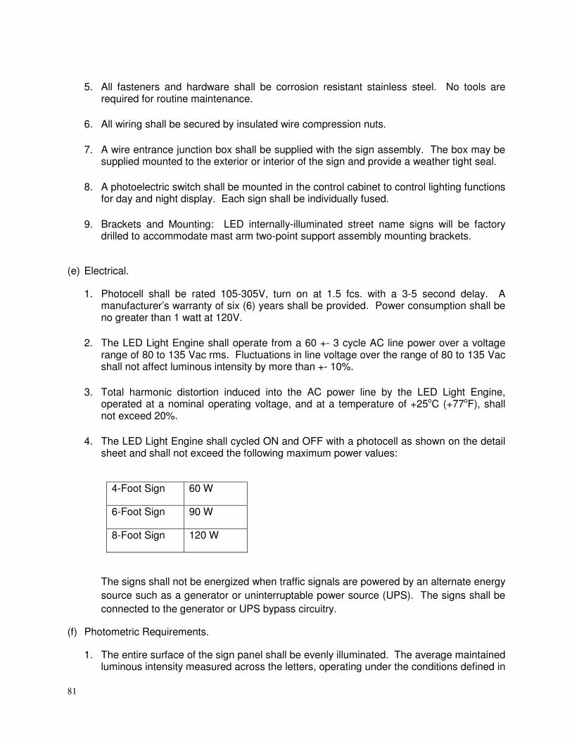
81
5. All fasteners and hardware shall be corrosion resistant stainless steel. No tools are required for routine maintenance.
6. All wiring shall be secured by insulated wire compression nuts.
7. A wire entrance junction box shall be supplied with the sign assembly. The box may be supplied mounted to the exterior or interior of the sign and provide a weather tight seal.
8. A photoelectric switch shall be mounted in the control cabinet to control lighting functions for day and night display. Each sign shall be individually fused.
9. Brackets and Mounting: LED internally-illuminated street name signs will be factory drilled to accommodate mast arm two-point support assembly mounting brackets.
(e) Electrical.
1. Photocell shall be rated 105-305V, turn on at 1.5 fcs. with a 3-5 second delay. A manufacturer’s warranty of six (6) years shall be provided. Power consumption shall be no greater than 1 watt at 120V.
2. The LED Light Engine shall operate from a 60 +- 3 cycle AC line power over a voltage range of 80 to 135 Vac rms. Fluctuations in line voltage over the range of 80 to 135 Vac shall not affect luminous intensity by more than +- 10%.
3. Total harmonic distortion induced into the AC power line by the LED Light Engine, operated at a nominal operating voltage, and at a temperature of +25oC (+77oF), shall not exceed 20%.
4. The LED Light Engine shall cycled ON and OFF with a photocell as shown on the detail sheet and shall not exceed the following maximum power values:
4-Foot Sign 60 W
6-Foot Sign 90 W
8-Foot Sign 120 W
The signs shall not be energized when traffic signals are powered by an alternate energy
source such as a generator or uninterruptable power source (UPS). The signs shall be
connected to the generator or UPS bypass circuitry.
(f) Photometric Requirements.
1. The entire surface of the sign panel shall be evenly illuminated. The average maintained luminous intensity measured across the letters, operating under the conditions defined in
82
Environmental Requirements and Wattage Sections shall be of a minimum value of 100 cd/m2.
2. The manufacturer shall make available independent laboratory test results to verify compliance to Voltage Range and Luminous Intensity Distribution Sections.
3. Twelve (12) 1.25 watt LED units shall be mounted on 1-inch x 22-inch metal cone printed circuit boards (MCPCB). The viewing angle shall be 120 degrees. LED shall have a color temperature of 5200k nominal, CRI of 80 with a life expectancy of 75,000 hrs.
(g) Quality Assurance.
The LED Light Engine shall be manufactured in accordance with a vendor quality assurance
(QA) program. The production QA shall include statistically controlled routine tests to
ensure minimum performance levels of the LED Light Engine build to meet this specification.
QA process and test result documentations shall be kept on file for a minimum period of
seven (7) years. The LED Light Engine that does not satisfy the production QA testing
performance requirements shall not be labeled, advertised, or sold as conforming to these
specifications. Each LED Light Engine shall be identified by a manufacturer’s serial number
for warranty purposes. LED Light Engines shall be replaced or repaired if they fail to
function as intended due to workmanship or material defects within the first sixty (60)
months from the date of acceptance. LED Light Engines that exhibit luminous intensities
less than the minimum value specified in Photometric Section within the first thirty-six (36)
months from the date of acceptance shall be replaced or repaired.