Embed Size (px)
Citation preview

036-21537-001-B-1004
FOR DISTRIBUTION USE ONLY - NOT TO BE USED AT POINT OF RETAIL SALE
TECHNICAL GUIDE
SUNLINE 2000™SINGLE PACKAGEHEAT PUMPS
MODEL BP180
15 NOMINAL TONS
(WORLD 50 HZ)
� � DESCRIPTION
York® Sunline 2000™ Heat Pumps are convertible single package units. All models have dual refrigerant circuits for efficient part load operation. Although the units are primarily designed for curb mounting on a roof, they can also be slab-mounted at ground level or set on steel beams above a finished roof.
These heat pumps utilize a unique ambient compensated time-temperature defrost system. The defrost module automatically increases the time interval between defrost cycles as the outdoor ambient temperature decreases. This helps to eliminate unneces-sary and costly defrosts.
All units include:
• Simplicity® Control Board• Powder Paint finish that meets ASTM-B-117 1000 hour salt
spray standards• Two-stage cooling provided by dual independent refrigeration
circuits with expansion valves, filter-driers, high and low pres-sure/loss of charge switches and freezestats
• Hermetically sealed compressors with crankcase heaters• Permanently lubricated motors• Bottom or side air discharge configuration capability (field con-
vertible)• Belt Drive Blower Motor• Manufactured under the quality standards of ISO9001• Twenty-four volt control circuit with compressor lock-out• Zero-25% fixed air damper with hood• Copper tube/aluminum fin coils• Easy access to all components• Rigging holes in base rails for lifting• Single point power connection• Complete factory package - tested, charged and wired• Agency approvals on all units
036-21537-001-B-1004
2 Unitary Products Group
TABLE OF CONTENTSDESCRIPTION . . . . . . . . . . . . . . . . . . . . . . . . . . . . . . . . . . . 1PRODUCT NOMENCLATURE. . . . . . . . . . . . . . . . . . . . . . . 3FEATURES. . . . . . . . . . . . . . . . . . . . . . . . . . . . . . . . . . . . . . 8FACTORY-INSTALLED OPTIONS . . . . . . . . . . . . . . . . . . . 9FIELD-INSTALLED ACCESSORIES . . . . . . . . . . . . . . . . . . 9
LIST OF FIGURES
Fig. # Pg. #
1 SUNLINE 2000TM HEAT PUMP . . . . . . . . . . . . . . . . . 11
2 ALTITUDE/TEMPERATURE CONVERSIONFACTOR (°C/METER) . . . . . . . . . . . . . . . . . . . . . . . . 16
3 ALTITUDE/TEMPERATURE CONVERSIONFACTOR (°F/FEET). . . . . . . . . . . . . . . . . . . . . . . . . . . 16
4 ELECTRONIC THERMOSTAT FIELD WIRING . . . . . 19
5 FIELD WIRING 24 VOLT THERMOSTAT . . . . . . . . . . 19
6 FIELD WIRING DISCONNECT . . . . . . . . . . . . . . . . . . 20
7 UNIT DIMENSIONS - 15 TON. . . . . . . . . . . . . . . . . . . 23
8 DETAIL “X” ACCY. SIDE SUPPLY & RETURNAIR OPENINGS. . . . . . . . . . . . . . . . . . . . . . . . . . . . . . 24
9 DETAIL “Y” UNIT WITH RAIN HOODS . . . . . . . . . . . . 24
10 CENTER OF GRAVITY . . . . . . . . . . . . . . . . . . . . . . . . 24
11 FOUR AND SIX POINT LOADS . . . . . . . . . . . . . . . . . 25
12 ROOF CURB DIMENSIONS - (180 & 240 UNITS) . . . 25
13 ROOF CURB BENEFITS. . . . . . . . . . . . . . . . . . . . . . . 26
14 UNIT AND CURB APPLICATION . . . . . . . . . . . . . . . . 26
15 TYPICAL APPLICATIONS. . . . . . . . . . . . . . . . . . . . . . 26
16 TYPICAL ROOF-TOP INSTALLATION . . . . . . . . . . . . 27
17 Simplicity® CONTROL WIRING DIAGRAM . . . . . . . . 27
LIST OF TABLES
Tbl. # Pg. #
1 CAPACITY RATINGS - COOLING . . . . . . . . . . . . . . . 11
2 CAPACITY RATINGS - HEATING . . . . . . . . . . . . . . . 11
3 COOLING CAPACITIES (M3/S AIRFLOW) -180 UNIT . . . . . . . . . . . . . . . . . . . . . . . . . . . . . . . . . . . 12
4 COOLING CAPACITIES (CFM AIRFLOW) -180 UNIT . . . . . . . . . . . . . . . . . . . . . . . . . . . . . . . . . . . 13
5 HEATING CAPACITIES (M3/S AIRFLOW) -180 UNIT . . . . . . . . . . . . . . . . . . . . . . . . . . . . . . . . . . . 14
6 HEATING CAPACITIES (CFM AIRFLOW) -180 UNIT . . . . . . . . . . . . . . . . . . . . . . . . . . . . . . . . . . . 14
7 ALTITUDE CORRECTION FACTORS (°C/METER). . 15
8 ALTITUDE CORRECTION FACTORS (°F/FEET) . . . 15
9 BP180 SUPPLY AIR WITH DOWNFLOWDUCT APPLICATIONS . . . . . . . . . . . . . . . . . . . . . . . . 17
10 STATIC RESISTANCES . . . . . . . . . . . . . . . . . . . . . . . 18
11 POWER EXHAUST PERFORMANCE . . . . . . . . . . . . 18
12 BLOWER MOTOR AND DRIVE DATA . . . . . . . . . . . . 18
13 VOLTAGE LIMITATIONS . . . . . . . . . . . . . . . . . . . . . . 20
14 ELECTRICAL DATA -WITHOUT POWEREDCONVENIENCE OUTLET. . . . . . . . . . . . . . . . . . . . . . 21
15 ELECTRICAL DATA -WITH POWEREDCONVENIENCE OUTLET. . . . . . . . . . . . . . . . . . . . . . 21
16 ELECTRIC HEAT CORRECTION FACTORS. . . . . . . 21
17 PHYSICAL DATA - BASIC UNIT. . . . . . . . . . . . . . . . . 22
18 OPERATING WEIGHTS (KG. / LBS.) . . . . . . . . . . . . . 22
19 MINIMUM CLEARANCES (MM/IN.) . . . . . . . . . . . . . . 23
20 UTILITIES ENTRY DATA (MM/IN.) . . . . . . . . . . . . . . . 23
21 FOUR AND SIX POINT LOADS . . . . . . . . . . . . . . . . . 25
036-21537-001-B-1004
Unitary Products Group 3
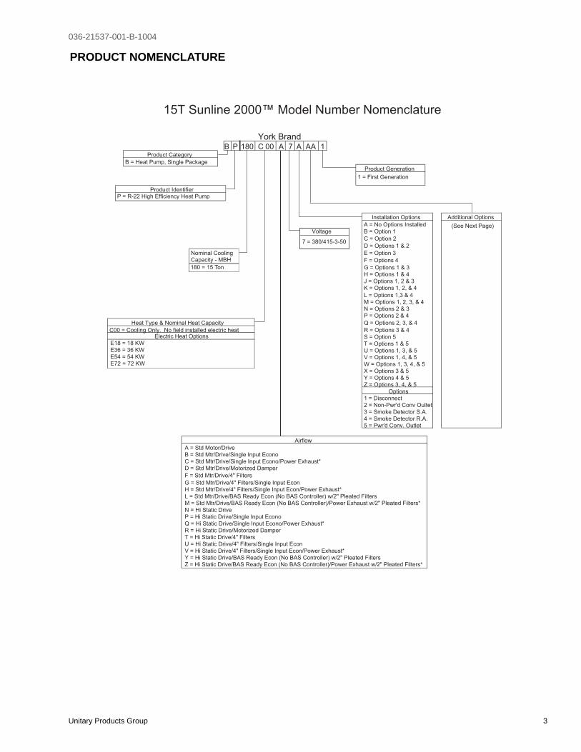
PRODUCT NOMENCLATURE
15T Sunline 2000™ Model Number Nomenclature
B P 180 C 00 A 7 A AA 1Product Category
B = Heat Pump, Single Package
Product Generation
1 = First Generation
Product Identifier
Installation Options Additional Options
A = No Options Installed (See Next Page)Voltage B = Option 1
C = Option 27 = 380/415-3-50
D = Options 1 & 2
Nominal CoolingCapacity - MBH
E = Option 3
F = Options 4
G = Options 1 & 3
H = Options 1 & 4
J = Options 1, 2 & 3
K = Options 1, 2, & 4
A = Std Motor/Drive
L = Options 1,3 & 4
B = Std Mtr/Drive/Single Input Econo
M = Options 1, 2, 3, & 4
C = Std Mtr/Drive/Single Input Econo/Power Exhaust*
N = Options 2 & 3
D = Std Mtr/Drive/Motorized Damper
P = Options 2 & 4
Heat Type & Nominal Heat Capacity
F = Std Mtr/Drive/4" Filters
Q = Options 2, 3, & 4
C00 = Cooling Only. No field installed electric heat
G = Std Mtr/Drive/4" Filters/Single Input Econ
R = Options 3 & 4
H = Std Mtr/Drive/4" Filters/Single Input Econ/Power Exhaust*
S = Option 5
L = Std Mtr/Drive/BAS Ready Econ (No BAS Controller) w/2" Pleated Filters
T = Options 1 & 5
M = Std Mtr/Drive/BAS Ready Econ (No BAS Controller)/Power Exhaust w/2" Pleated Filters*
U = Options 1, 3, & 5
N = Hi Static Drive
V = Options 1, 4, & 5
P = Hi Static Drive/Single Input Econo
W = Options 1, 3, 4, & 5
Electric Heat Options
Q = Hi Static Drive/Single Input Econo/Power Exhaust*
X = Options 3 & 5
E18 = 18 KW
R = Hi Static Drive/Motorized Damper
Y = Options 4 & 5
E36 = 36 KW
T = Hi Static Drive/4" Filters
Z = Options 3, 4, & 5
E54 = 54 KW
U = Hi Static Drive/4" Filters/Single Input Econ
Options
E72 = 72 KW
V = Hi Static Drive/4" Filters/Single Input Econ/Power Exhaust*
1 = Disconnect
Y = Hi Static Drive/BAS Ready Econ (No BAS Controller) w/2" Pleated Filters
2 = Non-Pwr'd Conv Oultet
Z = Hi Static Drive/BAS Ready Econ (No BAS Controller)/Power Exhaust w/2" Pleated Filters*
3 = Smoke Detector S.A.
4 = Smoke Detector R.A.
5 = Pwr'd Conv. Outlet
Airflow
York Brand
180 = 15 Ton
P = R-22 High Efficiency Heat Pump

036-21537-001-B-1004
4 Unitary Products Group
PRODUCT NOMENCLATURE - CONTINUED
15T Sunline 2000™ Model Number Nomenclature
Additional OptionsAA NoneAB Phase MonitorAC Coil GuardAD Dirty Filter SwitchAE Phase Monitor & Coil GuardAF Phase Monitor & Dirty Filter SwitchAG Coil Guard & Dirty Filter SwitchAH Phase Monitor, Coil Guard, & Dirty Filter SwitchBA Hinged Filter Door & Tooless Access PanelsBB Phase Monitor, Hinged Filter Door & Tooless Access PanelsBC Coil Guard, Hinged Filter Door & Tooless Access PanelsBD Dirty Filter Switch, Hinged Filter Door & Tooless Access PanelsBE Phase Monitor & Coil Guard, Hinged Filter Door & Tooless Access PanelsBF Phase Monitor & Dirty Filter Switch, Hinged Filter Door & Tooless Access PanelsBG Coil Guard & Dirty Filter Switch, Hinged Filter Door & Tooless Access PanelsBH Phase Monitor, Coil Guard, & Dirty Filter Switch, Hinged Filter Door & Tooless Access PanelsCA CPC Controller with Dirty Filter Switch & Air Proving SwitchCB CPC Controller, DFS, APS & Phase MonitorCC CPC Controller, DFS, APS & Coil GuardCD CPC Controller, DFS, APS, Phase Monitor, & Coil GuardCE CPC Controller, DFS, APS & Technicoat Cond. CoilCF CPC Controller, DFS, APS, Technicoat Cond. Coil, & Phase MonitorCG CPC Controller, DFS, APS, Technicoat Cond. Coil, & Coil GuardCH CPC Controller, DFS, APS, Technicoat Cond. Coil, Phase Monitor, & Coil GuardCJ CPC Controller, DFS, APS & Technicoat Evap. CoilCK CPC Controller, DFS, APS, Technicoat Evap. Coil, & Phase MonitorCL CPC Controller, DFS, APS, Technicoat Evap. Coil, & Coil GuardCM CPC Controller, DFS, APS, Technicoat Evap. Coil, Phase Monitor, & Coil GuardCN CPC Controller, DFS, APS & Technicoat Evap. & Cond CoilsCP CPC Controller, DFS, APS, Technicoat Evap. & Cond Coils, & Phase MonitorCQ CPC Controller, DFS, APS, Technicoat Evap. & Cond Coils, & Coil GuardCR CPC Controller, DFS, APS, Technicoat Evap. & Cond Coils, Phase Monitor, & Coil GuardDA CPC Controller with Dirty Filter Switch & Air Proving Switch, Hinged Filter Door & Tooless Access PanelsDB CPC Controller, DFS, APS & Phase Monitor, Hinged Filter Door & Tooless Access PanelsDC CPC Controller, DFS, APS & Coil Guard, Hinged Filter Door & Tooless Access PanelsDD CPC Controller, DFS, APS, Phase Monitor, & Coil Guard, Hinged Filter Door & Tooless Access PanelsDE CPC Controller, DFS, APS & Technicoat Cond. Coil, Hinged Filter Door & Tooless Access PanelsDF CPC Controller, DFS, APS, Technicoat Cond. Coil, & Phase Monitor, Hinged Filter Door & Tooless Access PanelsDG CPC Controller, DFS, APS, Technicoat Cond. Coil, & Coil Guard, Hinged Filter Door & Tooless Access PanelsDH CPC Controller, DFS, APS, Technicoat Cond. Coil, Phase Monitor, & Coil Guard, Hinged Filter Door & Tooless Access PanelsDJ CPC Controller, DFS, APS & Technicoat Evap. Coil, Hinged Filter Door & Tooless Access PanelsDK CPC Controller, DFS, APS, Technicoat Evap. Coil, & Phase Monitor, Hinged Filter Door & Tooless Access PanelsDL CPC Controller, DFS, APS, Technicoat Evap. Coil, & Coil Guard, Hinged Filter Door & Tooless Access PanelsDM CPC Controller, DFS, APS, Technicoat Evap. Coil, Phase Monitor, & Coil Guard, Hinged Filter Door & Tooless Access PanelsDN CPC Controller, DFS, APS & Technicoat Evap. & Cond Coils, Hinged Filter Door & Tooless Access PanelsDP CPC Controller, DFS, APS, Technicoat Evap. & Cond Coils, & Phase Monitor, Hinged Filter Door & Tooless Access PanelsDQ CPC Controller, DFS, APS, Technicoat Evap. & Cond Coils, & Coil Guard, Hinged Filter Door & Tooless Access PanelsDR CPC Controller, DFS, APS, Technicoat Evap. & Cond Coils, Phase Monitor, & Coil Guard, Hinged Filter Door & Tooless Access Panels
036-21537-001-B-1004
Unitary Products Group 5
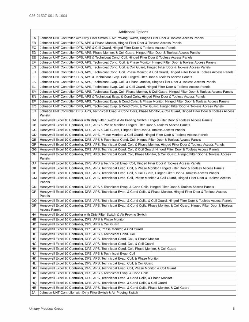
EA Johnson UNT Controller with Dirty Filter Switch & Air Proving Switch, Hinged Filter Door & Tooless Access PanelsEB Johnson UNT Controller, DFS, APS & Phase Monitor, Hinged Filter Door & Tooless Access PanelsEC Johnson UNT Controller, DFS, APS & Coil Guard, Hinged Filter Door & Tooless Access PanelsED Johnson UNT Controller, DFS, APS, Phase Monitor, & Coil Guard, Hinged Filter Door & Tooless Access PanelsEE Johnson UNT Controller, DFS, APS & Technicoat Cond. Coil, Hinged Filter Door & Tooless Access PanelsEF Johnson UNT Controller, DFS, APS, Technicoat Cond. Coil, & Phase Monitor, Hinged Filter Door & Tooless Access PanelsEG Johnson UNT Controller, DFS, APS, Technicoat Cond. Coil, & Coil Guard, Hinged Filter Door & Tooless Access PanelsEH Johnson UNT Controller, DFS, APS, Technicoat Cond. Coil, Phase Monitor, & Coil Guard, Hinged Filter Door & Tooless Access PanelsEJ Johnson UNT Controller, DFS, APS & Technicoat Evap. Coil, Hinged Filter Door & Tooless Access PanelsEK Johnson UNT Controller, DFS, APS, Technicoat Evap. Coil, & Phase Monitor, Hinged Filter Door & Tooless Access PanelsEL Johnson UNT Controller, DFS, APS, Technicoat Evap. Coil, & Coil Guard, Hinged Filter Door & Tooless Access PanelsEM Johnson UNT Controller, DFS, APS, Technicoat Evap. Coil, Phase Monitor, & Coil Guard, Hinged Filter Door & Tooless Access PanelsEN Johnson UNT Controller, DFS, APS & Technicoat Evap. & Cond Coils, Hinged Filter Door & Tooless Access PanelsEP Johnson UNT Controller, DFS, APS, Technicoat Evap. & Cond Coils, & Phase Monitor, Hinged Filter Door & Tooless Access PanelsEQ Johnson UNT Controller, DFS, APS, Technicoat Evap. & Cond Coils, & Coil Guard, Hinged Filter Door & Tooless Access PanelsER Johnson UNT Controller, DFS, APS, Technicoat Evap. & Cond Coils, Phase Monitor, & Coil Guard, Hinged Filter Door & Tooless Access
PanelsGA Honeywell Excel 10 Controller with Dirty Filter Switch & Air Proving Switch, Hinged Filter Door & Tooless Access PanelsGB Honeywell Excel 10 Controller, DFS, APS & Phase Monitor, Hinged Filter Door & Tooless Access PanelsGC Honeywell Excel 10 Controller, DFS, APS & Coil Guard, Hinged Filter Door & Tooless Access PanelsGD Honeywell Excel 10 Controller, DFS, APS, Phase Monitor, & Coil Guard, Hinged Filter Door & Tooless Access PanelsGE Honeywell Excel 10 Controller, DFS, APS & Technicoat Cond. Coil, Hinged Filter Door & Tooless Access PanelsGF Honeywell Excel 10 Controller, DFS, APS, Technicoat Cond. Coil, & Phase Monitor, Hinged Filter Door & Tooless Access PanelsGG Honeywell Excel 10 Controller, DFS, APS, Technicoat Cond. Coil, & Coil Guard, Hinged Filter Door & Tooless Access PanelsGH Honeywell Excel 10 Controller, DFS, APS, Technicoat Cond. Coil, Phase Monitor, & Coil Guard, Hinged Filter Door & Tooless Access
PanelsGJ Honeywell Excel 10 Controller, DFS, APS & Technicoat Evap. Coil, Hinged Filter Door & Tooless Access PanelsGK Honeywell Excel 10 Controller, DFS, APS, Technicoat Evap. Coil, & Phase Monitor, Hinged Filter Door & Tooless Access PanelsGL Honeywell Excel 10 Controller, DFS, APS, Technicoat Evap. Coil, & Coil Guard, Hinged Filter Door & Tooless Access PanelsGM Honeywell Excel 10 Controller, DFS, APS, Technicoat Evap. Coil, Phase Monitor, & Coil Guard, Hinged Filter Door & Tooless Access
PanelsGN Honeywell Excel 10 Controller, DFS, APS & Technicoat Evap. & Cond Coils, Hinged Filter Door & Tooless Access PanelsGP Honeywell Excel 10 Controller, DFS, APS, Technicoat Evap. & Cond Coils, & Phase Monitor, Hinged Filter Door & Tooless Access
PanelsGQ Honeywell Excel 10 Controller, DFS, APS, Technicoat Evap. & Cond Coils, & Coil Guard, Hinged Filter Door & Tooless Access PanelsGR Honeywell Excel 10 Controller, DFS, APS, Technicoat Evap. & Cond Coils, Phase Monitor, & Coil Guard, Hinged Filter Door & Tooless
Access PanelsHA Honeywell Excel 10 Controller with Dirty Filter Switch & Air Proving SwitchHB Honeywell Excel 10 Controller, DFS, APS & Phase MonitorHC Honeywell Excel 10 Controller, DFS, APS & Coil GuardHD Honeywell Excel 10 Controller, DFS, APS, Phase Monitor, & Coil GuardHE Honeywell Excel 10 Controller, DFS, APS & Technicoat Cond. CoilHF Honeywell Excel 10 Controller, DFS, APS, Technicoat Cond. Coil, & Phase MonitorHG Honeywell Excel 10 Controller, DFS, APS, Technicoat Cond. Coil, & Coil GuardHH Honeywell Excel 10 Controller, DFS, APS, Technicoat Cond. Coil, Phase Monitor, & Coil GuardHJ Honeywell Excel 10 Controller, DFS, APS & Technicoat Evap. CoilHK Honeywell Excel 10 Controller, DFS, APS, Technicoat Evap. Coil, & Phase MonitorHL Honeywell Excel 10 Controller, DFS, APS, Technicoat Evap. Coil, & Coil GuardHM Honeywell Excel 10 Controller, DFS, APS, Technicoat Evap. Coil, Phase Monitor, & Coil GuardHN Honeywell Excel 10 Controller, DFS, APS & Technicoat Evap. & Cond CoilsHP Honeywell Excel 10 Controller, DFS, APS, Technicoat Evap. & Cond Coils, & Phase MonitorHQ Honeywell Excel 10 Controller, DFS, APS, Technicoat Evap. & Cond Coils, & Coil GuardHR Honeywell Excel 10 Controller, DFS, APS, Technicoat Evap. & Cond Coils, Phase Monitor, & Coil GuardJA Johnson UNT Controller with Dirty Filter Switch & Air Proving Switch
Additional Options
036-21537-001-B-1004
6 Unitary Products Group
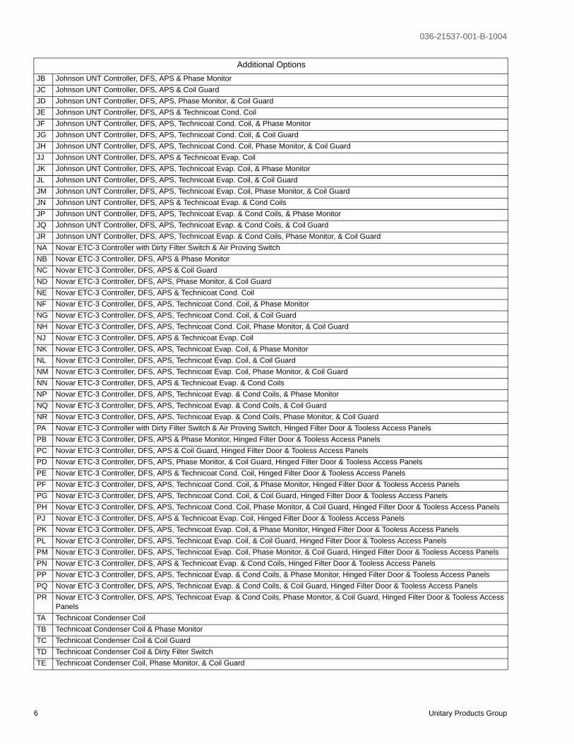
JB Johnson UNT Controller, DFS, APS & Phase MonitorJC Johnson UNT Controller, DFS, APS & Coil GuardJD Johnson UNT Controller, DFS, APS, Phase Monitor, & Coil GuardJE Johnson UNT Controller, DFS, APS & Technicoat Cond. CoilJF Johnson UNT Controller, DFS, APS, Technicoat Cond. Coil, & Phase MonitorJG Johnson UNT Controller, DFS, APS, Technicoat Cond. Coil, & Coil GuardJH Johnson UNT Controller, DFS, APS, Technicoat Cond. Coil, Phase Monitor, & Coil GuardJJ Johnson UNT Controller, DFS, APS & Technicoat Evap. CoilJK Johnson UNT Controller, DFS, APS, Technicoat Evap. Coil, & Phase MonitorJL Johnson UNT Controller, DFS, APS, Technicoat Evap. Coil, & Coil GuardJM Johnson UNT Controller, DFS, APS, Technicoat Evap. Coil, Phase Monitor, & Coil GuardJN Johnson UNT Controller, DFS, APS & Technicoat Evap. & Cond CoilsJP Johnson UNT Controller, DFS, APS, Technicoat Evap. & Cond Coils, & Phase MonitorJQ Johnson UNT Controller, DFS, APS, Technicoat Evap. & Cond Coils, & Coil GuardJR Johnson UNT Controller, DFS, APS, Technicoat Evap. & Cond Coils, Phase Monitor, & Coil GuardNA Novar ETC-3 Controller with Dirty Filter Switch & Air Proving SwitchNB Novar ETC-3 Controller, DFS, APS & Phase MonitorNC Novar ETC-3 Controller, DFS, APS & Coil GuardND Novar ETC-3 Controller, DFS, APS, Phase Monitor, & Coil GuardNE Novar ETC-3 Controller, DFS, APS & Technicoat Cond. CoilNF Novar ETC-3 Controller, DFS, APS, Technicoat Cond. Coil, & Phase MonitorNG Novar ETC-3 Controller, DFS, APS, Technicoat Cond. Coil, & Coil GuardNH Novar ETC-3 Controller, DFS, APS, Technicoat Cond. Coil, Phase Monitor, & Coil GuardNJ Novar ETC-3 Controller, DFS, APS & Technicoat Evap. CoilNK Novar ETC-3 Controller, DFS, APS, Technicoat Evap. Coil, & Phase MonitorNL Novar ETC-3 Controller, DFS, APS, Technicoat Evap. Coil, & Coil GuardNM Novar ETC-3 Controller, DFS, APS, Technicoat Evap. Coil, Phase Monitor, & Coil GuardNN Novar ETC-3 Controller, DFS, APS & Technicoat Evap. & Cond CoilsNP Novar ETC-3 Controller, DFS, APS, Technicoat Evap. & Cond Coils, & Phase MonitorNQ Novar ETC-3 Controller, DFS, APS, Technicoat Evap. & Cond Coils, & Coil GuardNR Novar ETC-3 Controller, DFS, APS, Technicoat Evap. & Cond Coils, Phase Monitor, & Coil GuardPA Novar ETC-3 Controller with Dirty Filter Switch & Air Proving Switch, Hinged Filter Door & Tooless Access PanelsPB Novar ETC-3 Controller, DFS, APS & Phase Monitor, Hinged Filter Door & Tooless Access PanelsPC Novar ETC-3 Controller, DFS, APS & Coil Guard, Hinged Filter Door & Tooless Access PanelsPD Novar ETC-3 Controller, DFS, APS, Phase Monitor, & Coil Guard, Hinged Filter Door & Tooless Access PanelsPE Novar ETC-3 Controller, DFS, APS & Technicoat Cond. Coil, Hinged Filter Door & Tooless Access PanelsPF Novar ETC-3 Controller, DFS, APS, Technicoat Cond. Coil, & Phase Monitor, Hinged Filter Door & Tooless Access PanelsPG Novar ETC-3 Controller, DFS, APS, Technicoat Cond. Coil, & Coil Guard, Hinged Filter Door & Tooless Access PanelsPH Novar ETC-3 Controller, DFS, APS, Technicoat Cond. Coil, Phase Monitor, & Coil Guard, Hinged Filter Door & Tooless Access PanelsPJ Novar ETC-3 Controller, DFS, APS & Technicoat Evap. Coil, Hinged Filter Door & Tooless Access PanelsPK Novar ETC-3 Controller, DFS, APS, Technicoat Evap. Coil, & Phase Monitor, Hinged Filter Door & Tooless Access PanelsPL Novar ETC-3 Controller, DFS, APS, Technicoat Evap. Coil, & Coil Guard, Hinged Filter Door & Tooless Access PanelsPM Novar ETC-3 Controller, DFS, APS, Technicoat Evap. Coil, Phase Monitor, & Coil Guard, Hinged Filter Door & Tooless Access PanelsPN Novar ETC-3 Controller, DFS, APS & Technicoat Evap. & Cond Coils, Hinged Filter Door & Tooless Access PanelsPP Novar ETC-3 Controller, DFS, APS, Technicoat Evap. & Cond Coils, & Phase Monitor, Hinged Filter Door & Tooless Access PanelsPQ Novar ETC-3 Controller, DFS, APS, Technicoat Evap. & Cond Coils, & Coil Guard, Hinged Filter Door & Tooless Access PanelsPR Novar ETC-3 Controller, DFS, APS, Technicoat Evap. & Cond Coils, Phase Monitor, & Coil Guard, Hinged Filter Door & Tooless Access
PanelsTA Technicoat Condenser CoilTB Technicoat Condenser Coil & Phase MonitorTC Technicoat Condenser Coil & Coil GuardTD Technicoat Condenser Coil & Dirty Filter SwitchTE Technicoat Condenser Coil, Phase Monitor, & Coil Guard
Additional Options
036-21537-001-B-1004
Unitary Products Group 7
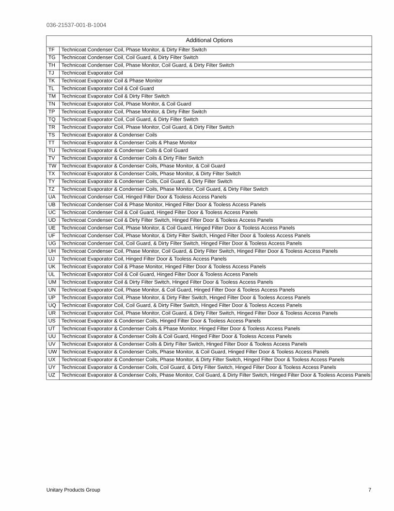
TF Technicoat Condenser Coil, Phase Monitor, & Dirty Filter SwitchTG Technicoat Condenser Coil, Coil Guard, & Dirty Filter SwitchTH Technicoat Condenser Coil, Phase Monitor, Coil Guard, & Dirty Filter SwitchTJ Technicoat Evaporator CoilTK Technicoat Evaporator Coil & Phase MonitorTL Technicoat Evaporator Coil & Coil GuardTM Technicoat Evaporator Coil & Dirty Filter SwitchTN Technicoat Evaporator Coil, Phase Monitor, & Coil GuardTP Technicoat Evaporator Coil, Phase Monitor, & Dirty Filter SwitchTQ Technicoat Evaporator Coil, Coil Guard, & Dirty Filter SwitchTR Technicoat Evaporator Coil, Phase Monitor, Coil Guard, & Dirty Filter SwitchTS Technicoat Evaporator & Condenser CoilsTT Technicoat Evaporator & Condenser Coils & Phase MonitorTU Technicoat Evaporator & Condenser Coils & Coil GuardTV Technicoat Evaporator & Condenser Coils & Dirty Filter SwitchTW Technicoat Evaporator & Condenser Coils, Phase Monitor, & Coil GuardTX Technicoat Evaporator & Condenser Coils, Phase Monitor, & Dirty Filter SwitchTY Technicoat Evaporator & Condenser Coils, Coil Guard, & Dirty Filter SwitchTZ Technicoat Evaporator & Condenser Coils, Phase Monitor, Coil Guard, & Dirty Filter SwitchUA Technicoat Condenser Coil, Hinged Filter Door & Tooless Access PanelsUB Technicoat Condenser Coil & Phase Monitor, Hinged Filter Door & Tooless Access PanelsUC Technicoat Condenser Coil & Coil Guard, Hinged Filter Door & Tooless Access PanelsUD Technicoat Condenser Coil & Dirty Filter Switch, Hinged Filter Door & Tooless Access PanelsUE Technicoat Condenser Coil, Phase Monitor, & Coil Guard, Hinged Filter Door & Tooless Access PanelsUF Technicoat Condenser Coil, Phase Monitor, & Dirty Filter Switch, Hinged Filter Door & Tooless Access PanelsUG Technicoat Condenser Coil, Coil Guard, & Dirty Filter Switch, Hinged Filter Door & Tooless Access PanelsUH Technicoat Condenser Coil, Phase Monitor, Coil Guard, & Dirty Filter Switch, Hinged Filter Door & Tooless Access PanelsUJ Technicoat Evaporator Coil, Hinged Filter Door & Tooless Access PanelsUK Technicoat Evaporator Coil & Phase Monitor, Hinged Filter Door & Tooless Access PanelsUL Technicoat Evaporator Coil & Coil Guard, Hinged Filter Door & Tooless Access PanelsUM Technicoat Evaporator Coil & Dirty Filter Switch, Hinged Filter Door & Tooless Access PanelsUN Technicoat Evaporator Coil, Phase Monitor, & Coil Guard, Hinged Filter Door & Tooless Access PanelsUP Technicoat Evaporator Coil, Phase Monitor, & Dirty Filter Switch, Hinged Filter Door & Tooless Access PanelsUQ Technicoat Evaporator Coil, Coil Guard, & Dirty Filter Switch, Hinged Filter Door & Tooless Access PanelsUR Technicoat Evaporator Coil, Phase Monitor, Coil Guard, & Dirty Filter Switch, Hinged Filter Door & Tooless Access PanelsUS Technicoat Evaporator & Condenser Coils, Hinged Filter Door & Tooless Access PanelsUT Technicoat Evaporator & Condenser Coils & Phase Monitor, Hinged Filter Door & Tooless Access PanelsUU Technicoat Evaporator & Condenser Coils & Coil Guard, Hinged Filter Door & Tooless Access PanelsUV Technicoat Evaporator & Condenser Coils & Dirty Filter Switch, Hinged Filter Door & Tooless Access PanelsUW Technicoat Evaporator & Condenser Coils, Phase Monitor, & Coil Guard, Hinged Filter Door & Tooless Access PanelsUX Technicoat Evaporator & Condenser Coils, Phase Monitor, & Dirty Filter Switch, Hinged Filter Door & Tooless Access PanelsUY Technicoat Evaporator & Condenser Coils, Coil Guard, & Dirty Filter Switch, Hinged Filter Door & Tooless Access PanelsUZ Technicoat Evaporator & Condenser Coils, Phase Monitor, Coil Guard, & Dirty Filter Switch, Hinged Filter Door & Tooless Access Panels
Additional Options

036-21537-001-B-1004
8 Unitary Products Group
FEATURES
All models are available with a wide variety of factory-mounted options such as phase monitor, dirty filter switch, and coil guard to make them suitable for almost every appli-cation.
All units are self-contained and assembled on full perimeter base rails with holes in the four corners for overhead rigging. Every unit is completely piped, wired, charged and tested at the factory to simplify the field installation and to provide years of dependable operation.
All models (including those with an economizer) are suitable for either bottom or horizontal duct connections. Models with factory installed power exhaust are suitable for bottom duct connections only. For bottom duct, you remove the sheet metal panels from the supply and return air openings through the base of the unit. For horizontal duct, you replace the supply and return air panels on the rear of the unit with a side duct flange accessory.
All models are available with these “factory mounted” outdoor air damper options:
• Single enthalpy economizer
• Single enthalpy economizer with power exhaust
• Motorized outdoor air damper
A fixed outdoor air intake assembly will be shipped in the return air compartment of all units ordered without an econo-mizer or motorized outdoor air damper option. The assembly includes a rain hood with a damper that can be set for 10, 15 or 25% outdoor air. With bottom duct connections, the intake damper assembly should be mounted over the opening in the return air panel. With horizontal ductwork, it should be mounted on the return air duct.
All supply air blowers are equipped with a belt drive that can be adjusted to meet the exact requirements of the job. A high static drive option is available for applications with a higher CFM and/or static pressure requirement.
All compressors have internal pressure relief. Every refriger-ant circuit includes an expansion valve, a liquid line filter-drier, a discharge line high pressure switch and a suction line with a freezestat and low pressure/loss of charge switch to protect all system components.
• Simplicity® Controls - Simplicity® control boards have standardized a number of features previously available only as options or by utilizing additional controls.
• Low Ambient - An integrated low-ambient control allows all units to operate in the cooling mode down to 0ºF outdoor ambient without additional assis-tance. Optionally, the control board can be pro-grammed to lockout the compressors when the outdoor air temperature is low or when free cooling is available.
• Anti-Short Cycle Protection - To aid compressor life, an anti-short cycle delay is incorporated into the standard controls. Compressor reliability is further ensured by programmable minimum run times. For testing, the anti short cycle delay can be temporarily overridden with the push of a button.
• Fan Delays - Fan on and fan off delays are fully pro-grammable. Furthermore, the heating and cooling fan delay times are independent of one another. All units are programmed with default values based upon their configuration of cooling and heat.
• Safety Monitoring - The control board monitors the high and low-pressure switches, the freezestats, the gas valve, if applicable, and the temperature limit switch on gas and electric heat units. The unit con-trol board will alarm on ignition failures, compressor lockouts and repeated limit switch trips.
• Nuisance Trip Protection and Strikes - To prevent nuisance trouble calls, the control board uses a “three times, you’re out” philosophy. The high and low-pressure switches and the freezestats must trip three times within two hours before the unit control board will lock out the associated compressor.
• On Board Diagnostics - Each alarm will energize a trouble light on the thermostat, if so equipped, and flash an alarm code on the control board LED. Each high and low-pressure switch alarm as well as each freezestat alarm has its own flash code. The control board saves the five most recent alarms in memory, and these alarms can be reviewed at any time. Alarms and programmed values are retained through the loss of power.
All units have long lasting powder paint cabinets with 1000 hour salt spray test approval under ASTM-B117 procedures.
All models are CSA approved.
• Electric Heat Operation - All electric heat models (fac-tory installed only) are wired for a single power source and include a bank of nickel chromium elements mounted at the discharge of the supply air blower to pro-vide a high velocity and uniform distribution of air across the heating elements. Every element is fully protected against excessive current and temperature by fuses and two thermal limit switches.
The power supply wiring can be routed into the control box through a threaded pipe connection in the base pan of the unit or through a knockout in the wiring panel on the front of the unit.
• BAS Controls - York’s Sunline™ series units offer fac-tory mounted BAS controls such as Novar, Honeywell, Johnson, and CPC.

036-21537-001-B-1004
Unitary Products Group 9
FACTORY-INSTALLED OPTIONS
• SINGLE INPUT ELECTRONIC ENTHALPY ECONO-MIZERS - Includes a slide-in / plug-in damper assembly with fully modulating spring-return motor actuator capa-ble of introducing up to 100% outdoor air with nominal 1% leakage type dampers.
The enthalpy system contains one sensor that monitors the outdoor air and determines when the air is cool enough and dry enough to provide free cooling.
The rainhood is painted to match the basic unit and must be field-assembled before installing.
Power exhaust is not available as a field installed option.
• POWER EXHAUST - Our single economizer options are available with power exhaust. Whenever the outdoor air intake dampers are opened for free cooling, the exhaust fan will be energized to prevent the conditioned space from being over-pressurized during economizer opera-tion.
The exhaust fan, motor and controls are installed and wired at the factory. The rain hood and the back-draft damper need to be assembled and installed in the field.
The power exhaust option can only be used on bot-tom duct configurations.
• MOTORIZED OUTDOOR AIR INTAKE DAMPER - Includes a slide-in / plug-in damper assembly with a 2-position, spring return motor actuator which opens to a pre-set position whenever the supply air blower is oper-ating and will drive fully closed when the blower unit shuts down.
The rain hood is painted to match the basic unit and must be field assembled before installing.
• PHENOLIC COATED EVAPORATOR AND CON-DENSER COILS - Special coating process that utilizes Technicoat 10-1" processes. Coating is applied by total immersion of the complete coil for maximum protection.
• ELECTRIC HEATERS wired for single point power sup-ply. These nickel chromium heater elements are pro-vided with limit and automatic reset capability to prevent operation at excessive temperatures.
• FILTER OPTIONS - Standard units are shipped with 2” throw-away filters installed. 2” pleated and 4” pleated fil-ters are offered as a factory installed option.
• CONVENIENCE OUTLET - This 110 volt outlet can be “powered” by the unit with a stepdown transformer or you may order the unit with a “non-powered” conve-nience outlet that can be wired in the field.
• DISCONNECT SWITCH - For heat pump units, a HACR breaker sized to the name plate max fuse size for the particular unit is provided. Factory installed option only.
• BAS - See “Additional Options” section in the product nomenclature.
• SMOKE DETECTORS - (supply air & return air) The smoke detectors stop operation of the unit by interrupting power to the control board if smoke is detected within the air compartment.
• COIL GUARD - Customers can purchase a coil guard kit to protect the condenser coil from damage. This is not a hail guard kit.
• PHASE MONITORS - Designed to prevent unit damage. The phase monitor will shut the unit down in an out-of-phase condition.
• HIGH SPEED DRIVE - Includes a belt and blower pulley upgrade to enhance blower performance.
• DIRTY FILTER SWITCH - This kit includes a differential pressure switch that energizes the fault light on the unit thermostat, indicating that there is an abnormally high pressure drop across the filters. Factory installed option or field installed accessory.
• HINGED FILTER DOOR/”TOOLESS” BLOWER AND ACCESS PANELS (not hinged) - This option allows for easy access and maintenance.
NOTE: Knobs are shipped separately within the unit to prevent shipping damage. These must be field installed for tool-less operation.
FIELD-INSTALLED ACCESSORIES
• SINGLE INPUT ELECTRONIC ENTHALPY ECONO-MIZERS - Includes a slide-in / plug-in damper assembly with fully modulating spring-return motor actuator capa-ble of introducing up to 100% outdoor air with nominal 1% leakage type dampers.
The enthalpy system contains one sensor that monitors the outdoor air and determines when the air is cool enough and dry enough to provide free cooling.
The rainhood is painted to match the basic unit and must be field-assembled before installing.
Power exhaust is not available as a field installed option.
• MOTORIZED OUTDOOR AIR INTAKE DAMPER - Includes a slide-in / plug-in damper assembly with a 2-position, spring return motor actuator which opens to some pre-set position whenever the supply air blower is operating and will drive fully closed when the blower unit shuts down.
The rain hood is painted to match the basic unit and must be field assembled before installing.
Power exhaust is not available as a field installed option.
• ROOF CURBS - Fourteen-inch high roof curbs provide a water-tight seal between the unit and the finished roof.
036-21537-001-B-1004
10 Unitary Products Group
These full perimeter curbs meet the requirements of the National Roofing Contractors Association (NRCA) and are shipped knocked-down for field assembly.
They're designed to fit inside the base rails of the unit and include both a wood nailing strip and duct hanger supports.
• SIDE DUCT FLANGES - One-inch flanges replace the supply and return air panels on the rear of the unit to accommodate horizontal duct connections. These flanges can also be used individually for bottom supply/horizontal return or horizontal supply/bottom return. They cannot be used on units with power exhaust.
• BAROMETRIC RELIEF DAMPER - This damper acces-sory can be used to relieve internal building air pressure on units with an economizer without power exhaust. This accessory includes a rain hood, a bird screen and a fully assembled damper. With bottom duct connections, the damper should be mounted over the opening in the return air panel. With horizontal ductwork, the accessory should be mounted on the return air duct.
• HIGH SPEED DRIVE - A smaller blower pulley and a shorter belt increase the speed of the supply air blower for applications with a higher CFM and/or static pressure requirements.
• ENTHALPY ACCESSORY CONTROL KIT - This kit contains the required components to convert a single enthalpy economizer to dual enthalpy.
• BURGLAR BARS - Mount in the supply and return openings to prevent entry into the duct work.
• WOOD SKID - Allows unit to be handled with 90” forks.
• CO2 SENSOR - Senses CO2 levels and automatically overrides the economizer when levels rise above the present limits.
• COIL GUARD - Customers can purchase a coil guard kit to protect the condenser coil from damage. This is not a hail guard kit.
• PHASE MONITORS - Designed to prevent unit damage. The phase monitor will shut the unit down in an out-of-phase condition.

036-21537-001-B-1004
Unitary Products Group 11
FIGURE 1 - SUNLINE 2000TM HEAT PUMP
������������������ ��� ������� ������������� �
���� ��������������������� �����
���������� ������ ������� �������� ��
����� �������������������������������������� !����"
�� ������������#$����%����#�� ��#&�$��'((�)�� *����+ �$+���! "
�������� �������� ���� ��������������� ��� �������
�����,���� ��� �������
����� �������� ������������"
����-� ������� ���
������� ���� �./����������� ����������������������
��������������������� ���
��������������������,� ��� ���� �
��� ��� �������� ����� ���������0� �
12���������������� �
�����0� ���
���������������� �������������
TABLE 1: CAPACITY RATINGS - COOLING
MODELDESIGN TEMPERATURES (°C)
TOTAL OUTPUTkW / MBH
TOTAL INPUTkW COP1 EER2
SENSIBLEOUTPUTkW / MBH
LATENT OUTPUTkW / MBHRATING3
POINTINDOORDB / WB
OUTDOORDB / WB
BP180
T1 27 / 19 35 / 24 43.8 / 149 17.7 2.50 8.45 38.8 / 132 5.0 / 17
T2 29 / 19 46 / 24 39.0 / 133 20.4 1.90 6.55 39.0 / 133 0.0 / 0
T3 21 / 15 27 / 19 42.7 / 146 16.1 2.65 9.05 34.8 / 119 7.9 / 27
1. COP = Coefficient of Performance - total output kW divided by the total input kW.2. EER = Energy Efficiency Ratio - total output Mbh divided by the total input kW.3. T1 = Moderate Climates, T2 = Hot Climates, T3 = Cool Climates.
TABLE 2: CAPACITY RATINGS - HEATING
MODELDESIGN TEMPERATURES (°C)
TOTAL OUTPUTkW / MBH
TOTAL INPUTkW COP1 EER2
ELECTRIC HEAT3
NOMINAL CAPACITY kW
RATINGPOINT
INDOORDB / WB
OUTDOORDB / WB
BP180
High 20 / 12 7 / 6 47.3 / 161 16.0 2.95 10.1
15, 27, 40, 54Low 20 / 12 2 / 1 27.4 / 93 14.5 1.90 6.45
X-Low 20 / 12 -7 / -8 19.8 / 68 13.3 1.50 5.10
1. COP = Coefficient of Performance - total output kW divided by the total input kW.2. EER = Energy Efficiency Ratio - total output Mbh divided by the total input kW.3. Heaters available as factory-installed options - all with single point power supply.
036-21537-001-B-1004
12 Unitary Products Group
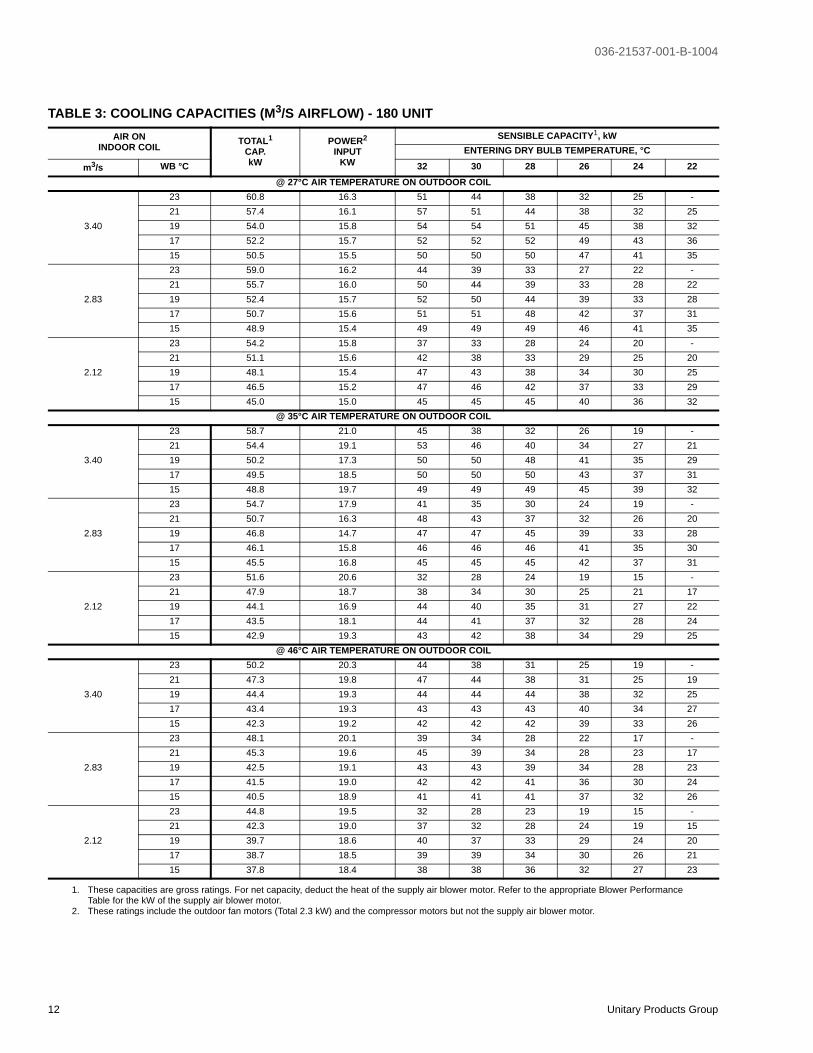
TABLE 3: COOLING CAPACITIES (M3/S AIRFLOW) - 180 UNITAIR ON
INDOOR COIL TOTAL1
CAP.kW
POWER2
INPUTKW
SENSIBLE CAPACITY1, kWENTERING DRY BULB TEMPERATURE, °C
m3/s WB °C 32 30 28 26 24 22@ 27°C AIR TEMPERATURE ON OUTDOOR COIL
3.40
23 60.8 16.3 51 44 38 32 25 -21 57.4 16.1 57 51 44 38 32 2519 54.0 15.8 54 54 51 45 38 3217 52.2 15.7 52 52 52 49 43 3615 50.5 15.5 50 50 50 47 41 35
2.83
23 59.0 16.2 44 39 33 27 22 -21 55.7 16.0 50 44 39 33 28 2219 52.4 15.7 52 50 44 39 33 2817 50.7 15.6 51 51 48 42 37 3115 48.9 15.4 49 49 49 46 41 35
2.12
23 54.2 15.8 37 33 28 24 20 -21 51.1 15.6 42 38 33 29 25 2019 48.1 15.4 47 43 38 34 30 2517 46.5 15.2 47 46 42 37 33 2915 45.0 15.0 45 45 45 40 36 32
@ 35°C AIR TEMPERATURE ON OUTDOOR COIL
3.40
23 58.7 21.0 45 38 32 26 19 -21 54.4 19.1 53 46 40 34 27 2119 50.2 17.3 50 50 48 41 35 2917 49.5 18.5 50 50 50 43 37 3115 48.8 19.7 49 49 49 45 39 32
2.83
23 54.7 17.9 41 35 30 24 19 -21 50.7 16.3 48 43 37 32 26 2019 46.8 14.7 47 47 45 39 33 2817 46.1 15.8 46 46 46 41 35 3015 45.5 16.8 45 45 45 42 37 31
2.12
23 51.6 20.6 32 28 24 19 15 -21 47.9 18.7 38 34 30 25 21 1719 44.1 16.9 44 40 35 31 27 2217 43.5 18.1 44 41 37 32 28 2415 42.9 19.3 43 42 38 34 29 25
@ 46°C AIR TEMPERATURE ON OUTDOOR COIL
3.40
23 50.2 20.3 44 38 31 25 19 -21 47.3 19.8 47 44 38 31 25 1919 44.4 19.3 44 44 44 38 32 2517 43.4 19.3 43 43 43 40 34 2715 42.3 19.2 42 42 42 39 33 26
2.83
23 48.1 20.1 39 34 28 22 17 -21 45.3 19.6 45 39 34 28 23 1719 42.5 19.1 43 43 39 34 28 2317 41.5 19.0 42 42 41 36 30 2415 40.5 18.9 41 41 41 37 32 26
2.12
23 44.8 19.5 32 28 23 19 15 -21 42.3 19.0 37 32 28 24 19 1519 39.7 18.6 40 37 33 29 24 2017 38.7 18.5 39 39 34 30 26 2115 37.8 18.4 38 38 36 32 27 23
1. These capacities are gross ratings. For net capacity, deduct the heat of the supply air blower motor. Refer to the appropriate Blower Performance Table for the kW of the supply air blower motor.
2. These ratings include the outdoor fan motors (Total 2.3 kW) and the compressor motors but not the supply air blower motor.

036-21537-001-B-1004
Unitary Products Group 13
TABLE 4: COOLING CAPACITIES (CFM AIRFLOW) - 180 UNITAIR ON
INDOOR COILTOTAL1
CAP.MBH
POWER2
INPUTKW
SENSIBLE CAPACITY1, MBHENTERING DRY BULB TEMPERATURE, °F
CFM WB °F 90 86 82 79 75 72@ 80°F AIR TEMPERATURE ON OUTDOOR COIL
7200
73 207 16.3 173 151 129 108 86 -70 196 16.1 195 173 152 130 108 8766 184 15.8 184 184 174 152 130 10963 178 15.7 178 178 178 167 145 12359 172 15.5 172 172 172 161 140 118
6000
73 201 16.2 151 132 113 94 75 -70 190 16.0 170 151 132 113 94 7566 179 15.7 179 170 151 132 113 9463 173 15.6 173 173 164 145 126 10759 167 15.4 167 167 167 158 139 120
4500
73 185 15.8 127 112 97 82 68 -70 175 15.6 143 129 114 99 84 7066 164 15.4 160 145 131 116 101 8663 159 15.2 159 157 142 127 112 9859 153 15.0 153 153 153 138 123 109
@ 95°F AIR TEMPERATURE ON OUTDOOR COIL
7200
73 200 21.0 153 131 109 88 66 -70 186 19.1 179 158 136 114 93 7166 171 17.3 171 171 163 141 120 9863 169 18.5 169 169 169 147 126 10459 167 19.7 167 167 167 154 132 110
6000
73 187 17.9 140 121 102 83 64 -70 173 16.3 165 146 127 108 89 7066 160 14.7 160 160 152 133 114 9563 157 15.8 157 157 157 139 120 10159 155 16.8 155 155 155 145 126 107
4500
73 176 20.6 110 96 81 66 51 -70 163 18.7 130 115 101 86 71 5666 151 16.9 150 135 121 106 91 7663 148 18.1 148 140 125 110 96 8159 146 19.3 146 145 130 115 100 86
@ 115°F AIR TEMPERATURE ON OUTDOOR COIL
7200
73 171 20.3 150 129 107 85 64 -70 161 19.8 161 151 129 107 86 6466 152 19.3 152 152 151 129 108 8663 148 19.3 148 148 148 136 114 9359 144 19.2 144 144 144 134 112 90
6000
73 164 20.1 133 114 95 76 57 -70 155 19.6 153 134 115 96 77 5866 145 19.1 145 145 134 115 96 7763 142 19.0 142 142 140 121 102 8359 138 18.9 138 138 138 127 108 89
4500
73 153 19.5 109 94 80 65 50 -70 144 19.0 125 111 96 81 66 5266 135 18.6 135 127 112 98 83 6863 132 18.5 132 132 117 103 88 7359 129 18.4 129 129 123 108 93 78
1. These capacities are gross ratings. For net capacity, deduct the heat of the supply air blower motor. Refer to the appropriate Blower Performance Table for the kW of the supply air blower motor.
2. These ratings include the outdoor fan motors (Total 2.3 kW) and the compressor motors but not the supply air blower motor.
036-21537-001-B-1004
14 Unitary Products Group
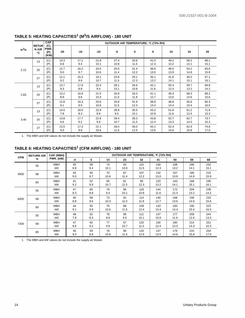
TABLE 5: HEATING CAPACITIES1 (M3/S AIRFLOW) - 180 UNIT
m3/sRETURN AIR
°C
CAP. (C)
PWR. (P)
(KW)
OUTDOOR AIR TEMPERATURE, °C (72% RH)
-20 -15 -10 -5 0 5 10 15 20
2.12
13 (C)(P)
13.38.8
17.19.4
21.810.1
27.410.8
33.811.5
41.012.3
49.213.2
58.214.1
68.115.1
20 (C)(P)
12.79.0
16.29.7
20.510.6
25.511.4
31.412.2
38.613.0
46.013.9
54.214.9
63.015.9
27 (C)(P)
12.19.2
15.39.9
19.110.7
23.811.5
29.112.3
35.113.2
41.814.1
49.215.1
57.116.1
2.83
13 (C)(P)
13.78.3
17.68.8
22.49.4
28.110.1
34.610.8
42.111.6
50.412.4
59.713.2
69.814.2
20 (C)(P)
13.28.9
16.99.6
21.510.3
26.911.0
33.311.8
41.112.7
49.313.6
58.314.6
68.215.6
27 (C)(P)
12.89.1
16.39.9
20.610.6
25.811.5
31.912.4
38.913.4
46.814.4
55.615.4
65.316.5
3.40
13 (C)(P)
14.07.8
18.08.3
22.98.9
28.89.5
35.510.1
43.210.9
51.811.6
61.212.4
71.613.3
20 (C)(P)
13.88.6
17.79.2
22.69.9
28.410.7
35.311.5
43.812.4
52.713.3
62.714.3
73.715.3
27 (C)(P)
13.59.0
17.39.8
22.110.6
28.011.5
35.012.5
43.113.5
52.414.6
62.915.8
74.617.0
1. The MBH and kW values do not include the supply air blower.
TABLE 6: HEATING CAPACITIES1 (CFM AIRFLOW) - 180 UNIT
CFM RETURN AIRºF
CAP. (MBH)PWR. (kW)
OUTDOOR AIR TEMPERATURE, ºF (72% RH)-4 5 14 23 32 41 50 59 68
4500
55 MBHkW
458.8
589.4
7410.1
9310.8
11511.5
14012.3
16813.2
19914.1
23215.1
68 MBHkW
439.0
559.7
7010.6
8711.4
10712.2
13213.0
15713.9
18514.9
21515.9
80 MBHkW
419.2
529.9
6510.7
8111.5
9912.3
12013.2
14314.1
16815.1
19516.1
6000
55 MBHkW
478.3
608.8
769.4
9610.1
11810.8
14411.6
17212.4
20413.2
23814.2
68 MBHkW
458.9
589.6
7310.3
9211.0
11411.8
14012.7
16813.6
19914.6
23315.6
80 MBHkW
449.1
559.9
7010.6
8811.5
10912.4
13313.4
16014.4
19015.4
22316.5
7200
55 MBHkW
487.8
628.3
788.9
989.5
12110.1
14710.9
17711.6
20912.4
24413.3
68 MBHkW
478.6
609.2
779.9
9710.7
12011.5
15012.4
18013.3
21414.3
25115.3
80 MBHkW
469.0
599.8
7610.6
9611.5
12012.5
14713.5
17914.6
21515.8
25417.0
1. The MBH and kW values do not include the supply air blower.
036-21537-001-B-1004
Unitary Products Group 15
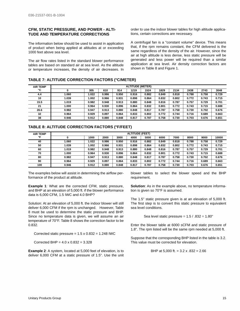
CFM, STATIC PRESSURE, AND POWER - ALTI-TUDE AND TEMPERATURE CORRECTIONS
The information below should be used to assist in applicationof product when being applied at altitudes at or exceeding1000 feet above sea level.
The air flow rates listed in the standard blower performancetables are based on standard air at sea level. As the altitudeor temperature increases, the density of air decreases. In
order to use the indoor blower tables for high altitude applica-tions, certain corrections are necessary.
A centrifugal fan is a "constant volume" device. This meansthat, if the rpm remains constant, the CFM delivered is thesame regardless of the density of the air. However, since theair at high altitude is less dense, less static pressure will begenerated and less power will be required than a similarapplication at sea level. Air density correction factors areshown in Table 8 and Figure 1.
The examples below will assist in determining the airflow per-formance of the product at altitude.
Example 1: What are the corrected CFM, static pressure,and BHP at an elevation of 5,000 ft. if the blower performancedata is 6,000 CFM, 1.5 IWC and 4.0 BHP?
Solution: At an elevation of 5,000 ft. the indoor blower will stilldeliver 6,000 CFM if the rpm is unchanged. However, Table8 must be used to determine the static pressure and BHP.Since no temperature data is given, we will assume an airtemperature of 70°F. Table 8 shows the correction factor to be0.832.
Corrected static pressure = 1.5 x 0.832 = 1.248 IWC
Corrected BHP = 4.0 x 0.832 = 3.328
Example 2: A system, located at 5,000 feet of elevation, is todeliver 6,000 CFM at a static pressure of 1.5". Use the unit
blower tables to select the blower speed and the BHPrequirement.
Solution: As in the example above, no temperature informa-tion is given so 70°F is assumed.
The 1.5" static pressure given is at an elevation of 5,000 ft.The first step is to convert this static pressure to equivalentsea level conditions.
Sea level static pressure = 1.5 / .832 = 1.80"
Enter the blower table at 6000 sCFM and static pressure of1.8". The rpm listed will be the same rpm needed at 5,000 ft.
Suppose that the corresponding BHP listed in the table is 3.2.This value must be corrected for elevation.
BHP at 5,000 ft. = 3.2 x .832 = 2.66
TABLE 7: ALTITUDE CORRECTION FACTORS (°C/METER)AIR TEMP
°C ALTITUDE (METER)
0 305 610 914 1219 1524 1829 2134 2438 2743 30484.4 1.060 1.022 0.986 0.950 0.916 0.882 0.849 0.818 0.788 0.758 0.72910 1.039 1.002 0.966 0.931 0.898 0.864 0.832 0.802 0.772 0.743 0.715
15.5 1.019 0.982 0.948 0.913 0.880 0.848 0.816 0.787 0.757 0.729 0.70121 1.000 0.964 0.930 0.896 0.864 0.832 0.801 0.772 0.743 0.715 0.688
26.6 0.982 0.947 0.913 0.880 0.848 0.817 0.787 0.758 0.730 0.702 0.67632 0.964 0.929 0.897 0.864 0.833 0.802 0.772 0.744 0.716 0.689 0.66338 0.946 0.912 0.880 0.848 0.817 0.787 0.758 0.730 0.703 0.676 0.651
TABLE 8: ALTITUDE CORRECTION FACTORS (°F/FEET)AIR TEMP
°F ALTITUDE (FEET)
0 1000 2000 3000 4000 5000 6000 7000 8000 9000 1000040 1.060 1.022 0.986 0.950 0.916 0.882 0.849 0.818 0.788 0.758 0.72950 1.039 1.002 0.966 0.931 0.898 0.864 0.832 0.802 0.772 0.743 0.71560 1.019 0.982 0.948 0.913 0.880 0.848 0.816 0.787 0.757 0.729 0.70170 1.000 0.964 0.930 0.896 0.864 0.832 0.801 0.772 0.743 0.715 0.68880 0.982 0.947 0.913 0.880 0.848 0.817 0.787 0.758 0.730 0.702 0.67690 0.964 0.929 0.897 0.864 0.833 0.802 0.772 0.744 0.716 0.689 0.663100 0.946 0.912 0.880 0.848 0.817 0.787 0.758 0.730 0.703 0.676 0.651

036-21537-001-B-1004
16 Unitary Products Group
FIGURE 1 - ALTITUDE/TEMPERATURE CONVERSION FACTOR (°C/METER)
������������������ ���������� ������
�����
�����
�����
�����
�����
�����
��� �� ���� � ��� �
����������� ����
����������������
�� �����
�� �����
���
���
���
���
��
��
��
���
���
FIGURE 2 - ALTITUDE/TEMPERATURE CONVERSION FACTOR (°F/FEET)
������������������ ���������� ������
�����
�����
�����
�����
�����
�����
�� �� �� �� �� �� ���
����������� ����
����������������
� �
���� ��
����
����
����
����
����
����
����
������
����

036-21537-001-B-1004
Unitary Products Group 17
NOTES: 1.Blower performance includes fixed outdoor air, 2” T/A filters, a dry evaporator coil and no electric heat.2.Refer to Table 10 for additional static resistances.
ESP = External Static Pressure available for the supply and return air duct system. All internal unit resistances have been deducted from the total static pressure of the blower.
* Do NOT close the pulley below 1 turn open.** Factory setting.
TABLE 9: BP180 SUPPLY AIR WITH DOWNFLOW DUCT APPLICATIONS
BLOWERSPEED,(RPM)
MOTORPULLEY(TURNSOPEN)*
AIRFLOW
2.10 m3/s 2.45 m3/s 2.80 m3/s 3.10 m3/s 3.40 m3/s
ESP(Pa)
Output(kW)
Input(kW)
ESP(Pa)
Output(kW)
Input(kW)
ESP(Pa)
Output(kW)
Input(kW)
ESP(Pa)
Output(kW)
Input(kW)
ESP(Pa)
Output(kW)
Input(kW)
STANDARD DRIVE (m3/s)
845 6.0 173 1.8 2.2 138 2.2 2.6 83 2.6 3.1 18 3.0 3.5 - - -
885 5.0 208 1.9 2.3 172 2.3 2.8 115 2.7 3.3 49 3.1 3.7 - - -
925 4.0 245 2.0 2.4 208 2.4 2.9 149 2.9 3.4 82 3.3 3.9 - - -
960 3.0 281 2.1 2.6 242 2.6 3.1 182 3.0 3.6 114 3.4 4.1 30 3.8 4.6
1000 2.0 323 2.3 2.7 283 2.7 3.2 222 3.2 3.8 152 3.6 4.3 67 4.0 4.8
1040 1.0 369 2.4 2.9 327 2.9 3.4 264 3.3 4.0 193 3.8 4.5 107 4.2 5.1
HIGH SPEED DRIVE (m3/s)
1030 6.0 357 2.4 2.8 316 2.8 3.4 253 3.3 3.9 183 3.7 4.5 97 4.2 5.0
1070 5.0 405 2.5 3.0 362 3.0 3.6 298 3.5 4.2 226 3.9 4.7 - - -
1115 4.0 461 2.7 3.2 416 3.2 3.8 351 3.7 4.4 278 4.2 5.0 - - -
1155 3.0 514 2.9 3.4 468 3.4 4.0 401 3.9 4.7 - - - - - -
1200 2.0 577 3.1 3.7 529 3.6 4.3 461 4.1 5.0 - - - - - -
1240 1.0 636 3.3 3.9 587 3.8 4.5 - - - - - - - - -
BLOWERSPEED,(RPM)
MOTORPULLEY(TURNSOPEN)*
AIRFLOW
4450 CFM 5190 CFM 5930 CFM 6565 CFM 7200 CFM
ESP(iwg)
Output(bhp)
Input(kW)
ESP(iwg)
Output(bhp)
Input(kW)
ESP(iwg)
Output(bhp)
Input(kW)
ESP(iwg)
Output(bhp)
Input(kW)
ESP(iwg)
Output(bhp)
Input(kW)
STANDARD DRIVE (CFM)
845 6.0 0.7 2.4 2.2 0.6 2.9 2.6 0.3 3.5 3.1 0.1 4.0 3.5 - - -
885 5.0 0.8 2.6 2.3 0.7 3.1 2.8 0.5 3.7 3.3 0.2 4.2 3.7 - - -
925 4.0 1.0 2.7 2.4 0.8 3.3 2.9 0.6 3.8 3.4 0.3 4.4 3.9 - - -
960 3.0 1.1 2.9 2.6 1.0 3.4 3.1 0.7 4.0 3.6 0.5 4.6 4.1 0.1 5.2 4.6
1000 2.0 1.3 3.0 2.7 1.1 3.6 3.2 0.9 4.2 3.8 0.6 4.8 4.3 0.3 5.4 4.8
1040 1.0 1.5 3.2 2.9 1.3 3.8 3.4 1.1 4.5 4.0 0.8 5.1 4.5 0.4 5.7 5.1
HIGH SPEED DRIVE (CFM)
1030 6.0 1.4 3.2 2.8 1.3 3.8 3.4 1.0 4.4 3.9 0.7 5.0 4.5 0.4 5.6 5.0
1070 5.0 1.6 3.4 3.0 1.5 4..0 3.6 1.2 4.7 4.2 0.9 5.3 4.7 - - -
1115 4.0 1.9 3.6 3.2 1.7 4.3 3.8 1.4 5.0 4.4 1.1 5.6 5.0 - - -
1155 3.0 2.1 3.9 3.4 1.9 4.5 4.0 1.6 5.2 4.7 - - - - - -
1200 2.0 2.3 4.1 3.7 2.1 4.8 4.3 1.8 5.5 5.0 - - - - - -
1240 1.0 2.6 4.4 3.9 2.4 5.1 4.5 - - - - - - - - -
036-21537-001-B-1004
18 Unitary Products Group
* Factory Setting Power Exhaust motor is a 3/4 HP, PSC type with sleeve bearings, a 48 frame and inherent protection.
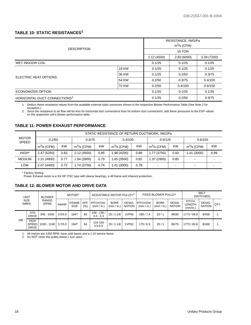
TABLE 10: STATIC RESISTANCES1
DESCRIPTION
RESISTANCE, IWG/Pam3/s (CFM)
15 TON
2.12 (4500) 2.83 (6000) 3.39 (7200)
WET INDOOR COIL 0.1/25 0.1/25 0.1/25
ELECTRIC HEAT OPTIONS
18 KW 0.1/25 0.1/25 0.1/25
36 KW 0.1/25 0.2/50 0.3/75
54 KW 0.2/50 0.3/75 0.4/100
72 KW 0.2/50 0.4/100 0.6/150
ECONOMIZER OPTION 0.1/25 0.1/25 0.1/25
HORIZONTAL DUCT CONNECTIONS2 0.1/25 0.2/50 0.3/75
1. Deduct these resistance values from the available external static pressures shown in the respective Blower Performance Table (See Note 2 for exception.)
2. Since the resistance to air flow will be less for horizontal duct connections than for bottom duct connections, add these pressures to the ESP values on the respective unit’s blower performance table.
TABLE 11: POWER EXHAUST PERFORMANCE
MOTORSPEED
STATIC RESISTANCE OF RETURN DUCTWORK, IWG/Pa
0.2/50 0.3/75 0.4/100 0.5/125 0.6/150
m3/s (CFM) KW m3/s (CFM) KW m3/s (CFM) KW m3/s (CFM) KW m3/s (CFM) KW
HIGH* 2.47 (5250) 0.83 2.12 (4500) 0.85 1.98 (4200) 0.88 1.77 (3750) 0.93 1.41 (3000) 0.99
MEDIUM 2.31 (4900) 0.77 1.84 (3900) 0.79 1.65 (3500) 0.82 1.37 (2900) 0.85 - -
LOW 2.07 (4400) 0.72 1.74 (3700) 0.74 1.41 (3000) 0.78 - - - -
TABLE 12: BLOWER MOTOR AND DRIVE DATA
UNITSIZE
(MBH)
BLOWERRANGE(RPM)
MOTOR1 ADJUSTABLE MOTOR PULLEY2 FIXED BLOWER PULLEY BELT(NOTCHED)
kW/HP FRAME SIZE
EFF.(%)
PITCH DIA. (mm / in.)
BORE(mm / in.)
DESIG-NATION
PITCH DIA. (mm / in.)
BORE(mm / in.)
DESIG-NATION
PITCHLENGTH(mm/in.)
DESIG-NATION QTY.
180
STDDRIVE 845 - 1040 3.0/4.0 184T 83 109 - 135 /
4.3 - 5.3 29 / 1-1/8 1VP56 188 / 7.4 25 / 1 BK80 1773 / 69.8 BX68 1
HIGHSPEEDDRIVE
1030 - 1240 3.7/5.0 184T 84 124-1504.9-5.9 29 / 1-1/8 1VP62 175 / 6.9 25 / 1 BK75 1773 / 69.8 BX68 1
1. All motors are 1450 RPM, have sold bases and a 1.10 service factor.2. Do NOT close this pulley below 1 turn open.

036-21537-001-B-1004
Unitary Products Group 19
NOTE: This unit does NOT REQUIRE a heat pump thermo-stat. It is designed to work with a standard two-stagecool, two-stage heat thermostat; however, the ther-mostat must provide a “G” signal when there is a callfor “W1”.
FIGURE 2 - ELECTRONIC THERMOSTAT FIELD WIRING
� �
� �
� �
� �
� �
� �
�
�
�
�
� �
� �
�
�
� � � � � � � � � � �
� � � � � � � � �
� � � � � � � � � � � � � �
� � � � � � � � �
� � � � � � � � ! " � � # � $ � % & & % ' � � � � ( � � & ) � % � � � � � * + + * * � * * � � � , " ! � � - . � ) � ) - ' ' % ) � / 0
� � � � & " ! % � ) � � � � % ! . � � � � # � 1 " . � � % � � � � % 2 � - � # - � � � � � � ) � � � ( � � - � . �
� � � � ! & " 3 � � � . % & # � � ) � 4 ( � ! � � ( � � � ( � � & ) � % � � ) 4 " � � ( � ) � � � � ( � � ) � � 5 ' % � 6 � # ) " � " ! 0
� � � 7 � �
� � % ! ) 8 � & � �
� � � � � � � � � � � � � � � �
� � � * � + * � � � � � 9 � � � � :
� � �
� �
� �
� �
�
� �
�
� :
�
������
�������
The thermostat must provide a “G” signalwhen there is a call for “W1.”The unit controlboard will energize the indoor blower whenthe compressors are energized; however, ifthe thermostat calls for “W2” during the anti-short-cycle delay, the electric heat (wheninstalled) will be energized immediatelyupon the call for “W2.”
FIGURE 3 - FIELD WIRING 24 VOLT THERMOSTAT
� � �
� �
� �
� �
�
� �
�
� :
�
������
�������
� �
� �
� �
�
� �
�
� � � � � � � � � � � �
� � � � :
� 5 � � � �
� �
� �
The thermostat must provide a “G” signalwhen there is a call for “W1.”The unit controlboard will energize the indoor blower whenthe compressors are energized; however, ifthe thermostat calls for “W2” during the anti-short-cycle delay, the electric heat (wheninstalled) will be energized immediatelyupon the call for “W2.”

036-21537-001-B-1004
20 Unitary Products Group
Note 1: Maximum HACR breaker of the same amp size is acceptable.
Note 2: Only 18kW of the 36 or 54kW, or only 36kW of the 72kW electric heat can be simultaneously energized with the mechanical heating. The full heater kW operates only if both compressors are locked out.
FIGURE 4 - FIELD WIRING DISCONNECTLD WIRING DISCONNECT
� � � � � � � � � � � � � ; � � � �
� � � � � :
� � �
� � � � �
� � � � �
� � � � �
� � � � � �
9 � � � � � � � � � � 9 � � � :
� � � � � � � : � : � � � � � � � � �
TABLE 13: VOLTAGE LIMITATIONS
POWER SUPPLYVOLTAGE
MIN. MAX.
380/415-3-50 342 456

036-21537-001-B-1004
Unitary Products Group 21
Note 1: Maximum HACR breaker of the same amp size is acceptable.Note 2: Only 18kW of the 36 or 54kW, or only 36kW of the 72kW electric heat can be simultaneously energized with the mechanical
heating. The full heater kW operates only if both compressors are locked out.
Note 1: Maximum HACR breaker of the same amp size is acceptable.Note 2: Only 18kW of the 36 or 54kW, or only 36kW of the 72kW electric heat can be simultaneously energized with the mechanical
heating. The full heater kW operates only if both compressors are locked out.
TABLE 14: ELECTRICAL DATA -WITHOUT POWERED CONVENIENCE OUTLET
MODELTONNAGE VOLTAGE
COMPRESSORSOD FAN
MOTORSFLA EACH
ID BLOWER MOTOR
FLA
CONVOUTLET
AMPS
HEATER OPTIONMIN.
CIRCUIT AMPACITY
(AMPS)
MAX.FUSE/BRKR1
SIZE(AMPS)
RLAEACH
LRAEACH MODEL KW2 STAGES AMPS
BP180
380 12.8 128 2.1 8.3 0.0
- 0.0 - - 41.3 50E18 11.3 1 17.1 62.8 70E36 22.6 2 34.3 62.8 60E54 33.8 2 51.4 74.6 80E72 45.1 2 68.6 96.0 100
415 12.8 128 2.1 8.3 0.0
- 0.0 - - 41.3 50E18 13.5 1 18.7 64.8 70E36 26.9 2 37.4 64.8 70E54 40.4 2 56.2 80.6 90E72 53.8 2 74.9 88.1 100
TABLE 15: ELECTRICAL DATA -WITH POWERED CONVENIENCE OUTLET
MODELTONNAGE VOLTAGE
COMPRESSORSOD FAN
MOTORSFLA EACH
ID BLOWER MOTOR
FLA
CONVOUTLET
AMPS
HEATER OPTIONMIN.
CIRCUIT AMPACITY
(AMPS)
MAX.FUSE/BRKR1
SIZE(AMPS)
RLAEACH
LRAEACH MODEL KW2 STAGES AMPS
BP180
380 12.8 128 2.1 8.3 6.3
- 0.0 - - 47.6 60E18 11.3 1 17.1 69.1 70E36 22.6 2 34.3 69.1 70E54 33.8 2 51.4 82.4 90E72 45.1 2 68.6 103.9 110
415 12.8 128 2.1 8.3 6.3
- 0.0 - - 47.6 60E18 13.5 1 18.7 71.1 80E36 26.9 2 37.4 71.1 80E54 40.4 2 56.2 88.5 90E72 53.8 2 74.9 94.4 100
TABLE 16: ELECTRIC HEAT CORRECTION FACTORSNOMINAL VOLTAGE VOLTAGE KW CAP. MULTIPLIER
380 380 0.627
415 415 0.75

036-21537-001-B-1004
22 Unitary Products Group
TABLE 17: PHYSICAL DATA - BASIC UNITMODEL BP180
SUPPLY AIRBLOWER
CENTRIFUGAL BLOWER (Dia. x Wd. mm.)(Dia. x Wd. in.)
381 x 38115 x 15
FAN MOTOR (KW/HP) 3.0/4
INDOOR COIL
ROWS DEEP 4
FINS PER INCH 13
FACE AREA (Sq. M./Sq. Ft.) 1.45/15/5
OUTDOORFAN
(Two Per Unit)
PROPELLER DIA. (mm/in.) (Each) 762/30
FAN MOTOR (KW/HP) (Each) 0.8/1.25
NOM. M3/S/CFM TOTAL (Each) 3.06/6500
OUTDOOR COIL
ROWS DEEP 3
FINS PER INCH 15
FACE AREA (Sq. M./Sq. Ft.) 3.35/36.0
COMPRESSOR(Qty. Per Unit) 7-1/2 TON SCROL 2
AIRFILTERS
QUANTITY PER UNIT (457 X 610 X 51 mm) / (18" X 24" X 2") 5
TOTAL FACE AREA (Sq. M./Sq. Ft.) 1.4/15.0
CHARGE REFRIGERANT 22SYSTEM NO. 1 (Kg./Lbs.) 10.2/22.5
SYSTEM NO. 2 (Kg./Lbs.) 10.2/22.5
TABLE 18: OPERATING WEIGHTS (KG. / LBS.)MODEL BP180
Basic Unit BP (Heat Pump) 862/1900
Options
Economizer 73/160
Economizer with Power Exhaust 111/245
Motorized Damper 68/150
Electric Heater
18 KW 11/25
36 KW 14/30
54 KW 16/35
72 KW 18/40
Accessories
Roof Curb 79175
Barometric Damper 20/45
Wood Skid 91/200
036-21537-001-B-1004
Unitary Products Group 23
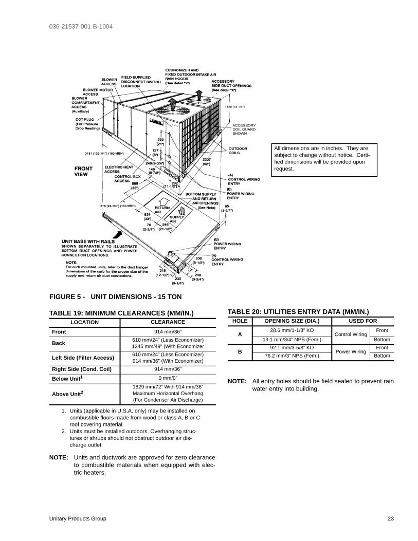
NOTE: Units and ductwork are approved for zero clearanceto combustible materials when equipped with elec-tric heaters.
NOTE: All entry holes should be field sealed to prevent rainwater entry into building.
FIGURE 5 - UNIT DIMENSIONS - 15 TON
All dimensions are in inches. They are subject to change without notice. Certi-fied dimensions will be provided upon request.
TABLE 19: MINIMUM CLEARANCES (MM/IN.)LOCATION CLEARANCE
Front 914 mm/36”
Back 610 mm/24” (Less Economizer)1245 mm/49” (With Economizer
Left Side (Filter Access) 610 mm/24” (Less Economizer)914 mm/36” (With Economizer)
Right Side (Cond. Coil) 914 mm/36”
Below Unit1
1. Units (applicable in U.S.A. only) may be installed on combustible floors made from wood or class A, B or C roof covering material.
0 mm/0”
Above Unit2
2. Units must be installed outdoors. Overhanging struc-tures or shrubs should not obstruct outdoor air dis-charge outlet.
1829 mm/72” With 914 mm/36”Maximum Horizontal Overhang(For Condenser Air Discharge)
TABLE 20: UTILITIES ENTRY DATA (MM/IN.)HOLE OPENING SIZE (DIA.) USED FOR
A28.6 mm/1-1/8” KO
Control WiringFront
19.1 mm/3/4” NPS (Fem.) Bottom
B92.1 mm/3-5/8” KO
Power WiringFront
76.2 mm/3” NPS (Fem.) Bottom
036-21537-001-B-1004
24 Unitary Products Group
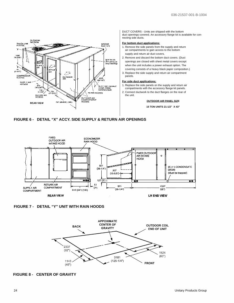
DUCT COVERS - Units are shipped with the bottomduct openings covered. An accessory flange kit is available for con-necting side ducts.
For bottom duct applications:1. Remove the side panels from the supply and return air compartments to gain access to the bottom supply and return air duct covers.2. Remove and discard the bottom duct covers. (Duct openings are closed with sheet metal covers except when the unit includes a power exhaust option. The covering consists of a heavy black paper composition.)3. Replace the side supply and return air compartment panels.
For side duct applications;1. Replace the side panels on the supply and return air compartments with the accessory flange kit panels.2. Connect ductwork to the duct flanges on the rear of the unit.
OUTDOOR AIR PANEL SIZE
15 TON UNITS 21-1/2" X 43"
FIGURE 6 - DETAIL “X” ACCY. SIDE SUPPLY & RETURN AIR OPENINGS
FIGURE 7 - DETAIL “Y” UNIT WITH RAIN HOODS
FIGURE 8 - CENTER OF GRAVITY

036-21537-001-B-1004
Unitary Products Group 25
FIGURE 9 - FOUR AND SIX POINT LOADS
�
�
�
�
�
�
����
�
�
�
�
����
4 Point Loads 6 Point Loads
TABLE 21: FOUR AND SIX POINT LOADS
UNIT4 - POINT LOADS (Kg. / Lbs.)
TOTAL A B C D
180 952 / 2100 233 / 513 231 / 510 253 / 558 253 / 559
NOTE: These weights are with economizer and 72 kW electric heat.
UNIT6 - POINT LOADS (Kg. / Lbs.)
TOTAL A B C D E F
180 952 / 2100 155 / 342 162 / 358 161 / 357 164 / 372 161 / 356 155 / 341
NOTE: These weights are with economizer and 72 kW electric heat.
FIGURE 10 - ROOF CURB DIMENSIONS - (180 & 240 UNITS)
036-21537-001-B-1004
26 Unitary Products Group
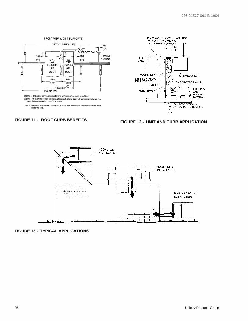
FIGURE 11 - ROOF CURB BENEFITS FIGURE 12 - UNIT AND CURB APPLICATION
FIGURE 13 - TYPICAL APPLICATIONS
036-21537-001-B-1004
Unitary Products Group 27
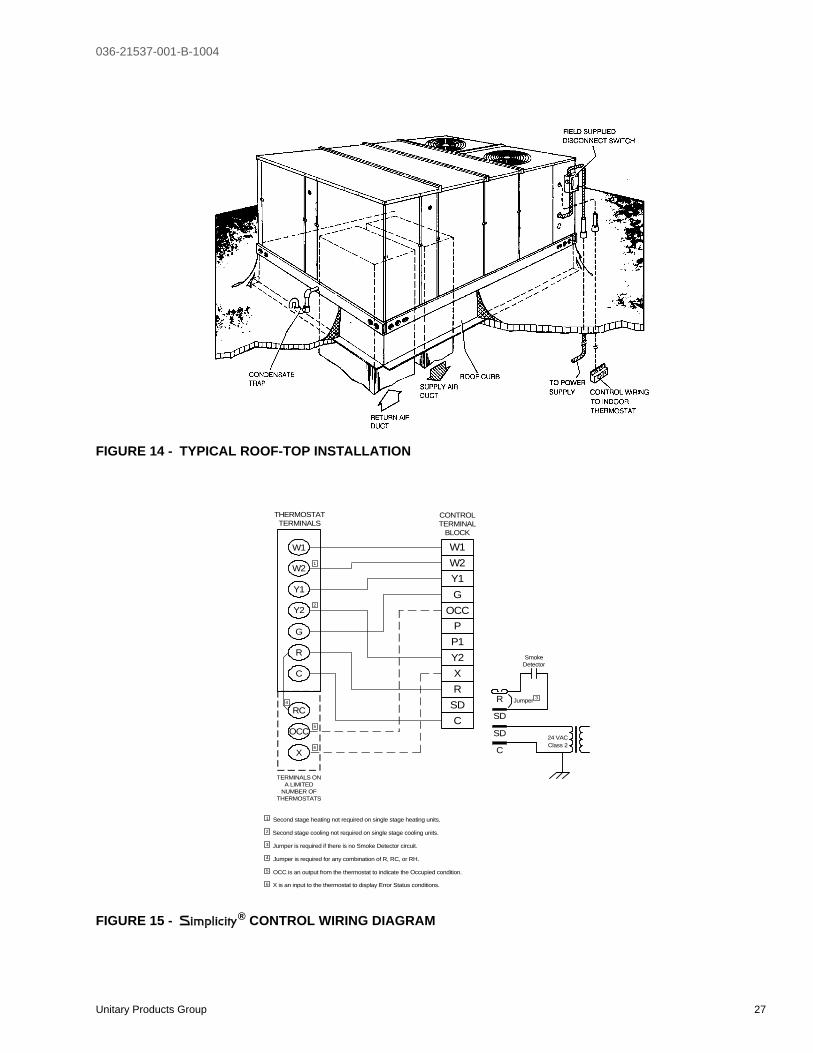
FIGURE 14 - TYPICAL ROOF-TOP INSTALLATION
FIGURE 15 - Simplicity® CONTROL WIRING DIAGRAM
W1
W2
Y1
G
OCC
P
P1
Y2
X
R
SD
C
C
SD
SD
R
OCC
C
RC
G
Y2
Y1
W2
W1
Jumper
SmokeDetector
24 VACClass 2
X
R
THERMOSTATTERMINALS
CONTROLTERMINAL
BLOCK
TERMINALS ONA LIMITED
NUMBER OFTHERMOSTATS
3
1
2
4
3
1
2
4
Second stage heating not required on single stage heating units.
Second stage cooling not required on single stage cooling units.
Jumper is required if there is no Smoke Detector circuit.
Jumper is required for any combination of R, RC, or RH.
6
5
5
6
OCC is an output from the thermostat to indicate the Occupied condition.
X is an input to the thermostat to display Error Status conditions.

Subject to change without notice. Printed in U.S.A. 036-21537-001-B-1004Copyright © by Unitary Products Group 2004. All rights reserved. Supersedes: 036-21537-001-A-0403
Unitary 5005 NormanProducts York OKGroup Drive 73069