Embed Size (px)
Citation preview
627
So
ftw
are
Software
CX-OneIntroduction 628Configuration CX-Integrator 630PLC Programming CX-Programmer 631
CX-Simulator 634CX-Protocol 636
Motion CX-Motion 638CX-Position 639CX-Motion NCF 640CX-Motion MCH 641CX-Drive 642
Regulation CX-Process Tool 643CX-Thermo 644
HMI CX-Designer 645Network & Fieldbus CX-PROFIBUS 647PC Specifications 648Ordering information 652
PC based visualisationCX-OPC 653CX-Lite 654CX-Supervisor 655
PC Specifications and Ordering Information 657
Y201-EN2-03.book Seite 627 Donnerstag, 30. März 2006 1:52 13
628 Software
Smart PlatformSmart Platform, Omron's new integrated automation architecture, demonstrates Omron to be one of the most innovative players in the market. Designed to simplify machine automation, the goal of Smart Platform is to allow increasingly complex machines to be developed, commissioned and maintained easily, allowing you time to 'just create'.Driven by the need to make connectivity as simple and flexible as pos-sible, Omron's Smart Platform creates a harmonious combination of sensing, control, motion and regulation devices. It enables users to mix and match their preferred solutions without the need to worry about hierarchy or other communication issues.The Smart Platform concept is built around three major advantages for the user:• One software • One connection• One minute
One software.
This single programming and configuration environment is an integra-ted software management tool called CX-One that enables the user to build, configure and program networks, PLCs, HMIs, motion control systems, drives, temperature controllers and sensors. The result of a single software is to reduce complexity of the configuration and allow automation systems to be programmed or configured with minimal trai-ning.
One connection.
From a single connection point either locally, through networks or from a modem connection the Omron 'Smart Platform' devices on your machine can programmed or parameterised. This allows remote access or servicing of your complete machine to become a reality. The same transparent communications architecture also allows Omron devices to easily communicate together passing and sharing informa-tion and enabling more effective modular machine design.
One minute.
SMART Active Parts greatly increase the functionality & information that is available to operators through Omrons' HMI. Written and tested for you by Omron's control experts these "drag and drop" visualization objects are called Smart and Active because they automate the com-munication from the NS HMI-series to all connected Omron products. (e.g. 'read actual speed' of an inverter, view a scene from a vision sen-sor, represent a temperature controllers etc.). Function Blocks offer similar 'drag & drop' programming and functiona-lity ('read actual speed' of an inverter, change a scene from a vision sensor, configure a temperature controllers) but they are used within the PLC. They can be programmed in Ladder or Structured Text, and can contain up to 16 layers of 'nested' function blocks (Function Block inside Function Block).For further information about Smart Platform go to http://www.smartplatform.info
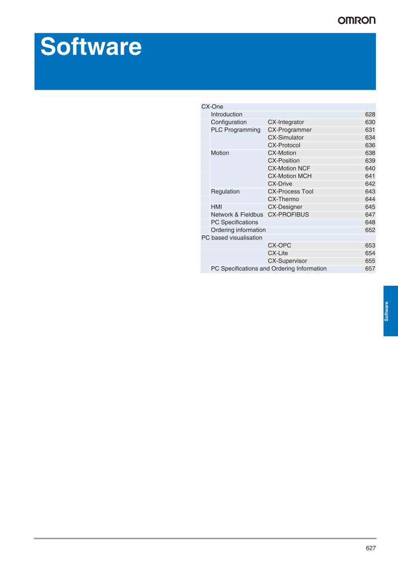
Motion control applications are perceived to be difficult and complex to setup, program and test, as need highly skilled people to get simple movements. However if you are to offer any flexibility in your machine then you must implement electronic motion control !
Just create
2 hours
20 minutes
3 hours
Xx? hours
1 minute
1 minute
1 minute
1 minute
10 core cable for each axis
Detailed studying required before operation
Complex ladder code
Simple co-ax connection
Integrated software
Pre-made objects to test motion
Drag n drop standard blocks
Traditional approach With Smart Platform
1 Wire up
2 Configure
3 Test
4 Program
Different software, cables and connections
PLC software
Motion software
Y201-EN2-03.book Seite 628 Donnerstag, 30. März 2006 1:52 13
629
So
ftw
are
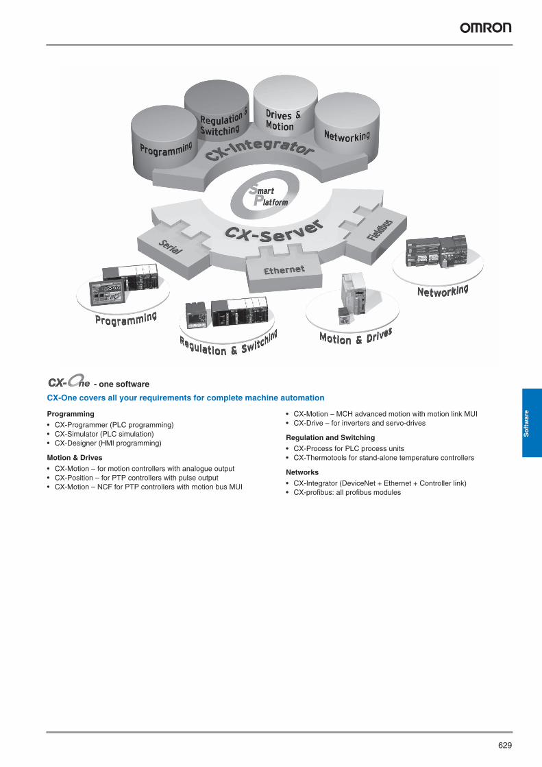
- one software
CX-One covers all your requirements for complete machine automation
Programming
• CX-Programmer (PLC programming)• CX-Simulator (PLC simulation)• CX-Designer (HMI programming)
Motion & Drives
• CX-Motion – for motion controllers with analogue output• CX-Position – for PTP controllers with pulse output• CX-Motion – NCF for PTP controllers with motion bus MUI
• CX-Motion – MCH advanced motion with motion link MUI• CX-Drive – for inverters and servo-drives
Regulation and Switching
• CX-Process for PLC process units• CX-Thermotools for stand-alone temperature controllers
Networks
• CX-Integrator (DeviceNet + Ethernet + Controller link)• CX-profibus: all profibus modules
Y201-EN2-03.book Seite 629 Donnerstag, 30. März 2006 1:52 13
630 Software
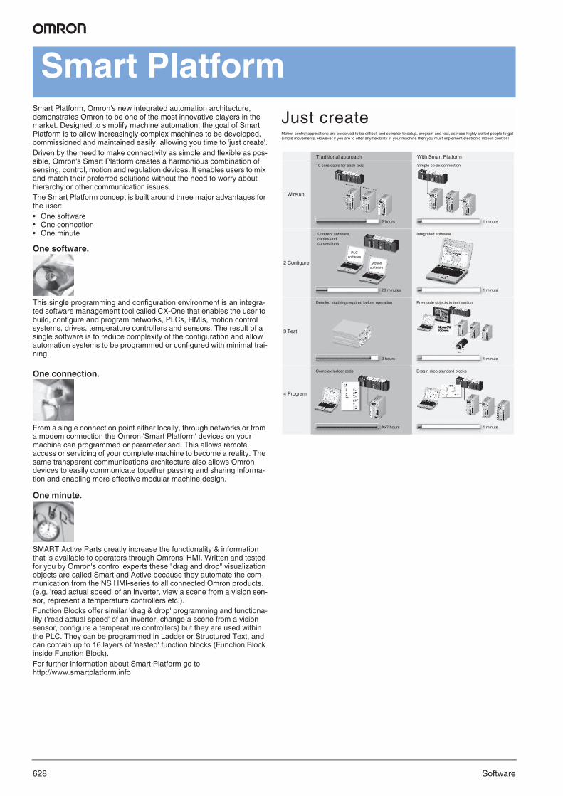
Configuration
CX-Integrator
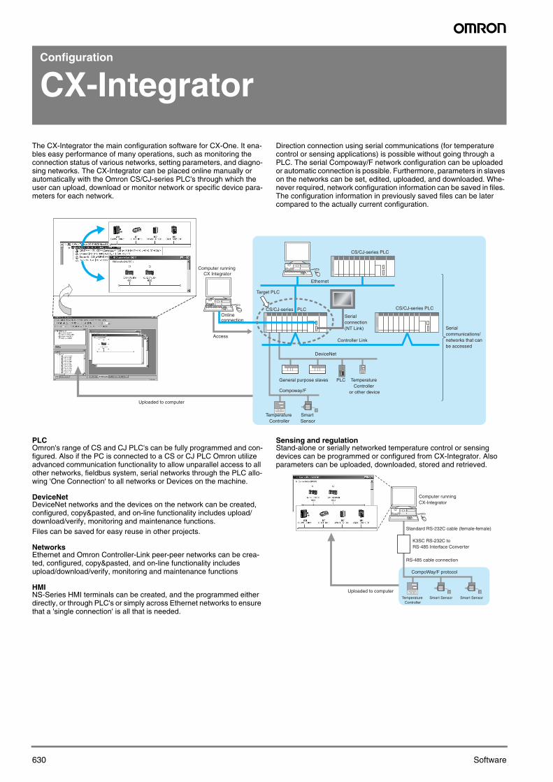
The CX-Integrator the main configuration software for CX-One. It ena-bles easy performance of many operations, such as monitoring the connection status of various networks, setting parameters, and diagno-sing networks. The CX-Integrator can be placed online manually or automatically with the Omron CS/CJ-series PLC's through which the user can upload, download or monitor network or specific device para-meters for each network.
Direction connection using serial communications (for temperature control or sensing applications) is possible without going through a PLC. The serial Compoway/F network configuration can be uploaded or automatic connection is possible. Furthermore, parameters in slaves on the networks can be set, edited, uploaded, and downloaded. Whe-never required, network configuration information can be saved in files. The configuration information in previously saved files can be later compared to the actually current configuration.
PLC Omron's range of CS and CJ PLC's can be fully programmed and con-figured. Also if the PC is connected to a CS or CJ PLC Omron utilize advanced communication functionality to allow unparallel access to all other networks, fieldbus system, serial networks through the PLC allo-wing 'One Connection' to all networks or Devices on the machine.
DeviceNetDeviceNet networks and the devices on the network can be created, configured, copy&pasted, and on-line functionality includes upload/download/verify, monitoring and maintenance functions.Files can be saved for easy reuse in other projects.
NetworksEthernet and Omron Controller-Link peer-peer networks can be crea-ted, configured, copy&pasted, and on-line functionality includes upload/download/verify, monitoring and maintenance functions
HMINS-Series HMI terminals can be created, and the programmed either directly, or through PLC's or simply across Ethernet networks to ensure that a 'single connection' is all that is needed.
Sensing and regulationStand-alone or serially networked temperature control or sensing devices can be programmed or configured from CX-Integrator. Also parameters can be uploaded, downloaded, stored and retrieved.
Smart Sensor
Temperature Controller
Online connection
Access
Uploaded to computer
Target PLC
CS/CJ-series PLC CS/CJ-series PLC
Ethernet
CS/CJ-series PLC
Serial connection (NT Link)
Controller Link
DeviceNet
Compoway/F
General purpose slaves PLC Temperature Controller
or other device
Serial communications/networks that can be accessed
Computer running CX Integrator
Smart Sensor Smart SensorTemperature Controller
Uploaded to computer
CompoWay/F protocol
RS-485 cable connection
K3SC RS-232C to RS-485 Interface Converter
Standard RS-232C cable (female-female)
Computer running CX-Integrator
CX-Integrator.fm Seite 630 Dienstag, 4. April 2006 10:49 10
631CX-Programmer
So
ftw
are
PLC Programming
CX-Programmer
Reduce application development and testing time and increase machine functionality with CX-Programmer.
Powerful, Easy-to-use Ladder Editor
· Program with single key inputs. No mouse required.
· Use the cross reference popup function to check a bit or output’s ON/OFF status in real time.
· When the program is input, the software automatically performs a circuit check and output-duplication check to prevent input mistakes.
· With one keystroke, jump to a desired location in the program fromthe search results or program check results displayed in the output window.
· Input various comments (such as rung comments, I/O comments, and circuit comments) to make the program easier to read and search.
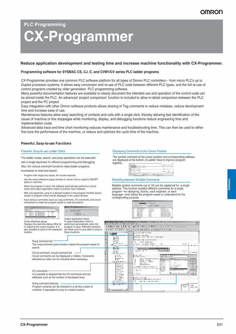
Rung comment listThe rung comment jump function makes the program easier to search.
Circuit comment, circuit comment listCircuit comments can be displayed or hidden. Comments attached as notes can be checked when necessary.
I/O commentsIt is possible to display/hide the I/O comments and set attributes such as the number of dis-played lines.
Programming software for SYSMAC CS, CJ, C, and CVM1/CV series PLC ladder programs
Cross reference popupDisplays the real-time status ofthe bit or output at the cursor location. It is also possible to jump to the displayed location.
Rung comment list/jumpProgram contents can be checked in a list like a table of contents. It ispossible to jump to a listed location.
Output duplication checkA output-duplication check is performed automatically when the program is input. Relevant locations are listed and it is pos-sible to jump to those locations.
Powerful, Easy-to-use Functions
The ladder create, search, and jump operations can be executed
with a single keystroke for efficient programming and debugging.
Also, the various comment functions make ladder programs
mucheasier to read and search.
Displaying Comments at the Cursor Position
The symbol comment at the cursor position and corresponding address are displayed at the bottom of Ladder View to improve program legibility.
Switching between Multiple Comments
Multiple symbol comments (up to 16) can be registered for a single address. This function enables different comments for a single program—for designing, factory, each engineer, or each language—and makes the program easier to understand for the corresponding purpose.
CX-Programmer provides one common PLC software platform for all types of Omron PLC controllers – from micro PLC's up to Duplex processor systems. It allows easy conversion and re-use of PLC code between different PLC types, and the full re-use of control programs created by older generation PLC programming software. Many powerful documentation features are available to clearly document the intended use and operation of the control code can be stored inside the PLC. An advanced ‘project comparison’ function is included to allow in-detail comparison between the PLC project and the PC project. Easy integration with other Omron software products allows sharing of Tag comments to reduce mistakes, reduce development time and increase ease of use. Maintenance features allow easy searching of contacts and coils with a single click, thereby allowing fast identification of the cause of machine or line stoppages while monitoring, display, and debugging functions reduce engineering time and implementation costs.Advanced data trace and time chart monitoring reduces maintenance and troubleshooting time. This can then be used to either fine-tune the performance of the machine, or reduce and optimize the cycle time of the machine.
Y201-EN2-03.book Seite 631 Donnerstag, 30. März 2006 1:52 13
632 Software
File
One section each
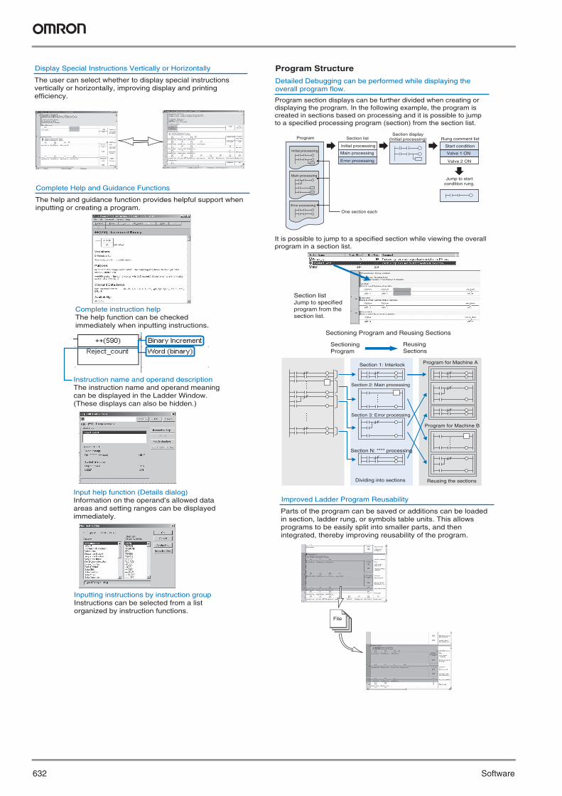
Program section displays can be further divided when creating or displaying the program. In the following example, the program is created in sections based on processing and it is possible to jump to a specified processing program (section) from the section list.
Complete Help and Guidance Functions
The help and guidance function provides helpful support when inputting or creating a program.
Complete instruction helpThe help function can be checked immediately when inputting instructions.
Instruction name and operand descriptionThe instruction name and operand meaning can be displayed in the Ladder Window. (These displays can also be hidden.)
Input help function (Details dialog)Information on the operand’s allowed data areas and setting ranges can be displayed immediately.
It is possible to jump to a specified section while viewing the overall program in a section list.
Section listJump to specified program from the section list.
Program Structure
Inputting instructions by instruction groupInstructions can be selected from a list organized by instruction functions.
Detailed Debugging can be performed while displaying the overall program flow.
Program
Sectioning Program and Reusing Sections
Section listSection display
(Initial processing) Rung comment list
Jump to start condition rung.
Sectioning Program
Reusing Sections
Section 1: Interlock
Section 2: Main processing
Section 3: Error processing
Section N: **** processing
Program for Machine A
Program for Machine B
Initial processing
Main processing
Error processing
Initial processing
Main processing
Error processing
Start condition
Valve 1 ON
Valve 2 ON
Reusing the sectionsDividing into sections
Display Special Instructions Vertically or Horizontally
The user can select whether to display special instructions vertically or horizontally, improving display and printing efficiency.
Improved Ladder Program Reusability
Parts of the program can be saved or additions can be loaded in section, ladder rung, or symbols table units. This allows programs to be easily split into smaller parts, and then integrated, thereby improving reusability of the program.
Y201-EN2-03.book Seite 632 Donnerstag, 30. März 2006 1:52 13
CX-Programmer 633
So
ftw
are
?
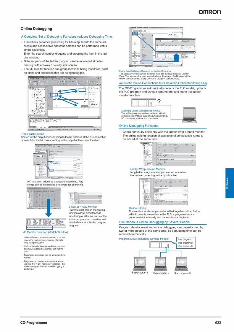
A Complete Set of Debugging Functions reduces Debugging Time.
· Trace-back searches (searching for bits/outputs with the same ad-dress) and consecutive addresss earches can be performed with a single keystroke.
· Enter the search item by dragging and dropping the item in the lad-der window.
· Different parts of the ladder program can be monitored simulta-neously with a 2-way or 4-way split screen.
· The I/O monitor function can group locations being monitored, such as steps and processes that are beingdebugged.
Program Developmentby Several People
I/O Monitor Function (Watch Window)
2-way or 4-way MonitorPowerful split-screen monitoring function allows simultaneous monitoring of different parts of the ladder program, an overview and detailed view of a ladder program rung, etc.
Automatic Online Connection to the PLCThe ladder program can be monitored with all comment information, including rung comments, I/O comments, and section comments.
Automatic Online Connections to PLCs make OnlineMonitoring Easy
The CX-Programmer automatically detects the PLC model, uploads the PLC program and various parameters, and starts the ladder monitor function.
Simultaneous Online Debugging by Several People
Program development and online debugging can beperformed by two or more people at the same time, so debugging time can be reduced dramatically.
Online Debugging Functions
· Check continuity efficiently with the ladder wrap-around monitor.· The online editing function allows several consecutive rungs to
be edited at the same time.
Trace-back SearchSearch for the output corresponding to the bit address at the cursor location or search for the bit corresponding to the output at the cursor location.
Ladder Wrap-around MonitorLong ladder rungs are wrapped around to another line before connecting to the right bus bar.
Online EditingConsecutive ladder rungs can be edited together online. Before edited contents are written to the PLC, a program check is performed automatically and the results are displayed.
Online Debugging
· Group different locations that need to be mo-nitored for each process or piece of machi-nery being debugged.
· Various data displays are available, such as decimal, hexadecimal, signed, and floating-point.
· Registered addresses can be sorted and mo-nitored.
· Registered addresses are automatically sa-ved to a file. It isn’t necessary to register the addresses again the next time debugging is performed.
Step program 1 Step program 2 Step program 3
Step program 1
Step program 2
Step program 3
“All” has been added as a target of searching. Any strings can be entered as a keyword for searching.
Easily Search Usages Overview on Ladder DiagramsThe usage overview can be launched from the a popup menu or Ladder View. This enables the user to easily check the usage of addresses at the cursor position and to easily check the usage of contacts/coils.
Y201-EN2-03.book Seite 633 Donnerstag, 30. März 2006 1:52 13
634 Software
PLC Programming
CX-Simulator
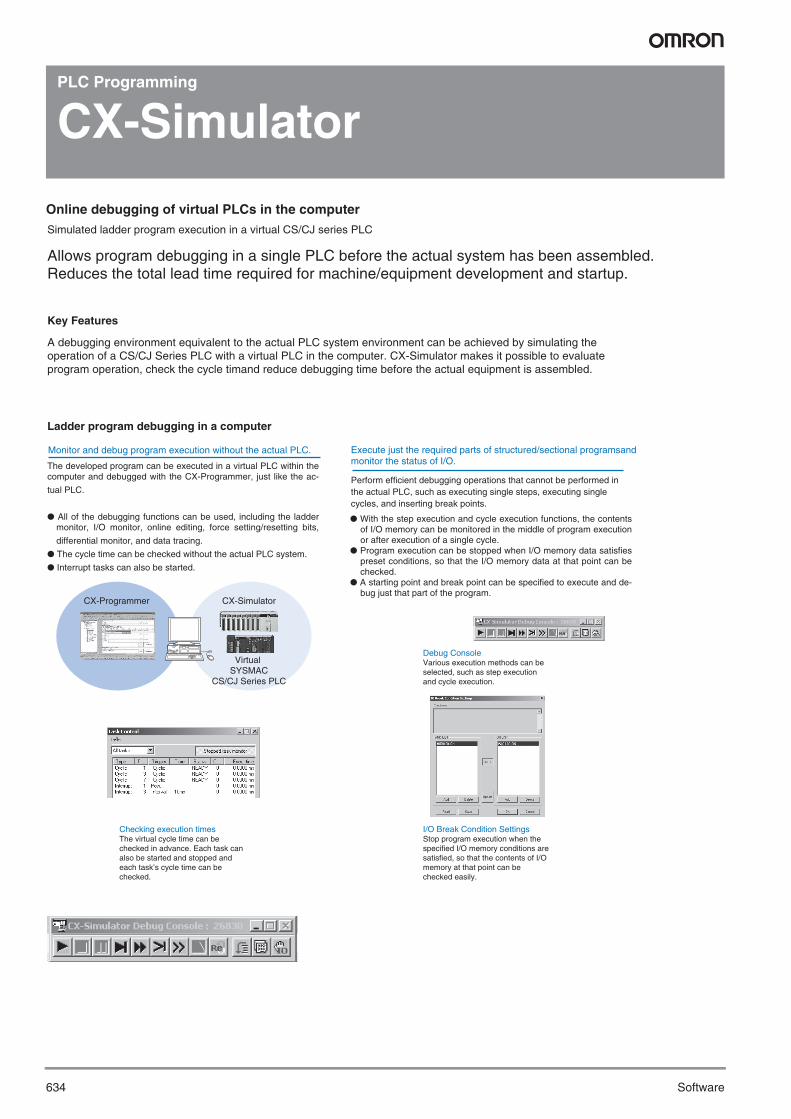
Online debugging of virtual PLCs in the computer
A debugging environment equivalent to the actual PLC system environment can be achieved by simulating the operation of a CS/CJ Series PLC with a virtual PLC in the computer. CX-Simulator makes it possible to evaluate program operation, check the cycle timand reduce debugging time before the actual equipment is assembled.
The developed program can be executed in a virtual PLC within the computer and debugged with the CX-Programmer, just like the ac-
tual PLC.
● All of the debugging functions can be used, including the ladder monitor, I/O monitor, online editing, force setting/resetting bits,
differential monitor, and data tracing.
● The cycle time can be checked without the actual PLC system.
● Interrupt tasks can also be started.
Perform efficient debugging operations that cannot be performed in the actual PLC, such as executing single steps, executing single cycles, and inserting break points.
Execute just the required parts of structured/sectional programsand monitor the status of I/O.
Allows program debugging in a single PLC before the actual system has been assembled.Reduces the total lead time required for machine/equipment development and startup.
Simulated ladder program execution in a virtual CS/CJ series PLC
Checking execution timesThe virtual cycle time can be checked in advance. Each task can also be started and stopped and each task’s cycle time can be checked.
I/O Break Condition SettingsStop program execution when the specified I/O memory conditions are satisfied, so that the contents of I/O memory at that point can be checked easily.
Debug ConsoleVarious execution methods can be selected, such as step execution and cycle execution.
CX-Programmer CX-Simulator
Virtual SYSMAC
CS/CJ Series PLC
Key Features
Ladder program debugging in a computer
Monitor and debug program execution without the actual PLC.
● With the step execution and cycle execution functions, the contents of I/O memory can be monitored in the middle of program execution or after execution of a single cycle.
● Program execution can be stopped when I/O memory data satisfies preset conditions, so that the I/O memory data at that point can be checked.
● A starting point and break point can be specified to execute and de-bug just that part of the program.
Y201-EN2-03.book Seite 634 Donnerstag, 30. März 2006 1:52 13
CX-Simulator 635
So
ftw
are● Communications can be debugged with external serialdevices
connected to the computer’s COM port.
● Communications can be tested with Programmable Controllers
through NT Link.
● Messages sent by the network communications program canbe checked. Messages (frames) sent by the TXD (TRANS-MIT), SEND/RECV (NETWORK SEND/RECEIVE), and CMND (DELI-VER COMMAND) instructions can be displayed at the computer.
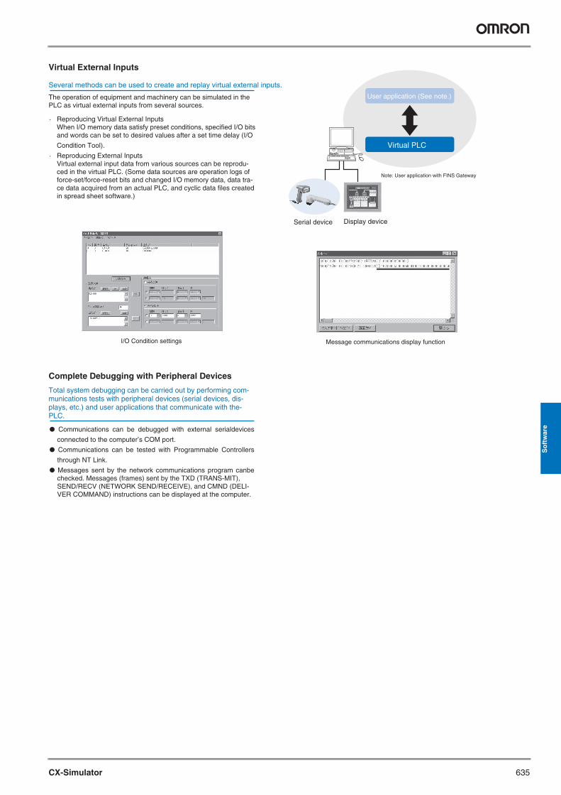
The operation of equipment and machinery can be simulated in the PLC as virtual external inputs from several sources.
Several methods can be used to create and replay virtual external inputs.
I/O Condition settings
User application (See note.)
Virtual PLC
Message communications display function
Virtual External Inputs
Complete Debugging with Peripheral Devices
Serial device
Note: User application with FINS Gateway
Display device
· Reproducing Virtual External Inputs When I/O memory data satisfy preset conditions, specified I/O bits
and words can be set to desired values after a set time delay (I/O
Condition Tool).
· Reproducing External Inputs Virtual external input data from various sources can be reprodu-
ced in the virtual PLC. (Some data sources are operation logs of force-set/force-reset bits and changed I/O memory data, data tra-ce data acquired from an actual PLC, and cyclic data files created in spread sheet software.)
Total system debugging can be carried out by performing com-munications tests with peripheral devices (serial devices, dis-plays, etc.) and user applications that communicate with the-PLC.
Y201-EN2-03.book Seite 635 Donnerstag, 30. März 2006 1:52 13
636 Software
PLC Programming
CX-Protocol
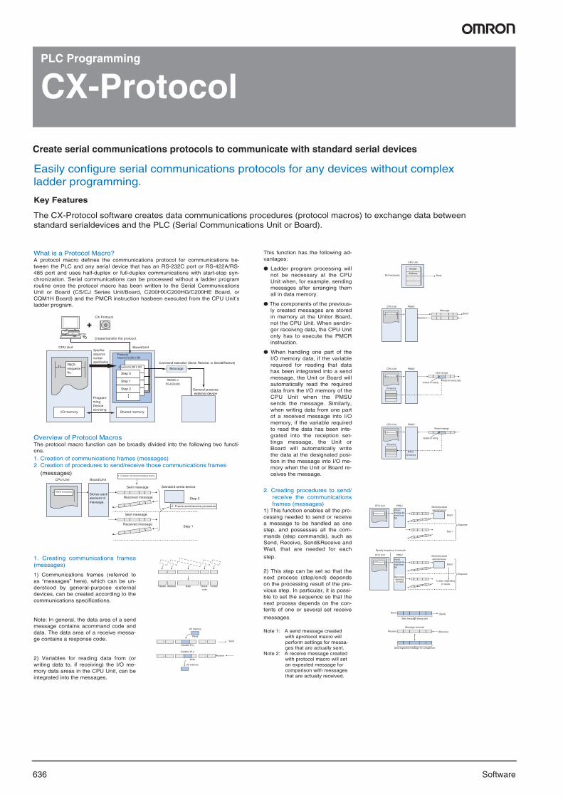
Create serial communications protocols to communicate with standard serial devices
What is a Protocol Macro?A protocol macro defines the communications protocol for communications be-tween the PLC and any serial device that has an RS-232C port or RS-422A/RS-485 port and uses half-duplex or full-duplex communications with start-stop syn-chronization. Serial communications can be processed without a ladder program routine once the protocol macro has been written to the Serial Communications Unit or Board (CS/CJ Series Unit/Board, C200HX/C200HG/C200HE Board, or CQM1H Board) and the PMCR instruction hasbeen executed from the CPU Unit’s ladder program.
Overview of Protocol MacrosThe protocol macro function can be broadly divided into the following two functi-ons.
1. Creation of communications frames (messages)2. Creation of procedures to send/receive those communications frames (messages)
1. Creating communications frames (messages)
1) Communications frames (referred to as “messages” here), which can be un-derstood by general-purpose external devices, can be created according to the communications specifications.
Note: In general, the data area of a send message contains acommand code and data. The data area of a receive messa-ge contains a response code.
2) Variables for reading data from (or writing data to, if receiving) the I/O me-mory data areas in the CPU Unit, can be integrated into the messages.
This function has the following ad-vantages:
● Ladder program processing will not be necessary at the CPU Unit when, for example, sending messages after arranging them all in data memory.
● The components of the previous-ly created messages are stored in memory at the Unitor Board, not the CPU Unit. When sendin-gor receiving data, the CPU Unit only has to execute the PMCR instruction.
● When handling one part of the I/O memory data, if the variable required for reading that data has been integrated into a send message, the Unit or Board will automatically read the required data from the I/O memory of the CPU Unit when the PMSU sends the message. Similarly, when writing data from one part of a received message into I/O memory, if the variable required to read the data has been inte-grated into the reception set-tings message, the Unit or Board will automatically write the data at the designated posi-tion in the message into I/O me-mory when the Unit or Board re-ceives the message.
2. Creating procedures to send/ receive the communications frames (messages)
1) This function enables all the pro-cessing needed to send or receive a message to be handled as one step, and possesses all the com-mands (step commands), such as Send, Receive, Send&Receive and Wait, that are needed for each
step.
2) This step can be set so that the next process (step/end) depends on the processing result of the pre-vious step. In particular, it is possi-ble to set the sequence so that the next process depends on the con-tents of one or several set receive
messages.
Note 1: A send message created with aprotocol macro will perform settings for messa-ges that are actually sent.
Note 2: A receive message created with protocol macro will set an expected message for comparison with messages that are actually received.
CPU Unit Board/Unit
Sent message
Received message
PMCR instruction
Sent message
Received message
Header Address Data Check code
Terminator
I/O memory
I/O memory
Read
Write
Variable R ()
Send
Receive
Variable W ()
CPU Unit
Header
Not necessary SendAddress
SendMessage
CPU Unit PMSU
Receive
PMCR instruction
Send message
Variable for readingRead I/O memory data
CPU Unit PMSU
I/O memory
Receive message
Variable for writing
CPU Unit PMSU
Write to I/O memory
CPU Unit PMSU General-purpose external device
Step 0
Step 1
Sequence
CPU Unit PMSU
Specify sequence to execute
General-purpose external device
Step 0
To step n depending on results
SequenceNext process
depending on results
Send (Send)
Sets message being sent
Message received
Sets expected message for comparison
Receive (Receive)
CPU Unit Board/Unit
Create/transfer the protocol.
CX-Protocol
PMCRseaquence No.
Specifies sequencenumber specification
Program- ming Device servicing
Step 0
Step 1
Step 2
Sequence No.000 to 059
Sequence No.060 to 099Protocol
Message
General-purpose external device
RS232C or RS-422A/485
Command execution (Send, Receive, or Send&Receive)
I/O memory Shared memory
PMCR instruction
PMCR instruction
PMCR instruction
Stores each element of message.
Easily configure serial communications protocols for any devices without complex ladder programming.
The CX-Protocol software creates data communications procedures (protocol macros) to exchange data between standard serialdevices and the PLC (Serial Communications Unit or Board).
Key Features
1. Creation of communications frame
Standard serial device
Step 0
2. Frame send/receive procedure
Step 1
I/O memory
PMCR instruction
Various message ele-ments recor-ded
Various message ele-ments recor-ded
Y201-EN2-03.book Seite 636 Donnerstag, 30. März 2006 1:52 13
CX-Protocol 637
So
ftw
are
1
Personal Computer
PLC External general-purpose device
Tracing the send/receive message or control signals that runs through the transmission line.
Trace display for send message, receive message, step number, and control signals.
Send message @ 0 2 R40
0 0 0 0 0 0 0
30 32 52
@ 0 040 30 30
Receive message
Step No.
RS
CS
· Send frames and receive frames can be created according to the com-munications frame (message) specifications of external devices. In addi-tion, variables for exchanging data with the PLC can be incorporated in send and receive frames.
· Supports error check code calculation, frame length calculation during transmission processes, and numeric data conversion between ASCII and hexadecimal.
· Repeat variables can be used, 1:N communications are supported, and write destinations can be switched.
· Supports send and receive time monitoring functions as well as retry processing, so the required communications error processing can be specified easily.
· The interrupt function can send an interrupt to the CPU Unit when recei-ving data, so high-speed data processing can be performed.
· Expected reception data can be registered and processing can be swit-ched based on the received data.
Supports a Wide Range of Communication Protocols
· Trace functionWith a CS/CJ Series PLC, up to 1,700 characters of time-sequential transmission or reception data, which the Board or Unit exchanges with external devices, can be traced. Tracing allows the user to determine which messages were transmitted or received in each step number. The results of tracing can be saved as data in project files or printed.
· I/O memory monitor functionSend/receive data stored in the PLC’s data areas can be moni-tored.
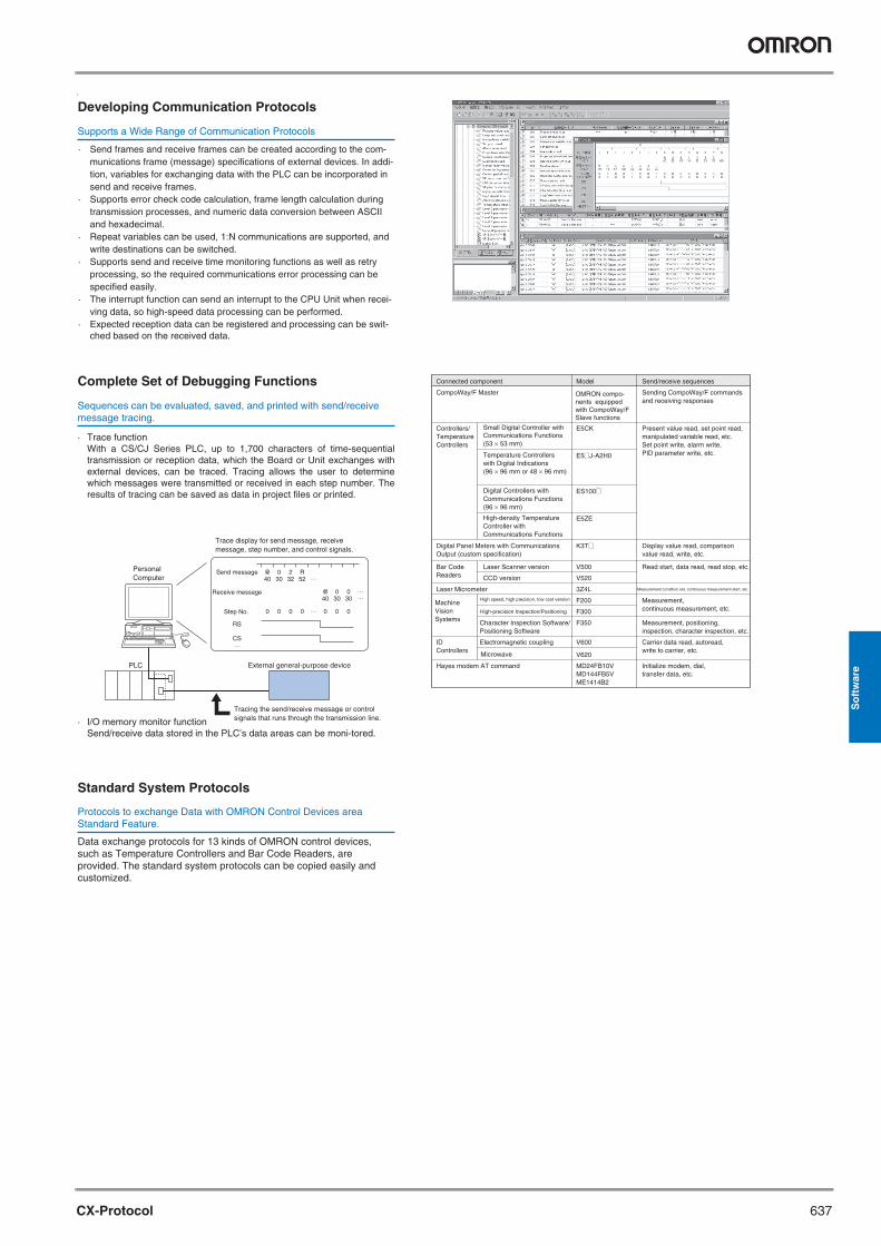
Sequences can be evaluated, saved, and printed with send/receive message tracing.
Data exchange protocols for 13 kinds of OMRON control devices, such as Temperature Controllers and Bar Code Readers, are provided. The standard system protocols can be copied easily and customized.
Protocols to exchange Data with OMRON Control Devices area Standard Feature.
Developing Communication Protocols
Complete Set of Debugging Functions
Standard System Protocols
Connected component Model Send/receive sequences
CompoWay/F Master Sending CompoWay/F commands and receiving responses
Present value read, set point read, manipulated variable read, etc.Set point write, alarm write, PID parameter write, etc.
Display value read, comparison value read, write, etc.
Controllers/ Temperature Controllers
Digital Panel Meters with Communications Output (custom specification)
E5CK
E5@J-A2H0Temperature Controllers with Digital Indications(96 × 96 mm or 48 × 96 mm)
Small Digital Controller with Communications Functions(53 × 53 mm)
ES100@Digital Controllers with Communications Functions(96 × 96 mm)
E5ZE
K3T@
Measurement condition set, continuous measurement start, etc.Laser Micrometer 3Z4L
Read start, data read, read stop, etc.Bar Code Readers
Laser Scanner version V500
Measurement, continuous measurement, etc.
ID Controllers
Hayes modem AT command
High speed, high precision, low cost version F200
CCD version V520
High-density Temperature Controller with Communications Functions
High-precision Inspection/Positioning F300
Measurement, positioning, inspection, character inspection, etc.
Character Inspection Software/ Positioning Software
F350
Carrier data read, autoread, write to carrier, etc.
Electromagnetic coupling V600
Microwave V620
Initialize modem, dial, transfer data, etc.
MD24FB10VMD144FB5VME1414B2
OMRON compo-nents equipped with CompoWay/F Slave functions
Machine Vision Systems
Y201-EN2-03.book Seite 637 Donnerstag, 30. März 2006 1:52 13
638 Software
Motion
CX-Motion
Creates programs to control the motion controller and monitors controller status
Lot No.
Job No. 2Job No. 3
Job No. X
CX-MotionCX-Programmer
MPG
MPG 1 channel
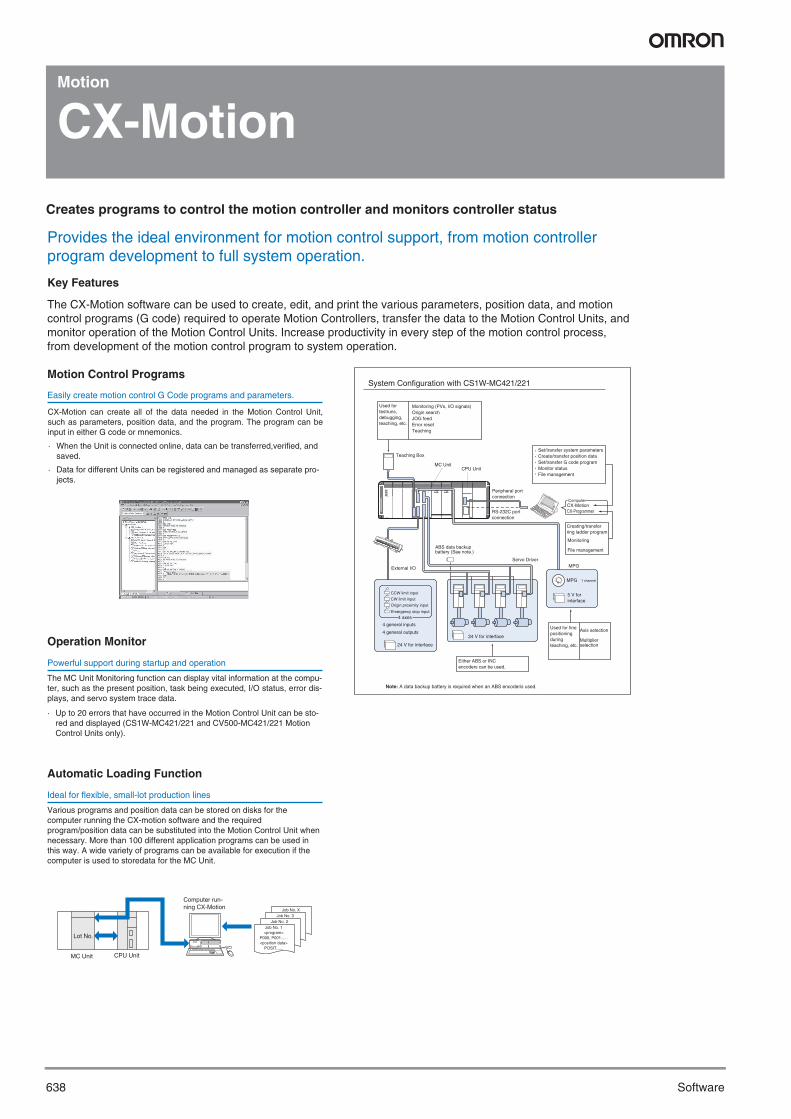
System Configuration with CS1W-MC421/221
Used for testruns, debugging, teaching, etc.
Provides the ideal environment for motion control support, from motion controller program development to full system operation.
The CX-Motion software can be used to create, edit, and print the various parameters, position data, and motion control programs (G code) required to operate Motion Controllers, transfer the data to the Motion Control Units, and monitor operation of the Motion Control Units. Increase productivity in every step of the motion control process, from development of the motion control program to system operation.
· When the Unit is connected online, data can be transferred,verified, and saved.
· Data for different Units can be registered and managed as separate pro-jects.
Easily create motion control G Code programs and parameters.
Ideal for flexible, small-lot production lines
MC Unit CPU Unit
Job No. 1<program>
P000, P001......<position data>
POSIT......
The MC Unit Monitoring function can display vital information at the compu-ter, such as the present position, task being executed, I/O status, error dis-plays, and servo system trace data.
· Up to 20 errors that have occurred in the Motion Control Unit can be sto-red and displayed (CS1W-MC421/221 and CV500-MC421/221 Motion Control Units only).
Powerful support during startup and operation
Various programs and position data can be stored on disks for the computer running the CX-motion software and the required program/position data can be substituted into the Motion Control Unit when necessary. More than 100 different application programs can be used in this way. A wide variety of programs can be available for execution if the computer is used to storedata for the MC Unit.
Key Features
Motion Control Programs
Operation Monitor
Automatic Loading Function
Computer run- ning CX-Motion
Monitoring (PVs, I/O signals)Origin searchJOG feedError resetTeaching
Teaching Box
MC UnitCPU Unit
Set/transfer system parametersCreate/transfer position dataSet/transfer G code programMonitor statusFile management
Peripheral port connection
RS-232C port connection
Computer
Creating/transfer ring ladder program
Monitoring
File management
External I/O
ABS data backupbattery (See note.)
Servo Driver
5 V for interface
CCW limit input
CW limit input
Origin proximity input
Emergency stop input
4 axes
4 general inputs
4 general outputs
24 V for interface
24 V for interfaceAxis selection
Multiplier selection
CX-Motion can create all of the data needed in the Motion Control Unit, such as parameters, position data, and the program. The program can be input in either G code or mnemonics.
Either ABS or INC encoders can be used.
Used for fine positioning during teaching, etc.
Note: A data backup battery is required when an ABS encoderis used.
Y201-EN2-03.book Seite 638 Donnerstag, 30. März 2006 1:52 13

639CX-Position
So
ftw
are
Motion
CX-Position
Set, transfer, store, and print position control unit data and monitor operation online
CCW limit inputCW limit inputOrigin inputOrigin proximity input
Emergency stop input
Interrupt input
Interface power supply (24 V)
External inputs
Stepping motors
or
Servo motors
Ste
ppin
g m
otor
dr
iver
s
CCW limit inputCW limit inputOrigin inputOrigin proximity input
Emergency stop input
Interrupt input
Interface power supply (24 V)
External inputs
Stepping motors Servo motors
Ser
vom
otor
driv
ers
NC Unit (CS1W-NC413/433)
CPU Unit (CS1 Series)
Power Supply Unit
Peripheral bus/Host Link
System Configuration with CS1W-NC413/433
Ser
vom
otor
driv
ers
or
Ste
ppin
g m
otor
dr
iver
s
CX-ProgrammerCreation and transfer of ladder programs, monitoring, file management, etc.
CX-Position Creation and transfer of data, NC Unit monitoring, file management, etc.
Increase productivity in all position control tasks, from design and startup to system maintenance.
The CX-Position software simplifies every aspect of position control, from creating/editing the data used in Position Control Units (NC Units) to communicating online and monitoring operation. The software is equipped with functions that can improve productivity, such as automatically generating project data and reusing existing data.
The CX-Position enables data for multiple NC Units on up to 1,000 PLCs to be handled as 1 project. Data is displayed in tree format and the data for an NC Unit can be moved or copied (overwritten) between PLCs in the project tree. This feature allows data to be edited and re-used in other PLCs or NC Units.
· The CX-Position can read information from NC Units connected online and automatically generate project data.
· Data created for a C200HW-NC@@@ using the SYSMAC-NCT can be imported and used as data for the CS1W-NC@@@ or CJS1W-NC@@@.
Data can be created for various applications
It is possible to communicate with NC Units through the Fins-Gateway. Depending on the FinsGateway driver version, HostLink or Ethernet. can be used to perform online operations (monitoring operation or transferring/verifying parameters,sequences, etc.) with the NC Unit.
Communicate with NC units through the network.
The sequence numbers and present positions can be dis-played for up to 4 Units. In addition, the contents of the operating memory area and operating data area can be monitored and the error log can be displayed.
Display the NC units’ present positions, error codes, sequence numbers, and I/O status.
Key Features
Creating and managing data
NC Monitor
Communications
Y201-EN2-03.book Seite 639 Donnerstag, 30. März 2006 1:52 13
640 Software
Motion
CX-Motion NCF
Configures mechatrolink II network
Provides easy configuration for the mechatrolink II network and devices on the network
Key Features
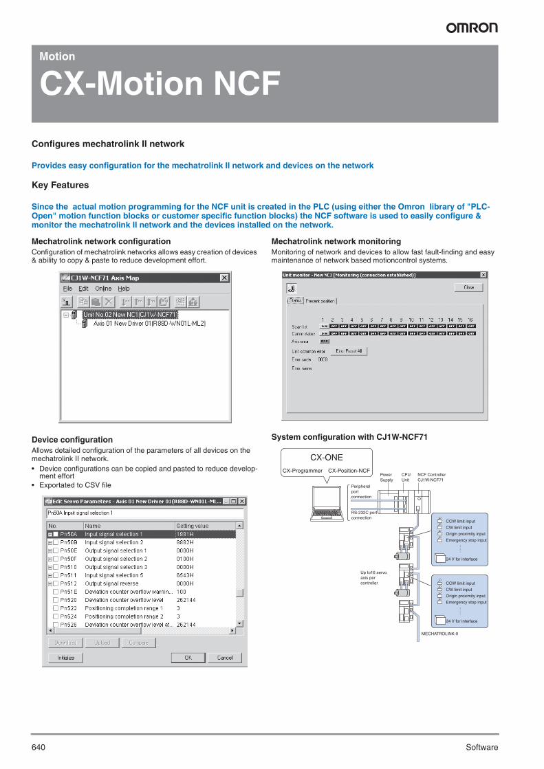
Since the actual motion programming for the NCF unit is created in the PLC (using either the Omron library of "PLC-Open" motion function blocks or customer specific function blocks) the NCF software is used to easily configure & monitor the mechatrolink II network and the devices installed on the network.
Mechatrolink network configuration Configuration of mechatrolink networks allows easy creation of devices & ability to copy & paste to reduce development effort.
Device configurationAllows detailed configuration of the parameters of all devices on the mechatrolink II network. • Device configurations can be copied and pasted to reduce develop-
ment effort• Exportated to CSV file
Mechatrolink network monitoringMonitoring of network and devices to allow fast fault-finding and easy maintenance of network based motioncontrol systems.
System configuration with CJ1W-NCF71
CCW limit input
CW limit input
Origin proximity input
Emergency stop input
24 V for interface
CCW limit input
CW limit input
Origin proximity input
Emergency stop input
24 V for interface
CX-Programmer CX-Position-NCF
MECHATROLINK-II
CX-ONE
Up to16 servo axis per controller
NCF ControllerCJ1W-NCF71
Power Supply
CPU Unit
Peripheral port connection
RS-232C port connection
Y201-EN2-03.book Seite 640 Donnerstag, 30. März 2006 1:52 13

641CX-Motion MCH
So
ftw
are
Motion
CX-Motion MCH
Reduce the complexity of advanced motion control.
Programming and configuration for Mechatrolink II based MCH motion controller.
Key Features
Create powerful motion solutions quickly using this integrated configuration and programming software for Mechatrolink II based systems.
Mechatrolink and device configuration Configuration of Mechatrolink networks allows easy creation of devices and the ability to copy&paste configurations to reduce development.
System configuration
Motion programmingEasy programming using a familiar 'workspace editor' to allow easy representation of all configurations and programming for each MCH unit.
Each MCH supports upto 32 axis of motion, to allow easy programming the programs can be split into 'Main' and 'Sub' programs. These pro-gram modules can easily be imported and exported to other projects, or to libraries to reduce the total development time.
Programming is carried out using standard 'Basic' type of language to allow easy creation of programs. A common symbol table also allows easier programming of larger systems.
Specific instructions allow key motion functionality to be used easily. CAM profiles are also integrated into MCH software and are created by importing the CAM able information from a CSV file, typically created from excel or CAM creation software.
CCW limit input
CW limit input
Origin proximity input
Emergency stop input
24 V for interface
CCW limit input
CW limit input
Origin proximity input
Emergency stop input
24 V for interface
CX-Programmer CX-Position-MCH
MECHATROLINK-II
CX-ONE
Up to16 servo axis per controller
MCH ControllerCJ1W-MCH71
Power Supply
CPU Unit
Peripheral port connection
RS-232C port connection
Y201-EN2-03.book Seite 641 Donnerstag, 30. März 2006 1:52 13
642 Software
Motion
CX-Drive
One software tool for inverters & servos
reduce the time and complexity of configuring, commissioning and maintaining servos or inverters with a single software tool.
Key Features
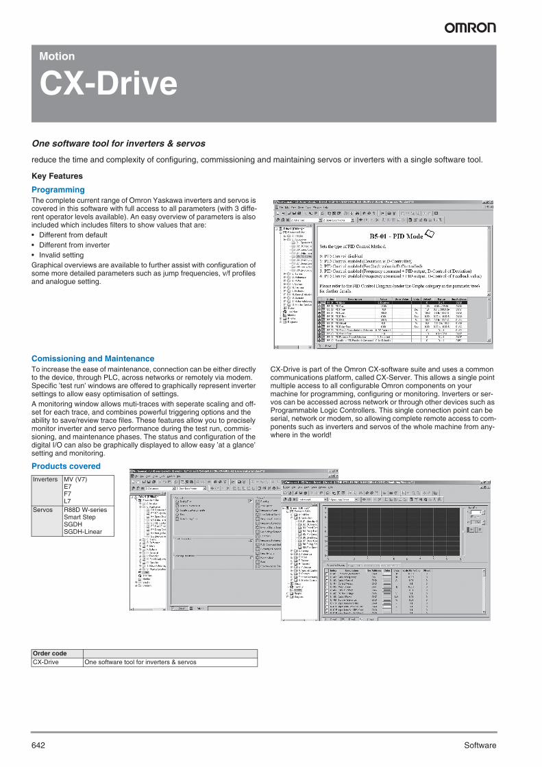
ProgrammingThe complete current range of Omron Yaskawa inverters and servos is covered in this software with full access to all parameters (with 3 diffe-rent operator levels available). An easy overview of parameters is also included which includes filters to show values that are:• Different from default• Different from inverter• Invalid settingGraphical overviews are available to further assist with configuration of some more detailed parameters such as jump frequencies, v/f profiles and analogue setting.
Comissioning and MaintenanceTo increase the ease of maintenance, connection can be either directly to the device, through PLC, across networks or remotely via modem. Specific ’test run’ windows are offered to graphically represent inverter settings to allow easy optimisation of settings.A monitoring window allows muti-traces with seperate scaling and off-set for each trace, and combines powerful triggering options and the ability to save/review trace files. These features allow you to precisely monitor inverter and servo performance during the test run, commis-sioning, and maintenance phases. The status and configuration of the digital I/O can also be graphically displayed to allow easy ’at a glance’ setting and monitoring.
CX-Drive is part of the Omron CX-software suite and uses a common communications platform, called CX-Server. This allows a single point multiple access to all configurable Omron components on your machine for programming, configuring or monitoring. Inverters or ser-vos can be accessed across network or through other devices such as Programmable Logic Controllers. This single connection point can be serial, network or modem, so allowing complete remote access to com-ponents such as inverters and servos of the whole machine from any-where in the world!
Products covered
Inverters MV (V7)E7F7L7
Servos R88D W-seriesSmart StepSGDHSGDH-Linear
Order codeCX-Drive One software tool for inverters & servos
Y201-EN2-03.book Seite 642 Donnerstag, 30. März 2006 1:52 13
643CX-Process Tool
So
ftw
are
Regulation
CX-Process Tool
Creates, transfers, runs, and debugs function blocks for loop control units/boards.
Easy Engineering Solutions for advanced PLC based process control
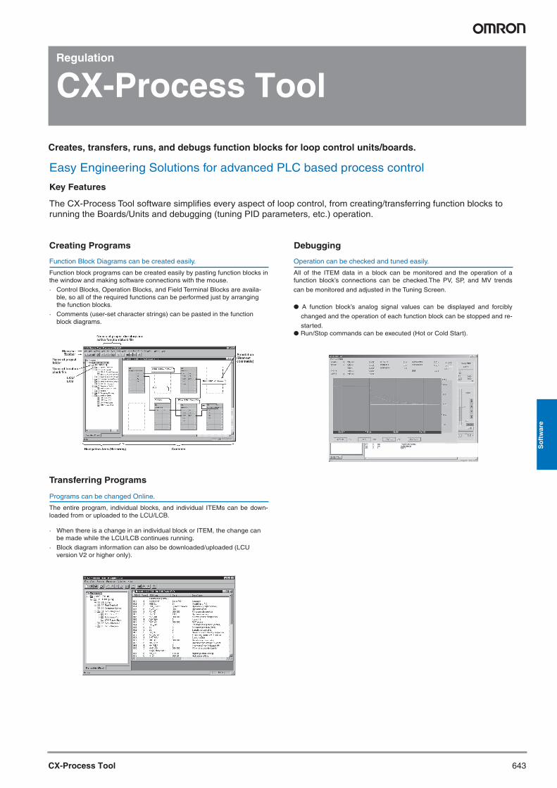
The CX-Process Tool software simplifies every aspect of loop control, from creating/transferring function blocks to running the Boards/Units and debugging (tuning PID parameters, etc.) operation.
Function block programs can be created easily by pasting function blocks in the window and making software connections with the mouse.
· Control Blocks, Operation Blocks, and Field Terminal Blocks are availa-ble, so all of the required functions can be performed just by arranging the function blocks.
· Comments (user-set character strings) can be pasted in the function block diagrams.
Function Block Diagrams can be created easily.
The entire program, individual blocks, and individual ITEMs can be down-loaded from or uploaded to the LCU/LCB.
· When there is a change in an individual block or ITEM, the change can be made while the LCU/LCB continues running.
· Block diagram information can also be downloaded/uploaded (LCU version V2 or higher only).
Programs can be changed Online.
All of the ITEM data in a block can be monitored and the operation of a function block’s connections can be checked.The PV, SP, and MV trends
can be monitored and adjusted in the Tuning Screen.
● A function block’s analog signal values can be displayed and forcibly
changed and the operation of each function block can be stopped and re-
started.● Run/Stop commands can be executed (Hot or Cold Start).
Operation can be checked and tuned easily.
Key Features
Creating Programs
Transferring Programs
Debugging
Y201-EN2-03.book Seite 643 Donnerstag, 30. März 2006 1:52 13
644 Software
Regulation
CX-Thermo
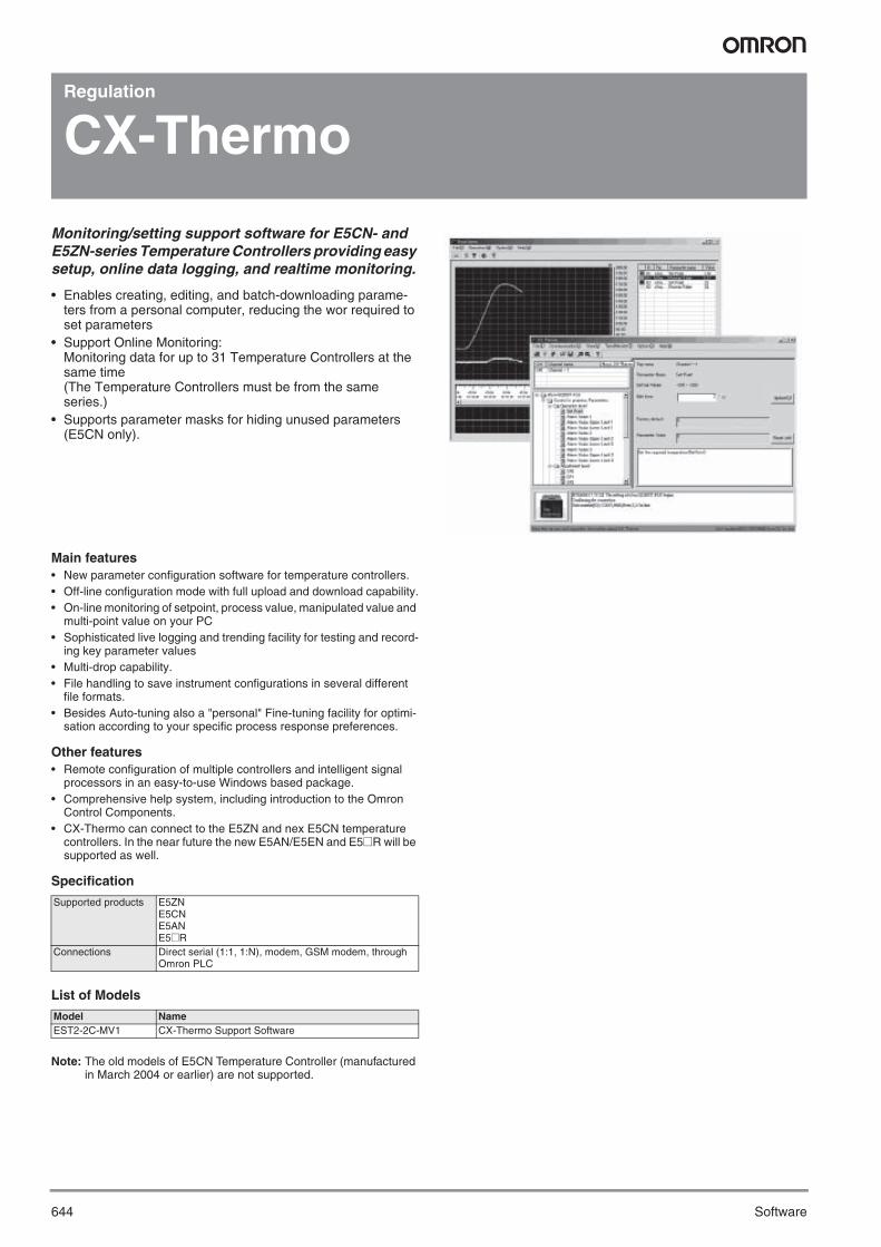
Monitoring/setting support software for E5CN- and E5ZN-series Temperature Controllers providing easy setup, online data logging, and realtime monitoring.
• Enables creating, editing, and batch-downloading parame-ters from a personal computer, reducing the wor required to set parameters
• Support Online Monitoring:Monitoring data for up to 31 Temperature Controllers at the same time(The Temperature Controllers must be from the same series.)
• Supports parameter masks for hiding unused parameters (E5CN only).
Main features• New parameter configuration software for temperature controllers.• Off-line configuration mode with full upload and download capability.• On-line monitoring of setpoint, process value, manipulated value and
multi-point value on your PC• Sophisticated live logging and trending facility for testing and record-
ing key parameter values• Multi-drop capability.• File handling to save instrument configurations in several different
file formats.• Besides Auto-tuning also a "personal" Fine-tuning facility for optimi-
sation according to your specific process response preferences.
Other features• Remote configuration of multiple controllers and intelligent signal
processors in an easy-to-use Windows based package.• Comprehensive help system, including introduction to the Omron
Control Components.• CX-Thermo can connect to the E5ZN and nex E5CN temperature
controllers. In the near future the new E5AN/E5EN and E5@R will be supported as well.
Specification
List of Models
Note: The old models of E5CN Temperature Controller (manufactured in March 2004 or earlier) are not supported.
Supported products E5ZNE5CNE5ANE5@R
Connections Direct serial (1:1, 1:N), modem, GSM modem, through Omron PLC
Model NameEST2-2C-MV1 CX-Thermo Support Software
Y201-EN2-03.book Seite 644 Donnerstag, 30. März 2006 1:52 13
645CX-Designer
So
ftw
are
CX-Designer
Efficient development process for screen creation, simulation and pro-ject deployment.The CX-Designer is used to create screen data for NS-series Pro-grammable Terminals. The CX-Designer can also check the operation of the created screen data on the computer.
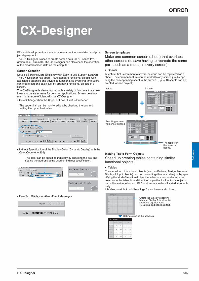
Screen CreationDevelop Screens More Efficiently with Easy-to-use Support Software. The CX-Designer has about 1,000 standard functional objects with associated graphics and advanced functions, so even first-time users can create screens easily just by arranging functional objects in a screen.The CX-Designer is also equipped with a variety of functions that make it easy to create screens for common applications. Screen develop-ment is far more efficient with the CX-Designer.• Color Change when the Upper or Lower Limit Is Exceeded
• Indirect Specification of the Display Color (Dynamic Display) with theColor Code (0 to 255)
• Flow Text Display for Alarm/Event Messages
Screen templatesMake one common screen (sheet) that overlaps other screens (to save having to recreate the same part, such as a menu, in every screen).• SheetsA feature that is common to several screens can be registered as a sheet. The common feature can be added to any screen just by app-lying the corresponding sheet to the screen. (Up to 10 sheets can be created for one project.)
Making Table Form ObjectsSpeed up creating tables containing similar functional objects.• TablesThe same kind of functional objects (such as Buttons, Text, or Numeral Display & Input objects) can be created together in a table just by spe-cifying the kind of functional object, number of rows, and number of columns in the table. In addition, the properties for functional objects can all be set together and PLC addresses can be allocated automati-cally.It is also possible to add headings for each row and column.
The upper limit can be monitored just by checking the box and setting the upper limit value.
The color can be specified indirectly by checking the box and setting the address being used for indirect specification.
Sheet Screen
Resulting screenwith sheet applied
The feature in the sheet is added.
Create the table by specifying Numeral Display & Input as the functional object, 4 rows, 4 columns, and headings (text).
Settings such as the headings
Y201-EN2-03.book Seite 645 Donnerstag, 30. März 2006 1:52 13
646 Software
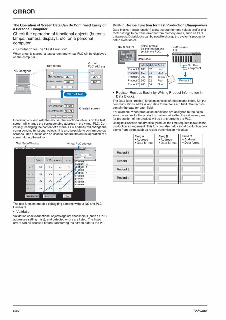
The Operation of Screen Data Can Be Confirmed Easily on a Personal Computer Check the operation of functional objects (buttons, lamps, numeral displays, etc. on a personal computer.• Simulation via the “Test Function”When a test is started, a test screen and virtual PLC will be displayed on the computer.
Operating (clicking with the mouse) the functional objects on the test screen will change the corresponding address in the virtual PLC. Con-versely, changing the content of a virtual PLC address will change the corresponding functional objects. It is also possible to confirm pop-up screens. This function can be used to confirm the actual operation of a screen during the edition.
The test function enables debugging screens without NS and PLC Hardware.
• ValidationValidation checks functional objects against checkpoints (such as PLC addresses setting miss), and detected errors are listed. The listed errors can be checked before transferring the screen data to the PT.
Built-in Recipe Function for Fast Production ChangeoversData blocks (recipe function) allow several numeric values and/or cha-racter strings to be transferred to/from memory areas, such as PLC data areas. Data blocks can be used to change the system’s production setup even faster.
• Register Recipes Easily by Writing Product Information in Data Blocks.
The Data Block (recipe) function consists of records and fields. Set the communications address and data format for each field. The records contain the data for each field.For example, when production conditions are assigned to the fields, write the values for the product in that record so that the values required for production of the product will be transferred to the PLC.Using this function can drastically reduce the time required to switch the production arrangement. This function also helps avoid production pro-blems from errors such as recipe transmission mistakes.
300
500
300
500
1
9999
9999
NS-Designer
Test mode
Set values:
Present values:
Virtual PLC address
Set values:
Present values:
Start of Test
Created screen
Test Mode Window Virtual PLC address
Select product B's information and set it in the PLC.
NS-series PT CS/CJ-series PLC
Data Block
To other equipment
Product B
Product A
Product B
Product C
Product D
Product E
Width100150200300400
Height5254566264
ColorRedBlueYellowRedBlue
Field A • Address• Data format
Record 1
Record 2
Record 3
Record 4
Field B • Address• Data format
Field C • Address• Data format
Y201-EN2-03.book Seite 646 Donnerstag, 30. März 2006 1:52 13
647CX-PROFIBUS
So
ftw
are
PROFIBUS configurator
CX-PROFIBUS
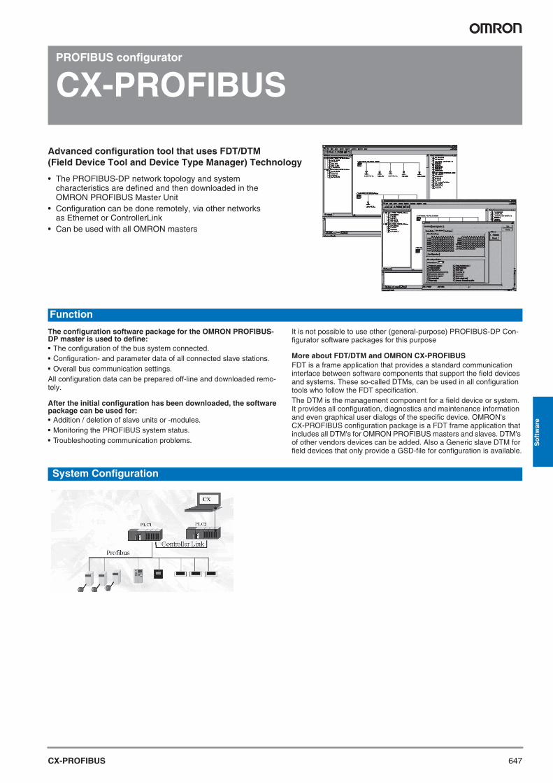
Advanced configuration tool that uses FDT/DTM (Field Device Tool and Device Type Manager) Technology
• The PROFIBUS-DP network topology and system characteristics are defined and then downloaded in the OMRON PROFIBUS Master Unit
• Configuration can be done remotely, via other networks as Ethernet or ControllerLink
• Can be used with all OMRON masters
The configuration software package for the OMRON PROFIBUS-DP master is used to define:• The configuration of the bus system connected.• Configuration- and parameter data of all connected slave stations.• Overall bus communication settings.All configuration data can be prepared off-line and downloaded remo-tely.
After the initial configuration has been downloaded, the software package can be used for:• Addition / deletion of slave units or -modules.• Monitoring the PROFIBUS system status.• Troubleshooting communication problems.
It is not possible to use other (general-purpose) PROFIBUS-DP Con-figurator software packages for this purpose
More about FDT/DTM and OMRON CX-PROFIBUSFDT is a frame application that provides a standard communication interface between software components that support the field devices and systems. These so-called DTMs, can be used in all configuration tools who follow the FDT specification.The DTM is the management component for a field device or system. It provides all configuration, diagnostics and maintenance information and even graphical user dialogs of the specific device. OMRON's CX-PROFIBUS configuration package is a FDT frame application that includes all DTM's for OMRON PROFIBUS masters and slaves. DTM's of other vendors devices can be added. Also a Generic slave DTM for field devices that only provide a GSD-file for configuration is available.
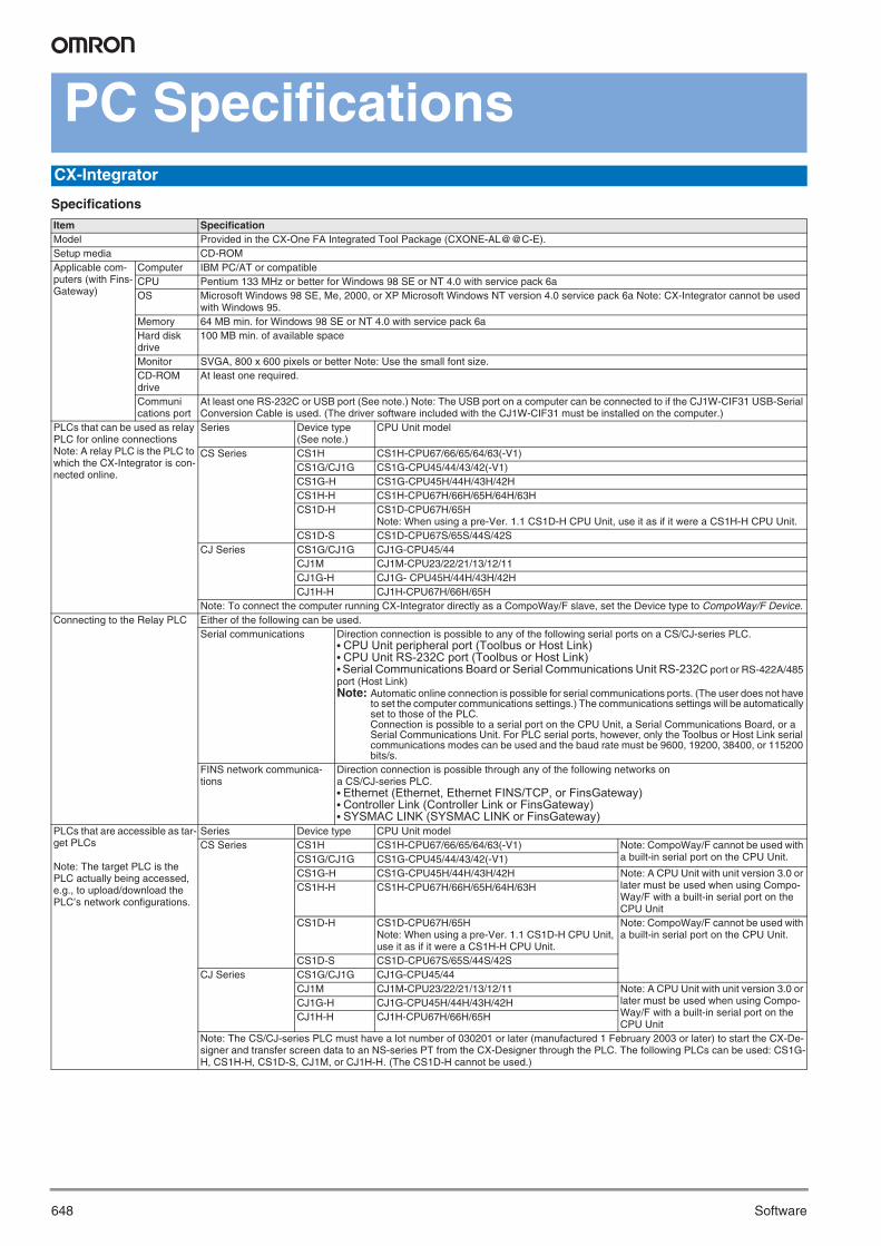
System Configuration
Function
Y201-EN2-03.book Seite 647 Donnerstag, 30. März 2006 1:52 13
648 Software
PC Specifications
Specifications
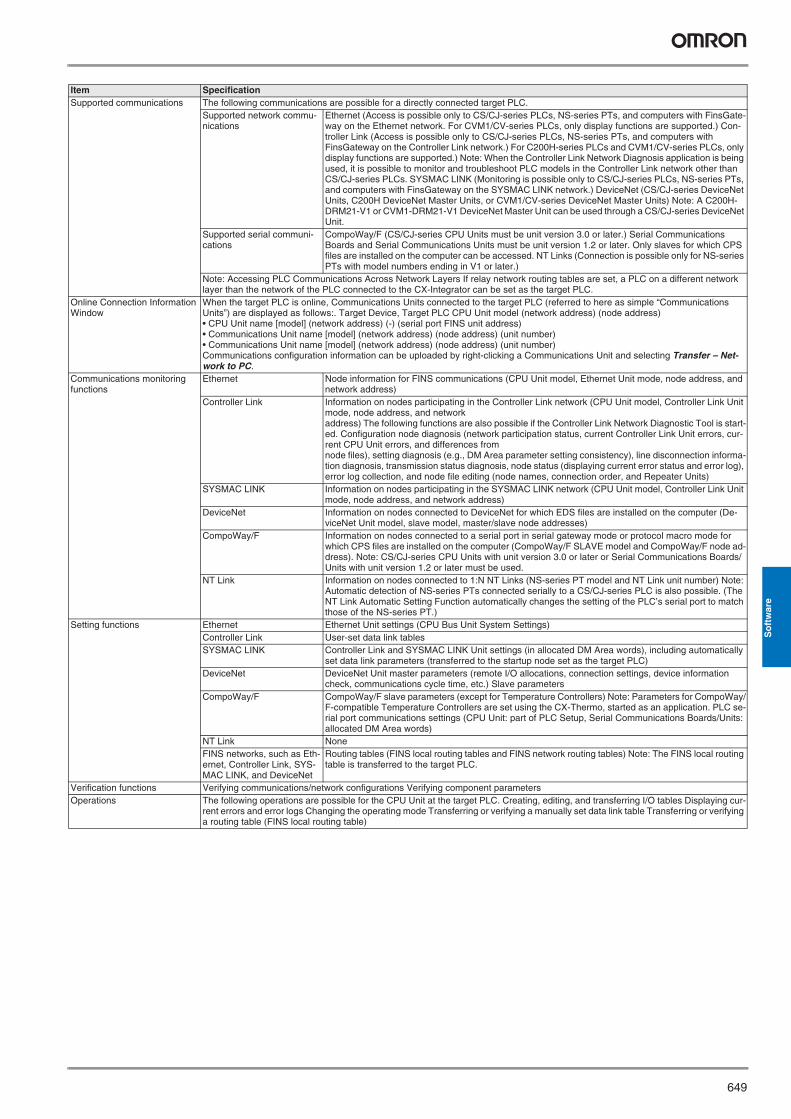
CX-Integrator
Item Specification Model Provided in the CX-One FA Integrated Tool Package (CXONE-AL@@C-E). Setup media CD-ROM Applicable com-puters (with Fins-Gateway)
Computer IBM PC/AT or compatible CPU Pentium 133 MHz or better for Windows 98 SE or NT 4.0 with service pack 6a OS Microsoft Windows 98 SE, Me, 2000, or XP Microsoft Windows NT version 4.0 service pack 6a Note: CX-Integrator cannot be used
with Windows 95. Memory 64 MB min. for Windows 98 SE or NT 4.0 with service pack 6a Hard disk drive
100 MB min. of available space
Monitor SVGA, 800 x 600 pixels or better Note: Use the small font size. CD-ROM drive
At least one required.
Communi cations port
At least one RS-232C or USB port (See note.) Note: The USB port on a computer can be connected to if the CJ1W-CIF31 USB-Serial Conversion Cable is used. (The driver software included with the CJ1W-CIF31 must be installed on the computer.)
PLCs that can be used as relay PLC for online connections Note: A relay PLC is the PLC to which the CX-Integrator is con-nected online.
Series Device type (See note.)
CPU Unit model
CS Series CS1H CS1H-CPU67/66/65/64/63(-V1)CS1G/CJ1G CS1G-CPU45/44/43/42(-V1)CS1G-H CS1G-CPU45H/44H/43H/42HCS1H-H CS1H-CPU67H/66H/65H/64H/63HCS1D-H CS1D-CPU67H/65H
Note: When using a pre-Ver. 1.1 CS1D-H CPU Unit, use it as if it were a CS1H-H CPU Unit.CS1D-S CS1D-CPU67S/65S/44S/42S
CJ Series CS1G/CJ1G CJ1G-CPU45/44CJ1M CJ1M-CPU23/22/21/13/12/11CJ1G-H CJ1G- CPU45H/44H/43H/42HCJ1H-H CJ1H-CPU67H/66H/65H
Note: To connect the computer running CX-Integrator directly as a CompoWay/F slave, set the Device type to CompoWay/F Device. Connecting to the Relay PLC Either of the following can be used.
Serial communications Direction connection is possible to any of the following serial ports on a CS/CJ-series PLC. • CPU Unit peripheral port (Toolbus or Host Link) • CPU Unit RS-232C port (Toolbus or Host Link) • Serial Communications Board or Serial Communications Unit RS-232C port or RS-422A/485 port (Host Link) Note: Automatic online connection is possible for serial communications ports. (The user does not have
to set the computer communications settings.) The communications settings will be automatically set to those of the PLC. Connection is possible to a serial port on the CPU Unit, a Serial Communications Board, or a Serial Communications Unit. For PLC serial ports, however, only the Toolbus or Host Link serial communications modes can be used and the baud rate must be 9600, 19200, 38400, or 115200 bits/s.
FINS network communica-tions
Direction connection is possible through any of the following networks on a CS/CJ-series PLC. • Ethernet (Ethernet, Ethernet FINS/TCP, or FinsGateway) • Controller Link (Controller Link or FinsGateway) • SYSMAC LINK (SYSMAC LINK or FinsGateway)
PLCs that are accessible as tar-get PLCs
Note: The target PLC is the PLC actually being accessed, e.g., to upload/download the PLC’s network configurations.
Series Device type CPU Unit model CS Series CS1H CS1H-CPU67/66/65/64/63(-V1) Note: CompoWay/F cannot be used with
a built-in serial port on the CPU Unit. CS1G/CJ1G CS1G-CPU45/44/43/42(-V1) CS1G-H CS1G-CPU45H/44H/43H/42H Note: A CPU Unit with unit version 3.0 or
later must be used when using Compo-Way/F with a built-in serial port on the CPU Unit
CS1H-H CS1H-CPU67H/66H/65H/64H/63H
CS1D-H CS1D-CPU67H/65H Note: When using a pre-Ver. 1.1 CS1D-H CPU Unit, use it as if it were a CS1H-H CPU Unit.
Note: CompoWay/F cannot be used with a built-in serial port on the CPU Unit.
CS1D-S CS1D-CPU67S/65S/44S/42S CJ Series CS1G/CJ1G CJ1G-CPU45/44
CJ1M CJ1M-CPU23/22/21/13/12/11 Note: A CPU Unit with unit version 3.0 or later must be used when using Compo-Way/F with a built-in serial port on the CPU Unit
CJ1G-H CJ1G-CPU45H/44H/43H/42H CJ1H-H CJ1H-CPU67H/66H/65H
Note: The CS/CJ-series PLC must have a lot number of 030201 or later (manufactured 1 February 2003 or later) to start the CX-De-signer and transfer screen data to an NS-series PT from the CX-Designer through the PLC. The following PLCs can be used: CS1G-H, CS1H-H, CS1D-S, CJ1M, or CJ1H-H. (The CS1D-H cannot be used.)
Y201-EN2-03.book Seite 648 Donnerstag, 30. März 2006 1:52 13
649
So
ftw
are
Supported communications The following communications are possible for a directly connected target PLC. Supported network commu-nications
Ethernet (Access is possible only to CS/CJ-series PLCs, NS-series PTs, and computers with FinsGate-way on the Ethernet network. For CVM1/CV-series PLCs, only display functions are supported.) Con-troller Link (Access is possible only to CS/CJ-series PLCs, NS-series PTs, and computers with FinsGateway on the Controller Link network.) For C200H-series PLCs and CVM1/CV-series PLCs, only display functions are supported.) Note: When the Controller Link Network Diagnosis application is being used, it is possible to monitor and troubleshoot PLC models in the Controller Link network other than CS/CJ-series PLCs. SYSMAC LINK (Monitoring is possible only to CS/CJ-series PLCs, NS-series PTs, and computers with FinsGateway on the SYSMAC LINK network.) DeviceNet (CS/CJ-series DeviceNet Units, C200H DeviceNet Master Units, or CVM1/CV-series DeviceNet Master Units) Note: A C200H-DRM21-V1 or CVM1-DRM21-V1 DeviceNet Master Unit can be used through a CS/CJ-series DeviceNet Unit.
Supported serial communi-cations
CompoWay/F (CS/CJ-series CPU Units must be unit version 3.0 or later.) Serial Communications Boards and Serial Communications Units must be unit version 1.2 or later. Only slaves for which CPS files are installed on the computer can be accessed. NT Links (Connection is possible only for NS-series PTs with model numbers ending in V1 or later.)
Note: Accessing PLC Communications Across Network Layers If relay network routing tables are set, a PLC on a different network layer than the network of the PLC connected to the CX-Integrator can be set as the target PLC.
Online Connection Information Window
When the target PLC is online, Communications Units connected to the target PLC (referred to here as simple “Communications Units”) are displayed as follows:. Target Device, Target PLC CPU Unit model (network address) (node address) • CPU Unit name [model] (network address) (-) (serial port FINS unit address) • Communications Unit name [model] (network address) (node address) (unit number) • Communications Unit name [model] (network address) (node address) (unit number) Communications configuration information can be uploaded by right-clicking a Communications Unit and selecting Transfer – Net-work to PC.
Communications monitoring functions
Ethernet Node information for FINS communications (CPU Unit model, Ethernet Unit mode, node address, and network address)
Controller Link Information on nodes participating in the Controller Link network (CPU Unit model, Controller Link Unit mode, node address, and network address) The following functions are also possible if the Controller Link Network Diagnostic Tool is start-ed. Configuration node diagnosis (network participation status, current Controller Link Unit errors, cur-rent CPU Unit errors, and differences from node files), setting diagnosis (e.g., DM Area parameter setting consistency), line disconnection informa-tion diagnosis, transmission status diagnosis, node status (displaying current error status and error log), error log collection, and node file editing (node names, connection order, and Repeater Units)
SYSMAC LINK Information on nodes participating in the SYSMAC LINK network (CPU Unit model, Controller Link Unit mode, node address, and network address)
DeviceNet Information on nodes connected to DeviceNet for which EDS files are installed on the computer (De-viceNet Unit model, slave model, master/slave node addresses)
CompoWay/F Information on nodes connected to a serial port in serial gateway mode or protocol macro mode for which CPS files are installed on the computer (CompoWay/F SLAVE model and CompoWay/F node ad-dress). Note: CS/CJ-series CPU Units with unit version 3.0 or later or Serial Communications Boards/Units with unit version 1.2 or later must be used.
NT Link Information on nodes connected to 1:N NT Links (NS-series PT model and NT Link unit number) Note: Automatic detection of NS-series PTs connected serially to a CS/CJ-series PLC is also possible. (The NT Link Automatic Setting Function automatically changes the setting of the PLC’s serial port to match those of the NS-series PT.)
Setting functions Ethernet Ethernet Unit settings (CPU Bus Unit System Settings) Controller Link User-set data link tables SYSMAC LINK Controller Link and SYSMAC LINK Unit settings (in allocated DM Area words), including automatically
set data link parameters (transferred to the startup node set as the target PLC) DeviceNet DeviceNet Unit master parameters (remote I/O allocations, connection settings, device information
check, communications cycle time, etc.) Slave parameters CompoWay/F CompoWay/F slave parameters (except for Temperature Controllers) Note: Parameters for CompoWay/
F-compatible Temperature Controllers are set using the CX-Thermo, started as an application. PLC se-rial port communications settings (CPU Unit: part of PLC Setup, Serial Communications Boards/Units: allocated DM Area words)
NT Link None FINS networks, such as Eth-ernet, Controller Link, SYS-MAC LINK, and DeviceNet
Routing tables (FINS local routing tables and FINS network routing tables) Note: The FINS local routing table is transferred to the target PLC.
Verification functions Verifying communications/network configurations Verifying component parameters Operations The following operations are possible for the CPU Unit at the target PLC. Creating, editing, and transferring I/O tables Displaying cur-
rent errors and error logs Changing the operating mode Transferring or verifying a manually set data link table Transferring or verifying a routing table (FINS local routing table)
Item Specification
Y201-EN2-03.book Seite 649 Donnerstag, 30. März 2006 1:52 13

650 Software
Files Created by the CX-Integrator
Note: With DeviceNet only, the following files can also be exported and saved. EDS files (.eds)The device list saved in CSV format (.csv)The I/O comments saved in CSV format (.csv)The device parameters of an OMRON DeviceNet Master Unit saved as an Open Network Controller DRM_UNIT (virtual unit) fileThe device parameters of an OMRON DeviceNet Master Unit saved as a NetX Server (NetX Server for DeviceNet) file
Note: The CX-Integrator does not support files created in the DeviceNet Config-urator Ver. 1.0 file format.
Files Contents Details Project files (.cin) Connection information to re-
lay PLC, all network configu-rations for target PLC, and parameters for DeviceNet masters, DeviceNet slaves, and Com-poWay/F slaves
These files are used offline to check network configurations and parameters and for other purposes, such as printing. Each file consists of the following: Device type setting information of the relay PLCCommunications Unit models connected to the target PLC (Ethernet Units, Controller Link Units, SYS-MAC LINK Units, DeviceNet Units, and Serial Communications Boards/Units) Device models connected to the above CPU Units or Communications Units via communications (De-viceNet slaves, CompoWay/F slaves, NS-series PTs, etc.) Parameters for DeviceNet Master Unit and Device parameters and DeviceNet slaves (for all devices for which EDS files are installed on the computer including slaves from other manufacturers) Parameters for CompoWay/F slaves (for all components for which CPS files are installed on the com-puter (except for Temperature Controllers) Controller Link network parameters Controller Link and SYSMAC LINK Unit allocated DM Area words settings, including automatically set data link parameters Ethernet Unit CPU Bus Unit System Settings Serial Communications Board/Unit serial communications settings Note: Routing tables (local network tables and relay network tables) and user-set data link tables are not included in project files.
Network configuration files DeviceNet network structure files (.npf)
Network configuration for one DeviceNet network connected directly to the target PLC (including master and slave parameters)Note: These are the same as the DeviceNet network structure files (.npf) created with DeviceNet Con-figurator version 2. Files created with DeviceNet Configurator version 2 can be imported/exported.
Controller Link node files (.crg)
Network configuration for Controller Link networks connected directly to the target PLC
Component parameter files DeviceNet device parameter files (.dvf)
Parameters for individual DeviceNet devices (master or slave) Note: These are the same as the DeviceNet device parameter files (.dvf) created with DeviceNet Con-figurator version 2. Files created with DeviceNet Configurator version 2 can be imported.
CompoWay/F component parameter files (.xml)
Parameters for individual CompoWay/F slaves (except for Temperature Controllers) CPU Unit parameters (parts of PLC Setup: serial communications settings) Controller Link or SYSMAC LINK network parameters Controller Link and SYSMAC LINK Unit allocated DM Area words settings, including automatically set data link parameters Ethernet Unit CPU Bus Unit System Settings Serial Communications Board/Unit serial communications settings
Data link table files Controller Link data link table files (.cl3)
Controller Link user-set data link tables Note: These are the same as the Controller Link data link table files (.cl3) created with the CX-Net. Files created with the CX-Net can be imported.
SYSMAC LINK data link ta-ble files (.sl3)
SYSMAC LINK user-set data link tables Note: These are the same as the SYSMAC LINK data link table files (.sl3) created with the CX-Net. Files created with the CX-Net can be imported.
Routing table files FINS local routing table files (.rtg)
Routing tables of the target PLC Note: These are the same as the FINS local routing table files (.rtg) created with the CX-Net. Files cre-ated with the CX-Net can be imported.
FINS network routing table files (.rt3)
Routing tables for all PLCs on networks to which the target PLC belongs Note: These are the same as the FINS network routing table files (.rt3) created with the CX-Net. Files created with the CX-Net can be imported.
Y201-EN2-03.book Seite 650 Donnerstag, 30. März 2006 1:52 13
651
So
ftw
are
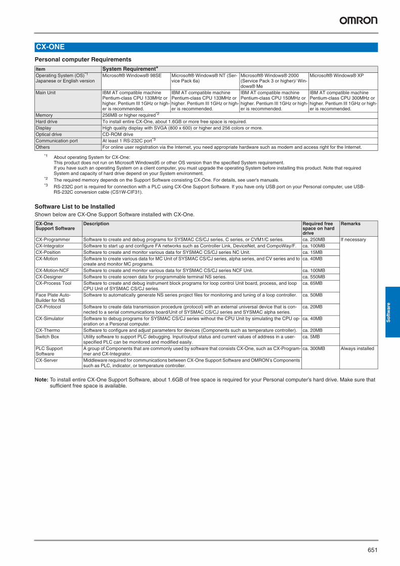
Personal computer Requirements
Software List to be InstalledShown below are CX-One Support Software installed with CX-One.
Note: To install entire CX-One Support Software, about 1.6GB of free space is required for your Personal computer’s hard drive. Make sure that sufficient free space is available.
CX-ONE
Item System Requirement* Operating System (OS)*1 Japanese or English version
*1 About operating System for CX-One: This product does not run on Microsoft Windows95 or other OS version than the specified System requirement.If you have such an operating System on a client computer, you must upgrade the operating System before installing this product. Note that required System and capacity of hard drive depend on your System environment.
Microsoft® Windows® 98SE Microsoft® Windows® NT (Ser-vice Pack 6a)
Microsoft® Windows® 2000 (Service Pack 3 or higher)/ Win-dows® Me
Microsoft® Windows® XP
Main Unit IBM AT compatible machine Pentium-class CPU 133MHz or higher. Pentium III 1GHz or high-er is recommended.
IBM AT compatible machine Pentium-class CPU 133MHz or higher. Pentium III 1GHz or high-er is recommended.
IBM AT compatible machine Pentium-class CPU 150MHz or higher. Pentium III 1GHz or high-er is recommended.
IBM AT compatible machine Pentium-class CPU 300MHz or higher. Pentium III 1GHz or high-er is recommended.
Memory 256MB or higher required*2
*2 The required memory depends on the Support Software consisting CX-One. For details, see user’s manuals.
Hard drive To install entire CX-One, about 1.6GB or more free space is required. Display High quality display with SVGA (800 x 600) or higher and 256 colors or more. Optical drive CD-ROM drive Communication port At least 1 RS-232C port*3
*3 RS-232C port is required for connection with a PLC using CX-One Support Software. If you have only USB port on your Personal computer, use USB-RS-232C conversion cable (CS1W-CIF31).
Others For online user registration via the Internet, you need appropriate hardware such as modem and access right for the Internet.
CX-One Support Software
Description Required free space on hard drive
Remarks
CX-Programmer Software to create and debug programs for SYSMAC CS/CJ series, C series, or CVM1/C series. ca. 250MB If necessary CX-Integrator Software to start up and configure FA networks such as Controller Link, DeviceNet, and CompoWay/F. ca. 100MB CX-Position Software to create and monitor various data for SYSMAC CS/CJ series NC Unit. ca. 15MB CX-Motion Software to create various data for MC Unit of SYSMAC CS/CJ series, alpha series, and CV series and to
create and monitor MC programs. ca. 40MB
CX-Motion-NCF Software to create and monitor various data for SYSMAC CS/CJ series NCF Unit. ca. 100MB CX-Designer Software to create screen data for programmable terminal NS series. ca. 550MB CX-Process Tool Software to create and debug instrument block programs for loop control Unit board, process, and loop
CPU Unit of SYSMAC CS/CJ series. ca. 65MB
Face Plate Auto-Builder for NS
Software to automatically generate NS series project files for monitoring and tuning of a loop controller. ca. 50MB
CX-Protocol Software to create data transmission procedure (protocol) with an external universal device that is con-nected to a serial communications board/Unit of SYSMAC CS/CJ series and SYSMAC alpha series.
ca. 20MB
CX-Simulator Software to debug programs for SYSMAC CS/CJ series without the CPU Unit by simulating the CPU op-eration on a Personal computer.
ca. 40MB
CX-Thermo Software to configure and adjust parameters for devices (Components such as temperature controller). ca. 20MB Switch Box Utility software to support PLC debugging. Input/output status and current values of address in a user-
specified PLC can be monitored and modified easily. ca. 5MB
PLC Support Software
A group of Components that are commonly used by software that consists CX-One, such as CX-Program-mer and CX-Integrator.
ca. 300MB Always installed
CX-Server Middleware required for communications between CX-One Support Software and OMRON’s Components such as PLC, indicator, or temperature controller.
Y201-EN2-03.book Seite 651 Donnerstag, 30. März 2006 1:52 13
652 Software
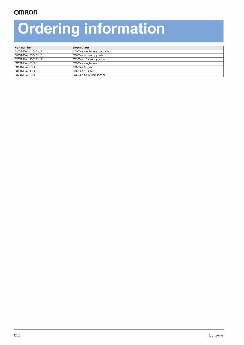
Ordering informationPart number DescriptionCXONE-AL01C-E-UP CX-One single user upgradeCXONE-AL03C-E-UP CX-One 3 user upgradeCXONE-AL10C-E-UP CX-One 10 user upgradeCXONE-AL01C-E CX-One single userCXONE-AL03C-E CX-One 3 user CXONE-AL10C-E CX-One 10 userCXONE-AL30C-E CX-One OEM site license
Y201-EN2-03.book Seite 652 Donnerstag, 30. März 2006 1:52 13
653CX-OPC
So
ftw
are
PC-based visualisation
CX-OPC
General Data
Product Overview
Functions
SpecificationSupported PLC systems CS1, CJ1, C20, CXxK, CXxH, CXxp, SRM1, CPM, CQM1, CQM1H, C200H/-HS/-HX/-HG/-HE, C1000H, C2000H, CV/CVM1Communication • Peripheral port and Host Link port via COMx (RS-232C)
• Controller Link, SYSMAC NET, SYSMAC Link• Ethernet• Modem
Supported Software • MS Excel 97 and later• MS Visual Basic 5 and later• MS Visual C++ 6.0• SCADA supporting OPC 2.04• MES applications using OPC 2.04
Description Model codeProgram OPC server to serial connection single application CX-OPC-EVx.xx-S
OPC server to serial connection 3 applications CX-OPC-E03Vx.xx-SOPC server to serial connection 10 applications CX-OPC-E10Vx.xx-SOPC server to serial+ network connection single application CX-OPC-EVx.xx-NOPC server to serial + network connection 3 applications CX-OPC-E03Vx.xx-NOPC server to serial + network connection 10 applications CX-OPC-E10Vx.xx-N
Program integration • Integration in VBA and Visual Basic via ActiveX® components• The interoperability of CX-Server OPC has been tested with numerous commercially available OPC clients
Application Application-based display of PLC and OPC Server data with the features of MS Office products as well as VBA and Visual BasicOPC functions • Synchronous or Asynchronous communication
• Reading from cache or device• Subscription update rates starting from 100 milliseconds
Standard controls • 7 Segment- and Display control to display data in multiple formats• Toggle button, Rotary Knob, Thumbwheel control and LED Indicator to write a value with a single click and to visualize the value
at the same time• Linear- and Rotational Gauge that can display data in a graphical way• Data Logging, Timer and Linker controls to log data, trigger actions and connect third party ActiveX® controls
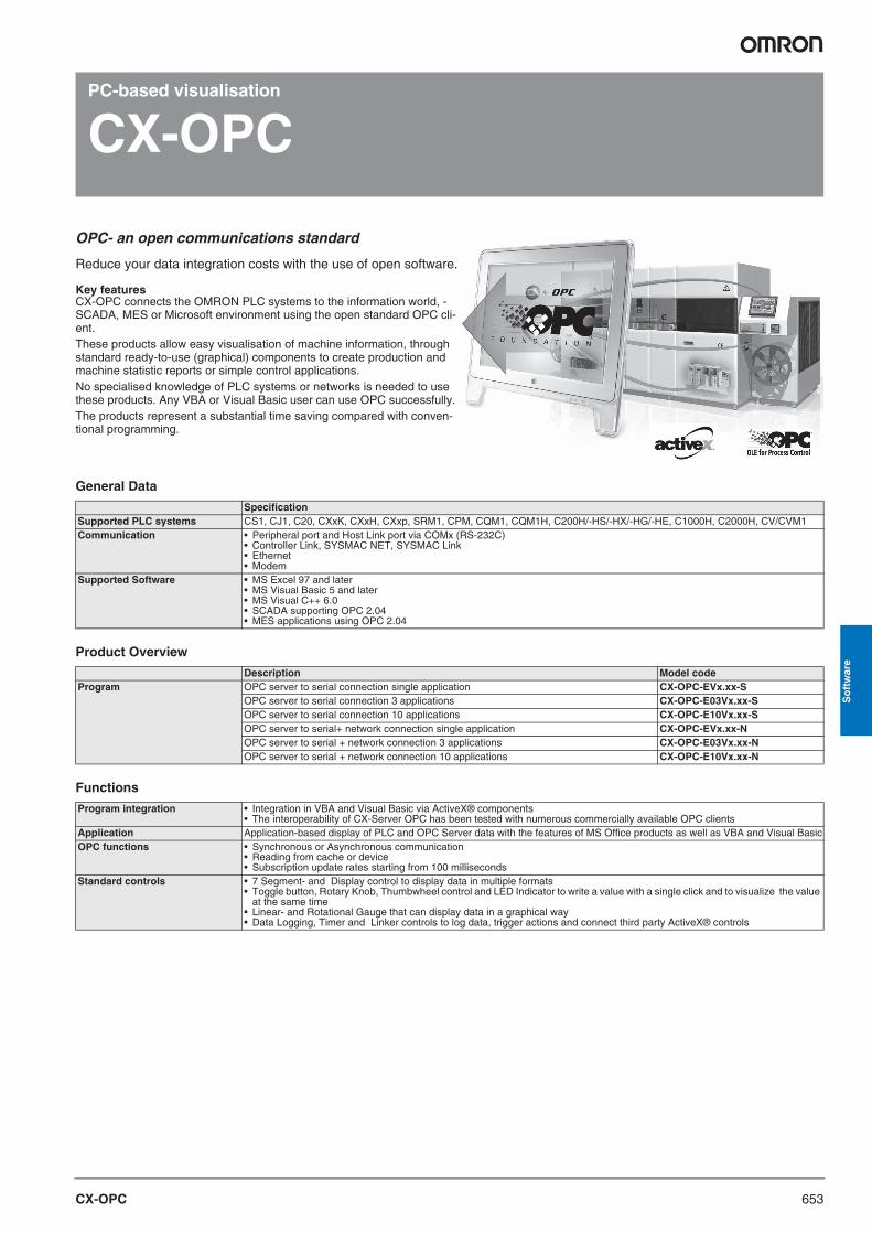
OPC- an open communications standard
Reduce your data integration costs with the use of open software.
Key featuresCX-OPC connects the OMRON PLC systems to the information world, - SCADA, MES or Microsoft environment using the open standard OPC cli-ent.These products allow easy visualisation of machine information, through standard ready-to-use (graphical) components to create production and machine statistic reports or simple control applications.No specialised knowledge of PLC systems or networks is needed to use these products. Any VBA or Visual Basic user can use OPC successfully.The products represent a substantial time saving compared with conven-tional programming.
Y201-EN2-03.book Seite 653 Donnerstag, 30. März 2006 1:52 13
654 Software
PC-based visualisation
CX-Lite
General Data
Product Overview
Functions
SpecificationSupported PLC systems CS1, CJ1, C20, CXxK, CXxH, CXxp, SRM1, CPM, CQM1, CQM1H, C200H/-HS/-HX/-HG/-HE, C1000H, C2000H, CV/CVM1Communication • Peripheral port and Host Link port via COMx (RS-232C)
• Controller Link, SYSMAC NET, SYSMAC Link• Ethernet• Modem
Supported Software • MS Excel 97 and later• MS Visual Basic 5 and later• MS Visual C++ 6.0
Description Model codeProgram Microsoft Excel interface to serial connection only single application CX-LITE-EVx.xx-S
Microsoft Excel interface to serial connection 3 applications CX-LITE-E03Vx.xx-SMicrosoft Excel interface to serial connection 10 application CX-LITE-E10Vx.xx-SMicrosoft Excel interface to serial+ network connection single application CX-LITE-EVx.xx-NMicrosoft Excel interface to serial + network connection 3 applications CX-LITE-E03Vx.xx-NMicrosoft Excel interface to serial + network connection 10 application CX-LITE-E10Vx.xx-N
Program integration • Integration in VBA and Visual Basic via ActiveX® components• Supports the use of ActiveX® components of other suppliers
Application Application-based display of PLC and OPC Server data with the features of MS Office products as well as VBA and Visual BasicOPC functions • Synchronous or Asynchronous communication
• Reading from cache or device• Subscription update rates starting from 100 milliseconds
Standard controls • 7 Segment- and Display control to display data in multiple formats• Toggle button, Rotary Knob, Thumbwheel control and LED Indicator to write a value with a single click and to visualize the value
at the same time• Linear- and Rotational Gauge that can display data in a graphical way• Data Logging, Timer and Linker controls to log data, trigger actions and connect third party ActiveX® controls
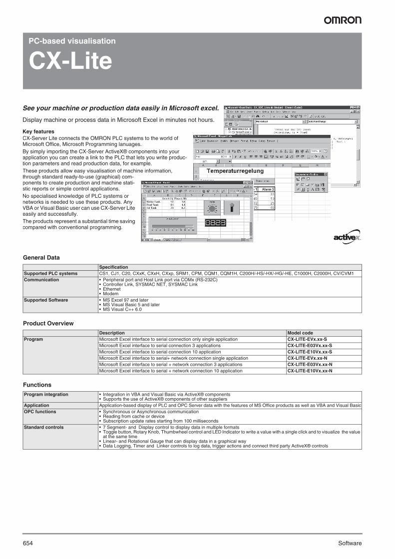
See your machine or production data easily in Microsoft excel.
Display machine or process data in Microsoft Excel in minutes not hours.
Key featuresCX-Server Lite connects the OMRON PLC systems to the world of Microsoft Office, Microsoft Programming lanuages.By simply importing the CX-Server ActiveX® components into your application you can create a link to the PLC that lets you write produc-tion parameters and read production data, for example.These products allow easy visualisation of machine information, through standard ready-to-use (graphical) com-ponents to create production and machine stati-stic reports or simple control applications.No specialised knowledge of PLC systems or networks is needed to use these products. Any VBA or Visual Basic user can use CX-Server Lite easily and successfully.The products represent a substantial time saving compared with conventional programming.
Y201-EN2-03.book Seite 654 Donnerstag, 30. März 2006 1:52 13
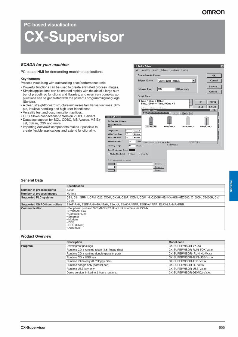
655CX-Supervisor
So
ftw
are
PC-based visualisation
CX-Supervisor
General Data
Product Overview
SpecificationNumber of process points 8,000Number of process images No limitSupported PLC systems CS1, CJ1, SRM1, CPM, C20, CXxK, CXxH, C20P, CQM1, CQM1H, C200H/-HS/-HX/-HG/-HEC500, C1000H, C2000H, CV/
CVM1Supported OMRON controllers E5AF-A/-H, E5EF-A/-H/-BA/-BAH, E5AJ-A, E5AK-A/-PRR, E5EK-A/-PRR, E5AX-LA/-MA/-PRRCommunication • Peripheral port and SYSMAC NET Host Link interface via COMx
• SYSMAC Link• Controller Link• Ethernet• Modem• DDE• OPC (Client)• ActiveX®
Description Model codeProgram Developmet package CX-SUPERVISOR-VX.XX
Runtime CD + runtime token (3.5' floppy disc) CX-SUPERVISOR-RUN-TOK-Vx.xxRuntime CD + runtime dongle (parallel port) CX-SUPERVISOR- RUN-HL-Vx.xxRuntime CD + USB key CX-SUPERVISOR-RUN-USB-Vx.xxRuntime token only (3.5' floppy disc) CX-SUPERVISOR-TOK-Vx.xxRuntime dongle only (parallel port) CX-SUPERVISOR-HL-Vx.xxRuntime USB key only CX-SUPERVISOR-USB-Vx.xxDemo version limited to 2 hours runtime. CX-SUPERVISOR-DEMO2-Vx.xx
SCADA for your machine
PC based HMI for demanding machine applications
Key featuresProcess visualising with outstanding price/performance ratio• Powerful functions can be used to create animated process images.• Simple applications can be created rapidly with the aid of a large num-
ber of predefined functions and libraries, and even very complex ap-plications can be generated with the powerful programming language (Scripts).
• A clear, straightforward structure minimises familiarisation times. Sim-ple, intuitive handling and high user friendliness
• Versatile test and documentation facilities.• OPC allows connections to Version 2 OPC Servers.• Database support for SQL, ODBC, MS Access, MS Ex-
cel, dBase, CSV and more.• Importing ActiveX® components makes it possible to
create flexible applications and extend functionality.
Y201-EN2-03.book Seite 655 Donnerstag, 30. März 2006 1:52 13
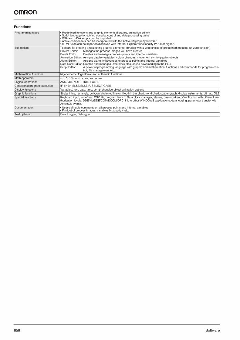
656 Software
Functions
Programming types • Predefined functions and graphic elements (libraries, animation editor)• Script language for solving complex control and data processing tasks • VBA and JAVA scripts can be imported• Active components can be incorporated with the ActiveX® property browser• HTML texts can be imported/displayed with Internet Explorer functionality (V.5.0 or higher)
Edit options Toolbars for creating and aligning graphic elements; libraries with a wide choice of predefined modules (Wizard function)Project Editor: Manages the process images you have createdPoints Editor: Creates and manages process points and internal variablesAnimation Editor: Assigns display variables, colour changes, movement etc. to graphic objectsAlarm Editor: Assigns alarm limits/ranges to process points and internal variablesData block Editor: Creates and manages Data block files, online downloading to the PLCScript Editor: A powerful programming language with graphic and mathematical functions and commands for program con-
trol, file management etc.Mathematical functions trigonometric, logarithmic and arithmetic functionsMath operators +, -, *, /, %, =, <, >, <=, >=, !=, ==Logical operations AND, OR, NOT, TRUE, FALSEConditional program execution IF-THEN-ELSE/ELSEIF, SELECT CASEDisplay functions Variables, text, date, time, comprehensive object animation optionsGraphic functions Straight line, rectangle, polygon, circle (outline or filled-in); bar chart, trend chart, scatter graph, display instruments, bitmap, OLESpecial functions Keyboard input, write/read CSV file, program launch, Data block manager, alarms, password entry/verification with different au-
thorisation levels, DDE/NetDDE/COM/DCOM/OPC-link to other WINDOWS applications, data logging, parameter transfer with ActiveX® events.
Documentation • User-definable comments on all process points and internal variables• Printout of process images, variables lists, scripts etc.
Test options Error Logger, Debugger
Y201-EN2-03.book Seite 656 Donnerstag, 30. März 2006 1:52 13
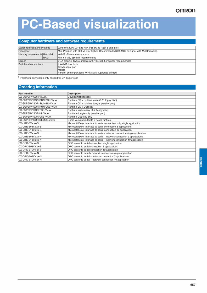
657
So
ftw
are
PC-Based visualizationComputer hardware and software requirements
Supported operating systems Windows 2000, XP and NT4.0 (Service Pack 5 and later)Processor Min. Pentium with 200 MHz or higher, Recommended 800 MHz or higher with Multithreading.Memory requirements Hard disk 40 MB of free memory space
RAM Min. 64 MB, 256 MB recommendedScreen VGA graphic, SVGA graphic with 1024x768 or higher recommendedPeripheral connections1 1.44 MB disk drive
COMx serial portMouseParallel printer port (any WINDOWS supported printer)
1 Peripheral connection only needed for CX-Supervisor
Ordering Information
Part number DescriptionCX-SUPERVISOR-VX.XX Developmet packageCX-SUPERVISOR-RUN-TOK-Vx.xx Runtime CD + runtime token (3.5' floppy disc)CX-SUPERVISOR- RUN-HL-Vx.xx Runtime CD + runtime dongle (parallel port)CX-SUPERVISOR-RUN-USB-Vx.xx Runtime CD + USB keyCX-SUPERVISOR-TOK-Vx.xx Runtime token onloy (3.5' floppy disc)CX-SUPERVISOR-HL-Vx.xx Runtime dongle only (parallel port)CX-SUPERVISOR-USB-Vx.xx Runtime USB key onlyCX-SUPERVISOR-DEMO2-Vx.xx Demo version limited to 2 hours runtime.CX-LITE-EVx.xx-S Microsoft Excel interface to serial connection only single applicationCX-LITE-E03Vx.xx-S Microsoft Excel interface to serial connection 3 applicationsCX-LITE-E10Vx.xx-S Microsoft Excel interface to serial connection 10 applicationCX-LITE-EVx.xx-N Microsoft Excel interface to serial+ network connection single applicationCX-LITE-E03Vx.xx-N Microsoft Excel interface to serial + network connection 3 applicationsCX-LITE-E10Vx.xx-N Microsoft Excel interface to serial + network connection 10 applicationCX-OPC-EVx.xx-S OPC server to serial connection single applicationCX-OPC-E03Vx.xx-S OPC server to serial connection 3 applicationsCX-OPC-E10Vx.xx-S OPC server to serial connection 10 applicationCX-OPC-EVx.xx-N OPC server to serial+ network connection single applicationCX-OPC-E03Vx.xx-N OPC server to serial + network connection 3 applicationsCX-OPC-E10Vx.xx-N OPC server to serial + network connection 10 application
Y201-EN2-03.book Seite 657 Donnerstag, 30. März 2006 1:52 13

658 Software
In the interest of product improvement, specifications are subject to change without notice.
ALL DIMENSIONS SHOWN ARE IN MILLIMETERS.To convert millimeters into inches, multiply by 0.03937. To convert grams into ounces, multiply by 0.03527.
Cat. No. P14E-EN-03A
Y201-EN2-03.book Seite 658 Donnerstag, 30. März 2006 1:52 13