Embed Size (px)
Citation preview

© 2008 Yamaha Corporation All rights reserved.
RX
-V1900
Printed in Malaysia WP38590
RX-V1900AV Receiver
OWNER’S MANUAL
U
RX-V1900_U-cv.fm Page 1 Friday, June 20, 2008 11:23 AM
Black process 45.0° 240.0 LPI

• Explanation of Graphical Symbols
The lightning flash with arrowhead symbol, within an equilateral triangle, is intended to alert you to the presence of uninsulated “dangerous voltage” within the product’s enclosure that may be of sufficient magnitude to constitute a risk of electric shock to persons.
The exclamation point within an equilateral triangle is intended to alert you to the presence of important operating and maintenance (servicing) instructions in the literature accompanying the appliance.
1 Read Instructions – All the safety and operating instructions should be read before the product is operated.
2 Retain Instructions – The safety and operating instructions should be retained for future reference.
3 Heed Warnings – All warnings on the product and in the operating instructions should be adhered to.
4 Follow Instructions – All operating and use instructions should be followed.
5 Cleaning – Unplug this product from the wall outlet before cleaning. Do not use liquid cleaners or aerosol cleaners.
6 Attachments – Do not use attachments not recommended by the product manufacturer as they may cause hazards.
7 Water and Moisture – Do not use this product near water – for example, near a bath tub, wash bowl, kitchen sink, or laundry tub; in a wet basement; or near a swimming pool; and the like.
8 Accessories – Do not place this product on an unstable cart, stand, tripod, bracket, or table. The product may fall, causing serious injury to a child or adult, and serious damage to the product. Use only with a cart, stand, tripod, bracket, or table recommended by the manufacturer, or sold with the product. Any mounting of the product should follow the manufacturer’s instructions, and should use a mounting accessory recommended by the manufacturer.
9 A product and cart combination should be moved with care. Quick stops, excessive force, and uneven surfaces may cause the product and cart combination to overturn.
10 Ventilation – Slots and openings in the cabinet are provided for ventilation and to ensure reliable operation of the product and to protect it from overheating, and these openings must not be blocked or covered. The openings should never be blocked by placing the product on a bed, sofa, rug, or other similar surface. This product should not be placed in a built-in installation such as a bookcase or rack unless proper ventilation is provided or the manufacturer’s instructions have been adhered to.
11 Power Sources – This product should be operated only from the type of power source indicated on the marking label. If you are not sure of the type of power supply to your home, consult your product dealer or local power company. For products intended to operate from battery power, or other sources, refer to the operating instructions.
12 Grounding or Polarization – This product may be equipped with a polarized alternating current line plug (a plug having one blade wider than the other). This plug will fit into the power outlet only one way. This is a safety feature. If you are unable to insert the plug fully into the outlet, try reversing the plug. If the plug should still fail to fit, contact your electrician to replace your obsolete outlet. Do not defeat the safety purpose of the polarized plug.
13 Power-Cord Protection – Power-supply cords should be routed so that they are not likely to be walked on or pinched by items placed upon or against them, paying particular attention to cords at plugs, convenience receptacles, and the point where they exit from the product.
14 Lightning – For added protection for this product during a lightning storm, or when it is left unattended and unused for long periods of time, unplug it from the wall outlet and disconnect the antenna or cable system. This will prevent damage to the product due to lightning and power-line surges.
15 Power Lines – An outside antenna system should not be located in the vicinity of overhead power lines or other electric light or power circuits, or where it can fall into such power lines or circuits. When installing an outside antenna system, extreme care should be taken to keep from touching such power lines or circuits as contact with them might be fatal.
16 Overloading – Do not overload wall outlets, extension cords, or integral convenience receptacles as this can result in a risk of fire or electric shock.
17 Object and Liquid Entry – Never push objects of any kind into this product through openings as they may touch dangerous voltage points or short-out parts that could result in a fire or electric shock. Never spill liquid of any kind on the product.
18 Servicing – Do not attempt to service this product yourself as opening or removing covers may expose you to dangerous voltage or other hazards. Refer all servicing to qualified service personnel.
19 Damage Requiring Service – Unplug this product from the wall outlet and refer servicing to qualified service personnel under the following conditions:
a) When the power-supply cord or plug is damaged,b) If liquid has been spilled, or objects have fallen into the
product,c) If the product has been exposed to rain or water,
IMPORTANT SAFETY INSTRUCTIONS
CAUTION
CAUTION: TO REDUCE THE RISK OF ELECTRIC SHOCK, DO NOT REMOVE
COVER (OR BACK). NO USER-SERVICEABLE PARTS INSIDE. REFER SERVICING TO
QUALIFIED SERVICE PERSONNEL.
RISK OF ELECTRIC SHOCK DO NOT OPEN
Caution-i En

EXAMPLE OF ANTENNA GROUNDING
MAST
GROUNDCLAMP
ANTENNALEAD INWIRE
ANTENNADISCHARGE UNIT(NEC SECTION 810–20)
GROUNDING CONDUCTORS(NEC SECTION 810–21)
GROUND CLAMPS
POWER SERVICE GROUNDINGELECTRODE SYSTEM(NEC ART 250. PART H)
ELECTRICSERVICEEQUIPMENT
NEC – NATIONAL ELECTRICAL CODE
d) If the product does not operate normally by following the operating instructions. Adjust only those controls that are covered by the operating instructions as an improper adjustment of other controls may result in damage and will often require extensive work by a qualified technician to restore the product to its normal operation,
e) If the product has been dropped or damaged in any way, and
f) When the product exhibits a distinct change in performance - this indicates a need for service.
20 Replacement Parts – When replacement parts are required, be sure the service technician has used replacement parts specified by the manufacturer or have the same characteristics as the original part. Unauthorized substitutions may result in fire, electric shock, or other hazards.
21 Safety Check – Upon completion of any service or repairs to this product, ask the service technician to perform safety checks to determine that the product is in proper operating condition.
22 Wall or Ceiling Mounting – The unit should be mounted to a wall or ceiling only as recommended by the manufacturer.
23 Heat – The product should be situated away from heat sources such as radiators, heat registers, stoves, or other products (including amplifiers) that produce heat.
24 Outdoor Antenna Grounding – If an outside antenna or cable system is connected to the product, be sure the antenna or cable system is grounded so as to provide some protection against voltage surges and built-up static charges. Article 810 of the National Electrical Code, ANSI/NFPA 70, provides information with regard to proper grounding of the mast and supporting structure, grounding of the lead-in wire to an antenna discharge unit, size of grounding conductors, location of antenna discharge unit, connection to grounding electrodes, and requirements for the grounding electrode.
Note to CATV system installer:This reminder is provided to call the CATV system installer’s attention to Article 820-40 of the NEC that provides guidelines for proper grounding and, in particular, specifies that the cable ground shall be connected to the grounding system of the building, as close to the point of cable entry as practical.
FCC INFORMATION (for US customers)1 IMPORTANT NOTICE: DO NOT MODIFY THIS
UNIT!This product, when installed as indicated in the instructions contained in this manual, meets FCC requirements. Modifications not expressly approved by Yamaha may void your authority, granted by the FCC, to use the product.
2 IMPORTANT: When connecting this product to accessories and/or another product use only high quality shielded cables. Cable/s supplied with this product MUST be used. Follow all installation instructions. Failure to follow instructions could void your FCC authorization to use this product in the USA.
3 NOTE: This product has been tested and found to comply with the requirements listed in FCC Regulations, Part 15 for Class “B” digital devices. Compliance with these requirements provides a reasonable level of assurance that your use of this product in a residential environment will not result in harmful interference with other electronic devices.This equipment generates/uses radio frequencies and, if not installed and used according to the instructions found in the users manual, may cause interference harmful to the operation of other electronic devices.
Compliance with FCC regulations does not guarantee that interference will not occur in all installations. If this product is found to be the source of interference, which can be determined by turning the unit “OFF” and “ON”, please try to eliminate the problem by using one of the following measures:
Relocate either this product or the device that is being affected by the interference.
Utilize power outlets that are on different branch (circuit breaker or fuse) circuits or install AC line filter/s.
In the case of radio or TV interference, relocate/reorient the antenna. If the antenna lead-in is 300 ohm ribbon lead, change the lead-in to coaxial type cable.
If these corrective measures do not produce satisfactory results, please contact the local retailer authorized to distribute this type of product. If you can not locate the appropriate retailer, please contact Yamaha Electronics Corp., U.S.A. 6660 Orangethorpe Ave, Buena Park, CA 90620.
The above statements apply ONLY to those products distributed by Yamaha Corporation of America or its subsidiaries.
Caution-ii En

1 To assure the finest performance, please read this manual carefully. Keep it in a safe place for future reference.
2 Install this sound system in a well ventilated, cool, dry, clean place – away from direct sunlight, heat sources, vibration, dust, moisture, and/or cold. Allow ventilation space of at least 30 cm on the top, 20 cm on the left and right, and 20 cm on the back of this unit.
3 Locate this unit away from other electrical appliances, motors, or transformers to avoid humming sounds.
4 Do not expose this unit to sudden temperature changes from cold to hot, and do not locate this unit in an environment with high humidity (i.e. a room with a humidifier) to prevent condensation inside this unit, which may cause an electrical shock, fire, damage to this unit, and/or personal injury.
5 Avoid installing this unit where foreign objects may fall onto this unit and/or this unit may be exposed to liquid dripping or splashing. On the top of this unit, do not place:– Other components, as they may cause damage and/or
discoloration on the surface of this unit.– Burning objects (i.e. candles), as they may cause fire,
damage to this unit, and/or personal injury.– Containers with liquid in them, as they may fall and liquid
may cause electrical shock to the user and/or damage to this unit.
6 Do not cover this unit with a newspaper, tablecloth, curtain, etc. in order not to obstruct heat radiation. If the temperature inside this unit rises, it may cause fire, damage to this unit, and/or personal injury.
7 Do not plug in this unit to a wall outlet until all connections are complete.
8 Do not operate this unit upside-down. It may overheat, possibly causing damage.
9 Do not use force on switches, knobs and/or cords.10 When disconnecting the power cable from the wall outlet,
grasp the plug; do not pull the cable.11 Do not clean this unit with chemical solvents; this might
damage the finish. Use a clean, dry cloth.12 Only voltage specified on this unit must be used. Using this
unit with a higher voltage than specified is dangerous and may cause fire, damage to this unit, and/or personal injury. Yamaha will not be held responsible for any damage resulting from use of this unit with a voltage other than specified.
13 To prevent damage by lightning, keep the power cord and outdoor antennas disconnected from a wall outlet or the unit during a lightning storm.
14 Do not attempt to modify or fix this unit. Contact qualified Yamaha service personnel when any service is needed. The cabinet should never be opened for any reasons.
15 When not planning to use this unit for long periods of time (i.e. vacation), disconnect the AC power plug from the wall outlet.
16 Install this unit near the AC outlet and where the AC power plug can be reached easily.
17 Be sure to read the “Troubleshooting” section on common operating errors before concluding that this unit is faulty.
18 Before moving this unit, press AMASTER ON/OFF to release it outward to the OFF position to turn off this unit, the main room, Zone 2 and Zone 3 and then disconnect the AC power plug from the AC wall outlet.
19 VOLTAGE SELECTOR (Asia and General models only)The VOLTAGE SELECTOR on the rear panel of this unit must be set for your local main voltage BEFORE plugging into the AC wall outlet. Voltages are:
................................AC 110/120/220/230–240 V, 50/60 Hz20 The batteries shall not be exposed to excessive heat such as
sunshine, fire or like.21 Excessive sound pressure from earphones and headphones can
cause hearing loss.22 When replacing the batteries, be sure to use batteries of the
same type. Danger of explosion may happen if batteries are incorrectly replaced.
Caution: Read this before operating your unit.
WARNINGTO REDUCE THE RISK OF FIRE OR ELECTRIC SHOCK, DO NOT EXPOSE THIS UNIT TO RAIN OR MOISTURE.
As long as this unit is connected to the AC wall outlet, it is not disconnected from the AC power source even if you turn off this unit by AMASTER ON/OFF. In this state, this unit is designed to consume a very small quantity of power.
FOR CANADIAN CUSTOMERSTo prevent electric shock, match wide blade of plug to wide slot and fully insert.This Class B digital apparatus complies with Canadian ICES-003.
POUR LES CONSOMMATEURS CANADIENSPour éviter les chocs électriques, introduire la lame la plus large de la fiche dans la borne correspondante de la prise et pousser jusqu’au fond.Cet appareil numérique de la classe B est conforme à la norme NMB-003 du Canada.
IMPORTANTPlease record the serial number of this unit in the space below.MODEL: Serial No.: The serial number is located on the rear of the unit. Retain this Owner’s Manual in a safe place for future reference.
Caution-iii En

1 En
PR
EPA
RA
TIO
NIN
TR
OD
UC
TIO
NB
AS
IC
OP
ER
AT
ION
AD
VAN
CE
D
OP
ER
AT
ION
AD
DIT
ION
AL
IN
FO
RM
AT
ION
AP
PE
ND
IXE
ng
lish
Features ................................................................... 3Supplied accessories .................................................. 3
Notice ....................................................................... 4Getting started ........................................................ 5Quick start guide .................................................... 6
Connections ........................................................... 10Optimizing the speaker setting for your
listening room.................................................... 30Before starting the automatic setup ......................... 30Basic automatic setup .............................................. 30Advanced automatic setup....................................... 33Reloading the automatic setup parameters .............. 34
Playback ................................................................ 35Basic procedure ....................................................... 35Selecting audio input jacks (AUDIO SELECT)...... 36Selecting the multi-channel input component ......... 36Using your headphones............................................ 36Muting the audio output........................................... 37Displaying the input source information
(SIGNAL INFO) ................................................. 37Using the sleep timer ............................................... 38
Sound field programs ........................................... 39Selecting sound field programs ............................... 39Using CINEMA DSP 3D mode............................... 45Enjoying unprocessed input sources........................ 45
Using audio features ............................................. 46Enjoying pure hi-fi sound ........................................ 46Adjusting the tonal quality....................................... 46Adjusting the speaker level...................................... 46
FM/AM tuning ...................................................... 47Overview.................................................................. 47FM/AM tuning operations ....................................... 47Preset FM/AM stations ............................................ 48
Using HD Radio™ features (U.S.A. model only)........................................... 50Selecting HD Radio™ audio programs ................... 50Displaying HD Radio™ information....................... 51
XM® Satellite Radio tuning ................................. 52Connecting XM Mini-Tuner Home Dock ............... 52Activating XM Satellite Radio ................................ 53XM Satellite Radio operations................................. 53Setting the XM Satellite Radio preset channels ...... 55Displaying the XM Satellite Radio information...... 56
SIRIUS Satellite Radio™ tuning......................... 57Connecting the SiriusConnect™ tuner .................... 57Activating SIRIUS Satellite Radio™ subscription.. 58SIRIUS Satellite Radio™ operations ...................... 58Setting the SIRIUS Satellite Radio™ preset
channels ............................................................... 60Setting the Parental Lock......................................... 61Displaying the SIRIUS Satellite Radio™
information .......................................................... 62Using iPod™.......................................................... 63
Controlling iPod™................................................... 63
Using Bluetooth™ components............................65Pairing the Bluetooth™ receiver and your
Bluetooth component .......................................... 65Playback of the Bluetooth™ component ................. 65
Advanced sound configurations...........................66Selecting decoders ................................................... 66Changing sound field parameter settings................. 67
Customizing this unit (MANUAL SETUP).........74Operating the MANUAL SETUP menu.................. 741 SPEAKER MENU................................................ 752 VOLUME MENU ................................................ 773 SOUND MENU.................................................... 784 VIDEO MENU ..................................................... 805 INPUT MENU...................................................... 816 OPTION MENU................................................... 83
Saving and recalling the system settings (SYSTEM MEMORY)......................................86Saving the system settings ....................................... 86Loading the system settings..................................... 87Using examples........................................................ 88
Remote control features........................................89Controlling this unit, a TV, or other components.... 89Setting remote control codes ................................... 91Programming codes from other remote controls ..... 93Changing source names in the display window....... 94Macro programming features .................................. 95Clearing configurations ........................................... 97Simplified remote control ........................................ 98
Using multi-zone configuration............................99Connecting the Zone 2 and Zone 3 components ..... 99Controlling Zone 2 or Zone 3 ................................ 100
Advanced setup....................................................102Using the advanced setup menu ............................ 102
Troubleshooting...................................................104Resetting the system............................................115Glossary................................................................116Sound field program information......................119Parametric equalizer information .....................120Specifications .......................................................121SET MENU tree ..................................................123Index .....................................................................125
(at the end of this manual)
Front panel................................................................iRemote control ....................................................... iiSound output in each sound field program......... iiiList of remote control codes ...................................v
Contents
INTRODUCTION
PREPARATION
BASIC OPERATION
ADVANCED OPERATION
ADDITIONAL INFORMATION
APPENDIX
“AMASTER ON/OFF” or “3DVD” (example) indicates the name of the parts on the front panel or the remote control. Refer to the attached sheet or the pages at the end of this manual for the information about each position of the parts.

By configuring the parameters in “MANUAL SETUP”, you can adjust a variety of system settings suited for your listening environment. The following is a brief description of some of the useful menus you can configure in “MANUAL SETUP”. For more detailed information, see “Customizing this unit (MANUAL SETUP)” (page 74) and “SET MENU tree” (page 123).
Fine adjusting the speaker settingsIn case speaker settings configured by automatic setup does not match your listening environment, you can configure them manually.SPEAKER MENU → CONFIG (page 75)SPEAKER MENU → LEVEL (page 76)SPEAKER MENU → DISTANCE (page 76)
Specifying the muting typeIn case you do not want to fully mute audio when you receive a call while watching your favorite TV program, you can use this menu to specify the muting level.VOLUME MENU → MUTING TYPE (page 78)
Specifying the initial volume levelBy adjusting this parameter, you can automatically control the initial volume level regardless of the recording level of the audio source.VOLUME MENU → INIT. VOL. (page 78)
Adjusting the dynamic rangeThe dynamic range is the difference between the minimum and maximum amplitude. The higher the dynamic range, the more accurate the sound reproduction for bitstream signals. You can adjust the dynamic range for speakers and headphones individually.SOUND MENU → DYNAMIC RANGE (page 79)
Adjusting the audio and video synchronizationSometimes, depending on your video source component, video is delayed relative to audio due to processing problems. In this case, you need to manually adjust the audio delay to keep it synchronized with the video. If you connect the video source component to this unit using an HDMI connection and your component supports the LIPSYNC feature, you can adjust the audio/video synchronization automatically.SOUND MENU → LIPSYNC (page 79)
Changing input/output assignmentIn case the initial input/output assignments do not correspond to your needs, you can rearrange them according to your component to be connected to this unit. You can also edit the input name to be displayed in the front panel or in the OSD as necessary.INPUT MENU → (input source) → I/O ASSIGNMENT (page 82)INPUT MENU → (input source) INPUT RENAME (page 82)
Fixing the volume difference between input sourcesThe sound output level may vary depending on the audio source components connected to this unit. In this case, you can reduce or increase the output level of each input source using this feature. INPUT MENU → (input source) → VOL. TRIM (page 82)
Setting the background video for audio sourcesIf you want to enjoy video images in combination with music playback or radio, configure this setting to specify the video input source. For example, to view DVD video images while listening to the FM radio, set this setting under “TUNER” to “DVD”.INPUT MENU → (input source) → BGV (page 82)
Adjusting the brightness of the front panel displayYou can make the front panel display darker or brighter by configuring this setting.OPTION MENU → DISPLAY SET → DIMMER (page 83)
Turning on or off the short message displayEach time you operate this unit using controls on the front panel or remote control keys, this unit displays short messages on the OSD. If you want to turn off the short message display, select “OFF” in this setting (Initial factory setting is “ON”).OPTION MENU → DISPLAY SET → SHORT MESSAGE (page 84)
Setting the amount of time to display OSD informationYou can set the amount of time to display HD Radio (U.S.A. model only), XM Satellite Radio, or SIRIUS Satellite Radio information or iPod menu in the OSD after you perform a certain operation.OPTION MENU → DISPLAY SET → ON SCREEN (page 84)
Protecting the setup valuesAfter you have configured the sound field program parameters and other system settings, you can use this feature to prevent accidental changes to those setup values. OPTION MENU → MEMORY GUARD (page 84)
What you can do with MANUAL SETUP
2 En

FEATURESIN
TR
OD
UC
TIO
NE
ng
lish
Built-in 7-channel power amplifier◆ Minimum RMS output power
(20 Hz to 20 kHz, 0.04% THD, 8 Ω)Front: 130 W + 130 WCenter: 130 WSurround: 130 W + 130 WSurround back: 130 W + 130 W
Various input/output connectors◆ HDMI (IN x 4, OUT x 1), Component video (IN x 3, OUT x
1), S-video (IN x 6, OUT x 3), Composite video (IN x 6, OUT x 3), Coaxial digital audio (IN x 3), Optical digital audio (IN x 5, OUT x 2), Analog audio (IN x 10, OUT x 3)
◆ Speaker out (7-channel), Pre out (7-channel), Subwoofer out, Presence out, Zone 2/Zone 3 out
◆ Discrete multi-channel input (6 or 8-channel)
Sound field programs◆ Proprietary Yamaha technology for the creation of sound
fields◆ CINEMA DSP 3D◆ Compressed Music Enhancer mode◆ Virtual CINEMA DSP◆ SILENT CINEMA
Digital audio decoders◆ Dolby TrueHD, Dolby Digital Plus decoder◆ DTS-HD Master Audio, DTS-HD High Resolution Audio
decoder◆ Dolby Digital/Dolby Digital EX decoder◆ DTS/DTS-ES Matrix 6.1, Discrete 6.1, DTS 96/24 decoder◆ Dolby Pro Logic/Dolby Pro Logic II/Dolby Pro Logic IIx
decoder◆ DTS NEO:6 decoder◆ Neural-THX Surround decoder
(U.S.A. and Canada models only)◆ SRS Circle Surround II decoder (U.S.A. model only)
Sophisticated FM/AM tuner◆ 40-station random and direct preset tuning◆ Automatic preset tuning
Radio tuners◆ FM/AM tuning capability◆ HD Radio™ digital broadcast reception capability (U.S.A.
model only)◆ XM Satellite Radio tuning capability (using XM Mini-Tuner
and Home Dock, sold separately)◆ SIRIUS Satellite Radio™ tuning capability (using
SiriusConnect tuner, sold separately)
HDMI™ (High-Definition Multimedia Interface)◆ HDMI interface for standard, enhanced or
high-definition video as well as multi-channel digital audio based on HDMI version 1.3a (HDMI is licensed by HDMI Licensing, LLC.) – Automatic audio and video synchronization (lip sync)
information capability– Deep Color video signal (30/36 bit) transmission capability– “x.v.Color” video signal transmission capability– High refresh rate and high resolution video signals
capability– High definition digital audio format signals capability
◆ HDCP (High-bandwidth Digital Content Protection System) licensed by Digital Content Protection, LLC.
◆ Analog video to HDMI digital video up-conversion (composite video ↔ S-video ↔ component video → HDMI digital video) capability for monitor out
◆ Analog video up-scaling from 480i (NTSC)/576i (PAL) or 480p/576p to 720p, 1080i or 1080p
DOCK terminal◆ DOCK terminal to connect a Yamaha iPod universal
dock (such as YDS-11, sold separately) or Bluetooth wireless audio receiver (such as YBA-10, sold separately)
Automatic speaker setup features◆ Advanced YPAO (Yamaha Parametric room Acoustic
Optimizer) for automatic speaker setup◆ Multi-point measurement feature for multiple listening
positions◆ Parametric equalizer select feature
Other features◆ 192-kHz/24-bit D/A converter◆ OSD (on-screen display) menus that allow you to optimize
this unit to suit your individual audiovisual system◆ Analog video interlace/progressive conversion from
480i (NTSC)/576i (PAL) to 480p/576p◆ Pure Direct mode for pure hi-fi sound for all sources◆ Adaptive dynamic range controlling capability◆ Adaptive DSP effect level controlling capability◆ Remote control with preset remote control codes, learning and
macro capability◆ ZONE 2/ZONE 3 custom installation facility◆ Zone switching capability between the main zone and
ZONE 2/ZONE 3 using ZONE CONTROLS◆ SYSTEM MEMORY capability for saving and recalling
multiple system parameter settings◆ Sleep timer for each zone
Check that you received all of the following parts.
❏ Remote control❏ Simplified remote control
(except Europe model)❏ Batteries (4) (AAA, R03, UM-4)❏ Power cable (Two for Asia model)
❏ Optimizer microphone❏ AM loop antenna❏ Indoor FM antenna❏ Speaker terminal wrench
Features
Supplied accessories
3 En

NOTICE
Manufactured under license from Dolby Laboratories.Dolby and the double-D symbol are registered trademarks of Dolby Laboratories.
Manufactured under license under U.S. Patent No’s: 5,451,942;5,956,674;5,974,380;5,978,762;6,226,616;6,487,535 & other U.S. and worldwide patents issued & pending. DTS is a registered trademark and the DTS logos, Symbol, DTS-HD and DTS-HD Master Audio are trademark of DTS, Inc. © 1996-2007 DTS, Inc. All Rights Reserved.
“iPod” is a trademark of Apple Inc., registered in the U.S. and other countries.
“HDMI”, the “HDMI” logo and “High-Definition Multimedia Interface” are trademarks, or registered trademarks of HDMI Licensing LLC.
x.v.Color™“x.v.Color” is a trademark of Sony Corporation.
“SILENT CINEMA” is a trademark of Yamaha Corporation.
The XM name and related logos are registered trademarks of XM Satellite Radio Inc.
This product is manufactured under license from Neural Audio Corporation and THX Ltd. YAMAHA CORPORATION hereby grants the user a non-exclusive, non-transferable, limited right of use to this product under U.S.A. and foreign patent, patent pending and other technology or trademarks owned by Neural Audio Corporation and THX Ltd. “Neural Surround”, “Neural Audio”, “Neural” and “NRL” are trademarks and logos owned by Neural Audio Corporation. THX is a trademark of THX Ltd., which may be registered in some jurisdictions. All rights reserved.
©2006 SIRIUS Satellite Radio Inc. “SIRIUS”, “SiriusConnect”, the SIRIUS dog logo, channel names and logos are trademarks of SIRIUS Satellite Radio Inc.
HD Radio™ Technology Manufactured Under License From iBiquity Digital Corp. U.S. and Foreign Patents. HD Radio™ and the HD Radio logo are proprietary trademarks of iBiquity Digital Corp.
Circle Surround II, Dialog Clarity, TruBass, SRS and the symbol are trademarks of SRS Labs, Inc. Circle Surround II, Dialog Clarity and TruBass technologies are incorporated under license from SRS Labs, Inc.
Notice
About this manual
• y indicates a tip for your operation.• Some operations can be performed by using either the
buttons on the front panel or the ones on the remote control. In case the button names differ between the front panel and the remote control, the button name on the remote control is given in parentheses.
• This manual is printed prior to production. Design and specifications are subject to change in part as a result of improvements, etc. In case of differences between the manual and product, the product has priority.
• “AMASTER ON/OFF” or “3DVD” (example) indicates the name of the parts on the front panel or the remote control. Refer to the attached sheet or the pages at the end of this manual for the information about each position of the parts.
iPodTM
4 En

GETTING STARTEDIN
TR
OD
UC
TIO
NE
ng
lish
■ Installing batteries in the remote control
1 Take off the battery compartment cover.
2 Insert the four supplied batteries (AAA, R03, UM-4) according to the polarity markings (+ and –) on the inside of the battery compartment.
3 Snap the battery compartment cover back into place.
• Change all of the batteries if you notice the following conditions:– the operation range of the remote control decreases.– the transmit indicator does not flash or its light becomes dim.
• Do not use old batteries together with new ones.• Do not use different types of batteries (such as alkaline and
manganese batteries) together. Read the packaging carefully as these different types of batteries may have the same shape and color.
• If the batteries have leaked, dispose of them immediately. Avoid touching the leaked material or letting it come into contact with clothing, etc. Clean the battery compartment thoroughly before installing new batteries.
• Do not throw away batteries with general house waste; dispose of them correctly in accordance with your local regulations.
• If the remote control is without batteries for more than 2 minutes, or if exhausted batteries remain in the remote control, the contents of the memory may be cleared. When the memory is cleared, insert new batteries, set up the remote control code and program any acquired functions that may have been cleared.
■ VOLTAGE SELECTOR(Asia and General models only)
Getting started
Notes
13
2
Caution
The VOLTAGE SELECTOR on the rear panel of this unit must be set for your local voltage BEFORE plugging the power cable into the AC wall outlet. Improper setting of the VOLTAGE SELECTOR may cause damage to this unit and create a potential fire hazard.Rotate the VOLTAGE SELECTOR clockwise or counterclockwise to the correct position using a straight slot screwdriver.Voltages are as follows: ........................AC 110/120/220/230–240 V, 50/60 Hz
230-240V
VOLTAGESELECTOR
Voltage indication
5 En

QUICK START GUIDE
The following steps describe the easiest way to enjoy DVD movie playback in your home theater.
In these steps, you need the following supplied accessories.
❏ Power cable
The following items are not included in the package of this unit.
❏ Speakers❏ Front speaker ..................................... x 2❏ Center speaker ................................... x 1❏ Surround speaker .............................. x 4Select magnetically shielded speakers. The minimum required speakers are two front speakers. The priority of the requirement of other speakers is as follows:
1. Two surround speakers2. One center speaker3. One (or two) surround back speaker(s)
❏ Active subwoofer ................................... x 1Select an active subwoofer equipped with an RCA input jack.
❏ Speaker cable ......................................... x 7❏ Subwoofer cable ..................................... x 1
Select a monaural RCA cable.
❏ DVD player .............................................. x 1Select DVD player equipped with coaxial digital audio output jack and composite video output jack.
❏ Video monitor .......................................... x 1Select a TV monitor, video monitor or projector equipped with a composite video input jack.
❏ Video cable ............................................. x 2Select RCA composite video cables.
❏ Digital coaxial audio cable .................... x 1
Quick start guide
Front right speaker
Subwoofer
Surround back right speaker
Surround left speaker
Front left speaker
Surround back left speaker
Surround right speaker
Center speaker
Video monitor
DVD player
Enjoy DVD playback!
Step 1: Set up your speakers
☞ P. 7
Step 2: Connect your DVD player and other components
Step 3: Turn on the power and start playback
☞ P. 8
☞ P. 9
Preparation: Check the items
6 En

Quick start guideIN
TR
OD
UC
TIO
NE
ng
lish
Place your speakers in the room and connect them to this unit.
1 Place your speakers and subwoofer in the room.
2 Connect speaker cables to each speaker.
3 Connect each speaker cable to the corresponding speaker terminal of this unit.
1 Make sure that this unit and the subwoofer are unplugged from the AC wall outlets.
2 Twist the exposed wires of the speaker cables together to prevent short circuits.
3 Do not let the bare speaker wires touch each other.4 Do not let the bare speaker wires touch any metal
part of this unit.
Be sure to connect the left channel (L), right channel (R), “+” (red) and “–” (black) properly.
Front speakers and center speaker
Surround and surround back speakers
4 Connect the subwoofer cable to the SUBWOOFER PRE OUT jack of this unit and the input jack of the subwoofer.
Step 1: Set up your speakers
AC IN
AC OUTLETSSWITCHED
HOLDERWRENCH
SPEAKERS
CENTERBI-AMP
SURROUND BACK/
PRESENCE/ZONE 2/ZONE 3SP1
FRONT
SURROUNDZONE 2/ZONE 3
SINGLE
SP2
ANTENNA
FM GND AM75Ω UNBAL.
VIDEO
S VIDEO
MONITOR OUTVIDEO
REMOTE
PHONOGND CD TV
HDMI COMPONENT VIDEO
AUDIODOCK XM
SIRIUS
DIGITAL INPUTMULTI CH INPUT PRE OUT
TRIGGER OUT RS-232C
DIGITAL OUTPUTZONE OUT
SUBWOOFER
SUBWOOFER
CENTER CENTERFRONT(6CH) FRONTSURROUND SURROUND
PRESENCESUR.BACK/
SINGLE(SB) ZONE 2 ZONE 3
CD DVD DVR
COAXIAL
1 2
TV BD/HD DVD
CBL/SAT
MD/CD-RDVD DVR
OPTICAL
987654321
SB(8CH)
DVD
(REC)(PLAY)IN OUT
CD-RMD/
BD/HD DVD VCRDVRCBL/SAT OUT OUTININBD/HD DVD DVD CBL/SATMONITOR OUT
Y
PR
Y
PR
PB PB
IN OUT
DVR
CBL/SAT
DVD
BD/HD DVD
OUT
+
+ +
A B C
R L
R
R
L
R
L
+ + +R L
+ +R L
+ +R L
L
IN2
IN3
IN4
IN1
SUBWOOFER PRE OUT Speaker terminals
1 2 3 4
1 2 3 4
To the front left speaker
To the front right speaker
Loosen Insert
Speaker terminal wrench
To the center speaker
Tighten
To the surroundback
right speakerTo the surround back left speaker
To the surround rightspeaker
To the surround left speaker
SUBWOOFER PRE OUT jack
Input jack
AV receiverSubwoofer
Subwoofer cable
7 En

Quick start guide
1 Connect the digital coaxial audio cable to the digital coaxial audio output jack of your DVD player and the DVD DIGITAL INPUT COAXIAL jack of this unit.
2 Connect the video cable to the composite video output jack of your DVD player and DVD VIDEO jack of this unit.
3 Connect the video cable to the VIDEO MONITOR OUT jack of this unit and the video input jack of your video monitor.
4 Connect the supplied power cable to this unit and then plug of the power cable and other components into the AC wall outlet.
yFor details about connecting the power cable, see page 25.
■ For other connections
• Other speaker combinations ☞ P. 13
• Information on jacks and cable plugs ☞ P. 16
• Information on HDMI™ ☞ P. 17
• TV monitor or projector ☞ P. 19
• Other components ☞ P. 20
• External amplifier ☞ P. 22
• Multi-format player or external decoder ☞ P. 23
• Yamaha iPod universal dock or Bluetooth wireless audio receiver ☞ P. 23
• FM/AM antennas ☞ P. 24
• XM Mini-Tuner Home Dock ☞ P. 52
• SiriusConnect tuner ☞ P. 57
Step 2: Connect your DVD player and other components
AC IN
AC OUTLETSSWITCHED
HOLDERWRENCH
SPEAKERS
CENTERBI-AMP
SURROUND BACK/
PRESENCE/ZONE 2/ZONE 3SP1
FRONT
SURROUNDZONE 2/ZONE 3
SINGLE
SP2
ANTENNA
FM GND AM75Ω UNBAL.
VIDEO
S VIDEO
MONITOR OUTVIDEO
REMOTE
PHONOGND CD TV
HDMI COMPONENT VIDEO
AUDIODOCK XM
SIRIUS
DIGITAL INPUTMULTI CH INPUT PRE OUT
TRIGGER OUT RS-232C
DIGITAL OUTPUTZONE OUT
SUBWOOFER
SUBWOOFER
CENTER CENTERFRONT(6CH) FRONTSURROUND SURROUND
PRESENCESUR.BACK/
SINGLE(SB) ZONE 2 ZONE 3
CD DVD DVR
COAXIAL
1 2
TV BD/HD DVD
CBL/SAT
MD/CD-RDVD DVR
OPTICAL
987654321
SB(8CH)
DVD
(REC)(PLAY)IN OUT
CD-RMD/
BD/HD DVD VCRDVRCBL/SAT OUT OUTININBD/HD DVD DVD CBL/SATMONITOR OUT
Y
PR
Y
PR
PB PB
IN OUT
DVR
CBL/SAT
DVD
BD/HD DVD
OUT
+
+ +
A B C
R L
R
R
L
R
L
+ + +R L
+ +R L
+ +R L
L
IN2
IN3
IN4
IN1
Make sure that this unit and the DVD player are unplugged from the AC wall outlets.
VIDEO MONITOR OUTDVD VIDEO
DVD DIGITAL INPUT COAXIAL
Digital coaxialaudio output
jackDigital coaxial audio
cable DVD DIGITAL INPUTCOAXIAL jack
DVD player AV receiver
Composite video output jack
Video cable
DVD VIDEO jack
DVD playerAV receiver
Video monitor AV receiver
Video cable VIDEO MONITOR OUT jackVideo input jack
8 En

Quick start guideIN
TR
OD
UC
TIO
NE
ng
lish
1 Turn on the video monitor connected to this unit.
2 Press AMASTER ON/OFF inward to the ON position on the front panel.
3 Rotate the CINPUT selector to set the input source to “DVD”.
4 Start playback of the desired DVD on your player.
5 Rotate QVOLUME to adjust the volume.
6 To set this unit to the standby mode, press B MAIN ZONE ON/OFF.
yFor details about turning on/off this unit and the standby mode, see page 26.
■ For other operations
• Optimizing the speaker parameters automatically ☞ P. 30
• Basic playback operations ☞ P. 35
• Sound field programs ☞ P. 39
• Pure high-fidelity sounds ☞ P. 46
• FM/AM radio tuning ☞ P. 47
• XM Satellite Radio tuning ☞ P. 52
• SIRIUS Satellite Radio tuning ☞ P. 57
• iPod playback ☞ P. 63
• Bluetooth component playback ☞ P. 65
Step 3: Turn on the power and start playback
Check the type of the connected speakers.If the speakers are 6-ohm speakers, set “SPEAKER IMP.” to “6Ω MIN” before using this unit (page 26). You can also use 4-ohm speakers as the front speakers (page 102).
9 En

• The TRIGGER OUT jacks are control expansion terminals for custom installation.
• The RS-232C terminal is a control expansion terminal for factory use only. Consult your dealer for details.
Connections
Rear panel
AC IN
AC OUTLETSSWITCHED
HOLDERWRENCH
SPEAKERS
CENTERBI-AMP
SURROUND BACK/
PRESENCE/ZONE 2/ZONE 3SP1
FRONT
SURROUNDZONE 2/ZONE 3
SINGLE
SP2
ANTENNA
FM GND AM75Ω UNBAL.
VIDEO
S VIDEO
MONITOR OUTVIDEO
REMOTE
PHONOGND CD TV
HDMI COMPONENT VIDEO
AUDIODOCK XM
SIRIUS
DIGITAL INPUTMULTI CH INPUT PRE OUT
TRIGGER OUT RS-232C
DIGITAL OUTPUTZONE OUT
SUBWOOFER
SUBWOOFER
CENTER CENTERFRONT(6CH) FRONTSURROUND SURROUND
PRESENCESUR.BACK/
SINGLE(SB) ZONE 2 ZONE 3
CD DVD DVR
COAXIAL
1 2
TV BD/HD DVD
CBL/SAT
MD/CD-RDVD DVR
OPTICAL
987654321
SB(8CH)
DVD
(REC)(PLAY)IN OUT
CD-RMD/
BD/HD DVD VCRDVRCBL/SAT OUT OUTININBD/HD DVD DVD CBL/SATMONITOR OUT
Y
PR
Y
PR
PB PB
IN OUT
DVR
CBL/SAT
DVD
BD/HD DVD
OUT
+
+ +
A B C
R L
R
R
L
R
L
+ + +R L
+ +R L
+ +R L
L
IN2
IN3
IN4
IN1
A B098 C
2 31 4 5 6 7
Name Page
1 HDMI jacks 17
2 COMPONENT VIDEO jacks 16
3 Audio component jacks 16
REMOTE IN/OUT jacks 23, 99
4 Video component jacks 16
5 ANTENNA terminals 24
6 VOLTAGE SELECTOR (Asia and General models only)
25
7 AC IN 25
AC OUTLET(S) 25
8 DOCK terminal 23
9 XM jack (U.S.A. and Canada models only) 52
SIRIUS jack (U.S.A. and Canada models only)
57
0 DIGITAL INPUT/OUTPUT jacks 16
A TRIGGER OUT jacks —
B RS-232C terminal —
C MULTI CH INPUT jacks 23
PRE OUT jacks 22
ZONE OUT jacks 99
Speaker terminals 13
WRENCH HOLDER 15
Notes
Name Page
10 En

ConnectionsP
RE
PAR
AT
ION
En
glish
The speaker layout below shows the speaker setting we recommend.
y• 7.1-channel speaker layout is highly recommended for playback of the high definition digital audio sources (Dolby TrueHD, DTS-HD
Master Audio, etc.) with sound field programs.• We recommend that you add the presence speakers for the effect sounds of the CINEMA DSP sound field program.
7.1-channel speaker layout
6.1-channel speaker layout
5.1-channel speaker layout
Placing speakers
SW
FR
FLSBR
SBL
SL
SR
C
60˚
30˚
SBRSBL
FL FRC
SL
SR
SR80˚
SL
1.8 m (6 ft)
30 cm (12 in) or more
60˚
30˚
SB
FL FRC
SL
SR
SR80˚
SL
SW
FR
FL
SB
SL
SR
C
1.8 m (6 ft)
SW
FR
FL
SL
SR
C
60˚
30˚
FL FRC
SL
SR
SR80˚
SL
1.8 m (6 ft)
11 En

Connections
■ Speaker typesFront left and right speakers (FL and FR)The front speakers are used for the main source sound plus effect sounds. Place these speakers at an equal distance from the ideal listening position. The distance of each speaker from each side of the video monitor should be the same.
Center speaker (C)The center speaker is for the center channel sounds (dialog, vocals, etc.). If for some reason it is not practical to use a center speaker, you can do without it. Best results, however, are obtained with the full system.
Surround left and right speakers (SL and SR)The surround speakers are used for effect and surround sounds.For 5.1-channel speaker layout, place these speakers farther back compared with the placement in the 7.1-channel speaker layout.
Surround back left and right speakers (SBL and SBR)/Surround back speaker (SB)The surround back speakers supplement the surround speakers and provide more realistic front-to-back transitions.For 6.1-channel speaker layout, surround back left and right channel signals are mixed down and output at the single surround back speaker by configuring the “SUR.B L/R SP” setting (page 76).For 5.1-channel speaker layout, surround back left and right channel signals are output at the surround left and right speakers by configuring the “SUR.B L/R SP” setting (page 76).
Subwoofer (SW)The use of a subwoofer with a built-in amplifier, such as the Yamaha Active Servo Processing Subwoofer System, is effective not only for reinforcing bass frequencies from any or all channels, but also for reproducing the high fidelity sound of the LFE (low-frequency effect) channel included in bitstreams and multi-channel PCM sources. The position of the subwoofer is not so critical, because low bass sounds are not highly directional. But it is better to place the subwoofer near the front speakers. Turn it slightly toward the center of the room to reduce wall reflections.
■ Presence left and right speakers (PL and PR)
The presence speakers supplement the sound from the front speakers with extra ambient effects produced by the sound field programs (page 39). We recommend that you use the presence speakers especially for the CINEMA DSP sound field programs. To use the presence speakers, connect the speakers to SP1 speaker terminals and then set “PRESENCE SP” to “YES” (page 76).
For other speaker combinationsYou can enjoy multi-channel sources with sound field programs by using a speaker combination other than the 7.1/6.1/5.1-channel speaker combinations.Use the automatic setup feature (pages 30) or set the “SPEAKER MENU” parameters (page 75) to output the surround sounds at the connected speakers.
FR
PRPL
C
FL 1.8 m (6 ft)
0.5 to 1 m (1 to 3 ft) 0.5 to 1 m (1 to 3 ft)
1.8 m (6 ft)
12 En

ConnectionsP
RE
PAR
AT
ION
En
glish
Be sure to connect the left channel (L), right channel (R), “+” (red) and “–” (black) properly. If the connections are faulty, this unit cannot reproduce the input sources accurately.
• A speaker cord is actually a pair of insulated cables running side by side. Cables are colored or shaped differently, perhaps with a stripe, groove or ridge. Connect the striped (grooved, etc.) cable to the “+” (red) terminals of this unit and your speaker. Connect the plain cable to the “–” (black) terminals.
• You can connect both surround back and presence speakers to this unit, however they do not output sound simultaneously. This unit automatically switches the presence speakers and surround back speakers depending on the input sources and the selected sound field programs.
■ 7.1-channel speaker connection
Connecting speakers
Caution
• Before connecting the speakers, make sure that this unit is turned off (page 26).• Do not let the bare speaker wires touch each other or do not let them touch any metal part of this unit. This could
damage this unit and/or speakers.• Use magnetically shielded speakers. If this type of speaker still creates interference with the monitor, place the
speakers away from the monitor.• If you are to use 6-ohm speakers, be sure to set “SPEAKER IMP.” to “6Ω MIN” before using this unit (page 26).
You can also use 4-ohm speakers as the front speakers (page 102).
Notes
SPEAKERS
CENTERBI-AMP
SURROUND BACK/
PRESENCE/ZONE 2/ZONE 3SP1
FRONT
SURROUNDZONE 2/ZONE 3
SINGLE
SP2
PRE OUT
SUBWOOFER
+
+ +
R L
R L
+ + +R L
+ +R L
+ +R L
Front speakers
Surround speakers
Presence speakers(page 12) or
Zone 2/Zone 3 speakers(page 99)
SubwooferLeft
Center speaker
Surround back speakersRight
Left
LeftRight
Right
Zone 2/Zone 3 speakers(page 99)
13 En

Connections
■ 6.1-channel speaker connection
■ 5.1-channel speaker connection
Surround back speaker
SPEAKERS
CENTERBI-AMP
SURROUND BACK/
PRESENCE/ZONE 2/ZONE 3SP1
FRONT
SURROUNDZONE 2/ZONE 3
SINGLE
SP2
PRE OUT
SUBWOOFER
+
+ +
R L
R L
+ + +R L
+ +R L
+ +R L
Front speakers
Surround speakers
Presence speakers(page 12) orZone 2/Zone 3 speakers(page 99)
Subwoofer
Center speaker
Left
LeftRight
Right
Zone 2/Zone 3 speakers(page 99)
SPEAKERS
CENTERBI-AMP
SURROUND BACK/
PRESENCE/ZONE 2/ZONE 3SP1
FRONT
SURROUNDZONE 2/ZONE 3
SINGLE
SP2
PRE OUT
SUBWOOFER
+
+ +
R L
R L
+ + +R L
+ +R L
+ +R L
Front speakers
Surround speakers
Subwoofer
Center speaker
Left
LeftRight
Right
Zone 2/Zone 3 speakers(page 99)
Front speakers for the bi-amplification connections (page 15)
Presence speakers(page 12) orZone 2/Zone 3 speakers(page 99)
14 En

ConnectionsP
RE
PAR
AT
ION
En
glish
■ Connecting the speaker cable
1 Remove approximately 10 mm (0.4 in) of insulation from the end of each speaker cable and then twist the exposed wires of the cable together to prevent short circuits.
2 Loosen the knob using the supplied speaker terminal wrench, insert one bare wire into the hole and then tighten the knob.
3 Hook the speaker terminal wrench onto WRENCH HOLDER on the rear panel of this unit when not in use.
■ Connecting to the SP2 speaker terminals
Connect Zone 2 or Zone 3 speakers to these terminals (page 99).
Open the tab, insert one bare wire into the hole and then close the tab.
■ Connecting the banana plug(Except U.K., Europe, Asia and Korea models)
Tighten the knob using the supplied speaker terminal wrench and then insert the banana plug into the end of the terminal.
yYou can also use the banana plug with the SP2 speaker terminals. Open the tab and then insert one banana plug into the hole on the terminal. Do not close the tab after connecting the banana plug.
■ Using bi-amplification connections
You can make bi-amplification connections to one speaker system which supports bi-amplification connection as shown below. To activate the connections, configure the “BI-AMP” setting (page 103).
When you make the conventional connection with the speakers, make sure that the shorting bars are put into the terminals of the speakers appropriately. Refer to the instruction manuals of the speakers for details.
10 mm (0.4 in)
Loosen Insert
Speaker terminal wrench
Tighten
Open the tab Insert Close the tab
CautionRemove the shorting bars or bridges of your speakers to separate the LPF (low pass filter) and HPF (high pass filter) crossovers.
Note
Banana plug
BI-AMPSURROUND BACK/
FRONT
SINGLE
+ +
++
R L
SURROUND+ +R
R
L
L
This unit
LeftRight
Front speakers
15 En

Connections
This unit has three types of audio jacks, three types of video jacks and HDMI jacks. You can choose the connection method depending on the component to be connected.
■ Audio jacks
AUDIO jacksFor conventional analog audio signals transmitted via left and right analog audio cables. Connect red plugs to the right jacks and white plugs to the left jacks.
COAXIAL jacksFor digital audio signals transmitted via coaxial digital audio cables.
OPTICAL jacksFor digital audio signals transmitted via optical digital audio cables.
You can use the digital jacks to input PCM, Dolby Digital and DTS bitstreams. When you connect components to both the COAXIAL and OPTICAL jacks, priority is given to the signals input at the COAXIAL jack. All digital input jacks are compatible with up to 96-kHz sampling digital signals.
■ Video jacks
VIDEO jacksFor conventional composite video signals transmitted via composite video cables.
S VIDEO jacksFor S-video signals, separated into the luminance (Y) and chrominance (C) video signals transmitted on separate wires of S-video cables.
COMPONENT VIDEO jacksFor component video signals, separated into the luminance (Y) and chrominance (PB, PR) video signals transmitted on separate wires of component video cables.
yThis unit is equipped with the video conversion function. (page 18)
Information on jacks and cable plugs
Note
COAXIAL
DIGITALAUDIO
OPTICAL
DIGITALRL
CORL
Left and right analog audio cable plugs
Optical digital
audio cable plug
Coaxial digital audio cable plug
(Red)(White) (Orange)
VIDEO S VIDEOCOMPONENT VIDEO
Y R PB P
PBY PRSV
Composite video cable
plug
S-video cable plug
Component video cable
plugs
(Yellow) (Green) (Blue) (Red)
16 En

ConnectionsP
RE
PAR
AT
ION
En
glish
This unit has four HDMI input jacks and one HDMI output jack for digital audio and video signal input/output.
■ HDMI jack and cable plug
y• We recommend that you use a commercially available HDMI
cable shorter than 5 meters (16 feet) with the HDMI logo printed on it.
• Use a conversion cable (HDMI jack ↔ DVI-D jack) to connect this unit to other DVI components.
• You can check the potential problem about the HDMI connection (page 37).
• This unit is equipped with the video conversion function (page 18).
• Do not disconnect or connect the cable or turn off the power of the HDMI components connected to the HDMI OUT jack of this unit while data is being transferred. Doing so may disrupt playback or cause noise.
• The HDMI OUT jack outputs the audio signals input at the HDMI input jacks only.
• If you turn off the video monitor connected to the HDMI OUT jack via a DVI connection, the connection may fail.
■ HDMI signal compatibility with this unit
Audio signals
y• If the input source component can decode the bitstream audio
signals of audio commentaries, you can play back the audio sources with the audio commentaries mixed down by using the following connections:– multi-channel analog audio input (page 23)– DIGITAL INPUT OPTICAL (or COAXIAL)
• Refer to the instruction manuals of the input source component, and set the component appropriately.
• When CPPM copy-protected DVD audio is played back, video and audio signals may not be output depending on the type of the DVD player.
• This unit is not compatible with HDCP-incompatible HDMI or DVI components.
• To decode the audio bitstream signals on this unit, set the input source component appropriately so that the component outputs the audio bitstream signals directly (does not decode the bitstream signals on the component).
• This unit is not compatible with the audio commentary features (for example, the special audio contents downloaded via Internet) of Blu-ray Disc or HD DVD. This unit does not play back the audio commentaries of the Blu-ray Disc or HD DVD contents.
Video signalsThis unit is compatible with the video signals of the following resolutions:
– 480i/60 Hz– 576i/50 Hz– 480p/60 Hz– 576p/50 Hz– 720p/60 Hz, 50 Hz– 1080i/60 Hz, 50 Hz– 1080p/60 Hz, 50 Hz, 24Hz
Compatibility with Deep Color and x.v.Color video signalsThis unit accepts Deep Color (30 or 36-bit) and x.v.Color video signals. To output those video signals from the HDMI OUT jack without any processing, set “HDMI RES.” to “THRGH” (page 81).
If the video monitor is not compatible with Deep Color or x.v.Color video signals, the video source may not be played back correctly.
■ Default input assignment of HDMI input jacks
Information on HDMI™
Notes
Audio signal types
Audio signal formats
Compatible media
2ch Linear PCM
2ch, 32-192 kHz, 16/20/24 bit
CD, DVD-Video, DVD-Audio, etc.
Multi-ch Linear PCM
8ch, 32-192 kHz, 16/20/24 bit
DVD-Audio, etc.
DSD 2/5.1ch, 2.8224 MHz,1 bit
SACD, etc.
Bitstream Dolby Digital, DTS
DVD-Video, etc.
Bitstream (High definition audio)
Dolby TrueHD, Dolby Digital Plus, DTS-HD Master Audio, DTS-HD High Resolution Audio
Blu-ray Disc,HD DVD, etc.
HDMI
HDMI cable plug
Notes
Note
HDMI input jack Assigned input source
IN1 BD/HD DVD
IN2 DVD
IN3 CBL/SAT
IN4 DVR
17 En

Connections
■ Audio signal flow
Only the HDMI input jacks support DSD, Dolby TrueHD, Dolby Digital Plus, DTS-HD Master Audio and DTS-HD High Resolution Audio signal inputs.
■ Video signal flow
y• To set the video conversion or change other video settings,
configure the “VIDEO MENU” parameters (page 80).• If different analog video signals are input concurrently, the
following priority order will be applied.(1) COMPONENT VIDEO, (2) S VIDEO, (3) VIDEO.
Audio and video signal flow
Note
DIGITAL AUDIO(OPTICAL)
DIGITAL AUDIO(COAXIAL)
HDMI
AUDIO
OutputInput
AnalogDigital
S VIDEO
VIDEO
COMPONENTVIDEO
HDMI
Through
OutputInput
Video conversion
18 En

ConnectionsP
RE
PAR
AT
ION
En
glish
If you turn off the video monitor connected to the HDMI OUT jack via a DVI connection, the connection may fail. In this case, the HDMI indicator flashes irregularly.
yTo select the types of the audio signals output at the HDMI OUT jack, configure the “HDMI AUDIO” setting (page 80).
Connecting a TV monitor or projector
Note
Make sure that this unit and other components are unplugged from the AC wall outlets.
VIDEO
S VIDEO
MONITOR OUTVIDEO
TV
HDMI COMPONENT VIDEO
AUDIODIGITAL INPUT
TV4
MONITOR OUT
Y
PR
PB
OUT
PRPB V SYL R
O
TV (or projector)
Optical outComponent video in
Video inAudio out
S-video inHDMI in
Recommended connections Alternative connections
19 En

Connections
■ Connecting audio and video componentsThis unit has three types of audio jacks, three types of video jacks and HDMI jacks. You can choose the connection method depending on the component to be connected.
yHDMI can transmit both digital audio and video over a single HDMI cable.
Connection example (connecting a DVD player)
Connecting other components
VIDEO
PHONOGND CD TV
HDMI COMPONENT VIDEO
AUDIO
CD DVD DVR
COAXIAL
TV BD/HD DVD
CBL/SAT
MD/CD-RDVD DVR
OPTICAL
987654321
DVD
(REC)(PLAY)IN OUT
CD-RMD/
BD/HD DVD VCRDVRCBL/SAT OUT OUTININBD/HD DVD DVD CBL/SAT
Y
PR
PB
DVR
CBL/SAT
DVD
BD/HD DVD
A B C
R
L
R
L
IN2
IN3
IN4
IN1
HDMI jacks
COMPONENT VIDEO VIDEO S VIDEO
AUDIO COAXIAL OPTICAL
Video jacks
Audio jacks
VIDEO
S VIDEO
VIDEOHDMI COMPONENT VIDEO
DIGITAL INPUT
DVD
COAXIAL
DVD
OPTICAL
62
DVDDVD
Y
PR
PB
DVD
B
R
L
IN2
C OVSL RPRPBY
DVD playerHDMI out
Coaxial out
Component out
S-videoout
Video out
Optical out
Audio out
Recommended connections
Alternative connections
20 En

ConnectionsP
RE
PAR
AT
ION
En
glish
Jacks used for audio and video connectionsRecommended connections are indicated by boldface. When connecting a recording component, you need to make additional connections for recording (signal transmission from this unit to the recording component).
yYou can also use the VIDEO AUX jacks (page 24) on the front panel to connect an additional component.
Make sure that this unit and other components are unplugged from the AC wall outlets.
Component Signal typeJacks to connect
On component On this unit
Blu-ray Disc or HD DVD player
Audio/Video HDMI out HDMI IN1 (BD/HD DVD)
Audio Optical out OPTICAL (BD/HD DVD)
Audio out (analog) AUDIO (BD/HD DVD)
Video Component out COMPONENT VIDEO (BD/HD DVD)
S-video out S VIDEO (BD/HD DVD)
Video out (composite) VIDEO (BD/HD DVD)
DVD player Audio/Video HDMI out HDMI IN2 (DVD)
Audio Optical out OPTICAL (DVD)
Coaxial out COAXIAL (DVD)
Audio out (analog) AUDIO (DVD)
Video Component out COMPONENT VIDEO (DVD)
S-video out S VIDEO (DVD)
Video out (composite) VIDEO (DVD)
Set-top box Audio/Video HDMI out HDMI IN3 (CBL/SAT)
Audio Optical out OPTICAL (CBL/SAT)
Audio out (analog) AUDIO (CBL/SAT)
Video Component out COMPONENT VIDEO (CBL/SAT)
S-video out S VIDEO (CBL/SAT)
Video out (composite) VIDEO (CBL/SAT)
DVD recorder Audio/Video HDMI out HDMI IN4 (DVR)
Audio Coaxial out COAXIAL (DVR)
Audio out (analog) AUDIO (DVR IN)
Video S-video out S VIDEO (DVR IN)
Video out (composite) VIDEO (DVR IN)
Audio recording Optical in OPTICAL (DVR)
Audio in (analog) AUDIO (DVR OUT)
Video recording S-video in S VIDEO (DVR OUT)
Video in (composite) VIDEO (DVR OUT)
21 En

Connections
• Be sure to make the same type of video connections as those made for your TV if the video conversion is disabled. For example, if you connected your TV to the VIDEO MONITOR OUT jack of this unit, connect other components to the VIDEO jacks.
• Check the copyright laws in your country to record from CDs, radio, etc. Recording of copyrighted material may infringe copyright laws.
• If you connect your DVD player to both the OPTICAL and COAXIAL jacks, priority is given to the signals input at the COAXIAL jack.
• OSD signals are not output at the DVR OUT and VCR OUT jacks and cannot be recorded.• To make a digital connection to a component other than the default one assigned to each DIGITAL INPUT or DIGITAL OUTPUT
jack, configure the “I/O ASSIGNMENT” setting (page 82).• When connecting a turntable with a low-output MC cartridge to the PHONO jack, use an in-line boosting transformer or MC-head
amplifier.• Connect your turntable to the GND terminal of this unit to reduce noise in the signal.
■ Connecting an external amplifierThis unit has more than enough power for any home use. However, if you want to add more power to the speaker output or if you want to use another amplifier, connect an external amplifier to the PRE OUT jacks. Each PRE OUT jack outputs the same channel signals as the corresponding SPEAKERS terminals.
• When you make connections to the PRE OUT jacks, do not make any connections to the SPEAKERS terminals.
• Adjust the volume level of the subwoofer with the control on the subwoofer.
[1] CENTER PRE OUT jackCenter channel output jack.
[2] FRONT PRE OUT jacksFront channel output jacks.
[3] SURROUND PRE OUT jacksSurround channel output jacks.
VCR Audio Audio out (analog) AUDIO (VCR IN)
Video S-video out S VIDEO (VCR IN)
Video out (composite) VIDEO (VCR IN)
Audio recording Audio in (analog) AUDIO (VCR OUT)
Video recording S-video in S VIDEO (VCR OUT)
Video in (composite) VIDEO (VCR OUT)
CD player Audio Coaxial out COAXIAL (CD)
Audio out (analog) AUDIO (CD)
MD or CD recorder Audio Audio out (analog) AUDIO (MD/CD-R IN)
Audio recording Optical in OPTICAL (MD/CD-R)
Audio in (analog) AUDIO (MD/CD-R OUT)
Turntable Audio Audio out (analog) AUDIO (PHONO)
Notes
Component Signal typeJacks to connect
On component On this unit
NotesPRE OUT
SUBWOOFER
CENTER FRONT SURROUND
PRESENCESUR.BACK/
SINGLE(SB)
R
L
[1] [2]
[5]
[3] [4]
22 En

ConnectionsP
RE
PAR
AT
ION
En
glish
[4] SUR.BACK/PRESENCE PRE OUT jacksSurround back or presence channel output jacks. When you only connect one external amplifier for the surround back channel, connect it to the SINGLE (SB) jack.
y• To output surround back channel signals at these jacks, set
“PRESENCE SP“ to “NONE” and “SUR.B L/R SP” to any parameter except “NONE” (page 76).
• To output presence channel signals at these jacks, set “PRESENCE SP“ to “YES” and “SUR.B L/R SP” to “NONE” (page 76).
[5] SUBWOOFER PRE OUT jackConnect a subwoofer with a built-in amplifier.
■ Connecting a multi-format player or an external decoder
This unit is equipped with 6 additional input jacks (FRONT L/R, CENTER, SURROUND L/R and SUBWOOFER) for discrete multi-channel input from a multi-format player, external decoder, etc. If you set “INPUT CH” to “8ch” (page 83), the analog audio input jacks assigned as “FRONT” can be used as the front channel input jacks.
• When you select “MULTI CH” as the input source, the digital sound field processor is automatically disabled.
• Since this unit does not redirect signals input at the MULTI CH INPUT jacks to accommodate for missing speakers, connect at least a 5.1-channel speaker system when using this feature.
* The analog audio input jacks assigned as “FRONT” in “MULTI CH” (page 83).
■ Connecting a Yamaha iPod universal dock or Bluetooth wireless audio receiver
This unit is equipped with the DOCK terminal on the rear panel that allows you to connect a Yamaha iPod universal dock (such as YDS-11, sold separately) or Bluetooth wireless audio receiver (such as YBA-10, sold separately). Connect a Yamaha iPod universal dock or Bluetooth receiver to the DOCK terminal on the rear panel of this unit using its dedicated cable.
■ Using REMOTE IN/OUT jacksWhen the components are the Yamaha products and have the capability of the transmission of the remote control signals, connect the REMOTE IN and REMOTE OUT jack to the remote control input and output jack with the monaural analog mini cable as follows.
Notes
MULTI CH INPUT
SUBWOOFER
SUB
CENTER FRONT(6CH) SURROUND
SB(8CH)
TAPEMD/
( C)( )
R
L
R
L
L R L RL R
Multi-format player/External decoder
Front out (8ch)
Subwoofer out
Center out
Surround out
Front out (6ch)S
urround back out (8ch)
*
DOCK
Yamaha iPod universal dock or Bluetooth wireless audio
receiver
REMOTE IN OUT
Yamaha component (CD or DVD player, etc.)
Remote control in
Remotecontrol out
Infrared signal receiver or
Yamaha component
23 En

Connections
Use the VIDEO AUX jacks on the front panel to connect a game console or a video camera to this unit. To reproduce the source signals input at these jacks, select “V-AUX” as the input source.
Both FM and AM indoor antennas are supplied with this unit. In general, these antennas should provide sufficient signal strength.
• The types of the supplied antennas and the FM antenna terminal of this unit are different depending on the models.
• (Asia and General models only) Be sure to set the tuner frequency step according to the frequency spacing in your area (page 103).
• The AM loop antenna should be placed away from this unit.• The AM loop antenna should always be connected, even if an
outdoor AM antenna is connected to this unit.• If you experience poor reception quality, install an outdoor
antenna. Consult the nearest authorized Yamaha dealer or service center about outdoor antennas.
Using the VIDEO AUX jacks on the front panel
CautionBe sure to turn down the volume of this unit and other components before making connections.
MASTER
PURE DIRECT
VOLUME
MAIN ZONE
INPUT
OFFON
INFO
ZONE ON/OFF ZONE CONTROLS
MULTI ZONE
MICOPTIMIZER
EFFECT
PROGRAM
YPAO
ZONE 3
RL OPTICAL
ZONE 2
AUDIO
VIDEO AUX
SILENT CINEMA S VIDEO VIDEO
PHONES
BAND
CATEGORYPRESET/TUNING/CH MONOSTEREO/
MODESEARCH
MEMORY
STRAIGHT
CONTROLSELECTAUDIO TONE
ENTER
ON/OFF
RL OPTICALAUDIOS VIDEO VIDEO
OVS L R
Game console or video camera
S-Video output
Video output
Audio
output
Optical output
Connecting the FM and AM antennas
Notes
ANTENNA
FM GND AM75Ω UNBAL.
Indoor FMantenna
(supplied)
Ground (GND terminal)For maximum safety and minimum interference, connect the antenna GND terminal to a good earth ground. A good earth ground is a metal stake driven into moist earth.
AM loop antenna (supplied)
Outdoor AM antennaUse a 5 to 10 m (16 to 33 ft) vinyl-covered wire extended outdoors from a window.
24 En

ConnectionsP
RE
PAR
AT
ION
En
glish
Assembling the supplied AM loop antenna
(U.S.A. model)
Connecting the wire of the AM loop antenna
yThe wire of the AM loop antenna does not have any polarity and you can connect either end of the wire to AM or GND terminal.
■ Connecting the AC power cablePlug the supplied AC power cable into the AC inlet after all other connections are complete, then plug the AC power cable into an AC wall outlet.
(Asia model only) Select one of the supplied power cables suitable for the type of AC wall outlet in your location before plugging this unit into the AC wall outlet.
■ AC OUTLET(S) (SWITCHED)U.K. and Australia models ..................................... 1 outletKorea model ...............................................................NoneOther models ......................................................... 2 outlets
Use these outlet(s) to supply power to any connected components. Connect the power cable of your other components to these outlet(s). Power to these outlet(s) is supplied when this unit is turned on. However, power to these outlet(s) is cut off when this unit is turned off. For information on the maximum power or the total power consumption of the components that can be connected to these outlet(s), see “Specifications” (page 121).
Press and hold Insert Release
Connecting the power cable
Note
Memory back-upThe memory back-up circuit prevents the stored data from being lost even if this unit is in the standby mode. However, the stored data will be lost in case the power cable is disconnected from the AC wall outlet or if the power supply is cut off for more than one week.
AC IN
AC OUTLETS
To the AC wall outlet
25 En

Connections
1 Make sure this unit is turned off.
2 Press and hold OSTRAIGHT on the front panel and then press AMASTER ON/OFF inward to the ON position.This unit turns on, and the advanced setup menu appears in the front panel display.
3 Rotate the NPROGRAM selector to select “SPEAKER IMP.”.
4 Press OSTRAIGHT repeatedly to select “6Ω MIN”.
5 Press AMASTER ON/OFF to release it outward to the OFF position to save the new setting and turn off this unit.
The setting you made is reflected next time you turn on this unit.
■ Turning on this unit
Press AMASTER ON/OFF on the front panel inward to the ON position.When you turn on this unit by pressing AMASTER ON/OFF, the main zone is turned on.
■ Turning off this unit
Press AMASTER ON/OFF on the front panel again to release it outward to the OFF position.
■ Set the main zone to the standby mode
Press BMAIN ZONE ON/OFF (or CSTANDBY).
■ Turning on the main zone from the standby mode
Press BMAIN ZONE ON/OFF (or DPOWER).
y• Basically, we recommend that you use the standby mode to turn
off this unit. In the standby mode, this unit consumes a small amount of power in order to receive infrared signals from the remote control.
• BMAIN ZONE ON/OFF, CSTANDBY and DPOWER are operational only when AMASTER ON/OFF is pressed inward to the ON position.
• When you turn on this unit, there will be a delay for a few seconds before this unit can reproduce sound.
Setting the speaker impedance
CautionIf you are to use 6 ohm speakers, set “SPEAKER IMP.” to “6Ω MIN” as follows BEFORE using this unit. You can also use 4 ohm speakers as the front speakers (page 102).
Note
EFFECT
STRAIGHT
MASTER
While holding down
Turning this unit on and off
If there are some problems...• First, turn off and then turn on this unit again.• If problems persist, initialize the parameters of this
unit (page 115).
26 En

ConnectionsP
RE
PAR
AT
ION
En
glish
a CSII indicator (U.S.A. model only)Lights up when the SRS Circle Surround II decoder is active (page 66).
b neural indicator(U.S.A. and Canada models only)
Lights up when the Neural-THX Surround decoder is active (page 66).
c Headphones indicatorLights up when headphones are connected (page 36).
d YPAO indicatorLights up when you run “AUTO SETUP” and when the speaker settings set in “AUTO SETUP” are used without any modifications (page 30).
e PRESET indicatorLights up while this unit is in the preset tuning mode.
f Input source indicatorsThe corresponding cursor lights up to show the currently selected input source.
The XM and SIRIUS indicators are only applicable to the U.S.A. and Canada models.
g Input signal indicatorsLights up when this unit is reproducing DSD (Direct Stream Digital) or PCM (Pulse Code Modulation) digital audio signals.
h Multi-information displayShows the name of the current sound field program and other information when adjusting or changing settings.
i HDMI indicatorLights up when the signal of the selected input source is input at one of the HDMI input jacks (page 17).
j ENHANCER indicatorLights up when the Compressed Music Enhancer mode is turned on (page 44).
k DSP indicatorsThe respective indicator lights up when any of the sound field programs are selected.
SILENT CINEMA indicatorLights up when headphones are connected and a sound field program is selected (page 44).
CINEMA DSP indicatorLights up when you select a CINEMA DSP sound field program (page 39).
3D indicatorLights up when the CINEMA DSP 3D mode is turned on (page 45).
VIRTUAL indicatorLights up when Virtual CINEMA DSP is active (see page 44).
l ADAPTIVE DRC indicatorLights up when the adaptive dynamic range control feature is turned on (page 77).
m Decoder indicatorsThe respective indicator lights up when any of the decoders of this unit function.
n Tuner indicatorsLight up when this unit is in the FM, AM, XM Satellite Radio, or SIRIUS Satellite Radio tuning mode.
Front panel display
VOLUMEdB
TUNED STEREOAUTO MEMORYCATEGORY ALL
HOLD
ZONE2SLEEPZONE3
MASTER AUDIO
MATRIXDISCRETE
SILENT CINEMA YPAO PRESET
ENHANCERVIRTUAL ADAPTIVE DRC
HD 9624
q DIGITAL PLUS
q TRUE HDq EXq PL x
3
DOCK V-AUX VCR DVR CBL/SAT DVD BD/HD DVD MD/CD-R TV CD PHONO MULTI CH TUNERHD
XM SIRIUS
L C RSL LFE SR
SBL SB SBR
neural
CSDSDPCM
F
VOLUMEdB
TUNED STEREOAUTO MEMORYCATEGORY ALL
HOLD
ZONE2SLEEPZONE3
HD
L C RSL LFE SR
SBL SB SBRMASTER AUDIO
MATRIXDISCRETE
SILENT CINEMA
ENHANCERVIRTUAL ADAPTIVE DRC
HD 9624
q DIGITAL PLUS
q TRUE HDq EXq PL x
3
s
g
b c da e f
h
r
qkl
m
p
n
o
i
j
Note
27 En

Connections
The HD indicator is only applicable to the U.S.A. model only and lights up when this unit is turned into the HD Radio reception band.
o Menu browsing indicatorLights up if any items exist under the current item during menu browsing for iPod, etc.
p SLEEP indicatorLights up while the sleep timer is on (page 38).
q VOLUME level indicator• Indicates the current volume level.• Flashes while the mute function is on (page 37).
r Input channel and speaker indicators
Input channel indicators• Indicate the channel components of the current
digital input signal.• Light up or flash according to the settings of the
speakers when this unit is in the automatic setup procedure (page 30).
Presence speaker indicatorsLight up according to setting for “PRESENCE SP” (page 76) in “CONFIG” when this unit is in the auto setup procedure (page 30) or the speaker level setting procedure in the “LEVEL” (page 76).
s ZONE2/ZONE3 indicatorsLights up when Zone 2 or Zone 3 is turned on (page 100).
The remote control transmits a directional infrared ray.Be sure to aim the remote control directly at the remote control sensor on this unit during operation.
Display window (4)
[1] ID1/ID2 indicatorIndicates the currently selected remote control ID (page 102).
[2] Transmit indicatorAppears while the remote control is sending infrared signals.
[3] Zone indicatorsIndicates the currently controlling zone (page 100).
[4] Information displayShows the name of the selected input source that you can control.
Infrared window (1)Outputs infrared control signals. Aim this window at the component you want to operate.
Note
L C RSL LFE SR
SBL SB SBR
Presence speaker indicators
Input channel indicators
Using the remote control
30 30Approximately 6 m (20 ft)
Remote control sensor
MAINZONE 2
ID 2ID 1
ZONE 3
[1] [2]
[3] [4]
28 En

ConnectionsP
RE
PAR
AT
ION
En
glish
Operation mode selector (E)The function of some buttons depends on the operation mode selector position.
AMPOperates the amplifier function of this unit.
SOURCEOperates the component selected with an input selector button (page 90).
TVOperates the TV (page 89).
• Do not spill water or other liquids on the remote control.• Do not drop the remote control.• Do not leave or store the remote control in the following
conditions:– places of high humidity, such as near a bath– places of high temperatures, such as near a heater or stove– places of extremely low temperatures– dusty places
• To set the remote control codes for other components, see page 91.
When you want to use the controls behind the front panel door, open the door by gently pressing on the lower part of the panel. Keep the door closed when not using these controls.
Notes
Opening and closing the front panel door
29 En

This unit employs the YPAO (Yamaha Parametric room Acoustic Optimizer) technology which lets you avoid troublesome listening-based speaker setup and achieves highly accurate sound adjustments automatically. The supplied optimizer microphone collects and this unit analyzes the sound your speakers produce in your actual listening environment. In addition, the multi-point measurement feature enables you to optimize the setup of this unit for up to eight listening positions.
1 Make sure of the following check points before starting the automatic setup operations.❏ Speakers are connected appropriately.❏ Headphones are disconnected from this unit.❏ This unit is turned on.❏ The connected subwoofer is turned on and the
volume level is set to about half way (or slightly less).
❏ The crossover frequency controls of the connected subwoofer is set to the maximum.
❏ The room is sufficiently quiet.❏ Set the operation mode selector on the remote
control to EAMP.
• Be advised that it is normal for loud test tones to be output during the automatic setup procedure.
• To achieve the best results, make sure the room is as quiet as possible while the automatic setup procedure is in progress. If there is too much ambient noise, the results may not be satisfactory.
2 Connect the supplied optimizer microphone to the OPTIMIZER MIC jack on the front panel.
“MIC ON View OSD MENU” appears in the front panel display and the “AUTO SETUP” screen appears on the video monitor.
yYou can also run “AUTO SETUP” using the system menu that appears in the OSD or in the front panel display. This manual uses the OSD illustrations to explain the automatic setup procedure.
3 Start the automatic setup.To optimize the setup of this unit for one listening position, follow “Basic automatic setup” (page 30).To optimize the setup of this unit for multiple listening positions, follow “Advanced automatic setup” (page 33).
If you have done all the preparations necessary, follow the procedure below to optimize the setup of this unit for one listening position.
1 Place the optimizer microphone at your normal listening position on a flat level surface with the omni-directional microphone heading upward.
Optimizing the speaker setting for your listening room
Before starting the automatic setup
Notes
VOLUME
MIN MAX MIN MAX
CROSSOVER HIGH CUT
Controls of a subwoofer (example)
INFO
ZONE ON/OFF ZONE CONTROLS
MULTI ZONE
MICOPTIMIZER
EFFECT
PROGRAM
YPAO
ZONE 3
RL OPTICAL
ZONE 2
AUDIO
VIDEO AUX
SILENT CINEMA S VIDEO VIDEO
PHONES
BAND
CATEGORYPRESET/TUNING/CH MONOSTEREO/
MODESEARCH
MEMORY
STRAIGHT
CONTROLSELECTAUDIO TONE
ENTER
Omni-directional microphone
Basic automatic setup
[�]/[�]:[ENTER]:
[ p
AUTO SETUP
SETUP;;;;;;;;;AUTOMULTI MEASURE;;;;1START
Up/DownStart
.
Optimizer microphone
30 En

Optimizing the speaker setting for your listening roomP
RE
PAR
AT
ION
En
glish
yIt is recommended that you use a tripod (etc.) to affix the optimizer microphone at the same height as your ears would be when you are seated in your listening position. You can use the attached screw of a tripod (etc.) to fix the optimizer microphone to the tripod (etc.).
2 Check if “START” is selected and then press 8ENTER.
3 Press 8ENTER to start the measurement.Loud test tones are output from each speaker during the measurement. Once all items are measured, “Measurement Complete” appears.
• During the automatic setup procedure, do not perform any operation on this unit.
• The measurement is canceled if an error occurs (page 32).
4 Press 8ENTER to display the result.
Number of the measured points MLTDisplays the number of listening positions actually measured.
Number of speakers SP
Displays the number of speakers connected to this unit in the following order:Front/Back/Subwoofer
Speaker distance DIST
Displays the speaker distance from the listening position in the following order:Closest speaker distance/Farthest speaker distance
Speaker level LVL
Displays the speaker output level in the following order:Lowest speaker output level/Highest speaker output level
“WARNING” and the number of warning messages appear in the above of “RESULT” if any potential problem occurs (page 33).
5 Press 8ENTER to display the setup results in detail.
Before proceeding next operationOnce you perform the next operation, this unit starts the automatic setup procedure in 10 seconds. For more accurate measurements, we recommended that you get out of the room or move to the wall where speakers are not around during the measurement. It takes approximately 3 minutes.
Notes
[�]/[�]:[ENTER]:
[ p
AUTO SETUP
SETUP;;;;;;;;;AUTOMULTI MEASURE;;;;1START
Up/DownStart
.
AUTO SETUP
Loud test tones areoutput.
Please keep quietor leave the room.
Press [ENTER]
AUTO SETUP
Measurement Complete
Press [ENTER]
Note
[�]/[�]:[ENTER]:
[ p
AUTO SETUP
RESULTMLT : 1SP : 5/4/0.1DIST: 14.0/17.0ftLVL : -10.0/+5.0dB>SET CANCEL
Up/DownDetail
.
[p]/[[]:[ENTER]:
RESULT MULTI MEASURE
Measured at1 point
SelectReturn
31 En

Optimizing the speaker setting for your listening room
6 Press 8l / h repeatedly to toggle between the setup result displays.Press 8k / n to toggle between the parameters in the result.
y• If you are not satisfied with the results or want to manually
adjust each parameter, use “MANUAL SETUP” (page 74).
• You can select the parametric equalizer type with “PEQ SELECT” (page 79).
• The distances displayed in the “DISTANCE” results may be longer than the actual distance depending on the characteristics of your subwoofer or external amplifiers if you connect them.
• In the “EQ” results, different values may be set for the same band to provide finer adjustments.
7 Press 8ENTER to return to the top result display.
8 Press 8l / h to select “SET” or “CANCEL” and then press 8ENTER.
Choices: SET, CANCEL• Select “SET” to confirm the “AUTO SETUP”
results.• Select “CANCEL” to cancel the “AUTO SETUP”
results.
9 Disconnect the optimizer microphone or press HMENU to exit from "SET MENU".
If you change speakers, speaker positions, or the layout of your listening environment, run “AUTO SETUP” again to recalibrate your system.
■ If an error screen appears
Press 8l / h to select “RETRY” or “EXIT” and then press 8ENTERThe following screen is an example where “E-9:USER CANCEL” appears in the OSD.
Choices: RETRY, EXIT• Select “RETRY” to retry the “AUTO SETUP”
procedure.• Select “EXIT” to exit from the “AUTO SETUP”
procedure.
y• If “E-5:NOISY” appears, you can also select “PROCEED” to
Notes
Results of the speaker connection and wiring
Results of the speaker distance from the listening position
Results of the speaker detection and size
Results of the parametric equalizer of each speaker
Results of the speaker output level
Number of the measured points
Note
[�]/[�]:[ENTER]:
[ p
AUTO SETUP
RESULTMLT : 1SP : 5/4/0.1DIST: 14.0/17.0ftLVL : -10.0/+5.0dB>SET CANCEL
Up/DownEnter
.
[�]/[�]:[ENTER]:
[ p
AUTO SETUP
RESULTMLT : 1SP : 5/4/0.1DIST: 14.0/17.0ftLVL : -10.0/+5.0dB>SET CANCEL
Up/DownEnter
.
[p]/[[]:[ENTER]:
ERROR
E-9:USER CANCELDon't operateany function
>RETRY EXIT
SelectEnter
.
32 En

Optimizing the speaker setting for your listening roomP
RE
PAR
AT
ION
En
glish
ignore the error and carry on the measurement. However, we recommend that you solve the problem before starting the measurement.
• If “E-10:INTERNAL ERROR” appears, you can select only “EXIT”.
• For details about each error message, see “AUTO SETUP” (page 113).
■ If “WARNING” appearsWhen this unit detects potential problems during the automatic setup procedure, “WARNING” appears in the result screen. Check the warning messages to correct your speaker settings.
yThe adjustments are made even if “WARNING” appears, however they may not be optimal.
1 Make sure the pointer is pointing at “WARNING” and then press 8ENTER to display the detailed information about the warning.The number on the right of “WARNING” indicates the number of warning messages.
2 Press 8l / h repeatedly to toggle between the warning displays.
y• For details about each warning message, see “AUTO
SETUP” (page 113).• When the corresponding warning message is not
applicable to a speaker, “– – –” is displayed instead.• If “SWFR:TOO LOW” or “SWFR:TOO HIGH” appears
under “W-3:LEVEL ERROR”, adjust the volume level of the subwoofer.
3 Press 8ENTER to return to the top result display.
If you have done all the preparations necessary, follow the procedure below to optimize the setup of this unit for multiple listening positions.
1 Place the optimizer microphone at the first listening position.The following illustration shows how to place the optimizer microphone in order to optimize the setup of this unit for seven listening positions for example.
1/2/3/4/5/6/7: Listening positions
2 Press 8k / n repeatedly to select “MULTI MEASURE” and then press 8l / h repeatedly to set the number of the listening position you want to make the measurement at.Choices: 1 (default), 2, 3, 4, 5, 6, 7, 8
3 Press 8k / n repeatedly to select “START” and then press 8ENTER.
[�]/[�]:[ENTER]:
[ p
AUTO SETUP
WARNING (2)RESULTMLT : 1SP : 5/4/0.1DIST: 14.0/17.0ftLVL : -10.0/+5.0dB>SET CANCEL
Up/DownDetail
.
[p]/[[]:[ENTER]:
WARNING
W-1:OUT OF PHASEReverse channel
FL ---CENTER--- PRSL ---SBL ---
SelectReturn
Advanced automatic setup
1 7
2 643 5
[�]/[�]:[p]/[[]:
[ p
AUTO SETUP
SETUP;;;;;;;;;AUTOMULTI MEASURE;;;;7START
Up/DownSelect
.
[�]/[�]:[ENTER]:
[ p
AUTO SETUP
SETUP;;;;;;;;;AUTOMULTI MEASURE;;;;7START
Up/DownStart
.
33 En

Optimizing the speaker setting for your listening room
4 Press 8ENTER to start the measurement.Loud test tones are output from each speaker during the measurement. Once all items for the first listening position are measured, the following message appears.
• During the automatic setup procedure, do not perform any operation on this unit.
• The measurement is canceled if an error occurs (page 32).
5 Move the optimizer microphone to the second listening position and then press 8ENTER to start the measurement.
yTo skip the measurements at the remaining listening positions, press 8n.
6 Repeat step 5 until the measurement at all listening positions are made.If you have made the measurement at all listening positions or skipped the measurement at the remaining listening positions, the following message appears.
7 Follow steps 4 to 10 in “Basic automatic setup” (page 30) to check the setup result and exit from “SET MENU”.
In case you are not satisfied with the speaker setup and sound adjustments made in “MANUAL SETUP”, you can restore the settings back to the values configured by the last automatic setup.
If you reload the automatic setup parameters, the settings you have made in “MANUAL SETUP” are cleared. To save the settings before reloading the automatic setup parameters, see “SYSTEM MEMORY” (page 86).
1 Set the operation mode selector to EAMP and then press HMENU.The top “SET MENU” screen appears in the OSD.
2 Press 8k / n repeatedly to select “AUTO SETUP” and then press 8ENTER.
3 Check if “SETUP” is selected and then press 8l / h repeatedly to select “RELOAD”.
4 Press 8k / n repeatedly to select “START” and then press 8ENTER.The results of the last automatic setup are displayed.
yFor details about automatic setup results and how to display the setup results in detail, see “Basic automatic setup” (page 30).
5 Press 8k / n repeatedly to select “SET” and then press 8ENTER.The automatic setup parameters are reloaded.
yTo cancel reloading the automatic setup parameters, press 8l / h repeatedly to select “CANCEL” and then press 8ENTER.
Before proceeding next operationOnce you perform the next operation, this unit starts the automatic setup procedure in 10 seconds. For more accurate measurements, we recommended that you get out of the room or move to the wall where speakers are not around during the measurement.
Notes
[ENTER]:[ ] :p
AUTO SETUP
Put the microphoneat 2nd listeningposition
NextSkip
AUTO SETUP
Measurement Complete
Press [ENTER]
Reloading the automatic setup parameters
Note
34 En

BA
SIC
O
PE
RA
TIO
NE
ng
lish
1 Turn on the video monitor connected to this unit.
yYou can configure the display settings with "VIDEO MENU" (page 80) and “DISPLAY SET” (page 83).
2 Rotate the CINPUT selector (or press one of the input selector buttons (3))
The name of the selected input source appears for a few seconds.
3 Start playback on the selected source component or select a broadcast station.• Refer to the instruction manuals for the source
component.• FM/AM radio tuning (page 47)• XM Satellite Radio tuning (page 52)• SIRIUS Satellite Radio tuning (page 57)• iPod playback (page 63)• Bluetooth component playback (page 65)
4 Rotate QVOLUME (or press IVOLUME +/–) to adjust the volume to the desired output level.
yTo adjust the level of each speaker, see page 46.
5 Rotate the NPROGRAM selector (or press one of the sound field program selector buttons (P) repeatedly) to select the desired sound field program.For details about sound field program, see page 39.
yTo switch the information (current input source, current sound field program, etc) displayed in the front panel display, press LINFO (or set the operation mode selector to EAMP and press BINFO) repeatedly.
Playback
CautionExtreme caution should be exercised when you play back CDs encoded in DTS. If you play back a CD encoded in DTS on a DTS-incompatible CD player, you will only hear some unwanted noise that may damage your speakers. Check whether your CD player supports CDs encoded in DTS. Also, check the sound output level of your CD player before you play back a CD encoded in DTS.
yTo play DTS-encoded CDs when using a digital audio connection, set “DECODER MODE” in “INPUT MENU” to “DTS” before the playback (page 82).
Before performing the following operations, set the operation mode selector on the remote control to EAMP.
Basic procedure
DOCK V-AUX VCR DVR CBL/SAT DVD BD/HD DVD MD/CD-R TV CD PHONO MULTI CH TUNER XM SIRIUS
D V D
Selected input source
Available input sources
M o v i eS c i - F i
Selected sound field program
Selected sound field program category
35 En

Playback
Use this feature (audio input jack select) to switch the input jack assigned to an input source when more than one jacks are assigned to an input source.
1 Rotate the CINPUT selector (or press one of the input selector buttons (3)) to select the desired input source.
2 Press DAUDIO SELECT (or set the operation mode to EAMP and then press NAUDIO SEL) repeatedly to select the desired audio input jack select setting.
yYou can configure the default audio input jack select setting with “AUDIO SELECT” (page 84).
This feature is not available if no digital input jack is assigned to the selected input source in “I/O ASSIGNMENT” (page 82). “HDMI” is available only when an HDMI input jack is assigned.
Use this feature to select the component connected to the MULTI CH INPUT jacks (page 23) as the input source.
Rotate the CINPUT selector on the front panel to select “MULTI CH” (or press 3MULTI).
yYou can configure the multi channel input settings with “MULTI CH” (page 81).
Sound field programs cannot be selected when “MULTI CH” is selected as the input source.
Connect a pair of headphones with a stereo analog audio cable plug to the PHONES jack on the front panel.
yWhen you select a sound field program, SILENT CINEMA mode activates automatically (page 44).
• When you connect headphones, no signals are output at the speaker terminals.
• All digital multi-channel audio signals are mixed down to the left and right headphone channels.
• When “MULTI CH” is selected as the input source, only the signals input at the MULTI CH INPUT FRONT jacks are output.
Selecting audio input jacks (AUDIO SELECT)
AUTO Automatically selects input signals in the following order:(1) HDMI(2) Digital signals(3) Analog signals
HDMI Selects only HDMI signals. When HDMI signals are not input, no sound is output.
COAX/OPT Automatically selects input signals in the following order:(1) Digital signals input at the COAXIAL jack.(2) Digital signals input at the OPTICAL jack.When no signals are input, no sound is output.
ANALOG Selects only analog signals. If no analog signals are input, no sound is output.
Note
DOCK V-AUX VCR DVR CBL/SAT DVD BD/HD DVD MD/CD-R TV CD PHONO MULTI CH TUNER XM SIRIUS
A . S E L : A U T O
Selected audio input jack select setting
Available input sources
Selecting the multi-channel input component
Note
Using your headphones
Notes
MASTER
PURE DIRECT
VOLUME
MAIN ZONE
INPUT
OFFON
INFO
ZONE ON/OFF ZONE CONTROLS
MULTI ZONE
MICOPTIMIZER
EFFECT
PROGRAM
YPAO
ZONE 3
RL OPTICAL
ZONE 2
AUDIO
VIDEO AUX
SILENT CINEMA S VIDEO VIDEO
PHONES
BAND
CATEGORYPRESET/TUNING/CH MONOSTEREO/
MODESEARCH
MEMORY
STRAIGHT
CONTROLSELECTAUDIO TONE
ENTER
ON/OFF
36 En

PlaybackB
AS
IC
OP
ER
AT
ION
En
glish
Press KMUTE on the remote control to mute the audio output. Press KMUTE again to resume the audio output.
y• The VOLUME level indicator flashes while the mute function is
on.• You can configure the muting level with “MUTING TYPE”
(page 78).
You can display the format, sampling frequency, channel, bit rate and flag data of the current input signal.
1 Set the operation mode selector to EAMP and then press HMENU on the remote control.The top “SET MENU” screen appears in the OSD.
2 Press 8n repeatedly to select “SIGNAL INFO” and then press 8ENTER.
3 Press 8l / h to toggle between the audio and video information.
4 Press HMENU on the remote control again to exit from “SET MENU”.
■ Audio information
• “–––” appears when this unit cannot display the corresponding information.
• Some high definition audio bitstream contents may not include the discrete surround back left and right channel signals but are encoded at the bitrate of 192 kHz.
• Even if you make settings to output bitstreams directly, some players convert the Dolby TrueHD or Dolby Digital Plus bitstreams to the Dolby Digital bitstreams, while converting the DTS-HD Master Audio or DTS-HD High Resolution Audio bitstreams to the DTS bitstreams.
■ Video information
HDMI error message
Muting the audio output
Displaying the input source information (SIGNAL INFO)
[�]/[�]:[ENTER]:
[ p
SET MENU
;AUTO SETUP;MANUAL SETUP;SYSTEM MEMORY;SIGNAL INFO
Up/DownEnter
.
FORMAT Signal format. When this unit cannot detect a digital signal, it automatically switches to analog input.
SAMPLING The number of samples per second taken from a continuous signal to make a discrete signal.
CHANNEL The number of source channels in the input signal (front/surround/LFE). For example, a multi-channel soundtrack with 3 front channels, 2 surround channels and LFE, is displayed as “3/2/0.1”.
BITRATE The number of bits passing a given point per second.
DIALOG The dialogue normalization level preset to the current input bitstream signal.
FLAG Flag data encoded in the bitstream, or PCM signals that cue this unit to automatically switch decoders.
Notes
HDMI SIGNAL Type of the source video signals and the video signals output at the HDMI OUT jack of this unit.
HDMI RES. Resolution of the input signal (analog or HDMI) and the output signal (HDMI).
ANALOG RES. Resolution of the source video signals and the analog video signals output at the COMPONENT MONITOR OUT jacks of this unit.
HDMI ERROR(HDMI MESSAGE)
Error message for HDMI sources or connected HDMI devices.
Device over The number of the connected HDMI components is over the limit.
HDCP Error HDCP authentication failed.
Out of Res. Out of resolution. The connected monitor is not compatible with the resolution of the input video signal.
37 En

Playback
Use this feature to automatically set the main zone to the standby mode after a certain amount of time. The sleep timer is useful when you are going to sleep while this unit is playing or recording a source. The sleep timer also automatically turns off any external components connected to the AC OUTLET(S) (page 25).
Press BSLEEP on the remote control repeatedly to set the amount of time.The sleep timer setting changes as shown below.
Once the sleep timer is set, the SLEEP indicator lights up in the front panel display, and the display returns to the selected sound field program.
To cancel the sleep timerPress BSLEEP on the remote control repeatedly to select “SLEEP OFF”.
yIf you set the main zone to the standby mode, the sleep timer is automatically canceled.
Before performing the following operations, set the operation mode selector on the remote control to EAMP.
Using the sleep timer
120min. 90min.
60min.30min.OFF
38 En

BA
SIC
O
PE
RA
TIO
NE
ng
lish
This unit is equipped with a variety of precise digital decoders that allow you to enjoy multi-channel playback from almost any stereo or multi-channel sound source. This unit is also equipped with a Yamaha digital sound field processing (DSP) chip containing several sound field programs which you can use to enhance your playback experience.
yThe Yamaha CINEMA DSP sound field programs are compatible with all Dolby Digital, DTS, Dolby Surround, Dolby TrueHD and DTS-HD Master Audio sources.
Rotate the NPROGRAM selector (or set the operation mode selector to EAMP and then press one of the sound field selector buttons (P) repeatedly).The name of the selected sound field program appears in the front panel display and in the OSD.
y• You can select the desired sound field program and setting the
parameters by using the OSD menu (page 67).• Available sound field parameters and the created sound field
differ depending on the input sources and the settings of this unit.
• When you select an input source, this unit automatically selects the last sound field program used with the corresponding input source.
• Sound field programs cannot be selected when the component connected to the MULTI CH INPUT jacks is selected as the input source (page 36) or when this unit is in the Pure Direct mode (page 46).
• When you play back DTS 96/24 sources with any sound field program, this unit applies the selected program without activating the DTS 96/24 decoder.
• Sampling frequencies higher than 48 kHz are sampled down to 48 kHz or lower and then sound field programs are applied.
Sound field programs
Selecting sound field programs
Notes
39 En

Sound field programs
■ For audio music sources
yFor audio music sources, we also recommend using the Pure Direct mode (page 46), the “STRAIGHT” mode (page 45), or surround decode mode (page 66).
CLASSICAL
Descriptions of the characteristics of the sound field programsFollowing indexes indicates the characteristics and trends of each sound field program.
Size of sound field space (Size)
Indicates the size of the sound field to be generated. If the value for this item is small, the sound is that of a small space, while if the value is large, the sound is that of a vast space.
Vertical/horizontal balance (V/H balance)
Indicates the balance of the vertical (height) and horizontal directions for the sound field to be generated. If this item is more in the horizontal direction, the sound is that of a space with strong reflections from the walls, while if it is more in the vertical direction, the sound is that of a space with strong reflections from the ceiling.
Front/rear balance (F/R balance)
A CINEMA DSP sound field processing expressing whether the effect is stronger towards the front or rear. When the effect is stronger towards the front, the listener senses a feeling of openness and depth towards the screen, while when the effect is stronger towards the rear, the listener gets a sense of envelopment and movement. Suits basically all types of contents for programs with a good front/rear balance, and is effective when selected appropriately for programs in which the balance is more towards either the front or rear.
Sound field atmosphere (Atmosphere)
The sound field to be generated is evaluated according to whether it is nearer to one or the other of the following;Simple: Sounds that fade straight-forwardly, with a light, gentle impression, depending on the program. This suits almost all contents relatively well, but provides little brilliance or powerfulness. Complex: Sounds transform in complex ways as they fade out, with a rich, brilliant impression, depending on the program. This is extremely effective for the right contents, but is suited for a smaller range of contents.
The sound field to be generated is evaluated according to whether it is nearer to one or the other of the following;Calm: An overall composed, moderate effect, stressing the overall quality of the atmosphere without aiming at any extreme effects. This suits almost all contents relatively well, but provides little showiness or powerfulness.Powerful: Designed with specific contents in mind (expressing vast spaces, feverish excitement, etc.). This is extremely effective for the right contents, but is suited for a smaller range of contents.
Hall in Munich
This sound field simulates a concert hall with approximately 2500 seats in Munich, using stylish wood for the interior finishing as normal standards for European concert halls. Fine, beautiful reverberations spread richly, creating a calming atmosphere. The listener’s virtual seat is at the center left of the arena.
Hall in Vienna
This is an approximately 1700-seated, middle-sized concert hall with a shoebox shape that is traditional in Vienna. Pillars and ornate carvings create extremely complex reflections from all around the audience, producing a very full, rich sound.
The characteristics of the sound field programs may differ depending on the settings of the listening room, etc.
Note
Small Large
Vertical Horizontal
Front Rear
Simple Complex
Calm Powerful
CLASSICAL1
Size
V/H balance
Atmosphere
Small
Vertical
Simple
Large
Horizontal
Complex
Size
V/H balance
Atmosphere
Small
Vertical
Simple
Large
Horizontal
Complex
40 En

Sound field programsB
AS
IC
OP
ER
AT
ION
En
glish
LIVE/CLUB
Hall in Amsterdam
The large, shoe box shaped hall seats about 2200 around the circle stage. Reflections are rich and pleasing while the sound travels freely.
Church in Freiburg
Located in the south of Germany, this grand, stone-built church has a pointed tower at 120 meters in height. Its long and narrow shape and the high ceiling enable the elongated reverberation time and limited initial reflection time. Thus, the rich reverberation rather than the sound itself reproduces the atmosphere of the church.
Chamber
This program creates a relatively wide space with a high ceiling like an audience hall in a palace. It offers pleasant reverberations that are suitable for courtly music and chamber music.
Village Vanguard
The Jazz club is on 7th Avenue, New York. This small club with the low ceiling makes the powerful reflections converge toward the stage located in the corner.
Warehouse Loft
The warehouse resembles some lofts in Soho. Sound reflects off the concrete walls clearly with a lot of energy.
Cellar Club
This program simulates a live house with a low ceiling and homey atmosphere. A realistic, live sound field features powerful sound as if the listener is in a row in front of a small stage.
The Roxy Theatre
This is the sound field of a rock music live house in Los Angeles, with approximately 460 seats. The listener’s virtual seat is at the center left of the hall.
The Bottom Line
This is the sound field at stage front in The Bottom Line, that was a famous New York jazz club once. The floor can seat 300 people to the left and right in a sound field offering real and vibrant sound.
Size
V/H balance
Atmosphere
Small
Vertical
Simple
Large
Horizontal
Complex
Size
V/H balance
Atmosphere
Small
Vertical
Simple
Large
Horizontal
Complex
Size
V/H balance
Atmosphere
Small
Vertical
Simple
Large
Horizontal
Complex
LIVE/CLUB2
Size
V/H balance
Atmosphere
Small
Vertical
Simple
Large
Horizontal
Complex
Size
V/H balance
Atmosphere
Small
Vertical
Simple
Large
Horizontal
Complex
Size
V/H balance
Atmosphere
Small
Vertical
Simple
Large
Horizontal
Complex
Size
V/H balance
Atmosphere
Small
Vertical
Simple
Large
Horizontal
Complex
Size
V/H balance
Atmosphere
Small
Vertical
Simple
Large
Horizontal
Complex
41 En

Sound field programs
■ For various sources
ENTERTAIN
■ For game programs
ENTERTAIN
■ For visual sources of music
ENTERTAIN
Sports
This program allows the listeners to enjoy stereo sport broadcasts and studio variety programs with enriched live feeling. In sports broadcasts, the voices of the commentator and sportscaster are positioned clearly on the center while the atmosphere of the stadium expands in an optimum space to offer the listeners with a feeling of presence in the stadium.
Action Game
This sound field is suitable for action games such as car racing and FPS games. It uses the reflection data that limits the effects range per channel in order to offer a powerful playing environment with a being-there feeling by enhancing various effects tones while maintaining a clear sense of directions.
Roleplaying Game
This sound field is suitable for role-playing and adventure games. It combines the sound field effects for movies and the sound field design used with “Action Game” to represent the depth and spatial feeling of the field during play, while offering movie-like surround effects in the movie scenes in the game.
Music Video
This sound field offers an image of a concert hall for live performance of pop, rock and jazz music. The listener can indulge oneself in a hot live space thanks to the presence sound field that emphasizes the vividness of vocals and solo play and the beat of rhythm instruments, and to the surround sound field that reproduces the space of a big live hall.
Recital/Opera
This program controls the amount of reverberations at an optimum level and emphasizes the depth and clarity of human voices. “Recital/Opera” offers the reverberations of an orchestra box in front of the listener at the same time as providing the acoustic positioning and feeling of presence on the stage. The surround sound field is relatively moderate, but the data for concert hall effects are used to represent the inherent beauty of music. The listener will not be fatigued even after long hours of opera entertainment.
ENTERTAIN3
Size
V/H balance
F/R balance
Atmosphere
Small
Vertical
Front
Calm
Large
Horizontal
Rear
Powerful
ENTERTAIN3
Size
V/H balance
F/R balance
Atmosphere
Small
Vertical
Front
Calm
Large
Horizontal
Rear
Powerful
Size
V/H balance
F/R balance
Atmosphere
Small
Vertical
Front
Calm
Large
Horizontal
Rear
Powerful
ENTERTAIN3
Size
V/H balance
F/R balance
Atmosphere
Small
Vertical
Front
Calm
Large
Horizontal
Rear
Powerful
Size
V/H balance
F/R balance
Atmosphere
Small
Vertical
Front
Calm
Large
Horizontal
Rear
Powerful
42 En

Sound field programsB
AS
IC
OP
ER
AT
ION
En
glish
■ For movie sources
yYou can select the desired decoder (page 66) used with following sound field program (except “Mono Movie”).
MOVIE
Standard
This program create a sound field emphasizing the surrounding feeling without disturbing the original acoustic positioning of multi-channel audio such as Dolby Digital and DTS. It has been designed with the concept of “an ideal movie theater”, in which the audience is surrounded by beautiful reverberations from the left, right and rear.
Spectacle
This program represents the spectacular feeling of large-scale movie productions. It reproduces a broad theater sound field matching the cinemascope and wider-screen movies with an excellent dynamic range from very small to extremely large sound.
Sci-Fi
This program clearly reproduces the finely elaborated sound design of the latest science fiction and special effects-featuring movies. You can enjoy a variety of cinematographically created virtual spaces reproduced with clear separation between dialog, sound effects and background music.
Adventure
This program is ideal for precisely reproducing the sound design of action and adventure movies. The sound field restrains reverberations but puts emphasis on reproducing a powerful space expanded widely to the left and right. The reproduced depth is also restrained relatively to ensure the separation between audio channels and the clarity of the sound.
Drama
This sound field features stable reverberations that match a wide range of movie genres from serious dramas to musicals and comedies. The reverberations are modest but offer an optimum spatial feeling, reproducing effects tones and background music softly but cubically around clear words and center positioning in a way that does not fatigue the listener even after long hours of viewing.
Mono Movie
This program is provided for reproducing monaural video sources such as a classic movie in an atmosphere of a good old movie theater. The program produces the optimum expansion and reverberation to the original audio to create a comfortable space with a certain sound depth.
MOVIE4
Size
V/H balance
F/R balance
Atmosphere
Small
Vertical
Front
Calm
Large
Horizontal
Rear
Powerful
Size
V/H balance
F/R balance
Atmosphere
Small
Vertical
Front
Calm
Large
Horizontal
Rear
Powerful
Size
V/H balance
F/R balance
Atmosphere
Small
Vertical
Front
Calm
Large
Horizontal
Rear
Powerful
Size
V/H balance
F/R balance
Atmosphere
Small
Vertical
Front
Calm
Large
Horizontal
Rear
Powerful
Size
V/H balance
F/R balance
Atmosphere
Small
Vertical
Front
Calm
Large
Horizontal
Rear
Powerful
Size
V/H balance
F/R balance
Atmosphere
Small
Vertical
Front
Calm
Large
Horizontal
Rear
Powerful
43 En
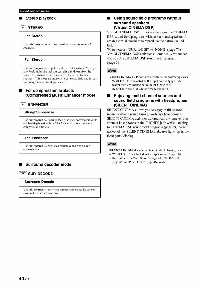
Sound field programs
■ Stereo playback
STEREO
■ For compression artifacts (Compressed Music Enhancer mode)
ENHANCER
■ Surround decoder mode
SUR. DECODE
■ Using sound field programs without surround speakers (Virtual CINEMA DSP)
Virtual CINEMA DSP allows you to enjoy the CINEMA DSP sound field programs without surround speakers. It creates virtual speakers to reproduce the natural sound field.When you set “SUR. L/R SP” to “NONE” (page 76), Virtual CINEMA DSP activates automatically whenever you select a CINEMA DSP sound field program (page 39).
Virtual CINEMA DSP does not activate in the following cases:– “MULTI CH“ is selected as the input source (page 36).– headphones are connected to the PHONES jack.– the unit is in the “7ch Stereo” mode (page 44).
■ Enjoying multi-channel sources and sound field programs with headphones (SILENT CINEMA)
SILENT CINEMA allows you to enjoy multi-channel music or movie sound through ordinary headphones. SILENT CINEMA activates automatically whenever you connect headphones to the PHONES jack while listening to CINEMA DSP sound field programs (page 39). When activated, the SILENT CINEMA indicator lights up in the front panel display.
SILENT CINEMA does not activate in the following cases:– “MULTI CH“ is selected as the input source (page 36).– the unit is in the “2ch Stereo” (page 44), “STRAIGHT”
(page 45) or “Pure Direct” (page 46) mode.
2ch Stereo
Use this program to mix down multi-channel sources to 2 channels.
7ch Stereo
Use this program to output sound from all speakers. When you play back multi-channel sources, this unit downmixes the source to 2 channels, and then output the sound from all speakers. This program creates a larger sound field and is ideal for background music at parties, etc.
Straight Enhancer
Use this program to improve the sound enhancer nearest to the original depth and width of the 2-channel or multi-channel compression artifacts.
7ch Enhancer
Use this program to play back compression artifacts in 7-channel stereo.
Surround Decode
Use this program to play back sources with using the desired surround decoders (page 66).
STEREO5
ENHANCER6
SUR. DECODE7
Note
Note
44 En

Sound field programsB
AS
IC
OP
ER
AT
ION
En
glish
CINEMA DSP 3D mode creates the intensive and accurate stereoscopic sound field in the listening room. You can activate and deactivate the CINEMA DSP 3D mode.
Press O3D DSP repeatedly to turn on or off the CINEMA DSP 3D mode.While this unit is in the CINEMA DSP 3D mode, the 3D indicator lights up.
CINEMA DSP 3D does not activate (“3D:--“ appears) in the following cases:– the “PRESENCE SP” setting is set to “NONE” (page 76).– no CINEMA DSP is selected.– headphones are connected to the PHONES jack.
When this unit is in the “STRAIGHT” mode, 2-channel stereo sources are output from only the front left and right speakers. Multi-channel sources are decoded straight into the appropriate channels without any additional effect processing.
Press OSTRAIGHT (or RSTRAIGHT) to select “STRAIGHT”.The names of the audio signal format of the input source and the active decoder appear in the front panel display.
To deactivate the “STRAIGHT” modePress OSTRAIGHT (or RSTRAIGHT) again or select another sound field program (page 39).
Before performing the following operation, set the operation mode selector on the remote control to EAMP.
Using CINEMA DSP 3D mode
Note
Before performing the following operation, set the operation mode selector on the remote control to EAMP.
Enjoying unprocessed input sources
45 En

Use the Pure Direct mode to enjoy the pure fidelity sound of the selected source. When the Pure Direct mode is activated, this unit plays back the selected source with the least circuitry.
Press MPURE DIRECT (or MPURE DIRECT) to turn on or off the Pure Direct mode.The MPURE DIRECT button on the front panel lights up and the front panel display and OSD automatically turns off while this unit is in the Pure Direct mode.
• The following operations are not possible when this unit is in the Pure Direct mode:– switching the sound field program– adjusting the “SET MENU” parameters– operating video functions (video conversion, etc.)
• The Pure Direct mode is automatically canceled whenever this unit is turned off.
yTo make this unit output video signals during the Pure Direct mode, configure the “PURE DIRECT” setting (page 80).
Use this feature to adjust the balance of bass and treble for the front L/R and center speaker channels and the subwoofer channel.
1 Press ETONE CONTROL on the front panel repeatedly to select the high-frequency response (TREBLE) or the low-frequency response (BASS).
2 Rotate the NPROGRAM selector to adjust the high-frequency response (TREBLE) or the low-frequency response (BASS).Control range: –6.0 dB to +6.0 dB
• If you increase or decrease the high-frequency or the low-frequency sound to an extreme level, the tonal quality of the surround speakers may not match that of the front L/R and center speakers and the subwoofer.
• TONE CONTROL is not effective when the Pure Direct mode is activated, or when “MULTI CH“ is selected as the input source.
You can adjust the output level of each speaker while listening to a music source. This is also possible when playing sources input at the MULTI CH INPUT jacks.
This operation will override the level adjustments made in “AUTO SETUP” (page 30) and “LEVEL” (page 76).
1 Press BLEVEL and then 8k / n repeatedly to select the speaker you want to adjust.
yThe available speaker channels differ depending on the speaker settings.
2 Press 8l / h on the remote control to adjust the speaker output level.Control range: –10.0 dB to +10.0 dB
Using audio features
Before performing the following operation, set the operation mode selector on the remote control to EAMP.
Enjoying pure hi-fi sound
Notes
Adjusting the tonal quality
Notes
Before performing the following operation, set the operation mode selector on the remote control to EAMP.
Adjusting the speaker level
Note
Display Adjusted speaker
FRONT L Front left speaker
CENTER Center speaker
FRONT R Front right speaker
SUR.R Surround right speaker
SB R Surround back right speaker
SB L Surround back left speaker
SUR.L Surround left speaker
SWFR Subwoofer
PRNS L Presence left speaker
PRNS R Presence right speaker
46 En

BA
SIC
O
PE
RA
TIO
NE
ng
lish
You can use two tuning modes to tune into the desired FM/AM station:
Frequency tuning modeYou can search or specify the frequency of the desired FM/AM station automatically or manually (see “FM/AM tuning operations” on this page).
Preset tuning modeYou can preset the desired FM/AM station in advance, and then recall the station by specifying the preset group and number (see “Recalling a preset station” on page 49).
Orient the connected FM and AM antennas for the best reception.
1 Press KBAND (or 7BAND) to select the desired reception band.
2 If the PRESET indicator in the front panel lights up, press ISEARCH MODE (or HSRCH MODE) to turn it off.
3 To search the station automatically, press and hold GPRESET/TUNING/CH l / h (or press 8PRESET/CH k / n) for about 2 seconds. To search the station manually, press GPRESET/TUNING/CH l / h repeatedly.• To tune into a higher frequency, press Gh (or 8k).
• To tune into a lower frequency, press Gl (or 8n).
If the signal from the station you want to select is weak, search the station manually or enter the frequency directly (page 47).
y• When this unit is tuned into a station, the TUNED
indicator lights up.• To switch the information (current input source, current
sound field program, etc) displayed in the front panel display, press LINFO (or set the operation mode to EAMP and then press BINFO) repeatedly.
• To switch between stereo or monaural FM reception, press JSTEREO/MONO (or NAUDIO).
• (U.S.A. model only)If this unit is tuned into an HD Radio station (page 50), the HD indicator lights up in the front panel display.
■ Direct frequency tuningUse this feature tune into the desired station directly by entering the frequency.
1 Follow steps 1 and 2 in “FM/AM tuning operations” (page 47) to select the desired reception band.
2 Enter the frequency of the desired station by pressing the numeric buttons (A).Example: To tune into 103.7 MHz
yIf the entered frequency is out of the range of the FM/AM tuning, “WRONG STATION!” appears in the front panel display.
FM/AM tuning
Overview
Note
Before performing the following operations, set the operation mode selector on the remote control to ESOURCE and then press 3TUNER.
FM/AM tuning operations
F M 8 8 . 9 M H z
PRESET turns off
Note
1 0 3 7
47 En

FM/AM tuning
Use this feature to store up to 40 stations FM/AM stations (A1 to E8: 8 preset station numbers in each of the 5 preset station groups). Preset the desired stations to this unit by using the automatic or manual station preset.
■ Automatic station presetYou can use the automatic preset tuning feature to store up to 40 FM stations with strong signals in order.
(U.S.A. model only) You can use the automatic preset tuning feature to store up to 40 AM HD Radio, FM HD Radio, and analog FM radio stations with strong signals.
(U.S.A. model only)
1 Press KBAND (or 7BAND) to select the desired reception band.This unit searches the stations in the selected band and then another band.
2 Press and hold KBAND (or 7BAND) for more than 3 seconds.The MEMORY indicator flashes and “AUTO MEMORY” appears in the front panel display. After approximately 5 seconds, automatic presetting starts from the current frequency and proceeds toward higher frequencies.
When automatic preset tuning is completed, the MEMORY indicator disappears.
y• To specify the preset group and number from which this unit
stores stations, press GPRESET/TUNING/CH l / h (or 8CAT./A-E l / h and 8PRESET/CH k / n) repeatedly after you perform step 2.
• To cancel the automatic station preset, press KBAND (or 7BAND) again.
• Any stored station data existing under a preset station number is cleared when you store a new station under the same preset station number.
• If the number of received stations does not reach 40 (E8), automatic preset tuning automatically stops after searching for all the available stations.
• (U.S.A. model only)When this unit stores the FM HD Radio stations with this feature, this unit stores only the main audio program of the stations (HD1). When you want to store the sub-audio programs of the FM HD Radio stations, preset the stations manually.
■ Manual station presetUse this feature to store the FM or AM stations manually.
(U.S.A. model only) You can store the analog FM/AM radio stations and FM/AM HD Radio stations manually, and you can also store the sub-audio programs of FM HD Radio station.
1 Tune into a station.See page 47 for tuning instructions.
y(U.S.A. model only) To store a sub-audio program of the HD Radio station (HD2 to HD8), press 0PRG SELECT b / a repeatedly to select the desired audio program (page 50).
2 Press HMEMORY (or 9MEMORY).The PRESET indicator lights up in the front panel and this unit automatically selects an empty preset number.
y• To store the selected station under an empty preset number
automatically, press and hold HMEMORY (or 9MEMORY) for more than 2 seconds instead of step 2. In this case, the following steps are unnecessary.
• To cancel the manual station preset, press HMEMORY (or 9MEMORY) again.
3 To select the preset group and number (A1 to E8), press GPRESET/TUNING/CH l / h (or 8CAT./A-E l / h and 8PRESET/CH k / n) repeatedly.• To select a higher preset station group and number,
press Gh (or 8k).• To select a lower preset station group and number,
press Gl (or 8n).
Before performing the following operations, set the operation mode selector on the remote control to ESOURCE and then press 3TUNER.
Preset FM/AM stations
Notes
MEMORYA 1 F M 8 8 . 9 M H zA U T O M E M O R Y
Flashes
Flashes
PRESET
M E M O R Y A 1F M 8 8 . 9 M H z
Lights up
PRESET
M E M O R Y C 2F M 8 8 . 9 M H z
Preset station group and number
48 En

FM/AM tuningB
AS
IC
OP
ER
AT
ION
En
glish
y• You can also select a preset number (1 to 8) by pressing
the numeric buttons (A).• If you select a preset number being used ("*" appears next
to the preset number), the current preset station will be overwritten.
4 Press FENTER (or 8ENTER).The preset station is set and the PRESET indicator disappears.
The reception mode (stereo or monaural) is stored along with the station frequency.
■ Recalling a preset station
1 If the PRESET indicator in the front panel turns off, press ISEARCH MODE (or HSRCH MODE) to turn it on.
You cannot enter the preset tuning mode if no preset station is set in advance.
2 Press GPRESET/TUNING/CH l / h (or 8PRESET/CH k / n) repeatedly to select the desired preset station group and number (A1 to E8).
y• Empty preset numbers are skipped.• You can also select a preset station group (A to E) by pressing 8CAT./A-E l / h and number (1 to 8) by pressing the numeric buttons (A),
• (U.S.A. model only) When you recall one of the sub-audio program (HD2 to HD8) of an FM HD Radio station, it takes a few seconds for this unit to recall the desired program. While this unit recalls the sub-audio program, this unit outputs the sound of the analog service of the station.
• (U.S.A. model only) If the selected sub-audio program is currently not available, this unit is tuned into the main audio program, and if the main audio program is also not available, this unit is tuned into the analog service.
■ Clearing preset stationsYou can clear the assignments of preset stations.
1 Select the preset station you want to clear.For details, see “Recalling a preset station” (page 49).
2 Press and hold ISEARCH MODE (or HSRCH MODE) until “CLEAR?” appears in the front panel display.
3 Press FENTER (or 8ENTER) to clear the preset station.
yTo cancel the operation, press ISEARCH MODE (or HSRCH MODE) again.
Note
Note
Note
PRESET
A F M 8 8 . 9 M H z
Lights up
PRESET
A 5 F M 8 9 . 5 M H z
Preset station group and number
A 1 C L E A R ? [ E N T ]F M 8 8 . 9 M H z
49 En

HD Radio technology is a new technology that enables FM and AM radio stations to broadcast programs digitally. Digital broadcasting provides listeners with radically improved audio quality and reception as well as new data services. Furthermore, supplemental program services allow listeners to select from up to 8 HD Radio programs multicast on a single FM HD Radio channel. For further information on HD Radio technology, visit “http://www.ibiquity.com/”.This unit is equipped with an HD Radio reception feature, facilitating CD quality FM broadcasts as well as analog FM stereo quality AM broadcasts. In addition, this unit can receive both audio and data (such as song titles, artist names, program types, and comments) from supplemental program services (HD1 to HD8).
• The tuning method for HD Radio stations are same as analog FM/AM radio stations; however, you cannot tune into a hybrid HD Radio station while this unit is in the monaural tuning mode (page 47).
• This unit is capable of receiving both hybrid and all-digital HD Radio station signals. However, this unit may not automatically receive all-digital FM station signals and the automatic tuning operation may stop. In this case, enter the frequency of the desired all-digital FM HD Radio station directly by using the numeric buttons (A) (page 47).
Use this feature to select one of the 8 HD Radio audio programs (HD1 to HD8) when the unit is in the tuner mode. Each audio program contains data programs.When the selected FM HD Radio station provides some audio programs, currently selected audio program number appears in the front panel display as follows.
Press 0PRG SELECT b / a on the remote control repeatedly to toggle between HD Radio audio programs.
yYou can also select the desired HD Radio audio program by pressing the numeric key. While this unit is in the automatic or manual tuning mode, press a numeric button (1-8) (A) and then MENT.
• Only 1 HD Radio audio program (HD1) is available for AM broadcasts, while up to 8 audio programs (HD1 to HD8) are available for FM broadcasts. The audio programs from HD2 to HD8 can be selected only when they contain data programs.
• When reception for an audio program ceases, the HD indicator disappears from the front panel display and HD1 is automatically selected after approximately 20 seconds.
• Some audio programs may not contain data programs depending on the broadcasting station and the time period.
• For the best reception, adjust the orientation of the antenna so that “ ” or “ ” is displayed.
Using HD Radio™ features (U.S.A. model only)
Notes
Before performing the following operations, set the operation mode selector on the remote control to ESOURCE and then press 3TUNER.
Selecting HD Radio™ audio programs
HD
F M 8 8 . 9 M H z 1W X Y Z - F M < 1 / 3 >
Audio program
Notes
50 En

Using HD Radio™ features (U.S.A. model only)B
AS
IC
OP
ER
AT
ION
En
glish
Use this feature to display the HD Radio information in the front panel display or in the OSD.
y• You can configure the display settings with “DISPLAY SET”
(page 83).• To hold or release the displayed information, set the operation
mode selector to ESOURCE and then press 8ENTER. While it is held, the HOLD indicator flashes in the front panel.
■ Front panel display
Press LINFO (or set the operation mode selector to EAMP and then press BINFO) repeatedly to toggle between the following HD Radio information displays.
Back to “STATION INFO”
■ Video monitor (OSD)
Set the operation mode selector to ESOURCE and then press JDISPLAY on the remote control to turn on or off the information display.The following information is displayed in the OSD.
[1] Preset station group and number, frequency, audio program (only when multiple audio programs are available)
[2] Program category
[3] Song title
[4] Album title
[5] Antenna reception level
[6] Stereo/mono
[7] Station name, audio program (only when multiple audio programs are available)
[8] Artist name
Displaying HD Radio™ information
STATION INFO
Station information such as station name, audio program (only when multiple audio programs are available) and frequency
CATEGORY INFO
Program category
SONG INFO
Artist name, song title
ALBUM INFO
Album title
ANTENNA INFO
Antenna reception level
DSP PROG. INFO
Sound field program
INPUT INFO
Input source
TUNER��������������ANT:
A1�FM�88.9MHz2��STEREOWXYZ-FM��HD�<2/3>
:Classic�Rock:Frankie�Zipper
:Road�to�India
:Made-to-order
[1]
[2]
[5][6]
[7]
[8]
[3]
[4]
51 En
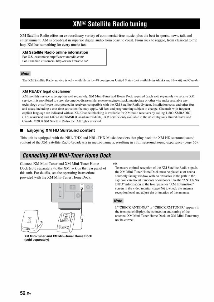
XM Satellite Radio offers an extraordinary variety of commercial-free music, plus the best in sports, news, talk and entertainment. XM is broadcast in superior digital audio from coast to coast. From rock to reggae, from classical to hip hop, XM has something for every music fan.
The XM Satellite Radio service is only available in the 48 contiguous United States (not available in Alaska and Hawaii) and Canada.
■ Enjoying XM HD Surround content
This unit is equipped with the NRL-THX and NRL-THX Music decoders that play back the XM HD surround sound content of the XM Satellite Radio broadcasts in multi-channels, resulting in a full surround sound experience (page 66).
Connect XM Mini-Tuner and XM Mini-Tuner Home Dock (sold separately) to the XM jack on the rear panel of this unit. For details, see the operating instructions provided with the XM Mini-Tuner Home Dock.
yTo ensure optimal reception of the XM Satellite Radio signals, the XM Mini-Tuner Home Dock must be placed at or near a southerly facing window with no obstacles in the path to the sky. You can mount it indoors or outdoors. Use the “ANTENNA INFO” information in the front panel or “XM Information” screen in the video monitor (page 56) to check the antenna reception level and adjust the orientation of the antenna.
If “CHECK ANTENNA” or “CHECK XM TUNER” appears in the front panel display, the connection and setting of the antenna, XM Mini-Tuner Home Dock, or XM Mini-Tuner may not be correct.
XM® Satellite Radio tuning
XM Satellite Radio online informationFor U.S. customers: http://www.xmradio.com/For Canadian customers: http://www.xmradio.ca/
Note
XM READY legal disclaimerXM monthly service subscription sold separately. XM Mini-Tuner and Home Dock required (each sold separately) to receive XM service. It is prohibited to copy, decompile, disassemble, reverse engineer, hack, manipulate or otherwise make available any technology or software incorporated in receivers compatible with the XM Satellite Radio System. Installation costs and other fees and taxes, including a one-time activation fee may apply. All fees and programming subject to change. Channels with frequent explicit language are indicated with an XL. Channel blocking is available for XM radio receivers by calling 1-800-XMRADIO (U.S. residents) and 1-877-GETXMSR (Canadian residents). XM service only available in the 48 contiguous United States and Canada. ©2008 XM Satellite Radio Inc. All rights reserved.
Connecting XM Mini-Tuner Home Dock
XM
XM Mini-Tuner and XM Mini-Tuner Home Dock (sold separately)
Note
52 En

XM® Satellite Radio tuningB
AS
IC
OP
ER
AT
ION
En
glish
Once you have installed the XM Mini-Tuner Home Dock, inserted the XM Mini-Tuner, connected the XM Mini-Tuner Home Dock to your XM Ready® home audio system, and installed the antenna, you are ready to subscribe and begin receiving XM programming. There are three places to find your eight character XM Radio ID: On the XM Mini-Tuner, on the XM Mini-Tuner package, and on XM Channel 0. Record the XM Radio ID in the following eight squares for reference.
The XM Radio ID does not use the letters “I”, “O”, “S” or “F”. Activate your XM Satellite Radio service in the U.S. online at http://activate.xmradio.com/ or call 1-800-XM-RADIO (1-800-967-2346). Activate your XM Satellite Radio service in Canada online at https://activate.xmradio.ca/ or call 1-877-GET-XMSR (1-877-438-9677). You will need a major credit card. XM will send a signal from the satellites to activate the full channel lineup. Activation normally takes 10 to 15 minutes, but during peak busy periods you may need to keep your XM Ready home audio system on for up to an hour. When you can access the full lineup on your XM Ready home audio system you are done.
1 Rotate the CINPUT selector (or press 3XM) to select “XM” as the input source.The cursor on the left of the XM indicator lights up in the front panel display and the XM Satellite Radio information (such as channel number, channel name, category, artist name, or song title) for the currently selected channel appears in the front panel display.
yWhen you select “XM” as the input source, this unit automatically recalls the previously selected channel.
• The XM Satellite Radio signals cannot be output at the analog AUDIO OUT jacks.
• If a status message or an error message appears in the front panel display or in the OSD, see “XM Satellite Radio” (page 109)
2 Search for a channel by using one of the XM Satellite Radio search modes.• To select a channel from the all channel list, see
“All Channel Search mode” (page 53).• To select a channel by category, see “Category
Search mode” (page 54).• To select a channel from the preset channels, see
“Preset Search mode” (page 54).• To select the desired channel directly by entering
the channel number, see “Direct number access mode” (page 54).
y• You can use the Neural Surround decoder to enjoy the XM HD
surround sound content of the XM Satellite Radio broadcasts in multi-channels (page 66).
• You can set the XM Satellite Radio preset channels (page 55).• You can display the XM Satellite Radio information in the front
panel display or in the OSD (page 56).
■ All Channel Search mode
1 Press ISEARCH MODE (or HSRCH MODE) repeatedly to select “ALL CH SEARCH”.
Activating XM Satellite Radio
Note
Before performing the following operations, set the operation mode selector on the remote control to ESOURCE.
XM Satellite Radio operations
Notes
DOCK V-AUX VCR DVR CBL/SAT DVD BD/HD DVD MD/CD-R TV CD PHONO MULTI CH TUNER XM SIRIUS
0 0 1 P r e v i e w
Lights up
53 En

XM® Satellite Radio tuning
2 Press GPRESET/TUNING/CH l / h (or 8PRESET/CH k / n) repeatedly to search for a channel within all channels.
yYou can search for a channel quickly by pressing and holding GPRESET/TUNING/CH l / h (or 8PRESET/CH k / n).
■ Category Search mode
1 Press ISEARCH MODE (or HSRCH MODE) repeatedly to select “CAT SEARCH”.
2 Press KCATEGORY (or 8A-E/CAT. l / h) repeatedly to change the channel category.
3 Press GPRESET/TUNING/CH l / h (or 8PRESET/CH k / n) repeatedly to search for a channel within the selected channel category.
yYou can search for a channel quickly by pressing and holding GPRESET/TUNING/CH l / h (or 8PRESET/CH k / n).
■ Preset Search modePrior to selecting a preset channel in the Preset Search mode, you must preset XM Satellite Radio channels. For details, see “Setting the XM Satellite Radio preset channels” (page 55).
1 Press ISEARCH MODE (or HSRCH MODE) repeatedly to select “PRESET SEARCH”.
2 Press KCATEGORY (or 8A-E/CAT. l / h) repeatedly to change the preset channel group (A to E).
3 Press GPRESET/TUNING/CH l / h (or 8PRESET/CH k / n) repeatedly to change the preset channel number (1 to 8).
yYou can also select the preset channel number directly by pressing the numeric buttons (1 to 8) (A).
■ Direct number access mode
1 Press HSRCH MODE on the remote control repeatedly to select “ALL CH SEARCH” or “CAT SEARCH”.
2 Press the numeric buttons (A) to enter the desired three-digit channel number.For example, to enter the number 123, press the numeric buttons (A) as shown below.
y• To display the XM Radio ID number in the front panel display,
select channel “0”.• To enter a one-digit or two-digit channel number, press the
numeric buttons (A) on the remote control and then press MENT to confirm the input number.
• Instead of pressing MENT to tune into the channel immediately, you can wait a few seconds until this unit confirms the entered channel number.
• Pressing a button other than the numeric buttons (A) or MENT cancels the Direct Number Access mode procedure.
1 2 3
54 En

XM® Satellite Radio tuningB
AS
IC
OP
ER
AT
ION
En
glish
You can use this feature to store up to 40 XM Satellite Radio channels (A1 to E8: 8 preset channel numbers in each of the 5 preset channel groups). You can then recall any preset channel easily by selecting the preset channel group and number as described in “Preset Search mode” (page 54).
1 Search for a channel you want to set as a preset channel by using one of the XM Satellite Radio search modes.For details, see “XM Satellite Radio operations” (page 53).
2 Press HMEMORY (or 9MEMORY).The PRESET indicator lights up in the front panel and this unit automatically selects an empty preset number.
y• To store the selected channel under an empty preset
number automatically, press and hold HMEMORY (or 9MEMORY) for more than 2 seconds instead of step 2. In this case, the following steps are unnecessary.
• To cancel the preset operation, press HMEMORY (or 9MEMORY) again.
3 To select the preset channel group and number (A1 to E8), press GPRESET/TUNING/CH l / h (or 8CAT./A-E l / h and 8PRESET/CH k / n) repeatedly.• To select a higher preset channel group and
number, press Gh (or 8k).• To select a lower preset channel group and number,
press Gl (or 8n).
y• You can also select a preset number (1 to 8) by pressing
the numeric buttons (A).• If you select a preset number being used ("*" appears next
to the preset number), the current preset channel will be overwritten.
4 Press FENTER (or 8ENTER).The preset channel is set and the PRESET indicator disappears.
■ Clearing preset channelsYou can clear the assignments of preset XM Satellite Radio channels.
1 Select the preset XM Satellite Radio channel to clear.For details, see “Preset Search mode” (page 54).
2 Press and hold ISEARCH MODE (or HSRCH MODE) until “CLEAR?” appears in the front panel display.
3 Press FENTER (or 8ENTER) to clear the preset channel.To cancel the operation, press ISEARCH MODE (or HSRCH MODE).
Before performing the following operations, set the operation mode selector on the remote control to ESOURCE and then press 3XM.
Setting the XM Satellite Radio preset channels
0 4 3 X M U
Channel number
PRESET
M E M O R Y A 10 4 3 X M U
Lights up
55 En

XM® Satellite Radio tuning
Use this feature to display the XM Satellite Radio information in the front panel display or in the OSD.
y• You can configure the display settings with “DISPLAY SET”
(page 83).• You can hold or release the displayed information by pressing 8ENTER. While it is held, the HOLD indicator flashes in the front panel.
• If a status message or an error message appears in the front panel display or video monitor, see “XM Satellite Radio” (page 109).
• The current XM Satellite Radio reception level appears on the top of the XM Satellite Radio information screen. For the best reception, adjust the orientation of the antenna of Home Dock
so that “ ” or “ ” is displayed here. “ ” is displayed if the antenna cannot receive the signals correctly. In this case, adjust the orientation of the antenna (page 52).
■ Front panel display
Press LINFO (or set the operation mode selector to EAMP and then press BINFO) repeatedly to toggle between the following XM Satellite Radio information display modes.
Back to “CATEGORY INFO”
y• If the XM Satellite Radio information contains a character that
cannot be recognized by this unit, the character will be displayed with a space.
• When the antenna of the XM Mini-Tuner Home Dock cannot receive the signals, “NO SIGNAL” appears in the front panel display.
■ Video monitor (OSD)
Press JDISPLAY on the remote control to turn on or off the information display.The following information is displayed in the OSD.
[1] Search mode (page 53)
[2] Channel category
[3] Song title
[4] Antenna reception level
[5] Channel number, channel name
[6] Artist name
Before performing the following operations, set the operation mode selector on the remote control to ESOURCE and then press 3XM.
Displaying the XM Satellite Radio information
Notes
CATEGORY INFO
Channel category, channel number, channel name
SONG INFO
Artist name, song title, channel number, channel name
ANTENNA INFO
Antenna reception level, channel number, channel name
DSP PROG. INFO
Sound field program
INPUT INFO
Input source, channel number, channel name
XM�����������������ANT:
ALL�CH�SEARCH043:XMU
:Rock:Coldplay:Speed�of�sound
[1]
[2]
[4]
[5]
[6][3]
56 En

BA
SIC
O
PE
RA
TIO
NE
ng
lish
SIRIUS Satellite Radio provides over 130 channels of exclusive entertainment and 100% commercial-free music. Only SIRIUS has more than 65 original music channels, from today’s hits to R&B, oldies, and classical masterpieces. From authentic country and real bluegrass to cool jazz, hot latin, reggae, rock and many more. Best of all, it’s all 100% commercial-free. SIRIUS also has more than 55 channels of world-class sports, news and entertainment. Included as part of your subscription, you get up to 16 NFL games a week, up to 40 NBA games a week and up to 40 NHL games a week. (Games are broadcast during their respective seasons.) Coupled with great sports news from ESPN, the SIRIUS sports offering is unrivaled. And don't forget a host of other great news and entertainment, like NPR, CNBC, Fox News, Radio Disney and E! Entertainment Radio. For more information, visit http://www.sirius.com/.
Connect the SiriusConnect tuner (sold separately) to the SIRIUS jack on the rear panel of this unit. For details, see the operating instructions provided with the SiriusConnect tuner.
y• To ensure optimal reception of the SIRIUS Satellite Radio
signals, the antenna of the SiriusConnect tuner must be placed at or near a window with no obstacles in the path to the sky. The orientation of the antenna for the best reception differs depending on the area. Refer to the instruction manuals supplied with the SiriusConnect tuner for the installation of the antenna.You can mount it indoors or outdoors.
• Use the “ANTENNA INFO” information in the front panel or “SIRIUS Information” screen in the video monitor (page 62) to check the antenna reception level and adjust the orientation of the antenna.
• You need to connect the SiriusConnect tuner to the AC wall outlet.
• If “CHECK SR TUNER” or “ANTENNA ERROR” appears in the front panel display, the connection of the SiriusConnect tuner or antenna is incorrect. In such cases, check the connection of the SiriusConnect tuner and the antenna.
• If “NOT SUPPORTED” appears in the front panel display, this unit does not support the connected SiriusConnect tuner.
SIRIUS Satellite Radio™ tuning
SIRIUS Satellite Radio legal disclaimerSIRIUS is available in the U.S.A. for subscribers with addresses in the continental U.S.A. and is available in Canada for subscribers with a Canadian address. To Get SIRIUS Satellite Radio a subscription and compatible tuner and antenna are required and sold separately. Visit sirius.com for the most complete and up-to-date channel lineup and information. “SIRIUS” and the SIRIUS dog logo and related marks are trademarks of SIRIUS Satellite Radio Inc.
Connecting the SiriusConnect™ tuner
SIRIUS
DC 5V
ANT
SiriusConnect™ tuner and the antenna (sold separately)
To the AC wall outlet
Notes
57 En

SIRIUS Satellite Radio™ tuning
Before using the SIRIUS Satellite Radio feature, you need to activate your SIRIUS Satellite Radio subscription. To activate the subscription you need the Sirius ID which is uniquely assigned to the SiriusConnect tuner. Sirius ID is 12-digit number and it appears on the package of the SiriusConnect tuner, on the label of the SiriusConnect tuner, and when you tune into the SIRIUS Satellite Radio channel “0” (see below).
■ Displaying the Sirius ID of your SiriusConnect tuner
1 Set the operation mode selector on the remote control to ESOURCE and then press 3SIRIUS.
2 Press A0 and then MENT to display the Sirius ID of your SiriusConnect tuner.“000 Sirius IDxxxxxxxxxxxx” (“xxxxxxxxxxxx” indicates the 12-digit Sirius ID of your SiriusConnect tuner) appears in the front panel display.
Write the Sirius ID below.
3 Contact SIRIUS Satellite Radio to activate your subscription.
yStatus messages appear in the front panel display or OSD during the activation. For details, see “SIRIUS Satellite Radio” (page 110). Once the activation is finished, “SUB UPDATED” appears.
1 Rotate the CINPUT selector (or press 3SIRIUS) to select “SIRIUS” as the input source.The cursor on the left of the SIRIUS indicator lights up in the front panel display and the SIRIUS Satellite Radio information (such as channel number, channel name, category, artist name, or song title) for the currently selected channel appears in the front panel display.
yWhen you select “SIRIUS” as the input source, this unit automatically recalls the previously selected channel.
• The SIRIUS Satellite Radio signals cannot be output at the analog AUDIO OUT jacks.
• When you have not activated your subscription yet, you can only select “184” or “000”.
• If a status message or an error message appears in the front panel display or in the OSD, see “SIRIUS Satellite Radio” (page 110).
2 Search for a channel by using one of the SIRIUS Satellite Radio search modes.• To select a channel from the all channel list, see
“All Channel Search mode” (page 59).• To select a channel by category, see “Category
Search mode” (page 59).• To select a channel from the preset channels, see
“Preset Search mode” (page 59).• To select the desired channel directly by entering
the channel number, see “Direct number access mode” (page 59).
y• If you tune into a channel that you do not subscribe, “CALL
888-539-SIRIUS TO SUBSCRIBE” appears in the front panel display.
• You can set the SIRIUS Satellite Radio preset channels (page 60).
• You can display the SIRIUS Satellite Radio information in the front panel display or in the video monitor (page 62).
Activating SIRIUS Satellite Radio™ subscription
SIRIUS Satellite Radio online informationContact for activationURL: https//activate.siriusradio.com/Phone: 1-888-539-SIRIUS (1-888-539-7474)
ID:
Before performing the following operations, set the operation mode selector on the remote control to ESOURCE.
SIRIUS Satellite Radio™ operations
Notes
DOCK V-AUX VCR DVR CBL/SAT DVD BD/HD DVD MD/CD-R TV CD PHONO MULTI CH TUNER XM SIRIUS
1 8 4 S I R I U S W e a
Lights up
58 En

SIRIUS Satellite Radio™ tuningB
AS
IC
OP
ER
AT
ION
En
glish
■ All Channel Search mode
1 Press ISEARCH MODE (or HSRCH MODE) repeatedly to select “ALL CH SEARCH”.
2 Press GPRESET/TUNING/CH l / h (or 8PRESET/CH k / n) repeatedly to search for a channel within all channels.
y• You can search for a channel quickly by pressing and holding GPRESET/TUNING/CH l / h (or 8PRESET/CH k / n).
• You can skip channels to the previous or next category by pressing KCATEGORY (or 8A-E/CAT. l / h).
■ Category Search mode
1 Press ISEARCH MODE (or HSRCH MODE) repeatedly to select “CAT SEARCH”.
2 Press KCATEGORY (or 8A-E/CAT. l / h) repeatedly to change the channel category.
3 Press GPRESET/TUNING/CH l / h (or 8PRESET/CH k / n) repeatedly to search for a channel within the selected channel category.
yYou can search for a channel quickly by pressing and holding GPRESET/TUNING/CH l / h (or 8PRESET/CH k / n).
This unit skips the channels when this unit is in the All Channel Search mode or Category Search mode in the following cases (it is not malfunction of this unit):– the channel is locked (page 61).– the channel is out of service.– you do not subscribe to the channel.
■ Preset Search modePrior to selecting a preset channel in the Preset Search mode, you must preset SIRIUS channels. For details, see “Setting the SIRIUS Satellite Radio™ preset channels” (page 60).
1 Press ISEARCH MODE (or HSRCH MODE) repeatedly to select “PRESET SEARCH”.
2 Press KCATEGORY (or 8A-E/CAT. l / h) repeatedly to change the preset channel group (A to E).
3 Press GPRESET/TUNING/CH l / h (or 8PRESET/CH k / n) repeatedly to change the preset channel number (1 to 8).
yYou can also select the preset channel number directly by pressing the numeric buttons (1 to 8) (A).
■ Direct number access mode
1 Press HSRCH MODE on the remote control repeatedly to select “ALL CH SEARCH” or “CAT SEARCH”.
2 Press the numeric buttons (A) to enter the desired three-digit channel number.For example, to enter the number 123, press the numeric buttons (A) as shown below.
y• To display the Sirius ID number displayed in the front panel
display, select channel “0”.• To enter a one-digit or two-digit channel number, press the
numeric buttons (A) on the remote control and then press MENT to confirm the input number.
• Instead of pressing MENT to tune into the channel immediately, you can wait a few seconds until this unit confirms the entered channel number.
• If no button is pressed within a few seconds after you enter a one-digit or two-digit number, this unit automatically confirms the entered channel number.
• If the selected channel is locked, “PIN:___” appears in the front panel display. Enter the four-digit Parental Lock code number by using the numeric buttons (A) or press MENT to cancel (page 61).
Note
1 2 3
59 En

SIRIUS Satellite Radio™ tuning
You can use this feature to store up to 40 SIRIUS Satellite Radio channels (A1 to E8: 8 preset channel numbers in each of the 5 preset channel groups). You can then recall any preset channel easily by selecting the preset channel group and number as described in “Preset Search mode” (page 54).
1 Search for a channel you want to set as a preset channel by using one of the SIRIUS Satellite Radio search modes.For details, see “SIRIUS Satellite Radio™ operations” (page 58).
2 Press HMEMORY (or 9MEMORY).The PRESET indicator lights up in the front panel and this unit automatically selects an empty preset number.
y• To store the selected channel under an empty preset
number automatically, press and hold HMEMORY (or 9MEMORY) for more than 2 seconds instead of step 2. In this case, the following steps are unnecessary.
• To cancel the preset operation, press HMEMORY (or 9MEMORY) again.
3 To select the preset channel group and number (A1 to E8), press GPRESET/TUNING/CH l / h (or 8CAT./A-E l / h and 8PRESET/CH k / n) repeatedly.• To select a higher preset channel group and
number, press Gh (or 8k).• To select a lower preset channel group and number,
press Gl (or 8n).
y• You can also select a preset number (1 to 8) by pressing
the numeric buttons (A).• If you select a preset number being used ("*" appears next
to the preset number), the current preset channel will be overwritten.
4 Press FENTER (or 8ENTER).The preset channel is set and the PRESET indicator disappears.
■ Clearing preset channelsYou can clear the assignments of preset SIRIUS Satellite Radio channels.
1 Select the preset SIRIUS Satellite Radio channel to clear.For details, see “Preset Search mode” (page 59).
2 Press and hold ISEARCH MODE (or HSRCH MODE) until “CLEAR?” appears in the front panel display.
3 Press FENTER (or 8ENTER) to clear the preset channel.To cancel the operation, press ISEARCH MODE (or HSRCH MODE).
Before performing the following operations, set the operation mode selector on the remote control to ESOURCE and then press 3SIRIUS.
Setting the SIRIUS Satellite Radio™ preset channels
0 0 1 S I R I U S H i t
Channel number
PRESET
M E M O R Y A 10 0 1 S I R I U S H I T
Lights up
60 En

SIRIUS Satellite Radio™ tuningB
AS
IC
OP
ER
AT
ION
En
glish
You can use the Parental Lock feature to limit the access to the desired SIRIUS Satellite channels. This unit automatically skips the locked channels when this unit is in the All Channel Search mode or Category Search mode and you search a channel by pressing GPRESET/TUNING/CH l / h (or 8PRESET/CH k / n).
■ Setting the code number and the locking channels
Use this feature to set the Parental Lock code number (PIN) and select the channels to be locked.
1 Press 7BAND.The "PARENTAL LOCK" screen appears.
If a SiriusConnect tuner is not connected to this unit, “Check Sirius Tuner” appears.
yIf the Parental Lock code number is already set, “PIN:___” appears instead of “NEW PIN:0000”. Refer to step 4 and then proceed the operations.
2 Enter the desired 4-digit code number by using the numeric buttons (A).
3 Press 8ENTER to confirm the code number.“OK” and then the SIRIUS Satellite Radio channel list appears. Refer to the step 5 and then proceed the operations.
4 Enter the 4-digit code number you set in step 2 above to unlock the protection.When the code number is correct, “OK” and then the SIRIUS Satellite Radio channel list appears.
5 Press 8l / h repeatedly to select the desired channel category and then press 8k / n repeatedly to select the channel you want to lock.
In the SIRIUS Satellite Radio channel list screen, this unit outputs the sound of the selected channel even if the channel is locked.
6 Press 8ENTER to lock the selected channel.Check mark appears before the locked channel.
yWhen you select the locked channel and press 8ENTER, this unit unlocks the selected channel.
7 Repeat steps 5 and 6 to lock the channels you want.
8 Press 7BAND to exit from the “PARENTAL LOCK” screen.This unit is tuned into the last channel you select in the “PARENTAL LOCK” screen. If the channel is locked, this unit is tuned into “184 SIRIUS Weather & Emergency” or “000 Sirius ID”.
y• If you forget or want to change the Parental lock code number,
use “SIRIUS PIN” (page 103) to reset the Parental Lock code number.
• Selecting “ALL” in “INITIALIZE” (page 103) will cancel all parental locks.
■ Tuning into the locked channelsYou can tune into the locked channels by the Direct number access mode or preset tuning mode. When you tune into the locked channel, following message appears in the front panel display. Enter the code number you set for the Parental Lock feature by using the numeric buttons (A) or press MENT to cancel the tuning.
• If the entered code number is incorrect, “Wrong” appears in the front panel display and this unit is tuned into the previously selected channel.
• If a channel is unlocked, you can also select the channel in Zone 2 and Zone 3.
Before performing the following operations, set the operation mode selector on the remote control to ESOURCE and then press 3SIRIUS.
Setting the Parental Lock
Note
PARENTAL LOCK
NEW�PIN:0000
[p]/[[]:Cursor[0] [9]:Number
[ENT]:Enter
-
Note
Notes
0 1 8 L O C K E DP I N : _ _ _ _
Channel number
61 En
SIRIUS Satellite Radio™ tuning
Use this feature to display the SIRIUS Satellite Radio information in the front panel display or in the OSD.
y• You can configure the display settings with “DISPLAY SET”
(page 83).• You can hold or release the displayed information by pressing 8ENTER. While it is held, the HOLD indicator flashes in the front panel.
If a status message or an error message appears in the front panel display or video monitor, see “SIRIUS Satellite Radio” (page 110).
■ Front panel display
Press LINFO (or set the operation mode selector to EAMP and then press BINFO) repeatedly to toggle between the following SIRIUS Satellite Radio information display modes.
Back to “CATEGORY INFO”
y• If the SIRIUS Satellite Radio information contains a character
that cannot be recognized by this unit, the character will be displayed with a space.
• When the antenna of the SiriusConnect tuner cannot receive the signals, “ACQUIRING” appears in the front panel display.
• When an information is unavailable, “––––” appears.
■ Video monitor (OSD)
Press JDISPLAY on the remote control to turn on or off the information display.The following information is displayed in the OSD.
[1] Search mode (page 58)
[2] Channel category
[3] Song title
[4] Composer name
[5] Antenna reception level
[6] Channel number/name
[7] Artist name
Before performing the following operations, set the operation mode selector on the remote control to ESOURCE and then press 3SIRIUS.
Displaying the SIRIUS Satellite Radio™ information
Note
CATEGORY INFO
Channel category, channel number, channel name
SONG INFO
Artist name, song title, channel number, channel name
COMPOSER INFO
Composer name, channel number, channel name
ANTENNA INFO
Antenna reception level, channel number, channel name
DSP PROG. INFO
Sound field program
INPUT INFO
Input source, channel number, channel name
SIRIUS�������������ANT:
ALL�CH�SEARCH008:Big�'80s
:Pop:Sanumemo
:Road�to�India
C:Frankie�Zipper
[1]
[2]
[5]
[6]
[7]
[3]
[4]
62 En

BA
SIC
O
PE
RA
TIO
NE
ng
lish
Once you have stationed your iPod in a Yamaha iPod universal dock (such as YDS-11, sold separately) connected to the DOCK terminal of this unit (page 23), you can enjoy playback of your iPod using the supplied remote control. You can also use the Compressed Music Enhancer mode of this unit to enhance the sound quality of the compression artifacts (such as the MP3 format) stored on your iPod (page 44).
• This unit supports iPod touch, iPod (Click Wheel, including iPod classic), iPod nano and iPod mini.• Some features may not be compatible depending on the model or the software version of your iPod.• Some features may not be compatible depending on the model of your Yamaha iPod universal dock. The following description is
based on using YDS-11.
y• Once the connection between your iPod and this unit is complete, “iPod connected” appears in the front panel display.• For details about status messages displayed in the front panel display and in the OSD, see “iPod” (page 112).• You can select whether or not this unit charges the battery of the stationed iPod when this unit is in the standby mode by configuring
the “STANDBY CHARGE” setting (page 82).
You can control your iPod when “DOCK” is selected as the input source. The operations of your iPod can be done with the aid of the OSD of this unit (menu browse mode) or without it (simple remote mode).
■ Remote control operation
■ Controlling iPod in the simple remote mode
You can perform the basic operations of your iPod (play, stop, skip, etc.) using the supplied remote control without the aid of the OSD of this unit.
yOperations can be also done with the controls on your iPod.
■ Controlling iPod in the menu browse mode
You can perform the advanced operations of your iPod using the supplied remote control with the aid of the OSD of this unit.You can also browse the songs and videos stored on your iPod in the OSD.Further, you can change or adjust settings for your iPod to suit your personal preferences.
yYou can configure the display settings with “DISPLAY SET” (page 83).
• Operations cannot be done with the controls on your iPod.• There are some characters that cannot be displayed in the front
panel display or in the OSD of this unit. Those characters are replaced with underscores “_”.
1 Press JDISPLAY on the remote control.The following display appears in the OSD.
Using iPod™
Notes
Before performing the following operations, set the operation mode selector on the remote control to ESOURCE and then press 3DOCK.
Controlling iPod™
Button Function
8 ENTER Subsequent menu
k Menu up
n Menu down
l Previous menu
h Subsequent menu
0 ll Search backward (Press and hold)
hh Search forward (Press and hold)
a Skip forward
b Skip backward
s Stop
e Pause (Menu browse mode)Play/Pause (Simple remote mode)
p Play (Menu browse mode)Play/Pause (Simple remote mode)
J DISPLAY Display
Notes
iPod Top
Music >Videos >Settings >
63 En

Using iPod™
2 Press 8k / n to select “Music”, “ Videos” or “Settings” and then press 8h.• To browse the music contents stored on your iPod,
select “Music”.• To browse the video contents stored on your iPod,
select “Videos”.• To change the playback settings of your iPod,
select “Settings”.
“Videos” does not appear unless both your iPod and Yamaha iPod universal dock support the video browsing feature.
3 Press 8k / n / l / h on the remote control to navigate the iPod menu and then press 8ENTER to begin playback of the selected item.
Items under “Music”Playlists (playlists), Artists (artists), Albums (albums), Songs (songs), Genres (genres), Composers (composers)• Playlists > Songs• Artists > Albums > Songs• Albums > Songs• Songs• Genres > Artists > Albums > Songs• Composers > Albums > Songs
Items under “Videos”Up to video contents stored on your iPod
Items under “Settings”Shuffle, Repeat
Shuffle Shuffle
Use this feature to set this unit to play songs or albums in random order.Choices: Off, Songs, Albums• Select “Off ” to deactivate this feature.• Select “Songs” to set this unit to play songs in random
order.• Select “Albums” to set this unit to play albums in
random order.
Repeat Repeat
Use this feature to set this unit to repeat one song or a sequence of songs.Choices: Off, One, All• Select “Off ” to deactivate this feature.• Select “One” to set this unit to repeat one song.• Select “All” to set this unit to repeat a sequence of
songs.
y• To toggle between the setting parameters, press 8ENTER
repeatedly.
• While the shuffle function is on, “ ” appears in the OSD.
• While the repeat function is set to “One” or “All”, “ ” or
“ ” appears in the OSD.
■ Function of the play information display
[1] Track number/total tracks
[2] Name of the artist
[3] Name of the album
[4] Name of the song
[5] Progress bar
[6] Elapsed time
[7] Shuffle and repeat icons
[8] (playback), (pausing), (search forward) or (search backward)
[9] Remaining time
Note
1
All
iPod�����[Play]����
�1�/�9������������������������������������������������Frankie�Zipper����������Made-to-order�����������Road�to�India�������������������������������������������������������������������������������|||||;;;;;;;;;;;;;;;����0:51�����������-7:44��
All
[1]
[2]
[7]
[8]
[9]
[3][4]
[5][6]
64 En

BA
SIC
O
PE
RA
TIO
NE
ng
lish
You can connect a Yamaha Bluetooth receiver (such as YBA-10, sold separately) to the DOCK terminal of this unit and enjoy the music contents stored in your Bluetooth component (such as a portable music player) without wiring between this unit and the Bluetooth component. You need to perform “pairing” the connected Bluetooth wireless audio receiver and your Bluetooth component in advance.
Pairing must be performed when using a Bluetooth component with the Bluetooth receiver connected to this unit for the first time or if the pairing data has been deleted. “Pairing” refers to the operation of registering a Bluetooth component for Bluetooth communications.
y• You need the pairing operation only for the first time when you
use the Bluetooth component with the Bluetooth receiver. • Pairing requires operations on this unit and on the other
component with which Bluetooth communications are to be established. If necessary, refer to the other component’s operating instructions.
There are two pairing methods: pairing by using “START PAIRING” in “SET MENU” and quick pairing.
■ Pairing by using “SET MENU”Use this feature to perform pairing with the OSD. For details, see “START PAIRING” (page 82).
■ Quick pairing
1 Rotate the CINPUT selector (or set the operation mode selector to ESOURCE and then press 3DOCK) to select “DOCK” as the input source.
2 Turn on your Bluetooth component and then set the Bluetooth component to the pairing mode.For details about how to operate the Bluetooth component, refer to the manual for it.
3 Press and hold FENTER (or 8ENTER) until “Searching” appears in the front panel display. While the Bluetooth receiver is in the pairing mode, DOCK indicator flashes in the front panel display.
yTo cancel the pairing, press FENTER (or 8ENTER) again.
4 Check that the Bluetooth component detects the Bluetooth receiver.If the Bluetooth component detects the Bluetooth receiver, “YBA-10 YAMAHA” (example) appears in the Bluetooth device list.
5 Select the Bluetooth receiver in the Bluetooth device list and then enter the pass key “0000” on the Bluetooth component. When the pairing procedure is successful, “Completed” appears in the front panel display.
The Yamaha Bluetooth receiver can be paired with up to eight Bluetooth components. When pairing is conducted successfully with a ninth component and the pairing data is registered, the pairing data for the least recently used other component is cleared.
1 Rotate the CINPUT selector (or set the operation mode selector to ESOURCE and then press 3DOCK) to select “DOCK” as the input source.
2 Start playback of your Bluetooth component.When the connected Bluetooth receiver detects the Bluetooth component, “BT connected” appears in the front panel display.
y• When you press 8ENTER on the remote control, the
connected Bluetooth receiver searches and connect to the last connected Bluetooth component. If the Bluetooth receiver cannot find the Bluetooth component, “Not found” appears in the front panel display.
• To disconnect the Bluetooth receiver from the Bluetooth component, press 8ENTER.
Using Bluetooth™ components
Pairing the Bluetooth™ receiver and your Bluetooth component
To ensure security, a time limit of 8 minutes is set for the pairing operation. You are recommended to read and fully understand all the instructions before starting.
Note
Playback of the Bluetooth™ component
65 En

■ Selecting decoders for 2-channel sources (surround decode mode)
Use this feature to play back sources with selected decoders. You can play back 2-channel sources on multi-channels.
Set the operation mode selector to EAMP and then press QSUR. DECODE repeatedly on the remote control to select the surround decode mode.You can select desired surround decoder modes depending on the type of source you are playing and your personal preference.
yYou can change the decoder parameter settings in the OSD. For details on how to change the parameters, See “Changing sound field parameter settings” on page 67.
■ Decoder descriptions
yWhen you select the surround decode mode for the multi-channel digital sources, this unit automatically selects the corresponding decoder for each source.
■ Selecting decoders used with MOVIE sound field programs
You can select one of the following decoder types for use with the MOVIE sound field programs (except “Mono Movie”). For details about the MOVIE sound field programs, see “For movie sources” (page 43). For details on how to select the decoder type, See “Changing sound field parameter settings” (page 67).Choices: PLIIx Movie (PLII Movie), Neo:6 Cinema
Advanced sound configurations
Selecting decoders
PRO LOGIC
Dolby Pro Logic processing for any sources.
PLIIx MoviePLII Movie
Dolby Pro Logic IIx (or Dolby Pro Logic II) processing for movie sources. The Pro Logic IIx decoder is not available when “SUR.B L/R SP” (page 76) is set to “NONE” or using headphones.
PLIIx MusicPLII Music
Dolby Pro Logic IIx (or Dolby Pro Logic II) processing for music sources. The Pro Logic IIx decoder is not available when “SUR.B L/R SP” (page 76) is set to “NONE” or using headphones.
Dolby Pro Logic IIx (or Dolby Pro Logic II) processing for music sources. The Pro Logic IIx decoder is not available when "SUR.B L/R SP" (page 76) is set to “NONE” or using headphones.
Decoder description
Name of the decoder (Decoder Type)
PLIIx MusicPLII Music
PLIIx GamePLII Game
Dolby Pro Logic IIx (or Dolby Pro Logic II) processing for game sources. The Pro Logic IIx decoder is not available when “SUR.B L/R SP” (page 76) is set to “NONE” or using headphones.
Neo:6 Cinema
DTS processing for movie sources.
Neo:6 Music
DTS processing for music sources.
CSII Cinema(U.S.A. model only)
SRS Circle Surround II processing for movie sources.
CSII Music(U.S.A. model only)
SRS Circle Surround II processing for music sources.
NRL-THX(U.S.A. and Canada models only)
Neural-THX Surround processing for any sources. The Neural-THX Surround decoder is especially suitable for the XM HD Surround program of XM Satellite Radio.
NRL-THX Music(U.S.A. and Canada models only)
Neural-THX Surround processing for music sources. The Neural-THX Surround decoder is especially suitable for the XM HD Surround music program of XM Satellite Radio.
66 En

Advanced sound configurationsA
DVA
NC
ED
O
PE
RA
TIO
NE
ng
lish
■ Selecting decoders for multi-channel sources
If you connected surround back speakers, use this feature to enjoy 6.1/7.1-channel playback for multi-channel sources using the Dolby Pro Logic IIx, Dolby Digital EX, DTS-ES, or Neural-THX decoders.
Set the operation mode selector to EAMP and then press LEXTD SUR. on the remote control repeatedly to switch between 5.1 and 6.1/7.1-channel playback.
yUse this feature to activate the desired decoder manually when this unit cannot detect the signal flag encoded to the input sources correctly.
• The available decoders vary depending on the setting of the speakers and the input sources.
• 6.1/7.1-channel playback is not possible in the following cases:– when “SUR. L/R SP” (page 75) or “SUR.B L/R SP” (page 76)
is set to “NONE”.– when the component connected to the MULTI CH INPUT
jacks is being played.– when the source being played does not contain surround left
and right channel signals.– when a Dolby Digital KARAOKE source is being played.– when this unit is in the stereo playback, 7ch Enhancer
(page 44) or Pure Direct (page 46) mode.– when “BI-AMP” is set to “ON” (page 103).
• You can set the initial extended decoder mode with "EXTD SUR." (page 85).
• “Neural-THX” is only available on the U.S.A. and Canada models.
You can enjoy good quality sound with the initial factory settings. Although you do not have to change the initial factory settings, you can change some of the parameters to better suit the input source or your listening room.
You cannot change the sound field parameter values when “MEMORY GUARD” in “OPTION MENU” is set to “ON” (page 84).
1 Turn on the video monitor connected to this unit.
2 Set the operation mode selector to EAMP and then press JPARAMETER on the remote control.The following screen appears in the OSD.
3 Press 8l / h repeatedly to select the desired sound field program you want to adjust.
4 Press 8k / n to select the desired sound field parameter and then 8l / h to change the selected sound field parameter value.For details about each sound field parameter, see page 39.• To increase the value, press 8h.• To decrease the value, press 8l.
Choice Functions
AUTO Activates the optimum decoder to play back signals in 6.1/7.1 channels when this unit recognizes a signal flag being input.
Decoders(PLIIx Movie, PLIIx Music, EX/ES, Neural-THX)
Use this feature to activate the desired decoders for the playback of multi-channel sources manually.
OFF Does not use any decoders to create 6.1/7.1 channels.
Notes
Changing sound field parameter settings
Note
Sound field program category
Sound field parameters Sound field parameter values
[p]/[[]:
MOVIE 1/2
Sci-FiSUR.;;PLIIx MovieDSP LEVEL;;;;;0dBP.INIT.DLY;;;16msP.ROOM SIZE;;;1.0S.INIT.DLY;;;16msS.ROOM SIZE;;;1.0
Select
.Cursor
67 En
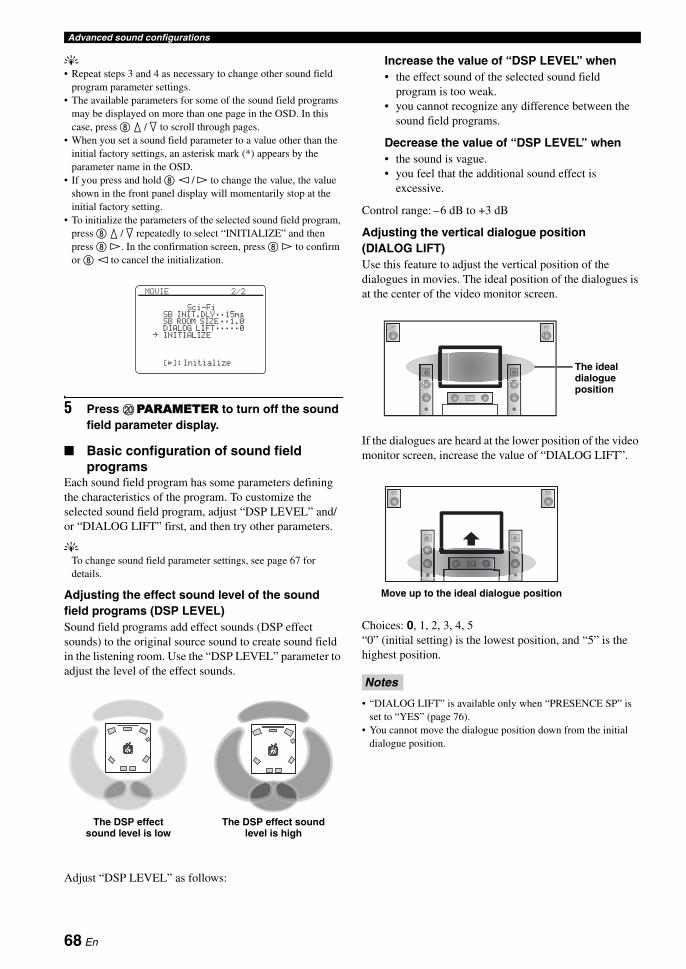
Advanced sound configurations
y• Repeat steps 3 and 4 as necessary to change other sound field
program parameter settings.• The available parameters for some of the sound field programs
may be displayed on more than one page in the OSD. In this case, press 8 k / n to scroll through pages.
• When you set a sound field parameter to a value other than the initial factory settings, an asterisk mark (*) appears by the parameter name in the OSD.
• If you press and hold 8 l / h to change the value, the value shown in the front panel display will momentarily stop at the initial factory setting.
• To initialize the parameters of the selected sound field program, press 8 k / n repeatedly to select “INITIALIZE” and then press 8 h. In the confirmation screen, press 8 h to confirm or 8 l to cancel the initialization.
5 Press JPARAMETER to turn off the sound field parameter display.
■ Basic configuration of sound field programs
Each sound field program has some parameters defining the characteristics of the program. To customize the selected sound field program, adjust “DSP LEVEL” and/or “DIALOG LIFT” first, and then try other parameters.
yTo change sound field parameter settings, see page 67 for details.
Adjusting the effect sound level of the sound field programs (DSP LEVEL)Sound field programs add effect sounds (DSP effect sounds) to the original source sound to create sound field in the listening room. Use the “DSP LEVEL” parameter to adjust the level of the effect sounds.
Adjust “DSP LEVEL” as follows:
Increase the value of “DSP LEVEL” when• the effect sound of the selected sound field
program is too weak.• you cannot recognize any difference between the
sound field programs.
Decrease the value of “DSP LEVEL” when• the sound is vague.• you feel that the additional sound effect is
excessive.
Control range: –6 dB to +3 dB
Adjusting the vertical dialogue position (DIALOG LIFT)Use this feature to adjust the vertical position of the dialogues in movies. The ideal position of the dialogues is at the center of the video monitor screen.
If the dialogues are heard at the lower position of the video monitor screen, increase the value of “DIALOG LIFT”.
Choices: 0, 1, 2, 3, 4, 5“0” (initial setting) is the lowest position, and “5” is the highest position.
• “DIALOG LIFT” is available only when “PRESENCE SP” is set to “YES” (page 76).
• You cannot move the dialogue position down from the initial dialogue position.
[[]:
MOVIE 2/2
Sci-FiSB INIT.DLY;;15msSB ROOM SIZE;;1.0DIALOG LIFT;;;;;0INITIALIZE
Initialize
.
The DSP effect sound level is low
The DSP effect sound level is high
Notes
The ideal dialogue position
Move up to the ideal dialogue position
68 En

Advanced sound configurationsA
DVA
NC
ED
O
PE
RA
TIO
NE
ng
lish
■ Sound field parameter descriptionsUse the following sound field parameters to customize the sound field programs in detail.
yTo change sound field parameter settings, see page 67 for details.
Sound field parameter Features
INIT.DLYP.INIT.DLYS.INIT.DLYSB INIT.DLY
Initial delay. Presence, surround, and surround back sound field initial delay. Changes the apparent size of the sound field by adjusting the delay between the direct sound and the first reflection heard by the listener. The smaller the value, the smaller the sound field seems to the listener.
yWhen you adjust the initial delay parameters, we also recommend that you adjust the corresponding room size parameters likewise.
Control range: 1 to 99 ms (INIT.DLY and P.INIT.DLY)1 to 49 ms (S.INIT.DLY and SB INIT.DLY)
ROOM SIZEP.ROOM SIZES.ROOM SIZESB ROOM SIZE
Room size. Presence, surround, and surround back room size. Adjusts the apparent size of the sound field. The larger the value, the larger the surround sound field becomes. As the sound is repeatedly reflected around a room, the larger the hall is, the longer the time between the original reflected sound and the subsequent reflections. By controlling the time between the reflected sounds, you can change the apparent size of the virtual venue. Changing this parameter from one to two doubles the apparent length of the room.
yWhen you adjust the room size parameters, we also recommend that you adjust the corresponding initial delay parameters likewise.
Control range: 0.1 to 2.0
Source sound
Early reflections
Time Time TimeDelay Delay Delay
Sound source
Reflection face
Lev
el
Small value = 1 ms Large value = 99 ms
Lev
el
Lev
el
Lev
el
Lev
el
Lev
el
Time Time Time
Source sound
Early reflections
Small value = 0.1 Large value = 2.0
Sound source
69 En

Advanced sound configurations
LIVENESSS.LIVENESSSB LIVENESS
Liveness. Surround and surround back liveness. Adjusts the reflectivity of the virtual walls in the hall by changing the rate at which the early reflections decay. The early reflections of a sound source decay much faster in a room with acoustically absorbent wall surfaces than in one which has highly reflective surfaces. A room with acoustically absorbent surfaces is referred to as “dead”, while a room with highly reflective surfaces is referred to as “live”. This parameter lets you adjust the early reflection decay rate and thus the “liveness” of the room.
Control range: 0 to 10
REV.TIME Reverberation time. Adjusts the amount of time taken for the dense, subsequent reverberation sound to decay by 60 dB at 1 kHz. This changes the apparent size of the acoustic environment over an extremely wide range. Set a longer reverberation time for "dead" sources and listening room environments, and a shorter time for "live" sources and listening room environments.
Control range: 1.0 to 5.0 s
Sound field parameter Features
Source sound
Lev
el
Lev
el
Lev
elDead
Live
Time Time Time
Small reflected sound
Large reflected sound
Small value = 0 Large value = 10
Reverberation ReverberationSource sound
REV.TIME REV.TIME REV.TIMESound source Short
reverberationLong reverberation
Small value = 1.0 s Large value = 5.0 s
Early reflections
60 dB 60 dB 60 dB
70 En

Advanced sound configurationsA
DVA
NC
ED
O
PE
RA
TIO
NE
ng
lish
REV.DELAY Reverberation delay. Adjusts the time difference between the beginning of the direct sound and the beginning of the reverberation sound. The larger the value, the later the reverberation sound begins. A later reverberation sound makes you feel as if you are in a larger acoustic environment.
Control range: 0 to 250 ms
REV.LEVEL Reverberation level. Adjusts the volume of the reverberation sound. The larger the value, the stronger the reverberation becomes.
Control range: 0 to 100%
DIRECT(“2ch Stereo” only)
2-channel stereo direct. Bypasses the decoders and DSP processors of this unit for pure hi-fi stereo sound when playing 2-channel analog sources.
Choices: AUTO, OFF
y• Select “AUTO” to bypass the decoders, DSP processors and the tone control circuitry only when
“BASS” and “TREBLE” are set to 0 dB (page 46).• Select “OFF” not to bypass the decoders, DSP processors and the tone control circuitry when
“BASS” and “TREBLE” are set to 0 dB.• When multi-channel signals are input, they are downmixed to 2 channels and output from the front
left and right speakers.• The low-frequency signals of the front left and right channels are redirected to the subwoofer in the
following cases:– “LFE/BASS OUT” is set to “BOTH” (page 75).– “FRONT SP” is set to “SMALL” (page 75) and “LFE/BASS OUT” is set to “SWFR” (page 75).
CT LEVELSL LEVELSR LEVELSB LEVELPL LEVELPR LEVEL(“7ch Stereo” only)
7-channel stereo center, surround left, surround right, surround back, presence left and presence right levels. Adjusts the volume level of each channel in the 7-channel stereo mode.
Control range: 0 to 100%
Sound field parameter Features
(dB)
Lev
el Source sound
Reverberation
REV.TIMEREV.DELAY
Time
60 dB
Source sound
Lev
el
REV. LEVEL
Time
71 En

Advanced sound configurations
EFFECT LEVEL(“Straight Enhancer” and “7ch Enhancer” only)
Straight and 7-channel Compressed Music Enhancer effect level. The high-frequency signals of some sources may be emphasized too much. In this case, set the effect level to “LOW”.
Choices: HIGH, LOW
• Select “HIGH” for a high effect level.• Select “LOW” for a low effect level.
SUR(MOVIE sound field programs (except “Mono Movie”) and “SUR. DECODE” only)
Decoder type. Select the decoder used with the selected sound field program. The decoder parameters for “SUR. DECODE” vary depending on the selected decoder type. See page 66 for details.
Sound field parameter Features
72 En
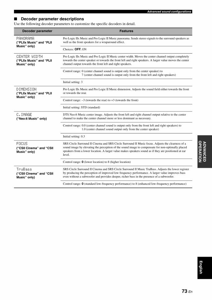
Advanced sound configurationsA
DVA
NC
ED
O
PE
RA
TIO
NE
ng
lish
■ Decoder parameter descriptionsUse the following decoder parameters to customize the specific decoders in detail.
Decoder parameter Features
PANORAMA(“PLIIx Music” and “PLII Music” only)
Pro Logic IIx Music and Pro Logic II Music panorama. Sends stereo signals to the surround speakers as well as the front speakers for a wraparound effect.
Choices: OFF, ON
CENTER WIDTH(“PLIIx Music” and “PLII Music” only)
Pro Logic IIx Music and Pro Logic II Music center width. Moves the center channel output completely towards the center speaker or towards the front left and right speakers. A larger value moves the center channel output towards the front left and right speakers.
Control range: 0 (center channel sound is output only from the center speaker) to 7 (center channel sound is output only from the front left and right speakers)
Initial setting: 3
DIMENSION(“PLIIx Music” and “PLII Music” only)
Pro Logic IIx Music and Pro Logic II Music dimension. Adjusts the sound field either towards the front or towards the rear.
Control range: –3 (towards the rear) to +3 (towards the front)
Initial setting: STD (standard)
C.IMAGE(“Neo:6 Music” only)
DTS Neo:6 Music center image. Adjusts the front left and right channel output relative to the center channel to make the center channel more or less dominant as necessary.
Control range: 0.0 (center channel sound is output only from the front left and right speakers) to 1.0 (center channel sound output only from the center speaker)
Initial setting: 0.3
FOCUS(“CSII Cinema” and “CSII Music” only)
SRS Circle Surround II Cinema and SRS Circle Surround II Music focus. Adjusts the clearness of a sound image by elevating the perception of the sound image to compensate for non-optimally placed speakers from a lower location. A larger value makes speakers sound as if they are positioned at ear level.
Control range: 0 (lower location) to 8 (higher location)
TruBass(“CSII Cinema” and “CSII Music” only)
SRS Circle Surround II Cinema and SRS Circle Surround II Music TruBass. Adjusts the lower register by producing the perception of improved low frequency performance. A larger value improves bass even without a subwoofer and provides deeper, richer bass in the presence of a subwoofer.
Control range: 0 (standard low-frequency performance) to 8 (enhanced low-frequency performance)
73 En

The “MANUAL SETUP” menu allows you to manually adjust speaker and system parameters using the remote control. For the complete menu structure, see “SET MENU tree” (page 123).
yThe initial factory settings are indicated in bold under each parameter.
This section explains how to configure parameters in the MANUAL SETUP menu using the OSD.
y• To return to the previous menu level, press 9RETURN.• Pressing JPARAMETER cancels the menu operation.
1 Set the operation mode selector to EAMP and then press HMENU to enter “SET MENU”.The top “SET MENU” screen appears in the OSD.
2 Press 8k / n to select “MANUAL SETUP” and then press 8ENTER.The “MANUAL SETUP” screen appears in the OSD.
3 Press 8k / n repeatedly and then press 8ENTER to select and enter the desired menu.As an example, the following screen appears if “SOUND MENU” is selected.
4 Press 8k / n repeatedly and then press 8ENTER to select and enter the desired submenu.As an example, the following screen appears if “LFE LEVEL” is selected.
5 Press 8k / n to select the desired parameter and then 8l / h to change the parameter settings.• To increase the value, press 8h.• To decrease the value, press 8l.
6 Press HMENU to exit from “SET MENU”.
Customizing this unit (MANUAL SETUP)
Operating the MANUAL SETUP menu
[�]/[�]:[ENTER]:
[ p
SET MENU
;AUTO SETUP;MANUAL SETUP;SYSTEM MEMORY;SIGNAL INFO
Up/DownEnter
.
[�]/[�]:[ENTER]:
[ p
MANUAL SETUP
1 SPEAKER MENU2 VOLUME MENU3 SOUND MENU4 VIDEO MENU5 INPUT MENU6 OPTION MENU
Up/DownEnter
.
[�]/[�]:[ENTER]:
[ p
3 SOUND MENU
A)EQUALIZERB)LFE LEVELC)DYNAMIC RANGED)LIPSYNCE)AUDIO SETF)PURE DIRECT
Up/DownEnter
.
[�]/[�]:[p]/[[]:
[ p
B)LFE LEVEL
SPEAKER;;;;;;0dBHEADPHONE;;-20dB
Up/DownAdjust
.
74 En

Customizing this unit (MANUAL SETUP)A
DVA
NC
ED
O
PE
RA
TIO
NE
ng
lish
Use this feature to manually adjust the basic speaker settings. Most of the “SPEAKER MENU” parameters are set automatically when you run the automatic setup.
y• Set “TEST TONE” to “ON” (page 77) to output the test tone for
the “CONFIG”, “LEVEL” and “DISTANCE” settings.• If your subwoofer can adjust the output volume and the
crossover frequency, set the volume to about half way (or slightly less) and set the crossover frequency to the maximum.
■ Speaker configurations A)CONFIG
LFE/bass out LFE/BASS OUT
Use this feature to select the speakers that output the LFE (low-frequency effect) and the low-frequency signals.
LFE signals output
Low-frequency signals output
*1 Output(s) the low-frequency signals of the front channels and other speakers set to “SMALL”.
*2 Always output the low-frequency signals of the front channels.
*3 Output the low-frequency signals if the speakers are set to “LARGE”.
*4 Outputs the low-frequency signals of the speakers set to “SMALL”.
Front speakers FRONT SP
When “LFE/BASS OUT” is set to “FRONT”, you can select only “LARGE” in “FRONT SP”. If the value of “FRONT SP” is set to other than “LARGE” in advance, this unit change the value to “LARGE” automatically.
Center speaker CENTER SP
Surround left/right speakers SUR. L/R SP
1 SPEAKER MENU
Choice
Subwoofer(s) and speakers
Subwoofer(s)Front
speakersOther
speakers
BOTH Output No output No output
SWFR Output No output No output
FRONT No output Output No output
Choice
Subwoofer(s) and speakers
Subwoofer(s)Front
speakersOther
speakers
BOTH *1 *2 *3
SWFR *4 *3 *3
FRONT No output *1 *3
Measure for the speaker sizeThe woofer section of a speaker is
– 16 cm (6.5 in) or larger: large– smaller than 16 cm (6.5 in): small
Choice Descriptions
LARGE Select this setting when the front speakers are large.
SMALL Select this setting when the front speakers are small.
Note
Choice Descriptions
LARGE Select this setting when the center speaker is large.
SMALL Select this setting when the center speaker is small.
NONE Select this setting when you do not use the center speaker. The center channel signals are directed to the front left and right speakers.
Choice Descriptions
LARGE Select this setting when the surround speakers are large.
SMALL Select this setting when the surround speakers are small.
NONE Select this setting when you do not use the surround speakers. This unit is set to the Virtual CINEMA DSP mode (page 44), and “SUR.B L/R SP” is automatically set to “NONE”.
75 En

Customizing this unit (MANUAL SETUP)
Surround back left/right speakersSUR.B L/R SP
Presence speakers PRESENCE SP
Bass cross over CROSS OVER
Use this feature to select the crossover frequency of all the speakers set to “SMALL” (or “SML”) in “CONFIG” (page 75). All frequencies below the selected frequency will be sent to the subwoofer or front speakers depending on the setting of “LFE/BASS OUT” (page 75).Choices: 40Hz, 60Hz, 80Hz, 90Hz, 100Hz, 110Hz,
120Hz, 160Hz, 200Hz
yIf your subwoofer can adjust the output volume and the crossover frequency, set the volume to about half way (or slightly less) and set the crossover frequency to the maximum.
Subwoofer phase SUBWOOFER PHASE
Use this feature to switch the phase of your subwoofer if bass sounds are lacking or unclear.
■ Speaker level B)LEVEL
Use this feature to manually balance the speaker levels between the front left or surround left speakers and each speaker selected in “CONFIG” (page 75).Control range: –10.0 dB to +10.0 dBControl step: 0.5 dBInitial setting:FR.L/FR.R/SWFR/PR.L/PR.R: 0 dBCENT./SUR.L/SUR.R/SB L/SB R: –1.0 dB
• The available speaker channels differ depending on the “CONFIG” setting.
• Instead of “SB L” and “SB R”, “SB” is displayed if “SUR. B L/R SP” is set to either “SMLx1” or “LRGx1”.
■ Speaker distance C)DISTANCE
Use this feature to manually adjust the distance of each speaker and the delay applied to the respective channel. Ideally, each speaker should be the same distance from the main listening position. However, this is not possible in most home situations. Thus, a certain amount of delay must be applied to the sound from each speaker so that all sounds will arrive at the listening position at the same time.
Unit for the speaker distance adjustment UNIT
Initial setting:[U.S.A. and Canada models]: feet (ft) [Other models]: meters (m)
Choice Descriptions
LRGx1 Select this setting when the single surround back speaker is large.
LRGx2 Select this setting when the surround back left and right speakers are large.
SMLx1 Select this setting when the single surround back speaker is small.
SMLx2 Select this setting when the surround back left and right speakers are small.
NONE Select this setting when you do not use the surround back speakers. The surround back channel signals are directed to the surround left and right speakers.
Choice Descriptions
YES Select this setting when you use the presence speakers.
NONE Select this setting when you do not use the presence speakers.
Choice Functions
NORMAL Does not change the phase of your subwoofer.
REVERSE Sets the phase of your subwoofer to reverse.
LEVEL Adjusted speaker
FR.L Front left speaker
FR.R Front right speaker
CENT. Center speaker
SUR.L Surround left speaker
SUR.R Surround right speaker
SB L Surround back left speaker
SB R Surround back right speaker
SWFR Subwoofer
PR.L Presence left speaker
PR.R Presence right speaker
Notes
Choice Functions
meters (m) Adjusts speaker distances in meters.
feet (ft) Adjusts speaker distances in feet.
76 En
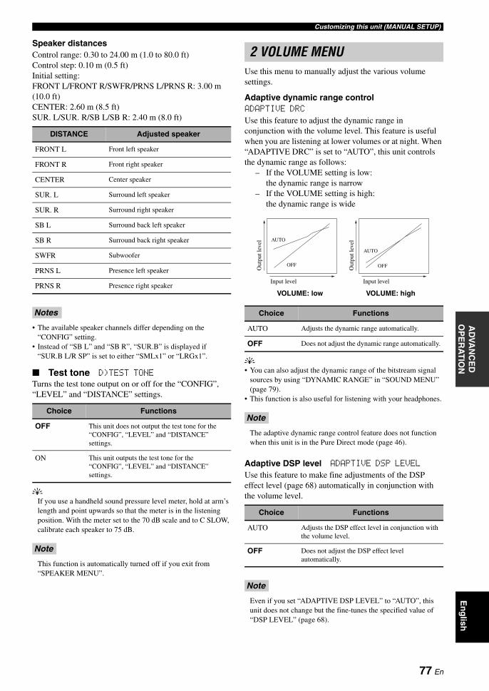
Customizing this unit (MANUAL SETUP)A
DVA
NC
ED
O
PE
RA
TIO
NE
ng
lish
Speaker distancesControl range: 0.30 to 24.00 m (1.0 to 80.0 ft)Control step: 0.10 m (0.5 ft)Initial setting:FRONT L/FRONT R/SWFR/PRNS L/PRNS R: 3.00 m (10.0 ft)CENTER: 2.60 m (8.5 ft)SUR. L/SUR. R/SB L/SB R: 2.40 m (8.0 ft)
• The available speaker channels differ depending on the “CONFIG” setting.
• Instead of “SB L” and “SB R”, “SUR.B” is displayed if “SUR.B L/R SP” is set to either “SMLx1” or “LRGx1”.
■ Test tone D)TEST TONE
Turns the test tone output on or off for the “CONFIG”, “LEVEL” and “DISTANCE” settings.
yIf you use a handheld sound pressure level meter, hold at arm’s length and point upwards so that the meter is in the listening position. With the meter set to the 70 dB scale and to C SLOW, calibrate each speaker to 75 dB.
This function is automatically turned off if you exit from “SPEAKER MENU”.
Use this menu to manually adjust the various volume settings.
Adaptive dynamic range control ADAPTIVE DRC
Use this feature to adjust the dynamic range in conjunction with the volume level. This feature is useful when you are listening at lower volumes or at night. When “ADAPTIVE DRC” is set to “AUTO”, this unit controls the dynamic range as follows:
– If the VOLUME setting is low: the dynamic range is narrow
– If the VOLUME setting is high: the dynamic range is wide
y• You can also adjust the dynamic range of the bitstream signal
sources by using “DYNAMIC RANGE” in “SOUND MENU” (page 79).
• This function is also useful for listening with your headphones.
The adaptive dynamic range control feature does not function when this unit is in the Pure Direct mode (page 46).
Adaptive DSP level ADAPTIVE DSP LEVEL
Use this feature to make fine adjustments of the DSP effect level (page 68) automatically in conjunction with the volume level.
Even if you set “ADAPTIVE DSP LEVEL” to “AUTO”, this unit does not change but the fine-tunes the specified value of “DSP LEVEL” (page 68).
DISTANCE Adjusted speaker
FRONT L Front left speaker
FRONT R Front right speaker
CENTER Center speaker
SUR. L Surround left speaker
SUR. R Surround right speaker
SB L Surround back left speaker
SB R Surround back right speaker
SWFR Subwoofer
PRNS L Presence left speaker
PRNS R Presence right speaker
Notes
Choice Functions
OFF This unit does not output the test tone for the “CONFIG”, “LEVEL” and “DISTANCE” settings.
ON This unit outputs the test tone for the “CONFIG”, “LEVEL” and “DISTANCE” settings.
Note
2 VOLUME MENU
Choice Functions
AUTO Adjusts the dynamic range automatically.
OFF Does not adjust the dynamic range automatically.
Note
Choice Functions
AUTO Adjusts the DSP effect level in conjunction with the volume level.
OFF Does not adjust the DSP effect level automatically.
Note
Input level
Out
put l
evel
Out
put l
evel
Input level
AUTO
OFF
AUTO
OFF
VOLUME: low VOLUME: high
77 En

Customizing this unit (MANUAL SETUP)
Muting type MUTING TYPE
Use this feature to adjust how much the mute function reduces the output volume (page 37).
Maximum volume MAX VOL.
Use this feature to set the maximum volume level in the main zone. This feature is useful to avoid the unexpected loud sound by mistake. For example, the original volume range is –80.0 dB to +16.5 dB. However, when “MAX VOL.” is set to –5.0 dB, the volume range becomes –80.0 dB to –5.0 dB.Control range: –30.0 dB to +15.0 dB, +16.5 dBControl step: 5.0 dB
• When this unit is in the automatic setup procedure, the volume level is automatically set to 0 dB regardless of the current “MAX VOL.” setting.
• The “MAX VOL.” setting takes priority over the “INIT. VOL.” setting.
Initial volume INIT. VOL.
Use this feature to set the volume level of the main zone when the power of this unit is turned on.Choices: OFF, MUTE, –80.0 dB to +16.5 dBControl step: 0.5 dB
The “MAX VOL.” setting takes priority over the “INIT. VOL.” setting.
Use this feature to adjust the audio parameters.
■ Equalizer A)EQUALIZER
Use this feature to select the parametric equalizer or the graphic equalizer.
Equalizer type select EQ TYPE
Use this feature to select the type of equalizer.
“AUTO PEQ” is available only after you have done the automatic setup procedure (page 30).
Graphic equalizer edit GEQ EDIT
Use this feature to adjust the tonal quality of each channel.Speaker channel: FRONT L, FRONT R, CENTER,
SUR. L, SUR. R, SB L, SB R, PRNS L, PRNS R, SWFR
Frequency band: 63 Hz, 160 Hz, 400 Hz, 1 kHz, 2.5 kHz, 6.3 kHz, 16 kHz
Control range: –6.0 dB to +6.0 dBControl step: 0.5 dB
yTo output a test tone while adjusting the tonal quality, set “TEST” to “ON”.
• “GEQ EDIT” is available only when “EQ TYPE” is set to “GEQ”.
• The available speaker channels differ depending on the “CONFIG” setting.
• Instead of “SB L” and “SB R”, “SB” is displayed if “SUR.B L/R SP” is set to either “SMLx1” or “LRGx1”.
Choice Functions
FULL Mutes all the audio output.
–20dB Reduces the current volume by 20 dB.
Notes
Note
3 SOUND MENU
Choice Functions
AUTO PEQ Uses the parametric equalizer adjusted in the automatic setup procedure.
GEQ Uses the equalizer settings adjusted in "GEQ EDIT".
OFF Deactivates the equalizing feature.
Note
Notes
78 En

Customizing this unit (MANUAL SETUP)A
DVA
NC
ED
O
PE
RA
TIO
NE
ng
lish
Parametric equalizer select PEQ SELECT
Use this feature to select the parametric equalizer type that applied to the results of the automatic setup.
“PEQ SELECT” is available only when “EQ TYPE” is set to “AUTO PEQ”.
■ Low-frequency effect level B)LFE LEVEL
Use this feature to adjust the output level of the LFE (low-frequency effect) channel according to the capacity of your subwoofer or headphones. The LFE channel carries low-frequency special effects which are only added to certain scenes. This setting is effective when the input signal contains the LFE channel.Control range: –20 to 0 dBControl step: 1 dB
Speakers SPEAKER
Adjusts the speaker LFE level.
Headphones HEADPHONE
Adjusts the headphone LFE level.
Depending on the “LFE/BASS OUT” setting (page 75), some signals may not be output at the SUBWOOFER PRE OUT jack.
■ Dynamic range C)DYNAMIC RANGE
Use this feature to select the amount of dynamic range compression to be applied to your speakers or headphones. This setting is effective only when this unit is decoding bitstream signals.
Speakers SPEAKER
Adjusts the dynamic range compression for the speakers.
Headphones HEADPHONE
Adjusts the dynamic range compression for the headphones.
■ Audio and video synchronization (lip sync) D)LIPSYNC
HDMI automatic lip sync mode HDMI AUTO
If the connected video monitor is connected to the HDMI OUT jack of this unit and compatible with the automatic audio and video synchronization function (automatic lip sync), this unit adjusts the audio and video synchronization automatically. Use this feature to activate or deactivate the automatic lip sync.
Auto delay AUTO DELAY
Use this feature to make fine adjustments of the audio and video synchronization when you set “HDMI AUTO” to “ON”.Control range: 0 to 240 msControl step: 1 ms
y“offset” indicates the difference between the value of the audio delay that this unit sets automatically and the value of the audio delay that you set in “AUTO”. This unit stores the value of “offset” and applies the value to other automatic lip sync compatible video monitors.
Manual delay MANUAL DELAY
Use this feature to adjust the delay of the sound output manually to synchronize audio with video images when you set “HDMI AUTO” to “OFF”.Control range: 0 to 240 msControl step: 1 ms
Choice Functions
NATURAL Averages out the frequency response of each all speakers with higher frequencies being less emphasized. Recommended if the “FLAT” setting sounds a little harsh.
FLAT Averages frequency response of all speakers. Recommended if all of your speakers are of similar quality.
FRONT Adjusts the frequency response of each speaker in accordance with the sound of your front speakers. Recommended if your front speakers are of much higher quality than your other speakers.
Note
Note
Choice Functions
MIN/AUTO • MIN: Adjusts the dynamic range to narrow when this unit is decoding bitstream signals (except Dolby TrueHD).
• AUTO: Adjusts the dynamic range according to the instruction of the input source signals when this unit is decoding Dolby TrueHD signals.
STD Adjusts the dynamic range to medium. When this unit is decoding Dolby TrueHD signals, the dynamic range control is always active regardless of the instruction of the input source signals.
MAX Preserves the greatest amount of dynamic range.
Choice Functions
OFF Select this setting if the video monitor is not compatible with the automatic lip sync or you do not want to use the automatic lip sync. Use “MANUAL DELAY” to adjustment the audio and video synchronization.
ON Select this setting if the connected video monitor is compatible with the automatic lip sync. Use “AUTO DELAY” to make fine adjustments of the audio and video synchronization.
79 En

Customizing this unit (MANUAL SETUP)
■ Audio settings E)AUDIO SET
Tone bypass TONE BYPASS
Use this feature to select whether the audio output bypasses the tone control circuitry when “TREBLE” and “BASS” are set to 0 dB (page 46).
HDMI audio HDMI AUDIO
Use this feature to select the types of the audio signals output at the HDMI OUT jack on the rear panel of this unit.
Available audio/video signals depend on the specification of the connected video monitor. Refer to the instruction manuals of your video monitor and audio source component.
■ Pure direct F)PURE DIRECTUse this feature to select whether this unit outputs the video signals when this unit is in the Pure Direct mode.
You cannot use the OSD menu even if “PURE DIRECT” is set to “AUDIO+VIDEO”.
Use this feature to adjust the video parameters.
yYou can reset the all parameters in “VIDEO MENU” to the initial factory settings by using “VIDEO” of “INITIALIZE” in “ADVANCED SETUP” (page 103).
Video conversion VIDEO CONV.
Use this feature to set whether to convert the video signals input at the VIDEO, S VIDEO, and COMPONENT VIDEO jacks.
• This unit does not convert 480 line video signals and 576 line video signals interchangeably.
• 480p-, 576p-, 1080i- and 720p-resolution video signals cannot be output at the S VIDEO and VIDEO MONITOR OUT jacks.
• The converted video signals are only output at the MONITOR OUT jacks. When recording a video source, you must make the same type of video connections between each component.
• When composite video or S-video signals from a VCR are converted into component video signals, the picture quality may suffer depending on your VCR.
• Unconventional signals input at the composite video or S-video jacks cannot be converted or may be output abnormally. In such cases, set “VIDEO CONV.” to “OFF”.
Component interlace/progressive up-conversionCOMPONENT I/P
Use this feature to activate or deactivate the analog interlace/progressive conversion of the analog video signals input at the composite video, S-video and component video jacks so that the analog video signals deinterlaced from 480i (NTSC)/576i (PAL) to 480p/576p are output at the COMPONENT MONITOR OUT jacks.
Choice Functions
AUTO Automatically bypasses the tone control circuitry to provide the purest signal possible when “TREBLE” and “BASS” are set to 0 dB.
OFF Does not bypass the tone control circuitry.
Choice Functions
AMP Outputs audio signals that can be decoded by this unit.
AMP+TV Outputs audio signals that can be decoded by your video monitor connected to the HDMI OUT jack of this unit.
Note
Choice Functions
AUDIO Does not Output video signals.
AUDIO+VIDEO
Outputs video signals. For the better sound quality, this unit only activates the limited video features.
Note
4 VIDEO MENU
Choice Functions
ON Converts composite, S-video, and component video signals interchangeably and up-converts composite, S-video, and component video signals to HDMI video signals.
OFF Does not convert any signals.
Notes
Choice Functions
ON Activates the analog interlace/progressive up-conversion of the analog video signals.
OFF Deactivates the analog interlace/progressive up-conversion of the analog video signals.
80 En

Customizing this unit (MANUAL SETUP)A
DVA
NC
ED
O
PE
RA
TIO
NE
ng
lish
• The “COMPONENT I/P” parameter appears only when you set “VIDEO CONV.” to “ON”.
• If your video monitor does not support analog video signals with 480p/576p of resolution, the SET MENU items may not be displayed on your video monitor when “COMPONENT I/P” is set to “ON”.
HDMI resolution HDMI RES.
Use this feature to activate or deactivate the HDMI up-scaling of the analog video signals input at the VIDEO, S VIDEO and COMPONENT VIDEO jacks so that the up-scaled video signals are output at the HDMI OUT jack.This unit up-scales the video signals as follows:• 480i (NTSC)/576i (PAL) → 480p/576p, 1080i, 720p,
or 1080p• 480p/576p → 1080i, 720p, or 1080p
• “HDMI RES.” is available only when “VIDEO CONV.” is set to “ON”.
• This unit automatically detects the video signal resolutions supported by the connected video monitor and uses an asterisk (*) to indicate them. If this unit cannot detect the resolutions, set “MONITOR CHECK” to “SKIP” (page 103).
HDMI aspect ratio HDMI ASPECT
Use this feature to select the adjustment of aspect ratio for analog video signals output at the HDMI OUT jack.
• “HDMI ASPECT” is available only when “HDMI RES.” is not set to “THROUGH”.
• If the aspect ratio of the input video source is other than 4:3, this unit automatically ignores the setting of “HDMI ASPECT”.
• When “HDMI ASPECT” is set to “SMART”, the video images of the edge of the video monitor are rather stretched.
Use this menu to adjust the parameters of each input source.
Notes
Choice Functions
THROUGH Does not up-scale any analog video signals.
480p (or 576p), 1080i, 720p, 1080p
Up-scales analog video signals to 480p or 576p, 1080i, 720p, or 1080p of resolution.
Notes
Choice Functions
THRGH Does not make any adjustments to the aspect ratio for the HDMI video signal sources.
16:9 Displays video images with the aspect ratio of 4:3 on your video monitor with the aspect ratio of 16:9. Black stripes appear on the right and left sides as a result.
SMART Fits video images with the aspect ratio of 4:3 to your video monitor with the aspect ratio of 16:9.
Notes
5 INPUT MENU
Input source Parameter
A)SIRIUS(U.S.A. and Canada models only)B)XM(U.S.A. and Canada models only)C)TUNER
INPUT RENAMEVOL. TRIMBGV
D)MULTI CH INPUT RENAMEVOL. TRIMBGVINPUT CHFRONT
E)PHONOF)CDG)TVH)MD/CD-R
I/O ASSIGNMENTINPUT RENAMEVOL. TRIMDECODER MODEBGV
I)BD/HD DVDJ)DVDK)CBL/SATL)DVRM)VCRN)V-AUX
I/O ASSIGNMENTINPUT RENAMEVOL. TRIMDECODER MODE
O)DOCK INPUT RENAMEVOL. TRIMSTANDBY CHARGE
P)BLUETOOTH INPUT RENAMEVOL. TRIMBGVSTART PAIRING
81 En

Customizing this unit (MANUAL SETUP)
Input/output assignmentI/O ASSIGNMENT
Use this feature to assign the input/output jacks according to the component to be used if the initial settings of this unit do not correspond to your needs. Change the parameter to reassign the respective jacks and effectively connect more components.Once the input/output jacks are reassigned, you can select the corresponding component by using the C INPUT selector (or the input selector buttons (3)).
y• “NONE” appears in the OSD when no input source is assigned
to the jack.• You cannot select a specific item more than once for the same
type of jack.• An asterisk (*) appears to the right of the jack names that have
been changed from their previous settings.• The input source currently assigned to the selected jack is
shown in the parentheses next to “Current”.
Input rename INPUT RENAME
Use this feature to change the name of the input source (up to 9 characters) that appears in the OSD and in the front panel display.• To locate the position to edit , press 8l / h.• To select a character, press 8k / n.• To confirm the setting, press 8ENTER.• To return to the previous screen without change, press
9RETURN.
yPress 8n to change the character in the following order, or press 8k to go in the reverse order: A to Z, 0 to 9, a to z, symbols (#, *, –, +, etc.), space.
Volume trim VOL. TRIM
Use this feature to adjust the level of the signal input at each jack. This feature is useful if you want to balance the level of each input source to avoid sudden changes in volume when switching between input sources.Control range: –6.0 dB to +6.0 dBControl step: 0.5 dBInitial setting: 0.0 dB
yThis parameter also affects the signals output at the audio ZONE OUT jacks.
Decoder mode DECODER MODE
Use this feature to switch the decoder activation mode.
“DECODER MODE” is available only when the digital audio input jacks (HDMI, OPTICAL and/or COAXIAL) are assigned to the selected input source.
Audio input BGV BGV
Use this feature to select the video source played in the background of the selected audio input source.
Charge on standby STANDBY CHARGE
Use this feature to select whether this unit charges the battery of the stationed iPod or not when this unit is in the standby mode.
Start pairing START PAIRING
Use this feature to start pairing the connected Yamaha Bluetooth wireless audio receiver (such as YBA-10, sold separately) with your Bluetooth component. For details about the pairing, refer to “Pairing the Bluetooth™ receiver and your Bluetooth component” (page 65).
1 Press 8ENTER to start pairing. The connected Bluetooth receiver starts searching Bluetooth components. “Searching...” appears in the OSD.
2 Check that the Bluetooth component detects the Bluetooth receiver.For details, refer to the instruction manual of the Bluetooth component.
Choice Functions
AUTO Automatically detects digital audio signal input types and selects the appropriate decoder.
DTS Activates the DTS decoder and plays back only DTS digital audio signals when digital audio signals are input.
Note
Choice Functions
BD/HD DVD, DVD, CBL/SAT, DVR, VCR, V-AUX, DOCK
Selects the corresponding input source as the background video source.
OFF Does not play the video source in the background.
Choice Functions
AUTO Charges the battery of the stationed iPod when this unit is turned on and in the standby mode.
OFF Charges the battery of the stationed iPod only when this unit is turned on.
To ensure security, a time limit of 8 minutes is set for the pairing operation. You are recommended to read and fully understand all the instructions before starting.
82 En

Customizing this unit (MANUAL SETUP)A
DVA
NC
ED
O
PE
RA
TIO
NE
ng
lish
3 Select the Bluetooth receiver in the Bluetooth device list and then enter the pass key “0000” on the Bluetooth component. Once this unit completes the pairing successfully, “Completed” appears.
yTo cancel the pairing, press 9RETURN.
4 Press 9RETURN to exit from “START PAIRING”.
• If the connected Bluetooth receiver cannot find any Bluetooth components, “Not found” appears.
• If a Bluetooth receiver is not connected to this unit, “No Bluetooth receiver” appears.
Input channels INPUT CH
Use this setting to select the number of channels input from an external decoder (page 23).
Front left and right channels input jack FRONT
If you set “INPUT CH” to “8CH”, you need to specify the analog audio jacks at which the front left and right channel signals output from the connected external decoder are input.Choices: CD, TV, MD/CD-R, BD/HD DVD, DVD, CBL/
SAT, DVR, VCR, V-AUX
“FRONT” is available only when “INPUT CH” is set to “8CH”.
Use this menu to adjust the optional system parameters.
■ Display settings A)DISPLAY SET
You can reset the “OSD SHIFT” and “GRAY BACK” settings to the initial factory settings by using “VIDEO” of “INITIALIZE” in “ADVANCED SETUP” (page 103).
Dimmer DIMMER
Use this feature to adjust the brightness of the front panel display.Control range: – 4 to 0Control step: 1• To make the front panel display dimmer, press 8l.• To make the front panel display brighter, press 8h.
OSD shift OSD SHIFT
Use this feature to adjust the vertical position of the OSD.Control range: –5 (downward) to +5 (upward)Control step: 1Initial setting: 0• To lower the position of the OSD, press 8l.• To raise the position of the OSD, press 8h.
Gray back GRAY BACK
Use this feature to display a gray background in your video monitor when there is no video signal being input.
Depending on the video signals being input or the system setting of your video monitor (NTSC or PAL), the OSD may be displayed abnormally. In such cases, set “GRAY BACK” to “OFF”.
Notes
Choice Functions
6ch Select this setting if the connected component outputs discrete 6-channel audio signals.
8ch Select this setting if the connected component outputs discrete 8-channel audio signals. You also need to configure the “FRONT” setting (below).
Note
6 OPTION MENU
Note
Choice Functions
AUTO Displays a gray background on your video monitor when there is no video signal being input.
OFF Does not display a gray background on your video monitor.
Note
83 En

Customizing this unit (MANUAL SETUP)
Short message displaySHORT MESSAGE
Use this feature to activate or deactivate the short message display function.
The short message display does not appear in the following cases:– when the component video signals with 480p/576p, 720p,
1080i or 1080p resolutions are input– when HDMI video signals are input
On-screen display time ON SCREEN
Use this feature to set the amount of time to display the HD Radio (U.S.A. model only), XM Satellite Radio, or SIRIUS Satellite Radio information or iPod menu in the OSD after you perform a certain operation.
Front panel display scroll FL SCROLL
Use this feature to set the mode to display the HD Radio (U.S.A model only), XM Satellite Radio information, SIRIUS Satellite Radio information, or iPod menu (such as song title or channel name) in the front panel display.
■ Memory guard B)MEMORY GUARD
Use this feature to prevent accidental changes to sound field program parameter and other system settings.
You can change the following parameters even if “MEMORY GUARD” is set to “ON”:
– “DECODER MODE” in “INPUT MENU” (page 82)– “MEMORY GUARD”– “SUR.” of the sound field program parameter (page 72)– "TONE BYPASS" in "SOUND MENU" (page 80)– Loading the system settings (page 87)
■ Initial configuration C)INIT. CONFIG
Use this feature to select the settings of the audio input jack select, active decoders and extended surround when you turn on this unit.
Audio select AUDIO SELECT
Use this feature to designate the default audio input jack select setting (page 36) for the input sources connected to the DIGITAL INPUT jacks when you turn on the power of this unit.
Decoder mode DECODER MODE
Use this feature to designate the default decoder mode (page 82) for the input sources connected to the DIGITAL INPUT jacks when you turn on the power of this unit.
Choice Functions
ON Activates the short message display function. The contents of the front panel display appear at the bottom of the screen each time you operate this unit.
OFF Deactivates the short message display function.
Note
Choice Functions
ALWAYS Displays the OSD unceasingly during an operation.
10S Turns off the OSD 10 seconds after you perform a certain operation.
30S Turns off the OSD 30 seconds after you perform a certain operation.
Choice Functions
CONT Select this to display the operation status in the front panel display in a continuous manner.
ONCE Select this to display the operation status in the front panel display by the first 14 alphanumeric characters after scrolling all characters once.
Choice Functions
OFF Turns off the memory guard feature.
ON Turns on the memory guard feature. While it is
turned on (“ ”appears at the top right of the “SET MENU” screen), the following settings are protected.
– sound field program parameters– “AUTO SETUP” items– all speaker levels– “MANUAL SETUP” items
Note
Choice Functions
AUTO Automatically detects the type of input signals and selects the appropriate audio input jack select setting.
LAST Automatically selects the last input jack select setting used for the connected input source.
Choice Functions
AUTO Automatically detects the type of input signals and select the appropriate decoder mode setting.
LAST Automatically selects the last decoder mode setting used for the connected input source.
G
84 En

Customizing this unit (MANUAL SETUP)A
DVA
NC
ED
O
PE
RA
TIO
NE
ng
lish
Extended surround EXTD SUR.
Use this feature to designate the extended decoder mode (page 67) for the input sources connected to the DIGITAL INPUT jacks when you turn on the power of this unit.
■ Zone set D)ZONE SET
Use this feature to set the items related in Zone 2 or Zone 3.
"MAX VOL." and "INIT. VOL." are available only when "VOLUME" is set to "VAR".
Setting zoneSelect the zone which you want to configure the settings for.
Zone 2/Zone 3 amplifier AMP
Use this feature to select how the Zone 2 or Zone 3 speakers are amplified. This parameter also effects the speaker settings and the sound output of sound field programs in the main zone.
yFor details on Zone 2 and Zone 3 connections, see “Connecting the Zone 2 and Zone 3 components” (page 99).
• If “BI AMP” in “ADVANCED SETUP” is set to “ON” (page 103), the “AMP” setting is fixed to “EXT”.
• When you set “AMP” to “[SP1]” and the corresponding zone is turned on, no sound is output from the surround back speakers.
• When you set “AMP” to “[SP2]” and the corresponding zone is turned on, no sound is output from both the surround and the surround back speakers.
• When you set “AMP” to “BOTH” for either “ZONE 2” or “ZONE 3”, the “AMP” setting for another zone is fixed to “EXT”.
• When you set “AMP” to “BOTH” and the corresponding zone is turned on, no sound is output from both the surround and surround back speakers.
Zone 2/Zone 3 volume VOLUME
Use this feature to select whether this unit controls the volume level of the audio signals output at the ZONE OUT (ZONE 2 or ZONE 3) jacks when you set “AMP” to “EXT” (page 85).
Zone 2/Zone 3 maximum volume MAX VOL.
Use this feature to set the maximum volume level in the Zone 2 or Zone 3.Control range: –30.0 dB to +15.0 dB, +16.5dBControl step: 5.0 dB
The “MAX VOL.” setting takes priority over the “INIT. VOL.” setting.
Zone 2/Zone 3 initial volume INIT. VOL.
Use this feature to set the volume level of Zone 2 or Zone 3 when the power of Zone 2 or Zone 3 is turned on.Choices: OFF, MUTE, –80.0 dB to +16.5 dBControl step: 0.5 dB
The “MAX VOL.” setting takes priority over the “INIT. VOL.” setting.
Choice Functions
AUTO Automatically detects the digital audio input signals and activates the appropriate decoder.
LAST Automatically selects the decoder mode selected last time.
Note
Choice Functions
EXT Select this setting when the Zone 2 or Zone 3 speakers are connected to the external amplifier which is connected to the ZONE OUT (ZONE 2 or ZONE 3) jacks of this unit.
[SP1] Select this setting when the Zone 2 or Zone 3 speakers are directly connected to the SP1 speaker terminals of this unit.
[SP2] Select this setting when the Zone 2 or Zone 3 speakers are directly connected to the SP2 speaker terminals of this unit.
BOTH Select this setting when the Zone 2 or Zone 3 speakers are connected to both the SP1 and SP2 speaker terminals of this unit (for example, the speakers are connected using the bi-amplifier connection or there are four speakers in the room) or when you want to play back the same source in the Zone 2 and Zone 3 simultaneously.
Notes
Choice Functions
VAR Select this setting if you want to adjust the ZONE OUT (ZONE 2 or ZONE 3) volume level using the remote control of this unit.
FIX Select this setting if you want to adjust the Zone 2 or Zone 3 volume level on the external amplifier. This unit fixed the ZONE OUT (ZONE 2 or ZONE 3) volume level to a standard line level.
Note
Note
85 En

Use this feature to save up to six of your favorite settings that can be easily recalled when needed. You can save the following system setting parameters:
* The settings of “DYNAMIC RANGE”, “LFE LEVEL”, and the tonal quality control for headphones are not saved.
■ Saving by the 6SYSTEM MEMORY buttons
You can save the system settings stored in “MEMORY1” to “MEMORY4” by pressing the corresponding 6SYSTEM MEMORY buttons.
Press and hold one of the 6SYSTEM MEMORY buttons on the remote control for 4 seconds.“MEMORY 1 SAVE Done” (example) appears in the front panel display, and then this unit saves the current system setting to the corresponding memory number.
yIf system settings are already stored in the selected memory number, this unit overwrites the old settings.
■ Saving by the SET MENU operationYou can save the system settings stored in “MEMORY1” to “MEMORY6” by using the “SYSTEM MEMORY” menu in “SET MENU”.
1 Set the operation mode selector on the remote control to EAMP and then press HMENU. The top “SET MENU” screen appears in the OSD.
2 Press 8n to select “SYSTEM MEMORY” and then press 8ENTER.The “SYSTEM MEMORY” menu appears.
3 Press 8n to select “SAVE” and then press 8ENTER.The current system settings are displayed.
4 Press 8l / h repeatedly to select the desired memory number (“MEMORY1” to “MEMORY6”).The system settings currently stored in the selected memory number are displayed. If the memory number is not in use, “EMPTY” appears.
y• If system settings are already stored in the selected
memory number, this unit overwrites the old settings.• To load the system settings with the 6SYSTEM
MEMORY button operation, use one of “MEMORY1” to “MEMORY4”.
5 Press 8ENTER to save the current system settings to the selected memory number.
Saving and recalling the system settings (SYSTEM MEMORY)
Saved parameters Page
“SPEAKER MENU” parameters(except “TEST TONE”)
75
“VOLUME MENU” parameters(except “INIT. VOL.”)
77
“SOUND MENU” parameters* 78
“VIDEO MENU” parameters 80
“DISPLAY SET” parameters(except “SHORT MESSAGE”)
83
Sound field program (or “Pure Direct”) currently selected
39
Sound field parameter settings 67
Tonal quality control settings* 46
Saving the system settings
43
SYSTEM MEMORY
21
[p]/[[]:[ENTER]:
SYSTEM MEMORY
SAVE;;;;;;;CURRENT
Church in FreiburgADAPTIVE DRC;;AUTOEQUALIZER;;;;;;PEQPEQ TYPE;;;NATURAL
SelectReturn
.
Current system settings
[p]/[[]:[ENTER]:
SYSTEM MEMORY
SAVE;;;;;;;MEMORY1
DramaADAPTIVE DRC;;AUTOEQUALIZER;;;;;;GEQPEQ TYPE;;;;;;NONE
SelectSave
.
System settings stored in the selected memory number
86 En

Saving and recalling the system settings (SYSTEM MEMORY)A
DVA
NC
ED
O
PE
RA
TIO
NE
ng
lish
6 Press HMENU to exit from “SET MENU”.
If you load the system settings, the settings currently configured are overwritten. If you do not want to erase the current settings, save the settings using the SYSTEM MEMORY feature in advance.
■ Loading by the 6SYSTEM MEMORY buttons
You can recall the system settings stored in “MEMORY1” to “MEMORY4” by pressing the corresponding 6SYSTEM MEMORY buttons.
1 Press one of the 6SYSTEM MEMORY buttons on the remote control to select the desired memory number.“MEMORY 1 LOAD” (example) appears in the front panel display.
y“EMPTY” appears in the menu screen if no system settings are stored in the selected memory number.
2 Press the selected 6SYSTEM MEMORY button once more to confirm the selection.This unit loads the settings stored in the selected memory number.
■ Loading by the SET MENU operation
1 Set the operation mode selector on the remote control to EAMP and then press HMENU. The top “SET MENU” display appears in the OSD.
2 Press 8n to select “SYSTEM MEMORY” and then press 8ENTER.The “SYSTEM MEMORY” menu appears.
3 Press 3ENTER to select “LOAD”.The current system settings are displayed.
4 Press 8l / h repeatedly to select the desired memory number where the system settings are stored and then press 8ENTER.This unit loads the selected system settings.
5 Press HMENU to exit from “SET MENU”.
Loading the system settings
Note
43
SYSTEM MEMORY
21
[p]/[[]:[ENTER]:
SYSTEM MEMORY
LOAD;;;;;;;CURRENT
Church in FreiburgADAPTIVE DRC;;AUTOEQUALIZER;;;;;;PEQPEQ TYPE;;;NATURAL
SelectReturn
.
[p]/[[]:[ENTER]:
SYSTEM MEMORY
LOAD;;;;;;;MEMORY6
StraightADAPTIVE DRC;;AUTOEQUALIZER;;;;;;PEQPEQ TYPE;;;;;;FLAT
SelectLoad
.
87 En

Saving and recalling the system settings (SYSTEM MEMORY)
■ Example 1: Comparing the results of the automatic setup and manual setup
This unit is equipped with three types of parametric equalizer settings (page 79), and you can also make your customized configuration of the sound settings of this unit by using the “MANUAL SETUP” parameters (see page 74). To compare the results of the automatic setup or your manual configuration, use the 6SYSTEM MEMORY buttons.
Saving each setting
1 Perform the automatic setup (page 30).
2 Press and hold 6SYSTEM MEMORY 1 for 4 seconds.This unit stores the results of the automatic setup (PEQ SELECT: NATURAL) to “MEMORY1”.
3 Set “PEQ SELECT” to “FRONT” (page 79).
4 Press and hold 6SYSTEM MEMORY 2 for 4 seconds.This unit stores the results of the automatic setup (PEQ SELECT: FRONT) to “MEMORY2”.
5 Configure the parameters of “SPEAKER MENU” (page 75) and “GEQ EDIT” (page 78) manually.
6 Press and hold 6SYSTEM MEMORY 3 for 4 seconds.This unit stores the settings configured manually to “MEMORY3”.
■ Example 2: Switching the settings for different room environments
The tonal characteristics of the listening room may vary depending on the situations of the room (for example, whether the curtains are open or closed), and the settings of this unit should be arranged for each situation of the room. You can switch between the settings of this unit easily by using 6SYSTEM MEMORY buttons.
Saving each setting
1 Close the curtains of the listening room and then perform the automatic setup (page 30).
2 Press and hold 6SYSTEM MEMORY 1 for 4 seconds.This unit stores the settings for the current room situation (i.e. the curtains are closed) to “MEMORY1”.
3 Open the curtains of the listening room and the perform the automatic setup.
4 Press and hold 6SYSTEM MEMORY 2 for 4 seconds.This unit stores the current room situation (i.e. the curtains are open) to “MEMORY2”.
Using examples
43
SYSTEM MEMORY
21
SYSTEM MEMORY 1Results of the automatic setup(PEQ SELECT: NATURAL)
SYSTEM MEMORY 2Results of the automatic setup(PEQ SELECT: FRONT)
SYSTEM MEMORY 3Settings configured manually
43
SYSTEM MEMORY
21
SYSTEM MEMORY 1The settings when the curtains of the listening room are closed
SYSTEM MEMORY 2The settings when the curtains of the listening room are open
88 En

AD
VAN
CE
D
OP
ER
AT
ION
En
glish
In addition to controlling this unit, the remote control can also operate other audiovisual components made by Yamaha and other manufacturers. To control your TV or other components, you must set up the appropriate remote control code for each input source (page 91).
■ Controlling this unitSet the operation mode selector to EAMP to control this unit.
*1 These buttons always control this unit regardless of the operation mode selector position.
*2 These buttons control this unit only when the component operation mode selector is set to EAMP.
■ Controlling a TVSet the operation mode selector to ETV to control your TV. To control your TV, you must set the appropriate remote control code for the TV operation mode in advance (page 91).
yIf no code has been set for the TV operation mode, the remote control operates the component that is set to the TV control area (page 91).
*1 2TV POWER can always turn on or off the power of the TV regardless of the operation mode selector position.
*2 These buttons control your TV only when the operation mode selector is set to ETV. For details, see the “TV” column on page 90.
*3 These buttons control your TV only when the operation mode selector is set to ETV or ESOURCE.
Remote control features
Controlling this unit, a TV, or other components
Notes
AMP
TV
SOURCE
ZONESETUP ID MACRO
MODE
DVD CD
V-AUX DOCKMULTI PHONO
AV
POWER
TV
POWER
TV DVR VCR
XM SIRIUSTUNER
BDHD DVD
MDCD-R
CBLSAT
SRCH MODEMENU
BANDTITLE
MEMORYRETURN
PARAMETERDISPLAY
MUTE
43
SYSTEM MEMORY
21
STANDBY POWER
SELECT
VOLUMEPRESET/CH
ENTER CAT.A-E
PRG SELECT
CLASSICAL1
LIVE/CLUB2
ENTERTAIN3
MOVIE4
STEREO5
ENHANCER6
SUR.DECODE7
STRAIGHT8
PURE DIRECTENT
AUDIO SELAUDIO
SLEEP
TV
MUTE
INPUT
9 0
LEVEL
TV CH
INFO
TV VOL
EXTD SUR.10
A
REC
3D DSP
Set to AMP
*1
*1
*2
*2
Notes
Remote control Functions
TV VOL +/– Increases or decreases the volume level.
TV CH +/– Changes the TV channel.
TV MUTE Mutes the audio output.
TV INPUT Changes the input source.
AMP
TV
SOURCE
ZONESETUP ID MACRO
MODE
DVD CD
V-AUX DOCKMULTI PHONO
AV
POWER
TV
POWER
TV DVR VCR
XM SIRIUSTUNER
BDHD DVD
MDCD-R
CBLSAT
SRCH MODEMENU
BANDTITLE
RETURN DISPLAY
MUTE
43
SYSTEM MEMORY
21
3D DSP
STANDBY POWER
SELECT
VOLUMEPRESET/CH
ENTER CAT.A-E
PRG SELECT
CLASSICAL1
LIVE/CLUB2
ENTERTAIN3
MOVIE4
STEREO5
ENHANCER6
SUR.DECODE7
STRAIGHT8
PURE DIRECTENT
AUDIO SELAUDIO
SLEEP
TV
MUTE
INPUT
9 0
LEVEL
TV CH
INFO
TV VOL
EXTD SUR.10
A
REC
MEMORY
PARAMETER
Set to TV
*1
*2
*2
*3
89 En

Remote control features
■ Controlling other componentsSet the operation mode selector to ESOURCE to control other components selected with the input selector buttons (3) or . You must set the appropriate remote control code for each input source in advance (page 91). The following table shows the function of each control button used to control other components assigned to each input selector button (3) or . Be advised that some buttons may not correctly operate the selected component.
yThe remote control has 16 modes (input areas) to control components so that the remote control can operate up to 16 different components.
*1 This button is operational only when the original remote control supplied with the component has a power button.*2 These buttons operate your video recorder (DVD recorder, etc.) only when you set the appropriate remote control code for DVR
(page 91).*3 These functions are used for selecting HD Radio audio programs (U.S.A. model only).
A
A
SRCH MODEMENU
BANDTITLE
RETURN DISPLAY
MUTE
VOLUMEPRESET/CH
ENTER CAT.A-E
PRG SELECT
CLASSICAL1
LIVE/CLUB2
ENTERTAIN3
MOVIE4
STEREO5
ENHANCER6
SUR.DECODE7
STRAIGHT8
PURE DIRECTENT
AUDIO SELAUDIO
SLEEP
TV
MUTE
INPUT
9 0
LEVEL
TV CH
INFO
TV VOL
EXTD SUR.10
REC
AMP
TV
SOURCE
ZONESETUP ID MACRO
MODE
DVD CD
V-AUX DOCKMULTI PHONO
AV
POWER
TV
POWER
TV DVR VCR
XM SIRIUSTUNER
BDHD DVD
MDCD-R
CBLSAT
43
SYSTEM MEMORY
21
STANDBY POWER
SELECT
VOLUMEPRESET/CH
A
MEMORY
PARAMETER
3D DSP
[1] [2]
[4]
[5]
[6]
[7]
[8]
[9][10]
[3]
Set to SOURCE
Blu-ray Disc/ HD DVD player/ recorder
DVD player LD player
DVD recorder/Digital video recorder
VCR TVCable TV/ Satellite tuner
CD player
MD recorder/CD recorder
Tape deck Tuner
[1] AV POWER Power *1 Power *1 Power *1 Power *1 Power *1 DVR power *2
Power *1 Power *1 Power *1 Power *1 Power *1
[2] TITLE, BAND
Title Title Title Title Band
[3] PRESET/CH k
Menu up Menu up Menu up Channel up Menu up Channel up Menu up
PRESET/CH n Menu down Menu down Menu down
Channel down
Menu downChannel down
Menu down
CAT. A-E l Menu left Menu left Menu left Menu left Menu left
CAT. A-E h Menu right Menu right Menu right Menu right
Direction A/B
Menu right
ENTER Menu enter Menu enter Menu enter Menu enter Menu enter
[4] RETURN, MEMORY
Return Return Return Return Memory
[5] REC Record (recorder)
Disc skip Record Record DVR record *2
DVR record *2
Disc skip Record Record
e Pause Pause Pause Pause Pause DVR pause *2
DVR pause *2
Pause Pause Pause
p Play Play Play Play Play DVR play *2 DVR play *2 Play Play Play
s Stop Stop Stop Stop Stop DVR stop *2 DVR stop *2 Stop Stop Stop
llSearch backward
Search backward
Search backward
Search backward
Search backward
DVR search backward *2
DVR search backward *2
Search backward
Search backward
Search backward
hhSearch forward
Search forward
Search forward
Search forward
Search forward
DVR search forward *2
DVR search forward *2
Search forward
Search forward
Search forward
bSkip backward
Skip backward
Skip backward
Skip backward
Skip backward
DVR skip backward *2
DVR skip backward *2
Skip backward
Skip backward
Direction AAudio program down *3
a Skip forwardSkip forward
Skip forward
Skip forward
Skip forward
DVR skip forward *2
DVR skip forward *2
Skip forward
Skip forward
Direction BAudio program up *3
[6] 1-9, 0, +10 Numeric buttons
Numeric buttons
Numeric buttons
Numeric buttons
Numeric buttons
Numeric buttons
Numeric buttons
Numeric buttons
Numeric buttons
Numeric buttons
[7] MENU,SRCH MODE
Menu Menu Menu MenuSearch mode
[8] DISPLAY Display Display Display Display Display Display Display Display Display Display
[9] ENTIndex Index
Chapter/time
Index Enter Enter Enter Index Index Enter
[10] AUDIO Audio Audio Audio Audio
Notes
90 En

Remote control featuresA
DVA
NC
ED
O
PE
RA
TIO
NE
ng
lish
■ Selecting a component to be controlledYou can select a component to be controlled independently of the input source selected with the input selector buttons (3).
Press 5SELECT l / h repeatedly to select the desired component.The name of the component to be controlled appears in the display window (4) on the remote control.
■ Controlling optional components (Option mode)
“OPTN1” and “OPTN2” are optional component control areas that can be programmed with remote control functions independently from any input source. These areas are useful for programming commands that are to be used only as a part of a macro function or for components that do not have a valid remote control code.
To select the option mode, press 5SELECT l / h repeatedly until “OPTN1” or “OPTN2” appears in the display window (4) on the remote control.
You cannot set a remote control code for the optional areas. See page 93 to program buttons operated within this component control area.
You can control other components by setting the appropriate remote control codes. Codes can be set up for each input area. For a complete list of available remote control codes, refer to “List of remote control codes” at the end of this manual.
The following table shows the default component (Library: component category) and the remote control code for each control area.
Remote control code default settings
You may not be able to operate your Yamaha component even if a Yamaha remote control code is preset as listed above. In this case, try setting another Yamaha remote control code.
1 Check the remote control code for your component in advance.For a complete list of available remote control codes, see “List of remote control codes” at the end of this manual.
2 Set the operation mode selector on the remote control to ESOURCE.If you want to set the remote control code for “TV”, set the operation mode selector to ETV.
Note
DVD
orOPTN1 OPTN2
Setting remote control codes
Control area
Library(component
category)Manufacturer
Default code
MULTI DVD Yamaha 04306
V-AUX — — —
PHONO — — —
DOCK SOURCE Yamaha 00012
BDHD DVD
BD Yamaha 04706
DVD DVD Yamaha 04306
CD CD Yamaha 01205
MDCD-R
CD-R Yamaha 01405
CBLSAT
— — —
TV — — —
DVR DVR Yamaha 00707
VCR — — —
TUNER SOURCE Yamaha 00012
XM SOURCE Yamaha 00012
SIRIUS SOURCE Yamaha 00012
— — —
Note
A
91 En

Remote control features
3 Press FSETUP using a ballpoint pen or similar object.“SETUP” appears in the display window (4) on the remote control.
In the “SETUP” menu, complete each of the operations within 30 seconds. Otherwise, the remote control automatically exits from the “SETUP” menu.
4 Press 8k / n repeatedly to select “P-SET” and then press 8ENTER.The remote control enters the preset mode. “P-SET” and name of the currently selected control area appears in the display window (4) alternately.
5 Press an input selector button (3) or 5SELECT l / h repeatedly to select the control area you want to customize.If you selected “TV” in step 2, skip this step.
6 Press 8ENTER.The current code setting appears.
7 Press the numeric buttons (A) to enter the five-digit remote control code for your component.
8 Press 8ENTER to set the number.“OK” appears in the display window (4) if setting was successful.“NG” appears in the display window (4) if the setting was unsuccessful. In this case, start over from step 5.
yIf you continuously want to set up another code for another control area, repeat steps 5 through 8.
9 Press FSETUP again to exit from the “SETUP” mode.
10 Press 2AV POWER or 0p to confirm whether you can control your component using the remote control.
y• If operation is not possible and the manufacturer of your
component has more than one code, try each of them until you find the correct one.
• If you set "00012" as the remote control code of the selected control area, you can operate the currently selected internal source (DOCK, TUNER, XM, or SIRIUS).
• “ERROR” appears in the display window (4) on the remote control if you press a button not indicated in the respective step, or when you press more than one button simultaneously.
• The supplied remote control does not contain all possible codes for commercially available audio and video components (including Yamaha components). If operation is not possible with any of the remote control codes, program the new remote control function using the learning feature (page 93) or use the remote control supplied with the component.
• Functions programmed using the learning mode take priority over remote control code functions.
Note
SETUP
P-SET
DVD
04306
OK
Notes
92 En

Remote control featuresA
DVA
NC
ED
O
PE
RA
TIO
NE
ng
lish
You can program remote control codes from other remote controls. Use the learning feature if you want to program functions not included in the basic operations covered by the remote control codes, or an appropriate remote control code is not available. You can program the function of other remote control to the buttons in the highlighted areas in the following illustration. The buttons can be programmed independently for each control area.
• The remote control transmits infrared rays. If the other remote control also uses infrared rays, this remote control can learn most of its functions. However, you may not be able to program some special signals or extremely long transmissions.
• You cannot program the desired remote control code even if you select the buttons in the highlighted area in the above illustration depending on the selected control area and the assigned library.
1 Set the operation mode selector to ESOURCE and then press an input selector button (3) to select the desired control area.If you want to program the remote control code for “TV”, set the operation mode selector to ETV.
Make sure that the operation mode selector is set to ESOURCE or ETV. When you set the operation mode selector to EAMP and program a remote control codes from other remote controls, the programmed key cannot operate the amplifier function of this unit.
2 Press FSETUP using a ballpoint pen or similar object.“SETUP” appears in the display window (4).
3 Press 8k / n repeatedly to select “LEARN” and then press 8ENTER.
4 Place this remote control about 5 to 10 cm (2 to 4 in) apart from the other remote control on a flat surface so that their infrared transmitters are aimed at each other and then press 8ENTER.“L–KEY” appears in the display window (4).
5 Press the button for which you want to program the new function.“START” appears in the display window (4).
6 Press and hold the button you want to program on the other remote control until “OK” appears in the display window (4).“NG” appears in the display window (4) if learning was unsuccessful. In this case, start over from step 4.
yWhen you want to program another function, repeat steps 4 througn 6.
Programming codes from other remote controls
Notes
Note
AMP
TV
SOURCE
ZONESETUP ID MACRO
MODE
DVD CD
V-AUX DOCKMULTI PHONO
AV
POWER
TV
POWER
TV DVR VCR
XM SIRIUSTUNER
BDHD DVD
MDCD-R
CBLSAT
SRCH MODEMENU
BANDTITLE
MEMORYRETURN
PARAMETERDISPLAY
MUTE
43
SYSTEM MEMORY
21
STANDBY POWER
SELECT
VOLUMEPRESET/CH
ENTER CAT.A-E
A
REC
SRCH MODEMENU
BANDTITLE
MEMORYRETURN
PARAMETERDISPLAY
MUTE
3D DSP
VOLUMEPRESET/CH
ENTER CAT.A-E
PRG SELECT
CLASSICAL1
LIVE/CLUB2
ENTERTAIN3
MOVIE4
STEREO5
ENHANCER6
SUR.DECODE7
STRAIGHT8
PURE DIRECTENT
AUDIO SELAUDIO
SLEEP
TV
MUTE
INPUT
9 0
LEVEL
TV CH
INFO
TV VOL
EXTD SUR.10
REC
Set to SOURCE
AM
P
TV
SOURCEZONESETUP
IDMACRO
MODE
DV
DC
D
V-AU
XD
OC
KM
ULTI
PHONO
AV
PO
WE
R
TV
PO
WE
R
TVD
VR
VC
R
XM
SIRIU
STU
NER
BDHD DVD
MD
CD
-R
CB
LS
AT
SRCH MODEMENU
BANDTITLE
RETURNDISPLAY
43
SY
STE
M M
EM
OR
Y
21
STANDBYP
OW
ER
SELECT
VO
LUM
EPRESET/CH
ENTERCAT.A-E
A
PARAMETER
5 to 10 cm (2 to 4 in)
Other remote control
AM
P
TV
SOURCEZONESETUP
IDMACRO
MODE
DV
DC
D
V-AU
XD
OC
KM
ULTI
PHONO
AV
PO
WE
R
TV
PO
WE
R
TVD
VR
VC
R
XM
SIRIU
STU
NER
BDHD DVD
MD
CD
-R
CB
LS
AT
SRCH MODEMENU
BANDTITLE
RETURNDISPLAY
43
SY
STE
M M
EM
OR
Y
21
STANDBYP
OW
ER
SELECT
VO
LUM
EPRESET/CH
ENTERCAT.A-E
A
PARAMETER
AM
P
TV
SOURCEZONESETUP
IDMACRO
MODE
DV
DC
D
V-AU
XD
OC
KM
ULTI
PHONO
AV
PO
WE
R
TV
PO
WE
R
TVD
VR
VC
R
XM
SIRIU
STU
NER
BDHD DVD
MD
CD
-R
CB
LS
AT
SRCH MODEMENU
BANDTITLE
43
SY
STE
M M
EM
OR
Y
21
STANDBYP
OW
ER
SELECT
VO
LUM
EPRESET/CH
A
Other remote control
OK
93 En

Remote control features
7 Press FSETUP again to exit the setup menu.
• “ERROR” appears in the display window (4) on the remote control if you press a button not indicated in the respective step, or when you press more than one button simultaneously.
• This remote control can learn approximately 200 functions. However, depending on the signals learned, “FULL” may appear in the display before you program 200 functions. In this case, clear unnecessary programmed functions to make room for further learning (page 97).
• Learning may not be possible in the following cases:– when the batteries in the remote control for this unit or other
components are weak.– when the remote control is exposed to direct sunlight.– when the function to be programmed is continuous or
uncommon.
You can change the name of the control area (input source) that appears in the display window (4) on the remote control.
1 Set the operation mode selector to ESOURCE and then press an input selector button (3) to select the desired control area.
2 Press FSETUP using a ballpoint pen or similar object.“SETUP” appears in the display window.
3 Press 8k / n repeatedly to select “RNAME” and then press 8ENTER.
4 Press 8k / n repeatedly to select 3-letter name or 5-letter name you want to edit and then press 8ENTER.Each control area has both 3-letter name and 5-letter name. You can rename the 3-letter name and 5-letter name independently.
5 Edit the name of the control area.To locate the position to edit , press 8l / h.To select a character, press 8k / n.
yPress 8k to change the character in the following order, or press 8n to go in the reverse order: A to Z, a to z, 0 to 9, space, symbols (–, +, /, :).
6 Press 8ENTER to set the new name.“OK” appears in the display window (4) on the remote control if renaming was successful.
yWhen you want to rename the another control area, press the input selector button (3) or 5SELECT l / h repeatedly to select the desired control area and then press 8ENTER and then carry out the operations of steps 4 through 6.
7 Press FSETUP again to exit the setup menu.
“ERROR” appears in the display window (4) on the remote control if you press a button not indicated in the respective step, or when you press more than one button simultaneously.
Notes
Changing source names in the display window
BD BD/HD
3-letter name 5-letter name
Note
BD/HD
94 En

Remote control featuresA
DVA
NC
ED
O
PE
RA
TIO
NE
ng
lish
The macro programming feature makes it possible to perform a series of operations with the press of a single button. For example, when you want to play a CD, normally you would turn on the components, select the CD input, and press the play button to start playback. The macro programming feature lets you perform all of these operations simply by pressing the CD macro button. The buttons listed as macro buttons below are factory set with macro programs. You can also program your own macros (page 96).
■ Recalling programmed macro-operations
1 Press GMACRO on the remote control.
2 Press the desired macro button.“M:the 3-letter name of the selected control area” (for example, “M:DVD”) appears in the display window (4), and this unit transmits the programmed functions. When you press CSTANDBY or DPOWER, “M:STB” or “M:PWR” appears in the display window (4), and this unit transmits the programmed functions.
3 Press GMACRO again to exit from the macro-operation mode.
• While the remote control is running a macro program (the transmission indicator flashes), it does not accept any other operation.
• Continue to aim the remote control at the component the macro is operating until the macro operation is complete.
• If you do not complete each of the operations within 30 seconds, this unit automatically exits from the macro-operation mode.
■ Default macro functions
*1 Set the appropriate remote control code for TV in advance (page 91).
*2 This unit plays the last received station or selected contents before the unit was set in the standby mode.
Macro programming features
Notes
AMP
TV
SOURCE
ZONESETUP ID MACRO
MODE
DVD CD
V-AUX DOCKMULTI PHONO
AV
POWER
TV
POWER
TV DVR VCR
XM SIRIUSTUNER
BDHD DVD
MDCD-R
CBLSAT
43
SYSTEM MEMORY
21
STANDBY POWER
SELECT
A
MACRO
Macro buttons
MACRO
Pressing macro button
To automatically transmit these signals in order
First Second
—
STANDBY STANDBY
POWER
POWER
POWER
TV
(*1)
MULTI MULTI
V-AUX V-AUX
PHONO PHONO
DOCK DOCK
BDHD DVD
BDHD DVD
DVD DVD
CD CD
MDCD-R
MDCD-R
CBLSAT
CBLSAT
TV TV
DVR DVR
VCR VCR
TUNER TUNER (*2)
XM XM (*2)
SIRIUS (*2)SIRIUS
A A
95 En

Remote control features
■ Programming macro operationsYou can program your own macro to transmit several remote control commands in sequence at the press of a button. Be sure to set up remote control codes or perform learning operations before programming the macro.
• The default macro is not cleared when a new macro is programmed for a button. The default macro can be used again when the programmed macro is cleared.
• It is not possible to add a new signal (macro step) to the default macro. Programming a macro changes all macro contents.
• We do not recommend that you program continuous operations (for example, volume control) in a macro.
1 Press FSETUP using a ballpoint pen or similar object.“SETUP” appears in the display window (4).
2 Press 8k / n repeatedly to select “MACRO” and then press 8ENTER.
3 Press the desired macro button you want to assign the macro program to and then press 8ENTER.“M:the three-letter name of the selected macro button” (for example, “M:DVD”) and the name of the currently selected control area appears in the display window (4) alternately.When you press CSTANDBY or DPOWER, “M:STB” or “M:PWR” and the name of the currently selected control area appears in the display window (4) alternately.
4 Press the buttons for the functions you want to include in the macro operation in sequence.
ExampleSet the input source to DVD → Turn on the DVD player → Turn on the video monitor
Step 1 (“MCR1”): Press DVD.Step 2 (“MCR2”): Press AV POWER.Step 3 (“MCR3”): Press TV POWER.
• To change the selected input area, press 5SELECT l / h. Pressing the input selector buttons will program a macro step, whereas 5SELECT l / h only changes the selected input area.
• The position of the operation mode selector (AMP/TV/SOURCE) affects the assigned function. When the operation mode selector is set to EAMP or ETV, the input source selectors do not function.
5 Press GMACRO to confirm the program.You can set up to 10 steps (10 functions). After you have set 10 steps, “FULL” appears and the remote control automatically exits from the macro programming mode.
6 Press FSETUP again to exit from the setup mode.
“ERROR” appears in the display window (4) if you press more than one button simultaneously.
Notes
Notes
Note
Indicates the number of macro steps entered
Flashes alternately so you can set the next step
(Selected macro button)
(Selected control area)
MCR 1
M:DVD
DVD
DVD CD
V-AUX DOCKMULTI PHONO
AV
POWER
TV
POWER
TV DVR VCR
XM SIRIUSTUNER
BDHD DVD
MDCD-R
CBLSAT
STANDBY POWER
A
1
23
96 En

Remote control featuresA
DVA
NC
ED
O
PE
RA
TIO
NE
ng
lish
You can clear all changes made in each function set, such as learned functions, macros, renamed control area names and setup remote control ID.
■ Clearing function sets
1 Press FSETUP using a ballpoint pen or similar object.“SETUP” appears in the display window (4).
2 Press 8k / n repeatedly to select “CLEAR” and then press 8ENTER.
3 Press 8k / n repeatedly to select the desired clear mode.
4 Press and hold 8ENTER for about 3 seconds.When the clearing is successful, “OK” appears in the display window (4).
• “NG” appears in the display window (4) if clearing was unsuccessful.
• “ERROR” appears in the display window (4) if you press a button not indicated in the respective step, or if you press more than one button simultaneously.
5 Press FSETUP again to exit from the setup mode.
■ Clearing a learned function
1 Press FSETUP using a ballpoint pen or similar object.“SETUP” appears in the display window (4).
2 Press 8k / n repeatedly to select “ERASE” and then press 8ENTER.
3 Set the operation mode selector to ESOURCE and then press an input selector button (3).If you want to erase the function learned in the AMP or TV control area, set the operation mode selector to EAMP or ETV.
4 Press 8ENTER.“E-KEY” appears in the display window (4).
5 Press and hold the button you want to clear for about 3 seconds.If clearing is successful, “OK” appears in the display window (4).
y• If you continuously want to clear another function, repeat
step 3 through 5.• Once you clear a learned function, the button reverts to the
factory setting (or to the manufacturer setting if you have set remote control codes).
6 Press FSETUP again to exit from the setup mode.
• “NG” appears in the display window (4) on the remote control if clearing was unsuccessful.
• “ERROR” appears in the display window (4) if you press more than one button simultaneously.
Clearing configurations
Clear mode Descriptions
L:DVD (etc.) (L:Three-digit name of the selected control area) Clears all learned functions the respective control area. You can change the control area to be cleared by pressing the desired input selector button (3) or 5SELECT l / h repeatedly.
L:AMP Sets all learned functions for controlling the amplifier functions to the initial factory settings. Set the operation mode selector to EAMP to select this clear mode.
L:TV Clears all learned functions for TV control area. Set the operation mode selector to ETV to select this clear mode.
L:ALL Clears all learned functions.
M:DVD (etc.) (M:Name of the selected macro button) Clears the macro programmed for the selected macro button (page 96). The assigned macro to the selected macro button reverts to the initial factory macro. Press the desired macro button if you want to change the macro button you want to clear the programmed functions of.
M:ALL Clears all programmed macros. The assigned macro to the selected macro button reverts to the initial factory macro.
RNAME Set all the name of the control areas to the default settings.
FCTRY Set all settings of the remote control to the initial factory settings.
Notes
Notes
97 En
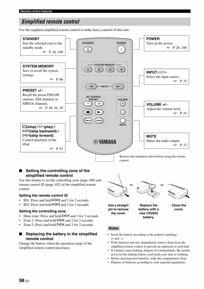
Remote control features
Use the supplied simplified remote control to make basic controls of this unit.
■ Setting the controlling zone of the simplified remote control
Use this feature to set the controlling zone (page 100) and remote control ID (page 102) of the simplified remote control.
Setting the remote control ID• ID1: Press and hold b and 1 for 3 seconds.• ID2: Press and hold b and 2 for 3 seconds.
Setting the controlling zone• Main zone: Press and hold a and 1 for 3 seconds.• Zone 2: Press and hold a and 2 for 3 seconds.• Zone 3: Press and hold a and 3 for 3 seconds.
■ Replacing the battery in the simplified remote control
Change the battery when the operation range of the simplified remote control decreases.
• Insert the battery according to the polarity markings (+ and –).
• If the batteries run out, immediately remove them from the simplified remote control to prevent an explosion or acid leak.
• If a battery starts leaking, dispose of it immediately. Be careful not to let the leaking battery acid touch your skin or clothing.
• Before inserting new batteries, wipe the compartment clean.• Dispose of batteries according to your regional regulations.
Simplified remote control
INPUT
MUTE
INT SOURCEPRESET
SYSTEM MEMORY
41 32
POWERSTANDBY
VOLUME
STANDBYSets the selected zone to the standby mode.
☞ P. 26, 100
SYSTEM MEMORYSave or recall the system settings.
☞ P. 86
INPUTl / hSelect the input source.
☞ P. 35
PRESET +/–Recall the preset FM/AM stations, XM channels or SIRIUS channels.
☞ P. 49, 54, 59
s(stop) / p(play) / b(skip backward) / a(skip forward)Control playback of the iPod.
☞ P. 63
POWERTurn on the power.
☞ P. 26, 100
VOLUME +/–Adjust the volume level.
☞ P. 35
MUTEMutes the audio output.
☞ P. 37
Remove the insulation sheet before using the remote control.
Notes
Use a straight pin to remove
the cover.
Replace the battery with a new CR2025
battery.
Close the cover.
98 En

AD
VAN
CE
D
OP
ER
AT
ION
En
glish
This unit allows you to configure a multi-zone audio system. The multi-zone configuration feature enables you to set this unit to reproduce separate input sources in the main zone, second zone (Zone 2) and third zone (Zone 3). You can control this unit from the second or third zone using the supplied remote control.
You need the following additional equipment to use the multi-zone functions of this unit:• An infrared signal receiver in the second zone and/or third zone.• An infrared signal emitter in the main zone. This emitter transmits the infrared signals from the remote control via the
infrared signal receiver in the second zone and/or third zone to a CD player or a DVD player, etc. in the main zone.• An amplifier and speakers in the second zone and/or third zone.
y• Since there are many possible ways to connect and use this unit in a multi-zone configuration, we recommend that you consult with
your nearest authorized Yamaha dealer or service center about the Zone 2 and Zone 3 connections that best meet your requirements.• Some Yamaha models are able to connect directly to the REMOTE jacks of this unit. If you own these products, you may not need to
use an infrared signal emitter. Up to 6 Yamaha components can be connected as shown below.
■ Using external amplifiersTo use an external amplifier in the second zone and/or third zone, connect the external amplifier to ZONE OUT jacks and set “AMP” to “EXT” (page 85).
• To avoid unexpected noise, DO NOT use the Zone 2/Zone 3 feature with CDs encoded in DTS.• Adjust the the second zone and/or third zone volume by using the amplifier in each zone when “VOLUME” are set to “FIX” (page 85).
Using multi-zone configuration
Only analog signals are sent to the second and third zones. Any source you want to listen to in the second zone and third zone must be connected to the analog AUDIO IN jacks of this unit.
Connecting the Zone 2 and Zone 3 components
Notes
OUTOUT IN
REMOTE
IN
REMOTE
OUT IN
REMOTE REMOTE
This unit Yamaha component
Yamaha component
Infrared signal receiver
MAIN
ZONE 2
ZONE 3
Infrared signal emitter
DVD player etc.
Amplifier
Remote control
Infrared signal receiver
Amplifier
Remote control
Infrared signal receiver
Second zone (Zone 2)
Third zone (Zone 3)Main zone
This unit
From the ZONE OUT (ZONE 2) jacks
From the ZONE OUT (ZONE 3) jacks
To the REMOTE IN jack
To the REMOTE IN jackFrom the REMOTE OUT jack
Analog audio signals only
99 En

Using multi-zone configuration
■ Using the internal amplifiers of this unit
If you want to use one internal amplifier (SP1 or SP2) of this unitConnect the Zone 2 or Zone 3 speakers directly to the SP1 or SP2 speaker terminals and set “AMP” to “[SP1]” or “[SP2]” (page 85).
If you want to use two internal amplifiers (SP1 and SP2) of this unitConnect the Zone 2 and Zone 3 speakers directly to the SP1 and SP2 speaker terminals and set “AMP” to “BOTH” (page 85).
You can select the zone you want to control by using the control buttons on the front panel or on the remote control.
■ Basic operation
Front panel operations
1 Press PZONE 2 or PZONE 3 on the front panel to individually turn on or off Zone 2 or Zone 3.
2 Press PZONE CONTROLS on the front panel repeatedly to select the zone you want to control.
Each time you press PZONE CONTROLS, the front panel display changes as shown below, and the indicator for the currently selected zone flashes for approximately 10 seconds. However, no indicator flashes when the main zone is selected.
ZONE2Controls the Zone 2 amplifier or tuner functions.
ZONE3Controls the Zone 3 amplifier or tuner functions.
yYou must complete this step within 10 seconds while the selected zone flashes in the front panel display. Otherwise, the currently selected zone mode is automatically canceled.
3 Perform the desired operation in the selected zone (page 101).
yTo turn off the desired zone, press PZONE 2 or PZONE 3 again.
Remote control operations
1 Press GZONE repeatedly to select the zone you want to control.“MAIN”, “ZONE 2”, or “ZONE 3” indicator appears in the display window (4) on the remote control.
Important safety notice
The SP1 or SP2 speaker terminals of this Receiver should not be connected to a Passive Loudspeaker Selector Box or more than one loudspeaker per channel.Connection to a Passive Loudspeaker Selector Box or multiple speakers per channel could create an abnormally low impedance load resulting in amplifier damage. See this owner’s manual for correct usage.Compliance with minimum speaker impedance information for all channels must be maintained at all times. This information is found on the back panel of your Receiver.
R L
+
–
SP2
SINGLE
R L+–+ –
BI-AMPSURROUND BACK/
PRESENCE/ZONE 2/ZONE 3ZONE 2/ZONE 3
R L
SP1
+–+ –
Third zone (Zone 3)
This unit
Second zone (Zone 2)
Controlling Zone 2 or Zone 3
ZONE2 ZONE3
No indicator flashes when the main zone is selected.
MAINZONE 2 ZONE 3(Zone 2) (Zone 3) (Main zone)
100 En

Using multi-zone configurationA
DVA
NC
ED
O
PE
RA
TIO
NE
ng
lish
2 Press EPOWER to turn on the selected zone.
3 Perform the desired operation in the selected zone (page 101).
yTo turn off the desired zone, press CSTANDBY.
■ Selecting the input source of Zone 2 or Zone 3
Rotate the CINPUT selector (or set the operation mode selector to EAMP and then press one of the input selector buttons (3)).
• Select “TUNER” as the input source to use the FM/AM tuning features (page 47) in the selected zone.
• Select “XM” as the input source to use the XM Satellite Radio features (page 52) in the selected zone.
• Select “SIRIUS” as the input source to use the SIRIUS Satellite Radio features (page 57) in the selected zone.
• Select “DOCK” as the input source to use the iPod features (page 63) or Bluetooth features (page 65) in the selected zone.
The input sources are shared across all zones. You cannot select the same input source in multiple zones simultaneously.
■ Adjusting the volume level of Zone 2 or Zone 3
Rotate QVOLUME (or press IVOLUME +/–) .
yPress KMUTE on the remote control to mute the sound output to the selected zone.
When you use the external amplifiers in Zone 2 or Zone 3, IVOLUME +/– can be used only when “VOLUME” is set to “VAR” in “ZONE SET” (page 85).
■ Adjusting the front speaker balance of Zone 2 or Zone 3
Press ETONE CONTROL repeatedly to select “BALANCE” and then rotate the NPROGRAM selector for adjustment.
■ Adjusting the tonal quality of Zone 2 or Zone 3
Press ETONE CONTROL repeatedly to select the high-frequency response (TREBLE) or the low-frequency response (BASS) and then rotate the NPROGRAM selector for adjustment.Control range: -10.0 dB to +10.0 dB
■ Setting the sleep timer for Zone 2 or Zone 3
Use this feature to turn of the desired zone after a certain amount of time.
Set the operation mode to EAMP and then press BSLEEP repeatedly to set the amount of time.The sleep timer setting changes as shown below.
Note
Note
120min. 90min.
60min.30min.OFF
101 En

This unit has additional menus that are displayed in the front panel display. The advanced setup menu offers additional operations to adjust and customize the way this unit operates. Change the initial settings (indicated in bold under each parameter) to reflect the needs of your listening environment.
• Only AMASTER ON/OFF, OSTRAIGHT and the NPROGRAM selector are effective while you are using the advanced setup menu.
• All the other operations cannot be made while you are using the advanced setup menu.• The advanced setup menu is only available in the front panel display.
1 Press AMASTER ON/OFF on the front panel to release it outward to the OFF position to turn off this unit.
2 Press and hold OSTRAIGHT and then press AMASTER ON/OFF inward to the ON position to turn on this unit.This unit turns on, and “ADVANCED SETUP” appears in the front panel display.
3 Rotate the NPROGRAM selector to select the parameter you want to adjust.
4 Press OSTRAIGHT repeatedly to change the selected parameter setting.
5 Press AMASTER ON/OFF to release it outward to the OFF position to save the new setting and turn off this unit.
yThe settings you made are reflected next time you turn on this unit.
■ Speaker impedance SPEAKER IMP.
Use this feature to set the speaker impedance of this unit so that it matches that of your speakers.
■ Remote sensor REMOTE SENSOR
Use this feature to activate or deactivate the signal-receiving capability of the remote control sensor on the front panel of this unit.
We recommend setting the parameter to “ON” in most cases.
■ Wake on RS-232C accessRS-232C STANDBY
Use this feature to set this unit to transmit data via the RS-232C interface when this unit is in the standby mode.
Initial setting:[U.S.A. and Canada models]: YES[Other models]: NO
■ Remote control ID settingREMOTE CON AMP
Use this feature to set the remote control ID of this unit for remote control recognition.
Setting remote control IDUse this feature to set the remote control ID. This feature is useful when you control multiple Yamaha AV receiver or amplifier with using the remote control.
Advanced setup
Notes
Using the advanced setup menu
Choice Descriptions
8ΩMIN Select this setting to set the speaker impedance to 8 Ω. The impedance of each speaker must be 8 Ω or higher.
6ΩMIN Select this setting to set the speaker impedance to 6 Ω. The impedance of each speaker must be 6 Ω or higher (front speakers only: 4 Ω or higher).
EFFECT
STRAIGHT
MASTER
While holding down
Choice Descriptions
ON Select this setting if you want to activate the signal-receiving capability of the remote control sensor.
OFF Select this setting if you want to deactivate the signal-receiving capability of the remote control sensor.
Note
Choice Functions
YES Select this setting to set this unit to transmit data via the RS-232C interface.
NO Select this setting to set this unit not to transmit data via the RS-232C interface.
Choice Descriptions
ID1 Select this setting when the ID of the remote control is set to “ID1”
ID2 Select this setting when the ID of the remote control is set to “ID2”
102 En

Advanced setupA
DVA
NC
ED
O
PE
RA
TIO
NE
ng
lish
Press FID repeatedly using a ballpoint pen or similar object on the remote control to select the desired remote control ID.Each time you press FID, the remote control ID indicator changes as shown below.
yTo set the remote control ID of the simplified remote control, see page 98 for details.
■ SIRIUS Satellite Radio Parental Lock code number reset SIRIUS PIN (U.S.A. and Canada models only)
Use this feature to set the code number for the SIRIUS Satellite Radio Parental Lock feature to the initial factory setting.
■ Tuner frequency step TUNER FRQ STEP(Asia and General models only)
Use this feature to set the tuner frequency step according to the frequency spacing in your area.
■ Bi-amplifier mode BI-AMP
Use this feature to activate or deactivate the bi-amplifier function.
When “BI-AMP” is set to “ON”, the SURROUND BACK terminals cannot be used to connect surround back speakers in that the terminals are already used for the bi-amplifier connection (page 15).
■ Parameter initialization INITIALIZE
Use this feature to reset the parameters of this unit to the initial factory settings. You can select the category of parameters to be initialized.
yTo initialize the parameters of each sound field program, use "INITIALIZE" in the sound field program menu (page 67).
■ HDMI monitor check MONITOR CHECK
Use this feature to activate or deactivate the monitor check function of this unit.
Choice Descriptions
RESET Sets the code number to the initial factory setting.
CANCEL Cancels the reset of the code number.
Choice Descriptions
AM10/FM100
Select this setting for North, Central and South America.
AM9/FM50 Select this setting for all other countries.
Choice Descriptions
ON Select this setting if you want to activate the bi-amplifier function.
OFF Select this setting if you want to deactivate the bi-amplifier function.
Note
ID
ID1
ID2
Choice Descriptions
DSP PARAM
Select this setting to initialize all the parameters of the sound field parameters (page 67).
VIDEO Select this setting to initialize all the parameters in “VIDEO MENU” and “OSD SHIFT” and “GRAY BACK” in “DISPLAY SET”.
ALL Select this setting to initialize all the parameters of this unit.
CANCEL Select this setting to cancel the initialization procedure.
Choice Descriptions
YES This unit receives the information of the available video signal resolutions from the video monitor connected via HDMI and you can only select the resolutions supported by the video monitor in “HDMI RES.” (page 81).
SKIP You can select any resolution in “HDMI RES.” (page 81).
103 En

TROUBLESHOOTING
Refer to the table below when this unit does not function properly. If the problem you are experiencing is not listed below or if the instruction below does not help, turn off this unit, disconnect the power cable, and contact the nearest authorized Yamaha dealer or service center.
■ General
Troubleshooting
Problem Cause RemedySee
page
This unit fails to turn on or enters the standby mode soon after the power is turned on.
The power cable is not connected or the plug is not completely inserted.
Connect the power cable firmly. —
The speaker impedance setting is incorrect.
Set the speaker impedance to match your speakers. 26
The protection circuitry has been activated.
Make sure that all speaker wire connections on this unit and on all speakers are secure and that the wire for each connection does not touch anything other than its respective connection.
13
This unit has been exposed to a strong external electric shock (such as lightning or strong static electricity).
Turn off this unit, disconnect the power cable, plug it back in after 30 seconds and then use it normally.
—
No sound. Incorrect input or output cable connections.
Connect the cables properly. If the problem persists, the cables may be defective.
19-24
Audio input jack select is set to “HDMI”, “COAX/OPT” or “ANALOG”.
Set the audio input jack select to “AUTO”. 36
Audio input jack select is set to “ANALOG” while the input source component outputs digital audio signals.
Set the audio input jack select to “AUTO” or “COAX/OPT”.
36
No appropriate input source has been selected.
Select an appropriate input source with the CINPUT selector (or the input selector buttons (3) ).
35, 36
Speaker connections are not secure. Secure the connections. 13
The volume is turned down or muted. Turn up the volume. —
Signals this unit cannot reproduce are being input from a source component, such as a CD-ROM.
Play a source whose signals can be reproduced by this unit.
—
The HDMI components connected to this unit do not support the HDCP copy protection standards.
Connect HDMI components that support the HDCP copy protection standards.
17
104 En

TroubleshootingA
DD
ITIO
NA
L
INF
OR
MA
TIO
NE
ng
lish
No picture. The output and input for the picture are connected to different types of video jacks.
Set “VIDEO CONV.” to “ON” or connect your source components in the same way as you connect your video monitor to this unit.
80
1080p-resolution analog video signals are only output at the COMPONENT VIDEO MONITOR OUT jacks.
Connect your video monitor to the COMPONENT VIDEO MONITOR jacks.
19
480p-, 576p-, 1080i- and 720p-resolution video signals cannot be output at the S VIDEO and VIDEO MONITOR OUT jacks.
Connect your video monitor to the HDMI OUT or COMPONENT VIDEO MONITOR OUT jacks.
—
This unit outputs the video signals are not supported on the video monitor connected to the HDMI OUT jack.
Select “INITIALIZE” in “VIDEO” to reset the video parameters.
103
Set “MONITOR CHECK” to “YES”. 103
Pure Direct mode is active. Turn off the Pure Direct mode. 46
Set “MODE” in “PURE DIRECT” to “AUDIO+VIDEO”.
80
Non-standard video signals are input.
Short message displays do not appear on the video monitor.
“SHORT MESSAGE” is set to “OFF”. Set “SHORT MESSAGE” to “ON”. 84
“GRAY BACK” is set to “OFF”. Set “GRAY BACK” to “AUTO”. 83
“VIDEO CONV.” is set to “OFF”. Set “VIDEO CONV.” to “ON”. 80
The signals input at the HDMI input jacks are being output at the HDMI OUT jack.
Video signals in the progressive format or HDTV video signals are being input.
The sound suddenly goes off.
The protection circuitry has been activated because of a short circuit, etc.
Check that the speaker impedance setting is correct. 26, 102
Check that the speaker wires are not touching each other and then turn this unit back on.
—
The sleep timer has turned off this unit. Turn on this unit, and play the source again. —
Sound is heard from the speaker on one side only.
Incorrect cable connections. Connect the cables properly. If the problem persists, the cables may be defective.
13
The speaker level settings are incorrect. Adjust “LEVEL” settings. 76
Only the center speaker outputs substantial sound.
When playing a monaural source with a CINEMA DSP program, the source signal is directed to the center channel, and the front and surround speakers output effect sounds.
No sound is heard from the center speaker.
“CENTER SP” in “CONFIG” is set to “NONE”.
Set “CENTER SP” to “SMALL” or “LARGE”. 75
No sound is heard from the presence speakers.
This unit is in the “STRAIGHT” mode. Press OSTRAIGHT to turn off the “STRAIGHT” mode.
45
You are using a source or program combination that does not output sound from all channels.
Try another sound field program. 35
Problem Cause RemedySee
page
105 En

Troubleshooting
No sound is heard from the surround speakers.
“SUR. L/R SP” in “CONFIG” is set to “NONE”.
Set “SUR. L/R SP” to “SMALL” or “LARGE”. 75
This unit is in the “STRAIGHT” mode and a monaural source is being played back.
Press OSTRAIGHT to turn off the “STRAIGHT” mode.
45
The surround speakers are connected to the SURROUND BACK speaker terminals.
Connect the surround speakers to the SURROUND speaker terminals.
45
No sound is heard from the subwoofer.
“LFE/BASS OUT” in “CONFIG” is set to “FRONT” when a Dolby Digital or DTS signal is being played.
Set “LFE/BASS OUT” to “SWFR” or “BOTH”. 75
“LFE/BASS OUT” in “CONFIG” is set to “SWFR” or “FRONT” when a 2-channel source is being played.
Set “LFE/BASS OUT” to “BOTH”. 75
The source does not contain low-frequency signals.
No sound is heard from the surround back speakers.
"SUR.B L/R SP" is set to "NONE". Check whether "SUR. L/R SP" is set to "SMALL" or "LARGE" and configure "SUR.B L/R SP" properly.
75, 76
While this unit is in the CINEMA DSP 3D mode, no sound is output at the surround back speakers.
The audio input sources cannot be played in the desired digital audio signal format (Desired input source indicator or decoder indicator in the front panel display does not light up).
The connected component is not set to output the desired digital audio signals.
Make an appropriate setting following the operating instructions for your component.
—
Audio input jack select is set to “ANALOG”.
Set the audio input jack select to “AUTO”. 36
A humming sound is heard.
Incorrect cable connections. Connect the audio cables firmly. If the problem persists, the cables may be defective.
—
No connection from the turntable to the GND terminal.
Connect the grounding cable of the turntable to the GND terminal of this unit.
22
The volume level is low while a record is being played.
The record is being played on a turntable with an MC cartridge.
Connect your turntable to this unit through an MC-head amplifier.
22
The volume level cannot be increased, or the sound is distorted.
The component connected to the AUDIO OUT (REC) jacks of this unit is turned off.
Turn on the power of the component. —
A source cannot be recorded by the recording component.
The audio source connected to the MULTI CH INPUT jacks of this unit cannot be recorded.
A given input source is not output at the same output channel (e.g. DVR IN to DVR OUT).
Connect the recording component to another channel that is not being used for connecting the source component.
21
You are trying to record a DTS source. (DTS signal is a digital bitstream. Attempting to record the DTS bitstream digitally will result in noise being recorded.)
Make a setting so that the analog signal will be output from your DTS-compatible player and then connect the DTS-compatible player to the AUDIO IN jacks while the recording component is connected to the analog AUDIO OUT (DVR, VCR or MD/CD-R) jacks.
21
Problem Cause RemedySee
page
106 En

TroubleshootingA
DD
ITIO
NA
L
INF
OR
MA
TIO
NE
ng
lish
An audio source cannot be recorded by the digital recording component connected to the DIGITAL OUTPUT jacks.
The audio source component is not connected to the DIGITAL INPUT jacks.
Connect the audio source component to the DIGITAL INPUT jacks.
21
Some components cannot records Dolby Digital or DTS sources.
You are trying to record an audio source input at the DOCK terminal by the digital recording component connected to the DIGITAL OUTPUT jacks.
Connect the recording component to the analog AUDIO OUT (DVR, VCR or MD/CD-R) jacks.
21
(U.S.A. model only)HD Radio signals are not output at the DIGITAL OUTPUT jacks
Connect the recording component to the analog AUDIO OUT (DVR, VCR or MD/CD-R) jacks.
21
An audio source cannot be recorded by the analog recording component connected to the analog AUDIO OUT (DVR, VCR or MD/CD-R) jacks.
The audio source component is not connected to the analog AUDIO IN jacks.
Connect the audio source component to the AUDIO IN jacks.
21
XM Satellite Radio and SIRIUS Satellite Radio signals are not output at the analog AUDIO OUT (DVR, VCR or MD/CD-R) jacks.
Recorded materials sound differently.
The settings made on this unit (such as tonal quality, volume level and sound field programs) do not affect recorded material.
A video source cannot be recorded by the recording component.
"VIDEO CONV." is set to "ON". While "VIDEO CONV." is set to "ON", video signals are output only at the MONITOR OUT jacks. To record a video source by the recording component, set "VIDEO CONV." to "OFF" and make the same type of video connections between each component (e.g. VCR IN (S VIDEO) to DVR OUT (S VIDEO).
21, 80
The sound field parameters and some other settings of this unit cannot be changed.
“MEMORY GUARD” in “SET MENU” is set to “ON”.
Set “MEMORY GUARD” to “OFF”. 84
This unit does not operate properly.
The internal microcomputer has been frozen by an external electric shock (such as lightning or excessive static electricity) or by a power supply with low voltage.
Disconnect the power cable from the AC wall outlet and then plug it in again after about 30 seconds.
—
“CHECK SP WIRES” appears in the front panel display.
Speaker cables are short-circuited. Make sure all speaker cables are connected correctly. 13
There is noise interference from digital or radio frequency equipment.
This unit is too close to the digital or high-frequency equipment.
Move this unit further away from such equipment. —
The picture is disturbed.
The video source uses scrambled or encoded signals to prevent dubbing.
This unit suddenly enters the standby mode.
The internal temperature becomes too high and the overheat protection circuitry has been activated.
Wait about 1 hour for this unit to cool down and then turn it back on.
—
Problem Cause RemedySee
page
107 En

Troubleshooting
■ HDMI
■ Tuner (FM/AM)
■ HD Radio (U.S.A. model only)
Problem Cause RemedySee
page
No picture or sound. The number of the connected HDMI components is over the limit.
Reduce the number of the connected HDMI components.
—
HDCP authentication failed. Check that the connected HDMI components support the HDCP copy protection standards.
—
Problem Cause RemedySee
page
FM
FM stereo reception is noisy.
The characteristics of FM stereo broadcasts may cause this problem when the transmitter is too far away or the antenna input is poor.
Check the antenna connections. 24
Try using a high-quality directional FM antenna.
—
Use the manual tuning method. 47
There is distortion, and clear reception cannot be obtained even with a good FM antenna.
There is multi-path interference. Adjust the antenna position to eliminate multi-path interference.
—
The desired station cannot be tuned into with the automatic tuning method.
The signal is too weak. Use a high-quality directional FM antenna. —
Use the manual tuning method. 47
Previously preset stations can no longer be tuned into.
This unit has been disconnected for a long period.
Preset the stations again. 48
AM
The desired station cannot be tuned into with the automatic tuning method.
The signal is weak or the antenna connections are loose.
Tighten the AM loop antenna connections and orient it for the best reception.
24
Use the manual tuning method. 47
There are continuous crackling and hissing noises.
Supplied AM loop antenna is not connected.
Connect the AM loop antenna correctly even if you use an outdoor antenna.
24
Noises can result from lightning, fluorescent lamps, motors, thermostats and other electrical equipment.
Use an outdoor antenna and a ground wire. This will help somewhat, but it is difficult to eliminate all noise.
24
There are buzzing and whining noises.
A TV set is being used nearby. Move this unit away from the TV set. —
Problem Cause RemedySee
page
This unit cannot receive the HD Radio signals of the selected radio station.
The radio station provides analog FM/AM radio service only.
Select other radio stations that provides the HD Radio service.
47
The signal is too weak. Adjust the antenna position. —
Use a high-quality FM/AM antenna. —
This unit cannot select other audio programs than the main program.
The radio station provides an audio program only.
HD Radio information does not appear.
The radio station does not provide the information.
108 En

TroubleshootingA
DD
ITIO
NA
L
INF
OR
MA
TIO
NE
ng
lish
■ XM Satellite RadioIf an operation takes longer than usual or an error occurs, one of the following messages may appear in the front panel display. In this case, read the cause and follow the corresponding remedies.
Status message Cause RemedySee
page
CHECK XM TUNER The XM Mini-Tuner is not installed in the XM Mini-Tuner Home Dock or the is not connected to this unit.
Confirm the XM Mini-Tuner is fully seated in the dock and check the XM Mini-Tuner Home Dock cable is connected to this unit.
52
CHECK ANTENNA The XM antenna is not connected to the XM Mini-Tuner Home Dock or the XM antenna cable has become damaged.
Check that the XM antenna is securely connected to the XM Mini-Tuner Home Dock and check the antenna cable for damage. Replace the XM antenna if the cable is damaged.
52
LOADING The XM Mini-Tuner is acquiring audio or program information from the XM satellite signal. This message can also occur in weak XM signal conditions. Note that this unit may not respond to some operations while this message is displayed.
This message should disappear in a few seconds in good signal conditions. If you see this message often, reposition the XM antenna to get better signal reception. Use the “ANTENNA INFO” information in the front panel or “XM Information” screen in the OSD to check the antenna reception level.
56
NO SIGNAL The XM Mini-Tuner is not receiving the XM satellite signal. Something may be blocking the XM antenna’s view of the satellites or the antenna is not properly aimed.
Check for antenna obstructions and reposition the XM antenna to get better signal reception. Use the “ANTENNA INFO” information in the front panel or “XM Information” screen in the OSD to check the antenna reception level. See instructions supplied with the XM Mini-Tuner and Dock for antenna installation information.
56
CH OFF AIR The XM channel you selected is not currently broadcasting.
Check back at a later time; in the meantime, select another channel.
—
CH UNAUTH You may be attempting to tune to an XM channel that is blocked or that you cannot receive with your XM subscription package.
Consult the latest channel guide at http://www.xmradio.com/ (US residents) and http://www.xmradio.ca/ (Canadian residents) for the current list of channels. For information on receiving this channel, visit http://www.xmradio.com/ (US residents) and http://www.xmradio.ca/ (Canadian residents) or contact XM Satellite Radio at 1-800-967-2346 (US residents) and 1-877-438-9677 (Canadian residents).
52
CH UNAVAIL The selected channel is not available. The channel may have been reassigned to a different channel number. This message may occur initially with a new XM Mini-Tuner or an XM Mini-Tuner that has not received XM’s signal for an extended period.
Consult the latest channel guide at http://www.xmradio.com/ (US residents) and http://www.xmradio.ca/ (Canadian residents) for the current list of channels. For cases of a new XM Mini-Tuner or an XM Mini-Tuner that has not received XM’s signal for an extended period, allow the XM Mini-Tuner to receive the XM satellite signal for at least 5 minutes and then try to select the channel again.
—
- - - - No artist name or song title is available for this selection.
No action required. —
109 En

Troubleshooting
■ SIRIUS Satellite RadioIf an operation takes longer than usual or an error occurs, one of the following messages may appear in the front panel display. In this case, read the cause and follow the corresponding remedies.
Status message Cause RemedySee
page
ANTENNA ERROR The antenna is not connected to the SiriusConnect tuner properly.
Check the connection of the antenna and SiriusConnect tuner.
57
CHECK SR TUNER The SiriusConnect tuner is not connected to the SIRIUS jack of this unit correctly.
Check the connection of the SiriusConnect tuner and this unit.
57
The SiriusConnect tuner is not connected to the AC wall outlet.
Connect the power cable of the SiriusConnect tuner to the AC wall outlet.
57
NOT SUPPORTED This unit does not support the connected SIRIUS Satellite Radio tuner.
Connect the SiriusConnect tuner that this unit supports.
57
ACQUIRING The signal is too weak. Adjust the orientation of the antenna of the SiriusConnect tuner. Use the “ANTENNA INFO” information in the front panel display or “SIRIUS Information” screen in the OSD to check the antenna reception level.
62
UPDATING The SiriusConnect tuner is updating the channel list.
Wait until the updating is complete. —
The period of the subscription is end. Contact SIRIUS Satellite Radio to renew the subscription.
58
F/W UPDATING The SiriusConnect tuner is updating the firmware.
Wait until the updating is complete. —
CALL SIRIUS (CALL 888-539-SIRIUS TO SUBSCRIBE)
The selected channel is not subscribed. Contact SIRIUS Satellite Radio to subscribe the selected channel.URL: https://activate.siriusradio.com/Phone: 1-888-539-SIRIUS (1-888-539-7474)
58
Select another channel. 58
SUB UPDATED The subscription information is updated.
INVALID The selected channel is currently out of service.
Select another channel. 58
Not Available The operation you made is not available.
110 En

TroubleshootingA
DD
ITIO
NA
L
INF
OR
MA
TIO
NE
ng
lish
■ Remote control
Problem Cause RemedySee
page
The remote control does not work or function properly.
Wrong distance or angle. The remote control will function within a maximum range of 6 m (20 ft) and no more than 30 degrees off-axis from the front panel.
28
Direct sunlight or lighting (from an inverter type of fluorescent lamp, etc.) is striking the remote control sensor of this unit.
Reposition this unit. —
The batteries are weak. Replace all batteries. 5
The operation mode selector is set incorrectly.
Set the operation mode selector correctly. When operating this unit, set it to the EAMP position. When operating the component selected by the input selector button, set it to the ESOURCE position. When operating the TV set in the 3TV area, set it to the ETV position.
—
The control zone setting is incorrect. Select the zone you want to control. 100
The remote control code is not correctly set.
Set the remote control code correctly using “List of remote control codes” at the end of this manual.
91
Try setting another code of the same manufacturer using “List of remote control codes” at the end of this manual.
91
The remote control ID of the remote control and this unit do not match.
Match the remote control ID of this unit and the remote control.
98, 102
Even if the remote control code is correctly set, there are some models that do not respond to the remote control.
Program the necessary functions independently into the programmable buttons using the Learn feature.
93
The remote control does not learn new functions.
The batteries of this remote control and/or the other remote control are too weak.
Replace the batteries. 5
The distance between the two remote controls is too much or too little.
Place the remote controls at the proper distance. 93
The signal coding or modulation of the other remote control is not compatible with this remote control.
Learning is not possible. —
Memory capacity is full. Delete other unnecessary functions to make room for the new functions.
97
111 En

Troubleshooting
■ iPod
In case of a transmission error without a status message appearing in the front panel and in the OSD, check the connection of your iPod (page 23).
■ Bluetooth
Note
Status message Cause RemedySee
page
Loading... This unit is in the middle of recognizing the connection with your iPod.
This unit is in the middle of acquiring song lists from your iPod.
Connect error There is a problem with the signal path from your iPod to this unit.
Turn off this unit and reconnect the Yamaha iPod universal dock to the DOCK terminal of this unit.
23
Try resetting your iPod. —
Unknown iPod The iPod being used is not supported by this unit.
This unit supports iPod touch, iPod (Click Wheel, including iPod classic), iPod nano and iPod mini.
—
iPod connected Your iPod is properly stationed in a Yamaha iPod universal dock (such as YDS-11, sold separately) connected to the DOCK terminal of this unit, and the connection between your iPod and this unit is complete.
Disconnected Your iPod was removed from a Yamaha iPod universal dock (such as YDS-11, sold separately) connected to the DOCK terminal of this unit.
Station your iPod back in a Yamaha iPod universal dock (such as YDS-11, sold separately) connected to the DOCK terminal of this unit.
23
Unable to play This unit cannot play back the songs currently stored on your iPod.
Check that the songs currently stored on your iPod are playable.
—
Store some other playable music files on your iPod. —
Status message Cause RemedySee
page
Searching... The Bluetooth receiver and the Bluetooth component is in the middle of the pairing.
The Bluetooth receiver and the Bluetooth component is in the middle of establishing the connection.
Completed The pairing is completed.
Canceled The pairing is canceled.
BT connected The connection between the Yamaha Bluetooth wireless audio receiver (such as YBA-10, sold separately) and the Bluetooth component is established.
Disconnected The Bluetooth component is disconnected from the Yamaha Bluetooth wireless audio receiver (such as YBA-10, sold separately).
No BT receiver The Bluetooth receiver is not connected to the DOCK terminal.
Connect the Yamaha Bluetooth wireless audio receiver (such as YBA-10, sold separately) to the DOCK terminal.
23
112 En

TroubleshootingA
DD
ITIO
NA
L
INF
OR
MA
TIO
NE
ng
lish
■ AUTO SETUP
Before AUTO SETUP
During AUTO SETUP
Error message Cause RemedySee
page
Connect MIC! Optimizer microphone is not connected. Connect the supplied optimizer microphone to the OPTIMIZER MIC jack on the front panel.
30
Unplug HP! Headphones are connected. Unplug the headphones. —
Memory Guard! The parameters of this unit are protected. Set “MEMORY GUARD” to “OFF”. 84
Error message Cause RemedySee
page
E-1:NO FRONT SP Front L/R channel signals are not detected. Check the front L/R speaker connections. 13
E-2:NO SUR. SP A surround channel signal is not detected. Check the surround speaker connections. 13
E-3:NO PRNS SP A presence channel signal is not detected. Check the presence speaker connections. 13
E-4:SBR.SBL Only right surround back channel signal is detected.
Connect the surround back speaker to the SURROUND BACK (SINGLE) speaker terminal if you only have one surround back speaker.
13
E-5:NOISY Background noise is too loud. Try running “AUTO SETUP” in a quiet environment.
—
Turn off noisy electric equipment like air conditioners or move them away from the optimizer microphone.
—
E-6:CHECK SUR. Surround back speakers are connected, though surround L/R speakers are not.
Connect surround speakers when you use surround back speakers.
14
E-7:NO MIC The optimizer microphone was unplugged during the “AUTO SETUP” procedure.
Connect the supplied optimizer microphone to the OPTIMIZER MIC jack on the front panel.
30
E-8:NO SIGNAL The optimizer microphone does not detect test tones.
Check the microphone setting. 30
Check the speaker connections and placement.
13
The optimizer microphone or OPTIMIZER MIC jack may be defective. Contact the nearest Yamaha dealer or service center.
—
E-9:USER CANCEL The “AUTO SETUP” procedure was cancelled due to user activity.
Run “AUTO SETUP” again. 30
E-10:INTERNAL ERROR An internal error occurred. Run “AUTO SETUP” again. 30
113 En

Troubleshooting
After AUTO SETUP
• If the “ERROR” or “WARNING” screens appears, check the cause of the problem, then run “AUTO SETUP” again.• If warning message “W-2” or “W-3” appears, the adjustments are made, however the adjustment may not be optimal.• Depending on the speakers, warning message “W-1” may appears even if the speaker connections are correct.• If error message “E-10” occurs repeatedly, contact a qualified Yamaha service center.
Warning message Cause RemedySee
page
W-1:OUT OF PHASE Speaker polarity is not correct. This message may appear depending on the speakers even when the speakers are connected correctly.
Check the speaker connections for proper polarity (+ or –).
13
W-2:OVER 24m (80ft) The distance between the speaker and the listening position is over 24 m (80 ft).
Bring the speaker closer to the listening position.
—
W-3:LEVEL ERROR The difference of volume level among speakers is excessive.
Readjust the speaker installation so that all speakers are set in locations with similar conditions.
—
Check the speaker connections. 13
Use speakers of similar quality. —
Adjust the output volume of the subwoofer. 30
Notes
114 En
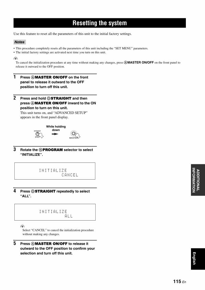
RESETTING THE SYSTEMA
DD
ITIO
NA
L
INF
OR
MA
TIO
NE
ng
lish
Use this feature to reset all the parameters of this unit to the initial factory settings.
• This procedure completely resets all the parameters of this unit including the “SET MENU” parameters.• The initial factory settings are activated next time you turn on this unit.
yTo cancel the initialization procedure at any time without making any changes, press AMASTER ON/OFF on the front panel to release it outward to the OFF position.
1 Press AMASTER ON/OFF on the front panel to release it outward to the OFF position to turn off this unit.
2 Press and hold OSTRAIGHT and then press AMASTER ON/OFF inward to the ON position to turn on this unit.This unit turns on, and “ADVANCED SETUP” appears in the front panel display.
3 Rotate the NPROGRAM selector to select “INITIALIZE”.
4 Press OSTRAIGHT repeatedly to select “ALL”.
ySelect “CANCEL” to cancel the initialization procedure without making any changes.
5 Press AMASTER ON/OFF to release it outward to the OFF position to confirm your selection and turn off this unit.
Resetting the system
Notes
EFFECT
STRAIGHT
MASTER
While holding down
I N I T I A L I Z EC A N C E L
I N I T I A L I Z EA L L
115 En

GLOSSARY
■ Audio and video synchronization (lip sync)
Lip sync, an abbreviation for lip synchronization, is a technical term that involves both a problem and a capability of maintaining audio and video signals synchronized during post-production and transmission. Whereas the audio and video latency requires complex end-user adjustments, HDMI version 1.3 incorporates an automatic audio and video syncing capability that allows devices to perform this synchronization automatically and accurately without user interaction.
■ Bi-amplification connectionA bi-amplification connection uses two amplifiers for a speaker. One amplifier is connected to the woofer section of a loudspeaker while the other is connected to the combined mid and tweeter section. With this arrangement each amplifier operates over a restricted frequency range. This restricted range presents each amplifier with a much simpler job and each amplifier is less likely to influence the sound in some way. The internal crossover of the speaker consists of a LPF (low pass filter) and a HPF (high pass filter). As its name implies, the LPF passes frequencies below a cutoff and rejects frequencies above the cutoff frequency. Likewise, the HPF passes frequencies above its cutoff.
■ Component video signalWith the component video signal system, the video signal is separated into the Y signal for the luminance and the PB and PR signals for the chrominance. Color can be reproduced more faithfully with this system because each of these signals is independent. The component signal is also called the “color difference signal” because the luminance signal is subtracted from the color signal. A monitor with component input jacks is required in order to output component signals.
■ Composite video signalWith the composite video signal system, the video signal is composed of three basic elements of a video picture: color, brightness and synchronization data. A composite video jack on a video component transmits these three elements combined.
■ Deep ColorDeep Color refers to the use of various color depths in displays, up from the 24-bit depths in previous versions of the HDMI specification. This extra bit depth allows HDTVs and other displays go from millions of colors to billions of colors and eliminate on-screen color banding for smooth tonal transitions and subtle gradations between colors. The increased contrast ratio can represent many times more shades of gray between black and white. Also Deep Color increases the number of available colors within the boundaries defined by the RGB or YcbCr color space.
■ Dolby DigitalDolby Digital is a digital surround sound system that gives you completely independent multi-channel audio. With 3 front channels (front L/R and center), and 2 surround stereo channels, Dolby Digital provides 5 full-range audio channels. With an additional channel especially for bass effects, called LFE (Low Frequency Effect), the system has a total of 5.1-channels (LFE is counted as 0.1 channel). By using 2-channel stereo for the surround speakers, more accurate moving sound effects and surround sound environment are possible than with Dolby Surround. The wide dynamic range from maximum to minimum volume reproduced by the 5 full-range channels and the precise sound orientation generated using digital sound processing provide listeners with unprecedented excitement and realism. With this unit, any sound environment from monaural up to a 5.1-channel configuration can be freely selected for your enjoyment.
■ Dolby Digital EXDolby Digital EX creates 6 full-bandwidth output channels from 5.1-channel sources. This is done using a matrix decoder that derives 3 surround channels from the 2 in the original recording. For the best results, Dolby Digital EX should be used with movie sound tracks recorded with Dolby Digital Surround EX. With this additional channel, you can experience more dynamic and realistic moving sound especially with scenes with “fly-over” and “fly-around” effects.
■ Dolby Digital PlusDolby Digital Plus is an advanced audio technology developed for high-definition programming and media including HD broadcasts, HD DVD, and Blu-ray Disc. Selected as a mandatory audio standard for HD DVD and as an optional audio standard for Blu-ray Disc, this technology delivers multichannel sound with discrete channel output. Supporting bitrates up to 6.0 Mbps, Dolby Digital Plus can carry up to 7.1 discreet audio channels simultaneously. Supported by HDMI version 1.3 and designed for the optical disc players and AV receivers/amplifiers of the future, Dolby Digital Plus also remains fully compatible with the existing multichannel audio systems that incorporate Dolby Digital.
■ Dolby Pro Logic IIDolby Pro Logic II is an improved technique used to decode vast numbers of existing Dolby Surround sources. This new technology enables a discrete 5-channel playback with 2 front left and right channels, 1 center channel, and 2 surround left and right channels instead of only 1 surround channel for conventional Pro Logic technology. There are three modes available: “Music mode” for music sources, “Movie mode” for movie sources and “Game mode” for game sources.
■ Dolby Pro Logic IIxDolby Pro Logic IIx is a new technology enabling discrete multi-channel playback from 2-channel or multi-channel sources. There are three modes available: “Music mode” for music sources, “Movie mode” for movie sources (for 2-channel sources only) and “Game mode” for game sources.
Glossary
116 En

GlossaryA
DD
ITIO
NA
L
INF
OR
MA
TIO
NE
ng
lish
■ Dolby SurroundDolby Surround uses a 4-channel analog recording system to reproduce realistic and dynamic sound effects: 2 front left and right channels (stereo), a center channel for dialog (monaural), and a surround channel for special sound effects (monaural). The surround channel reproduces sound within a narrow frequency range. Dolby Surround is widely used with nearly all video tapes and laser discs, and in many TV and cable broadcasts as well. The Dolby Pro Logic decoder built into this unit employs a digital signal processing system that automatically stabilizes the volume on each channel to enhance moving sound effects and directionality.
■ Dolby TrueHDDolby TrueHD is an advanced lossless audio technology developed for high-definition disc-based media including HD DVD and Blu-ray Disc. Selected as a mandatory audio standard for HD DVD and as an optional audio standard for Blu-ray Disc, this technology delivers sound that is bit-for-bit identical to the studio master, offering a high-definition home theater experience. Supporting bitrates up to 18.0 Mbps, Dolby TrueHD can carry up to 8 discrete channels of 24-bit/96 kHz audio simultaneously. Supported by HDMI version 1.3 and designed for the optical disc players and AV receivers/amplifiers of the future, Dolby TrueHD also remains fully compatible with the existing multichannel audio systems and retains the metadata capability of Dolby Digital, allowing dialog normalization and dynamic range control.
■ DSDDirect Stream Digital (DSD) technology stores audio signals on digital storage media, such as Super Audio CDs. Using DSD, signals are stored as single bit values at a high-frequency sampling rate of 2.8224 MHz, while noise shaping and oversampling are used to reduce distortion, a common occurrence with very high quantization of audio signals. Due to the high sampling rate, better audio quality can be achieved than that offered by the PCM format used for normal audio CDs.
■ DTS 96/24DTS 96/24 offers an unprecedented level of audio quality for multi-channel sound on DVD video, and is fully backward-compatible with all DTS decoders. “96” refers to a 96 kHz sampling rate compared to the typical 48 kHz sampling rate. “24” refers to 24-bit word length. DTS 96/24 offers sound quality transparent to the original 96/24 master, and 96/24 5.1-channel sound with full-quality full-motion video for music programs and motion picture soundtracks on DVD video.
■ DTS Digital SurroundDTS digital surround was developed to replace the analog soundtracks of movies with a 6.1-channel digital sound track, and is now rapidly gaining popularity in movie theaters around the world. DTS, Inc. has developed a home theater system so that you can enjoy the depth of sound and natural spatial representation of DTS digital surround in your home. This system produces practically distortion-free 6-channel sound (technically, front left and right, center, surround left and right, and LFE 0.1 (subwoofer) channels for a total of 5.1 channels). This unit incorporates a DTS-ES decoder that enables 6.1-channel reproduction by adding the surround back channel to the existing 5.1-channel format.
■ DTS ExpressDTS Express is an advanced audio technology for the optional feature on Blu-ray Disc or HD DVD, which offers high-quality, low bit rate audio optimized for network streaming, and Internet applications. DTS Express is used for the Secondary Audio feature of Blu-ray Disc or the Sub Audio feature of HD DVD. These features deliver audio commentaries (for example, the additional commentaries made by the director of a film) on demand by the users via the Internet, etc. DTS Express signals are mixed down with the main audio stream on the player component, and the component sends the mixed audio stream to the AV receivers/amplifiers via digital coaxial, digital optical, or analog connections.
■ DTS-HD High Resolution AudioDTS-HD High Resolution Audio is an high resolution audio technology developed for high-definition disc-based media including HD DVD and Blu-ray Disc. Selected as an optional audio standard for both HD DVD and Blu-ray Disc, this technology delivers sound that is virtually indistinguishable from the original, offering a high-definition home theater experience. Supporting bitrates up to 3.0 Mbps for HD DVD and 6.0 Mbps for Blu-ray Disc, DTS-HD High Resolution Audio can carry up to 7.1 discrete channels of 24-bit/96 kHz audio simultaneously. Supported by HDMI version 1.3 and designed for the optical disc players and AV receivers/amplifiers of the future, DTS-HD High Resolution Audio also remains fully compatible with the existing multichannel audio systems that incorporate DTS Digital Surround.
■ DTS-HD Master AudioDTS-HD Master Audio is an advanced lossless audio technology developed for high-definition disc-based media including HD DVD and Blu-ray Disc. Selected as a mandatory audio standard for both HD DVD and Blu-ray Disc, this technology delivers sound that is bit-for-bit identical to the studio master, offering a high-definition home theater experience. Supporting bitrates up to 18.0 Mbps for HD DVD and up to 24.5 Mbps for Blu-ray Disc, DTS-HD Master Audio can carry up to 7.1 discrete channels of 24-bit/96 kHz audio simultaneously. Supported by HDMI version 1.3 and designed for the optical disc players and AV receivers/amplifiers of the future, DTS-HD Master Audio also remains fully compatible with the existing multichannel audio systems that incorporate DTS Digital Surround.
■ HDMIHDMI (High-Definition Multimedia Interface) is the first industry-supported, uncompressed, all-digital audio/video interface. Providing an interface between any source (such as a set-top box or AV receiver) and an audio/video monitor (such as a digital television), HDMI supports standard, enhanced or high-definition video as well as multi-channel digital audio using a single cable. HDMI transmits all ATSC HDTV standards and supports 8-channel digital audio, with bandwidth to spare to accommodate future enhancements and requirements.When used in combination with HDCP (High-bandwidth Digital Content Protection), HDMI provides a secure audio/video interface that meets the security requirements of content providers and system operators. For further information on HDMI, visit the HDMI website at “http://www.hdmi.org/”.
117 En

Glossary
■ LFE 0.1 channelThis channel reproduces low-frequency signals. The frequency range of this channel is from 20 Hz to 120 Hz. This channel is counted as 0.1 because it only enforces a low-frequency range compared to the full-range reproduced by the other 5/6 channels in Dolby Digital or DTS 5.1/6.1-channel systems.
■ Neo:6Neo:6 decodes the conventional 2-channel sources for 6- channel playback by the specific decoder. It enables playback with the full-range channels with higher separation just like digital discrete signal playback. There are two modes available: “Music mode” for music sources and “Cinema mode” for movie sources.
■ Neural-THX Surround“Neural-THX®” Surround is taking surround sound to the next level. This revolutionary new technology delivers the rich envelopment and discrete image detail of surround sound in a format that is fully compatible with stereo. Neural-THX Surround reduces the bandwidth needed for broadcasters to deliver true, multi-channel surround presentations, and enables 7.1-channel support for gaming and movies. By unmasking the audio details, typically lost by other playback systems, audiences will experience the deep ambience and subtle details of movies, music and games. And with this technology being used by sound designers during content creation, as well as embedded into playback devices, Neural-THX Surround promises a listening experience that is true to the original mix. Neural-THX Surround has been chosen as the official surround sound broadcast format for XM Satellite Radio’s “XM HD Surround”, as well as other leading FM/HD radio stations worldwide. For additional information, please visit http://www.neuralsurround.com/.
■ PCM (Linear PCM)Linear PCM is a signal format under which an analog audio signal is digitized, recorded and transmitted without using any compression. This is used as a method of recording CDs and DVD audio. The PCM system uses a technique for sampling the size of the analog signal per very small unit of time. Standing for “Pulse Code Modulation”, the analog signal is encoded as pulses and then modulated for recording.
■ Sampling frequency and number of quantized bits
When digitizing an analog audio signal, the number of times the signal is sampled per second is called the sampling frequency, while the degree of fineness when converting the sound level into a numeric value is called the number of quantized bits. The range of rates that can be played back is determined based on the sampling rate, while the dynamic range representing the sound level difference is determined by the number of quantized bits. In principle, the higher the sampling frequency, the wider the range of frequencies that can be played back, and the higher the number of quantized bits, the more finely the sound level can be reproduced.
■ SRS CS II (SRS Circle Surround II™)SRS CS II (SRS Circle Surround II) is a high-performance 6.1 channel matrix surround sound decoding system. It is the next-generation of the original SRS Circle Surround technology, incorporating powerful industry-first features including the dialog clarity enhancement technology and added cinema-like bass to the front channels and subwoofer.
■ S-video signalWith the S-video signal system, the video signal normally transmitted using a pin cable is separated and transmitted as the Y signal for the luminance and the C signal for the chrominance through the S-video cable. Using the S VIDEO jack eliminates video signal transmission loss and allows recording and playback of even more beautiful images.
■ “x.v.Color”A color space standard supported by HDMI version 1.3. It is a more extensive color space than sRGB, and allows the expression of colors that could not be expressed before. While remaining compatible with the color gamut of sRGB standards, “x.v.Color” expands the color space and can thus produce more vivid, natural images. It is particularly effective for still pictures and computer graphics.
118 En

SOUND FIELD PROGRAM INFORMATIONA
DD
ITIO
NA
L
INF
OR
MA
TIO
NE
ng
lish
■ Elements of a sound fieldWhat really creates the rich, full tones of a live instrument are the multiple reflections from the walls of the room. In addition to making the sound live, these reflections enable us to tell where the player is situated as well as the size and shape of the room in which we are sitting.There are two distinct types of sound reflections that combine to make up the sound field in addition to the direct sound coming straight to our ears from the player’s instrument.
Early reflectionsReflected sounds reach our ears extremely rapidly (50 ms to 100 ms after the direct sound), after reflecting from one surface only (for example, from a wall or the ceiling). Early reflections actually add clarity to the direct sound.
ReverberationsThese are caused by reflections from more than one surface (for example, from the walls, and/or the ceiling) so numerous that they merge together to form a continuous sonic afterglow. They are non-directional and lessen the clarity of the direct sound.
Direct sound, early reflections and subsequent reverberations taken together help us to determine the subjective size and shape of the room, and it is this information that the digital sound field processor reproduces in order to create sound fields.
If you could create the appropriate early reflections and subsequent reverberations in your listening room, you would be able to create your own listening environment. The acoustics in your room could be changed to those of a concert hall, a dance floor, or a room with virtually any size at all. This ability to create sound fields at will is exactly what Yamaha has done with the digital sound field processor.
■ CINEMA DSPSince the Dolby Surround and DTS systems were originally designed for use in movie theaters, their effect is best felt in a theater having many speakers designed for acoustic effects. Since home conditions, such as room size, wall material, number of speakers, and so on, can differ so widely, it is inevitable that there are differences in the sound heard. Based on a wealth of actually measured data, Yamaha CINEMA DSP provides the audiovisual experience of a movie theater in the listening room of your own home by using the Yamaha original sound field technology combined with various digital audio systems.
■ CINEMA DSP 3DThe actually measured sound field data contain the information of the height of the sound images. CINEMA DSP 3D feature achieves the reproduction of the accurate height of the sound images so that it creates the accurate and intensive stereoscopic sound fields in a listening room.
■ SILENT CINEMAYamaha has developed a natural, realistic sound effect DSP algorithm for headphones. Parameters for headphones have been set for each sound field so that accurate representations of all the sound field programs can be enjoyed on headphones.
■ Virtual CINEMA DSPYamaha has developed a Virtual CINEMA DSP algorithm that allows you to enjoy DSP sound field surround effects even without any surround speakers by using virtual surround speakers. It is even possible to enjoy Virtual CINEMA DSP using a minimal two-speaker system that does not include a center speaker.
■ Compressed Music EnhancerThe Compressed Music Enhancer feature of this unit enhances your listening experience by regenerating the missing harmonics in a compression artifact. As a result, flattened complexity due to the loss of high-frequency fidelity as well as lack of bass due to the loss of low-frequency bass is compensated, providing improved performance of the overall sound system.
Sound field program information
119 En

PARAMETRIC EQUALIZER INFORMATION
This unit employs Yamaha Parametric room Acoustic Optimizer (YPAO) technology to optimize the frequency characteristics of its parametric equalizer to match your listening environment. YPAO uses a combination of the following three parameters (Frequency, Gain and Q factor) to provide highly precise adjustment of the frequency characteristics.
■ FrequencyThis parameter is adjustable in one-third octave increments between 32 Hz and 16 kHz.
■ GainThis parameter is adjustable in increments of 0.5 dB between –20 and +6 dB.
■ Q factorThe width of the specified frequency band is referred to as the Q factor. This parameter is adjustable between the values 0.5 and 10.
YPAO adjusts frequency characteristics to suit your listening requirements using a combination of the above three parameters (Frequency, Gain and Q factor) for each equalizer band in this unit’s parametric equalizer. This unit has 7 equalizer bands for each channel.The use of multiple equalizer bands enables more precise adjustments of frequency characteristics (as in Figure 2). This is not possible using only a single equalizer band (as in Figure 1).
Figure 1
Figure 2
Parametric equalizer information
Gain
Frequency
Original frequency characteristic
Band 1
Frequency characteristic after correction
Gain
Frequency
Band 1
Band 2
Frequency characteristic after correction
Original frequency characteristic
120 En

SPECIFICATIONSA
DD
ITIO
NA
L
INF
OR
MA
TIO
NE
ng
lish
AUDIO SECTION• Minimum RMS Output Power for Front, Center, Surround,
Surround back20 Hz to 20 kHz, 0.04% THD, 8 Ω .................................... 130 W
• Dynamic Power (IHF)8/6/4/2 Ω ........................................................ 160/195/255/335 W
• Maximum Useful Output Power (JEITA) [Asia, General, China and Korea models]
1 kHz, 10% THD, 8 Ω ........................................................ 175 W
• Maximum Output Power [U.K. and Europe models]1 kHz, 0.7% THD, 4 Ω ....................................................... 180 W
• Dynamic Headroom [U.S.A., Canada, General, Asia, China, Korea, and Australia models]
8 Ω ...................................................................................... 0.9 dB
• IEC Output Power [U.K. and Europe models]1 kHz, 0.04% THD, 8 Ω ..................................................... 130 W
• Damping Factor (IHF)1 kHz, 8 Ω .................................................................. 150 or more
• Input Sensitivity/Input ImpedancePHONO .................................................................. 3.5 mV/47 kΩCD, etc. ................................................................. 200 mV/47 kΩMULTI CH INPUT ............................................... 200 mV/47 kΩ
• Maximum Input VoltagePHONO (1 kHz, 0.1% THD) ................................ 60 mV or moreCD, etc. (1 kHz, 0.5% THD) .................................. 2.4 V or more
• Rated Output Voltage/Output ImpedanceOUT (REC) ........................................................... 200 mV/900 ΩPRE OUT .................................................................. 1.0 V/1.2 kΩSUBWOOFER .......................................................... 2.0 V/1.2 kΩZONE 2/ZONE 3 OUT ............................................. 1.0 V/1.4 kΩ
• Headphone Jack Rated Output/ImpedanceCD, etc. (1 kHz, 40 mV, 8 Ω) ............................... 150 mV/100 Ω
• Frequency ResponseCD to Front L/R, Pure Direct .......... 10 Hz to 100 kHz, +0/–3 dB
• RIAA Equalization DeviationPHONO (20 Hz to 20 kHz) .......................................... 0 ± 0.5 dB
• Total Harmonic DistortionPHONO to OUT (REC)
(20 Hz to 20 kHz, 1 V) ......................................... 0.02% or lessCD, etc. to Front L/R
(20 Hz to 20 kHz, 65 W, 8 Ω) ............................... 0.04% or less
• Signal to Noise Ratio (IHF-A Network)PHONO (5 mV) to Front L/R[Australia, U.K. and Europe models] .................... 81 dB or more[Other models] ....................................................... 86 dB or moreCD, etc. (250 mV) to Front L/R .......................... 100 dB or more
• Residual Noise (IHF-A Network)Front L/R ............................................................... 150 µV or less
• Channel Separation (1 kHz/10 kHz)PHONO (shortened) to Front L/R ............... 60 dB/55 dB or moreCD, etc. (5.1 kΩ shortened)
to Front L/R .............................................. 60 dB/45 dB or more
• Tone Control (Front L/R, Center, Subwoofer)BASS Boost/Cut ........................................................ ±6 dB/50 HzBASS Turnover Frequency ................................................ 350 HzTREBLE Boost/Cut ................................................ ±6 dB/20 kHzTREBLE Turnover Frequency .......................................... 3.5 kHz
• Zone 2/Zone 3 Tone Control (Front L/R)BASS Boost/Cut .................................................... ±10 dB/100 HzBASS Turnover Frequency ................................................ 450 HzTREBLE Boost/Cut .............................................. ±10 dB/10 kHzTREBLE Turnover Frequency .......................................... 2.0 kHz
• Filter Characteristics (fc=40/60/80/90/100/110/120/160/200 Hz)H.P.F. (Front, Center, Surround, Surround back) .......... 12 dB/oct.L.P.F. (Subwoofer) ........................................................ 24 dB/oct.
VIDEO SECTION• Video Format (Gray Back)
[U.S.A., Canada, General and Korea models] .................... NTSC[U.K., Europe, Australia, Asia and China models] ................ PAL
• Video Format (Video Conversion) ................................. NTSC/PAL
• Signal LevelComposite ................................................................. 1 Vp-p/75 ΩS-video ............................ 1 Vp-p/75 Ω (Y), 0.286 Vp-p/75 Ω (C)Component ................... 1 Vp-p/75 Ω (Y), 0.7 Vp-p/75 Ω (PB/PR)
• Maximum Input Level (Video Conversion Off) ............................................................................... 1.5 Vp-p or more
• Signal to Noise Ratio (Video Conversion Off) .................................................................................... 60 dB or more
• Frequency Response (MONITOR OUT)Component (Video Conversion Off)
............................................................. 5 Hz to 100 MHz, ±3 dB
FM SECTION• Tuning Range
[U.S.A. and Canada models] ........................... 87.5 to 107.9 MHz[Asia and General models] ........ 87.5/87.50 to 108.0/108.00 MHz[Other models] ............................................ 87.50 to 108.00 MHz
• 50 dB Quieting Sensitivity (IHF)Mono/Stereo ........................................ 2.0/25 µV (17.3/39.2 dBf)
• Usable Sensitivity (IHF) ....................................... 1.0 µV (11.2 dBf)
• Selectivity (400 kHz) .............................................................. 70 dB
• Signal to Noise Ratio (IHF)Mono/Stereo .............................................................. 76 dB/70 dB
• Harmonic Distortion (1 kHz)Mono/Stereo .................................................................... 0.2/0.3%
• Stereo Separation (1 kHz) Stereo .....................................................................................42 dB
• Frequency Response Stereo .............................................. 20 Hz to 15 kHz, +0.5, –2 dB
• Antenna Input (unbalanced) ..................................................... 75 Ω
AM SECTION• Tuning Range
[U.S.A. and Canada models] .............................. 530 to 1710 kHz[Asia and General models] ................. 530/531 to 1710/1611 kHz[Other models] ................................................... 531 to 1611 kHz
• Usable Sensitivity ............................................................. 300 µV/m
Specifications
121 En

Specifications
GENERAL• Power Supply
[U.S.A. and Canada models] .............................. AC 120 V, 60 Hz[General and Asia models]
....................................... AC 110/120/220/230–240 V, 50/60 Hz[China model] .................................................... AC 220 V, 50 Hz[Korea model] .................................................... AC 220 V, 60 Hz[Australia model] ............................................... AC 240 V, 50 Hz[U.K. and Europe models] ................................. AC 230 V, 50 Hz
• Power Consumption[U.S.A. and Canada models] ................................. 500 W/630 VA[Other models] ................................................................... 500 W
• Standby Power Consumption[General model] (AC 240 V, 50 Hz) ...................... 0.33 W or less[Other models] ......................................................... 0.1 W or less
• Maximum Power Consumption [General model only]6ch, 10% THD ................................................................. 1100 W
• AC Outlets[U.S.A. and Canada models] .... 2 (Total 100 W/0.8 A maximum)[Asia, General and China models] ....... 2 (Total 50 W maximum)[Australia model] ......................................... 1 (100 W maximum)[U.K. model] ...................................... 1 (100 W/0.4 A maximum)[Europe model] ......................... 2 (Total 100 W/0.4 A maximum)
• Dimensions (W x H x D) ............................. 435 x 171 x 438.5 mm(17-1/8 x 6-3/4 x 17-1/4 in)
• Weight ......................................................... 17.1 kg (37 lbs. 11 oz.)
* Specifications are subject to change without notice.
We Want You Listening For A Lifetime
Yamaha and the Electronic Industries Association’s Consumer Electronics Group want you to get the most out of your equipment by playing it at a safe level. One that lets the sound come through loud and clear without annoying blaring or distortion – and, most importantly, without affecting your sensitive hearing. Since hearing damage from loud sounds is often undetectable until it is too late, Yamaha and the Electronic Industries Association’s Consumer Electronics Group recommend you to avoid prolonged exposure from excessive volume levels.
122 En

SET MENU TREEA
DD
ITIO
NA
L
INF
OR
MA
TIO
NE
ng
lish
SET MENU tree
AUTO SETUP
MANUAL SETUP
SPEAKER MENU
VOLUME MENU
SOUND MENU
VIDEO MENU
INPUT MENU
EQ TYPEGEQ EDIT *1
PEQ SELECT *1
SPEAKERHEADPHONESPEAKERHEADPHONE
HDMI AUTOAUTO DELAYMANUAL DELAYTONE BYPASSHDMI AUDIO
INPUT RENAMEVOL. TRIMBGVINPUT RENAMEVOL. TRIMBGVINPUT RENAMEVOL. TRIMBGVINPUT RENAMEVOL. TRIMBGVINPUT CHFRONT *5
Press EMENU on the remote control
CONFIG
LEVEL
DISTANCE
TEST TONE
ADAPTIVE DRCADAPTIVE DSP LEVELMUTING TYPEMAX VOL.INIT. VOL.
EQUALIZER
LFE LEVEL
DYNAMIC RANGE
LIPSYNC
AUDIO SET
PURE DIRECT
VIDEO CONV.COMPONENT I/P *2
HDMI RES. *2
HDMI ASPECT *3
SIRIUS *4
XM *4
TUNER
MULTI CH
LFE/BASS OUTFRONT SPCENTER SPSUR. L/R SPSUR.B L/R SPPRESENCE SPCROSS OVERSUBWOOFER PHASE
123 En

SET MENU tree
*1Available depending on the parameter selected in “EQ TYPE”.*2Available when “VIDEO CONV.” is set to “ON”.*3Available when “HDMI RES.” is not set to “THRGH”.*4U.S.A. and Canada models only.*5Available when “INPUT CH” is set to “8ch”.*6Available when a digital audio input jack is assigned in “I/O ASSIGNMENT”.*7Available when “VOLUME” is not set to “FIX”.
Notes
OPTION MENU
LOADSAVE
AUDIOVIDEO
PHONOCDTVMD/CD-R
BD/HD DVDDVDCBL/SATDVRVCR
V-AUX
DOCK
BLUETOOTH
DISPLAY SET
MEMORY GUARDINIT. CONFIG
ZONE SET
I/O ASSIGNMENT
INPUT RENAMEVOL. TRIMDECODER MODE *6
BGVI/O ASSIGNMENT
INPUT RENAMEVOL. TRIMDECODER MODE *6
I/O ASSIGNMENT
INPUT RENAMEVOL. TRIMDECODER MODEINPUT RENAMEVOL. TRIMSTANDBY CHARGEINPUT RENAMEVOL. TRIMBGVSTART PAIRING
DIMMEROSD SHIFTGRAY BACKSHORT MESSAGEON SCREENFL SCROLL
AUDIO SELECTDECODER MODEEXTD SUR.ZONE/ZONE3AMPVOLUMEMAX VOL. *7
INIT. VOL. *7
COAXIAL INOPTICAL INOPTICAL OUT
COMPONENT INCOAXIAL INOPTICAL INOPTICAL OUTHDMI IN
COMPONENT INCOAXIAL INOPTICAL OUTHDMI IN
SYSTEM MEMORY
SIGNAL INFO
124 En

AD
DIT
ION
AL
IN
FO
RM
AT
ION
En
glish
■ Numerics1 SPEAKER MENU,
MANUAL SETUP .......................... 752 VOLUME MENU,
MANUAL SETUP .......................... 772ch Stereo, sound field program .......... 443 SOUND MENU,
MANUAL SETUP .......................... 783D indicator ......................................... 274 VIDEO MENU,
MANUAL SETUP .......................... 805 INPUT MENU,
MANUAL SETUP .......................... 815.1-channel speaker connection ........... 145.1-channel speaker layout .................. 116 OPTION MENU,
MANUAL SETUP .......................... 836.1-channel speaker connection ........... 146.1-channel speaker layout .................. 117.1-channel speaker connection ........... 137.1-channel speaker layout .................. 117ch Enhancer, sound field program ..... 447ch Stereo, sound field program .......... 44
■ AA)CONFIG, SPEAKER MENU .......... 75A)DISPLAY SET, OPTION MENU ... 83A)EQUALIZER, SOUND MENU ...... 78AC OUTLET(S) .................................. 25AC power cable connection ................. 25Action Game, sound field program ...... 42Activating SIRIUS Satellite Radio
subscription ...................................... 58Activating XM Satellite Radio ............ 53ADAPTIVE DRC indicator ................. 27ADAPTIVE DRC,
VOLUME MENU ........................... 77ADAPTIVE DSP LEVEL,
VOLUME MENU ........................... 77Adaptive DSP level,
VOLUME MENU ........................... 77Adaptive dynamic range control,
VOLUME MENU ........................... 77Advanced setup .................................. 102Advanced sound configurations ........... 66Adventure, sound field program .......... 43All Channel Search mode,
SIRIUS tuning ................................. 59All Channel Search mode,
XM tuning ........................................ 53AM antenna connection ....................... 24AM tuner, troubleshooting ................. 108AM tuning ............................................ 47AM tuning operation ............................ 47AMP, operation mode selector ............ 29AMP, zone set ...................................... 85ANALOG RES.,
input source information .................. 37ANTENNA terminals .......................... 10
Audio and video synchronization, SOUND MENU ...............................79
Audio input BGV, INPUT MENU .......82Audio input jack selection ....................36AUDIO jacks ........................................16Audio jacks ...........................................16AUDIO SELECT .................................36AUDIO SELECT,
initial configuration ..........................84Audio select, initial configuration ........84Audio settings, SOUND MENU ..........80Audio signal flow .................................18Audio signals, HDMI ...........................17AUTO DELAY, lip sync ......................79Auto delay, lip sync ..............................79AUTO SETUP .....................................30AUTO SETUP, message ....................113Automatic setup ...................................30Automatic station preset,
FM/AM tuning .................................48
■ BB)LEVEL, SPEAKER MENU .............76B)LFE LEVEL, SOUND MENU ........79B)MEMORY GUARD,
OPTION MENU ..............................84Banana plug ..........................................15Bass cross over,
speaker configurations .....................76BGV, INPUT MENU ...........................82BI-AMP, advanced setup ...................103Bi-amplification connections ...............15Bi-amplifier mode, advanced setup ....103BITRATE, input source information ...37Bluetooth component playback ............65Bluetooth receiver connection ..............23Bluetooth, troubleshooting .................112Blu-ray Disc player connection ............21
■ CC)DISTANCE, SPEAKER MENU .....76C)DYNAMIC RANGE,
SOUND MENU ...............................79C)INIT. CONFIG, OPTION MENU ...84C.IMAGE, decoder parameter .............73Category Search mode,
SIRIUS tuning ..................................59Category Search mode, XM tuning ......54CD player connection ...........................22CD recorder connection .......................22Cellar Club, sound field program .........41CENTER jack .......................................23CENTER PRE OUT jack .....................22CENTER SP, speaker configurations ..75Center speaker ......................................12Center speaker,
speaker configurations .....................75CENTER WIDTH,
decoder parameter ............................73Chamber, sound field program .............41
CHANNEL, input source information ................. 37
Charge on standby, INPUT MENU ..... 82Church in Freiburg,
sound field program ........................ 41CINEMA DSP 3D mode ..................... 45CINEMA DSP indicator ...................... 27CLASSICAL, sound field program ..... 40Clearing configurations,
remote control ................................. 97Clearing preset channels,
SIRIUS tuning ................................. 60Clearing preset channels, XM tuning .. 55Clearing preset stations,
FM/AM tuning ................................ 49COAXIAL jacks .................................. 16COMPONENT I/P, VIDEO MENU ... 80Component interlace/progressive
up-conversion, VIDEO MENU ....... 80COMPONENT VIDEO jacks .............. 16Compressed Music Enhancer mode .... 44Connecting AC power cable ................ 25Connecting AM antenna ...................... 24Connecting Bluetooth receiver ............ 23Connecting Blu-ray Disc player .......... 21Connecting CD player ......................... 22Connecting CD recorder ...................... 22Connecting DVD player ...................... 21Connecting DVD recorder ................... 21Connecting external amplifier ............. 22Connecting FM antenna ...................... 24Connecting HD DVD player ............... 21Connecting iPod universal dock .......... 23Connecting MD recorder ..................... 22Connecting power cable ...................... 25Connecting projector ........................... 19Connecting set-top box ........................ 21Connecting SiriusConnect tuner .......... 57Connecting speaker cable .................... 15Connecting speakers ............................ 13Connecting turntable ........................... 22Connecting TV monitor ....................... 19Connecting VCR ................................. 22Connecting XM Mini-Tuner
Home Dock ..................................... 52Connecting YBA-10 ............................ 23Connecting YDS-11 ............................ 23Connecting Zone 2/3 components ....... 99Connections ......................................... 10Controlling other components ............. 90Controlling Zone 2/3 ......................... 100CROSS OVER,
speaker configurations ..................... 76CSII Cinema ........................................ 66CSII indicator ...................................... 27CSII Music ........................................... 66CT LEVEL, sound field parameter ..... 71
Index
125 En

Index
■ DD)LIPSYNC, SOUND MENU ............ 79D)TEST TONE, SPEAKER MENU ... 77D)ZONE SET, OPTION MENU ......... 85Decoder descriptions ............................ 66Decoder indicators ............................... 27DECODER MODE,
initial configuration ......................... 84Decoder mode, initial configuration .... 84DECODER MODE, INPUT MENU ... 82Decoder mode, INPUT MENU ........... 82Decoder parameter ............................... 73Decoder selection ................................. 66DIALOG LIFT,
sound field parameter ...................... 68DIALOG, input source information ..... 37DIGITAL INPUT jacks ....................... 10DIGITAL OUTPUT jacks ................... 10DIMENSION, decoder parameter ....... 73DIMMER, Display settings ................. 83Dimmer, Display settings .................... 83Direct frequency tuning,
FM/AM tuning ................................. 47Direct number access mode,
SIRIUS tuning ................................. 59Direct number access mode,
XM tuning ....................................... 54DIRECT, sound field parameter .......... 71Display settings, OPTION MENU ...... 83Display window, remote control .......... 28Displaying HD Radio information ....... 51Displaying input source information ... 37Displaying SIRIUS Satellite Radio
information ...................................... 62Displaying XM Satellite Radio
information ...................................... 56DIST, automatic setup ......................... 31Drama, sound field program ................ 43DSP indicators ..................................... 27DSP LEVEL, sound field parameter .... 68DVD player connection ....................... 21DVD recorder connection .................... 21Dynamic range, SOUND MENU ........ 79
■ EE)AUDIO SET, SOUND MENU ........ 80EFFECT LEVELL,
sound field parameter ...................... 72Effect sound level,
sound field parameter ...................... 68ENHANCER indicator ........................ 27ENHANCER, sound field program ..... 44ENTERTAIN, sound field program ..... 42Equalizer type select, equalizer ........... 78Equalizer, SOUND MENU .................. 78EXTD SUR., initial configuration ....... 85Extended surround,
initial configuration ......................... 85External amplifier connection .............. 22
■ FF)PURE DIRECT, Audio settings ....... 80FL SCROLL, Display settings ............. 84FLAG, input source information ......... 37
FM antenna connection ........................24FM tuner, troubleshooting ..................108FM tuning .............................................47FM tuning operation .............................47FOCUS, decoder parameter .................73FORMAT, input source information ...37FRONT L/R jacks ................................23Front left and right channels input jack,
INPUT MENU .................................83Front left/right speaker .........................12Front panel display scroll,
Display settings ................................84Front panel door ...................................29FRONT PRE OUT jacks ......................22FRONT SP, speaker configurations .....75Front speakers,
speaker configurations .....................75FRONT, INPUT MENU ......................83
■ GGEQ EDIT, equalizer ...........................78Graphic equalizer edit, equalizer ..........78Gray back, Display settings .................83GRAY BACK, Display settings,
Display settings ................................83
■ HHall in Amsterdam,
sound field program .........................41Hall in Munich, sound field program ...40Hall in Vienna, sound field program ....40HD DVD player connection .................21HD Radio .............................................50HD Radio audio program selection ......50HD Radio information display .............51HD Radio, troubleshooting ................108HDMI aspect ratio, VIDEO MENU ....81HDMI ASPECT, VIDEO MENU ........81HDMI AUDIO, Audio settings ............80HDMI audio, Audio settings ................80HDMI cable plug .................................17HDMI error message ............................37HDMI information ...............................17HDMI jack ...........................................17HDMI monitor check,
advanced setup ...............................103HDMI RES.,
input source information ..................37HDMI RES., VIDEO MENU ..............81HDMI resolution, VIDEO MENU .......81HDMI signal ........................................17HDMI SIGNAL,
input source information ..................37HDMI, troubleshooting ......................108HEADPHONE, dynamic range ............79Headphones indicator ...........................27Headphones use ....................................36Headphones, dynamic range ................79
■ II/O ASSIGNMENT, INPUT MENU ...82ID1/ID2 indicator .................................28Information display ..............................28Infrared window, remote control .........28
INIT. VOL., zone set ............................85INIT.DLY, sound field parameter ........69Initial configuration,
OPTION MENU ..............................84INITIALIZE, advanced setup .............103INPUT CH, INPUT MENU .................83Input channel indicators .......................28Input channels, INPUT MENU ............83INPUT RENAME, INPUT MENU ......82Input rename, INPUT MENU ..............82Input signal indicators ..........................27Input source indicators .........................27Input source information display ..........37Input/output assignment,
INPUT MENU .................................82iPod control ..........................................63iPod playback .......................................63iPod universal dock connection ............23iPod, troubleshooting ..........................112
■ LLFE/BASS OUT,
speaker configurations .....................75LFE/bass out, speaker configurations ..75Lip sync, SOUND MENU ....................79LIVE/CLUB, sound field program .......41LIVENESS, sound field parameter ......70Loading system settings .......................87Low-frequency effect level,
SOUND MENU ...............................79LVL, automatic setup ...........................31
■ MMacro programming, remote control ...95MANUAL DELAY, lip sync ...............79Manual delay, lip sync ..........................79MANUAL SETUP ...............................74MANUAL SETUP operation ...............74Manual station preset,
FM/AM tuning .................................48MAX VOL., VOLUME MENU ...........78MAX VOL., zone set ...........................85Maximum volume,
VOLUME MENU ............................78MD recorder connection .......................22Memory guard, OPTION MENU .........84Menu browse mode control,
iPod playback ...................................63Menu browsing indicator ......................28MONITOR CHECK,
advanced setup ...............................103Mono Movie, sound field program .......43MOVIE, sound field program ..............43MULTI CH INPUT jacks .....................10Multi-channel input component
selection ............................................36Multi-channel sources with
headphones .......................................44Multi-zone configuration ......................99Music Video, sound field program .......42Muting audio output .............................37MUTING TYPE, VOLUME MENU ...78Muting type, VOLUME MENU ..........78
126 En

IndexA
DD
ITIO
NA
L
INF
OR
MA
TIO
NE
ng
lish
■ NNeo:6 Cinema ...................................... 66Neo:6 Music ......................................... 66neural indicator .................................... 27NRL-THX ............................................ 66NRL-THX Music ................................. 66Number of speakers, automatic setup .. 31
■ OON SCREEN, Display settings ............ 84On-screen display time,
Display settings ................................ 84Operation mode selector ...................... 29OPTICAL jacks ................................... 16Optimizing speaker setting .................. 30OSD SHIFT, Display settings .............. 83OSD shift, Display settings .................. 83
■ PP.INIT.DLY, sound field parameter .... 69Pairing with Bluetooth component ...... 65PANORAMA, decoder parameter ....... 73Parameter initialization,
advanced setup ............................... 103Parametric equalizer information ....... 120Parametric equalizer select, equalizer .. 79Parental Lock, SIRIUS tuning ............. 61PEQ SELECT, equalizer ...................... 79PHONES jack ...................................... 36PL LEVEL, sound field parameter ...... 71Placing speakers ................................... 11PLII Game ............................................ 66PLII Movie ........................................... 66PLII Music ........................................... 66PLIIx Game .......................................... 66PLIIx Movie ......................................... 66PLIIx Music ......................................... 66Power cable connection ....................... 25PR LEVEL, sound field parameter ...... 71PRE OUT jacks .................................... 10Presence left/right speaker ................... 12PRESENCE SP,
speaker configurations ..................... 76Presence speaker indicators ................. 28Presence speakers,
speaker configurations ..................... 76Preset channel clear, SIRIUS tuning .... 60Preset channel clear, XM tuning .......... 55Preset channel setting,
SIRIUS tuning ................................. 60Preset channel setting, XM tuning ....... 55PRESET indicator ................................ 27Preset Search mode, SIRIUS tuning .... 59Preset Search mode, XM tuning .......... 54Preset stations, FM/AM tuner .............. 48Pro Logic .............................................. 66Programming other remote controls .... 93Projector connection ............................ 19Pure Direct mode ................................. 46Pure direct, Audio settings ................... 80Pure hi-fi sound listening ..................... 46
■ RRear panel .............................................10Recalling a preset station,
FM/AM tuning .................................49Recital/Opera, sound field program .....42REMOTE CON AMP,
advanced setup ...............................102Remote control .....................................89Remote control code setting .................91Remote control ID setting,
advanced setup ...............................102Remote control use ...............................28Remote control, installing batteries ........5Remote control, troubleshooting ........111REMOTE IN/OUT jacks ......................23REMOTE SENSOR,
advanced setup ...............................102Remote sensor, advanced setup ..........102Repeat, iPod playback ..........................64Resetting system .................................115REV.DELAY, sound field parameter ..71REV.LEVEL, sound field parameter ...71REV.TIMES, sound field parameter ....70Roleplaying Game,
sound field program .........................42ROOM SIZE, sound field parameter ...69RS-232C STANDBY,
advanced setup ...............................102
■ SS VIDEO jacks .....................................16S.INIT.DLY, sound field parameter ....69S.LIVENESS, sound field parameter ...70S.ROOM SIZE,
sound field parameter .......................69SAMPLING,
input source information ..................37Saving system settings .........................86SB INIT.DLY, sound field parameter ..69SB LEVELSL LEVEL .........................71SB LIVENESS,
sound field parameter .......................70SB ROOM SIZE,
sound field parameter .......................69Sci-Fi, sound field program ..................43Selecting audio input jacks ...................36Selecting HD Radio audio programs ....50Selecting multi-channel input
component ........................................36Selecting sound field programs ............39SET MENU tree .................................123Setting preset channels,
SIRIUS tuning ..................................60Setting preset channels, XM tuning .....55Setting remote control ID,
remote control ID setting ...............102Setting zone, zone set ...........................85Set-top box connection .........................21Short message display ..........................84SHORT MESSAGE,
Display settings ................................84Shuffle, iPod playback .........................64Signal flow ...........................................18SIGNAL INFO .....................................37
SILENT CINEMA ............................... 44SILENT CINEMA indicator ............... 27Simple remote mode control,
iPod playback .................................. 63Simplified remote control .................... 98Sirius ID diaplay .................................. 58SIRIUS PIN, advanced setup ............ 103SIRIUS Satellite Radio information
display ............................................. 62SIRIUS Satellite Radio operations ...... 58SIRIUS Satellite Radio Parental Lock
code number reset, advanced setup .............................. 103
SIRIUS Satellite Radio subscription activation ......................................... 58
SIRIUS Satellite Radio tuning ............. 57SIRIUS Satellite Radio,
troubleshooting .............................. 110SiriusConnect tuner connection ........... 57SL LEVEL, sound field parameter ...... 71SLEEP indicator .................................. 28Sleep timer ........................................... 38Sound field parameter .......................... 69Sound field parameter settings ............ 67Sound field program information ...... 119Sound field program selection ............. 39Sound field programs .......................... 39Sound field programs with
headphones ...................................... 44Sound field programs without
surround speakers ............................ 44Source name change ............................ 94SOURCE, operation mode selector ..... 29SP, automatic setup ............................. 31SP2 speaker terminals .......................... 15Speaker cable connection .................... 15Speaker configurations,
SPEAKER MENU .......................... 75Speaker connection .............................. 13Speaker distance, automatic setup ....... 31Speaker distance, SPEAKER MENU .. 76SPEAKER IMP., advanced setup ...... 102Speaker impedance setting .................. 26Speaker impedance,
advanced setup .............................. 102Speaker level adjustment ..................... 46Speaker level, automatic setup ............ 31Speaker level, SPEAKER MENU ....... 76Speaker placement ............................... 11Speaker setting optimization ............... 30Speaker terminals ................................ 10SPEAKER, dynamic range .................. 79Speakers, dynamic range ..................... 79Specifications .................................... 121Spectacle, sound field program ........... 43Sports, sound field program ................ 42SR LEVEL, sound field parameter ...... 71Standard, sound field program ............ 43STANDBY CHARGE,
INPUT MENU ................................ 82Standby mode ...................................... 26START PAIRING, INPUT MENU ..... 82Start pairing, INPUT MENU ............... 82Stereo playback ................................... 44
127 En
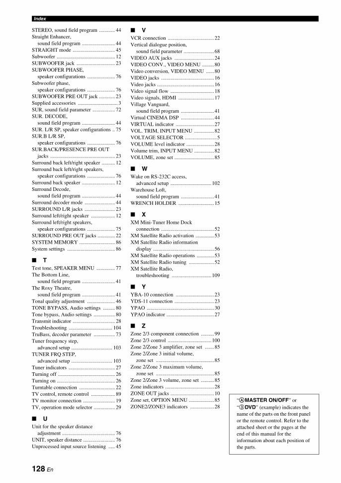
Index
STEREO, sound field program ............ 44Straight Enhancer,
sound field program ......................... 44STRAIGHT mode ................................ 45Subwoofer ............................................ 12SUBWOOFER jack ............................. 23SUBWOOFER PHASE,
speaker configurations ..................... 76Subwoofer phase,
speaker configurations ..................... 76SUBWOOFER PRE OUT jack ............ 23Supplied accessories .............................. 3SUR, sound field parameter ................. 72SUR. DECODE,
sound field program ......................... 44SUR. L/R SP, speaker configurations .. 75SUR.B L/R SP,
speaker configurations ..................... 76SUR.BACK/PRESENCE PRE OUT
jacks ................................................. 23Surround back left/right speaker .......... 12Surround back left/right speakers,
speaker configurations ..................... 76Surround back speaker ......................... 12Surround Decode,
sound field program ......................... 44Surround decoder mode ....................... 44SURROUND L/R jacks ....................... 23Surround left/right speaker .................. 12Surround left/right speakers,
speaker configurations ..................... 75SURROUND PRE OUT jacks ............. 22SYSTEM MEMORY ........................... 86System settings .................................... 86
■ TTest tone, SPEAKER MENU .............. 77The Bottom Line,
sound field program ......................... 41The Roxy Theatre,
sound field program ......................... 41Tonal quality adjustment ..................... 46TONE BYPASS, Audio settings ......... 80Tone bypass, Audio settings ................ 80Transmit indicator ................................ 28Troubleshooting ................................. 104TruBass, decoder parameter ................ 73Tuner frequency step,
advanced setup ............................... 103TUNER FRQ STEP,
advanced setup ............................... 103Tuner indicators ................................... 27Turning off ........................................... 26Turning on ............................................ 26Turntable connection ........................... 22TV control, remote control .................. 89TV monitor connection ........................ 19TV, operation mode selector ................ 29
■ UUnit for the speaker distance
adjustment ........................................ 76UNIT, speaker distance ........................ 76Unprocessed input source listening ..... 45
■ VVCR connection ...................................22Vertical dialogue position,
sound field parameter .......................68VIDEO AUX jacks ..............................24VIDEO CONV., VIDEO MENU .........80Video conversion, VIDEO MENU ......80VIDEO jacks ........................................16Video jacks ...........................................16Video signal flow .................................18Video signals, HDMI ...........................17Village Vanguard,
sound field program .........................41Virtual CINEMA DSP .........................44VIRTUAL indicator .............................27VOL. TRIM, INPUT MENU ...............82VOLTAGE SELECTOR ........................5VOLUME level indicator .....................28Volume trim, INPUT MENU ...............82VOLUME, zone set ..............................85
■ WWake on RS-232C access,
advanced setup ...............................102Warehouse Loft,
sound field program .........................41WRENCH HOLDER ...........................15
■ XXM Mini-Tuner Home Dock
connection ........................................52XM Satellite Radio activation ..............53XM Satellite Radio information
display ..............................................56XM Satellite Radio operations .............53XM Satellite Radio tuning ...................52XM Satellite Radio,
troubleshooting ..............................109
■ YYBA-10 connection .............................23YDS-11 connection ..............................23YPAO ...................................................30YPAO indicator ....................................27
■ ZZone 2/3 component connection ..........99Zone 2/3 control .................................100Zone 2/Zone 3 amplifier, zone set .......85Zone 2/Zone 3 initial volume,
zone set ............................................85Zone 2/Zone 3 maximum volume,
zone set ............................................85Zone 2/Zone 3 volume, zone set ..........85Zone indicators .....................................28ZONE OUT jacks .................................10Zone set, OPTION MENU ...................85ZONE2/ZONE3 indicators ..................28
“AMASTER ON/OFF” or “3DVD” (example) indicates the name of the parts on the front panel or the remote control. Refer to the attached sheet or the pages at the end of this manual for the information about each position of the parts.
128 En


■ Front panel
MASTER
PURE DIRECT
VOLUME
MAIN ZONE
INPUT
OFFON
INFO
ZONE ON/OFF ZONE CONTROLS
MULTI ZONE
MICOPTIMIZER
EFFECT
PROGRAM
YPAO
ZONE 3
RL OPTICAL
ZONE 2
AUDIO
VIDEO AUX
SILENT CINEMA S VIDEO VIDEO
PHONES
BAND
CATEGORYPRESET/TUNING/CH MONOSTEREO/
MODESEARCH
MEMORY
STRAIGHT
CONTROLSELECTAUDIO TONE
ENTER
ON/OFF
INFO
ZONE ON/OFF ZONE CONTROLS
MULTI ZONE
MICOPTIMIZER
EFFECT
PROGRAM
YPAO
ZONE 3
RL OPTICAL
ZONE 2
AUDIO
VIDEO AUX
SILENT CINEMA S VIDEO VIDEO
PHONES
BAND
CATEGORYPRESET/TUNING/CH MONOSTEREO/
MODESEARCH
MEMORY
STRAIGHT
CONTROLSELECTAUDIO TONE
ENTER
CB MA
Q
PN O
LKIGFED H J
i

AP
PE
ND
IX
■ Remote control
AMP
TV
SOURCE
ZONESETUP ID MACRO
MODE
DVD CD
V-AUX DOCKMULTI PHONO
AV
POWER
TV
POWER
TV DVR VCR
XM SIRIUSTUNER
BDHD DVD
MDCD-R
CBLSAT
SRCH MODEMENU
BANDTITLE
MEMORYRETURN
PARAMETERDISPLAY
MUTE
43
SYSTEM MEMORY
21
3D DSP
STANDBY POWER
SELECT
VOLUMEPRESET/CH
ENTER CAT.A-E
PRG SELECT
CLASSICAL1
LIVE/CLUB2
ENTERTAIN3
MOVIE4
STEREO5
ENHANCER6
SUR.DECODE7
STRAIGHT8
PURE DIRECTENT
AUDIO SELAUDIO
SLEEP
TV
MUTE
INPUT
9 0
LEVEL
TV CH
INFO
TV VOL
EXTD SUR.10
A
REC
CLASSICAL1
LIVE/CLUB2
ENTERTAIN3
MOVIE4
STEREO5
ENHANCER6
SUR.DECODE7
STRAIGHT8
1
LM
N
O
2
3
4
7
5
6
8
9
0
A
B
Q R
P
C
D
E
FG
H
I
J
K
ii

Sound output in each sound field program
*1 / / / : OFF
*2 / / / : ON or discrete 6.1/7.1-channel audio signals are input.
Front left speaker Surround left speaker Surround back right speaker
Center speaker Surround right speaker Presence left speaker
Front right speaker Surround back left speaker Presence right speaker
Speaker from which sound is being output Speaker from which no sound is being output
L SL SBR
C SR PL
R SBL PR
Speaker settings
7-channel 5-channel
1
2
3
4
L
PL
C
R
PR
SL
SBRSBL
SR
L
C
R
SL SR
L
PL
C
R
PR
SL
SBRSBL
SR
L
C
R
SL SR
L
PL
C
R
PR
SL
SBRSBL
SR
L
C
R
SL SR
L
PL
C
R
PR
SL
SBRSBL
SR
L
C
R
SL SR
Speaker settings
7-channel 5-channel
5
6
7
8
L
PL
C
R
PR
SL
SBRSBL
SR
L
C
R
SL SR
L
PL
C
R
PR
SL
SBRSBL
SR
L
C
R
SL SR
L
PL
C
R
PR
SL
SBRSBL
SR
L
C
R
SL SR
L
PL
C
R
PR
SL
SBRSBL
SR
L
C
R
SL SR
EX PL x neural
EX PL x neural
Program 3D
Input audio source
2-channel (monaural)
2-channel (stereo) 5.1-channel*1 6.1/7.1-channel*2
CLASSICALHall in MunichHall in ViennaHall in AmsterdamChurch in FreiburgChamber
LIVE/CLUBVillage VanguardWarehouse LoftCellar ClubThe Roxy TheatreThe Bottom Line
ON 1 1 2 2
OFF
1 1 2 4
iii

AP
PE
ND
IX
ENTERTAINMENTSportsAction GameRoleplaying GameMusic VideoRecital/Opera
MOVIEStandardSpectacleSci-FiAdventureDrama
ON 2 2 2 2
OFF
7 4 2 4
MOVIEMono Movie
ON 2 2 2 2
OFF 3 2 2 4
STEREO2ch Stereo
–– 5 5 5 5
STEREO7ch Stereo
MUSIC ENHANCER7ch Enhancer
––
4 4 4 4
SUR.DECODESurround Decoder
(Pro Logic)(PLII Movie)(PLII Game)
––
6 7 7 4
SUR.DECODESurround Decoder
(PLII Music)
––8 7 7 4
SUR.DECODESurround Decoder
(PLIIx Movie)(PLIIx Game)(Neo:6 Cinema)(CSII Cinema)(NRL-THX)
––
6 4 7 4
SUR.DECODESurround Decoder
(PLIIx Music)(Neo:6 Music)(CSII Music)(NRL-THX Music)
––
8 4 7 4
STRAIGHTPure DirectMUSIC ENHANCERStraight Enhancer
––
5 5 7 4
Program 3D
Input audio source
2-channel (monaural)
2-channel (stereo) 5.1-channel*1 6.1/7.1-channel*2
iv

List of remote control codes
TVACURA 00101ADDISON 01201, 01601,
08401ADMIRAL 01301, 02201,
05801ADVENT 09601AGB 06801AIKO 01201AKAI 00101, 00301,
02901, 04601, 06801, 08901, 10501
AKURA 03701ALBA 00101, 00401,
04801, 08501AMERICA ACTION
02701AMPRO 09401AMSTRAD 00101, 00401,
02501, 04801, 05101, 05301, 06801
ANAM 00101, 02701, 03401
ANAM NATIONAL03401, 08301
ANITECH 00101AOC 00101, 00301,
00901, 01201, 01301, 01601, 02601, 02701, 05601
APEX DIGITAL09301, 09701, 09901
ASA 01401AUDIOSONIC 00401, 01701AWA 00101BANG & OLUFSEN
07201BASIC 00101BAUR 00401, 04601,
06701BAYSONIC 02701BEAUMARK 02601BEKO 04701, 06201,
09001, 09101BELL & HOWELL
02001BEON 00401BLAUPUNKT 02801BLUE SKY 08501, 11401BONDSTEC 03301BRADFORD 02701BRANDT 01701, 04201BROKSONIC 03101, 05801BUSH 00101, 00101,
00401, 04801, 04901, 08501, 11401
BYDESIGN 14301, 14401, 14501, 14601
CANDLE 00301CARNIVALE 00301CARVER 00801, 02401CASCADE 00101CATHAY 00401CCE 00401CELEBRITY 00001CELERA 09701
CENTURION 00401CGE 03301CHANGHONG 09701CHING TAI 00101, 01201CHUN YUN 00001, 00101,
01201, 02701CHUNG HSIN 00701, 01601,
02701CIMLINE 00101CINERAL 01201, 05601CITIZEN 00301, 00901,
01201CLARION 02701CLARIVOX 00401CLATRONIC 03301, 04701CONDOR 04101, 04701CONRAC 10301CONTEC 00101, 02701CRAIG 02701CROSLEY 00801CROWN 00101, 00401,
02701, 04701, 05201
CTC 03301CURTIS MATHES
00301, 00501, 00801, 00901, 01301, 01801, 02001, 02301, 05601, 08901, 11801, 12201
CXC 02701DAEWOO 00101, 00301,
00401, 01201, 01601, 02001, 02401, 02601, 02701, 04901, 05601, 07901, 08201, 13101
DANSAI 00401DAYTON 00101DE GRAAF 02901, 06901DECCA 00401, 06801DENON 01801DIGATRON 00401DIXI 00101, 00401DUMONT 00201DWIN 09201, 10101ECE 00401ELBE 03501ELECTROBAND
00001ELIN 00401, 06901ELITE 04101ELTA 00101EMERSON 02001, 02601,
02701, 03101, 04601, 05801, 07901
ENVISION 00301, 10601EPSON 11001ERRES 00401ETHER 00101, 00301ETRON 00101EUROPHON 06801FERGUSON 00401, 01001,
01701, 03201, 03801, 04201, 07101
FIDELITY 04601FINLANDIA 02901, 04401
FINLUX 00401, 01401, 01501, 04401, 06801
FIRSTAR 00101, 03101FIRSTLINE 00101, 03301,
08501FISHER 01401, 02001,
02901, 04701FLINT 05701FORMENTI 00401, 04101FORTRESS 01301FRONTECH 02201, 03301,
03701FUJITSU 08701, 10401FUNAI 02501, 02701,
03701FUTURETECH 02701GATEWAY 13301, 13401GE 00301, 00501,
00601, 01201, 02601, 02701, 05601, 07101, 11801, 12201, 12601
GEC 00401, 06801GELOSO 00101GENEXXA 02201GIBRALTER 00201, 00301GOLDSTAR 00301, 00401,
01701, 02001, 02601, 05001
GOODMANS 00401, 04801, 04901, 08201
GOREMJE 04701GRADIENTE 00701, 02401GRAETZ 02201, 04601GRANADA 00401, 02901,
04301, 06801GRANDIN 07701GRUNDIG 00401, 02801,
06301, 07001, 07401
GRUNPY 02701HALLMARK 02601HANKOOK 00301, 02601,
02701HANSEATIC 00401, 04101,
04601, 05201, 07001
HANTAREX 06801HARMAN/KARDON
00801HARVARD 02701HAVERMY 01301HCM 00101, 05101HELLO KITTY 05601HINARI 00101, 00401HISAWA 05701HITACHI 00101, 00301,
01201, 01501, 01701, 01801, 02201, 02601, 03001, 04501, 06101, 06901, 07301, 11701, 12101
HUA TUN 00101HUANYU 04901HYPSON 00401, 03701ICE 03701, 04801
IMPERIAL 03301, 04701, 05201
INDIANA 00401INFINITY 00801INGELEN 02201INNO HIT 06801INNOVA 00401INTEQ 00201INTERFUNK 00401, 02201,
03301, 04601, 06701
INTERVISION 00401, 03701, 05001
ITS 04801ITT 02201, 04601,
06901JBL 00801JCB 00001JEAN 00101, 00601,
01201, 02101, 03101
JENSEN 09601JVC 00701, 04801,
05801, 08401, 08701
KAISUI 00101KAPSCH 02201KARCHER 07701KATHREIN 07001KEC 02701KENDO 00401KENWOOD 00301KNEISSEL 03501, 05401KOLIN 00701, 01601,
02701KORPEL 00401KOYODA 00101KTV 00301, 02701L&S ELECTRONIC
10301LEYCO 00401, 03701LG 00301, 00401,
00901, 01601, 02601, 09001
LIESENK & TTER00401
LOEWE 06701LUXOR 04501, 04601LXI 00501, 00801,
02001, 02101, 02601
M ELECTRONIC00101, 00401, 01401, 01501, 01701, 02201, 03801, 04401, 04901, 06001
MAGNADYNE 03301, 06801MAGNAFON 06801MAGNAVOX 00301, 00801,
12001, 12601MANESTH 03701, 04101MARANTZ 00301, 00401,
00801, 07001MARK 00401MATSUI 00101, 00401,
02901, 04801, 06301, 06801
MATSUSHITA 03401, 08301MEDIATOR 00401
v

AP
PE
ND
IX
MEDION 08501, 10301, 11401
MEGATRON 01801, 02601MEMOREX 00101, 01901,
02001, 02601, 03401, 05801, 11401
METZ 05501MGA 00301, 01901,
02601MICROMAXX 10301MICROSTAR 10301MIDLAND 00201, 00501,
00601MINERVA 06301MINOKA 05101MITSUBISHI 00301, 01301,
01601, 01901, 02001, 02601, 02701, 03101, 03401, 06701, 11201, 11901
MIVAR 03901, 04001, 06801, 07601
MOTOROLA 01301MTC 00301, 00901,
06701MULTITECH 00101, 02701MYRYAD 07001NAD 02101, 02601,
04601, 11301NEC 00101, 00301,
00601, 02001, 02101, 02401, 02601, 05701, 06501, 13201
NECKERMANN00401, 07001
NEI 00401NETSAT 00401NEWAVE 00101, 01201,
01301, 02601NIKKAI 00401, 03701NIKKO 00301, 01201,
02601NOKIA 04601, 05901,
06001, 06901, 08101
NORCENT 09301, 10801NORDMENDE 01701, 03801,
07101NTC 01201OCEANIC 02201, 04601ONWA 02701, 05301OPTIMUS 02001, 02301,
03401, 08301OPTONICA 01301ORION 00401, 03101,
04101, 05801, 06801
OSAKI 03701, 05101OTTO VERSAND
00401, 04101, 06701, 07001
PALLADIUM 04701, 05201PANAMA 03701PANASONIC 00401, 00601,
00801, 02201, 03401, 08301, 12401
PATHE CINEMA03201, 04101
PAUSA 00101
PENNEY 00301, 00501, 00601, 00901, 02101, 02601, 12201
PERDIO 04101PHILCO 00301, 00401,
00801, 01801, 02601, 02701, 03301, 05801, 13101
PHILIPS 00001, 00301, 00401, 00601, 00801, 01201, 01601, 02601, 04901, 07001, 08801, 12601
PHONOLA 00401PILOT 00301PIONEER 01701, 02201,
02301, 03801, 08601, 09501, 11301
PORTLAND 01201PRANDONI-PRINCE
06801PRIMA 09601PRISM 00601PROFEX 00101, 04601PROSCAN 00501PROTECH 00101, 00401,
03301, 03701, 05201, 08501
PROTON 00101, 00301, 02601
PULSAR 00201QUASAR 00601, 03401,
08301QUELLE 00401, 01401,
04601, 06701RADIOLA 00401RADIOMARELLI
06801RADIOSHACK 00301, 00501,
02001, 02601, 02701
RCA 00001, 00301, 00501, 01101, 01201, 02601, 08601, 11501, 11801, 13901, 12201, 12501, 12601, 12801
REALISTIC 00301, 02001, 02601, 02701
REDIFFUSION 04601REOC 09001REVOX 00401REX 02201, 03501,
03701RFT 05201R-LINE 00401ROADSTAR 00101, 03701,
05201RUNCO 00201, 00301,
06501, 07501SABA 01701, 02201,
03801, 04201SACCS 03201SAGEM 07701SAISHO 00101, 03701,
06801SALORA 02201, 04601,
06901SAMBERS 06801
SAMPO 00101, 00301, 01201, 01301, 02001, 02501, 02601, 08301, 13301
SAMSUNG 00101, 00301, 00401, 00901, 01101, 01201, 02001, 02601, 03701, 04701, 07001, 07401, 07801, 08901, 09801, 10501, 10701
SANSEI 05601SANSUI 05801SANYO 01401, 02001,
02701, 02901, 04301, 10201
SBR 00401SCHAUB LORENZ
04601SCHNEIDER 00401, 03301,
04801, 08501SCOTCH 02601SCOTT 02601, 02701,
03101SEARS 00501, 00801,
02001, 02101, 02501, 02601
SEG 03701, 08501SEI 06801SELECO 02201, 03501SEMIVOX 02701SEMP 02101SHARP 00301, 01301,
08301SHEN YING 00101, 01201SHENG CHIA 00101, 01301,
03101SIAREM 06801SIEMENS 00401, 02801SINUDYNE 06801SKANTIC 04501SKY 00401SKYGIANT 02701SKYWORTH 00401SOLAVOX 02201SONITRON 02901SONOKO 00101, 00401SONOLOR 02201, 02901SONTEC 00401SONY 00001, 08301,
11101, 11601, 12701, 12901
SOUNDESIGN 02601, 02701SOUNDWAVE 00401, 05201SOWA 00601, 00901,
01201, 02101, 02601
SQUAREVIEW 02501SSS 02701STANDARD 00101STARLITE 02701STERN 02201, 03501SUPREME 00001SYLVANIA 00301, 00801,
02501SYMPHONIC 02501, 02701SYNCO 00001, 00901,
01201, 01301, 02601, 05601
SYSLINE 00401T + A 05501
TACICO 00101, 01201, 02601
TAI YI 00101TANDY 01301, 02201TASHIKO 01201, 08301TATUNG 00101, 00401,
00601, 00801, 00901, 02001, 02101, 06801
TCM 10301TEAC 00101, 00401,
03701, 05101, 05201, 05701, 08501, 11401
TEC 03301TECHNEMA 04101TECHNICS 00601, 03401,
08301TECHWOOD 00601TECO 00101, 00601,
01201, 01301, 02601, 03701, 08401
TEKNIKA 00801, 00901, 01201, 01901, 02701
TELEFUNKEN 01701, 03601, 04201, 08001, 08901
TELEMEISTER04101TELETECH 00101TENSAI 04101TERA 00301THOMSON 01701, 03801,
07101, 08001, 12501
THORN 00401, 01401, 04601, 06701
TMK 02601TNCI 00201TOSHIBA 00901, 02001,
02101, 06601, 07801, 08301, 10901, 12101, 12301, 13001, 13201
TRIUMPH 06801TUNTEX 00101, 00301,
01201TVS 05801UHER 04101UNIVERSUM 00401, 01401,
01501, 03701, 04401, 04701, 06401
VECTOR RESEARCH00301
VESTEL 00401VICTOR 00701, 03401,
08301, 08401VIDEOSAT 03301VIDIKRON 00801VIDTECH 02601VIEWSONIC 13301VISION 04101VOXSON 02201WALTHAM 04501WARDS 00301, 00801,
02601, 11301WATSON 00401, 04101WAYCON 02101WHITE WESTINGHOUSE
00401, 04101, 05801, 07901
vi
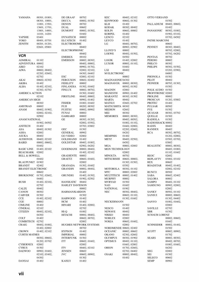
YAMAHA 00301, 01801, 08301, 10001, 11001, 13501, 13601, 13701, 13801, 14001, 14101, 14201
YAPSHE 03401YOKO 00401, 03701ZENITH 00201, 01201,
02601, 05801
VCRADMIRAL 01102ADVENTURA 00002AIKO 02102AIWA 00002, 00402,
02202, 02602, 02702
AKAI 00602, 02302AKIBA 01402ALBA 01402, 02102,
02302, 02702AMERICA ACTION
02102AMERICAN HIGH
00302AMSTRAD 00002ANAM 00402, 01902,
02002, 02102, 02902
ANAM NATIONAL01902, 04502
ANITECH 01402ASA 00402, 01502ASHA 02002ASUKA 00402AUDIOVOX 00402, 02102BAIRD 00002, 00602,
01602BASIC LINE 01402, 02102BEAUMARK 02002BELL & HOWELL
01602BLAUPUNKT 01902BRANDT 02402BRANDT ELECTRONIC
00602BROKSONIC 01702, 02602,
04402BUSH 01402, 02102,
02702CALIX 00402CANON 00302CARVER 01502CCE 01402, 02102CGE 00002CIMLINE 01402CINERAL 02102CITIZEN 00402, 02102,
04302COLT 01402COMBITECH 02702CRAIG 00402, 01002,
01402, 02002CROWN 01402, 02102CURTIS MATHES
00302, 00602, 01202, 03702
CYBERNEX 02002CYRUS 01502DAEWOO 00902, 01602,
02102, 03402, 04302
DANSAI 01402
DE GRAAF 00702DECCA 00002, 01502DENON 00702DUAL 00602DUMONT 00002, 01502,
01602DYNATECH 00002ELCATECH 01402ELECTROHOME
00402ELECTROPHONIC
00402EMEREX 00102EMERSON 00002, 00302,
00402, 00802, 00902, 01702, 02002, 02102, 04302, 04402
ESC 02002, 02102FERGUSON 00602, 02402FIDELITY 00002FINLANDIA 01502, 01602FINLUX 00002, 00702,
01502, 01602FIRSTLINE 00402, 00802,
00902, 01402FISHER 01002, 01602FUJI 00202, 00302FUJITSU 00002, 00902FUNAI 00002GARRARD 00002GE 00302, 01202,
02002, 03502, 03702, 03802
GEC 01502GENERAL 00902GO VIDEO 02802GOLDHAND 01402GOLDSTAR 00402, 01802,
02902, 04202GOODMANS 00002, 00402,
01402, 02102GRADIENTE 00002GRAETZ 00602, 01602,
02002GRANADA 01502, 01602GRANDIN 00002, 00402,
01402GRUNDIG 01402, 01502,
01902, 02502HANSEATIC 00402HARLEY DAVIDSON
00002HARMAN/KARDON
01502HARWOOD 01402HCM 01402HINARI 01402, 02002,
02702HI-Q 01002HITACHI 00002, 00402,
00602, 00702, 02002
HUGHES NETWORK SYSTEMS00702
HYPSON 01402IMPERIAL 00002INTERFUNK 01502ITT 00602, 01602,
02002ITV 00402, 02102JENSEN 00602JVC 00602, 00902,
01302KAISUI 01402
KEC 00402, 02102KENWOOD 00602, 01302KLH 01402KODAK 00302, 00402KOLIN 00602, 00802KORPEL 01402LENCO 02102LEYCO 01402LG 00402, 00702,
00902, 02902LLOYD’S 00002LOEWE 00402, 01502,
04502LOGIK 01402, 02002LUXOR 00802, 01102,
01602LXI 00402M ELECTRONIC
00002MAGNASONIC04302MAGNAVOX 00002, 00302,
00502, 01502MAGNIN 02002MANESTH 00902, 01402MARANTZ 00302, 01502MARTA 00402MATSUI 02602, 02702MATSUSHITA 00302MEDION 02602MEI 00302MEMOREX 00002, 00302,
00402, 00502, 01002, 01102, 01602, 02002, 02202, 02602, 04202
MEMPHIS 01402METZ 00402, 02502,
04502MGA 00802, 02002MGN TECHNOLOGY
02002MINOLTA 00702MITSUBISHI 00602, 00802,
01302, 01502, 03502
MOTOROLA 00302, 01102MTC 00002, 02002MULTITECH 00002, 01402MURPHY 00002MYRYAD 01502NAD 01602NATIONAL 01902NEC 00302, 00402,
00602, 01102, 01302, 01602
NECKERMANN01502
NESCO 01402NEWAVE 00402NIKKO 00402NOBLEX 02002NOKIA 00602, 01602,
02002NORDMENDE 00602, 02402OCEANIC 00002, 00602OKANO 02302, 02602OLYMPUS 00302, 01902OPTIMUS 00402, 01102,
01602, 02802ORION 01702, 02602,
02702, 04402OSAKI 00002, 00402,
01402
OTTO VERSAND01502
PALLADIUM 00402, 00602, 01402
PANASONIC 00302, 01802, 01902, 03102, 03702, 04502
PATHE MARCONI00602
PENNEY 00302, 00402, 00702, 02002, 03702, 04202
PENTAX 00702PERDIO 00002PHILCO 00302PHILIPS 00302, 01502,
03202, 03902, 04002
PHONOLA 01502PILOT 00402PIONEER 00702, 01302,
01502POLK AUDIO 01502PROFITRONIC 02002PROLINE 00002PROSCAN 01202, 03802PROTEC 01402PULSAR 00502PYE 01502QUASAR 00302, 03702QUELLE 01502RADIOLA 01502RADIOSHACK 00002RADIX 00402RANDEX 00402RCA 00302, 00702,
01202, 02002, 03502, 03702, 03802
REALISTIC 00002, 00302, 00402, 01002, 01102, 01602
REOC 02602REPLAYTV 03002, 03102REX 00602ROADSTAR 00402, 01402,
02002, 02102RUNCO 00502SABA 00602, 02402SALORA 00802SAMPO 00402, 01102SAMSUNG 00902, 02002,
02802SANKY 00502, 01102SANSUI 00002, 00602,
01302, 04402SANYO 01002, 01602,
02002SAVILLE 02702SBR 01502SCHAUB LORENZ
00002, 00602, 01602
SCHNEIDER 00002, 01402, 01502
SCOTT 00802, 00902, 01702
SEARS 00002, 00302, 00402, 00702, 01002, 01602, 04202
SEG 02002SEI 01502SELECO 00602SEMP 00902
vii

AP
PE
ND
IX
SHARP 01102, 03502SHINTOM 01402, 01602SIEMENS 00402, 01502,
01602SILVA 00402SINGER 00902, 01402SINUDYNE 01502SONIC BLUE 03002, 03102SONTEC 00402SONY 00002, 00102,
00202, 00302, 03302, 04102
STS 00702SUNKAI 02602SUNSTAR 00002SUNTRONIC 00002SYLVANIA 00002, 00302,
00802, 01502SYMPHONIC 00002TANDY 00002, 01602TASHIKO 00002, 00402TATUNG 00002, 00602,
00902, 01302, 01502
TEAC 00002, 00602, 02102, 02202, 03402
TECHNICS 00302, 01902TECO 00302, 00402,
00602, 01102TEKNIKA 00002, 00302,
00402TELEAVIA 00602TELEFUNKEN 00602, 02402TENOSAL 01402TENSAI 00002THOMAS 00002THOMSON 00602, 01202,
01302, 02402THORN 00602, 01602TIVO 03202, 03302TMK 02002TOSHIBA 00602, 00802,
00902, 01302, 01502, 03602
TOTEVISION 00402, 02002UHER 02002UNITECH 02002UNIVERSUM 00002, 00402,
01502, 02002VECTOR 00902VICTOR 00602, 01302VIDEO CONCEPTS
00902VIDEOMAGIC 00402VIDEOSONIC 02002VILLAIN 00002WARDS 00002, 00302,
00702, 01002, 01102, 01202, 01402, 01502, 02002
WHITE WESTINGHOUSE01402
XR-1000 00002, 00302, 01402
YAMAHA 00602YAMISHI 01402YOKAN 01402YOKO 02002ZENITH 00002, 00202,
00502, 04402
CABLEABC 00103, 00203AMERICAST 02003BELL SOUTH 02003BIRMINGHAM CABLE COMMUNICATIONS
00803BRITISH TELECOM
00103DAERYUNG 00203, 01403,
01903DIRECTOR 01303FILMNET 01203GENERAL INSTRUMENT
00103, 00803, 01303, 01703
GOLDSTAR 00503HAMLIN 00303, 00703JERROLD 00103, 00803,
01303, 01703LG 00503MEMOREX 00003MNET 01203MOTOROLA 00803, 01303,
01703, 02303NOOS 01803PACE 00603, 02203PANASONIC 00003, 00203,
00403PARAGON 00003PHILIPS 01003, 01103PIONEER 00503, 01603,
01903PULSAR 00003PVP STEREO VISUAL MATRIX
00103QUASAR 00003RCA 02403, 02503REGAL 00703, 00903RUNCO 00003SAGEM 01803SAMSUNG 00003, 00503SCIENTIFIC ATLANTA
00203, 01403, 01903
SONY 02103STARCOM 00103SUPERCABLE 00803TELE+1 01203TORX 00103TOSHIBA 00003TRANS PX 00803TS 00103UNITED CABLE
00103ZENITH 00003, 01503,
02003
SATELLITE TUNER@SAT 06404ABSAT 00104ALBA 01404ALPHASTAR 02504AMSTRAD 03004ASTON 00304, 05004ASTRO 00604ATSAT 06404AVALON 01304BLAUPUNKT 00604BRITISH SKY BROADCASTING
03004, 05204CANAL DIGITAL
03104
CANAL SATELLITE03104
CANAL+ 03104CHAPARRAL 00804CITYCOM 05304CONNEXIONS 01304CROSSDIGITAL
04604CYRUS 00704DAERYUNG 01304DAEWOO 06304D-BOX 02104, 04904DIGENIUS 01104DIRECTV 00904, 01204,
01504, 01704, 02204, 02304, 02804, 04104, 04604, 05104, 06904
DISH NETWORK SYSTEM02604, 03704
DISHPRO 02604, 03704DISTRATEL 00004DMT 04004DNT 00704, 01304DREAM MULTIMEDIA
05804ECHOSTAR 00504, 01304,
01604, 02604, 03104, 03604, 03704, 04304
ENGEL 03804EXPRESSVU 02604FINLUX 01404FOXTEL 07004, 07104,
07204, 07304, 07404
FRACARRO 03604FTE 03404FUBA 01304GALAXIS 03404, 04704GE 01504GENERAL INSTRUMENT
03504GOI 02604GOLD BOX 03104GRUNDIG 00604, 03004HIRSCHMANN00604, 01304HITACHI 01404, 02804HTS 02604HUGHES NETWORK SYSTEM
02304, 05104, 06904
HUMAX 03404, 05304INVIDEO 03604JVC 02604KATHREIN 00104, 00604,
00704, 01004, 01804, 05604
KREISELMEYER00604
LABGEAR 06304LOGIX 03804LORENZEN 01104MAGNAVOX 02004, 02204MANHATTAN 01404, 03804,
04204MARANTZ 00704MEDIASAT 03104MEMOREX 02204METRONIC 00004MITSUBISHI 02304MOTOROLA 03504MYRYAD 00704NEXT LEVEL 03504
NOKIA 01404, 02104, 02404, 04904, 05704, 06804
OCTALTV 03704ORBITECH 04504PACE 01404, 03004,
05204, 06604PANASONIC 00904, 01904,
03004, 06504PANDA 01404PAYSAT 02204PHILIPS 00204, 00704,
01404, 02004, 02204, 02304, 03104, 04104, 05104, 06904
PIONEER 03104PROMAX 01404PROSCAN 01204, 01504RADIOLA 00704RADIOSHACK 03504RADIX 01304RCA 00404, 01204,
01504, 03204RFT 00704SABRE 01404SAGEM 02904, 04804,
05904SAMSUNG 03804, 04604,
06004, 06204SAT CONTROL06404SATSTATION 04204SCHWAIGER 04704SEEMANN 01304SIEMENS 00604SKY 03004, 03304,
05204SM ELECTRONIC
05404SONY 01704, 03004,
06704STAR CHOICE 03504STRONG 06404TANTEC 01404TECHNISAT 04404, 04504TELESTAR 04504THOMSON 01404, 03104,
03904, 06104TOPFIELD 05504TOSHIBA 02304, 02704,
06904TPS 02904, 05904ULTIMATETV 01204, 01704UNIDEN 02004, 02204UNIVERSUM 00604VENTANA 00704WISI 00604, 01304,
01404XSAT 00104ZEHNDER 04004ZENITH 03304
CD PLAYERAIWA 00605ARCAM 00605AUDIO RESEARCH
00605AUDIO TON 00605AUDIOLAB 00605AUDIOMECA 00605CAIRN 00605CALIFORNIA AUDIO LABS
00205CARVER 00605, 00805
viii

CYRUS 00605DENON 01005DKK 00005DMX ELECTRONICS
00605DYNAMIC BASS
00805EMERSON 00905FISHER 00805GENEXXA 00305, 00905GOODMANS 00905GRUNDIG 00605HARMAN/KARDON
00605, 00705HITACHI 00305JVC 00505KENWOOD 00105, 00405KRELL 00605LINN 00605LXI 00905MAGNAVOX 00605, 00905MARANTZ 00205, 00605MATSUI 00605MCS 00205MEMOREX 00905MERIDIAN 00605MICROMEGA 00605MIRO 00005MISSION 00605MYRYAD 00605NAD 00005NAIM 00605NSM 00605OPTIMUS 00005, 00305,
00405, 00805, 00905
PANASONIC 00205PHILIPS 00605PIONEER 00305, 00905POLK AUDIO 00605PROTON 00605QED 00605QUAD 00605QUASAR 00205RCA 00305, 00805,
00905REALISTIC 00805REVOX 00605ROTEL 00605SAE 00605SANSUI 00605, 00905SANYO 00805SCOTT 00905SEARS 00905SHARP 00405SIMAUDIO 00605SONIC FRONTIERS
00605SONY 00005SYMPHONIC 00905TAG MCLAREN
00605TANDY 00305TECHNICS 00205THORENS 00605THULE 00605UNIVERSUM 00605VICTOR 00505WARDS 00605YAMAHA 01105, 01205
CD RECORDERKENWOOD 01305MARANTZ 01305
PHILIPS 01305YAMAHA 01405
BLU-RAY/DVD PLAYERACOUSTIC SOLUTIONS
02806ALBA 02606AMSTRAD 02306APEX DIGITAL02106, 02606,
03006, 03506, 03606, 03706, 04106
BLAUPINKT 02606BLUE PARADE01006BUSH 02306CENTREX 02106CLATRONIC 03406CYBERHOME 02406DAEWOO 03206, 03306DANSAI 03206DECCA 03206DENON 00006DIAMOND 03106DIGITREX 02106DVD2000 00206EMERSON 01206ENTERPRISE 01206FISHER 02006GE 00306, 02606GO VIDEO 02506GOLDSTAR 02906, 04906GRADIENTE 01806GREENHILL 02606GRUNDIG 00706HITACHI 01106, 01507,
01906HITEKER 02106JVC 00906, 01306KENWOOD 00006, 00606KLH 02606KOSS 01806LG 02906LIMIT 03106MAGNAVOX 00106, 02206MARANTZ 00706MEMOREX 03806MICO 02706MICROSOFT 00306MINTEK 02606MITSUBISHI 00206MUSTEK 02806NESA 02606ONKYO 00106, 04806ORITRON 01806PALSONIC 02106PANASONIC 00006, 00007,
00107, 00207, 01606, 04206, 05006
PHILIPS 00106, 00706, 00807, 01706, 03906, 05206
PIONEER 00406, 00407, 00507, 00607, 01006, 01506, 01606, 05306
POLK AUDIO 00706PROSCAN 00306QWESTAR 01806RCA 00306, 01006,
02606, 04806ROTEL 01306SAMSUNG 01106, 04506SANYO 02006
SHARP 01207, 01307, 01406
SHERWOOD 03206SHINSONIC 00506SLIM ART 03306SM ELECTRONIC
02806SONY 00506, 00907,
01007, 01107, 04006, 05106
SYLVANIA 02206TATUNG 03206TEAC 01006, 02606TECHNICS 00006THETA DIGITAL
01006THOMSON 00306TOSHIBA 00106, 00307,
04606, 04806, 05406
URBAN CONCEPTS00106
VICTOR 01407XBOX 00306YAMAHA 00006, 00706,
00707, 00806, 04306, 04406, 04706
ZENITH 00106, 01206, 02906
ZEUS 03306
LD PLAYERCARVER 00108DENON 00008MARANTZ 00108MITSUBISHI 00008NAD 00008NAGSMI 00008OPTIMUS 00008PHILIPS 00108PIONEER 00008SALORA 00108SONY 00208TELEFUNKEN 00008YAMAHA 00308
MD RECORDERKENWOOD 00109ONKYO 00309SHARP 00209SONY 00009YAMAHA 00409, 00509,
00609
RECEIVER (TUNER)ADC 00710AIWA 00410, 01210,
03610, 03910, 04410
ALCO 03810ANAM 04310APEX DIGITAL01810AUDIOLAB 01510AUDIOTRONIC01510AUDIOVOX 03810BOSE 01610CAMBRIDGE SOUNDWORKS
03310CAPETRONIC 00710CARVER 01210, 01510CENTREX 01810
DENON 03210FERGUSON 00710FINE ARTS 01510GRUNDIG 01510HARMAN/KARDON
00210, 02610INTEGRA 00310, 02510JBL 00210, 02710JVC 00110, 00710,
03410, 04110KENWOOD 01010, 03010KLH 03810, 04010MAGNAVOX 00710, 01210,
01510, 02110MARANTZ 00010, 01210,
01510, 02410MCS 00010MICROMEGA 01510MUSICMAGIC 01210MYRYAD 01510NAD 00610NORCENT 03710ONKYO 00310, 00810,
02510OPTIMUS 00710, 00910PANASONIC 00010, 02310,
04210, 04710PHILIPS 01210, 01510,
01910, 02010, 02110, 02210, 02410
PIONEER 00710, 00910, 03510
POLK AUDIO 02410PROSCAN 01710QUASAR 00010RCA 00710, 00910,
01710, 03810, 04310
SABA 00710SANSUI 01210SCHNEIDER 00710SONY 00410, 01110,
01310, 04510, 04610
STEREOPHONICS00910
SUNFIRE 03010TEAC 03810TECHNICS 00010, 02810,
02910, 04210TELEFUNKEN 00710THOMSON 01710THORENS 01510UHER 00710VENTURER 03810VICTOR 00110WARDS 00410YAMAHA 00510, 01410,
03110, 04810, 05510, 05610, 05710, 05810, 05910, 06010
YAMAHA (iPOD)05310
YAMAHA (TUNER ID1)04910
YAMAHA (TUNER ID2)05010
YAMAHA (XM ID1)05110
YAMAHA (XM ID2)05210
ix

AP
PE
ND
IX
TAPE DECKAIWA 00111CARVER 00111GRUNDIG 00111HARMAN/KARDON
00111MAGNAVOX 00111MARANTZ 00111MYRYAD 00111OPTIMUS 00011PHILIPS 00111PIONEER 00011POLK AUDIO 00111RCA 00011REVOX 00111SANSUI 00111SONY 00211THORENS 00111WARDS 00011YAMAHA 00311, 00411
x

© 2008 Yamaha Corporation All rights reserved.
RX
-V1900
Printed in Malaysia WP38590
RX-V1900AV Receiver
OWNER’S MANUAL
U
RX-V1900_U-cv.fm Page 1 Friday, June 20, 2008 11:23 AM
Black process 45.0° 240.0 LPI

The circled numbers and alphabets correspond to those in the Owner’s Manual.Les nombres et lettres dans un cercle correspondent à ceux du mode d’emploi.
■ Front panel / Face avant
RX-V1900UC
MASTER
PURE DIRECT
VOLUME
MAIN ZONE
INPUT
OFFON
INFO
ZONE ON/OFF ZONE CONTROLS
MULTI ZONE
MICOPTIMIZER
EFFECT
PROGRAM
YPAO
ZONE 3
RL OPTICAL
ZONE 2
AUDIO
VIDEO AUX
SILENT CINEMA S VIDEO VIDEO
PHONES
BAND
CATEGORYPRESET/TUNING/CH MONOSTEREO/
MODESEARCH
MEMORY
STRAIGHT
CONTROLSELECTAUDIO TONE
ENTER
ON/OFF
CB MA LKIGFED H J
QPN O

■ Remote control / Boîtier de télécommande
WP38720Printed in Malaysia
AMP
TV
SOURCE
ZONESETUP ID MACRO
MODE
DVD CD
V-AUX DOCKMULTI PHONO
AV
POWER
TV
POWER
TV DVR VCR
XM SIRIUSTUNER
BDHD DVD
MDCD-R
CBLSAT
SRCH MODEMENU
BANDTITLE
MEMORYRETURN
PARAMETERDISPLAY
MUTE
43
SYSTEM MEMORY
21
STANDBY POWER
SELECT
VOLUMEPRESET/CH
ENTER CAT.A-E
PRG SELECT
CLASSICAL1
LIVE/CLUB2
ENTERTAIN3
MOVIE4
STEREO5
ENHANCER6
SUR.DECODE7
STRAIGHT8
PURE DIRECTENT
AUDIO SELAUDIO
SLEEP
TV
MUTE
INPUT
9 0
LEVEL
TV CH
INFO
TV VOL
EXTD SUR.10
A
REC
3D DSP
CLASSICAL1
LIVE/CLUB2
ENTERTAIN3
MOVIE4
STEREO5
ENHANCER6
SUR.DECODE7
STRAIGHT8
1
LM
N
O
2
3
4
7
5
6
8
9
0
A
B
Q R
P
C
D
E
FG
H
I
J
K