Embed Size (px)
Citation preview

Ver. 1.09
MF Type
EUC0127500
E37Ver. 5.00
User’s Manual
YAMAHA LINEAR MOTOR ROBOTS PHASER series


i
General C
ontents
General Contents
Introduction
Chapter 1 Using the Robot Safely
1-1 Safety information 1-1
1-2 Essential precautions 1-3
1-3 Industrial robot operating and maintenance personnel 1-9
1-4 Robot safety functions 1-10
1-5 Safety measures for the system 1-11
1-6 Trial operation 1-11
1-7 Work within the safety enclosure 1-12
1-8 Automatic operation 1-13
1-9 Warranty 1-14
Chapter 2 Product Overview
2-1 Checking the product 2-1
2-2 Robot part names 2-2
2-3 Robot internal structure 2-3
Chapter 3 Installation and connections
3-1 Carrying the robot 3-1
3-2 Robot installation conditions 3-23-2-1 Installation environments 3-2
3-2-2 Installation base 3-3
3-3 Installing the robot 3-5
3-4 Installing an external leakage breaker and circuit protector 3-7
3-5 Protective bonding 3-8
3-6 Connecting the robot to the controller 3-9
General C
ontents
ii iii
3-7 Precautions during user wiring and air tube installation 3-12
Chapter 4 Robot operation
4-1 Notes on robot operation 4-14-1-1 Magnetic pole estimation action 4-1
4-1-2 Absolute search (semi-absolute specification) 4-1
4-1-3 Return to origin (incremental specification) 4-2
4-2 Setting operating conditions 4-44-2-1 Process flow for setting operating conditions 4-4
4-2-2 Duty monitor 4-5
4-2-3 Acceleration setting 4-6
4-3 Pulse train control (SRCP, SRCP30) 4-84-3-1 Acceleration/deceleration and position proportional gain 4-8
4-3-2 Setting the maximum speed 4-10
Chapter 5 Periodic inspection and maintenance
5-1 Before beginning work 5-1
5-2 Periodic inspection 5-45-2-1 Daily inspection 5-4
5-2-2 Three-month inspection 5-5
5-2-3 Six-month inspection 5-6
5-2-4 Three-year inspection 5-6
5-2-5 Greasing to the linear guides 5-7
5-3 Replacing the shutter 5-10
5-4 Replacing the shutter roller 5-12
5-5 Maintenance parts 5-15
Chapter 6 Troubleshooting
6-1 If you suspect trouble 6-1
6-2 Feedback error 6-1
6-3 Magnetic pole detection error 6-3
6-4 Overload 6-4
6-5 Position deviation error 6-5
ii iii
General C
ontents
Chapter 7 Specifications
7-1 Main unit 7-17-1-1 MF7 7-1
7-1-2 MF15 7-8
7-1-3 MF20 7-14
7-1-4 MF30 7-20
7-1-5 MF50 7-26
7-1-6 MF75 7-30
7-1-7 MF100 7-34
7-2 Robot connector (I/O signal connector) 7-38
7-3 Robot connector (motor connector) 7-38
7-4 Robot cable (I/O signal wires) 7-39
7-5 Robot cable (motor wires) 7-39

iv
MEMO
Introduction
IntroductionThe YAMAHA single-axis robots MF type is an industrial robot that uses the semi-absolute
positioning method as standard and has improved ease of use, resistance to environmental
conditions, and maintenance work. A wide varaiety of product lineup allows you to select
the desired robot model that best matches your application.
This user's manual describes the safety measures, handling, adjustment and maintenance
of the MF type robots for correct, safe and effective use.
Be sure to read this manual carefully before installing the MF type robots. Even after you
have read this manual, keep it in a safe and convenient place for future reference.
• Thisuser'smanualshouldbeusedwiththerobotandconsideredanintegralpartof
it. When the robot is moved, transferred or sold, send this manual to the new user
along with the robot. Be sure to explain to the new user the need to read through this
manual.
• Specificationsofrobotmodelsotherthanstandardmodelsmaybeomittedinthis
manual if they are common to those of standard models. In this case, refer to the
specifications of standard models.
• Fordetailsonspecificoperationoftherobot,refertotheseparateuser’smanualfor
the robot controller being used.
NOTES
The contents of this manual are subject to change without prior notice.
While every effort has been made to ensure the contents of this manual are
correct, please contact us if you find any part of this manual to be unclear,
confusing or inaccurate.YAMAHA MOTOR CO., LTD. IM Operations

MEMO

Chapter 1 Using the Robot Safely
Contents
1-1 Safety information 1-1
1-2 Essential precautions 1-3
1-3 Industrial robot operating and maintenance personnel 1-9
1-4 Robot safety functions 1-10
1-5 Safety measures for the system 1-11
1-6 Trial operation 1-11
1-7 Work within the safety enclosure 1-12
1-8 Automatic operation 1-13
1-9 Warranty 1-14

1-1

1
Using the R
obot Safely
1-1 Safety information
1-1
1-1 Safety informationIndustrial robots are highly programmable, mechanical devices that provide a large degree of freedom when performing various manipulative tasks. To ensure correct and safe use of YAMAHA industrial robots, carefully read this manual and make yourself well acquainted withthecontents.FOLLOWTHEWARNINGS,CAUTIONSANDINSTRUCTIONSincludedin this manual. Failure to take necessary safety measures or mishandling due to not following the instructions in this manual may result in trouble or damage to the robot and injury to personnel (robot operator or service personnel) including fatal accidents.
Warning symbols and signal words used in this manual are classified as explained below. Make sure that you fully understand the meaning of each symbol and comply with the instructions.
wDANGER FAIlURE TO FOllOW DANGER INSTRUCTIONS WIll RESUlT IN SEvERE INjURy OR DEATh TO ThE ROBOT OPERATOR, BySTANDERS OR PERSONS INSPECTING OR REPAIRING ThE ROBOT.
wWARNING FAIlURE TO FOllOW WARNING INSTRUCTIONS COUlD RESUlT IN SEvERE INjURy OR DEATh TO ThE ROBOT OPERATOR, BySTANDERS OR PERSONS INSPECTING OR REPAIRING ThE ROBOT.
cCAUTION Failure to follow CAUTION instructions may result in injury to the robot operator, bystanders or persons inspecting or repairing the robot, or damage to the robot and/or robot controller.
nNOTE
Explains the key point in the operation in a simple and clear manner.
Reference
Gives useful information related to the robot operation.

Using the R
obot Safely
1
1-1 Safety information
1-2 1-3
Refer to the user's manual by any of the following methods to operate or adjust the robot
safely and correctly.
1. Operate or adjust the robot while referring to the printed version of the user's
manual (available for an additional fee).
2.OperateoradjusttherobotwhileviewingtheCD-ROMversionoftheuser's
manual on your computer screen.
3. Operate or adjust the robot while referring to a printout of the necessary pages
fromtheCD-ROMversionoftheuser'smanual.
It is not possible to list all safety items in detail within the limited space of
this manual. So it is essential that the user have a full knowledge of basic
safety rules and also that the operator makes correct judgments on safety
procedures during operation.
For specific safety information and standards, refer to the applicable local
regulations and comply with the instructions. This manual and warning labels
supplied with or attached to the robot are written in English. Unless the
robot operators or service personnel understand English, do not permit them
to handle the robot.
* CautionsregardingtheofficiallanguageofEUcountries
ForequipmentthatwillbeinstalledinEUcountries,thelanguageusedforthe
user'smanuals,CEdeclarations,andoperationscreencharactersisEnglishonly.
Warning labels only have pictograms or else include warning messages in English.
In the latter case, Japanese messages might be added.

1-2
1
Using the R
obot Safely
1-2 Essential precautions
1-3
1-2 Essential precautionsParticularly important cautions for handling or operating the robot are described below. In
addition, precautions during installation, operation, inspection and maintenance are also
provided in each chapter. Be sure to comply with these instructions to ensure safe use of
the robot.
(1) Observe the following cautions during automatic operation.
•Installasafeguard(protectiveenclosure)tokeepanypersonfromenteringwithin
the movement range of the robot and suffering injury due to being struck by
moving parts.
•Installasafetyinterlockthattriggersemergencystopwhenthedoororpanelis
opened.
•Installsafeguardssothatnoonecanenterinsideexceptfromdoorsorpanels
equipped with safety interlocks.
•Warninglabels1aresuppliedwiththerobotandshouldbeaffixedtoconspicuous
spots on doors or panels equipped with safety interlocks.
wDANGER SERIOUS INjURy OR DEATh WIll RESUlT FROM IMPACT WITh MOvING ROBOT. • Keepoutsideofguardduringoperation. • LocKoutpowerbeforeapproachingrobot.
Warning label 1
DANGERSerious injury or death will result from impact with moving robot.• Keep outside of guard
during operation.• Lock out power before
approaching robot.
(2) Use caution to prevent hands or fingers from being pinched or crushed.
Warninglabel2isaffixedtotherobot.Usecautiontopreventhandsorfingersfrom
being pinched or crushed by the moving parts when carrying the robot or during
teaching.
(The labels for the MF7 are supplied with the robot.)
wWARNING MOvING PARTS CAN PINCh OR CRUSh. Keephandsawayfromrobotarms.
Using the R
obot Safely
1
1-2 Essential precautions
1-4 1-5
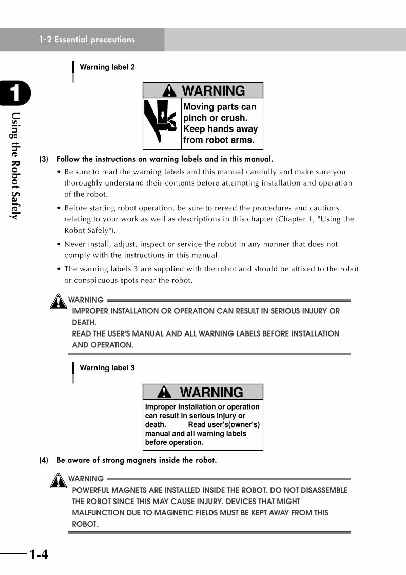
Warning label 2
Moving parts can pinch or crush.Keep hands away from robot arms.
WARNING
(3) Follow the instructions on warning labels and in this manual.
•Besuretoreadthewarninglabelsandthismanualcarefullyandmakesureyou
thoroughly understand their contents before attempting installation and operation
of the robot.
•Beforestartingrobotoperation,besuretorereadtheproceduresandcautions
relatingtoyourworkaswellasdescriptionsinthischapter(Chapter1,"Usingthe
RobotSafely").
•Neverinstall,adjust,inspectorservicetherobotinanymannerthatdoesnot
comply with the instructions in this manual.
•Thewarninglabels3aresuppliedwiththerobotandshouldbeaffixedtotherobot
or conspicuous spots near the robot.
wWARNING IMPROPER INSTAllATION OR OPERATION CAN RESUlT IN SERIOUS INjURy OR DEATh. READ ThE USER'S MANUAl AND All WARNING lABElS BEFORE INSTAllATION AND OPERATION.
Warning label 3
Improper Installation or operation can result in serious injury or death. Read user's(owner's) manual and all warning labels before operation.
WARNING
(4) Be aware of strong magnets inside the robot.
wWARNING POWERFUl MAGNETS ARE INSTAllED INSIDE ThE ROBOT. DO NOT DISASSEMBlE ThE ROBOT SINCE ThIS MAy CAUSE INjURy. DEvICES ThAT MIGhT maLfunctionduetomagneticfieLdsmustbeKeptawayfromthisROBOT.
1-4
1
Using the R
obot Safely
1-2 Essential precautions
1-5
(5) Do not remove, alter or stain the warning labels.
wWARNING IF WARNING lABElS ARE REMOvED OR DIFFICUlT TO SEE, ThEN ESSENTIAl precautionsmightnotbetaKen,resuLtinginaccidents. • donotremoVe,aLterorstainthewarningLabeLsontherobot. • donotaLLowthewarningLabeLstobehiddenbydeVicesinstaLLed ONTO ThE ROBOT By ThE USER. • proVideproperLightingsothatthesymboLsandinstructionson ThE WARNING lABElS CAN BE ClEARly SEEN EvEN FROM OUTSIDE ThE SAFETy ENClOSURE.
(6) Do not use the robot in environments containing inflammable gas, etc.
wWARNING • thisrobotwasnotdesignedforoperationinenVironmentswhere INFlAMMABlE OR EXPlOSIvE SUBSTANCES ARE PRESENT. • donotusetherobotinenVironmentscontaininginfLammabLe GAS, DUST OR lIQUIDS. EXPlOSIONS OR FIRE MIGhT OThERWISE RESUlT.
(7) Do not use the robot in locations possibly subject to electromagnetic interference, etc.
wWARNING DO NOT USE ThE ROBOT IN lOCATIONS SUBjECT TO ElECTROMAGNETIC INTERFERENCE, ElECTROSTATIC DISChARGE OR RADIO FREQUENCy INTERFERENCE. MAlFUNCTIONS MIGhT OThERWISE OCCUR.
(8) Provide safety measures for end effector (gripper, etc.).
wWARNING • endeffectorsmustbedesignedandmanufacturedsothatthey createnohaZards(foreXampLe,aworKpiecethatcomesLoose) EvEN IF POWER (ElECTRICITy, AIR PRESSURE, ETC.) IS ShUT OFF OR POWER FlUCTUATIONS OCCUR. • ifthereisapossibLedangerthattheobJectgrippedbytheend EFFECTOR MAy Fly OFF OR DROP, ThEN PROvIDE APPROPRIATE SAFETy protectiontaKingintoaccounttheobJectsiZe,weight, TEMPERATURE AND ChEMICAl PROPERTIES.
Using the R
obot Safely
1
1-2 Essential precautions
1-6 1-7
(9) Be careful not to touch the motor and peripheral parts when hot.
wWARNING The motor and speed reduction gear casing are extremely hot after automatic operation, so burns may occur if these are touched. Before handling these parts during inspection or servicing, turn off the controller, wait for a while and check that the parts have cooled.
(10) Take the following safety precautions during inspection of controller.
wWARNING • whenyouneedtotouchtheterminaLsorconnectorsonthe OUTSIDE OF ThE CONTROllER DURING INSPECTION, AlWAyS FIRST TURN OFF ThE CONTROllER POWER SWITCh AND AlSO ThE POWER SOURCE IN ORDER topreVentpossibLeeLectricaLshocK. • donotdisassembLethecontroLLer.neVertouchanyinternaL partsofthecontroLLer.doingsomightcausebreaKdowns, MAlFUNCTIONS, INjURy OR FIRE. IF ANy PARTS OF ThE CONTROllER NEED TO BE REPlACED, FOllOW ThE SPECIFIED INSTRUCTIONS. • refertothecontroLLeruser'smanuaLforprecautionson hANDlING ThE CONTROllER.
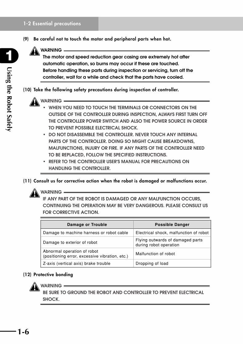
(11) Consult us for corrective action when the robot is damaged or malfunctions occur.
wWARNING IF ANy PART OF ThE ROBOT IS DAMAGED OR ANy MAlFUNCTION OCCURS, CONTINUING ThE OPERATION MAy BE vERy DANGEROUS. PlEASE CONSUlT US FOR CORRECTIvE ACTION.
Damage or Trouble Possible Danger
Damage to machine harness or robot cable Electrical shock, malfunction of robot
Damage to exterior of robotFlying outwards of damaged parts during robot operation
Abnormal operation of robot (positioning error, excessive vibration, etc.)
Malfunction of robot
Z-axis (vertical axis) brake trouble Dropping of load
(12) Protective bonding
wWARNING BE SURE TO GROUND ThE ROBOT AND CONTROllER TO PREvENT ElECTRICAl shocK.

1-6
1
Using the R
obot Safely
1-2 Essential precautions
1-7
(13) Be sure to make correct parameter settings.
cCAUTION The robot must be operated with correct tolerable moment of inertia and acceleration coefficients according to the manipulator tip mass and moment of inertia. If these are not correct, drive unit service life may end prematurely, and damage to robot parts or residual vibration during positioning may result.
(14) Follow the specified procedures when installing, adjusting or inspecting the robot.
wWARNING AlWAyS FOllOW ThE SPECIFIED PROCEDURES WhEN INSTAllING, ADjUSTING OR INSPECTING ThE ROBOT. NEvER ATTEMPT ANy PROCEDURE NOT DESCRIBED IN ThIS MANUAl.
(15) Do not attempt any repair, parts replacement and modification.
wWARNING DO NOT ATTEMPT ANy REPAIR, PARTS REPlACEMENT AND MODIFICATION UNlESS DESCRIBED IN ThIS MANUAl. theseworKsreQuiretechnicaLKnowLedgeandsKiLL,andmayaLsoinVoLVeworKhaZards.
(16) Do not use the robot in locations where strong magnetic sources are present.
wWARNING DO NOT USE ThE ROBOT NEAR A STRONG MAGNETIC SOURCE. ThE ROBOT mightotherwisebreaKdownormaLfunction.
(17) Precautions when disposing of the robot
When disposing of the robot, handle it as industrial waste.
wWARNING hANDlE ThE ROBOT CAREFUlly WhEN DISPOSING OF IT SINCE POWERFUl MAGNETS ARE INSTAllED INSIDE.
(18) Location for installing the controller and the programming box or Handy Terminal
The robot controller, programming box, and Handy Terminal should be installed at a
location that is outside the robot movement range yet where it is easy to operate and
view the robot performing tasks.
(19) Protect electrical wiring and hydraulic/pneumatic hoses as needed.
Install a cover or similar item to protect the electrical wring and hydraulic/pneumatic
hoses from possible damage.

Using the R
obot Safely
1
1-2 Essential precautions
1-8 1-9
(20) Install an operation status light.
Install an operation status light (signal light tower, etc.) at an easy-to-see position so
the operator will know whether the robot is merely stopped or is in emergency-error
stop.
(21) Clean work tools, etc.
Work tools such as welding guns and paint nozzles which are mounted in the robot
arm will preferably be cleaned automatically.
(22) Provide adequate lighting.
Make sure to provide enough lighting to ensure safety during work.
(23) Prevent the gripped object from flying outwards.
If the object or workpiece gripped by the robot might fly outward or drop and create
a hazard to the operator, then protective equipment should be installed by taking the
size, weight, temperature and chemical properties of the object into account.
(24) Draw up "work instructions" and makes sure the operator learns them well.
Decideon"workinstructions"forthefollowingitemsincaseswherepersonnel
must work within the robot movement range to perform teaching, maintenance or
inspection.Makesuretheworkersknowthese"workinstructions"well.
(1) Robot operating procedures needed for tasks such as startup procedures and
handling switches
(2) Robot speeds used during tasks such as teaching
(3) Methods for workers to signal each other when two or more workers perform
tasks
(4) Stepsthattheworkershouldtakewhenaproblemoremergencyoccurs
(5) Stepstotakeaftertherobothascometoastopwhentheemergencystopdevice
was triggered, including checks for cancelling the problem or error state and
safety checks in order to restart the robot.
(6) In cases other than above, the following actions should be taken as needed to
prevent hazardous situations due to sudden or unexpected robot operation or
faulty robot operation, as listed below.
1.Showadisplayontheoperatorpanel
2. Ensure the safety of workers performing tasks within the robot movement range
3.Clearlyspecifypositionandpostureduringwork
Position and posture where worker can constantly check robot movements and
immediately move to avoid trouble if an error/problem occurs
4. Install noise prevention measures
5.Usemethodsforsignalingoperatorsofrelatedequipment
6.Usemethodstodecidethatanerrorhasoccurredandidentifythetypeoferror
1-8
1
Using the R
obot Safely
1-3 Industrial robot operating and maintenance personnel
1-9
Implementthe"workinstructions"accordingtothetypeofrobot,installation
location, and type of work task.
Whendrawingupthe"workinstructions",makeanefforttoincludeopinionsfrom
the workers involved, equipment manufacture's technicians, and workplace safety
consultants, etc.
(25) Display a sign on operation panel during work
Displayaneasytounderstandsignormessageontheprogrammingbox,Handy
Terminal, and operation panel during the job task, to prevent anyone other than the
operators for that job task from mistakenly operating a start or selector switch. If
needed, take other measures such as locking the cover on the operation panel.
(26) Make daily and periodic inspections.
(1) Always make sure that daily and periodic inspections are performed, and make
a pre-work check to ensure there are no problems with the robot or related
equipment. If a problem or abnormality is found, then promptly repair it or take
other measures as necessary.
(2) When you make periodic inspections or repairs, make a record and store it for at
least 3 years.
1-3 Industrial robot operating and maintenance personnelOperators or persons who handle the robot such as for teaching, programming, movement
check, inspection, adjustment, and repair must receive appropriate training and also have
the skills needed to perform the job correctly and safely. They must read the user's manual
carefully to understand its contents before attempting the robot operation.
Tasks related to industrial robots (teaching, programming, movement check, inspection,
adjustment, repair, etc.) must be performed by qualified persons who meet requirements
established by local regulations and safety standards for industrial robots.
Using the R
obot Safely
1
1-4 Robot safety functions
1-10 1-11
1-4 Robot safety functions
(1) Overload detection
This function detects an overload applied to the motor and shuts off the servo power.
(2) Overheat detection
This detects an abnormal temperature rise in the controller driver and shuts off the
servo power.
If an overload or overheat error occurs, take the following measures.
1. Reduce the speed.
2.Inserta"stopperiod"intheoperation.
3. Reduce the acceleration coefficient.
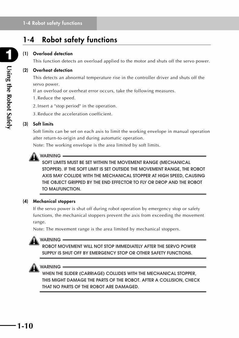
(3) Soft limits
Softlimitscanbesetoneachaxistolimittheworkingenvelopeinmanualoperation
after return-to-origin and during automatic operation.
Note: The working envelope is the area limited by soft limits.
wWARNING SOFT lIMITS MUST BE SET WIThIN ThE MOvEMENT RANGE (MEChANICAl STOPPER). IF ThE SOFT lIMIT IS SET OUTSIDE ThE MOvEMENT RANGE, ThE ROBOT AXIS MAy COllIDE WITh ThE MEChANICAl STOPPER AT hIGh SPEED, CAUSING ThE OBjECT GRIPPED By ThE END EFFECTOR TO Fly OR DROP AND ThE ROBOT TO MAlFUNCTION.
(4) Mechanical stoppers
If the servo power is shut off during robot operation by emergency stop or safety
functions, the mechanical stoppers prevent the axis from exceeding the movement
range.
Note: The movement range is the area limited by mechanical stoppers.
wWARNING ROBOT MOvEMENT WIll NOT STOP IMMEDIATEly AFTER ThE SERvO POWER SUPPly IS ShUT OFF By EMERGENCy STOP OR OThER SAFETy FUNCTIONS.
wWARNING WhEN ThE SlIDER (CARRIAGE) COllIDES WITh ThE MEChANICAl STOPPER, thismightdamagethepartsoftherobot.afteracoLLision,checKThAT NO PARTS OF ThE ROBOT ARE DAMAGED.
1-10
1
Using the R
obot Safely
1-5 Safety measures for the system
1-11
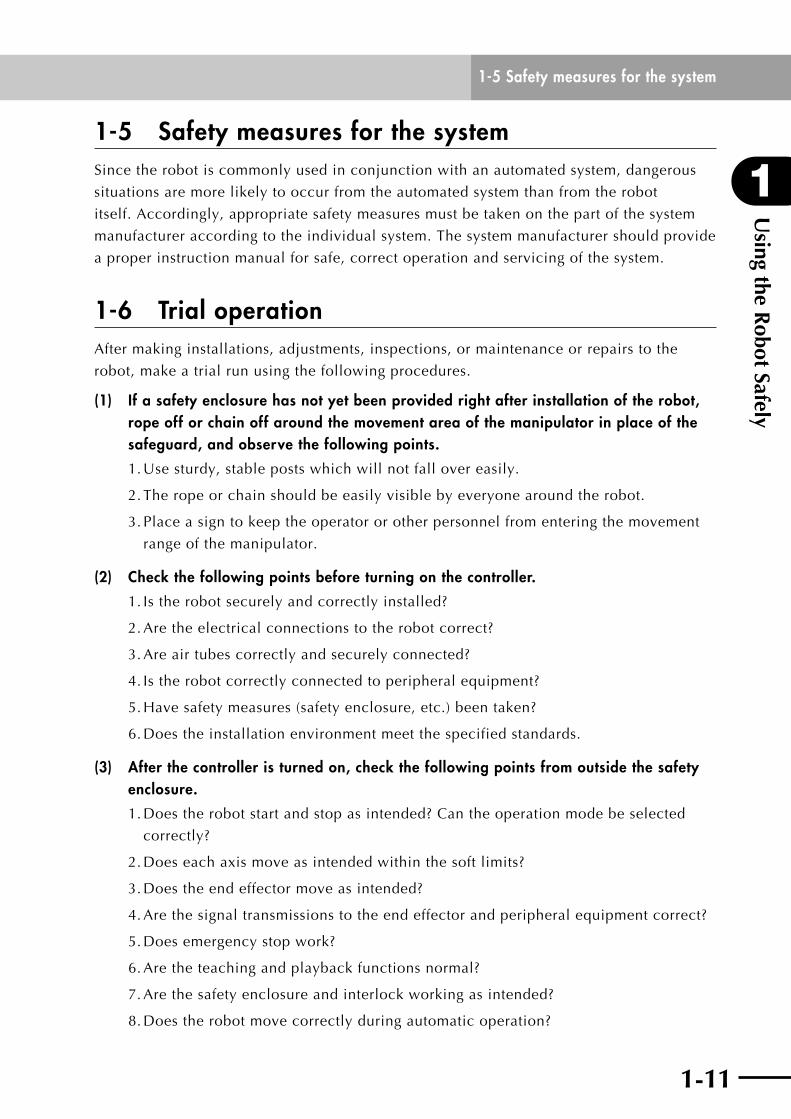
1-5 Safety measures for the systemSincetherobotiscommonlyusedinconjunctionwithanautomatedsystem,dangerous
situations are more likely to occur from the automated system than from the robot
itself. Accordingly, appropriate safety measures must be taken on the part of the system
manufacturer according to the individual system. The system manufacturer should provide
a proper instruction manual for safe, correct operation and servicing of the system.
1-6 Trial operationAfter making installations, adjustments, inspections, or maintenance or repairs to the
robot, make a trial run using the following procedures.
(1) If a safety enclosure has not yet been provided right after installation of the robot, rope off or chain off around the movement area of the manipulator in place of the safeguard, and observe the following points.
1.Usesturdy,stablepostswhichwillnotfallovereasily.
2. The rope or chain should be easily visible by everyone around the robot.
3. Place a sign to keep the operator or other personnel from entering the movement
range of the manipulator.
(2) Check the following points before turning on the controller.
1. Is the robot securely and correctly installed?
2. Are the electrical connections to the robot correct?
3. Are air tubes correctly and securely connected?
4. Is the robot correctly connected to peripheral equipment?
5. Have safety measures (safety enclosure, etc.) been taken?
6.Doestheinstallationenvironmentmeetthespecifiedstandards.
(3) After the controller is turned on, check the following points from outside the safety enclosure.
1.Doestherobotstartandstopasintended?Cantheoperationmodebeselected
correctly?
2.Doeseachaxismoveasintendedwithinthesoftlimits?
3.Doestheendeffectormoveasintended?
4. Are the signal transmissions to the end effector and peripheral equipment correct?
5.Doesemergencystopwork?
6. Are the teaching and playback functions normal?
7. Are the safety enclosure and interlock working as intended?
8.Doestherobotmovecorrectlyduringautomaticoperation?

Using the R
obot Safely
1
1-7 Work within the safety enclosure
1-12 1-13
Reference
When starting the PHASER series robots, the slider always moves a few
millimeters right after the servo is turned on and emits a high pitched noise.
This is just the routine pre-action for estimating the magnetic pole and is not
a problem.
1-7 Work within the safety enclosure
(1) Work within the safety enclosure
When work is required inside the safety enclosure, always turn off the controller and
place a sign indicating that the robot is being adjusted or serviced in order to keep
any other person from touching the controller switch or operation panel, except for
the soft limit setting and teaching. For soft limit setting, follow the suitable cautions,
notes, etc. in this manual. For teaching, follow the procedure shown below.
(2) Teaching
When performing teaching within the safety enclosure, comply with the instructions
listed below.
1)Checkorperformthefollowingpointsfromoutsidethesafetyenclosure.
1. Make sure that no hazards are present within the safety enclosure by a visual
check.
2.CheckthattheprogrammingboxorHandyTerminalisoperatingnormally.
3.Checkthatnofailuresarefoundintherobot.
4.Checkthatemergencystopworkscorrectly.
5.Selectteachingmodeandprohibitautomaticoperation.
2) Never enter the movement range of the manipulator while within the safety
enclosure.
1-12
1
Using the R
obot Safely
1-8 Automatic operation
1-13
1-8 Automatic operationAutomaticoperationdescribedhereincludesalloperationsinAUTOmode.
(1) Check the following before starting automatic operation.
1. No one is within the safety enclosure.
2. The programming box or Handy Terminal, tools, etc. are in their prescribed
positions.
3. The alarm or error lamps on the robot and peripheral equipment do not flash.
4. The safety enclosure is securely installed with safety interlocks actuated.
(2) Observe the following during automatic operation or in cases where an error occurs.
1) After automatic operation has started, check the operation status and signal light to
ensure that the robot is in automatic operation.
2) Never enter the safety enclosure during automatic operation.
3) If an error occurs in the robot or peripheral equipment, observe the following
procedure before entering the safety enclosure.
1. Press the emergency stop button to set the robot to emergency stop.
2. Place a sign on the start switch, indicating that the robot is being inspected in
order to keep any other person from touching the start switch and restarting the
robot.

Using the R
obot Safely
1
1-9 Warranty
1-14
1-9 WarrantyFor information on the warranty period and terms, please contact our distributor where you purchased the product.
n This warranty does not cover any failure caused by:
1. Installation, wiring, connection to other control devices, operating methods, inspection or maintenance that does not comply with industry standards or instructions specified in the YAMAHA manual;
2.UsagethatexceededthespecificationsorstandardperformanceshownintheYAMAHA manual;
3. Product usage other than intended by YAMAHA;
4.Storage,operatingconditionsandutilitiesthatareoutsidetherangespecifiedinthe manual;
5.Damageduetoimpropershippingorshippingmethods;
6. Accident or collision damage;
7. Installation of other than genuine YAMAHA parts and/or accessories;
8. Modification to original parts or modifications not conforming to standard specifications designated by YAMAHA, including customizing performed by YAMAHA in compliance with distributor or customer requests;
9. Pollution, salt damage, condensation;
10. Fires or natural disasters such as earthquakes, tsunamis, lightning strikes, wind and flood damage, etc;
11. Breakdown due to causes other than the above that are not the fault or responsibility of YAMAHA;
n The following cases are not covered under the warranty:
1. Products whose serial number or production date (month & year) cannot be verified.
2.Changesinsoftwareorinternaldatasuchasprogramsorpointsthatwerecreatedor changed by the customer.
3. Products whose trouble cannot be reproduced or identified by YAMAHA.
4. Products utilized, for example, in radiological equipment, biological test equipment applications or for other purposes whose warranty repairs are judged as hazardous by YAMAHA.
THEWARRANTYSTATEDHEREINPROVIDEDBYYAMAHAONLYCOVERSDEFECTS
INPRODUCTSANDPARTSSOLDBYYAMAHATODISTRIBUTORSUNDERTHIS
AGREEMENT.ANYANDALLOTHERWARRANTIESORLIABILITIES,EXPRESSOR
IMPLIED,INCLUDINGBUTNOTLIMITEDTOANYIMPLIEDWARRANTIESOF
MERCHANTABILITYORFITNESSFORAPARTICULARPURPOSEAREHEREBYEXPRESSLY
DISCLAIMEDBYYAMAHA.MOREOVER,YAMAHASHALLNOTBEHELDRESPONSIBLE
FORCONSEQUENTORINDIRECTDAMAGESINANYMANNERRELATINGTOTHE
PRODUCT.Ver.1.00_201205

Chapter 2 Product Overview
Contents
2-1 Checking the product 2-1
2-2 Robot part names 2-2
2-3 Robot internal structure 2-3

2-1
2
Product Overview
2-1 Checking the product
2-1
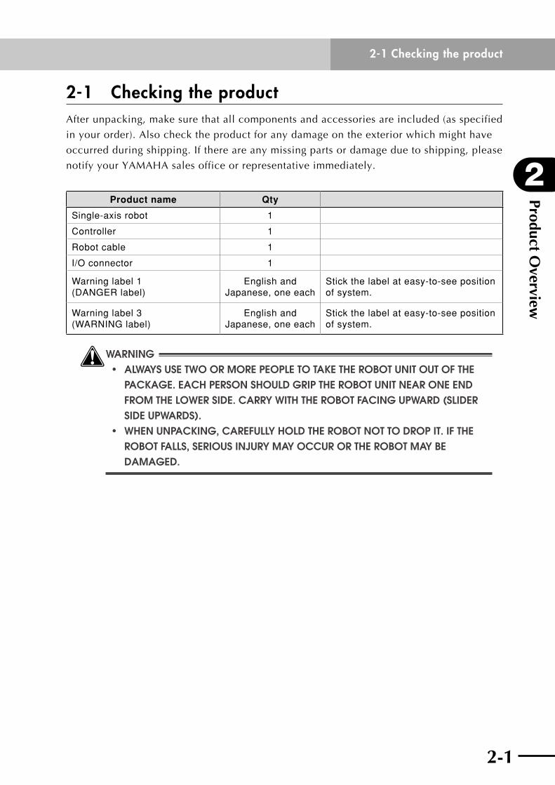
2-1 Checking the productAfter unpacking, make sure that all components and accessories are included (as specified
in your order). Also check the product for any damage on the exterior which might have
occurred during shipping. If there are any missing parts or damage due to shipping, please
notify your YAMAHA sales office or representative immediately.
Product name Qty
Single-axis robot 1
Controller 1
Robot cable 1
I/O connector 1
Warning label 1 (DANGER label)
English and Japanese, one each
Stick the label at easy-to-see position of system.
Warning label 3 (WARNING label)
English and Japanese, one each
Stick the label at easy-to-see position of system.
wWARNING • aLwaysusetwoormorepeopLetotaKetherobotunitoutofthe pacKage.eachpersonshouLdgriptherobotunitnearoneend FROM ThE lOWER SIDE. CARRy WITh ThE ROBOT FACING UPWARD (SlIDER SIDE UPWARDS). • whenunpacKing,carefuLLyhoLdtherobotnottodropit.ifthe ROBOT FAllS, SERIOUS INjURy MAy OCCUR OR ThE ROBOT MAy BE DAMAGED.
Product Overview
2
2-2 Robot part names
2-2 2-3
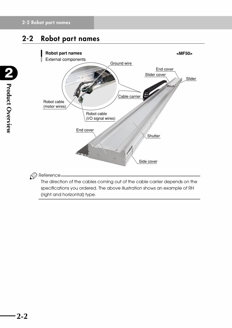
2-2 Robot part names
Robot part names
External components
End coverSlider cover
Shutter
End cover
Slider
Cable carrierRobot cable (motor wires)
Robot cable (I/O signal wires)
Ground wire
Side cover
<MF50>
Reference
The direction of the cables coming out of the cable carrier depends on the
specifications you ordered. The above illustration shows an example of RH
(right and horizontal) type.
2-2
2
Product Overview
2-3 Robot internal structure
2-3
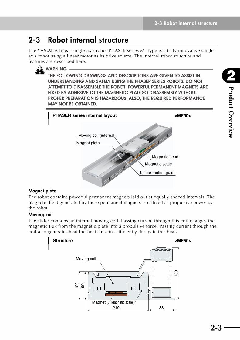
2-3 Robot internal structureTheYAMAHAlinearsingle-axisrobotPHASERseriesMFtypeisatrulyinnovativesingle-axis robot using a linear motor as its drive source. The internal robot structure and features are described here.
wWARNING ThE FOllOWING DRAWINGS AND DESCRIPTIONS ARE GIvEN TO ASSIST IN UNDERSTANDING AND SAFEly USING ThE PhASER SERIES ROBOTS. DO NOT ATTEMPT TO DISASSEMBlE ThE ROBOT. POWERFUl PERMANENT MAGNETS ARE FIXED By ADhESIvE TO ThE MAGNETIC PlATE SO DISASSEMBly WIThOUT PROPER PREPARATION IS hAzARDOUS. AlSO, ThE REQUIRED PERFORMANCE MAy NOT BE OBTAINED.
Magnet plate
Linear motion guide
PHASER series internal layout
Moving coil (internal)
Magnetic scale
Magnetic head
<MF50>
Magnet plateThe robot contains powerful permanent magnets laid out at equally spaced intervals. The magnetic field generated by these permanent magnets is utilized as propulsive power by the robot.
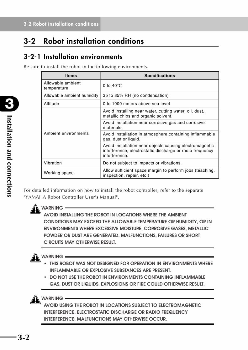
Moving coilThe slider contains an internal moving coil. Passing current through this coil changes the magnetic flux from the magnetic plate into a propulsive force. Passing current through the coil also generates heat but heat sink fins efficiently dissipate this heat.
100
180
210 88
99
Moving coil
Structure
Magnet Magnetic scale
<MF50>

Product Overview
2
2-3 Robot internal structure
2-4
Linear guideThe MF50 use a linear guide assembled with a ball retainer that efficiently eliminates
friction between adjacent balls. This achieves low noise, long service life and long
maintenance-free operation.
Magnetic scale and magnetic headThe magnetic scale utilizes YAMAHA's superb magnetic signal detection technology
developed in-house. The scale is made of a special alloy that retains a high-strength
magnetic field with virtually no weakening over time. Integrating it with a magnetic head
yields an astonishingly high resolution of one micrometer. Fully closed control directly
detects the table (slider) position for stable and highly precise positioning.
cCAUTION Do not bring a strong magnet close to the magnetic scale. A strong magnet may erase the information recorded on the scale and cause the robot to malfunction. A magnetic force of about 10mT (100 Gauss) does not cause any problem. As shown in the photos below, for example, bringing the magnetized side of a magnetic base close to the side of the robot may erase the information on the magnetic scale, so use caution.
Magnetized side of magnetic base Magnetized side of magnetic base
cCAUTION The magnetic flux slightly leaks from the robot surface. (Max. 10mT) When a device (sensor) that responds to the magnetism is installed, it may respond incorrectly. Install such device 100 mm or more apart from the robot, make the fine adjustment to eliminate incorrect response, or use a device designed for the strong magnetic field.
Magnetic flux leak rangeRobotRobot

Chapter 3 Installation and connections
Contents
3-1 Carrying the robot 3-1
3-2 Robot installation conditions 3-23-2-1 Installation environments 3-2
3-2-2 Installation base 3-3
3-3 Installing the robot 3-5
3-4 Installing an external leakage breaker and circuit protector 3-7
3-5 Protective bonding 3-8
3-6 Connecting the robot to the controller 3-9
3-7 Precautions during user wiring and air tube installation 3-12

3-1

3
Installation and connections
3-1 Carrying the robot
3-1
3-1 Carrying the robotAlways use 2 people to carry the robot unit. Each person should grip the robot unit near
oneendfromthelowersideasshownandcarrywiththeloadwellbalanced.Carrywith
the robot facing upward (slider side upwards).
wWARNING AlWAyS OBSERvE ThE FOllOWING PRECAUTIONS WhEN CARRyING ThE ROBOT. • remoVeanyandaLLobJectssuchashandsandgrippersattached TO ThE ROBOT SlIDER BEFORE MOvING ThE ROBOT. ThE SlIDER WIll lOSE BAlANCE IF MOvED WITh OBjECTS STIll ATTAChED AND CAUSE INjURIES. • KeeptherobotbaLancedanddon'tLetittiLtwhiLemoVingit.ifthe ROBOT TIlTS, ThE SlIDER MAy MOvE UNDER ITS OWN WEIGhT CAUSING SERIOUS INjURIES SUCh AS CRUShED FINGERS. • neVerattempttohoLdtherobotinanyofthefoLLowingmanners.
[Never try this when moving!]
• Do not carry by holding the slider.• Do not carry by holding the cable.• Do not carry by holding the cable carrier.• Do not carry by gripping the end cover.
Installation and connections
3
3-2 Robot installation conditions
3-2 3-3
3-2 Robot installation conditions
3-2-1 Installation environmentsBe sure to install the robot in the following environments.
Items Specifications
Allowable ambient temperature
0 to 40°C
Allowable ambient humidity 35 to 85% RH (no condensation)
Altitude 0 to 1000 meters above sea level
Ambient environments
Avoid installing near water, cutting water, oil, dust, metallic chips and organic solvent.
Avoid installation near corrosive gas and corrosive materials.
Avoid installation in atmosphere containing inflammable gas, dust or liquid.
Avoid installation near objects causing electromagnetic interference, electrostatic discharge or radio frequency interference.
Vibration Do not subject to impacts or vibrations.
Working spaceAllow sufficient space margin to perform jobs (teaching, inspection, repair, etc.)
For detailed information on how to install the robot controller, refer to the separate
"YAMAHARobotControllerUser'sManual".
wWARNING AvOID INSTAllING ThE ROBOT IN lOCATIONS WhERE ThE AMBIENT CONDITIONS MAy EXCEED ThE AllOWABlE TEMPERATURE OR hUMIDITy, OR IN ENvIRONMENTS WhERE EXCESSIvE MOISTURE, CORROSIvE GASES, METAllIC POWDER OR DUST ARE GENERATED. MAlFUNCTIONS, FAIlURES OR ShORT CIRCUITS MAy OThERWISE RESUlT.
wWARNING • thisrobotwasnotdesignedforoperationinenVironmentswhere INFlAMMABlE OR EXPlOSIvE SUBSTANCES ARE PRESENT. • donotusetherobotinenVironmentscontaininginfLammabLe GAS, DUST OR lIQUIDS. EXPlOSIONS OR FIRE COUlD OThERWISE RESUlT.
wWARNING AvOID USING ThE ROBOT IN lOCATIONS SUBjECT TO ElECTROMAGNETIC INTERFERENCE, ElECTROSTATIC DISChARGE OR RADIO FREQUENCy INTERFERENCE. MAlFUNCTIONS MAy OThERWISE OCCUR.
3-2
3
Installation and connections
3-2 Robot installation conditions
3-3
wWARNING DO NOT USE ThE ROBOT IN lOCATIONS SUBjECT TO EXCESSIvE vIBRATION. ROBOT INSTAllATION BOlTS MAy OThERWISE BECOME lOOSE CAUSING ThE ROBOT TO FAll OvER.
3-2-2 Installation baseTo mount the robot, use an installation base that satisfies the following conditions.
1) The installation base is subjected to a great deal of stress while the robot is in operation.
Prepare a sufficiently rigid and stable installation base, taking into account the robot
weight including the end effector (gripper) and workpiece.
wWARNING IF ThE INSTAllATION BASE IS NOT SUFFICIENTly RIGID AND STABlE, vIBRATION (RESONANCE) MAy OCCUR DURING OPERATION, CAUSING ADvERSE EFFECTS ontherobotworK.
2) The installation base surface must be machined within a flatness of ±0.05mm/500mm.
cCAUTION The robot positioning accuracy, acceleration and duty might not satisfy the required performance or the service life might be reduced if the installation surface precision is insufficient. In worst cases, the coil inside the robot might burn out.
Installation and connections
3
3-2 Robot installation conditions
3-4 3-5
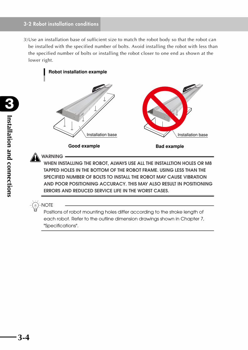
3)Useaninstallationbaseofsufficientsizetomatchtherobotbodysothattherobotcan
be installed with the specified number of bolts. Avoid installing the robot with less than
the specified number of bolts or installing the robot closer to one end as shown at the
lower right.
Good example
Installation base
Bad example
Installation base
Robot installation example
wWARNING WhEN INSTAllING ThE ROBOT, AlWAyS USE All ThE INSTAllTION hOlES OR M8 TAPPED hOlES IN ThE BOTTOM OF ThE ROBOT FRAME. USING lESS ThAN ThE SPECIFIED NUMBER OF BOlTS TO INSTAll ThE ROBOT MAy CAUSE vIBRATION AND POOR POSITIONING ACCURACy. ThIS MAy AlSO RESUlT IN POSITIONING ERRORS AND REDUCED SERvICE lIFE IN ThE WORST CASES.
nNOTE
Positions of robot mounting holes differ according to the stroke length of
each robot. Refer to the outline dimension drawings shown in Chapter 7,
"Specifications".
3-4
3
Installation and connections
3-3 Installing the robot
3-5
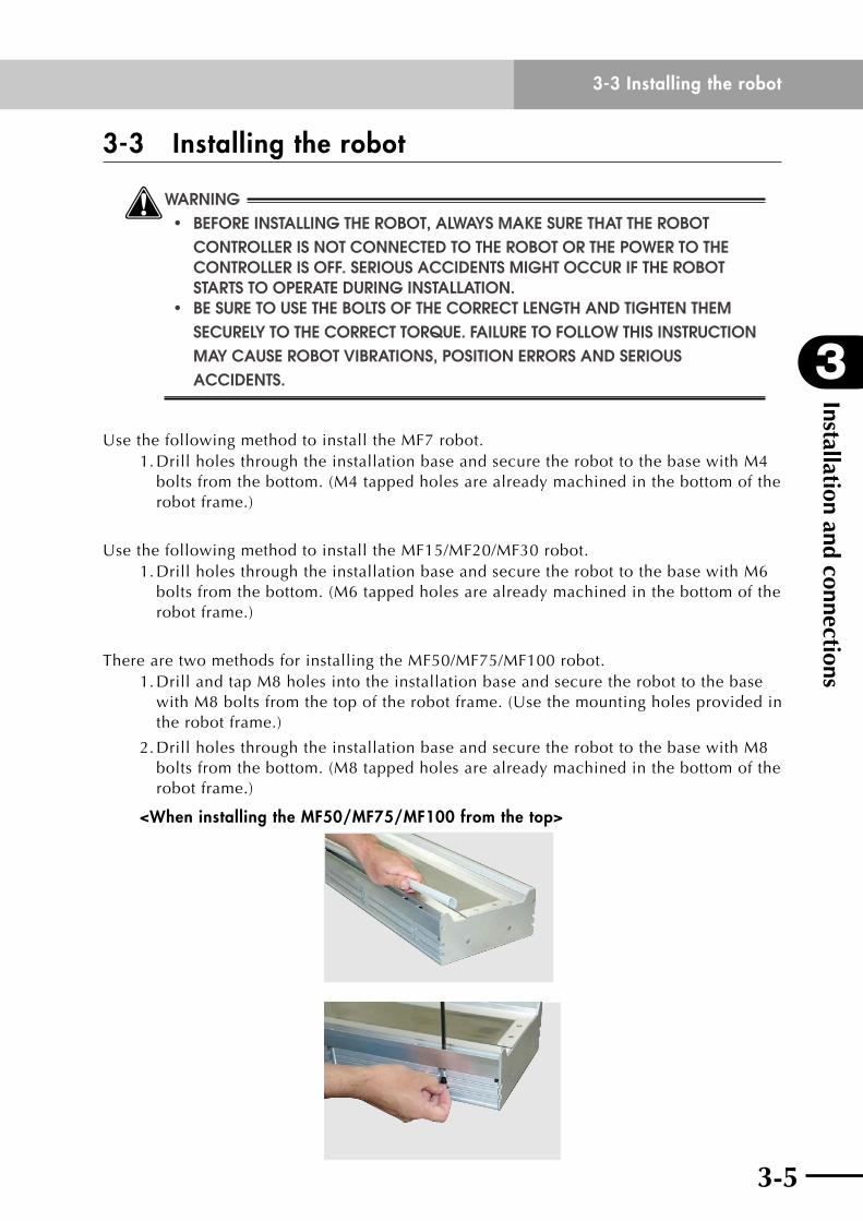
3-3 Installing the robot
wWARNING • beforeinstaLLingtherobot,aLwaysmaKesurethattherobot CONTROllER IS NOT CONNECTED TO ThE ROBOT OR ThE POWER TO ThE CONTROllER IS OFF. SERIOUS ACCIDENTS MIGhT OCCUR IF ThE ROBOT STARTS TO OPERATE DURING INSTAllATION. • besuretousetheboLtsofthecorrectLengthandtightenthem SECUREly TO ThE CORRECT TORQUE. FAIlURE TO FOllOW ThIS INSTRUCTION MAy CAUSE ROBOT vIBRATIONS, POSITION ERRORS AND SERIOUS ACCIDENTS.
UsethefollowingmethodtoinstalltheMF7robot.1.DrillholesthroughtheinstallationbaseandsecuretherobottothebasewithM4
bolts from the bottom. (M4 tapped holes are already machined in the bottom of the robot frame.)
UsethefollowingmethodtoinstalltheMF15/MF20/MF30robot.1.DrillholesthroughtheinstallationbaseandsecuretherobottothebasewithM6
bolts from the bottom. (M6 tapped holes are already machined in the bottom of the robot frame.)
There are two methods for installing the MF50/MF75/MF100 robot.1.DrillandtapM8holesintotheinstallationbaseandsecuretherobottothebase
withM8boltsfromthetopoftherobotframe.(Usethemountingholesprovidedinthe robot frame.)
2.DrillholesthroughtheinstallationbaseandsecuretherobottothebasewithM8bolts from the bottom. (M8 tapped holes are already machined in the bottom of the robot frame.)
<When installing the MF50/MF75/MF100 from the top>
Installation and connections
3
3-3 Installing the robot
3-6 3-7
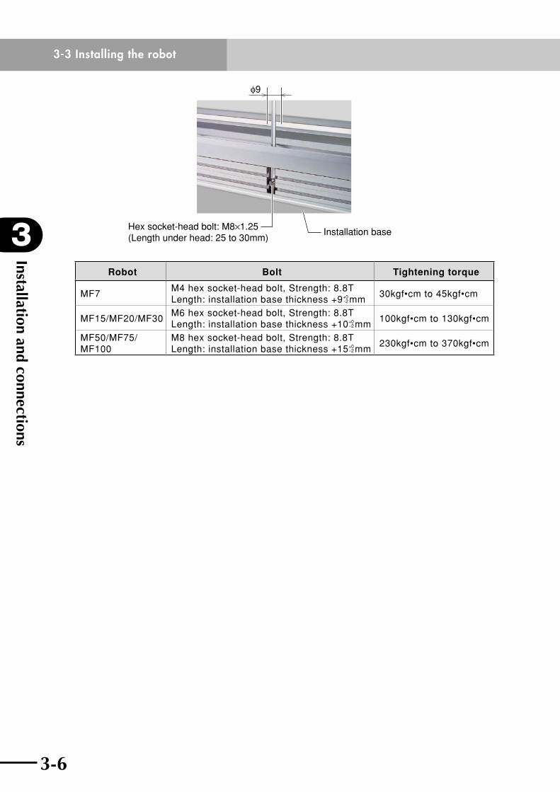
φ9
Installation baseHex socket-head bolt: M8×1.25(Length under head: 25 to 30mm)
Robot Bolt Tightening torque
MF7M4 hex socket-head bolt, Strength: 8.8T Length: installation base thickness +9-2
+0 mm30kgf•cm to 45kgf•cm
MF15/MF20/MF30M6 hex socket-head bolt, Strength: 8.8T Length: installation base thickness +10-2
+0 mm100kgf•cm to 130kgf•cm
MF50/MF75/MF100
M8 hex socket-head bolt, Strength: 8.8T Length: installation base thickness +15-2
+0 mm230kgf•cm to 370kgf•cm

3-6
3
Installation and connections
3-4 Installing an external leakage breaker and circuit protector
3-7
3-4 Installing an external leakage breaker and circuit protectorTo ensure safety, a leakage breaker and circuit protector must be installed in the power supply connection section of the robot controller. Make power connections to the controller by following the instructions in the controller user's manual.
wWARNING • eLectricaLshocKs,inJuriesorfiresmightoccurifthemotor breaKsdownwhiLetherobotcontroLLerisusedwithout instaLLingaLeaKagebreaKerinthepowersuppLysection. • eLectricaLshocKs,inJuriesorfiresmightoccurifthemotor breaKsdownwhiLetherobotcontroLLerisusedwithoutmaKing CORRECT CONNECTIONS TO ThE POWER SUPPly. useawirethicKerthan2.0sQuaremiLLimeters.
cCAUTION • besurethatthepowersupplyvoltageandtheterminalconnectionsare correct. Incorrect voltage and connections could cause an equipment failure. • shutthecontrolpoweroffwhileina"servooff"condition.
Installation and connections
3
3-5 Protective bonding
3-8 3-9
3-5 Protective bonding
wWARNING AlWAyS GROUND ThE ROBOT AND CONTROllER UNIT TO PREvENT ElECTRICAl shocK.
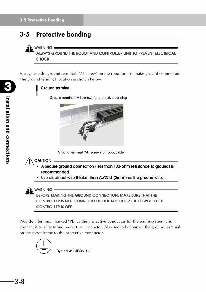
Always use the ground terminal (M4 screw) on the robot unit to make ground connection.
The ground terminal location is shown below.
Ground terminal
Ground terminal (M4 screw) for protective bonding
Ground terminal (M4 screw) for robot cable
cCAUTION • asecuregroundconnection(lessthan100-ohmresistancetoground)is recommended. • useelectricalwirethickerthanawg14(2mm2) as the ground wire.
wWARNING beforemaKingthegroundconnection,maKesurethattheCONTROllER IS NOT CONNECTED TO ThE ROBOT OR ThE POWER TO ThE CONTROllER IS OFF.
Provideaterminalmarked"PE"astheprotectiveconductorfortheentiresystem,and
connect it to an external protective conductor. Also securely connect the ground terminal
on the robot frame to the protective conductor.
(Symbol 417-IEC5019)
3-8
3
Installation and connections
3-6 Connecting the robot to the controller
3-9
3-6 Connecting the robot to the controllerConnecttherobotcablestothematingconnectorsonthecontrollerasshown.Forthe
connectors on the controller, refer to the user's manual of the YAMAHA robot controller
being used.
wWARNING • beforeconnectingthecabLes,checKthattherearenobendsor breaKsintherobotcabLeconnectorpinsandthatthecabLesare notdamaged.bentorbroKenpinsorcabLedamagemaycause ROBOT MAlFUNCTIONS. • aLwaysmaKesurethatthepowertotherobotcontroLLerisoff BEFORE CONNECTING ThE CABlES OR GROUND WIRES.
cCAUTION • After connecting the robot cable intermediate connectors together, fit the connector hoods together securely. • Standard robot cables do not permit much movement, so attach the robot cable securely to prevent unwanted movement of the motor power and signal wires.
wWARNING • iftheconnectorsarenotsecureLyinsertedandtheconnector pinsmaKepoorcontact,therobotmaymaLfunctioncausing hAzARDOUS SITUATIONS. BEFORE TURNING ON POWER TO ThE ROBOT, aLwaysmaKesurethateachconnectoriscorrectLyandsecureLy INSERTED. • DO NOT PlACE A STRAIN OR lOAD ON ThE CONNECTOR By PUllING ON ThE ROBOT CABlE ITSElF.
wWARNING INSTAll ThE ROBOT CABlE SO ThAT IT WIll NOT INTERFERE WITh ThE ROBOT MOvEMENT. DO NOT USE AN AREA WhERE INTERFERENCE MIGhT OCCUR BETWEEN ThE robotcabLeandLoadattachedtothetipoftherobotasaworKarea.therobotcabLemightbreaKifithangsuponthemoVingPARTS OF ThE ROBOT AND CAUSE hAzARDOUS SITUATIONS DUE TO MAlFUNCTION.
wWARNING INSTAll ThE CONNECTED ROBOT CABlE IN A POSITION WhERE IT WIll NOT interferewithotherworKersoroperators.peopLemighttripoVerThE CABlE AND FAll CAUSING INjURIES.
Installation and connections
3
3-6 Connecting the robot to the controller
3-10 3-11
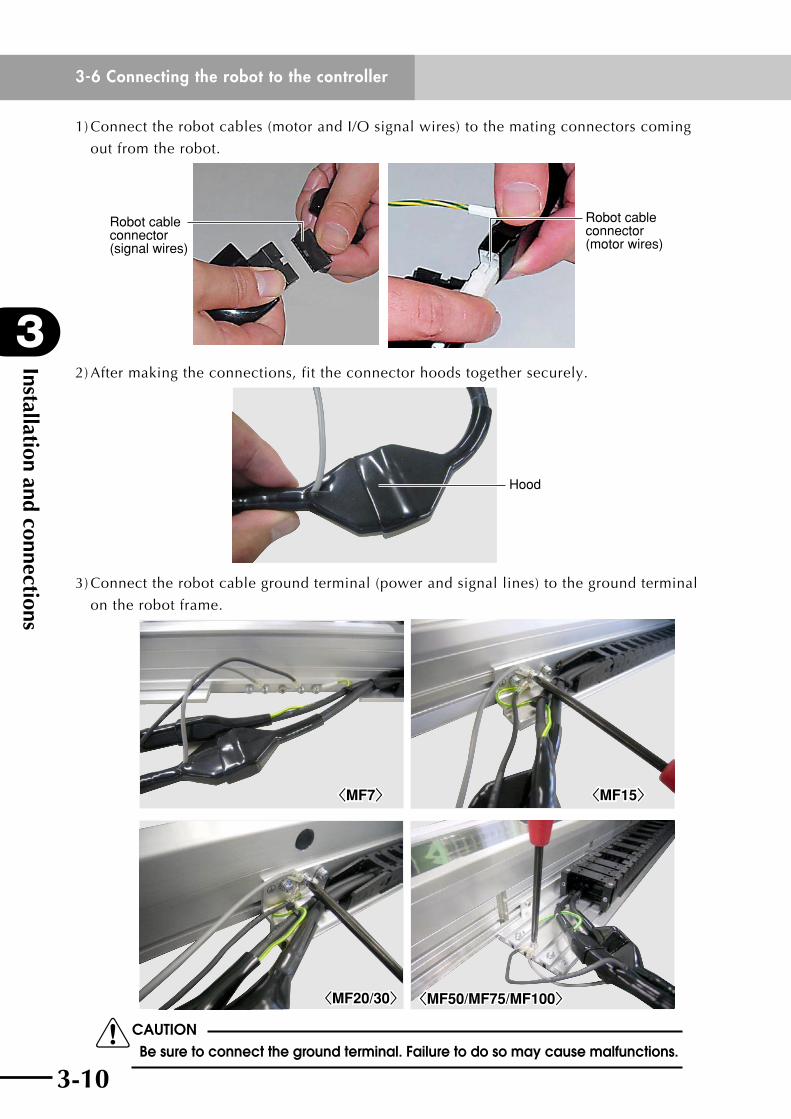
1)Connecttherobotcables(motorandI/Osignalwires)tothematingconnectorscoming
out from the robot.
Robot cable connector (signal wires)
Robot cable connector (motor wires)
2) After making the connections, fit the connector hoods together securely.
Hood
3)Connecttherobotcablegroundterminal(powerandsignallines)tothegroundterminal
on the robot frame.
<MF7><MF7>
<MF15><MF15>
<MF20/30><MF20/30>
<MF50/MF75/MF100><MF50/MF75/MF100>
cCAUTION Be sure to connect the ground terminal. Failure to do so may cause malfunctions.
3-10
3
Installation and connections
3-6 Connecting the robot to the controller
3-11
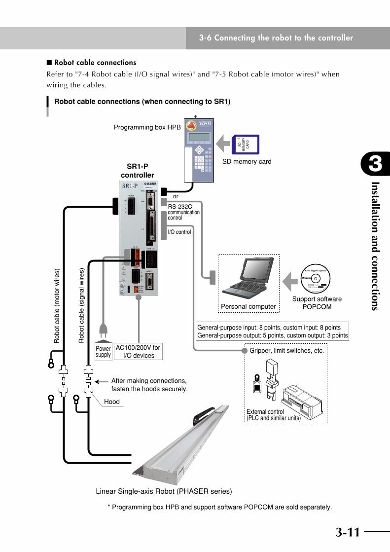
n Robot cable connectionsReferto"7-4Robotcable(I/Osignalwires)"and"7-5Robotcable(motorwires)"when
wiring the cables.
Robot cable connections (when connecting to SR1)
* Programming box HPB and support software POPCOM are sold separately.
SR1-Pcontroller
RS-232C communication control
or
Programming box HPB
SD memory card
Powersupply
General-purpose input: 8 points, custom input: 8 pointsGeneral-purpose output: 5 points, custom output: 3 points
Support softwarePOPCOM
Gripper, limit switches, etc.
External control(PLC and similar units)
I/O control
Personal computer
AC100/200V for I/O devices
Hood
After making connections, fasten the hoods securely.
Linear Single-axis Robot (PHASER series)
SD
ME
MO
RY
CA
RD
Rob
ot c
able
(m
otor
wire
s)
Rob
ot c
able
(si
gnal
wire
s)
Installation and connections
3
3-7 Precautions during user wiring and air tube installation
3-12
3-7 Precautions during user wiring and air tube installation
Cable carries (plastic chain for cable guide)
UsercablesandairtubescanberoutedinthecablecarrieroftheMFtyperobots.
Observe the following precautions when routing user cables and air tubes in the
cable carrier.
cCAUTION • thecableandairtubesshouldtakeuplessthan30%ofthespacewhen storing them inside the cable carrier. lay out the cables and air tubes in rows inside the cable carrier so they do not cross each other. Use the table below as a general guide for cable and air tube installation. • thecablesandairtubesinsidethecablecarrierwillshiftwhiletherobot is operating, becoming taut and placing a strain on the connectors at both ends. To prevent this loosely fasten the cables and air tube to the cable carrier with cable ties to prevent strain from being applied. (Fasten them lightly since the cables and air tubes might break if secured too tightly.) • donotremoveormountbracketsinstalledonthecablecarrieror attempt to modify them.
n Cable and air tube installation (reference)
Robot modelOptional
cable carrier typeCable and air tube
MF7/15/20/30
S f8 flexible cable ×1, f4 air tube ×1
M f8 flexible cable ×2, f6 air tube ×2
L f8 flexible cable ×2, f6 air tube ×3
MF50/75/100 – f8 flexible cable ×2, f6 air tube ×3

Chapter 4 Robot operation
Contents
4-1 Notes on robot operation 4-14-1-1 Magnetic pole estimation action 4-1
4-1-2 Absolute search (semi-absolute specification) 4-1
4-1-3 Return to origin (incremental specification) 4-2
4-2 Setting operating conditions 4-44-2-1 Process flow for setting operating conditions 4-4
4-2-2 Duty monitor 4-5
4-2-3 Acceleration setting 4-6
4-3 Pulse train control (SRCP, SRCP30) 4-84-3-1 Acceleration/deceleration and position proportional gain 4-8
4-3-2 Setting the maximum speed 4-10

4-1
4
Robot operation
4-1 Notes on robot operation
4-1
4-1 Notes on robot operationOn the MF7/MF15/MF20/MF30/MF50/MF75, two linear scale specifications are provided:
incremental specification and semi-absolute specification. The MF100 is available only
in incremental specification. Action after power-on differs depending on the linear scale
specifications. Keep the following points in mind.
4-1-1 Magnetic pole estimation action•WhenstartingthePHASERseriesrobots,theslideralwaysmovesafewmillimeters
right after the servo is turned on and emits a high pitched noise. This is just the
routine pre-action for estimating the magnetic pole and is not a problem.
•Donotapplyanyexternalforceorimpactontherobotduringthemagneticpole
estimationaction.Doingsomaycauseafailureinthemagneticpoleestimation
action.
•Bothintheincrementalandsemi-absolutespecifications,themagneticpole
estimation action is performed at servo-on immediately after turning the power on.
4-1-2 Absolute search (semi-absolute specification)On the semi-absolute specification, absolute search (absolute position detection) must be
performedafterturningpoweronbeforestartingoperation.Currentpositionisfoundby
reading the signal recorded on the linear scale during absolute search. The slider (carriage)
moves a maximum of 76mm while reading the signal. (The distance that the slider moves
can be shortened by allowing the slider to move back and force for signal read.
n Absolute search motion
•Absoluteresetspeedissetto20(mmpersecond)priortoshipment.Thisspeed
can be reduced by parameter entry.
•Absolutesearchsequence: Whenanabsolutesearch(return-to-origin)command
is input or the HPB is used to perform absolute
search, the slider moves in the direction specified by
parameter and then stops when the origin position is
found, allowing automatic operation.
Robot operation
4
4-1 Notes on robot operation
4-2 4-3
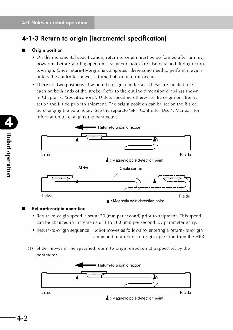
4-1-3 Return to origin (incremental specification)
n Origin position
•Ontheincrementalspecification,return-to-originmustbeperformedafterturning
power on before starting operation. Magnetic poles are also detected during return-
to-origin. Once return-to-origin is completed, there is no need to perform it again
unless the controller power is turned off or an error occurs.
•Therearetwopositionsatwhichtheorigincanbeset.Thesearelocatedone
each on both ends of the stroke. Refer to the outline dimension drawings shown
inChapter7,"Specifications".Unlessspecifiedotherwise,theoriginpositionis
set on the L side prior to shipment. The origin position can be set on the R side
bychangingtheparameter.(Seetheseparate"SR1ControllerUser'sManual"for
information on changing the parameter.)
Return-to-origin direction
L side R side : Magnetic pole detection point
L side R side
Slider
: Magnetic pole detection point
Cable carrier
n Return-to-origin operation
•Return-to-originspeedissetat20(mmpersecond)priortoshipment.Thisspeed
can be changed in increments of 1 to 100 (mm per second) by parameter entry.
•Return-to-originsequence: Robotmovesasfollowsbyenteringareturn-to-origin
command or a return-to-origin operation from the HPB.
(1) Slidermovesinthespecifiedreturn-to-origindirectionataspeedsetbythe
parameter.
Return-to-origin direction
L side R side : Magnetic pole detection point
4-2
4
Robot operation
4-1 Notes on robot operation
4-3
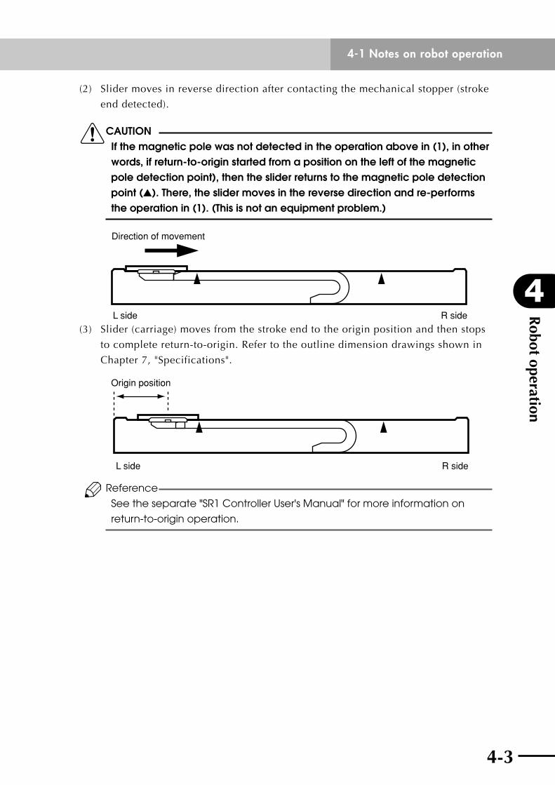
(2) Slidermovesinreversedirectionaftercontactingthemechanicalstopper(stroke
end detected).
cCAUTION If the magnetic pole was not detected in the operation above in (1), in other words, if return-to-origin started from a position on the left of the magnetic pole detection point), then the slider returns to the magnetic pole detection point (). There, the slider moves in the reverse direction and re-performs the operation in (1). (This is not an equipment problem.)
Direction of movement
L side R side
(3) Slider(carriage)movesfromthestrokeendtotheoriginpositionandthenstops
to complete return-to-origin. Refer to the outline dimension drawings shown in
Chapter7,"Specifications".
L side R side
Origin position
Reference
See the separate "SR1 Controller User's Manual" for more information on
return-to-origin operation.
Robot operation
4
4-2 Setting operating conditions
4-4 4-5
4-2 Setting operating conditionsYou must set operating parameters such as the payload, speed and acceleration in order to
obtainmaximumperformancefromthePHASERseriesrobot.
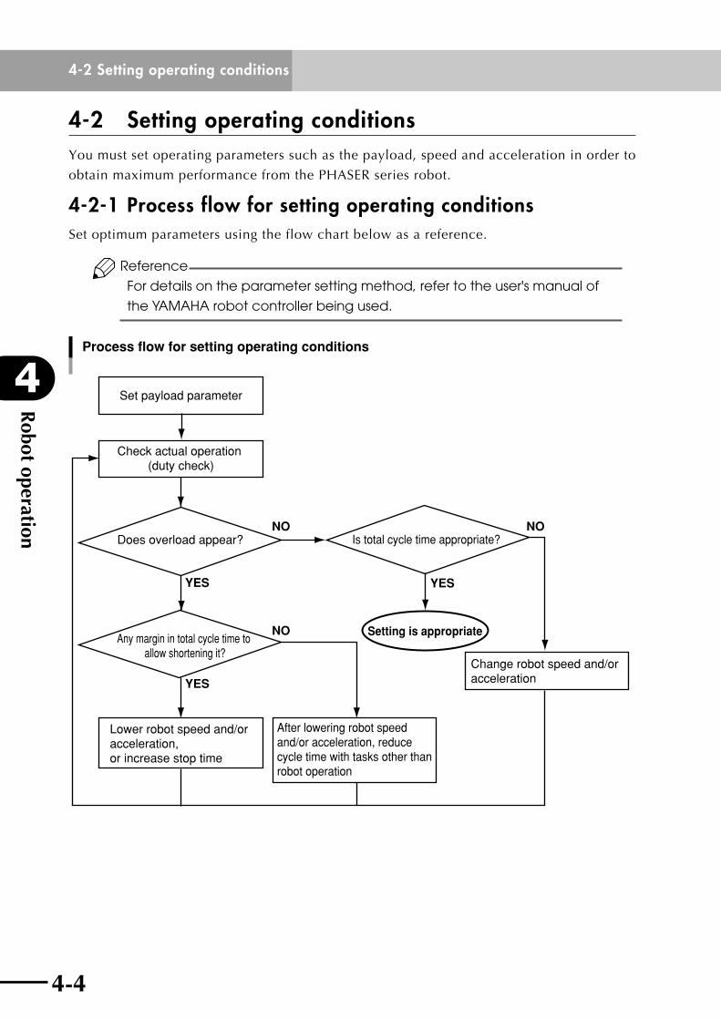
4-2-1 Process flow for setting operating conditionsSetoptimumparametersusingtheflowchartbelowasareference.
Reference
For details on the parameter setting method, refer to the user's manual of
the YAMAHA robot controller being used.
Set payload parameter
Check actual operation (duty check)
Does overload appear? Is total cycle time appropriate?
Any margin in total cycle time to allow shortening it?
Lower robot speed and/or acceleration, or increase stop time
After lowering robot speed and/or acceleration, reduce cycle time with tasks other than robot operation
Change robot speed and/or acceleration
Setting is appropriate
Process flow for setting operating conditions
NO NO
NO
YES YES
YES
4-4
4
Robot operation
4-2 Setting operating conditions
4-5
4-2-2 Duty monitorAn overload error appears to warn the motor is working too hard during tough robot
operation. In these cases, either the robot acceleration or maximum speed must be
lowered, or the robot stop time increased (lower the duty). On the other hand, if you want
to shorten the cycle time even further, when there is currently no overload, you can raise
the acceleration or maximum speed, or shorten the robot stop time (raise the duty).
Viewingthedutymonitorallowsyoutoeasilycheckthecurrentrobotoperatingstatusto
find out how hard the robot can still work versus overload criteria. By checking the duty
monitor, you can repeatedly change the settings and view the available duty to obtain
ideal operating conditions.
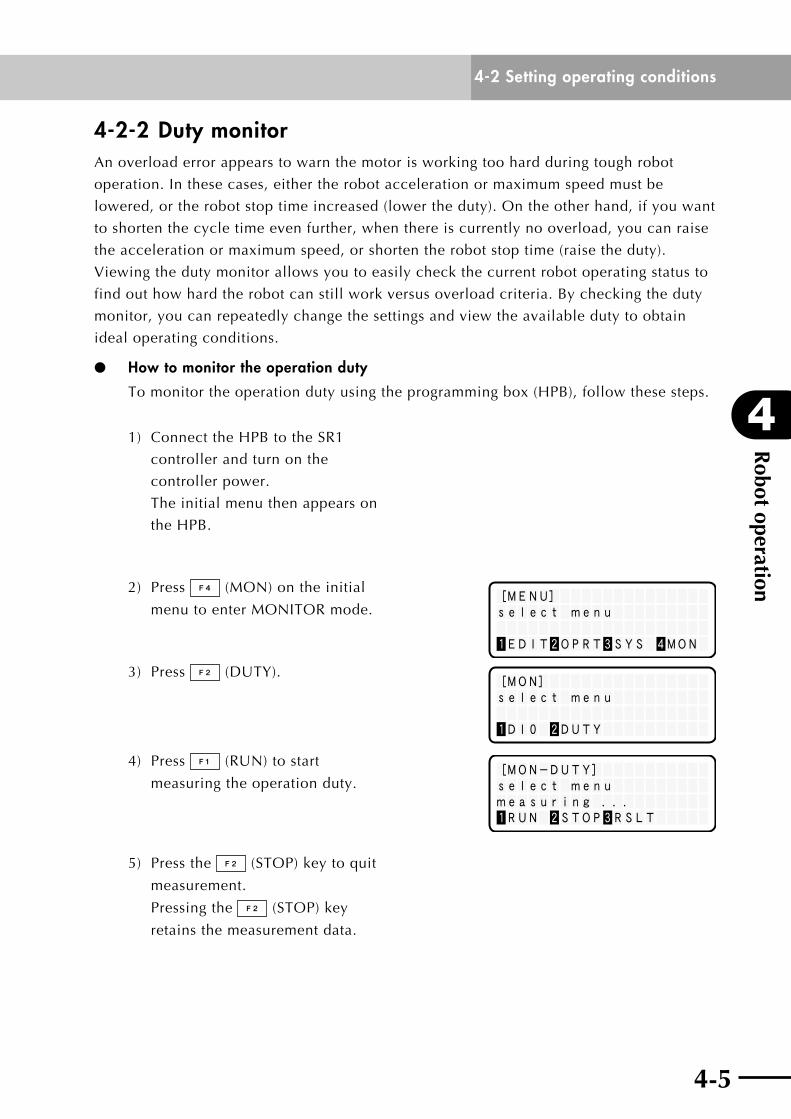
How to monitor the operation duty
To monitor the operation duty using the programming box (HPB), follow these steps.
1) ConnecttheHPBtotheSR1
controller and turn on the
controller power.
The initial menu then appears on
the HPB.
[MENU]select menu
1EDIT2OPRT3SYS 4MON
2) Press (MON) on the initial
menu to enter MONITOR mode.
[MON]select menu
1DI0 2DUTY
3) Press (DUTY).
[MON-DUTY]select menumeasuring ...1RUN 2STOP3RSLT
4) Press (RUN)tostart
measuring the operation duty.
5) Press the (STOP)keytoquit
measurement.
Pressing the (STOP)key
retains the measurement data.
Robot operation
4
4-2 Setting operating conditions
4-6 4-7
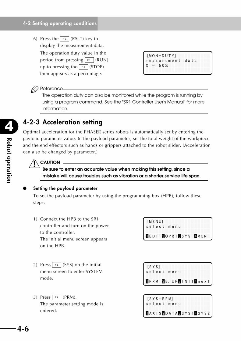
6) Press the (RSLT)keyto
display the measurement data.
[MON-DUTY]measurement dataX = 50%
The operation duty value in the
period from pressing (RUN)
up to pressing the (STOP)
then appears as a percentage.
Reference
The operation duty can also be monitored while the program is running by
using a program command. See the "SR1 Controller User's Manual" for more
information.
4-2-3 Acceleration settingOptimalaccelerationforthePHASERseriesrobotsisautomaticallysetbyenteringthe
payload parameter value. In the payload parameter, set the total weight of the workpiece
and the end effectors such as hands or grippers attached to the robot slider. (Acceleration
can also be changed by parameter.)
cCAUTION Be sure to enter an accurate value when making this setting, since a mistake will cause troubles such as vibration or a shorter service life span.
Setting the payload parameter
To set the payload parameter by using the programming box (HPB), follow these
steps.
[MENU]select menu
1EDIT2OPRT3SYS 4MON
1) ConnecttheHPBtotheSR1
controller and turn on the power
to the controller.
The initial menu screen appears
on the HPB.
[SYS]select menu
1PRM 2B.UP 3INIT 4next
2) Press (SYS)ontheinitial
menuscreentoenterSYSTEM
mode.
[SYS-PRM]select menu
1AXIS2DATA3SYS14SYS2
3) Press (PRM).
The parameter setting mode is
entered.
4-6
4
Robot operation
4-2 Setting operating conditions
4-7
[SYS-PRM-AXIS]PRM100 = 4210robot typeread only
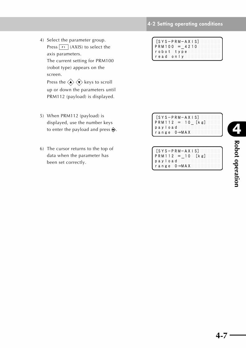
4) Selecttheparametergroup.
Press (AXIS)toselectthe
axis parameters.
The current setting for PRM100
(robot type) appears on the
screen.
Press the keys to scroll
up or down the parameters until
PRM112 (payload) is displayed.
[SYS-PRM-AXIS]PRM112 = 10 [kg]payloadrange 0→MAX
5) When PRM112 (payload) is
displayed, use the number keys
to enter the payload and press .
[SYS-PRM-AXIS]PRM112 = 10 [kg]payloadrange 0→MAX
6) The cursor returns to the top of
data when the parameter has
been set correctly.
Robot operation
4
4-3 Pulse train control (SRCP, SRCP30)
4-8 4-9
4-3 Pulse train control (SRCP, SRCP30)When you control the robot movement by pulse train input, read the following description
and comply with the precautions. For detailed information on pulse train control and
specifications,refertotheseparate"SRCPcontroller:Pulsetrainmode"supplementary
manual.
4-3-1 Acceleration/deceleration and position proportional gain Acceleration/deceleration waveforms
Usesinusoidalacceleration/decelerationtoissueacceleration/deceleration
instructions.Usingotherwaveformsmightadverselyaffectpositioningaccuracyand
current value stability.
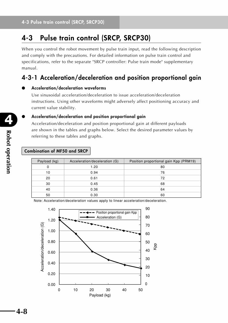
Acceleration/deceleration and position proportional gain
Acceleration/deceleration and position proportional gain at different payloads
areshowninthetablesandgraphsbelow.Selectthedesiredparametervaluesby
referring to these tables and graphs.
Combination of MF50 and SRCP
Payload (kg) Acceleration/deceleration (G) Position proportional gain Kpp (PRM19)
0 1.20 80
10 0.94 76
20 0.61 72
30 0.45 68
40 0.36 64
50 0.30 60
Note: Acceleration/deceleration values apply to linear acceleration/deceleration.
0.00
0.20
0.40
0.60
0.80
1.00
1.20
1.40
100 20 30 40 50
0
10
20
30
40
50
60
70
80
90
Acceleration (G)Position proportional gain Kpp
Payload (kg)
Acc
eler
atio
n/de
cele
ratio
n (G
)
Kpp
4-8
4
Robot operation
4-3 Pulse train control (SRCP, SRCP30)
4-9
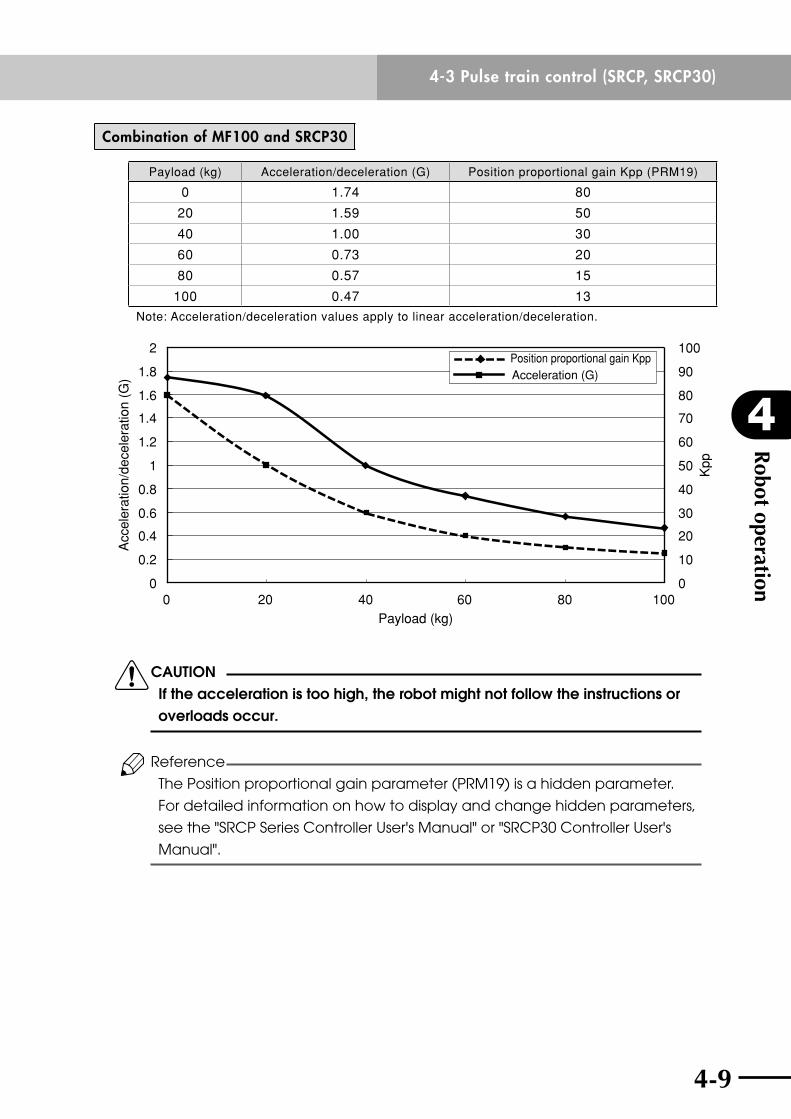
Combination of MF100 and SRCP30
Payload (kg) Acceleration/deceleration (G) Position proportional gain Kpp (PRM19)
0 1.74 80
20 1.59 50
40 1.00 30
60 0.73 20
80 0.57 15
100 0.47 13
Note: Acceleration/deceleration values apply to linear acceleration/deceleration.
0
0.2
0.4
0.6
0.8
1
1.2
1.4
1.6
1.8
2
0
10
20
30
40
50
60
70
80
90
100
0 20 40 60 80 100Payload (kg)
Kpp
Acc
eler
atio
n/de
cele
ratio
n (G
)
Position proportional gain KppAcceleration (G)
cCAUTION If the acceleration is too high, the robot might not follow the instructions or overloads occur.
Reference
The Position proportional gain parameter (PRM19) is a hidden parameter.
For detailed information on how to display and change hidden parameters,
see the "SRCP Series Controller User's Manual" or "SRCP30 Controller User's
Manual".

Robot operation
4
4-3 Pulse train control (SRCP, SRCP30)
4-10
4-3-2 Setting the maximum speedIn the case of pulse train control, the robot moves 1 micrometer per pulse.
To operate the robot at a maximum speed (2500 mm/sec), a pulse train at 2.5Mpps
must be input. (The maximum speed might not be obtained depending on the operating
conditions.)
As the speed increases, the sliding resistance also increases and overloads tend to occur.

Chapter 5 Periodic inspection and maintenance
Contents
5-1 Before beginning work 5-1
5-2 Periodic inspection 5-45-2-1 Daily inspection 5-4
5-2-2 Three-month inspection 5-5
5-2-3 Six-month inspection 5-6
5-2-4 Three-year inspection 5-6
5-2-5 Greasing to the linear guides 5-7
5-3 Replacing the shutter 5-10
5-4 Replacing the shutter roller 5-12
5-5 Maintenance parts 5-15

5-1
5
Periodic inspection and maintenance
5-1
5-1 Before beginning work
5-1 Before beginning workPeriodic inspection and maintenance are essential to ensure safe and efficient operation of
YAMAHA robots. This chapter describes periodic inspection items and procedures for the
PHASERseries.Beforebeginningwork,readtheprecautionsbelowandalsoinChapter1
"UsingtheRobotSafely"andfollowtheinstructions.
[Safety precautions]
(1) Read and understand the contents of this chapter completely before attempting to
adjust the robot.
(2) Place a sign indicating that the robot is being adjusted or serviced in order to keep
any other person from operating the controller power switch, programming box or
Handy Terminal, and the operation panel, etc.
(3) If a safety enclosure or fence has not yet been provided right after installation of the
robot, rope off or chain off the movement area around the robot in place of a safety
enclosure or fence, and observe the following points.
1.Usestablepostswhichwillnotfallovereasily.
2. The rope or chain should be easily visible by everyone around the robot.
3. Place a conspicuous sign prohibiting anyone other than the person who is adjusting
the robot from entering the movement area of the robot.
(4) Tocheckoperationafteradjustment,referto"1-6TrialOperation"inChapter1.
(5) For precautions on handling the controller, refer to the controller user's manual.
wDANGER IF ThE INSPECTION OR MAINTENANCE PROCEDURE CAllS FOR OPERATION OF therobot,stayoutoftheworKingareaoftherobotduringOPERATION. DO NOT TOUCh ANy PARTS INSIDE ThE CONTROllER. KeepwatchingtherobotmoVementandsurroundingareasothatThE OPERATOR CAN PRESS ThE EMERGENCy STOP BUTTON IF ANy DANGER OCCURS.
Periodic inspection and maintenance
5
5-2
5-1 Before beginning work
5-3
wWARNING • whentherobotdoesnotneedtobeoperatedduringadJustment OR MAINTENANCE, AlWAyS TURN OFF ThE CONTROllER AND ThE EXTERNAl SWITCh BOARD. • donottouchinternaLpartsofthecontroLLerfor10minutes AFTER ThE CONTROllER hAS BEEN TURNED OFF. • whenonLymaKingeLectricaLinspectionsandreQuiringno mechanicaLmoVementoftherobot,Keeptheemergencystop BUTTON PRESSED. • useonLyLubricantandgreasesspecifiedbyyamahasaLesoffice OR REPRESENTATIvE. • useonLypartsspecifiedbyyamahasaLesofficeorrepresentatiVe. taKesufficientcarenottoaLLowanyforeignmatterto CONTAMINATE ThEM DURING ADjUSTMENT, PARTS REPlACEMENT OR REASSEMBly. • donotmodifyanypartsontherobotorcontroLLer. MODIFICATION MAy RESUlT IN UNSATISFACTORy SPECIFICATIONS OR ThREATEN OPERATOR SAFETy. • whenadJustmentormaintenanceiscompLete,retightentheboLts AND SCREWS SECUREly. • duringrobotadJustmentormaintenance,pLaceasign INDICATING ThAT ThE ROBOT IS BEING ADjUSTED OR SERvICED TO PREvENT othersfromtouchingthecontroLKeysorswitches.proVidea LocKontheswitchKeysorasKsomeonetoKeepwatchasneeded.
wWARNING DO NOT DISASSEMBlE ThE ROBOT. ThE INTERNAl MAGNETIC PlATE USES POWERFUl PERMANENT MAGNETS SO DISASSEMBly WIThOUT PROPER PREPARATION IS hAzARDOUS. ATTEMPTING TO DISASSEMBlE IT MIGhT AlSO PREvENT OBTAINING ThE SPECIFIED PERFORMANCE.

5-2
5
Periodic inspection and maintenance
5-3
5-1 Before beginning work
When applying grease to the internal linear guide, take the following precautions.
wWARNING PRECAUTIONS WhEN hANDlING GREASE: • infLammationmayoccurifthisgetsintheeyes. BEFORE hANDlING ThE GREASE, WEAR yOUR SAFETy GOGGlES TO ENSURE ThE GREASE WIll NOT COME IN CONTACT WITh ThE EyES. • infLammationmayoccurifthegreasecomesintocontactwith sKin.besuretowearprotectiVegLoVestopreVentcontactwith sKin. • donottaKeoraLLyoreat.(eatingwiLLcausediarrheaand vOMITING.) • handsandfingersmightbecutwhenopeningthegrease CONTAINER, SO USE PROTECTIvE GlOvES. • KeepoutofthereachofchiLdren. • donotheatthegreaseorpLacenearanopenfLamesincethis couLdLeadtosparKsandfires. EMERGENCy TREATMENT: • ifgreasegetsintheeyes,washLiberaLLywithpurewaterforabout 15 MINUTES AND CONSUlT A PhySICIAN FOR TREATMENT. • ifgreasecomesincontactwiththesKin,washawaycompLeteLy WITh SOAP AND WATER. • iftaKeninternaLLy,donotinduceVomitingbutpromptLyconsuLt A PhySICIAN FOR PROPER TREATMENT.
wWARNING DISPOSAl OF GREASE AND WASTE CONTAINERS • disposaLmethodsaresubJecttoLegaLreguLations.besurethat DISPOSAl METhODS COMPly WITh ThE ESTABlIShED lEGAl REGUlATIONS. • donotappLypressuretoemptycontainers.pressuremightcause ThE CONTAINERS TO RUPTURE. • donotattempttoweLd,heat,driLLhoLesorcutthesecontainers. BESIDES A POTENTIAl EXPlOSION, ThE REMAINING CONTENTS OF ThE CONTAINER MIGhT IGNITE AND CATCh FIRE.
Periodic inspection and maintenance
5
5-4
5-2 Periodic inspection
5-5
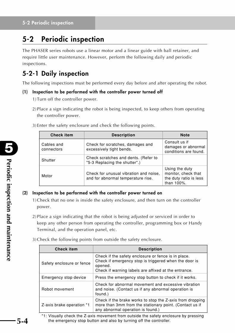
5-2 Periodic inspectionThePHASERseriesrobotsusealinearmotorandalinearguidewithballretainer,and
require little user maintenance. However, perform the following daily and periodic
inspections.
5-2-1 Daily inspectionThe following inspections must be performed every day before and after operating the robot.
(1) Inspection to be performed with the controller power turned off
1) Turn off the controller power.
2) Place a sign indicating the robot is being inspected, to keep others from operating
the controller power.
3) Enter the safety enclosure and check the following points.
Check item Description Note
Cables and connectors
Check for scratches, damages and excessively tight bends.
Consult us if damages or abnormal conditions are found.
ShutterCheck scratches and dents. (Refer to "5-3 Replacing the shutter".)
MotorCheck for unusual vibration and noise, and for abnormal temperature rise.
Using the duty monitor, check that the duty ratio is less than 100%.
(2) Inspection to be performed with the controller power turned on
1)Checkthatnooneisinsidethesafetyenclosure,andthenturnonthecontroller
power.
2) Place a sign indicating that the robot is being adjusted or serviced in order to
keep any other person from operating the controller, programming box or Handy
Terminal, and the operation panel, etc.
3)Checkthefollowingpointsfromoutsidethesafetyenclosure.
Check item Description
Safety enclosure or fence
Check if the safety enclosure or fence is in place. Check if emergency stop is triggered when the door is opened. Check if warning labels are affixed at the entrance.
Emergency stop device Press the emergency stop button to check if it works.
Robot movementCheck for abnormal movement and excessive vibration and noise. (Contact us if any abnormal operation is found.)
Z-axis brake operation *1Check if the brake works to stop the Z-axis from dropping more than 3mm from the stationary point. (Contact us if any abnormal operation is found.)
*1: Visually check the Z-axis movement from outside the safety enclosure by pressing the emergency stop button and also by turning off the controller.
5-4
5
Periodic inspection and maintenance
5-5
5-2 Periodic inspection
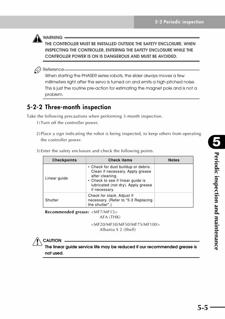
wWARNING ThE CONTROllER MUST BE INSTAllED OUTSIDE ThE SAFETy ENClOSURE. WhEN INSPECTING ThE CONTROllER, ENTERING ThE SAFETy ENClOSURE WhIlE ThE CONTROllER POWER IS ON IS DANGEROUS AND MUST BE AvOIDED.
Reference
When starting the PHASER series robots, the slider always moves a few
millimeters right after the servo is turned on and emits a high pitched noise.
This is just the routine pre-action for estimating the magnet pole and is not a
problem.
5-2-2 Three-month inspectionTake the following precautions when performing 3-month inspection.
1) Turn off the controller power.
2) Place a sign indicating the robot is being inspected, to keep others from operating
the controller power.
3) Enter the safety enclosure and check the following points.
Checkpoints Check items Notes
Linear guide
• Check for dust buildup or debris. Clean if necessary. Apply grease after cleaning.
• Check to see if linear guide is lubricated (not dry). Apply grease if necessary.
ShutterCheck for slack. Adjust if necessary. (Refer to "5-3 Replacing the shutter".)
Recommended grease: <MF7/MF15> AFA (THK)
<MF20/MF30/MF50/MF75/MF100> AlbaniaS2(Shell)
cCAUTION The linear guide service life may be reduced if our recommended grease is not used.
Periodic inspection and maintenance
5
5-6
5-2 Periodic inspection
5-7
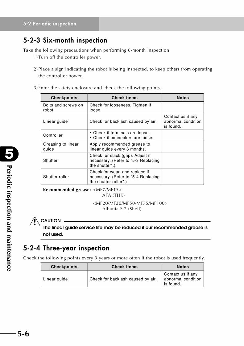
5-2-3 Six-month inspectionTake the following precautions when performing 6-month inspection.
1) Turn off the controller power.
2) Place a sign indicating the robot is being inspected, to keep others from operating
the controller power.
3) Enter the safety enclosure and check the following points.
Checkpoints Check items Notes
Bolts and screws on robot
Check for looseness. Tighten if loose.
Linear guide Check for backlash caused by air.Contact us if any abnormal condition is found.
Controller• Check if terminals are loose.• Check if connectors are loose.
Greasing to linear guide
Apply recommended grease to linear guide every 6 months.
ShutterCheck for slack (gap). Adjust if necessary. (Refer to "5-3 Replacing the shutter".)
Shutter rollerCheck for wear, and replace if necessary. (Refer to "5-4 Replacing the shutter roller".)
Recommended grease: <MF7/MF15> AFA (THK)
<MF20/MF30/MF50/MF75/MF100> AlbaniaS2(Shell)
cCAUTION The linear guide service life may be reduced if our recommended grease is not used.
5-2-4 Three-year inspectionCheckthefollowingpointsevery3yearsormoreofteniftherobotisusedfrequently.
Checkpoints Check items Notes
Linear guide Check for backlash caused by air.Contact us if any abnormal condition is found.
5-6
5
Periodic inspection and maintenance
5-7
5-2 Periodic inspection
5-2-5 Greasing to the linear guidesWhen applying grease to the linear guide according to periodic inspection, follow the
procedure below.
cCAUTION Using grease other than those recommended by yAMAhA might shorten the service life of the linear guide.
<MF7/MF15>
1) Prepare the following tools required for replacement.
• Phillipsscrewdriver
• Greasegun(recommendedgreasegun:THKMG70withTypeNnozzle)
2) Turn off the controller power.
3) Place a sign indicating the robot is being inspected, to keep others from operating the
controller power.
4) Enter the safety enclosure.
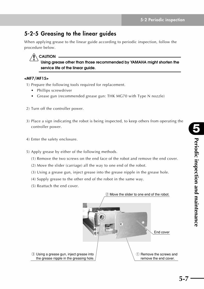
5) Apply grease by either of the following methods.
(1) Remove the two screws on the end face of the robot and remove the end cover.
(2) Move the slider (carriage) all the way to one end of the robot.
(3)Usingagreasegun,injectgreaseintothegreasenippleinthegreasehole.
(4)Supplygreasetotheotherendoftherobotinthesameway.
(5) Reattach the end cover.
End cover
w Move the slider to one end of the robot.
q Remove the screws and remove the end cover.
e Using a grease gun, inject grease into the grease nipple in the greasing hole.
Periodic inspection and maintenance
5
5-8
5-2 Periodic inspection
5-9
<MF20/MF30>
1) Prepare the following tools required for replacement.
• Phillipsscrewdriver
• Greasegun(recommendedgreasegun:THKMG70withTypeLnozzle)
2) Turn off the controller power.
3) Place a sign indicating the robot is being inspected, to keep others from operating the
controller power.
4) Enter the safety enclosure.
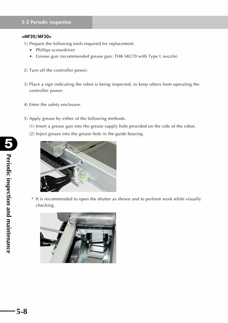
5) Apply grease by either of the following methods.
(1) Insert a grease gun into the grease supply hole provided on the side of the robot.
(2) Inject grease into the grease hole in the guide bearing.
* It is recommended to open the shutter as shown and to perform work while visually
checking.

5-8
5
Periodic inspection and maintenance
5-9
5-2 Periodic inspection
<MF50/MF75/MF100>
1) Prepare the following tools required for replacement.
• Phillipsscrewdriver
• Greasegun(recommendedgreasegun:THKMG70withTypeNnozzle)
2) Turn off the controller power.
3) Place a sign indicating the robot is being inspected, to keep others from operating the
controller power.
4) Enter the safety enclosure.
5) Apply grease by either of the following methods.
(1) Remove the four screws on the end face of the robot and remove the end cover.
(2) Move the slider (carriage) all the way to one end of the robot.
(3)Usingagreasegun,injectgreaseintothegreasenipple.
(4)Supplygreasetotheotherendoftherobotinthesameway.
(5) Reattach the end cover.
w Move the slider to one end of the robot.
e Using a grease gun, inject grease into the grease nipple.
q Remove the screws and remove the end cover.
End cover
Periodic inspection and maintenance
5
5-10
5-3 Replacing the shutter
5-11
5-3 Replacing the shutter
wWARNING BE CAREFUl NOT TO lET ThE ShUTTER DROP INSIDE ThE ROBOT BODy DURING shutterrepLacement.thiscouLdcausebreaKdownsordamageinBOTh ThE ShUTTER AND ThE ROBOT.
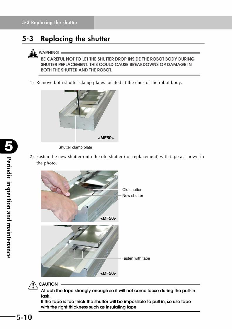
1) Remove both shutter clamp plates located at the ends of the robot body.
Shutter clamp plate
<MF50><MF50>
2) Fasten the new shutter onto the old shutter (for replacement) with tape as shown in
the photo.
Old shutter
New shutter
<MF50><MF50>
Fasten with tape
<MF50><MF50>
cCAUTION Attach the tape strongly enough so it will not come loose during the pull-in task. If the tape is too thick the shutter will be impossible to pull in, so use tape with the right thickness such as insulating tape.
5-10
5
Periodic inspection and maintenance
5-11
5-3 Replacing the shutter
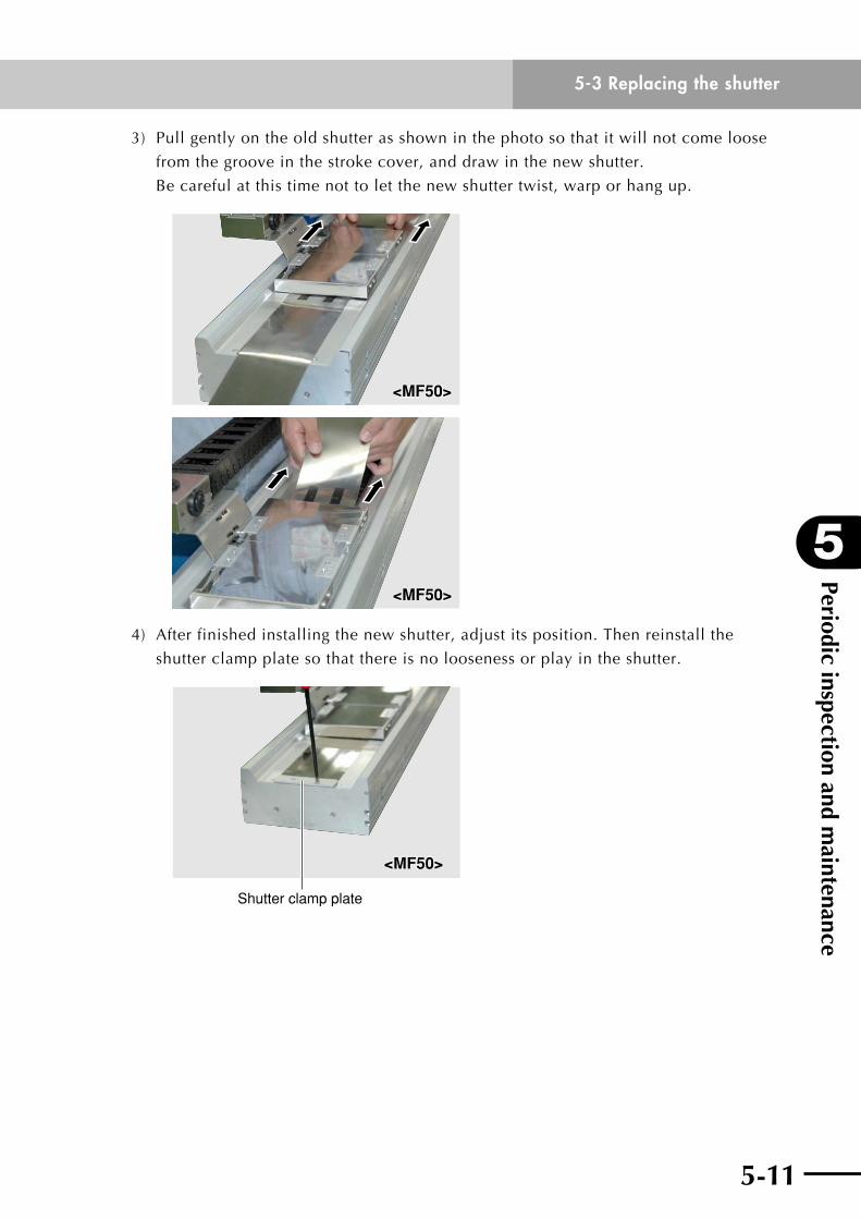
3) Pull gently on the old shutter as shown in the photo so that it will not come loose
from the groove in the stroke cover, and draw in the new shutter.
Be careful at this time not to let the new shutter twist, warp or hang up.
<MF50><MF50>
<MF50><MF50>
4) After finished installing the new shutter, adjust its position. Then reinstall the
shutter clamp plate so that there is no looseness or play in the shutter.
Shutter clamp plate
<MF50><MF50>
Periodic inspection and maintenance
5
5-12
5-4 Replacing the shutter roller
5-13
5-4 Replacing the shutter roller
wWARNING BE CAREFUl NOT TO DROP ThE TOOlS AND BOlTS ONTO ThE ShUTTER OR INTO ThE ROBOT BODy DURING ShUTTER ROllER REPlACEMENT. ThIS COUlD CAUSE breaKdownsordamageinboththeshutterandtherobot.
cCAUTION This procedure applies only to the MF7 and MF75. To replace the shutter roller for the other MF series robots, the carried object must be removed.
<For MF7>
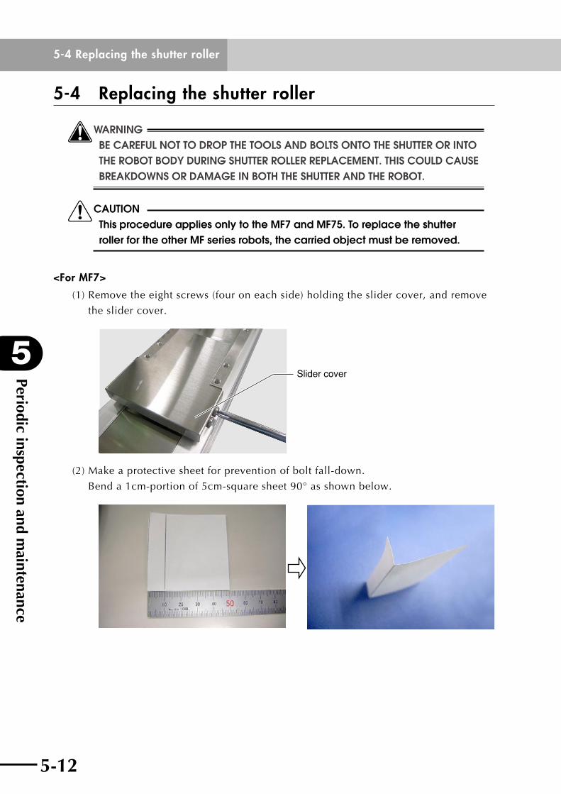
(1) Remove the eight screws (four on each side) holding the slider cover, and remove
the slider cover.
Slider cover
(2) Make a protective sheet for prevention of bolt fall-down.
Bend a 1cm-portion of 5cm-square sheet 90° as shown below.
5-12
5
Periodic inspection and maintenance
5-13
5-4 Replacing the shutter roller
(3) Insert the protective sheet into the clearance, remove the two screws (one on each
side) that secure the shutter roller, and remove the shutter roller.
Protective sheet Shutter roller
(4) With the protective sheet kept inserted into the clearance, install a new shutter
roller. When installing the new shutter roller, place its metal plate against the
slider.
Place the shutter roller against the slider.
(5) Reattach the slider cover and cap.
<For MF75>
(1) Remove the cap on the side cover.
Cap
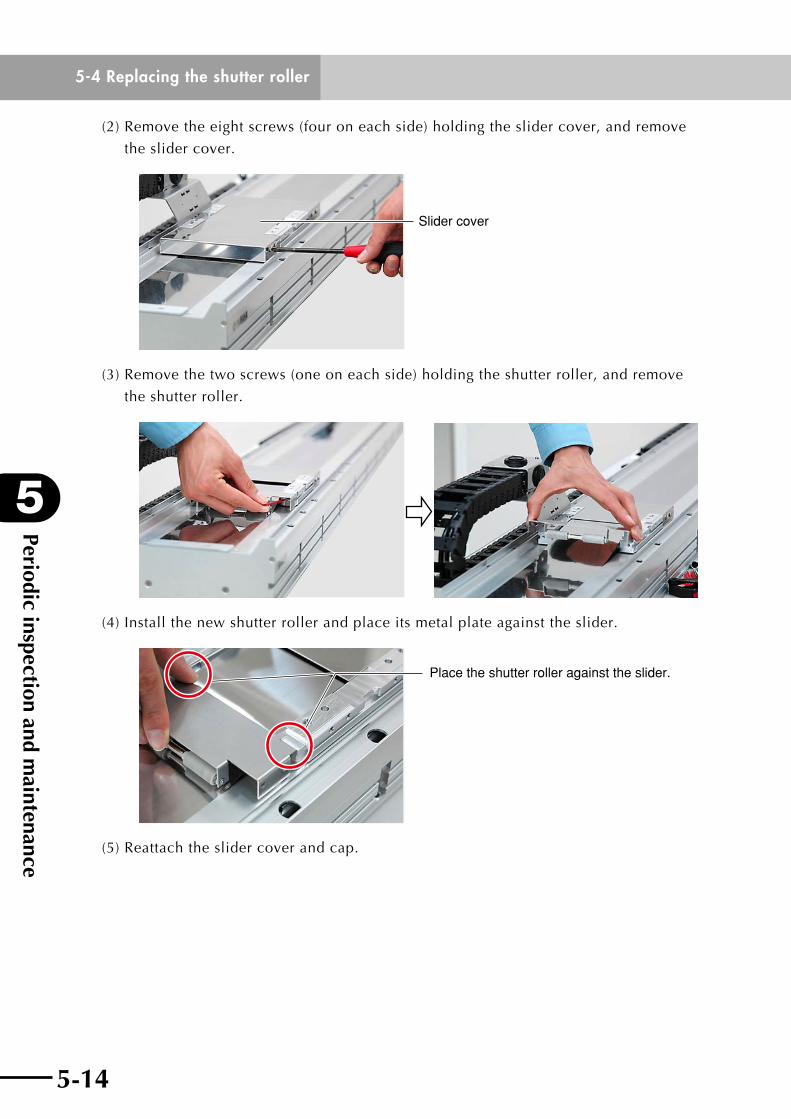
Periodic inspection and maintenance
5
5-14
5-4 Replacing the shutter roller
5-15
(2) Remove the eight screws (four on each side) holding the slider cover, and remove
the slider cover.
Slider cover
(3) Remove the two screws (one on each side) holding the shutter roller, and remove
the shutter roller.
(4) Install the new shutter roller and place its metal plate against the slider.
Place the shutter roller against the slider.
(5) Reattach the slider cover and cap.
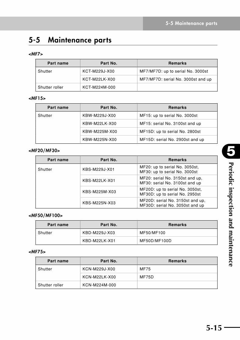
5-14
5
Periodic inspection and maintenance
5-15
5-5 Maintenance parts
5-5 Maintenance parts
<MF7>
Part name Part No. Remarks
Shutter KCT-M229J-X00 MF7/MF7D: up to serial No. 3000st
KCT-M22LK-X00 MF7/MF7D: serial No. 3000st and up
Shutter roller KCT-M224M-000
<MF15>
Part name Part No. Remarks
Shutter KBW-M229J-X00 MF15: up to serial No. 3000st
KBW-M22LK-X00 MF15: serial No. 3100st and up
KBW-M225M-X00 MF15D: up to serial No. 2800st
KBW-M225N-X00 MF15D: serial No. 2900st and up
<MF20/MF30>
Part name Part No. Remarks
Shutter KBS-M229J-X01MF20: up to serial No. 3050st, MF30: up to serial No. 3000st
KBS-M22LK-X01MF20: serial No. 3150st and up, MF30: serial No. 3100st and up
KBS-M225M-X03MF20D: up to serial No. 3050st, MF30D: up to serial No. 2950st
KBS-M225N-X03MF20D: serial No. 3150st and up, MF30D: serial No. 3050st and up
<MF50/MF100>
Part name Part No. Remarks
Shutter KBD-M229J-X03 MF50/MF100
KBD-M22LK-X01 MF50D/MF100D
<MF75>
Part name Part No. Remarks
Shutter KCN-M229J-X00 MF75
KCN-M22LK-X00 MF75D
Shutter roller KCN-M224M-000

5-16
MEMO

Chapter 6 Troubleshooting
Contents
6-1 If you suspect trouble 6-1
6-2 Feedback error 6-1
6-3 Magnetic pole detection error 6-3
6-4 Overload 6-4
6-5 Position deviation error 6-5

6-1
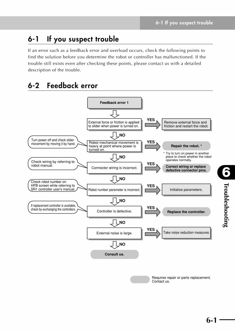
6
Troubleshooting
6-1
6-1 If you suspect trouble
6-1 If you suspect troubleIf an error such as a feedback error and overload occurs, check the following points to
find the solution before you determine the robot or controller has malfunctioned. If the
trouble still exists even after checking these points, please contact us with a detailed
description of the trouble.
6-2 Feedback error
Feedback error 1
External force or friction is applied to slider when power is turned on.
Robot mechanical movement is heavy at point where power is turned on.
Turn power off and check slider movement by moving it by hand.
Check wiring by referring to robot manual.
Check robot number on HPB screen while referring to SR1 controller user's manual.
If replacement controller is available, check by exchanging the controllers.
Connector wiring is incorrect. Correct wiring or replace defective connector pins.
Replace the controller.
Repair the robot. *
Robot number parameter is incorrect.
Remove external force and friction and restart the robot.
Initialize parameters.
Take noise reduction measures.
Controller is defective.
External noise is large.
Consult us.
YES
NO
NO
NO
NO
NO
NO
YES
YES
YES
YES
YES
* Try to turn on power in another place to check whether the robot operates normally.
Requires repair or parts replacement. Contact us.
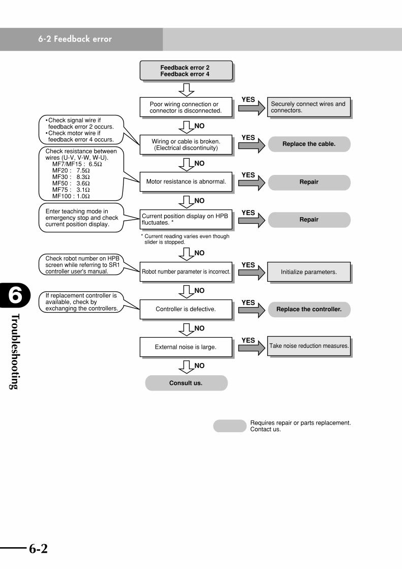
Troubleshooting
6
6-2
6-2 Feedback error
6-3
Feedback error 2Feedback error 4
Poor wiring connection or connector is disconnected.
Wiring or cable is broken.(Electrical discontinuity)
• Check signal wire if feedback error 2 occurs.• Check motor wire if feedback error 4 occurs.
Check resistance between wires (U-V, V-W, W-U). MF7/MF15 : 6.5Ω MF20 : 7.5Ω MF30 : 8.3Ω MF50 : 3.6Ω MF75 : 3.1Ω MF100 : 1.0Ω
Enter teaching mode in emergency stop and check current position display.
Check robot number on HPB screen while referring to SR1 controller user's manual.
Motor resistance is abnormal. Repair
Repair
Replace the cable.
Current position display on HPB fluctuates. *
Securely connect wires and connectors.
Take noise reduction measures.
Initialize parameters.Robot number parameter is incorrect.
External noise is large.
Consult us.
YES
NO
NO
NO
NO
NO
NO
YES
YES
YES
YES
If replacement controller is available, check by exchanging the controllers. Replace the controller.Controller is defective.
NO
YES
YES
* Current reading varies even though slider is stopped.
Requires repair or parts replacement. Contact us.
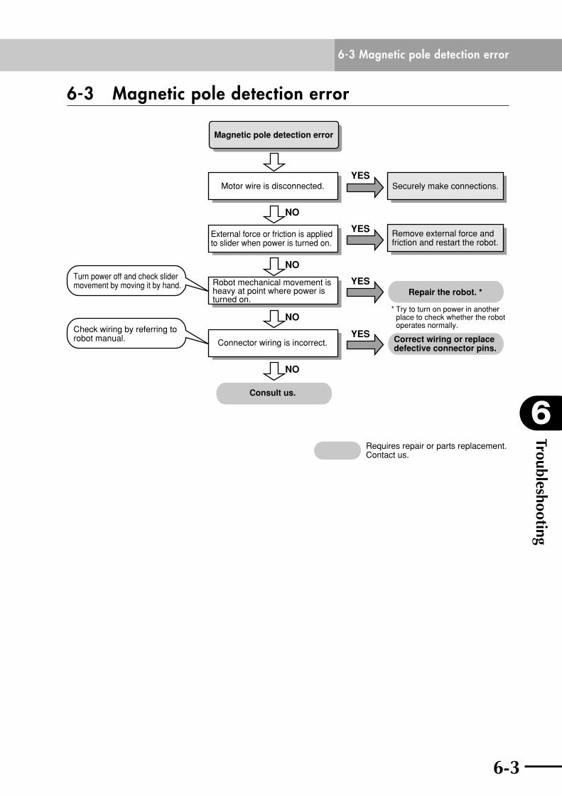
6-2
6
Troubleshooting
6-3
6-3 Magnetic pole detection error
6-3 Magnetic pole detection error
Magnetic pole detection error
Motor wire is disconnected.
External force or friction is applied to slider when power is turned on.
Turn power off and check slider movement by moving it by hand.
Check wiring by referring to robot manual.
Robot mechanical movement is heavy at point where power is turned on.
Repair the robot. *
Correct wiring or replace defective connector pins.
Connector wiring is incorrect.
Securely make connections.
Remove external force and friction and restart the robot.
Consult us.
YES
NO
NO
NO
NO
YES
YES
YES
Requires repair or parts replacement. Contact us.
* Try to turn on power in another place to check whether the robot operates normally.
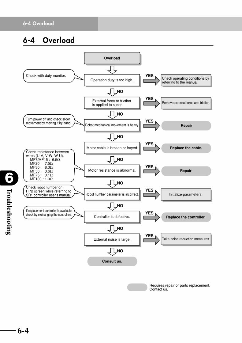
Troubleshooting
6
6-4
6-4 Overload
6-5
6-4 Overload
Overload
Operation duty is too high.
External force or friction is applied to slider.
Check with duty monitor.
Turn power off and check slider movement by moving it by hand.
Check robot number on HPB screen while referring to SR1 controller user's manual.
Robot mechanical movement is heavy. Repair
Replace the cable.
Remove external force and friction.
Motor cable is broken or frayed.
Motor resistance is abnormal.
Check operating conditions by referring to the manual.
Take noise reduction measures.
Initialize parameters.Robot number parameter is incorrect.
External noise is large.
Consult us.
YES
NO
NO
NO
NO
NO
NO
YES
YES
YES
Repair
NO
YES
YES
If replacement controller is available, check by exchanging the controllers.
Replace the controller.Controller is defective.
NO
YES
YES
Requires repair or parts replacement. Contact us.
Check resistance between wires (U-V, V-W, W-U). MF7/MF15 : 6.5Ω MF20 : 7.5Ω MF30 : 8.3Ω MF50 : 3.6Ω MF75 : 3.1Ω MF100 : 1.0Ω
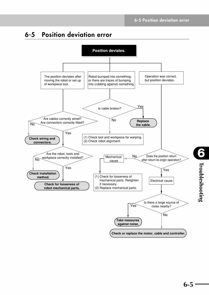
6-4
6
Troubleshooting
6-5
6-5 Position deviation error
6-5 Position deviation error
Robot bumped into something,or there are traces of bumping into (rubbing against) something.
The position deviates aftermoving the robot or set up of workpiece tool.
Operation was correct,but position deviates.
Position deviates.
(1) Check for looseness of mechanical parts. Retighten if necessary.(2) Replace mechanical parts.
(1) Check tool and workpiece for warping.(2) Check robot alignment.
Are cables correctly wired?Are connectors correctly fitted?
Are the robot, tools andworkpiece correctly installed?
Yes
Yes
No
Check installation method.
Check wiring and connectors.
Check for looseness ofrobot mechanical parts.
No
Check or replace the motor, cable and controller.
No
Take measures against noise.
Yes
Is cable broken?
No
Does the position returnafter return-to-origin operation?
Is there a large source ofnoise nearby?
No
Electrical cause
Mechanical cause
Replace the cable.
Yes
Yes

6-6
MEMO
Chapter 7 Specifications
Contents
7-1 Main unit 7-17-1-1 MF7 7-1
7-1-2 MF15 7-8
7-1-3 MF20 7-14
7-1-4 MF30 7-20
7-1-5 MF50 7-26
7-1-6 MF75 7-30
7-1-7 MF100 7-34
7-2 Robot connector (I/O signal connector) 7-38
7-3 Robot connector (motor connector) 7-38
7-4 Robot cable (I/O signal wires) 7-39
7-5 Robot cable (motor wires) 7-39

7-1
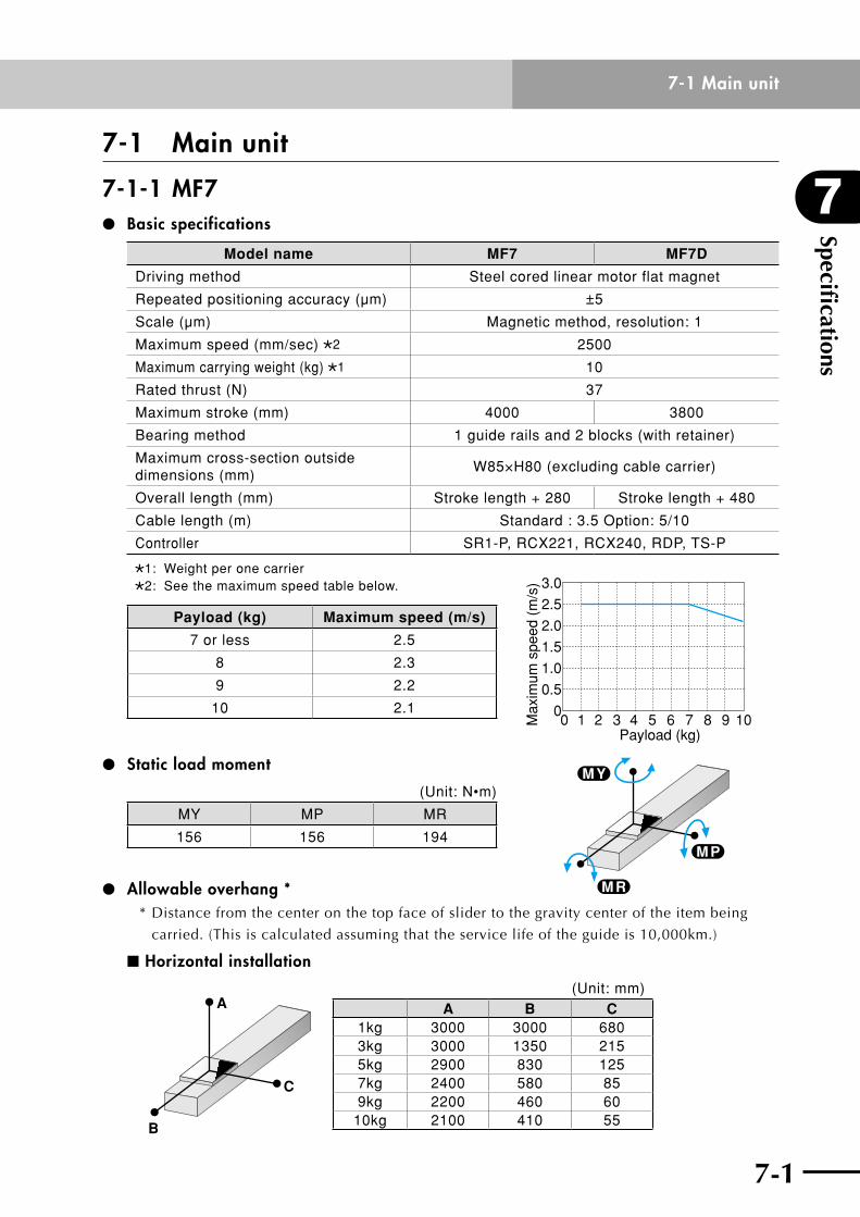
7
Specifications
7-1
7-1 Main unit
7-1 Main unit
7-1-1 MF7 Basic specifications
Model name MF7 MF7D
Driving method Steel cored linear motor flat magnet
Repeated positioning accuracy (µm) ±5
Scale (µm) Magnetic method, resolution: 1
Maximum speed (mm/sec) 2 2500
Maximum carrying weight (kg) 1 10
Rated thrust (N) 37
Maximum stroke (mm) 4000 3800
Bearing method 1 guide rails and 2 blocks (with retainer)
Maximum cross-section outside dimensions (mm)
W85×H80 (excluding cable carrier)
Overall length (mm) Stroke length + 280 Stroke length + 480
Cable length (m) Standard : 3.5 Option: 5/10
Controller SR1-P, RCX221, RCX240, RDP, TS-P
1: Weight per one carrier2: See the maximum speed table below.
Payload (kg) Maximum speed (m/s)
7 or less 2.5
8 2.3
9 2.2
10 2.1
Static load moment
(Unit: N•m)
MY MP MR
156 156 194
Allowable overhang **Distancefromthecenteronthetopfaceofslidertothegravitycenteroftheitembeing
carried. (This is calculated assuming that the service life of the guide is 10,000km.)
n Horizontal installation
A
C
B
(Unit: mm)A B C
1kg 3000 3000 6803kg 3000 1350 2155kg 2900 830 1257kg 2400 580 859kg 2200 460 60
10kg 2100 410 55
0 1 2 3 4 5 6 7 8 9 10Payload (kg)
Max
imum
spe
ed (
m/s
) 3.0
2.5
2.0
1.5
1.0
0.5
0
M P
M R
M Y
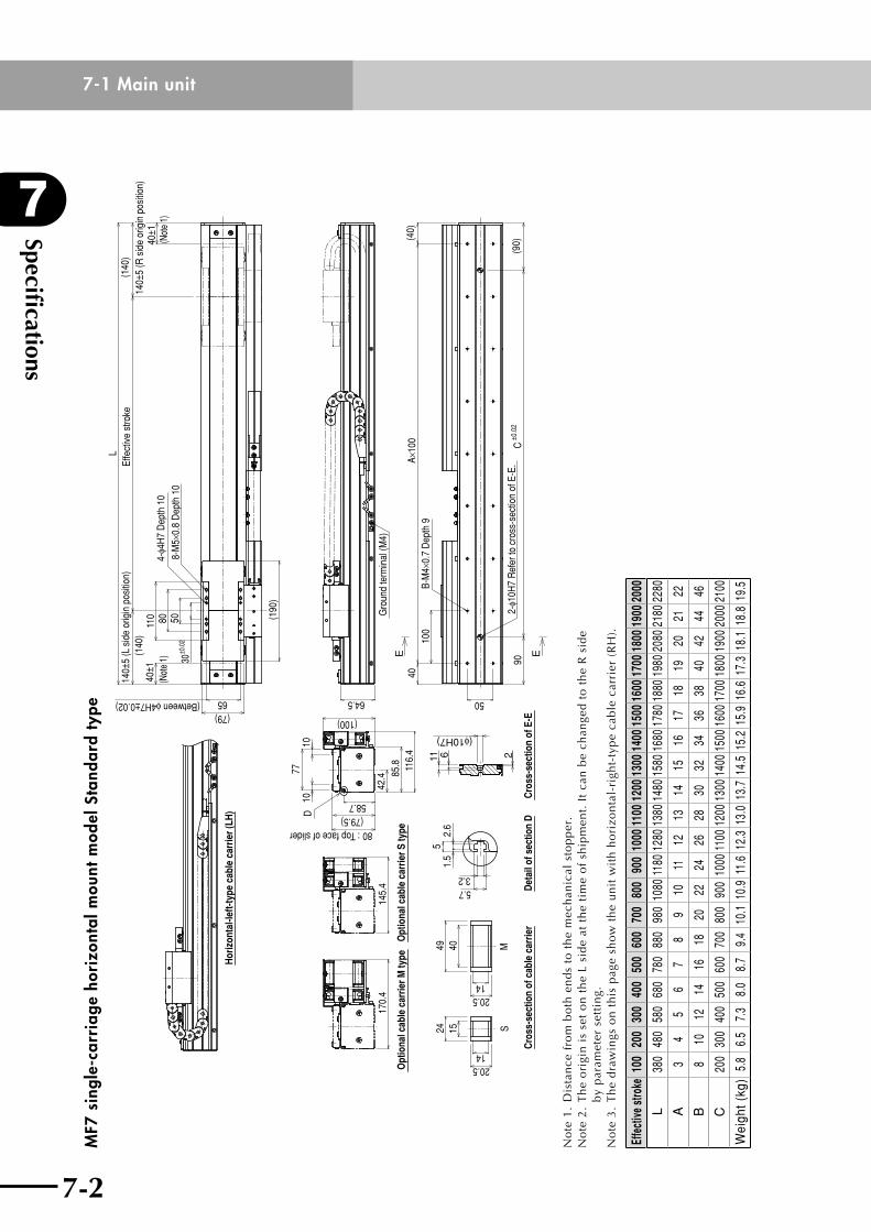
Specifications
7
7-2
7-1 Main unit
7-3
MF7
sin
gle-
carr
iage
hor
izon
tal m
ount
mod
el S
tand
ard
type
S
Cro
ss-s
ectio
n of
cab
le c
arrie
r
M49
20.5
40
14
15
20.514
24
Det
ail o
f sec
tion
D
3.25.7
1.5
2.6
5
Opt
iona
l cab
le c
arrie
r S ty
peO
ptio
nal c
able
car
rier M
type
80 : Top face of slider
7710
(79.5)
10
42.4
(100)
58.7
D
116.
485
.814
5.4
170.
4
Hor
izon
tal-l
eft-t
ype
cabl
e ca
rrie
r (LH
)
90C
±0.0
2(9
0)
100
40A×
100
(40)
50
B-M
4×0.
7 D
epth
9
2-φ1
0H7
Ref
er to
cro
ss-s
ectio
n of
E-E
.
Gro
und
term
inal
(M4)
64.5
30±0
.02
5080
65(79)
140±
5 (L
sid
e or
igin
pos
ition
)
(140
)
LEf
fect
ive
stro
ke
4-φ4
H7
Dep
th 1
08-
M5×
0.8
Dep
th 1
0
(190
)
110
40±1
(Not
e 1)
(1
40)
140±
5 (R
sid
e or
igin
pos
ition
)40
±1(N
ote
1)
(Between φ4H7±0.02)
E E
(φ10H7)
611 2
Cro
ss-s
ectio
n of
E-E
No
te1
.D
ista
nce
fro
mb
oth
en
ds
tot
he
mec
han
ical
sto
pp
er.
No
te 2
. T
he
ori
gin
is
set
on
th
e L
sid
e at
th
e ti
me
of
ship
men
t. I
t ca
n b
e ch
ange
d t
o t
he
R s
ide
by
par
amet
er s
etti
ng.
No
te 3
. T
he
dra
win
gs o
n t
his
pag
e sh
ow
th
e u
nit
wit
h h
ori
zon
tal-
righ
t-ty
pe
cab
le c
arri
er (
RH
).
Effe
ctive
stro
ke10
020
030
040
050
060
070
080
090
010
0011
0012
0013
0014
0015
0016
0017
0018
0019
0020
00
L38
048
058
068
078
088
098
010
8011
8012
8013
8014
8015
8016
8017
8018
8019
8020
8021
8022
80
A3
45
67
89
1011
1213
1415
1617
1819
2021
22
B8
1012
1416
1820
2224
2628
3032
3436
3840
4244
46
C20
030
040
050
060
070
080
090
010
0011
0012
0013
0014
0015
0016
0017
0018
0019
0020
0021
00
Wei
ght (
kg)
5.8
6.5
7.3
8.0
8.7
9.4
10.1
10.
9 11
.6 1
2.3
13.0
13.
7 14
.5 1
5.2
15.9
16.
6 17
.3 1
8.1
18.8
19.
5
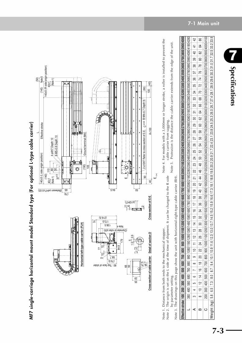
7-2
7
Specifications
7-3
7-1 Main unitM
F7 s
ingl
e-ca
rria
ge h
oriz
onta
l mou
nt m
odel
Sta
ndar
d ty
pe (F
or o
ptio
nal L
-typ
e ca
ble
carr
ier)
Hor
izon
tal-l
eft-t
ype
cabl
e ca
rrie
r (FL
H)
80 : Top face of slider
10
(79.5)
10
58.7
D
84.8
173.537(216.5)
77
138.5
(Diameter of roller:φ30)Note 4
179
Cro
ss-s
ectio
n of
cab
le c
arrie
r
66 50
3529
φ6.7
φ7.5
Det
ail o
f sec
tion
D
3.25.7
1.5
2.6
5
90C
±0.0
2(9
0)
100
40A×
100
(40)
50
B-M
4×0.
7 D
epth
92-
φ10H
7 Re
fer t
o cr
oss-
sect
ion
of E
-E.
64.5
105
Gro
und
term
inal
(M4)
30±0
.025080
65(79)
140±
5 (L
sid
e or
igin
pos
ition
)
(1
40)
LEf
fect
ive
stro
ke
(140
)
140±
5 (R
sid
e or
igin
pos
ition
)
4-φ4
H7
Dep
th 1
0
8-M
5×0.
8 D
epth
10
(190
)
110
(50)
Note
5
40±1
(Not
e 1)
40±1 (Not
e 1)
(Between φ4H7±0.02)EE
(φ10H7)2611
Cro
ss-s
ectio
n of
E-E
No
te1
.D
ista
nce
fro
mb
oth
en
ds
tot
he
mec
han
ical
sto
pp
er.
No
te 2
. T
he
ori
gin
is
set
on
th
e L
sid
e at
th
e ti
me
of
ship
men
t. I
t ca
n b
e ch
ange
d t
o t
he
R s
ide
by
par
amet
er s
etti
ng.
No
te 3
. T
he
dra
win
gs o
n t
his
pag
e sh
ow
th
e u
nit
wit
h h
ori
zon
tal-
righ
t-ty
pe
cab
le c
arri
er (
RH
).
No
te 4
. Fo
r m
od
els
wit
h a
3,0
00
mm
or
lon
ger
stro
ke,
a ro
ller
is
inst
alle
d t
o p
reve
nt
the
cab
le c
arri
er f
rom
sag
gin
g.N
ote
5.
Pro
tru
sio
n i
s th
e d
ista
nce
th
e ca
ble
car
rier
ext
end
s fr
om
th
e ed
ge o
f th
e u
nit
.
Effe
ctive
stro
ke10
020
030
040
050
060
070
080
090
010
0011
0012
0013
0014
0015
0016
0017
0018
0019
0020
0021
0022
0023
0024
0025
0026
0027
0028
0029
0030
0031
0032
0033
0034
0035
0036
0037
0038
0039
0040
00
L38
048
058
068
078
088
098
010
8011
8012
8013
8014
8015
8016
8017
8018
8019
8020
8021
8022
8023
8024
8025
8026
8027
8028
8029
8030
8031
8032
8033
8034
8035
8036
8037
8038
8039
8040
8041
8042
80
A3
45
67
89
1011
1213
1415
1617
1819
2021
2223
2425
2627
2829
3031
3233
3435
3637
3839
4041
42
B8
1012
1416
1820
2224
2628
3032
3436
3840
4244
4648
5052
5456
5860
6264
6668
7072
7476
7880
8284
86
C20
030
040
050
060
070
080
090
010
0011
0012
0013
0014
0015
0016
0017
0018
0019
0020
0021
0022
0023
0024
0025
0026
0027
0028
0029
0030
0031
0032
0033
0034
0035
0036
0037
0038
0039
0040
0041
00
Wei
ght (
kg)
5.8
6.5
7.3
8.0
8.7
9.4
10.1
10.
9 11
.6 1
2.3
13.0
13.
7 14
.5 1
5.2
15.9
16.
6 17
.3 1
8.1
18.8
19.
5 20
.2 2
0.9
21.7
22.
4 23
.1 2
3.8
24.5
25.
3 26
.0 2
6.7
27.4
28.
1 28
.9 2
9.6
30.3
31.
0 31
.7 3
2.5
33.2
33.
9
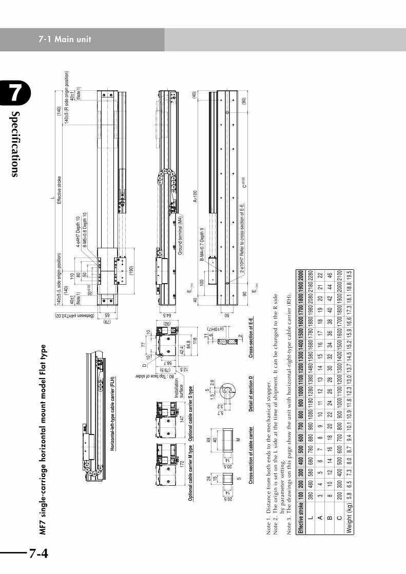
Specifications
7
7-4
7-1 Main unit
7-5
MF7
sin
gle-
carr
iage
hor
izon
tal m
ount
mod
el F
lat t
ype
Hor
izon
tal-l
eft-t
ype
cabl
e ca
rrie
r (FL
H)
Opt
iona
l cab
le c
arrie
r S ty
peO
ptio
nal c
able
car
rier M
type
80 : Top face of slider
7710
(79.5)
10
58.7
D
118
84.8
12.5
(92)
Inst
alla
tion
surfa
ce17
214
742
.4
30±0
.02
5080
65(79)
140±
5 (L
sid
e or
igin
pos
ition
)
(1
40)
LEf
fect
ive
stro
ke
(140
)
140±
5 (R
sid
e or
igin
pos
ition
)
4-φ4
H7
Dep
th 1
08-
M5×
0.8
Dep
th 1
0
(190
)
110
40±1
(Not
e 1)
40±1
(Not
e 1)
(Between φ4H7±0.02)
Gro
und
term
inal
(M4)
64.5
90C
±0.0
2(9
0)
100
40A×
100
(40)
50
B-M
4×0.
7 D
epth
9
2-φ1
0H7
Ref
er to
cro
ss-s
ectio
n of
E-E
.S
Cro
ss-s
ectio
n of
cab
le c
arrie
r
M49
20.5
40
14
15
20.514
24
Det
ail o
f sec
tion
D
3.25.7
1.5
2.6
5
Cro
ss-s
ectio
n of
E-E
E E
6
(φ10H7)
11 2
No
te1
.D
ista
nce
fro
mb
oth
en
ds
tot
he
mec
han
ical
sto
pp
er.
No
te 2
. T
he
ori
gin
is
set
on
th
e L
sid
e at
th
e ti
me
of
ship
men
t. I
t ca
n b
e ch
ange
d t
o t
he
R s
ide
by
par
amet
er s
etti
ng.
No
te 3
. T
he
dra
win
gs o
n t
his
pag
e sh
ow
th
e u
nit
wit
h h
ori
zon
tal-
righ
t-ty
pe
cab
le c
arri
er (
RH
).
Effe
ctive
stro
ke10
020
030
040
050
060
070
080
090
010
0011
0012
0013
0014
0015
0016
0017
0018
0019
0020
00
L38
048
058
068
078
088
098
010
8011
8012
8013
8014
8015
8016
8017
8018
8019
8020
8021
8022
80
A3
45
67
89
1011
1213
1415
1617
1819
2021
22
B8
1012
1416
1820
2224
2628
3032
3436
3840
4244
46
C20
030
040
050
060
070
080
090
010
0011
0012
0013
0014
0015
0016
0017
0018
0019
0020
0021
00
Wei
ght (
kg)
5.8
6.5
7.3
8.0
8.7
9.4
10.1
10.
9 11
.6 1
2.3
13.0
13.
7 14
.5 1
5.2
15.9
16.
6 17
.3 1
8.1
18.8
19.
5
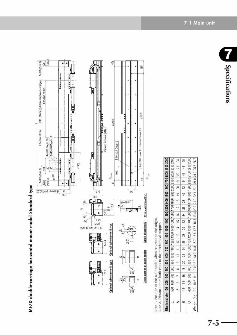
7-4
7
Specifications
7-5
7-1 Main unitM
F7D
dou
ble-
carr
iage
hor
izon
tal m
ount
mod
el S
tand
ard
type
Opt
iona
l cab
le c
arrie
r S ty
peO
ptio
nal c
able
car
rier M
type
80 : Top face of slider
7710
(79.5)
10
42.4
(100)
58.7
D
116.
485
.814
5.4
170.
4
30±0
.02
5080
65(79)
140±
5 (N
ote
1)L
Effe
ctiv
e st
roke
140±
5 (N
ote
1)
4-φ4
H7
Dep
th 1
08-
M5×
0.8
Dep
th 1
0
(190
)
110
40±1
(Not
e 2)
40±1
(Not
e 2)
Effe
ctiv
e st
roke
(200
: M
inim
um d
istan
ce b
etwe
en c
arria
ges)
(Between φ4H7±0.02)
Gro
und
term
inal
(M4)
64.590
C±0
.02
(90)
100
40A×
100
(40)
50
B-M
4×0.
7 D
epth
9
2-φ1
0H7
Ref
er to
cro
ss-s
ectio
n of
E-E
.S
Cro
ss-s
ectio
n of
cab
le c
arrie
r
M49
20.5
40
14
15
20.514
24
Det
ail o
f sec
tion
D
3.25.7
1.5
2.6
5
E E
(φ10H7)
611 2
Cro
ss-s
ectio
n of
E-E
No
te 1
. P
osi
tio
n o
f th
e ta
ble
sli
der
wh
en r
etu
rned
to
th
e o
rigi
n.
No
te2
.D
ista
nce
fro
mb
oth
en
ds
tot
he
mec
han
ical
sto
pp
er.
Effe
ctive
stro
ke10
020
030
040
050
060
070
080
090
010
0011
0012
0013
0014
0015
0016
0017
0018
0019
0020
00
L58
068
078
088
098
010
8011
8012
8013
8014
8015
8016
8017
8018
8019
8020
8021
8022
8023
8024
80
A5
67
89
1011
1213
1415
1617
1819
2021
2223
24
B12
1416
1820
2224
2628
3032
3436
3840
4244
4648
50
C40
050
060
070
080
090
010
0011
0012
0013
0014
0015
0016
0017
0018
0019
0020
0021
0022
0023
00
Wei
ght (
kg)
9.3
10.2
11.
1 12
.0 1
2.9
13.9
14.
8 15
.7 1
6.6
17.5
18.
5 19
.4 2
0.3
21.2
22.
1 23
.1 2
4.0
24.9
25.
8 26
.7
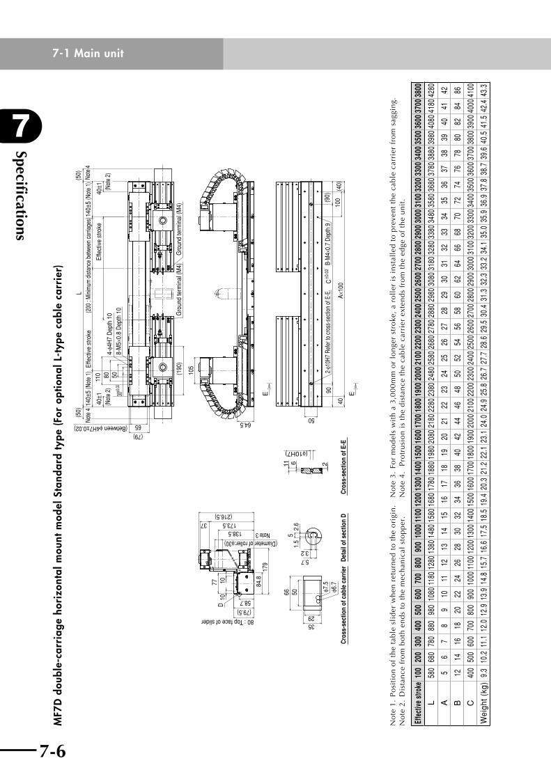
Specifications
7
7-6
7-1 Main unit
7-7
MF7
D d
oubl
e-ca
rria
ge h
oriz
onta
l mou
nt m
odel
Sta
ndar
d ty
pe (F
or o
ptio
nal L
-typ
e ca
ble
carr
ier)
80 : Top face of slider
10
(79.5)
10
58.7
D
84.8
173.537(216.5)
77
138.5
(Diameter of roller:φ30)Note 3
179
Cro
ss-s
ectio
n of
cab
le c
arrie
r
66 50
3529
φ6.7
φ7.5
Det
ail o
f sec
tion
D
3.25.7
1.5
2.6
5
90C
±0.0
2(9
0)
100
40A×
100
(40)
50
B-M
4×0.
7 De
pth
92-
φ10H
7 Re
fer t
o cr
oss-
sect
ion
of E
-E.
(Between φ4H7±0.02)64.5
105
Gro
und
term
inal
(M4)
Gro
und
term
inal
(M4)
30±0
.025080
65
(79)
L
4-φ4
H7
Dep
th 1
08-
M5×
0.8
Dep
th 1
0
(190
)
110
40±1
(Not
e 2)
40±1 (N
ote
2)
Effe
ctiv
e st
roke
140±
5 (N
ote
1)
Effe
ctiv
e st
roke
140±
5 (N
ote
1)(2
00 :
Min
imum
dist
ance
bet
ween
car
riage
s)
(50)
Note
4
(50)
Note
4
Cro
ss-s
ectio
n of
E-E
6
(φ10H7)
11 2
E E
No
te 1
. P
osi
tio
n o
f th
e ta
ble
sli
der
wh
en r
etu
rned
to
th
e o
rigi
n.
No
te2
.D
ista
nce
fro
mb
oth
en
ds
tot
he
mec
han
ical
sto
pp
er.
No
te 3
. Fo
r m
od
els
wit
h a
3,0
00
mm
or
lon
ger
stro
ke,
a ro
ller
is
inst
alle
d t
o p
reve
nt
the
cab
le c
arri
er f
rom
sag
gin
g.N
ote
4.
Pro
tru
sio
n i
s th
e d
ista
nce
th
e ca
ble
car
rier
ext
end
s fr
om
th
e ed
ge o
f th
e u
nit
.
Effe
ctive
stro
ke10
020
030
040
050
060
070
080
090
010
0011
0012
0013
0014
0015
0016
0017
0018
0019
0020
0021
0022
0023
0024
0025
0026
0027
0028
0029
0030
0031
0032
0033
0034
0035
0036
0037
0038
00
L58
068
078
088
098
010
8011
8012
8013
8014
8015
8016
8017
8018
8019
8020
8021
8022
8023
8024
8025
8026
8027
8028
8029
8030
8031
8032
8033
8034
8035
8036
8037
8038
8039
8040
8041
8042
80
A5
67
89
1011
1213
1415
1617
1819
2021
2223
2425
2627
2829
3031
3233
3435
3637
3839
4041
42
B12
1416
1820
2224
2628
3032
3436
3840
4244
4648
5052
5456
5860
6264
6668
7072
7476
7880
8284
86
C40
050
060
070
080
090
010
0011
0012
0013
0014
0015
0016
0017
0018
0019
0020
0021
0022
0023
0024
0025
0026
0027
0028
0029
0030
0031
0032
0033
0034
0035
0036
0037
0038
0039
0040
0041
00
Wei
ght (
kg)
9.3
10.2
11.
1 12
.0 1
2.9
13.9
14.
8 15
.7 1
6.6
17.5
18.
5 19
.4 2
0.3
21.2
22.
1 23
.1 2
4.0
24.9
25.
8 26
.7 2
7.7
28.6
29.
5 30
.4 3
1.3
32.3
33.
2 34
.1 3
5.0
35.9
36.
9 37
.8 3
8.7
39.6
40.
5 41
.5 4
2.4
43.3
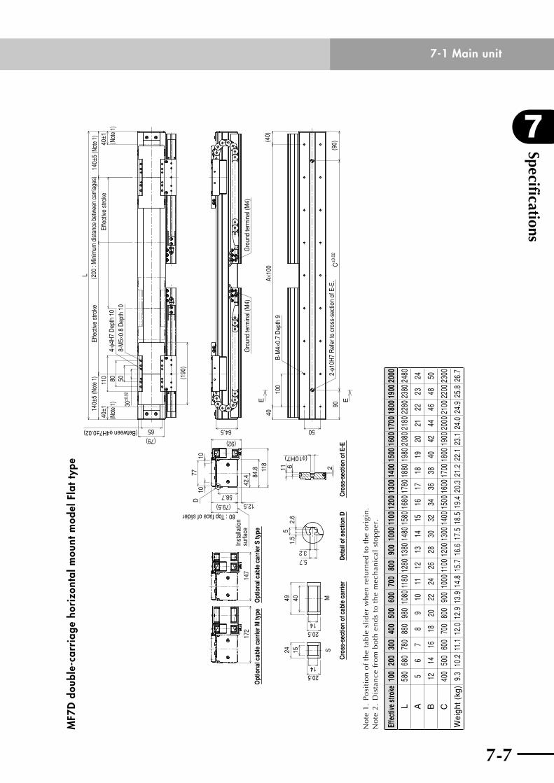
7-6
7
Specifications
7-7
7-1 Main unitM
F7D
dou
ble-
carr
iage
hor
izon
tal m
ount
mod
el F
lat t
ype
E E
Opt
iona
l cab
le c
arrie
r S ty
peO
ptio
nal c
able
car
rier M
type
80 : Top face of slider
7710
(79.5)
10
58.7
D
118
84.8
12.5
(92)
Inst
alla
tion
surfa
ce17
214
742
.4
30±0
.02
5080
65
(79)
L
4-φ4
H7
Dep
th 1
08-
M5×
0.8
Dep
th 1
0
(190
)
110
40±1
(Not
e 1)
40±1
(Not
e 1)
Effe
ctiv
e st
roke
140±
5 (N
ote
1)
Effe
ctiv
e st
roke
140±
5 (N
ote
1)(2
00 :
Min
imum
dist
ance
bet
ween
car
riage
s)
(Between φ4H7±0.02)
Gro
und
term
inal
(M4)
64.5
Gro
und
term
inal
(M4)
90C
±0.0
2(9
0)
100
40A×
100
(40)
50
B-M
4×0.
7 D
epth
9
2-φ1
0H7
Ref
er to
cro
ss-s
ectio
n of
E-E
.S
Cro
ss-s
ectio
n of
cab
le c
arrie
r
M49
20.5
40
14
15
20.514
24
Det
ail o
f sec
tion
D
3.25.7
1.5
2.6
5
Cro
ss-s
ectio
n of
E-E
(φ10H7)
611 2
No
te 1
. P
osi
tio
n o
f th
e ta
ble
sli
der
wh
en r
etu
rned
to
th
e o
rigi
n.
No
te2
.D
ista
nce
fro
mb
oth
en
ds
tot
he
mec
han
ical
sto
pp
er.
Effe
ctive
stro
ke10
020
030
040
050
060
070
080
090
010
0011
0012
0013
0014
0015
0016
0017
0018
0019
0020
00
L58
068
078
088
098
010
8011
8012
8013
8014
8015
8016
8017
8018
8019
8020
8021
8022
8023
8024
80
A5
67
89
1011
1213
1415
1617
1819
2021
2223
24
B12
1416
1820
2224
2628
3032
3436
3840
4244
4648
50
C40
050
060
070
080
090
010
0011
0012
0013
0014
0015
0016
0017
0018
0019
0020
0021
0022
0023
00
Wei
ght (
kg)
9.3
10.2
11.
1 12
.0 1
2.9
13.9
14.
8 15
.7 1
6.6
17.5
18.
5 19
.4 2
0.3
21.2
22.
1 23
.1 2
4.0
24.9
25.
8 26
.7
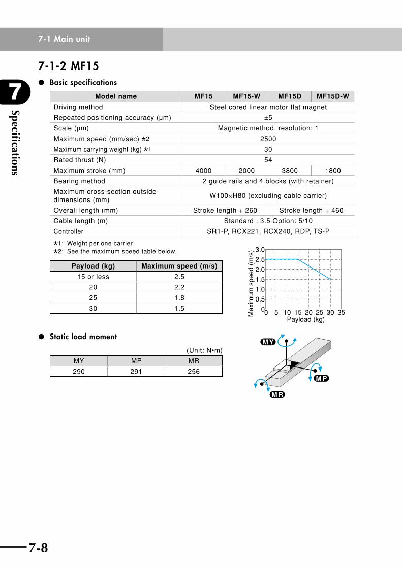
Specifications
7
7-8
7-1 Main unit
7-9
7-1-2 MF15 Basic specifications
Model name MF15 MF15-W MF15D MF15D-W
Driving method Steel cored linear motor flat magnet
Repeated positioning accuracy (µm) ±5
Scale (µm) Magnetic method, resolution: 1
Maximum speed (mm/sec) 2 2500
Maximum carrying weight (kg) 1 30
Rated thrust (N) 54
Maximum stroke (mm) 4000 2000 3800 1800
Bearing method 2 guide rails and 4 blocks (with retainer)
Maximum cross-section outside dimensions (mm)
W100×H80 (excluding cable carrier)
Overall length (mm) Stroke length + 260 Stroke length + 460
Cable length (m) Standard : 3.5 Option: 5/10
Controller SR1-P, RCX221, RCX240, RDP, TS-P
1: Weight per one carrier2: See the maximum speed table below.
Payload (kg) Maximum speed (m/s)
15 or less 2.5
20 2.2
25 1.8
30 1.5
Static load moment
(Unit: N•m)
MY MP MR
290 291 256
0 5 10 15 20Payload (kg)
25 30 35Max
imum
spe
ed (
m/s
) 3.0
2.5
2.0
1.5
1.0
0.5
0
M P
M R
M Y
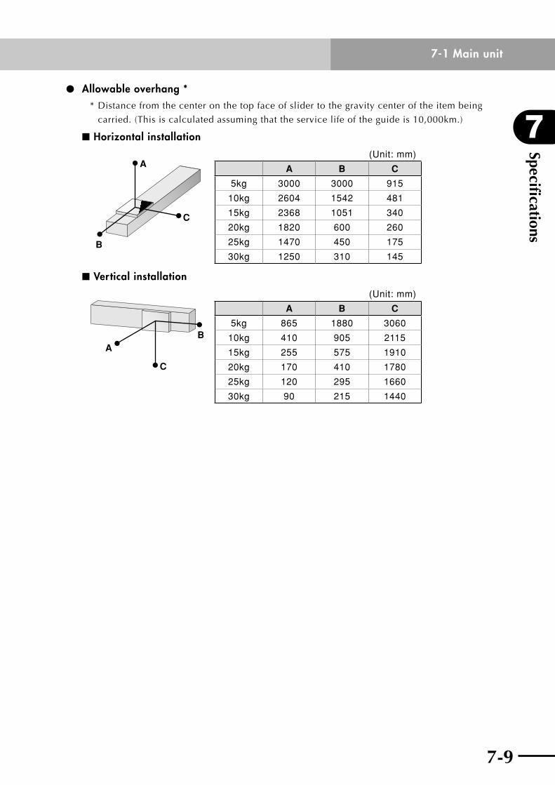
7-8
7
Specifications
7-9
7-1 Main unit
Allowable overhang **Distancefromthecenteronthetopfaceofslidertothegravitycenteroftheitembeing
carried. (This is calculated assuming that the service life of the guide is 10,000km.)
n Horizontal installation
A
C
B
(Unit: mm)
A B C
5kg 3000 3000 915
10kg 2604 1542 481
15kg 2368 1051 340
20kg 1820 600 260
25kg 1470 450 175
30kg 1250 310 145
n Vertical installation
C
BA
(Unit: mm)
A B C
5kg 865 1880 3060
10kg 410 905 2115
15kg 255 575 1910
20kg 170 410 1780
25kg 120 295 1660
30kg 90 215 1440
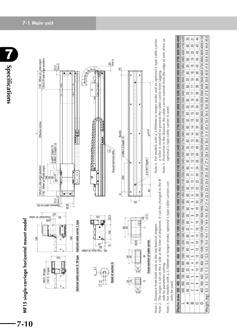
Specifications
7
7-10
7-1 Main unit
7-11
MF1
5 si
ngle
-car
riag
e ho
rizo
ntal
mou
nt m
odel
Opt
iona
l cab
le c
arrie
r S /
M ty
peO
ptio
nal c
able
car
rier L
type
186.
5 : M
type
(161
.5 :
S ty
pe)
100
184
188
16790
φ30Diameter of roller
20
100
G10
0
6680 : Top face of slider
32.5
Det
ail o
f sec
tion
G
23.
7
7.24.5
LS
Cro
ss-s
ectio
n of
cab
le c
arrie
r
M49
20.5
40
14
15
20.514
2466 50
3529
φ8 φ7.5
(Between φ6H7±0.02)
6848
±0.0
2
186
31±1
(Not
e 2)
8494
2-φ6
H7
Dep
th 1
04-
M6x
1.0
Dep
th 1
2
90
Effe
ctiv
e st
roke
L13
0±5
(L s
ide
orig
in p
ositi
on)
(130
: W
hen
at R
sid
e or
igin
)
31±1
(Not
e 2)
(130
: W
hen
at L
sid
e or
igin
)13
0±5
(R s
ide
orig
in p
ositi
on)
Gro
und
term
inal
(M4)
30
(Not
e 3)
A20
0Bx
200
(A)
80D
±0.0
2
60
C-M
6x1.
0 D
epth
10
2-φ1
0H7
Dep
th 7
No
te1
.D
ista
nce
fro
mb
oth
en
ds
tot
he
mec
han
ical
sto
pp
er.
No
te 2
. T
he
ori
gin
is
set
on
th
e L
sid
e at
th
e ti
me
of
ship
men
t. I
t ca
n b
e ch
ange
d t
o t
he
R
sid
e b
y p
aram
eter
set
tin
g.N
ote
3.
For
mo
del
s w
ith
a 2
,10
0m
m o
r lo
nge
r st
roke
, o
pti
on
al L
typ
e ca
ble
car
rier
s ca
n
on
ly b
e u
sed
.
No
te 4
. Fo
r m
od
els
wit
h a
3,0
00
mm
or
lon
ger
stro
ke a
nd
an
op
tio
nal
L t
ype
cab
le c
arri
er,
a ro
ller
is
inst
alle
d t
o p
reve
nt
the
cab
le c
arri
er f
rom
sag
gin
g.N
ote
5.
Pro
tru
sio
n i
s th
e d
ista
nce
th
e ca
ble
car
rier
ext
end
s fr
om
th
e ed
ge o
f u
nit
wh
en a
n
op
tio
nal
L t
ype
cab
le c
arri
er i
s u
sed
.
Effe
ctive
stro
ke30
040
050
060
070
080
090
010
0011
0012
0013
0014
0015
0016
0017
0018
0019
0020
0021
0022
0023
0024
0025
0026
0027
0028
0029
0030
0031
0032
0033
0034
0035
0036
0037
0038
0039
0040
00L
560
660
760
860
960
1060
1160
1260
1360
1460
1560
1660
1760
1860
1960
2060
2160
2260
2360
2460
2560
2660
2760
2860
2960
3060
3160
3260
3360
3460
3560
3660
3760
3860
3960
4060
4160
4260
A80
3080
3080
3080
3080
3080
3080
3080
3080
3080
3080
3080
3080
3080
3080
3080
3080
3080
3080
30B
23
34
45
56
67
78
89
910
1011
1112
1213
1314
1415
1516
1617
1718
1819
1920
2021
C6
88
1010
1212
1414
1616
1818
2020
2222
2424
2626
2828
3030
3232
3434
3636
3838
4040
4242
44D
400
500
600
700
800
900
1000
1100
1200
1300
1400
1500
1600
1700
1800
1900
2000
2100
2200
2300
2400
2500
2600
2700
2800
2900
3000
3100
3200
3300
3400
3500
3600
3700
3800
3900
4000
4100
Wei
ght (
kg)
8.3
9.3
10.3
11.3
12.3
13.3
14.3
15.4
16.4
17.4
18.4
19.4
20.4
21.4
22.4
23.4
24.4
25.4
26.4
27.4
28.4
29.4
30.4
31.4
32.4
33.4
34.4
35.8
36.8
37.8
38.8
39.8
40.8
41.8
42.8
43.8
44.8
45.8
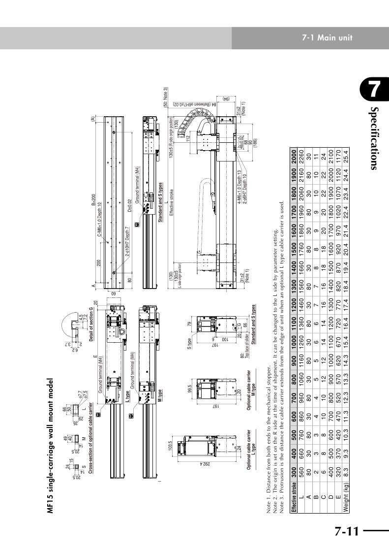
7-10
7
Specifications
7-11
7-1 Main unitM
F15
sing
le-c
arri
age
wal
l mou
nt m
odel
l
LM
SC
ross
-sec
tion
of o
ptio
nal c
able
car
rier
1524 14
20.5
20.514
404966 50
2935
φ7.7
φ7.5
31±2
48±0
.02
68 90(1
86)
(94)
(130
)Ef
fect
ive
stro
keL
(50:
Not
e 3)
(Not
e 1)
(Not
e 1)
(130
)13
0±5
(L si
de or
igin p
ositio
n)
Gro
und
term
inal
(M4)
Stan
dard
and
S ty
pes
M ty
pe
Gro
und
term
inal
(M4)
20E
L ty
peGro
und
term
inal
(M4)
A20
0B×
200
80D
±0.0
2
(A)
60
2066
80:
Top
face
of s
lider
79
100197
6
S ty
pe Stan
dard
and
S ty
pes
G20
197
99.5
Opt
iona
l cab
le c
arrie
r M
type
24
292.4
103.
5
Opt
iona
l cab
le c
arrie
r L
type
4.5
7.2
23.76.2
Det
ail o
f sec
tion
G
C-M
6×1.
0 D
epth
10
2-φ1
0H7
Dep
th 7
130±
5 (R
side
origi
n pos
ition)
84 (Between φ6H7±0.02)
31±2
4-M
6×1.
0 D
epth
13
2-φ6
H7
Dep
th 1
0
112
No
te 1
. D
ista
nce
fro
m b
oth
en
ds
to t
he
mec
han
ical
sto
pp
er.
No
te 2
. T
he
ori
gin
is
set
on
th
e R
sid
e at
th
e ti
me
of
ship
men
t. I
t ca
n b
e ch
ange
d t
o t
he
L si
de
by
par
amet
er s
etti
ng.
No
te 3
. P
rotr
usi
on
is
the
dis
tan
ce t
he
cab
le c
arri
er e
xten
ds
fro
m t
he
edge
of
un
it w
hen
an
op
tio
nal
L t
ype
cab
le c
arri
er i
s u
sed
.
Effe
ctive
stro
ke3
00
40
05
00
60
07
00
80
09
00
10
00
110
01
20
01
30
01
40
01
50
01
60
01
70
01
80
01
90
02
00
0L
56
06
60
76
08
60
96
01
06
011
60
12
60
13
60
14
60
15
60
16
60
17
60
18
60
19
60
20
60
21
60
22
60
A8
03
08
03
08
03
08
03
08
03
08
03
08
03
08
03
08
03
0B
23
34
45
56
67
78
89
91
01
011
C6
88
10
10
12
12
14
14
16
16
18
18
20
20
22
22
24
D4
00
50
06
00
70
08
00
90
01
00
011
00
12
00
13
00
14
00
15
00
16
00
17
00
18
00
19
00
20
00
21
00
E3
20
37
04
20
47
05
20
57
06
20
67
07
20
77
08
20
87
09
20
97
01
02
01
07
011
20
117
0W
eigh
t (kg
)8
.3
9.3
1
0.3
11
.3
12
.3
13
.3
14
.3
15
.4
16
.4
17
.4
18
.4
19
.4
20
.4
21
.4
22
.4
23
.4
24
.4
25
.4
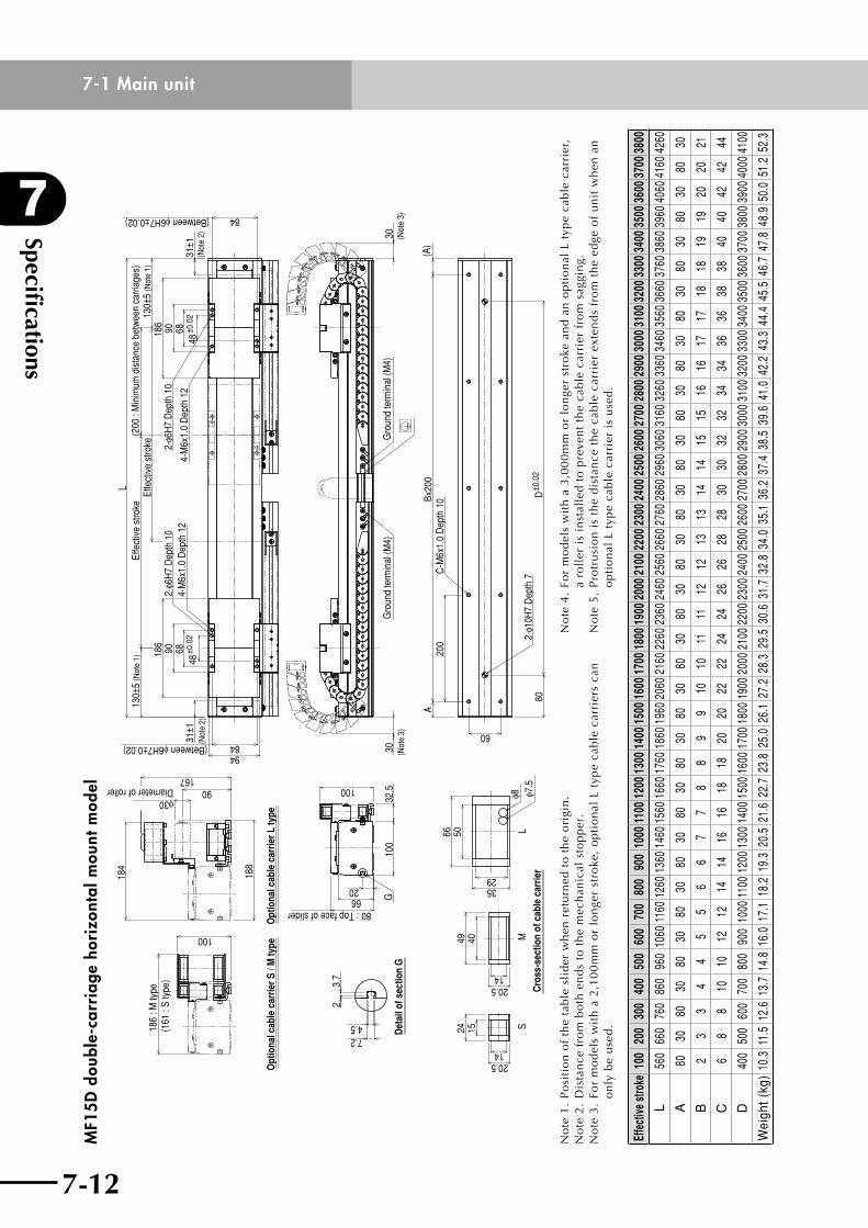
Specifications
7
7-12
7-1 Main unit
7-13
MF1
5D d
oubl
e-ca
rria
ge h
oriz
onta
l mou
nt m
odel
Opt
iona
l cab
le c
arrie
r S /
M ty
pe
Opt
iona
l cab
le c
arrie
r L ty
pe100
186
: M ty
pe(1
61 :
S ty
pe)
184
188
16790
φ30Diameter of roller
32.5
80 : Top face of slider66
100
G
100
20
Det
ail o
f sec
tion
G
23.
7
7.24.5
LS
Cro
ss-s
ectio
n of
cab
le c
arrie
r
M49
20.5
40
14
15
20.514
2466 50
φ8 φ7.5
(Between φ6H7±0.02)
(Between φ6H7±0.02)
6848
±0.0
2
186
31±1
(Not
e 2)
31±1
(Not
e 2)
8494
2-φ6
H7
Dep
th 1
04-
M6x
1.0
Dep
th 1
290
L13
0±5
(Not
e 1)
130±
5 (N
ote
1)
90
84
186
48±0
.02
68
Effe
ctiv
e st
roke
Effe
ctiv
e st
roke
(200
: M
inim
um d
ista
nce
betw
een
carri
ages
)
2-φ6
H7
Dep
th 1
0
4-M
6x1.
0 D
epth
12
30
(Not
e 3)
Gro
und
term
inal
(M4)
Gro
und
term
inal
(M4)
30
(Not
e 3)
A20
0Bx
200
(A)
80D
±0.0
2
60
C-M
6x1.
0 D
epth
10
2-φ1
0H7
Dep
th 7
3529
No
te 1
. P
osi
tio
n o
f th
e ta
ble
sli
der
wh
en r
etu
rned
to
th
e o
rigi
n.
No
te2
.D
ista
nce
fro
mb
oth
en
ds
tot
he
mec
han
ical
sto
pp
er.
No
te 3
. Fo
r m
od
els
wit
h a
2,1
00
mm
or
lon
ger
stro
ke,
op
tio
nal
L t
ype
cab
le c
arri
ers
can
o
nly
be
use
d.
No
te 4
. Fo
r m
od
els
wit
h a
3,0
00
mm
or
lon
ger
stro
ke a
nd
an
op
tio
nal
L t
ype
cab
le c
arri
er,
a ro
ller
is
inst
alle
d t
o p
reve
nt
the
cab
le c
arri
er f
rom
sag
gin
g.N
ote
5.
Pro
tru
sio
n i
s th
e d
ista
nce
th
e ca
ble
car
rier
ext
end
s fr
om
th
e ed
ge o
f u
nit
wh
en a
n
op
tio
nal
L t
ype
cab
le c
arri
er i
s u
sed
.
Effe
ctive
stro
ke10
020
030
040
050
060
070
080
090
010
0011
0012
0013
0014
0015
0016
0017
0018
0019
0020
0021
0022
0023
0024
0025
0026
0027
0028
0029
0030
0031
0032
0033
0034
0035
0036
0037
0038
00
L56
066
076
086
096
010
6011
6012
6013
6014
6015
6016
6017
6018
6019
6020
6021
6022
6023
6024
6025
6026
6027
6028
6029
6030
6031
6032
6033
6034
6035
6036
6037
6038
6039
6040
6041
6042
60
A80
3080
3080
3080
3080
3080
3080
3080
3080
3080
3080
3080
3080
3080
3080
3080
3080
3080
3080
30
B2
33
44
55
66
77
88
99
1010
1111
1212
1313
1414
1515
1616
1717
1818
1919
2020
21
C6
88
1010
1212
1414
1616
1818
2020
2222
2424
2626
2828
3030
3232
3434
3636
3838
4040
4242
44
D40
050
060
070
080
090
010
0011
0012
0013
0014
0015
0016
0017
0018
0019
0020
0021
0022
0023
0024
0025
0026
0027
0028
0029
0030
0031
0032
0033
0034
0035
0036
0037
0038
0039
0040
0041
00
Wei
ght (
kg)
10.3
11.5
12.6
13.7
14.8
16.0
17.1
18.2
19.3
20.5
21.6
22.7
23.8
25.0
26.1
27.2
28.3
29.5
30.6
31.7
32.8
34.0
35.1
36.2
37.4
38.5
39.6
41.0
42.2
43.3
44.4
45.5
46.7
47.8
48.9
50.0
51.2
52.3
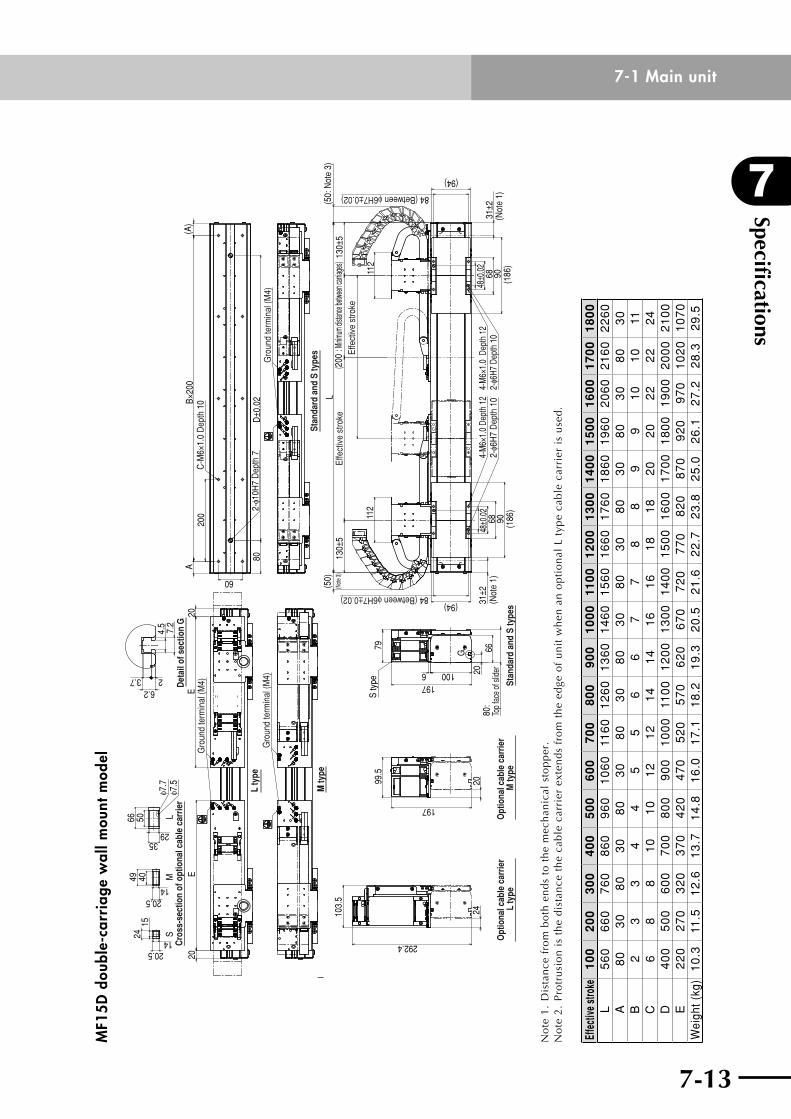
7-12
7
Specifications
7-13
7-1 Main unitM
F15D
dou
ble-
carr
iage
wal
l mou
nt m
odel
l
31±2
(200
: Min
imum
distan
ce be
tween
carria
ges)
Effe
ctiv
e st
roke
Effe
ctiv
e st
roke
31±2
48±0
.02
68 90(1
86)
(94)
130±
5
112
130±
5L
112
48±0
.02
68 90 (186
)(94)
(50)
(50:
Not
e 3)
(Not
e 1)
(Not
e 1)
(Note
3)
Stan
dard
and
S ty
pes
Gro
und
term
inal
(M4)
M ty
pe
Gro
und
term
inal
(M4)
2020
EE
L ty
pe
Gro
und
term
inal
(M4)
60
A20
0B×
200
80D
±0.0
2
(A)
79
100
6680
:To
p fa
ce o
f slid
er20
1976
S ty
pe
G
2099.5
197
103.
5
24
292.47.
24.
5
23.76.2
LM
S
1524 14
20.5
20.514
404966 50
2935
φ7.7
φ7.5
Stan
dard
and
S ty
pes
Opt
iona
l cab
le c
arrie
r M
type
Opt
iona
l cab
le c
arrie
r L
type
C-M
6×1.
0 D
epth
10
2-φ1
0H7
Dep
th 7
84 (Between φ6H7±0.02)
4-M
6×1.
0 De
pth
122-
φ6H
7 D
epth
10
4-M
6×1.
0 D
epth
12
2-φ6
H7 D
epth
10
84 (Between φ6H7±0.02)
Cro
ss-s
ectio
n of
opt
iona
l cab
le c
arrie
rD
etai
l of s
ectio
n G
No
te 1
. D
ista
nce
fro
m b
oth
en
ds
to t
he
mec
han
ical
sto
pp
er.
No
te 2
. P
rotr
usi
on
is
the
dis
tan
ce t
he
cab
le c
arri
er e
xten
ds
fro
m t
he
edge
of
un
it w
hen
an
op
tio
nal
L t
ype
cab
le c
arri
er i
s u
sed
.
Effe
ctive
stro
ke1
00
20
03
00
40
05
00
60
07
00
80
09
00
10
00
110
01
20
01
30
01
40
01
50
01
60
01
70
01
80
0L
56
06
60
76
08
60
96
01
06
011
60
12
60
13
60
14
60
15
60
16
60
17
60
18
60
19
60
20
60
21
60
22
60
A8
03
08
03
08
03
08
03
08
03
08
03
08
03
08
03
08
03
0B
23
34
45
56
67
78
89
91
01
011
C6
88
10
10
12
12
14
14
16
16
18
18
20
20
22
22
24
D4
00
50
06
00
70
08
00
90
01
00
011
00
12
00
13
00
14
00
15
00
16
00
17
00
18
00
19
00
20
00
21
00
E2
20
27
03
20
37
04
20
47
05
20
57
06
20
67
07
20
77
08
20
87
09
20
97
01
02
01
07
0W
eigh
t (kg
)1
0.3
11
.5
12
.6
13
.7
14
.8
16
.0
17
.1
18
.2
19
.3
20
.5
21
.6
22
.7
23
.8
25
.0
26
.1
27
.2
28
.3
29
.5
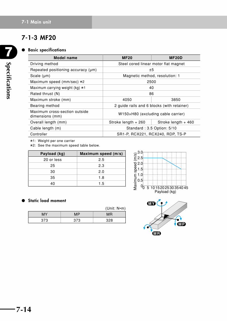
Specifications
7
7-14
7-1 Main unit
7-15
7-1-3 MF20
Basic specifications
Model name MF20 MF20D
Driving method Steel cored linear motor flat magnet
Repeated positioning accuracy (µm) ±5
Scale (µm) Magnetic method, resolution: 1
Maximum speed (mm/sec) 2 2500
Maximum carrying weight (kg) 1 40
Rated thrust (N) 86
Maximum stroke (mm) 4050 3850
Bearing method 2 guide rails and 6 blocks (with retainer)
Maximum cross-section outside dimensions (mm)
W150×H80 (excluding cable carrier)
Overall length (mm) Stroke length + 260 Stroke length + 460
Cable length (m) Standard : 3.5 Option: 5/10
Controller SR1-P, RCX221, RCX240, RDP, TS-P
1: Weight per one carrier2: See the maximum speed table below.
Payload (kg) Maximum speed (m/s)
20 or less 2.5
25 2.3
30 2.0
35 1.8
40 1.5
Static load moment
(Unit: N•m)
MY MP MR
373 373 328
0 5 101520Payload (kg)
2530 3540 45Max
imum
spe
ed (
m/s
) 3.0
2.5
2.0
1.5
1.0
0.5
0
M P
M R
M Y
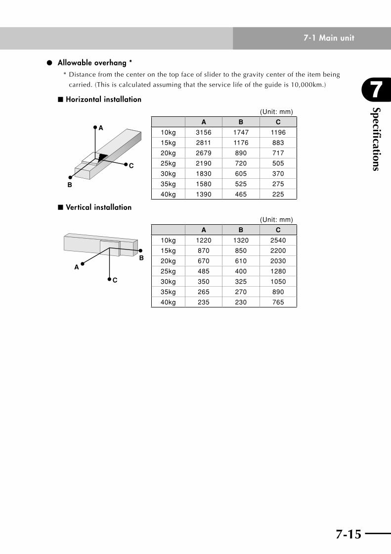
7-14
7
Specifications
7-15
7-1 Main unit
Allowable overhang **Distancefromthecenteronthetopfaceofslidertothegravitycenteroftheitembeing
carried. (This is calculated assuming that the service life of the guide is 10,000km.)
n Horizontal installation
A
C
B
(Unit: mm)
A B C
10kg 3156 1747 1196
15kg 2811 1176 883
20kg 2679 890 717
25kg 2190 720 505
30kg 1830 605 370
35kg 1580 525 275
40kg 1390 465 225
n Vertical installation
C
BA
(Unit: mm)
A B C
10kg 1220 1320 2540
15kg 870 850 2200
20kg 670 610 2030
25kg 485 400 1280
30kg 350 325 1050
35kg 265 270 890
40kg 235 230 765
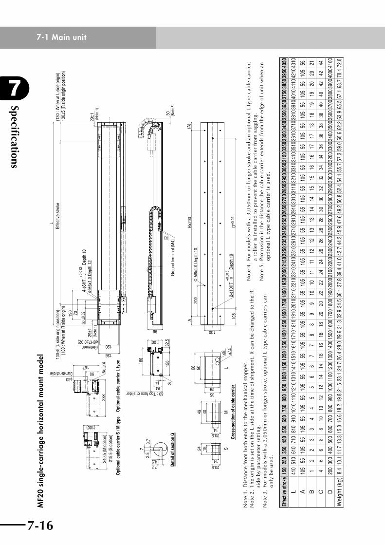
Specifications
7
7-16
7-1 Main unit
7-17
MF2
0 si
ngle
-car
riag
e ho
rizo
ntal
mou
nt m
odel
Det
ail o
f sec
tion
G
73.
72.
5
4.57.2
(100)
240.
5 (M
opt
ion)
215.
5 (S
opt
ion)
Opt
iona
l cab
le c
arrie
r S /
M ty
pe
1464
80 : Top face of slider
186
(100)
150
32.5
G
24
1420.5
1540
1420.5
49
Cro
ss-s
ectio
n of
cab
le c
arrie
r
MS
2935
5066
φ8 φ7.5
L
L13
0±5
(L s
ide
orig
in p
ositi
on)
(130
: W
hen
at R
sid
e or
igin
)Ef
fect
ive
stro
ke(1
30 :
Whe
n at
L s
ide
orig
in)
130±
5 (R
sid
e or
igin
pos
ition
)
(Between φ6H7±0.02)
136
120
190
70
29±1
(Not
e 1)
50±0
.02
4-φ6
H7
+0.0
12 0
Dep
th 1
04-
M6x
1.0
Dep
th 1
229
±1(N
ote
1)
(A)
30
(Not
e 5)
Gro
und
term
inal
(M4)
105
D±0
.02
2-φ1
0H7
+0.0
15 0
Dep
th 1
0
ABx
200
200
C-M
6x1.
0 D
epth
10
10098
Opt
iona
l cab
le c
arrie
r L ty
pe
90φ30Diameter of roller
167
238
Not
e 4
No
te1
.D
ista
nce
fro
mb
oth
en
ds
tot
he
mec
han
ical
sto
pp
er.
No
te 2
. T
he
ori
gin
is
set
on
th
e L
sid
e at
th
e ti
me
of
ship
men
t. I
t ca
n b
e ch
ange
d t
o t
he
R
sid
e b
y p
aram
eter
set
tin
g.N
ote
3.
For
mo
del
s w
ith
a 2
,05
0m
m o
r lo
nge
r st
roke
, o
pti
on
al L
typ
e ca
ble
car
rier
s ca
n
on
ly b
e u
sed
.
No
te 4
. Fo
r m
od
els
wit
h a
3,0
50
mm
or
lon
ger
stro
ke a
nd
an
op
tio
nal
L t
ype
cab
le c
arri
er,
a ro
ller
is
inst
alle
d t
o p
reve
nt
the
cab
le c
arri
er f
rom
sag
gin
g.N
ote
5.
Pro
tru
sio
n i
s th
e d
ista
nce
th
e ca
ble
car
rier
ext
end
s fr
om
th
e ed
ge o
f u
nit
wh
en a
n
op
tio
nal
L t
ype
cab
le c
arri
er i
s u
sed
.
Effe
ctive
stro
ke15
025
035
045
055
065
075
085
095
010
5011
5012
5013
5014
5015
5016
5017
5018
5019
5020
5021
5022
5023
5024
5025
5026
5027
5028
5029
5030
5031
5032
5033
5034
5035
5036
5037
5038
5039
5040
50
L41
051
061
071
081
091
010
1011
1012
1013
1014
1015
1016
1017
1018
1019
1020
1021
1022
1023
1024
1025
1026
1027
1028
1029
1030
1031
1032
1033
1034
1035
1036
1037
1038
1039
1040
1041
1042
1043
10
A10
555
105
5510
555
105
5510
555
105
5510
555
105
5510
555
105
5510
555
105
5510
555
105
5510
555
105
5510
555
105
5510
555
105
55
B1
22
33
44
55
66
77
88
99
1010
1111
1212
1313
1414
1515
1616
1717
1818
1919
2020
21
C4
66
88
1010
1212
1414
1616
1818
2020
2222
2424
2626
2828
3030
3232
3434
3636
3838
4040
4242
44
D20
030
040
050
060
070
080
090
010
0011
0012
0013
0014
0015
0016
0017
0018
0019
0020
0021
0022
0023
0024
0025
0026
0027
0028
0029
0030
0031
0032
0033
0034
0035
0036
0037
0038
0039
0040
0041
00
Wei
ght (
kg)
8.4
10.1
11.7
13.3
15.0
16.6
18.2
19.8
21.5
23.1
24.7
26.4
28.0
29.6
31.3
32.9
34.5
36.1
37.8
39.4
41.0
42.7
44.3
45.9
47.6
49.2
50.8
52.4
54.1
55.7
57.3
59.0
60.6
62.2
63.9
65.5
67.1
68.7
70.4
72.0
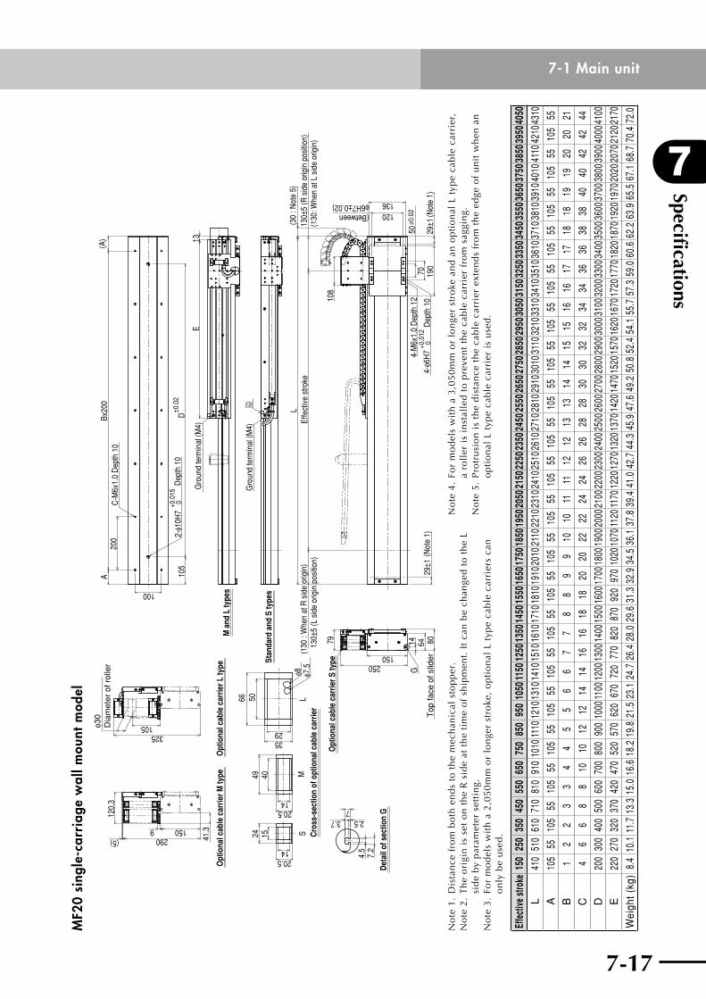
7-16
7
Specifications
7-17
7-1 Main unitM
F20
sing
le-c
arri
age
wal
l mou
nt m
odel
24 15
20.514
S Cro
ss-s
ectio
n of
opt
iona
l cab
le c
arrie
r
20.514
M49 403529
66 50
φ7.5
φ8L
100
A20
0Bx
200
C-M
6x1.
0 D
epth
10
(A)
105
D±0
.02
2-φ1
0H7
+0.0
15 0
Dep
th 1
0
Det
ail o
f sec
tion
G
7.2
4.5
73.7 2.5
325
φ30
Dia
met
er o
f rol
ler
105
Opt
iona
l cab
le c
arrie
r L ty
peO
ptio
nal c
able
car
rier M
type
41.3
(5) 2901509
120.
3
Opt
iona
l cab
le c
arrie
r S ty
pe79
250150
G14 80
Top
face
of s
lider
64
Gro
und
term
inal
(M4)
E13
Gro
und
term
inal
(M4)
(30
: Not
e 5)
130±
5 (R
sid
e or
igin
pos
ition
)(1
30: W
hen
at L
sid
e or
igin
)
M a
nd L
type
s
Stan
dard
and
S ty
pes
(130
: W
hen
at R
sid
e or
igin
)13
0±5
(L s
ide
orig
in p
ositi
on)
Effe
ctiv
e st
roke
L
108
4-M
6x1.
0 D
epth
12
29±1
(Not
e 1)
4-φ6
H7
+0.0
12 0
Dep
th 1
029
±1(N
ote
1)19
070
50±0
.02
136(Between φ6H7±0.02)
120
No
te1
.D
ista
nce
fro
mb
oth
en
ds
tot
he
mec
han
ical
sto
pp
er.
No
te 2
. T
he
ori
gin
is
set
on
th
e R
sid
e at
th
e ti
me
of
ship
men
t. I
t ca
n b
e ch
ange
d t
o t
he
L si
de
by
par
amet
er s
etti
ng.
No
te 3
. Fo
r m
od
els
wit
h a
2,0
50
mm
or
lon
ger
stro
ke,
op
tio
nal
L t
ype
cab
le c
arri
ers
can
o
nly
be
use
d.
No
te 4
. Fo
r m
od
els
wit
h a
3,0
50
mm
or
lon
ger
stro
ke a
nd
an
op
tio
nal
L t
ype
cab
le c
arri
er,
a ro
ller
is
inst
alle
d t
o p
reve
nt
the
cab
le c
arri
er f
rom
sag
gin
g.N
ote
5.
Pro
tru
sio
n i
s th
e d
ista
nce
th
e ca
ble
car
rier
ext
end
s fr
om
th
e ed
ge o
f u
nit
wh
en a
n
op
tio
nal
L t
ype
cab
le c
arri
er i
s u
sed
.
Effe
ctive
stro
ke15
025
035
045
055
065
075
085
095
010
5011
5012
5013
5014
5015
5016
5017
5018
5019
5020
5021
5022
5023
5024
5025
5026
5027
5028
5029
5030
5031
5032
5033
5034
5035
5036
5037
5038
5039
5040
50
L41
051
061
071
081
091
010
1011
1012
1013
1014
1015
1016
1017
1018
1019
1020
1021
1022
1023
1024
1025
1026
1027
1028
1029
1030
1031
1032
1033
1034
1035
1036
1037
1038
1039
1040
1041
1042
1043
10
A10
555
105
5510
555
105
5510
555
105
5510
555
105
5510
555
105
5510
555
105
5510
555
105
5510
555
105
5510
555
105
5510
555
105
55
B1
22
33
44
55
66
77
88
99
1010
1111
1212
1313
1414
1515
1616
1717
1818
1919
2020
21
C4
66
88
1010
1212
1414
1616
1818
2020
2222
2424
2626
2828
3030
3232
3434
3636
3838
4040
4242
44
D20
030
040
050
060
070
080
090
010
0011
0012
0013
0014
0015
0016
0017
0018
0019
0020
0021
0022
0023
0024
0025
0026
0027
0028
0029
0030
0031
0032
0033
0034
0035
0036
0037
0038
0039
0040
0041
00
E22
027
032
037
042
047
052
057
062
067
072
077
082
087
092
097
010
2010
7011
2011
7012
2012
7013
2013
7014
2014
7015
2015
7016
2016
7017
2017
7018
2018
7019
2019
7020
2020
7021
2021
70
Wei
ght (
kg)
8.4
10.1
11.7
13.3
15.0
16.6
18.2
19.8
21.5
23.1
24.7
26.4
28.0
29.6
31.3
32.9
34.5
36.1
37.8
39.4
41.0
42.7
44.3
45.9
47.6
49.2
50.8
52.4
54.1
55.7
57.3
59.0
60.6
62.2
63.9
65.5
67.1
68.7
70.4
72.0
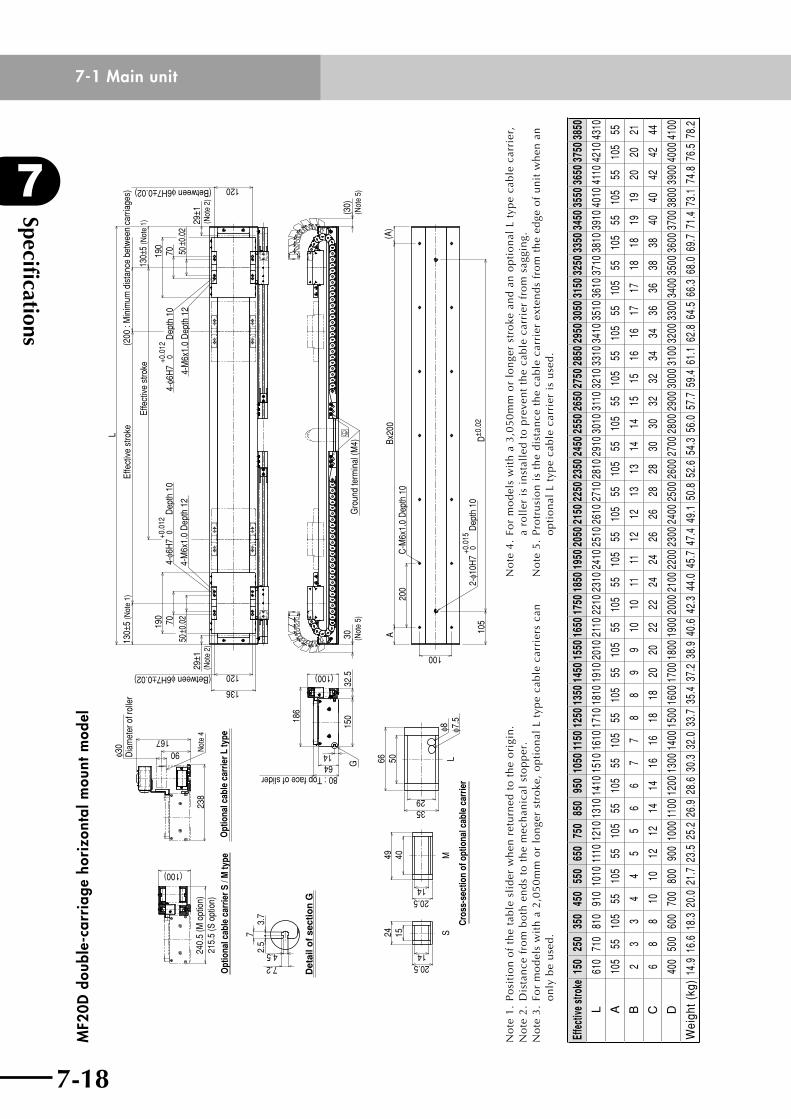
Specifications
7
7-18
7-1 Main unit
7-19
MF2
0D d
oubl
e-ca
rria
ge h
oriz
onta
l mou
nt m
odel
72.
53.
7
7.24.5
Det
ail o
f se
ctio
n G
Opt
iona
l cab
le c
arrie
r S /
M ty
pe
240.
5 (M
opt
ion)
215.
5 (S
opt
ion)
(100)
32.5
150
80 : Top face of slider6414
G
(100)
186
20.514
1524
20.514
49 40
3529
66 50 LS
Cro
ss-s
ectio
n of
opt
iona
l cab
le c
arrie
r
Mφ8 φ7
.5
C-M
6x1.
0 D
epth
10
200
(A)
Bx20
0A
2-φ1
0H7
+0.0
150
Dep
th 1
0D
±0.0
210
5
100
(30)
(Not
e 5)
30 (Not
e 5)
Gro
und
term
inal
(M4)
L
130±
5 (N
ote
1)
190 70
50±0
.02
29±1
(Not
e 2)
(Between φ6H7±0.02) 120
136
(Between φ6H7±0.02)
29±1
(Not
e 2)
120
Effe
ctiv
e st
roke
(200
: M
inim
um d
ista
nce
betw
een
carri
ages
)
4-φ6
H7+0
.012
0 D
epth
10
4-M
6x1.
0 D
epth
12
4-M
6x1.
0 D
epth
12
Effe
ctiv
e st
roke
4-φ6
H7
+0.0
120
Dep
th 1
050
±0.0
270
130±
5 (N
ote
1)
190
167
Opt
iona
l cab
le c
arrie
r L ty
pe
φ30
Dia
met
er o
f rol
ler
90
238
Not
e 4
No
te 1
. P
osi
tio
n o
f th
e ta
ble
sli
der
wh
en r
etu
rned
to
th
e o
rigi
n.
No
te2
.D
ista
nce
fro
mb
oth
en
ds
tot
he
mec
han
ical
sto
pp
er.
No
te 3
. Fo
r m
od
els
wit
h a
2,0
50
mm
or
lon
ger
stro
ke,
op
tio
nal
L t
ype
cab
le c
arri
ers
can
o
nly
be
use
d.
No
te 4
. Fo
r m
od
els
wit
h a
3,0
50
mm
or
lon
ger
stro
ke a
nd
an
op
tio
nal
L t
ype
cab
le c
arri
er,
a ro
ller
is
inst
alle
d t
o p
reve
nt
the
cab
le c
arri
er f
rom
sag
gin
g.N
ote
5.
Pro
tru
sio
n i
s th
e d
ista
nce
th
e ca
ble
car
rier
ext
end
s fr
om
th
e ed
ge o
f u
nit
wh
en a
n
op
tio
nal
L t
ype
cab
le c
arri
er i
s u
sed
.
Effe
ctive
stro
ke15
025
035
045
055
065
075
085
095
010
5011
5012
5013
5014
5015
5016
5017
5018
5019
5020
5021
5022
5023
5024
5025
5026
5027
5028
5029
5030
5031
5032
5033
5034
5035
5036
5037
5038
50
L61
071
081
091
010
1011
1012
1013
1014
1015
1016
1017
1018
1019
1020
1021
1022
1023
1024
1025
1026
1027
1028
1029
1030
1031
1032
1033
1034
1035
1036
1037
1038
1039
1040
1041
1042
1043
10
A10
555
105
5510
555
105
5510
555
105
5510
555
105
5510
555
105
5510
555
105
5510
555
105
5510
555
105
5510
555
105
5510
555
B2
33
44
55
66
77
88
99
1010
1111
1212
1313
1414
1515
1616
1717
1818
1919
2020
21
C6
88
1010
1212
1414
1616
1818
2020
2222
2424
2626
2828
3030
3232
3434
3636
3838
4040
4242
44
D40
050
060
070
080
090
010
0011
0012
0013
0014
0015
0016
0017
0018
0019
0020
0021
0022
0023
0024
0025
0026
0027
0028
0029
0030
0031
0032
0033
0034
0035
0036
0037
0038
0039
0040
0041
00
Wei
ght (
kg)
14.9
16.6
18.3
20.0
21.7
23.5
25.2
26.9
28.6
30.3
32.0
33.7
35.4
37.2
38.9
40.6
42.3
44.0
45.7
47.4
49.1
50.8
52.6
54.3
56.0
57.7
59.4
61.1
62.8
64.5
66.3
68.0
69.7
71.4
73.1
74.8
76.5
78.2
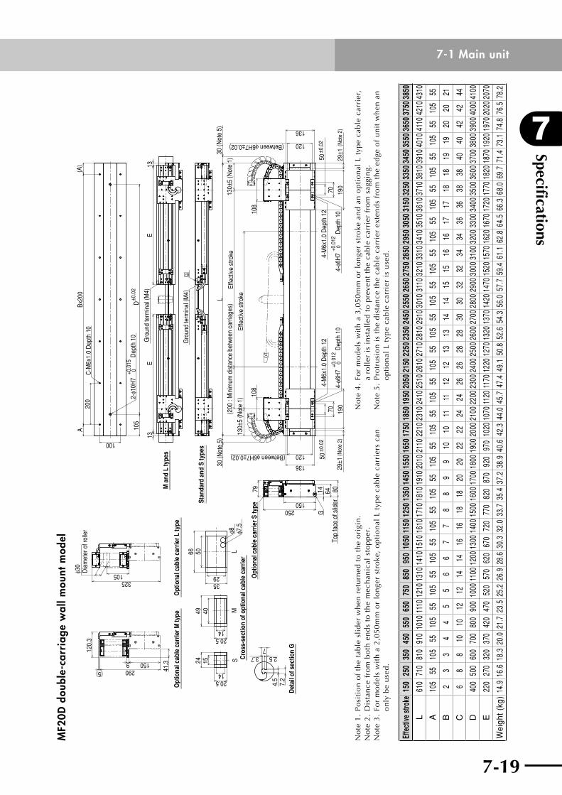
7-18
7
Specifications
7-19
7-1 Main unitM
F20D
dou
ble-
carr
iage
wal
l mou
nt m
odel
24 15
1420.5
4049
Cro
ss-s
ectio
n of
opt
iona
l cab
le c
arrie
rM
SL
1420.5
φ8 φ7.5
5066
2935
73.7 2.5
Det
ail o
f sec
tion
G
4.5
7.2
φ30
Dia
met
er o
f rol
ler
325105
Opt
iona
l cab
le c
arrie
r M ty
peO
ptio
nal c
able
car
rier L
type
41.31509
290(5)
79O
ptio
nal c
able
car
rier S
type
120.
3
G
150250
14 64 80To
p fa
ce o
f slid
er
ABx
200
(A)
200
C-M
6x1.
0 D
epth
10
100
105
D±0
.02
2-φ1
0H7
+0.0
15 0
Dep
th 1
0
M a
nd L
type
s
Stan
dard
and
S ty
pes
13E
13E
Gro
und
term
inal
(M4)
Gro
und
term
inal
(M4)
(Between φ6H7±0.02)
136
120
30 (N
ote
5)
50±0
.02
29±1
(Not
e 2)
70 190
4-φ6
H7
+0.0
120
Dep
th 1
0
4-M
6x1.
0 D
epth
12
50±0
.02
70 190
29±1
(Not
e 2)
4-φ6
H7
+0.0
12 0
Dep
th 1
0
4-M
6x1.
0 D
epth
12
(Between φ6H7±0.02) 120
136
Effe
ctiv
e st
rokeL
30 (N
ote
5)
130±
5 (N
ote
1)
130±
5 (N
ote
1)Ef
fect
ive
stro
ke(2
00 :
Min
imum
dis
tanc
e be
twee
n ca
rriag
es)
108
108
No
te 1
. P
osi
tio
n o
f th
e ta
ble
sli
der
wh
en r
etu
rned
to
th
e o
rigi
n.
No
te2
.D
ista
nce
fro
mb
oth
en
ds
tot
he
mec
han
ical
sto
pp
er.
No
te 3
. Fo
r m
od
els
wit
h a
2,0
50
mm
or
lon
ger
stro
ke,
op
tio
nal
L t
ype
cab
le c
arri
ers
can
o
nly
be
use
d.
No
te 4
. Fo
r m
od
els
wit
h a
3,0
50
mm
or
lon
ger
stro
ke a
nd
an
op
tio
nal
L t
ype
cab
le c
arri
er,
a ro
ller
is
inst
alle
d t
o p
reve
nt
the
cab
le c
arri
er f
rom
sag
gin
g.N
ote
5.
Pro
tru
sio
n i
s th
e d
ista
nce
th
e ca
ble
car
rier
ext
end
s fr
om
th
e ed
ge o
f u
nit
wh
en a
n
op
tio
nal
L t
ype
cab
le c
arri
er i
s u
sed
.
Effe
ctive
stro
ke15
025
035
045
055
065
075
085
095
010
5011
5012
5013
5014
5015
5016
5017
5018
5019
5020
5021
5022
5023
5024
5025
5026
5027
5028
5029
5030
5031
5032
5033
5034
5035
5036
5037
5038
50
L61
071
081
091
010
1011
1012
1013
1014
1015
1016
1017
1018
1019
1020
1021
1022
1023
1024
1025
1026
1027
1028
1029
1030
1031
1032
1033
1034
1035
1036
1037
1038
1039
1040
1041
1042
1043
10
A10
555
105
5510
555
105
5510
555
105
5510
555
105
5510
555
105
5510
555
105
5510
555
105
5510
555
105
5510
555
105
5510
555
B2
33
44
55
66
77
88
99
1010
1111
1212
1313
1414
1515
1616
1717
1818
1919
2020
21
C6
88
1010
1212
1414
1616
1818
2020
2222
2424
2626
2828
3030
3232
3434
3636
3838
4040
4242
44
D40
050
060
070
080
090
010
0011
0012
0013
0014
0015
0016
0017
0018
0019
0020
0021
0022
0023
0024
0025
0026
0027
0028
0029
0030
0031
0032
0033
0034
0035
0036
0037
0038
0039
0040
0041
00
E22
027
032
037
042
047
052
057
062
067
072
077
082
087
092
097
010
2010
7011
2011
7012
2012
7013
2013
7014
2014
7015
2015
7016
2016
7017
2017
7018
2018
7019
2019
7020
2020
70
Wei
ght (
kg)
14.9
16.6
18.3
20.0
21.7
23.5
25.2
26.9
28.6
30.3
32.0
33.7
35.4
37.2
38.9
40.6
42.3
44.0
45.7
47.4
49.1
50.8
52.6
54.3
56.0
57.7
59.4
61.1
62.8
64.5
66.3
68.0
69.7
71.4
73.1
74.8
76.5
78.2
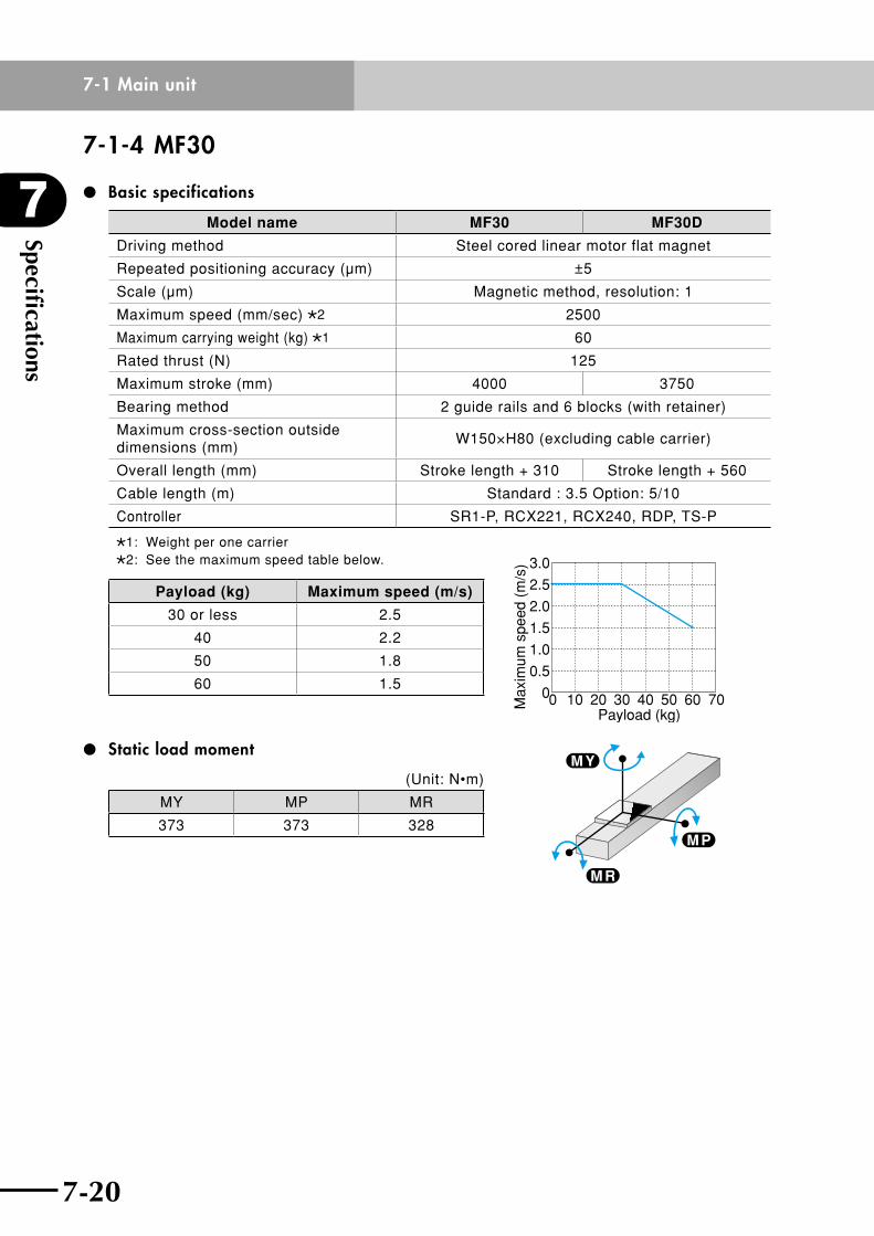
Specifications
7
7-20
7-1 Main unit
7-21
7-1-4 MF30
Basic specifications
Model name MF30 MF30D
Driving method Steel cored linear motor flat magnet
Repeated positioning accuracy (µm) ±5
Scale (µm) Magnetic method, resolution: 1
Maximum speed (mm/sec) 2 2500
Maximum carrying weight (kg) 1 60
Rated thrust (N) 125
Maximum stroke (mm) 4000 3750
Bearing method 2 guide rails and 6 blocks (with retainer)
Maximum cross-section outside dimensions (mm)
W150×H80 (excluding cable carrier)
Overall length (mm) Stroke length + 310 Stroke length + 560
Cable length (m) Standard : 3.5 Option: 5/10
Controller SR1-P, RCX221, RCX240, RDP, TS-P
1: Weight per one carrier2: See the maximum speed table below.
Payload (kg) Maximum speed (m/s)
30 or less 2.5
40 2.2
50 1.8
60 1.5
Static load moment
(Unit: N•m)
MY MP MR
373 373 328
0 10 20 30 40Payload (kg)
50 60 70Max
imum
spe
ed (
m/s
) 3.0
2.5
2.0
1.5
1.0
0.5
0
M P
M R
M Y
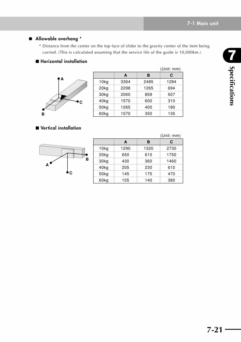
7-20
7
Specifications
7-21
7-1 Main unit
Allowable overhang **Distancefromthecenteronthetopfaceofslidertothegravitycenteroftheitembeing
carried. (This is calculated assuming that the service life of the guide is 10,000km.)
n Horizontal installation
A
C
B
(Unit: mm)
A B C
10kg 3364 2485 1284
20kg 2298 1265 694
30kg 2060 859 507
40kg 1570 600 310
50kg 1265 400 180
60kg 1070 350 135
n Vertical installation
C
BA
(Unit: mm)
A B C
10kg 1290 1320 2730
20kg 650 610 1750
30kg 430 360 1460
40kg 205 230 610
50kg 145 175 470
60kg 105 140 380
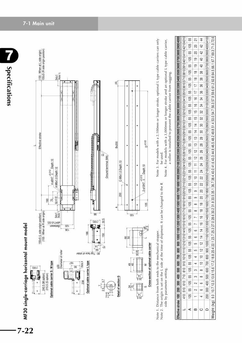
Specifications
7
7-22
7-1 Main unit
7-23
MF3
0 si
ngle
-car
riag
e ho
rizo
ntal
mou
nt m
odel
73.
72.
5
4.57.2 D
etai
l of s
ectio
n G
240.
5 (M
opt
ion)
215.
5 (S
opt
ion)
(100)
Opt
iona
l cab
le c
arrie
r S /
M ty
pe
80 : Top face of slider6414
186
(100)
32.5
150
G
24 15
1420.5
1420.5
4049
2935
5066
φ8 φ7.5
(Betweenφ6H7±0.02)
120136
Effe
ctiv
e st
roke
(155
: W
hen
at L
sid
e or
igin
)15
5±5
(R s
ide
orig
in p
ositi
on)
L
54±1
(Not
e 1)
155±
5 (L
sid
e or
igin
pos
ition
)(1
55 :
Whe
n at
R s
ide
orig
in)
4-M
6x1.
0 D
epth
12
4-φ6
H7
+0.0
120
Dep
th 1
0
50±0
.02
70190
54±1
(Not
e 1)
Gro
und
term
inal
(M4)
98
ABx
200
(A)
200
C-M
6x1.
0 D
epth
10
105
D±0
.02
2-φ1
0H7
+0.0
15 0
Dep
th 1
0
100
Cro
ss-s
ectio
n of
opt
iona
l cab
le c
arrie
rM
SL
238
Opt
iona
l cab
le c
arrie
r L ty
pe
Not
e 4167
90
φ30
Dia
met
er o
f rol
ler
No
te 1
. D
ista
nce
from
bot
hen
dst
oth
em
echa
nica
lst
oppe
r.N
ote
2.
Th
e o
rigi
n i
s se
t o
n t
he
L si
de
at t
he
tim
e o
f sh
ipm
ent.
It
can
be
chan
ged
to
th
e R
si
de
by
par
amet
er s
etti
ng.
No
te 3
. Fo
r m
odel
s w
ith
a 2,
100m
m o
r lo
nger
str
oke,
opt
iona
l L
type
cab
le c
arri
ers
can
only
be
use
d.N
ote
4.
For
mo
del
s w
ith
a 3
,00
0m
m o
r lo
nge
r st
roke
an
d a
n o
pti
on
al L
typ
e ca
ble
car
rier
, a
roll
er i
s in
stal
led
to
pre
ven
t th
e ca
ble
car
rier
fro
m s
aggi
ng.
Effe
ctive
stro
ke10
020
030
040
050
060
070
080
090
010
0011
0012
0013
0014
0015
0016
0017
0018
0019
0020
0021
0022
0023
0024
0025
0026
0027
0028
0029
0030
0031
0032
0033
0034
0035
0036
0037
0038
0039
0040
00
L41
051
061
071
081
091
010
1011
1012
1013
1014
1015
1016
1017
1018
1019
1020
1021
1022
1023
1024
1025
1026
1027
1028
1029
1030
1031
1032
1033
1034
1035
1036
1037
1038
1039
1040
1041
1042
1043
10
A10
555
105
5510
555
105
5510
555
105
5510
555
105
5510
555
105
5510
555
105
5510
555
105
5510
555
105
5510
555
105
5510
555
105
55
B1
22
33
44
55
66
77
88
99
1010
1111
1212
1313
1414
1515
1616
1717
1818
1919
2020
21
C4
66
88
1010
1212
1414
1616
1818
2020
2222
2424
2626
2828
3030
3232
3434
3636
3838
4040
4242
44
D20
030
040
050
060
070
080
090
010
0011
0012
0013
0014
0015
0016
0017
0018
0019
0020
0021
0022
0023
0024
0025
0026
0027
0028
0029
0030
0031
0032
0033
0034
0035
0036
0037
0038
0039
0040
0041
00
Wei
ght (
kg)
9.0
10.7
12.3
13.9
15.6
17.2
18.8
20.4
22.1
23.7
25.3
27.0
28.6
30.2
31.9
33.5
35.1
36.7
38.4
40.0
41.6
43.3
44.9
46.5
48.2
49.8
51.4
53.0
54.7
56.3
57.9
59.6
61.2
62.8
64.5
66.1
67.7
69.3
71.0
72.6
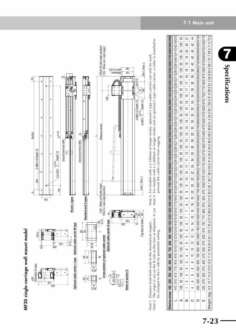
7-22
7
Specifications
7-23
7-1 Main unitM
F30
sing
le-c
arri
age
wal
l mou
nt m
odel
24
1420.5
15
Cro
ss-s
ectio
n of
opt
iona
l cab
le c
arrie
r
MS
Lφ7
.5
1420.5
40495066
2935
φ8
Det
ail o
f sec
tion
G
4.5
7.2
73.7 2.5
325105φ3
0D
iam
eter
of r
olle
r
1509290 41
.3
(5)
Opt
iona
l cab
le c
arrie
r S ty
pe
120.
3
G
150250
Opt
iona
l cab
le c
arrie
r M ty
peO
ptio
nal c
able
car
rier L
type
14 64 80To
p fa
ce o
f slid
er
79
M a
nd L
type
s
Stan
dard
and
S ty
pes
(155
: W
hen
at R
sid
e or
igin
)15
5±5
(L s
ide
orig
in p
ositi
on)
54±1
(Not
e 1)
ABx
200
(A)
200
C-M
6x1.
0 D
epth
10
100
105
D±0
.02
2-φ1
0H7
+0.0
15 0
Dep
th 1
0
13G
roun
d te
rmin
al (M
4)
Gro
und
term
inal
(M4)
155±
5 (R
sid
e or
igin
pos
ition
)(1
55 :
Whe
n at
L s
ide
orig
in)
(Between φ6H7±0.02)
L
Effe
ctiv
e st
roke
108
190
54±1
(Not
e 1)
50±0
.02
704-
φ6H
7+0
.012
0 D
epth
10
4-M
6x1.
0 D
epth
12
120
136
No
te1
.D
ista
nce
fro
mb
oth
en
ds
tot
he
mec
han
ical
sto
pp
er.
No
te 2
. T
he
ori
gin
is
set
on
th
e R
sid
e at
th
e ti
me
of
ship
men
t. I
t ca
n
be
chan
ged
to
th
e L
sid
e b
y p
aram
eter
set
tin
g.
No
te 3
. Fo
r m
od
els
wit
h a
2,1
00
mm
or
lon
ger
stro
ke,
op
tio
nal
L t
ype
cab
le c
arri
ers
can
on
ly b
e u
sed
.N
ote
4.
For
mo
del
s w
ith
a 3
,00
0m
m o
r lo
nge
r st
roke
an
d a
n o
pti
on
al L
typ
e ca
ble
car
rier
, a
roll
er i
s in
stal
led
to
p
reve
nt
the
cab
le c
arri
er f
rom
sag
gin
g.
Effe
ctive
stro
ke10
020
030
040
050
060
070
080
090
010
0011
0012
0013
0014
0015
0016
0017
0018
0019
0020
0021
0022
0023
0024
0025
0026
0027
0028
0029
0030
0031
0032
0033
0034
0035
0036
0037
0038
0039
0040
00
L41
051
061
071
081
091
010
1011
1012
1013
1014
1015
1016
1017
1018
1019
1020
1021
1022
1023
1024
1025
1026
1027
1028
1029
1030
1031
1032
1033
1034
1035
1036
1037
1038
1039
1040
1041
1042
1043
10
A10
555
105
5510
555
105
5510
555
105
5510
555
105
5510
555
105
5510
555
105
5510
555
105
5510
555
105
5510
555
105
5510
555
105
55
B1
22
33
44
55
66
77
88
99
1010
1111
1212
1313
1414
1515
1616
1717
1818
1919
2020
21
C4
66
88
1010
1212
1414
1616
1818
2020
2222
2424
2626
2828
3030
3232
3434
3636
3838
4040
4242
44
D20
030
040
050
060
070
080
090
010
0011
0012
0013
0014
0015
0016
0017
0018
0019
0020
0021
0022
0023
0024
0025
0026
0027
0028
0029
0030
0031
0032
0033
0034
0035
0036
0037
0038
0039
0040
0041
00
E22
027
032
037
042
047
052
057
062
067
072
077
082
087
092
097
010
2010
7011
2011
7012
2012
7013
2013
7014
2014
7015
2015
7016
2016
7017
2017
7018
2018
7019
2019
7020
2020
7021
2021
70
Wei
ght (
kg)
9.0
10.7
12.3
13.9
15.6
17.2
18.8
20.4
22.1
23.7
25.3
27.0
28.6
30.2
31.9
33.5
35.1
36.7
38.4
40.0
41.6
43.3
44.9
46.5
48.2
49.8
51.4
53.0
54.7
56.3
57.9
59.6
61.2
62.8
64.5
66.1
67.7
69.3
71.0
72.6
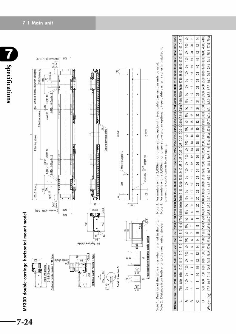
Specifications
7
7-24
7-1 Main unit
7-25
MF3
0D d
oubl
e-ca
rria
ge h
oriz
onta
l mou
nt m
odel
(Between φ6H7±0.02) 120
136D
etai
l of s
ectio
n G
7
7.24.52.
53.
7
54±1
(Not
e 2)
(Between φ6H7±0.02)
54±1
(Not
e 2)
Effe
ctiv
e st
roke
L
50±0
.027019
04-
φ6H
7+0
.012
0 D
epth
10
4-M
6x1.
0 D
epth
12
4-M
6x1.
0 D
epth
12
4-φ6
H7
+0.0
12 0
Dep
th 1
050
±0.0
270190
Effe
ctiv
e st
roke
(250
: M
inim
um d
istan
ce b
etwe
en c
arria
ges)
155±
5 (N
ote
1)
155±
5 (N
ote
1)
120
240.
5 (M
opt
ion)
215.
5 (S
opt
ion)
(100)
Opt
iona
l cab
le c
arrie
r S /
M ty
pe
15
20.514
24
150
1464
80 : Top face of slider18
6
32.5(100)
G
20.514
49 40
3529
66 50 LS C
ross
-sec
tion
of o
ptio
nal c
able
car
rier
Mφ8 φ7
.5
Gro
und
term
inal
(M4)
98
2-φ1
0H7
+0.0
150
Dep
th 1
0D
±0.0
210
5
C-M
6x1.
0 D
epth
10
200
(A)
Bx20
0A
100
238
Opt
iona
l cab
le c
arrie
r L ty
pe 167
φ30Diameter of roller 90 N
ote
4
No
te 1
. P
osi
tio
n o
f th
e ta
ble
sli
der
wh
en r
etu
rned
to
th
e o
rigi
n.
No
te2
.D
ista
nce
fro
mb
oth
en
ds
tot
he
mec
han
ical
sto
pp
er.
No
te 3
. Fo
r m
od
els
wit
h a
2,0
50
mm
or
lon
ger
stro
ke,
op
tio
nal
L t
ype
cab
le c
arri
ers
can
on
ly b
e u
sed
.N
ote
4.
For
mo
del
s w
ith
a 3
,05
0m
m o
r lo
nge
r st
roke
an
d a
n o
pti
on
al L
typ
e ca
ble
car
rier
, a
roll
er i
s in
stal
led
to
p
reve
nt
the
cab
le c
arri
er f
rom
sag
gin
g.
Effe
ctive
stro
ke15
025
035
045
055
065
075
085
095
010
5011
5012
5013
5014
5015
5016
5017
5018
5019
5020
5021
5022
5023
5024
5025
5026
5027
5028
5029
5030
5031
5032
5033
5034
5035
5036
5037
50
L71
081
091
010
1011
1012
1013
1014
1015
1016
1017
1018
1019
1020
1021
1022
1023
1024
1025
1026
1027
1028
1029
1030
1031
1032
1033
1034
1035
1036
1037
1038
1039
1040
1041
1042
1043
10
A55
105
5510
555
105
5510
555
105
5510
555
105
5510
555
105
5510
555
105
5510
555
105
5510
555
105
5510
555
105
5510
555
B3
34
45
56
67
78
89
910
1011
1112
1213
1314
1415
1516
1617
1718
1819
1920
2021
C8
810
1012
1214
1416
1618
1820
2022
2224
2426
2628
2830
3032
3234
3436
3638
3840
4042
4244
D50
060
070
080
090
010
0011
0012
0013
0014
0015
0016
0017
0018
0019
0020
0021
0022
0023
0024
0025
0026
0027
0028
0029
0030
0031
0032
0033
0034
0035
0036
0037
0038
0039
0040
0041
00
Wei
ght (
kg)
17.6
19.3
21.0
22.8
24.5
26.2
27.9
29.6
31.3
33.0
34.7
36.5
38.2
39.9
41.6
43.3
45.0
46.7
48.4
50.2
51.9
53.6
55.3
57.0
58.7
60.4
62.1
63.9
65.6
67.3
69.0
70.7
72.4
74.1
75.8
77.5
79.3
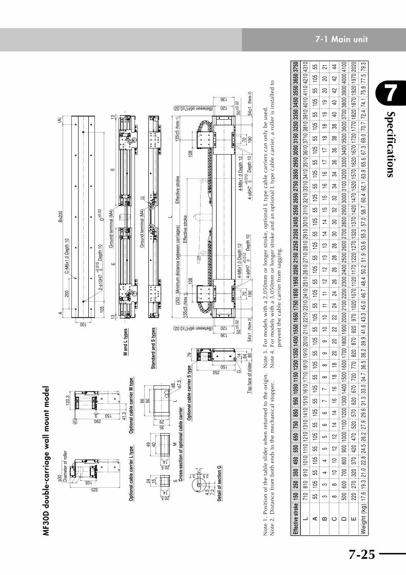
7-24
7
Specifications
7-25
7-1 Main unitM
F30D
dou
ble-
carr
iage
wal
l mou
nt m
odel
155±
5 (N
ote
1)M
SL
24
1420.5
154049
1420.5
Det
ail o
f sec
tion
G
4.5
7.2
73.7 2.5
Cro
ss-s
ectio
n of
opt
iona
l cab
le c
arrie
r
5066
2935
φ8 φ7.5
ABx
200
(A)
200
C-M
6x1.
0 D
epth
10
100
105
D±0
.02
2-φ1
0H7
+0.0
150
Dep
th 1
0
325
105φ30
Dia
met
er o
f rol
ler
1509290 41
.3
(5)
120.
3
79O
ptio
nal c
able
car
rier S
type
Opt
iona
l cab
le c
arrie
r M ty
peO
ptio
nal c
able
car
rier L
type
G14 64 80
Top
face
of s
lider150
250
M a
nd L
type
s
Stan
dard
and
S ty
pes
13E
13E
Gro
und
term
inal
(M4)
Gro
und
term
inal
(M4)
(Between φ6H7±0.02)136
120
(Between φ6H7±0.02) 120
136
L
(250
: M
inim
um d
ista
nce
betw
een
carri
ages
)
108
108
155±
5 (N
ote
1)
Effe
ctiv
e st
roke
Effe
ctiv
e st
roke
50±0
.02
70 190
4-φ6
H7
+0.0
120
Dep
th 1
0
4-M
6x1.
0 D
epth
12
50±0
.02
70 190
4-φ6
H7
+0.0
120
Dep
th 1
0
4-M
6x1.
0 D
epth
12
54±1
(Not
e 2)
54±1
(Not
e 2)
No
te 1
. P
osi
tio
n o
f th
e ta
ble
sli
der
wh
en r
etu
rned
to
th
e o
rigi
n.
No
te2
.D
ista
nce
fro
mb
oth
en
ds
tot
he
mec
han
ical
sto
pp
er.
No
te 3
. Fo
r m
od
els
wit
h a
2,0
50
mm
or
lon
ger
stro
ke,
op
tio
nal
L t
ype
cab
le c
arri
ers
can
on
ly b
e u
sed
. N
ote
4.
For
mo
del
s w
ith
a 3
,05
0m
m o
r lo
nge
r st
roke
an
d a
n o
pti
on
al L
typ
e ca
ble
car
rier
, a
roll
er i
s in
stal
led
to
p
reve
nt
the
cab
le c
arri
er f
rom
sag
gin
g.
Effe
ctive
stro
ke15
025
035
045
055
065
075
085
095
010
5011
5012
5013
5014
5015
5016
5017
5018
5019
5020
5021
5022
5023
5024
5025
5026
5027
5028
5029
5030
5031
5032
5033
5034
5035
5036
5037
50
L71
081
091
010
1011
1012
1013
1014
1015
1016
1017
1018
1019
1020
1021
1022
1023
1024
1025
1026
1027
1028
1029
1030
1031
1032
1033
1034
1035
1036
1037
1038
1039
1040
1041
1042
1043
10
A55
105
5510
555
105
5510
555
105
5510
555
105
5510
555
105
5510
555
105
5510
555
105
5510
555
105
5510
555
105
5510
555
B3
34
45
56
67
78
89
910
1011
1112
1213
1314
1415
1516
1617
1718
1819
1920
2021
C8
810
1012
1214
1416
1618
1820
2022
2224
2426
2628
2830
3032
3234
3436
3638
3840
4042
4244
D50
060
070
080
090
010
0011
0012
0013
0014
0015
0016
0017
0018
0019
0020
0021
0022
0023
0024
0025
0026
0027
0028
0029
0030
0031
0032
0033
0034
0035
0036
0037
0038
0039
0040
0041
00
E22
027
032
037
042
047
052
057
062
067
072
077
082
087
092
097
010
2010
7011
2011
7012
2012
7013
2013
7014
2014
7015
2015
7016
2016
7017
2017
7018
2018
7019
2019
7020
20
Wei
ght (
kg)
17.6
19.3
21.0
22.8
24.5
26.2
27.9
29.6
31.3
33.0
34.7
36.5
38.2
39.9
41.6
43.3
45.0
46.7
48.4
50.2
51.9
53.6
55.3
57.0
58.7
60.4
62.1
63.9
65.6
67.3
69.0
70.7
72.4
74.1
75.8
77.5
79.3
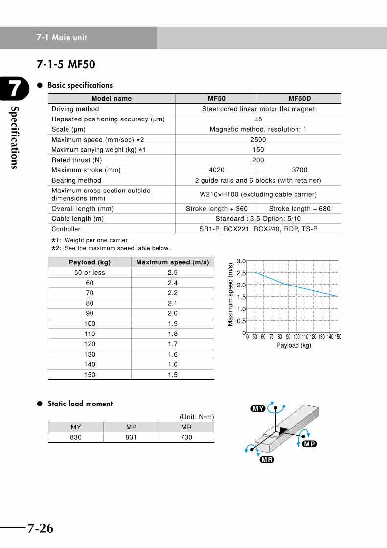
Specifications
7
7-26
7-1 Main unit
7-27
7-1-5 MF50
Basic specifications
Model name MF50 MF50D
Driving method Steel cored linear motor flat magnet
Repeated positioning accuracy (µm) ±5
Scale (µm) Magnetic method, resolution: 1
Maximum speed (mm/sec) 2 2500
Maximum carrying weight (kg) 1 150
Rated thrust (N) 200
Maximum stroke (mm) 4020 3700
Bearing method 2 guide rails and 6 blocks (with retainer)
Maximum cross-section outside dimensions (mm)
W210×H100 (excluding cable carrier)
Overall length (mm) Stroke length + 360 Stroke length + 680
Cable length (m) Standard : 3.5 Option: 5/10
Controller SR1-P, RCX221, RCX240, RDP, TS-P
1: Weight per one carrier2: See the maximum speed table below.
Payload (kg) Maximum speed (m/s)
50 or less 2.5
60 2.4
70 2.2
80 2.1
90 2.0
100 1.9
110 1.8
120 1.7
130 1.6
140 1.6
150 1.5
Static load moment
(Unit: N•m)
MY MP MR
830 831 730
0 50 60 70 80Payload (kg)
90 100 110 120 130 140 150
Max
imum
spe
ed (
m/s
) 3.0
2.5
2.0
1.5
1.0
0.5
0
M P
M R
M Y

7-26
7
Specifications
7-27
7-1 Main unit
Allowable overhang **Distancefromthecenteronthetopfaceofslidertothegravitycenteroftheitembeing
carried. (This is calculated assuming that the service life of the guide is 10,000km.)
n Horizontal installation
A
C
B
(Unit: mm)
A B C
10kg 4000 4000 3514
20kg 3397 2841 1840
30kg 3045 1873 1247
40kg 2795 1389 964
50kg 2602 1096 797
60kg 2200 530 450
70kg 2000 290 180
80kg 1800 175 150
90kg 1650 150 125
100kg 1500 130 110
110kg 1350 115 95
120kg 1250 100 80
130kg 1150 85 70
140kg 1100 80 65
150kg 1000 70 55
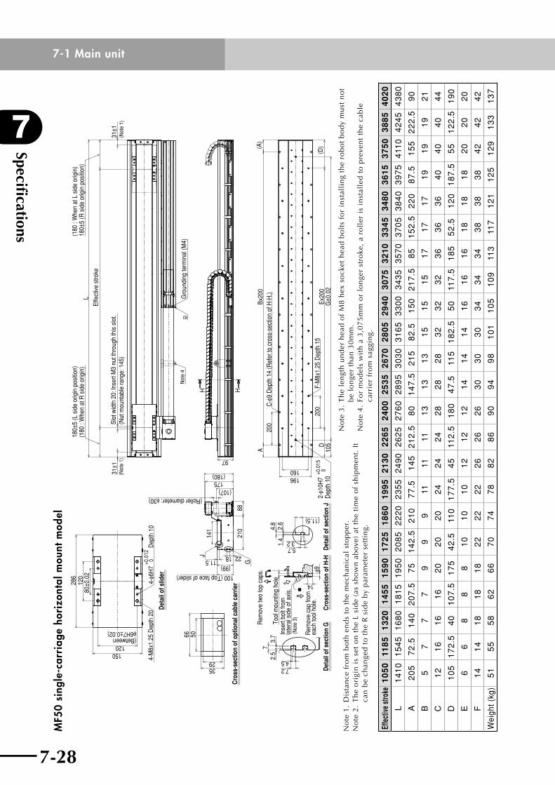
Specifications
7
7-28
7-1 Main unit
7-29
MF5
0 si
ngle
-car
riag
e ho
rizo
ntal
mou
nt m
odel
80±0
.02
120
286
120(Betweenφ6H7±0.02)
150
4-φ6
H7
+0.0
12 0
Dep
th 1
04-
M8x
1.25
Dep
th 2
0
66 50
3529
Cro
ss-s
ectio
n of
opt
iona
l cab
le c
arrie
r
Det
ail o
f sec
tion
G
2.5
73.
7
4.57.2
Cro
ss-s
ectio
n of
H-H
Rem
ove
two
top
caps
.
Inse
rt bo
lt fro
mla
tera
l sid
e of
axi
s.(N
ote
3)Tool
mou
ntin
g ho
le
Rem
ove
cap
from
each
tool
hol
e.φ9
14
3.25.71.
42.
64.
8
Det
ail o
f sec
tion
J
(11.5)
Det
ail o
f slid
er 100 (Top face of slider)
(99)11.5 G
2218
175(180)
(Roller diameter: φ30)(107)
210
88
141
J
31±1
(Not
e 1)
180±
5 (L
sid
e or
igin
pos
ition
)(1
80 :
Whe
n at
R s
ide
orig
in)
L
Effe
ctiv
e st
roke
(180
: W
hen
at L
sid
e or
igin
)18
0±5
(R s
ide
orig
in p
ositi
on)
31±1
(Not
e 1)
Slot
wid
th 2
0: ln
sert
M3
nut t
hrou
gh th
is s
lot.
(Nut
mou
ntab
le ra
nge:
145
)
Not
e 4
Gro
undi
ng te
rmin
al (M
4)
97
H H
ABx
200
200
C-φ
9 D
epth
14
(Ref
er to
cro
ss-s
ectio
n of
H-H
.)
(A)
160196
2-φ1
0H7
+0.0
15 0
Dep
th 1
0Ex
200
200
F-M
8x1.
25 D
epth
15
G±0
.02
D10
5(D
)
No
te1
.D
ista
nce
fro
mb
oth
en
ds
tot
he
mec
han
ical
sto
pp
er.
No
te 2
. T
he
ori
gin
is
set
on
th
e L
sid
e (a
s sh
ow
n a
bo
ve)
at t
he
tim
e o
f sh
ipm
ent.
It
can
be
chan
ged
to
th
e R
sid
e b
y p
aram
eter
set
tin
g.
No
te 3
. T
he
len
gth
un
der
hea
d o
f M
8 h
ex s
ock
et h
ead
bo
lts
for
inst
alli
ng
the
rob
ot
bo
dy
mu
st n
ot
be
lon
ger
than
30
mm
.N
ote
4.
For
mo
del
s w
ith
a 3
,07
5m
m o
r lo
nge
r st
roke
, a
roll
er i
s in
stal
led
to
pre
ven
t th
e ca
ble
ca
rrie
r fr
om
sag
gin
g.
Effe
ctive
stro
ke1
05
011
85
13
20
14
55
15
90
17
25
18
60
19
95
21
30
22
65
24
00
25
35
26
70
28
05
29
40
30
75
32
10
33
45
34
80
36
15
37
50
38
85
40
20
L1
41
01
54
51
68
01
81
51
95
02
08
52
22
02
35
52
49
02
62
52
76
02
89
53
03
03
16
53
30
03
43
53
57
03
70
53
84
03
97
54
110
42
45
43
80
A2
05
72
.51
40
20
7.5
75
14
2.5
21
07
7.5
14
52
12
.58
01
47
.52
15
82
.51
50
21
7.5
85
15
2.5
22
08
7.5
15
52
22
.59
0
B5
77
79
99
1111
111
31
31
31
51
51
51
71
71
71
91
91
92
1
C1
21
61
61
62
02
02
02
42
42
42
82
82
83
23
23
23
63
63
64
04
04
04
4
D1
05
17
2.5
40
10
7.5
17
54
2.5
110
17
7.5
45
112
.51
80
47
.511
51
82
.55
011
7.5
18
55
2.5
12
01
87
.55
51
22
.51
90
E6
68
88
10
10
10
12
12
12
14
14
14
16
16
16
18
18
18
20
20
20
F1
41
41
81
81
82
22
22
22
62
62
63
03
03
03
43
43
43
83
83
84
24
24
2
Wei
ght (
kg)
51
55
58
62
66
70
74
78
82
86
90
94
98
10
11
05
10
911
311
71
21
12
51
29
13
31
37
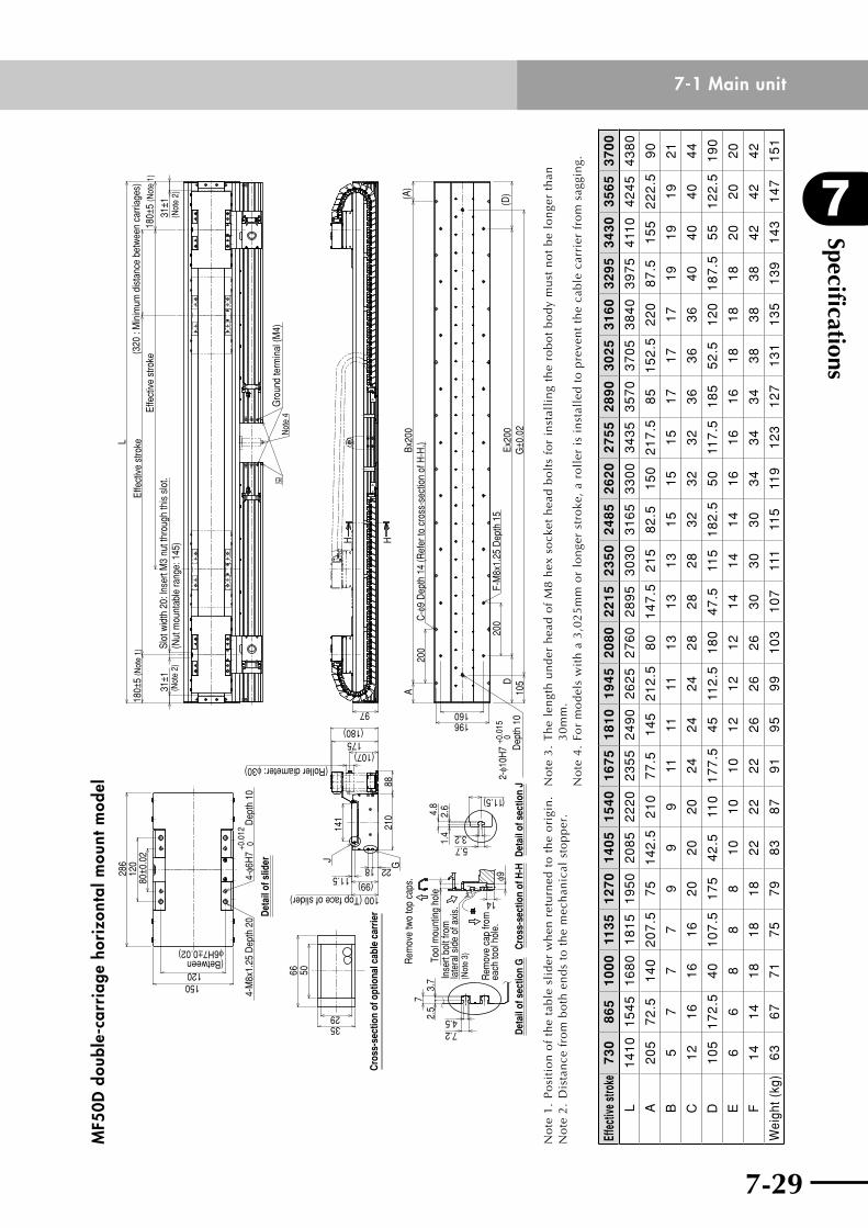
7-28
7
Specifications
7-29
7-1 Main unitM
F50D
dou
ble-
carr
iage
hor
izon
tal m
ount
mod
el
120(Betweenφ6H7±0.02)
150
80±0
.02
120
286
66 50
3529
(Roller diameter: φ30)
4-φ6
H7
+0.0
120
Dep
th 1
04-
M8x
1.25
Dep
th 2
0
100 (Top face of slider)
Det
ail o
f slid
er
Cro
ss-s
ectio
n of
opt
iona
l cab
le c
arrie
r
72.
53.
7
7.24.5
Det
ail o
f sec
tion
GRem
ove
two
top
caps
.
Inse
rt bo
lt fro
mla
tera
l sid
e of
axi
s.(N
ote
3)
Cro
ss-s
ectio
n of
H-H
Tool
mou
ntin
g ho
le
Rem
ove
cap
from
each
tool
hol
e.φ9
14
Det
ail o
f sec
tion
J
4.8
2.6
1.4
5.73.2
(11.5)
8821
0
(99)22 G
11.518
141
J
(107)175(180)
972-
φ10H
7+0
.015
0 D
epth
10
160196
Not
e 4
Gro
und
term
inal
(M4)
31±1
(Not
e 2)
31±1
(Not
e 2)
180±
5 (N
ote
1)
L
Effe
ctiv
e st
roke
180±
5 (N
ote
1)(3
20 :
Min
imum
dis
tanc
e be
twee
n ca
rriag
es)
Effe
ctiv
e st
roke
Slot
wid
th 2
0: ln
sert
M3
nut t
hrou
gh th
is s
lot.
(Nut
mou
ntab
le ra
nge:
145
)
Ex20
0(D
)G
±0.0
2
200
F-M
8x1.
25 D
epth
15
D10
5
ABx
200
200
C-φ
9 D
epth
14
(Ref
er to
cro
ss-s
ectio
n of
H-H
.)(A
)
HH
No
te 1
. P
osi
tio
n o
f th
e ta
ble
sli
der
wh
en r
etu
rned
to
th
e o
rigi
n.
No
te2
.D
ista
nce
fro
mb
oth
en
ds
tot
he
mec
han
ical
sto
pp
er.
No
te 3
. T
he
len
gth
un
der
hea
d o
f M
8 h
ex s
ock
et h
ead
bo
lts
for
inst
alli
ng
the
rob
ot
bo
dy
mu
st n
ot
be
lon
ger
than
3
0m
m.
No
te 4
. Fo
r m
od
els
wit
h a
3,0
25
mm
or
lon
ger
stro
ke,
a ro
ller
is
inst
alle
d t
o p
reve
nt
the
cab
le c
arri
er f
rom
sag
gin
g.
Effe
ctive
stro
ke7
30
86
51
00
011
35
12
70
14
05
15
40
16
75
18
10
19
45
20
80
22
15
23
50
24
85
26
20
27
55
28
90
30
25
31
60
32
95
34
30
35
65
37
00
L1
41
01
54
51
68
01
81
51
95
02
08
52
22
02
35
52
49
02
62
52
76
02
89
53
03
03
16
53
30
03
43
53
57
03
70
53
84
03
97
54
110
42
45
43
80
A2
05
72
.51
40
20
7.5
75
14
2.5
21
07
7.5
14
52
12
.58
01
47
.52
15
82
.51
50
21
7.5
85
15
2.5
22
08
7.5
15
52
22
.59
0
B5
77
79
99
1111
111
31
31
31
51
51
51
71
71
71
91
91
92
1
C1
21
61
61
62
02
02
02
42
42
42
82
82
83
23
23
23
63
63
64
04
04
04
4
D1
05
17
2.5
40
10
7.5
17
54
2.5
110
17
7.5
45
112
.51
80
47
.511
51
82
.55
011
7.5
18
55
2.5
12
01
87
.55
51
22
.51
90
E6
68
88
10
10
10
12
12
12
14
14
14
16
16
16
18
18
18
20
20
20
F1
41
41
81
81
82
22
22
22
62
62
63
03
03
03
43
43
43
83
83
84
24
24
2
Wei
ght (
kg)
63
67
71
75
79
83
87
91
95
99
10
31
07
111
115
119
12
31
27
13
11
35
13
91
43
14
71
51
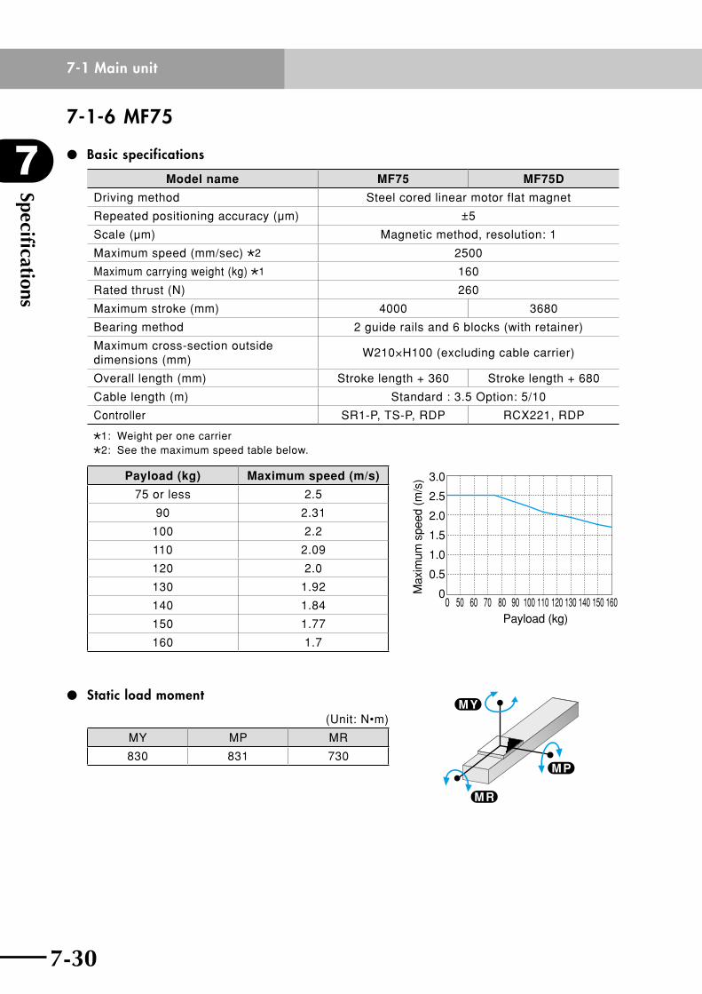
Specifications
7
7-30
7-1 Main unit
7-31
7-1-6 MF75
Basic specifications
Model name MF75 MF75D
Driving method Steel cored linear motor flat magnet
Repeated positioning accuracy (µm) ±5
Scale (µm) Magnetic method, resolution: 1
Maximum speed (mm/sec) 2 2500
Maximum carrying weight (kg) 1 160
Rated thrust (N) 260
Maximum stroke (mm) 4000 3680
Bearing method 2 guide rails and 6 blocks (with retainer)
Maximum cross-section outside dimensions (mm)
W210×H100 (excluding cable carrier)
Overall length (mm) Stroke length + 360 Stroke length + 680
Cable length (m) Standard : 3.5 Option: 5/10
Controller SR1-P, TS-P, RDP RCX221, RDP
1: Weight per one carrier2: See the maximum speed table below.
Payload (kg) Maximum speed (m/s)
75 or less 2.5
90 2.31
100 2.2
110 2.09
120 2.0
130 1.92
140 1.84
150 1.77
160 1.7
Static load moment
(Unit: N•m)
MY MP MR
830 831 730
Payload (kg)
Max
imum
spe
ed (
m/s
)
0 50 60 70 80 90 100 110 120 130 140 150 160
3.0
2.5
2.0
1.5
1.0
0.5
0
M P
M R
M Y
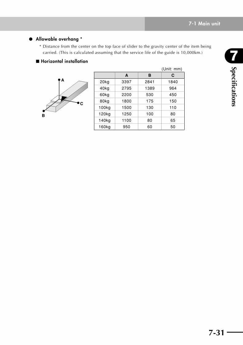
7-30
7
Specifications
7-31
7-1 Main unit
Allowable overhang **Distancefromthecenteronthetopfaceofslidertothegravitycenteroftheitembeing
carried. (This is calculated assuming that the service life of the guide is 10,000km.)
n Horizontal installation
A
C
B
(Unit: mm)
A B C
20kg 3397 2841 1840
40kg 2795 1389 964
60kg 2200 530 450
80kg 1800 175 150
100kg 1500 130 110
120kg 1250 100 80
140kg 1100 80 65
160kg 950 60 50
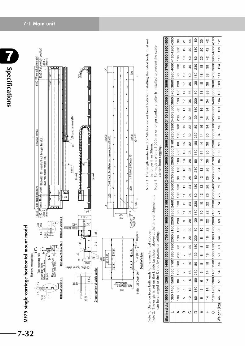
Specifications
7
7-32
7-1 Main unit
7-33
MF7
5 si
ngle
-car
riag
e ho
rizo
ntal
mou
nt m
odel
4.57.2
2.5
73.
7
(11.5)
3.25.71.
42.
64.
8
φ9
14
175(180)
141
210
88
2218 G11.5
J
: φ30) (107)
(99)
80±
0.02
120
286
120(Betweenφ6H7±0.02)
150
4-φ6
H7
+0.
012
0
+0.
015
0
66 50
3529
ABx
200
DEx
200
200
200
160196
G±
0.02
130
2-φ1
0H7
( A)
( D)
H H
97
31±
2
L
31±
2
Rem
ove
two
top
caps
.
Tool
mou
ntin
g ho
leIn
sert
bolt
from
late
ral s
ide
of a
xis.
(Not
e 3)
Rem
ove
cap
from
each
tool
hol
e.
Cro
ss-s
ectio
n of
H-H
Det
ail o
f sec
tion
GD
etai
l of s
ectio
n J
Cro
ss-s
ectio
n of
cab
le c
arrie
r
100 (Top face of slider)
(Roller diameter
4-M
8x1.
25 D
epth
20
Dep
th 1
0
Det
ail o
f slid
er
Dep
th 1
0F-
M8x
1.25
Dep
th 1
5
C-φ
9 D
epth
14
(Ref
er to
cro
ss-s
ectio
n of
H-H
.)Gro
und
term
inal
(M4)
Not
e 4
(Not
e 1)
180±
5 (L
sid
e or
igin
pos
ition
)(1
80 :
Whe
n at
R s
ide
orig
in)
(180
: W
hen
at R
sid
e or
igin
)Sl
ot w
idth
20:
lnse
rt M
3 nu
t thr
ough
this
slo
t.(N
ut m
ount
able
rang
e: 1
45)
Effe
ctiv
e st
roke
(180
Whe
n at
L s
ide
orig
in)
180±
5 (R
sid
e or
igin
pos
ition
)
(Not
e 1)
No
te1
.D
ista
nce
fro
mb
oth
en
ds
tot
he
mec
han
ical
sto
pp
er.
No
te 2
. T
he
ori
gin
is
set
on
th
e L
sid
e (a
s sh
ow
n a
bo
ve)
at t
he
tim
e o
f sh
ipm
ent.
It
can
be
chan
ged
to
th
e R
sid
e b
y p
aram
eter
set
tin
g.
No
te 3
. T
he
len
gth
un
der
hea
d o
f M
8 h
ex s
ock
et h
ead
bo
lts
for
inst
alli
ng
the
rob
ot
bo
dy
mu
st n
ot
be
lon
ger
than
30
mm
.N
ote
4.
For
mo
del
s w
ith
a 3
,00
0m
m o
r lo
nge
r st
roke
, a
roll
er i
s in
stal
led
to
pre
ven
t th
e ca
ble
ca
rrie
r fr
om
sag
gin
g.
Effe
ctive
stro
ke1
00
011
00
12
00
13
00
14
00
15
00
16
00
17
00
18
00
19
00
20
00
21
00
22
00
23
00
24
00
25
00
26
00
27
00
28
00
29
00
30
00
31
00
32
00
33
00
34
00
35
00
36
00
37
00
38
00
39
00
40
00
L1
36
01
46
01
56
01
66
01
76
01
86
01
96
02
06
02
16
02
26
02
36
02
46
02
56
02
66
02
76
02
86
02
96
03
06
03
16
03
26
03
36
03
46
03
56
03
66
03
76
03
86
03
96
04
06
04
16
04
26
04
36
0
A1
80
23
08
01
30
18
02
30
80
13
01
80
23
08
01
30
18
02
30
80
13
01
80
23
08
01
30
18
02
30
80
13
01
80
23
08
01
30
18
02
30
80
B5
57
77
79
99
911
1111
111
31
31
31
31
51
51
51
51
71
71
71
71
91
91
91
92
1
C1
21
21
61
61
61
62
02
02
02
02
42
42
42
42
82
82
82
83
23
23
23
23
63
63
63
64
04
04
04
04
4
D8
01
30
18
02
30
80
13
01
80
23
08
01
30
18
02
30
80
13
01
80
23
08
01
30
18
02
30
80
13
01
80
23
08
01
30
18
02
30
80
13
01
80
E6
66
68
88
81
01
01
01
01
21
21
21
21
41
41
41
41
61
61
61
61
81
81
81
82
02
02
0
F1
41
41
41
41
81
81
81
82
22
22
22
22
62
62
62
63
03
03
03
03
43
43
43
43
83
83
83
84
24
24
2
G11
00
12
00
13
00
14
00
15
00
16
00
17
00
18
00
19
00
20
00
21
00
22
00
23
00
24
00
25
00
26
00
27
00
28
00
29
00
30
00
31
00
32
00
33
00
34
00
35
00
36
00
37
00
38
00
39
00
40
00
41
00
Wei
ght (
kg)
46
49
51
54
56
59
61
64
66
69
71
74
76
79
81
84
86
89
91
94
96
99
10
11
04
10
61
09
111
114
116
119
12
1
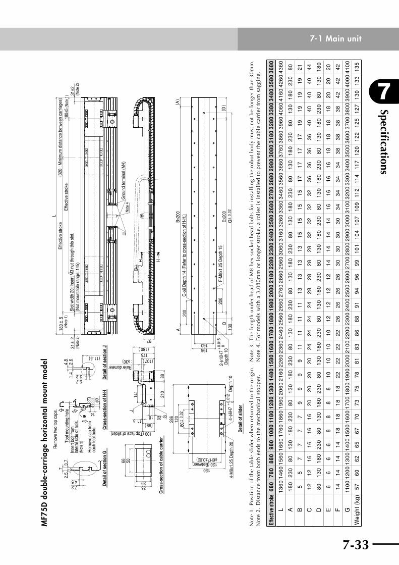
7-32
7
Specifications
7-33
7-1 Main unitM
F75D
dou
ble-
carr
iage
hor
izon
tal m
ount
mod
el
4.57.2
2.5
73.
7
14
φ9
(11.5)
3.25.71.
42.
64.
8
175(180)
141
210
88
2218 G11.5
J
: φ30) (107)
(99)
80±
0.02
120
286
150
4-φ6
H7
+0.
012
0
66 50
3529
A
D20
0
200
160196
130
2-φ1
0H7
+0.
015
0
Bx20
0
Ex20
0
G±
0.02
( A)
( D)
H H
97
L
180
±5
31±
231
±2
Rem
ove
two
top
caps
.
Tool
mou
ntin
g ho
leIn
sert
bolt
from
late
ral s
ide
of a
xis.
(Not
e 3)
Rem
ove
cap
from
each
tool
hol
e.
Det
ail o
f sec
tion
GC
ross
-sec
tion
of H
-HD
etai
l of s
ectio
n J
Cro
ss-s
ectio
n of
cab
le c
arrie
r
100 (Top face of slider)
(Roller diameter
120 (Betweenφ6H7±0.02)
4-M
8x1.
25 D
epth
20
Det
ail o
f slid
er
Dep
th 1
0 D
epth
10
F-M
8x1.
25 D
epth
15
C-φ
9 D
epth
14
(Ref
er to
cro
ss-s
ectio
n of
H-H
.)
(Not
e 2)
(Not
e 1)
Slot
wid
th 2
0: ln
sert
M3
nut t
hrou
gh th
is s
lot.
(Nut
mou
ntab
le ra
nge:
145
)Sl
ot w
idth
20:
lnse
rt M
3 nu
t thr
ough
this
slo
t.(N
ut m
ount
able
rang
e: 1
45)
Not
e 4
Gro
und
term
inal
(M4)
Effe
ctiv
e st
roke
Effe
ctiv
e st
roke
(320
: M
inim
um d
ista
nce
betw
een
carri
ages
)
(Not
e 2)
180±
5 (N
ote
1)
No
te 1
. P
osi
tio
n o
f th
e ta
ble
sli
der
wh
en r
etu
rned
to
th
e o
rigi
n.
No
te2
.D
ista
nce
fro
mb
oth
en
ds
tot
he
mec
han
ical
sto
pp
er.
No
te 3
. Th
e le
ngth
und
er h
ead
of M
8 he
x so
cket
hea
d bo
lts
for
inst
alli
ng t
he r
obot
bod
y m
ust
not
be l
onge
r th
an 3
0mm
.N
ote
4.
For
mo
del
s w
ith
a 3
,08
0m
m o
r lo
nge
r st
roke
, a
roll
er i
s in
stal
led
to
pre
ven
t th
e ca
ble
car
rier
fro
m s
aggi
ng.
Effe
ctive
stro
ke6
80
78
08
80
98
01
08
011
80
12
80
13
80
14
80
15
80
16
80
17
80
18
80
19
80
20
80
21
80
22
80
23
80
24
80
25
80
26
80
27
80
28
80
29
80
30
80
31
80
32
80
33
80
34
80
35
80
36
80
L1
36
01
46
01
56
01
66
01
76
01
86
01
96
02
06
02
16
02
26
02
36
02
46
02
56
02
66
02
76
02
86
02
96
03
06
03
16
03
26
03
36
03
46
03
56
03
66
03
76
03
86
03
96
04
06
04
16
04
26
04
36
0
A1
80
23
08
01
30
18
02
30
80
13
01
80
23
08
01
30
18
02
30
80
13
01
80
23
08
01
30
18
02
30
80
13
01
80
23
08
01
30
18
02
30
80
B5
57
77
79
99
911
1111
111
31
31
31
31
51
51
51
51
71
71
71
71
91
91
91
92
1
C1
21
21
61
61
61
62
02
02
02
02
42
42
42
42
82
82
82
83
23
23
23
23
63
63
63
64
04
04
04
04
4
D8
01
30
18
02
30
80
13
01
80
23
08
01
30
18
02
30
80
13
01
80
23
08
01
30
18
02
30
80
13
01
80
23
08
01
30
18
02
30
80
13
01
80
E6
66
68
88
81
01
01
01
01
21
21
21
21
41
41
41
41
61
61
61
61
81
81
81
82
02
02
0
F1
41
41
41
41
81
81
81
82
22
22
22
22
62
62
62
63
03
03
03
03
43
43
43
43
83
83
83
84
24
24
2
G11
00
12
00
13
00
14
00
15
00
16
00
17
00
18
00
19
00
20
00
21
00
22
00
23
00
24
00
25
00
26
00
27
00
28
00
29
00
30
00
31
00
32
00
33
00
34
00
35
00
36
00
37
00
38
00
39
00
40
00
41
00
Wei
ght (
kg)
57
60
62
65
67
70
73
75
78
81
83
86
88
91
94
96
99
10
11
04
10
71
09
112
114
117
12
01
22
12
51
27
13
01
33
13
5
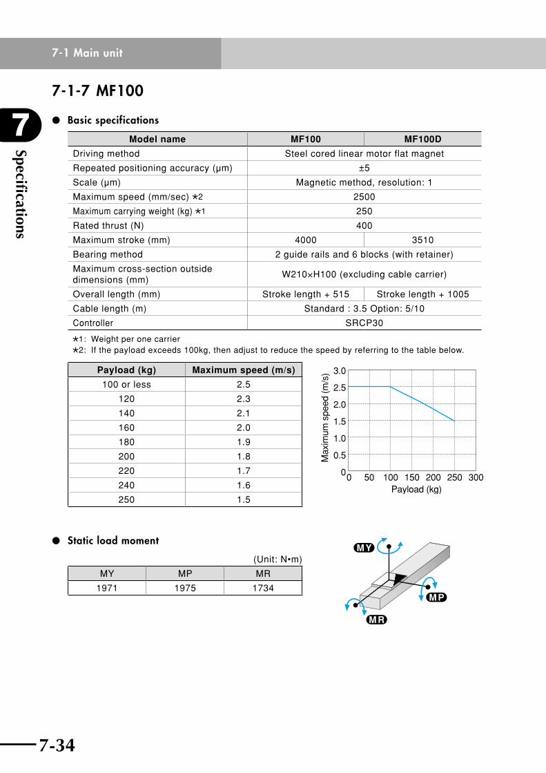
Specifications
7
7-34
7-1 Main unit
7-35
7-1-7 MF100
Basic specifications
Model name MF100 MF100D
Driving method Steel cored linear motor flat magnet
Repeated positioning accuracy (µm) ±5
Scale (µm) Magnetic method, resolution: 1
Maximum speed (mm/sec) 2 2500
Maximum carrying weight (kg) 1 250
Rated thrust (N) 400
Maximum stroke (mm) 4000 3510
Bearing method 2 guide rails and 6 blocks (with retainer)
Maximum cross-section outside dimensions (mm)
W210×H100 (excluding cable carrier)
Overall length (mm) Stroke length + 515 Stroke length + 1005
Cable length (m) Standard : 3.5 Option: 5/10
Controller SRCP30
1: Weight per one carrier2: If the payload exceeds 100kg, then adjust to reduce the speed by referring to the table below.
Payload (kg) Maximum speed (m/s)
100 or less 2.5
120 2.3
140 2.1
160 2.0
180 1.9
200 1.8
220 1.7
240 1.6
250 1.5
Static load moment
(Unit: N•m)
MY MP MR
1971 1975 1734
0 50 100 150 200Payload (kg)
250 300
Max
imum
spe
ed (
m/s
) 3.0
2.5
2.0
1.5
1.0
0.5
0
M P
M R
M Y
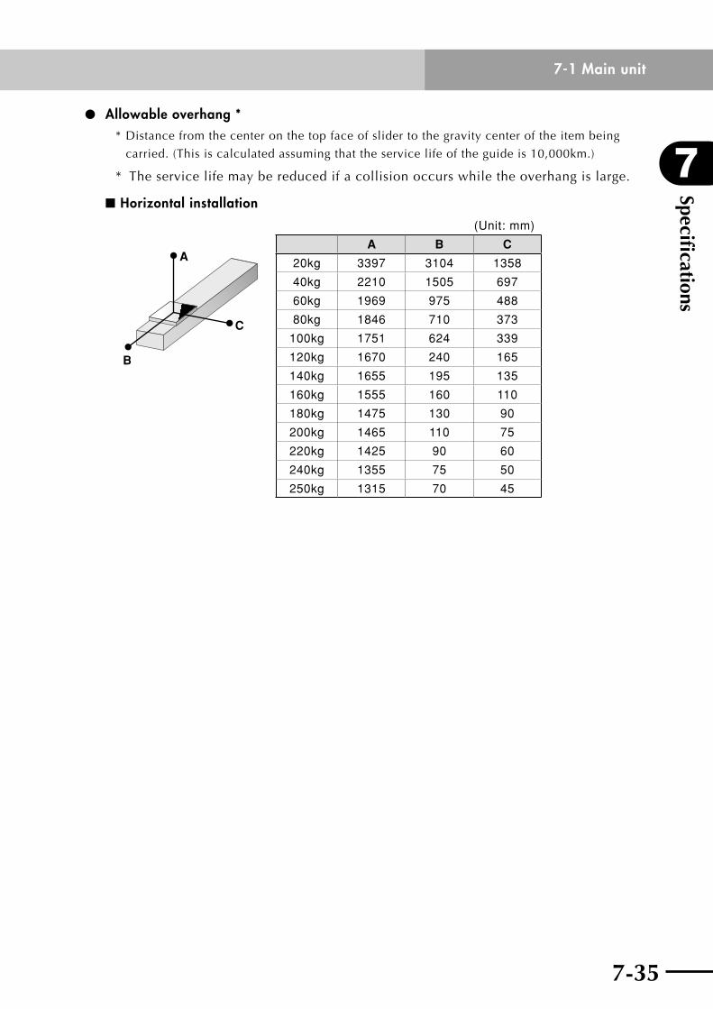
7-34
7
Specifications
7-35
7-1 Main unit
Allowable overhang **Distancefromthecenteronthetopfaceofslidertothegravitycenteroftheitembeing
carried. (This is calculated assuming that the service life of the guide is 10,000km.)
* The service life may be reduced if a collision occurs while the overhang is large.
n Horizontal installation
A
C
B
(Unit: mm)
A B C
20kg 3397 3104 1358
40kg 2210 1505 697
60kg 1969 975 488
80kg 1846 710 373
100kg 1751 624 339
120kg 1670 240 165
140kg 1655 195 135
160kg 1555 160 110
180kg 1475 130 90
200kg 1465 110 75
220kg 1425 90 60
240kg 1355 75 50
250kg 1315 70 45
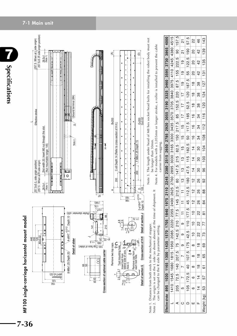
Specifications
7
7-36
7-1 Main unit
7-37
MF1
00 s
ingl
e-ca
rria
ge h
oriz
onta
l mou
nt m
odel
80±0
.02
120
446
200
120(Betweenφ6H7±0.02)
150
4-φ6
H7
+0.0
120
Dep
th 1
08-
M8x
1.25
Dep
th 2
0 Det
ail o
f slid
er
66 50
3529
Cro
ss-s
ectio
n of
opt
iona
l cab
le c
arrie
r
18 2211.5
100 (Top face of slider)
G
(99)
(Roller diameter: φ30)
(180)175
(107)
141
8821
0
J
7.24.52.
57
3.7
Det
ail o
f sec
tion
GD
etai
l of s
ectio
n J
Cro
ss-s
ectio
n of
H-H
Rem
ove
two
top
caps
.
Tool
mou
ntin
g ho
leIn
sert
bolt
from
late
ral s
ide
of a
xis.
(Not
e 3)
Rem
ove
cap
from
each
tool
hol
e.
14
φ9
3.2
(11.5)
5.71.4
2.6
4.8
28.5
±1(N
ote
1)
257.
5±5
(L s
ide
orig
in p
ositi
on)
(257
.5 :
Whe
n at
R s
ide
orig
in)
L
Effe
ctiv
e st
roke
Slot
wid
th 2
0: ln
sert
M3
nut t
hrou
gh th
is s
lot.
(Nut
mou
ntab
le ra
nge:
145
)
(257
.5 W
hen
at L
sid
e or
igin
)25
7.5±
5 (R
sid
e or
igin
pos
ition
)
28.5
±1(N
ote
1)
Gro
und
term
inal
(M4)
Not
e 4
ABx
200
DEx
200
200
200
160196
C-φ
9 D
epth
14
(Ref
er to
cro
ss-s
ectio
n of
H-H
.)
F-M
8x1.
25 D
epth
15
(A)
(D)
2-φ1
0H7
+0.0
150
Dep
th 1
010
5G
±0.0
2
HH
97
No
te1
.D
ista
nce
fro
mb
oth
en
ds
tot
he
mec
han
ical
sto
pp
er.
No
te 2
. T
he
ori
gin
is
set
on
th
e L
sid
e (a
s sh
ow
n a
bo
ve)
at t
he
tim
e o
f sh
ipm
ent.
It
can
be
chan
ged
to
th
e R
sid
e b
y p
aram
eter
set
tin
g.
No
te 3
. T
he
len
gth
un
der
hea
d o
f M
8 h
ex s
ock
et h
ead
bo
lts
for
inst
alli
ng
the
rob
ot
bo
dy
mu
st n
ot
be
lon
ger
than
30
mm
.N
ote
4.
For
mo
del
s w
ith
a 3
,05
5m
m o
r lo
nge
r st
roke
, a
roll
er i
s in
stal
led
to
pre
ven
t th
e ca
ble
ca
rrie
r fr
om
sag
gin
g.
Effe
ctive
stro
ke8
95
10
30
116
51
30
01
43
51
57
01
70
51
84
01
97
52
110
22
45
23
80
25
15
26
50
27
85
29
20
30
55
31
90
33
25
34
60
35
95
37
30
38
65
40
00
L1
41
01
54
51
68
01
81
51
95
02
08
52
22
02
35
52
49
02
62
52
76
02
89
53
03
03
16
53
30
03
43
53
57
03
70
53
84
03
97
54
110
42
45
43
80
45
15
A2
05
72
.51
40
20
7.5
75
14
2.5
21
07
7.5
14
52
12
.58
01
47
.52
15
82
.51
50
21
7.5
85
15
2.5
22
08
7.5
15
52
22
.59
01
57
.5
C5
77
79
99
1111
111
31
31
31
51
51
51
71
71
71
91
91
92
12
1
D1
05
17
2.5
40
10
7.5
17
54
2.5
110
17
7.5
45
112
.51
80
47
.511
51
82
.55
011
7.5
18
55
2.5
12
01
87
.55
51
22
.51
90
57
.5
E6
68
88
10
10
10
12
12
12
14
14
14
16
16
16
18
18
18
20
20
20
22
F1
41
41
81
81
82
22
22
22
62
62
63
03
03
03
43
43
43
83
83
84
24
24
24
6
Wei
ght (
kg)
53
57
61
65
69
73
77
81
84
88
92
96
10
01
04
10
811
211
61
20
12
41
27
13
11
35
13
91
43
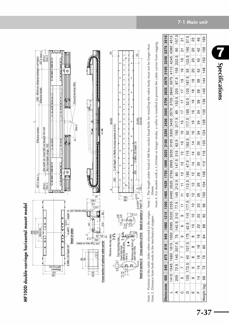
7-36
7
Specifications
7-37
7-1 Main unitM
F100
D d
oubl
e-ca
rria
ge h
oriz
onta
l mou
nt m
odel
2.5
73.
7
4.57.2
Det
ail o
f sec
tion
GD
etai
l of s
ectio
n J
Cro
ss-s
ectio
n of
H-H
Rem
ove
two
top
caps
.
Tool
mou
ntin
g ho
leIn
sert
bolt
from
late
ral s
ide
of a
xis.
(Not
e 3)
Rem
ove
cap
from
each
tool
hol
e.φ9
14
3.25.71.
42.
64.
8
(11.5)
Cro
ss-s
ectio
n of
opt
iona
l cab
le c
arrie
r
66 50
3529
(99)100 (Top face of slider)
11.52218
(107)175
(180)
(Roller diameter: φ30)
210
88
141
J
G80±0
.02
120
446
200
120(Betweenφ6H7±0.02)
150
Det
ail o
f slid
er4-
φ6H
7+0
.012
0 D
epth
10
8-M
8x1.
25 D
epth
20
28.5
±1(N
ote
2)
L
28.5
±1(N
ote
2)
257.
5 (N
ote
1)Ef
fect
ive
stro
ke(4
90 :
Min
imum
dis
tanc
e be
twee
n ca
rriag
es)
257.
5 (N
ote
1)Ef
fect
ive
stro
keSl
ot w
idth
20:
lnse
rt M
3 nu
t thr
ough
this
slo
t.(N
ut m
ount
able
rang
e: 1
45)
Gro
und
term
inal
(M4)
Not
e 4
97
HH
ABx
200
DEx
200
200
200
160196
C-φ
9 D
epth
14
(Ref
er to
cro
ss-s
ectio
n of
H-H
.)
F-M
8x1.
25 D
epth
15
(A)
(D)
G±0
.02
105
2-φ1
0H7
+0.0
150
Dep
th 1
0
No
te 1
. P
osi
tio
n o
f th
e ta
ble
sli
der
wh
en r
etu
rned
to
th
e o
rigi
n.
No
te2
.D
ista
nce
fro
mb
oth
en
ds
tot
he
mec
han
ical
sto
pp
er.
No
te 3
. T
he
len
gth
un
der
hea
d o
f M
8 h
ex s
ock
et h
ead
bo
lts
for
inst
alli
ng
the
rob
ot
bo
dy
mu
st n
ot
be
lon
ger
than
3
0m
m.
No
te 4
. Fo
r m
od
els
wit
h a
3,1
05
mm
or
lon
ger
stro
ke,
a ro
ller
is
inst
alle
d t
o p
reve
nt
the
cab
le c
arri
er f
rom
sag
gin
g.
Effe
ctive
stro
ke40
554
067
581
094
510
8012
1513
5014
8516
2017
5518
9020
2521
6022
9524
3025
6527
0028
352
97
03
10
53
24
03
37
53
51
0
L1
41
01
54
51
68
01
81
51
95
02
08
52
22
02
35
52
49
02
62
52
76
02
89
53
03
03
16
53
30
03
43
53
57
03
70
53
84
03
97
54
110
42
45
43
80
45
15
A2
05
72
.51
40
20
7.5
75
14
2.5
21
07
7.5
14
52
12
.58
01
47
.52
15
82
.51
50
21
7.5
85
15
2.5
22
08
7.5
15
52
22
.59
01
57
.5
C5
77
79
99
1111
111
31
31
31
51
51
51
71
71
71
91
91
92
12
1
D1
05
17
2.5
40
10
7.5
17
54
2.5
110
17
7.5
45
112
.51
80
47
.511
51
82
.55
011
7.5
18
55
2.5
12
01
87
.55
51
22
.51
90
57
.5
E6
68
88
10
10
10
12
12
12
14
14
14
16
16
16
18
18
18
20
20
20
22
F1
41
41
81
81
82
22
22
22
62
62
63
03
03
03
43
43
43
83
83
84
24
24
24
6
Wei
ght (
kg)
68
72
76
80
84
88
92
96
10
01
04
10
811
211
61
20
12
41
28
13
21
36
14
01
44
14
81
52
15
61
60
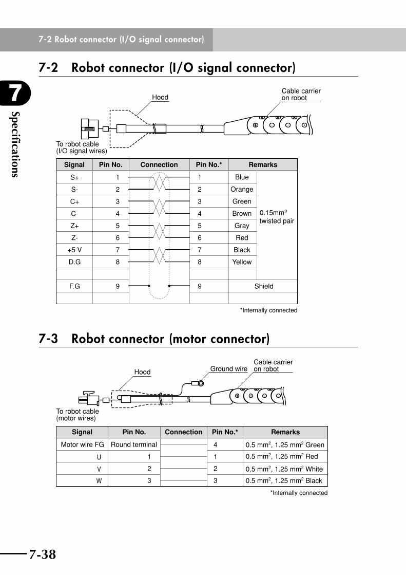
Specifications
7
7-38
7-2 Robot connector (I/O signal connector)
7-39
7-2 Robot connector (I/O signal connector)
Cable carrier on robotHood
To robot cable (I/O signal wires)
D.G
6
5
4
3
2
1
Z-
Z+
S+
C+
C-
7
9F.G
+5 V
S-
0.15mm2 twisted pair
Shield
8
6
5
4
3
2
1
7
9
8
Signal Connection RemarksPin No. Pin No.*
Blue
Orange
Green
Brown
Gray
Red
Black
Yellow
*Internally connected
7-3 Robot connector (motor connector)
Ground wireCable carrier on robotHood
To robot cable (motor wires)
3
2
1
4
3
2
1
0.5 mm2, 1.25 mm2 Green
0.5 mm2, 1.25 mm2 Red
0.5 mm2, 1.25 mm2 White
0.5 mm2, 1.25 mm2 Black
Signal Pin No. Pin No.*Connection Remarks
Round terminalMotor wire FG
U
W
V
*Internally connected
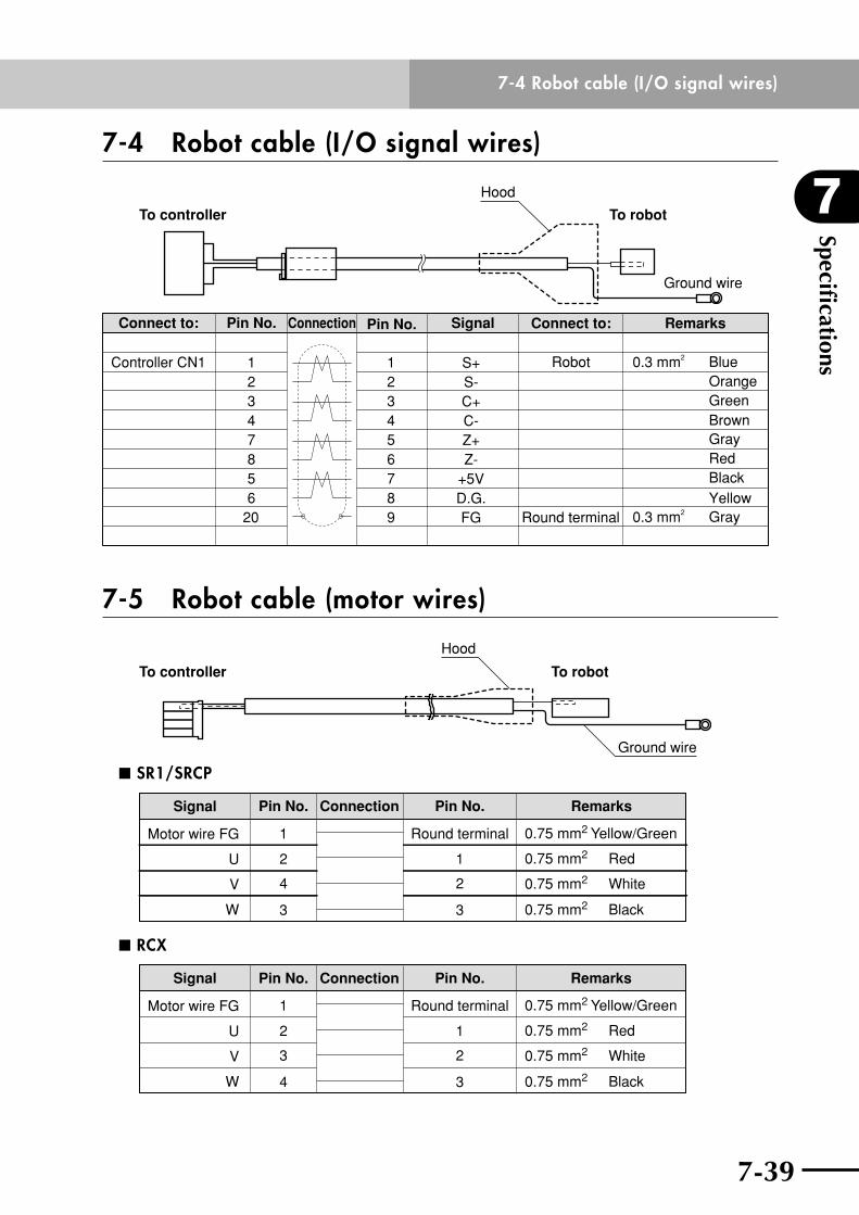
7-38
7
Specifications
7-39
7-4 Robot cable (I/O signal wires)
7-4 Robot cable (I/O signal wires)
To controller To robot
Hood
Ground wire
Signal
RobotController CN1
Connect to: RemarksConnect to:Connection Pin No.Pin No.
1
7
3
6
2
54
98
0.3 mm2 Blue
0.3 mm2 Gray
OrangeGreenBrownGrayRedBlackYellow
5
1
3
8
2
74
206
Z+
C+S-
C-
S+
Z-
FG
+5VD.G.
Round terminal
7-5 Robot cable (motor wires)
Ground wire
Hood
To controller To robot
n SR1/SRCP
Motor wire FG
U
V
W
0.75 mm2 Yellow/Green
0.75 mm2
0.75 mm2
0.75 mm2
1
2
4
3
Round terminal
1
2
3 Black
White
Red
Signal RemarksConnection Pin No.Pin No.
n RCX
Motor wire FG
U
V
W
0.75 mm2 Yellow/Green
0.75 mm2
0.75 mm2
0.75 mm2
1
2
3
4
Round terminal
1
2
3 Black
White
Red
Signal RemarksConnection Pin No.Pin No.
All rights reserved. No part of this publication may be reproduced in any form without the permission of YAMAHA MOTOR CO., LTD. Information furnished by YAMAHA in this manual is believed to be reliable. However, no responsibility is assumed for possible inaccuracies or omissions. If you find any part unclear in this manual, please contact your distributor..
LINEAR MOTOR ROBOTS PHASER series
User's Manual
YAMAHA MOTOR CO., LTD. IM Operations
MF TypeJul. 2012Ver. 5.00This manual is based on Ver. 5.00 of Japanese manual.
Revision record
Manual version Issue date Description
Ver. 2.05 Oct. 2009 Addition and correction of explanations in "Chapter 1 Using the Robot Safely". Addition and correction of "Chapter 5 Periodic inspection and maintenance". Clerical error corrections, etc.
Ver. 3.00 Dec. 2008 Addition of descriptions regarding the addition of MF75. Addition and correction of "Chapter 5 Periodic inspection and maintenance". Clerical error corrections.
Ver. 4.00 Aug. 2010 Addition of descriptions regarding the addition of MF7. Clerical error corrections.
Ver. 4.01 Jan. 2011 External view of MF7 in "7-1 Specifications" was modified/added. The description regarding "Warranty" was changed. Clerical error corrections, etc.
Ver. 4.02 Jun. 2011 Clerical error corrections.
Ver. 5.00 Jul. 2012 Wall-mount model was added to MF15. The description regarding "Warranty" was changed. Clerical errors were corrected, etc.


http://www.yamaha-motor.co.jp/global/industrial/robot/
Robot manuals can be downloaded from our company website. Please use the following for more detailed information.
YAMAHA MOTOR CO., LTD.
IM Operations
882 Soude, Nakaku, Hamamatsu, Shizuoka, 435-0054, JapanTel. 81-53-460-6103 Fax. 81-53-460-6811