Embed Size (px)
Citation preview

E97-Ver. 2.05
RD Series
EUN0127207
E97Ver. 2.07
User’s Manual
RDX/RDP
YAMAHA SINGLE-AXIS ROBOT DRIVER

Note to the userOur sincere thanks for purchasing this "YAMAHA single-axis robot driver RD series".This user's manual describes handling and maintenance of the RD series. Read this manual thoroughly before using the RD series. Keep this manual handy so that the operator or maintenance personnel can easily refer to it when needed.Before starting installation, operation, maintenance or inspection, read this manual carefully to understand RD series functions and comply with its safety information, precautions, and operating and handling instructions.Always use the RD series within the operation range specified in this manual.Perform correct inspection and maintenance to prevent possible problems.When using optional products for this robot driver also be sure to carefully read their instruction manuals.Please make sure this user's manual and option product manuals are delivered to the end user.
About this manual
• Thecontentsofthismanualaresubjecttochangewithoutpriornotice.
• Carefullykeepthismanualbecauseitwillnotbereissued.
• Thismanualmustnotbereproducedorreprintedinpartorinwholewithoutourpermission.
• Everyeffortwasmadetoensurethatthismanualisaccurateandcomplete.However, please contact us if you notice any errors, omissions or dubious points.
Please note that we accept no responsibility for any results that might occur from use of this manual or the unit described in it.

MEMO
General Contents
Chapter 1 Safety precautions1.1 Precautions for use 1-1
1.2 Storage 1-2
1.3 Carrying 1-3
1.4 Installation 1-3
1.5 Wiring 1-4
1.6 Control and operation 1-5
1.7 Maintenance and inspection 1-6
Chapter 2 Before using the unit2.1 Inspection after unpacking 2-1
2.1.1 Checking the product 2-1
2.1.2 User's manual 2-2
2.2 Product inquiries and warranty 2-3
2.2.1 Notes when making an inquiry 2-3
2.2.2 Warranty 2-4
2.3 External view and part names 2-5
2.4 Robot driver and robot combination 2-6
Chapter 3 Installation and wiring3.1 Installation 3-1
3.1.1 Precautions during installation 3-2
3.2 Wiring 3-4
3.2.1 Terminal block and connectors 3-4
3.2.2 Main circuit wiring 3-5
3.2.3 Wiring to the control terminal block (TM2) 3-13
3.2.4 Input/output signal wiring 3-14
3.2.5 Wiring for position sensor signals 3-27
Chapter 4 Operation4.1 Control and operation 4-1
4.1.1 Position control by pulse train input 4-2
4.2 Test Run 4-3
4.2.1 Jog from the digital operator 4-3
4.2.2 Making a test run using "TOP" software for RD series 4-4
4.3 Emergency stop 4-6
Chapter 5 Functions5.1 Terminal function list 5-1
5.2 Input terminal functions 5-3
5.3 Output terminal functions 5-7
5.4 Return-to-origin function 5-10
5.5 Analog output function 5-21
5.6 Pulse train input function 5-22
5.7 Smoothing function 5-25
5.8 Position sensor monitor function 5-26
5.9 Adjusting the control gain 5-27
5.9.1 Basic rules of gain adjustment 5-27
5.9.2 Setting the mechanical rigidity and response 5-28
5.9.3 Adjusting the position control loop 5-29
5.10 Offline auto-tuning function 5-30
5.10.1 Offline auto-tuning method 5-30
5.10.2 Offline auto-tuning using the TOP software 5-33
5.11 Gain change function 5-35
5.11.1 Changing the control gain 5-35
5.12 Clearing the alarm log and setting the default values 5-38
5.13 Motor rotating direction 5-40
5.13.1 FLIP-X series phase sequence 5-40
5.13.2 PHASER series phase sequence 5-40
5.14 Speed limit function 5-41
5.15 Fast positioning function 5-42
5.16 Notch filter function 5-44
5.17 Magnetic pole position estimation action 5-45
5.18 Magnetic pole position estimation and parameters 5-46
Chapter 6 Parameter description6.1 Digital operator part names and operation 6-1
6.1.1 Part names of digital operator 6-1
6.1.2 Operating the digital operator 6-2
6.2 Function lists 6-5
6.2.1 List of monitor functions 6-6
6.2.2 List of setup parameters 6-7
6.3 Function description 6-12
6.3.1 Monitor display description 6-12
6.3.2 Setup parameter description 6-15
6.3.3 Reference graph for setting the acceleration and position
control cut-off frequency 6-32n RDX …………………………………………………………………………… 6-33
T4H-2 (C4H-2) ……………………………………………………………………… 6-33
T4H-2-BK (C4H-2-BK) ……………………………………………………………… 6-33

T4H-6 (C4H-6) ……………………………………………………………………… 6-34
T4H-6-BK (C4H-6-BK) ……………………………………………………………… 6-34
T4H-12 (C4H-12) …………………………………………………………………… 6-35
T4H-12-BK (C4H-12-BK) …………………………………………………………… 6-35
T4LH-2 (C4LH-2) …………………………………………………………………… 6-36
T4LH-2-BK (C4LH-2-BK) …………………………………………………………… 6-36
T4LH-6 (C4LH-6) …………………………………………………………………… 6-37
T4LH-6-BK (C4LH-6-BK) …………………………………………………………… 6-37
T4LH-12 (C4LH-12) ………………………………………………………………… 6-38
T4LH-12-BK (C4LH-12-BK) ………………………………………………………… 6-38
T5H-6 (C5H-6) ……………………………………………………………………… 6-39
T5H-6-BK (C5H-6-BK) ……………………………………………………………… 6-39
T5H-12 (C5H-12) …………………………………………………………………… 6-40
T5H-12-BK (C5H-12-BK) …………………………………………………………… 6-40
T5H-20 ……………………………………………………………………………… 6-41
T5LH-6 (C5LH-6) …………………………………………………………………… 6-41
T5LH-6-BK (C5LH-6-BK) …………………………………………………………… 6-42
T5LH-12 (C5LH-12) ………………………………………………………………… 6-42
T5LH-12-BK (C5LH-12-BK) ………………………………………………………… 6-43
T5LH-20 (C5LH-20) ………………………………………………………………… 6-43
T6-6 (C6-6) ………………………………………………………………………… 6-44
T6-6-BK (C6-6-BK) ………………………………………………………………… 6-44
T6-12 (C6-12) ……………………………………………………………………… 6-45
T6-12-BK (C6-12-BK) ……………………………………………………………… 6-45
T6-20 ………………………………………………………………………………… 6-46
T6L-6 (C6L-6) ……………………………………………………………………… 6-46
T6L-6-BK (C6L-6-BK) ……………………………………………………………… 6-47
T6L-12 (C6L-12) …………………………………………………………………… 6-47
T6L-12-BK (C6L-12-BK) …………………………………………………………… 6-48
T6L-20 (C6L-20) …………………………………………………………………… 6-48
T7-12 ………………………………………………………………………………… 6-49
T7-12-BK …………………………………………………………………………… 6-49
T9-5 ………………………………………………………………………………… 6-50
T9-5-BK ……………………………………………………………………………… 6-50
T9-10 ………………………………………………………………………………… 6-51
T9-10-BK …………………………………………………………………………… 6-51
T9-20 ………………………………………………………………………………… 6-52
T9-20-BK …………………………………………………………………………… 6-52
T9-30 ………………………………………………………………………………… 6-53
T9H-5 ………………………………………………………………………………… 6-53
T9H-5-BK …………………………………………………………………………… 6-54
T9H-10 ……………………………………………………………………………… 6-54
T9H-10-BK …………………………………………………………………………… 6-55
T9H-20 ……………………………………………………………………………… 6-55
T9H-20-BK …………………………………………………………………………… 6-56
T9H-30 ……………………………………………………………………………… 6-56
F8-6 (C8-6) ………………………………………………………………………… 6-57
F8-6-BK (C8-6-BK) ………………………………………………………………… 6-57
F8-12 (C8-12) ……………………………………………………………………… 6-58
F8-12-BK (C8-12-BK) ……………………………………………………………… 6-58
F8-20 (C8-20) ……………………………………………………………………… 6-59
F8L-5 (C8L-5) ……………………………………………………………………… 6-59
F8L-5-BK (C8L-5-BK) ……………………………………………………………… 6-60
F8L-10 (C8L-10) …………………………………………………………………… 6-60
F8L-10-BK (C8L-10-BK) …………………………………………………………… 6-61
F8L-20 (C8L-20) …………………………………………………………………… 6-61

F8L-20-BK (C8L-20-BK) …………………………………………………………… 6-62
F8L-30 ……………………………………………………………………………… 6-62
F8LH-5 (C8LH-5) …………………………………………………………………… 6-63
F8LH-10 (C8LH-10) ………………………………………………………………… 6-63
F8LH-20 (C8LH-20) ………………………………………………………………… 6-64
F10-5 (C10-5) ……………………………………………………………………… 6-64
F10-5-BK (C10-5-BK) ……………………………………………………………… 6-65
F10-10 (C10-10) …………………………………………………………………… 6-65
F10-10-BK (C10-10-BK) …………………………………………………………… 6-66
F10-20 (C10-20) …………………………………………………………………… 6-66
F10-20-BK (C10-20-BK) …………………………………………………………… 6-67
F10-30 ……………………………………………………………………………… 6-67
F14-5 (C14-5) ……………………………………………………………………… 6-68
F14-5-BK (C14-5-BK) ……………………………………………………………… 6-68
F14-10 (C14-10) …………………………………………………………………… 6-69
F14-10-BK (C14-10-BK) …………………………………………………………… 6-69
F14-20 (C14-20) …………………………………………………………………… 6-70
F14-20-BK (C14-20-BK) …………………………………………………………… 6-70
F14-30 ……………………………………………………………………………… 6-71
F14H-5 (C14H-5) ………………………………………………………………… 6-71
F14H-5-BK (C14H-5-BK) ………………………………………………………… 6-72
F14H-10 (C14H-10) ……………………………………………………………… 6-72
F14H-10-BK (C14H-10-BK) ……………………………………………………… 6-73
F14H-20 (C14H-20) ……………………………………………………………… 6-73
F14H-20-BK (C14H-20-BK) ……………………………………………………… 6-74
F14H-30 …………………………………………………………………………… 6-74
F17L-50 (C17L-50) ………………………………………………………………… 6-75
F17L-50-BK (C17L-50-BK) ………………………………………………………… 6-75
F17-10 (C17-10) …………………………………………………………………… 6-76
F17-10-BK (C17-10-BK) …………………………………………………………… 6-76
F17-20 (C17-20) …………………………………………………………………… 6-77
F17-20-BK (C17-20-BK) …………………………………………………………… 6-77
F17-40 ……………………………………………………………………………… 6-78
F20-10-BK (C20-10-BK) …………………………………………………………… 6-78
F20-20 (C20-20) …………………………………………………………………… 6-79
F20-20-BK (C20-20-BK) …………………………………………………………… 6-79
F20-40 ……………………………………………………………………………… 6-80
F20N-20 …………………………………………………………………………… 6-80
N15-10 ……………………………………………………………………………… 6-81
N15-20 ……………………………………………………………………………… 6-81
N15-30 ……………………………………………………………………………… 6-82
N18-20 ……………………………………………………………………………… 6-82
B10 ………………………………………………………………………………… 6-83
B14 ………………………………………………………………………………… 6-83
B14H ………………………………………………………………………………… 6-84
R5 …………………………………………………………………………………… 6-84
R10 ………………………………………………………………………………… 6-85
R20 ………………………………………………………………………………… 6-85
n RDP …………………………………………………………………………… 6-86
MR12………………………………………………………………………………… 6-86
MR16………………………………………………………………………………… 6-86
MR16H ……………………………………………………………………………… 6-87
MR20………………………………………………………………………………… 6-87
MR25………………………………………………………………………………… 6-88
MF7 ………………………………………………………………………………… 6-88
MF15 ………………………………………………………………………………… 6-89
MF20 ………………………………………………………………………………… 6-89
MF30 ………………………………………………………………………………… 6-90
MF50 ………………………………………………………………………………… 6-90
MF75 ………………………………………………………………………………… 6-91
6.4 Control block diagram and monitors 6-92
Chapter 7 Maintenance and Inspection7.1 Maintenance and inspection 7-1
7.1.1 Precautions for maintenance and inspection 7-2
7.1.2 Daily inspection 7-2
7.1.3 Cleaning 7-2
7.1.4 Periodic inspection 7-2
7.2 Daily inspection and periodic inspection 7-3
7.3 Megger test and breakdown voltage test 7-4
7.4 Checking the inverter and converter 7-4
7.5 Capacitor life curve 7-6
Chapter 8 Specifications and Dimensions8.1 Specification tables 8-1
8.1.1 RDP specification table 8-1
8.1.2 RDX specification table 8-2
8.2 Robot driver dimensions and mounting holes 8-3
Chapter 9 Troubleshooting9.1 Alarm display (alarm log) 9-1
9.2 Protective function list 9-2
9.3 Troubleshooting 9-3
9.3.1 When an alarm or error has not tripped 9-3
9.3.2 When an alarm or error has tripped 9-5
Chapter 10 Appendix10.1 Timing chart 10-1
10.2 Options 10-2
10.3 Recommended peripheral devices 10-7
10.4 Internal block diagram of robot driver 10-13


Chapter 1 Safety precautionsTo use this unit correctly and safely, always read this manual and all other attached documents carefully before use. Use this unit only after you are thoroughly familiar with its features and functions, safety information and precautions.
Contents
1.1 Precautions for use 1-1
1.2 Storage 1-2
1.3 Carrying 1-3
1.4 Installation 1-3
1.5 Wiring 1-4
1.6 Control and operation 1-5
1.7 Maintenance and inspection 1-6

1-1
1-1
1
Safety precautions
1. Safety precautions
To use this unit correctly and safely, always read this manual and all other attached documents carefully before use. Use this unit only after you are thoroughly familiar with its features and functions, safety information and precautions.
This manual classifies safety caution items into the following alert levels, using the signal words"DANGER"and"CAUTION".
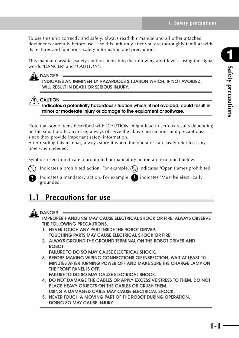
wDANGER INDICATES AN IMMINENTly hAzARDOuS SITuATION WhICh, IF NOT AvOIDED, WIll RESulT IN DEATh OR SERIOuS INjuRy.
cCAuTION Indicates a potentially hazardous situation which, if not avoided, could result in minor or moderate injury or damage to the equipment or software.
Notethatsomeitemsdescribedwith"CAUTION"mightleadtoseriousresultsdependingonthesituation.Inanycase,alwaysobservetheaboveinstructionsandprecautionssince they provide important safety information.After reading this manual, always store it where the operator can easily refer to it any time when needed.
Symbols used to indicate a prohibited or mandatory action are explained below.
:Indicatesaprohibitedaction.Forexample, indicates "Open flames prohibited
:Indicatesamandatoryaction.Forexample, indicates "Must be electrically grounded.
1.1 Precautions for use
wDANGER IMPROPER hANDlING MAy CAuSE ElECTRICAl ShOCk OR FIRE. AlWAyS ObSERvE ThE FOllOWING PRECAuTIONS. 1. NEvER TOuCh ANy PART INSIDE ThE RObOT DRIvER. TOuChING PARTS MAy CAuSE ElECTRICAl ShOCk OR FIRE. 2. AlWAyS GROuND ThE GROuND TERMINAl ON ThE RObOT DRIvER AND RObOT. FAIluRE TO DO SO MAy CAuSE ElECTRICAl ShOCk. 3. bEFORE MAkING WIRING CONNECTIONS OR INSPECTION, WAIT AT lEAST 10 MINuTES AFTER TuRNING POWER OFF AND MAkE SuRE ThE ChARGE lAMP ON ThE FRONT PANEl IS OFF. FAIluRE TO DO SO MAy CAuSE ElECTRICAl ShOCk. 4. DO NOT DAMAGE ThE CAblES OR APPly ExCESSIvE STRESS TO ThEM. DO NOT PlACE hEAvy ObjECTS ON ThE CAblES OR CRuSh ThEM. uSING A DAMAGED CAblE MAy CAuSE ElECTRICAl ShOCk. 5. NEvER TOuCh A MOvING PART OF ThE RObOT DuRING OPERATION. DOING SO MAy CAuSE INjuRy.

Safety precautions
1
1-2
1. Safety precautions
1-3
cCAuTION 1. use only the specified robot and controller combination. using the wrong combination may cause fire or malfunction. 2. Never use this unit in locations subject to water, grinding fluid mist, corrosive gases, explosive gases or salt damage. Do not use near inflammable objects or materials. Doing so may cause fire, malfunction or accidents. 3. The robot driver, robot and peripheral equipment may become hot during operation. be careful not to touch them. Touching them may cause burns. 4. The robot driver's heat-sink fins, regenerative resistor, and robot may become hot when power is being supplied or shortly after power is turned off, so do not touch them. Touching them may cause burns. 5. Allow at least a 5-minute time interval between power on and off. Failure to do so may cause fire. 6. Install a leakage breaker on the power supply side of the robot driver. Failure to do so may cause fire. 7. use a power line, leakage breakers and electromagnetic contacts that meet the required specifications (ratings). Failure to do so may cause fire. 8. Do not start/stop operation by turning on or off the electromagnetic contact installed on the power supply side of the robot driver. Doing so may cause fire.
1.2 Storage
PROhIbITED DO NOT STORE ThE uNIT IN lOCATIONS ExPOSED TO RAIN, WATER DROPlETS, GRINDING FluID MIST OR hARMFul GASES OR lIquIDS.
MANDATORy 1. STORE ThE uNIT IN lOCATIONS NOT ExPOSED TO DIRECT SuNlIGhT AND WIThIN ThE SPECIFIED huMIDITy AND TEMPERATuRE RANGE (–10 TO +70°C, 20 TO 90% Rh WIThOuT CONDENSATION). 2. CONSulT WITh OuR COMPANy IF yOu hAvE STORED ThE uNIT OvER AN ExTENDED PERIOD OF TIME.

1-2 1-3
1
Safety precautions
1. Safety precautions
1.3 Carrying
cCAuTION 1. Do not carry the robot driver by the cables. Doing so may cause malfunction or injury. 2. Do not carry the unit by the top cover or by the main circuit terminal block cover. Doing so may cause the unit to fall resulting in injury.
MANDATORy lOAD ThE uNITS CORRECTly AS INDICATED. STACkING TOO MANy uNITS MAy CAuSE ThEM TO FAll OvER.
1.4 Installation
cCAuTION 1. Do not step or stand on the unit. Do not place heavy objects on the unit. Doing so may cause injury. 2. Do not block the air intake and exhaust vents. Do not allow foreign matter or debris to penetrate inside. Doing so may cause fire. 3. Always use the correct method to install the unit. The unit may malfunction if not properly installed. 4. Install the robot driver on a straight, vertical wall not subject to vibration. The unit may fall and injure someone if not properly installed. 5. Install the unit on a surface made of incombustible materials such as metal. Failure to do so may cause fire. 6. Install the unit at a place strong enough to support the weight of the unit. The unit may fall and injure someone if not properly installed. 7. Tighten the screws to the specified torque. Make sure that all screws are securely fastened before operation. The unit may fall and injure someone if not properly installed. 8. Provide the specified clearance between the robot driver and the inner surface of the control panel or any other unit. Failure to do so may cause malfunction. 9. Do not allow foreign matter such as cut wire fragments, welding debris, iron waste or similar items to penetrate inside. Doing so may cause fire.
10. Avoid applying strong shock to the unit to prevent malfunction. 11. Do not install the unit if any part is damaged or missing. Doing so may cause fire or injury.

Safety precautions
1
1-4
1. Safety precautions
1-5
1.5 Wiring
wDANGER 1. WIRING WORk ShOulD bE CARRIED OuT by quAlIFIED ElECTRICIANS. IMPROPER WIRING MAy CAuSE ElECTRICAl ShOCk OR FIRE. 2. AlWAyS FIRST INSTAll ThE uNIT bEFORE CARRyING OuT WIRING. FAIluRE TO DO SO MAy CAuSE ElECTRICAl ShOCk OR INjuRy. 3. MAkE SuRE ThE POWER IS OFF bEFORE CARRyING OuT WIRING. FAIluRE TO DO SO MAy CAuSE ElECTRICAl ShOCk OR FIRE. 4. bE SuRE TO CONNECT ThE RObOT DRIvER'S GROuND TERMINAl TO ThE GROuNDING POINT (ClASS D: 100 OhMS OR lESS). FAIluRE TO DO SO MAy CAuSE ElECTRICAl ShOCk OR FIRE.
cCAuTION 1. Make sure that wiring connections are correct. Wrong connections may cause abnormal robot motion resulting in injury. 2. Cables connecting to the robot driver should be securely fastened near the robot driver so that no tensile stress is applied to the cables. Stress on the cables may lead to malfunction.

1-4 1-5
1
Safety precautions
1. Safety precautions
1.6 Control and operation
cCAuTION 1. To prevent unstable or erratic operation never make drastic adjustments to the unit. Doing so may cause injury. 2. Install a safety circuit that actuates an electromagnetic contactor to cut off the main circuit power supply in case of an alarm. If an alarm has occurred, eliminate the cause of the alarm and ensure safety. Then reset the alarm and restart the operation. Failure to do so may cause injury. 3. If a momentary power outage occurs and power is restored, the unit might suddenly restart so do not approach the machine at that time. (Design the machine so that personal safety is ensured even if it suddenly restarts.) Failure to do so may cause injury. 4. Make sure that the AC power specifications match the product power specifications. using the wrong power specifications may cause injury. 5. While power is being supplied, do not touch any parts inside the robot driver or its terminals. Also, do not check the signals or attach/detach the cables. Doing so may cause electrical shock or injury. 6. While power is being supplied, do not touch any terminals on the robot driver even if the robot is stopped. Doing so may cause electrical shock or fire. 7. When moving the robot for debugging the user program, configure a control circuit that turns off the servo ON terminal in cases where an emergency stop is required. Failure to do so may cause injury or damage the machine.
MANDATORy INSTAll AN ExTERNAl EMERGENCy STOP CIRCuIT SO ThAT yOu CAN IMMEDIATEly STOP OPERATION AND ShuT OFF POWER WhENEvER NEEDED.
Safety precautions
1
1-6
1. Safety precautions
1.7 Maintenance and inspection
wDANGER AFTER TuRNING POWER OFF, WAIT AT lEAST 10 MINuTES bEFORE STARTING MAINTENANCE AND MAkE SuRE ThE ChARGE lAMP ON ThE DIGITAl OPERATOR PANEl IS OFF. FAIluRE TO DO SO MAy CAuSE ElECTRICAl ShOCk.
cCAuTION The capacitance of the capacitor on the power supply line drops due to deterioration. Replacing the capacitor based on its service life curve is recommended in order to prevent secondary damage resulting from capacitor failure. (See Chapter 7, "Maintenance and inspection", of this manual.) using a deteriorated or defective capacitor may cause malfunction.
PROhIbITED DO NOT ATTEMPT TO DISASSEMblE OR REPAIR ThE uNIT OR REPlACE ANy PARTS OF ThE uNIT. ONly quAlIFIED SERvICE PERSONNEl ARE AllOWED TO DO REPAIR WORk.

Chapter 2 Before using the unitThis chapter explains what you need to check after receiving the product you purchased as well as the warranty and the product part names.
Contents
2.1 Inspection after unpacking 2-12.1.1 Checking the product 2-1
2.1.2 User's manual 2-2
2.2 Product inquiries and warranty 2-32.2.1 Notes when making an inquiry 2-3
2.2.2 Warranty 2-4
2.3 External view and part names 2-5
2.4 Robot driver and robot combination 2-6

2-1
2-1
2
Before using the unit
2. Before using the unit
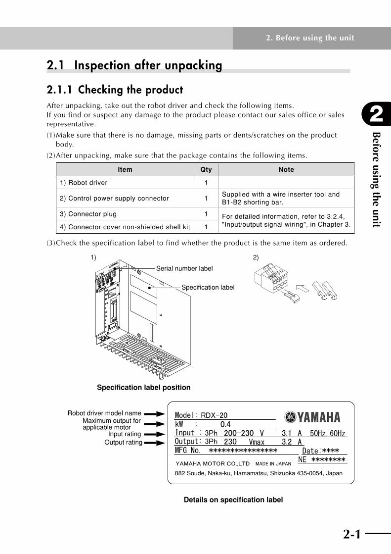
2.1 Inspection after unpacking
2.1.1 Checking the productAfter unpacking, take out the robot driver and check the following items. Ifyoufindorsuspectanydamagetotheproductpleasecontactoursalesofficeorsalesrepresentative.
(1) Make sure that there is no damage, missing parts or dents/scratches on the product body.
(2) After unpacking, make sure that the package contains the following items.
Item Qty Note
1) Robot driver 1
2) Control power supply connector 1Supplied with a wire inserter tool and B1-B2 shorting bar.
3) Connector plug 1 For detailed information, refer to 3.2.4, "Input/output signal wiring", in Chapter 3.4) Connector cover non-shielded shell kit 1
(3)Checkthespecificationlabeltofindwhethertheproductisthesameitemasordered.
RDX
NE
882 Soude, Naka-ku, Hamamatsu, Shizuoka 435-0054, Japan
Specification label
Serial number label
Specification label position
Robot driver model nameMaximum output for applicable motor
Input ratingOutput rating
Details on specification label
1) 2)

Before using the unit
2
2-2
2. Before using the unit
2-3
X05 X05 0001
–
X05X10X20P05P10P20P25
RDX-05RDX-10RDX-20RDP-05RDP-10RDP-20RDP-25
1 to 9OXY
January to SeptemberOctober
NovemberDecember
Production number
Production month
Production year: Last 2 digits of year
Details on serial number label
Robot driver model No.
2.1.2 User's manualThis user's manual describes how to use the YAMAHA single-axis robot driver RD series. Before using the RD series, read this manual thoroughly in order to handle and operate it correctly. Store this manual carefully even after reading it.

2-2 2-3
2
Before using the unit
2. Before using the unit
2.2 Product inquiries and warranty
2.2.1 Notes when making an inquiryIfyouneedtoinquireaboutpossibleproductdamage,failuresorpointsthatareunclear,then please contact us with the following information.
(1) Robot driver model
(2) Production number
(3) Date of purchase
(4)Detailsofyourinquiry
• Damagedsectionandcondition,etc.
• Dubiouspointanddescription,etc.

Before using the unit
2
2-4
2. Before using the unit
2-5
2.2.2 WarrantyFor information on the warranty period and terms, please contact our distributor where you purchased the product.
This warranty does not cover any failure caused by:
1. Installation, wiring, connection to other control devices, operating methods, inspection or maintenance that does not comply with industry standards or instructions specified in the YAMAHA manual;
2. Usage that exceeded the specifications or standard performance shown in the YAMAHA manual;
3. Product usage other than intended by YAMAHA;
4. Storage, operating conditions and utilities that are outside the range specified in the manual;
5. Damage due to improper shipping or shipping methods;
6. Accident or collision damage;
7. Installation of other than genuine YAMAHA parts and/or accessories;
8. Modification to original parts or modifications not conforming to standard specifications designated by YAMAHA, including customizing performed by YAMAHA in compliance with distributor or customer requests;
9. Pollution, salt damage, condensation;
10. Fires or natural disasters such as earthquakes, tsunamis, lightning strikes, wind and flood damage, etc;
11. Breakdown due to causes other than the above that are not the fault or responsibility of YAMAHA;
The following cases are not covered under the warranty:
1. Products whose serial number or production date (month & year) cannot be verified.
2. Changes in software or internal data such as programs or points that were created or changed by the customer.
3. Products whose trouble cannot be reproduced or identified by YAMAHA.
4. Products utilized, for example, in radiological equipment, biological test equipment applications or for other purposes whose warranty repairs are judged as hazardous by YAMAHA.
THE WARRANTY STATED HEREIN PROVIDED BY YAMAHA ONLY COVERS DEFECTS IN PRODUCTS AND PARTS SOLD BY YAMAHA TO DISTRIBUTORS UNDER THIS AGREEMENT. ANY AND ALL OTHER WARRANTIES OR LIABILITIES, EXPRESS OR IMPLIED, INCLUDING BUT NOT LIMITED TO ANY IMPLIED WARRANTIES OF MERCHANTABILITY OR FITNESS FOR A PARTICULAR PURPOSE ARE HEREBY EXPRESSLY DISCLAIMED BY YAMAHA. MOREOVER, YAMAHA SHALL NOT BE HELD RESPONSIBLE FOR CONSEQUENT OR INDIRECT DAMAGES IN ANY MANNER RELATING TO THE PRODUCT.
Ver.1.00_201205

2-4 2-5
2
Before using the unit
2. Before using the unit
2.3 External view and part names
RDX
Battery holderNot used.
Battery housing cover
Charge lampLights up when the main power supply is turned on. This lamp remains lit as long as the main circuit capacitor retains a charge after the power supply is turned off. Do not touch the robot driver while the lamp is lit.
Main circuit terminal block (TM1)Terminals for connecting to the main circuit power supply, external regenerative resistor, and motor power cable.A cover is fitted to this terminal block when purchased.
Display panelThis is a 5-digit 7-segment LED display used as the operation monitor, parameter display and trip (alarm) display.
Digital operatorUse these operator keys to set parameters.
Computer connector (PC)Connects to a PC (personal computer) for data transfer.
Input/output signal connector (I/O)Connector for command input signals, programmable controller input signals, and origin sensor signals.Position sensor connector (ENC)Connects to the linear motor position sensor or resolver.
B1-B2 shorting barAlways connect this shorting bar when using an internal braking resistor (RD*-20 and RDP-25).(RD*-05 and RD*-10 have no internal braking resistor.)
Ground terminalAlways ground the unit through this terminal to prevent electrical shock.
Control power supply connector (TM2)Connects to the control power supply.
Intake air (Natural air convection)
Exhaust air

Before using the unit
2
2-6
2. Before using the unit
2.4 Robot driver and robot combinationThe table below shows applicable combinations of robot drivers and robots.
Robot driver name Model No. Applicable robots
RDP (For PHASER series)
RDP-05 MR12, MR16
RDP-10 MR16H, MR25, MF7
RDP-20 MR20, MF15, MF20, MF30, MF50
RDP-25 MF75
RDX (For FLIP-X series)
RDX-05T4H, T5H, T6, T7, T9, F8, F8L, F8LH, F10, F14, B10, B14, R5, R10, C4H, C5H, C6, C8, C8L, C8LH, C10, C14
RDX-10 T9H, F14H, B14H, R20, C14H
RDX-20 F17, F17L, F20, F20N, N15, N18, C17, C17L, C20
Note:Parametersareadjustedatthefactorypriortoshippingsothattherobotdriveroperatesto control the target robot. Please contact us if you want to change the target robot model after shipping.

Chapter 3 Installation and wiringThis chapter explains how to install the robot driver, as well as how to connect wiring to the main circuit and input/output signals. Typical connection examples are shown.
Contents
3.1 Installation 3-13.1.1 Precautions during installation 3-2
3.2 Wiring 3-43.2.1 Terminal block and connectors 3-4
3.2.2 Main circuit wiring 3-5
3.2.3 Wiring to the control terminal block (TM2) 3-13
3.2.4 Input/output signal wiring 3-14
3.2.5 Wiring for position sensor signals 3-27

3-1

3-1
3
Installation and wiring
3. Installation and wiring
3.1 Installation
cCAuTION 1. Do not step or stand on the unit. Do not place heavy objects on the unit. Doing so may cause injury. 2. Do not block the air intake and exhaust vents. Do not allow foreign matter or debris to penetrate inside. Doing so may cause fire. 3. Always use the correct method to install the unit. The unit may malfunction if not properly installed. 4. Install the robot driver on a perpendicular wall not subject to vibration. The unit may fall and injure someone if not properly installed. 5. Install the unit on a surface made of incombustible materials such as metal. Failure to do so may cause fire. 6. Install the unit at a place strong enough to support the weight of the unit. The unit may fall and injure someone if not properly installed. 7. Tighten the screws to the specified torque. Make sure that all screws are securely fastened before operation. The unit may fall and injure someone if not properly installed. Screw size Tightening torque (N•m) Note
M3 0.6 to 0.9
Mounting screws for robot driver and peripheral devices
M4 1.5 to 2.1
M5 2.8 to 3.9
M6 4.1 to 5.3
M8 13.9 to 20.0
8. Provide the specified clearance between the robot driver and the inner surface of the control panel or any other unit. Failure to do so may cause malfunction. 9. Do not allow foreign matter such as cut wire fragments, welding debris, iron waste or similar items to penetrate inside. Doing so may cause fire.
10. Avoid applying strong shock to the unit to prevent malfunction. 11. Do not install the unit if any part is damaged or missing. Doing so may cause fire or injury.

Installation and wiring
3
3-2
3. Installation and wiring
3-3
3.1.1 Precautions during installation(1) Precautions when carrying the unit
The robot driver uses plastic parts. Handle it carefully to avoid damage to the plastic parts. Take special care not to carry the unit in such a way that force is applied only to the front cover or terminal block cover. Otherwise you might drop the unit. Do not install and operate the unit if any part is damaged or missing.
(2) Install the unit on an incombustible (metal) surface.The robot driver becomes hot during operation. To prevent fire always install it on an incombustible, straight vertical metal wall. Alsoprovideenoughspacearoundtheunit.Ifthereisanyheatgeneratingdevice(braking resistor, electric reactor, etc.), keep the unit a sufficient distance away from it.
Air flow
Robot driver
Provide enough space so that upper/lower wiring ducts will not block cooling air flow.
Wall
(3) Ambient temperature precautionsThe ambient temperature in the installation place should not exceed the allowable operatingtemperaturerange(0to40˚C)specifiedinthestandardspecifications. Measure the ambient temperature at a position about 50mm away from the lower center of the robot driver body, and make sure that it is within the allowable operating temperature range. Operating the robot driver at a temperature exceeding the allowable range may shorten its service life (especially, capacitor life) or damage the internal components.
(4) Do not install the unit in locations subject to high temperatures and high humidity where condensation tends to occur.
Always operate the robot driver within the allowable operating humidity range (20 to 90%RH)specifiedinthestandardspecifications.Inparticular,operateitinlocationsfree from condensation. Ifwaterdropletsformedinsidetherobotdriverduetocondensation,thismightcauseshort-circuits between electronic components that result in malfunction. Avoid installing the unit in locations exposed to direct sunlight.
(5) Installation environment precautionsAvoidinstallingtheunitinlocationssubjecttodust,corrosivegases,explosivegases,combustible gases, grinding lubricant mist or salt damage. Dust or debris penetrating the unit may cause malfunction. Iftheunitmustbeusedinverydustyplace,houseitinasealeddust-proofbox.

3-2 3-3
3
Installation and wiring
3. Installation and wiring
(6) Installation method and direction precautionsInstalltherobotdriveronaverticalsurfacecapableofsupportingtheweight.Securethe robot driver firmly by screws or bolts. Iftherobotdriverisnotinstalledverticallyonthewallsurface,thecoolingcapacitymay degrade causing a trip or alarm and/or damaging the internal components. Formountingholelocations,referto8.2,"Robotdriverdimensionsandmountingholes".
(7) Precautions when housing robot drivers in a boxWhen housing multiple robot drivers in a box and using ventilation fans, attach the fans as shown below in order to ensure a uniform temperature around each robot driver.
100mm or more
100mm or more 40mm or more
40mm or more
10mm or more
10mm or more
10mm or more
Fan Fan
Wiring space of 75mm or more
Robot driver
Installtherobotdrivers40mmormoreawayfromtheinnersidewallsoftheboxand100mm or more away from the inner top/bottom walls of the box. Allow a clearance of10mmormorebetweenadjacentrobotdrivers.

Installation and wiring
3
3-4
3. Installation and wiring
3-5
3.2 Wiring
wDANGER 1. WIRING WORk ShOulD bE CARRIED OuT by quAlIFIED ElECTRICIANS. IMPROPER WIRING MAy CAuSE ElECTRICAl ShOCk OR FIRE. 2. AlWAyS FIRST INSTAll ThE uNIT bEFORE CARRyING OuT WIRING. FAIluRE TO DO SO MAy CAuSE ElECTRICAl ShOCk OR INjuRy. 3. MAkE SuRE ThE POWER IS OFF bEFORE CARRyING OuT WIRING. FAIluRE TO DO SO MAy CAuSE ElECTRICAl ShOCk OR FIRE.
cCAuTION 1. Make sure that wiring connections are correct. Wrong connections may cause abnormal robot motion resulting in injury. 2. Cables connecting to the robot driver should be securely fastened near the robot driver so that no tensile stress is applied to the cables. Stress on the cables may lead to malfunction.
3.2.1 Terminal block and connectorsThe terminal block and connectors on the robot driver are shown below.
FUNC
SETCHARGE
RDX
Main circuit terminal block (TM1)
Ground terminal
Computer connector (PC)
Input/output signal connector (I/O)
Position sensor connector (ENC)
Control power supply connector (TM2)

3-4 3-5
3
Installation and wiring
3. Installation and wiring
3.2.2 Main circuit wiring
(1) Terminal connection diagram
(+)1
(+)
RB
(-)
L2
L1
L3MG
L1C
L2C
B1
B2
TM1
TM2
I/O
U
TM1
V
W
ENC
PC
ELB
Note 1)
Shorting bar(DC reactor connecting terminal)
Regenerative braking resistor (option)
Power supply3-phase 200 to 230 V AC
When using external regenerative braking resistor, disconnect B1-B2 shorting bar.
Master controller
Origin sensor
Robot driver
PC for parameter setting and operation monitoring
Note 1: Regenerative braking resistor is built in RD*-20 and RDP-25 robot drivers. (Not built into RD*-05 and RD*-10 robot drivers.)

Installation and wiring
3
3-6
3. Installation and wiring
3-7
(2) Terminal assignment
Terminal block
connectorTerminal assignment
Terminal screw size
Terminal width (mm)
Main circuit
terminal block (TM1)
(+)1 (+) RB (–)L1 L2 L3UVW
Shorting bar
DC reactor connection terminal(Short these terminals when not used.)External braking resistor connection terminalDC power input terminal
Main power input terminal
Motor power cable connection terminal
M4 8.1
Ground terminal
Ground connection terminal M4 –
Control power
connector (TM2)
B1B2
L1CL2C
Shorting bar
Shorting terminals for internal braking resistor(Open when external resistor is used.)
Control power input terminal
Note: Diagram is shown as viewed from bottom of robot driver.
Applicable wire size: 1.25 to 2.0 mm2
cCAuTION 1. unplug the control power supply connector from the robot driver before wiring. Failure to do so may damage the robot driver. 2. When inserting the wires into the terminal, be careful not to bring the core wire braid into contact with other conductive parts. Failure to do so may damage the robot driver. 3. If for some reason the inserted portion of the wire is frayed, cut off that frayed portion and restrip the wire. Then reconnect the wire securely. using frayed wire may damage the robot driver.

3-6 3-7
3
Installation and wiring
3. Installation and wiring
(3) Wiring precautions
Before starting wiring, make sure that the charge lamp is completely off. Use caution because the capacitor might still be charged with high voltage creating a hazardous condition. About 10 minutes or more after power-off use a voltmeter or similar instrument to check that no voltage remains across the (+) and (–) terminals on the main circuit terminal block, and then start wiring.
1) Main power input terminals (L1, L2, L3)
•Useanearthleakagebreaker(ELB)toprotectcircuit(wiring)betweenthepower supplyandmainpowerinputterminals(L1,L2,orL3).
•Someearthleakagebreakersmaymalfunctionduetoeffectsfromhigher harmonics,souseonehavinglargecurrentsensitivityathighfrequencies.
•Connectanelectromagneticcontactorthatshutsoffthepowersupplytotherobot driver to prevent a failure or accident from spreading when the robot driver's protective function is activated.
•Donotattempttostartorstoptherobotdriverbyturningonoroffeach electromagnetic contactor provided on the primary side and secondary side of the robot driver.
•Donotusetherobotdriverinanopen-phasecondition.
•Anyofthefollowingconditionsmaydamagetheconvertermodulesousecaution. The power supply voltage imbalance is 3% or more. The power supply capacity is 10 times larger than the robot driver capacity or 500kVA or more. A sudden fluctuation occurs in the power supply. (Example)Multiplerobotdriversareconnectedtoeachotherbyashortbus line. Inanycase,connectingaDCreactor(DCL)isrecommended.
•Whenturningpoweronoroffallowatleasta5-minutetimeintervalbetween power on and off in order to avoid damage to the robot driver.
2) Motor cable connection terminals (U, V, W)
•Tominimizevoltagedrops,usethickerwiresthannormallyused.
3) DC reactor (DCL) connection terminals ( (+)1, (+) )
•TheseterminalsareusedtoconnectaDCreactorDCLforpowerfactor improvement.
A shorting bar is connected across terminals (+)1 and (+) at the factory prior to shipping.WhenconnectingaDCreactortotheseterminals,disconnectthe shortingbar.WhennotusingaDCreactor,leavetheshortingbarconnected.
Installation and wiring
3
3-8
3. Installation and wiring
3-9
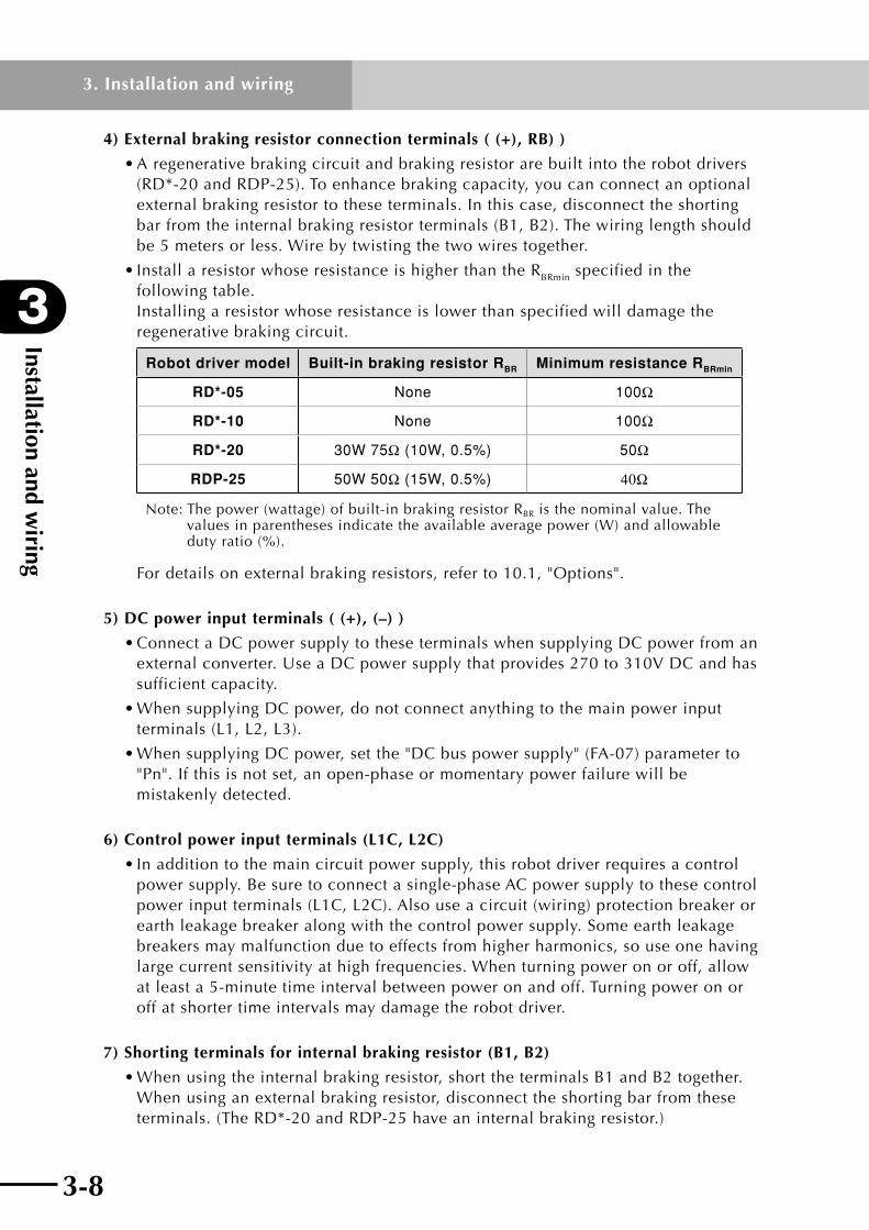
4) External braking resistor connection terminals ( (+), RB) )
•Aregenerativebrakingcircuitandbrakingresistorarebuiltintotherobotdrivers (RD*-20 and RDP-25). To enhance braking capacity, you can connect an optional externalbrakingresistortotheseterminals.Inthiscase,disconnecttheshorting bar from the internal braking resistor terminals (B1, B2). The wiring length should be 5 meters or less. Wire by twisting the two wires together.
•InstallaresistorwhoseresistanceishigherthantheRBRmin specified in the following table. Installingaresistorwhoseresistanceislowerthanspecifiedwilldamagethe regenerative braking circuit.
Robot driver model Built-in braking resistor RBR Minimum resistance RBRmin
RD*-05 None 100W
RD*-10 None 100W
RD*-20 30W 75W (10W, 0.5%) 50W
RDP-25 50W 50W (15W, 0.5%) 40W
Note: The power (wattage) of built-in braking resistor RBR is the nominal value. The values in parentheses indicate the available average power (W) and allowable duty ratio (%).
Fordetailsonexternalbrakingresistors,referto10.1,"Options".
5) DC power input terminals ( (+), (–) )
•ConnectaDCpowersupplytotheseterminalswhensupplyingDCpowerfroman externalconverter.UseaDCpowersupplythatprovides270to310VDCandhas sufficient capacity.
•WhensupplyingDCpower,donotconnectanythingtothemainpowerinput terminals(L1,L2,L3).
•WhensupplyingDCpower,setthe"DCbuspowersupply"(FA-07)parameterto "Pn".Ifthisisnotset,anopen-phaseormomentarypowerfailurewillbe mistakenly detected.
6) Control power input terminals (L1C, L2C)
•Inadditiontothemaincircuitpowersupply,thisrobotdriverrequiresacontrol powersupply.Besuretoconnectasingle-phaseACpowersupplytothesecontrol powerinputterminals(L1C,L2C).Alsouseacircuit(wiring)protectionbreakeror earth leakage breaker along with the control power supply. Some earth leakage breakers may malfunction due to effects from higher harmonics, so use one having largecurrentsensitivityathighfrequencies.Whenturningpoweronoroff,allow at least a 5-minute time interval between power on and off. Turning power on or off at shorter time intervals may damage the robot driver.
7) Shorting terminals for internal braking resistor (B1, B2)
•Whenusingtheinternalbrakingresistor,shorttheterminalsB1andB2together. When using an external braking resistor, disconnect the shorting bar from these terminals. (The RD*-20 and RDP-25 have an internal braking resistor.)

3-8 3-9
3
Installation and wiring
3. Installation and wiring
8) Ground terminals ( )
•Topreventelectricalshock,besuretogroundtherobotdriverandtherobot body.
•Connectthegroundterminalstoapropergroundingpoint(ClassD:100ohmsor less).
•Thegroundwireshouldbethickerthanthosegenerallyusedandasshortas possible.
Note 1: To connect wiring to the terminal block, use crimp terminals that match the terminal width. If the crimp terminal width is too wide, then a bad connection or misconnection may result.
Note 2: Separate the robot driver signal input cable and position sensor cable at least 30cm from the main circuit power cable and control power cable. If those cables must intersect each other, then route them so that they intersect at right angles as shown below. The robot driver may result in malfunction if the cables are not separated from each other.
Main circuit power cable(L1, L2, L3, U, V, W, (+), (+)1, RB)Control power supply cable(L1C, L2C)
Cables should intersect at right angles.
Signal input and position sensor cables30cm or more

Installation and wiring
3
3-10
3. Installation and wiring
3-11
(4) Peripheral cables and products
Name Function Availability
1TOP (software for YAMAHA RD series)
Allows setting parameters, monitoring operation and displaying graphics from a PC connected to the robot driver.
Option
2 Position sensor cableConnects to the robot position sensor, brake and origin sensor.
Standard
3 Power cable Supplies power to the robot. Standard
4 PC connection cable Connects to a PC. Option
5Connector set for I/O signals
Mating connector and cover for robot driver I/O connector
Standard
6 External braking resistor Boosts the braking capacity. Option
Typical wiring diagram for robot driver is shown below.
I/O
ENC
FUNC
(+)1
SETCHARGE
4. PC connection cable
1. TOP (software for YAMAHA RD series)
6. External braking resistor
3. Power cable
2. Position sensor cable
5. Connector set for I/O signals
Power supply3-phase 200 V AC class
Earth leakage breaker (ELB)
Robot
Electromagnetic contactor
Robot driver
PC (IBM PC compatible)Master
controller

3-10 3-11
3
Installation and wiring
3. Installation and wiring
(5) Recommended wire size and wiring accessories
• Selectoptimalbreakersbytakingtheirbreakingcapacityintoaccount.
• Useanearthleakagebreaker(ELB)toensuresafety.
• Useanappropriatecopperwirewithaheatresistanttemperatureof75˚Cormore.
• Tightentheterminalscrewstothespecifiedtorque.Insufficienttighteningmay result in a short circuit or fire.
• Selectthesensitivitycurrentoftheearthleakagebreaker(ELB)bytakingaccountof the total wiring length needed to connect between the robot driver and power supply and also between the robot driver and robot. When the total wiring length is shorter than 30 meters, use a 15mA sensitivity current (per one robot driver). Useanearthleakagebreakercompatiblewithinverters.Conventionalbreakersmay malfunctionbyhighharmonicsgeneratedfromaninverter.Contactthebreaker manufacturer for details.
• Refertothefollowingtablewhenselectingwiringsizeandwiringaccessoriesfor robot drivers.
Robot driver model
Main circuit power cable
L1, L2, L3 (+)1, (+), RB, (–)
Control power cable
L1C, L2C
Earth leakage breaker (ELB) *
Electromagnetic contactor (MC) *
RD*-05 1.25mm2 or more 0.5mm2 or more EX30 (5A) H10C / HK10
RD*-10 1.25mm2 or more 0.5mm2 or more EX30 (5A) H10C / HK10
RD*-20 1.25mm2 or more 0.5mm2 or more EX30 (5A) H10C / HK10
RDP-25 1.25mm2 or more 0.5mm2 or more EX30 (10A) H10C / HK10
*:ELBandMCmodelslistedintheabovetablearemanufacturedbyHitachiIndustrialEquipmentSystemsCo.,Ltd. (HitachistandardELBproductsmanufacturedfromDecember1987arecompatiblewithinverters.)

Installation and wiring
3
3-12
3. Installation and wiring
3-13
(6) Attaching the cover to the main circuit terminal block (TM1)
1.Insertthebottomhookofthemaincircuitterminalblockcoverintotheslotintherobot driver front panel as shown below.
2. Attach the main circuit terminal block cover into place by gently pressing on it from the front.
3. Tighten the screw to fasten the main circuit terminal block cover to the robot driver.
RDX
1
2
3
Main circuit terminal block cover

3-12 3-13
3
Installation and wiring
3. Installation and wiring
3.2.3 Wiring to the control terminal block (TM2)
cCAuTION 1. unplug the control power supply connector (TM2) from the robot driver before wiring. Failure to do so may damage the robot driver. 2. Insert one cable into one terminal hole of the control power connector (TM2). Failure to follow this instruction may cause the robot driver to malfunction. 3. When inserting the wires into the terminal, be careful not to bring the core wire braid into contact with other conductive parts. Failure to do so may damage the robot driver. 4. If for some reason the inserted portion of the wire is frayed, cut off that frayed portion and restrip the wire. Then reconnect the wire securely. using frayed wire might damage the robot driver.
(1) Cable termination
StripthecablesheathasshowninFig.1.Thecablecanthenbeusedasis.Applicablewire size is as follows:
Solid wire .......Wire size 1.25 to 2.0mm2
Stranded wire ...Wire size 1.25 to 2.0mm2
8 to 9mm
Fig. 1 Control power cable termination
(2) Connection method
Insertthecorewireofthecableintotheterminalholeofthecontrolpowerconnector(TM2)showninFig.2byusingeitherofthefollowingmethodsofFig.3andFig.4.Make sure the wire does not come loose if pulled.
1) InsertthewirebyusingthesuppliedleverasshowninFig.3.
2) Insertthewirebyusingasmallflat-bladescrewdriverasshowninFig.4.
B2L1
L2C
B1
Fig. 2 Control power connector
Fig. 4Fig. 3

Installation and wiring
3
3-14
3. Installation and wiring
3-15
3.2.4 Input/output signal wiring
(1) Input/output signal connector
Pin No.1 of the input/output signal connectorI/Oislocatedattheupperleft when viewed from the front of the robot driver as shown on the right. The table below shows the signal assignment on the input/output signal connectorI/O(robotdriverside).
FUNC
SETCHARE
1 26
2550
Input/output signal connector I/O
Robot driver front view
Pin No.
Pin symbol Signal name Pin
No.Pin
symbol Signal name
1 P24 Interface power 26 SON Servo ON
2 PLC Intelligent input common 27 RS Alarm reset
3 – – 28 FOT Forward overtravel
4 TL Torque limit 29 ROT Reverse overtravel
5 B24 Brake power input (24V) 30 CM1 Interface power common
6 B0 Brake power input (0V) 31 B0 Brake power input (0V)
7 – – 32 ORG Return-to-origin (homing)
8 ORL Origin sensor 33 PEN Pulse train input enable
9 CER Position error clear 34 ALME Alarm (emitter)
10 CM1 Interface power common 35 SRD Servo ready (collector)
11 ALM Alarm (collector) 36 – –
12 INP Positioning complete (collector) 37 – –
13 BK Brake release relay output 38 – –
14 – – 39 INPE Positioning complete (emitter)
15 PLSP Position command pulse (P) 40 SIGP Position command sign (P)
16 PLSN Position command pulse (N) 41 SIGN Position command sign (N)
17 – – 42 SRDE Servo ready (emitter)
18 – – 43 – –
19 – – 44 – –
20 L Analog input /output common 45 – –
21 OAP Phase A signal output (P) 46 OBP Phase B signal output (P)
22 OAN Phase A signal output (N) 47 OBN Phase B signal output (N)
23 OZP Phase Z signal output (P) 48 OZ Phase Z detection
24 OZN Phase Z signal output (N) 49 L Phase Z detection common
25 AO1 Analog monitor 1 50 AO2 Analog monitor 2

3-14 3-15
3
Installation and wiring
3. Installation and wiring
On the mating input/output signal connector (cable side), pin No.1 is located at the upper left when viewed from the soldered side (inner side) as shown below.
The following connector is supplied with the controller as the input/output signal connector (cable side).
Product name Type No. Manufacturer
Connector plug 10150-3000PE (soldered) Sumitomo 3M
Connector cover non-shield shell kit
10350-52A0-008 Sumitomo 3M
SRDE
26 28 30
48
27 29 31
50
47 49
1 3 5
23 25
2 4 6
22 24
Soldered side of input/output signal connector
2 PLC
4 TL
6 BO
8 ORL
10 CM1
12 INP
1 P24
3 −
5 B24
7 −
9 CER
11 ALM
13 BK 14 −
15 PLSP16 PLSN
17 −
18 −
19 −
20 L21 OAP
22 OAN23 OZP
24 OZN25 AO1
40 SIGP
27 RS
29 ROT
31 BO
33 PEN
35 SRD
37 −
39 INPE
41 SIGN
43 −
45 −
47 OBN
49 L
26 SON
28 FOT
30 CM1
32 ORG
34 ALME
36 −
38 −
42
44 −
46 OBP
48 OZ
50 AO2
Note1:Forrobotsusinganoriginsensororrobotsequippedwithamechanicalbrake, the input/output signal connector is shipped with pin No. 1, 8, 10, 13 and 31 soldered.
Note 2: Brake release relay output (BK) is not available from the RDP.
Installation and wiring
3
3-16
3. Installation and wiring
3-17
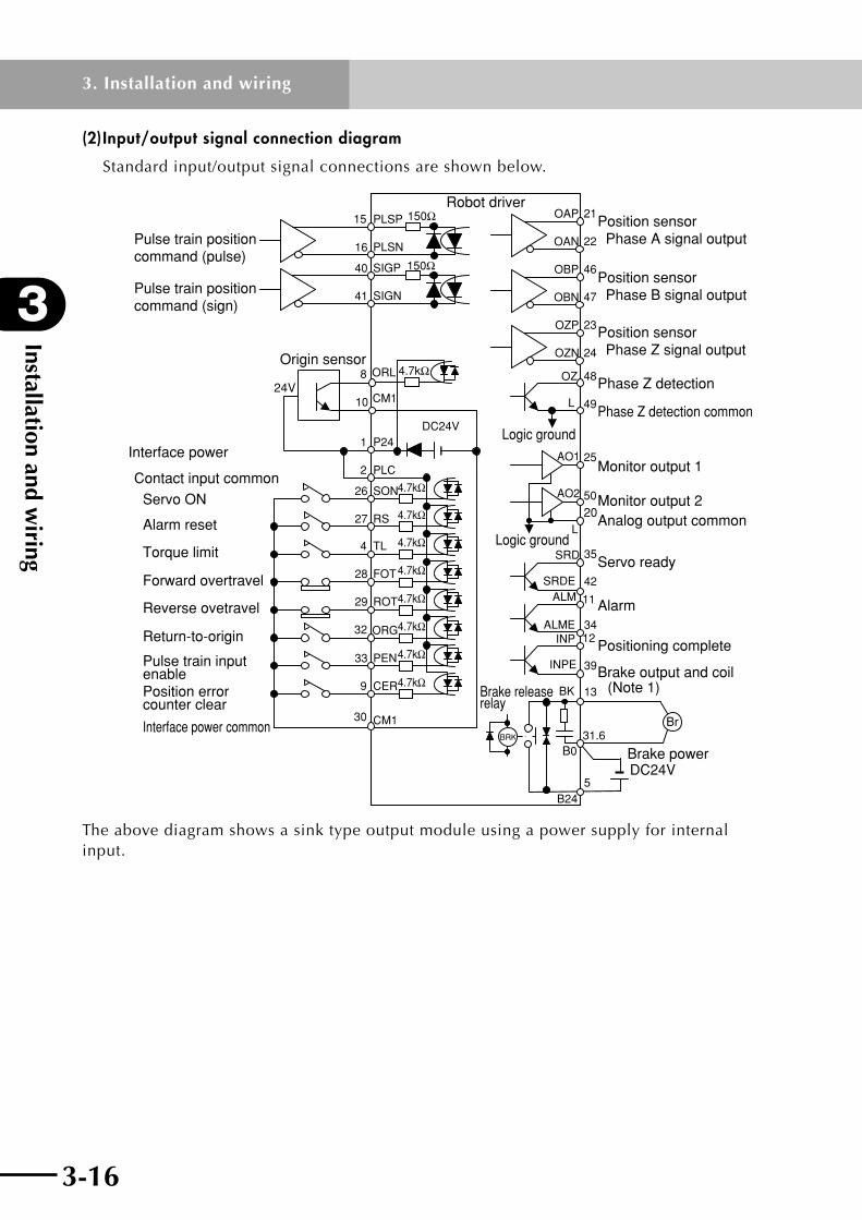
(2) Input/output signal connection diagram
Standard input/output signal connections are shown below.
PLSP
PLSN
150Ω
150ΩSIGP
SIGN
15
16
40
41
P24
PLC
RS
1
2
26
27
SON4.7kΩ
4.7kΩ
4.7kΩ
4.7kΩ
4.7kΩ
4.7kΩ
4.7kΩ
4.7kΩ
TL 4
FOT28
ROT29
ORG32
PEN33
CER 9
CM130
DC24V
OAP
OAN
21
22
OBP
OBN
46
47
OZP
OZN
23
24
SRD
ALMSRDE
INPALME
BK
B24
OZ 48
L 49
AO1 25
AO2 50
INPE
BRK
35
42 11
34 12
39
13
5
4.7kΩORL
CM1
8
10
B0
Br
DC24V
31.6
24V
20L
(Note 1)
Robot driver
Pulse train position command (pulse)
Pulse train position command (sign)
Interface power
Contact input commonServo ON
Alarm reset
Torque limit
Forward overtravel
Reverse ovetravel
Return-to-origin
Pulse train input enablePosition error counter clear
Interface power common
Origin sensor
Position sensor Phase A signal output
Position sensor Phase B signal output
Position sensor Phase Z signal output
Phase Z detection
Phase Z detection common
Monitor output 1
Monitor output 2Analog output common
Servo ready
Alarm
Positioning complete
Brake output and coil
Brake power
Brake release relay
Logic ground
Logic ground
The above diagram shows a sink type output module using a power supply for internal input.

3-16 3-17
3
Installation and wiring
3. Installation and wiring
(3) Input/output signal functions
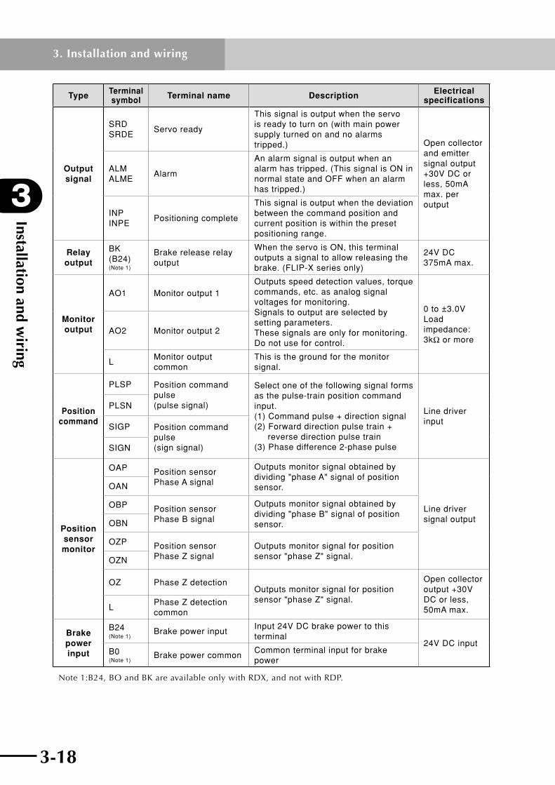
Input/outputsignalfunctionsaresummarizedinthefollowingtable.
Type Terminal symbol Terminal name Description Electrical
specifications
Input signal
P24 Interface power
Supplies 24V DC for contact inputs. Connecting this signal to the PLC terminal allows using the internal power supply. Use this terminal only for contact input. Do not use for controlling external equipment connected to the robot driver, such as brakes.
DC +24V±10% 80mA max.
CM1Interface power common
This is a ground signal for the power supply connected to P24. If using the internal power supply then input a contact signal between this signal and the contact-point signal.
PLCIntelligent input common
Connect this signal to the power supply common contact input. Connect an external supply or internal power supply (P24).
SON Servo ON
Setting this signal to ON turns the servo on (supplies power to motor to control it). This signal is also used for estimating magnetic pole position when FA-90 is set to oFF2.
Contact input Close: ON Open: OFF 5mA (at 24V) per input
RS Alarm reset
After an alarm has tripped, inputting this signal cancels the alarm. But before inputting this reset signal, first set the SON terminal to OFF and eliminate the cause of the trouble.
TL Torque limitWhen this signal is ON, the torque limit is enabled.
FOT Forward overtravelWhen this signal is OFF, the robot will not run in forward direction. (Forward direction limit signal)
ROT Reverse overtravelWhen this signal is OFF, the robot will not run in reverse direction. (Reverse direction limit signal)
ORL Origin sensorInput an origin limit switch signal showing the origin area.
ORG Return-to-originInputting this signal starts return-to-origin operation.
PENPulse train input enable
When this signal is turned on, the pulse train position command input is enabled.
CERPosition error counter clear
Inputting this signal clears the position deviation (position error) counter. (Position command value is viewed as current position.)
Analog common
L Analog commonThis is the ground for the analog signal.
0 to ±10V Input impedance: approx. 10kW
Installation and wiring
3
3-18
3. Installation and wiring
3-19
Type Terminal symbol Terminal name Description Electrical
specifications
Output signal
SRD SRDE
Servo ready
This signal is output when the servo is ready to turn on (with main power supply turned on and no alarms tripped.) Open collector
and emitter signal output +30V DC or less, 50mA max. per output
ALM ALME
Alarm
An alarm signal is output when an alarm has tripped. (This signal is ON in normal state and OFF when an alarm has tripped.)
INP INPE
Positioning complete
This signal is output when the deviation between the command position and current position is within the preset positioning range.
Relay output
BK (B24) (Note 1)
Brake release relay output
When the servo is ON, this terminal outputs a signal to allow releasing the brake. (FLIP-X series only)
24V DC 375mA max.
Monitor output
AO1 Monitor output 1Outputs speed detection values, torque commands, etc. as analog signal voltages for monitoring. Signals to output are selected by setting parameters. These signals are only for monitoring. Do not use for control.
0 to ±3.0V Load impedance: 3kW or more
AO2 Monitor output 2
LMonitor output common
This is the ground for the monitor signal.
Position command
PLSP Position command pulse (pulse signal)
Select one of the following signal forms as the pulse-train position command input. (1) Command pulse + direction signal (2) Forward direction pulse train + reverse direction pulse train (3) Phase difference 2-phase pulse
Line driver input
PLSN
SIGP Position command pulse (sign signal)SIGN
Position sensor monitor
OAP Position sensor Phase A signal
Outputs monitor signal obtained by dividing "phase A" signal of position sensor.
Line driver signal output
OAN
OBP Position sensor Phase B signal
Outputs monitor signal obtained by dividing "phase B" signal of position sensor.OBN
OZP Position sensor Phase Z signal
Outputs monitor signal for position sensor "phase Z" signal.OZN
OZ Phase Z detectionOutputs monitor signal for position sensor "phase Z" signal.
Open collector output +30V DC or less, 50mA max.L
Phase Z detection common
Brake power input
B24 (Note 1)
Brake power inputInput 24V DC brake power to this terminal
24V DC inputB0 (Note 1)
Brake power commonCommon terminal input for brake power
Note 1:B24, BO and BK are available only with RDX, and not with RDP.
3-18 3-19
3
Installation and wiring
3. Installation and wiring
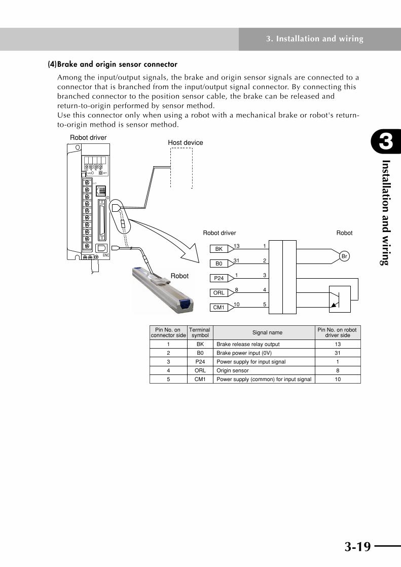
(4) Brake and origin sensor connector
Among the input/output signals, the brake and origin sensor signals are connected to a connector that is branched from the input/output signal connector. By connecting this branched connector to the position sensor cable, the brake can be released and return-to-origin performed by sensor method. Use this connector only when using a robot with a mechanical brake or robot's return-to-origin method is sensor method.
BK 13 1
B0 31 2
P24 1 3
ORL 8 4
CM1 10 5
Br
Robot driver Robot
Robot
I/O
ENC
FUNC
(+)1
SETCHARGE
Robot driverHost device
Brake release relay output
Brake power input (0V)
Power supply for input signal
Origin sensor
Power supply (common) for input signal
Signal name
1
2
3
4
5
Pin No. on connector side
13
Pin No. on robot driver side
31
1
8
10
BK
B0
P24
ORL
Terminal symbol
CM1
Installation and wiring
3
3-20
3. Installation and wiring
3-21
(5) Details of input/output signal wiring
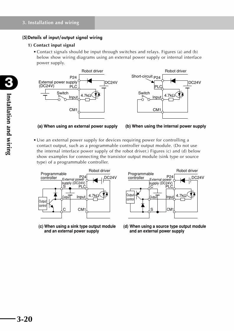
1) Contact input signal
•Contactsignalsshouldbeinputthroughswitchesandrelays.Figures(a)and(b) below show wiring diagrams using an external power supply or internal interface power supply.
P24
PLC
4.7kΩ
DC24V
CM1
P24
PLC
4.7kΩ
DC24V
CM1
InputSwitch
Robot driver Robot driver
InputSwitch
External power supply(DC24V)
Short-circuit
(a) When using an external power supply (b) When using the internal power supply
•Useanexternalpowersupplyfordevicesrequiringpowerforcontrollinga contact output, such as a programmable controller output module. (Do not use theinternalinterfacepowersupplyoftherobotdriver.)Figures(c)and(d)below show examples for connecting the transistor output module (sink type or source type) of a programmable controller.
P24
PLC
4.7kΩ
DC24V
CM1
S
C
P24
PLC
4.7kΩ
DC24V
CM1
C
S
(c) When using a sink type output module and an external power supply
(d) When using a source type output module and an external power supply
Robot driver Robot driver
Input
External power supply (DC24V)
External power supply (DC24V)
OutputOutput control
Programmable controller
Output
Programmable controller
Output control
Input
3-20 3-21
3
Installation and wiring
3. Installation and wiring
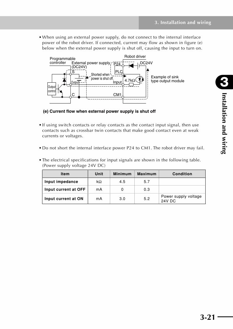
•Whenusinganexternalpowersupply,donotconnecttotheinternalinterface poweroftherobotdriver.Ifconnected,currentmayflowasshowninfigure(e) below when the external power supply is shut off, causing the input to turn on.
P24
PLC
4.7kΩ
DC24V
CM1
S
C
Input
(e) Current flow when external power supply is shut off
Output
Shorted when power is shut off. Example of sink
type output module
Robot driverProgrammable controller External power supply
(DC24V)
Output control
•Ifusingswitchcontactsorrelaycontactsasthecontactinputsignal,thenuse contacts such as crossbar twin contacts that make good contact even at weak currents or voltages.
•DonotshorttheinternalinterfacepowerP24toCM1.Therobotdrivermayfail.
•Theelectricalspecificationsforinputsignalsareshowninthefollowingtable. (Powersupplyvoltage24VDC)
Item Unit Minimum Maximum Condition
Input impedance kW 4.5 5.7
Input current at OFF mA 0 0.3
Input current at ON mA 3.0 5.2Power supply voltage 24V DC

Installation and wiring
3
3-22
3. Installation and wiring
3-23
2) Open collector output signal
•Connectarelaycoilortheinputmoduleofaprogrammablecontrollerasshown inFigures(a)and(b)below.Whenusingarelay,connectadiodeasasurge absorberinparallelwiththecoil.ConnectthatdiodeasshowninFigure(a)so that the current flow direction of the diode is opposite the direction that voltage is applied to the coil.
C
(a) Relay coil connection (b) Programmable controller connection
(Emitter)
Output Input
Relay coil
Surge-absorbing diode
Output(Collector)
(Emitter)
Robot driverRobot driver
External power supply
(DC24V)
External power supply
(DC24V)
Programmable controller
•Prepareanexternalpowersupplyforoutputsignals.Donotusetheinternal interfacepowersupply(P24-CM1)oftherobotdriver.Therobotdrivermayfail.
•Electricalspecificationsforcontactoutputsignalsareshowninthefollowing table.
Item Unit Minimum Maximum Condition
Output power supply voltage
V – 30
Output current at ON mA – 50
Leakage current at output OFF
mA – 0.1
Output saturation voltage at ON
V 0.5 1.5 Output current 50mA
3-22 3-23
3
Installation and wiring
3. Installation and wiring
3) Monitor output signal
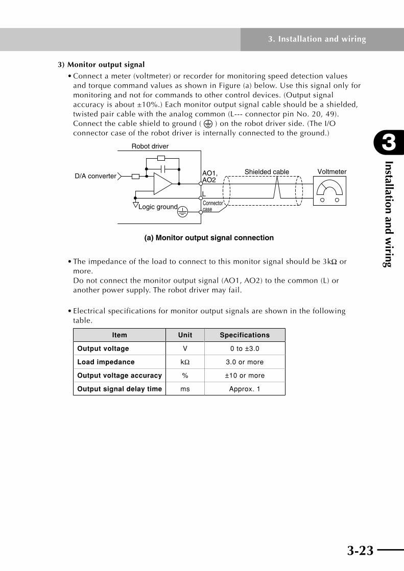
•Connectameter(voltmeter)orrecorderformonitoringspeeddetectionvalues andtorquecommandvaluesasshowninFigure(a)below.Usethissignalonlyfor monitoring and not for commands to other control devices. (Output signal accuracyisabout±10%.)Eachmonitoroutputsignalcableshouldbeashielded, twistedpaircablewiththeanalogcommon(L---connectorpinNo.20,49). Connectthecableshieldtoground( )ontherobotdriverside.(TheI/O connector case of the robot driver is internally connected to the ground.)
AO1,AO2
L
(a) Monitor output signal connection
D/A converterShielded cable
Logic ground
Voltmeter
Connector case
Robot driver
•Theimpedanceoftheloadtoconnecttothismonitorsignalshouldbe3kW or more. Donotconnectthemonitoroutputsignal(AO1,AO2)tothecommon(L)or another power supply. The robot driver may fail.
•Electricalspecificationsformonitoroutputsignalsareshowninthefollowing table.
Item Unit Specifications
Output voltage V 0 to ±3.0
Load impedance kW 3.0 or more
Output voltage accuracy % ±10 or more
Output signal delay time ms Approx. 1

Installation and wiring
3
3-24
3. Installation and wiring
3-25
4) Position command signal
•Connectthepulsetrainsignalforpositioncommand.Asshowninthefigure below, the line receiver receives a pulse train signal output from the line driver (AM26LS31orequivalent)ofthemastercontroller. Eachpositioncommandsignalcableshouldbeashielded,twistedpaircable. Connectthecableshieldtoground( )ontherobotdriverside.(TheI/O connector case of the robot driver is internally connected to the ground.)
150ΩPLSP,SIGP PLSN,SIGN
Line driver(AM26LS31) Shielded cable
Connectorcase
Robot driver
•Electricalspecificationsandtimingchartforpositionpulsesignalsareshownin the following table.
Electrical specifications for position command pulses
Item Unit Specifications Condition
Input current of logic 1 mA 8 to 15
Maximum input pulse rate
(Frequency)
• FWD/REV pulse input
• Command pulse + sign input
pulses/s 2MLine driver signal
• Phase difference 90° pulse input
pulses/s 500kLine driver signal

3-24 3-25
3
Installation and wiring
3. Installation and wiring
Position command pulse timing chart
Pulse train signal form Pulse train input timing
(1) Pulse train command
When FA-11 = P-S (Movement direction is reversed if FA-11 = -P-S.) See note below.
t1 t2
T
t0 tS4tS2
t4tS3t3
tS1
"1"
"0"
"1"
"0"
FWD signal LogicREV signal
PLS signal
SIG signal
(2) FWD/REV pulse When FA-11 = F-r (Movement direction is reversed if FA-11 = r-F.) See note below.
t1 t2
T
t0
tS0
"1"
"0"
"1"
"0"
FWD signal REV signal
PLS signal
SIG signal
(3) Phase difference 2-phase pulse
* In the case of phase difference 2-phase pulse, the count is multiplied by 4.
When FA-11 = A-b (Movement direction is reversed if FA-11 = b-A.) See note below.
t1 t2
T
t0
t6t5
"1"
"0"
"1"
"0"
FWD signal REV signal
PLS signal(Phase A)
SIG signal(Phase B)
Note:Whenatlogic1,thepulsetraininputcurrentdirectionisPLSP→PLSN,SIGP→SIGN.
Position command pulse timing values
Pulse train signal form (See above)
Line driver signal
(1), (2) above (3) above
Timing values
Rise time : t1, t3 0.1μs or less 0.1μs or less
Fall time : t2, t4 0.1μs or less 0.1μs or less
Switching time : tS0, tS1, tS2, tS3, tS4 3μs or more –
Phase difference : t5, t6 –
Pulse width : (t0/T)×100 50±10% 50±10%
Maximum pulse rate (frequency) 2M (pulses/s) 500k (pulses/s)
Installation and wiring
3
3-26
3. Installation and wiring
3-27
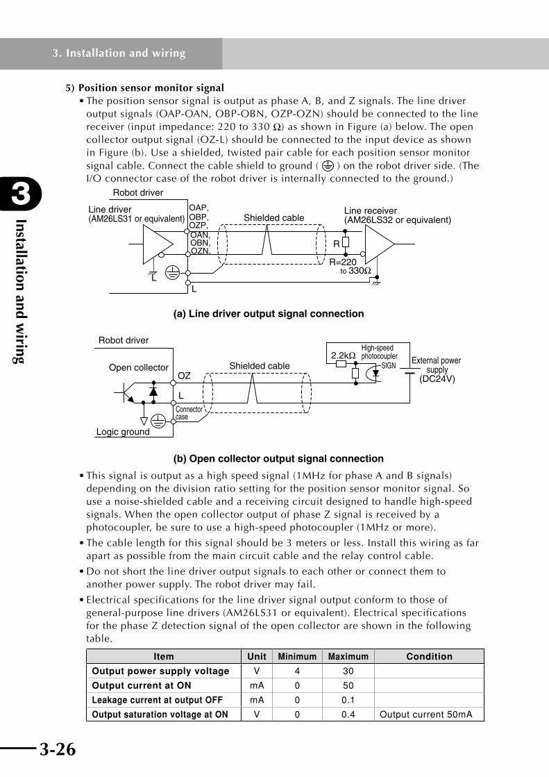
5) Position sensor monitor signal •ThepositionsensorsignalisoutputasphaseA,B,andZsignals.Thelinedriver
outputsignals(OAP-OAN,OBP-OBN,OZP-OZN)shouldbeconnectedtotheline receiver (input impedance: 220 to 330 W)asshowninFigure(a)below.Theopen collectoroutputsignal(OZ-L)shouldbeconnectedtotheinputdeviceasshown inFigure(b).Useashielded,twistedpaircableforeachpositionsensormonitor signalcable.Connectthecableshieldtoground( ) on the robot driver side. (The I/Oconnectorcaseoftherobotdriverisinternallyconnectedtotheground.)
2.2kΩ
OAP,OBP,OZP,OAN,OBN,OZN,
OZ
L
R
R=220to 330Ω
LL
Open collector
High-speed photocoupler
SIGN
Logic ground
(b) Open collector output signal connection
External power supply
(DC24V)
Robot driver
Shielded cable
Connector case
(a) Line driver output signal connection
Robot driver
Shielded cableLine driver(AM26LS31 or equivalent)
Line receiver(AM26LS32 or equivalent)
•Thissignalisoutputasahighspeedsignal(1MHzforphaseAandBsignals) depending on the division ratio setting for the position sensor monitor signal. So use a noise-shielded cable and a receiving circuit designed to handle high-speed signals.WhentheopencollectoroutputofphaseZsignalisreceivedbya photocoupler, be sure to use a high-speed photocoupler (1MHz or more).
•Thecablelengthforthissignalshouldbe3metersorless.Installthiswiringasfar apart as possible from the main circuit cable and the relay control cable.
•Donotshortthelinedriveroutputsignalstoeachotherorconnectthemto another power supply. The robot driver may fail.
•Electricalspecificationsforthelinedriversignaloutputconformtothoseof general-purposelinedrivers(AM26LS31orequivalent).Electricalspecifications forthephaseZdetectionsignaloftheopencollectorareshowninthefollowing table.
Item Unit Minimum Maximum Condition
Output power supply voltage V 4 30
Output current at ON mA 0 50
Leakage current at output OFF mA 0 0.1
Output saturation voltage at ON V 0 0.4 Output current 50mA

3-26 3-27
3
Installation and wiring
3. Installation and wiring
3.2.5 Wiring for position sensor signals
(1) Position sensor signal connector
Connector compatible with lead-free solder
Type No. Manufacturer
54599-1015 Molex
•Descriptionofterminalcode
RDP ENC connector terminal symbol
Pin No.Terminal symbol
Signal name Pin No.Terminal symbol
Signal name
1 EP Position sensor power supply 5V
2 EG Position sensor power supply Common 0V3 EP 4 EG
5 SIN+ Sine output (+) 6 SIN– Sine output (–)
7 COS+ Cosine output (+) 8 COS– Cosine output (–)
9 Z+ Phase Z (+) output 10 Z– Phase Z (–) output
RDX ENC connector terminal symbol
Pin No.Terminal symbol
Signal name Pin No. Terminal symbol
Signal name
1 R1 Position sensor excitation input terminal
2 R2 Position sensor excitation input terminal3 R1 4 R2
5 S2S2-S4 coil output terminal
6 S4S2-S4 coil output terminal
7 S1S1-S3 coil output terminal
8 S3S1-S3 coil output terminal
9 – – 10 – –
2 4 6 8 10
EG(R2) EG(R2) SIN-(S4) COS-(S3) Z–
1 3 5 7 9
EP(R1) EP(R1) SIN+(S2) COS+(S1) Z+
Numbers in parentheses indicate position sensors used with the RDX.

3-28
MEMO

Chapter 4 OperationThis chapter explains typical product operation and shows simple trial runs.
Contents
4.1 Control and operation 4-14.1.1 Position control by pulse train input 4-2
4.2 Test Run 4-34.2.1 Jog from the digital operator 4-3
4.2.2 Making a test run using "TOP"
software for RD series 4-4
4.3 Emergency stop 4-6

4-1

4-1
4
Operation
4. Operation
4.1 Control and operation
cCAuTION 1. To prevent unstable or erratic operation never make drastic adjustments to the unit. Doing so may cause injury. 2. Install a safety circuit that actuates an electromagnetic contactor to cut off the main circuit power supply in case of an alarm. 3. If an alarm has occurred, eliminate the cause of the alarm and ensure safety. Then reset the alarm and restart the operation. Failure to do so may cause injury. 4. If a momentary power outage occurs and power is restored, the unit might suddenly restart so do not approach the machine at that time. (Design the machine so that personal safety is ensured even if it suddenly restarts.) Failure to do so may cause injury. 5. Make sure that the AC power specifications match the product power specifications. using the wrong power specifications may cause injury. 6. While power is being supplied, do not touch any parts inside the robot driver or its terminals. Also, do not check the signals or attach/detach the cables. Doing so may cause electrical shock or injury. 7. While power is being supplied, do not touch any terminals on the robot driver even if the robot is stopped. Doing so may cause electrical shock or fire. 8. This product does not incorporate any power failure detection function. When necessary, install an external power failure detection circuit and configure an appropriate circuit that stops the operation safely when a power failure is detected. (Refer to 4.3, "Emergency stop", in this chapter.)
MANDATORy INSTAll AN ExTERNAl EMERGENCy STOP CIRCuIT SO ThAT yOu CAN IMMEDIATEly STOP OPERATION AND ShuT OFF POWER WhENEvER NEEDED.

Operation
4
4-2
4. Operation
4-3
4.1.1 Position control by pulse train inputThis method controls the position with external pulse train signals.
1) Make connections as shown below and check that they are correct.
2) TurnontheELB(earthleakagebreaker)andthenturnonthecontrolpowertotherobot driver. The digital operator comes on and "d-00" is displayed. (This is the factory default setting.)
3) Setthe"Pulsetraininputmode"(FA-11)parameter.
4) Setthe"Electronicgearnumerator/denominator"(FA-12,FA-13)parameters. (Thesearesetbydefaultsothat1pulseisequaltoa1μmpositioncommand.)
5) Checkthatthe"Controlmode"(FA-00)parameterissetto"Positioncontrol"(P-S).
6) TurnontheFOTandROTterminals.
7) TurnontheelectromagneticcontactorMCandthenturnonthemaincircuitpowersupply.
8) Turn on the SON terminal. (On the RDP, magnetic pole position is found right after power is first turned on.)
9) TurnonthePENterminalandinputthepositionpulsecommand.(Therobotwillmove to the commanded position.) Tostoptherobot,turnoffthePENterminalaftercompletingpositioning.Checkthat the robot has stopped and then turn off the SON terminal.
ELBL1L2L3
L1CL2C
UVW
ENC
P24
ROTPEN
SON
FOT
CERCM1PLSPPLSN
SIGPSIGN
PLC
RS
200 to 230V
MCDigital operator
Down transformer
Robot driverRobot
Ground (100 ohms or less)
Position pulse command
200 to 230 V AC3-phase
The above diagram shows a sink type output module using a power supply for internal input.

4-2 4-3
4
Operation
4. Operation
4.2 Test RunThis section explains how to make a test run.
4.2.1 Jog from the digital operatorJogcanbeperformedfromthedigitaloperatorjustbywiringtherobotdrivertotherobotand power supply. This test run method allows checking the wiring between the robot driver, robot and power supply.
(1) Jog operation
Perform the following steps with the SON terminal turned off.
× 3 times
SET
SET
FUNC
FUNCFUNC
FUNC
Blinking
or
Blinking
Blinking
Blinking
Run
: Saves the setting.
: Does not save the setting.
1) Operate the and keys to show the "Jogging speed" (Fb-03) parameter setting.
2) Set the operation speed by using the , and keys. (The example on the left shows the operating procedure for changing only the run direction.)
To reverse the run direction, set the speed with a negative sign. Enter the sign in the second digit column from the left on the LED display.
3) To perform jog operation, select the most significant digit with the key.
4) Press the key while in the above state.
Jog operation now starts to move the robot, so use caution.
5) Press any of the following keys to stop the operation. key: Continues displaying the
setting. key: Saves the speed setting. key: Returns to the menu
display without saving the speed setting.
Note: When a PHASER series robot is used, magnetic pole position estimation must be performed before this operation. For information on magnetic pole position estimation,refer to section 5.17, "Magnetic pole position estimation action".

Operation
4
4-4
4. Operation
4-5
4.2.2 Making a test run using "TOP" software for RD seriesJogcanberunfromaPC.Duringthisjogoperation,wiringcheckscanbemadefortherobotdriver,robotandpowersupplybecausenooutsideconnectionstotheI/Oconnectorareneeded.Fordetails,refertotheTOP(softwareforRDseries)user'smanual.
Therearetwotypesofjogoperation:(1)normaljogperformedataspecifiedspeedand(2)pulsefeedjogthatmovesadistanceequaltoaspecifiednumberofpulses. Eachoftheseisexplainedbelow.
Note 1: Do not input any signals through the I/O connector including the SON terminal during this operation. Doing so runs the operation according to the input terminal.
Note 2: In this jog operation, the robot moves at an acceleration/deceleration time of 0 seconds and the current settings for control gain and speed limit parameters.
Note 3: This jog operation cannot be used simultaneously with the TOP monitor display.
Note 4: When a PHASER series robot is used, magnetic pole position estimation must be performed before this operation. For information on magnetic pole position estimation,refer to section 5.17, "Magnetic pole position estimation action".
(1) Operation in normal jog
Innormaljog,therobotmovesataconstantspeedspecifiedbythespeedcommanduntil a stop command is input. AfterstartingtheTOP(softwareforRDseries),runthejogoperationasexplainedbelow.
1) After connecting the TOP to the robot driver, click the [Test Run and Adjustment] button on the opening screen. (Click the [Jogging] tab.)
2) Enter the speed command for jog operation.
3) Check safety and then click the button that indicates the direction to move the robot. (The robot will start moving in the specified direction.)
4) Click the [Stop] button to stop operation.
Note: The robot moves during this operation, so check safety before starting operation.

4-4 4-5
4
Operation
4. Operation
(2) Pulse feed jog operation
Inthisjogoperation,therobotmovesinpositioncontrolmodeuptothepositionspecified by the position command. AfterstartingtheTOPsoftwareforRDseries,runjogoperationasexplainedbelow.Refer to the TOP software user's manual for details.
1) Click the [Test Run and Adjustment] button on the opening screen. (Click the [Jogging] tab.)
2) Enter the number of feed pulses.
3) Check safety and then click the [Forward] or [Reverse] button. (The robot will start moving in the specified direction and stop at the position specified by the command.)
4) After positioning is complete, the display returns to the initial screen. The servo is still ON at this point so click the [Stop] button.
Note: The robot moves during this operation, so check safety before starting operation. To stop positioning, click [Stop] button.

Operation
4
4-6
4. Operation
4.3 Emergency stopTo safely stop the robot in case of an emergency, configure an emergency stop circuit while referring to the explanations below.Fordetailsoninputterminalfunctionsandparameters,referto5.2,"Inputterminalfunctions" and 6.3.2, "Setup parameter description".
(1) Servo OFF
WhentheSONsignalisturnedoff,theservoisOFFandthebrakingisappliedbythedynamic brake.
• TheDBOperationselection(FA-16)mustbesetto"SoF".Thebrakingisnotappliedbythedynamicbrakeunlessthisselectionissetto"SoF".
• WhentheServoOFFwaittime(FA-24)isset,theservoisOFFandthebrakingisapplied by the dynamic brake after the SON signal has been turned off and the servoOFFwaittimehaselapsed.
(2) How to shorten the braking distance
Shortenthebreakingdistancebyproducingthedecelerationtorquethroughtheservocontrol.
Example) Decelerationtorqueisproducedbyclampingthespeedcommandatzero.
• TheservoOFFwaittimeisset,andtheSONsignalandFOT/ROTsignalare turned off at the same time in case of an emergency.
• ThespeedcommandisclampedatzerobytheFOT/ROTsignalOFFwhiletheservoOFFisdelayed.Atthistime,thedecelerationtorqueisproduced to shorten the braking distance.
FOT
ROT
Current speed
Speed command
Servo
Main power
SON
0
V
0
VFA-24
Note 1: If the heavy braking is applied as described in the example shown above when the payload of the robot is large or offset, the deceleration torque becomes too large, causing the robot to break. In this case, it is recommended that the FOT/ROT signal is not turned off and the position command is changed so that the speed command changes gradually.
Note 2: When the servo is OFF if a trip occurs, the power to the motor is shut down immediately even when the Servo OFF wait time has been set.

Chapter 5 FunctionsThischapterexplainstheinput/outputsignalfunctionsofthisproductanditsmajorcontrolfunctions.
Contents
5.1 Terminal function list 5-1
5.2 Input terminal functions 5-3
5.3 Output terminal functions 5-7
5.4 Return-to-origin function 5-10
5.5 Analog output function 5-21
5.6 Pulse train input function 5-22
5.7 Smoothing function 5-25
5.8 Position sensor monitor function 5-26
5.9 Adjusting the control gain 5-275.9.1 Basic rules of gain adjustment 5-27
5.9.2 Setting the mechanical rigidity and response 5-28
5.9.3 Adjusting the position control loop 5-29
5.10 Offline auto-tuning function 5-305.10.1 Offline auto-tuning method 5-30
5.10.2 Offline auto-tuning using the TOP software 5-33
5.11 Gain change function 5-355.11.1 Changing the control gain 5-35
5.12 Clearing the alarm log and setting the default values 5-38
5.13 Motor rotating direction 5-405.13.1 FLIP-X series phase sequence 5-40
5.13.2 PHASER series phase sequence 5-40
5.14 Speed limit function 5-41
5.15 Fast positioning function 5-42
5.16 Notch filter function 5-44
5.17 Magnetic pole position estimation action 5-45
5.18 Magnetic pole position estimation
and parameters 5-46

5-1
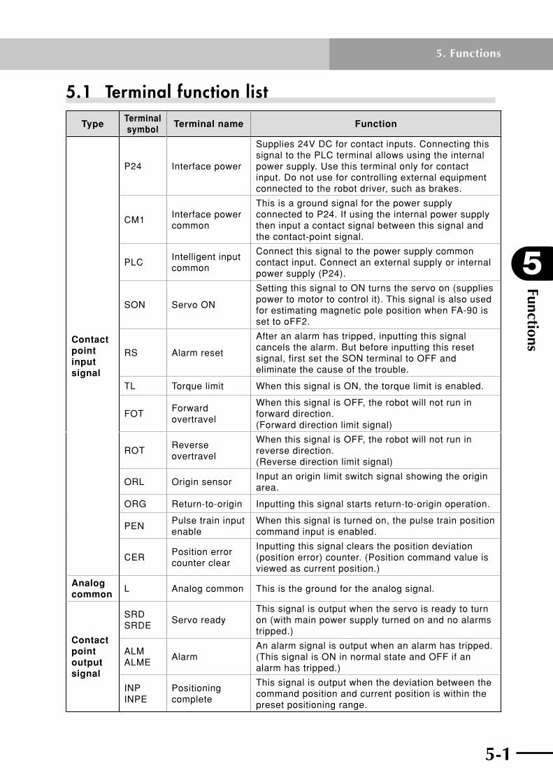
5-1
5
Functions
5. Functions
5.1 Terminal function list
TypeTerminal symbol
Terminal name Function
Contact point input signal
P24 Interface power
Supplies 24V DC for contact inputs. Connecting this signal to the PLC terminal allows using the internal power supply. Use this terminal only for contact input. Do not use for controlling external equipment connected to the robot driver, such as brakes.
CM1Interface power common
This is a ground signal for the power supply connected to P24. If using the internal power supply then input a contact signal between this signal and the contact-point signal.
PLCIntelligent input common
Connect this signal to the power supply common contact input. Connect an external supply or internal power supply (P24).
SON Servo ON
Setting this signal to ON turns the servo on (supplies power to motor to control it). This signal is also used for estimating magnetic pole position when FA-90 is set to oFF2.
RS Alarm reset
After an alarm has tripped, inputting this signal cancels the alarm. But before inputting this reset signal, first set the SON terminal to OFF and eliminate the cause of the trouble.
TL Torque limit When this signal is ON, the torque limit is enabled.
FOTForward overtravel
When this signal is OFF, the robot will not run in forward direction. (Forward direction limit signal)
ROTReverse overtravel
When this signal is OFF, the robot will not run in reverse direction. (Reverse direction limit signal)
ORL Origin sensorInput an origin limit switch signal showing the origin area.
ORG Return-to-origin Inputting this signal starts return-to-origin operation.
PENPulse train input enable
When this signal is turned on, the pulse train position command input is enabled.
CERPosition error counter clear
Inputting this signal clears the position deviation (position error) counter. (Position command value is viewed as current position.)
Analog common
L Analog common This is the ground for the analog signal.
Contact point output signal
SRD SRDE
Servo readyThis signal is output when the servo is ready to turn on (with main power supply turned on and no alarms tripped.)
ALM ALME
AlarmAn alarm signal is output when an alarm has tripped. (This signal is ON in normal state and OFF if an alarm has tripped.)
INP INPE
Positioning complete
This signal is output when the deviation between the command position and current position is within the preset positioning range.

Functions
5
5-2
5. Functions
5-3
TypeTerminal symbol
Terminal name Function
Relay output
BK (B24)
Brake release relay output
When the servo is ON, this terminal outputs a signal to allow releasing the brake. (FLIP-X series only)
Monitor output
AO1 Monitor output 1Outputs speed detection values, torque commands, etc. as analog signal voltages for monitoring. Signals to output are selected by setting parameters. These signals are only for monitoring. Do not use for control.
AO2 Monitor output 2
LMonitor output common
This is the ground for the monitor signal.
Position command
PLSP Position command pulse (pulse signal)
Select one of the following signal forms as the pulse-train position command input. (1) Command pulse + direction signal (2) Forward direction pulse train + reverse direction pulse train (3) Phase difference 2-phase pulse
PLSN
SIGP Position command pulse (sign signal)SIGN
Position sensor monitor
OAP Position sensor "phase A" signal
Outputs monitor signal obtained by dividing "phase A" signal of position sensor.OAN
OBP Position sensor "phase B" signal
Outputs monitor signal obtained by dividing "phase B" signal of position sensor.OBN
OZP Position sensor "phase Z" signal
Outputs monitor signal for position sensor "phase Z" signal.OZN
OZ"Phase Z" detection
Outputs monitor signal for position sensor "phase Z" signal.
L"Phase Z" detection common
Brake power input
B24Brake power input
Input 24V DC brake power to this terminal.
B0Brake power common
Common terminal input for brake power.

5-2 5-3
5
Functions
5. Functions
5.2 Input terminal functionsFunctionsoftherobotdriverinputterminalsaredescribedbelow.Fordetailsoninput/outputterminaltimingchartfromthepower-ontothepositioncommandinput,referto10.1,“Timingchart”,inChapter10.
SON terminalSetting this signal to ON turns the servo on (supplies power to the servo). The timing chart is shown below. This signal is also used by the magnetic pole position estimation operation of the RDP. See 5.17, "Magnetic pole position estimation action" for more details.
FA-16 : DB Operation selectionFC-01 : Input terminal polarity setting
Related parameters
• Receivesaservo-ONsignalandenterstheservo-ONstate(whenSRDisON)onlywhen the main circuit power supply is connected and no alarm has tripped. Unless all these conditions are met, no power is supplied even when this signal is ON. However, magnetic pole position estimation can be performed even if SRD is not ON.
• Whenthe"DBoperationselection"(FA-16)parameterissetto"SoF"(duringservoOFF),thedynamicbrakeengagesbyturningtheservooff.
• Periodfrominputofaservo-ONsignaluntiltheoperationisreadytostartis20ms.
• Bychangingthe"Inputterminalpolarity"(FC-01)setting,theservocanalsobeturned on when this input terminal is opened.
• WhentheSONsignalisswitchedfromOFFtoON,thepositioncommandissettothe current position and the deviation (position error) counter is cleared.
SRD
FOT/ROT
SON
RDX operation Power-off Servo-off Normal servo-on
10 [ms] or more1000 [ms] or more
Power
RDX
10 [ms] or more1000 [ms] or more
SRD
FOT/ROT
SON
RDP operation
Power
Power-off Servo-off Magnetic pole position estimation Normal servo-on
RDP

Functions
5
5-4
5. Functions
5-5
RS terminalWhen an alarm has tripped, setting the SON signaltoOFFandthisRSsignaltoONclearsthe tripped alarm state, and operation can resume.
FC-01 : Input terminal polarity setting
Related parameters
• Ifnoalarmhastripped,thissignalisignoredevenifsettoON.
• WhenanalarmhastrippedandthenthissignalisswitchedfromOFFtoON,thealarm trip state is canceled if the ON state lasts more than 20ms.
• EvenifthissignalremainsattheONstate,resetoperationisperformedonlyonce.
• Bychangingthe"Inputterminalpolarity"(FC-01)setting,alarmscanalsoberesetwhen this input terminal is opened.
• TheRSterminalmightnotalwaysbeabletocancelatrippedstate,duetotheproblem that triggered the alarm. See "9.3 Troubleshooting".
TL terminalSettingthisterminaltoONenablestorquelimit.UsetheparametersFb-07throughFb-10todeterminethetorquelimitvalues.
FA-00 : Control mode
FA-17 : Torque limit mode
Fb-07 to 10 : Torque limit value 1 to 4
FC-01 : Input terminal polarity setting
Related parameters
• Bychangingthe"Inputterminalpolarity"(FC-01)setting,torquelimitcanalsobeenabled when this input terminal is opened.
• TheparametersFb-07throughFb-10limitthetorqueineachquadrantasshowninthefigurebelow.(However,usetheabsolutevalueasthetorquelimitvaluewhenentering the parameters.)
Fb-08
Fb-09
Fb-07
Fb-10
Torque
Speed
Secondquadrant First
quadrant
Thirdquadrant Fourth
quadrant

5-4 5-5
5
Functions
5. Functions
FOT/ROT terminalsThese terminals connect to operating range limit switches in order to prevent overtravel. FC-01 : Input terminal polarity setting
Related parameters
• Whenthissignalisturnedon,driveisallowed.
• Topreventovertravel,theinternalspeedcommandlimitvalueinthatdirectionisset to 0.
• Bychangingthe"Inputterminalpolarity"(FC-01)setting,driveisalsoallowedwhen this input terminal is opened.
• Anovertravelerror(E25)occursiftheservoisONformorethan1secondaftertheFOTandROTwerebothsettoOFF.
• TheFOTandROTterminalfunctiondoesnotchangeeveniftheFA-14(Motorrevolutiondirection)settingischanged.TheFOTalwaysprohibitsdriveintheCCWdirectionandtheROTprohibitsdriveintheCWdirection.
• WhenoperatingtherobotwiththeRDP,themagneticpolepositionestimationshouldbeperformedwiththeFOTandROTsettoON.
• Amagneticpolepositionestimationerror(E95)occursifeitheroftheFOTorROTissettoOFFwhilethemagneticpolepositionisbeingestimated.
PEN terminalThe position command pulse input is valid (enabled) only when this signal is ON. FC-01 : Input terminal polarity setting
Related parameters
• Thepositioncommandvaluecanberefreshedbypulsetraininputwhilethissignalis ON.
• The"Inputterminalpolarity"(FC-01)settingallowspositionpulsetraininputtobeenabled when this input terminal is opened.
CER terminalThis signal clears the deviation (position error) counter to "0" by setting the position command value as the current position during position control.
FC-01 : Input terminal polarity setting
Related parameters
• Thissignalisonlyvalidduringpositioncontrol.ThepositioncommandvalueissettothecurrentpositionvalueattheinstantthissignalisswitchedfromOFFtoON.Since this signal turns on at the pulse edge, the counter clearing does not continue evenifthissignaliskeptON.Toclearthecounteragain,setthissignaltoOFFandthen back ON again.
• Bychangingthe"Inputterminalpolarity"(FC-01)setting,thedeviationcountercanalso be cleared when this input terminal is opened.
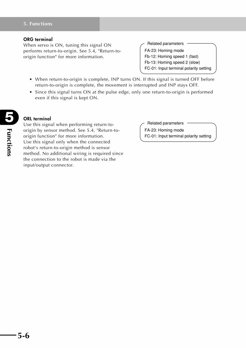
Functions
5
5-6
5. Functions
5-7
ORG terminalWhen servo is ON, tuning this signal ON performs return-to-origin. See 5.4, "Return-to-origin function" for more information.
Related parameters
FA-23: Homing modeFb-12: Homing speed 1 (fast)Fb-13: Homing speed 2 (slow)FC-01: Input terminal polarity setting
• Whenreturn-to-originiscomplete,INPturnsON.IfthissignalisturnedOFFbeforereturn-to-originiscomplete,themovementisinterruptedandINPstaysOFF.
• SincethissignalturnsONatthepulseedge,onlyonereturn-to-originisperformedeven if this signal is kept ON.
ORL terminalUse this signal when performing return-to-origin by sensor method. See 5.4, "Return-to-origin function" for more information. Use this signal only when the connected robot's return-to-origin method is sensor method.Noadditionalwiringisrequiredsincethe connection to the robot is made via the input/output connector.
Related parameters
FA-23: Homing modeFC-01: Input terminal polarity setting

5-6 5-7
5
Functions
5. Functions
5.3 Output terminal functionsRobot driver output terminal functions are described next.Fordetailsoninput/outputterminaltimingchartfromthepower-ontothepositioncommandinput,referto10.1,“Timingchart”,inChapter10.
SRD terminalThis signal is output when the main circuit power is connected and no alarm has tripped. Servo-ON signals can be accepted when this signal is ON, but cannot be accepted if this signalisOFF.
FC-02 : Output terminal polarity setting
Related parameters
• On the RDP, this signal is not output unless magnetic pole position estimation ended correctly. See 5.17, "Magnetic pole position estimation action" for more details.
• Bychangingthe"Outputterminalpolarity"(FC-02)setting,thisoutputterminalcanalso be opened when the servo is ready.
ALM terminal
FC-02 : Output terminal polarity settingRelated parametersThis signal indicates that an alarm has tripped,
and can be set to "normally open" or "normally closed" by the "Output terminal polarity setting"(FC-02).(Defaultsettingis"normallyclosed" contact.) The table below shows the relation between each contact specification and alarm output. When this signal indicates an alarm has tripped, then inputting an alarm reset (RS) or turning the power off and then back on cancels that alarm, and this signal returns to its normal state.
Contact specifications Power OFF Normal state Alarm state
Normally closed OFF ON OFF
Normally open OFF OFF ON
INP terminalThis signal indicates that positioning or return-to-origin is complete. Fb-23 : Positioning detection range
FC-02 : Output terminal polarity setting
Related parameters
• ThissignalturnsOFFwhenreturn-to-originsignalisinput,andreturn-to-originthenstarts. After return-to-origin is complete, this signal turns ON when the positioning deviationiswithintherangespecifiedby"Positioningdetectionrange"(Fb-23).
• ThissignalisOFFwhentheservoisOFF.
• Bychangingthe"Outputterminalpolarity"(FC-02)setting,thisoutputterminalcanalso be opened when positioning is completed.
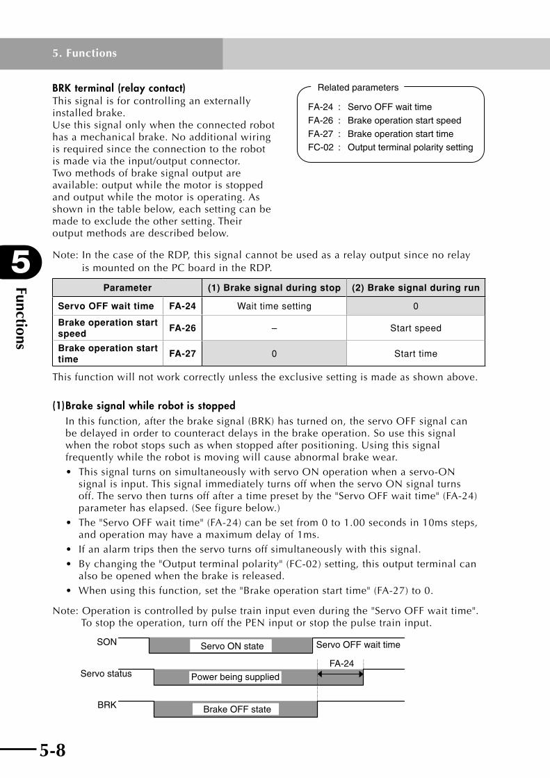
Functions
5
5-8
5. Functions
5-9
BRK terminal (relay contact)This signal is for controlling an externally installed brake. Use this signal only when the connected robot has a mechanical brake. No additional wiring isrequiredsincetheconnectiontotherobotis made via the input/output connector.Two methods of brake signal output are available: output while the motor is stopped and output while the motor is operating. As shown in the table below, each setting can be made to exclude the other setting. Their output methods are described below.
FA-24 : Servo OFF wait time
FA-26 : Brake operation start speed
FA-27 : Brake operation start time
FC-02 : Output terminal polarity setting
Related parameters
Note:InthecaseoftheRDP,thissignalcannotbeusedasarelayoutputsincenorelay is mountedonthePCboardintheRDP.
Parameter (1) Brake signal during stop (2) Brake signal during run
Servo OFF wait time FA-24 Wait time setting 0
Brake operation start speed
FA-26 – Start speed
Brake operation start time
FA-27 0 Start time
This function will not work correctly unless the exclusive setting is made as shown above.
(1) Brake signal while robot is stoppedInthisfunction,afterthebrakesignal(BRK)hasturnedon,theservoOFFsignalcanbe delayed in order to counteract delays in the brake operation. So use this signal when the robot stops such as when stopped after positioning. Using this signal frequentlywhiletherobotismovingwillcauseabnormalbrakewear.• ThissignalturnsonsimultaneouslywithservoONoperationwhenaservo-ON
signal is input. This signal immediately turns off when the servo ON signal turns off.Theservothenturnsoffafteratimepresetbythe"ServoOFFwaittime"(FA-24)parameter has elapsed. (See figure below.)
• The"ServoOFFwaittime"(FA-24)canbesetfrom0to1.00secondsin10mssteps,and operation may have a maximum delay of 1ms.
• Ifanalarmtripsthentheservoturnsoffsimultaneouslywiththissignal.• Bychangingthe"Outputterminalpolarity"(FC-02)setting,thisoutputterminalcan
also be opened when the brake is released.• Whenusingthisfunction,setthe"Brakeoperationstarttime"(FA-27)to0.
Note:Operationiscontrolledbypulsetraininputevenduringthe"ServoOFFwaittime". To stop theoperation,turnoffthePENinputorstopthepulsetraininput.
FA-24
SON
Servo status
BRK Brake OFF state
Power being supplied
Servo ON state Servo OFF wait time

5-8 5-9
5
Functions
5. Functions
(2) Brake signal while robot is operatingThis function is used when applying the brake while the robot is operating so use in applications where the robot can slow sufficiently such as when the robot is free-running. Using this function when moving a heavy payload may cause braking delays, resulting in dropping hazards so use caution.
• ThissignalturnsonsimultaneouslywithservoONoperationwhenaservo-ONsignal is input. Also, when the servo turns off or an alarm trips, the brake is applied whentherobotspeedfallsbelowthe"Brakeoperationstartspeed"(FA-26)orafterthe"Brakeoperationstarttime"(FA-27)haselapsedaftertheservoturnsoff.(Seefigure below.)
• The"Brakeoperationstarttime"(FA-27)canbesetfrom0to1.000secondin4mssteps, and operation may have a maximum delay of 1ms.
• Bychangingthe"Outputterminalpolarity"(FC-02)setting,thisoutputterminalcanalso be opened when the brake is released.
• Whenusingthisfunction,setthe"ServoOFFwaittime"(FA-24)to0.
FA-27
FA-26
*
SON
Servo status
BRK
Robot speed
Power being supplied
Servo ON state
Brake OFF status
*Operation conditionFA-26 > | Speed | or FA-27 time has elapsed.
Brake operation start time
Brake operation start speed
SON=OFF or alarm

Functions
5
5-10
5. Functions
5-11
5.4 Return-to-origin function(1) Return-to-origin using stroke end method (RDX)
The following table shows the RDX return-to-origin operation using the stroke end method.
FA-23 Return-to-origin using stroke end method
t-F(4) 57 6
2
31
(Fb-12)
4096
2048
L
2048
L- [(Fb-35)-1]×4096+2048/4096
Forward run
First Z
Reverse runPosition
(Machine reference=100%)
Phase Z
Stroke end
Homing back distance counter
When "Homing back distance" (Fb-35) = 1
Machine reference (d-18)
t-r2
1
7
65
4
3
Forward run
(Fb-12)
(Fb-12)
(Fb-13)
4096
4096 2048
L[(Fb-35)-1]×4096
2048
L- [(Fb-35)-1]×4096+2048/4096
Stroke end
First Z
Reverse runPosition
Homing back distance counter
When "Homing back distance" (Fb-35) = 2
(Machine reference=100%)Machine reference (d-18)
Phase Z
Op
era
tio
n s
eq
ue
nc
e
1. Start return-to-origin.
2. Robot moves towards stroke end at return-to-origin speed (Fb-12).
3. Reverses movement direction while adjusting speed during acceleration/deceleration time (Fb-04, Fb-05) when the robot has reached the stroke end, which is determined by detecting (in first part of this step) a motor current exceeding the rated current and then the specified "Stroke-end current" (Fb-36). (Note 1)
4. Moves in direction opposite the stroke end at return-to-origin speed (Fb-12). Starts counting the Homing back distance from the stroke end. (If the "Homing back distance" (Fb-35) is set to 1, then step 4 is skipped and goes to step 5.)
5. When the Homing back distance count exceeds "[(Fb-35) – 1] × 4096" pulses, the robot starts slowing down during deceleration time (Fb-05) and moves at slow return-to-origin speed (Fb-13). (Note 1)
6. Continues moving at slow return-to-origin speed (Fb-13).
7. Stops at first "phase Z" position after the Homing back distance count has exceeded "[(Fb-35) – 1] × 4096+2048" pulses. (Machine reference is displayed on d-18, which is calculated as follows: L (distance from stroke end to stop point)–[(Fb-35) – 1]× 4096+2048 / 4096)
Note 1: The acceleration/deceleration time parameters specify the time needed to accelerate or decelerate between 0 and maximum speed.

5-10 5-11
5
Functions
5. Functions
(2) Return-to-origin using sensor method (RDX)The following table shows the RDX return-to-origin operation using the sensor method.
FA-23ORL terminal at start of return-to-origin using sensor method
OFF ON
S-F
(ORL)
2
1
3
45
(Fb-12)
(Fb-13)
A
Sensor4096 pulses (machine reference=100%)
Machine reference (d-18)
(Note 3) PositionReverse run Forward run
First phase ZPhase Z
5
6
A
2
3
4
1
(Fb-12)×0.5
(Fb-12)×0.5
7
(Fb-13)
Sensor(ORL)
First phase Z
Reverse run
Phase Z
PositionForward run
Machine reference (d-18)
(Note 3)
4096 pulses (machine reference=100%)
S-r
1(Fb-13)(Note 3)
32
4
5 A
(Fb-12)×0.5
Sensor(ORL)
First phase ZPhase Z
Forward runPosition
Reverse run
4096 pulses (machine reference=100%)
Machine reference (d-18)
1 A2
76 5
4
3(Fb-12)×0.5
(Fb-12)×0.5
(ORL)Sensor
(Note 3)Reverse run Forward runPosition
4096 pulses (machine reference=100%)
Machine reference (d-18)
Phase ZFirst phase Z
Op
era
tio
n s
eq
ue
nc
e
1. Start return-to-origin.
2. Robot moves towards origin at return-to-origin speed (Fb-12).
3. Slows down during deceleration time (Fb-05) when sensor (ORL terminal) turns on. (Note 5)
4. Continues moving at slow return-to-origin speed (Fb-13).
5. Stops at first "phase Z" position after reaching the slow return-to-origin speed (Fb-13). (Machine reference displayed on d-18.) (Note 3)
1. Start return-to-origin.
2. Robot moves away from origin at 50% of return-to-origin speed (Fb-12).
3. Reverses movement direction when sensor (ORL terminal) turns off. (Deceleration/acceleration time is determined by parameters (Fb-05, Fb-04). (Note 5)
4. Moves back towards origin at 50% of return-to- origin speed (Fb-12). (Note 4)
5. Slows down during deceleration time (Fb-05) when sensor (ORL terminal) turns on. (Note 5)
6. Continues moving at slow return-to-origin speed (Fb-13).
7. Stops at first "phase Z" position after reaching the slow return-to-origin speed (Fb-13). (Machine reference displayed on d-18.) (Note 3)
Note1:Iftheoriginsensor(ORLterminal)doesnotturnoffevenwhentherobothasmovedadistanceof50,000pulsesafterstartingreturn-to-originwiththeoriginsensor(ORLterminal)turnedon(operationinsteps1and2),thenanoriginsensoralarm(E80)occurs.
Note2:Iftheoriginsensor(ORLterminal)doesnotturnonandtherobotcomesintocontactwiththemechanicalend(strokeend),thenanoverloadalarm(E05)occurs.
Note 3: Machine reference is displayed after return-to-origin is completed normally.
Note4:Iftheoriginsensor(ORLterminal)turnsonduringacceleration,thentherobotimmediatelyslowsdownandsetstostep5.(Speedmightnotalwaysreach50%ofreturn-to-originspeed(Fb-12)).
Note 5: Acceleration/deceleration time parameters set the time needed to accelerate or decelerate between 0 and maximum speed.

Functions
5
5-12
5. Functions
5-13
(3) Return-to-origin using stroke end method (RDP)The following table shows the RDP return-to-origin operation using the stroke end method.
FA-23 Return-to-origin using stroke end method
t-F
When phase ZM is between return-to-origin start position and stroke end
4
5
74096
6
[(Fb-35)-1]×4096
2 3
1
8
(Fb-12)
(1.024mm)
9
4096 4096 d
(Fb-12)
(Fb-13)
256(=100H)
256(=100H)
When "Homing back distance" (Fb-35) = 2
1024 pulses
Stroke end
768 (=300H) pulses
Reference phase Z
Machine reference (d-18)=(d+256)/4096Machine reference=100%
Phase ZM
Forward run
Homing back distance counter
(R/D converter)
Phase Z (Dotted line indicates phase ZY.)
Reverse runPosition
768 (=300H) pulses
L sideWhen FA-14 is set to CC
R sideWhen FA-14 is set to CC
When return-to-origin start position is between phase ZM is and stroke end
13
4096
45
7
6
2
3
1
12
10 (11)
9
8
14
4096 d
4096(Fb-13)
(Fb-12)
(Fb-12)
256(=100H)
Stroke end
Reference phase Z
When "Homing back distance" (Fb-35) = 1Phase ZM
1024 pulses(1.024mm)
1024 or more pulses
768 (=300H) pulses
Machine reference (d-18)=(d+256)/4096Machine reference=100%
Forward run
Homing back distance counter
(R/D converter)
Phase Z (Dotted line indicates phase ZY.)
256(=100H)
Reverse runPosition
768 (=300H) pulses
L sideWhen FA-14 is set to CC
R sideWhen FA-14 is set to CC
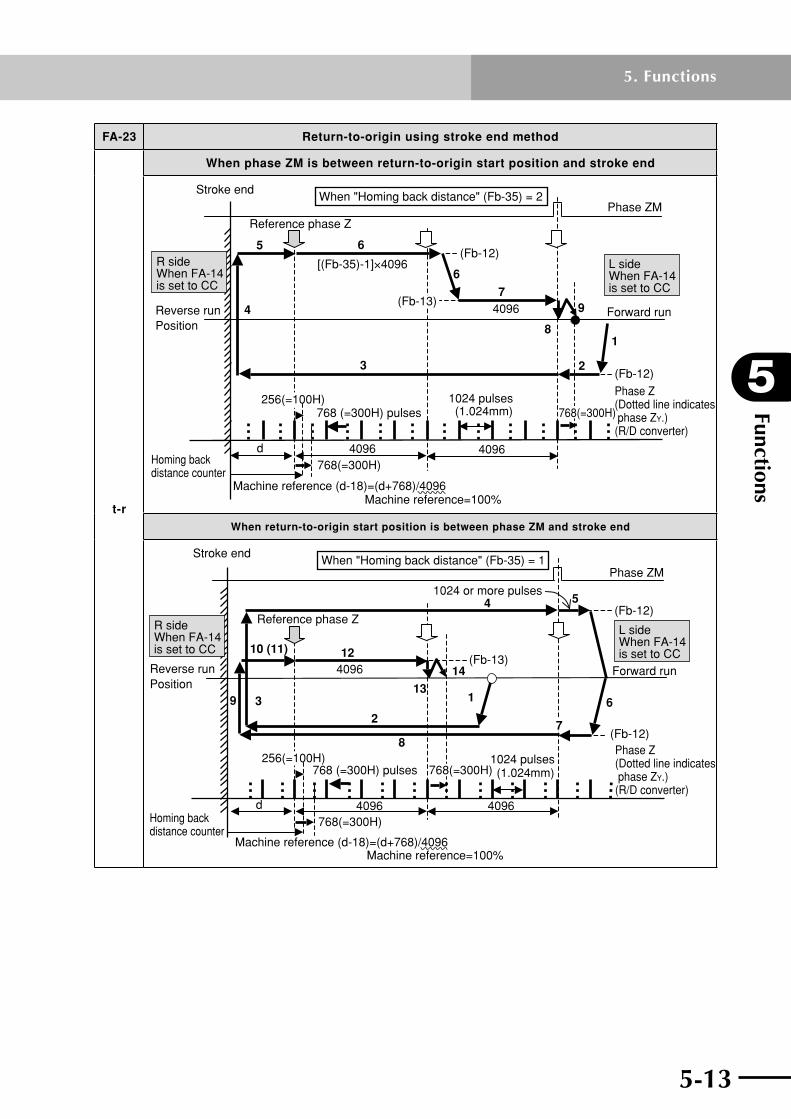
5-12 5-13
5
Functions
5. Functions
FA-23 Return-to-origin using stroke end method
t-r
When phase ZM is between return-to-origin start position and stroke end
4
5
6
23
18
9
d 4096 4096768(=300H)
6
74096
(Fb-12)
(Fb-12)
(Fb-13)
768(=300H)
[(Fb-35)-1]×4096
Stroke endWhen "Homing back distance" (Fb-35) = 2
Forward run
Phase ZM
Phase Z (Dotted line indicates phase ZY.)(R/D converter)
1024 pulses(1.024mm)
Machine reference (d-18)=(d+768)/4096Machine reference=100%
Homing back distance counter
Reverse runPosition
Reference phase Z
768 (=300H) pulses256(=100H)
R sideWhen FA-14 is set to CC
L sideWhen FA-14 is set to CC
When return-to-origin start position is between phase ZM and stroke end
913
4
62
3
8
4096
1
10 (11)
5
14
768(=300H)4096d
124096
(Fb-12)
(Fb-12)
(1.024mm)
(Fb-13)
768(=300H)
7
Forward run
Stroke endWhen "Homing back distance" (Fb-35) = 1
Reference phase Z
Phase ZM
1024 or more pulses
1024 pulses768 (=300H) pulses
Phase Z (Dotted line indicates phase ZY.)(R/D converter)
Machine reference (d-18)=(d+768)/4096Machine reference=100%
Homing back distance counter
Reverse runPosition
256(=100H)
L sideWhen FA-14 is set to CC
R sideWhen FA-14 is set to CC

Functions
5
5-14
5. Functions
5-15
FA-23
Return-to-origin using stroke end method
When phase ZM is between return-to-origin start position and stroke end
When return-to-origin start position is between phase ZM is and stroke end
Op
era
tio
n s
eq
ue
nc
e
1. Start return-to-origin.
2. Robot moves towards stroke end at return-to-origin speed (Fb-12).
3. Continues moving towards the stroke end at return- to-origin speed (Fb-12). Starts counting "Homing back distance" after detecting the sensor signal (phase ZM). Among phase Z at each 4096 count, the phase Z detected at a point closest to the stroke end is regarded as reference phase Z.
4. Reverses movement direction while adjusting speed during acceleration/deceleration time (Fb-04, Fb-05) when robot has reached the stroke end, which is determined by detecting (in first part of this step) a motor current that exceeded the rated current and then the specified stroke-end current.
5. Moves in direction opposite the stroke end at return- to-origin speed (Fb-12).
6. Continues moving in direction opposite the stroke end until reaching the position "[(Fb-35)–1] × 4096]" pulses away from the reference phase Z. (If "Homing back distance" (Fb-35) is set to 1, then step 6 is skipped and goes to step 7.)
7. Moves at slow return-to-origin speed (Fb-13) after adjusting speed during deceleration time (Fb-05). (Note 1)
8. Temporarily stops at a position 4096 pulses away from phase Z at the deceleration point.
9. Further moves a distance equal to the following phase difference between phase ZY and phase Z, and then stops there. When moving to L: 256=100H pulses When moving to R: 768=300H pulses Machine reference is displayed on d-18, which is calculated as follows: When moving to L: (d-18)=(d+768)/4096 When moving to R: (d-18)=(d+256)/4096
1. Start return-to-origin.
2. Robot moves towards stroke end at return-to-origin speed (Fb-12).
3. Reverses movement direction while adjusting speed during acceleration/deceleration time (Fb-04, Fb-05) when robot has reached the stroke end, which is determined by detecting (in first part of this step) a motor current that exceeded the rated current and then the specified stroke-end current (Fb-36). (Note 1)
4. Moves in direction opposite the stroke end at return- to-origin speed (Fb-12).
5. Moves a distance of 1024 pulses after detecting the sensor signal (phase ZM).
6. Reverses movement direction while adjusting speed during deceleration time (Fb-05) after checking that at least 1024 pulses have elapsed. (Note 1)
7. Moves towards the stroke end after changing speed back to the return-to-origin speed (Fb-12) during acceleration time (Fb-04).
8. Continues moving towards the stroke end at return- to-origin speed (Fb-12). Starts counting the "Homing back distance" after detecting the sensor signal (phase ZM). Among phase Z at each 4096 count, the phase Z detected at a point closest to the stroke end is regarded as reference phase Z.
9. Reverses movement direction while adjusting speed during acceleration/deceleration time (Fb-04, Fb-05) when the robot has reached the stroke end, which is determined by detecting (in first part of this step) a motor current that exceeded the rated current, and then the specified stroke-end current.
10. Moves in direction opposite the stroke end at return- to-origin speed (Fb-12).
11. Continues moving in direction opposite the stroke end until reaching the position "[(Fb-35)–1] × 4096]" pulses away from the reference phase Z. (If "Homing back distance" (Fb-35) is set to 1, then step 11 is skipped and goes to step 12.)
12. Moves at slow return-to-origin speed (Fb-13) after adjusting speed during deceleration time (Fb-05). (Note 1)
13. Temporarily stops at a position 4096 pulses away from phase Z at the deceleration point.
14. Further moves a distance equal to the following phase difference between phase ZY and phase Z, and then stops there. When moving to L: 256=100H pulses When moving to R: 768=300H pulses Machine reference is displayed on d-18, which is calculated as follows: When moving to L: (d-18)=(d+768)/4096 When moving to R: (d-18)=(d+256)/4096
Note 1: The acceleration/deceleration time parameters specify the time needed to accelerate or decelerate between 0 and maximum speed.
Note2:TherearetwophaseZtypesasdescribedbelow.Becarefulnottoconfusethem.PhaseZM :PhaseZsignalthatisinputfromthemechanicalsectionviaENC.(Thissensorsignalisoutput
from two points at both ends of the mechanical stroke.)
PHASER series
Phase ZM Phase ZM
One each of phase ZM is present near both ends of robot.
PhaseZ(R/D converter) : PhaseZsignalthatisoutputfromtheresolverorR/Dconverter.(Thisisoutputevery1024pulses.) AlsonotethattheORLterminalisleftunconnectedwhenperformingtheRDPreturn-to-originoperationusingthestrokeendmethod.Note 3: PhaseZYisapositionoffset768(=300H)pulsesfromthephaseZ(R/Dconverter)signal.
MachinereferencecorrespondstothedistancebetweenthestrokeendandphaseZYasshownintheoperationsequencediagram.Note 4: ThemagneticpolepositionisdeterminedwhenphaseZMispassed.
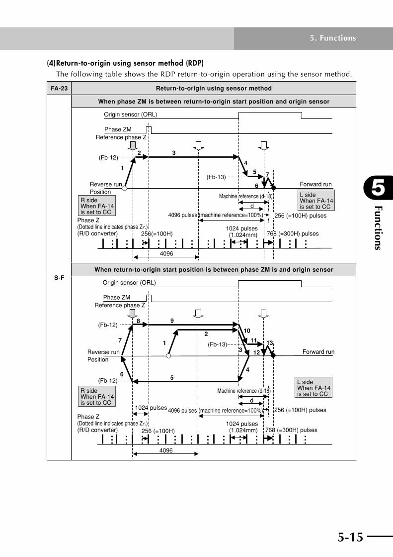
5-14 5-15
5
Functions
5. Functions
(4) Return-to-origin using sensor method (RDP)The following table shows the RDP return-to-origin operation using the sensor method.
FA-23 Return-to-origin using sensor method
S-F
When phase ZM is between return-to-origin start position and origin sensor
4
5
2 3
1
(1.024mm)
4096
6
7
d
(Fb-12)
(Fb-13)
256(=100H)
Forward run
1024 pulses
Origin sensor (ORL)
4096 pulses (machine reference=100%)
Phase ZM
Reverse runPosition
Reference phase Z
768 (=300H) pulses
Phase Z (Dotted line indicates phase ZY.)(R/D converter)
Machine reference (d-18)R sideWhen FA-14 is set to CC
L sideWhen FA-14 is set to CC
256 (=100H) pulses
When return-to-origin start position is between phase ZM is and origin sensor
(1.024mm)
(Fb-13)
(Fb-12)
(Fb-12)
10
11
3
7
4096
12
131
2
456
8 9
d
256 (=100H)1024 pulses
Origin sensor (ORL)
4096 pulses (machine reference=100%)
Phase ZM
Reverse runPosition
Reference phase Z
Forward run
Phase Z (Dotted line indicates phase ZY.)(R/D converter)
1024 pulses
768 (=300H) pulses
Machine reference (d-18)
L sideWhen FA-14 is set to CCR side
When FA-14 is set to CC
256 (=100H) pulses

Functions
5
5-16
5. Functions
5-17
FA-23 Return-to-origin using sensor method
S-F
When origin sensor is ON when starting return-to-origin
12
139
11
4096
14 15
8
10
1
2
3
4 5
67
d
(1.024mm)
Origin sensor (ORL)
(Fb-12)×0.5
(Fb-12)
(Fb-12)
(Fb-13)
256(=100H)
Reverse runPosition
Phase ZMReference phase Z
Phase Z (Dotted line indicates phase ZY.)(R/D converter)
Forward run
1024 pulses
4096 pulses (machine reference=100%)
768 (=300H) pulses
Machine reference (d-18)
1024 pulses
R sideWhen FA-14 is set to CC
L sideWhen FA-14 is set to CC
256 (=100H) pulses
Operating direction (as viewed from cable carrier side of robot)
FA-14
CC C
Forward run Slider moves to L side Slider moves to R side
Reverse run Slider moves to R side Slider moves to L side

5-16 5-17
5
Functions
5. Functions
FA-23 Return-to-origin using sensor method
S-r
When phase ZM is between return-to-origin start position and origin sensor
4
5
231
4096
6
7
d
(1.024mm)
(Fb-12)
(Fb-13)
256(=100H)
Forward run
Origin sensor (ORL)
Phase ZMReference phase Z
Reverse runPosition
1024 pulses4096 pulses (machine reference=100%)
768 (=300H) pulses
Phase Z (Dotted line indicates phase ZY.)(R/D converter)
Machine reference (d-18)
R sideWhen FA-14 is set to CC
L sideWhen FA-14 is set to CC
768 (=300H) pulses
When return-to-origin start position is between phase ZM is and origin sensor
10
112
31
4096
1213
8
4
56
7
9
d
(1.024mm)
(Fb-12)
(Fb-13)
256(=100H)
Forward runReverse runPosition
1024 pulses
Origin sensor (ORL)
4096 pulses (machine reference=100%)
Phase ZMReference phase Z
768 (=300H) pulses
Phase Z (Dotted line indicates phase ZY.)(R/D converter)
Machine reference (d-18)
1024 pulses
L sideWhen FA-14 is set to CC
R sideWhen FA-14 is set to CC
768 (=300H) pulses

Functions
5
5-18
5. Functions
5-19
FA-23 Return-to-origin using sensor method
S-r
When origin sensor is ON when starting return-to-origin
12
13
4096
14
15
10
6 78
911
1
2
3
45
(Fb-12)×0.5
d
(1.024mm)
(Fb-12)
(Fb-13)
256(=100H)
Forward run
1024 pulses
Origin sensor (ORL)
4096 pulses (machine reference=100%)
Phase ZMReference phase Z
768 (=300H) pulses
Machine reference (d-18)
1024 pulses
Reverse runPosition
Phase Z (Dotted line indicates phase ZY.)(R/D converter)
L sideWhen FA-14 is set to CC
R sideWhen FA-14 is set to CC
768 (=300H) pulses
Operating direction (as viewed from cable carrier side of robot)
FA-14
CC C
Forward run Slider moves to L side Slider moves to R side
Reverse run Slider moves to R side Slider moves to L side
5-18 5-19
5
Functions
5. Functions
FA-23 Return-to-origin using sensor method
Op
era
tio
n s
eq
ue
nc
e
When phase ZM is between return-to-origin start position and origin sensor
1. Start return-to-origin.
2. Robot moves at return-to-origin speed (Fb-12).
3. Continues moving at return-to-origin speed (Fb-12). Starts detecting phase Z at each 4096 count after detecting the sensor (phase ZM) signal. At this point, phase Z just before detecting the sensor (phase ZM) signal is regarded as reference phase Z which is the start point to detect phase Z at each 4096 count.
4. Slows down during deceleration time (Fb-05) after detecting that the origin sensor (ORL terminal) has turned on. (Note 2)
5. Moves at slow return-to-origin speed (Fb-13).
6. After detecting the origin sensor signal, the robot temporarily stops at first "phase Z" position detected at each 4096 count.
7. Further moves a distance equal to the phase difference between phase ZY and phase Z, and then stops there. When moving to L: 256=100H pulses When moving to R: 768=300H pulses Machine reference is displayed on d-18, which is calculated as follows: When moving to L: (d-18)=(d+768)/4096 When moving to R: (d-18)=(d+256)/4096
When return-to-origin start position is between phase ZM is and origin sensor
1. Start return-to-origin.
2. Robot moves at return-to-origin speed (Fb-12).
3. Slows down during deceleration time (Fb-05) after detecting that the origin sensor (ORL terminal) has turned on. (Note 2)
4. Reverses movement direction after the motor has stopped, and speeds up during acceleration time (Fb-04).
5. Moves at return-to-origin speed (Fb-12) until 1024 pulses have elapsed after detecting the sensor (phase ZM) signal.
6. Slows down during deceleration time (Fb-05).
7. Reverses movement direction after the motor has stopped, and speeds up during acceleration time (Fb-04).
8. Moves at return-to-origin speed (Fb-12).
9. Continues moving at return-to-origin speed (Fb-12). Starts detecting phase Z at each 4096 count after detecting the sensor (phase ZM) signal. At this point, phase Z just before detecting the sensor (phase ZM) signal is regarded as reference phase Z which is the start point to detect phase Z at each 4096 count.
10. Slows down during deceleration time (Fb-05) after detecting that the origin sensor (ORL terminal) has turned on. (Note 2)
11. Moves at slow return-to-origin speed (Fb-13).
12. After detecting the origin sensor signal, the robot temporarily stops at first "phase Z" position detected at each 4096 count.
13. Further moves a distance equal to the phase difference between phase ZY and phase Z, and then stops there. When moving to L: 256=100H pulses When moving to R: 768=300H pulses Machine reference is displayed on d-18, which is calculated as follows: When moving to L: (d-18)=(d+768)/4096 When moving to R: (d-18)=(d+256)/4096

Functions
5
5-20
5. Functions
FA-23 Return-to-origin using sensor method
Op
era
tio
n s
eq
ue
nc
e
When origin sensor is ON when starting return-to-origin
1. Start return-to-origin.
2. Robot moves at 50% of return-to-origin speed (Fb-12).
3. Slows down during deceleration time (Fb-05) after detecting that the origin sensor (ORL terminal) has turned off. (Note 2)
4. Reverses movement direction after the motor has stopped, and speeds up during acceleration time (Fb-04). Then moves at 50% of return-to-origin speed (Fb-12).
5. Slows down during deceleration time (Fb-05) after detecting that the origin sensor (ORL terminal) has turned on. (Note 2)
6. Reverses movement direction after the motor has stopped, and speeds up during acceleration time (Fb-04). Then moves at return-to-origin speed (Fb-12).
7. Continue moving at return-to-origin speed (Fb-12) until 1024 pulses have elapsed after detecting the sensor (phase ZM) signal.
8. Slows down during deceleration time (Fb-05).
9. Reverses movement direction after the motor has stopped, and speeds up during acceleration time (Fb-04).
10. Moves at return-to-origin speed (Fb-12).
11. Continues moving at return-to-origin speed (Fb-12). Starts detecting phase Z at each 4096 count after detecting the sensor (phase ZM) signal. At this point, phase Z just before detecting the sensor (phase ZM) signal is regarded as reference phase Z which is the start point to detect phase Z at each 4096 count.
12. Slows down during deceleration time (Fb-05) after detecting that the origin sensor (ORL terminal) has turned on. (Note 2)
13. Moves at slow return-to-origin speed (Fb-13).
14. After detecting the origin sensor signal, the robot temporarily stops at first "phase Z" position detected at each 4096 count.
15. Further moves a distance equal to the phase difference between phase ZY and phase Z, and then stops there. When moving to L: 256=100H pulses When moving to R: 768=300H pulses Machine reference is displayed on d-18, which is calculated as follows: When moving to L: (d-18)=(d+768)/4096 When moving to R: (d-18)=(d+256)/4096
Note 1: The acceleration/deceleration time parameters specify the time needed to accelerate or decelerate between 0 and maximum speed.
Note2:Iftheoriginsensor(ORLterminal)doesnotturnonandtherobotcomesintocontactwiththe mechanicalend(strokeend),thenanoverloadalarm(E05)occurs.
Note3:TherearetwophaseZtypesasdescribedbelow.Becarefulnottoconfusethem.
PhaseZM :PhaseZsignalthatisinputfromthemechanicalsectionviaENC.(Thissensor signal is output from two points at both ends of the mechanical stroke.)
PHASER series
Phase ZM Phase ZMOne each of phase ZM is present near both ends of robot.
PhaseZ(R/D converter):PhaseZsignalthatisoutputfromtheresolverorR/Dconverter.(Thisis output every 1024 pulses.)
Note4:PhaseZYisapositionoffset768(=300H)pulsesfromthephaseZ(R/Dconverter)signal.
Note5:ConnecttheoriginsensortotheORLterminal.
Note6:Iftheoriginsensor(ORLterminal)doesnotturnoffevenwhentherobothasmovedadistanceof 50,000pulsesafterstartingreturn-to-originwiththeoriginsensor(ORLterminal)turnedon,thenan originsensoralarm(E80)occurs.
Note7:ThemagneticpolepositionisdeterminedwhenphaseZMispassed.

5-21
5
Functions
5. Functions
5.5 Analog output functionThe robot driver has 2 channels provided with analog monitor output terminals. The outputvoltageisfrom0to±3.0V.Thespeeddetectionvalue(nFb),torquecommandvalue(tqr),speedcommandvalue(nrF),speeddeviation(nEr),positiondeviation(PEr),currentvalue(iFb),commandpulsefrequency(PFq),andregenerativebrakingresistordutyratio(brd)canbeselectedwithparameters(FC-30,FC-33)onthemonitorterminalsAO1,AO2(commonLterminal)forthe2channels.ThemonitoroutputgaincanbesetinFC-32andFC-35.Thepositive/negativepolarityoutput(0to±3.0V) or the absolute valueoutput(0to±3.0V)canbeselectedwithFC-31andFC-34.
Analog monitor output function
Setting Data name Maximum monitor output value (3.0V output value) (Note 1)
Monitor output 1, 2 gain setting range (%)
(FC-32)(FC-35)
nFb Speed detection value Maximum speed
0 to 3000.0 (Default: 100%)
tqr Torque command value Maximum torque
nrF Speed command value Maximum speed
nEr Speed deviation Maximum speed
PEr Position deviation 5 rotations of motor
iFb Current value Maximum current
PFq Command pulse frequency Maximum speed
brdRegenerative braking
resistor duty ratioAlarm level
(FA-08)
Note 1: Monitor output is 3.0V as in the above table when the monitor output gain is 100%.Note 2: Output signal accuracy is within ±10%.Note3:Setthemonitoroutputdataforanoutputof0to±3.0V,or0to3.0VinFC-31andFC-34.
However,"PFq"and"brd"areonlypositiveoutputs.
100.0%
0
3.0V200.0%
nFb, tqr, nrF, nEr, PEr, iFb, PFq, brd
±10%
1.5
-1.5
-3.0
50.0%
−(Maximum value)
+ (Maximum value)
Gain setting for monitor outputs 1, 2 (FC-32), (FC-35)

Functions
5
5-22
5. Functions
5-23
5.6 Pulse train input function
(1) Position pulse train input Thepulsetrainsignals(PLS,SIG)forthepositioncommandarevalidinpositioncontrol mode. Position commands from this signal are counted only when the pulse traininputenablesignal(PEN)isON.Thereare6positioncommandcountmodesasshowninthetablebelowandthesearesetbytheparameter(FA-11).
FA-11 Signal name Pulse train input
P-S (Default)
Pulse train command 1
01
0
PLS terminal(Pulse train command)
SIG terminalON : Forward runOFF: Reverse run
Forward run Reverse run
F-rForward/
Reverse run pulse
Forward run
0
01
1
PLS terminal(Forward runside command)
SIG terminal(Reverse runside command) Reverse run
A-b
Phase difference two-phase
pulse
1
01
0
PLS terminal(Phase differencetwo-phase, phase A)
SIG terminal(Phase differencetwo-phase, phase B) Reverse runForward run
[ * Count is multiplied by 4.]
-P-SReverse
pulse train command 1
01
0Forward run Reverse run
PLS terminal(Pulse train command)
SIG terminalON : Forward runOFF: Reverse run
r-FReverse/
Forward run pulse
1
01
0
PLS terminal(Reverse runside command)
SIG terminal(Forward runside command)
Reverse run
Forward run
b-A
Reverse phase
difference two-phase
pulse
1
01
0
PLS terminal(Phase differencetwo-phase, phase B)
SIG terminal(Phase differencetwo-phase, phase A) Forward runReverse run
[ * Count is multiplied by 4.]

5-22 5-23
5
Functions
5. Functions
The"Commandpulsefiltertimeconstant"(FC-19)parameterforthepulsetraininputcircuithardwarecanbeselectedbythecommandpulsefrequency.
Command pulse filter time constant
FC-19
Filter time constant (µs)
Recommended command pulse frequency
Lo 1 Less than 200k pulses/s
Hi (default setting) 0.2 More than 200k pulses/s
Note: When using phase difference two-phase pulse (A, B phase input), the recommendedinputfrequencyis1/4ofthefrequencyvalueintheabovetable.
(2) Electronic gearPosition commands input by pulse train signals are processed in the electronic gear and become the position command value. This electronic gear multiples the input commandvalueby(FA-12/FA-13)toformthepositioncommandvalue.Thatrelationis shown in the following formula.
× (Pulse train input)(Electronic gear denominator FA-13)
(Electronic gear numerator FA-12)(Position command value) =
The pulse train input is summarized in the following figure.
PLS
SIG
FA-12
FA-13
FA-11
Input form
Pulse train input circuit
Electronicgear
Positioncommand
Note:TheFLIP-Xseriesresolutionis16384pulsesperrevolutionofthemotor. ThePHASERseriesresolutionis1pulsepermicrometer.

Functions
5
5-24
5. Functions
5-25
[Calculation examples of electronic gear ratio]
1. To move the MR16 (PHASER series) robot at a speed of 2000 millimeters per second [mm/s] with input pulses at a frequency of 500kpps:
Here,bysettingtheresolution[mm/pulse]asa,theinputfrequency[pps]asP,themovementspeed[mm/s]asV,andtheelectronicgearratioasG(=FA-12/FA-13),Vcan then be expressed as follows.
V = G × (P × a) (1)
SincethePHASERseriesresolutionis1μmandsincea=0.001[mm/pulse]thenbyapplying formula (1) we obtain:
G = 4
SosettinganelectronicgearratioofFA-12:FA-13=4:1allowsrobotmovementat a speed of 2000 [mm/s].
2. To move the F14-20 (FLIP-X series) robot a distance of 1 μm per pulse:
Here,bysettingtheresolution[mm/pulse]asa,theleadlength[mm/rev]asL,andpulses per motor revolution [pulses/rev] as n, and the electronic gear ratio as G(=FA-12/FA-13),theresolutionacanthenbeexpressedasfollows.
a = L / n (2)
To move the robot 0.001mm per pulse, an electronic gear ratio G that satisfies the following relation is needed.
0.001 = G × a (3)
OntheF14-20robot,L=20[mm/rev]andn=16384[pulses/rev],sobyapplyingformulas (2) and (3) we obtain:
G = 16384 / 20000
SosettinganelectronicgearratioofFA-12:FA-13=16384:20000allowsrobotmovementat1μmperpulse.
Note 1: When the position pulse train signal type is phase difference 2-phase pulse, theelectronicgearratioshouldbecalculatedusingtheinputfrequencymultiplied by 4.
Note2:Donotsetafrequencyorelectronicgearratiothatexceedsthemaximumrobot speed.
Note 3: Operation cannot be guaranteed when the electronic gear is set to an extreme value.Makesurethatthesetting(FA-12/FA-13)isinarangefrom1/20to50.
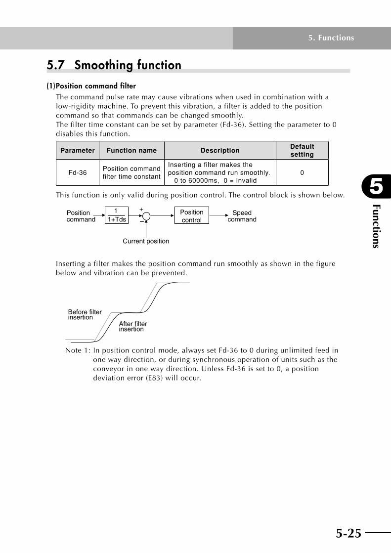
5-24 5-25
5
Functions
5. Functions
5.7 Smoothing function
(1) Position command filterThe command pulse rate may cause vibrations when used in combination with a low-rigidity machine. To prevent this vibration, a filter is added to the position command so that commands can be changed smoothly. Thefiltertimeconstantcanbesetbyparameter(Fd-36).Settingtheparameterto0disables this function.
Parameter Function name DescriptionDefault setting
Fd-36Position command filter time constant
Inserting a filter makes the position command run smoothly. 0 to 60000ms, 0 = Invalid
0
This function is only valid during position control. The control block is shown below.
+Positioncommand
Positioncontrol
Speedcommand
Current position
1+Tds 1
Insertingafiltermakesthepositioncommandrunsmoothlyasshowninthefigurebelow and vibration can be prevented.
Before filterinsertion
After filterinsertion
Note1:Inpositioncontrolmode,alwayssetFd-36to0duringunlimitedfeedinone way direction, or during synchronous operation of units such as the conveyorinonewaydirection.UnlessFd-36issetto0,apositiondeviationerror(E83)willoccur.
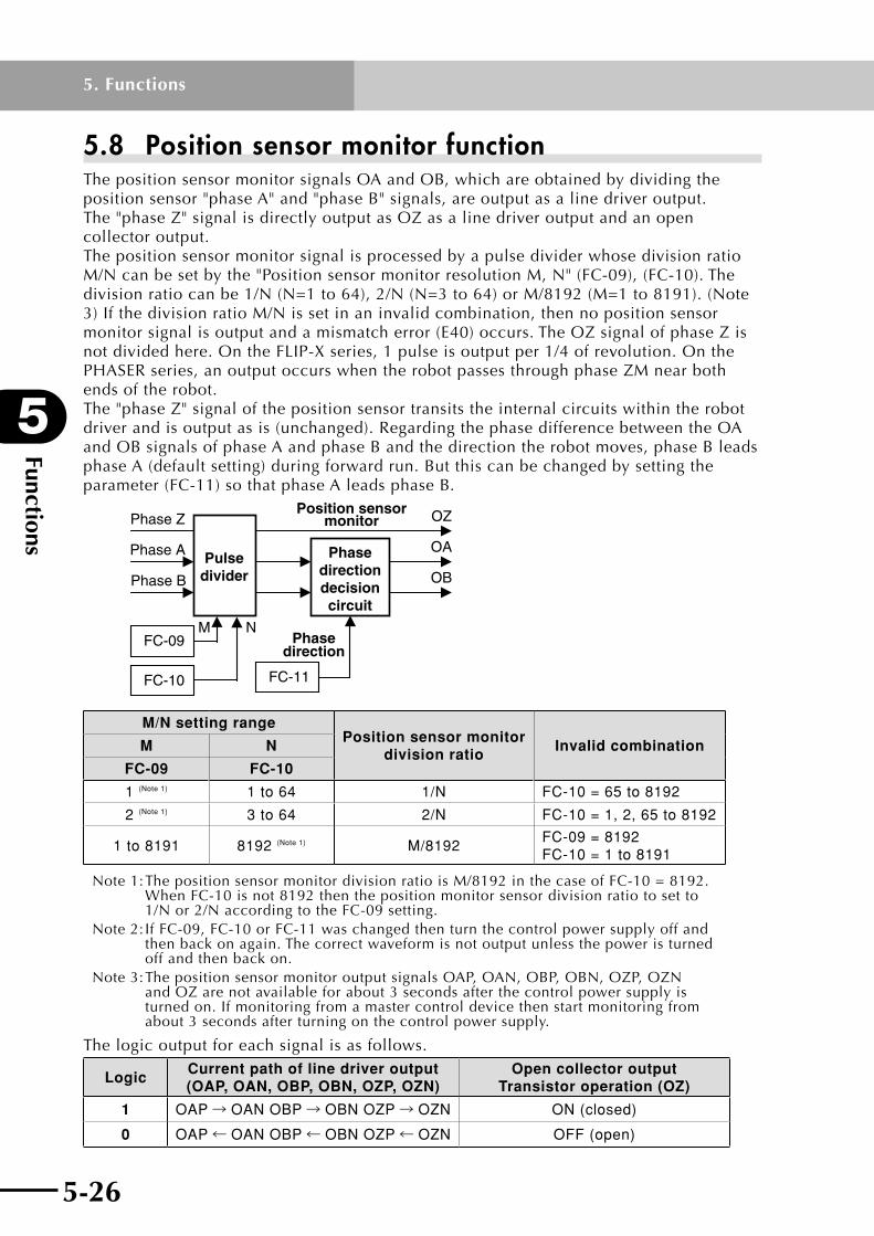
Functions
5
5-26
5. Functions
5-27
5.8 Position sensor monitor functionThe position sensor monitor signals OA and OB, which are obtained by dividing the position sensor "phase A" and "phase B" signals, are output as a line driver output. The"phaseZ"signalisdirectlyoutputasOZasalinedriveroutputandanopencollector output. The position sensor monitor signal is processed by a pulse divider whose division ratio M/Ncanbesetbythe"PositionsensormonitorresolutionM,N"(FC-09),(FC-10).Thedivision ratio can be 1/N (N=1 to 64), 2/N (N=3 to 64) or M/8192 (M=1 to 8191). (Note 3)IfthedivisionratioM/Nissetinaninvalidcombination,thennopositionsensormonitorsignalisoutputandamismatcherror(E40)occurs.TheOZsignalofphaseZisnotdividedhere.OntheFLIP-Xseries,1pulseisoutputper1/4ofrevolution.OnthePHASERseries,anoutputoccurswhentherobotpassesthroughphaseZMnearbothends of the robot. The"phaseZ"signalofthepositionsensortransitstheinternalcircuitswithintherobotdriver and is output as is (unchanged). Regarding the phase difference between the OA and OB signals of phase A and phase B and the direction the robot moves, phase B leads phase A (default setting) during forward run. But this can be changed by setting the parameter(FC-11)sothatphaseAleadsphaseB.
FC-11
M
FC-10
OA
OB
OZ
FC-09N
Pulsedivider
Phasedirectiondecisioncircuit
Phase A
Phase B
Phase ZPosition sensor
monitor
Phasedirection
M/N setting rangePosition sensor monitor
division ratioInvalid combinationM N
FC-09 FC-10
1 (Note 1) 1 to 64 1/N FC-10 = 65 to 8192
2 (Note 1) 3 to 64 2/N FC-10 = 1, 2, 65 to 8192
1 to 8191 8192 (Note 1) M/8192FC-09 = 8192 FC-10 = 1 to 8191
Note1:ThepositionsensormonitordivisionratioisM/8192inthecaseofFC-10=8192. WhenFC-10isnot8192thenthepositionmonitorsensordivisionratiotosetto 1/Nor2/NaccordingtotheFC-09setting.
Note2:IfFC-09,FC-10orFC-11waschangedthenturnthecontrolpowersupplyoffand then back on again. The correct waveform is not output unless the power is turned off and then back on.
Note3:ThepositionsensormonitoroutputsignalsOAP,OAN,OBP,OBN,OZP,OZN andOZarenotavailableforabout3secondsafterthecontrolpowersupplyis turnedon.Ifmonitoringfromamastercontroldevicethenstartmonitoringfrom about 3 seconds after turning on the control power supply.
The logic output for each signal is as follows.
LogicCurrent path of line driver output (OAP, OAN, OBP, OBN, OZP, OZN)
Open collector output Transistor operation (OZ)
1 OAP→ OAN OBP→ OBN OZP→ OZN ON (closed)
0 OAP← OAN OBP← OBN OZP← OZN OFF (open)

5-26 5-27
5
Functions
5. Functions
5.9 Adjusting the control gainThissectiondescribesthemethodforadjustingthecontrolgainrequiredwhenadjustingthe servo system. Adjustingthecontrolgainisnotrequiredwhensettingtheparametersbyfollowingthedescription in 6.3.3, "Reference graph for setting the acceleration and position control cut-offfrequency". Ifahighermotionresponseisneeded,settheparametersaccordingtothemethodsforadjustingthecontrolgainexplainedbelow. Mainparameterconstantsyouneedtoadjustareasfollows.
• Movermass(Fd-00)• Speedcontrolcut-offfrequency(Fd-01)• Positioncontrolcut-offfrequency(Fd-09)
The block diagram for the servo system is shown below.
+++
Detector
RobotPositioncontrol
Speedcontrol
Current feedback loop
Speed feedback loopPosition feedback loop
Positioncommand
Setting
Mover mass
(Fd-00)
Position controlcut-off frequency
(Fd-09)
Speed controlcut-off frequency
(Fd-01)
Currentcontrol
Powerconverter
5.9.1 Basic rules of gain adjustment(1) The servo system is made of 3 loops consisting of a position control loop, a speed
control loop, and a current control loop. The internal loop process and the response (cut-offfrequency)mustbesettoahighlevel.Youneedtoadjustthepositioncontrolloop gain and the speed control loop gain. The current control gain has sufficient responsesonoadjustmentisneeded.
(2)Thepositioncontrolloopandthespeedcontrollooprequiremakingasettingthatyields a balanced response. Basically, set the loop gain in a range that holds the relation:"Positioncontrolcut-offfrequency"(Fd-09)islowerthan"Speedcontrolcut-offfrequency"(Fd-01). Asageneralguidewhenmakingthissetting,the"Positioncontrolcut-offfrequency"(Fd-09)shouldbelessthan1/6thofthe"Speedcontrolcut-offfrequency"(Fd-01).
(3) The mechanical system might sometimes oscillate if the response of the position control loop is set to a high value. The gain cannot be set any higher than this so use caution. Usually, the response of the position control loop cannot be set higher than thecharacteristicoscillationfrequencyofthemechanicalsystem.Setaloopgainthatmatches the rigidity and strength of the mechanical system. Setting the response and the rigidity of the mechanical system is described next.
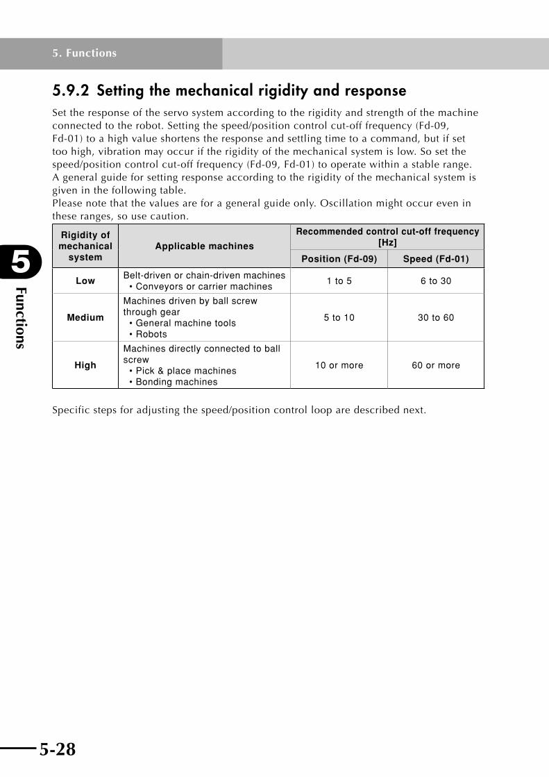
Functions
5
5-28
5. Functions
5-29
5.9.2 Setting the mechanical rigidity and responseSet the response of the servo system according to the rigidity and strength of the machine connectedtotherobot.Settingthespeed/positioncontrolcut-offfrequency(Fd-09,Fd-01)toahighvalueshortenstheresponseandsettlingtimetoacommand,butifsettoo high, vibration may occur if the rigidity of the mechanical system is low. So set the speed/positioncontrolcut-offfrequency(Fd-09,Fd-01)tooperatewithinastablerange.A general guide for setting response according to the rigidity of the mechanical system is given in the following table. Please note that the values are for a general guide only. Oscillation might occur even in these ranges, so use caution.
Rigidity of mechanical
systemApplicable machines
Recommended control cut-off frequency [Hz]
Position (Fd-09) Speed (Fd-01)
LowBelt-driven or chain-driven machines • Conveyors or carrier machines
1 to 5 6 to 30
Medium
Machines driven by ball screw through gear • General machine tools • Robots
5 to 10 30 to 60
High
Machines directly connected to ball screw • Pick & place machines • Bonding machines
10 or more 60 or more
Specificstepsforadjustingthespeed/positioncontrollooparedescribednext.
5-28 5-29
5
Functions
5. Functions
5.9.3 Adjusting the position control loop(1) Parameter constants used for position control
Parameter constants used for position control are described below.
(a) Position control cut-off frequency (Fd-09)
This parameter constant determines the response of the position control loop. SettingFd-09toahighvalueimprovestheresponseandshortensthepositioningtime.
Note 1: Robot might oscillate if the Fd-09 setting is too large.
(b) Speed control cut-off frequency (Fd-01)
This parameter constant determines the response of the speed control loop. Set it within a range where no mechanical vibration occurs. Setting to a high value improvestheresponse.Ifthe"Movermass"(Fd-00)ofthemechanicalsystem(includingrobot)wassetcorrectly,thenthespeedcontrolcut-offfrequencyislargelyequivalenttothevaluesetinFd-01.
(c) Speed PI control proportional gain (Fd-02)
ThespeedPIcontrolproportionalgainisautomaticallydeterminedaccordingtothe"Speedcontrolcut-offfrequency"(Fd-01).However,fineadjustmentstothespeedPIcontrolproportionalgaincanbemadebysettingFd-02.
(d) Speed PI control integral gain (Fd-03)
ThespeedPIcontrolintegralgainisautomaticallydeterminedaccordingtothe"Speedcontrolcut-offfrequency"(Fd-01).However,fineadjustmentstothespeedPIcontrolintegralgaincanbemadebysettingFd-03.
Note 1: Robot might oscillate if the Fd-03 setting is too large.
(2) Adjustment method1.Setthe"Positioncontrolcut-offfrequency"(Fd-09)somewhatlow,andsetthe
"Speedcontrolcut-offfrequency"(Fd-01)inarangewherenoabnormalnoiseoroscillation occurs.
2.Setthe"Positioncontrolcut-offfrequency"(Fd-09)toalargevalueinarangewhereovershoot and vibrations do not occur. As a general guide, set to 1/6th or less of the "Speedcontrolcut-offfrequency"(Fd-01).
3.Lastly,fine-adjustthe"SpeedPIcontrolproportionalgain"(Fd-02)and"SpeedPIcontrolintegralgain"(Fd-03)whilemonitoringthesettlingcharacteristicsandmovement, and search for the optimal point.

Functions
5
5-30
5. Functions
5-31
5.10 Offline auto-tuning functionThe auto-tuning function is described here.Offlineauto-tuningisafunctionforautomaticallyadjustingtheservosystemgainaccordingtothespeedcontrolcutofffrequency.
Offline auto-tuning operates the robot at a pre-determined operating pattern, estimates themovermass,andcorrectlysetsthe"Movermass"(Fd-00)parameter.Thecontrolgainisthenautomaticallysetfromthe"Speedcontrolcut-offfrequency"(Fd-01)thatdetermines the response of the speed control loop.
Note 1: It is not necessary to use this function when setting the parameters by following the description in 6.3.3, "Reference graph for setting the acceleration and position control cut-off frequency".
Note 2: To use the auto-tuning function, connect the robot to the equipment, and operate it at the same load as when actually used. The servo system is optimally adjusted for that load.
Note 3: During auto-tuning, the control mode for the speed control loop must be set to "Speed PI control". (Cannot be correctly tuned under IP control.)
Note 4: Moment of inertia may not be estimated correctly, depending on the robot model and operating conditions (load, etc.).
Note 5: During offline auto-tuning, information such as speed settings and torque data can be checked as graphics on the user PC by using the TOP software for RD series. So using the TOP software is recommended.
Note 6: When a PHASER series robot is used, magnetic pole position estimation must be performed before this operation. For information on magnetic pole position estimation,refer to section 5.17, "Magnetic pole position estimation action".
5.10.1 Offline auto-tuning method(1) Parameter constants used in offline auto-tuning
Parameter constants used at this time are described below.
(a) Auto-tuning mode (FA-10)
This parameter constant permits you to run auto-tuning. To run auto-tuning, set it to"oFL".
(b) Speed control cut-off frequency (Fd-01)
This parameter constant sets the response of the speed control loop. Set it within a range where oscillation does not occur in the mechanical system. Setting this value higher improves the response.
Note 1: In the case of a large load, the robot might oscillate unless the Fd-01 parameter is set small.
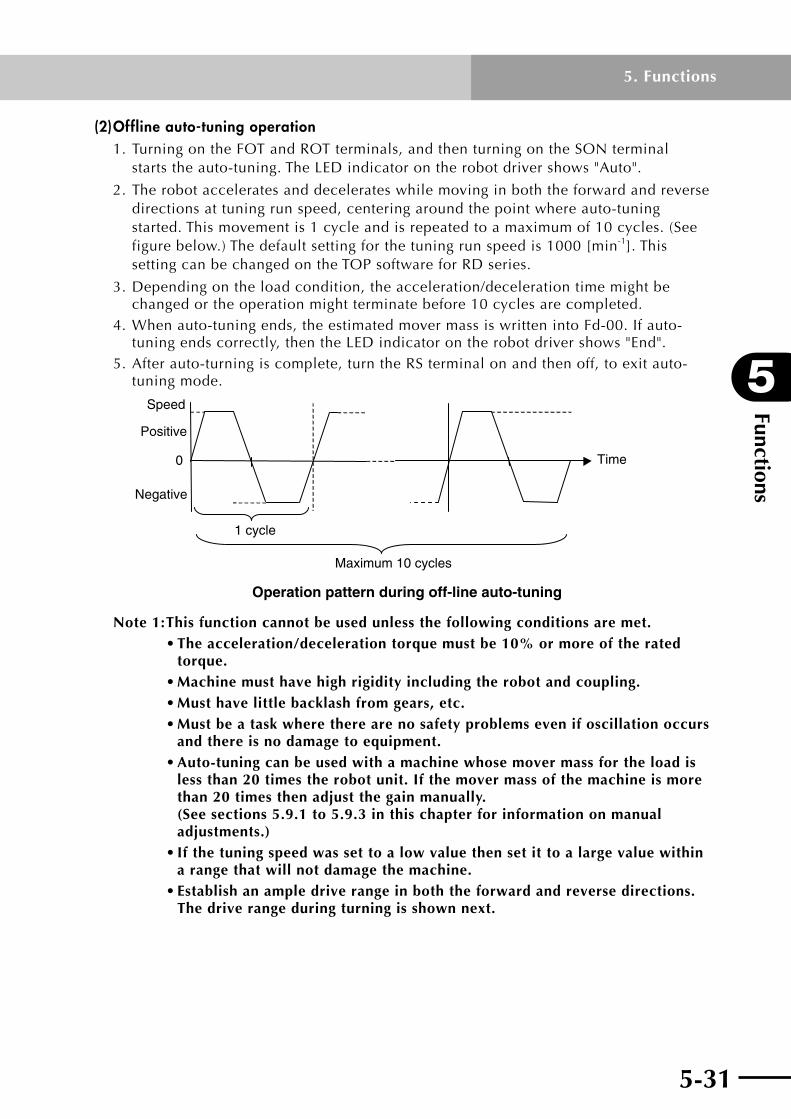
5-30 5-31
5
Functions
5. Functions
(2) Offline auto-tuning operation1.TurningontheFOTandROTterminals,andthenturningontheSONterminal
startstheauto-tuning.TheLEDindicatorontherobotdrivershows"Auto".
2. The robot accelerates and decelerates while moving in both the forward and reverse directions at tuning run speed, centering around the point where auto-tuning started. This movement is 1 cycle and is repeated to a maximum of 10 cycles. (See figure below.) The default setting for the tuning run speed is 1000 [min-1]. This setting can be changed on the TOP software for RD series.
3. Depending on the load condition, the acceleration/deceleration time might be changed or the operation might terminate before 10 cycles are completed.
4.Whenauto-tuningends,theestimatedmovermassiswrittenintoFd-00.Ifauto-tuningendscorrectly,thentheLEDindicatorontherobotdrivershows"End".
5. After auto-turning is complete, turn the RS terminal on and then off, to exit auto-tuning mode.
0
Positive
Negative
Speed
1 cycle
Maximum 10 cycles
Time
Operation pattern during off-line auto-tuning
Note 1: This function cannot be used unless the following conditions are met. •Theacceleration/decelerationtorquemustbe10%ormoreoftherated
torque. •Machinemusthavehighrigidityincludingtherobotandcoupling. •Musthavelittlebacklashfromgears,etc. •Mustbeataskwheretherearenosafetyproblemsevenifoscillationoccurs
and there is no damage to equipment. •Auto-tuningcanbeusedwithamachinewhosemovermassfortheloadis
less than 20 times the robot unit. If the mover mass of the machine is more than 20 times then adjust the gain manually. (See sections 5.9.1 to 5.9.3 in this chapter for information on manual adjustments.)
•Ifthetuningspeedwassettoalowvaluethensetittoalargevaluewithin a range that will not damage the machine.
•Establishanampledriverangeinboththeforwardandreversedirections. The drive range during turning is shown next.

Functions
5
5-32
5. Functions
5-33
Calculating the robot axis rotation during offline auto-tuningIfthetuningspeedisVa[min-1] and the accel/decel time is Dt [s], then the robot axis rotation, S, can be calculated by the following formula.
∆t60
3·VaS= ×
Calculatedexamplesareshowninthefollowing table. Set an ample drive range for the values in the table. The tuning speed and accel/decel time differ depending on whether operated by the digital operator or using the TOP software as shown next.
Calculated example of robot axis rotation during offline auto-tuning
Tuning speed Va [min-1]
Accel/decel time Dt [s]
Robot axis rotation S [rotation]
500 0.05 0.1
1.25 2.5
1000 0.05 0.1
2.5 5.0
1500 0.05 0.1
3.75 7.5
Tuning speed and accel/decel time for off-line auto-tuning
Tuning speed Va (min-1) Accel/decel time Dt(s)
Digital operator 1000 (fixed) 0.05 (fixed)
TOP software Adjustable Adjustable
Note:Theaccel/deceltimeduringofflineauto-tuningisthetimerequiredtoreachthe tuning speed from 0 or slow down to 0 from the tuning speed.
(3) Offline auto-tuning sequence1.Torunofflineauto-tuning,select"offlineauto-tuning"(oFL)onthe"Auto-tuning"
(FA-10)parameter,andafterwritingthevalue,turntheservoon.
Select "auto-tuning (oFL)" and write the value.(FA-10)
Tuning starts. (Auto)
Auto-tuning ends (End) Error occurred (Err)
End
(a) When auto-tuning ends normally: TheestimatedmomentumofinertiaiswritteninFd-00.
(b) When an auto-tuning error occurs: Ifanyofthefollowingeventsoccurred,thenatuningerrorresults.
•Anerror/abnormalityoccurred
•TheSONterminalturnedoffduringtuning.
•Resonanceorsimilarphenomenonoccurredsoauto-tuningcouldnotbe performed correctly.
5-32 5-33
5
Functions
5. Functions
2. When tuning ends, turn the SON terminal off, and turn the RS terminal on and then off, to exit the auto-tuning mode.
Note1:Thetuningmightnotendnormallyiftheaccel/deceltorqueislessthan10[%]of the rated torque. If that happens, use the TOP software for RD series to set the default value 0.05[s] for the accel/decel time to a smaller value. Also, if a tuning error occurred, then each gain value returns to the value prior to tuning. No alarm will trip unless there is an abnormal condition, so be aware of the need for safety especially during resonance.
Note 2: If you did not turn the RS terminal on and then off in step 2 above after turning ended, then set the "Auto-tuning mode" (FA-10) to "non".
5.10.2 Offline auto-tuning using the TOP softwareThe TOP (software for RD series) allows you to run fully automatic offline auto-tuning or runoneatatimewhilecheckingeachresult.Abriefdescriptionisgivenbelow.Fordetailed information, refer to the TOP software user's manual.
Thefollowingparametersettingsarerequiredforauto-tuning.
(a) Cut-off frequency setting
Setthecut-offfrequencyforcontrollingthespeedduringauto-tuning.Seta value that will not cause hunting.
Note 1: In the case of a large load, the robot might cause hunting unless this parameter is set small.
(b) Initial value of tuning mover mass
Setthemovermassatstartofauto-tuning.Tuningwillendquicklyifsettingthis toavaluethatyouknowwillroughlymatchthemovermass.Ifyoudonot know this value then leave the setting as is. The auto-tuning function will estimate the mover mass.
(c) Tuning speed
Enterthespeedtouseforauto-tuning.Enteraspeedthatwillnotdamagethe machineconnectedtotherobot.Ifthespeedislowthenthetuningmayfail. Set it to a higher speed at a level that will not damage the machine.
(d) Accel/decel time
Set an initial value for accel/decel time for pattern operation during auto- tuning.Setthisvaluetoasmallvalueiftheaccel/deceltorqueislessthan10% oftheratedtorque.(Refertothetorquedatashownonthedisplayduring pattern operation.)
(1) Procedure for fully automatic offline auto-tuning
1.Clickthe[TestrunandAdjustment]buttonontheopeningscreen. Clickthe[Offlinetuning]tabonthescreenthatappears.
2.Settheparametersthatarerequiredforauto-tuning.

Functions
5
5-34
5. Functions
5-35
3.Clickthe[Continuouspatterntuningstart]button.
4.ChecksafetyconditionsandthenturnontheFOTandROTterminals,andturnonthe SON terminal. This starts continuous pattern operation and estimates the mover mass.
5. After estimating the mover mass, the pattern operation waveforms are downloaded from the robot driver and displayed.
6. After tuning ends, turn the SON terminal off, and turn the RS terminal on and then off, to exit the auto-tuning mode.
Note 1: This function automatically rewrites the "Mover mass" (Fd-00) parameter.
Note 2: When tuning is interrupted before it is complete, turn the SON terminal off, and turn the RS terminal on and then off, to exit the auto-tuning mode.
Note 3: If the auto-tuning failed, then see the notes in 5.10.1.
(2) Procedure for offline auto-tuning while checking the result each time
1.Clickthe[TestrunandAdjustment]buttonontheopeningscreen. Clickthe[Offlinetuning]tabonthescreenthatappears.
2.Settheparametersthatarerequiredforauto-tuning.
3.Clickthe[1patterntuningstart]button.
4.ChecksafetyconditionsandthenturnontheFOTandROTterminals,andturnonthe SON terminal. This starts 1-pattern operation and estimates the mover mass.
5. After estimating the mover mass, the pattern operation waveforms are downloaded from the robot driver and displayed.
6.Checkifthewaveformissatisfactoryandclickthe[1-patterntuningstart]buttonagain if necessary. This runs the 1-pattern operation and estimates the mover mass. Repeat this to perform tuning while checking one waveform at a time.
7. After tuning ends, turn the SON terminal off, and turn the RS terminal on and then off, to exit the auto-tuning mode.
Note 1: This function automatically rewrites the "Mover mass" (Fd-00) parameter.
Note 2: When tuning is interrupted before it is complete, turn the SON terminal off, and turn the RS terminal on and then off, to exit the auto-tuning mode.

5-34 5-35
5
Functions
5. Functions
5.11 Gain change functionThe gain change function is a function for changing the position and speed control gain during operation and is used in the following cases.
• Toraisethecontrolgainduringservo-lockbuttolowerthegaintoreducenoiseduring run.
• Toraisethecontrolgainduringsettlingtoshortenthesettlingtime.
5.11.1 Changing the control gainA block diagram of the gain change function is shown below.
+ +
Position controlcut-off
frequency
Fd-09
Second positioncontrol cut-off
frequency
Fd-32
Fd-33
Speed controlcut-off
frequency
Position gainchange time
constant
Fd-01
Positioncommand
Positionerror
Speedcommand
Positioncontrol
Torquecommand
Speed
Position Detector
RobotSpeedcontrol
Input terminalfunction
Positionerror width
for gainchange
Gain changemode
Fd-30
Fd-31
FC-40
No gain changeAuto change
• non• AUto
Gainchange
Switching signal

Functions
5
5-36
5. Functions
5-37
(1) Parameter constants used for the gain change functionThe parameter constants used for changing the gain are explained below.
(a) Speed control cut-off frequency (Fd-01)
Settheresponse(cutofffrequency)ofthespeedcontrolsystem.Thisisalwaysenabled.
(b) Position control cut-off frequency (Fd-09)
Settheresponse(cut-offfrequency)ofthepositioncontrolsystem.Thisisalwaysenabled.
(c) Gain change mode (Fd-30)
Set whether or not to use the gain change mode.
• Whenusing"non": The cut-ff frequency of the position control section is equal to the "Position control
cut-off frequency" (Fd-09), and the cut-off frequency for the speed control section is equal to the "Speed control cut-off frequency" (Fd-01).
• Whenusing"AUto": If the position deviation is larger than the "Position error width for gain change" (Fd-31),
then the cut-ff frequency of the position control section is equal to the "Position control cut-off frequency" (Fd-09), and the cut-off frequency for the speed control section is equal to the "Speed control cut-off frequency" (Fd-01). If the position deviation is smaller than the "Position error width for gain change" (Fd-31), then the cut-ff frequency of the position control section is equal to the "Second position control cut-off frequency" (Fd-32), and the cut-off frequency for the speed control section is equal to the "Second speed control cut-off frequency" (Fd-34).
(d) Position error width for gain change (Fd-31)
Set the "position deviation" where you want to start the gain change.
(e) Second position control cut-off frequency (Fd-32)
Setthepositioncontrolcut-offfrequencytouseaftergainchange.
(f) Position gain change time constant (Fd-33)
Setthefiltertimeconstantforgainvariationsduringgainchange(Fd-09⇔Fd-32).
(g) Second speed control cut-off frequency (Fd-34)
Setthespeedcontrolcut-offfrequencytouseaftergainchange.
(h) Speed gain change time constant (Fd-35)
Setsthefiltertimeconstantforgainvariationsduringgainchange(Fd-01⇔Fd-34).

5-36 5-37
5
Functions
5. Functions
(2) Procedure for setting the gain change function1.Setthe"Gainchangemode"(Fd-30)to"AUto".
•Setthe"Positionerrorwidthforgainchange"(Fd-31).
•Thepositioncontrolgainischangedbasedontheinterrelationof"Positionerror monitor"(d-09)and"Positionerrorwidthforgainchange"(Fd-31).
2.Setthe"Secondpositioncontrolcut-offfrequency"(Fd-32)andthe"Secondspeedcontrolcut-offfrequency"(Fd-34).
Default values are:
•Thedefaultvalueforthe"Secondpositioncontrolcut-offfrequency"(Fd-32)is doublethevalue(10.00[Hz])ofthe"Positioncontrolcut-offfrequency"(Fd-09).
•Thedefaultvalueforthe"Secondspeedcontrolcut-offfrequency"(Fd-34)is doublethevalue(60.00[Hz])ofthe"Speedcontrolcut-offfrequency"(Fd-01).
•AsageneralguidesettheFd-32to1/6thorlessofFd-34.
3. After making the settings in 1 and 2 above, turn the servo on.
Note 1: A large gain difference during the gain change might cause mechanical shocks to the machine. If that happens, set the "Position gain change time constant" (Fd-33) and "Speed gain change time constant" (Fd-35) to a large value (the default value is set to 1 [ms]).
Note 2: If abnormal noise and oscillation occur during servo-lock, then set the "Second position control cut-off frequency" (Fd-32) and the "Second speed control cut-off frequency" (Fd-34) to a value low enough so that abnormal noise and oscillation do not occur.

Functions
5
5-38
5. Functions
5-39
5.12 Clearing the alarm log and setting the default valuesThe tripped alarm log can be cleared and all parameter data can be initialized.
Note: Data initialization alone does not reset the robot parameters to their default values. To reset the robot parameters to their default values, generation is required after data initialization. For details on generation, refer to the TOP software user's manual.
Theprocedureforthisresettingisshownbelow.Iftheparameterdatahasdeviatedfromthe expected value due, for example, by an entry error, then you can clear the alarm log with the procedure given below or return the parameter to the default value (default value in the robot driver).
(1) When initializing from the digital operator1. Select initializing mode.
1-1 Open FA-98, and select one of the following items according to the initializing information.
Clear Trip Log : CH
Factory Setting : dAtA
Clear Position Sensor to Zero : AbS
1-2 Press the SET key. (DisplaychangestoFA-98)
(SeeChapter6,"Parameterdescription",forinformationonhowtoset.)
2. Press the key for at least 2 seconds while simultaneously holding down the key.
3. While holding down the above arrow keys, press and release the SET key. The initializing now starts and the following table appears on the display panel.
Initializing information LED display
Alarm log clear HC
Data initializing JP
Note: Do not shut down the control power for the robot driver during initialization. Shutting off the power while data is being written may destroy the EEPROM data (stored data) within the robot driver, and the robot driver may fail to operate correctly.
4. After the display panel returns to d-00, turn the control power supply off and then back on.
Note: After initializing the parameters, always perform generation before operating the robot. If the robot is operated in the initialized state, it might malfunction or be damaged.
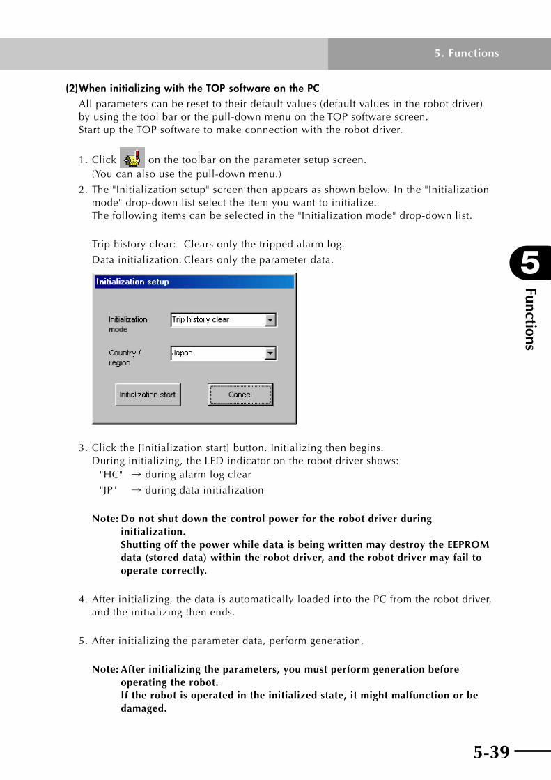
5-38 5-39
5
Functions
5. Functions
(2) When initializing with the TOP software on the PC All parameters can be reset to their default values (default values in the robot driver) by using the tool bar or the pull-down menu on the TOP software screen. Start up the TOP software to make connection with the robot driver.
1.Click on the toolbar on the parameter setup screen. (You can also use the pull-down menu.)
2.The"Initializationsetup"screenthenappearsasshownbelow.Inthe"Initializationmode" drop-down list select the item you want to initialize. Thefollowingitemscanbeselectedinthe"Initializationmode"drop-downlist.
Triphistoryclear: Clearsonlythetrippedalarmlog.
Datainitialization:Clearsonlytheparameterdata.
3.Clickthe[Initializationstart]button.Initializingthenbegins. Duringinitializing,theLEDindicatorontherobotdrivershows:
"HC"→ during alarm log clear
"JP" → during data initialization
Note: Do not shut down the control power for the robot driver during initialization. Shutting off the power while data is being written may destroy the EEPROM data (stored data) within the robot driver, and the robot driver may fail to operate correctly.
4.Afterinitializing,thedataisautomaticallyloadedintothePCfromtherobotdriver,and the initializing then ends.
5. After initializing the parameter data, perform generation.
Note: After initializing the parameters, you must perform generation before operating the robot. If the robot is operated in the initialized state, it might malfunction or be damaged.

Functions
5
5-40
5. Functions
5-41
5.13 Motor rotating direction
5.13.1 FLIP-X series phase sequenceTheforwarddirectionwhentheRDXisusedincombinationwiththeFLIP-Xseriesrobotis shown in the table below. The rotating direction for the robot can be set to the reverse directionbychangingthe"Motorrevolutiondirection"(FA-14)parameter.
RotationFA-14
CC C
Forward run CCW CW
Reverse run CW CCW
5.13.2 PHASER series phase sequenceTheforwarddirectionwhentheRDPisusedincombinationwiththePHASERseriesrobot is shown in the table below. The movement direction for the robot can be set to thereversedirectionbychangingthe"Motorrevolutiondirection"(FA-14)parameter.
Operating direction
FA-14
CC C
Forward run
Motor forward direction
Slider movement directionL side R side
Motor forward direction
Slider movement directionL side R side
Reverse run
Motor forward direction
Slider movement direction
L side R side
Motor forward direction
Slider movement direction
L side R side
Note1: The above figures are viewed from the cable carrier side of the robot.

5-40 5-41
5
Functions
5. Functions
5.14 Speed limit functionSpeedcanbelimitedbytheparameters(Fb-20,Fb-21)asshowninthetablebelow.
SettingSpeed limit mode
FA-20
Speed limit value
Forward Reverse
Fixed value by parameter setting
non Fb-20 Fb-21
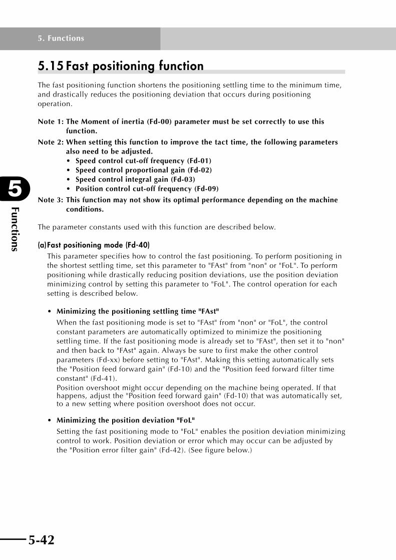
Functions
5
5-42
5. Functions
5-43
5.15 Fast positioning functionThe fast positioning function shortens the positioning settling time to the minimum time, and drastically reduces the positioning deviation that occurs during positioning operation.
Note 1: The Moment of inertia (Fd-00) parameter must be set correctly to use this function.
Note 2: When setting this function to improve the tact time, the following parameters also need to be adjusted. • Speedcontrolcut-offfrequency(Fd-01) • Speedcontrolproportionalgain(Fd-02) • Speedcontrolintegralgain(Fd-03) • Positioncontrolcut-offfrequency(Fd-09)
Note 3: This function may not show its optimal performance depending on the machine conditions.
The parameter constants used with this function are described below.
(a) Fast positioning mode (Fd-40)This parameter specifies how to control the fast positioning. To perform positioning in theshortestsettlingtime,setthisparameterto"FAst"from"non"or"FoL".Toperformpositioning while drastically reducing position deviations, use the position deviation minimizingcontrolbysettingthisparameterto"FoL".Thecontroloperationforeachsetting is described below.
• Minimizingthepositioningsettlingtime"FAst"
Whenthefastpositioningmodeissetto"FAst"from"non"or"FoL",thecontrolconstant parameters are automatically optimized to minimize the positioning settlingtime.Ifthefastpositioningmodeisalreadysetto"FAst",thensetitto"non"andthenbackto"FAst"again.Alwaysbesuretofirstmaketheothercontrolparameters(Fd-xx)beforesettingto"FAst".Makingthissettingautomaticallysetsthe"Positionfeedforwardgain"(Fd-10)andthe"Positionfeedforwardfiltertimeconstant"(Fd-41). Positionovershootmightoccurdependingonthemachinebeingoperated.Ifthathappens,adjustthe"Positionfeedforwardgain"(Fd-10)thatwasautomaticallyset,to a new setting where position overshoot does not occur.
• Minimizingthepositiondeviation"FoL"
Settingthefastpositioningmodeto"FoL"enablesthepositiondeviationminimizingcontroltowork.Positiondeviationorerrorwhichmayoccurcanbeadjustedbythe"Positionerrorfiltergain"(Fd-42).(Seefigurebelow.)
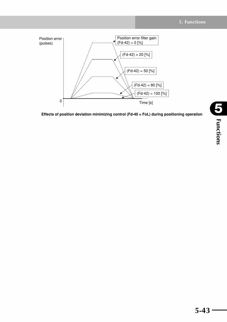
5-42 5-43
5
Functions
5. Functions
0
Effects of position deviation minimizing control (Fd-40 = FoL) during positioning operation
Position error (pulses)
Time [s]
Position error filter gain (Fd-42) = 0 [%]
(Fd-42) = 20 [%]
(Fd-42) = 50 [%]
(Fd-42) = 80 [%]
(Fd-42) = 100 [%]

Functions
5
5-44
5. Functions
5-45
5.16 Notch filter functionThe notch filter function reduces the vibration originating from the machine resonance, byloweringthegainataparticularfrequency.Theparameterconstantsusedinthisfunction are described below. Set these parameters using the TOP software's machine system diagnosis function. See the TOP software user's manual for more information on the machine system diagnosis function.
(a) Notch filter 1 frequency (Fd-12)
Thisisthefirstnotchfilter.Setthefrequencywhereyouwanttolowerthegain.
(b) Notch filter 1 bandwidth (Fd-13)
Set the gain attenuation rate for the notch filter 1. Setting this parameter to 0 disables the notch filter 1.
(c) Notch filter 2 frequency (Fd-14)
Thisisthesecondnotchfilter.Setthefrequencywhereyouwanttolowerthegain.
(d) Notch filter 2 bandwidth (Fd-15)
Set the gain attenuation rate for the notch filter 2. Setting this parameter to 0 disables the notch filter 2.
n Machine system diagnosis function on TOP software
5-44 5-45
5
Functions
5. Functions
5.17 Magnetic pole position estimation actionOn the RDP, magnetic pole position estimation must be performed after power is turned on when operating a robot in pulse train mode. To perform magnetic pole position estimation,setFA90(Hallsensorconnection)tooFF2,andfollowthesequenceshownbelow in "Magnetic pole position estimation and terminal states". TheSRDterminalturns"OFF"duringmagneticpoleestimation,butturns"ON"whenthemagnetic pole estimation ends correctly. Also, when magnetic pole estimation ended correctly, the normal servo-ON state returns, and the servo operates according to the commands that are input. To determine the magnetic pole position after magnetic pole position estimation is complete,performreturn-to-origin.Fordetailedinformationonreturn-to-origin,seesection 5.4, "Return-to-origin function".
Note: To perform magnetic pole position estimation, set FA-90 (Hall sensor connection) to oFF2. Do not set FA-90 to oFF.
n Magnetic pole position estimation and terminal states
ON
OFF
ON
ON
OFF
OFF
FOT/ROT terminal
SON terminal
SRD terminal
Robot operation Servo-off
Second and subsequent servo-on after power-on
First servo-on (magnetic poleposition estimation) after power-on
Magnetic pole position estimation Normal servo-on Servo-off Normal servo-on
10 [ms] or more No particular instructions
Note 1: The magnetic pole position estimation operation relies on speed command values generated internally in the robot driver so if command values such as position command pulses are input from outside the robot driver, then the robot might suddenly start to operate immediately after the magnetic pole position estimation ends. So do not enter command values such as position command pulses from outside the robot driver during magnetic pole position estimation.
Note 2: If the magnetic pole position estimation ends in an error, then a magnetic pole position estimation error (E95) occurs.
Note 3: The RDP shipped after October 2008 issues an error E95 (magnetic pole position estimation error) when magnetic pole position estimation starts unless both FOT and ROT terminals are ON. The RDP shipped before then does not issue an error, but fails to estimate the magnetic pole position.

Functions
5
5-46
5. Functions
5-47
5.18 Magnetic pole position estimation and parametersThe magnetic pole position estimation is performed by repeatedly generating the speed patterns automatically within the robot driver, as shown below. The number of repeating cycles automatically generated in one magnetic pole position estimation ranges from 6 to 13 cycles. (The number of repeating cycles may change according to the robot status.)Iffailedtoestimatethemagneticpolepositioncorrectly,amaximumof4retriesareautomatically attempted to estimate the magnetic pole position.
0
Fb-41
Fb-40
Speed [mm/s]
Time [s]
–Fb-40
Fb-42Fb-43
Fb-43Fb-41
Twait
1 cycle
6 to 13 cycles (to a maximum of 4 retries)
* Twait (wait time)The wait time Twait [s] for 1 operation pattern cycle is shown in the formula below. ThewaittimeTwait[s]undertwoconditions:(1)Fb-42[s]≥ Tstop [s], and (2)Fb-42[s] < Tstop [s], are shown below.
= Fb-42 [s] (1) Fb-42 [s] ≥ Tstop [s]Twait [s]
= Tstop [s] (2) Fb-42 [s] < Tstop [s]
Tstop [s]: This is the time in seconds for the speed detection value of 0 [mm/s] in the robot driver, to converge to the range of the "Zero speed detection value" (Fb-22) .
<Wait time Twait state (relation between speed command value, speed detection value within robot driver and wait time Twait [s]>
00
Speed [mm/s]
-Fb-22
Speed command value within robot driver
Speed detection value within robot driver
Twait(=Fb-42)
Tstop
Time [s]
Speed [mm/s]
Twait(=Tstop)
Fb-42
-Fb-22
Speed detection value within robot driver
Time [s]
Speed command value within robot driver
(1) Fb-42[s] ≥ Tstop[s] (Twait = Fb-24)
(2) Fb-42[s] < Tstop[s] (Twait = Tstop)

5-46 5-47
5
Functions
5. Functions
The distance the motor or slider moves during magnetic pole position estimation can be derived by the following formula.
Movementdistance[mm]=Fb-40×(Fb-41+Fb-43)/1000
Example:DistancemovedwithFb-40=80,Fb-41=10,andFb-43=10
Movementdistance[mm]=80×(10+10)/1000=1.6[mm]
[Mover mass and speed control cut-off frequency for magnetic pole position estimation]UseFd-46(Movermassforpolepositionestimation)tosetthemovermassformagneticpolepositionestimation.Likewise,useFd-47(Speedcontrolcut-offfrequencyforpolepositionestimation)tosetthespeedcontrolcut-offfrequency. AlsouseFd-48(Gainchangetimeconstantafterpolepositionestimation)tosetthetime constant of the first-order lag filter for gain switching when shifting to normal control after estimating the magnetic pole position.
SRD
SON
Mover mass
Speed control cut-off frequency
Magnetic pole position estimation operation
Fd-48 × 5 or more
Fd-00
Fd-01 (Fd-34)
Fd-46
Fd-47
Note 1: Fd-46, Fd-47 and Fd-48 cannot be set for RDP that was shipped initially. Use Fd-00 and Fd-01 to set the mover mass and speed control cut-off frequency for magnetic pole position estimation and normal control operation.
Note 2: These parameters can be set with the dedicated software TOP (Ver. 6.5.1 or later). If using an earlier version of TOP, set them from the front panel.
<To shorten the distance moved during magnetic pole position estimation>Setting the parameters as shown below in (1) through (3) shortens the distance moved during magnetic pole position estimation.
(1)SetFb-42(Polepositionestimationwaittime)toapproximately300[ms].
(2) Set as follows to reduce the movement distance.
•Fb-41(PolepositionestimationACC/DECtime)=10[ms]
•Fb-43(Polepositionestimationconstant-speedtime)=0[ms]
(3)Todecreasethemovementdistance,adjustFb-40(Polepositionestimationspeed)to a small value.

Functions
5
5-48
5. Functions
Note 1: Magnetic pole position estimation might sometimes be unable to accurately estimate the magnetic pole position due to how the torque is generated during the magnetic pole position estimation period.
Note 2: If an abnormal movement occurs, adjust the Fd-46, Fd-47 and/or Fd-48 parameters.
Note 3: Depending on the robot load conditions, magnetic pole position estimation may fail with an error E95 (magnetic pole position estimation error). If this happens, adjust the pole position estimation parameter to an appropriate value.
Note 4: The center position of the magnetic pole position estimation operation may shift, depending on the start position.
Note 5: After magnetic pole position estimation is complete, the magnetic pole position is determined when phase ZM is passed.

Chapter 6 Parameter descriptionThis chapter describes part names of the digital operator integrated into this product and how to operate it. This chapter also describes monitor mode and setup parameters.
Contents
6.1 Digital operator part names and operation 6-16.1.1 Part names of digital operator 6-1
6.1.2 Operating the digital operator 6-2
6.2 Function lists 6-56.2.1 List of monitor functions 6-6
6.2.2 List of setup parameters 6-7
6.3 Function description 6-126.3.1 Monitor display description 6-12
6.3.2 Setup parameter description 6-15
6.3.3 Reference graph for setting the acceleration and position control cut-off frequency 6-32
n RDX.................................................................... 6-33T4H-2 (C4H-2) ..............................................................6-33
T4H-2-BK (C4H-2-BK)....................................................6-33
T4H-6 (C4H-6) ..............................................................6-34
T4H-6-BK (C4H-6-BK)....................................................6-34
T4H-12 (C4H-12) ..........................................................6-35
T4H-12-BK (C4H-12-BK) ................................................6-35
T4LH-2 (C4LH-2)...........................................................6-36
T4LH-2-BK (C4LH-2-BK) ................................................6-36
T4LH-6 (C4LH-6)...........................................................6-37
T4LH-6-BK (C4LH-6-BK) ................................................6-37
T4LH-12 (C4LH-12) .......................................................6-38
T4LH-12-BK (C4LH-12-BK) .............................................6-38
T5H-6 (C5H-6) ..............................................................6-39
T5H-6-BK (C5H-6-BK)....................................................6-39
T5H-12 (C5H-12) ..........................................................6-40
T5H-12-BK (C5H-12-BK) ................................................6-40
T5H-20 .........................................................................6-41
T5LH-6 (C5LH-6)...........................................................6-41
T5LH-6-BK (C5LH-6-BK) ................................................6-42
T5LH-12 (C5LH-12) .......................................................6-42
T5LH-12-BK (C5LH-12-BK) .............................................6-43
T5LH-20 (C5LH-20) .......................................................6-43
T6-6 (C6-6) ..................................................................6-44
T6-6-BK (C6-6-BK) ........................................................6-44
T6-12 (C6-12)...............................................................6-45

T6-12-BK (C6-12-BK) ....................................................6-45
T6-20 ............................................................................6-46
T6L-6 (C6L-6) ...............................................................6-46
T6L-6-BK (C6L-6-BK) .....................................................6-47
T6L-12 (C6L-12) ...........................................................6-47
T6L-12-BK (C6L-12-BK) .................................................6-48
T6L-20 (C6L-20) ...........................................................6-48
T7-12 ............................................................................6-49
T7-12-BK ......................................................................6-49
T9-5 .............................................................................6-50
T9-5-BK ........................................................................6-50
T9-10 ............................................................................6-51
T9-10-BK ......................................................................6-51
T9-20 ............................................................................6-52
T9-20-BK ......................................................................6-52
T9-30 ............................................................................6-53
T9H-5 ...........................................................................6-53
T9H-5-BK ......................................................................6-54
T9H-10 .........................................................................6-54
T9H-10-BK ....................................................................6-55
T9H-20 .........................................................................6-55
T9H-20-BK ....................................................................6-56
T9H-30 .........................................................................6-56
F8-6 (C8-6) ..................................................................6-57
F8-6-BK (C8-6-BK) ........................................................6-57
F8-12 (C8-12) ..............................................................6-58
F8-12-BK (C8-12-BK) ....................................................6-58
F8-20 (C8-20) ..............................................................6-59
F8L-5 (C8L-5) ...............................................................6-59
F8L-5-BK (C8L-5-BK) .....................................................6-60
F8L-10 (C8L-10) ...........................................................6-60
F8L-10-BK (C8L-10-BK) .................................................6-61
F8L-20 (C8L-20) ...........................................................6-61
F8L-20-BK (C8L-20-BK) .................................................6-62
F8L-30 ..........................................................................6-62
F8LH-5 (C8LH-5) ..........................................................6-63
F8LH-10 (C8LH-10) .......................................................6-63
F8LH-20 (C8LH-20) .......................................................6-64
F10-5 (C10-5) ..............................................................6-64
F10-5-BK (C10-5-BK) ....................................................6-65
F10-10 (C10-10) ...........................................................6-65
F10-10-BK (C10-10-BK) ................................................6-66
F10-20 (C10-20) ...........................................................6-66
F10-20-BK (C10-20-BK) ................................................6-67

F10-30 .........................................................................6-67
F14-5 (C14-5) ..............................................................6-68
F14-5-BK (C14-5-BK) ....................................................6-68
F14-10 (C14-10) ...........................................................6-69
F14-10-BK (C14-10-BK) ................................................6-69
F14-20 (C14-20) ...........................................................6-70
F14-20-BK (C14-20-BK) ................................................6-70
F14-30 .........................................................................6-71
F14H-5 (C14H-5) ..........................................................6-71
F14H-5-BK (C14H-5-BK) ................................................6-72
F14H-10 (C14H-10) ......................................................6-72
F14H-10-BK (C14H-10-BK) ............................................6-73
F14H-20 (C14H-20) ......................................................6-73
F14H-20-BK (C14H-20-BK) ............................................6-74
F14H-30 .......................................................................6-74
F17L-50 (C17L-50) .......................................................6-75
F17L-50-BK (C17L-50-BK) .............................................6-75
F17-10 (C17-10) ...........................................................6-76
F17-10-BK (C17-10-BK) ................................................6-76
F17-20 (C17-20) ...........................................................6-77
F17-20-BK (C17-20-BK) ................................................6-77
F17-40 .........................................................................6-78
F20-10-BK (C20-10-BK) ................................................6-78
F20-20 (C20-20) ...........................................................6-79
F20-20-BK (C20-20-BK) ................................................6-79
F20-40 .........................................................................6-80
F20N-20 .......................................................................6-80
N15-10 .........................................................................6-81
N15-20 .........................................................................6-81
N15-30 .........................................................................6-82
N18-20 .........................................................................6-82
B10 ..............................................................................6-83
B14 ..............................................................................6-83
B14H ............................................................................6-84
R5 ................................................................................6-84
R10 ..............................................................................6-85
R20 ..............................................................................6-85
n RDP .................................................................... 6-86MR12 ...........................................................................6-86
MR16 ...........................................................................6-86
MR16H .........................................................................6-87
MR20 ...........................................................................6-87
MR25 ...........................................................................6-88
MF7 .............................................................................6-88

6-1
MF15 ...........................................................................6-89
MF20 ...........................................................................6-89
MF30 ...........................................................................6-90
MF50 ...........................................................................6-90
MF75 ...........................................................................6-91
6.4 Control block diagram and monitors 6-92

6-1
6
Parameter description
6. Parameter description
6.1 Digital operator part names and operation
6.1.1 Part names of digital operatorThe RD series is operated from the built-in digital operator.
CHARGE
FUNC
SET Function key
Shift key
Save key
Down key
Monitor indicator(5-digit LED)
Up key
Charge lamp
Name Description
Monitor indicator Displays a monitor value or set value.
Charge lamp Lights up when charge in DC bus capacitor exceeds 30V.
FUNC Function key Enters the monitor mode or parameter setting mode.
Shift keyMoves the indicating digit or setting digit to the left. Pressing this key at the leftmost digit moves the selected position to the rightmost digit.
Up key
Down key
Changes the monitor number, setup parameter number, or parameter setting.
SET Save key Saves parameter setting.

Parameter description
6
6-2
6. Parameter description
6-3
6.1.2 Operating the digital operator(1) Changing the monitor mode display and parameter setting
The button marks over/under the right/left arrows ( ) or at the side of the up/down arrows ( ) show that those buttons were pressed. To save data you have entered always be sure to press the SET key. Pressing the FUNC key will not save the data but retains the previous value.
× 3
SETFUNC
FUNC
FUNC
FUNC
FUNC
FUNC
FUNC
FUNC
FUNC
FUNC
FUNC
FUNC
SET
SET
SET
Note 5)
When the key is pressed in monitor mode (d-xx), the parameter data displayed at that time will automatically appear the next time power is turned on. This setting can be cancelled by setting another parameter in monitor mode or by clearing the alarm log.
Blinking
Blinking
Note 1)
Note 3)Blinking
Note 3)
Blinking
Hierarchy 1 Hierarchy 2
To enter a negative value, place the cursor at the leftmost digit and change the polarity by pressing the or key. If the data is 0 at this point, it is not set to "–0" but to the maximum negative value (–5000).
Note 2)
Hierarchy 3
Note 1: When the FUNC key in hierarchy 1 is held down, the hierarchy changes in order, from hierarchy 2 → hierarchy 3 → hierarchy 2 → hierarchy 1. The parameter name displayed after pressing the FUNC keyatFA---(hierarchy1)will be the parameter name that was last displayed at hierarchy 3 (if up to hierarchy 3 was displayed).
Note 2: The blinking digit indicates the current cursor position.
Note 3: Pressing the SET key saves the data you have entered.
Pressing the FUNC key cancels the data you have entered and retains the previous value.
Note4:Whenchangingaparameter(FA-12,FA-13,etc.)from"100"to"001",theminimum setting range prevents changing it from the higher-order digit to "000". So, first set it to "101" and then change it to "001".
Note5:Toquicklymovefromthemonitormodedisplay(d-xx)totheparametersettingmode(FAtoFd)usethe or keys.

6-2 6-3
6
Parameter description
6. Parameter description
(2) Operating the trip monitor and the trip log monitorThe button marks over/under the right/left arrows ( ) or at the side of the up/down arrows ( ) show that those buttons were pressed.
……
FUNC
FUNC
FUNC
FUNC
Speed command
Speed detection value
DC bus voltage
Input terminal
Output terminal
Shows the same information as above "d-11".
Note 2)
Note 2)
Note 1)
Current
This indicates no alarm log is stored.
Note 1: The number at the right of the alarm code shows the alarm log number. The number "1" is the newest data. The larger the log number the older the log.Formoreinformationreferto9.1,"Alarmdisplay(alarmlog)".
Note 2: A period ( . ) in the last digit indicates the following information.
Period Displayed information Remarks
No Speed command Two speed data items (speed command and speed detection value) are used and can be identified by the period on the trip monitor.Yes Speed detection value

Parameter description
6
6-4
6. Parameter description
6-5
(3) Special displayA special display appears to indicate the robot driver status as shown in the following table.
Display Description
Voltage is too low during servo-off. (Control power supply)
No alarm log is stored.
User initialization in-progress. (LED segments within the leftmost digit light in sequence.)
Log initialization in-progress. (LED segments within the leftmost digit light in sequence.
Sample display: When setting Fb-14, Fb-16 or Fb-18 to a value between –10000 and –19999. Display at left shows a parameter value of –11491. (A minus sign "-" is appended to the leftmost digit "1" in order to indicate a 6-digit number including a sign.) <To set Fb-14, Fb-16 and Fb-18:> As the basic method, use the key to select the digit you want to change and then use the or key to set the desired value. Note that the leftmost digit is displayed as follows:
Press the SET key when the desired value is displayed.
6-4 6-5
6
Parameter description
6. Parameter description
6.2 Function listsThis section describes monitor functions and parameters that can be set for the robot driver. Parameters are divided into several groups as shown in the following table.
Group Description
d-xx Allows checking monitor parameters such as speed and position.
FA-xx Operation mode or protection level parameters
Fb-xx Operation constant parameters
FC-xx Input/output terminal parameters
Fd-xx Control constant parameters such as mover mass and response speed.
"xx" means a parameter number.
Parameters for each group are listed on the following pages.
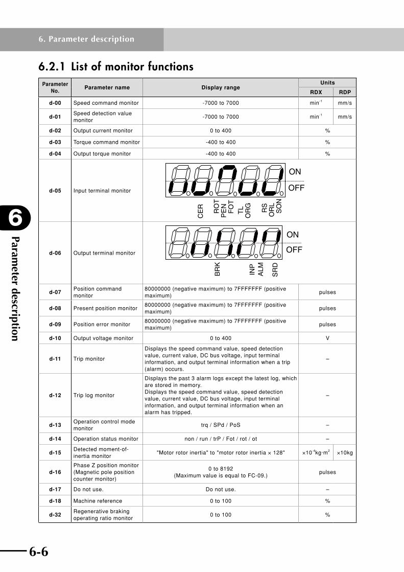
Parameter description
6
6-6
6. Parameter description
6-7
6.2.1 List of monitor functionsParameter
No.Parameter name Display range
Units
RDX RDP
d-00 Speed command monitor -7000 to 7000 min-1 mm/s
d-01Speed detection value monitor
-7000 to 7000 min-1 mm/s
d-02 Output current monitor 0 to 400 %
d-03 Torque command monitor -400 to 400 %
d-04 Output torque monitor -400 to 400 %
d-05 Input terminal monitor
CE
R RS
OR
L S
ON
TL
OR
G
ON
OFF
RO
TP
EN
FO
T
d-06 Output terminal monitor
ALM
SR
D
IN
P
BR
K
ON
OFF
d-07Position command monitor
80000000 (negative maximum) to 7FFFFFFF (positive maximum)
pulses
d-08 Present position monitor80000000 (negative maximum) to 7FFFFFFF (positive maximum)
pulses
d-09 Position error monitor80000000 (negative maximum) to 7FFFFFFF (positive maximum)
pulses
d-10 Output voltage monitor 0 to 400 V
d-11 Trip monitor
Displays the speed command value, speed detection value, current value, DC bus voltage, input terminal information, and output terminal information when a trip (alarm) occurs.
–
d-12 Trip log monitor
Displays the past 3 alarm logs except the latest log, which are stored in memory. Displays the speed command value, speed detection value, current value, DC bus voltage, input terminal information, and output terminal information when an alarm has tripped.
–
d-13Operation control mode monitor
trq / SPd / PoS –
d-14 Operation status monitor non / run / trP / Fot / rot / ot –
d-15Detected moment-of-inertia monitor
"Motor rotor inertia" to "motor rotor inertia × 128" ×10-4kg·m2 ×10kg
d-16Phase Z position monitor (Magnetic pole position counter monitor)
0 to 8192 (Maximum value is equal to FC-09.)
pulses
d-17 Do not use. Do not use. –
d-18 Machine reference 0 to 100 %
d-32Regenerative braking operating ratio monitor
0 to 100 %

6-6 6-7
6
Parameter description
6. Parameter description
6.2.2 List of setup parametersParameter setting ranges and default values are shown in the following tables.
(1) Operation mode parameters
Parameter No.
Parameter name
Setting rangeDefault setting Units Change
during servo-onRDX RDP RDX RDP
FA-00 (Note 3)
Control modeS-P, S-t, P-t, P-S, t-S, t-P
P-S – No
FA-01Position sensor wire breaking detection
OFF, on on – No
FA-02Allowable time of power failure
0.00, 0.05 to 1.00
0.00 s No
FA-03Overspeed error detection level
0 to 150 110 % No
FA-04Speed error detection value
0 to maximum speed
Depends on model min-1 mm/s No
FA-05Position error detection value
0.0 to 100.0 20.0 rotation No
FA-07 (Note 3)
DC bus power supply
L123, Pn L123 – No
FA-08Regenerative braking operating ratio
0.0 to 100.0 Depends on model % No
FA-09Overload notice level
20 to 100 80 % No
FA-10Auto tuning mode
non, oFL, FFtnon – No
onL1, onL2 (Note 3)
FA-11Pulse train input mode
F-r, P-S, A-b r-F, -P-S, b-A
F-r – No
FA-12Electronic gear numerator
1 to 65535Depends on model
1– No
FA-13Electronic gear denominator
1 to 65535 – No
FA-14Motor revolution direction
CC, C Depends on model – No
FA-16DB Operation selection
non, trP, SoF SoF – No
FA-17 (Note 3)
Torque limit mode
non, A2, oP non – No
FA-18Torque bias mode
non, CnSnon – No
A2, oP (Note 3)
FA-20 (Note 3)
Speed limit mode
non, A1, oP non – No
FA-22 (Note 3)
Position command selection
PLS, Pro, oP PLS – No
Note 1: Displayed on RDP only.
Note2:InvalidonRDP.
Note 3: Do not change the setting.
Note 4: Set this parameter to the default value for each model.
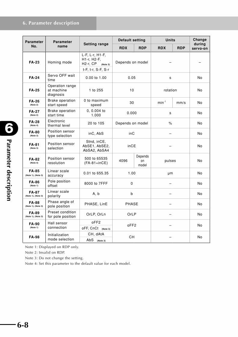
Parameter description
6
6-8
6. Parameter description
6-9
Parameter No.
Parameter name
Setting rangeDefault setting Units Change
during servo-onRDX RDP RDX RDP
FA-23 Homing mode
L-F, L-r, H1-F, H1-r, H2-F, H2-r, CP (Note 3)
Depends on model – –
t-F, t-r, S-F, S-r
FA-24Servo OFF wait time
0.00 to 1.00 0.05 s No
FA-25Operation range at machine diagnosis
1 to 255 10 rotation No
FA-26 (Note 2)
Brake operation start speed
0 to maximum speed
30 min-1 mm/s No
FA-27 (Note 2)
Brake operation start time
0, 0.004 to 1.000
0.000 s No
FA-28 (Note 4)
Electronic thermal level
20 to 105 Depends on model % No
FA-80 (Note 3)
Position sensor type selection
inC, AbS inC – No
FA-81 (Note 3)
Position sensor selection
Stnd, inCE, AbSE1, AbSE2, AbSA2, AbSA4
inCE – No
FA-82 (Note 4)
Position sensor resolution
500 to 65535 (FA-81=inCE)
4096Depends
on model
pulses No
FA-85 (Note 1), (Note 3)
Linear scale accuracy
0.01 to 655.35 1.00 μm No
FA-86 (Note 1)
Pole position offset
8000 to 7FFF 0 – No
FA-87 (Note 1), (Note 3)
Linear scale polarity
A, b b – No
FA-88 (Note 1), (Note 3)
Phase angle of pole position
PHASE, LinE PHASE – No
FA-89 (Note 1), (Note 3)
Preset condition for pole position
OrLP, OrLn OrLP – No
FA-90 (Note 1)
Hall sensor connection
oFF2oFF2 – No
oFF, CnCt (Note 3)
FA-98Initialization mode selection
CH, dAtACH – No
AbS (Note 3)
Note 1: Displayed on RDP only.
Note2:InvalidonRDP.
Note 3: Do not change the setting.
Note 4: Set this parameter to the default value for each model.

6-8 6-9
6
Parameter description
6. Parameter description
(2) Operation constant parameters
Parameter No.
Parameter nameSetting range Default setting Units Change
during servo-onRDX RDP RDX RDP RDX RDP
Fb-04 Acceleration time 0.00 to 99.99 10.00 s Yes
Fb-05 Deceleration time 0.00 to 99.99 10.00 s Yes
Fb-07Torque limit value 1 (first quadrant)
0 to maximum torque
Depends on model % Yes
Fb-08Torque limit value 2 (second quadrant)
0 to maximum torque
Depends on model % Yes
Fb-09Torque limit value 3 (third quadrant)
0 to maximum torque
Depends on model % Yes
Fb-10Torque limit value 4 (fourth quadrant)
0 to maximum torque
Depends on model % Yes
Fb-11 Torque bias value ±0 to ±300 0 % Yes
Fb-12 Homing speed 1 (fast)1 to
maximum speed
1 to 100 60 20 min-1 mm/s Yes
Fb-13 Homing speed 2 (slow) 1 to 999 1 to 20 6 5 min-1 mm/s Yes
Fb-14Homing position offset value (H)
±0 to ±19999 0 pulses Yes
Fb-15Homing position offset value (L)
0 to 99999 0 pulses Yes
Fb-16Forward position limit value (H)
±0 to ±19999 0 pulses Yes
Fb-17Forward position limit value (L)
0 to 99999 0 pulses Yes
Fb-18Reverse position limit value (H)
±0 to ±19999 0 pulses Yes
Fb-19Reverse position limit value (L)
0 to 99999 0 pulses Yes
Fb-20Forward speed limit value
0 to maximum speed Depends on model min-1 mm/s Yes
Fb-21Reverse speed limit value
– maximum speed to 0 Depends on model min-1 mm/s Yes
Fb-23Positioning defection range
1 to 65535 20 pulses Yes
Fb-24Positioning interval time limit
0.00 to 10.00 (in 0.02 steps)
0.00 s Yes
Fb-25Up to speed detection range
0 to 100 10 min-1 mm/s Yes
Fb-30 (Note 2)
S-curve rationon, SHArP,
rEGLr, LooSEnon – Yes
Fb-35 Homing back distance 1 to 255 Depends on model – No
Fb-36 Current for striking limit 40 to 100 Depends on model % No
Fb-37 Time for striking limit 0.1 to 2.0 0.2 s No
Fb-40 (Note 1)
Pole position estimation speed
–500 to 500 Depends on model mm/s Yes
Fb-41 (Note 1)
Pole position estimation ACC/ DEC time
10 to 500 Depends on model ms Yes
Fb-42 (Note 1)
Pole position estimation wait time
0 to 500 100 ms Yes
Fb-43 (Note 1)
Pole position estimation constant-speed time
0 to 500 Depends on model ms Yes
Fb-44 (Note 1)
Position sensor wire breaking detection current
20 to 100 Depends on model % Yes
Fb-45 (Note 1)
Speed error detection value at pole position estimation
0 to maximum speed 500 mm/s No
Note 1: Displayed on RDP only.
Note 2: Do not change the setting.

Parameter description
6
6-10
6. Parameter description
6-11
(3) Input/output terminal parameters
Parameter No. Parameter name Setting range
Default setting Units Change during
servo-onRDX RDP RDX RDP
FC-01Input terminal polarity setting
0000 to 3FFF 0400 – No
FC-02Output terminal polarity setting
0000 to 00FF 0002 – No
FC-09Position sensor monitor resolution M
16 to 8192 1 – No
FC-10Position sensor monitor resolution N
1 to 8192 4 1 – No
FC-11 (Note 1)
Position sensor monitor polarity
A, b b – No
FC-12 (Note 1)
Phase Z output selection
1PLS, nCunt ECunt, qFort
1PLS – No
FC-19Command pulse filter time constant
Lo, Hi Hi – No
FC-21Communication baud rate
1200, 2400, 4800, 9600,
19200, 3840019200 bps No
FC-22Communication bit length
7, 8 8 bit No
FC-23Communication parity
non, odd, EvEn non – No
FC-24Communication stop bit
1, 2 2 – No
FC-30Monitor output 1 function
nrF, nFb, iFb, tqr, nEr, PEr,
PFq, brdnFb – No
FC-31Monitor output 1 polarity
SiGn, AbS SiGn – No
FC-32Monitor output 1 gain
0.0 to 3000.0 100.0 % No
FC-33Monitor output 2 function
nrF, nFb, iFb, tqr, nEr, PEr,
PFq, brdtqr – No
FC-34Monitor output 2 polarity
SiGn, AbS SiGn – No
FC-35Monitor output 2 gain
0.0 to 3000.0 100.0 % No
FC-40Input terminal function
0 to 3FFF 0 – No
FC-70 (Note 1)
Debug mode selection
0 0 – –
Note 1: Do not change the setting.

6-10 6-11
6
Parameter description
6. Parameter description
(4) Control constant parameters
Parameter No.
Parameter name Setting rangeDefault setting
Units Change during
servo-onRDX RDP
Fd-00 Moment of inertia (RDX) Mover mass (RDP)
"Motor rotor inertia" to "motor
rotor inertia × 128"Depends on model ×10-4kg·m2 ×10kg Yes
Fd-01 Speed control cut-off frequency 0.1 to 500.0 Depends on model Hz Yes
Fd-02 Speed control proportional gain 0.01 to 300.00 Depends on model % Yes
Fd-03 Speed control integral gain 0.01 to 300.00 Depends on model % Yes
Fd-04 P-control gain 0.1 to 99.9 Depends on model % Yes
Fd-05 IP-control gain 0.00 to 1.00 Depends on model – Yes
Fd-06 Torque command filter time constant 0.00 to 500.00 Depends on model ms Yes
Fd-07 Position phase compensating ratio 0.01 to 9.99 Depends on model – Yes
Fd-08Position phase compensating time constant
0.1 to 999.9 Depends on model ms Yes
Fd-09 Position control cut-off frequency 0.01 to 99.99 Depends on model Hz Yes
Fd-10 Position feed forward gain 0.00 to 1.00 Depends on model – Yes
Fd-12 Notch filter 1 frequency 3.0 to 1000.0 Depends on model Hz Yes
Fd-13 Notch filter 1 bandwidth 0 to 40 Depends on model dB Yes
Fd-14 Notch filter 2 frequency 3.0 to 1000.0 Depends on model Hz Yes
Fd-15 Notch filter 2 bandwidth 0 to 40 Depends on model dB Yes
Fd-20 Speed command filter time constant 0 to 60000 Depends on model ms Yes
Fd-30 Gain change modenon, AUto
Depends on model – YesGCH (Note 2)
Fd-31 Position error width for gain change 0 to 65535 Depends on model pulses Yes
Fd-32Second position control cut-off frequency
0.01 to 99.99 Depends on model Hz Yes
Fd-33 Position gain change time constant 0.0 to 500.0 Depends on model ms Yes
Fd-36 Position command filter time constant 0 to 60000 Depends on model ms Yes
Fd-40 Fast positioning mode non, FASt, FoL Depends on model – Yes
Fd-41 Position feed forward filter time constant 0.00 to 500.00 Depends on model ms Yes
Fd-42 Position error filter gain 0 to 100 Depends on model % Yes
Fd-44 (Note 1)
Speed feedback filter time constant 0.00 to 500.00 Depends on model ms No
Fd-46 (Note 1)
Mover mass for pole position estimation
"Robot mass" to "robot mass × 128" Depends on model ×10kg No
Fd-47 (Note 1)
Speed control cut-off frequency for pole position estimation
0.1 to 500.0 Depends on model Hz No
Fd-48 (Note 1)
Gain change time constant after pole position estimation
0.0 to 500.0 Depends on model ms No
Note 1: Displayed on RDP only.Note 2: Do not change the setting.

Parameter description
6
6-12
6. Parameter description
6-13
6.3 Function description
6.3.1 Monitor display descriptionTo automatically display a parameter setting when power is on, display the monitor for that parameter and press the SET key. This allows setting that parameter to appear when power is turned on next time. This setting is cancelled when you clear the alarm log.
Monitor No.
Monitor name Display range Description
d-00Speed command monitor
–7000 to 7000 RDX [min-1] RDP [mm/s]
Displays the signed speed command value in 1 min-1 units.
d-01Speed detection value monitor
–7000 to 7000 RDX [min-1] RDP [mm/s]
Displays the signed speed detection value in 1 min-1 units.
d-02Output current monitor
0 to 400 [%] Displays the output current in 1% units.
d-03Torque command monitor
–400 to 400 [%] Displays the torque command in 1% units.
d-04Output torque monitor
–400 to 400 [%] Displays the output torque in 1% units.
d-05Input terminal monitor
Displays the input terminal status. (See below.)
In this example, SON, FOT, ROT and PEN are ON and the others are OFF.
RS
O
RL
SO
N
ON
OFF
TL
OR
G
RO
TP
EN
F
OT
CE
R
Black: ON
White: OFF
d-06Output terminal monitor
Displays the output terminal status. (See below.)
In this example, OL1 and TLM are OFF, and the others are ON.
ALM SR
D
ON
OFF
INP
BR
K
Black: ON
White: OFF

6-12 6-13
6
Parameter description
6. Parameter description
Monitor No.
Monitor name Display range Description
d-07Position command monitor
80000000 (negative maximum) to
7FFFFFFF (positive maximum) [pulses]
Displays the position command in a hexadecimal 32-bit signed (two's complement) value. Displays the 5 low-order digits immediately after d-07 is opened. The display shifts to high-order digits by pressing to allow checking high-order digits. (A decimal point is placed between high-order word and low-order word.)
d-08Present position monitor
80000000 (negative maximum) to
7FFFFFFF (positive maximum) [pulses]
Displays the position command in a hexadecimal 32-bit signed (two's complement) value. Displays the 5 low-order digits immediately after d-08 is opened. The display shifts to high-order digits by pressing to allow checking high-order digits. (A decimal point is placed between high-order word and low-order word.)
d-09Position error monitor
80000000 (negative maximum) to
7FFFFFFF (positive maximum) [pulses]
Displays the position command in a hexadecimal 32-bit signed (two's complement) value. Displays the 5 low-order digits immediately after d-09 is opened. The display shifts to high-order digits by pressing to allow checking high-order digits. (A decimal point is placed between high-order word and low-order word.)
d-10Output voltage monitor
0 to 400 [V] Displays the output voltage in 1V units.
d-11 Trip monitor
Displays the last alarm, speed command value, speed detection value, current value, and DC bus voltage. Data is displayed in the following sequence each time is pressed. Alarm number : E01-1, etc. (Last digit of -1 indicates the latest information.) Speed command value : −5000 (Contains no period.) Speed detection value : −5000. (Contains a period.) Current value : 4.60A DC bus voltage : 270u Input terminal information : Complies with d-05 display. Output terminal information : Complies with d-06 display.
d-12 Trip log monitorRefer to the example shown on the right.
Displays the past 3 alarm logs except the latest log. Pressing or displays the alarm number only. Pressing displays the alarm information. Alarm number : E01-2, etc. (The larger the last digit, the older the log.) Speed command : −5000 (Contains no period.) value Speed detection : −5000. (Contains a period.) value Current value : 4.60A DC bus voltage : 270u Input terminal : Complies with d-05 display. information Output terminal : Complies with d-06 display. information
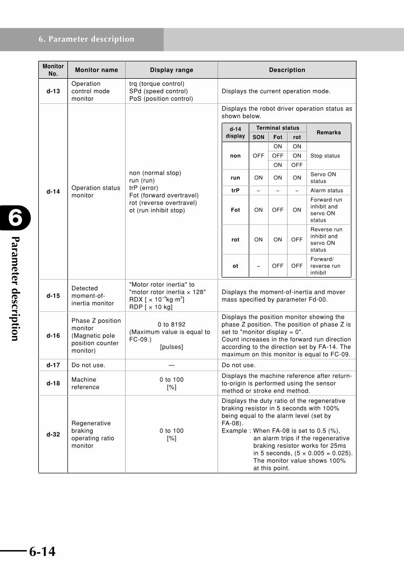
Parameter description
6
6-14
6. Parameter description
6-15
Monitor No.
Monitor name Display range Description
d-13Operation control mode monitor
trq (torque control) SPd (speed control) PoS (position control)
Displays the current operation mode.
d-14Operation status monitor
non (normal stop) run (run) trP (error) Fot (forward overtravel) rot (reverse overtravel) ot (run inhibit stop)
Displays the robot driver operation status as shown below.
d-14 display
Terminal statusRemarks
SON Fot rot
non OFF
ON ON
Stop statusOFF ON
ON OFF
run ON ON ONServo ON status
trP − − − Alarm status
Fot ON OFF ON
Forward run inhibit and servo ON status
rot ON ON OFF
Reverse run inhibit and servo ON status
ot − OFF OFFForward/reverse run inhibit
d-15Detected moment-of-inertia monitor
"Motor rotor inertia" to "motor rotor inertia × 128" RDX [ × 10−4kg·m2] RDP [ × 10 kg]
Displays the moment-of-inertia and mover mass specified by parameter Fd-00.
d-16
Phase Z position monitor (Magnetic pole position counter monitor)
0 to 8192(Maximum value is equal to FC-09.)
[pulses]
Displays the position monitor showing the phase Z position. The position of phase Z is set to "monitor display = 0". Count increases in the forward run direction according to the direction set by FA-14. The maximum on this monitor is equal to FC-09.
d-17 Do not use. — Do not use.
d-18Machine reference
0 to 100 [%]
Displays the machine reference after return-to-origin is performed using the sensor method or stroke end method.
d-32
Regenerative braking operating ratio monitor
0 to 100 [%]
Displays the duty ratio of the regenerative braking resistor in 5 seconds with 100% being equal to the alarm level (set by FA-08).Example : When FA-08 is set to 0.5 (%),
an alarm trips if the regenerative braking resistor works for 25ms in 5 seconds, (5 × 0.005 = 0.025). The monitor value shows 100% at this point.

6-14 6-15
6
Parameter description
6. Parameter description
6.3.2 Setup parameter description(1) Operation mode parameters, etc.
Parameter No.
Parameter nameSetting range
[Default value]Description
FA-00 Control modeS-P, P-S,S-t, t-S,t-P, P-t
[P-S]Set this parameter to "P-S (position control)".
FA-01Position sensor wire breaking detection
on, OFF [on]
Selects whether to make an alarm trip when a position sensor error occurs (or wire breakage or open circuit fault is detected). When this parameter is set to "on", an alarm trips if a position sensor error (E39) is detected. When set to "OFF" no alarm will trip even if a position sensor error (E39) occurs. Even when set to "OFF", a position sensor error (E39) occurs if a counter error is detected by the position sensor. A position sensor error (E39) also occurs at servo ON if power has been turned on without the position sensor connected, regardless of this parameter setting. Set this parameter to "on" in normal operation, and do not set to "OFF" except in case of emergency.
FA-02Allowable time of power failure
0.00, 0.05 to 1.00 (s)
[0.00]
Sets the allowable time for momentary power outage (main circuit power supply shut-off, main circuit power supply open-phase, insufficient main circuit power supply voltage). When this parameter is set to 0.00, the above momentary power outage is not detected.
FA-03Overspeed error detection level
0 to 150 (%)
[110]
When the detected speed value becomes abnormally high compared to the maximum speed, an alarm trips as an overspeed error. This parameter specifies the threshold level for detecting the overspeed error as a percentage of the maximum rotational speed of the robot. When set to 0, overspeed errors are not detected.
FA-04Speed error detection value
0 to maximum speed *1
RDX (min-1) RDP (mm/s)
[Depends on model]
When the speed error (difference between speed command value and speed detection value) becomes abnormally large, an alarm trips as a speed error. This parameter specifies the threshold value for detecting the speed error. When set to 0, speed errors are not detected.
FA-05Position error detection value
0.0 to 100.0 (rotations)
[20.0]
When the position error (difference between position command value and position detection value) becomes abnormally large, an alarm trips as a position deviation error. This parameter specifies the threshold value for detecting the position error in rotation units. When set to 0.0, no position deviation errors are detected.
FA-07DC bus power supply
L123 Pn
[L123]
This parameter sets the method for supplying the main power. When this parameter is set to "Pn", momentary power outage is not detected. Set this parameter to "L123".
Setting Method for supplying main power
L123Supply 3-phase AC power as the main power from terminals L1, L2 and L3.
*1:Thisisthemaximumspeedoftherobot.Checktherobotspecifications.

Parameter description
6
6-16
6. Parameter description
6-17
Parameter No.
Parameter name
Setting range [Default value]
Description
FA-08Regenerative braking operating ratio
0.0 to 100.0 (%)
[Depends on model]
Use this parameter to set the duty ratio of the regenerative braking resistor for 5 seconds. An alarm trips if the regenerative braking time exceeds this setting. (See table below.) When set to 0.0, no alarm due to the duty ratio will trip. Set this parameter value when using an external braking resistor with overheat protection, which is different from the external braking resistors available from YAMAHA as options. When not connecting an external braking resistor, set the allowable duty ratio of the internal braking resistor shown in the table. When using an optional external braking resistor, set the allowable braking frequency value by referring to 10.1, "Options".
Robot driver output Allowable duty ratio of internal braking resistor
3-phase 200V
RD*-05, 10 Other than 0.0%
RD*-20, RDP-25 0.5%
Note: When making the FA-08 setting, always set a value that matches the internal or external braking resistance. If the setting is incorrect, the braking resistor may break down.
FA-09Overload notice level
20 to 100 (%) [80]
If the overload level exceeds the value set in this parameter, then the electronic thermal function outputs an overload warning signal.
FA-10Auto tuning mode
non oFL
onL1 FFt
onL2 [non]
Auto-tuning and mechanical system diagnosis are performed according to the setting of this parameter. Do not set this parameter to "onL1" and "onL2".
Setting Descriptionnon Does not perform auto-tuning.
oFL
Performs offline auto-tuning. When servo is turned ON with this parameter set to "oFL", offline auto-tuning automatically starts. When auto-tuning is completed, the mover mass is automatically set and this parameter is reset to "non".
FFt
Performs mechanical system diagnosis. When the servo is turned ON with this parameter set to "FFt", an FFT analysis is performed by moving the robot in a vibrational motion, and the transmission characteristics of the user’s mechanical system are displayed. After the operation is completed, this parameter is reset to “non”. (Make this setting via the TOP software. Operation will not be correct if this setting is made only on the robot driver. )

6-16 6-17
6
Parameter description
6. Parameter description
Parameter No.
Parameter name
Setting range [Default value]
Description
FA-11Pulse train input mode
F-r P-S A-b r-F
-P-S b-A [F-r]
Use this parameter to select the pulse train position command signal mode from among the following 6 modes.
SettingPulse train position command signal
mode
F-r
PLS : Gives the motion amount in the forward direction in pulse trains.
SIG : Gives the motion amount in the reverse direction in pulse trains.
P-S
PLS : Gives the motion amount in pulse trains.
SIG : Set to OFF when moving in the forward direction or set to ON when in the reverse direction.
A-b
PLS : Input phase A of phase difference 2-phase signal.
SIG : Input phase B of phase difference 2-phase signal.
r-F
PLS : Gives the motion amount in the reverse direction in pulse trains.
SIG : Gives the motion amount in the forward direction in pulse trains.
-P-S
PLS : Give the motion amount in pulse trains.
SIG : Set to ON when moving in the forward direction or set to OFF when in the reverse direction.
b-A
PLS : Input phase B of phase difference 2-phase signal.
SIG : Input phase A of phase difference 2-phase signal.
FA-12Electronic gear numerator
1 to 65535 RDX
[Depends on model] RDP [1]
To input a pulse train position command, set the electronic gear ratio applied to the command value. The gear ratio is given by (FA-12) / (FA-13). The numerator and denominator can be set separately. The settings must meet the following condition: 1/20 ≤ (FA-12) / (FA-13) ≤ 50 The FLIP-X series resolution is 16384 pulses per revolution of the motor, and the PHASER series resolution is 1 pulse per micrometer. The default values are set so as to issue a command of 1μm per pulse.
FA-13Electronic gear denominator
FA-14Motor revolution direction
CC C
[Depends on model]
Use this parameter to change the forward direction of the motor.
Setting Forward direction of motor
CCThe counterclockwise direction as viewed from the motor output shaft end is specified as the forward direction.
CThe clockwise direction as viewed from the motor output shaft end is specified as the forward direction.

Parameter description
6
6-18
6. Parameter description
6-19
Parameter No.
Parameter name
Setting range [Default value]
Description
FA-16DB Operation selection
non trP
SoF [SoF]
Set the condition for applying the dynamic brake.
SettingCondition for applying dynamic
brake
non Does not use the dynamic brake.
trPApplies the dynamic brake only when an alarm has tripped.
SoFApplies the dynamic brake when the servo ON terminal is turned off (including an alarm). (Note 1)
Note 1: The dynamic brake is for emergency stop. Do not perform start or stop by turning the servo ON terminal to ON or OFF. Always turn the servo off after the robot has stopped. Note 2: Regardless of this parameter setting, the dynamic brake is applied when the voltage of the main circuit power supply becomes too low while the control power supply is ON.(RD*-5, 10, and 20)
FA-17Torque limit mode
non A2 oP
[non]
Sets the input source of the torque limit value and the torque limit mode. Set this parameter to "non".
Setting Torque limit mode
nonLimits the torque according only to the 4 quadrant torque limit values (Fb-07 to Fb-10).
FA-18Torque bias mode
non CnS A2 oP
[non]
Sets the input source of torque bias value. Do not set this parameter to "A2" or "oP".
Setting Torque bias mode
non Does not use a torque bias.
CnSApplies a bias using the set torque bias value (Fb-11).
FA-20Speed limit mode
non A1 oP
[non]
Sets the input source of speed limit value and the torque limit mode. Set this parameter to "non".
Setting Speed limit mode
non
Limits the speed according only to the set forward speed limit value and reverse speed limit value (Fb-20, Fb-21).
FA-22Position command selection
PLS Pro oP
[PLS]
Sets the input source of position command value. Set this parameter to "PLS".
Setting Input source of position command
PLSControls the position with the pulse train command input as the command value.

6-18 6-19
6
Parameter description
6. Parameter description
Parameter No.
Parameter name
Setting range [Default value]
Description
FA-23 Homing mode
L-F L-r
H1-F H1-r H2-F H2-r CP t-F t-r
S-F S-r
[Depends on model]
This parameter specifies the homing mode and return-to-origin direction.
SettingReturn-to-origin
direction Return-to-origin
operation
L-F
Do not change.
L-r
H1-F
H1-r
H2-F
H2-r
CP
t-F Forward runStroke end method
t-r Reverse run
S-F Forward runSensor method
S-r Reverse run
When the return-to-origin mode (FA-23) is set to "stroke end method" (t-F, t-r), the robot driver determines whether the robot has reached its stroke end (mechanical end) as follows: When the robot comes into contact with its stroke end during return-to-origin operation, the current increases. When the current exceeds the rated current Ir and the integrated current reaches the current Ia specified by the stroke-end current parameter (Fb-36) as shown below, the robot driver determines that the robot has reached its stroke end.
Current
( ) ) × (Fb-37)lr–100
(Fb-36)×Imax>Ir-Ia 2222∑
Ir: Rated current
Ia: Stroke end current (Fb-36)
Time
( ( )
Note: Return-to-origin operation stops and the servo locks when the ORG terminal is switched from ON to OFF.
FA-24Servo OFF wait time
0.00 to 1.00 (s)
[0.05]
Sets the time from when Servo ON command is turned off until servo ON status is actually cleared. Note: This parameter allows the servo to delay turning off until the specified wait time elapses after activating the brake. Set this wait time to counteract delays in the brake operation. Use this parameter as needed when stopping the robot such as after positioning is complete.
FA-25Operation range at machine diagnosis
1 to 255 (rotations)
[10]
Set the allowable rotation range of the robot during mechanical system diagnosis. Mechanical systems are diagnosed in the positive/negative range of the allowable setting range.

Parameter description
6
6-20
6. Parameter description
6-21
Parameter No.
Parameter name
Setting range [Default value]
Description
FA-26
Brake operation start speed
* Valid only for robot with mechanical brake.
0 to maximum speed
RDX (min-1) RDP (mm/s)
[30]
If the speed becomes lower than the set speed after the Servo ON command is turned off or an alarm has tripped, the brake signal (BRK) activates the brake. If the time set in FA-27 elapses before the speed becomes lower than the set speed, the BRK signal also works to activate the brake.
FA-27
Brake operation start time
* Valid only for robot with mechanical brake.
0, 0.004 to 1.000 (s) [0]
Sets the maximum time from when the Servo ON command is turned off or an alarm has tripped until the brake signal (BRK) works to activate the brake. The time can be set in 4ms steps. If the speed becomes lower than the setting in FA-26 after turning off the Servo ON command, then the BRK signal activates the brake, regardless of this setting (FA-27).
FA-28Electronic thermal level
20 to 105 (%)
[Depends on model]
Sets the electronic thermal level. Change the thermal level so that it matches the ambient temperature and robot operating conditions. When this parameter is changed, the asymptotic line can be moved in parallel with the operation time as shown below. Set this parameter to the default value for each model.
Servo lock
Ope
ratio
n tim
e (s
)
1000
20 105
Asymptotic line
Rotating
Torque
FA-80Position sensor type selection
inC AbS [inC]
When an absolute position sensor is used, this parameter specifies the position sensor type. Set this parameter to "inC".
FA-81Position sensor selection
Stnd inCE
AbSE1 AbSE2 AbSA2 AbSA4 [inCE]
This parameter specifies the position sensor type . Set this parameter to "inCE". Note 1: A "Mismatch error (E40)" occurs if this parameter is set incorrectly. Note 2: This setting is enabled by turning power off and then back on. Note 3: This parameter is not reset by user initialization.
FA-82Position sensor resolution
500 to 65535 (pulses)
RDX [4096] RDP
[Depends on model]
Sets the number of pulses per rotation of the position sensor. Set this parameter to the default value for each model.
FA-85
Linear scale accuracy
* Valid only for RDP.
0.01 to 655.35 (μm) [1.00]
Sets the machine length equivalent to 1 pulse of ×4 signal on the linear scale. Set this parameter to "1.00".

6-20 6-21
6
Parameter description
6. Parameter description
Parameter No.
Parameter name
Setting range [Default value]
Description
FA-86
Pole position offset
* Valid only for RDP.
8000 to 7FFF [0]
Specifies the phase Z distance used as the reference and zero crossing (rising) for the induced voltage of phase U or across U and V. Set this parameter in signed hexadecimal of 16-bit length. By quantizing this setting, the 180° electrical angle of the linear motor will be H'4000 (hexadecimal). Use FA-88 to set the type of reference voltage (phase voltage or line voltage).
FA-87
Linear scale polarity
* Valid only for RDP.
A, b [b]
Sets the phase direction in the forward run of the linear scale. Set this parameter to "b".
Setting Phase
b Phase B leads phase A.
FA-88
Phase angle of pole position
* Valid only for RDP.
PHASE, LinE
[PHASE]
Sets whether the phase of magnetic pole position signal is the same as the phase voltage or line voltage of the linear motor induced voltage. The offset specified by parameter FA-86 is relative to this parameter setting. Set this parameter to "PHASE".
Setting Phase
PHASE
• Magnetic pole position signal has the same phase as phase voltage. • FA-86 is relative to the induced voltage of phase U.
FA-89
Preset condition for pole position
* Valid only for RDP.
OrLP, OrLn
[OrLP]
Sets the condition for presetting the magnetic pole position. Set this parameter to "OrLP".
Setting Preset condition
OrLPPreset at the first phase Z position after the ORL signal is switched from OFF to ON.
FA-90
Hall sensor connection
* Valid only for RDP.
oFF, CnCt, oFF2
[oFF2]
Sets the sequence of magnetic pole position estimation operation. Use this parameter by setting to "oFF2".
Setting Description
oFF2
Starts magnetic pole position estimation only when the SON terminal is first switched from OFF to ON after power-on.
Note 1: When set to "oFF2", the RS terminal is enabled only when resetting an alarm after it has tripped.
FA-98Initialization mode selection
CH dAtA AbS [CH]
Use this parameter to select whether to clear the alarm/trip log or to initialize the user data. Do not set this parameter to "AbS".
Setting Description
CH
Clears the alarm/trip log. Cancels the monitor of a specific parameter (d-xx) that is automatically displayed at power-on.
dAtA Initializes the user data.

Parameter description
6
6-22
6. Parameter description
6-23
(2) Operation constant parameters
Parameter No.
Parameter nameSetting range
[Default value]Description
Fb-04Speed acceleration time 0.00 to 99.99
(s) [10.00]
Sets the acceleration/deceleration time to perform return-to-origin. Set the time needed to accelerate from 0 to the maximum motor speed (or time needed to decelerate from maximum motor speed to 0).Fb-05
Speed deceleration time
Fb-07 Torque limit value 1
0 to maximum torque
(%) [Depends on model]
Sets the torque limit value for each quadrant. Torque limit values 1, 2, 3, and 4 correspond to the first quadrant through fourth quadrant. Set an absolute value for all quadrants. Movement direction is same for Fb-07 to Fb10.
Fb-08
Fb-09
Fb-07
Fb-10
Torque (Forward direction: CCW)
Speed (CCW)
Secondquadrant First
quadrant
Thirdquadrant Fourth
quadrant
Fb-08 Torque limit value 2
Fb-09 Torque limit value 3
Fb-10 Torque limit value 4
Fb-11 Torque bias value±0 to ±300
(%) [0]
When setting the torque bias to a fixed value, specify it with this parameter. In this case, FA-18 must be set to "CnS". Set the bias value in the ratio to the rated torque defined as 100%.
Fb-12Homing speed 1 (Fast)
RDX 1 to maximum
speed *1 (min-1) [60]
RDP 1 to 100
(mm/s) [20]
Sets the fast speed to perform return-to-origin.
Fb-13Homing speed 2 (Slow)
RDX 1 to 999
(min-1) [6] RDP
1 to 20 (mm/s) [5]
Sets the slow speed to perform return-to-origin.
Fb-14Offset position (H/L) at return-to-origin (homing)
±0 to ±19999 *2 (pulses)
[0]
Sets the offset position to perform return-to-origin. Ten-digit data consisting of high-order digits specified by Fb-14 and lower-order digits specified by Fb-15 is used to determine the offset position during return-to-origin.Fb-15
0 to 99999 (pulses)
[0]
*1:Thisisthemaximumspeedoftherobot.Checktherobotspecifications.
*2: Methods for displaying and entering these parameter values (–10000 to –19999) differ from other methods.Fortheoperationmethod,referto"(3)Specialdisplay"insection6.1.2,"Operatingthedigitaloperator".

6-22 6-23
6
Parameter description
6. Parameter description
Parameter No.
Parameter nameSetting range
[Default value]Description
Fb-16Forward position limit value (H/L)
±0 to ±19999 *2 (pulses)
[0]
Sets the drive range in the forward (+) direction. Ten-digit data (number of position sensor pulses) consisting of high-order digits specified by Fb-16 and lower-order digits specified by Fb-17 is used to determine the forward (+) position limit value. No limit is in effect when these parameters are set to 0. Note: Refer to precautions on Fb-18 and Fb-19.
Fb-170 to 99999
(pulses) [0]
Fb-18Reverse position limit value (H/L)
±0 to ±19999 *2 (pulses)
[0]
Sets the drive range in the reverse (–) direction. No limit is in effect when these parameters are set to 0. Note: In the following case, the setting is invalid and the motor operates with no limit. Position limit value (+) ≤ Position limit value (–) (Fb-16: Fb-17) (Fb-18: Fb-19)
Fb-190 to 99999
(pulses) [0]
Fb-20Forward speed limit value
0 to maximum speed *1
RDX (min-1) RDP (mm/s)
[Depends on model]Sets the upper speed limit.
Fb-21Reverse speed limit value
-maximum speed to 0
RDX (min-1) RDP (mm/s)
[Depends on model]
Fb-23Positioning detection range
1 to 65535 (pulses)
[20]
Sets the threshold value for position deviation (difference between position command value and position detection value) used to determine whether positioning is complete.
Fb-24Positioning interval time limit
0.00 to 10.00 (s)
[0.00]
Sets the threshold value for the time difference between position command value and position detection value (time required for position detection value to reach the position command value) used to determine whether positioning is complete. When set to 0.00, no monitoring is performed. This parameter can be set in 0.02 steps.
Fb-25Up to speed detection range
0 to 100 RDX (min-1) RDP (mm/s)
[10]
Sets the threshold value for the speed deviation (difference between speed command value and speed detection value) used to determine whether the specified speed is reached.
Fb-30 S-curve ratio
non SHArP rEGLr LooSE [non]
Set this parameter to "non".
Fb-35Homing back distance
1 to 255 [Depends on model]
Sets the distance the robot moves back from the mechanical end after detecting it during return-to-origin operation using the stroke end method.
*1:Thisisthemaximumspeedoftherobot.Checktherobotspecifications.
*2: Methods for displaying and entering these parameter values (–10000 to –19999) differ from other methods.Fortheoperationmethod,referto"(3)Specialdisplay"insection6.1.2,"Operatingthedigitaloperator".

Parameter description
6
6-24
6. Parameter description
6-25
Parameter No.
Parameter nameSetting range
[Default value]Description
Fb-36Current for striking limit
40 to 100 (%)
[Depends on model]
Sets the stroke-end current that is detected when the robot comes into contact with its mechanical end during return-to-origin operation using the stroke end method.
Fb-37Time for striking limit
0.1 to 2.0 (s)
[0.2]
Sets the time during which the mechanical end is detected during return-to-origin operation using the stroke end method.
Fb-40 (Note 1)
Pole position estimation speed
* Valid only for RDP.
–500 to 500 (mm/s)
[Depends on model]
Sets the speed command value during magnetic pole position estimation.
Fb-41 (Note 1)
Pole position estimation ACC/DEC time
* Valid only for RDP.
10 to 500 (ms)
[Depends on model]
Sets the acceleration/deceleration time during magnetic pole position estimation.
Fb-42 (Note 1)
Pole position estimation wait time
* Valid only for RDP.
0 to 500 (ms) [100]
Sets the time interval during magnetic pole position estimation.
Fb-43 (Note 1)
Pole position estimation constant-speed time
* Valid only for RDP.
0 to 500 (ms)
[Depends on model]
Sets the constant-speed time during magnetic pole position estimation.
Fb-44 (Note 1)
Position sensor wire breaking detection current
* Valid only for RDP.
20 to 100 (%)
[Depends on model]
Set the current to be applied for detecting the position sensor wire breakage. If this parameter is set to 100 [%], then the motor rated current will be applied.
Fb-45 (Note 1)
Speed error detection value at pole position estimation
* Valid only for RDP.
0 to maximum speed (mm/s)
[500]
Set the speed deviation error detection value during magnetic pole position estimation. When set to 0, speed deviation errors will not be detected.
Note 1: Displayed on the RDP only.
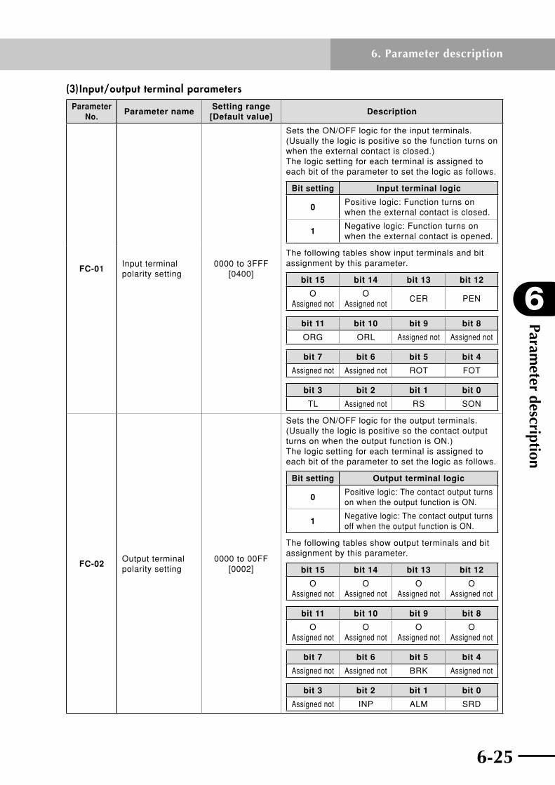
6-24 6-25
6
Parameter description
6. Parameter description
(3) Input/output terminal parameters
Parameter No.
Parameter nameSetting range
[Default value]Description
FC-01Input terminal polarity setting
0000 to 3FFF [0400]
Sets the ON/OFF logic for the input terminals. (Usually the logic is positive so the function turns on when the external contact is closed.) The logic setting for each terminal is assigned to each bit of the parameter to set the logic as follows.
Bit setting Input terminal logic
0Positive logic: Function turns on when the external contact is closed.
1Negative logic: Function turns on when the external contact is opened.
The following tables show input terminals and bit assignment by this parameter.
bit 15 bit 14 bit 13 bit 12
O Assigned not
O Assigned not
CER PEN
bit 11 bit 10 bit 9 bit 8
ORG ORL Assigned not Assigned not
bit 7 bit 6 bit 5 bit 4
Assigned not Assigned not ROT FOT
bit 3 bit 2 bit 1 bit 0
TL Assigned not RS SON
FC-02Output terminal polarity setting
0000 to 00FF [0002]
Sets the ON/OFF logic for the output terminals. (Usually the logic is positive so the contact output turns on when the output function is ON.) The logic setting for each terminal is assigned to each bit of the parameter to set the logic as follows.
Bit setting Output terminal logic
0Positive logic: The contact output turns on when the output function is ON.
1Negative logic: The contact output turns off when the output function is ON.
The following tables show output terminals and bit assignment by this parameter.
bit 15 bit 14 bit 13 bit 12
O Assigned not
O Assigned not
O Assigned not
O Assigned not
bit 11 bit 10 bit 9 bit 8
O Assigned not
O Assigned not
O Assigned not
O Assigned not
bit 7 bit 6 bit 5 bit 4
Assigned not Assigned not BRK Assigned not
bit 3 bit 2 bit 1 bit 0
Assigned not INP ALM SRD
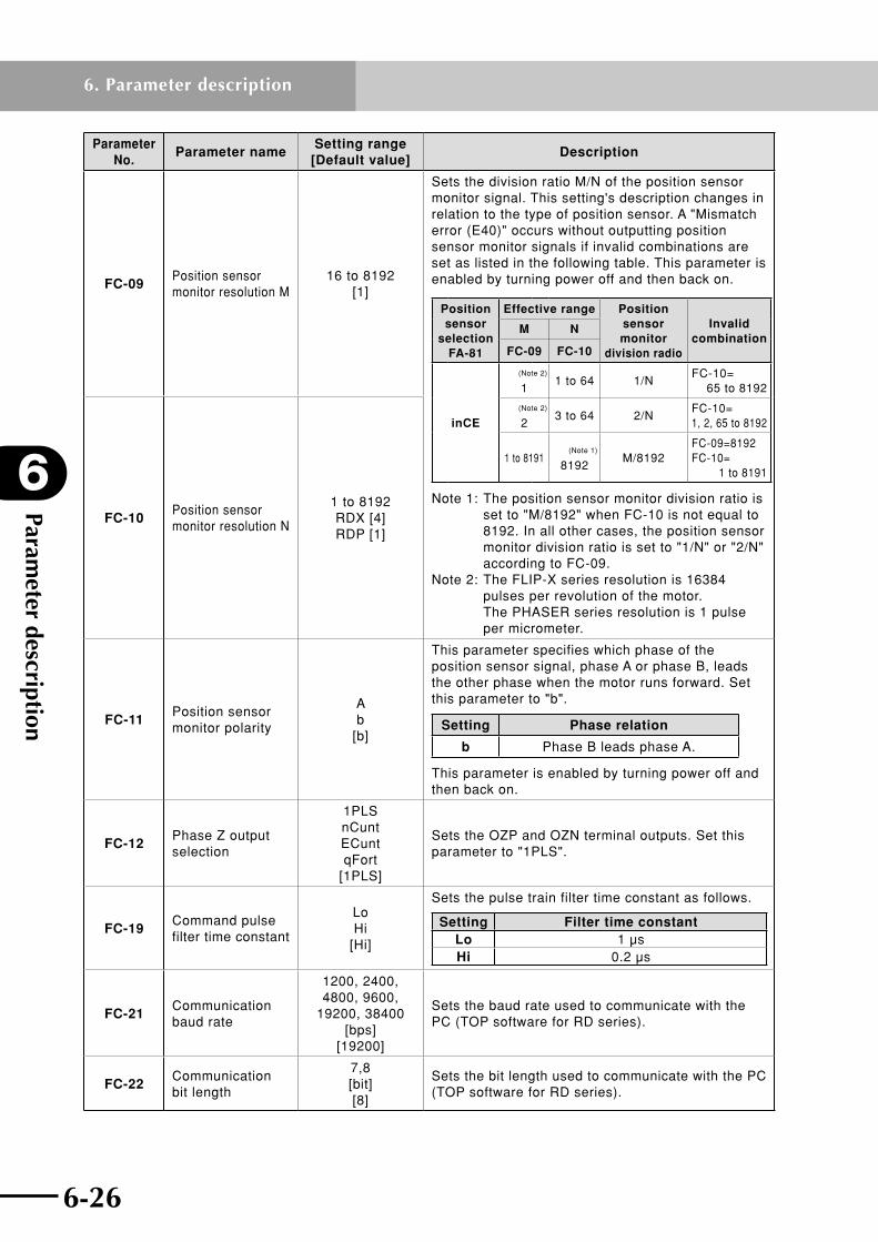
Parameter description
6
6-26
6. Parameter description
6-27
Parameter No.
Parameter nameSetting range
[Default value]Description
FC-09Position sensor monitor resolution M
16 to 8192 [1]
Sets the division ratio M/N of the position sensor monitor signal. This setting's description changes in relation to the type of position sensor. A "Mismatch error (E40)" occurs without outputting position sensor monitor signals if invalid combinations are set as listed in the following table. This parameter is enabled by turning power off and then back on.
Position sensor
selection FA-81
Effective range Position sensor monitor
division radio
Invalid combination
M N
FC-09 FC-10
inCE
(Note 2)
11 to 64 1/N
FC-10= 65 to 8192
(Note 2)
23 to 64 2/N
FC-10= 1, 2, 65 to 8192
1 to 8191(Note 1)
8192M/8192
FC-09=8192 FC-10= 1 to 8191
Note 1: The position sensor monitor division ratio is set to "M/8192" when FC-10 is not equal to 8192. In all other cases, the position sensor monitor division ratio is set to "1/N" or "2/N" according to FC-09. Note 2: The FLIP-X series resolution is 16384 pulses per revolution of the motor. The PHASER series resolution is 1 pulse per micrometer.
FC-10Position sensor monitor resolution N
1 to 8192 RDX [4] RDP [1]
FC-11Position sensor monitor polarity
A b
[b]
This parameter specifies which phase of the position sensor signal, phase A or phase B, leads the other phase when the motor runs forward. Set this parameter to "b".
Setting Phase relation
b Phase B leads phase A.
This parameter is enabled by turning power off and then back on.
FC-12Phase Z output selection
1PLS nCunt ECunt qFort
[1PLS]
Sets the OZP and OZN terminal outputs. Set this parameter to "1PLS".
FC-19Command pulse filter time constant
Lo Hi
[Hi]
Sets the pulse train filter time constant as follows.
Setting Filter time constantLo 1 μsHi 0.2 μs
FC-21Communication baud rate
1200, 2400, 4800, 9600,
19200, 38400 [bps]
[19200]
Sets the baud rate used to communicate with the PC (TOP software for RD series).
FC-22Communication bit length
7,8 [bit] [8]
Sets the bit length used to communicate with the PC (TOP software for RD series).

6-26 6-27
6
Parameter description
6. Parameter description
Parameter No.
Parameter nameSetting range
[Default value]Description
FC-23Communication parity
non, odd, EvEn [non]
Sets the parity f used to communicate with the PC (TOP software for RD series).
Setting Description
non Communication parity: none
odd Communication parity: odd
EvEn Communication parity: even
After this parameter is changed, turn power off and then back on to enable the change. Otherwise, a malfunction will occur.
FC-24Communication stop bit
1, 2 [2]
Sets the stop bit used to communicate with the PC (TOP software for RD series).
FC-30Monitor output 1 function
nrF, nFb, iFb, tqr, nEr, PEr,
PFq, brd [nFb]
Sets the data items to be output as the monitor outputs 1 and 2 as shown in the table below. "yes" indicates that the corresponding value is output, and "no" indicates that 0V is output. The data items shown in the "3V output value" column are available when the monitor output gains 1 and 2 are 100.0.
Setting Data item3.0V
output value
Control mode
Position Speed Torque
nFbSpeed detection value
Maximum speed yes yes yes
tqrTorque command value
Maximum torque yes yes yes
nrFSpeed command value
Maximum speed yes yes no
nEr Speed deviation
Maximum speed yes yes no
PEr Position deviation
Five motor
rotationsyes no no
iFb Current value
Maximum current yes yes yes
PFqCommand pulse frequency
Maximum speed yes no no
brd
Regenerative braking resistor duty ratio
Trip level
(FA-08)yes yes yes
Note: When an alarm has tripped, 0V is output from all data items except the speed detection value. However, if a position sensor error (E39) occurs then the speed detection value is no longer fixed.
FC-33Monitor output 2 function
nrF, nFb, iFb, tqr, nEr, PEr,
PFq, brd [tqr]
FC-31Monitor output 1 polarity
SiGn, AbS [SiGn]
This parameter specifies whether to output data from monitor outputs 1 and 2 in a range of 0 to ±3.0V or 0 to 3.0V.
Setting Description
SiGn 0 to ±3.0V (Note)
AbS 0 to 3.0V
Note: The output is positive only when FC-30 and FC-33 are set to "PFq" or "brd".
FC-34Monitor output 2 polarity

Parameter description
6
6-28
6. Parameter description
6-29
Parameter No.
Parameter nameSetting range
[Default value]Description
FC-32Monitor output 1 gain
0.0 to 3000.0 (%)
[100.0]
Use these parameters to set the gain of monitor outputs 1 and 2. When set to 100.0, the voltage shown in the table for FC-30 and FC-33 is output. The following graph shows the relation between gain and output voltage (when FC-30 and FC-33 are set to "tqr").
100.0%
-3.0V
3.0V
0
0
50.0%
200.0%
Maximum value %
Minimumvalue %
Torque command value
FC-35Monitor output 2 gain
FC-40Input terminal function
0 to 3FFF [0]
This parameter specifies which of 1st function and 2nd function of the input terminal should be enabled. (0 = 1st function, 1 = 2nd function)
Setting b13 b12 b11 b10 b9 b8
0 CER PEN ORG ORL – –
1 Does not function. – –
Setting b7 b6 b5 b4 b3 b2 b1 b0
0 – – ROT FOT TL – RS SON
1 – – FOT ROTDoes not
function.–
Does not function.
Note 1: When either of b4 or b5 of FC40 is set to 1, b4 functions as FOT and b5 as FOT. Note 2: The FOT and ROT terminal functions do not change even if the FA-14 (Motor revolution direction) setting is changed. FOT prohibits counterclockwise direction and ROT prohibits clockwise direction. Note 3: After FA-14 or FC-40 setting is changed, turn power off and then back on to enable the change.
FC-70Debug mode selection
0 [0]
Set this parameter to "0".

6-28 6-29
6
Parameter description
6. Parameter description
(4) Control constant parameter
Parameter No.
Parameter nameSetting range
[Default value]Description
Fd-00
Moment of inertia (RDX)
"Motor rotor inertia" to "motor
rotor inertia × 128" RDX (×10-4kg·m2)
RDP (×10kg) [Depends on model]
Use this parameter to set the entire mover mass including both rotary motor and load. This parameter can also be set automatically by auto-tuning.
Mover mass (RDP)
Use this parameter to set the entire mover mass including both linear motor and load. This parameter can also be set automatically by auto-tuning.
Fd-01Speed control cut-off frequency
0.1 to 500.0 (Hz)
[Depends on model]
The speed control gain for speed PI control is calculated from the mover mass and this parameter setting. Usually set this parameter to a value close to the 3dB cut-off frequency obtained by measuring the frequency characteristic with a repetitive waveform when the speed control section performs PI control. When IP control is specified in Fd-05, the response speed becomes lower than the set value.
Fd-02Speed control proportional gain
0.01 to 300.00 (%)
[Depends on model]
Set this parameter to adjust the proportional gain used for speed PI control. When set to 100%, the proportional gain is set to the constant specified in Fd-00 and Fd-01. (Proportional gain) ∝ (Fd-00) × (Fd-01) × Fd-02 / 100
Fd-03Speed control integral gain
0.01 to 300.00 (%)
[Depends on model]
Set this parameter to adjust the integral gain used for speed PI control. When set to 100%, the integral gain is set to the constant specified in Fd-00 and Fd-01. (Integral gain) ∝ (Fd-00) × (Fd-01)2 × Fd-03 / 100
Fd-04 P-control gain0.1 to 99.9
(%) [Depends on model]
Set the gain used for speed P control. Set it by the torque (rated torque) to be output when a 1% speed deviation is provided.
Fd-05 IP-control gain0.00 to 1.00
[Depends on model]
Use this parameter to continuously switch the speed feedback loop between PI and IP. When this parameter is set to 0, ordinary PI control is performed. At 1.00, IP control is performed. However, if this parameter (Fd-05) is set to a large value while Fd-00 and Fd-01 are large, then oscillation might occur. In this case, reduce Fd-02 to avoid such oscillation.
Fd-06Torque command filter time constant
0.00 to 500.00 (ms)
[Depends on model]
This parameter sets the time constant for the first-order lag filter to be applied to the torque command value. When this parameter is set to 0, no filtering is performed.
Fd-07Position phase compensating ratio
0.01 to 9.99 [Depends on model]
Sets the compensation ratio for the phase lag filter to apply to the speed command value serving as the position control loop output. When this parameter exceeds 1, a phase lag occurs.
Fd-08Position phase compensating time constant
0.1 to 999.9 (ms)
[Depends on model]
Sets the compensation time constant for the phase lag filter to apply to the speed command serving as the position control loop output.
Fd-09Position control cut-off frequency
0.01 to 99.99 (Hz)
[Depends on model]
Sets the response frequency of the position feedback loop. Usually set this parameter to about 1/6 of the speed control cut-off frequency.
Fd-10Position feed forward gain
0.00 to 1.00 [Depends on model]
Sets the ratio used to perform feed-forward compensation for the position control.
Fd-12Notch filter 1 frequency
3.0 to 1000.0 (Hz)
[Depends on model]
Sets the resonance frequency of notch filter 1. (Use TOP software to set this parameter.)
Fd-13Notch filter 1 bandwidth
0 to 40 (dB)
[Depends on model]
Sets the bandwidth of notch filter 1 at the resonance frequency. (Use TOP software to set this parameter.)
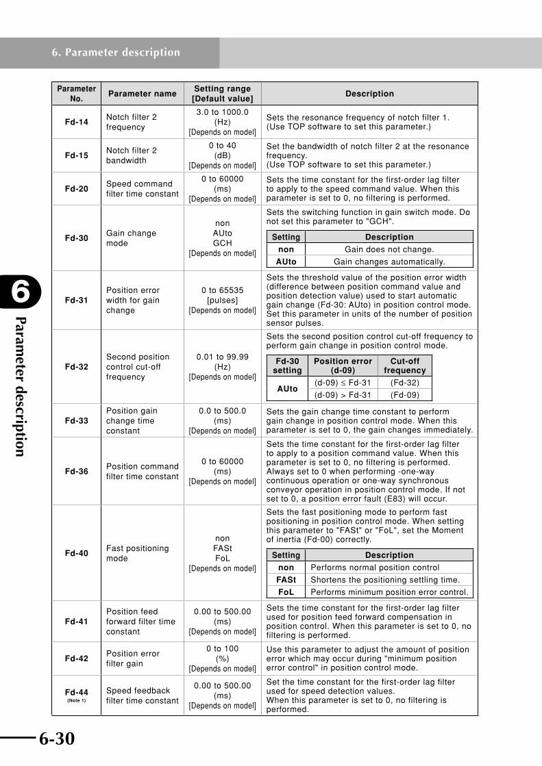
Parameter description
6
6-30
6. Parameter description
6-31
Parameter No.
Parameter nameSetting range
[Default value]Description
Fd-14Notch filter 2 frequency
3.0 to 1000.0 (Hz)
[Depends on model]
Sets the resonance frequency of notch filter 1. (Use TOP software to set this parameter.)
Fd-15Notch filter 2 bandwidth
0 to 40 (dB)
[Depends on model]
Set the bandwidth of notch filter 2 at the resonance frequency. (Use TOP software to set this parameter.)
Fd-20Speed command filter time constant
0 to 60000 (ms)
[Depends on model]
Sets the time constant for the first-order lag filter to apply to the speed command value. When this parameter is set to 0, no filtering is performed.
Fd-30Gain change mode
non AUto GCH
[Depends on model]
Sets the switching function in gain switch mode. Do not set this parameter to "GCH".
Setting Description
non Gain does not change.
AUto Gain changes automatically.
Fd-31Position error width for gain change
0 to 65535 [pulses]
[Depends on model]
Sets the threshold value of the position error width (difference between position command value and position detection value) used to start automatic gain change (Fd-30: AUto) in position control mode. Set this parameter in units of the number of position sensor pulses.
Fd-32Second position control cut-off frequency
0.01 to 99.99 (Hz)
[Depends on model]
Sets the second position control cut-off frequency to perform gain change in position control mode.
Fd-30 setting
Position error (d-09)
Cut-off frequency
AUto(d-09) ≤ Fd-31 (Fd-32)
(d-09) > Fd-31 (Fd-09)
Fd-33Position gain change time constant
0.0 to 500.0 (ms)
[Depends on model]
Sets the gain change time constant to perform gain change in position control mode. When this parameter is set to 0, the gain changes immediately.
Fd-36Position command filter time constant
0 to 60000 (ms)
[Depends on model]
Sets the time constant for the first-order lag filter to apply to a position command value. When this parameter is set to 0, no filtering is performed. Always set to 0 when performing -one-way continuous operation or one-way synchronous conveyor operation in position control mode. If not set to 0, a position error fault (E83) will occur.
Fd-40Fast positioning mode
non FASt FoL
[Depends on model]
Sets the fast positioning mode to perform fast positioning in position control mode. When setting this parameter to "FASt" or "FoL", set the Moment of inertia (Fd-00) correctly.
Setting Description
non Performs normal position control
FASt Shortens the positioning settling time.
FoL Performs minimum position error control.
Fd-41Position feed forward filter time constant
0.00 to 500.00 (ms)
[Depends on model]
Sets the time constant for the first-order lag filter used for position feed forward compensation in position control. When this parameter is set to 0, no filtering is performed.
Fd-42Position error filter gain
0 to 100 (%)
[Depends on model]
Use this parameter to adjust the amount of position error which may occur during "minimum position error control" in position control mode.
Fd-44 (Note 1)
Speed feedback filter time constant
0.00 to 500.00 (ms)
[Depends on model]
Set the time constant for the first-order lag filter used for speed detection values. When this parameter is set to 0, no filtering is performed.

6-30 6-31
6
Parameter description
6. Parameter description
Parameter No.
Parameter nameSetting range
[Default value]Description
Fd-46 (Note 1)
Mover mass for pole position estimation
"Robot mass" to "robot mass × 128"
(× 10kg) [Depends on model]
Sets the mover mass during for pole position estimation.
Fd-47 (Note 1)
Speed control cut-off frequency for pole position estimation
0.1 to 500.0 (Hz)
[Depends on model]
Sets the speed control cut-off frequency for magnetic pole position estimation.
Fd-48 (Note 1)
Gain change time constant after pole position estimation
0.0 to 500.0 (ms)
[Depends on model
Sets the time constant of the first-order lag filter to reduce switching shock during control gain switching after the magnetic pole position estimation is completed.
Note 1: Displayed on RDP only.

Parameter description
6
6-32
6. Parameter description
6-33
6.3.3 Reference graph for setting the acceleration and position control cut-off frequency
Foryourreference,thefollowinggraphsshowpayload,acceleration,andpositioncontrolcut-offfrequency(Fd-09),plottedwhenthemomentofinertiaormovermass(Fd-00),speedcontrolcut-offfrequency(Fd-01),andspeedcontrolintegralgain(Fd-03)parameters are set to the specified values for each robot model. By referring to these graphs,setthepositioncontrolcut-offfrequency(Fd-09)andaccelerationthatmatchtherequiredpayload.
How to read graph
Example: T7-12
Model T7-12
Maximum payload [kg] 8.0 [kg]
Fd-00 Moment of inertia 0.125 [×10-4kg •m2]Fd-01 Speed control cut-off frequency 100.0 [Hz]Fd-03 Speed control integral gain 65.0 [%]
0.00
0.10
0.20
0.30
0.40
0.50
0.60
0.0 1.0 2.0 3.0 4.0 5.0 6.0 7.0 8.00.0
2.0
4.0
6.0
8.0
10.0
12.0
14.0
Fd-
09[H
z]
Acceleration[G]
Fd-09[Hz]
Payload[kg]
Acc
eler
atio
n[G
]
Payload[kg]
Acceleration[G]
Fd-09[Hz]
0.0 0.55 11.6
2.0 0.49 8.8
4.0 0.43 7.0
6.0 0.37 5.9
8.0 0.31 5.0
0.46[G]0.46[G]
7.85[Hz]7.85[Hz]
The above table shows examples for setting accel-erations and position control cut-off frequencies (Fd-09) that match different payloads. If the required payload is not listed in this table, refer to the graph on the right.
Example: If a payload of 3kg is required, then the acceleration is 0.46 [G] and the position control cut-off frequency (Fd-09) is 7.85 [Hz].
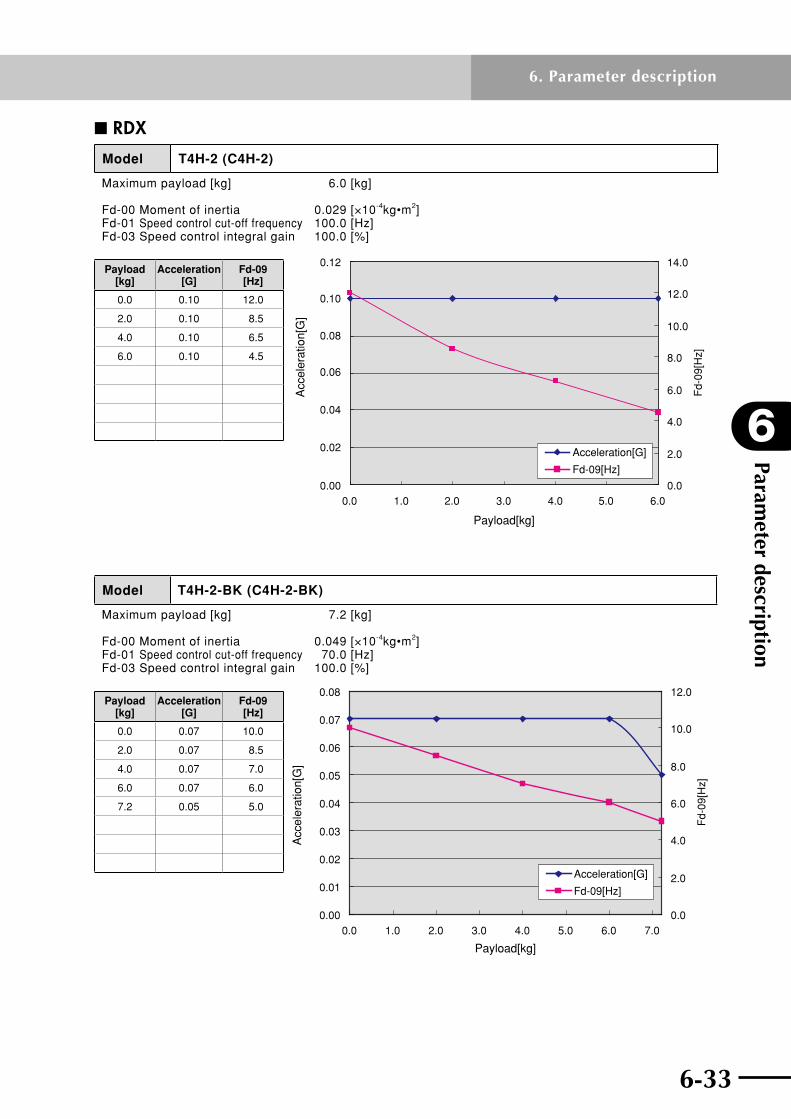
6-32 6-33
6
Parameter description
6. Parameter description
n RDX
Model T4H-2 (C4H-2)
Maximum payload [kg] 6.0 [kg]
Fd-00 Moment of inertia 0.029 [×10-4kg•m2]Fd-01 Speed control cut-off frequency 100.0 [Hz]Fd-03 Speed control integral gain 100.0 [%]
0.00
0.02
0.04
0.06
0.08
0.10
0.12
0.0 1.0 2.0 3.0 4.0 5.0 6.00.0
2.0
4.0
6.0
8.0
10.0
12.0
14.0
Fd-
09[H
z]
Payload[kg]
Acc
eler
atio
n[G
]
Acceleration[G]
Fd-09[Hz]
Payload [kg]
Acceleration [G]
Fd-09 [Hz]
0.0 0.10 12.0
2.0 0.10 8.5
4.0 0.10 6.5
6.0 0.10 4.5
Model T4H-2-BK (C4H-2-BK)
Maximum payload [kg] 7.2 [kg]
Fd-00 Moment of inertia 0.049 [×10-4kg•m2]Fd-01 Speed control cut-off frequency 70.0 [Hz]Fd-03 Speed control integral gain 100.0 [%]
0.00
0.01
0.02
0.03
0.04
0.05
0.06
0.07
0.08
0.0 1.0 2.0 3.0 4.0 5.0 6.0 7.00.0
2.0
4.0
6.0
8.0
10.0
12.0F
d-09
[Hz]
Payload[kg]
Acc
eler
atio
n[G
]
Acceleration[G]
Fd-09[Hz]
Payload [kg]
Acceleration [G]
Fd-09 [Hz]
0.0 0.07 10.0
2.0 0.07 8.5
4.0 0.07 7.0
6.0 0.07 6.0
7.2 0.05 5.0
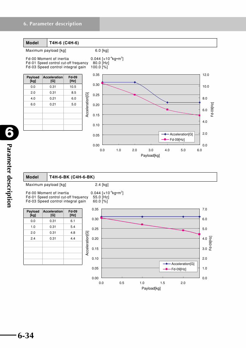
Parameter description
6
6-34
6. Parameter description
6-35
Model T4H-6 (C4H-6)
Maximum payload [kg] 6.0 [kg]
Fd-00 Moment of inertia 0.044 [×10-4kg•m2]Fd-01 Speed control cut-off frequency 80.0 [Hz]Fd-03 Speed control integral gain 100.0 [%]
0.00
0.05
0.10
0.15
0.20
0.25
0.30
0.35
0.0 1.0 2.0 3.0 4.0 5.0 6.00.0
2.0
4.0
6.0
8.0
10.0
12.0
Payload[kg]
Acc
eler
atio
n[G
]
Fd-
09[H
z]
Acceleration[G]
Fd-09[Hz]
Payload [kg]
Acceleration [G]
Fd-09 [Hz]
0.0 0.31 10.5
2.0 0.31 8.5
4.0 0.21 6.0
6.0 0.21 5.0
Model T4H-6-BK (C4H-6-BK)
Maximum payload [kg] 2.4 [kg]
Fd-00 Moment of inertia 0.044 [×10-4kg•m2]Fd-01 Speed control cut-off frequency 55.0 [Hz]Fd-03 Speed control integral gain 60.0 [%]
0.00
0.05
0.10
0.15
0.20
0.25
0.30
0.35
0.0 0.5 1.0 1.5 2.0
Payload[kg]
Acc
eler
atio
n[G
]
0.0
1.0
2.0
3.0
4.0
5.0
6.0
7.0F
d-09
[Hz]
Acceleration[G]
Fd-09[Hz]
Payload [kg]
Acceleration [G]
Fd-09 [Hz]
0.0 0.31 6.1
1.0 0.31 5.4
2.0 0.31 4.8
2.4 0.31 4.4

6-34 6-35
6
Parameter description
6. Parameter description
Model T4H-12 (C4H-12)
Maximum payload [kg] 4.5 [kg]
Fd-00 Moment of inertia 0.038 [×10-4kg•m2]Fd-01 Speed control cut-off frequency 100.0 [Hz]Fd-03 Speed control integral gain 65.0 [%]
0.00
0.10
0.20
0.30
0.40
0.50
0.60
0.70
0.0 1.0 2.0 3.0 4.00.0
1.0
2.0
3.0
4.0
5.0
6.0
7.0
8.0
9.0
10.0
Fd-
09[H
z]
Payload[kg]
Acc
eler
atio
n[G
]
Acceleration[G]
Fd-09[Hz]
Payload [kg]
Acceleration [G]
Fd-09 [Hz]
0.0 0.61 9.2
1.0 0.61 6.4
2.0 0.43 5.0
3.0 0.43 5.0
4.5 0.31 5.0
Model T4H-12-BK (C4H-12-BK)
Maximum payload [kg] 1.2 [kg]
Fd-00 Moment of inertia 0.044 [×10-4kg•m2]Fd-01 Speed control cut-off frequency 80.0 [Hz]Fd-03 Speed control integral gain 100.0 [%]
0.00
0.10
0.20
0.30
0.40
0.50
0.60
0.70
0.0 0.2 0.4 0.6 0.8 1.0 1.20.0
1.0
2.0
3.0
4.0
5.0
6.0
7.0
Fd-
09[H
z]
Payload[kg]
Acc
eler
atio
n[G
]
Acceleration[G]
Fd-09[Hz]
Payload [kg]
Acceleration [G]
Fd-09 [Hz]
0.0 0.61 6.0
1.2 0.61 6.0
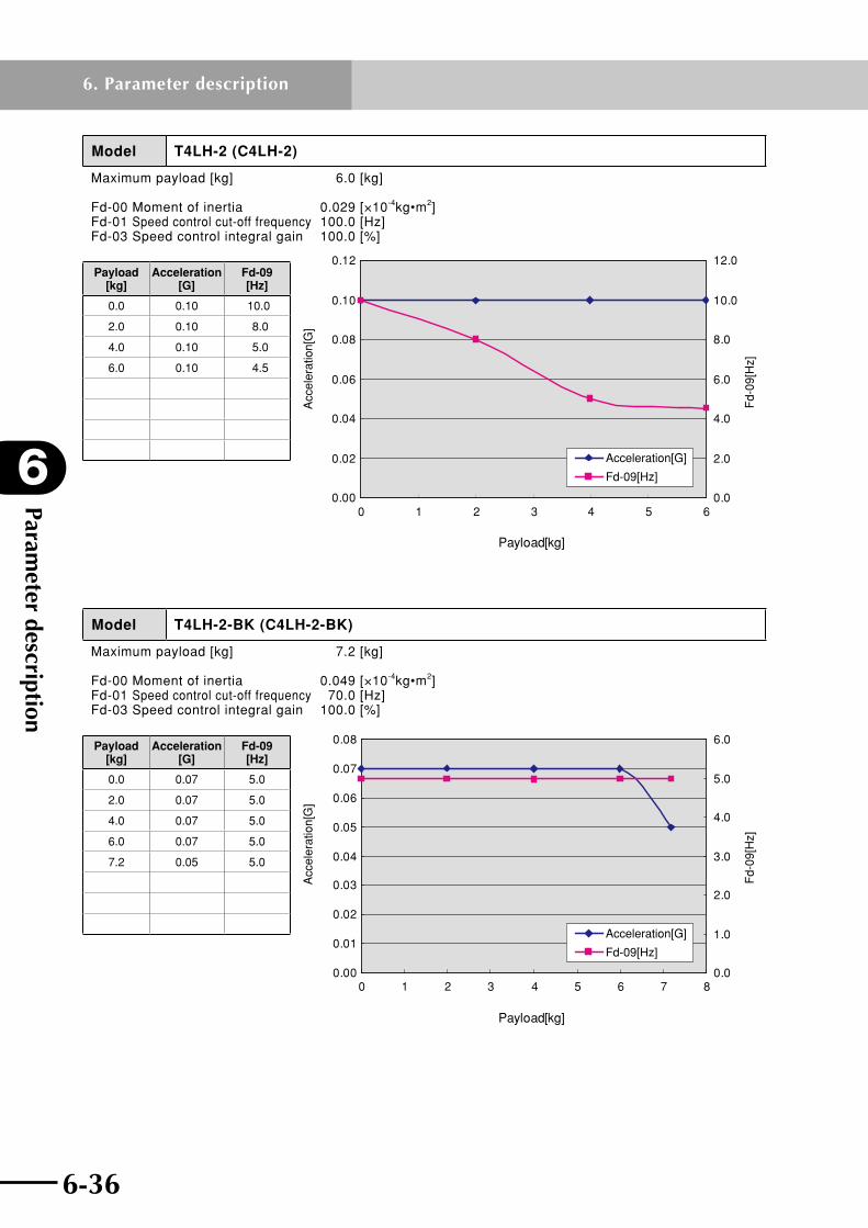
Parameter description
6
6-36
6. Parameter description
6-37
Model T4LH-2 (C4LH-2)
Maximum payload [kg] 6.0 [kg]
Fd-00 Moment of inertia 0.029 [×10-4kg•m2]Fd-01 Speed control cut-off frequency 100.0 [Hz]Fd-03 Speed control integral gain 100.0 [%]
Payload[kg]
Acc
eler
atio
n[G
]
Fd-
09[H
z]
0.00
0.02
0.04
0.06
0.08
0.10
0.12
0 1 2 3 4 5 60.0
2.0
4.0
6.0
8.0
10.0
12.0
Acceleration[G]
Fd-09[Hz]
Payload [kg]
Acceleration [G]
Fd-09 [Hz]
0.0 0.10 10.0
2.0 0.10 8.0
4.0 0.10 5.0
6.0 0.10 4.5
Model T4LH-2-BK (C4LH-2-BK)
Maximum payload [kg] 7.2 [kg]
Fd-00 Moment of inertia 0.049 [×10-4kg•m2]Fd-01 Speed control cut-off frequency 70.0 [Hz]Fd-03 Speed control integral gain 100.0 [%]
Payload[kg]
Acc
eler
atio
n[G
]
Fd-
09[H
z]
0.00
0.01
0.02
0.03
0.04
0.05
0.06
0.07
0.08
0 1 2 3 4 5 6 7 80.0
1.0
2.0
3.0
4.0
5.0
6.0
Acceleration[G]
Fd-09[Hz]
Payload [kg]
Acceleration [G]
Fd-09 [Hz]
0.0 0.07 5.0
2.0 0.07 5.0
4.0 0.07 5.0
6.0 0.07 5.0
7.2 0.05 5.0

6-36 6-37
6
Parameter description
6. Parameter description
Model T4LH-6 (C4LH-6)
Maximum payload [kg] 6.0 [kg]
Fd-00 Moment of inertia 0.044 [×10-4kg•m2]Fd-01 Speed control cut-off frequency 80.0 [Hz]Fd-03 Speed control integral gain 100.0 [%]
Payload[kg]
Acc
eler
atio
n[G
]
Fd-
09[H
z]
0.00
0.05
0.10
0.15
0.20
0.25
0.30
0.35
0 1 2 3 4 5 60.0
1.0
2.0
3.0
4.0
5.0
6.0
7.0
8.0Acceleration[G]
Fd-09[Hz]
Payload [kg]
Acceleration [G]
Fd-09 [Hz]
0.0 0.31 7.5
2.0 0.31 7.5
4.0 0.21 5.0
6.0 0.21 5.0
Model T4LH-6-BK (C4LH-6-BK)
Maximum payload [kg] 2.4 [kg]
Fd-00 Moment of inertia 0.044 [×10-4kg•m2]Fd-01 Speed control cut-off frequency 55.0 [Hz]Fd-03 Speed control integral gain 60.0 [%]
Payload[kg]
Acc
eler
atio
n[G
]
Fd-
09[H
z]
0.00
0.05
0.10
0.15
0.20
0.25
0.30
0.35
0 0.5 1 1.5 2 2.5 30.0
2.0
4.0
6.0
8.0
10.0
12.0
Acceleration[G]
Fd-09[Hz]
Payload [kg]
Acceleration [G]
Fd-09 [Hz]
0.0 0.31 10.0
1.0 0.31 10.0
2.0 0.31 10.0
2.4 0.31 10.0

Parameter description
6
6-38
6. Parameter description
6-39
Model T4LH-12 (C4LH-12)
Maximum payload [kg] 4.0 [kg]
Fd-00 Moment of inertia 0.038 [×10-4kg•m2]Fd-01 Speed control cut-off frequency 100.0 [Hz]Fd-03 Speed control integral gain 65.0 [%]
Payload[kg]
Acc
eler
atio
n[G
]
Fd-
09[H
z]
0.00
0.10
0.20
0.30
0.40
0.50
0.60
0.70
0 0.5 1 1.5 2 2.5 3 3.5 40.0
2.0
4.0
6.0
8.0
10.0
12.0
14.0
Acceleration[G]
Fd-09[Hz]
Payload [kg]
Acceleration [G]
Fd-09 [Hz]
0.0 0.61 12.0
1.0 0.61 7.5
2.0 0.43 5.8
3.0 0.43 5.0
4.5 0.31 5.0
Model T4LH-12-BK (C4LH-12-BK)
Maximum payload [kg] 1.0 [kg]
Fd-00 Moment of inertia 0.044 [×10-4kg•m2]Fd-01 Speed control cut-off frequency 80.0 [Hz]Fd-03 Speed control integral gain 100.0 [%]
Payload[kg]
Acc
eler
atio
n[G
]
Fd-
09[H
z]
0.00
0.10
0.20
0.30
0.40
0.50
0.60
0.70
0 0.2 0.4 0.6 0.8 10.0
1.0
2.0
3.0
4.0
5.0
6.0
7.0
Acceleration[G]
Fd-09[Hz]
Payload [kg]
Acceleration [G]
Fd-09 [Hz]
0.0 0.61 6.0
1.2 0.61 6.0

6-38 6-39
6
Parameter description
6. Parameter description
Model T5H-6 (C5H-6)
Maximum payload [kg] 9.0 [kg]
Fd-00 Moment of inertia 0.063 [×10-4kg•m2]Fd-01 Speed control cut-off frequency 85.0 [Hz]Fd-03 Speed control integral gain 70.0 [%]
0.00
0.05
0.10
0.15
0.20
0.25
0.0 2.0 4.0 6.0 8.00.0
1.0
2.0
3.0
4.0
5.0
6.0
7.0
8.0
9.0
Fd-
09[H
z]
Payload[kg]
Acc
eler
atio
n[G
]
Acceleration[G]
Fd-09[Hz]
Payload [kg]
Acceleration [G]
Fd-09 [Hz]
0.0 0.21 8.0
1.0 0.20 8.0
3.0 0.17 8.0
5.0 0.14 8.0
7.0 0.12 8.0
9.0 0.10 8.0
Model T5H-6-BK (C5H-6-BK)
Maximum payload [kg] 2.4 [kg]
Fd-00 Moment of inertia 0.074 [×10-4kg•m2]Fd-01 Speed control cut-off frequency 80.0 [Hz]Fd-03 Speed control integral gain 100.0 [%]
0.00
0.05
0.10
0.15
0.20
0.25
0.0 0.5 1.0 1.5 2.00.0
1.0
2.0
3.0
4.0
5.0
6.0
7.0
8.0
9.0
Fd-
09[H
z]
Payload[kg]
Acc
eler
atio
n[G
]
Acceleration[G]
Fd-09[Hz]
Payload [kg]
Acceleration [G]
Fd-09 [Hz]
0.0 0.21 8.0
1.0 0.21 8.0
2.0 0.18 8.0
2.4 0.14 8.0
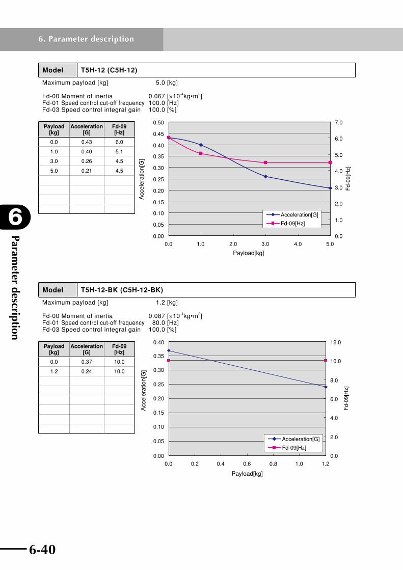
Parameter description
6
6-40
6. Parameter description
6-41
Model T5H-12 (C5H-12)
Maximum payload [kg] 5.0 [kg]
Fd-00 Moment of inertia 0.067 [×10-4kg•m2]Fd-01 Speed control cut-off frequency 100.0 [Hz]Fd-03 Speed control integral gain 100.0 [%]
0.00
0.05
0.10
0.15
0.20
0.25
0.30
0.35
0.40
0.45
0.50
0.0 1.0 2.0 3.0 4.0 5.00.0
1.0
2.0
3.0
4.0
5.0
6.0
7.0
Fd-
09[H
z]
Payload[kg]
Acc
eler
atio
n[G
]
Acceleration[G]
Fd-09[Hz]
Payload [kg]
Acceleration [G]
Fd-09 [Hz]
0.0 0.43 6.0
1.0 0.40 5.1
3.0 0.26 4.5
5.0 0.21 4.5
Model T5H-12-BK (C5H-12-BK)
Maximum payload [kg] 1.2 [kg]
Fd-00 Moment of inertia 0.087 [×10-4kg•m2]Fd-01 Speed control cut-off frequency 80.0 [Hz]Fd-03 Speed control integral gain 100.0 [%]
0.00
0.05
0.10
0.15
0.20
0.25
0.30
0.35
0.40
0.0 0.2 0.4 0.6 0.8 1.0 1.20.0
2.0
4.0
6.0
8.0
10.0
12.0F
d-09
[Hz]
Payload[kg]
Acc
eler
atio
n[G
]
Acceleration[G]
Fd-09[Hz]
Payload [kg]
Acceleration [G]
Fd-09 [Hz]
0.0 0.37 10.0
1.2 0.24 10.0

6-40 6-41
6
Parameter description
6. Parameter description
Model T5H-20
Maximum payload [kg] 3.0 [kg]
Fd-00 Moment of inertia 0.100 [×10-4kg•m2]Fd-01 Speed control cut-off frequency 70.0 [Hz]Fd-03 Speed control integral gain 60.0 [%]
0.00
0.05
0.10
0.15
0.20
0.25
0.30
0.35
0.0 0.5 1.0 1.5 2.0 2.5 3.00.0
1.0
2.0
3.0
4.0
5.0
6.0
7.0
Fd-
09[H
z]
Payload[kg]
Acc
eler
atio
n[G
]
Acceleration[G]
Fd-09[Hz]
Payload [kg]
Acceleration [G]
Fd-09 [Hz]
0.0 0.32 6.0
1.0 0.32 6.0
2.0 0.24 6.0
3.0 0.19 6.0
Model T5LH-6 (C5LH-6)
Maximum payload [kg] 9.0 [kg]
Fd-00 Moment of inertia 0.063 [×10-4kg•m2]Fd-01 Speed control cut-off frequency 85.0 [Hz]Fd-03 Speed control integral gain 70.0 [%]
Payload[kg]
Acc
eler
atio
n[G
]
Fd-
09[H
z]
0.00
0.05
0.10
0.15
0.20
0.25
0 1 2 3 4 5 6 7 8 90.0
1.0
2.0
3.0
4.0
5.0
6.0
7.0
8.0
9.0
Acceleration[G]
Fd-09[Hz]
Payload [kg]
Acceleration [G]
Fd-09 [Hz]
0.0 0.21 8.0
1.0 0.20 8.0
3.0 0.17 8.0
5.0 0.14 8.0
7.0 0.12 8.0
9.0 0.10 8.0

Parameter description
6
6-42
6. Parameter description
6-43
Model T5LH-6-BK (C5LH-6-BK)
Maximum payload [kg] 2.4 [kg]
Fd-00 Moment of inertia 0.074 [×10-4kg•m2]Fd-01 Speed control cut-off frequency 80.0 [Hz]Fd-03 Speed control integral gain 100.0 [%]
Payload[kg]
Acc
eler
atio
n[G
]
Fd-
09[H
z]
0.00
0.05
0.10
0.15
0.20
0.25
0 0.5 1 1.5 2 2.58.2
8.4
8.6
8.8
9.0
9.2
9.4
9.6Acceleration[G]
Fd-09[Hz]
Payload [kg]
Acceleration [G]
Fd-09 [Hz]
0.0 0.21 9.5
1.0 0.21 9.0
2.0 0.18 8.3
2.4 0.14 8.3
Model T5LH-12 (C5LH-12)
Maximum payload [kg] 5.0 [kg]
Fd-00 Moment of inertia 0.067 [×10-4kg•m2]Fd-01 Speed control cut-off frequency 100.0 [Hz]Fd-03 Speed control integral gain 100.0 [%]
Payload[kg]
Acc
eler
atio
n[G
]
Fd-
09[H
z]
0.00
0.05
0.10
0.15
0.20
0.25
0.30
0.35
0.40
0.45
0.50
0 1 2 3 4 50.0
1.0
2.0
3.0
4.0
5.0
6.0
7.0
8.0Acceleration[G]
Fd-09[Hz]
Payload [kg]
Acceleration [G]
Fd-09 [Hz]
0.0 0.43 7,5
1.0 0.40 7.2
3.0 0.26 6.0
5.0 0.21 6.0

6-42 6-43
6
Parameter description
6. Parameter description
Model T5LH-12-BK (C5LH-12-BK)
Maximum payload [kg] 1.0 [kg]
Fd-00 Moment of inertia 0.087 [×10-4kg•m2]Fd-01 Speed control cut-off frequency 80.0 [Hz]Fd-03 Speed control integral gain 100.0 [%]
Payload[kg]
Acc
eler
atio
n[G
]
Fd-
09[H
z]
0.00
0.05
0.10
0.15
0.20
0.25
0.30
0.35
0.40
0 0.2 0.4 0.6 0.8 1 1.20.0
2.0
4.0
6.0
8.0
10.0
12.0
Acceleration[G]
Fd-09[Hz]
Payload [kg]
Acceleration [G]
Fd-09 [Hz]
0.0 0.37 10.0
1.2 0.24 10.0
Model T5LH-20 (C5LH-20)
Maximum payload [kg] 3.0 [kg]
Fd-00 Moment of inertia 0.100 [×10-4kg•m2]Fd-01 Speed control cut-off frequency 70.0 [Hz]Fd-03 Speed control integral gain 60.0 [%]
Payload[kg]
Acc
eler
atio
n[G
]
Fd-
09[H
z]
0.00
0.05
0.10
0.15
0.20
0.25
0.30
0.35
0 0.5 1 1.5 2 2.5 30.0
2.0
4.0
6.0
8.0
10.0
12.0
Acceleration[G]
Fd-09[Hz]
Payload [kg]
Acceleration [G]
Fd-09 [Hz]
0.0 0.32 10.0
1.0 0.32 6.0
2.0 0.24 5.0
3.0 0.19 5.0
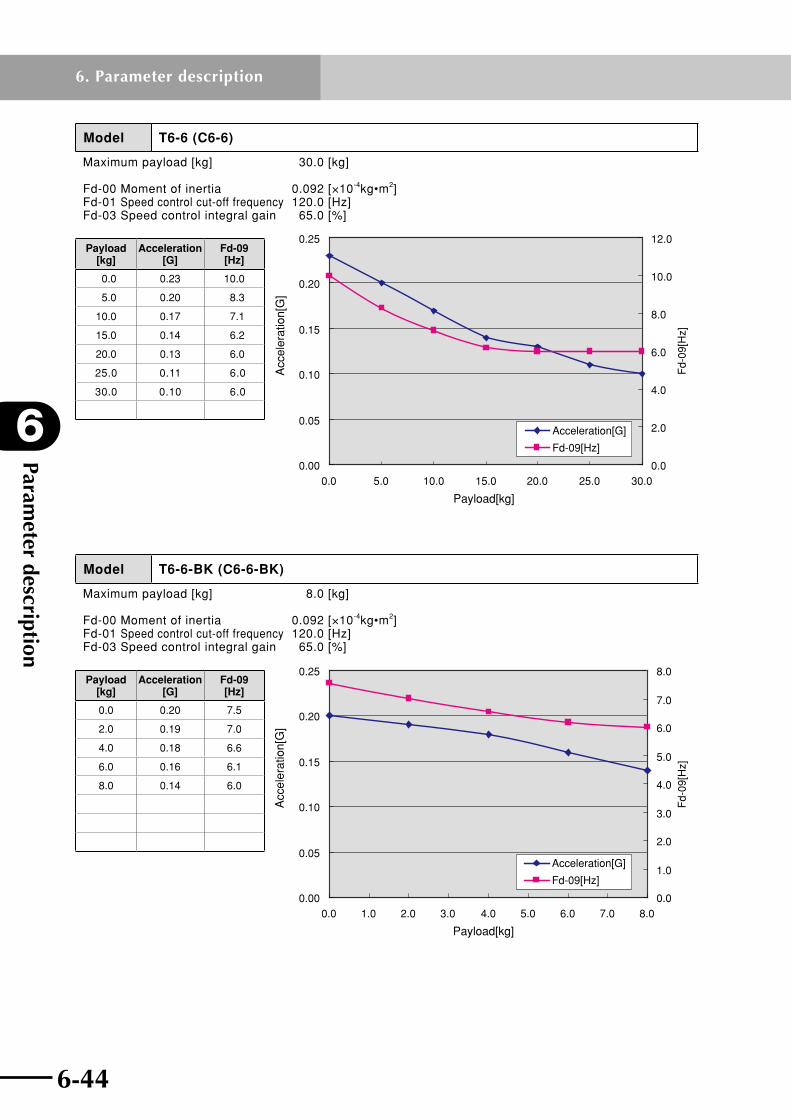
Parameter description
6
6-44
6. Parameter description
6-45
Model T6-6 (C6-6)
Maximum payload [kg] 30.0 [kg]
Fd-00 Moment of inertia 0.092 [×10-4kg•m2]Fd-01 Speed control cut-off frequency 120.0 [Hz]Fd-03 Speed control integral gain 65.0 [%]
0.00
0.05
0.10
0.15
0.20
0.25
0.0 5.0 10.0 15.0 20.0 25.0 30.00.0
2.0
4.0
6.0
8.0
10.0
12.0
Fd-
09[H
z]
Payload[kg]
Acc
eler
atio
n[G
]
Acceleration[G]
Fd-09[Hz]
Payload [kg]
Acceleration [G]
Fd-09 [Hz]
0.0 0.23 10.0
5.0 0.20 8.3
10.0 0.17 7.1
15.0 0.14 6.2
20.0 0.13 6.0
25.0 0.11 6.0
30.0 0.10 6.0
Model T6-6-BK (C6-6-BK)
Maximum payload [kg] 8.0 [kg]
Fd-00 Moment of inertia 0.092 [×10-4kg•m2]Fd-01 Speed control cut-off frequency 120.0 [Hz]Fd-03 Speed control integral gain 65.0 [%]
0.00
0.05
0.10
0.15
0.20
0.25
0.0 1.0 2.0 3.0 4.0 5.0 6.0 7.0 8.00.0
1.0
2.0
3.0
4.0
5.0
6.0
7.0
8.0F
d-09
[Hz]
Payload[kg]
Acc
eler
atio
n[G
]
Acceleration[G]
Fd-09[Hz]
Payload [kg]
Acceleration [G]
Fd-09 [Hz]
0.0 0.20 7.5
2.0 0.19 7.0
4.0 0.18 6.6
6.0 0.16 6.1
8.0 0.14 6.0

6-44 6-45
6
Parameter description
6. Parameter description
Model T6-12 (C6-12)
Maximum payload [kg] 12.0 [kg]
Fd-00 Moment of inertia 0.110 [×10-4kg•m2]Fd-01 Speed control cut-off frequency 100.0 [Hz]Fd-03 Speed control integral gain 65.0 [%]
0.00
0.05
0.10
0.15
0.20
0.25
0.30
0.35
0.40
0.45
0.50
0.0 2.0 4.0 6.0 8.0 10.0 12.00.0
1.0
2.0
3.0
4.0
5.0
6.0
7.0
8.0
9.0
Fd-
09[H
z]
Payload[kg]
Acc
eler
atio
n[G
]
Acceleration[G]
Fd-09[Hz]
Payload [kg]
Acceleration [G]
Fd-09 [Hz]
0.0 0.46 8.3
2.0 0.40 6.5
4.0 0.34 5.4
6.0 0.30 5.0
8.0 0.26 5.0
10.0 0.23 5.0
12.0 0.18 5.0
Model T6-12-BK (C6-12-BK)
Maximum payload [kg] 4.0 [kg]
Fd-00 Moment of inertia 0.110 [×10-4kg•m2]Fd-01 Speed control cut-off frequency 100.0 [Hz]Fd-03 Speed control integral gain 65.0 [%]
0.00
0.05
0.10
0.15
0.20
0.25
0.30
0.35
0.40
0.45
0.0 0.5 1.0 1.5 2.0 2.5 3.0 3.5 4.00.0
1.0
2.0
3.0
4.0
5.0
6.0
7.0
Fd-
09[H
z]
Payload[kg]
Acc
eler
atio
n[G
]
Acceleration[G]
Fd-09[Hz]
Payload [kg]
Acceleration [G]
Fd-09 [Hz]
0.0 0.40 6.6
1.0 0.40 5.8
2.0 0.37 5.2
3.0 0.34 5.0
4.0 0.31 5.0

Parameter description
6
6-46
6. Parameter description
6-47
Model T6-20
Maximum payload [kg] 10.0 [kg]
Fd-00 Moment of inertia 0.110 [×10-4kg•m2]Fd-01 Speed control cut-off frequency 120.0 [Hz]Fd-03 Speed control integral gain 45.0 [%]
0.00
0.20
0.40
0.60
0.80
1.00
1.20
0.0 2.0 4.0 6.0 8.0 10.04.4
4.5
4.6
4.7
4.8
4.9
5.0
5.1
5.2
5.3
Fd-
09[H
z]
Acceleration[G]
Fd-09[Hz]
Payload[kg]
Acc
eler
atio
n[G
]
Payload [kg]
Acceleration [G]
Fd-09 [Hz]
0.0 1.05 5.2
3.0 0.94 4.5
5.0 0.84 4.5
7.0 0.79 4.5
10.0 0.68 4.5
Model T6L-6 (C6L-6)
Maximum payload [kg] 30.0 [kg]
Fd-00 Moment of inertia 0.092 [×10-4kg•m2]Fd-01 Speed control cut-off frequency 120.0 [Hz]Fd-03 Speed control integral gain 65.0 [%]
Payload[kg]
Acc
eler
atio
n[G
]
Fd-
09[H
z]
0.00
0.05
0.10
0.15
0.20
0.25
0 5 10 15 20 25 300.0
1.0
2.0
3.0
4.0
5.0
6.0
7.0
Acceleration[G]
Fd-09[Hz]
Payload [kg]
Acceleration [G]
Fd-09 [Hz]
0.0 0.23 6.0
5.0 0.20 6.0
10.0 0.17 6.0
15.0 0.14 6.0
20.0 0.13 6.0
25.0 0.11 6.0
30.0 0.10 6.0
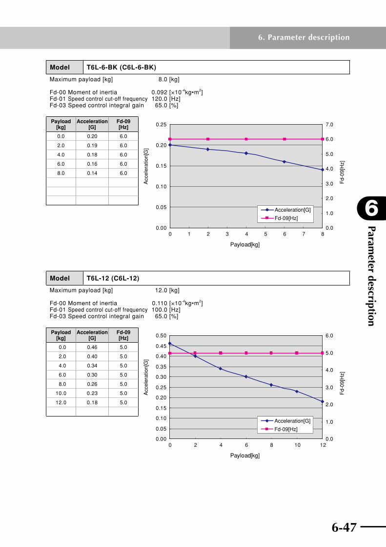
6-46 6-47
6
Parameter description
6. Parameter description
Model T6L-6-BK (C6L-6-BK)
Maximum payload [kg] 8.0 [kg]
Fd-00 Moment of inertia 0.092 [×10-4kg•m2]Fd-01 Speed control cut-off frequency 120.0 [Hz]Fd-03 Speed control integral gain 65.0 [%]
Payload[kg]
Acc
eler
atio
n[G
]
Fd-
09[H
z]
0.00
0.05
0.10
0.15
0.20
0.25
0 1 2 3 4 5 6 7 80.0
1.0
2.0
3.0
4.0
5.0
6.0
7.0
Acceleration[G]
Fd-09[Hz]
Payload [kg]
Acceleration [G]
Fd-09 [Hz]
0.0 0.20 6.0
2.0 0.19 6.0
4.0 0.18 6.0
6.0 0.16 6.0
8.0 0.14 6.0
Model T6L-12 (C6L-12)
Maximum payload [kg] 12.0 [kg]
Fd-00 Moment of inertia 0.110 [×10-4kg•m2]Fd-01 Speed control cut-off frequency 100.0 [Hz]Fd-03 Speed control integral gain 65.0 [%]
Payload[kg]
Acc
eler
atio
n[G
]
Fd-
09[H
z]
0.00
0.05
0.10
0.15
0.20
0.25
0.30
0.35
0.40
0.45
0.50
0 2 4 6 8 10 120.0
1.0
2.0
3.0
4.0
5.0
6.0
Acceleration[G]
Fd-09[Hz]
Payload [kg]
Acceleration [G]
Fd-09 [Hz]
0.0 0.46 5.0
2.0 0.40 5.0
4.0 0.34 5.0
6.0 0.30 5.0
8.0 0.26 5.0
10.0 0.23 5.0
12.0 0.18 5.0
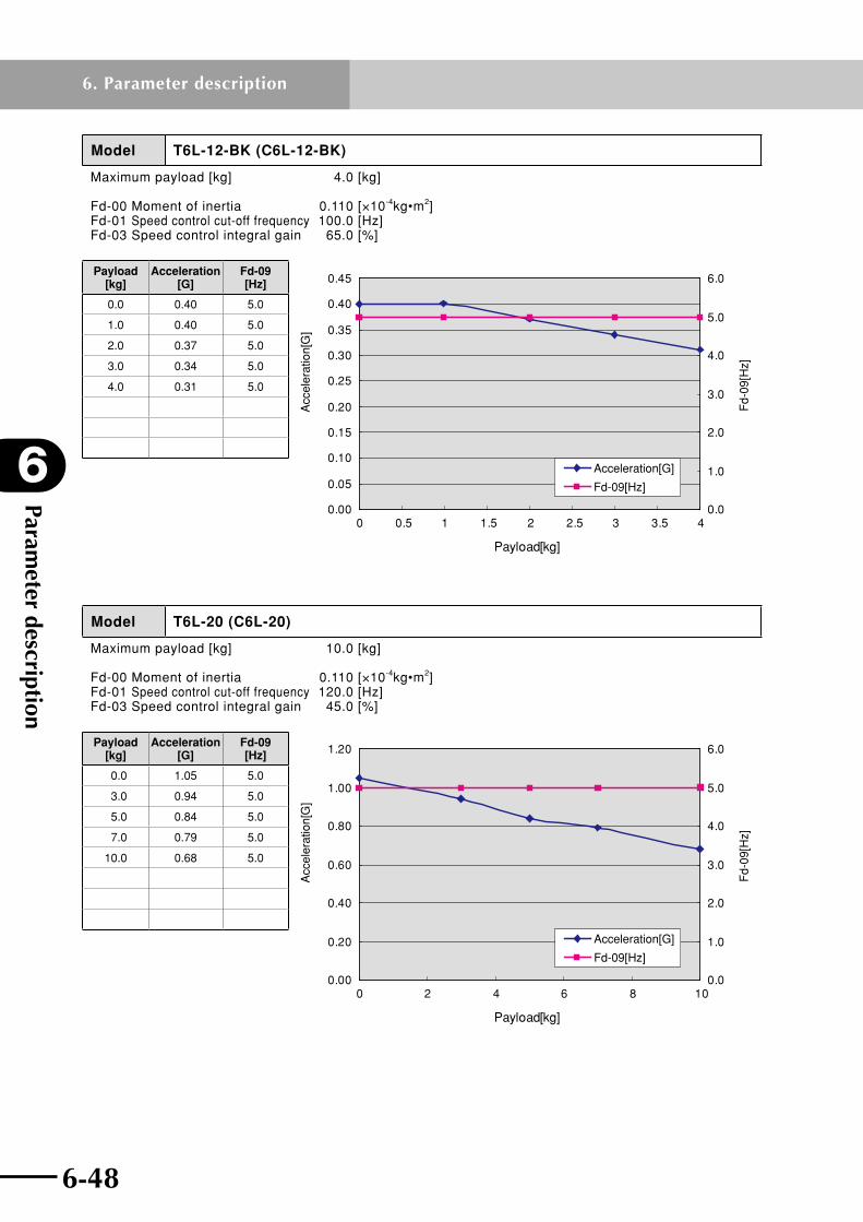
Parameter description
6
6-48
6. Parameter description
6-49
Model T6L-12-BK (C6L-12-BK)
Maximum payload [kg] 4.0 [kg]
Fd-00 Moment of inertia 0.110 [×10-4kg•m2]Fd-01 Speed control cut-off frequency 100.0 [Hz]Fd-03 Speed control integral gain 65.0 [%]
Payload[kg]
Acc
eler
atio
n[G
]
Fd-
09[H
z]
0.00
0.05
0.10
0.15
0.20
0.25
0.30
0.35
0.40
0.45
0 0.5 1 1.5 2 2.5 3 3.5 40.0
1.0
2.0
3.0
4.0
5.0
6.0
Acceleration[G]
Fd-09[Hz]
Payload [kg]
Acceleration [G]
Fd-09 [Hz]
0.0 0.40 5.0
1.0 0.40 5.0
2.0 0.37 5.0
3.0 0.34 5.0
4.0 0.31 5.0
Model T6L-20 (C6L-20)
Maximum payload [kg] 10.0 [kg]
Fd-00 Moment of inertia 0.110 [×10-4kg•m2]Fd-01 Speed control cut-off frequency 120.0 [Hz]Fd-03 Speed control integral gain 45.0 [%]
Payload[kg]
Acc
eler
atio
n[G
]
Fd-
09[H
z]
0.00
0.20
0.40
0.60
0.80
1.00
1.20
0 2 4 6 8 100.0
1.0
2.0
3.0
4.0
5.0
6.0
Acceleration[G]
Fd-09[Hz]
Payload [kg]
Acceleration [G]
Fd-09 [Hz]
0.0 1.05 5.0
3.0 0.94 5.0
5.0 0.84 5.0
7.0 0.79 5.0
10.0 0.68 5.0

6-48 6-49
6
Parameter description
6. Parameter description
Model T7-12
Maximum payload [kg] 8.0 [kg]
Fd-00 Moment of inertia 0.125 [×10-4kg•m2]Fd-01 Speed control cut-off frequency 100.0 [Hz]Fd-03 Speed control integral gain 65.0 [%]
0.00
0.10
0.20
0.30
0.40
0.50
0.60
0.0 1.0 2.0 3.0 4.0 5.0 6.0 7.0 8.00.0
2.0
4.0
6.0
8.0
10.0
12.0
14.0
Fd-
09[H
z]
Acceleration[G]
Fd-09[Hz]
Payload[kg]
Acc
eler
atio
n[G
]
Payload [kg]
Acceleration [G]
Fd-09 [Hz]
0.0 0.55 11.6
2.0 0.49 8.8
4.0 0.43 7.0
6.0 0.37 5.9
8.0 0.31 5.0
Model T7-12-BK
Maximum payload [kg] 3.0 [kg]
Fd-00 Moment of inertia 0.134 [×10-4kg•m2]Fd-01 Speed control cut-off frequency 100.0 [Hz]Fd-03 Speed control integral gain 65.0 [%]
0.00
0.05
0.10
0.15
0.20
0.25
0.30
0.35
0.40
0.45
0.50
0.0 0.5 1.0 1.5 2.0 2.5 3.00.0
2.0
4.0
6.0
8.0
10.0
12.0
Fd-
09[H
z]
Acceleration[G]
Fd-09[Hz]
Payload[kg]
Acc
eler
atio
n[G
]
Payload [kg]
Acceleration [G]
Fd-09 [Hz]
0.0 0.43 10.4
1.0 0.40 8.9
2.0 0.37 7.7
3.0 0.34 6.9

Parameter description
6
6-50
6. Parameter description
6-51
Model T9-5
Maximum payload [kg] 80.0 [kg]
Fd-00 Moment of inertia 0.282 [×10-4kg•m2]Fd-01 Speed control cut-off frequency 100.0 [Hz]Fd-03 Speed control integral gain 60.0 [%]
0.00
0.02
0.04
0.06
0.08
0.10
0.12
0.14
0.16
0.18
0.0 10.0 20.0 30.0 40.0 50.0 60.0 70.0 80.00.0
1.0
2.0
3.0
4.0
5.0
6.0
7.0
8.0
9.0
Fd-
09[H
z]
Acceleration[G]
Fd-09[Hz]
Payload[kg]
Acc
eler
atio
n[G
]
Payload [kg]
Acceleration [G]
Fd-09 [Hz]
0.0 0.17 8.4
20.0 0.14 7.1
40.0 0.12 6.1
60.0 0.09 6.0
80.0 0.08 6.0
Model T9-5-BK
Maximum payload [kg] 20.0 [kg]
Fd-00 Moment of inertia 0.282 [×10-4kg•m2]Fd-01 Speed control cut-off frequency 100.0 [Hz]Fd-03 Speed control integral gain 60.0 [%]
0.00
0.02
0.04
0.06
0.08
0.10
0.12
0.14
0.16
0.18
0.0 5.0 10.0 15.0 20.05.9
6.0
6.1
6.2
6.3
6.4
6.5
6.6
6.7
6.8
6.9F
d-09
[Hz]
Acceleration[G]
Fd-09[Hz]
Payload[kg]
Acc
eler
atio
n[G
]
Payload [kg]
Acceleration [G]
Fd-09 [Hz]
0.0 0.17 6.8
5.0 0.15 6.5
10.0 0.14 6.3
15.0 0.13 6.0
20.0 0.11 6.0
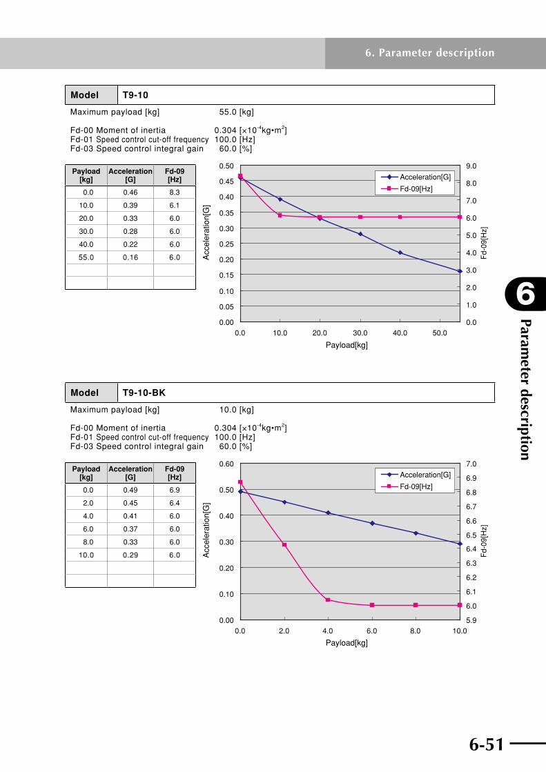
6-50 6-51
6
Parameter description
6. Parameter description
Model T9-10
Maximum payload [kg] 55.0 [kg]
Fd-00 Moment of inertia 0.304 [×10-4kg•m2]Fd-01 Speed control cut-off frequency 100.0 [Hz]Fd-03 Speed control integral gain 60.0 [%]
0.00
0.05
0.10
0.15
0.20
0.25
0.30
0.35
0.40
0.45
0.50
0.0 10.0 20.0 30.0 40.0 50.00.0
1.0
2.0
3.0
4.0
5.0
6.0
7.0
8.0
9.0
Fd-
09[H
z]
Acceleration[G]
Fd-09[Hz]
Payload[kg]
Acc
eler
atio
n[G
]
Payload [kg]
Acceleration [G]
Fd-09 [Hz]
0.0 0.46 8.3
10.0 0.39 6.1
20.0 0.33 6.0
30.0 0.28 6.0
40.0 0.22 6.0
55.0 0.16 6.0
Model T9-10-BK
Maximum payload [kg] 10.0 [kg]
Fd-00 Moment of inertia 0.304 [×10-4kg•m2]Fd-01 Speed control cut-off frequency 100.0 [Hz]Fd-03 Speed control integral gain 60.0 [%]
0.00
0.10
0.20
0.30
0.40
0.50
0.60
0.0 2.0 4.0 6.0 8.0 10.05.9
6.0
6.1
6.2
6.3
6.4
6.5
6.6
6.7
6.8
6.9
7.0
Fd-
09[H
z]Acceleration[G]
Fd-09[Hz]
Payload[kg]
Acc
eler
atio
n[G
]
Payload [kg]
Acceleration [G]
Fd-09 [Hz]
0.0 0.49 6.9
2.0 0.45 6.4
4.0 0.41 6.0
6.0 0.37 6.0
8.0 0.33 6.0
10.0 0.29 6.0
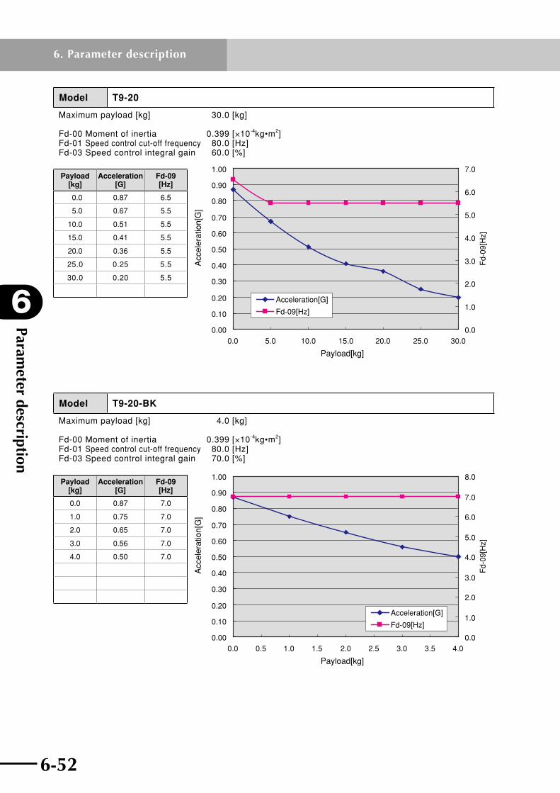
Parameter description
6
6-52
6. Parameter description
6-53
Model T9-20
Maximum payload [kg] 30.0 [kg]
Fd-00 Moment of inertia 0.399 [×10-4kg•m2]Fd-01 Speed control cut-off frequency 80.0 [Hz]Fd-03 Speed control integral gain 60.0 [%]
0.00
0.10
0.20
0.30
0.40
0.50
0.60
0.70
0.80
0.90
1.00
0.0 5.0 10.0 15.0 20.0 25.0 30.00.0
1.0
2.0
3.0
4.0
5.0
6.0
7.0
Fd-
09[H
z]
Acceleration[G]
Fd-09[Hz]
Payload[kg]
Acc
eler
atio
n[G
]
Payload [kg]
Acceleration [G]
Fd-09 [Hz]
0.0 0.87 6.5
5.0 0.67 5.5
10.0 0.51 5.5
15.0 0.41 5.5
20.0 0.36 5.5
25.0 0.25 5.5
30.0 0.20 5.5
Model T9-20-BK
Maximum payload [kg] 4.0 [kg]
Fd-00 Moment of inertia 0.399 [×10-4kg•m2]Fd-01 Speed control cut-off frequency 80.0 [Hz]Fd-03 Speed control integral gain 70.0 [%]
0.00
0.10
0.20
0.30
0.40
0.50
0.60
0.70
0.80
0.90
1.00
0.0 0.5 1.0 1.5 2.0 2.5 3.0 3.5 4.00.0
1.0
2.0
3.0
4.0
5.0
6.0
7.0
8.0F
d-09
[Hz]
Payload[kg]
Acc
eler
atio
n[G
]
Acceleration[G]
Fd-09[Hz]
Payload [kg]
Acceleration [G]
Fd-09 [Hz]
0.0 0.87 7.0
1.0 0.75 7.0
2.0 0.65 7.0
3.0 0.56 7.0
4.0 0.50 7.0
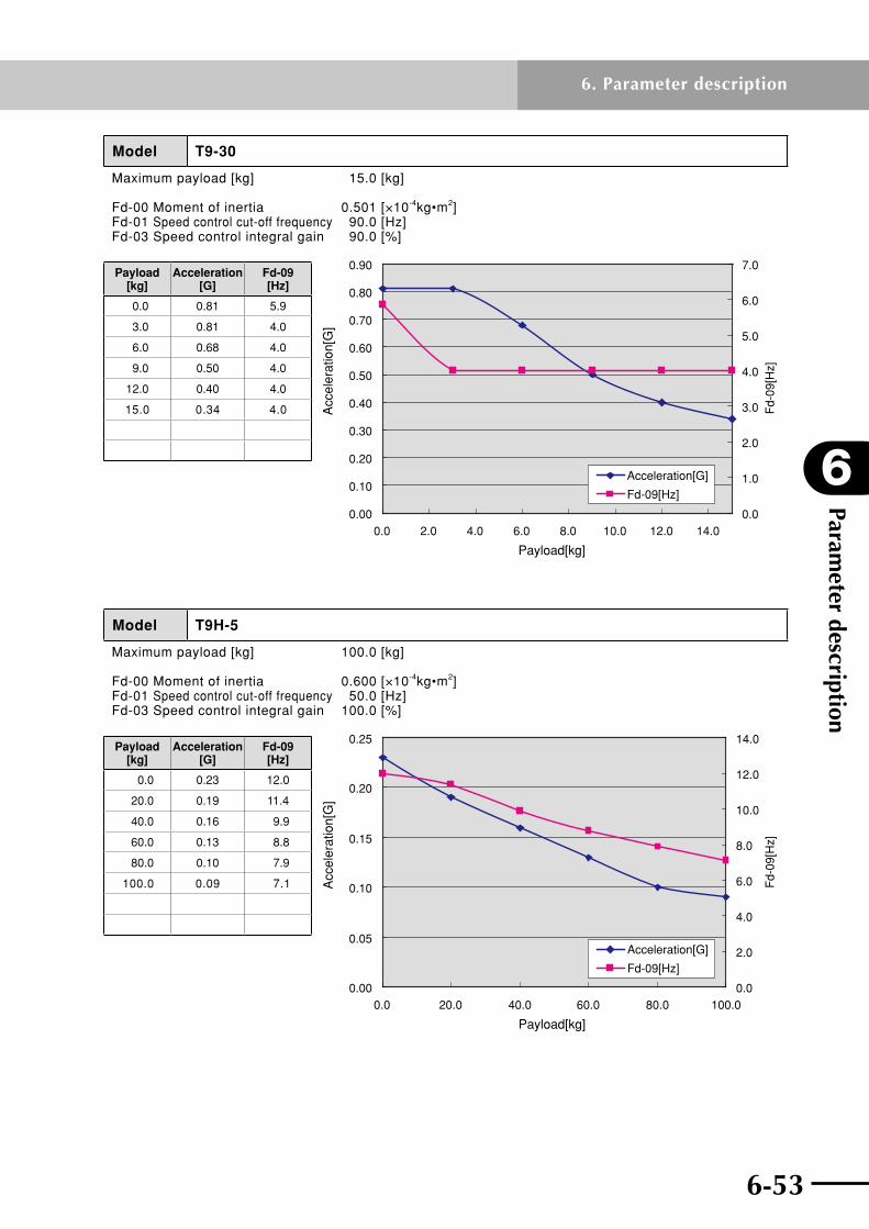
6-52 6-53
6
Parameter description
6. Parameter description
Model T9-30
Maximum payload [kg] 15.0 [kg]
Fd-00 Moment of inertia 0.501 [×10-4kg•m2]Fd-01 Speed control cut-off frequency 90.0 [Hz]Fd-03 Speed control integral gain 90.0 [%]
0.00
0.10
0.20
0.30
0.40
0.50
0.60
0.70
0.80
0.90
0.0 2.0 4.0 6.0 8.0 10.0 12.0 14.00.0
1.0
2.0
3.0
4.0
5.0
6.0
7.0
Fd-
09[H
z]
Payload[kg]
Acc
eler
atio
n[G
]
Acceleration[G]
Fd-09[Hz]
Payload [kg]
Acceleration [G]
Fd-09 [Hz]
0.0 0.81 5.9
3.0 0.81 4.0
6.0 0.68 4.0
9.0 0.50 4.0
12.0 0.40 4.0
15.0 0.34 4.0
Model T9H-5
Maximum payload [kg] 100.0 [kg]
Fd-00 Moment of inertia 0.600 [×10-4kg•m2]Fd-01 Speed control cut-off frequency 50.0 [Hz]Fd-03 Speed control integral gain 100.0 [%]
0.00
0.05
0.10
0.15
0.20
0.25
0.0 20.0 40.0 60.0 80.0 100.00.0
2.0
4.0
6.0
8.0
10.0
12.0
14.0
Fd-
09[H
z]
Payload[kg]
Acc
eler
atio
n[G
]
Acceleration[G]
Fd-09[Hz]
Payload [kg]
Acceleration [G]
Fd-09 [Hz]
0.0 0.23 12.0
20.0 0.19 11.4
40.0 0.16 9.9
60.0 0.13 8.8
80.0 0.10 7.9
100.0 0.09 7.1

Parameter description
6
6-54
6. Parameter description
6-55
Model T9H-5-BK
Maximum payload [kg] 30.0 [kg]
Fd-00 Moment of inertia 0.416 [×10-4kg•m2]Fd-01 Speed control cut-off frequency 70.0 [Hz]Fd-03 Speed control integral gain 100.0 [%]
0.00
0.02
0.04
0.06
0.08
0.10
0.12
0.14
0.16
0.18
0.20
0.0 5.0 10.0 15.0 20.0 25.0 30.00.0
1.0
2.0
3.0
4.0
5.0
6.0
7.0
8.0
Fd-
09[H
z]
Payload[kg]
Acc
eler
atio
n[G
]
Acceleration[G]
Fd-09[Hz]
Payload [kg]
Acceleration [G]
Fd-09 [Hz]
0.0 0.19 7.5
10.0 0.17 7.0
20.0 0.14 6.5
30.0 0.11 6.1
Model T9H-10
Maximum payload [kg] 80.0 [kg]
Fd-00 Moment of inertia 0.424 [×10-4kg•m2]Fd-01 Speed control cut-off frequency 80.0 [Hz]Fd-03 Speed control integral gain 100.0 [%]
0.00
0.10
0.20
0.30
0.40
0.50
0.60
0.0 10.0 20.0 30.0 40.0 50.0 60.0 70.0 80.00.0
1.0
2.0
3.0
4.0
5.0
6.0
7.0
8.0
9.0
10.0F
d-09
[Hz]
Acceleration[G]
Fd-09[Hz]
Payload[kg]
Acc
eler
atio
n[G
]
Payload [kg]
Acceleration [G]
Fd-09 [Hz]
0.0 0.51 9.3
20.0 0.38 5.6
40.0 0.28 4.5
60.0 0.20 4.5
80.0 0.15 4.5

6-54 6-55
6
Parameter description
6. Parameter description
Model T9H-10-BK
Maximum payload [kg] 20.0 [kg]
Fd-00 Moment of inertia 0.424 [×10-4kg•m2]Fd-01 Speed control cut-off frequency 80.0 [Hz]Fd-03 Speed control integral gain 100.0 [%]
0.27
0.28
0.29
0.30
0.31
0.32
0.33
0.34
0.0 5.0 10.0 15.0 20.00.0
1.0
2.0
3.0
4.0
5.0
6.0
7.0
8.0
9.0
Fd-
09[H
z]
Acceleration[G]
Fd-09[Hz]
Payload[kg]
Acc
eler
atio
n[G
]
Payload [kg]
Acceleration [G]
Fd-09 [Hz]
0.0 0.33 7.9
5.0 0.32 6.8
10.0 0.31 6.0
15.0 0.30 5.4
20.0 0.28 4.9
Model T9H-20
Maximum payload [kg] 40.0 [kg]
Fd-00 Moment of inertia 0.926 [×10-4kg•m2]Fd-01 Speed control cut-off frequency 40.0 [Hz]Fd-03 Speed control integral gain 100.0 [%]
0.00
0.10
0.20
0.30
0.40
0.50
0.60
0.70
0.80
0.0 5.0 10.0 15.0 20.0 25.0 30.0 35.0 40.00.0
2.0
4.0
6.0
8.0
10.0
12.0
14.0
Fd-
09[H
z]
Payload[kg]
Acc
eler
atio
n[G
]
Acceleration[G]
Fd-09[Hz]
Payload [kg]
Acceleration [G]
Fd-09 [Hz]
0.0 0.67 12.0
10.0 0.61 6.7
20.0 0.56 4.5
30.0 0.51 4.5
40.0 0.46 4.5

Parameter description
6
6-56
6. Parameter description
6-57
Model T9H-20-BK
Maximum payload [kg] 8.0 [kg]
Fd-00 Moment of inertia 0.564 [×10-4kg•m2]Fd-01 Speed control cut-off frequency 60.0 [Hz]Fd-03 Speed control integral gain 100.0 [%]
0.00
0.10
0.20
0.30
0.40
0.50
0.60
0.70
0.80
0.90
1.00
0.0 1.0 2.0 3.0 4.0 5.0 6.0 7.0 8.00.0
1.0
2.0
3.0
4.0
5.0
6.0
7.0
Fd-
09[H
z]
Payload[kg]
Acc
eler
atio
n[G
]
Acceleration[G]
Fd-09[Hz]
Payload [kg]
Acceleration [G]
Fd-09 [Hz]
0.0 0.91 6.7
2.0 0.86 5.6
4.0 0.81 5.5
6.0 0.76 5.5
8.0 0.71 5.5
Model T9H-30
Maximum payload [kg] 25.0 [kg]
Fd-00 Moment of inertia 0.715 [×10-4kg•m2]Fd-01 Speed control cut-off frequency 100.0 [Hz]Fd-03 Speed control integral gain 90.0 [%]
0.00
0.20
0.40
0.60
0.80
1.00
1.20
0.0 5.0 10.0 15.0 20.0 25.00.0
2.0
4.0
6.0
8.0
10.0
12.0F
d-09
[Hz]
Acceleration[G]
Fd-09[Hz]
Payload[kg]
Acc
eler
atio
n[G
]
Payload [kg]
Acceleration [G]
Fd-09 [Hz]
0.0 1.00 11.1
5.0 1.00 5.9
10.0 0.86 4.0
15.0 0.64 3.0
20.0 0.48 2.5
25.0 0.28 2.5

6-56 6-57
6
Parameter description
6. Parameter description
Model F8-6 (C8-6)
Maximum payload [kg] 40.0 [kg]
Fd-00 Moment of inertia 0.109 [×10-4kg•m2]Fd-01 Speed control cut-off frequency 110.0 [Hz]Fd-03 Speed control integral gain 80.0 [%]
Payload[kg]
Acc
eler
atio
n[G
]
Fd-
09[H
z]
0.00
0.05
0.10
0.15
0.20
0.25
0.30
0.35
0.0 5.0 10.0 15.0 20.0 25.0 30.0 35.0 40.00.0
1.0
2.0
3.0
4.0
5.0
6.0
7.0
8.0
9.0
10.0Acceleration[G]
Fd-09[Hz]
Payload [kg]
Acceleration [G]
Fd-09 [Hz]
0.0 0.31 9.0
10.0 0.25 7.5
20.0 0.19 6.4
30.0 0.14 5.2
40.0 0.07 5.0
Model F8-6-BK (C8-6-BK)
Maximum payload [kg] 8.0 [kg]
Fd-00 Moment of inertia 0.154 [×10-4kg•m2]Fd-01 Speed control cut-off frequency 110.0 [Hz]Fd-03 Speed control integral gain 65.0 [%]
Payload[kg]
Acc
eler
atio
n[G
]
Fd-
09[H
z]
0.00
0.05
0.10
0.15
0.20
0.25
0.30
0.35
0.40
0.0 1.0 2.0 3.0 4.0 5.0 6.0 7.0 8.00.0
2.0
4.0
6.0
8.0
10.0
12.0
Acceleration[G]
Fd-09[Hz]
Payload [kg]
Acceleration [G]
Fd-09 [Hz]
0.0 0.34 11.0
2.0 0.31 10.5
4.0 0.28 10.5
6.0 0.25 10.0
8.0 0.22 9.0

Parameter description
6
6-58
6. Parameter description
6-59
Model F8-12 (C8-12)
Maximum payload [kg] 20.0 [kg]
Fd-00 Moment of inertia 0.124 [×10-4kg•m2]Fd-01 Speed control cut-off frequency 120.0 [Hz]Fd-03 Speed control integral gain 80.0 [%]
Payload[kg]
Acc
eler
atio
n[G
]
Fd-
09[H
z]
0.00
0.05
0.10
0.15
0.20
0.25
0.30
0.35
0.40
0.45
0.50
0.0 5.0 10.0 15.0 20.00.0
1.0
2.0
3.0
4.0
5.0
6.0
7.0
8.0
9.0
10.0Acceleration[G]
Fd-09[Hz]
Payload [kg]
Acceleration [G]
Fd-09 [Hz]
0.0 0.43 9.0
5.0 0.37 7.2
10.0 0.27 5.0
15.0 0.22 4.5
20.0 0.19 4.5
Model F8-12-BK (C8-12-BK)
Maximum payload [kg] 4.0 [kg]
Fd-00 Moment of inertia 0.169 [×10-4kg•m2]Fd-01 Speed control cut-off frequency 110.0 [Hz]Fd-03 Speed control integral gain 70.0 [%]
0.00
0.10
0.20
0.30
0.40
0.50
0.60
0.0 0.5 1.0 1.5 2.0 2.5 3.0 3.5 4.0
Payload[kg]
Acc
eler
atio
n[G
]
0.0
2.0
4.0
6.0
8.0
10.0
12.0F
d-09
[Hz]
Acceleration[G]
Fd-09[Hz]
Payload [kg]
Acceleration [G]
Fd-09 [Hz]
0.0 0.49 11.0
1.0 0.47 11.0
2.0 0.45 10.0
3.0 0.42 9.5
4.0 0.40 8.8
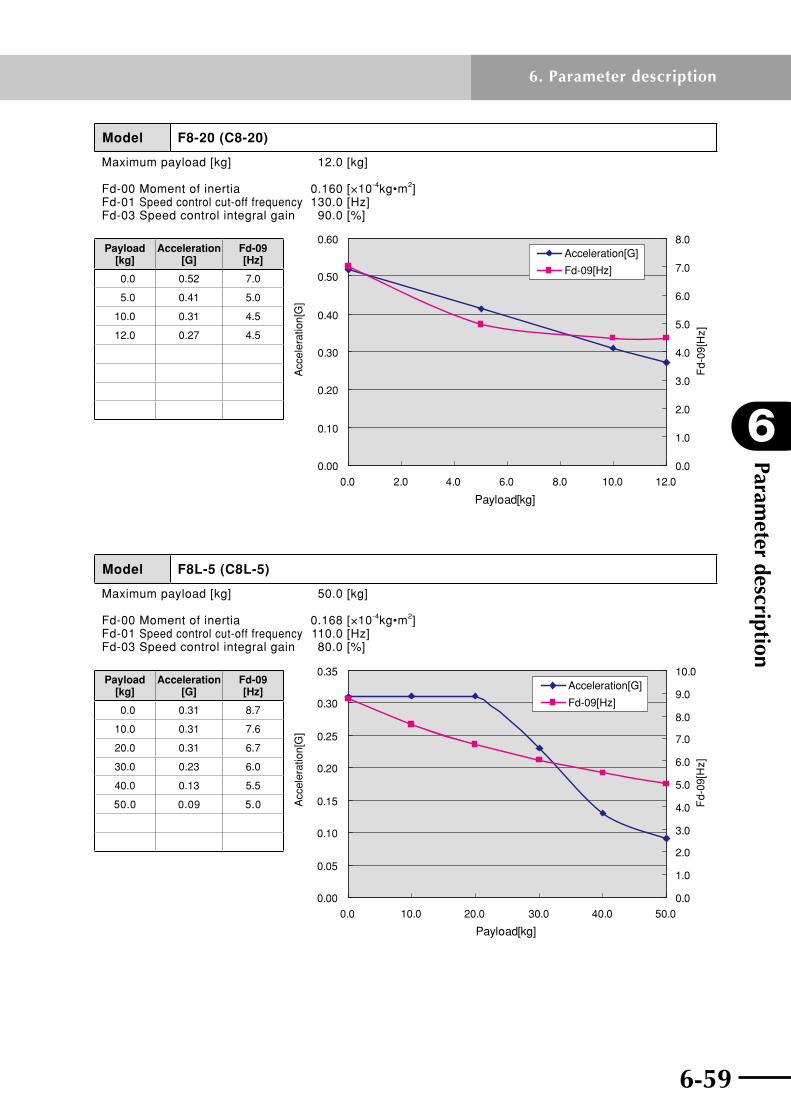
6-58 6-59
6
Parameter description
6. Parameter description
Model F8-20 (C8-20)
Maximum payload [kg] 12.0 [kg]
Fd-00 Moment of inertia 0.160 [×10-4kg•m2]Fd-01 Speed control cut-off frequency 130.0 [Hz]Fd-03 Speed control integral gain 90.0 [%]
Payload[kg]
Acc
eler
atio
n[G
]
Fd-
09[H
z]
0.00
0.10
0.20
0.30
0.40
0.50
0.60
0.0 2.0 4.0 6.0 8.0 10.0 12.00.0
1.0
2.0
3.0
4.0
5.0
6.0
7.0
8.0Acceleration[G]
Fd-09[Hz]
Payload [kg]
Acceleration [G]
Fd-09 [Hz]
0.0 0.52 7.0
5.0 0.41 5.0
10.0 0.31 4.5
12.0 0.27 4.5
Model F8L-5 (C8L-5)
Maximum payload [kg] 50.0 [kg]
Fd-00 Moment of inertia 0.168 [×10-4kg•m2]Fd-01 Speed control cut-off frequency 110.0 [Hz]Fd-03 Speed control integral gain 80.0 [%]
0.00
0.05
0.10
0.15
0.20
0.25
0.30
0.35
0.0 10.0 20.0 30.0 40.0 50.0
Payload[kg]
Acc
eler
atio
n[G
]
0.0
1.0
2.0
3.0
4.0
5.0
6.0
7.0
8.0
9.0
10.0
Fd-
09[H
z]Acceleration[G]
Fd-09[Hz]
Payload [kg]
Acceleration [G]
Fd-09 [Hz]
0.0 0.31 8.7
10.0 0.31 7.6
20.0 0.31 6.7
30.0 0.23 6.0
40.0 0.13 5.5
50.0 0.09 5.0

Parameter description
6
6-60
6. Parameter description
6-61
Model F8L-5-BK (C8L-5-BK)
Maximum payload [kg] 16.0 [kg]
Fd-00 Moment of inertia 0.213 [×10-4kg•m2]Fd-01 Speed control cut-off frequency 100.0 [Hz]Fd-03 Speed control integral gain 65.0 [%]
0.00
0.05
0.10
0.15
0.20
0.25
0.30
0.0 2.0 4.0 6.0 8.0 10.0 12.0 14.0 16.0
Payload[kg]
Acc
eler
atio
n[G
]
0.0
1.0
2.0
3.0
4.0
5.0
6.0
7.0
8.0
9.0
10.0
Fd-
09[H
z]
Acceleration[G]
Fd-09[Hz]
Payload [kg]
Acceleration [G]
Fd-09 [Hz]
0.0 0.26 9.1
5.0 0.23 8.5
10.0 0.21 8.0
15.0 0.18 7.6
16.0 0.18 7.5
Model F8L-10 (C8L-10)
Maximum payload [kg] 40.0 [kg]
Fd-00 Moment of inertia 0.184 [×10-4kg•m2]Fd-01 Speed control cut-off frequency 110.0 [Hz]Fd-03 Speed control integral gain 90.0 [%]
0.00
0.10
0.20
0.30
0.40
0.50
0.60
0.70
0.0 5.0 10.0 15.0 20.0 25.0 30.0 35.0 40.0
Payload[kg]
Acc
eler
atio
n[G
]
0.0
1.0
2.0
3.0
4.0
5.0
6.0
7.0
8.0
9.0
10.0F
d-09
[Hz]
Acceleration[G]
Fd-09[Hz]
Payload [kg]
Acceleration [G]
Fd-09 [Hz]
0.0 0.62 8.9
10.0 0.41 5.7
20.0 0.31 4.2
30.0 0.22 4.0
40.0 0.16 4.0

6-60 6-61
6
Parameter description
6. Parameter description
Model F8L-10-BK (C8L-10-BK)
Maximum payload [kg] 8.0 [kg]
Fd-00 Moment of inertia 0.229 [×10-4kg•m2]Fd-01 Speed control cut-off frequency 100.0 [Hz]Fd-03 Speed control integral gain 60.0 [%]
0.00
0.10
0.20
0.30
0.40
0.50
0.60
0.0 1.0 2.0 3.0 4.0 5.0 6.0 7.0 8.0
Payload[kg]
Acc
eler
atio
n[G
]
0.0
1.0
2.0
3.0
4.0
5.0
6.0
7.0
8.0
9.0
10.0
Fd-
09[H
z]
Acceleration[G]
Fd-09[Hz]
Payload [kg]
Acceleration [G]
Fd-09 [Hz]
0.0 0.57 9.1
2.0 0.52 8.3
4.0 0.46 7.6
6.0 0.41 7.0
8.0 0.36 6.5
Model F8L-20 (C8L-20)
Maximum payload [kg] 20.0 [kg]
Fd-00 Moment of inertia 0.254 [×10-4kg•m2]Fd-01 Speed control cut-off frequency 110.0 [Hz]Fd-03 Speed control integral gain 80.0 [%]
0.00
0.10
0.20
0.30
0.40
0.50
0.60
0.70
0.80
0.0 5.0 10.0 15.0 20.0
Payload[kg]
Acc
eler
atio
n[G
]
0.0
1.0
2.0
3.0
4.0
5.0
6.0
7.0
8.0
9.0
10.0
Fd-
09[H
z]Acceleration[G]
Fd-09[Hz]
Payload [kg]
Acceleration [G]
Fd-09 [Hz]
0.0 0.72 9.2
5.0 0.62 5.0
10.0 0.41 3.5
15.0 0.31 3.0
20.0 0.21 3.0

Parameter description
6
6-62
6. Parameter description
6-63
Model F8L-20-BK (C8L-20-BK)
Maximum payload [kg] 4.0 [kg]
Fd-00 Moment of inertia 0.299 [×10-4kg•m2]Fd-01 Speed control cut-off frequency 100.0 [Hz]Fd-03 Speed control integral gain 65.0 [%]
0.00
0.10
0.20
0.30
0.40
0.50
0.60
0.70
0.0 0.5 1.0 1.5 2.0 2.5 3.0 3.5 4.0
Payload[kg]
Acc
eler
atio
n[G
]
0.0
1.0
2.0
3.0
4.0
5.0
6.0
7.0
8.0
9.0
10.0
Fd-
09[H
z]
Acceleration[G]
Fd-09[Hz]
Payload [kg]
Acceleration [G]
Fd-09 [Hz]
0.0 0.62 9.2
1.0 0.58 8.0
2.0 0.54 7.0
3.0 0.50 7.0
4.0 0.46 7.0
Model F8L-30
Maximum payload [kg] 10.0 [kg]
Fd-00 Moment of inertia 0.368 [×10-4kg•m2]Fd-01 Speed control cut-off frequency 110.0 [Hz]Fd-03 Speed control integral gain 80.0 [%]
0.00
0.10
0.20
0.30
0.40
0.50
0.60
0.70
0.80
0.0 2.0 4.0 6.0 8.0 10.0
Payload[kg]
Acc
eler
atio
n[G
]
0.0
1.0
2.0
3.0
4.0
5.0
6.0
7.0
8.0F
d-09
[Hz]
Fd-09[Hz]
Acceleration[G]Payload [kg]
Acceleration [G]
Fd-09 [Hz]
0.0 0.71 7.0
2.0 0.65 6.0
4.0 0.59 4.6
6.0 0.53 4.0
8.0 0.47 4.0
10.0 0.40 4.0

6-62 6-63
6
Parameter description
6. Parameter description
Model F8LH-5 (C8LH-5)
Maximum payload [kg] 80.0 [kg]
Fd-00 Moment of inertia 0.171 [×10-4kg•m2]Fd-01 Speed control cut-off frequency 120.0 [Hz]Fd-03 Speed control integral gain 70.0 [%]
0.00
0.05
0.10
0.15
0.20
0.25
0.30
0.35
0.0 10.0 20.0 30.0 40.0 50.0 60.0 70.0 80.0
Payload[kg]
Acc
eler
atio
n[G
]
0.0
2.0
4.0
6.0
8.0
10.0
12.0
Fd-
09[H
z]
Acceleration[G]
Fd-09[Hz]
Payload [kg]
Acceleration [G]
Fd-09 [Hz]
0.0 0.31 9.7
20.0 0.31 7.4
40.0 0.13 6.0
60.0 0.08 5.0
80.0 0.08 5.0
Model F8LH-10 (C8LH-10)
Maximum payload [kg] 60.0 [kg]
Fd-00 Moment of inertia 0.193 [×10-4kg•m2]Fd-01 Speed control cut-off frequency 120.0 [Hz]Fd-03 Speed control integral gain 60.0 [%]
0.00
0.10
0.20
0.30
0.40
0.50
0.60
0.70
0.0 10.0 20.0 30.0 40.0 50.0 60.0
Payload[kg]
Acc
eler
atio
n[G
]
0.0
2.0
4.0
6.0
8.0
10.0
12.0
Fd-
09[H
z]Acceleration[G]
Fd-09[Hz]
Payload [kg]
Acceleration [G]
Fd-09 [Hz]
0.0 0.62 9.8
20.0 0.31 4.7
40.0 0.16 3.1
60.0 0.10 3.0
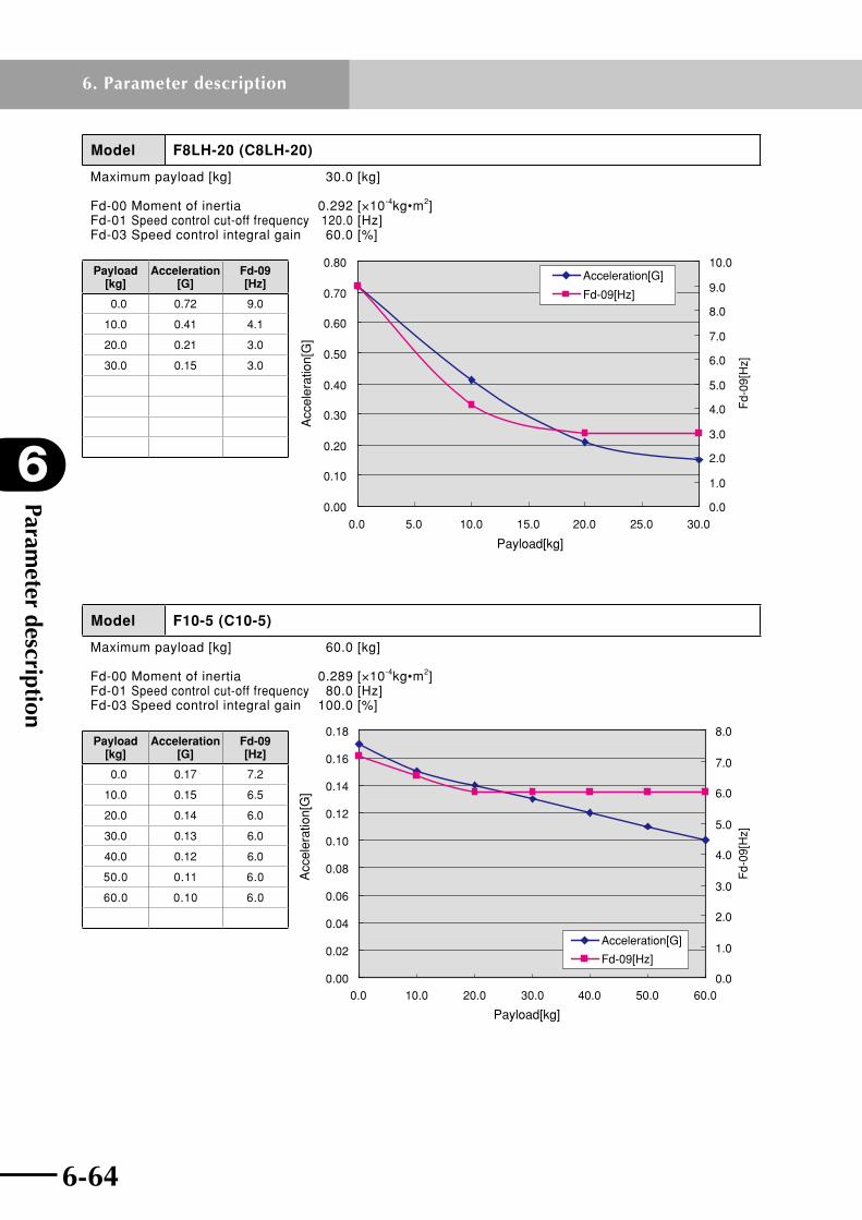
Parameter description
6
6-64
6. Parameter description
6-65
Model F8LH-20 (C8LH-20)
Maximum payload [kg] 30.0 [kg]
Fd-00 Moment of inertia 0.292 [×10-4kg•m2]Fd-01 Speed control cut-off frequency 120.0 [Hz]Fd-03 Speed control integral gain 60.0 [%]
0.00
0.10
0.20
0.30
0.40
0.50
0.60
0.70
0.80
0.0 5.0 10.0 15.0 20.0 25.0 30.0
Payload[kg]
Acc
eler
atio
n[G
]
0.0
1.0
2.0
3.0
4.0
5.0
6.0
7.0
8.0
9.0
10.0
Fd-
09[H
z]
Acceleration[G]
Fd-09[Hz]
Payload [kg]
Acceleration [G]
Fd-09 [Hz]
0.0 0.72 9.0
10.0 0.41 4.1
20.0 0.21 3.0
30.0 0.15 3.0
Model F10-5 (C10-5)
Maximum payload [kg] 60.0 [kg]
Fd-00 Moment of inertia 0.289 [×10-4kg•m2]Fd-01 Speed control cut-off frequency 80.0 [Hz]Fd-03 Speed control integral gain 100.0 [%]
0.00
0.02
0.04
0.06
0.08
0.10
0.12
0.14
0.16
0.18
0.0 10.0 20.0 30.0 40.0 50.0 60.00.0
1.0
2.0
3.0
4.0
5.0
6.0
7.0
8.0F
d-09
[Hz]
Payload[kg]
Acc
eler
atio
n[G
]
Acceleration[G]
Fd-09[Hz]
Payload [kg]
Acceleration [G]
Fd-09 [Hz]
0.0 0.17 7.2
10.0 0.15 6.5
20.0 0.14 6.0
30.0 0.13 6.0
40.0 0.12 6.0
50.0 0.11 6.0
60.0 0.10 6.0

6-64 6-65
6
Parameter description
6. Parameter description
Model F10-5-BK (C10-5-BK)
Maximum payload [kg] 20.0 [kg]
Fd-00 Moment of inertia 0.289 [×10-4kg•m2]Fd-01 Speed control cut-off frequency 80.0 [Hz]Fd-03 Speed control integral gain 100.0 [%]
0.00
0.02
0.04
0.06
0.08
0.10
0.12
0.14
0.16
0.18
0.0 5.0 10.0 15.0 20.00.0
1.0
2.0
3.0
4.0
5.0
6.0
7.0
Fd-
09[H
z]
Payload[kg]
Acc
eler
atio
n[G
]
Acceleration[G]
Fd-09[Hz]
Payload [kg]
Acceleration [G]
Fd-09 [Hz]
0.0 0.17 6.0
5.0 0.15 6.0
10.0 0.14 6.0
15.0 0.13 6.0
20.0 0.11 6.0
Model F10-10 (C10-10)
Maximum payload [kg] 40.0 [kg]
Fd-00 Moment of inertia 0.304 [×10-4kg•m2]Fd-01 Speed control cut-off frequency 80.0 [Hz]Fd-03 Speed control integral gain 100.0 [%]
0.00
0.05
0.10
0.15
0.20
0.25
0.30
0.35
0.40
0.45
0.50
0.0 5.0 10.0 15.0 20.0 25.0 30.0 35.0 40.05.8
6.0
6.2
6.4
6.6
6.8
7.0
7.2
Fd-
09[H
z]Acceleration[G]
Fd-09[Hz]
Payload[kg]
Acc
eler
atio
n[G
]
Payload [kg]
Acceleration [G]
Fd-09 [Hz]
0.0 0.46 7.0
10.0 0.39 6.0
20.0 0.33 6.0
30.0 0.28 6.0
40.0 0.22 6.0

Parameter description
6
6-66
6. Parameter description
6-67
Model F10-10-BK (C10-10-BK)
Maximum payload [kg] 10.0 [kg]
Fd-00 Moment of inertia 0.304 [×10-4kg•m2]Fd-01 Speed control cut-off frequency 100.0 [Hz]Fd-03 Speed control integral gain 60.0 [%]
0.00
0.05
0.10
0.15
0.20
0.25
0.30
0.35
0.40
0.0 2.0 4.0 6.0 8.0 10.05.8
6.0
6.2
6.4
6.6
6.8
7.0
7.2
Fd-
09[H
z]
Acceleration[G]
Fd-09[Hz]
Payload[kg]
Acc
eler
atio
n[G
]
Payload [kg]
Acceleration [G]
Fd-09 [Hz]
0.0 0.38 7.1
2.0 0.35 6.7
4.0 0.32 6.3
6.0 0.29 6.0
8.0 0.27 6.0
10.0 0.24 6.0
Model F10-20 (C10-20)
Maximum payload [kg] 20.0 [kg]
Fd-00 Moment of inertia 0.399 [×10-4kg•m2]Fd-01 Speed control cut-off frequency 80.0 [Hz]Fd-03 Speed control integral gain 60.0 [%]
0.00
0.10
0.20
0.30
0.40
0.50
0.60
0.70
0.0 5.0 10.0 15.0 20.00.0
1.0
2.0
3.0
4.0
5.0
6.0
7.0
8.0F
d-09
[Hz]
Acceleration[G]
Fd-09[Hz]
Payload[kg]
Acc
eler
atio
n[G
]
Payload [kg]
Acceleration [G]
Fd-09 [Hz]
0.0 0.61 7.4
5.0 0.49 5.5
10.0 0.39 5.5
15.0 0.31 5.5
20.0 0.26 5.5
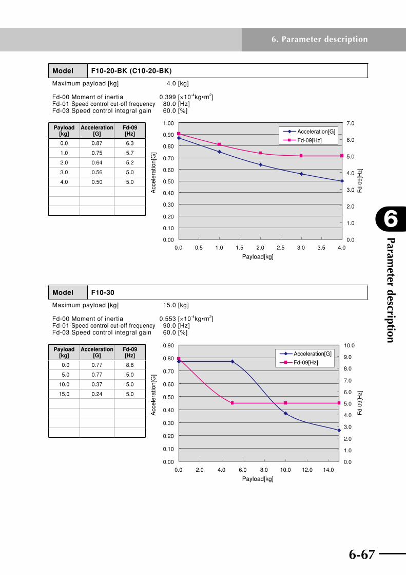
6-66 6-67
6
Parameter description
6. Parameter description
Model F10-20-BK (C10-20-BK)
Maximum payload [kg] 4.0 [kg]
Fd-00 Moment of inertia 0.399 [×10-4kg•m2]Fd-01 Speed control cut-off frequency 80.0 [Hz]Fd-03 Speed control integral gain 60.0 [%]
0.00
0.10
0.20
0.30
0.40
0.50
0.60
0.70
0.80
0.90
1.00
0.0 0.5 1.0 1.5 2.0 2.5 3.0 3.5 4.00.0
1.0
2.0
3.0
4.0
5.0
6.0
7.0
Fd-
09[H
z]
Acceleration[G]
Fd-09[Hz]
Payload[kg]
Acc
eler
atio
n[G
]
Payload [kg]
Acceleration [G]
Fd-09 [Hz]
0.0 0.87 6.3
1.0 0.75 5.7
2.0 0.64 5.2
3.0 0.56 5.0
4.0 0.50 5.0
Model F10-30
Maximum payload [kg] 15.0 [kg]
Fd-00 Moment of inertia 0.553 [×10-4kg•m2]Fd-01 Speed control cut-off frequency 90.0 [Hz]Fd-03 Speed control integral gain 60.0 [%]
0.00
0.10
0.20
0.30
0.40
0.50
0.60
0.70
0.80
0.90
0.0 2.0 4.0 6.0 8.0 10.0 12.0 14.00.0
1.0
2.0
3.0
4.0
5.0
6.0
7.0
8.0
9.0
10.0
Fd-
09[H
z]Acceleration[G]
Fd-09[Hz]
Payload[kg]
Acc
eler
atio
n[G
]
Payload [kg]
Acceleration [G]
Fd-09 [Hz]
0.0 0.77 8.8
5.0 0.77 5.0
10.0 0.37 5.0
15.0 0.24 5.0

Parameter description
6
6-68
6. Parameter description
6-69
Model F14-5 (C14-5)
Maximum payload [kg] 80.0 [kg]
Fd-00 Moment of inertia 0.282 [×10-4kg•m2]Fd-01 Speed control cut-off frequency 100.0 [Hz]Fd-03 Speed control integral gain 60.0 [%]
0.00
0.02
0.04
0.06
0.08
0.10
0.12
0.14
0.16
0.18
0.0 10.0 20.0 30.0 40.0 50.0 60.0 70.0 80.00.0
1.0
2.0
3.0
4.0
5.0
6.0
7.0
8.0
9.0
10.0
Fd-
09[H
z]
Acceleration[G]
Fd-09[Hz]
Payload[kg]
Acc
eler
atio
n[G
]
Payload [kg]
Acceleration [G]
Fd-09 [Hz]
0.0 0.17 8.8
20.0 0.14 7.4
40.0 0.12 6.3
60.0 0.09 6.0
80.0 0.08 6.0
Model F14-5-BK (C14-5-BK)
Maximum payload [kg] 20.0 [kg]
Fd-00 Moment of inertia 0.282 [×10-4kg•m2]Fd-01 Speed control cut-off frequency 100.0 [Hz]Fd-03 Speed control integral gain 60.0 [%]
0.00
0.02
0.04
0.06
0.08
0.10
0.12
0.14
0.16
0.18
0.0 5.0 10.0 15.0 20.05.8
6.0
6.2
6.4
6.6
6.8
7.0
7.2F
d-09
[Hz]
Acceleration[G]
Fd-09[Hz]
Payload[kg]
Acc
eler
atio
n[G
]
Payload [kg]
Acceleration [G]
Fd-09 [Hz]
0.0 0.17 7.1
5.0 0.15 6.8
10.0 0.14 6.5
15.0 0.13 6.3
20.0 0.11 6.0

6-68 6-69
6
Parameter description
6. Parameter description
Model F14-10 (C14-10)
Maximum payload [kg] 55.0 [kg]
Fd-00 Moment of inertia 0.304 [×10-4kg•m2]Fd-01 Speed control cut-off frequency 100.0 [Hz]Fd-03 Speed control integral gain 60.0 [%]
0.00
0.05
0.10
0.15
0.20
0.25
0.30
0.35
0.40
0.45
0.50
0.0 10.0 20.0 30.0 40.0 50.00.0
1.0
2.0
3.0
4.0
5.0
6.0
7.0
8.0
9.0
10.0
Fd-
09[H
z]
Acceleration[G]
Fd-09[Hz]
Payload[kg]
Acc
eler
atio
n[G
]
Payload [kg]
Acceleration [G]
Fd-09 [Hz]
0.0 0.46 9.0
10.0 0.39 6.5
20.0 0.33 6.0
30.0 0.28 6.0
40.0 0.22 6.0
55.0 0.16 6.0
Model F14-10-BK (C14-10-BK)
Maximum payload [kg] 10.0 [kg]
Fd-00 Moment of inertia 0.304 [×10-4kg•m2]Fd-01 Speed control cut-off frequency 100.0 [Hz]Fd-03 Speed control integral gain 60.0 [%]
0.00
0.10
0.20
0.30
0.40
0.50
0.60
0.0 2.0 4.0 6.0 8.0 10.00.0
1.0
2.0
3.0
4.0
5.0
6.0
7.0
8.0
Fd-
09[H
z]
Payload[kg]
Acc
eler
atio
n[G
]
Acceleration[G]
Fd-09[Hz]
Payload [kg]
Acceleration [G]
Fd-09 [Hz]
0.0 0.49 7.3
3.0 0.43 6.6
5.0 0.39 6.2
8.0 0.33 6.0
10.0 0.29 6.0
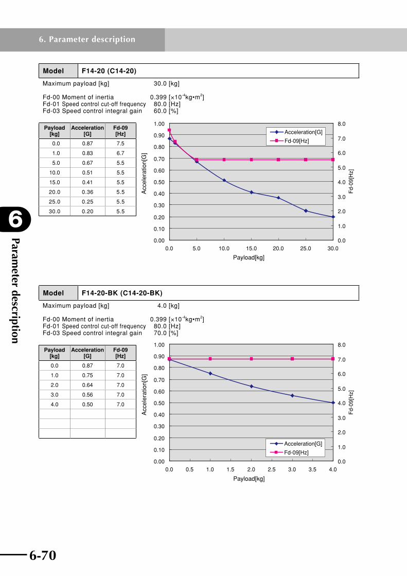
Parameter description
6
6-70
6. Parameter description
6-71
Model F14-20 (C14-20)
Maximum payload [kg] 30.0 [kg]
Fd-00 Moment of inertia 0.399 [×10-4kg•m2]Fd-01 Speed control cut-off frequency 80.0 [Hz]Fd-03 Speed control integral gain 60.0 [%]
0.00
0.10
0.20
0.30
0.40
0.50
0.60
0.70
0.80
0.90
1.00
0.0 5.0 10.0 15.0 20.0 25.0 30.00.0
1.0
2.0
3.0
4.0
5.0
6.0
7.0
8.0
Fd-
09[H
z]
Acceleration[G]
Fd-09[Hz]
Payload[kg]
Acc
eler
atio
n[G
]
Payload [kg]
Acceleration [G]
Fd-09 [Hz]
0.0 0.87 7.5
1.0 0.83 6.7
5.0 0.67 5.5
10.0 0.51 5.5
15.0 0.41 5.5
20.0 0.36 5.5
25.0 0.25 5.5
30.0 0.20 5.5
Model F14-20-BK (C14-20-BK)
Maximum payload [kg] 4.0 [kg]
Fd-00 Moment of inertia 0.399 [×10-4kg•m2]Fd-01 Speed control cut-off frequency 80.0 [Hz]Fd-03 Speed control integral gain 70.0 [%]
0.00
0.10
0.20
0.30
0.40
0.50
0.60
0.70
0.80
0.90
1.00
0.0 0.5 1.0 1.5 2.0 2.5 3.0 3.5 4.00.0
1.0
2.0
3.0
4.0
5.0
6.0
7.0
8.0F
d-09
[Hz]
Payload[kg]
Acc
eler
atio
n[G
]
Acceleration[G]
Fd-09[Hz]
Payload [kg]
Acceleration [G]
Fd-09 [Hz]
0.0 0.87 7.0
1.0 0.75 7.0
2.0 0.64 7.0
3.0 0.56 7.0
4.0 0.50 7.0

6-70 6-71
6
Parameter description
6. Parameter description
Model F14-30
Maximum payload [kg] 15.0 [kg]
Fd-00 Moment of inertia 0.501 [×10-4kg•m2]Fd-01 Speed control cut-off frequency 90.0 [Hz]Fd-03 Speed control integral gain 90.0 [%]
0.00
0.20
0.40
0.60
0.80
1.00
1.20
0.0 2.0 4.0 6.0 8.0 10.0 12.0 14.00.0
1.0
2.0
3.0
4.0
5.0
6.0
7.0
8.0
Fd-
09[H
z]
Acceleration[G]
Fd-09[Hz]
Payload[kg]
Acc
eler
atio
n[G
]
Payload [kg]
Acceleration [G]
Fd-09 [Hz]
0.0 1.03 7.2
3.0 1.03 4.5
6.0 0.68 4.0
9.0 0.50 4.0
12.0 0.40 4.0
15.0 0.34 4.0
Model F14H-5 (C14H-5)
Maximum payload [kg] 100.0 [kg]
Fd-00 Moment of inertia 0.600 [×10-4kg•m2]Fd-01 Speed control cut-off frequency 50.0 [Hz]Fd-03 Speed control integral gain 100.0 [%]
0.00
0.05
0.10
0.15
0.20
0.25
0.0 20.0 40.0 60.0 80.0 100.00.0
2.0
4.0
6.0
8.0
10.0
12.0
14.0
Fd-
09[H
z]Acceleration[G]
Fd-09[Hz]
Payload[kg]
Acc
eler
atio
n[G
]
Payload [kg]
Acceleration [G]
Fd-09 [Hz]
0.0 0.23 12.0
20.0 0.19 10.7
40.0 0.16 9.3
60.0 0.13 8.3
80.0 0.10 7.4
100.0 0.09 6.7
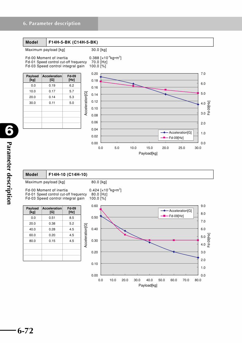
Parameter description
6
6-72
6. Parameter description
6-73
Model F14H-5-BK (C14H-5-BK)
Maximum payload [kg] 30.0 [kg]
Fd-00 Moment of inertia 0.388 [×10-4kg•m2]Fd-01 Speed control cut-off frequency 70.0 [Hz]Fd-03 Speed control integral gain 100.0 [%]
0.00
0.02
0.04
0.06
0.08
0.10
0.12
0.14
0.16
0.18
0.20
0.0 5.0 10.0 15.0 20.0 25.0 30.00.0
1.0
2.0
3.0
4.0
5.0
6.0
7.0
Fd-
09[H
z]
Payload[kg]
Acc
eler
atio
n[G
]
Acceleration[G]
Fd-09[Hz]
Payload [kg]
Acceleration [G]
Fd-09 [Hz]
0.0 0.19 6.2
10.0 0.17 5.7
20.0 0.14 5.3
30.0 0.11 5.0
Model F14H-10 (C14H-10)
Maximum payload [kg] 80.0 [kg]
Fd-00 Moment of inertia 0.424 [×10-4kg•m2]Fd-01 Speed control cut-off frequency 80.0 [Hz]Fd-03 Speed control integral gain 100.0 [%]
0.00
0.10
0.20
0.30
0.40
0.50
0.60
0.0 10.0 20.0 30.0 40.0 50.0 60.0 70.0 80.00.0
1.0
2.0
3.0
4.0
5.0
6.0
7.0
8.0
9.0F
d-09
[Hz]
Acceleration[G]
Fd-09[Hz]
Payload[kg]
Acc
eler
atio
n[G
]
Payload [kg]
Acceleration [G]
Fd-09 [Hz]
0.0 0.51 8.5
20.0 0.38 5.2
40.0 0.28 4.5
60.0 0.20 4.5
80.0 0.15 4.5
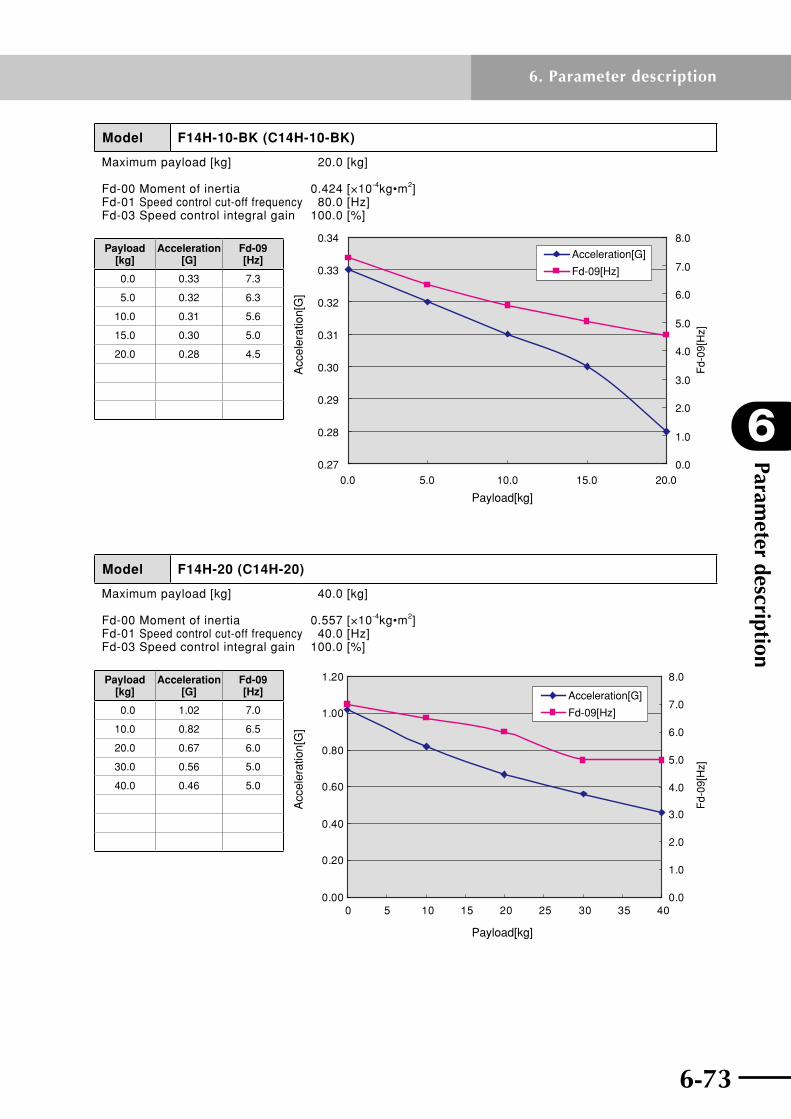
6-72 6-73
6
Parameter description
6. Parameter description
Model F14H-10-BK (C14H-10-BK)
Maximum payload [kg] 20.0 [kg]
Fd-00 Moment of inertia 0.424 [×10-4kg•m2]Fd-01 Speed control cut-off frequency 80.0 [Hz]Fd-03 Speed control integral gain 100.0 [%]
0.27
0.28
0.29
0.30
0.31
0.32
0.33
0.34
0.0 5.0 10.0 15.0 20.00.0
1.0
2.0
3.0
4.0
5.0
6.0
7.0
8.0
Fd-
09[H
z]
Acceleration[G]
Fd-09[Hz]
Payload[kg]
Acc
eler
atio
n[G
]
Payload [kg]
Acceleration [G]
Fd-09 [Hz]
0.0 0.33 7.3
5.0 0.32 6.3
10.0 0.31 5.6
15.0 0.30 5.0
20.0 0.28 4.5
Model F14H-20 (C14H-20)
Maximum payload [kg] 40.0 [kg]
Fd-00 Moment of inertia 0.557 [×10-4kg•m2]Fd-01 Speed control cut-off frequency 40.0 [Hz]Fd-03 Speed control integral gain 100.0 [%]
Fd-
09[H
z]
0.00
0.20
0.40
0.60
0.80
1.00
1.20
0 5 10 15 20 25 30 35 400.0
1.0
2.0
3.0
4.0
5.0
6.0
7.0
8.0
Acceleration[G]
Fd-09[Hz]
Payload[kg]
Acc
eler
atio
n[G
]
Payload [kg]
Acceleration [G]
Fd-09 [Hz]
0.0 1.02 7.0
10.0 0.82 6.5
20.0 0.67 6.0
30.0 0.56 5.0
40.0 0.46 5.0

Parameter description
6
6-74
6. Parameter description
6-75
Model F14H-20-BK (C14H-20-BK)
Maximum payload [kg] 8.0 [kg]
Fd-00 Moment of inertia 0.620 [×10-4kg•m2]Fd-01 Speed control cut-off frequency 60.0 [Hz]Fd-03 Speed control integral gain 100.0 [%]
0.00
0.10
0.20
0.30
0.40
0.50
0.60
0.70
0.80
0.90
1.00
0.0 1.0 2.0 3.0 4.0 5.0 6.0 7.0 8.00.0
1.0
2.0
3.0
4.0
5.0
6.0
7.0
8.0
Fd-
09[H
z]
Payload[kg]
Acc
eler
atio
n[G
]
Acceleration[G]
Fd-09[Hz]
Payload [kg]
Acceleration [G]
Fd-09 [Hz]
0.0 0.91 7.0
2.0 0.86 5.8
4.0 0.81 5.5
6.0 0.76 5.5
8.0 0.71 5.5
Model F14H-30
Maximum payload [kg] 25.0 [kg]
Fd-00 Moment of inertia 0.823 [×10-4kg•m2]Fd-01 Speed control cut-off frequency 90.0 [Hz]Fd-03 Speed control integral gain 60.0 [%]
0.00
0.20
0.40
0.60
0.80
1.00
1.20
0.0 5.0 10.0 15.0 20.0 25.00.0
2.0
4.0
6.0
8.0
10.0
12.0F
d-09
[Hz]
Acceleration[G]
Fd-09[Hz]
Payload[kg]
Acc
eler
atio
n[G
]
Payload [kg]
Acceleration [G]
Fd-09 [Hz]
0.0 1.00 10.6
5.0 1.00 5.8
10.0 0.86 4.0
15.0 0.64 3.1
20.0 0.50 3.0
25.0 0.31 3.0

6-74 6-75
6
Parameter description
6. Parameter description
Model F17L-50 (C17L-50)
Maximum payload [kg] 50.0 [kg]
Fd-00 Moment of inertia 6.080 [×10-4kg•m2]Fd-01 Speed control cut-off frequency 100.0 [Hz]Fd-03 Speed control integral gain 60.0 [%]
0.00
0.10
0.20
0.30
0.40
0.50
0.60
0.70
0.80
0.90
0 10 20 30 40 500.0
1.0
2.0
3.0
4.0
5.0
6.0
7.0
Fd-
09[H
z]
Acceleration[G]
Fd-09[Hz]
Acc
eler
atio
n[G
]
Payload[kg]
Payload [kg]
Acceleration [G]
Fd-09 [Hz]
0.0 0.77 6.5
10.0 0.55 6.5
20.0 0.37 5.9
30.0 0.24 4.5
40.0 0.16 3.6
50.0 0.16 3.5
Model F17L-50-BK (C17L-50-BK)
Maximum payload [kg] 10.0 [kg]
Fd-00 Moment of inertia 6.420 [×10-4kg•m2]Fd-01 Speed control cut-off frequency 50.0 [Hz]Fd-03 Speed control integral gain 100.0 [%]
0.00
0.10
0.20
0.30
0.40
0.50
0.60
0.70
0.80
0.90
1.00
0.0 2.0 4.0 6.0 8.0 10.05.0
5.2
5.4
5.6
5.8
6.0
6.2
6.4
6.6
6.8
7.0
Fd-
09[H
z]
Payload[kg]
Acc
eler
atio
n[G
]
Acceleration[G]
Fd-09[Hz]
Payload [kg]
Acceleration [G]
Fd-09 [Hz]
0.0 0.94 6.4
5.0 0.57 6.0
10.0 0.28 6.0

Parameter description
6
6-76
6. Parameter description
6-77
Model F17-10 (C17-10)
Maximum payload [kg] 120.0 [kg]
Fd-00 Moment of inertia 1.480 [×10-4kg•m2]Fd-01 Speed control cut-off frequency 110.0 [Hz]Fd-03 Speed control integral gain 90.0 [%]
0.00
0.05
0.10
0.15
0.20
0.25
0.30
0.35
0.40
0.45
0.50
0.0 20.0 40.0 60.0 80.0 100.0 120.00.0
2.0
4.0
6.0
8.0
10.0
12.0
Fd-
09[H
z]
Acceleration[G]
Fd-09[Hz]
Payload[kg]
Acc
eler
atio
n[G
]
Payload [kg]
Acceleration [G]
Fd-09 [Hz]
0.0 0.47 11.4
30.0 0.36 9.1
60.0 0.26 7.6
90.0 0.20 6.5
120.0 0.15 5.7
Model F17-10-BK (C17-10-BK)
Maximum payload [kg] 35.0 [kg]
Fd-00 Moment of inertia 1.480 [×10-4kg•m2]Fd-01 Speed control cut-off frequency 90.0 [Hz]Fd-03 Speed control integral gain 100.0 [%]
0.00
0.05
0.10
0.15
0.20
0.25
0.30
0.35
0.40
0.0 5.0 10.0 15.0 20.0 25.0 30.0 35.00.0
2.0
4.0
6.0
8.0
10.0
12.0F
d-09
[Hz]
Payload[kg]
Acc
eler
atio
n[G
]
Acceleration[G]
Fd-09[Hz]
Payload [kg]
Acceleration [G]
Fd-09 [Hz]
0.0 0.38 10.0
5.0 0.36 10.0
10.0 0.33 10.0
15.0 0.31 10.0
20.0 0.28 10.0
25.0 0.26 10.0
30.0 0.23 10.0
35.0 0.20 10.0

6-76 6-77
6
Parameter description
6. Parameter description
Model F17-20 (C17-20)
Maximum payload [kg] 80.0 [kg]
Fd-00 Moment of inertia 1.720 [×10-4kg•m2]Fd-01 Speed control cut-off frequency 110.0 [Hz]Fd-03 Speed control integral gain 100.0 [%]
0.00
0.10
0.20
0.30
0.40
0.50
0.60
0.70
0.80
0.0 10.0 20.0 30.0 40.0 50.0 60.0 70.0 80.00.0
2.0
4.0
6.0
8.0
10.0
12.0
14.0
Fd-
09[H
z]
Acceleration[G]
Fd-09[Hz]
Payload[kg]
Acc
eler
atio
n[G
]
Payload [kg]
Acceleration [G]
Fd-09 [Hz]
0.0 0.72 11.8
1.0 0.72 11.5
10.0 0.67 9.1
20.0 0.61 7.3
40.0 0.51 5.3
60.0 0.41 4.2
80.0 0.31 3.5
Model F17-20-BK (C17-20-BK)
Maximum payload [kg] 15.0 [kg]
Fd-00 Moment of inertia 2.060 [×10-4kg•m2]Fd-01 Speed control cut-off frequency 100.0 [Hz]Fd-03 Speed control integral gain 85.0 [%]
0.00
0.10
0.20
0.30
0.40
0.50
0.60
0.70
0.80
0.90
0.0 2.0 4.0 6.0 8.0 10.0 12.0 14.00.0
2.0
4.0
6.0
8.0
10.0
12.0
14.0
Fd-
09[H
z]Acceleration[G]
Fd-09[Hz]
Payload[kg]
Acc
eler
atio
n[G
]
Payload [kg]
Acceleration [G]
Fd-09 [Hz]
0.0 0.81 11.6
5.0 0.68 10.2
10.0 0.55 9.1
15.0 0.44 8.2

Parameter description
6
6-78
6. Parameter description
6-79
Model F17-40
Maximum payload [kg] 40.0 [kg]
Fd-00 Moment of inertia 1.930 [×10-4kg•m2]Fd-01 Speed control cut-off frequency 100.0 [Hz]Fd-03 Speed control integral gain 100.0 [%]
0.00
0.10
0.20
0.30
0.40
0.50
0.60
0.70
0.80
0.0 5.0 10.0 15.0 20.0 25.0 30.0 35.0 40.00.0
1.0
2.0
3.0
4.0
5.0
6.0
7.0
Fd-
09[H
z]
Payload[kg]
Acc
eler
atio
n[G
]
Acceleration[G]
Fd-09[Hz]
Payload [kg]
Acceleration [G]
Fd-09 [Hz]
0.0 0.74 6.1
10.0 0.74 5.0
20.0 0.49 5.0
30.0 0.37 5.0
40.0 0.29 5.0
Model F20-10-BK (C20-10-BK)
Maximum payload [kg] 45.0 [kg]
Fd-00 Moment of inertia 2.210 [×10-4kg•m2]Fd-01 Speed control cut-off frequency 70.0 [Hz]Fd-03 Speed control integral gain 100.0 [%]
0.00
0.05
0.10
0.15
0.20
0.25
0.30
0.35
0.40
0.0 10.0 20.0 30.0 40.00.0
1.0
2.0
3.0
4.0
5.0
6.0
7.0
8.0
9.0F
d-09
[Hz]
Payload[kg]
Acc
eler
atio
n[G
]
Acceleration[G]
Fd-09[Hz]
Payload [kg]
Acceleration [G]
Fd-09 [Hz]
0.0 0.38 8.5
10.0 0.33 8.0
20.0 0.28 7.5
30.0 0.23 7.1
40.0 0.18 6.7
45.0 0.15 6.5
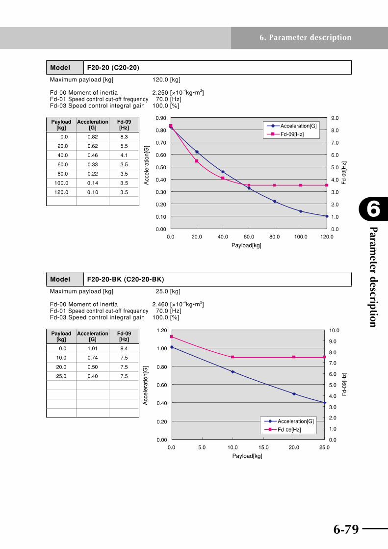
6-78 6-79
6
Parameter description
6. Parameter description
Model F20-20 (C20-20)
Maximum payload [kg] 120.0 [kg]
Fd-00 Moment of inertia 2.250 [×10-4kg•m2]Fd-01 Speed control cut-off frequency 70.0 [Hz]Fd-03 Speed control integral gain 100.0 [%]
0.00
0.10
0.20
0.30
0.40
0.50
0.60
0.70
0.80
0.90
0.0 20.0 40.0 60.0 80.0 100.0 120.00.0
1.0
2.0
3.0
4.0
5.0
6.0
7.0
8.0
9.0
Fd-
09[H
z]
Acceleration[G]
Fd-09[Hz]
Payload[kg]
Acc
eler
atio
n[G
]
Payload [kg]
Acceleration [G]
Fd-09 [Hz]
0.0 0.82 8.3
20.0 0.62 5.5
40.0 0.46 4.1
60.0 0.33 3.5
80.0 0.22 3.5
100.0 0.14 3.5
120.0 0.10 3.5
Model F20-20-BK (C20-20-BK)
Maximum payload [kg] 25.0 [kg]
Fd-00 Moment of inertia 2.460 [×10-4kg•m2]Fd-01 Speed control cut-off frequency 70.0 [Hz]Fd-03 Speed control integral gain 100.0 [%]
0.00
0.20
0.40
0.60
0.80
1.00
1.20
0.0 5.0 10.0 15.0 20.0 25.00.0
1.0
2.0
3.0
4.0
5.0
6.0
7.0
8.0
9.0
10.0
Fd-
09[H
z]
Payload[kg]
Acc
eler
atio
n[G
]
Acceleration[G]
Fd-09[Hz]
Payload [kg]
Acceleration [G]
Fd-09 [Hz]
0.0 1.01 9.4
10.0 0.74 7.5
20.0 0.50 7.5
25.0 0.40 7.5
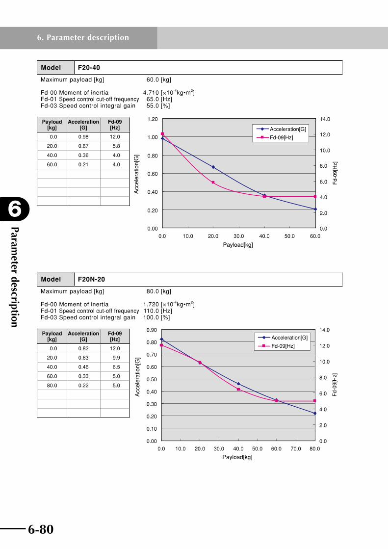
Parameter description
6
6-80
6. Parameter description
6-81
Model F20-40
Maximum payload [kg] 60.0 [kg]
Fd-00 Moment of inertia 4.710 [×10-4kg•m2]Fd-01 Speed control cut-off frequency 65.0 [Hz]Fd-03 Speed control integral gain 55.0 [%]
0.00
0.20
0.40
0.60
0.80
1.00
1.20
0.0 10.0 20.0 30.0 40.0 50.0 60.00.0
2.0
4.0
6.0
8.0
10.0
12.0
14.0
Fd-
09[H
z]
Payload[kg]
Acc
eler
atio
n[G
]Acceleration[G]
Fd-09[Hz]
Payload [kg]
Acceleration [G]
Fd-09 [Hz]
0.0 0.98 12.0
20.0 0.67 5.8
40.0 0.36 4.0
60.0 0.21 4.0
Model F20N-20
Maximum payload [kg] 80.0 [kg]
Fd-00 Moment of inertia 1.720 [×10-4kg•m2]Fd-01 Speed control cut-off frequency 110.0 [Hz]Fd-03 Speed control integral gain 100.0 [%]
0.00
0.10
0.20
0.30
0.40
0.50
0.60
0.70
0.80
0.90
0.0 10.0 20.0 30.0 40.0 50.0 60.0 70.0 80.00.0
2.0
4.0
6.0
8.0
10.0
12.0
14.0F
d-09
[Hz]
Acceleration[G]
Fd-09[Hz]
Payload[kg]
Acc
eler
atio
n[G
]
Payload [kg]
Acceleration [G]
Fd-09 [Hz]
0.0 0.82 12.0
20.0 0.63 9.9
40.0 0.46 6.5
60.0 0.33 5.0
80.0 0.22 5.0

6-80 6-81
6
Parameter description
6. Parameter description
Model N15-10
Maximum payload [kg] 80.0 [kg]
Fd-00 Moment of inertia 2.940 [×10-4kg•m2]Fd-01 Speed control cut-off frequency 70.0 [Hz]Fd-03 Speed control integral gain 100.0 [%]
0.00
0.10
0.20
0.30
0.40
0.50
0.60
0.0 10.0 20.0 30.0 40.0 50.0 60.0 70.0 80.0
Payload[kg]
Acc
eler
atio
n[G
]
0.0
2.0
4.0
6.0
8.0
10.0
12.0
14.0
Fd-
09[H
z]
Acceleration [G]
Fd-09 [Hz]
Payload [kg]
Acceleration [G]
Fd-09 [Hz]
0.0 0.51 11.7
20.0 0.38 10.0
40.0 0.28 8.7
60.0 0.20 7.7
80.0 0.14 6.9
Model N15-20
Maximum payload [kg] 50.0 [kg]
Fd-00 Moment of inertia 3.220 [×10-4kg•m2]Fd-01 Speed control cut-off frequency 70.0 [Hz]Fd-03 Speed control integral gain 100.0 [%]
0.00
0.20
0.40
0.60
0.80
1.00
1.20
0.0 10.0 20.0 30.0 40.0 50.00.0
2.0
4.0
6.0
8.0
10.0
12.0
14.0
Fd-
09[H
z]Acceleration[G]
Fd-09[Hz]
Payload[kg]
Acc
eler
atio
n[G
]
Payload [kg]
Acceleration [G]
Fd-09 [Hz]
0.0 1.02 12.0
10.0 0.82 10.4
20.0 0.67 8.4
30.0 0.56 7.1
40.0 0.46 6.1
50.0 0.40 6.0

Parameter description
6
6-82
6. Parameter description
6-83
Model N15-30
Maximum payload [kg] 30.0 [kg]
Fd-00 Moment of inertia 3.720 [×10-4kg•m2]Fd-01 Speed control cut-off frequency 45.0 [Hz]Fd-03 Speed control integral gain 100.0 [%]
0.00
0.20
0.40
0.60
0.80
1.00
1.20
0.0 5.0 10.0 15.0 20.0 25.0 30.0
Payload[kg]
Acc
eler
atio
n[G
]
0.0
1.0
2.0
3.0
4.0
5.0
6.0
7.0
8.0
9.0
Fd-
09[H
z]
Acceleration [G]
Fd-09 [Hz]
Payload [kg]
Acceleration [G]
Fd-09 [Hz]
0.0 0.99 8.5
10.0 0.86 5.4
20.0 0.50 5.0
30.0 0.36 5.0
Model N18-20
Maximum payload [kg] 80.0 [kg]
Fd-00 Moment of inertia 5.240 [×10-4kg•m2]Fd-01 Speed control cut-off frequency 70.0 [Hz]Fd-03 Speed control integral gain 70.0 [%]
0.00
0.10
0.20
0.30
0.40
0.50
0.60
0.70
0.80
0.90
0.0 10.0 20.0 30.0 40.0 50.0 60.0 70.0 80.00.0
2.0
4.0
6.0
8.0
10.0
12.0
14.0F
d-09
[Hz]
Acceleration[G]
Fd-09[Hz]
Payload[kg]
Acc
eler
atio
n[G
]
Payload [kg]
Acceleration [G]
Fd-09 [Hz]
0.0 0.82 12.0
20.0 0.56 9.4
40.0 0.43 7.4
60.0 0.35 6.1
80.0 0.29 5.2

6-82 6-83
6
Parameter description
6. Parameter description
Model B10
Maximum payload [kg] 10.0 [kg]
Fd-00 Moment of inertia 0.451 [×10-4kg•m2]Fd-01 Speed control cut-off frequency 100.0 [Hz]Fd-03 Speed control integral gain 75.0 [%]
0.00
0.20
0.40
0.60
0.80
1.00
1.20
0.0 2.0 4.0 6.0 8.0 10.00.0
1.0
2.0
3.0
4.0
5.0
6.0
7.0
8.0
9.0
Fd-
09[H
z]
Payload[kg]
Acc
eler
atio
n[G
]
Acceleration[G]
Fd-09[Hz]
Payload [kg]
Acceleration [G]
Fd-09 [Hz]
0.0 0.97 8.5
2.0 0.87 6.0
4.0 0.74 6.0
6.0 0.63 6.0
8.0 0.52 6.0
10.0 0.43 6.0
Model B14
Maximum payload [kg] 20.0 [kg]
Fd-00 Moment of inertia 0.643 [×10-4kg•m2]Fd-01 Speed control cut-off frequency 70.0 [Hz]Fd-03 Speed control integral gain 70.0 [%]
0.00
0.10
0.20
0.30
0.40
0.50
0.60
0.70
0.80
0.90
0.0 5.0 10.0 15.0 20.00.0
2.0
4.0
6.0
8.0
10.0
12.0
Fd-
09[H
z]
Payload[kg]
Acc
eler
atio
n[G
]
Acceleration[G]
Fd-09[Hz]
Payload [kg]
Acceleration [G]
Fd-09 [Hz]
0.0 0.77 11.2
5.0 0.60 5.7
10.0 0.47 3.8
15.0 0.36 3.5
20.0 0.29 3.5

Parameter description
6
6-84
6. Parameter description
6-85
Model B14H
Maximum payload [kg] 30.0 [kg]
Fd-00 Moment of inertia 0.800 [×10-4kg•m2]Fd-01 Speed control cut-off frequency 80.0 [Hz]Fd-03 Speed control integral gain 40.0 [%]
0.00
0.20
0.40
0.60
0.80
1.00
1.20
0.0 5.0 10.0 15.0 20.0 25.0 30.00.0
2.0
4.0
6.0
8.0
10.0
12.0
14.0
Fd-
09[H
z]
Payload[kg]
Acc
eler
atio
n[G
]
Acceleration[G]
Fd-09[Hz]
Payload [kg]
Acceleration [G]
Fd-09 [Hz]
0.0 1.07 12.0
5.0 0.82 7.3
10.0 0.69 5.0
15.0 0.56 3.8
20.0 0.45 3.1
25.0 0.41 3.0
30.0 0.38 3.0
Model R5
Moment of inertia of maximum allowable load 1.22 [kgf•cm•sec2]
Fd-00 Moment of inertia 0.235 [×10-4kg•m2]Fd-01 Speed control cut-off frequency 60.0 [Hz]Fd-03 Speed control integral gain 100.0 [%]
0
500
1000
1500
2000
2500
3000
3500
0.00 0.20 0.40 0.60 0.80 1.00 1.20 1.40
Moment of Inertia[kgf•cm•sec 2]
Acc
eler
atio
n[de
g/se
c2]
0.0
2.0
4.0
6.0
8.0
10.0
12.0
14.0F
d-09
[Hz]
Acceleration[deg/sec 2 ]
Fd-09[Hz]
Moment of inertia of load [kgf•cm•sec2]
Acceleration [deg/sec2]
Fd-09 [Hz]
0.00 3243 12.0
0.24 2880 6.6
0.49 2535 6.0
0.73 2169 6.0
0.98 1800 6.0
1.22 1440 6.0

6-84 6-85
6
Parameter description
6. Parameter description
Model R10
Moment of inertia of maximum allowable load 3.71 [kgf•cm•sec2]
Fd-00 Moment of inertia 0.239 [×10-4kg•m2]Fd-01 Speed control cut-off frequency 110.0 [Hz]Fd-03 Speed control integral gain 60.0 [%]
0
500
1000
1500
2000
2500
3000
3500
4000
0.00 0.50 1.00 1.50 2.00 2.50 3.00 3.50 4.000.0
2.0
4.0
6.0
8.0
10.0
12.0
14.0
Fd-
09[H
z]
Fd-09[Hz]
Acceleration[deg/sec 2 ]
Moment of Inertia[kgf•cm•sec 2]
Acc
eler
atio
n[de
g/se
c2]
Moment of inertia of load [kgf•cm•sec2]
Acceleration [deg/sec2]
Fd-09 [Hz]
0.00 3600 12.0
0.25 3429 10.8
1.24 2707 4.0
2.47 1800 4.0
3.71 898 4.0
Model R20
Moment of inertia of maximum allowable load 18.70 [kgf•cm•sec2]
Fd-00 Moment of inertia 0.644 [×10-4kg•m2]Fd-01 Speed control cut-off frequency 150.0 [Hz]Fd-03 Speed control integral gain 30.0 [%]
0
500
1000
1500
2000
2500
0.00 5.00 10.00 15.000.0
2.0
4.0
6.0
8.0
10.0
12.0
14.0
Fd-
09[H
z]Fd-09[Hz]
2 ]
2]
Acceleration[deg/sec 2 ]
Moment of Inertia[kgf•cm•sec
Acc
eler
atio
n[de
g/se
c
Moment of inertia of load [kgf•cm•sec2]
Acceleration [deg/sec2]
Fd-09 [Hz]
0.00 2093 12.0
0.93 2022 12.0
6.50 1622 3.0
12.10 1259 3.0
18.70 791 3.0

Parameter description
6
6-86
6. Parameter description
6-87
n RDP
Model MR12
Maximum payload [kg] 5.0 [kg]
Fd-00 Mover mass 0.108 [×10kg]Fd-01 Speed control cut-off frequency 120.0 [Hz]Fd-03 Speed control integral gain 100.0 [%]
0.00
0.10
0.20
0.30
0.40
0.50
0.60
0.70
0.80
0.90
0 1 2 3 4 50.0
2.0
4.0
6.0
8.0
10.0
12.0
14.0
Fd-
09[H
z]
Acceleration[G]
Fd-09[Hz]
Payload[kg]
Acc
eler
atio
n[G
]Payload
[kg]Acceleration
[G]Fd-09 [Hz]
0 0.82 12.0
1 0.48 8.4
2 0.36 7.0
3 0.29 7.0
4 0.23 7.0
5 0.20 7.0
Model MR16
Maximum payload [kg] 7.0 [kg]
Fd-00 Mover mass 0.151 [×10kg]Fd-01 Speed control cut-off frequency 130.0 [Hz]Fd-03 Speed control integral gain 50.0 [%]
0.00
0.20
0.40
0.60
0.80
1.00
1.20
1.40
1.60
0 1 2 3 4 5 6 70.0
2.0
4.0
6.0
8.0
10.0
12.0
14.0F
d-09
[Hz]
Acceleration[G]
Fd-09[Hz]
Payload[kg]
Acc
eler
atio
n[G
]
Payload [kg]
Acceleration [G]
Fd-09 [Hz]
0 1.34 12.0
1 0.93 11.2
3 0.55 7.1
5 0.36 6.0
7 0.31 6.0

6-86 6-87
6
Parameter description
6. Parameter description
Model MR16H
Maximum payload [kg] 9.0 [kg]
Fd-00 Mover mass 0.182 [×10kg]Fd-01 Speed control cut-off frequency 130.0 [Hz]Fd-03 Speed control integral gain 65.0 [%]
0.00
0.50
1.00
1.50
2.00
2.50
0 2 4 6 80.0
2.0
4.0
6.0
8.0
10.0
12.0
14.0
Fd-
09[H
z]
Acceleration[G]
Fd-09[Hz]
Payload[kg]
Acc
eler
atio
n[G
]
Payload [kg]
Acceleration [G]
Fd-09 [Hz]
0 1.92 12.0
1 1.36 12.0
3 0.82 8.1
5 0.55 6.1
7 0.43 6.0
9 0.35 6.0
Model MR20
Maximum payload [kg] 17.0 [kg]
Fd-00 Mover mass 0.370 [×10kg]Fd-01 Speed control cut-off frequency 110.0 [Hz]Fd-03 Speed control integral gain 70.0 [%]
0.00
0.50
1.00
1.50
2.00
2.50
0 5 10 150.0
2.0
4.0
6.0
8.0
10.0
12.0
14.0
Fd-
09[H
z]Acceleration[G]
Fd-09[Hz]
Payload[kg]
Acc
eler
atio
n[G
]
Payload [kg]
Acceleration [G]
Fd-09 [Hz]
0 2.07 12.0
1 1.57 12.0
3 1.16 10.6
5 0.96 8.4
9 0.70 6.0
15 0.52 6.0
17 0.47 6.0

Parameter description
6
6-88
6. Parameter description
6-89
Model MR25
Maximum payload [kg] 23.0 [kg]
Fd-00 Mover mass 0.386 [×10kg]Fd-01 Speed control cut-off frequency 120.0 [Hz]Fd-03 Speed control integral gain 100.0 [%]
0.00
0.20
0.40
0.60
0.80
1.00
1.20
1.40
1.60
1.80
2.00
0 5 10 15 200.0
2.0
4.0
6.0
8.0
10.0
12.0
14.0
Fd-
09[H
z]
Acceleration[G]
Fd-09[Hz]
Payload[kg]
Acc
eler
atio
n[G
]
Payload [kg]
Acceleration [G]
Fd-09 [Hz]
0 1.82 12.0
5 0.88 9.4
10 0.59 6.2
15 0.36 5.5
20 0.29 5.5
23 0.28 5.5
Model MF7
Maximum payload [kg] 7.0 [kg]
Fd-00 Mover mass 0.150 [×10kg]Fd-01 Speed control cut-off frequency 130.0 [Hz]Fd-03 Speed control integral gain 90.0 [%]
Fd-
09[H
z]
0.0
2.0
4.0
6.0
8.0
10.0
12.0
0.00
0.20
0.40
0.60
0.80
1.00
1.20
0 1 2 3 4 5 6 7
Acc
eler
atio
n[G
]
Payload[kg]
Acceleration [G]
Fd-09 [Hz]
Payload [kg]
Acceleration [G]
Fd-09 [Hz]
0 1.00 11.0
2 0.67 8.5
4 0.46 7.0
6 0.37 6.0
7 0.34 6.0

6-88 6-89
6
Parameter description
6. Parameter description
Model MF15
Maximum payload [kg] 15.0 [kg]
Fd-00 Mover mass 0.180 [×10kg]Fd-01 Speed control cut-off frequency 140.0 [Hz]Fd-03 Speed control integral gain 80.0 [%]
0.00
0.50
1.00
1.50
2.00
2.50
0 2 4 6 8 10 12 14
Payload[kg]
Acc
eler
atio
n[G
]
0.0
2.0
4.0
6.0
8.0
10.0
12.0
14.0
Acceleration [G]
Fd-09 [Hz]
Fd-
09[H
z]
Payload [kg]
Acceleration [G]
Fd-09 [Hz]
0 1.95 12.0
5 0.77 7.1
10 0.47 4.5
15 0.30 4.5
Model MF20
Maximum payload [kg] 20.0 [kg]
Fd-00 Mover mass 0.290 [×10kg]Fd-01 Speed control cut-off frequency 150.0 [Hz]Fd-03 Speed control integral gain 75.0 [%]
0.00
0.50
1.00
1.50
2.00
2.50
0 5 10 15 20
Payload[kg]
Acc
eler
atio
n[G
]
0.0
2.0
4.0
6.0
8.0
10.0
12.0
14.0
Fd-
09[H
z]Acceleration[G]
Fd-09[Hz]
Payload [kg]
Acceleration [G]
Fd-09 [Hz]
0 1.95 12.0
5 1.02 9.8
10 0.62 6.3
15 0.45 5.5
20 0.36 5.5

Parameter description
6
6-90
6. Parameter description
6-91
Model MF30
Maximum payload [kg] 30.0 [kg]
Fd-00 Mover mass 0.310 [×10kg]Fd-01 Speed control cut-off frequency 150.0 [Hz]Fd-03 Speed control integral gain 90.0 [%]
0.00
0.50
1.00
1.50
2.00
2.50
0 5 10 15 20 25 30
Payload[kg]
Acc
eler
atio
n[G
]
0
2
4
6
8
10
12
14
Fd-
09[H
z]
Acceleration[G]
Fd-09[Hz]
Payload [kg]
Acceleration [G]
Fd-09 [Hz]
0 2.33 12.0
10 1.06 7
20 0.68 4.5
30 0.51 4.5
Model MF50
Maximum payload [kg] 50.0 [kg]
Fd-00 Mover mass 0.790 [×10kg]Fd-01 Speed control cut-off frequency 130.0 [Hz]Fd-03 Speed control integral gain 80.0 [%]
0.00
0.20
0.40
0.60
0.80
1.00
1.20
1.40
1.60
1.80
2.00
0 10 20 30 40 500.0
2.0
4.0
6.0
8.0
10.0
12.0
14.0F
d-09
[Hz]
Acceleration[G]
Fd-09[Hz]
Payload[kg]
Acc
eler
atio
n[G
]
Payload [kg]
Acceleration [G]
Fd-09 [Hz]
0 1.89 12.0
10 0.85 10.9
20 0.51 7.1
30 0.39 6.0
40 0.30 6.0
50 0.26 6.0

6-90 6-91
6
Parameter description
6. Parameter description
Model MF75
Maximum payload [kg] 75.0 [kg]
Fd-00 Mover mass 0.840 [×10kg]Fd-01 Speed control cut-off frequency 135.0 [Hz]Fd-03 Speed control integral gain 90.0 [%]
Fd-
09[H
z]
0.00
0.20
0.40
0.60
0.80
1.00
1.20
1.40
1.60
1.80
2.00
0 10 20 30 40 50 60 700.0
2.0
4.0
6.0
8.0
10.0
12.0
14.0
Acceleration[G]
Fd-09[Hz]
Payload[kg]
Acc
eler
atio
n[G
]
Payload [kg]
Acceleration [G]
Fd-09 [Hz]
0.0 1.88 12.0
25.0 0.82 6.6
50.0 0.47 4.5
75.0 0.33 4.5
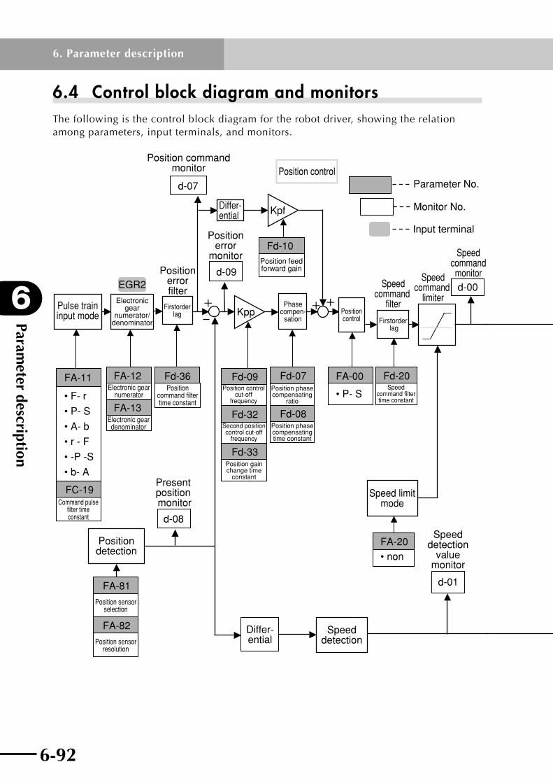
Parameter description
6
6-92
6. Parameter description
6-93
6.4 Control block diagram and monitorsThe following is the control block diagram for the robot driver, showing the relation among parameters, input terminals, and monitors.
Electronicgear
numerator/denominator
FA-11
• F- r
• P- S
• A- b
• r - F
• -P -S
• b- A
Positioncommand filtertime constant
Speedcommandmonitor
Pulse traininput mode
d-07
Differ-ential Kpf
d-00Speed
command limiter
Position control
d-09
Position commandmonitor
FA-20• non
Speed limitmode
FA-00
• P- S
Positioncontrol
d-08
Present position monitor
Positiondetection
Speeddetection
d-01
Position feedforward gain
Electronic gearnumerator
FA-12
FA-13Electronic gear
denominator
Positionerror
monitor
Speeddetection
valuemonitor
Kpp
Fd-07Position phasecompensating
ratio
Fd-08Position phasecompensatingtime constant
Phasecompen-
sation
Parameter No.
Input terminal
Monitor No.
Fd-20Speed
command filtertime constant
Speedcommand
filter
Firstorder lag
Fd-09Position control
cut-offfrequency
Fd-32Second positioncontrol cut-off
frequency
Fd-33
Differ-ential
Fd-36
Positionerrorfilter
Firstorderlag
EGR2
FC-19Command pulse
filter timeconstant
FA-81
Position sensorselection
FA-82
Position sensorresolution
Fd-10
Position gain change time
constant

6-92 6-93
6
Parameter description
6. Parameter description
Torquecommand filtertime constant
Speed control
Torquecommand
limiterPropor-tional
controlswitching
PPI
FA-18
• non • CnS
Torquebias
mode
FA-17
• non
Torquelimit
mode
d-03
Torque commandmonitor
Kspp
Ksi
Ksp
α
1-α
Ksp
Fd-02
Fd-04P-control
gain
Fd-03Speedcontrol
integral gain
Fd-00
Mover mass
Fd-01
Integral
Fd-06
Torquecommand
filterFirst-orderlag
Fd-05IP-control
gain
Speed controlcut-off
frequency
Speed controlproportional
gain
Notch filter 1
Fd-12Notch filter 1
frequency
Fd-13
Fd-14
Fd-15
Notch filter 2
Notch filter 2 frequency
Notch filter 1 bandwidth
Notch filter 2 bandwidth
Torque control

6-94
MEMO

Chapter 7 Maintenance and InspectionThis chapter explains precautions and procedures for maintaining and inspecting this product.
Contents
7.1 Maintenance and inspection 7-17.1.1 Precautions for maintenance and inspection 7-2
7.1.2 Daily inspection 7-2
7.1.3 Cleaning 7-2
7.1.4 Periodic inspection 7-2
7.2 Daily inspection and periodic inspection 7-3
7.3 Megger test and breakdown voltage test 7-4
7.4 Checking the inverter and converter 7-4
7.5 Capacitor life curve 7-6

7-1

7-1
7
Maintenance and Inspection
7. Maintenance and Inspection
7.1 Maintenance and inspection
wDANGER AFTER TuRNING POWER OFF, WAIT AT lEAST 10 MINuTES bEFORE STARTING MAINTENANCE AND MAkE SuRE ThE ChARGE lAMP ON ThE DIGITAl OPERATOR PANEl IS OFF. FAIluRE TO DO SO MAy CAuSE ElECTRICAl ShOCk.
cCAuTION The capacitance of the capacitor on the power supply line drops due to deterioration.Replacing the capacitor based on its service life curve is recommended in order to prevent secondary damage resulting from capacitor failure. (See section 7.5 in this chapter.) using a deteriorated or defective capacitor may cause malfunction.
PROhIbITED DO NOT ATTEMPT TO DISASSEMblE OR REPAIR ThE uNIT OR REPlACE ANy PARTS OF ThE uNIT. ONly quAlIFIED SERvICE PERSONNEl ARE AllOWED TO DO REPAIR WORk.

Maintenance and Inspection
7
7-2
7. Maintenance and Inspection
7-3
7.1.1 Precautions for maintenance and inspection(1) After turning power off, wait at least 10 minutes before starting maintenance and make
sure the charge lamp on the digital operator panel is off.
(2) Do not attempt to disassemble or repair the unit.
(3) Do not perform a megger test or voltage breakdown test on the robot driver.
7.1.2 Daily inspection•Checkforanyabnormalconditionsoroperationsuchaslistedbelow:
1.Checkiftherobotoperatescorrectlyaccordingtothesettings.
2.Checkiftheenvironmentwheretheunitisinstalledconformstothespecifications.
3.Checkthecoolingsystemforabnormalconditions.(Controlbox,airfilters,coolingfans, etc.)
4.Checkforabnormalvibrationornoise.
5.Checkforoverheatingordiscoloration.
6.Checkforunusualodors.
•Checktheinputvoltagetotherobotdriverwithavoltmeterduringoperation.
1.Checkifpowersupplyvoltagefluctuatesfrequently.
2.Checkifthelinevoltageisbalanced.
7.1.3 Cleaning•Alwaysoperatetherobotdriverinacleancondition.
•Tocleantheunit,wipeitgentlywithasoftclothmoistenedwithneutraldetergent.
Note: Solvents such as acetone, benzene, toluene and alcohol can dissolve the robot driver surface or peel the paint. Do not use such solvents. Using detergent or alcohol might damage the display panel on the digital operator. Do not use them to clean the display panel.
7.1.4 Periodic inspection•Checkthefollowingpointsorsectionsthatcannotbeinspectedduringoperationor
thatrequireperiodicinspection.
1.Checkthecoolingsystemforabnormalconditions....Checkthefanforoperation.
2.Checkthescrewsfortightnessandretightenifnecessary.... The screws and bolts mightloosenduetovibrationortemperaturechanges.Carefullycheckthattheyaresecurely tightened.
3.Checktheconductorsandinsulatorsforcorrosionordamage.
4. Measure the insulation resistance.
5.Checkthecoolingfanandreplaceifnecessary.

7-2 7-3
7
Maintenance and Inspection
7. Maintenance and Inspection
7.2 Daily inspection and periodic inspection
Check point Check item Check item
Check interval
Check method Criteria InstrumentDaily
Regular1
year2
years
Ge
ne
ral
Ambient environment
Check ambient temperature, humidity, dust.
ORefer to Chapter 3, "Installation and Wiring".
Ambient temperature should be 0°C or more without freezing. Ambient humidity should be 90% or less without condensation.
·Thermometer ·Hygrometer ·Recorder
Overall equipment
Check for abnormal vibration or noise. O Visual and aural
inspection No abnormalities.
Power supply voltage
Check the main and control power circuit voltage.
O
Measure the voltage between L1, L2 and L3 on the robot driver main circuit, and between L1C and L2C on the control circuit.
Voltage should be within the specified AC voltage.
·Tester ·Digital multimeter
Ma
in c
irc
uit
General
(1) Check connections for tightness. (2) Check for evidence of overheating in various components. (3) Cleaning Note: Do not perform a megger test.
O O O
(1) Retighten. (2) Visual inspection
(1)(2) No abnormalities.
Connection conductors and cables
(1) Check the conductors for deformation. (2) Check the cable sheath for wear or damage.
O O
(1)(2) Visual inspection (1)(2) No abnormalities.
Terminal block
Check the terminal block for damage. O Visual inspection No abnormalities.
Inverter, converter
Check resistance between terminals. O
Disconnect the cables from the robot driver and measure the resistance between terminals L1, L2 or L3 and (+) or (–), and between U, V or W and (+) or (–) with a tester or multimeter of ×1 W range.
Refer to the procedure described in 7.4, "Checking the converter and inverter", in this chapter. Typical inverter replacement interval: 106 start/stop cycles.
Analog tester
Smoothing capacitor
(1) Check for liquid leakage. (2) Check for bulging.
O O
(1)(2) Visual inspection (Check for evidence of liquid leakage and deformation of the case.)
(1)(2) No abnormalities. Typical replacement intervals: 5 years (See capacitor life curve.)
Relay Check for chattering noise at on/off. O Aural inspection No abnormalities.
Braking resistor
Check for wire breakage. O
Remove the shorting bar or wire from control power connectors B1-B2 (200V class), and measure the resistance with a tester or multimeter.
Error should be within ±10% of specified resistance value.
·Tester ·Digital multimeter
Ind
ica
tor
Indicator
(1) Check if the 7-segment LED and charge lamp light up correctly. (2) Cleaning
O O
(1) Visual inspection (2) Clean with wiping cloth.
(1) Check if the LED and lamp light up correctly.
Note1:Thecapacitorlifeisaffectedbyambienttemperature.Referto7.5,"Capacitorlifecurve",asageneralguideforreplacement.
Note 2: Refer to the robot user's manual for information regarding the robot.

Maintenance and Inspection
7
7-4
7. Maintenance and Inspection
7-5
7.3 Megger test and breakdown voltage testDo not perform a megger test or voltage breakdown test. Semiconductor devices used in theinvertermaincircuitmaydeteriorateifsubjectedtosuchatest.
7.4 Checking the inverter and converter•Useatesterormultimetertocheckwhetherthemodulewilloperatecorrectly.
[Preparation]1.Disconnecttheexternallyconnectedpowercables(L1,L2,L3,L1C,L2C),motor
connection cables (U, V, W), regenerative braking resistor (+) and RB, and external DCpowersupplycables(+)and(–).
2. Prepare an analog tester or multimeter. (Use the 1-ohm resistance measurement range.)
[Check method]MeasurethecontinuityatL1,L2,L3,U,V,W,RB,(+),and(–)ontherobotdriverterminal block by alternately changing the polarity on the tester to determine if module operation is satisfactory.
Note 1: First, measure the voltage across the (+) and (–) terminals on the terminal block of the robot driver by using the DC voltage range on the multimeter to make sure the smoothing capacitor is fully discharged. Then switch the multimeter to measure resistance and start making the checks.
Note 2: In the non-conducting state, the reading should be nearly infinite. However, the reading might not be infinite due to momentary conduction caused by effects of the smoothing capacitor. In a conducting state, the reading is usually several to several dozen ohms. The reading might not always be the same depending on the device type and tester. However, the reading is satisfactory if equal to other values.
Note 3: Remove the cables from (+) and (–) on the main circuit terminal block (all models) and also remove the shorting bar or wire connected across terminals B1 and B2.
Note 4: The robot driver has an internal DB circuit between the main circuit terminals U and W, so the reading measured across the main circuit terminals is different from those shown in the table.

7-4 7-5
7
Maintenance and Inspection
7. Maintenance and Inspection
Tester polarity *1Reading
(red)
(black)
Co
nv
ert
er
D1L1 (+)1 Non-conducting
(+)1 L1 Conducting
D2L2 (+)1 Non-conducting
(+)1 L2 Conducting
D3L3 (+)1 Non-conducting
(+)1 L3 Conducting
D4L1 (−) Conducting
(−) L1 Non-conducting
D5L2 (−) Conducting
(−) L2 Non-conducting
D6L3 (−) Conducting
(−) L3 Non-conducting
Inv
ert
er
TR1U (+) Non-conducting
(+) U Conducting
TR2V (+) Non-conducting
(+) V Conducting
TR3W (+) Non-conducting
(+) W Conducting
TR4U (−) Conducting
(−) U Non-conducting
TR5V (−) Conducting
(−) V Non-conducting
TR6W (−) Conducting
(−) W Non-conducting
BR
se
cti
on
TR7
RB (+) Non-conducting
(+) RB Conducting
RB (−) Non-conducting
(−) RB Non-conducting
(+)1(+)RB
U
V
W
TR1D1 D2 D3
L1
L2
L3 TR7
C
TR2 TR3
D4 D5 D6TR4
(–)TR6 TR5
+
InverterConverter
*1: Tester polarity may have to be reversed depending on the tester or multimeter type.

Maintenance and Inspection
7
7-6
7. Maintenance and Inspection
7.5 Capacitor life curve
10
20
30
40
1 2 3 4 5 6 7 8 9 10
50
0
-10
24-hour daily operation
Capacitor life (year)
12-hour daily operation
Ambient temperature (°C)
Note 1: Ambient temperature is the temperature around the robot driver. When the robot driver is housed in a box, it is the temperature in the box.
Note 2: The smoothing capacitor wears out due to internal chemical reaction and should usually be replaced at 5 year intervals. Note, however, that the capacitor life will shorten drastically if the ambient temperature of the robot driver is high.
Note 3: Replacing the smoothing capacitor is not easy due to the robot driver structure. If servicing is needed, please contact our sales office or sales representative.

Chapter 8 Specifications and DimensionsThis chapter explains the specifications and dimensions of this product.
Contents
8.1 Specification tables 8-18.1.1 RDP specification table 8-1
8.1.2 RDX specification table 8-2
8.2 Robot driver dimensions and mounting holes 8-3

8-1

8-1
8
Specifications and D
imensions
8. Specifications and Dimensions
8.1 Specification tables
8.1.1 RDP specification tableRobot driver
ItemRDP-05 RDP-10 RDP-20 RDP-25
Ba
sic
sp
ec
ific
ati
on
s
Applicable motor specifications 200V, 100W or less 200V, 200W or less 200V, 400W or less 200V, 750W or less
Power supply capacity (KVA) 0.3 0.5 0.9 1.3
Input power supply (main circuit) Three-phase 200 to 230V AC +10%, –15%, 50/60Hz ± 5%
Input power supply (control circuit) Single-phase 200 to 230V AC +10%, –15%, 50/60Hz ± 5%
Maximum speed (min/s) (Note
6) 3.0
Protective structure (Note 3) Open type (IP00)
Control system Sine-wave PWM (pulse width modulation)
Control mode Position control
Position detection method Magnetic linear scale
Inp
ut/
ou
tpu
t fu
nc
tio
ns
Position command input
Line driver signal (2M pulses/s or less) (1) Forward pulse + reverse pulse (2) Sign pulse + Command pulse (3) 90-degree phase difference 2-phase pulse command (maximum frequency: 500k pulses/s.) One of (1) to (3) is selectable.
Input signal
24V DC contact point signal input (usable for sink/source) (24V DC power supply incorporated) (1) Servo ON (2) Alarm reset (3) Torque limit (4) Forward overtravel (5) Reverse overtravel (6) Origin sensor (Note 5) (7) Return-to-origin (8)Pulse train input enable (9) Deviation counter clear
Output signal Open collector signal output (usable for sink/source) (1) Servo ready (2) Alarm (3) Positioning complete
Position sensor monitor signal output
Phase A, B signal output: Line driver signal output Phase Z signal output: Line driver signal output / open collector signal output N/8192 (N=1 to 8191), 1/N (N=1 to 64) or 2/N (N=3 to 64)
Monitor output Selectable items: 2 ch, 0 to ±3V voltage output, speed detection value, torque command, etc.
Inte
rna
l fu
nc
tio
ns
Built-in operator 5-digit number indicator, key input × 5
External operator Connectable to PC running on Windows 95/98/Me, Windows NT/2000/XP (via RS-232C port)
Regenerative braking circuit Built-in (without a braking resistor) Built-in
Dynamic brake (Note 4) Built-in (operating condition settable) (without DB resistor, wiring: 2-phase short circuit)
Built-in (operating condition settable) (with DB resistor, wiring: 2-phase short circuit)
Protective function
Overcurrent, overload, braking resistor overload, main circuit overvoltage, memory error, main circuit undervoltage, CT error, CPU error 1, ground fault detection at servo ON, control circuit undervoltage, robot driver temperature error, CPU error 2, overtravel error, PM error, resolver error, mismatch error, position deviation error, speed deviation error, overspeed error, drive range error, position monitor timeout error, magnetic pole position estimation error, magnetic pole position estimation incomplete
En
vir
on
me
nt Ambient temperature/
storage temperature (Note 1) 0 to +40°C / –10 to +70°C
Humidity 20 to 90% RH or less (no condensation)
Vibration (Note 2) 5.9m/s2 (0.6G) 10 to 55Hz
Installation location 1000 meters or less above sea level, indoor place (free from corrosive gas and dust)
Approximate mass (kg) 0.8 1.0 1.4
Note 1: Storage temperature is the short-term temperature during transport.Note2:ConformstoJISC0040testingmethod.Note3:ProtectivesystemconformstoJEM1030.Note 4: Use the dynamic brake only for emergency stop. Braking effect might be small depending on robot type.Note5:Astheoriginsensor,GX-F8B(madebySUNX)orFL7M-1P5B6-Z(madebyYAMATAKE)isused.Originsensor
current consumption is 15mA or less (at open output) and only 1 origin sensor is connected to 1 robot driver.Note6:Calculatedfromparametersforcontrollingrobotdriver.Thisisnotthemaximumspeedthattherobotwillmove.
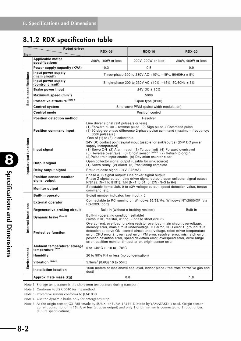
Specifications and D
imensions
8
8-2
8. Specifications and Dimensions
8-3
8.1.2 RDX specification tableRobot driver
ItemRDX-05 RDX-10 RDX-20
Ba
sic
sp
ec
ific
ati
on
s
Applicable motor specifications 200V, 100W or less 200V, 200W or less 200V, 400W or less
Power supply capacity (KVA) 0.3 0.5 0.9
Input power supply (main circuit) Three-phase 200 to 230V AC +10%, –15%, 50/60Hz ± 5%
Input power supply (control circuit) Single-phase 200 to 230V AC +10%, –15%, 50/60Hz ± 5%
Brake power input 24V DC ± 10%
Maximum speed (min-1) 5000
Protective structure (Note 3) Open type (IP00)
Control system Sine-wave PWM (pulse width modulation)
Control mode Position control
Position detection method Resolver
Inp
ut/
ou
tpu
t fu
nc
tio
ns
Position command input
Line driver signal (2M pulses/s or less) (1) Forward pulse + reverse pulse (2) Sign pulse + Command pulse (3) 90-degree phase difference 2-phase pulse command (maximum frequency: 500k pulses/s.) One of (1) to (3) is selectable.
Input signal
24V DC contact point signal input (usable for sink/source) (24V DC power supply incorporated) (1) Servo ON (2) Alarm reset (3) Torque limit (4) Forward overtravel (5) Reverse overtravel (6) Origin sensor (Note 5) (7) Return-to-origin (8)Pulse train input enable (9) Deviation counter clear
Output signal Open collector signal output (usable for sink/source) (1) Servo ready (2) Alarm (3) Positioning complete
Relay output signal Brake release signal (24V, 375mA)
Position sensor monitor signal output
Phase A, B signal output: Line driver signal output Phase Z signal output: Line driver signal output / open collector signal output N/8192 (N=1 to 8191), 1/N (N=1 to 64) or 2/N (N=3 to 64)
Monitor output Selectable items: 2ch, 0 to ±3V voltage output, speed detection value, torque command, etc.
Inte
rna
l fu
nc
tio
ns
Built-in operator 5-digit number indicator, key input × 5
External operator Connectable to PC running on Windows 95/98/Me, Windows NT/2000/XP (via RS-232C port)
Regenerative braking circuit Built-in (without a braking resistor) Built-in
Dynamic brake (Note 4) Built-in (operating condition settable) (without DB resistor, wiring: 2-phase short circuit)
Protective function
Overcurrent, overload, braking resistor overload, main circuit overvoltage, memory error, main circuit undervoltage, CT error, CPU error 1, ground fault detection at servo ON, control circuit undervoltage, robot driver temperature error, CPU error 2, overtravel error, PM error, resolver error, mismatch error, position deviation error, speed deviation error, overspeed error, drive range error, position monitor timeout error, origin sensor error
En
vir
on
me
nt
Ambient temperature/ storage temperature (Note 1) 0 to +40°C / –10 to +70°C
Humidity 20 to 90% RH or less (no condensation)
Vibration (Note 2) 5.9m/s2 (0.6G) 10 to 55Hz
Installation location 1000 meters or less above sea level, indoor place (free from corrosive gas and dust)
Approximate mass (kg) 0.8 1.0
Note 1: Storage temperature is the short-term temperature during transport.Note2:ConformstoJISC0040testingmethod.Note3:ProtectivesystemconformstoJEM1030.Note 4: Use the dynamic brake only for emergency stop.Note5:Astheoriginsensor,GX-F8B(madebySUNX)orFL7M-1P5B6-Z(madebyYAMATAKE)isused.Originsensor
current consumption is 15mA or less (at open output) and only 1 origin sensor is connected to 1 robot driver. (Futurespecifications)

8-2 8-3
8
Specifications and D
imensions
8. Specifications and Dimensions
8.2 Robot driver dimensions and mounting holesModel name Model No. Drawing
RDP (For PHASER series)
RDP-05 Fig. 1
RDP-10 Fig. 1
RDP-20 Fig. 2
RDP-25 Fig. 3
RDX (For FLIP-X series)
RDX-05 Fig. 1
RDX-10 Fig. 1
RDX-20 Fig. 2
Fig. 1

Specifications and D
imensions
8
8-4
8. Specifications and Dimensions
8-5
Fig. 2
Fig. 3
φ6
170(75)
150
±0.5(*)
160
56
70
CHARGE
PC(+)1
I/O
U
V
(+)
L3
RB
(-)
L2
W
L1
ENC
(*)MOUNTING HOLE PITCH
SET
FUNC
DIMENSION in mm
MAIN TERMINALNAME PLATE
CONNECTOR OF CONTROL SUPPLY
5(5)
(14)
(16)
6
(4)

8-4 8-5
8
Specifications and D
imensions
8. Specifications and Dimensions
Terminal block and mounting hole drawing
Output W D1
100W 200W
57 5
400W 65 9
750W 70 14

8-6
MEMO
Chapter 9 TroubleshootingThis chapter explains the protective functions, alarm display, and troubleshooting of this product.
Contents
9.1 Alarm display (alarm log) 9-1
9.2 Protective function list 9-2
9.3 Troubleshooting 9-39.3.1 When an alarm or error has not tripped 9-3
9.3.2 When an alarm or error has tripped 9-5

9-1

9-1
9
Troubleshooting
9. Troubleshooting
9.1 Alarm display (alarm log)Ifanalarmhastripped,adisplaylikethatshownbelowappears. The trip log monitor d-12 also shows the same information.
Alarm code Alarm number
Display Description
Alarm code (error number) See section 9.2 in this chapter.
Alarm number1 to 4: Number "1" is the latest alarm. A total of four alarms are saved in the memory.
The following information is displayed by pressing the key.
Information Description
Speed command value Speed command value when alarm tripped
Speed detection valueSpeed detection value when alarm tripped (decimal display)
Output current value Output current value when alarm tripped
DC voltage value between (+) and (–)DC bus voltage between (+) and (–) when alarm tripped
Input terminal information See the description of d-05.
Output terminal information See the description of d-06.
The above example shows that an overcurrent alarm has tripped or the latest alarm log is an overcurrent.

Troubleshooting
9
9-2
9. Troubleshooting
9-3
9.2 Protective function listThe table below shows alarms and errors that might occur to protect the robot driver and robot.
No. Alarm name Alarm code Description (cause of error)
1 Overcurrent E01 Motor current higher than the specified value
2 Overload E05 Overload current for longer than the specified time
3Braking resistor overload
E06The duty ratio of internal regenerative braking resistor exceeded the specified duty ratio (FA-08).
4Main power overvoltage
E07 Main circuit DC bus voltage exceeded the specified value.
5 Memory error E08A check sum error occurred in the internal EEPROM of the robot driver due to external noise or abnormal temperature rise.
6Main power undervoltage
E09Main circuit DC bus voltage dropped below the specified value during servo-on.
7 CT error E10An abnormal offset value or out-of-range output value appeared in current detection CT output during servo-off.
8 CPU error 1 E11 A CPU watchdog error occurred.
9 Ground fault E14 A motor output ground fault occurred when the servo was switched from OFF to ON.
10Control power undervoltage
E20The servo was turned off due to the control power supply voltage dropping below the specified value and the power then recovered before internal reset.
11Abnormal temperature
E21 Power module temperature in the robot driver increased to abnormal levels.
12 CPU error 2 E22 A communication error with the CPU.
13 Overtravel error E25Both FOT and ROT were simultaneously enabled for 1 second or more during servo-on.
14Power module error (Note 1) E31
Overcurrent was detected by the power module, or power supply voltage for the base circuit dropped.
15Position sensor signal error
E39
The following error was detected during constant monitoring. RDX: An error was detected by the ERR signal for the R/D converter. RDP: An error was detected by the wire breakage detection circuit signal for the resolver. Or, in the case of the RDP, an error occurred due to wire breakage detected by the "position sensor wire breaking detection" function which works when FA-90 (Hall sensor connection) is set to "oFF2".
16Motor power mismatch
E40Motor output or supply voltage does not match the robot driver. This error cannot be cleared from the RS (alarm reset) terminal.
17 Position error fault E83The difference between the position command value and the position detection value is larger than the "Position error detection value" (FA-05).
18 Speed error fault E84The difference between the speed command value and the speed detection value is larger than the "Speed error detection value" (FA-04).
19 Overspeed error E85Detection speed increased over the specified speed (maximum speed × FA-03).
20 Driving range error E88 Position detection value was outside the specified range (Fb-16 to Fb-19).
21Position monitoring timeout error
E89Time required for the position error to enter positioning range after a position command value reached a certain position exceeded the "Positioning interval time limit" (Fb-24).
22Magnetic pole position estimation error (Note 2)
E95 Magnetic pole position estimation failed.
23Magnetic pole position estimation incomplete (Note 2)
E96
When in FA-90=oFF, the servo was turned on without performing any magnetic pole position estimation after power-on. When in FA-90=oFF, the SON terminal was turned on with the RS terminal turned on, in order to start mechanical system diagnosis or offline auto-tuning.
24 Origin sensor error E80
After starting return-to-origin with the "Homing mode" (FA-23) set to "S-F" or "S-r" (sensor method) while the sensor (ORL terminal) was 0=ON, the ORL terminal did not turn off even when the robot moved a distance of 50,000 pulses or more.
Note 1: To clear the tripped alarm, shut off the power.Note 2: Displayed on RDP only.
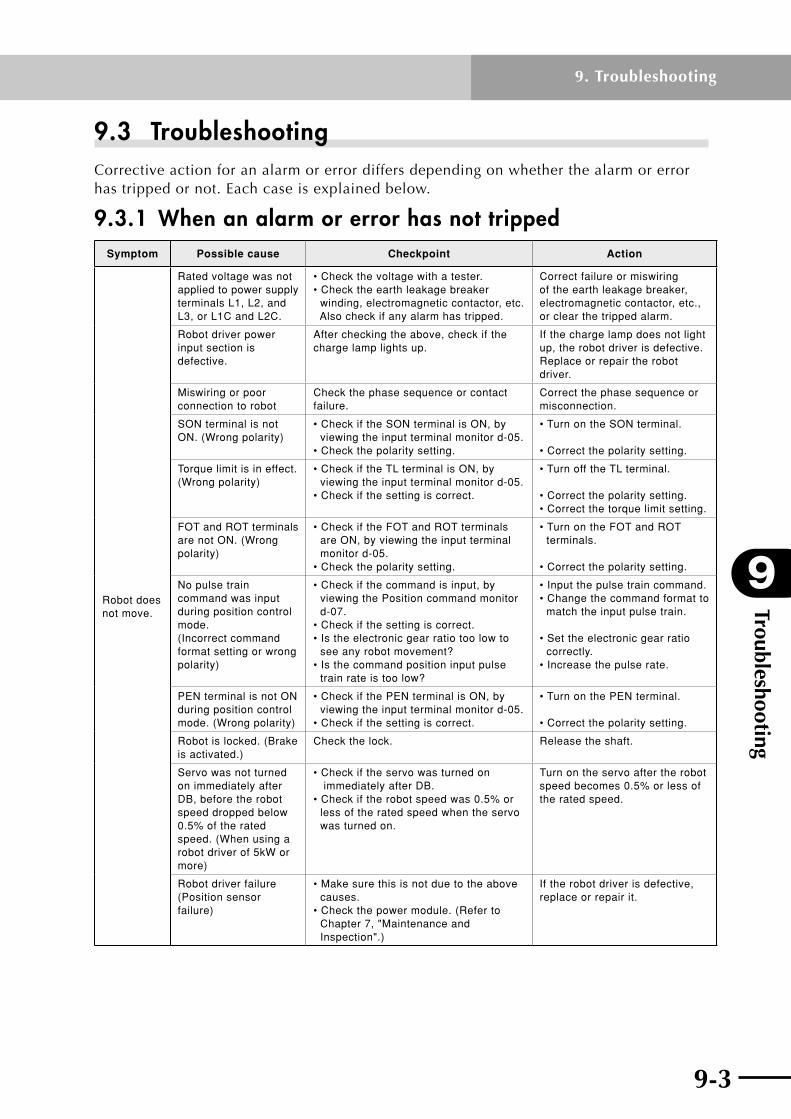
9-2 9-3
9
Troubleshooting
9. Troubleshooting
9.3 TroubleshootingCorrectiveactionforanalarmorerrordiffersdependingonwhetherthealarmorerrorhastrippedornot.Eachcaseisexplainedbelow.
9.3.1 When an alarm or error has not trippedSymptom Possible cause Checkpoint Action
Robot does not move.
Rated voltage was not applied to power supply terminals L1, L2, and L3, or L1C and L2C.
• Check the voltage with a tester. • Check the earth leakage breaker winding, electromagnetic contactor, etc. Also check if any alarm has tripped.
Correct failure or miswiring of the earth leakage breaker, electromagnetic contactor, etc., or clear the tripped alarm.
Robot driver power input section is defective.
After checking the above, check if the charge lamp lights up.
If the charge lamp does not light up, the robot driver is defective. Replace or repair the robot driver.
Miswiring or poor connection to robot
Check the phase sequence or contact failure.
Correct the phase sequence or misconnection.
SON terminal is not ON. (Wrong polarity)
• Check if the SON terminal is ON, by viewing the input terminal monitor d-05. • Check the polarity setting.
• Turn on the SON terminal. • Correct the polarity setting.
Torque limit is in effect. (Wrong polarity)
• Check if the TL terminal is ON, by viewing the input terminal monitor d-05. • Check if the setting is correct.
• Turn off the TL terminal. • Correct the polarity setting. • Correct the torque limit setting.
FOT and ROT terminals are not ON. (Wrong polarity)
• Check if the FOT and ROT terminals are ON, by viewing the input terminal monitor d-05. • Check the polarity setting.
• Turn on the FOT and ROT terminals. • Correct the polarity setting.
No pulse train command was input during position control mode. (Incorrect command format setting or wrong polarity)
• Check if the command is input, by viewing the Position command monitor d-07. • Check if the setting is correct. • Is the electronic gear ratio too low to see any robot movement? • Is the command position input pulse train rate is too low?
• Input the pulse train command. • Change the command format to match the input pulse train. • Set the electronic gear ratio correctly. • Increase the pulse rate.
PEN terminal is not ON during position control mode. (Wrong polarity)
• Check if the PEN terminal is ON, by viewing the input terminal monitor d-05. • Check if the setting is correct.
• Turn on the PEN terminal. • Correct the polarity setting.
Robot is locked. (Brake is activated.)
Check the lock. Release the shaft.
Servo was not turned on immediately after DB, before the robot speed dropped below 0.5% of the rated speed. (When using a robot driver of 5kW or more)
• Check if the servo was turned on immediately after DB. • Check if the robot speed was 0.5% or less of the rated speed when the servo was turned on.
Turn on the servo after the robot speed becomes 0.5% or less of the rated speed.
Robot driver failure (Position sensor failure)
• Make sure this is not due to the above causes. • Check the power module. (Refer to Chapter 7, "Maintenance and Inspection".)
If the robot driver is defective, replace or repair it.

Troubleshooting
9
9-4
9. Troubleshooting
9-5
Symptom Possible cause Checkpoint Action
Robot motion is unstable.
Large load variation • Check the load variation. • Check the capacity calculation.
• Reduce the load variation. • Increase the capacity.
Large backlash of the mechanical system
Check the backlash. Reduce the backlash.
Improper control gain Check the parameter settings. Readjust the control gain.
Signal cable or position sensor cable intersects the main circuit cable. (These are in the same cable duct.)
Check the routing of the signal cable and position sensor cable.
Separate the signal cable and position sensor cable from the main circuit cable.
Shield wire of the position sensor cable is not connected.
Check the shield wire connection on position sensor cable.
Connect the shield wire of the position sensor cable correctly.
Robot driver failure (Position sensor failure)
• Check the power module. (Refer to Chapter 7, "Maintenance and Inspection".) • Check the position count function, by viewing the present position monitor d-08.
If the robot driver is defective, replace or repair it.
Offline auto-tuning mode is set.
Check if the "Auto tuning mode" (FA-10) parameter is set to "non".
Set FA-10 to "non".
Robot speed does not increase.
Speed limit is applied. • Check the parameter settings (Fb-20 and Fb-21).
Set the speed limit value correctly.
Torque limit is in effect. (Wrong polarity)
• Check if the TL terminal is ON, by viewing the Input terminal monitor d-05. • Check if the setting is correct.
• Disconnect the TL terminal. • Correct the polarity setting. • Correct the torque limit setting.
Incorrect command speed setting
Check the speed command input by viewing the Monitor d-00.
Correct the command setting.
Improper control gain Check if hunting occurs. Readjust the control gain.
Load is heavy. • Check the load. • Check the calculated capacity.
• Reduce the load. • Increase the capacity.
Brake is applied to the robot.
Check the brake. Release the brake.

9-4 9-5
9
Troubleshooting
9. Troubleshooting
9.3.2 When an alarm or error has trippedWhen an alarm or error has tripped, clear the alarm or error by inputting a reset signal through the RS terminal and take corrective action as shown in the following table. Then turntheservoon.(Forclearingthetrippedalarm,refertotheRSterminaldescriptioninsection5.2,"Inputterminalfunctions".)
Alarm No.
Alarm name Possible cause Checkpoint Action Reset
E01 Overcurrent
• Output terminal is shorted. • Ground fault • Incorrect motor phase sequence
Check the cable connection. Correct the cable connection.
ASudden motor lock Check the load. Adjust the brake timing to avoid a lock.
• Power supply voltage is low. • Power supply fluctuates.
Check the power supply voltage. (Check the power supply capacity.)
Correct the power supply voltage, capacity, and wiring.
Position sensor failure Check the count by viewing the present position monitor (d-08).
If defective, replace or repair it. C
Power (inverter) module is damaged.
Check the power module. (Refer to Chapter 7, "Maintenance and Inspection".)
ADB relay failure Disconnect the motor cables from the robot driver and check the resistance between U, V and W, using an ohmmeter or multimeter.
E05 Overload
Load is too heavy. Check the load. Reduce the load. B
Motor is locked. Adjust the brake timing to avoid a lock.
C
Incorrect robot phase sequence
Check the cable connection. Correct the cable connection.
A
Robot's position sensor failure
Check if the counter correctly works, by viewing the present position monitor d-08.
If the sensor is defective, replace or repair it.
C
E06Braking resistor overload
Regenerative load is too heavy. Balance weight is so large that continuous regeneration is applied.
Check the regenerative load.
• Reduce the load. • Shorten the deceleration time.
A
Insufficient regenerative capacity
Review the regenerative resistance.
Deceleration time is too short.
Check if an alarm tripped during deceleration.
Increase the deceleration time.
B
Power supply voltage is high.
Check the power supply voltage.
Adjust the power supply voltage correctly.
A
Regenerative braking operating ratio is set to a small value.
Check if the duty ratio matches the regenerative resistance.
Set a correct duty ratio.B
LettersintheResetcolumn:
A: Shut off the power to the robot driver, perform troubleshooting, replace or repair defective parts.
B: After the robot stops, wait until the robot driver cools. Then short RS to P24, and perform troubleshooting.
C:Aftertherobotstops,shortRStoP24,andperformtroubleshootingorshutoffthepower.

Troubleshooting
9
9-6
9. Troubleshooting
9-7
Alarm No.
Alarm name Possible cause Checkpoint Action Reset
E07Main power overvoltage
Regenerative resistance is large.
Check the regenerative resistance.
Reduce the regenerative resistance to the minimum (RBRmin). (Refer to (3) of section 3.2.2, "Main circuit wiring".
A
Deceleration time is too short.
Check the deceleration time.
Increase the deceleration time.
CRobot was put into hunting and momentary regeneration occurred.
Check if the robot was placed in hunting (abnormal noise).
Adjust the position/speed control gain correctly.
Regenerative resistor is not connected, or is open or damaged.
Check the regenerative resistor connection or the regenerative resistance.
• Connect the regenerative resistor correctly. • Replace the regenerative resistor. A
Received power voltage is too high or a ground fault has occurred.
• Check the power supply voltage. • Check the connection.
• Reduce the voltage. • Correct the connection.
E08Memory error
Sum error in the internal EEPROM of robot driver
Check if all settings for the robot driver are correct.
• After clearing the tripped alarm, return the parameters to the factory settings, and then restart operation. • If defective, replace or repair it.
C
An EEPROM write or read error was caused by noise.
• Check if any noise source exists near the robot driver. • Check if the set values are correct.
• Remove the noise source. • After clearing the tripped alarm, return the parameters to the factory settings, and then restart operation.
A
LettersintheResetcolumn:
A: Shut off the power to the robot driver, perform troubleshooting, replace or repair defective parts.
B: After the robot stops, wait until the robot driver cools. Then short RS to P24, and perform troubleshooting.
C:Aftertherobotstops,shortRStoP24,andperformtroubleshootingorshutoffthepower.

9-6 9-7
9
Troubleshooting
9. Troubleshooting
Alarm No.
Alarm name Possible cause Checkpoint Action Reset
E09Main power undervoltage
Main circuit power supply voltage is low.
Check the power supply system.
Increase the power supply voltage.
C
A unit in the power supply system is drawing a heavy current that lowers the voltage while that unit is operating.
Isolate the power supply system into separate units and the robot driver.
A
Chattering occurs in the electromagnetic contactor on power supply side.
Replace the electromagnetic contactor.
Poor connection in power supply system
Repair the poor connection.
Insufficient power supply capacity
Provide larger power supply capacity.
Only control power supply is provided.
Connect wiring to the main circuit.
SON terminal turns on before the power voltage of the main circuit becomes stable.
Check the SON terminal input timing.
Turn on the SON terminal 1 second or longer after the main power has turned on.
• Main circuit power supply voltage is lowered. • A momentary power failure occurred.
Check if the symptom shown at left has occurred.
After clearing the tripped alarm, restart operation.
C
E10 CT error
• Current detector failure • Current detector malfunction caused by noise
Turn off and on the power supply again.
If the CT is defective, contact us for repair.
ACheck if there is any noise source near the robot driver.
Isolate the noise source away from the robot driver.
E11 CPU error 1
Microcomputer in robot driver is out of control due to noise.
Check if there is any noise source (including a solenoid coil and electromagnetic contactor) near the robot driver.
• Isolate the noise source away from the robot driver. • Install a noise filter or surge absorber. A
Turn off and on the power supply again and check the condition.
If the CPU is defective, contact us for repair.
E14Ground fault at servo-on
A ground fault occurred in the robot or between the robot and robot driver.
Disconnect the cables and check the ground fault point by megger test.
Correct the ground fault point.
A
Robot driver is at fault. Contact us for repair.
LettersintheResetcolumn:
A: Shut off the power to the robot driver, perform troubleshooting, replace or repair defective parts.
B: After the robot stops, wait until the robot driver cools. Then short RS to P24, and perform troubleshooting.
C:Aftertherobotstops,shortRStoP24,andperformtroubleshootingorshutoffthepower.

Troubleshooting
9
9-8
9. Troubleshooting
9-9
Alarm No.
Alarm name Possible cause Checkpoint Action Reset
E20Control power undervoltage
Control circuit power supply voltage is low.
Check the power supply system.
Increase the power supply voltage.
C
A unit in the power supply system is drawing a heavy current that lowers the voltage while that unit is operating.
Isolate the power supply system into separate units and the robot driver.
AChattering in electromagnetic contactor on power supply side
Replace the electromagnetic contactor.
Poor connection in power supply system
Repair the poor connection.
Insufficient power supply capacity
Provide larger power supply capacity.
Control circuit power supply voltage is lowered. A momentary power failure occurred.
Check if the symptom shown at left has occurred.
After clearing the tripped alarm, restart operation.
C
E21Robot driver overheat
The load is too heavy. Check the load. Check the ambient temperature.
• Clear the tripped alarm after the robot driver cools down, or lower the ambient temperature.
B or CAmbient temperature of robot driver is higher than 55°C.
Motor shaft is locked. Visual check. Unlock the motor.
AThe duty ratio of the built-in regenerative braking resistor is high.
Check the regenerative capacity.
Use an external braking resistor.
E22 CPU error 2
Microcomputer in robot driver cannot communicate due to noise.
Check if there is any noise source (including a solenoid coil and electromagnetic contactor) near the robot driver.
• Isolate the noise source away from the robot driver. • Install a noise filter or surge absorber. A
Problem in communication circuit
Turn off and on the power supply again and check the condition.
If the circuit is defective, contact us for repair.
E25 Overtravel
Wrong terminal connection
Check the cable connection. Correct the cable connection.
A
FOT/ROT terminals were not ON (closed) at servo-on.
Check if the FOT/ROT terminals are ON, by viewing the Input terminal monitor d-05.
Turn on both or at least one terminal of the FOT and ROT terminals.
C
LettersintheResetcolumn:
A: Shut off the power to the robot driver, perform troubleshooting, replace or repair defective parts.
B: After the robot stops, wait until the robot driver cools. Then short RS to P24, and perform troubleshooting.
C:Aftertherobotstops,shortRStoP24,andperformtroubleshootingorshutoffthepower.
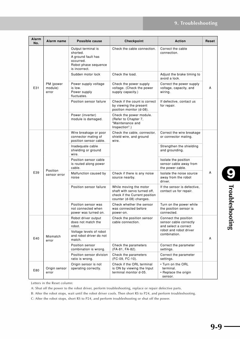
9-8 9-9
9
Troubleshooting
9. Troubleshooting
Alarm No.
Alarm name Possible cause Checkpoint Action Reset
E31PM (power module) error
Output terminal is shorted. A ground fault has occurred. Robot phase sequence is incorrect.
Check the cable connection. Correct the cable connection.
A
Sudden motor lock Check the load. Adjust the brake timing to avoid a lock.
Power supply voltage is low. Power supply fluctuates.
Check the power supply voltage. (Check the power supply capacity.)
Correct the power supply voltage, capacity, and wiring.
Position sensor failure Check if the count is correct by viewing the present position monitor (d-08).
If defective, contact us for repair.
Power (inverter) module is damaged.
Check the power module. (Refer to Chapter 7, "Maintenance and Inspection".)
E39Position sensor error
Wire breakage or poor connector mating of position sensor cable.
Check the cable, connector, shield wire, and ground wire.
Correct the wire breakage or connector mating.
A
Inadequate cable shielding or ground wire.
Strengthen the shielding and grounding.
Position sensor cable is routed along power cable.
Isolate the position sensor cable away from the power cable.
Malfunction caused by noise
Check if there is any noise source nearby.
Isolate the noise source away from the robot driver.
Position sensor failure While moving the motor shaft with servo turned off, check if the Current position counter (d-08) changes.
If the sensor is defective, contact us for repair.
Position sensor was not connected when power was turned on.
Check whether the sensor was connected before power-on.
Turn on the power while the position sensor is connected.
E40Mismatch error
Robot driver output does not match the robot.
Check the position sensor cable connection.
Connect the position sensor cable correctly and select a correct robot and robot driver combination.
A
Voltage levels of robot and robot driver do not match.
Position sensor combination is wrong.
Check the parameters (FA-81, FA-82).
Correct the parameter settings.
Position sensor division ratio is wrong.
Check the parameters (FC-09, FC-10).
Correct the parameter settings.
E80Origin sensor error
Origin sensor is not operating correctly.
Check if the ORL terminal is ON by viewing the Input terminal monitor d-05.
• Turn on the ORL terminal. • Replace the origin sensor.
LettersintheResetcolumn:
A: Shut off the power to the robot driver, perform troubleshooting, replace or repair defective parts.
B: After the robot stops, wait until the robot driver cools. Then short RS to P24, and perform troubleshooting.
C:Aftertherobotstops,shortRStoP24,andperformtroubleshootingorshutoffthepower.

Troubleshooting
9
9-10
9. Troubleshooting
9-11
Alarm No.
Alarm name Possible cause Checkpoint Action Reset
E83Position deviation error
Pulse position command rate is too fast.
Check the position command input rate.
Lower the pulse position command rate.
C
Electronic gear setting is incorrect.
Set the electronic gear correctly (reduce the ratio).
Control gain does not match.
Check the setting. Adjust the control gain.
Speed or torque limiter is too low.
Set (increase) the speed or torque limiter correctly.
Position error detection level setting is too small.
Set (increase) the position error detection level correctly.
Malfunction caused by noise
• Check if there is any noise source nearby. • Check the routing of the cable, connectors, shield wire, and ground wire.
• Isolate the noise source away from the drive. • Strengthen the shielding and grounding. • Isolate the position sensor cable away from the power cable.
A
Moment of load inertia is too heavy.
Check relation of load to position command rate.
Reduce the load.
E84Speed deviation error
Speed command input setting is incorrect.
Check the setting. Correct the input setting.
C
Control gain does not match.
Adjust the control gain.
Torque limiter is too low.
Correct (increase) the torque limiter.
Speed error detection level setting is too small.
Correct (increase) the speed error detection value.
Malfunction caused by noise
• Check if there is any noise source nearby. • Check the routing of the cable, connectors, shield wire, and ground wire.
• Isolate the noise source away from the drive. • Strengthen the shielding and grounding. • Isolate the position sensor cable away from the power cable.
A
Moment of load inertia is too heavy.
Check relation of load to position command rate.
Reduce the load.
LettersintheResetcolumn:
A: Shut off the power to the robot driver, perform troubleshooting, replace or repair defective parts.
B: After the robot stops, wait until the robot driver cools. Then short RS to P24, and perform troubleshooting.
C:Aftertherobotstops,shortRStoP24,andperformtroubleshootingorshutoffthepower.

9-10 9-11
9
Troubleshooting
9. Troubleshooting
Alarm No.
Alarm name Possible cause Checkpoint Action Reset
E85Overspeed error
Speed command input setting is wrong.
Check the setting. Correct the input setting.
C
Control gain does not match.
Adjust the control gain.
Torque limiter is too low.
Correct (increase) the torque limiter correctly.
Overspeed error detection level setting is too low.
Set the overspeed error detection level correctly (increase).
Malfunction caused by noise
• Check if there is any noise source nearby. • Check the routing of the cable, connectors, shield wire, and ground wire.
• Isolate the noise source away from the drive. • Strengthen the shielding and grounding. • Isolate the position sensor cable away from the power cable.
A
Moment of load inertia is too heavy.
Check if overshooting has occurred.
Reduce the load.
Wrong motor cable connection
Check the connection. Correct the connection.
Position sensor failure While rotating the motor shaft, check if the display on the present position monitor d-08 changes sequentially.
If the sensor is defective, contact us for repair.
C
E88Drive range error
• Pulse train position command was mistakenly input. • Origin position is wrong. • Operated outside the drive range.
Check the master control unit.
After removing the cause of trouble, clear the tripped alarm and restart operation. A
Needs larger operating margin outside the drive range
Check if a load moved the robot near the drive range limit.
• Review the setting outside the drive range. • Adjust or remove the load so that it will not move the robot.
CElectronic gear setting is incorrect.
Check the control device. Correct the setting.
Torque limiter is too low.
Control gain does not match.
Adjust the control gain.
LettersintheResetcolumn:
A: Shut off the power to the robot driver, perform troubleshooting, replace or repair defective parts.
B: After the robot stops, wait until the robot driver cools. Then short RS to P24, and perform troubleshooting.
C:Aftertherobotstops,shortRStoP24,andperformtroubleshootingorshutoffthepower.

Troubleshooting
9
9-12
9. Troubleshooting
Alarm No.
Alarm name Possible cause Checkpoint Action Reset
E89Position monitoring timeout error
Control gain, Positioning detection range (Fb-23), or wrong positioning interval time-limit setting (Fb-24).
Check the setting. Adjust each setting.
CElectronic gear setting is wrong.
Correct the setting.
Robot is locked. Check the load. • Unlock the robot. • Adjust the brake release timing.
Load is larger than the estimated level.
• Reduce the load. • Increase the robot and robot driver capacity.
A
Torque limiter is in effect.
Check the TL terminal and setting.
• Disconnect the TL terminal. • Change the setting.
C
E95
Magnetic pole position estimation error
Related parameter settings are incorrect.
Check the parameter (FA-82, FA-85, FA-87, Fd-00) settings.
Correct the parameter settings.
A
Parameter settings for magnetic pole position estimation (Fb-40 through Fb-43) are incorrect.
Torque during magnetic pole position estimation is small.
Adjust Fb-40 through Fb-43 to make the generated torque larger.
Torque during magnetic pole position estimation is limited.
Adjust Fb-40 through Fb-43 to eliminate the torque limit.
FOT and ROT terminals turn off during magnetic pole position estimation.
Check the FOT and ROT terminal conditions.
• Turn on the FOT and ROT terminals. • Change the FC-01 setting.
Rotor was moved by external force during magnetic pole position estimation.
Check if external force is applied.
• Remove the external force.
Position sensor failure While rotating the motor shaft, check if the display on the present position monitor d-08 changes sequentially.
If the sensor is defective (display does not change), contact us for repair.
SON terminal and the FOT and ROT terminals turn on at the same time.
Check the input timing of the FOT, ROT, and SON terminals.
Turn on the SON terminal 10 [ms] or longer after the FOT and ROT terminals have turned on.
E96
Magnetic pole position estimation incomplete
Any magnetic pole position estimation operation was not performed after power-on.
Check that the SRD terminal is ON.
Perform magnetic pole position estimation.
A
_ _ErrAuto-tuning error
Operation was performed in offline auto-tuning mode.
Check if FA-10 is set to "non".
Turn off the SON terminal, turn the RS terminal on and off, and then check that FA-10 is set to "non".
C
Moment of load inertia exceeded 128 times.
Check the moment of load inertia.
LettersintheResetcolumn:
A: Shut off the power to the robot driver, perform troubleshooting, replace or repair defective parts.
B: After the robot stops, wait until the robot driver cools. Then short RS to P24, and perform troubleshooting.
C:Aftertherobotstops,shortRStoP24,andperformtroubleshootingorshutoffthepower.

Chapter 10 AppendixThis chapter explains the options for this product.
Contents
10.1 Timing chart 10-1
10.2 Options 10-2
10.3 Recommended peripheral devices 10-7
10.4 Internal block diagram of robot driver 10-13

10-1

10-1
10
Appendix
10. Appendix
10.1 Timing chartThe following shows the timing chart from the power-on to the position command input (when the return-to-origin is performed).
n RDXControl power
Main circuit power
Input signal
Output signal
Position command
SON
FOT
ROT
ORG
PEN
SRD
INP
RDX operation
(Note 1)
(Note 2)
(Note 2)
1000 [ms] or more10 [ms] or more
50 [ms] or more (Note 3)
(Note 4)
approx.10[ms] approx.10[ms]
approx.50[ms]
Servo-offPower-off Servo-on Return-to-origin Servo-on Operation
Note 1: Turn on the main circuit power after the control power has been turned on or at the same time
when the control power is turned on.
Note 2: Turn on the FOT and ROT signals 10 [ms] or more before the SON signal is turned on.
Note 3: When the return-to-origin has been completed, the INP signal turns on. So, turn off the ORG signal
after the INP signal has turned on.
Note 4: Turn on the PEN signal 10 [ms] or more before the position command is input.
position command input
n RDPControl power
Main circuit power
Position command
SON
FOT
ROT(Note 3)
ORG
PEN (Note 4)
SRDapprox.10[ms]
INP
RDP operation Power-off Servo-off Magnetic pole position estimation Servo-on Return-to-origin Servo-on Operation
Note 1: Turn on the main circuit power after the control power has been turned on or at the same time
when the control power is turned on.
Note 2: Turn on the FOT and ROT signals 10 [ms] or more before the SON signal is turned on.
Note 3: When the return-to-origin has been completed, the INP signal turns on. So, turn off the ORG signal
after the INP signal has turned on.
Note 4: Turn on the PEN signal 10 [ms] or more before the position command is input.
(Note 1) 1000 [ms] or more10 [ms] or more
(Note 2)
(Note 2)Input signal
Output signal
position command input

Appendix
10
10-2
10. Appendix
10-3
10.2 Options
(1) Dedicated software for YAMAHA RD series (TOP for Windows)
WhentheRDseriesrobotdriverisconnectedtoaPC,theTOPsoftwareallowsyoutosetparameters,monitortheposition/speed/torquesettings,anddisplaygraphics.TheTOP software runs on Windows and offers user-friendly operation.
n System requirements
Item Condition
PC
IBM PC compatible computer Memory: 32MB or more Free hard disc space : 30MB or more Monitor resolution: 800 × 600 or higher recommended.
OS Windows 95/98/Me, Windows NT, Windows 2000, Windows XP
PC cable KBH-M538F-00
n Monitoring functionMonitors operation information and terminal status in real time.
n Parameter settingAllows setting, saving and loading parametersfromthePC.
n Operation trace functionThis function graphically displays the robot speed and motor current, etc.
n Test run and adjustmentSupports useful functions such as testrun,jogoperationandofflineauto-tuning, etc.

10-2 10-3
10
Appendix
10. Appendix
(2) Cables
n PC cable
Length L Description
2m
8-pin modular connector 9-pin D-Sub connector
Robot driver side PC side
Wiring and pin assignment are shown below.
Connection of PC cable
Robot driver side PC side 1
9 pins8 pins
88-pin modular
connector
1 GND234 ER25 SD6 RD
7 DR8 RS
1 DCD2 RxD3 TxD
4 DTR5 GND6 DSR7 RTS
8 CTS9 –
n Connection to a PC with no serial port (RS-232C)WhenrunningtheTOPsoftwareonaPCwithnoRS-232CportandconnectingthePCtotheRDseriesrobotdriver,youmayusethefollowingPCcardorUSB-serialconverter. Use these devices at your own risk.
< PC card >
Product name PC Card Standard Type II RS-232C PC Card
Manufacturer RATOC Systems
Type No. REX-5056V
Accessory 9-pin D-sub (male) cable (50 cm)
< USB-serial converter >
Product name USB Serial Converter
Manufacturer RATOC Systems
Type No. REX-USB60F
Connector USB (type A)
OS Windows XP, Windows 2000, Windows 98 SE
Fordetailedinformation,youcanaccessRATOCSystemswebsite:http://www.rexpccard.co.jpOperation under different software usage conditions such as effects due to the installation environmentatthesiteordifferentPCtypeshasnotbeenconfirmed.Usageundersuchconditions is the responsibility of the customer.

Appendix
10
10-4
10. Appendix
10-5
(3) Precautions for braking resistor
cCAuTION • Installthebrakingresistoronanoncombustibleobject,suchasmetal. Failure to do so may cause fire. • Donotplacethebrakingresistorclosetoacombustibleobject.Doingso may cause fire. • Donotinstallthebrakingresistorinanambientenvironmentwherethe temperature is high, the humidity is high, or dew condensation occurs easily or a place where dust, corrosive gas, explosive gas, flammable gas, coolant mist, or salt damage exists. Always install the braking resistor in a well-ventilated indoor place where it is not exposed to the direct sunlight. Failure to do so may cause fire. • Thebrakingresistorgeneratesheatbyitself.So,installthebrakingresistor far away from the robot driver or cables. Additionally, carefully check the ventilation and dimensions so that the ambient temperature of the robot driver does not exceed its operating range. Failure to do so may cause fire. • Wheninstallingthebrakingresistorinaplacewhereitmaybeincontact with a human body, cover it with breathable protective metal fixtures so that it is not directly in contact with a human body. Failure to do so may cause personal injury.

10-4 10-5
10
Appendix
10. Appendix
(4) Braking resistor RBR1 (small type)
n Dimensions (mm)
P
RB
2
1
2-4.
2+
0.3
–0
150 ±1
160 ±1
170 ±1.5
t1.2
20±
0.8
39±
0.8
42.5
±1
500+20−10
n Circuit diagram
P21RB
Model No.Rated
wattageResistance
Allowable braking ratio (%ED)
Allowable continuous braking time
Mass (kg)
KBH-M5850-00 120W 100W 2.5% (1.5%)* 12 sec. 0.27
Error detection function
Internal thermal relay (contact capacity, AC 240V, 2A max, Normally ON (b-contact), internal thermal fuse (unrecoverable)
* : Value in ( ) indicates the allowable braking ratio for 400V class.
Note 1:Thermal relay and fuse are built into the braking resistor.
Note 2: Internal thermal fuse prevents excessive heat generation which may occur due to misoperation (unrecoverable).
Note 3: An appropriate safety circuit is configured so that the main power of the robot driver is turned off if the thermal relay is tripped (an alarm occurs).
n Connection diagram
(+)
RB
P 1
RB 2
Robot driver
Alarm contact(Normally closed)
Normally ON
Braking resistor

Appendix
10
10-6
10. Appendix
10-7
(5) Braking resistor RBR2 (standard type)
n Dimensions (mm)
55L1±1.5
70 25
7.5 L2+0–1 7.5
W±
1
R3.57
φ15R3.5
10
L3±1
T
H2H1
Labe
l sho
win
g ra
tings
n Circuit diagram
PRB12
n Connection diagram
(+)
RB
P 1
RB 2
Robot driver
Alarm contact(Normally closed)
Normally ON
Braking resistor
Model No.Dimensions (mm)
Mass (kg)L1 L2 L3 H1 H2 W T
KBH-M5850-10 310 295 160 67 12 64 1.6 0.97
Model No.Rated
wattageResistance
Allowable braking ratio (%ED)
Allowable continuous braking time
KBH-M5850-10 200W 100W 7.5% (3%)* 30 sec.
Error detection function
Internal thermal relay (contact capacity, AC 240V, 2A max, Normally ON (b-contact), internal thermal fuse (unrecoverable)
* : Value in ( ) indicates the allowable braking ratio for 400V class.
Note 1: Thermal relay and fuse are built into the braking resistor.
Note 2: Internal thermal fuse prevents abnormal heat generation which may occur due to misoperation (unrecoverable).
Note 3: An appropriate safety circuit is configured so that the main power of the robot driver is turned off if the thermal relay is tripped (an alarm occurs).

10-6 10-7
10
Appendix
10. Appendix
10.3 Recommended peripheral devicesThis section describes the recommended optional devices for the RD series robot drivers. AlloptionaldevicesintroducedherearemanufacturedbyHitachiIndustrialEquipmentSystemsCo.,Ltd.
(1) Input side AC reactor (for harmonic suppression, power coordination, power factor improvement)
n Model No.
A L I– 2 . 5 L
Capacity (See the table below for interrelation with robot driver.)
Input side AC reactor
n Connection diagram
Reactor Robot driver
M
R0S0T0
RST
VW
U
L3L2L1
RobotPowersupply
n Dimension drawing
Cmax.
Dmax. Emax.Amax.6-M K
Hm
ax.
X Y
4-φJ
Robot driver
model No.
Input side AC reactor model No.
Dimensions (mm)J K
Mass (kg)A C D E H X Y
RD*-05
ALI-2.5L 130 82 60 40 150 50 67 6 4 2.4RD*-10
RD*-20
RDP-25

Appendix
10
10-8
10. Appendix
10-9
(2) DC reactor (for harmonic suppression, power coordination, power factor improvement)
n Model No.
D C L - L - 0 . 2
Capacity (See the table below for interrelation with robot driver.)
n Connection diagram
M
L1
L2
L3
U
V
W
(+)1 (+)
Robot driver
PD P DC reactor
Robot
Powersupply
n Dimensions (mm)
2-K
Caution label
Hm
ax.
Bmax.
Y±
1
X±1
4-CW
D
Robot driver model No.
DC reactor model No.
Dimensions (mm) Mass (kg)W D H B X Y C K
RD*-05 DCL-L-0.2 66 90 98 85 56 72 5.2×8 M4 0.8
RD*-10 DCL-L-0.4 66 90 98 95 56 72 5.2×8 M4 1.0
RD*-20 DCL-L-0.7 66 90 98 105 56 72 5.2×8 M4 1.3
RDP-25 DCL-L-1.5 66 90 98 115 56 72 5.2×8 M4 1.6

10-8 10-9
10
Appendix
10. Appendix
(3) Input side noise filter
n Model No.
N F - L 6Rated current of noise filter
Series name (NF series)
n Connection diagram (3-phase product)
ML1 L2 L3
UVW
L1L2L3
L1’L2’L3’
Noise filter Robot driverRobot
Powersupply
n Dimensions (mm)
L3 L2 L1
L3’L2’L1’
(10)52±166±3
Robot drive side
Productlabel (8
4)10
0 ±1
117±
2
10 M42-φ5.0
Power supply side
(15)
67M
AX
n Specifications
Robot driver model No.
Noise filter model No.
Rated voltage Rated currentMass (kg)
RD*-05
NF-L6 250V AC 6A 0.5RD*-10
RD*-20
RDP-25

Appendix
10
10-10
10. Appendix
10-11
(4) Input side noise filter (EMC compliance)
n Model No
N F – C E H 7Rated current of noise filter
Series name (NF series)EMC compliance
n Connection diagram (3-phase filter)
ML1 L2 L3
U V W
L1L2L3
L1’L2’L3’
Powersupply
Noise filter Robot driverRobot
n Dimensions (mm)
L3 L2 L1
L3’L2’L1’
Productlabel
Power supply side
Robot drive side
11 M4φ5
(15)
73±
3
556±274±3
(95)
130±
214
4±2
n Specifications
Robot driver model No.
Noise filter model No.
Rated voltage Rated currentMass (kg)
RD*-05
NF-CEH7 480V AC 7A 0.7RD*-10
RD*-20
RDP-25

10-10 10-11
10
Appendix
10. Appendix
(5) Radio noise filter (zero-phase reactor)
n Connection diagram
R
S
T
M
L1
L2
L3
U V W
Should be as close as possible to robot driver.
Powersupply
Robotdriver
Radio noisefilter Robot
Note 1: Wind 3-phase wires L1, L2 and L3 in the same direction.
Note 2: This filter can be used on both input and output sides of robot driver.
n Dimensions (mm)
7±0.
5
Cable through-hole
ZCL–B75
ZCL–A ZCL–B40
Cablethrough-hole
Cablethrough-hole
112
75
85
35
83
129
3-M4
φ7 mounting hole
32 7×14
160 180
2-φ5.5 (M5)
12.5
±0.
3
95 max 80±0.5
26 max
3
78m
ax.
72±
0.5
39.5
min
32
R3.5±0.3 7±0.5140±0.5161 MAX
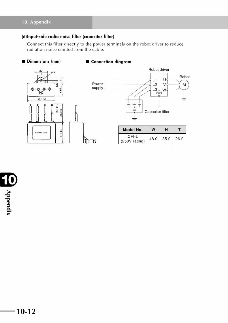
Appendix
10
10-12
10. Appendix
10-13
(6) Input-side radio noise filter (capacitor filter)
Connectthisfilterdirectlytothepowerterminalsontherobotdrivertoreduceradiation noise emitted from the cable.
n Dimensions (mm) n Connection diagram
Powersupply
Robot driver
Robot
M L1 L2 L3
U V W
Capacitor filter
Model No. W H T
CFI-L (250V rating)
48.0 35.0 26.0
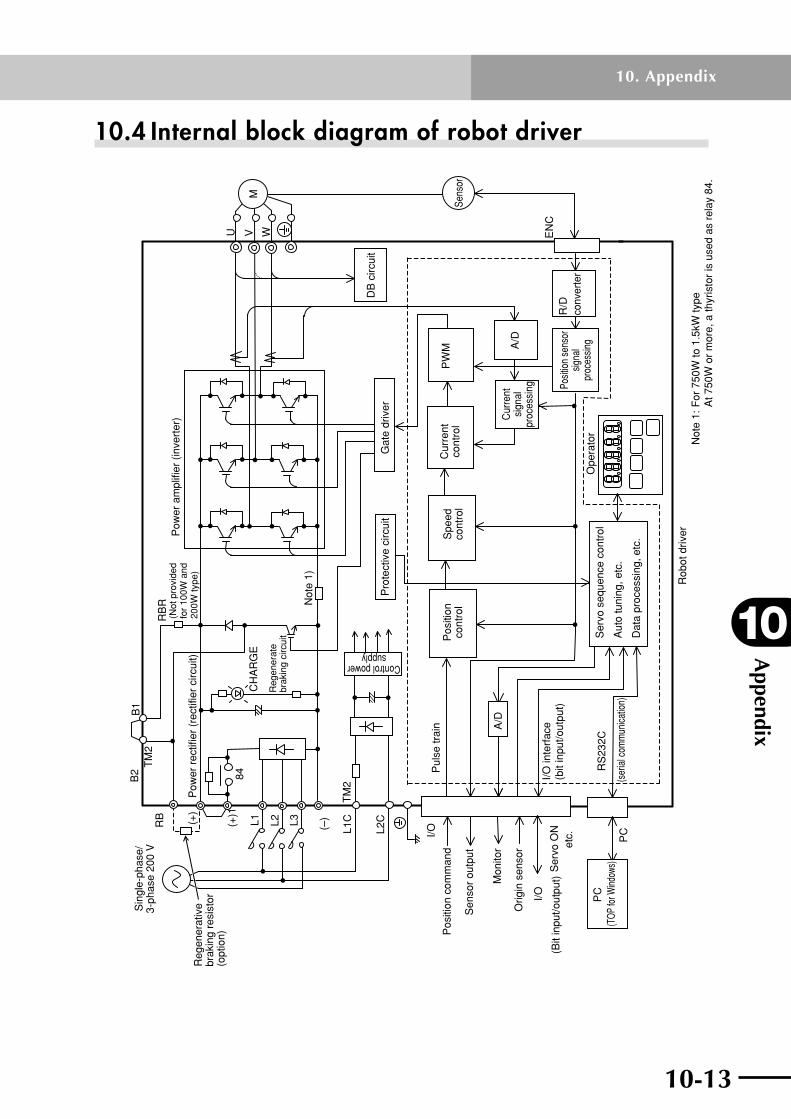
10-12 10-13
10
Appendix
10. Appendix
10.4 Internal block diagram of robot driver
B2
B1
84
PC
PW
M
RS
232C
TM
2 L1
C
L2C
EN
C
A/D
CH
AR
GE
U
WM
TM
2 R
B
(+)
(+)1
L1
L3
(–)
I/O
L2
A/D
V
Sin
gle-
phas
e/3-
phas
e 20
0 V
Reg
ener
ativ
ebr
akin
g re
sist
or(o
ptio
n)
Pow
er r
ectif
ier
(rec
tifie
r ci
rcui
t) Control powersupply
Reg
ener
ate
brak
ing
circ
uit
Pul
se tr
ain
Pos
ition
com
man
d
Sen
sor
outp
ut
I/O
Ser
vo O
Net
c.
Orig
in s
enso
r
(Bit
inpu
t/out
put)
I/O in
terf
ace
(bit
inpu
t/out
put)
(ser
ial c
omm
unica
tion)
Ope
rato
rS
ervo
seq
uenc
e co
ntro
l
Aut
o tu
ning
, etc
.
Dat
a pr
oces
sing
, etc
.
Rob
ot d
river
Posit
ion
sens
orsig
nal
proc
essin
g
Cur
rent
sign
alpr
oces
sing
Cur
rent
cont
rol
Spe
edco
ntro
lP
ositi
onco
ntro
l
Pro
tect
ive
circ
uit
Gat
e dr
iver
Pow
er a
mpl
ifier
(in
vert
er)
Mon
itor
conv
erte
r
DB
circ
uit
RB
R(N
ot p
rovi
ded
for
100W
and
20
0W ty
pe)
(TOP
for W
indow
s)P
C
Not
e 1)
Sens
or
Not
e 1:
For
750
W to
1.5
kW ty
pe
At 7
50W
or
mor
e, a
thyr
isto
r is
use
d as
rel
ay 8
4.
R/D

Revision record
Manual version Issue date Description
Ver. 2.00 Dec. 2009 Addition of RDP-25 and applicable robot type. Addition and correction of reference graph for setting the position control cut-off frequency. Modification in "5.17 Magnetic pole position estimation action". The address and other information were added to the front cover.
Ver. 2.01 Mar. 2010 Addition of parameter (Fd-44) and modification in other parameters in accordance with the addition.
Ver. 2.02 Aug. 2010 Addition of reference graph for setting the acceleration and position control cut-off frequency in accordance with addition of applicable robot (MF7). Modification of serial number label. Addition of "4.3 Emergency stop", etc.
Ver. 2.03 Jan. 2011 The description regarding "Warranty" was changed, etc.
Ver. 2.04 May 2011 Correction of reference graph for setting the acceleration and position control cut-off frequency. Clerical error corrections.
Ver. 2.05 Dec. 2011 The timing chart regarding servo-on was added. The description regarding error codes (E09 and E95) was added and corrected. The cautions on regenerative braking resistor were added. “10.1 Timing chart” was added, etc.
Ver. 2.06 Mar. 2012 The reference graph for setting the acceleration and position control cut-off frequency was added, etc.
Ver. 2.07 Jul. 2012 The drawings of the braking resistors RBR1 and RBR2 were changed. The description regarding "Warranty" was changed.
All rights reserved. No part of this publication may be reproduced in any form without the permission of YAMAHA MOTOR CO., LTD. Information furnished by YAMAHA in this manual is believed to be reliable. However, no responsibility is assumed for possible inaccuracies or omissions. If you find any part unclear in this manual, please contact your distributor.
Robot Driver
User's Manual
YAMAHA MOTOR CO., LTD. IM Operations
RD SeriesJul. 2012Ver. 2.07This manual is based on Ver. 2.07 of Japanese manual.


http://www.yamaha-motor.co.jp/global/industrial/robot/
Instruction manuals can be downloaded from our company website. Please use the following for more detailed information.
YAMAHA MOTOR CO., LTD.
IM Operations
882 Soude, Nakaku, Hamamatsu, Shizuoka, 435-0054, JapanTel. 81-53-460-6103 Fax. 81-53-460-6811


![YAMAHA ROBOT CONTROLLER SUPPORTING ......YAMAHA ROBOT CONTROLLER SUPPORTING SOFTWARE E64-P-Ver. 1.13.0 POPCOM Contents: [1] Installation Guide [2] Backup current data from robot controller](https://img.pdfslide.net/doc/110x75/5f0b5fca7e708231d4303425/yamaha-robot-controller-supporting-yamaha-robot-controller-supporting-software.jpg)