Embed Size (px)
Citation preview
YASKAWA Europe YEU TOEP C710616 99A - A1000 Option EtherCAT - Installation Manual EN 1
Installation Manual
YASKAWA AC Drive A1000 Option
MANUAL NO. YEU TOEP C710616 99A
Type: SI-ES3 for A1000 Series
To properly use the product, read this manual thoroughly and retain for easy reference, inspection, and maintenance. Ensure the end user receives this manual.
1
2
3
4
5
6
7
8
ATTENTION! This product can only be used on A1000 drives with firmware version VSA901017 to VSA901099 installed.

EN 2 YASKAWA Europe YEU TOEP C710616 99A - A1000 Option EtherCAT - Installation Manual
Copyright © 2011 YASKAWA EUROPE GMBHAll rights reserved. No part of this publication may be reproduced, stored in a retrieval system, or transmitted, in any form or by any means, mechanical, electronic, photocopying, recording, or otherwise, without the prior written permission of YASKAWA. No patent liability is assumed with respect to the use of the information contained herein. Moreover, because YASKAWA is constantly striving to improve its high-quality products, the information contained in this manual is subject to change without notice. Every precaution has been taken in the preparation of this manual. YASKAWA assumes no responsibility for errors or omissions. Neither is any liability assumed for damages resulting from the use of the information contained in this publication.
EtherCATInstallation Manual
H
A1000 Option
YASKAWA Europe YEU TOEP C710616 99A - A1000 Option EtherCAT - Installation Manual
EN
GLI
STable of Contents
1 Preface and Safety. . . . . . . . . . . . . . . . . . . . . . . . . . . . . . 4
2 Product Overview . . . . . . . . . . . . . . . . . . . . . . . . . . . . . . 8
3 Software Parts . . . . . . . . . . . . . . . . . . . . . . . . . . . . . . . . . 9
4 Receiving . . . . . . . . . . . . . . . . . . . . . . . . . . . . . . . . . . . . 10
5 EtherCAT® Option Components . . . . . . . . . . . . . . . . . 11
6 Installation Procedure . . . . . . . . . . . . . . . . . . . . . . . . . . 16
7 EtherCAT® Option Related Drive Parameters . . . . . . 22
8 Object Dictionary . . . . . . . . . . . . . . . . . . . . . . . . . . . . . . 24
9 Process Data Objects (PDO). . . . . . . . . . . . . . . . . . . . . 27
10 Fault Diagnosis and Possible Solutions . . . . . . . . . . 29
11 Specifications . . . . . . . . . . . . . . . . . . . . . . . . . . . . . . . 38
1 Preface and Safety
1 Preface and SafetyYASKAWA manufactures products used as components in a wide variety of industrialsystems and equipment. The selection and application of YASKAWA products remain theresponsibility of the equipment manufacturer or end user. YASKAWA accepts noresponsibility for the way its products are incorporated into the final system design. Underno circumstances should any YASKAWA product be incorporated into any product or designas the exclusive or sole safety control. Without exception, all controls should be designed todetect faults dynamically and fail safely under all circumstances. All systems or equipmentdesigned to incorporate a product manufactured by YASKAWA must be supplied to the enduser with appropriate warnings and instructions as to the safe use and operation of that part.Any warnings provided by YASKAWA must be promptly provided to the end user.YASKAWA offers an express warranty only as to the quality of its products in conforming tostandards and specifications published in the YASKAWA manual. NO OTHERWARRANTY, EXPRESS OR IMPLIED, IS OFFERED. YASKAWA assumes no liabilityfor any personal injury, property damage, losses, or claims arising from misapplication of itsproducts.
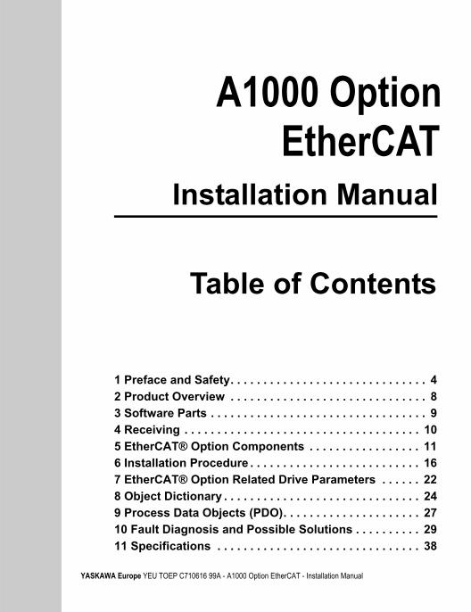
Applicable Documentation
The following manuals are available for SI-ES3 EtherCAT® Option card:
Option CardYASKAWA AC Drive A1000 Option EtherCAT® Installation Manual (this book)Manual No.: YEU TOEP C710616 99A
Read this manual first.The installation manual is packaged with the EtherCAT® Option and contains a basic overview of wiring, settings, functions, and fault diagnoses.
YASKAWA AC Drive A1000 Option EtherCAT® Technical ManualManual No.: YEU SIEP C710616 99A
The technical manual contains detailed information.To obtain the technical manual access these sites:Europe: http://www.yaskawa.eu.comJapan: http://www.e-mechatronics.comUSA: http://www.yaskawa.comOther areas: contact a YASKAWA representative.
EN 4 YASKAWA Europe YEU TOEP C710616 99A - A1000 Option EtherCAT - Installation Manual
1 Preface and Safety
For the drive setup, refer to one of the documentation listed below.
TermsNote: Indicates supplemental information that YASKAWA highly recommends be
followed. Content identified by Note: is not related to personnel safety orequipment damage safety messages.
Registered Trademarks• EtherCAT® is registered trademark and patented technology, licensed by Beckhoff
Automation GmbH, Germany.
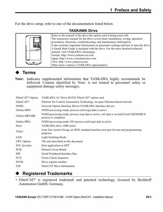
YASKAWA DriveRefer to the manual of the drive this option card is being used with.The instruction manual for the drive covers basic installation, wiring, operation procedures, functions, troubleshooting, and maintenance information. It also includes important information on parameter settings and how to tune the drive.A Quick Start Guide is included with the drive. For the more detailed technical manual, visit YASKAWA’s homepage.Europe: http://www.yaskawa.eu.comJapan: http://www.e-mechatronics.comUSA: http://www.yaskawa.comOther areas: contact a YASKAWA representative
EtherCAT® Option: YASKAWA AC Drive SI-ES3 EtherCAT® option card
EtherCAT®: Ethernet for Control Automation Technology, an open Ethernet-based network
NOID: Network Option Interface Driver (YASKAWA Interface driver)
Online-DRV: NOID processing mode, process (ctrl/resp) data is active
Online-DRVMB:NOID processing mode, process resp data is active, ctrl data is on hold (Until MEMOBUS process is complete)
Online-PRG: NOID processing mode, NO process (ctrl/resp) data is active
Host: YASKAWA drive 1000 series
JTAG:Joint Test Action Group, an IEEE standard interface test port for test and programming purposes
LED: Light Emitting Diode
OPT, Option: The unit described in this document
INV, Inverter: Host application to OPT
PCB: Printed Circuit Board
SPI: Serial Peripheral Interface Bus
FCS: Frame Check Sequence
INVR: Drive register number
ESI: EtherCAT Slave Information
YASKAWA Europe YEU TOEP C710616 99A - A1000 Option EtherCAT - Installation Manual EN 5
1 Preface and Safety
• Other company names and product names listed in this manual are registered trademarksof those companies.
Supplemental Safety Information
Read and understand this manual before installing, operating, or servicing this option card.The option card must be installed according to this manual and local codes.
The following conventions are used to indicate safety messages in this manual. Failure toheed these messages could result in serious or possibly even fatal injury or damage to theproducts or to related equipment and systems.
General Safety
DANGER
Indicates a hazardous situation, which, if not avoided, will result in death or serious injury.
WARNING
Indicates a hazardous situation, which, if not avoided, could result in death or seriousinjury.
CAUTION
Indicates a hazardous situation, which, if not avoided, could result in minor or moderateinjury.
NOTICE
Indicates an equipment damage message.
General Precautions
• The diagrams in this section may include drives without covers or safety shields to illustrate details. Be sure to rein-stall covers or shields before operating any devices. The option board should be used according to the instructions described in this manual.
• Any illustrations, photographs, or examples used in this manual are provided as examples only and may not apply to all products to which this manual is applicable.
• The products and specifications described in this manual or the content and presentation of the manual may be changed without notice to improve the product and/or the manual.
• When ordering a new copy of the manual due to damage or loss, contact your YASKAWA representative or the nearest YASKAWA sales office and provide the manual number shown on the front cover.
EN 6 YASKAWA Europe YEU TOEP C710616 99A - A1000 Option EtherCAT - Installation Manual
1 Preface and Safety
DANGER
Heed the safety messages in this manual.Failure to comply will result in death or serious injury.The operating company is responsible for any injuries or equipment damage resulting fromfailure to heed the warnings in this manual.
NOTICE
Do not expose the drive to halogen group disinfectants.Failure to comply may cause damage to the electrical components in the option card. Do not pack the drive in wooden materials that have been fumigated or sterilized.Do not sterilize the entire package after the product is packed.Do not modify the drive circuitry.Failure to comply could result in damage to the drive and will void warranty. YASKAWA is not responsible for any modification of the product made by the user. This productmust not be modified.
YASKAWA Europe YEU TOEP C710616 99A - A1000 Option EtherCAT - Installation Manual EN 7
2 Product Overview
2 Product Overview
About This Product
The EtherCAT® Option (Model: SI-ES3) is an option card designed to connect theYASKAWA AC drive to an EtherCAT® network. Using this option card and an EtherCAT®
master can;
• operate the drive• monitor the drive operation status• read or modify drive parameters.
The SI-ES3 option provides instant connectivity to an EtherCAT® network for theYASKAWA A1000 drive. The option contains support for the Velocity mode according theCANopen Device Profile and Motion Control (DSP402) profile. It also contains YASKAWAvendor specific CANopen objects based on the present CANopen option board specification.
The EtherCAT® Option supports the following communication profiles;
• DS 301 Ver. 4.02• DSP 402 Ver. 3.0 Velocity Mode
Figure E.1
EtherCAT Conformance tested
Applicable Models
The option can be used with the drive models in Table E.1.
Table E.1 Applicable ModelsDrive Series Drive Model Number Software Version <1>
<1> See “PRG” on the drive nameplate for the software version number.
A1000CIMR-A2A
VSA901017 to VSA901099CIMR-A4A
EN 8 YASKAWA Europe YEU TOEP C710616 99A - A1000 Option EtherCAT - Installation Manual
3 Software Parts
3 Software Parts
NOID - Network Option Interface Driver
This section explains communication sequences provided by the SI-ES3 option to startupand control the drive.
Functionality provided:
• Startup/initialization of option with the drive.• Option and drive compatibility/acceptance management.• Process data parameter (register) mapping.• Drive <--> Option re-initialization management (remap of process data).• MEMOBUS channel.• Error management.• Drive <- -> Option basic control response data in Online-DRV mode.• Drive <- -> Option operation mode.
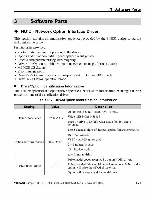
Drive/Option Identification InformationThis section specifies the option/drive specific identification information exchanged duringpower-up state of the application driver.
Table E.2 Drive/Option Identification Information
Setting Value Description
Option model code 0x53455333
Option mode code, 4-digot ASCII string.
Value: SES3=0x53455333
Used by drive to identify what kind of option that is mounted.
Option software version DEC: 24201
Last 5 decimal digits of decimal option firmware revision.
Def: VST9242zz
VST9 = A1000 option card
2 = European product
42 = Product code
zz = Minor revision
Drive model codes ALL
Drive model codes accepted by option NOID driver.
If the provided drive model code does not match the list the option will raise the OFx31 drive error.
Option will accept any drive model code.
YASKAWA Europe YEU TOEP C710616 99A - A1000 Option EtherCAT - Installation Manual EN 9
4 Receiving
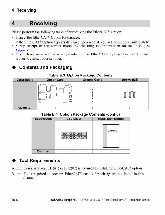
4 ReceivingPlease perform the following tasks after receiving the EtherCAT® Option:
• Inspect the EtherCAT® Option for damage.If the EtherCAT® Option appears damaged upon receipt, contact the shipper immediately.
• Verify receipt of the correct model by checking the information on the PCB (seeFigure E.2).
• If you have received the wrong model or the EtherCAT® Option does not functionproperly, contact your supplier.
Contents and Packaging
Table E.3 Option Package Contents
Table E.4 Option Package Contents (cont’d)
Tool Requirements
A Phillips screwdriver PH1(#1) or PH2(#2) is required to install the EtherCAT® option.
Note: Tools required to prepare EtherCAT® cables for wiring are not listed in thismanual.
Description: Option Card Ground Cable Screws (M3)
Quantity: 1 1 3
Description: LED Label Installation Manual
Quantity: 1 1
RUN ERRL/A IN L/A OUT
MANUAL
EN 10 YASKAWA Europe YEU TOEP C710616 99A - A1000 Option EtherCAT - Installation Manual
5 EtherCAT® Option Components
5 EtherCAT® Option Components
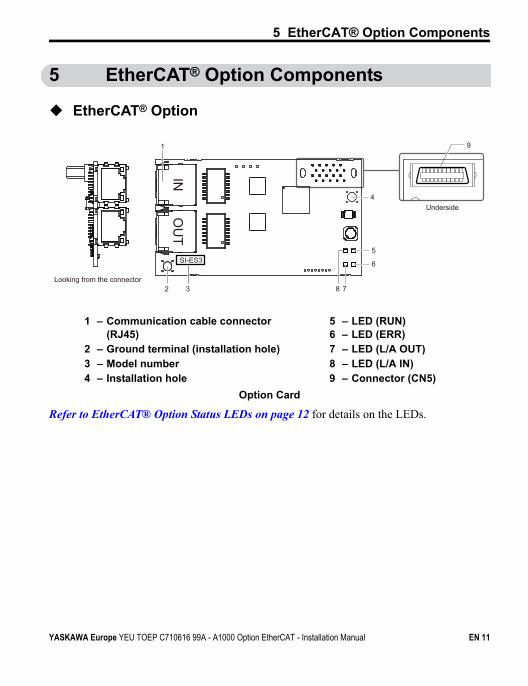
EtherCAT® OptionFigure E.2
Option Card
Refer to EtherCAT® Option Status LEDs on page 12 for details on the LEDs.
1 – Communication cable connector (RJ45)
5 – LED (RUN)6 – LED (ERR)
2 – Ground terminal (installation hole) 7 – LED (L/A OUT)3 – Model number 8 – LED (L/A IN)4 – Installation hole 9 – Connector (CN5)
Underside
9
Looking from the connector
1
4
5
6
8 72
SI-ES3
3
INO
UT
YASKAWA Europe YEU TOEP C710616 99A - A1000 Option EtherCAT - Installation Manual EN 11
5 EtherCAT® Option Components
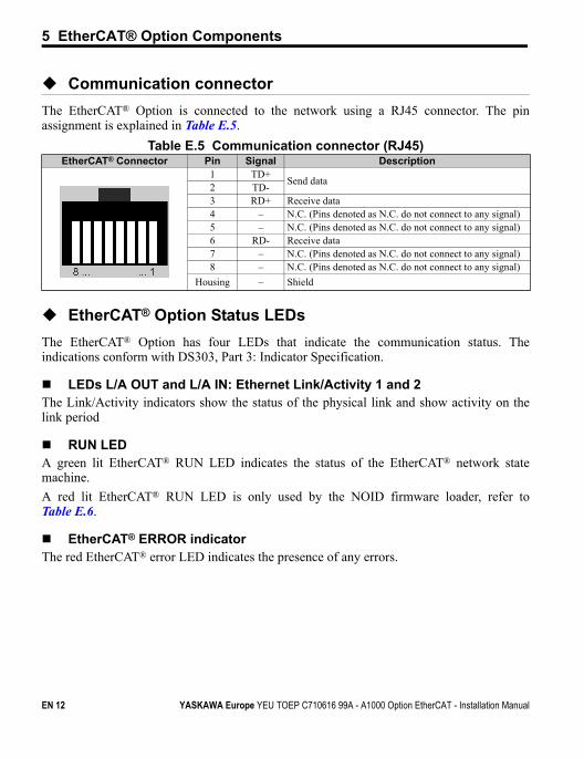
Communication connector
The EtherCAT® Option is connected to the network using a RJ45 connector. The pinassignment is explained in Table E.5.
Table E.5 Communication connector (RJ45)
EtherCAT® Option Status LEDs
The EtherCAT® Option has four LEDs that indicate the communication status. Theindications conform with DS303, Part 3: Indicator Specification.
LEDs L/A OUT and L/A IN: Ethernet Link/Activity 1 and 2The Link/Activity indicators show the status of the physical link and show activity on thelink period
RUN LEDA green lit EtherCAT® RUN LED indicates the status of the EtherCAT® network statemachine.
A red lit EtherCAT® RUN LED is only used by the NOID firmware loader, refer toTable E.6.
EtherCAT® ERROR indicatorThe red EtherCAT® error LED indicates the presence of any errors.
EtherCAT® Connector Pin Signal Description1 TD+
Send data2 TD-3 RD+ Receive data4 – N.C. (Pins denoted as N.C. do not connect to any signal)5 – N.C. (Pins denoted as N.C. do not connect to any signal)6 RD- Receive data7 – N.C. (Pins denoted as N.C. do not connect to any signal)8 – N.C. (Pins denoted as N.C. do not connect to any signal)
Housing – Shield
EN 12 YASKAWA Europe YEU TOEP C710616 99A - A1000 Option EtherCAT - Installation Manual
5 EtherCAT® Option Components
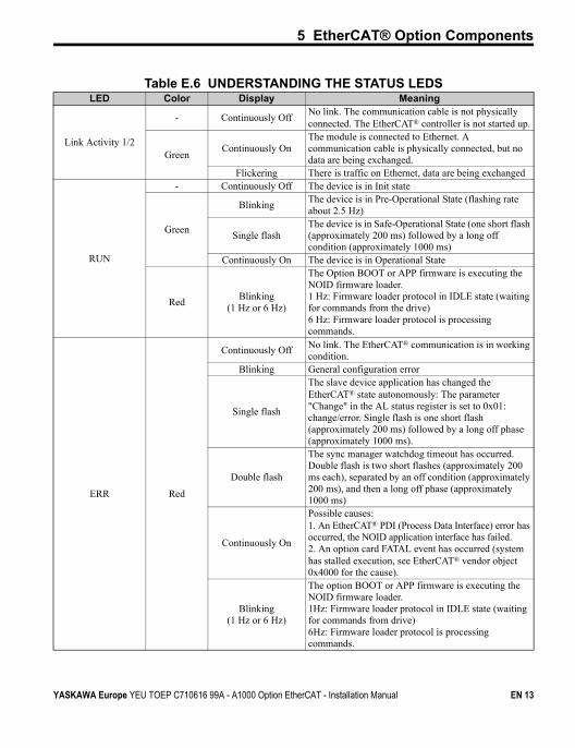
Table E.6 UNDERSTANDING THE STATUS LEDSLED Color Display Meaning
Link Activity 1/2
- Continuously OffNo link. The communication cable is not physically connected. The EtherCAT® controller is not started up.
GreenContinuously On
The module is connected to Ethernet. A communication cable is physically connected, but no data are being exchanged.
Flickering There is traffic on Ethernet, data are being exchanged
RUN
- Continuously Off The device is in Init state
Green
BlinkingThe device is in Pre-Operational State (flashing rate about 2.5 Hz)
Single flashThe device is in Safe-Operational State (one short flash (approximately 200 ms) followed by a long off condition (approximately 1000 ms)
Continuously On The device is in Operational State
RedBlinking
(1 Hz or 6 Hz)
The Option BOOT or APP firmware is executing the NOID firmware loader.1 Hz: Firmware loader protocol in IDLE state (waiting for commands from the drive)6 Hz: Firmware loader protocol is processing commands.
ERR Red
Continuously Off No link. The EtherCAT® communication is in working condition.
Blinking General configuration error
Single flash
The slave device application has changed the EtherCAT® state autonomously: The parameter "Change" in the AL status register is set to 0x01: change/error. Single flash is one short flash (approximately 200 ms) followed by a long off phase (approximately 1000 ms).
Double flash
The sync manager watchdog timeout has occurred.Double flash is two short flashes (approximately 200 ms each), separated by an off condition (approximately 200 ms), and then a long off phase (approximately 1000 ms)
Continuously On
Possible causes:1. An EtherCAT® PDI (Process Data Interface) error has occurred, the NOID application interface has failed.2. An option card FATAL event has occurred (system has stalled execution, see EtherCAT® vendor object 0x4000 for the cause).
Blinking(1 Hz or 6 Hz)
The option BOOT or APP firmware is executing the NOID firmware loader.1Hz: Firmware loader protocol in IDLE state (waiting for commands from drive)6Hz: Firmware loader protocol is processing commands.
YASKAWA Europe YEU TOEP C710616 99A - A1000 Option EtherCAT - Installation Manual EN 13
5 EtherCAT® Option Components
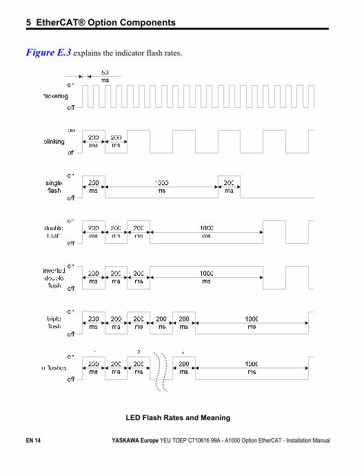
Figure E.3 explains the indicator flash rates.Figure E.3
LED Flash Rates and Meaning
EN 14 YASKAWA Europe YEU TOEP C710616 99A - A1000 Option EtherCAT - Installation Manual
5 EtherCAT® Option Components
DSP402 functionality
This part manages the DSP402 drive profile functionality in the option and converts thecontrol/status data into drive specific control/status data.
Vendor specific CANopen objects
This part integrates the vendor specific CANopen object model into EtherCAT®.
Error management
This part processes drive and EtherCAT® specific errors and assures that all faults processand propagate properly to the drive/EtherCAT® network.
EtherCAT® processing stack
The "EtherCAT® Slave example code" from the EtherCAT® technology group (ETG) is usedas a main base in this project. It is internally adopted to fit the product.
YASKAWA Europe YEU TOEP C710616 99A - A1000 Option EtherCAT - Installation Manual EN 15
6 Installation Procedure
6 Installation Procedure
Section Safety
DANGER
Electric Shock HazardPower to the drive must be shut off when installing this option card.Even though the power has been shut off, voltage still remains in the drive’s DC bus. Wait beforeremoving the front cover once the drive has been turned off.The CHARGE light on the drive will go out after voltage in the DC bus drops below 50 V, atwhich point it is safe to remove the front cover.Due to the risk of electric shock, be sure that all LEDs have gone out and that the DC bus voltagehas reached a safe level prior to performing any work on the drive.
WARNINGElectrical Shock Hazard
Do not remove the front cover of the drive while the power is on.Failure to comply could result in death or serious injury.The diagrams in this section may include drives without covers or safety shields to show details.Be sure to reinstall covers or shields before operating any devices. The option board should beused according to the instructions described in this manual.
Do not allow unqualified personnel to use equipment.Failure to comply could result in death or serious injury.Maintenance, inspection, and replacement of parts must be performed only by authorizedpersonnel familiar with installation, adjustment, and maintenance of this product.
Do not touch the option card while the power supply to the drive is switched on.Failure to comply could result in death or serious injury.
Do not use damaged wires, place excessive stress on wiring, or damage the wire insulation.Failure to comply could result in death or serious injury.
NOTICEDamage to Equipment
Observe proper electrostatic discharge procedures (ESD) when handling the option card,drive, and circuit boards.Failure to comply may result in ESD damage to circuitry.
Never shut the power off while the drive is outputting voltage.Failure to comply may cause the application to operate incorrectly or damage the drive.
EN 16 YASKAWA Europe YEU TOEP C710616 99A - A1000 Option EtherCAT - Installation Manual
6 Installation Procedure
Do not operate damaged equipment.Failure to comply may cause further damage to the equipment.Do not connect or operate any equipment with visible damage or missing parts.
Tighten all terminal screws to the specified tightening torque.Loose electrical connections could result in death or serious injury by fire due to overheating ofelectrical connections.
Do not use unshielded cable for control wiring.Failure to comply may cause electrical interference resulting in poor system performance.Use shielded twisted-pair wires and ground the shield to the ground terminal of the drive.
Properly connect all pins and connectors.Failure to comply may prevent proper operation and possibly damage equipment.
Check wiring to ensure that all connections are correct after installing the option card andconnecting any other devices.Failure to comply may result in damage to the option card.
NOTICE
YASKAWA Europe YEU TOEP C710616 99A - A1000 Option EtherCAT - Installation Manual EN 17
6 Installation Procedure
Prior to Installing the Option Card
Prior to installing the EtherCAT® Option, wire the drive and make necessary connections tothe drive terminals. For more information on wiring and connecting the drive, refer to themanual packaged with the drive. Verify that the drive runs normally without the optioninstalled.
Installing the Option
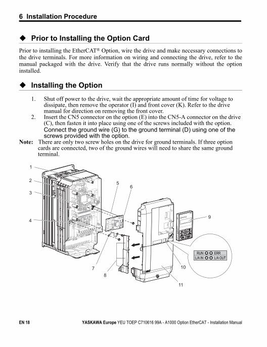
1. Shut off power to the drive, wait the appropriate amount of time for voltage to dissipate, then remove the operator (I) and front cover (K). Refer to the drive manual for direction on removing the front cover.
2. Insert the CN5 connector on the option (E) into the CN5-A connector on the drive (C), then fasten it into place using one of the screws included with the option.Connect the ground wire (G) to the ground terminal (D) using one of the screws provided with the option.
Note: There are only two screw holes on the drive for ground terminals. If three optioncards are connected, two of the ground wires will need to share the same groundterminal.
Figure E.4
RUN ERRL/A IN L/A OUT
7
1
56
9
10
2
3
4
8
11
EN 18 YASKAWA Europe YEU TOEP C710616 99A - A1000 Option EtherCAT - Installation Manual
6 Installation Procedure
Installing the Option Card
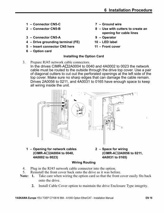
3. Prepare RJ45 network cable connectors.In the drives CIMR-A2A0004 to 0040 and 4A0002 to 0023 the network cable must be routed to the outside through the drive top cover. Use a pair of diagonal cutters to cut out the perforated openings at the left side of the top cover. Make sure no sharp edges that can damage the cable remain.Drives 2A0056 to 0211, and 4A0031 to 0165 have enough space to keep all wiring inside the unit.
Figure E.5
Wiring Routing
4. Plug in the RJ45 network cable connector into the option.5. Reinstall the front cover back onto the drive as it was before.
Note: 1. Take care when wiring the option card so that the front cover easily fits back onto the drive.
2. Install Cable Cover option to maintain the drive Enclosure Type integrity.
1 – Connector CN5-C 7 – Ground wire2 – Connector CN5-B 8 – Use with cutters to create an
opening for cable lines3 – Connector CN5-A 9 – Operator4 – Drive grounding terminal (FE) 10 – LED label5 – Insert connector CN5 here 11 – Front cover6 – Option card
1 – Opening for network cables(CIMR-A2A0004 to 0040, 4A0002 to 0023)
2 – Space for wiring (CIMR-A2A0056 to 0211, 4A0031 to 0165)
2
1
YASKAWA Europe YEU TOEP C710616 99A - A1000 Option EtherCAT - Installation Manual EN 19
6 Installation Procedure
6. Attach the LED label (J) packaged with the option as shown in Figure E.4.7. Switch on the drive power supply.
An “AEr” Alarm message indicating that the node address is set to 0 will appear on the drive display. Set the node address in parameter F6-35. Set the communication speed in parameter F6-36.
8. Cycle the power supply to activate the changed settings. Installation complete.
Communication Cable Specifications
To ensure proper performance, YASKAWA recommends using EtherCAT® dedicated Cat5ecommunication cables.
Network Termination
The EtherCAT® network does not require a termination resistor if the drive is the last node inthe network. Network termination is realized by the ASIC of the EtherCAT® option card.
ESI File
For easy network implementation of drives equipped with an EtherCAT® Option, the ESIfile can be obtained from:
Europe: http://www.yaskawa.eu.com
Japan: http://www.e-mechatronics.com
USA: http://www.yaskawa.com
Other areas: contact a YASKAWA representative
EN 20 YASKAWA Europe YEU TOEP C710616 99A - A1000 Option EtherCAT - Installation Manual
6 Installation Procedure
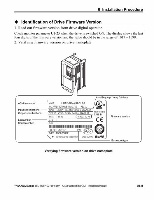
Identification of Drive Firmware Version1. Read out firmware version from drive digital operator.
Check monitor parameter U1-25 when the drive is switched ON. The display shows the lastfour digits of the firmware version and the value should be in the range of 1017 ~ 1099.
2. Verifying firmware version on drive nameplateFigure E.6
Verifying firmware version on drive nameplate
PRG : 1010
IND.CONT.EQ.7J48 B
CIMR-AC2A0021FAA
YASKAWA ELECTRIC CORPORATION MADE IN JAPAN
:
: AC3PH 200-240V 50/60Hz 24A/18.9A: AC3PH 0-240V 0-400Hz 21A/17.5A: 3.5 kg: :
: E131457 IP20 PASS
MODEL MAX APPLI. MOTOR : 5.5kW / 3.7kW REV : AINPUTOUTPUTMASSO / NS / N
FILE NOTYPE 1 ENCLOSURE
AC drive model
Input specificationsOutput specifications
Lot numberSerial number
Firmware version
Enclosure type
Normal Duty Amps / Heavy Duty Amps
YASKAWA Europe YEU TOEP C710616 99A - A1000 Option EtherCAT - Installation Manual EN 21
7 EtherCAT® Option Related Drive Parameters
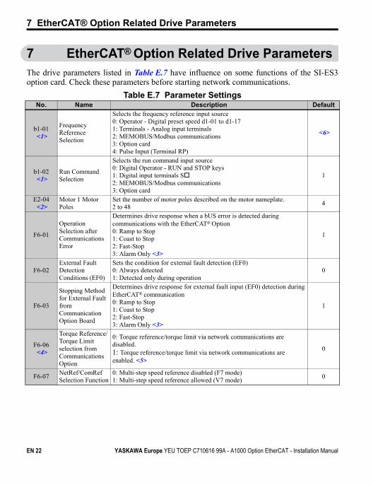
7 EtherCAT® Option Related Drive ParametersThe drive parameters listed in Table E.7 have influence on some functions of the SI-ES3option card. Check these parameters before starting network communications.
Table E.7 Parameter SettingsNo. Name Description Default
b1-01<1>
Frequency Reference Selection
Selects the frequency reference input source0: Operator - Digital preset speed d1-01 to d1-171: Terminals - Analog input terminals2: MEMOBUS/Modbus communications3: Option card4: Pulse Input (Terminal RP)
<6>
b1-02<1>
Run Command Selection
Selects the run command input source0: Digital Operator - RUN and STOP keys1: Digital input terminals S2: MEMOBUS/Modbus communications3: Option card
1
E2-04<2>
Motor 1 Motor Poles
Set the number of motor poles described on the motor nameplate.2 to 48
4
F6-01
Operation Selection after Communications Error
Determines drive response when a bUS error is detected during communications with the EtherCAT® Option0: Ramp to Stop 1: Coast to Stop2: Fast-Stop3: Alarm Only <3>
1
F6-02External Fault Detection Conditions (EF0)
Sets the condition for external fault detection (EF0)0: Always detected1: Detected only during operation
0
F6-03
Stopping Method for External Fault from Communication Option Board
Determines drive response for external fault input (EF0) detection during EtherCAT® communication0: Ramp to Stop 1: Coast to Stop2: Fast-Stop3: Alarm Only <3>
1
F6-06<4>
Torque Reference/Torque Limit selection from Communications Option
0: Torque reference/torque limit via network communications are disabled.1: Torque reference/torque limit via network communications are enabled. <5>
0
F6-07NetRef/ComRef Selection Function
0: Multi-step speed reference disabled (F7 mode)1: Multi-step speed reference allowed (V7 mode)
0
EN 22 YASKAWA Europe YEU TOEP C710616 99A - A1000 Option EtherCAT - Installation Manual
7 EtherCAT® Option Related Drive Parameters
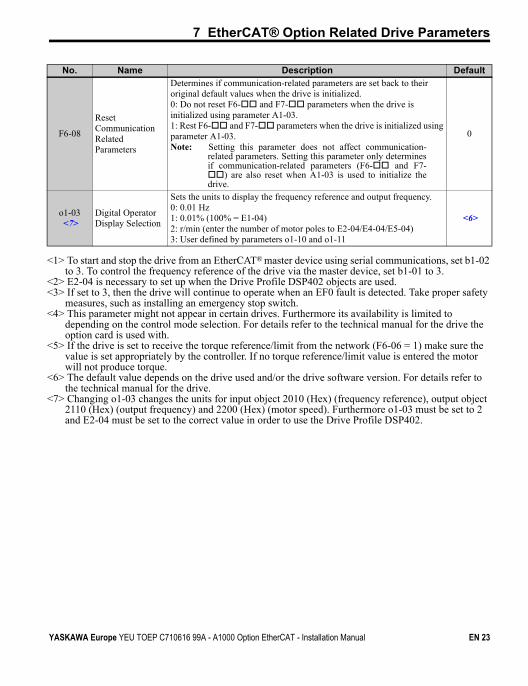
F6-08
Reset Communication Related Parameters
Determines if communication-related parameters are set back to their original default values when the drive is initialized.0: Do not reset F6- and F7- parameters when the drive is initialized using parameter A1-03.1: Rest F6- and F7- parameters when the drive is initialized using parameter A1-03.Note: Setting this parameter does not affect communication-
related parameters. Setting this parameter only determinesif communication-related parameters (F6- and F7-) are also reset when A1-03 is used to initialize thedrive.
0
o1-03<7>
Digital Operator Display Selection
Sets the units to display the frequency reference and output frequency.0: 0.01 Hz 1: 0.01% (100% = E1-04) 2: r/min (enter the number of motor poles to E2-04/E4-04/E5-04) 3: User defined by parameters o1-10 and o1-11
<6>
<1> To start and stop the drive from an EtherCAT® master device using serial communications, set b1-02 to 3. To control the frequency reference of the drive via the master device, set b1-01 to 3.
<2> E2-04 is necessary to set up when the Drive Profile DSP402 objects are used.<3> If set to 3, then the drive will continue to operate when an EF0 fault is detected. Take proper safety
measures, such as installing an emergency stop switch.<4> This parameter might not appear in certain drives. Furthermore its availability is limited to
depending on the control mode selection. For details refer to the technical manual for the drive the option card is used with.
<5> If the drive is set to receive the torque reference/limit from the network (F6-06 = 1) make sure the value is set appropriately by the controller. If no torque reference/limit value is entered the motor will not produce torque.
<6> The default value depends on the drive used and/or the drive software version. For details refer to the technical manual for the drive.
<7> Changing o1-03 changes the units for input object 2010 (Hex) (frequency reference), output object 2110 (Hex) (output frequency) and 2200 (Hex) (motor speed). Furthermore o1-03 must be set to 2 and E2-04 must be set to the correct value in order to use the Drive Profile DSP402.
No. Name Description Default
YASKAWA Europe YEU TOEP C710616 99A - A1000 Option EtherCAT - Installation Manual EN 23
8 Object Dictionary
8 Object Dictionary
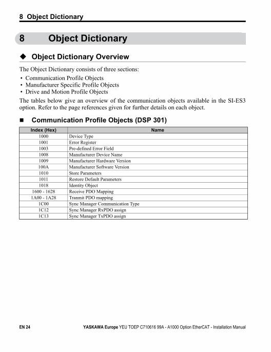
Object Dictionary Overview
The Object Dictionary consists of three sections:
• Communication Profile Objects• Manufacturer Specific Profile Objects• Drive and Motion Profile Objects
The tables below give an overview of the communication objects available in the SI-ES3option. Refer to the page references given for further details on each object.
Communication Profile Objects (DSP 301)Index (Hex) Name
1000 Device Type1001 Error Register1003 Pre-defined Error Field1008 Manufacturer Device Name1009 Manufacturer Hardware Version100A Manufacturer Software Version1010 Store Parameters1011 Restore Default Parameters1018 Identity Object
1600 - 1628 Receive PDO Mapping1A00 - 1A28 Tranmit PDO mapping
1C00 Sync Manager Communication Type1C12 Sync Manager RxPDO assign1C13 Sync Manager TxPDO assign
EN 24 YASKAWA Europe YEU TOEP C710616 99A - A1000 Option EtherCAT - Installation Manual
8 Object Dictionary
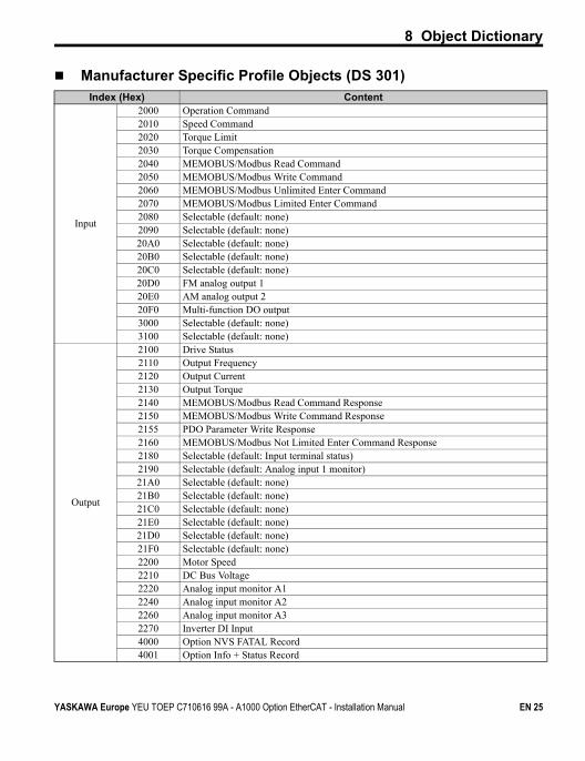
Manufacturer Specific Profile Objects (DS 301)Index (Hex) Content
Input
2000 Operation Command2010 Speed Command2020 Torque Limit2030 Torque Compensation2040 MEMOBUS/Modbus Read Command2050 MEMOBUS/Modbus Write Command 2060 MEMOBUS/Modbus Unlimited Enter Command2070 MEMOBUS/Modbus Limited Enter Command2080 Selectable (default: none)2090 Selectable (default: none)20A0 Selectable (default: none)20B0 Selectable (default: none)20C0 Selectable (default: none)20D0 FM analog output 120E0 AM analog output 220F0 Multi-function DO output3000 Selectable (default: none)3100 Selectable (default: none)
Output
2100 Drive Status2110 Output Frequency2120 Output Current2130 Output Torque2140 MEMOBUS/Modbus Read Command Response2150 MEMOBUS/Modbus Write Command Response2155 PDO Parameter Write Response2160 MEMOBUS/Modbus Not Limited Enter Command Response2180 Selectable (default: Input terminal status)2190 Selectable (default: Analog input 1 monitor)21A0 Selectable (default: none)21B0 Selectable (default: none)21C0 Selectable (default: none)21E0 Selectable (default: none)21D0 Selectable (default: none)21F0 Selectable (default: none)2200 Motor Speed2210 DC Bus Voltage2220 Analog input monitor A12240 Analog input monitor A22260 Analog input monitor A32270 Inverter DI Input4000 Option NVS FATAL Record4001 Option Info + Status Record
YASKAWA Europe YEU TOEP C710616 99A - A1000 Option EtherCAT - Installation Manual EN 25
8 Object Dictionary
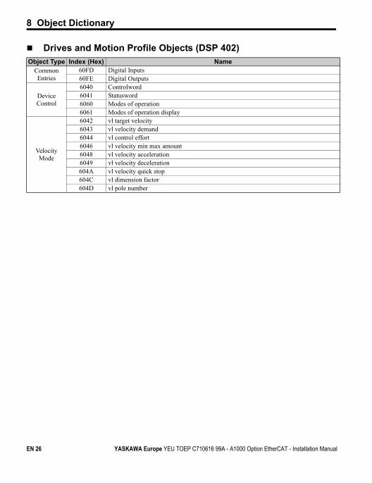
Drives and Motion Profile Objects (DSP 402)Object Type Index (Hex) Name
Common Entries
60FD Digital Inputs60FE Digital Outputs
Device Control
6040 Controlword6041 Statusword6060 Modes of operation6061 Modes of operation display
Velocity Mode
6042 vl target velocity6043 vl velocity demand6044 vl control effort6046 vl velocity min max amount6048 vl velocity acceleration6049 vl velocity deceleration604A vl velocity quick stop604C vl dimension factor604D vl pole number
EN 26 YASKAWA Europe YEU TOEP C710616 99A - A1000 Option EtherCAT - Installation Manual
9 Process Data Objects (PDO)
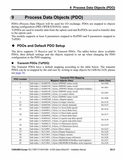
9 Process Data Objects (PDO)PDOs (Process Data Object) will be used for I/O exchange. PDOs are mapped to objectsduring configuration (PRE-OPERATIONAL state).TxPDOs are used to transfer data from the option card and RxPDOs are used to transfer datato the option card.The module supports at least 8 parameters mapped to RxPDO and 8 parameters mapped toTxPDO.
PDOs and Default PDO Setup
The drive supports 15 Receive and 16 Transmit PDOs. The tables below show availablePDOs, their default settings and the objects required to set up when changing the PDOconfiguration or the PDO mapping.
Transmit PDOs (TxPDO)The Transmit PDOs have a default mapping according to the table below. The transmitPDOs can be re-mapped by the end user by writing to map objects 0x1A00-0x1A28, pleasesee page 24.
PDO numberTransmit PDO Mapping
Mapped objects (Hex) Index (Hex)1 Sub-index 1: 0x6041#0, 2-bytes (DSP402 status word) 0x1A00
2Sub-index 1: 0x6041#0, 2-bytes (DSP402 status word)Sub-index 2: 0x6061#0, 2-bytes, (DSP402 Modes of operation display)
0x1A01
6Sub-index 1: 0x6041#0, 2-bytes (DSP402 status word)Sub-index 2: 0x6044#0, 2-bytes, (vl control effort)
0x1A05
7Sub-index 1: 0x6041#0, 2-bytes (DSP402 status word)Sub-index 2: 0x60FD#0, 4-bytes, (Digital inputs)
0x1A06
21 Sub-index 1: 0x6042#0, 2-bytes (vl target velocity) 0x1A1422 Sub-index 1: 0x6043#0, 2-bytes (vl velocity demand) 0x1A15
23Sub-index 1: 0x6048#1, 4-bytes (vl Accel delta speed)Sub-index 2: 0x6048#2, 2-bytes, (vl Accel delta time)
0x1A16
24Sub-index 1: 0x6049#1, 4-bytes (vl Decel delta speed)Sub-index 2: 0x6049#2, 2-bytes, (vl Decel delta time)
0x1A17
25Sub-index 1: 0x604A#1, 4-bytes (vl quick-stop delta speed)Sub-index 2: 0x604A#2, 2-bytes, (vl quick-stop delta time)
0x1A18
26Sub-index 1: 0x604C#1, 4-bytes (vl Dimension factor)Sub-index 2: 0x604C#2, 4-bytes, (vl Dimension factor)
0x1A19
36 Sub-index 1: 0x2100#1, 2-bytes (Drive status) 0x1A2337 Sub-index 1: 0x2110#1, 2-bytes (Output frequency) 0x1A2438 Sub-index 1: 0x2120#1, 2-bytes (Output current) 0x1A2539 Sub-index 1: 0x2130#1, 2-bytes (Output torque reference) 0x1A2640 Sub-index 1: 0x2140#1, 2-bytes (MEMOBUS/Modbus read response) 0x1A2741 Sub-index 1: 0x2150#1, 2-bytes (MEMOBUS/Modbus write response) 0x1A28
YASKAWA Europe YEU TOEP C710616 99A - A1000 Option EtherCAT - Installation Manual EN 27
9 Process Data Objects (PDO)
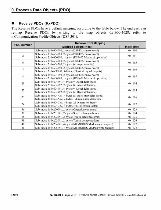
Receive PDOs (RxPDO)The Receive PDOs have a default mapping according to the table below. The end user canre-map Receive PDOs by writing to the map objects 0x1600-1628, refer ton Communication Profile Objects (DSP 301).
PDO numberReceive PDO Mapping
Mapped objects (Hex) Index (Hex)1 Sub-index 1: 0x6040#0, 2-bytes (DSP402 control word) 0x1600
2Sub-index 1: 0x6040#0, 2-bytes (DSP402 control word)Sub-index 2: 0x6060#0, 1-bytes, (DSP402 Modes of operation)
0x1601
6Sub-index 1: 0x6040#0, 2-bytes (DSP402 control word)Sub-index 2: 0x6042#0, 2-bytes, (vl target velocity)
0x1605
7Sub-index 1: 0x6040#0, 2-bytes (DSP402 control word)Sub-index 2: 0x60FE#1, 4-bytes, (Physical digital outputs)
0x1606
8Sub-index 1: 0x6040#0, 2-bytes (DSP402 control word)Sub-index 2: 0x6060#0, 1-bytes, (DSP402 Modes of operation)
0x1607
21Sub-index 1: 0x6048#1, 4-bytes (vl Accel delta speed)Sub-index 2: 0x6048#2, 2-bytes, (vl Accel delta time)
0x1614
22Sub-index 1: 0x6049#1, 4-bytes (vl Decel delta speed)Sub-index 2: 0x6049#2, 2-bytes, (vl Decel delta time)
0x1615
23Sub-index 1: 0x604A#1, 4-bytes (vl quick-stop delta speed)Sub-index 2: 0x604A#2, 2-bytes, (vl quick-stop delta time)
0x1616
24Sub-index 1: 0x604C#1, 4-bytes (vl Dimension factor)Sub-index 2: 0x604C#2, 4-bytes, (vl Dimension factor)
0x1617
36 Sub-index 1: 0x2000#1, 2-bytes (Operation command) 0x162337 Sub-index 1: 0x2010#1, 2-bytes (Speed reference/limit) 0x162438 Sub-index 1: 0x2020#1, 2-bytes (Torque reference/limit) 0x162539 Sub-index 1: 0x2030#1, 2-bytes (Torque compensation) 0x162640 Sub-index 1: 0x2040#1, 4-bytes (MEMOBUS/Modbus read request) 0x162741 Sub-index 1: 0x2050#1, 4-bytes (MEMOBUS/Modbus write request) 0x1628
EN 28 YASKAWA Europe YEU TOEP C710616 99A - A1000 Option EtherCAT - Installation Manual
10 Fault Diagnosis and Possible Solutions
10 Fault Diagnosis and Possible Solutions
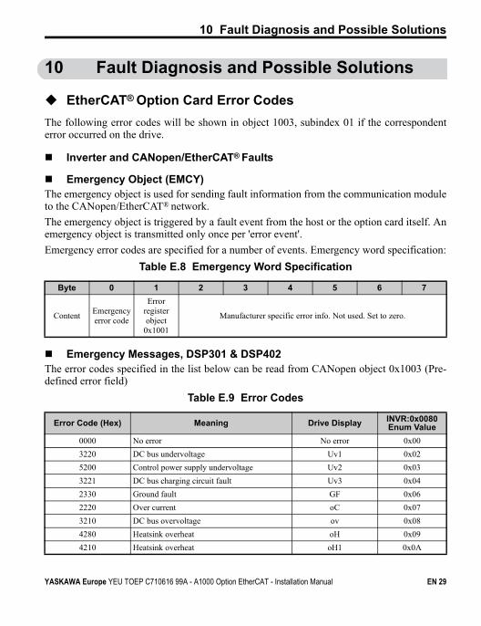
EtherCAT® Option Card Error Codes
The following error codes will be shown in object 1003, subindex 01 if the correspondenterror occurred on the drive.
Inverter and CANopen/EtherCAT® Faults
Emergency Object (EMCY)The emergency object is used for sending fault information from the communication moduleto the CANopen/EtherCAT® network.
The emergency object is triggered by a fault event from the host or the option card itself. Anemergency object is transmitted only once per 'error event'.
Emergency error codes are specified for a number of events. Emergency word specification:
Table E.8 Emergency Word Specification
Emergency Messages, DSP301 & DSP402The error codes specified in the list below can be read from CANopen object 0x1003 (Pre-defined error field)
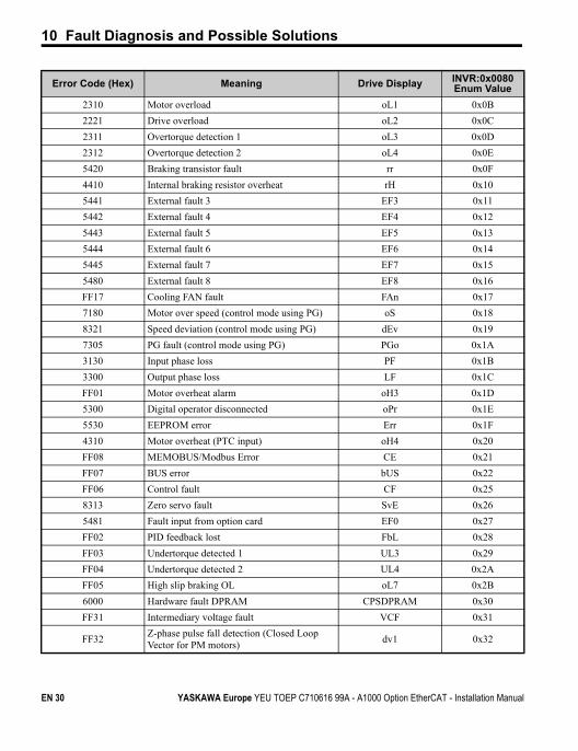
Table E.9 Error Codes
Byte 0 1 2 3 4 5 6 7
ContentEmergency error code
Error register object
0x1001
Manufacturer specific error info. Not used. Set to zero.
Error Code (Hex) Meaning Drive Display INVR:0x0080 Enum Value
0000 No error No error 0x00
3220 DC bus undervoltage Uv1 0x02
5200 Control power supply undervoltage Uv2 0x03
3221 DC bus charging circuit fault Uv3 0x04
2330 Ground fault GF 0x06
2220 Over current oC 0x07
3210 DC bus overvoltage ov 0x08
4280 Heatsink overheat oH 0x09
4210 Heatsink overheat oH1 0x0A
YASKAWA Europe YEU TOEP C710616 99A - A1000 Option EtherCAT - Installation Manual EN 29
10 Fault Diagnosis and Possible Solutions
2310 Motor overload oL1 0x0B
2221 Drive overload oL2 0x0C
2311 Overtorque detection 1 oL3 0x0D
2312 Overtorque detection 2 oL4 0x0E
5420 Braking transistor fault rr 0x0F
4410 Internal braking resistor overheat rH 0x10
5441 External fault 3 EF3 0x11
5442 External fault 4 EF4 0x12
5443 External fault 5 EF5 0x13
5444 External fault 6 EF6 0x14
5445 External fault 7 EF7 0x15
5480 External fault 8 EF8 0x16
FF17 Cooling FAN fault FAn 0x17
7180 Motor over speed (control mode using PG) oS 0x18
8321 Speed deviation (control mode using PG) dEv 0x19
7305 PG fault (control mode using PG) PGo 0x1A
3130 Input phase loss PF 0x1B
3300 Output phase loss LF 0x1C
FF01 Motor overheat alarm oH3 0x1D
5300 Digital operator disconnected oPr 0x1E
5530 EEPROM error Err 0x1F
4310 Motor overheat (PTC input) oH4 0x20
FF08 MEMOBUS/Modbus Error CE 0x21
FF07 BUS error bUS 0x22
FF06 Control fault CF 0x25
8313 Zero servo fault SvE 0x26
5481 Fault input from option card EF0 0x27
FF02 PID feedback lost FbL 0x28
FF03 Undertorque detected 1 UL3 0x29
FF04 Undertorque detected 2 UL4 0x2A
FF05 High slip braking OL oL7 0x2B
6000 Hardware fault DPRAM CPSDPRAM 0x30
FF31 Intermediary voltage fault VCF 0x31
FF32Z-phase pulse fall detection (Closed Loop Vector for PM motors)
dv1 0x32
Error Code (Hex) Meaning Drive Display INVR:0x0080 Enum Value
EN 30 YASKAWA Europe YEU TOEP C710616 99A - A1000 Option EtherCAT - Installation Manual
10 Fault Diagnosis and Possible Solutions
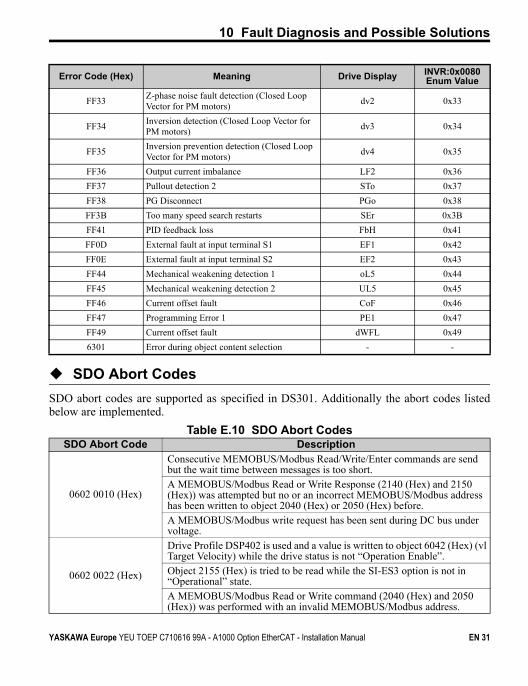
SDO Abort Codes
SDO abort codes are supported as specified in DS301. Additionally the abort codes listedbelow are implemented.
Table E.10 SDO Abort Codes
FF33Z-phase noise fault detection (Closed Loop Vector for PM motors)
dv2 0x33
FF34Inversion detection (Closed Loop Vector for PM motors)
dv3 0x34
FF35Inversion prevention detection (Closed Loop Vector for PM motors)
dv4 0x35
FF36 Output current imbalance LF2 0x36
FF37 Pullout detection 2 STo 0x37
FF38 PG Disconnect PGo 0x38
FF3B Too many speed search restarts SEr 0x3B
FF41 PID feedback loss FbH 0x41
FF0D External fault at input terminal S1 EF1 0x42
FF0E External fault at input terminal S2 EF2 0x43
FF44 Mechanical weakening detection 1 oL5 0x44
FF45 Mechanical weakening detection 2 UL5 0x45
FF46 Current offset fault CoF 0x46
FF47 Programming Error 1 PE1 0x47
FF49 Current offset fault dWFL 0x49
6301 Error during object content selection - -
SDO Abort Code Description
0602 0010 (Hex)
Consecutive MEMOBUS/Modbus Read/Write/Enter commands are send but the wait time between messages is too short.A MEMOBUS/Modbus Read or Write Response (2140 (Hex) and 2150 (Hex)) was attempted but no or an incorrect MEMOBUS/Modbus address has been written to object 2040 (Hex) or 2050 (Hex) before.A MEMOBUS/Modbus write request has been sent during DC bus under voltage.
0602 0022 (Hex)
Drive Profile DSP402 is used and a value is written to object 6042 (Hex) (vl Target Velocity) while the drive status is not “Operation Enable”.Object 2155 (Hex) is tried to be read while the SI-ES3 option is not in “Operational” state.A MEMOBUS/Modbus Read or Write command (2040 (Hex) and 2050 (Hex)) was performed with an invalid MEMOBUS/Modbus address.
Error Code (Hex) Meaning Drive Display INVR:0x0080 Enum Value
YASKAWA Europe YEU TOEP C710616 99A - A1000 Option EtherCAT - Installation Manual EN 31
10 Fault Diagnosis and Possible Solutions
Drive-Side Error Codes
Drive-side error codes appear on the drive’s digital operator. Causes of the errors andcorrective actions are listed in Table E.11 and Table E.9. For additional error codes, refer tothe technical manual for the drive.
The bUS (EtherCAT® Option Communication Error) and EF0 (External Fault Input from theEtherCAT® Option) may appear as an alarm or a fault. If they occur as an alarm, the "ALM"LED on the drive digital operator will blink and the alarm code will flash in the display.When these occur as a fault, the “ALM” LED will light and the display will show the faultcode.
If communication stops while the drive is running, check the following items:
• Is the EtherCAT® Option properly installed?• Is the communication line properly connected to the EtherCAT® Option? Is it loose?• Is the controller program working? Has the controller CPU stopped?• Did a momentary power loss interrupt communications?
EN 32 YASKAWA Europe YEU TOEP C710616 99A - A1000 Option EtherCAT - Installation Manual
10 Fault Diagnosis and Possible Solutions
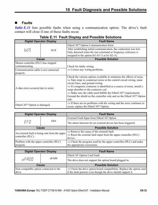
FaultsTable E.11 lists possible faults when using a communication option. The drive’s faultcontact will close if one of these faults occur.
Table E.11 Fault Display and Possible SolutionsDigital Operator Display Fault Name
bUS
EtherCAT® Option Communication ErrorAfter establishing initial communication, the connection was lost.Only detected when the run command or frequency reference is assigned to the option (b1-01=3 or b1-02=3).
Cause Possible SolutionMaster controller (PLC) has stopped communicating. Check for faulty wiring.
Correct any wiring problems.Communication cable is not connected properly.
A data error occurred due to noise.
Check the various options available to minimize the effects of noise. Take steps to counteract noise in the control circuit wiring, main circuit lines, and ground wiring. If a magnetic contactor is identified as a source of noise, install a surge absorber to the contactor coil. Make sure the cable used fulfills the EtherCAT® requirements. Ground the shield on the controller side and on the EtherCAT® Option side.
EtherCAT® Option is damaged. If there are no problems with the wiring and the error continues to occur, replace the EtherCAT® Option.
Digital Operator Display Fault Name
EF0External Fault Input from EtherCAT Option
The alarm function for an external device has been triggered.
Cause Possible Solution
An external fault is being sent from the upper controller (PLC).
Remove the cause of the external fault. Reset the external fault input from the upper controller (PLC) device.
Problem with the upper controller (PLC) program.
Check the program used by the upper controller (PLC) and make the appropriate corrections.
Digital Operator Display Fault Name
oFA00EtherCAT Option Card Fault
The drive does not support the option board plugged in.
Cause Possible SolutionNon-compatible option connected to the drive.
Check the drive option board compatibility. Replace the option card if the fault persists even though the drive should support it.
YASKAWA Europe YEU TOEP C710616 99A - A1000 Option EtherCAT - Installation Manual EN 33
10 Fault Diagnosis and Possible Solutions
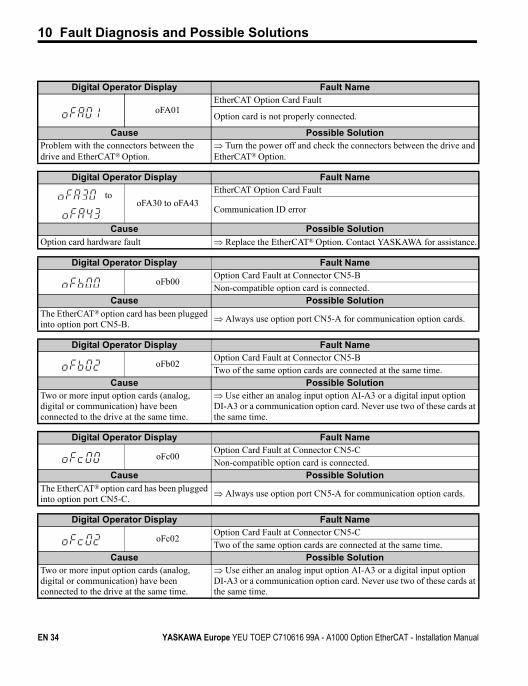
Digital Operator Display Fault Name
oFA01EtherCAT Option Card Fault
Option card is not properly connected.
Cause Possible SolutionProblem with the connectors between the drive and EtherCAT® Option.
Turn the power off and check the connectors between the drive and EtherCAT® Option.
Digital Operator Display Fault Name
tooFA30 to oFA43
EtherCAT Option Card Fault
Communication ID error
Cause Possible Solution
Option card hardware fault Replace the EtherCAT® Option. Contact YASKAWA for assistance.
Digital Operator Display Fault Name
oFb00Option Card Fault at Connector CN5-BNon-compatible option card is connected.
Cause Possible Solution
The EtherCAT® option card has been plugged into option port CN5-B.
Always use option port CN5-A for communication option cards.
Digital Operator Display Fault Name
oFb02Option Card Fault at Connector CN5-BTwo of the same option cards are connected at the same time.
Cause Possible SolutionTwo or more input option cards (analog, digital or communication) have been connected to the drive at the same time.
Use either an analog input option AI-A3 or a digital input option DI-A3 or a communication option card. Never use two of these cards at the same time.
Digital Operator Display Fault Name
oFc00Option Card Fault at Connector CN5-CNon-compatible option card is connected.
Cause Possible Solution
The EtherCAT® option card has been plugged into option port CN5-C.
Always use option port CN5-A for communication option cards.
Digital Operator Display Fault Name
oFc02Option Card Fault at Connector CN5-CTwo of the same option cards are connected at the same time.
Cause Possible SolutionTwo or more input option cards (analog, digital or communication) have been connected to the drive at the same time.
Use either an analog input option AI-A3 or a digital input option DI-A3 or a communication option card. Never use two of these cards at the same time.
EN 34 YASKAWA Europe YEU TOEP C710616 99A - A1000 Option EtherCAT - Installation Manual
10 Fault Diagnosis and Possible Solutions
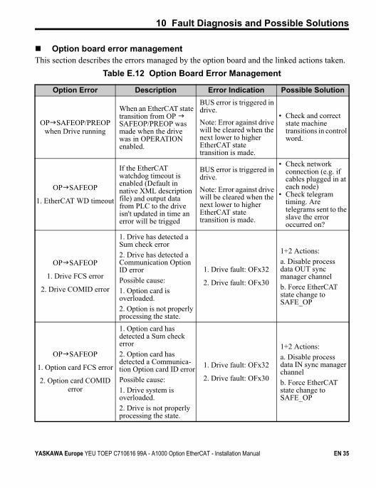
Option board error managementThis section describes the errors managed by the option board and the linked actions taken.
Table E.12 Option Board Error Management
Option Error Description Error Indication Possible Solution
OPSAFEOP/PREOP when Drive running
When an EtherCAT state transition from OP SAFEOP/PREOP was made when the drive was in OPERATION enabled.
BUS error is triggered in drive.
Note: Error against drive will be cleared when the next lower to higher EtherCAT state transition is made.
• Check and correct state machine transitions in control word.
OPSAFEOP
1. EtherCAT WD timeout
If the EtherCAT watchdog timeout is enabled (Default in native XML description file) and output data from PLC to the drive isn't updated in time an error will be trigged
BUS error is triggered in drive.
Note: Error against drive will be cleared when the next lower to higher EtherCAT state transition is made.
• Check network connection (e.g. if cables plugged in at each node)
• Check telegram timing. Are telegrams sent to the slave the error occurred on?
OPSAFEOP
1. Drive FCS error
2. Drive COMID error
1. Drive has detected a Sum check error2. Drive has detected a Communication Option ID errorPossible cause:1. Option card is overloaded.2. Option is not properly processing the state.
1. Drive fault: OFx32
2. Drive fault: OFx30
1+2 Actions:a. Disable process data OUT sync manager channelb. Force EtherCAT state change to SAFE_OP
OPSAFEOP
1. Option card FCS error
2. Option card COMID error
1. Option card has detected a Sum check error2. Option card has detected a Communica-tion Option card ID errorPossible cause: 1. Drive system is overloaded.2. Drive is not properly processing the state.
1. Drive fault: OFx32
2. Drive fault: OFx30
1+2 Actions:a. Disable process data IN sync manager channelb. Force EtherCAT state change to SAFE_OP
YASKAWA Europe YEU TOEP C710616 99A - A1000 Option EtherCAT - Installation Manual EN 35
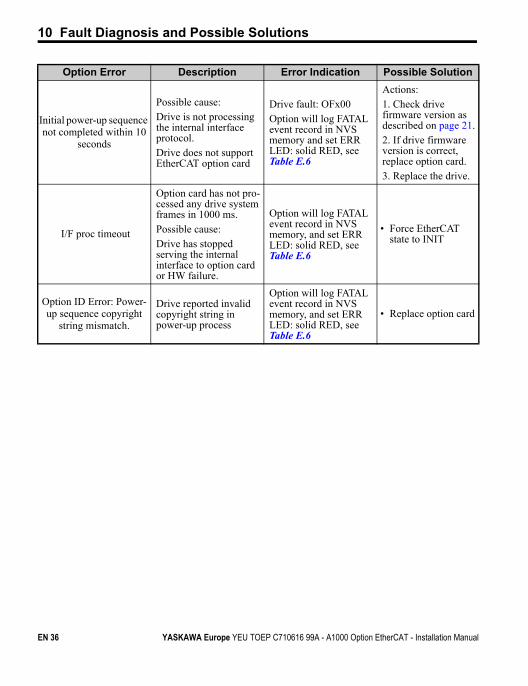
10 Fault Diagnosis and Possible Solutions
Initial power-up sequence not completed within 10
seconds
Possible cause:Drive is not processing the internal interface protocol.Drive does not support EtherCAT option card
Drive fault: OFx00Option will log FATAL event record in NVS memory and set ERR LED: solid RED, see Table E.6
Actions:1. Check drive firmware version as described on page 21.2. If drive firmware version is correct, replace option card.3. Replace the drive.
I/F proc timeout
Option card has not pro-cessed any drive system frames in 1000 ms.Possible cause:Drive has stopped serving the internal interface to option card or HW failure.
Option will log FATAL event record in NVS memory, and set ERR LED: solid RED, see Table E.6
• Force EtherCAT state to INIT
Option ID Error: Power-up sequence copyright
string mismatch.
Drive reported invalid copyright string in power-up process
Option will log FATAL event record in NVS memory, and set ERR LED: solid RED, see Table E.6
• Replace option card
Option Error Description Error Indication Possible Solution
EN 36 YASKAWA Europe YEU TOEP C710616 99A - A1000 Option EtherCAT - Installation Manual
10 Fault Diagnosis and Possible Solutions
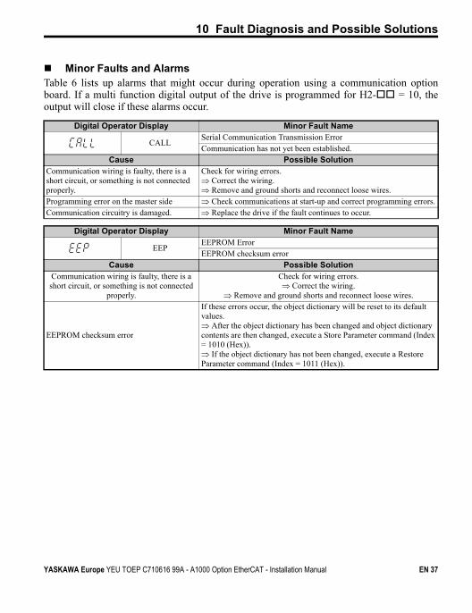
Minor Faults and AlarmsTable 6 lists up alarms that might occur during operation using a communication optionboard. If a multi function digital output of the drive is programmed for H2- = 10, theoutput will close if these alarms occur.
Digital Operator Display Minor Fault Name
CALLSerial Communication Transmission ErrorCommunication has not yet been established.
Cause Possible SolutionCommunication wiring is faulty, there is a short circuit, or something is not connected properly.
Check for wiring errors. Correct the wiring. Remove and ground shorts and reconnect loose wires.
Programming error on the master side Check communications at start-up and correct programming errors.Communication circuitry is damaged. Replace the drive if the fault continues to occur.
Digital Operator Display Minor Fault Name
EEPEEPROM ErrorEEPROM checksum error
Cause Possible SolutionCommunication wiring is faulty, there is a short circuit, or something is not connected
properly.
Check for wiring errors. Correct the wiring.
Remove and ground shorts and reconnect loose wires.
EEPROM checksum error
If these errors occur, the object dictionary will be reset to its default values. After the object dictionary has been changed and object dictionary contents are then changed, execute a Store Parameter command (Index = 1010 (Hex)). If the object dictionary has not been changed, execute a Restore Parameter command (Index = 1011 (Hex)).
YASKAWA Europe YEU TOEP C710616 99A - A1000 Option EtherCAT - Installation Manual EN 37
11 Specifications
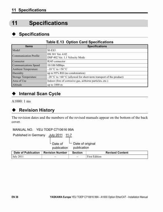
11 Specifications
Specifications
Table E.13 Option Card Specifications
Internal Scan Cycle
A1000: 1 ms
Revision History
The revision dates and the numbers of the revised manuals appear on the bottom of the backcover.
Items SpecificationsModel SI-ES3
Communication ProfileDS 301 Ver. 4.02DSP 402 Ver. 1.1 Velocity Mode
Connector RJ45 connectorCommunications Speed 10/100 MBbpsAmbient Temperature –10 C to +50 CHumidity up to 95% RH (no condensation)Storage Temperature –20 C to +60 C (allowed for short-term transport of the product)Area of Use Indoor (free of corrosive gas, airborne particles, etc.)Altitude up to 1000 m
Date of Publication Revision Number Section Revised ContentJuly 2011 First Edition
MANUAL NO. YEU TOEP C710616 99APublished in Germany July 2011 11-7
Date of publication
Date of original publication
EN 38 YASKAWA Europe YEU TOEP C710616 99A - A1000 Option EtherCAT - Installation Manual
11 Specifications
YASKAWA Europe YEU TOEP C710616 99A - A1000 Option EtherCAT - Installation Manual EN 39
Published in Germany July 2011 11-7
MANUAL NO. YEU TOEP C710616 99A
YASKAWA Europe GmbH
In the event that the end user of this product is to be the military and said product is to be employed in any weapons systems or the manufacture thereof, the export will fall under the relevant regulations as stipulated in the Foreign Exchange and Foreign Trade Regulations. Therefore, be sure to follow all procedures and submit all relevant documentation according to any and all rules, regulations and laws that may apply.
Specifications are subject to change without notice for ongoing product modifications and improvements.
© 2011 YASKAWA Europe GmbH. All rights reserved.
Installation Manual
YASKAWA AC Drive A1000 Option
DRIVE CENTER (INVERTER PLANT)2-13-1, Nishimiyaichi, Yukuhashi, Fukuoka, 824-8511, JapanPhone: 81-930-25-3844 Fax: 81-930-25-4369http://www.yaskawa.co.jp
YASKAWA ELECTRIC CORPORATIONNew Pier Takeshiba South Tower, 1-16-1, Kaigan, Minatoku, Tokyo, 105-6891, JapanPhone: 81-3-5402-4502 Fax: 81-3-5402-4580http://www.yaskawa.co.jp
YASKAWA AMERICA, INC.2121 Norman Drive South, Waukegan, IL 60085, U.S.A.Phone: (800) YASKAWA (927-5292) or 1-847-887-7000 Fax: 1-847-887-7310http://www.yaskawa.com
YASKAWA ELÉTRICO DO BRASIL LTDA.Avenda Fagundes Filho, 620 Bairro Saude, São Paulo, SP04304-000, BrasilPhone: 55-11-3585-1100 Fax: 55-11-5581-8795http://www.yaskawa.com.br
YASKAWA EUROPE GmbHHauptstrasse 185, 65760 Eschborn, GermanyPhone: 49-6196-569-300 Fax: 49-6196-569-398http://www.yaskawa.eu.com
YASKAWA ELECTRIC UK LTD.1 Hunt Hill Orchardton Woods, Cumbernauld, G68 9LF, United KingdomPhone: 44-1236-735000 Fax: 44-1236-458182http://www.yaskawa.co.uk
YASKAWA ELECTRIC KOREA CORPORATION7F, Doore Bldg. 24, Yeoido-dong, Yeoungdungpo-gu, Seoul, 150-877, KoreaPhone: 82-2-784-7844 Fax: 82-2-784-8495http://www.yaskawa.co.kr
YASKAWA ELECTRIC (SINGAPORE) PTE. LTD.151 Lorong Chuan, #04-01, New Tech Park, 556741, SingaporePhone: 65-6282-3003 Fax: 65-6289-3003http://www.yaskawa.com.sg
YASKAWA ELECTRIC (SHANGHAI) CO., LTD.No. 18 Xizang Zhong Road, 17F, Harbour Ring Plaza, Shanghai, 200001, ChinaPhone: 86-21-5385-2200 Fax: 86-21-5385-3299http://www.yaskawa.com.cn
YASKAWA ELECTRIC (SHANGHAI) CO., LTD. BEIJING OFFICERoom 1011, Tower W3 Oriental Plaza, No. 1 East Chang An Ave., Dong Cheng District, Beijing, 100738, ChinaPhone: 86-10-8518-4086 Fax: 86-10-8518-4082
YASKAWA ELECTRIC TAIWAN CORPORATION9F, 16, Nanking E. Rd., Sec. 3, Taipei, 104, TaiwanPhone: 886-2-2502-5003 Fax: 886-2-2505-1280