Embed Size (px)
Citation preview
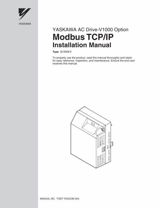
Modbus TCP/IPYASKAWA AC Drive-V1000 Option
Installation ManualType SI-EM3/V
To properly use the product, read this manual thoroughly and retainfor easy reference, inspection, and maintenance. Ensure the end userreceives this manual.
MANUAL NO. TOEP YEACOM 02A
Copyright © 2008 YASKAWA ELECTRIC AMERICA, INC.All rights reserved. No part of this publication may be reproduced, stored in a retrieval system, or transmitted, in any form or by any means, mechanical, electronic, photocopying, recording, or otherwise, without the prior written permission of Yaskawa. No patent liability is assumed with respect to the use of the information contained herein. Moreover, because Yaskawa is constantly striving to improve its high-quality products, the information contained in this manual is subject to change without notice. Every precaution has been taken in the preparation of this manual. Yaskawa assumes no responsibility for errors or omissions. Neither is any liability assumed for damages resulting from the use of the information contained in this publication.
2 YASKAWA ELECTRIC TOEP YEACOM 02A - V1000 Option Modbus TCP/IP Installation Manual
Table of Contents
1 PREFACE AND SAFETY . . . . . . . . . . . . . . . . . . . . . . . . . . . . 42 PRODUCT OVERVIEW . . . . . . . . . . . . . . . . . . . . . . . . . . . . . . 93 RECEIVING . . . . . . . . . . . . . . . . . . . . . . . . . . . . . . . . . . . . . .104 OPTION COMPONENTS. . . . . . . . . . . . . . . . . . . . . . . . . . . .115 INSTALLATION PROCEDURE. . . . . . . . . . . . . . . . . . . . . . .156 WEB INTERFACE . . . . . . . . . . . . . . . . . . . . . . . . . . . . . . . . .237 OPTION DRIVE PARAMETERS . . . . . . . . . . . . . . . . . . . . . .278 MODBUS TCP/IP MESSAGING . . . . . . . . . . . . . . . . . . . . . .299 TROUBLESHOOTING. . . . . . . . . . . . . . . . . . . . . . . . . . . . . .3410 SPECIFICATIONS . . . . . . . . . . . . . . . . . . . . . . . . . . . . . . . .38
YASKAWA ELECTRIC TOEP YEACOM 02A - V1000 Option Modbus TCP/IP Installation Manual 3
1 Preface and Safety
1 Preface and SafetyYaskawa manufactures products used as components in a wide variety of industrial systems and equipment. The selection and application of Yaskawa products remain the responsibility of the equipment manufacturer or end user. Yaskawa accepts no responsibility for the way its products are incorporated into the final system design. Under no circumstances should any Yaskawa product be incorporated into any product or design as the exclusive or sole safety control. Without exception, all controls should be designed to detect faults dynamically and fail safely under all circumstances. All systems or equipment designed to incorporate a product manufactured by Yaskawa must be supplied to the end user with appropriate warnings and instructions as to the safe use and operation of that part. Any warnings provided by Yaskawa must be promptly provided to the end user. Yaskawa offers an express warranty only as to the quality of its products in conforming to standards and specifications published in the Yaskawa manual. NO OTHER WARRANTY, EXPRESSED OR IMPLIED, IS OFFERED. Yaskawa assumes no liability for any personal injury, property damage, losses, or claims arising from misapplication of its products.
4 YASKAWA ELECTRIC TOEP YEACOM 02A - V1000 Option Modbus TCP/IP Installation Manual
1 Preface and Safety
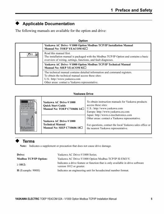
◆ Applicable DocumentationThe following manuals are available for the option and drive:
◆ TermsNote: Indicates a supplement or precaution that does not cause drive damage.
OptionYaskawa AC Drive -V1000 Option Modbus TCP/IP Installation ManualManual No: TOEP YEACOM 02Read this manual first.The installation manual is packaged with the Modbus TCP/IP Option and contains a basic overview of wiring, settings, functions, and fault diagnoses.Yaskawa AC Drive -V1000 Option Modbus TCP/IP Technical ManualManual No: SIEP YEACOM 02The technical manual contains detailed information and command registers.To obtain the technical manual access these sites:U.S.: http://www.yaskawa.comOther areas: contact a Yaskawa representative.
Yaskawa Drive
Yaskawa AC Drive-V1000 Quick Start GuideManual No: TOEP C710606 14
To obtain instruction manuals for Yaskawa products access these sites:U.S.: http://www.yaskawa.comEurope: http://www.yaskawa.eu.comJapan: http://www.e-mechatronics.comOther areas: contact a Yaskawa representative.
For questions, contact the local Yaskawa sales office or the nearest Yaskawa representative.
Yaskawa AC Drive-V1000 Technical ManualManual No: SIEP C710606 18
Drive: Yaskawa AC Drive-V1000 Series.Modbus TCP/IP Option: Yaskawa AC Drive-V1000 Option Modbus TCP/IP SI-EM3/V.
≥ 1012: Indicates a drive feature or function that is only available in drive software version 1012 or greater.
H (Example: 900H) Indicates an engineering unit for hexadecimal number format.
STOP
(Hz)
(Hz)(A)(V)
V1000
5
400V
YASKAWA ELECTRIC TOEP YEACOM 02A - V1000 Option Modbus TCP/IP Installation Manual 5
1 Preface and Safety
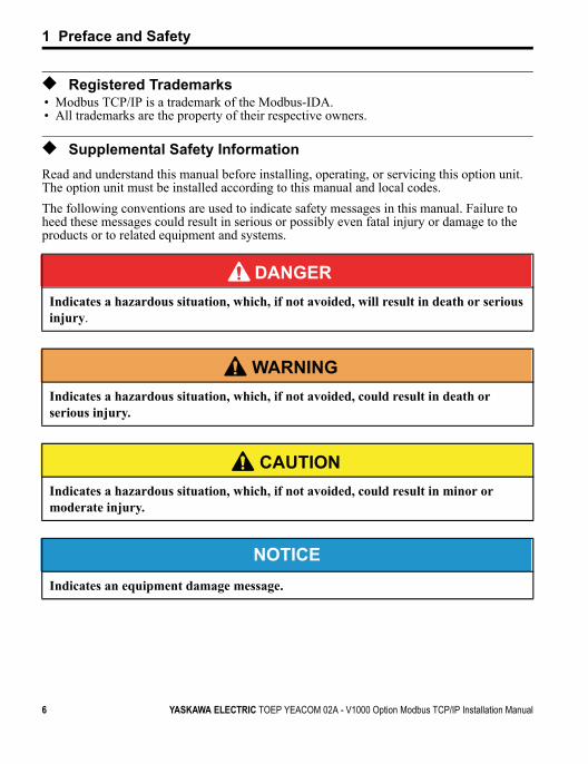
◆ Registered Trademarks• Modbus TCP/IP is a trademark of the Modbus-IDA.• All trademarks are the property of their respective owners.
◆ Supplemental Safety InformationRead and understand this manual before installing, operating, or servicing this option unit. The option unit must be installed according to this manual and local codes.The following conventions are used to indicate safety messages in this manual. Failure to heed these messages could result in serious or possibly even fatal injury or damage to the products or to related equipment and systems.
DANGERIndicates a hazardous situation, which, if not avoided, will result in death or serious injury.
W ARNING Indicates a hazardous situation, which, if not avoided, could result in death or serious injury.
CAUTION Indicates a hazardous situation, which, if not avoided, could result in minor or moderate injury.
NOTICEIndicates an equipment damage message.
6 YASKAWA ELECTRIC TOEP YEACOM 02A - V1000 Option Modbus TCP/IP Installation Manual
1 Preface and Safety
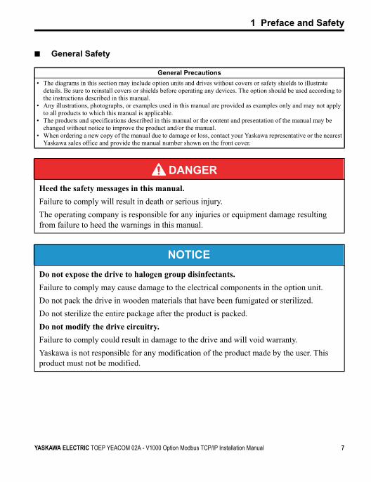
■ General Safety
General Precautions• The diagrams in this section may include option units and drives without covers or safety shields to illustrate
details. Be sure to reinstall covers or shields before operating any devices. The option should be used according to the instructions described in this manual.
• Any illustrations, photographs, or examples used in this manual are provided as examples only and may not apply to all products to which this manual is applicable.
• The products and specifications described in this manual or the content and presentation of the manual may be changed without notice to improve the product and/or the manual.
• When ordering a new copy of the manual due to damage or loss, contact your Yaskawa representative or the nearest Yaskawa sales office and provide the manual number shown on the front cover.
DANGERHeed the safety messages in this manual.Failure to comply will result in death or serious injury.The operating company is responsible for any injuries or equipment damage resulting from failure to heed the warnings in this manual.
NOTICEDo not expose the drive to halogen group disinfectants.Failure to comply may cause damage to the electrical components in the option unit. Do not pack the drive in wooden materials that have been fumigated or sterilized.Do not sterilize the entire package after the product is packed.Do not modify the drive circuitry.Failure to comply could result in damage to the drive and will void warranty. Yaskawa is not responsible for any modification of the product made by the user. This product must not be modified.
YASKAWA ELECTRIC TOEP YEACOM 02A - V1000 Option Modbus TCP/IP Installation Manual 7
1 Preface and Safety
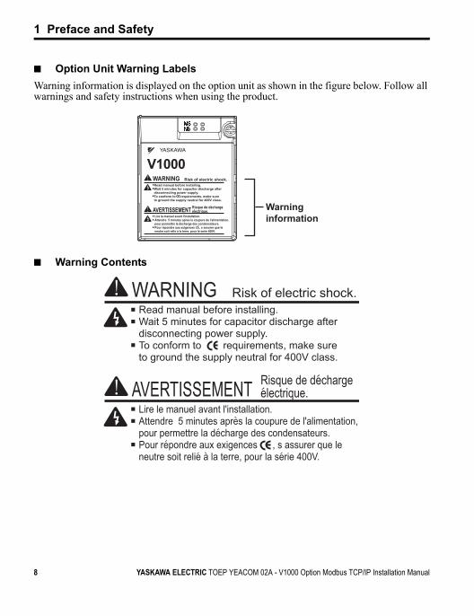
■ Option Unit Warning LabelsWarning information is displayed on the option unit as shown in the figure below. Follow all warnings and safety instructions when using the product.
■ Warning Contents
8 YASKAWA ELECTRIC TOEP YEACOM 02A - V1000 Option Modbus TCP/IP Installation Manual
2 Product Overview
2 Product Overview
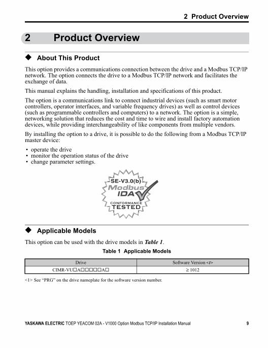
◆ About This ProductThis option provides a communications connection between the drive and a Modbus TCP/IP network. The option connects the drive to a Modbus TCP/IP network and facilitates the exchange of data.This manual explains the handling, installation and specifications of this product.The option is a communications link to connect industrial devices (such as smart motor controllers, operator interfaces, and variable frequency drives) as well as control devices (such as programmable controllers and computers) to a network. The option is a simple, networking solution that reduces the cost and time to wire and install factory automation devices, while providing interchangeability of like components from multiple vendors.By installing the option to a drive, it is possible to do the following from a Modbus TCP/IP master device:• operate the drive• monitor the operation status of the drive• change parameter settings.
◆ Applicable ModelsThis option can be used with the drive models in Table 1.
Table 1 Applicable Models
Drive Software Version <1>
<1> See “PRG” on the drive nameplate for the software version number.
CIMR-VU A A ≥ 1012
YASKAWA ELECTRIC TOEP YEACOM 02A - V1000 Option Modbus TCP/IP Installation Manual 9
3 Receiving
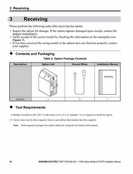
3 ReceivingPlease perform the following tasks after receiving the option.• Inspect the option for damage. If the option appears damaged upon receipt, contact the
shipper immediately.• Verify receipt of the correct model by checking the information on the nameplate (see
Figure 1).• If you have received the wrong model or the option does not function properly, contact
your supplier.
◆ Contents and PackagingTable 2 Option Package Contents
◆ Tool Requirements
Note: Tools required to prepare the option cables for wiring are not listed in this manual.
Description: Option Unit Ground Wires Installation Manual
_
Quantity: 1 4 1
A Phillips screwdriver (M3, M3.5 to M6 metric or #1, #2 U.S. standard <1>) is required to install the option.
<1> Screw sizes vary by drive capacity. Select a screwdriver that matches the drive capacity.
MANUAL
10 YASKAWA ELECTRIC TOEP YEACOM 02A - V1000 Option Modbus TCP/IP Installation Manual
4 Option Components
4 Option Components
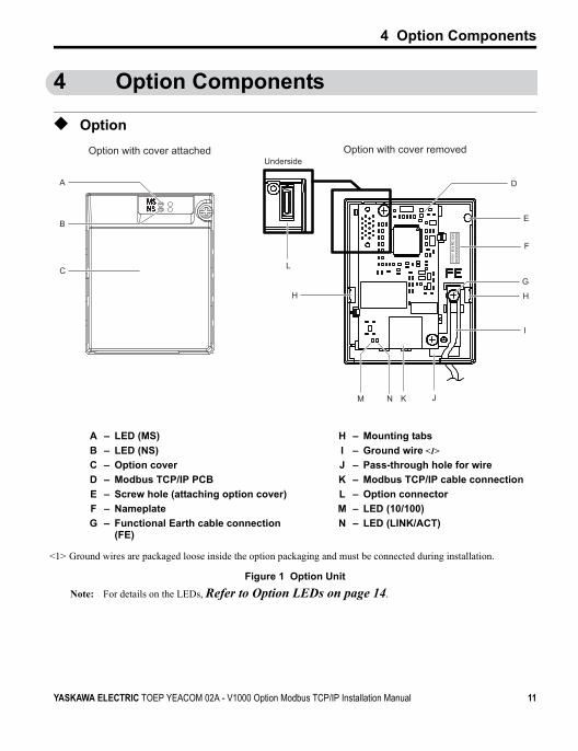
◆ OptionFigure 1
Figure 1 Option UnitNote: For details on the LEDs, Refer to Option LEDs on page 14.
A – LED (MS) H – Mounting tabsB – LED (NS) I – Ground wire <1>
C – Option cover J – Pass-through hole for wire
<1> Ground wires are packaged loose inside the option packaging and must be connected during installation.
D – Modbus TCP/IP PCB K – Modbus TCP/IP cable connectionE – Screw hole (attaching option cover) L – Option connectorF – Nameplate M – LED (10/100)G – Functional Earth cable connection
(FE)N – LED (LINK/ACT)
A
B
C
H
E
D
H
G
I
J
L
F
K
0000
0000
0000
00SI
-EN3
/V1X
XX
NM
Option with cover removedUnderside
Option with cover attached
YASKAWA ELECTRIC TOEP YEACOM 02A - V1000 Option Modbus TCP/IP Installation Manual 11
4 Option Components
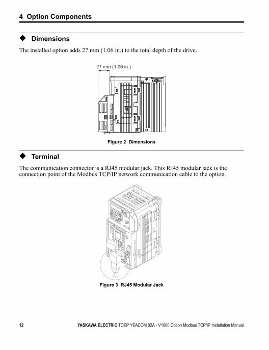
◆ DimensionsThe installed option adds 27 mm (1.06 in.) to the total depth of the drive.Figure 2
Figure 2 Dimensions
◆ TerminalThe communication connector is a RJ45 modular jack. This RJ45 modular jack is the connection point of the Modbus TCP/IP network communication cable to the option.Figure 3
Figure 3 RJ45 Modular Jack
27 mm (1.06 in.)
12 YASKAWA ELECTRIC TOEP YEACOM 02A - V1000 Option Modbus TCP/IP Installation Manual
4 Option Components
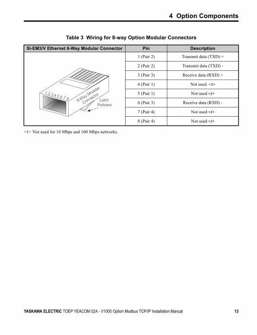
Table 3 Wiring for 8-way Option Modular Connectors
SI-EM3/V Ethernet 8-Way Modular Connector Pin Description
1 (Pair 2) Transmit data (TXD) +
2 (Pair 2) Transmit data (TXD) -
3 (Pair 3) Receive data (RXD) +
4 (Pair 1) Not used <1>
<1> Not used for 10 Mbps and 100 Mbps networks.
5 (Pair 1) Not used <1>
6 (Pair 3) Receive data (RXD) -
7 (Pair 4) Not used <1>
8 (Pair 4) Not used <1>
YASKAWA ELECTRIC TOEP YEACOM 02A - V1000 Option Modbus TCP/IP Installation Manual 13
4 Option Components
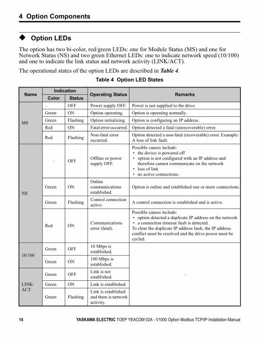
◆ Option LEDsThe option has two bi-color, red/green LEDs: one for Module Status (MS) and one for Network Status (NS) and two green Ethernet LEDs: one to indicate network speed (10/100) and one to indicate the link status and network activity (LINK/ACT).The operational states of the option LEDs are described in Table 4.
Table 4 Option LED States
NameIndication
Operating Status RemarksColor Status
MS
– OFF Power supply OFF. Power is not supplied to the drive.Green ON Option operating. Option is operating normally.Green Flashing Option initializing. Option is configuring an IP address.Red ON Fatal error occurred. Option detected a fatal (unrecoverable) error.
Red Flashing Non-fatal error occurred.
Option detected a non-fatal (recoverable) error. Example: A loss of link fault.
NS
– OFF Offline or power supply OFF.
Possible causes include:• the device is powered off• option is not configured with an IP address and
therefore cannot communicate on the network• loss of link• no active connections.
Green ONOnline communications established.
Option is online and established one or more connections.
Green Flashing Control connection active. A control connection is established and is active.
Red ON Communications error (fatal).
Possible causes include:• option detected a duplicate IP address on the network• a connection timeout fault is detected.To clear the duplicate IP address fault, the IP address conflict must be resolved and the drive power must be cycled.
10/100Green OFF 10 Mbps is
established.
–
Green ON 100 Mbps is established.
LINK/ACT
Green OFF Link is not established.
Green ON Link is established.
Green FlashingLink is established and there is network activity.
14 YASKAWA ELECTRIC TOEP YEACOM 02A - V1000 Option Modbus TCP/IP Installation Manual
5 Installation Procedure
5 Installation Procedure
◆ Section Safety
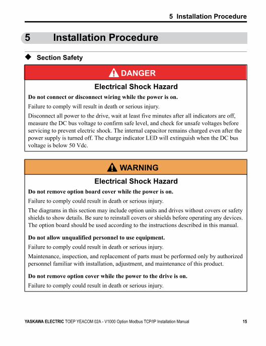
DANGERElectrical Shock Hazard
Do not connect or disconnect wiring while the power is on.Failure to comply will result in death or serious injury.Disconnect all power to the drive, wait at least five minutes after all indicators are off, measure the DC bus voltage to confirm safe level, and check for unsafe voltages before servicing to prevent electric shock. The internal capacitor remains charged even after the power supply is turned off. The charge indicator LED will extinguish when the DC bus voltage is below 50 Vdc.
W ARNING Electrical Shock Hazard
Do not remove option board cover while the power is on.Failure to comply could result in death or serious injury.The diagrams in this section may include option units and drives without covers or safety shields to show details. Be sure to reinstall covers or shields before operating any devices. The option board should be used according to the instructions described in this manual.
Do not allow unqualified personnel to use equipment.Failure to comply could result in death or serious injury.Maintenance, inspection, and replacement of parts must be performed only by authorized personnel familiar with installation, adjustment, and maintenance of this product.
Do not remove option cover while the power to the drive is on.Failure to comply could result in death or serious injury.
YASKAWA ELECTRIC TOEP YEACOM 02A - V1000 Option Modbus TCP/IP Installation Manual 15
5 Installation Procedure
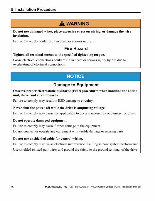
Do not use damaged wires, place excessive stress on wiring, or damage the wire insulation.Failure to comply could result in death or serious injury.
Fire HazardTighten all terminal screws to the specified tightening torque.Loose electrical connections could result in death or serious injury by fire due to overheating of electrical connections.
NOTICE
Damage to EquipmentObserve proper electrostatic discharge (ESD) procedures when handling the option unit, drive, and circuit boards.Failure to comply may result in ESD damage to circuitry.
Never shut the power off while the drive is outputting voltage.Failure to comply may cause the application to operate incorrectly or damage the drive.
Do not operate damaged equipment. Failure to comply may cause further damage to the equipment.Do not connect or operate any equipment with visible damage or missing parts.
Do not use unshielded cable for control wiring.Failure to comply may cause electrical interference resulting in poor system performance.Use shielded twisted-pair wires and ground the shield to the ground terminal of the drive.
W ARNING
16 YASKAWA ELECTRIC TOEP YEACOM 02A - V1000 Option Modbus TCP/IP Installation Manual
5 Installation Procedure
◆ Wiring Diagram
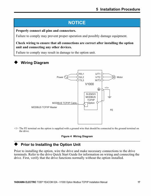
Figure 4 Wiring Diagram
◆ Prior to Installing the Option UnitPrior to installing the option, wire the drive and make necessary connections to the drive terminals. Refer to the drive Quick Start Guide for information on wiring and connecting the drive. First, verify that the drive functions normally without the option installed.
Properly connect all pins and connectors. Failure to comply may prevent proper operation and possibly damage equipment.
Check wiring to ensure that all connections are correct after installing the option unit and connecting any other devices. Failure to comply may result in damage to the option unit.
<1> The FE terminal on the option is supplied with a ground wire that should be connected to the ground terminal on the drive.
NOTICE
V1000
MU/T1V/T2W/T3
R/L1S/L2T/L3
SI-EM3/VMODBUS
TCP/IP Option
FE
<1>
MODBUS TCP/IP Master
MODBUS TCP/IP Cable
MotorPower
YASKAWA ELECTRIC TOEP YEACOM 02A - V1000 Option Modbus TCP/IP Installation Manual 17
5 Installation Procedure
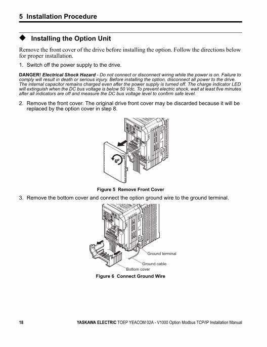
◆ Installing the Option UnitRemove the front cover of the drive before installing the option. Follow the directions below for proper installation.1. Switch off the power supply to the drive.
DANGER! Electrical Shock Hazard - Do not connect or disconnect wiring while the power is on. Failure to comply will result in death or serious injury. Before installing the option, disconnect all power to the drive. The internal capacitor remains charged even after the power supply is turned off. The charge indicator LED will extinguish when the DC bus voltage is below 50 Vdc. To prevent electric shock, wait at least five minutes after all indicators are off and measure the DC bus voltage level to confirm safe level.
2. Remove the front cover. The original drive front cover may be discarded because it will be replaced by the option cover in step 8.
Figure 4
Figure 5 Remove Front Cover
3. Remove the bottom cover and connect the option ground wire to the ground terminal.Figure 5
Figure 6 Connect Ground Wire
Ground terminal
Ground cableBottom cover
18 YASKAWA ELECTRIC TOEP YEACOM 02A - V1000 Option Modbus TCP/IP Installation Manual
5 Installation Procedure
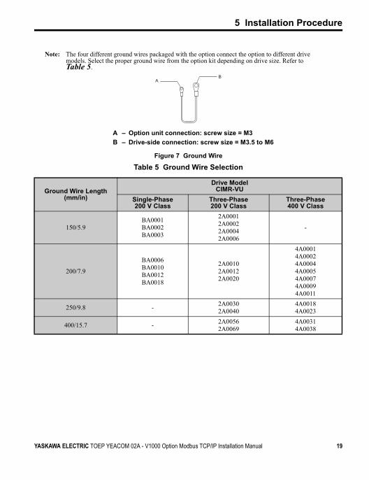
Note: The four different ground wires packaged with the option connect the option to different drive models. Select the proper ground wire from the option kit depending on drive size. Refer to Table 5.
Figure 6
Figure 7 Ground Wire
Table 5 Ground Wire Selection
A – Option unit connection: screw size = M3B – Drive-side connection: screw size = M3.5 to M6
Ground Wire Length (mm/in)
Drive ModelCIMR-VU
Single-Phase 200 V Class
Three-Phase 200 V Class
Three-Phase 400 V Class
150/5.9BA0001BA0002BA0003
2A00012A00022A00042A0006
-
200/7.9
BA0006BA0010BA0012BA0018
2A00102A00122A0020
4A00014A00024A00044A00054A00074A00094A0011
250/9.8 - 2A00302A0040
4A00184A0023
400/15.7 - 2A00562A0069
4A00314A0038
AB
YASKAWA ELECTRIC TOEP YEACOM 02A - V1000 Option Modbus TCP/IP Installation Manual 19
5 Installation Procedure
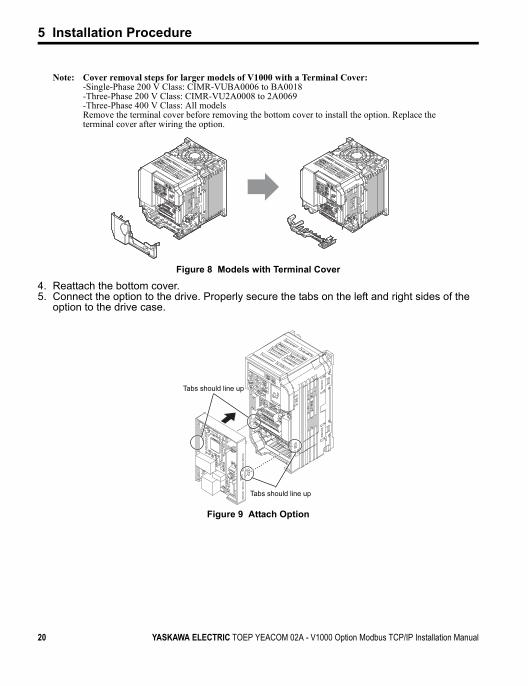
Note: Cover removal steps for larger models of V1000 with a Terminal Cover: -Single-Phase 200 V Class: CIMR-VUBA0006 to BA0018-Three-Phase 200 V Class: CIMR-VU2A0008 to 2A0069-Three-Phase 400 V Class: All modelsRemove the terminal cover before removing the bottom cover to install the option. Replace the terminal cover after wiring the option.
Figure 7
Figure 8 Models with Terminal Cover
4. Reattach the bottom cover.5. Connect the option to the drive. Properly secure the tabs on the left and right sides of the
option to the drive case. Figure 8
Figure 9 Attach Option
Tabs should line up
Tabs should line up
20 YASKAWA ELECTRIC TOEP YEACOM 02A - V1000 Option Modbus TCP/IP Installation Manual
5 Installation Procedure
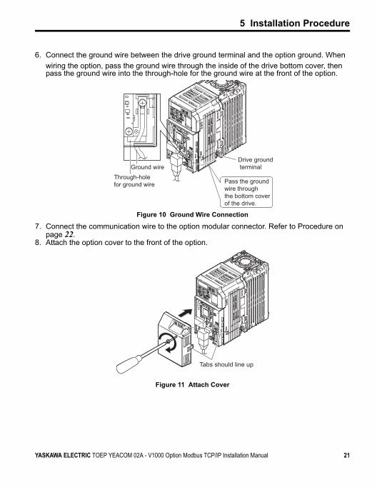
6. Connect the ground wire between the drive ground terminal and the option ground. When wiring the option, pass the ground wire through the inside of the drive bottom cover, then pass the ground wire into the through-hole for the ground wire at the front of the option.
Figure 9
Figure 10 Ground Wire Connection
7. Connect the communication wire to the option modular connector. Refer to Procedure on page 22.
8. Attach the option cover to the front of the option.Figure 10
Figure 11 Attach Cover
Drive ground terminal
Through-holefor ground wire
Ground wire
Pass the ground wire throughthe bottom cover of the drive.
Tabs should line up
YASKAWA ELECTRIC TOEP YEACOM 02A - V1000 Option Modbus TCP/IP Installation Manual 21
5 Installation Procedure
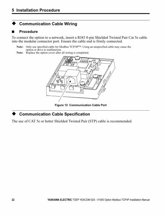
◆ Communication Cable Wiring
■ ProcedureTo connect the option to a network, insert a RJ45 8-pin Shielded Twisted Pair Cat 5e cable into the modular connector port. Ensure the cable end is firmly connected.
Note: Only use specified cable for Modbus TCP/IP™. Using an unspecified cable may cause the option or drive to malfunction.
Note: Replace the option cover after all wiring is completed.Figure 11
Figure 12 Communication Cable Port
◆ Communication Cable SpecificationThe use of CAT 5e or better Shielded Twisted Pair (STP) cable is recommended.
22 YASKAWA ELECTRIC TOEP YEACOM 02A - V1000 Option Modbus TCP/IP Installation Manual
6 Web Interface
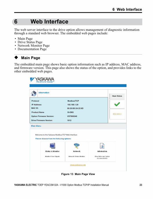
6 Web InterfaceThe web server interface to the drive option allows management of diagnostic information through a standard web browser. The embedded web pages include:• Main Page • Drive Status Page • Network Monitor Page• Documentation Page
◆ Main PageThe embedded main page shows basic option information such as IP address, MAC address, and firmware version. This page also shows the status of the option, and provides links to the other embedded web pages.Figure 12
Figure 13 Main Page View
Protocol
IP Address:
MAC ID:
Product Name
Option Firmware Version:
Drive Firmware Version: 1012
VST800240
SI-EM3
00:20:B5:24:22:6D
192.168.1.20
Modbus/TCP
Welcome to the Yaskawa Modbus/TCP Web Interface
YASKAWA ELECTRIC TOEP YEACOM 02A - V1000 Option Modbus TCP/IP Installation Manual 23
6 Web Interface
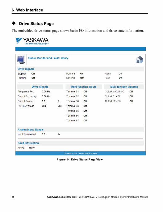
◆ Drive Status PageThe embedded drive status page shows basic I/O information and drive state information.Figure 13
Figure 14 Drive Status Page View
Hz
Hz
24 YASKAWA ELECTRIC TOEP YEACOM 02A - V1000 Option Modbus TCP/IP Installation Manual
6 Web Interface
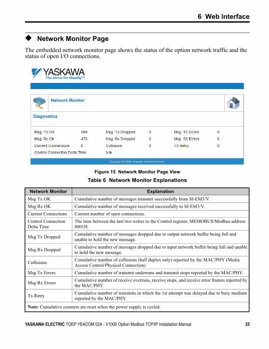
◆ Network Monitor PageThe embedded network monitor page shows the status of the option network traffic and the status of open I/O connections.Figure 14
Figure 15 Network Monitor Page View
Table 6 Network Monitor Explanations
Network Monitor ExplanationMsg Tx OK Cumulative number of messages transmit successfully from SI-EM3/V.Msg Rx OK Cumulative number of messages received successfully to SI-EM3/V.Current Connections Current number of open connections.Control Connection Delta Time
The time between the last two writes to the Control register, MEMOBUS/Modbus address 0001H.
Msg Tx Dropped Cumulative number of messages dropped due to output network buffer being full and unable to hold the new message.
Msg Rx Dropped Cumulative number of messages dropped due to input network buffer being full and unable to hold the new message.
Collisions Cumulative number of collisions (half duplex only) reported by the MAC/PHY (Media Access Control/Physical Connection)
Msg Tx Errors Cumulative number of transmit underruns and transmit stops reported by the MAC/PHY.
Msg Rx Errors Cumulative number of receive overruns, receive stops, and receive error frames reported by the MAC/PHY.
Tx Retry Cumulative number of transmits in which the 1st attempt was delayed due to busy medium reported by the MAC/PHY.
Note: Cumulative counters are reset when the power supply is cycled.
YASKAWA ELECTRIC TOEP YEACOM 02A - V1000 Option Modbus TCP/IP Installation Manual 25
6 Web Interface
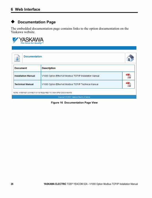
◆ Documentation PageThe embedded documentation page contains links to the option documentation on the Yaskawa website.Figure 15
Figure 16 Documentation Page View
26 YASKAWA ELECTRIC TOEP YEACOM 02A - V1000 Option Modbus TCP/IP Installation Manual
7 Option Drive Parameters
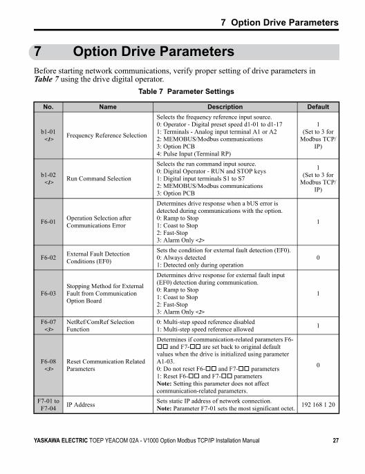
7 Option Drive ParametersBefore starting network communications, verify proper setting of drive parameters in Table 7 using the drive digital operator.
Table 7 Parameter Settings
No. Name Description Default
b1-01<1>
Frequency Reference Selection
Selects the frequency reference input source.0: Operator - Digital preset speed d1-01 to d1-171: Terminals - Analog input terminal A1 or A22: MEMOBUS/Modbus communications 3: Option PCB4: Pulse Input (Terminal RP)
1 (Set to 3 for
Modbus TCP/IP)
b1-02<1>
Run Command Selection
Selects the run command input source.0: Digital Operator - RUN and STOP keys1: Digital input terminals S1 to S7 2: MEMOBUS/Modbus communications 3: Option PCB
1 (Set to 3 for
Modbus TCP/IP)
F6-01 Operation Selection after Communications Error
Determines drive response when a bUS error is detected during communications with the option.0: Ramp to Stop 1: Coast to Stop2: Fast-Stop3: Alarm Only <2>
1
F6-02 External Fault Detection Conditions (EF0)
Sets the condition for external fault detection (EF0).0: Always detected1: Detected only during operation
0
F6-03Stopping Method for External Fault from Communication Option Board
Determines drive response for external fault input (EF0) detection during communication.0: Ramp to Stop 1: Coast to Stop2: Fast-Stop3: Alarm Only <2>
1
F6-07<3>
NetRef/ComRef Selection Function
0: Multi-step speed reference disabled1: Multi-step speed reference allowed 1
F6-08<3>
Reset Communication Related Parameters
Determines if communication-related parameters F6- and F7- are set back to original default
values when the drive is initialized using parameter A1-03.0: Do not reset F6- and F7- parameters1: Reset F6- and F7- parametersNote: Setting this parameter does not affect communication-related parameters.
0
F7-01 toF7-04 IP Address Sets static IP address of network connection.
Note: Parameter F7-01 sets the most significant octet. 192 168 1 20
YASKAWA ELECTRIC TOEP YEACOM 02A - V1000 Option Modbus TCP/IP Installation Manual 27
7 Option Drive Parameters
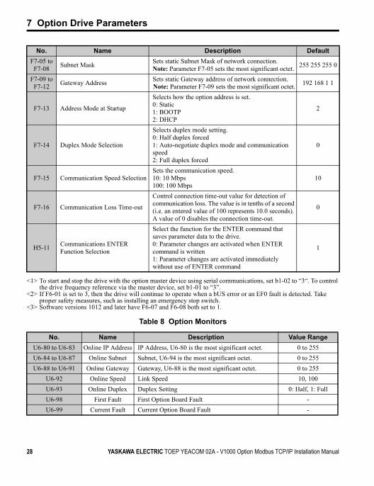
Table 8 Option Monitors
F7-05 toF7-08 Subnet Mask Sets static Subnet Mask of network connection.
Note: Parameter F7-05 sets the most significant octet. 255 255 255 0
F7-09 toF7-12 Gateway Address Sets static Gateway address of network connection.
Note: Parameter F7-09 sets the most significant octet. 192 168 1 1
F7-13 Address Mode at Startup
Selects how the option address is set.0: Static1: BOOTP2: DHCP
2
F7-14 Duplex Mode Selection
Selects duplex mode setting.0: Half duplex forced1: Auto-negotiate duplex mode and communication speed2: Full duplex forced
0
F7-15 Communication Speed SelectionSets the communication speed.10: 10 Mbps100: 100 Mbps
10
F7-16 Communication Loss Time-out
Control connection time-out value for detection of communication loss. The value is in tenths of a second (i.e. an entered value of 100 represents 10.0 seconds). A value of 0 disables the connection time-out.
0
H5-11 Communications ENTER Function Selection
Select the function for the ENTER command that saves parameter data to the drive.0: Parameter changes are activated when ENTER command is written1: Parameter changes are activated immediately without use of ENTER command
1
<1> To start and stop the drive with the option master device using serial communications, set b1-02 to “3“. To control the drive frequency reference via the master device, set b1-01 to “3”.
<2> If F6-01 is set to 3, then the drive will continue to operate when a bUS error or an EF0 fault is detected. Take proper safety measures, such as installing an emergency stop switch.
<3> Software versions 1012 and later have F6-07 and F6-08 both set to 1.
No. Name Description Value RangeU6-80 to U6-83 Online IP Address IP Address, U6-80 is the most significant octet. 0 to 255U6-84 to U6-87 Online Subnet Subnet, U6-94 is the most significant octet. 0 to 255U6-88 to U6-91 Online Gateway Gateway, U6-88 is the most significant octet. 0 to 255
U6-92 Online Speed Link Speed 10, 100U6-93 Online Duplex Duplex Setting 0: Half, 1: FullU6-98 First Fault First Option Board Fault -U6-99 Current Fault Current Option Board Fault -
No. Name Description Default
28 YASKAWA ELECTRIC TOEP YEACOM 02A - V1000 Option Modbus TCP/IP Installation Manual
8 Modbus TCP/IP Messaging
8 Modbus TCP/IP Messaging
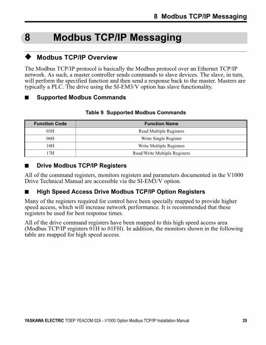
◆ Modbus TCP/IP OverviewThe Modbus TCP/IP protocol is basically the Modbus protocol over an Ethernet TCP/IP network. As such, a master controller sends commands to slave devices. The slave, in turn, will perform the specified function and then send a response back to the master. Masters are typically a PLC. The drive using the SI-EM3/V option has slave functionality.
■ Supported Modbus Commands
Table 9 Supported Modbus Commands
■ Drive Modbus TCP/IP RegistersAll of the command registers, monitors registers and parameters documented in the V1000 Drive Technical Manual are accessible via the SI-EM3/V option.
■ High Speed Access Drive Modbus TCP/IP Option RegistersMany of the registers required for control have been specially mapped to provide higher speed access, which will increase network performance. It is recommended that these registers be used for best response times.All of the drive command registers have been mapped to this high speed access area (Modbus TCP/IP registers 01H to 01FH). In addition, the monitors shown in the following table are mapped for high speed access.
Function Code Function Name03H Read Multiple Registers06H Write Single Register10H Write Multiple Registers17H Read/Write Multiple Registers
YASKAWA ELECTRIC TOEP YEACOM 02A - V1000 Option Modbus TCP/IP Installation Manual 29
8 Modbus TCP/IP Messaging
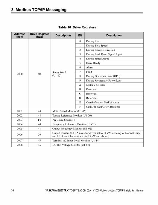
Table 10 Drive Registers
Address (hex)
Drive Register (hex) Description Bit Description
2000 4B Status Word (U1-12)
0 During Run1 During Zero Speed2 During Reverse Direction3 During Fault Reset Signal Input4 During Speed Agree5 Drive Ready6 Alarm7 Fault8 During Operation Error (OPE)9 During Momentary Power LossA Motor 2 SelectedB ReservedC ReservedD ReservedE ComRef status, NetRef statusF ComCtrl status, NetCtrl status
2001 44 Motor Speed Monitor (U1-05)2002 48 Torque Reference Monitor (U1-09)2003 F0 PG Count Channel 12004 40 Frequency Reference Monitor (U1-01)2005 41 Output Frequency Monitor (U1-02)
2006 26 Output Current (0.01 A units for drives set to 11 kW in Heavy or Normal Duty and 0.1 A units for drives set to 15 kW and above.)
2007 4F Terminal A2 Input Level Monitor (U1-14)2008 46 DC Bus Voltage Monitor (U1-07)
30 YASKAWA ELECTRIC TOEP YEACOM 02A - V1000 Option Modbus TCP/IP Installation Manual
8 Modbus TCP/IP Messaging
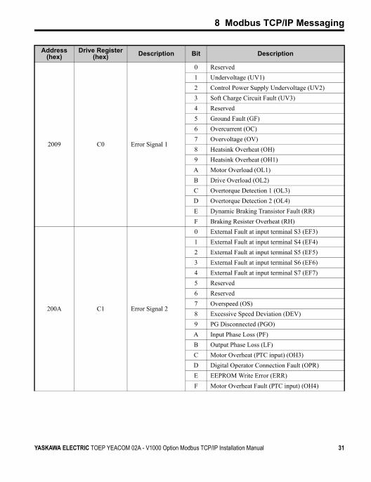
2009 C0 Error Signal 1
0 Reserved1 Undervoltage (UV1)2 Control Power Supply Undervoltage (UV2)3 Soft Charge Circuit Fault (UV3)4 Reserved5 Ground Fault (GF)6 Overcurrent (OC)7 Overvoltage (OV)8 Heatsink Overheat (OH)9 Heatsink Overheat (OH1)A Motor Overload (OL1)B Drive Overload (OL2)C Overtorque Detection 1 (OL3)D Overtorque Detection 2 (OL4)E Dynamic Braking Transistor Fault (RR)F Braking Resister Overheat (RH)
200A C1 Error Signal 2
0 External Fault at input terminal S3 (EF3)1 External Fault at input terminal S4 (EF4)2 External Fault at input terminal S5 (EF5)3 External Fault at input terminal S6 (EF6)4 External Fault at input terminal S7 (EF7)5 Reserved6 Reserved7 Overspeed (OS)8 Excessive Speed Deviation (DEV)9 PG Disconnected (PGO)A Input Phase Loss (PF)B Output Phase Loss (LF)C Motor Overheat (PTC input) (OH3)D Digital Operator Connection Fault (OPR)E EEPROM Write Error (ERR)F Motor Overheat Fault (PTC input) (OH4)
Address (hex)
Drive Register (hex) Description Bit Description
YASKAWA ELECTRIC TOEP YEACOM 02A - V1000 Option Modbus TCP/IP Installation Manual 31
8 Modbus TCP/IP Messaging
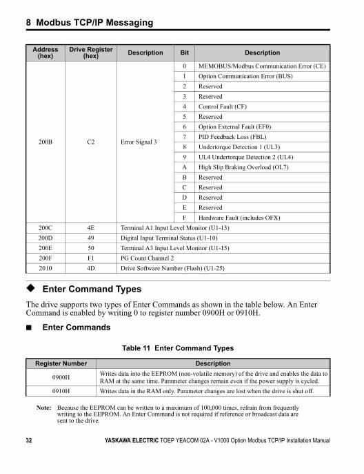
◆ Enter Command TypesThe drive supports two types of Enter Commands as shown in the table below. An Enter Command is enabled by writing 0 to register number 0900H or 0910H.
■ Enter Commands
Table 11 Enter Command Types
Note: Because the EEPROM can be written to a maximum of 100,000 times, refrain from frequently writing to the EEPROM. An Enter Command is not required if reference or broadcast data are sent to the drive.
200B C2 Error Signal 3
0 MEMOBUS/Modbus Communication Error (CE)1 Option Communication Error (BUS)2 Reserved3 Reserved4 Control Fault (CF)5 Reserved6 Option External Fault (EF0)7 PID Feedback Loss (FBL)8 Undertorque Detection 1 (UL3)9 UL4 Undertorque Detection 2 (UL4)A High Slip Braking Overload (OL7)B ReservedC ReservedD ReservedE ReservedF Hardware Fault (includes OFX)
200C 4E Terminal A1 Input Level Monitor (U1-13)200D 49 Digital Input Terminal Status (U1-10)200E 50 Terminal A3 Input Level Monitor (U1-15)200F F1 PG Count Channel 22010 4D Drive Software Number (Flash) (U1-25)
Register Number Description
0900H Writes data into the EEPROM (non-volatile memory) of the drive and enables the data to RAM at the same time. Parameter changes remain even if the power supply is cycled.
0910H Writes data in the RAM only. Parameter changes are lost when the drive is shut off.
Address (hex)
Drive Register (hex) Description Bit Description
32 YASKAWA ELECTRIC TOEP YEACOM 02A - V1000 Option Modbus TCP/IP Installation Manual
8 Modbus TCP/IP Messaging
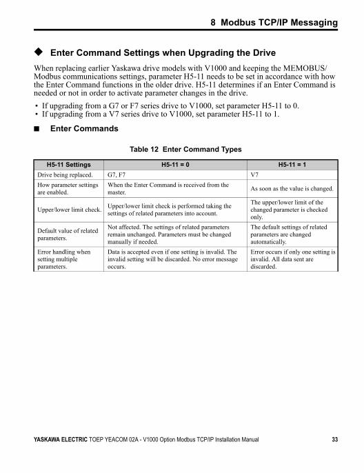
◆ Enter Command Settings when Upgrading the DriveWhen replacing earlier Yaskawa drive models with V1000 and keeping the MEMOBUS/Modbus communications settings, parameter H5-11 needs to be set in accordance with how the Enter Command functions in the older drive. H5-11 determines if an Enter Command is needed or not in order to activate parameter changes in the drive.• If upgrading from a G7 or F7 series drive to V1000, set parameter H5-11 to 0.• If upgrading from a V7 series drive to V1000, set parameter H5-11 to 1.
■ Enter Commands
Table 12 Enter Command Types
H5-11 Settings H5-11 = 0 H5-11 = 1Drive being replaced. G7, F7 V7How parameter settings are enabled.
When the Enter Command is received from the master. As soon as the value is changed.
Upper/lower limit check. Upper/lower limit check is performed taking the settings of related parameters into account.
The upper/lower limit of the changed parameter is checked only.
Default value of related parameters.
Not affected. The settings of related parameters remain unchanged. Parameters must be changed manually if needed.
The default settings of related parameters are changed automatically.
Error handling when setting multiple parameters.
Data is accepted even if one setting is invalid. The invalid setting will be discarded. No error message occurs.
Error occurs if only one setting is invalid. All data sent are discarded.
YASKAWA ELECTRIC TOEP YEACOM 02A - V1000 Option Modbus TCP/IP Installation Manual 33

9 Troubleshooting
9 Troubleshooting
◆ Drive-Side Error CodesDrive-side error codes appear on the drive digital operator. Causes of the errors and corrective actions are listed in Table 13. For additional error codes that may appear on the drive digital operator, refer to the drive technical manual.
■ FaultsBoth bUS (Option Communication Error) and EF0 (External Fault Input from the option) can appear as an alarm or as a fault. When a fault occurs, the digital operator ALM LED remains lit. When an alarm occurs, the ALM LED flashes.If communication stops while the drive is running, use the following questions as a guide to help remedy the fault:• Is the option properly installed?• Is the communication line properly connected to the option? Is it loose?• Is the controller program working? Has the controller/PLC CPU stopped?• Did a momentary power loss interrupt communications?
Table 13 Fault Display and Possible Solutions
LED Operator Display Fault Name
bUS
Option Communication Error.• After establishing initial communication, the connection was lost• Only detected when the run command or frequency reference is assigned
to the option (b1-01 = 3 or b1-02 = 3)Cause Possible Solution
Master controller (PLC) has stopped communicating.
• Check that power is supplied to the PLC• Check that PLC is not in program mode
Communication cable is not connected properly.
• Check for faulty wiring• Correct any wiring problems
Option is damaged. If there are no problems with the wiring and the error continues to occur, replace the option.
Control Connection Time-out.
• Option did not receive a command (write to Modbus Address 01H) within the time-out period specified in parameter F7-16
• Check value programmed in F7-16• Check if PLC program stopped running
Duplicate IP Address. The option shares IP Address with at least one other node.
34 YASKAWA ELECTRIC TOEP YEACOM 02A - V1000 Option Modbus TCP/IP Installation Manual
9 Troubleshooting
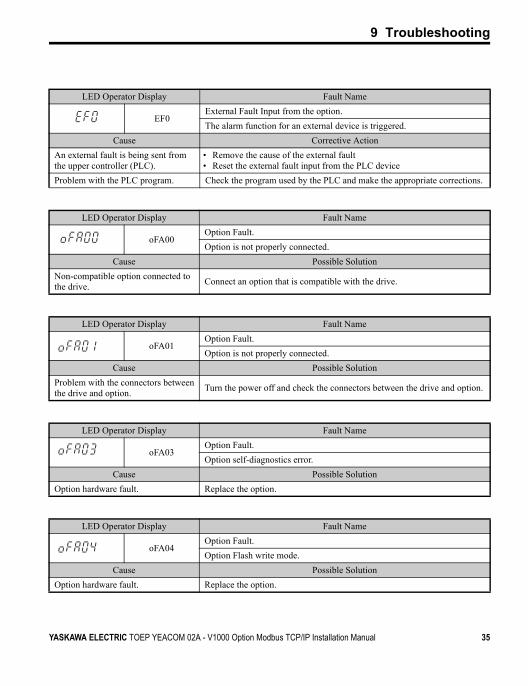
LED Operator Display Fault Name
EF0External Fault Input from the option.The alarm function for an external device is triggered.
Cause Corrective ActionAn external fault is being sent from the upper controller (PLC).
• Remove the cause of the external fault• Reset the external fault input from the PLC device
Problem with the PLC program. Check the program used by the PLC and make the appropriate corrections.
LED Operator Display Fault Name
oFA00Option Fault.Option is not properly connected.
Cause Possible SolutionNon-compatible option connected to the drive. Connect an option that is compatible with the drive.
LED Operator Display Fault Name
oFA01Option Fault.Option is not properly connected.
Cause Possible SolutionProblem with the connectors between the drive and option. Turn the power off and check the connectors between the drive and option.
LED Operator Display Fault Name
oFA03Option Fault.Option self-diagnostics error.
Cause Possible SolutionOption hardware fault. Replace the option.
LED Operator Display Fault Name
oFA04Option Fault.Option Flash write mode.
Cause Possible SolutionOption hardware fault. Replace the option.
YASKAWA ELECTRIC TOEP YEACOM 02A - V1000 Option Modbus TCP/IP Installation Manual 35
9 Troubleshooting
■ Minor Faults and Alarms
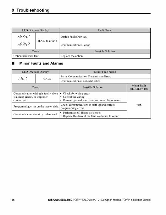
LED Operator Display Fault Name
to oFA30 to oFA43
Option Fault (Port A).
Communication ID error.
Cause Possible SolutionOption hardware fault. Replace the option.
LED Operator Display Minor Fault Name
CALLSerial Communication Transmission Error.Communication is not established.
Cause Possible Solution Minor Fault (H2- = 10)
Communication wiring is faulty, there is a short circuit, or improper connection.
• Check for wiring errors• Correct the wiring• Remove ground shorts and reconnect loose wires
YESProgramming error on the master side. Check communications at start-up and correct programming errors.
Communication circuitry is damaged. • Perform a self-diagnostics check• Replace the drive if the fault continues to occur
36 YASKAWA ELECTRIC TOEP YEACOM 02A - V1000 Option Modbus TCP/IP Installation Manual
9 Troubleshooting
◆ Option Error Codes
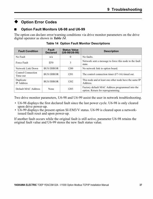
■ Option Fault Monitors U6-98 and U6-99The option can declare error/warning conditions via drive monitor parameters on the drive digital operator as shown in Table 14.
Table 14 Option Fault Monitor Descriptions
Two drive monitor parameters, U6-98 and U6-99 assist the user in network troubleshooting.• U6-98 displays the first declared fault since the last power cycle. U6-98 is only cleared
upon drive power-up.• U6-99 displays the present option SI-EM3/V status. U6-99 is cleared upon a network-
issued fault reset and upon power-up.If another fault occurs while the original fault is still active, parameter U6-98 retains the original fault value and U6-99 stores the new fault status value.
Fault Condition Fault Declared
Status Value(U6-98/U6-99) Description
No Fault n/a 0 No faults.
Force Fault EF0 3 Network sent a message to force this node to the fault state.
Network Link Down BUS ERROR 1200 No network link to option board.Control Connection Time-out BUS ERROR 1201 The control connection timer (F7-16) timed out.
Duplicate IP Address BUS ERROR 1202 This node and at least one other node have the same IP
Address.
Default MAC Address None 1203 Factory default MAC Address programmed into the option. Return for reprogramming.
YASKAWA ELECTRIC TOEP YEACOM 02A - V1000 Option Modbus TCP/IP Installation Manual 37
10 Specifications
10 Specifications
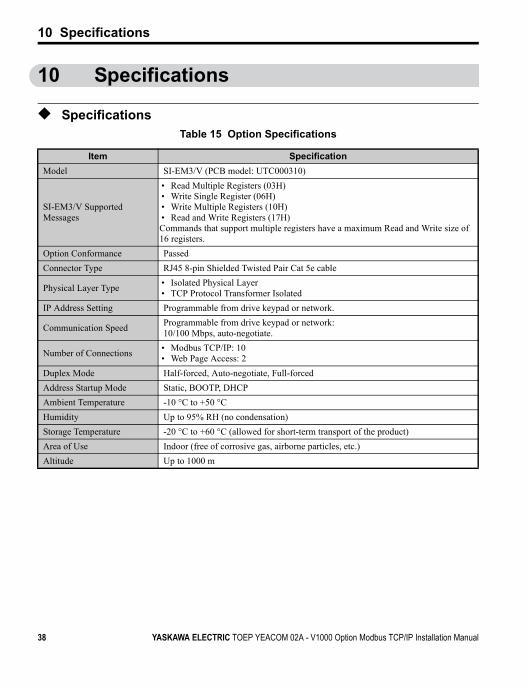
◆ SpecificationsTable 15 Option Specifications
Item SpecificationModel SI-EM3/V (PCB model: UTC000310)
SI-EM3/V Supported Messages
• Read Multiple Registers (03H)• Write Single Register (06H)• Write Multiple Registers (10H)• Read and Write Registers (17H)Commands that support multiple registers have a maximum Read and Write size of 16 registers.
Option Conformance PassedConnector Type RJ45 8-pin Shielded Twisted Pair Cat 5e cable
Physical Layer Type • Isolated Physical Layer• TCP Protocol Transformer Isolated
IP Address Setting Programmable from drive keypad or network.
Communication Speed Programmable from drive keypad or network:10/100 Mbps, auto-negotiate.
Number of Connections • Modbus TCP/IP: 10• Web Page Access: 2
Duplex Mode Half-forced, Auto-negotiate, Full-forcedAddress Startup Mode Static, BOOTP, DHCPAmbient Temperature -10 °C to +50 °CHumidity Up to 95% RH (no condensation)Storage Temperature -20 °C to +60 °C (allowed for short-term transport of the product)Area of Use Indoor (free of corrosive gas, airborne particles, etc.)Altitude Up to 1000 m
38 YASKAWA ELECTRIC TOEP YEACOM 02A - V1000 Option Modbus TCP/IP Installation Manual
10 Specifications
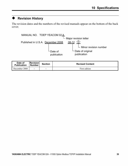
◆ Revision HistoryThe revision dates and the numbers of the revised manuals appear on the bottom of the back cover.
Date of Publication
Revision Number Section Revised Content
December 2008 − − First edition
Published in U.S.A. December 2008 08-12
Date of publication
Date of original publication
Minor revision number
1Major revision letter
MANUAL NO. TOEP YEACOM 02 A
YASKAWA ELECTRIC TOEP YEACOM 02A - V1000 Option Modbus TCP/IP Installation Manual 39
Modbus TCP/IPYASKAWA AC Drive-V1000 Option
Installation Manual
YASKAWA ELECTRIC AMERICA, INC.2121 Norman Drive South, Waukegan, IL 60085, U.S.A.Phone: 1-847-887-7000 or (800)YASKAWA (800-927-5292) Fax: 1-847-887-7370Internet: http://www.yaskawa.com
YASKAWA ELETRICO DO BRASIL LTDA.Avenida Fagundes Filho, 620 Sao Paulo-SP CEP 04304-000, Brazil Phone 55-11-3585-1100 Fax 55-11-5581-8795Internet: http://www.yaskawa.com.br
YASKAWA ELECTRIC AMERICA INC.
In the event that the end user of this product is to be the military and said product is to be employed in any weapons systems or the manufacture thereof, the export will fall under the relevant regulations as stipulated in the Foreign Exchange and Foreign Trade Regulations. Therefore, be sure to follow all procedures and submit all relevant documentation according to any and all rules, regulations and laws that may apply.
Specifications are subject to change without notice for ongoing product modifications and improvements.
© 2008 YASKAWA ELECTRIC AMERICA INC. All rights reserved.
YASKAWA
Published in U.S.A December 2008 08-12
MANUAL NO. TOEP YEACOM 02A