Embed Size (px)
Citation preview
713
Yeager Airport: Deconstruction and Reconstruction of the Side of a Mountain
Allen Cadden, P.E., D.GE1, Gary Brill, P.E.2, and Michael Senior, E.I.T.3
1Schnabel Engineering, 3 Dickinson Drive, Suite 200, Chadds Ford, PA 19317; e-mail: [email protected] 2Schnabel Engineering, 3502 Overlook Circle, Knoxville, TN 37909; e-mail: [email protected] 3Schnabel Engineering, 3 Dickinson Drive, Suite 200, Chadds Ford, PA 19317; e-mail: [email protected] ABSTRACT On March 12, 2015, the Runway Safety Area (RSA) and Engineered Material Arresting System (EMAS) were destroyed when the 73 m (240 ft) high reinforced soil slope failed at Yeager Airport in Charleston, West Virginia. The result of the structural fill failure was a near vertical soil face in the remnant fill over a massive debris field extending over Keystone Drive and Elk Two Mile Creek. The airport authority selected an engineering firm to develop emergency mitigation plans to stabilize the resulting 48 m (160 ft) near vertical head scarp and the massive lower debris field. The mitigation plans were necessary for the safe removal of approximately 413,000 cubic meters (540,000 cubic yards) of debris and to allow installation of long-term monitoring and safe working conditions for forensic investigations. The mitigation plans included temporary surface drainage, erosion protection, staging and access requirements, the design of waste fills, and emergency contingencies should the head scarp area fail farther during removal efforts. The cleanup and stabilization of the area resulted in the displacement of the Runway 5 threshold and the shortening of the usable length of Runway 5-23. The 1.5H:1V soil slopes with some steeper rock exposed areas was a temporary configuration. It was critical to restore safety features and normal operations as quickly as possible once the debris was removed. This paper will present the mitigation and safety challenges posed by the post-failure site conditions, as well as the reconstruction efforts to restore the EMAS. INTRODUCTION Yeager Airport is located on top of a series of hills and mountains in Charleston, West Virginia. Completion of the original airport construction in the 1940s consisted of earthwork estimated to be 6.9 million cubic meters (9 million cubic yards) of soil and rock (Keller, 2017). In 2005, due to FAA Safety Requirements, it was necessary to construct a safety area at the end of Runway 5 with EMAS approximately 150 meters (500 ft) in length. Approximately 765,000 cubic meters (1 million cubic yards) of fill was placed, in part as a Reinforced Soil Slope (RSS) and a 1.5H:1V unreinforced slope, to build the safety area. The RSS slope zone was 73 m (240 ft) tall at a 1H:1V slope. The RSS slope constructed between August 2005 and December 2006 failed in March 2015. The failed slope is shown in Figure 1. The RSS slope failure destroyed multiple
714
homes, a church, blocked Elk Two Mile Creek resulting in major flood damage to upstream homes, and disrupted airport operations. The slope failure also damaged power lines, sanitary sewer lines, storm sewer lines, and completely blocked a key corridor road in northeast Charleston.
Figure 1. Aerial view of the 2008 failed EMAS slope.
As part of the restoration plan after the 2015 slope failure, approximately 413,000 cubic meters (540,000 cubic yards) of soil backfill was removed from the end of Runway 5-23 from the summer of 2015 to December 2016. Emergency Runway 5 Safety Area & Slope Mitigation work was carried out in 3 construction phases and was completed in 2017. The deconstruction included a list of upfront challenges and uncertainties that impacted safety and mitigation design: materials used, in situ density and strength, remnant grid limits, and the unknown slope failure mechanism. As such, risk was a foremost consideration for the Airport Authority as well as the engineers.
Two of the most critical risk concerns of the authority were personnel safety (workers as well as the public), and the risk of further movements causing a blockage and repeated flooding of Elk Two Mile Creek. SLOPE DECONSTRUCTION Phase 1 of the deconstruction was an emergency response and focused on stabilizing the upper portion of the slope face. This near vertical soil face approximately 48 m (160 ft) high is shown in Figures 1 and 2 with the most critical area referred to as the Chimney, jutting out in front of the main face line. Visibly widening tension cracks on the remaining EMAS fill surface and large portions of the face breaking away, reinforced the need to take action quickly in an effort to limit further damage to the valley below. The observed instability posed safety concerns to
715
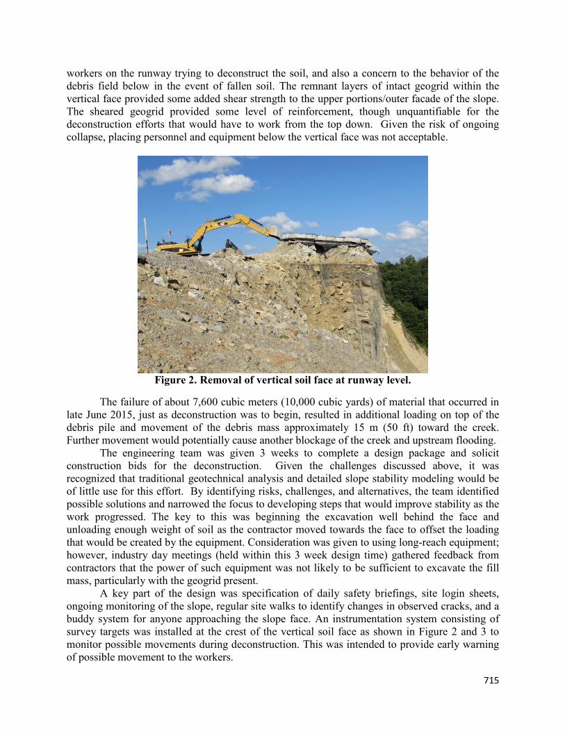
workers on the runway trying to deconstruct the soil, and also a concern to the behavior of the debris field below in the event of fallen soil. The remnant layers of intact geogrid within the vertical face provided some added shear strength to the upper portions/outer facade of the slope. The sheared geogrid provided some level of reinforcement, though unquantifiable for the deconstruction efforts that would have to work from the top down. Given the risk of ongoing collapse, placing personnel and equipment below the vertical face was not acceptable.
Figure 2. Removal of vertical soil face at runway level.
The failure of about 7,600 cubic meters (10,000 cubic yards) of material that occurred in late June 2015, just as deconstruction was to begin, resulted in additional loading on top of the debris pile and movement of the debris mass approximately 15 m (50 ft) toward the creek. Further movement would potentially cause another blockage of the creek and upstream flooding.
The engineering team was given 3 weeks to complete a design package and solicit construction bids for the deconstruction. Given the challenges discussed above, it was recognized that traditional geotechnical analysis and detailed slope stability modeling would be of little use for this effort. By identifying risks, challenges, and alternatives, the team identified possible solutions and narrowed the focus to developing steps that would improve stability as the work progressed. The key to this was beginning the excavation well behind the face and unloading enough weight of soil as the contractor moved towards the face to offset the loading that would be created by the equipment. Consideration was given to using long-reach equipment; however, industry day meetings (held within this 3 week design time) gathered feedback from contractors that the power of such equipment was not likely to be sufficient to excavate the fill mass, particularly with the geogrid present.
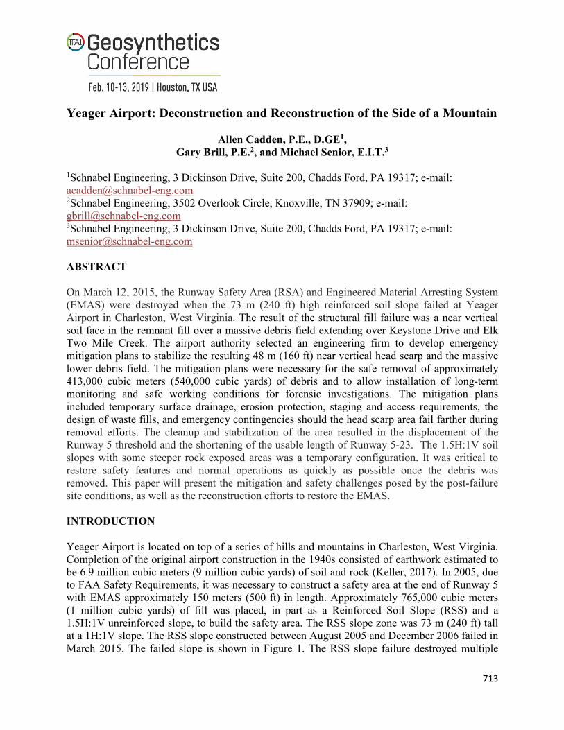
A key part of the design was specification of daily safety briefings, site login sheets, ongoing monitoring of the slope, regular site walks to identify changes in observed cracks, and a buddy system for anyone approaching the slope face. An instrumentation system consisting of survey targets was installed at the crest of the vertical soil face as shown in Figure 2 and 3 to monitor possible movements during deconstruction. This was intended to provide early warning of possible movement to the workers.
716
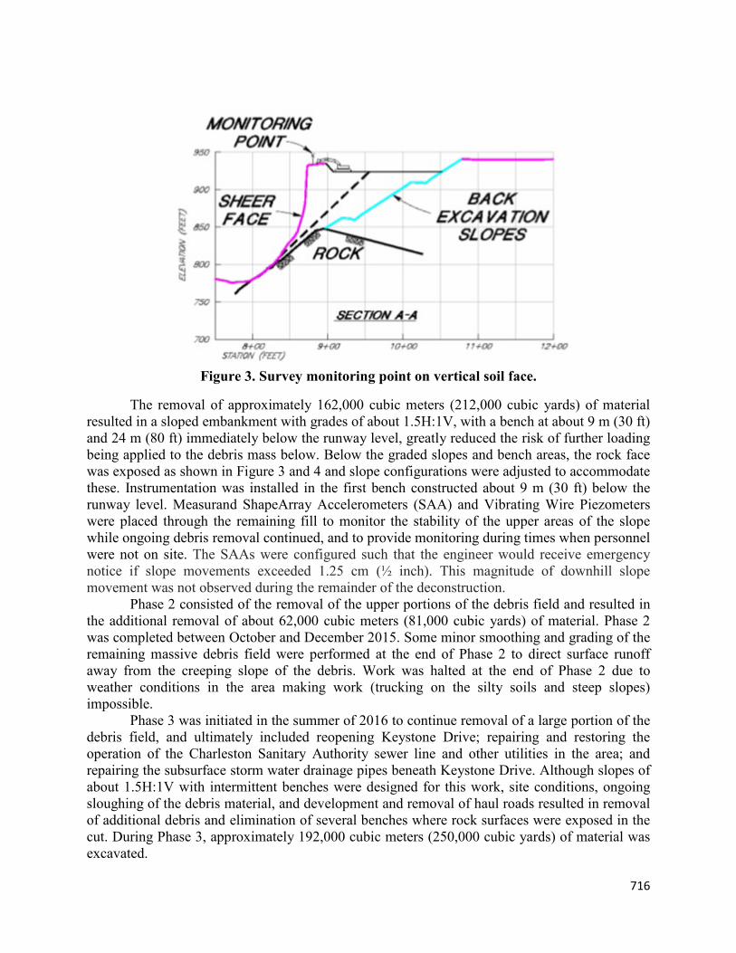
Figure 3. Survey monitoring point on vertical soil face.
The removal of approximately 162,000 cubic meters (212,000 cubic yards) of material resulted in a sloped embankment with grades of about 1.5H:1V, with a bench at about 9 m (30 ft) and 24 m (80 ft) immediately below the runway level, greatly reduced the risk of further loading being applied to the debris mass below. Below the graded slopes and bench areas, the rock face was exposed as shown in Figure 3 and 4 and slope configurations were adjusted to accommodate these. Instrumentation was installed in the first bench constructed about 9 m (30 ft) below the runway level. Measurand ShapeArray Accelerometers (SAA) and Vibrating Wire Piezometers were placed through the remaining fill to monitor the stability of the upper areas of the slope while ongoing debris removal continued, and to provide monitoring during times when personnel were not on site. The SAAs were configured such that the engineer would receive emergency notice if slope movements exceeded 1.25 cm (½ inch). This magnitude of downhill slope movement was not observed during the remainder of the deconstruction.
Phase 2 consisted of the removal of the upper portions of the debris field and resulted in the additional removal of about 62,000 cubic meters (81,000 cubic yards) of material. Phase 2 was completed between October and December 2015. Some minor smoothing and grading of the remaining massive debris field were performed at the end of Phase 2 to direct surface runoff away from the creeping slope of the debris. Work was halted at the end of Phase 2 due to weather conditions in the area making work (trucking on the silty soils and steep slopes) impossible.
Phase 3 was initiated in the summer of 2016 to continue removal of a large portion of the debris field, and ultimately included reopening Keystone Drive; repairing and restoring the operation of the Charleston Sanitary Authority sewer line and other utilities in the area; and repairing the subsurface storm water drainage pipes beneath Keystone Drive. Although slopes of about 1.5H:1V with intermittent benches were designed for this work, site conditions, ongoing sloughing of the debris material, and development and removal of haul roads resulted in removal of additional debris and elimination of several benches where rock surfaces were exposed in the cut. During Phase 3, approximately 192,000 cubic meters (250,000 cubic yards) of material was excavated.
717
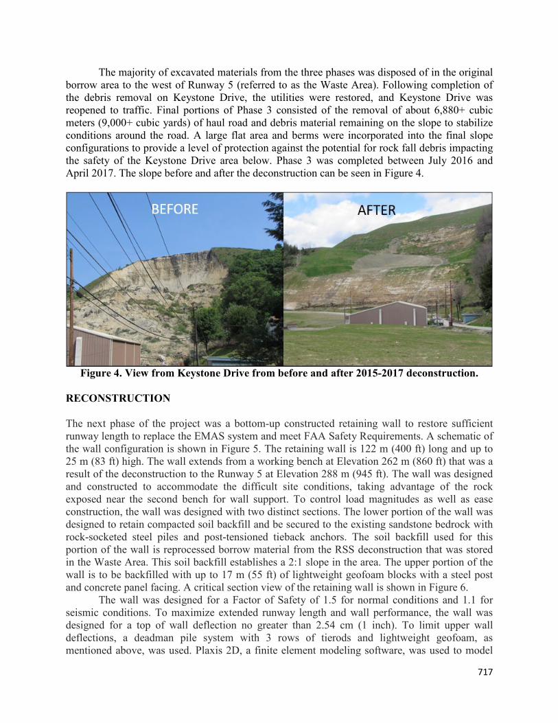
The majority of excavated materials from the three phases was disposed of in the original borrow area to the west of Runway 5 (referred to as the Waste Area). Following completion of the debris removal on Keystone Drive, the utilities were restored, and Keystone Drive was reopened to traffic. Final portions of Phase 3 consisted of the removal of about 6,880+ cubic meters (9,000+ cubic yards) of haul road and debris material remaining on the slope to stabilize conditions around the road. A large flat area and berms were incorporated into the final slope configurations to provide a level of protection against the potential for rock fall debris impacting the safety of the Keystone Drive area below. Phase 3 was completed between July 2016 and April 2017. The slope before and after the deconstruction can be seen in Figure 4.
Figure 4. View from Keystone Drive from before and after 2015-2017 deconstruction.
RECONSTRUCTION The next phase of the project was a bottom-up constructed retaining wall to restore sufficient runway length to replace the EMAS system and meet FAA Safety Requirements. A schematic of the wall configuration is shown in Figure 5. The retaining wall is 122 m (400 ft) long and up to 25 m (83 ft) high. The wall extends from a working bench at Elevation 262 m (860 ft) that was a result of the deconstruction to the Runway 5 at Elevation 288 m (945 ft). The wall was designed and constructed to accommodate the difficult site conditions, taking advantage of the rock exposed near the second bench for wall support. To control load magnitudes as well as ease construction, the wall was designed with two distinct sections. The lower portion of the wall was designed to retain compacted soil backfill and be secured to the existing sandstone bedrock with rock-socketed steel piles and post-tensioned tieback anchors. The soil backfill used for this portion of the wall is reprocessed borrow material from the RSS deconstruction that was stored in the Waste Area. This soil backfill establishes a 2:1 slope in the area. The upper portion of the wall is to be backfilled with up to 17 m (55 ft) of lightweight geofoam blocks with a steel post and concrete panel facing. A critical section view of the retaining wall is shown in Figure 6.
The wall was designed for a Factor of Safety of 1.5 for normal conditions and 1.1 for seismic conditions. To maximize extended runway length and wall performance, the wall was designed for a top of wall deflection no greater than 2.54 cm (1 inch). To limit upper wall deflections, a deadman pile system with 3 rows of tierods and lightweight geofoam, as mentioned above, was used. Plaxis 2D, a finite element modeling software, was used to model

718
the response of the system under staged construction and provide forces and stress development in both the soil and structural elements at critical sections of the wall. Structural components of the wall were designed using AASHTO load combinations and load reduction factors. Further details of this reconstruction are provided by Simon et al., 2019.
Figure 5. Aerial view of the new retaining wall alignment and EMAS bed.
Figure 6. Cross section view of new retaining wall.
719
CONCLUSION In 2015, the Runway Safety Area (RSA) and Engineered Material Arresting System (EMAS) were destroyed when the 73 m (240 ft) high reinforced soil slope failed at Yeager Airport in Charleston, West Virginia. The result of the structural fill failure was a near vertical soil face in the remnant fill over a massive debris field. The mitigation plans were necessary for the safe removal of approximately 413,000 cubic meters (540,000 cubic yards) of debris and to create a temporarily stable condition in wait of the permanent solution. The cleanup and stabilization of the area resulted in the displacement of the Runway 5 threshold and the shortening of the usable length of Runway 5-23. The deconstruction left a temporary 1.5:1 slope with working benches at Elevation 262 m (860 ft) and 277 m (910 ft) approximately 5 m (17 ft) wide, and a stockpile of soil to be used as part of the new wall backfill. The retaining wall is 25 m (83 ft) tall and extends from the working bench at Elevation 262 m (860 ft) up to Runway 5 elevation at 288 m (945 ft) to restore the EMAS.
Risk assessments, including a formal risk register, were used throughout this project. Engagement of all stakeholders was a critical element of this project and included Airport management, operations, maintenance, contractors; agencies; material suppliers; and others all contributed to identifying concerns, prioritizations, and mitigation option development. Engagement throughout the process is believed to have been a critical component of achieving the rapid response of both the deconstruction and the restoration design and construction. ACKNOWLEDGEMENTS We would like to thank the many others at Schnabel Engineering who were involved in the project as well as the innumerable parties who assisted with the risk register discussed above. The exceptional staff at Yeager Airport provided significant support throughout this effort with the clearly focused goal of restoring the safety of the airport as soon as possible. REFERENCES Keller, N. (2017). Yeager Airport and Charleston Aviation, Arcadia, Charleston, SC. Simon, J., Cadden, A.W., Shull, P., and Senior, M. (2019). Restoring RW5 at Yeager Airport:
Design and Construction of Tall Retaining Wall on the Side of a Mountain, Geocongress ’19, Philadelphia, PA, USA.
West Virginia Geologic and Economical Survey (WVGES). (2011), Geologic Map of West Virginia, Map 25A. Revised May 16, 2011, Morgantown, WV.


![Danish University Colleges Deconstruction/Reconstruction a ... · reconstruction method are discussed using Enzo Mari's 1963 poster "Arte Programmata: Kinetische Kunst" [16] (figure](https://img.pdfslide.net/doc/110x75/5e55cf4bd5aac8406a53e41a/danish-university-colleges-deconstructionreconstruction-a-reconstruction-method.jpg)