Embed Size (px)
Citation preview

Thank
Citatio
See th
Version
Copyri
Link to
you for do
on:
is record i
n:
ght Statem
o Published
wnloading
in the RMI
ment: ©
d Version:
this docum
IT Researc
ment from
ch Reposit
the RMIT R
ory at:
Research RRepository
PLEASE DO NOT REMOVE THIS PAGE
Sabatini, R, Moore, T and Hill, C 2013, 'A new avionics based GNSS integrity augmentationsystem: Part 2 - integrity flags', The Journal of Navigation, vol. 66, no. 4, pp. 501-522.
https://researchbank.rmit.edu.au/view/rmit:22676
Accepted Manuscript
The Royal Institute of Navigation 2013
http://dx.doi.org/10.1017/S0373463313000143

1
A New Avionics Based GNSS Integrity
Augmentation System: Part 2 - Integrity Flags
Roberto Sabatini1, Terry Moore
2, Chris Hill
2
1(Cranfield University – Department of Aerospace Engineering, Bedford MK43 0AL, UK)
2(University of Nottingham – Nottingham Geospatial Institute, Nottingham NG7 2TU, UK)
(Email: [email protected])
This paper presents the second part of the research activities carried out to develop a novel GNSS
Avionics Based Integrity Augmentation (ABIA) system for manned and Unmanned Aerial Vehicle
(UAV) applications. The ABIA systems architecture was developed to allow real-time avoidance of
safety-critical flight conditions and fast recovery of the required navigation performance in case of
GNSS data losses. In more detail, our novel ABIA system addresses all four cornerstones of GNSS
integrity augmentation in mission- and safety-critical avionics applications: prediction (caution flags),
avoidance (optimal flight path guidance), reaction (warning flags) and correction (recovery flight
path guidance). Part 1 (Sabatini et al., 2012) presented the ABIA concept, architecture and key
mathematical models used to describe GNSS integrity issues in aircraft applications. This second part
addresses the ABIA caution and warning integrity flags criteria and presents detailed results of a
simulation case-study performed on the TORNADO-IDS aircraft.
KEY WORDS
1. GNSS Integrity. 2. Aircraft Based Augmentation System. 3. Avionics Based Integrity
Augmentation. 4. Safety-Critical GNSS Applications.
1. INTRODUCTION. In recent years, various strategies have been developed for increasing
the levels of integrity of GNSS based navigation and landing systems. In addition to Space
Based Augmentation Systems (SBAS) and Ground Based Augmentation Systems (GBAS),
GNSS augmentation may also take the form of additional information being provided by
other avionics systems. As the additional avionics systems operate via separate principles
than the GNSS, they are not subject to the same sources of error or interference. A system
such as this is referred to as an Aircraft Based Augmentation System (ABAS). Unlike SBAS
and GBAS technology, previous research on ABAS mainly concentrates on additional
information being blended into the position calculation to increase accuracy and/or continuity
of the integrated navigation solutions. Additionally, no significant attempts have been made
of developing ABAS architectures capable of generating integrity signals suitable for
mission- and safety-critical GNSS applications (e.g., aircraft precision approach and landing)
and no commercial ABAS products are available at present. In our research, we developed
an ABIA architecture specifically targeting GNSS integrity augmentation for manned and
unmanned aerial vehicle (UAV) applications. Although current and likely future
SBAS/GBAS augmentation systems can provide significant improvement of GNSS
navigation performance, a properly designed and flight certified AIAS could play a key role
in GNSS Augmentation for mission- and safety-critical applications such as aircraft precision
approach, automatic landing and UAV Sense-and-Avoid (SAA). Furthermore, using suitable
data link and data processing technologies, a certified ABIA capability could be a core
element of the future GNSS Space-Ground-Avionics Augmentation Network (SGAAN).
2. INTEGRITY FLAG GENERATOR SIMULATION. The ABIA Integrity Flag Generator
(IFG) is designed to provide CIF and WIF alerts (i.e., in accordance with the specified TTC

2
and TTW requirements) in all relevant flight phases. In order to evaluate the performance of
the Masking, Multipath, Carrier-to-Noise (C/N0), Jamming-to-Signal (J/S) and Doppler
analysis algorithms presented in part 1 (Sabatini et al., 2012), the IFG software was
developed and tested in MATLAB, together with a detailed Aircraft (A/C) Three
Dimensional (3D) Model in CATIA (Computer Aided Three-dimensional Interactive
Application), a 3D Terrain and Objects Database, a GNSS Constellation Simulator and a
Navigation/Flight Dynamics Simulator. Fig. 1 shows the architecture adopted for the IFG
module simulation. Another key feature of the IFG module presented in this second paper is
a pre-defined set of CIF and WIF thresholds applicable to the specific A/C dynamic
conditions and satellite constellations observed during the flight.
Figure 1. ABIA IFG module simulation.
A GNSS Constellation Simulator (GCS) was implemented to support GNSS satellite
visibility, signal and geometry analysis. It calculated GNSS satellite position and velocity in
the Earth-Centred Earth-Fixed (ECEF) reference frame and obtained satellite visibility data
from any point along the A/C flight trajectory. The GCS was developed in MATLAB to
simulate GPS and GALILEO constellations. However, the GCS was conceived as a flexible
tool capable to incorporate other current and likely future GNSS constellations (GLONASS,
COMPASS, etc.), including space-based regional and global augmentation systems. The
satellite position and velocity were calculated from the Kepler's laws of orbital motion and,
for the case of GPS satellites, using either the YUMA or SEM almanac data (Celestrak, 2012).
An A/C Navigation/Dynamics Simulator (ADS) was also implemented to generate the
nominal flight path trajectory and attitude (Euler) angles. The ADS employed a classical
Three Degrees of Freedom (3-DOF) point-and-variable mass model. The assumptions are:
The Earth shape is approximated as an ellipsoid using WGS-84 parameters.
The atmosphere is considered at rest relatively to the Earth.

3
A standard ISA atmospheric model is adopted to describe temperature, pressure and
density variations as a function of altitude.
The A/C is modelled as a rigid body with a vertical plane of symmetry.
The A/C mass reduction in flight is due to fuel consumption only.
Thrust, aerodynamic forces and weight act on the A/C Centre of Gravity (CoG).
The flight is supposed to be symmetric (i.e., no sideslip).
The 3-DOF scalar equations are the following:
( )
(1)
( )
(2)
( )
(3)
( )
(4)
(5)
( ) ( )
(6)
(7)
where:
= A/C mass;
= Aerodynamic speed;
= Thrust magnitude;
= Angle of attack;
= Altitude;
= Lift magnitude;
= Drag, defined as a function of , and ;
= Gravity acceleration;
= Flight path angle;
= Bank or roll angle;
= Heading angle;
= Specific fuel consumption, defined as a function of and ;
= Geodetic latitude;
= Geodetic longitude;
= Meridional radius of curvature;
= Transverse radius of curvature.
This model presents seven state variables ( ) and three control variables
( ) Hence, for it to be solved, at least three flight constraints must be specified for each
flight manoeuvre. As described in part 1 (Sabatini et al., 2012), the ABIA IFG uses a set of
predefined threshold parameters to trigger the generation of both caution and warning flags
associated with antenna obscuration, Doppler shift, multipath, direct carrier/interference and

4
satellite geometry degradations. More details about the simulation process are provided in
the following paragraphs with a special focus on the CIF and WIF threshold setting criteria
incorporated into the ABIA IFG module design.
3. INTEGRITY FLAG CRITERIA. The philosophy adopted to set-up thresholds for the
ABIA CIF and WIF integrity flags is depicted in Fig. 2. Integrity flags are generated based
on a dedicated error analysis addressing the following aspects of GNSS performance:
Satellite-A/C (receiver) relative geometry and position errors;
Radio frequency (RF) signal errors (i.e., Doppler shift, jamming and multipath);
Receiver Tracking Errors (RTE).
CIF and WIF
Thresholds
Relative
Geometry
Radio
Frequency
Receiver
Tracking
Antenna Masking
Position Accuracy
PLL Tracking
FLL Tracking
Masking Matrixes
Estimated HPE/VPE
Rx Tracking Errors
DLL Tracking
Multipath
Link Budget
Interference
C/N0 Calculation
J/S Calculation
Doppler Shift
Phase/Range Errors
Frequency Error
Figure 2. Integrity flag thresholds criteria.
In particular, the RTE models are used to support the development of robust criteria for
the RF signal thresholds, in addition to the criteria based on experimental results (e.g., ground
and flight test activities with GNSS). In the following, we present the detailed criteria
adopted for setting the various CIF and WIF thresholds.
3.1. Satellite-A/C Relative Geometry and Position Errors. As described in (Sabatini et al.,
2012), in order to generate CIF/WIF associated to critical antenna masking conditions, a
dedicated analysis is required taking into account the variation of the attitude angles.
Therefore, using the CATIA 3D model of the A/C, series of Antenna Obscuration Matrixes
(AOMs) are collected with pitch angles varying between -90 degree and 90 degree and with
roll angles varying between -90 degree and 90 degree. An example of the resulting Global
Masking Profile (GMP) obtained for the TORNADO-IDS is shown in Fig. 3. In this figure,
also the GPS satellite constellation is shown (from the GCS module). The obscuration
integrity flag criteria are the following:
When the current A/C manoeuvre will lead to less the 4 satellite in view, the CIF shall
be generated.

5
When less than 4 satellites are in view, the WIF shall be generated.
Additionally, if only four satellites are in view:
When one (or more) satellite(s) elevation angle (antenna frame) is less than 10
degrees, the caution integrity flag shall be generated.
When one (or more) satellite(s) elevation angle is less than 5 degrees, the warning
integrity flag shall be generated.
Figure 3. TORNADO-IDS global masking profile (B = bank and P = pitch - all values in degrees).
Using the definition of Dilution of Precision (DOP) factors, GNSS accuracy can be expressed
as (Kaplan and Hegarty, 2006):
(8)
where is the standard deviation of the positioning accuracy and is the standard
deviation of the satellite pseudorange measurement error. For the C/A-code is in the
order of 33.3m. Therefore, the 1-σ Estimated Position, Horizontal and Vertical Errors of a
GNSS receiver are calculated using the PDOP (Estimated Position Error - EPE), the HDOP
(Estimated Horizontal Error - EHE) or the VDOP (Estimated Vertical Error - EVE)
respectively. In order to generate CIFs and WIFs that are consistent with current GNSS
Required Navigation Performance (RNP), we need to introduce the Horizontal and Vertical
Accuracy (HA/VA) requirements applicable to the different flight phases. Table 1 shows the
GNSS signal-in-space alert requirements in terms of HA/VA for En-route, Non-precision
Approach (NPA) and for the three categories of Precision Approach. Table 2 shows the
GNSS signal-in-space protection requirements. The Horizontal Alert Limit (HAL) is the
radius of a circle in the horizontal plane, with its centre being at the true position, which
describes the region which is required to contain the indicated horizontal position with the
required probability for a particular navigation mode. Similarly, the Vertical Alert Limit
(VAL) is half the length of a segment on the vertical axis, with its centre being at the true

6
position, which describes the region which is required to contain the indicated vertical
position with the required probability for a particular navigation mode.
Table 1. GNSS signal-in-space alert requirements (ICAO, 2006).
Table 2. GNSS signal-in-space protection requirements (CAA, 2003).
As a result of our discussion, the DOP integrity flags criteria are the following:
When the EHE exceeds the HA 95% or the VA 95% alert requirements, the CIF shall
be generated.
When the EHE exceeds the HAL or the EVE exceeds the VAL, the WIF shall be
generated.
During the landing phase, a GNSS Landing System (GLS) has to be augmented by GBAS in
order to achieve the Required Navigation Performance (RNP), as well as Lateral and Vertical
Protection Levels (LPL and VPL). LPL/VPL is defined as the statistical error value that
bounds the Lateral/Vertical Navigation System Error (NSE) with a specified level of
Typical operation Accuracy horizontal 95% Accuracy vertical 95%
En-route 3.7 km N/A
En-route, Terminal 0.74km N/A
NPA 220m N/A
APV-I 16m 20m
APV-II 16m 8m
Category-I precision approach 16m 6m-4m
Category-II precision approach 6.9m 2m
Category-III precision approach 6.2m 2m
Typical operation Horizontal Alert Limit Vertical Alert Limit TTA
En-route 7.4 km N/A 5min
En-route (continental) 3.7km N/A 15s
En-route, Terminal 1.85 km N/A 10s
NPA 556m N/A 10s
APV-I 40m 50m 6s
APV-II 40m 20m 6s
Category-I precision approach 40m 15m-10m 6s
Category-II precision approach 17.3m 5.3m 1s
Category-III precision approach 15.5m 5.3m 1s

7
confidence. In particular, for the case of LAAS, which allows for multiple DGPS reference
receivers (up to four) to be implemented, two different hypotheses are made regarding the
presence of errors in the measurements. These hypotheses are (RTCA, 2004):
H0 Hypothesis – No faults are present in the range measurements (includes both the
signal and the receiver measurements) used in the ground station to compute the
differential corrections.
H1 Hypothesis – A fault is present in one or more range measurements and is caused
by one of the reference receivers used in the ground station.
Consequently, LPL and VPL are computed as follows:
(9)
(10)
The lateral and vertical accuracy (NSE 95%) and alert limits required by a GLS in the
presence of LAAS, considering the continuously varying position of the A/C with respect to
the Landing Threshold Point (LTP) are also given in (RTCA, 2004). Additionally, this
RTCA standard provides the so-called Continuity of Protection Levels in terms of Predicted
Lateral and Vertical Protection Levels (PLPL and PVPL). Although the definition in (RTCA,
2004) is quite comprehensive, a generic statement is made that the PVPL and PLPL
computations shall be based on the ranging sources expected to be available for the duration
of the approach. In other terms, it is implied that the airborne subsystem shall determine
which ranging sources are expected to be available, including the ground subsystem’s
declaration of satellite differential correction availability (satellite setting information).
Unfortunately, this generic definition does not address the various conditions for satellite
signal losses associated to specific A/C manoeuvres (including curved GLS precision
approaches). Therefore, it is suggested that an extended definition of PLPL and PVPL is
developed taking into account the continuously varying A/C-satellite relative geometry. In
particular, when the current A/C manoeuvre will lead to less than 4 satellites in view or
unacceptable accuracy degradations, the CIF shall be generated. Following our discussion,
the additional integrity flags criteria adopted for GLS in the presence of LAAS are the
following:
When the PLPL exceeds LAL or PVPL exceeds the VAL, the CIF shall be generated.
When the LPL exceeds the LAL or the VPL exceeds the VAL, the WIF shall be
generated.
3.2. Radio Frequency Link Errors. Multipath integrity flags were defined using the Early-
Late Phase (ELP) observable and the range error. In a GPS receiver having three correlators
(early, prompt and late), the phase of a correlator is given by (Mubarak and Dempster, 2009).
( ) (
) (11)
where the subscript C can refer to early (E), prompt (P) and late (L) respectively. The prompt
phase is always kept close to zero by the carrier tracking loop. Early and late correlators are
then placed on each side of the prompt, which means one of the phase of the correlator is
positive and the other is negative. So, the phase difference between the two is increased in the
presence of multipath. ELP is simply the phase difference between the early and late

8
correlator outputs, where the phase of a correlator output is equal to the inverse tangent of the
Q channel output divided by the I channel output. Mathematically, the ELP is calculated by
(Mubarak and Dempster, 2009):
E ( ) [ ( )
( )
( )
( )]
(12)
The probability of multipath detection is approximately 80% by setting the ELP threshold at
0.1 radians (Fig. 4).
Figure 4. Probability of detecting multipath for varying ELP thresholds. The symbol indicates the radio
of multipath to direct signal amplitude (i.e., = Am/Ad). Adapted from (Mubarak and Dempster, 2010).
Additionally, as shown in Fig. 5, with an ELP threshold of 0.1 radians, the Probability of
False Alarm (PFA) is 0.3 when is 42 dB/Hz. This is an acceptable compromise for the
ABIA caution flag implementation.
Figure 5. PFA for varying ELP threshold. Adapted from (Mubarak and Dempster, 2010).

9
Multipath range error experimental results are also used to trigger the warning integrity
flag associated to multipath. As discussed in (Sabatini et al., 2012), the effect of ground-echo
signals translate into a sudden increase of the multipath ranging error of up to two orders of
magnitude with respect to the airframe multipath errors alone. However, the region of
potential ground-echo multipath for the L1 frequency only extends up to 448.5 metres AGL
(theoretical value applicable to all A/C types). As a result of our analysis, the multipath
integrity flags criteria are the following:
When the ELP exceeds 0.1 radians, the caution integrity flag shall be generated.
When the multipath ranging error shows a sudden increase with the A/C flying in
proximity of the ground (below 448.5 metres), the warning integrity flag shall be
generated.
Based on results of the GPS-TSPI flight test activities (Sabatini and Palmerini, 2008), an
additional (practical) criteria was developed for the TORNADO-IDS A/C. During
TORNADO-IDS flight trials it was observed that flying above 500 ft AGL (even with
pitch/bank angles exceeding 45 degrees), the ground-echo multipath was not a factor and the
multipath range error (due to the airframe only) never exceeded 2 metres. Consequently, the
additional criteria applicable to the TORNADO-IDS A/C is:
When the multipath ranging error exceeds 2 metres and the A/C flies in proximity of
the ground (below 500 ft AGL), the warning integrity flag shall be generated.
As discussed in (Sabatini et al., 2012), avionics GNSS receivers are resistant to dynamic
stress errors. A robust avionics GNSS receiver design typically employs an FLL as a backup
to the PLL during initial loop closure and during high-dynamic stress with loss of phase lock,
but will revert to pure PLL for the steady-state low to moderate dynamics in order to produce
the highest carrier Doppler phase measurements. However, flight test activities performed
with avionics GPS receivers showed that the reacquisition time after loss of one or more
satellite signals could be up to 40 seconds, depending on flight conditions and satellite
constellations (Sabatini and Palmerini, 2008).
Additionally, the analysis of receiver data recorded during several flights and up to speed
of 500 kts highlighted that the Doppler effect causes a frequency shift, with respect to the L1
carrier frequency, reaching a maximum value of about 15 KHz (Sabatini and Palmerini,
2008). This value is relatively low if compared with the GPS frequency bandwidth (i.e., about
30 MHz), and the high dynamic characteristics of the carrier tracking loops internal to the
avionics receiver guarantee that neither the data accuracy is degraded nor the carrier phase is
lost because of Doppler shift. Nevertheless, the coupling between such frequency shift and
the signal reacquisition strategy of the receiver can significantly affects the time necessary to
get data after a signal loss.
Fig. 7 shows the fitting functions and associated curves relative to the acquisition time
experimental data presented in (Sabatini et al., 2012). These functions were conveniently
used to estimate GNSS acquisition time based on satellite-A/C relative velocity (LOS). With
reference to Fig. 7, it is evident that for C/N0 below 28 dB-Hz the acquisition time exceeds 1
sec even in low dynamics conditions. Therefore, in these conditions, the required acquisition
times might become unacceptable in case of satellite signal losses during certain mission- and
safety-critical GNSS applications (military weapon aiming, missile guidance, precision
approach, etc.).

10
Figure 16. Doppler shift and signal acquisition in avionics GPS receivers.
Consequently, the following criteria were defined for the Doppler integrity flags thresholds:
When the C/N0 is below 28 dB-Hz and the signal is lost, the caution integrity flag
shall be generated if the estimated acquisition time is less than the application-
specific TTA requirements.
When the C/N0 is below 28 dB-Hz and the signal is lost, the warning integrity flag
shall be generated if the estimated acquisition time exceeds the application-specific
TTA requirements.
3.3. Receiver Tracking Errors. As discussed before, in order to define additional robust
criteria for the ABIA integrity thresholds associated with dynamic stress errors, signal fading
(C/N0 reduction) and interferences (J/S increase), a dedicated analysis of the GNSS receiver
tracking performance was required. When the GNSS code and/or carrier tracking errors
exceed certain thresholds, the receiver loses lock to the satellites. Since both the code and
carrier tracking loops are nonlinear, especially near the threshold regions, only Monte Carlo
simulations of the GNSS receiver in different dynamics and SNR conditions can determine
the receiver tracking performance (Ward, 1997). Nevertheless, some conservative rule-of-
thumbs approximating the measurement errors of the GNSS tracking loops were used for the

11
ABIA initial design. Numerous sources of measurement errors affect the Carrier Tracking
Loops and Code Tracking Loops. However, for our purposes, it was sufficient to analyze the
dominant error sources in each type of tracking loop. Considering a typical avionics GNSS
receiver employing a two-quadrant arctangent discriminator, the Phase Lock Loop (PLL)
threshold is given by [4, 13]:
(13)
where:
= 1-sigma phase jitter from all sources except dynamic stress error;
= dynamic stress error in the PLL tracking loop.
Expanding Eq. (13), the 1-sigma threshold for the PLL tracking loop becomes (Kaplan and
Hegarty, 2006):
√
(14)
where:
= 1-sigma thermal noise;
= vibration-induced oscillator phase noise;
= Allan variance–induced oscillator jitter.
The PLL thermal noise is often thought to be the only carrier tracking error, since the other
sources of PLL jitter may be either transient or negligible. The PLL thermal noise jitter is
computed as follows:
σ
√
(
) ( )
(15)
where:
= carrier loop noise bandwidth (Hz);
= carrier to noise power ratio ( ( ) for expressed in dB-Hz);
T = predetection integration time (seconds);
and can be derived from the SNR model described before. Determination of the
vibration-induced oscillator phase noise is a complex analysis problem. In some cases, the
expected vibration environment is so severe that the reference oscillator must be mounted
using vibration isolators in order for the GPS receiver to successfully operate in PLL. The
equation for vibration induced oscillator jitter is:
√ ∫ ( )
( )
( )
(16)
where:
= L-band frequency (Hz);

12
( ) = oscillator vibration sensitivity of per g as a function of fm;
= random vibration modulation frequency (Hz);
( ) = power curve of the random vibration as a function of ( );
g = gravity acceleration.
Usually the oscillator vibration sensitivity, ( ) is not variable over the range of the
random vibration modulation frequency, then Eq. (16) can be simplified to:
√ ∫
( )
( )
(17)
The equations used to determine Allan deviation phase noise are empirical. They are stated in
terms of what the requirements are for the short-term stability of the reference oscillator as
determined by the Allan variance method of stability measurement. The equation for second-
order loop short-term Allan deviation is:
( )
( )
(18)
The equation for third–order loop short-term Allan deviation for PLL is:
( )
( )
(19)
where:
( ) = Allan deviation-induced jitter (degrees);
= L-band input frequency (Hz);
= short-term stability gate time for Allan variance measurement (seconds);
= noise bandwidth.
Usually ( ) can be determined for the oscillator and it changes very little with gate time .
In our research, the loop filter is assumed as a third-order with a noise bandwidth = 18 Hz
and the gate time . The Allan deviation is specified to be ( ) .
The dynamic stress error depends on the loop bandwidth and order. In a third-order loop, the
dynamic stress error is [4, 13]:
(
)
( )
(20)
where:
= LOS range to the satellite;
= maximum LOS acceleration dynamics (° );
= loop filter natural radian frequency;
= noise bandwidth.

13
For the L1 frequency we have: ( ) ( ) ( ) . Frequency jitter due to thermal noise and dynamic stress
error are the main errors in a GNSS receiver Frequency Lock Loop (FLL). The receiver
tracking threshold is such that the 3-sigma jitter must not exceed one-fourth of the frequency
pull-in range of the FLL discriminator. Therefore, the FLL tracking threshold is [4, 13]:
( ) (21)
where:
3 = 3-sigma thermal noise frequency jitter;
= dynamic stress error in the FLL tracking loop.
Eq. (21) shows that the dynamic stress frequency error is a 3-sigma effect and is additive to
the thermal noise frequency jitter. The reference oscillator vibration and Allan deviation–
induced frequency jitter are small-order effects on the FLL and are considered negligible. The
1-sigma frequency jitter threshold is 1/(12T) = 0.0833/T Hz. The FLL tracking loop jitter
due to thermal noise is:
√
[
] ( ) (22)
where F is 1 at high and 2 near the threshold. is independent of C/A or P(Y) code
modulation and loop order. Since the FLL tracking loop involves one more integrator that
the PLL tracking loop of the same order [4, 12], the dynamic stress error is:
(
)
( )
(23)
Regarding the code tracking loop, a conservative rule-of-thumb for the Delay Lock Loop
(DLL) tracking threshold is that the 3-sigma value of the jitter due to all sources of loop
stress must not exceed the correlator spacing (d), expressed in chips. Therefore [4, 13]:
( ) (24)
where:
= 1-sigma thermal noise code tracking jitter;
Re = dynamic stress error in the DLL tracking loop.
The DLL thermal noise code tracking jitter is given by:
√
[ ( )
] ( )
(
(25)
where:
= DLL discriminator correlator factor (1 for time shared tau-dithered early/late
correlator and 0.5 for dedicated early and late correlators);
d = Correlator spacing between early, prompt and late;

14
Bn = Code loop noise bandwidth;
F2 = DLL dicriminator type factor (1 for early/late type discriminator and 0.5 for dot
product type discriminator).
The DLL tracking loop dynamic stress error is given by:
( )
(
(26)
where / is expressed in chips/secn.
The PLL, FLL and DLL error equations described above allow to determine the
corresponding to the tracking threshold of the receiver. A generic criteria applicable to the
ABIA system is:
( ) [( ) ( ) ( ) ] (27)
where:
( ) = Minimum carrier-to-noise ratio for PLL carrier tracking; ( ) = Minimum carrier-to-noise ratio for FLL carrier tracking; ( ) = Minimum carrier-to-noise ratio for DLL code tracking.
Numerical solutions of Eqs. (13), (21) and (24) show that the weak link in unaided
avionics GNSS receivers is the PLL due to its greater sensitivity to dynamics stress.
Therefore, the ( ) threshold can be adopted in these cases. In general, when the PLL
loop order is made higher, there is an improvement in dynamic stress performance. This is
why third order PLL are widely adopted in avionics GNSS receivers (e.g., TORNADO-IDS).
Assuming 15 to 18 Hz noise bandwidth and 5 to 20 msec predetection integration time
(typical values for avionics receivers), the rule-of-thumb tracking threshold for the PLL gives
25 to 28 dB-Hz. Additionally, in aided avionics receiver applications, the PLL tracking
threshold can be significantly reduced by using external velocity aiding in the carrier tracking
loop. With this provision, a tracking threshold of approximately 15 to 18 dB-Hz can be
achieved. Using these theoretical and experimental threshold values, we can also calculate
the receiver Jamming-to-Signal (J/S) performance for the various cases of practical interest,
as described in (Sabatini et al., 2012). When available, flight test data collected in
representative portions of the A/C operational flight envelope (or the results of Monte Carlo
simulation) shall be used. Taking an additional 5% margin on the 3-sigma tracking
thresholds for the CIF, the following additional criteria are introduced for the ABIA integrity
thresholds:
When the
CIF shall be generated.
When or or the WIF shall be generated.
Additionally, taking a 1 dB margin on the maximum J/S performance of the receiver to
generate the CIF, the following criteria were adopted for the CIF and WIF flags associated to
interference:
When the difference between the received (incident) jammer power (dBw) and the
received (incident) signal power (dBw) is 1 dB below the J/S performance of the
receiver at its tracking threshold, the CIF shall be generated.

15
When the difference between the received (incident) jammer power (dBw) and the
received (incident) signal power (dBw) is above the J/S performance of the receiver at
its tracking threshold, the WIF shall be generated.
During the GPS-TSPI flight test activities performed on TORNADO-IDS with unaided L1
C/A code avionics receivers (Sabatini and Palmerini, 2008), it was also found that, in all
dynamics conditions explored, a of 25 dB-Hz was sufficient to keep tracking of the
satellites (Sabatini and Palmerini, 2008). Consequently, taking the usual 1 dB margin for the
CIF, the following additional criteria were adopted for the TORNADO-IDS C/N0 integrity
flags:
When the is less than 26 dB-Hz the CIF shall be generated.
When the is less than 25 dB-Hz the WIF shall be generated.
4. SIMULATION. In order to validate the design of the ABIA IFG module, a detailed
simulation case-study was performed on the TORNADO-IDS A/C, whose flight dynamics
and GPS receiver performance characteristics were available from previous research
(Sabatini and Palmerini, 2008). Various geometric parameters were required to draw a
detailed CATIA model of the A/C. Some of the main parameters are listed in Table 3
(Aircraft Drawings, 2012).
Table 3. TORNADO-IDS dimensions.
Length 16.72 m (54 ft 10 in)
Wingspan 13.91 m at 25° wing sweep (45.6 ft)
8.60 m at 67° wing sweep (28.2 ft)
Height 5.95 m (19.5 ft)
Wing area 26.6 m² (286 ft²)
The TORNADO-IDS 3-D CATIA model obtained is shown in Fig. 7.
25° wing sweep
67° wing sweep

16
Figure 7. TORNADO-IDS 3-D CATIA model.
When calculating the antenna masking matrix and the corresponding satellite visibility, the
antenna location must be included in the model. Military A/C typically have an Upper
Antenna (UA) at the top of the fuselage and a Lower Antenna (LA) at the base of the
fuselage. In our case, the upper antenna is assumed to be located 1.5 m behind the cockpit
along the A/C centreline projection and 5 cm high on the A/C skin surface (Sabatini and
Palmerini, 2008). The lower antenna is right below the upper antenna on the opposite side of
the fuselage (Fig. 8). When calculating the satellite visibility, the line of sight (LOS) is
measured in the antenna frame (i.e., origin at the antenna focal point). The transformation
from body-frame to antenna frame is obtained from:
(m) (31)
Figure 8. TORNADO-IDS antennae locations.
17
The transformation matrixes for the upper and lower antennae are:
[
] (m) (32)
[
] ( )
(33)
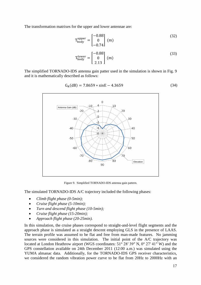
The simplified TORNADO-IDS antenna gain patter used in the simulation is shown in Fig. 9
and it is mathematically described as follows:
( ) E (34)
17-Feb-201239© Roberto Sabatini, 2012 39
Antenna Gain (dB)
Elevation
Figure 9. Simplified TORNADO-IDS antenna gain pattern.
The simulated TORNADO-IDS A/C trajectory included the following phases:
Climb flight phase (0-5min);
Cruise flight phase (5-10min);
Turn and descend flight phase (10-5min);
Cruise flight phase (15-20min);
Approach flight phase (20-25min).
In this simulation, the cruise phases correspond to straight-and-level flight segments and the
approach phase is simulated as a straight descent employing GLS in the presence of LAAS.
The terrain profile was assumed to be flat and free from man-made features. No jamming
sources were considered in this simulation. The initial point of the A/C trajectory was
located at London Heathrow airport (WGS coordinates: 51° 28′ 39″ N, 0° 27′ 41″ W) and the
GPS constellation available on 24th December 2011 (12:00 a.m.) was simulated using the
YUMA almanac data. Additionally, for the TORNADO-IDS GPS receiver characteristics,
we considered the random vibration power curve to be flat from 20Hz to 2000Hz with an

18
amplitude of 0.005 and the oscillator vibration sensitivity ( ) parts/g.
Finally, the third-order loop noise bandwidth is 18Hz and the maximum LOS jerk dynamic
stress is 10g/s=98 . The CIFs and WIFs relative to antenna masking, geometric accuracy
degradations, S/N, multipath and Doppler shift were generated. The overall results are shown
in the Tables 4.
Table 4. GPS Integrity Flags for TORNADO-IDS.
Table 5 shows the details of the specific CIFs and WIFs generated during the various
TORNADO-IDS flight phases. There was only one case (flight slice 600-608s) where the
CIF was generated not being followed by the WIF (this was due to a temporary adverse
relative geometry during the TDP manoeuvres). In all other cases, the CIF was followed by
the WIF. It was also observed that the CIF was always triggered at least 2 seconds before the
successive WIF onset (up to 6 seconds during the straight descent phase). These results
contribute to corroborate the validity of the models developed for the CIF/WIF thresholds. It
was also observed that the CIF was always triggered at least 2 seconds before the successive
WIF onset. This evidence is particularly important for the ABIA system design. In fact, it is
evident that the availability of a usable CIF represents a significant progress in this research
with the potential for both manned A/C and UAVs to recover from mission- and safety-
critical flight conditions potentially leading to GNSS data losses. Therefore, it is envisaged
that a properly designed ABIA Flight Path Module (FPM) could take full advantage of this
predictive behaviour, allowing an A/C or UAV to correct its flight trajectory/attitude in order
to avoid the occurrence of the critical GNSS data losses. Additionally, it is possible that this
predictive behaviour be exploited in the pursuit of a GNSS based auto-land capability.
Phase 1 2 3 4 5
Trajectory Climb Cruise Turning
descent
Cruise Approach
(LAAS
assisted)
Duration 5min 5min 5min 5min 5min
Available
satellites
16
PRN 1, 3, 6, 7,
9, 11, 12, 13,
14, 15, 22, 23,
26, 27, 30, 31
16
PRN 1, 3, 6, 7,
9, 11, 12, 13,
14, 15, 22, 23,
26, 27, 30, 31
16
PRN 1, 3, 6, 7,
9, 11, 12, 13,
14, 15, 22, 23,
26, 27, 30, 31
16
PRN 1, 3, 6, 7,
9, 11, 12, 13,
14, 15, 22, 23,
26, 27, 30, 31
16
PRN 1, 3, 6, 7,
9, 11, 12, 13,
14, 15, 22, 23,
26, 27, 30, 31
CIF - - 600~608s
672~ 698s
762~788s
852~878s
- 1484~1500s
WIF - - 674~692s
764~782s
854~872s
- 1490~1500s

19
Table 5. GPS Integrity Flags for TORNADO-IDS (CIF/WIF details).
5. CONCLUSIONS AND FUTURE WORK. In this research the architecture of an ABIA
system for GNSS applications was defined. The detailed design of the ABIA IFG module
was also accomplished. This module can generate both CIFs and WIFs associated to antenna
obscuration, geometric accuracy degradations, SNR, multipath and Doppler shift. A detailed
simulation case study was performed on the TORNADO-IDS A/C. Relevant flight
manoeuvres/phases were considered in this simulation, including climb, cruise, turning
descent and straight descent. From the results of this simulation activity, the following
conclusions were drawn:
The ABIA Integrity Flag Generator (IFG) is capable of generating integrity flags to
provide both caution and warning signals to the pilot when GNSS signals are
degraded or lost.
After the integrity caution flag is generated, the time available for the pilot/autopilot
to react (before the integrity warning flag is generated), is sufficient for safety-critical
tasks including GLS curved/segmented precision approach and automatic landing
applications.
In the limited range of dynamic conditions explored, data analysis showed that the
ABIA system can provided useful integrity signals for CAT-III precision approach
and automatic landing.
Our current research is focussing on the following areas:
Phase 1 2 3 4 5
Trajectory Climb Cruise Turning descent Cruise Approach (LAAS
assisted)
Duration 5min 5min 5min 5min 5min
Accuracy CIF - - - - 1484~1500s
Accuracy WIF - - - - 1490~1500s
Obscuration CIF 0~300s
PRN 30
300~600s
PRN30
PRN 3, 6, 11, 12, 13,
14, 15, 22, 23, 26
900~1200s
PRN 30
1200~1500s
PRN30
Obscuration WIF - - PRN 3, 6, 11, 12, 13,
14, 15, 22, 23, 26
- 1210~1236s
1254~1500s
PRN30
C/N0 CIF 0~300s
PRN 1, 3, 9, 11, 12,
13, 30
300~600s
PRN 1, 3, 9, 11, 12,
13, 30
600~900s
PRN 1, 3, 12, 13, 30
900~1200s
PRN 1, 3, 9, 11, 12,
13, 30
1200~1500s
PRN 1, 3, 9, 11, 12,
13, 30
C/N0 WIF 0~300s
PRN 1, 3, 11, 12, 13,
30
0~50s
PRN 9
300~600s
PRN 1, 3, 11, 12, 13,
30
600~900s
PRN 1, 3, 12, 13, 30
900~1200s
PRN 1, 3, 11, 12, 13,
30
1200~1500s
PRN 1, 3, 11, 12, 13,
30
Multipath CIF 0~300s
PRN 1, 3, 7, 9, 11,
12, 13, 30
300~600s
PRN 1, 3, 7, 9, 11,
12, 13, 30
600~900s
PRN 1, 3, 7, 9, 11,
12, 13, 30
900~1200s
PRN 1, 3, 7, 9, 11,
12, 13, 30
1200~1500s
PRN 1, 3, 11, 12, 13,
30
Multipath WIF 0~300s
PRN 1, 3, 7, 9, 11,
12, 13, 30
300~600s
PRN 1, 3, 7, 9, 11,
12, 13, 30
600~900s
PRN 1, 3, 7, 9, 11,
12, 13, 30
900~1200s
PRN 1, 3, 7, 9, 11,
12, 13, 30
1200~1500s
PRN 1, 3, 11, 12, 13,
30
Doppler CIF 0~300s
PRN 1, 3, 7, 9, 11,
12, 13, 30
300~600s
PRN 1, 3, 7, 9, 11,
12, 13, 30
600~900s
PRN 1, 3, 7, 9, 11,
12, 13, 30
900~1200s
PRN 1, 3, 7, 9, 11,
12, 13, 30
1200~1500s
PRN 1,3,11,12,13,30
Doppler WIF 0~300s
PRN 1, 3, 7, 9, 11,
12, 13, 30
300~600s
PRN 1, 3, 7, 9, 11,
12, 13, 30
600~900s
PRN 1, 3, 7, 9, 11,
12, 13, 30
900~1200s
PRN 1, 3, 7, 9, 11,
12, 13, 30
1200~1500s
PRN 1, 3, 11, 12, 13,
30

20
Examine other types of manned A/C (e.g., civil airliners) and Unmanned Aerial
Vehicles (UAVs).
Multipath detection and isolation in various kinds of receivers for avionics
applications.
Develop and test ABIA Flight Path Guidance (FPG) modules for manned A/C and
UAVs.
Additional long-term objectives of our research include:
Evaluate the potential of ABAS techniques to improve integrity levels in a wide
spectrum of civil/military mission-critical and safety-critical GNSS applications.
Evaluate the potential of ABAS techniques to supplement current and likely future
SBAS/GBAS technology for en-route, terminal, approach and surface operations.
Investigate and compare different types of avionics sensor technologies and their
potential to support the design of a robust ABAS architecture.
Investigate the potential of ABAS techniques to support UAV Sense-and-Avoid (SAA).
Investigate the potential of ABAS techniques to enhance the performance of next
generation Flight Management Systems (FMS) for Four-Dimensional Trajectory
(4DT) Operations in the future Air Traffic Management (ATM) environment.
REFERENCES
Sabatini, R., Moore, T., Hill, C. (2012). A Novel GNSS Integrity Augmentation System: Part 1 -
Fundamentals. The Journal of Navigation, XX, XX–XX.
Celestrak (2012). YUMA Almanacs. http://www.celestrak.com/GPS/almanac/Yuma/ definition.asp.
Accessed 15 June 2011.
Celestrak (2012). SEM Almanacs. http://www.celestrak.com/GPS/almanac/SEM/ definition.asp.
Accessed 15 June 2012.
Kaplan, E. D., Hegarty, C. J. (2006). Understanding GPS: Principles and Applications. Second
Edition. Artech House (London).
ICAO (2006). Annex 10 to the Convention on International Civil Aviation. Aeronautical
Telecommunications - Volume 1: Radio Navigation Aids. Edition 6.
CAA (2003). GPS Integrity and Potential Impact on Aviation Safety. CAA Safety Regulation Group
Paper 2003/09.
RTCA (2004). DO-245A: Minimum Aviation System Performance Standards for Local Area
Augmentation System (LAAS).
Mubarak, O. M., Dempster, A. G. (2010). Analysis of early late phase in single and dual frequency
GPS receivers for multipath detection. The University of New South Wales (Australia) online
paper. http://www. gmat.unsw.edu.au/snap/staff/omer_mubarak.htm. Accessed May 2011.
Mubarak, O. M., Dempster, A. G. (2009). Statistical Analysis of Early Late Phase for Multipath
Detection. IGNSS Symposium 2009. Gold Coast, Australia.
Ward, P. W. (1997). Using a GPS Receiver Monte Carlo Simulator to Predict RF Interference
Performance. Proceedings of the 10th International Technical Meeting of The Satellite Division of
The Institute of Navigation, Kansas City, MO.
Parkinson, B.W., and Spilker J.J. (1996). Global Positioning System: Theory and Applications -
Volume I. AIAA - Progress in Astronautics and Aeronautics.
Aircraft Drawings (2012). Military and Commercial Aircraft Line Drawings. Online database.
http://www.aircraftdrawindsdownload.com. Accessed 15 June 2011.
Sabatini, R., Palmerini, G. (2008). Differential Global Positioning System (DGPS) for Flight Testing.
NATO Research and Technology Organization (RTO) Systems Concepts and Integration Panel
(SCI) AGARDograph Series RTO-AG-160 Vol. 21.


![PLEASE DO NOT REMOVE THIS PAGE - RMIT …researchbank.rmit.edu.au/eserv/rmit:38728/n2006067879.pdfdistances[17, 18], but an error-corrected repeater network with su cient bandwidth](https://img.pdfslide.net/doc/110x75/5f4b1ab468b0ac588c3e94b6/please-do-not-remove-this-page-rmit-38728n2006067879pdf-distances17-18-but.jpg)