Embed Size (px)
Citation preview
YST PRE START-UP CHECKLIST
OFFICE LOCATION ____________________ TECHNICIAN’S NAME ______________________ UNIT MODEL NUMBER _________________ YORK CONTRACT NO. _____________________ JOB NAME ___________________________ UNIT SERIAL NUMBER _____________________ START DATE __________________________ SOFTWARE VERSION _____________________ COMPRESSOR SERIAL NO. _____________ BIOS NUMBER / CSUM ____________________ TURBINE SERIAL NO. __________________ SURFACE COND. SERIAL NO._______________
START-UP CHECKLIST
STEAM TURBINECENTRIFUGAL LIQUID CHILLERS
Supersedes 160.67-CL1 (1108) Form 160.67-CL1 (114)
Equipment damage can occur if the unit is not properly installed and commissioned. The following checks must be performed prior to the startup of the chiller, AFTER the installation is complete as detailed in the Installation Instructions (Form 160.67-N2). The following checklist must be used to ensure that all steps have been completed prior to starting/running equipment.
Do not apply power to the chiller before ensuring that the compressor oil heater overload (OL1) and all motor protec-tor overloads (OL2 - OL6) in the Power Panel are in the “OFF/Tripped” position. Remove fuses FU10, FU11, and FU12 to prevent premature operation of the compressor oil pump. Do not switch mo-tor protectors ON or replace fuses until instructed to do so per Operation and Maintenance Manual 160.67-O2.
Prior to and during the following checks, all pressure and temperature displays on the OptiView™ screens should be observed to verify that the displayed values are as expected for the present ambient tempera-tures and condition of the chiller compo-nents (pressures, oil heater on, oil pump running, etc). If displays are not correct, perform diagnostic checks per the Service Instructions manual (Form 160.67-M3), and correct the problem prior to operation of the chiller.
Reference all applicable drawings sup-plied with the job manual, and FIG’s 8 and 9 in form 160.67-N2 for piping connections. Reference all applicable drawings supplied with the job manual, and forms 160.67-PW2, 160.67-PW4, 160.67-PW5, and 160.67-PW6 for appli-cable wiring diagrams.
JOHNSON CONTROLS2
FORM 160.67-CL1 ISSUE DATE: 1/20/2014
UNIT PRE START-UP CHECKLIST
PROCEDURE MANUAL SECTION / HEADINGChiller installed level and Vibration Isolators/Pads installed.
160.67-N2Section 2 - Locating & Installing Isolator Pads, leveling the Unit
Verify customer supplied Components/Piping correctly installed.
160.67-N2 Section 3, Section 4
Governor Valve and Spool Piece adequately sup-ported.
160.67-N2Section 4 - Governor Valve and Spool Piece
Steam Exhaust Expansion Joint properly installed.
Job ManualField Notes - Steam Condenser Field Kit Drawing
Verify pipe strain testing procedure has been com-pleted.
160.67-N2 Section 4 - Pipe Strain Testing
Verify incoming steam supply design temperature/pressure.
160.67-01 Sales Order Screen
Verify status of all utilities including power and instru-ment air.
160.67-O2Section 2 - Check The Status Of All Utili-ties
Verify Field Wiring. 160.67-N2 Section 6 - Field Installed Wiring
Verify Oil level in Compressor Oil Reservoir. 160.67-O2Section 2 - Check The Oil Level in The Compressor
Verify Compressor Oil Pump operation. 160.67-O2Section 2 - Verify Compressor Oil Pump Operation
Verify Governor Valve calibration and operation.
160.67-O2Section 2 - Verify Turbine Governor Valve Operation
160.67-M3Section 24 - Diagnostics and Trouble-shooting - Analog I/O Expansion Tests - Analog Outputs
Verify Compressor Pre-Rotation Vane operation.
160.67-02Section 2 - Verify Compressor Pre-rota-tion Vane Operation
160.67-M3Section 24 - Digital Input/Output Tests - Digital Outputs
Verify Subcooler level control operation.
160.67-O2Section 2 - Pre-Startup and System Operating Procedure
160.67-M3Section 24 - Diagnostics and Trouble-shooting - Analog I/O Expansion Tests - Analog Outputs
Verify Hot-gas Bypass operation.
160.67-02Section 2 - Verify Hot-Gas Bypass Operation
160.67-M3Section 24 - Diagnostics and Trouble-shooting - Analog I/O Expansion Tests - Analog Outputs
Prepare the chilled and condenser water Piping and Pumps.
160.67-N2Section 4 - Checking Piping Circuits and Venting Air
Verify Microboard Switches and Program Jumpers
160.67-M3 TABLE 1 & TABLE 2
Verify/adjust system setpoints, Micro configuration, Anti-Surge tuning.
See pages 4-11
JOHNSON CONTROLS 3
FORM 160.67-CL1 ISSUE DATE: 1/20/2014
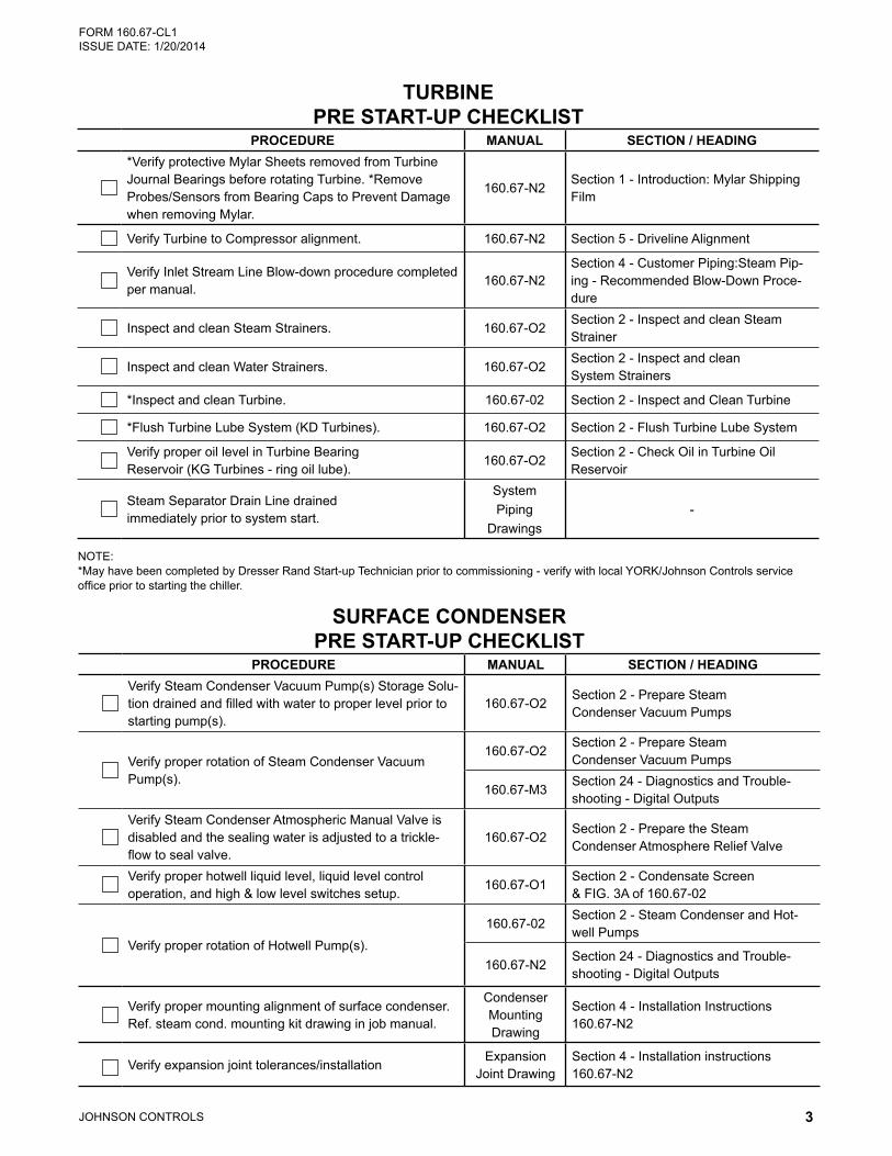
TURBINE PRE START-UP CHECKLIST
PROCEDURE MANUAL SECTION / HEADING*Verify protective Mylar Sheets removed from Turbine Journal Bearings before rotating Turbine. *Remove Probes/Sensors from Bearing Caps to Prevent Damage when removing Mylar.
160.67-N2Section 1 - Introduction: Mylar Shipping Film
Verify Turbine to Compressor alignment. 160.67-N2 Section 5 - Driveline Alignment
Verify Inlet Stream Line Blow-down procedure completed per manual.
160.67-N2Section 4 - Customer Piping:Steam Pip-ing - Recommended Blow-Down Proce-dure
Inspect and clean Steam Strainers. 160.67-O2Section 2 - Inspect and clean Steam Strainer
Inspect and clean Water Strainers. 160.67-O2Section 2 - Inspect and clean System Strainers
*Inspect and clean Turbine. 160.67-02 Section 2 - Inspect and Clean Turbine
*Flush Turbine Lube System (KD Turbines). 160.67-O2 Section 2 - Flush Turbine Lube System
Verify proper oil level in Turbine Bearing Reservoir (KG Turbines - ring oil lube).
160.67-O2Section 2 - Check Oil in Turbine Oil Reservoir
Steam Separator Drain Line drained immediately prior to system start.
System Piping
Drawings-
NOTE: * May have been completed by Dresser Rand Start-up Technician prior to commissioning - verify with local YORK/Johnson Controls service office prior to starting the chiller.
SURFACE CONDENSER PRE START-UP CHECKLIST
PROCEDURE MANUAL SECTION / HEADINGVerify Steam Condenser Vacuum Pump(s) Storage Solu-tion drained and filled with water to proper level prior to starting pump(s).
160.67-O2Section 2 - Prepare Steam Condenser Vacuum Pumps
Verify proper rotation of Steam Condenser Vacuum Pump(s).
160.67-O2Section 2 - Prepare Steam Condenser Vacuum Pumps
160.67-M3Section 24 - Diagnostics and Trouble-shooting - Digital Outputs
Verify Steam Condenser Atmospheric Manual Valve is disabled and the sealing water is adjusted to a trickle-flow to seal valve.
160.67-O2Section 2 - Prepare the Steam Condenser Atmosphere Relief Valve
Verify proper hotwell liquid level, liquid level control operation, and high & low level switches setup.
160.67-O1Section 2 - Condensate Screen& FIG. 3A of 160.67-02
Verify proper rotation of Hotwell Pump(s).
160.67-02Section 2 - Steam Condenser and Hot-well Pumps
160.67-N2Section 24 - Diagnostics and Trouble-shooting - Digital Outputs
Verify proper mounting alignment of surface condenser. Ref. steam cond. mounting kit drawing in job manual.
Condenser Mounting Drawing
Section 4 - Installation Instructions 160.67-N2
Verify expansion joint tolerances/installationExpansion
Joint DrawingSection 4 - Installation instructions 160.67-N2
JOHNSON CONTROLS4
FORM 160.67-CL1 ISSUE DATE: 1/20/2014
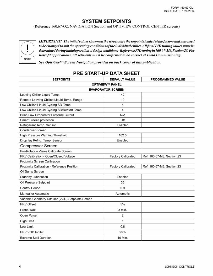
SETPOINTS DEFAULT VALUE PROGRAMMED VALUEOPTIVIEW™ PANEL
EVAPORATOR SCREENLeaving Chiller Liquid Temp. 42Remote Leaving Chilled Liquid Temp. Range 10Low Chilled Liquid Cycling SD Temp. 4Low Chilled Liquid Cycling SD/Restart Temp. 4Brine Low Evaporator Pressure Cutout N/ASmart Freeze protection OffRefrigerant Temp. Sensor EnabledCondenser ScreenHigh Pressure Warning Threshold 162.5Drop leg Refrig. Temp. Sensor Enabled
Compressor ScreenPre-Rotation Vanes Calibrate ScreenPRV Calibration - Open/Closed Voltage Factory Calibrated Ref. 160.67-M3, Section 23Proximity Screen CalibrationProximity Calibration - Reference Position Factory Calibrated Ref. 160.67-M3, Section 23Oil Sump Screen
Standby Lubrication Enabled
Oil Pressure Setpoint 35
Control Period 0.9
Manual or Automatic Automatic
Variable Geometry Diffuser (VGD) Setpoints Screen
PRV Offset 5%
Probe Wait 3 min.
Open Pulse 2
High Limit 1
Low Limit 0.8
PRV VGD Inhibit 95%
Extreme Stall Duration 10 Min.
SYSTEM SETPOINTS (Reference 160.67-O2, NAVIGATION Section and OPTIVIEW CONTROL CENTER screens)
PRE START-UP DATA SHEET
IMPORTANT! The initial values shown on the screens are the setpoints loaded at the factory and may need to be changed to suit the operating conditions of the individual chiller. All final PID tuning values must be determined during initial operation at design conditions - Reference PID tuning in 160.67-M3, Section 23. For Retrofit applications, all setpoints must be confirmed to be correct at Field Commissioning.
See OptiView™ Screen Navigation provided on back cover of this publication.
JOHNSON CONTROLS 5
FORM 160.67-CL1 ISSUE DATE: 1/20/2014
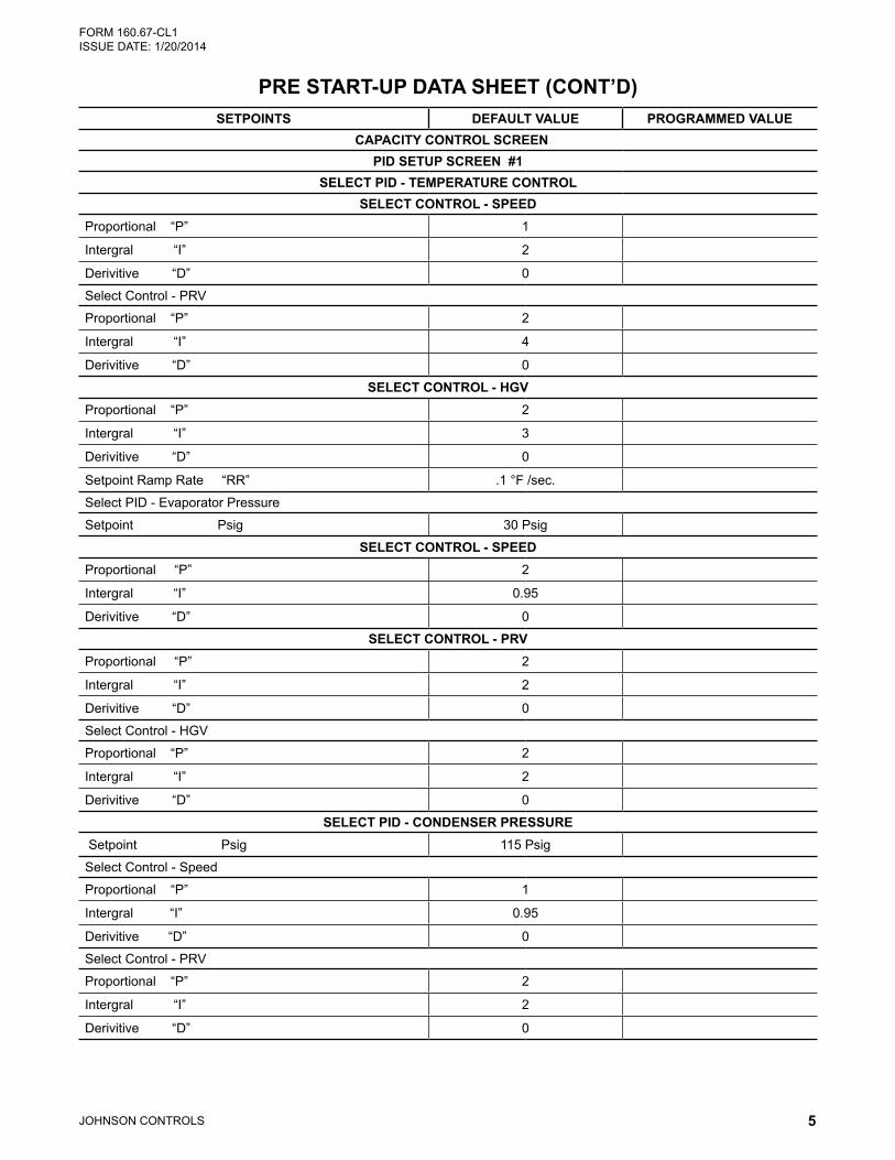
PRE START-UP DATA SHEET (CONT’D)SETPOINTS DEFAULT VALUE PROGRAMMED VALUE
CAPACITY CONTROL SCREENPID SETUP SCREEN #1
SELECT PID - TEMPERATURE CONTROLSELECT CONTROL - SPEED
Proportional “P” 1
Intergral “I” 2
Derivitive “D” 0
Select Control - PRV
Proportional “P” 2
Intergral “I” 4
Derivitive “D” 0
SELECT CONTROL - HGVProportional “P” 2
Intergral “I” 3
Derivitive “D” 0
Setpoint Ramp Rate “RR” .1 °F /sec.
Select PID - Evaporator Pressure
Setpoint Psig 30 Psig
SELECT CONTROL - SPEEDProportional “P” 2
Intergral “I” 0.95
Derivitive “D” 0
SELECT CONTROL - PRVProportional “P” 2
Intergral “I” 2
Derivitive “D” 0
Select Control - HGV
Proportional “P” 2
Intergral “I” 2
Derivitive “D” 0
SELECT PID - CONDENSER PRESSURE Setpoint Psig 115 Psig
Select Control - Speed
Proportional “P” 1
Intergral “I” 0.95
Derivitive “D” 0
Select Control - PRV
Proportional “P” 2
Intergral “I” 2
Derivitive “D” 0
JOHNSON CONTROLS6
FORM 160.67-CL1 ISSUE DATE: 1/20/2014
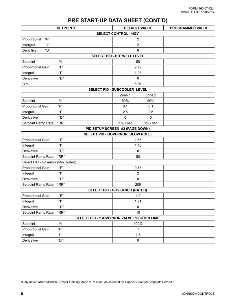
PRE START-UP DATA SHEET (CONT’D)SETPOINTS DEFAULT VALUE PROGRAMMED VALUE
SELECT CONTROL - HGVProportional “P” 2Intergral “I” 2Derivitive “D” 0
SELECT PID - HOTWELL LEVELSetpoint % 50Proportional Gain “P” 2.79Integral “I” 1.25Derivative “D” 0O % 50%
SELECT PID - SUBCOOLER LEVELZone 1 Zone 2
Setpoint % 50% 50%Proportional Gain “P” 0.1 0.1Integral “I” 2.5 2.5Derivative “D” 0 0Setpoint Ramp Rate “RR” .1 % / sec. .1% / sec.
PID SETUP SCREEN #2 (PAGE DOWN)SELECT PID - GOVERNOR (SLOW ROLL)
Proportional Gain “P” 1.68Integral “I” 1.46Derivative “D” 0Setpoint Ramp Rate “RR” 50Select PID - Governor (Min. Rated)Proportional Gain “P” 0.75Integral “I” 2Derivative “D” 0Setpoint Ramp Rate “RR” 200
SELECT PID - GOVERNOR (RATED)Proportional Gain “P” 1.2Integral “I” 1.21Derivative “D” 0Setpoint Ramp Rate “RR” 10
SELECT PID - *GOVERNOR VALVE POSITION LIMITSetpoint % 100%Proportional Gain “P” 1Integral “I” 1.5Derivative “D” 0
* Only active when MSSP8 - Power Limiting Mode = Position, as selected on Capacity Control Setpoints Screen 1.
JOHNSON CONTROLS 7
FORM 160.67-CL1 ISSUE DATE: 1/20/2014
PRE START-UP DATA SHEET (CONT’D)SETPOINTS DEFAULT VALUE PROGRAMMED VALUE
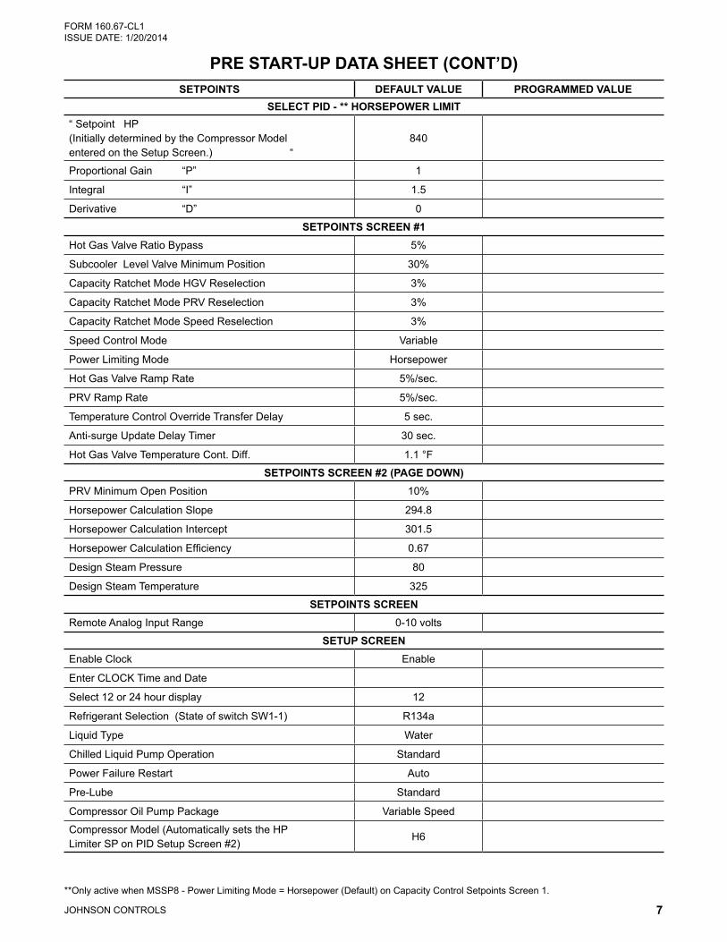
SELECT PID - ** HORSEPOWER LIMIT“ Setpoint HP (Initially determined by the Compressor Model entered on the Setup Screen.) “
840
Proportional Gain “P” 1
Integral “I” 1.5
Derivative “D” 0
SETPOINTS SCREEN #1Hot Gas Valve Ratio Bypass 5%
Subcooler Level Valve Minimum Position 30%
Capacity Ratchet Mode HGV Reselection 3%
Capacity Ratchet Mode PRV Reselection 3%
Capacity Ratchet Mode Speed Reselection 3%
Speed Control Mode Variable
Power Limiting Mode Horsepower
Hot Gas Valve Ramp Rate 5%/sec.
PRV Ramp Rate 5%/sec.
Temperature Control Override Transfer Delay 5 sec.
Anti-surge Update Delay Timer 30 sec.
Hot Gas Valve Temperature Cont. Diff. 1.1 °F
SETPOINTS SCREEN #2 (PAGE DOWN)PRV Minimum Open Position 10%
Horsepower Calculation Slope 294.8
Horsepower Calculation Intercept 301.5
Horsepower Calculation Efficiency 0.67
Design Steam Pressure 80
Design Steam Temperature 325
SETPOINTS SCREENRemote Analog Input Range 0-10 volts
SETUP SCREENEnable Clock Enable
Enter CLOCK Time and Date
Select 12 or 24 hour display 12
Refrigerant Selection (State of switch SW1-1) R134a
Liquid Type Water
Chilled Liquid Pump Operation Standard
Power Failure Restart Auto
Pre-Lube Standard
Compressor Oil Pump Package Variable Speed
Compressor Model (Automatically sets the HP Limiter SP on PID Setup Screen #2)
H6
** Only active when MSSP8 - Power Limiting Mode = Horsepower (Default) on Capacity Control Setpoints Screen 1.
JOHNSON CONTROLS8
FORM 160.67-CL1 ISSUE DATE: 1/20/2014
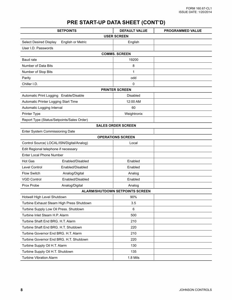
SETPOINTS DEFAULT VALUE PROGRAMMED VALUEUSER SCREEN
Select Desired Display English or Metric English
User I.D. Passwords
COMMS. SCREENBaud rate 19200
Number of Data Bits 8
Number of Stop Bits 1
Parity odd
Chiller I.D. 0
PRINTER SCREENAutomatic Print Logging Enable/Disable Disabled
Automatic Printer Logging Start Time 12:00 AM
Automatic Logging Interval 60
Printer Type Weightronix
Report Type (Status/Setpoints/Sales Order)
SALES ORDER SCREENEnter System Commissioning Date
OPERATIONS SCREENControl Source( LOCAL/ISN/Digital/Analog) Local
Edit Regional telephone if necessary
Enter Local Phone Number
Hot Gas Enabled/Disabled Enabled
Level Control Enabled/Disabled Enabled
Flow Switch Analog/Digital Analog
VGD Control Enabled/Disabled Enabled
Prox Probe Analog/Digital Analog
ALARM/SHUTDOWN SETPOINTS SCREENHotwell High Level Shutdown 90%
Turbine Exhaust Steam High Press Shutdown 3.5
Turbine Supply Low Oil Press. Shutdown 6
Turbine Inlet Steam H.P. Alarm 500
Turbine Shaft End BRG. H.T. Alarm 210
Turbine Shaft End BRG. H.T. Shutdown 220
Turbine Governor End BRG. H.T. Alarm 210
Turbine Governor End BRG. H.T. Shutdown 220
Turbine Supply Oil H.T. Alarm 130
Turbine Supply Oil H.T. Shutdown 135
Turbine Vibration Alarm 1.8 Mils
PRE START-UP DATA SHEET (CONT’D)
JOHNSON CONTROLS 9
FORM 160.67-CL1 ISSUE DATE: 1/20/2014
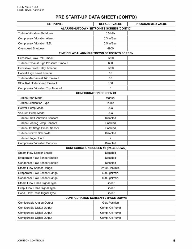
SETPOINTS DEFAULT VALUE PROGRAMMED VALUEALARM/SHUTDOWN SETPOINTS SCREEN (CONT’D)
Turbine Vibration Shutdown 3.0 Mils
Compressor Vibration Alarm 0.3 In/Sec.
Compressor Vibration S.D. 0.5 In/Sec.
Overspeed Shutdown 4900
TIME DELAY ALARM/SHUTDOWN SETPOINTS SCREENExcessive Slow Roll Timeout 1200
Turbine Exhaust High Pressure Timeout 600
Excessive Start Delay Timeout 1200
Hotwell High Level Timeout 10
Turbine Mechanical Trip Timeout 10
Slow Roll Underspeed Timeout 100
Compressor Vibration Trip Timeout 5
CONFIGURATION SCREEN #1Turbine Start Mode Manual
Turbine Lubrication Type Pump
Hotwell Pump Mode Dual
Vacuum Pump Mode Dual
Turbine Shaft Vibration Sensors Disabled
Turbine Bearing Temp Sensors Enabled
Turbine 1st Stage Press. Sensor Enabled
Turbine Nozzle Solenoids Disabled
Turbine Stage Count 7
Compressor Vibration Sensors Disabled
CONFIGURATION SCREEN #2 (PAGE DOWN)Steam Flow Sensor Enable Disabled
Evaporator Flow Sensor Enable Disabled
Condenser Flow Sensor Enable Disabled
Steam Flow Sensor Range 24000 lbs/min.
Evaporator Flow Sensor Range 6000 gal/min.
Condenser Flow Sensor Range 8000 gal/min.
Steam Flow Trans Signal Type Linear
Evap. Flow Trans Signal Type Linear
Cond. Flow Trans Signal Type Linear
CONFIGURATION SCREEN # 3 (PAGE DOWN)Configurable Analog Output Gov. Position
Configurable Digital Output Comp. Oil Pump
Configurable Digital Output Comp. Oil Pump
Configurable Digital Output Comp. Oil Pump
PRE START-UP DATA SHEET (CONT’D)
JOHNSON CONTROLS10
FORM 160.67-CL1 ISSUE DATE: 1/20/2014
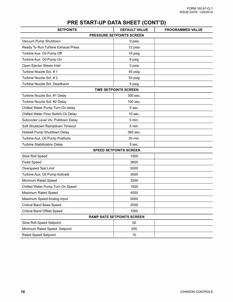
SETPOINTS DEFAULT VALUE PROGRAMMED VALUEPRESSURE SETPOINTS SCREEN
Vacuum Pump Shutdown 9 psia
Ready To Run Turbine Exhaust Press 12 psia
Turbine Aux. Oil Pump Off 16 psig
Turbine Aux. Oil Pump On 8 psig
Open Ejector Steam Inlet 5 psia
Turbine Nozzle Sol. # 1 45 psig
Turbine Nozzle Sol. # 2 50 psig
Turbine Nozzle Sol. Deadband 5 psig
TIME SETPOINTS SCREENTurbine Nozzle Sol. #1 Delay 300 sec.
Turbine Nozzle Sol. #2 Delay 100 sec.
Chilled Water Pump Turn-On delay 5 sec.
Chilled Water Flow Switch Ck Delay 10 sec.
Subcooler Level Vlv. Pulldown Delay 5 min.
Soft Shutdown Rampdown Timeout 5 min.
Hotwell Pump Shutdown Delay 360 sec.
Turbine Aux. Oil Pump Postlube 30 min.
Turbine Stabilization Delay 5 sec.
SPEED SETPOINTS SCREENSlow Roll Speed 1000
Fixed Speed 3600
Overspeed Test Limit 5000
Turbine Aux. Oil Pump Activate 3000
Minimum Rated Speed 3200
Chilled Water Pump Turn On Speed 1500
Maximum Rated Speed 4500
Maximum Speed Analog Input 5000
Critical Band Base Speed 2000
Critical Band Offset Speed 1000
RAMP RATE SETPOINTS SCREENSlow Roll Speed Setpoint 50
Minimum Rated Speed Setpoint 200
Rated Speed Setpoint 10
PRE START-UP DATA SHEET (CONT’D)
JOHNSON CONTROLS 11
FORM 160.67-CL1 ISSUE DATE: 1/20/2014
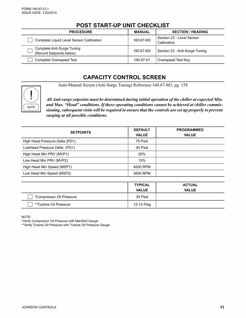
NOTE: * Verify Compressor Oil Pressure with Manifold Gauge. ** Verify Turbine Oil Pressure with Turbine Oil Pressure Gauge.
POST START-UP UNIT CHECKLISTPROCEDURE MANUAL SECTION / HEADING
Complete Liquid Level Sensor Calibration 160.67-M3Section 23 - Level Sensor Calibration
Complete Anti-Surge Tuning(Record Setpoints below)
160.67-M3 Section 23 - Anti-Surge Tuning
Complete Overspeed Test 160.67-01 Overspeed Test Key
CAPACITY CONTROL SCREENAuto/Manual Screen (Anti-Surge Tuning) Reference 160.67-M3, pg. 158
All Anti-surge setpoints must be determined during initial operation of the chiller at expected Min. and Max. “Head” conditions. If these operating conditions cannot be achieved at chiller commis-sioning, subsequent visits will be required to ensure that the controls are set up properly to prevent surging at all possible conditions.
SETPOINTSDEFAULT
VALUEPROGRAMMED
VALUEHigh Head Pressure Delta (PD1) 75 Psid
LowHead Pressure Delta (PD1) 40 Psid
High Head Min PRV (MVP1) 20%
Low Head Min PRV (MVP2) 15%
High Head Min Speed (MSP1) 4500 RPM
Low Head Min Speed (MSP2) 3600 RPM
TYPICALVALUE
ACTUALVALUE
*Compressor Oil Pressure 35 Psid
**Turbine Oil Pressure 12-15 Psig
P.O. Box 1592, York, Pennsylvania USA 17405-1592 800-861-1001 Subject to change without notice. Printed in USACopyright © by Johnson Controls 2014 www.johnsoncontrols.com ALL RIGHTS RESERVEDForm160.67-CL1 (114)Issue Date: January 20, 2014 Supersedes: 160.67-CL1 (1108)
FORM 160.67-CL1 ISSUE DATE: 1/20/2014
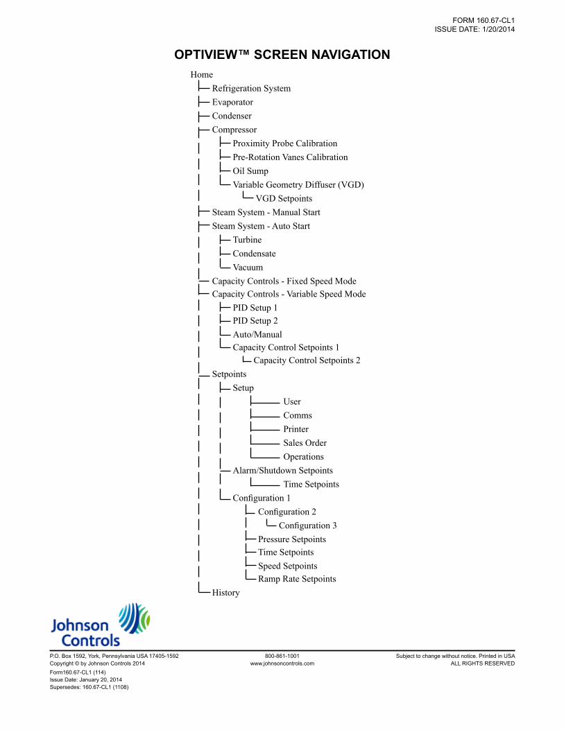
OPTIVIEW™ SCREEN NAVIGATIONHome
Refrigeration System Evaporator Condenser Compressor
Proximity Probe Calibration Pre-Rotation Vanes Calibration Oil Sump Variable Geometry Diffuser (VGD) VGD Setpoints
Steam System - Manual Start Steam System - Auto Start
Turbine Condensate Vacuum
Capacity Controls - Fixed Speed Mode Capacity Controls - Variable Speed Mode
PID Setup 1 PID Setup 2 Auto/Manual Capacity Control Setpoints 1 Capacity Control Setpoints 2
Setpoints Setup
User Comms Printer Sales Order Operations
Alarm/Shutdown Setpoints Time Setpoints
Configuration 1 Configuration 2 Configuration 3 Pressure Setpoints Time Setpoints Speed Setpoints Ramp Rate Setpoints
History