Embed Size (px)
Citation preview
AIR-COOLED SCREW LIQUID CHILLERS
INSTALLATION, OPERATION, MAINTENANCE Supersedes: 201.28-NM1.1 (514) Form 201.28-NM1.1 (215)
Issue Date:February 6, 2015
HFC-134A
LD15045
150 - 500 TONS525 - 1750 KW
2 COMPRESSOR 50 AND 60 HZ
MODEL YVAA STYLE A AIR-COOLED SCREW LIQUID CHILLERS WITH
VARIABLE SPEED DRIVEFRAME SIZES 015 - 052
035-23219-100
JOHNSON CONTROLS2
FORM 201.28-NM1.1 ISSUE DATE: 2/06/2015
This equipment is a relatively complicated apparatus. During rigging, installation, operation, maintenance, or service, individuals may be exposed to certain com-ponents or conditions including, but not limited to: heavy objects, refrigerants, materials under pressure, rotating components, and both high and low voltage. Each of these items has the potential, if misused or handled improperly, to cause bodily injury or death. It is the obligation and responsibility of rigging, instal-lation, and operating/service personnel to identify and recognize these inherent hazards, protect themselves, and proceed safely in completing their tasks. Failure to comply with any of these requirements could result in serious damage to the equipment and the property in
IMPORTANT!READ BEFORE PROCEEDING!
GENERAL SAFETY GUIDELINES
which it is situated, as well as severe personal injury or death to themselves and people at the site.
This document is intended for use by owner-authorized rigging, installation, and operating/service personnel. It is expected that these individuals possess independent training that will enable them to perform their assigned tasks properly and safely. It is essential that, prior to performing any task on this equipment, this individual shall have read and understood the on-product labels, this document and any referenced materials. This in-dividual shall also be familiar with and comply with all applicable industry and governmental standards and regulations pertaining to the task in question.
SAFETY SYMBOLSThe following symbols are used in this document to alert the reader to specific situations:
Indicates a possible hazardous situation which will result in death or serious injury if proper care is not taken.
Indicates a potentially hazardous situa-tion which will result in possible injuries or damage to equipment if proper care is not taken.
Identifies a hazard which could lead to damage to the machine, damage to other equipment and/or environmental pollu-tion if proper care is not taken or instruc-tions and are not followed.
Highlights additional information useful to the technician in completing the work being performed properly.
External wiring, unless specified as an optional connection in the manufacturer’s product line, is not to be connected inside the control cabinet. Devices such as relays, switches, transducers and controls and any external wiring must not be installed inside the micro panel. All wiring must be in accor-dance with Johnson Controls’ published specifications and must be performed only by a qualified electrician. Johnson Controls will NOT be responsible for damage/problems resulting from improper connections to the controls or application of improper control signals. Failure to follow this warn-ing will void the manufacturer’s warranty and cause serious damage to property or personal injury.
JOHNSON CONTROLS 3
FORM 201.28-NM1.1ISSUE DATE: 2/06/2015
In complying with Johnson Controls’ policy for con-tinuous product improvement, the information con-tained in this document is subject to change without notice. Johnson Controls makes no commitment to update or provide current information automatically to the manual or product owner. Updated manuals, if applicable, can be obtained by contacting the nearest Johnson Controls Service office or accessing the John-son Controls QuickLIT website at http://cgproducts.johnsoncontrols.com.
It is the responsibility of rigging, lifting, and operating/ service personnel to verify the applicability of these documents to the equipment. If there is any question
The Control/VSD Cabinet contains lethal high AC and DC voltages. Before per-forming service inside the cabinet, remove the AC supply feeding the chiller and verify using a non-contact voltage sensor.
The DC voltage on the VSD DC Bus will take 5 minutes to bleed off, after AC power is removed. Always check the DC Bus Voltage with a Voltmeter to assure the capacitor charge has bled off before working on the system.
NEVER short out the DC Bus to dis-charge the filter capacitors.
NEVER place loose tools, debris, or any objects inside the Control Panel/VSD Cabinet.
NEVER allow the Control Panel VSD Cabinet doors to remain open if there is a potential for rain to enter the panel. Keep doors closed and assure all latches are engaged on each door unless the unit is being serviced.
ALWAYS lockout the disconnect supply-ing AC to the chiller.
The 1L Line Inductor will reach operating temperatures of over 150°C (300°F.) DO NOT open panel doors during operation. Assure the inductor is cool whenever working near the inductor with power OFF.
regarding the applicability of these documents, rig-ging, lifting, and operating/service personnel should verify whether the equipment has been modified and if current literature is available from the owner of the equipment prior to performing any work on the chiller.
CHANGE BARSRevisions made to this document are indicated with a line along the left or right hand column in the area the revision was made. These revisions are to technical in-formation and any other changes in spelling, grammar or formatting are not included.
CHANGEABILITY OF THIS DOCUMENT
ASSOCIATED LITERATURE
MANUAL DESCRIPTION FORM NUMBER
Equipment Pre-Startup and Startup Checklist 201.28-CL2
YVAA Style A Frame Size 015 - 027, 2 Compressor 60 Hz (150-350 Tons)YVAA Style A Frame Size 054 - 098, 2 Compressor 50 Hz (525-950 KW) Manufactured before April 2012
201.28-RP1
YVAA Style A Frame Size 015 - 052, 2 Compressor 50 & 60 Hz (150-500 Tons) (Manufactured after April 2012 to before September 2014)
201.28-RP2
YVAA Style B Frame Size 015 - 052, 2 Compressor 50 & 60 Hz (150-500 Tons) (Manufactured after September 2014)
201.28-RP3

JOHNSON CONTROLS4
FORM 201.28-NM1.1 ISSUE DATE: 2/06/2015
THIS PAGE INTENTIONALLY LEFT BLANK
JOHNSON CONTROLS 5
FORM 201.28-NM1.1ISSUE DATE: 2/06/2015
TABLE OF CONTENTS
SECTION 1 - GENERAL CHILLER INFORMATION AND SAFETY ......................................................................13Introduction .....................................................................................................................................................13Warranty .........................................................................................................................................................13Quality Assurance and Safety ........................................................................................................................13Fluorinated Greenhouse Gases .....................................................................................................................14Responsibility for Safety .................................................................................................................................14About This Manual..........................................................................................................................................14Misuse of Equipment ......................................................................................................................................14
Suitability for Application .......................................................................................................................14Structural Support .................................................................................................................................14Mechanical Strength .............................................................................................................................14General Access .....................................................................................................................................14Pressure Systems .................................................................................................................................15Electrical ................................................................................................................................................15Rotating Parts ........................................................................................................................................15Sharp Edges ..........................................................................................................................................15Refrigerants and Oils .............................................................................................................................15High Temperature and Pressure Cleaning ............................................................................................15Emergency Shutdown ...........................................................................................................................16Safety Labels .........................................................................................................................................16
SECTION 2 - PRODUCT DESCRIPTION ...............................................................................................................17General System Description ...........................................................................................................................17Semi-Hermetic YORK Twin-Screw Compressors ...........................................................................................18Evaporator ......................................................................................................................................................19Condenser ......................................................................................................................................................19Refrigerant Circuit ..........................................................................................................................................19Electrical .........................................................................................................................................................19Building Automation System Capabilities .......................................................................................................19Microcomputer Control Center .......................................................................................................................20
Display Data ..........................................................................................................................................20Programmable Setpoints ......................................................................................................................20
Accessories and Options ................................................................................................................................21Sound Attenuation .................................................................................................................................21
Fan Options ....................................................................................................................................................21Condenser Coils .............................................................................................................................................21
Condenser Coil Protection ....................................................................................................................21Protective Chiller Panels .......................................................................................................................21Evaporator Options ...............................................................................................................................22Controls Options ....................................................................................................................................22General Options ....................................................................................................................................22Vibration Isolation ..................................................................................................................................23
JOHNSON CONTROLS6
FORM 201.28-NM1.1 ISSUE DATE: 2/06/2015
TABLE OF CONTENTS (CONT'D)
SECTION 3 - RIGGING, HANDLING AND STORAGE ..........................................................................................25Lifting Weights ................................................................................................................................................25Delivery and Storage ......................................................................................................................................25Inspection .......................................................................................................................................................25Moving the Chiller ...........................................................................................................................................26Unit Removal From Shipping Container .........................................................................................................26Lifting Using Lugs ...........................................................................................................................................26Lifting Using Shackles ....................................................................................................................................26
SECTION 4 - INSTALLATION ................................................................................................................................37Location Requirements ..................................................................................................................................37Outdoor Installations ......................................................................................................................................37Location Clearances .......................................................................................................................................37
Recommended Minimum Clearances ...................................................................................................37Vibration Isolators ...........................................................................................................................................38
Installation .............................................................................................................................................38Shipping Braces .............................................................................................................................................38Chilled Liquid Piping .......................................................................................................................................39
General Requirements ..........................................................................................................................39Water Treatment .............................................................................................................................................40Pipework Arrangement ...................................................................................................................................40Minimum Water Volume .................................................................................................................................40Leaving Water Temperature Out of Range .....................................................................................................40Flow Rate Out of Range .................................................................................................................................40Thermal Storage .............................................................................................................................................41Variable Primary Flow ....................................................................................................................................41Connection Types and Sizes ..........................................................................................................................41Evaporator Connections .................................................................................................................................41
Option Flanges ......................................................................................................................................43Refrigerant Relief Valve Piping .......................................................................................................................43Electrical Connection ......................................................................................................................................43Power Wiring ..................................................................................................................................................44Power Supply Wiring ......................................................................................................................................44115VAC Control Supply Transformer ..............................................................................................................44Control Wiring .................................................................................................................................................44Volts Free Contacts ........................................................................................................................................44
Chilled Liquid Pump Starter ...................................................................................................................44Run Contact ..........................................................................................................................................44Alarm Contacts ......................................................................................................................................44
System Inputs .................................................................................................................................................45Flow Switch ...........................................................................................................................................45Remote Run / Stop ................................................................................................................................45Remote Print .........................................................................................................................................45Optional Remote Setpoint Offset – Temperature...................................................................................45Optional Remote Setpoint Offset – Current ...........................................................................................45Optional Remote Setpoint Offset – Sound Limiting ...............................................................................45
Power Supply Wiring ......................................................................................................................................46Single Point Wiring ................................................................................................................................46Voltage Utilization Range ......................................................................................................................46Dual Point Wiring ...................................................................................................................................47
Customer Control Wiring ................................................................................................................................49
JOHNSON CONTROLS 7
FORM 201.28-NM1.1ISSUE DATE: 2/06/2015
TABLE OF CONTENTS (CONT'D)
SECTION 5 - TECHNICAL DATA ...........................................................................................................................61Nomenclature .................................................................................................................................................61Elastometric Isolator Installation .....................................................................................................................80Elastometric Isolator Specifications ................................................................................................................81One Inch Deflection Isolator Installation .........................................................................................................82One Inch Deflection Spring Isolator Specifications ........................................................................................83Two Inch Deflection Isolator Installation And Adjustment ...............................................................................84Two Inch Deflection, Restrained Spring Isolator Specifications .....................................................................85Elastometric Isolator Installation (GB Certified Units) ....................................................................................86Elastometric Isolator Specifications (GB Certified Units) Specifications ........................................................87One Inch Deflection Isolator Installation (GB Certified Units) .........................................................................88One Inch Deflection Isolator Installation (GB Certified Units) Specifications .................................................89Two Inch Deflection Isolator Installation And Adjustment (GB Certified Units) ...............................................90Two Inch Deflection, Restrained Spring Isolator Specifications (GB Certified Units) .....................................91
SECTION 6 - COMMISSIONING ............................................................................................................................93Preparation .....................................................................................................................................................93
Inspection .............................................................................................................................................93Refrigerant Charge ................................................................................................................................93Correct System Refrigerant Charge ......................................................................................................93Service and Oil Line Valves ...................................................................................................................93Compressor Oil .....................................................................................................................................93Fans .....................................................................................................................................................94Isolation / Protection ..............................................................................................................................94Control Panel .........................................................................................................................................94Power Connections ...............................................................................................................................94Grounding ..............................................................................................................................................94Water System ........................................................................................................................................94Flow Switch ...........................................................................................................................................94Temperature Sensor(s) ..........................................................................................................................94Programmed Options ............................................................................................................................94Programmed Settings ...........................................................................................................................94Date and Time .......................................................................................................................................94Start/Stop Schedule ..............................................................................................................................95Setpoint and Remote Offset ..................................................................................................................95
First Time Start Up .........................................................................................................................................95Interlocks ...............................................................................................................................................95Unit Switch ............................................................................................................................................95Startup ...................................................................................................................................................95Oil Pressure ...........................................................................................................................................95Loading ..................................................................................................................................................95Condenser and Fan Rotation ................................................................................................................95System Charge ......................................................................................................................................95
General Operation .........................................................................................................................................95Operation in Sub-freezing Conditions ...................................................................................................96Unit Maintenance and Shutdown in Sub-freezing Conditions ..............................................................96
JOHNSON CONTROLS8
FORM 201.28-NM1.1 ISSUE DATE: 2/06/2015
SECTION 7 - OPERATION .....................................................................................................................................97Operating Controls .........................................................................................................................................97
Unit Switch ............................................................................................................................................97Keypad ..................................................................................................................................................97Keypad Data Entry Mode ......................................................................................................................98Display ...................................................................................................................................................98Anti-recycle Timer ..................................................................................................................................98Evaporator Pump Control ......................................................................................................................98Evaporator Heater Control ....................................................................................................................98Alarms ...................................................................................................................................................99Chiller Run Contact ...............................................................................................................................99Flow Switch Control ...............................................................................................................................99Remote Run / Stop ................................................................................................................................99
Basic Operating Sequence .............................................................................................................................99Start Sequence and Loading .................................................................................................................99
Unit Warning ...................................................................................................................................................99Unit Warning Operation .........................................................................................................................99Low Battery Warning .............................................................................................................................99Invalid Number of Compressors Warning............................................................................................100Invalid Serial Number Warning ............................................................................................................100
Unit Safeties .................................................................................................................................................100Unit Safety Operation ..........................................................................................................................100High Ambient Temp Fault ....................................................................................................................100Low Ambient Temp Fault .....................................................................................................................101Low Leaving Chilled Liquid Temp Fault ...............................................................................................101VSD Communications Failure Fault ....................................................................................................101
System Safeties (Faults) ..............................................................................................................................101System Safety (Fault) Operation .........................................................................................................101High Discharge Pressure Cutout (Software) Fault ..............................................................................102High Discharge Pressure Cutout (HPCO) (Hardware) Fault ..............................................................102Low Suction Pressure Cutout (Software) Fault ...................................................................................102Low Motor Current Cutout Fault ..........................................................................................................103High Differential Oil Pressure Cutout Fault .........................................................................................103Low Differential Oil Pressure Cutout Fault ..........................................................................................103High Discharge Temperature Cutout Fault ..........................................................................................103Low Discharge Superheat Cutout Fault ..............................................................................................104Sensor Failure Cutout Fault ................................................................................................................104High Motor Temperature Cutout Fault .................................................................................................104System Control Voltage Cutout Fault ..................................................................................................105Eductor Clog Fault ...............................................................................................................................105
TABLE OF CONTENTS (CONT'D)
JOHNSON CONTROLS 9
FORM 201.28-NM1.1ISSUE DATE: 2/06/2015
SECTION 8 - MICROPANEL ................................................................................................................................107Unit Data Key ............................................................................................................................................... 110System Data Keys 1 Through 4.................................................................................................................... 112VSD Data Key .............................................................................................................................................. 115Operating Hours / Start Counter Key ........................................................................................................... 116History Key ................................................................................................................................................... 117Setpoints Key ...............................................................................................................................................124Program Key ................................................................................................................................................126Options Key ..................................................................................................................................................129Date/Time and Schedule Keys .....................................................................................................................132Manual Override Key ....................................................................................................................................135Print Key .......................................................................................................................................................136System Switches Key ...................................................................................................................................139
SECTION 9 - MAINTENANCE ..............................................................................................................................141General Requirements .................................................................................................................................141
Weekly Maintenance ...........................................................................................................................141Unit Status ...........................................................................................................................................141Refrigerant Leaks ................................................................................................................................141Operating Conditions ...........................................................................................................................141Compressor Oil Level ..........................................................................................................................141Refrigerant Charge ..............................................................................................................................141Adding Charge to a System ................................................................................................................141
Refrigerant Removal, Evacuation and Charging a YVAA Chiller .................................................................142Refrigerant Removal ...........................................................................................................................142Evacuating a System ...........................................................................................................................142Charging Refrigerant into a System ....................................................................................................143
Microchannel Coil Cleaning ..........................................................................................................................143Scheduled Maintenance ......................................................................................................................143
Maintenance Requirements for YVAA Chillers .............................................................................................144
SECTION 10 - DECOMMISSIONING, DISMANTLING AND DISPOSAL ............................................................153
TABLE OF CONTENTS (CONT'D)
JOHNSON CONTROLS10
FORM 201.28-NM1.1 ISSUE DATE: 2/06/2015
LIST OF FIGURES
FIGURE 1 - YVAA Air-Cooled Screw Liquid Chiller with Variable Speed Drive .......................................................17FIGURE 2 - Chiller Control System .........................................................................................................................18FIGURE 3 - View of York Control Center User Interface .........................................................................................20FIGURE 4 - Acceptable Minimum Clearances Around/Between Unit(s) .................................................................38FIGURE 5 - Pipework Arrangement ........................................................................................................................40FIGURE 6 - Leaving Water Temperature Out of Range Suggested Layout ............................................................40FIGURE 7 - Suggested Layout For Applications With A Flow Rate Less Than
The Evaporator Minimum Allowable Flow Rate ...................................................................................41FIGURE 8 - Suggested Layout For Applications With A Flow Rate Greater Than
The Evaporator Maximum Allowable Flow Rate ..................................................................................41FIGURE 9 - Victaulic Groove ...................................................................................................................................41FIGURE 10 - Flange For GB Vessels ......................................................................................................................43FIGURE 11 - Flange Attachment .............................................................................................................................43FIGURE 12 - Single Point Power Wiring .................................................................................................................46FIGURE 13 - Dual Point Power Wiring ....................................................................................................................47FIGURE 14 - Customer Control Connections .........................................................................................................49FIGURE 15 - YVAA Dimensions ..............................................................................................................................68FIGURE 16 - Keyboard and Display........................................................................................................................97
JOHNSON CONTROLS 11
FORM 201.28-NM1.1ISSUE DATE: 2/06/2015
LIST OF TABLES
TABLE 1 - Unit Rigging ...........................................................................................................................................28TABLE 2 - Minimum Evaporator Tube Removal Clearance ....................................................................................38TABLE 3 - Evaporator Connections Dimensions ....................................................................................................42TABLE 4 - Electrical Lug Data ................................................................................................................................50TABLE 5 - Physical Data - Microchannel Coil .........................................................................................................62TABLE 6 - Physical Data - Round Tube Coil ..........................................................................................................66TABLE 7 - Isolator Selection and Mounting Locations ............................................................................................70TABLE 8 - Low Differential Oil Pressure Cutout ...................................................................................................103TABLE 9 - Start Inhibit Sensor Thresholds ...........................................................................................................104TABLE 10 - Sensor Min/Max Outputs ................................................................................................................... 114TABLE 11 - Setpoint Limits ...................................................................................................................................125TABLE 12 - Programmable Operating Parameters ...............................................................................................128TABLE 13 - Printout Types ....................................................................................................................................136TABLE 14 - Troubleshooting Guide ......................................................................................................................145TABLE 15 - Temperature Input Voltage Sensor (Measured Signal To Shield At The Sensor) ..............................148TABLE 16 - Outside Air Temperature Sensor Input Voltage (Measured Signal To Shield At The Sensor) ............149TABLE 17 - Pressure Transducer Output Voltage (Measured Signal To Return At The Transducer) ...................150TABLE 18 - Motor Temperature Sensor Resistance (Check At The Motor) ..........................................................151TABLE 19 - SI Metric Conversion .........................................................................................................................155

JOHNSON CONTROLS12
FORM 201.28-NM1.1 ISSUE DATE: 2/06/2015
THIS PAGE INTENTIONALLY LEFT BLANK
JOHNSON CONTROLS 13
FORM 201.28-NM1.1ISSUE DATE: 2/06/2015
1SECTION 1 - GENERAL CHILLER INFORMATION AND SAFETY
INTRODUCTIONYORK YVAA chillers are manufactured to the highest design and construction standards to ensure high per-formance, reliability and adaptability to all types of air conditioning installations.
The unit is intended for cooling water or glycol solu-tions and is not suitable for purposes other than those specified in this manual.
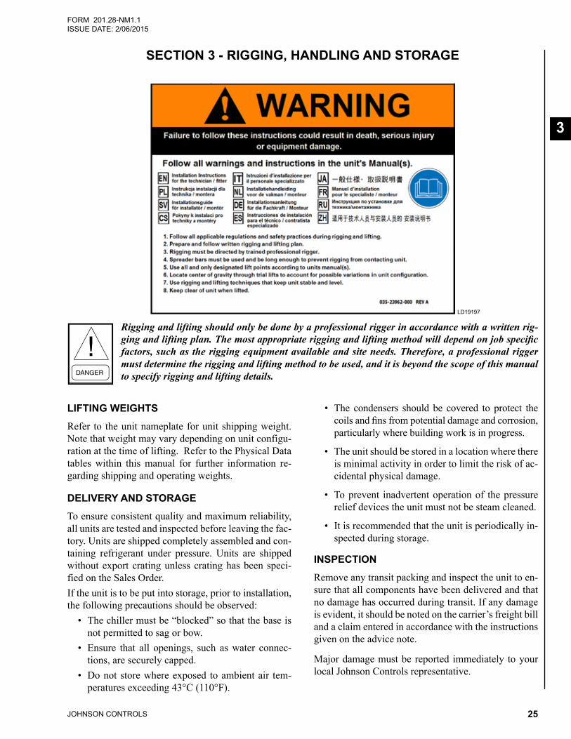
Rigging and lifting should only be done by a profes-sional rigger in accordance with a written rigging and lifting plan. The most appropriate rigging and lifting method will depend on job specific factors, such as the rigging equipment available and site needs. Therefore, a professional rigger must determine the rigging and lifting method to be used, and it is beyond the scope of this manual to specify rigging and lifting details.
This manual contains all the information required for correct installation and commissioning of the unit, to-gether with operating and maintenance instructions. The manual should be read thoroughly before attempt-ing to operate or service the unit.
All procedures detailed in the manual, including in-stallation, commissioning and maintenance tasks must only be performed by suitably trained and qualified personnel.
The manufacturer will not be liable for any injury or damage caused by incorrect installation, commission-ing, operation or maintenance resulting from a failure to follow the procedures and instructions detailed in the manual.
WARRANTYJohnson Controls warrants YVAA chillers in accor-dance with the "Limited Warranty Engineered Systems Equipment" procedure, Form 50.05-NM2.
Johnson Controls warrants all equipment and materi-als against defects in workmanship and materials for a period of eighteen months from date of shipment or 12 months from date of startup, whichever comes first, unless labor or extended warranty has been purchased as part of the contract.
The warranty is limited to parts only replacement and shipping of any faulty part, or sub-assembly, which has failed due to poor quality or manufacturing errors. All
claims must be supported by evidence that the failure has occurred within the warranty period, and that the unit has been operated within the designed parameters specified.
All warranty claims must specify the unit model, serial number, order number and run hours/starts. Model and serial number information is printed on the unit identi-fication plate.
The unit warranty will be void if any modification to the unit is carried out without prior written approval from Johnson Controls.
For warranty purposes, the following conditions must be satisfied:
• The initial start of the unit must be carried out by trained personnel from an authorized Johnson Controls Service Center. Refer to SECTION 6 - COMMISSIONING for more information.
• Only genuine YORK approved spare parts, oils, coolants, and refrigerants must be used.
• All the scheduled maintenance operations detailed inthismanualmustbeperformedatthespecifiedtimesbysuitablytrainedandqualifiedpersonnel.See SECTION 9 - MAINTENANCE for more in-formation.
• Failure to satisfy any of these conditions will automatically void the warranty. Refer to Form 50.05-NM2 for complete details.
QUALITY ASSURANCE AND SAFETYYVAA chillers are designed within EN ISO 9001 and built within an EN ISO 9002 accredited manufacturing organization.
Units conform with the following European Directives:
• Machinery Directive (2006/42/EC)
• EMC Directive (2004/108/EC)
• Pressure Equipment Directive (97/23/EC)
• Low Voltage Directive (2006/95/EC)
• Safety Code for Mechanical Refrigeration (EN378-2(2008))
JOHNSON CONTROLS14
SECTION 1 - GENERAL CHILLER INFORMATION AND SAFETYFORM 201.28-NM1.1
ISSUE DATE: 2/06/2015
CE/PED marked units conform to the following stan-dards:
• Machinery Directive (2006/42/EC).
• EMC Directive (2004/108/EC).
• Pressure Equipment Directive (97/23/EC).
• Low Voltage Directive (2006/95/EC).
• Safety Code for Mechanical Refrigeration (EN378-2(2008)).
ETL/ASME marked units conform to the following standards:
• ANSI/ASHRAE 15 – Safety Code for Mechanical Refrigeration.
• ANSI/ASHRAE 34 – Number Designation and SafetyClassificationofRefrigerants.
• ANSI/NFPA 70 – National Electrical Code (N.E.C.).
• ASME Boiler and Pressure Vessel Code, Section VIII, Division 1.
GB marked units conform to the following standards:
• GB5226.1 Safety of machinery- Electrical equip-ment of machines – Part 1: General requirements.
• GB25131 Safety requirements for water chiller (heat pump) using the vapor compression cycle.
FLUORINATED GREENHOUSE GASES• This equipment contains fluorinated greenhouse
gases covered by the Kyoto Protocol.
• The global warming potential of the refrigerant (HFC-134a) used in this unit is 1300.
• The refrigerant quantity is stated in Table 5 on Page 62 of this document.
• The fluorinated greenhouse gases in this equip-ment may not be vented to the atmosphere.
• This equipment should only be serviced by quali-fiedtechnicians.
RESPONSIBILITY FOR SAFETYEvery care has been taken in the design and manufac-ture of the unit to ensure compliance with the safety requirements listed above. However, the individual rigging, lifting, maintaining, operating or working on any machinery is primarily responsible for:
• Personal safety, safety of other personnel, and the machinery.
• Correct utilization of the machinery in accordance with the procedures detailed in the manual.
ABOUT THIS MANUALThe contents of this manual include suggested best working practices and procedures. These are issued for guidance only, and they do not take precedence over the above stated individual responsibility and/or local safety regulations.
This manual and any other document supplied with the unit are the property of Johnson Controls which re-serves all rights. They may not be reproduced, in whole or in part, without prior written authorization from an authorized Johnson Controls representative.
MISUSE OF EQUIPMENT
Suitability for ApplicationThe unit is intended for cooling water or glycol solu-tions and is not suitable for purposes other than those specified in these instructions. Any use of the equip-ment other than its intended use, or operation of the equipment contrary to the relevant procedures may re-sult in injury to the operator, or damage to the equip-ment.
The unit must not be operated outside the design pa-rameters specified in this manual.
Structural SupportStructural support of the unit must be provided as in-dicated in these instructions. Failure to provide proper support may result in injury to the operator, or damage to the equipment and/or building.
Mechanical Strength The unit is not designed to withstand loads or stresses from adjacent equipment, pipework or structures. Ad-ditional components must not be mounted on the unit. Any such extraneous loads may cause structural failure and may result in injury to the operator, or damage to the equipment.
General AccessThere are a number of areas and features, which may be a hazard and potentially cause injury when working on the unit unless suitable safety precautions are taken. It is important to ensure access to the unit is restricted to suitably qualified persons who are familiar with the
SECTION 1 - GENERAL CHILLER INFORMATION AND SAFETY
JOHNSON CONTROLS 15
FORM 201.28-NM1.1ISSUE DATE: 2/06/2015
1potential hazards and precautions necessary for safe operation and maintenance of equipment containing high temperatures, pressures and voltages.
Pressure SystemsThe unit contains refrigerant vapor and liquid under pres-sure, release of which can be a danger and cause injury. The user should ensure that care is taken during installa-tion, operation and maintenance to avoid damage to the pressure system. No attempt should be made to gain ac-cess to the component parts of the pressure system other than by suitably trained and qualified personnel.
ElectricalThe unit must be grounded. No installation or main-tenance work should be attempted on the electrical equipment without first switching power OFF, isolat-ing and locking-off the power supply. Servicing and maintenance on live equipment must not be attempted. No attempt should be made to gain access to the con-trol panel or electrical enclosures during normal opera-tion of the unit.
Caution:This equipment (Class A, Group 1) is designed and manufactured for use in an industrial environment, in accordance with EN 61000-6-2:2005 and EN 61000-6 4:2007 (with EN 55011:2007 limits). It is not intended to be used on a low-voltage public network which sup-plies domestic premises. Radio frequency interference may occur if it is used on a lowvoltage public network.
This equipment equipped with VSD, may generate conducted and radiated disturbances, which may inter-fere with or damage susceptible connected apparatus.
Generally accepted engineering standards and practic-es should be followed to ensure trouble-free and EMC compliant electrical installation. Installations must be supervised or completed by a competent person in ac-cordance with EN 13313.
Special considerations depending on the application:
• Industry standard grounding or “earthing” prac-tices for the equipment and installation
• Use of shielded or special cables (power and/or control)
• Use of metallic conduit and/or cable trays for power and control cables connected to equipment
• Cable segregation (in order to avoid the risk of crosstalk or cross interference to signal cables, the power cables shall be segregated from signal cables)
• Dedicated isolation transformer
• UseofadditionalEMCfilters
It is the responsibility of a designated System Integra-tor to take proper steps assuring the Electromagnetic Compatibility of both equipment and installation as a system.
Rotating PartsFan guards must be fitted at all times and not removed unless the power supply has been isolated. If ductwork is to be fitted, requiring the wire fan guards to be re-moved, alternative safety measures must be taken to protect against the risk of injury from rotating fans.
Sharp EdgesThe fins on the air-cooled condenser coils have sharp metal edges. Reasonable care should be taken when working in contact with the coils to avoid the risk of minor abrasions and lacerations. The use of gloves is recommended.
Frame rails, brakes, and other components may also have sharp edges. Reasonable care should be taken when working in contact with any components to avoid risk of minor abrasions and lacerations.
Refrigerants and OilsRefrigerants and oils used in the unit are generally non-toxic, non-flammable and non-corrosive, and pose no special safety hazards. Use of gloves and safety glasses is, however, recommended when working on the unit. The buildup of refrigerant vapor, from a leak for ex-ample, does pose a risk of asphyxiation in confined or enclosed spaces and attention should be given to good ventilation.
Use only the refrigerant specifically designated for the unit. Any other type of refrigerant may cause damage to the equipment and will void the warranty.
High Temperature and Pressure CleaningHigh temperature and pressure cleaning methods (e.g. steam cleaning) should not be used on any part of the pressure system as this may cause operation of the pressure relief device(s). Detergents and solvents, which may cause corrosion, should also be avoided.
JOHNSON CONTROLS16
SECTION 1 - GENERAL CHILLER INFORMATION AND SAFETYFORM 201.28-NM1.1
ISSUE DATE: 2/06/2015
Emergency ShutdownIn case of emergency , the control panel is fitted with an incoming supply circuit breaker with a red and yellow han-dle which can be used as the emergency stop device. When operated it removes the electrical supply to the inverter, fans, and control circuit thus shutting down the unit.
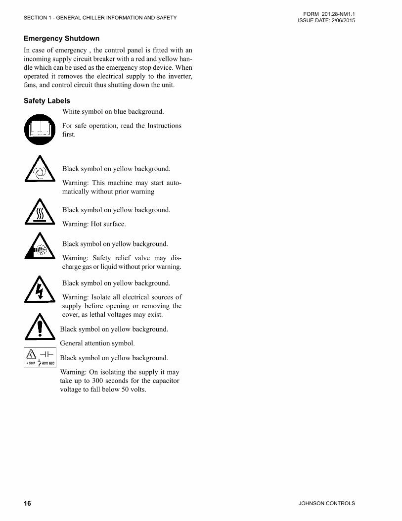
Safety LabelsWhite symbol on blue background.
For safe operation, read the Instructions first.
Black symbol on yellow background.
Warning: This machine may start auto-matically without prior warning
Black symbol on yellow background.
Warning: Hot surface.
Black symbol on yellow background.
Warning: Safety relief valve may dis-charge gas or liquid without prior warning.
Black symbol on yellow background.
Warning: Isolate all electrical sources of supply before opening or removing the cover, as lethal voltages may exist.
Black symbol on yellow background.
General attention symbol.
Black symbol on yellow background.
Warning: On isolating the supply it may take up to 300 seconds for the capacitor voltage to fall below 50 volts.
JOHNSON CONTROLS 17
FORM 201.28-NM1.1ISSUE DATE: 2/06/2015
2
SECTION 2 - PRODUCT DESCRIPTION
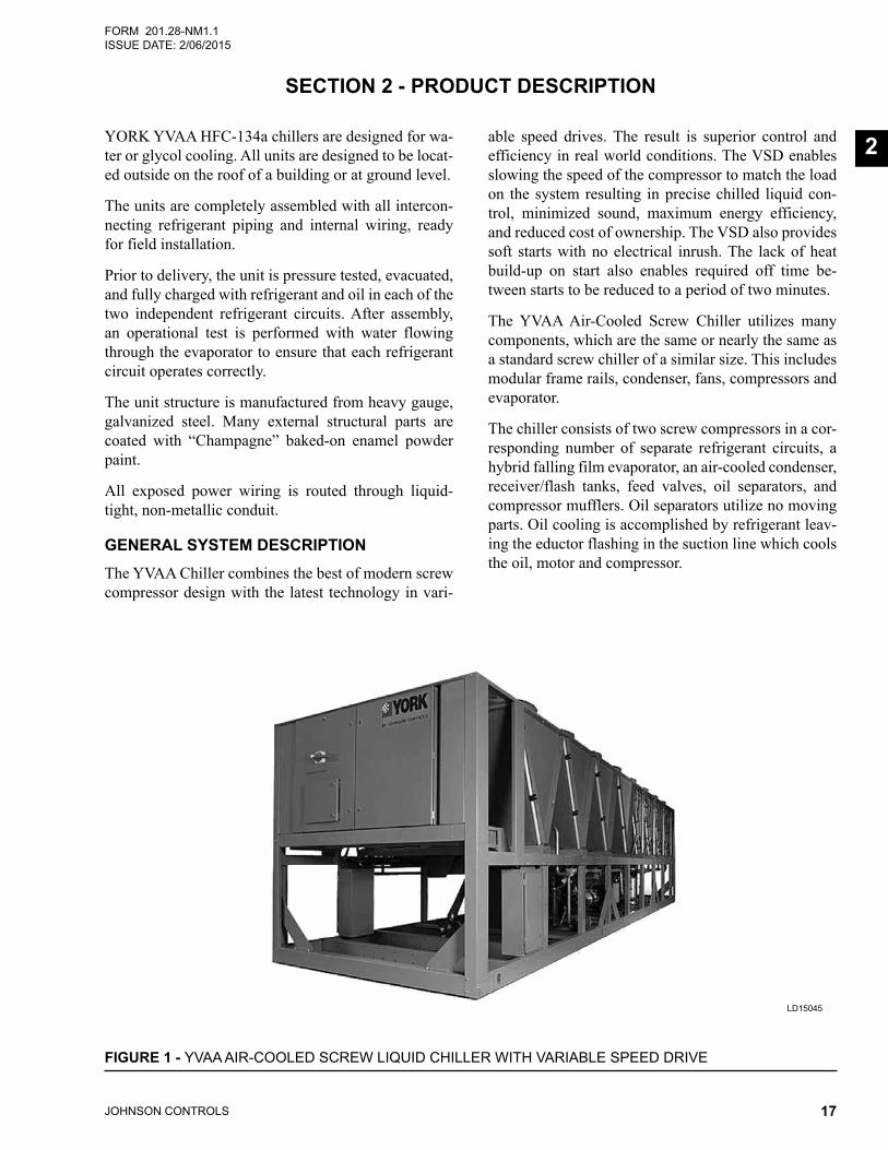
YORK YVAA HFC-134a chillers are designed for wa-ter or glycol cooling. All units are designed to be locat-ed outside on the roof of a building or at ground level.
The units are completely assembled with all intercon-necting refrigerant piping and internal wiring, ready for field installation.
Prior to delivery, the unit is pressure tested, evacuated, and fully charged with refrigerant and oil in each of the two independent refrigerant circuits. After assembly, an operational test is performed with water flowing through the evaporator to ensure that each refrigerant circuit operates correctly.
The unit structure is manufactured from heavy gauge, galvanized steel. Many external structural parts are coated with “Champagne” baked-on enamel powder paint.
All exposed power wiring is routed through liquid-tight, non-metallic conduit.
GENERAL SYSTEM DESCRIPTIONThe YVAA Chiller combines the best of modern screw compressor design with the latest technology in vari-
able speed drives. The result is superior control and efficiency in real world conditions. The VSD enables slowing the speed of the compressor to match the load on the system resulting in precise chilled liquid con-trol, minimized sound, maximum energy efficiency, and reduced cost of ownership. The VSD also provides soft starts with no electrical inrush. The lack of heat build-up on start also enables required off time be-tween starts to be reduced to a period of two minutes.
The YVAA Air-Cooled Screw Chiller utilizes many components, which are the same or nearly the same as a standard screw chiller of a similar size. This includes modular frame rails, condenser, fans, compressors and evaporator.
The chiller consists of two screw compressors in a cor-responding number of separate refrigerant circuits, a hybrid falling film evaporator, an air-cooled condenser, receiver/flash tanks, feed valves, oil separators, and compressor mufflers. Oil separators utilize no moving parts. Oil cooling is accomplished by refrigerant leav-ing the eductor flashing in the suction line which cools the oil, motor and compressor.
FIGURE 1 - YVAA AIR-COOLED SCREW LIQUID CHILLER WITH VARIABLE SPEED DRIVE
LD15045
JOHNSON CONTROLS18
SECTION 2 - PRODUCT DESCRIPTIONFORM 201.28-NM1.1
ISSUE DATE: 2/06/2015
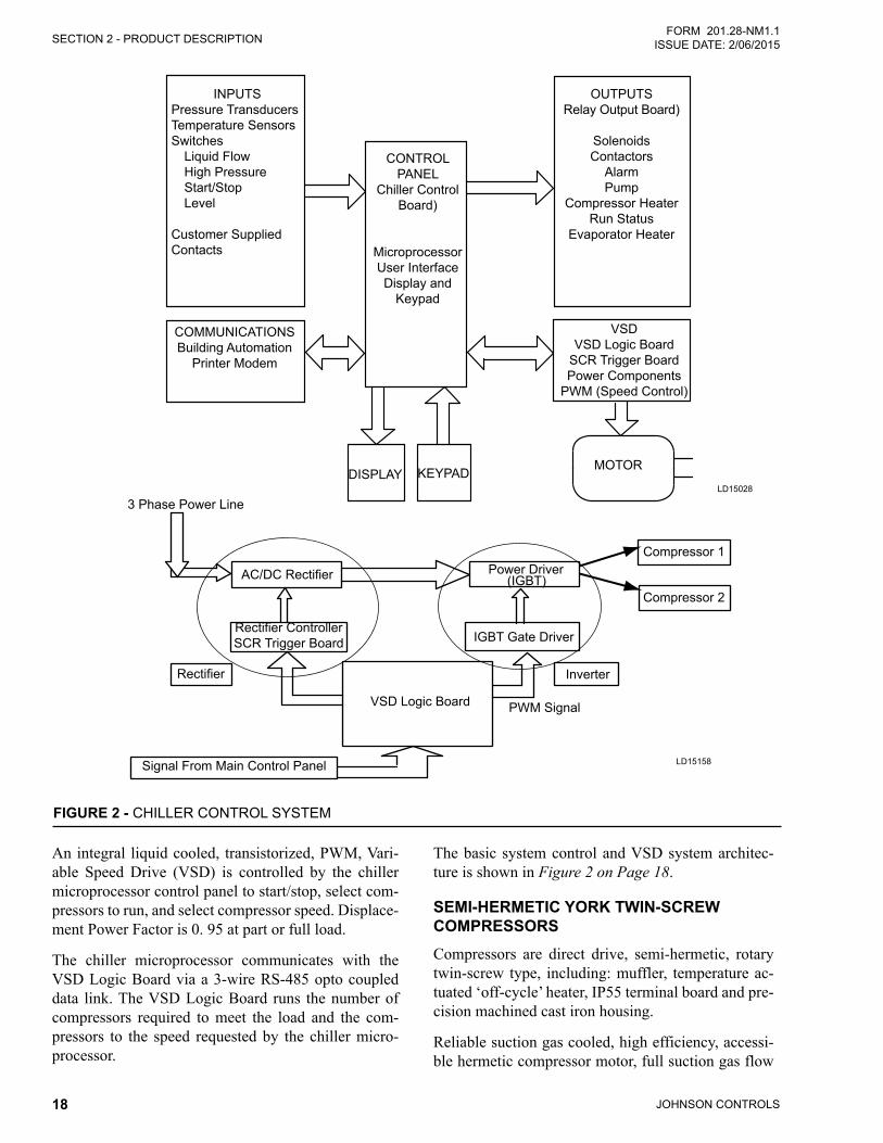
An integral liquid cooled, transistorized, PWM, Vari-able Speed Drive (VSD) is controlled by the chiller microprocessor control panel to start/stop, select com-pressors to run, and select compressor speed. Displace-ment Power Factor is 0. 95 at part or full load.
The chiller microprocessor communicates with the VSD Logic Board via a 3-wire RS-485 opto coupled data link. The VSD Logic Board runs the number of compressors required to meet the load and the com-pressors to the speed requested by the chiller micro-processor.
The basic system control and VSD system architec-ture is shown in Figure 2 on Page 18.
SEMI-HERMETIC YORK TWIN-SCREW COMPRESSORSCompressors are direct drive, semi-hermetic, rotary twin-screw type, including: muffler, temperature ac-tuated ‘off-cycle’ heater, IP55 terminal board and pre-cision machined cast iron housing.
Reliable suction gas cooled, high efficiency, accessi-ble hermetic compressor motor, full suction gas flow
FIGURE 2 - CHILLER CONTROL SYSTEM
LD15028
INPUTSPressure TransducersTemperature SensorsSwitches
Liquid FlowHigh PressureStart/StopLevel
Customer SuppliedContacts
CONTROLPANEL
Chiller ControlBoard)
MicroprocessorUser InterfaceDisplay and
Keypad
DISPLAY KEYPAD MOTOR
OUTPUTSRelay Output Board)
SolenoidsContactors
AlarmPump
Compressor HeaterRun Status
Evaporator Heater
VSDVSD Logic Board
SCR Trigger BoardPower Components
PWM (Speed Control)
COMMUNICATIONSBuilding Automation
Printer Modem
LD15158
3 Phase Power Line
AC/DC Rectifier Power Driver
IGBT Gate Driver
VSD Logic Board
Inverter
PWM Signal
Signal From Main Control Panel
Rectifier
Compressor 1
Compressor 2
Rectifier Controller SCR Trigger Board
(IGBT)
SECTION 2 - PRODUCT DESCRIPTION
JOHNSON CONTROLS 19
FORM 201.28-NM1.1ISSUE DATE: 2/06/2015
2
through mesh screen filter, with inherent internal ther-mal overload protection and external current overload on all three phases.
Continuous function, microprocessor controlled, Vari-able Speed Drive (VSD) shall provide valve-less, smooth capacity control from 100% down to 10% of chiller capacity.
In addition, elimination of the slide valve and associ-ated unloading components has resulted in a 50% re-duction in compressor moving parts.
EVAPORATORThe evaporator is a shell and tube, hybrid falling film type heat exchanger. It contains a balance of flooded and falling film technology to optimize efficiency, min-imize refrigerant charge, and maintain reliable control. A specifically designed distribution system provides uniform refrigerant flow for optimum performance.
CONDENSERThe YVAA introduces micro-channel coil to the York screw compressor chiller line. The micro-channel max-imizes condenser heat transfer, resulting in a smaller footprint, and reduces refrigerant charge by as much as 50%.
Each condenser coil is a single piece all aluminum construction including headers, tubes and fins to avoid galvanic corrosion due to dissimilar metals. Coils and headers are brazed as one piece. Integral sub-cooling is included. The design working pressure is 25.9 barg.
Multiple, standard low sound, high efficiency, TEAO motor driven fans move air through the coils. They are dynamically and statically balanced, direct drive with corrosion-resistant glass fiber reinforced composite blades molded into low-noise, full airfoil cross sec-tions, providing vertical air discharge from extended orifices for efficiency and low sound.
Fan motors are Totally Enclosed Air-Over (TEAO), squirrel-cage type and current protected. The direct drive motors feature double-sealed and permanently lubricated ball bearings, cutting down on maintenance cost over the life of the unit.
REFRIGERANT CIRCUITAn independent refrigerant circuit is provided per compressor. Each circuit uses copper refrigerant pipe formed on computer controlled bending machines to
reduce the number of brazed joints resulting in a reli-able and leak resistant system.
• Discharge lines are provided with a manual com-pressor shutoff service valve (See Accessories and Options on Page 21 for suction line service valve).
• The external oil separators, with no moving parts and designed for minimum oil carry-over, are mounted in the discharge line of the compressor.
• Liquid line components include: high absorp-tionremovablecorefilter-drier,sightglasseswithmoisture indicators, manual shut-off valve with charging port, orifice and electronic expansionvalve.
• Aneconomizer(flash)tankislocatedineachre-frigerantcircuittoincreasethesystemefficiency.
ELECTRICALJohnson Controls has over 25 years of experience de-signing variable -speed drives specifically for chiller applications. The result is an extremely reliable air-cooled chiller system that offers industry leading ef-ficiency at real world operating conditions, valve-less compressor loading/unloading, excellent capacity con-trol, high power factor and soft start..
Incoming single point power is standard utilizing a lockable circuit breaker, 115VACcontrol transformer, VSD, fan contactors, ON/OFF unit switch, microcom-puter keypad and display, Chiller Control and VSD Logic boards, and relay boards.
Standard design includes IP55 rating, powder painted steel cabinet with hinged, latched, and gasket sealed outer doors equipped with wind struts for safer servic-ing. The panel includes a control display access door so that display and control features can be accessed with-out opening main cabinet doors.
All exposed power wiring is routed through liquid-tight, UV-stabilized, non-metallic conduit.
BUILDING AUTOMATION SYSTEM CAPABILITIESThe E-Link Gateway provides an economical and ver-satile connection between York equipment and open/standard protocols. It efficiently manages the commu-nication protocols currently used by York equipment, exposing the data in a consistent, organized, and de-fined fashion. The E-Link Gateway is available as a
JOHNSON CONTROLS20
SECTION 2 - PRODUCT DESCRIPTIONFORM 201.28-NM1.1
ISSUE DATE: 2/06/2015
field-installed option on YVAA. A simple switch se-lection allows configuration of the required equipment profile and output protocol, which reduces equipment connectivity startup time.
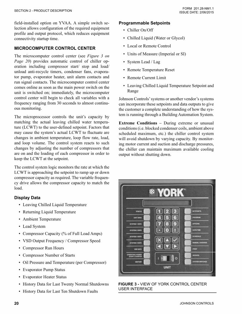
MICROCOMPUTER CONTROL CENTERThe microcomputer control center (see Figure 3 on Page 20) provides automatic control of chiller op-eration including compressor start/ stop and load/unload anti-recycle timers, condenser fans, evapora-tor pump, evaporator heater, unit alarm contacts and run signal contacts. The microcomputer control center comes online as soon as the main power switch on the unit is switched on; immediately, the microcomputer control center will begin to check all variables with a frequency ranging from 30 seconds to almost continu-ous monitoring.
The microprocessor controls the unit’s capacity by matching the actual leaving chilled water tempera-ture (LCWT) to the user-defined setpoint. Factors that may cause the system’s actual LCWT to fluctuate are changes in ambient temperature, loop flow rate, load, and loop volume. The control system reacts to such changes by adjusting the number of compressors that are on and the loading of each compressor in order to keep the LCWT at the setpoint.
The control system logic monitors the rate at which the LCWT is approaching the setpoint to ramp up or down compressor capacity as required. The variable frequen-cy drive allows the compressor capacity to match the load.
Display Data• Leaving Chilled Liquid Temperature
• Returning Liquid Temperature
• Ambient Temperature
• Lead System
• Compressor Capacity (% of Full Load Amps)
• VSD Output Frequency / Compressor Speed
• Compressor Run Hours
• Compressor Number of Starts
• Oil Pressure and Temperature (per Compressor)
• Evaporator Pump Status
• Evaporator Heater Status
• History Data for Last Twenty Normal Shutdowns
• History Data for Last Ten Shutdown Faults
Programmable Setpoints • Chiller On/Off
• Chilled Liquid (Water or Glycol)
• Local or Remote Control
• Units of Measure (Imperial or SI)
• System Lead / Lag
• Remote Temperature Reset
• Remote Current Limit
• Leaving Chilled Liquid Temperature Setpoint and Range
Johnson Controls’ systems or another vendor’s systems can incorporate these setpoints and data outputs to give the customer a complete understanding of how the sys-tem is running through a Building Automation System.
Extreme Conditions – During extreme or unusual conditions (i.e. blocked condenser coils, ambient above scheduled maximum, etc.) the chiller control system will avoid shutdown by varying capacity. By monitor-ing motor current and suction and discharge pressures, the chiller can maintain maximum available cooling output without shutting down.
FIGURE 3 - VIEW OF YORK CONTROL CENTER USER INTERFACE
SECTION 2 - PRODUCT DESCRIPTION
JOHNSON CONTROLS 21
FORM 201.28-NM1.1ISSUE DATE: 2/06/2015
2
Unit Safeties are provided for the chiller to perform auto-reset shut down for the following conditions:
• Ambient temperature above or below allowable range
• Out of range leaving chilled liquid temperature
• Under voltage
• Flow switch operation
ACCESSORIES AND OPTIONSAll options factory mounted unless otherwise noted.
Sound AttenuationLow Noise Kits – The standard chiller configuration is equipped with low sound fans and acoustic treatments on the refrig erant lines and compressors. There are several sound attenuation options available to further reduce sound at its source thereby meeting local sound level regulations.
SilentNight™ – Due to time of day based sound regu-lations in some locations it may be desirable to force the chiller to a lower sound level on demand. The SilentNight control option provides a control input to limit sound output of the chiller based on time of day. This feature is programmable at the chiller panel or can be controlled remotely via a signal (4-20mA or 0-10VDC) from a BAS system.
FAN OPTIONSUltra Quiet Fans – The chiller is equipped with spe-cially designed fans and motors to provide lower sound levels yet retain appropriate airflow. The result is re-duced fan generated sound with minimal effect on the chiller capacity or efficiency.
High Static Fans – The chiller is equipped with con-denser fans with higher power motors suitable for high external static pressure, up to 100 Pa (0.4 in. water), across condenser coils. This option should be selected if additional airflow resistance may be present due to flow restrictions such as field installed ducts, filters, sound enclosures etc. Please contact your local JCI representative for more information.
High Airflow Fans – The chiller is equipped with con-denser fans with airfoil type blades and high power mo-tors providing extra airflow across coils. In some chiller configurations, this option can provide an increase in chiller capacity at high ambient. The high airflow fans are also available with variable speed control. Please contact your local JCI representative for more information.
CONDENSER COILSFin and tub condenser coilds of seamless, internally-enhanced, high-condensing-coefficient, corrosion re-sistant copper tubes are arranged in staggered rows. The tubes are mechanically expanded into aluminum fins. Integral subcooling is included. The design work-ing pressure of the coils is 350 PSIG (24 barg).
Condenser Coil ProtectionThe aluminum alloys used in the YVAA micro-chan-nel condenser have been carefully selected and tested for high corrosion resistance. However, all metals can corrode in harsh conditions. Consider protecting coils from corrosive environments such as coastal, marine, urban and industrial.
Post-Coated Epoxy Dipped Condenser – Micro-channel condenser coils applied with electro-deposited and baked flexible epoxy coating that is finished with a polyurethane UV resistant top-coat suitable for highly corrosive applications.
Protective Chiller PanelsWire Panels – UV stabilized black polyvinyl chloride coated, heavy gauge, welded wire mesh guards mounted on the exterior of the full unit. Protects condenser coil faces and prevents unauthorized access to refrigerant components (compressors, pipes, evaporator, etc.), yet provides free air flow. This can cut installation cost by eliminating the need for separate, expensive fencing.
Louvered Panels – Louvered panels, painted the same color as the unit, enclose the unit to visually screen and protect the coils as well as preventing unauthor-ized access to internal components. Also available as a condenser-only option.
Louvered/Wire Panels Combination – Louvered pan-els, painted the same color as the unit, are mounted on external condenser coil faces. Heavy gauge, welded wire-mesh panels, coated to resist corrosion, are mounted around base of machine to restrict unauthorized access.
End Hail Guard – Louvered panels, painted the same color as the unit, are installed on the rear of the unit (opposite end of the control panel) to protect the ex-posed condenser from flying debris or hail.
V-Guard Panels – Solid panels, painted the same col-or as the unit, are installed along the sides of the units to cover exposed piping within the condenser section without impacting airflow. These guard panels can be combined with End Hail Guard option for additional protection from debris.
JOHNSON CONTROLS22
SECTION 2 - PRODUCT DESCRIPTIONFORM 201.28-NM1.1
ISSUE DATE: 2/06/2015
Evaporator Options38 mm insulation – Double thickness insulation pro-vided.
Flange Kit – Provides contractor with the couplings best suited to tie into the chilled water piping. All flanges are PN10.
Connection Location – The standard unit configura-tion is available with fluid inlet connections at rear (op-posite control panel end) of unit. Option available for front fluid inlet on select configurations.
Water Box Heater – The standard unit comes with evaporator shell heaters and water pump control soft-ware. Optional water box heaters are required for stor-age below 0°F (-17°C). Refer to the Refrigerant Valve - Off option on page 96 for more information on freeze protection.
Controls OptionsHigh Ambient Operation – This provides special control logic coupled with high airflow fans to permit high ambient up to 52°C (125°F) operation. Fans are airfoil type blades with high power motors. This option may also allow for increased machine capacity, allow-ing the selection of a smaller chassis to meet specific capacity requirements.
Building Automation System Interface (Tempera-ture) – Factory installed option to accept a 4 to 20mA or a 0 to 10VDC input to allow remote reset of the Leaving Chilled Liquid Temperature Setpoint. The setpoint can be positively offset upwards up to 22.2°C (40°F). This option is useful for ice storage or process applications or for periods where higher chilled liquid temperatures are adequate for low loads. Available alone or in combination with BAS Load Limit.
Building Automation System Interface (Load Lim-it) – Factory installed option to accept a 4 to 20mA or a 0 to 10VDC input to allow remote reset of the Load Limit Setpoint. The setpoint can limit system demand from 30-100%. Available alone or in combination with BAS Temperature Reset.
E-Link – The optional E-Link gateway provides com-munication between the equipment and Building Auto-mation Systems, including BACnet (MS/TP), Modbus, LON and N2.
Thermal Storage – Provides special control logic and modifications to produce leaving chilled brine temper-atures below 4.4°C (40°F) primarily at times of low ambient temperatures (night time). Option can be used to produce ice to supplement cooling and significantly decrease energy costs. The capability of the chiller is enhanced by using both ice and chilled water simulta-neously during times of peak cooling needs.
General OptionsFlow Switch Accessory – Vapor proof SPDT, NEMA 3R switch, 10.3 barg (150 psig) DWP, -29°C to 121°C (-20°F to 250°F) with 1" NPT (IPS) connection for upright mounting in horizontal pipe. This flow switch or equivalent must be furnished with each unit. Field mounted.
Differential Pressure Switch – This 0.2-3 barg (3-45 psig) range switch, with 1/4" NPTE pressure connec-tions, is an alternative to the paddle-type flow switch. Field mounted.
Service Isolation Valve – Service suction isolation valve added to unit for each refrigerant circuit.
Dual Pressure Relief Valve – Two safety relief valves are mounted in parallel; one is always operational to assist in valve replacement during maintenance.
Terminal Block [not available for CE marked units] – Terminal Block connections shall be provided at the point of incoming single point connection for field con-nection and interconnecting wiring to the compressors. Separate external protection must be supplied, by oth-ers, in the incoming power wiring, which must comply with local codes.
Circuit Breaker – A unit-mounted circuit breaker with external lockable handle will be supplied to isolate the single point power voltage for servicing. The circuit breaker is sized to provide motor branch circuit protec-tion, short circuit protection and ground fault protec-tion for the motor branch-circuit conductors, the motor control apparatus and the motors.
Non-Fused Disconnect Switch – Unit-mounted dis-connect switch with external lockable handle can be supplied to isolate the unit power voltage for servicing. Separate external fusing must be supplied by the power wiring, which must comply with local codes.
SECTION 2 - PRODUCT DESCRIPTION
JOHNSON CONTROLS 23
FORM 201.28-NM1.1ISSUE DATE: 2/06/2015
2
Vibration IsolationElastomeric Isolation – This option is recommended for normal installations. It provides very good perfor-mance in most applications for the least cost. Field mounted.
25 mm (1") Spring Isolators – Spring and cage type isolators for mounting under the unit base rails are available to support unit. They are level adjustable. 25 mm (1") nominal deflection may vary slightly by ap-plic ation. Field mounted.
50 mm (2") Restrained Spring Isolators – Restrained Spring-Flex Mounting isolators incorporate a rugged welded steel housing with vertical and horizontal limit stops. Housings designed to withstand a minimum 1.0g accelerated force in all directions up to 51 mm (2"). The deflection may vary slightly by application. They are level adjustable. Field mounted.

JOHNSON CONTROLS24
FORM 201.28-NM1.1 ISSUE DATE: 2/06/2015
THIS PAGE INTENTIONALLY LEFT BLANK
JOHNSON CONTROLS 25
FORM 201.28-NM1.1ISSUE DATE: 2/06/2015
3
SECTION 3 - RIGGING, HANDLING AND STORAGE
LIFTING WEIGHTSRefer to the unit nameplate for unit shipping weight. Note that weight may vary depending on unit configu-ration at the time of lifting. Refer to the Physical Data tables within this manual for further information re-garding shipping and operating weights.
DELIVERY AND STORAGETo ensure consistent quality and maximum reliability, all units are tested and inspected before leaving the fac-tory. Units are shipped completely assembled and con-taining refrigerant under pressure. Units are shipped without export crating unless crating has been speci-fied on the Sales Order.If the unit is to be put into storage, prior to installation, the following precautions should be observed:• The chiller must be “blocked” so that the base is
not permitted to sag or bow.• Ensure that all openings, such as water connec-
tions, are securely capped.• Do not store where exposed to ambient air tem-
peratures exceeding 43°C (110°F).
• The condensers should be covered to protect the coilsandfinsfrompotentialdamageandcorrosion,particularly where building work is in progress.
• The unit should be stored in a location where there is minimal activity in order to limit the risk of ac-cidental physical damage.
• To prevent inadvertent operation of the pressure relief devices the unit must not be steam cleaned.
• It is recommended that the unit is periodically in-spected during storage.
INSPECTIONRemove any transit packing and inspect the unit to en-sure that all components have been delivered and that no damage has occurred during transit. If any damage is evident, it should be noted on the carrier’s freight bill and a claim entered in accordance with the instructions given on the advice note.
Major damage must be reported immediately to your local Johnson Controls representative.
Rigging and lifting should only be done by a professional rigger in accordance with a written rig-ging and lifting plan. The most appropriate rigging and lifting method will depend on job specific factors, such as the rigging equipment available and site needs. Therefore, a professional rigger must determine the rigging and lifting method to be used, and it is beyond the scope of this manual to specify rigging and lifting details.
LD19197
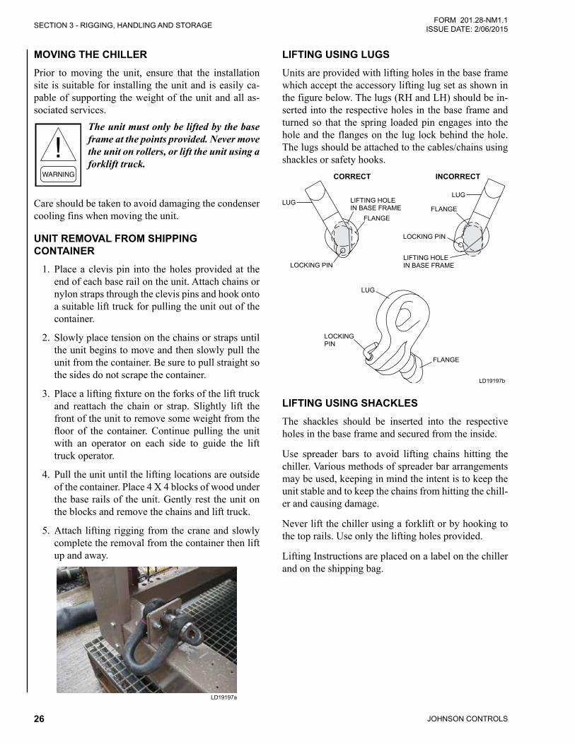
JOHNSON CONTROLS26
SECTION 3 - RIGGING, HANDLING AND STORAGEFORM 201.28-NM1.1
ISSUE DATE: 2/06/2015
MOVING THE CHILLERPrior to moving the unit, ensure that the installation site is suitable for installing the unit and is easily ca-pable of supporting the weight of the unit and all as-sociated services.
The unit must only be lifted by the base frame at the points provided. Never move the unit on rollers, or lift the unit using a forklift truck.
Care should be taken to avoid damaging the condenser cooling fins when moving the unit.
UNIT REMOVAL FROM SHIPPING CONTAINER
1. Place a clevis pin into the holes provided at the end of each base rail on the unit. Attach chains or nylon straps through the clevis pins and hook onto a suitable lift truck for pulling the unit out of the container.
2. Slowly place tension on the chains or straps until the unit begins to move and then slowly pull the unit from the container. Be sure to pull straight so the sides do not scrape the container.
3. Placealiftingfixtureontheforksofthelifttruckand reattach the chain or strap. Slightly lift the front of the unit to remove some weight from the floor of the container.Continue pulling the unitwith an operator on each side to guide the lift truck operator.
4. Pull the unit until the lifting locations are outside of the container. Place 4 X 4 blocks of wood under the base rails of the unit. Gently rest the unit on the blocks and remove the chains and lift truck.
5. Attach lifting rigging from the crane and slowly complete the removal from the container then lift up and away.
LD19197a
LIFTING USING LUGSUnits are provided with lifting holes in the base frame which accept the accessory lifting lug set as shown in the figure below. The lugs (RH and LH) should be in-serted into the respective holes in the base frame and turned so that the spring loaded pin engages into the hole and the flanges on the lug lock behind the hole. The lugs should be attached to the cables/chains using shackles or safety hooks.
LOCKING PIN
LUG
FLANGE
LIFTING HOLEIN BASE FRAME
CORRECT
LOCKING PIN
LUG
LIFTING HOLEIN BASE FRAME
FLANGE
INCORRECT
LOCKINGPIN
FLANGE
LUG
LD19197b
LIFTING USING SHACKLESThe shackles should be inserted into the respective holes in the base frame and secured from the inside.
Use spreader bars to avoid lifting chains hitting the chiller. Various methods of spreader bar arrangements may be used, keeping in mind the intent is to keep the unit stable and to keep the chains from hitting the chill-er and causing damage.
Never lift the chiller using a forklift or by hooking to the top rails. Use only the lifting holes provided.
Lifting Instructions are placed on a label on the chiller and on the shipping bag.

SECTION 3 - RIGGING, HANDLING AND STORAGE
JOHNSON CONTROLS 27
FORM 201.28-NM1.1ISSUE DATE: 2/06/2015
THIS PAGE INTENTIONALLY LEFT BLANK
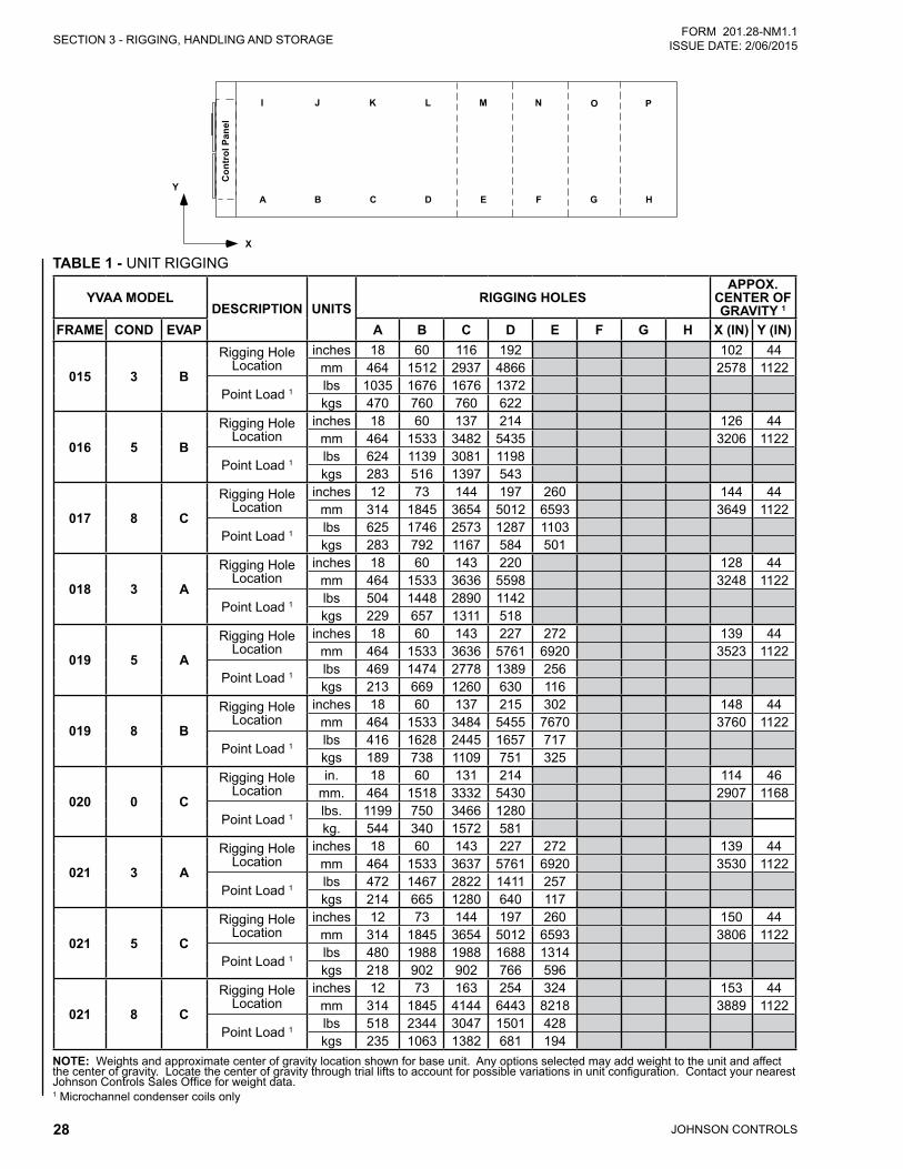
JOHNSON CONTROLS28
SECTION 3 - RIGGING, HANDLING AND STORAGEFORM 201.28-NM1.1
ISSUE DATE: 2/06/2015
� � � � � � � �
� �
���
��������
�
�
�
� � � �
TABLE 1 - UNIT RIGGING
YVAA MODELDESCRIPTION UNITS
RIGGING HOLESAPPOX.
CENTER OF GRAVITY 1
FRAME COND EVAP A B C D E F G H X (IN) Y (IN)
015 3 B
Rigging Hole Location
inches 18 60 116 192 102 44mm 464 1512 2937 4866 2578 1122
Point Load 1 lbs 1035 1676 1676 1372 kgs 470 760 760 622
016 5 B
Rigging Hole Location
inches 18 60 137 214 126 44mm 464 1533 3482 5435 3206 1122
Point Load 1 lbs 624 1139 3081 1198kgs 283 516 1397 543
017 8 C
Rigging Hole Location
inches 12 73 144 197 260 144 44mm 314 1845 3654 5012 6593 3649 1122
Point Load 1 lbs 625 1746 2573 1287 1103kgs 283 792 1167 584 501
018 3 A
Rigging Hole Location
inches 18 60 143 220 128 44mm 464 1533 3636 5598 3248 1122
Point Load 1 lbs 504 1448 2890 1142kgs 229 657 1311 518
019 5 A
Rigging Hole Location
inches 18 60 143 227 272 139 44mm 464 1533 3636 5761 6920 3523 1122
Point Load 1 lbs 469 1474 2778 1389 256kgs 213 669 1260 630 116
019 8 B
Rigging Hole Location
inches 18 60 137 215 302 148 44mm 464 1533 3484 5455 7670 3760 1122
Point Load 1 lbs 416 1628 2445 1657 717kgs 189 738 1109 751 325
020 0 C
Rigging Hole Location
in. 18 60 131 214 114 46mm. 464 1518 3332 5430 2907 1168
Point Load 1 lbs. 1199 750 3466 1280kg. 544 340 1572 581
021 3 A
Rigging Hole Location
inches 18 60 143 227 272 139 44mm 464 1533 3637 5761 6920 3530 1122
Point Load 1 lbs 472 1467 2822 1411 257kgs 214 665 1280 640 117
021 5 C
Rigging Hole Location
inches 12 73 144 197 260 150 44mm 314 1845 3654 5012 6593 3806 1122
Point Load 1 lbs 480 1988 1988 1688 1314kgs 218 902 902 766 596
021 8 C
Rigging Hole Location
inches 12 73 163 254 324 153 44mm 314 1845 4144 6443 8218 3889 1122
Point Load 1 lbs 518 2344 3047 1501 428kgs 235 1063 1382 681 194
NOTE: Weights and approximate center of gravity location shown for base unit. Any options selected may add weight to the unit and affect the center of gravity. Locate the center of gravity through trial lifts to account for possible variations in unit configuration. Contact your nearest Johnson Controls Sales Office for weight data. 1 Microchannel condenser coils only
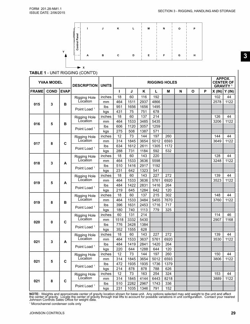
SECTION 3 - RIGGING, HANDLING AND STORAGE
JOHNSON CONTROLS 29
FORM 201.28-NM1.1ISSUE DATE: 2/06/2015
3
TABLE 1 - UNIT RIGGING (CONT'D)
� � � � � � � �
� �
���
��������
�
�
�
� � � �
YVAA MODELDESCRIPTION UNITS
RIGGING HOLESAPPOX.
CENTER OF GRAVITY 1
FRAME COND EVAP I J K L M N O P X (IN) Y (IN)
015 3 B
Rigging Hole Location
inches 18 60 116 192 102 44mm 464 1511 2937 4866 2578 1122
Point Load 1 lbs 951 1656 1656 1495kgs 431 75 751 678
016 5 B
Rigging Hole Location
inches 18 60 137 214 126 44mm 464 1533 3485 5435 3206 1122
Point Load 1 lbs 606 1120 3057 1259kgs 275 508 1387 571
017 8 C
Rigging Hole Location
inches 12 73 144 197 260 144 44mm 314 1845 3654 5012 6593 3649 1122
Point Load 1 lbs 634 1612 2611 1305 1172kgs 288 731 1184 592 532
018 3 A
Rigging Hole Location
inches 18 60 143 220 128 44mm 464 1533 3636 5598 3248 1122
Point Load 1 lbs 510 1416 2917 1192kgs 231 642 1323 541
019 5 A
Rigging Hole Location
inches 18 60 143 227 272 139 44mm 464 1533 3636 5761 6920 3523 1122
Point Load 1 lbs 484 1422 2831 1416 264kgs 219 645 1284 642 120
019 8 B
Rigging Hole Location
inches 18 60 137 215 302 148 44mm 464 1533 3484 5455 7670 3760 1122
Point Load 1 lbs 396 1631 2453 1716 717kgs 180 740 1113 779 325
020 0 C
Rigging Hole Location
inches 60 131 214 114 46mm 1518 3332 5430 2907 1168
Point Load 1 lbs 776 3428 1384kgs 352 1555 628
021 3 A
Rigging Hole Location
inches 18 60 143 227 272 139 44mm 464 1533 3637 5761 6920 3530 1122
Point Load 1 lbs 484 1419 2841 1420 264kgs 220 644 1288 644 120
021 5 C
Rigging Hole Location
inches 12 73 144 197 260 150 44mm 314 1845 3654 5012 6593 3806 1122
Point Load 1 lbs 472 1935 1935 1736 1379kgs 214 878 878 788 626
021 8 C
Rigging Hole Location
inches 12 73 163 254 324 153 44mm 314 1845 4144 6443 8218 3889 1122
Point Load 1 lbs 510 2282 2967 1743 336kgs 231 1035 1346 791 152
NOTE: Weights and approximate center of gravity location shown for base unit. Any options selected may add weight to the unit and affect the center of gravity. Locate the center of gravity through trial lifts to account for possible variations in unit configuration. Contact your nearest Johnson Controls Sales Office for weight data. 1 Microchannel condenser coils only
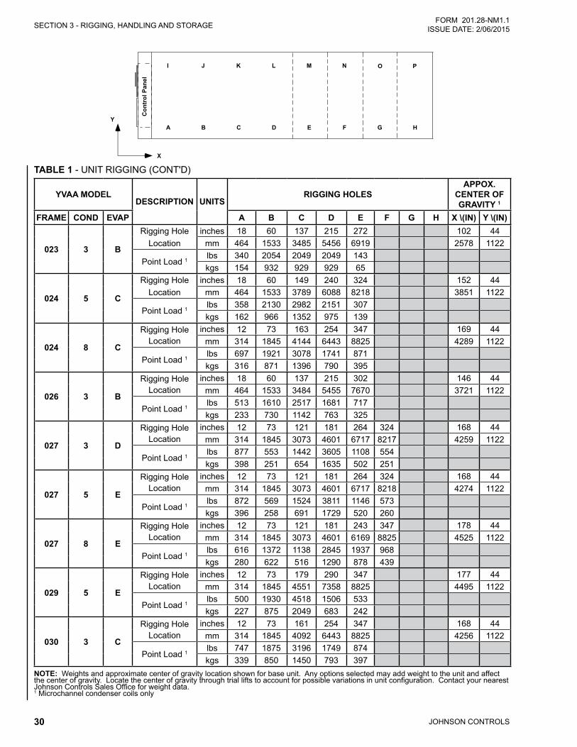
JOHNSON CONTROLS30
SECTION 3 - RIGGING, HANDLING AND STORAGEFORM 201.28-NM1.1
ISSUE DATE: 2/06/2015
TABLE 1 - UNIT RIGGING (CONT'D)
� � � � � � � �
� �
���
��������
�
�
�
� � � �
YVAA MODELDESCRIPTION UNITS
RIGGING HOLESAPPOX.
CENTER OF GRAVITY 1
FRAME COND EVAP A B C D E F G H X \(IN) Y \(IN)
023 3 B
Rigging HoleLocation
inches 18 60 137 215 272 102 44mm 464 1533 3485 5456 6919 2578 1122
Point Load 1lbs 340 2054 2049 2049 143kgs 154 932 929 929 65
024 5 C
Rigging HoleLocation
inches 18 60 149 240 324 152 44mm 464 1533 3789 6088 8218 3851 1122
Point Load 1lbs 358 2130 2982 2151 307kgs 162 966 1352 975 139
024 8 C
Rigging Hole Location
inches 12 73 163 254 347 169 44mm 314 1845 4144 6443 8825 4289 1122
Point Load 1lbs 697 1921 3078 1741 871kgs 316 871 1396 790 395
026 3 B
Rigging Hole Location
inches 18 60 137 215 302 146 44mm 464 1533 3484 5455 7670 3721 1122
Point Load 1lbs 513 1610 2517 1681 717kgs 233 730 1142 763 325
027 3 D
Rigging Hole Location
inches 12 73 121 181 264 324 168 44mm 314 1845 3073 4601 6717 8217 4259 1122
Point Load 1lbs 877 553 1442 3605 1108 554kgs 398 251 654 1635 502 251
027 5 E
Rigging Hole Location
inches 12 73 121 181 264 324 168 44mm 314 1845 3073 4601 6717 8218 4274 1122
Point Load 1lbs 872 569 1524 3811 1146 573kgs 396 258 691 1729 520 260
027 8 E
Rigging Hole Location
inches 12 73 121 181 243 347 178 44mm 314 1845 3073 4601 6169 8825 4525 1122
Point Load 1lbs 616 1372 1138 2845 1937 968 kgs 280 622 516 1290 878 439
029 5 E
Rigging Hole Location
inches 12 73 179 290 347 177 44mm 314 1845 4551 7358 8825 4495 1122
Point Load 1lbs 500 1930 4518 1506 533 kgs 227 875 2049 683 242
030 3 C
Rigging Hole Location
inches 12 73 161 254 347 168 44mm 314 1845 4092 6443 8825 4256 1122
Point Load 1lbs 747 1875 3196 1749 874kgs 339 850 1450 793 397
NOTE: Weights and approximate center of gravity location shown for base unit. Any options selected may add weight to the unit and affect the center of gravity. Locate the center of gravity through trial lifts to account for possible variations in unit configuration. Contact your nearest Johnson Controls Sales Office for weight data. 1 Microchannel condenser coils only
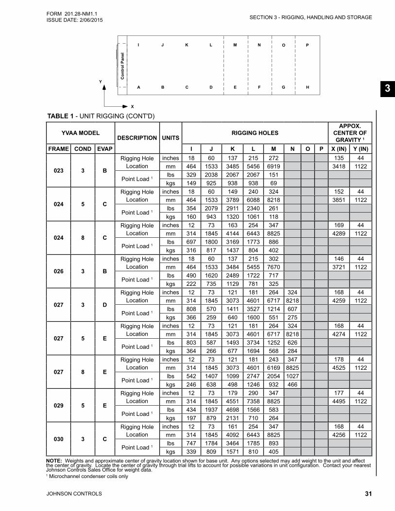
SECTION 3 - RIGGING, HANDLING AND STORAGE
JOHNSON CONTROLS 31
FORM 201.28-NM1.1ISSUE DATE: 2/06/2015
3
TABLE 1 - UNIT RIGGING (CONT'D)
� � � � � � � �
� �
���
��������
�
�
�
� � � �
YVAA MODELDESCRIPTION UNITS
RIGGING HOLESAPPOX.
CENTER OF GRAVITY 1
FRAME COND EVAP I J K L M N O P X (IN) Y (IN)
023 3 B
Rigging Hole Location
inches 18 60 137 215 272 135 44mm 464 1533 3485 5456 6919 3418 1122
Point Load 1lbs 329 2038 2067 2067 151kgs 149 925 938 938 69
024 5 C
Rigging Hole Location
inches 18 60 149 240 324 152 44mm 464 1533 3789 6088 8218 3851 1122
Point Load 1lbs 354 2079 2911 2340 261kgs 160 943 1320 1061 118
024 8 C
Rigging Hole Location
inches 12 73 163 254 347 169 44mm 314 1845 4144 6443 8825 4289 1122
Point Load 1lbs 697 1800 3169 1773 886kgs 316 817 1437 804 402
026 3 B
Rigging Hole Location
inches 18 60 137 215 302 146 44mm 464 1533 3484 5455 7670 3721 1122
Point Load 1lbs 490 1620 2489 1722 717kgs 222 735 1129 781 325
027 3 D
Rigging Hole Location
inches 12 73 121 181 264 324 168 44mm 314 1845 3073 4601 6717 8218 4259 1122
Point Load 1lbs 808 570 1411 3527 1214 607kgs 366 259 640 1600 551 275
027 5 E
Rigging Hole Location
inches 12 73 121 181 264 324 168 44mm 314 1845 3073 4601 6717 8218 4274 1122
Point Load 1lbs 803 587 1493 3734 1252 626kgs 364 266 677 1694 568 284
027 8 E
Rigging Hole Location
inches 12 73 121 181 243 347 178 44mm 314 1845 3073 4601 6169 8825 4525 1122
Point Load 1lbs 542 1407 1099 2747 2054 1027kgs 246 638 498 1246 932 466
029 5 E
Rigging Hole Location
inches 12 73 179 290 347 177 44mm 314 1845 4551 7358 8825 4495 1122
Point Load 1lbs 434 1937 4698 1566 583kgs 197 879 2131 710 264
030 3 C
Rigging Hole Location
inches 12 73 161 254 347 168 44mm 314 1845 4092 6443 8825 4256 1122
Point Load 1lbs 747 1784 3464 1785 893 kgs 339 809 1571 810 405
NOTE: Weights and approximate center of gravity location shown for base unit. Any options selected may add weight to the unit and affect the center of gravity. Locate the center of gravity through trial lifts to account for possible variations in unit configuration. Contact your nearest Johnson Controls Sales Office for weight data. 1 Microchannel condenser coils only
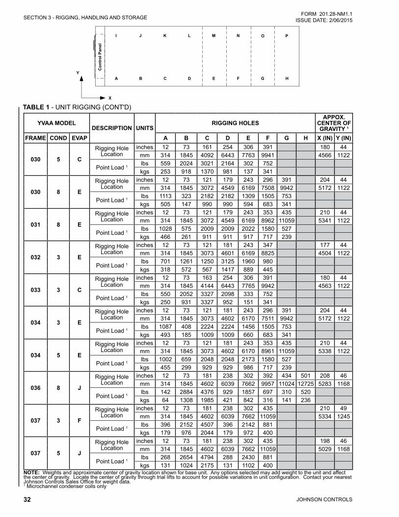
JOHNSON CONTROLS32
SECTION 3 - RIGGING, HANDLING AND STORAGEFORM 201.28-NM1.1
ISSUE DATE: 2/06/2015
TABLE 1 - UNIT RIGGING (CONT'D)
� � � � � � � �
� �
���
��������
�
�
�
� � � �
YVAA MODELDESCRIPTION UNITS
RIGGING HOLESAPPOX.
CENTER OF GRAVITY 1
FRAME COND EVAP A B C D E F G H X (IN) Y (IN)
030 5 C
Rigging Hole Location
inches 12 73 161 254 306 391 180 44mm 314 1845 4092 6443 7763 9941 4566 1122
Point Load 1 lbs 559 2024 3021 2164 302 752kgs 253 918 1370 981 137 341
030 8 E
Rigging Hole Location
inches 12 73 121 179 243 296 391 204 44mm 314 1845 3072 4549 6169 7508 9942 5172 1122
Point Load 1 lbs 1113 323 2182 2182 1309 1505 753 kgs 505 147 990 990 594 683 341
031 8 E
Rigging Hole Location
inches 12 73 121 179 243 353 435 210 44mm 314 1845 3072 4549 6169 8962 11059 5341 1122
Point Load 1 lbs 1028 575 2009 2009 2022 1580 527kgs 466 261 911 911 917 717 239
032 3 E
Rigging Hole Location
inches 12 73 121 181 243 347 177 44mm 314 1845 3073 4601 6169 8825 4504 1122
Point Load 1 lbs 701 1261 1250 3125 1960 980kgs 318 572 567 1417 889 445
033 3 C
Rigging Hole Location
inches 12 73 163 254 306 391 180 44mm 314 1845 4144 6443 7765 9942 4563 1122
Point Load 1 lbs 550 2052 3327 2098 333 752kgs 250 931 3327 952 151 341
034 3 E
Rigging Hole Location
inches 12 73 121 181 243 296 391 204 44mm 314 1845 3073 4602 6170 7511 9942 5172 1122
Point Load 1 lbs 1087 408 2224 2224 1456 1505 753kgs 493 185 1009 1009 660 683 341
034 5 E
Rigging Hole Location
inches 12 73 121 181 243 353 435 210 44mm 314 1845 3073 4602 6170 8961 11059 5338 1122
Point Load 1 lbs 1002 659 2048 2048 2173 1580 527kgs 455 299 929 929 986 717 239
036 8 J
Rigging Hole Location
inches 12 73 181 238 302 392 434 501 208 46mm 314 1845 4602 6039 7662 9957 11024 12725 5283 1168
Point Load 1 lbs 142 2884 4376 929 1857 697 310 520kgs 64 1308 1985 421 842 316 141 236
037 3 F
Rigging Hole Location
inches 12 73 181 238 302 435 210 49mm 314 1845 4602 6039 7662 11059 5334 1245
Point Load 1 lbs 396 2152 4507 396 2142 881kgs 179 976 2044 179 972 400
037 5 J
Rigging Hole Location
inches 12 73 181 238 302 435 198 46mm 314 1845 4602 6039 7662 11059 5029 1168
Point Load 1 lbs 268 2654 4794 288 2430 881kgs 131 1024 2175 131 1102 400
NOTE: Weights and approximate center of gravity location shown for base unit. Any options selected may add weight to the unit and affect the center of gravity. Locate the center of gravity through trial lifts to account for possible variations in unit configuration. Contact your nearest Johnson Controls Sales Office for weight data. 1 Microchannel condenser coils only
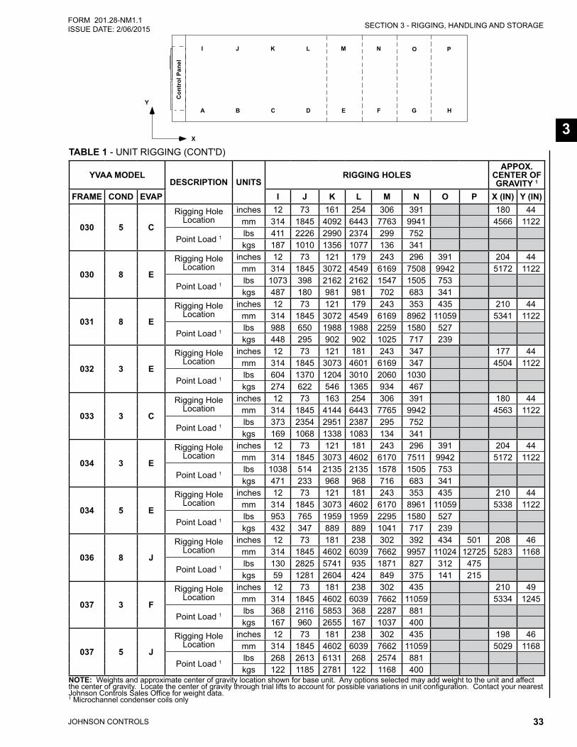
SECTION 3 - RIGGING, HANDLING AND STORAGE
JOHNSON CONTROLS 33
FORM 201.28-NM1.1ISSUE DATE: 2/06/2015
3TABLE 1 - UNIT RIGGING (CONT'D)
� � � � � � � �
� �
���
��������
�
�
�
� � � �
YVAA MODELDESCRIPTION UNITS
RIGGING HOLESAPPOX.
CENTER OF GRAVITY 1
FRAME COND EVAP I J K L M N O P X (IN) Y (IN)
030 5 C
Rigging Hole Location
inches 12 73 161 254 306 391 180 44mm 314 1845 4092 6443 7763 9941 4566 1122
Point Load 1 lbs 411 2226 2990 2374 299 752kgs 187 1010 1356 1077 136 341
030 8 E
Rigging Hole Location
inches 12 73 121 179 243 296 391 204 44mm 314 1845 3072 4549 6169 7508 9942 5172 1122
Point Load 1 lbs 1073 398 2162 2162 1547 1505 753kgs 487 180 981 981 702 683 341
031 8 E
Rigging Hole Location
inches 12 73 121 179 243 353 435 210 44mm 314 1845 3072 4549 6169 8962 11059 5341 1122
Point Load 1 lbs 988 650 1988 1988 2259 1580 527kgs 448 295 902 902 1025 717 239
032 3 E
Rigging Hole Location
inches 12 73 121 181 243 347 177 44mm 314 1845 3073 4601 6169 347 4504 1122
Point Load 1 lbs 604 1370 1204 3010 2060 1030kgs 274 622 546 1365 934 467
033 3 C
Rigging Hole Location
inches 12 73 163 254 306 391 180 44mm 314 1845 4144 6443 7765 9942 4563 1122
Point Load 1 lbs 373 2354 2951 2387 295 752kgs 169 1068 1338 1083 134 341
034 3 E
Rigging Hole Location
inches 12 73 121 181 243 296 391 204 44mm 314 1845 3073 4602 6170 7511 9942 5172 1122
Point Load 1 lbs 1038 514 2135 2135 1578 1505 753kgs 471 233 968 968 716 683 341
034 5 E
Rigging Hole Location
inches 12 73 121 181 243 353 435 210 44mm 314 1845 3073 4602 6170 8961 11059 5338 1122
Point Load 1 lbs 953 765 1959 1959 2295 1580 527kgs 432 347 889 889 1041 717 239
036 8 J
Rigging Hole Location
inches 12 73 181 238 302 392 434 501 208 46mm 314 1845 4602 6039 7662 9957 11024 12725 5283 1168
Point Load 1 lbs 130 2825 5741 935 1871 827 312 475kgs 59 1281 2604 424 849 375 141 215
037 3 F
Rigging Hole Location
inches 12 73 181 238 302 435 210 49mm 314 1845 4602 6039 7662 11059 5334 1245
Point Load 1 lbs 368 2116 5853 368 2287 881kgs 167 960 2655 167 1037 400
037 5 J
Rigging Hole Location
inches 12 73 181 238 302 435 198 46mm 314 1845 4602 6039 7662 11059 5029 1168
Point Load 1 lbs 268 2613 6131 268 2574 881kgs 122 1185 2781 122 1168 400
NOTE: Weights and approximate center of gravity location shown for base unit. Any options selected may add weight to the unit and affect the center of gravity. Locate the center of gravity through trial lifts to account for possible variations in unit configuration. Contact your nearest Johnson Controls Sales Office for weight data. 1 Microchannel condenser coils only
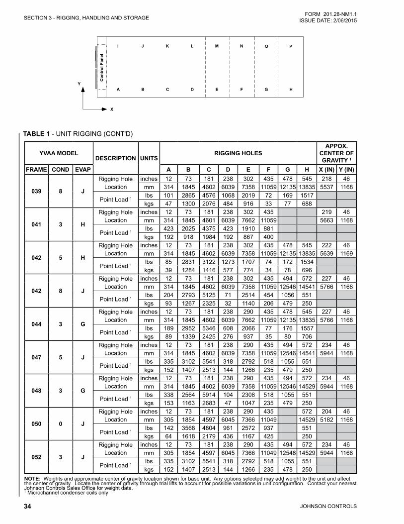
JOHNSON CONTROLS34
SECTION 3 - RIGGING, HANDLING AND STORAGEFORM 201.28-NM1.1
ISSUE DATE: 2/06/2015
TABLE 1 - UNIT RIGGING (CONT'D)
� � � � � � � �
� �
���
��������
�
�
�
� � � �
YVAA MODELDESCRIPTION UNITS
RIGGING HOLESAPPOX.
CENTER OF GRAVITY 1
FRAME COND EVAP A B C D E F G H X (IN) Y (IN)
039 8 J
Rigging Hole Location
inches 12 73 181 238 302 435 478 545 218 46mm 314 1845 4602 6039 7358 11059 12135 13835 5537 1168
Point Load 1 lbs 101 2865 4576 1068 2019 72 169 1517kgs 47 1300 2076 484 916 33 77 688
041 3 H
Rigging Hole Location
inches 12 73 181 238 302 435 219 46mm 314 1845 4601 6039 7662 11059 5663 1168
Point Load 1 lbs 423 2025 4375 423 1910 881kgs 192 918 1984 192 867 400
042 5 H
Rigging Hole Location
inches 12 73 181 238 302 435 478 545 222 46mm 314 1845 4602 6039 7358 11059 12135 13835 5639 1169
Point Load 1 lbs 85 2831 3122 1273 1707 74 172 1534kgs 39 1284 1416 577 774 34 78 696
042 8 J
Rigging Hole Location
inches 12 73 181 238 302 435 494 572 227 46mm 314 1845 4602 6039 7358 11059 12546 14541 5766 1168
Point Load 1 lbs 204 2793 5125 71 2514 454 1056 551kgs 93 1267 2325 32 1140 206 479 250
044 3 G
Rigging Hole Location
inches 12 73 181 238 290 435 478 545 227 46mm 314 1845 4602 6039 7662 11059 12135 13835 5766 1168
Point Load 1 lbs 189 2952 5346 608 2066 77 176 1557kgs 89 1339 2425 276 937 35 80 706
047 5 J
Rigging Hole Location
inches 12 73 181 238 290 435 494 572 234 46mm 314 1845 4602 6039 7358 11059 12546 14541 5944 1168
Point Load 1 lbs 335 3102 5541 318 2792 518 1055 551kgs 152 1407 2513 144 1266 235 479 250
048 3 G
Rigging Hole Location
inches 12 73 181 238 290 435 494 572 234 46mm 314 1845 4602 6039 7358 11059 12546 14529 5944 1168
Point Load 1 lbs 338 2564 5914 104 2308 518 1055 551kgs 153 1163 2683 47 1047 235 479 250
050 0 J
Rigging Hole Location
inches 12 73 181 238 290 435 572 204 46mm 305 1854 4597 6045 7366 11049 14529 5182 1168
Point Load 1 lbs 142 3568 4804 961 2572 937 551kgs 64 1618 2179 436 1167 425 250
052 3 J
Rigging Hole Location
inches 12 73 181 238 290 435 494 572 234 46mm 305 1854 4597 6045 7366 11049 12548 14529 5944 1168
Point Load 1 lbs 335 3102 5541 318 2792 518 1055 551kgs 152 1407 2513 144 1266 235 478 250
NOTE: Weights and approximate center of gravity location shown for base unit. Any options selected may add weight to the unit and affect the center of gravity. Locate the center of gravity through trial lifts to account for possible variations in unit configuration. Contact your nearest Johnson Controls Sales Office for weight data. 1 Microchannel condenser coils only
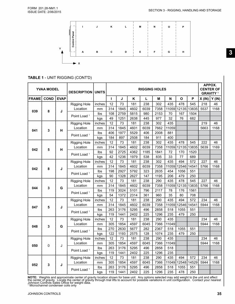
SECTION 3 - RIGGING, HANDLING AND STORAGE
JOHNSON CONTROLS 35
FORM 201.28-NM1.1ISSUE DATE: 2/06/2015
3
TABLE 1 - UNIT RIGGING (CONT'D)
� � � � � � � �
� �
���
��������
�
�
�
� � � �
YVAA MODELDESCRIPTION UNITS
RIGGING HOLESAPPOX.
CENTER OF GRAVITY 1
FRAME COND EVAP I J K L M N O P X (IN) Y (IN)
039 8 J
Rigging Hole Location
inches 12 73 181 238 302 435 478 545 218 46mm 314 1845 4602 6039 7358 11059 12135 13835 5537 1168
Point Load 1 lbs 108 2759 5815 980 2153 70 167 1504kgs 49 1251 2638 445 977 32 76 682
041 3 H
Rigging Hole Location
inches 12 73 181 238 302 435 219 46mm 314 1845 4601 6039 7662 11059 5663 1168
Point Load 1 lbs 406 1977 5529 406 2008 881kgs 184 897 2508 184 911 400
042 5 H
Rigging Hole Location
inches 12 73 181 238 302 435 478 545 222 46mm 314 1845 4602 6039 7358 11059 12135 13835 5639 1169
Point Load 1 lbs 92 2725 4362 1185 1841 72 170 1520kgs 42 1236 1979 538 835 33 77 689
042 8 J
Rigging Hole Location
inches 12 73 181 238 302 435 494 572 227 46mm 314 1845 4602 6039 7358 11059 12546 14541 5766 1168
Point Load 1 lbs 198 2927 5792 323 2635 454 1056 551kgs 90 1328 2627 147 1195 206 479 250
044 3 G
Rigging Hole Location
inches 12 73 181 238 290 435 478 545 227 46mm 314 1845 4602 6039 7358 11059 12135 13835 5766 1168
Point Load 1 lbs 119 3024 5101 796 2117 78 176 1561kgs 54 1372 2314 361 960 35 80 708
047 5 J
Rigging Hole Location
inches 12 73 181 238 290 435 494 572 234 46mm 314 1845 4602 6039 7358 11059 12546 14541 5944 1168
Point Load 1 lbs 263 3176 5295 496 2858 518 1055 551kgs 119 1441 2402 225 1296 235 479 250
048 3 G
Rigging Hole Location
inches 12 73 181 238 290 435 234 46mm 305 1854 4597 6045 7366 11049 5944 1168
Point Load 1 lbs 270 2630 5677 282 2367 518 1055 551kgs 122 1193 2575 128 1074 235 479 250
050 0 J
Rigging Hole Location
inches 12 73 181 238 290 435 234 46mm 305 1854 4597 6045 7366 11049 5944 1168
Point Load 1 lbs 263 3176 5295 496 2858 518kgs 119 1441 2402 225 1296 235
052 3 J
Rigging Hole Location
inches 12 73 181 238 290 435 494 572 234 46mm 305 1854 4597 6045 7366 11049 12548 14529 5944 1168
Point Load 1 lbs 263 3176 5295 496 2858 518 1055 551 kgs 119 1441 2402 225 1296 235 478 250
NOTE: Weights and approximate center of gravity location shown for base unit. Any options selected may add weight to the unit and affect the center of gravity. Locate the center of gravity through trial lifts to account for possible variations in unit configuration. Contact your nearest Johnson Controls Sales Office for weight data. 1 Microchannel condenser coils only

JOHNSON CONTROLS36
FORM 201.28-NM1.1 ISSUE DATE: 2/06/2015
THIS PAGE INTENTIONALLY LEFT BLANK
JOHNSON CONTROLS 37
FORM 201.28-NM1.1ISSUE DATE: 2/06/2015
4
SECTION 4 - INSTALLATION
LOCATION REQUIREMENTSFor optimum performance and trouble-free service, it is essential that the installation site meet the location and space requirements for the model being installed.
It is important to ensure that the minimum service ac-cess space is maintained for cleaning and maintenance purposes.
OUTDOOR INSTALLATIONSThe units are designed for outdoor installation and can be installed at ground level on a suitable flat level foundation easily capable of supporting the weight of the unit, or on a suitable rooftop location. In both cases an adequate supply of air is required. Avoid locations where the sound output and air discharge from the unit may be objectionable.
The location should be selected for minimum sun ex-posure and away from boiler flues and other sources of airborne chemicals that could attack the condenser coils and steel parts of the unit.
If located in an area accessible to unauthorized per-sons, steps must be taken to prevent access to the unit by means of a protective fence. This will help to pre-vent the possibility of vandalism, accidental damage, or possible harm caused by unauthorized removal of protective guards or opening panels to expose rotating or high voltage components.
For ground level locations, the unit must be installed on a suitable flat and level concrete base that extends to fully support the two side channels of the unit base frame. A one-piece concrete slab, with footings ex-tending below the frost line is recommended. To avoid noise and vibration transmission, the unit should not be secured to the building foundation.
On rooftop locations, choose a place with adequate structural strength to safely support the entire operating weight of the unit and service personnel. The unit can be mounted on a concrete slab, similar to ground floor locations, or on steel channels of suitable strength. The channels should be spaced with the same centers as the unit side and front base rails. This will allow vibration isolators to be fitted if required. Isolators are recom-mended for rooftop locations.
Mounting holes (5/8”) are provided in the base rails for bolting the unit to its foundation. Refer to Table 7 on Page 70 for location of the mounting holes.
Any ductwork or attenuators fitted to the unit must not have a total static pressure resistance, at full unit air-flow, exceeding the capability of the fans installed in the unit.
The condenser fans are propeller-type and are not rec-ommended for use with ductwork, filters or other im-pediments to airflow in the condenser air stream.
When it is desirable to surround the unit(s) in addi-tion to whatever optional louver package is selected, it is recommended that the screening be able to pass the required chiller CFM without exceeding 0.1"w.g. (24.9084 pa) external static pressure.
Protection against corrosive environments is avail-able by ordering the units with cured epoxy-coating on the microchannel condenser coil. Epoxy-coated coils should be used with any units being installed at the sea-shore where salt spray/mist may hit the units, or where acid rain is prevalent.
On installations where winter operation is intended and snow accumulations are expected, additional elevation must be provided to insure normal condenser air flow.
Avoid locations near windows or structures where nor-mal operating sounds may be objectionable.
LOCATION CLEARANCESAdequate clearances around the unit(s) are required for the unrestricted airflow for the air-cooled condenser coils and to prevent re-circulation of warm discharge air back onto the coils. If clearances given are not maintained, airflow restriction or re-circulation will cause a loss of unit performance, an increase in power consumption, and may cause the unit to malfunction. Consideration should also be given to the possibility of down drafts, caused by adjacent buildings, which may cause re-circulation or uneven unit airflow.
For locations where significant cross winds are expect-ed, such as exposed roof tops, an enclosure of solid or louver type is recommended to prevent wind turbu-lence interfering with the unit airflow.
When units are installed in an enclosure, the enclosure height should not exceed the height of the unit on more than one side. If the enclosure is of louvered construc-tion, the same requirement of static pressure loss ap-plies as for ducts and attenuators stated above.
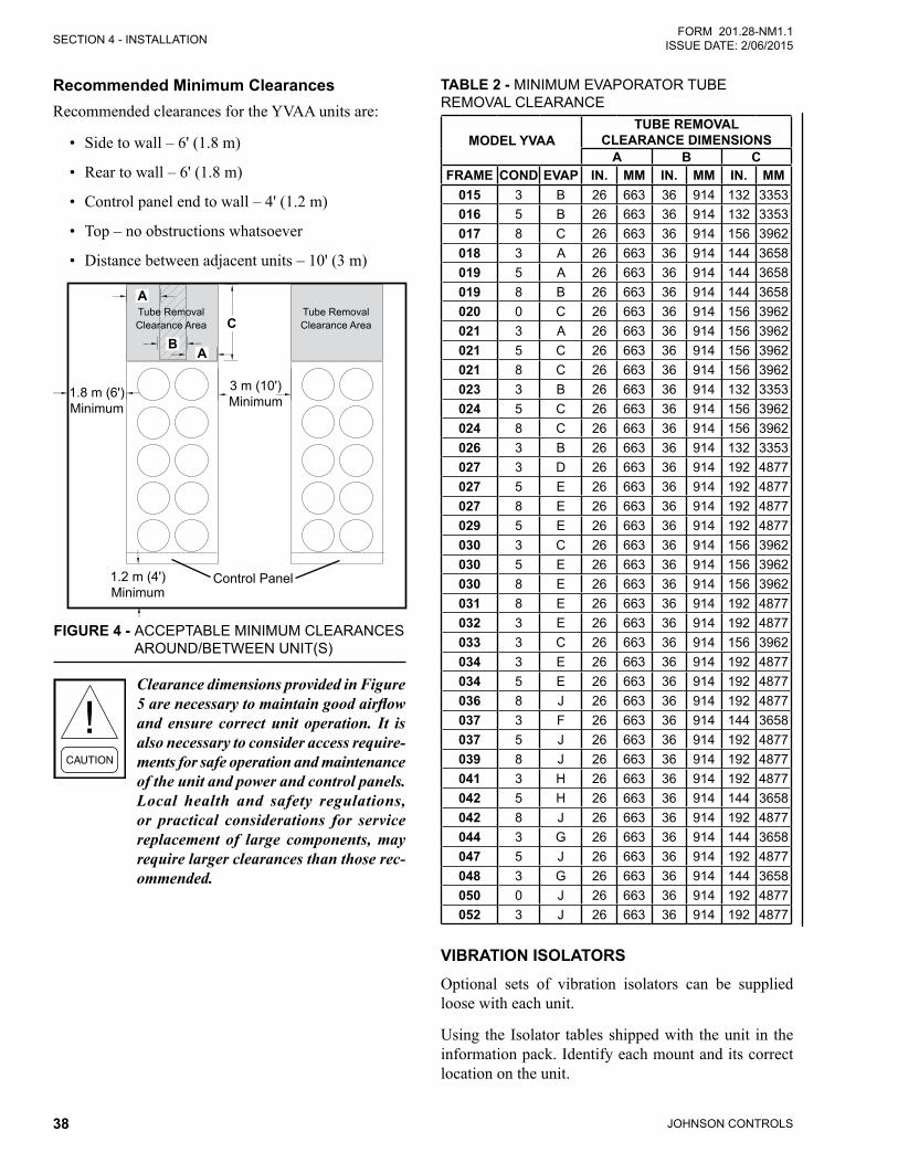
JOHNSON CONTROLS38
SECTION 4 - INSTALLATIONFORM 201.28-NM1.1
ISSUE DATE: 2/06/2015
Recommended Minimum ClearancesRecommended clearances for the YVAA units are:
• Side to wall – 6' (1.8 m)
• Rear to wall – 6' (1.8 m)
• Control panel end to wall – 4' (1.2 m)
• Top – no obstructions whatsoever
• Distance between adjacent units – 10' (3 m)
FIGURE 4 - ACCEPTABLE MINIMUM CLEARANCES AROUND/BETWEEN UNIT(S)
1.8 m (6')Minimum
1.2 m (4')Minimum
3 m (10')Minimum
Control Panel
C
A
A
Tube Removal Clearance Area
Tube Removal Clearance Area
B
Clearance dimensions provided in Figure 5 are necessary to maintain good airflow and ensure correct unit operation. It is also necessary to consider access require-ments for safe operation and maintenance of the unit and power and control panels. Local health and safety regulations, or practical considerations for service replacement of large components, may require larger clearances than those rec-ommended.
TABLE 2 - MINIMUM EVAPORATOR TUBE REMOVAL CLEARANCE
MODEL YVAATUBE REMOVAL
CLEARANCE DIMENSIONSA B C
FRAME COND EVAP IN. MM IN. MM IN. MM015 3 B 26 663 36 914 132 3353016 5 B 26 663 36 914 132 3353017 8 C 26 663 36 914 156 3962018 3 A 26 663 36 914 144 3658019 5 A 26 663 36 914 144 3658019 8 B 26 663 36 914 144 3658020 0 C 26 663 36 914 156 3962021 3 A 26 663 36 914 156 3962021 5 C 26 663 36 914 156 3962021 8 C 26 663 36 914 156 3962023 3 B 26 663 36 914 132 3353024 5 C 26 663 36 914 156 3962024 8 C 26 663 36 914 156 3962026 3 B 26 663 36 914 132 3353027 3 D 26 663 36 914 192 4877027 5 E 26 663 36 914 192 4877027 8 E 26 663 36 914 192 4877029 5 E 26 663 36 914 192 4877030 3 C 26 663 36 914 156 3962030 5 E 26 663 36 914 156 3962030 8 E 26 663 36 914 156 3962031 8 E 26 663 36 914 192 4877032 3 E 26 663 36 914 192 4877033 3 C 26 663 36 914 156 3962034 3 E 26 663 36 914 192 4877034 5 E 26 663 36 914 192 4877036 8 J 26 663 36 914 192 4877037 3 F 26 663 36 914 144 3658037 5 J 26 663 36 914 192 4877039 8 J 26 663 36 914 192 4877041 3 H 26 663 36 914 192 4877042 5 H 26 663 36 914 144 3658042 8 J 26 663 36 914 192 4877044 3 G 26 663 36 914 144 3658047 5 J 26 663 36 914 192 4877048 3 G 26 663 36 914 144 3658050 0 J 26 663 36 914 192 4877052 3 J 26 663 36 914 192 4877
VIBRATION ISOLATORSOptional sets of vibration isolators can be supplied loose with each unit.
Using the Isolator tables shipped with the unit in the information pack. Identify each mount and its correct location on the unit.
SECTION 4 - INSTALLATION
JOHNSON CONTROLS 39
FORM 201.28-NM1.1ISSUE DATE: 2/06/2015
4
InstallationPlace each mount in its correct position and lower the unit carefully onto the mounts ensuring the mount en-gages in the mounting holes in the unit base frame.
On adjustable mounts, transfer the unit weight evenly to the springs by turning the mount adjusting nuts (lo-cated just below the top plate of the mount) counter-clockwise to raise and clockwise to lower. This should be done two turns at a time until the top plates of all mounts are between 1/4" (6 mm) and 1/2" (12 mm) clear of top of their housing and the unit base is level.
SHIPPING BRACESThe chiller’s modular design does not require shipping braces.
CHILLED LIQUID PIPING
General RequirementsThe following piping recommendations are intended to ensure satisfactory operation of the unit(s). Failure to follow these recommendations could cause damage to the unit, or loss of performance, and may invalidate the warranty.
The maximum flow rate and pressure drop for the evaporator must not be exceeded at any time. Refer to Section 5 - Technical Data on Page 61 for details.
The liquid must enter the evaporator at the inlet connection. The standard inlet connection for the evaporator is opposite the control panel end of the evaporator.
A flow switch must be installed in the customer piping at the outlet of the evapo-rator and wired back to the control panel using shielded cable.
There should be a straight run of piping of at least 5 pipe diameters on either side. The flow switch should be wired to Terminals 2 and 13 on the 1TB terminal block. A flow switch is required to prevent damage to the evaporator caused by the unit operating without ad-equate liquid flow.
The flow switch used must have gold plated contacts for low voltage/current operation. Paddle type flow switches suitable for 10 bar (150 PSIG) working pressure and hav-ing a 1" N.P.T. connection can be obtained from Johnson Controls as an accessory for the unit. Alternatively, a
differential pressure switch fitted across an orifice plate may be used, preferably of the high/low limit type.
The chilled liquid pump(s) installed in the piping system(s) should discharge directly into the unit evap-orator section of the system. The pump(s) may be con-trolled by the chiller controls or external to the unit.
Pipework and fittings must be separately supported to prevent any loading on the evaporator. Flexible con-nections are recommended which will also minimize transmission of vibrations to the building. Flexible connections must be used if the unit is mounted on anti-vibration mounts, as some movement of the unit can be expected in normal operation.
Piping and fittings immediately next to the evaporator should be readily de-mountable to enable cleaning be-fore operation, and to facilitate visual inspection of the exchanger nozzles.
The evaporator must be protected by a strainer, preferably of 40 mesh, fitted as close as possible to the liquid inlet connec-tion, and provided with a means of local isolation.
The evaporator must not be exposed to flushing veloci-ties or debris released during flushing. It is recommend-ed that a suitably sized bypass and valve arrangement is installed to allow flushing of the piping system. The by-pass can be used during maintenance to isolate the heat exchanger without disrupting flow to other units.
Thermometer and pressure gauge connections should be provided on the inlet and outlet connections of each evaporator. Gauges and thermometers are not provided with the unit and are to be furnished by others.
Drain and air vent connections should be provided at all low and high points in the piping to permit drainage of the system and to vent any air in the pipes.
Liquid system lines at risk of freezing, due to low am-bient temperatures should be protected using insula-tion and heater tape and/or a suitable glycol solution. The liquid pump(s) may also be used to ensure liquid is circulated when the ambient temperature approaches freezing point.
Insulation should also be installed around the evapora-tor nozzles. Heater tape of 21 Watts per meter under the insulation is recommended, supplied independently and controlled by an ambient temperature thermostat set to switch ON at approximately 2.2°C (4°F), above the freezing temperature of the chilled liquid.
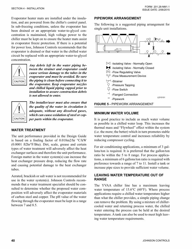
JOHNSON CONTROLS40
SECTION 4 - INSTALLATIONFORM 201.28-NM1.1
ISSUE DATE: 2/06/2015
Evaporator heater mats are installed under the insula-tion, and are powered from the chiller's control panel. In sub-freezing conditions, unless the evaporator has been drained or an appropriate water-to-glycol con-centration is maintained, high voltage power to the chiller must be kept on to ensure the heater mats assist in evaporator freeze protection. If there is a potential for power loss, Johnson Controls recommends that the evaporator is drained or that water in the chilled water circuit be replaced with an appropriate water-to-glycol concentration.
Any debris left in the water piping be-tween the strainer and evaporator could cause serious damage to the tubes in the evaporator and must be avoided. Be sure the piping is clean before connecting it to the evaporator. Keep evaporator nozzles and chilled liquid piping capped prior to installation to assure construction debris is not allowed to enter.
The installer/user must also ensure that the quality of the water in circulation is adequate, without any dissolved gases, which can cause oxidation of steel or cop-per parts within the evaporator.
WATER TREATMENTThe unit performance provided in the Design Guide is based on a fouling factor of 0.018m2/hr °C/kW (0.0001 ft2hr°F/Btu). Dirt, scale, grease and certain types of water treatment will adversely affect the heat exchanger surfaces and therefore the unit performance. Foreign matter in the water system(s) can increase the heat exchanger pressure drop, reducing the flow rate and causing potential damage to the heat exchanger tubes.
Aerated, brackish or salt water is not recommended for use in the water system(s). Johnson Controls recom-mends that a water treatment specialist should be con-sulted to determine whether the proposed water com-position will adversely affect the evaporator materials of carbon steel and copper. The pH value of the water flowing through the evaporator must be kept in a range between 7 and 8.5.
PIPEWORK ARRANGEMENTThe following is a suggested piping arrangement for single unit installations.
FIGURE 5 - PIPEWORK ARRANGEMENT
LD15151
-Isolating Valve - Normally Open-Isolating Valve - Normally Closed-Flow Regulating Valve-Flow Measurement Device
-Strainer-Pressure Tapping-Flow Switch
-Flanged Connection-Pipework
MINIMUM WATER VOLUMEIt is good practice to include as much water volume as possible in a chilled water loop. This increases the thermal mass and “Flywheel” effect within the system (i.e. the more; the better) which in turn promotes stable water temperature control and increases reliability by reducing compressor cycling.
For air conditioning applications, a minimum of 3 gal-lons/ton is required. It is preferred that the gallon/ton ratio be within the 5 to 8 range. For process applica-tions, a minimum of 6 gallons/ton ratio is required with preference towards a range of 7 to 11. Install a tank or increase pipe sizes to provide sufficient water volume.
LEAVING WATER TEMPERATURE OUT OF RANGEThe YVAA chiller line has a maximum leaving water temperature of 15.6°C (60°F). Where process applications require a chilled water temperature higher than what the chiller provides, a simple piping change can remove the problem. By using a mixture of chiller-cooled water and returning process water, the chilled water entering the process can be held at the desired temperature. A tank can also be used to meet high leav-ing water temperature requirements.
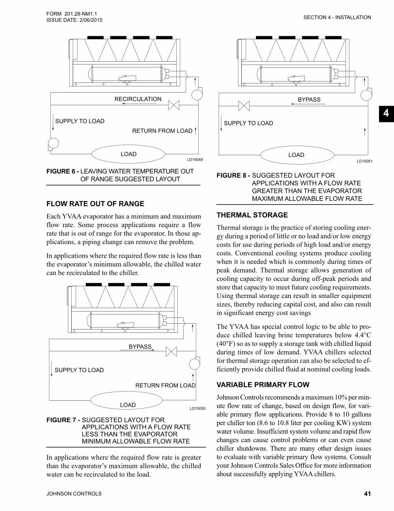
SECTION 4 - INSTALLATION
JOHNSON CONTROLS 41
FORM 201.28-NM1.1ISSUE DATE: 2/06/2015
4
FIGURE 6 - LEAVING WATER TEMPERATURE OUT OF RANGE SUGGESTED LAYOUT
LD15049
RECIRCULATION
SUPPLY TO LOAD
RETURN FROM LOAD
LOAD
FLOW RATE OUT OF RANGEEach YVAA evaporator has a minimum and maximum flow rate. Some process applications require a flow rate that is out of range for the evaporator. In those ap-plications, a piping change can remove the problem.
In applications where the required flow rate is less than the evaporator’s minimum allowable, the chilled water can be recirculated to the chiller.
FIGURE 7 - SUGGESTED LAYOUT FOR APPLICATIONS WITH A FLOW RATE LESS THAN THE EVAPORATOR MINIMUM ALLOWABLE FLOW RATE
LD15050LOAD
SUPPLY TO LOAD
BYPASS
RETURN FROM LOAD
In applications where the required flow rate is greater than the evaporator’s maximum allowable, the chilled water can be recirculated to the load.
LD15051
FIGURE 8 - SUGGESTED LAYOUT FOR APPLICATIONS WITH A FLOW RATE GREATER THAN THE EVAPORATOR MAXIMUM ALLOWABLE FLOW RATE
BYPASS
SUPPLY TO LOAD
LOAD
THERMAL STORAGEThermal storage is the practice of storing cooling ener-gy during a period of little or no load and/or low energy costs for use during periods of high load and/or energy costs. Conventional cooling systems produce cooling when it is needed which is commonly during times of peak demand. Thermal storage allows generation of cooling capacity to occur during off-peak periods and store that capacity to meet future cooling requirements. Using thermal storage can result in smaller equipment sizes, thereby reducing capital cost, and also can result in significant energy cost savings
The YVAA has special control logic to be able to pro-duce chilled leaving brine temperatures below 4.4°C (40°F) so as to supply a storage tank with chilled liquid during times of low demand. YVAA chillers selected for thermal storage operation can also be selected to ef-ficiently provide chilled fluid at nominal cooling loads.
VARIABLE PRIMARY FLOW Johnson Controls recommends a maximum 10% per min-ute flow rate of change, based on design flow, for vari-able primary flow applications. Provide 8 to 10 gallons per chiller ton (8.6 to 10.8 liter per cooling KW) system water volume. Insufficient system volume and rapid flow changes can cause control problems or can even cause chiller shutdowns. There are many other design issues to evaluate with variable primary flow systems. Consult your Johnson Controls Sales Office for more information about successfully applying YVAA chillers.
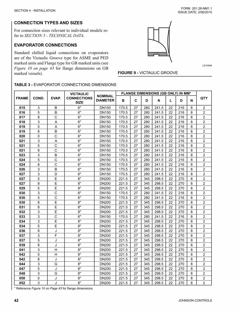
JOHNSON CONTROLS42
SECTION 4 - INSTALLATIONFORM 201.28-NM1.1
ISSUE DATE: 2/06/2015
CONNECTION TYPES AND SIZESFor connection sizes relevant to individual models re-fer to SECTION 5 - TECHNICAL DATA.
EVAPORATOR CONNECTIONSStandard chilled liquid connections on evaporators are of the Victaulic Groove type for ASME and PED marked units and Flange type for GB marked units (see Figure 10 on page 43 for flange dimensions on GB marked vessels). FIGURE 9 - VICTAULIC GROOVE
LD10494
TABLE 3 - EVAPORATOR CONNECTIONS DIMENSIONS
FRAME COND. EVAP.VICTAULIC
CONNECTIONS SIZE
NOMINAL DIAMETER
FLANGE DIMENSIONS (GB ONLY) IN MM*QTYB C D K L D N
015 3 B 6" DN150 170.5 27 280 241.5 22 216 8 2016 5 B 6" DN150 170.5 27 280 241.5 22 216 8 2017 8 C 6" DN150 170.5 27 280 241.5 22 216 8 2018 3 A 6" DN150 170.5 27 280 241.5 22 216 8 2019 5 A 6" DN150 170.5 27 280 241.5 22 216 8 2019 8 B 6" DN150 170.5 27 280 241.5 22 216 8 2020 0 C 6" DN150 170.5 27 280 241.5 22 216 8 2021 3 A 6" DN150 170.5 27 280 241.5 22 216 8 2021 5 C 6" DN150 170.5 27 280 241.5 22 216 8 2021 8 C 6" DN150 170.5 27 280 241.5 22 216 8 2023 3 B 6" DN150 170.5 27 280 241.5 22 216 8 2024 5 C 6" DN150 170.5 27 280 241.5 22 216 8 2024 8 C 6" DN150 170.5 27 280 241.5 22 216 8 2026 3 B 6" DN150 170.5 27 280 241.5 22 216 8 2027 3 D 6" DN150 170.5 27 280 241.5 22 216 8 2027 5 E 8" DN200 221.5 27 345 298.5 22 270 8 2027 8 E 8" DN200 221.5 27 345 298.5 22 270 8 2029 5 E 8" DN200 221.5 27 345 298.5 22 270 8 2030 3 C 6" DN150 170.5 27 280 241.5 22 216 8 2030 5 C 6" DN150 170.5 27 280 241.5 22 216 8 2030 8 E 8" DN200 221.5 27 345 298.5 22 270 8 2031 8 E 8" DN200 221.5 27 345 298.5 22 270 8 2032 3 E 8" DN200 221.5 27 345 298.5 22 270 8 2033 3 C 6" DN150 170.5 27 280 241.5 22 216 8 2034 3 E 8" DN200 221.5 27 345 298.5 22 270 8 2034 5 E 8" DN200 221.5 27 345 298.5 22 270 8 2036 8 J 8" DN200 221.5 27 345 298.5 22 270 8 2037 3 F 8" DN200 221.5 27 345 298.5 22 270 8 2037 5 J 8" DN200 221.5 27 345 298.5 22 270 8 2039 8 J 8" DN200 221.5 27 345 298.5 22 270 8 2041 3 H 8" DN200 221.5 27 345 298.5 22 270 8 2042 5 H 8" DN200 221.5 27 345 298.5 22 270 8 2042 8 J 8" DN200 221.5 27 345 298.5 22 270 8 2044 3 G 8" DN200 221.5 27 345 298.5 22 270 8 2047 5 J 8" DN200 221.5 27 345 298.5 22 270 8 2048 3 G 8" DN200 221.5 27 345 298.5 22 270 8 2050 0 J 8" DN200 221.5 27 345 298.5 22 270 8 2052 3 J 8" DN200 221.5 27 345 298.5 22 270 8 2
* Reference Figure 10 on Page 43 for flange dimensions.
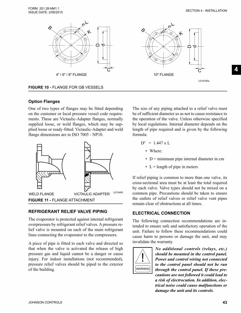
SECTION 4 - INSTALLATION
JOHNSON CONTROLS 43
FORM 201.28-NM1.1ISSUE DATE: 2/06/2015
4
BK K
n-LB n-L
D d D d
C C4" / 6" / 8" FLANGE 10" FLANGE
FIGURE 10 - FLANGE FOR GB VESSELS
LD16185a
Option FlangesOne of two types of flanges may be fitted depending on the customer or local pressure vessel code require-ments. These are Victaulic-Adapter flanges, normally supplied loose, or weld flanges, which may be sup-plied loose or ready-fitted. Victaulic-Adapter and weld flange dimensions are to ISO 7005 - NP10.
FIGURE 11 - FLANGE ATTACHMENT
LD10495WELD FLANGE VICTAULIC ADAPTER
REFRIGERANT RELIEF VALVE PIPINGThe evaporator is protected against internal refrigerant overpressure by refrigerant relief valves. A pressure re-lief valve is mounted on each of the main refrigerant lines connecting the evaporator to the compressors.
A piece of pipe is fitted to each valve and directed so that when the valve is activated the release of high pressure gas and liquid cannot be a danger or cause injury. For indoor installations (not recommended), pressure relief valves should be piped to the exterior of the building.
The size of any piping attached to a relief valve must be of sufficient diameter so as not to cause resistance to the operation of the valve. Unless otherwise specified by local regulations. Internal diameter depends on the length of pipe required and is given by the following formula:
D5 = 1.447 x L
• Where:
• D = minimum pipe internal diameter in cm
• L = length of pipe in meters
If relief piping is common to more than one valve, its cross-sectional area must be at least the total required by each valve. Valve types should not be mixed on a common pipe. Precautions should be taken to ensure the outlets of relief valves or relief valve vent pipes remain clear of obstructions at all times.
ELECTRICAL CONNECTIONThe following connection recommendations are in-tended to ensure safe and satisfactory operation of the unit. Failure to follow these recommendations could cause harm to persons or damage the unit, and may invalidate the warranty.
No additional controls (relays, etc.) should be mounted in the control panel. Power and control wiring not connected to the control panel should not be run through the control panel. If these pre-cautions are not followed it could lead to a risk of electrocution. In addition, elec-trical noise could cause malfunctions or damage the unit and its controls.
JOHNSON CONTROLS44
SECTION 4 - INSTALLATIONFORM 201.28-NM1.1
ISSUE DATE: 2/06/2015
After power wiring connection, do not switch on mains power to the unit. Some internal components are live when the mains are switched on and this must only be done by “Authorized” persons familiar with starting, operating, and troubleshooting this type of equipment.
POWER WIRINGAll electrical wiring should be carried out in accor-dance with local regulations. Route properly sized cables to cable entries on the unit.
In accordance with local codes, NEC codes, U.L. and C.E. standards, it is the responsibility of the user to in-stall over current protection devices between the sup-ply conductors and the power supply terminals on the unit.
To ensure that no eddy currents are set up in the power panel, the cables forming the 3-phase power supply must enter via the same cable entry.
All sources of supply to the unit must be taken via a common point of isolation (not supplied by Johnson Controls).
POWER SUPPLY WIRINGUnits require only one 3-phase supply, plus earth.
Connect the 3-phase supplies to the circuit breaker lo-cated in the panel (See Electrical Lug Data in Table 4 on Page 50).
Connect a suitably sized earth wire to the PE terminal in the panel.
115VAC CONTROL SUPPLY TRANSFORMERA 3-wire high voltage to 115VAC supply transformer is standard in the chiller. This transformer is mounted in the cabinet and steps down the high voltage supply to 115VAC to be used by the controls, VSD, Feed and Drain Valve Controller, valves, solenoids, heaters, etc.
The high voltage for the transformer primary is taken from the chiller input. Fusing is provided for the trans-former.
Removing high voltage power to the chill-er will remove the 115VAC supply voltage to the control panel circuitry and the evaporator heater mat. In sub-freezing weather, this could cause serious damage to the chiller due to evaporator freeze-up. Do not remove power unless alternate means are taken to ensure operation of the control panel, evaporator heater mat, and waterbox heaters.
CONTROL WIRINGAll control wiring utilizing contact closures to the con-trol panel terminal block is nominal 115VAC and must be run in shielded cable, with the shield grounded at the panel end only, and run in water tight conduit. Run shielded cable separately from mains cable to avoid electrical noise pick-up. Use the control panel cable entry to avoid the power cables.
Voltage free contacts connected to the panel must be suitable for 115VAC10 ma (gold contacts recommend-ed). If the voltage free contacts form part of a relay or contactor, the coil of the device must be suppressed using a standard R/C suppressor. The above precautions must be taken to avoid electrical noise, which could cause a malfunction or damage to the unit and its controls.
VOLTS FREE CONTACTS
Chilled Liquid Pump StarterTerminals 23 and 24 on 1TB close to start the chilled liquid pump. This contact can be used as a master start/stop for the pump in conjunction with the daily start/stop schedule. Cycle the pumps from the unit panel if the unit will be operational or shut-down during sub-freezing conditions. Refer to the Evaporator Pump Control on Page 98 for more information on testing the pumps.
Run ContactTerminals 21 and 22 on 1TB close to indicate that a system is running.
Alarm ContactsEach system has a single voltage-free contact, which will operate to signal an alarm condition whenever any system locks out, or there is a power failure. To obtain
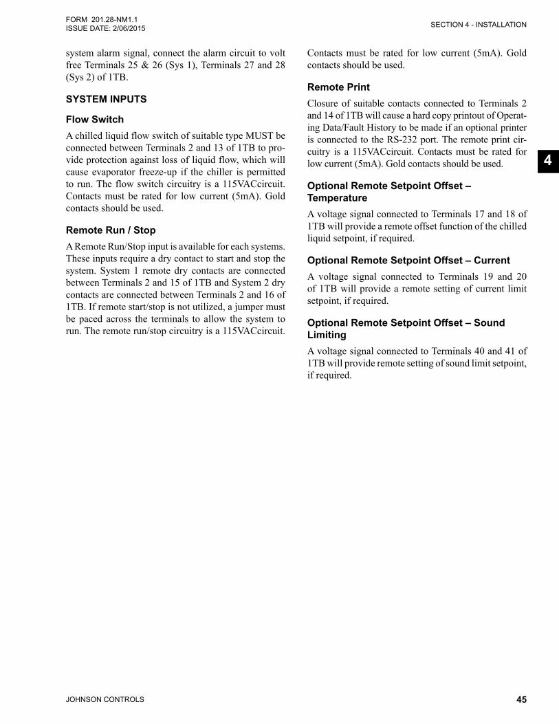
SECTION 4 - INSTALLATION
JOHNSON CONTROLS 45
FORM 201.28-NM1.1ISSUE DATE: 2/06/2015
4
system alarm signal, connect the alarm circuit to volt free Terminals 25 & 26 (Sys 1), Terminals 27 and 28 (Sys 2) of 1TB.
SYSTEM INPUTS
Flow SwitchA chilled liquid flow switch of suitable type MUST be connected between Terminals 2 and 13 of 1TB to pro-vide protection against loss of liquid flow, which will cause evaporator freeze-up if the chiller is permitted to run. The flow switch circuitry is a 115VACcircuit. Contacts must be rated for low current (5mA). Gold contacts should be used.
Remote Run / StopA Remote Run/Stop input is available for each systems. These inputs require a dry contact to start and stop the system. System 1 remote dry contacts are connected between Terminals 2 and 15 of 1TB and System 2 dry contacts are connected between Terminals 2 and 16 of 1TB. If remote start/stop is not utilized, a jumper must be paced across the terminals to allow the system to run. The remote run/stop circuitry is a 115VACcircuit.
Contacts must be rated for low current (5mA). Gold contacts should be used.
Remote PrintClosure of suitable contacts connected to Terminals 2 and 14 of 1TB will cause a hard copy printout of Operat-ing Data/Fault History to be made if an optional printer is connected to the RS-232 port. The remote print cir-cuitry is a 115VACcircuit. Contacts must be rated for low current (5mA). Gold contacts should be used.
Optional Remote Setpoint Offset – TemperatureA voltage signal connected to Terminals 17 and 18 of 1TB will provide a remote offset function of the chilled liquid setpoint, if required.
Optional Remote Setpoint Offset – CurrentA voltage signal connected to Terminals 19 and 20 of 1TB will provide a remote setting of current limit setpoint, if required.
Optional Remote Setpoint Offset – Sound LimitingA voltage signal connected to Terminals 40 and 41 of 1TB will provide remote setting of sound limit setpoint, if required.
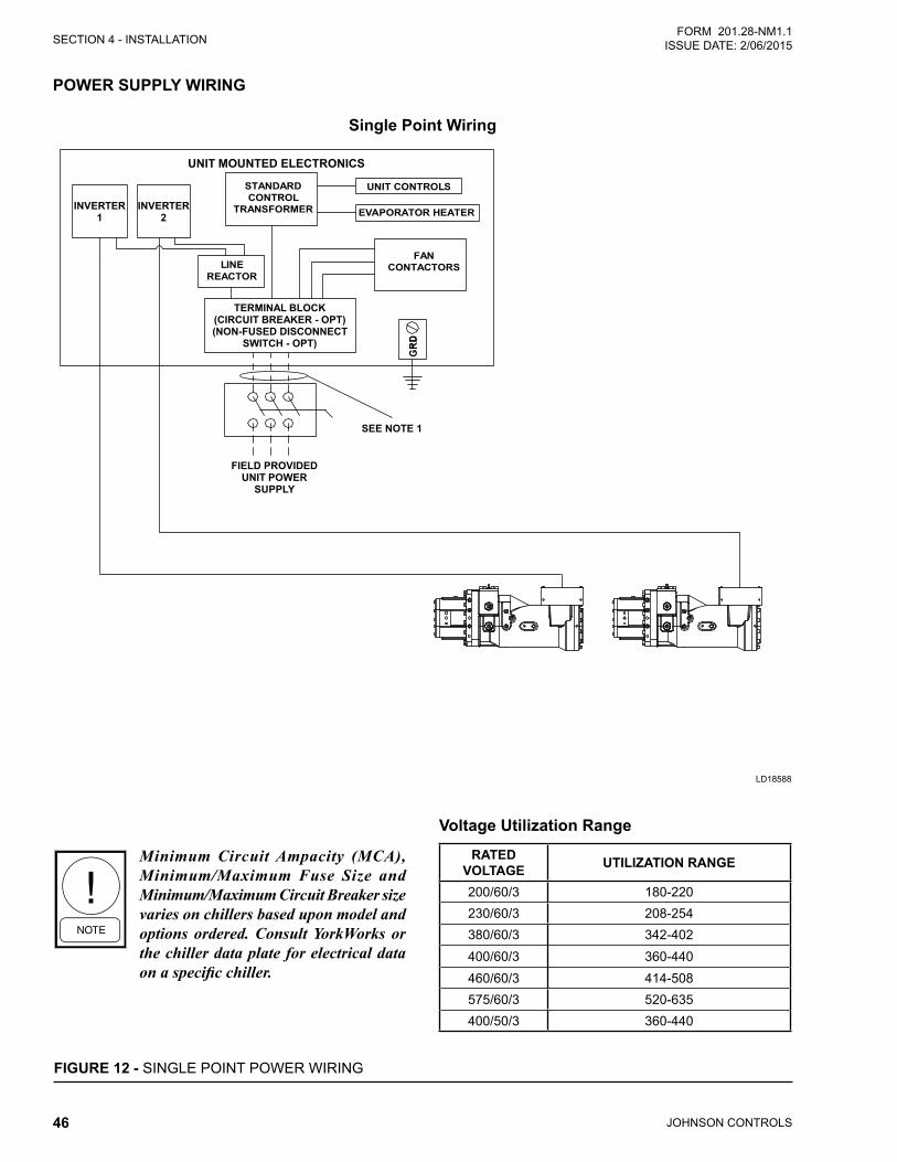
JOHNSON CONTROLS46
SECTION 4 - INSTALLATIONFORM 201.28-NM1.1
ISSUE DATE: 2/06/2015
FIGURE 12 - SINGLE POINT POWER WIRING
Minimum Circuit Ampacity (MCA), Minimum/Maximum Fuse Size and Minimum/Maximum Circuit Breaker size varies on chillers based upon model and options ordered. Consult YorkWorks or the chiller data plate for electrical data on a specific chiller.
Voltage Utilization Range
RATED VOLTAGE UTILIZATION RANGE
200/60/3 180-220230/60/3 208-254380/60/3 342-402400/60/3 360-440460/60/3 414-508575/60/3 520-635400/50/3 360-440
LD18588
POWER SUPPLY WIRING
Single Point Wiring
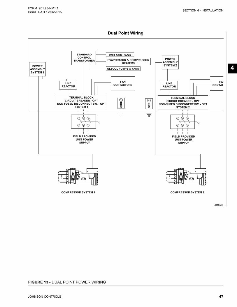
SECTION 4 - INSTALLATION
JOHNSON CONTROLS 47
FORM 201.28-NM1.1ISSUE DATE: 2/06/2015
4
LD18589
Dual Point Wiring
2
FIGURE 13 - DUAL POINT POWER WIRING

JOHNSON CONTROLS48
SECTION 4 - INSTALLATIONFORM 201.28-NM1.1
ISSUE DATE: 2/06/2015
THIS PAGE INTENTIONALLY LEFT BLANK
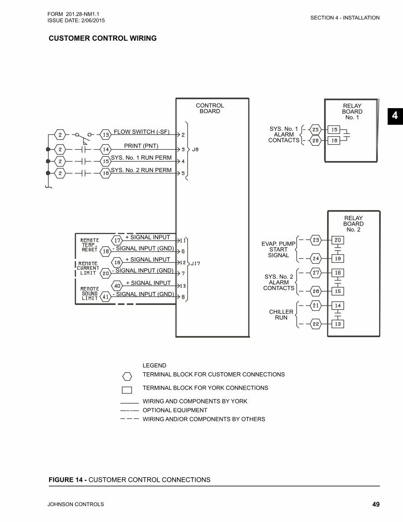
SECTION 4 - INSTALLATION
JOHNSON CONTROLS 49
FORM 201.28-NM1.1ISSUE DATE: 2/06/2015
4
FIGURE 14 - CUSTOMER CONTROL CONNECTIONS
SYS. No. 1ALARM
CONTACTS
SYS. No. 2ALARM
CONTACTS
CHILLERRUN
EVAP. PUMPSTARTSIGNAL
SYS. No. 1 RUN PERM
SYS. No. 2 RUN PERM
FLOW SWITCH (-SF)
PRINT (PNT)
LEGENDTERMINAL BLOCK FOR CUSTOMER CONNECTIONS
TERMINAL BLOCK FOR YORK CONNECTIONS
WIRING AND COMPONENTS BY YORKOPTIONAL EQUIPMENTWIRING AND/OR COMPONENTS BY OTHERS
RELAYBOARD
No. 2
RELAYBOARD
No. 1
CONTROLBOARD
+ SIGNAL INPUT
+ SIGNAL INPUT
+ SIGNAL INPUT
- SIGNAL INPUT (GND)
- SIGNAL INPUT (GND)
- SIGNAL INPUT (GND)
CUSTOMER CONTROL WIRING
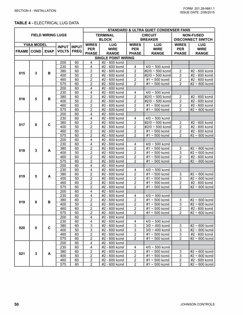
JOHNSON CONTROLS50
SECTION 4 - INSTALLATIONFORM 201.28-NM1.1
ISSUE DATE: 2/06/2015
TABLE 4 - ELECTRICAL LUG DATA
FIELD WIRING LUGSSTANDARD & ULTRA QUIET CONDENSER FANS
TERMINAL BLOCK
CIRCUIT BREAKER
NON-FUSED DISCONNECT SWITCH
YVAA MODEL INPUT VOLTS
INPUT FREQ
WIRES PER
PHASE
LUG WIRE
RANGE
WIRES PER
PHASE
LUG WIRE
RANGE
WIRES PER
PHASE
LUG WIRE
RANGEFRAME COND EVAP
SINGLE POINT WIRING
015 3 B
200 60 4 #2 - 600 kcmil230 60 4 #2 - 600 kcmil 4 4/0 ~ 500 kcmil380 60 2 #2 - 600 kcmil 2 #2/0 ~ 500 kcmil 2 #2 - 600 kcmil400 50 2 #2 - 600 kcmil 2 #2/0 ~ 500 kcmil 2 #2 - 600 kcmil460 60 2 #2 - 600 kcmil 2 #1 ~ 500 kcmil 2 #2 - 600 kcmil575 60 2 #2 - 600 kcmil 2 #1 ~ 500 kcmil 2 #2 ~ 600 kcmil
016 5 B
200 60 4 #2 - 600 kcmil230 60 4 #2 - 600 kcmil 4 4/0 ~ 500 kcmil380 60 2 #2 - 600 kcmil 2 #2/0 ~ 500 kcmil 2 #2 - 600 kcmil400 50 2 #2 - 600 kcmil 2 #2/0 ~ 500 kcmil 2 #2 - 600 kcmil460 60 2 #2 - 600 kcmil 2 #1 ~ 500 kcmil 2 #2 - 600 kcmil575 60 2 #2 - 600 kcmil 2 #1 ~ 500 kcmil 2 #2 ~ 600 kcmil
017 8 C
200 60 4 #2 - 600 kcmil230 60 4 #2 - 600 kcmil 4 4/0 ~ 500 kcmil380 60 2 #2 - 600 kcmil 2 #2/0 ~ 500 kcmil 2 #2 - 600 kcmil400 50 2 #2 - 600 kcmil 2 #2/0 ~ 500 kcmil 2 #2 - 600 kcmil460 60 2 #2 - 600 kcmil 2 #1 ~ 500 kcmil 2 #2 - 600 kcmil575 60 2 #2 - 600 kcmil 2 #1 ~ 500 kcmil 2 #2 ~ 600 kcmil
018 3 A
200 60 4 #2 - 600 kcmil230 60 4 #2 - 600 kcmil 4 4/0 ~ 500 kcmil380 60 2 #2 - 600 kcmil 2 #1 ~ 500 kcmil 3 #2 ~ 600 kcmil400 50 2 #2 - 600 kcmil 2 #1 ~ 500 kcmil 3 #2 ~ 600 kcmil460 60 2 #2 - 600 kcmil 2 #1 ~ 500 kcmil 2 #2 - 600 kcmil575 60 2 #2 - 600 kcmil 2 #1 ~ 500 kcmil 2 #2 ~ 600 kcmil
019 5 A
200 60 4 #2 - 600 kcmil230 60 4 #2 - 600 kcmil 4 4/0 ~ 500 kcmil380 60 2 #2 - 600 kcmil 2 #1 ~ 500 kcmil 3 #2 ~ 600 kcmil400 50 2 #2 - 600 kcmil 2 #1 ~ 500 kcmil 3 #2 ~ 600 kcmil460 60 2 #2 - 600 kcmil 2 #1 ~ 500 kcmil 2 #2 - 600 kcmil575 60 2 #2 - 600 kcmil 2 #1 ~ 500 kcmil 2 #2 ~ 600 kcmil
019 8 B
200 60 4 #2 - 600 kcmil230 60 4 #2 - 600 kcmil 4 4/0 ~ 500 kcmil380 60 2 #2 - 600 kcmil 2 #1 ~ 500 kcmil 3 #2 ~ 600 kcmil400 50 2 #2 - 600 kcmil 2 #1 ~ 500 kcmil 3 #2 ~ 600 kcmil460 60 2 #2 - 600 kcmil 2 #1 ~ 500 kcmil 2 #2 - 600 kcmil575 60 2 #2 - 600 kcmil 2 #1 ~ 500 kcmil 2 #2 ~ 600 kcmil
020 0 C
200 60 4 #2 - 600 kcmil230 60 4 #2 - 600 kcmil 4 4/0 ~ 500 kcmil380 60 3 #2 - 600 kcmil 3 3/0 ~ 400 kcmil 3 #2 ~ 600 kcmil400 50 3 #2 - 600 kcmil 3 3/0 ~ 400 kcmil 3 #2 ~ 600 kcmil460 60 2 #2 - 600 kcmil 2 #1 ~ 500 kcmil 3 #2 - 600 kcmil575 60 2 #2 - 600 kcmil 2 #1 ~ 500 kcmil 2 #2 ~ 600 kcmil
021 3 A
200 60 4 #2 - 600 kcmil230 60 4 #2 - 600 kcmil 4 4/0 ~ 500 kcmil380 60 2 #2 - 600 kcmil 2 #1 ~ 500 kcmil 3 #2 ~ 600 kcmil400 50 2 #2 - 600 kcmil 2 #1 ~ 500 kcmil 3 #2 ~ 600 kcmil460 60 2 #2 - 600 kcmil 2 #1 ~ 500 kcmil 2 #2 - 600 kcmil575 60 2 #2 - 600 kcmil 2 #1 ~ 500 kcmil 2 #2 ~ 600 kcmil
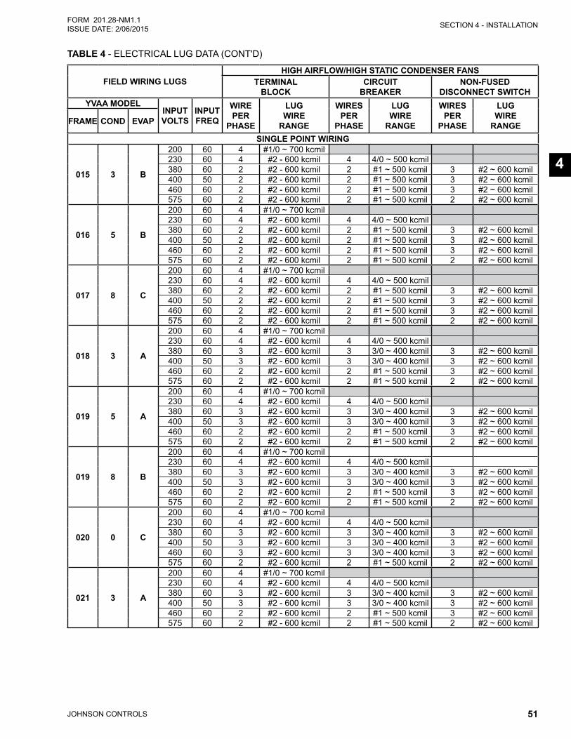
SECTION 4 - INSTALLATION
JOHNSON CONTROLS 51
FORM 201.28-NM1.1ISSUE DATE: 2/06/2015
4
TABLE 4 - ELECTRICAL LUG DATA (CONT'D)
FIELD WIRING LUGSHIGH AIRFLOW/HIGH STATIC CONDENSER FANS
TERMINAL BLOCK
CIRCUIT BREAKER
NON-FUSED DISCONNECT SWITCH
YVAA MODELINPUT VOLTS
INPUT FREQ
WIRE PER
PHASE
LUG WIRE
RANGE
WIRES PER
PHASE
LUG WIRE
RANGE
WIRES PER
PHASE
LUG WIRE
RANGEFRAME COND EVAP
SINGLE POINT WIRING
015 3 B
200 60 4 #1/0 ~ 700 kcmil230 60 4 #2 - 600 kcmil 4 4/0 ~ 500 kcmil380 60 2 #2 - 600 kcmil 2 #1 ~ 500 kcmil 3 #2 ~ 600 kcmil400 50 2 #2 - 600 kcmil 2 #1 ~ 500 kcmil 3 #2 ~ 600 kcmil460 60 2 #2 - 600 kcmil 2 #1 ~ 500 kcmil 3 #2 ~ 600 kcmil575 60 2 #2 - 600 kcmil 2 #1 ~ 500 kcmil 2 #2 ~ 600 kcmil
016 5 B
200 60 4 #1/0 ~ 700 kcmil230 60 4 #2 - 600 kcmil 4 4/0 ~ 500 kcmil380 60 2 #2 - 600 kcmil 2 #1 ~ 500 kcmil 3 #2 ~ 600 kcmil400 50 2 #2 - 600 kcmil 2 #1 ~ 500 kcmil 3 #2 ~ 600 kcmil460 60 2 #2 - 600 kcmil 2 #1 ~ 500 kcmil 3 #2 ~ 600 kcmil575 60 2 #2 - 600 kcmil 2 #1 ~ 500 kcmil 2 #2 ~ 600 kcmil
017 8 C
200 60 4 #1/0 ~ 700 kcmil230 60 4 #2 - 600 kcmil 4 4/0 ~ 500 kcmil380 60 2 #2 - 600 kcmil 2 #1 ~ 500 kcmil 3 #2 ~ 600 kcmil400 50 2 #2 - 600 kcmil 2 #1 ~ 500 kcmil 3 #2 ~ 600 kcmil460 60 2 #2 - 600 kcmil 2 #1 ~ 500 kcmil 3 #2 ~ 600 kcmil575 60 2 #2 - 600 kcmil 2 #1 ~ 500 kcmil 2 #2 ~ 600 kcmil
018 3 A
200 60 4 #1/0 ~ 700 kcmil230 60 4 #2 - 600 kcmil 4 4/0 ~ 500 kcmil380 60 3 #2 - 600 kcmil 3 3/0 ~ 400 kcmil 3 #2 ~ 600 kcmil400 50 3 #2 - 600 kcmil 3 3/0 ~ 400 kcmil 3 #2 ~ 600 kcmil460 60 2 #2 - 600 kcmil 2 #1 ~ 500 kcmil 3 #2 ~ 600 kcmil575 60 2 #2 - 600 kcmil 2 #1 ~ 500 kcmil 2 #2 ~ 600 kcmil
019 5 A
200 60 4 #1/0 ~ 700 kcmil230 60 4 #2 - 600 kcmil 4 4/0 ~ 500 kcmil380 60 3 #2 - 600 kcmil 3 3/0 ~ 400 kcmil 3 #2 ~ 600 kcmil400 50 3 #2 - 600 kcmil 3 3/0 ~ 400 kcmil 3 #2 ~ 600 kcmil460 60 2 #2 - 600 kcmil 2 #1 ~ 500 kcmil 3 #2 ~ 600 kcmil575 60 2 #2 - 600 kcmil 2 #1 ~ 500 kcmil 2 #2 ~ 600 kcmil
019 8 B
200 60 4 #1/0 ~ 700 kcmil230 60 4 #2 - 600 kcmil 4 4/0 ~ 500 kcmil380 60 3 #2 - 600 kcmil 3 3/0 ~ 400 kcmil 3 #2 ~ 600 kcmil400 50 3 #2 - 600 kcmil 3 3/0 ~ 400 kcmil 3 #2 ~ 600 kcmil460 60 2 #2 - 600 kcmil 2 #1 ~ 500 kcmil 3 #2 ~ 600 kcmil575 60 2 #2 - 600 kcmil 2 #1 ~ 500 kcmil 2 #2 ~ 600 kcmil
020 0 C
200 60 4 #1/0 ~ 700 kcmil230 60 4 #2 - 600 kcmil 4 4/0 ~ 500 kcmil380 60 3 #2 - 600 kcmil 3 3/0 ~ 400 kcmil 3 #2 ~ 600 kcmil400 50 3 #2 - 600 kcmil 3 3/0 ~ 400 kcmil 3 #2 ~ 600 kcmil460 60 3 #2 - 600 kcmil 3 3/0 ~ 400 kcmil 3 #2 ~ 600 kcmil575 60 2 #2 - 600 kcmil 2 #1 ~ 500 kcmil 2 #2 ~ 600 kcmil
021 3 A
200 60 4 #1/0 ~ 700 kcmil230 60 4 #2 - 600 kcmil 4 4/0 ~ 500 kcmil380 60 3 #2 - 600 kcmil 3 3/0 ~ 400 kcmil 3 #2 ~ 600 kcmil400 50 3 #2 - 600 kcmil 3 3/0 ~ 400 kcmil 3 #2 ~ 600 kcmil460 60 2 #2 - 600 kcmil 2 #1 ~ 500 kcmil 3 #2 ~ 600 kcmil575 60 2 #2 - 600 kcmil 2 #1 ~ 500 kcmil 2 #2 ~ 600 kcmil
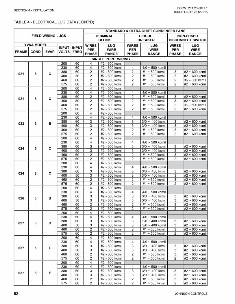
JOHNSON CONTROLS52
SECTION 4 - INSTALLATIONFORM 201.28-NM1.1
ISSUE DATE: 2/06/2015
TABLE 4 - ELECTRICAL LUG DATA (CONT'D)
FIELD WIRING LUGSSTANDARD & ULTRA QUIET CONDENSER FANS
TERMINAL BLOCK
CIRCUIT BREAKER
NON-FUSED DISCONNECT SWITCH
YVAA MODELINPUT VOLTS
INPUT FREQ
WIRES PER
PHASE
LUG WIRE
RANGE
WIRES PER
PHASE
LUG WIRE
RANGE
WIRES PER
PHASE
LUG WIRE
RANGEFRAME COND EVAP
SINGLE POINT WIRING
021 5 C
200 60 4 #2 - 600 kcmil230 60 4 #2 - 600 kcmil 4 4/0 ~ 500 kcmil380 60 2 #2 - 600 kcmil 2 #1 ~ 500 kcmil 3 #2 ~ 600 kcmil400 50 2 #2 - 600 kcmil 2 #1 ~ 500 kcmil 3 #2 ~ 600 kcmil460 60 2 #2 - 600 kcmil 2 #1 ~ 500 kcmil 2 #2 - 600 kcmil575 60 2 #2 - 600 kcmil 2 #1 ~ 500 kcmil 2 #2 ~ 600 kcmil
021 8 C
200 60 4 #2 - 600 kcmil230 60 4 #2 - 600 kcmil 4 4/0 ~ 500 kcmil380 60 2 #2 - 600 kcmil 2 #1 ~ 500 kcmil 3 #2 ~ 600 kcmil400 50 2 #2 - 600 kcmil 2 #1 ~ 500 kcmil 3 #2 ~ 600 kcmil460 60 2 #2 - 600 kcmil 2 #1 ~ 500 kcmil 2 #2 - 600 kcmil575 60 2 #2 - 600 kcmil 2 #1 ~ 500 kcmil 2 #2 ~ 600 kcmil
023 3 B
200 60 4 #2 - 600 kcmil230 60 4 #2 - 600 kcmil 4 4/0 ~ 500 kcmil380 60 3 #2 - 600 kcmil 3 3/0 ~ 400 kcmil 3 #2 ~ 600 kcmil400 50 3 #2 - 600 kcmil 3 3/0 ~ 400 kcmil 3 #2 ~ 600 kcmil460 60 2 #2 - 600 kcmil 2 #1 ~ 500 kcmil 3 #2 ~ 600 kcmil575 60 2 #2 - 600 kcmil 2 #1 ~ 500 kcmil 2 #2 ~ 600 kcmil
024 5 C
200 60 4 #2 - 600 kcmil230 60 4 #2 - 600 kcmil 4 4/0 ~ 500 kcmil380 60 3 #2 - 600 kcmil 3 3/0 ~ 400 kcmil 3 #2 ~ 600 kcmil400 50 3 #2 - 600 kcmil 3 3/0 ~ 400 kcmil 3 #2 ~ 600 kcmil460 60 2 #2 - 600 kcmil 2 #1 ~ 500 kcmil 3 #2 ~ 600 kcmil575 60 2 #2 - 600 kcmil 2 #1 ~ 500 kcmil 2 #2 ~ 600 kcmil
024 8 C
200 60 4 #2 - 600 kcmil230 60 4 #2 - 600 kcmil 4 4/0 ~ 500 kcmil380 60 3 #2 - 600 kcmil 3 3/0 ~ 400 kcmil 3 #2 ~ 600 kcmil400 50 3 #2 - 600 kcmil 3 3/0 ~ 400 kcmil 3 #2 ~ 600 kcmil460 60 2 #2 - 600 kcmil 2 #1 ~ 500 kcmil 3 #2 ~ 600 kcmil575 60 2 #2 - 600 kcmil 2 #1 ~ 500 kcmil 2 #2 ~ 600 kcmil
026 3 B
200 60 4 #2 - 600 kcmil230 60 4 #2 - 600 kcmil 4 4/0 ~ 500 kcmil380 60 3 #2 - 600 kcmil 3 3/0 ~ 400 kcmil 3 #2 ~ 600 kcmil400 50 3 #2 - 600 kcmil 3 3/0 ~ 400 kcmil 3 #2 ~ 600 kcmil460 60 2 #2 - 600 kcmil 2 #1 ~ 500 kcmil 3 #2 ~ 600 kcmil575 60 2 #2 - 600 kcmil 2 #1 ~ 500 kcmil 2 #2 ~ 600 kcmil
027 3 D
200 60 4 #2 - 600 kcmil230 60 4 #2 - 600 kcmil 4 4/0 ~ 500 kcmil380 60 3 #2 - 600 kcmil 3 3/0 ~ 400 kcmil 3 #2 ~ 600 kcmil400 50 3 #2 - 600 kcmil 3 3/0 ~ 400 kcmil 3 #2 ~ 600 kcmil460 60 2 #2 - 600 kcmil 2 #1 ~ 500 kcmil 3 #2 ~ 600 kcmil575 60 2 #2 - 600 kcmil 2 #1 ~ 500 kcmil 2 #2 ~ 600 kcmil
027 5 E
200 60 4 #2 - 600 kcmil230 60 4 #2 - 600 kcmil 4 4/0 ~ 500 kcmil380 60 3 #2 - 600 kcmil 3 3/0 ~ 400 kcmil 3 #2 ~ 600 kcmil400 50 3 #2 - 600 kcmil 3 3/0 ~ 400 kcmil 3 #2 ~ 600 kcmil460 60 2 #2 - 600 kcmil 2 #1 ~ 500 kcmil 3 #2 ~ 600 kcmil575 60 2 #2 - 600 kcmil 2 #1 ~ 500 kcmil 2 #2 ~ 600 kcmil
027 8 E
200 60 4 #2 - 600 kcmil230 60 4 #2 - 600 kcmil 4 4/0 ~ 500 kcmil380 60 3 #2 - 600 kcmil 3 3/0 ~ 400 kcmil 3 #2 ~ 600 kcmil400 50 3 #2 - 600 kcmil 3 3/0 ~ 400 kcmil 3 #2 ~ 600 kcmil460 60 2 #2 - 600 kcmil 2 #1 ~ 500 kcmil 3 #2 ~ 600 kcmil575 60 2 #2 - 600 kcmil 2 #1 ~ 500 kcmil 2 #2 ~ 600 kcmil
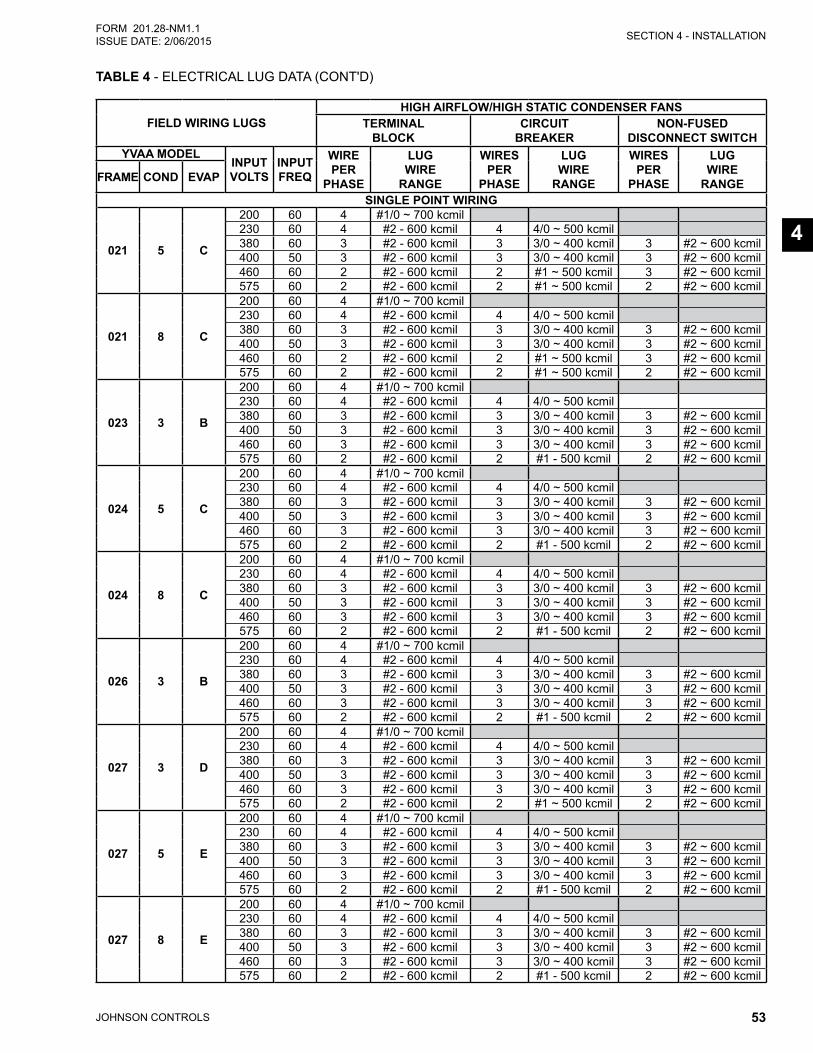
SECTION 4 - INSTALLATION
JOHNSON CONTROLS 53
FORM 201.28-NM1.1ISSUE DATE: 2/06/2015
4
FIELD WIRING LUGSHIGH AIRFLOW/HIGH STATIC CONDENSER FANS
TERMINAL BLOCK
CIRCUIT BREAKER
NON-FUSED DISCONNECT SWITCH
YVAA MODELINPUT VOLTS
INPUT FREQ
WIRE PER
PHASE
LUG WIRE
RANGE
WIRES PER
PHASE
LUG WIRE
RANGE
WIRES PER
PHASE
LUG WIRE
RANGEFRAME COND EVAP
SINGLE POINT WIRING
021 5 C
200 60 4 #1/0 ~ 700 kcmil230 60 4 #2 - 600 kcmil 4 4/0 ~ 500 kcmil380 60 3 #2 - 600 kcmil 3 3/0 ~ 400 kcmil 3 #2 ~ 600 kcmil400 50 3 #2 - 600 kcmil 3 3/0 ~ 400 kcmil 3 #2 ~ 600 kcmil460 60 2 #2 - 600 kcmil 2 #1 ~ 500 kcmil 3 #2 ~ 600 kcmil575 60 2 #2 - 600 kcmil 2 #1 ~ 500 kcmil 2 #2 ~ 600 kcmil
021 8 C
200 60 4 #1/0 ~ 700 kcmil230 60 4 #2 - 600 kcmil 4 4/0 ~ 500 kcmil380 60 3 #2 - 600 kcmil 3 3/0 ~ 400 kcmil 3 #2 ~ 600 kcmil400 50 3 #2 - 600 kcmil 3 3/0 ~ 400 kcmil 3 #2 ~ 600 kcmil460 60 2 #2 - 600 kcmil 2 #1 ~ 500 kcmil 3 #2 ~ 600 kcmil575 60 2 #2 - 600 kcmil 2 #1 ~ 500 kcmil 2 #2 ~ 600 kcmil
023 3 B
200 60 4 #1/0 ~ 700 kcmil230 60 4 #2 - 600 kcmil 4 4/0 ~ 500 kcmil380 60 3 #2 - 600 kcmil 3 3/0 ~ 400 kcmil 3 #2 ~ 600 kcmil400 50 3 #2 - 600 kcmil 3 3/0 ~ 400 kcmil 3 #2 ~ 600 kcmil460 60 3 #2 - 600 kcmil 3 3/0 ~ 400 kcmil 3 #2 ~ 600 kcmil575 60 2 #2 - 600 kcmil 2 #1 - 500 kcmil 2 #2 ~ 600 kcmil
024 5 C
200 60 4 #1/0 ~ 700 kcmil230 60 4 #2 - 600 kcmil 4 4/0 ~ 500 kcmil380 60 3 #2 - 600 kcmil 3 3/0 ~ 400 kcmil 3 #2 ~ 600 kcmil400 50 3 #2 - 600 kcmil 3 3/0 ~ 400 kcmil 3 #2 ~ 600 kcmil460 60 3 #2 - 600 kcmil 3 3/0 ~ 400 kcmil 3 #2 ~ 600 kcmil575 60 2 #2 - 600 kcmil 2 #1 - 500 kcmil 2 #2 ~ 600 kcmil
024 8 C
200 60 4 #1/0 ~ 700 kcmil230 60 4 #2 - 600 kcmil 4 4/0 ~ 500 kcmil380 60 3 #2 - 600 kcmil 3 3/0 ~ 400 kcmil 3 #2 ~ 600 kcmil400 50 3 #2 - 600 kcmil 3 3/0 ~ 400 kcmil 3 #2 ~ 600 kcmil460 60 3 #2 - 600 kcmil 3 3/0 ~ 400 kcmil 3 #2 ~ 600 kcmil575 60 2 #2 - 600 kcmil 2 #1 - 500 kcmil 2 #2 ~ 600 kcmil
026 3 B
200 60 4 #1/0 ~ 700 kcmil230 60 4 #2 - 600 kcmil 4 4/0 ~ 500 kcmil380 60 3 #2 - 600 kcmil 3 3/0 ~ 400 kcmil 3 #2 ~ 600 kcmil400 50 3 #2 - 600 kcmil 3 3/0 ~ 400 kcmil 3 #2 ~ 600 kcmil460 60 3 #2 - 600 kcmil 3 3/0 ~ 400 kcmil 3 #2 ~ 600 kcmil575 60 2 #2 - 600 kcmil 2 #1 - 500 kcmil 2 #2 ~ 600 kcmil
027 3 D
200 60 4 #1/0 ~ 700 kcmil230 60 4 #2 - 600 kcmil 4 4/0 ~ 500 kcmil380 60 3 #2 - 600 kcmil 3 3/0 ~ 400 kcmil 3 #2 ~ 600 kcmil400 50 3 #2 - 600 kcmil 3 3/0 ~ 400 kcmil 3 #2 ~ 600 kcmil460 60 3 #2 - 600 kcmil 3 3/0 ~ 400 kcmil 3 #2 ~ 600 kcmil575 60 2 #2 - 600 kcmil 2 #1 ~ 500 kcmil 2 #2 ~ 600 kcmil
027 5 E
200 60 4 #1/0 ~ 700 kcmil230 60 4 #2 - 600 kcmil 4 4/0 ~ 500 kcmil380 60 3 #2 - 600 kcmil 3 3/0 ~ 400 kcmil 3 #2 ~ 600 kcmil400 50 3 #2 - 600 kcmil 3 3/0 ~ 400 kcmil 3 #2 ~ 600 kcmil460 60 3 #2 - 600 kcmil 3 3/0 ~ 400 kcmil 3 #2 ~ 600 kcmil575 60 2 #2 - 600 kcmil 2 #1 - 500 kcmil 2 #2 ~ 600 kcmil
027 8 E
200 60 4 #1/0 ~ 700 kcmil230 60 4 #2 - 600 kcmil 4 4/0 ~ 500 kcmil380 60 3 #2 - 600 kcmil 3 3/0 ~ 400 kcmil 3 #2 ~ 600 kcmil400 50 3 #2 - 600 kcmil 3 3/0 ~ 400 kcmil 3 #2 ~ 600 kcmil460 60 3 #2 - 600 kcmil 3 3/0 ~ 400 kcmil 3 #2 ~ 600 kcmil575 60 2 #2 - 600 kcmil 2 #1 - 500 kcmil 2 #2 ~ 600 kcmil
TABLE 4 - ELECTRICAL LUG DATA (CONT'D)
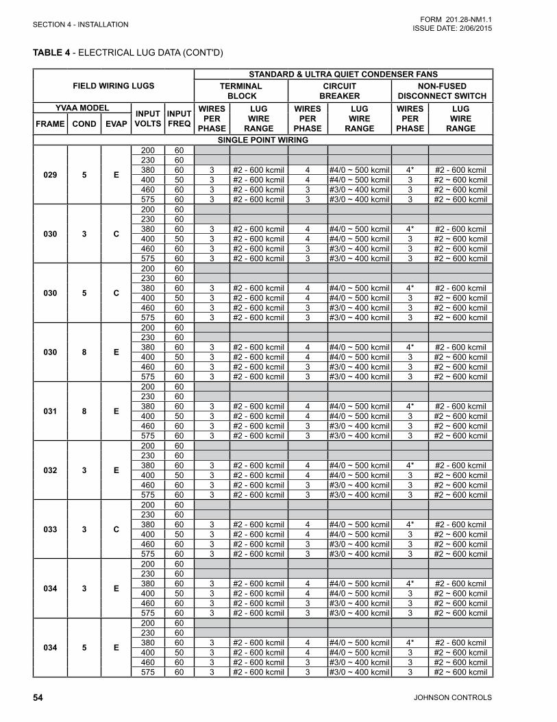
JOHNSON CONTROLS54
SECTION 4 - INSTALLATIONFORM 201.28-NM1.1
ISSUE DATE: 2/06/2015
TABLE 4 - ELECTRICAL LUG DATA (CONT'D)
FIELD WIRING LUGSSTANDARD & ULTRA QUIET CONDENSER FANS
TERMINAL BLOCK
CIRCUIT BREAKER
NON-FUSED DISCONNECT SWITCH
YVAA MODELINPUT VOLTS
INPUT FREQ
WIRES PER
PHASE
LUG WIRE
RANGE
WIRES PER
PHASE
LUG WIRE
RANGE
WIRES PER
PHASE
LUG WIRE
RANGEFRAME COND EVAP
SINGLE POINT WIRING
029 5 E
200 60230 60380 60 3 #2 - 600 kcmil 4 #4/0 ~ 500 kcmil 4* #2 - 600 kcmil400 50 3 #2 - 600 kcmil 4 #4/0 ~ 500 kcmil 3 #2 ~ 600 kcmil460 60 3 #2 - 600 kcmil 3 #3/0 ~ 400 kcmil 3 #2 ~ 600 kcmil575 60 3 #2 - 600 kcmil 3 #3/0 ~ 400 kcmil 3 #2 ~ 600 kcmil
030 3 C
200 60230 60380 60 3 #2 - 600 kcmil 4 #4/0 ~ 500 kcmil 4* #2 - 600 kcmil400 50 3 #2 - 600 kcmil 4 #4/0 ~ 500 kcmil 3 #2 ~ 600 kcmil460 60 3 #2 - 600 kcmil 3 #3/0 ~ 400 kcmil 3 #2 ~ 600 kcmil575 60 3 #2 - 600 kcmil 3 #3/0 ~ 400 kcmil 3 #2 ~ 600 kcmil
030 5 C
200 60230 60380 60 3 #2 - 600 kcmil 4 #4/0 ~ 500 kcmil 4* #2 - 600 kcmil400 50 3 #2 - 600 kcmil 4 #4/0 ~ 500 kcmil 3 #2 ~ 600 kcmil460 60 3 #2 - 600 kcmil 3 #3/0 ~ 400 kcmil 3 #2 ~ 600 kcmil575 60 3 #2 - 600 kcmil 3 #3/0 ~ 400 kcmil 3 #2 ~ 600 kcmil
030 8 E
200 60230 60380 60 3 #2 - 600 kcmil 4 #4/0 ~ 500 kcmil 4* #2 - 600 kcmil400 50 3 #2 - 600 kcmil 4 #4/0 ~ 500 kcmil 3 #2 ~ 600 kcmil460 60 3 #2 - 600 kcmil 3 #3/0 ~ 400 kcmil 3 #2 ~ 600 kcmil575 60 3 #2 - 600 kcmil 3 #3/0 ~ 400 kcmil 3 #2 ~ 600 kcmil
031 8 E
200 60230 60380 60 3 #2 - 600 kcmil 4 #4/0 ~ 500 kcmil 4* #2 - 600 kcmil400 50 3 #2 - 600 kcmil 4 #4/0 ~ 500 kcmil 3 #2 ~ 600 kcmil460 60 3 #2 - 600 kcmil 3 #3/0 ~ 400 kcmil 3 #2 ~ 600 kcmil575 60 3 #2 - 600 kcmil 3 #3/0 ~ 400 kcmil 3 #2 ~ 600 kcmil
032 3 E
200 60230 60380 60 3 #2 - 600 kcmil 4 #4/0 ~ 500 kcmil 4* #2 - 600 kcmil400 50 3 #2 - 600 kcmil 4 #4/0 ~ 500 kcmil 3 #2 ~ 600 kcmil460 60 3 #2 - 600 kcmil 3 #3/0 ~ 400 kcmil 3 #2 ~ 600 kcmil575 60 3 #2 - 600 kcmil 3 #3/0 ~ 400 kcmil 3 #2 ~ 600 kcmil
033 3 C
200 60230 60380 60 3 #2 - 600 kcmil 4 #4/0 ~ 500 kcmil 4* #2 - 600 kcmil400 50 3 #2 - 600 kcmil 4 #4/0 ~ 500 kcmil 3 #2 ~ 600 kcmil460 60 3 #2 - 600 kcmil 3 #3/0 ~ 400 kcmil 3 #2 ~ 600 kcmil575 60 3 #2 - 600 kcmil 3 #3/0 ~ 400 kcmil 3 #2 ~ 600 kcmil
034 3 E
200 60230 60380 60 3 #2 - 600 kcmil 4 #4/0 ~ 500 kcmil 4* #2 - 600 kcmil400 50 3 #2 - 600 kcmil 4 #4/0 ~ 500 kcmil 3 #2 ~ 600 kcmil460 60 3 #2 - 600 kcmil 3 #3/0 ~ 400 kcmil 3 #2 ~ 600 kcmil575 60 3 #2 - 600 kcmil 3 #3/0 ~ 400 kcmil 3 #2 ~ 600 kcmil
034 5 E
200 60230 60380 60 3 #2 - 600 kcmil 4 #4/0 ~ 500 kcmil 4* #2 - 600 kcmil400 50 3 #2 - 600 kcmil 4 #4/0 ~ 500 kcmil 3 #2 ~ 600 kcmil460 60 3 #2 - 600 kcmil 3 #3/0 ~ 400 kcmil 3 #2 ~ 600 kcmil575 60 3 #2 - 600 kcmil 3 #3/0 ~ 400 kcmil 3 #2 ~ 600 kcmil
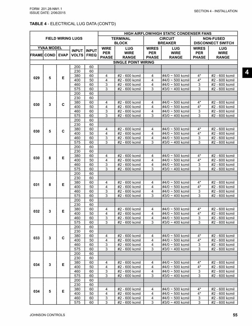
SECTION 4 - INSTALLATION
JOHNSON CONTROLS 55
FORM 201.28-NM1.1ISSUE DATE: 2/06/2015
4
FIELD WIRING LUGSHIGH AIRFLOW/HIGH STATIC CONDENSER FANS
TERMINAL BLOCK
CIRCUIT BREAKER
NON-FUSED DISCONNECT SWITCH
YVAA MODELINPUT VOLTS
INPUT FREQ
WIRE PER
PHASE
LUG WIRE
RANGE
WIRES PER
PHASE
LUG WIRE
RANGE
WIRES PER
PHASE
LUG WIRE
RANGEFRAME COND EVAP
SINGLE POINT WIRING
029 5 E
200 60230 60380 60 4 #2 - 600 kcmil 4 #4/0 ~ 500 kcmil 4* #2 - 600 kcmil400 50 4 #2 - 600 kcmil 4 #4/0 ~ 500 kcmil 4* #2 - 600 kcmil460 60 3 #2 - 600 kcmil 4 #4/0 ~ 500 kcmil 3 #2 - 600 kcmil575 60 3 #2 - 600 kcmil 3 #3/0 ~ 400 kcmil 3 #2 - 600 kcmil
030 3 C
200 60230 60380 60 4 #2 - 600 kcmil 4 #4/0 ~ 500 kcmil 4* #2 - 600 kcmil400 50 4 #2 - 600 kcmil 4 #4/0 ~ 500 kcmil 4* #2 - 600 kcmil460 60 3 #2 - 600 kcmil 4 #4/0 ~ 500 kcmil 3 #2 - 600 kcmil575 60 3 #2 - 600 kcmil 3 #3/0 ~ 400 kcmil 3 #2 - 600 kcmil
030 5 C
200 60230 60380 60 4 #2 - 600 kcmil 4 #4/0 ~ 500 kcmil 4* #2 - 600 kcmil400 50 4 #2 - 600 kcmil 4 #4/0 ~ 500 kcmil 4* #2 - 600 kcmil460 60 3 #2 - 600 kcmil 4 #4/0 ~ 500 kcmil 3 #2 - 600 kcmil575 60 3 #2 - 600 kcmil 3 #3/0 ~ 400 kcmil 3 #2 - 600 kcmil
030 8 E
200 60230 60380 60 4 #2 - 600 kcmil 4 #4/0 ~ 500 kcmil 4* #2 - 600 kcmil400 50 4 #2 - 600 kcmil 4 #4/0 ~ 500 kcmil 4* #2 - 600 kcmil460 60 3 #2 - 600 kcmil 4 #4/0 ~ 500 kcmil 3 #2 - 600 kcmil575 60 3 #2 - 600 kcmil 3 #3/0 ~ 400 kcmil 3 #2 - 600 kcmil
031 8 E
200 60230 60380 60 4 #2 - 600 kcmil 4 #4/0 ~ 500 kcmil 4* #2 - 600 kcmil400 50 4 #2 - 600 kcmil 4 #4/0 ~ 500 kcmil 4* #2 - 600 kcmil460 60 3 #2 - 600 kcmil 4 #4/0 ~ 500 kcmil 3 #2 - 600 kcmil575 60 3 #2 - 600 kcmil 3 #3/0 ~ 400 kcmil 3 #2 - 600 kcmil
032 3 E
200 60230 60380 60 4 #2 - 600 kcmil 4 #4/0 ~ 500 kcmil 4* #2 - 600 kcmil400 50 4 #2 - 600 kcmil 4 #4/0 ~ 500 kcmil 4* #2 - 600 kcmil460 60 3 #2 - 600 kcmil 4 #4/0 ~ 500 kcmil 3 #2 - 600 kcmil575 60 3 #2 - 600 kcmil 3 #3/0 ~ 400 kcmil 3 #2 - 600 kcmil
033 3 C
200 60230 60380 60 4 #2 - 600 kcmil 4 #4/0 ~ 500 kcmil 4* #2 - 600 kcmil400 50 4 #2 - 600 kcmil 4 #4/0 ~ 500 kcmil 4* #2 - 600 kcmil460 60 3 #2 - 600 kcmil 4 #4/0 ~ 500 kcmil 3 #2 - 600 kcmil575 60 3 #2 - 600 kcmil 3 #3/0 ~ 400 kcmil 3 #2 - 600 kcmil
034 3 E
200 60230 60380 60 4 #2 - 600 kcmil 4 #4/0 ~ 500 kcmil 4* #2 - 600 kcmil400 50 4 #2 - 600 kcmil 4 #4/0 ~ 500 kcmil 4* #2 - 600 kcmil460 60 3 #2 - 600 kcmil 4 #4/0 ~ 500 kcmil 3 #2 - 600 kcmil575 60 3 #2 - 600 kcmil 3 #3/0 ~ 400 kcmil 3 #2 - 600 kcmil
034 5 E
200 60230 60380 60 4 #2 - 600 kcmil 4 #4/0 ~ 500 kcmil 4* #2 - 600 kcmil400 50 4 #2 - 600 kcmil 4 #4/0 ~ 500 kcmil 4* #2 - 600 kcmil460 60 3 #2 - 600 kcmil 4 #4/0 ~ 500 kcmil 3 #2 - 600 kcmil575 60 3 #2 - 600 kcmil 3 #3/0 ~ 400 kcmil 3 #2 - 600 kcmil
TABLE 4 - ELECTRICAL LUG DATA (CONT'D)

JOHNSON CONTROLS56
SECTION 4 - INSTALLATIONFORM 201.28-NM1.1
ISSUE DATE: 2/06/2015
TABLE 4 - ELECTRICAL LUG DATA (CONT'D)
FIELD WIRING LUGSSTANDARD & ULTRA QUIET CONDENSER FANS
TERMINAL BLOCK
CIRCUIT BREAKER
NON-FUSED DISCONNECT SWITCH
YVAA MODELINPUT VOLTS
INPUT FREQ
WIRES PER
PHASE
LUG WIRE
RANGE
WIRES PER
PHASE
LUG WIRE
RANGE
WIRES PER
PHASE
LUG WIRE
RANGEFRAME COND EVAP
DUAL POINT WIRING
036 8 J
200 60230 60380 60 3 #2 - 600 kcmil 3 #3/0 ~ 400 kcmil 3 #3/0 ~ 400 kcmil400 50 3 #2 - 600 kcmil 3 #3/0 ~ 400 kcmil 3 #3/0 ~ 400 kcmil460 60 2 #2 - 600 kcmil 2 #1 ~ 500 kcmil 2 #1 ~ 500 kcmil575 60 2 #2 - 600 kcmil 2 #1 ~ 500 kcmil 2 #1 ~ 500 kcmil
037 3 F
200 60230 60380 60 3 #2 - 600 kcmil 3 #3/0 ~ 400 kcmil 3 #3/0 ~ 400 kcmil400 50 3 #2 - 600 kcmil 3 #3/0 ~ 400 kcmil 3 #3/0 ~ 400 kcmil460 60 2 #2 - 600 kcmil 2 #1 ~ 500 kcmil 2 #1 ~ 500 kcmil575 60 2 #2 - 600 kcmil 2 #1 ~ 500 kcmil 2 #1 ~ 500 kcmil
037 5 J
200 60230 60380 60 3 #2 - 600 kcmil 3 #3/0 ~ 400 kcmil 3 #3/0 ~ 400 kcmil400 50 3 #2 - 600 kcmil 3 #3/0 ~ 400 kcmil 3 #3/0 ~ 400 kcmil460 60 2 #2 - 600 kcmil 2 #1 ~ 500 kcmil 2 #1 ~ 500 kcmil575 60 2 #2 - 600 kcmil 2 #1 ~ 500 kcmil 2 #1 ~ 500 kcmil
039 8 J
200 60230 60380 60 3 #2 - 600 kcmil 3 #3/0 ~ 400 kcmil 3 #3/0 ~ 400 kcmil400 50 3 #2 - 600 kcmil 3 #3/0 ~ 400 kcmil 3 #3/0 ~ 400 kcmil460 60 2 #2 - 600 kcmil 2 #1 ~ 500 kcmil 2 #1 ~ 500 kcmil575 60 2 #2 - 600 kcmil 2 #1 ~ 500 kcmil 2 #1 ~ 500 kcmil
041 3 H
200 60230 60380 60 3 #2 - 600 kcmil 3 #3/0 ~ 400 kcmil 3 #3/0 ~ 400 kcmil400 50 3 #2 - 600 kcmil 3 #3/0 ~ 400 kcmil 3 #3/0 ~ 400 kcmil460 60 2 #2 - 600 kcmil 2 #1 ~ 500 kcmil 2 #1 ~ 500 kcmil575 60 2 #2 - 600 kcmil 2 #1 ~ 500 kcmil 2 #1 ~ 500 kcmil
042 5 H
200 60230 60380 60 3 #2 - 600 kcmil 3 #3/0 ~ 400 kcmil 3 #3/0 ~ 400 kcmil400 50 3 #2 - 600 kcmil 3 #3/0 ~ 400 kcmil 3 #3/0 ~ 400 kcmil460 60 2 #2 - 600 kcmil 2 #1 ~ 500 kcmil 2 #1 ~ 500 kcmil575 60 2 #2 - 600 kcmil 2 #1 ~ 500 kcmil 2 #1 ~ 500 kcmil
042 8 J
200 60230 60380 60 3 #2 - 600 kcmil 3 #3/0 ~ 400 kcmil 3 #3/0 ~ 400 kcmil400 50 3 #2 - 600 kcmil 3 #3/0 ~ 400 kcmil 3 #3/0 ~ 400 kcmil460 60 2 #2 - 600 kcmil 2 #1 ~ 500 kcmil 2 #1 ~ 500 kcmil575 60 2 #2 - 600 kcmil 2 #1 ~ 500 kcmil 2 #1 ~ 500 kcmil
044 3 G
200 60230 60380 60 3 #2 - 600 kcmil 3 #3/0 ~ 400 kcmil 3 #3/0 ~ 400 kcmil400 50 3 #2 - 600 kcmil 3 #3/0 ~ 400 kcmil 3 #3/0 ~ 400 kcmil460 60 2 #2 - 600 kcmil 2 #1 ~ 500 kcmil 2 #1 ~ 500 kcmil575 60 2 #2 - 600 kcmil 2 #1 ~ 500 kcmil 2 #1 ~ 500 kcmil
047 5 J
200 60230 60380 60 3 #2 - 600 kcmil 3 #3/0 ~ 400 kcmil 3 #3/0 ~ 400 kcmil400 50 3 #2 - 600 kcmil 3 #3/0 ~ 400 kcmil 3 #3/0 ~ 400 kcmil460 60 2 #2 - 600 kcmil 2 #1 ~ 500 kcmil 2 #1 ~ 500 kcmil575 60 2 #2 - 600 kcmil 2 #1 ~ 500 kcmil 2 #1 ~ 500 kcmil
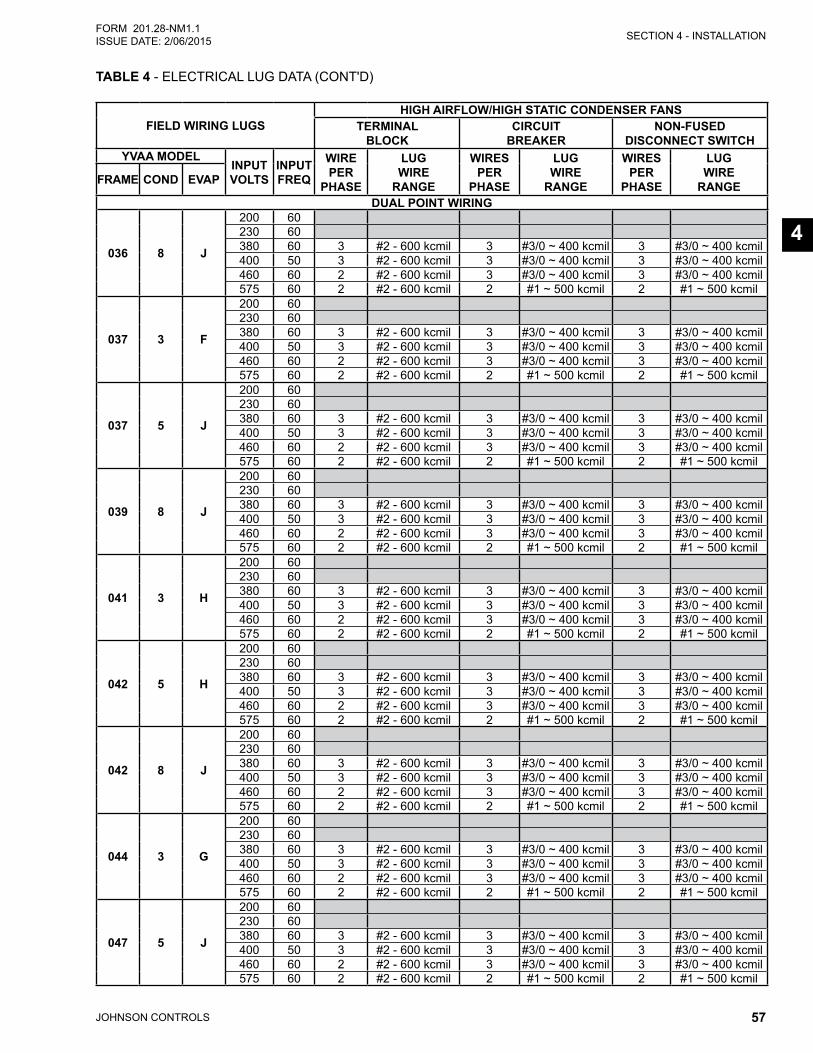
SECTION 4 - INSTALLATION
JOHNSON CONTROLS 57
FORM 201.28-NM1.1ISSUE DATE: 2/06/2015
4
FIELD WIRING LUGSHIGH AIRFLOW/HIGH STATIC CONDENSER FANS
TERMINAL BLOCK
CIRCUIT BREAKER
NON-FUSED DISCONNECT SWITCH
YVAA MODELINPUT VOLTS
INPUT FREQ
WIRE PER
PHASE
LUG WIRE
RANGE
WIRES PER
PHASE
LUG WIRE
RANGE
WIRES PER
PHASE
LUG WIRE
RANGEFRAME COND EVAP
DUAL POINT WIRING
036 8 J
200 60230 60380 60 3 #2 - 600 kcmil 3 #3/0 ~ 400 kcmil 3 #3/0 ~ 400 kcmil400 50 3 #2 - 600 kcmil 3 #3/0 ~ 400 kcmil 3 #3/0 ~ 400 kcmil460 60 2 #2 - 600 kcmil 3 #3/0 ~ 400 kcmil 3 #3/0 ~ 400 kcmil575 60 2 #2 - 600 kcmil 2 #1 ~ 500 kcmil 2 #1 ~ 500 kcmil
037 3 F
200 60230 60380 60 3 #2 - 600 kcmil 3 #3/0 ~ 400 kcmil 3 #3/0 ~ 400 kcmil400 50 3 #2 - 600 kcmil 3 #3/0 ~ 400 kcmil 3 #3/0 ~ 400 kcmil460 60 2 #2 - 600 kcmil 3 #3/0 ~ 400 kcmil 3 #3/0 ~ 400 kcmil575 60 2 #2 - 600 kcmil 2 #1 ~ 500 kcmil 2 #1 ~ 500 kcmil
037 5 J
200 60230 60380 60 3 #2 - 600 kcmil 3 #3/0 ~ 400 kcmil 3 #3/0 ~ 400 kcmil400 50 3 #2 - 600 kcmil 3 #3/0 ~ 400 kcmil 3 #3/0 ~ 400 kcmil460 60 2 #2 - 600 kcmil 3 #3/0 ~ 400 kcmil 3 #3/0 ~ 400 kcmil575 60 2 #2 - 600 kcmil 2 #1 ~ 500 kcmil 2 #1 ~ 500 kcmil
039 8 J
200 60230 60380 60 3 #2 - 600 kcmil 3 #3/0 ~ 400 kcmil 3 #3/0 ~ 400 kcmil400 50 3 #2 - 600 kcmil 3 #3/0 ~ 400 kcmil 3 #3/0 ~ 400 kcmil460 60 2 #2 - 600 kcmil 3 #3/0 ~ 400 kcmil 3 #3/0 ~ 400 kcmil575 60 2 #2 - 600 kcmil 2 #1 ~ 500 kcmil 2 #1 ~ 500 kcmil
041 3 H
200 60230 60380 60 3 #2 - 600 kcmil 3 #3/0 ~ 400 kcmil 3 #3/0 ~ 400 kcmil400 50 3 #2 - 600 kcmil 3 #3/0 ~ 400 kcmil 3 #3/0 ~ 400 kcmil460 60 2 #2 - 600 kcmil 3 #3/0 ~ 400 kcmil 3 #3/0 ~ 400 kcmil575 60 2 #2 - 600 kcmil 2 #1 ~ 500 kcmil 2 #1 ~ 500 kcmil
042 5 H
200 60230 60380 60 3 #2 - 600 kcmil 3 #3/0 ~ 400 kcmil 3 #3/0 ~ 400 kcmil400 50 3 #2 - 600 kcmil 3 #3/0 ~ 400 kcmil 3 #3/0 ~ 400 kcmil460 60 2 #2 - 600 kcmil 3 #3/0 ~ 400 kcmil 3 #3/0 ~ 400 kcmil575 60 2 #2 - 600 kcmil 2 #1 ~ 500 kcmil 2 #1 ~ 500 kcmil
042 8 J
200 60230 60380 60 3 #2 - 600 kcmil 3 #3/0 ~ 400 kcmil 3 #3/0 ~ 400 kcmil400 50 3 #2 - 600 kcmil 3 #3/0 ~ 400 kcmil 3 #3/0 ~ 400 kcmil460 60 2 #2 - 600 kcmil 3 #3/0 ~ 400 kcmil 3 #3/0 ~ 400 kcmil575 60 2 #2 - 600 kcmil 2 #1 ~ 500 kcmil 2 #1 ~ 500 kcmil
044 3 G
200 60230 60380 60 3 #2 - 600 kcmil 3 #3/0 ~ 400 kcmil 3 #3/0 ~ 400 kcmil400 50 3 #2 - 600 kcmil 3 #3/0 ~ 400 kcmil 3 #3/0 ~ 400 kcmil460 60 2 #2 - 600 kcmil 3 #3/0 ~ 400 kcmil 3 #3/0 ~ 400 kcmil575 60 2 #2 - 600 kcmil 2 #1 ~ 500 kcmil 2 #1 ~ 500 kcmil
047 5 J
200 60230 60380 60 3 #2 - 600 kcmil 3 #3/0 ~ 400 kcmil 3 #3/0 ~ 400 kcmil400 50 3 #2 - 600 kcmil 3 #3/0 ~ 400 kcmil 3 #3/0 ~ 400 kcmil460 60 2 #2 - 600 kcmil 3 #3/0 ~ 400 kcmil 3 #3/0 ~ 400 kcmil575 60 2 #2 - 600 kcmil 2 #1 ~ 500 kcmil 2 #1 ~ 500 kcmil
TABLE 4 - ELECTRICAL LUG DATA (CONT'D)
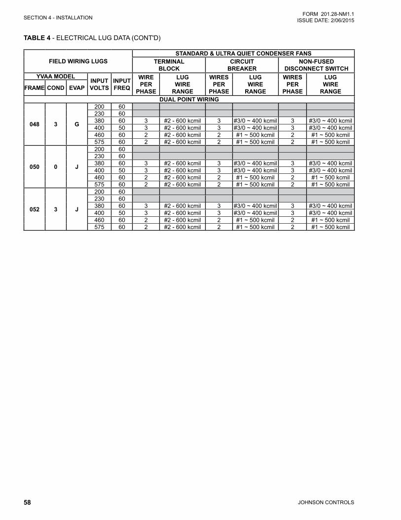
JOHNSON CONTROLS58
SECTION 4 - INSTALLATIONFORM 201.28-NM1.1
ISSUE DATE: 2/06/2015
TABLE 4 - ELECTRICAL LUG DATA (CONT'D)
FIELD WIRING LUGSSTANDARD & ULTRA QUIET CONDENSER FANS
TERMINAL BLOCK
CIRCUIT BREAKER
NON-FUSED DISCONNECT SWITCH
YVAA MODELINPUT VOLTS
INPUT FREQ
WIRE PER
PHASE
LUG WIRE
RANGE
WIRES PER
PHASE
LUG WIRE
RANGE
WIRES PER
PHASE
LUG WIRE
RANGEFRAME COND EVAP
DUAL POINT WIRING
048 3 G
200 60230 60380 60 3 #2 - 600 kcmil 3 #3/0 ~ 400 kcmil 3 #3/0 ~ 400 kcmil400 50 3 #2 - 600 kcmil 3 #3/0 ~ 400 kcmil 3 #3/0 ~ 400 kcmil460 60 2 #2 - 600 kcmil 2 #1 ~ 500 kcmil 2 #1 ~ 500 kcmil575 60 2 #2 - 600 kcmil 2 #1 ~ 500 kcmil 2 #1 ~ 500 kcmil
050 0 J
200 60230 60380 60 3 #2 - 600 kcmil 3 #3/0 ~ 400 kcmil 3 #3/0 ~ 400 kcmil400 50 3 #2 - 600 kcmil 3 #3/0 ~ 400 kcmil 3 #3/0 ~ 400 kcmil460 60 2 #2 - 600 kcmil 2 #1 ~ 500 kcmil 2 #1 ~ 500 kcmil575 60 2 #2 - 600 kcmil 2 #1 ~ 500 kcmil 2 #1 ~ 500 kcmil
052 3 J
200 60230 60380 60 3 #2 - 600 kcmil 3 #3/0 ~ 400 kcmil 3 #3/0 ~ 400 kcmil400 50 3 #2 - 600 kcmil 3 #3/0 ~ 400 kcmil 3 #3/0 ~ 400 kcmil460 60 2 #2 - 600 kcmil 2 #1 ~ 500 kcmil 2 #1 ~ 500 kcmil575 60 2 #2 - 600 kcmil 2 #1 ~ 500 kcmil 2 #1 ~ 500 kcmil
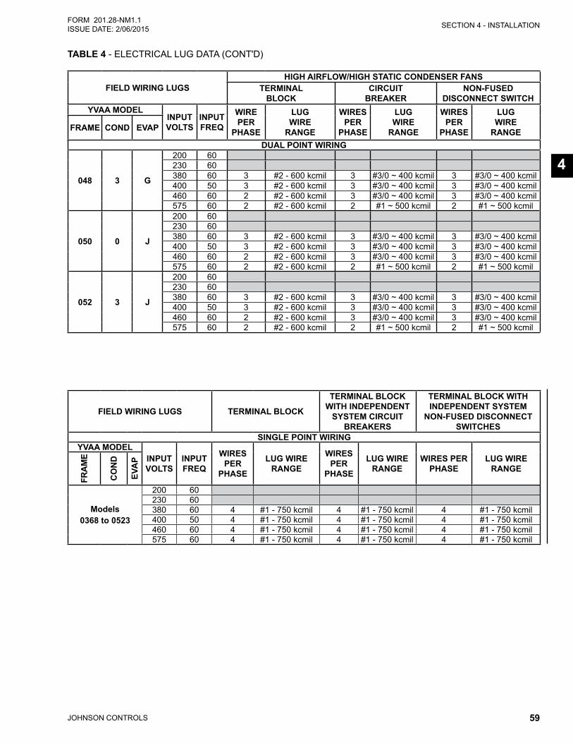
SECTION 4 - INSTALLATION
JOHNSON CONTROLS 59
FORM 201.28-NM1.1ISSUE DATE: 2/06/2015
4
TABLE 4 - ELECTRICAL LUG DATA (CONT'D)
FIELD WIRING LUGS TERMINAL BLOCK
TERMINAL BLOCK WITH INDEPENDENT
SYSTEM CIRCUIT BREAKERS
TERMINAL BLOCK WITH INDEPENDENT SYSTEM
NON-FUSED DISCONNECT SWITCHES
SINGLE POINT WIRINGYVAA MODEL
INPUT VOLTS
INPUT FREQ
WIRES PER
PHASE
LUG WIRE RANGE
WIRES PER
PHASE
LUG WIRE RANGE
WIRES PER PHASE
LUG WIRE RANGE
FRAM
E
CO
ND
EVA
P
Models 0368 to 0523
200 60230 60380 60 4 #1 - 750 kcmil 4 #1 - 750 kcmil 4 #1 - 750 kcmil400 50 4 #1 - 750 kcmil 4 #1 - 750 kcmil 4 #1 - 750 kcmil460 60 4 #1 - 750 kcmil 4 #1 - 750 kcmil 4 #1 - 750 kcmil575 60 4 #1 - 750 kcmil 4 #1 - 750 kcmil 4 #1 - 750 kcmil
FIELD WIRING LUGSHIGH AIRFLOW/HIGH STATIC CONDENSER FANS
TERMINAL BLOCK
CIRCUIT BREAKER
NON-FUSED DISCONNECT SWITCH
YVAA MODELINPUT VOLTS
INPUT FREQ
WIRE PER
PHASE
LUG WIRE
RANGE
WIRES PER
PHASE
LUG WIRE
RANGE
WIRES PER
PHASE
LUG WIRE
RANGEFRAME COND EVAP
DUAL POINT WIRING
048 3 G
200 60230 60380 60 3 #2 - 600 kcmil 3 #3/0 ~ 400 kcmil 3 #3/0 ~ 400 kcmil400 50 3 #2 - 600 kcmil 3 #3/0 ~ 400 kcmil 3 #3/0 ~ 400 kcmil460 60 2 #2 - 600 kcmil 3 #3/0 ~ 400 kcmil 3 #3/0 ~ 400 kcmil575 60 2 #2 - 600 kcmil 2 #1 ~ 500 kcmil 2 #1 ~ 500 kcmil
050 0 J
200 60230 60380 60 3 #2 - 600 kcmil 3 #3/0 ~ 400 kcmil 3 #3/0 ~ 400 kcmil400 50 3 #2 - 600 kcmil 3 #3/0 ~ 400 kcmil 3 #3/0 ~ 400 kcmil460 60 2 #2 - 600 kcmil 3 #3/0 ~ 400 kcmil 3 #3/0 ~ 400 kcmil575 60 2 #2 - 600 kcmil 2 #1 ~ 500 kcmil 2 #1 ~ 500 kcmil
052 3 J
200 60230 60380 60 3 #2 - 600 kcmil 3 #3/0 ~ 400 kcmil 3 #3/0 ~ 400 kcmil400 50 3 #2 - 600 kcmil 3 #3/0 ~ 400 kcmil 3 #3/0 ~ 400 kcmil460 60 2 #2 - 600 kcmil 3 #3/0 ~ 400 kcmil 3 #3/0 ~ 400 kcmil575 60 2 #2 - 600 kcmil 2 #1 ~ 500 kcmil 2 #1 ~ 500 kcmil

JOHNSON CONTROLS60
FORM 201.28-NM1.1 ISSUE DATE: 2/06/2015
THIS PAGE INTENTIONALLY LEFT BLANK
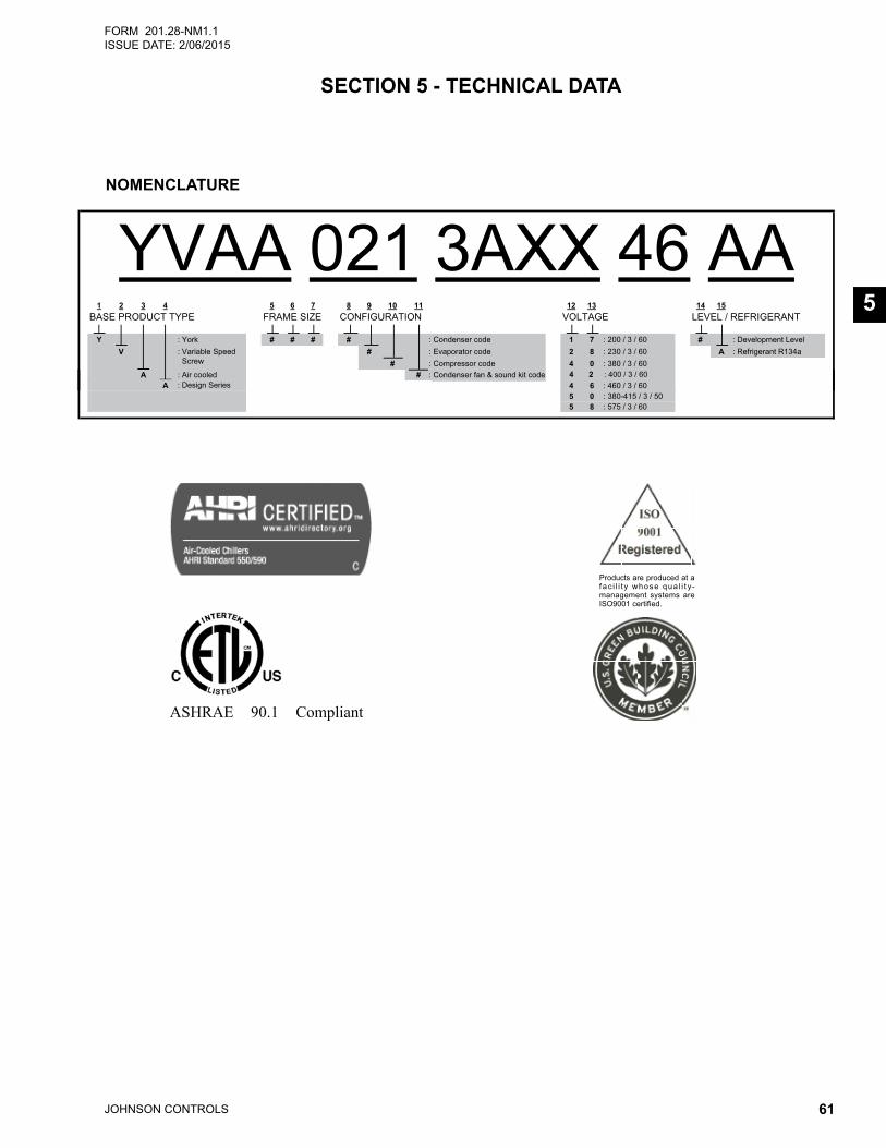
JOHNSON CONTROLS 61
FORM 201.28-NM1.1ISSUE DATE: 2/06/2015
5
SECTION 5 - TECHNICAL DATA
NOMENCLATURE
ASHRAE 90.1 Compliant
���������������������������� �� � � � � � ������ � �� � � � � ��������� �������������������������������
YVAA 021 3AXX 46 AA1 2 3 4 5 6 7 8 9 10 11 12 13 14 15
TNAREGIRFER / LEVELEGATLOVNOITARUGIFNOCEZIS EMARFEPYT TCUDORP ESAB
Y : York # # # # : Condenser code 1 7 : 200 / 3 / 60 # : Development LevelV : Variable Speed
Screw# : Evaporator code 2 8 : 230 / 3 / 60 A : Refrigerant R134a
# : Compressor code 4 0 : 380 / 3 / 60A : Air cooled # : Condenser fan & sound kit code
4 6 : 460 / 3 / 60A5 0 : 380-415 / 3 / 505 8 : 575 / 3 / 60
: Design Series 4 2 : 400 / 3 / 60
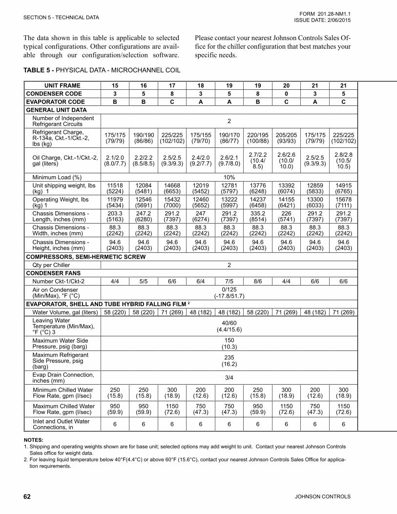
JOHNSON CONTROLS62
SECTION 5 - TECHNICAL DATAFORM 201.28-NM1.1
ISSUE DATE: 2/06/2015
TABLE 5 - PHYSICAL DATA - MICROCHANNEL COIL
The data shown in this table is applicable to selected typical configurations. Other configurations are avail-able through our configuration/selection software.
Please contact your nearest Johnson Controls Sales Of-fice for the chiller configuration that best matches your specific needs.
NOTES: 1. Shipping and operating weights shown are for base unit; selected options may add weight to unit. Contact your nearest Johnson Controls
Sales office for weight data. 2. For leaving liquid temperature below 40°F(4.4°C) or above 60°F (15.6°C), contact your nearest Johnson Controls Sales Office for applica-
tion requirements.
UNIT FRAME 15 16 17 18 19 19 20 21 21 UNIT FRAME 21 23 24 24 26 27 27 27 29 30CONDENSER CODE 3 5 8 3 5 8 0 3 5 CONDENSER CODE 8 3 5 8 3 3 5 8 5 3EVAPORATOR CODE B B C A A B C A C EVAPORATOR CODE C B C C B D E E E CGENERAL UNIT DATA GENERAL UNIT DATA
Number of Independent Refrigerant Circuits 2 Number of Independent
Refrigerant Circuits 2
Refrigerant Charge, R-134a, Ckt.-1/Ckt.-2, lbs (kg)
175/175 (79/79)
190/190 (86/86)
225/225 (102/102)
175/155 (79/70)
190/170 (86/77)
220/195 (100/88)
205/205 (93/93)
175/175 (79/79)
225/225 (102/102)
Refrigerant Charge, R-134a, Ckt.-1/Ckt.-2, lbs (kg)
240/240 (109/109)
210/190 (95/86)
250/225 (113/102)
250/250 (113/113)
210/210 (95/95)
265/265 (120/120)
265/265 (120/120)
270/270 (122/122)
310/265 (141/120)
290/245 (132/111)
Oil Charge, Ckt.-1/Ckt.-2, gal (liters)
2.1/2.0 (8.0/7.7)
2.2/2.2 (8.5/8.5)
2.5/2.5 (9.3/9.3)
2.4/2.0 (9.2/7.7)
2.6/2.1 (9.7/8.0)
2.7/2.2 (10.4/ 8.5)
2.6/2.6 (10.0/ 10.0)
2.5/2.5 (9.3/9.3)
2.8/2.8 (10.5/ 10.5)
Oil Charge, Ckt.-1/Ckt.-2, gal (liters)
2.9/2.9 (10.8/ 10.8)
2.7/2.6 (10.1/ 9.7)
2.9/2.8 (11.1/ 10.5)
2.9/2.9 (11.1/ 11.1)
2.7/2.7 (10.1/ 10.1)
3.0/3.0 (11.4/ 11.4)
3.0/3.0 (11.4/ 11.4)
3.1/3.1 (11.6/ 11.6)
4.2/3.1 (15.9/ 11.7)
4.1/3.0 (15.5/ 11.4)
Minimum Load (%) 10% Minimum Load (%) 10%Unit shipping weight, lbs (kg) 1
11518 (5224)
12084 (5481)
14668 (6653)
12019 (5452)
12781 (5797)
13776 (6248)
13392 (6074)
12859 (5833)
14915 (6765)
Unit shipping weight, lbs (kg) 1
15677 (7111)
13288 (6027)
15873 (7200)
16634 (7545)
14076 (6385)
16275 (7382)
16991 (7707)
17753 (8052)
18205 (8258)
17114 (7763)
Operating Weight, lbs (kg) 1
11979 (5434)
12546 (5691)
15432 (7000)
12460 (5652)
13222 (5997)
14237 (6458)
14155 (6421)
13300 (6033)
15678 (7111)
Operating Weight, lbs (kg) 1
16440 (7457)
13750 (6237)
16636 (7546)
17398 (7891)
14538 (6594)
17103 (7758)
17851 (8097)
18612 (8442)
19065 (8648)
17877 (8109)
Chassis Dimensions - Length, inches (mm)
203.3 (5163)
247.2 (6280)
291.2 (7397)
247 (6274)
291.2 (7397)
335.2 (8514)
226 (5741)
291.2 (7397)
291.2 (7397)
Chassis Dimensions - Length, inches (mm)
335.2 (8514)
291.2 (7397)
335.2 (8514)
379.1 (9631)
335.2 (8514)
335.2 (8514)
335.2 (8514)
379.2 (9631)
379.2 (9631)
379.2 (9631)
Chassis Dimensions - Width, inches (mm)
88.3 (2242)
88.3 (2242)
88.3 (2242)
88.3 (2242)
88.3 (2242)
88.3 (2242)
88.3 (2242)
88.3 (2242)
88.3 (2242)
Chassis Dimensions - Width, inches (mm)
88.3 (2242)
88.3 (2242)
88.3 (2242)
88.3 (2242)
88.3 (2242)
88.3 (2242)
88.3 (2242)
88.3 (2242)
88.3 (2242)
88.3 (2242)
Chassis Dimensions - Height, inches (mm)
94.6 (2403)
94.6 (2403)
94.6 (2403)
94.6 (2403)
94.6 (2403)
94.6 (2403)
94.6 (2403)
94.6 (2403)
94.6 (2403)
Chassis Dimensions - Height, inches (mm)
94.6 (2403)
94.6 (2403)
94.6 (2403)
94.6 (2403)
94.6 (2403)
94.6 (2403)
94.6 (2403)
94.6 (2403)
94.6 (2403)
94.6 (2403)
COMPRESSORS, SEMI-HERMETIC SCREW COMPRESSORS, SEMI-HERMETIC SCREWQty per Chiller 2 Qty per Chiller 2
CONDENSER FANS CONDENSER FANSNumber Ckt-1/Ckt-2 4/4 5/5 6/6 6/4 7/5 8/6 4/4 6/6 6/6 Number Ckt-1/Ckt-2 7/7 7/5 8/6 8/8 7/7 7/7 7/7 8/8 9/7 9/7Air on Condenser (Min/Max), °F (°C)
0/125(-17.8/51.7)
Air on Condenser (Min/Max), °F (°C) 0/125
EVAPORATOR, SHELL AND TUBE HYBRID FALLING FILM 2 EVAPORATOR, SHELL AND TUBE HYBRID FALLING FILM 2
Water Volume, gal (liters) 58 (220) 58 (220) 71 (269) 48 (182) 48 (182) 58 (220) 71 (269) 48 (182) 71 (269) Water Volume, gal (liters) 71(269) 58(220) 71(269) 71(269) 58(220) 82(310) 113(428) 113(428) 113(428) 71(269)Leaving Water Temperature (Min/Max), °F (°C) 3
40/60 (4.4/15.6)
Leaving Water Temperature (Min/Max), °F (°C) 3
40/60 (4.4/15.6)
Maximum Water Side Pressure, psig (barg)
150 (10.3)
Maximum Water Side Pressure, psig (barg)
150 (10.3)
Maximum Refrigerant Side Pressure, psig (barg)
235 (16.2)
Maximum Refrigerant Side Pressure, psig (barg)
235 (16.2)
Evap Drain Connection, inches (mm) 3/4 Evap Drain Connection,
inches (mm) 3/4
Minimum Chilled Water Flow Rate, gpm (l/sec)
250(15.8)
250(15.8)
300(18.9)
200(12.6)
200(12.6)
250(15.8)
300(18.9)
200(12.6)
300 (18.9)
Minimum Chilled Water Flow Rate, gpm (l/sec)
300 (18.9)
250(15.8)
300(18.9)
300(18.9)
250(15.8)
300(18.9)
400 (25.2)
400 (25.2)
400 (25.2)
300 (18.9)
Maximum Chilled Water Flow Rate, gpm (l/sec)
950(59.9)
950(59.9)
1150(72.6)
750(47.3)
750(47.3)
950(59.9)
1150(72.6)
750(47.3)
1150 (72.6)
Maximum Chilled Water Flow Rate, gpm (l/sec)
1150 (72.6)
950(59.9)
1150(72.6)
1150(72.6)
950(59.9)
1150(72.6)
1500 (94.7)
1500 (94.7)
1500 (94.7)
1150 (72.6)
Inlet and Outlet Water Connections, in 6 6 6 6 6 6 6 6 6 Inlet and Outlet Water
Connections, in 6 6 6 6 6 6 8 8 8 6
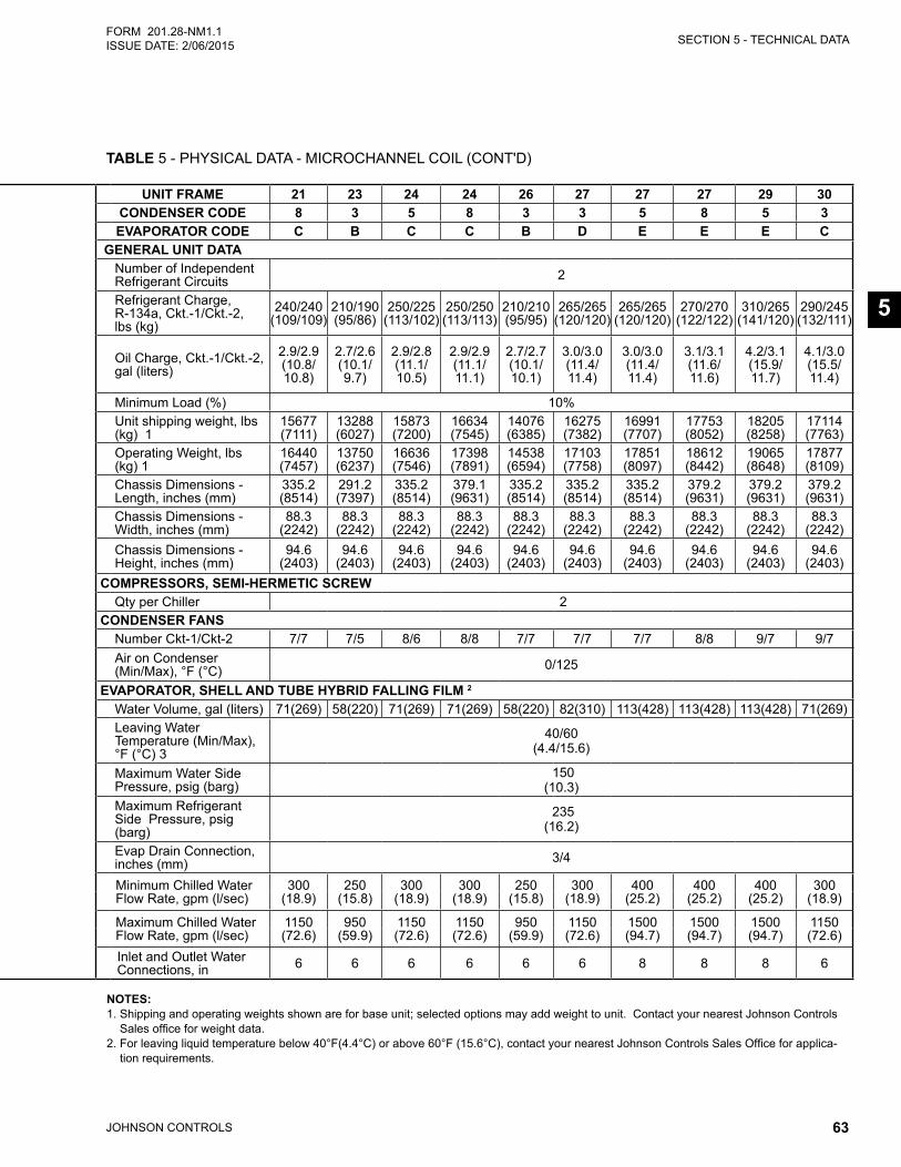
SECTION 5 - TECHNICAL DATA
JOHNSON CONTROLS 63
FORM 201.28-NM1.1ISSUE DATE: 2/06/2015
5
TABLE 5 - PHYSICAL DATA - MICROCHANNEL COIL (CONT'D)
UNIT FRAME 15 16 17 18 19 19 20 21 21 UNIT FRAME 21 23 24 24 26 27 27 27 29 30CONDENSER CODE 3 5 8 3 5 8 0 3 5 CONDENSER CODE 8 3 5 8 3 3 5 8 5 3EVAPORATOR CODE B B C A A B C A C EVAPORATOR CODE C B C C B D E E E CGENERAL UNIT DATA GENERAL UNIT DATA
Number of Independent Refrigerant Circuits 2 Number of Independent
Refrigerant Circuits 2
Refrigerant Charge, R-134a, Ckt.-1/Ckt.-2, lbs (kg)
175/175 (79/79)
190/190 (86/86)
225/225 (102/102)
175/155 (79/70)
190/170 (86/77)
220/195 (100/88)
205/205 (93/93)
175/175 (79/79)
225/225 (102/102)
Refrigerant Charge, R-134a, Ckt.-1/Ckt.-2, lbs (kg)
240/240 (109/109)
210/190 (95/86)
250/225 (113/102)
250/250 (113/113)
210/210 (95/95)
265/265 (120/120)
265/265 (120/120)
270/270 (122/122)
310/265 (141/120)
290/245 (132/111)
Oil Charge, Ckt.-1/Ckt.-2, gal (liters)
2.1/2.0 (8.0/7.7)
2.2/2.2 (8.5/8.5)
2.5/2.5 (9.3/9.3)
2.4/2.0 (9.2/7.7)
2.6/2.1 (9.7/8.0)
2.7/2.2 (10.4/ 8.5)
2.6/2.6 (10.0/ 10.0)
2.5/2.5 (9.3/9.3)
2.8/2.8 (10.5/ 10.5)
Oil Charge, Ckt.-1/Ckt.-2, gal (liters)
2.9/2.9 (10.8/ 10.8)
2.7/2.6 (10.1/ 9.7)
2.9/2.8 (11.1/ 10.5)
2.9/2.9 (11.1/ 11.1)
2.7/2.7 (10.1/ 10.1)
3.0/3.0 (11.4/ 11.4)
3.0/3.0 (11.4/ 11.4)
3.1/3.1 (11.6/ 11.6)
4.2/3.1 (15.9/ 11.7)
4.1/3.0 (15.5/ 11.4)
Minimum Load (%) 10% Minimum Load (%) 10%Unit shipping weight, lbs (kg) 1
11518 (5224)
12084 (5481)
14668 (6653)
12019 (5452)
12781 (5797)
13776 (6248)
13392 (6074)
12859 (5833)
14915 (6765)
Unit shipping weight, lbs (kg) 1
15677 (7111)
13288 (6027)
15873 (7200)
16634 (7545)
14076 (6385)
16275 (7382)
16991 (7707)
17753 (8052)
18205 (8258)
17114 (7763)
Operating Weight, lbs (kg) 1
11979 (5434)
12546 (5691)
15432 (7000)
12460 (5652)
13222 (5997)
14237 (6458)
14155 (6421)
13300 (6033)
15678 (7111)
Operating Weight, lbs (kg) 1
16440 (7457)
13750 (6237)
16636 (7546)
17398 (7891)
14538 (6594)
17103 (7758)
17851 (8097)
18612 (8442)
19065 (8648)
17877 (8109)
Chassis Dimensions - Length, inches (mm)
203.3 (5163)
247.2 (6280)
291.2 (7397)
247 (6274)
291.2 (7397)
335.2 (8514)
226 (5741)
291.2 (7397)
291.2 (7397)
Chassis Dimensions - Length, inches (mm)
335.2 (8514)
291.2 (7397)
335.2 (8514)
379.1 (9631)
335.2 (8514)
335.2 (8514)
335.2 (8514)
379.2 (9631)
379.2 (9631)
379.2 (9631)
Chassis Dimensions - Width, inches (mm)
88.3 (2242)
88.3 (2242)
88.3 (2242)
88.3 (2242)
88.3 (2242)
88.3 (2242)
88.3 (2242)
88.3 (2242)
88.3 (2242)
Chassis Dimensions - Width, inches (mm)
88.3 (2242)
88.3 (2242)
88.3 (2242)
88.3 (2242)
88.3 (2242)
88.3 (2242)
88.3 (2242)
88.3 (2242)
88.3 (2242)
88.3 (2242)
Chassis Dimensions - Height, inches (mm)
94.6 (2403)
94.6 (2403)
94.6 (2403)
94.6 (2403)
94.6 (2403)
94.6 (2403)
94.6 (2403)
94.6 (2403)
94.6 (2403)
Chassis Dimensions - Height, inches (mm)
94.6 (2403)
94.6 (2403)
94.6 (2403)
94.6 (2403)
94.6 (2403)
94.6 (2403)
94.6 (2403)
94.6 (2403)
94.6 (2403)
94.6 (2403)
COMPRESSORS, SEMI-HERMETIC SCREW COMPRESSORS, SEMI-HERMETIC SCREWQty per Chiller 2 Qty per Chiller 2
CONDENSER FANS CONDENSER FANSNumber Ckt-1/Ckt-2 4/4 5/5 6/6 6/4 7/5 8/6 4/4 6/6 6/6 Number Ckt-1/Ckt-2 7/7 7/5 8/6 8/8 7/7 7/7 7/7 8/8 9/7 9/7Air on Condenser (Min/Max), °F (°C)
0/125(-17.8/51.7)
Air on Condenser (Min/Max), °F (°C) 0/125
EVAPORATOR, SHELL AND TUBE HYBRID FALLING FILM 2 EVAPORATOR, SHELL AND TUBE HYBRID FALLING FILM 2
Water Volume, gal (liters) 58 (220) 58 (220) 71 (269) 48 (182) 48 (182) 58 (220) 71 (269) 48 (182) 71 (269) Water Volume, gal (liters) 71(269) 58(220) 71(269) 71(269) 58(220) 82(310) 113(428) 113(428) 113(428) 71(269)Leaving Water Temperature (Min/Max), °F (°C) 3
40/60 (4.4/15.6)
Leaving Water Temperature (Min/Max), °F (°C) 3
40/60 (4.4/15.6)
Maximum Water Side Pressure, psig (barg)
150 (10.3)
Maximum Water Side Pressure, psig (barg)
150 (10.3)
Maximum Refrigerant Side Pressure, psig (barg)
235 (16.2)
Maximum Refrigerant Side Pressure, psig (barg)
235 (16.2)
Evap Drain Connection, inches (mm) 3/4 Evap Drain Connection,
inches (mm) 3/4
Minimum Chilled Water Flow Rate, gpm (l/sec)
250(15.8)
250(15.8)
300(18.9)
200(12.6)
200(12.6)
250(15.8)
300(18.9)
200(12.6)
300 (18.9)
Minimum Chilled Water Flow Rate, gpm (l/sec)
300 (18.9)
250(15.8)
300(18.9)
300(18.9)
250(15.8)
300(18.9)
400 (25.2)
400 (25.2)
400 (25.2)
300 (18.9)
Maximum Chilled Water Flow Rate, gpm (l/sec)
950(59.9)
950(59.9)
1150(72.6)
750(47.3)
750(47.3)
950(59.9)
1150(72.6)
750(47.3)
1150 (72.6)
Maximum Chilled Water Flow Rate, gpm (l/sec)
1150 (72.6)
950(59.9)
1150(72.6)
1150(72.6)
950(59.9)
1150(72.6)
1500 (94.7)
1500 (94.7)
1500 (94.7)
1150 (72.6)
Inlet and Outlet Water Connections, in 6 6 6 6 6 6 6 6 6 Inlet and Outlet Water
Connections, in 6 6 6 6 6 6 8 8 8 6
NOTES: 1. Shipping and operating weights shown are for base unit; selected options may add weight to unit. Contact your nearest Johnson Controls
Sales office for weight data. 2. For leaving liquid temperature below 40°F(4.4°C) or above 60°F (15.6°C), contact your nearest Johnson Controls Sales Office for applica-
tion requirements.
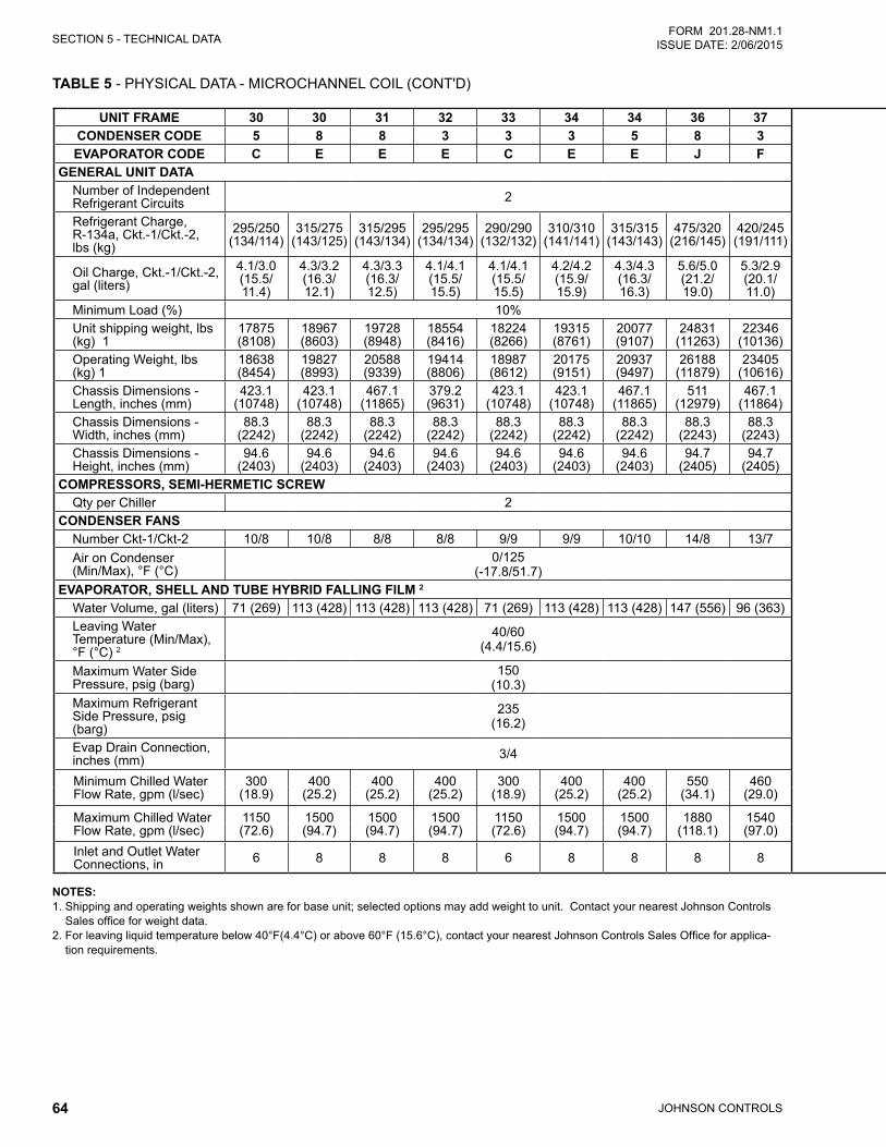
JOHNSON CONTROLS64
SECTION 5 - TECHNICAL DATAFORM 201.28-NM1.1
ISSUE DATE: 2/06/2015
TABLE 5 - PHYSICAL DATA - MICROCHANNEL COIL (CONT'D)
NOTES: 1. Shipping and operating weights shown are for base unit; selected options may add weight to unit. Contact your nearest Johnson Controls
Sales office for weight data. 2. For leaving liquid temperature below 40°F(4.4°C) or above 60°F (15.6°C), contact your nearest Johnson Controls Sales Office for applica-
tion requirements.
UNIT FRAME 30 30 31 32 33 34 34 36 37 UNIT FRAME 37 39 41 42 42 44 47 48 50 52CONDENSER CODE 5 8 8 3 3 3 5 8 3 CONDENSER CODE 5 8 3 5 8 3 5 3 0 3EVAPORATOR CODE C E E E C E E J F EVAPORATOR CODE J J H H J G J G J J
GENERAL UNIT DATA GENERAL UNIT DATANumber of Independent Refrigerant Circuits 2 Number of Independent
Refrigerant Circuits 2
Refrigerant Charge, R-134a, Ckt.-1/Ckt.-2, lbs (kg)
295/250 (134/114)
315/275 (143/125)
315/295 (143/134)
295/295 (134/134)
290/290 (132/132)
310/310 (141/141)
315/315 (143/143)
475/320 (216/145)
420/245 (191/111)
Refrigerant Charge, R-134a, Ckt.-1/Ckt.-2, lbs (kg)
470/310 (213/141)
475/360 (216/163)
460/345 (209/156)
480/365 (218/166)
475/385 (215/175)
370/370 (168/168)
445/445 (202/202)
385/385 (175/175)
405/405 (184/184)
445/445 (202/202)
Oil Charge, Ckt.-1/Ckt.-2, gal (liters)
4.1/3.0 (15.5/ 11.4)
4.3/3.2 (16.3/ 12.1)
4.3/3.3 (16.3/ 12.5)
4.1/4.1 (15.5/ 15.5)
4.1/4.1 (15.5/ 15.5)
4.2/4.2 (15.9/ 15.9)
4.3/4.3 (16.3/ 16.3)
5.6/5.0 (21.2/ 19.0)
5.3/2.9 (20.1/ 11.0)
Oil Charge, Ckt.-1/Ckt.-2, gal (liters)
5.6/4.3 (21.2/ 16.3)
5.6/5.1 (21.2/ 19.3)
5.5/4.3 (20.8/ 16.3)
5.6/4.4 (21.2/ 16.7)
5.6/5.1 (21.2/ 19.3)
5.0/5.0 (18.9/ 18.9)
5.4/5.4 (20.4/ 20.4)
5.1/5.1 (19.3/ 19.3)
5.2/5.2 (19.7/ 19.7)
5.4/5.4 (20.4/ 20.4)
Minimum Load (%) 10% Minimum Load (%) 10%Unit shipping weight, lbs (kg) 1
17875 (8108)
18967 (8603)
19728 (8948)
18554 (8416)
18224 (8266)
19315 (8761)
20077 (9107)
24831 (11263)
22346 (10136)
Unit shipping weight, lbs (kg) 1
24070 (10918)
25941 (11767)
21242 (9635)
22765 (10326)
26703 (12112)
25942 (11767)
28427 (12894)
26704 (12113)
25968 (11779)
28427 (12894)
Operating Weight, lbs (kg) 1
18638 (8454)
19827 (8993)
20588 (9339)
19414 (8806)
18987 (8612)
20175 (9151)
20937 (9497)
26188 (11879)
23405 (10616)
Operating Weight, lbs (kg) 1
25426 (11533)
27298 (12382)
22049 (10001)
23572 (10692)
28060 (12728)
27001 (12247)
29784 (13510)
27763 (12593)
27325 (12394)
29784 (13510)
Chassis Dimensions - Length, inches (mm)
423.1 (10748)
423.1 (10748)
467.1 (11865)
379.2 (9631)
423.1 (10748)
423.1 (10748)
467.1 (11865)
511 (12979)
467.1 (11864)
Chassis Dimensions - Length, inches (mm)
467.1 (11864)
555.3 (14104)
467.1 (11864)
555.3 (14104)
599.3 (15222)
555.3 (14104)
599.3 (15222)
599.3 (15222)
467.1 (11865)
599.3 (15222)
Chassis Dimensions - Width, inches (mm)
88.3 (2242)
88.3 (2242)
88.3 (2242)
88.3 (2242)
88.3 (2242)
88.3 (2242)
88.3 (2242)
88.3 (2243)
88.3 (2243)
Chassis Dimensions - Width, inches (mm)
88.3 (2243)
88.3 (2243)
88.3 (2243)
88.3 (2243)
88.3 (2243)
88.3 (2243)
88.3 (2243)
88.4 (2244)
88.3 (2243)
88.3 (2243)
Chassis Dimensions - Height, inches (mm)
94.6 (2403)
94.6 (2403)
94.6 (2403)
94.6 (2403)
94.6 (2403)
94.6 (2403)
94.6 (2403)
94.7 (2405)
94.7 (2405)
Chassis Dimensions - Height, inches (mm)
94.7 (2405)
94.7 (2405)
94.7 (2405)
94.7 (2405)
94.7 (2405)
94.7 (2405)
94.7 (2405)
94.7 (2405)
94.7 (2405)
94.7 (2405)
COMPRESSORS, SEMI-HERMETIC SCREW COMPRESSORS, SEMI-HERMETIC SCREWQty per Chiller 2 Qty per Chiller 2
CONDENSER FANS CONDENSER FANSNumber Ckt-1/Ckt-2 10/8 10/8 8/8 8/8 9/9 9/9 10/10 14/8 13/7 Number Ckt-1/Ckt-2 13/7 14/10 12/8 14/10 14/12 12/12 13/13 13/13 10/10 13/13Air on Condenser (Min/Max), °F (°C)
0/125(-17.8/51.7)
Air on Condenser (Min/Max), °F (°C) 0/125
EVAPORATOR, SHELL AND TUBE HYBRID FALLING FILM 2 EVAPORATOR, SHELL AND TUBE HYBRID FALLING FILM 2
Water Volume, gal (liters) 71 (269) 113 (428) 113 (428) 113 (428) 71 (269) 113 (428) 113 (428) 147 (556) 96 (363) Water Volume, gal (liters) 147(556) 147(556) 130(492) 130(492) 147(556) 96(363) 147(556) 96(363) 147(556) 147(556)Leaving Water Temperature (Min/Max), °F (°C) 2
40/60 (4.4/15.6)
Leaving Water Temperature (Min/Max), °F (°C) 2
40/60 (4.4/15.6)
Maximum Water Side Pressure, psig (barg)
150 (10.3)
Maximum Water Side Pressure, psig (barg)
150 (10.3)
Maximum Refrigerant Side Pressure, psig (barg)
235 (16.2)
Maximum Refrigerant Side Pressure, psig (barg)
235 (16.2)
Evap Drain Connection, inches (mm) 3/4 Evap Drain Connection,
inches (mm) 3/4
Minimum Chilled Water Flow Rate, gpm (l/sec)
300 (18.9)
400 (25.2)
400 (25.2)
400 (25.2)
300(18.9)
400 (25.2)
400 (25.2)
550 (34.1)
460 (29.0)
Minimum Chilled Water Flow Rate, gpm (l/sec)
550 (34.1)
550 (34.1)
520 (33.0)
520 (33.0)
550 (34.1)
460 (29.0)
550 (34.1)
460 (29.0)
550 (34.1)
550 (34.1)
Maximum Chilled Water Flow Rate, gpm (l/sec)
1150 (72.6)
1500 (94.7)
1500 (94.7)
1500 (94.7)
1150(72.6)
1500 (94.7)
1500 (94.7)
1880 (118.1)
1540 (97.0)
Maximum Chilled Water Flow Rate, gpm (l/sec)
1880 (118.1)
1880 (118.1)
1700 (107.0)
1700 (107.0)
1880 (118.1)
1540 (97.0)
1880 (118.1)
1540 (97.0)
1880 (118.1)
1880 (118.1)
Inlet and Outlet Water Connections, in 6 8 8 8 6 8 8 8 8 Inlet and Outlet Water
Connections, in 8 8 8 8 8 8 8 8 8 8
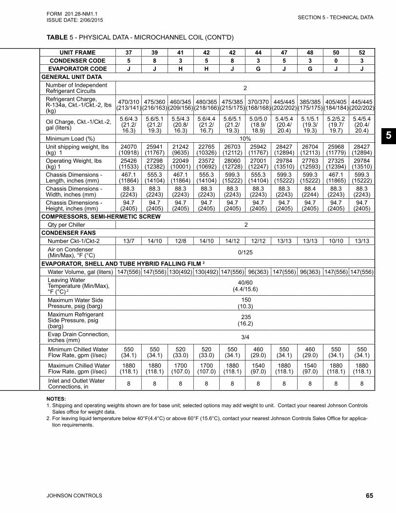
SECTION 5 - TECHNICAL DATA
JOHNSON CONTROLS 65
FORM 201.28-NM1.1ISSUE DATE: 2/06/2015
5
TABLE 5 - PHYSICAL DATA - MICROCHANNEL COIL (CONT'D)
UNIT FRAME 30 30 31 32 33 34 34 36 37 UNIT FRAME 37 39 41 42 42 44 47 48 50 52CONDENSER CODE 5 8 8 3 3 3 5 8 3 CONDENSER CODE 5 8 3 5 8 3 5 3 0 3EVAPORATOR CODE C E E E C E E J F EVAPORATOR CODE J J H H J G J G J J
GENERAL UNIT DATA GENERAL UNIT DATANumber of Independent Refrigerant Circuits 2 Number of Independent
Refrigerant Circuits 2
Refrigerant Charge, R-134a, Ckt.-1/Ckt.-2, lbs (kg)
295/250 (134/114)
315/275 (143/125)
315/295 (143/134)
295/295 (134/134)
290/290 (132/132)
310/310 (141/141)
315/315 (143/143)
475/320 (216/145)
420/245 (191/111)
Refrigerant Charge, R-134a, Ckt.-1/Ckt.-2, lbs (kg)
470/310 (213/141)
475/360 (216/163)
460/345 (209/156)
480/365 (218/166)
475/385 (215/175)
370/370 (168/168)
445/445 (202/202)
385/385 (175/175)
405/405 (184/184)
445/445 (202/202)
Oil Charge, Ckt.-1/Ckt.-2, gal (liters)
4.1/3.0 (15.5/ 11.4)
4.3/3.2 (16.3/ 12.1)
4.3/3.3 (16.3/ 12.5)
4.1/4.1 (15.5/ 15.5)
4.1/4.1 (15.5/ 15.5)
4.2/4.2 (15.9/ 15.9)
4.3/4.3 (16.3/ 16.3)
5.6/5.0 (21.2/ 19.0)
5.3/2.9 (20.1/ 11.0)
Oil Charge, Ckt.-1/Ckt.-2, gal (liters)
5.6/4.3 (21.2/ 16.3)
5.6/5.1 (21.2/ 19.3)
5.5/4.3 (20.8/ 16.3)
5.6/4.4 (21.2/ 16.7)
5.6/5.1 (21.2/ 19.3)
5.0/5.0 (18.9/ 18.9)
5.4/5.4 (20.4/ 20.4)
5.1/5.1 (19.3/ 19.3)
5.2/5.2 (19.7/ 19.7)
5.4/5.4 (20.4/ 20.4)
Minimum Load (%) 10% Minimum Load (%) 10%Unit shipping weight, lbs (kg) 1
17875 (8108)
18967 (8603)
19728 (8948)
18554 (8416)
18224 (8266)
19315 (8761)
20077 (9107)
24831 (11263)
22346 (10136)
Unit shipping weight, lbs (kg) 1
24070 (10918)
25941 (11767)
21242 (9635)
22765 (10326)
26703 (12112)
25942 (11767)
28427 (12894)
26704 (12113)
25968 (11779)
28427 (12894)
Operating Weight, lbs (kg) 1
18638 (8454)
19827 (8993)
20588 (9339)
19414 (8806)
18987 (8612)
20175 (9151)
20937 (9497)
26188 (11879)
23405 (10616)
Operating Weight, lbs (kg) 1
25426 (11533)
27298 (12382)
22049 (10001)
23572 (10692)
28060 (12728)
27001 (12247)
29784 (13510)
27763 (12593)
27325 (12394)
29784 (13510)
Chassis Dimensions - Length, inches (mm)
423.1 (10748)
423.1 (10748)
467.1 (11865)
379.2 (9631)
423.1 (10748)
423.1 (10748)
467.1 (11865)
511 (12979)
467.1 (11864)
Chassis Dimensions - Length, inches (mm)
467.1 (11864)
555.3 (14104)
467.1 (11864)
555.3 (14104)
599.3 (15222)
555.3 (14104)
599.3 (15222)
599.3 (15222)
467.1 (11865)
599.3 (15222)
Chassis Dimensions - Width, inches (mm)
88.3 (2242)
88.3 (2242)
88.3 (2242)
88.3 (2242)
88.3 (2242)
88.3 (2242)
88.3 (2242)
88.3 (2243)
88.3 (2243)
Chassis Dimensions - Width, inches (mm)
88.3 (2243)
88.3 (2243)
88.3 (2243)
88.3 (2243)
88.3 (2243)
88.3 (2243)
88.3 (2243)
88.4 (2244)
88.3 (2243)
88.3 (2243)
Chassis Dimensions - Height, inches (mm)
94.6 (2403)
94.6 (2403)
94.6 (2403)
94.6 (2403)
94.6 (2403)
94.6 (2403)
94.6 (2403)
94.7 (2405)
94.7 (2405)
Chassis Dimensions - Height, inches (mm)
94.7 (2405)
94.7 (2405)
94.7 (2405)
94.7 (2405)
94.7 (2405)
94.7 (2405)
94.7 (2405)
94.7 (2405)
94.7 (2405)
94.7 (2405)
COMPRESSORS, SEMI-HERMETIC SCREW COMPRESSORS, SEMI-HERMETIC SCREWQty per Chiller 2 Qty per Chiller 2
CONDENSER FANS CONDENSER FANSNumber Ckt-1/Ckt-2 10/8 10/8 8/8 8/8 9/9 9/9 10/10 14/8 13/7 Number Ckt-1/Ckt-2 13/7 14/10 12/8 14/10 14/12 12/12 13/13 13/13 10/10 13/13Air on Condenser (Min/Max), °F (°C)
0/125(-17.8/51.7)
Air on Condenser (Min/Max), °F (°C) 0/125
EVAPORATOR, SHELL AND TUBE HYBRID FALLING FILM 2 EVAPORATOR, SHELL AND TUBE HYBRID FALLING FILM 2
Water Volume, gal (liters) 71 (269) 113 (428) 113 (428) 113 (428) 71 (269) 113 (428) 113 (428) 147 (556) 96 (363) Water Volume, gal (liters) 147(556) 147(556) 130(492) 130(492) 147(556) 96(363) 147(556) 96(363) 147(556) 147(556)Leaving Water Temperature (Min/Max), °F (°C) 2
40/60 (4.4/15.6)
Leaving Water Temperature (Min/Max), °F (°C) 2
40/60 (4.4/15.6)
Maximum Water Side Pressure, psig (barg)
150 (10.3)
Maximum Water Side Pressure, psig (barg)
150 (10.3)
Maximum Refrigerant Side Pressure, psig (barg)
235 (16.2)
Maximum Refrigerant Side Pressure, psig (barg)
235 (16.2)
Evap Drain Connection, inches (mm) 3/4 Evap Drain Connection,
inches (mm) 3/4
Minimum Chilled Water Flow Rate, gpm (l/sec)
300 (18.9)
400 (25.2)
400 (25.2)
400 (25.2)
300(18.9)
400 (25.2)
400 (25.2)
550 (34.1)
460 (29.0)
Minimum Chilled Water Flow Rate, gpm (l/sec)
550 (34.1)
550 (34.1)
520 (33.0)
520 (33.0)
550 (34.1)
460 (29.0)
550 (34.1)
460 (29.0)
550 (34.1)
550 (34.1)
Maximum Chilled Water Flow Rate, gpm (l/sec)
1150 (72.6)
1500 (94.7)
1500 (94.7)
1500 (94.7)
1150(72.6)
1500 (94.7)
1500 (94.7)
1880 (118.1)
1540 (97.0)
Maximum Chilled Water Flow Rate, gpm (l/sec)
1880 (118.1)
1880 (118.1)
1700 (107.0)
1700 (107.0)
1880 (118.1)
1540 (97.0)
1880 (118.1)
1540 (97.0)
1880 (118.1)
1880 (118.1)
Inlet and Outlet Water Connections, in 6 8 8 8 6 8 8 8 8 Inlet and Outlet Water
Connections, in 8 8 8 8 8 8 8 8 8 8
NOTES: 1. Shipping and operating weights shown are for base unit; selected options may add weight to unit. Contact your nearest Johnson Controls
Sales office for weight data. 2. For leaving liquid temperature below 40°F(4.4°C) or above 60°F (15.6°C), contact your nearest Johnson Controls Sales Office for applica-
tion requirements.
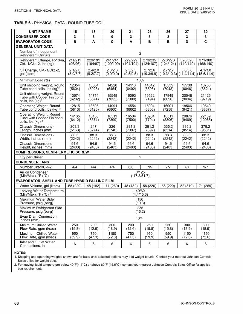
JOHNSON CONTROLS66
SECTION 5 - TECHNICAL DATAFORM 201.28-NM1.1
ISSUE DATE: 2/06/2015
TABLE 6 - PHYSICAL DATA - ROUND TUBE COIL
UNIT FRAME 15 18 20 21 23 26 27 30CONDENSER CODE 3 3 0 3 3 3 3 3EVAPORATOR CODE B A C A B B D CGENERAL UNIT DATA
Number of Independent Refrigerant Circuits 2
Refrigerant Charge, R-134a, Ckt.-1/Ckt.-2, lbs (kg)
211/211 (96/96)
229/191 (104/87)
241/241 (109/109)
229/229 (104/104)
273/235 (124/107)
273/273 (124/124)
328/328 (149/149)
371/308 (168/140)
Oil Charge, Ckt.-1/Ckt.-2, gal (liters)
2.1/2.0 (8.0/7.7)
2.4/2.0 (9.2/7.7)
2.6/2.6 (9.9/9.9)
2.5/2.5 (9.5/9.5)
2.7/2.6 (10.3/9.9)
2.7/2.7 (10.3/10.3)
3.0/3.0 (11.4/11.4)
4.1/3.0 (15.6/11.4)
Minimum Load (%) 10%Unit shipping weight, Round Tube cond coils, lbs (kg)2
12354 (5604)
13064 (5926)
14228 (6454)
14113 (6402)
14542 (6596)
15539 (7048)
17738 (8046)
18786 (8521)
Unit shipping weight, Round Tube with Copper Fin cond coils, lbs (kg)2
13674 (6202)
14714 (6674)
15548 (7052)
16093 (7300)
16522 (7494)
17849 (8096)
20048 (9094)
21426 (9719)
Operating Weight, Round Tube cond coils, lbs (kg) 2
12815 (5813)
13505 (6126)
14991 (6800)
14554 (6602)
15004 (6806)
16001 (7258)
18566 (8421)
19549 (8867)
Operating Weight, Round Tube with Copper Fin cond coils, lbs (kg) 2
14135 (6412)
15155 (6874)
16311 (7399)
16534 (7500)
16984 (7704)
18311 (8306)
20876 (9469)
22189 (10065)
Chassis Dimensions - Length, inches (mm)
203.3 (5163)
247 (6274)
226 (5740)
291.2 (7397)
291.2 (7397)
335.2 (8514)
335.2 (8514)
379.2 (9631)
Chassis Dimensions - Width, inches (mm)
88.3 (2242)
88.3 (2242)
88.3 (2242)
88.3 (2242)
88.3 (2242)
88.3 (2242)
88.3 (2242)
88.3 (2242)
Chassis Dimensions - Height, inches (mm)
94.6 (2403)
94.6 (2403)
94.6 (2403)
94.6 (2403)
94.6 (2403)
94.6 (2403)
94.6 (2403)
94.6 (2403)
COMPRESSORS, SEMI-HERMETIC SCREWQty per Chiller 2
CONDENSER FANSNumber Ckt-1/Ckt-2 4/4 6/4 4/4 6/6 7/5 7/7 7/7 9/7Air on Condenser (Min/Max), °F (°C)
0/125 (-17.8/51.7)
EVAPORATOR, SHELL AND TUBE HYBRID FALLING FILM Water Volume, gal (liters) 58 (220) 48 (182) 71 (269) 48 (182) 58 (220) 58 (220) 82 (310) 71 (269)Leaving Water Temperature (Min/Max), °F (°C) 2
40/60 (4.4/15.6)
Maximum Water Side Pressure, psig (barg)
150 (10.3)
Maximum Refrigerant Side Pressure, psig (barg)
235 (16.2)
Evap Drain Connection, inches (mm) 3/4
Minimum Chilled Water Flow Rate, gpm (l/sec)
250 (15.8)
200 (12.6)
300 (18.9)
200 (12.6)
250 (15.8)
250 (15.8)
300 (18.9)
300 (18.9)
Maximum Chilled Water Flow Rate, gpm (l/sec)
950 (59.9)
750 (47.3)
1150 (72.6)
750 (47.3)
950 (59.9)
950 (59.9)
1150 (72.6)
1150 (72.6)
Inlet and Outlet Water Connections, in 6 6 6 6 6 6 6 6
NOTES: 1. Shipping and operating weights shown are for base unit; selected options may add weight to unit. Contact your nearest Johnson Controls
Sales office for weight data. 2. For leaving liquid temperature below 40°F(4.4°C) or above 60°F (15.6°C), contact your nearest Johnson Controls Sales Office for applica-
tion requirements.
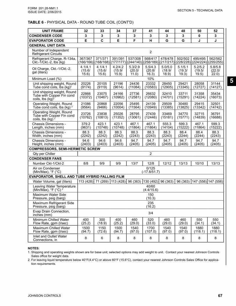
SECTION 5 - TECHNICAL DATA
JOHNSON CONTROLS 67
FORM 201.28-NM1.1ISSUE DATE: 2/06/2015
5
TABLE 6 - PHYSICAL DATA - ROUND TUBE COIL (CONT'D)
UNIT FRAME 32 33 34 37 41 44 48 50 52CONDENSER CODE 3 3 3 3 3 3 3 0 3EVAPORATOR CODE E C E F H G G J JGENERAL UNIT DATA
Number of Independent Refrigerant Circuits 2
Refrigerant Charge, R-134a, Ckt.-1/Ckt.-2, lbs (kg)
367/367 (166/166)
371/371 (168/168)
391/391 (177/177)
537/308 (244/140)
568/417 (258/189)
478/478 (217/217)
502/502 (228/228)
495/495 (224/224)
562/562 (255/255)
Oil Charge, Ckt.-1/Ckt.-2, gal (liters)
4.1/4.1 (15.6/ 15.6)
4.1/4.1 (15.6/ 15.6)
4.2/4.2 (15.9/ 15.9)
5.3/2.9 (20.0/ 11.0)
5.5/4.3 (20.8/ 16.3)
5.0/5.0 (18.9/ 18.9)
5.1/5.1 (19.3/ 19.3)
5.2/5.2 (19.5/ 19.5)
5.8/5.8 (22.0/ 22.0)
Minimum Load (%) 10%Unit shipping weight, Round Tube cond coils, lbs (kg)2
20226 (9174)
20105 (9119)
21196 (9614)
24436 (11084)
23332 (10583)
28450 (12905)
29421 (13345)
28058 (12727)
31144 (14127)
Unit shipping weight, Round Tube with Copper Fin cond coils, lbs (kg)2
22866 (10372)
23075 (10467)
24166 (10962)
27736 (12581)
26632 (12080)
32410 (14701)
33711 (15291)
31358 (14224)
35434 (16073)
Operating Weight, Round Tube cond coils, lbs (kg) 2
21086 (9564)
20868 (9466)
22056 (10004)
25495 (11564)
24139 (10949)
29509 (13385)
30480 (13825)
29415 (13342)
32501 (14742)
Operating Weight, Round Tube with Copper Fin cond coils, lbs (kg) 2
23726 (10762)
23838 (10813)
25026 (11352)
28795 (13061)
27439 (12446)
33469 (15181)
34770 (15771)
32715 (14839)
36791 (16688)
Chassis Dimensions - Length, inches (mm)
379.2 (9631)
423.1 (10748)
423.1 (10748)
467.1 (11864)
467.1 (11864)
555.3 (14104)
599.3 (15222)
467.1 (11864)
599.3 (15222)
Chassis Dimensions - Width, inches (mm)
88.3 (2242)
88.3 (2242)
88.3 (2242)
88.3 (2243)
88.3 (2243)
88.3 (2243)
88.4 (2244)
88.4 (2244)
88.3 (2243)
Chassis Dimensions - Height, inches (mm)
94.6 (2403)
94.6 (2403)
94.6 (2403)
94.7 (2405)
94.7 (2405)
94.7 (2405)
94.7 (2405)
94.7 (2405)
94.7 (2405)
COMPRESSORS, SEMI-HERMETIC SCREWQty per Chiller 2
CONDENSER FANSNumber Ckt-1/Ckt-2 8/8 9/9 9/9 13/7 12/8 12/12 13/13 10/10 13/13Air on Condenser (Min/Max), °F (°C)
0/125 (-17.8/51.7)
EVAPORATOR, SHELL AND TUBE HYBRID FALLING FILM Water Volume, gal (liters) 113 (428) 71 (269) 113 (428) 96 (363) 130 (492) 96 (363) 96 (363) 147 (556) 147 (556)Leaving Water Temperature (Min/Max), °F (°C) 2
40/60 (4.4/15.6)
Maximum Water Side Pressure, psig (barg)
150 (10.3)
Maximum Refrigerant Side Pressure, psig (barg)
235 (16.2)
Evap Drain Connection, inches (mm) 3/4
Minimum Chilled Water Flow Rate, gpm (l/sec)
400 (25.2)
300 (18.9)
400 (25.2)
460 (29.0)
520 (33.0)
460 (29.0)
460 (29.0)
550 (34.1)
550 (34.1)
Maximum Chilled Water Flow Rate, gpm (l/sec)
1500 (94.7)
1150 (72.6)
1500 (94.7)
1540 (97.0)
1700 (107.0)
1540 (97.0)
1540 (97.0)
1880 (118.1)
1880 (118.1)
Inlet and Outlet Water Connections, in 8 6 8 8 8 8 8 8 8
NOTES: 1. Shipping and operating weights shown are for base unit; selected options may add weight to unit. Contact your nearest Johnson Controls
Sales office for weight data. 2. For leaving liquid temperature below 40°F(4.4°C) or above 60°F (15.6°C), contact your nearest Johnson Controls Sales Office for applica-
tion requirements.
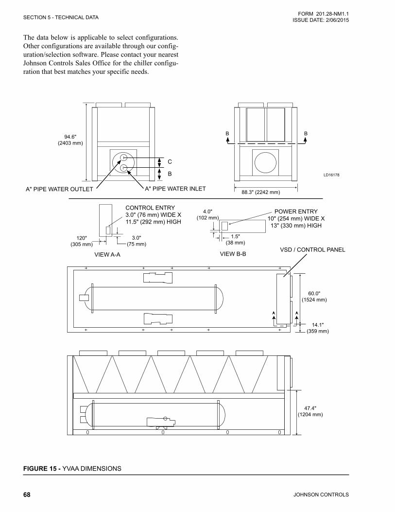
JOHNSON CONTROLS68
SECTION 5 - TECHNICAL DATAFORM 201.28-NM1.1
ISSUE DATE: 2/06/2015
The data below is applicable to select configurations. Other configurations are available through our config-uration/selection software. Please contact your nearest Johnson Controls Sales Office for the chiller configu-ration that best matches your specific needs.
FIGURE 15 - YVAA DIMENSIONS
A" PIPE WATER OUTLET A" PIPE WATER INLET
C
B
POWER ENTRY10" (254 mm) WIDE X13" (330 mm) HIGH
VIEW B-BVIEW A-A
CONTROL ENTRY3.0" (76 mm) WIDE X 11.5" (292 mm) HIGH
LD16178
VSD / CONTROL PANEL
88.3" (2242 mm)
BB94.6" (2403 mm)
4.0" (102 mm)
1.5" (38 mm)
120" (305 mm)
3.0" (75 mm)
47.4" (1204 mm)
60.0" (1524 mm)
14.1" (359 mm)
SECTION 5 - TECHNICAL DATA
JOHNSON CONTROLS 69
FORM 201.28-NM1.1ISSUE DATE: 2/06/2015
THIS PAGE INTENTIONALLY LEFT BLANK
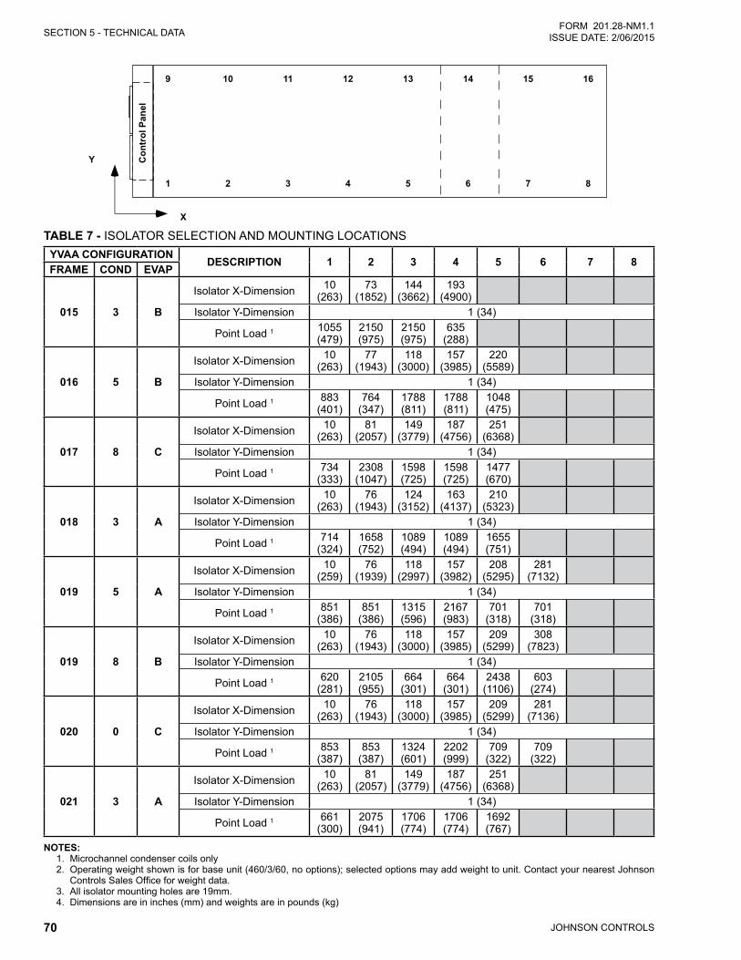
JOHNSON CONTROLS70
SECTION 5 - TECHNICAL DATAFORM 201.28-NM1.1
ISSUE DATE: 2/06/2015
���
��������
��
� � � � � � � �
�� �� ��
�
�� �� �� ��
TABLE 7 - ISOLATOR SELECTION AND MOUNTING LOCATIONSYVAA CONFIGURATION
DESCRIPTION 1 2 3 4 5 6 7 8FRAME COND EVAP
015 3 B
Isolator X-Dimension 10 (263)
73 (1852)
144 (3662)
193 (4900)
Isolator Y-Dimension 1 (34)
Point Load 1 1055 (479)
2150 (975)
2150 (975)
635 (288)
016 5 B
Isolator X-Dimension 10 (263)
77 (1943)
118 (3000)
157 (3985)
220 (5589)
Isolator Y-Dimension 1 (34)
Point Load 1 883 (401)
764 (347)
1788 (811)
1788 (811)
1048 (475)
017 8 C
Isolator X-Dimension 10 (263)
81 (2057)
149 (3779)
187 (4756)
251 (6368)
Isolator Y-Dimension 1 (34)
Point Load 1 734 (333)
2308 (1047)
1598 (725)
1598 (725)
1477 (670)
018 3 A
Isolator X-Dimension 10 (263)
76 (1943)
124 (3152)
163 (4137)
210 (5323)
Isolator Y-Dimension 1 (34)
Point Load 1 714 (324)
1658 (752)
1089 (494)
1089 (494)
1655 (751)
019 5 A
Isolator X-Dimension 10 (259)
76 (1939)
118 (2997)
157 (3982)
208 (5295)
281 (7132)
Isolator Y-Dimension 1 (34)
Point Load 1 851 (386)
851 (386)
1315 (596)
2167 (983)
701 (318)
701 (318)
019 8 B
Isolator X-Dimension 10 (263)
76 (1943)
118 (3000)
157 (3985)
209 (5299)
308 (7823)
Isolator Y-Dimension 1 (34)
Point Load 1 620 (281)
2105 (955)
664 (301)
664 (301)
2438 (1106)
603 (274)
020 0 C
Isolator X-Dimension 10 (263)
76 (1943)
118 (3000)
157 (3985)
209 (5299)
281 (7136)
Isolator Y-Dimension 1 (34)
Point Load 1 853 (387)
853 (387)
1324 (601)
2202 (999)
709 (322)
709 (322)
021 3 A
Isolator X-Dimension 10 (263)
81 (2057)
149 (3779)
187 (4756)
251 (6368)
Isolator Y-Dimension 1 (34)
Point Load 1 661 (300)
2075 (941)
1706 (774)
1706 (774)
1692 (767)
NOTES:1. Microchannel condenser coils only2. Operating weight shown is for base unit (460/3/60, no options); selected options may add weight to unit. Contact your nearest Johnson
Controls Sales Office for weight data.3. All isolator mounting holes are 19mm.4. Dimensions are in inches (mm) and weights are in pounds (kg)
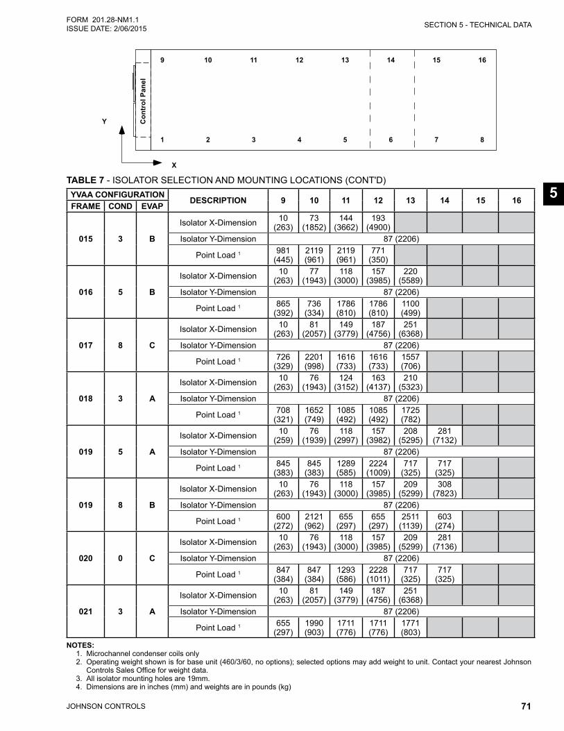
SECTION 5 - TECHNICAL DATA
JOHNSON CONTROLS 71
FORM 201.28-NM1.1ISSUE DATE: 2/06/2015
5
���
��������
��� � � � � � � �
�� �� ��
�
�� �� �� ��
YVAA CONFIGURATIONDESCRIPTION 9 10 11 12 13 14 15 16
FRAME COND EVAP
015 3 B
Isolator X-Dimension 10 (263)
73 (1852)
144 (3662)
193 (4900)
Isolator Y-Dimension 87 (2206)
Point Load 1 981 (445)
2119 (961)
2119 (961)
771 (350)
016 5 B
Isolator X-Dimension 10 (263)
77 (1943)
118 (3000)
157 (3985)
220 (5589)
Isolator Y-Dimension 87 (2206)
Point Load 1 865 (392)
736 (334)
1786 (810)
1786 (810)
1100 (499)
017 8 C
Isolator X-Dimension 10 (263)
81 (2057)
149 (3779)
187 (4756)
251 (6368)
Isolator Y-Dimension 87 (2206)
Point Load 1 726 (329)
2201 (998)
1616 (733)
1616 (733)
1557 (706)
018 3 A
Isolator X-Dimension 10 (263)
76 (1943)
124 (3152)
163 (4137)
210 (5323)
Isolator Y-Dimension 87 (2206)
Point Load 1 708 (321)
1652 (749)
1085 (492)
1085 (492)
1725 (782)
019 5 A
Isolator X-Dimension 10 (259)
76 (1939)
118 (2997)
157 (3982)
208 (5295)
281 (7132)
Isolator Y-Dimension 87 (2206)
Point Load 1 845 (383)
845 (383)
1289 (585)
2224 (1009)
717 (325)
717 (325)
019 8 B
Isolator X-Dimension 10 (263)
76 (1943)
118 (3000)
157 (3985)
209 (5299)
308 (7823)
Isolator Y-Dimension 87 (2206)
Point Load 1 600 (272)
2121 (962)
655 (297)
655 (297)
2511 (1139)
603 (274)
020 0 C
Isolator X-Dimension 10 (263)
76 (1943)
118 (3000)
157 (3985)
209 (5299)
281 (7136)
Isolator Y-Dimension 87 (2206)
Point Load 1 847 (384)
847 (384)
1293 (586)
2228 (1011)
717 (325)
717 (325)
021 3 A
Isolator X-Dimension 10 (263)
81 (2057)
149 (3779)
187 (4756)
251 (6368)
Isolator Y-Dimension 87 (2206)
Point Load 1 655 (297)
1990 (903)
1711 (776)
1711 (776)
1771 (803)
TABLE 7 - ISOLATOR SELECTION AND MOUNTING LOCATIONS (CONT'D)
NOTES:1. Microchannel condenser coils only2. Operating weight shown is for base unit (460/3/60, no options); selected options may add weight to unit. Contact your nearest Johnson
Controls Sales Office for weight data.3. All isolator mounting holes are 19mm.4. Dimensions are in inches (mm) and weights are in pounds (kg)
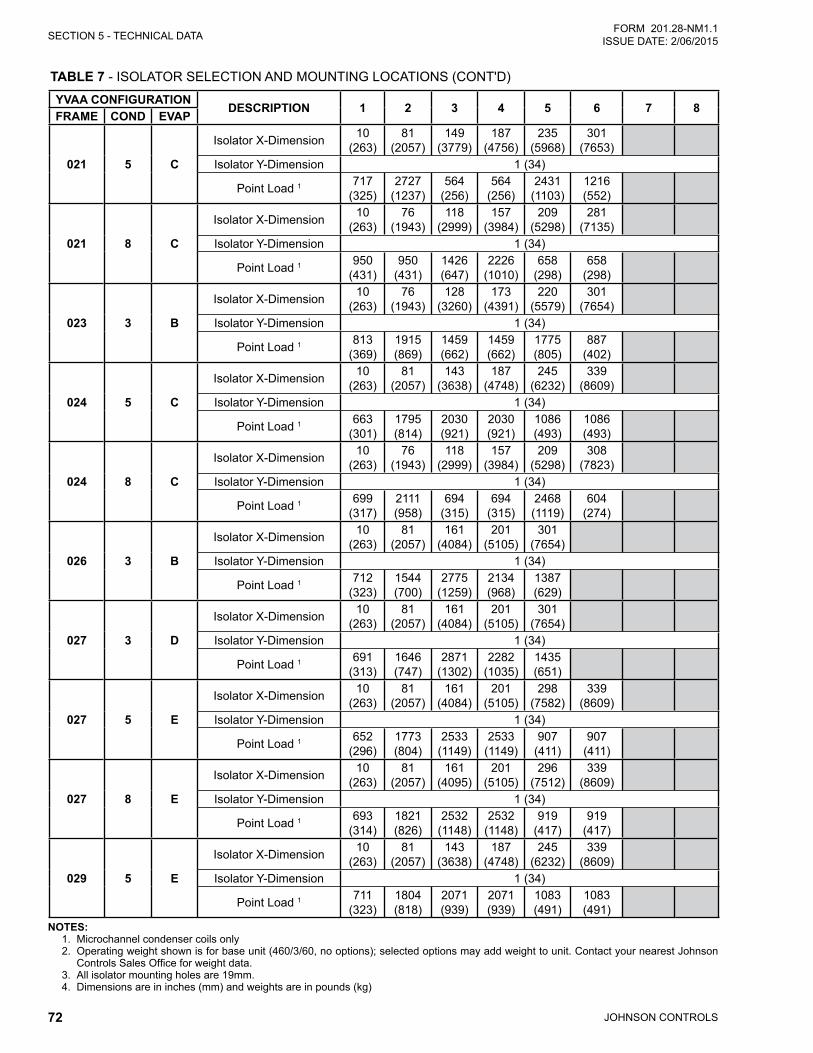
JOHNSON CONTROLS72
SECTION 5 - TECHNICAL DATAFORM 201.28-NM1.1
ISSUE DATE: 2/06/2015
TABLE 7 - ISOLATOR SELECTION AND MOUNTING LOCATIONS (CONT'D)
YVAA CONFIGURATIONDESCRIPTION 1 2 3 4 5 6 7 8
FRAME COND EVAP
021 5 C
Isolator X-Dimension 10 (263)
81 (2057)
149 (3779)
187 (4756)
235 (5968)
301 (7653)
Isolator Y-Dimension 1 (34)
Point Load 1 717 (325)
2727 (1237)
564 (256)
564 (256)
2431 (1103)
1216 (552)
021 8 C
Isolator X-Dimension 10 (263)
76 (1943)
118 (2999)
157 (3984)
209 (5298)
281 (7135)
Isolator Y-Dimension 1 (34)
Point Load 1 950 (431)
950 (431)
1426 (647)
2226 (1010)
658 (298)
658 (298)
023 3 B
Isolator X-Dimension 10 (263)
76 (1943)
128 (3260)
173 (4391)
220 (5579)
301 (7654)
Isolator Y-Dimension 1 (34)
Point Load 1 813 (369)
1915 (869)
1459 (662)
1459 (662)
1775 (805)
887 (402)
024 5 C
Isolator X-Dimension 10 (263)
81 (2057)
143 (3638)
187 (4748)
245 (6232)
339 (8609)
Isolator Y-Dimension 1 (34)
Point Load 1 663 (301)
1795 (814)
2030 (921)
2030 (921)
1086 (493)
1086 (493)
024 8 C
Isolator X-Dimension 10 (263)
76 (1943)
118 (2999)
157 (3984)
209 (5298)
308 (7823)
Isolator Y-Dimension 1 (34)
Point Load 1 699 (317)
2111 (958)
694 (315)
694 (315)
2468 (1119)
604 (274)
026 3 B
Isolator X-Dimension 10 (263)
81 (2057)
161 (4084)
201 (5105)
301 (7654)
Isolator Y-Dimension 1 (34)
Point Load 1 712 (323)
1544 (700)
2775 (1259)
2134 (968)
1387 (629)
027 3 D
Isolator X-Dimension 10 (263)
81 (2057)
161 (4084)
201 (5105)
301 (7654)
Isolator Y-Dimension 1 (34)
Point Load 1 691 (313)
1646 (747)
2871 (1302)
2282 (1035)
1435 (651)
027 5 E
Isolator X-Dimension 10 (263)
81 (2057)
161 (4084)
201 (5105)
298 (7582)
339 (8609)
Isolator Y-Dimension 1 (34)
Point Load 1 652 (296)
1773 (804)
2533 (1149)
2533 (1149)
907 (411)
907 (411)
027 8 E
Isolator X-Dimension 10 (263)
81 (2057)
161 (4095)
201 (5105)
296 (7512)
339 (8609)
Isolator Y-Dimension 1 (34)
Point Load 1 693 (314)
1821 (826)
2532 (1148)
2532 (1148)
919 (417)
919 (417)
029 5 E
Isolator X-Dimension 10 (263)
81 (2057)
143 (3638)
187 (4748)
245 (6232)
339 (8609)
Isolator Y-Dimension 1 (34)
Point Load 1 711 (323)
1804 (818)
2071 (939)
2071 (939)
1083 (491)
1083 (491)
NOTES:1. Microchannel condenser coils only2. Operating weight shown is for base unit (460/3/60, no options); selected options may add weight to unit. Contact your nearest Johnson
Controls Sales Office for weight data.3. All isolator mounting holes are 19mm.4. Dimensions are in inches (mm) and weights are in pounds (kg)
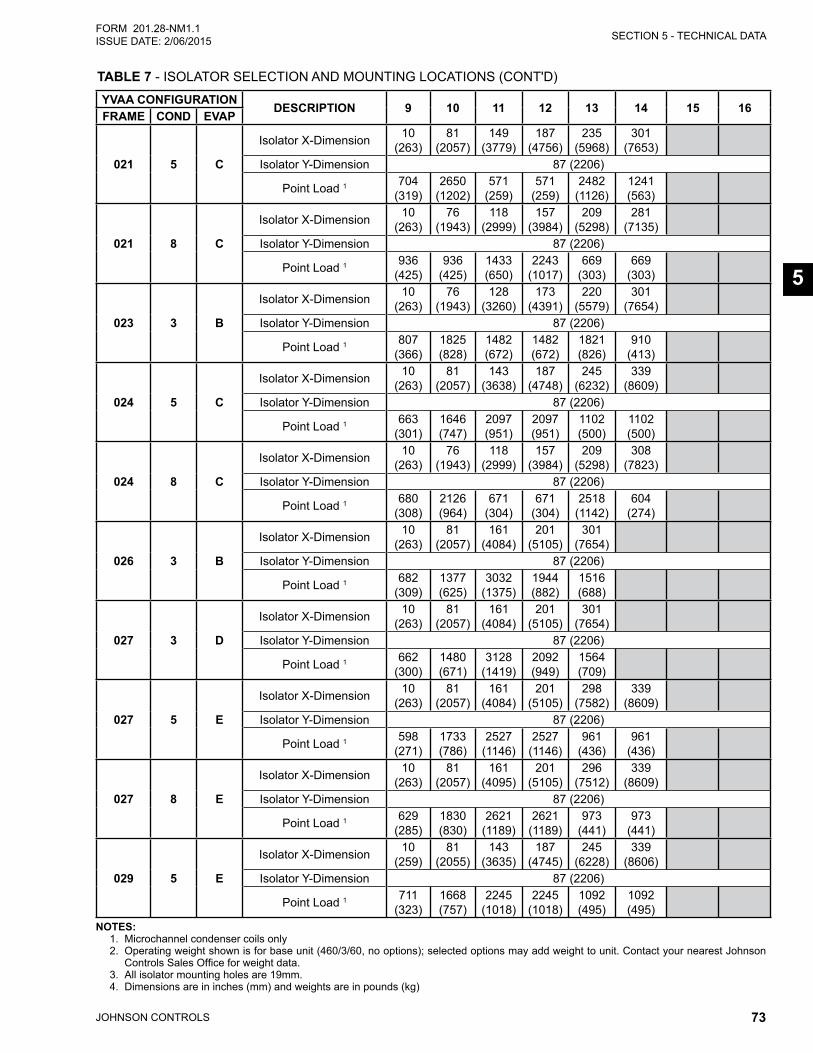
SECTION 5 - TECHNICAL DATA
JOHNSON CONTROLS 73
FORM 201.28-NM1.1ISSUE DATE: 2/06/2015
5
YVAA CONFIGURATIONDESCRIPTION 9 10 11 12 13 14 15 16
FRAME COND EVAP
021 5 C
Isolator X-Dimension 10 (263)
81 (2057)
149 (3779)
187 (4756)
235 (5968)
301 (7653)
Isolator Y-Dimension 87 (2206)
Point Load 1 704 (319)
2650 (1202)
571 (259)
571 (259)
2482 (1126)
1241 (563)
021 8 C
Isolator X-Dimension 10 (263)
76 (1943)
118 (2999)
157 (3984)
209 (5298)
281 (7135)
Isolator Y-Dimension 87 (2206)
Point Load 1 936 (425)
936 (425)
1433 (650)
2243 (1017)
669 (303)
669 (303)
023 3 B
Isolator X-Dimension 10 (263)
76 (1943)
128 (3260)
173 (4391)
220 (5579)
301 (7654)
Isolator Y-Dimension 87 (2206)
Point Load 1 807 (366)
1825 (828)
1482 (672)
1482 (672)
1821 (826)
910 (413)
024 5 C
Isolator X-Dimension 10 (263)
81 (2057)
143 (3638)
187 (4748)
245 (6232)
339 (8609)
Isolator Y-Dimension 87 (2206)
Point Load 1 663 (301)
1646 (747)
2097 (951)
2097 (951)
1102 (500)
1102 (500)
024 8 C
Isolator X-Dimension 10 (263)
76 (1943)
118 (2999)
157 (3984)
209 (5298)
308 (7823)
Isolator Y-Dimension 87 (2206)
Point Load 1 680 (308)
2126 (964)
671 (304)
671 (304)
2518 (1142)
604 (274)
026 3 B
Isolator X-Dimension 10 (263)
81 (2057)
161 (4084)
201 (5105)
301 (7654)
Isolator Y-Dimension 87 (2206)
Point Load 1 682 (309)
1377 (625)
3032 (1375)
1944 (882)
1516 (688)
027 3 D
Isolator X-Dimension 10 (263)
81 (2057)
161 (4084)
201 (5105)
301 (7654)
Isolator Y-Dimension 87 (2206)
Point Load 1 662 (300)
1480 (671)
3128 (1419)
2092 (949)
1564 (709)
027 5 E
Isolator X-Dimension 10 (263)
81 (2057)
161 (4084)
201 (5105)
298 (7582)
339 (8609)
Isolator Y-Dimension 87 (2206)
Point Load 1 598 (271)
1733 (786)
2527 (1146)
2527 (1146)
961 (436)
961 (436)
027 8 E
Isolator X-Dimension 10 (263)
81 (2057)
161 (4095)
201 (5105)
296 (7512)
339 (8609)
Isolator Y-Dimension 87 (2206)
Point Load 1 629 (285)
1830 (830)
2621 (1189)
2621 (1189)
973 (441)
973 (441)
029 5 E
Isolator X-Dimension 10 (259)
81 (2055)
143 (3635)
187 (4745)
245 (6228)
339 (8606)
Isolator Y-Dimension 87 (2206)
Point Load 1 711 (323)
1668 (757)
2245 (1018)
2245 (1018)
1092 (495)
1092 (495)
TABLE 7 - ISOLATOR SELECTION AND MOUNTING LOCATIONS (CONT'D)
NOTES:1. Microchannel condenser coils only2. Operating weight shown is for base unit (460/3/60, no options); selected options may add weight to unit. Contact your nearest Johnson
Controls Sales Office for weight data.3. All isolator mounting holes are 19mm.4. Dimensions are in inches (mm) and weights are in pounds (kg)
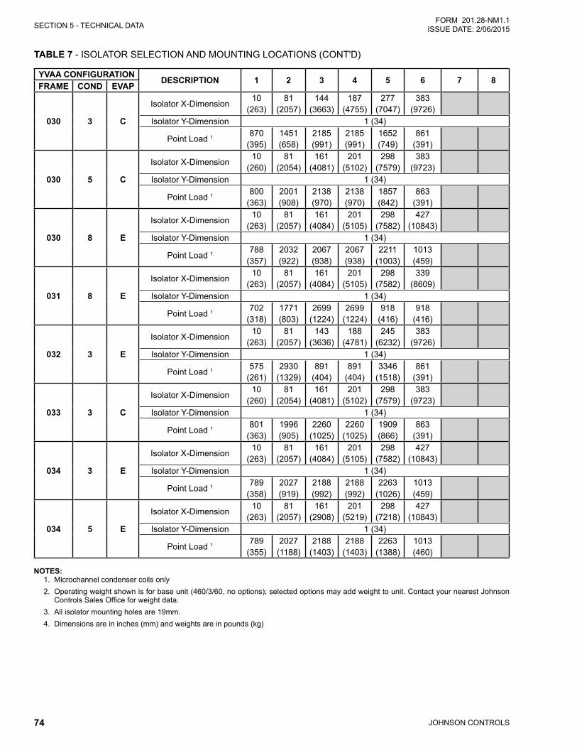
JOHNSON CONTROLS74
SECTION 5 - TECHNICAL DATAFORM 201.28-NM1.1
ISSUE DATE: 2/06/2015
TABLE 7 - ISOLATOR SELECTION AND MOUNTING LOCATIONS (CONT'D)
YVAA CONFIGURATIONDESCRIPTION 1 2 3 4 5 6 7 8
FRAME COND EVAP
030 3 C
Isolator X-Dimension10
(263)81
(2057)144
(3663)187
(4755)277
(7047)383
(9726)Isolator Y-Dimension 1 (34)
Point Load 1 870 (395)
1451 (658)
2185 (991)
2185 (991)
1652 (749)
861 (391)
030 5 C
Isolator X-Dimension10
(260)81
(2054)161
(4081)201
(5102)298
(7579)383
(9723)Isolator Y-Dimension 1 (34)
Point Load 1 800 (363)
2001 (908)
2138 (970)
2138 (970)
1857 (842)
863 (391)
030 8 E
Isolator X-Dimension10
(263)81
(2057)161
(4084)201
(5105)298
(7582)427
(10843)Isolator Y-Dimension 1 (34)
Point Load 1 788 (357)
2032 (922)
2067 (938)
2067 (938)
2211 (1003)
1013 (459)
031 8 E
Isolator X-Dimension10
(263)81
(2057)161
(4084)201
(5105)298
(7582)339
(8609)Isolator Y-Dimension 1 (34)
Point Load 1 702 (318)
1771 (803)
2699 (1224)
2699 (1224)
918 (416)
918 (416)
032 3 E
Isolator X-Dimension10
(263)81
(2057)143
(3636)188
(4781)245
(6232)383
(9726)Isolator Y-Dimension 1 (34)
Point Load 1 575 (261)
2930 (1329)
891 (404)
891 (404)
3346 (1518)
861 (391)
033 3 C
Isolator X-Dimension10
(260)81
(2054)161
(4081)201
(5102)298
(7579)383
(9723)Isolator Y-Dimension 1 (34)
Point Load 1 801 (363)
1996 (905)
2260 (1025)
2260 (1025)
1909 (866)
863 (391)
034 3 E
Isolator X-Dimension10
(263)81
(2057)161
(4084)201
(5105)298
(7582)427
(10843)Isolator Y-Dimension 1 (34)
Point Load 1 789 (358)
2027 (919)
2188 (992)
2188 (992)
2263 (1026)
1013 (459)
034 5 E
Isolator X-Dimension10
(263)81
(2057)161
(2908)201
(5219)298
(7218)427
(10843)Isolator Y-Dimension 1 (34)
Point Load 1 789 (355)
2027 (1188)
2188 (1403)
2188 (1403)
2263 (1388)
1013 (460)
NOTES:1. Microchannel condenser coils only2. Operating weight shown is for base unit (460/3/60, no options); selected options may add weight to unit. Contact your nearest Johnson
Controls Sales Office for weight data.3. All isolator mounting holes are 19mm.4. Dimensions are in inches (mm) and weights are in pounds (kg)
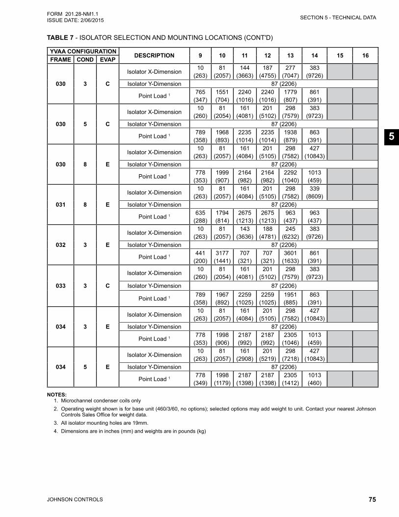
SECTION 5 - TECHNICAL DATA
JOHNSON CONTROLS 75
FORM 201.28-NM1.1ISSUE DATE: 2/06/2015
5
TABLE 7 - ISOLATOR SELECTION AND MOUNTING LOCATIONS (CONT'D)
YVAA CONFIGURATIONDESCRIPTION 9 10 11 12 13 14 15 16
FRAME COND EVAP
030 3 C
Isolator X-Dimension10
(263)81
(2057)144
(3663)187
(4755)277
(7047)383
(9726)Isolator Y-Dimension 87 (2206)
Point Load 1 765 (347)
1551 (704)
2240 (1016)
2240 (1016)
1779 (807)
861 (391)
030 5 C
Isolator X-Dimension10
(260)81
(2054)161
(4081)201
(5102)298
(7579)383
(9723)Isolator Y-Dimension 87 (2206)
Point Load 1 789 (358)
1968 (893)
2235 (1014)
2235 (1014)
1938 (879)
863 (391)
030 8 E
Isolator X-Dimension10
(263)81
(2057)161
(4084)201
(5105)298
(7582)427
(10843)Isolator Y-Dimension 87 (2206)
Point Load 1 778 (353)
1999 (907)
2164 (982)
2164 (982)
2292 (1040)
1013 (459)
031 8 E
Isolator X-Dimension10
(263)81
(2057)161
(4084)201
(5105)298
(7582)339
(8609)Isolator Y-Dimension 87 (2206)
Point Load 1 635 (288)
1794 (814)
2675 (1213)
2675 (1213)
963 (437)
963 (437)
032 3 E
Isolator X-Dimension10
(263)81
(2057)143
(3636)188
(4781)245
(6232)383
(9726)Isolator Y-Dimension 87 (2206)
Point Load 1 441 (200)
3177 (1441)
707 (321)
707 (321)
3601 (1633)
861 (391)
033 3 C
Isolator X-Dimension10
(260)81
(2054)161
(4081)201
(5102)298
(7579)383
(9723)Isolator Y-Dimension 87 (2206)
Point Load 1 789 (358)
1967 (892)
2259 (1025)
2259 (1025)
1951 (885)
863 (391)
034 3 E
Isolator X-Dimension10
(263)81
(2057)161
(4084)201
(5105)298
(7582)427
(10843)Isolator Y-Dimension 87 (2206)
Point Load 1 778 (353)
1998 (906)
2187 (992)
2187 (992)
2305 (1046)
1013 (459)
034 5 E
Isolator X-Dimension10
(263)81
(2057)161
(2908)201
(5219)298
(7218)427
(10843)Isolator Y-Dimension 87 (2206)
Point Load 1 778 (349)
1998 (1179)
2187 (1398)
2187 (1398)
2305 (1412)
1013 (460)
NOTES:1. Microchannel condenser coils only2. Operating weight shown is for base unit (460/3/60, no options); selected options may add weight to unit. Contact your nearest Johnson
Controls Sales Office for weight data.3. All isolator mounting holes are 19mm.4. Dimensions are in inches (mm) and weights are in pounds (kg)
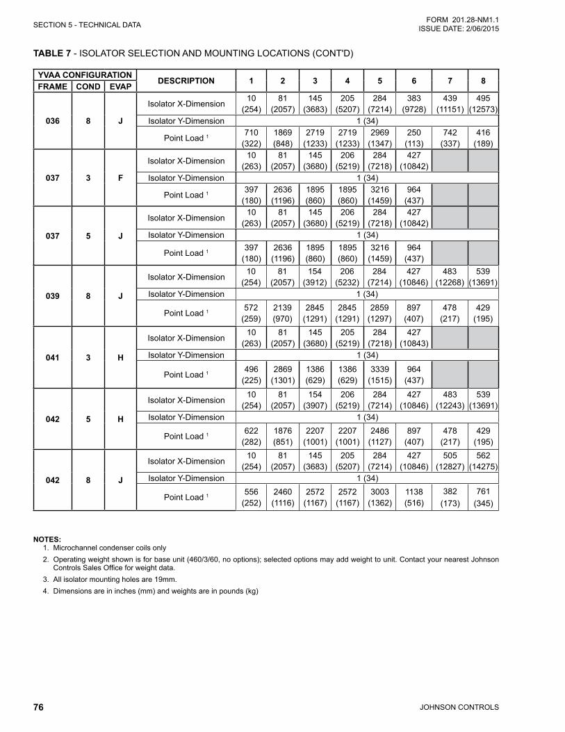
JOHNSON CONTROLS76
SECTION 5 - TECHNICAL DATAFORM 201.28-NM1.1
ISSUE DATE: 2/06/2015
YVAA CONFIGURATIONDESCRIPTION 1 2 3 4 5 6 7 8
FRAME COND EVAP
036 8 J
Isolator X-Dimension10
(254)81
(2057)145
(3683)205
(5207)284
(7214)383
(9728)439
(11151)495
(12573)Isolator Y-Dimension 1 (34)
Point Load 1 710 (322)
1869 (848)
2719 (1233)
2719 (1233)
2969 (1347)
250 (113)
742 (337)
416 (189)
037 3 F
Isolator X-Dimension10
(263)81
(2057)145
(3680)206
(5219)284
(7218)427
(10842)Isolator Y-Dimension 1 (34)
Point Load 1 397 (180)
2636 (1196)
1895 (860)
1895 (860)
3216 (1459)
964 (437)
037 5 J
Isolator X-Dimension10
(263)81
(2057)145
(3680)206
(5219)284
(7218)427
(10842)Isolator Y-Dimension 1 (34)
Point Load 1 397 (180)
2636 (1196)
1895 (860)
1895 (860)
3216 (1459)
964 (437)
039 8 J
Isolator X-Dimension10
(254)81
(2057)154
(3912)206
(5232)284
(7214)427
(10846)483
(12268)539
(13691)Isolator Y-Dimension 1 (34)
Point Load 1 572 (259)
2139 (970)
2845 (1291)
2845 (1291)
2859 (1297)
897 (407)
478 (217)
429 (195)
041 3 H
Isolator X-Dimension10
(263)81
(2057)145
(3680)205
(5219)284
(7218)427
(10843)Isolator Y-Dimension 1 (34)
Point Load 1 496 (225)
2869 (1301)
1386 (629)
1386 (629)
3339 (1515)
964 (437)
042 5 H
Isolator X-Dimension10
(254)81
(2057)154
(3907)206
(5219)284
(7214)427
(10846)483
(12243)539
(13691)Isolator Y-Dimension 1 (34)
Point Load 1 622 (282)
1876 (851)
2207 (1001)
2207 (1001)
2486 (1127)
897 (407)
478 (217)
429 (195)
042 8 J
Isolator X-Dimension10
(254)81
(2057)145
(3683)205
(5207)284
(7214)427
(10846)505
(12827)562
(14275)Isolator Y-Dimension 1 (34)
Point Load 1 556 (252)
2460 (1116)
2572 (1167)
2572 (1167)
3003 (1362)
1138 (516)
382(173)
761(345)
TABLE 7 - ISOLATOR SELECTION AND MOUNTING LOCATIONS (CONT'D)
NOTES:1. Microchannel condenser coils only2. Operating weight shown is for base unit (460/3/60, no options); selected options may add weight to unit. Contact your nearest Johnson
Controls Sales Office for weight data.3. All isolator mounting holes are 19mm.4. Dimensions are in inches (mm) and weights are in pounds (kg)
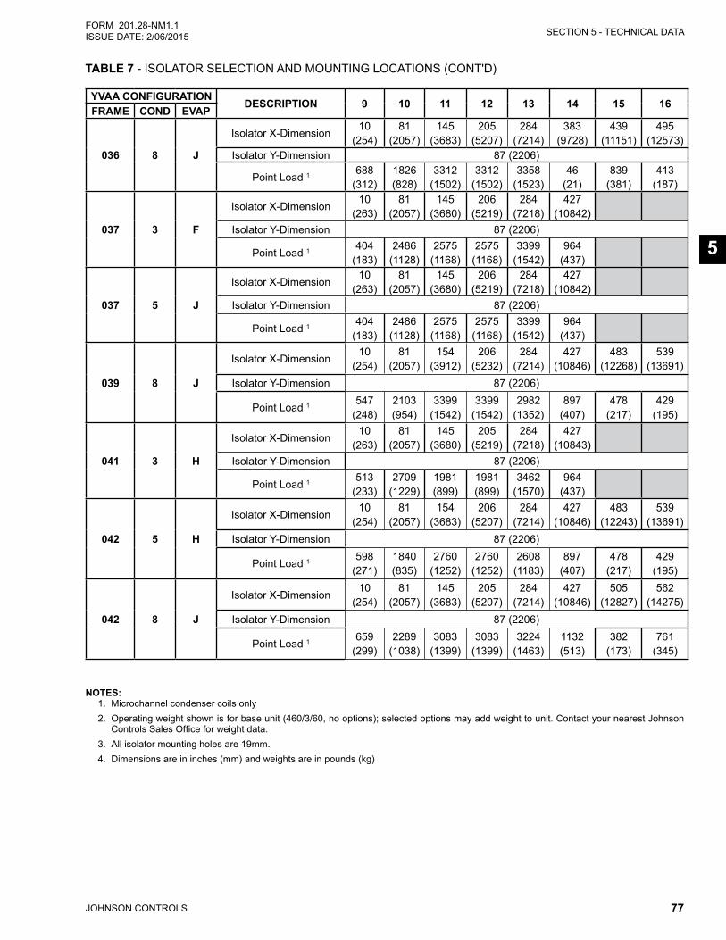
SECTION 5 - TECHNICAL DATA
JOHNSON CONTROLS 77
FORM 201.28-NM1.1ISSUE DATE: 2/06/2015
5
YVAA CONFIGURATIONDESCRIPTION 9 10 11 12 13 14 15 16
FRAME COND EVAP
036 8 J
Isolator X-Dimension10
(254)81
(2057)145
(3683)205
(5207)284
(7214)383
(9728)439
(11151)495
(12573)Isolator Y-Dimension 87 (2206)
Point Load 1 688 (312)
1826 (828)
3312 (1502)
3312 (1502)
3358 (1523)
46 (21)
839 (381)
413 (187)
037 3 F
Isolator X-Dimension10
(263)81
(2057)145
(3680)206
(5219)284
(7218)427
(10842)Isolator Y-Dimension 87 (2206)
Point Load 1 404 (183)
2486 (1128)
2575 (1168)
2575 (1168)
3399 (1542)
964 (437)
037 5 J
Isolator X-Dimension10
(263)81
(2057)145
(3680)206
(5219)284
(7218)427
(10842)Isolator Y-Dimension 87 (2206)
Point Load 1 404 (183)
2486 (1128)
2575 (1168)
2575 (1168)
3399 (1542)
964 (437)
039 8 J
Isolator X-Dimension10
(254)81
(2057)154
(3912)206
(5232)284
(7214)427
(10846)483
(12268)539
(13691)Isolator Y-Dimension 87 (2206)
Point Load 1 547 (248)
2103 (954)
3399 (1542)
3399 (1542)
2982 (1352)
897 (407)
478 (217)
429 (195)
041 3 H
Isolator X-Dimension10
(263)81
(2057)145
(3680)205
(5219)284
(7218)427
(10843)Isolator Y-Dimension 87 (2206)
Point Load 1 513 (233)
2709 (1229)
1981 (899)
1981 (899)
3462 (1570)
964 (437)
042 5 H
Isolator X-Dimension10
(254)81
(2057)154
(3683)206
(5207)284
(7214)427
(10846)483
(12243)539
(13691)Isolator Y-Dimension 87 (2206)
Point Load 1 598 (271)
1840 (835)
2760 (1252)
2760 (1252)
2608 (1183)
897 (407)
478 (217)
429 (195)
042 8 J
Isolator X-Dimension10
(254)81
(2057)145
(3683)205
(5207)284
(7214)427
(10846)505
(12827)562
(14275)Isolator Y-Dimension 87 (2206)
Point Load 1 659 (299)
2289 (1038)
3083 (1399)
3083 (1399)
3224 (1463)
1132 (513)
382 (173)
761 (345)
TABLE 7 - ISOLATOR SELECTION AND MOUNTING LOCATIONS (CONT'D)
NOTES:1. Microchannel condenser coils only2. Operating weight shown is for base unit (460/3/60, no options); selected options may add weight to unit. Contact your nearest Johnson
Controls Sales Office for weight data.3. All isolator mounting holes are 19mm.4. Dimensions are in inches (mm) and weights are in pounds (kg)
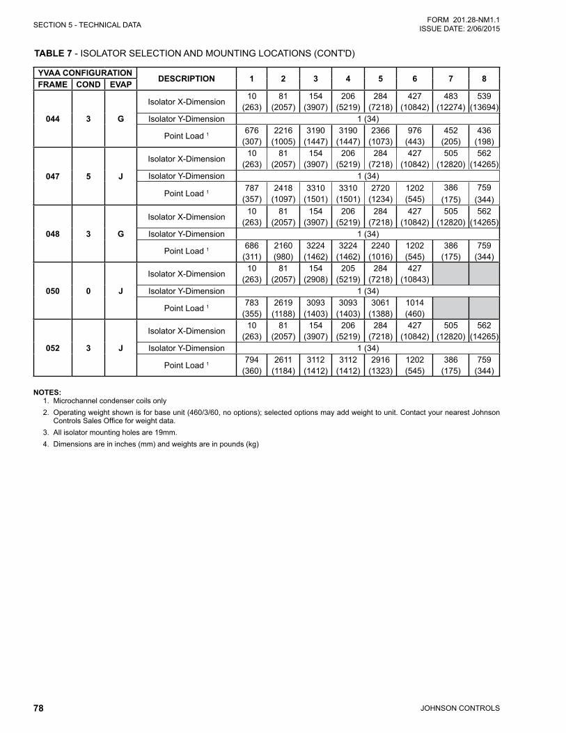
JOHNSON CONTROLS78
SECTION 5 - TECHNICAL DATAFORM 201.28-NM1.1
ISSUE DATE: 2/06/2015
YVAA CONFIGURATIONDESCRIPTION 1 2 3 4 5 6 7 8
FRAME COND EVAP
044 3 G
Isolator X-Dimension10
(263)81
(2057)154
(3907)206
(5219)284
(7218)427
(10842)483
(12274)539
(13694)Isolator Y-Dimension 1 (34)
Point Load 1 676 (307)
2216 (1005)
3190 (1447)
3190 (1447)
2366 (1073)
976 (443)
452 (205)
436 (198)
047 5 J
Isolator X-Dimension10
(263)81
(2057)154
(3907)206
(5219)284
(7218)427
(10842)505
(12820)562
(14265)Isolator Y-Dimension 1 (34)
Point Load 1 787 (357)
2418 (1097)
3310 (1501)
3310 (1501)
2720 (1234)
1202 (545)
386(175)
759(344)
048 3 G
Isolator X-Dimension10
(263)81
(2057)154
(3907)206
(5219)284
(7218)427
(10842)505
(12820)562
(14265)Isolator Y-Dimension 1 (34)
Point Load 1 686 (311)
2160 (980)
3224 (1462)
3224 (1462)
2240 (1016)
1202 (545)
386 (175)
759 (344)
050 0 J
Isolator X-Dimension10
(263)81
(2057)154
(2908)205
(5219)284
(7218)427
(10843)Isolator Y-Dimension 1 (34)
Point Load 1 783 (355)
2619 (1188)
3093 (1403)
3093 (1403)
3061 (1388)
1014 (460)
052 3 J
Isolator X-Dimension10
(263)81
(2057)154
(3907)206
(5219)284
(7218)427
(10842)505
(12820)562
(14265)Isolator Y-Dimension 1 (34)
Point Load 1 794 (360)
2611 (1184)
3112 (1412)
3112 (1412)
2916 (1323)
1202 (545)
386 (175)
759 (344)
TABLE 7 - ISOLATOR SELECTION AND MOUNTING LOCATIONS (CONT'D)
NOTES:1. Microchannel condenser coils only2. Operating weight shown is for base unit (460/3/60, no options); selected options may add weight to unit. Contact your nearest Johnson
Controls Sales Office for weight data.3. All isolator mounting holes are 19mm.4. Dimensions are in inches (mm) and weights are in pounds (kg)
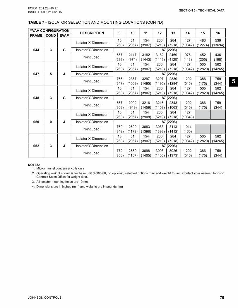
SECTION 5 - TECHNICAL DATA
JOHNSON CONTROLS 79
FORM 201.28-NM1.1ISSUE DATE: 2/06/2015
5
YVAA CONFIGURATIONDESCRIPTION 9 10 11 12 13 14 15 16
FRAME COND EVAP
044 3 G
Isolator X-Dimension10
(263)81
(2057)154
(3907)206
(5219)284
(7218)427
(10842)483
(12274)539
(13694)Isolator Y-Dimension 87 (2206)
Point Load 1 657 (298)
2147 (974)
3182 (1443)
3182 (1443)
2469 (1120)
976 (443)
452 (205)
436 (198)
047 5 J
Isolator X-Dimension10
(263)81
(2057)154
(3907)206
(5219)284
(7218)427
(10842)505
(12820)562
(14265)Isolator Y-Dimension 87 (2206)
Point Load 1 765 (347)
2357 (1069)
3297 (1495)
3297 (1495)
2830 (1284)
1202 (545)
386 (175)
759 (344)
048 3 G
Isolator X-Dimension10
(263)81
(2057)154
(3907)206
(5219)284
(7218)427
(10842)505
(12820)562
(14265)Isolator Y-Dimension 87 (2206)
Point Load 1 667 (303)
2092 (949)
3216 (1459)
3216 (1459)
2343 (1063)
1202 (545)
386 (175)
759 (344)
050 0 J
Isolator X-Dimension10
(263)81
(2057)154
(2908)205
(5219)284
(7218)427
(10843)Isolator Y-Dimension 87 (2206)
Point Load 1 769 (349)
2600 (1179)
3083 (1398)
3083 (1398)
3113 (1412)
1014 (460)
052 3 J
Isolator X-Dimension10
(263)81
(2057)154
(3907)206
(5219)284
(7218)427
(10842)505
(12820)562
(14265)Isolator Y-Dimension 87 (2206)
Point Load 1 772 (350)
2550 (1157)
3098 (1405)
3098 (1405)
3026 (1373)
1202 (545)
386 (175)
759 (344)
TABLE 7 - ISOLATOR SELECTION AND MOUNTING LOCATIONS (CONT'D)
NOTES:1. Microchannel condenser coils only2. Operating weight shown is for base unit (460/3/60, no options); selected options may add weight to unit. Contact your nearest Johnson
Controls Sales Office for weight data.3. All isolator mounting holes are 19mm.4. Dimensions are in inches (mm) and weights are in pounds (kg)
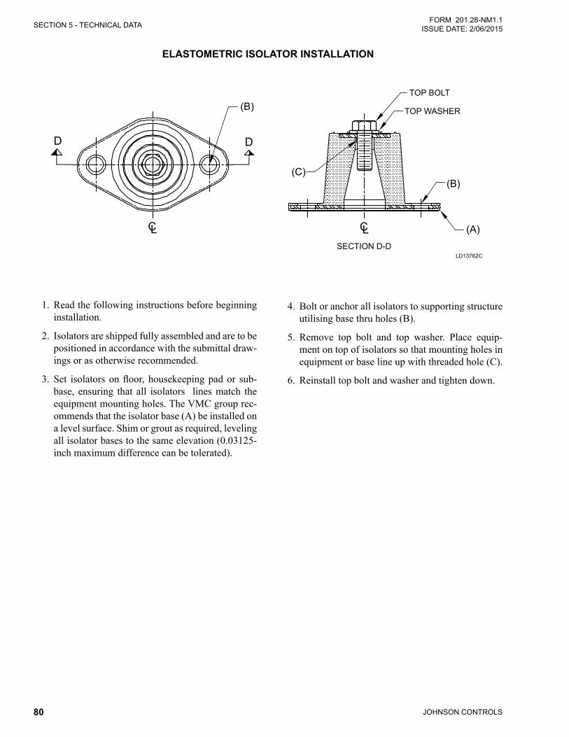
JOHNSON CONTROLS80
SECTION 5 - TECHNICAL DATAFORM 201.28-NM1.1
ISSUE DATE: 2/06/2015
ELASTOMETRIC ISOLATOR INSTALLATION
1. Read the following instructions before beginning installation.
2. Isolators are shipped fully assembled and are to be positioned in accordance with the submittal draw-ings or as otherwise recommended.
3. Set isolatorsonfloor, housekeepingpador sub-base, ensuring that all isolators lines match the equipment mounting holes. The VMC group rec-ommends that the isolator base (A) be installed on a level surface. Shim or grout as required, leveling all isolator bases to the same elevation (0.03125-inch maximum difference can be tolerated).
4. Bolt or anchor all isolators to supporting structure utilising base thru holes (B).
5. Remove top bolt and top washer. Place equip-ment on top of isolators so that mounting holes in equipment or base line up with threaded hole (C).
6. Reinstall top bolt and washer and tighten down.
LD13762C
D D
CLSECTION D-D
CL
(B)
(B)
(A)
(C)
TOP BOLT
TOP WASHER
SECTION D-D
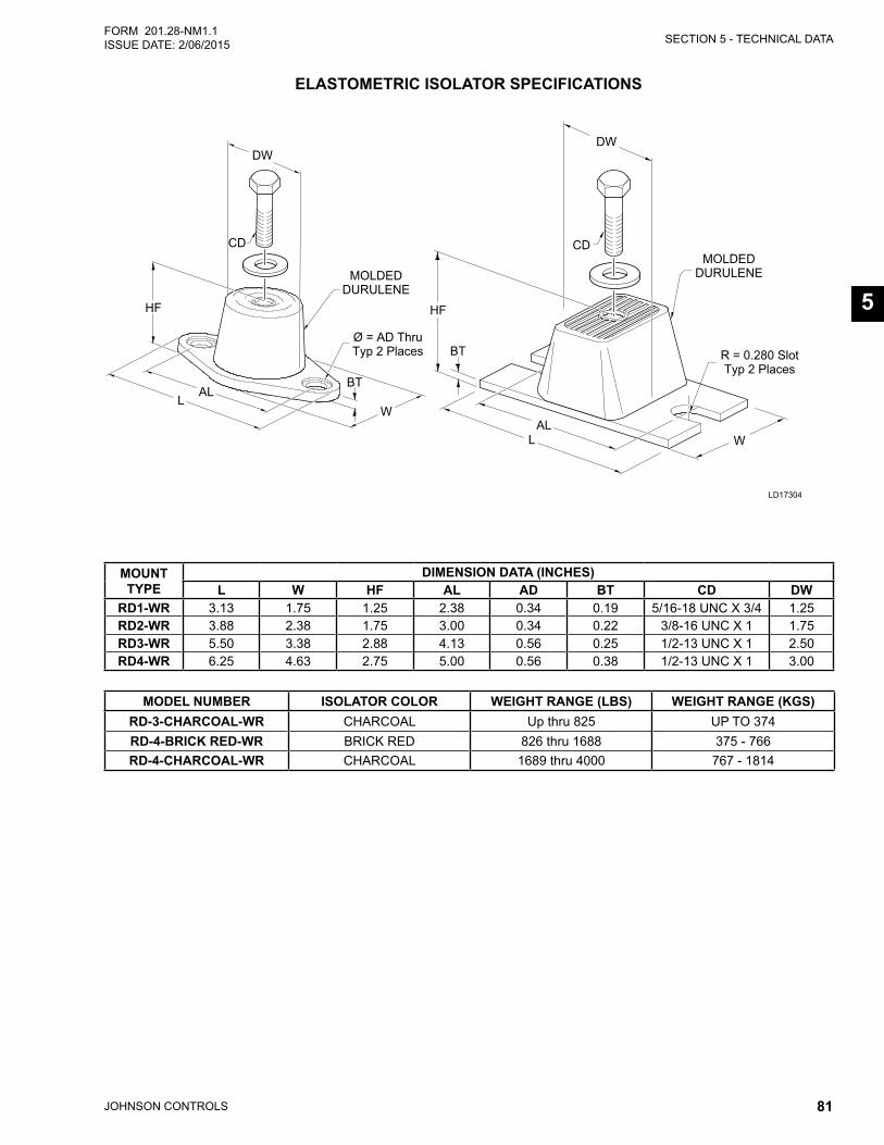
SECTION 5 - TECHNICAL DATA
JOHNSON CONTROLS 81
FORM 201.28-NM1.1ISSUE DATE: 2/06/2015
5
ELASTOMETRIC ISOLATOR SPECIFICATIONS
LD17304
CDCD
HFHF
BT
BT
ALL
ALL
W
W
DWDW
MOLDEDDURULENEMOLDED
DURULENE
R = 0.280 SlotTyp 2 Places
Ø = AD ThruTyp 2 Places
MOUNT TYPE
DIMENSION DATA (INCHES)L W HF AL AD BT CD DW
RD1-WR 3.13 1.75 1.25 2.38 0.34 0.19 5/16-18 UNC X 3/4 1.25RD2-WR 3.88 2.38 1.75 3.00 0.34 0.22 3/8-16 UNC X 1 1.75RD3-WR 5.50 3.38 2.88 4.13 0.56 0.25 1/2-13 UNC X 1 2.50RD4-WR 6.25 4.63 2.75 5.00 0.56 0.38 1/2-13 UNC X 1 3.00
MODEL NUMBER ISOLATOR COLOR WEIGHT RANGE (LBS) WEIGHT RANGE (KGS)RD-3-CHARCOAL-WR CHARCOAL Up thru 825 UP TO 374RD-4-BRICK RED-WR BRICK RED 826 thru 1688 375 - 766RD-4-CHARCOAL-WR CHARCOAL 1689 thru 4000 767 - 1814
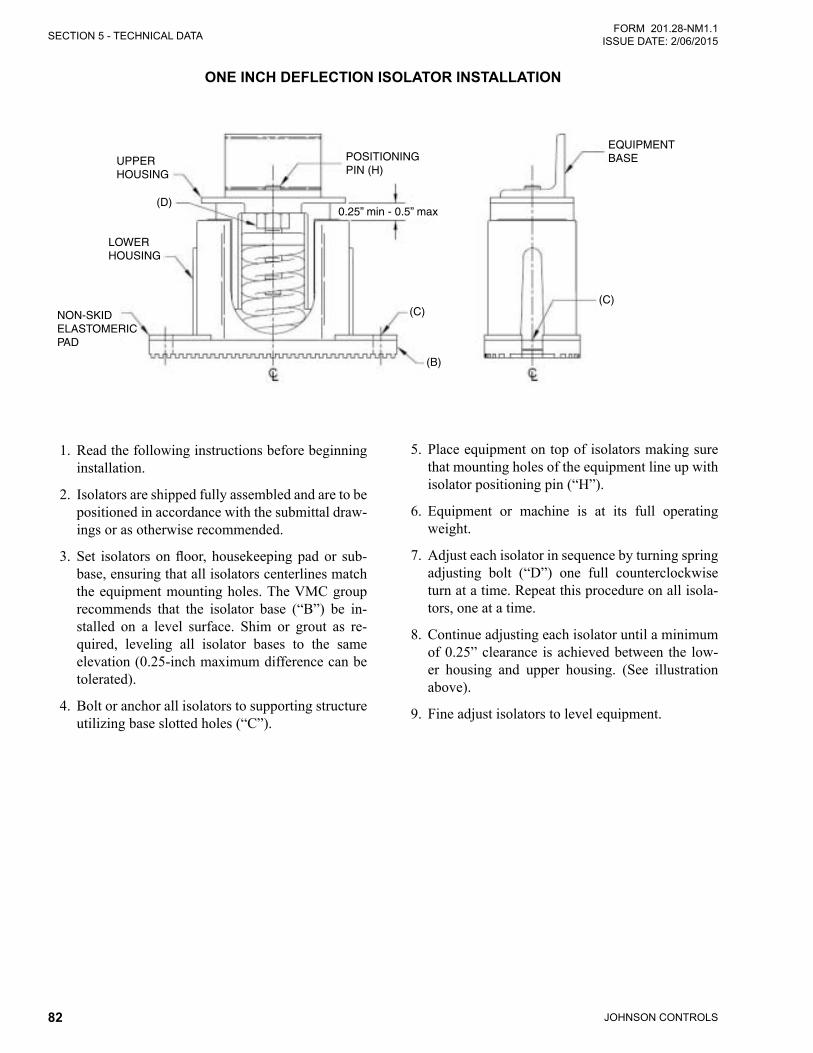
JOHNSON CONTROLS82
SECTION 5 - TECHNICAL DATAFORM 201.28-NM1.1
ISSUE DATE: 2/06/2015
ONE INCH DEFLECTION ISOLATOR INSTALLATION
UPPERHOUSING
(D)
LOWERHOUSING
NON-SKIDELASTOMERICPAD
POSITIONINGPIN (H)
0.25” min - 0.5” max
(C)(C)
(B)
EQUIPMENTBASE
1. Read the following instructions before beginning installation.
2. Isolators are shipped fully assembled and are to be positioned in accordance with the submittal draw-ings or as otherwise recommended.
3. Set isolatorsonfloor, housekeepingpador sub-base, ensuring that all isolators centerlines match the equipment mounting holes. The VMC group recommends that the isolator base (“B”) be in-stalled on a level surface. Shim or grout as re-quired, leveling all isolator bases to the same elevation (0.25-inch maximum difference can be tolerated).
4. Bolt or anchor all isolators to supporting structure utilizing base slotted holes (“C”).
5. Place equipment on top of isolators making sure that mounting holes of the equipment line up with isolator positioning pin (“H”).
6. Equipment or machine is at its full operating weight.
7. Adjust each isolator in sequence by turning spring adjusting bolt (“D”) one full counterclockwise turn at a time. Repeat this procedure on all isola-tors, one at a time.
8. Continue adjusting each isolator until a minimum of 0.25” clearance is achieved between the low-er housing and upper housing. (See illustration above).
9. Fine adjust isolators to level equipment.
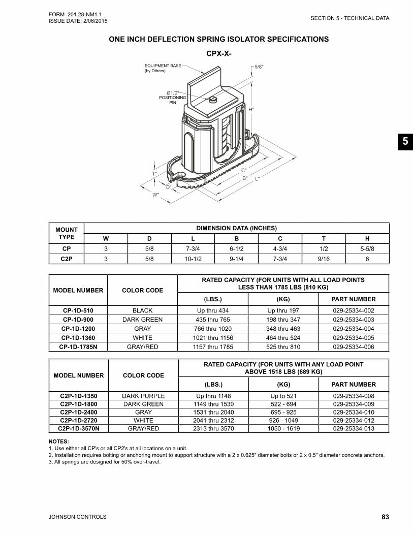
SECTION 5 - TECHNICAL DATA
JOHNSON CONTROLS 83
FORM 201.28-NM1.1ISSUE DATE: 2/06/2015
5
ONE INCH DEFLECTION SPRING ISOLATOR SPECIFICATIONS
NOTES:1. Use either all CP's or all CP2's at all locations on a unit. 2. Installation requires bolting or anchoring mount to support structure with a 2 x 0.625" diameter bolts or 2 x 0.5" diameter concrete anchors. 3. All springs are designed for 50% over-travel.
CPX-X-EQUIPMENT BASE(by Others)
POSITIONINGPIN
MODEL NUMBER COLOR CODERATED CAPACITY (FOR UNITS WITH ALL LOAD POINTS
LESS THAN 1785 LBS (810 KG)
(LBS.) (KG) PART NUMBER
CP-1D-510 BLACK Up thru 434 Up thru 197 029-25334-002CP-1D-900 DARK GREEN 435 thru 765 198 thru 347 029-25334-003
CP-1D-1200 GRAY 766 thru 1020 348 thru 463 029-25334-004CP-1D-1360 WHITE 1021 thru 1156 464 thru 524 029-25334-005
CP-1D-1785N GRAY/RED 1157 thru 1785 525 thru 810 029-25334-006
MODEL NUMBER COLOR CODE
RATED CAPACITY (FOR UNITS WITH ANY LOAD POINT ABOVE 1518 LBS (689 KG)
(LBS.) (KG) PART NUMBER
C2P-1D-1350 DARK PURPLE Up thru 1148 Up to 521 029-25334-008C2P-1D-1800 DARK GREEN 1149 thru 1530 522 - 694 029-25334-009C2P-1D-2400 GRAY 1531 thru 2040 695 - 925 029-25334-010C2P-1D-2720 WHITE 2041 thru 2312 926 - 1049 029-25334-012
C2P-1D-3570N GRAY/RED 2313 thru 3570 1050 - 1619 029-25334-013
MOUNT TYPE
DIMENSION DATA (INCHES)W D L B C T H
CP 3 5/8 7-3/4 6-1/2 4-3/4 1/2 5-5/8
C2P 3 5/8 10-1/2 9-1/4 7-3/4 9/16 6
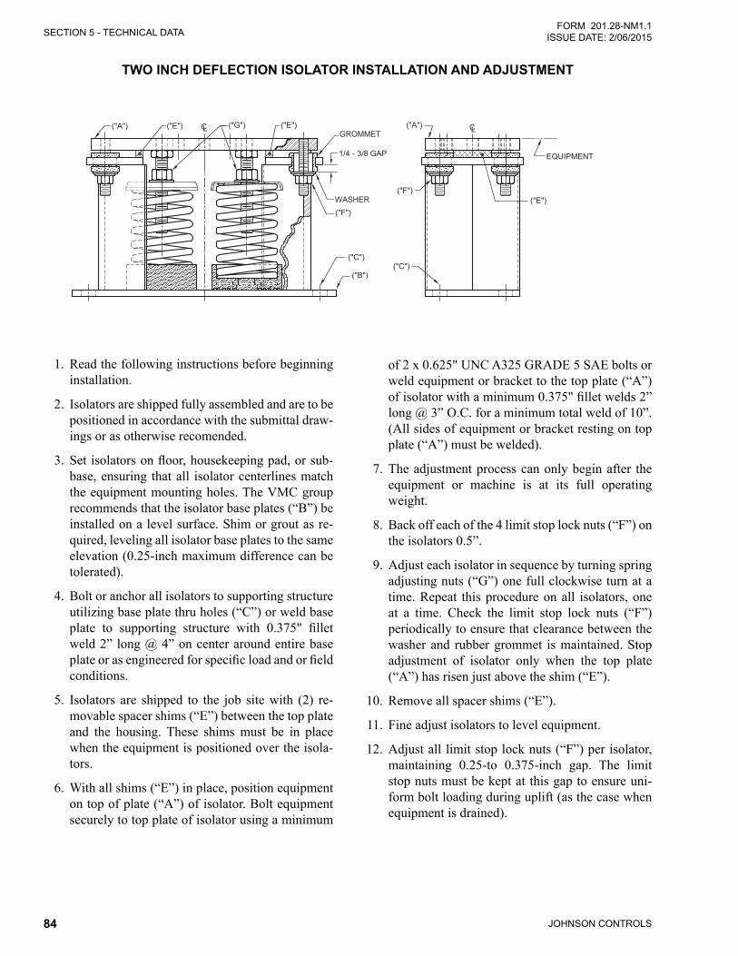
JOHNSON CONTROLS84
SECTION 5 - TECHNICAL DATAFORM 201.28-NM1.1
ISSUE DATE: 2/06/2015
TWO INCH DEFLECTION ISOLATOR INSTALLATION AND ADJUSTMENT
WASHER("F")
("B")
GROMMET("G") ("A")
("C")
("F")("E")
("E") ("E")
1/4 - 3/8 GAP
CLCL
("C")
EQUIPMENT
("A")
1. Read the following instructions before beginning installation.
2. Isolators are shipped fully assembled and are to be positioned in accordance with the submittal draw-ings or as otherwise recomended.
3. Setisolatorsonfloor,housekeepingpad,orsub-base, ensuring that all isolator centerlines match the equipment mounting holes. The VMC group recommends that the isolator base plates (“B”) be installed on a level surface. Shim or grout as re-quired, leveling all isolator base plates to the same elevation (0.25-inch maximum difference can be tolerated).
4. Bolt or anchor all isolators to supporting structure utilizing base plate thru holes (“C”) or weld base plate to supporting structure with 0.375" filletweld 2” long @ 4” on center around entire base plateorasengineeredforspecificloadandorfieldconditions.
5. Isolators are shipped to the job site with (2) re-movable spacer shims (“E”) between the top plate and the housing. These shims must be in place when the equipment is positioned over the isola-tors.
6. With all shims (“E”) in place, position equipment on top of plate (“A”) of isolator. Bolt equipment securely to top plate of isolator using a minimum
of 2 x 0.625" UNC A325 GRADE 5 SAE bolts or weld equipment or bracket to the top plate (“A”) ofisolatorwithaminimum0.375"filletwelds2”long @ 3” O.C. for a minimum total weld of 10”. (All sides of equipment or bracket resting on top plate (“A”) must be welded).
7. The adjustment process can only begin after the equipment or machine is at its full operating weight.
8. Back off each of the 4 limit stop lock nuts (“F”) on the isolators 0.5”.
9. Adjust each isolator in sequence by turning spring adjusting nuts (“G”) one full clockwise turn at a time. Repeat this procedure on all isolators, one at a time. Check the limit stop lock nuts (“F”) periodically to ensure that clearance between the washer and rubber grommet is maintained. Stop adjustment of isolator only when the top plate (“A”) has risen just above the shim (“E”).
10. Remove all spacer shims (“E”).
11. Fine adjust isolators to level equipment.
12. Adjust all limit stop lock nuts (“F”) per isolator, maintaining 0.25-to 0.375-inch gap. The limit stop nuts must be kept at this gap to ensure uni-form bolt loading during uplift (as the case when equipment is drained).
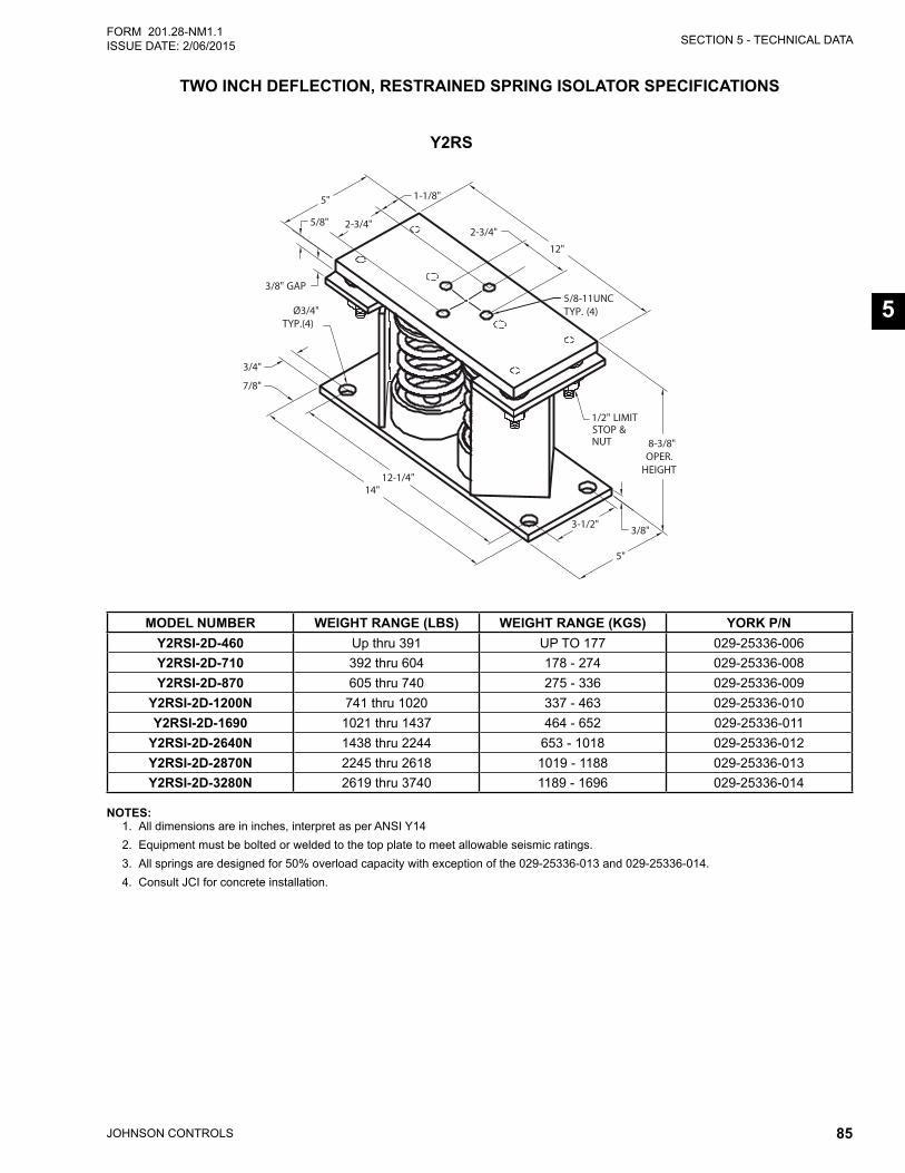
SECTION 5 - TECHNICAL DATA
JOHNSON CONTROLS 85
FORM 201.28-NM1.1ISSUE DATE: 2/06/2015
5
TWO INCH DEFLECTION, RESTRAINED SPRING ISOLATOR SPECIFICATIONS
12"
5"
2-3/4"
12-1/4"
8-3/8"OPER.HEIGHT
14"
5/8"
3/8"
Ø3/4"TYP.(4)
3-1/2"
5/8-11UNCTYP. (4)
2-3/4"
3/4"
7/8"
1-1/8"
3/8" GAP
5"
1/2" LIMITSTOP &NUT
NOTES:1. All dimensions are in inches, interpret as per ANSI Y142. Equipment must be bolted or welded to the top plate to meet allowable seismic ratings.3. All springs are designed for 50% overload capacity with exception of the 029-25336-013 and 029-25336-014.4. Consult JCI for concrete installation.
Y2RS
MODEL NUMBER WEIGHT RANGE (LBS) WEIGHT RANGE (KGS) YORK P/NY2RSI-2D-460 Up thru 391 UP TO 177 029-25336-006Y2RSI-2D-710 392 thru 604 178 - 274 029-25336-008Y2RSI-2D-870 605 thru 740 275 - 336 029-25336-009
Y2RSI-2D-1200N 741 thru 1020 337 - 463 029-25336-010Y2RSI-2D-1690 1021 thru 1437 464 - 652 029-25336-011
Y2RSI-2D-2640N 1438 thru 2244 653 - 1018 029-25336-012Y2RSI-2D-2870N 2245 thru 2618 1019 - 1188 029-25336-013Y2RSI-2D-3280N 2619 thru 3740 1189 - 1696 029-25336-014
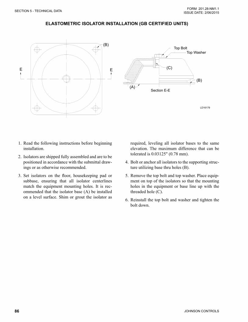
JOHNSON CONTROLS86
SECTION 5 - TECHNICAL DATAFORM 201.28-NM1.1
ISSUE DATE: 2/06/2015
ELASTOMETRIC ISOLATOR INSTALLATION (GB CERTIFIED UNITS)
1. Read the following instructions before beginning installation.
2. Isolators are shipped fully assembled and are to be positioned in accordance with the submittal draw-ings or as otherwise recommended.
3. Set isolators on the floor, housekeeping pad orsubbase, ensuring that all isolator centerlines match the equipment mounting holes. It is rec-ommended that the isolator base (A) be installed on a level surface. Shim or grout the isolator as
required, leveling all isolator bases to the same elevation. The maximum difference that can be tolerated is 0.03125" (0.78 mm).
4. Bolt or anchor all isolators to the supporting struc-ture utilizing base thru holes (B).
5. Remove the top bolt and top washer. Place equip-ment on top of the isolators so that the mounting holes in the equipment or base line up with the threaded hole (C).
6. Reinstall the top bolt and washer and tighten the bolt down.
SECTION 5 - TECHNICAL DATA FORM_201.28-NM1.1.EN (1106)
52 JOHNSON CONTROLS
ELASTOMETRIC ISOLATOR INSTALLATION
1. Read the following instructions before begin
ning installation.
2. Isolators are shipped fully assembled and are to
be positioned in accordance with the submittal
drawings or as otherwise recommended.
3. Set isolators on floor, housekeeping pad or
subbase, ensuring that all isolators’ centerlines
match the equipment mounting holes. It is
recommends that the isolator base (A) be
installed on a level surface. Shim or grout as
required, leveling all isolator bases to the same
elevation (0.03125" (0.78 mm) maximum
difference can be tolerated).
4. Bolt or anchor all isolators to supporting structure
utilizing base thru holes (B).
5. Remove top bolt and top washer. Place equip-
ment on top of isolators so that mounting holes
in equipment or base line up with threaded hole
(C).
6. Reinstall top bolt and washer and tighten down.
Top Bolt
(C")
(B")
(A")
E E
(B")
Top Washer
Section E-E
(B)
(B)
(C)
(A)
Top BoltTop Washer
Section E-E
E E
LD16179
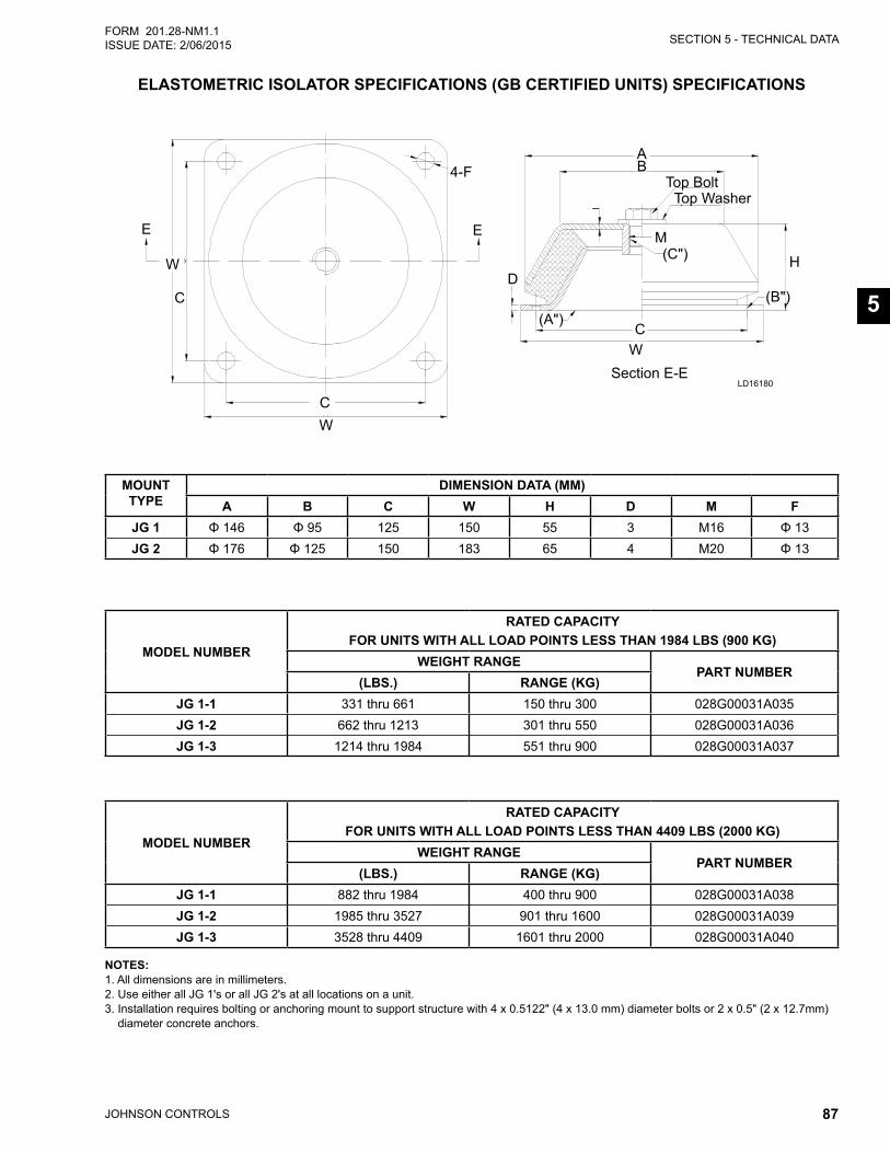
SECTION 5 - TECHNICAL DATA
JOHNSON CONTROLS 87
FORM 201.28-NM1.1ISSUE DATE: 2/06/2015
5
ELASTOMETRIC ISOLATOR SPECIFICATIONS (GB CERTIFIED UNITS) SPECIFICATIONS
MOUNT TYPE
DIMENSION DATA (MM)A B C W H D M F
JG 1 Φ 146 Φ 95 125 150 55 3 M16 Φ 13JG 2 Φ 176 Φ 125 150 183 65 4 M20 Φ 13
MODEL NUMBER
RATED CAPACITYFOR UNITS WITH ALL LOAD POINTS LESS THAN 1984 LBS (900 KG)
WEIGHT RANGEPART NUMBER
(LBS.) RANGE (KG)JG 1-1 331 thru 661 150 thru 300 028G00031A035JG 1-2 662 thru 1213 301 thru 550 028G00031A036JG 1-3 1214 thru 1984 551 thru 900 028G00031A037
MODEL NUMBER
RATED CAPACITYFOR UNITS WITH ALL LOAD POINTS LESS THAN 4409 LBS (2000 KG)
WEIGHT RANGEPART NUMBER
(LBS.) RANGE (KG)JG 1-1 882 thru 1984 400 thru 900 028G00031A038JG 1-2 1985 thru 3527 901 thru 1600 028G00031A039JG 1-3 3528 thru 4409 1601 thru 2000 028G00031A040
NOTES: 1. All dimensions are in millimeters. 2. Use either all JG 1's or all JG 2's at all locations on a unit. 3. Installation requires bolting or anchoring mount to support structure with 4 x 0.5122" (4 x 13.0 mm) diameter bolts or 2 x 0.5" (2 x 12.7mm)
diameter concrete anchors.
FORM_201.28-NM1.1.EN (1106) SECTION 5 - TECHNICAL DATA
JOHNSON CONTORLS 53
ELASTOMETRIC ISOLATOR SPECIFICATIONS
MOUNT TYPE DIMENSION DATA (mm)
A B C W H D M F
JG 1 146 95 125 150 55 3 M16 13
JG 2 176 125 150 183 65 4 M20 13
MODEL NUMBER
RATED CAPACITY (FOR UNITS WITH ALL LOAD POINTS LESS THAN 1984 LBS
(900 KG)) Weight Range
PART NUMBER (LBS.) (KG)
JG 1-1 331 thru 661 150 thru 300 028G00031A035
JG 1-2 662 thru 1213 301 thru 550 028G00031A036
JG 1-3 1214 thru 1984 551 thru 900 028G00031A037
MODEL NUMBER
RATED CAPACITY (FOR UNITS WITH ALL LOAD POINTS LESS THAN 4409 LBS
(2000 KG)) Weight Range
PART NUMBER (LBS.) (KG)
JG 2-1 882 thru 1984 400 thru 900 028G00031A038
JG 2-2 1985 thru 3527 901 thru 1600 028G00031A039
JG 2-3 3528 thru 4409 1601 thru 2000 028G00031A040
Notes: 1. All dimensions are in millimeter. 2. Use either all JG 1's or all JG 2's at all locations on a unit 3. Installation requires bolting or anchoring mount to support structure with a 4 x 0.5122"(4 x 13.0mm) diameter bolts or 2 x 0.5"(2 x 12.7mm ) diameter concrete anchors
5
C
W
W
CW
D
H
4-F
I
A
B
C
Top Bolt
(C")
(B")
(A")
E E
Top Washer
Section E-E
E
W
W
C
C
E
BA
H
(B")(A")
Top BoltTop Washer
Section E-E
4-F
M
D
WC
(C")
LD16180
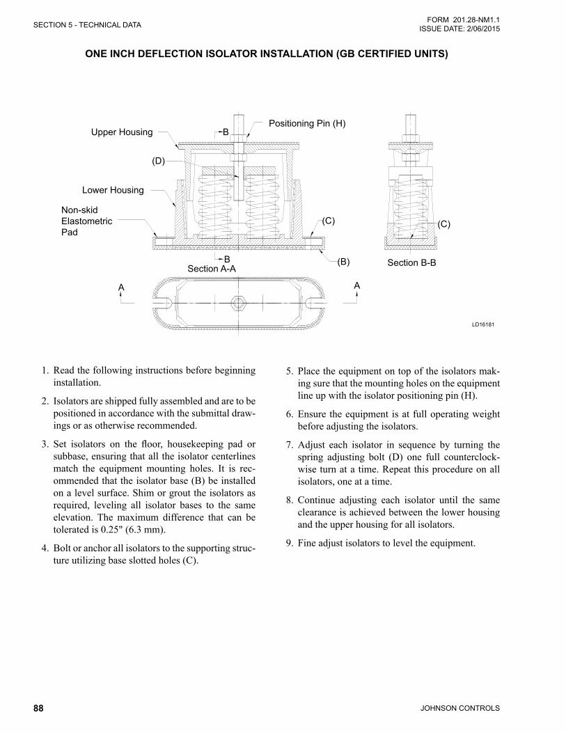
JOHNSON CONTROLS88
SECTION 5 - TECHNICAL DATAFORM 201.28-NM1.1
ISSUE DATE: 2/06/2015
1. Read the following instructions before beginning installation.
2. Isolators are shipped fully assembled and are to be positioned in accordance with the submittal draw-ings or as otherwise recommended.
3. Set isolators on the floor, housekeeping pad orsubbase, ensuring that all the isolator centerlines match the equipment mounting holes. It is rec-ommended that the isolator base (B) be installed on a level surface. Shim or grout the isolators as required, leveling all isolator bases to the same elevation. The maximum difference that can be tolerated is 0.25" (6.3 mm).
4. Bolt or anchor all isolators to the supporting struc-ture utilizing base slotted holes (C).
5. Place the equipment on top of the isolators mak-ing sure that the mounting holes on the equipment line up with the isolator positioning pin (H).
6. Ensure the equipment is at full operating weight before adjusting the isolators.
7. Adjust each isolator in sequence by turning the spring adjusting bolt (D) one full counterclock-wise turn at a time. Repeat this procedure on all isolators, one at a time.
8. Continue adjusting each isolator until the same clearance is achieved between the lower housing and the upper housing for all isolators.
9. Fine adjust isolators to level the equipment.
ONE INCH DEFLECTION ISOLATOR INSTALLATION (GB CERTIFIED UNITS)SECTION 5 - TECHNICAL DATA FORM_201.28-NM1.1.EN (1106)
54 JOHNSON CONTROLS
ONE INCH DEFLECTION ISOLATOR INSTALLATION
1. Read the following instructions before beginning
installation.
2. Isolators are shipped fully assembled and are to be
positioned in accordance with the submittal draw-
ings or as otherwise recommended.
3. Set isolators on floor, housekeeping pad or sub-
base, ensuring that all isolator’s centerlines match
the equipment mounting holes. It is recommends
that the isolator base (B) be in- stalled on a level
surface. Shim or grout as required, leveling all
isolator bases to the same elevation (0.25"(6.3mm)
maximum difference can be tolerated).
4. Bolt or anchor all isolators to supporting structure
utilizing base slotted holes (C).
5. Place equipment on top of isolators making sure
that mounting holes of the equipment line up with
isolator positioning pin (H).
6. Equipment or machine is at its full operating
weight.
7. Adjust each isolator in sequence by turning spring
adjusting bolt (D) one full counterclockwise turn
at a time. Repeat this procedure on all isolators,
one at a time.
8. Continue adjusting each isolator until same
clearance is achieved between the lower housing
and upper housing for all isolators.
9. Fine adjust isolators to level equipment.
Section A-A
A A
Section B-BB
B
LowerHousing
Non-skid
Elastomeric
Pad
Upper
Housing
Positioning
PIN(H)
(C)
(B)
(D)
(C)
Upper HousingPositioning Pin (H)
Section A-A Section B-B
(C)(C)
(B)B
B
AA
(D)
Lower Housing
Non-skid Elastometric Pad
LD16181
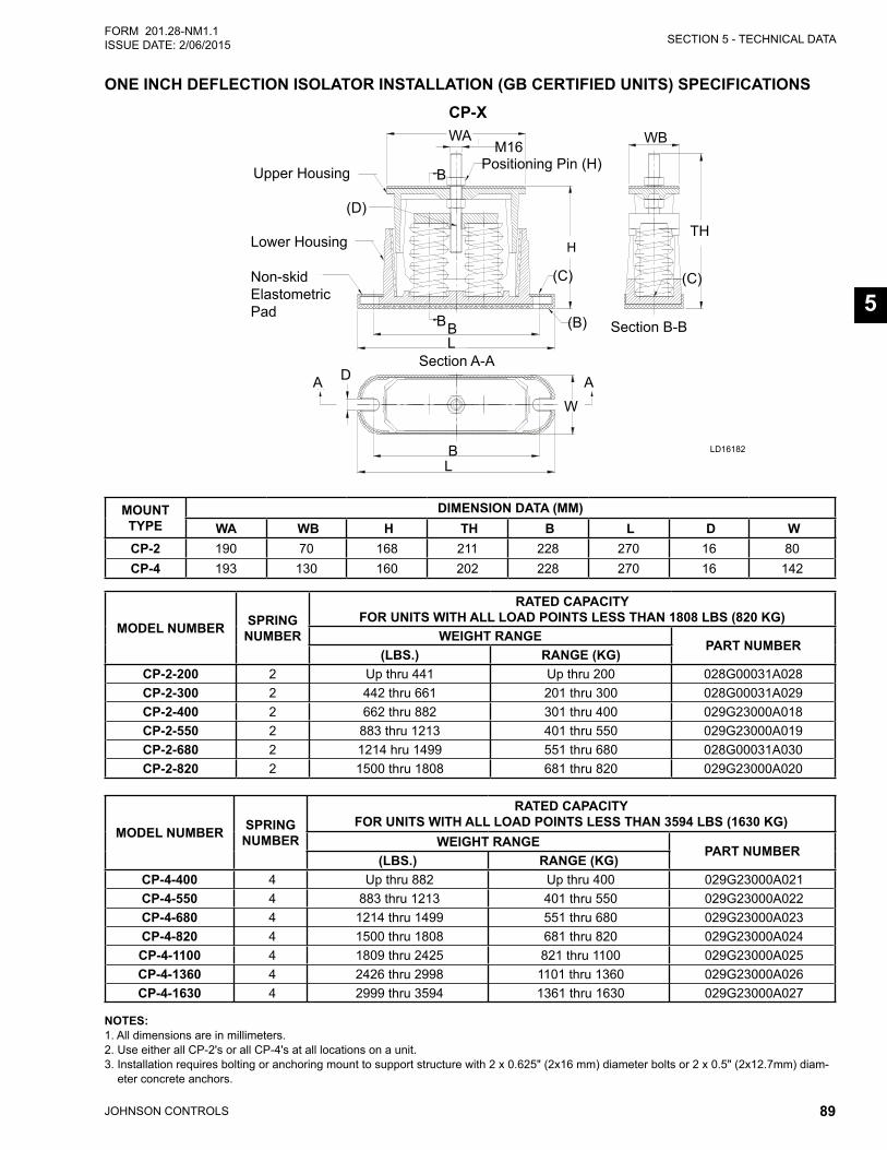
SECTION 5 - TECHNICAL DATA
JOHNSON CONTROLS 89
FORM 201.28-NM1.1ISSUE DATE: 2/06/2015
5
MOUNT TYPE
DIMENSION DATA (MM)WA WB H TH B L D W
CP-2 190 70 168 211 228 270 16 80CP-4 193 130 160 202 228 270 16 142
MODEL NUMBER SPRING NUMBER
RATED CAPACITY FOR UNITS WITH ALL LOAD POINTS LESS THAN 1808 LBS (820 KG)
WEIGHT RANGEPART NUMBER
(LBS.) RANGE (KG)CP-2-200 2 Up thru 441 Up thru 200 028G00031A028CP-2-300 2 442 thru 661 201 thru 300 028G00031A029CP-2-400 2 662 thru 882 301 thru 400 029G23000A018CP-2-550 2 883 thru 1213 401 thru 550 029G23000A019CP-2-680 2 1214 hru 1499 551 thru 680 028G00031A030CP-2-820 2 1500 thru 1808 681 thru 820 029G23000A020
MODEL NUMBER SPRING NUMBER
RATED CAPACITY FOR UNITS WITH ALL LOAD POINTS LESS THAN 3594 LBS (1630 KG)
WEIGHT RANGEPART NUMBER
(LBS.) RANGE (KG)CP-4-400 4 Up thru 882 Up thru 400 029G23000A021CP-4-550 4 883 thru 1213 401 thru 550 029G23000A022CP-4-680 4 1214 thru 1499 551 thru 680 029G23000A023CP-4-820 4 1500 thru 1808 681 thru 820 029G23000A024CP-4-1100 4 1809 thru 2425 821 thru 1100 029G23000A025CP-4-1360 4 2426 thru 2998 1101 thru 1360 029G23000A026CP-4-1630 4 2999 thru 3594 1361 thru 1630 029G23000A027
NOTES: 1. All dimensions are in millimeters. 2. Use either all CP-2's or all CP-4's at all locations on a unit. 3. Installation requires bolting or anchoring mount to support structure with 2 x 0.625" (2x16 mm) diameter bolts or 2 x 0.5" (2x12.7mm) diam-
eter concrete anchors.
FORM_201.28-NM1.1.EN (1106) SECTION 5 - TECHNICAL DATA
JOHNSON CONTORLS 55
ONE INCH DEFLECTION SPRING ISOLATOR
CP-X
MOUNT TYPE DIMENSION DATA (mm)
WA WB H TH B L D W
CP-2 190 70 168 211 228 270 16 80
CP-4 193 130 160 202 228 270 16 142
MODEL NUMBER
Spring Number
RATED CAPACITY (FOR UNITS WITH ALL LOAD POINTS LESS THAN 1808
LBS (820 KG)) Weight Range
PART NUMBER (LBS.) (KG)
CP-2-200 2 Up thru 441 Up thru 200 028G00031A028
CP-2-300 2 442 thru 661 201 thru 300 028G00031A029
CP-2-400 2 662 thru 882 301 thru 400 029G23000A018
CP-2-550 2 883 thru 1213 401 thru 550 029G23000A019 CP-2-680 2 1214 thru 1499 551 thru 680 028G00031A030 CP-2-820 2 1500 thru 1808 681 thru 820 029G23000A020
MODEL NUMBER
Spring Number
RATED CAPACITY (FOR UNITS WITH ALL LOAD POINTS LESS THAN 3594
LBS (1630 KG)) Weight Range
PART NUMBER (LBS.) (KG)
CP-4-400 4 Up thru 882 Up thru 400 029G23000A021 CP-4-550 4 883 thru 1213 401 thru 550 029G23000A022 CP-4-680 4 1214 thru 1499 551 thru 680 029G23000A023 CP-4-820 4 1500 thru 1808 681 thru 820 029G23000A024
CP-4-1100 4 1809 thru 2425 821 thru 1100 029G23000A025 CP-4-1360 4 2426 thru 2998 1101 thru 1360 029G23000A026 CP-4-1630 4 2999 thru 3594 1361 thru 1630 029G23000A027
Notes: 1. All dimensions are in millimeter.
2. Use either all CP-1's or all CP-2's at all locations on a unit.
3. Installation requires bolting or anchoring mount to support structure with a 2 x 0.625"(2x16mm) diameter bolts or 2 x 0.5"(2x12.7mm) diameter concrete anchors.
5
WB
TH
M16
WA
HW
B
D
Section A-A
A A
Section B-BB
B
B
L
L
Lower
Housing
Non-skidElastomericPad
UpperHousing
Positioning
PIN(H)
(C)
(B)
(D)
(C)
CP-X
A D ASection A-A
Section B-B
B
B
L
L
W
B (B)
(C) (C)
H
B
(D)
M16Positioning Pin (H)Upper Housing
Lower Housing
Non-skid Elastometric Pad
WA WB
TH
LD16182
ONE INCH DEFLECTION ISOLATOR INSTALLATION (GB CERTIFIED UNITS) SPECIFICATIONS

JOHNSON CONTROLS90
SECTION 5 - TECHNICAL DATAFORM 201.28-NM1.1
ISSUE DATE: 2/06/2015
TWO INCH DEFLECTION ISOLATOR INSTALLATION AND ADJUSTMENT (GB CERTIFIED UNITS)
1. Read the following instructions before beginning installation.
2. Isolators are shipped fully assembled and are to be positioned in accordance with the submittal draw-ings or as otherwise recommended.
3. Set isolators on the floor, housekeeping pad, orsubbase, ensuring that all isolator centerlines match the equipment mounting holes. It is recom-mends that the isolator base plates (B) be installed on a level surface. Shim or grout the isolators as required, leveling all isolator bases to the same elevation. The maximum difference that can be tolerated is 0.25" (6.35 mm).
4. Bolt or anchor all isolators to the supporting struc-ture utilizing base plate thru holes (C) or weld the base plate to the supporting structure with 0.375"(9.5mm)filletweld2"(50.8mm)long@4"(101.6mm) on center around the entire base plate; orasengineeredforspecificloadandorfieldcon-ditions.
5. Ensure the equipment is at full operating weight before adjusting the isolators.
6. Bolt or anchor all isolators to the supporting struc-ture utilizing the base slotted holes (C).
7. Place equipment on top of the isolators making sure that mounting holes of the equipment line up with the isolator M16 bolt.
8. Adjust each isolator in sequence by turning spring adjusting nuts (G) one full clockwise turn at a time. Repeat this procedure on all isolators, one at a time. Continue adjusting each isolator until the same clearance is achieved between the lower housing and top plate. Check the limit stop lock nuts (F) periodically to ensure that clearance be-tween the washer and grommet is maintained.
9. Fine adjust the isolators to level equipment.
10. Adjust all limit stop lock nuts (F) per isolator, maintaining a gap between 0.25" (6.3mm) to 0.375" (9.5mm). The limit stop lock nuts must be kept at this gap to ensure uniform bolt load-ing during uplift (as is the case when equipment is drained)
SECTION 5 - TECHNICAL DATA FORM_201.28-NM1.1.EN (1106)
56 JOHNSON CONTROLS
TWO INCH DEFLECTION ISOLATOR INSTALLATION AND ADJUSTMENT
1. Read the following instructions before beginning
installation.
2. Isolators are shipped fully assembled and are to be
positioned in accordance with the submittal draw-
ings or as otherwise recommended.
3. Set isolators on floor, housekeeping pad, or sub-
base, ensuring that all isolator centerlines match
the equipment mounting holes. It is recommends
that the isolator base plates (B) be installed on a
level surface. Shim or grout as required, leveling
all isolator base plates to the same elevation
(0.25"(6.35mm) maximum difference can be
tolerated).
4. Bolt or anchor all isolators to supporting structure
utilizing base plate thru holes (C) or weld base
plate to supporting structure with 0.375"(9.5mm)
fillet weld 2"(50.8mm) long @ 4"(101.6mm) on
centre around entire base plate or as engineered
for specific load and or field conditions.
5. The adjustment process can only begin after the
equipment or machine is at its full operating
weight
6. Bolt or anchor all isolators to supporting structure
utilizing base slotted holes (C).
.
7. Place equipment on top of isolators making sure
that mounting holes of the equipment line up with
isolator M16 bolt.
8. Adjust each isolator in sequence by turning spring
adjusting nuts (G) one full clockwise turn at a
time. Repeat this procedure on all isolators, one
at a time. Continue adjusting each isolator until
same clearance is achieved between the lower
housing and top plate. Check the limit stop lock
nuts (F) periodically to ensure that clearance
between the washer and grommet is maintained.
8. Fine adjust isolators to level equipment.
9. Adjust all limit stop lock nuts (F) per isolator,
maintaining 0.25"(6.3mm) to 0.375"(9.5mm) gap.
The limit stop nuts must be kept at this gap to
ensure uniform bolt loading during uplift (as the
case when equipment is drained)
A A
Section A-A
(C)
(B)
(F)
(A)
Equipment
M16
Bolt/Washer
(G)
(A)
(C)
A A
Section A-A
M16 Bolt/Washer
Equipment
(A)
(G)
(C)
(B)
(F)
(C)
(A)
LD16183
ZGT-F2
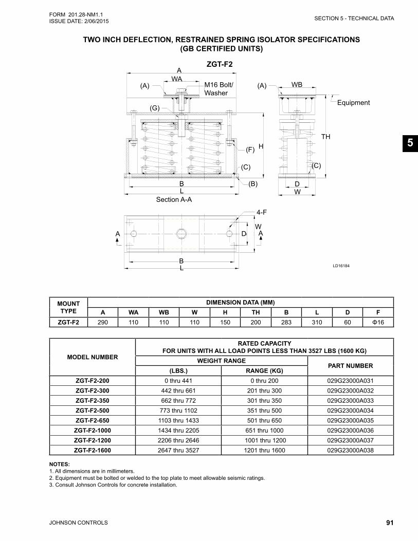
SECTION 5 - TECHNICAL DATA
JOHNSON CONTROLS 91
FORM 201.28-NM1.1ISSUE DATE: 2/06/2015
5
ZGT-F2
MOUNT TYPE
DIMENSION DATA (MM)A WA WB W H TH B L D F
ZGT-F2 290 110 110 110 150 200 283 310 60 Φ16
MODEL NUMBER
RATED CAPACITY FOR UNITS WITH ALL LOAD POINTS LESS THAN 3527 LBS (1600 KG)
WEIGHT RANGEPART NUMBER
(LBS.) RANGE (KG)ZGT-F2-200 0 thru 441 0 thru 200 029G23000A031ZGT-F2-300 442 thru 661 201 thru 300 029G23000A032ZGT-F2-350 662 thru 772 301 thru 350 029G23000A033ZGT-F2-500 773 thru 1102 351 thru 500 029G23000A034ZGT-F2-650 1103 thru 1433 501 thru 650 029G23000A035
ZGT-F2-1000 1434 thru 2205 651 thru 1000 029G23000A036ZGT-F2-1200 2206 thru 2646 1001 thru 1200 029G23000A037ZGT-F2-1600 2647 thru 3527 1201 thru 1600 029G23000A038
NOTES: 1. All dimensions are in millimeters. 2. Equipment must be bolted or welded to the top plate to meet allowable seismic ratings. 3. Consult Johnson Controls for concrete installation.
TWO INCH DEFLECTION, RESTRAINED SPRING ISOLATOR SPECIFICATIONS (GB CERTIFIED UNITS)
FORM_201.28-NM1.1.EN (1106) SECTION 5 - TECHNICAL DATA
JOHNSON CONTORLS 57
TWO INCH DEFLECTION, RESTRAINED SPRING ISOLATOR ZGT-F2
MOUNT TYPE DIMENSION DATA (mm)
A WA WB W H TH B L D F
ZGT-F2 290 110 110 110 150 200 283 310 60 16
MODEL NUMBER
RATED CAPACITY (FOR UNITS WITH ALL LOAD POINTS LESS THAN 3527
LBS (1600 KG) Weight Range
PART NUMBER (LBS.) (KG)
ZGT-F2-200 0 thru 441 0 thru 200 029G23000A031
ZGT-F2-300 442 thru 661 201 thru 300 029G23000A032
ZGT-F2-350 662 thru 772 301 thru 350 029G23000A033
ZGT-F2-500 773 thru 1102 351 thru 500 029G23000A034
ZGT-F2-650 1103 thru 1433 501 thru 650 029G23000A035
ZGT-F2-1000 1434 thru 2205 651 thru 1000 029G23000A036
ZGT-F2-1200 2206 thru 2646 1001 thru 1200 029G23000A037
ZGT-F2-1600 2647 thru 3527 1201 thru 1600 029G23000A038
Notes: 1. All dimensions are in millimeter.
2. Equipment must be bolted or welded to the top plate to meet allowable seismic ratings.
3. Consult JCI for concrete installation.
TH
WB
B
A
W
LH
WA
D A
D
L
Section A-A
W
(C)
(B)
(F)
(A)
Equipment
B
4-F
M16
Bolt/Washer
(G)
(A)
(C)
5
(A) (A)
A
A A
4-F
B
B
H
D
D
L
L
W
W
WAWB
Equipment
TH
M16 Bolt/Washer
Section A-A
(C)(C)
(F)
(B)
(G)
LD16184

JOHNSON CONTROLS92
FORM 201.28-NM1.1 ISSUE DATE: 2/06/2015
THIS PAGE INTENTIONALLY LEFT BLANK
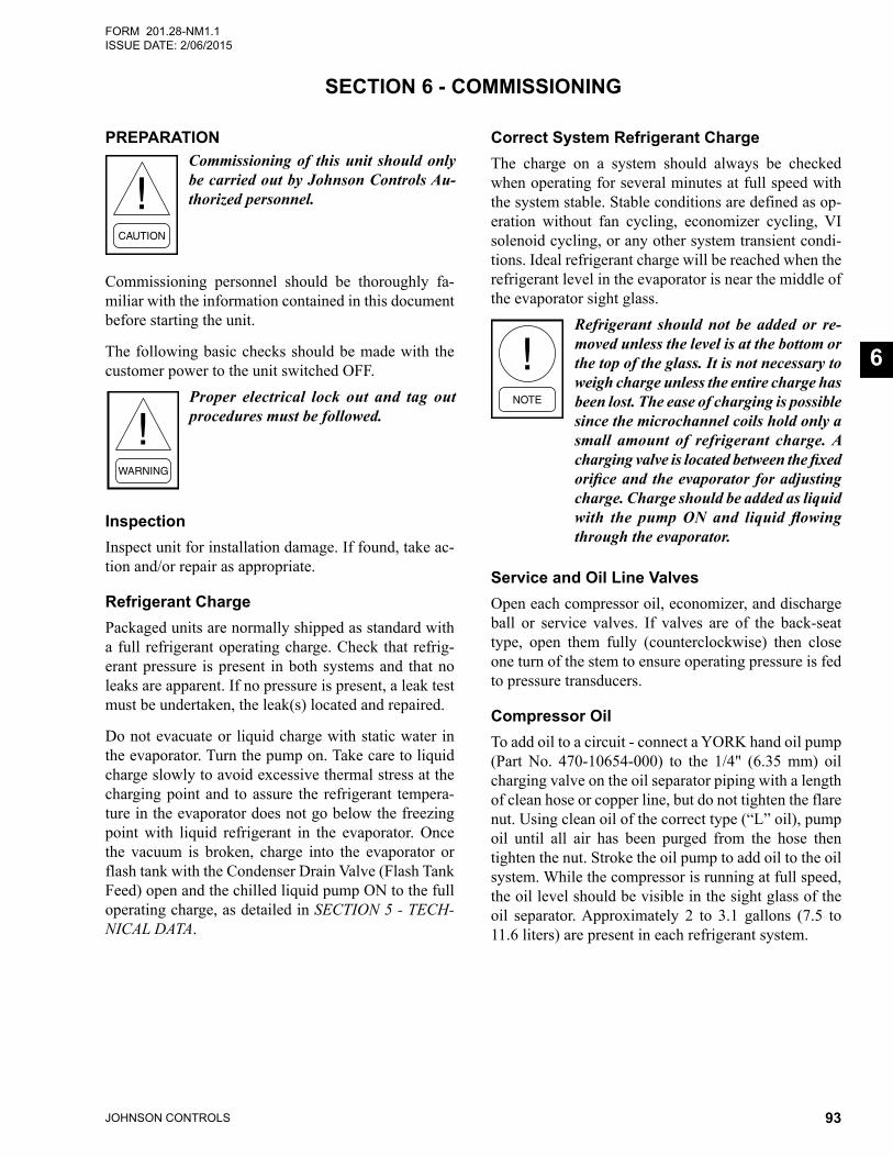
JOHNSON CONTROLS 93
FORM 201.28-NM1.1ISSUE DATE: 2/06/2015
6
SECTION 6 - COMMISSIONING
PREPARATIONCommissioning of this unit should only be carried out by Johnson Controls Au-thorized personnel.
Commissioning personnel should be thoroughly fa-miliar with the information contained in this document before starting the unit.
The following basic checks should be made with the customer power to the unit switched OFF.
Proper electrical lock out and tag out procedures must be followed.
Inspection Inspect unit for installation damage. If found, take ac-tion and/or repair as appropriate.
Refrigerant ChargePackaged units are normally shipped as standard with a full refrigerant operating charge. Check that refrig-erant pressure is present in both systems and that no leaks are apparent. If no pressure is present, a leak test must be undertaken, the leak(s) located and repaired.
Do not evacuate or liquid charge with static water in the evaporator. Turn the pump on. Take care to liquid charge slowly to avoid excessive thermal stress at the charging point and to assure the refrigerant tempera-ture in the evaporator does not go below the freezing point with liquid refrigerant in the evaporator. Once the vacuum is broken, charge into the evaporator or flash tank with the Condenser Drain Valve (Flash Tank Feed) open and the chilled liquid pump ON to the full operating charge, as detailed in SECTION 5 - TECH-NICAL DATA.
Correct System Refrigerant ChargeThe charge on a system should always be checked when operating for several minutes at full speed with the system stable. Stable conditions are defined as op-eration without fan cycling, economizer cycling, VI solenoid cycling, or any other system transient condi-tions. Ideal refrigerant charge will be reached when the refrigerant level in the evaporator is near the middle of the evaporator sight glass.
Refrigerant should not be added or re-moved unless the level is at the bottom or the top of the glass. It is not necessary to weigh charge unless the entire charge has been lost. The ease of charging is possible since the microchannel coils hold only a small amount of refrigerant charge. A charging valve is located between the fixed orifice and the evaporator for adjusting charge. Charge should be added as liquid with the pump ON and liquid flowing through the evaporator.
Service and Oil Line ValvesOpen each compressor oil, economizer, and discharge ball or service valves. If valves are of the back-seat type, open them fully (counterclockwise) then close one turn of the stem to ensure operating pressure is fed to pressure transducers.
Compressor OilTo add oil to a circuit - connect a YORK hand oil pump (Part No. 470-10654-000) to the 1/4" (6.35 mm) oil charging valve on the oil separator piping with a length of clean hose or copper line, but do not tighten the flare nut. Using clean oil of the correct type (“L” oil), pump oil until all air has been purged from the hose then tighten the nut. Stroke the oil pump to add oil to the oil system. While the compressor is running at full speed, the oil level should be visible in the sight glass of the oil separator. Approximately 2 to 3.1 gallons (7.5 to 11.6 liters) are present in each refrigerant system.
JOHNSON CONTROLS94
SECTION 6 - COMMISSIONINGFORM 201.28-NM1.1
ISSUE DATE: 2/06/2015
Avoid levels in either oil separator that are above the middle of the top sight glass. This may cause exces-sive oil carryover in the system. High oil concentration in the system may cause nuisance trips resulting from incorrect readings on the level sensor and temperature sensors. Temperature sensor errors may result in poor liquid control which will result in liquid overfeed and subsequently damage the compressor. High oil carry-over may also cause liquid to be returned to the com-pressor, which can damage the compressor.
Fans Check that all fans are free to rotate and are not dam-aged. Ensure blades are at the same height when ro-tated. Ensure fan guards are securely fixed.
Isolation / ProtectionVerify all sources of electrical supply to the unit are taken from a single point of isolation. Check that the maximum recommended fuse sizes given in SECTION 5 - TECHNICAL DATA has not been exceeded.
Control PanelCheck the panel to see that it is free of foreign materials (wire, metal chips, etc.) and clean out if required.
Power ConnectionsCheck that the customer power cables are connected cor-rectly to the terminal blocks or optional circuit breaker. Ensure that connections of power cables within the pan-els to the circuit breaker or terminal blocks are tight.
GroundingVerify that the unit’s protective ground terminal(s) are properly connected to a suitable grounding point. En-sure that all unit internal ground connections are tight.
Water SystemVerify the chilled liquid system has been installed cor-rectly, and has been commissioned with the correct di-rection of water flow through the evaporator. The inlet should be at the bottom connection on a two pass evapo-rator. Purge air from the top of the evaporator using the plugged air vent mounted on the top of the evaporator body.
Flow rates and pressure drops must be within the limits given in SECTION 5 - TECHNICAL DATA. Operation outside of these limits is undesirable and could cause damage.
If main power must be switched OFF for maintenance or shutdown, precautions must be taken. See Unit Maintenance and Shutdown in Sub-freezing Conditions on Page 96. Before placing the unit back in service, valves should be opened and power must be switched on (if power is removed for more than 8 hours) for at least 8 hours (24 hours if ambient temperature is below 86°F [30°C]) before the unit is restarted.
Flow SwitchVerify a chilled water flow switch is correctly fitted in the customer’s piping on the evaporator outlet, and wired into the control panel correctly using shielded cable.
There should be a straight run of at least five pipe diam-eters on either side of the flow switch. The flow switch should be connected to Terminals 2 and 13 in the panel.
Temperature Sensor(s)Ensure the leaving liquid temperature sensor is coated with heat conductive compound (Part No. 013-00890-000) and is inserted to the bottom of the water outlet sensor well in the evaporator. This sensor is part of the pump control freeze protection operation. It provides some freeze protection and must always be fully in-serted in the water outlet sensor well.
Programmed OptionsVerify that the options factory-programmed into the Micro Panel are in accordance with the customer’s order requirements by pressing the OPTIONS key on the keypad and reading the settings from the display.
Programmed Settings Ensure the system cutout and operational settings are in accordance with the operating requirements by press-ing the PROGRAM key.
Date and TimeProgram the date and time by first ensuring that the CLK jumper JP2 on the Chiller Control Board is in the ON position. Then press the DATE/TIME key and set the date and time (see SECTION 8 - MICROPANEL Date/Time and Schedule Keys on Page 132).
SECTION 6 - COMMISSIONING
JOHNSON CONTROLS 95
FORM 201.28-NM1.1ISSUE DATE: 2/06/2015
6
Start/Stop ScheduleProgram the daily and holiday start/stop by pressing the SCHEDULE key (see SECTION 8 - MICROPANEL Date/Time and Schedule Keys on Page 132).
Setpoint and Remote OffsetSet the required leaving chilled liquid temperature setpoint and Control Range under the SETPOINTS key. The chilled liquid temperature control settings need to be set according to the required operating conditions.
If remote temperature reset (offset) is to be used, the maximum reset required must be programmed by pressing the SETPOINTS key (see SECTION 8 - MICROPANEL Setpoints Key on Page 124).
FIRST TIME START UPDuring the commissioning period there should be sufficient heat load to run the unit under stable full load operation to enable the unit controls, and system op-eration to be set up correctly, and a com-missioning log taken.
InterlocksVerify that liquid is flowing through the evaporator and that heat load is present. Ensure that any remote run interlocks are in the run position and that the Daily Schedule requires the unit to run or is overridden.
Unit SwitchPlace the UNIT switch on the keypad to the ON position.
StartupPress the SYSTEM SWITCHES key and place the system switch for System 1 to the ON position. There may be a few seconds delay before the first compres-sor starts because of the anti-recycle timer). Be ready when each compressor starts, to switch the UNIT switch OFF immediately, if any unusual noises or oth-er adverse conditions develop.
When a compressor is running, the controller monitors oil pressure, motor current, and various other system parameters such as discharge pressure, chilled liquid temperature, etc. Should any problems occur; the con-trol system will immediately take appropriate action and display the nature of the fault.
Oil PressureWhen a compressor starts, press the relevant “System Pressures” key and verify that oil differential pressure (oil pressure-suction pressure) develops immediately. If oil pressure does not develop, the automatic con-trols will shut down the compressor. Under no circum-stances should a restart attempt be made on a compres-sor, which does not develop oil pressure immediately. Switch the UNIT switch to the OFF position.
LoadingOnce the unit has been started, all operations are fully automatic. After an initial period at minimum capacity, the control system will adjust the unit load depending on the chilled liquid temperature and rate of tempera-ture change. If a high heat load is present, the control-ler will increase the speed of the compressor(s).
Condenser and Fan RotationOnce a compressor is running, discharge pressure rises as refrigerant is pumped into the air-cooled condenser coils. This pressure is controlled by stages of fans to ensure maximum unit efficiency while maintaining sufficient pressure for correct operation of the con-densers and the lubrication system.
As discharge pressure rises, the condenser fans operate in stages or ramp up in speed to control the pressure. Verify that the fans operate in the correct direction of rotation and operation is correct for the type of unit.
System ChargeCheck system charge at steady full compressor load only. It is important that all fans are running for the system. The refrigerant level in the evaporator should be about in the middle of the sight glass. Unless lev-els are at the bottom or the top of the sight glass, they should not cause concern or require adding or remov-ing charge.
GENERAL OPERATION After completion of the above checks for System 1, switch OFF the SYS 1 switch on the keypad and repeat the process for each subsequent system. When all run correctly, stop the unit, switch all applicable switches to the ‘ON’ position and restart the unit.
Assure all checks are completed in the Equipment Pre - Startup and Startup Checklist. The chiller is then ready to be placed into operation.
JOHNSON CONTROLS96
SECTION 6 - COMMISSIONINGFORM 201.28-NM1.1
ISSUE DATE: 2/06/2015
Operation in Sub-freezing ConditionsThe YVAA may be operated in sub-freezing conditions if the following freeze protections are taken :
A. A suction service valve electric actuator is in-stalled. Chiller software will operate the actuator in order to protect against freezing due to evapo-rator refrigerant migration.
-or-
B. No suction service valve is installed but the water circuit valves are kept open, there is continuous power to the chiller and pump for chilled water pump control, and the pump will operate and cir-culate water through the evaporator whenever commanded by the chiller.
The above operation is only advised if uninterrupted power can be ensured. Un-foreseen power interruptions can damage the evaporator in a very short time frame if the temperature falls below freezing.
If there is potential for power loss, Johnson Controls recommends the water in the chilled water circuit be replaced with an appropriate water-to-glycol concen-tration.
Unit Maintenance and Shutdown in Sub-freezing Conditions If the YVAA is maintained or shut down and will be subjected to sub-freezing conditions, it is critical to protect against evaporator and waterbox freeze dam-age. Johnson Controls recommends the following op-tions (in order of freeze protection level) be performed on each circuit.
A. Glycol: Replace water with an appropriate water to glycol concentration of antifreeze.
-or-
B. Drain: Remove power to the waterbox heaters. Close the water valves, drain the evaporator, and leave the evaporator drain valves open.
-or-
C. Refrigerant Valve - Off: Close the water valves, close flash tank drain valves, close the suctionservice valves and leave power to the chiller for evaporator heater mat and waterbox heater op-eration. For units without a suction service valve, close the discharge and compressor oil valves.
-or-
D. Pump Control: Keep power to the chiller in or-der to have control over chilled water pumps and heater operation and leave the water circuit valves open. This will enable water to circulate through the evaporator to avoid freezing.
Options A and B are the recommended processes for unit maintenance and shutdown. Unforeseen power interrup-tions can damage the evaporator in a very short time frame if the temperature falls below freezing.
Failure to follow Johnson Controls freeze protection recommendations can void the warranty.
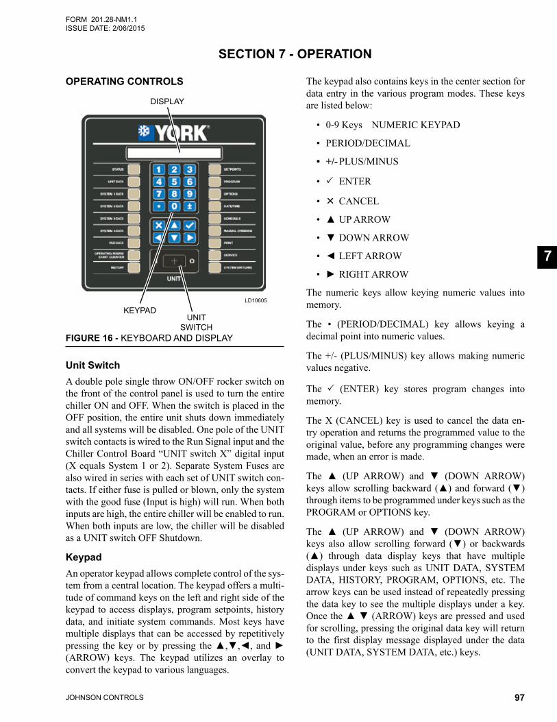
JOHNSON CONTROLS 97
FORM 201.28-NM1.1ISSUE DATE: 2/06/2015
7
SECTION 7 - OPERATION
OPERATING CONTROLS
Unit SwitchA double pole single throw ON/OFF rocker switch on the front of the control panel is used to turn the entire chiller ON and OFF. When the switch is placed in the OFF position, the entire unit shuts down immediately and all systems will be disabled. One pole of the UNIT switch contacts is wired to the Run Signal input and the Chiller Control Board “UNIT switch X” digital input (X equals System 1 or 2). Separate System Fuses are also wired in series with each set of UNIT switch con-tacts. If either fuse is pulled or blown, only the system with the good fuse (Input is high) will run. When both inputs are high, the entire chiller will be enabled to run. When both inputs are low, the chiller will be disabled as a UNIT switch OFF Shutdown.
KeypadAn operator keypad allows complete control of the sys-tem from a central location. The keypad offers a multi-tude of command keys on the left and right side of the keypad to access displays, program setpoints, history data, and initiate system commands. Most keys have multiple displays that can be accessed by repetitively pressing thekeyorbypressing the▲,▼,◄,and►(ARROW) keys. The keypad utilizes an overlay to convert the keypad to various languages.
LD10605
UNITSWITCH
KEYPAD
DISPLAY
FIGURE 16 - KEYBOARD AND DISPLAY
The keypad also contains keys in the center section for data entry in the various program modes. These keys are listed below:
• 0-9 Keys NUMERIC KEYPAD
• PERIOD/DECIMAL
• +/- PLUS/MINUS
• ENTER
• CANCEL
• ▲UPARROW
• ▼DOWNARROW
• ◄LEFTARROW
• ►RIGHTARROW
The numeric keys allow keying numeric values into memory.
The • (PERIOD/DECIMAL) key allows keying a decimal point into numeric values.
The +/- (PLUS/MINUS) key allows making numeric values negative.
The (ENTER) key stores program changes into memory.
The X (CANCEL) key is used to cancel the data en-try operation and returns the programmed value to the original value, before any programming changes were made, when an error is made.
The ▲ (UP ARROW) and ▼ (DOWN ARROW)keysallowscrollingbackward(▲)andforward(▼)through items to be programmed under keys such as the PROGRAM or OPTIONS key.
The ▲ (UP ARROW) and ▼ (DOWN ARROW)keys also allow scrolling forward (▼) or backwards(▲) through data display keys that have multipledisplays under keys such as UNIT DATA, SYSTEM DATA, HISTORY, PROGRAM, OPTIONS, etc. The arrow keys can be used instead of repeatedly pressing the data key to see the multiple displays under a key. Oncethe▲▼(ARROW)keysarepressedandusedfor scrolling, pressing the original data key will return to the first display message displayed under the data (UNIT DATA, SYSTEM DATA, etc.) keys.
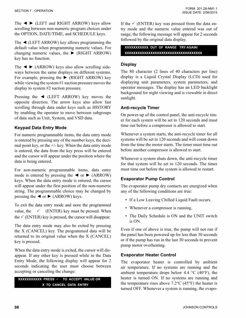
JOHNSON CONTROLS98
SECTION 7 - OPERATIONFORM 201.28-NM1.1
ISSUE DATE: 2/06/2015
The◄► (LEFT andRIGHTARROW)keys allowscrolling between non-numeric program choices under the OPTION, DATE/TIME, and SCHEDULE keys.
The◄(LEFTARROW)keyallowsprogrammingthedefault value when programming numeric values. For changing numeric values, the► (RIGHTARROW)key has no function.
The◄►(ARROW)keysalsoallowscrollingside-ways between the same displays on different systems. Forexample,pressing the►(RIGHTARROW)keywhile viewing the system #1 suction pressure moves the display to system #2 suction pressure.
Pressing the ◄ (LEFT ARROW) key moves the opposite direction. The arrow keys also allow fast scrolling through data under keys such as HISTORY by enabling the operator to move between subgroups of data such as Unit, System, and VSD data.
Keypad Data Entry ModeFor numeric programmable items, the data entry mode is entered by pressing any of the number keys, the deci-mal point key, or the +/- key. When the data entry mode is entered, the data from the key press will be entered and the cursor will appear under the position where the data is being entered.
For non-numeric programmable items, data entry mode isenteredbypressing the◄or►(ARROW)keys. When the data entry mode is entered, the cursor will appear under the first position of the non-numeric string. The programmable choice may be changed by pressingthe◄or►(ARROW)keys.
To exit the data entry mode and store the programmed value, the (ENTER) key must be pressed. When the (ENTER) key is pressed, the cursor will disappear.
The data entry mode may also be exited by pressing the X (CANCEL) key. The programmed data will be returned to its original value when the X (CANCEL) key is pressed.
When the data entry mode is exited, the cursor will dis-appear. If any other key is pressed while in the Data Entry Mode, the following display will appear for 2 seconds indicating the user must choose between accepting or canceling the change:
XXXXXXXXXXX PRESS TO ACCEPT VALUE OR
X TO CANCEL DATA ENTRY
If the (ENTER) key was pressed from the data en-try mode and the numeric value entered was out of range, the following message will appear for 2 seconds followed by the original data display.
XXXXXXXXXXX OUT OF RANGE TRY AGAIN!
XXXXXXXXXXXXXXXXXXXXXXXXXXXXXXXXXXXX
DisplayThe 80 character (2 lines of 40 characters per line) display is a Liquid Crystal Display (LCD) used for displaying unit parameters, system parameters, and operator messages. The display has an LED backlight background for night viewing and is viewable in direct sunlight.
Anti-recycle TimerOn power-up of the control panel, the anti-recycle tim-er for each system will be set to 120 seconds and must time out before a compressor is allowed to start.
Whenever a system starts, the anti-recycle timer for all systems will be set to 120 seconds and will count down from the time the motor starts. The timer must time out before another compressor is allowed to start.
Whenever a system shuts down, the anti-recycle timer for that system will be set to 120 seconds. The timer must time out before the system is allowed to restart.
Evaporator Pump ControlThe evaporator pump dry contacts are energized when any of the following conditions are true:
• If a Low Leaving Chilled Liquid Fault occurs.
• Whenever a compressor is running.
• The Daily Schedule is ON and the UNIT switch is ON.
Even if one of above is true, the pump will not run if the panel has been powered up for less than 30 seconds or if the pump has run in the last 30 seconds to prevent pump motor overheating.
Evaporator Heater ControlThe evaporator heater is controlled by ambient air temperature. If no systems are running and the ambient temperature drops below 4.4 °C (40°F), the heater is turned ON. If no systems are running and the temperature rises above 7.2°C (45°F) the heater is turned OFF. Whenever a system is running, the evapo-
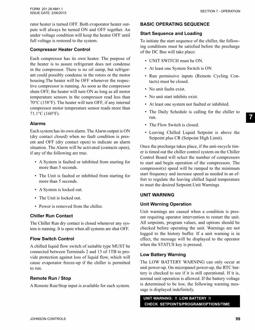
SECTION 7 - OPERATION
JOHNSON CONTROLS 99
FORM 201.28-NM1.1ISSUE DATE: 2/06/2015
7
rator heater is turned OFF. Both evaporator heater out-puts will always be turned ON and OFF together. An under voltage condition will keep the heater OFF until full voltage is restored to the system.
Compressor Heater Control
Each compressor has its own heater. The purpose of the heater is to assure refrigerant does not condense in the compressor. There is no oil sump, but refriger-ant could possibly condense in the rotors or the motor housing.The heater will be OFF whenever the respec-tive compressor is running. As soon as the compressor shuts OFF, the heater will turn ON as long as all motor temperature sensors in the compressor read less than 70°C (158°F). The heater will turn OFF, if any internal compressor motor temperature sensor reads more than 71.1°C (160°F).
AlarmsEach system has its own alarm. The Alarm output is ON (dry contact closed) when no fault condition is pres-ent and OFF (dry contact open) to indicate an alarm situation. The Alarm will be activated (contacts open), if any of the following are true.
• A System is faulted or inhibited from starting for more than 5 seconds.
• The Unit is faulted or inhibited from starting for more than 5 seconds.
• A System is locked out.
• The Unit is locked out.
• Power is removed from the chiller.
Chiller Run ContactThe Chiller Run dry contact is closed whenever any sys-tem is running. It is open when all systems are shut OFF.
Flow Switch ControlA chilled liquid flow switch of suitable type MUST be connected between Terminals 2 and 13 of 1TB to pro-vide protection against loss of liquid flow, which will cause evaporator freeze-up if the chiller is permitted to run.
Remote Run / StopA Remote Run/Stop input is available for each system.
BASIC OPERATING SEQUENCE
Start Sequence and LoadingTo initiate the start sequence of the chiller, the follow-ing conditions must be satisfied before the precharge of the DC Bus will take place:
• UNIT SWITCH must be ON.
• At least one System Switch is ON
• Run permissive inputs (Remote Cycling Con-tacts) must be closed.
• No unit faults exist.
• No unit start inhibits exist.
• At least one system not faulted or inhibited.
• The Daily Schedule is calling for the chiller to run.
• The Flow Switch is closed.
• Leaving Chilled Liquid Setpoint is above the Setpoint plus CR (Setpoint High Limit).
Once the precharge takes place, if the anti-recycle tim-er is timed out the chiller control system on the Chiller Control Board will select the number of compressors to start and begin operation of the compressors. The compressor(s) speed will be ramped to the minimum start frequency and increase speed as needed in an ef-fort to regulate the leaving chilled liquid temperature to meet the desired Setpoint.Unit Warnings
UNIT WARNING
Unit Warning OperationUnit warnings are caused when a condition is pres-ent requiring operator intervention to restart the unit. All setpoints, program values, and options should be checked before operating the unit. Warnings are not logged to the history buffer. If a unit warning is in effect, the message will be displayed to the operator when the STATUS key is pressed.
Low Battery WarningThe LOW BATTERY WARNING can only occur at unit power-up. On micropanel power-up, the RTC bat-tery is checked to see if it is still operational. If it is, normal unit operation is allowed. If the battery voltage is determined to be low, the following warning mes-sage is displayed indefinitely.
UNIT WARNING: !! LOW BATTERY !! CHECK SETPOINTS/PROGRAM/OPTIONS/TIME
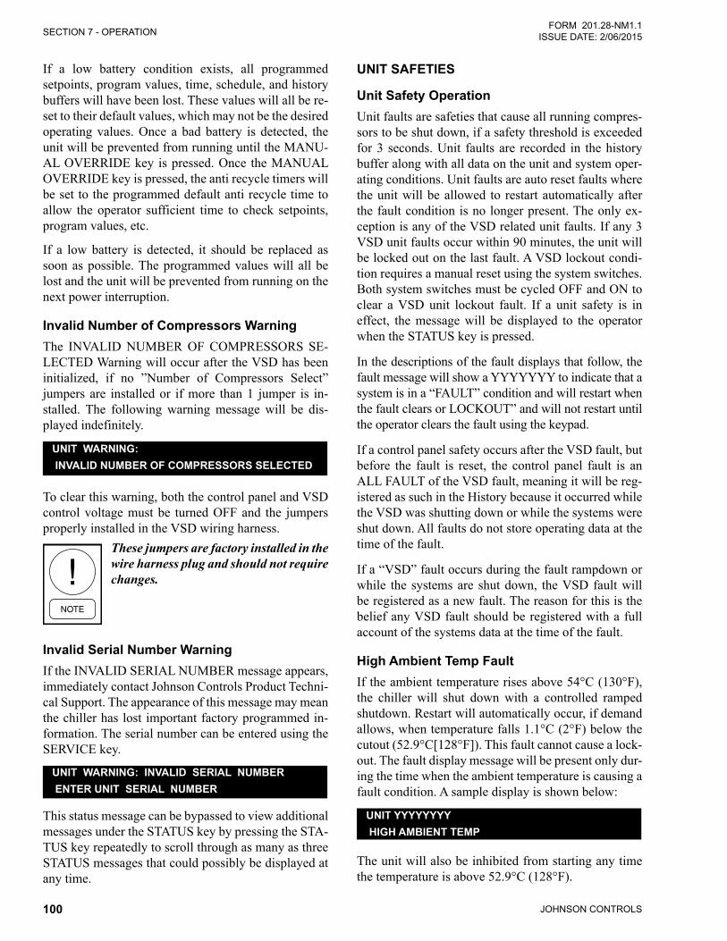
JOHNSON CONTROLS100
SECTION 7 - OPERATIONFORM 201.28-NM1.1
ISSUE DATE: 2/06/2015
If a low battery condition exists, all programmed setpoints, program values, time, schedule, and history buffers will have been lost. These values will all be re-set to their default values, which may not be the desired operating values. Once a bad battery is detected, the unit will be prevented from running until the MANU-AL OVERRIDE key is pressed. Once the MANUAL OVERRIDE key is pressed, the anti recycle timers will be set to the programmed default anti recycle time to allow the operator sufficient time to check setpoints, program values, etc.
If a low battery is detected, it should be replaced as soon as possible. The programmed values will all be lost and the unit will be prevented from running on the next power interruption.
Invalid Number of Compressors WarningThe INVALID NUMBER OF COMPRESSORS SE-LECTED Warning will occur after the VSD has been initialized, if no ”Number of Compressors Select” jumpers are installed or if more than 1 jumper is in-stalled. The following warning message will be dis-played indefinitely.
UNIT WARNING: INVALID NUMBER OF COMPRESSORS SELECTED
To clear this warning, both the control panel and VSD control voltage must be turned OFF and the jumpers properly installed in the VSD wiring harness.
These jumpers are factory installed in the wire harness plug and should not require changes.
Invalid Serial Number WarningIf the INVALID SERIAL NUMBER message appears, immediately contact Johnson Controls Product Techni-cal Support. The appearance of this message may mean the chiller has lost important factory programmed in-formation. The serial number can be entered using the SERVICE key.
UNIT WARNING: INVALID SERIAL NUMBER ENTER UNIT SERIAL NUMBER
This status message can be bypassed to view additional messages under the STATUS key by pressing the STA-TUS key repeatedly to scroll through as many as three STATUS messages that could possibly be displayed at any time.
UNIT SAFETIES
Unit Safety OperationUnit faults are safeties that cause all running compres-sors to be shut down, if a safety threshold is exceeded for 3 seconds. Unit faults are recorded in the history buffer along with all data on the unit and system oper-ating conditions. Unit faults are auto reset faults where the unit will be allowed to restart automatically after the fault condition is no longer present. The only ex-ception is any of the VSD related unit faults. If any 3 VSD unit faults occur within 90 minutes, the unit will be locked out on the last fault. A VSD lockout condi-tion requires a manual reset using the system switches. Both system switches must be cycled OFF and ON to clear a VSD unit lockout fault. If a unit safety is in effect, the message will be displayed to the operator when the STATUS key is pressed.
In the descriptions of the fault displays that follow, the fault message will show a YYYYYYY to indicate that a system is in a “FAULT” condition and will restart when the fault clears or LOCKOUT” and will not restart until the operator clears the fault using the keypad.
If a control panel safety occurs after the VSD fault, but before the fault is reset, the control panel fault is an ALL FAULT of the VSD fault, meaning it will be reg-istered as such in the History because it occurred while the VSD was shutting down or while the systems were shut down. All faults do not store operating data at the time of the fault.
If a “VSD” fault occurs during the fault rampdown or while the systems are shut down, the VSD fault will be registered as a new fault. The reason for this is the belief any VSD fault should be registered with a full account of the systems data at the time of the fault.
High Ambient Temp FaultIf the ambient temperature rises above 54°C (130°F), the chiller will shut down with a controlled ramped shutdown. Restart will automatically occur, if demand allows, when temperature falls 1.1°C (2°F) below the cutout (52.9°C[128°F]). This fault cannot cause a lock-out. The fault display message will be present only dur-ing the time when the ambient temperature is causing a fault condition. A sample display is shown below:
UNIT YYYYYYYY HIGH AMBIENT TEMP
The unit will also be inhibited from starting any time the temperature is above 52.9°C (128°F).
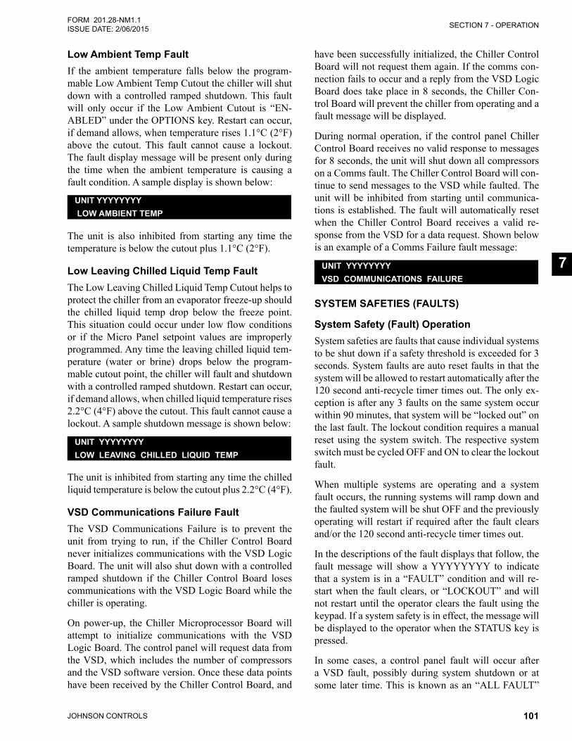
SECTION 7 - OPERATION
JOHNSON CONTROLS 101
FORM 201.28-NM1.1ISSUE DATE: 2/06/2015
7
Low Ambient Temp FaultIf the ambient temperature falls below the program-mable Low Ambient Temp Cutout the chiller will shut down with a controlled ramped shutdown. This fault will only occur if the Low Ambient Cutout is “EN-ABLED” under the OPTIONS key. Restart can occur, if demand allows, when temperature rises 1.1°C (2°F) above the cutout. This fault cannot cause a lockout. The fault display message will be present only during the time when the ambient temperature is causing a fault condition. A sample display is shown below:
UNIT YYYYYYYY LOW AMBIENT TEMP
The unit is also inhibited from starting any time the temperature is below the cutout plus 1.1°C (2°F).
Low Leaving Chilled Liquid Temp FaultThe Low Leaving Chilled Liquid Temp Cutout helps to protect the chiller from an evaporator freeze-up should the chilled liquid temp drop below the freeze point. This situation could occur under low flow conditions or if the Micro Panel setpoint values are improperly programmed. Any time the leaving chilled liquid tem-perature (water or brine) drops below the program-mable cutout point, the chiller will fault and shutdown with a controlled ramped shutdown. Restart can occur, if demand allows, when chilled liquid temperature rises 2.2°C (4°F) above the cutout. This fault cannot cause a lockout. A sample shutdown message is shown below:
UNIT YYYYYYYYLOW LEAVING CHILLED LIQUID TEMP
The unit is inhibited from starting any time the chilled liquid temperature is below the cutout plus 2.2°C (4°F).
VSD Communications Failure FaultThe VSD Communications Failure is to prevent the unit from trying to run, if the Chiller Control Board never initializes communications with the VSD Logic Board. The unit will also shut down with a controlled ramped shutdown if the Chiller Control Board loses communications with the VSD Logic Board while the chiller is operating.
On power-up, the Chiller Microprocessor Board will attempt to initialize communications with the VSD Logic Board. The control panel will request data from the VSD, which includes the number of compressors and the VSD software version. Once these data points have been received by the Chiller Control Board, and
have been successfully initialized, the Chiller Control Board will not request them again. If the comms con-nection fails to occur and a reply from the VSD Logic Board does take place in 8 seconds, the Chiller Con-trol Board will prevent the chiller from operating and a fault message will be displayed.
During normal operation, if the control panel Chiller Control Board receives no valid response to messages for 8 seconds, the unit will shut down all compressors on a Comms fault. The Chiller Control Board will con-tinue to send messages to the VSD while faulted. The unit will be inhibited from starting until communica-tions is established. The fault will automatically reset when the Chiller Control Board receives a valid re-sponse from the VSD for a data request. Shown below is an example of a Comms Failure fault message:
UNIT YYYYYYYYVSD COMMUNICATIONS FAILURE
SYSTEM SAFETIES (FAULTS)
System Safety (Fault) OperationSystem safeties are faults that cause individual systems to be shut down if a safety threshold is exceeded for 3 seconds. System faults are auto reset faults in that the system will be allowed to restart automatically after the 120 second anti-recycle timer times out. The only ex-ception is after any 3 faults on the same system occur within 90 minutes, that system will be “locked out” on the last fault. The lockout condition requires a manual reset using the system switch. The respective system switch must be cycled OFF and ON to clear the lockout fault.
When multiple systems are operating and a system fault occurs, the running systems will ramp down and the faulted system will be shut OFF and the previously operating will restart if required after the fault clears and/or the 120 second anti-recycle timer times out.
In the descriptions of the fault displays that follow, the fault message will show a YYYYYYYY to indicate that a system is in a “FAULT” condition and will re-start when the fault clears, or “LOCKOUT” and will not restart until the operator clears the fault using the keypad. If a system safety is in effect, the message will be displayed to the operator when the STATUS key is pressed.
In some cases, a control panel fault will occur after a VSD fault, possibly during system shutdown or at some later time. This is known as an “ALL FAULT”
JOHNSON CONTROLS102
SECTION 7 - OPERATIONFORM 201.28-NM1.1
ISSUE DATE: 2/06/2015
and these faults will be recorded as such under the HISTORY information stored at the instant of the pri-mary fault. In some cases, this information may be valuable in troubleshooting the primary fault. An ex-ample of the “ALL FAULT” history message is shown on page 118 under the HISTORY key. When an “ALL FAULT” occurs, associated history information will not be stored. If an additional fault does not occur, the “ALL FAULTS” display will indicate NONE.
In cases where a VSD fault occurs during the ramp-down of a control panel fault (i.e.: low suction pressure, low water temp, etc.), the VSD fault will be stored as a new fault with the associated fault information stored at the instant the VSD fault occurred (i.e.: IGBT Gate Drive, Single Phase Input, VSD CT Plug, etc.). The control panel fault that occurred prior to the VSD fault will be stored with the associated complete data related to the fault as a numerically lower numbered history in the history buffers.
High Discharge Pressure Cutout (Software) FaultThe High Discharge Pressure Cutout is a software fault. A system will fault and shut down with a con-trolled ramped shutdown on high discharge pressure when the discharge pressure rises above 22.4 barg (325 PSIG) for 0.5 seconds. The system will be allowed to restart when the discharge pressure falls to 20.3 barg (295 PSIG). The system will also be inhibited from starting if the pressure is above 20.3 barg (295 PSIG). The fault message for this safety is shown below:
SYS X YYYYYYYY HIGH DISCHARGE PRESSURE
The X indicates the system and YYYYYYYY indi-cates the system is in a “FAULT” condition and will restart when the 120 second anti-recycle timer times out, or “LOCKOUT” and will not restart until the op-erator clears the fault using the keypad.
High Discharge Pressure Cutout (HPCO) (Hardware) Fault The mechanical High Pressure Cutout protects the system from experiencing dangerously high discharge pressure. A system will fault and shut down immedi-ately when the mechanical high pressure cutout con-tacts open. The fault will occur immediately and not wait 3 seconds, which is typical of most system faults. The HPCO is wired in series with the VSD Run Signal and will only be checked by the Chiller Control Board
when the system is running. The mechanical cutout opens at 23.2 barg ± 0.55 barg (337 PSIG ± 8 PSIG) and closes at 17.4 barg ± 0.69 barg (252 PSIG ± 10 PSIG). The Status display fault message for this sys-tem is shown below:
SYS X YYYYYYYY HPCO FAULT
The X indicates the system and YYYYYYY indicates the system is in a “FAULT” condition and will restart when the 120 second anti-recycle timer times out or “LOCKOUT” and will not restart until the operator clears the fault using the keypad.
Low Suction Pressure Cutout (Software) FaultThe programmable Low Suction Pressure Cutout is a secondary back-up for the flow switch and protects against operation with low refrigerant charge, which helps protect the chiller from an evaporator freeze-up, should the system attempt to run with a low refrigerant charge. The Status display fault message for this cut-out is shown below:
SYS X YYYYYYYY LOW SUCTION PRESSURE
The X indicates the system and YYYYYYY indicates the system is in a “FAULT” condition and will restart when the 120 second anti-recycle timer times out or “LOCKOUT” and will not restart until the operator clears the fault using the keypad. Typically, the cutout will be set at 1.65 barg (24 PSIG) for chilled water ap-plications.
The cutout is ignored for the first 30 seconds of system run time. During the next 3 minutes of run time the cutout point is linearly ramped from 10% of the cutout value up to the programmed cutout point. If at any time during the first 3 minutes of operation the suction pres-sure falls below the ramped cutout point, the system will shut down with a controlled ramped shutdown.
The cutout pressure during operating periods of 30 sec-onds to 210 seconds is ramped and can be calculated by:
After the first 3 minutes and 30 seconds of run time, if the suction pressure falls below the cutout as a result of a transient in the system, a transient timer is set at 30 seconds and a linearly ramped cutout is set start-ing at 10% of the programmed cutout. If over the next
����������������������������������� �����������
���
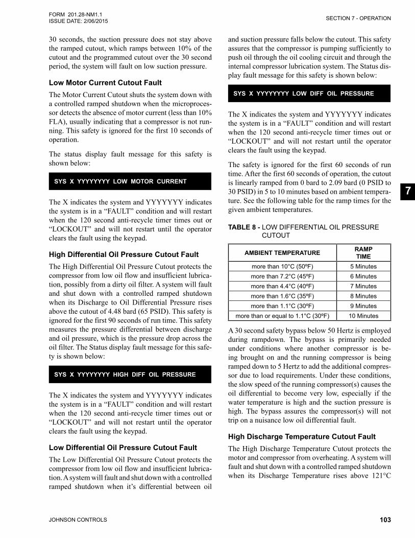
SECTION 7 - OPERATION
JOHNSON CONTROLS 103
FORM 201.28-NM1.1ISSUE DATE: 2/06/2015
7
30 seconds, the suction pressure does not stay above the ramped cutout, which ramps between 10% of the cutout and the programmed cutout over the 30 second period, the system will fault on low suction pressure.
Low Motor Current Cutout FaultThe Motor Current Cutout shuts the system down with a controlled ramped shutdown when the microproces-sor detects the absence of motor current (less than 10% FLA), usually indicating that a compressor is not run-ning. This safety is ignored for the first 10 seconds of operation.
The status display fault message for this safety is shown below:
SYS X YYYYYYYY LOW MOTOR CURRENT
The X indicates the system and YYYYYYY indicates the system is in a “FAULT” condition and will restart when the 120 second anti-recycle timer times out or “LOCKOUT” and will not restart until the operator clears the fault using the keypad.
High Differential Oil Pressure Cutout FaultThe High Differential Oil Pressure Cutout protects the compressor from low oil flow and insufficient lubrica-tion, possibly from a dirty oil filter. A system will fault and shut down with a controlled ramped shutdown when its Discharge to Oil Differential Pressure rises above the cutout of 4.48 bard (65 PSID). This safety is ignored for the first 90 seconds of run time. This safety measures the pressure differential between discharge and oil pressure, which is the pressure drop across the oil filter. The Status display fault message for this safe-ty is shown below:
SYS X YYYYYYYY HIGH DIFF OIL PRESSURE
The X indicates the system and YYYYYYY indicates the system is in a “FAULT” condition and will restart when the 120 second anti-recycle timer times out or “LOCKOUT” and will not restart until the operator clears the fault using the keypad.
Low Differential Oil Pressure Cutout FaultThe Low Differential Oil Pressure Cutout protects the compressor from low oil flow and insufficient lubrica-tion. A system will fault and shut down with a controlled ramped shutdown when it’s differential between oil
and suction pressure falls below the cutout. This safety assures that the compressor is pumping sufficiently to push oil through the oil cooling circuit and through the internal compressor lubrication system. The Status dis-play fault message for this safety is shown below:
SYS X YYYYYYYY LOW DIFF OIL PRESSURE
The X indicates the system and YYYYYYY indicates the system is in a “FAULT” condition and will restart when the 120 second anti-recycle timer times out or “LOCKOUT” and will not restart until the operator clears the fault using the keypad.
The safety is ignored for the first 60 seconds of run time. After the first 60 seconds of operation, the cutout is linearly ramped from 0 bard to 2.09 bard (0 PSID to 30 PSID) in 5 to 10 minutes based on ambient tempera-ture. See the following table for the ramp times for the given ambient temperatures.
TABLE 8 - LOW DIFFERENTIAL OIL PRESSURE CUTOUT
AMBIENT TEMPERATURE RAMP TIME
more than 10°C (50ºF) 5 Minutesmore than 7.2°C (45ºF) 6 Minutesmore than 4.4°C (40ºF) 7 Minutesmore than 1.6°C (35ºF) 8 Minutesmore than 1.1°C (30ºF) 9 Minutes
more than or equal to 1.1°C (30ºF) 10 Minutes
A 30 second safety bypass below 50 Hertz is employed during rampdown. The bypass is primarily needed under conditions where another compressor is be-ing brought on and the running compressor is being ramped down to 5 Hertz to add the additional compres-sor due to load requirements. Under these conditions, the slow speed of the running compressor(s) causes the oil differential to become very low, especially if the water temperature is high and the suction pressure is high. The bypass assures the compressor(s) will not trip on a nuisance low oil differential fault.
High Discharge Temperature Cutout FaultThe High Discharge Temperature Cutout protects the motor and compressor from overheating. A system will fault and shut down with a controlled ramped shutdown when its Discharge Temperature rises above 121°C
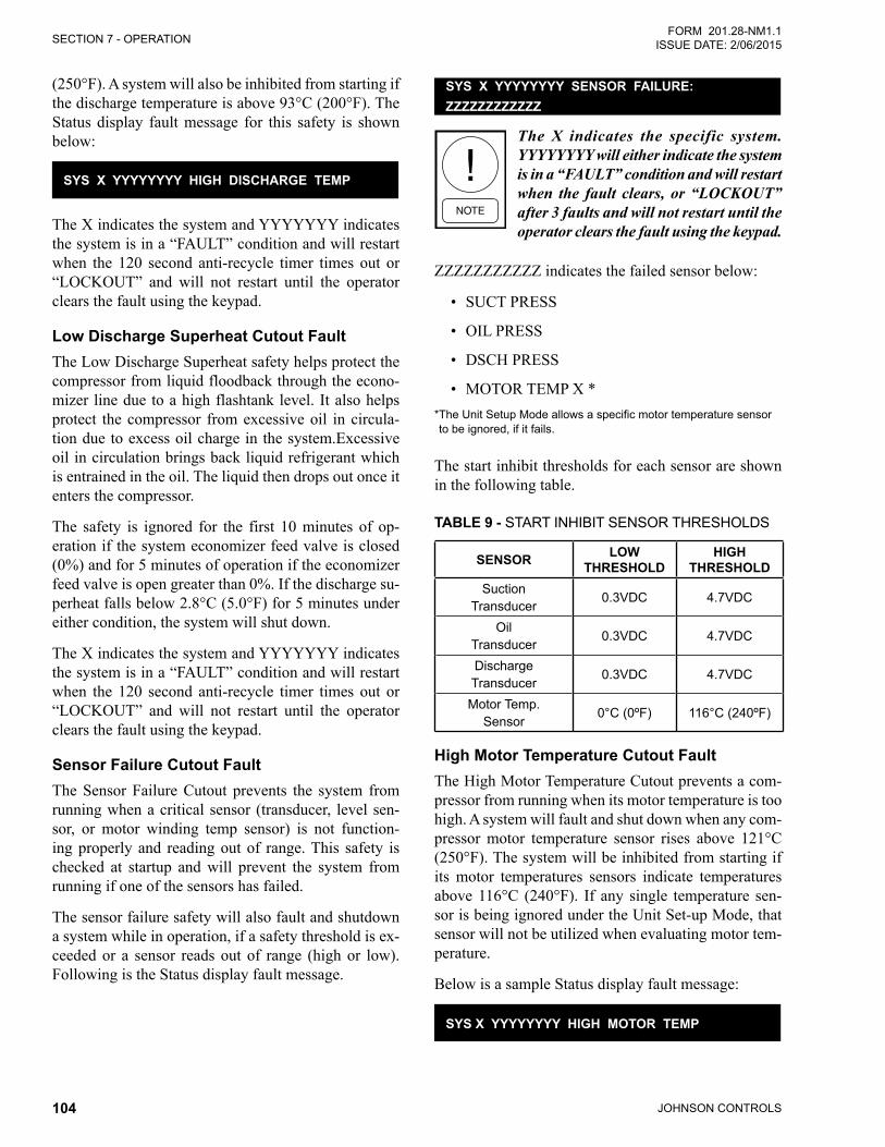
JOHNSON CONTROLS104
SECTION 7 - OPERATIONFORM 201.28-NM1.1
ISSUE DATE: 2/06/2015
(250°F). A system will also be inhibited from starting if the discharge temperature is above 93°C (200°F). The Status display fault message for this safety is shown below:
SYS X YYYYYYYY HIGH DISCHARGE TEMP
The X indicates the system and YYYYYYY indicates the system is in a “FAULT” condition and will restart when the 120 second anti-recycle timer times out or “LOCKOUT” and will not restart until the operator clears the fault using the keypad.
Low Discharge Superheat Cutout FaultThe Low Discharge Superheat safety helps protect the compressor from liquid floodback through the econo-mizer line due to a high flashtank level. It also helps protect the compressor from excessive oil in circula-tion due to excess oil charge in the system.Excessive oil in circulation brings back liquid refrigerant which is entrained in the oil. The liquid then drops out once it enters the compressor.
The safety is ignored for the first 10 minutes of op-eration if the system economizer feed valve is closed (0%) and for 5 minutes of operation if the economizer feed valve is open greater than 0%. If the discharge su-perheat falls below 2.8°C (5.0°F) for 5 minutes under either condition, the system will shut down.
The X indicates the system and YYYYYYY indicates the system is in a “FAULT” condition and will restart when the 120 second anti-recycle timer times out or “LOCKOUT” and will not restart until the operator clears the fault using the keypad.
Sensor Failure Cutout FaultThe Sensor Failure Cutout prevents the system from running when a critical sensor (transducer, level sen-sor, or motor winding temp sensor) is not function-ing properly and reading out of range. This safety is checked at startup and will prevent the system from running if one of the sensors has failed.
The sensor failure safety will also fault and shutdown a system while in operation, if a safety threshold is ex-ceeded or a sensor reads out of range (high or low).Following is the Status display fault message.
SYS X YYYYYYYY SENSOR FAILURE: ZZZZZZZZZZZZ
The X indicates the specific system.YYYYYYYY will either indicate the system is in a “FAULT” condition and will restart when the fault clears, or “LOCKOUT” after 3 faults and will not restart until the operator clears the fault using the keypad.
ZZZZZZZZZZZ indicates the failed sensor below:
• SUCT PRESS
• OIL PRESS
• DSCH PRESS
• MOTOR TEMP X ** The Unit Setup Mode allows a specific motor temperature sensor to be ignored, if it fails.
The start inhibit thresholds for each sensor are shown in the following table.
TABLE 9 - START INHIBIT SENSOR THRESHOLDS
SENSOR LOW THRESHOLD
HIGH THRESHOLD
Suction Transducer
0.3VDC 4.7VDC
Oil Transducer
0.3VDC 4.7VDC
Discharge Transducer
0.3VDC 4.7VDC
Motor Temp. Sensor
0°C (0ºF) 116°C (240ºF)
High Motor Temperature Cutout FaultThe High Motor Temperature Cutout prevents a com-pressor from running when its motor temperature is too high. A system will fault and shut down when any com-pressor motor temperature sensor rises above 121°C (250°F). The system will be inhibited from starting if its motor temperatures sensors indicate temperatures above 116°C (240°F). If any single temperature sen-sor is being ignored under the Unit Set-up Mode, that sensor will not be utilized when evaluating motor tem-perature.
Below is a sample Status display fault message:
SYS X YYYYYYYY HIGH MOTOR TEMP
SECTION 7 - OPERATION
JOHNSON CONTROLS 105
FORM 201.28-NM1.1ISSUE DATE: 2/06/2015
7
The X indicates the system and YYYYYYY indicates the system is in a “FAULT” condition and will restart when the fault clears or “LOCKOUT” and will not re-start until the operator clears the fault using the keypad.
System Control Voltage Cutout FaultThe System Control Voltage Cutout alerts the operator the 115VAC Control voltage to one of the systems is missing. This could be due to a system fuse that has been removed or is blown. The affected system will fault and shut down immediately when the 115VAC supply is lost.
The safety will “not” shut down a system if the UNIT switch is OFF, which electrically removes the 115VAC to “all” systems. The safety is only used to indicate a situation where a single system is missing the 115VAC.The safety will not cause a lockout and the system fault will reset when power is returned. A sample message is shown below:
SYS X YYYYYYYY CONTROL VOLTAGE
The X indicates the system and YYYYYYY indicates the system is in a “FAULT” condition and will restart when the fault clears or “LOCKOUT” and will not re-start until the operator clears the fault using the keypad.
Eductor Clog FaultTo sense a loss of oil return to the compressor, an educ-tor clog detection safety is utilized. The safety moni-tors the temperature of the line between the eductor and the suction line.
The control algorithm looks at the eductor line temper-ature once a second. At start, a clog timer is set at 600 seconds. If the eductor line temperature is less than the saturated suction temperature plus 5.5°C (10°F) each time the control circuit looks at the temperature, the clog timer is reset to 600 seconds.
If the eductor line temperatures is greater than the satu-rated suction temperature plus 5.5°C (10°F), the clog timer is decremented one second. If the temperature remains above the saturated suction temperature plus 5.5°C (10°F) for 600 seconds, the clog timer will count to “0” and the system will shut down and lock out. The status fault will indicate an eductor clog fault.
EDUCTOR CLOG FAULT
Whenever this fault occurs, the eductor filter should be changed.
The clog timer resets to 600 seconds whenever the con-trol algorithm sees the eductor line temperature is less than the saturated suction pressure plus 5.5°C (10°F). This prevents nuisance eductor clog faults.

JOHNSON CONTROLS106
FORM 201.28-NM1.1 ISSUE DATE: 2/06/2015
THIS PAGE INTENTIONALLY LEFT BLANK.
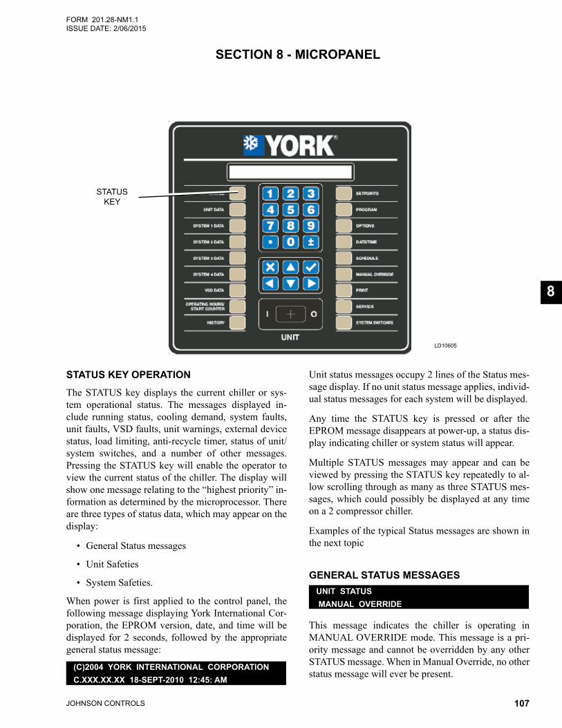
JOHNSON CONTROLS 107
FORM 201.28-NM1.1ISSUE DATE: 2/06/2015
8
LD10605
STATUS KEY
STATUS KEY OPERATIONThe STATUS key displays the current chiller or sys-tem operational status. The messages displayed in-clude running status, cooling demand, system faults, unit faults, VSD faults, unit warnings, external device status, load limiting, anti-recycle timer, status of unit/system switches, and a number of other messages. Pressing the STATUS key will enable the operator to view the current status of the chiller. The display will show one message relating to the “highest priority” in-formation as determined by the microprocessor. There are three types of status data, which may appear on the display:
• General Status messages
• Unit Safeties
• System Safeties.
When power is first applied to the control panel, the following message displaying York International Cor-poration, the EPROM version, date, and time will be displayed for 2 seconds, followed by the appropriate general status message:
(C)2004 YORK INTERNATIONAL CORPORATIONC.XXX.XX.XX 18-SEPT-2010 12:45: AM
Unit status messages occupy 2 lines of the Status mes-sage display. If no unit status message applies, individ-ual status messages for each system will be displayed.
Any time the STATUS key is pressed or after the EPROM message disappears at power-up, a status dis-play indicating chiller or system status will appear.
Multiple STATUS messages may appear and can be viewed by pressing the STATUS key repeatedly to al-low scrolling through as many as three STATUS mes-sages, which could possibly be displayed at any time on a 2 compressor chiller.
Examples of the typical Status messages are shown in the next topic
GENERAL STATUS MESSAGESUNIT STATUS MANUAL OVERRIDE
This message indicates the chiller is operating in MANUAL OVERRIDE mode. This message is a pri-ority message and cannot be overridden by any other STATUS message. When in Manual Override, no other status message will ever be present.
SECTION 8 - MICROPANEL
JOHNSON CONTROLS108
SECTION 8 - MICROPANELFORM 201.28-NM1.1
ISSUE DATE: 2/06/2015
UNIT STATUS UNIT SWITCH OFF SHUTDOWN
This message indicates the UNIT SWITCH is in the OFF position and not allowing the unit to run.
UNIT STATUS DAILY SCHEDULE SHUTDOWN
This message indicates that either the daily or holi-day schedule programmed is keeping the chiller from running.
UNIT STATUS REMOTE CONTROLLED SHUTDOWN
This message indicates that either an ISN or RCC has turned the chiller OFF and is not allowing it to run.
UNIT STATUS FLOW SWITCH SHUTDOWN
This message indicates the flow switch is not allowing the chiller to run. There is a 1 second delay on this safety to assure the flow switch did not momentarily open.
UNIT STATUS VSD COOLING SHUTDOWN
This message indicates the chiller is shutdown, but running all the condenser fans, VSD glycol pump, and VSD fan in an effort to bring the internal VSD ambient temperature down to an acceptable level before allow-ing the chiller to start.
SYS X REMOTE RUN CONTACT IS OPEN
This message indicates the remote start/stop contact be-tween 2 and 15 or 2 and 16 of the 1TB terminal block is open. There is a 1 second delay on this safety to assure the remote contacts did not momentarily open.
SYS X SYSTEM SWITCH IS OFF
This message indicates the system switch (software via keypad) is turned OFF. The system will not be allowed to run until the system switch is turned ON via the keypad.
SYS X NOT RUNNING
This message indicates the system is not running be-cause the chilled liquid is below the setpoint or the micro has not loaded the lead system far enough into the loading sequence to bring the lag system ON. This
message will be displayed on the lag system until the loading sequence is ready for the lag system to start.
SYS X COOLING DEMAND SHUTDOWN
This message is only displayed in the Normal Shut-down History display to indicate a capacity control shutdown.
SYS X COMPRESSOR RUNNING
This message indicates the system is running as a result of cooling demand.
SYS X SHUTTING DOWN
The compressor shutting down message indicates the re-spective system is ramping down in speed prior to shut-ting OFF. This message is displayed after the software run signal is disabled until the VSD notifies the Chiller Control Board the compressor is no longer running.
SYS X ANTI-RECYCLE TIMER = XXX SEC
This message indicates the amount of time left on the respective system anti-recycle timer and the system is unable to start until the timer times out.
SYS X DISCHARGE PRESSURE LIMITING
The Discharge Pressure Limiting message indicates the discharge pressure load limit or discharge pressure unloading is in effect.
SYS X SUCTION PRESSURE LIMITING
The Suction Pressure Limiting message indicates the suction pressure load limit or suction pressure unload-ing is in effect.
SYS X MOTOR TEMP LIMITING
The Motor Temp Limiting message indicates the motor temp load limit or motor temp unloading is in effect.
SYS X MOTOR CURRENT LIMITING
The motor current limiting message indicates the mo-tor current load limit or motor current unloading is in effect.
SECTION 8 - MICROPANEL
JOHNSON CONTROLS 109
FORM 201.28-NM1.1ISSUE DATE: 2/06/2015
8
SYS X PULLDOWN MOTOR CURRENT LIMITING
The pulldown motor current limiting message indicates the pulldown motor current load limit or pulldown motor current unloading is in effect based on the pro-grammed setpoint.
SYS X ISN CURRENT LIMITING
The ISN Current Limiting message indicates the motor current load limit or motor current unloading is in ef-fect through the use of the YORKTalk setpoint.
SYS X REMOTE MOTOR CURRENT LIMITING
The Remote Motor Current Limiting message indicates the motor current load limit or motor current unloading is in effect through the use of the remote setpoint off-set.The setpoint may be offset using a remote voltage or a current signal. The remote current limit must be activated for this function to operate.
SYS X VSD BASEPLATE TEMP LIMITING
The VSD Baseplate Temp Limiting message indicates the VSD Baseplate temp is high and load limit or un-loading is in effect.
SYS X VSD INTERNAL AMBIENT TEMP LIMITING
The VSD Internal Ambient Temp Limiting message in-dicates the VSD internal ambient temp is high and load limit or unloading is in effect.
SYS X SOUND LIMITING
The sound limiting message indicates the sound load limit is in effect based on the locally programmed sound limit from the keypad. The sound limit must be activated for this function to operate.
SYS X ISN SOUND LIMITING
The ISN sound limiting message indicates the sound load limit is in effect based on the ISN transmitted sound limit setpoint. The sound limit must be activated for this function to operate.
SYS X REMOTE SOUND LIMITING
The Remote sound limiting message indicates the sound load limit is in effect based on the Remote con-trolled sound limit setpoint. The setpoint may be offset using a remote voltage or current signal. The sound limit option must be activated for this function to operate.
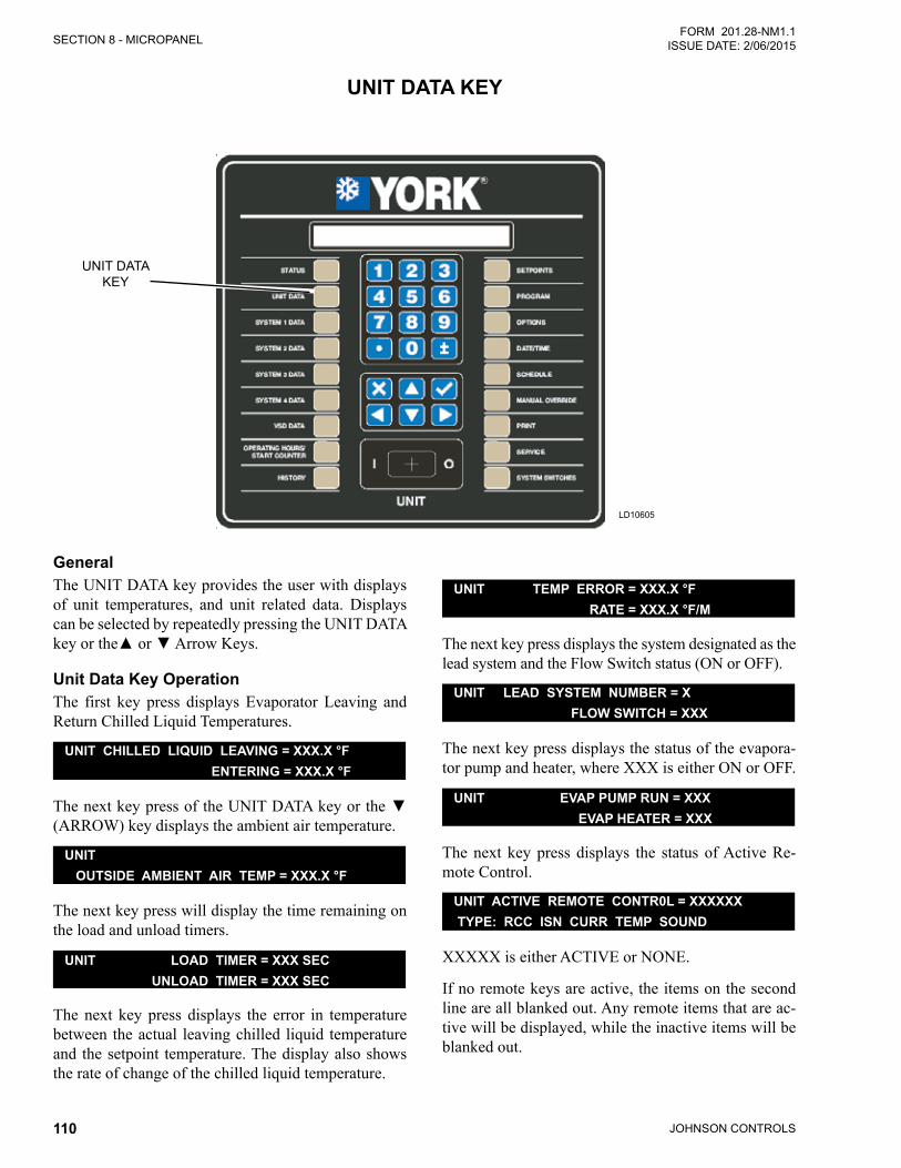
JOHNSON CONTROLS110
SECTION 8 - MICROPANELFORM 201.28-NM1.1
ISSUE DATE: 2/06/2015
UNIT DATA KEY
LD10605
UNIT DATAKEY
GeneralThe UNIT DATA key provides the user with displays of unit temperatures, and unit related data. Displays can be selected by repeatedly pressing the UNIT DATA keyorthe▲or▼ArrowKeys.
Unit Data Key OperationThe first key press displays Evaporator Leaving and Return Chilled Liquid Temperatures.
UNIT CHILLED LIQUID LEAVING = XXX.X °F ENTERING = XXX.X °F
ThenextkeypressoftheUNITDATAkeyorthe▼(ARROW) key displays the ambient air temperature.
UNIT OUTSIDE AMBIENT AIR TEMP = XXX.X °F
The next key press will display the time remaining on the load and unload timers.
UNIT LOAD TIMER = XXX SEC UNLOAD TIMER = XXX SEC
The next key press displays the error in temperature between the actual leaving chilled liquid temperature and the setpoint temperature. The display also shows the rate of change of the chilled liquid temperature.
UNIT TEMP ERROR = XXX.X °F RATE = XXX.X °F/M
The next key press displays the system designated as the lead system and the Flow Switch status (ON or OFF).
UNIT LEAD SYSTEM NUMBER = X FLOW SWITCH = XXX
The next key press displays the status of the evapora-tor pump and heater, where XXX is either ON or OFF.
UNIT EVAP PUMP RUN = XXX EVAP HEATER = XXX
The next key press displays the status of Active Re-mote Control.
UNIT ACTIVE REMOTE CONTR0L = XXXXXX TYPE: RCC ISN CURR TEMP SOUND
XXXXX is either ACTIVE or NONE.
If no remote keys are active, the items on the second line are all blanked out. Any remote items that are ac-tive will be displayed, while the inactive items will be blanked out.
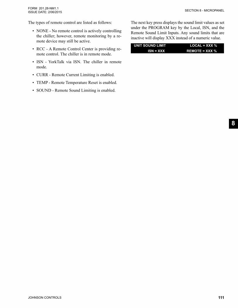
SECTION 8 - MICROPANEL
JOHNSON CONTROLS 111
FORM 201.28-NM1.1ISSUE DATE: 2/06/2015
8
The types of remote control are listed as follows:
• NONE - No remote control is actively controlling the chiller; however, remote monitoring by a re-mote device may still be active.
• RCC - A Remote Control Center is providing re-mote control. The chiller is in remote mode.
• ISN - YorkTalk via ISN. The chiller in remote mode.
• CURR - Remote Current Limiting is enabled.
• TEMP - Remote Temperature Reset is enabled.
• SOUND - Remote Sound Limiting is enabled.
The next key press displays the sound limit values as set under the PROGRAM key by the Local, ISN, and the Remote Sound Limit Inputs. Any sound limits that are inactive will display XXX instead of a numeric value.
UNIT SOUND LIMIT LOCAL = XXX % ISN = XXX REMOTE = XXX %
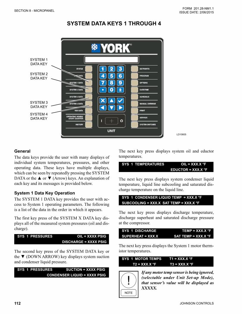
JOHNSON CONTROLS112
SECTION 8 - MICROPANELFORM 201.28-NM1.1
ISSUE DATE: 2/06/2015
SYSTEM DATA KEYS 1 THROUGH 4
LD10605
SYSTEM 1 DATA KEY
SYSTEM 2 DATA KEY
SYSTEM 3 DATA KEY
SYSTEM 4 DATA KEY
GeneralThe data keys provide the user with many displays of individual system temperatures, pressures, and other operating data. These keys have multiple displays, which can be seen by repeatedly pressing the SYSTEM DATAorthe▲or▼(Arrow)keys.Anexplanationofeach key and its messages is provided below.
System 1 Data Key OperationThe SYSTEM 1 DATA key provides the user with ac-cess to System 1 operating parameters. The following is a list of the data in the order in which it appears.
The first key press of the SYSTEM X DATA key dis-plays all of the measured system pressures (oil and dis-charge).
SYS 1 PRESSURES OIL = XXXX PSIG DISCHARGE = XXXX PSIG
The second key press of the SYSTEM DATA key or the▼(DOWNARROW)keydisplayssystemsuctionand condenser liquid pressure. SYS 1 PRESSURES SUCTION = XXXX PSIG
CONDENSER LIQUID = XXXX PSIG
The next key press displays system oil and eductor temperatures.
SYS 1 TEMPERATURES OIL = XXX.X °F EDUCTOR = XXX.X °F
The next key press displays system condenser liquid temperature, liquid line subcooling and saturated dis-charge temperature on the liquid line. SYS 1 CONDENSER LIQUID TEMP = XXX.X °F
SUBCOOLING = XXX.X SAT TEMP = XXX.X °F
The next key press displays discharge temperature, discharge superheat and saturated discharge pressure at the compressor.
SYS 1 DISCHARGE TEMP = XXX.X °FSUPERHEAT = XXX.X SAT TEMP = XXX.X °F
The next key press displays the System 1 motor therm-istor temperatures.
SYS 1 MOTOR TEMPS T1 = XXX.X °F T2 = XXX.X °F T3 = XXX.X °F
If any motor temp sensor is being ignored, (selectable under Unit Set-up Mode), that sensor’s value will be displayed as XXXXX.
SECTION 8 - MICROPANEL
JOHNSON CONTROLS 113
FORM 201.28-NM1.1ISSUE DATE: 2/06/2015
8
The next key press displays the compressor speed in % (0 to100%) and the compressor heater status (ON or OFF)
SYS 1 COMPRESSOR SPEED = XXX.X % HEATER = XXX
The next key press indicates the flash tank level low/high and the economizer valve % open.
SYS 1 FLASH TANK LEVEL = XXX.X % ECONOMIZER VALVE = XXX.X %
The next key press displays the condenser liquid line subcooling and the drain valve position.
SYS 1 CONDENSER SUBCOOLING = XXX.X °F CONDENSER DRAIN VALVE = XXX.X %
The next key press indicates the number of condenser fans steps that are enabled (1 to 4), if the fans are not operating on a VSD.
SYS 1 CONDENSER FANS ON = X
If the fans are controlled by an optional VSD, the dis-play will indicate fan speed signal control voltage to the VSD and the fan speed (0 to 100%).
SYS 1 CONDENSER FANS ON = X VSD FAN SPEED = XX.X V = XXX %
The next key press will indicate the state of the op-tional VI solenoids where XXX indicates ON or OFF.
SYS 1 VI STEP SOLENOID 1 = XXX VI STEP SOLENOID 2 = XXX
The next key press displays the system run time in days, hours, minutes and seconds.
SYS 1 RUN TIMEXX DAYS XX HOURS XX MINUTES XX SECONDS
The next key press indicates the status of the RUN Re-lay where XXX is ON or OFF, the status of the RUN Permissive signal (flow switch/remote start/stop circuit 2 and 15 of 1TB, SYS 1) or 2 and 16 of 1TB, SYS 2) and whether the internal software is telling the system to run (ON or OFF)
SYS 1 RUN SIGNALS RELAY = XXXRUN PERM = XXX SOFTWARE = XXX
System 2 Data Key OperationSystem 2 keys function the same as the SYSTEM 1 DATA key except that it displays data for System 2.
On a 2 compressor system, the SYSTEM 3 and SYS-TEM 4 data keys will display the following messages:
SYS 3 DATA NOT AVAILABLE
SYS 4 DATA NOT AVAILABLE
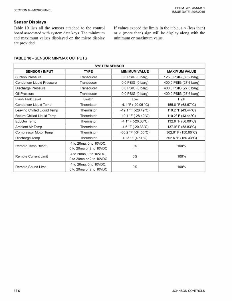
JOHNSON CONTROLS114
SECTION 8 - MICROPANELFORM 201.28-NM1.1
ISSUE DATE: 2/06/2015
Sensor DisplaysTable 10 lists all the sensors attached to the control board associated with system data keys. The minimum and maximum values displayed on the micro display are provided.
TABLE 10 - SENSOR MIN/MAX OUTPUTS
SYSTEM SENSORSENSOR / INPUT TYPE MINIMUM VALUE MAXIMUM VALUE
Suction Pressure Transducer 0.0 PSIG (0 barg) 125.0 PSIG (8.62 barg)Condenser Liquid Pressure Transducer 0.0 PSIG (0 barg) 400.0 PSIG (27.6 barg)Discharge Pressure Transducer 0.0 PSIG (0 barg) 400.0 PSIG (27.6 barg)Oil Pressure Transducer 0.0 PSIG (0 barg) 400.0 PSIG (27.6 barg)Flash Tank Level Switch Low HighCondenser Liquid Temp Thermistor -4.1 °F (-20.06 °C) 155.6 °F (68.67°C)Leaving Chilled Liquid Temp Thermistor -19.1 °F (-28.49°C) 110.2 °F (43.44°C)Return Chilled Liquid Temp Thermistor -19.1 °F (-28.49°C) 110.2° F (43.44°C)Eductor Temp Thermistor -4.1° F (-20.06°C) 132.8 °F (56.00°C)Ambient Air Temp Thermistor -4.6 °F (-20.33°C) 137.9° F (58.83°C)Compressor Motor Temp Thermistor -30.2 °F (-34.56°C) 302.0° F (150.00°C)Discharge Temp Thermistor 40.3 °F (4.61°C) 302.6 °F (150.33°C)
Remote Temp Reset4 to 20ma, 0 to 10VDC,
0 to 20ma or 2 to 10VDC0% 100%
Remote Current Limit4 to 20ma, 0 to 10VDC,
0 to 20ma or 2 to 10VDC0% 100%
Remote Sound Limit4 to 20ma, 0 to 10VDC,
0 to 20ma or 2 to 10VDC0% 100%
If values exceed the limits in the table, a < (less than) or > (more than) sign will be display along with the minimum or maximum value.
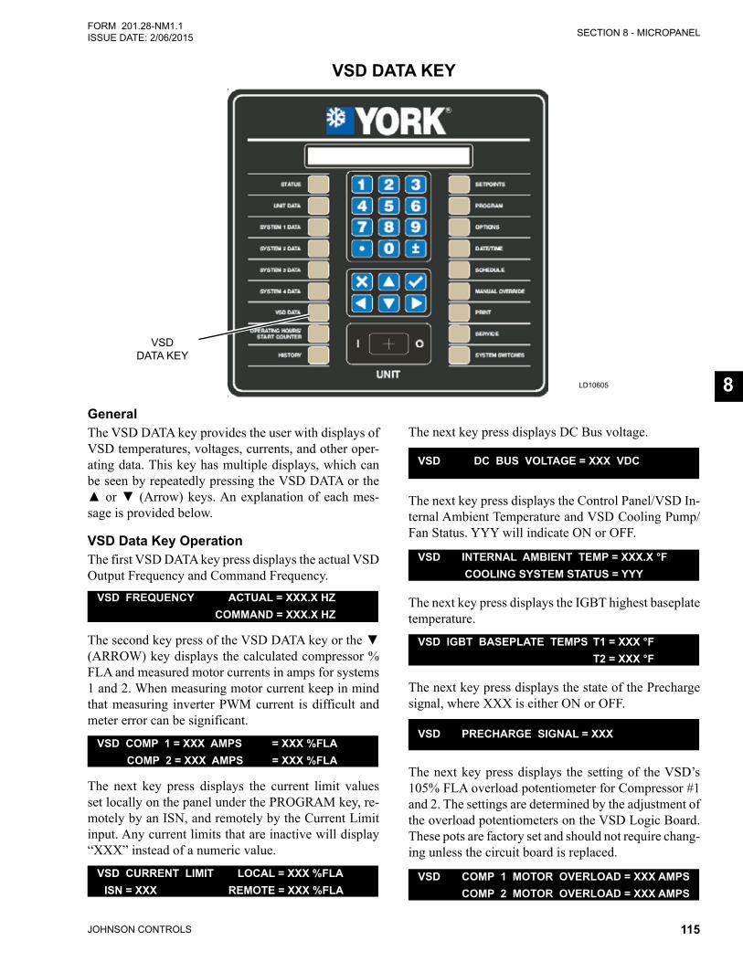
SECTION 8 - MICROPANEL
JOHNSON CONTROLS 115
FORM 201.28-NM1.1ISSUE DATE: 2/06/2015
8
VSD DATA KEY
LD10605
VSDDATA KEY
GeneralThe VSD DATA key provides the user with displays of VSD temperatures, voltages, currents, and other oper-ating data. This key has multiple displays, which can be seen by repeatedly pressing the VSD DATA or the ▲or▼(Arrow)keys.Anexplanationofeachmes-sage is provided below.
VSD Data Key OperationThe first VSD DATA key press displays the actual VSD Output Frequency and Command Frequency.
VSD FREQUENCY ACTUAL = XXX.X HZ COMMAND = XXX.X HZ
ThesecondkeypressoftheVSDDATAkeyorthe▼(ARROW) key displays the calculated compressor % FLA and measured motor currents in amps for systems 1 and 2. When measuring motor current keep in mind that measuring inverter PWM current is difficult and meter error can be significant.
VSD COMP 1 = XXX AMPS = XXX %FLA COMP 2 = XXX AMPS = XXX %FLA
The next key press displays the current limit values set locally on the panel under the PROGRAM key, re-motely by an ISN, and remotely by the Current Limit input. Any current limits that are inactive will display “XXX” instead of a numeric value.
VSD CURRENT LIMIT LOCAL = XXX %FLA ISN = XXX REMOTE = XXX %FLA
The next key press displays DC Bus voltage.
VSD DC BUS VOLTAGE = XXX VDC
The next key press displays the Control Panel/VSD In-ternal Ambient Temperature and VSD Cooling Pump/Fan Status. YYY will indicate ON or OFF.
VSD INTERNAL AMBIENT TEMP = XXX.X °F COOLING SYSTEM STATUS = YYY
The next key press displays the IGBT highest baseplate temperature.
VSD IGBT BASEPLATE TEMPS T1 = XXX °F T2 = XXX °F
The next key press displays the state of the Precharge signal, where XXX is either ON or OFF.
VSD PRECHARGE SIGNAL = XXX
The next key press displays the setting of the VSD’s 105% FLA overload potentiometer for Compressor #1 and 2. The settings are determined by the adjustment of the overload potentiometers on the VSD Logic Board. These pots are factory set and should not require chang-ing unless the circuit board is replaced.
VSD COMP 1 MOTOR OVERLOAD = XXX AMPS COMP 2 MOTOR OVERLOAD = XXX AMPS
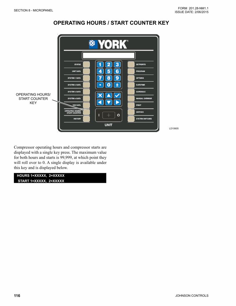
JOHNSON CONTROLS116
SECTION 8 - MICROPANELFORM 201.28-NM1.1
ISSUE DATE: 2/06/2015
OPERATING HOURS / START COUNTER KEY
LD10605
OPERATING HOURS/START COUNTER
KEY
Compressor operating hours and compressor starts are displayed with a single key press. The maximum value for both hours and starts is 99,999, at which point they will roll over to 0. A single display is available under this key and is displayed below.
HOURS 1=XXXXX, 2=XXXXX START 1=XXXXX, 2=XXXXX`
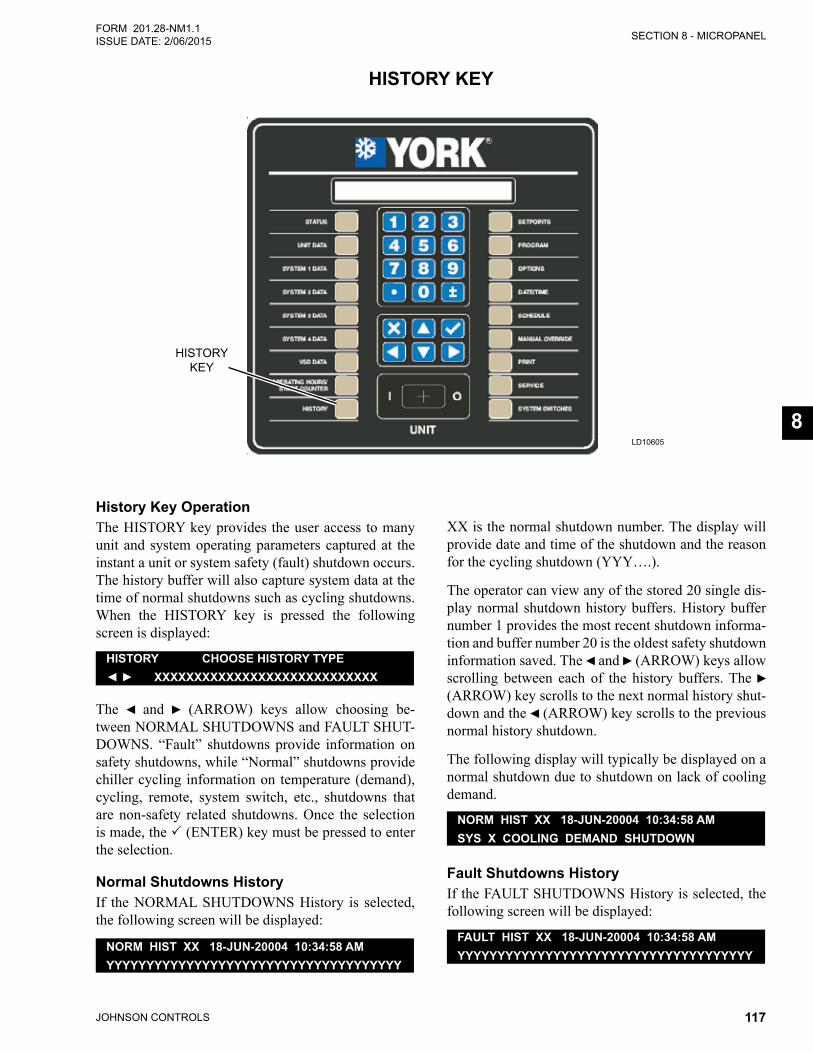
SECTION 8 - MICROPANEL
JOHNSON CONTROLS 117
FORM 201.28-NM1.1ISSUE DATE: 2/06/2015
8
HISTORY KEY
LD10605
HISTORY KEY
History Key OperationThe HISTORY key provides the user access to many unit and system operating parameters captured at the instant a unit or system safety (fault) shutdown occurs. The history buffer will also capture system data at the time of normal shutdowns such as cycling shutdowns. When the HISTORY key is pressed the following screen is displayed:
HISTORY CHOOSE HISTORY TYPE◄ ► XXXXXXXXXXXXXXXXXXXXXXXXXXXX
The ◄ and ► (ARROW) keys allow choosing be-tween NORMAL SHUTDOWNS and FAULT SHUT-DOWNS. “Fault” shutdowns provide information on safety shutdowns, while “Normal” shutdowns provide chiller cycling information on temperature (demand), cycling, remote, system switch, etc., shutdowns that are non-safety related shutdowns. Once the selection is made, the (ENTER) key must be pressed to enter the selection.
Normal Shutdowns HistoryIf the NORMAL SHUTDOWNS History is selected, the following screen will be displayed:
NORM HIST XX 18-JUN-20004 10:34:58 AMYYYYYYYYYYYYYYYYYYYYYYYYYYYYYYYYYYYYY
XX is the normal shutdown number. The display will provide date and time of the shutdown and the reason for the cycling shutdown (YYY….).
The operator can view any of the stored 20 single dis-play normal shutdown history buffers. History buffer number 1 provides the most recent shutdown informa-tion and buffer number 20 is the oldest safety shutdown information saved. The ◄ and ► (ARROW) keys allow scrolling between each of the history buffers. The ► (ARROW) key scrolls to the next normal history shut-down and the ◄ (ARROW) key scrolls to the previous normal history shutdown.
The following display will typically be displayed on a normal shutdown due to shutdown on lack of cooling demand.
NORM HIST XX 18-JUN-20004 10:34:58 AMSYS X COOLING DEMAND SHUTDOWN
Fault Shutdowns HistoryIf the FAULT SHUTDOWNS History is selected, the following screen will be displayed:
FAULT HIST XX 18-JUN-20004 10:34:58 AMYYYYYYYYYYYYYYYYYYYYYYYYYYYYYYYYYYYYY
JOHNSON CONTROLS118
SECTION 8 - MICROPANELFORM 201.28-NM1.1
ISSUE DATE: 2/06/2015
XX is the FAULT HISTORY shutdown number. The display will provide the date, time, and a description of the specific type of fault that occurred (YYY….).
The operator can view any of the stored 10 fault history buffers. History buffer number 1 provides the most re-cent safety shutdown information and buffer number 10 is the oldest safety shutdown information saved. The◄ and► arrow keys allow scrolling betweeneachoftheFAULTHISTbuffers1through10.The▲(UP)and▼(DOWN)arrowkeyscanbeusedtoscrollforwards and backwards through the data in a specific history buffer, once it is displayed.
There is a large amount of data provided under each history. Rather than scroll sequentially through the data inahistory,whichispossibleusingthe▼arrowkey,theuseofacombinationofthe◄,►,▲‚and▼ar-row keys allows fast scrolling to specific data the user desires to view. To use this feature, the user needs to beawarethe◄and►arrowkeysallowscrollingtothe top of the data subgroups. Once a specific history is selected, the history data is divided under the sub-groups of Unit Data, VSD Data, System Data, Hours/Starts,Setpoints,Options, andProgramdata.The◄and►arrowkeys allowmoving to the first displayunder the next or previous subgroup at any time. Once thefirstdisplayofasubgroupisdisplayed,the▲‚and▼arrowkeysallowscrolling though thedata in thesubgroup.The▼arrowkey allows scrolling thoughthe data from first to last. When the last piece of data isdisplayed,thenextpressofthe▼arrowkeyscrollstothefirstpieceofdatainthenextsubgroup.The▲arrow key allows going to the previous display.
Listed below is a description of the fault data displays and their meaning. Data will be displayed in a specific order starting with the Status Display (System Faults only), Fault Display, All Fault Display, Unit Data, VSD Data, System Data, Operating Hours/Starts, Setpoints, Options, and Program Values at the time of the fault.
Status Fault TypeSYS X COMPRESSOR RUNNINGSYS X YYYYYYYY HIGH DIFF OIL PRESSURE
This message indicates the type of system fault. This screen is skipped if a UNIT Fault caused the shutdown.
Unit Fault TypeUNIT FAULT LOW AMBIENT TEMP
This message indicates the type of unit fault. This screen is skipped if a SYSTEM Fault caused the shut-down.
All Fault DataFAULT HIST XX ALL FAULTS ZZ OF WWYYYYYYYYYYYYYYYYYYYYYYYYYYYYYYYYYYYYY
The ALL FAULT display indicates whether a fault oc-curred while the unit is shutting down on another fault.
If a control panel fault occurred while the unit is shut-ting down on a VSD fault before it is reset, the control panel fault is an ALL FAULT of the VSD fault.
If another VSD fault occurs while the unit is shutting down on a VSD fault, the next VSD fault will be regis-tered as an ALL FAULT of the VSD fault.
If a VSD fault occurs during the ramp down shutdown of a control panel fault, the VSD fault is registered as a new fault, not an ALL FAULT
XX is the history number, YYY is the ALL FAULT description, ZZ is the ALL FAULT number and WW is the total number of All Faults for the current his-tory. Sometimes, multiple faults may occur during the shutdown and multiple displays will be observed when scrollingthroughthedatausingthe▼arrow.Inmostcases, the ALL FAULT display will indicate NONE. The ALL FAULT display will only indicate the cause of the fault. No additional chiller information will be displayed under the ALL FAULT, since a snapshot of all chiller data was taken at the time of the first fault.
Unit DataEvaporator Leaving and Entering Chilled Liquid Temperatures
UNIT CHILLED LIQUID LEAVING = XXX.X °F ENTERING = XXX.X °F
This message indicates the leaving and entering chilled liquid temperatures at the time of the fault.
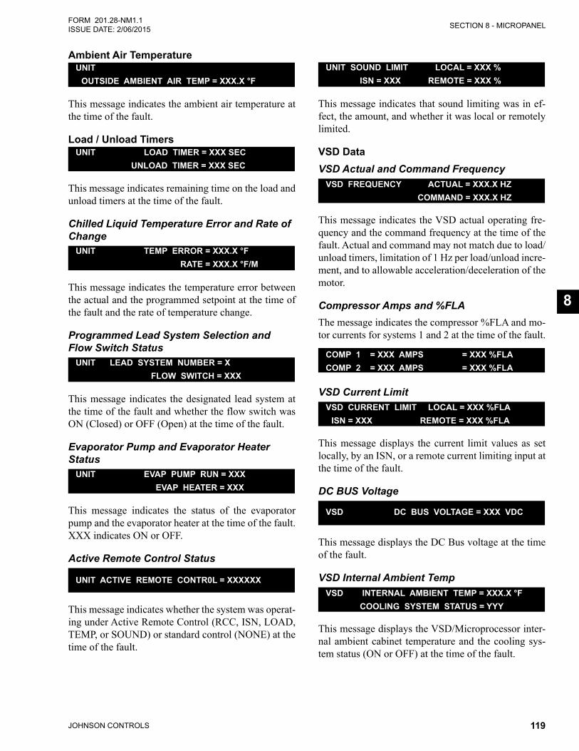
SECTION 8 - MICROPANEL
JOHNSON CONTROLS 119
FORM 201.28-NM1.1ISSUE DATE: 2/06/2015
8
Ambient Air TemperatureUNIT OUTSIDE AMBIENT AIR TEMP = XXX.X °F
This message indicates the ambient air temperature at the time of the fault.
Load / Unload TimersUNIT LOAD TIMER = XXX SEC UNLOAD TIMER = XXX SEC
This message indicates remaining time on the load and unload timers at the time of the fault.
Chilled Liquid Temperature Error and Rate of Change
UNIT TEMP ERROR = XXX.X °F RATE = XXX.X °F/M
This message indicates the temperature error between the actual and the programmed setpoint at the time of the fault and the rate of temperature change.
Programmed Lead System Selection and Flow Switch Status
UNIT LEAD SYSTEM NUMBER = X FLOW SWITCH = XXX
This message indicates the designated lead system at the time of the fault and whether the flow switch was ON (Closed) or OFF (Open) at the time of the fault.
Evaporator Pump and Evaporator Heater Status
UNIT EVAP PUMP RUN = XXX EVAP HEATER = XXX
This message indicates the status of the evaporator pump and the evaporator heater at the time of the fault. XXX indicates ON or OFF.
Active Remote Control Status
UNIT ACTIVE REMOTE CONTR0L = XXXXXX
This message indicates whether the system was operat-ing under Active Remote Control (RCC, ISN, LOAD, TEMP, or SOUND) or standard control (NONE) at the time of the fault.
UNIT SOUND LIMIT LOCAL = XXX % ISN = XXX REMOTE = XXX %
This message indicates that sound limiting was in ef-fect, the amount, and whether it was local or remotely limited.
VSD DataVSD Actual and Command Frequency
VSD FREQUENCY ACTUAL = XXX.X HZ COMMAND = XXX.X HZ
This message indicates the VSD actual operating fre-quency and the command frequency at the time of the fault. Actual and command may not match due to load/unload timers, limitation of 1 Hz per load/unload incre-ment, and to allowable acceleration/deceleration of the motor.
Compressor Amps and %FLAThe message indicates the compressor %FLA and mo-tor currents for systems 1 and 2 at the time of the fault.
COMP 1 = XXX AMPS = XXX %FLACOMP 2 = XXX AMPS = XXX %FLA
VSD Current LimitVSD CURRENT LIMIT LOCAL = XXX %FLA ISN = XXX REMOTE = XXX %FLA
This message displays the current limit values as set locally, by an ISN, or a remote current limiting input at the time of the fault.
DC BUS Voltage
VSD DC BUS VOLTAGE = XXX VDC
This message displays the DC Bus voltage at the time of the fault.
VSD Internal Ambient TempVSD INTERNAL AMBIENT TEMP = XXX.X °F COOLING SYSTEM STATUS = YYY
This message displays the VSD/Microprocessor inter-nal ambient cabinet temperature and the cooling sys-tem status (ON or OFF) at the time of the fault.
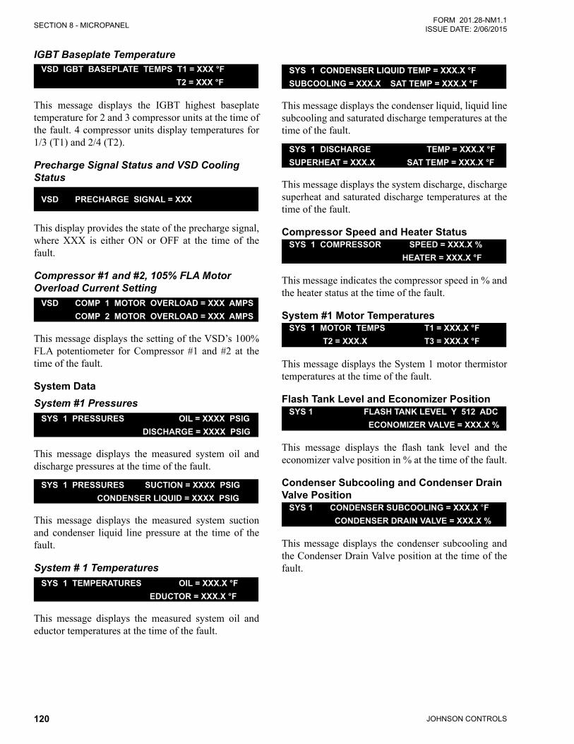
JOHNSON CONTROLS120
SECTION 8 - MICROPANELFORM 201.28-NM1.1
ISSUE DATE: 2/06/2015
IGBT Baseplate TemperatureVSD IGBT BASEPLATE TEMPS T1 = XXX °F T2 = XXX °F
This message displays the IGBT highest baseplate temperature for 2 and 3 compressor units at the time of the fault. 4 compressor units display temperatures for 1/3 (T1) and 2/4 (T2).
Precharge Signal Status and VSD Cooling Status
VSD PRECHARGE SIGNAL = XXX
This display provides the state of the precharge signal, where XXX is either ON or OFF at the time of the fault.
Compressor #1 and #2, 105% FLA Motor Overload Current Setting
VSD COMP 1 MOTOR OVERLOAD = XXX AMPS COMP 2 MOTOR OVERLOAD = XXX AMPS
This message displays the setting of the VSD’s 100% FLA potentiometer for Compressor #1 and #2 at the time of the fault.
System DataSystem #1 Pressures
SYS 1 PRESSURES OIL = XXXX PSIG DISCHARGE = XXXX PSIG
This message displays the measured system oil and discharge pressures at the time of the fault.
SYS 1 PRESSURES SUCTION = XXXX PSIG CONDENSER LIQUID = XXXX PSIG
This message displays the measured system suction and condenser liquid line pressure at the time of the fault.
System # 1 TemperaturesSYS 1 TEMPERATURES OIL = XXX.X °F EDUCTOR = XXX.X °F
This message displays the measured system oil and eductor temperatures at the time of the fault.
SYS 1 CONDENSER LIQUID TEMP = XXX.X °FSUBCOOLING = XXX.X SAT TEMP = XXX.X °F
This message displays the condenser liquid, liquid line subcooling and saturated discharge temperatures at the time of the fault.
SYS 1 DISCHARGE TEMP = XXX.X °FSUPERHEAT = XXX.X SAT TEMP = XXX.X °F
This message displays the system discharge, discharge superheat and saturated discharge temperatures at the time of the fault.
Compressor Speed and Heater StatusSYS 1 COMPRESSOR SPEED = XXX.X % HEATER = XXX.X °F
This message indicates the compressor speed in % and the heater status at the time of the fault.
System #1 Motor TemperaturesSYS 1 MOTOR TEMPS T1 = XXX.X °F T2 = XXX.X T3 = XXX.X °F
This message displays the System 1 motor thermistor temperatures at the time of the fault.
Flash Tank Level and Economizer PositionSYS 1 FLASH TANK LEVEL Y 512 ADC ECONOMIZER VALVE = XXX.X %
This message displays the flash tank level and the economizer valve position in % at the time of the fault.
Condenser Subcooling and Condenser Drain Valve Position
SYS 1 CONDENSER SUBCOOLING = XXX.X °F CONDENSER DRAIN VALVE = XXX.X %
This message displays the condenser subcooling and the Condenser Drain Valve position at the time of the fault.
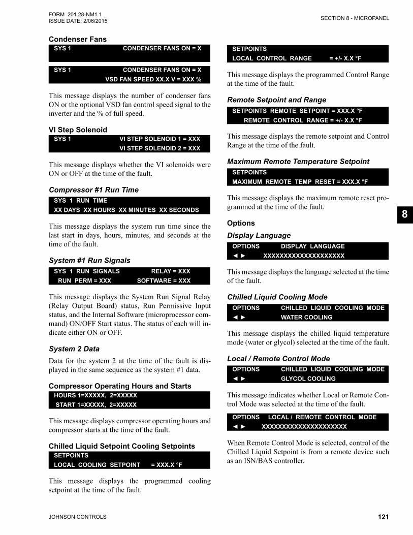
SECTION 8 - MICROPANEL
JOHNSON CONTROLS 121
FORM 201.28-NM1.1ISSUE DATE: 2/06/2015
8
Condenser FansSYS 1 CONDENSER FANS ON = X
SYS 1 CONDENSER FANS ON = X VSD FAN SPEED XX.X V = XXX %
This message displays the number of condenser fans ON or the optional VSD fan control speed signal to the inverter and the % of full speed.
VI Step SolenoidSYS 1 VI STEP SOLENOID 1 = XXX VI STEP SOLENOID 2 = XXX
This message displays whether the VI solenoids were ON or OFF at the time of the fault.
Compressor #1 Run TimeSYS 1 RUN TIMEXX DAYS XX HOURS XX MINUTES XX SECONDS
This message displays the system run time since the last start in days, hours, minutes, and seconds at the time of the fault.
System #1 Run SignalsSYS 1 RUN SIGNALS RELAY = XXX RUN PERM = XXX SOFTWARE = XXX
This message displays the System Run Signal Relay (Relay Output Board) status, Run Permissive Input status, and the Internal Software (microprocessor com-mand) ON/OFF Start status. The status of each will in-dicate either ON or OFF.
System 2 Data Data for the system 2 at the time of the fault is dis-played in the same sequence as the system #1 data.
Compressor Operating Hours and StartsHOURS 1=XXXXX, 2=XXXXX START 1=XXXXX, 2=XXXXX
This message displays compressor operating hours and compressor starts at the time of the fault.
Chilled Liquid Setpoint Cooling SetpointsSETPOINTSLOCAL COOLING SETPOINT = XXX.X °F
This message displays the programmed cooling setpoint at the time of the fault.
SETPOINTSLOCAL CONTROL RANGE = +/- X.X °F
This message displays the programmed Control Range at the time of the fault.
Remote Setpoint and RangeSETPOINTS REMOTE SETPOINT = XXX.X °F REMOTE CONTROL RANGE = +/- X.X °F
This message displays the remote setpoint and Control Range at the time of the fault.
Maximum Remote Temperature SetpointSETPOINTS MAXIMUM REMOTE TEMP RESET = XXX.X °F
This message displays the maximum remote reset pro-grammed at the time of the fault.
OptionsDisplay Language
OPTIONS DISPLAY LANGUAGE◄ ► XXXXXXXXXXXXXXXXXXXX
This message displays the language selected at the time of the fault.
Chilled Liquid Cooling ModeOPTIONS CHILLED LIQUID COOLING MODE◄ ► WATER COOLING
This message displays the chilled liquid temperature mode (water or glycol) selected at the time of the fault.
Local / Remote Control ModeOPTIONS CHILLED LIQUID COOLING MODE◄ ► GLYCOL COOLING
This message indicates whether Local or Remote Con-trol Mode was selected at the time of the fault.
OPTIONS LOCAL / REMOTE CONTROL MODE◄ ► XXXXXXXXXXXXXXXXXXXXX
When Remote Control Mode is selected, control of the Chilled Liquid Setpoint is from a remote device such as an ISN/BAS controller.
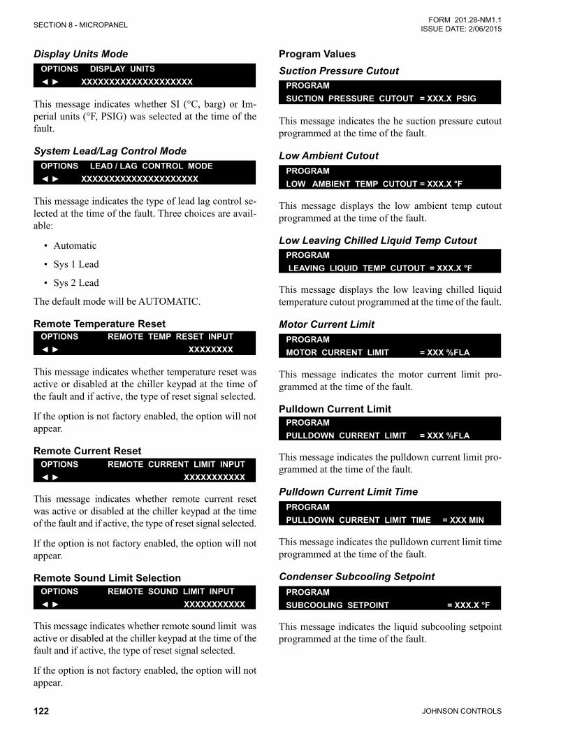
JOHNSON CONTROLS122
SECTION 8 - MICROPANELFORM 201.28-NM1.1
ISSUE DATE: 2/06/2015
Display Units ModeOPTIONS DISPLAY UNITS◄ ► XXXXXXXXXXXXXXXXXXXX
This message indicates whether SI (°C, barg) or Im-perial units (°F, PSIG) was selected at the time of the fault.
System Lead/Lag Control ModeOPTIONS LEAD / LAG CONTROL MODE◄ ► XXXXXXXXXXXXXXXXXXXXX
This message indicates the type of lead lag control se-lected at the time of the fault. Three choices are avail-able:
• Automatic
• Sys 1 Lead
• Sys 2 Lead
The default mode will be AUTOMATIC.
Remote Temperature ResetOPTIONS REMOTE TEMP RESET INPUT◄ ► XXXXXXXX
This message indicates whether temperature reset was active or disabled at the chiller keypad at the time of the fault and if active, the type of reset signal selected.
If the option is not factory enabled, the option will not appear.
Remote Current ResetOPTIONS REMOTE CURRENT LIMIT INPUT◄ ► XXXXXXXXXXX
This message indicates whether remote current reset was active or disabled at the chiller keypad at the time of the fault and if active, the type of reset signal selected.
If the option is not factory enabled, the option will not appear.
Remote Sound Limit SelectionOPTIONS REMOTE SOUND LIMIT INPUT◄ ► XXXXXXXXXXX
This message indicates whether remote sound limit was active or disabled at the chiller keypad at the time of the fault and if active, the type of reset signal selected.
If the option is not factory enabled, the option will not appear.
Program ValuesSuction Pressure Cutout
PROGRAMSUCTION PRESSURE CUTOUT = XXX.X PSIG
This message indicates the he suction pressure cutout programmed at the time of the fault.
Low Ambient CutoutPROGRAMLOW AMBIENT TEMP CUTOUT = XXX.X °F
This message displays the low ambient temp cutout programmed at the time of the fault.
Low Leaving Chilled Liquid Temp CutoutPROGRAM LEAVING LIQUID TEMP CUTOUT = XXX.X °F
This message displays the low leaving chilled liquid temperature cutout programmed at the time of the fault.
Motor Current LimitPROGRAMMOTOR CURRENT LIMIT = XXX %FLA
This message indicates the motor current limit pro-grammed at the time of the fault.
Pulldown Current LimitPROGRAMPULLDOWN CURRENT LIMIT = XXX %FLA
This message indicates the pulldown current limit pro-grammed at the time of the fault.
Pulldown Current Limit TimePROGRAMPULLDOWN CURRENT LIMIT TIME = XXX MIN
This message indicates the pulldown current limit time programmed at the time of the fault.
Condenser Subcooling SetpointPROGRAMSUBCOOLING SETPOINT = XXX.X °F
This message indicates the liquid subcooling setpoint programmed at the time of the fault.
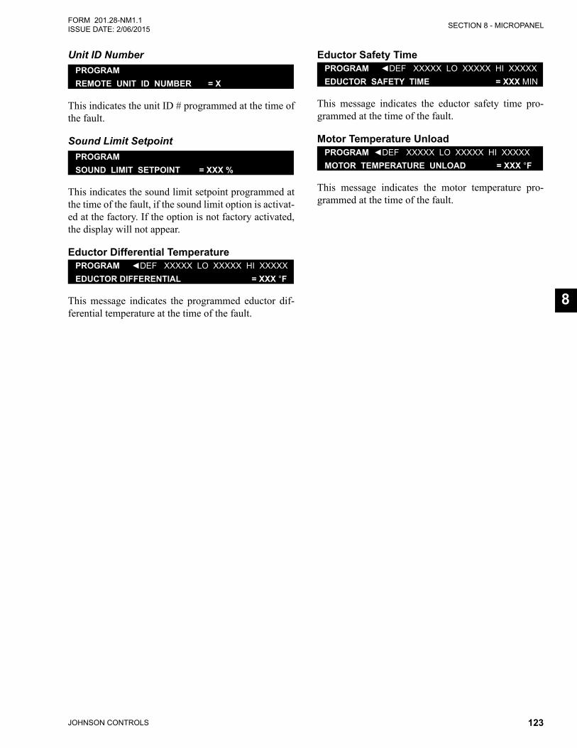
SECTION 8 - MICROPANEL
JOHNSON CONTROLS 123
FORM 201.28-NM1.1ISSUE DATE: 2/06/2015
8
Unit ID NumberPROGRAMREMOTE UNIT ID NUMBER = X
This indicates the unit ID # programmed at the time of the fault.
Sound Limit SetpointPROGRAMSOUND LIMIT SETPOINT = XXX %
This indicates the sound limit setpoint programmed at the time of the fault, if the sound limit option is activat-ed at the factory. If the option is not factory activated, the display will not appear.
Eductor Differential TemperaturePROGRAM ◄DEF XXXXX LO XXXXX HI XXXXXEDUCTOR DIFFERENTIAL = XXX °F
This message indicates the programmed eductor dif-ferential temperature at the time of the fault.
Eductor Safety TimePROGRAM ◄DEF XXXXX LO XXXXX HI XXXXXEDUCTOR SAFETY TIME = XXX MIN
This message indicates the eductor safety time pro-grammed at the time of the fault.
Motor Temperature UnloadPROGRAM ◄DEF XXXXX LO XXXXX HI XXXXXMOTOR TEMPERATURE UNLOAD = XXX °F
This message indicates the motor temperature pro-grammed at the time of the fault.
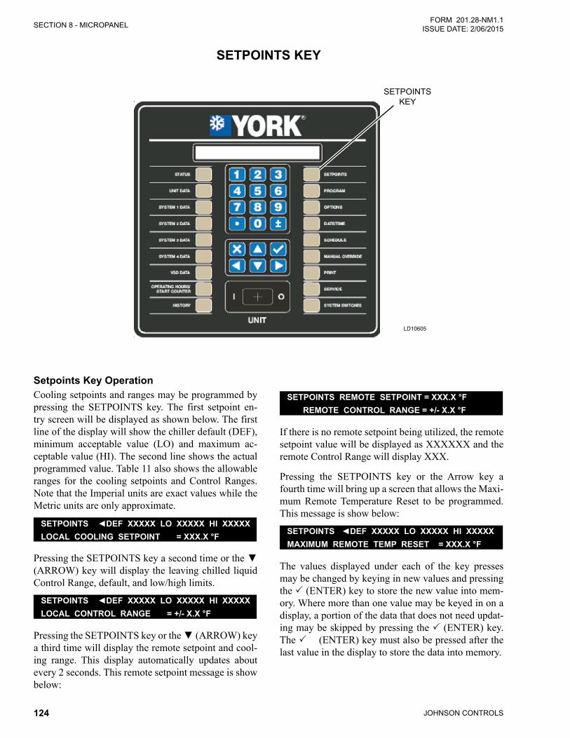
JOHNSON CONTROLS124
SECTION 8 - MICROPANELFORM 201.28-NM1.1
ISSUE DATE: 2/06/2015
LD10605
SETPOINTSKEY
SETPOINTS KEY
Setpoints Key OperationCooling setpoints and ranges may be programmed by pressing the SETPOINTS key. The first setpoint en-try screen will be displayed as shown below. The first line of the display will show the chiller default (DEF), minimum acceptable value (LO) and maximum ac-ceptable value (HI). The second line shows the actual programmed value. Table 11 also shows the allowable ranges for the cooling setpoints and Control Ranges. Note that the Imperial units are exact values while the Metric units are only approximate.
SETPOINTS ◄DEF XXXXX LO XXXXX HI XXXXXLOCAL COOLING SETPOINT = XXX.X °F
PressingtheSETPOINTSkeyasecondtimeorthe▼(ARROW) key will display the leaving chilled liquid Control Range, default, and low/high limits.
SETPOINTS ◄DEF XXXXX LO XXXXX HI XXXXXLOCAL CONTROL RANGE = +/- X.X °F
PressingtheSETPOINTSkeyorthe▼(ARROW) key a third time will display the remote setpoint and cool-ing range. This display automatically updates about every 2 seconds. This remote setpoint message is show below:
SETPOINTS REMOTE SETPOINT = XXX.X °F REMOTE CONTROL RANGE = +/- X.X °F
If there is no remote setpoint being utilized, the remote setpoint value will be displayed as XXXXXX and the remote Control Range will display XXX.
Pressing the SETPOINTS key or the Arrow key a fourth time will bring up a screen that allows the Maxi-mum Remote Temperature Reset to be programmed. This message is show below:
SETPOINTS ◄DEF XXXXX LO XXXXX HI XXXXXMAXIMUM REMOTE TEMP RESET = XXX.X °F
The values displayed under each of the key presses may be changed by keying in new values and pressing the (ENTER) key to store the new value into mem-ory. Where more than one value may be keyed in on a display, a portion of the data that does not need updat-ing may be skipped by pressing the (ENTER) key. The (ENTER) key must also be pressed after the last value in the display to store the data into memory.
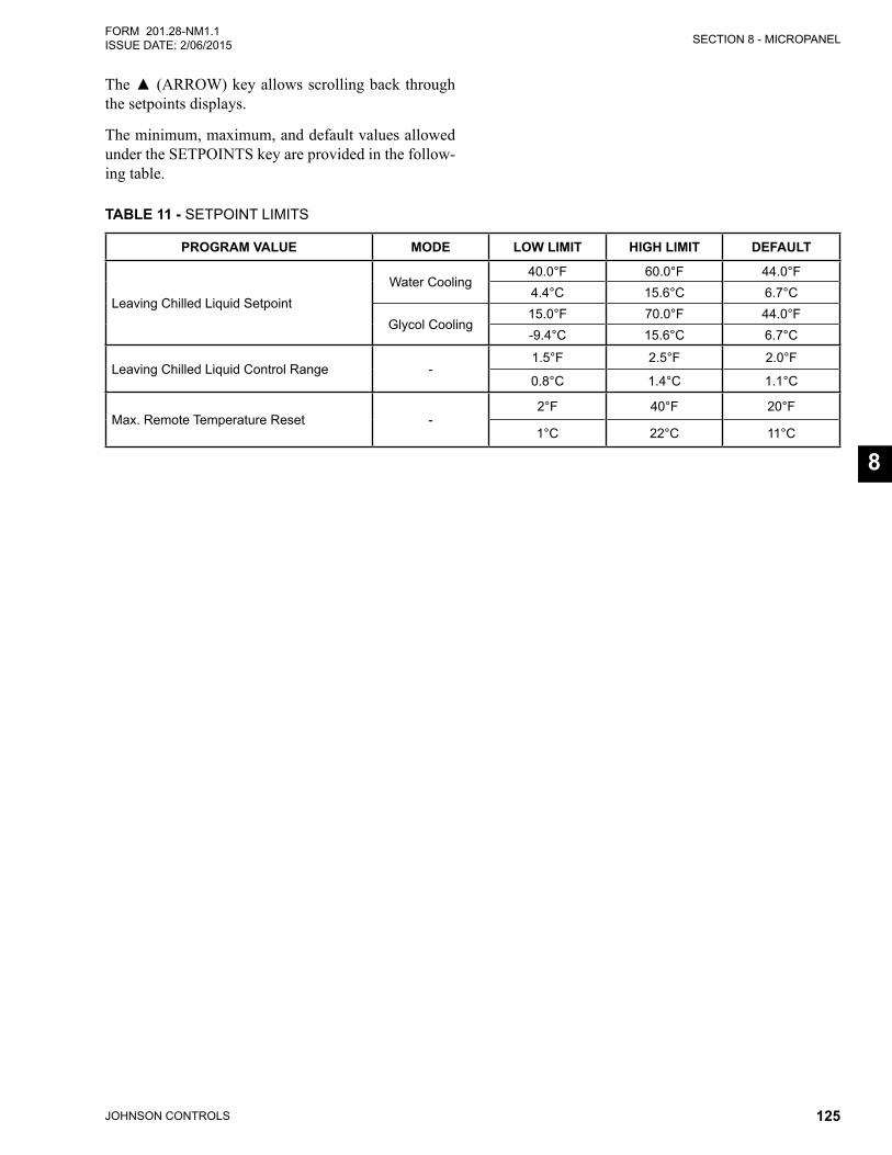
SECTION 8 - MICROPANEL
JOHNSON CONTROLS 125
FORM 201.28-NM1.1ISSUE DATE: 2/06/2015
8
TABLE 11 - SETPOINT LIMITS
PROGRAM VALUE MODE LOW LIMIT HIGH LIMIT DEFAULT
Leaving Chilled Liquid Setpoint Water Cooling
40.0°F 60.0°F 44.0°F4.4°C 15.6°C 6.7°C
Glycol Cooling15.0°F 70.0°F 44.0°F-9.4°C 15.6°C 6.7°C
Leaving Chilled Liquid Control Range -1.5°F 2.5°F 2.0°F
0.8°C 1.4°C 1.1°C
Max. Remote Temperature Reset -2°F 40°F 20°F
1°C 22°C 11°C
The▲(ARROW)keyallowsscrollingbackthroughthe setpoints displays.
The minimum, maximum, and default values allowed under the SETPOINTS key are provided in the follow-ing table.
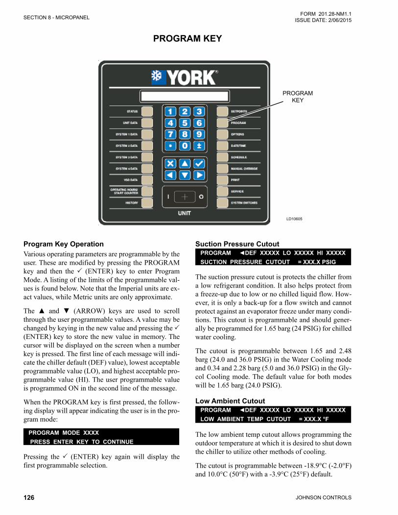
JOHNSON CONTROLS126
SECTION 8 - MICROPANELFORM 201.28-NM1.1
ISSUE DATE: 2/06/2015
LD10605
PROGRAM KEY
PROGRAM KEY
Program Key OperationVarious operating parameters are programmable by the user. These are modified by pressing the PROGRAM key and then the (ENTER) key to enter Program Mode. A listing of the limits of the programmable val-ues is found below. Note that the Imperial units are ex-act values, while Metric units are only approximate.
The ▲ and ▼ (ARROW) keys are used to scroll through the user programmable values. A value may be changed by keying in the new value and pressing the (ENTER) key to store the new value in memory. The cursor will be displayed on the screen when a number key is pressed. The first line of each message will indi-cate the chiller default (DEF) value), lowest acceptable programmable value (LO), and highest acceptable pro-grammable value (HI). The user programmable value is programmed ON in the second line of the message.
When the PROGRAM key is first pressed, the follow-ing display will appear indicating the user is in the pro-gram mode:
PROGRAM MODE XXXX PRESS ENTER KEY TO CONTINUE
Pressing the (ENTER) key again will display the first programmable selection.
Suction Pressure CutoutPROGRAM ◄DEF XXXXX LO XXXXX HI XXXXXSUCTION PRESSURE CUTOUT = XXX.X PSIG
The suction pressure cutout is protects the chiller from a low refrigerant condition. It also helps protect from a freeze-up due to low or no chilled liquid flow. How-ever, it is only a back-up for a flow switch and cannot protect against an evaporator freeze under many condi-tions. This cutout is programmable and should gener-ally be programmed for 1.65 barg (24 PSIG) for chilled water cooling.
The cutout is programmable between 1.65 and 2.48 barg (24.0 and 36.0 PSIG) in the Water Cooling mode and 0.34 and 2.28 barg (5.0 and 36.0 PSIG) in the Gly-col Cooling mode. The default value for both modes will be 1.65 barg (24.0 PSIG).
Low Ambient CutoutPROGRAM ◄DEF XXXXX LO XXXXX HI XXXXXLOW AMBIENT TEMP CUTOUT = XXX.X °F
The low ambient temp cutout allows programming the outdoor temperature at which it is desired to shut down the chiller to utilize other methods of cooling.
The cutout is programmable between -18.9°C (-2.0°F) and 10.0°C (50°F) with a -3.9°C (25°F) default.
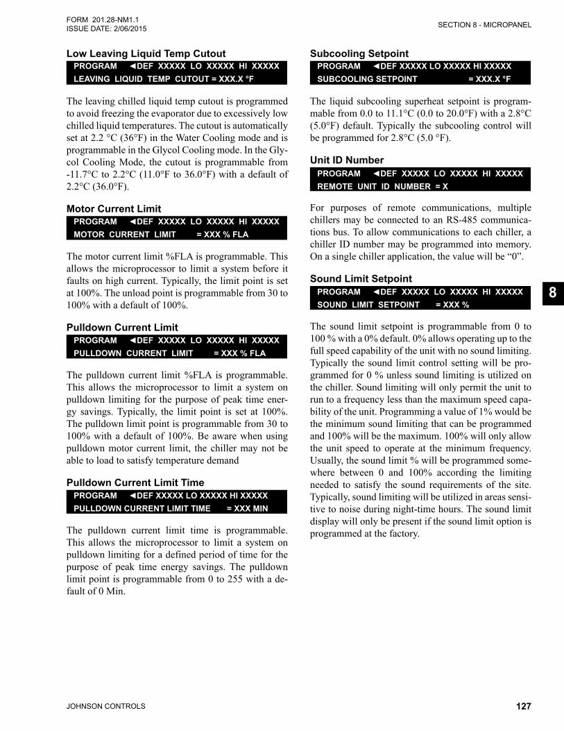
SECTION 8 - MICROPANEL
JOHNSON CONTROLS 127
FORM 201.28-NM1.1ISSUE DATE: 2/06/2015
8
Low Leaving Liquid Temp CutoutPROGRAM ◄DEF XXXXX LO XXXXX HI XXXXXLEAVING LIQUID TEMP CUTOUT = XXX.X °F
The leaving chilled liquid temp cutout is programmed to avoid freezing the evaporator due to excessively low chilled liquid temperatures. The cutout is automatically set at 2.2 °C (36°F) in the Water Cooling mode and is programmable in the Glycol Cooling mode. In the Gly-col Cooling Mode, the cutout is programmable from -11.7°C to 2.2°C (11.0°F to 36.0°F) with a default of 2.2°C (36.0°F).
Motor Current LimitPROGRAM ◄DEF XXXXX LO XXXXX HI XXXXXMOTOR CURRENT LIMIT = XXX % FLA
The motor current limit %FLA is programmable. This allows the microprocessor to limit a system before it faults on high current. Typically, the limit point is set at 100%. The unload point is programmable from 30 to 100% with a default of 100%.
Pulldown Current LimitPROGRAM ◄DEF XXXXX LO XXXXX HI XXXXXPULLDOWN CURRENT LIMIT = XXX % FLA
The pulldown current limit %FLA is programmable. This allows the microprocessor to limit a system on pulldown limiting for the purpose of peak time ener-gy savings. Typically, the limit point is set at 100%. The pulldown limit point is programmable from 30 to 100% with a default of 100%. Be aware when using pulldown motor current limit, the chiller may not be able to load to satisfy temperature demand
Pulldown Current Limit TimePROGRAM ◄DEF XXXXX LO XXXXX HI XXXXXPULLDOWN CURRENT LIMIT TIME = XXX MIN
The pulldown current limit time is programmable. This allows the microprocessor to limit a system on pulldown limiting for a defined period of time for the purpose of peak time energy savings. The pulldown limit point is programmable from 0 to 255 with a de-fault of 0 Min.
Subcooling SetpointPROGRAM ◄DEF XXXXX LO XXXXX HI XXXXXSUBCOOLING SETPOINT = XXX.X °F
The liquid subcooling superheat setpoint is program-mable from 0.0 to 11.1°C (0.0 to 20.0°F) with a 2.8°C (5.0°F) default. Typically the subcooling control will be programmed for 2.8°C (5.0 °F).
Unit ID NumberPROGRAM ◄DEF XXXXX LO XXXXX HI XXXXXREMOTE UNIT ID NUMBER = X
For purposes of remote communications, multiple chillers may be connected to an RS-485 communica-tions bus. To allow communications to each chiller, a chiller ID number may be programmed into memory. On a single chiller application, the value will be “0”.
Sound Limit SetpointPROGRAM ◄DEF XXXXX LO XXXXX HI XXXXXSOUND LIMIT SETPOINT = XXX %
The sound limit setpoint is programmable from 0 to 100 % with a 0% default. 0% allows operating up to the full speed capability of the unit with no sound limiting. Typically the sound limit control setting will be pro-grammed for 0 % unless sound limiting is utilized on the chiller. Sound limiting will only permit the unit to run to a frequency less than the maximum speed capa-bility of the unit. Programming a value of 1% would be the minimum sound limiting that can be programmed and 100% will be the maximum. 100% will only allow the unit speed to operate at the minimum frequency. Usually, the sound limit % will be programmed some-where between 0 and 100% according the limiting needed to satisfy the sound requirements of the site. Typically, sound limiting will be utilized in areas sensi-tive to noise during night-time hours. The sound limit display will only be present if the sound limit option is programmed at the factory.
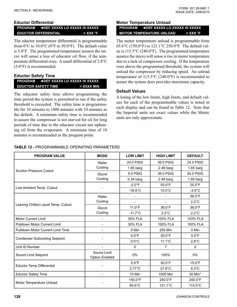
JOHNSON CONTROLS128
SECTION 8 - MICROPANELFORM 201.28-NM1.1
ISSUE DATE: 2/06/2015
Eductor DifferentialPROGRAM ◄DEF XXXXX LO XXXXX HI XXXXXEDUCTOR DIFFERENTIAL = XXX °F
The eductor temperature differential is programmable from 0°C to 10.0°C (0°F to 50.0°F). The default value is 5.0°F. The programmed temperature assures the mi-cro will sense a loss of educator oil flow, if the tem-perature differential rises. A small differential of 2.8°C (5.0°F) is recommended.
Eductor Safety TimePROGRAM ◄DEF XXXXX LO XXXXX HI XXXXXEDUCTOR SAFETY TIME = XXXX MIN
The educator safety time allows programming the time period the system is permitted to run if the safety threshold is exceeded. The safety time is programma-ble for 10 minutes to 1000 minutes with 10 minutes as the default. A minimum safety time is recommended to assure the compressor is not starved for oil for long periods of time due to the educator circuit not siphon-ing oil from the evaporator. A minimum time of 10 minutes is recommended as the program point.
Motor Temperature UnloadPROGRAM ◄DEF XXXXX LO XXXXX HI XXXXXMOTOR TEMPERATURE UNLOAD = XXX °F
The motor temperature unload is programmable from 65.6°C (150.0°F) to 121.1°C 250.0°F. The default val-ue is 115.5°C (240.0°F). The programmed temperature assures the micro will sense a rise in motor temperature due to a lack of compressor cooling. If the temperature rises above the programmed threshold, the system will unload the compressor by reducing speed. An unload temperature of 115.5°C (240.0°F) is recommended to assure the system does provides maximum capacity.
Default ValuesA listing of the low limits, high limits, and default val-ues for each of the programmable values is noted in each display and can be found in Table 12. Note that the Imperial units are exact values while the Metric units are only approximate.
TABLE 12 - PROGRAMMABLE OPERATING PARAMETERS
PROGRAM VALUE MODE LOW LIMIT HIGH LIMIT DEFAULT
Suction Pressure Cutout
Water Cooling
24.0 PSIG 36.0 PSIG 24.0 PSIG1.65 barg 2.48 barg 1.65 barg
Glycol Cooling
5.0 PSIG 36.0 PSIG 24.0 PSIG0.34 barg 2.48 barg 1.65 barg
Low Ambient Temp. Cutout --2.0°F 50.0°F 25.0°F
-18.9°C 10.0°C -3.9°C
Leaving Chilled Liquid Temp. Cutout
Water Cooling
- - 36.0°F- - 2.2°C
Glycol Cooling
11.0°F 36.0°F 36.0°F-11.7°C 2.2°C 2.2°C
Motor Current Limit - 30% FLA 103% FLA 103% FLAPulldown Motor Current Limit - 30% FLA 100% FLA 100% FLAPulldown Motor Current Limit Time - 0 Min 255 Min 0 Min
Condenser Subcooling Setpoint -0.0°F 20.0°F 5.0°F0.0°C 11.1°C 2.8°C
Unit ID Number - 0 7 0
Sound Limit SetpointSound Limit
Option Enabled0% 100% 0%
Eductor Temp Differential -5.0°F 50.0°F 15.0°F
2.77°C 27.8°C 8.3°CEductor Safety Time - 10 Min 1000 Min 30 Min*
Motor Temperature Unload -150.0°F 250.0°F 240.0°F65.6°C 121.1°C 115.5°C
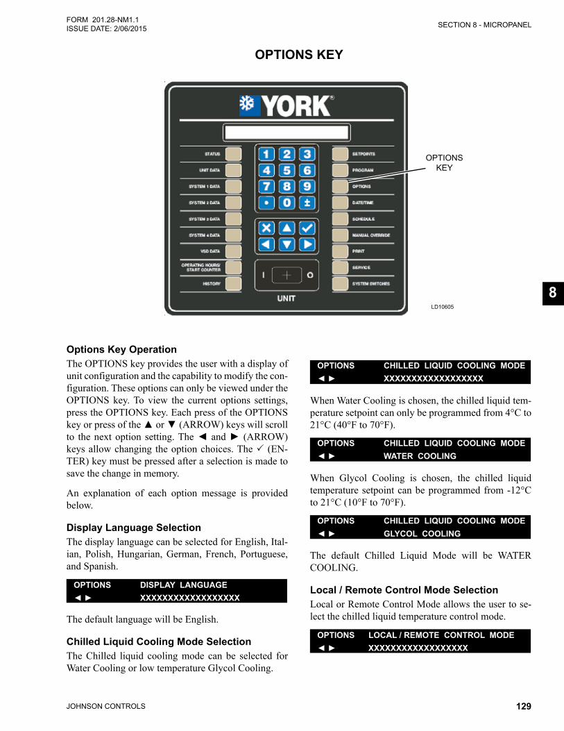
SECTION 8 - MICROPANEL
JOHNSON CONTROLS 129
FORM 201.28-NM1.1ISSUE DATE: 2/06/2015
8
OPTIONS KEY
LD10605
OPTIONSKEY
Options Key OperationThe OPTIONS key provides the user with a display of unit configuration and the capability to modify the con-figuration. These options can only be viewed under the OPTIONS key. To view the current options settings, press the OPTIONS key. Each press of the OPTIONS keyorpressofthe▲or▼(ARROW) keys will scroll to thenextoption setting.The◄and►(ARROW) keys allow changing the option choices. The (EN-TER) key must be pressed after a selection is made to save the change in memory.
An explanation of each option message is provided below.
Display Language SelectionThe display language can be selected for English, Ital-ian, Polish, Hungarian, German, French, Portuguese, and Spanish.
OPTIONS DISPLAY LANGUAGE◄ ► XXXXXXXXXXXXXXXXXX
The default language will be English.
Chilled Liquid Cooling Mode SelectionThe Chilled liquid cooling mode can be selected for Water Cooling or low temperature Glycol Cooling.
OPTIONS CHILLED LIQUID COOLING MODE◄ ► XXXXXXXXXXXXXXXXXX
When Water Cooling is chosen, the chilled liquid tem-perature setpoint can only be programmed from 4°C to 21°C (40°F to 70°F).
OPTIONS CHILLED LIQUID COOLING MODE◄ ► WATER COOLING
When Glycol Cooling is chosen, the chilled liquid temperature setpoint can be programmed from -12°C to 21°C (10°F to 70°F).
OPTIONS CHILLED LIQUID COOLING MODE◄ ► GLYCOL COOLING
The default Chilled Liquid Mode will be WATER COOLING.
Local / Remote Control Mode SelectionLocal or Remote Control Mode allows the user to se-lect the chilled liquid temperature control mode.
OPTIONS LOCAL / REMOTE CONTROL MODE◄ ► XXXXXXXXXXXXXXXXXX
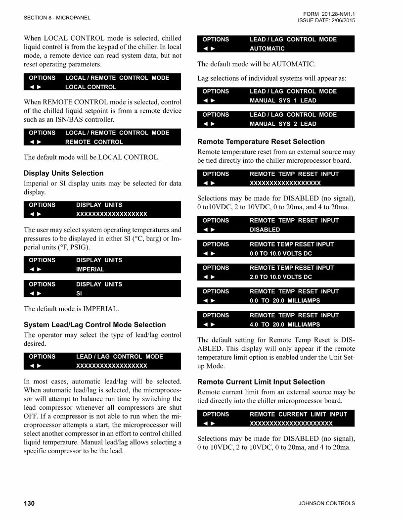
JOHNSON CONTROLS130
SECTION 8 - MICROPANELFORM 201.28-NM1.1
ISSUE DATE: 2/06/2015
When LOCAL CONTROL mode is selected, chilled liquid control is from the keypad of the chiller. In local mode, a remote device can read system data, but not reset operating parameters.
OPTIONS LOCAL / REMOTE CONTROL MODE◄ ► LOCAL CONTROL
When REMOTE CONTROL mode is selected, control of the chilled liquid setpoint is from a remote device such as an ISN/BAS controller.
OPTIONS LOCAL / REMOTE CONTROL MODE◄ ► REMOTE CONTROL
The default mode will be LOCAL CONTROL.
Display Units SelectionImperial or SI display units may be selected for data display.
OPTIONS DISPLAY UNITS◄ ► XXXXXXXXXXXXXXXXXX
The user may select system operating temperatures and pressures to be displayed in either SI (°C, barg) or Im-perial units (°F, PSIG).
OPTIONS DISPLAY UNITS◄ ► IMPERIAL
OPTIONS DISPLAY UNITS◄ ► SI
The default mode is IMPERIAL.
System Lead/Lag Control Mode SelectionThe operator may select the type of lead/lag control desired.
OPTIONS LEAD / LAG CONTROL MODE◄ ► XXXXXXXXXXXXXXXXXX
In most cases, automatic lead/lag will be selected. When automatic lead/lag is selected, the microproces-sor will attempt to balance run time by switching the lead compressor whenever all compressors are shut OFF. If a compressor is not able to run when the mi-croprocessor attempts a start, the microprocessor will select another compressor in an effort to control chilled liquid temperature. Manual lead/lag allows selecting a specific compressor to be the lead.
OPTIONS LEAD / LAG CONTROL MODE◄ ► AUTOMATIC
The default mode will be AUTOMATIC.
Lag selections of individual systems will appear as:
OPTIONS LEAD / LAG CONTROL MODE◄ ► MANUAL SYS 1 LEAD
OPTIONS LEAD / LAG CONTROL MODE◄ ► MANUAL SYS 2 LEAD
Remote Temperature Reset SelectionRemote temperature reset from an external source may be tied directly into the chiller microprocessor board.
OPTIONS REMOTE TEMP RESET INPUT◄ ► XXXXXXXXXXXXXXXXXX
Selections may be made for DISABLED (no signal), 0 to10VDC, 2 to 10VDC, 0 to 20ma, and 4 to 20ma.
OPTIONS REMOTE TEMP RESET INPUT◄ ► DISABLED
OPTIONS REMOTE TEMP RESET INPUT◄ ► 0.0 TO 10.0 VOLTS DC
OPTIONS REMOTE TEMP RESET INPUT◄ ► 2.0 TO 10.0 VOLTS DC
OPTIONS REMOTE TEMP RESET INPUT◄ ► 0.0 TO 20.0 MILLIAMPS
OPTIONS REMOTE TEMP RESET INPUT◄ ► 4.0 TO 20.0 MILLIAMPS
The default setting for Remote Temp Reset is DIS-ABLED. This display will only appear if the remote temperature limit option is enabled under the Unit Set-up Mode.
Remote Current Limit Input SelectionRemote current limit from an external source may be tied directly into the chiller microprocessor board.
OPTIONS REMOTE CURRENT LIMIT INPUT◄ ► XXXXXXXXXXXXXXXXXXXXX
Selections may be made for DISABLED (no signal), 0 to 10VDC, 2 to 10VDC, 0 to 20ma, and 4 to 20ma.
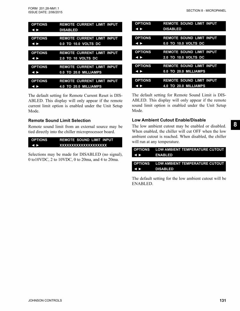
SECTION 8 - MICROPANEL
JOHNSON CONTROLS 131
FORM 201.28-NM1.1ISSUE DATE: 2/06/2015
8
OPTIONS REMOTE CURRENT LIMIT INPUT◄ ► DISABLED
OPTIONS REMOTE CURRENT LIMIT INPUT◄ ► 0.0 TO 10.0 VOLTS DC
OPTIONS REMOTE CURRENT LIMIT INPUT◄ ► 2.0 TO 10 VOLTS DC
OPTIONS REMOTE CURRENT LIMIT INPUT◄ ► 0.0 TO 20.0 MILLIAMPS
OPTIONS REMOTE CURRENT LIMIT INPUT◄ ► 4.0 TO 20.0 MILLIAMPS
The default setting for Remote Current Reset is DIS-ABLED. This display will only appear if the remote current limit option is enabled under the Unit Setup Mode.
Remote Sound Limit SelectionRemote sound limit from an external source may be tied directly into the chiller microprocessor board.
OPTIONS REMOTE SOUND LIMIT INPUT◄ ► XXXXXXXXXXXXXXXXXXXX
Selections may be made for DISABLED (no signal), 0 to10VDC, 2 to 10VDC, 0 to 20ma, and 4 to 20ma.
OPTIONS REMOTE SOUND LIMIT INPUT◄ ► DISABLED
OPTIONS REMOTE SOUND LIMIT INPUT◄ ► 0.0 TO 10.0 VOLTS DC
OPTIONS REMOTE SOUND LIMIT INPUT◄ ► 2.0 TO 10.0 VOLTS DC
OPTIONS REMOTE SOUND LIMIT INPUT◄ ► 0.0 TO 20.0 MILLIAMPS
OPTIONS REMOTE SOUND LIMIT INPUT◄ ► 4.0 TO 20.0 MILLIAMPS
The default setting for Remote Sound Limit is DIS-ABLED. This display will only appear if the remote sound limit option is enabled under the Unit Setup Mode.
Low Ambient Cutout Enable/DisableThe low ambient cutout may be enabled or disabled. When enabled, the chiller will cut OFF when the low ambient cutout is reached. When disabled, the chiller will run at any temperature.
OPTIONS LOW AMBIENT TEMPERATURE CUTOUT◄ ► ENABLED
OPTIONS LOW AMBIENT TEMPERATURE CUTOUT◄ ► DISABLED
The default setting for the low ambient cutout will be ENABLED.
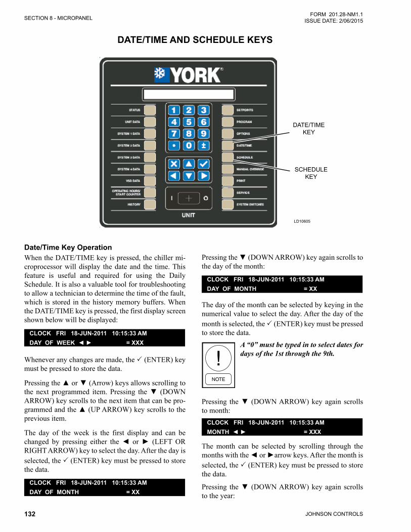
JOHNSON CONTROLS132
SECTION 8 - MICROPANELFORM 201.28-NM1.1
ISSUE DATE: 2/06/2015
DATE/TIME AND SCHEDULE KEYS
LD10605
DATE/TIMEKEY
SCHEDULEKEY
Date/Time Key OperationWhen the DATE/TIME key is pressed, the chiller mi-croprocessor will display the date and the time. This feature is useful and required for using the Daily Schedule. It is also a valuable tool for troubleshooting to allow a technician to determine the time of the fault, which is stored in the history memory buffers. When the DATE/TIME key is pressed, the first display screen shown below will be displayed:
CLOCK FRI 18-JUN-2011 10:15:33 AM DAY OF WEEK ◄ ► = XXX
Whenever any changes are made, the (ENTER) key must be pressed to store the data.
Pressingthe▲or▼(Arrow)keysallowsscrollingtothe next programmed item. Pressing the▼ (DOWNARROW) key scrolls to the next item that can be pro-grammedandthe▲(UPARROW)keyscrollstotheprevious item.
The day of the week is the first display and can be changed by pressing either the◄ or► (LEFTORRIGHT ARROW) key to select the day. After the day is selected, the (ENTER) key must be pressed to store the data.
CLOCK FRI 18-JUN-2011 10:15:33 AM DAY OF MONTH = XX
Pressingthe▼(DOWNARROW)keyagainscrollstothe day of the month:
CLOCK FRI 18-JUN-2011 10:15:33 AM DAY OF MONTH = XX
The day of the month can be selected by keying in the numerical value to select the day. After the day of the month is selected, the (ENTER) key must be pressed to store the data.
A “0” must be typed in to select dates for days of the 1st through the 9th.
Pressing the▼(DOWNARROW)keyagain scrollsto month:
CLOCK FRI 18-JUN-2011 10:15:33 AM MONTH ◄ ► = XXX
The month can be selected by scrolling through the monthswiththe◄or►arrowkeys.Afterthemonthisselected, the (ENTER) key must be pressed to store the data.
Pressing the▼(DOWNARROW)keyagain scrollsto the year:
SECTION 8 - MICROPANEL
JOHNSON CONTROLS 133
FORM 201.28-NM1.1ISSUE DATE: 2/06/2015
8
CLOCK FRI 18-JUN-2011 10:15:33 AM YEAR = XXXX
The year can be selected by keying in the numerical value to select the year. After the year is selected, the (ENTER) key must be pressed to store the data.
Pressing the▼(DOWNARROW)keyagain scrollsto the hour:
CLOCK FRI 18-JUN-2011 10:15:33 AM HOUR = XX
The hour can be selected by keying in the numerical value for the hour. After the hour is selected, the (ENTER) key must be pressed to store the data.
One or two “0’s” must be keyed in for minutes 00 through 09.
Pressing the▼(DOWNARROW)keyagain scrollsto the minute:
CLOCK FRI 18-JUN-2011 10:15:33 AM MINUTE = XX
The minute can be selected by keying in the numerical value for the hour. After the minute is selected, the (ENTER) key must be pressed to store the data.
One or two “0’s” must be keyed in for minutes 00 through 09.
Pressing the▼(DOWNARROW)keyagain scrollsto AM/PM:
CLOCK FRI 18-JUN-2011 10:15:33 AMAM/PM ◄ ► = XX
AM/PM can be selected by pressing the ◄ or ►(ARROW) keys. After the meridian is selected, the (ENTER) key must be pressed to store the data.
Pressingthe▼(DOWNARROW)keyagainscrollstothe time format selection:
CLOCK FRI 18-JUN-2011 10:15:33 AM TIME FORMAT ◄ ► = XXXXXXX
The time format may be displayed in either a 12 hour or 24 hour format. Selection can be changed by press-ingthe◄or►(ARROW) keys. The (ENTER) key must be pressed to store the data.
Schedule Key OperationThe Daily Schedule must be programmed for the unit start and stop times. To set the schedule, press the SCHEDULE key. The display will provide a message allowing access to 2 types of schedule information:
SCHEDULE CHOOSE SCHEDULE TYPE◄ ► XXXXXXXXXXXXXXXXXXXXXXXXX
The schedule types are:
• UNIT OPERATING SCHEDULE
• (Default selection)
• SOUND LIMIT SCHEDULE(Only if Sound Limiting is enabled by the factory when the option is installed.)
The schedule type (UNIT OPERATING SCHEDULE or SOUND LIMIT SCHEDULE) may be changed by pressing the ◄ (LEFT ARROW) or ► (RIGHT AR-ROW) keys followed by the (ENTER) key. The se-lection must be entered by pressing the (ENTER) key before a schedule display will appear.
Unit Operating ScheduleThe Unit Operating Schedule is used to enable/dis-able the chiller unit on time of day. The chiller can be enabled and disabled once each day or it can be pro-grammed to run continuously. Any time the daily or holiday schedule shuts the chiller down, the running system(s) will go through a controlled ramped shut-down. If the UNIT OPERATING SCHEDULE is se-lected under the CHOOSE SCHEDULE display, the following message will appear:
SCHEDULE UNIT OPERATINGMON START = 06:00 AM STOP = 10:00 PM
The line under the 0 above is the cursor. If the start time is wrong, it can be changed by keying in the new time from the numeric keypad. Once the correct val-ues for the START hour and minute are entered, press the (ENTER) key. The cursor will then move to the AM/PM selection. The meridian (AM/PM) value may bechangedbythe◄(LEFTARROW)or►(RIGHTARROW) keys and entered by pressing (ENTER) key. Repeat this process for the STOP time. Once a schedule is entered, the schedule for the next day will
JOHNSON CONTROLS134
SECTION 8 - MICROPANELFORM 201.28-NM1.1
ISSUE DATE: 2/06/2015
appear. The start and stop time of each day may be pro-grammed differently.
To view the schedule without making a change, sim-ply press the SCHEDULE key until the day you wish toviewappears.The▲(UPARROW)keywillscrollbackwards to the previous screen.
If at any time the schedule is changed for Monday, all the other days will change to the new Monday schedule. This means if the Monday times are not applicable for the whole week, then the exceptional days would need to be reprogrammed to the desired schedule.
To program the chiller for 24 hour operation, program the start and stop times of each day of the week for 00:00.
After the SUN (Sunday) schedule appears on the dis-play,asubsequentpressoftheSCHEDULEor▲(UPARROW) key will display the Holiday schedule. This is a two-part display. The first reads:
SCHEDULE UNIT OPERATINGHOL START = 00:00 AM STOP = 00:00 PM
The holiday times may be set using the same procedure as described above for the days of the week. Be sure to press the (ENTER) key after setting the START and STOP times to save the change in memory. Pressing the SCHEDULE key a second time, the display will show the individual days:
SCHEDULE UNIT OPERATINGS M T W T F S HOLIDAY NOTED BY *
The line below the empty space is the cursor and will movetothenextorpreviousemptyspacewhenthe◄(LEFTARROW)or► (RIGHTARROW)keys andpressed. To set a day for the Holiday Schedule, the cur-sor must be moved to the space following the day of the week. The * key is then pressed and an “*” will appear in the space signifying that day as a holiday. The Holiday schedule must be programmed weekly. If there is no holiday, the “*” key is also used to delete the “*”. The (ENTER) key is used to accept the holiday schedule for the entire week.
The HOLIDAY SCHEDULE is a tem-porary schedule. Once the schedule is executed, the selected holidays will be cleared from memory for the following week.
Sound Limit ScheduleThe SOUND LIMIT SCHEDULE allows setting the day and time when the user desires using the “SILENT NIGHT” factory programmed option to limit chiller loading and fan operation for reduced audible noise in the surrounding area. If the SOUND LIMIT SCHED-ULE is selected under the CHOOSE SCHEDULE dis-play, the following message will appear:
SCHEDULE SOUND LIMIT = XXX %MON START = 06:00 AM STOP = 10:00 PM
The Sound Limit option can be enabled and disabled once each day or the chiller can be set to run continu-ously in this mode for sound limiting whenever the chiller is operating. When sound limiting is enabled, the unit will be limited by the Sound Limit setpoint % as set under the PROGRAM key. XXX in the dis-play above will show the Sound Limit Setpoint % pro-grammed under the PROGRAM key. 0% will cause no speed reduction, while 100% only allows running at minimum speed.
The START Time for a specific day (hour and minute) is entered using the same guidelines used for the start/stop schedules, and press the (ENTER) key to store it into memory. The cursor will then move to the AM/PM selection.
TheAM/PM selection may be chosen using the ◄(LEFTARROW)or► (RIGHTARROW)keys andpressing (ENTER) key to store the value.
This process is repeated for the STOP time.
Once the schedule for a specific day is programmed and entered, the schedule for the next day will appear. The schedule for each day may be programmed the same or differently.
To view the schedule without changing it, simply press theSCHEDULEkeyorthe▼(DOWNARROW)keyuntilthedesireddayisdisplayed.The▲(UPARROW)key will scroll backwards to the previous screen.
If the schedule is changed for Monday, all other days will change to the Mon-day schedule. Be aware of this when programming.
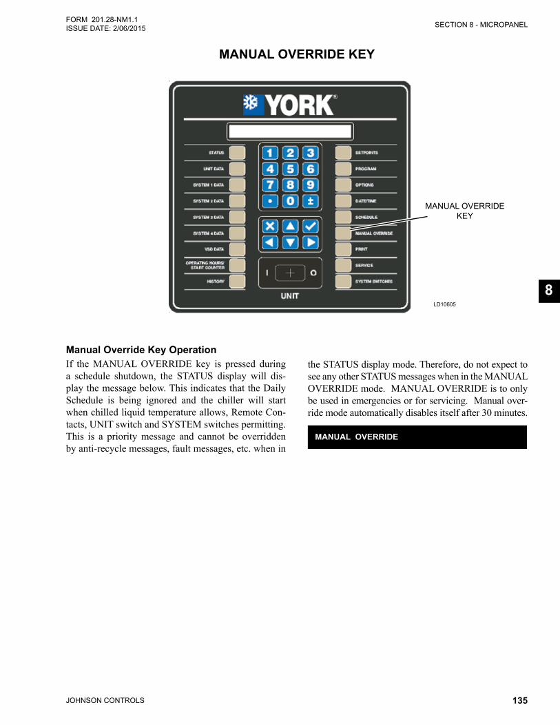
SECTION 8 - MICROPANEL
JOHNSON CONTROLS 135
FORM 201.28-NM1.1ISSUE DATE: 2/06/2015
8
LD10605
MANUAL OVERRIDEKEY
MANUAL OVERRIDE KEY
Manual Override Key OperationIf the MANUAL OVERRIDE key is pressed during a schedule shutdown, the STATUS display will dis-play the message below. This indicates that the Daily Schedule is being ignored and the chiller will start when chilled liquid temperature allows, Remote Con-tacts, UNIT switch and SYSTEM switches permitting. This is a priority message and cannot be overridden by anti-recycle messages, fault messages, etc. when in
the STATUS display mode. Therefore, do not expect to see any other STATUS messages when in the MANUAL OVERRIDE mode. MANUAL OVERRIDE is to only be used in emergencies or for servicing. Manual over-ride mode automatically disables itself after 30 minutes.
MANUAL OVERRIDE
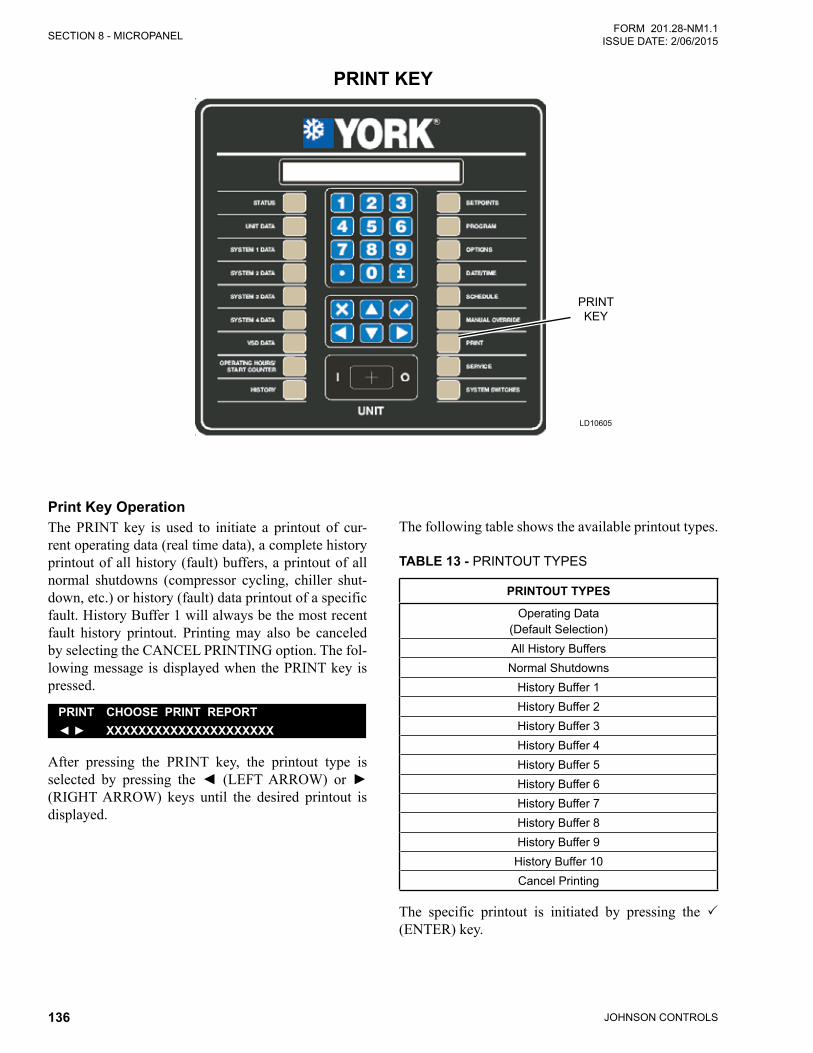
JOHNSON CONTROLS136
SECTION 8 - MICROPANELFORM 201.28-NM1.1
ISSUE DATE: 2/06/2015
LD10605
PRINTKEY
PRINT KEY
Print Key OperationThe PRINT key is used to initiate a printout of cur-rent operating data (real time data), a complete history printout of all history (fault) buffers, a printout of all normal shutdowns (compressor cycling, chiller shut-down, etc.) or history (fault) data printout of a specific fault. History Buffer 1 will always be the most recent fault history printout. Printing may also be canceled by selecting the CANCEL PRINTING option. The fol-lowing message is displayed when the PRINT key is pressed.
PRINT CHOOSE PRINT REPORT◄ ► XXXXXXXXXXXXXXXXXXXXX
After pressing the PRINT key, the printout type is selected by pressing the◄ (LEFTARROW) or►(RIGHT ARROW) keys until the desired printout is displayed.
The following table shows the available printout types.
TABLE 13 - PRINTOUT TYPES
PRINTOUT TYPES
Operating Data (Default Selection)All History BuffersNormal Shutdowns
History Buffer 1History Buffer 2History Buffer 3History Buffer 4History Buffer 5History Buffer 6History Buffer 7History Buffer 8History Buffer 9
History Buffer 10Cancel Printing
The specific printout is initiated by pressing the (ENTER) key.
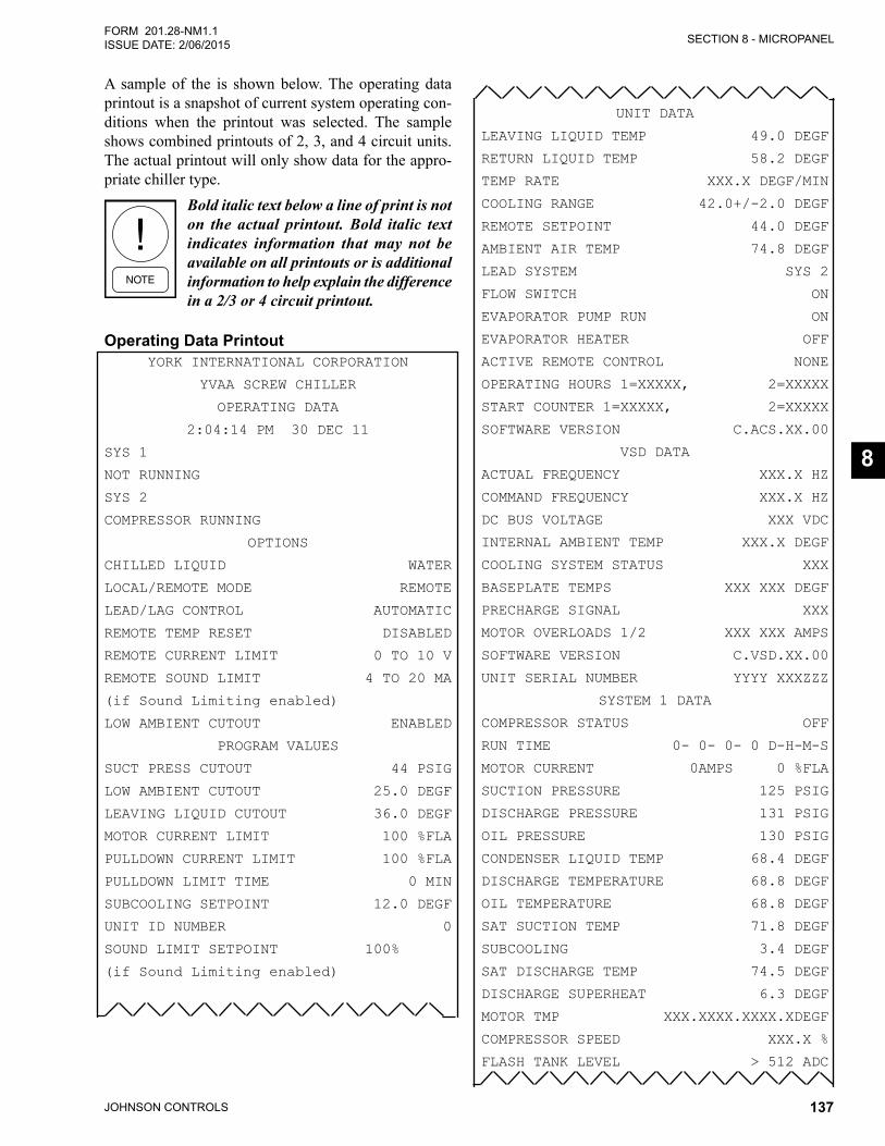
SECTION 8 - MICROPANEL
JOHNSON CONTROLS 137
FORM 201.28-NM1.1ISSUE DATE: 2/06/2015
8
A sample of the is shown below. The operating data printout is a snapshot of current system operating con-ditions when the printout was selected. The sample shows combined printouts of 2, 3, and 4 circuit units. The actual printout will only show data for the appro-priate chiller type.
Bold italic text below a line of print is not on the actual printout. Bold italic text indicates information that may not be available on all printouts or is additional information to help explain the difference in a 2/3 or 4 circuit printout.
Operating Data PrintoutYORK INTERNATIONAL CORPORATION
YVAA SCREW CHILLER
OPERATING DATA
2:04:14 PM 30 DEC 11
SYS 1
NOT RUNNING
SYS 2
COMPRESSOR RUNNING
OPTIONS
CHILLED LIQUID WATER
LOCAL/REMOTE MODE REMOTE
LEAD/LAG CONTROL AUTOMATIC
REMOTE TEMP RESET DISABLED
REMOTE CURRENT LIMIT 0 TO 10 V
REMOTE SOUND LIMIT 4 TO 20 MA
(if Sound Limiting enabled)
LOW AMBIENT CUTOUT ENABLED
PROGRAM VALUES
SUCT PRESS CUTOUT 44 PSIG
LOW AMBIENT CUTOUT 25.0 DEGF
LEAVING LIQUID CUTOUT 36.0 DEGF
MOTOR CURRENT LIMIT 100 %FLA
PULLDOWN CURRENT LIMIT 100 %FLA
PULLDOWN LIMIT TIME 0 MIN
SUBCOOLING SETPOINT 12.0 DEGF
UNIT ID NUMBER 0
SOUND LIMIT SETPOINT 100%
(if Sound Limiting enabled)
UNIT DATA
LEAVING LIQUID TEMP 49.0 DEGF
RETURN LIQUID TEMP 58.2 DEGF
TEMP RATE XXX.X DEGF/MIN
COOLING RANGE 42.0+/-2.0 DEGF
REMOTE SETPOINT 44.0 DEGF
AMBIENT AIR TEMP 74.8 DEGF
LEAD SYSTEM SYS 2
FLOW SWITCH ON
EVAPORATOR PUMP RUN ON
EVAPORATOR HEATER OFF
ACTIVE REMOTE CONTROL NONE
OPERATING HOURS 1=XXXXX, 2=XXXXX
START COUNTER 1=XXXXX, 2=XXXXX
SOFTWARE VERSION C.ACS.XX.00
VSD DATA
ACTUAL FREQUENCY XXX.X HZ
COMMAND FREQUENCY XXX.X HZ
DC BUS VOLTAGE XXX VDC
INTERNAL AMBIENT TEMP XXX.X DEGF
COOLING SYSTEM STATUS XXX
BASEPLATE TEMPS XXX XXX DEGF
PRECHARGE SIGNAL XXX
MOTOR OVERLOADS 1/2 XXX XXX AMPS
SOFTWARE VERSION C.VSD.XX.00
UNIT SERIAL NUMBER YYYY XXXZZZ
SYSTEM 1 DATA
COMPRESSOR STATUS OFF
RUN TIME 0- 0- 0- 0 D-H-M-S
MOTOR CURRENT 0AMPS 0 %FLA
SUCTION PRESSURE 125 PSIG
DISCHARGE PRESSURE 131 PSIG
OIL PRESSURE 130 PSIG
CONDENSER LIQUID TEMP 68.4 DEGF
DISCHARGE TEMPERATURE 68.8 DEGF
OIL TEMPERATURE 68.8 DEGF
SAT SUCTION TEMP 71.8 DEGF
SUBCOOLING 3.4 DEGF
SAT DISCHARGE TEMP 74.5 DEGF
DISCHARGE SUPERHEAT 6.3 DEGF
MOTOR TMP XXX.XXXX.XXXX.XDEGF
COMPRESSOR SPEED XXX.X %
FLASH TANK LEVEL > 512 ADC
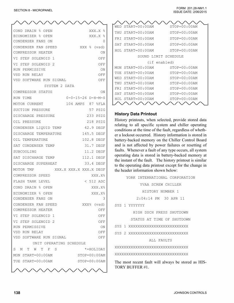
JOHNSON CONTROLS138
SECTION 8 - MICROPANELFORM 201.28-NM1.1
ISSUE DATE: 2/06/2015
COND DRAIN % OPEN XXX.X %ECONOMIZER % OPEN XXX.X %CONDENSER FANS ON 0
CONDENSER FAN SPEED XXX % (vsd)COMPRESSOR HEATER ON
VI STEP SOLENOID 1 OFF
VI STEP SOLENOID 2 OFFRUN PERMISSIVE ONVSD RUN RELAY OFFVSD SOFTWARE RUN SIGNAL OFF
SYSTEM 2 DATA
COMPRESSOR STATUS ON
RUN TIME 0-0-15-26 D-H-M-S
MOTOR CURRENT 104 AMPS 87 %FLA
SUCTION PRESSURE 57 PSIG
DISCHARGE PRESSURE 233 PSIG
OIL PRESSURE 218 PSIG
CONDENSER LIQUID TEMP 42.9 DEGF
DISCHARGE TEMPERATURE 145.5 DEGF
OIL TEMPERATURE 102.8 DEGF
SAT CONDENSER TEMP 31.7 DEGF
SUBCOOLING 11.2 DEGF
SAT DISCHARGE TEMP 112.1 DEGF
DISCHARGE SUPERHEAT 33.4 DEGF
MOTOR TMP XXX.X XXX.X XXX.X DEGF
COMPRESSOR SPEED XXX.X%
FLASH TANK LEVEL < 512 ADC
COND DRAIN % OPEN XXX.X%
ECONOMIZER % OPEN XXX.X%CONDENSER FANS ON 3
CONDENSER FAN SPEED XXX% (vsd)COMPRESSOR HEATER OFF
VI STEP SOLENOID 1 OFF
VI STEP SOLENOID 2 OFFRUN PERMISSIVE ONVSD RUN RELAY OFFVSD SOFTWARE RUN SIGNAL OFF
UNIT OPERATING SCHEDULE
S M T W T F S *=HOLIDAY
MON START=00:00AM STOP=00:00AM
TUE START=00:00AM STOP=00:00AM
WED START=00:00AM STOP=00:00AM
THU START=00:00AM STOP=00:00AM
FRI START=00:00AM STOP=00:00AM
SAT START=00:00AM STOP=00:00AM
HOL START=00:00AM STOP=00:00AM
SOUND LIMIT SCHEDULE
(if enabled)MON START=00:00AM STOP=00:00AMTUE START=00:00AM STOP=00:00AMWED START=00:00AM STOP=00:00AMTHU START=00:00AM STOP=00:00AMFRI START=00:00AM STOP=00:00AMSAT START=00:00AM STOP=00:00AMHOL START=00:00AM STOP=00:00AM
History Data PrintoutHistory printouts, when selected, provide stored data relating to all specific system and chiller operating conditions at the time of the fault, regardless of wheth-er a lockout occurred. History information is stored in battery-backed memory on the Chiller Control Board and is not affected by power failures or resetting of faults. Whenever a fault of any type occurs, all system operating data is stored in battery-backed memory at the instant of the fault. The history printout is similar to the operating data printout except for the change in the header information shown below:
YORK INTERNATIONAL CORPORATION
YVAA SCREW CHILLER
HISTORY NUMBER 1
2:04:14 PM 30 APR 11
SYS 1 YYYYYYY
HIGH DSCH PRESS SHUTDOWN
STATUS AT TIME OF SHUTDOWN
SYS 1 XXXXXXXXXXXXXXXXXXXXXXXXXX
SYS 2 XXXXXXXXXXXXXXXXXXXXXXXXXX
ALL FAULTS
XXXXXXXXXXXXXXXXXXXXXXXXXXXXXXXX
XXXXXXXXXXXXXXXXXXXXXXXXXXXXXXXX
The most recent fault will always be stored as HIS-TORY BUFFER #1.
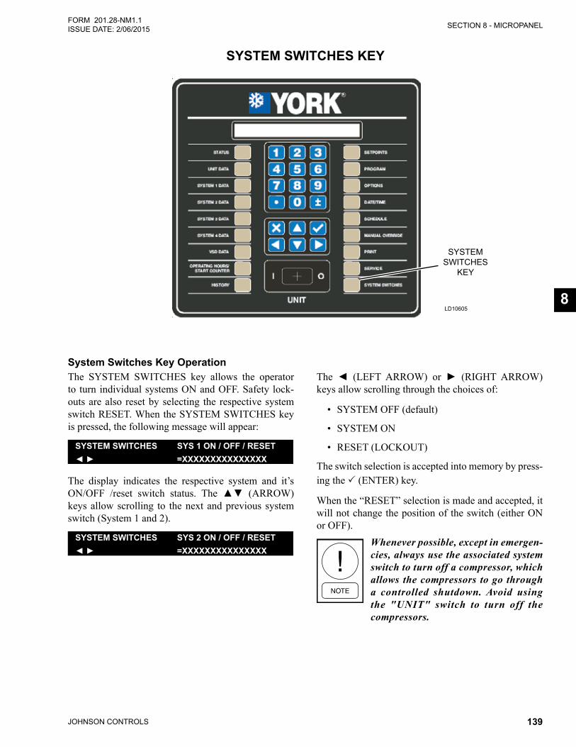
SECTION 8 - MICROPANEL
JOHNSON CONTROLS 139
FORM 201.28-NM1.1ISSUE DATE: 2/06/2015
8
LD10605
SYSTEM SWITCHES
KEY
SYSTEM SWITCHES KEY
System Switches Key OperationThe SYSTEM SWITCHES key allows the operator to turn individual systems ON and OFF. Safety lock-outs are also reset by selecting the respective system switch RESET. When the SYSTEM SWITCHES key is pressed, the following message will appear:
SYSTEM SWITCHES SYS 1 ON / OFF / RESET◄ ► =XXXXXXXXXXXXXXX
The display indicates the respective system and it’s ON/OFF /reset switch status. The ▲▼ (ARROW)keys allow scrolling to the next and previous system switch (System 1 and 2).
SYSTEM SWITCHES SYS 2 ON / OFF / RESET◄ ► =XXXXXXXXXXXXXXX
The ◄ (LEFT ARROW) or ► (RIGHT ARROW)keys allow scrolling through the choices of:
• SYSTEM OFF (default)
• SYSTEM ON
• RESET (LOCKOUT)
The switch selection is accepted into memory by press-ing the (ENTER) key.
When the “RESET” selection is made and accepted, it will not change the position of the switch (either ON or OFF).
Whenever possible, except in emergen-cies, always use the associated system switch to turn off a compressor, which allows the compressors to go through a controlled shutdown. Avoid using the "UNIT" switch to turn off the compressors.

JOHNSON CONTROLS140
FORM 201.28-NM1.1 ISSUE DATE: 2/06/2015
THIS PAGE INTENTIONALLY LEFT BLANK.
JOHNSON CONTROLS 141
FORM 201.28-NM1.1ISSUE DATE: 2/06/2015
9
GENERAL REQUIREMENTSThe units have been designed to operate continuously, provided they are regularly maintained and operated within the limitations given in this manual. Each unit should be included in a routine schedule of daily main-tenance checks by the operator/customer, backed up by regular service inspection and maintenance visits by a suitably qualified Service Engineer.
It is entirely the responsibility of the owner to pro-vide for these regular maintenance requirements and/or enter into a maintenance agreement with a Johnson Controls service organization to protect the operation of the unit. If damage or a system failure occurs due to improper maintenance during the warranty period, Johnson Controls shall not be liable for costs incurred to return the unit to satisfactory condition.
This “Maintenance” section applies to the basic unit only and may, on individual contracts, be supplemented by additional requirements to cover any modifications or ancillary equipment as applicable.
The “Safety” section of this manual should be read carefully before attempt-ing any maintenance operations on the unit.
Weekly MaintenanceThe following maintenance checks should be carried out on a weekly basis by the operator/customer. Please note that the units are not generally user serviceable and no attempt should be made to rectify faults or problems found during daily checks unless competent and equipped to do so. If in any doubt, contact your lo-cal Johnson Controls Service Agent.
Unit StatusPress the ‘STATUS’ key on the keypad and ensure no fault messages are displayed.
SECTION 9 - MAINTENANCE
Refrigerant LeaksVisually check the heat exchangers, compressors and pipework for damage and gas leaks.
Operating ConditionsRead the operating pressures and temperatures at the control panel using the display keys and check that these are within the operating limitations given in the manual.
Compressor Oil LevelCompressor oil level will typically run below the bot-tom of the sight glass. Oil levels will only be visible in the sight glass after running for periods of 15 to 30 minutes at full compressor speed. Do not run with oil levels above the sight glass. Be careful when viewing the sight glass not to confuse a full sight glass with an empty sight glass.
Refrigerant ChargeAssure there is a level of refrigerant in the evaporator sight glass while running at “Full Load” for 15 to 30 minutes.
Adding Charge to a SystemA sight glass is located in the evaporator. When opti-mally charged after running full load, the refrigerant level should be approximately in the center of the sight glass. There should be little concern if the level is high or low in the glass, it should not affect operation.
It is not necessary to weigh charge unless the entire charge has been lost. The ease of charging is possible since the micro-channel coils hold only a small amount of refrigerant charge. A charging valve, located between the fixed orifice and the evaporator, may be used if charge adjust-ment is required. Charge should be added as liquid while circulating water through the evaporator. If the complete charge needs to be added, see Refrigerant Re-moval, Evacuation and Charging a YVAA Chiller on Page 142 in this section. Use the valve on the liquid line for adding the full charge and open the valves per the procedure.
JOHNSON CONTROLS142
SECTION 9 - MAINTENANCEFORM 201.28-NM1.1
ISSUE DATE: 2/06/2015
REFRIGERANT REMOVAL, EVACUATION AND CHARGING A YVAA CHILLER
Refrigerant RemovalThe YVAA utilizes a flooded evaporator. Extreme care must be taken when removing refrigerant to prevent damage to the evaporator and the chiller. Carefully re-view the following caution below before proceeding with the recommended process.
Incorrect removal of refrigerant will result in catastrophic freeze damage to the evaporator and possible additional damage to other chiller components. Whenever there is water in the evaporator, the chilled liquid pumps must be ON and circulating liquid through the evaporator above minimum recommended flow rates. When liquid refrigerant is being removed, monitor the pressure and do not allow the pressure to drop below the freeze point of the chilled liquid flowing through the evaporator until all liquid refrigerant has been removed from the evaporator and only gas remains. Once all liquid has been removed, the remaining refrigerant vapor can be removed while allowing the pressure to drop below the freeze point with the pump circulating liquid through the evaporator.
To remove refrigerant from the evaporator, follow the procedure below:
1. Turn the chilled liquid pump ON and assure the flowisabovetheminimumrecommendedflow.
2. Assure all manual valves in the system are open. Open Condenser Drain and Economizer Feed valves to 100% in the service mode.
3. Connect the recovery unit and a manifold gauge to the liquid line feeding the eductor. There may beavalveinthelineoraSchraderfittingontheeductorfilterforthispurpose.
4. Connect the recovery unit to a recovery cylinder sitting on an accurate scale. Turn the recovery unitONandobservetheliquidrefrigerantflow-ing from the line into the cylinder.Theflowofliquid should be obvious.
5. Monitor the pressure gauge to assure that the pres-sure does not drop below the freeze point of the chilledliquid.Throttletheflowasneededwiththemanifold gauge valves to prevent pressures from dropping below the freeze point.
6. Continue to remove the liquid refrigerant while observing the flow and the pressure. Note thecharge in the system based on the nameplate data to determine when the charge removal is nearly complete. Monitor the weight of the recovery cylinder to determine when the cylinder is full. Change the cylinder as needed.
7. Continue removing refrigerant until liquid is no longerobservedflowinginthemanifoldhoses.
8. Once the liquid is removed and no longer visible in the hose, the remaining gas can be pumped out with the recovery unit while the pressure is al-lowed to drop to 0 barg (0 PSIG).
9. Servicing may now be performed on the system as needed.
Evacuating a SystemTo evacuate a system, follow the procedure below:
1. Turn the chilled liquid pump ON and assure the flowisabovetheminimumrecommendedflow.
2. Assure all manual values are open. Open the Con-denser Drain (Flash Tank Feed) and Economizer Valves in the Service Mode to 100 %
3. Connect vacuum hoses to as many points as pos-sible. Be sure that at least one connection is made on both the high and low side of the piping. A con-nectiontotheevacuationfittingonthecompres-sor is also recommended. Evacuate the system to a minimum of 500 microns. Close the valves at the evacuation points and assure the pressure in the chiller does not rise more than 50 microns in 10 minutes. Check for leaks if the pressure rises.
SECTION 9 - MAINTENANCE
JOHNSON CONTROLS 143
FORM 201.28-NM1.1ISSUE DATE: 2/06/2015
9
Charging Refrigerant into a SystemTo charge the system with refrigerant, follow the pro-cedure below:
1. With all system valves open and the Condenser Drain and Economizer Valves open to 100% by manually opening them in the Service Mode, charge refrigerant vapor into the high side of the system at the charging port on the liquid line. Con-tinue charging vapor until the pressure is above the freeze point of the chilled liquid. Once above the freeze point, liquid can be charged according to the recommended nameplate charge.
2. Reconnect the water piping to the water boxes.
3. Close the evaporator drain valves and fill theevaporator with water from the cooling loop.
4. Fill the water loop and check for leaks.
5. Close (0%) the Condenser Drain and Economizer Valve in the Service Mode. Recycle the chiller power.
6. Once the system is operating, the charge will distribute itself throughout the system. Trim the charge as needed to a level of about midway on the evaporator sight glass while running full speed for 15 minutes.
MICROCHANNEL COIL CLEANINGThe coil cleaning procedure for microchannel coils is significantly different than tube and fin type coils. As such, care must be taken to understand the differences to avoid damage to the microchannel coil. These dif-ferences require a number of DO NOT’s that must be observed:
• DO NOT use coil cleaners or any chemical on a microchannel coil. This can cause severe damage to the coils.
• DO NOT use a pressure washer to clean the coils. While it is possible to clean a coil with a pressure washer, it’s also possible to destroy it.
• DO NOT contact the coil with a hard surface such as a hose nozzle or metal vacuum nozzle or any other tool.
Microchannel coils tend to accumulate more dirt on the surface, but less dirt inside the coils, which makes them easier to clean. Follow the three steps below for cleaning the coils:
1. Remove surface debris such as dirt, leaves, in-sects, fibers, etc.with a vacuum cleaner havinga soft attachment rather than a metal tube. Com-pressed air blown from the inside out can also be used. When brushing debris off the face of the coil a soft bristle (not wire) brush can be used. Do not scrape the coil with the vacuum nozzle, air nozzle, or any other tool.
2. Rinse the coil with tap water. Do not use coil cleaners. Rinse the coil from the inside out, run-ning water through every passage in the heat ex-changer surface until it is clean. Microchannel coilsarestrongerthanconventionaltubeandfincoils, but handle them with care, since you can cause a leak due to impact. Use a gentle spray from a spray nozzle with a plastic end or put your finger on the end of the spray nozzle to reduceimpact and provide a gentle spray.
3. Becauseof thefingeometry,microchannelcoilsretainwatermorethantubeandfinstyle.Itisgen-erally recommended to blow or vacuum out the rinse water from the coils to speed drying and pre-vent water pooling.
Scheduled MaintenanceThe maintenance operations detailed in the following table should be carried out on a regular basis by a suit-ably qualified Service Engineer. It should be noted that the interval necessary between each ‘minor’ and ‘ma-jor’ service can vary depending on, for instance, appli-cation, site conditions and expected operating sched-ule. Normally a ‘minor’ service should be carried out every three to six months and a ‘major’ service once a year. It is recommended that your local Johnson Con-trols Service Center is contacted for recommendations for individual sites.
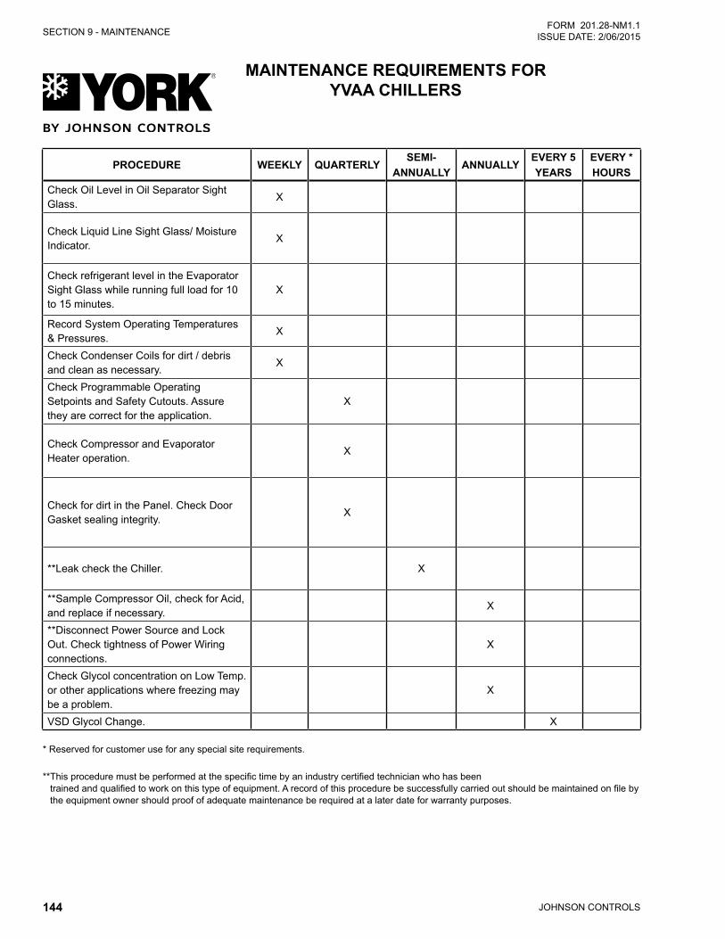
JOHNSON CONTROLS144
SECTION 9 - MAINTENANCEFORM 201.28-NM1.1
ISSUE DATE: 2/06/2015
PROCEDURE WEEKLY QUARTERLYSEMI-
ANNUALLYANNUALLY
EVERY 5YEARS
EVERY *HOURS
Check Oil Level in Oil Separator Sight Glass.
X
Check Liquid Line Sight Glass/ Moisture Indicator.
X
Check refrigerant level in the Evaporator Sight Glass while running full load for 10 to 15 minutes.
X
Record System Operating Temperatures & Pressures.
X
Check Condenser Coils for dirt / debris and clean as necessary.
X
Check Programmable Operating Setpoints and Safety Cutouts. Assure they are correct for the application.
X
Check Compressor and Evaporator Heater operation.
X
Check for dirt in the Panel. Check Door Gasket sealing integrity.
X
**Leak check the Chiller. X
**Sample Compressor Oil, check for Acid, and replace if necessary.
X
**Disconnect Power Source and Lock Out. Check tightness of Power Wiring connections.
X
Check Glycol concentration on Low Temp. or other applications where freezing may be a problem.
X
VSD Glycol Change. X
* Reserved for customer use for any special site requirements.
** This procedure must be performed at the specific time by an industry certified technician who has been trained and qualified to work on this type of equipment. A record of this procedure be successfully carried out should be maintained on file by the equipment owner should proof of adequate maintenance be required at a later date for warranty purposes.
MAINTENANCE REQUIREMENTS FOR YVAA CHILLERS
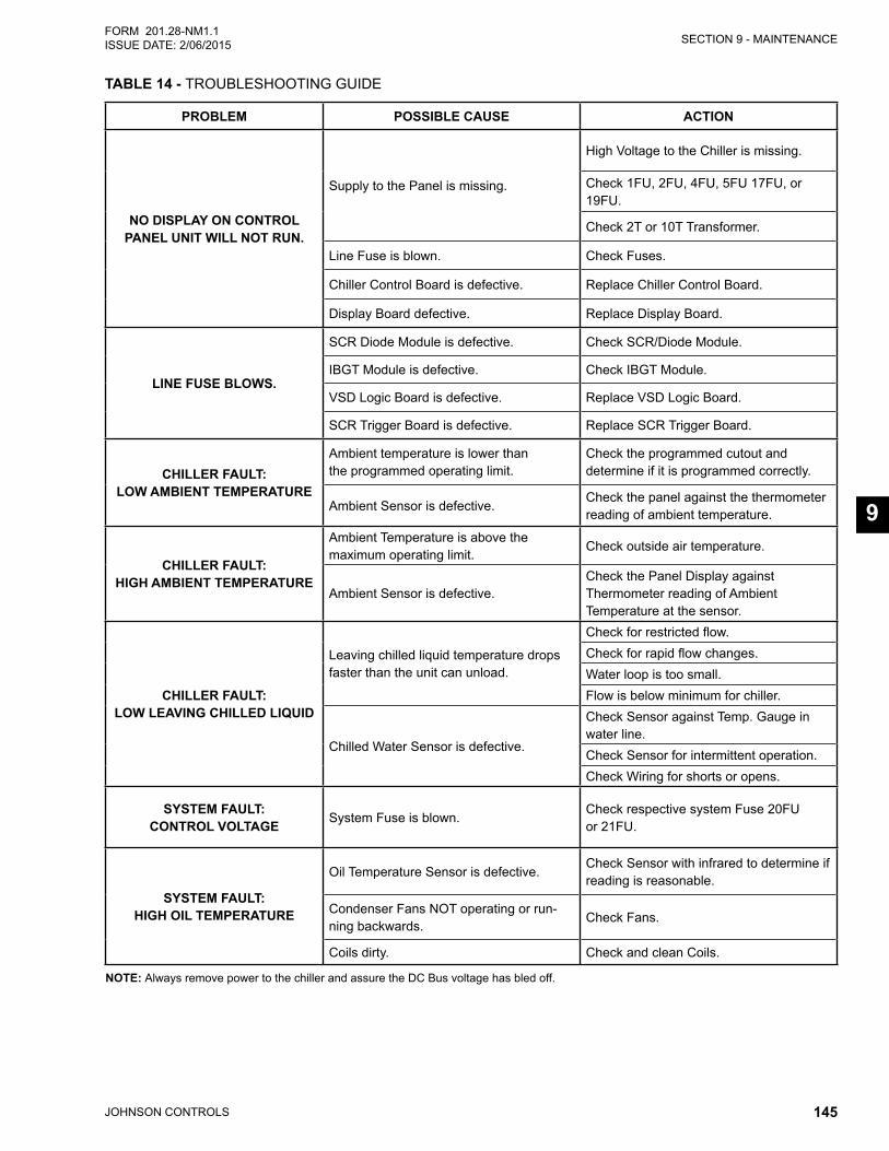
SECTION 9 - MAINTENANCE
JOHNSON CONTROLS 145
FORM 201.28-NM1.1ISSUE DATE: 2/06/2015
9
TABLE 14 - TROUBLESHOOTING GUIDE
PROBLEM POSSIBLE CAUSE ACTION
NO DISPLAY ON CONTROL PANEL UNIT WILL NOT RUN.
Supply to the Panel is missing.
High Voltage to the Chiller is missing.
Check 1FU, 2FU, 4FU, 5FU 17FU, or 19FU.
Check 2T or 10T Transformer.
Line Fuse is blown. Check Fuses.
Chiller Control Board is defective. Replace Chiller Control Board.
Display Board defective. Replace Display Board.
LINE FUSE BLOWS.
SCR Diode Module is defective. Check SCR/Diode Module.
IBGT Module is defective. Check IBGT Module.
VSD Logic Board is defective. Replace VSD Logic Board.
SCR Trigger Board is defective. Replace SCR Trigger Board.
CHILLER FAULT: LOW AMBIENT TEMPERATURE
Ambient temperature is lower than the programmed operating limit.
Check the programmed cutout and determine if it is programmed correctly.
Ambient Sensor is defective.Check the panel against the thermometer reading of ambient temperature.
CHILLER FAULT: HIGH AMBIENT TEMPERATURE
Ambient Temperature is above the maximum operating limit.
Check outside air temperature.
Ambient Sensor is defective.Check the Panel Display against Thermometer reading of Ambient Temperature at the sensor.
CHILLER FAULT: LOW LEAVING CHILLED LIQUID
Leaving chilled liquid temperature drops faster than the unit can unload.
Check for restricted flow.Check for rapid flow changes.Water loop is too small.Flow is below minimum for chiller.
Chilled Water Sensor is defective.
Check Sensor against Temp. Gauge in water line.Check Sensor for intermittent operation.Check Wiring for shorts or opens.
SYSTEM FAULT: CONTROL VOLTAGE System Fuse is blown.
Check respective system Fuse 20FU or 21FU.
SYSTEM FAULT: HIGH OIL TEMPERATURE
Oil Temperature Sensor is defective.Check Sensor with infrared to determine if reading is reasonable.
Condenser Fans NOT operating or run-ning backwards.
Check Fans.
Coils dirty. Check and clean Coils.
NOTE: Always remove power to the chiller and assure the DC Bus voltage has bled off.
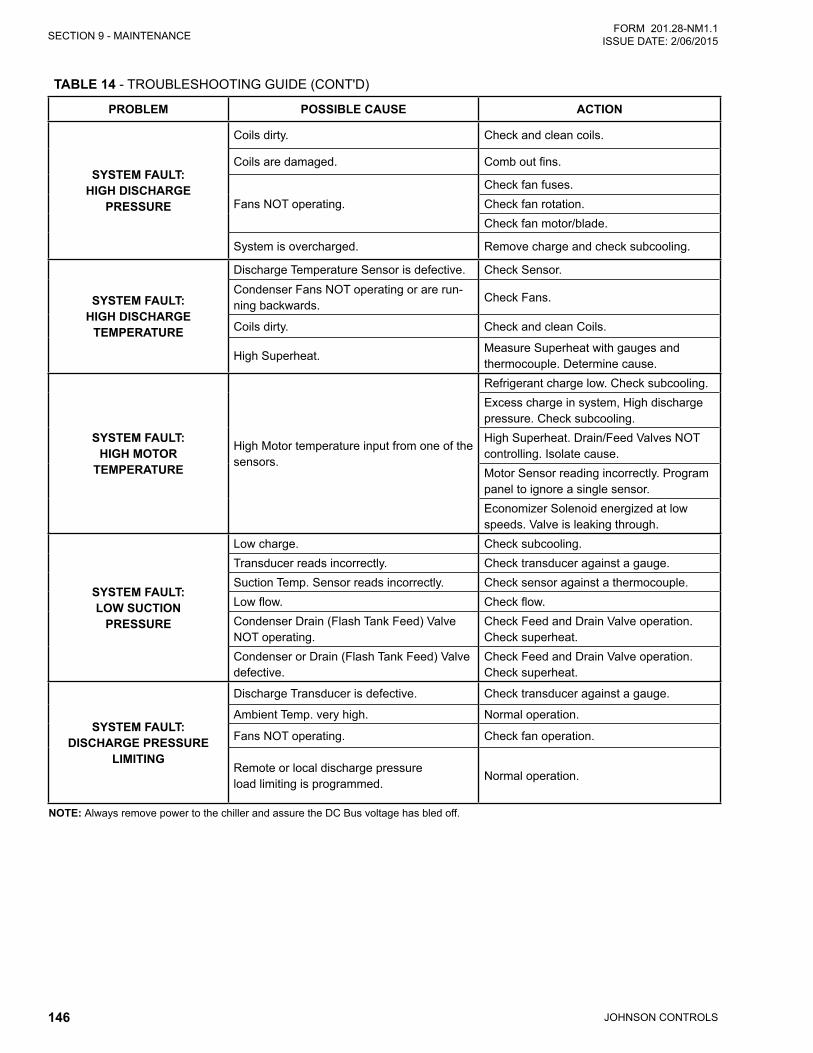
JOHNSON CONTROLS146
SECTION 9 - MAINTENANCEFORM 201.28-NM1.1
ISSUE DATE: 2/06/2015
TABLE 14 - TROUBLESHOOTING GUIDE (CONT'D)
PROBLEM POSSIBLE CAUSE ACTION
SYSTEM FAULT: HIGH DISCHARGE
PRESSURE
Coils dirty. Check and clean coils.
Coils are damaged. Comb out fins.
Fans NOT operating.Check fan fuses.Check fan rotation.Check fan motor/blade.
System is overcharged. Remove charge and check subcooling.
SYSTEM FAULT: HIGH DISCHARGE
TEMPERATURE
Discharge Temperature Sensor is defective. Check Sensor.Condenser Fans NOT operating or are run-ning backwards.
Check Fans.
Coils dirty. Check and clean Coils.
High Superheat.Measure Superheat with gauges and thermocouple. Determine cause.
SYSTEM FAULT: HIGH MOTOR
TEMPERATURE
High Motor temperature input from one of the sensors.
Refrigerant charge low. Check subcooling.Excess charge in system, High discharge pressure. Check subcooling.High Superheat. Drain/Feed Valves NOT controlling. Isolate cause.Motor Sensor reading incorrectly. Program panel to ignore a single sensor.Economizer Solenoid energized at low speeds. Valve is leaking through.
SYSTEM FAULT: LOW SUCTION
PRESSURE
Low charge. Check subcooling.Transducer reads incorrectly. Check transducer against a gauge.Suction Temp. Sensor reads incorrectly. Check sensor against a thermocouple.Low flow. Check flow.Condenser Drain (Flash Tank Feed) Valve NOT operating.
Check Feed and Drain Valve operation.Check superheat.
Condenser or Drain (Flash Tank Feed) Valve defective.
Check Feed and Drain Valve operation.Check superheat.
SYSTEM FAULT: DISCHARGE PRESSURE
LIMITING
Discharge Transducer is defective. Check transducer against a gauge.
Ambient Temp. very high. Normal operation.
Fans NOT operating. Check fan operation.
Remote or local discharge pressureload limiting is programmed.
Normal operation.
NOTE: Always remove power to the chiller and assure the DC Bus voltage has bled off.
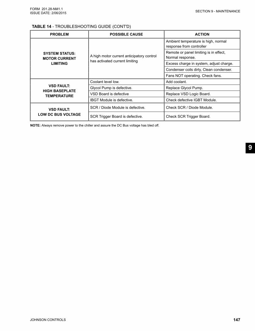
SECTION 9 - MAINTENANCE
JOHNSON CONTROLS 147
FORM 201.28-NM1.1ISSUE DATE: 2/06/2015
9
TABLE 14 - TROUBLESHOOTING GUIDE (CONT'D)
PROBLEM POSSIBLE CAUSE ACTION
SYSTEM STATUS: MOTOR CURRENT
LIMITING
A high motor current anticipatory control has activated current limiting
Ambient temperature is high, normal response from controllerRemote or panel limiting is in effect, Normal response.Excess charge in system, adjust charge.Condenser coils dirty, Clean condenser.Fans NOT operating. Check fans.
VSD FAULT: HIGH BASEPLATE
TEMPERATURE
Coolant level low. Add coolant.Glycol Pump is defective. Replace Glycol Pump.VSD Board is defective Replace VSD Logic Board.IBGT Module is defective. Check defective IGBT Module.
VSD FAULT: LOW DC BUS VOLTAGE
SCR / Diode Module is defective. Check SCR / Diode Module.
SCR Trigger Board is defective. Check SCR Trigger Board.
NOTE: Always remove power to the chiller and assure the DC Bus voltage has bled off.
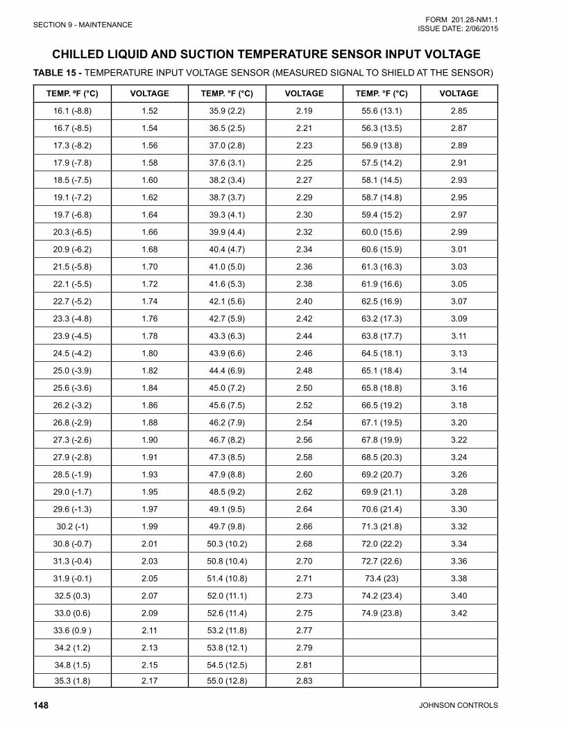
JOHNSON CONTROLS148
SECTION 9 - MAINTENANCEFORM 201.28-NM1.1
ISSUE DATE: 2/06/2015
CHILLED LIQUID AND SUCTION TEMPERATURE SENSOR INPUT VOLTAGE TABLE 15 - TEMPERATURE INPUT VOLTAGE SENSOR (MEASURED SIGNAL TO SHIELD AT THE SENSOR)
TEMP. ºF (°C) VOLTAGE TEMP. °F (°C) VOLTAGE TEMP. °F (°C) VOLTAGE
16.1 (-8.8) 1.52 35.9 (2.2) 2.19 55.6 (13.1) 2.85
16.7 (-8.5) 1.54 36.5 (2.5) 2.21 56.3 (13.5) 2.87
17.3 (-8.2) 1.56 37.0 (2.8) 2.23 56.9 (13.8) 2.89
17.9 (-7.8) 1.58 37.6 (3.1) 2.25 57.5 (14.2) 2.91
18.5 (-7.5) 1.60 38.2 (3.4) 2.27 58.1 (14.5) 2.93
19.1 (-7.2) 1.62 38.7 (3.7) 2.29 58.7 (14.8) 2.95
19.7 (-6.8) 1.64 39.3 (4.1) 2.30 59.4 (15.2) 2.97
20.3 (-6.5) 1.66 39.9 (4.4) 2.32 60.0 (15.6) 2.99
20.9 (-6.2) 1.68 40.4 (4.7) 2.34 60.6 (15.9) 3.01
21.5 (-5.8) 1.70 41.0 (5.0) 2.36 61.3 (16.3) 3.03
22.1 (-5.5) 1.72 41.6 (5.3) 2.38 61.9 (16.6) 3.05
22.7 (-5.2) 1.74 42.1 (5.6) 2.40 62.5 (16.9) 3.07
23.3 (-4.8) 1.76 42.7 (5.9) 2.42 63.2 (17.3) 3.09
23.9 (-4.5) 1.78 43.3 (6.3) 2.44 63.8 (17.7) 3.11
24.5 (-4.2) 1.80 43.9 (6.6) 2.46 64.5 (18.1) 3.13
25.0 (-3.9) 1.82 44.4 (6.9) 2.48 65.1 (18.4) 3.14
25.6 (-3.6) 1.84 45.0 (7.2) 2.50 65.8 (18.8) 3.16
26.2 (-3.2) 1.86 45.6 (7.5) 2.52 66.5 (19.2) 3.18
26.8 (-2.9) 1.88 46.2 (7.9) 2.54 67.1 (19.5) 3.20
27.3 (-2.6) 1.90 46.7 (8.2) 2.56 67.8 (19.9) 3.22
27.9 (-2.8) 1.91 47.3 (8.5) 2.58 68.5 (20.3) 3.24
28.5 (-1.9) 1.93 47.9 (8.8) 2.60 69.2 (20.7) 3.26
29.0 (-1.7) 1.95 48.5 (9.2) 2.62 69.9 (21.1) 3.28
29.6 (-1.3) 1.97 49.1 (9.5) 2.64 70.6 (21.4) 3.30
30.2 (-1) 1.99 49.7 (9.8) 2.66 71.3 (21.8) 3.32
30.8 (-0.7) 2.01 50.3 (10.2) 2.68 72.0 (22.2) 3.34
31.3 (-0.4) 2.03 50.8 (10.4) 2.70 72.7 (22.6) 3.36
31.9 (-0.1) 2.05 51.4 (10.8) 2.71 73.4 (23) 3.38
32.5 (0.3) 2.07 52.0 (11.1) 2.73 74.2 (23.4) 3.40
33.0 (0.6) 2.09 52.6 (11.4) 2.75 74.9 (23.8) 3.42
33.6 (0.9 ) 2.11 53.2 (11.8) 2.77
34.2 (1.2) 2.13 53.8 (12.1) 2.79
34.8 (1.5) 2.15 54.5 (12.5) 2.81
35.3 (1.8) 2.17 55.0 (12.8) 2.83
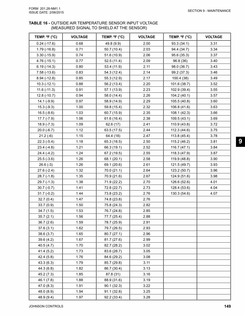
SECTION 9 - MAINTENANCE
JOHNSON CONTROLS 149
FORM 201.28-NM1.1ISSUE DATE: 2/06/2015
9
TABLE 16 - OUTSIDE AIR TEMPERATURE SENSOR INPUT VOLTAGE (MEASURED SIGNAL TO SHIELD AT THE SENSOR)
TEMP. ºF (°C) VOLTAGE TEMP. ºF (°C) VOLTAGE TEMP. ºF (°C) VOLTAGE
0.24 (-17.6) 0.68 49.8 (9.9) 2.00 93.3 (34.1) 3.311.79 (-16.8) 0.71 50.7 (10.4) 2.03 94.4 (34.7) 3.343.30 (-15.9) 0.74 51.6 (10.9) 2.06 95.6 (35.3) 3.374.76 (-15.1) 0.77 52.5 (11.4) 2.09 96.8 (36) 3.406.19 (-14.3) 0.80 53.4 (11.9) 2.11 98.0 (36.7) 3.437.58 (-13.6) 0.83 54.3 (12.4) 2.14 99.2 (37.3) 3.468.94 (-12.8) 0.85 55.3 (12.9) 2.17 100.4 (38) 3.4910.3 (-12.1) 0.88 56.2 (13.4) 2.20 101.6 (38.7) 3.5211.6 (-11.3) 0.91 57.1 (13.9) 2.23 102.9 (39.4) 3.5512.8 (-10.7) 0.94 58.0 (14.4) 2.26 104.2 (40.1) 3.5714.1 (-9.9) 0.97 58.9 (14.9) 2.29 105.5 (40.8) 3.6015.3 (-9.3) 1.00 59.8 (15.4) 2.32 106.8 (41.6) 3.6316.5 (-8.6) 1.03 60.7 (15.9) 2.35 108.1 (42.3) 3.6617.7 (-7.9) 1.06 61.6 (16.4) 2.38 109.5 (43.1) 3.6918.9 (-7.3) 1.09 62.6 (17) 2.41 110.9 (43.8) 3.7220.0 (-6.7) 1.12 63.5 (17.5) 2.44 112.3 (44.6) 3.7521.2 (-6) 1.15 64.4 (18) 2.47 113.8 (45.4) 3.78
22.3 (-5.4) 1.18 65.3 (18.5) 2.50 115.2 (46.2) 3.8123.4 (-4.8) 1.21 66.3 (19.1) 2.52 116.7 (47.1) 3.8424.4 (-4.2) 1.24 67.2 (19.5) 2.55 118.3 (47.9) 3.8725.5 (-3.6) 1.26 68.1 (20.1) 2.58 119.9 (48.8) 3.9026.6 (-3) 1.26 69.1 (20.6) 2.61 121.5 (49.7) 3.93
27.6 (-2.4) 1.32 70.0 (21.1) 2.64 123.2 (50.7) 3.9628.7 (-1.8) 1.35 70.9 (21.6) 2.67 124.9 (51.6) 3.9829.7 (-1.3) 1.38 71.9 (22.2) 2.70 126.6 (52.6) 4.0130.7 (-0.7) 1.41 72.8 (22.7) 2.73 128.4 (53.6) 4.0431.7 (-0.2) 1.44 73.8 (23.2) 2.76 130.3 (54.6) 4.0732.7 (0.4) 1.47 74.8 (23.8) 2.7633.7 (0.9) 1.50 75.8 (24.3) 2.8234.7 (1.5) 1.53 76.7 (24.8) 2.8535.7 (2.1) 1.56 77.7 (25.4) 2.8836.7 (2.6) 1.59 78.7 (25.9) 2.9137.6 (3.1) 1.62 79.7 (26.5) 2.9338.6 (3.7) 1.65 80.7 (27.1) 2.9639.6 (4.2) 1.67 81.7 (27.6) 2.9940.5 (4.7) 1.70 82.7 (28.2) 3.0241.4 (5.2) 1.73 83.6 (28.7) 3.0542.4 (5.8) 1.76 84.6 (29.2) 3.0843.3 (6.3) 1.79 85.7 (29.8) 3.1144.3 (6.8) 1.82 86.7 (30.4) 3.1345.2 (7.3) 1.85 87.8 (31) 3.1646.1 (7.8) 1.88 88.9 (31.6) 3.1947.0 (8.3) 1.91 90.1 (32.3) 3.2248.0 (8.9) 1.94 91.1 (32.8) 3.2548.9 (9.4) 1.97 92.2 (33.4) 3.28
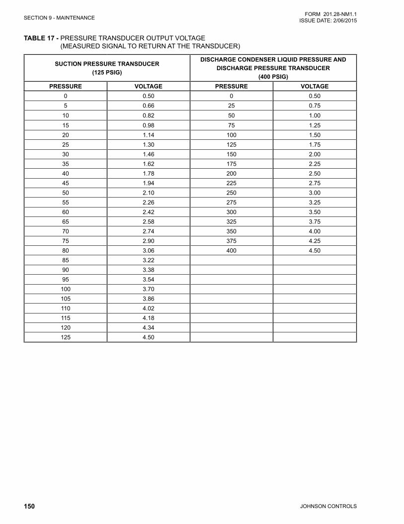
JOHNSON CONTROLS150
SECTION 9 - MAINTENANCEFORM 201.28-NM1.1
ISSUE DATE: 2/06/2015
TABLE 17 - PRESSURE TRANSDUCER OUTPUT VOLTAGE (MEASURED SIGNAL TO RETURN AT THE TRANSDUCER)
SUCTION PRESSURE TRANSDUCER(125 PSIG)
DISCHARGE CONDENSER LIQUID PRESSURE AND DISCHARGE PRESSURE TRANSDUCER
(400 PSIG)PRESSURE VOLTAGE PRESSURE VOLTAGE
0 0.50 0 0.505 0.66 25 0.75
10 0.82 50 1.0015 0.98 75 1.2520 1.14 100 1.5025 1.30 125 1.7530 1.46 150 2.0035 1.62 175 2.2540 1.78 200 2.5045 1.94 225 2.7550 2.10 250 3.0055 2.26 275 3.2560 2.42 300 3.5065 2.58 325 3.7570 2.74 350 4.0075 2.90 375 4.2580 3.06 400 4.5085 3.2290 3.3895 3.54
100 3.70105 3.86110 4.02115 4.18120 4.34125 4.50
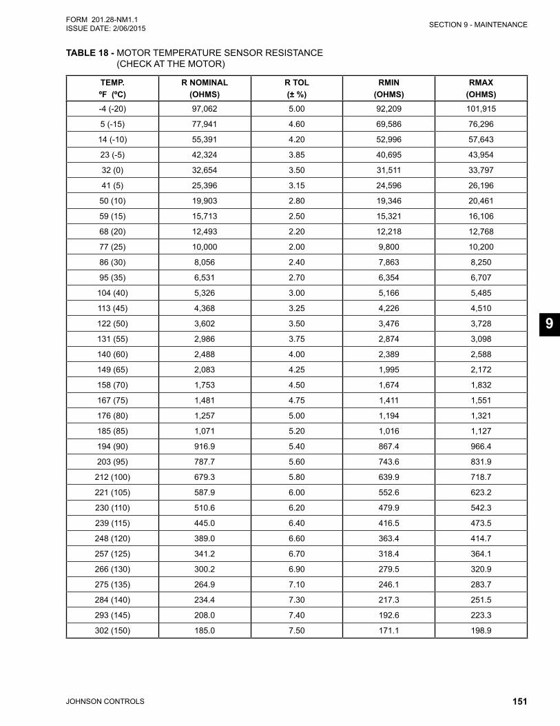
SECTION 9 - MAINTENANCE
JOHNSON CONTROLS 151
FORM 201.28-NM1.1ISSUE DATE: 2/06/2015
9
TABLE 18 - MOTOR TEMPERATURE SENSOR RESISTANCE (CHECK AT THE MOTOR)
TEMP.ºF (ºC)
R NOMINAL(OHMS)
R TOL(± %)
RMIN(OHMS)
RMAX(OHMS)
-4 (-20) 97,062 5.00 92,209 101,915
5 (-15) 77,941 4.60 69,586 76,296
14 (-10) 55,391 4.20 52,996 57,643
23 (-5) 42,324 3.85 40,695 43,954
32 (0) 32,654 3.50 31,511 33,797
41 (5) 25,396 3.15 24,596 26,196
50 (10) 19,903 2.80 19,346 20,461
59 (15) 15,713 2.50 15,321 16,106
68 (20) 12,493 2.20 12,218 12,768
77 (25) 10,000 2.00 9,800 10,200
86 (30) 8,056 2.40 7,863 8,250
95 (35) 6,531 2.70 6,354 6,707
104 (40) 5,326 3.00 5,166 5,485
113 (45) 4,368 3.25 4,226 4,510
122 (50) 3,602 3.50 3,476 3,728
131 (55) 2,986 3.75 2,874 3,098
140 (60) 2,488 4.00 2,389 2,588
149 (65) 2,083 4.25 1,995 2,172
158 (70) 1,753 4.50 1,674 1,832
167 (75) 1,481 4.75 1,411 1,551
176 (80) 1,257 5.00 1,194 1,321
185 (85) 1,071 5.20 1,016 1,127
194 (90) 916.9 5.40 867.4 966.4
203 (95) 787.7 5.60 743.6 831.9
212 (100) 679.3 5.80 639.9 718.7
221 (105) 587.9 6.00 552.6 623.2
230 (110) 510.6 6.20 479.9 542.3
239 (115) 445.0 6.40 416.5 473.5
248 (120) 389.0 6.60 363.4 414.7
257 (125) 341.2 6.70 318.4 364.1
266 (130) 300.2 6.90 279.5 320.9
275 (135) 264.9 7.10 246.1 283.7
284 (140) 234.4 7.30 217.3 251.5
293 (145) 208.0 7.40 192.6 223.3
302 (150) 185.0 7.50 171.1 198.9

JOHNSON CONTROLS152
FORM 201.28-NM1.1 ISSUE DATE: 2/06/2015
THIS PAGE INTENTIONALLY LEFT BLANK.
JOHNSON CONTROLS 153
FORM 201.28-NM1.1ISSUE DATE: 2/06/2015
10
SECTION 10 - DECOMMISSIONING, DISMANTLING AND DISPOSAL
Never release refrigerant to the atmo-sphere when emptying the refrigerating circuits. Suitable retrieval equipment must be used. If reclaimed refrigerant cannot be reused. It must be returned to the manufacturer.
Never discard used compressor oil, as it contains refrigerant in solution. Return used oil to the oil manufacturer.
Never discard used compressor oil, as it contains re-frigerant in solution. Return used oil to the oil manu-facturer.
Unless otherwise indicated, the operations described below can be performed by any properly trained main-tenance technician.
GENERALIsolate all sources of electrical supply to the unit in-cluding any control system supplies switched by the unit. Ensure that all points of isolation are secured in the ‘OFF’ position. The supply cables may then be dis-connected and removed. For connection points refer to SECTION 4 - INSTALLATION.
Remove all refrigerant from each system of the unit into a suitable container using a refrigerant reclaim or recovery unit. This refrigerant may then be re-used, if appropriate, or returned to the manufacturer for dis-posal. Under NO circumstances should refrigerant be vented to atmosphere. Drain the refrigerant oil from each system into a suitable container and dispose of according to local laws and regulations governing the disposal of oily wastes. Any spilt oil should be mopped up and similarly disposed of.
Isolate the unit heat exchanger from the external wa-ter systems and drain the heat exchanger section of the system. If no isolation valves are installed it may be necessary to drain the complete system.
If glycol or similar solutions have been used in the water system, or chemical additives are contained, the solution MUST be disposed of in a suitable and safe manner. Under NO circumstances should any system containing glycol or similar solutions be drained directly into domestic waste or natural water systems.
After draining, the water pipework can be disconnect-ed and removed.
Packaged units can generally be removed in one piece after disconnection as above. Any fixing down bolts should be removed and then the unit should be lifted from position using the points provided and equipment of adequate lifting capacity.
Reference should be made to SECTION 4 - INSTAL-LATION for unit installation instructions, SECTION 9 - MAINTENANCE for unit weights and SECTION 3 - RIGGING, HANDLING AND STORAGE for handling.
Units which cannot be removed in one piece after dis-connection as above must be dismantled in position. Special care should be taken regarding the weight and handling of each component. Where possible units should be dismantled in the reverse order of installa-tion.
Residual refrigerant oil and glycol or sim-ilar solutions may remain in some parts of the system. These should be mopped up and disposed of as described above.
It is important to ensure that whilst components are be-ing removed the remaining parts are supported in a safe manner.
Only use lifting equipment of adequate capacity.
After removal from position the unit parts may be dis-posed of according to local laws and regulations.
JOHNSON CONTROLS154
FORM 201.28-NM1.1 ISSUE DATE: 2/06/2015
NOTES
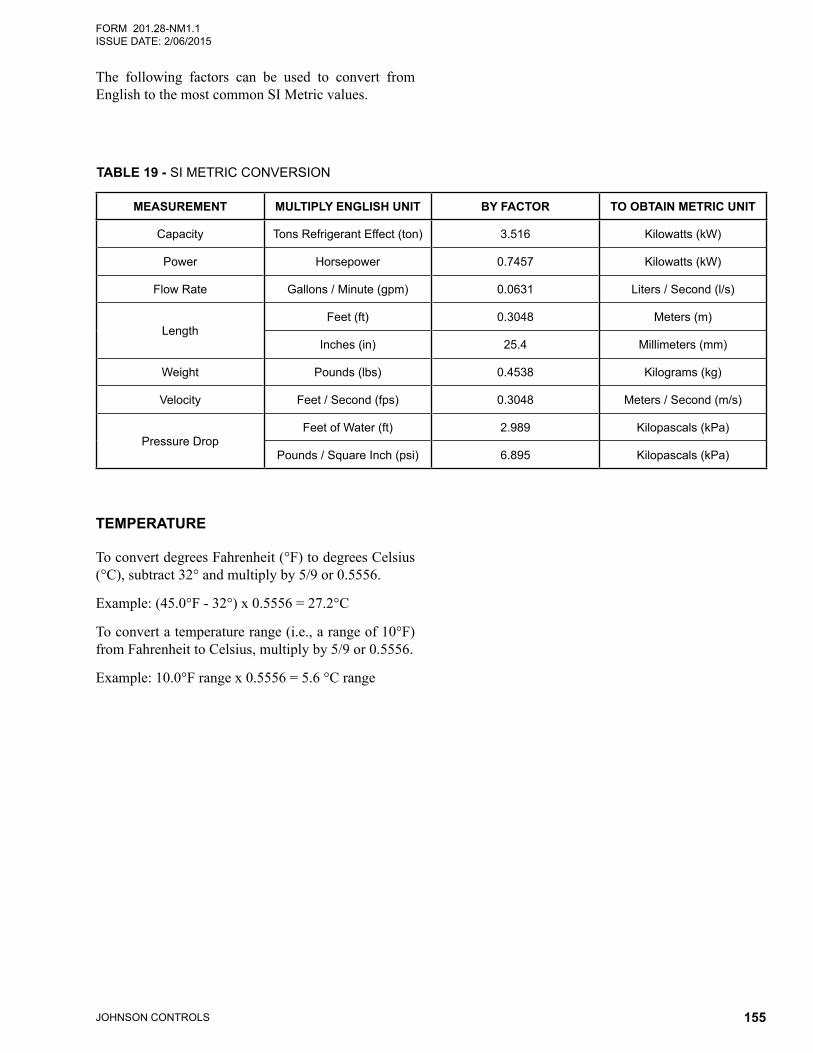
JOHNSON CONTROLS 155
FORM 201.28-NM1.1ISSUE DATE: 2/06/2015
The following factors can be used to convert from English to the most common SI Metric values.
TEMPERATURE
To convert degrees Fahrenheit (°F) to degrees Celsius (°C), subtract 32° and multiply by 5/9 or 0.5556.
Example: (45.0°F - 32°) x 0.5556 = 27.2°C
To convert a temperature range (i.e., a range of 10°F) from Fahrenheit to Celsius, multiply by 5/9 or 0.5556.
Example: 10.0°F range x 0.5556 = 5.6 °C range
TABLE 19 - SI METRIC CONVERSION
MEASUREMENT MULTIPLY ENGLISH UNIT BY FACTOR TO OBTAIN METRIC UNIT
Capacity Tons Refrigerant Effect (ton) 3.516 Kilowatts (kW)
Power Horsepower 0.7457 Kilowatts (kW)
Flow Rate Gallons / Minute (gpm) 0.0631 Liters / Second (l/s)
LengthFeet (ft) 0.3048 Meters (m)
Inches (in) 25.4 Millimeters (mm)
Weight Pounds (lbs) 0.4538 Kilograms (kg)
Velocity Feet / Second (fps) 0.3048 Meters / Second (m/s)
Pressure DropFeet of Water (ft) 2.989 Kilopascals (kPa)
Pounds / Square Inch (psi) 6.895 Kilopascals (kPa)

P.O. Box 1592, York, Pennsylvania USA 17405-1592 Subject to change without notice. Printed in USACopyright © by Johnson Controls 2015 ALL RIGHTS RESERVEDForm 201.28-NM1.1 (215)Issue Date: February 6, 2015 Supersedes 201.28-NM1.1 (514)
800-861-1001www.johnsoncontrols.com