Embed Size (px)
Citation preview
Z-transform electromagnetic transient analysis ofcrossbonded cable transmission systems
Prof. W.D. Humpage, B.Sc, Ph.D., K.P. Wong, M.Sc, Ph.D., and T.T. Nguyen, B.E.
Indexing terms: Power transmission. Underground cables, Z-transform, Electromagnetic transient analysis
Abstract: A recursive time-domain formulation for electromagnetic transient analysis in power networkshas recently been derived drawing on a particular transformation sequence in which the z-transform hasa central part. Following its original development primarily in the context of overhead lines, the presentpaper investigates the possible role of the formulation in transient propagation in crossbonded undergroundcable systems. In those terms, the earlier z-plane analysis scheme extends easily to the conductor and sheathconfiguration of a cable section between points of successive sheath discontinuities. It is then shown in thepaper, in detailed working, how the boundary conditions of sheath transpositions, sheath earthing, andsurge-arrester connections may be introduced into analysis. From the outcome of this working, an overallsolution procedure is formulated for a cable system of any arbitrary number of sections in terms of theindividual section equations rearranged to comply with the boundary conditions which they are requiredto fulfil. A Newton-Raphson algorithm is used to solve the nonlinear equations of surge arresters in con-junction with those of the cable sheaths to which they are connected. Close comparisons with solutionsfrom an established Fourier transform method confirm, as in the overhead line case, the high underlyingaccuracy of z-transform analysis. Computing time requirements have a dependence on the number of sectionsinto which the complete cable system is subdivided: for three sections, z-transform computing times areabout 1% of those in Fourier transform analysis.
List of principal symbols
v, i vectors of voltage and current variablesCi, C2 modal transformation matricesZ surge-impedance matrixA matrix of propagation coefficientsF matrix of forward impulse responsesC connection matrix in sheath earthingG conductance matrix in sheath earthingM core-sheath reordering matrixJ Jacobian matrix in surge-arrester analysisvg vector of surge-arrester gap voltagesig vector of surge-arrester currentsRe sheath earthing resistancet identifies current time step in recursive analysisAt step-intervalz z-transform parameter
SubscriptsI, m, k, j identify node sets at sheath discontinuitiese identifies earth-return variables
Superscriptsc, s identify core and sheath variablesa, b, c identify variables in a, b, c phasesp identifies phase-variable vectors and matricesn iteration step counter in Newton-Raphson surge-
arrester analysis
1 Introduction
Several different analysis schemes for multiconductor cross-bonded cable systems have now been derived with reference tosteady-state operating modes [1,2] and, more extensively,for transient over-voltage evaluations [3—11]. As in wave-propagation models for overhead transmission lines, someof the fundamental nonlinearities of corresponding modelsfor underground cables are most directly formed in thefrequency domain. In turn, this has led to the developmentof Fourier-transform methods [4—9] of transient analysisin which frequency-dependent forms of nonlinearities canbe reflected formally into solution. By comparison, thenonlinear characteristics of the surge arresters at individual
Paper 1186C, first received 27th June and in revised form 11thNovember 1980The authors are with the Department of Electrical & ElectronicEngineering, University of Western Australia, Crawley, WesternAustralia 6009
IEEPROC, Vol. 128, Pt. C, No. 2, MARCH 1981
points of sheath crossbonding along the length of a cablesystem are the more directly included in analysis which isin the time domain. To make provision for both forms ofnonlinearity in a comprehensive transient over-voltage formu-lation suggests the use of time convolution, but the authorsare aware of only one previous paper [10] which has de-veloped convolution methods for cable-system analysis.A recent paper by Kersten [11] has given a solution methodwhich is wholly in the time domain, and in which surge-arrester representations are included, but this discountsthe nonlinear frequency dependence of cable-system par-ameters that Fourier transform methods were developedprimarily to take into account. Inevitably, in making com-parisons between different solution methods, reference haspreviously been made to their computing-time requirements,and to their general effectiveness in computer-analysisprocedures.
In independent work [12], the authors have sought tointroduce a new recursive form of time-domain electromag-netic transient analysis in power systems which has itsderivation in the z-transform. As the original developmentof this formulation has been in its relationship to overheadtransmission lines, the purpose of the present paper is thatof investigating its possible role in underground-cable-systemanalysis. No previous paper has referred to z-transform elec-tromagnetic transient analysis in crossbonded cable systems.
2 Z-plane formulation for minor section
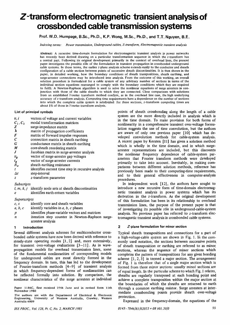
Typical sheath transpositions and connections for a part ofa high-voltage-cable system are shown in Fig. 1. In the com-monly used notation, the sections between successive points^of sheath transposition or earthing are referred to as minorisections, whereas the sequence of minor sections whichcompletes the pattern of transpositions for any given bondingscheme [1, 2, 3] is termed a major section. The arrangementof Fig. 1 is therefore that of a single major section which isformed from three minor sections: usually minor sections.areof equal length. In the particular scheme to which Fig. 1 relates,sheaths are regularly transposed at each bonding point andachieve a complete transposition within the major section atthe boundaries of which the sheaths are returned to earththrough a common earthing resistor. Surge arresters at inter-mediate crossbonding points provide sheath over-voltageprotection.
Expressed in the frequency-domain, the equations of the
0143-7046/81/02055 + 08 $01.50/0 55
single minor section between node sets k and / in Fig. 1arrange to the scattering form [12].
)} (1)
>} (2)
In eqns. 1 and 2, V(CJ) and /(CJ) denote vectors of core andsheath voltage and current variables following transformationto modal axes. Zkj(oj>) is the modal surge impedance matrixfor the minor section between node sets k and /, and F(co)is the matrix of modal impulse responses for the section.
A L A L
Fig. 1 Elements of multiconductor crossbonded cable system
Cable system of three minor sections with surge diverters at pointsof sheath transposition
If X(co) is the matrix of modal propagation coefficients then
F(OJ) = exp(-A(co)/m) (3)
where lm is the length of the minor section.Following definitive work on the parameters of cable models
[4], Zfey(co) and X (cS) can be evaluated over the range of fre-quencies relevant to electromagnetic transient propagation.Using eqn. 3, the impulse response matrix can therefore easilybe found.
On taking z-transforms of both sides of eqns. 1 and 2:
(4)
(5)
ikj(z) = F(z){Vj(z) + ZkJ(z)ijk(z)}
vj(z) - Zkj(z)iJk(z) = F(z){vk(z) + Zfe/(z)/fe;(z)}
Rational fraction forms of ZkJ(z) and F(z) allow a rearrange-ment of eqns. 4 and 5 for which inverse z-transform operationslead to the recursive form in the time-domain:
(7)
= vzk(t-nAt)
Vj(t)-Zoijk(t) = vzj(t-nAt)
Expressions for the vectors of previous-step values vzk(t — nAt)and vzj(t — nAt), together with that of the constant matrixZo, are given in Reference 12.
Subject to boundary constraints at the terminations ofthe minor section, solving eqns. 6 and 7 provides a solutionfor electomagnetic transient propagation through the section.Much of the detail of the complete analysis scheme arises fromthe different boundary conditions to be considered, and therearrangement of eqns. 6 and 7 to accept them. For the systemof Fig. 1, the minor-section boundary conditions to be evalu-ated are those of sheath transpositions, sheath earthing, andsurge-arrester operation.
Once these evaluations have been achieved, as in Sections3—5 of the present paper, an overall analysis procedure canthen be derived as in Section 6.
3 Sheath transpositions
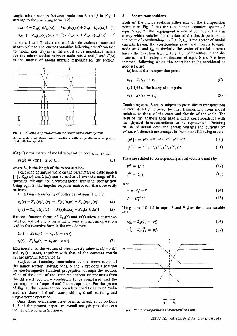
Each of the minor sections either side of the transpositionpoint Jc in Fig. 2 has the time-domain equation system ofeqns. 6 and 7. The requirement is one of combining these ina way which satisfies the rotation of the sheath positions atthe point of crossbonding. In Fig. 2, ikl is the vector of modalcurrents leaving the crossbonding point and flowing towardsnode set /, and ikj is similarly the vector of modal currentshaving the direction from k to /. For compactness in the de-rivation, the time-step identification of eqns. 6 and 7 is hereremoved, following which the equations to be considered atnode set k are
(a) left of the transposition point
(8)
(9)
- vzl
(b) right of the transposition point
vkj-Zoikj = vzj
Combining eqns. 8 and 9 subject to given sheath transpositionsis most directly achieved by first transforming from modalvariables to those of the cores and sheaths of the cable. Thesteps of the analysis then have a direct correspondence withthe physical interconnections to be represented. Denotingvectors of actual core and sheath voltages and currents byvp and ip, elements are arranged in them in the following order:
= vac,va8,vbc,vb8,vcc,vC8
IjP]t _ ;ac bc
(10)
(11)
These are related to corresponding modal vectors v and i by
vp = Ctv (12)
ip = C2i (13)
Also
v =
i = Clxip
(14)
(15)
Using eqns. 10—15 in eqns. 8 and 9 gives the phase-variablesets
vpkj-Zpi
pkj = VP
(16)
(17)
' k l t ' k j
Fig. 2 Sheath transpositions at crossbonding point
56 IEEPROC, Vol. 128, Pt. C, No. 2, MARCH 1981
where
= Cxvzl
VZ)
(18)
(19)
(20)
The constraints to which sheath transpositions give rise cannow be introduced using a transposition matrix T so that
vpi = Tut,t,
In explicit form:
ac as be bs cc cs
(21)
(22)
nr —
ac
as
be
bs
cc
cs
1
0
0
0
0
0
0
0
0
0
0
1
0
0
1
0
0
0
0
1
0
0
0
0
0
0
0
0
1
0
0
0
0
1
0
0
(23)
Premultiplying eqn. 17 by T and replacing ipj by —T~xi%igives
(24)
(25)
(26)
(27)
where
Zt = TZpT'1
Eliminating ip\ from eqns. 16 and 24 gives
(II + Z < V )vgx = ZtZ;1 vpzl + Tv'j
or
vgt = (II + ZtZjr^Z&vZ + Tvp})
This is the key relationship in the derivation. As v^i is availablefrom eqn. 27, all other variables at the crossbonding point
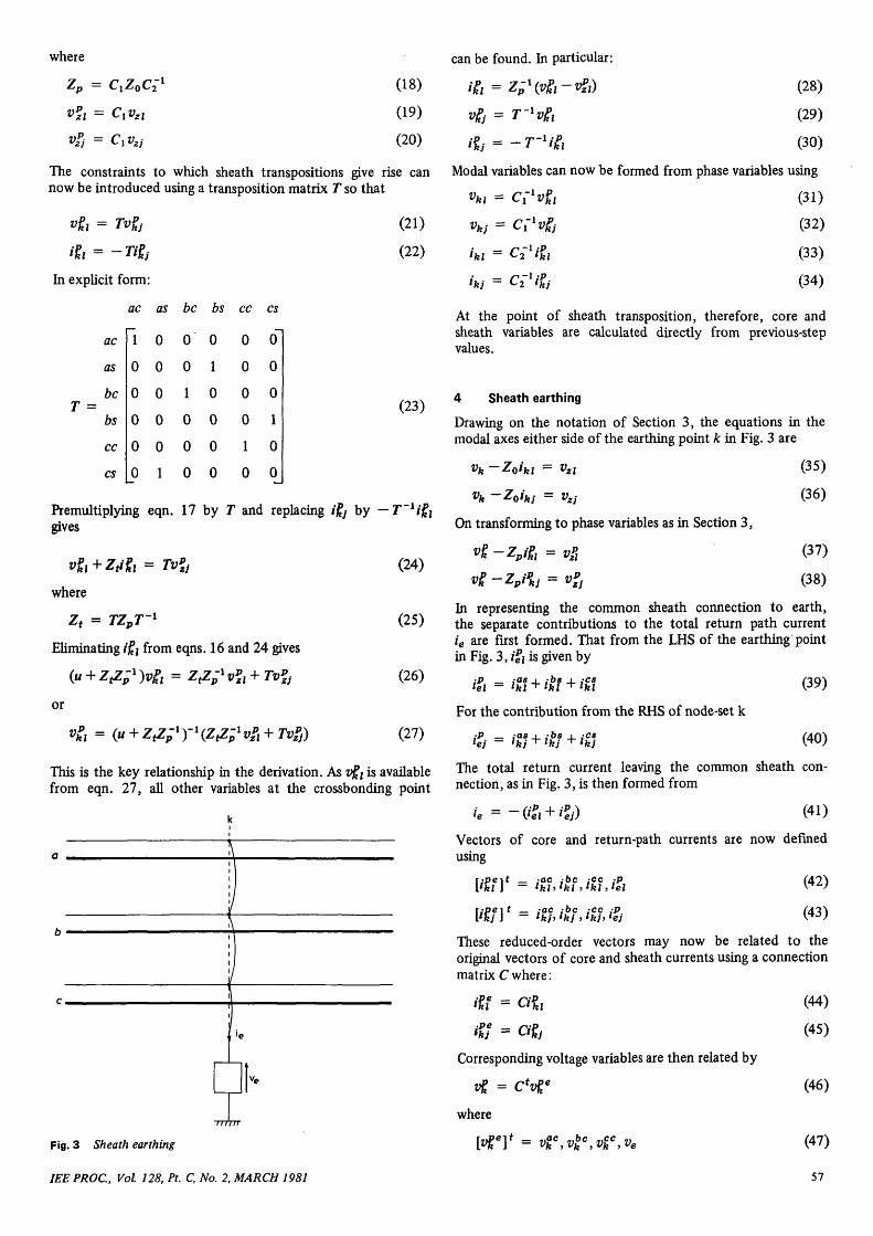
Fig. 3 Sheath earthing
IEEPROC, Vol. 128, Pt. C, No. 2, MARCH 1981
can be found. In particular:
/ft = Zp->£
vg, = r"Vi
(28)
(29)
(30)
Modal variables can now be formed from phase variables using
iki = C{lipkl
(32)
(33)
(34)
At the point of sheath transposition, therefore, core andsheath variables are calculated directly from previous-stepvalues.
4 Sheath earthing
Drawing on the notation of Section 3, the equations in themodal axes either side of the earthing point k in Fig. 3 are
vk-Zoikl = vzl (35)
vk -Zoikj = vzj (36)
On transforming to phase variables as in Section 3,
vt-Zpit, = v& 07)v* ~Zpi
pkj = v;t (38)
In representing the common sheath connection to earth,the separate contributions to the total return path currentie are first formed. That from the LHS of the earthing pointin Fig. 3, ip\ is given by
For the contribution from the RHS of node-set k
,-P _ .-as i ;b8 i 4C8lj l j + lkj + Ikj
(39)
(40)
The total return current leaving the common sheath con-nection, as in Fig. 3, is then formed from
Vectors of core and return-path currents are now definedusing
r.'Peit _ iac ,-bc ,-ec {p['kl 1 - lkl>lkl ,lkl,lel
r;pei t _ -ac ;bc ,-cc ,-PI'kj J - lkh lkj . lkb lej (43)
These reduced-order vectors may now be related to theoriginal vectors of core and sheath currents using a connectionmatrix C where:
•Pelkl '•
ikf ••
= Cipkl
= Cipj
Corresponding voltage variables are then related by
vt =where
w
- C*vf
)* = vF ,vlc ,v%c ,ve
(44)
(45)
(46)
(47)
57
In explicit form
ac as be bs cc cs
c
From
ac
be
cc
e
eqns. 37
1
0
0
0
0
0
0
1
0
1
0
0
0
0
0
1
0
0
1
0
0
0
0
1
(48)
(49)
Using the connection matrix relationships of eqns. 44 and 46,
lkl l Cuk *zl K?v)
where
and
p,
Similar steps starting from eqn. 38 then give
,-Pe __ y ..pe __ -pe'kj ~ *Cvk hj
for
ipe = C7' ~*tP
Combining eqns. 50 and 53,
iff + iff = 2Ycvge -iPf -iPf
If vector ie 0 is defined by
i | 0 '= 0 ,0 ,0 , - / e
then•pe I /pe .•'«J IRJ 'eO
Also
ve = &eU
Defining
G =
0
0
0
0
0
0
0
0
0
0
0
0
0
0
0
I/Re
then
From eqns. 55, 57 and 60
on rearranging
(51)
(52)
(53)
(54)
(55)
(56)
(57)
(58)
(59)
(60)
(61)
+ G]-1 [ipf + ipf] (62)
Eqn. 62 is the principal outcome of considering sheath earth-ing constraints. From it, all other variables at the earthingpoint become available as in
58
and
(63)
(64)
(65)
As in the case of sheath transpositions, the constraints ofsheath earthing lead* to a combination of time-domainequations in which current time-step values of variablesat the point of discontinuity can be calculated directly frompreviqus values. Phase-variable vectors in eqns. 63—65 thentransform to modal vectors as previously for use in previous-value calculations for the next step advance in solution.
5 Surge arrester connections
In terms of Fig. 1, the constraints to be included when surgearresters conduct, together with their nonlinear, characteristics,are to be superimposed on the transposition constraints ofSection 3. Sheath voltages either side of the transpositionare related, as in eqn. 21, by
»fi = (66)
Sheath currents, however, are not directly interrelated bythe transposition matrix when surge arresters at the trans-position point conduct.-.If eqn. 22 of Section 3 is replacedby
;P _lkr ~
(67)
then, in the subsequent development, the shunt-path currentsin the surge arresters can be formed from the currents onthe LHS of the surge arresters in ip
h and those on the RHSwhen sheath transpositions have been taken into account as
On this basis, the time-domain equations correspondingto eqns. 16 and 24 in Section 3 are
= ifzfzl
= vzpr
where
Zt = TZpT'1
and
Ti)p-
(68)
(69)
(70)
(71)
In preparation for grouping sheath variables in a form inwhich they can be combined with those of surge arresters,it is now necessary to reorder the voltage and current vectorsfrom their original forms in eqns. 10 and 11 to the forms
r nrif iiac 7i^c nicc 7ias 7i'>s 7ics
[Vkl\ = VkhVkhvkhVkhVkhVklr;pr-\t _ ,-ac ,-bc ,cc ,-as ,-bs :cs[ikl J - lkl , Ikl > lkl , Ikl > lkl , Ikl
(72)
(73)
Using a reordering matrix M, the original and reorderedvectors are related by
vtf = Mvpt (74)
ipl = Mipj (75)
m = Mipr (76)
IEEPROC, Vol. 128, Pt. C, No. 2, MARCH 1981
[n explicit form:
ac
be
ccM =
as
bs
cs
acT—
0
0
0
0
0
as
0
0
0
1
0
0
be
0
1
0
0
0
0
bs
0
0
0
0
1
0
cc
0
0
1
0
0
0
cs
0
0
0
0
0
1
(77)
Replacing the original vectors in eqns. 68 and 69 by thereordered ones of eqns. 74—76 leads to
Vkl ^plkl Vzl \'°)
where
Z; = MZpM~l
7r. = MZfM ~1
t
vi{ = Mv»zl
vfrr = MTvl
From eqns. 78 and 79ipr _ \JT i - llhl - Lzpl
and
(80)
(81)
(82)
(83)
(84)
(85)
Core and sheath currents are now separated in the partitionedforms:
Hi ='ftr
(86)
(87)
(88)
In eqn. 88, ig is the vector of currents leaving the sheathconnections and flowing into the surge arrester.
Similar partitions in eqns. 78 and 79 now follow:
[z!Vl + Wr1 =
\Ap\ vzi
vhkV
(89)
(90)
(91)
With these partitions, eqns. 84 and 85, together with theresults of eqns. 87 and 88, give
0 = Yccvckl+YC8v
8kl-v
cp
-ig = Y8Cvckl+Y88v
8kl-v
8p
IEEPROC, Vol. 128, Pt. C, No. 2, MARCH 1981
(92)
(93)
On eliminating v^\ from eqns. 92 and 93:
where
y> _ y —Y Y'1 Y1 88 * 88 M 8C£ CC * CS
and
v = v8 — Y Y~1vcvp up ' sc * cc up
(94)
(95)
(96)
Eqn. 94 is now in a form in which it can be solved in con-junction with the surge arrester equations: a Newton-Raphsonsequence for achieving this is given in Appendix 12.1. Onachieving a solution for the sheath voltages in v8
hl when surgearresters are conducting, cable core voltages in v^i are foundfrom
v ck l = (97)
All variables at the point of surge arrester connection nowbecome available.
6 Overall solution procedure
A complete solution for any given number of cable sectionsis formed progressively from evaluations at successive, dis-continuities, each of which requires only previous time-stepvalues. For the model of Fig. 1, core voltages at the switchingend of the first cable section are specified on circuit-breakerpole-closure. In asymmetrical or sequential closing sequences,the core currents of the unswitched phases are set to zero.Eqns. 50 and 58 then allow the unswitched core voltagesto be found, together with the common sheath voltage, ve.At the first sheath transposition, and prior to surge arrestersconducting, eqns 27—30 give solutions for all variables drawingonly on previous time-step values. Applied to the secondtransposition, the same group of equations allows all variablesat that discontinuity to be found. If the cable end remotefrom the switching source is on open circuit, all core currentsare set to zero, following which core voltages, and' thecommon sheath voltage, are available from eqn. 50 combinedwith eqn. 58. When one or more surge arresters conduct,sheath voltages at the point of surge-arrester connectionare found from the sequence of Appendix 12.1. All variablesat that point of discontinuity then become available.
On completion of all evaluations at a given time step,all previous-value vectors are recalculated for use in thenext solution step. Reference 12 derives expressions forprevious-value vectors in terms of forward- and backward-travelling waves. In previous-value calculations modal variablesare used throughout, whereas the incorporation of boundaryconditions at sheath discontinuities, as in Sections 3-5, drawsextensively on actual core and sheath components. In general,the modal transformation matrices relating core and sheathquantities to corresponding modal variables are frequencydependent, but several studies [14, 15] have confirmedthat errors of only low order arise when, as in the transformsequences of Sections 3-5, the real parts of modal matricesevaluated at a single frequency are used. In the present work,modal matrices are formed at 5 kHz.
7 Model validation
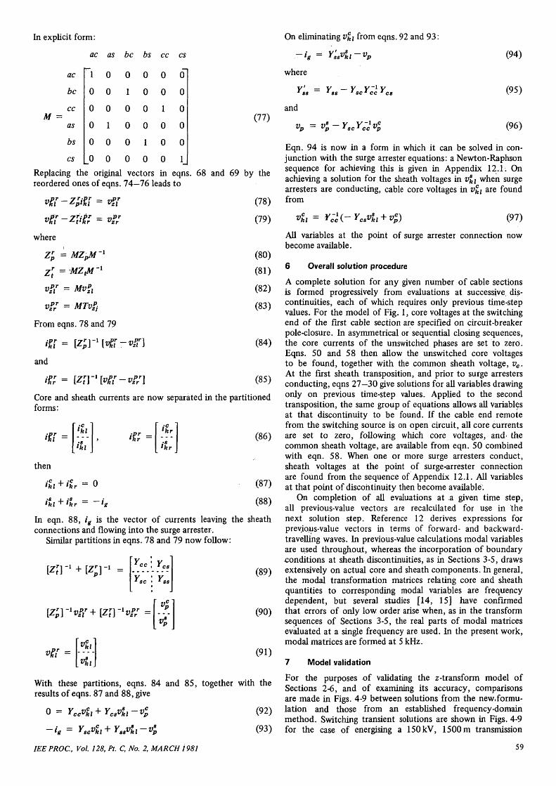
For the purposes of validating the z-transform model ofSections 2-6, and of examining its accuracy, comparisonsare made in Figs. 4-9 between solutions from the new.formu-lation and those from an established frequency-domainmethod. Switching transient solutions are shown in Figs. 4-9for the case of energising a 150kV, 1500 m transmission
59
cable system having the section configuration and sheathtranspositions of Fig. 1. The end of the cable remote fromthat at which switching takes place is on open circuit. Thecore-voltage solutions of Figs. 4-6 are those at the open-circuited end where core overvoltages are likely to be greatest.
300.00270.00240.00210.00180.00150.00120.0090.0060.0030.00
0.000.02 0.04 0.06 0.08 0.X) 012 0.14 0.16
time.ms0.18 0.20
Fig. 4 Receiving-end core-voltage transient in phase 'a'
Phase 'a' core energisationfrequency domainz-transform
Fig. 5
008 CHO 0.12 0.V4 0.16 0J8 020time.ms
Receiving-end core-voltage transient in phase 'b'
Phase 'a' core energisationfrequency domainz-transform
0.08 0.10 0.12time.ms
0.14 0.16 0B 0.20
Fig. 6 Receiving-end core-voltage transient in phase 'c'
Phase 'a' core energisationfrequency domainz-transform •
By comparison, sheath overvoltages are generally most severeat the first crossbonding point. The sheath-voltage solutionsof Figs. 7-9 are for this point.
To achieve comparable accuracy to that which the z-transform method can provide, an upper-frequency iimit of2 x 106 rad/s has been found necessary in frequency-domainanalysis, together with a frequency separation of 2000 rad/s.With these analysis parameters; solutions from the twomethods correlate closely for all variables in the model ofwhich those in Figs 4-9 are representative. Data for the cablesystem of the test analysis are those of Reference 11, and aresummarised in Appendix 12.2. The switching mode is that ofenergising one phase of the multiconductor/sheath cablesystem. This pronounced asymmetry in the energisationmode allows the representation of the nonlinear frequencydependencies of the earth modes to be tested,, and modelaccuracy to be evaluated when these modes are prominentin solution. Moreover, the switching condition is one forwhich a reference solution can be achieved without difficultyusing frequency-domain analysis. Sequential modes of circuit-breaker pole closing are considered in Section 8.2.
60
500040.00300020.0010.000.00
-10.00-20.00-30.00-40.00--saoo
10.02 004 0.06 008 0.10 0.12 0.14 0.16 OB 0.20time.ms
Fig. 7 Sheath-voltage transient at the first crossbonding pointPhase V core energisation
frequency domainz-transform
t' 5000Jf 40.00T3 30.00I 2000I 10.00"> 0.00P HO.0O§ -20.00& -30.00
-40.00-50.00
0.02 0.04 006 008 0.10 0.12 0.14 0.16 0.18 0.20time.ms
Fig. 8 Sheath-voltage transient at the first crossbonding point
Phase 'a' core energisationfrequency domainz-transform
-10.00-20.00-3000-4000-50.001
0.02 004 0.06 0.08 OK) Q12 014time.ms
Q16 Q18 Q20
Fig. 9 Sheath-voltage, transient at.the first crossbonding point
Phase 'a' core energisationfrequency domain <z-transform
.H2.00-15.00
0.04 0.06 0.08 OX) 0.12 0.14 OB 0.18 020time,ms
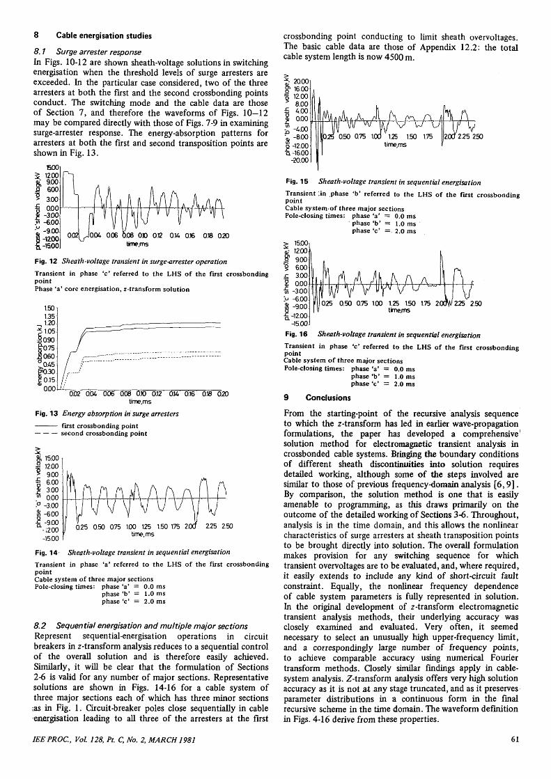
Fig. 10 Sheath-voltage transient in surge-arrester operation
Transient in phase 'a' referred to the LHS of the first crossbondingpoint.Phase 'a' core energisation, z-transform solution
VOX) 0.12 0.14
time.ms0.16 0.18 020
Fig. 11 Sheatk-voltage transient in surge-arrester operation
Transient in phase *b* referred to the LHS of the first crossbondingpoint.Phase 'a' core energisation, z-transform solution
IEEPROC, Vol. 128, Pt. C, No. 2, MARCH 1981
8 Cable energisation studies
8.1 Surge arrester responseIn Figs. 10-12 are shown sheath-voltage solutions in switchingenergisation when the threshold levels of surge arresters areexceeded. In the particular case considered, two of the threearresters at both the first and the second crossbonding pointsconduct. The switching mode and the cable data are thoseof Section 7, and therefore the waveforms of Figs. 10—12may be compared directly with those of Figs. 7-9 in examiningsurge-arrester response. The energy-absorption patterns forarresters at both the first and second transposition points areshown in Fig. 13.
.08 010 0.12time,ms
OK 0.16 0.18 020
Fig. 12 Sheath-voltage transient in surge-arrester operation
Transient in phase 'c' referred to the LHS of the first crossbondingpointPhase 'a' core energisation, z-transform solution
0.000.02 0.04 006 0.08 OX) 0.12 014 0.16 0.18 020
time.ms
Fig. 13 Energy absorption in surge arresters
first crossbonding pointsecond crossbonding point
& 15.00| 12.005 9.00% 6.00j j 3.00•" 0.00-° -3.008j -6.00£-9.00
-I200-15.00
0.25 0.50 075 100 125 1.50 1.75 2(time.ms
225 2.50
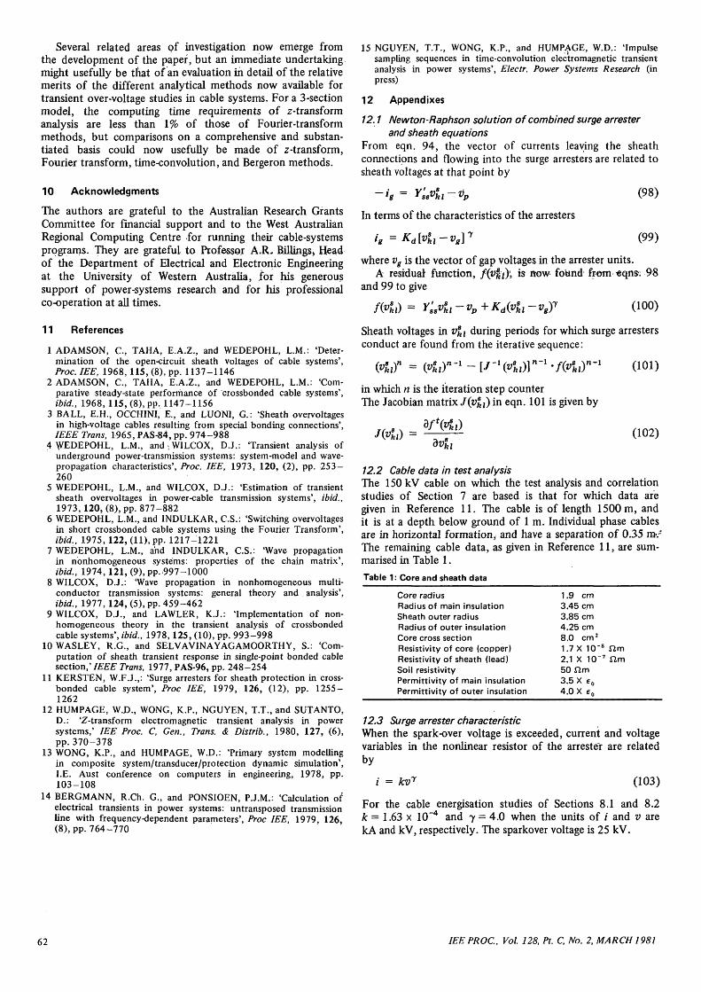
Fig. 14 Sheath-voltage transient in sequential energisation
Transient in phase 'a' referred to the LHS of the first crossbondingpointCable system of three major sectionsPole-closing times: phase 'a' = 0.0 ms
phase 'b' = 1.0 msphase 'c' = 2.0 ms
8.2 Sequential energisation and multiple major sectionsRepresent sequential-energisation operations in circuitbreakers in z-transform analysis reduces to a sequential controlof the overall solution and is therefore easily achieved.Similarly, it will be clear that the formulation of Sections2-6 is valid for any number of major sections. Representativesolutions are shown in Figs. 14-16 for a cable system ofthree major sections each of which has three minor sections;as in Fig. 1. Circuit-breaker poles close sequentially in cableenergisation leading to all three of the arresters at the first
crossbonding point conducting to limit sheath overvoltages.The basic cable data are those of Appendix 12.2: the totalcable system length is now 4500 m.
t- 20.00g1 16.00% 12.005 8.00£ 4.00S 0.00
£-4.00\ "8.008 -12.00a-16.00
-20.00
Aw \J
1.25 1.50 1.75time.ms
Fig. 15 Sheath-voltage transient in sequential energisation
Transient :in phase 'b' referred to the LHS of the first crossbondingpointCable systemof three major sectionsPole-closing times: phase 'a' = 0.0 ms
phase V = 1.0 msphase 'c' = 2.0 ms
025 0.50 0.75 1.00 1.25 1.50 1.75 2time/ns
225 2.50
Sheath-voltage transient in sequential energisation
Transient in phase 'c' referred to the LHS of the first crossbondingpointCable system of three major sectionsPole-closing times: phase 'a' = 0.0 ms
phase V = 1.0 msphase 'c' = 2.0 ms
9 Conclusions
From the starting-point of the recursive analysis sequenceto which the z-transform has led in earlier wave-propagationformulations, the paper has developed a comprehensive'solution method for electromagnetic transient analysis incrossbonded cable systems. Bringing the boundary conditionsof different sheath discontinuities into solution requiresdetailed working, although some of the steps involved aresimilar to those of previous frequency-domain analysis [6 ,9] .By comparison, the solution method is one that is easilyamenable to programming, as this draws primarily on theoutcome of the detailed working of Sections 3-6. Throughout,analysis is in the time domain, and this allows the nonlinearcharacteristics of surge arresters at sheath transposition pointsto be brought directly into solution. The overall formulationmakes provision for any switching sequence for whichtransient overvoltages are to be evaluated, and, where required,it easily extends to include any kind of short-circuit faultconstraint. Equally, the nonlinear frequency dependenceof cable system parameters is fully represented in solution.In the original development of z-transform electromagnetictransient analysis methods, their underlying accuracy wasclosely examined and evaluated. Very often, it seemednecessary to select an unusually high upper-frequency limit,and a correspondingly large number of frequency points,to achieve comparable accuracy using numerical Fouriertransform methods. Closely similar findings apply in cable-system analysis. Z-transform analysis offers very high solutionaccuracy as it is not at any stage truncated, and as it preservesparameter distributions in a continuous form in the finalrecursive scheme in the time domain. The waveform definitionin Figs. 4-16 derive from these properties.
IEEPROC, Vol. 128, Pt. C, No. 2, MARCH 1981 61
Several related areas of investigation now emerge fromthe development of the paper, but an immediate undertakingmight usefully be that of an evaluation in detail of the relativemerits of the different analytical methods now available fortransient over-voltage studies in cable systems. For a 3-sectionmodel, the computing time requirements of z-transformanalysis are less than 1% of those of Fourier-transformmethods, but comparisons on a comprehensive and substan-tiated basis could now usefully be made of z-transform,Fourier transform, time-convolution, and Bergeron methods.
10 Acknowledgments
The authors are grateful to the Australian Research GrantsCommittee for financial support and to the West AustralianRegional Computing Centre for running their cable-systemsprograms. They are grateful to Professor A.R. Billings* Headof the Department of Electrical and Electronic Engineeringat the University of Western Australia, for his generoussupport of power-systems research and for his professionalco-operation at all times.
11 References
1 ADAMSON, C, TAHA, E.A.Z., and WEDEPOHL, L.M.: 'Deter-mination of the open-circuit sheath voltages of cable systems',Proc. IEE, 1968, 115, (8), pp. 1137-1146
2 ADAMSON, C, TAHA, E.A.Z., and WEDEPOHL, L.M.: 'Com-parative steady-state performance of crossbonded cable systems',ibid., 1968, 115, (8), pp. 1147-1156
3 BALL, E.H., OCCHINI, E., and LUONI, G.: 'Sheath overvoltagesin high-voltage cables resulting from special bonding connections',IEEE Trans, 1965, PAS-84, pp. 974-988
4 WEDEPOHL, L.M., and ; WILCOX, D.J.: 'Transient analysis ofunderground power-transmission systems: system-model and wave-propagation characteristics', Proc. IEE, 1973, 120, (2), pp. 253-260
5 WEDEPOHL, L.M., and WILCOX, D.J.: 'Estimation of transientsheath overvoltages in power-cable transmission systems', ibid.,1973,120, (8), pp. 877-882
6 WEDEPOHL, L.M., and INDULKAR, C.S.: 'Switching overvoltagesin short crossbonded cable systems using the Fourier Transform',ibid., 1975, 122, (11), pp. 1217-1221
7 WEDEPOHL, L.M., and INDULKAR, C.S.: 'Wave propagationin nonhomogeneous systems: properties of the chain matrix',ibid., 1974,121, (9), pp. 997-1000
8 WILCOX, D.J.: 'Wave propagation in nonhomogeneous multi-conductor transmission systems: general theory and analysis',ibid., 1977, 124, (5), pp. 459-462
9 WILCOX, D.J., and LAWLER, K.J.: 'Implementation of non-homogeneous theory in the transient analysis of crossbondedcable systems', ibid., 1978,125, (10), pp. 993-998
10 WASLEY, R.G., and SELVAVINAYAGAMOORTHY, S.: 'Com-putation of sheath transient response in single-point bonded cablesection,' IEEE Trans, 1977, PAS-96, pp. 248-254
11 KERSTEN, W.F.J.,: 'Surge arresters for sheath protection in cross-bonded cable system', Proc IEE, 1979, 126, (12), pp. 1255-1262
12 HUMPAGE, W.D., WONG, K.P., NGUYEN, T.T., and SUTANTO,D.: 'Z-transform electromagnetic transient analysis in powersystems,' IEE Proc. C, Gen., Trans. & Distrib., 1980, 127, (6),pp. 370-378
13 WONG, K.P., and HUMPAGE, W.D.: 'Primary system modellingin composite system/transducer/protection dynamic simulation',I.E. Aust conference on computers in engineering, 1978, pp.103-108
14 BERGMANN, R.Ch. G., and PONSIOEN, P.J.M.: 'Calculation ofelectrical transients in power systems: untransposed transmissionline with frequency-dependent parameters', Proc IEE, 1979, 126,(8), pp. 764-770
15 NGUYEN, T.T., WONG, K.P., and HUMP-AGE, W.D.: 'Impulsesampling sequences in time-convolution electromagnetic transientanalysis in power systems', Electr. Power Systems Research (inpress)
12 Appendixes
12.1 Newton-Raphson solution of combined surge arresterand sheath equations
From eqn. 94, the vector of currents leaving the sheathconnections and flowing into the surge arresters are related tosheath voltages at that point by
In terms of the characteristics of the arresters
(98)
(99)
where vg is the vector of gap voltages in the arrester units.A residual function, /(vj|j)> is now found from eqns-. 98
and 99 to give
/Kz) = Y^8v8kl-vp+Kd(v
8ki-vgy (100)
Sheath voltages in v^ during periods for which surge arrestersconduct are found from the iterative sequence:
= (vskl)
n-1 -(v8klf = (v8
kl)in which n is the iteration step counterThe Jacobian matrix /(Vfcj) in eqn. 101 is given by
dvl
(101)
(102)
12.2 Cable data in test analysisThe 150 kV cable on which the test analysis and correlationstudies of Section 7 are based is that for which data aregiven in Reference 11. The cable is of length 1500 m, andit is at a depth below ground of 1 m. Individual phase cablesare in horizontal formation, and have a separation of 0.3-5 m>.-The remaining cable data, as given in Reference 11, are sum-marised in Table 1.
Table 1: Core and sheath data
Core radiusRadius of main insulationSheath outer radiusRadius of outer insulationCore cross sectionResistivity of core (copper)Resistivity of sheath (lead)Soil resistivityPermittivity of main insulationPermittivity of outer insulation
1.9 cm3.45 cm3.85 cm4.25 cm8.0 cm2
1.7 X 10~8 ftm2.1 X 1(T7 ftm50 firm3.5 X c0
4.0 X eft
12.3 Surge arrester characteristicWhen the spark-over voltage is exceeded, current and voltagevariables in the nonlinear resistor of the arrester are relatedby
i = kv7 (103)
For the cable energisation studies of Sections 8.1 and 8.2k = 1.63 x 10~4 and y = 4.0 when the units of / and v arekA and kV, respectively. The sparkover voltage is 25 kV.
62 IEE PROC., Vol. 128, Pt. C, No. 2, MARCH 1981


![Massively Parallel Electromagnetic Transient Simulation of ... · The electromagnetic transient program (EMTP) [1], which analyzes the temporary electro- magnetic phenomena in both](https://img.pdfslide.net/doc/110x75/5e7d93ff28f8280cd266c837/massively-parallel-electromagnetic-transient-simulation-of-the-electromagnetic.jpg)