Embed Size (px)
Citation preview

® ®Z-Wave to Radio Technology Somfy Interface
#1811265
HOME MOTION by

® ®Z-Wave to Radio Technology Somfy Interface Overview
During normal operation after programming, the ZRTSI's Home Screen will display up to 2 system indicators on the LCD screen.
“S” will blink to indicate RTS signal transmission. Only visible while RTS commands are being sent
“Z” indicates the ZRTSI base node is included in a Z-Wave Network.
Left and right Directional Buttons for navigating through menu options, center Select Button for selection.
Directional buttons are used to navigate through all menus (ex: Cycling past a menu's “BACK” will return to the first item of the same menu).
NOTE: After 10 minutes of inactivity, the LCD backlight will turn off. Pressing any button will turn on the backlight.
S Z
® ®The Somfy Z-Wave to Radio Technology Somfy Interface (ZRTSI) is a Z-Wave bridge controller that receives Z-Wave transmissions and translates them to motor control commands for Somfy's range of Radio Technology Somfy (RTS) motors. The ZRTSI resides as a bridge controller node within a Z-Wave Network and becomes a repeating node in the mesh network. The ZRTSI also features Network Wide Inclusion (NWI) which allows inclusion and exclusion to take advantage of the mesh topology of Z-Wave networks. Z-wave devices from all manufacturers can be used in the same network together.
The ZRTSI has 1 base node and 16 virtual nodes. The 16 virtual nodes correspond to 16 RTS channels that, once programmed to the ZRTSI, duplicate all settings associated with each channel for RTS motor control within Z-Wave networks. The ZRTSI requires 110V AC power and can be plugged into any standard outlet.
Somfy recommends one ZRTSI be used for each 25' to 35' area where RTS motors are present.

1
SECTION 1: Including the ZRTSI Base Node into a Z-Wave Network
3.
4.
5.
NOTE: Once the Base Node is successfully included into a Z-Wave Network, the “Z” system indicator will appear in the lower right hand corner of the Home Screen. This indicates that the Base Node is now included in the Z-Wave Network. In addition, the “Base Node Include” command will no longer be available from the Base Node Sub Menu. Only “Base Node Exclude” will be available.
If “BASE INCLUDE FAIL” appears, retry inclusion following steps 2 through 4. If that is unsuccessful, restore the ZRTSI to factory default by following the steps outlined in Section 7.
SELECT
THEN OR
NOTE: If the “Z” system indicator is present, the ZRTSI has previously been configured. To reset the ZRTSI to factory default settings, please refer to Section 7.
Plug the ZRTSI into a standard AC electrical outlet. Press the Select button to illuminate the LCD Screen. The LCD Screen should display “SOMFY” and neither system indicators should be visible. This means the ZRTSI is at factory default settings and ready to be configured.
From the ZRTSI's Home Screen, navigate to the Base Node Include screen.
Enable Inclusion Mode on the Primary Z-Wave Controller.
On the ZRTSI, Activate the “Base Node Include” command by pressing the SelectButton.
The LCD Screen will display “BASE NODE INCLUDING” then either “BASE INCLUDE SUCCESS!” or “BASE INCLUDE FAIL” and return to the Base Node Sub Menu.
1.
2.
SELECT

SECTION 2: Including ZRTSI Virtual Nodes into a Z-Wave Network
SELECT SELECT
On the ZRTSI, navigate to the Virtual Node to be included. Briefly press and release the Select button. The LCD Screen will display “VIRTUAL NODE INCLUDING” and then either “Vxx INCLUDE SUCCESS!” or “Vxx INCLUDE FAIL” (where xx = 01 thru 16).
Follow the Primary Z-Wave Controller manufacturer's instructions regarding naming and organization of new devices.
Once the Virtual Node has been successfully included, the ZRTSI will automatically return to the Virtual Node Inclusion Selection Menu. The next available Virtual Node will appear at the top of the list.
Repeat steps 2 through 4 until all desired Virtual Nodes have been successfully included.
THEN OR
NOTE: Once a Virtual Node has been included into a Z-Wave network, an asterisk (*) will appear next to the corresponding RTS Channel in the RTS Channel Programming Selection Menu. In addition, the Virtual Node will no longer appear in the Virtual Node Inclusion Selection Menu.
NOTE: If “Vxx INCLUDE FAIL” appears, retry inclusion following steps 1 through 3. If inclusion is still unsuccessful, move the ZRTSI closer to the Primary Z-Wave Controller
2
NOTE: Each Virtual Node corresponds directly to the RTS Channels programmed in Section 2 (ex: VNode 1 = RTS Chan 1).
Virtual Nodes can only be included once the Base Node is included into the system.
From the ZRTSI's Home Screen, navigate to the Virtual Node Inclusion Selection Menu.
Enable the Inclusion Mode on the Primary Z-Wave Controller.
3.
4.
5.
1.
2.
6.
SELECT

SECTION 3: RTS Programming
From the ZRTSI's Home Screen, navigate to the RTS Channel Selection Menu.
Press and hold the programming button on the separate RTS control of themotorized product you wish to program until the product jogs.
On the ZRTSI, select the RTS Channel to be programmed (Somfy recommendsbeginning with RTS Chan 1). Then, press and hold the Select Button until themotorized product jogs again. While the Select Button is being held, a blinking“S” will appear to indicate RTS signal transmission.
SELECT SELECT
NOTE: For multichannel controls, make sure to select the appropriate channel.
S
P*
Repeat steps 2 through 4 until all RTS motorized products have beenprogrammed, remembering each time to select the next available RTS channel on the ZRTSI, up to 16.
NOTE: For Group Programming, do not select another RTS channel on the ZRTSI. Repeat RTS programming steps for each individual motorized product to include in the same group, and then select the next available channel on the ZRTSI as needed.
3
NOTE: All RTS motorized products must have limits set and be fully operational from an independent RTS control (handheld, in-wall or tabletop).
When Virtual Nodes are already included into a Z-Wave Network, an asterisk (*) will appear in front of the corresponding RTS Channel.
1.
2.
3.
4.

SECTION 4: RTS Testing
NOTE: If “Vxx EXCLUDE FAIL” appears, retry exclusion following steps 1 through 3. If exclusion is still unsuccessful, move the ZRTSI closer to the Primary Z-Wave Controller.
SELECT SELECT
SELECT SELECT
THEN OR
4
SELECT
From the ZRTSI's Home Screen, navigate to the RTS Test Channel Selection Menu.
Select the RTS Channel to be tested. On the Test Command screen that appears, choose either UP, STOP or DOWN. Press the Select Button to activate the command.
Select Back to return to the RTS Test Channel Selection Menu.
Repeat steps 2 and 3 to test all programmed RTS channels.
From the ZRTSI's Home Screen, navigate to the Virtual Node Exclusion Selection Menu.
Enable the Exclusion Mode on the Primary Z-Wave Controller.
Select the Virtual Node to be excluded. Briefly press and release the Select Button. The LCD Screen will display “VIRTUAL NODE EXCLUDING” and then either “Vxx EXCLUDE SUCCESS!” or “Vxx EXCLUDE FAIL” (where xx = 01 thru 16).
1.
2.
3.
4.
1.
2.
3.
SECTION 5: Excluding ZRTSI Virtual Nodes from a Z-Wave Network
After programming RTS channels to the ZRTSI, confirm proper activation using the RTS Test menu.
NOTE: Once a Virtual Node has been excluded from a Z-Wave Network, it will no longer appear in the Virtual Node Exclusion Selection Menu. In addition, the asterisk (*) will disappear from the corresponding RTS Channel in the RTS Programming Channel Selection Menu.
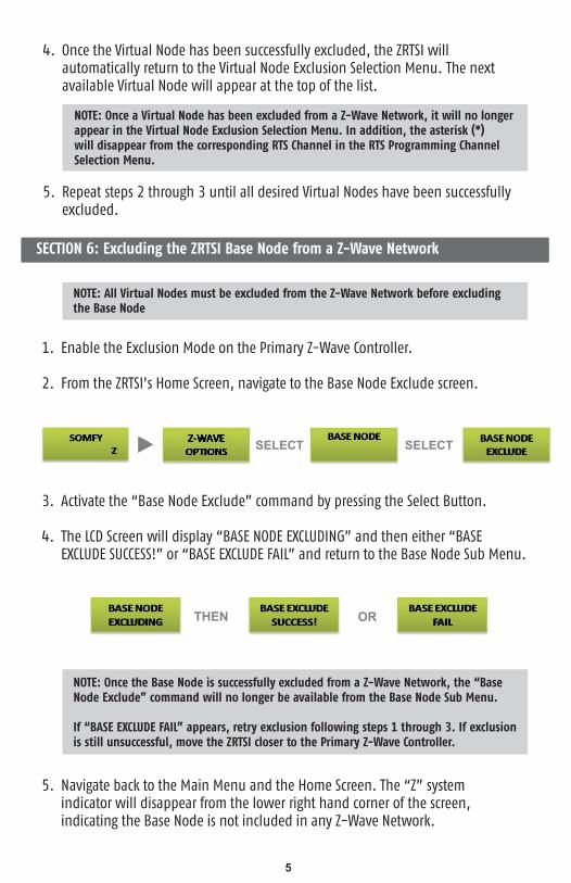
SECTION 6: Excluding the ZRTSI Base Node from a Z-Wave Network
NOTE: Once the Base Node is successfully excluded from a Z-Wave Network, the “Base Node Exclude” command will no longer be available from the Base Node Sub Menu.
If “BASE EXCLUDE FAIL” appears, retry exclusion following steps 1 through 3. If exclusion is still unsuccessful, move the ZRTSI closer to the Primary Z-Wave Controller.
SELECT SELECT
THEN OR
5
NOTE: All Virtual Nodes must be excluded from the Z-Wave Network before excludingthe Base Node
Once the Virtual Node has been successfully excluded, the ZRTSI will automatically return to the Virtual Node Exclusion Selection Menu. The next available Virtual Node will appear at the top of the list.
Repeat steps 2 through 3 until all desired Virtual Nodes have been successfully excluded.
Enable the Exclusion Mode on the Primary Z-Wave Controller.
From the ZRTSI's Home Screen, navigate to the Base Node Exclude screen.
Activate the “Base Node Exclude” command by pressing the Select Button.
The LCD Screen will display “BASE NODE EXCLUDING” and then either “BASE EXCLUDE SUCCESS!” or “BASE EXCLUDE FAIL” and return to the Base Node Sub Menu.
Navigate back to the Main Menu and the Home Screen. The “Z” system indicator will disappear from the lower right hand corner of the screen, indicating the Base Node is not included in any Z-Wave Network.
4.
5.
1.
2.
3.
4.
5.

SECTION 7: Restoring the ZRTSI to Factory Default
SECTION 8: ZRTSI Properties
It is possible to access detailed ZRTSI information directly on the device including Home ID, Node ID, ZRTSI Version, and RTS Address.
Home ID: When a Z-Wave device is included into a network, it receives the Home ID of the Primary Z-Wave Controller, identifying it as part of the network. Only appears after inclusion.
Node ID: The unique address of the Base Node within the Z-Wave Network. Only appears after inclusion.
ZRTSI Version: The certified version of the ZRTSI is 01.08.05. If any other version number appears, please contact Somfy technical support.
RTS Address: Is the unique address of a ZRTSI.
SELECT
6
NOTE: This will reset the Z-Wave programming only. RTS programming is not affected.
From the ZRTSI's Home Screen, navigate to the Z-Wave Reset Sub Menu.
Select “PROCEED WITH Z-WAVE RESET”.
When “ARE YOU SURE?” appears, press and hold the Select Button until either “Z-WAVE RESET SUCCESS!” or “Z-WAVE RESET FAIL” appears and then release. While pressing the Select Button, before the success or fail message appears, “Z-WAVE RESETTING” will appear on the screen.
If “Z-WAVE RESET FAIL” appears, retry restoring to factory default following steps 1 through 3.
Navigate back to the Home Screen. The “Z” system indicator will disappear from the lower right hand corner of the screen, indicating the Base Node is not included in any Z-Wave Network.
1.
2.
3.
4.
5.

Navigate to the desired menu item and press the Select Button. Once the information has appeared (ex: “HOME ID XXXXXX”), pressing either Directional Button will return the ZRTSI to the Properties Sub Menu.
SELECT SELECT
1. From the ZRTSI's Home Screen, navigate to the Properties Sub Menu.
To select either
2.
7

BASE NODE
VIRTUAL NODE
BACK
SELECTBUTTON
BASE NODEINCLUDE
BASE NODEEXCLUDE
BACK
VIRTUAL NODEINCLUDE
VIRTUAL NODEEXCLUDE
BACK
VNODE 1VNODE2
VNODE 16
BACK
RTSPROGRAMMING
RTS TEST
RTS CHAN 1RTS CHAN 2
RTS CHAN 16
BACK
BASE INCLUDESUCCESS!
-or-BASE INCLUDE
FAIL
BASE EXCLUDESUCCESS!
-or-BASE EXCLUDE
FAIL
Vxx INCLUDESUCCESS!
-or-Vxx INCLUDE
FAIL
Vxx EXCLUDESUCCESS!
-or-Vxx EXCLUDE
FAIL
BACK
RTS CHAN xx
SELECTBUTTON
SELECTBUTTON
SELECTBUTTON
SELECTBUTTON
SELECTBUTTON
SELECTBUTTON
SELECTBUTTON
SELECTBUTTON
SELECTBUTTON
SELECTBUTTON
SELECTBUTTON
SELECTBUTTON
SELECTBUTTON
SELECTBUTTON
SELECTBUTTON
SELECTBUTTON
SELECTBUTTON
L
R
L
R
L
R
L
R
L
R
L
R
L
R
L
R
L
R
L
R
BASE NODEINCLUDING
REMOVE VNODE FIRST
BASE NODEEXCLUDING
VIRTUAL NODEINCLUDING
VIRTUAL NODEEXCLUDING
POWER UP
Z-WAVEOPTIONS
RTSOPTIONS
SOMFYS Z
IF VNODEIS
INCLUDED
IF VNODEIS
EXCLUDED
GENERAL NOTES
1. This is a menu driven unit. The “L” and “R” buttons are usedto navigate inside any menu. The “SELECT” button is used to execute one of the items in a particular menu.
2. The “L” and “R” buttons work in a circular buffer fashion.
3. After 10 minutes of inactivity inside a menu or at the defaultscreen, the LCD backlight will power down and the main menuSomfy screen will be displayed as default. Any Z-Wave inclusionsmade before the power down will be retained.
4. Pressing any button at the main menu Somfy screen will turnon the backlight.
RTS PROGRAMMING NOTES1. When VNODES are included, an asterisk will appear in front of the corresponding RTS channel(e.g. *RTS CHAN 1 when VNODE1 is included).
Advance L/R todesired channel
or BACK
NOTE: The default Somfy screen is:SOMFYS Z
The “S” will only appear during RTStransmission, and the “Z” will only
appear when BASE NODE is included
Advance L/R todesired channel
or BACK
Main Menu
Home Screen
Z-Wave to Radio Technology Somfy Interface Menu Workflow
BACK
CHANxx UP
CHANxx STOP
CHANxx DOWN
BACK
RTS CHAN 1RTS CHAN 2
RTS CHAN 16
BACK BACK
CHANxx UPor
STOPor
DOWN
PROPERTIES
Z-WAVE RESET
BACK
BACK
PROCEED WITHZ-WAVE RESET
BACK
ARE YOUSURE?
HOME IDXXXXXX
BASE NODE IDXXXXXX
ZRTSI VERXXXXXX
RTS ADDRESSXXXXXX
HOME ID
NODE ID
ZRTSIVERSION
RTS CHAN 1ADDRESS
BACK
SELECTBUTTON
SELECTBUTTON
SELECTBUTTON
SELECTBUTTON
SELECTBUTTON
SELECTBUTTON
SELECTBUTTON
SELECTBUTTON
SELECTBUTTON
SELECTBUTTON
SELECTBUTTON
SELECTBUTTON
SELECTBUTTON
SELECTBUTTON
SELECTBUTTON
SELECTBUTTON
SELECTBUTTON
SELECTBUTTON
SELECTBUTTON
SELECTBUTTON
L
R
L
R
L
R
L
R
L
R
L
R
L
R
L
R
L
R
L
R
Z-WAVE RESETFAIL
Z-WAVE RESETSUCCESS
Z-WAVE RESETTING
Hold Select Button for5 seconds to resetZ-Wave variables
(Factory Condition)
RTSOPTIONS
ADVANCEDOPTIONS
Once a property is displayed,selecting either L or R buttons will automatically bring you back to theProperties sub menu.
Advance L/R todesired channel
or BACK
Advance L/R todesired channel
or BACK
Advance L/R todesired channel
or BACK
SELECTBUTTON
L
R
L
R

C Copyright Somfy Systems, Inc. 7/2013
www.somfypro.com
Somfy Systems, Inc.North America Headquarters121 Herrod BlvdDayton, NJ 08810(P) 800 227 6639(P) 609 395 1300(F) 609 395 1776
P-0016
HOME MOTION by
Florida6100 Broken Sound PkwyNorthwest Suite 14Boca Raton, FL 33487(P) 877 227 6639(P) 561 995 8376(F) 561 995 7502
California15291 Barranca PkwyIrvine, CA 92618(P) 877 727 6639(F) 949 727 3775
Somfy ULCSomfy Canada Division5178 Everest DriveMississauga, Ontario L4W2R4Phone: CN: 1-800-66-SOMFYCN: (905) 564-6446Fax: (905) 238-1491