Embed Size (px)
Citation preview
1
Z77 Extreme11
User Manual
Version 1.0Published September 2012
Copyright©2012 ASRock INC. All rights reserved.

2
Copyright Notice:No part of this manual may be reproduced, transcribed, transmitted, or translated in any language, in any form or by any means, except duplication of documentation by the purchaser for backup purpose, without written consent of ASRock Inc.Products and corporate names appearing in this manual may or may not be regis-tered trademarks or copyrights of their respective companies, and are used only for identification or explanation and to the owners’ benefit, without intent to infringe.
Disclaimer:Specifications and information contained in this manual are furnished for informa-tional use only and subject to change without notice, and should not be constructed as a commitment by ASRock. ASRock assumes no responsibility for any errors or omissions that may appear in this manual. With respect to the contents of this manual, ASRock does not provide warranty of any kind, either expressed or implied, including but not limited to the implied warran-ties or conditions of merchantability or fitness for a particular purpose.In no event shall ASRock, its directors, officers, employees, or agents be liable for any indirect, special, incidental, or consequential damages (including damages for loss of profits, loss of business, loss of data, interruption of business and the like), even if ASRock has been advised of the possibility of such damages arising from any defect or error in the manual or product.
This device complies with Part 15 of the FCC Rules. Operation is subject to the fol-lowing two conditions: (1) this device may not cause harmful interference, and (2) this device must accept any interference received, including interference that
may cause undesired operation.
CALIFORNIA, USA ONLYThe Lithium battery adopted on this motherboard contains Perchlorate, a toxic substance controlled in Perchlorate Best Management Practices (BMP) regulations passed by the California Legislature. When you discard the Lithium battery in Cali-fornia, USA, please follow the related regulations in advance.“Perchlorate Material-special handling may apply, see www.dtsc.ca.gov/hazardouswaste/perchlorate”
ASRock Website: http://www.asrock.com

3
Contents1. Introduction ................................................................ 5 1.1 Package Contents .......................................................... 5 1.2 Specifications ................................................................. 6 1.3 Unique Features ............................................................. 11 1.4 Motherboard Layout ..................................................... 16 1.5 I/O Panel ...................................................................... 182. Installation .................................................................. 20 2.1 Installing the CPU .......................................................... 21 2.2 Installing the CPU Fan and Heatsink ............................. 23 2.3 Installing Memory Modules (DIMM) ............................... 24 2.4 Expansion Slots (PCI Express Slots) ............................. 25 2.5 Installing Serial SATA / SATA2 / SATA3 Hard Disks ....... 27 2.6 Power Connectors .......................................................... 29 2.7 Installing the System Panel ............................................ 30 2.8 Onboard Headers and Connectors ................................ 31 2.9 Jumpers Setup ............................................................... 35 2.10 WiFi + BT Module and ASRock Wi-SB Box ................... 36 2.11 Operating System Setup ................................................ 40 2.11.1 Installing Windows® 8 / 8 64-bit / 7 / 7 64-bit / VistaTM / VistaTM 64-bit Without RAID ................. 40 2.11.2 Installing Windows® 8 64-bit / 7 64-bit / VistaTM 64-bit on a HDD Larger than 2 terabytes ........... 41 2.11.3 Installing Windows® 8 / 8 64-bit / 7 / 7 64-bit / VistaTM / VistaTM 64-bit with RAID ....................... 42 2.12 Installing Drivers ............................................................. 43 2.13 Smart Switches .............................................................. 44 2.14 Dr. Debug ....................................................................... 45 2.15 SLITM, 3-Way SLITM and Quad SLITM Operation Guide ... 47 2.16 CrossFireXTM, 3-Way CrossFireXTM, 4-Way CrossFireXTM and Quad CrossFireXTM Operation Guide 52 2.17 Surround Display ............................................................ 57 2.18 Hot Plug and Hot Swap for Hard Disk Drives ................. 58 2.19 Dual LAN and Teaming Operation Guide ....................... 62
4
3. UEFI SETUP UTILITY .................................................. 63 3.1 Introduction .................................................................... 63 3.1.1 UEFI Menu Bar ..................................................... 63 3.1.2 Navigation Keys .................................................... 64 3.2 Main Screen ................................................................... 65 3.3 OC Tweaker Screen ....................................................... 66 3.4 Advanced Screen ........................................................... 73 3.4.1 CPU Configuration ............................................... 74 3.4.2 North Bridge Configuration ................................... 76 3.4.3 South Bridge Configuration .................................. 77 3.4.4 Storage Configuration .......................................... 79 3.4.5 Intel(R) Rapid Start Technology ........................... 80 3.4.6 Intel(R) Smart Connect Technology ..................... 81 3.4.7 Super IO Configuration ........................................ 82 3.4.8 ACPI Configuration ............................................... 83 3.4.8 USB Configuration ............................................... 85 3.5 Tool .............................................................................. 86 3.6 Hardware Health Event Monitoring Screen .................... 88 3.7 Boot Screen ................................................................... 90 3.8 Security Screen .............................................................. 92 3.9 Exit Screen ..................................................................... 93
5
1. Introduction
Thank you for purchasing ASRock Z77 Extreme11 motherboard, a reli-able motherboard produced under ASRock’s consistently stringent quality control. It delivers excellent performance with robust design conforming to ASRock’s commitment to quality and endurance.In this manual, chapter 1 and 2 contains the introduction of the mother-board and step-by-step hardware installation guide. Chapter 3 and 4 con-tains the configuration guide of BIOS setup and information of the Support CD.
Because the motherboard specifications and the BIOS software might be updated, the content of this manual will be subject to change without notice. In case any modifications of this manual occur, the updated version will be available on ASRock’s web-site without further notice. You may find the latest VGA cards and CPU support list on ASRock’s website as well. ASRock website http://www.asrock.com
If you require technical support related to this motherboard, please visit our website for specific information about the model you are using.www.asrock.com/support/index.asp
1.1 Package ContentsASRock Z77 Extreme11 Motherboard (EATX Form Factor: 12.0-in x 10.5-in, 30.5 cm x 26.7 cm)ASRock Z77 Extreme11 Quick Installation GuideASRock Z77 Extreme11 Support CD8 x Serial ATA (SATA) Data Cables2 x Serial ATA (SATA) HDD Power Cables1 x I/O Panel Shield1 x ASRock SLI_Bridge_3S Card1 x ASRock 3-Way SLI Bridge Card1 x ASRock Wi-SB Box12 x Screws
6
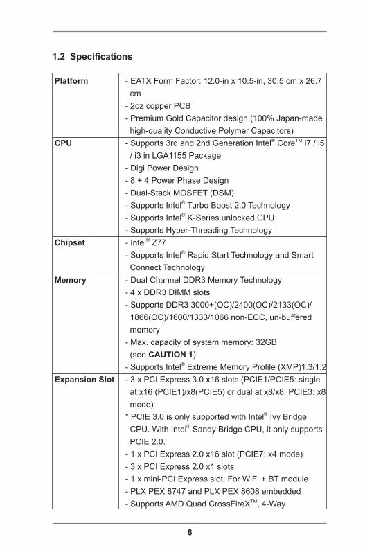
1.2 Specifications
Platform - EATX Form Factor: 12.0-in x 10.5-in, 30.5 cm x 26.7 cm - 2oz copper PCB - Premium Gold Capacitor design (100% Japan-made high-quality Conductive Polymer Capacitors) CPU - Supports 3rd and 2nd Generation Intel® CoreTM i7 / i5 / i3 in LGA1155 Package - Digi Power Design - 8 + 4 Power Phase Design - Dual-Stack MOSFET (DSM) - Supports Intel® Turbo Boost 2.0 Technology - Supports Intel® K-Series unlocked CPU - Supports Hyper-Threading Technology Chipset - Intel® Z77 - Supports Intel® Rapid Start Technology and Smart Connect Technology Memory - Dual Channel DDR3 Memory Technology - 4 x DDR3 DIMM slots - Supports DDR3 3000+(OC)/2400(OC)/2133(OC)/ 1866(OC)/1600/1333/1066 non-ECC, un-buffered memory - Max. capacity of system memory: 32GB (see CAUTION 1) - Supports Intel® Extreme Memory Profile (XMP)1.3/1.2 Expansion Slot - 3 x PCI Express 3.0 x16 slots (PCIE1/PCIE5: single at x16 (PCIE1)/x8(PCIE5) or dual at x8/x8; PCIE3: x8 mode) * PCIE 3.0 is only supported with Intel® Ivy Bridge CPU. With Intel® Sandy Bridge CPU, it only supports PCIE 2.0. - 1 x PCI Express 2.0 x16 slot (PCIE7: x4 mode) - 3 x PCI Express 2.0 x1 slots - 1 x mini-PCI Express slot: For WiFi + BT module - PLX PEX 8747 and PLX PEX 8608 embedded - Supports AMD Quad CrossFireXTM, 4-Way
7
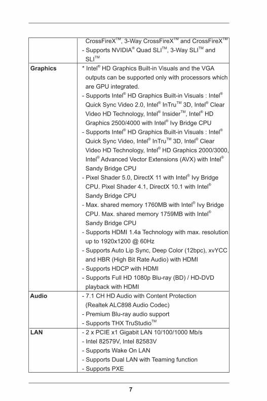
CrossFireXTM, 3-Way CrossFireXTM and CrossFireXTM
- Supports NVIDIA® Quad SLITM, 3-Way SLITM and SLITM
Graphics * Intel® HD Graphics Built-in Visuals and the VGA outputs can be supported only with processors which are GPU integrated. - Supports Intel® HD Graphics Built-in Visuals : Intel® Quick Sync Video 2.0, Intel® InTruTM 3D, Intel® Clear Video HD Technology, Intel® InsiderTM, Intel® HD Graphics 2500/4000 with Intel® Ivy Bridge CPU - Supports Intel® HD Graphics Built-in Visuals : Intel® Quick Sync Video, Intel® InTruTM 3D, Intel® Clear Video HD Technology, Intel® HD Graphics 2000/3000, Intel® Advanced Vector Extensions (AVX) with Intel® Sandy Bridge CPU - Pixel Shader 5.0, DirectX 11 with Intel® Ivy Bridge CPU. Pixel Shader 4.1, DirectX 10.1 with Intel® Sandy Bridge CPU - Max. shared memory 1760MB with Intel® Ivy Bridge CPU. Max. shared memory 1759MB with Intel® Sandy Bridge CPU - Supports HDMI 1.4a Technology with max. resolution up to 1920x1200 @ 60Hz - Supports Auto Lip Sync, Deep Color (12bpc), xvYCC and HBR (High Bit Rate Audio) with HDMI - Supports HDCP with HDMI - Supports Full HD 1080p Blu-ray (BD) / HD-DVD playback with HDMI Audio - 7.1 CH HD Audio with Content Protection (Realtek ALC898 Audio Codec) - Premium Blu-ray audio support - Supports THX TruStudioTM
LAN - 2 x PCIE x1 Gigabit LAN 10/100/1000 Mb/s - Intel 82579V, Intel 82583V - Supports Wake On LAN - Supports Dual LAN with Teaming function - Supports PXE
8
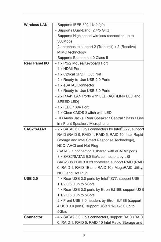
Wireless LAN - Supports IEEE 802.11a/b/g/n - Supports Dual-Band (2.4/5 GHz) - Supports High speed wireless connection up to 300Mbps - 2 antennas to support 2 (Transmit) x 2 (Receive) MIMO technology - Supports Bluetooth 4.0 Class II Rear Panel I/O - 1 x PS/2 Mouse/Keyboard Port - 1 x HDMI Port - 1 x Optical SPDIF Out Port - 2 x Ready-to-Use USB 2.0 Ports - 1 x eSATA3 Connector - 8 x Ready-to-Use USB 3.0 Ports - 2 x RJ-45 LAN Ports with LED (ACT/LINK LED and SPEED LED) - 1 x IEEE 1394 Port - 1 x Clear CMOS Switch with LED - HD Audio Jacks: Rear Speaker / Central / Bass / Line in / Front Speaker / Microphone SAS2/SATA3 - 2 x SATA3 6.0 Gb/s connectors by Intel® Z77, support RAID (RAID 0, RAID 1, RAID 5, RAID 10, Intel Rapid Storage and Intel Smart Response Technology), NCQ, AHCI and Hot Plug (SATA3_1 connector is shared with eSATA3 port) - 8 x SAS2/SATA3 6.0 Gb/s connectors by LSI SAS2308 PCIe 3.0 x8 controller, support RAID (RAID 0, RAID 1, RAID 1E and RAID 10), MegaRAID Utility, NCQ and Hot Plug USB 3.0 - 4 x Rear USB 3.0 ports by Intel® Z77, support USB 1.1/2.0/3.0 up to 5Gb/s - 4 x Rear USB 3.0 ports by Etron EJ188, support USB 1.1/2.0/3.0 up to 5Gb/s - 2 x Front USB 3.0 headers by Etron EJ188 (support 4 USB 3.0 ports), support USB 1.1/2.0/3.0 up to 5Gb/s Connector - 4 x SATA2 3.0 Gb/s connectors, support RAID (RAID 0, RAID 1, RAID 5, RAID 10 Intel Rapid Storage and
9
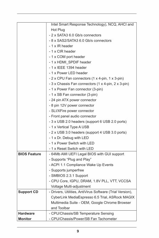
Intel Smart Response Technology), NCQ, AHCI and Hot Plug - 2 x SATA3 6.0 Gb/s connectors - 8 x SAS2/SATA3 6.0 Gb/s connectors - 1 x IR header - 1 x CIR header - 1 x COM port header - 1 x HDMI_SPDIF header - 1 x IEEE 1394 header - 1 x Power LED header - 2 x CPU Fan connectors (1 x 4-pin, 1 x 3-pin) - 3 x Chassis Fan connectors (1 x 4-pin, 2 x 3-pin) - 1 x Power Fan connector (3-pin) - 1 x SB Fan connector (3-pin) - 24 pin ATX power connector - 8 pin 12V power connector - SLI/XFire power connector - Front panel audio connector - 3 x USB 2.0 headers (support 6 USB 2.0 ports) - 1 x Vertical Type A USB - 2 x USB 3.0 headers (support 4 USB 3.0 ports) - 1 x Dr. Debug with LED - 1 x Power Switch with LED - 1 x Reset Switch with LED BIOS Feature - 64Mb AMI UEFI Legal BIOS with GUI support - Supports “Plug and Play” - ACPI 1.1 Compliance Wake Up Events - Supports jumperfree - SMBIOS 2.3.1 Support - CPU Core, IGPU, DRAM, 1.8V PLL, VTT, VCCSA Voltage Multi-adjustment Support CD - Drivers, Utilities, AntiVirus Software (Trial Version), CyberLink MediaEspresso 6.5 Trial, ASRock MAGIX Multimedia Suite - OEM, Google Chrome Browser and Toolbar Hardware - CPU/Chassis/SB Temperature Sensing Monitor - CPU/Chassis/Power/SB Fan Tachometer
10
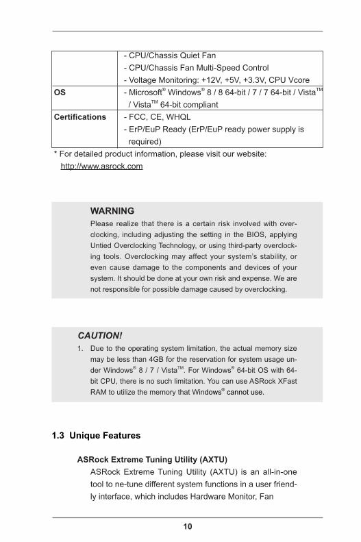
CAUTION!1. Due to the operating system limitation, the actual memory size
may be less than 4GB for the reservation for system usage un-der Windows® 8 / 7 / VistaTM. For Windows® 64-bit OS with 64-bit CPU, there is no such limitation. You can use ASRock XFast RAM to utilize the memory that Windows® cannot use.
WARNING Please realize that there is a certain risk involved with over-
clocking, including adjusting the setting in the BIOS, applying Untied Overclocking Technology, or using third-party overclock-ing tools. Overclocking may affect your system’s stability, or even cause damage to the components and devices of your system. It should be done at your own risk and expense. We are not responsible for possible damage caused by overclocking.
- CPU/Chassis Quiet Fan - CPU/Chassis Fan Multi-Speed Control - Voltage Monitoring: +12V, +5V, +3.3V, CPU Vcore OS - Microsoft® Windows® 8 / 8 64-bit / 7 / 7 64-bit / VistaTM / VistaTM 64-bit compliant Certifications - FCC, CE, WHQL - ErP/EuP Ready (ErP/EuP ready power supply is required) * For detailed product information, please visit our website: http://www.asrock.com
1.3 Unique Features
ASRock Extreme Tuning Utility (AXTU) ASRock Extreme Tuning Utility (AXTU) is an all-in-one
tool to ne-tune different system functions in a user friend-ly interface, which includes Hardware Monitor, Fan
11
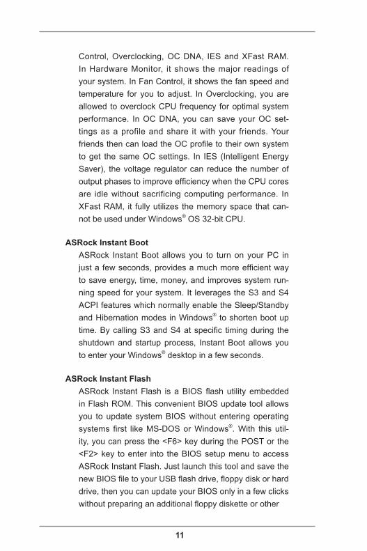
Control, Overclocking, OC DNA, IES and XFast RAM. In Hardware Monitor, it shows the major readings of your system. In Fan Control, it shows the fan speed and temperature for you to adjust. In Overclocking, you are allowed to overclock CPU frequency for optimal system performance. In OC DNA, you can save your OC set-tings as a profile and share it with your friends. Your friends then can load the OC profile to their own system to get the same OC settings. In IES (Intelligent Energy Saver), the voltage regulator can reduce the number of output phases to improve efficiency when the CPU cores are idle without sacrificing computing performance. In XFast RAM, it fully utilizes the memory space that can-not be used under Windows® OS 32-bit CPU.
ASRock Instant Boot ASRock Instant Boot allows you to turn on your PC in
just a few seconds, provides a much more efficient way to save energy, time, money, and improves system run-ning speed for your system. It leverages the S3 and S4 ACPI features which normally enable the Sleep/Standby and Hibernation modes in Windows® to shorten boot up time. By calling S3 and S4 at specific timing during the shutdown and startup process, Instant Boot allows you to enter your Windows® desktop in a few seconds.
ASRock Instant Flash ASRock Instant Flash is a BIOS flash utility embedded
in Flash ROM. This convenient BIOS update tool allows you to update system BIOS without entering operating systems first like MS-DOS or Windows®. With this util-ity, you can press the <F6> key during the POST or the <F2> key to enter into the BIOS setup menu to access ASRock Instant Flash. Just launch this tool and save the new BIOS file to your USB flash drive, floppy disk or hard drive, then you can update your BIOS only in a few clicks without preparing an additional floppy diskette or other
12
complicated flash utility. Please be noted that the USB flash drive or hard drive must use FAT32/16/12 file sys-tem.
ASRock APP Charger If you desire a faster, less restricted way of charging your
Apple devices, such as iPhone/iPad/iPod Touch, ASRock has prepared a wonderful solution for you - ASRock APP Charger. Simply install the APP Charger driver, it makes your iPhone charge much quickly from your computer and up to 40% faster than before. ASRock APP Charger allows you to quickly charge many Apple devices simul-taneously and even supports continuous charging when your PC enters into Standby mode (S1), Suspend to RAM (S3), hibernation mode (S4) or power off (S5). With APP Charger driver installed, you can easily enjoy the marvelous charging experience.
ASRock XFast USB ASRock XFast USB can boost USB storage device per-
formance. The performance may depend on the proper-ties of the device.
ASRock XFast LAN ASRock XFast LAN provides faster internet access,
which includes the benefits listed below. LAN Application Prioritization: You can configure your application’s prior-ity ideally and/or add new programs. Lower Latency in Game: After setting online game’s priority higher, it can lower the latency in games. Traffic Shaping: You can watch Youtube HD videos and download simultaneously. Real-Time Analysis of Your Data: With the status win-dow, you can easily recognize which data streams you are transferring currently.
ASRock XFast RAM ASRock XFast RAM is a new function that is included in
13
ASRock Extreme Tuning Utility (AXTU). It fully utilizes the memory space that cannot be used under Windows® 32-bit OS. ASRock XFast RAM shortens the loading time of previously visited websites, making web surfing faster than ever. And it also boosts the speed of Adobe Photo-shop 5 times faster. Another advantage of ASRock XFast RAM is that it reduces the frequency of accessing your SSDs or HDDs in order to extend their lifespan.
ASRock X-FAN ASRock X-FAN will be automatically activated only when
the system rises to a certain temperature under heavy-loading or overclocking. Normally, ASRock X-FAN will remain deactivated to give users the quietest computing experience. The target temperature and fan speed set-tings can be configured in the UEFI setup utility.
ASRock Crashless BIOS ASRock Crashless BIOS allows users to update their
BIOS without fear of failing. If power loss occurs during the BIOS update process, ASRock Crashless BIOS will automatically finish the BIOS update procedure after regaining power. Please note that BIOS files need to be placed in the root directory of your USB disk. Only USB2.0 ports support this feature.
ASRock OMG (Online Management Guard) Administrators are able to establish an internet curfew or
restrict internet access at specified times via OMG. You may schedule the starting and ending hours of internet access granted to other users. In order to prevent users from bypassing OMG, guest accounts without permission to modify the system time are required.
ASRock Internet Flash ASRock Internet Flash searches for available UEFI firm-
ware updates from our servers. In other words, the
14
system can auto-detect the latest UEFI from our servers and flash them without entering Windows® OS. Please note that you must be running on a DHCP configured computer in order to enable this function.
ASRock UEFI System Browser ASRock UEFI system browser is a useful tool included in
graphical UEFI. It can detect the devices and configura-tions that users are currently using in their PC. With the UEFI system browser, you can easily examine the cur-rent system configuration in UEFI setup.
ASRock Dehumidifier Function Users may prevent motherboard damages due to damp-
ness by enabling “Dehumidifier Function”. When en-abling Dehumidifier Function, the computer will power on automatically to dehumidify the system after entering S4/S5 state.
Lucid Virtu Universal MVP VIRTU Universal MVP includes the base features of Virtu
Universal technology, which virtualizes integrated GPU and discrete GPU for best of breed functionality. It also features Virtual Vsync™ for no-compromise visual qual-ity. With the added benefits of HyperFormance technol-ogy, VIRTU Universal MVP improves game performance by intelligently reducing redundant rendering tasks in the flow between the CPU, GPU and the display.
ASRock Interactive UEFI ASRock Interactive UEFI is a blend of system configura-
tion tools, cool sound effects and stunning visuals. The unprecedented UEFI provides a more attractive interface and brings a lot more amusing.
ASRock Easy RAID Installer ASRock Easy RAID Installer can help you to copy the
15
RAID driver from a support CD to your USB storage de-vice. After copying the RAID driver to your USB storage device, please change “SATA Mode” to “RAID”, then you can start installing the OS in RAID mode.
ASRock Fast Boot With ASRock’s exclusive Fast Boot technology, it takes
less than 1.5 seconds to logon to Windows 8 from a cold boot. No more waiting! The speedy boot will completely change your user experience and behavior.
ASRock Restart to UEFI Windows® 8 brings the ultimate boot up experience.
The lightning boot up speed makes it hard to access the UEFI setup. ASRock Restart to UEFI allows users to easily enter the UEFI automatically when turning on the PC. Just simply enable this function; the PC will enter the UEFI directly after you restart.
ASRock Good Night LED ASRock Good Night LED technology can offer you a bet-
ter environment by extinguishing the unessential LED. By enabling Good Night LED in BIOS, the Power / HDD / LAN LED will be switched off when system is on. Not only this, Good night LED will automatically switch off Power and Keyboard LED when the system enters into Standby / Hibernation mode as well.
Vertical Type A USB Vertical type USB ports are rarely seen on motherboard
designs. This ASRock motherboard is unprecedentedly equipped with a vertical USB 2.0 port named Vertical Type A USB. Besides the USB ports on the rear I/O, Vertical Type A USB is a convenient alternative port for users to plug in devices.

16
1.4 Motherboard Layout
ATX12V1
SLI/XFIRE_PWR1
DD
R3
_A
2 (
64 b
it, 2
40
-pin
mo
du
le)
DD
R3
_A
1 (
64 b
it, 2
40
-pin
mo
du
le)
DD
R3
_B
2 (
64 b
it, 2
40
-pin
mo
du
le)
DD
R3
_B
1 (
64 b
it, 2
40
-pin
mo
du
le)
CPU_FAN1
CPU_FAN2
PWR_FAN1
AT
XP
WR
1
64MbBIOS
1
US
B3
_11
_1
2
1
US
B3
_9
_1
0
CMOSBattery
SA
TA
3_
0_
1S
AT
A2
_2
_3
SA
TA
2_
4_
5S
AS
_0
_1
SA
S_
2_
3S
AS
_4
_5
SA
S_
6_
7
Dr.Debug
CHA_FAN1 CHA_FAN2
SuperI/O
PCIE3
PCIE2
PCIE5
PCIE7
PCIE1
PCIE4
PCIE6
1
HDMI_SPDIF1
COM1
1
1
HD_AUDIO1
IR1
1
FRONT_1394
1
USB6_7
1
CIR11
USB4_5
1
USB2_3
1
MIN
I_P
CIE
1
PLED1
1
CLRCMOS1
1 HDLED RESET
PLED PWRBTN
PANEL1
1
1
SPEAKER1
RSTBTN PWRBTN
Z77 Extreme11
CHA_FAN3
AUDIOCODEC
26.7cm (10.5 in)
30
.5cm
(1
2.0
in
)
1
USB 3.0T: USB1B: USB2
PS2Keyboard/
Mouse
ClrCMOS
USB 2.0T: USB0B: USB1
IEE
E 1
39
4
eS
AT
A_
1
USB 3.0T: USB3B: USB4H
DM
I1
Top:RJ-45
USB 3.0T: USB5B: USB6
Top:RJ-45
USB 3.0T: USB7B: USB8
To
p:
Ce
ntra
l/Ba
ss
Ce
nte
r:R
EA
R S
PK
To
p:
LIN
E IN
Ce
nte
r:F
RO
NT
Bo
ttom
:O
ptic
al
SP
DIF
Bo
ttom
:M
IC IN
DDR3 3000+
Fro
nt
US
B 3
.0
ErP/EuP Ready RoHSXFast LAN
XFast RAM
XFast USB
PC
I E
xp
res
s 3
.0
2 3 4 5 6 7
8
9
10
1112
13
14
15
16
17
18
19
20
212322242526272829303132333435363738
3940
41
42
43
44
45
46
47
48
49
VerticalType A USB
USB8
PEX8747
PEX8608
IntelZ77
LSI2308
SB_FAN1
WIFI + BTModule
Dual-Stack MOSFET
3-W
ay
SL
I
LSI SAS
2 o
z C
op
pe
r P
CB
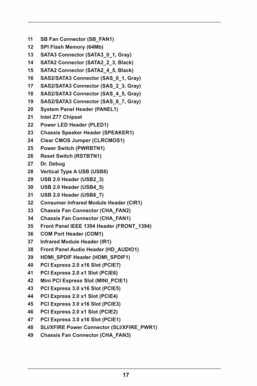
1 ATX 12V Power Connector (ATX12V1) 2 1155-Pin CPU Socket 3 CPU Fan Connector (CPU_FAN2) 4 CPU Fan Connector (CPU_FAN1) 5 2 x 240-pin DDR3 DIMM Slots (DDR3_A1, DDR3_B1, Black) 6 2 x 240-pin DDR3 DIMM Slots (DDR3_A2, DDR3_B2, Black) 7 Power Fan Connector (PWR_FAN1) 8 ATX Power Connector (ATXPWR1) 9 USB 3.0 Header (USB3_11_12)10 USB 3.0 Header (USB3_9_10)
17
11 SB Fan Connector (SB_FAN1)12 SPI Flash Memory (64Mb)13 SATA3 Connector (SATA3_0_1, Gray)14 SATA2 Connector (SATA2_2_3, Black)15 SATA2 Connector (SATA2_4_5, Black)16 SAS2/SATA3 Connector (SAS_0_1, Gray)17 SAS2/SATA3 Connector (SAS_2_3, Gray)18 SAS2/SATA3 Connector (SAS_4_5, Gray)19 SAS2/SATA3 Connector (SAS_6_7, Gray)20 System Panel Header (PANEL1)21 Intel Z77 Chipset22 Power LED Header (PLED1)23 Chassis Speaker Header (SPEAKER1)24 Clear CMOS Jumper (CLRCMOS1)25 Power Switch (PWRBTN1)26 Reset Switch (RSTBTN1)27 Dr. Debug28 Vertical Type A USB (USB8)29 USB 2.0 Header (USB2_3)30 USB 2.0 Header (USB4_5)31 USB 2.0 Header (USB6_7)32 Consumer Infrared Module Header (CIR1)33 Chassis Fan Connector (CHA_FAN2)34 Chassis Fan Connector (CHA_FAN1)35 Front Panel IEEE 1394 Header (FRONT_1394)36 COM Port Header (COM1)37 Infrared Module Header (IR1)38 Front Panel Audio Header (HD_AUDIO1)39 HDMI_SPDIF Header (HDMI_SPDIF1)40 PCI Express 2.0 x16 Slot (PCIE7)41 PCI Express 2.0 x1 Slot (PCIE6)42 Mini PCI Express Slot (MINI_PCIE1)43 PCI Express 3.0 x16 Slot (PCIE5)44 PCI Express 2.0 x1 Slot (PCIE4)45 PCI Express 3.0 x16 Slot (PCIE3)46 PCI Express 2.0 x1 Slot (PCIE2)47 PCI Express 3.0 x16 Slot (PCIE1)48 SLI/XFIRE Power Connector (SLI/XFIRE_PWR1)49 Chassis Fan Connector (CHA_FAN3)
18
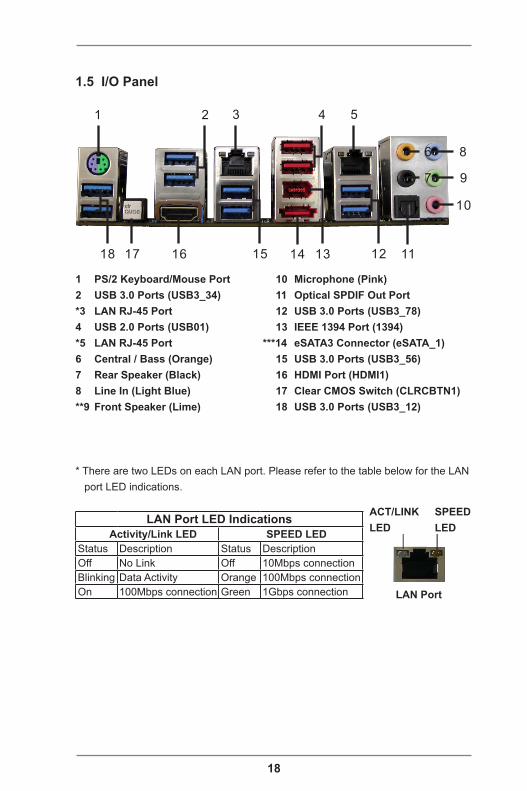
1.5 I/O Panel
1 PS/2 Keyboard/Mouse Port2 USB 3.0 Ports (USB3_34)*3 LAN RJ-45 Port4 USB 2.0 Ports (USB01)*5 LAN RJ-45 Port6 Central / Bass (Orange)7 Rear Speaker (Black)8 Line In (Light Blue)**9 Front Speaker (Lime)
10 Microphone (Pink) 11 Optical SPDIF Out Port 12 USB 3.0 Ports (USB3_78) 13 IEEE 1394 Port (1394) ***14 eSATA3 Connector (eSATA_1) 15 USB 3.0 Ports (USB3_56) 16 HDMI Port (HDMI1) 17 Clear CMOS Switch (CLRCBTN1) 18 USB 3.0 Ports (USB3_12)
* There are two LEDs on each LAN port. Please refer to the table below for the LAN port LED indications.
ACT/LINKLED
SPEEDLED
LAN Port
LAN Port LED IndicationsActivity/Link LED SPEED LED
Status Description Status DescriptionOff No Link Off 10Mbps connectionBlinking Data Activity Orange 100Mbps connectionOn 100Mbps connection Green 1Gbps connection
1 2 4 5
10
6
7
8
9
1114 12131617
3
1518
19
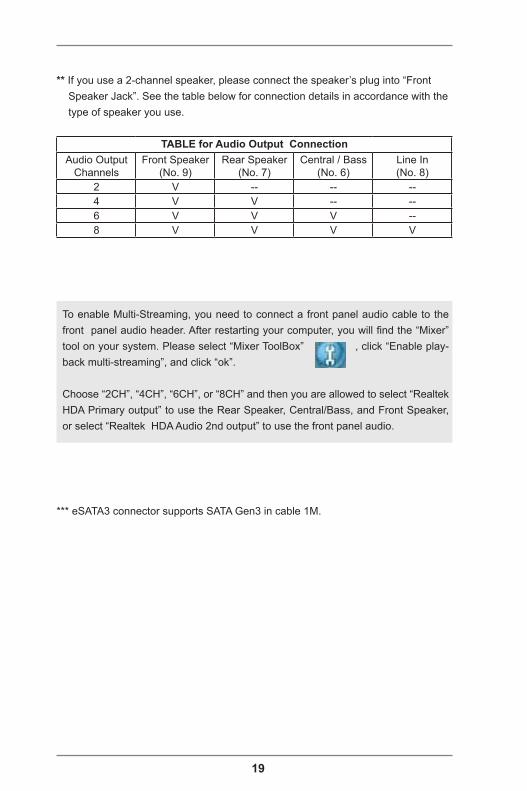
To enable Multi-Streaming, you need to connect a front panel audio cable to the front panel audio header. After restarting your computer, you will find the “Mixer” tool on your system. Please select “Mixer ToolBox” , click “Enable play-back multi-streaming”, and click “ok”.
Choose “2CH”, “4CH”, “6CH”, or “8CH” and then you are allowed to select “Realtek HDA Primary output” to use the Rear Speaker, Central/Bass, and Front Speaker, or select “Realtek HDA Audio 2nd output” to use the front panel audio.
*** eSATA3 connector supports SATA Gen3 in cable 1M.
** If you use a 2-channel speaker, please connect the speaker’s plug into “Front Speaker Jack”. See the table below for connection details in accordance with the type of speaker you use.
TABLE for Audio Output ConnectionAudio Output
ChannelsFront Speaker
(No. 9)Rear Speaker
(No. 7)Central / Bass
(No. 6)Line In(No. 8)
2 V -- -- --4 V V -- --6 V V V --8 V V V V
20
Chapter 2: Installation
This is an EATX form factor motherboard. Before you install the mother-board, study the configuration of your chassis to ensure that the mother-board fits into it.
Pre-installation PrecautionsTake note of the following precautions before you install motherboard com-ponents or change any motherboard settings.
1. Make sure to unplug the power cord before installing or removing the motherboard. Failure to do so may cause physical injuries to you and damages to motherboard com-ponents.
2. In order to avoid damage from static electricity to the moth-erboard’s components, NEVER place your motherboard directly on a carpet. Also remember to use a grounded wrist strap or touch a safety grounded object before you handle the components.
3. Hold components by the edges and do not touch the ICs.4. Whenever you uninstall any components, place them on a
grounded anti-static pad or in the bag that comes with the components.
5. When placing screws to secure the motherboard to the chassis, please do not over-tighten the screws! Doing so may damage the motherboard.
21
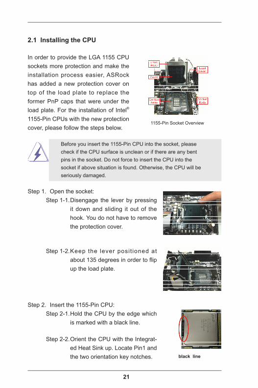
2.1 Installing the CPU
In order to provide the LGA 1155 CPU sockets more protection and make the installation process easier, ASRock has added a new protection cover on top of the load plate to replace the former PnP caps that were under the load plate. For the installation of Intel® 1155-Pin CPUs with the new protection cover, please follow the steps below.
Before you insert the 1155-Pin CPU into the socket, please check if the CPU surface is unclean or if there are any bent pins in the socket. Do not force to insert the CPU into the socket if above situation is found. Otherwise, the CPU will be seriously damaged.
Step 1. Open the socket:Step 1-1. Disengage the lever by pressing
it down and sliding it out of the hook. You do not have to remove the protection cover.
Step 1-2. Keep the lever posit ioned at about 135 degrees in order to flip up the load plate.
Step 2. Insert the 1155-Pin CPU:Step 2-1. Hold the CPU by the edge which
is marked with a black line.
Step 2-2. Orient the CPU with the Integrat-ed Heat Sink up. Locate Pin1 and the two orientation key notches. black line
1155-Pin Socket Overview
22
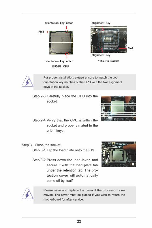
Pin1
alignment key
alignment key
Pin1
1155-Pin CPU
For proper installation, please ensure to match the two orientation key notches of the CPU with the two alignment keys of the socket.
Step 2-3. Carefully place the CPU into the socket.
Step 2-4. Verify that the CPU is within the socket and properly mated to the orient keys.
Step 3. Close the socket:Step 3-1. Flip the load plate onto the IHS.
Step 3-2. Press down the load lever, and secure it with the load plate tab under the retention tab. The pro-tection cover will automatically come off by itself.
Please save and replace the cover if the processor is re-moved. The cover must be placed if you wish to return the motherboard for after service.
orientation key notch
orientation key notch 1155-Pin Socket

23
2.2 Installing the CPU Fan and Heatsink
This motherboard is equipped with 1155-Pin socket that supports Intel 1155-Pin CPUs. Please adopt the type of heatsink and cooling fan com-pliant with Intel 1155-Pin CPU to dissipate heat. Before you install the heatsink, you need to spray thermal interface material between the CPU and the heatsink to improve heat dissipation. Ensure that the CPU and the heatsink are securely fastened and in good contact with each other. Then connect the CPU fan to the CPU_FAN connector (CPU_FAN1, see p.16, No. 4 or CPU_FAN2, see p.16, No. 3).For proper installation, please kindly refer to the instruction manuals of your CPU fan and heatsink.
Below is an example to illustrate the installation of a heatsink and fan for 1155-Pin CPUs.Step 1. Apply thermal interface material onto the
center of the IHS on the socket’s surface.Step 2. Place the heatsink onto the socket. En-
sure that the fan cables are faced on the side closest to the CPU fan connector on the motherboard (CPU_FAN1, see p.16, No. 4 or CPU_FAN2, see p.16, No. 3).
Step 3. Align the fasteners with the holes on the motherboard.
Step 4. Rotate the fastener clockwise, then press the fastener caps down with your thumb to install and lock. Repeat with the remaining fasteners.
If you press down the fasteners without rotating them clock-wise, the heatsink cannot be secured on the motherboard.
Step 5. Connect the CPU fan connector with the fan header on the motherboard.Step 6. Secure redundant cable with tie-wrap to ensure that the cable does not interfere with the fan’s operation or contact other components.
24
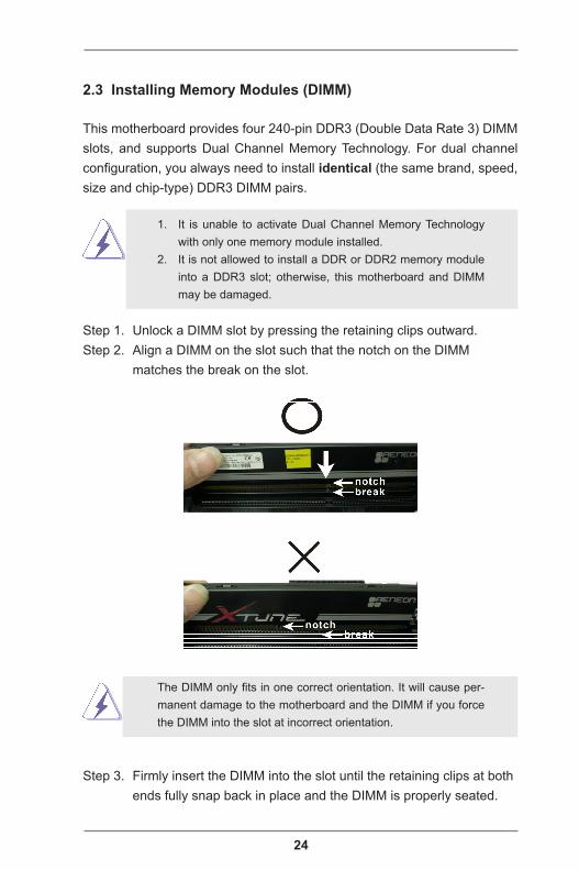
2.3 Installing Memory Modules (DIMM)
This motherboard provides four 240-pin DDR3 (Double Data Rate 3) DIMM slots, and supports Dual Channel Memory Technology. For dual channel configuration, you always need to install identical (the same brand, speed, size and chip-type) DDR3 DIMM pairs.
1. It is unable to activate Dual Channel Memory Technology with only one memory module installed.
2. It is not allowed to install a DDR or DDR2 memory module into a DDR3 slot; otherwise, this motherboard and DIMM may be damaged.
Step 1. Unlock a DIMM slot by pressing the retaining clips outward.Step 2. Align a DIMM on the slot such that the notch on the DIMM matches the break on the slot.
The DIMM only fits in one correct orientation. It will cause per-manent damage to the motherboard and the DIMM if you force the DIMM into the slot at incorrect orientation.
Step 3. Firmly insert the DIMM into the slot until the retaining clips at both ends fully snap back in place and the DIMM is properly seated.
25
2.4 Expansion Slots (PCI Express Slots)
There are 7 PCI Express slots and 1 mini_PCI Express slot on this moth-erboard.
Mini-PCIE Slots: MINI_PCIE1 is used for mini-PCIE cards.PCIE slots: PCIE2, PCIE4 and PCIE6 (PCIE 2.0 x1 slots) are used for
PCI Express x1 lane width cards, such as a Gigabit LAN card or SATA2 cards, etc.
PCIE1 (PCIE 3.0 x16 slot) is used for PCI Express x16 lane width graphics cards.
PCIE3 and PCIE5 (PCIE 3.0 x16 slot) are used for PCI Express x8 lane width graphics cards, or used to install PCI Express graphics cards to support CrossFireXTM or SLITM.
PCIE7 (PCIE 2.0 x16 slot) is used for PCI Express x4 lane width graphics cards or ASRock Game Blaster.
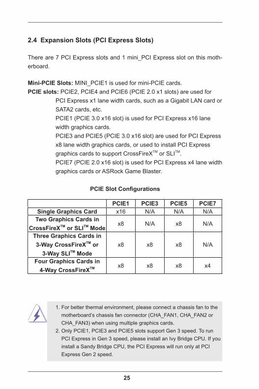
PCIE Slot Configurations
1. For better thermal environment, please connect a chassis fan to the motherboard’s chassis fan connector (CHA_FAN1, CHA_FAN2 or CHA_FAN3) when using multiple graphics cards. 2. Only PCIE1, PCIE3 and PCIE5 slots support Gen 3 speed. To run PCI Express in Gen 3 speed, please install an Ivy Bridge CPU. If you install a Sandy Bridge CPU, the PCI Express will run only at PCI Express Gen 2 speed.
PCIE1 PCIE3 PCIE5 PCIE7Single Graphics Card x16 N/A N/A N/A
Two Graphics Cards in CrossFireXTM or SLITM Mode
x8 N/A x8 N/A
Three Graphics Cards in 3-Way CrossFireXTM or
3-Way SLITM Modex8 x8 x8 N/A
Four Graphics Cards in 4-Way CrossFireXTM x8 x8 x8 x4

26
Installing an Expansion Card
Step 1. Before installing an expansion card, please make sure that the power supply is switched off or the power cord is unplugged. Please read the documentation of the expansion card and make necessary hardware settings for the card before you start the installation.
Step 2. Remove the bracket facing the slot that you intend to use. Keep the screws for later use.
Step 3. Align the card connector with the slot and press firmly until the card is completely seated on the slot.
Step 4. Fasten the card to the chassis with screws.
27
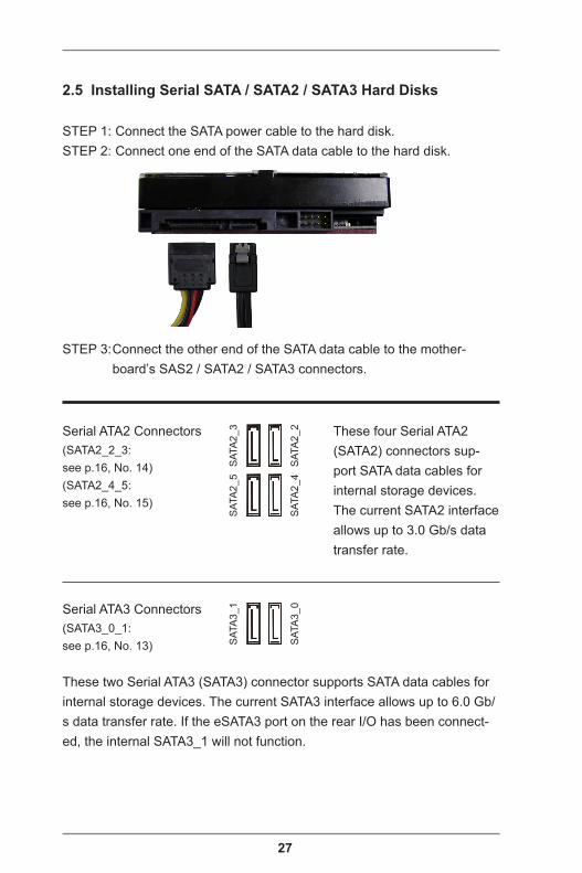
2.5 Installing Serial SATA / SATA2 / SATA3 Hard Disks
STEP 1: Connect the SATA power cable to the hard disk.STEP 2: Connect one end of the SATA data cable to the hard disk.
STEP 3: Connect the other end of the SATA data cable to the mother-board’s SAS2 / SATA2 / SATA3 connectors.
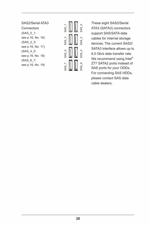
Serial ATA3 Connectors(SATA3_0_1: see p.16, No. 13)
These two Serial ATA3 (SATA3) connector supports SATA data cables for internal storage devices. The current SATA3 interface allows up to 6.0 Gb/s data transfer rate. If the eSATA3 port on the rear I/O has been connect-ed, the internal SATA3_1 will not function.
Serial ATA2 Connectors(SATA2_2_3: see p.16, No. 14)(SATA2_4_5: see p.16, No. 15)
SAT
A2_
3S
ATA
2_5
SAT
A2_
2S
ATA
2_4
These four Serial ATA2 (SATA2) connectors sup-port SATA data cables for internal storage devices. The current SATA2 interface allows up to 3.0 Gb/s data transfer rate.
SAT
A3_
1
SAT
A3_
0
28
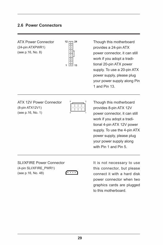
SAS2/Serial ATA3 Connectors(SAS_0_1: see p.16, No. 16)(SAS_2_3: see p.16, No. 17)(SAS_4_5: see p.16, No. 18)(SAS_6_7: see p.16, No. 19)
These eight SAS2/Serial ATA3 (SATA3) connectors support SAS/SATA data cables for internal storage devices. The current SAS2/SATA3 interface allows up to 6.0 Gb/s data transfer rate. We recommend using Intel® Z77 SATA2 ports instead of SAS ports for your ODDs. For connecting SAS HDDs, please contact SAS data cable dealers.
SA
S_1
SA
S_5
SA
S_3
SA
S_7
SA
S_0
SA
S_4
SA
S_2
SA
S_6
29
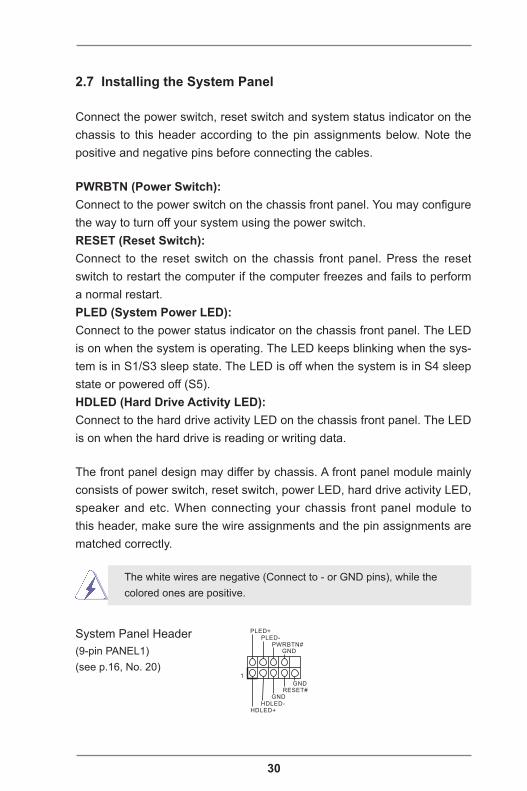
SLI/XFIRE Power Connector(4-pin SLI/XFIRE_PWR1)(see p.16, No. 48)
ATX Power Connector(24-pin ATXPWR1)(see p.16, No. 8)
12
1
24
13
2.6 Power Connectors
ATX 12V Power Connector(8-pin ATX12V1)(see p.16, No. 1) 4 1
8 5 Though this motherboard provides 8-pin ATX 12V power connector, it can still work if you adopt a tradi-tional 4-pin ATX 12V power supply. To use the 4-pin ATX power supply, please plug your power supply along with Pin 1 and Pin 5.
Though this motherboard provides a 24-pin ATX power connector, it can still work if you adopt a tradi-tional 20-pin ATX power supply. To use a 20-pin ATX power supply, please plug your power supply along Pin 1 and Pin 13.
It is not necessary to use this connector, but please connect it with a hard disk power connector when two graphics cards are plugged to this motherboard.
30
2.7 Installing the System Panel
Connect the power switch, reset switch and system status indicator on the chassis to this header according to the pin assignments below. Note the positive and negative pins before connecting the cables.
PWRBTN (Power Switch):Connect to the power switch on the chassis front panel. You may configure the way to turn off your system using the power switch.RESET (Reset Switch):Connect to the reset switch on the chassis front panel. Press the reset switch to restart the computer if the computer freezes and fails to perform a normal restart.PLED (System Power LED):Connect to the power status indicator on the chassis front panel. The LED is on when the system is operating. The LED keeps blinking when the sys-tem is in S1/S3 sleep state. The LED is off when the system is in S4 sleep state or powered off (S5).HDLED (Hard Drive Activity LED):Connect to the hard drive activity LED on the chassis front panel. The LED is on when the hard drive is reading or writing data.
The front panel design may differ by chassis. A front panel module mainly consists of power switch, reset switch, power LED, hard drive activity LED, speaker and etc. When connecting your chassis front panel module to this header, make sure the wire assignments and the pin assignments are matched correctly.
The white wires are negative (Connect to - or GND pins), while the colored ones are positive.
System Panel Header(9-pin PANEL1)(see p.16, No. 20)
GND
RESET#
PWRBTN#PLED-
PLED+
GNDHDLED-
HDLED+
1
GND
31
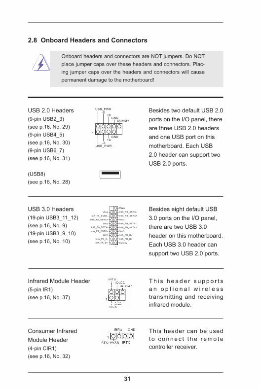
Infrared Module Header(5-pin IR1)(see p.16, No. 37)
2.8 Onboard Headers and Connectors
Onboard headers and connectors are NOT jumpers. Do NOT place jumper caps over these headers and connectors. Plac-ing jumper caps over the headers and connectors will cause permanent damage to the motherboard!
Consumer Infrared Module Header(4-pin CIR1)(see p.16, No. 32)
USB 2.0 Headers(9-pin USB2_3)(see p.16, No. 29)(9-pin USB4_5)(see p.16, No. 30)(9-pin USB6_7)(see p.16, No. 31)
(USB8)(see p.16, No. 28)
Besides two default USB 2.0 ports on the I/O panel, there are three USB 2.0 headers and one USB port on this motherboard. Each USB 2.0 header can support two USB 2.0 ports.
This header can be used t o c o n n e c t t h e r e m o t e controller receiver.
T h i s h e a d e r s u p p o r t s a n o p t i o n a l w i r e l e s s transmitting and receiving infrared module.
DUMMYGND
GND
+B-B
USB_PWR
+A-A
USB_PWR
1
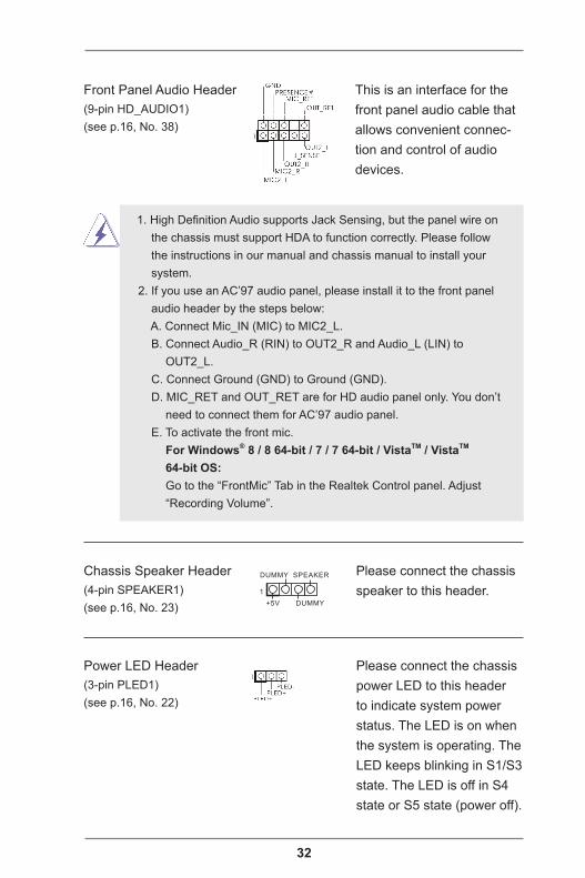
USB 3.0 Headers(19-pin USB3_11_12)(see p.16, No. 9)(19-pin USB3_9_10)(see p.16, No. 10)
Besides eight default USB 3.0 ports on the I/O panel, there are two USB 3.0 header on this motherboard. Each USB 3.0 header can support two USB 2.0 ports.
1
IntA_PB_D+
Dummy
IntA_PB_D-
GND
IntA_PB_SSTX+
GND
IntA_PB_SSTX-
IntA_PB_SSRX+
IntA_PB_SSRX-
VbusVbus
Vbus
IntA_PA_SSRX-
IntA_PA_SSRX+
GND
IntA_PA_SSTX-
IntA_PA_SSTX+
GND
IntA_PA_D-
IntA_PA_D+
32
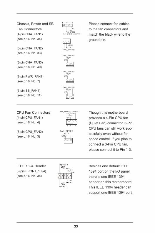
Power LED Header(3-pin PLED1)(see p.16, No. 22)
Front Panel Audio Header(9-pin HD_AUDIO1)(see p.16, No. 38)
This is an interface for the front panel audio cable that allows convenient connec-tion and control of audio devices.
1. High Definition Audio supports Jack Sensing, but the panel wire on the chassis must support HDA to function correctly. Please follow the instructions in our manual and chassis manual to install your system.2. If you use an AC’97 audio panel, please install it to the front panel audio header by the steps below: A. Connect Mic_IN (MIC) to MIC2_L. B. Connect Audio_R (RIN) to OUT2_R and Audio_L (LIN) to OUT2_L. C. Connect Ground (GND) to Ground (GND). D. MIC_RET and OUT_RET are for HD audio panel only. You don’t need to connect them for AC’97 audio panel. E. To activate the front mic. For Windows® 8 / 8 64-bit / 7 / 7 64-bit / VistaTM / VistaTM 64-bit OS: Go to the “FrontMic” Tab in the Realtek Control panel. Adjust “Recording Volume”.
Chassis Speaker Header(4-pin SPEAKER1)(see p.16, No. 23)
Please connect the chassis speaker to this header.
Please connect the chassis power LED to this header to indicate system power status. The LED is on when the system is operating. The LED keeps blinking in S1/S3 state. The LED is off in S4 state or S5 state (power off).
1
+5V
DUMMY
DUMMY
SPEAKER
33
IEEE 1394 Header(9-pin FRONT_1394)(see p.16, No. 35)
CPU Fan Connectors(4-pin CPU_FAN1)(see p.16, No. 4)
(3-pin CPU_FAN2)(see p.16, No. 3)
Though this motherboard provides a 4-Pin CPU fan (Quiet Fan) connector, 3-Pin CPU fans can still work suc-cessfully even without fan speed control. If you plan to connect a 3-Pin CPU fan, please connect it to Pin 1-3.
Chassis, Power and SB Fan Connectors(4-pin CHA_FAN1)(see p.16, No. 34)
(3-pin CHA_FAN2)(see p.16, No. 33)
(3-pin CHA_FAN3)(see p.16, No. 49)
(3-pin PWR_FAN1)(see p.16, No. 7)
(3-pin SB_FAN1)(see p.16, No. 11)
Please connect fan cables to the fan connectors and match the black wire to the ground pin.
Besides one default IEEE 1394 port on the I/O panel, there is one IEEE 1394 header on this motherboard. This IEEE 1394 header can support one IEEE 1394 port.
GND+12V
FAN_SPEED
GND+12V
FAN_SPEED
GND+12V
FAN_SPEED
GND+12V
FAN_SPEED
GND+12V
FAN_SPEED
FAN_SPEED
FAN_SPEED_CONTROL
GND+12V
1 2 3 4
34
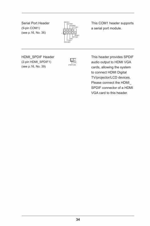
HDMI_SPDIF Header(2-pin HDMI_SPDIF1)(see p.16, No. 39)
Serial Port Header(9-pin COM1)(see p.16, No. 36)
This COM1 header supports a serial port module.
This header provides SPDIF audio output to HDMI VGA cards, allowing the system to connect HDMI Digital TV/projector/LCD devices. Please connect the HDMI_SPDIF connector of a HDMI VGA card to this header.
CCTS#1
RRTS#1
DDSR#1DDTR#1
RRXD1
GNDTTXD1
DDCD#1
1
RRI#1
35
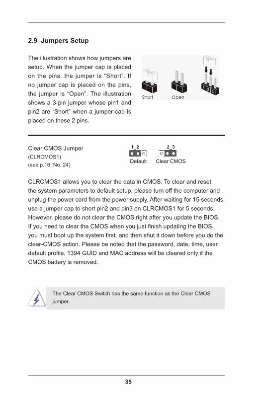
Clear CMOS Jumper(CLRCMOS1)(see p.16, No. 24)
Clear CMOSDefault
CLRCMOS1 allows you to clear the data in CMOS. To clear and reset the system parameters to default setup, please turn off the computer and unplug the power cord from the power supply. After waiting for 15 seconds, use a jumper cap to short pin2 and pin3 on CLRCMOS1 for 5 seconds. However, please do not clear the CMOS right after you update the BIOS. If you need to clear the CMOS when you just finish updating the BIOS, you must boot up the system first, and then shut it down before you do the clear-CMOS action. Please be noted that the password, date, time, user default profile, 1394 GUID and MAC address will be cleared only if the CMOS battery is removed.
2.9 Jumpers Setup
The illustration shows how jumpers are setup. When the jumper cap is placed on the pins, the jumper is “Short”. If no jumper cap is placed on the pins, the jumper is “Open”. The illustration shows a 3-pin jumper whose pin1 and pin2 are “Short” when a jumper cap is placed on these 2 pins.
The Clear CMOS Switch has the same function as the Clear CMOS jumper.
36
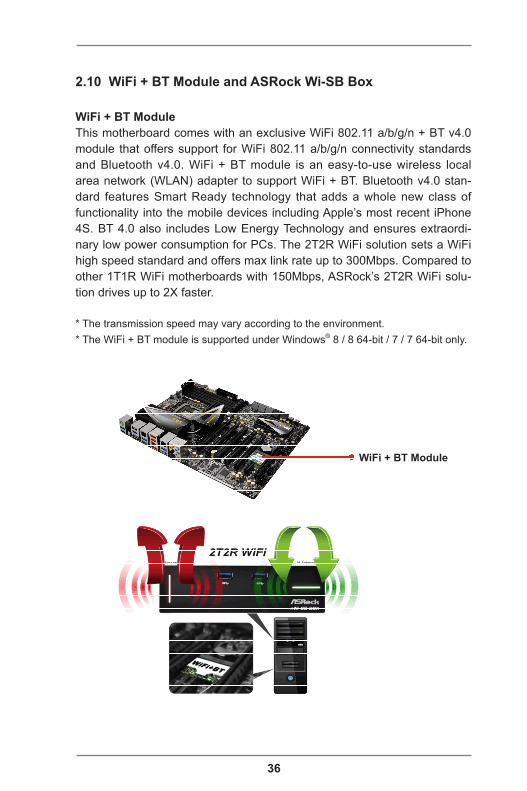
2.10 WiFi + BT Module and ASRock Wi-SB Box
WiFi + BT ModuleThis motherboard comes with an exclusive WiFi 802.11 a/b/g/n + BT v4.0 module that offers support for WiFi 802.11 a/b/g/n connectivity standards and Bluetooth v4.0. WiFi + BT module is an easy-to-use wireless local area network (WLAN) adapter to support WiFi + BT. Bluetooth v4.0 stan-dard features Smart Ready technology that adds a whole new class of functionality into the mobile devices including Apple’s most recent iPhone 4S. BT 4.0 also includes Low Energy Technology and ensures extraordi-nary low power consumption for PCs. The 2T2R WiFi solution sets a WiFi high speed standard and offers max link rate up to 300Mbps. Compared to other 1T1R WiFi motherboards with 150Mbps, ASRock’s 2T2R WiFi solu-tion drives up to 2X faster.
* The transmission speed may vary according to the environment.* The WiFi + BT module is supported under Windows® 8 / 8 64-bit / 7 / 7 64-bit only.
WiFi + BT Module

37
ASRock Wi-SB BoxThanks to the excellent placement of antennas, ASRock Wi-SB Box comes with two invisible antennas (placed in a vertical/horizontal position), hidden inside the front panel that provides the most stable and unrestricted-direction wireless network coverage, optimized for maximum broadband network. Additionally, it provides two Front USB 3.0 ports for easier USB 3.0 device access and 1 rack for SSD place-ment.
ASRock Wi-SB Box
38
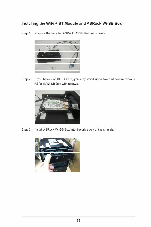
Installing the WiFi + BT Module and ASRock Wi-SB Box
Step 1. Prepare the bundled ASRock Wi-SB Box and screws.
Step 2. If you have 2.5” HDD/SSDs, you may insert up to two and secure them in ASRock Wi-SB Box with screws.
Step 3. Install ASRock Wi-SB Box into the drive bay of the chassis.
39
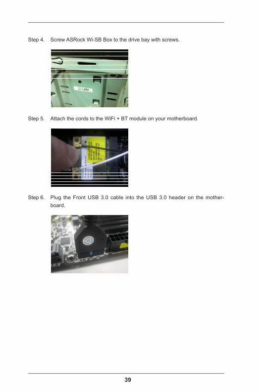
Step 4. Screw ASRock Wi-SB Box to the drive bay with screws.
Step 5. Attach the cords to the WiFi + BT module on your motherboard.
Step 6. Plug the Front USB 3.0 cable into the USB 3.0 header on the mother-board.
40
2.11 Operating System Setup
This motherboard supports various Microsoft® Windows® operating sys-tems: 8 / 8 64-bit / 7 / 7 64-bit / VistaTM / VistaTM 64-bit. Because mother-board settings and hardware options vary, use the setup procedures in this chapter for general reference only. Refer your OS documentation for more information.
2.11.1 Installing Windows® 8 / 8 64-bit / 7 / 7 64-bit / VistaTM / VistaTM 64-bit without RAID
Using AHCI Mode
STEP 1: Set Up UEFI.Press <F2> or <Delete> at system POST. Set AHCI Mode in UEFI Setup Utility > Advanced > Storage Configuration > SATA Mode.
STEP 2: Install Windows® 8 / 8 64-bit / 7 / 7 64-bit / VistaTM / VistaTM 64-bit on your system.
Using IDE Mode
STEP 1: Set Up UEFI.Press <F2> or <Delete> at system POST. Set IDE Mode in UEFI Setup Utility > Advanced > Storage Configuration > SATA Mode.
STEP 2: Install Windows® 8 / 8 64-biy / 7 / 7 64-bit / VistaTM / VistaTM 64-bit on your system.
41
2.11.2 Installing Windows® 8 64-bit / 7 64-bit / VistaTM 64-bit on a HDD Larger than 2 terabytes (2TB) without RAID
This motherboard adopts UEFI BIOS that allows Windows® OS to be installed on a large size HDD (>2TB). Please make sure to use Windows® VistaTM 64-bit (with SP2 or above), 7 64-bit or 8 64-bit and follow the procedures below to install the operating system.
Using AHCI Mode
STEP 1: Set Up UEFI.Press <F2> or <Delete> at system POST. Set AHCI Mode in UEFI Setup Utility > Advanced > Storage Configuration > SATA Mode.
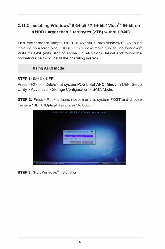
STEP 2: Press <F11> to launch boot menu at system POST and choose the item “UEFI:<Optical disk drive>“ to boot.
STEP 3: Start Windows® installation.
42
2.11.3 Installing Windows® 8 / 8 64-bit / 7 / 7 64-bit / VistaTM / VistaTM 64-bit with RAID
STEP 1: Set Up UEFI.Press <F2> or <Delete> at system POST. Set RAID Mode in UEFI Setup Utility > Advanced > Storage Configuration > SATA Mode.
STEP 2: Use “RAID Installation Guide” to set the RAID configuration.Before you start to configure RAID, you need to check the installation guide in the Support CD for proper configuration. Please refer to the document in the Support CD, “Guide to SATA Hard Disks Installation and RAID Configuration”, which is located in the folder at the following path: .. \ RAID Installation Guide
STEP 3: Install Windows® 8 / 8 64-bit / 7 / 7 64-bit / VistaTM / VistaTM 64-bit on your system.
43
2.12 Installing Drivers
The Support CD that comes with the motherboard contains necessary driv-ers and useful utilities that enhance the motherboard’s features.
2.12.1 Running The Support CDTo begin using the support CD, insert the CD into your CD-ROM drive. The CD automatically displays the Main Menu if “AUTORUN” is enabled in your computer. If the Main Menu does not appear auto-matically, locate and double click on the file “ASRSETUP.EXE” in the Support CD to display the menu.
2.12.2 Drivers MenuThe drivers compatible to your system will be auto-detected and list-ed on the support CD driver page. Please follow the order from top to bottom to install those required drivers. Therefore, the drivers you install can work properly.
2.12.3 Utilities MenuThe Utilities Menu shows the application softwares that the mother-board supports. Click on a specific item then follow the installation wizard to install it.
2.12.4 Contact InformationIf you need to contact ASRock or want to know more about ASRock, you’re welcome to visit ASRock’s website at http://www.asrock.com; or you may contact your dealer for further information.
44
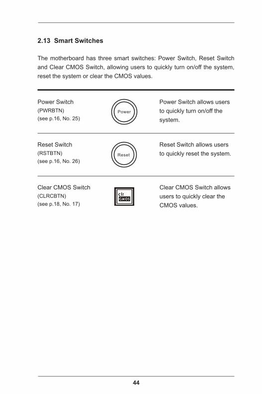
Power Switch(PWRBTN)(see p.16, No. 25)
Reset Switch(RSTBTN)(see p.16, No. 26)
Clear CMOS Switch(CLRCBTN)(see p.18, No. 17)
2.13 Smart Switches
The motherboard has three smart switches: Power Switch, Reset Switch and Clear CMOS Switch, allowing users to quickly turn on/off the system, reset the system or clear the CMOS values.
Power Switch allows users to quickly turn on/off the system.
Reset Switch allows users to quickly reset the system.
Clear CMOS Switch allows users to quickly clear the CMOS values.
Power
Reset
45
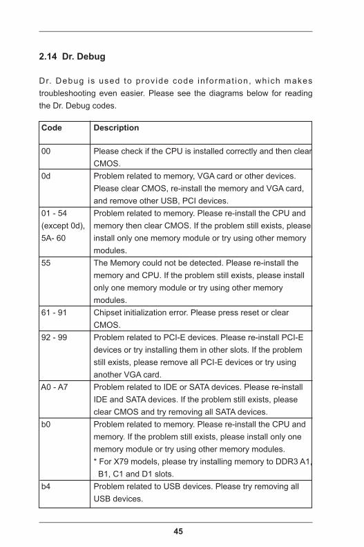
2.14 Dr. Debug
Dr. Debug is used to prov ide code in format ion, which makes troubleshooting even easier. Please see the diagrams below for reading the Dr. Debug codes.
Code Description
00 Please check if the CPU is installed correctly and then clear CMOS. 0d Problem related to memory, VGA card or other devices. Please clear CMOS, re-install the memory and VGA card, and remove other USB, PCI devices. 01 - 54 Problem related to memory. Please re-install the CPU and (except 0d), memory then clear CMOS. If the problem still exists, please 5A- 60 install only one memory module or try using other memory modules. 55 The Memory could not be detected. Please re-install the memory and CPU. If the problem still exists, please install only one memory module or try using other memory modules. 61 - 91 Chipset initialization error. Please press reset or clear CMOS. 92 - 99 Problem related to PCI-E devices. Please re-install PCI-E devices or try installing them in other slots. If the problem still exists, please remove all PCI-E devices or try using another VGA card. A0 - A7 Problem related to IDE or SATA devices. Please re-install IDE and SATA devices. If the problem still exists, please clear CMOS and try removing all SATA devices. b0 Problem related to memory. Please re-install the CPU and memory. If the problem still exists, please install only one memory module or try using other memory modules. * For X79 models, please try installing memory to DDR3 A1, B1, C1 and D1 slots. b4 Problem related to USB devices. Please try removing all USB devices.
46
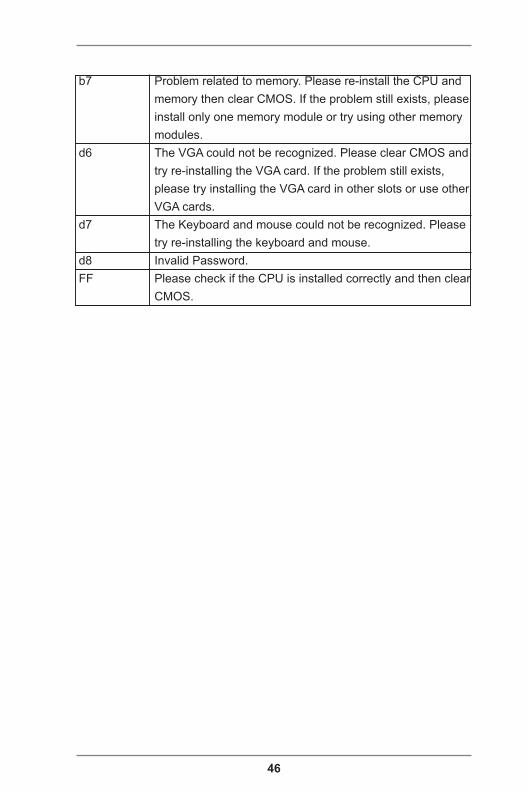
b7 Problem related to memory. Please re-install the CPU and memory then clear CMOS. If the problem still exists, please install only one memory module or try using other memory modules. d6 The VGA could not be recognized. Please clear CMOS and try re-installing the VGA card. If the problem still exists, please try installing the VGA card in other slots or use other VGA cards. d7 The Keyboard and mouse could not be recognized. Please try re-installing the keyboard and mouse. d8 Invalid Password. FF Please check if the CPU is installed correctly and then clear CMOS.
47
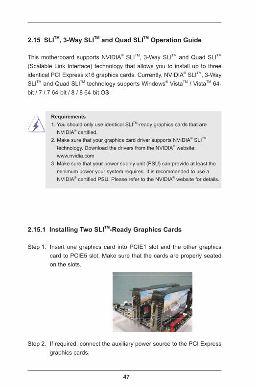
2.15.1 Installing Two SLITM-Ready Graphics Cards
Step 1. Insert one graphics card into PCIE1 slot and the other graphics card to PCIE5 slot. Make sure that the cards are properly seated on the slots.
Step 2. If required, connect the auxiliary power source to the PCI Express graphics cards.
2.15 SLITM, 3-Way SLITM and Quad SLITM Operation Guide
This motherboard supports NVIDIA® SLITM, 3-Way SLITM and Quad SLITM (Scalable Link Interface) technology that allows you to install up to three identical PCI Express x16 graphics cards. Currently, NVIDIA® SLITM, 3-Way SLITM and Quad SLITM technology supports Windows® VistaTM / VistaTM 64-bit / 7 / 7 64-bit / 8 / 8 64-bit OS.
Requirements 1. You should only use identical SLITM-ready graphics cards that are NVIDIA® certified. 2. Make sure that your graphics card driver supports NVIDIA® SLITM technology. Download the drivers from the NVIDIA® website: www.nvidia.com 3. Make sure that your power supply unit (PSU) can provide at least the minimum power your system requires. It is recommended to use a NVIDIA® certified PSU. Please refer to the NVIDIA® website for details.
48
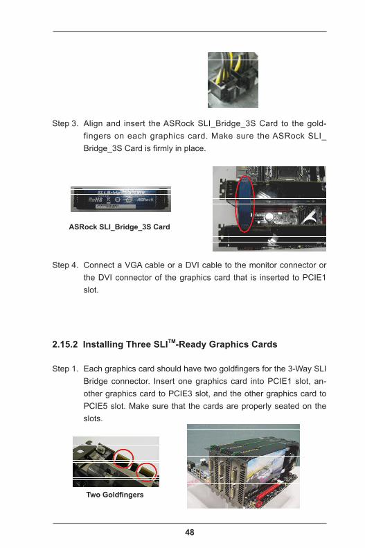
Step 4. Connect a VGA cable or a DVI cable to the monitor connector or the DVI connector of the graphics card that is inserted to PCIE1 slot.
Step 3. Align and insert the ASRock SLI_Bridge_3S Card to the gold-fingers on each graphics card. Make sure the ASRock SLI_Bridge_3S Card is firmly in place.
ASRock SLI_Bridge_3S Card
2.15.2 Installing Three SLITM-Ready Graphics Cards
Step 1. Each graphics card should have two goldfingers for the 3-Way SLI Bridge connector. Insert one graphics card into PCIE1 slot, an-other graphics card to PCIE3 slot, and the other graphics card to PCIE5 slot. Make sure that the cards are properly seated on the slots.
Two Goldfingers
49
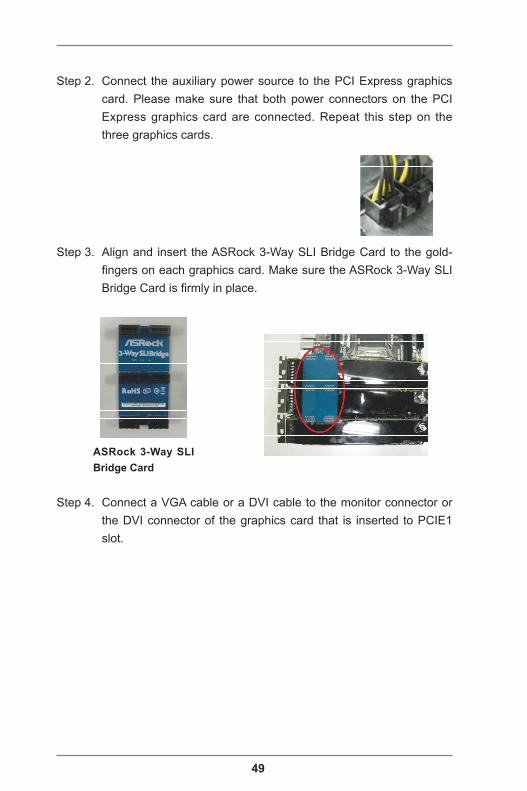
Step 4. Connect a VGA cable or a DVI cable to the monitor connector or the DVI connector of the graphics card that is inserted to PCIE1 slot.
Step 3. Align and insert the ASRock 3-Way SLI Bridge Card to the gold-fingers on each graphics card. Make sure the ASRock 3-Way SLI Bridge Card is firmly in place.
ASRock 3-Way SLI Bridge Card
Step 2. Connect the auxiliary power source to the PCI Express graphics card. Please make sure that both power connectors on the PCI Express graphics card are connected. Repeat this step on the three graphics cards.

50
2.15.3 Driver Installation and Setup
Install the graphics card drivers to your system. After that, you can enable the Multi-Graphics Processing Unit (GPU) in the NVIDIA® nView system tray utility. Please follow the below procedures to enable the multi-GPU.
For SLITM and Quad SLITM mode
A. Click the Start icon on your Windows taskbar. B. From the pop-up menu, select All Programs, and then click NVIDIA Corporation. C. Select NVIDIA Control Panel tab. D. Select Control Panel tab.
E. From the pop-up menu, select Set SLI and PhysX configuration. In Set PhysX GPU acceleration item, please select Enabled. F. In Select an SLI configuration item, please select Enable SLI. And click Apply.
51
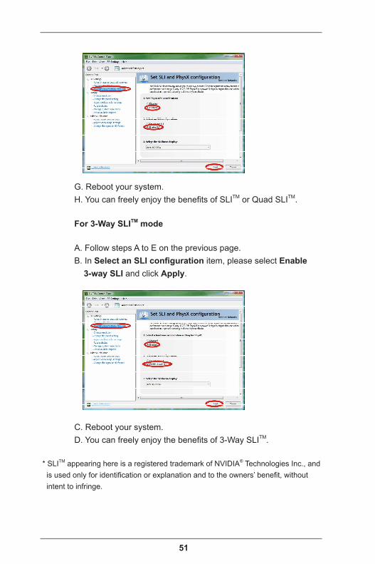
G. Reboot your system. H. You can freely enjoy the benefits of SLITM or Quad SLITM.
For 3-Way SLITM mode
A. Follow steps A to E on the previous page. B. In Select an SLI configuration item, please select Enable 3-way SLI and click Apply.
C. Reboot your system. D. You can freely enjoy the benefits of 3-Way SLITM.
* SLITM appearing here is a registered trademark of NVIDIA® Technologies Inc., and is used only for identification or explanation and to the owners’ benefit, without intent to infringe.
52
2.16 CrossFireXTM, 3-Way CrossFireXTM, 4-Way CrossFireXTM and Quad CrossFireXTM Operation Guide
This motherboard supports CrossFireXTM, 3-way CrossFireXTM, 4-way CrossFireXTM and Quad CrossFireXTM that allows you to install up to four identical PCI Express x16 graphics cards. Currently CrossFireXTM, 3-way CrossFireXTM, 4-way CrossFireXTM and Quad CrossFireXTM are supported with Windows® VistaTM / VistaTM 64-bit / 7 / 7 64-bit / 8 / 8 64-bit OS.
1. You should only use identical CrossFireXTM-ready graphics cards that are AMD certified. 2. Make sure that your graphics card driver supports AMD CrossFireXTM technology. Download the drivers from the AMD’s website: www.amd.com 3. Make sure that your power supply unit (PSU) can provide at least the minimum power your system requires. It is recommended to use a AMD certified PSU. Please refer to the AMD’s website for details. 4. If you pair a 12-pipe CrossFireXTM Edition card with a 16-pipe card, both cards will operate as 12-pipe cards while in CrossFireXTM mode. 5. Different CrossFireXTM cards may require different methods to enable CrossFireXTM. Please refer to AMD graphics card manuals for detailed installation guide.
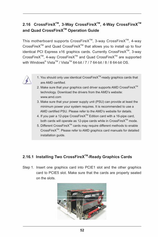
2.16.1 Installing Two CrossFireXTM-Ready Graphics Cards
Step 1. Insert one graphics card into PCIE1 slot and the other graphics card to PCIE5 slot. Make sure that the cards are properly seated on the slots.
53
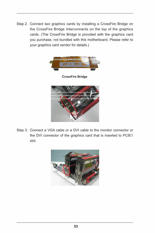
CrossFire Bridge
Step 3. Connect a VGA cable or a DVI cable to the monitor connector or the DVI connector of the graphics card that is inserted to PCIE1 slot.
Step 2. Connect two graphics cards by installing a CrossFire Bridge on the CrossFire Bridge Interconnects on the top of the graphics cards. (The CrossFire Bridge is provided with the graphics card you purchase, not bundled with this motherboard. Please refer to your graphics card vendor for details.)

54
2.16.2 Installing Three CrossFireXTM-Ready Graphics Cards
Step 1. Insert one graphics card into PCIE1 slot, another graphics card to PCIE3 slot, and the other graphics card to PCIE5 slot. Make sure that the cards are properly seated on the slots.
Step 2. Use one CrossFireTM Bridge to connect the graphics cards on PCIE1 and PCIE3 slots, and use the other CrossFireTM Bridge to connect the graphics cards on PCIE3 and PCIE5 slots. (The CrossFireTM Bridge is provided with the graphics card you pur-chase, not bundled with this motherboard. Please refer to your graphics card vendor for details.)
CrossFireTM Bridge
Step 3. Connect a VGA cable or a DVI cable to the monitor connector or the DVI connector of the graphics card that is inserted to PCIE1 slot.
55
2.16.3 Installing Four CrossFireXTM-Ready Graphics Cards
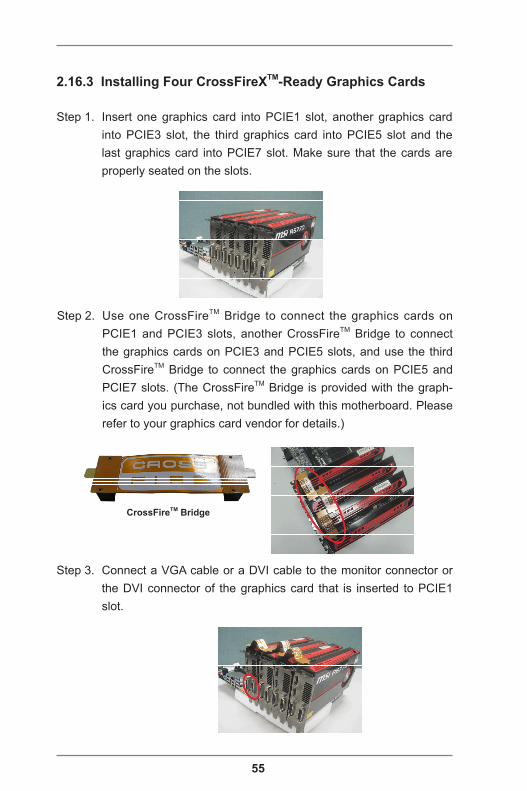
Step 1. Insert one graphics card into PCIE1 slot, another graphics card into PCIE3 slot, the third graphics card into PCIE5 slot and the last graphics card into PCIE7 slot. Make sure that the cards are properly seated on the slots.
Step 2. Use one CrossFireTM Bridge to connect the graphics cards on PCIE1 and PCIE3 slots, another CrossFireTM Bridge to connect the graphics cards on PCIE3 and PCIE5 slots, and use the third CrossFireTM Bridge to connect the graphics cards on PCIE5 and PCIE7 slots. (The CrossFireTM Bridge is provided with the graph-ics card you purchase, not bundled with this motherboard. Please refer to your graphics card vendor for details.)
CrossFireTM Bridge
Step 3. Connect a VGA cable or a DVI cable to the monitor connector or the DVI connector of the graphics card that is inserted to PCIE1 slot.
56
2.16.4 Driver Installation and Setup
Step 1. Power on your computer and boot into OS.Step 2. Remove the AMD drivers if you have any VGA drivers installed in
your system.
The Catalyst Uninstaller is an optional download. We recommend using this utility to uninstall any previously installed Catalyst drivers prior to in-
stallation. Please check AMD’s website for AMD driver updates.
Step 3. Install the required drivers and CATALYST Control Center then restart your computer. Please check AMD’s website for details.
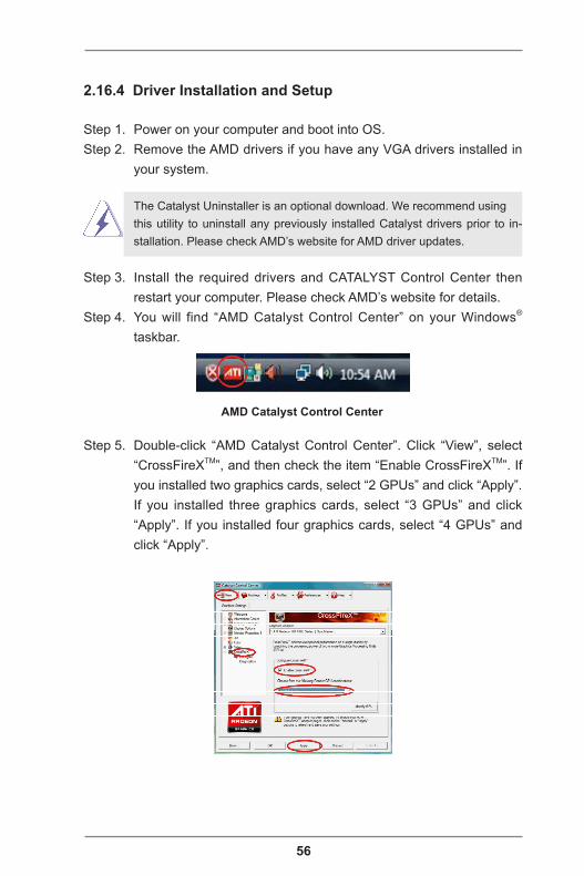
Step 4. You will find “AMD Catalyst Control Center” on your Windows® taskbar.
Step 5. Double-click “AMD Catalyst Control Center”. Click “View”, select “CrossFireXTM”, and then check the item “Enable CrossFireXTM”. If you installed two graphics cards, select “2 GPUs” and click “Apply”. If you installed three graphics cards, select “3 GPUs” and click “Apply”. If you installed four graphics cards, select “4 GPUs” and click “Apply”.
AMD Catalyst Control Center
57
2.17 Surround Display
This motherboard supports surround display upgrade. With the internal VGA output support (HDMI) and external add-on PCI Express VGA cards, you can easily enjoy surround display.Please refer to the following steps to set up a surround display environ-ment:
1. Install the VGA cards on the PCIE slots. Please refer to Installing Memory Modules for details of proper expansion card installation procedures.2. Connect monitor cables to the corresponding connectors of the rear I/O and the add-on PCI Express VGA cards.3. Install the onboard VGA driver and the add-on PCI Express VGA card drivers to your system. If you have installed the drivers already, there is no need to install them again.4. Set up a multi-monitor display.
For Windows® 8 / 8 64-bit / 7 / 7 64-bit / VistaTM / VistaTM 64-bit OS: Right click the desktop, choose “Personalize”, and select the “Display Settings” tab so that you can adjust the parameters of the multi-monitor according to the steps below.
A. Click the number ”2” icon. B. Click the items “This is my main monitor” and “Extend the desktop onto this monitor”. C. Click “OK” to save your change. D. Repeat steps A through C for the display icon identified by the numbers.
6. Use Surround Display. Click and drag the display icons to positions representing the physical setup of your monitors that you would like to use. The placement of display icons determines how you move items from one monitor to another.

58
2.18 Hot Plug and Hot Swap for Hard Disk Drives
This motherboard supports Hot Plug and Hot Swap for SAS2 / SATA2 / SATA3 in AHCI / RAID mode.
What is Hot Plug and Hot Swap?If the HDDs are NOT set for RAID, it is called “Hot Plug” for the action to insert and remove the HDDs while the system is still powered on and in working condition. If the HDDs are set for RAID then it is called “Hot Swap”. However, please note that it cannot perform Hot Plug or Hot Swap if the OS has been installed into the HDD.
Hot Plug / Hot Swap Operation Guide
Please read the operation guide of Hot Plug / Hot Swap below carefully. Before you process Hot Plug / Hot Swap, please check the cable accessories from the motherboard gift box pack below.A. 7-pin SATA data cableB. SATA power cable with SATA 15-pin power connector interface
SATA 7-pinconnector
The 1x4-pin conventional power connector (White) should be connected to a power supply
The SATA 15-pin power connector (Black) should be connected to your SATA3 HDD
A. SATA data cable (Red) B. SATA power cable

59
Points for attention, before you process Hot Plug / Hot Swap:1. Without the SATA 15-pin power connector interface, Hot Plug / Hot Swap cannot be processed.2. Even though some HDDs provide both SATA 15-pin power connectors and IDE 1x4-pin conventional power connectors, IDE 1x4-pin conventional power connector’s interface is definitely unable to support Hot Plug / Hot Swap and will cause the HDD damage and data loss.3. The operation procedure below is designed only for our motherboard which supports Hot Plug / Hot Swap. * Hot Plug / Hot Swap might not be supported by the chipset because of its limitation. The support information of our motherboards are indicated in the product spec on our website: www.asrock.com4. Make sure your HDDs can support Hot Plug / Hot Swap from your dealer or HDD user manual. HDDs that do not support Hot Plug / Hot Swap will be damaged.5. Please make sure that the required SATA drivers are installed properly. The latest SATA drivers are available on our support website: www.asrock.com6. Make sure to use the SATA power cable & data cable from our motherboard package.7. Please follow the instructions below step by step to reduce the risk of HDD crash or data loss.
60
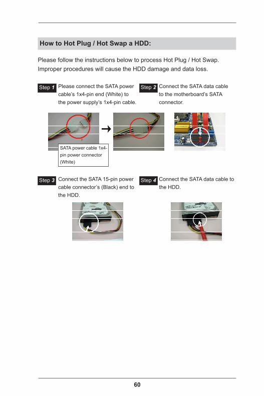
How to Hot Plug / Hot Swap a HDD:
Please follow the instructions below to process Hot Plug / Hot Swap. Improper procedures will cause the HDD damage and data loss.
Connect the SATA 15-pin power cable connector’s (Black) end to the HDD.
Connect the SATA data cable to the HDD.
Please connect the SATA power cable’s 1x4-pin end (White) to the power supply’s 1x4-pin cable.
Connect the SATA data cable to the motherboard’s SATA connector.
Step 1 Step 2
Step 3 Step 4
SATA power cable 1x4-pin power connector (White)

61
How to Hot Unplug / Hot Swap a HDD:
Please follow the instructions below to process Hot Unplug / Hot Swap. Improper procedures will cause the HDD damage and data loss.
Unplug the SATA data cable from the HDD’s side.
Unplug the SATA 15-pin power cable connector (Black) from the HDD's side.
Step 1
Step 2
62
2.19 Dual LAN and Teaming Operation Guide
Dual LAN with Teaming enabled on this motherboard allows two single connections to act as one single connection for twice the transmission bandwidth, making data transmission more effective and improving the quality of transmission of distant images. Fault tolerance on the dual LAN network prevents network downtime by transferring the workload from a failed port to a working port.
The speed of transmission is subject to the actual network environment or status even with Teaming enabled.
Before setting up Teaming, please make sure whether your Switch (or Router) supports Teaming (IEEE 802.3ad Link Aggregation). You can specify a preferred adapter in Intel PROSet. Under normal conditions, the Primary adapter handles all non-TCP/IP traffic. The Secondary adapter will receive fallback traffic if the primary fails. If the Preferred Primary adapter fails, but is later restored to an active status, control is automatically switched back to the Preferred Primary adapter.
1. From Device Manager, open the properties of a team.
2. Click the Settings tab.
3. Click the Modify Team button.
4. Select the adapter you want to be the primary adapter and click the Set Primary button.
If you do not specify a preferred primary adapter, the software will choose an adapter of the highest capability (model and speed) to act as the default primary. If a failover occurs, another adapter becomes the primary. The adapter will, however, rejoin the team as a non-primary.
63
Chapter 3: UEFI SETUP UTILITY
3.1 IntroductionASRock Interactive UEFI is a blend of system configuration tools, cool sound effects and stunning visuals. Not only will it make BIOS setup less difficult but also a lot more amusing.This section explains how to use the UEFI SETUP UTILITY to configure your system. The UEFI chip on the motherboard stores the UEFI SETUP UTILITY. You may run the UEFI SETUP UTILITY when you start up the computer. Please press <F2> or <Del> during the Power-On-Self-Test (POST) to enter the UEFI SETUP UTILITY, otherawise, POST will continue with its test routines.If you wish to enter the UEFI SETUP UTILITY after POST, restart the sys-tem by pressing <Ctl> + <Alt> + <Delete>, or by pressing the reset button on the system chassis. You may also restart by turning the system off and then back on.
Because the UEFI software is constantly being updated, the following UEFI setup screens and descriptions are for reference purpose only, and they may not exactly match what you see on your screen.
3.1.1 UEFI Menu BarThe top of the screen has a menu bar with the following selections:Main For setting system time/date informationOC Tweaker For overclocking configurationsAdvanced For advanced system configurationsTool Useful toolsH/W Monitor Displays current hardware statusBoot For configuring boot settings and boot prioritySecurity For security settingsExit Exit the current screen or the UEFI Setup Utility
64
3.1.2 Navigation KeysUse < > key or < > key to choose among the selections on the menu bar, and use < > key or < > key to move the cursor up or down to select items, then press <Enter> to get into the sub screen. You can also use the mouse to click your required item.
Please check the following table for the descriptions of each navigation key.
Navigation Key(s) Description+ / - To change option for the selected items
<Tab> Switch to next function<PGUP> Go to the previous page<PGDN> Go to the next page<HOME> Go to the top of the screen<END> Go to the bottom of the screen<F1> To display the General Help Screen<F4> Toggle sound on/off<F7> Discard changes and exit the SETUP UTILITY<F9> Load optimal default values for all the settings
<F10> Save changes and exit the SETUP UTILITY<F12> Print screen<ESC> Jump to the Exit Screen or exit the current screen
65
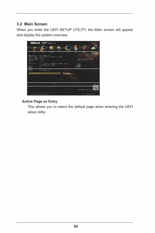
3.2 Main ScreenWhen you enter the UEFI SETUP UTILITY, the Main screen will appear and display the system overview.
Active Page on EntryThis allows you to select the default page when entering the UEFI setup utility.
66
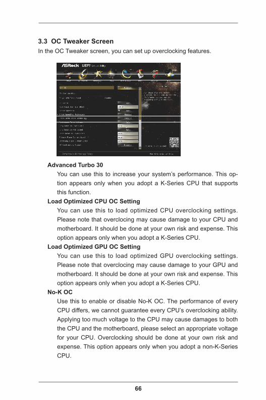
3.3 OC Tweaker ScreenIn the OC Tweaker screen, you can set up overclocking features.
Advanced Turbo 30You can use this to increase your system’s performance. This op-tion appears only when you adopt a K-Series CPU that supports this function.
Load Optimized CPU OC SettingYou can use this to load optimized CPU overclocking settings. Please note that overclocing may cause damage to your CPU and motherboard. It should be done at your own risk and expense. This option appears only when you adopt a K-Series CPU.
Load Optimized GPU OC SettingYou can use this to load optimized GPU overclocking settings. Please note that overclocing may cause damage to your GPU and motherboard. It should be done at your own risk and expense. This option appears only when you adopt a K-Series CPU.
No-K OCUse this to enable or disable No-K OC. The performance of every CPU differs, we cannot guarantee every CPU’s overclocking ability. Applying too much voltage to the CPU may cause damages to both the CPU and the motherboard, please select an appropriate voltage for your CPU. Overclocking should be done at your own risk and expense. This option appears only when you adopt a non-K-Series CPU.
67
CPU ConfigurationCPU Ratio
Use this to change the ratio value of this motherboard.Host Clock Override (BCLK)
Use this to adjust the host clock (BCLK) frequency. The default value is [100.0].
Spread SpectrumThis should always be [Auto] for better system stability.
Intel SpeedStep TechnologyIntel SpeedStep technology is Intel’s power saving technology. Processors can switch between multiple frequencies and voltage points to enable power saving. The default value is [Enabled]. Con-figuration options: [Enabled] and [Disabled]. If you install Windows® and want to enable this function, please set to [Enabled]. This item will be hidden if the current CPU does not support Intel SpeedStep technology.
Please note that enabling this function may reduce CPU voltage and lead to system stability or compatibility issues with some power supplies. Please set this item to [Disabled] if above issues occur.
Intel Turbo Boost TechnologyUse this to enable or disable Intel Turbo Boost Mode Technology. Turbo Boost Mode allows processor cores to run faster than marked frequency in specific conditions. The default value is [Enabled].
Additional Turbo Voltage Use this to add voltage when the CPU is in Turbo mode.
Long Duration Power LimitUse this to configure long duration power limit in watts. The default value is [Auto].
Long Duration MaintainedUse this to configure time window which the long duration power is maintained. The default value is [Auto].
Short Duration Power LimitUse this to configure short duration power limit in watts. The default value is [Auto].
Primary Plane Current Limit
68
Use this to configure the maximum instantaneous current allowed for the primary plane. The default value is [Auto].
Secondary Plane Current LimitUse this to configure the maximum instantaneous current allowed for the secondary plane. The default value is [Auto].
GT OverClocking SupportUse this to enable or disable GT OverClocking Support. The default value is [Disabled].
DRAM Timing ConfigurationLoad XMP Setting
Use this to load XMP settings. Configuration options: [Auto], [De-fault], [Profile 1] and [Profile 2]. The default value is [Auto].
DRAM FrequencyIf [Auto] is selected, the motherboard will detect the memory module(s) inserted and assign the appropriate frequency automati-cally.
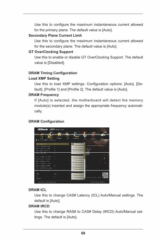
DRAM Configuration
DRAM tCLUse this to change CAS# Latency (tCL) Auto/Manual settings. The default is [Auto].
DRAM tRCDUse this to change RAS# to CAS# Delay (tRCD) Auto/Manual set-tings. The default is [Auto].

69
DRAM tRPUse this to change Row Precharge Time (tRP) Auto/Manual set-tings. The default is [Auto].
DRAM tRASUse this to change RAS# Active Time (tRAS) Auto/Manual settings. The default is [Auto].
Command Rate (CR)Use this to change Command Rate (CR) Auto/Manual settings. The default is [Auto].
DRAM tWRUse this to change Write Recovery Time (tWR) Auto/Manual set-tings. The default is [Auto].
DRAM tRFCUse this to change Refresh Cyle Time (tRFC) Auto/Manual settings. The default is [Auto].
DRAM tRRD Use this to change RAS to RAS Delay (tRRD) Auto/Manual set-tings. The default is [Auto].
DRAM tWTRUse this to change Write to Read Delay (tWTR) Auto/Manual set-tings. The default is [Auto].
DRAM tRTPUse this to change Read to Precharge (tRTP) Auto/Manual settings. The default is [Auto].
DRAM tFAWUse this to change Four Activate Window (tFAW) Auto/Manual set-tings. The default is [Auto].
DRAM tCWLUse this to change CAS# Write Latency (tCWL) Auto/Manual set-tings. The default is [Auto].
tREFIUse this to change tREFI Auto/Manual settings. The default is [Auto].
tCKEUse this to change tCKE Auto/Manual settings. The default is [Auto].
tWRDR(DD)

70
Use this to change DRAM tWRDR Auto/Manual settings. The de-fault is [Auto].
tRWDR(DD)Use this to change DRAM tRWDR Auto/Manual settings. The de-fault is [Auto].
tRWSRUse this to change DRAM tRWSR Auto/Manual settings. The de-fault is [Auto].
tRRDDUse this to change DRAM tRRDD Auto/Manual settings. The de-fault is [Auto].
tRRDRUse this to change DRAM tRRDR Auto/Manual settings. The de-fault is [Auto].
tRRSRUse this to change DRAM tRRSR Auto/Manual settings. The default is [Auto].
tWWDDUse this to change DRAM tWWDD Auto/Manual settings. The de-fault is [Auto].
tWWDRUse this to change DRAM tWWDR Auto/Manual settings. The de-fault is [Auto].
tWWSRUse this to change DRAM tWWSR Auto/Manual settings. The de-fault is [Auto].
RTL (CHA)Use this to change RTL (CHA) Auto/Manual settings. The default is [Auto].
RTL (CHB)Use this to change RTL (CHB) Auto/Manual settings. The default is [Auto].
IO-L (CHA)Use this to change IO-L (CHA) Auto/Manual settings. The default is [Auto].
IO-L (CHB)Use this to change IO-L (CHB) Auto/Manual settings. The default is
71
[Auto].
ODT WR (CHA)Use this to change ODT (CHA) Auto/Manual settings. The default is [Auto].
ODT WR (CHB)Use this to change ODT (CHB) Auto/Manual settings. The default is [Auto].
ODT NOM (CHA)Use this to change ODT (CHA) Auto/Manual settings. The default is [Auto].
ODT NOM (CHB)Use this to change ODT (CHB) Auto/Manual settings. The default is [Auto].
DRAM Clock DelayUse this to configure DRAM Clock Delay. The default is [Auto].
MRC Fast BootUse this to enable or disable MRC Fast Boot. The default is [En-abled].
DIMM Exit ModeUse this to configure DIMM Exit Mode. The default is [Fast Exit].
Power Down ModeUse this to enable or disable DDR power down mode.
Voltage ConfigurationCPU Voltage
Use this to select CPU Voltage. The default value is [Auto].CPU Load-Line Calibration
CPU Load-Line Calibration helps prevent CPU voltage droop when the system is under heavy load.
IGPU VoltageUse this to configure IGPU Voltage. The default value is [Auto].
IGPU Load-Line CalibrationIGPU Load-Line Calibration helps prevent IGPU voltage droop when the system is under heavy load.
DRAM VoltageUse this to configure DRAM Voltage. The default value is [Auto].

72
VTT VoltageUse this to configure VTT Voltage. The default value is [Auto].
PCH VoltageUse this to configure PCH Voltage. The default value is [Auto].
CPU PLL VoltageUse this to configure CPU PLL Voltage. The default value is [Auto].
VCCSA VoltageUse this to configure VCCSA Voltage. The default value is [Auto].
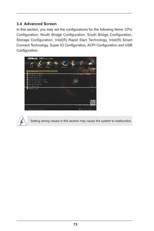
73
3.4 Advanced ScreenIn this section, you may set the configurations for the following items: CPU Configuration, Nouth Bridge Configuration, South Bridge Configuration, Storage Configuration, Intel(R) Rapid Start Technology, Intel(R) Smart Connect Technology, Super IO Configuration, ACPI Configuration and USB Configuration.
Setting wrong values in this section may cause the system to malfunction.
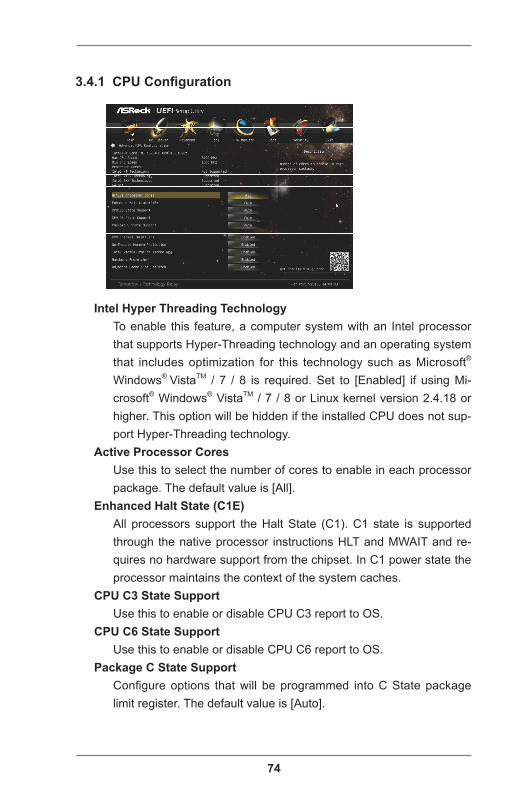
74
3.4.1 CPU Configuration
Intel Hyper Threading TechnologyTo enable this feature, a computer system with an Intel processor that supports Hyper-Threading technology and an operating system that includes optimization for this technology such as Microsoft® Windows® VistaTM / 7 / 8 is required. Set to [Enabled] if using Mi-crosoft® Windows® VistaTM / 7 / 8 or Linux kernel version 2.4.18 or higher. This option will be hidden if the installed CPU does not sup-port Hyper-Threading technology.
Active Processor CoresUse this to select the number of cores to enable in each processor package. The default value is [All].
Enhanced Halt State (C1E)All processors support the Halt State (C1). C1 state is supported through the native processor instructions HLT and MWAIT and re-quires no hardware support from the chipset. In C1 power state the processor maintains the context of the system caches.
CPU C3 State SupportUse this to enable or disable CPU C3 report to OS.
CPU C6 State SupportUse this to enable or disable CPU C6 report to OS.
Package C State SupportConfigure options that will be programmed into C State package limit register. The default value is [Auto].
75
CPU Thermal ThrottlingUse this to enable CPU internal thermal control mechanism to keep the CPU from overheated. The default value is [Enabled].
No-Execute Memory ProtectionNo-Execution (NX) Memory Protection Technology is an enhance-ment to the IA-32 Intel Architecture. An IA-32 processor with “No Execute (NX) Memory Protection” can prevent data pages from being used by malicious software to execute codes. This option will be hidden if the current CPU does not support No-Excute Memory Protection.
Intel Virtualization TechnologyWhen this option is set to [Enabled], a VMM (Virtual Machine Archi-tecture) can utilize the additional hardware capabilities provided by Vanderpool Technology. This option will be hidden if the installed CPU does not support Intel Virtualization Technology.
Hardware PrefetcherUse this turn on/off the MLC streamer prefetcher.
Adjacent Cache Line PrefetchUse this to turn on/off prefetching of adjacent cache lines.
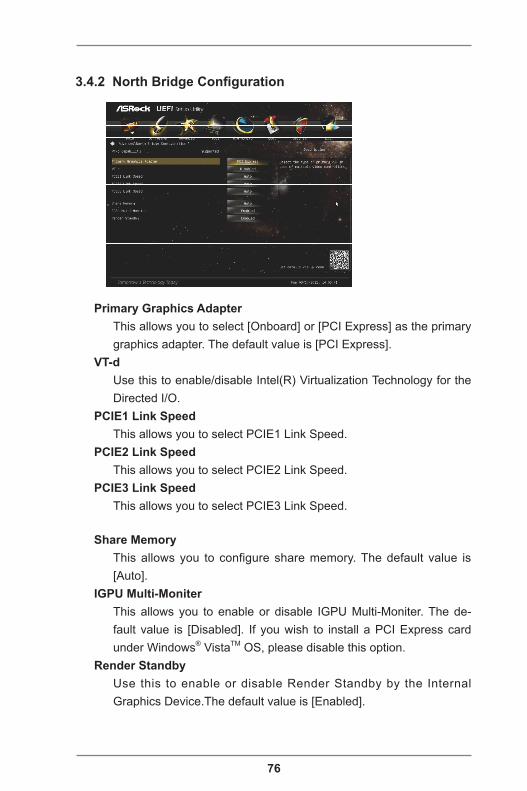
76
3.4.2 North Bridge Configuration
Primary Graphics AdapterThis allows you to select [Onboard] or [PCI Express] as the primary graphics adapter. The default value is [PCI Express].
VT-dUse this to enable/disable Intel(R) Virtualization Technology for the Directed I/O.
PCIE1 Link SpeedThis allows you to select PCIE1 Link Speed.
PCIE2 Link SpeedThis allows you to select PCIE2 Link Speed.
PCIE3 Link SpeedThis allows you to select PCIE3 Link Speed.
Share MemoryThis allows you to configure share memory. The default value is [Auto].
IGPU Multi-MoniterThis allows you to enable or disable IGPU Multi-Moniter. The de-fault value is [Disabled]. If you wish to install a PCI Express card under Windows® VistaTM OS, please disable this option.
Render StandbyUse this to enable or disable Render Standby by the Internal Graphics Device.The default value is [Enabled].
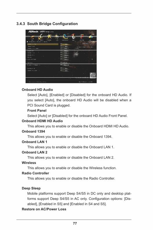
77
3.4.3 South Bridge Configuration
Onboard HD AudioSelect [Auto], [Enabled] or [Disabled] for the onboard HD Audio. If you select [Auto], the onboard HD Audio will be disabled when a PCI Sound Card is plugged.Front PanelSelect [Auto] or [Disabled] for the onboard HD Audio Front Panel.
Onboard HDMI HD AudioThis allows you to enable or disable the Onboard HDMI HD Audio.
Onboard 1394This allows you to enable or disable the Onboard 1394.
Onboard LAN 1This allows you to enable or disable the Onboard LAN 1.
Onboard LAN 2This allows you to enable or disable the Onboard LAN 2.
WirelessThis allows you to enable or disable the Wireless function.
Radio ControllerThis allows you to enable or disable the Radio Controller.
Deep SleepMobile platforms support Deep S4/S5 in DC only and desktop plat-forms support Deep S4/S5 in AC only. Configuration options: [Dis-abled], [Enabled in S5] and [Enabled in S4 and S5].
Restore on AC/Power Loss

78
This allows you to set the power state after an unexpected AC/power loss. If [Power Off] is selected, the AC/power remains off when the power recovers. If [Power On] is selected, the AC/power resumes and the system starts to boot up when the power recov-ers.
Good Night LEDUse this to enable or disable the Power LED and LAN LED.
Onboard Debug Port LEDUse this to enable or disable the Onboard Debug Port LED.
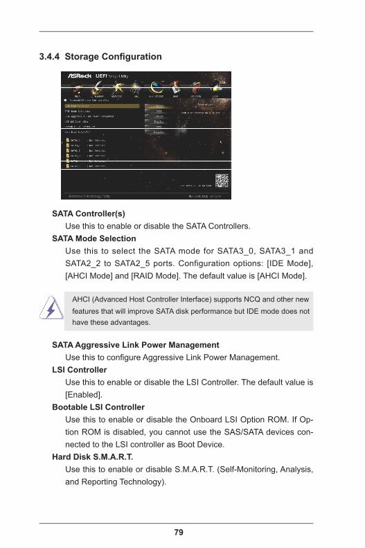
79
3.4.4 Storage Configuration
SATA Controller(s)Use this to enable or disable the SATA Controllers.
SATA Mode SelectionUse this to select the SATA mode for SATA3_0, SATA3_1 and SATA2_2 to SATA2_5 ports. Configuration options: [IDE Mode], [AHCI Mode] and [RAID Mode]. The default value is [AHCI Mode].
AHCI (Advanced Host Controller Interface) supports NCQ and other new features that will improve SATA disk performance but IDE mode does not have these advantages.
SATA Aggressive Link Power ManagementUse this to configure Aggressive Link Power Management.
LSI ControllerUse this to enable or disable the LSI Controller. The default value is [Enabled].
Bootable LSI ControllerUse this to enable or disable the Onboard LSI Option ROM. If Op-tion ROM is disabled, you cannot use the SAS/SATA devices con-nected to the LSI controller as Boot Device.
Hard Disk S.M.A.R.T.Use this to enable or disable S.M.A.R.T. (Self-Monitoring, Analysis, and Reporting Technology).
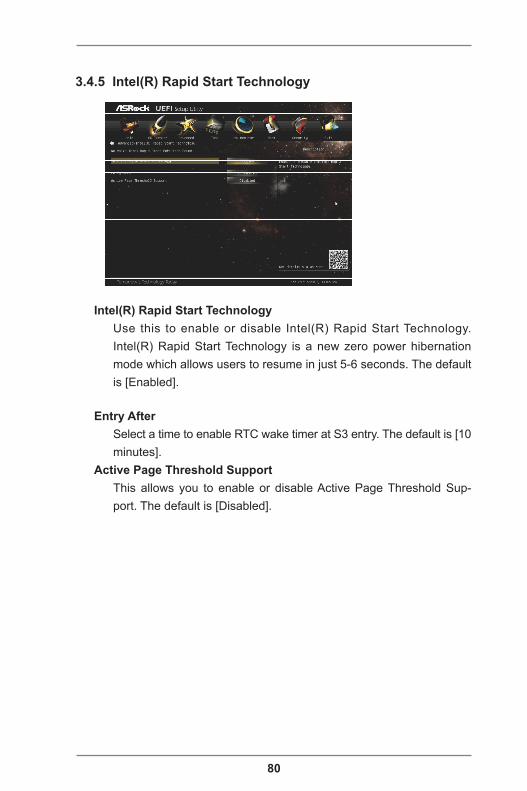
80
3.4.5 Intel(R) Rapid Start Technology
Intel(R) Rapid Start TechnologyUse this to enable or disable Intel(R) Rapid Start Technology. Intel(R) Rapid Start Technology is a new zero power hibernation mode which allows users to resume in just 5-6 seconds. The default is [Enabled].
Entry AfterSelect a time to enable RTC wake timer at S3 entry. The default is [10 minutes].
Active Page Threshold SupportThis allows you to enable or disable Active Page Threshold Sup-port. The default is [Disabled].

81
3.4.6 Intel(R) Smart Connect Technology
Intel(R) Smart Connect TechnologyUse this to enable or disable Intel(R) Smart Connect Technology. Intel(R) Smart Connect Technology keeps your e-mail and social networks, such as Twitter, Facebook, etc. updated automatically while the computer is in sleep mode. The default is [Enabled].
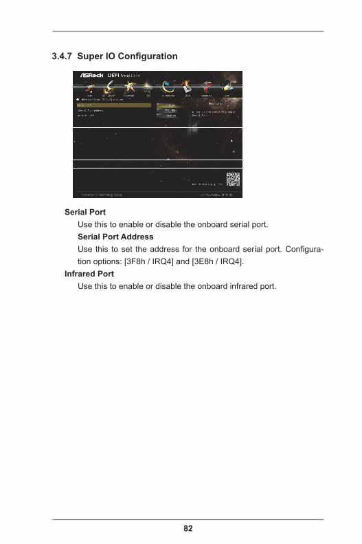
82
3.4.7 Super IO Configuration
Serial PortUse this to enable or disable the onboard serial port.Serial Port AddressUse this to set the address for the onboard serial port. Configura-tion options: [3F8h / IRQ4] and [3E8h / IRQ4].
Infrared PortUse this to enable or disable the onboard infrared port.
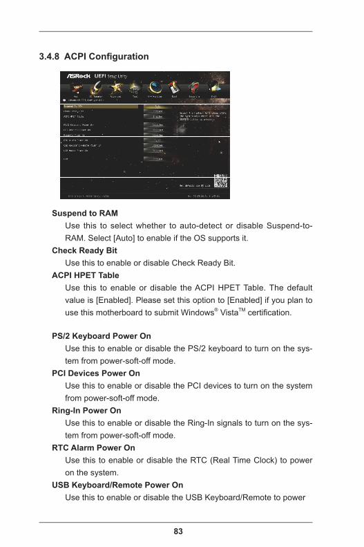
83
3.4.8 ACPI Configuration
Suspend to RAMUse this to select whether to auto-detect or disable Suspend-to-RAM. Select [Auto] to enable if the OS supports it.
Check Ready BitUse this to enable or disable Check Ready Bit.
ACPI HPET TableUse this to enable or disable the ACPI HPET Table. The default value is [Enabled]. Please set this option to [Enabled] if you plan to use this motherboard to submit Windows® VistaTM certification.
PS/2 Keyboard Power OnUse this to enable or disable the PS/2 keyboard to turn on the sys-tem from power-soft-off mode.
PCI Devices Power OnUse this to enable or disable the PCI devices to turn on the system from power-soft-off mode.
Ring-In Power OnUse this to enable or disable the Ring-In signals to turn on the sys-tem from power-soft-off mode.
RTC Alarm Power OnUse this to enable or disable the RTC (Real Time Clock) to power on the system.
USB Keyboard/Remote Power OnUse this to enable or disable the USB Keyboard/Remote to power

84
on the system.USB Mouse Power On
Use this to enable or disable the USB Mouse to power on the sys-tem.
CSMPlease disable CSM when Fast Boot is enabled. The default value is [Enabled].

85
3.4.9 USB Configuration
USB 2.0 ControllerUse this to enable or disable the USB 2.0 controller.
USB 3.0 ControllerUse this to enable or disable the USB 3.0 controller.
Legacy USB SupportUse this to select legacy support for USB devices. There are four configuration options: [Enabled], [Auto], [Disabled] and [UEFI Setup Only]. The default value is [Enabled]. Please refer to the descrip-tions below for details of these four options:[Enabled] - Enables support for legacy USB.[Auto] - Enables legacy support if USB devices are connected.[Disabled] - USB devices are not allowed to be used under legacy OS and UEFI setup when [Disabled] is selected. If you have USB compatibility issues, it is recommended to select [Disabled] to enter the OS.[UEFI Setup Only] - USB devices are allowed to be used only under UEFI setup and Windows / Linux OS.
Legacy USB 3.0 SupportUse this to enable or disable legacy support for USB 3.0 devices. The default value is [Enabled].

86
3.5 Tool
System BrowserSystem Browser can let you easily check your current system con-figuration in UEFI setup.
OMG (Online Management Guard)Administrators are able to establish an internet curfew or restrict internet access at specified times via OMG. You may schedule the starting and ending hours of internet access granted to other us-ers. In order to prevent users from bypassing OMG, guest accounts without permission to modify the system time are required.
Easy RAID InstallerEasy RAID Installer can help you copy the RAID driver from the support CD to your USB storage device. After copying the RAID driver to your USB storage device, please change “SATA Mode Selection” to “RAID”, then you can start installing the OS in RAID mode.
Instant FlashInstant Flash is a UEFI flash utility embedded in Flash ROM. This convenient UEFI update tool allows you to update the system UEFI without entering operating systems like MS-DOS or Windows® first. Just save the new UEFI file to your USB flash drive, floppy disk or hard drive and launch this tool, then you can update your UEFI only in a few clicks without preparing an additional floppy diskette or other complicated flash utility. Please be noted that the USB flash
87
drive or hard drive must use FAT32/16/12 file system. If you ex-ecute Instant Flash utility, the utility will show the UEFI files and their respective information. Select the proper UEFI file to update your UEFI, and reboot your system after the UEFI update process is completed.
Internet FlashInternet Flash searches for available UEFI firmware updates from our servers. In other words, the system can auto-detect the latest UEFI from our servers and flash them without entering Windows OS. Please note that you must be running on a DHCP configured computer in order to enable this function.
Network ConfigurationUse this to configure internet connection settings for Internet Flash.
Sound EffectEnable or disable sound effects in the setup utility.
Dehumidifier FunctionUsers may prevent motherboard damages due to dampness by en-abling “Dehumidifier Function”. When enabling Dehumidifier Func-tion, the computer will power on automatically to dehumidify the system after entering S4/S5 state.Dehumidifier PeriodThis allows users to configure the period of time until the computer powers on and enables “Dehumidifier” after entering S4/S5 state.Dehumidifier DurationThis allows users to configure the duration of the dehumidifying process before it returns to S4/S5 state.Dehumidifier CPU Fan SettingUse this setting to configure CPU fan speed while “Dehumidifier” is enabled.
User DefaultsYou are allowed to load and save three user defaults according to your own requirements.
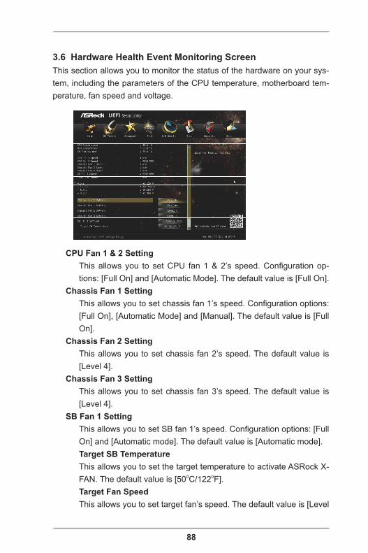
88
3.6 Hardware Health Event Monitoring ScreenThis section allows you to monitor the status of the hardware on your sys-tem, including the parameters of the CPU temperature, motherboard tem-perature, fan speed and voltage.
CPU Fan 1 & 2 SettingThis allows you to set CPU fan 1 & 2’s speed. Configuration op-tions: [Full On] and [Automatic Mode]. The default value is [Full On].
Chassis Fan 1 SettingThis allows you to set chassis fan 1’s speed. Configuration options: [Full On], [Automatic Mode] and [Manual]. The default value is [Full On].
Chassis Fan 2 SettingThis allows you to set chassis fan 2’s speed. The default value is [Level 4].
Chassis Fan 3 SettingThis allows you to set chassis fan 3’s speed. The default value is [Level 4].
SB Fan 1 SettingThis allows you to set SB fan 1’s speed. Configuration options: [Full On] and [Automatic mode]. The default value is [Automatic mode].Target SB TemperatureThis allows you to set the target temperature to activate ASRock X-FAN. The default value is [50oC/122oF].Target Fan SpeedThis allows you to set target fan’s speed. The default value is [Level

89
9].Over Temperature Protection
Use this to enable or disable Over Temperature Protection. The de-fault value is [Enabled].
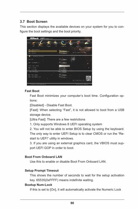
90
3.7 Boot ScreenThis section displays the available devices on your system for you to con-figure the boot settings and the boot priority.
Fast BootFast Boot minimizes your computer’s boot time. Configuration op-tions:[Disabled] - Disable Fast Boot.[Fast]: When selecting “Fast”, it is not allowed to boot from a USB storage device.[Ultra Fast]: There are a few restrictions1. Only supports Windows 8 UEFI operating system2. You will not be able to enter BIOS Setup by using the keyboard. The only way to enter UEFI Setup is to clear CMOS or run the “Re-start to UEFI” utility in windows.3. If you are using an external graphics card, the VBIOS must sup-port UEFI GOP in order to boot.
Boot From Onboard LANUse this to enable or disable Boot From Onboard LAN.
Setup Prompt TimeoutThis shows the number of seconds to wait for the setup activation key. 65535(0xFFFF) means indefinite waiting.
Bootup Num-LockIf this is set to [On], it will automatically activate the Numeric Lock
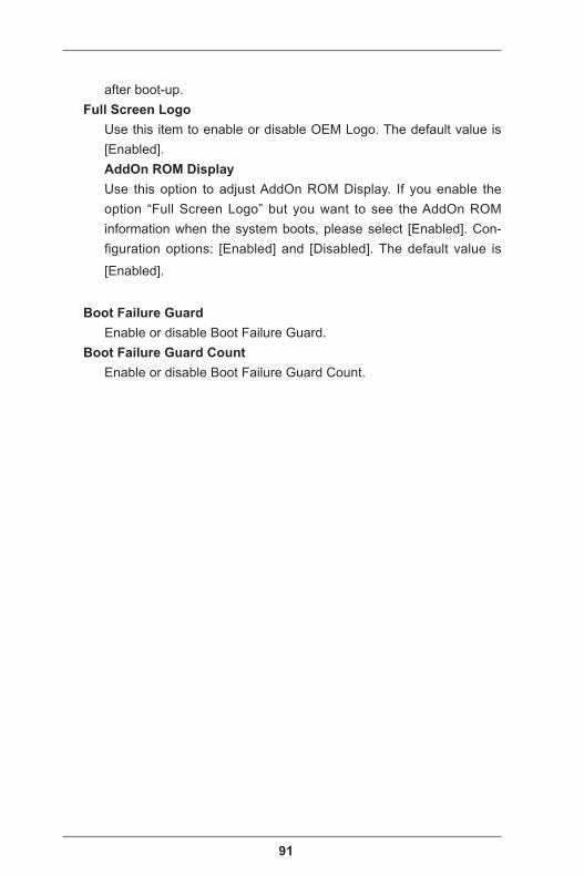
91
after boot-up.Full Screen Logo
Use this item to enable or disable OEM Logo. The default value is [Enabled].AddOn ROM DisplayUse this option to adjust AddOn ROM Display. If you enable the option “Full Screen Logo” but you want to see the AddOn ROM information when the system boots, please select [Enabled]. Con-figuration options: [Enabled] and [Disabled]. The default value is
[Enabled].
Boot Failure GuardEnable or disable Boot Failure Guard.
Boot Failure Guard CountEnable or disable Boot Failure Guard Count.
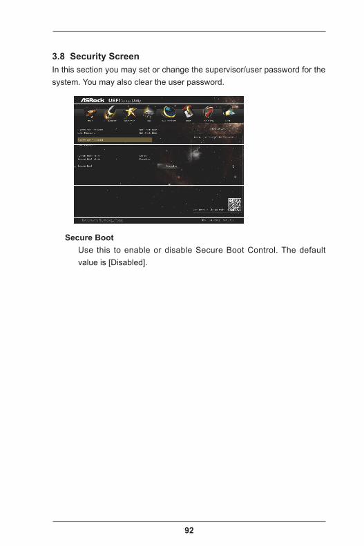
92
3.8 Security ScreenIn this section you may set or change the supervisor/user password for the system. You may also clear the user password.
Secure BootUse this to enable or disable Secure Boot Control. The default value is [Disabled].
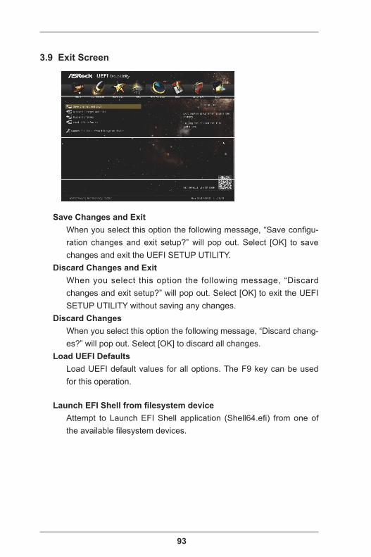
93
3.9 Exit Screen
Save Changes and ExitWhen you select this option the following message, “Save configu-ration changes and exit setup?” will pop out. Select [OK] to save changes and exit the UEFI SETUP UTILITY.
Discard Changes and ExitWhen you select this option the following message, “Discard changes and exit setup?” will pop out. Select [OK] to exit the UEFI SETUP UTILITY without saving any changes.
Discard ChangesWhen you select this option the following message, “Discard chang-es?” will pop out. Select [OK] to discard all changes.
Load UEFI DefaultsLoad UEFI default values for all options. The F9 key can be used for this operation.
Launch EFI Shell from filesystem deviceAttempt to Launch EFI Shell application (Shell64.efi) from one of the available filesystem devices.


![Digitale camera EX-Z77 - Support | Home | CASIO€¦ · Druk op [BS] om heen en weer te schakelen tussen het 12-uren en 24-uren formaat. 8. Druk na het voltooien van de instellingen](https://img.pdfslide.net/doc/110x75/601376283067cf08c405b71e/digitale-camera-ex-z77-support-home-casio-druk-op-bs-om-heen-en-weer-te.jpg)