Embed Size (px)
Citation preview
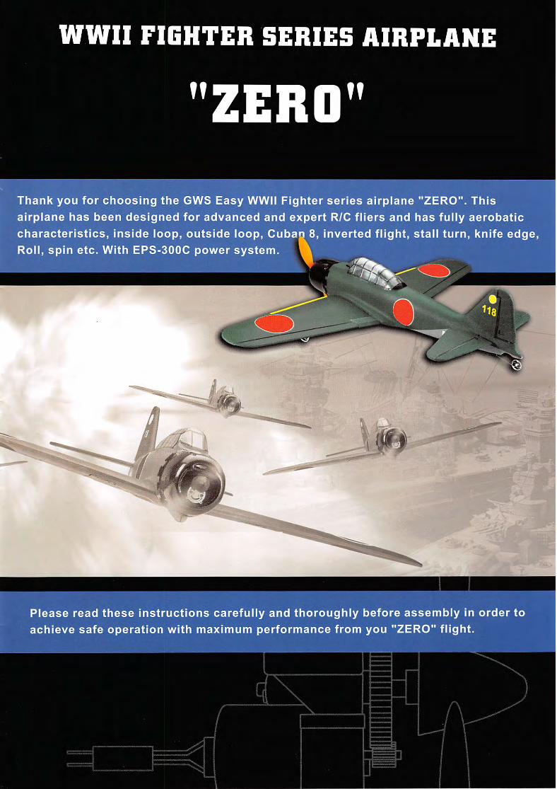
WWII FIGHTER SERIES AIRPLANE
ZERO
Thank you for choosing the GWS Easy WWII Fighter series airplane "ZERO". This
airplane has been designed for advanced and expert R/C fliers and has fully aerobatic
characteristics, inside loop, outside loop, Cuban 8, inverted flight, stall turn, knife edge.
Roll, spin etc. With EPS-300C power system. A
Please read these instructions carefully and thoroughly before assembly in order to
achieve safe operation with maximum performance from you "ZERO" flight.
EASY • • r-BGHTER.
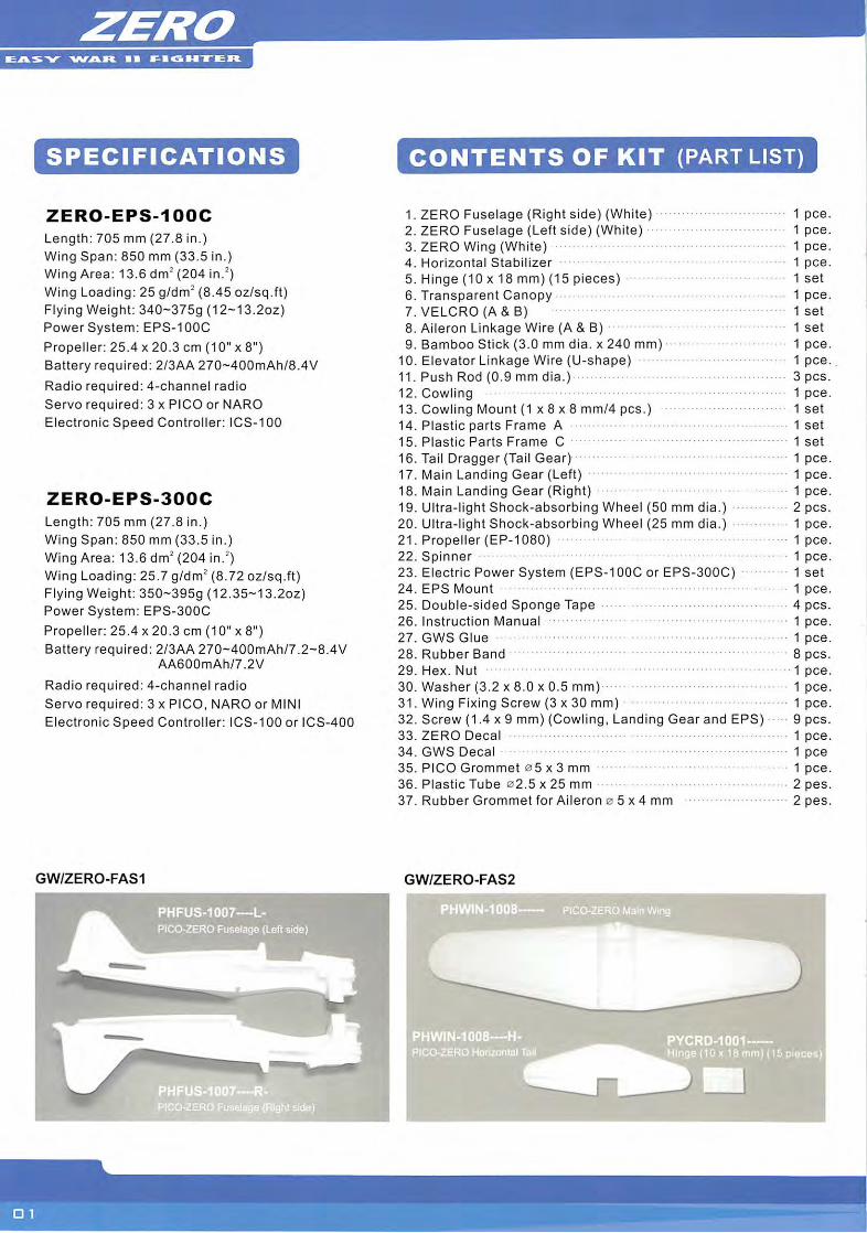
SPECIFICATIONS
ZERO-EPS-100C
Length: 705 mm (27.8 in.)
Wing Span: 850 mm (33.5 in.)
Wing Area: 13.6 dm' (204 in.')Wing Loading: 25 g/dm' (8.45 oz/sq.ft)Flying Weight: 340~375g (12~13.2oz)Power System: EPS-100C
Propeller: 25.4 x 20.3 cm (10" x 8")
Battery required: 2/3AA 270--400mAh/8.4V
Radio required: 4-channel radio
Servo required: 3 x PICO or NARO
Electronic Speed Controller: ICS-100
ZERO-EPS-300C
Length: 705 mm (27.8 in.)
Wing Span: 850 mm (33.5 in.)Wing Area: 13.6 dm' (204 in.')Wing Loading: 25.7 g/dm' (8.72 oz/sq.ft)Flying Weight: 350-395g (12.35-13.2oz)
Power System: EPS-300C
Propeller: 25.4 x 20.3 cm (10" x 8")
Battery required: 2/3AA 270-400mAh/7.2-8.4VAA600mAh/7.2V
Radio required: 4-channel radio
Servo required: 3 x PICO, NARO or MINI
Electronic Speed Controller: ICS-100 or ICS-400
GW/2ER0-FAS1
PHFUS-1007—L-
PICO-ZERO Fuselage (Left side)
CONTENTS OF KIT (PART LIST)
1. ZERO Fuselage (Right side) (White) 1 pee.2. ZERO Fuselage (Left side) (White) 1 pee.3. ZERO Wing (White) 1 pee.4. Horizontal Stabilizer 1 pee.5. Hinge (10 X18 mm) (15 pieces) 1 set6. Transparent Canopy 1 pee.7. VELCRO(A&B) 1 set8. Aileron Linkage Wire (A & B) 1 set9. Bamboo Stick (3.0 mm dia. x 240 mm) 1 pee.
10. Elevator Linkage Wire (U-shape) 1 pee.11. Push Rod (0.9 mm dia.) 3 pcs.12. Cowling 1 pee.13. Cowling Mount (1 X8 X8 mm/4 pcs.) 1 set14. Plastic parts Frame A 1 set15. Plastic Parts Frame C 1 set
16. Tail Dragger (Tail Gear) 1 pee.17. Main Landing Gear (Left) 1 pee.18. Main Landing Gear (Right) 1 pee.19. Ultra-light Shock-absorbing Wheel (50 mm dia.) 2 pcs.20. Ultra-light Shock-absorbing Wheel (25 mm dia.) 1 pee.21. Propeller (EP-1080) 1 pee.22. Spinner 1 pee.23. Electric Power System (EPS-100C or EPS-300C) 1 set24. EPS Mount 1 pee.25. Double-sided Sponge Tape 4 pcs.26. Instruction Manual 1 pee.27. GWS Glue 1 pee.28. Rubber Band 8 pcs.29. Hex. Nut 1 pee.30. Washer (3.2 x 8.0 x 0.5 mm) 1 pee.31. Wing Fixing Screw (3 x 30 mm) 1 pee.32. Screw (1.4 x 9 mm) (Cowling. Landing Gear and EPS) 9 pcs.33. ZERO Decal 1 pee.34. GWS Decal 1 pee35. PICO Grommet 05x3 mm 1 pee.36. Plastic Tube 02.5 x 25 mm 2 pes.37. Rubber Grommet for Aileron 0 5x4 mm 2 pes.
GW/ZER0-FAS2
N^IOOS PICO-ZERO Main Wing
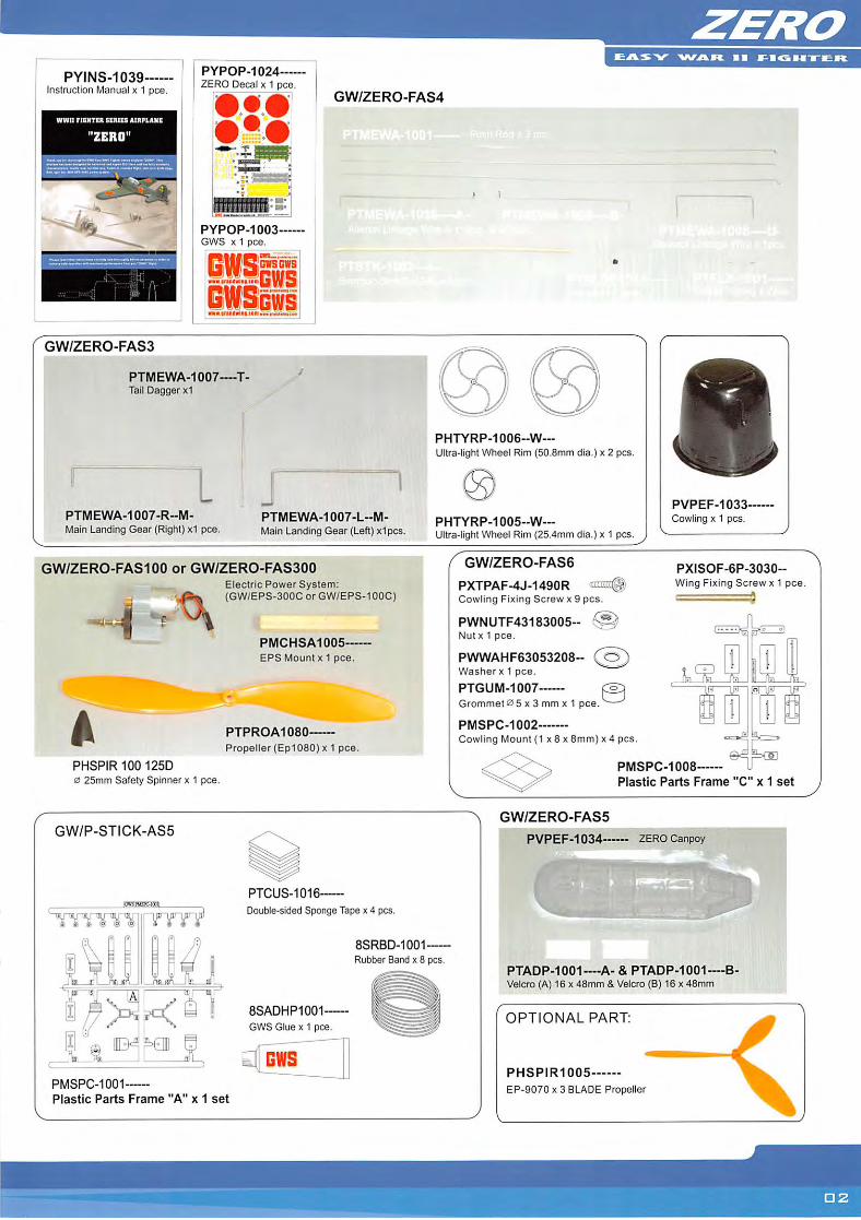
PYINS-1039Instruction Manual x 1 pee.
PYPOP.1024—ZERO Decal x 1 pee.
GW/ZER0-FAS4
mmmmm
k: fk;
e I P 11
GW/ZER0-FAS3
PYPOP-1003•:-2 GWS X1 pee.
GWSGWSGWS'
• IIIBlVlM Clllvnfi
PTMEWA-1007-—T-Tail Dagger x1
PTMEWA-1007-R-M-Main Landing Gear (Right) x1 pee.
PTMEWA-1007-L-M-Maln Landing Gear (Left) x1pcs.
# I
PHTYRP-1006--W—Ultra-light Wheel Rim (50.8mm dia.) x 2 pcs.
PHTYRP-1005-W—Ultra-light Wheel Rim (25.4mm dIa.) x 1 pcs.
PVPEF-1033-Cowling x 1 pcs.
GW/ZERO-FAS100 or GW/ZERO-FAS300Electric Power System:(GW/EPS-300C or GW/EPS-100C)
GW/ZER0-FAS6
PXTPAF-4J-1490RCowling Fixing Screw x 9 pcs.
PWNUTF43183005-Nutx 1 pee.
PWWAHF63053208-Washer x 1 pee.
PTGUM-ia07 ^Grommet0 5 x 3 mm x 1 pee. —
PMSPC-1002Cowling Mount (1 x 8 x 8mm) x4 pcs.
PXISOF-6P-3030-Wing Fixing Screw x 1 pee.
=sj=
PMCHSA1005—
EPS Mount X1 pee.
k PTPROA1080
Propeller (Ep1080) X1 pee.
PHSPIR100 125D0 25mm Safety Spinner x 1 pee.
GW/P-STICK-AS5
PMSPC-1001
Plastic Parts Frame "A" x 1 set
PTCUS-1016
Double-sided Sponge Tape x 4 pcs.
8SADHP1001-
GWS Glue X1 pee.
BWS
8SRBD-1001—Rubber Band x 8 pcs.
V
PMSPC-1008
Plastic Parts Frame "C" x 1 set
GW/ZERO-FAS5
1 PVPEF-1034—— ZEROCanpoy
V
PTADP-1001-—A-& PTADP-1001—B-Velcro (A) 16 X48mm & Velcro (B) 16 x 48mm
OPTIONAL PART:
PHSPIR1005
EP-9070 X3 BLADE Propeller
I
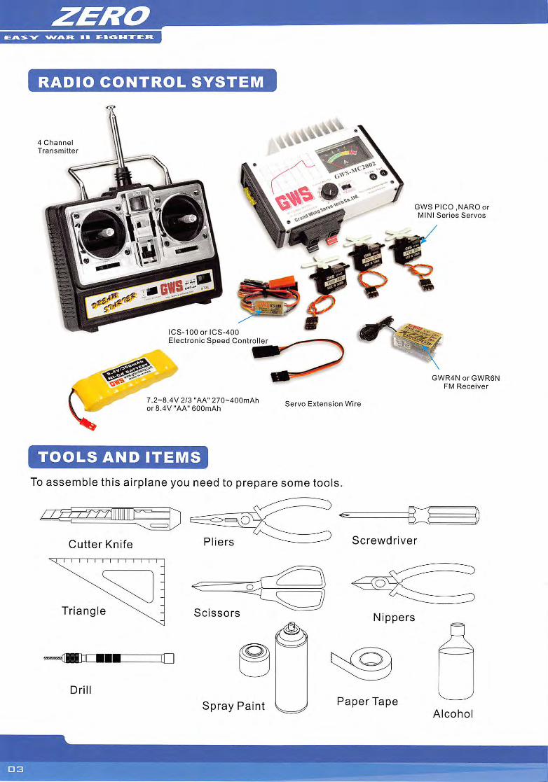
RADIO CONTROL SYSTEM
4 Channel
Transmitter
ICS-IOOorlCS-400
Electronic Speed Controller
7.2-8.4V 2/3 "AA" 270~400mAhor 8.4V ••AA"600mAh
TOOLS AND ITEMS
Servo Extension Wire
GWS PICO .NAROorMINI Series Servos
GWR4NorGWR6N
FM Receiver
To assemble this airplane you need to prepare some tools.
Cutter Knife Pliers Screwdriver
Triangle Scissors Nippers
Spray Paint Paper TapeAlcohol
EASY • • SBGHTER
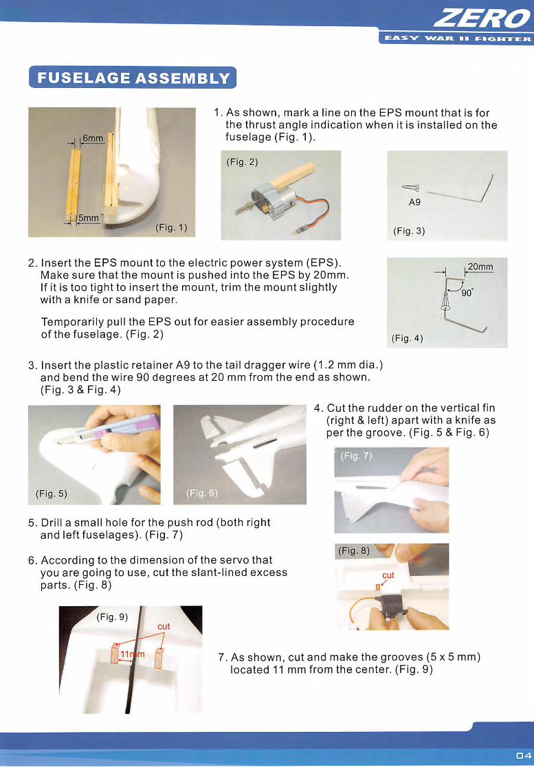
FUSELAGE ASSEMBLY
1. As shown, mark a line on the EPS mount that is forthe thrust angle indication when it is installed on thefuselage (Fig. 1).
(Fig. 2)
2. Insert the EPS mount to the electric power system (EPS).Make sure that the mount is pushed into the EPS by 20mm.If it is too tight to insert the mount, trim the mount slightlywith a knife or sand paper.
Temporarily pull the EPS out for easier assembly procedureof the fuselage. (Fig. 2)
3. Insert the plastic retainer A9 to the tail dragger wire (1.2 mm dia.)and bend the wire 90 degrees at 20 mm from the end as shown.(Fig. 3 & Fig. 4)
A9
(Fig. 3)
(Fig. 4)
20mm
4. Cut the rudder on the vertical fin
(right & left) apart with a knife asperthe groove. (Fig. 5 & Fig. 6)
(Fig. 5) (Fig. 6
5. Drill a small hole forthe push rod (both rightand left fuselages). (Fig. 7)
6. According to the dimension of the servo thatyou are going to use, cut the slant-lined excessparts. (Fig. 8)
Fig. 9
7. As shown, cut and make the grooves (5x5 mm)located 11 mm from the center. (Fig. 9)
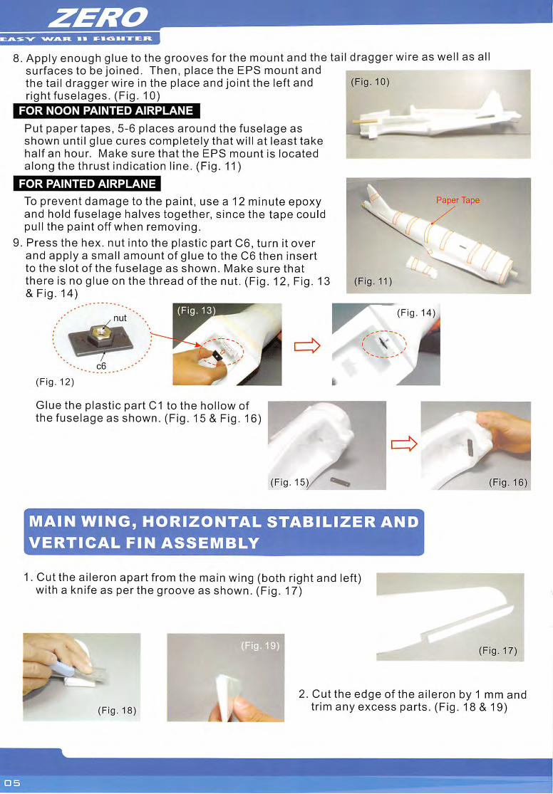
8. Apply enough glue to the grooves for the mount and the tail dragger wire as well as allsurfaces to be joined. Then, place the EPS mount andthe tail dragger wire in the place and joint the left andright fuselages. (Fig. 10)
FOR NOON PAINTED AIRPLANE
Put paper tapes, 5-6 places around the fuselage asshown until glue cures completely that will at least takehalf an hour. Make sure that the EPS mount is locatedalong the thrust indication line. (Fig. 11)
FOR PAINTED AIRPLANE
To prevent damage to the paint, use a 12 minute epoxyand hold fuselage halves together, since the tape couldpull the paint off when removing.
9. Press the hex. nut into the plastic part C6, turn it overand apply a small amount of glue to the C6 then insertto the slot of the fuselage as shown. Make sure thatthere is no glue on the thread of the nut. (Fig. 12, Fig. 13& Fig. 14)
(Fig. 12)
Glue the plastic part C1 to the hollow ofthe fuselage as shown. (Fig. 15 & Fig. 16)
(Fig. 15)
(Fig. 10)
Fig.11
Fig. 14)
MAIN WING, HORIZONTAL STABILIZER AND
VERTICAL FIN ASSEMBLY
1. Cut the aileron apart from the main wing (both right and left)with a knife as perthe groove as shown. (Fig. 17)
(Fig. 19
aperTape
(Fig. 16)
(Fig. 17)
(Fig. 18)
2. Cut the edge of the aileron by 1 mm andtrim any excess parts. (Fig. 18 & 19)
EASY -WAVC I •
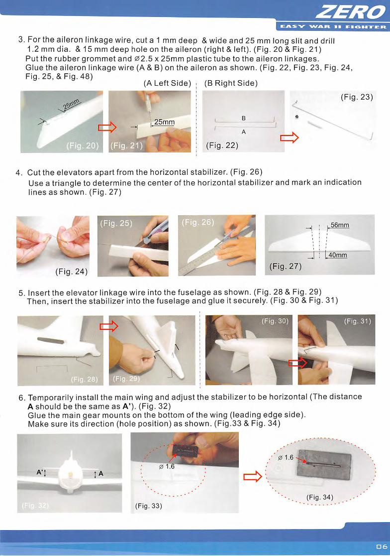
3. For the aileron linkage wire, cut a 1 mm deep &wide and 25 mm long slit and drill1.2mmdia. &15mm deep hole on the aileron (right & left). (Fig. 20 & Fig. 21)Put the rubber grommet and 02.5 x 25mm plastic tube to the aileron linkages.Glue the aileron linkage wire (A & B) on the aileron as shown. (Fig. 22, Fig. 23, Fig. 24,Fig. 25, & Fig. 48)
(A Leftside) (B Right Side)
(Fig. 23)
25mm
(Fig. 22)
4. Cut the elevators apart from the horizontal stabilizer. (Fig. 26)Use a triangle to determine the center of the horizontal stabilizer and mark an indicationlines as shown. (Fig. 27)
56mm
/
j .40mm
(Fig. 24)(Fig. 27)
5. Insert the elevator linkage wire into the fuselage as shown. (Fig. 28 & Fig. 29)Then, insert the stabilizer into the fuselage and glue it securely. (Fig. 30 & Fig. 31)
6. Temporarily install the main wing and adjust the stabilizerto be horizontal (The distanceA should be the same as A'). (Fig. 32)Glue the main gear mounts on the bottom of the wing (leading edge side).Make sure its direction (hole position) as shown. (Fig.33 & Fig. 34)
/ 01.6
(Fig. 34)(Fig. 33)
J
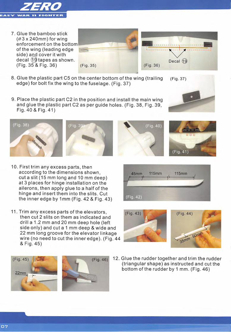
7. Glue the bamboo stick
(0 3 X240mm) for wingenforcement on the bottom!of the wing (leading edgeside) and cover it withdecal (Qtapes as shown.(Fig. 35 & Fig. 36) (Fig. 35) (Fig. 36)
8. Glue the plastic part C5 on the center bottom of the wing (trailingedge) for bolt fix the wing to the fuselage. (Fig. 37)
9. Place the plastic part C2 in the position and install the main wingand glue the plastic part C2 as per guide holes. (Fig. 38, Fig. 39,Fig.40&Fig.41)
10. First trim any excess parts, thenaccording to the dimensions shown,cut a slit (15 mm long and 10 mm deep)at 3 places for hinge installation on theailerons, then apply glue to a half of thehinge and insert them into the slits. Cutthe inner edge by 1mm (Fig. 42 & Fig. 43)
11. Trim any excess parts of the elevators,then cut 2 slits on them as indicated anddrill a 1.2 mm and 20 mm deep hole (leftside only) and cut a 1 mm deep & wide and22 mm long groove forthe elevator linkagewire (no need to cut the inner edge). (Fig. 44& Fig. 45)
Fig. 43)
Deca
(Fig. 37)
11 smm
Fig. 45)
22mm
12. Glue the rudder together and trim the rudder(triangular shape) as instructed and cutthebottom of the rudder by 1 mm. (Fig. 46)
EASY WAJR 11 F-l<
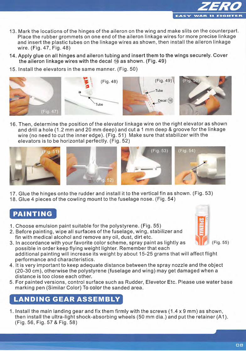
13. Mark the locations of the hinges of the aileron on the wing and make slits on the counterpart.Place the rubber grommets on one end of the aileron linkage wires for more precise linkageand insert the plastic tubes on the linkage wires as shown, then install the aileron linkagewire. (Fig. 47, Fig. 48)
14. Apply glue on all hinges and aileron tubing and insert them to the wings securely. Coverthe aileron linkage wires with the decal @ as shown. (Fig. 49)
15. Install the elevators in the same manner. (Fig. 50)
>
(Fig. 48) (Fig. 49;
Decal (1(
16. Then, determine the position of the elevator linkage wire on the right elevator as shownand drill a hole (1.2 mm and 20 mm deep) and cut a 1 mm deep &groove for the linkagewire (no need to cut the inner edge). (Fig. 51) Make sure that stabilizer with theelevators is to be horizontal perfectly. (Fig. 52)
(Fig. 54
17. Glue the hinges onto the rudder and install it to the vertical fin as shown. (Fig. 53)18. Glue 4 pieces of the cowling mount to the fuselage nose. (Fig. 54)
PAINTING
1. Choose emulsion paint suitable for the polystyrene. (Fig. 55)2. Before painting, wipe all surfaces of the fuselage, wing, stabilizer and
fin with medical alcohol and remove any oil, dust, dirt etc.3. In accordance with your favorite color scheme, spray paint as lightly as (Fig. 55)
possible in order keep flying weight lighter. Remember that eachadditional painting will increase its weight by about 15-25 grams that will affect flightperformance and characteristics.
4. It is very important to keep adequate distance between the spray nozzle and the object(20-30 cm), otherwise the polystyrene (fuselage and wing) may get damaged when adistance is too close each other.
5. For painted versions, control surface such as Rudder, Elevetor Etc. Please use water basemarking pen (Similar Color) To color the sanded area.
LANDING GEAR ASSEMBLY
1. Install the main landing gear and fix them firmly with the screws (1.4 x 9 mm) as shown,then install the ultra-light shock-absorbing wheels (50 mm dia.) and put the retainer (A1).(Fig. 56, Fig. 57&Fig. 58)
• I ^BGH-S-CR.
I'
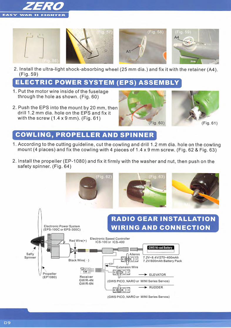
2. Install the ultra-light shock-absorbing wheel (25 mm dia.) and fix it with the retainer (A4).(Fig. 59)
ELECTRIC POWER SYSTEM (EPS) ASSEMBLY1. Put the motor wire inside of the fuselage
through the hole as shown. (Fig. 60)
2. Push the EPS into the mount by 20 mm, thendrill 1.2 mm dia. hole on the EPS and fix itwith the screw (1.4 x 9 mm). (Fig. 61)
COWLING, PROPELLER AND SPINNER
(Fig.61)
1. According to the cutting guideline, cut the cowling and drill 1.2 mm dia. hole on the cowlingmount (4 places) and fix the cowling with 4 pieces of 1.4 x 9 mm screw. (Fig. 62 & Fig. 63)
2. Install the propeller (EP-1080) and fix it firmly with the washer and nut, then push on thesafety spinner. (Fig. 64)
SaftySpinner
Electronic Power System(EPS-100CorEPS-300C)
RADIO GEAR INSTALLATION
WIRING AND CONNECTION
r, , , Electronic Speed Controller3 RedW.re(+) icS-100or ICS-400
\J Propeller(EP1080)
Black Wire -)
• t-
Receiver
GW/R-4N
GW/R-6N
3 n Aileron
Extension Wire
6WS Nl-cadBattery
7.2V-8.4V/270-400mAh
2V/600mAh Battery Pack
ELEVATOR
(GWS PICO, NARO or MINI Series Servos)
»QERUDDER
(GWS PICO, NARO or MINI Series Servos)
PEEOG
EASY >/VAR • •
(Fig. 68) r
\ A5&A10JytLEVATDD
^TO'rUDD^
VShape V_
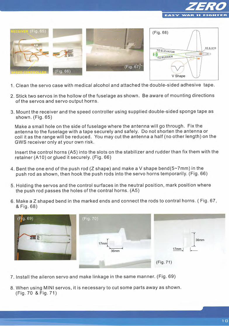
1. Clean the servo case with medical alcohol and attached the double-sided adhesive tape.
2. Stick two servos in the hollow of the fuselage as shown. Be aware of mounting directionsof the servos and servo output horns.
3. Mount the receiver and the speed controller using supplied double-sided sponge tape asshown. (Fig. 65)
Make a small hole on the side of fuselage where the antenna will go through. Fix theantenna to the fuselage with a tape securely and safely. Do not shorten the antenna orcoil it as the range will be reduced. You may cut the antenna a half (no other length) on theGWS receiver only at your own risk.
Insert the control horns (A5) into the slots on the stabilizer and rudder than fix them with theretainer (AlO)orglued it securely. (Fig. 66)
4. Bent the one end of the push rod (Z shape) and make a V shape bend(5-7mm) in thepush rod as shown, then hook the push rods into the servo horns temporarily. (Fig. 66)
5. Holding the servos and the control surfaces in the neutral position, mark position wherethe push rod passes the holes of the contra! horns. (A5)
6. Make a Z shaped bend in the marked ends and connect the rods to contral horns. ( Fig. 67,& Fig. 68)
(Fjg.69)
17mm
36mm17mm
(Fig. 71)
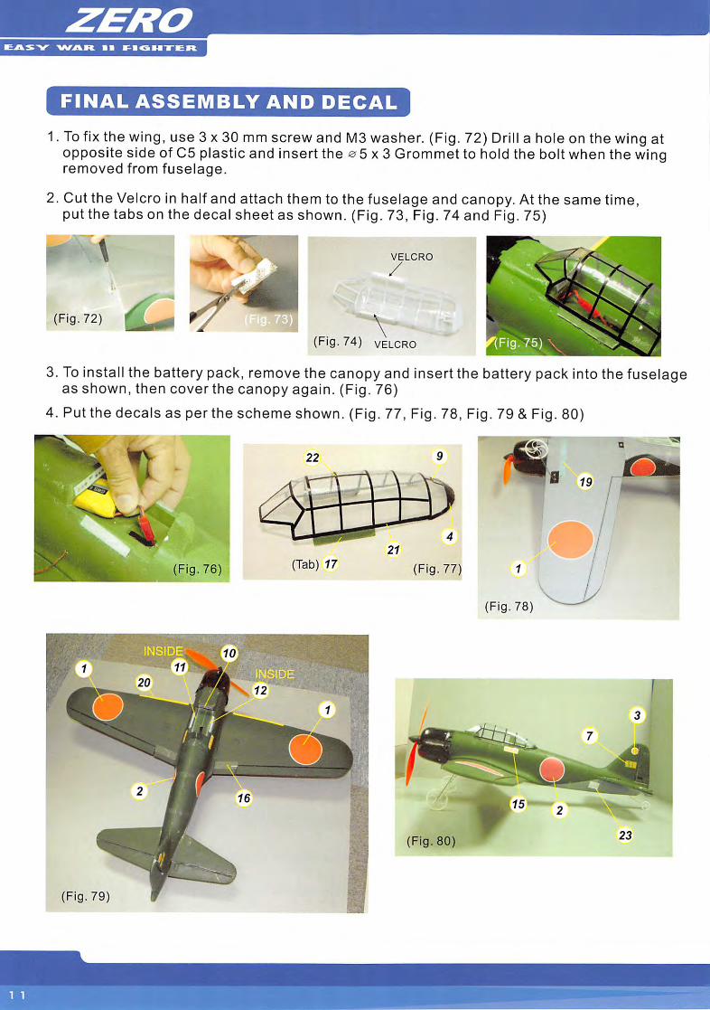
7. Install the aileron servo and make linkage in the same manner. (Fig. 69)
8. When using MINI servos, it is necessary to cut some parts away as shown.(Fig. 70 & Fig. 71)
36mm
EASY V\rAR 11 SIGMTER
FINAL ASSEMBLY AND DECAL
1. Tofix the wing, use 3 x 30 mm screw and M3 washer. (Fig. 72) Drill a hole on the wing atopposite side of C5 plastic and insert the ^5x3 Grommet to hold the bolt when the wingremoved from fuselage.
2. Cut the Velcro in half and attach them to the fuselage and canopy. At the same time,put the tabs on the decal sheet as shown. (Fig. 73, Fig. 74 and Fig. 75)
(Fig. 72)
VELCRO
/
(Fig. 74) VELCRO
3. To Install the battery pack, remove the canopy and insert the battery pack into the fuselageas shown, then coverthe canopy again. (Fig. 76)
4. Put the decals as per the scheme shown. (Fig. 77, Fig. 78, Fig. 79 & Fig. 80)
22
(Fig. 76) (Tab) 17 (Fig. 77)
(Fig. 78)
(Fig. 80)
(Fig. 79)
TIPS AND HINTS PREFLIGHT CHECKS
It is always recommended that you charge your transmitter and receiver batteries as wellas the battery pack for the motor before attempting to fly your airplane.
The Center of Gravity (C.G./balancing point) is located 55~65mm back from the leading edgeof the wing. After all radio gear and the battery pack is installed, check the C.G. point of yourairplane. If the balancing point is offset, move the receiver and speed controller forward orback ward until you find the recommended balancing point.
Check the radio gear and the linkage thoroughly on the ground and make sure that all thecontrol surfaces are working properly and correctly before attempting to take off your airplane.
We recommend that you should check the range of your radio before the first flight of the day.
FLIGHT
Always turn on the receiver last after turning on the transmitter, and shut off the receiverfirstbefore turning off the transmitter.
You can take off your airplane from the smooth surface ground, normally 3-5 meters for runand take off.
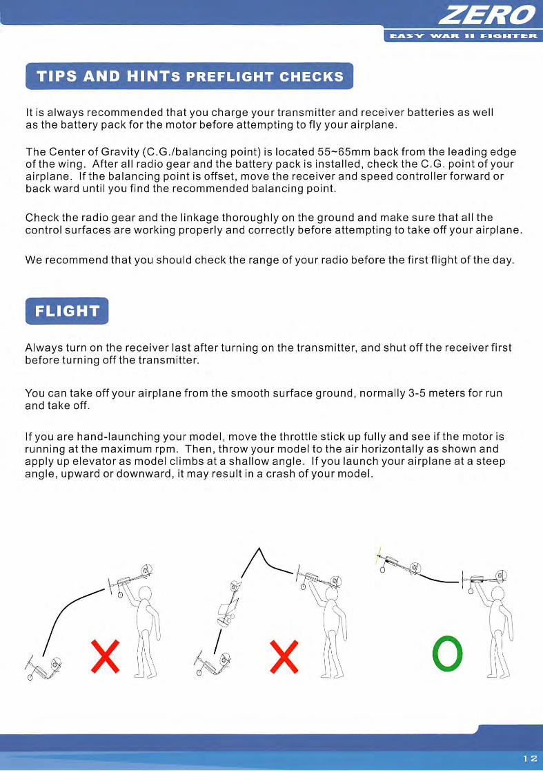
If you are hand-launching your model, move the throttle stick up fully and see if the motor isrunning at the maximum rpm. Then, throw your model to the air horizontally as shown andapply up elevator as model climbs at a shallow angle. If you launch your airplane at a steepangle, upward or downward, it may result in a crash of your model.
NEVER FLY OVER PEOPLES' HEADS OR CARS .
• If you are only beginner for the radio control model flying, do not attempt to fly your
model without any assistance or advice from advanced and expert fliers.
• Do not fly close to buildings, electric power lines, or roads. Do not fly near other people
who are not aware of what you are doing.
• Fly on a calm day. Gusty winds will make it hard for you until you learn to control your
aircraft well. Turbulence caused by wind blowing over near by trees and buildings will
make it very difficult for you to fly. Pick an open area and wait until the wind is calm.
If you are flying at a field with other modelers, DO NOT turn on you transmitter until you
are certain that no one else is using your channel.
LIMITED WARRANTY
• Your new GWS ZERO airplane kit is warranted against defects in material
and workmanship.
• This warranty does not apply to any component parts, which have been improperly
installed, handled, abused, damaged, modified and used.
WARNING:
• If you are a beginner to R/C model flight then we strongly recommend you seek advice
from your supplier and local model flying club before attempting to fly your model.
• This model is not a toy and must be assembled and used responsibility In order for
successful flight to be achieved.
• Improper use of this model may lead to injury or damage to persons or property.
GWS and their distributors will not accept any responsibility for any injury or damage
arising from improper use of this model.