Embed Size (px)
DESCRIPTION
Â
Citation preview

ECO D I S TR IC T | GHEN T | B401ZERO IMPACT BUILDING MA (SCI) ARCHITECTUREKU LEUVEN middot SINT LUCAS GROUP 42 middot GENT copy2015
MAHGOL MOTALLEBIE SUSTAINABLE CONCEPTKASRA HAJI HASSANDOKHT SMART BUILDINGPETRA ROSS LOW TECHNICSEVANGELOS STAVRAKAKIS ZERO ENERGY amp IMPACTGILLES PLAETINCK CALCULATIONS
ZIB2015 ECO DISTRICT | GENT | B401Evangelos Stavrakakis | Petra Ross | Mahgol Motallebie | Gilles Plaetinck | Kasra Haji Hassandokht
ZIB2015
|
TERRITORY
a CITY OUTSKIRTSb CITY RINGC WITHIN THE CITY
A
B
C
TIME SPAN
NOW+5-10YRS+50YRS
2015
2020
2060
TOPICS
MOBILITYNATURECULTURE
After studying the negative impacts of cutting away the highway B401 we decided to take on with a greater vision that may span in a period of time that exceeds the present and the near future By that desicion our intention is to systemize our reswponse to the problem and to think in advance with a sutainainable vision so that the shape of the urban fututre to come may be given a more positive and sustainable functions and value Space time alongside our chozen spatial and building programming form our toolbox palette
In order to unfold our greater planning vision we have defined 3 different zones -the borders of the city with its ring road the trasition space just where one enters the city and the city itself- Furthermore 3 different gradients have been defined -starting from a more global and reaching to a more local situation- while also 3 different topics have been attempted to be tackled -namely transport culture and nature All the afore described within a time context of the present the near future and the deeper future vision
Our proposal should be seen as a pioneer project and serve as an example for similar flyover spaces in Ghent and other cities
The intention is to positively activate the spaces around the Flyover and stitch it back to the city and its people by taking away its current notions of a hard barrier
FromHARD BORDER
PERMEABLE SPACE
STITCHING ELEMENT
VISION STATEMENT
RESISTANCE
POROSITY
INTERCONNECTING EDGE
FLYOVER AS AN INTERCONNECTING EDGE
CONTENTbullVISIONSTATEMENT PROJECTSUMMARYbull6KEYWORDS
FLYOVERCONTEXTbullSUNPATHbullWINDbullAERIALVIEW
VISIONOFNATUREANDCULTUREbullCPULs
MOBILITYVISIONbullCPULs
ZONINGPLANbullSITEPLAN
GROUNDPLANS1100
SECTIONS1100
DETAILS
ELEVATIONS1100
VISUALIZATIONS
MATERIALSbullSUPPLIERS
MATERIALSbullSPECIFICATION
MATERIALSbullLCAbullEMBODIEDENERGY
STRUCTUREbullZEROIMPACTAPPROACH
VERTICALHARVESTINGbullWORKSHOP
GREENWALLS
VENTILATIONbullinsummerandwinter
ELECTRICITY
LIGHTINGSYSTEMbullDAYLIGHT
WATERMANAGEMENT
SEWAGESYSTEM
CHANGESINDESIGN
CALCULATIONS
CONTENT
40
30
90
70
1 GRADIENT OF FUNCTIONS amp ATMOSPHERES
2 MOBILITY VISION
3 WORKSHOP SPACES FOOD HARVESTING COOKING CLASSES amp MARKETS
4 GREEN CORRIDORS CPULs 4
5 CONNECTIONS BETWEEN NEIGHBOURHOODS
6 CLEAN ENERGY (green)
6 KEYWORDSPROJECT SUMMARY
CO
NC
EP
TD
ES
IGN
TE
CH
NIC
S
ENERGY
MOBILITY
WATER
MATERIALS
LOW TECHNIC
SOCIAL INTERACTION
POSITIVE PROJECT
ARCHITECTURECONTEXT
bull B 401 Info center and workshopbull Number of users 10bull Footprint 185 m2- building on highwaybull Gross internal area 2987 m2
bull Gains 64 240 kWh yearbull Demands 5423 kWh yearbull Solar roadways - PV panels placed on highwaybull Heating 10 kWh msup2abull Cooling 4 kWh msup2abull Overheating 42
bull Tube hybrid solar panelsbull Rainwater collection 28773 m3yearbull Demand 16425 m3 yearbull Rainwater tank 10m3
bull Wadi systembull Divided sewer system
bull CLT columns (plato weather treated)bull Timber beems and claddingbull e- glazing
bull Ventilation - system Dbull Chimney effectbull Shading systembull Daylight usebull Temperature zoningbull Compact building
bull Bikes + pedestrian prioritybull Universal accessbull Separate ramp for cars bikesbull Connection for bikes pedestrianbull Public transport future vision
bull Info centerbull Workshop - communitybull Marketsbull Green park on highwaybull Connection buildingbull Vertical harvesting + green walls
bull Extra energy productionbull More greenerybull Futuristic vision towards Ecopolicbull Changing parking highway to parkbull Flexibility for different use
ZIB2015 ECO DISTRICT | GENT | B401Evangelos Stavrakakis | Petra Ross | Mahgol Motallebie | Gilles Plaetinck | Kasra Haji Hassandokht
ZIB2015
|
STEREGRAPHIC PROJECTION SUNPATH WIND DIRECTION DISTRIBUTION IN ()
B 401 FLYOVER middot CONTEXT
BELGIUM FLANDERS
Aalst Brussels
Sint Niklaas Antwerp
Kortrijk
Brugge
Maldegem
GHENT
GHENT
SIT
UA
TIO
N A
T L
OC
AT
ION
O
N J
UN
E 2
1
CU
RR
EN
T
DE
CE
MB
ER
21
AERIAL VIEW - LOCATION
ZIB2015 ECO DISTRICT | GENT | B401Evangelos Stavrakakis | Petra Ross | Mahgol Motallebie | Gilles Plaetinck | Kasra Haji Hassandokht
ZIB2015
|
VISION OF NATURE AND CULTURE
CURRENT SITUATION
CURRENT SITUATION FUTURE+5-10YRS
Section B-Bacute
Section A-Aacute
Section B-Bacute
Section A-Aacute
Continuous productive urban landscapes [within] cities
A-Aacuteacute B-Bacute C-Cacute
FUTURE+5-10YRS
CPULc
A vision and a strategy for the 21st century for the city to be green A healthy place for all where zero net pollution is genberated CPULs as a strategy aims towards bringing the -Natural- back to the city and through this to engage people and neighborhoods in positive activities Whether for the city the neighborhood their family or themselves this objective may capacitate a broad number of parallel activities programs and motivation for a healthy urban environment CPULs is simply taking back that for which we usually travel good distances as an -escape means- of the city and its negative side effects
ZIB2015 ECO DISTRICT | GENT | B401Evangelos Stavrakakis | Petra Ross | Mahgol Motallebie | Gilles Plaetinck | Kasra Haji Hassandokht
ZIB2015
|
A BETWEEN CITIES B CITY RING
PUBLIC
PRIVATE
SUPPLY
PSKYtranel
PSKYtrangoogleCar
googleCar
P
cambio
SKYtran
minimized night
ONEwheel
eltram
C INSIDE THE CITY
tram
SKY TRANGOING DOWN TO RING
INTERCHANGE SPOT
euro
life
sty
le c
ha
ng
e o
ve
r ti
me
15 min
90 min
PREVENT COMMUTINGMORE LOCAL LIFESTYLE
A
B
C
sophisticated apps
SHAREWAY
INTERVENTION IN TIME CURRENT SITUATION ON CITY RING SKYTRAN MOBILITY - PASSIVE MAGLEV TECHNOLOGY
NOW
+ 5-10YRS
+ 50YRS
SPEED VISION
A between cities
B city ring
C inside the city
SK
YT
RA
N
GO
OG
LE
CA
R
ON
EW
HE
EL
PASSIVE MAGLEV REQUIRES VERY LIT-TLE ENERGY AND ONLY MINOR INFRA-STRUCTURE LEADING TO THE LOW-EST COST TRANSPORTATION SYSTEM KNOWN TO MAN
ACTIVE MALEV RQUIRES HIGH ENERGY AND MASSIVE INFRA-STRUCTURE LEADING TO HIGH COSTS AS WELL
Section C-Cacute
FUTURISTIC VISION
BICYCLE UNDERGROUND PARKING
SKYtran
MOBILITY VISION
ZIB2015 ECO DISTRICT | GENT | B401Evangelos Stavrakakis | Petra Ross | Mahgol Motallebie | Gilles Plaetinck | Kasra Haji Hassandokht
ZIB2015
|
SITE PLAN
OUTTER CITY RINGINTEREVENTION LOCATIONTOWARDS THE CITY CENTRE
ZONE A SPORT AND CULTURE Pi ZONE C TRANSPORT TRANSITIONZONE B INFO AND WORKSHOP
TOP OF THE FLYOVER PARK AND ENERGY
TRANSPORT
bikespedestrian ramp
elevated park
ramp for cars in 2 directionsbus
tram
ECO QUATER
ZIB
drawing over existing situation
roundabout+ underpass
OFFICE PARK
EDUCATION
EDUCATION
HOUSING FLATS
HOUSING
HOUSING
ECO CITY GHENT
0 50 100 200
HOUSING FLATSOFFICE PARK
COMMERCE
HOUSING
HOUSING
0 10 50 100
P
P
P
PEDESTRIANCYCLE ROADS
P
i
PLAY TRAILS
ALLOTMENTS
PEDESTRIAN CYCLE RAMP
RAMP FOR CARS
ZIB
ZONING PLAN
ZIB2015 ECO DISTRICT | GENT | B401Evangelos Stavrakakis | Petra Ross | Mahgol Motallebie | Gilles Plaetinck | Kasra Haji Hassandokht
ZIB2015
|
GROUNDPLANS 1100
B-Bacute
A-Aacute
B-Bacute
A-Aacute
B-Bacute
A-Aacute
B-Bacute
A-Aacute
ZIB2015 ECO DISTRICT | GENT | B401Evangelos Stavrakakis | Petra Ross | Mahgol Motallebie | Gilles Plaetinck | Kasra Haji Hassandokht
ZIB2015
|
SECTIONS 1100
Section A-AacuteSection B-Bacute
AArsquo
AArsquo
Detai l 01
Detai l 02
Detai l 03
Detai l 04
Detai l 05
Detai l 06
ZIB2015 ECO DISTRICT | GENT | B401Evangelos Stavrakakis | Petra Ross | Mahgol Motallebie | Gilles Plaetinck | Kasra Haji Hassandokht
ZIB2015
|
DETAILS
DETAIL 01 DETAIL 02 DETAIL 03 DETAIL 04 DETAIL 05 DETAIL 06
AArsquo
PIR f loorGypsum plasterboardPIR 100 mmOSB 15 mmFJI beam cel lu lose 350 mmcel i t 4D woodf iber 18 mmfinish gypsum plasterboard
plato wood f in ishframework 30 mmcel i t 4D 18 mmwood structure SLS 38140Eurowal l 2x70 mmOSB Eurothane G 70 mmfinish gypsum plasterboard
ZIB2015 ECO DISTRICT | GENT | B401Evangelos Stavrakakis | Petra Ross | Mahgol Motallebie | Gilles Plaetinck | Kasra Haji Hassandokht
ZIB2015
|
ELEVATIONS 1100
South elevation
South Elevation
North Elevation
South Elevation
North Elevation
South Elevation
North Elevation
South Elevation
North Elevation
North elevation
ZIB2015 ECO DISTRICT | GENT | B401Evangelos Stavrakakis | Petra Ross | Mahgol Motallebie | Gilles Plaetinck | Kasra Haji Hassandokht
ZIB2015
|
VISUALIZATIONS
East Elevation
West Elevation
East Elevation
West Elevation
East Elevation
West Elevation East Elevation
West Elevation
ELEVATIONS 1100
West elevation East elevation
ZIB2015 ECO DISTRICT | GENT | B401Evangelos Stavrakakis | Petra Ross | Mahgol Motallebie | Gilles Plaetinck | Kasra Haji Hassandokht
ZIB2015
|
VISUALIZATIONS
ZIB2015 ECO DISTRICT | GENT | B401Evangelos Stavrakakis | Petra Ross | Mahgol Motallebie | Gilles Plaetinck | Kasra Haji Hassandokht
ZIB2015
|
MATERIALS WOOD FCS Certi f ied Suppliers Distance MATERIALS Building Structure
ZIB2015 ECO DISTRICT | GENT | B401Evangelos Stavrakakis | Petra Ross | Mahgol Motallebie | Gilles Plaetinck | Kasra Haji Hassandokht
ZIB2015
|
MATERIALS Specs InsulationMATERIALS Specs Solid amp Structural Wood
ZIB2015 ECO DISTRICT | GENT | B401Evangelos Stavrakakis | Petra Ross | Mahgol Motallebie | Gilles Plaetinck | Kasra Haji Hassandokht
ZIB2015
|
MATERIALS Life Cycle Assesment MATERIALS Embodied energy CO2 other materials
ZIB2015 ECO DISTRICT | GENT | B401Evangelos Stavrakakis | Petra Ross | Mahgol Motallebie | Gilles Plaetinck | Kasra Haji Hassandokht
ZIB2015
|
STRUCTURE
Gilles Plaetinck
schaal
ZIB BUILDINGEnter address here
7 _ Unnamed
Owner
begeleider Checker
3D Copy 11 Gilles Plaetinck
schaal
ZIB BUILDINGEnter address here
8 _ Unnamed
Owner
begeleider Checker
3D Copy 21
Gilles Plaetinck
schaal
ZIB BUILDINGEnter address here
8 _ Unnamed
Owner
begeleider Checker
3D Copy 31
Gilles Plaetinck
schaal
ZIB BUILDINGEnter address here
9 _ Unnamed
Owner
begeleider Checker3D Copy 4
1
ECONOMY - USIBILITY DURING THE DAY
i1000
ALWAYS
2000
ECONONY - USIBILITY DURING THE DAY
GENERAL PRINCIPLES OF THE BUILDING
ZERO IMPACT APPROACH
i
0 Food market in park Vertical harvesting Entrance
1 Workshop area technical room
2 Info center Entrance from highway
3 Roof terrace
ZIB2015 ECO DISTRICT | GENT | B401Evangelos Stavrakakis | Petra Ross | Mahgol Motallebie | Gilles Plaetinck | Kasra Haji Hassandokht
ZIB2015
|
Vertical Harvest places plants on carousels that keep them moving the length of the greenhouse giving them equal time in natural light and also al-lowing workers to pick and tand transfer the crops Using hydroponics Verti-cal Harvest will be capa-ble of producing over
Vertical Harvest places plants on carousels that keep them moving the length of the pulls giving them equal time in natu-ral light and also allowing workers and local people to pick and transfer the crops Using hydroponics Vertical Harvest will be capable of producing over greens and herbs
VERTICAL HARVESTING
PLANT CABLE LIFT (PLC) SECTION
Sustainable Food zorkshop centerrsquos mission is to ldquocultivate a healthy community by strengthening the local food system and improving access to nu-tritious affordable foodrdquo The main goal of our design is to deliver skills and information for sus-tainability practioners in the organic food tradeThe program attempts to1) affect positive changes in shopping cooking eating habits and nutrition2) reduce diet-related diseases3) promote the health and development of young children 4) place emphasis on local seasonal and cultural-ly-appropriate foods5) integrate food systems concepts into its curric-ulumndash such as shopping at farmers markets and growing onersquos own food
Healthy food is a basic human right the ability to access healthy food is often related to multiple issues and not just a result of low income
FOOD TEAM = a group of people from the same neighbourhood who work for the direct purchase of regional and seasonal products They order food on internet via web page voedselteambe and it is then delivered once a week to the depot of a team
+ minimal transport requirements+ no returnable packaging+ fair p+ fair pricing+ high-quality local and seasonal food+ community initiative
Healthy food is a basic human right the ability to access healthy food is often related to multiple issues and not just a result of low income
Sustainable Food zorkshop centerrsquos mission is to ldquocultivate a healthy community by strengthening the local food system and improving access to nutritious affordable foodrdquo The main goal of our design is to deliver skills and information for sustainability practioners in the organic food tradeThe program attempts to
1) affect positive changes in shopping cookingeating habits and nutrition2) reduce diet-related diseases3) promote the health and development of youngchildren4) place emphasis on local seasonal and culturally-appropriate foods5) integrate food systems concepts into its curriculumndashsuch as shopping at farmers markets andgrowing onersquos own food
FOOD TEAM = a group of people from the same neighbourhood who work for the direct purchase of regional and seasonal products They order food on internet via web page voedselteambe and it is then delivered once a week to the depot of a team
+ minimal transport requirements+ no returnable packaging+ fair pricing+ high-quality local and seasonal food+ community initiative
WORKSHOP
ZIB2015 ECO DISTRICT | GENT | B401Evangelos Stavrakakis | Petra Ross | Mahgol Motallebie | Gilles Plaetinck | Kasra Haji Hassandokht
ZIB2015
|
Black coral pea
Factors should be considered when seleccng plants
- Quality of growth- Ability to adapt to the wall environment- Environmental Tolerances- Temperature Resistance- Drought Tolerance- Wind - Wind Tolerance- Solar Exposure Tolerance- Salt Tolerance in Seaside installacons- Air and Water Pollucon Tolerance- Pest and Disease Resistance- Arcficial Environment Tolerance- Transplantacon Tolerance- Pruning - Pruning Tolerance
- Ornamental Qualices- Design Purpose- Manageability Maintainability- Environmental and Societal Effects- Visual Effect- Feeling Effect
Blac
k co
ral p
eaSn
ake
vine
kidn
ey w
eed
purple coral peaBasil
Pandorea
GREEN WALLS
ZIB2015 ECO DISTRICT | GENT | B401Evangelos Stavrakakis | Petra Ross | Mahgol Motallebie | Gilles Plaetinck | Kasra Haji Hassandokht
ZIB2015
|
Extraction of air
Pulsion of airRecuperation unit
outdoor space
18 degC15 degC
18 degC
In-take Out-take of air
VENTILATION
Gilles Plaetinck
schaal 1 100
ZIB BUILDINGEnter address here
3 _ level 2
Owner
begeleider Checker
DN
Gilles Plaetinck
schaal 1 100
ZIB BUILDINGEnter address here
2 _ level 1
Owner
begeleider Checker
Extraction of air
Pulsion of air
VENTILATION IN GROUPLANS CALCULATION AND SYSTEM
level 01
level 02
T 42ECO DISTRICT | GENT | B401
ZIB2015Mechanical Ventilation with Heat Recovery (MVHR)
Up to 95 of the heat can be recovered The Heat Recovery Unit runs continu-ously on trickle and can and is boosted when higher rates of ventilation are required eg bathing cooking In warmer months a summer by-pass function helps ensure comfort levels are maintained in the home When summer by-pass is activated the dwelling contin-ues to be ventilaated and recieve fresh filtered air however the heat recovery process is intermittently switched off (heat recovery is by-passed)
Key BenefitsYear round removal of condensation and indoor pol-lutants A direct impact on the Dwelling Emission Rate re-quired in SAP helping reduce the carbon footprint of the property Fresh filtered air supplied to dwelling ideal for allergy sufferers and those with conditions such as asthma A balanced ventilation system for the whole house and recovering of heat that would have otherwise have been lost Low noise non-intrusive ventilation system ndash located away from the room however consideration should be given to duct runs to ensure cross-talk contamination doesnrsquot happen AND the unit is sized correctly so it is not running a high rate all of the time
Zehnder ComfoSystems Passive Haus accredited product suitable for large houses up to 300m2 Designed to ensure low noise excellent energy performance and heat exchange efficiency Choice of control options including LCD touch screen display Can be combine with ComfoCool for optional cooling of up to 5 degrees and humidity reduction by 20
Semi Rigid Ducting
With a manifold system the resistance caused by duct-ing is reduced therefore Semi-Rigid ducting resistance is very low The manifold takes mass airflow directly from the MVHR Heat Recovery Unit and allows lower rates to pass through to each individual room runDirecting mass flow to the manifold eliminates the need to increase the running speed of the MVHR Heat Re-covery unit to overcome the resistance of ducting which in turn causes noise for the homeowner
MECHANICAL VENTILATION WITH HEAT RECOVERY (MVHR)
Up to 95 of the heat can be recoveredThe Heat Recovery Unit runs continuously on trickle and can and is boosted when higher rates of ventilation are required eg bathing cooking
In warmer months a summer by-pass function helps ensure comfort levels are maintained in the home When summer by-pass is activated the dwelling continues to be ventilaated and recieve fresh filtered air however the heat recovery process is intermittently switched off (heat recovery is by-passed)
EXTRACT VENTILATION RATES
T 42ECO DISTRICT | GENT | B401
ZIB2015Mechanical Ventilation with Heat Recovery (MVHR)
Up to 95 of the heat can be recovered The Heat Recovery Unit runs continu-ously on trickle and can and is boosted when higher rates of ventilation are required eg bathing cooking In warmer months a summer by-pass function helps ensure comfort levels are maintained in the home When summer by-pass is activated the dwelling contin-ues to be ventilaated and recieve fresh filtered air however the heat recovery process is intermittently switched off (heat recovery is by-passed)
Key BenefitsYear round removal of condensation and indoor pol-lutants A direct impact on the Dwelling Emission Rate re-quired in SAP helping reduce the carbon footprint of the property Fresh filtered air supplied to dwelling ideal for allergy sufferers and those with conditions such as asthma A balanced ventilation system for the whole house and recovering of heat that would have otherwise have been lost Low noise non-intrusive ventilation system ndash located away from the room however consideration should be given to duct runs to ensure cross-talk contamination doesnrsquot happen AND the unit is sized correctly so it is not running a high rate all of the time
Zehnder ComfoSystems Passive Haus accredited product suitable for large houses up to 300m2 Designed to ensure low noise excellent energy performance and heat exchange efficiency Choice of control options including LCD touch screen display Can be combine with ComfoCool for optional cooling of up to 5 degrees and humidity reduction by 20
Semi Rigid Ducting
With a manifold system the resistance caused by duct-ing is reduced therefore Semi-Rigid ducting resistance is very low The manifold takes mass airflow directly from the MVHR Heat Recovery Unit and allows lower rates to pass through to each individual room runDirecting mass flow to the manifold eliminates the need to increase the running speed of the MVHR Heat Re-covery unit to overcome the resistance of ducting which in turn causes noise for the homeowner
Heating 10 kwh msup2aCooling 4 kWh msup2aOverheating 42
ZIB2015 ECO DISTRICT | GENT | B401Evangelos Stavrakakis | Petra Ross | Mahgol Motallebie | Gilles Plaetinck | Kasra Haji Hassandokht
ZIB2015
|
Shutters control system+ -
Solar roadways - PV panels
LED lights
Elevator Fuse box
ElectricityBattery withtransformator
ELECTRICITY
Summer night
cross- ventilation through building
Summer day
air through recuperation unit small change of temperature
15 degC 18 degC
+ groundplans
heated zone
not heated zone
ZONING ACCORDING TO TEMPERATURESSUMMER NIGHT - cross-ventilation through building
SUMMER DAY - air through recuperation unit small change of temperatureSHADING SYSTEM
As a shading was chozen system Renson Icarus Lamellas with angle 45deg made in wood
ZIB2015 ECO DISTRICT | GENT | B401Evangelos Stavrakakis | Petra Ross | Mahgol Motallebie | Gilles Plaetinck | Kasra Haji Hassandokht
ZIB2015
|
average only 4 hours of peak daylight hours per day (4 x 365 = 1460 hours per year)
- Surface area ( first part) Fly-over +- 20 000 msup2-gt 16 000 x 230 Watt = 3 680 000 Watt or 3680 kWonly 50 of fly-over covered with solar roadways
-gt 3680 kW x 4 h = 7360 kWh day-gt 3680 kW x 1460 h = 2 686 400 kWh year -gt +- 540 households (+- 5000 kWh year)
Tesla Powerwall Therersquos a 10 kWh unit at $3500 -gt 737 Tesla Batteries
gt the Solar Roadway has the ability to cut greenhouse gases by up to 75-percentgt A decentralized self-healing secure power grid
IN FRONT OF FLY-OVER
- Surface area Fly-over = 16 x 30 m = 480 msup2-gt 384 x 230 Watt = 88 320 Watt or 883 kWonly 50 of fly-over covered with solar roadways
-gt 44 kW x 4 h = 176 kWh day-gt 44 kW x 1460 h = 64 240 kWh year -gt +- 13 households (+- 5000 kWh year)
lightsshutters
elevator
2 fridges
2 coffeemakers
1 microwave
1 owen
2 cooking plates
stereo
ventilation unit
electricity transformer (AC to DC) for PV panels + batteries
summer 05 kWh daywinter 03 kWh day183 days x 05= 915 kWh182 days x 03 = 546 kWh = 1641 kWh
262 kWh
A++fridge 104 kWhyear104 x x2 = 208 kWh
900 W x 01 hours day = 09 kWhx 220 days x 2= 198 kWh a
67 kWh a
085x100 days= 85 kWh a
400 kWh x 2 = 800 kWh a
150 kWh a 419 kWha
68 kWh a
ENERGY DEMAND OVERVIEW ENERGY SUPPLY OVERVIEW - FLY-OVER
1 spot 56 W 10000 = 0056 KW4 hours per day 365 days a year = 1460 h0056 x 1460 = 8176 kWh10 spots x 8176= 8176 kWh a
1 spot 72 W 10000 = 0072 KW4 hours per day 365 days a year = 1460 h0072 x 1460 = 10512 kWh5 spots x 10512= 5256 kWh a
1 spot 52 W 10000 = 0052 KW4 hours per day 365 days a year = 1460 h0052 x 1460 = 7592 kWh21 spots x 7592= 159432 kWh a
1 spot 9 W 10000 = 0009 KW4 hours per day 365 days a year = 1460 h0009 x 1460 = 1314 kWh5 spots x 1314 = 657 kWh a
SOLAR ROADWAYS - PV PANELSEnergy from the sun
1 To generate energy for the ZIB building2 To generate energy for the surrounding houses3 To generate energy for lighting or signs on the road4 The panels will also have the capacity to charge electric vehicles while parked
ELECTRICITY SCHEME
5423 kWh a
ZIB2015 ECO DISTRICT | GENT | B401Evangelos Stavrakakis | Petra Ross | Mahgol Motallebie | Gilles Plaetinck | Kasra Haji Hassandokht
ZIB2015
|
SUMMER SUNNY 10-42 LUXWINTER SUNNY 10-42 LUX
DAYLIGHT - DIALuxLIGHTING SYSTEM - DIALux
Workplane 9 Results overview
Height of working plane 0800 m Wall zone 0000 m
Result Mean (target) Min Max Minaverage MinmaxPerpendicular illuminance [lx] 463 (500) 105 689 0227 0152
Profile Offices Writing typewriting reading data processing
B401-Gent 6222015
Site 1 Building 2 Zib Room 9 Workplane 9 Results overview
Page 70
Workplane 9 False coloursPerpendicular illuminance (adaptive)
Scale 1 200
Perpendicular illuminance (Surface)Mean (actual) 463 lx Min 105 lx Max 689 lx Minaverage 0227 Minmax 0152
B401-Gent 6222015
Site 1 Building 2 Zib Room 9 Workplane 9 False coloursPerpendicular illuminance (adaptive)
Page 72
Workplane 9 Value chartPerpendicular illuminance (adaptive)
Scale 1 200
Perpendicular illuminance (Surface)Mean (actual) 463 lx Min 105 lx Max 689 lx Minaverage 0227 Minmax 0152
B401-Gent 6222015
Site 1 Building 2 Zib Room 9 Workplane 9 Value chartPerpendicular illuminance (adaptive)
Page 73
Workplane 13 Results overview
Height of working plane 0800 m Wall zone 0000 m
Result Mean (target) Min Max Minaverage MinmaxPerpendicular illuminance [lx] 388 (500) 69 732 0178 0094
Profile Offices Writing typewriting reading data processing
B401-Gent 6222015
Site 1 Building 6 Storey 1 Room 13 Workplane 13 Results overview
Page 94
Workplane 13 False coloursPerpendicular illuminance (adaptive)
Scale 1 100
Perpendicular illuminance (Surface)Mean (actual) 388 lx Min 69 lx Max 732 lx Minaverage 0178 Minmax 0094
B401-Gent 6222015
Site 1 Building 6 Storey 1 Room 13 Workplane 13 False coloursPerpendicular illuminance (adaptive)
Page 96
Workplane 13 Value chartPerpendicular illuminance (adaptive)
Scale 1 100
Perpendicular illuminance (Surface)Mean (actual) 388 lx Min 69 lx Max 732 lx Minaverage 0178 Minmax 0094
B401-Gent 6222015
Site 1 Building 6 Storey 1 Room 13 Workplane 13 Value chartPerpendicular illuminance (adaptive)
Page 97
Workplane 9 False coloursPerpendicular illuminance (adaptive)
Scale 1 200
Perpendicular illuminance (Surface)Mean (actual) 463 lx Min 105 lx Max 689 lx Minaverage 0227 Minmax 0152
B401-Gent 6222015
Site 1 Building 2 Zib Room 9 Workplane 9 False coloursPerpendicular illuminance (adaptive)
Page 72
1st f loor 2nd f loor Site 1 Luminaire parts listQuantity Luminaire (Luminous emittance)10 3F Filippi 12736 P 202x24W LED OP 196x1231
Luminous emittance 1Fitting 1x24W 2xLEDLight output ratio 100Lamp luminous flux 5332 lmLuminaire Luminous Flux 5332 lmPower 560 WLight yield 952 lmW
200
300
400
cdklm η = 100C0 - C180 C90 - C270
0deg 15deg 30deg
45deg
60deg
75deg
90deg
105deg105deg
90deg
75deg
60deg
45deg
30deg 15deg 0deg
5 SFN Eclairages 0732360X CLFV 236Luminous emittance 1Fitting 2xT26 36W840Light output ratio 6889Lamp luminous flux 6700 lmLuminaire Luminous Flux 4615 lmPower 720 WLight yield 641 lmW
160
240
cdklm η = 69C0 - C180 C90 - C270
0deg 15deg 30deg
45deg
60deg
75deg
90deg
105deg105deg
90deg
75deg
60deg
45deg
30deg 15deg 0deg
21 SFN Eclairages 332226XX SAM F 2x26W BELuminous emittance 1Fitting 2xTC-DEL 26W840Light output ratio 3297Lamp luminous flux 3600 lmLuminaire Luminous Flux 1187 lmPower 520 WLight yield 228 lmW
40
60
80
100
120
140
cdklm η = 33C0 - C180 C90 - C270
0deg 15deg 30deg
45deg
60deg
75deg
90deg
105deg105deg
90deg
75deg
60deg
45deg
30deg 15deg 0deg
1 Signcomplex AR111-009-AW-W-06 AR111 COB 9W38deg WhiteLuminous emittance 1Fitting 1xAR111-009-AW-W-06Light output ratio 8078Lamp luminous flux 600 lmLuminaire Luminous Flux 485 lmPower 90 WLight yield 539 lmW
800
1200
cdklm η = 81C0 - C180 C90 - C270
0deg 15deg 30deg
45deg
60deg
75deg
90deg
105deg105deg
90deg
75deg
60deg
45deg
30deg 15deg 0deg
Total lamp luminous flux 163020 lm Total luminaire luminous flux 101807 lm Total Load 20210 W Light yield 504 lmW
B401-Gent 6222015
Site 1 Luminaire parts list
Page 19
10x
6x
21x
1x
types of l ights
Perpendicular i l luminance (Surface)Mean (actual ) 463 lx Min 105 lx Max 689 lx Minaverage 0 227 Minmax 0 152
Perpendicular i l luminance (Surface)Mean (actual ) 388 lx Min 69 lx Max 732 lx Minaverage 0 178 Minmax 0 094
ZIB2015 ECO DISTRICT | GENT | B401Evangelos Stavrakakis | Petra Ross | Mahgol Motallebie | Gilles Plaetinck | Kasra Haji Hassandokht
ZIB2015
|
Tube hybrid Solar panels
Hot water tank Water taps
City water supply
Rain water collection for vertical harvesting
City water supply
WADI
Rain water tank
WATER MANAGEMENT
Sinks
Available roof area
In Ghent avarage of 900mmm2year
3197 m2
09x 3197 = 28773 m3year
RAIN WATER GAIN
toilet - 3x - 03lskitchen -4x - 02ls
POTABLE WATER DEMAND
3 toiletsVertical gardening
Total
relative RW usage
300 l day150 l day = 450lday= 16425 m3 year
1407 lday100m2
RAIN WATER DEMAND
RAIN WATER TANK
Relative RWT volumeRain water tank volume
3m3 100 m2
9591 l gt 10 m3
DIMESION OF PIPES
City water supplyRainwater tank
178 mm (DN 18 - 15 - 12)165 mm (DN 17-15)
are composed of hexagonal tiles Rainwater can infiltrate between the gaps from where it goes to rainwatter collector which supplies the vegetation on fly-over
THE SOLAR ROADWAYS
WATER SUPPLY SCHEME AND CALCULATION
ZIB2015 ECO DISTRICT | GENT | B401Evangelos Stavrakakis | Petra Ross | Mahgol Motallebie | Gilles Plaetinck | Kasra Haji Hassandokht
ZIB2015
|
WADI
City water supply
Rain water tank
Sinks
Divided sewer systemwithin building
SEWAGE SYSTEM
ToiletToilet sinkKitchen sink
DU = 2 lsDU = 05 lsDU = 08 ls
WATER DRAINAGE OF DEVICES
Frequency of usage at the same time
K 05
DIMESION OF PIPES
Black waterGrey water
110 mm (DU 110)75 mm (DU 75 - 63)
WATER DRAINAGE SCHEME AND CALCULATION
ZIB2015 ECO DISTRICT | GENT | B401Evangelos Stavrakakis | Petra Ross | Mahgol Motallebie | Gilles Plaetinck | Kasra Haji Hassandokht
ZIB2015
|
DN
Gilles Plaetinck
schaal 1 100
ZIB BUILDINGEnter address here
2 _ level 1
Owner
begeleider Checker
Gilles Plaetinck
schaal 1 100
ZIB BUILDINGEnter address here
3 _ level 2
Owner
begeleider Checker
WATER SUPPLY
HOT WATER
WATER DRAINAGE
WATER SUPPLY AND DRAINAGE IN GROUPLANS
level 01
level 02
ENERGY
RAINWATER TANK
HELOPHYTE FILTER
IRRIGATION SYSTEM
BIO-ROTOR
MICRO TURBINE
PHOSPHOR
In this building a closed water system is applied which is based on reusing water in mullple wasRainRain water from the roof will be collected in a storage tank situated on the ground floor This water will be used to flush the toilet and irrigate crops in verlcal harveslng system In case of an overflow the water will be stored in the con-structed wetland near the building The rainwater can be fil-tered through a helophyte filter up to drinking water stan-dard The waste water system includes three types of water yellyellow black and grey waterThe yellow water will be stored for its phosphor while the black water will be purified into grey water This grey water is comparable to the quality of rain water aaer purificalon b means of a bio rotor The remaining residue from the bio rotor together with the organic waste from the harveslng is fermented into biogas that drives a micro turbine in order to produce some addilonal energy
TheThe waste product deriving from this process will be used as compost in verlcal harveslng This efficient yet complex system closes the ullizalon cycle of the building and turns it into an efficient vicious circle that can be considered au arkic
In this building a closed water system is applied which is based on reusing water in multiple was
Rain water from the roof will be collected in a storage tank situated on the ground floor This water will be used to flushthe toilet and irrigate crops in vertical harvesting system In case of an overflow the water will be stored in the constructed wetland near the building The rainwater can be filtered through a helophyte filter up to drinking water standard
The waste water system includes three types of water yellow black and grey water The yellow water will be stored for its phosphor while the black water will be purified into grey water This grey water is comparable to the quality of rain water after purification b means of a bio rotor The remaining residue from the bio rotor together with the organic waste from the harvesting is fermented into biogas that drives a micro turbine in order to produce some additional energy The waste product deriving from this process will be used ascompost in ver1048991cal harves1048991ng This efficient yet complexsystem closes the u1048991liza1048991on cycle of the building and turns itinto an efficient vicious circle that can be considered au arkic
WATER CYCLE
ZIB2015 ECO DISTRICT | GENT | B401Evangelos Stavrakakis | Petra Ross | Mahgol Motallebie | Gilles Plaetinck | Kasra Haji Hassandokht
ZIB2015
|
CALCULATIONS
Passive House verification
Photo or Drawing
Building Workshop + info pointStreet
PostcodeCityCountry
Building Type non-residentialClimate Ukkel
Home Owner(s) Client(s)Street
PostcodeCity
ArchitectStreet
PostcodeCity Calculation electricity Internal heat gains
Mechanical System Building type
StreetPostcodeCity Internal heat gains
Year of Construction 2015 Interior Temperature 200 degC Utilisation pattern
Number of Dwelling Units 1 Internal Heat Gains 20 Wm2 Type of values used Fill in worksheet IHG Non-Dom Enclosed Volume Ve 12442 Planned number of occupants
Number of Occupants 80 8 Design
Specific building demands with reference to the treated floor area use Annual method
Treated floor area 2840 msup2 Requirements Fulfilled Verification Annual method The monthly method should be used for building certification
Space heating Annual heating demand 10 kWh(m2a) 15 kWh(msup2a) yes Specific space heating demand annual method 103 kWh(msup2a)
Heating load 11 Wm2 10 Wmsup2 - Specific space heating demand monthly Method 120 kWh(msup2a)
Space cooling Overall specific space cooling demand kWh(m2a) 15 kWh(msup2a)
Cooling load Wm2 - -Frequency of overheating (gt 25 degC) - -
Primary Energy Space heating and dehumidification
cooling household electricity 73 kWh(m2a) 120 kWh(msup2a) yes
DHW space heating and auxiliary electricity 24 kWh(m2a) - -Specific primary energy reduction through solar electricity 21 kWh(m2a) - -
Airtightness Pressurization test result n50 06 1h 06 1h yes
PHPP Verification FINAL ZIB FILE CALCULTIONS PHPPxls
L B H VOLUME
main 1 226 7 4 6328main 2 184 7 35 4508
core 0 6 2 5 3 5 108 5core 0 62 5 35 1085core 3 62 3 28 521
12442
AREAmain 1 storage 35
wc big 35wc 2wc 2workshop 103
MAIN 2 infolounge 92
staircase 56storage technical 22
284
Floor_exterior 1582 31 1272
Roof_exterior 1582
Passive House verification
Photo or Drawing
Building Workshop + info pointStreet
PostcodeCityCountry
Building Type non-residentialClimate Ukkel
Home Owner(s) Client(s)Street
PostcodeCity
ArchitectStreet
PostcodeCity Calculation electricity Internal heat gains
Mechanical System Building type
StreetPostcodeCity Internal heat gains
Year of Construction 2015 Interior Temperature 200 degC Utilisation pattern
Number of Dwelling Units 1 Internal Heat Gains 20 Wm2 Type of values used Fill in worksheet IHG Non-Dom Enclosed Volume Ve 12442 Planned number of occupants
Number of Occupants 80 8 Design
Specific building demands with reference to the treated floor area use Annual method
Treated floor area 2840 msup2 Requirements Fulfilled Verification Annual method The monthly method should be used for building certification
Space heating Annual heating demand 10 kWh(m2a) 15 kWh(msup2a) yes Specific space heating demand annual method 103 kWh(msup2a)
Heating load 11 Wm2 10 Wmsup2 - Specific space heating demand monthly Method 120 kWh(msup2a)
Space cooling Overall specific space cooling demand kWh(m2a) 15 kWh(msup2a)
Cooling load Wm2 - -Frequency of overheating (gt 25 degC) - -
Primary Energy Space heating and dehumidification
cooling household electricity 73 kWh(m2a) 120 kWh(msup2a) yes
DHW space heating and auxiliary electricity 24 kWh(m2a) - -Specific primary energy reduction through solar electricity 21 kWh(m2a) - -
Airtightness Pressurization test result n50 06 1h 06 1h yes
PHPP Verification FINAL ZIB FILE CALCULTIONS PHPPxls
SURFACE AREAcurrent orientation only night ventilation
current orientation only night ventilation 6 windows less 52 msup2
current orientation only night ventilation 7 windows less 60msup2 (stays the same for each side)
current orientation only night ventilation 8 windows less 69 msup2
orientation turned 90deg only night ventilation 6 windows less 52 msup2
orientation turned 90deg only night ventilation 7 windows less 60msup2 (window less at SE side)
orientation turned 90deg only night ventilation 8 windows less 69 msup2
-gt orientation turned 90deg only night ventilation 9 windows less 77msup2 (window less at NW side althought theres less overheating in the case of a window less at SE side the heating demand exceeds 15)
CHANGE IN DESIGN
ZIB2015 ECO DISTRICT | GENT | B401Evangelos Stavrakakis | Petra Ross | Mahgol Motallebie | Gilles Plaetinck | Kasra Haji Hassandokht
ZIB2015
|
Passive House verificationS P E C I F I C A N N U A L H E A T I N G D E M A N D
Climate Ukkel Interior Temperature 200 degC
Building Workshop + info point Building TypeUse non-residentialTreated Floor Area ATFA 2840 msup2
per msup2Area U-Value Temp Factor ft Gt Treated Data for heating balance diagram
Building Element Temperature Zone msup2 W(msup2K) kKha kWha Floor Area Losses GainsExterior Wall - Ambient A 5595 0101 100 743 = 4181 1472 Exterior Wall - Ambient 147234373Exterior Wall - Ground B 069 = Exterior Wall - GroundRoofCeiling - Ambient A 1550 0094 100 743 = 1085 382 RoofCeiling - Ambient 381903529Floor slab basement ceiling B 310 0105 069 743 = 167 059 Floor slab basement ceiling 058811509
A 100 =A 100 =
unheated basement X 075 = unheated basementWindows A 1154 0648 100 743 = 5562 1958 Windows 195834732Exterior Door A 100 = Exterior DoorExterior TB (lengthm) A 1169 -0030 100 743 = -259 -091 Thermal Bridge Heat LossPerimeter TB (lengthm) P 069 = 000 not useful heat gains 365267499Ground TB (lengthm) B 069 =
Total of All Building Envelope Areas 8609 ndashndashndashndashndashndashndashndashndashndashndashndashndash- kWh(msup2a) Ventilation 395818713
Transmission Heat Losses QT Total 10736 378Annual Heating Demand 102516636
ATFA Clear Room Height internal gains 100951487msup2 m msup3 passive solar gains 250668423
Ventilation System Effective Air Volume VV 2840 280 = 7952 Thermal bridge credit 091126837Effective Heat Recovery Efficiency eff 81 Cross check sum 46324923 46324923of Heat Recovery
Efficiency of Subsoil Heat Exchanger SHX 0 nVsystem HR nVRes
1h 1h 1h
Energetically Effective Air Exchange nV 0105 (1 - 081 ) + 0038 = 0058
VV nV cAir Gt
msup3 1h Wh(msup3K) kKha kWha kWh(msup2a)
Ventilation Heat Losses QV 795 0058 033 743 = 1124 40
Reduction Factor QT QV NightWeekend
kWha kWha Saving kWha kWh(msup2a)
Total Heat Losses QL ( 10736 + 1124 ) 10 = 11860 418
Orientation Reduction Factor g-Value Area Radiation HPof the Area See Windows Sheet (perp radiation)
msup2 kWh(msup2a) kWha
1 North 054 050 2700 163 = 11822 East 058 000 440 197 = 03 South 056 050 4860 314 = 42874 West 032 050 3216 254 = 13275 Horizontal 063 050 324 317 = 323
kWh(msup2a)
Available Solar Heat Gains QS Total 7119 251
Length Heat Period Spec Power qI ATFA
khd da Wmsup2 msup2 kWha kWh(msup2a)
Internal Heat Gains QI 0024 209 201 2840 = 2867 101
kWha kWh(msup2a)
Free Heat QF QS + QI = 9986 352
Ratio of Free Heat to Losses QF QL = 084
Utilisation Factor Heat Gains G (1 - ( QF QL )5 ) (1 - ( QF QL )
6 ) = 90kWha kWh(msup2a)
Heat Gains QG G QF = 8949 315
kWha kWh(msup2a)
Annual Heating Demand QH QL - QG = 2911 10
kWh(msup2a) (YesNo)
Limiting Value 15 Requirement met yes
00
147
00
3806000000
196
00
40
37
09
103
101
251
0
5
10
15
20
25
30
35
40
45
50
Losses Gains
Hea
t flo
ws
[kW
h(m
sup2a)]
Heating energy balance
passive solar gains
internal gains
Annual Heating Demand
Thermal bridge credit
not useful heat gains
Ventilation
Exterior Door
Windows
unheated basement
Floor slab basement ceiling
RoofCeiling - Ambient
Exterior Wall - Ground
Exterior Wall - Ambient
Thermal Bridge Heat Loss
HPP Annual Heating Demand FINAL ZIB FILE CALCULTIONS PHPPxls
Passive House verification Passive House verificationS P E C I F I C U S E F U L C O O L I N G D E M A N D S P E C I F I C U S E F U L C O O L I N G D E M A N D
M O N T H L Y M E T H O D M O N T H L Y M E T H O D
(This page displays the sums of the monthly method over the cooling period))Climate Ukkel Interior Temperature Summer 25 degC Climate Ukkel Interior Temperature 25 degC
Building Workshop + info point Building TypeUse non-residential Building Workshop + info point Building TypeUse non-residential
Spec Capacity 60 Wh(msup2K) (Enter in Summer worksheet) Treated Floor Area ATFA 2840 msup2 Treated Floor Area ATFA 284 msup2
per msup2Temperature Zone Area U-Value Mon Red Fac Gt Treated Jan Feb Mar Apr May Jun Jul Aug Sep Oct Nov Dec Year
Building Element msup2 W(msup2K) kKha kWha Floor Area Heating Degree Hours - Ex 168 150 144 121 92 73 57 59 82 109 140 160 136 kKh1 Exterior Wall - Ambient A 5595 0101 100 103 = 5782 Heating Degree Hours - G 126 123 135 120 106 83 63 54 58 71 86 109 113 kKh2 Exterior Wall - Ground B 100 = Losses - Exterior 2553 2286 2189 1838 1393 1117 871 904 1245 1660 2123 2432 20612 kWh3 RoofCeiling - Ambient A 1550 0094 100 103 = 1500 Losses - Ground 41 40 44 39 35 27 21 18 19 23 28 36 370 kWh4 Floor slab basement ceil B 310 0105 100 90 = 294 Losses Summer Ventilatio 67 71 244 372 629 720 880 865 658 499 234 126 5366 kWh5 A 100 = Sum Spec Heat Losses 94 84 87 79 72 66 62 63 68 77 84 91 928 kWhmsup26 A 100 = Solar Load North 44 81 141 212 286 298 298 255 178 116 54 35 1998 kWh7 unheated basement X 075 = Solar Load East 0 0 0 0 0 0 0 0 0 0 0 0 0 kWh8 Windows A 1154 0648 100 103 = 7690 Solar Load South 218 315 464 577 681 644 681 658 532 416 242 171 5601 kWh9 Exterior Door A 100 = Solar Load West 79 125 213 303 385 378 370 347 256 177 91 60 2785 kWh
10 Exterior TB (lengthm) A 1169 -0030 100 103 = -358 Solar Load Horiz 11 21 37 57 79 79 80 69 47 30 14 9 533 kWh11 Perimeter TB (lengthm) P 100 = Solar Load Opaque 3 5 9 13 18 19 19 16 11 7 3 2 126 kWh12 Ground TB (lengthm) B 100 = Internal Heat Gains 425 384 425 411 425 411 425 425 411 425 411 425 5001 kWh
ndashndashndashndashndashndashndashndashndashndashndash kWh(msup2a) Sum Spec Loads Solar + 28 33 45 55 66 64 66 62 51 41 29 25 565 kWhmsup2
Transmission Losses QT (Negative Heat Loads) Total 14907 525 Utilisation Factor Losses 29 39 52 69 84 88 82 88 73 53 34 27 58Useful Cooling Energy Dem 0 0 4 30 142 192 417 192 40 4 0 0 1021 kWh
ATFA Clear Room Height Spec Cooling Demand 00 00 00 01 05 07 15 07 01 00 00 00 36 kWhmsup2Effective msup2 m msup3
Air Volume VV 284 280 = 795
Heat Transfer Coef Gt
WK kKha kWha kWh(msup2a)
Exterior 99 103 = 1013 36Ground 00 105 = 0 00
Additional Summer Ventilation
Select X Window Night Ventilation Manual Corresponding Air Change Rate 136 1h
Mechanical Automatically Controlled Ventilation (for window ventilation at 1 K temperature difference indoor - outdoor)
Minimum Acceptable Indoor Temperatu 220 degC
kWha kWh(msup2a)
Heat Losses Summer Ventilation 5172 182
QLext QLground QLsummer
kWha kWha kWha kWha kWh(msup2a)
Ventilation Heat Losses QV 1013 + 0 + 5172 = 6185 218
2
3
4
5
6
7
8
9
10
Spec
ific
loss
es l
oads
l c
oolin
g de
man
d [k
Wh
(msup2 m
onth
)] Spec Cooling Demand Sum Spec Heat Losses Sum Spec Loads Solar + Internal
QT QV
kWha kWha kWha kWh(msup2a)
Total Heat Losses QL 14907 + 6185 = 21092 743
Orientation Reduction Factor g-Value Area Global Radiationof the Area (perp radiation)
msup2 kWh(msup2a) kWha
1 North 031 050 270 462 = 19182 East 061 000 44 578 = 0 Temperature Amplitude Summer 82 K3 South 030 050 486 707 = 52114 West 025 050 322 654 = 2646 Month 1 2 3 4 5 6 7 8 9 10 11 12 Annual Total5 Horizontal 035 050 32 913 = 513 Days 31 28 31 30 31 30 31 31 30 31 30 31 3656 Sum Opaque Areas 121 Ambient Temp 250 270 572 828 1275 1487 1737 1707 1369 1039 568 356 96
kWh(msup2a) North Radiation 106 195 329 494 667 697 712 599 419 275 129 87 471
Available Solar Heat Gains QS Total 10409 367 East Radiation 146 266 452 698 937 940 988 851 574 382 179 123 654
South Radiation 311 440 645 786 912 858 898 885 733 579 341 241 763Length Heat Period Spec Power qI ATFA West Radiation 155 261 471 707 926 926 896 819 580 382 183 116 642
khd da Wmsup2 msup2 kWha kWh(msup2a) Hori Radiation 200 369 662 1021 1398 1410 1418 1234 842 535 243 156 949
Internal Heat Gains QI 0024 303 20 2840 = 4151 146 Tsky -750 -730 -428 -172 275 487 737 707 369 039 -432 -644 -04
Ground Temp 805 676 686 830 1072 1345 1647 1776 1696 1552 1310 1037 121kWha kWh(msup2a)
Sum Heat Loads QF QS + QI = 14560 513
Ratio of Losses to Free Heat Gains QL QF = 145
Utilisation Factor Heat Losses G = 64kWha kWh(msup2a)
Useful Heat Losses QVn G QL = 13539 477
kWha kWh(msup2a)
Useful Cooling Demand QK QF - QVn = 1021 4
kWh(msup2a) (YesNo)
Limiting Value 15 Requirement met yes
0
1
2
Jan Feb Mar Apr May Jun Jul Aug Sep Oct Nov Dec
usef
u
HPP Cooling FINAL ZIB FILE CALCULTIONS PHPPxls
Passive House verificationS P E C I F I C A N N U A L H E A T I N G D E M A N D
Climate Ukkel Interior Temperature 200 degC
Building Workshop + info point Building TypeUse non-residentialTreated Floor Area ATFA 2840 msup2
per msup2Area U-Value Temp Factor ft Gt Treated Data for heating balance diagram
Building Element Temperature Zone msup2 W(msup2K) kKha kWha Floor Area Losses GainsExterior Wall - Ambient A 5595 0101 100 743 = 4181 1472 Exterior Wall - Ambient 147234373Exterior Wall - Ground B 069 = Exterior Wall - GroundRoofCeiling - Ambient A 1550 0094 100 743 = 1085 382 RoofCeiling - Ambient 381903529Floor slab basement ceiling B 310 0105 069 743 = 167 059 Floor slab basement ceiling 058811509
A 100 =A 100 =
unheated basement X 075 = unheated basementWindows A 1154 0648 100 743 = 5562 1958 Windows 195834732Exterior Door A 100 = Exterior DoorExterior TB (lengthm) A 1169 -0030 100 743 = -259 -091 Thermal Bridge Heat LossPerimeter TB (lengthm) P 069 = 000 not useful heat gains 365267499Ground TB (lengthm) B 069 =
Total of All Building Envelope Areas 8609 ndashndashndashndashndashndashndashndashndashndashndashndashndash- kWh(msup2a) Ventilation 395818713
Transmission Heat Losses QT Total 10736 378Annual Heating Demand 102516636
ATFA Clear Room Height internal gains 100951487msup2 m msup3 passive solar gains 250668423
Ventilation System Effective Air Volume VV 2840 280 = 7952 Thermal bridge credit 091126837Effective Heat Recovery Efficiency eff 81 Cross check sum 46324923 46324923of Heat Recovery
Efficiency of Subsoil Heat Exchanger SHX 0 nVsystem HR nVRes
1h 1h 1h
Energetically Effective Air Exchange nV 0105 (1 - 081 ) + 0038 = 0058
VV nV cAir Gt
msup3 1h Wh(msup3K) kKha kWha kWh(msup2a)
Ventilation Heat Losses QV 795 0058 033 743 = 1124 40
Reduction Factor QT QV NightWeekend
kWha kWha Saving kWha kWh(msup2a)
Total Heat Losses QL ( 10736 + 1124 ) 10 = 11860 418
Orientation Reduction Factor g-Value Area Radiation HPof the Area See Windows Sheet (perp radiation)
msup2 kWh(msup2a) kWha
1 North 054 050 2700 163 = 11822 East 058 000 440 197 = 03 South 056 050 4860 314 = 42874 West 032 050 3216 254 = 13275 Horizontal 063 050 324 317 = 323
kWh(msup2a)
Available Solar Heat Gains QS Total 7119 251
Length Heat Period Spec Power qI ATFA
khd da Wmsup2 msup2 kWha kWh(msup2a)
Internal Heat Gains QI 0024 209 201 2840 = 2867 101
kWha kWh(msup2a)
Free Heat QF QS + QI = 9986 352
Ratio of Free Heat to Losses QF QL = 084
Utilisation Factor Heat Gains G (1 - ( QF QL )5 ) (1 - ( QF QL )
6 ) = 90kWha kWh(msup2a)
Heat Gains QG G QF = 8949 315
kWha kWh(msup2a)
Annual Heating Demand QH QL - QG = 2911 10
kWh(msup2a) (YesNo)
Limiting Value 15 Requirement met yes
00
147
00
3806000000
196
00
40
37
09
103
101
251
0
5
10
15
20
25
30
35
40
45
50
Losses Gains
Hea
t flo
ws
[kW
h(m
sup2a)]
Heating energy balance
passive solar gains
internal gains
Annual Heating Demand
Thermal bridge credit
not useful heat gains
Ventilation
Exterior Door
Windows
unheated basement
Floor slab basement ceiling
RoofCeiling - Ambient
Exterior Wall - Ground
Exterior Wall - Ambient
Thermal Bridge Heat Loss
HPP Annual Heating Demand FINAL ZIB FILE CALCULTIONS PHPPxls
factor 05Wd (ls) 088
nominal diameter 75 mmVERTICAL COLLECTOR sink toilets 3 05 15
sink kitchen 2 08 16Total 5 31factor 05
Wd (ls) 088nominal diameter 75 mm
Toevoerend ROOF SURFACE
horizontal roof surface (msup2) orientation coeff angle (deg) roofcover filter coeff toevoerend
444 1 0 08 09 3197
RAIN WATER USAGE
Type usage ( l usage) persons day frequency usageday yearly usage
toilet use small 3 20 3 180 65700toilet use big 6 20 1 120 43800VERTICAL GARDENING 150 54750TOTAL 450 164250 L year
16425 msup3 year
TOTAL RAINWATER USAGE 450 L dayRELATIVE RAINWATER USAGE 1407 L day100msup2
LEEGSTAND
relative rainwater usage 1407 L day 100 msup2LEEGSTAND 7 relative volume rainwater tank 3 msup3 100 msup2rainwater tank volume 9591 Liter
suggestion 50 msup2 02 m= 10 msup3
SUPPLYtype amount debiet Q total total WW
lsec lsec lsecMAIN LEVEL POTABLE
sink toilet 3 01 03 03sink kitchen 2 01 02 02
Total 5 05 05Gelijktijdigheid 05 05debiet Q (lsec) 025 025
diameter 178 178 cm
type amount debiet Q total total WWlsec lsec lsec
MAIN LEVEL RAIN WATER toilet 3 01 03 0
Total 3 03Gelijktijdigheid 071debiet Q (lsec) 0213
diameter 165 cm
FECALIEumlNtype amount value Total (ls)
COLLECTOR HORIZONTAL toilet 3 2Total 6factor 05
Wd (ls) 122nominal diameter 110 mm
type amount value Total (ls)COLLECTOR VERTICAL toilet 3 2
Total 6factor 05
Wd (ls) 122nominal diameter 110 mm
DRAINtype amount value Total (ls)
HORIZONTAL COLLECTOR sink toilets 3 05 15sink kitchen 2 08 16
Total 5 31
WATER
ZIB2015 ECO DISTRICT | GENT | B401Evangelos Stavrakakis | Petra Ross | Mahgol Motallebie | Gilles Plaetinck | Kasra Haji Hassandokht
ZIB2015
|
Passive House verificationS P E C I F I C S P A C E H E A T I N G L O A D Risk Determination of Group Heating for a Critical Room
Building Workshop + info point Building TypeUse non-residential Workshop room ( 1= Yes 0 = No)
Climate (HL) Ukkel Treated Floor Area ATFA 2840 msup2 Interior Temperature 20 degC Building Satisfies Passive House Criteria 1
Design Temperature Radiation North East South West Horizontal Room floor area 100 msup2 Supply Air per msup2 Living AreaWeather Condition 1 -31 degC 10 10 30 15 20 Wmsup2 Planned ambient air quantity for the room 150 msup3h 150 msup3hmsup2Weather Condition 2 -22 degC 5 5 20 10 10 Wmsup2 Planned ambient air quantities for the remaining rooms -67 msup3hGround Design Temp 68 degC Area U-Value Factor TempDiff 1 TempDiff 2 PT 1 PT 2
Building Element Temperature Zone msup2 W(msup2K) Always 1(except X) K K W W Building Element Temperature Zone msup2 W(msup2K) Always 1
(except X) K Room Trans Loss W
1 Exterior Wall - Ambient A 5595 0101 100 231 or 222 = 1299 or 1249 Aboveground Exterior Wall A 650 010 100 231 = 1512 Exterior Wall - Ground B 100 132 or 132 = or Belowground Exterior Wall B 00 100 132 =3 RoofCeiling - Ambient A 1550 0094 100 231 or 222 = 337 or 324 RoofCeiling D 880 009 100 231 = 1914 Floor slab basement ceiling B 310 0105 100 132 or 132 = 43 or 43 Underground Floor Slab B 00 011 100 132 = 05 A 100 231 or 222 = or A 100 231 =6 A 100 231 or 222 = or A 100 231 =7 unheated basement X 075 231 or 222 = or X 100 231 =8 Windows A 1154 0648 100 231 or 222 = 1728 or 1661 Windows A 480 065 100 231 = 7199 Exterior Door A 100 231 or 222 = or Exterior Door A 100 231 =
10 Exterior TB (lengthm) A 1169 -0030 100 231 or 222 = -80 or -77 Exterior thermal bridges (Lengthm) A 100 231 =11 Perimeter TB (lengthm) P 100 132 or 132 = or Perimeter Thermal Bridges (Lengthm) A 100 231 =12 Ground TB (lengthm) B 100 132 or 132 = or Floor Slab Thermal Bridges (Lengthm) A 50 100 231 =13 HouseDU Partition Wall I 100 30 or 30 = or HouseDU Partition Wall I 200 100 30 =
Transmission Heat Losses PT ndashndashndashndashndashndashndashndashndashndashndashndashndash- ndashndashndashndashndashndashndashndashndashndashndash-
Total = 3328 or 3200 = 1061
ATFA Clear Room HeightVentilation System msup2 m msup3 Risk
Effective Air Volume VV 2840 280 = 795 Enter 1 = Yes 0 = No PTRoom W PSupply Air W Ratio Summand
SHX 1 SHX 2 Transmission Heat Losses 1061 1386 077 -023Efficiency of Heat Recovery HR 81 Heat Recovery Efficiency SHX 0 Efficiency SHX 0 or 0 Concentrated leakages 0 000of the Heat Exchanger Insulation to other rooms better R = 15 msup2KW 1 ( 2 = no thermal contact except door) 050
nVRes (Heating Load) nVsystem HR HR Room is on the ground floor 0 0001h 1h 1h 1h open staircase 0 000
Energetically Effective Air Exchange nV 0094 + 0105 (1- 081 or 081 ) = 0114 or 0114 TOTAL of the Risk Summands 027Ventilation Heating Load PV
VL nL nL cAir TempDiff 1 TempDiff 2 PV 1 PV 2 Interior doors predominantly closed 1 Risk Factor 200msup3 1h 1h Wh(msup3K) K K W W
7952 0114 or 0114 033 231 or 222 = 691 or 664Total Room Risk 89
PL 1 PL 2
Total Heating Load PL W W Appraisal and Advice normally no problemPT + PV = 4019 or 3864
Orientation Area g-Value Reduction Factor Radiation 1 Radiation 2 PS 1 PS 2the Area msup2 (perp radiation) (see Windows worksheet) Wmsup2 Wmsup2 W W
1 North 270 05 05 11 or 6 = 77 or 412 East 44 00 06 8 or 3 = 0 or 03 South 486 05 06 28 or 18 = 378 or 2474 West 322 05 03 19 or 13 = 100 or 685 Horizontal 32 05 06 20 or 10 = 20 or 10
Solar heating power PS Total = 575 or 367
Spec Power ATFA PI 1 PI 2Internal heating power PI Wmsup2 msup2 W W
16 284 = 454 or 454
PG 1 PG 2
Heating power (gains) PG W W
PS + PI = 1029 or 821
PL - PG = 2989 or 3042
Heating Load PH = 3042 W
Specific Heating Load PH ATFA = 107 Wmsup2
Input Max Supply Air Temperature 48 degC degC degC
Max Supply Air Temperature SupplyMax 48 degC Supply Air Temperature Without Heating SupplyMin 156 157
For Comparison Heating Load Transportable by Supply Air PSupply AirMax = 886 W specific 31 Wmsup2
(YesNo)
Supply Air Heating Sufficient No
HPP Heating Load FINAL ZIB FILE CALCULTIONS PHPPxls
Passive House verificationU - V A L U E S O F B U I L D I N G E L E M E N T S
Wedge shaped building element layeBuilding Workshop + info point still air spaces -gt Secondary calculation to th
Assembly No Building assembly description Interior insulation1 Exterior wall x
Heat transfer resistance [msup2KW] interior Rsi 013exterior Rse 004
Area section 1 [W(mK)] Area section 2 (optional) [W(mK)] Area section 3 (optional) [W(mK)] Thickness [mm]
1 hout gevel 0160 17
2 regelwerk hout 0158 30
3 houtvezel celit 4D 0048 18
4 Eurowall 0023 hout FJI beam 0286 140
5 OSB -plaat 0130 15
6 Eurothane G 0023 70
7 Plaster insulating 0100 10
8Percentage of Sec 2 Percentage of Sec 3 Total
26 300
U-Value 0107 W(msup2K)
Assembly No Building assembly description Interior insulation2 Roof x
Heat transfer resistance [msup2KW] interior Rsi 010exterior Rse 004
Area section 1 [W(mK)] Area section 2 (optional) [W(mK)] Area section 3 (optional) [W(mK)] Thickness [mm]Area section 1 [W(mK)] Area section 2 (optional) [W(mK)] Area section 3 (optional) [W(mK)] Thickness [mm]
1 bitumenmembraam 0230 5
23 EPS 0036 70
4 OSB -plaat 0130 18
5 cellulose 0039 hout FJI beam 0286 350
6 OSB -plaat 0130 15
7 regelwerk hout 5 0177 30
8 gipskartonplaat 0290 12
Percentage of Sec 2 Percentage of Sec 3 Total
26 500
U-Value 0094 W(msup2K)
Assembly No Building assembly description Interior insulation3 Floor x
Heat transfer resistance [msup2KW] interior Rsi 017
exterior Rse 004
Area section 1 [W(mK)] Area section 2 (optional) [W(mK)] Area section 3 (optional) [W(mK)] Thickness [mm]
1 PIR dekvloer 0023 5
2 gipskartonplaat 0290 10
3 gespoten pur 0028 100
4 OSB -plaat 0130 15
5 cellulose 0039 hout FJI beam 0286 350
6 houtvezel Celit 4D 0048 15
7 regelwerk hout 6 0149 30
8 afwerking hout 0160 5
Percentage of Sec 2 Percentage of Sec 3 Total
26 530
U-Value 0078 W(msup2K)
PHPP U-Values FINAL ZIB FILE CALCULTIONS PHPPxls
ers and he right
n Secondary Calculation Equivalent Thermal Conductivity of Still Air Spaces
Air Layer Thickness 30 mm Direction of Upwards ha 125 W(msup2K) 016 W(mK)
Heat Flow X Horizontal hr 417 W(msup2K)
(check only one field) Downwards
cm
n
cm
n Secondary Calculation Equivalent Thermal Conductivity of Still Air Spaces
Air Layer Thickness 30 mm
Direction of Upwards ha 08333 W(msup2K) 015 W(mK)Heat Flow Horizontal hr 417 W(msup2K)
(check only one field) X Downwards
cm
PHPP U-Values FINAL ZIB FILE CALCULTIONS PHPPxls
Passive House verificationS U M M E R
Climate Ukkel Interior Temperature 20 degC
Building Workshop + info point Building TypeUse non-residentialTreated Floor Area ATFA 2840 msup2
Spec Capacity 60 WhK pro msup2 TFAOverheating
limit25 degC Area U-Value Red Factor fTSummer HSummer Heat Conductance
Building Element Temperature Zone msup2 W(msup2K)
1 Exterior Wall - Ambien A 5595 0101 100 = 5632 Exterior Wall - Ground B 100 =3 RoofCeiling - Ambient A 1550 0094 100 = 1464 Floor slab basement B 310 0105 100 = 335 A 100 =6 A 100 =7 unheated basement X 075 =8 Windows A 1154 0648 100 = 7489 Exterior Door A 100 =
10 Exterior TB (lengthm) A 1169 -0030 100 = -3511 Perimeter TB (lengthm P 100 =12 Ground TB (lengthm) B 100 =
ndashndashndashndashndashndashndashndashndashndashndashExterior Thermal Transmittance HTe 1422 WK
Ground Thermal Transmittance HTg 33 WK
ATFA Clear Room HeightEffective msup2 m msup3
Heat Recovery Efficiency HR 81 Air Volume VV 2840 280 = 795
SHX Efficiency SHX 0
Summer Ventilation continuous ventilation to provide sufficient indoor air quality
Air Change Rate by Natural (Windows amp Leakages) or Exhaust-Only Mechanical Ventilation Summer 000 1h
Mechanical Ventilation Summer 1h X with HR (check if applicable)
nLnat nVsystem HR nVRest
1h 1h 1h 1h
Energetically Effective Airchange Rate nV 0000 + 0000 (1 - 0808 ) + 0038 = 0038
VV nVequifraction cAir
msup3 1h Wh(msup3K)
Ventilation Transm Ambient HVe 795 0038 033 = 99 WK
Ventilation Transm Ground HVg 795 0000 033 = 00 WK
Additional Summer Ventilation for Cooling Temperature amplitude summer 82 K
Select X Window Night Ventilation Manual Corresponding Air Change Rate 136 1hMechanical Automatically Controlled Ventilation (for window ventilation at 1 K temperature difference indoor - outdoor)
Minimum Acceptable Indoor Temperature 220 degC
Orientation Angle Shading g-Value Area Portion of Glazing Apertureof the Area Factor Factor Dirt (perp radiation)
Summer Summer msup2 msup2
1 North 09 044 095 050 270 82 = 422 East 09 100 095 000 44 71 = 003 South 09 043 095 050 486 82 = 744 West 09 039 095 050 322 76 = 405 Horizontal 09 052 095 050 32 78 = 066 Sum Opaque Areas 03
msup2msup2
Solar Aperture Total 164 006
Specif Power qI ATFA
Wmsup2 msup2 W Wmsup2
Internal Heat Gains QI 201 284 = 571 20
Frequency of Overheating hmax 42 at the overheating limit max = 25 degC
If the frequency over 25degC exceeds 10 additional measures to protect against summer heat waves are necessary
Solar Load Spec Capacity ATFA
kWhd 1k Wh(msup2K) msup2
Daily Temperature Swing due to Solar Load 00 1000 ( 60 284 ) = 00 K
PHPP Summer FINAL ZIB FILE CALCULTIONS PHPPxls
Passive House verification Passive House verificationS P E C I F I C A N N U A L H E A T I N G D E M A N D S P E C I F I C A N N U A L H E A T D E M A N D
M O N T H L Y M E T H O D M O N T H L Y M E T H O D
(This page displays the sums of the monthly method over the heating period)Climate Ukkel Interior Temperature 20 degC Climate Ukkel Interior Temperature 20 degC
Building Workshop + info point Building TypeUse non-residential Building Workshop + info point Building TypeUse non-residentialSpec Capacity 60 Wh(msup2K) (Enter in Summer worksheet) Treated Floor Area ATFA 2840 msup2 Treated Floor Area ATFA 284 msup2
per msup2Temperature Zone Area U-Value Month Red Fac Gt Treated Jan Feb Mar Apr May Jun Jul Aug Sep Oct Nov Dec Year
Building Element msup2 W(msup2K) kKha kWha Floor Area Heating Degree Hours - E 131 117 107 85 54 37 20 22 46 72 104 123 92 kKhExterior Wall - Ambient A 5595 0101 100 78 = 4406 Heating Degree Hours - G 89 89 98 84 69 47 26 17 22 33 50 72 70 kKhExterior Wall - Ground B 100 = Losses - Exterior 2056 1836 1679 1335 856 589 316 350 722 1132 1630 1931 14433 kWhRoofCeiling - Ambient A 1550 0094 100 78 = 1143 Losses - Ground 29 29 32 28 23 15 9 5 7 11 16 23 227 kWhFloor slab basement ceiling B 310 0105 100 54 = 175 Sum Spec Losses 73 66 60 48 31 21 11 13 26 40 58 69 516 kWhmsup2
A 100 = Solar Gains - North 78 142 246 371 500 520 520 445 311 202 94 62 3490 kWhA 100 = Solar Gains - East 0 0 0 0 0 0 0 0 0 0 0 0 0 kWh
unheated basement X 075 = Solar Gains - South 405 583 860 1069 1261 1194 1263 1220 986 771 448 318 10377 kWhWindows A 1154 0648 100 78 = 5861 Solar Gains - West 103 162 275 391 497 489 478 448 331 229 118 77 3597 kWhExterior Door A 100 = Solar Gains - Horiz 20 38 68 104 143 144 145 126 86 55 25 16 968 kWhExterior TB (lengthm) A 1169 -0030 100 78 = -273 Solar Gains - Opaque 3 5 9 13 18 19 19 16 11 7 3 2 126 kWhPerimeter TB (lengthm) P 100 = Internal Heat Gains 425 384 425 411 425 411 425 425 411 425 411 425 5001 kWhGround TB (lengthm) B 100 = Sum Spec Gains Solar + 36 46 66 83 100 98 100 94 75 59 39 32 830 kWhmsup2
ndashndashndashndashndashndashndashndashndashndashndash kWh(msup2a) Utilisation Factor 100 98 84 57 31 22 11 13 34 67 98 100 48Transmission Heat Losses QT Total 11313 398 Annual Heating Demand 1055 580 134 9 0 0 0 0 0 19 564 1057 3419 kWh
Spec Heating Demand 37 20 05 00 00 00 00 00 00 01 20 37 120 kWhmsup2ATFA Clear Room Height
Effective msup2 m msup3
Air Volume VRAX 284 280 = 795
nVsystem SHX HR nVRes nVequifraction
1h 1h 1h
Effective Air Change Rate Ambient nVe 0105 (1- 0 )(1- 081 )+ 0038 = 0058Effective Air Change Rate Ground nVg 0105 0 (1- 081 ) = 0000
VRAX nVequifraction cAir Gt
msup3 1h Wh(msup3K) kKha kWha kWh(msup2a)
Ventilation Losses Ambient QV 795 0058 033 78 = 1185 42
Ventilation Losses Ground QVe 795 0000 033 55 = 0 00ndashndashndashndashndashndashndashndashndashndashndash
Ventilation Heat Losses QV Total 1185 42
Reduction Factor QT QV NightWeekend
kWha kWha Saving kWha kWh(msup2a)
Total Heat Losses QL ( 11313 + 1185 ) 10 = 12497 440
Orientation Reduction Factor g-Value Area Global Radiationof the Area See Windows worksheet (perp radiation)
msup2 kWh(msup2a) kWha
North 054 050 270 208 = 1505East 058 000 44 250 = 0South 056 050 486 398 = 5440West 032 050 322 323 = 1685Horizontal 063 050 32 403 = 411Sum Opaque Areas 55
kWh(msup2a)
Available Solar Heat Gains QS Total 9095 320 Annual Heating Demand Comparison
EN 13790 Monthly Method 3419 kWha 120 kWh(msup2a) Reference to habitable area
Length Heat Period Spec Power qI ATFA PHPP Heating Period Method 2911 kWha 103 kWh(msup2a) Reference to habitable area
khd da Wmsup2 msup2 kWha kWh(msup2a)
Internal Heat Gains QI 0024 242 20 2840 = 3315 117
kWha kWh(msup2a) Month 1 2 3 4 5 6 7 8 9 10 11 12 Annual Total Heating Period Method
Free Heat QF QS + QI = 12411 437 Days 31 28 31 30 31 30 31 31 30 31 30 31 365 209Ambient Temp 250 270 572 828 1275 1487 1737 1707 1369 1039 568 356 96 52
Ratio Free Heat to Losses QF QL = 099 North Radiation 106 195 329 494 667 697 712 599 419 275 129 87 471 163East Radiation 146 266 452 698 937 940 988 851 574 382 179 123 654 197
Utilisation Factor Heat Gains G = 73 South Radiation 311 440 645 786 912 858 898 885 733 579 341 241 763 314kWha kWh(msup2a) West Radiation 155 261 471 707 926 926 896 819 580 382 183 116 642 254
Heat Gains QG G QF = 9078 320 Hori Radiation 200 369 662 1021 1398 1410 1418 1234 842 535 243 156 949 317
Tsky -750 -730 -428 -172 275 487 737 707 369 039 -432 -644 -04kWha kWh(msup2a) Ground Temp 805 676 686 830 1072 1345 1647 1776 1696 1552 1310 1037 121 98
Annual Heating Demand QH QL - QG = 3419 12
kWh(msup2a) (YesNo)
Limiting Value 15 Requirement met yes
0
2
4
6
8
10
12
Jan Feb Mar Apr May Jun Jul Aug Sep Oct Nov Dec
Spec
ific
loss
es g
ains
he
atin
g de
man
d [k
Wh
(msup2 m
onth
)]
Spec Heating Demand Sum Spec Gains Solar + Internal Sum Spec Losses
HPP Monthly Method FINAL ZIB FILE CALCULTIONS PHPPxls
ZIB2015 ECO DISTRICT | GENT | B401Evangelos Stavrakakis | Petra Ross | Mahgol Motallebie | Gilles Plaetinck | Kasra Haji Hassandokht
ZIB2015
|
Passive House verificationV E N T I L A T I O N D A T A
Building Workshop + info point
Treated floor area ATFA msup2 284 (Areas worksheet)
Room height h m 28 (Annual Heating Demand worksheet)
Room ventilation volume (ATFAh) = VV msup3 795 (Annual Heating Demand worksheet)
Type of ventilation systemx Balanced PH ventilation Please Check
Pure extract air
Infiltration air change rate
Wind protection coefficients e and f Several One
Coefficient e for screening class sides sideexposed exposed
No screening 010 003Moderate screening 007 002High screening 004 001Coefficient f 15 20
for Annual Demand for Heating Load
Wind protection coefficient e 004 010Wind protection coefficient f 15 15 Net Air Volume for
Press Test Vn50 Air permeability q50
Air Change Rate at Press Test n50 1h 060 060 1244 msup3 087 msup3(hmsup2)
for Annual Demand for Heating Load
Excess extract air 1h 000 000Infiltration air change rate nVRes 1h 0038 0094
Selection of ventilation data input - ResultsThe PHPP offers two methods for dimensioning the air quantities and choosing the ventilation unit Fresh air or extract air quantities for residential buildings and parameters for ventilation syscan be determined using the standard planning option in the Ventilation sheet The Additional Vent sheet has been created for more complex ventilation systems and allows up to 10 differenFurthermore air quantities can be determined on a room-by-room or zone-by-zone basis Please select your design method here
Extract air Effective heat Specific HeatVentilation unit Heat recovery efficiency design Mean Mean excess recovery power recovery
X Sheet Ventilation (Standard design) (Sheet Ventilation see below) Air exchange Air Change Rate (Extract air system) efficiency Unit input efficiency SHXSheet Extended ventilation (Sheet Additional Vent) msup3h 1h 1h [-] Whmsup3(Multiple ventilation units non-residential buildings) 83 010 000 818 029 00
SHX efficiency SHX 0
PHPP Ventilation FINAL ZIB FILE CALCULTIONS PHPPxls
SHX efficiency SHX 0
PHPP Ventilation FINAL ZIB FILE CALCULTIONS PHPPxls
S T A N D A R D I N P U T F O R B A L A N C E D V E N T I L A T I O NVentilation dimensioning for systems with one ventilation unit
Occupancy msup2P 36Number of occupants P 80Supply air per person msup3(Ph) 30Supply air requirement msup3h 240 BathroomExtract air rooms Kitchen Bathroom (shower only) WC 0Quantity 2 3 0Extract air requirement per room msup3h 60 40 20 20 0Total Extract Air Requirement msup3h 180
Design air flow rate (maximum) msup3h 240
Average air change rate calculationDaily operation Factors referenced to Air flow rate Air change rateduration maximum
Type of operation hd msup3h 1hMaximum 100 240 030Standard 80 077 185 023Basic 40 054 130 016Minimum 120 0 000
Average air flow rate (msup3h) Average air change rate (1h)Average value 035 83 010
Selection of ventilation unit with heat recovery
X Central unit within the thermal envelope
Central unit outside of the thermal envelope Heat recovery Specificefficiency power Application Frost UnitUnit input range protection noise levelHR [Whmsup3] [msup3h] required lt 35dB(A)
Ventilation unit selection 19 mfoAir 350 - Zehnder 084 029 71 - 293 yes no
Conductance value of outdoor air duct W(mK) 0338 See calculation belowLength of outdoor air duct m 08Conductance value of exhaust air duct W(mK) 0338 See calculation belowLength of exhaust air duct m 15 Room Temperature (degC) 20Temperature of mechanical services room degC Av Ambient Temp Heating P (degC) 59(Enter only if the central unit is outside of the thermal envelope) Av Ground Temp (degC) 106
ComfoAir 350 - Zehnder
PHPP Ventilation FINAL ZIB FILE CALCULTIONS PHPPxls
Effective heat recovery efficiency HReff 818
Effective heat recovery efficiency subsoil heat exchangerSHX efficiency SHX
Heat recovery efficiency SHX SHX 0
Secondary calculation Secondary calculation-value supply or ambient air duct -value extract or exhaust air duct
Nominal width 200 mm Nominal width 200 mmInsul Thickness 50 mm Insul Thickness 50 mm
Reflective Please mark with an x Reflective Please mark with an xx Yes x Yes
No NoThermal conductivity 003 W(mK) Thermal conductivity 003 W(mK)Nominal air flow rate 83 msup3h Nominal air flow rate 83 msup3h
14 K 14 KExterior duct diameter 0200 m Exterior duct diameter 0200 m
Exterior diameter 0300 m Exterior diameter 0300 m-Interior 416 W(msup2K) -Interior 416 W(msup2K)
Surface 252 W(msup2K) Surface 252 W(msup2K)-value 0338 W(mK) -value 0338 W(mK)
Surface temperature difference 2002 K Surface temperature difference 2002 K
ComfoAir 350 - Zehnder
PHPP Ventilation FINAL ZIB FILE CALCULTIONS PHPPxls
Passive House verificationR E D U C T I O N F A C T O R S O L A R R A D I A T I O N W I N D O W U - V A L U E
Building Workshop + info point Annual heating demand 10 kWh(msup2a) Heating degree hours
Climate Ukkel 743
Window area orientation
Global radiation (cardinal points)
Shading Dirt
Non-perpendicu-lar incident radiation
Glazing fraction g-Value Reduction factor
for solar radiationWindow
areaWindowU-Value
Glazingarea
Average global
radiation
Transmission losses
Heat gains solar radiation
maximum kWh(msup2a) 075 095 085 m2 W(m2K) m2 kWh(m2a) kWha kWhaNorth 160 081 095 085 0822 050 054 2700 062 222 163 1243 1182East 222 100 095 085 0714 000 058 440 129 31 197 423 0South 321 085 095 085 0822 050 056 4860 062 399 314 2237 4287West 225 053 095 085 0758 050 032 3216 063 244 254 1517 1327Horizontal 317 100 095 085 0780 050 063 324 059 25 317 143 323
Total or Average Value for All Windows 048 049 11540 065 921 5562 7119
Glazing inclination ne 90deg Please check Ug value manually Window rough openings Installed Glazing Frame g-Value U-Value -
SpacerInstallation Results
(unhide cells to make U- amp -values from WinType worksheet visible)
Quan-tity Description Deviation from
north
Angle of inclination from the
horizontal
Orientation Width Heightin Area in the
Areas worksheet
Nr
Select glazing from the WinType
worksheet
Nr
Select window from the WinType
worksheet
NrPerpen-dicular
RadiationGlazing Frames
(centre) spacer (centre)
Left10
Right10
Bottom10
Top10
installation left
installation right
installation bottom
installation top
installation Average value
Window Area
Glazing Area
U-ValueWindow
Glazed Fraction
per Window
Degrees Degrees m m Select Select Select - W(m2K) W(m2K) W(mK) W(mK) W(mK) W(mK) W(mK) W(mK) m2 m2 W(m2K) 3 Door glass 250 90 West 1200 2200 5 2 3 050 049 071 0028 0 0 1 1 0040 79 591 065 755 window_NW 340 90 North 1800 3000 5 2 3 050 049 071 0028 1 1 0 0 0040 270 2218 062 821 window_SW 250 90 West 0600 3000 5 2 3 050 049 071 0028 0 0 1 1 0040 18 109 070 609 window SE 160 90 South 1800 3000 5 2 3 050 049 071 0028 1 1 0 0 0040 486 3992 062 821 Door elev 250 90 West 1800 2200 5 2 3 050 049 071 0028 0 0 1 1 0040 40 316 062 80
2 Door glass 250 90 West 1200 2200 7 2 3 050 049 071 0028 0 0 1 1 0040 53 394 065 751 Door_Ext 70 90 East 1000 2200 7 1 2 000 140 059 0049 0 0 1 1 0005 22 157 129 711 Door elev 250 90 West 1800 2200 7 2 3 050 049 071 0028 0 0 1 1 0040 40 316 062 80
0 0 0
Wall main INTERPANE iplus batimet batiment TA
Wall main
Wall main
Wall main
Wall main
Wall core 0
Wall core 0
Wall core 0
INTERPANE iplus
INTERPANE iplus
INTERPANE iplus
INTERPANE iplus
INTERPANE iplus
Door _wooden
INTERPANE iplus
batimet batiment TA
batimet batiment TA
batimet batiment TA
batimet batiment TA
batimet batiment TA
Wooden frame
batimet batiment TA
0 0 0
2 Door glass 250 90 West 1200 2200 8 2 3 050 049 071 0028 0 0 1 0 0040 53 394 063 751 Door_Ext 70 90 East 1000 2200 8 1 2 000 140 059 0049 0 0 1 0 0005 22 157 129 711 Door elev 250 90 West 1800 2200 8 2 3 050 049 071 0028 0 0 1 0 0040 40 316 060 801 skylight 250 0 Horizontal 1800 1800 6 2 3 050 049 071 0028 0 0 0 0 0000 32 253 059 78
0 0 0
0 0 0
0 0 0
0 0 0
Wall core 3
Wall core 3
Wall core 3
Roof
INTERPANE iplus
Door _wooden
INTERPANE iplus
INTERPANE iplus
batimet batiment TA
Wooden frame
batimet batiment TA
batimet batiment TA
PHPP Windows FINAL ZIB FILE CALCULTIONS PHPPxls
Passive House verificationC A L C U L A T I N G S H A D I N G F A C T O R S
Climate Ukkel
Building Workshop + info point Orientation Glazing area Reduction factor
Latitude 508 deg msup2 rS
North 2218 81East 314 100
South 3992 85West 2437 53
Horizontal 253 100
Quantity Description Deviation from North
Angle of Inclination from the Horizontal
Orientation Glazing width Glazing height Glazing area Height of the shading object
Horizontal distance
Window reveal depth
Distance from glazing edge to
revealOverhang depth
Distance from upper glazing
edge to overhang
Additional shading reduction factor
Horizontal shading reduction factor
Reveal Shading Reduction Factor
Overhang shading reduction factor
Total shading reduction factor
Degrees Degrees m m m m m m m m wG hG AG hHori dHori oReveal dReveal oover dover rother rH rR rO rS
3 Door glass 250 90 West 099 199 59 0060 420 050 100 100 51 515 window_NW 340 90 North 159 279 222 060 0060 100 81 100 811 window_SW 250 90 West 039 279 11 0060 420 050 100 100 58 589 window SE 160 90 South 159 279 399 060 0060 100 85 100 851 Door elev 250 90 West 159 199 32 0060 420 100 100 39 39
2 Door glass 250 90 West 099 199 39 750 420 0060 420 100 26 100 60 161 Door_Ext 70 90 East 081 195 16 0060 1200 100 100 100 27 271 Door elev 250 90 West 159 199 32 750 420 0060 420 26 100 39 10
2 Door glass 250 90 West 099 199 39 0060 100 100 100 1001 Door_Ext 70 90 East 081 195 16 0060 100 100 100 1001 Door elev 250 90 West 159 199 32 0060 100 100 100 1001 skylight 250 0 Horizontal 159 159 25 0060 100 100 100 100
PHPP Shading FINAL ZIB FILE CALCULTIONS PHPPxls
ZIB2015 ECO DISTRICT | GENT | B401Evangelos Stavrakakis | Petra Ross | Mahgol Motallebie | Gilles Plaetinck | Kasra Haji Hassandokht
ZIB2015
|
Passive House verificationS O L A R H O T W A T E R G E N E R A T I O N
Building Workshop + info point Building TypeUse non-residential
Treated Floor Area ATFA 2840 msup2
Solar Fraction with DHW demand including washing and dish-washing
Heating Demand DHW qgDHW 5183 kWha from DHW+Distribution worksheet
Latitude 508 deg from Climate Data worksheet
Selection of collector from list (see below) 8 Selection 8 Vacuum Tube Collector VTC
Solar Collector Area 600 msup2
Deviation from North 180 deg
Angle of Inclination from the Horizontal 45 deg
Height of the Collector Field 05 m
Height of Horizon hHori m
Horizontal Distance aHori m
Additional Reduction Factor Shading rother
Occupancy 80 Persons
Specific Collector Area 08 msup2Pers
Estimated Solar Fraction of DHW Production 49Solar Contribution to Useful Heat 2545 kWha 9 kWh(msup2a)
Secondary Calculation of Storage Losses
Selection of DHW storage from list (see below) 2 Selection Zonneboiler 200
Total Storage Volume 200 litre
Volume Standby Part (above) 60 litre
Volume Solar Part (below) 140 litre
Specific Heat Losses Storage (total) 20 WK
Typical Temperature DHW 60 degC
Room Temperature 20 degC
Storage Heat Losses (Standby Part Only) 24 W
Total Storage Heat Losses 80 W
02
03
04
05
06
07
08
09
10
200
300
400
500
600
700
800
900
1000
Sola
r fra
ctio
n[-]
ion
hea
ting
load
DH
W g
ener
atio
n h
eatin
g lo
ad
co
vere
d by
sol
ar [k
Wh
mon
th]
Monthly Heating Load Covered by Solar
Total Monthly Heating Load DHW Production
Radiation on Tilted Collector Surface
Monthly Solar Fraction
8 Vacuum Tube Collector
Zonneboiler 200
Monthly Solar Fraction January February March April May June July August September October November December
Radiation on Tilted Collector Surface 198 326 535 725 883 835 864 835 643 453 230 153 kWhMonth
Monthly Solar Fraction 018 031 049 064 075 072 074 072 058 042 021 013 -
Total Monthly Heating Load DHW Production 432 432 432 432 432 432 432 432 432 432 432 432 kWhMonth
Monthly Heating Load Covered by Solar 77 133 212 277 325 311 319 310 250 181 92 58 kWhMonth
Selection List Solar Collectors 0 = FR(ta) k1 k2 C Kdir(50deg) Kdfu OutputModule Area
(Aperture)VTC FPC Comments
InsertManufacturer Brief Description - W(msup2K) W(msup2Ksup2) kJ(msup2K) - - kWh(msup2a) msup2 please enter new
1 Brink F3-Q 08 35 00 81 10 4880 20 FPC columns2 BEFORE3 this4 column56 6 Standard Flat Plate Collector 077 35 002 64 09 08 300 2 FPC FK AD7 7 Improved Flat Plate Collector 0854 337 00104 47 097 094 546 26 FPC FK AD AR8 8 Vacuum Tube Collector 062 0395 002 1153 095 09 487 12 VTC FK AD9 RK AD101112 Insert new rows ABOVE this row only in order to maintain the integrity of references
00
01
0
100
January February March April May June July August September October November December
Sola
rad
iati
HPP SolarDHW FINAL ZIB FILE CALCULTIONS PHPPxls
Passive House verificationE F F I C I E N C Y O F H E A T G E N E R A T I O N ( G A S O I L W O O D )
Building Workshop + info point Building TypeUse non-residential
Treated Floor Area ATFA 284 msup2
Covered Fraction of Space Heating Demand (PE Value worksheet) 100
Space Heating Demand + Distribution Losses QH+QHS (DHW+Distribution) 3021 kWh
Solar Fraction for Space Heat Solar H (Separate Calculation) 48
Effective Annual Heating Demand QHWi=QH(1-Solar H) 1571 kWh
Space Heating Demand without Distribution Losses QH (Verification sheet) 2911 kWh
Covered Fraction of DHW Demand (PE Value worksheet) 100
Total Heating Demand of DHW system QgDHW (DHW+Distribution) 5183 kWh
Solar Fraction for DHW Solar DHW (SolarDHW worksheet) 49
Effective DHW Demand QDHWWi=QDHW(1-Solar DHW) 2638 kWh
Boiler Type (Project) oved gas condensing boiler 2
Primary Energy Factor (Data worksheet) 11 kWhkWh
CO2-Emissions Factor (CO2-Equivalent) 250 gkWh
Useful Heat Provided QUse 4209 kWha
Max Heating Power Required for Heating the Building PBH (Heating Load worksheet) 304 kW
Length of the Heating Period tHP 5022 h
Length of DHW Heating Period tDHW 8760 h
Use characteristic values entered (check if appropriate)
Project Data Standard Values Input field
Design Output Pnominal (Rating Plate) 15 kW 15 kW 3
Installation of Boiler (Outdoor 0 Indoor 1) 0 0 1
Input Values (Oil and Gas Boiler) Project Data Standard Values Input field
Boiler Efficiency at 30 Load (Manufacturer) 104 104 99
Boiler Efficiency at Nominal Output 100 (Manufacturer) 95 95 95
Standby Heat Loss Boiler at 70 degC qB70 (Manufacturer) 14 14 20
Improved gas condensing boiler
Average Return Temperature Measured at 30 Load 30 (Manufacturer) 30 degC 30
Input Values (Biomass Heat Generator) Project Data Standard Values Input field
Efficiency of Heat Generator in Basic Cycle GZ (Manufacturer) 60
Efficiency of Heat Generator in Constant Operation SO (Manufacturer) 70
Average Fraction of Heat Output Released to Heating Circuit zHCm (Manufacturer) 04
Temperature Difference Betw Power-On and Power-Off (Manufacturer) K 30 K
For Interior Installations Area of Mechanical Room Ainstall (Project) msup2 0 msup2
Useful Heat Output per Basic Cycle QNGZ (Manufacturer) kWh 225 kWh
Average Power Output of the Heat Generator QNm (Manufacturer) kW 150 kW
Heat generator without pellets conveyor x
Unit with regulation (no fan no starting aid)
Heating energy demand for a basic machine cycle QHEGZ (Manufacturer) kWh kWh kWh
PelSB (Manufacturer) W W W
Utilisation Factor Heat Generator Heating Run hHgK =fk 86Utilisation Factor Heat Generator DHW Run hTWgK =100fTW 87Utilisation Factor Heat Generator DHW amp Heating hgK 87
kWha kWh(msup2a)
Final Energy Demand Space Heating QFinal HE QHwi eHgK 1821Final Energy Demand DHW QFinal DHW QWWwi eTWgK 3030Total Final Energy Demand QFinal QFinalDHW + QFinalHE 4851 171Annual Primary Energy Demand 5336 188
kga kg(msup2a)
Annual CO2-Equivalent Emissions 1213 43
PHPP Boiler FINAL ZIB FILE CALCULTIONS PHPPxls
Passive House verificationS U M M E R V E N T I L A T I O N
Building Workshop + info point Building TypeUse non-residential
Building Volume 795 msup3
Description Day_ NightFraction of Opening Duration 50 50
Climate Boundary ConditionsTemperature Diff Interior - Exterior 4 1 KWind Velocity 1 0 ms
Note for summer night ventilation please set a temperature difference of 1 K and a wind velocity of 0 msotherwise the cooling effects of the night ventilation will be overestimated
Window Group 1Quantity 16Clear Width 180 180 mClear Height 270 270 mTilting Windows XOpening Width (for tilting windows) 0200 0200 m
Window Group 2 (Cross Ventilation)QuantityClear Width mClear Height mTilting WindowsOpening Width (for Tilting Windows) mDifference in Height to Window 1 m
Single-Sided Ventilation 1 - Airflow Volume 0 0 2161 0 0 0 msup3hSingle-Sided Ventilation 2 - Airflow Volume 0 0 0 0 0 0 msup3h
Cross Ventilation Airflow Volume 0 0 2161 0 0 0 msup3hContribution to Air Change Rate 000 000 136 000 000 000 1h
Summary of Summer Ventilation Distribution
Description Ventilation Type Daily Average Air Change Rate
Night time Window Ventilation 136 1hDaytime Window Ventilation 000 1h
1h
PHPP SummVent FINAL ZIB FILE CALCULTIONS PHPPxls
Passive House verificationC O M P R E S S O R C O O L I N G U N I T S
Climate Ukkel Interior Temperature Summer 25 degC
Building Workshop + info point Building TypeUse non-residentialTreated Floor Area ATFA 2840 msup2
ATFA Clear Room HeightEffective msup2 m msup3
Air Volume VV 284 280 = 795
nVsystem HR
1h Efficiency Humidity Rec 1h
Hygrically Effective Mech Air Change Rate Summer 0000 (1 - 80 ) = 0000
nVnat nVRes nNightWindows nNightmechanical
1h 1h 1h 1h
Direct Ambient Air Change Rate Summer 0000 + 0038 + 2603 + 0000 = 2641
Ambient Air Change Rate Summer Total 264 1h
Supply Air Cooling
check as appropriateOnOff Mode (check as appropriate) XMinimum Temperature of Cooling Coil Surface 0 degC
Recirculation Cooling
check as appropriateOnOff Mode (check as appropriate) xMinimum Temperature of Cooling Coil Surface 10 degCVolume Flow Rate 150 msup3h
X Additional Dehumidificationcheck as appropriate
Max Humidity Ratio 12 gkgHumidity Sources 2 g(msup2h)
Humidity Capacity Building 700 g(gkg)msup2
Humidity at Beginning of Cooling Period 8 gkg
X Panel Coolingcheck as appropriate
sensible latent
Useful Cooling Demand 36 00Useful Cooling Demand 00of which Sensible Fraction
Supply Air Cooling kWh(msup2a)
Recirculation Cooling kWh(msup2a)
Dehumidification kWh(msup2a)
Remaining for Panel Cooling 36 kWh(msup2a)
Total 36 00 kWh(msup2a) 1000
Unsatisfied Demand 00 00 kWh(msup2a)
PHPP Cooling Units FINAL ZIB FILE CALCULTIONS PHPPxls
ZIB2015 ECO DISTRICT | GENT | B401Evangelos Stavrakakis | Petra Ross | Mahgol Motallebie | Gilles Plaetinck | Kasra Haji Hassandokht
ZIB2015
|
Passive House verificationBuilding Workshop + info point E L E C T R I C I T Y D E M A N D Non-Domestic Use
Treated Floor Area ATFA 2840 msup2 Window Properties (from Windows worksheet)
Auxiliary Electricity Demand 5103 kWha Shading Dirt FactorNon-
Perpendicular Radiation
Glazing Fraction
Primary Energy Factors North 081 095 085 082Electricity 26 kWhkWh East 100 071
Gas 11 kWhkWh South 085 082
Energy Carrier for DHW 07 kWhkWh West 053 076
Solar Fraction of DHW 49
Marginal Performance Ratio DHW
Room Geometry Input of a Typical Room or Room by Room
Lighting Non-Domestic
Frac
tion
of T
reat
ed
Floo
r Are
a
Roo
m C
ateg
ory
Roo
m C
ateg
ory
Nom
inal
Illu
min
ance
Le
vel
Dev
iatio
n fro
m
Nor
th
Orie
ntat
ion
Ligh
t Tra
nsm
issi
on
Gla
zing
Exis
ting
win
dow
(1
0)
Roo
m D
epth
Roo
m W
idth
Roo
m H
eigh
t
Lint
el H
eigh
t
Win
dow
Wid
th
Day
light
Util
isat
ion
Use
r Dat
a In
stal
led
Ligh
ting
Pow
er
Inst
alle
d Li
ghtin
g Po
wer
(S
tand
ard)
Ligh
ting
Con
trol
Mot
ion
Det
ecto
r w
ithw
ithou
t (1
0)
Util
isat
ion
Hou
rs p
er
Year
[ha
]
Use
r Det
erm
ined
Li
ghtin
g Fu
ll Lo
ad H
ours
Full
Load
Hou
rs o
f Li
ghtin
g
Elec
tric
ity D
eman
d (k
Wh
a)
Spec
Ele
ctric
ity
Dem
and
(kW
h(m
sup2a))
Prim
ary
Ener
gy
Dem
and
(kW
ha)
Room Zone Lux Degrees - m m m m m Wmsup2 Wmsup2 ha ha ha kWha kWh(msup2a) kWha
2 159
workshop room a 18 41 Workshop 500 70 East 50 1 35 105 28 27 100 good 12 120 3 1 Automatic not permanently on
WithMotion 2250 8 80 49 01 128
wc 6 35 WC Sanitary 200 0 0 20 45 28 27 none 12 120 3 1 Automatic not permanently on
WithMotion 2750 8 80 16 01 43
storage 15 34 Kitchen Storage Preparation
300 0 0 40 58 28 27 none 12 120 3 1 Automatic not permanently on
WithMotion 3900 8 80 41 01 106
circulation 1 9 38 Circulation Area 100 70 East 50 1 14 116 28 27 110 good 12 120 3 1 Automatic not permanently on
WithMotion 2750 8 80 25 01 64
technical room 7 39 Storage Services 100 0 0 18 55 28 27 none 12 120 3 1 Automatic not permanently on
WithMotion 2750 3 30 07 00 19
circulation 2 9 38 Circulation Area 100 250 West 50 1 14 116 28 27 110 good 12 120 3 1 Automatic not permanently on
WithMotion 2750 8 80 25 01 64
reception a 9 37 Secondary Areas 100 70 East 50 1 35 38 28 27 36 good 12 120 3 1 Automatic not permanently on
WithMotion 2750 8 80 25 01 64
workshop room b 18 41 Workshop 500 250 West 50 1 35 105 28 27 100 low 12 120 3 1 Automatic not permanently on
WithMotion 2250 8 80 49 01 128
reception b 9 37 Secondary Areas 100 250 West 50 1 35 38 28 27 36 low 12 120 3 1 Automatic not permanently on
WithMotion 2750 8 80 25 01 64
0 0 Manual Without 0 0
Facade with Windows
Ligh
ting
Con
trol
Inpu
t War
ning
00 ManualMotion 00
00 Manual WithoutMotion 00
00 Manual WithoutMotion 00
00 Manual WithoutMotion 00
00 Manual WithoutMotion 00
00 Manual WithoutMotion 00
00 Manual WithoutMotion 00
00 Manual WithoutMotion 00
00 Manual WithoutMotion 00
00 Manual WithoutMotion 00
00 Manual WithoutMotion 00
00 Manual WithoutMotion 00
00 Manual WithoutMotion 00
HPP Electricity Non-Dom FINAL ZIB FILE CALCULTIONS PHPPxls
Office Equipment
Roo
m C
ateg
ory
Roo
m C
ateg
ory
In th
e th
erm
al
enve
lope
(1
0)
Exis
ting
Plan
ned
(1
0)
Qua
ntity
Pow
er R
atin
g (W
)
Util
isat
ion
Hou
rs
per Y
ear (
ha)
rela
tive
abse
ntee
ism
Dur
atio
n of
U
tilis
atio
n in
Ene
rgy
Savi
ng M
ode
(ha
)
Use
ful E
nerg
y(k
Wh
a)
Elec
tric
ity
Dem
and
(kW
ha)
Prim
ary
Ener
gy
Dem
and
(kW
ha)
2 9 20 18PC 1 37 Secondary Areas 1 1 1 80 ( 2750 (1- 09 ) = 22 = 220 57
PC in Energy Saving Mode 1 1 20 2750 09 = 5 = 50 13Monitor 1 1 0 28 ( 0 (1- 0 ) = 0 = 00 0
Monitor in Energy Saving Mode 1 0 20 0 0 = 0 = 00 0PC 2 41 Workshop 1 1 1 80 ( 2250 (1- 0 ) = 180 = 1800 468
PC in Energy Saving Mode 1 1 20 2250 0 = 0 = 00 0Monitor 2 1 0 28 ( 0 (1- 0 ) = 0 = 00 0
Monitor in Energy Saving Mode 1 0 20 0 0 = 0 = 00 0Copier 1 1 400 ( 0 - 0 ) = 0 = 00 0
Copier in Energy Saving Mode 1 1 30 0 = 0 = 00 0Printer 1 2 300 ( 0 - 0 ) = 0 = 00 0
Printer in Energy Saving Mode 1 2 2 0 = 0 = 00 0Server 1 1 100 ( 0 = 0 = 00 0
Server in Energy Saving Mode 1 1 ( 8760 - 0 ) = 0 = 00 0Telephone System 8760 = 0 = 00 0
= 0 = 00 0 = 0 = 00 0 = 0 = 00 0 = 0 = 00 0 = 0 = 00 0
Kitchen Aux Electricity
Roo
m C
ateg
ory
Predominant Utilisation Pattern of
Building
In th
e th
erm
al
enve
lope
(1
0)
Exis
ting
Plan
ned
(1
0)
Util
isat
ion
Day
s pe
r Ye
ar (d
a)
Num
ber o
f Mea
ls
per U
tilis
atio
n D
ay
Nor
m
Con
sum
ptio
n
Use
ful E
nerg
y (k
Wh
a)
Non
-Ele
ctric
Fra
ctio
n
Elec
tric
Frac
tion
Addi
tiona
l D
eman
d
Mar
gina
l Pe
rform
ance
R
atio
Sola
r Fra
ctio
n
Oth
er P
rimar
y En
ergy
Dem
and
(kW
ha)
Elec
tric
ity
Dem
and
(kW
ha)
Prim
ary
Ener
gy
Dem
and
(kW
ha)
8kWh Meal
Cooking 41 Workshop 2 2 250 10 025 = 1250 100 = 12500 32501 kWh
Cover 0 = 0 0Dishwashing 250 10 0 10 = 0 100 = 0 0 0Electricity
Dishwashing 250 10 010 = 0 100 = 00 01 kWhd 0 (1+ 030 ) 120 (1- 049 ) = 0 0
Refrigerating 2 2 365 053 = 387 100 = 3869 1006030 0 100 = 00 0
coffee machine 1 1 250 000 1 100 = 08 2Mixer 1 1 200 000 1 100 = 06 2
0 100 = 00 0vacuum cleaner 1 1 35 020 7 100 = 70 18
0 100 = 00 00 100 = 00 00 100 = 00 0
Total Auxiliary Electricity 5103 1327
Total kWh 0 0 2389 kWha 6210 kWha
Specific Demand 00 00 8 kWh(msup2a) 22 kWh(msup2a)
2389
Hot
Wat
er N
on-
Elec
tric
Dis
hwas
hing
510
Cold Water Connection
HPP Electricity Non-Dom FINAL ZIB FILE CALCULTIONS PHPPxls
Passive House verificationBuilding Workshop + info point A U X I L I A R Y E L E C T R I C I T Y
1 Living Area 284 msup2 Operation Vent System Winter 502 kha Primary Energy Factor - Electricity 26 kWhkWh2 Heating Period 209 d Operation Vent System Summer 374 kha Annual Space Heating Demand 10 kWh(m2a)3 Air Volume 795 msup3 Air Change Rate 010 h-1 Boiler Rated Power 15 kW4 Dwelling Units 1 HH Defrosting HX from -20 degC DHW System Heating Demand 5183 kWha5 Enclosed Volume 1244 msup3 Design Flow Temperature 55 degC
Column Nr 1 2 3 4 5 6 7 8 9 10 11
Application
Use
d
(10
)
With
in th
e Th
erm
al
Env
elop
e (1
0)
Nor
m D
eman
d
Util
izat
ion
Fact
or
Per
iod
of O
pera
tion
Ref
eren
ce S
ize
Elec
tric
ity
Dem
and
(kW
ha)
Ava
ilabl
e as
Inte
rior
Hea
t
Use
d D
urin
g Ti
me
Per
iod
(kh
a)
Inte
rnal
Hea
t So
urce
(W)
Prim
ary
Ener
gy
Dem
and
(kW
ha)
Ventilation SystemWinter Ventilation 1 1 031 Whmsup3 010 h-1 50 kha 7952 msup3 = 130 considered in heat recovery efficiency 337Summer Ventilation 031 Whmsup3 000 h-1 37 kha 7952 msup3 = 0 no summer contribution to IHG 0Defroster HX 1 1 244 W 100 01 kha 1 = 32 10 502 = 6 82Heating System ControlledUncontrolled (10)
Enter the Rated Power of the Pump 36 W 1
Circulation Pump 1 0 36 W 07 50 kha 1 = 134 10 502 = 0 348Boiler Electricity Consumption at 30 Load 40 W
Aux Energy - Heat Boiler 1 0 40 W 1 00 0 35 kha 1 = 14 1 0 5 02 = 0 36Aux Energy Heat Boiler 1 0 40 W 100 035 kha 1 14 10 502 0 36Aux Energy - Wood firedpellet boiler 0 0 Data entries in worksheet Boiler Auxiliary energy demand including possible drinking water product 0 10 502 = 0 0
DHW systemEnter Average Power Consumption of Pump 29 W
Circulation Pump 1 0 29 W 100 55 kha 1 = 160 06 876 = 0 416Enter the Rated Power of the Pump W
Storage Load Pump DHW 1 0 67 W 100 03 kha 1 = 23 10 502 = 0 61Boiler Electricity Consumption at 100 Load 1 W
DHW Boiler Aux Energy 1 0 1 W 100 02 kha 1 = 0 10 502 = 0 0Enter the Rated Power of the Solar DHW Pump 15 W
Solar Aux Electricity 1 0 15 W 100 18 kha 1 = 26 06 876 = 0 68Misc Aux Electricity Misc Aux Electricity 0 0 30 kWha 100 10 1 HH = 0 10 876 = 0 0
Total 519 6 1349
Specific Demand kWh(msup2a) Divide by Living Area 18 47
PHPP Aux Electricity FINAL ZIB FILE CALCULTIONS PHPPxls
ZIB2015
Passive House verificationI N T E R N A L H E A T G A I N S Non-domestic Use
Building Workshop + info point
Utilisation Pattern 201 Wmsup2 217 Wmsup2 Carefully complete the Electricity Non-Dom worksheet
Type of Values Used Manual entry 20 Wmsup2
Calculation Persons 80 P Room Temperature 20 degCInternal Heat TF Area 284 msup2 Heating Period 2092693 da Internal Heat Gains Aux Electricity 63 W
Column Nr
Persons
Sel
ect
Util
isat
ion
Pat
tern
Sel
ect
Act
ivity
of P
erso
nsPlanning with the number
of persons or via floor area of utilisation zone
(planning via area only if the occupancy is available for this
utilisation pattern) PersArea (1 0) N
umbe
r of O
ccup
ants
Floo
r Are
a of
Util
isat
ion
Zone
(msup2)
Ave
rage
Occ
upan
cy
(Per
sons
m
sup2)
Hea
t Em
itted
per
Per
son
(W)
Util
isat
ion
Hou
rs p
er Y
ear
[ha
]
Rel
ativ
e P
rese
nce
Use
d in
Tim
e S
pan
(ha
)
Ave
rage
Hea
t Em
itted
by
Pers
ons
(W)
27 9 18
Persons A 41 Workshop 3 gt10 yr standing or light work 1 planning with of
persons 6 or no standard value 100 2250 100 8760 = 154
Persons B 3 gt10 yr standing or light work 1 Enter of persons
or floor area or no standard value 100 0 100 8760 = 0
Persons C 3 gt10 yr standing or light work 1 Enter of persons
or floor area or no standard value 100 0 100 8760 = 0
Persons D 3 gt10 yr standing or light work 1 Enter of persons
or floor area or no standard value 100 0 100 8760 = 0
Persons E 37 Secondary Areas 2 gt 10 yr sitting 1 planning with of persons 2 or no standard
value 80 2750 010 8760 = 5Persons F 2 gt 10 yr sitting 1 Enter of persons
or floor area or no standard value 80 0 100 8760 = 0
Persons G 2 gt 10 yr sitting 1 Enter of persons or floor area or no standard
value 80 0 100 8760 = 0Evaporation (person specific) 51 -15 2750 010 8760 = -24
ergy
] ity im
eh
a)
Hea
t e
Other
PHPP Calculation Non-residential buildings
Lighting Equipment Aux Electricity
Use
ful E
ne[k
Wh
a]
Ava
ilabi
li
Use
d in
Ti
Per
iod
(kh
Ave
rage
HR
elea
se
Lighting 3850 100 876 = 440Office Applications (Within Therm Envelope) 207 100 876 = 24Cooking (Within Therm Envelope) 625 050 876 = 36Dishwashing (Within Therm Envelope) 0 030 876 = 0Cooling (Within Therm Envelope) 0 100 876 = 0Other (Within Therm Envelope) 8 100 876 = 1Auxiliary Appliances (See Aux Electricity Worksheet) = 6
Heat Loss Due to Cold Water (calculation from column AJ)
ono
ff (1
0) Predominant
Utilisation Pattern of Building
(Data transfered from Electricity Non-Dom
worksheet input kitchen) Num
ber o
f WC
s (u
ser d
ata)
Num
ber o
f WC
s U
se
stan
dard
val
ue fo
r sc
hool
s (X
)
Num
ber o
f WC
s (c
alcu
latio
n va
lue)
T C
old
Wat
er
Tem
p -
Roo
m
Tem
p [K
]
Occ
upie
d D
ays
per Y
ear [
da]
Loss
Day
time
[W]
Loss
Nig
httim
e [W
]
Ava
ilabi
lity
Use
d in
Per
iod
(da
)
Ave
rage
Pow
er
Col
d W
ater
2 8
Cold Water Due to Flushing WC 1 41 Workshop 3 3 -8 250 ( -23 + -11 ) 100 365 = -24
Total W 618Specific Demand Wmsup2 22Heat Available From Internal Sources 209 da kWh(msup2a) 11
PHPP IHG Non-Dom FINAL ZIB FILE CALCULTIONS PHPPxls
Passive House verification Secondary Calculation -Values of Plumbing
H E A T D I S T R I B U T I O N A N D D H W S Y S T E M
Building Workshop + info point Nominal Width 18 mmInsulation Thickness mm
Interior Temperature 20 degC Reflective Please mark with an xBuilding TypeUsenon-residential x Yes
Treated Floor Area ATFA 284 msup2 NoOccupancy 80 Pers Thermal Conductivity 043 W(mK)
Number of Residences 1Annual Heating Demand qHeating 2911 kWha 30 K
Length of Heating Period 209 d Interior Pipe Diameter 001800 mAverage heating load Pave 06 kW Exterior Pipe Diameter 002025 m
Marginal Utilisability of Additional Heat Gains 59 Parts Exterior Pipe Diameter 002025 m
Warm Region Cold Region Total
Space Heat Distribution 1 2 3 Surface 551 W(msup2K)Length of Distribution Pipes LH (Project) 500 m -Value 0350 W(mK)Heat Loss Coefficient per m Pipe (Project) 0350 W(mK) Surface Temperature Difference 29996 K
Temperature of the Room Through Which the Pipes X Mechanical Room 20 degC
Design Flow Temperature dist Flow Design Value 550 degC
Design System heating load Pheating (existcalc) 30 kW
Flow Temperature Control (check) 5000Design Return Temperature R dist-20)+20 450 degCAnnual Heat Emission per m of Plumbing qHL mX) tHeating0024 53 Total 123 kWh(mmiddota)Possible Utilization Factor of Released Heat G 59 -
Annual Losses QHL = LH middot qHL middot (1-G) 109 0 0 109 kWha
Specif Losses qHL = QHL ATFA kWh(msup2a) 04Performance ratio of heat distribution eaHL = ( qH + qHL) qH 104 -
DHW Standard Useful HeatDHW Consumption per Person and Day (60 degC) VDHW (Project or Average Value 25 LitresPd) 120 LitrePersondAverage Cold Water Temperature of the Supply DW Temperature of Drinking Water (10deg) 106 degCDHW Non-Electric Wash and Dish (Electricity worksheet) 0 kWha
Useful Heat - DHW QDHW 2008 kWha
Specif Useful Heat - DHW qDHW = QDHW ATFA kWh(msup2a) 71
DHW Distribution and Storage Warm Region Cold Region Total
Length of Circulation Pipes (Flow + Return) LHS (Project) 15 00 m
Heat Loss Coefficient per m Pipe (Project) 0350 0000 WmK
Temperature of the Room Through Which the Pipes X Mechanical Room 20 00 degC
Design Flow Temperature dist Flow Design Value 600 00 degC
Daily circulation period of operation tdCirc (Project) 120 00 hdDesign Return Temperature R =0875(dist-20)+20 55 3 degCCirculation period of operation per year tCirc = 365 tdCirc 4380 0 haAnnual Heat Released per m of Pipe qZ mX) tCirc 57 0 kWhmaPossible Utilization Factor of Released Heat GDHW =theating365d G 34 0 -
Annual Heat Loss from Circulation Lines QZ = LHS middot qZ middot(1-GDHW) 57 0 57 kWha
Total Length of Individual Pipes LU (Project) 5000 mExterior Pipe Diameter dU_Pipe (Project) 0018 mHeat loss per tap opening qIndividual =(cpH2OVH2O+cpMatVMat)(dist-X) 04557 kWhtap openingAmount of tap openings per year nTap = nPers 3 365 nLU 8760 Tap openings per yearAnnual Heat Loss qU = nTap
qIndividual 3992 kWhaPossible Utilization Factor of Released Heat G_U =theating8760G 34 -
Annual Heat Loss of Individual Pipes QU = qU middot(1-G_U) 2652 2652 kWha
Total 123
Average Heat Released From Storage PS 80 W Secondary Calculation Storage LossesPossible Utilization Factor of Released Heat G_S =theating8760G 34
Annual Heat Losses from Storage QS = PSmiddot8760 khmiddot(1-G_S) 466 466 kWha Specific Heat Losses Storage (total) 25 WK
Total 123 Typical Temperature DHW 60 degC
Total Heat Losses of the DHW System QWL = QZ+QU+QS 3175 kWha Room Temperature 20 degC
Specif Losses of the DHW System qWL = QWL ATFA kWh(msup2a) 112 Total Storage Heat Losses 100 W
Performance ratio DHW-distribution + storage eaWL = (qTWW + qWV) qTWW 2581 -
Total Heating Demand of DHW system QgDHW = QDHW+QWL 5183 kWha
Total Spec Heating Demand of DHW System qgDHW = QgDHW ATFA kWh(msup2a) 183
PHPP DHW+Distribution FINAL ZIB FILE CALCULTIONS PHPPxlsPHPP DHW+Distribution FINAL ZIB FILE CALCULTIONS PHPPxls
ZERO IMPACT BUILDING MA (SCI) ARCHITECTUREKU LEUVEN middot SINT LUCAS GROUP 42 middot GENT copy2015
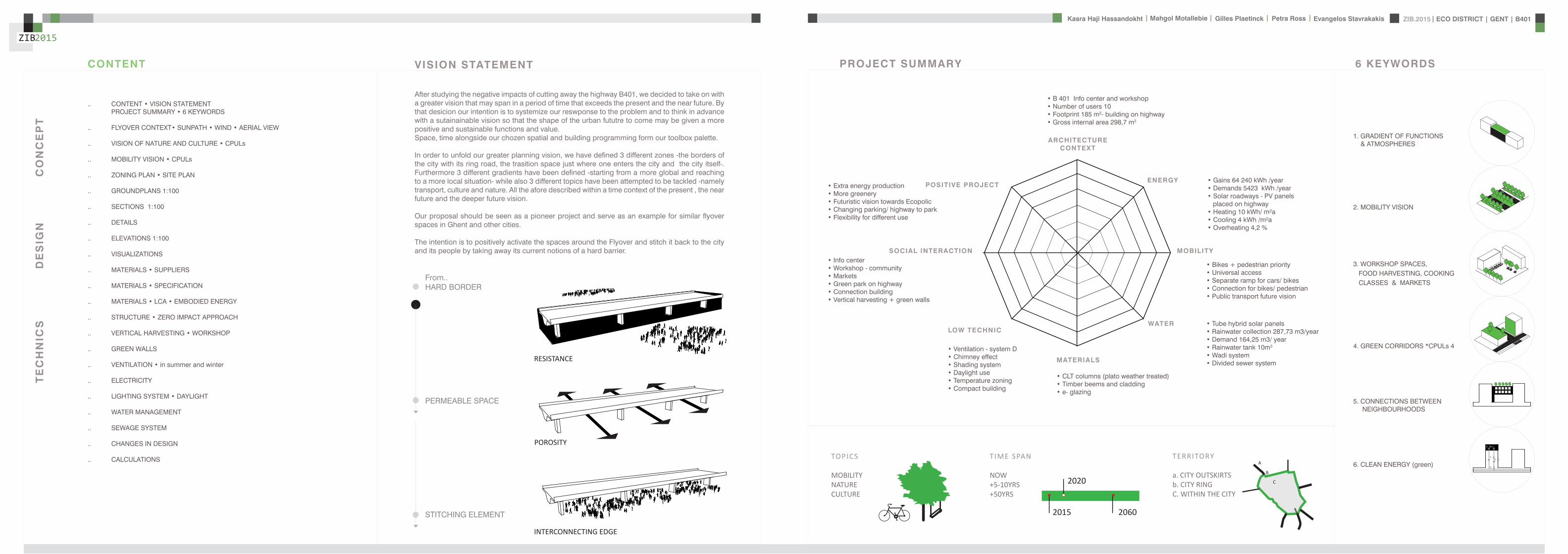
ZIB2015 ECO DISTRICT | GENT | B401Evangelos Stavrakakis | Petra Ross | Mahgol Motallebie | Gilles Plaetinck | Kasra Haji Hassandokht
ZIB2015
|
TERRITORY
a CITY OUTSKIRTSb CITY RINGC WITHIN THE CITY
A
B
C
TIME SPAN
NOW+5-10YRS+50YRS
2015
2020
2060
TOPICS
MOBILITYNATURECULTURE
After studying the negative impacts of cutting away the highway B401 we decided to take on with a greater vision that may span in a period of time that exceeds the present and the near future By that desicion our intention is to systemize our reswponse to the problem and to think in advance with a sutainainable vision so that the shape of the urban fututre to come may be given a more positive and sustainable functions and value Space time alongside our chozen spatial and building programming form our toolbox palette
In order to unfold our greater planning vision we have defined 3 different zones -the borders of the city with its ring road the trasition space just where one enters the city and the city itself- Furthermore 3 different gradients have been defined -starting from a more global and reaching to a more local situation- while also 3 different topics have been attempted to be tackled -namely transport culture and nature All the afore described within a time context of the present the near future and the deeper future vision
Our proposal should be seen as a pioneer project and serve as an example for similar flyover spaces in Ghent and other cities
The intention is to positively activate the spaces around the Flyover and stitch it back to the city and its people by taking away its current notions of a hard barrier
FromHARD BORDER
PERMEABLE SPACE
STITCHING ELEMENT
VISION STATEMENT
RESISTANCE
POROSITY
INTERCONNECTING EDGE
FLYOVER AS AN INTERCONNECTING EDGE
CONTENTbullVISIONSTATEMENT PROJECTSUMMARYbull6KEYWORDS
FLYOVERCONTEXTbullSUNPATHbullWINDbullAERIALVIEW
VISIONOFNATUREANDCULTUREbullCPULs
MOBILITYVISIONbullCPULs
ZONINGPLANbullSITEPLAN
GROUNDPLANS1100
SECTIONS1100
DETAILS
ELEVATIONS1100
VISUALIZATIONS
MATERIALSbullSUPPLIERS
MATERIALSbullSPECIFICATION
MATERIALSbullLCAbullEMBODIEDENERGY
STRUCTUREbullZEROIMPACTAPPROACH
VERTICALHARVESTINGbullWORKSHOP
GREENWALLS
VENTILATIONbullinsummerandwinter
ELECTRICITY
LIGHTINGSYSTEMbullDAYLIGHT
WATERMANAGEMENT
SEWAGESYSTEM
CHANGESINDESIGN
CALCULATIONS
CONTENT
40
30
90
70
1 GRADIENT OF FUNCTIONS amp ATMOSPHERES
2 MOBILITY VISION
3 WORKSHOP SPACES FOOD HARVESTING COOKING CLASSES amp MARKETS
4 GREEN CORRIDORS CPULs 4
5 CONNECTIONS BETWEEN NEIGHBOURHOODS
6 CLEAN ENERGY (green)
6 KEYWORDSPROJECT SUMMARY
CO
NC
EP
TD
ES
IGN
TE
CH
NIC
S
ENERGY
MOBILITY
WATER
MATERIALS
LOW TECHNIC
SOCIAL INTERACTION
POSITIVE PROJECT
ARCHITECTURECONTEXT
bull B 401 Info center and workshopbull Number of users 10bull Footprint 185 m2- building on highwaybull Gross internal area 2987 m2
bull Gains 64 240 kWh yearbull Demands 5423 kWh yearbull Solar roadways - PV panels placed on highwaybull Heating 10 kWh msup2abull Cooling 4 kWh msup2abull Overheating 42
bull Tube hybrid solar panelsbull Rainwater collection 28773 m3yearbull Demand 16425 m3 yearbull Rainwater tank 10m3
bull Wadi systembull Divided sewer system
bull CLT columns (plato weather treated)bull Timber beems and claddingbull e- glazing
bull Ventilation - system Dbull Chimney effectbull Shading systembull Daylight usebull Temperature zoningbull Compact building
bull Bikes + pedestrian prioritybull Universal accessbull Separate ramp for cars bikesbull Connection for bikes pedestrianbull Public transport future vision
bull Info centerbull Workshop - communitybull Marketsbull Green park on highwaybull Connection buildingbull Vertical harvesting + green walls
bull Extra energy productionbull More greenerybull Futuristic vision towards Ecopolicbull Changing parking highway to parkbull Flexibility for different use
ZIB2015 ECO DISTRICT | GENT | B401Evangelos Stavrakakis | Petra Ross | Mahgol Motallebie | Gilles Plaetinck | Kasra Haji Hassandokht
ZIB2015
|
STEREGRAPHIC PROJECTION SUNPATH WIND DIRECTION DISTRIBUTION IN ()
B 401 FLYOVER middot CONTEXT
BELGIUM FLANDERS
Aalst Brussels
Sint Niklaas Antwerp
Kortrijk
Brugge
Maldegem
GHENT
GHENT
SIT
UA
TIO
N A
T L
OC
AT
ION
O
N J
UN
E 2
1
CU
RR
EN
T
DE
CE
MB
ER
21
AERIAL VIEW - LOCATION
ZIB2015 ECO DISTRICT | GENT | B401Evangelos Stavrakakis | Petra Ross | Mahgol Motallebie | Gilles Plaetinck | Kasra Haji Hassandokht
ZIB2015
|
VISION OF NATURE AND CULTURE
CURRENT SITUATION
CURRENT SITUATION FUTURE+5-10YRS
Section B-Bacute
Section A-Aacute
Section B-Bacute
Section A-Aacute
Continuous productive urban landscapes [within] cities
A-Aacuteacute B-Bacute C-Cacute
FUTURE+5-10YRS
CPULc
A vision and a strategy for the 21st century for the city to be green A healthy place for all where zero net pollution is genberated CPULs as a strategy aims towards bringing the -Natural- back to the city and through this to engage people and neighborhoods in positive activities Whether for the city the neighborhood their family or themselves this objective may capacitate a broad number of parallel activities programs and motivation for a healthy urban environment CPULs is simply taking back that for which we usually travel good distances as an -escape means- of the city and its negative side effects
ZIB2015 ECO DISTRICT | GENT | B401Evangelos Stavrakakis | Petra Ross | Mahgol Motallebie | Gilles Plaetinck | Kasra Haji Hassandokht
ZIB2015
|
A BETWEEN CITIES B CITY RING
PUBLIC
PRIVATE
SUPPLY
PSKYtranel
PSKYtrangoogleCar
googleCar
P
cambio
SKYtran
minimized night
ONEwheel
eltram
C INSIDE THE CITY
tram
SKY TRANGOING DOWN TO RING
INTERCHANGE SPOT
euro
life
sty
le c
ha
ng
e o
ve
r ti
me
15 min
90 min
PREVENT COMMUTINGMORE LOCAL LIFESTYLE
A
B
C
sophisticated apps
SHAREWAY
INTERVENTION IN TIME CURRENT SITUATION ON CITY RING SKYTRAN MOBILITY - PASSIVE MAGLEV TECHNOLOGY
NOW
+ 5-10YRS
+ 50YRS
SPEED VISION
A between cities
B city ring
C inside the city
SK
YT
RA
N
GO
OG
LE
CA
R
ON
EW
HE
EL
PASSIVE MAGLEV REQUIRES VERY LIT-TLE ENERGY AND ONLY MINOR INFRA-STRUCTURE LEADING TO THE LOW-EST COST TRANSPORTATION SYSTEM KNOWN TO MAN
ACTIVE MALEV RQUIRES HIGH ENERGY AND MASSIVE INFRA-STRUCTURE LEADING TO HIGH COSTS AS WELL
Section C-Cacute
FUTURISTIC VISION
BICYCLE UNDERGROUND PARKING
SKYtran
MOBILITY VISION
ZIB2015 ECO DISTRICT | GENT | B401Evangelos Stavrakakis | Petra Ross | Mahgol Motallebie | Gilles Plaetinck | Kasra Haji Hassandokht
ZIB2015
|
SITE PLAN
OUTTER CITY RINGINTEREVENTION LOCATIONTOWARDS THE CITY CENTRE
ZONE A SPORT AND CULTURE Pi ZONE C TRANSPORT TRANSITIONZONE B INFO AND WORKSHOP
TOP OF THE FLYOVER PARK AND ENERGY
TRANSPORT
bikespedestrian ramp
elevated park
ramp for cars in 2 directionsbus
tram
ECO QUATER
ZIB
drawing over existing situation
roundabout+ underpass
OFFICE PARK
EDUCATION
EDUCATION
HOUSING FLATS
HOUSING
HOUSING
ECO CITY GHENT
0 50 100 200
HOUSING FLATSOFFICE PARK
COMMERCE
HOUSING
HOUSING
0 10 50 100
P
P
P
PEDESTRIANCYCLE ROADS
P
i
PLAY TRAILS
ALLOTMENTS
PEDESTRIAN CYCLE RAMP
RAMP FOR CARS
ZIB
ZONING PLAN
ZIB2015 ECO DISTRICT | GENT | B401Evangelos Stavrakakis | Petra Ross | Mahgol Motallebie | Gilles Plaetinck | Kasra Haji Hassandokht
ZIB2015
|
GROUNDPLANS 1100
B-Bacute
A-Aacute
B-Bacute
A-Aacute
B-Bacute
A-Aacute
B-Bacute
A-Aacute
ZIB2015 ECO DISTRICT | GENT | B401Evangelos Stavrakakis | Petra Ross | Mahgol Motallebie | Gilles Plaetinck | Kasra Haji Hassandokht
ZIB2015
|
SECTIONS 1100
Section A-AacuteSection B-Bacute
AArsquo
AArsquo
Detai l 01
Detai l 02
Detai l 03
Detai l 04
Detai l 05
Detai l 06
ZIB2015 ECO DISTRICT | GENT | B401Evangelos Stavrakakis | Petra Ross | Mahgol Motallebie | Gilles Plaetinck | Kasra Haji Hassandokht
ZIB2015
|
DETAILS
DETAIL 01 DETAIL 02 DETAIL 03 DETAIL 04 DETAIL 05 DETAIL 06
AArsquo
PIR f loorGypsum plasterboardPIR 100 mmOSB 15 mmFJI beam cel lu lose 350 mmcel i t 4D woodf iber 18 mmfinish gypsum plasterboard
plato wood f in ishframework 30 mmcel i t 4D 18 mmwood structure SLS 38140Eurowal l 2x70 mmOSB Eurothane G 70 mmfinish gypsum plasterboard
ZIB2015 ECO DISTRICT | GENT | B401Evangelos Stavrakakis | Petra Ross | Mahgol Motallebie | Gilles Plaetinck | Kasra Haji Hassandokht
ZIB2015
|
ELEVATIONS 1100
South elevation
South Elevation
North Elevation
South Elevation
North Elevation
South Elevation
North Elevation
South Elevation
North Elevation
North elevation
ZIB2015 ECO DISTRICT | GENT | B401Evangelos Stavrakakis | Petra Ross | Mahgol Motallebie | Gilles Plaetinck | Kasra Haji Hassandokht
ZIB2015
|
VISUALIZATIONS
East Elevation
West Elevation
East Elevation
West Elevation
East Elevation
West Elevation East Elevation
West Elevation
ELEVATIONS 1100
West elevation East elevation
ZIB2015 ECO DISTRICT | GENT | B401Evangelos Stavrakakis | Petra Ross | Mahgol Motallebie | Gilles Plaetinck | Kasra Haji Hassandokht
ZIB2015
|
VISUALIZATIONS
ZIB2015 ECO DISTRICT | GENT | B401Evangelos Stavrakakis | Petra Ross | Mahgol Motallebie | Gilles Plaetinck | Kasra Haji Hassandokht
ZIB2015
|
MATERIALS WOOD FCS Certi f ied Suppliers Distance MATERIALS Building Structure
ZIB2015 ECO DISTRICT | GENT | B401Evangelos Stavrakakis | Petra Ross | Mahgol Motallebie | Gilles Plaetinck | Kasra Haji Hassandokht
ZIB2015
|
MATERIALS Specs InsulationMATERIALS Specs Solid amp Structural Wood
ZIB2015 ECO DISTRICT | GENT | B401Evangelos Stavrakakis | Petra Ross | Mahgol Motallebie | Gilles Plaetinck | Kasra Haji Hassandokht
ZIB2015
|
MATERIALS Life Cycle Assesment MATERIALS Embodied energy CO2 other materials
ZIB2015 ECO DISTRICT | GENT | B401Evangelos Stavrakakis | Petra Ross | Mahgol Motallebie | Gilles Plaetinck | Kasra Haji Hassandokht
ZIB2015
|
STRUCTURE
Gilles Plaetinck
schaal
ZIB BUILDINGEnter address here
7 _ Unnamed
Owner
begeleider Checker
3D Copy 11 Gilles Plaetinck
schaal
ZIB BUILDINGEnter address here
8 _ Unnamed
Owner
begeleider Checker
3D Copy 21
Gilles Plaetinck
schaal
ZIB BUILDINGEnter address here
8 _ Unnamed
Owner
begeleider Checker
3D Copy 31
Gilles Plaetinck
schaal
ZIB BUILDINGEnter address here
9 _ Unnamed
Owner
begeleider Checker3D Copy 4
1
ECONOMY - USIBILITY DURING THE DAY
i1000
ALWAYS
2000
ECONONY - USIBILITY DURING THE DAY
GENERAL PRINCIPLES OF THE BUILDING
ZERO IMPACT APPROACH
i
0 Food market in park Vertical harvesting Entrance
1 Workshop area technical room
2 Info center Entrance from highway
3 Roof terrace
ZIB2015 ECO DISTRICT | GENT | B401Evangelos Stavrakakis | Petra Ross | Mahgol Motallebie | Gilles Plaetinck | Kasra Haji Hassandokht
ZIB2015
|
Vertical Harvest places plants on carousels that keep them moving the length of the greenhouse giving them equal time in natural light and also al-lowing workers to pick and tand transfer the crops Using hydroponics Verti-cal Harvest will be capa-ble of producing over
Vertical Harvest places plants on carousels that keep them moving the length of the pulls giving them equal time in natu-ral light and also allowing workers and local people to pick and transfer the crops Using hydroponics Vertical Harvest will be capable of producing over greens and herbs
Vertical Harvest places plants on carousels that keep them moving the length of the greenhouse giving them equal time in natural light and also al-lowing workers to pick and tand transfer the crops Using hydroponics Verti-cal Harvest will be capa-ble of producing over
Vertical Harvest places plants on carousels that keep them moving the length of the pulls giving them equal time in natu-ral light and also allowing workers and local people to pick and transfer the crops Using hydroponics Vertical Harvest will be capable of producing over greens and herbs
VERTICAL HARVESTING
PLANT CABLE LIFT (PLC) SECTION
Sustainable Food zorkshop centerrsquos mission is to ldquocultivate a healthy community by strengthening the local food system and improving access to nu-tritious affordable foodrdquo The main goal of our design is to deliver skills and information for sus-tainability practioners in the organic food tradeThe program attempts to1) affect positive changes in shopping cooking eating habits and nutrition2) reduce diet-related diseases3) promote the health and development of young children 4) place emphasis on local seasonal and cultural-ly-appropriate foods5) integrate food systems concepts into its curric-ulumndash such as shopping at farmers markets and growing onersquos own food
Healthy food is a basic human right the ability to access healthy food is often related to multiple issues and not just a result of low income
FOOD TEAM = a group of people from the same neighbourhood who work for the direct purchase of regional and seasonal products They order food on internet via web page voedselteambe and it is then delivered once a week to the depot of a team
+ minimal transport requirements+ no returnable packaging+ fair p+ fair pricing+ high-quality local and seasonal food+ community initiative
Sustainable Food zorkshop centerrsquos mission is to ldquocultivate a healthy community by strengthening the local food system and improving access to nu-tritious affordable foodrdquo The main goal of our design is to deliver skills and information for sus-tainability practioners in the organic food tradeThe program attempts to1) affect positive changes in shopping cooking eating habits and nutrition2) reduce diet-related diseases3) promote the health and development of young children 4) place emphasis on local seasonal and cultural-ly-appropriate foods5) integrate food systems concepts into its curric-ulumndash such as shopping at farmers markets and growing onersquos own food
Healthy food is a basic human right the ability to access healthy food is often related to multiple issues and not just a result of low income
FOOD TEAM = a group of people from the same neighbourhood who work for the direct purchase of regional and seasonal products They order food on internet via web page voedselteambe and it is then delivered once a week to the depot of a team
+ minimal transport requirements+ no returnable packaging+ fair p+ fair pricing+ high-quality local and seasonal food+ community initiative
Sustainable Food zorkshop centerrsquos mission is to ldquocultivate a healthy community by strengthening the local food system and improving access to nu-tritious affordable foodrdquo The main goal of our design is to deliver skills and information for sus-tainability practioners in the organic food tradeThe program attempts to1) affect positive changes in shopping cooking eating habits and nutrition2) reduce diet-related diseases3) promote the health and development of young children 4) place emphasis on local seasonal and cultural-ly-appropriate foods5) integrate food systems concepts into its curric-ulumndash such as shopping at farmers markets and growing onersquos own food
Healthy food is a basic human right the ability to access healthy food is often related to multiple issues and not just a result of low income
FOOD TEAM = a group of people from the same neighbourhood who work for the direct purchase of regional and seasonal products They order food on internet via web page voedselteambe and it is then delivered once a week to the depot of a team
+ minimal transport requirements+ no returnable packaging+ fair p+ fair pricing+ high-quality local and seasonal food+ community initiative
Healthy food is a basic human right the ability to access healthy food is often related to multiple issues and not just a result of low income
Sustainable Food zorkshop centerrsquos mission is to ldquocultivate a healthy community by strengthening the local food system and improving access to nutritious affordable foodrdquo The main goal of our design is to deliver skills and information for sustainability practioners in the organic food tradeThe program attempts to
1) affect positive changes in shopping cookingeating habits and nutrition2) reduce diet-related diseases3) promote the health and development of youngchildren4) place emphasis on local seasonal and culturally-appropriate foods5) integrate food systems concepts into its curriculumndashsuch as shopping at farmers markets andgrowing onersquos own food
FOOD TEAM = a group of people from the same neighbourhood who work for the direct purchase of regional and seasonal products They order food on internet via web page voedselteambe and it is then delivered once a week to the depot of a team
+ minimal transport requirements+ no returnable packaging+ fair pricing+ high-quality local and seasonal food+ community initiative
WORKSHOP
ZIB2015 ECO DISTRICT | GENT | B401Evangelos Stavrakakis | Petra Ross | Mahgol Motallebie | Gilles Plaetinck | Kasra Haji Hassandokht
ZIB2015
|
Black coral pea
Factors should be considered when seleccng plants
- Quality of growth- Ability to adapt to the wall environment- Environmental Tolerances- Temperature Resistance- Drought Tolerance- Wind - Wind Tolerance- Solar Exposure Tolerance- Salt Tolerance in Seaside installacons- Air and Water Pollucon Tolerance- Pest and Disease Resistance- Arcficial Environment Tolerance- Transplantacon Tolerance- Pruning - Pruning Tolerance
- Ornamental Qualices- Design Purpose- Manageability Maintainability- Environmental and Societal Effects- Visual Effect- Feeling Effect
Blac
k co
ral p
eaSn
ake
vine
kidn
ey w
eed
purple coral peaBasil
Pandorea
Black coral pea
Factors should be considered when seleccng plants
- Quality of growth- Ability to adapt to the wall environment- Environmental Tolerances- Temperature Resistance- Drought Tolerance- Wind - Wind Tolerance- Solar Exposure Tolerance- Salt Tolerance in Seaside installacons- Air and Water Pollucon Tolerance- Pest and Disease Resistance- Arcficial Environment Tolerance- Transplantacon Tolerance- Pruning - Pruning Tolerance
- Ornamental Qualices- Design Purpose- Manageability Maintainability- Environmental and Societal Effects- Visual Effect- Feeling Effect
Blac
k co
ral p
eaSn
ake
vine
kidn
ey w
eed
purple coral peaBasil
Pandorea
Black coral pea
Factors should be considered when seleccng plants
- Quality of growth- Ability to adapt to the wall environment- Environmental Tolerances- Temperature Resistance- Drought Tolerance- Wind - Wind Tolerance- Solar Exposure Tolerance- Salt Tolerance in Seaside installacons- Air and Water Pollucon Tolerance- Pest and Disease Resistance- Arcficial Environment Tolerance- Transplantacon Tolerance- Pruning - Pruning Tolerance
- Ornamental Qualices- Design Purpose- Manageability Maintainability- Environmental and Societal Effects- Visual Effect- Feeling Effect
Blac
k co
ral p
eaSn
ake
vine
kidn
ey w
eed
purple coral peaBasil
Pandorea
GREEN WALLS
ZIB2015 ECO DISTRICT | GENT | B401Evangelos Stavrakakis | Petra Ross | Mahgol Motallebie | Gilles Plaetinck | Kasra Haji Hassandokht
ZIB2015
|
Extraction of air
Pulsion of airRecuperation unit
outdoor space
18 degC15 degC
18 degC
In-take Out-take of air
VENTILATION
Gilles Plaetinck
schaal 1 100
ZIB BUILDINGEnter address here
3 _ level 2
Owner
begeleider Checker
DN
Gilles Plaetinck
schaal 1 100
ZIB BUILDINGEnter address here
2 _ level 1
Owner
begeleider Checker
Extraction of air
Pulsion of air
VENTILATION IN GROUPLANS CALCULATION AND SYSTEM
level 01
level 02
T 42ECO DISTRICT | GENT | B401
ZIB2015Mechanical Ventilation with Heat Recovery (MVHR)
Up to 95 of the heat can be recovered The Heat Recovery Unit runs continu-ously on trickle and can and is boosted when higher rates of ventilation are required eg bathing cooking In warmer months a summer by-pass function helps ensure comfort levels are maintained in the home When summer by-pass is activated the dwelling contin-ues to be ventilaated and recieve fresh filtered air however the heat recovery process is intermittently switched off (heat recovery is by-passed)
Key BenefitsYear round removal of condensation and indoor pol-lutants A direct impact on the Dwelling Emission Rate re-quired in SAP helping reduce the carbon footprint of the property Fresh filtered air supplied to dwelling ideal for allergy sufferers and those with conditions such as asthma A balanced ventilation system for the whole house and recovering of heat that would have otherwise have been lost Low noise non-intrusive ventilation system ndash located away from the room however consideration should be given to duct runs to ensure cross-talk contamination doesnrsquot happen AND the unit is sized correctly so it is not running a high rate all of the time
Zehnder ComfoSystems Passive Haus accredited product suitable for large houses up to 300m2 Designed to ensure low noise excellent energy performance and heat exchange efficiency Choice of control options including LCD touch screen display Can be combine with ComfoCool for optional cooling of up to 5 degrees and humidity reduction by 20
Semi Rigid Ducting
With a manifold system the resistance caused by duct-ing is reduced therefore Semi-Rigid ducting resistance is very low The manifold takes mass airflow directly from the MVHR Heat Recovery Unit and allows lower rates to pass through to each individual room runDirecting mass flow to the manifold eliminates the need to increase the running speed of the MVHR Heat Re-covery unit to overcome the resistance of ducting which in turn causes noise for the homeowner
T 42ECO DISTRICT | GENT | B401
ZIB2015Mechanical Ventilation with Heat Recovery (MVHR)
Up to 95 of the heat can be recovered The Heat Recovery Unit runs continu-ously on trickle and can and is boosted when higher rates of ventilation are required eg bathing cooking In warmer months a summer by-pass function helps ensure comfort levels are maintained in the home When summer by-pass is activated the dwelling contin-ues to be ventilaated and recieve fresh filtered air however the heat recovery process is intermittently switched off (heat recovery is by-passed)
Key BenefitsYear round removal of condensation and indoor pol-lutants A direct impact on the Dwelling Emission Rate re-quired in SAP helping reduce the carbon footprint of the property Fresh filtered air supplied to dwelling ideal for allergy sufferers and those with conditions such as asthma A balanced ventilation system for the whole house and recovering of heat that would have otherwise have been lost Low noise non-intrusive ventilation system ndash located away from the room however consideration should be given to duct runs to ensure cross-talk contamination doesnrsquot happen AND the unit is sized correctly so it is not running a high rate all of the time
Zehnder ComfoSystems Passive Haus accredited product suitable for large houses up to 300m2 Designed to ensure low noise excellent energy performance and heat exchange efficiency Choice of control options including LCD touch screen display Can be combine with ComfoCool for optional cooling of up to 5 degrees and humidity reduction by 20
Semi Rigid Ducting
With a manifold system the resistance caused by duct-ing is reduced therefore Semi-Rigid ducting resistance is very low The manifold takes mass airflow directly from the MVHR Heat Recovery Unit and allows lower rates to pass through to each individual room runDirecting mass flow to the manifold eliminates the need to increase the running speed of the MVHR Heat Re-covery unit to overcome the resistance of ducting which in turn causes noise for the homeowner
MECHANICAL VENTILATION WITH HEAT RECOVERY (MVHR)
Up to 95 of the heat can be recoveredThe Heat Recovery Unit runs continuously on trickle and can and is boosted when higher rates of ventilation are required eg bathing cooking
In warmer months a summer by-pass function helps ensure comfort levels are maintained in the home When summer by-pass is activated the dwelling continues to be ventilaated and recieve fresh filtered air however the heat recovery process is intermittently switched off (heat recovery is by-passed)
EXTRACT VENTILATION RATES
T 42ECO DISTRICT | GENT | B401
ZIB2015Mechanical Ventilation with Heat Recovery (MVHR)
Up to 95 of the heat can be recovered The Heat Recovery Unit runs continu-ously on trickle and can and is boosted when higher rates of ventilation are required eg bathing cooking In warmer months a summer by-pass function helps ensure comfort levels are maintained in the home When summer by-pass is activated the dwelling contin-ues to be ventilaated and recieve fresh filtered air however the heat recovery process is intermittently switched off (heat recovery is by-passed)
Key BenefitsYear round removal of condensation and indoor pol-lutants A direct impact on the Dwelling Emission Rate re-quired in SAP helping reduce the carbon footprint of the property Fresh filtered air supplied to dwelling ideal for allergy sufferers and those with conditions such as asthma A balanced ventilation system for the whole house and recovering of heat that would have otherwise have been lost Low noise non-intrusive ventilation system ndash located away from the room however consideration should be given to duct runs to ensure cross-talk contamination doesnrsquot happen AND the unit is sized correctly so it is not running a high rate all of the time
Zehnder ComfoSystems Passive Haus accredited product suitable for large houses up to 300m2 Designed to ensure low noise excellent energy performance and heat exchange efficiency Choice of control options including LCD touch screen display Can be combine with ComfoCool for optional cooling of up to 5 degrees and humidity reduction by 20
Semi Rigid Ducting
With a manifold system the resistance caused by duct-ing is reduced therefore Semi-Rigid ducting resistance is very low The manifold takes mass airflow directly from the MVHR Heat Recovery Unit and allows lower rates to pass through to each individual room runDirecting mass flow to the manifold eliminates the need to increase the running speed of the MVHR Heat Re-covery unit to overcome the resistance of ducting which in turn causes noise for the homeowner
T 42ECO DISTRICT | GENT | B401
ZIB2015Mechanical Ventilation with Heat Recovery (MVHR)
Up to 95 of the heat can be recovered The Heat Recovery Unit runs continu-ously on trickle and can and is boosted when higher rates of ventilation are required eg bathing cooking In warmer months a summer by-pass function helps ensure comfort levels are maintained in the home When summer by-pass is activated the dwelling contin-ues to be ventilaated and recieve fresh filtered air however the heat recovery process is intermittently switched off (heat recovery is by-passed)
Key BenefitsYear round removal of condensation and indoor pol-lutants A direct impact on the Dwelling Emission Rate re-quired in SAP helping reduce the carbon footprint of the property Fresh filtered air supplied to dwelling ideal for allergy sufferers and those with conditions such as asthma A balanced ventilation system for the whole house and recovering of heat that would have otherwise have been lost Low noise non-intrusive ventilation system ndash located away from the room however consideration should be given to duct runs to ensure cross-talk contamination doesnrsquot happen AND the unit is sized correctly so it is not running a high rate all of the time
Zehnder ComfoSystems Passive Haus accredited product suitable for large houses up to 300m2 Designed to ensure low noise excellent energy performance and heat exchange efficiency Choice of control options including LCD touch screen display Can be combine with ComfoCool for optional cooling of up to 5 degrees and humidity reduction by 20
Semi Rigid Ducting
With a manifold system the resistance caused by duct-ing is reduced therefore Semi-Rigid ducting resistance is very low The manifold takes mass airflow directly from the MVHR Heat Recovery Unit and allows lower rates to pass through to each individual room runDirecting mass flow to the manifold eliminates the need to increase the running speed of the MVHR Heat Re-covery unit to overcome the resistance of ducting which in turn causes noise for the homeowner
Heating 10 kwh msup2aCooling 4 kWh msup2aOverheating 42
ZIB2015 ECO DISTRICT | GENT | B401Evangelos Stavrakakis | Petra Ross | Mahgol Motallebie | Gilles Plaetinck | Kasra Haji Hassandokht
ZIB2015
|
Shutters control system+ -
Solar roadways - PV panels
LED lights
Elevator Fuse box
ElectricityBattery withtransformator
ELECTRICITY
Summer night
cross- ventilation through building
Summer day
air through recuperation unit small change of temperature
15 degC 18 degC
+ groundplans
heated zone
not heated zone
ZONING ACCORDING TO TEMPERATURESSUMMER NIGHT - cross-ventilation through building
SUMMER DAY - air through recuperation unit small change of temperatureSHADING SYSTEM
As a shading was chozen system Renson Icarus Lamellas with angle 45deg made in wood
ZIB2015 ECO DISTRICT | GENT | B401Evangelos Stavrakakis | Petra Ross | Mahgol Motallebie | Gilles Plaetinck | Kasra Haji Hassandokht
ZIB2015
|
average only 4 hours of peak daylight hours per day (4 x 365 = 1460 hours per year)
- Surface area ( first part) Fly-over +- 20 000 msup2-gt 16 000 x 230 Watt = 3 680 000 Watt or 3680 kWonly 50 of fly-over covered with solar roadways
-gt 3680 kW x 4 h = 7360 kWh day-gt 3680 kW x 1460 h = 2 686 400 kWh year -gt +- 540 households (+- 5000 kWh year)
Tesla Powerwall Therersquos a 10 kWh unit at $3500 -gt 737 Tesla Batteries
gt the Solar Roadway has the ability to cut greenhouse gases by up to 75-percentgt A decentralized self-healing secure power grid
IN FRONT OF FLY-OVER
- Surface area Fly-over = 16 x 30 m = 480 msup2-gt 384 x 230 Watt = 88 320 Watt or 883 kWonly 50 of fly-over covered with solar roadways
-gt 44 kW x 4 h = 176 kWh day-gt 44 kW x 1460 h = 64 240 kWh year -gt +- 13 households (+- 5000 kWh year)
lightsshutters
elevator
2 fridges
2 coffeemakers
1 microwave
1 owen
2 cooking plates
stereo
ventilation unit
electricity transformer (AC to DC) for PV panels + batteries
summer 05 kWh daywinter 03 kWh day183 days x 05= 915 kWh182 days x 03 = 546 kWh = 1641 kWh
262 kWh
A++fridge 104 kWhyear104 x x2 = 208 kWh
900 W x 01 hours day = 09 kWhx 220 days x 2= 198 kWh a
67 kWh a
085x100 days= 85 kWh a
400 kWh x 2 = 800 kWh a
150 kWh a 419 kWha
68 kWh a
ENERGY DEMAND OVERVIEW ENERGY SUPPLY OVERVIEW - FLY-OVER
1 spot 56 W 10000 = 0056 KW4 hours per day 365 days a year = 1460 h0056 x 1460 = 8176 kWh10 spots x 8176= 8176 kWh a
1 spot 72 W 10000 = 0072 KW4 hours per day 365 days a year = 1460 h0072 x 1460 = 10512 kWh5 spots x 10512= 5256 kWh a
1 spot 52 W 10000 = 0052 KW4 hours per day 365 days a year = 1460 h0052 x 1460 = 7592 kWh21 spots x 7592= 159432 kWh a
1 spot 9 W 10000 = 0009 KW4 hours per day 365 days a year = 1460 h0009 x 1460 = 1314 kWh5 spots x 1314 = 657 kWh a
SOLAR ROADWAYS - PV PANELSEnergy from the sun
1 To generate energy for the ZIB building2 To generate energy for the surrounding houses3 To generate energy for lighting or signs on the road4 The panels will also have the capacity to charge electric vehicles while parked
ELECTRICITY SCHEME
5423 kWh a
ZIB2015 ECO DISTRICT | GENT | B401Evangelos Stavrakakis | Petra Ross | Mahgol Motallebie | Gilles Plaetinck | Kasra Haji Hassandokht
ZIB2015
|
SUMMER SUNNY 10-42 LUXWINTER SUNNY 10-42 LUX
DAYLIGHT - DIALuxLIGHTING SYSTEM - DIALux
Workplane 9 Results overview
Height of working plane 0800 m Wall zone 0000 m
Result Mean (target) Min Max Minaverage MinmaxPerpendicular illuminance [lx] 463 (500) 105 689 0227 0152
Profile Offices Writing typewriting reading data processing
B401-Gent 6222015
Site 1 Building 2 Zib Room 9 Workplane 9 Results overview
Page 70
Workplane 9 False coloursPerpendicular illuminance (adaptive)
Scale 1 200
Perpendicular illuminance (Surface)Mean (actual) 463 lx Min 105 lx Max 689 lx Minaverage 0227 Minmax 0152
B401-Gent 6222015
Site 1 Building 2 Zib Room 9 Workplane 9 False coloursPerpendicular illuminance (adaptive)
Page 72
Workplane 9 Value chartPerpendicular illuminance (adaptive)
Scale 1 200
Perpendicular illuminance (Surface)Mean (actual) 463 lx Min 105 lx Max 689 lx Minaverage 0227 Minmax 0152
B401-Gent 6222015
Site 1 Building 2 Zib Room 9 Workplane 9 Value chartPerpendicular illuminance (adaptive)
Page 73
Workplane 13 Results overview
Height of working plane 0800 m Wall zone 0000 m
Result Mean (target) Min Max Minaverage MinmaxPerpendicular illuminance [lx] 388 (500) 69 732 0178 0094
Profile Offices Writing typewriting reading data processing
B401-Gent 6222015
Site 1 Building 6 Storey 1 Room 13 Workplane 13 Results overview
Page 94
Workplane 13 False coloursPerpendicular illuminance (adaptive)
Scale 1 100
Perpendicular illuminance (Surface)Mean (actual) 388 lx Min 69 lx Max 732 lx Minaverage 0178 Minmax 0094
B401-Gent 6222015
Site 1 Building 6 Storey 1 Room 13 Workplane 13 False coloursPerpendicular illuminance (adaptive)
Page 96
Workplane 13 Value chartPerpendicular illuminance (adaptive)
Scale 1 100
Perpendicular illuminance (Surface)Mean (actual) 388 lx Min 69 lx Max 732 lx Minaverage 0178 Minmax 0094
B401-Gent 6222015
Site 1 Building 6 Storey 1 Room 13 Workplane 13 Value chartPerpendicular illuminance (adaptive)
Page 97
Workplane 9 False coloursPerpendicular illuminance (adaptive)
Scale 1 200
Perpendicular illuminance (Surface)Mean (actual) 463 lx Min 105 lx Max 689 lx Minaverage 0227 Minmax 0152
B401-Gent 6222015
Site 1 Building 2 Zib Room 9 Workplane 9 False coloursPerpendicular illuminance (adaptive)
Page 72
1st f loor 2nd f loor Site 1 Luminaire parts listQuantity Luminaire (Luminous emittance)10 3F Filippi 12736 P 202x24W LED OP 196x1231
Luminous emittance 1Fitting 1x24W 2xLEDLight output ratio 100Lamp luminous flux 5332 lmLuminaire Luminous Flux 5332 lmPower 560 WLight yield 952 lmW
200
300
400
cdklm η = 100C0 - C180 C90 - C270
0deg 15deg 30deg
45deg
60deg
75deg
90deg
105deg105deg
90deg
75deg
60deg
45deg
30deg 15deg 0deg
5 SFN Eclairages 0732360X CLFV 236Luminous emittance 1Fitting 2xT26 36W840Light output ratio 6889Lamp luminous flux 6700 lmLuminaire Luminous Flux 4615 lmPower 720 WLight yield 641 lmW
160
240
cdklm η = 69C0 - C180 C90 - C270
0deg 15deg 30deg
45deg
60deg
75deg
90deg
105deg105deg
90deg
75deg
60deg
45deg
30deg 15deg 0deg
21 SFN Eclairages 332226XX SAM F 2x26W BELuminous emittance 1Fitting 2xTC-DEL 26W840Light output ratio 3297Lamp luminous flux 3600 lmLuminaire Luminous Flux 1187 lmPower 520 WLight yield 228 lmW
40
60
80
100
120
140
cdklm η = 33C0 - C180 C90 - C270
0deg 15deg 30deg
45deg
60deg
75deg
90deg
105deg105deg
90deg
75deg
60deg
45deg
30deg 15deg 0deg
1 Signcomplex AR111-009-AW-W-06 AR111 COB 9W38deg WhiteLuminous emittance 1Fitting 1xAR111-009-AW-W-06Light output ratio 8078Lamp luminous flux 600 lmLuminaire Luminous Flux 485 lmPower 90 WLight yield 539 lmW
800
1200
cdklm η = 81C0 - C180 C90 - C270
0deg 15deg 30deg
45deg
60deg
75deg
90deg
105deg105deg
90deg
75deg
60deg
45deg
30deg 15deg 0deg
Total lamp luminous flux 163020 lm Total luminaire luminous flux 101807 lm Total Load 20210 W Light yield 504 lmW
B401-Gent 6222015
Site 1 Luminaire parts list
Page 19
10x
6x
21x
1x
types of l ights
Perpendicular i l luminance (Surface)Mean (actual ) 463 lx Min 105 lx Max 689 lx Minaverage 0 227 Minmax 0 152
Perpendicular i l luminance (Surface)Mean (actual ) 388 lx Min 69 lx Max 732 lx Minaverage 0 178 Minmax 0 094
ZIB2015 ECO DISTRICT | GENT | B401Evangelos Stavrakakis | Petra Ross | Mahgol Motallebie | Gilles Plaetinck | Kasra Haji Hassandokht
ZIB2015
|
Tube hybrid Solar panels
Hot water tank Water taps
City water supply
Rain water collection for vertical harvesting
City water supply
WADI
Rain water tank
WATER MANAGEMENT
Sinks
Available roof area
In Ghent avarage of 900mmm2year
3197 m2
09x 3197 = 28773 m3year
RAIN WATER GAIN
toilet - 3x - 03lskitchen -4x - 02ls
POTABLE WATER DEMAND
3 toiletsVertical gardening
Total
relative RW usage
300 l day150 l day = 450lday= 16425 m3 year
1407 lday100m2
RAIN WATER DEMAND
RAIN WATER TANK
Relative RWT volumeRain water tank volume
3m3 100 m2
9591 l gt 10 m3
DIMESION OF PIPES
City water supplyRainwater tank
178 mm (DN 18 - 15 - 12)165 mm (DN 17-15)
are composed of hexagonal tiles Rainwater can infiltrate between the gaps from where it goes to rainwatter collector which supplies the vegetation on fly-over
THE SOLAR ROADWAYS
WATER SUPPLY SCHEME AND CALCULATION
ZIB2015 ECO DISTRICT | GENT | B401Evangelos Stavrakakis | Petra Ross | Mahgol Motallebie | Gilles Plaetinck | Kasra Haji Hassandokht
ZIB2015
|
WADI
City water supply
Rain water tank
Sinks
Divided sewer systemwithin building
SEWAGE SYSTEM
ToiletToilet sinkKitchen sink
DU = 2 lsDU = 05 lsDU = 08 ls
WATER DRAINAGE OF DEVICES
Frequency of usage at the same time
K 05
DIMESION OF PIPES
Black waterGrey water
110 mm (DU 110)75 mm (DU 75 - 63)
WATER DRAINAGE SCHEME AND CALCULATION
ZIB2015 ECO DISTRICT | GENT | B401Evangelos Stavrakakis | Petra Ross | Mahgol Motallebie | Gilles Plaetinck | Kasra Haji Hassandokht
ZIB2015
|
DN
Gilles Plaetinck
schaal 1 100
ZIB BUILDINGEnter address here
2 _ level 1
Owner
begeleider Checker
Gilles Plaetinck
schaal 1 100
ZIB BUILDINGEnter address here
3 _ level 2
Owner
begeleider Checker
WATER SUPPLY
HOT WATER
WATER DRAINAGE
WATER SUPPLY AND DRAINAGE IN GROUPLANS
level 01
level 02
ENERGY
RAINWATER TANK
HELOPHYTE FILTER
IRRIGATION SYSTEM
BIO-ROTOR
MICRO TURBINE
PHOSPHOR
In this building a closed water system is applied which is based on reusing water in mullple wasRainRain water from the roof will be collected in a storage tank situated on the ground floor This water will be used to flush the toilet and irrigate crops in verlcal harveslng system In case of an overflow the water will be stored in the con-structed wetland near the building The rainwater can be fil-tered through a helophyte filter up to drinking water stan-dard The waste water system includes three types of water yellyellow black and grey waterThe yellow water will be stored for its phosphor while the black water will be purified into grey water This grey water is comparable to the quality of rain water aaer purificalon b means of a bio rotor The remaining residue from the bio rotor together with the organic waste from the harveslng is fermented into biogas that drives a micro turbine in order to produce some addilonal energy
TheThe waste product deriving from this process will be used as compost in verlcal harveslng This efficient yet complex system closes the ullizalon cycle of the building and turns it into an efficient vicious circle that can be considered au arkic
In this building a closed water system is applied which is based on reusing water in multiple was
Rain water from the roof will be collected in a storage tank situated on the ground floor This water will be used to flushthe toilet and irrigate crops in vertical harvesting system In case of an overflow the water will be stored in the constructed wetland near the building The rainwater can be filtered through a helophyte filter up to drinking water standard
The waste water system includes three types of water yellow black and grey water The yellow water will be stored for its phosphor while the black water will be purified into grey water This grey water is comparable to the quality of rain water after purification b means of a bio rotor The remaining residue from the bio rotor together with the organic waste from the harvesting is fermented into biogas that drives a micro turbine in order to produce some additional energy The waste product deriving from this process will be used ascompost in ver1048991cal harves1048991ng This efficient yet complexsystem closes the u1048991liza1048991on cycle of the building and turns itinto an efficient vicious circle that can be considered au arkic
WATER CYCLE
ZIB2015 ECO DISTRICT | GENT | B401Evangelos Stavrakakis | Petra Ross | Mahgol Motallebie | Gilles Plaetinck | Kasra Haji Hassandokht
ZIB2015
|
CALCULATIONS
Passive House verification
Photo or Drawing
Building Workshop + info pointStreet
PostcodeCityCountry
Building Type non-residentialClimate Ukkel
Home Owner(s) Client(s)Street
PostcodeCity
ArchitectStreet
PostcodeCity Calculation electricity Internal heat gains
Mechanical System Building type
StreetPostcodeCity Internal heat gains
Year of Construction 2015 Interior Temperature 200 degC Utilisation pattern
Number of Dwelling Units 1 Internal Heat Gains 20 Wm2 Type of values used Fill in worksheet IHG Non-Dom Enclosed Volume Ve 12442 Planned number of occupants
Number of Occupants 80 8 Design
Specific building demands with reference to the treated floor area use Annual method
Treated floor area 2840 msup2 Requirements Fulfilled Verification Annual method The monthly method should be used for building certification
Space heating Annual heating demand 10 kWh(m2a) 15 kWh(msup2a) yes Specific space heating demand annual method 103 kWh(msup2a)
Heating load 11 Wm2 10 Wmsup2 - Specific space heating demand monthly Method 120 kWh(msup2a)
Space cooling Overall specific space cooling demand kWh(m2a) 15 kWh(msup2a)
Cooling load Wm2 - -Frequency of overheating (gt 25 degC) - -
Primary Energy Space heating and dehumidification
cooling household electricity 73 kWh(m2a) 120 kWh(msup2a) yes
DHW space heating and auxiliary electricity 24 kWh(m2a) - -Specific primary energy reduction through solar electricity 21 kWh(m2a) - -
Airtightness Pressurization test result n50 06 1h 06 1h yes
PHPP Verification FINAL ZIB FILE CALCULTIONS PHPPxls
L B H VOLUME
main 1 226 7 4 6328main 2 184 7 35 4508
core 0 6 2 5 3 5 108 5core 0 62 5 35 1085core 3 62 3 28 521
12442
AREAmain 1 storage 35
wc big 35wc 2wc 2workshop 103
MAIN 2 infolounge 92
staircase 56storage technical 22
284
Floor_exterior 1582 31 1272
Roof_exterior 1582
Passive House verification
Photo or Drawing
Building Workshop + info pointStreet
PostcodeCityCountry
Building Type non-residentialClimate Ukkel
Home Owner(s) Client(s)Street
PostcodeCity
ArchitectStreet
PostcodeCity Calculation electricity Internal heat gains
Mechanical System Building type
StreetPostcodeCity Internal heat gains
Year of Construction 2015 Interior Temperature 200 degC Utilisation pattern
Number of Dwelling Units 1 Internal Heat Gains 20 Wm2 Type of values used Fill in worksheet IHG Non-Dom Enclosed Volume Ve 12442 Planned number of occupants
Number of Occupants 80 8 Design
Specific building demands with reference to the treated floor area use Annual method
Treated floor area 2840 msup2 Requirements Fulfilled Verification Annual method The monthly method should be used for building certification
Space heating Annual heating demand 10 kWh(m2a) 15 kWh(msup2a) yes Specific space heating demand annual method 103 kWh(msup2a)
Heating load 11 Wm2 10 Wmsup2 - Specific space heating demand monthly Method 120 kWh(msup2a)
Space cooling Overall specific space cooling demand kWh(m2a) 15 kWh(msup2a)
Cooling load Wm2 - -Frequency of overheating (gt 25 degC) - -
Primary Energy Space heating and dehumidification
cooling household electricity 73 kWh(m2a) 120 kWh(msup2a) yes
DHW space heating and auxiliary electricity 24 kWh(m2a) - -Specific primary energy reduction through solar electricity 21 kWh(m2a) - -
Airtightness Pressurization test result n50 06 1h 06 1h yes
PHPP Verification FINAL ZIB FILE CALCULTIONS PHPPxls
SURFACE AREAcurrent orientation only night ventilation
current orientation only night ventilation 6 windows less 52 msup2
current orientation only night ventilation 7 windows less 60msup2 (stays the same for each side)
current orientation only night ventilation 8 windows less 69 msup2
orientation turned 90deg only night ventilation 6 windows less 52 msup2
orientation turned 90deg only night ventilation 7 windows less 60msup2 (window less at SE side)
orientation turned 90deg only night ventilation 8 windows less 69 msup2
-gt orientation turned 90deg only night ventilation 9 windows less 77msup2 (window less at NW side althought theres less overheating in the case of a window less at SE side the heating demand exceeds 15)
CHANGE IN DESIGN
ZIB2015 ECO DISTRICT | GENT | B401Evangelos Stavrakakis | Petra Ross | Mahgol Motallebie | Gilles Plaetinck | Kasra Haji Hassandokht
ZIB2015
|
Passive House verificationS P E C I F I C A N N U A L H E A T I N G D E M A N D
Climate Ukkel Interior Temperature 200 degC
Building Workshop + info point Building TypeUse non-residentialTreated Floor Area ATFA 2840 msup2
per msup2Area U-Value Temp Factor ft Gt Treated Data for heating balance diagram
Building Element Temperature Zone msup2 W(msup2K) kKha kWha Floor Area Losses GainsExterior Wall - Ambient A 5595 0101 100 743 = 4181 1472 Exterior Wall - Ambient 147234373Exterior Wall - Ground B 069 = Exterior Wall - GroundRoofCeiling - Ambient A 1550 0094 100 743 = 1085 382 RoofCeiling - Ambient 381903529Floor slab basement ceiling B 310 0105 069 743 = 167 059 Floor slab basement ceiling 058811509
A 100 =A 100 =
unheated basement X 075 = unheated basementWindows A 1154 0648 100 743 = 5562 1958 Windows 195834732Exterior Door A 100 = Exterior DoorExterior TB (lengthm) A 1169 -0030 100 743 = -259 -091 Thermal Bridge Heat LossPerimeter TB (lengthm) P 069 = 000 not useful heat gains 365267499Ground TB (lengthm) B 069 =
Total of All Building Envelope Areas 8609 ndashndashndashndashndashndashndashndashndashndashndashndashndash- kWh(msup2a) Ventilation 395818713
Transmission Heat Losses QT Total 10736 378Annual Heating Demand 102516636
ATFA Clear Room Height internal gains 100951487msup2 m msup3 passive solar gains 250668423
Ventilation System Effective Air Volume VV 2840 280 = 7952 Thermal bridge credit 091126837Effective Heat Recovery Efficiency eff 81 Cross check sum 46324923 46324923of Heat Recovery
Efficiency of Subsoil Heat Exchanger SHX 0 nVsystem HR nVRes
1h 1h 1h
Energetically Effective Air Exchange nV 0105 (1 - 081 ) + 0038 = 0058
VV nV cAir Gt
msup3 1h Wh(msup3K) kKha kWha kWh(msup2a)
Ventilation Heat Losses QV 795 0058 033 743 = 1124 40
Reduction Factor QT QV NightWeekend
kWha kWha Saving kWha kWh(msup2a)
Total Heat Losses QL ( 10736 + 1124 ) 10 = 11860 418
Orientation Reduction Factor g-Value Area Radiation HPof the Area See Windows Sheet (perp radiation)
msup2 kWh(msup2a) kWha
1 North 054 050 2700 163 = 11822 East 058 000 440 197 = 03 South 056 050 4860 314 = 42874 West 032 050 3216 254 = 13275 Horizontal 063 050 324 317 = 323
kWh(msup2a)
Available Solar Heat Gains QS Total 7119 251
Length Heat Period Spec Power qI ATFA
khd da Wmsup2 msup2 kWha kWh(msup2a)
Internal Heat Gains QI 0024 209 201 2840 = 2867 101
kWha kWh(msup2a)
Free Heat QF QS + QI = 9986 352
Ratio of Free Heat to Losses QF QL = 084
Utilisation Factor Heat Gains G (1 - ( QF QL )5 ) (1 - ( QF QL )
6 ) = 90kWha kWh(msup2a)
Heat Gains QG G QF = 8949 315
kWha kWh(msup2a)
Annual Heating Demand QH QL - QG = 2911 10
kWh(msup2a) (YesNo)
Limiting Value 15 Requirement met yes
00
147
00
3806000000
196
00
40
37
09
103
101
251
0
5
10
15
20
25
30
35
40
45
50
Losses Gains
Hea
t flo
ws
[kW
h(m
sup2a)]
Heating energy balance
passive solar gains
internal gains
Annual Heating Demand
Thermal bridge credit
not useful heat gains
Ventilation
Exterior Door
Windows
unheated basement
Floor slab basement ceiling
RoofCeiling - Ambient
Exterior Wall - Ground
Exterior Wall - Ambient
Thermal Bridge Heat Loss
HPP Annual Heating Demand FINAL ZIB FILE CALCULTIONS PHPPxls
Passive House verification Passive House verificationS P E C I F I C U S E F U L C O O L I N G D E M A N D S P E C I F I C U S E F U L C O O L I N G D E M A N D
M O N T H L Y M E T H O D M O N T H L Y M E T H O D
(This page displays the sums of the monthly method over the cooling period))Climate Ukkel Interior Temperature Summer 25 degC Climate Ukkel Interior Temperature 25 degC
Building Workshop + info point Building TypeUse non-residential Building Workshop + info point Building TypeUse non-residential
Spec Capacity 60 Wh(msup2K) (Enter in Summer worksheet) Treated Floor Area ATFA 2840 msup2 Treated Floor Area ATFA 284 msup2
per msup2Temperature Zone Area U-Value Mon Red Fac Gt Treated Jan Feb Mar Apr May Jun Jul Aug Sep Oct Nov Dec Year
Building Element msup2 W(msup2K) kKha kWha Floor Area Heating Degree Hours - Ex 168 150 144 121 92 73 57 59 82 109 140 160 136 kKh1 Exterior Wall - Ambient A 5595 0101 100 103 = 5782 Heating Degree Hours - G 126 123 135 120 106 83 63 54 58 71 86 109 113 kKh2 Exterior Wall - Ground B 100 = Losses - Exterior 2553 2286 2189 1838 1393 1117 871 904 1245 1660 2123 2432 20612 kWh3 RoofCeiling - Ambient A 1550 0094 100 103 = 1500 Losses - Ground 41 40 44 39 35 27 21 18 19 23 28 36 370 kWh4 Floor slab basement ceil B 310 0105 100 90 = 294 Losses Summer Ventilatio 67 71 244 372 629 720 880 865 658 499 234 126 5366 kWh5 A 100 = Sum Spec Heat Losses 94 84 87 79 72 66 62 63 68 77 84 91 928 kWhmsup26 A 100 = Solar Load North 44 81 141 212 286 298 298 255 178 116 54 35 1998 kWh7 unheated basement X 075 = Solar Load East 0 0 0 0 0 0 0 0 0 0 0 0 0 kWh8 Windows A 1154 0648 100 103 = 7690 Solar Load South 218 315 464 577 681 644 681 658 532 416 242 171 5601 kWh9 Exterior Door A 100 = Solar Load West 79 125 213 303 385 378 370 347 256 177 91 60 2785 kWh
10 Exterior TB (lengthm) A 1169 -0030 100 103 = -358 Solar Load Horiz 11 21 37 57 79 79 80 69 47 30 14 9 533 kWh11 Perimeter TB (lengthm) P 100 = Solar Load Opaque 3 5 9 13 18 19 19 16 11 7 3 2 126 kWh12 Ground TB (lengthm) B 100 = Internal Heat Gains 425 384 425 411 425 411 425 425 411 425 411 425 5001 kWh
ndashndashndashndashndashndashndashndashndashndashndash kWh(msup2a) Sum Spec Loads Solar + 28 33 45 55 66 64 66 62 51 41 29 25 565 kWhmsup2
Transmission Losses QT (Negative Heat Loads) Total 14907 525 Utilisation Factor Losses 29 39 52 69 84 88 82 88 73 53 34 27 58Useful Cooling Energy Dem 0 0 4 30 142 192 417 192 40 4 0 0 1021 kWh
ATFA Clear Room Height Spec Cooling Demand 00 00 00 01 05 07 15 07 01 00 00 00 36 kWhmsup2Effective msup2 m msup3
Air Volume VV 284 280 = 795
Heat Transfer Coef Gt
WK kKha kWha kWh(msup2a)
Exterior 99 103 = 1013 36Ground 00 105 = 0 00
Additional Summer Ventilation
Select X Window Night Ventilation Manual Corresponding Air Change Rate 136 1h
Mechanical Automatically Controlled Ventilation (for window ventilation at 1 K temperature difference indoor - outdoor)
Minimum Acceptable Indoor Temperatu 220 degC
kWha kWh(msup2a)
Heat Losses Summer Ventilation 5172 182
QLext QLground QLsummer
kWha kWha kWha kWha kWh(msup2a)
Ventilation Heat Losses QV 1013 + 0 + 5172 = 6185 218
2
3
4
5
6
7
8
9
10
Spec
ific
loss
es l
oads
l c
oolin
g de
man
d [k
Wh
(msup2 m
onth
)] Spec Cooling Demand Sum Spec Heat Losses Sum Spec Loads Solar + Internal
QT QV
kWha kWha kWha kWh(msup2a)
Total Heat Losses QL 14907 + 6185 = 21092 743
Orientation Reduction Factor g-Value Area Global Radiationof the Area (perp radiation)
msup2 kWh(msup2a) kWha
1 North 031 050 270 462 = 19182 East 061 000 44 578 = 0 Temperature Amplitude Summer 82 K3 South 030 050 486 707 = 52114 West 025 050 322 654 = 2646 Month 1 2 3 4 5 6 7 8 9 10 11 12 Annual Total5 Horizontal 035 050 32 913 = 513 Days 31 28 31 30 31 30 31 31 30 31 30 31 3656 Sum Opaque Areas 121 Ambient Temp 250 270 572 828 1275 1487 1737 1707 1369 1039 568 356 96
kWh(msup2a) North Radiation 106 195 329 494 667 697 712 599 419 275 129 87 471
Available Solar Heat Gains QS Total 10409 367 East Radiation 146 266 452 698 937 940 988 851 574 382 179 123 654
South Radiation 311 440 645 786 912 858 898 885 733 579 341 241 763Length Heat Period Spec Power qI ATFA West Radiation 155 261 471 707 926 926 896 819 580 382 183 116 642
khd da Wmsup2 msup2 kWha kWh(msup2a) Hori Radiation 200 369 662 1021 1398 1410 1418 1234 842 535 243 156 949
Internal Heat Gains QI 0024 303 20 2840 = 4151 146 Tsky -750 -730 -428 -172 275 487 737 707 369 039 -432 -644 -04
Ground Temp 805 676 686 830 1072 1345 1647 1776 1696 1552 1310 1037 121kWha kWh(msup2a)
Sum Heat Loads QF QS + QI = 14560 513
Ratio of Losses to Free Heat Gains QL QF = 145
Utilisation Factor Heat Losses G = 64kWha kWh(msup2a)
Useful Heat Losses QVn G QL = 13539 477
kWha kWh(msup2a)
Useful Cooling Demand QK QF - QVn = 1021 4
kWh(msup2a) (YesNo)
Limiting Value 15 Requirement met yes
0
1
2
Jan Feb Mar Apr May Jun Jul Aug Sep Oct Nov Dec
usef
u
HPP Cooling FINAL ZIB FILE CALCULTIONS PHPPxls
Passive House verificationS P E C I F I C A N N U A L H E A T I N G D E M A N D
Climate Ukkel Interior Temperature 200 degC
Building Workshop + info point Building TypeUse non-residentialTreated Floor Area ATFA 2840 msup2
per msup2Area U-Value Temp Factor ft Gt Treated Data for heating balance diagram
Building Element Temperature Zone msup2 W(msup2K) kKha kWha Floor Area Losses GainsExterior Wall - Ambient A 5595 0101 100 743 = 4181 1472 Exterior Wall - Ambient 147234373Exterior Wall - Ground B 069 = Exterior Wall - GroundRoofCeiling - Ambient A 1550 0094 100 743 = 1085 382 RoofCeiling - Ambient 381903529Floor slab basement ceiling B 310 0105 069 743 = 167 059 Floor slab basement ceiling 058811509
A 100 =A 100 =
unheated basement X 075 = unheated basementWindows A 1154 0648 100 743 = 5562 1958 Windows 195834732Exterior Door A 100 = Exterior DoorExterior TB (lengthm) A 1169 -0030 100 743 = -259 -091 Thermal Bridge Heat LossPerimeter TB (lengthm) P 069 = 000 not useful heat gains 365267499Ground TB (lengthm) B 069 =
Total of All Building Envelope Areas 8609 ndashndashndashndashndashndashndashndashndashndashndashndashndash- kWh(msup2a) Ventilation 395818713
Transmission Heat Losses QT Total 10736 378Annual Heating Demand 102516636
ATFA Clear Room Height internal gains 100951487msup2 m msup3 passive solar gains 250668423
Ventilation System Effective Air Volume VV 2840 280 = 7952 Thermal bridge credit 091126837Effective Heat Recovery Efficiency eff 81 Cross check sum 46324923 46324923of Heat Recovery
Efficiency of Subsoil Heat Exchanger SHX 0 nVsystem HR nVRes
1h 1h 1h
Energetically Effective Air Exchange nV 0105 (1 - 081 ) + 0038 = 0058
VV nV cAir Gt
msup3 1h Wh(msup3K) kKha kWha kWh(msup2a)
Ventilation Heat Losses QV 795 0058 033 743 = 1124 40
Reduction Factor QT QV NightWeekend
kWha kWha Saving kWha kWh(msup2a)
Total Heat Losses QL ( 10736 + 1124 ) 10 = 11860 418
Orientation Reduction Factor g-Value Area Radiation HPof the Area See Windows Sheet (perp radiation)
msup2 kWh(msup2a) kWha
1 North 054 050 2700 163 = 11822 East 058 000 440 197 = 03 South 056 050 4860 314 = 42874 West 032 050 3216 254 = 13275 Horizontal 063 050 324 317 = 323
kWh(msup2a)
Available Solar Heat Gains QS Total 7119 251
Length Heat Period Spec Power qI ATFA
khd da Wmsup2 msup2 kWha kWh(msup2a)
Internal Heat Gains QI 0024 209 201 2840 = 2867 101
kWha kWh(msup2a)
Free Heat QF QS + QI = 9986 352
Ratio of Free Heat to Losses QF QL = 084
Utilisation Factor Heat Gains G (1 - ( QF QL )5 ) (1 - ( QF QL )
6 ) = 90kWha kWh(msup2a)
Heat Gains QG G QF = 8949 315
kWha kWh(msup2a)
Annual Heating Demand QH QL - QG = 2911 10
kWh(msup2a) (YesNo)
Limiting Value 15 Requirement met yes
00
147
00
3806000000
196
00
40
37
09
103
101
251
0
5
10
15
20
25
30
35
40
45
50
Losses Gains
Hea
t flo
ws
[kW
h(m
sup2a)]
Heating energy balance
passive solar gains
internal gains
Annual Heating Demand
Thermal bridge credit
not useful heat gains
Ventilation
Exterior Door
Windows
unheated basement
Floor slab basement ceiling
RoofCeiling - Ambient
Exterior Wall - Ground
Exterior Wall - Ambient
Thermal Bridge Heat Loss
HPP Annual Heating Demand FINAL ZIB FILE CALCULTIONS PHPPxls
factor 05Wd (ls) 088
nominal diameter 75 mmVERTICAL COLLECTOR sink toilets 3 05 15
sink kitchen 2 08 16Total 5 31factor 05
Wd (ls) 088nominal diameter 75 mm
Toevoerend ROOF SURFACE
horizontal roof surface (msup2) orientation coeff angle (deg) roofcover filter coeff toevoerend
444 1 0 08 09 3197
RAIN WATER USAGE
Type usage ( l usage) persons day frequency usageday yearly usage
toilet use small 3 20 3 180 65700toilet use big 6 20 1 120 43800VERTICAL GARDENING 150 54750TOTAL 450 164250 L year
16425 msup3 year
TOTAL RAINWATER USAGE 450 L dayRELATIVE RAINWATER USAGE 1407 L day100msup2
LEEGSTAND
relative rainwater usage 1407 L day 100 msup2LEEGSTAND 7 relative volume rainwater tank 3 msup3 100 msup2rainwater tank volume 9591 Liter
suggestion 50 msup2 02 m= 10 msup3
SUPPLYtype amount debiet Q total total WW
lsec lsec lsecMAIN LEVEL POTABLE
sink toilet 3 01 03 03sink kitchen 2 01 02 02
Total 5 05 05Gelijktijdigheid 05 05debiet Q (lsec) 025 025
diameter 178 178 cm
type amount debiet Q total total WWlsec lsec lsec
MAIN LEVEL RAIN WATER toilet 3 01 03 0
Total 3 03Gelijktijdigheid 071debiet Q (lsec) 0213
diameter 165 cm
FECALIEumlNtype amount value Total (ls)
COLLECTOR HORIZONTAL toilet 3 2Total 6factor 05
Wd (ls) 122nominal diameter 110 mm
type amount value Total (ls)COLLECTOR VERTICAL toilet 3 2
Total 6factor 05
Wd (ls) 122nominal diameter 110 mm
DRAINtype amount value Total (ls)
HORIZONTAL COLLECTOR sink toilets 3 05 15sink kitchen 2 08 16
Total 5 31
WATER
ZIB2015 ECO DISTRICT | GENT | B401Evangelos Stavrakakis | Petra Ross | Mahgol Motallebie | Gilles Plaetinck | Kasra Haji Hassandokht
ZIB2015
|
Passive House verificationS P E C I F I C S P A C E H E A T I N G L O A D Risk Determination of Group Heating for a Critical Room
Building Workshop + info point Building TypeUse non-residential Workshop room ( 1= Yes 0 = No)
Climate (HL) Ukkel Treated Floor Area ATFA 2840 msup2 Interior Temperature 20 degC Building Satisfies Passive House Criteria 1
Design Temperature Radiation North East South West Horizontal Room floor area 100 msup2 Supply Air per msup2 Living AreaWeather Condition 1 -31 degC 10 10 30 15 20 Wmsup2 Planned ambient air quantity for the room 150 msup3h 150 msup3hmsup2Weather Condition 2 -22 degC 5 5 20 10 10 Wmsup2 Planned ambient air quantities for the remaining rooms -67 msup3hGround Design Temp 68 degC Area U-Value Factor TempDiff 1 TempDiff 2 PT 1 PT 2
Building Element Temperature Zone msup2 W(msup2K) Always 1(except X) K K W W Building Element Temperature Zone msup2 W(msup2K) Always 1
(except X) K Room Trans Loss W
1 Exterior Wall - Ambient A 5595 0101 100 231 or 222 = 1299 or 1249 Aboveground Exterior Wall A 650 010 100 231 = 1512 Exterior Wall - Ground B 100 132 or 132 = or Belowground Exterior Wall B 00 100 132 =3 RoofCeiling - Ambient A 1550 0094 100 231 or 222 = 337 or 324 RoofCeiling D 880 009 100 231 = 1914 Floor slab basement ceiling B 310 0105 100 132 or 132 = 43 or 43 Underground Floor Slab B 00 011 100 132 = 05 A 100 231 or 222 = or A 100 231 =6 A 100 231 or 222 = or A 100 231 =7 unheated basement X 075 231 or 222 = or X 100 231 =8 Windows A 1154 0648 100 231 or 222 = 1728 or 1661 Windows A 480 065 100 231 = 7199 Exterior Door A 100 231 or 222 = or Exterior Door A 100 231 =
10 Exterior TB (lengthm) A 1169 -0030 100 231 or 222 = -80 or -77 Exterior thermal bridges (Lengthm) A 100 231 =11 Perimeter TB (lengthm) P 100 132 or 132 = or Perimeter Thermal Bridges (Lengthm) A 100 231 =12 Ground TB (lengthm) B 100 132 or 132 = or Floor Slab Thermal Bridges (Lengthm) A 50 100 231 =13 HouseDU Partition Wall I 100 30 or 30 = or HouseDU Partition Wall I 200 100 30 =
Transmission Heat Losses PT ndashndashndashndashndashndashndashndashndashndashndashndashndash- ndashndashndashndashndashndashndashndashndashndashndash-
Total = 3328 or 3200 = 1061
ATFA Clear Room HeightVentilation System msup2 m msup3 Risk
Effective Air Volume VV 2840 280 = 795 Enter 1 = Yes 0 = No PTRoom W PSupply Air W Ratio Summand
SHX 1 SHX 2 Transmission Heat Losses 1061 1386 077 -023Efficiency of Heat Recovery HR 81 Heat Recovery Efficiency SHX 0 Efficiency SHX 0 or 0 Concentrated leakages 0 000of the Heat Exchanger Insulation to other rooms better R = 15 msup2KW 1 ( 2 = no thermal contact except door) 050
nVRes (Heating Load) nVsystem HR HR Room is on the ground floor 0 0001h 1h 1h 1h open staircase 0 000
Energetically Effective Air Exchange nV 0094 + 0105 (1- 081 or 081 ) = 0114 or 0114 TOTAL of the Risk Summands 027Ventilation Heating Load PV
VL nL nL cAir TempDiff 1 TempDiff 2 PV 1 PV 2 Interior doors predominantly closed 1 Risk Factor 200msup3 1h 1h Wh(msup3K) K K W W
7952 0114 or 0114 033 231 or 222 = 691 or 664Total Room Risk 89
PL 1 PL 2
Total Heating Load PL W W Appraisal and Advice normally no problemPT + PV = 4019 or 3864
Orientation Area g-Value Reduction Factor Radiation 1 Radiation 2 PS 1 PS 2the Area msup2 (perp radiation) (see Windows worksheet) Wmsup2 Wmsup2 W W
1 North 270 05 05 11 or 6 = 77 or 412 East 44 00 06 8 or 3 = 0 or 03 South 486 05 06 28 or 18 = 378 or 2474 West 322 05 03 19 or 13 = 100 or 685 Horizontal 32 05 06 20 or 10 = 20 or 10
Solar heating power PS Total = 575 or 367
Spec Power ATFA PI 1 PI 2Internal heating power PI Wmsup2 msup2 W W
16 284 = 454 or 454
PG 1 PG 2
Heating power (gains) PG W W
PS + PI = 1029 or 821
PL - PG = 2989 or 3042
Heating Load PH = 3042 W
Specific Heating Load PH ATFA = 107 Wmsup2
Input Max Supply Air Temperature 48 degC degC degC
Max Supply Air Temperature SupplyMax 48 degC Supply Air Temperature Without Heating SupplyMin 156 157
For Comparison Heating Load Transportable by Supply Air PSupply AirMax = 886 W specific 31 Wmsup2
(YesNo)
Supply Air Heating Sufficient No
HPP Heating Load FINAL ZIB FILE CALCULTIONS PHPPxls
Passive House verificationU - V A L U E S O F B U I L D I N G E L E M E N T S
Wedge shaped building element layeBuilding Workshop + info point still air spaces -gt Secondary calculation to th
Assembly No Building assembly description Interior insulation1 Exterior wall x
Heat transfer resistance [msup2KW] interior Rsi 013exterior Rse 004
Area section 1 [W(mK)] Area section 2 (optional) [W(mK)] Area section 3 (optional) [W(mK)] Thickness [mm]
1 hout gevel 0160 17
2 regelwerk hout 0158 30
3 houtvezel celit 4D 0048 18
4 Eurowall 0023 hout FJI beam 0286 140
5 OSB -plaat 0130 15
6 Eurothane G 0023 70
7 Plaster insulating 0100 10
8Percentage of Sec 2 Percentage of Sec 3 Total
26 300
U-Value 0107 W(msup2K)
Assembly No Building assembly description Interior insulation2 Roof x
Heat transfer resistance [msup2KW] interior Rsi 010exterior Rse 004
Area section 1 [W(mK)] Area section 2 (optional) [W(mK)] Area section 3 (optional) [W(mK)] Thickness [mm]Area section 1 [W(mK)] Area section 2 (optional) [W(mK)] Area section 3 (optional) [W(mK)] Thickness [mm]
1 bitumenmembraam 0230 5
23 EPS 0036 70
4 OSB -plaat 0130 18
5 cellulose 0039 hout FJI beam 0286 350
6 OSB -plaat 0130 15
7 regelwerk hout 5 0177 30
8 gipskartonplaat 0290 12
Percentage of Sec 2 Percentage of Sec 3 Total
26 500
U-Value 0094 W(msup2K)
Assembly No Building assembly description Interior insulation3 Floor x
Heat transfer resistance [msup2KW] interior Rsi 017
exterior Rse 004
Area section 1 [W(mK)] Area section 2 (optional) [W(mK)] Area section 3 (optional) [W(mK)] Thickness [mm]
1 PIR dekvloer 0023 5
2 gipskartonplaat 0290 10
3 gespoten pur 0028 100
4 OSB -plaat 0130 15
5 cellulose 0039 hout FJI beam 0286 350
6 houtvezel Celit 4D 0048 15
7 regelwerk hout 6 0149 30
8 afwerking hout 0160 5
Percentage of Sec 2 Percentage of Sec 3 Total
26 530
U-Value 0078 W(msup2K)
PHPP U-Values FINAL ZIB FILE CALCULTIONS PHPPxls
ers and he right
n Secondary Calculation Equivalent Thermal Conductivity of Still Air Spaces
Air Layer Thickness 30 mm Direction of Upwards ha 125 W(msup2K) 016 W(mK)
Heat Flow X Horizontal hr 417 W(msup2K)
(check only one field) Downwards
cm
n
cm
n Secondary Calculation Equivalent Thermal Conductivity of Still Air Spaces
Air Layer Thickness 30 mm
Direction of Upwards ha 08333 W(msup2K) 015 W(mK)Heat Flow Horizontal hr 417 W(msup2K)
(check only one field) X Downwards
cm
PHPP U-Values FINAL ZIB FILE CALCULTIONS PHPPxls
ers and he right
n Secondary Calculation Equivalent Thermal Conductivity of Still Air Spaces
Air Layer Thickness 30 mm Direction of Upwards ha 125 W(msup2K) 016 W(mK)
Heat Flow X Horizontal hr 417 W(msup2K)
(check only one field) Downwards
cm
n
cm
n Secondary Calculation Equivalent Thermal Conductivity of Still Air Spaces
Air Layer Thickness 30 mm
Direction of Upwards ha 08333 W(msup2K) 015 W(mK)Heat Flow Horizontal hr 417 W(msup2K)
(check only one field) X Downwards
cm
PHPP U-Values FINAL ZIB FILE CALCULTIONS PHPPxls
ers and he right
n Secondary Calculation Equivalent Thermal Conductivity of Still Air Spaces
Air Layer Thickness 30 mm Direction of Upwards ha 125 W(msup2K) 016 W(mK)
Heat Flow X Horizontal hr 417 W(msup2K)
(check only one field) Downwards
cm
n
cm
n Secondary Calculation Equivalent Thermal Conductivity of Still Air Spaces
Air Layer Thickness 30 mm
Direction of Upwards ha 08333 W(msup2K) 015 W(mK)Heat Flow Horizontal hr 417 W(msup2K)
(check only one field) X Downwards
cm
PHPP U-Values FINAL ZIB FILE CALCULTIONS PHPPxls
Passive House verificationS U M M E R
Climate Ukkel Interior Temperature 20 degC
Building Workshop + info point Building TypeUse non-residentialTreated Floor Area ATFA 2840 msup2
Spec Capacity 60 WhK pro msup2 TFAOverheating
limit25 degC Area U-Value Red Factor fTSummer HSummer Heat Conductance
Building Element Temperature Zone msup2 W(msup2K)
1 Exterior Wall - Ambien A 5595 0101 100 = 5632 Exterior Wall - Ground B 100 =3 RoofCeiling - Ambient A 1550 0094 100 = 1464 Floor slab basement B 310 0105 100 = 335 A 100 =6 A 100 =7 unheated basement X 075 =8 Windows A 1154 0648 100 = 7489 Exterior Door A 100 =
10 Exterior TB (lengthm) A 1169 -0030 100 = -3511 Perimeter TB (lengthm P 100 =12 Ground TB (lengthm) B 100 =
ndashndashndashndashndashndashndashndashndashndashndashExterior Thermal Transmittance HTe 1422 WK
Ground Thermal Transmittance HTg 33 WK
ATFA Clear Room HeightEffective msup2 m msup3
Heat Recovery Efficiency HR 81 Air Volume VV 2840 280 = 795
SHX Efficiency SHX 0
Summer Ventilation continuous ventilation to provide sufficient indoor air quality
Air Change Rate by Natural (Windows amp Leakages) or Exhaust-Only Mechanical Ventilation Summer 000 1h
Mechanical Ventilation Summer 1h X with HR (check if applicable)
nLnat nVsystem HR nVRest
1h 1h 1h 1h
Energetically Effective Airchange Rate nV 0000 + 0000 (1 - 0808 ) + 0038 = 0038
VV nVequifraction cAir
msup3 1h Wh(msup3K)
Ventilation Transm Ambient HVe 795 0038 033 = 99 WK
Ventilation Transm Ground HVg 795 0000 033 = 00 WK
Additional Summer Ventilation for Cooling Temperature amplitude summer 82 K
Select X Window Night Ventilation Manual Corresponding Air Change Rate 136 1hMechanical Automatically Controlled Ventilation (for window ventilation at 1 K temperature difference indoor - outdoor)
Minimum Acceptable Indoor Temperature 220 degC
Orientation Angle Shading g-Value Area Portion of Glazing Apertureof the Area Factor Factor Dirt (perp radiation)
Summer Summer msup2 msup2
1 North 09 044 095 050 270 82 = 422 East 09 100 095 000 44 71 = 003 South 09 043 095 050 486 82 = 744 West 09 039 095 050 322 76 = 405 Horizontal 09 052 095 050 32 78 = 066 Sum Opaque Areas 03
msup2msup2
Solar Aperture Total 164 006
Specif Power qI ATFA
Wmsup2 msup2 W Wmsup2
Internal Heat Gains QI 201 284 = 571 20
Frequency of Overheating hmax 42 at the overheating limit max = 25 degC
If the frequency over 25degC exceeds 10 additional measures to protect against summer heat waves are necessary
Solar Load Spec Capacity ATFA
kWhd 1k Wh(msup2K) msup2
Daily Temperature Swing due to Solar Load 00 1000 ( 60 284 ) = 00 K
PHPP Summer FINAL ZIB FILE CALCULTIONS PHPPxls
Passive House verification Passive House verificationS P E C I F I C A N N U A L H E A T I N G D E M A N D S P E C I F I C A N N U A L H E A T D E M A N D
M O N T H L Y M E T H O D M O N T H L Y M E T H O D
(This page displays the sums of the monthly method over the heating period)Climate Ukkel Interior Temperature 20 degC Climate Ukkel Interior Temperature 20 degC
Building Workshop + info point Building TypeUse non-residential Building Workshop + info point Building TypeUse non-residentialSpec Capacity 60 Wh(msup2K) (Enter in Summer worksheet) Treated Floor Area ATFA 2840 msup2 Treated Floor Area ATFA 284 msup2
per msup2Temperature Zone Area U-Value Month Red Fac Gt Treated Jan Feb Mar Apr May Jun Jul Aug Sep Oct Nov Dec Year
Building Element msup2 W(msup2K) kKha kWha Floor Area Heating Degree Hours - E 131 117 107 85 54 37 20 22 46 72 104 123 92 kKhExterior Wall - Ambient A 5595 0101 100 78 = 4406 Heating Degree Hours - G 89 89 98 84 69 47 26 17 22 33 50 72 70 kKhExterior Wall - Ground B 100 = Losses - Exterior 2056 1836 1679 1335 856 589 316 350 722 1132 1630 1931 14433 kWhRoofCeiling - Ambient A 1550 0094 100 78 = 1143 Losses - Ground 29 29 32 28 23 15 9 5 7 11 16 23 227 kWhFloor slab basement ceiling B 310 0105 100 54 = 175 Sum Spec Losses 73 66 60 48 31 21 11 13 26 40 58 69 516 kWhmsup2
A 100 = Solar Gains - North 78 142 246 371 500 520 520 445 311 202 94 62 3490 kWhA 100 = Solar Gains - East 0 0 0 0 0 0 0 0 0 0 0 0 0 kWh
unheated basement X 075 = Solar Gains - South 405 583 860 1069 1261 1194 1263 1220 986 771 448 318 10377 kWhWindows A 1154 0648 100 78 = 5861 Solar Gains - West 103 162 275 391 497 489 478 448 331 229 118 77 3597 kWhExterior Door A 100 = Solar Gains - Horiz 20 38 68 104 143 144 145 126 86 55 25 16 968 kWhExterior TB (lengthm) A 1169 -0030 100 78 = -273 Solar Gains - Opaque 3 5 9 13 18 19 19 16 11 7 3 2 126 kWhPerimeter TB (lengthm) P 100 = Internal Heat Gains 425 384 425 411 425 411 425 425 411 425 411 425 5001 kWhGround TB (lengthm) B 100 = Sum Spec Gains Solar + 36 46 66 83 100 98 100 94 75 59 39 32 830 kWhmsup2
ndashndashndashndashndashndashndashndashndashndashndash kWh(msup2a) Utilisation Factor 100 98 84 57 31 22 11 13 34 67 98 100 48Transmission Heat Losses QT Total 11313 398 Annual Heating Demand 1055 580 134 9 0 0 0 0 0 19 564 1057 3419 kWh
Spec Heating Demand 37 20 05 00 00 00 00 00 00 01 20 37 120 kWhmsup2ATFA Clear Room Height
Effective msup2 m msup3
Air Volume VRAX 284 280 = 795
nVsystem SHX HR nVRes nVequifraction
1h 1h 1h
Effective Air Change Rate Ambient nVe 0105 (1- 0 )(1- 081 )+ 0038 = 0058Effective Air Change Rate Ground nVg 0105 0 (1- 081 ) = 0000
VRAX nVequifraction cAir Gt
msup3 1h Wh(msup3K) kKha kWha kWh(msup2a)
Ventilation Losses Ambient QV 795 0058 033 78 = 1185 42
Ventilation Losses Ground QVe 795 0000 033 55 = 0 00ndashndashndashndashndashndashndashndashndashndashndash
Ventilation Heat Losses QV Total 1185 42
Reduction Factor QT QV NightWeekend
kWha kWha Saving kWha kWh(msup2a)
Total Heat Losses QL ( 11313 + 1185 ) 10 = 12497 440
Orientation Reduction Factor g-Value Area Global Radiationof the Area See Windows worksheet (perp radiation)
msup2 kWh(msup2a) kWha
North 054 050 270 208 = 1505East 058 000 44 250 = 0South 056 050 486 398 = 5440West 032 050 322 323 = 1685Horizontal 063 050 32 403 = 411Sum Opaque Areas 55
kWh(msup2a)
Available Solar Heat Gains QS Total 9095 320 Annual Heating Demand Comparison
EN 13790 Monthly Method 3419 kWha 120 kWh(msup2a) Reference to habitable area
Length Heat Period Spec Power qI ATFA PHPP Heating Period Method 2911 kWha 103 kWh(msup2a) Reference to habitable area
khd da Wmsup2 msup2 kWha kWh(msup2a)
Internal Heat Gains QI 0024 242 20 2840 = 3315 117
kWha kWh(msup2a) Month 1 2 3 4 5 6 7 8 9 10 11 12 Annual Total Heating Period Method
Free Heat QF QS + QI = 12411 437 Days 31 28 31 30 31 30 31 31 30 31 30 31 365 209Ambient Temp 250 270 572 828 1275 1487 1737 1707 1369 1039 568 356 96 52
Ratio Free Heat to Losses QF QL = 099 North Radiation 106 195 329 494 667 697 712 599 419 275 129 87 471 163East Radiation 146 266 452 698 937 940 988 851 574 382 179 123 654 197
Utilisation Factor Heat Gains G = 73 South Radiation 311 440 645 786 912 858 898 885 733 579 341 241 763 314kWha kWh(msup2a) West Radiation 155 261 471 707 926 926 896 819 580 382 183 116 642 254
Heat Gains QG G QF = 9078 320 Hori Radiation 200 369 662 1021 1398 1410 1418 1234 842 535 243 156 949 317
Tsky -750 -730 -428 -172 275 487 737 707 369 039 -432 -644 -04kWha kWh(msup2a) Ground Temp 805 676 686 830 1072 1345 1647 1776 1696 1552 1310 1037 121 98
Annual Heating Demand QH QL - QG = 3419 12
kWh(msup2a) (YesNo)
Limiting Value 15 Requirement met yes
0
2
4
6
8
10
12
Jan Feb Mar Apr May Jun Jul Aug Sep Oct Nov Dec
Spec
ific
loss
es g
ains
he
atin
g de
man
d [k
Wh
(msup2 m
onth
)]
Spec Heating Demand Sum Spec Gains Solar + Internal Sum Spec Losses
HPP Monthly Method FINAL ZIB FILE CALCULTIONS PHPPxls
Passive House verification Passive House verificationS P E C I F I C A N N U A L H E A T I N G D E M A N D S P E C I F I C A N N U A L H E A T D E M A N D
M O N T H L Y M E T H O D M O N T H L Y M E T H O D
(This page displays the sums of the monthly method over the heating period)Climate Ukkel Interior Temperature 20 degC Climate Ukkel Interior Temperature 20 degC
Building Workshop + info point Building TypeUse non-residential Building Workshop + info point Building TypeUse non-residentialSpec Capacity 60 Wh(msup2K) (Enter in Summer worksheet) Treated Floor Area ATFA 2840 msup2 Treated Floor Area ATFA 284 msup2
per msup2Temperature Zone Area U-Value Month Red Fac Gt Treated Jan Feb Mar Apr May Jun Jul Aug Sep Oct Nov Dec Year
Building Element msup2 W(msup2K) kKha kWha Floor Area Heating Degree Hours - E 131 117 107 85 54 37 20 22 46 72 104 123 92 kKhExterior Wall - Ambient A 5595 0101 100 78 = 4406 Heating Degree Hours - G 89 89 98 84 69 47 26 17 22 33 50 72 70 kKhExterior Wall - Ground B 100 = Losses - Exterior 2056 1836 1679 1335 856 589 316 350 722 1132 1630 1931 14433 kWhRoofCeiling - Ambient A 1550 0094 100 78 = 1143 Losses - Ground 29 29 32 28 23 15 9 5 7 11 16 23 227 kWhFloor slab basement ceiling B 310 0105 100 54 = 175 Sum Spec Losses 73 66 60 48 31 21 11 13 26 40 58 69 516 kWhmsup2
A 100 = Solar Gains - North 78 142 246 371 500 520 520 445 311 202 94 62 3490 kWhA 100 = Solar Gains - East 0 0 0 0 0 0 0 0 0 0 0 0 0 kWh
unheated basement X 075 = Solar Gains - South 405 583 860 1069 1261 1194 1263 1220 986 771 448 318 10377 kWhWindows A 1154 0648 100 78 = 5861 Solar Gains - West 103 162 275 391 497 489 478 448 331 229 118 77 3597 kWhExterior Door A 100 = Solar Gains - Horiz 20 38 68 104 143 144 145 126 86 55 25 16 968 kWhExterior TB (lengthm) A 1169 -0030 100 78 = -273 Solar Gains - Opaque 3 5 9 13 18 19 19 16 11 7 3 2 126 kWhPerimeter TB (lengthm) P 100 = Internal Heat Gains 425 384 425 411 425 411 425 425 411 425 411 425 5001 kWhGround TB (lengthm) B 100 = Sum Spec Gains Solar + 36 46 66 83 100 98 100 94 75 59 39 32 830 kWhmsup2
ndashndashndashndashndashndashndashndashndashndashndash kWh(msup2a) Utilisation Factor 100 98 84 57 31 22 11 13 34 67 98 100 48Transmission Heat Losses QT Total 11313 398 Annual Heating Demand 1055 580 134 9 0 0 0 0 0 19 564 1057 3419 kWh
Spec Heating Demand 37 20 05 00 00 00 00 00 00 01 20 37 120 kWhmsup2ATFA Clear Room Height
Effective msup2 m msup3
Air Volume VRAX 284 280 = 795
nVsystem SHX HR nVRes nVequifraction
1h 1h 1h
Effective Air Change Rate Ambient nVe 0105 (1- 0 )(1- 081 )+ 0038 = 0058Effective Air Change Rate Ground nVg 0105 0 (1- 081 ) = 0000
VRAX nVequifraction cAir Gt
msup3 1h Wh(msup3K) kKha kWha kWh(msup2a)
Ventilation Losses Ambient QV 795 0058 033 78 = 1185 42
Ventilation Losses Ground QVe 795 0000 033 55 = 0 00ndashndashndashndashndashndashndashndashndashndashndash
Ventilation Heat Losses QV Total 1185 42
Reduction Factor QT QV NightWeekend
kWha kWha Saving kWha kWh(msup2a)
Total Heat Losses QL ( 11313 + 1185 ) 10 = 12497 440
Orientation Reduction Factor g-Value Area Global Radiationof the Area See Windows worksheet (perp radiation)
msup2 kWh(msup2a) kWha
North 054 050 270 208 = 1505East 058 000 44 250 = 0South 056 050 486 398 = 5440West 032 050 322 323 = 1685Horizontal 063 050 32 403 = 411Sum Opaque Areas 55
kWh(msup2a)
Available Solar Heat Gains QS Total 9095 320 Annual Heating Demand Comparison
EN 13790 Monthly Method 3419 kWha 120 kWh(msup2a) Reference to habitable area
Length Heat Period Spec Power qI ATFA PHPP Heating Period Method 2911 kWha 103 kWh(msup2a) Reference to habitable area
khd da Wmsup2 msup2 kWha kWh(msup2a)
Internal Heat Gains QI 0024 242 20 2840 = 3315 117
kWha kWh(msup2a) Month 1 2 3 4 5 6 7 8 9 10 11 12 Annual Total Heating Period Method
Free Heat QF QS + QI = 12411 437 Days 31 28 31 30 31 30 31 31 30 31 30 31 365 209Ambient Temp 250 270 572 828 1275 1487 1737 1707 1369 1039 568 356 96 52
Ratio Free Heat to Losses QF QL = 099 North Radiation 106 195 329 494 667 697 712 599 419 275 129 87 471 163East Radiation 146 266 452 698 937 940 988 851 574 382 179 123 654 197
Utilisation Factor Heat Gains G = 73 South Radiation 311 440 645 786 912 858 898 885 733 579 341 241 763 314kWha kWh(msup2a) West Radiation 155 261 471 707 926 926 896 819 580 382 183 116 642 254
Heat Gains QG G QF = 9078 320 Hori Radiation 200 369 662 1021 1398 1410 1418 1234 842 535 243 156 949 317
Tsky -750 -730 -428 -172 275 487 737 707 369 039 -432 -644 -04kWha kWh(msup2a) Ground Temp 805 676 686 830 1072 1345 1647 1776 1696 1552 1310 1037 121 98
Annual Heating Demand QH QL - QG = 3419 12
kWh(msup2a) (YesNo)
Limiting Value 15 Requirement met yes
0
2
4
6
8
10
12
Jan Feb Mar Apr May Jun Jul Aug Sep Oct Nov Dec
Spec
ific
loss
es g
ains
he
atin
g de
man
d [k
Wh
(msup2 m
onth
)]
Spec Heating Demand Sum Spec Gains Solar + Internal Sum Spec Losses
HPP Monthly Method FINAL ZIB FILE CALCULTIONS PHPPxls
ZIB2015 ECO DISTRICT | GENT | B401Evangelos Stavrakakis | Petra Ross | Mahgol Motallebie | Gilles Plaetinck | Kasra Haji Hassandokht
ZIB2015
|
Passive House verificationV E N T I L A T I O N D A T A
Building Workshop + info point
Treated floor area ATFA msup2 284 (Areas worksheet)
Room height h m 28 (Annual Heating Demand worksheet)
Room ventilation volume (ATFAh) = VV msup3 795 (Annual Heating Demand worksheet)
Type of ventilation systemx Balanced PH ventilation Please Check
Pure extract air
Infiltration air change rate
Wind protection coefficients e and f Several One
Coefficient e for screening class sides sideexposed exposed
No screening 010 003Moderate screening 007 002High screening 004 001Coefficient f 15 20
for Annual Demand for Heating Load
Wind protection coefficient e 004 010Wind protection coefficient f 15 15 Net Air Volume for
Press Test Vn50 Air permeability q50
Air Change Rate at Press Test n50 1h 060 060 1244 msup3 087 msup3(hmsup2)
for Annual Demand for Heating Load
Excess extract air 1h 000 000Infiltration air change rate nVRes 1h 0038 0094
Selection of ventilation data input - ResultsThe PHPP offers two methods for dimensioning the air quantities and choosing the ventilation unit Fresh air or extract air quantities for residential buildings and parameters for ventilation syscan be determined using the standard planning option in the Ventilation sheet The Additional Vent sheet has been created for more complex ventilation systems and allows up to 10 differenFurthermore air quantities can be determined on a room-by-room or zone-by-zone basis Please select your design method here
Extract air Effective heat Specific HeatVentilation unit Heat recovery efficiency design Mean Mean excess recovery power recovery
X Sheet Ventilation (Standard design) (Sheet Ventilation see below) Air exchange Air Change Rate (Extract air system) efficiency Unit input efficiency SHXSheet Extended ventilation (Sheet Additional Vent) msup3h 1h 1h [-] Whmsup3(Multiple ventilation units non-residential buildings) 83 010 000 818 029 00
SHX efficiency SHX 0
PHPP Ventilation FINAL ZIB FILE CALCULTIONS PHPPxls
SHX efficiency SHX 0
PHPP Ventilation FINAL ZIB FILE CALCULTIONS PHPPxls
S T A N D A R D I N P U T F O R B A L A N C E D V E N T I L A T I O NVentilation dimensioning for systems with one ventilation unit
Occupancy msup2P 36Number of occupants P 80Supply air per person msup3(Ph) 30Supply air requirement msup3h 240 BathroomExtract air rooms Kitchen Bathroom (shower only) WC 0Quantity 2 3 0Extract air requirement per room msup3h 60 40 20 20 0Total Extract Air Requirement msup3h 180
Design air flow rate (maximum) msup3h 240
Average air change rate calculationDaily operation Factors referenced to Air flow rate Air change rateduration maximum
Type of operation hd msup3h 1hMaximum 100 240 030Standard 80 077 185 023Basic 40 054 130 016Minimum 120 0 000
Average air flow rate (msup3h) Average air change rate (1h)Average value 035 83 010
Selection of ventilation unit with heat recovery
X Central unit within the thermal envelope
Central unit outside of the thermal envelope Heat recovery Specificefficiency power Application Frost UnitUnit input range protection noise levelHR [Whmsup3] [msup3h] required lt 35dB(A)
Ventilation unit selection 19 mfoAir 350 - Zehnder 084 029 71 - 293 yes no
Conductance value of outdoor air duct W(mK) 0338 See calculation belowLength of outdoor air duct m 08Conductance value of exhaust air duct W(mK) 0338 See calculation belowLength of exhaust air duct m 15 Room Temperature (degC) 20Temperature of mechanical services room degC Av Ambient Temp Heating P (degC) 59(Enter only if the central unit is outside of the thermal envelope) Av Ground Temp (degC) 106
ComfoAir 350 - Zehnder
PHPP Ventilation FINAL ZIB FILE CALCULTIONS PHPPxls
Effective heat recovery efficiency HReff 818
Effective heat recovery efficiency subsoil heat exchangerSHX efficiency SHX
Heat recovery efficiency SHX SHX 0
Secondary calculation Secondary calculation-value supply or ambient air duct -value extract or exhaust air duct
Nominal width 200 mm Nominal width 200 mmInsul Thickness 50 mm Insul Thickness 50 mm
Reflective Please mark with an x Reflective Please mark with an xx Yes x Yes
No NoThermal conductivity 003 W(mK) Thermal conductivity 003 W(mK)Nominal air flow rate 83 msup3h Nominal air flow rate 83 msup3h
14 K 14 KExterior duct diameter 0200 m Exterior duct diameter 0200 m
Exterior diameter 0300 m Exterior diameter 0300 m-Interior 416 W(msup2K) -Interior 416 W(msup2K)
Surface 252 W(msup2K) Surface 252 W(msup2K)-value 0338 W(mK) -value 0338 W(mK)
Surface temperature difference 2002 K Surface temperature difference 2002 K
ComfoAir 350 - Zehnder
PHPP Ventilation FINAL ZIB FILE CALCULTIONS PHPPxls
Passive House verificationR E D U C T I O N F A C T O R S O L A R R A D I A T I O N W I N D O W U - V A L U E
Building Workshop + info point Annual heating demand 10 kWh(msup2a) Heating degree hours
Climate Ukkel 743
Window area orientation
Global radiation (cardinal points)
Shading Dirt
Non-perpendicu-lar incident radiation
Glazing fraction g-Value Reduction factor
for solar radiationWindow
areaWindowU-Value
Glazingarea
Average global
radiation
Transmission losses
Heat gains solar radiation
maximum kWh(msup2a) 075 095 085 m2 W(m2K) m2 kWh(m2a) kWha kWhaNorth 160 081 095 085 0822 050 054 2700 062 222 163 1243 1182East 222 100 095 085 0714 000 058 440 129 31 197 423 0South 321 085 095 085 0822 050 056 4860 062 399 314 2237 4287West 225 053 095 085 0758 050 032 3216 063 244 254 1517 1327Horizontal 317 100 095 085 0780 050 063 324 059 25 317 143 323
Total or Average Value for All Windows 048 049 11540 065 921 5562 7119
Glazing inclination ne 90deg Please check Ug value manually Window rough openings Installed Glazing Frame g-Value U-Value -
SpacerInstallation Results
(unhide cells to make U- amp -values from WinType worksheet visible)
Quan-tity Description Deviation from
north
Angle of inclination from the
horizontal
Orientation Width Heightin Area in the
Areas worksheet
Nr
Select glazing from the WinType
worksheet
Nr
Select window from the WinType
worksheet
NrPerpen-dicular
RadiationGlazing Frames
(centre) spacer (centre)
Left10
Right10
Bottom10
Top10
installation left
installation right
installation bottom
installation top
installation Average value
Window Area
Glazing Area
U-ValueWindow
Glazed Fraction
per Window
Degrees Degrees m m Select Select Select - W(m2K) W(m2K) W(mK) W(mK) W(mK) W(mK) W(mK) W(mK) m2 m2 W(m2K) 3 Door glass 250 90 West 1200 2200 5 2 3 050 049 071 0028 0 0 1 1 0040 79 591 065 755 window_NW 340 90 North 1800 3000 5 2 3 050 049 071 0028 1 1 0 0 0040 270 2218 062 821 window_SW 250 90 West 0600 3000 5 2 3 050 049 071 0028 0 0 1 1 0040 18 109 070 609 window SE 160 90 South 1800 3000 5 2 3 050 049 071 0028 1 1 0 0 0040 486 3992 062 821 Door elev 250 90 West 1800 2200 5 2 3 050 049 071 0028 0 0 1 1 0040 40 316 062 80
2 Door glass 250 90 West 1200 2200 7 2 3 050 049 071 0028 0 0 1 1 0040 53 394 065 751 Door_Ext 70 90 East 1000 2200 7 1 2 000 140 059 0049 0 0 1 1 0005 22 157 129 711 Door elev 250 90 West 1800 2200 7 2 3 050 049 071 0028 0 0 1 1 0040 40 316 062 80
0 0 0
Wall main INTERPANE iplus batimet batiment TA
Wall main
Wall main
Wall main
Wall main
Wall core 0
Wall core 0
Wall core 0
INTERPANE iplus
INTERPANE iplus
INTERPANE iplus
INTERPANE iplus
INTERPANE iplus
Door _wooden
INTERPANE iplus
batimet batiment TA
batimet batiment TA
batimet batiment TA
batimet batiment TA
batimet batiment TA
Wooden frame
batimet batiment TA
0 0 0
2 Door glass 250 90 West 1200 2200 8 2 3 050 049 071 0028 0 0 1 0 0040 53 394 063 751 Door_Ext 70 90 East 1000 2200 8 1 2 000 140 059 0049 0 0 1 0 0005 22 157 129 711 Door elev 250 90 West 1800 2200 8 2 3 050 049 071 0028 0 0 1 0 0040 40 316 060 801 skylight 250 0 Horizontal 1800 1800 6 2 3 050 049 071 0028 0 0 0 0 0000 32 253 059 78
0 0 0
0 0 0
0 0 0
0 0 0
Wall core 3
Wall core 3
Wall core 3
Roof
INTERPANE iplus
Door _wooden
INTERPANE iplus
INTERPANE iplus
batimet batiment TA
Wooden frame
batimet batiment TA
batimet batiment TA
PHPP Windows FINAL ZIB FILE CALCULTIONS PHPPxls
Passive House verificationC A L C U L A T I N G S H A D I N G F A C T O R S
Climate Ukkel
Building Workshop + info point Orientation Glazing area Reduction factor
Latitude 508 deg msup2 rS
North 2218 81East 314 100
South 3992 85West 2437 53
Horizontal 253 100
Quantity Description Deviation from North
Angle of Inclination from the Horizontal
Orientation Glazing width Glazing height Glazing area Height of the shading object
Horizontal distance
Window reveal depth
Distance from glazing edge to
revealOverhang depth
Distance from upper glazing
edge to overhang
Additional shading reduction factor
Horizontal shading reduction factor
Reveal Shading Reduction Factor
Overhang shading reduction factor
Total shading reduction factor
Degrees Degrees m m m m m m m m wG hG AG hHori dHori oReveal dReveal oover dover rother rH rR rO rS
3 Door glass 250 90 West 099 199 59 0060 420 050 100 100 51 515 window_NW 340 90 North 159 279 222 060 0060 100 81 100 811 window_SW 250 90 West 039 279 11 0060 420 050 100 100 58 589 window SE 160 90 South 159 279 399 060 0060 100 85 100 851 Door elev 250 90 West 159 199 32 0060 420 100 100 39 39
2 Door glass 250 90 West 099 199 39 750 420 0060 420 100 26 100 60 161 Door_Ext 70 90 East 081 195 16 0060 1200 100 100 100 27 271 Door elev 250 90 West 159 199 32 750 420 0060 420 26 100 39 10
2 Door glass 250 90 West 099 199 39 0060 100 100 100 1001 Door_Ext 70 90 East 081 195 16 0060 100 100 100 1001 Door elev 250 90 West 159 199 32 0060 100 100 100 1001 skylight 250 0 Horizontal 159 159 25 0060 100 100 100 100
PHPP Shading FINAL ZIB FILE CALCULTIONS PHPPxls
ZIB2015 ECO DISTRICT | GENT | B401Evangelos Stavrakakis | Petra Ross | Mahgol Motallebie | Gilles Plaetinck | Kasra Haji Hassandokht
ZIB2015
|
Passive House verificationS O L A R H O T W A T E R G E N E R A T I O N
Building Workshop + info point Building TypeUse non-residential
Treated Floor Area ATFA 2840 msup2
Solar Fraction with DHW demand including washing and dish-washing
Heating Demand DHW qgDHW 5183 kWha from DHW+Distribution worksheet
Latitude 508 deg from Climate Data worksheet
Selection of collector from list (see below) 8 Selection 8 Vacuum Tube Collector VTC
Solar Collector Area 600 msup2
Deviation from North 180 deg
Angle of Inclination from the Horizontal 45 deg
Height of the Collector Field 05 m
Height of Horizon hHori m
Horizontal Distance aHori m
Additional Reduction Factor Shading rother
Occupancy 80 Persons
Specific Collector Area 08 msup2Pers
Estimated Solar Fraction of DHW Production 49Solar Contribution to Useful Heat 2545 kWha 9 kWh(msup2a)
Secondary Calculation of Storage Losses
Selection of DHW storage from list (see below) 2 Selection Zonneboiler 200
Total Storage Volume 200 litre
Volume Standby Part (above) 60 litre
Volume Solar Part (below) 140 litre
Specific Heat Losses Storage (total) 20 WK
Typical Temperature DHW 60 degC
Room Temperature 20 degC
Storage Heat Losses (Standby Part Only) 24 W
Total Storage Heat Losses 80 W
02
03
04
05
06
07
08
09
10
200
300
400
500
600
700
800
900
1000
Sola
r fra
ctio
n[-]
ion
hea
ting
load
DH
W g
ener
atio
n h
eatin
g lo
ad
co
vere
d by
sol
ar [k
Wh
mon
th]
Monthly Heating Load Covered by Solar
Total Monthly Heating Load DHW Production
Radiation on Tilted Collector Surface
Monthly Solar Fraction
8 Vacuum Tube Collector
Zonneboiler 200
Monthly Solar Fraction January February March April May June July August September October November December
Radiation on Tilted Collector Surface 198 326 535 725 883 835 864 835 643 453 230 153 kWhMonth
Monthly Solar Fraction 018 031 049 064 075 072 074 072 058 042 021 013 -
Total Monthly Heating Load DHW Production 432 432 432 432 432 432 432 432 432 432 432 432 kWhMonth
Monthly Heating Load Covered by Solar 77 133 212 277 325 311 319 310 250 181 92 58 kWhMonth
Selection List Solar Collectors 0 = FR(ta) k1 k2 C Kdir(50deg) Kdfu OutputModule Area
(Aperture)VTC FPC Comments
InsertManufacturer Brief Description - W(msup2K) W(msup2Ksup2) kJ(msup2K) - - kWh(msup2a) msup2 please enter new
1 Brink F3-Q 08 35 00 81 10 4880 20 FPC columns2 BEFORE3 this4 column56 6 Standard Flat Plate Collector 077 35 002 64 09 08 300 2 FPC FK AD7 7 Improved Flat Plate Collector 0854 337 00104 47 097 094 546 26 FPC FK AD AR8 8 Vacuum Tube Collector 062 0395 002 1153 095 09 487 12 VTC FK AD9 RK AD101112 Insert new rows ABOVE this row only in order to maintain the integrity of references
00
01
0
100
January February March April May June July August September October November December
Sola
rad
iati
HPP SolarDHW FINAL ZIB FILE CALCULTIONS PHPPxls
Passive House verificationE F F I C I E N C Y O F H E A T G E N E R A T I O N ( G A S O I L W O O D )
Building Workshop + info point Building TypeUse non-residential
Treated Floor Area ATFA 284 msup2
Covered Fraction of Space Heating Demand (PE Value worksheet) 100
Space Heating Demand + Distribution Losses QH+QHS (DHW+Distribution) 3021 kWh
Solar Fraction for Space Heat Solar H (Separate Calculation) 48
Effective Annual Heating Demand QHWi=QH(1-Solar H) 1571 kWh
Space Heating Demand without Distribution Losses QH (Verification sheet) 2911 kWh
Covered Fraction of DHW Demand (PE Value worksheet) 100
Total Heating Demand of DHW system QgDHW (DHW+Distribution) 5183 kWh
Solar Fraction for DHW Solar DHW (SolarDHW worksheet) 49
Effective DHW Demand QDHWWi=QDHW(1-Solar DHW) 2638 kWh
Boiler Type (Project) oved gas condensing boiler 2
Primary Energy Factor (Data worksheet) 11 kWhkWh
CO2-Emissions Factor (CO2-Equivalent) 250 gkWh
Useful Heat Provided QUse 4209 kWha
Max Heating Power Required for Heating the Building PBH (Heating Load worksheet) 304 kW
Length of the Heating Period tHP 5022 h
Length of DHW Heating Period tDHW 8760 h
Use characteristic values entered (check if appropriate)
Project Data Standard Values Input field
Design Output Pnominal (Rating Plate) 15 kW 15 kW 3
Installation of Boiler (Outdoor 0 Indoor 1) 0 0 1
Input Values (Oil and Gas Boiler) Project Data Standard Values Input field
Boiler Efficiency at 30 Load (Manufacturer) 104 104 99
Boiler Efficiency at Nominal Output 100 (Manufacturer) 95 95 95
Standby Heat Loss Boiler at 70 degC qB70 (Manufacturer) 14 14 20
Improved gas condensing boiler
Average Return Temperature Measured at 30 Load 30 (Manufacturer) 30 degC 30
Input Values (Biomass Heat Generator) Project Data Standard Values Input field
Efficiency of Heat Generator in Basic Cycle GZ (Manufacturer) 60
Efficiency of Heat Generator in Constant Operation SO (Manufacturer) 70
Average Fraction of Heat Output Released to Heating Circuit zHCm (Manufacturer) 04
Temperature Difference Betw Power-On and Power-Off (Manufacturer) K 30 K
For Interior Installations Area of Mechanical Room Ainstall (Project) msup2 0 msup2
Useful Heat Output per Basic Cycle QNGZ (Manufacturer) kWh 225 kWh
Average Power Output of the Heat Generator QNm (Manufacturer) kW 150 kW
Heat generator without pellets conveyor x
Unit with regulation (no fan no starting aid)
Heating energy demand for a basic machine cycle QHEGZ (Manufacturer) kWh kWh kWh
PelSB (Manufacturer) W W W
Utilisation Factor Heat Generator Heating Run hHgK =fk 86Utilisation Factor Heat Generator DHW Run hTWgK =100fTW 87Utilisation Factor Heat Generator DHW amp Heating hgK 87
kWha kWh(msup2a)
Final Energy Demand Space Heating QFinal HE QHwi eHgK 1821Final Energy Demand DHW QFinal DHW QWWwi eTWgK 3030Total Final Energy Demand QFinal QFinalDHW + QFinalHE 4851 171Annual Primary Energy Demand 5336 188
kga kg(msup2a)
Annual CO2-Equivalent Emissions 1213 43
PHPP Boiler FINAL ZIB FILE CALCULTIONS PHPPxls
Passive House verificationS U M M E R V E N T I L A T I O N
Building Workshop + info point Building TypeUse non-residential
Building Volume 795 msup3
Description Day_ NightFraction of Opening Duration 50 50
Climate Boundary ConditionsTemperature Diff Interior - Exterior 4 1 KWind Velocity 1 0 ms
Note for summer night ventilation please set a temperature difference of 1 K and a wind velocity of 0 msotherwise the cooling effects of the night ventilation will be overestimated
Window Group 1Quantity 16Clear Width 180 180 mClear Height 270 270 mTilting Windows XOpening Width (for tilting windows) 0200 0200 m
Window Group 2 (Cross Ventilation)QuantityClear Width mClear Height mTilting WindowsOpening Width (for Tilting Windows) mDifference in Height to Window 1 m
Single-Sided Ventilation 1 - Airflow Volume 0 0 2161 0 0 0 msup3hSingle-Sided Ventilation 2 - Airflow Volume 0 0 0 0 0 0 msup3h
Cross Ventilation Airflow Volume 0 0 2161 0 0 0 msup3hContribution to Air Change Rate 000 000 136 000 000 000 1h
Summary of Summer Ventilation Distribution
Description Ventilation Type Daily Average Air Change Rate
Night time Window Ventilation 136 1hDaytime Window Ventilation 000 1h
1h
PHPP SummVent FINAL ZIB FILE CALCULTIONS PHPPxls
Passive House verificationC O M P R E S S O R C O O L I N G U N I T S
Climate Ukkel Interior Temperature Summer 25 degC
Building Workshop + info point Building TypeUse non-residentialTreated Floor Area ATFA 2840 msup2
ATFA Clear Room HeightEffective msup2 m msup3
Air Volume VV 284 280 = 795
nVsystem HR
1h Efficiency Humidity Rec 1h
Hygrically Effective Mech Air Change Rate Summer 0000 (1 - 80 ) = 0000
nVnat nVRes nNightWindows nNightmechanical
1h 1h 1h 1h
Direct Ambient Air Change Rate Summer 0000 + 0038 + 2603 + 0000 = 2641
Ambient Air Change Rate Summer Total 264 1h
Supply Air Cooling
check as appropriateOnOff Mode (check as appropriate) XMinimum Temperature of Cooling Coil Surface 0 degC
Recirculation Cooling
check as appropriateOnOff Mode (check as appropriate) xMinimum Temperature of Cooling Coil Surface 10 degCVolume Flow Rate 150 msup3h
X Additional Dehumidificationcheck as appropriate
Max Humidity Ratio 12 gkgHumidity Sources 2 g(msup2h)
Humidity Capacity Building 700 g(gkg)msup2
Humidity at Beginning of Cooling Period 8 gkg
X Panel Coolingcheck as appropriate
sensible latent
Useful Cooling Demand 36 00Useful Cooling Demand 00of which Sensible Fraction
Supply Air Cooling kWh(msup2a)
Recirculation Cooling kWh(msup2a)
Dehumidification kWh(msup2a)
Remaining for Panel Cooling 36 kWh(msup2a)
Total 36 00 kWh(msup2a) 1000
Unsatisfied Demand 00 00 kWh(msup2a)
PHPP Cooling Units FINAL ZIB FILE CALCULTIONS PHPPxls
ZIB2015 ECO DISTRICT | GENT | B401Evangelos Stavrakakis | Petra Ross | Mahgol Motallebie | Gilles Plaetinck | Kasra Haji Hassandokht
ZIB2015
|
Passive House verificationBuilding Workshop + info point E L E C T R I C I T Y D E M A N D Non-Domestic Use
Treated Floor Area ATFA 2840 msup2 Window Properties (from Windows worksheet)
Auxiliary Electricity Demand 5103 kWha Shading Dirt FactorNon-
Perpendicular Radiation
Glazing Fraction
Primary Energy Factors North 081 095 085 082Electricity 26 kWhkWh East 100 071
Gas 11 kWhkWh South 085 082
Energy Carrier for DHW 07 kWhkWh West 053 076
Solar Fraction of DHW 49
Marginal Performance Ratio DHW
Room Geometry Input of a Typical Room or Room by Room
Lighting Non-Domestic
Frac
tion
of T
reat
ed
Floo
r Are
a
Roo
m C
ateg
ory
Roo
m C
ateg
ory
Nom
inal
Illu
min
ance
Le
vel
Dev
iatio
n fro
m
Nor
th
Orie
ntat
ion
Ligh
t Tra
nsm
issi
on
Gla
zing
Exis
ting
win
dow
(1
0)
Roo
m D
epth
Roo
m W
idth
Roo
m H
eigh
t
Lint
el H
eigh
t
Win
dow
Wid
th
Day
light
Util
isat
ion
Use
r Dat
a In
stal
led
Ligh
ting
Pow
er
Inst
alle
d Li
ghtin
g Po
wer
(S
tand
ard)
Ligh
ting
Con
trol
Mot
ion
Det
ecto
r w
ithw
ithou
t (1
0)
Util
isat
ion
Hou
rs p
er
Year
[ha
]
Use
r Det
erm
ined
Li
ghtin
g Fu
ll Lo
ad H
ours
Full
Load
Hou
rs o
f Li
ghtin
g
Elec
tric
ity D
eman
d (k
Wh
a)
Spec
Ele
ctric
ity
Dem
and
(kW
h(m
sup2a))
Prim
ary
Ener
gy
Dem
and
(kW
ha)
Room Zone Lux Degrees - m m m m m Wmsup2 Wmsup2 ha ha ha kWha kWh(msup2a) kWha
2 159
workshop room a 18 41 Workshop 500 70 East 50 1 35 105 28 27 100 good 12 120 3 1 Automatic not permanently on
WithMotion 2250 8 80 49 01 128
wc 6 35 WC Sanitary 200 0 0 20 45 28 27 none 12 120 3 1 Automatic not permanently on
WithMotion 2750 8 80 16 01 43
storage 15 34 Kitchen Storage Preparation
300 0 0 40 58 28 27 none 12 120 3 1 Automatic not permanently on
WithMotion 3900 8 80 41 01 106
circulation 1 9 38 Circulation Area 100 70 East 50 1 14 116 28 27 110 good 12 120 3 1 Automatic not permanently on
WithMotion 2750 8 80 25 01 64
technical room 7 39 Storage Services 100 0 0 18 55 28 27 none 12 120 3 1 Automatic not permanently on
WithMotion 2750 3 30 07 00 19
circulation 2 9 38 Circulation Area 100 250 West 50 1 14 116 28 27 110 good 12 120 3 1 Automatic not permanently on
WithMotion 2750 8 80 25 01 64
reception a 9 37 Secondary Areas 100 70 East 50 1 35 38 28 27 36 good 12 120 3 1 Automatic not permanently on
WithMotion 2750 8 80 25 01 64
workshop room b 18 41 Workshop 500 250 West 50 1 35 105 28 27 100 low 12 120 3 1 Automatic not permanently on
WithMotion 2250 8 80 49 01 128
reception b 9 37 Secondary Areas 100 250 West 50 1 35 38 28 27 36 low 12 120 3 1 Automatic not permanently on
WithMotion 2750 8 80 25 01 64
0 0 Manual Without 0 0
Facade with Windows
Ligh
ting
Con
trol
Inpu
t War
ning
00 ManualMotion 00
00 Manual WithoutMotion 00
00 Manual WithoutMotion 00
00 Manual WithoutMotion 00
00 Manual WithoutMotion 00
00 Manual WithoutMotion 00
00 Manual WithoutMotion 00
00 Manual WithoutMotion 00
00 Manual WithoutMotion 00
00 Manual WithoutMotion 00
00 Manual WithoutMotion 00
00 Manual WithoutMotion 00
00 Manual WithoutMotion 00
HPP Electricity Non-Dom FINAL ZIB FILE CALCULTIONS PHPPxls
Office Equipment
Roo
m C
ateg
ory
Roo
m C
ateg
ory
In th
e th
erm
al
enve
lope
(1
0)
Exis
ting
Plan
ned
(1
0)
Qua
ntity
Pow
er R
atin
g (W
)
Util
isat
ion
Hou
rs
per Y
ear (
ha)
rela
tive
abse
ntee
ism
Dur
atio
n of
U
tilis
atio
n in
Ene
rgy
Savi
ng M
ode
(ha
)
Use
ful E
nerg
y(k
Wh
a)
Elec
tric
ity
Dem
and
(kW
ha)
Prim
ary
Ener
gy
Dem
and
(kW
ha)
2 9 20 18PC 1 37 Secondary Areas 1 1 1 80 ( 2750 (1- 09 ) = 22 = 220 57
PC in Energy Saving Mode 1 1 20 2750 09 = 5 = 50 13Monitor 1 1 0 28 ( 0 (1- 0 ) = 0 = 00 0
Monitor in Energy Saving Mode 1 0 20 0 0 = 0 = 00 0PC 2 41 Workshop 1 1 1 80 ( 2250 (1- 0 ) = 180 = 1800 468
PC in Energy Saving Mode 1 1 20 2250 0 = 0 = 00 0Monitor 2 1 0 28 ( 0 (1- 0 ) = 0 = 00 0
Monitor in Energy Saving Mode 1 0 20 0 0 = 0 = 00 0Copier 1 1 400 ( 0 - 0 ) = 0 = 00 0
Copier in Energy Saving Mode 1 1 30 0 = 0 = 00 0Printer 1 2 300 ( 0 - 0 ) = 0 = 00 0
Printer in Energy Saving Mode 1 2 2 0 = 0 = 00 0Server 1 1 100 ( 0 = 0 = 00 0
Server in Energy Saving Mode 1 1 ( 8760 - 0 ) = 0 = 00 0Telephone System 8760 = 0 = 00 0
= 0 = 00 0 = 0 = 00 0 = 0 = 00 0 = 0 = 00 0 = 0 = 00 0
Kitchen Aux Electricity
Roo
m C
ateg
ory
Predominant Utilisation Pattern of
Building
In th
e th
erm
al
enve
lope
(1
0)
Exis
ting
Plan
ned
(1
0)
Util
isat
ion
Day
s pe
r Ye
ar (d
a)
Num
ber o
f Mea
ls
per U
tilis
atio
n D
ay
Nor
m
Con
sum
ptio
n
Use
ful E
nerg
y (k
Wh
a)
Non
-Ele
ctric
Fra
ctio
n
Elec
tric
Frac
tion
Addi
tiona
l D
eman
d
Mar
gina
l Pe
rform
ance
R
atio
Sola
r Fra
ctio
n
Oth
er P
rimar
y En
ergy
Dem
and
(kW
ha)
Elec
tric
ity
Dem
and
(kW
ha)
Prim
ary
Ener
gy
Dem
and
(kW
ha)
8kWh Meal
Cooking 41 Workshop 2 2 250 10 025 = 1250 100 = 12500 32501 kWh
Cover 0 = 0 0Dishwashing 250 10 0 10 = 0 100 = 0 0 0Electricity
Dishwashing 250 10 010 = 0 100 = 00 01 kWhd 0 (1+ 030 ) 120 (1- 049 ) = 0 0
Refrigerating 2 2 365 053 = 387 100 = 3869 1006030 0 100 = 00 0
coffee machine 1 1 250 000 1 100 = 08 2Mixer 1 1 200 000 1 100 = 06 2
0 100 = 00 0vacuum cleaner 1 1 35 020 7 100 = 70 18
0 100 = 00 00 100 = 00 00 100 = 00 0
Total Auxiliary Electricity 5103 1327
Total kWh 0 0 2389 kWha 6210 kWha
Specific Demand 00 00 8 kWh(msup2a) 22 kWh(msup2a)
2389
Hot
Wat
er N
on-
Elec
tric
Dis
hwas
hing
510
Cold Water Connection
HPP Electricity Non-Dom FINAL ZIB FILE CALCULTIONS PHPPxls
Passive House verificationBuilding Workshop + info point A U X I L I A R Y E L E C T R I C I T Y
1 Living Area 284 msup2 Operation Vent System Winter 502 kha Primary Energy Factor - Electricity 26 kWhkWh2 Heating Period 209 d Operation Vent System Summer 374 kha Annual Space Heating Demand 10 kWh(m2a)3 Air Volume 795 msup3 Air Change Rate 010 h-1 Boiler Rated Power 15 kW4 Dwelling Units 1 HH Defrosting HX from -20 degC DHW System Heating Demand 5183 kWha5 Enclosed Volume 1244 msup3 Design Flow Temperature 55 degC
Column Nr 1 2 3 4 5 6 7 8 9 10 11
Application
Use
d
(10
)
With
in th
e Th
erm
al
Env
elop
e (1
0)
Nor
m D
eman
d
Util
izat
ion
Fact
or
Per
iod
of O
pera
tion
Ref
eren
ce S
ize
Elec
tric
ity
Dem
and
(kW
ha)
Ava
ilabl
e as
Inte
rior
Hea
t
Use
d D
urin
g Ti
me
Per
iod
(kh
a)
Inte
rnal
Hea
t So
urce
(W)
Prim
ary
Ener
gy
Dem
and
(kW
ha)
Ventilation SystemWinter Ventilation 1 1 031 Whmsup3 010 h-1 50 kha 7952 msup3 = 130 considered in heat recovery efficiency 337Summer Ventilation 031 Whmsup3 000 h-1 37 kha 7952 msup3 = 0 no summer contribution to IHG 0Defroster HX 1 1 244 W 100 01 kha 1 = 32 10 502 = 6 82Heating System ControlledUncontrolled (10)
Enter the Rated Power of the Pump 36 W 1
Circulation Pump 1 0 36 W 07 50 kha 1 = 134 10 502 = 0 348Boiler Electricity Consumption at 30 Load 40 W
Aux Energy - Heat Boiler 1 0 40 W 1 00 0 35 kha 1 = 14 1 0 5 02 = 0 36Aux Energy Heat Boiler 1 0 40 W 100 035 kha 1 14 10 502 0 36Aux Energy - Wood firedpellet boiler 0 0 Data entries in worksheet Boiler Auxiliary energy demand including possible drinking water product 0 10 502 = 0 0
DHW systemEnter Average Power Consumption of Pump 29 W
Circulation Pump 1 0 29 W 100 55 kha 1 = 160 06 876 = 0 416Enter the Rated Power of the Pump W
Storage Load Pump DHW 1 0 67 W 100 03 kha 1 = 23 10 502 = 0 61Boiler Electricity Consumption at 100 Load 1 W
DHW Boiler Aux Energy 1 0 1 W 100 02 kha 1 = 0 10 502 = 0 0Enter the Rated Power of the Solar DHW Pump 15 W
Solar Aux Electricity 1 0 15 W 100 18 kha 1 = 26 06 876 = 0 68Misc Aux Electricity Misc Aux Electricity 0 0 30 kWha 100 10 1 HH = 0 10 876 = 0 0
Total 519 6 1349
Specific Demand kWh(msup2a) Divide by Living Area 18 47
PHPP Aux Electricity FINAL ZIB FILE CALCULTIONS PHPPxls
ZIB2015
Passive House verificationI N T E R N A L H E A T G A I N S Non-domestic Use
Building Workshop + info point
Utilisation Pattern 201 Wmsup2 217 Wmsup2 Carefully complete the Electricity Non-Dom worksheet
Type of Values Used Manual entry 20 Wmsup2
Calculation Persons 80 P Room Temperature 20 degCInternal Heat TF Area 284 msup2 Heating Period 2092693 da Internal Heat Gains Aux Electricity 63 W
Column Nr
Persons
Sel
ect
Util
isat
ion
Pat
tern
Sel
ect
Act
ivity
of P
erso
nsPlanning with the number
of persons or via floor area of utilisation zone
(planning via area only if the occupancy is available for this
utilisation pattern) PersArea (1 0) N
umbe
r of O
ccup
ants
Floo
r Are
a of
Util
isat
ion
Zone
(msup2)
Ave
rage
Occ
upan
cy
(Per
sons
m
sup2)
Hea
t Em
itted
per
Per
son
(W)
Util
isat
ion
Hou
rs p
er Y
ear
[ha
]
Rel
ativ
e P
rese
nce
Use
d in
Tim
e S
pan
(ha
)
Ave
rage
Hea
t Em
itted
by
Pers
ons
(W)
27 9 18
Persons A 41 Workshop 3 gt10 yr standing or light work 1 planning with of
persons 6 or no standard value 100 2250 100 8760 = 154
Persons B 3 gt10 yr standing or light work 1 Enter of persons
or floor area or no standard value 100 0 100 8760 = 0
Persons C 3 gt10 yr standing or light work 1 Enter of persons
or floor area or no standard value 100 0 100 8760 = 0
Persons D 3 gt10 yr standing or light work 1 Enter of persons
or floor area or no standard value 100 0 100 8760 = 0
Persons E 37 Secondary Areas 2 gt 10 yr sitting 1 planning with of persons 2 or no standard
value 80 2750 010 8760 = 5Persons F 2 gt 10 yr sitting 1 Enter of persons
or floor area or no standard value 80 0 100 8760 = 0
Persons G 2 gt 10 yr sitting 1 Enter of persons or floor area or no standard
value 80 0 100 8760 = 0Evaporation (person specific) 51 -15 2750 010 8760 = -24
ergy
] ity im
eh
a)
Hea
t e
Other
PHPP Calculation Non-residential buildings
Lighting Equipment Aux Electricity
Use
ful E
ne[k
Wh
a]
Ava
ilabi
li
Use
d in
Ti
Per
iod
(kh
Ave
rage
HR
elea
se
Lighting 3850 100 876 = 440Office Applications (Within Therm Envelope) 207 100 876 = 24Cooking (Within Therm Envelope) 625 050 876 = 36Dishwashing (Within Therm Envelope) 0 030 876 = 0Cooling (Within Therm Envelope) 0 100 876 = 0Other (Within Therm Envelope) 8 100 876 = 1Auxiliary Appliances (See Aux Electricity Worksheet) = 6
Heat Loss Due to Cold Water (calculation from column AJ)
ono
ff (1
0) Predominant
Utilisation Pattern of Building
(Data transfered from Electricity Non-Dom
worksheet input kitchen) Num
ber o
f WC
s (u
ser d
ata)
Num
ber o
f WC
s U
se
stan
dard
val
ue fo
r sc
hool
s (X
)
Num
ber o
f WC
s (c
alcu
latio
n va
lue)
T C
old
Wat
er
Tem
p -
Roo
m
Tem
p [K
]
Occ
upie
d D
ays
per Y
ear [
da]
Loss
Day
time
[W]
Loss
Nig
httim
e [W
]
Ava
ilabi
lity
Use
d in
Per
iod
(da
)
Ave
rage
Pow
er
Col
d W
ater
2 8
Cold Water Due to Flushing WC 1 41 Workshop 3 3 -8 250 ( -23 + -11 ) 100 365 = -24
Total W 618Specific Demand Wmsup2 22Heat Available From Internal Sources 209 da kWh(msup2a) 11
PHPP IHG Non-Dom FINAL ZIB FILE CALCULTIONS PHPPxls
Passive House verification Secondary Calculation -Values of Plumbing
H E A T D I S T R I B U T I O N A N D D H W S Y S T E M
Building Workshop + info point Nominal Width 18 mmInsulation Thickness mm
Interior Temperature 20 degC Reflective Please mark with an xBuilding TypeUsenon-residential x Yes
Treated Floor Area ATFA 284 msup2 NoOccupancy 80 Pers Thermal Conductivity 043 W(mK)
Number of Residences 1Annual Heating Demand qHeating 2911 kWha 30 K
Length of Heating Period 209 d Interior Pipe Diameter 001800 mAverage heating load Pave 06 kW Exterior Pipe Diameter 002025 m
Marginal Utilisability of Additional Heat Gains 59 Parts Exterior Pipe Diameter 002025 m
Warm Region Cold Region Total
Space Heat Distribution 1 2 3 Surface 551 W(msup2K)Length of Distribution Pipes LH (Project) 500 m -Value 0350 W(mK)Heat Loss Coefficient per m Pipe (Project) 0350 W(mK) Surface Temperature Difference 29996 K
Temperature of the Room Through Which the Pipes X Mechanical Room 20 degC
Design Flow Temperature dist Flow Design Value 550 degC
Design System heating load Pheating (existcalc) 30 kW
Flow Temperature Control (check) 5000Design Return Temperature R dist-20)+20 450 degCAnnual Heat Emission per m of Plumbing qHL mX) tHeating0024 53 Total 123 kWh(mmiddota)Possible Utilization Factor of Released Heat G 59 -
Annual Losses QHL = LH middot qHL middot (1-G) 109 0 0 109 kWha
Specif Losses qHL = QHL ATFA kWh(msup2a) 04Performance ratio of heat distribution eaHL = ( qH + qHL) qH 104 -
DHW Standard Useful HeatDHW Consumption per Person and Day (60 degC) VDHW (Project or Average Value 25 LitresPd) 120 LitrePersondAverage Cold Water Temperature of the Supply DW Temperature of Drinking Water (10deg) 106 degCDHW Non-Electric Wash and Dish (Electricity worksheet) 0 kWha
Useful Heat - DHW QDHW 2008 kWha
Specif Useful Heat - DHW qDHW = QDHW ATFA kWh(msup2a) 71
DHW Distribution and Storage Warm Region Cold Region Total
Length of Circulation Pipes (Flow + Return) LHS (Project) 15 00 m
Heat Loss Coefficient per m Pipe (Project) 0350 0000 WmK
Temperature of the Room Through Which the Pipes X Mechanical Room 20 00 degC
Design Flow Temperature dist Flow Design Value 600 00 degC
Daily circulation period of operation tdCirc (Project) 120 00 hdDesign Return Temperature R =0875(dist-20)+20 55 3 degCCirculation period of operation per year tCirc = 365 tdCirc 4380 0 haAnnual Heat Released per m of Pipe qZ mX) tCirc 57 0 kWhmaPossible Utilization Factor of Released Heat GDHW =theating365d G 34 0 -
Annual Heat Loss from Circulation Lines QZ = LHS middot qZ middot(1-GDHW) 57 0 57 kWha
Total Length of Individual Pipes LU (Project) 5000 mExterior Pipe Diameter dU_Pipe (Project) 0018 mHeat loss per tap opening qIndividual =(cpH2OVH2O+cpMatVMat)(dist-X) 04557 kWhtap openingAmount of tap openings per year nTap = nPers 3 365 nLU 8760 Tap openings per yearAnnual Heat Loss qU = nTap
qIndividual 3992 kWhaPossible Utilization Factor of Released Heat G_U =theating8760G 34 -
Annual Heat Loss of Individual Pipes QU = qU middot(1-G_U) 2652 2652 kWha
Total 123
Average Heat Released From Storage PS 80 W Secondary Calculation Storage LossesPossible Utilization Factor of Released Heat G_S =theating8760G 34
Annual Heat Losses from Storage QS = PSmiddot8760 khmiddot(1-G_S) 466 466 kWha Specific Heat Losses Storage (total) 25 WK
Total 123 Typical Temperature DHW 60 degC
Total Heat Losses of the DHW System QWL = QZ+QU+QS 3175 kWha Room Temperature 20 degC
Specif Losses of the DHW System qWL = QWL ATFA kWh(msup2a) 112 Total Storage Heat Losses 100 W
Performance ratio DHW-distribution + storage eaWL = (qTWW + qWV) qTWW 2581 -
Total Heating Demand of DHW system QgDHW = QDHW+QWL 5183 kWha
Total Spec Heating Demand of DHW System qgDHW = QgDHW ATFA kWh(msup2a) 183
PHPP DHW+Distribution FINAL ZIB FILE CALCULTIONS PHPPxlsPHPP DHW+Distribution FINAL ZIB FILE CALCULTIONS PHPPxls
Passive House verification Secondary Calculation -Values of Plumbing
H E A T D I S T R I B U T I O N A N D D H W S Y S T E M
Building Workshop + info point Nominal Width 18 mmInsulation Thickness mm
Interior Temperature 20 degC Reflective Please mark with an xBuilding TypeUsenon-residential x Yes
Treated Floor Area ATFA 284 msup2 NoOccupancy 80 Pers Thermal Conductivity 043 W(mK)
Number of Residences 1Annual Heating Demand qHeating 2911 kWha 30 K
Length of Heating Period 209 d Interior Pipe Diameter 001800 mAverage heating load Pave 06 kW Exterior Pipe Diameter 002025 m
Marginal Utilisability of Additional Heat Gains 59 Parts Exterior Pipe Diameter 002025 m
Warm Region Cold Region Total
Space Heat Distribution 1 2 3 Surface 551 W(msup2K)Length of Distribution Pipes LH (Project) 500 m -Value 0350 W(mK)Heat Loss Coefficient per m Pipe (Project) 0350 W(mK) Surface Temperature Difference 29996 K
Temperature of the Room Through Which the Pipes X Mechanical Room 20 degC
Design Flow Temperature dist Flow Design Value 550 degC
Design System heating load Pheating (existcalc) 30 kW
Flow Temperature Control (check) 5000Design Return Temperature R dist-20)+20 450 degCAnnual Heat Emission per m of Plumbing qHL mX) tHeating0024 53 Total 123 kWh(mmiddota)Possible Utilization Factor of Released Heat G 59 -
Annual Losses QHL = LH middot qHL middot (1-G) 109 0 0 109 kWha
Specif Losses qHL = QHL ATFA kWh(msup2a) 04Performance ratio of heat distribution eaHL = ( qH + qHL) qH 104 -
DHW Standard Useful HeatDHW Consumption per Person and Day (60 degC) VDHW (Project or Average Value 25 LitresPd) 120 LitrePersondAverage Cold Water Temperature of the Supply DW Temperature of Drinking Water (10deg) 106 degCDHW Non-Electric Wash and Dish (Electricity worksheet) 0 kWha
Useful Heat - DHW QDHW 2008 kWha
Specif Useful Heat - DHW qDHW = QDHW ATFA kWh(msup2a) 71
DHW Distribution and Storage Warm Region Cold Region Total
Length of Circulation Pipes (Flow + Return) LHS (Project) 15 00 m
Heat Loss Coefficient per m Pipe (Project) 0350 0000 WmK
Temperature of the Room Through Which the Pipes X Mechanical Room 20 00 degC
Design Flow Temperature dist Flow Design Value 600 00 degC
Daily circulation period of operation tdCirc (Project) 120 00 hdDesign Return Temperature R =0875(dist-20)+20 55 3 degCCirculation period of operation per year tCirc = 365 tdCirc 4380 0 haAnnual Heat Released per m of Pipe qZ mX) tCirc 57 0 kWhmaPossible Utilization Factor of Released Heat GDHW =theating365d G 34 0 -
Annual Heat Loss from Circulation Lines QZ = LHS middot qZ middot(1-GDHW) 57 0 57 kWha
Total Length of Individual Pipes LU (Project) 5000 mExterior Pipe Diameter dU_Pipe (Project) 0018 mHeat loss per tap opening qIndividual =(cpH2OVH2O+cpMatVMat)(dist-X) 04557 kWhtap openingAmount of tap openings per year nTap = nPers 3 365 nLU 8760 Tap openings per yearAnnual Heat Loss qU = nTap
qIndividual 3992 kWhaPossible Utilization Factor of Released Heat G_U =theating8760G 34 -
Annual Heat Loss of Individual Pipes QU = qU middot(1-G_U) 2652 2652 kWha
Total 123
Average Heat Released From Storage PS 80 W Secondary Calculation Storage LossesPossible Utilization Factor of Released Heat G_S =theating8760G 34
Annual Heat Losses from Storage QS = PSmiddot8760 khmiddot(1-G_S) 466 466 kWha Specific Heat Losses Storage (total) 25 WK
Total 123 Typical Temperature DHW 60 degC
Total Heat Losses of the DHW System QWL = QZ+QU+QS 3175 kWha Room Temperature 20 degC
Specif Losses of the DHW System qWL = QWL ATFA kWh(msup2a) 112 Total Storage Heat Losses 100 W
Performance ratio DHW-distribution + storage eaWL = (qTWW + qWV) qTWW 2581 -
Total Heating Demand of DHW system QgDHW = QDHW+QWL 5183 kWha
Total Spec Heating Demand of DHW System qgDHW = QgDHW ATFA kWh(msup2a) 183
PHPP DHW+Distribution FINAL ZIB FILE CALCULTIONS PHPPxlsPHPP DHW+Distribution FINAL ZIB FILE CALCULTIONS PHPPxls
Passive House verification Secondary Calculation -Values of Plumbing
H E A T D I S T R I B U T I O N A N D D H W S Y S T E M
Building Workshop + info point Nominal Width 18 mmInsulation Thickness mm
Interior Temperature 20 degC Reflective Please mark with an xBuilding TypeUsenon-residential x Yes
Treated Floor Area ATFA 284 msup2 NoOccupancy 80 Pers Thermal Conductivity 043 W(mK)
Number of Residences 1Annual Heating Demand qHeating 2911 kWha 30 K
Length of Heating Period 209 d Interior Pipe Diameter 001800 mAverage heating load Pave 06 kW Exterior Pipe Diameter 002025 m
Marginal Utilisability of Additional Heat Gains 59 Parts Exterior Pipe Diameter 002025 m
Warm Region Cold Region Total
Space Heat Distribution 1 2 3 Surface 551 W(msup2K)Length of Distribution Pipes LH (Project) 500 m -Value 0350 W(mK)Heat Loss Coefficient per m Pipe (Project) 0350 W(mK) Surface Temperature Difference 29996 K
Temperature of the Room Through Which the Pipes X Mechanical Room 20 degC
Design Flow Temperature dist Flow Design Value 550 degC
Design System heating load Pheating (existcalc) 30 kW
Flow Temperature Control (check) 5000Design Return Temperature R dist-20)+20 450 degCAnnual Heat Emission per m of Plumbing qHL mX) tHeating0024 53 Total 123 kWh(mmiddota)Possible Utilization Factor of Released Heat G 59 -
Annual Losses QHL = LH middot qHL middot (1-G) 109 0 0 109 kWha
Specif Losses qHL = QHL ATFA kWh(msup2a) 04Performance ratio of heat distribution eaHL = ( qH + qHL) qH 104 -
DHW Standard Useful HeatDHW Consumption per Person and Day (60 degC) VDHW (Project or Average Value 25 LitresPd) 120 LitrePersondAverage Cold Water Temperature of the Supply DW Temperature of Drinking Water (10deg) 106 degCDHW Non-Electric Wash and Dish (Electricity worksheet) 0 kWha
Useful Heat - DHW QDHW 2008 kWha
Specif Useful Heat - DHW qDHW = QDHW ATFA kWh(msup2a) 71
DHW Distribution and Storage Warm Region Cold Region Total
Length of Circulation Pipes (Flow + Return) LHS (Project) 15 00 m
Heat Loss Coefficient per m Pipe (Project) 0350 0000 WmK
Temperature of the Room Through Which the Pipes X Mechanical Room 20 00 degC
Design Flow Temperature dist Flow Design Value 600 00 degC
Daily circulation period of operation tdCirc (Project) 120 00 hdDesign Return Temperature R =0875(dist-20)+20 55 3 degCCirculation period of operation per year tCirc = 365 tdCirc 4380 0 haAnnual Heat Released per m of Pipe qZ mX) tCirc 57 0 kWhmaPossible Utilization Factor of Released Heat GDHW =theating365d G 34 0 -
Annual Heat Loss from Circulation Lines QZ = LHS middot qZ middot(1-GDHW) 57 0 57 kWha
Total Length of Individual Pipes LU (Project) 5000 mExterior Pipe Diameter dU_Pipe (Project) 0018 mHeat loss per tap opening qIndividual =(cpH2OVH2O+cpMatVMat)(dist-X) 04557 kWhtap openingAmount of tap openings per year nTap = nPers 3 365 nLU 8760 Tap openings per yearAnnual Heat Loss qU = nTap
qIndividual 3992 kWhaPossible Utilization Factor of Released Heat G_U =theating8760G 34 -
Annual Heat Loss of Individual Pipes QU = qU middot(1-G_U) 2652 2652 kWha
Total 123
Average Heat Released From Storage PS 80 W Secondary Calculation Storage LossesPossible Utilization Factor of Released Heat G_S =theating8760G 34
Annual Heat Losses from Storage QS = PSmiddot8760 khmiddot(1-G_S) 466 466 kWha Specific Heat Losses Storage (total) 25 WK
Total 123 Typical Temperature DHW 60 degC
Total Heat Losses of the DHW System QWL = QZ+QU+QS 3175 kWha Room Temperature 20 degC
Specif Losses of the DHW System qWL = QWL ATFA kWh(msup2a) 112 Total Storage Heat Losses 100 W
Performance ratio DHW-distribution + storage eaWL = (qTWW + qWV) qTWW 2581 -
Total Heating Demand of DHW system QgDHW = QDHW+QWL 5183 kWha
Total Spec Heating Demand of DHW System qgDHW = QgDHW ATFA kWh(msup2a) 183
PHPP DHW+Distribution FINAL ZIB FILE CALCULTIONS PHPPxlsPHPP DHW+Distribution FINAL ZIB FILE CALCULTIONS PHPPxls
ZERO IMPACT BUILDING MA (SCI) ARCHITECTUREKU LEUVEN middot SINT LUCAS GROUP 42 middot GENT copy2015
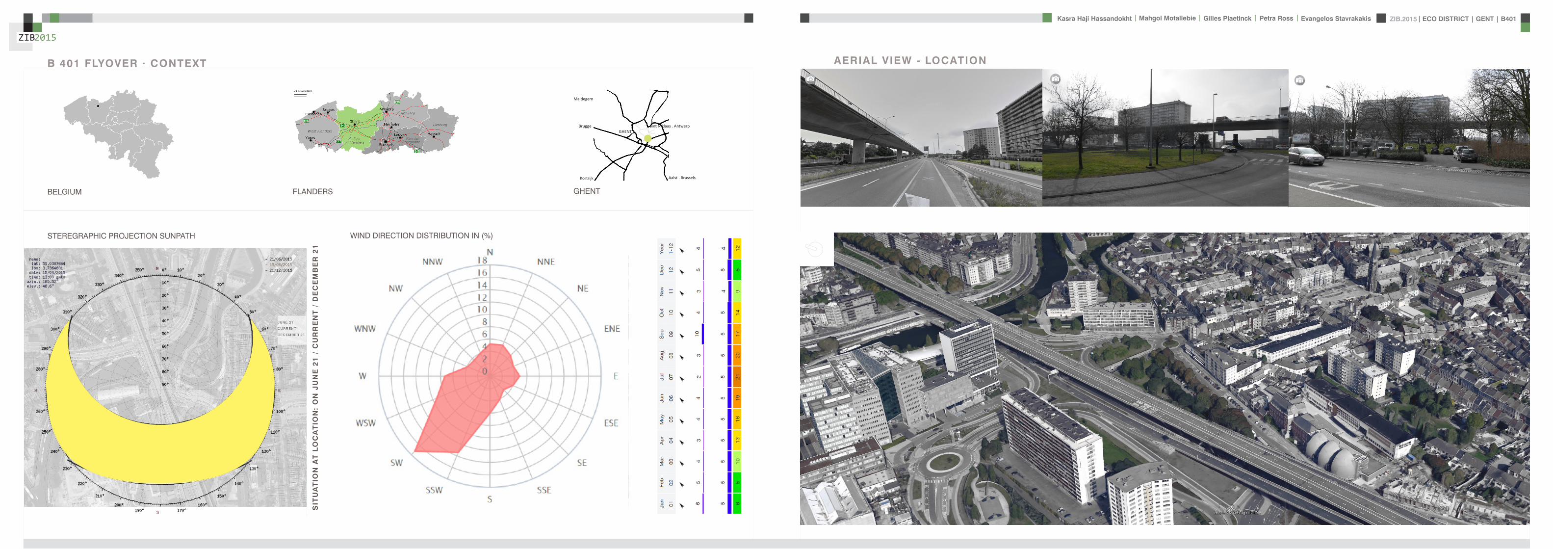
ZIB2015 ECO DISTRICT | GENT | B401Evangelos Stavrakakis | Petra Ross | Mahgol Motallebie | Gilles Plaetinck | Kasra Haji Hassandokht
ZIB2015
|
STEREGRAPHIC PROJECTION SUNPATH WIND DIRECTION DISTRIBUTION IN ()
B 401 FLYOVER middot CONTEXT
BELGIUM FLANDERS
Aalst Brussels
Sint Niklaas Antwerp
Kortrijk
Brugge
Maldegem
GHENT
GHENT
SIT
UA
TIO
N A
T L
OC
AT
ION
O
N J
UN
E 2
1
CU
RR
EN
T
DE
CE
MB
ER
21
AERIAL VIEW - LOCATION
ZIB2015 ECO DISTRICT | GENT | B401Evangelos Stavrakakis | Petra Ross | Mahgol Motallebie | Gilles Plaetinck | Kasra Haji Hassandokht
ZIB2015
|
VISION OF NATURE AND CULTURE
CURRENT SITUATION
CURRENT SITUATION FUTURE+5-10YRS
Section B-Bacute
Section A-Aacute
Section B-Bacute
Section A-Aacute
Continuous productive urban landscapes [within] cities
A-Aacuteacute B-Bacute C-Cacute
FUTURE+5-10YRS
CPULc
A vision and a strategy for the 21st century for the city to be green A healthy place for all where zero net pollution is genberated CPULs as a strategy aims towards bringing the -Natural- back to the city and through this to engage people and neighborhoods in positive activities Whether for the city the neighborhood their family or themselves this objective may capacitate a broad number of parallel activities programs and motivation for a healthy urban environment CPULs is simply taking back that for which we usually travel good distances as an -escape means- of the city and its negative side effects
ZIB2015 ECO DISTRICT | GENT | B401Evangelos Stavrakakis | Petra Ross | Mahgol Motallebie | Gilles Plaetinck | Kasra Haji Hassandokht
ZIB2015
|
A BETWEEN CITIES B CITY RING
PUBLIC
PRIVATE
SUPPLY
PSKYtranel
PSKYtrangoogleCar
googleCar
P
cambio
SKYtran
minimized night
ONEwheel
eltram
C INSIDE THE CITY
tram
SKY TRANGOING DOWN TO RING
INTERCHANGE SPOT
euro
life
sty
le c
ha
ng
e o
ve
r ti
me
15 min
90 min
PREVENT COMMUTINGMORE LOCAL LIFESTYLE
A
B
C
sophisticated apps
SHAREWAY
INTERVENTION IN TIME CURRENT SITUATION ON CITY RING SKYTRAN MOBILITY - PASSIVE MAGLEV TECHNOLOGY
NOW
+ 5-10YRS
+ 50YRS
SPEED VISION
A between cities
B city ring
C inside the city
SK
YT
RA
N
GO
OG
LE
CA
R
ON
EW
HE
EL
PASSIVE MAGLEV REQUIRES VERY LIT-TLE ENERGY AND ONLY MINOR INFRA-STRUCTURE LEADING TO THE LOW-EST COST TRANSPORTATION SYSTEM KNOWN TO MAN
ACTIVE MALEV RQUIRES HIGH ENERGY AND MASSIVE INFRA-STRUCTURE LEADING TO HIGH COSTS AS WELL
Section C-Cacute
FUTURISTIC VISION
BICYCLE UNDERGROUND PARKING
SKYtran
MOBILITY VISION
ZIB2015 ECO DISTRICT | GENT | B401Evangelos Stavrakakis | Petra Ross | Mahgol Motallebie | Gilles Plaetinck | Kasra Haji Hassandokht
ZIB2015
|
SITE PLAN
OUTTER CITY RINGINTEREVENTION LOCATIONTOWARDS THE CITY CENTRE
ZONE A SPORT AND CULTURE Pi ZONE C TRANSPORT TRANSITIONZONE B INFO AND WORKSHOP
TOP OF THE FLYOVER PARK AND ENERGY
TRANSPORT
bikespedestrian ramp
elevated park
ramp for cars in 2 directionsbus
tram
ECO QUATER
ZIB
drawing over existing situation
roundabout+ underpass
OFFICE PARK
EDUCATION
EDUCATION
HOUSING FLATS
HOUSING
HOUSING
ECO CITY GHENT
0 50 100 200
HOUSING FLATSOFFICE PARK
COMMERCE
HOUSING
HOUSING
0 10 50 100
P
P
P
PEDESTRIANCYCLE ROADS
P
i
PLAY TRAILS
ALLOTMENTS
PEDESTRIAN CYCLE RAMP
RAMP FOR CARS
ZIB
ZONING PLAN
ZIB2015 ECO DISTRICT | GENT | B401Evangelos Stavrakakis | Petra Ross | Mahgol Motallebie | Gilles Plaetinck | Kasra Haji Hassandokht
ZIB2015
|
GROUNDPLANS 1100
B-Bacute
A-Aacute
B-Bacute
A-Aacute
B-Bacute
A-Aacute
B-Bacute
A-Aacute
ZIB2015 ECO DISTRICT | GENT | B401Evangelos Stavrakakis | Petra Ross | Mahgol Motallebie | Gilles Plaetinck | Kasra Haji Hassandokht
ZIB2015
|
SECTIONS 1100
Section A-AacuteSection B-Bacute
AArsquo
AArsquo
Detai l 01
Detai l 02
Detai l 03
Detai l 04
Detai l 05
Detai l 06
ZIB2015 ECO DISTRICT | GENT | B401Evangelos Stavrakakis | Petra Ross | Mahgol Motallebie | Gilles Plaetinck | Kasra Haji Hassandokht
ZIB2015
|
DETAILS
DETAIL 01 DETAIL 02 DETAIL 03 DETAIL 04 DETAIL 05 DETAIL 06
AArsquo
PIR f loorGypsum plasterboardPIR 100 mmOSB 15 mmFJI beam cel lu lose 350 mmcel i t 4D woodf iber 18 mmfinish gypsum plasterboard
plato wood f in ishframework 30 mmcel i t 4D 18 mmwood structure SLS 38140Eurowal l 2x70 mmOSB Eurothane G 70 mmfinish gypsum plasterboard
ZIB2015 ECO DISTRICT | GENT | B401Evangelos Stavrakakis | Petra Ross | Mahgol Motallebie | Gilles Plaetinck | Kasra Haji Hassandokht
ZIB2015
|
ELEVATIONS 1100
South elevation
South Elevation
North Elevation
South Elevation
North Elevation
South Elevation
North Elevation
South Elevation
North Elevation
North elevation
ZIB2015 ECO DISTRICT | GENT | B401Evangelos Stavrakakis | Petra Ross | Mahgol Motallebie | Gilles Plaetinck | Kasra Haji Hassandokht
ZIB2015
|
VISUALIZATIONS
East Elevation
West Elevation
East Elevation
West Elevation
East Elevation
West Elevation East Elevation
West Elevation
ELEVATIONS 1100
West elevation East elevation
ZIB2015 ECO DISTRICT | GENT | B401Evangelos Stavrakakis | Petra Ross | Mahgol Motallebie | Gilles Plaetinck | Kasra Haji Hassandokht
ZIB2015
|
VISUALIZATIONS
ZIB2015 ECO DISTRICT | GENT | B401Evangelos Stavrakakis | Petra Ross | Mahgol Motallebie | Gilles Plaetinck | Kasra Haji Hassandokht
ZIB2015
|
MATERIALS WOOD FCS Certi f ied Suppliers Distance MATERIALS Building Structure
ZIB2015 ECO DISTRICT | GENT | B401Evangelos Stavrakakis | Petra Ross | Mahgol Motallebie | Gilles Plaetinck | Kasra Haji Hassandokht
ZIB2015
|
MATERIALS Specs InsulationMATERIALS Specs Solid amp Structural Wood
ZIB2015 ECO DISTRICT | GENT | B401Evangelos Stavrakakis | Petra Ross | Mahgol Motallebie | Gilles Plaetinck | Kasra Haji Hassandokht
ZIB2015
|
MATERIALS Life Cycle Assesment MATERIALS Embodied energy CO2 other materials
ZIB2015 ECO DISTRICT | GENT | B401Evangelos Stavrakakis | Petra Ross | Mahgol Motallebie | Gilles Plaetinck | Kasra Haji Hassandokht
ZIB2015
|
STRUCTURE
Gilles Plaetinck
schaal
ZIB BUILDINGEnter address here
7 _ Unnamed
Owner
begeleider Checker
3D Copy 11 Gilles Plaetinck
schaal
ZIB BUILDINGEnter address here
8 _ Unnamed
Owner
begeleider Checker
3D Copy 21
Gilles Plaetinck
schaal
ZIB BUILDINGEnter address here
8 _ Unnamed
Owner
begeleider Checker
3D Copy 31
Gilles Plaetinck
schaal
ZIB BUILDINGEnter address here
9 _ Unnamed
Owner
begeleider Checker3D Copy 4
1
ECONOMY - USIBILITY DURING THE DAY
i1000
ALWAYS
2000
ECONONY - USIBILITY DURING THE DAY
GENERAL PRINCIPLES OF THE BUILDING
ZERO IMPACT APPROACH
i
0 Food market in park Vertical harvesting Entrance
1 Workshop area technical room
2 Info center Entrance from highway
3 Roof terrace
ZIB2015 ECO DISTRICT | GENT | B401Evangelos Stavrakakis | Petra Ross | Mahgol Motallebie | Gilles Plaetinck | Kasra Haji Hassandokht
ZIB2015
|
Vertical Harvest places plants on carousels that keep them moving the length of the greenhouse giving them equal time in natural light and also al-lowing workers to pick and tand transfer the crops Using hydroponics Verti-cal Harvest will be capa-ble of producing over
Vertical Harvest places plants on carousels that keep them moving the length of the pulls giving them equal time in natu-ral light and also allowing workers and local people to pick and transfer the crops Using hydroponics Vertical Harvest will be capable of producing over greens and herbs
Vertical Harvest places plants on carousels that keep them moving the length of the greenhouse giving them equal time in natural light and also al-lowing workers to pick and tand transfer the crops Using hydroponics Verti-cal Harvest will be capa-ble of producing over
Vertical Harvest places plants on carousels that keep them moving the length of the pulls giving them equal time in natu-ral light and also allowing workers and local people to pick and transfer the crops Using hydroponics Vertical Harvest will be capable of producing over greens and herbs
VERTICAL HARVESTING
PLANT CABLE LIFT (PLC) SECTION
Sustainable Food zorkshop centerrsquos mission is to ldquocultivate a healthy community by strengthening the local food system and improving access to nu-tritious affordable foodrdquo The main goal of our design is to deliver skills and information for sus-tainability practioners in the organic food tradeThe program attempts to1) affect positive changes in shopping cooking eating habits and nutrition2) reduce diet-related diseases3) promote the health and development of young children 4) place emphasis on local seasonal and cultural-ly-appropriate foods5) integrate food systems concepts into its curric-ulumndash such as shopping at farmers markets and growing onersquos own food
Healthy food is a basic human right the ability to access healthy food is often related to multiple issues and not just a result of low income
FOOD TEAM = a group of people from the same neighbourhood who work for the direct purchase of regional and seasonal products They order food on internet via web page voedselteambe and it is then delivered once a week to the depot of a team
+ minimal transport requirements+ no returnable packaging+ fair p+ fair pricing+ high-quality local and seasonal food+ community initiative
Sustainable Food zorkshop centerrsquos mission is to ldquocultivate a healthy community by strengthening the local food system and improving access to nu-tritious affordable foodrdquo The main goal of our design is to deliver skills and information for sus-tainability practioners in the organic food tradeThe program attempts to1) affect positive changes in shopping cooking eating habits and nutrition2) reduce diet-related diseases3) promote the health and development of young children 4) place emphasis on local seasonal and cultural-ly-appropriate foods5) integrate food systems concepts into its curric-ulumndash such as shopping at farmers markets and growing onersquos own food
Healthy food is a basic human right the ability to access healthy food is often related to multiple issues and not just a result of low income
FOOD TEAM = a group of people from the same neighbourhood who work for the direct purchase of regional and seasonal products They order food on internet via web page voedselteambe and it is then delivered once a week to the depot of a team
+ minimal transport requirements+ no returnable packaging+ fair p+ fair pricing+ high-quality local and seasonal food+ community initiative
Sustainable Food zorkshop centerrsquos mission is to ldquocultivate a healthy community by strengthening the local food system and improving access to nu-tritious affordable foodrdquo The main goal of our design is to deliver skills and information for sus-tainability practioners in the organic food tradeThe program attempts to1) affect positive changes in shopping cooking eating habits and nutrition2) reduce diet-related diseases3) promote the health and development of young children 4) place emphasis on local seasonal and cultural-ly-appropriate foods5) integrate food systems concepts into its curric-ulumndash such as shopping at farmers markets and growing onersquos own food
Healthy food is a basic human right the ability to access healthy food is often related to multiple issues and not just a result of low income
FOOD TEAM = a group of people from the same neighbourhood who work for the direct purchase of regional and seasonal products They order food on internet via web page voedselteambe and it is then delivered once a week to the depot of a team
+ minimal transport requirements+ no returnable packaging+ fair p+ fair pricing+ high-quality local and seasonal food+ community initiative
Healthy food is a basic human right the ability to access healthy food is often related to multiple issues and not just a result of low income
Sustainable Food zorkshop centerrsquos mission is to ldquocultivate a healthy community by strengthening the local food system and improving access to nutritious affordable foodrdquo The main goal of our design is to deliver skills and information for sustainability practioners in the organic food tradeThe program attempts to
1) affect positive changes in shopping cookingeating habits and nutrition2) reduce diet-related diseases3) promote the health and development of youngchildren4) place emphasis on local seasonal and culturally-appropriate foods5) integrate food systems concepts into its curriculumndashsuch as shopping at farmers markets andgrowing onersquos own food
FOOD TEAM = a group of people from the same neighbourhood who work for the direct purchase of regional and seasonal products They order food on internet via web page voedselteambe and it is then delivered once a week to the depot of a team
+ minimal transport requirements+ no returnable packaging+ fair pricing+ high-quality local and seasonal food+ community initiative
WORKSHOP
ZIB2015 ECO DISTRICT | GENT | B401Evangelos Stavrakakis | Petra Ross | Mahgol Motallebie | Gilles Plaetinck | Kasra Haji Hassandokht
ZIB2015
|
Black coral pea
Factors should be considered when seleccng plants
- Quality of growth- Ability to adapt to the wall environment- Environmental Tolerances- Temperature Resistance- Drought Tolerance- Wind - Wind Tolerance- Solar Exposure Tolerance- Salt Tolerance in Seaside installacons- Air and Water Pollucon Tolerance- Pest and Disease Resistance- Arcficial Environment Tolerance- Transplantacon Tolerance- Pruning - Pruning Tolerance
- Ornamental Qualices- Design Purpose- Manageability Maintainability- Environmental and Societal Effects- Visual Effect- Feeling Effect
Blac
k co
ral p
eaSn
ake
vine
kidn
ey w
eed
purple coral peaBasil
Pandorea
Black coral pea
Factors should be considered when seleccng plants
- Quality of growth- Ability to adapt to the wall environment- Environmental Tolerances- Temperature Resistance- Drought Tolerance- Wind - Wind Tolerance- Solar Exposure Tolerance- Salt Tolerance in Seaside installacons- Air and Water Pollucon Tolerance- Pest and Disease Resistance- Arcficial Environment Tolerance- Transplantacon Tolerance- Pruning - Pruning Tolerance
- Ornamental Qualices- Design Purpose- Manageability Maintainability- Environmental and Societal Effects- Visual Effect- Feeling Effect
Blac
k co
ral p
eaSn
ake
vine
kidn
ey w
eed
purple coral peaBasil
Pandorea
Black coral pea
Factors should be considered when seleccng plants
- Quality of growth- Ability to adapt to the wall environment- Environmental Tolerances- Temperature Resistance- Drought Tolerance- Wind - Wind Tolerance- Solar Exposure Tolerance- Salt Tolerance in Seaside installacons- Air and Water Pollucon Tolerance- Pest and Disease Resistance- Arcficial Environment Tolerance- Transplantacon Tolerance- Pruning - Pruning Tolerance
- Ornamental Qualices- Design Purpose- Manageability Maintainability- Environmental and Societal Effects- Visual Effect- Feeling Effect
Blac
k co
ral p
eaSn
ake
vine
kidn
ey w
eed
purple coral peaBasil
Pandorea
GREEN WALLS
ZIB2015 ECO DISTRICT | GENT | B401Evangelos Stavrakakis | Petra Ross | Mahgol Motallebie | Gilles Plaetinck | Kasra Haji Hassandokht
ZIB2015
|
Extraction of air
Pulsion of airRecuperation unit
outdoor space
18 degC15 degC
18 degC
In-take Out-take of air
VENTILATION
Gilles Plaetinck
schaal 1 100
ZIB BUILDINGEnter address here
3 _ level 2
Owner
begeleider Checker
DN
Gilles Plaetinck
schaal 1 100
ZIB BUILDINGEnter address here
2 _ level 1
Owner
begeleider Checker
Extraction of air
Pulsion of air
VENTILATION IN GROUPLANS CALCULATION AND SYSTEM
level 01
level 02
T 42ECO DISTRICT | GENT | B401
ZIB2015Mechanical Ventilation with Heat Recovery (MVHR)
Up to 95 of the heat can be recovered The Heat Recovery Unit runs continu-ously on trickle and can and is boosted when higher rates of ventilation are required eg bathing cooking In warmer months a summer by-pass function helps ensure comfort levels are maintained in the home When summer by-pass is activated the dwelling contin-ues to be ventilaated and recieve fresh filtered air however the heat recovery process is intermittently switched off (heat recovery is by-passed)
Key BenefitsYear round removal of condensation and indoor pol-lutants A direct impact on the Dwelling Emission Rate re-quired in SAP helping reduce the carbon footprint of the property Fresh filtered air supplied to dwelling ideal for allergy sufferers and those with conditions such as asthma A balanced ventilation system for the whole house and recovering of heat that would have otherwise have been lost Low noise non-intrusive ventilation system ndash located away from the room however consideration should be given to duct runs to ensure cross-talk contamination doesnrsquot happen AND the unit is sized correctly so it is not running a high rate all of the time
Zehnder ComfoSystems Passive Haus accredited product suitable for large houses up to 300m2 Designed to ensure low noise excellent energy performance and heat exchange efficiency Choice of control options including LCD touch screen display Can be combine with ComfoCool for optional cooling of up to 5 degrees and humidity reduction by 20
Semi Rigid Ducting
With a manifold system the resistance caused by duct-ing is reduced therefore Semi-Rigid ducting resistance is very low The manifold takes mass airflow directly from the MVHR Heat Recovery Unit and allows lower rates to pass through to each individual room runDirecting mass flow to the manifold eliminates the need to increase the running speed of the MVHR Heat Re-covery unit to overcome the resistance of ducting which in turn causes noise for the homeowner
T 42ECO DISTRICT | GENT | B401
ZIB2015Mechanical Ventilation with Heat Recovery (MVHR)
Up to 95 of the heat can be recovered The Heat Recovery Unit runs continu-ously on trickle and can and is boosted when higher rates of ventilation are required eg bathing cooking In warmer months a summer by-pass function helps ensure comfort levels are maintained in the home When summer by-pass is activated the dwelling contin-ues to be ventilaated and recieve fresh filtered air however the heat recovery process is intermittently switched off (heat recovery is by-passed)
Key BenefitsYear round removal of condensation and indoor pol-lutants A direct impact on the Dwelling Emission Rate re-quired in SAP helping reduce the carbon footprint of the property Fresh filtered air supplied to dwelling ideal for allergy sufferers and those with conditions such as asthma A balanced ventilation system for the whole house and recovering of heat that would have otherwise have been lost Low noise non-intrusive ventilation system ndash located away from the room however consideration should be given to duct runs to ensure cross-talk contamination doesnrsquot happen AND the unit is sized correctly so it is not running a high rate all of the time
Zehnder ComfoSystems Passive Haus accredited product suitable for large houses up to 300m2 Designed to ensure low noise excellent energy performance and heat exchange efficiency Choice of control options including LCD touch screen display Can be combine with ComfoCool for optional cooling of up to 5 degrees and humidity reduction by 20
Semi Rigid Ducting
With a manifold system the resistance caused by duct-ing is reduced therefore Semi-Rigid ducting resistance is very low The manifold takes mass airflow directly from the MVHR Heat Recovery Unit and allows lower rates to pass through to each individual room runDirecting mass flow to the manifold eliminates the need to increase the running speed of the MVHR Heat Re-covery unit to overcome the resistance of ducting which in turn causes noise for the homeowner
MECHANICAL VENTILATION WITH HEAT RECOVERY (MVHR)
Up to 95 of the heat can be recoveredThe Heat Recovery Unit runs continuously on trickle and can and is boosted when higher rates of ventilation are required eg bathing cooking
In warmer months a summer by-pass function helps ensure comfort levels are maintained in the home When summer by-pass is activated the dwelling continues to be ventilaated and recieve fresh filtered air however the heat recovery process is intermittently switched off (heat recovery is by-passed)
EXTRACT VENTILATION RATES
T 42ECO DISTRICT | GENT | B401
ZIB2015Mechanical Ventilation with Heat Recovery (MVHR)
Up to 95 of the heat can be recovered The Heat Recovery Unit runs continu-ously on trickle and can and is boosted when higher rates of ventilation are required eg bathing cooking In warmer months a summer by-pass function helps ensure comfort levels are maintained in the home When summer by-pass is activated the dwelling contin-ues to be ventilaated and recieve fresh filtered air however the heat recovery process is intermittently switched off (heat recovery is by-passed)
Key BenefitsYear round removal of condensation and indoor pol-lutants A direct impact on the Dwelling Emission Rate re-quired in SAP helping reduce the carbon footprint of the property Fresh filtered air supplied to dwelling ideal for allergy sufferers and those with conditions such as asthma A balanced ventilation system for the whole house and recovering of heat that would have otherwise have been lost Low noise non-intrusive ventilation system ndash located away from the room however consideration should be given to duct runs to ensure cross-talk contamination doesnrsquot happen AND the unit is sized correctly so it is not running a high rate all of the time
Zehnder ComfoSystems Passive Haus accredited product suitable for large houses up to 300m2 Designed to ensure low noise excellent energy performance and heat exchange efficiency Choice of control options including LCD touch screen display Can be combine with ComfoCool for optional cooling of up to 5 degrees and humidity reduction by 20
Semi Rigid Ducting
With a manifold system the resistance caused by duct-ing is reduced therefore Semi-Rigid ducting resistance is very low The manifold takes mass airflow directly from the MVHR Heat Recovery Unit and allows lower rates to pass through to each individual room runDirecting mass flow to the manifold eliminates the need to increase the running speed of the MVHR Heat Re-covery unit to overcome the resistance of ducting which in turn causes noise for the homeowner
T 42ECO DISTRICT | GENT | B401
ZIB2015Mechanical Ventilation with Heat Recovery (MVHR)
Up to 95 of the heat can be recovered The Heat Recovery Unit runs continu-ously on trickle and can and is boosted when higher rates of ventilation are required eg bathing cooking In warmer months a summer by-pass function helps ensure comfort levels are maintained in the home When summer by-pass is activated the dwelling contin-ues to be ventilaated and recieve fresh filtered air however the heat recovery process is intermittently switched off (heat recovery is by-passed)
Key BenefitsYear round removal of condensation and indoor pol-lutants A direct impact on the Dwelling Emission Rate re-quired in SAP helping reduce the carbon footprint of the property Fresh filtered air supplied to dwelling ideal for allergy sufferers and those with conditions such as asthma A balanced ventilation system for the whole house and recovering of heat that would have otherwise have been lost Low noise non-intrusive ventilation system ndash located away from the room however consideration should be given to duct runs to ensure cross-talk contamination doesnrsquot happen AND the unit is sized correctly so it is not running a high rate all of the time
Zehnder ComfoSystems Passive Haus accredited product suitable for large houses up to 300m2 Designed to ensure low noise excellent energy performance and heat exchange efficiency Choice of control options including LCD touch screen display Can be combine with ComfoCool for optional cooling of up to 5 degrees and humidity reduction by 20
Semi Rigid Ducting
With a manifold system the resistance caused by duct-ing is reduced therefore Semi-Rigid ducting resistance is very low The manifold takes mass airflow directly from the MVHR Heat Recovery Unit and allows lower rates to pass through to each individual room runDirecting mass flow to the manifold eliminates the need to increase the running speed of the MVHR Heat Re-covery unit to overcome the resistance of ducting which in turn causes noise for the homeowner
Heating 10 kwh msup2aCooling 4 kWh msup2aOverheating 42
ZIB2015 ECO DISTRICT | GENT | B401Evangelos Stavrakakis | Petra Ross | Mahgol Motallebie | Gilles Plaetinck | Kasra Haji Hassandokht
ZIB2015
|
Shutters control system+ -
Solar roadways - PV panels
LED lights
Elevator Fuse box
ElectricityBattery withtransformator
ELECTRICITY
Summer night
cross- ventilation through building
Summer day
air through recuperation unit small change of temperature
15 degC 18 degC
+ groundplans
heated zone
not heated zone
ZONING ACCORDING TO TEMPERATURESSUMMER NIGHT - cross-ventilation through building
SUMMER DAY - air through recuperation unit small change of temperatureSHADING SYSTEM
As a shading was chozen system Renson Icarus Lamellas with angle 45deg made in wood
ZIB2015 ECO DISTRICT | GENT | B401Evangelos Stavrakakis | Petra Ross | Mahgol Motallebie | Gilles Plaetinck | Kasra Haji Hassandokht
ZIB2015
|
average only 4 hours of peak daylight hours per day (4 x 365 = 1460 hours per year)
- Surface area ( first part) Fly-over +- 20 000 msup2-gt 16 000 x 230 Watt = 3 680 000 Watt or 3680 kWonly 50 of fly-over covered with solar roadways
-gt 3680 kW x 4 h = 7360 kWh day-gt 3680 kW x 1460 h = 2 686 400 kWh year -gt +- 540 households (+- 5000 kWh year)
Tesla Powerwall Therersquos a 10 kWh unit at $3500 -gt 737 Tesla Batteries
gt the Solar Roadway has the ability to cut greenhouse gases by up to 75-percentgt A decentralized self-healing secure power grid
IN FRONT OF FLY-OVER
- Surface area Fly-over = 16 x 30 m = 480 msup2-gt 384 x 230 Watt = 88 320 Watt or 883 kWonly 50 of fly-over covered with solar roadways
-gt 44 kW x 4 h = 176 kWh day-gt 44 kW x 1460 h = 64 240 kWh year -gt +- 13 households (+- 5000 kWh year)
lightsshutters
elevator
2 fridges
2 coffeemakers
1 microwave
1 owen
2 cooking plates
stereo
ventilation unit
electricity transformer (AC to DC) for PV panels + batteries
summer 05 kWh daywinter 03 kWh day183 days x 05= 915 kWh182 days x 03 = 546 kWh = 1641 kWh
262 kWh
A++fridge 104 kWhyear104 x x2 = 208 kWh
900 W x 01 hours day = 09 kWhx 220 days x 2= 198 kWh a
67 kWh a
085x100 days= 85 kWh a
400 kWh x 2 = 800 kWh a
150 kWh a 419 kWha
68 kWh a
ENERGY DEMAND OVERVIEW ENERGY SUPPLY OVERVIEW - FLY-OVER
1 spot 56 W 10000 = 0056 KW4 hours per day 365 days a year = 1460 h0056 x 1460 = 8176 kWh10 spots x 8176= 8176 kWh a
1 spot 72 W 10000 = 0072 KW4 hours per day 365 days a year = 1460 h0072 x 1460 = 10512 kWh5 spots x 10512= 5256 kWh a
1 spot 52 W 10000 = 0052 KW4 hours per day 365 days a year = 1460 h0052 x 1460 = 7592 kWh21 spots x 7592= 159432 kWh a
1 spot 9 W 10000 = 0009 KW4 hours per day 365 days a year = 1460 h0009 x 1460 = 1314 kWh5 spots x 1314 = 657 kWh a
SOLAR ROADWAYS - PV PANELSEnergy from the sun
1 To generate energy for the ZIB building2 To generate energy for the surrounding houses3 To generate energy for lighting or signs on the road4 The panels will also have the capacity to charge electric vehicles while parked
ELECTRICITY SCHEME
5423 kWh a
ZIB2015 ECO DISTRICT | GENT | B401Evangelos Stavrakakis | Petra Ross | Mahgol Motallebie | Gilles Plaetinck | Kasra Haji Hassandokht
ZIB2015
|
SUMMER SUNNY 10-42 LUXWINTER SUNNY 10-42 LUX
DAYLIGHT - DIALuxLIGHTING SYSTEM - DIALux
Workplane 9 Results overview
Height of working plane 0800 m Wall zone 0000 m
Result Mean (target) Min Max Minaverage MinmaxPerpendicular illuminance [lx] 463 (500) 105 689 0227 0152
Profile Offices Writing typewriting reading data processing
B401-Gent 6222015
Site 1 Building 2 Zib Room 9 Workplane 9 Results overview
Page 70
Workplane 9 False coloursPerpendicular illuminance (adaptive)
Scale 1 200
Perpendicular illuminance (Surface)Mean (actual) 463 lx Min 105 lx Max 689 lx Minaverage 0227 Minmax 0152
B401-Gent 6222015
Site 1 Building 2 Zib Room 9 Workplane 9 False coloursPerpendicular illuminance (adaptive)
Page 72
Workplane 9 Value chartPerpendicular illuminance (adaptive)
Scale 1 200
Perpendicular illuminance (Surface)Mean (actual) 463 lx Min 105 lx Max 689 lx Minaverage 0227 Minmax 0152
B401-Gent 6222015
Site 1 Building 2 Zib Room 9 Workplane 9 Value chartPerpendicular illuminance (adaptive)
Page 73
Workplane 13 Results overview
Height of working plane 0800 m Wall zone 0000 m
Result Mean (target) Min Max Minaverage MinmaxPerpendicular illuminance [lx] 388 (500) 69 732 0178 0094
Profile Offices Writing typewriting reading data processing
B401-Gent 6222015
Site 1 Building 6 Storey 1 Room 13 Workplane 13 Results overview
Page 94
Workplane 13 False coloursPerpendicular illuminance (adaptive)
Scale 1 100
Perpendicular illuminance (Surface)Mean (actual) 388 lx Min 69 lx Max 732 lx Minaverage 0178 Minmax 0094
B401-Gent 6222015
Site 1 Building 6 Storey 1 Room 13 Workplane 13 False coloursPerpendicular illuminance (adaptive)
Page 96
Workplane 13 Value chartPerpendicular illuminance (adaptive)
Scale 1 100
Perpendicular illuminance (Surface)Mean (actual) 388 lx Min 69 lx Max 732 lx Minaverage 0178 Minmax 0094
B401-Gent 6222015
Site 1 Building 6 Storey 1 Room 13 Workplane 13 Value chartPerpendicular illuminance (adaptive)
Page 97
Workplane 9 False coloursPerpendicular illuminance (adaptive)
Scale 1 200
Perpendicular illuminance (Surface)Mean (actual) 463 lx Min 105 lx Max 689 lx Minaverage 0227 Minmax 0152
B401-Gent 6222015
Site 1 Building 2 Zib Room 9 Workplane 9 False coloursPerpendicular illuminance (adaptive)
Page 72
1st f loor 2nd f loor Site 1 Luminaire parts listQuantity Luminaire (Luminous emittance)10 3F Filippi 12736 P 202x24W LED OP 196x1231
Luminous emittance 1Fitting 1x24W 2xLEDLight output ratio 100Lamp luminous flux 5332 lmLuminaire Luminous Flux 5332 lmPower 560 WLight yield 952 lmW
200
300
400
cdklm η = 100C0 - C180 C90 - C270
0deg 15deg 30deg
45deg
60deg
75deg
90deg
105deg105deg
90deg
75deg
60deg
45deg
30deg 15deg 0deg
5 SFN Eclairages 0732360X CLFV 236Luminous emittance 1Fitting 2xT26 36W840Light output ratio 6889Lamp luminous flux 6700 lmLuminaire Luminous Flux 4615 lmPower 720 WLight yield 641 lmW
160
240
cdklm η = 69C0 - C180 C90 - C270
0deg 15deg 30deg
45deg
60deg
75deg
90deg
105deg105deg
90deg
75deg
60deg
45deg
30deg 15deg 0deg
21 SFN Eclairages 332226XX SAM F 2x26W BELuminous emittance 1Fitting 2xTC-DEL 26W840Light output ratio 3297Lamp luminous flux 3600 lmLuminaire Luminous Flux 1187 lmPower 520 WLight yield 228 lmW
40
60
80
100
120
140
cdklm η = 33C0 - C180 C90 - C270
0deg 15deg 30deg
45deg
60deg
75deg
90deg
105deg105deg
90deg
75deg
60deg
45deg
30deg 15deg 0deg
1 Signcomplex AR111-009-AW-W-06 AR111 COB 9W38deg WhiteLuminous emittance 1Fitting 1xAR111-009-AW-W-06Light output ratio 8078Lamp luminous flux 600 lmLuminaire Luminous Flux 485 lmPower 90 WLight yield 539 lmW
800
1200
cdklm η = 81C0 - C180 C90 - C270
0deg 15deg 30deg
45deg
60deg
75deg
90deg
105deg105deg
90deg
75deg
60deg
45deg
30deg 15deg 0deg
Total lamp luminous flux 163020 lm Total luminaire luminous flux 101807 lm Total Load 20210 W Light yield 504 lmW
B401-Gent 6222015
Site 1 Luminaire parts list
Page 19
10x
6x
21x
1x
types of l ights
Perpendicular i l luminance (Surface)Mean (actual ) 463 lx Min 105 lx Max 689 lx Minaverage 0 227 Minmax 0 152
Perpendicular i l luminance (Surface)Mean (actual ) 388 lx Min 69 lx Max 732 lx Minaverage 0 178 Minmax 0 094
ZIB2015 ECO DISTRICT | GENT | B401Evangelos Stavrakakis | Petra Ross | Mahgol Motallebie | Gilles Plaetinck | Kasra Haji Hassandokht
ZIB2015
|
Tube hybrid Solar panels
Hot water tank Water taps
City water supply
Rain water collection for vertical harvesting
City water supply
WADI
Rain water tank
WATER MANAGEMENT
Sinks
Available roof area
In Ghent avarage of 900mmm2year
3197 m2
09x 3197 = 28773 m3year
RAIN WATER GAIN
toilet - 3x - 03lskitchen -4x - 02ls
POTABLE WATER DEMAND
3 toiletsVertical gardening
Total
relative RW usage
300 l day150 l day = 450lday= 16425 m3 year
1407 lday100m2
RAIN WATER DEMAND
RAIN WATER TANK
Relative RWT volumeRain water tank volume
3m3 100 m2
9591 l gt 10 m3
DIMESION OF PIPES
City water supplyRainwater tank
178 mm (DN 18 - 15 - 12)165 mm (DN 17-15)
are composed of hexagonal tiles Rainwater can infiltrate between the gaps from where it goes to rainwatter collector which supplies the vegetation on fly-over
THE SOLAR ROADWAYS
WATER SUPPLY SCHEME AND CALCULATION
ZIB2015 ECO DISTRICT | GENT | B401Evangelos Stavrakakis | Petra Ross | Mahgol Motallebie | Gilles Plaetinck | Kasra Haji Hassandokht
ZIB2015
|
WADI
City water supply
Rain water tank
Sinks
Divided sewer systemwithin building
SEWAGE SYSTEM
ToiletToilet sinkKitchen sink
DU = 2 lsDU = 05 lsDU = 08 ls
WATER DRAINAGE OF DEVICES
Frequency of usage at the same time
K 05
DIMESION OF PIPES
Black waterGrey water
110 mm (DU 110)75 mm (DU 75 - 63)
WATER DRAINAGE SCHEME AND CALCULATION
ZIB2015 ECO DISTRICT | GENT | B401Evangelos Stavrakakis | Petra Ross | Mahgol Motallebie | Gilles Plaetinck | Kasra Haji Hassandokht
ZIB2015
|
DN
Gilles Plaetinck
schaal 1 100
ZIB BUILDINGEnter address here
2 _ level 1
Owner
begeleider Checker
Gilles Plaetinck
schaal 1 100
ZIB BUILDINGEnter address here
3 _ level 2
Owner
begeleider Checker
WATER SUPPLY
HOT WATER
WATER DRAINAGE
WATER SUPPLY AND DRAINAGE IN GROUPLANS
level 01
level 02
ENERGY
RAINWATER TANK
HELOPHYTE FILTER
IRRIGATION SYSTEM
BIO-ROTOR
MICRO TURBINE
PHOSPHOR
In this building a closed water system is applied which is based on reusing water in mullple wasRainRain water from the roof will be collected in a storage tank situated on the ground floor This water will be used to flush the toilet and irrigate crops in verlcal harveslng system In case of an overflow the water will be stored in the con-structed wetland near the building The rainwater can be fil-tered through a helophyte filter up to drinking water stan-dard The waste water system includes three types of water yellyellow black and grey waterThe yellow water will be stored for its phosphor while the black water will be purified into grey water This grey water is comparable to the quality of rain water aaer purificalon b means of a bio rotor The remaining residue from the bio rotor together with the organic waste from the harveslng is fermented into biogas that drives a micro turbine in order to produce some addilonal energy
TheThe waste product deriving from this process will be used as compost in verlcal harveslng This efficient yet complex system closes the ullizalon cycle of the building and turns it into an efficient vicious circle that can be considered au arkic
In this building a closed water system is applied which is based on reusing water in multiple was
Rain water from the roof will be collected in a storage tank situated on the ground floor This water will be used to flushthe toilet and irrigate crops in vertical harvesting system In case of an overflow the water will be stored in the constructed wetland near the building The rainwater can be filtered through a helophyte filter up to drinking water standard
The waste water system includes three types of water yellow black and grey water The yellow water will be stored for its phosphor while the black water will be purified into grey water This grey water is comparable to the quality of rain water after purification b means of a bio rotor The remaining residue from the bio rotor together with the organic waste from the harvesting is fermented into biogas that drives a micro turbine in order to produce some additional energy The waste product deriving from this process will be used ascompost in ver1048991cal harves1048991ng This efficient yet complexsystem closes the u1048991liza1048991on cycle of the building and turns itinto an efficient vicious circle that can be considered au arkic
WATER CYCLE
ZIB2015 ECO DISTRICT | GENT | B401Evangelos Stavrakakis | Petra Ross | Mahgol Motallebie | Gilles Plaetinck | Kasra Haji Hassandokht
ZIB2015
|
CALCULATIONS
Passive House verification
Photo or Drawing
Building Workshop + info pointStreet
PostcodeCityCountry
Building Type non-residentialClimate Ukkel
Home Owner(s) Client(s)Street
PostcodeCity
ArchitectStreet
PostcodeCity Calculation electricity Internal heat gains
Mechanical System Building type
StreetPostcodeCity Internal heat gains
Year of Construction 2015 Interior Temperature 200 degC Utilisation pattern
Number of Dwelling Units 1 Internal Heat Gains 20 Wm2 Type of values used Fill in worksheet IHG Non-Dom Enclosed Volume Ve 12442 Planned number of occupants
Number of Occupants 80 8 Design
Specific building demands with reference to the treated floor area use Annual method
Treated floor area 2840 msup2 Requirements Fulfilled Verification Annual method The monthly method should be used for building certification
Space heating Annual heating demand 10 kWh(m2a) 15 kWh(msup2a) yes Specific space heating demand annual method 103 kWh(msup2a)
Heating load 11 Wm2 10 Wmsup2 - Specific space heating demand monthly Method 120 kWh(msup2a)
Space cooling Overall specific space cooling demand kWh(m2a) 15 kWh(msup2a)
Cooling load Wm2 - -Frequency of overheating (gt 25 degC) - -
Primary Energy Space heating and dehumidification
cooling household electricity 73 kWh(m2a) 120 kWh(msup2a) yes
DHW space heating and auxiliary electricity 24 kWh(m2a) - -Specific primary energy reduction through solar electricity 21 kWh(m2a) - -
Airtightness Pressurization test result n50 06 1h 06 1h yes
PHPP Verification FINAL ZIB FILE CALCULTIONS PHPPxls
L B H VOLUME
main 1 226 7 4 6328main 2 184 7 35 4508
core 0 6 2 5 3 5 108 5core 0 62 5 35 1085core 3 62 3 28 521
12442
AREAmain 1 storage 35
wc big 35wc 2wc 2workshop 103
MAIN 2 infolounge 92
staircase 56storage technical 22
284
Floor_exterior 1582 31 1272
Roof_exterior 1582
Passive House verification
Photo or Drawing
Building Workshop + info pointStreet
PostcodeCityCountry
Building Type non-residentialClimate Ukkel
Home Owner(s) Client(s)Street
PostcodeCity
ArchitectStreet
PostcodeCity Calculation electricity Internal heat gains
Mechanical System Building type
StreetPostcodeCity Internal heat gains
Year of Construction 2015 Interior Temperature 200 degC Utilisation pattern
Number of Dwelling Units 1 Internal Heat Gains 20 Wm2 Type of values used Fill in worksheet IHG Non-Dom Enclosed Volume Ve 12442 Planned number of occupants
Number of Occupants 80 8 Design
Specific building demands with reference to the treated floor area use Annual method
Treated floor area 2840 msup2 Requirements Fulfilled Verification Annual method The monthly method should be used for building certification
Space heating Annual heating demand 10 kWh(m2a) 15 kWh(msup2a) yes Specific space heating demand annual method 103 kWh(msup2a)
Heating load 11 Wm2 10 Wmsup2 - Specific space heating demand monthly Method 120 kWh(msup2a)
Space cooling Overall specific space cooling demand kWh(m2a) 15 kWh(msup2a)
Cooling load Wm2 - -Frequency of overheating (gt 25 degC) - -
Primary Energy Space heating and dehumidification
cooling household electricity 73 kWh(m2a) 120 kWh(msup2a) yes
DHW space heating and auxiliary electricity 24 kWh(m2a) - -Specific primary energy reduction through solar electricity 21 kWh(m2a) - -
Airtightness Pressurization test result n50 06 1h 06 1h yes
PHPP Verification FINAL ZIB FILE CALCULTIONS PHPPxls
SURFACE AREAcurrent orientation only night ventilation
current orientation only night ventilation 6 windows less 52 msup2
current orientation only night ventilation 7 windows less 60msup2 (stays the same for each side)
current orientation only night ventilation 8 windows less 69 msup2
orientation turned 90deg only night ventilation 6 windows less 52 msup2
orientation turned 90deg only night ventilation 7 windows less 60msup2 (window less at SE side)
orientation turned 90deg only night ventilation 8 windows less 69 msup2
-gt orientation turned 90deg only night ventilation 9 windows less 77msup2 (window less at NW side althought theres less overheating in the case of a window less at SE side the heating demand exceeds 15)
CHANGE IN DESIGN
ZIB2015 ECO DISTRICT | GENT | B401Evangelos Stavrakakis | Petra Ross | Mahgol Motallebie | Gilles Plaetinck | Kasra Haji Hassandokht
ZIB2015
|
Passive House verificationS P E C I F I C A N N U A L H E A T I N G D E M A N D
Climate Ukkel Interior Temperature 200 degC
Building Workshop + info point Building TypeUse non-residentialTreated Floor Area ATFA 2840 msup2
per msup2Area U-Value Temp Factor ft Gt Treated Data for heating balance diagram
Building Element Temperature Zone msup2 W(msup2K) kKha kWha Floor Area Losses GainsExterior Wall - Ambient A 5595 0101 100 743 = 4181 1472 Exterior Wall - Ambient 147234373Exterior Wall - Ground B 069 = Exterior Wall - GroundRoofCeiling - Ambient A 1550 0094 100 743 = 1085 382 RoofCeiling - Ambient 381903529Floor slab basement ceiling B 310 0105 069 743 = 167 059 Floor slab basement ceiling 058811509
A 100 =A 100 =
unheated basement X 075 = unheated basementWindows A 1154 0648 100 743 = 5562 1958 Windows 195834732Exterior Door A 100 = Exterior DoorExterior TB (lengthm) A 1169 -0030 100 743 = -259 -091 Thermal Bridge Heat LossPerimeter TB (lengthm) P 069 = 000 not useful heat gains 365267499Ground TB (lengthm) B 069 =
Total of All Building Envelope Areas 8609 ndashndashndashndashndashndashndashndashndashndashndashndashndash- kWh(msup2a) Ventilation 395818713
Transmission Heat Losses QT Total 10736 378Annual Heating Demand 102516636
ATFA Clear Room Height internal gains 100951487msup2 m msup3 passive solar gains 250668423
Ventilation System Effective Air Volume VV 2840 280 = 7952 Thermal bridge credit 091126837Effective Heat Recovery Efficiency eff 81 Cross check sum 46324923 46324923of Heat Recovery
Efficiency of Subsoil Heat Exchanger SHX 0 nVsystem HR nVRes
1h 1h 1h
Energetically Effective Air Exchange nV 0105 (1 - 081 ) + 0038 = 0058
VV nV cAir Gt
msup3 1h Wh(msup3K) kKha kWha kWh(msup2a)
Ventilation Heat Losses QV 795 0058 033 743 = 1124 40
Reduction Factor QT QV NightWeekend
kWha kWha Saving kWha kWh(msup2a)
Total Heat Losses QL ( 10736 + 1124 ) 10 = 11860 418
Orientation Reduction Factor g-Value Area Radiation HPof the Area See Windows Sheet (perp radiation)
msup2 kWh(msup2a) kWha
1 North 054 050 2700 163 = 11822 East 058 000 440 197 = 03 South 056 050 4860 314 = 42874 West 032 050 3216 254 = 13275 Horizontal 063 050 324 317 = 323
kWh(msup2a)
Available Solar Heat Gains QS Total 7119 251
Length Heat Period Spec Power qI ATFA
khd da Wmsup2 msup2 kWha kWh(msup2a)
Internal Heat Gains QI 0024 209 201 2840 = 2867 101
kWha kWh(msup2a)
Free Heat QF QS + QI = 9986 352
Ratio of Free Heat to Losses QF QL = 084
Utilisation Factor Heat Gains G (1 - ( QF QL )5 ) (1 - ( QF QL )
6 ) = 90kWha kWh(msup2a)
Heat Gains QG G QF = 8949 315
kWha kWh(msup2a)
Annual Heating Demand QH QL - QG = 2911 10
kWh(msup2a) (YesNo)
Limiting Value 15 Requirement met yes
00
147
00
3806000000
196
00
40
37
09
103
101
251
0
5
10
15
20
25
30
35
40
45
50
Losses Gains
Hea
t flo
ws
[kW
h(m
sup2a)]
Heating energy balance
passive solar gains
internal gains
Annual Heating Demand
Thermal bridge credit
not useful heat gains
Ventilation
Exterior Door
Windows
unheated basement
Floor slab basement ceiling
RoofCeiling - Ambient
Exterior Wall - Ground
Exterior Wall - Ambient
Thermal Bridge Heat Loss
HPP Annual Heating Demand FINAL ZIB FILE CALCULTIONS PHPPxls
Passive House verification Passive House verificationS P E C I F I C U S E F U L C O O L I N G D E M A N D S P E C I F I C U S E F U L C O O L I N G D E M A N D
M O N T H L Y M E T H O D M O N T H L Y M E T H O D
(This page displays the sums of the monthly method over the cooling period))Climate Ukkel Interior Temperature Summer 25 degC Climate Ukkel Interior Temperature 25 degC
Building Workshop + info point Building TypeUse non-residential Building Workshop + info point Building TypeUse non-residential
Spec Capacity 60 Wh(msup2K) (Enter in Summer worksheet) Treated Floor Area ATFA 2840 msup2 Treated Floor Area ATFA 284 msup2
per msup2Temperature Zone Area U-Value Mon Red Fac Gt Treated Jan Feb Mar Apr May Jun Jul Aug Sep Oct Nov Dec Year
Building Element msup2 W(msup2K) kKha kWha Floor Area Heating Degree Hours - Ex 168 150 144 121 92 73 57 59 82 109 140 160 136 kKh1 Exterior Wall - Ambient A 5595 0101 100 103 = 5782 Heating Degree Hours - G 126 123 135 120 106 83 63 54 58 71 86 109 113 kKh2 Exterior Wall - Ground B 100 = Losses - Exterior 2553 2286 2189 1838 1393 1117 871 904 1245 1660 2123 2432 20612 kWh3 RoofCeiling - Ambient A 1550 0094 100 103 = 1500 Losses - Ground 41 40 44 39 35 27 21 18 19 23 28 36 370 kWh4 Floor slab basement ceil B 310 0105 100 90 = 294 Losses Summer Ventilatio 67 71 244 372 629 720 880 865 658 499 234 126 5366 kWh5 A 100 = Sum Spec Heat Losses 94 84 87 79 72 66 62 63 68 77 84 91 928 kWhmsup26 A 100 = Solar Load North 44 81 141 212 286 298 298 255 178 116 54 35 1998 kWh7 unheated basement X 075 = Solar Load East 0 0 0 0 0 0 0 0 0 0 0 0 0 kWh8 Windows A 1154 0648 100 103 = 7690 Solar Load South 218 315 464 577 681 644 681 658 532 416 242 171 5601 kWh9 Exterior Door A 100 = Solar Load West 79 125 213 303 385 378 370 347 256 177 91 60 2785 kWh
10 Exterior TB (lengthm) A 1169 -0030 100 103 = -358 Solar Load Horiz 11 21 37 57 79 79 80 69 47 30 14 9 533 kWh11 Perimeter TB (lengthm) P 100 = Solar Load Opaque 3 5 9 13 18 19 19 16 11 7 3 2 126 kWh12 Ground TB (lengthm) B 100 = Internal Heat Gains 425 384 425 411 425 411 425 425 411 425 411 425 5001 kWh
ndashndashndashndashndashndashndashndashndashndashndash kWh(msup2a) Sum Spec Loads Solar + 28 33 45 55 66 64 66 62 51 41 29 25 565 kWhmsup2
Transmission Losses QT (Negative Heat Loads) Total 14907 525 Utilisation Factor Losses 29 39 52 69 84 88 82 88 73 53 34 27 58Useful Cooling Energy Dem 0 0 4 30 142 192 417 192 40 4 0 0 1021 kWh
ATFA Clear Room Height Spec Cooling Demand 00 00 00 01 05 07 15 07 01 00 00 00 36 kWhmsup2Effective msup2 m msup3
Air Volume VV 284 280 = 795
Heat Transfer Coef Gt
WK kKha kWha kWh(msup2a)
Exterior 99 103 = 1013 36Ground 00 105 = 0 00
Additional Summer Ventilation
Select X Window Night Ventilation Manual Corresponding Air Change Rate 136 1h
Mechanical Automatically Controlled Ventilation (for window ventilation at 1 K temperature difference indoor - outdoor)
Minimum Acceptable Indoor Temperatu 220 degC
kWha kWh(msup2a)
Heat Losses Summer Ventilation 5172 182
QLext QLground QLsummer
kWha kWha kWha kWha kWh(msup2a)
Ventilation Heat Losses QV 1013 + 0 + 5172 = 6185 218
2
3
4
5
6
7
8
9
10
Spec
ific
loss
es l
oads
l c
oolin
g de
man
d [k
Wh
(msup2 m
onth
)] Spec Cooling Demand Sum Spec Heat Losses Sum Spec Loads Solar + Internal
QT QV
kWha kWha kWha kWh(msup2a)
Total Heat Losses QL 14907 + 6185 = 21092 743
Orientation Reduction Factor g-Value Area Global Radiationof the Area (perp radiation)
msup2 kWh(msup2a) kWha
1 North 031 050 270 462 = 19182 East 061 000 44 578 = 0 Temperature Amplitude Summer 82 K3 South 030 050 486 707 = 52114 West 025 050 322 654 = 2646 Month 1 2 3 4 5 6 7 8 9 10 11 12 Annual Total5 Horizontal 035 050 32 913 = 513 Days 31 28 31 30 31 30 31 31 30 31 30 31 3656 Sum Opaque Areas 121 Ambient Temp 250 270 572 828 1275 1487 1737 1707 1369 1039 568 356 96
kWh(msup2a) North Radiation 106 195 329 494 667 697 712 599 419 275 129 87 471
Available Solar Heat Gains QS Total 10409 367 East Radiation 146 266 452 698 937 940 988 851 574 382 179 123 654
South Radiation 311 440 645 786 912 858 898 885 733 579 341 241 763Length Heat Period Spec Power qI ATFA West Radiation 155 261 471 707 926 926 896 819 580 382 183 116 642
khd da Wmsup2 msup2 kWha kWh(msup2a) Hori Radiation 200 369 662 1021 1398 1410 1418 1234 842 535 243 156 949
Internal Heat Gains QI 0024 303 20 2840 = 4151 146 Tsky -750 -730 -428 -172 275 487 737 707 369 039 -432 -644 -04
Ground Temp 805 676 686 830 1072 1345 1647 1776 1696 1552 1310 1037 121kWha kWh(msup2a)
Sum Heat Loads QF QS + QI = 14560 513
Ratio of Losses to Free Heat Gains QL QF = 145
Utilisation Factor Heat Losses G = 64kWha kWh(msup2a)
Useful Heat Losses QVn G QL = 13539 477
kWha kWh(msup2a)
Useful Cooling Demand QK QF - QVn = 1021 4
kWh(msup2a) (YesNo)
Limiting Value 15 Requirement met yes
0
1
2
Jan Feb Mar Apr May Jun Jul Aug Sep Oct Nov Dec
usef
u
HPP Cooling FINAL ZIB FILE CALCULTIONS PHPPxls
Passive House verificationS P E C I F I C A N N U A L H E A T I N G D E M A N D
Climate Ukkel Interior Temperature 200 degC
Building Workshop + info point Building TypeUse non-residentialTreated Floor Area ATFA 2840 msup2
per msup2Area U-Value Temp Factor ft Gt Treated Data for heating balance diagram
Building Element Temperature Zone msup2 W(msup2K) kKha kWha Floor Area Losses GainsExterior Wall - Ambient A 5595 0101 100 743 = 4181 1472 Exterior Wall - Ambient 147234373Exterior Wall - Ground B 069 = Exterior Wall - GroundRoofCeiling - Ambient A 1550 0094 100 743 = 1085 382 RoofCeiling - Ambient 381903529Floor slab basement ceiling B 310 0105 069 743 = 167 059 Floor slab basement ceiling 058811509
A 100 =A 100 =
unheated basement X 075 = unheated basementWindows A 1154 0648 100 743 = 5562 1958 Windows 195834732Exterior Door A 100 = Exterior DoorExterior TB (lengthm) A 1169 -0030 100 743 = -259 -091 Thermal Bridge Heat LossPerimeter TB (lengthm) P 069 = 000 not useful heat gains 365267499Ground TB (lengthm) B 069 =
Total of All Building Envelope Areas 8609 ndashndashndashndashndashndashndashndashndashndashndashndashndash- kWh(msup2a) Ventilation 395818713
Transmission Heat Losses QT Total 10736 378Annual Heating Demand 102516636
ATFA Clear Room Height internal gains 100951487msup2 m msup3 passive solar gains 250668423
Ventilation System Effective Air Volume VV 2840 280 = 7952 Thermal bridge credit 091126837Effective Heat Recovery Efficiency eff 81 Cross check sum 46324923 46324923of Heat Recovery
Efficiency of Subsoil Heat Exchanger SHX 0 nVsystem HR nVRes
1h 1h 1h
Energetically Effective Air Exchange nV 0105 (1 - 081 ) + 0038 = 0058
VV nV cAir Gt
msup3 1h Wh(msup3K) kKha kWha kWh(msup2a)
Ventilation Heat Losses QV 795 0058 033 743 = 1124 40
Reduction Factor QT QV NightWeekend
kWha kWha Saving kWha kWh(msup2a)
Total Heat Losses QL ( 10736 + 1124 ) 10 = 11860 418
Orientation Reduction Factor g-Value Area Radiation HPof the Area See Windows Sheet (perp radiation)
msup2 kWh(msup2a) kWha
1 North 054 050 2700 163 = 11822 East 058 000 440 197 = 03 South 056 050 4860 314 = 42874 West 032 050 3216 254 = 13275 Horizontal 063 050 324 317 = 323
kWh(msup2a)
Available Solar Heat Gains QS Total 7119 251
Length Heat Period Spec Power qI ATFA
khd da Wmsup2 msup2 kWha kWh(msup2a)
Internal Heat Gains QI 0024 209 201 2840 = 2867 101
kWha kWh(msup2a)
Free Heat QF QS + QI = 9986 352
Ratio of Free Heat to Losses QF QL = 084
Utilisation Factor Heat Gains G (1 - ( QF QL )5 ) (1 - ( QF QL )
6 ) = 90kWha kWh(msup2a)
Heat Gains QG G QF = 8949 315
kWha kWh(msup2a)
Annual Heating Demand QH QL - QG = 2911 10
kWh(msup2a) (YesNo)
Limiting Value 15 Requirement met yes
00
147
00
3806000000
196
00
40
37
09
103
101
251
0
5
10
15
20
25
30
35
40
45
50
Losses Gains
Hea
t flo
ws
[kW
h(m
sup2a)]
Heating energy balance
passive solar gains
internal gains
Annual Heating Demand
Thermal bridge credit
not useful heat gains
Ventilation
Exterior Door
Windows
unheated basement
Floor slab basement ceiling
RoofCeiling - Ambient
Exterior Wall - Ground
Exterior Wall - Ambient
Thermal Bridge Heat Loss
HPP Annual Heating Demand FINAL ZIB FILE CALCULTIONS PHPPxls
factor 05Wd (ls) 088
nominal diameter 75 mmVERTICAL COLLECTOR sink toilets 3 05 15
sink kitchen 2 08 16Total 5 31factor 05
Wd (ls) 088nominal diameter 75 mm
Toevoerend ROOF SURFACE
horizontal roof surface (msup2) orientation coeff angle (deg) roofcover filter coeff toevoerend
444 1 0 08 09 3197
RAIN WATER USAGE
Type usage ( l usage) persons day frequency usageday yearly usage
toilet use small 3 20 3 180 65700toilet use big 6 20 1 120 43800VERTICAL GARDENING 150 54750TOTAL 450 164250 L year
16425 msup3 year
TOTAL RAINWATER USAGE 450 L dayRELATIVE RAINWATER USAGE 1407 L day100msup2
LEEGSTAND
relative rainwater usage 1407 L day 100 msup2LEEGSTAND 7 relative volume rainwater tank 3 msup3 100 msup2rainwater tank volume 9591 Liter
suggestion 50 msup2 02 m= 10 msup3
SUPPLYtype amount debiet Q total total WW
lsec lsec lsecMAIN LEVEL POTABLE
sink toilet 3 01 03 03sink kitchen 2 01 02 02
Total 5 05 05Gelijktijdigheid 05 05debiet Q (lsec) 025 025
diameter 178 178 cm
type amount debiet Q total total WWlsec lsec lsec
MAIN LEVEL RAIN WATER toilet 3 01 03 0
Total 3 03Gelijktijdigheid 071debiet Q (lsec) 0213
diameter 165 cm
FECALIEumlNtype amount value Total (ls)
COLLECTOR HORIZONTAL toilet 3 2Total 6factor 05
Wd (ls) 122nominal diameter 110 mm
type amount value Total (ls)COLLECTOR VERTICAL toilet 3 2
Total 6factor 05
Wd (ls) 122nominal diameter 110 mm
DRAINtype amount value Total (ls)
HORIZONTAL COLLECTOR sink toilets 3 05 15sink kitchen 2 08 16
Total 5 31
WATER
ZIB2015 ECO DISTRICT | GENT | B401Evangelos Stavrakakis | Petra Ross | Mahgol Motallebie | Gilles Plaetinck | Kasra Haji Hassandokht
ZIB2015
|
Passive House verificationS P E C I F I C S P A C E H E A T I N G L O A D Risk Determination of Group Heating for a Critical Room
Building Workshop + info point Building TypeUse non-residential Workshop room ( 1= Yes 0 = No)
Climate (HL) Ukkel Treated Floor Area ATFA 2840 msup2 Interior Temperature 20 degC Building Satisfies Passive House Criteria 1
Design Temperature Radiation North East South West Horizontal Room floor area 100 msup2 Supply Air per msup2 Living AreaWeather Condition 1 -31 degC 10 10 30 15 20 Wmsup2 Planned ambient air quantity for the room 150 msup3h 150 msup3hmsup2Weather Condition 2 -22 degC 5 5 20 10 10 Wmsup2 Planned ambient air quantities for the remaining rooms -67 msup3hGround Design Temp 68 degC Area U-Value Factor TempDiff 1 TempDiff 2 PT 1 PT 2
Building Element Temperature Zone msup2 W(msup2K) Always 1(except X) K K W W Building Element Temperature Zone msup2 W(msup2K) Always 1
(except X) K Room Trans Loss W
1 Exterior Wall - Ambient A 5595 0101 100 231 or 222 = 1299 or 1249 Aboveground Exterior Wall A 650 010 100 231 = 1512 Exterior Wall - Ground B 100 132 or 132 = or Belowground Exterior Wall B 00 100 132 =3 RoofCeiling - Ambient A 1550 0094 100 231 or 222 = 337 or 324 RoofCeiling D 880 009 100 231 = 1914 Floor slab basement ceiling B 310 0105 100 132 or 132 = 43 or 43 Underground Floor Slab B 00 011 100 132 = 05 A 100 231 or 222 = or A 100 231 =6 A 100 231 or 222 = or A 100 231 =7 unheated basement X 075 231 or 222 = or X 100 231 =8 Windows A 1154 0648 100 231 or 222 = 1728 or 1661 Windows A 480 065 100 231 = 7199 Exterior Door A 100 231 or 222 = or Exterior Door A 100 231 =
10 Exterior TB (lengthm) A 1169 -0030 100 231 or 222 = -80 or -77 Exterior thermal bridges (Lengthm) A 100 231 =11 Perimeter TB (lengthm) P 100 132 or 132 = or Perimeter Thermal Bridges (Lengthm) A 100 231 =12 Ground TB (lengthm) B 100 132 or 132 = or Floor Slab Thermal Bridges (Lengthm) A 50 100 231 =13 HouseDU Partition Wall I 100 30 or 30 = or HouseDU Partition Wall I 200 100 30 =
Transmission Heat Losses PT ndashndashndashndashndashndashndashndashndashndashndashndashndash- ndashndashndashndashndashndashndashndashndashndashndash-
Total = 3328 or 3200 = 1061
ATFA Clear Room HeightVentilation System msup2 m msup3 Risk
Effective Air Volume VV 2840 280 = 795 Enter 1 = Yes 0 = No PTRoom W PSupply Air W Ratio Summand
SHX 1 SHX 2 Transmission Heat Losses 1061 1386 077 -023Efficiency of Heat Recovery HR 81 Heat Recovery Efficiency SHX 0 Efficiency SHX 0 or 0 Concentrated leakages 0 000of the Heat Exchanger Insulation to other rooms better R = 15 msup2KW 1 ( 2 = no thermal contact except door) 050
nVRes (Heating Load) nVsystem HR HR Room is on the ground floor 0 0001h 1h 1h 1h open staircase 0 000
Energetically Effective Air Exchange nV 0094 + 0105 (1- 081 or 081 ) = 0114 or 0114 TOTAL of the Risk Summands 027Ventilation Heating Load PV
VL nL nL cAir TempDiff 1 TempDiff 2 PV 1 PV 2 Interior doors predominantly closed 1 Risk Factor 200msup3 1h 1h Wh(msup3K) K K W W
7952 0114 or 0114 033 231 or 222 = 691 or 664Total Room Risk 89
PL 1 PL 2
Total Heating Load PL W W Appraisal and Advice normally no problemPT + PV = 4019 or 3864
Orientation Area g-Value Reduction Factor Radiation 1 Radiation 2 PS 1 PS 2the Area msup2 (perp radiation) (see Windows worksheet) Wmsup2 Wmsup2 W W
1 North 270 05 05 11 or 6 = 77 or 412 East 44 00 06 8 or 3 = 0 or 03 South 486 05 06 28 or 18 = 378 or 2474 West 322 05 03 19 or 13 = 100 or 685 Horizontal 32 05 06 20 or 10 = 20 or 10
Solar heating power PS Total = 575 or 367
Spec Power ATFA PI 1 PI 2Internal heating power PI Wmsup2 msup2 W W
16 284 = 454 or 454
PG 1 PG 2
Heating power (gains) PG W W
PS + PI = 1029 or 821
PL - PG = 2989 or 3042
Heating Load PH = 3042 W
Specific Heating Load PH ATFA = 107 Wmsup2
Input Max Supply Air Temperature 48 degC degC degC
Max Supply Air Temperature SupplyMax 48 degC Supply Air Temperature Without Heating SupplyMin 156 157
For Comparison Heating Load Transportable by Supply Air PSupply AirMax = 886 W specific 31 Wmsup2
(YesNo)
Supply Air Heating Sufficient No
HPP Heating Load FINAL ZIB FILE CALCULTIONS PHPPxls
Passive House verificationU - V A L U E S O F B U I L D I N G E L E M E N T S
Wedge shaped building element layeBuilding Workshop + info point still air spaces -gt Secondary calculation to th
Assembly No Building assembly description Interior insulation1 Exterior wall x
Heat transfer resistance [msup2KW] interior Rsi 013exterior Rse 004
Area section 1 [W(mK)] Area section 2 (optional) [W(mK)] Area section 3 (optional) [W(mK)] Thickness [mm]
1 hout gevel 0160 17
2 regelwerk hout 0158 30
3 houtvezel celit 4D 0048 18
4 Eurowall 0023 hout FJI beam 0286 140
5 OSB -plaat 0130 15
6 Eurothane G 0023 70
7 Plaster insulating 0100 10
8Percentage of Sec 2 Percentage of Sec 3 Total
26 300
U-Value 0107 W(msup2K)
Assembly No Building assembly description Interior insulation2 Roof x
Heat transfer resistance [msup2KW] interior Rsi 010exterior Rse 004
Area section 1 [W(mK)] Area section 2 (optional) [W(mK)] Area section 3 (optional) [W(mK)] Thickness [mm]Area section 1 [W(mK)] Area section 2 (optional) [W(mK)] Area section 3 (optional) [W(mK)] Thickness [mm]
1 bitumenmembraam 0230 5
23 EPS 0036 70
4 OSB -plaat 0130 18
5 cellulose 0039 hout FJI beam 0286 350
6 OSB -plaat 0130 15
7 regelwerk hout 5 0177 30
8 gipskartonplaat 0290 12
Percentage of Sec 2 Percentage of Sec 3 Total
26 500
U-Value 0094 W(msup2K)
Assembly No Building assembly description Interior insulation3 Floor x
Heat transfer resistance [msup2KW] interior Rsi 017
exterior Rse 004
Area section 1 [W(mK)] Area section 2 (optional) [W(mK)] Area section 3 (optional) [W(mK)] Thickness [mm]
1 PIR dekvloer 0023 5
2 gipskartonplaat 0290 10
3 gespoten pur 0028 100
4 OSB -plaat 0130 15
5 cellulose 0039 hout FJI beam 0286 350
6 houtvezel Celit 4D 0048 15
7 regelwerk hout 6 0149 30
8 afwerking hout 0160 5
Percentage of Sec 2 Percentage of Sec 3 Total
26 530
U-Value 0078 W(msup2K)
PHPP U-Values FINAL ZIB FILE CALCULTIONS PHPPxls
ers and he right
n Secondary Calculation Equivalent Thermal Conductivity of Still Air Spaces
Air Layer Thickness 30 mm Direction of Upwards ha 125 W(msup2K) 016 W(mK)
Heat Flow X Horizontal hr 417 W(msup2K)
(check only one field) Downwards
cm
n
cm
n Secondary Calculation Equivalent Thermal Conductivity of Still Air Spaces
Air Layer Thickness 30 mm
Direction of Upwards ha 08333 W(msup2K) 015 W(mK)Heat Flow Horizontal hr 417 W(msup2K)
(check only one field) X Downwards
cm
PHPP U-Values FINAL ZIB FILE CALCULTIONS PHPPxls
ers and he right
n Secondary Calculation Equivalent Thermal Conductivity of Still Air Spaces
Air Layer Thickness 30 mm Direction of Upwards ha 125 W(msup2K) 016 W(mK)
Heat Flow X Horizontal hr 417 W(msup2K)
(check only one field) Downwards
cm
n
cm
n Secondary Calculation Equivalent Thermal Conductivity of Still Air Spaces
Air Layer Thickness 30 mm
Direction of Upwards ha 08333 W(msup2K) 015 W(mK)Heat Flow Horizontal hr 417 W(msup2K)
(check only one field) X Downwards
cm
PHPP U-Values FINAL ZIB FILE CALCULTIONS PHPPxls
ers and he right
n Secondary Calculation Equivalent Thermal Conductivity of Still Air Spaces
Air Layer Thickness 30 mm Direction of Upwards ha 125 W(msup2K) 016 W(mK)
Heat Flow X Horizontal hr 417 W(msup2K)
(check only one field) Downwards
cm
n
cm
n Secondary Calculation Equivalent Thermal Conductivity of Still Air Spaces
Air Layer Thickness 30 mm
Direction of Upwards ha 08333 W(msup2K) 015 W(mK)Heat Flow Horizontal hr 417 W(msup2K)
(check only one field) X Downwards
cm
PHPP U-Values FINAL ZIB FILE CALCULTIONS PHPPxls
Passive House verificationS U M M E R
Climate Ukkel Interior Temperature 20 degC
Building Workshop + info point Building TypeUse non-residentialTreated Floor Area ATFA 2840 msup2
Spec Capacity 60 WhK pro msup2 TFAOverheating
limit25 degC Area U-Value Red Factor fTSummer HSummer Heat Conductance
Building Element Temperature Zone msup2 W(msup2K)
1 Exterior Wall - Ambien A 5595 0101 100 = 5632 Exterior Wall - Ground B 100 =3 RoofCeiling - Ambient A 1550 0094 100 = 1464 Floor slab basement B 310 0105 100 = 335 A 100 =6 A 100 =7 unheated basement X 075 =8 Windows A 1154 0648 100 = 7489 Exterior Door A 100 =
10 Exterior TB (lengthm) A 1169 -0030 100 = -3511 Perimeter TB (lengthm P 100 =12 Ground TB (lengthm) B 100 =
ndashndashndashndashndashndashndashndashndashndashndashExterior Thermal Transmittance HTe 1422 WK
Ground Thermal Transmittance HTg 33 WK
ATFA Clear Room HeightEffective msup2 m msup3
Heat Recovery Efficiency HR 81 Air Volume VV 2840 280 = 795
SHX Efficiency SHX 0
Summer Ventilation continuous ventilation to provide sufficient indoor air quality
Air Change Rate by Natural (Windows amp Leakages) or Exhaust-Only Mechanical Ventilation Summer 000 1h
Mechanical Ventilation Summer 1h X with HR (check if applicable)
nLnat nVsystem HR nVRest
1h 1h 1h 1h
Energetically Effective Airchange Rate nV 0000 + 0000 (1 - 0808 ) + 0038 = 0038
VV nVequifraction cAir
msup3 1h Wh(msup3K)
Ventilation Transm Ambient HVe 795 0038 033 = 99 WK
Ventilation Transm Ground HVg 795 0000 033 = 00 WK
Additional Summer Ventilation for Cooling Temperature amplitude summer 82 K
Select X Window Night Ventilation Manual Corresponding Air Change Rate 136 1hMechanical Automatically Controlled Ventilation (for window ventilation at 1 K temperature difference indoor - outdoor)
Minimum Acceptable Indoor Temperature 220 degC
Orientation Angle Shading g-Value Area Portion of Glazing Apertureof the Area Factor Factor Dirt (perp radiation)
Summer Summer msup2 msup2
1 North 09 044 095 050 270 82 = 422 East 09 100 095 000 44 71 = 003 South 09 043 095 050 486 82 = 744 West 09 039 095 050 322 76 = 405 Horizontal 09 052 095 050 32 78 = 066 Sum Opaque Areas 03
msup2msup2
Solar Aperture Total 164 006
Specif Power qI ATFA
Wmsup2 msup2 W Wmsup2
Internal Heat Gains QI 201 284 = 571 20
Frequency of Overheating hmax 42 at the overheating limit max = 25 degC
If the frequency over 25degC exceeds 10 additional measures to protect against summer heat waves are necessary
Solar Load Spec Capacity ATFA
kWhd 1k Wh(msup2K) msup2
Daily Temperature Swing due to Solar Load 00 1000 ( 60 284 ) = 00 K
PHPP Summer FINAL ZIB FILE CALCULTIONS PHPPxls
Passive House verification Passive House verificationS P E C I F I C A N N U A L H E A T I N G D E M A N D S P E C I F I C A N N U A L H E A T D E M A N D
M O N T H L Y M E T H O D M O N T H L Y M E T H O D
(This page displays the sums of the monthly method over the heating period)Climate Ukkel Interior Temperature 20 degC Climate Ukkel Interior Temperature 20 degC
Building Workshop + info point Building TypeUse non-residential Building Workshop + info point Building TypeUse non-residentialSpec Capacity 60 Wh(msup2K) (Enter in Summer worksheet) Treated Floor Area ATFA 2840 msup2 Treated Floor Area ATFA 284 msup2
per msup2Temperature Zone Area U-Value Month Red Fac Gt Treated Jan Feb Mar Apr May Jun Jul Aug Sep Oct Nov Dec Year
Building Element msup2 W(msup2K) kKha kWha Floor Area Heating Degree Hours - E 131 117 107 85 54 37 20 22 46 72 104 123 92 kKhExterior Wall - Ambient A 5595 0101 100 78 = 4406 Heating Degree Hours - G 89 89 98 84 69 47 26 17 22 33 50 72 70 kKhExterior Wall - Ground B 100 = Losses - Exterior 2056 1836 1679 1335 856 589 316 350 722 1132 1630 1931 14433 kWhRoofCeiling - Ambient A 1550 0094 100 78 = 1143 Losses - Ground 29 29 32 28 23 15 9 5 7 11 16 23 227 kWhFloor slab basement ceiling B 310 0105 100 54 = 175 Sum Spec Losses 73 66 60 48 31 21 11 13 26 40 58 69 516 kWhmsup2
A 100 = Solar Gains - North 78 142 246 371 500 520 520 445 311 202 94 62 3490 kWhA 100 = Solar Gains - East 0 0 0 0 0 0 0 0 0 0 0 0 0 kWh
unheated basement X 075 = Solar Gains - South 405 583 860 1069 1261 1194 1263 1220 986 771 448 318 10377 kWhWindows A 1154 0648 100 78 = 5861 Solar Gains - West 103 162 275 391 497 489 478 448 331 229 118 77 3597 kWhExterior Door A 100 = Solar Gains - Horiz 20 38 68 104 143 144 145 126 86 55 25 16 968 kWhExterior TB (lengthm) A 1169 -0030 100 78 = -273 Solar Gains - Opaque 3 5 9 13 18 19 19 16 11 7 3 2 126 kWhPerimeter TB (lengthm) P 100 = Internal Heat Gains 425 384 425 411 425 411 425 425 411 425 411 425 5001 kWhGround TB (lengthm) B 100 = Sum Spec Gains Solar + 36 46 66 83 100 98 100 94 75 59 39 32 830 kWhmsup2
ndashndashndashndashndashndashndashndashndashndashndash kWh(msup2a) Utilisation Factor 100 98 84 57 31 22 11 13 34 67 98 100 48Transmission Heat Losses QT Total 11313 398 Annual Heating Demand 1055 580 134 9 0 0 0 0 0 19 564 1057 3419 kWh
Spec Heating Demand 37 20 05 00 00 00 00 00 00 01 20 37 120 kWhmsup2ATFA Clear Room Height
Effective msup2 m msup3
Air Volume VRAX 284 280 = 795
nVsystem SHX HR nVRes nVequifraction
1h 1h 1h
Effective Air Change Rate Ambient nVe 0105 (1- 0 )(1- 081 )+ 0038 = 0058Effective Air Change Rate Ground nVg 0105 0 (1- 081 ) = 0000
VRAX nVequifraction cAir Gt
msup3 1h Wh(msup3K) kKha kWha kWh(msup2a)
Ventilation Losses Ambient QV 795 0058 033 78 = 1185 42
Ventilation Losses Ground QVe 795 0000 033 55 = 0 00ndashndashndashndashndashndashndashndashndashndashndash
Ventilation Heat Losses QV Total 1185 42
Reduction Factor QT QV NightWeekend
kWha kWha Saving kWha kWh(msup2a)
Total Heat Losses QL ( 11313 + 1185 ) 10 = 12497 440
Orientation Reduction Factor g-Value Area Global Radiationof the Area See Windows worksheet (perp radiation)
msup2 kWh(msup2a) kWha
North 054 050 270 208 = 1505East 058 000 44 250 = 0South 056 050 486 398 = 5440West 032 050 322 323 = 1685Horizontal 063 050 32 403 = 411Sum Opaque Areas 55
kWh(msup2a)
Available Solar Heat Gains QS Total 9095 320 Annual Heating Demand Comparison
EN 13790 Monthly Method 3419 kWha 120 kWh(msup2a) Reference to habitable area
Length Heat Period Spec Power qI ATFA PHPP Heating Period Method 2911 kWha 103 kWh(msup2a) Reference to habitable area
khd da Wmsup2 msup2 kWha kWh(msup2a)
Internal Heat Gains QI 0024 242 20 2840 = 3315 117
kWha kWh(msup2a) Month 1 2 3 4 5 6 7 8 9 10 11 12 Annual Total Heating Period Method
Free Heat QF QS + QI = 12411 437 Days 31 28 31 30 31 30 31 31 30 31 30 31 365 209Ambient Temp 250 270 572 828 1275 1487 1737 1707 1369 1039 568 356 96 52
Ratio Free Heat to Losses QF QL = 099 North Radiation 106 195 329 494 667 697 712 599 419 275 129 87 471 163East Radiation 146 266 452 698 937 940 988 851 574 382 179 123 654 197
Utilisation Factor Heat Gains G = 73 South Radiation 311 440 645 786 912 858 898 885 733 579 341 241 763 314kWha kWh(msup2a) West Radiation 155 261 471 707 926 926 896 819 580 382 183 116 642 254
Heat Gains QG G QF = 9078 320 Hori Radiation 200 369 662 1021 1398 1410 1418 1234 842 535 243 156 949 317
Tsky -750 -730 -428 -172 275 487 737 707 369 039 -432 -644 -04kWha kWh(msup2a) Ground Temp 805 676 686 830 1072 1345 1647 1776 1696 1552 1310 1037 121 98
Annual Heating Demand QH QL - QG = 3419 12
kWh(msup2a) (YesNo)
Limiting Value 15 Requirement met yes
0
2
4
6
8
10
12
Jan Feb Mar Apr May Jun Jul Aug Sep Oct Nov Dec
Spec
ific
loss
es g
ains
he
atin
g de
man
d [k
Wh
(msup2 m
onth
)]
Spec Heating Demand Sum Spec Gains Solar + Internal Sum Spec Losses
HPP Monthly Method FINAL ZIB FILE CALCULTIONS PHPPxls
Passive House verification Passive House verificationS P E C I F I C A N N U A L H E A T I N G D E M A N D S P E C I F I C A N N U A L H E A T D E M A N D
M O N T H L Y M E T H O D M O N T H L Y M E T H O D
(This page displays the sums of the monthly method over the heating period)Climate Ukkel Interior Temperature 20 degC Climate Ukkel Interior Temperature 20 degC
Building Workshop + info point Building TypeUse non-residential Building Workshop + info point Building TypeUse non-residentialSpec Capacity 60 Wh(msup2K) (Enter in Summer worksheet) Treated Floor Area ATFA 2840 msup2 Treated Floor Area ATFA 284 msup2
per msup2Temperature Zone Area U-Value Month Red Fac Gt Treated Jan Feb Mar Apr May Jun Jul Aug Sep Oct Nov Dec Year
Building Element msup2 W(msup2K) kKha kWha Floor Area Heating Degree Hours - E 131 117 107 85 54 37 20 22 46 72 104 123 92 kKhExterior Wall - Ambient A 5595 0101 100 78 = 4406 Heating Degree Hours - G 89 89 98 84 69 47 26 17 22 33 50 72 70 kKhExterior Wall - Ground B 100 = Losses - Exterior 2056 1836 1679 1335 856 589 316 350 722 1132 1630 1931 14433 kWhRoofCeiling - Ambient A 1550 0094 100 78 = 1143 Losses - Ground 29 29 32 28 23 15 9 5 7 11 16 23 227 kWhFloor slab basement ceiling B 310 0105 100 54 = 175 Sum Spec Losses 73 66 60 48 31 21 11 13 26 40 58 69 516 kWhmsup2
A 100 = Solar Gains - North 78 142 246 371 500 520 520 445 311 202 94 62 3490 kWhA 100 = Solar Gains - East 0 0 0 0 0 0 0 0 0 0 0 0 0 kWh
unheated basement X 075 = Solar Gains - South 405 583 860 1069 1261 1194 1263 1220 986 771 448 318 10377 kWhWindows A 1154 0648 100 78 = 5861 Solar Gains - West 103 162 275 391 497 489 478 448 331 229 118 77 3597 kWhExterior Door A 100 = Solar Gains - Horiz 20 38 68 104 143 144 145 126 86 55 25 16 968 kWhExterior TB (lengthm) A 1169 -0030 100 78 = -273 Solar Gains - Opaque 3 5 9 13 18 19 19 16 11 7 3 2 126 kWhPerimeter TB (lengthm) P 100 = Internal Heat Gains 425 384 425 411 425 411 425 425 411 425 411 425 5001 kWhGround TB (lengthm) B 100 = Sum Spec Gains Solar + 36 46 66 83 100 98 100 94 75 59 39 32 830 kWhmsup2
ndashndashndashndashndashndashndashndashndashndashndash kWh(msup2a) Utilisation Factor 100 98 84 57 31 22 11 13 34 67 98 100 48Transmission Heat Losses QT Total 11313 398 Annual Heating Demand 1055 580 134 9 0 0 0 0 0 19 564 1057 3419 kWh
Spec Heating Demand 37 20 05 00 00 00 00 00 00 01 20 37 120 kWhmsup2ATFA Clear Room Height
Effective msup2 m msup3
Air Volume VRAX 284 280 = 795
nVsystem SHX HR nVRes nVequifraction
1h 1h 1h
Effective Air Change Rate Ambient nVe 0105 (1- 0 )(1- 081 )+ 0038 = 0058Effective Air Change Rate Ground nVg 0105 0 (1- 081 ) = 0000
VRAX nVequifraction cAir Gt
msup3 1h Wh(msup3K) kKha kWha kWh(msup2a)
Ventilation Losses Ambient QV 795 0058 033 78 = 1185 42
Ventilation Losses Ground QVe 795 0000 033 55 = 0 00ndashndashndashndashndashndashndashndashndashndashndash
Ventilation Heat Losses QV Total 1185 42
Reduction Factor QT QV NightWeekend
kWha kWha Saving kWha kWh(msup2a)
Total Heat Losses QL ( 11313 + 1185 ) 10 = 12497 440
Orientation Reduction Factor g-Value Area Global Radiationof the Area See Windows worksheet (perp radiation)
msup2 kWh(msup2a) kWha
North 054 050 270 208 = 1505East 058 000 44 250 = 0South 056 050 486 398 = 5440West 032 050 322 323 = 1685Horizontal 063 050 32 403 = 411Sum Opaque Areas 55
kWh(msup2a)
Available Solar Heat Gains QS Total 9095 320 Annual Heating Demand Comparison
EN 13790 Monthly Method 3419 kWha 120 kWh(msup2a) Reference to habitable area
Length Heat Period Spec Power qI ATFA PHPP Heating Period Method 2911 kWha 103 kWh(msup2a) Reference to habitable area
khd da Wmsup2 msup2 kWha kWh(msup2a)
Internal Heat Gains QI 0024 242 20 2840 = 3315 117
kWha kWh(msup2a) Month 1 2 3 4 5 6 7 8 9 10 11 12 Annual Total Heating Period Method
Free Heat QF QS + QI = 12411 437 Days 31 28 31 30 31 30 31 31 30 31 30 31 365 209Ambient Temp 250 270 572 828 1275 1487 1737 1707 1369 1039 568 356 96 52
Ratio Free Heat to Losses QF QL = 099 North Radiation 106 195 329 494 667 697 712 599 419 275 129 87 471 163East Radiation 146 266 452 698 937 940 988 851 574 382 179 123 654 197
Utilisation Factor Heat Gains G = 73 South Radiation 311 440 645 786 912 858 898 885 733 579 341 241 763 314kWha kWh(msup2a) West Radiation 155 261 471 707 926 926 896 819 580 382 183 116 642 254
Heat Gains QG G QF = 9078 320 Hori Radiation 200 369 662 1021 1398 1410 1418 1234 842 535 243 156 949 317
Tsky -750 -730 -428 -172 275 487 737 707 369 039 -432 -644 -04kWha kWh(msup2a) Ground Temp 805 676 686 830 1072 1345 1647 1776 1696 1552 1310 1037 121 98
Annual Heating Demand QH QL - QG = 3419 12
kWh(msup2a) (YesNo)
Limiting Value 15 Requirement met yes
0
2
4
6
8
10
12
Jan Feb Mar Apr May Jun Jul Aug Sep Oct Nov Dec
Spec
ific
loss
es g
ains
he
atin
g de
man
d [k
Wh
(msup2 m
onth
)]
Spec Heating Demand Sum Spec Gains Solar + Internal Sum Spec Losses
HPP Monthly Method FINAL ZIB FILE CALCULTIONS PHPPxls
ZIB2015 ECO DISTRICT | GENT | B401Evangelos Stavrakakis | Petra Ross | Mahgol Motallebie | Gilles Plaetinck | Kasra Haji Hassandokht
ZIB2015
|
Passive House verificationV E N T I L A T I O N D A T A
Building Workshop + info point
Treated floor area ATFA msup2 284 (Areas worksheet)
Room height h m 28 (Annual Heating Demand worksheet)
Room ventilation volume (ATFAh) = VV msup3 795 (Annual Heating Demand worksheet)
Type of ventilation systemx Balanced PH ventilation Please Check
Pure extract air
Infiltration air change rate
Wind protection coefficients e and f Several One
Coefficient e for screening class sides sideexposed exposed
No screening 010 003Moderate screening 007 002High screening 004 001Coefficient f 15 20
for Annual Demand for Heating Load
Wind protection coefficient e 004 010Wind protection coefficient f 15 15 Net Air Volume for
Press Test Vn50 Air permeability q50
Air Change Rate at Press Test n50 1h 060 060 1244 msup3 087 msup3(hmsup2)
for Annual Demand for Heating Load
Excess extract air 1h 000 000Infiltration air change rate nVRes 1h 0038 0094
Selection of ventilation data input - ResultsThe PHPP offers two methods for dimensioning the air quantities and choosing the ventilation unit Fresh air or extract air quantities for residential buildings and parameters for ventilation syscan be determined using the standard planning option in the Ventilation sheet The Additional Vent sheet has been created for more complex ventilation systems and allows up to 10 differenFurthermore air quantities can be determined on a room-by-room or zone-by-zone basis Please select your design method here
Extract air Effective heat Specific HeatVentilation unit Heat recovery efficiency design Mean Mean excess recovery power recovery
X Sheet Ventilation (Standard design) (Sheet Ventilation see below) Air exchange Air Change Rate (Extract air system) efficiency Unit input efficiency SHXSheet Extended ventilation (Sheet Additional Vent) msup3h 1h 1h [-] Whmsup3(Multiple ventilation units non-residential buildings) 83 010 000 818 029 00
SHX efficiency SHX 0
PHPP Ventilation FINAL ZIB FILE CALCULTIONS PHPPxls
SHX efficiency SHX 0
PHPP Ventilation FINAL ZIB FILE CALCULTIONS PHPPxls
S T A N D A R D I N P U T F O R B A L A N C E D V E N T I L A T I O NVentilation dimensioning for systems with one ventilation unit
Occupancy msup2P 36Number of occupants P 80Supply air per person msup3(Ph) 30Supply air requirement msup3h 240 BathroomExtract air rooms Kitchen Bathroom (shower only) WC 0Quantity 2 3 0Extract air requirement per room msup3h 60 40 20 20 0Total Extract Air Requirement msup3h 180
Design air flow rate (maximum) msup3h 240
Average air change rate calculationDaily operation Factors referenced to Air flow rate Air change rateduration maximum
Type of operation hd msup3h 1hMaximum 100 240 030Standard 80 077 185 023Basic 40 054 130 016Minimum 120 0 000
Average air flow rate (msup3h) Average air change rate (1h)Average value 035 83 010
Selection of ventilation unit with heat recovery
X Central unit within the thermal envelope
Central unit outside of the thermal envelope Heat recovery Specificefficiency power Application Frost UnitUnit input range protection noise levelHR [Whmsup3] [msup3h] required lt 35dB(A)
Ventilation unit selection 19 mfoAir 350 - Zehnder 084 029 71 - 293 yes no
Conductance value of outdoor air duct W(mK) 0338 See calculation belowLength of outdoor air duct m 08Conductance value of exhaust air duct W(mK) 0338 See calculation belowLength of exhaust air duct m 15 Room Temperature (degC) 20Temperature of mechanical services room degC Av Ambient Temp Heating P (degC) 59(Enter only if the central unit is outside of the thermal envelope) Av Ground Temp (degC) 106
ComfoAir 350 - Zehnder
PHPP Ventilation FINAL ZIB FILE CALCULTIONS PHPPxls
Effective heat recovery efficiency HReff 818
Effective heat recovery efficiency subsoil heat exchangerSHX efficiency SHX
Heat recovery efficiency SHX SHX 0
Secondary calculation Secondary calculation-value supply or ambient air duct -value extract or exhaust air duct
Nominal width 200 mm Nominal width 200 mmInsul Thickness 50 mm Insul Thickness 50 mm
Reflective Please mark with an x Reflective Please mark with an xx Yes x Yes
No NoThermal conductivity 003 W(mK) Thermal conductivity 003 W(mK)Nominal air flow rate 83 msup3h Nominal air flow rate 83 msup3h
14 K 14 KExterior duct diameter 0200 m Exterior duct diameter 0200 m
Exterior diameter 0300 m Exterior diameter 0300 m-Interior 416 W(msup2K) -Interior 416 W(msup2K)
Surface 252 W(msup2K) Surface 252 W(msup2K)-value 0338 W(mK) -value 0338 W(mK)
Surface temperature difference 2002 K Surface temperature difference 2002 K
ComfoAir 350 - Zehnder
PHPP Ventilation FINAL ZIB FILE CALCULTIONS PHPPxls
Passive House verificationR E D U C T I O N F A C T O R S O L A R R A D I A T I O N W I N D O W U - V A L U E
Building Workshop + info point Annual heating demand 10 kWh(msup2a) Heating degree hours
Climate Ukkel 743
Window area orientation
Global radiation (cardinal points)
Shading Dirt
Non-perpendicu-lar incident radiation
Glazing fraction g-Value Reduction factor
for solar radiationWindow
areaWindowU-Value
Glazingarea
Average global
radiation
Transmission losses
Heat gains solar radiation
maximum kWh(msup2a) 075 095 085 m2 W(m2K) m2 kWh(m2a) kWha kWhaNorth 160 081 095 085 0822 050 054 2700 062 222 163 1243 1182East 222 100 095 085 0714 000 058 440 129 31 197 423 0South 321 085 095 085 0822 050 056 4860 062 399 314 2237 4287West 225 053 095 085 0758 050 032 3216 063 244 254 1517 1327Horizontal 317 100 095 085 0780 050 063 324 059 25 317 143 323
Total or Average Value for All Windows 048 049 11540 065 921 5562 7119
Glazing inclination ne 90deg Please check Ug value manually Window rough openings Installed Glazing Frame g-Value U-Value -
SpacerInstallation Results
(unhide cells to make U- amp -values from WinType worksheet visible)
Quan-tity Description Deviation from
north
Angle of inclination from the
horizontal
Orientation Width Heightin Area in the
Areas worksheet
Nr
Select glazing from the WinType
worksheet
Nr
Select window from the WinType
worksheet
NrPerpen-dicular
RadiationGlazing Frames
(centre) spacer (centre)
Left10
Right10
Bottom10
Top10
installation left
installation right
installation bottom
installation top
installation Average value
Window Area
Glazing Area
U-ValueWindow
Glazed Fraction
per Window
Degrees Degrees m m Select Select Select - W(m2K) W(m2K) W(mK) W(mK) W(mK) W(mK) W(mK) W(mK) m2 m2 W(m2K) 3 Door glass 250 90 West 1200 2200 5 2 3 050 049 071 0028 0 0 1 1 0040 79 591 065 755 window_NW 340 90 North 1800 3000 5 2 3 050 049 071 0028 1 1 0 0 0040 270 2218 062 821 window_SW 250 90 West 0600 3000 5 2 3 050 049 071 0028 0 0 1 1 0040 18 109 070 609 window SE 160 90 South 1800 3000 5 2 3 050 049 071 0028 1 1 0 0 0040 486 3992 062 821 Door elev 250 90 West 1800 2200 5 2 3 050 049 071 0028 0 0 1 1 0040 40 316 062 80
2 Door glass 250 90 West 1200 2200 7 2 3 050 049 071 0028 0 0 1 1 0040 53 394 065 751 Door_Ext 70 90 East 1000 2200 7 1 2 000 140 059 0049 0 0 1 1 0005 22 157 129 711 Door elev 250 90 West 1800 2200 7 2 3 050 049 071 0028 0 0 1 1 0040 40 316 062 80
0 0 0
Wall main INTERPANE iplus batimet batiment TA
Wall main
Wall main
Wall main
Wall main
Wall core 0
Wall core 0
Wall core 0
INTERPANE iplus
INTERPANE iplus
INTERPANE iplus
INTERPANE iplus
INTERPANE iplus
Door _wooden
INTERPANE iplus
batimet batiment TA
batimet batiment TA
batimet batiment TA
batimet batiment TA
batimet batiment TA
Wooden frame
batimet batiment TA
0 0 0
2 Door glass 250 90 West 1200 2200 8 2 3 050 049 071 0028 0 0 1 0 0040 53 394 063 751 Door_Ext 70 90 East 1000 2200 8 1 2 000 140 059 0049 0 0 1 0 0005 22 157 129 711 Door elev 250 90 West 1800 2200 8 2 3 050 049 071 0028 0 0 1 0 0040 40 316 060 801 skylight 250 0 Horizontal 1800 1800 6 2 3 050 049 071 0028 0 0 0 0 0000 32 253 059 78
0 0 0
0 0 0
0 0 0
0 0 0
Wall core 3
Wall core 3
Wall core 3
Roof
INTERPANE iplus
Door _wooden
INTERPANE iplus
INTERPANE iplus
batimet batiment TA
Wooden frame
batimet batiment TA
batimet batiment TA
PHPP Windows FINAL ZIB FILE CALCULTIONS PHPPxls
Passive House verificationC A L C U L A T I N G S H A D I N G F A C T O R S
Climate Ukkel
Building Workshop + info point Orientation Glazing area Reduction factor
Latitude 508 deg msup2 rS
North 2218 81East 314 100
South 3992 85West 2437 53
Horizontal 253 100
Quantity Description Deviation from North
Angle of Inclination from the Horizontal
Orientation Glazing width Glazing height Glazing area Height of the shading object
Horizontal distance
Window reveal depth
Distance from glazing edge to
revealOverhang depth
Distance from upper glazing
edge to overhang
Additional shading reduction factor
Horizontal shading reduction factor
Reveal Shading Reduction Factor
Overhang shading reduction factor
Total shading reduction factor
Degrees Degrees m m m m m m m m wG hG AG hHori dHori oReveal dReveal oover dover rother rH rR rO rS
3 Door glass 250 90 West 099 199 59 0060 420 050 100 100 51 515 window_NW 340 90 North 159 279 222 060 0060 100 81 100 811 window_SW 250 90 West 039 279 11 0060 420 050 100 100 58 589 window SE 160 90 South 159 279 399 060 0060 100 85 100 851 Door elev 250 90 West 159 199 32 0060 420 100 100 39 39
2 Door glass 250 90 West 099 199 39 750 420 0060 420 100 26 100 60 161 Door_Ext 70 90 East 081 195 16 0060 1200 100 100 100 27 271 Door elev 250 90 West 159 199 32 750 420 0060 420 26 100 39 10
2 Door glass 250 90 West 099 199 39 0060 100 100 100 1001 Door_Ext 70 90 East 081 195 16 0060 100 100 100 1001 Door elev 250 90 West 159 199 32 0060 100 100 100 1001 skylight 250 0 Horizontal 159 159 25 0060 100 100 100 100
PHPP Shading FINAL ZIB FILE CALCULTIONS PHPPxls
ZIB2015 ECO DISTRICT | GENT | B401Evangelos Stavrakakis | Petra Ross | Mahgol Motallebie | Gilles Plaetinck | Kasra Haji Hassandokht
ZIB2015
|
Passive House verificationS O L A R H O T W A T E R G E N E R A T I O N
Building Workshop + info point Building TypeUse non-residential
Treated Floor Area ATFA 2840 msup2
Solar Fraction with DHW demand including washing and dish-washing
Heating Demand DHW qgDHW 5183 kWha from DHW+Distribution worksheet
Latitude 508 deg from Climate Data worksheet
Selection of collector from list (see below) 8 Selection 8 Vacuum Tube Collector VTC
Solar Collector Area 600 msup2
Deviation from North 180 deg
Angle of Inclination from the Horizontal 45 deg
Height of the Collector Field 05 m
Height of Horizon hHori m
Horizontal Distance aHori m
Additional Reduction Factor Shading rother
Occupancy 80 Persons
Specific Collector Area 08 msup2Pers
Estimated Solar Fraction of DHW Production 49Solar Contribution to Useful Heat 2545 kWha 9 kWh(msup2a)
Secondary Calculation of Storage Losses
Selection of DHW storage from list (see below) 2 Selection Zonneboiler 200
Total Storage Volume 200 litre
Volume Standby Part (above) 60 litre
Volume Solar Part (below) 140 litre
Specific Heat Losses Storage (total) 20 WK
Typical Temperature DHW 60 degC
Room Temperature 20 degC
Storage Heat Losses (Standby Part Only) 24 W
Total Storage Heat Losses 80 W
02
03
04
05
06
07
08
09
10
200
300
400
500
600
700
800
900
1000
Sola
r fra
ctio
n[-]
ion
hea
ting
load
DH
W g
ener
atio
n h
eatin
g lo
ad
co
vere
d by
sol
ar [k
Wh
mon
th]
Monthly Heating Load Covered by Solar
Total Monthly Heating Load DHW Production
Radiation on Tilted Collector Surface
Monthly Solar Fraction
8 Vacuum Tube Collector
Zonneboiler 200
Monthly Solar Fraction January February March April May June July August September October November December
Radiation on Tilted Collector Surface 198 326 535 725 883 835 864 835 643 453 230 153 kWhMonth
Monthly Solar Fraction 018 031 049 064 075 072 074 072 058 042 021 013 -
Total Monthly Heating Load DHW Production 432 432 432 432 432 432 432 432 432 432 432 432 kWhMonth
Monthly Heating Load Covered by Solar 77 133 212 277 325 311 319 310 250 181 92 58 kWhMonth
Selection List Solar Collectors 0 = FR(ta) k1 k2 C Kdir(50deg) Kdfu OutputModule Area
(Aperture)VTC FPC Comments
InsertManufacturer Brief Description - W(msup2K) W(msup2Ksup2) kJ(msup2K) - - kWh(msup2a) msup2 please enter new
1 Brink F3-Q 08 35 00 81 10 4880 20 FPC columns2 BEFORE3 this4 column56 6 Standard Flat Plate Collector 077 35 002 64 09 08 300 2 FPC FK AD7 7 Improved Flat Plate Collector 0854 337 00104 47 097 094 546 26 FPC FK AD AR8 8 Vacuum Tube Collector 062 0395 002 1153 095 09 487 12 VTC FK AD9 RK AD101112 Insert new rows ABOVE this row only in order to maintain the integrity of references
00
01
0
100
January February March April May June July August September October November December
Sola
rad
iati
HPP SolarDHW FINAL ZIB FILE CALCULTIONS PHPPxls
Passive House verificationE F F I C I E N C Y O F H E A T G E N E R A T I O N ( G A S O I L W O O D )
Building Workshop + info point Building TypeUse non-residential
Treated Floor Area ATFA 284 msup2
Covered Fraction of Space Heating Demand (PE Value worksheet) 100
Space Heating Demand + Distribution Losses QH+QHS (DHW+Distribution) 3021 kWh
Solar Fraction for Space Heat Solar H (Separate Calculation) 48
Effective Annual Heating Demand QHWi=QH(1-Solar H) 1571 kWh
Space Heating Demand without Distribution Losses QH (Verification sheet) 2911 kWh
Covered Fraction of DHW Demand (PE Value worksheet) 100
Total Heating Demand of DHW system QgDHW (DHW+Distribution) 5183 kWh
Solar Fraction for DHW Solar DHW (SolarDHW worksheet) 49
Effective DHW Demand QDHWWi=QDHW(1-Solar DHW) 2638 kWh
Boiler Type (Project) oved gas condensing boiler 2
Primary Energy Factor (Data worksheet) 11 kWhkWh
CO2-Emissions Factor (CO2-Equivalent) 250 gkWh
Useful Heat Provided QUse 4209 kWha
Max Heating Power Required for Heating the Building PBH (Heating Load worksheet) 304 kW
Length of the Heating Period tHP 5022 h
Length of DHW Heating Period tDHW 8760 h
Use characteristic values entered (check if appropriate)
Project Data Standard Values Input field
Design Output Pnominal (Rating Plate) 15 kW 15 kW 3
Installation of Boiler (Outdoor 0 Indoor 1) 0 0 1
Input Values (Oil and Gas Boiler) Project Data Standard Values Input field
Boiler Efficiency at 30 Load (Manufacturer) 104 104 99
Boiler Efficiency at Nominal Output 100 (Manufacturer) 95 95 95
Standby Heat Loss Boiler at 70 degC qB70 (Manufacturer) 14 14 20
Improved gas condensing boiler
Average Return Temperature Measured at 30 Load 30 (Manufacturer) 30 degC 30
Input Values (Biomass Heat Generator) Project Data Standard Values Input field
Efficiency of Heat Generator in Basic Cycle GZ (Manufacturer) 60
Efficiency of Heat Generator in Constant Operation SO (Manufacturer) 70
Average Fraction of Heat Output Released to Heating Circuit zHCm (Manufacturer) 04
Temperature Difference Betw Power-On and Power-Off (Manufacturer) K 30 K
For Interior Installations Area of Mechanical Room Ainstall (Project) msup2 0 msup2
Useful Heat Output per Basic Cycle QNGZ (Manufacturer) kWh 225 kWh
Average Power Output of the Heat Generator QNm (Manufacturer) kW 150 kW
Heat generator without pellets conveyor x
Unit with regulation (no fan no starting aid)
Heating energy demand for a basic machine cycle QHEGZ (Manufacturer) kWh kWh kWh
PelSB (Manufacturer) W W W
Utilisation Factor Heat Generator Heating Run hHgK =fk 86Utilisation Factor Heat Generator DHW Run hTWgK =100fTW 87Utilisation Factor Heat Generator DHW amp Heating hgK 87
kWha kWh(msup2a)
Final Energy Demand Space Heating QFinal HE QHwi eHgK 1821Final Energy Demand DHW QFinal DHW QWWwi eTWgK 3030Total Final Energy Demand QFinal QFinalDHW + QFinalHE 4851 171Annual Primary Energy Demand 5336 188
kga kg(msup2a)
Annual CO2-Equivalent Emissions 1213 43
PHPP Boiler FINAL ZIB FILE CALCULTIONS PHPPxls
Passive House verificationS U M M E R V E N T I L A T I O N
Building Workshop + info point Building TypeUse non-residential
Building Volume 795 msup3
Description Day_ NightFraction of Opening Duration 50 50
Climate Boundary ConditionsTemperature Diff Interior - Exterior 4 1 KWind Velocity 1 0 ms
Note for summer night ventilation please set a temperature difference of 1 K and a wind velocity of 0 msotherwise the cooling effects of the night ventilation will be overestimated
Window Group 1Quantity 16Clear Width 180 180 mClear Height 270 270 mTilting Windows XOpening Width (for tilting windows) 0200 0200 m
Window Group 2 (Cross Ventilation)QuantityClear Width mClear Height mTilting WindowsOpening Width (for Tilting Windows) mDifference in Height to Window 1 m
Single-Sided Ventilation 1 - Airflow Volume 0 0 2161 0 0 0 msup3hSingle-Sided Ventilation 2 - Airflow Volume 0 0 0 0 0 0 msup3h
Cross Ventilation Airflow Volume 0 0 2161 0 0 0 msup3hContribution to Air Change Rate 000 000 136 000 000 000 1h
Summary of Summer Ventilation Distribution
Description Ventilation Type Daily Average Air Change Rate
Night time Window Ventilation 136 1hDaytime Window Ventilation 000 1h
1h
PHPP SummVent FINAL ZIB FILE CALCULTIONS PHPPxls
Passive House verificationC O M P R E S S O R C O O L I N G U N I T S
Climate Ukkel Interior Temperature Summer 25 degC
Building Workshop + info point Building TypeUse non-residentialTreated Floor Area ATFA 2840 msup2
ATFA Clear Room HeightEffective msup2 m msup3
Air Volume VV 284 280 = 795
nVsystem HR
1h Efficiency Humidity Rec 1h
Hygrically Effective Mech Air Change Rate Summer 0000 (1 - 80 ) = 0000
nVnat nVRes nNightWindows nNightmechanical
1h 1h 1h 1h
Direct Ambient Air Change Rate Summer 0000 + 0038 + 2603 + 0000 = 2641
Ambient Air Change Rate Summer Total 264 1h
Supply Air Cooling
check as appropriateOnOff Mode (check as appropriate) XMinimum Temperature of Cooling Coil Surface 0 degC
Recirculation Cooling
check as appropriateOnOff Mode (check as appropriate) xMinimum Temperature of Cooling Coil Surface 10 degCVolume Flow Rate 150 msup3h
X Additional Dehumidificationcheck as appropriate
Max Humidity Ratio 12 gkgHumidity Sources 2 g(msup2h)
Humidity Capacity Building 700 g(gkg)msup2
Humidity at Beginning of Cooling Period 8 gkg
X Panel Coolingcheck as appropriate
sensible latent
Useful Cooling Demand 36 00Useful Cooling Demand 00of which Sensible Fraction
Supply Air Cooling kWh(msup2a)
Recirculation Cooling kWh(msup2a)
Dehumidification kWh(msup2a)
Remaining for Panel Cooling 36 kWh(msup2a)
Total 36 00 kWh(msup2a) 1000
Unsatisfied Demand 00 00 kWh(msup2a)
PHPP Cooling Units FINAL ZIB FILE CALCULTIONS PHPPxls
ZIB2015 ECO DISTRICT | GENT | B401Evangelos Stavrakakis | Petra Ross | Mahgol Motallebie | Gilles Plaetinck | Kasra Haji Hassandokht
ZIB2015
|
Passive House verificationBuilding Workshop + info point E L E C T R I C I T Y D E M A N D Non-Domestic Use
Treated Floor Area ATFA 2840 msup2 Window Properties (from Windows worksheet)
Auxiliary Electricity Demand 5103 kWha Shading Dirt FactorNon-
Perpendicular Radiation
Glazing Fraction
Primary Energy Factors North 081 095 085 082Electricity 26 kWhkWh East 100 071
Gas 11 kWhkWh South 085 082
Energy Carrier for DHW 07 kWhkWh West 053 076
Solar Fraction of DHW 49
Marginal Performance Ratio DHW
Room Geometry Input of a Typical Room or Room by Room
Lighting Non-Domestic
Frac
tion
of T
reat
ed
Floo
r Are
a
Roo
m C
ateg
ory
Roo
m C
ateg
ory
Nom
inal
Illu
min
ance
Le
vel
Dev
iatio
n fro
m
Nor
th
Orie
ntat
ion
Ligh
t Tra
nsm
issi
on
Gla
zing
Exis
ting
win
dow
(1
0)
Roo
m D
epth
Roo
m W
idth
Roo
m H
eigh
t
Lint
el H
eigh
t
Win
dow
Wid
th
Day
light
Util
isat
ion
Use
r Dat
a In
stal
led
Ligh
ting
Pow
er
Inst
alle
d Li
ghtin
g Po
wer
(S
tand
ard)
Ligh
ting
Con
trol
Mot
ion
Det
ecto
r w
ithw
ithou
t (1
0)
Util
isat
ion
Hou
rs p
er
Year
[ha
]
Use
r Det
erm
ined
Li
ghtin
g Fu
ll Lo
ad H
ours
Full
Load
Hou
rs o
f Li
ghtin
g
Elec
tric
ity D
eman
d (k
Wh
a)
Spec
Ele
ctric
ity
Dem
and
(kW
h(m
sup2a))
Prim
ary
Ener
gy
Dem
and
(kW
ha)
Room Zone Lux Degrees - m m m m m Wmsup2 Wmsup2 ha ha ha kWha kWh(msup2a) kWha
2 159
workshop room a 18 41 Workshop 500 70 East 50 1 35 105 28 27 100 good 12 120 3 1 Automatic not permanently on
WithMotion 2250 8 80 49 01 128
wc 6 35 WC Sanitary 200 0 0 20 45 28 27 none 12 120 3 1 Automatic not permanently on
WithMotion 2750 8 80 16 01 43
storage 15 34 Kitchen Storage Preparation
300 0 0 40 58 28 27 none 12 120 3 1 Automatic not permanently on
WithMotion 3900 8 80 41 01 106
circulation 1 9 38 Circulation Area 100 70 East 50 1 14 116 28 27 110 good 12 120 3 1 Automatic not permanently on
WithMotion 2750 8 80 25 01 64
technical room 7 39 Storage Services 100 0 0 18 55 28 27 none 12 120 3 1 Automatic not permanently on
WithMotion 2750 3 30 07 00 19
circulation 2 9 38 Circulation Area 100 250 West 50 1 14 116 28 27 110 good 12 120 3 1 Automatic not permanently on
WithMotion 2750 8 80 25 01 64
reception a 9 37 Secondary Areas 100 70 East 50 1 35 38 28 27 36 good 12 120 3 1 Automatic not permanently on
WithMotion 2750 8 80 25 01 64
workshop room b 18 41 Workshop 500 250 West 50 1 35 105 28 27 100 low 12 120 3 1 Automatic not permanently on
WithMotion 2250 8 80 49 01 128
reception b 9 37 Secondary Areas 100 250 West 50 1 35 38 28 27 36 low 12 120 3 1 Automatic not permanently on
WithMotion 2750 8 80 25 01 64
0 0 Manual Without 0 0
Facade with Windows
Ligh
ting
Con
trol
Inpu
t War
ning
00 ManualMotion 00
00 Manual WithoutMotion 00
00 Manual WithoutMotion 00
00 Manual WithoutMotion 00
00 Manual WithoutMotion 00
00 Manual WithoutMotion 00
00 Manual WithoutMotion 00
00 Manual WithoutMotion 00
00 Manual WithoutMotion 00
00 Manual WithoutMotion 00
00 Manual WithoutMotion 00
00 Manual WithoutMotion 00
00 Manual WithoutMotion 00
HPP Electricity Non-Dom FINAL ZIB FILE CALCULTIONS PHPPxls
Office Equipment
Roo
m C
ateg
ory
Roo
m C
ateg
ory
In th
e th
erm
al
enve
lope
(1
0)
Exis
ting
Plan
ned
(1
0)
Qua
ntity
Pow
er R
atin
g (W
)
Util
isat
ion
Hou
rs
per Y
ear (
ha)
rela
tive
abse
ntee
ism
Dur
atio
n of
U
tilis
atio
n in
Ene
rgy
Savi
ng M
ode
(ha
)
Use
ful E
nerg
y(k
Wh
a)
Elec
tric
ity
Dem
and
(kW
ha)
Prim
ary
Ener
gy
Dem
and
(kW
ha)
2 9 20 18PC 1 37 Secondary Areas 1 1 1 80 ( 2750 (1- 09 ) = 22 = 220 57
PC in Energy Saving Mode 1 1 20 2750 09 = 5 = 50 13Monitor 1 1 0 28 ( 0 (1- 0 ) = 0 = 00 0
Monitor in Energy Saving Mode 1 0 20 0 0 = 0 = 00 0PC 2 41 Workshop 1 1 1 80 ( 2250 (1- 0 ) = 180 = 1800 468
PC in Energy Saving Mode 1 1 20 2250 0 = 0 = 00 0Monitor 2 1 0 28 ( 0 (1- 0 ) = 0 = 00 0
Monitor in Energy Saving Mode 1 0 20 0 0 = 0 = 00 0Copier 1 1 400 ( 0 - 0 ) = 0 = 00 0
Copier in Energy Saving Mode 1 1 30 0 = 0 = 00 0Printer 1 2 300 ( 0 - 0 ) = 0 = 00 0
Printer in Energy Saving Mode 1 2 2 0 = 0 = 00 0Server 1 1 100 ( 0 = 0 = 00 0
Server in Energy Saving Mode 1 1 ( 8760 - 0 ) = 0 = 00 0Telephone System 8760 = 0 = 00 0
= 0 = 00 0 = 0 = 00 0 = 0 = 00 0 = 0 = 00 0 = 0 = 00 0
Kitchen Aux Electricity
Roo
m C
ateg
ory
Predominant Utilisation Pattern of
Building
In th
e th
erm
al
enve
lope
(1
0)
Exis
ting
Plan
ned
(1
0)
Util
isat
ion
Day
s pe
r Ye
ar (d
a)
Num
ber o
f Mea
ls
per U
tilis
atio
n D
ay
Nor
m
Con
sum
ptio
n
Use
ful E
nerg
y (k
Wh
a)
Non
-Ele
ctric
Fra
ctio
n
Elec
tric
Frac
tion
Addi
tiona
l D
eman
d
Mar
gina
l Pe
rform
ance
R
atio
Sola
r Fra
ctio
n
Oth
er P
rimar
y En
ergy
Dem
and
(kW
ha)
Elec
tric
ity
Dem
and
(kW
ha)
Prim
ary
Ener
gy
Dem
and
(kW
ha)
8kWh Meal
Cooking 41 Workshop 2 2 250 10 025 = 1250 100 = 12500 32501 kWh
Cover 0 = 0 0Dishwashing 250 10 0 10 = 0 100 = 0 0 0Electricity
Dishwashing 250 10 010 = 0 100 = 00 01 kWhd 0 (1+ 030 ) 120 (1- 049 ) = 0 0
Refrigerating 2 2 365 053 = 387 100 = 3869 1006030 0 100 = 00 0
coffee machine 1 1 250 000 1 100 = 08 2Mixer 1 1 200 000 1 100 = 06 2
0 100 = 00 0vacuum cleaner 1 1 35 020 7 100 = 70 18
0 100 = 00 00 100 = 00 00 100 = 00 0
Total Auxiliary Electricity 5103 1327
Total kWh 0 0 2389 kWha 6210 kWha
Specific Demand 00 00 8 kWh(msup2a) 22 kWh(msup2a)
2389
Hot
Wat
er N
on-
Elec
tric
Dis
hwas
hing
510
Cold Water Connection
HPP Electricity Non-Dom FINAL ZIB FILE CALCULTIONS PHPPxls
Passive House verificationBuilding Workshop + info point A U X I L I A R Y E L E C T R I C I T Y
1 Living Area 284 msup2 Operation Vent System Winter 502 kha Primary Energy Factor - Electricity 26 kWhkWh2 Heating Period 209 d Operation Vent System Summer 374 kha Annual Space Heating Demand 10 kWh(m2a)3 Air Volume 795 msup3 Air Change Rate 010 h-1 Boiler Rated Power 15 kW4 Dwelling Units 1 HH Defrosting HX from -20 degC DHW System Heating Demand 5183 kWha5 Enclosed Volume 1244 msup3 Design Flow Temperature 55 degC
Column Nr 1 2 3 4 5 6 7 8 9 10 11
Application
Use
d
(10
)
With
in th
e Th
erm
al
Env
elop
e (1
0)
Nor
m D
eman
d
Util
izat
ion
Fact
or
Per
iod
of O
pera
tion
Ref
eren
ce S
ize
Elec
tric
ity
Dem
and
(kW
ha)
Ava
ilabl
e as
Inte
rior
Hea
t
Use
d D
urin
g Ti
me
Per
iod
(kh
a)
Inte
rnal
Hea
t So
urce
(W)
Prim
ary
Ener
gy
Dem
and
(kW
ha)
Ventilation SystemWinter Ventilation 1 1 031 Whmsup3 010 h-1 50 kha 7952 msup3 = 130 considered in heat recovery efficiency 337Summer Ventilation 031 Whmsup3 000 h-1 37 kha 7952 msup3 = 0 no summer contribution to IHG 0Defroster HX 1 1 244 W 100 01 kha 1 = 32 10 502 = 6 82Heating System ControlledUncontrolled (10)
Enter the Rated Power of the Pump 36 W 1
Circulation Pump 1 0 36 W 07 50 kha 1 = 134 10 502 = 0 348Boiler Electricity Consumption at 30 Load 40 W
Aux Energy - Heat Boiler 1 0 40 W 1 00 0 35 kha 1 = 14 1 0 5 02 = 0 36Aux Energy Heat Boiler 1 0 40 W 100 035 kha 1 14 10 502 0 36Aux Energy - Wood firedpellet boiler 0 0 Data entries in worksheet Boiler Auxiliary energy demand including possible drinking water product 0 10 502 = 0 0
DHW systemEnter Average Power Consumption of Pump 29 W
Circulation Pump 1 0 29 W 100 55 kha 1 = 160 06 876 = 0 416Enter the Rated Power of the Pump W
Storage Load Pump DHW 1 0 67 W 100 03 kha 1 = 23 10 502 = 0 61Boiler Electricity Consumption at 100 Load 1 W
DHW Boiler Aux Energy 1 0 1 W 100 02 kha 1 = 0 10 502 = 0 0Enter the Rated Power of the Solar DHW Pump 15 W
Solar Aux Electricity 1 0 15 W 100 18 kha 1 = 26 06 876 = 0 68Misc Aux Electricity Misc Aux Electricity 0 0 30 kWha 100 10 1 HH = 0 10 876 = 0 0
Total 519 6 1349
Specific Demand kWh(msup2a) Divide by Living Area 18 47
PHPP Aux Electricity FINAL ZIB FILE CALCULTIONS PHPPxls
ZIB2015
Passive House verificationI N T E R N A L H E A T G A I N S Non-domestic Use
Building Workshop + info point
Utilisation Pattern 201 Wmsup2 217 Wmsup2 Carefully complete the Electricity Non-Dom worksheet
Type of Values Used Manual entry 20 Wmsup2
Calculation Persons 80 P Room Temperature 20 degCInternal Heat TF Area 284 msup2 Heating Period 2092693 da Internal Heat Gains Aux Electricity 63 W
Column Nr
Persons
Sel
ect
Util
isat
ion
Pat
tern
Sel
ect
Act
ivity
of P
erso
nsPlanning with the number
of persons or via floor area of utilisation zone
(planning via area only if the occupancy is available for this
utilisation pattern) PersArea (1 0) N
umbe
r of O
ccup
ants
Floo
r Are
a of
Util
isat
ion
Zone
(msup2)
Ave
rage
Occ
upan
cy
(Per
sons
m
sup2)
Hea
t Em
itted
per
Per
son
(W)
Util
isat
ion
Hou
rs p
er Y
ear
[ha
]
Rel
ativ
e P
rese
nce
Use
d in
Tim
e S
pan
(ha
)
Ave
rage
Hea
t Em
itted
by
Pers
ons
(W)
27 9 18
Persons A 41 Workshop 3 gt10 yr standing or light work 1 planning with of
persons 6 or no standard value 100 2250 100 8760 = 154
Persons B 3 gt10 yr standing or light work 1 Enter of persons
or floor area or no standard value 100 0 100 8760 = 0
Persons C 3 gt10 yr standing or light work 1 Enter of persons
or floor area or no standard value 100 0 100 8760 = 0
Persons D 3 gt10 yr standing or light work 1 Enter of persons
or floor area or no standard value 100 0 100 8760 = 0
Persons E 37 Secondary Areas 2 gt 10 yr sitting 1 planning with of persons 2 or no standard
value 80 2750 010 8760 = 5Persons F 2 gt 10 yr sitting 1 Enter of persons
or floor area or no standard value 80 0 100 8760 = 0
Persons G 2 gt 10 yr sitting 1 Enter of persons or floor area or no standard
value 80 0 100 8760 = 0Evaporation (person specific) 51 -15 2750 010 8760 = -24
ergy
] ity im
eh
a)
Hea
t e
Other
PHPP Calculation Non-residential buildings
Lighting Equipment Aux Electricity
Use
ful E
ne[k
Wh
a]
Ava
ilabi
li
Use
d in
Ti
Per
iod
(kh
Ave
rage
HR
elea
se
Lighting 3850 100 876 = 440Office Applications (Within Therm Envelope) 207 100 876 = 24Cooking (Within Therm Envelope) 625 050 876 = 36Dishwashing (Within Therm Envelope) 0 030 876 = 0Cooling (Within Therm Envelope) 0 100 876 = 0Other (Within Therm Envelope) 8 100 876 = 1Auxiliary Appliances (See Aux Electricity Worksheet) = 6
Heat Loss Due to Cold Water (calculation from column AJ)
ono
ff (1
0) Predominant
Utilisation Pattern of Building
(Data transfered from Electricity Non-Dom
worksheet input kitchen) Num
ber o
f WC
s (u
ser d
ata)
Num
ber o
f WC
s U
se
stan
dard
val
ue fo
r sc
hool
s (X
)
Num
ber o
f WC
s (c
alcu
latio
n va
lue)
T C
old
Wat
er
Tem
p -
Roo
m
Tem
p [K
]
Occ
upie
d D
ays
per Y
ear [
da]
Loss
Day
time
[W]
Loss
Nig
httim
e [W
]
Ava
ilabi
lity
Use
d in
Per
iod
(da
)
Ave
rage
Pow
er
Col
d W
ater
2 8
Cold Water Due to Flushing WC 1 41 Workshop 3 3 -8 250 ( -23 + -11 ) 100 365 = -24
Total W 618Specific Demand Wmsup2 22Heat Available From Internal Sources 209 da kWh(msup2a) 11
PHPP IHG Non-Dom FINAL ZIB FILE CALCULTIONS PHPPxls
Passive House verification Secondary Calculation -Values of Plumbing
H E A T D I S T R I B U T I O N A N D D H W S Y S T E M
Building Workshop + info point Nominal Width 18 mmInsulation Thickness mm
Interior Temperature 20 degC Reflective Please mark with an xBuilding TypeUsenon-residential x Yes
Treated Floor Area ATFA 284 msup2 NoOccupancy 80 Pers Thermal Conductivity 043 W(mK)
Number of Residences 1Annual Heating Demand qHeating 2911 kWha 30 K
Length of Heating Period 209 d Interior Pipe Diameter 001800 mAverage heating load Pave 06 kW Exterior Pipe Diameter 002025 m
Marginal Utilisability of Additional Heat Gains 59 Parts Exterior Pipe Diameter 002025 m
Warm Region Cold Region Total
Space Heat Distribution 1 2 3 Surface 551 W(msup2K)Length of Distribution Pipes LH (Project) 500 m -Value 0350 W(mK)Heat Loss Coefficient per m Pipe (Project) 0350 W(mK) Surface Temperature Difference 29996 K
Temperature of the Room Through Which the Pipes X Mechanical Room 20 degC
Design Flow Temperature dist Flow Design Value 550 degC
Design System heating load Pheating (existcalc) 30 kW
Flow Temperature Control (check) 5000Design Return Temperature R dist-20)+20 450 degCAnnual Heat Emission per m of Plumbing qHL mX) tHeating0024 53 Total 123 kWh(mmiddota)Possible Utilization Factor of Released Heat G 59 -
Annual Losses QHL = LH middot qHL middot (1-G) 109 0 0 109 kWha
Specif Losses qHL = QHL ATFA kWh(msup2a) 04Performance ratio of heat distribution eaHL = ( qH + qHL) qH 104 -
DHW Standard Useful HeatDHW Consumption per Person and Day (60 degC) VDHW (Project or Average Value 25 LitresPd) 120 LitrePersondAverage Cold Water Temperature of the Supply DW Temperature of Drinking Water (10deg) 106 degCDHW Non-Electric Wash and Dish (Electricity worksheet) 0 kWha
Useful Heat - DHW QDHW 2008 kWha
Specif Useful Heat - DHW qDHW = QDHW ATFA kWh(msup2a) 71
DHW Distribution and Storage Warm Region Cold Region Total
Length of Circulation Pipes (Flow + Return) LHS (Project) 15 00 m
Heat Loss Coefficient per m Pipe (Project) 0350 0000 WmK
Temperature of the Room Through Which the Pipes X Mechanical Room 20 00 degC
Design Flow Temperature dist Flow Design Value 600 00 degC
Daily circulation period of operation tdCirc (Project) 120 00 hdDesign Return Temperature R =0875(dist-20)+20 55 3 degCCirculation period of operation per year tCirc = 365 tdCirc 4380 0 haAnnual Heat Released per m of Pipe qZ mX) tCirc 57 0 kWhmaPossible Utilization Factor of Released Heat GDHW =theating365d G 34 0 -
Annual Heat Loss from Circulation Lines QZ = LHS middot qZ middot(1-GDHW) 57 0 57 kWha
Total Length of Individual Pipes LU (Project) 5000 mExterior Pipe Diameter dU_Pipe (Project) 0018 mHeat loss per tap opening qIndividual =(cpH2OVH2O+cpMatVMat)(dist-X) 04557 kWhtap openingAmount of tap openings per year nTap = nPers 3 365 nLU 8760 Tap openings per yearAnnual Heat Loss qU = nTap
qIndividual 3992 kWhaPossible Utilization Factor of Released Heat G_U =theating8760G 34 -
Annual Heat Loss of Individual Pipes QU = qU middot(1-G_U) 2652 2652 kWha
Total 123
Average Heat Released From Storage PS 80 W Secondary Calculation Storage LossesPossible Utilization Factor of Released Heat G_S =theating8760G 34
Annual Heat Losses from Storage QS = PSmiddot8760 khmiddot(1-G_S) 466 466 kWha Specific Heat Losses Storage (total) 25 WK
Total 123 Typical Temperature DHW 60 degC
Total Heat Losses of the DHW System QWL = QZ+QU+QS 3175 kWha Room Temperature 20 degC
Specif Losses of the DHW System qWL = QWL ATFA kWh(msup2a) 112 Total Storage Heat Losses 100 W
Performance ratio DHW-distribution + storage eaWL = (qTWW + qWV) qTWW 2581 -
Total Heating Demand of DHW system QgDHW = QDHW+QWL 5183 kWha
Total Spec Heating Demand of DHW System qgDHW = QgDHW ATFA kWh(msup2a) 183
PHPP DHW+Distribution FINAL ZIB FILE CALCULTIONS PHPPxlsPHPP DHW+Distribution FINAL ZIB FILE CALCULTIONS PHPPxls
Passive House verification Secondary Calculation -Values of Plumbing
H E A T D I S T R I B U T I O N A N D D H W S Y S T E M
Building Workshop + info point Nominal Width 18 mmInsulation Thickness mm
Interior Temperature 20 degC Reflective Please mark with an xBuilding TypeUsenon-residential x Yes
Treated Floor Area ATFA 284 msup2 NoOccupancy 80 Pers Thermal Conductivity 043 W(mK)
Number of Residences 1Annual Heating Demand qHeating 2911 kWha 30 K
Length of Heating Period 209 d Interior Pipe Diameter 001800 mAverage heating load Pave 06 kW Exterior Pipe Diameter 002025 m
Marginal Utilisability of Additional Heat Gains 59 Parts Exterior Pipe Diameter 002025 m
Warm Region Cold Region Total
Space Heat Distribution 1 2 3 Surface 551 W(msup2K)Length of Distribution Pipes LH (Project) 500 m -Value 0350 W(mK)Heat Loss Coefficient per m Pipe (Project) 0350 W(mK) Surface Temperature Difference 29996 K
Temperature of the Room Through Which the Pipes X Mechanical Room 20 degC
Design Flow Temperature dist Flow Design Value 550 degC
Design System heating load Pheating (existcalc) 30 kW
Flow Temperature Control (check) 5000Design Return Temperature R dist-20)+20 450 degCAnnual Heat Emission per m of Plumbing qHL mX) tHeating0024 53 Total 123 kWh(mmiddota)Possible Utilization Factor of Released Heat G 59 -
Annual Losses QHL = LH middot qHL middot (1-G) 109 0 0 109 kWha
Specif Losses qHL = QHL ATFA kWh(msup2a) 04Performance ratio of heat distribution eaHL = ( qH + qHL) qH 104 -
DHW Standard Useful HeatDHW Consumption per Person and Day (60 degC) VDHW (Project or Average Value 25 LitresPd) 120 LitrePersondAverage Cold Water Temperature of the Supply DW Temperature of Drinking Water (10deg) 106 degCDHW Non-Electric Wash and Dish (Electricity worksheet) 0 kWha
Useful Heat - DHW QDHW 2008 kWha
Specif Useful Heat - DHW qDHW = QDHW ATFA kWh(msup2a) 71
DHW Distribution and Storage Warm Region Cold Region Total
Length of Circulation Pipes (Flow + Return) LHS (Project) 15 00 m
Heat Loss Coefficient per m Pipe (Project) 0350 0000 WmK
Temperature of the Room Through Which the Pipes X Mechanical Room 20 00 degC
Design Flow Temperature dist Flow Design Value 600 00 degC
Daily circulation period of operation tdCirc (Project) 120 00 hdDesign Return Temperature R =0875(dist-20)+20 55 3 degCCirculation period of operation per year tCirc = 365 tdCirc 4380 0 haAnnual Heat Released per m of Pipe qZ mX) tCirc 57 0 kWhmaPossible Utilization Factor of Released Heat GDHW =theating365d G 34 0 -
Annual Heat Loss from Circulation Lines QZ = LHS middot qZ middot(1-GDHW) 57 0 57 kWha
Total Length of Individual Pipes LU (Project) 5000 mExterior Pipe Diameter dU_Pipe (Project) 0018 mHeat loss per tap opening qIndividual =(cpH2OVH2O+cpMatVMat)(dist-X) 04557 kWhtap openingAmount of tap openings per year nTap = nPers 3 365 nLU 8760 Tap openings per yearAnnual Heat Loss qU = nTap
qIndividual 3992 kWhaPossible Utilization Factor of Released Heat G_U =theating8760G 34 -
Annual Heat Loss of Individual Pipes QU = qU middot(1-G_U) 2652 2652 kWha
Total 123
Average Heat Released From Storage PS 80 W Secondary Calculation Storage LossesPossible Utilization Factor of Released Heat G_S =theating8760G 34
Annual Heat Losses from Storage QS = PSmiddot8760 khmiddot(1-G_S) 466 466 kWha Specific Heat Losses Storage (total) 25 WK
Total 123 Typical Temperature DHW 60 degC
Total Heat Losses of the DHW System QWL = QZ+QU+QS 3175 kWha Room Temperature 20 degC
Specif Losses of the DHW System qWL = QWL ATFA kWh(msup2a) 112 Total Storage Heat Losses 100 W
Performance ratio DHW-distribution + storage eaWL = (qTWW + qWV) qTWW 2581 -
Total Heating Demand of DHW system QgDHW = QDHW+QWL 5183 kWha
Total Spec Heating Demand of DHW System qgDHW = QgDHW ATFA kWh(msup2a) 183
PHPP DHW+Distribution FINAL ZIB FILE CALCULTIONS PHPPxlsPHPP DHW+Distribution FINAL ZIB FILE CALCULTIONS PHPPxls
Passive House verification Secondary Calculation -Values of Plumbing
H E A T D I S T R I B U T I O N A N D D H W S Y S T E M
Building Workshop + info point Nominal Width 18 mmInsulation Thickness mm
Interior Temperature 20 degC Reflective Please mark with an xBuilding TypeUsenon-residential x Yes
Treated Floor Area ATFA 284 msup2 NoOccupancy 80 Pers Thermal Conductivity 043 W(mK)
Number of Residences 1Annual Heating Demand qHeating 2911 kWha 30 K
Length of Heating Period 209 d Interior Pipe Diameter 001800 mAverage heating load Pave 06 kW Exterior Pipe Diameter 002025 m
Marginal Utilisability of Additional Heat Gains 59 Parts Exterior Pipe Diameter 002025 m
Warm Region Cold Region Total
Space Heat Distribution 1 2 3 Surface 551 W(msup2K)Length of Distribution Pipes LH (Project) 500 m -Value 0350 W(mK)Heat Loss Coefficient per m Pipe (Project) 0350 W(mK) Surface Temperature Difference 29996 K
Temperature of the Room Through Which the Pipes X Mechanical Room 20 degC
Design Flow Temperature dist Flow Design Value 550 degC
Design System heating load Pheating (existcalc) 30 kW
Flow Temperature Control (check) 5000Design Return Temperature R dist-20)+20 450 degCAnnual Heat Emission per m of Plumbing qHL mX) tHeating0024 53 Total 123 kWh(mmiddota)Possible Utilization Factor of Released Heat G 59 -
Annual Losses QHL = LH middot qHL middot (1-G) 109 0 0 109 kWha
Specif Losses qHL = QHL ATFA kWh(msup2a) 04Performance ratio of heat distribution eaHL = ( qH + qHL) qH 104 -
DHW Standard Useful HeatDHW Consumption per Person and Day (60 degC) VDHW (Project or Average Value 25 LitresPd) 120 LitrePersondAverage Cold Water Temperature of the Supply DW Temperature of Drinking Water (10deg) 106 degCDHW Non-Electric Wash and Dish (Electricity worksheet) 0 kWha
Useful Heat - DHW QDHW 2008 kWha
Specif Useful Heat - DHW qDHW = QDHW ATFA kWh(msup2a) 71
DHW Distribution and Storage Warm Region Cold Region Total
Length of Circulation Pipes (Flow + Return) LHS (Project) 15 00 m
Heat Loss Coefficient per m Pipe (Project) 0350 0000 WmK
Temperature of the Room Through Which the Pipes X Mechanical Room 20 00 degC
Design Flow Temperature dist Flow Design Value 600 00 degC
Daily circulation period of operation tdCirc (Project) 120 00 hdDesign Return Temperature R =0875(dist-20)+20 55 3 degCCirculation period of operation per year tCirc = 365 tdCirc 4380 0 haAnnual Heat Released per m of Pipe qZ mX) tCirc 57 0 kWhmaPossible Utilization Factor of Released Heat GDHW =theating365d G 34 0 -
Annual Heat Loss from Circulation Lines QZ = LHS middot qZ middot(1-GDHW) 57 0 57 kWha
Total Length of Individual Pipes LU (Project) 5000 mExterior Pipe Diameter dU_Pipe (Project) 0018 mHeat loss per tap opening qIndividual =(cpH2OVH2O+cpMatVMat)(dist-X) 04557 kWhtap openingAmount of tap openings per year nTap = nPers 3 365 nLU 8760 Tap openings per yearAnnual Heat Loss qU = nTap
qIndividual 3992 kWhaPossible Utilization Factor of Released Heat G_U =theating8760G 34 -
Annual Heat Loss of Individual Pipes QU = qU middot(1-G_U) 2652 2652 kWha
Total 123
Average Heat Released From Storage PS 80 W Secondary Calculation Storage LossesPossible Utilization Factor of Released Heat G_S =theating8760G 34
Annual Heat Losses from Storage QS = PSmiddot8760 khmiddot(1-G_S) 466 466 kWha Specific Heat Losses Storage (total) 25 WK
Total 123 Typical Temperature DHW 60 degC
Total Heat Losses of the DHW System QWL = QZ+QU+QS 3175 kWha Room Temperature 20 degC
Specif Losses of the DHW System qWL = QWL ATFA kWh(msup2a) 112 Total Storage Heat Losses 100 W
Performance ratio DHW-distribution + storage eaWL = (qTWW + qWV) qTWW 2581 -
Total Heating Demand of DHW system QgDHW = QDHW+QWL 5183 kWha
Total Spec Heating Demand of DHW System qgDHW = QgDHW ATFA kWh(msup2a) 183
PHPP DHW+Distribution FINAL ZIB FILE CALCULTIONS PHPPxlsPHPP DHW+Distribution FINAL ZIB FILE CALCULTIONS PHPPxls
ZERO IMPACT BUILDING MA (SCI) ARCHITECTUREKU LEUVEN middot SINT LUCAS GROUP 42 middot GENT copy2015
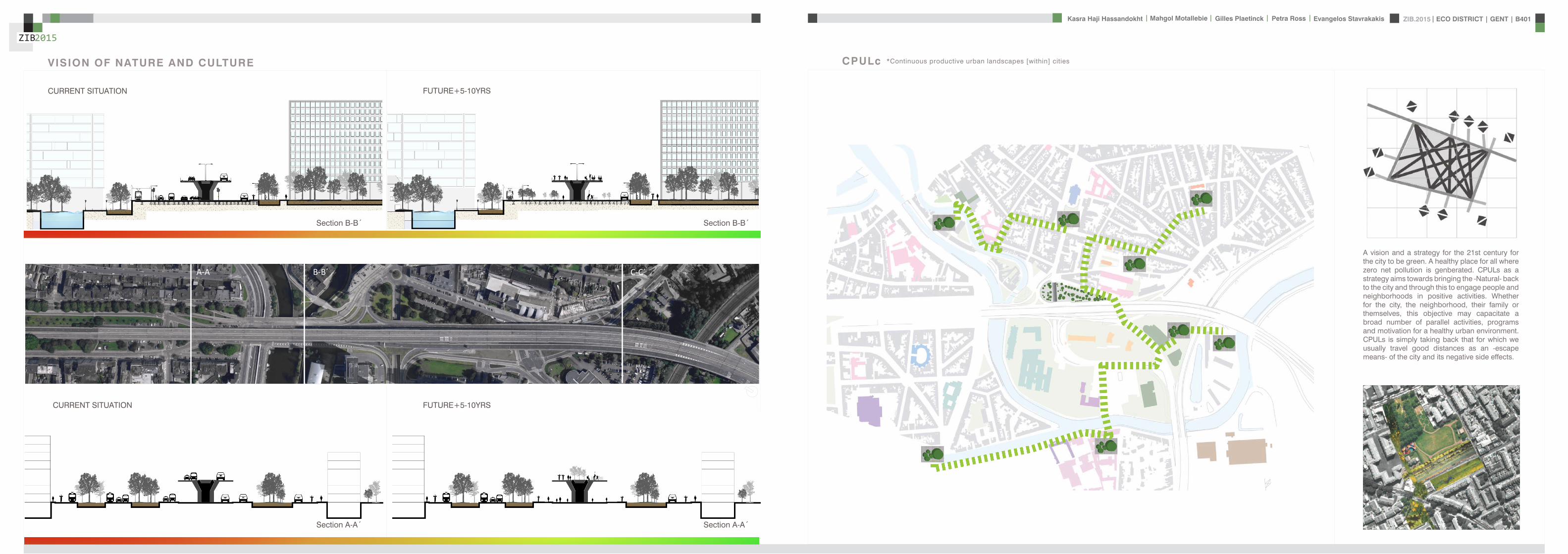
ZIB2015 ECO DISTRICT | GENT | B401Evangelos Stavrakakis | Petra Ross | Mahgol Motallebie | Gilles Plaetinck | Kasra Haji Hassandokht
ZIB2015
|
A BETWEEN CITIES B CITY RING
PUBLIC
PRIVATE
SUPPLY
PSKYtranel
PSKYtrangoogleCar
googleCar
P
cambio
SKYtran
minimized night
ONEwheel
eltram
C INSIDE THE CITY
tram
SKY TRANGOING DOWN TO RING
INTERCHANGE SPOT
euro
life
sty
le c
ha
ng
e o
ve
r ti
me
15 min
90 min
PREVENT COMMUTINGMORE LOCAL LIFESTYLE
A
B
C
sophisticated apps
SHAREWAY
INTERVENTION IN TIME CURRENT SITUATION ON CITY RING SKYTRAN MOBILITY - PASSIVE MAGLEV TECHNOLOGY
NOW
+ 5-10YRS
+ 50YRS
SPEED VISION
A between cities
B city ring
C inside the city
SK
YT
RA
N
GO
OG
LE
CA
R
ON
EW
HE
EL
PASSIVE MAGLEV REQUIRES VERY LIT-TLE ENERGY AND ONLY MINOR INFRA-STRUCTURE LEADING TO THE LOW-EST COST TRANSPORTATION SYSTEM KNOWN TO MAN
ACTIVE MALEV RQUIRES HIGH ENERGY AND MASSIVE INFRA-STRUCTURE LEADING TO HIGH COSTS AS WELL
Section C-Cacute
FUTURISTIC VISION
BICYCLE UNDERGROUND PARKING
SKYtran
MOBILITY VISION
ZIB2015 ECO DISTRICT | GENT | B401Evangelos Stavrakakis | Petra Ross | Mahgol Motallebie | Gilles Plaetinck | Kasra Haji Hassandokht
ZIB2015
|
SITE PLAN
OUTTER CITY RINGINTEREVENTION LOCATIONTOWARDS THE CITY CENTRE
ZONE A SPORT AND CULTURE Pi ZONE C TRANSPORT TRANSITIONZONE B INFO AND WORKSHOP
TOP OF THE FLYOVER PARK AND ENERGY
TRANSPORT
bikespedestrian ramp
elevated park
ramp for cars in 2 directionsbus
tram
ECO QUATER
ZIB
drawing over existing situation
roundabout+ underpass
OFFICE PARK
EDUCATION
EDUCATION
HOUSING FLATS
HOUSING
HOUSING
ECO CITY GHENT
0 50 100 200
HOUSING FLATSOFFICE PARK
COMMERCE
HOUSING
HOUSING
0 10 50 100
P
P
P
PEDESTRIANCYCLE ROADS
P
i
PLAY TRAILS
ALLOTMENTS
PEDESTRIAN CYCLE RAMP
RAMP FOR CARS
ZIB
ZONING PLAN
ZIB2015 ECO DISTRICT | GENT | B401Evangelos Stavrakakis | Petra Ross | Mahgol Motallebie | Gilles Plaetinck | Kasra Haji Hassandokht
ZIB2015
|
GROUNDPLANS 1100
B-Bacute
A-Aacute
B-Bacute
A-Aacute
B-Bacute
A-Aacute
B-Bacute
A-Aacute
ZIB2015 ECO DISTRICT | GENT | B401Evangelos Stavrakakis | Petra Ross | Mahgol Motallebie | Gilles Plaetinck | Kasra Haji Hassandokht
ZIB2015
|
SECTIONS 1100
Section A-AacuteSection B-Bacute
AArsquo
AArsquo
Detai l 01
Detai l 02
Detai l 03
Detai l 04
Detai l 05
Detai l 06
ZIB2015 ECO DISTRICT | GENT | B401Evangelos Stavrakakis | Petra Ross | Mahgol Motallebie | Gilles Plaetinck | Kasra Haji Hassandokht
ZIB2015
|
DETAILS
DETAIL 01 DETAIL 02 DETAIL 03 DETAIL 04 DETAIL 05 DETAIL 06
AArsquo
PIR f loorGypsum plasterboardPIR 100 mmOSB 15 mmFJI beam cel lu lose 350 mmcel i t 4D woodf iber 18 mmfinish gypsum plasterboard
plato wood f in ishframework 30 mmcel i t 4D 18 mmwood structure SLS 38140Eurowal l 2x70 mmOSB Eurothane G 70 mmfinish gypsum plasterboard
ZIB2015 ECO DISTRICT | GENT | B401Evangelos Stavrakakis | Petra Ross | Mahgol Motallebie | Gilles Plaetinck | Kasra Haji Hassandokht
ZIB2015
|
ELEVATIONS 1100
South elevation
South Elevation
North Elevation
South Elevation
North Elevation
South Elevation
North Elevation
South Elevation
North Elevation
North elevation
ZIB2015 ECO DISTRICT | GENT | B401Evangelos Stavrakakis | Petra Ross | Mahgol Motallebie | Gilles Plaetinck | Kasra Haji Hassandokht
ZIB2015
|
VISUALIZATIONS
East Elevation
West Elevation
East Elevation
West Elevation
East Elevation
West Elevation East Elevation
West Elevation
ELEVATIONS 1100
West elevation East elevation
ZIB2015 ECO DISTRICT | GENT | B401Evangelos Stavrakakis | Petra Ross | Mahgol Motallebie | Gilles Plaetinck | Kasra Haji Hassandokht
ZIB2015
|
VISUALIZATIONS
ZIB2015 ECO DISTRICT | GENT | B401Evangelos Stavrakakis | Petra Ross | Mahgol Motallebie | Gilles Plaetinck | Kasra Haji Hassandokht
ZIB2015
|
MATERIALS WOOD FCS Certi f ied Suppliers Distance MATERIALS Building Structure
ZIB2015 ECO DISTRICT | GENT | B401Evangelos Stavrakakis | Petra Ross | Mahgol Motallebie | Gilles Plaetinck | Kasra Haji Hassandokht
ZIB2015
|
MATERIALS Specs InsulationMATERIALS Specs Solid amp Structural Wood
ZIB2015 ECO DISTRICT | GENT | B401Evangelos Stavrakakis | Petra Ross | Mahgol Motallebie | Gilles Plaetinck | Kasra Haji Hassandokht
ZIB2015
|
MATERIALS Life Cycle Assesment MATERIALS Embodied energy CO2 other materials
ZIB2015 ECO DISTRICT | GENT | B401Evangelos Stavrakakis | Petra Ross | Mahgol Motallebie | Gilles Plaetinck | Kasra Haji Hassandokht
ZIB2015
|
STRUCTURE
Gilles Plaetinck
schaal
ZIB BUILDINGEnter address here
7 _ Unnamed
Owner
begeleider Checker
3D Copy 11 Gilles Plaetinck
schaal
ZIB BUILDINGEnter address here
8 _ Unnamed
Owner
begeleider Checker
3D Copy 21
Gilles Plaetinck
schaal
ZIB BUILDINGEnter address here
8 _ Unnamed
Owner
begeleider Checker
3D Copy 31
Gilles Plaetinck
schaal
ZIB BUILDINGEnter address here
9 _ Unnamed
Owner
begeleider Checker3D Copy 4
1
ECONOMY - USIBILITY DURING THE DAY
i1000
ALWAYS
2000
ECONONY - USIBILITY DURING THE DAY
GENERAL PRINCIPLES OF THE BUILDING
ZERO IMPACT APPROACH
i
0 Food market in park Vertical harvesting Entrance
1 Workshop area technical room
2 Info center Entrance from highway
3 Roof terrace
ZIB2015 ECO DISTRICT | GENT | B401Evangelos Stavrakakis | Petra Ross | Mahgol Motallebie | Gilles Plaetinck | Kasra Haji Hassandokht
ZIB2015
|
Vertical Harvest places plants on carousels that keep them moving the length of the greenhouse giving them equal time in natural light and also al-lowing workers to pick and tand transfer the crops Using hydroponics Verti-cal Harvest will be capa-ble of producing over
Vertical Harvest places plants on carousels that keep them moving the length of the pulls giving them equal time in natu-ral light and also allowing workers and local people to pick and transfer the crops Using hydroponics Vertical Harvest will be capable of producing over greens and herbs
Vertical Harvest places plants on carousels that keep them moving the length of the greenhouse giving them equal time in natural light and also al-lowing workers to pick and tand transfer the crops Using hydroponics Verti-cal Harvest will be capa-ble of producing over
Vertical Harvest places plants on carousels that keep them moving the length of the pulls giving them equal time in natu-ral light and also allowing workers and local people to pick and transfer the crops Using hydroponics Vertical Harvest will be capable of producing over greens and herbs
VERTICAL HARVESTING
PLANT CABLE LIFT (PLC) SECTION
Sustainable Food zorkshop centerrsquos mission is to ldquocultivate a healthy community by strengthening the local food system and improving access to nu-tritious affordable foodrdquo The main goal of our design is to deliver skills and information for sus-tainability practioners in the organic food tradeThe program attempts to1) affect positive changes in shopping cooking eating habits and nutrition2) reduce diet-related diseases3) promote the health and development of young children 4) place emphasis on local seasonal and cultural-ly-appropriate foods5) integrate food systems concepts into its curric-ulumndash such as shopping at farmers markets and growing onersquos own food
Healthy food is a basic human right the ability to access healthy food is often related to multiple issues and not just a result of low income
FOOD TEAM = a group of people from the same neighbourhood who work for the direct purchase of regional and seasonal products They order food on internet via web page voedselteambe and it is then delivered once a week to the depot of a team
+ minimal transport requirements+ no returnable packaging+ fair p+ fair pricing+ high-quality local and seasonal food+ community initiative
Sustainable Food zorkshop centerrsquos mission is to ldquocultivate a healthy community by strengthening the local food system and improving access to nu-tritious affordable foodrdquo The main goal of our design is to deliver skills and information for sus-tainability practioners in the organic food tradeThe program attempts to1) affect positive changes in shopping cooking eating habits and nutrition2) reduce diet-related diseases3) promote the health and development of young children 4) place emphasis on local seasonal and cultural-ly-appropriate foods5) integrate food systems concepts into its curric-ulumndash such as shopping at farmers markets and growing onersquos own food
Healthy food is a basic human right the ability to access healthy food is often related to multiple issues and not just a result of low income
FOOD TEAM = a group of people from the same neighbourhood who work for the direct purchase of regional and seasonal products They order food on internet via web page voedselteambe and it is then delivered once a week to the depot of a team
+ minimal transport requirements+ no returnable packaging+ fair p+ fair pricing+ high-quality local and seasonal food+ community initiative
Sustainable Food zorkshop centerrsquos mission is to ldquocultivate a healthy community by strengthening the local food system and improving access to nu-tritious affordable foodrdquo The main goal of our design is to deliver skills and information for sus-tainability practioners in the organic food tradeThe program attempts to1) affect positive changes in shopping cooking eating habits and nutrition2) reduce diet-related diseases3) promote the health and development of young children 4) place emphasis on local seasonal and cultural-ly-appropriate foods5) integrate food systems concepts into its curric-ulumndash such as shopping at farmers markets and growing onersquos own food
Healthy food is a basic human right the ability to access healthy food is often related to multiple issues and not just a result of low income
FOOD TEAM = a group of people from the same neighbourhood who work for the direct purchase of regional and seasonal products They order food on internet via web page voedselteambe and it is then delivered once a week to the depot of a team
+ minimal transport requirements+ no returnable packaging+ fair p+ fair pricing+ high-quality local and seasonal food+ community initiative
Healthy food is a basic human right the ability to access healthy food is often related to multiple issues and not just a result of low income
Sustainable Food zorkshop centerrsquos mission is to ldquocultivate a healthy community by strengthening the local food system and improving access to nutritious affordable foodrdquo The main goal of our design is to deliver skills and information for sustainability practioners in the organic food tradeThe program attempts to
1) affect positive changes in shopping cookingeating habits and nutrition2) reduce diet-related diseases3) promote the health and development of youngchildren4) place emphasis on local seasonal and culturally-appropriate foods5) integrate food systems concepts into its curriculumndashsuch as shopping at farmers markets andgrowing onersquos own food
FOOD TEAM = a group of people from the same neighbourhood who work for the direct purchase of regional and seasonal products They order food on internet via web page voedselteambe and it is then delivered once a week to the depot of a team
+ minimal transport requirements+ no returnable packaging+ fair pricing+ high-quality local and seasonal food+ community initiative
WORKSHOP
ZIB2015 ECO DISTRICT | GENT | B401Evangelos Stavrakakis | Petra Ross | Mahgol Motallebie | Gilles Plaetinck | Kasra Haji Hassandokht
ZIB2015
|
Black coral pea
Factors should be considered when seleccng plants
- Quality of growth- Ability to adapt to the wall environment- Environmental Tolerances- Temperature Resistance- Drought Tolerance- Wind - Wind Tolerance- Solar Exposure Tolerance- Salt Tolerance in Seaside installacons- Air and Water Pollucon Tolerance- Pest and Disease Resistance- Arcficial Environment Tolerance- Transplantacon Tolerance- Pruning - Pruning Tolerance
- Ornamental Qualices- Design Purpose- Manageability Maintainability- Environmental and Societal Effects- Visual Effect- Feeling Effect
Blac
k co
ral p
eaSn
ake
vine
kidn
ey w
eed
purple coral peaBasil
Pandorea
Black coral pea
Factors should be considered when seleccng plants
- Quality of growth- Ability to adapt to the wall environment- Environmental Tolerances- Temperature Resistance- Drought Tolerance- Wind - Wind Tolerance- Solar Exposure Tolerance- Salt Tolerance in Seaside installacons- Air and Water Pollucon Tolerance- Pest and Disease Resistance- Arcficial Environment Tolerance- Transplantacon Tolerance- Pruning - Pruning Tolerance
- Ornamental Qualices- Design Purpose- Manageability Maintainability- Environmental and Societal Effects- Visual Effect- Feeling Effect
Blac
k co
ral p
eaSn
ake
vine
kidn
ey w
eed
purple coral peaBasil
Pandorea
Black coral pea
Factors should be considered when seleccng plants
- Quality of growth- Ability to adapt to the wall environment- Environmental Tolerances- Temperature Resistance- Drought Tolerance- Wind - Wind Tolerance- Solar Exposure Tolerance- Salt Tolerance in Seaside installacons- Air and Water Pollucon Tolerance- Pest and Disease Resistance- Arcficial Environment Tolerance- Transplantacon Tolerance- Pruning - Pruning Tolerance
- Ornamental Qualices- Design Purpose- Manageability Maintainability- Environmental and Societal Effects- Visual Effect- Feeling Effect
Blac
k co
ral p
eaSn
ake
vine
kidn
ey w
eed
purple coral peaBasil
Pandorea
GREEN WALLS
ZIB2015 ECO DISTRICT | GENT | B401Evangelos Stavrakakis | Petra Ross | Mahgol Motallebie | Gilles Plaetinck | Kasra Haji Hassandokht
ZIB2015
|
Extraction of air
Pulsion of airRecuperation unit
outdoor space
18 degC15 degC
18 degC
In-take Out-take of air
VENTILATION
Gilles Plaetinck
schaal 1 100
ZIB BUILDINGEnter address here
3 _ level 2
Owner
begeleider Checker
DN
Gilles Plaetinck
schaal 1 100
ZIB BUILDINGEnter address here
2 _ level 1
Owner
begeleider Checker
Extraction of air
Pulsion of air
VENTILATION IN GROUPLANS CALCULATION AND SYSTEM
level 01
level 02
T 42ECO DISTRICT | GENT | B401
ZIB2015Mechanical Ventilation with Heat Recovery (MVHR)
Up to 95 of the heat can be recovered The Heat Recovery Unit runs continu-ously on trickle and can and is boosted when higher rates of ventilation are required eg bathing cooking In warmer months a summer by-pass function helps ensure comfort levels are maintained in the home When summer by-pass is activated the dwelling contin-ues to be ventilaated and recieve fresh filtered air however the heat recovery process is intermittently switched off (heat recovery is by-passed)
Key BenefitsYear round removal of condensation and indoor pol-lutants A direct impact on the Dwelling Emission Rate re-quired in SAP helping reduce the carbon footprint of the property Fresh filtered air supplied to dwelling ideal for allergy sufferers and those with conditions such as asthma A balanced ventilation system for the whole house and recovering of heat that would have otherwise have been lost Low noise non-intrusive ventilation system ndash located away from the room however consideration should be given to duct runs to ensure cross-talk contamination doesnrsquot happen AND the unit is sized correctly so it is not running a high rate all of the time
Zehnder ComfoSystems Passive Haus accredited product suitable for large houses up to 300m2 Designed to ensure low noise excellent energy performance and heat exchange efficiency Choice of control options including LCD touch screen display Can be combine with ComfoCool for optional cooling of up to 5 degrees and humidity reduction by 20
Semi Rigid Ducting
With a manifold system the resistance caused by duct-ing is reduced therefore Semi-Rigid ducting resistance is very low The manifold takes mass airflow directly from the MVHR Heat Recovery Unit and allows lower rates to pass through to each individual room runDirecting mass flow to the manifold eliminates the need to increase the running speed of the MVHR Heat Re-covery unit to overcome the resistance of ducting which in turn causes noise for the homeowner
T 42ECO DISTRICT | GENT | B401
ZIB2015Mechanical Ventilation with Heat Recovery (MVHR)
Up to 95 of the heat can be recovered The Heat Recovery Unit runs continu-ously on trickle and can and is boosted when higher rates of ventilation are required eg bathing cooking In warmer months a summer by-pass function helps ensure comfort levels are maintained in the home When summer by-pass is activated the dwelling contin-ues to be ventilaated and recieve fresh filtered air however the heat recovery process is intermittently switched off (heat recovery is by-passed)
Key BenefitsYear round removal of condensation and indoor pol-lutants A direct impact on the Dwelling Emission Rate re-quired in SAP helping reduce the carbon footprint of the property Fresh filtered air supplied to dwelling ideal for allergy sufferers and those with conditions such as asthma A balanced ventilation system for the whole house and recovering of heat that would have otherwise have been lost Low noise non-intrusive ventilation system ndash located away from the room however consideration should be given to duct runs to ensure cross-talk contamination doesnrsquot happen AND the unit is sized correctly so it is not running a high rate all of the time
Zehnder ComfoSystems Passive Haus accredited product suitable for large houses up to 300m2 Designed to ensure low noise excellent energy performance and heat exchange efficiency Choice of control options including LCD touch screen display Can be combine with ComfoCool for optional cooling of up to 5 degrees and humidity reduction by 20
Semi Rigid Ducting
With a manifold system the resistance caused by duct-ing is reduced therefore Semi-Rigid ducting resistance is very low The manifold takes mass airflow directly from the MVHR Heat Recovery Unit and allows lower rates to pass through to each individual room runDirecting mass flow to the manifold eliminates the need to increase the running speed of the MVHR Heat Re-covery unit to overcome the resistance of ducting which in turn causes noise for the homeowner
MECHANICAL VENTILATION WITH HEAT RECOVERY (MVHR)
Up to 95 of the heat can be recoveredThe Heat Recovery Unit runs continuously on trickle and can and is boosted when higher rates of ventilation are required eg bathing cooking
In warmer months a summer by-pass function helps ensure comfort levels are maintained in the home When summer by-pass is activated the dwelling continues to be ventilaated and recieve fresh filtered air however the heat recovery process is intermittently switched off (heat recovery is by-passed)
EXTRACT VENTILATION RATES
T 42ECO DISTRICT | GENT | B401
ZIB2015Mechanical Ventilation with Heat Recovery (MVHR)
Up to 95 of the heat can be recovered The Heat Recovery Unit runs continu-ously on trickle and can and is boosted when higher rates of ventilation are required eg bathing cooking In warmer months a summer by-pass function helps ensure comfort levels are maintained in the home When summer by-pass is activated the dwelling contin-ues to be ventilaated and recieve fresh filtered air however the heat recovery process is intermittently switched off (heat recovery is by-passed)
Key BenefitsYear round removal of condensation and indoor pol-lutants A direct impact on the Dwelling Emission Rate re-quired in SAP helping reduce the carbon footprint of the property Fresh filtered air supplied to dwelling ideal for allergy sufferers and those with conditions such as asthma A balanced ventilation system for the whole house and recovering of heat that would have otherwise have been lost Low noise non-intrusive ventilation system ndash located away from the room however consideration should be given to duct runs to ensure cross-talk contamination doesnrsquot happen AND the unit is sized correctly so it is not running a high rate all of the time
Zehnder ComfoSystems Passive Haus accredited product suitable for large houses up to 300m2 Designed to ensure low noise excellent energy performance and heat exchange efficiency Choice of control options including LCD touch screen display Can be combine with ComfoCool for optional cooling of up to 5 degrees and humidity reduction by 20
Semi Rigid Ducting
With a manifold system the resistance caused by duct-ing is reduced therefore Semi-Rigid ducting resistance is very low The manifold takes mass airflow directly from the MVHR Heat Recovery Unit and allows lower rates to pass through to each individual room runDirecting mass flow to the manifold eliminates the need to increase the running speed of the MVHR Heat Re-covery unit to overcome the resistance of ducting which in turn causes noise for the homeowner
T 42ECO DISTRICT | GENT | B401
ZIB2015Mechanical Ventilation with Heat Recovery (MVHR)
Up to 95 of the heat can be recovered The Heat Recovery Unit runs continu-ously on trickle and can and is boosted when higher rates of ventilation are required eg bathing cooking In warmer months a summer by-pass function helps ensure comfort levels are maintained in the home When summer by-pass is activated the dwelling contin-ues to be ventilaated and recieve fresh filtered air however the heat recovery process is intermittently switched off (heat recovery is by-passed)
Key BenefitsYear round removal of condensation and indoor pol-lutants A direct impact on the Dwelling Emission Rate re-quired in SAP helping reduce the carbon footprint of the property Fresh filtered air supplied to dwelling ideal for allergy sufferers and those with conditions such as asthma A balanced ventilation system for the whole house and recovering of heat that would have otherwise have been lost Low noise non-intrusive ventilation system ndash located away from the room however consideration should be given to duct runs to ensure cross-talk contamination doesnrsquot happen AND the unit is sized correctly so it is not running a high rate all of the time
Zehnder ComfoSystems Passive Haus accredited product suitable for large houses up to 300m2 Designed to ensure low noise excellent energy performance and heat exchange efficiency Choice of control options including LCD touch screen display Can be combine with ComfoCool for optional cooling of up to 5 degrees and humidity reduction by 20
Semi Rigid Ducting
With a manifold system the resistance caused by duct-ing is reduced therefore Semi-Rigid ducting resistance is very low The manifold takes mass airflow directly from the MVHR Heat Recovery Unit and allows lower rates to pass through to each individual room runDirecting mass flow to the manifold eliminates the need to increase the running speed of the MVHR Heat Re-covery unit to overcome the resistance of ducting which in turn causes noise for the homeowner
Heating 10 kwh msup2aCooling 4 kWh msup2aOverheating 42
ZIB2015 ECO DISTRICT | GENT | B401Evangelos Stavrakakis | Petra Ross | Mahgol Motallebie | Gilles Plaetinck | Kasra Haji Hassandokht
ZIB2015
|
Shutters control system+ -
Solar roadways - PV panels
LED lights
Elevator Fuse box
ElectricityBattery withtransformator
ELECTRICITY
Summer night
cross- ventilation through building
Summer day
air through recuperation unit small change of temperature
15 degC 18 degC
+ groundplans
heated zone
not heated zone
ZONING ACCORDING TO TEMPERATURESSUMMER NIGHT - cross-ventilation through building
SUMMER DAY - air through recuperation unit small change of temperatureSHADING SYSTEM
As a shading was chozen system Renson Icarus Lamellas with angle 45deg made in wood
ZIB2015 ECO DISTRICT | GENT | B401Evangelos Stavrakakis | Petra Ross | Mahgol Motallebie | Gilles Plaetinck | Kasra Haji Hassandokht
ZIB2015
|
average only 4 hours of peak daylight hours per day (4 x 365 = 1460 hours per year)
- Surface area ( first part) Fly-over +- 20 000 msup2-gt 16 000 x 230 Watt = 3 680 000 Watt or 3680 kWonly 50 of fly-over covered with solar roadways
-gt 3680 kW x 4 h = 7360 kWh day-gt 3680 kW x 1460 h = 2 686 400 kWh year -gt +- 540 households (+- 5000 kWh year)
Tesla Powerwall Therersquos a 10 kWh unit at $3500 -gt 737 Tesla Batteries
gt the Solar Roadway has the ability to cut greenhouse gases by up to 75-percentgt A decentralized self-healing secure power grid
IN FRONT OF FLY-OVER
- Surface area Fly-over = 16 x 30 m = 480 msup2-gt 384 x 230 Watt = 88 320 Watt or 883 kWonly 50 of fly-over covered with solar roadways
-gt 44 kW x 4 h = 176 kWh day-gt 44 kW x 1460 h = 64 240 kWh year -gt +- 13 households (+- 5000 kWh year)
lightsshutters
elevator
2 fridges
2 coffeemakers
1 microwave
1 owen
2 cooking plates
stereo
ventilation unit
electricity transformer (AC to DC) for PV panels + batteries
summer 05 kWh daywinter 03 kWh day183 days x 05= 915 kWh182 days x 03 = 546 kWh = 1641 kWh
262 kWh
A++fridge 104 kWhyear104 x x2 = 208 kWh
900 W x 01 hours day = 09 kWhx 220 days x 2= 198 kWh a
67 kWh a
085x100 days= 85 kWh a
400 kWh x 2 = 800 kWh a
150 kWh a 419 kWha
68 kWh a
ENERGY DEMAND OVERVIEW ENERGY SUPPLY OVERVIEW - FLY-OVER
1 spot 56 W 10000 = 0056 KW4 hours per day 365 days a year = 1460 h0056 x 1460 = 8176 kWh10 spots x 8176= 8176 kWh a
1 spot 72 W 10000 = 0072 KW4 hours per day 365 days a year = 1460 h0072 x 1460 = 10512 kWh5 spots x 10512= 5256 kWh a
1 spot 52 W 10000 = 0052 KW4 hours per day 365 days a year = 1460 h0052 x 1460 = 7592 kWh21 spots x 7592= 159432 kWh a
1 spot 9 W 10000 = 0009 KW4 hours per day 365 days a year = 1460 h0009 x 1460 = 1314 kWh5 spots x 1314 = 657 kWh a
SOLAR ROADWAYS - PV PANELSEnergy from the sun
1 To generate energy for the ZIB building2 To generate energy for the surrounding houses3 To generate energy for lighting or signs on the road4 The panels will also have the capacity to charge electric vehicles while parked
ELECTRICITY SCHEME
5423 kWh a
ZIB2015 ECO DISTRICT | GENT | B401Evangelos Stavrakakis | Petra Ross | Mahgol Motallebie | Gilles Plaetinck | Kasra Haji Hassandokht
ZIB2015
|
SUMMER SUNNY 10-42 LUXWINTER SUNNY 10-42 LUX
DAYLIGHT - DIALuxLIGHTING SYSTEM - DIALux
Workplane 9 Results overview
Height of working plane 0800 m Wall zone 0000 m
Result Mean (target) Min Max Minaverage MinmaxPerpendicular illuminance [lx] 463 (500) 105 689 0227 0152
Profile Offices Writing typewriting reading data processing
B401-Gent 6222015
Site 1 Building 2 Zib Room 9 Workplane 9 Results overview
Page 70
Workplane 9 False coloursPerpendicular illuminance (adaptive)
Scale 1 200
Perpendicular illuminance (Surface)Mean (actual) 463 lx Min 105 lx Max 689 lx Minaverage 0227 Minmax 0152
B401-Gent 6222015
Site 1 Building 2 Zib Room 9 Workplane 9 False coloursPerpendicular illuminance (adaptive)
Page 72
Workplane 9 Value chartPerpendicular illuminance (adaptive)
Scale 1 200
Perpendicular illuminance (Surface)Mean (actual) 463 lx Min 105 lx Max 689 lx Minaverage 0227 Minmax 0152
B401-Gent 6222015
Site 1 Building 2 Zib Room 9 Workplane 9 Value chartPerpendicular illuminance (adaptive)
Page 73
Workplane 13 Results overview
Height of working plane 0800 m Wall zone 0000 m
Result Mean (target) Min Max Minaverage MinmaxPerpendicular illuminance [lx] 388 (500) 69 732 0178 0094
Profile Offices Writing typewriting reading data processing
B401-Gent 6222015
Site 1 Building 6 Storey 1 Room 13 Workplane 13 Results overview
Page 94
Workplane 13 False coloursPerpendicular illuminance (adaptive)
Scale 1 100
Perpendicular illuminance (Surface)Mean (actual) 388 lx Min 69 lx Max 732 lx Minaverage 0178 Minmax 0094
B401-Gent 6222015
Site 1 Building 6 Storey 1 Room 13 Workplane 13 False coloursPerpendicular illuminance (adaptive)
Page 96
Workplane 13 Value chartPerpendicular illuminance (adaptive)
Scale 1 100
Perpendicular illuminance (Surface)Mean (actual) 388 lx Min 69 lx Max 732 lx Minaverage 0178 Minmax 0094
B401-Gent 6222015
Site 1 Building 6 Storey 1 Room 13 Workplane 13 Value chartPerpendicular illuminance (adaptive)
Page 97
Workplane 9 False coloursPerpendicular illuminance (adaptive)
Scale 1 200
Perpendicular illuminance (Surface)Mean (actual) 463 lx Min 105 lx Max 689 lx Minaverage 0227 Minmax 0152
B401-Gent 6222015
Site 1 Building 2 Zib Room 9 Workplane 9 False coloursPerpendicular illuminance (adaptive)
Page 72
1st f loor 2nd f loor Site 1 Luminaire parts listQuantity Luminaire (Luminous emittance)10 3F Filippi 12736 P 202x24W LED OP 196x1231
Luminous emittance 1Fitting 1x24W 2xLEDLight output ratio 100Lamp luminous flux 5332 lmLuminaire Luminous Flux 5332 lmPower 560 WLight yield 952 lmW
200
300
400
cdklm η = 100C0 - C180 C90 - C270
0deg 15deg 30deg
45deg
60deg
75deg
90deg
105deg105deg
90deg
75deg
60deg
45deg
30deg 15deg 0deg
5 SFN Eclairages 0732360X CLFV 236Luminous emittance 1Fitting 2xT26 36W840Light output ratio 6889Lamp luminous flux 6700 lmLuminaire Luminous Flux 4615 lmPower 720 WLight yield 641 lmW
160
240
cdklm η = 69C0 - C180 C90 - C270
0deg 15deg 30deg
45deg
60deg
75deg
90deg
105deg105deg
90deg
75deg
60deg
45deg
30deg 15deg 0deg
21 SFN Eclairages 332226XX SAM F 2x26W BELuminous emittance 1Fitting 2xTC-DEL 26W840Light output ratio 3297Lamp luminous flux 3600 lmLuminaire Luminous Flux 1187 lmPower 520 WLight yield 228 lmW
40
60
80
100
120
140
cdklm η = 33C0 - C180 C90 - C270
0deg 15deg 30deg
45deg
60deg
75deg
90deg
105deg105deg
90deg
75deg
60deg
45deg
30deg 15deg 0deg
1 Signcomplex AR111-009-AW-W-06 AR111 COB 9W38deg WhiteLuminous emittance 1Fitting 1xAR111-009-AW-W-06Light output ratio 8078Lamp luminous flux 600 lmLuminaire Luminous Flux 485 lmPower 90 WLight yield 539 lmW
800
1200
cdklm η = 81C0 - C180 C90 - C270
0deg 15deg 30deg
45deg
60deg
75deg
90deg
105deg105deg
90deg
75deg
60deg
45deg
30deg 15deg 0deg
Total lamp luminous flux 163020 lm Total luminaire luminous flux 101807 lm Total Load 20210 W Light yield 504 lmW
B401-Gent 6222015
Site 1 Luminaire parts list
Page 19
10x
6x
21x
1x
types of l ights
Perpendicular i l luminance (Surface)Mean (actual ) 463 lx Min 105 lx Max 689 lx Minaverage 0 227 Minmax 0 152
Perpendicular i l luminance (Surface)Mean (actual ) 388 lx Min 69 lx Max 732 lx Minaverage 0 178 Minmax 0 094
ZIB2015 ECO DISTRICT | GENT | B401Evangelos Stavrakakis | Petra Ross | Mahgol Motallebie | Gilles Plaetinck | Kasra Haji Hassandokht
ZIB2015
|
Tube hybrid Solar panels
Hot water tank Water taps
City water supply
Rain water collection for vertical harvesting
City water supply
WADI
Rain water tank
WATER MANAGEMENT
Sinks
Available roof area
In Ghent avarage of 900mmm2year
3197 m2
09x 3197 = 28773 m3year
RAIN WATER GAIN
toilet - 3x - 03lskitchen -4x - 02ls
POTABLE WATER DEMAND
3 toiletsVertical gardening
Total
relative RW usage
300 l day150 l day = 450lday= 16425 m3 year
1407 lday100m2
RAIN WATER DEMAND
RAIN WATER TANK
Relative RWT volumeRain water tank volume
3m3 100 m2
9591 l gt 10 m3
DIMESION OF PIPES
City water supplyRainwater tank
178 mm (DN 18 - 15 - 12)165 mm (DN 17-15)
are composed of hexagonal tiles Rainwater can infiltrate between the gaps from where it goes to rainwatter collector which supplies the vegetation on fly-over
THE SOLAR ROADWAYS
WATER SUPPLY SCHEME AND CALCULATION
ZIB2015 ECO DISTRICT | GENT | B401Evangelos Stavrakakis | Petra Ross | Mahgol Motallebie | Gilles Plaetinck | Kasra Haji Hassandokht
ZIB2015
|
WADI
City water supply
Rain water tank
Sinks
Divided sewer systemwithin building
SEWAGE SYSTEM
ToiletToilet sinkKitchen sink
DU = 2 lsDU = 05 lsDU = 08 ls
WATER DRAINAGE OF DEVICES
Frequency of usage at the same time
K 05
DIMESION OF PIPES
Black waterGrey water
110 mm (DU 110)75 mm (DU 75 - 63)
WATER DRAINAGE SCHEME AND CALCULATION
ZIB2015 ECO DISTRICT | GENT | B401Evangelos Stavrakakis | Petra Ross | Mahgol Motallebie | Gilles Plaetinck | Kasra Haji Hassandokht
ZIB2015
|
DN
Gilles Plaetinck
schaal 1 100
ZIB BUILDINGEnter address here
2 _ level 1
Owner
begeleider Checker
Gilles Plaetinck
schaal 1 100
ZIB BUILDINGEnter address here
3 _ level 2
Owner
begeleider Checker
WATER SUPPLY
HOT WATER
WATER DRAINAGE
WATER SUPPLY AND DRAINAGE IN GROUPLANS
level 01
level 02
ENERGY
RAINWATER TANK
HELOPHYTE FILTER
IRRIGATION SYSTEM
BIO-ROTOR
MICRO TURBINE
PHOSPHOR
In this building a closed water system is applied which is based on reusing water in mullple wasRainRain water from the roof will be collected in a storage tank situated on the ground floor This water will be used to flush the toilet and irrigate crops in verlcal harveslng system In case of an overflow the water will be stored in the con-structed wetland near the building The rainwater can be fil-tered through a helophyte filter up to drinking water stan-dard The waste water system includes three types of water yellyellow black and grey waterThe yellow water will be stored for its phosphor while the black water will be purified into grey water This grey water is comparable to the quality of rain water aaer purificalon b means of a bio rotor The remaining residue from the bio rotor together with the organic waste from the harveslng is fermented into biogas that drives a micro turbine in order to produce some addilonal energy
TheThe waste product deriving from this process will be used as compost in verlcal harveslng This efficient yet complex system closes the ullizalon cycle of the building and turns it into an efficient vicious circle that can be considered au arkic
In this building a closed water system is applied which is based on reusing water in multiple was
Rain water from the roof will be collected in a storage tank situated on the ground floor This water will be used to flushthe toilet and irrigate crops in vertical harvesting system In case of an overflow the water will be stored in the constructed wetland near the building The rainwater can be filtered through a helophyte filter up to drinking water standard
The waste water system includes three types of water yellow black and grey water The yellow water will be stored for its phosphor while the black water will be purified into grey water This grey water is comparable to the quality of rain water after purification b means of a bio rotor The remaining residue from the bio rotor together with the organic waste from the harvesting is fermented into biogas that drives a micro turbine in order to produce some additional energy The waste product deriving from this process will be used ascompost in ver1048991cal harves1048991ng This efficient yet complexsystem closes the u1048991liza1048991on cycle of the building and turns itinto an efficient vicious circle that can be considered au arkic
WATER CYCLE
ZIB2015 ECO DISTRICT | GENT | B401Evangelos Stavrakakis | Petra Ross | Mahgol Motallebie | Gilles Plaetinck | Kasra Haji Hassandokht
ZIB2015
|
CALCULATIONS
Passive House verification
Photo or Drawing
Building Workshop + info pointStreet
PostcodeCityCountry
Building Type non-residentialClimate Ukkel
Home Owner(s) Client(s)Street
PostcodeCity
ArchitectStreet
PostcodeCity Calculation electricity Internal heat gains
Mechanical System Building type
StreetPostcodeCity Internal heat gains
Year of Construction 2015 Interior Temperature 200 degC Utilisation pattern
Number of Dwelling Units 1 Internal Heat Gains 20 Wm2 Type of values used Fill in worksheet IHG Non-Dom Enclosed Volume Ve 12442 Planned number of occupants
Number of Occupants 80 8 Design
Specific building demands with reference to the treated floor area use Annual method
Treated floor area 2840 msup2 Requirements Fulfilled Verification Annual method The monthly method should be used for building certification
Space heating Annual heating demand 10 kWh(m2a) 15 kWh(msup2a) yes Specific space heating demand annual method 103 kWh(msup2a)
Heating load 11 Wm2 10 Wmsup2 - Specific space heating demand monthly Method 120 kWh(msup2a)
Space cooling Overall specific space cooling demand kWh(m2a) 15 kWh(msup2a)
Cooling load Wm2 - -Frequency of overheating (gt 25 degC) - -
Primary Energy Space heating and dehumidification
cooling household electricity 73 kWh(m2a) 120 kWh(msup2a) yes
DHW space heating and auxiliary electricity 24 kWh(m2a) - -Specific primary energy reduction through solar electricity 21 kWh(m2a) - -
Airtightness Pressurization test result n50 06 1h 06 1h yes
PHPP Verification FINAL ZIB FILE CALCULTIONS PHPPxls
L B H VOLUME
main 1 226 7 4 6328main 2 184 7 35 4508
core 0 6 2 5 3 5 108 5core 0 62 5 35 1085core 3 62 3 28 521
12442
AREAmain 1 storage 35
wc big 35wc 2wc 2workshop 103
MAIN 2 infolounge 92
staircase 56storage technical 22
284
Floor_exterior 1582 31 1272
Roof_exterior 1582
Passive House verification
Photo or Drawing
Building Workshop + info pointStreet
PostcodeCityCountry
Building Type non-residentialClimate Ukkel
Home Owner(s) Client(s)Street
PostcodeCity
ArchitectStreet
PostcodeCity Calculation electricity Internal heat gains
Mechanical System Building type
StreetPostcodeCity Internal heat gains
Year of Construction 2015 Interior Temperature 200 degC Utilisation pattern
Number of Dwelling Units 1 Internal Heat Gains 20 Wm2 Type of values used Fill in worksheet IHG Non-Dom Enclosed Volume Ve 12442 Planned number of occupants
Number of Occupants 80 8 Design
Specific building demands with reference to the treated floor area use Annual method
Treated floor area 2840 msup2 Requirements Fulfilled Verification Annual method The monthly method should be used for building certification
Space heating Annual heating demand 10 kWh(m2a) 15 kWh(msup2a) yes Specific space heating demand annual method 103 kWh(msup2a)
Heating load 11 Wm2 10 Wmsup2 - Specific space heating demand monthly Method 120 kWh(msup2a)
Space cooling Overall specific space cooling demand kWh(m2a) 15 kWh(msup2a)
Cooling load Wm2 - -Frequency of overheating (gt 25 degC) - -
Primary Energy Space heating and dehumidification
cooling household electricity 73 kWh(m2a) 120 kWh(msup2a) yes
DHW space heating and auxiliary electricity 24 kWh(m2a) - -Specific primary energy reduction through solar electricity 21 kWh(m2a) - -
Airtightness Pressurization test result n50 06 1h 06 1h yes
PHPP Verification FINAL ZIB FILE CALCULTIONS PHPPxls
SURFACE AREAcurrent orientation only night ventilation
current orientation only night ventilation 6 windows less 52 msup2
current orientation only night ventilation 7 windows less 60msup2 (stays the same for each side)
current orientation only night ventilation 8 windows less 69 msup2
orientation turned 90deg only night ventilation 6 windows less 52 msup2
orientation turned 90deg only night ventilation 7 windows less 60msup2 (window less at SE side)
orientation turned 90deg only night ventilation 8 windows less 69 msup2
-gt orientation turned 90deg only night ventilation 9 windows less 77msup2 (window less at NW side althought theres less overheating in the case of a window less at SE side the heating demand exceeds 15)
CHANGE IN DESIGN
ZIB2015 ECO DISTRICT | GENT | B401Evangelos Stavrakakis | Petra Ross | Mahgol Motallebie | Gilles Plaetinck | Kasra Haji Hassandokht
ZIB2015
|
Passive House verificationS P E C I F I C A N N U A L H E A T I N G D E M A N D
Climate Ukkel Interior Temperature 200 degC
Building Workshop + info point Building TypeUse non-residentialTreated Floor Area ATFA 2840 msup2
per msup2Area U-Value Temp Factor ft Gt Treated Data for heating balance diagram
Building Element Temperature Zone msup2 W(msup2K) kKha kWha Floor Area Losses GainsExterior Wall - Ambient A 5595 0101 100 743 = 4181 1472 Exterior Wall - Ambient 147234373Exterior Wall - Ground B 069 = Exterior Wall - GroundRoofCeiling - Ambient A 1550 0094 100 743 = 1085 382 RoofCeiling - Ambient 381903529Floor slab basement ceiling B 310 0105 069 743 = 167 059 Floor slab basement ceiling 058811509
A 100 =A 100 =
unheated basement X 075 = unheated basementWindows A 1154 0648 100 743 = 5562 1958 Windows 195834732Exterior Door A 100 = Exterior DoorExterior TB (lengthm) A 1169 -0030 100 743 = -259 -091 Thermal Bridge Heat LossPerimeter TB (lengthm) P 069 = 000 not useful heat gains 365267499Ground TB (lengthm) B 069 =
Total of All Building Envelope Areas 8609 ndashndashndashndashndashndashndashndashndashndashndashndashndash- kWh(msup2a) Ventilation 395818713
Transmission Heat Losses QT Total 10736 378Annual Heating Demand 102516636
ATFA Clear Room Height internal gains 100951487msup2 m msup3 passive solar gains 250668423
Ventilation System Effective Air Volume VV 2840 280 = 7952 Thermal bridge credit 091126837Effective Heat Recovery Efficiency eff 81 Cross check sum 46324923 46324923of Heat Recovery
Efficiency of Subsoil Heat Exchanger SHX 0 nVsystem HR nVRes
1h 1h 1h
Energetically Effective Air Exchange nV 0105 (1 - 081 ) + 0038 = 0058
VV nV cAir Gt
msup3 1h Wh(msup3K) kKha kWha kWh(msup2a)
Ventilation Heat Losses QV 795 0058 033 743 = 1124 40
Reduction Factor QT QV NightWeekend
kWha kWha Saving kWha kWh(msup2a)
Total Heat Losses QL ( 10736 + 1124 ) 10 = 11860 418
Orientation Reduction Factor g-Value Area Radiation HPof the Area See Windows Sheet (perp radiation)
msup2 kWh(msup2a) kWha
1 North 054 050 2700 163 = 11822 East 058 000 440 197 = 03 South 056 050 4860 314 = 42874 West 032 050 3216 254 = 13275 Horizontal 063 050 324 317 = 323
kWh(msup2a)
Available Solar Heat Gains QS Total 7119 251
Length Heat Period Spec Power qI ATFA
khd da Wmsup2 msup2 kWha kWh(msup2a)
Internal Heat Gains QI 0024 209 201 2840 = 2867 101
kWha kWh(msup2a)
Free Heat QF QS + QI = 9986 352
Ratio of Free Heat to Losses QF QL = 084
Utilisation Factor Heat Gains G (1 - ( QF QL )5 ) (1 - ( QF QL )
6 ) = 90kWha kWh(msup2a)
Heat Gains QG G QF = 8949 315
kWha kWh(msup2a)
Annual Heating Demand QH QL - QG = 2911 10
kWh(msup2a) (YesNo)
Limiting Value 15 Requirement met yes
00
147
00
3806000000
196
00
40
37
09
103
101
251
0
5
10
15
20
25
30
35
40
45
50
Losses Gains
Hea
t flo
ws
[kW
h(m
sup2a)]
Heating energy balance
passive solar gains
internal gains
Annual Heating Demand
Thermal bridge credit
not useful heat gains
Ventilation
Exterior Door
Windows
unheated basement
Floor slab basement ceiling
RoofCeiling - Ambient
Exterior Wall - Ground
Exterior Wall - Ambient
Thermal Bridge Heat Loss
HPP Annual Heating Demand FINAL ZIB FILE CALCULTIONS PHPPxls
Passive House verification Passive House verificationS P E C I F I C U S E F U L C O O L I N G D E M A N D S P E C I F I C U S E F U L C O O L I N G D E M A N D
M O N T H L Y M E T H O D M O N T H L Y M E T H O D
(This page displays the sums of the monthly method over the cooling period))Climate Ukkel Interior Temperature Summer 25 degC Climate Ukkel Interior Temperature 25 degC
Building Workshop + info point Building TypeUse non-residential Building Workshop + info point Building TypeUse non-residential
Spec Capacity 60 Wh(msup2K) (Enter in Summer worksheet) Treated Floor Area ATFA 2840 msup2 Treated Floor Area ATFA 284 msup2
per msup2Temperature Zone Area U-Value Mon Red Fac Gt Treated Jan Feb Mar Apr May Jun Jul Aug Sep Oct Nov Dec Year
Building Element msup2 W(msup2K) kKha kWha Floor Area Heating Degree Hours - Ex 168 150 144 121 92 73 57 59 82 109 140 160 136 kKh1 Exterior Wall - Ambient A 5595 0101 100 103 = 5782 Heating Degree Hours - G 126 123 135 120 106 83 63 54 58 71 86 109 113 kKh2 Exterior Wall - Ground B 100 = Losses - Exterior 2553 2286 2189 1838 1393 1117 871 904 1245 1660 2123 2432 20612 kWh3 RoofCeiling - Ambient A 1550 0094 100 103 = 1500 Losses - Ground 41 40 44 39 35 27 21 18 19 23 28 36 370 kWh4 Floor slab basement ceil B 310 0105 100 90 = 294 Losses Summer Ventilatio 67 71 244 372 629 720 880 865 658 499 234 126 5366 kWh5 A 100 = Sum Spec Heat Losses 94 84 87 79 72 66 62 63 68 77 84 91 928 kWhmsup26 A 100 = Solar Load North 44 81 141 212 286 298 298 255 178 116 54 35 1998 kWh7 unheated basement X 075 = Solar Load East 0 0 0 0 0 0 0 0 0 0 0 0 0 kWh8 Windows A 1154 0648 100 103 = 7690 Solar Load South 218 315 464 577 681 644 681 658 532 416 242 171 5601 kWh9 Exterior Door A 100 = Solar Load West 79 125 213 303 385 378 370 347 256 177 91 60 2785 kWh
10 Exterior TB (lengthm) A 1169 -0030 100 103 = -358 Solar Load Horiz 11 21 37 57 79 79 80 69 47 30 14 9 533 kWh11 Perimeter TB (lengthm) P 100 = Solar Load Opaque 3 5 9 13 18 19 19 16 11 7 3 2 126 kWh12 Ground TB (lengthm) B 100 = Internal Heat Gains 425 384 425 411 425 411 425 425 411 425 411 425 5001 kWh
ndashndashndashndashndashndashndashndashndashndashndash kWh(msup2a) Sum Spec Loads Solar + 28 33 45 55 66 64 66 62 51 41 29 25 565 kWhmsup2
Transmission Losses QT (Negative Heat Loads) Total 14907 525 Utilisation Factor Losses 29 39 52 69 84 88 82 88 73 53 34 27 58Useful Cooling Energy Dem 0 0 4 30 142 192 417 192 40 4 0 0 1021 kWh
ATFA Clear Room Height Spec Cooling Demand 00 00 00 01 05 07 15 07 01 00 00 00 36 kWhmsup2Effective msup2 m msup3
Air Volume VV 284 280 = 795
Heat Transfer Coef Gt
WK kKha kWha kWh(msup2a)
Exterior 99 103 = 1013 36Ground 00 105 = 0 00
Additional Summer Ventilation
Select X Window Night Ventilation Manual Corresponding Air Change Rate 136 1h
Mechanical Automatically Controlled Ventilation (for window ventilation at 1 K temperature difference indoor - outdoor)
Minimum Acceptable Indoor Temperatu 220 degC
kWha kWh(msup2a)
Heat Losses Summer Ventilation 5172 182
QLext QLground QLsummer
kWha kWha kWha kWha kWh(msup2a)
Ventilation Heat Losses QV 1013 + 0 + 5172 = 6185 218
2
3
4
5
6
7
8
9
10
Spec
ific
loss
es l
oads
l c
oolin
g de
man
d [k
Wh
(msup2 m
onth
)] Spec Cooling Demand Sum Spec Heat Losses Sum Spec Loads Solar + Internal
QT QV
kWha kWha kWha kWh(msup2a)
Total Heat Losses QL 14907 + 6185 = 21092 743
Orientation Reduction Factor g-Value Area Global Radiationof the Area (perp radiation)
msup2 kWh(msup2a) kWha
1 North 031 050 270 462 = 19182 East 061 000 44 578 = 0 Temperature Amplitude Summer 82 K3 South 030 050 486 707 = 52114 West 025 050 322 654 = 2646 Month 1 2 3 4 5 6 7 8 9 10 11 12 Annual Total5 Horizontal 035 050 32 913 = 513 Days 31 28 31 30 31 30 31 31 30 31 30 31 3656 Sum Opaque Areas 121 Ambient Temp 250 270 572 828 1275 1487 1737 1707 1369 1039 568 356 96
kWh(msup2a) North Radiation 106 195 329 494 667 697 712 599 419 275 129 87 471
Available Solar Heat Gains QS Total 10409 367 East Radiation 146 266 452 698 937 940 988 851 574 382 179 123 654
South Radiation 311 440 645 786 912 858 898 885 733 579 341 241 763Length Heat Period Spec Power qI ATFA West Radiation 155 261 471 707 926 926 896 819 580 382 183 116 642
khd da Wmsup2 msup2 kWha kWh(msup2a) Hori Radiation 200 369 662 1021 1398 1410 1418 1234 842 535 243 156 949
Internal Heat Gains QI 0024 303 20 2840 = 4151 146 Tsky -750 -730 -428 -172 275 487 737 707 369 039 -432 -644 -04
Ground Temp 805 676 686 830 1072 1345 1647 1776 1696 1552 1310 1037 121kWha kWh(msup2a)
Sum Heat Loads QF QS + QI = 14560 513
Ratio of Losses to Free Heat Gains QL QF = 145
Utilisation Factor Heat Losses G = 64kWha kWh(msup2a)
Useful Heat Losses QVn G QL = 13539 477
kWha kWh(msup2a)
Useful Cooling Demand QK QF - QVn = 1021 4
kWh(msup2a) (YesNo)
Limiting Value 15 Requirement met yes
0
1
2
Jan Feb Mar Apr May Jun Jul Aug Sep Oct Nov Dec
usef
u
HPP Cooling FINAL ZIB FILE CALCULTIONS PHPPxls
Passive House verificationS P E C I F I C A N N U A L H E A T I N G D E M A N D
Climate Ukkel Interior Temperature 200 degC
Building Workshop + info point Building TypeUse non-residentialTreated Floor Area ATFA 2840 msup2
per msup2Area U-Value Temp Factor ft Gt Treated Data for heating balance diagram
Building Element Temperature Zone msup2 W(msup2K) kKha kWha Floor Area Losses GainsExterior Wall - Ambient A 5595 0101 100 743 = 4181 1472 Exterior Wall - Ambient 147234373Exterior Wall - Ground B 069 = Exterior Wall - GroundRoofCeiling - Ambient A 1550 0094 100 743 = 1085 382 RoofCeiling - Ambient 381903529Floor slab basement ceiling B 310 0105 069 743 = 167 059 Floor slab basement ceiling 058811509
A 100 =A 100 =
unheated basement X 075 = unheated basementWindows A 1154 0648 100 743 = 5562 1958 Windows 195834732Exterior Door A 100 = Exterior DoorExterior TB (lengthm) A 1169 -0030 100 743 = -259 -091 Thermal Bridge Heat LossPerimeter TB (lengthm) P 069 = 000 not useful heat gains 365267499Ground TB (lengthm) B 069 =
Total of All Building Envelope Areas 8609 ndashndashndashndashndashndashndashndashndashndashndashndashndash- kWh(msup2a) Ventilation 395818713
Transmission Heat Losses QT Total 10736 378Annual Heating Demand 102516636
ATFA Clear Room Height internal gains 100951487msup2 m msup3 passive solar gains 250668423
Ventilation System Effective Air Volume VV 2840 280 = 7952 Thermal bridge credit 091126837Effective Heat Recovery Efficiency eff 81 Cross check sum 46324923 46324923of Heat Recovery
Efficiency of Subsoil Heat Exchanger SHX 0 nVsystem HR nVRes
1h 1h 1h
Energetically Effective Air Exchange nV 0105 (1 - 081 ) + 0038 = 0058
VV nV cAir Gt
msup3 1h Wh(msup3K) kKha kWha kWh(msup2a)
Ventilation Heat Losses QV 795 0058 033 743 = 1124 40
Reduction Factor QT QV NightWeekend
kWha kWha Saving kWha kWh(msup2a)
Total Heat Losses QL ( 10736 + 1124 ) 10 = 11860 418
Orientation Reduction Factor g-Value Area Radiation HPof the Area See Windows Sheet (perp radiation)
msup2 kWh(msup2a) kWha
1 North 054 050 2700 163 = 11822 East 058 000 440 197 = 03 South 056 050 4860 314 = 42874 West 032 050 3216 254 = 13275 Horizontal 063 050 324 317 = 323
kWh(msup2a)
Available Solar Heat Gains QS Total 7119 251
Length Heat Period Spec Power qI ATFA
khd da Wmsup2 msup2 kWha kWh(msup2a)
Internal Heat Gains QI 0024 209 201 2840 = 2867 101
kWha kWh(msup2a)
Free Heat QF QS + QI = 9986 352
Ratio of Free Heat to Losses QF QL = 084
Utilisation Factor Heat Gains G (1 - ( QF QL )5 ) (1 - ( QF QL )
6 ) = 90kWha kWh(msup2a)
Heat Gains QG G QF = 8949 315
kWha kWh(msup2a)
Annual Heating Demand QH QL - QG = 2911 10
kWh(msup2a) (YesNo)
Limiting Value 15 Requirement met yes
00
147
00
3806000000
196
00
40
37
09
103
101
251
0
5
10
15
20
25
30
35
40
45
50
Losses Gains
Hea
t flo
ws
[kW
h(m
sup2a)]
Heating energy balance
passive solar gains
internal gains
Annual Heating Demand
Thermal bridge credit
not useful heat gains
Ventilation
Exterior Door
Windows
unheated basement
Floor slab basement ceiling
RoofCeiling - Ambient
Exterior Wall - Ground
Exterior Wall - Ambient
Thermal Bridge Heat Loss
HPP Annual Heating Demand FINAL ZIB FILE CALCULTIONS PHPPxls
factor 05Wd (ls) 088
nominal diameter 75 mmVERTICAL COLLECTOR sink toilets 3 05 15
sink kitchen 2 08 16Total 5 31factor 05
Wd (ls) 088nominal diameter 75 mm
Toevoerend ROOF SURFACE
horizontal roof surface (msup2) orientation coeff angle (deg) roofcover filter coeff toevoerend
444 1 0 08 09 3197
RAIN WATER USAGE
Type usage ( l usage) persons day frequency usageday yearly usage
toilet use small 3 20 3 180 65700toilet use big 6 20 1 120 43800VERTICAL GARDENING 150 54750TOTAL 450 164250 L year
16425 msup3 year
TOTAL RAINWATER USAGE 450 L dayRELATIVE RAINWATER USAGE 1407 L day100msup2
LEEGSTAND
relative rainwater usage 1407 L day 100 msup2LEEGSTAND 7 relative volume rainwater tank 3 msup3 100 msup2rainwater tank volume 9591 Liter
suggestion 50 msup2 02 m= 10 msup3
SUPPLYtype amount debiet Q total total WW
lsec lsec lsecMAIN LEVEL POTABLE
sink toilet 3 01 03 03sink kitchen 2 01 02 02
Total 5 05 05Gelijktijdigheid 05 05debiet Q (lsec) 025 025
diameter 178 178 cm
type amount debiet Q total total WWlsec lsec lsec
MAIN LEVEL RAIN WATER toilet 3 01 03 0
Total 3 03Gelijktijdigheid 071debiet Q (lsec) 0213
diameter 165 cm
FECALIEumlNtype amount value Total (ls)
COLLECTOR HORIZONTAL toilet 3 2Total 6factor 05
Wd (ls) 122nominal diameter 110 mm
type amount value Total (ls)COLLECTOR VERTICAL toilet 3 2
Total 6factor 05
Wd (ls) 122nominal diameter 110 mm
DRAINtype amount value Total (ls)
HORIZONTAL COLLECTOR sink toilets 3 05 15sink kitchen 2 08 16
Total 5 31
WATER
ZIB2015 ECO DISTRICT | GENT | B401Evangelos Stavrakakis | Petra Ross | Mahgol Motallebie | Gilles Plaetinck | Kasra Haji Hassandokht
ZIB2015
|
Passive House verificationS P E C I F I C S P A C E H E A T I N G L O A D Risk Determination of Group Heating for a Critical Room
Building Workshop + info point Building TypeUse non-residential Workshop room ( 1= Yes 0 = No)
Climate (HL) Ukkel Treated Floor Area ATFA 2840 msup2 Interior Temperature 20 degC Building Satisfies Passive House Criteria 1
Design Temperature Radiation North East South West Horizontal Room floor area 100 msup2 Supply Air per msup2 Living AreaWeather Condition 1 -31 degC 10 10 30 15 20 Wmsup2 Planned ambient air quantity for the room 150 msup3h 150 msup3hmsup2Weather Condition 2 -22 degC 5 5 20 10 10 Wmsup2 Planned ambient air quantities for the remaining rooms -67 msup3hGround Design Temp 68 degC Area U-Value Factor TempDiff 1 TempDiff 2 PT 1 PT 2
Building Element Temperature Zone msup2 W(msup2K) Always 1(except X) K K W W Building Element Temperature Zone msup2 W(msup2K) Always 1
(except X) K Room Trans Loss W
1 Exterior Wall - Ambient A 5595 0101 100 231 or 222 = 1299 or 1249 Aboveground Exterior Wall A 650 010 100 231 = 1512 Exterior Wall - Ground B 100 132 or 132 = or Belowground Exterior Wall B 00 100 132 =3 RoofCeiling - Ambient A 1550 0094 100 231 or 222 = 337 or 324 RoofCeiling D 880 009 100 231 = 1914 Floor slab basement ceiling B 310 0105 100 132 or 132 = 43 or 43 Underground Floor Slab B 00 011 100 132 = 05 A 100 231 or 222 = or A 100 231 =6 A 100 231 or 222 = or A 100 231 =7 unheated basement X 075 231 or 222 = or X 100 231 =8 Windows A 1154 0648 100 231 or 222 = 1728 or 1661 Windows A 480 065 100 231 = 7199 Exterior Door A 100 231 or 222 = or Exterior Door A 100 231 =
10 Exterior TB (lengthm) A 1169 -0030 100 231 or 222 = -80 or -77 Exterior thermal bridges (Lengthm) A 100 231 =11 Perimeter TB (lengthm) P 100 132 or 132 = or Perimeter Thermal Bridges (Lengthm) A 100 231 =12 Ground TB (lengthm) B 100 132 or 132 = or Floor Slab Thermal Bridges (Lengthm) A 50 100 231 =13 HouseDU Partition Wall I 100 30 or 30 = or HouseDU Partition Wall I 200 100 30 =
Transmission Heat Losses PT ndashndashndashndashndashndashndashndashndashndashndashndashndash- ndashndashndashndashndashndashndashndashndashndashndash-
Total = 3328 or 3200 = 1061
ATFA Clear Room HeightVentilation System msup2 m msup3 Risk
Effective Air Volume VV 2840 280 = 795 Enter 1 = Yes 0 = No PTRoom W PSupply Air W Ratio Summand
SHX 1 SHX 2 Transmission Heat Losses 1061 1386 077 -023Efficiency of Heat Recovery HR 81 Heat Recovery Efficiency SHX 0 Efficiency SHX 0 or 0 Concentrated leakages 0 000of the Heat Exchanger Insulation to other rooms better R = 15 msup2KW 1 ( 2 = no thermal contact except door) 050
nVRes (Heating Load) nVsystem HR HR Room is on the ground floor 0 0001h 1h 1h 1h open staircase 0 000
Energetically Effective Air Exchange nV 0094 + 0105 (1- 081 or 081 ) = 0114 or 0114 TOTAL of the Risk Summands 027Ventilation Heating Load PV
VL nL nL cAir TempDiff 1 TempDiff 2 PV 1 PV 2 Interior doors predominantly closed 1 Risk Factor 200msup3 1h 1h Wh(msup3K) K K W W
7952 0114 or 0114 033 231 or 222 = 691 or 664Total Room Risk 89
PL 1 PL 2
Total Heating Load PL W W Appraisal and Advice normally no problemPT + PV = 4019 or 3864
Orientation Area g-Value Reduction Factor Radiation 1 Radiation 2 PS 1 PS 2the Area msup2 (perp radiation) (see Windows worksheet) Wmsup2 Wmsup2 W W
1 North 270 05 05 11 or 6 = 77 or 412 East 44 00 06 8 or 3 = 0 or 03 South 486 05 06 28 or 18 = 378 or 2474 West 322 05 03 19 or 13 = 100 or 685 Horizontal 32 05 06 20 or 10 = 20 or 10
Solar heating power PS Total = 575 or 367
Spec Power ATFA PI 1 PI 2Internal heating power PI Wmsup2 msup2 W W
16 284 = 454 or 454
PG 1 PG 2
Heating power (gains) PG W W
PS + PI = 1029 or 821
PL - PG = 2989 or 3042
Heating Load PH = 3042 W
Specific Heating Load PH ATFA = 107 Wmsup2
Input Max Supply Air Temperature 48 degC degC degC
Max Supply Air Temperature SupplyMax 48 degC Supply Air Temperature Without Heating SupplyMin 156 157
For Comparison Heating Load Transportable by Supply Air PSupply AirMax = 886 W specific 31 Wmsup2
(YesNo)
Supply Air Heating Sufficient No
HPP Heating Load FINAL ZIB FILE CALCULTIONS PHPPxls
Passive House verificationU - V A L U E S O F B U I L D I N G E L E M E N T S
Wedge shaped building element layeBuilding Workshop + info point still air spaces -gt Secondary calculation to th
Assembly No Building assembly description Interior insulation1 Exterior wall x
Heat transfer resistance [msup2KW] interior Rsi 013exterior Rse 004
Area section 1 [W(mK)] Area section 2 (optional) [W(mK)] Area section 3 (optional) [W(mK)] Thickness [mm]
1 hout gevel 0160 17
2 regelwerk hout 0158 30
3 houtvezel celit 4D 0048 18
4 Eurowall 0023 hout FJI beam 0286 140
5 OSB -plaat 0130 15
6 Eurothane G 0023 70
7 Plaster insulating 0100 10
8Percentage of Sec 2 Percentage of Sec 3 Total
26 300
U-Value 0107 W(msup2K)
Assembly No Building assembly description Interior insulation2 Roof x
Heat transfer resistance [msup2KW] interior Rsi 010exterior Rse 004
Area section 1 [W(mK)] Area section 2 (optional) [W(mK)] Area section 3 (optional) [W(mK)] Thickness [mm]Area section 1 [W(mK)] Area section 2 (optional) [W(mK)] Area section 3 (optional) [W(mK)] Thickness [mm]
1 bitumenmembraam 0230 5
23 EPS 0036 70
4 OSB -plaat 0130 18
5 cellulose 0039 hout FJI beam 0286 350
6 OSB -plaat 0130 15
7 regelwerk hout 5 0177 30
8 gipskartonplaat 0290 12
Percentage of Sec 2 Percentage of Sec 3 Total
26 500
U-Value 0094 W(msup2K)
Assembly No Building assembly description Interior insulation3 Floor x
Heat transfer resistance [msup2KW] interior Rsi 017
exterior Rse 004
Area section 1 [W(mK)] Area section 2 (optional) [W(mK)] Area section 3 (optional) [W(mK)] Thickness [mm]
1 PIR dekvloer 0023 5
2 gipskartonplaat 0290 10
3 gespoten pur 0028 100
4 OSB -plaat 0130 15
5 cellulose 0039 hout FJI beam 0286 350
6 houtvezel Celit 4D 0048 15
7 regelwerk hout 6 0149 30
8 afwerking hout 0160 5
Percentage of Sec 2 Percentage of Sec 3 Total
26 530
U-Value 0078 W(msup2K)
PHPP U-Values FINAL ZIB FILE CALCULTIONS PHPPxls
ers and he right
n Secondary Calculation Equivalent Thermal Conductivity of Still Air Spaces
Air Layer Thickness 30 mm Direction of Upwards ha 125 W(msup2K) 016 W(mK)
Heat Flow X Horizontal hr 417 W(msup2K)
(check only one field) Downwards
cm
n
cm
n Secondary Calculation Equivalent Thermal Conductivity of Still Air Spaces
Air Layer Thickness 30 mm
Direction of Upwards ha 08333 W(msup2K) 015 W(mK)Heat Flow Horizontal hr 417 W(msup2K)
(check only one field) X Downwards
cm
PHPP U-Values FINAL ZIB FILE CALCULTIONS PHPPxls
ers and he right
n Secondary Calculation Equivalent Thermal Conductivity of Still Air Spaces
Air Layer Thickness 30 mm Direction of Upwards ha 125 W(msup2K) 016 W(mK)
Heat Flow X Horizontal hr 417 W(msup2K)
(check only one field) Downwards
cm
n
cm
n Secondary Calculation Equivalent Thermal Conductivity of Still Air Spaces
Air Layer Thickness 30 mm
Direction of Upwards ha 08333 W(msup2K) 015 W(mK)Heat Flow Horizontal hr 417 W(msup2K)
(check only one field) X Downwards
cm
PHPP U-Values FINAL ZIB FILE CALCULTIONS PHPPxls
ers and he right
n Secondary Calculation Equivalent Thermal Conductivity of Still Air Spaces
Air Layer Thickness 30 mm Direction of Upwards ha 125 W(msup2K) 016 W(mK)
Heat Flow X Horizontal hr 417 W(msup2K)
(check only one field) Downwards
cm
n
cm
n Secondary Calculation Equivalent Thermal Conductivity of Still Air Spaces
Air Layer Thickness 30 mm
Direction of Upwards ha 08333 W(msup2K) 015 W(mK)Heat Flow Horizontal hr 417 W(msup2K)
(check only one field) X Downwards
cm
PHPP U-Values FINAL ZIB FILE CALCULTIONS PHPPxls
Passive House verificationS U M M E R
Climate Ukkel Interior Temperature 20 degC
Building Workshop + info point Building TypeUse non-residentialTreated Floor Area ATFA 2840 msup2
Spec Capacity 60 WhK pro msup2 TFAOverheating
limit25 degC Area U-Value Red Factor fTSummer HSummer Heat Conductance
Building Element Temperature Zone msup2 W(msup2K)
1 Exterior Wall - Ambien A 5595 0101 100 = 5632 Exterior Wall - Ground B 100 =3 RoofCeiling - Ambient A 1550 0094 100 = 1464 Floor slab basement B 310 0105 100 = 335 A 100 =6 A 100 =7 unheated basement X 075 =8 Windows A 1154 0648 100 = 7489 Exterior Door A 100 =
10 Exterior TB (lengthm) A 1169 -0030 100 = -3511 Perimeter TB (lengthm P 100 =12 Ground TB (lengthm) B 100 =
ndashndashndashndashndashndashndashndashndashndashndashExterior Thermal Transmittance HTe 1422 WK
Ground Thermal Transmittance HTg 33 WK
ATFA Clear Room HeightEffective msup2 m msup3
Heat Recovery Efficiency HR 81 Air Volume VV 2840 280 = 795
SHX Efficiency SHX 0
Summer Ventilation continuous ventilation to provide sufficient indoor air quality
Air Change Rate by Natural (Windows amp Leakages) or Exhaust-Only Mechanical Ventilation Summer 000 1h
Mechanical Ventilation Summer 1h X with HR (check if applicable)
nLnat nVsystem HR nVRest
1h 1h 1h 1h
Energetically Effective Airchange Rate nV 0000 + 0000 (1 - 0808 ) + 0038 = 0038
VV nVequifraction cAir
msup3 1h Wh(msup3K)
Ventilation Transm Ambient HVe 795 0038 033 = 99 WK
Ventilation Transm Ground HVg 795 0000 033 = 00 WK
Additional Summer Ventilation for Cooling Temperature amplitude summer 82 K
Select X Window Night Ventilation Manual Corresponding Air Change Rate 136 1hMechanical Automatically Controlled Ventilation (for window ventilation at 1 K temperature difference indoor - outdoor)
Minimum Acceptable Indoor Temperature 220 degC
Orientation Angle Shading g-Value Area Portion of Glazing Apertureof the Area Factor Factor Dirt (perp radiation)
Summer Summer msup2 msup2
1 North 09 044 095 050 270 82 = 422 East 09 100 095 000 44 71 = 003 South 09 043 095 050 486 82 = 744 West 09 039 095 050 322 76 = 405 Horizontal 09 052 095 050 32 78 = 066 Sum Opaque Areas 03
msup2msup2
Solar Aperture Total 164 006
Specif Power qI ATFA
Wmsup2 msup2 W Wmsup2
Internal Heat Gains QI 201 284 = 571 20
Frequency of Overheating hmax 42 at the overheating limit max = 25 degC
If the frequency over 25degC exceeds 10 additional measures to protect against summer heat waves are necessary
Solar Load Spec Capacity ATFA
kWhd 1k Wh(msup2K) msup2
Daily Temperature Swing due to Solar Load 00 1000 ( 60 284 ) = 00 K
PHPP Summer FINAL ZIB FILE CALCULTIONS PHPPxls
Passive House verification Passive House verificationS P E C I F I C A N N U A L H E A T I N G D E M A N D S P E C I F I C A N N U A L H E A T D E M A N D
M O N T H L Y M E T H O D M O N T H L Y M E T H O D
(This page displays the sums of the monthly method over the heating period)Climate Ukkel Interior Temperature 20 degC Climate Ukkel Interior Temperature 20 degC
Building Workshop + info point Building TypeUse non-residential Building Workshop + info point Building TypeUse non-residentialSpec Capacity 60 Wh(msup2K) (Enter in Summer worksheet) Treated Floor Area ATFA 2840 msup2 Treated Floor Area ATFA 284 msup2
per msup2Temperature Zone Area U-Value Month Red Fac Gt Treated Jan Feb Mar Apr May Jun Jul Aug Sep Oct Nov Dec Year
Building Element msup2 W(msup2K) kKha kWha Floor Area Heating Degree Hours - E 131 117 107 85 54 37 20 22 46 72 104 123 92 kKhExterior Wall - Ambient A 5595 0101 100 78 = 4406 Heating Degree Hours - G 89 89 98 84 69 47 26 17 22 33 50 72 70 kKhExterior Wall - Ground B 100 = Losses - Exterior 2056 1836 1679 1335 856 589 316 350 722 1132 1630 1931 14433 kWhRoofCeiling - Ambient A 1550 0094 100 78 = 1143 Losses - Ground 29 29 32 28 23 15 9 5 7 11 16 23 227 kWhFloor slab basement ceiling B 310 0105 100 54 = 175 Sum Spec Losses 73 66 60 48 31 21 11 13 26 40 58 69 516 kWhmsup2
A 100 = Solar Gains - North 78 142 246 371 500 520 520 445 311 202 94 62 3490 kWhA 100 = Solar Gains - East 0 0 0 0 0 0 0 0 0 0 0 0 0 kWh
unheated basement X 075 = Solar Gains - South 405 583 860 1069 1261 1194 1263 1220 986 771 448 318 10377 kWhWindows A 1154 0648 100 78 = 5861 Solar Gains - West 103 162 275 391 497 489 478 448 331 229 118 77 3597 kWhExterior Door A 100 = Solar Gains - Horiz 20 38 68 104 143 144 145 126 86 55 25 16 968 kWhExterior TB (lengthm) A 1169 -0030 100 78 = -273 Solar Gains - Opaque 3 5 9 13 18 19 19 16 11 7 3 2 126 kWhPerimeter TB (lengthm) P 100 = Internal Heat Gains 425 384 425 411 425 411 425 425 411 425 411 425 5001 kWhGround TB (lengthm) B 100 = Sum Spec Gains Solar + 36 46 66 83 100 98 100 94 75 59 39 32 830 kWhmsup2
ndashndashndashndashndashndashndashndashndashndashndash kWh(msup2a) Utilisation Factor 100 98 84 57 31 22 11 13 34 67 98 100 48Transmission Heat Losses QT Total 11313 398 Annual Heating Demand 1055 580 134 9 0 0 0 0 0 19 564 1057 3419 kWh
Spec Heating Demand 37 20 05 00 00 00 00 00 00 01 20 37 120 kWhmsup2ATFA Clear Room Height
Effective msup2 m msup3
Air Volume VRAX 284 280 = 795
nVsystem SHX HR nVRes nVequifraction
1h 1h 1h
Effective Air Change Rate Ambient nVe 0105 (1- 0 )(1- 081 )+ 0038 = 0058Effective Air Change Rate Ground nVg 0105 0 (1- 081 ) = 0000
VRAX nVequifraction cAir Gt
msup3 1h Wh(msup3K) kKha kWha kWh(msup2a)
Ventilation Losses Ambient QV 795 0058 033 78 = 1185 42
Ventilation Losses Ground QVe 795 0000 033 55 = 0 00ndashndashndashndashndashndashndashndashndashndashndash
Ventilation Heat Losses QV Total 1185 42
Reduction Factor QT QV NightWeekend
kWha kWha Saving kWha kWh(msup2a)
Total Heat Losses QL ( 11313 + 1185 ) 10 = 12497 440
Orientation Reduction Factor g-Value Area Global Radiationof the Area See Windows worksheet (perp radiation)
msup2 kWh(msup2a) kWha
North 054 050 270 208 = 1505East 058 000 44 250 = 0South 056 050 486 398 = 5440West 032 050 322 323 = 1685Horizontal 063 050 32 403 = 411Sum Opaque Areas 55
kWh(msup2a)
Available Solar Heat Gains QS Total 9095 320 Annual Heating Demand Comparison
EN 13790 Monthly Method 3419 kWha 120 kWh(msup2a) Reference to habitable area
Length Heat Period Spec Power qI ATFA PHPP Heating Period Method 2911 kWha 103 kWh(msup2a) Reference to habitable area
khd da Wmsup2 msup2 kWha kWh(msup2a)
Internal Heat Gains QI 0024 242 20 2840 = 3315 117
kWha kWh(msup2a) Month 1 2 3 4 5 6 7 8 9 10 11 12 Annual Total Heating Period Method
Free Heat QF QS + QI = 12411 437 Days 31 28 31 30 31 30 31 31 30 31 30 31 365 209Ambient Temp 250 270 572 828 1275 1487 1737 1707 1369 1039 568 356 96 52
Ratio Free Heat to Losses QF QL = 099 North Radiation 106 195 329 494 667 697 712 599 419 275 129 87 471 163East Radiation 146 266 452 698 937 940 988 851 574 382 179 123 654 197
Utilisation Factor Heat Gains G = 73 South Radiation 311 440 645 786 912 858 898 885 733 579 341 241 763 314kWha kWh(msup2a) West Radiation 155 261 471 707 926 926 896 819 580 382 183 116 642 254
Heat Gains QG G QF = 9078 320 Hori Radiation 200 369 662 1021 1398 1410 1418 1234 842 535 243 156 949 317
Tsky -750 -730 -428 -172 275 487 737 707 369 039 -432 -644 -04kWha kWh(msup2a) Ground Temp 805 676 686 830 1072 1345 1647 1776 1696 1552 1310 1037 121 98
Annual Heating Demand QH QL - QG = 3419 12
kWh(msup2a) (YesNo)
Limiting Value 15 Requirement met yes
0
2
4
6
8
10
12
Jan Feb Mar Apr May Jun Jul Aug Sep Oct Nov Dec
Spec
ific
loss
es g
ains
he
atin
g de
man
d [k
Wh
(msup2 m
onth
)]
Spec Heating Demand Sum Spec Gains Solar + Internal Sum Spec Losses
HPP Monthly Method FINAL ZIB FILE CALCULTIONS PHPPxls
Passive House verification Passive House verificationS P E C I F I C A N N U A L H E A T I N G D E M A N D S P E C I F I C A N N U A L H E A T D E M A N D
M O N T H L Y M E T H O D M O N T H L Y M E T H O D
(This page displays the sums of the monthly method over the heating period)Climate Ukkel Interior Temperature 20 degC Climate Ukkel Interior Temperature 20 degC
Building Workshop + info point Building TypeUse non-residential Building Workshop + info point Building TypeUse non-residentialSpec Capacity 60 Wh(msup2K) (Enter in Summer worksheet) Treated Floor Area ATFA 2840 msup2 Treated Floor Area ATFA 284 msup2
per msup2Temperature Zone Area U-Value Month Red Fac Gt Treated Jan Feb Mar Apr May Jun Jul Aug Sep Oct Nov Dec Year
Building Element msup2 W(msup2K) kKha kWha Floor Area Heating Degree Hours - E 131 117 107 85 54 37 20 22 46 72 104 123 92 kKhExterior Wall - Ambient A 5595 0101 100 78 = 4406 Heating Degree Hours - G 89 89 98 84 69 47 26 17 22 33 50 72 70 kKhExterior Wall - Ground B 100 = Losses - Exterior 2056 1836 1679 1335 856 589 316 350 722 1132 1630 1931 14433 kWhRoofCeiling - Ambient A 1550 0094 100 78 = 1143 Losses - Ground 29 29 32 28 23 15 9 5 7 11 16 23 227 kWhFloor slab basement ceiling B 310 0105 100 54 = 175 Sum Spec Losses 73 66 60 48 31 21 11 13 26 40 58 69 516 kWhmsup2
A 100 = Solar Gains - North 78 142 246 371 500 520 520 445 311 202 94 62 3490 kWhA 100 = Solar Gains - East 0 0 0 0 0 0 0 0 0 0 0 0 0 kWh
unheated basement X 075 = Solar Gains - South 405 583 860 1069 1261 1194 1263 1220 986 771 448 318 10377 kWhWindows A 1154 0648 100 78 = 5861 Solar Gains - West 103 162 275 391 497 489 478 448 331 229 118 77 3597 kWhExterior Door A 100 = Solar Gains - Horiz 20 38 68 104 143 144 145 126 86 55 25 16 968 kWhExterior TB (lengthm) A 1169 -0030 100 78 = -273 Solar Gains - Opaque 3 5 9 13 18 19 19 16 11 7 3 2 126 kWhPerimeter TB (lengthm) P 100 = Internal Heat Gains 425 384 425 411 425 411 425 425 411 425 411 425 5001 kWhGround TB (lengthm) B 100 = Sum Spec Gains Solar + 36 46 66 83 100 98 100 94 75 59 39 32 830 kWhmsup2
ndashndashndashndashndashndashndashndashndashndashndash kWh(msup2a) Utilisation Factor 100 98 84 57 31 22 11 13 34 67 98 100 48Transmission Heat Losses QT Total 11313 398 Annual Heating Demand 1055 580 134 9 0 0 0 0 0 19 564 1057 3419 kWh
Spec Heating Demand 37 20 05 00 00 00 00 00 00 01 20 37 120 kWhmsup2ATFA Clear Room Height
Effective msup2 m msup3
Air Volume VRAX 284 280 = 795
nVsystem SHX HR nVRes nVequifraction
1h 1h 1h
Effective Air Change Rate Ambient nVe 0105 (1- 0 )(1- 081 )+ 0038 = 0058Effective Air Change Rate Ground nVg 0105 0 (1- 081 ) = 0000
VRAX nVequifraction cAir Gt
msup3 1h Wh(msup3K) kKha kWha kWh(msup2a)
Ventilation Losses Ambient QV 795 0058 033 78 = 1185 42
Ventilation Losses Ground QVe 795 0000 033 55 = 0 00ndashndashndashndashndashndashndashndashndashndashndash
Ventilation Heat Losses QV Total 1185 42
Reduction Factor QT QV NightWeekend
kWha kWha Saving kWha kWh(msup2a)
Total Heat Losses QL ( 11313 + 1185 ) 10 = 12497 440
Orientation Reduction Factor g-Value Area Global Radiationof the Area See Windows worksheet (perp radiation)
msup2 kWh(msup2a) kWha
North 054 050 270 208 = 1505East 058 000 44 250 = 0South 056 050 486 398 = 5440West 032 050 322 323 = 1685Horizontal 063 050 32 403 = 411Sum Opaque Areas 55
kWh(msup2a)
Available Solar Heat Gains QS Total 9095 320 Annual Heating Demand Comparison
EN 13790 Monthly Method 3419 kWha 120 kWh(msup2a) Reference to habitable area
Length Heat Period Spec Power qI ATFA PHPP Heating Period Method 2911 kWha 103 kWh(msup2a) Reference to habitable area
khd da Wmsup2 msup2 kWha kWh(msup2a)
Internal Heat Gains QI 0024 242 20 2840 = 3315 117
kWha kWh(msup2a) Month 1 2 3 4 5 6 7 8 9 10 11 12 Annual Total Heating Period Method
Free Heat QF QS + QI = 12411 437 Days 31 28 31 30 31 30 31 31 30 31 30 31 365 209Ambient Temp 250 270 572 828 1275 1487 1737 1707 1369 1039 568 356 96 52
Ratio Free Heat to Losses QF QL = 099 North Radiation 106 195 329 494 667 697 712 599 419 275 129 87 471 163East Radiation 146 266 452 698 937 940 988 851 574 382 179 123 654 197
Utilisation Factor Heat Gains G = 73 South Radiation 311 440 645 786 912 858 898 885 733 579 341 241 763 314kWha kWh(msup2a) West Radiation 155 261 471 707 926 926 896 819 580 382 183 116 642 254
Heat Gains QG G QF = 9078 320 Hori Radiation 200 369 662 1021 1398 1410 1418 1234 842 535 243 156 949 317
Tsky -750 -730 -428 -172 275 487 737 707 369 039 -432 -644 -04kWha kWh(msup2a) Ground Temp 805 676 686 830 1072 1345 1647 1776 1696 1552 1310 1037 121 98
Annual Heating Demand QH QL - QG = 3419 12
kWh(msup2a) (YesNo)
Limiting Value 15 Requirement met yes
0
2
4
6
8
10
12
Jan Feb Mar Apr May Jun Jul Aug Sep Oct Nov Dec
Spec
ific
loss
es g
ains
he
atin
g de
man
d [k
Wh
(msup2 m
onth
)]
Spec Heating Demand Sum Spec Gains Solar + Internal Sum Spec Losses
HPP Monthly Method FINAL ZIB FILE CALCULTIONS PHPPxls
ZIB2015 ECO DISTRICT | GENT | B401Evangelos Stavrakakis | Petra Ross | Mahgol Motallebie | Gilles Plaetinck | Kasra Haji Hassandokht
ZIB2015
|
Passive House verificationV E N T I L A T I O N D A T A
Building Workshop + info point
Treated floor area ATFA msup2 284 (Areas worksheet)
Room height h m 28 (Annual Heating Demand worksheet)
Room ventilation volume (ATFAh) = VV msup3 795 (Annual Heating Demand worksheet)
Type of ventilation systemx Balanced PH ventilation Please Check
Pure extract air
Infiltration air change rate
Wind protection coefficients e and f Several One
Coefficient e for screening class sides sideexposed exposed
No screening 010 003Moderate screening 007 002High screening 004 001Coefficient f 15 20
for Annual Demand for Heating Load
Wind protection coefficient e 004 010Wind protection coefficient f 15 15 Net Air Volume for
Press Test Vn50 Air permeability q50
Air Change Rate at Press Test n50 1h 060 060 1244 msup3 087 msup3(hmsup2)
for Annual Demand for Heating Load
Excess extract air 1h 000 000Infiltration air change rate nVRes 1h 0038 0094
Selection of ventilation data input - ResultsThe PHPP offers two methods for dimensioning the air quantities and choosing the ventilation unit Fresh air or extract air quantities for residential buildings and parameters for ventilation syscan be determined using the standard planning option in the Ventilation sheet The Additional Vent sheet has been created for more complex ventilation systems and allows up to 10 differenFurthermore air quantities can be determined on a room-by-room or zone-by-zone basis Please select your design method here
Extract air Effective heat Specific HeatVentilation unit Heat recovery efficiency design Mean Mean excess recovery power recovery
X Sheet Ventilation (Standard design) (Sheet Ventilation see below) Air exchange Air Change Rate (Extract air system) efficiency Unit input efficiency SHXSheet Extended ventilation (Sheet Additional Vent) msup3h 1h 1h [-] Whmsup3(Multiple ventilation units non-residential buildings) 83 010 000 818 029 00
SHX efficiency SHX 0
PHPP Ventilation FINAL ZIB FILE CALCULTIONS PHPPxls
SHX efficiency SHX 0
PHPP Ventilation FINAL ZIB FILE CALCULTIONS PHPPxls
S T A N D A R D I N P U T F O R B A L A N C E D V E N T I L A T I O NVentilation dimensioning for systems with one ventilation unit
Occupancy msup2P 36Number of occupants P 80Supply air per person msup3(Ph) 30Supply air requirement msup3h 240 BathroomExtract air rooms Kitchen Bathroom (shower only) WC 0Quantity 2 3 0Extract air requirement per room msup3h 60 40 20 20 0Total Extract Air Requirement msup3h 180
Design air flow rate (maximum) msup3h 240
Average air change rate calculationDaily operation Factors referenced to Air flow rate Air change rateduration maximum
Type of operation hd msup3h 1hMaximum 100 240 030Standard 80 077 185 023Basic 40 054 130 016Minimum 120 0 000
Average air flow rate (msup3h) Average air change rate (1h)Average value 035 83 010
Selection of ventilation unit with heat recovery
X Central unit within the thermal envelope
Central unit outside of the thermal envelope Heat recovery Specificefficiency power Application Frost UnitUnit input range protection noise levelHR [Whmsup3] [msup3h] required lt 35dB(A)
Ventilation unit selection 19 mfoAir 350 - Zehnder 084 029 71 - 293 yes no
Conductance value of outdoor air duct W(mK) 0338 See calculation belowLength of outdoor air duct m 08Conductance value of exhaust air duct W(mK) 0338 See calculation belowLength of exhaust air duct m 15 Room Temperature (degC) 20Temperature of mechanical services room degC Av Ambient Temp Heating P (degC) 59(Enter only if the central unit is outside of the thermal envelope) Av Ground Temp (degC) 106
ComfoAir 350 - Zehnder
PHPP Ventilation FINAL ZIB FILE CALCULTIONS PHPPxls
Effective heat recovery efficiency HReff 818
Effective heat recovery efficiency subsoil heat exchangerSHX efficiency SHX
Heat recovery efficiency SHX SHX 0
Secondary calculation Secondary calculation-value supply or ambient air duct -value extract or exhaust air duct
Nominal width 200 mm Nominal width 200 mmInsul Thickness 50 mm Insul Thickness 50 mm
Reflective Please mark with an x Reflective Please mark with an xx Yes x Yes
No NoThermal conductivity 003 W(mK) Thermal conductivity 003 W(mK)Nominal air flow rate 83 msup3h Nominal air flow rate 83 msup3h
14 K 14 KExterior duct diameter 0200 m Exterior duct diameter 0200 m
Exterior diameter 0300 m Exterior diameter 0300 m-Interior 416 W(msup2K) -Interior 416 W(msup2K)
Surface 252 W(msup2K) Surface 252 W(msup2K)-value 0338 W(mK) -value 0338 W(mK)
Surface temperature difference 2002 K Surface temperature difference 2002 K
ComfoAir 350 - Zehnder
PHPP Ventilation FINAL ZIB FILE CALCULTIONS PHPPxls
Passive House verificationR E D U C T I O N F A C T O R S O L A R R A D I A T I O N W I N D O W U - V A L U E
Building Workshop + info point Annual heating demand 10 kWh(msup2a) Heating degree hours
Climate Ukkel 743
Window area orientation
Global radiation (cardinal points)
Shading Dirt
Non-perpendicu-lar incident radiation
Glazing fraction g-Value Reduction factor
for solar radiationWindow
areaWindowU-Value
Glazingarea
Average global
radiation
Transmission losses
Heat gains solar radiation
maximum kWh(msup2a) 075 095 085 m2 W(m2K) m2 kWh(m2a) kWha kWhaNorth 160 081 095 085 0822 050 054 2700 062 222 163 1243 1182East 222 100 095 085 0714 000 058 440 129 31 197 423 0South 321 085 095 085 0822 050 056 4860 062 399 314 2237 4287West 225 053 095 085 0758 050 032 3216 063 244 254 1517 1327Horizontal 317 100 095 085 0780 050 063 324 059 25 317 143 323
Total or Average Value for All Windows 048 049 11540 065 921 5562 7119
Glazing inclination ne 90deg Please check Ug value manually Window rough openings Installed Glazing Frame g-Value U-Value -
SpacerInstallation Results
(unhide cells to make U- amp -values from WinType worksheet visible)
Quan-tity Description Deviation from
north
Angle of inclination from the
horizontal
Orientation Width Heightin Area in the
Areas worksheet
Nr
Select glazing from the WinType
worksheet
Nr
Select window from the WinType
worksheet
NrPerpen-dicular
RadiationGlazing Frames
(centre) spacer (centre)
Left10
Right10
Bottom10
Top10
installation left
installation right
installation bottom
installation top
installation Average value
Window Area
Glazing Area
U-ValueWindow
Glazed Fraction
per Window
Degrees Degrees m m Select Select Select - W(m2K) W(m2K) W(mK) W(mK) W(mK) W(mK) W(mK) W(mK) m2 m2 W(m2K) 3 Door glass 250 90 West 1200 2200 5 2 3 050 049 071 0028 0 0 1 1 0040 79 591 065 755 window_NW 340 90 North 1800 3000 5 2 3 050 049 071 0028 1 1 0 0 0040 270 2218 062 821 window_SW 250 90 West 0600 3000 5 2 3 050 049 071 0028 0 0 1 1 0040 18 109 070 609 window SE 160 90 South 1800 3000 5 2 3 050 049 071 0028 1 1 0 0 0040 486 3992 062 821 Door elev 250 90 West 1800 2200 5 2 3 050 049 071 0028 0 0 1 1 0040 40 316 062 80
2 Door glass 250 90 West 1200 2200 7 2 3 050 049 071 0028 0 0 1 1 0040 53 394 065 751 Door_Ext 70 90 East 1000 2200 7 1 2 000 140 059 0049 0 0 1 1 0005 22 157 129 711 Door elev 250 90 West 1800 2200 7 2 3 050 049 071 0028 0 0 1 1 0040 40 316 062 80
0 0 0
Wall main INTERPANE iplus batimet batiment TA
Wall main
Wall main
Wall main
Wall main
Wall core 0
Wall core 0
Wall core 0
INTERPANE iplus
INTERPANE iplus
INTERPANE iplus
INTERPANE iplus
INTERPANE iplus
Door _wooden
INTERPANE iplus
batimet batiment TA
batimet batiment TA
batimet batiment TA
batimet batiment TA
batimet batiment TA
Wooden frame
batimet batiment TA
0 0 0
2 Door glass 250 90 West 1200 2200 8 2 3 050 049 071 0028 0 0 1 0 0040 53 394 063 751 Door_Ext 70 90 East 1000 2200 8 1 2 000 140 059 0049 0 0 1 0 0005 22 157 129 711 Door elev 250 90 West 1800 2200 8 2 3 050 049 071 0028 0 0 1 0 0040 40 316 060 801 skylight 250 0 Horizontal 1800 1800 6 2 3 050 049 071 0028 0 0 0 0 0000 32 253 059 78
0 0 0
0 0 0
0 0 0
0 0 0
Wall core 3
Wall core 3
Wall core 3
Roof
INTERPANE iplus
Door _wooden
INTERPANE iplus
INTERPANE iplus
batimet batiment TA
Wooden frame
batimet batiment TA
batimet batiment TA
PHPP Windows FINAL ZIB FILE CALCULTIONS PHPPxls
Passive House verificationC A L C U L A T I N G S H A D I N G F A C T O R S
Climate Ukkel
Building Workshop + info point Orientation Glazing area Reduction factor
Latitude 508 deg msup2 rS
North 2218 81East 314 100
South 3992 85West 2437 53
Horizontal 253 100
Quantity Description Deviation from North
Angle of Inclination from the Horizontal
Orientation Glazing width Glazing height Glazing area Height of the shading object
Horizontal distance
Window reveal depth
Distance from glazing edge to
revealOverhang depth
Distance from upper glazing
edge to overhang
Additional shading reduction factor
Horizontal shading reduction factor
Reveal Shading Reduction Factor
Overhang shading reduction factor
Total shading reduction factor
Degrees Degrees m m m m m m m m wG hG AG hHori dHori oReveal dReveal oover dover rother rH rR rO rS
3 Door glass 250 90 West 099 199 59 0060 420 050 100 100 51 515 window_NW 340 90 North 159 279 222 060 0060 100 81 100 811 window_SW 250 90 West 039 279 11 0060 420 050 100 100 58 589 window SE 160 90 South 159 279 399 060 0060 100 85 100 851 Door elev 250 90 West 159 199 32 0060 420 100 100 39 39
2 Door glass 250 90 West 099 199 39 750 420 0060 420 100 26 100 60 161 Door_Ext 70 90 East 081 195 16 0060 1200 100 100 100 27 271 Door elev 250 90 West 159 199 32 750 420 0060 420 26 100 39 10
2 Door glass 250 90 West 099 199 39 0060 100 100 100 1001 Door_Ext 70 90 East 081 195 16 0060 100 100 100 1001 Door elev 250 90 West 159 199 32 0060 100 100 100 1001 skylight 250 0 Horizontal 159 159 25 0060 100 100 100 100
PHPP Shading FINAL ZIB FILE CALCULTIONS PHPPxls
ZIB2015 ECO DISTRICT | GENT | B401Evangelos Stavrakakis | Petra Ross | Mahgol Motallebie | Gilles Plaetinck | Kasra Haji Hassandokht
ZIB2015
|
Passive House verificationS O L A R H O T W A T E R G E N E R A T I O N
Building Workshop + info point Building TypeUse non-residential
Treated Floor Area ATFA 2840 msup2
Solar Fraction with DHW demand including washing and dish-washing
Heating Demand DHW qgDHW 5183 kWha from DHW+Distribution worksheet
Latitude 508 deg from Climate Data worksheet
Selection of collector from list (see below) 8 Selection 8 Vacuum Tube Collector VTC
Solar Collector Area 600 msup2
Deviation from North 180 deg
Angle of Inclination from the Horizontal 45 deg
Height of the Collector Field 05 m
Height of Horizon hHori m
Horizontal Distance aHori m
Additional Reduction Factor Shading rother
Occupancy 80 Persons
Specific Collector Area 08 msup2Pers
Estimated Solar Fraction of DHW Production 49Solar Contribution to Useful Heat 2545 kWha 9 kWh(msup2a)
Secondary Calculation of Storage Losses
Selection of DHW storage from list (see below) 2 Selection Zonneboiler 200
Total Storage Volume 200 litre
Volume Standby Part (above) 60 litre
Volume Solar Part (below) 140 litre
Specific Heat Losses Storage (total) 20 WK
Typical Temperature DHW 60 degC
Room Temperature 20 degC
Storage Heat Losses (Standby Part Only) 24 W
Total Storage Heat Losses 80 W
02
03
04
05
06
07
08
09
10
200
300
400
500
600
700
800
900
1000
Sola
r fra
ctio
n[-]
ion
hea
ting
load
DH
W g
ener
atio
n h
eatin
g lo
ad
co
vere
d by
sol
ar [k
Wh
mon
th]
Monthly Heating Load Covered by Solar
Total Monthly Heating Load DHW Production
Radiation on Tilted Collector Surface
Monthly Solar Fraction
8 Vacuum Tube Collector
Zonneboiler 200
Monthly Solar Fraction January February March April May June July August September October November December
Radiation on Tilted Collector Surface 198 326 535 725 883 835 864 835 643 453 230 153 kWhMonth
Monthly Solar Fraction 018 031 049 064 075 072 074 072 058 042 021 013 -
Total Monthly Heating Load DHW Production 432 432 432 432 432 432 432 432 432 432 432 432 kWhMonth
Monthly Heating Load Covered by Solar 77 133 212 277 325 311 319 310 250 181 92 58 kWhMonth
Selection List Solar Collectors 0 = FR(ta) k1 k2 C Kdir(50deg) Kdfu OutputModule Area
(Aperture)VTC FPC Comments
InsertManufacturer Brief Description - W(msup2K) W(msup2Ksup2) kJ(msup2K) - - kWh(msup2a) msup2 please enter new
1 Brink F3-Q 08 35 00 81 10 4880 20 FPC columns2 BEFORE3 this4 column56 6 Standard Flat Plate Collector 077 35 002 64 09 08 300 2 FPC FK AD7 7 Improved Flat Plate Collector 0854 337 00104 47 097 094 546 26 FPC FK AD AR8 8 Vacuum Tube Collector 062 0395 002 1153 095 09 487 12 VTC FK AD9 RK AD101112 Insert new rows ABOVE this row only in order to maintain the integrity of references
00
01
0
100
January February March April May June July August September October November December
Sola
rad
iati
HPP SolarDHW FINAL ZIB FILE CALCULTIONS PHPPxls
Passive House verificationE F F I C I E N C Y O F H E A T G E N E R A T I O N ( G A S O I L W O O D )
Building Workshop + info point Building TypeUse non-residential
Treated Floor Area ATFA 284 msup2
Covered Fraction of Space Heating Demand (PE Value worksheet) 100
Space Heating Demand + Distribution Losses QH+QHS (DHW+Distribution) 3021 kWh
Solar Fraction for Space Heat Solar H (Separate Calculation) 48
Effective Annual Heating Demand QHWi=QH(1-Solar H) 1571 kWh
Space Heating Demand without Distribution Losses QH (Verification sheet) 2911 kWh
Covered Fraction of DHW Demand (PE Value worksheet) 100
Total Heating Demand of DHW system QgDHW (DHW+Distribution) 5183 kWh
Solar Fraction for DHW Solar DHW (SolarDHW worksheet) 49
Effective DHW Demand QDHWWi=QDHW(1-Solar DHW) 2638 kWh
Boiler Type (Project) oved gas condensing boiler 2
Primary Energy Factor (Data worksheet) 11 kWhkWh
CO2-Emissions Factor (CO2-Equivalent) 250 gkWh
Useful Heat Provided QUse 4209 kWha
Max Heating Power Required for Heating the Building PBH (Heating Load worksheet) 304 kW
Length of the Heating Period tHP 5022 h
Length of DHW Heating Period tDHW 8760 h
Use characteristic values entered (check if appropriate)
Project Data Standard Values Input field
Design Output Pnominal (Rating Plate) 15 kW 15 kW 3
Installation of Boiler (Outdoor 0 Indoor 1) 0 0 1
Input Values (Oil and Gas Boiler) Project Data Standard Values Input field
Boiler Efficiency at 30 Load (Manufacturer) 104 104 99
Boiler Efficiency at Nominal Output 100 (Manufacturer) 95 95 95
Standby Heat Loss Boiler at 70 degC qB70 (Manufacturer) 14 14 20
Improved gas condensing boiler
Average Return Temperature Measured at 30 Load 30 (Manufacturer) 30 degC 30
Input Values (Biomass Heat Generator) Project Data Standard Values Input field
Efficiency of Heat Generator in Basic Cycle GZ (Manufacturer) 60
Efficiency of Heat Generator in Constant Operation SO (Manufacturer) 70
Average Fraction of Heat Output Released to Heating Circuit zHCm (Manufacturer) 04
Temperature Difference Betw Power-On and Power-Off (Manufacturer) K 30 K
For Interior Installations Area of Mechanical Room Ainstall (Project) msup2 0 msup2
Useful Heat Output per Basic Cycle QNGZ (Manufacturer) kWh 225 kWh
Average Power Output of the Heat Generator QNm (Manufacturer) kW 150 kW
Heat generator without pellets conveyor x
Unit with regulation (no fan no starting aid)
Heating energy demand for a basic machine cycle QHEGZ (Manufacturer) kWh kWh kWh
PelSB (Manufacturer) W W W
Utilisation Factor Heat Generator Heating Run hHgK =fk 86Utilisation Factor Heat Generator DHW Run hTWgK =100fTW 87Utilisation Factor Heat Generator DHW amp Heating hgK 87
kWha kWh(msup2a)
Final Energy Demand Space Heating QFinal HE QHwi eHgK 1821Final Energy Demand DHW QFinal DHW QWWwi eTWgK 3030Total Final Energy Demand QFinal QFinalDHW + QFinalHE 4851 171Annual Primary Energy Demand 5336 188
kga kg(msup2a)
Annual CO2-Equivalent Emissions 1213 43
PHPP Boiler FINAL ZIB FILE CALCULTIONS PHPPxls
Passive House verificationS U M M E R V E N T I L A T I O N
Building Workshop + info point Building TypeUse non-residential
Building Volume 795 msup3
Description Day_ NightFraction of Opening Duration 50 50
Climate Boundary ConditionsTemperature Diff Interior - Exterior 4 1 KWind Velocity 1 0 ms
Note for summer night ventilation please set a temperature difference of 1 K and a wind velocity of 0 msotherwise the cooling effects of the night ventilation will be overestimated
Window Group 1Quantity 16Clear Width 180 180 mClear Height 270 270 mTilting Windows XOpening Width (for tilting windows) 0200 0200 m
Window Group 2 (Cross Ventilation)QuantityClear Width mClear Height mTilting WindowsOpening Width (for Tilting Windows) mDifference in Height to Window 1 m
Single-Sided Ventilation 1 - Airflow Volume 0 0 2161 0 0 0 msup3hSingle-Sided Ventilation 2 - Airflow Volume 0 0 0 0 0 0 msup3h
Cross Ventilation Airflow Volume 0 0 2161 0 0 0 msup3hContribution to Air Change Rate 000 000 136 000 000 000 1h
Summary of Summer Ventilation Distribution
Description Ventilation Type Daily Average Air Change Rate
Night time Window Ventilation 136 1hDaytime Window Ventilation 000 1h
1h
PHPP SummVent FINAL ZIB FILE CALCULTIONS PHPPxls
Passive House verificationC O M P R E S S O R C O O L I N G U N I T S
Climate Ukkel Interior Temperature Summer 25 degC
Building Workshop + info point Building TypeUse non-residentialTreated Floor Area ATFA 2840 msup2
ATFA Clear Room HeightEffective msup2 m msup3
Air Volume VV 284 280 = 795
nVsystem HR
1h Efficiency Humidity Rec 1h
Hygrically Effective Mech Air Change Rate Summer 0000 (1 - 80 ) = 0000
nVnat nVRes nNightWindows nNightmechanical
1h 1h 1h 1h
Direct Ambient Air Change Rate Summer 0000 + 0038 + 2603 + 0000 = 2641
Ambient Air Change Rate Summer Total 264 1h
Supply Air Cooling
check as appropriateOnOff Mode (check as appropriate) XMinimum Temperature of Cooling Coil Surface 0 degC
Recirculation Cooling
check as appropriateOnOff Mode (check as appropriate) xMinimum Temperature of Cooling Coil Surface 10 degCVolume Flow Rate 150 msup3h
X Additional Dehumidificationcheck as appropriate
Max Humidity Ratio 12 gkgHumidity Sources 2 g(msup2h)
Humidity Capacity Building 700 g(gkg)msup2
Humidity at Beginning of Cooling Period 8 gkg
X Panel Coolingcheck as appropriate
sensible latent
Useful Cooling Demand 36 00Useful Cooling Demand 00of which Sensible Fraction
Supply Air Cooling kWh(msup2a)
Recirculation Cooling kWh(msup2a)
Dehumidification kWh(msup2a)
Remaining for Panel Cooling 36 kWh(msup2a)
Total 36 00 kWh(msup2a) 1000
Unsatisfied Demand 00 00 kWh(msup2a)
PHPP Cooling Units FINAL ZIB FILE CALCULTIONS PHPPxls
ZIB2015 ECO DISTRICT | GENT | B401Evangelos Stavrakakis | Petra Ross | Mahgol Motallebie | Gilles Plaetinck | Kasra Haji Hassandokht
ZIB2015
|
Passive House verificationBuilding Workshop + info point E L E C T R I C I T Y D E M A N D Non-Domestic Use
Treated Floor Area ATFA 2840 msup2 Window Properties (from Windows worksheet)
Auxiliary Electricity Demand 5103 kWha Shading Dirt FactorNon-
Perpendicular Radiation
Glazing Fraction
Primary Energy Factors North 081 095 085 082Electricity 26 kWhkWh East 100 071
Gas 11 kWhkWh South 085 082
Energy Carrier for DHW 07 kWhkWh West 053 076
Solar Fraction of DHW 49
Marginal Performance Ratio DHW
Room Geometry Input of a Typical Room or Room by Room
Lighting Non-Domestic
Frac
tion
of T
reat
ed
Floo
r Are
a
Roo
m C
ateg
ory
Roo
m C
ateg
ory
Nom
inal
Illu
min
ance
Le
vel
Dev
iatio
n fro
m
Nor
th
Orie
ntat
ion
Ligh
t Tra
nsm
issi
on
Gla
zing
Exis
ting
win
dow
(1
0)
Roo
m D
epth
Roo
m W
idth
Roo
m H
eigh
t
Lint
el H
eigh
t
Win
dow
Wid
th
Day
light
Util
isat
ion
Use
r Dat
a In
stal
led
Ligh
ting
Pow
er
Inst
alle
d Li
ghtin
g Po
wer
(S
tand
ard)
Ligh
ting
Con
trol
Mot
ion
Det
ecto
r w
ithw
ithou
t (1
0)
Util
isat
ion
Hou
rs p
er
Year
[ha
]
Use
r Det
erm
ined
Li
ghtin
g Fu
ll Lo
ad H
ours
Full
Load
Hou
rs o
f Li
ghtin
g
Elec
tric
ity D
eman
d (k
Wh
a)
Spec
Ele
ctric
ity
Dem
and
(kW
h(m
sup2a))
Prim
ary
Ener
gy
Dem
and
(kW
ha)
Room Zone Lux Degrees - m m m m m Wmsup2 Wmsup2 ha ha ha kWha kWh(msup2a) kWha
2 159
workshop room a 18 41 Workshop 500 70 East 50 1 35 105 28 27 100 good 12 120 3 1 Automatic not permanently on
WithMotion 2250 8 80 49 01 128
wc 6 35 WC Sanitary 200 0 0 20 45 28 27 none 12 120 3 1 Automatic not permanently on
WithMotion 2750 8 80 16 01 43
storage 15 34 Kitchen Storage Preparation
300 0 0 40 58 28 27 none 12 120 3 1 Automatic not permanently on
WithMotion 3900 8 80 41 01 106
circulation 1 9 38 Circulation Area 100 70 East 50 1 14 116 28 27 110 good 12 120 3 1 Automatic not permanently on
WithMotion 2750 8 80 25 01 64
technical room 7 39 Storage Services 100 0 0 18 55 28 27 none 12 120 3 1 Automatic not permanently on
WithMotion 2750 3 30 07 00 19
circulation 2 9 38 Circulation Area 100 250 West 50 1 14 116 28 27 110 good 12 120 3 1 Automatic not permanently on
WithMotion 2750 8 80 25 01 64
reception a 9 37 Secondary Areas 100 70 East 50 1 35 38 28 27 36 good 12 120 3 1 Automatic not permanently on
WithMotion 2750 8 80 25 01 64
workshop room b 18 41 Workshop 500 250 West 50 1 35 105 28 27 100 low 12 120 3 1 Automatic not permanently on
WithMotion 2250 8 80 49 01 128
reception b 9 37 Secondary Areas 100 250 West 50 1 35 38 28 27 36 low 12 120 3 1 Automatic not permanently on
WithMotion 2750 8 80 25 01 64
0 0 Manual Without 0 0
Facade with Windows
Ligh
ting
Con
trol
Inpu
t War
ning
00 ManualMotion 00
00 Manual WithoutMotion 00
00 Manual WithoutMotion 00
00 Manual WithoutMotion 00
00 Manual WithoutMotion 00
00 Manual WithoutMotion 00
00 Manual WithoutMotion 00
00 Manual WithoutMotion 00
00 Manual WithoutMotion 00
00 Manual WithoutMotion 00
00 Manual WithoutMotion 00
00 Manual WithoutMotion 00
00 Manual WithoutMotion 00
HPP Electricity Non-Dom FINAL ZIB FILE CALCULTIONS PHPPxls
Office Equipment
Roo
m C
ateg
ory
Roo
m C
ateg
ory
In th
e th
erm
al
enve
lope
(1
0)
Exis
ting
Plan
ned
(1
0)
Qua
ntity
Pow
er R
atin
g (W
)
Util
isat
ion
Hou
rs
per Y
ear (
ha)
rela
tive
abse
ntee
ism
Dur
atio
n of
U
tilis
atio
n in
Ene
rgy
Savi
ng M
ode
(ha
)
Use
ful E
nerg
y(k
Wh
a)
Elec
tric
ity
Dem
and
(kW
ha)
Prim
ary
Ener
gy
Dem
and
(kW
ha)
2 9 20 18PC 1 37 Secondary Areas 1 1 1 80 ( 2750 (1- 09 ) = 22 = 220 57
PC in Energy Saving Mode 1 1 20 2750 09 = 5 = 50 13Monitor 1 1 0 28 ( 0 (1- 0 ) = 0 = 00 0
Monitor in Energy Saving Mode 1 0 20 0 0 = 0 = 00 0PC 2 41 Workshop 1 1 1 80 ( 2250 (1- 0 ) = 180 = 1800 468
PC in Energy Saving Mode 1 1 20 2250 0 = 0 = 00 0Monitor 2 1 0 28 ( 0 (1- 0 ) = 0 = 00 0
Monitor in Energy Saving Mode 1 0 20 0 0 = 0 = 00 0Copier 1 1 400 ( 0 - 0 ) = 0 = 00 0
Copier in Energy Saving Mode 1 1 30 0 = 0 = 00 0Printer 1 2 300 ( 0 - 0 ) = 0 = 00 0
Printer in Energy Saving Mode 1 2 2 0 = 0 = 00 0Server 1 1 100 ( 0 = 0 = 00 0
Server in Energy Saving Mode 1 1 ( 8760 - 0 ) = 0 = 00 0Telephone System 8760 = 0 = 00 0
= 0 = 00 0 = 0 = 00 0 = 0 = 00 0 = 0 = 00 0 = 0 = 00 0
Kitchen Aux Electricity
Roo
m C
ateg
ory
Predominant Utilisation Pattern of
Building
In th
e th
erm
al
enve
lope
(1
0)
Exis
ting
Plan
ned
(1
0)
Util
isat
ion
Day
s pe
r Ye
ar (d
a)
Num
ber o
f Mea
ls
per U
tilis
atio
n D
ay
Nor
m
Con
sum
ptio
n
Use
ful E
nerg
y (k
Wh
a)
Non
-Ele
ctric
Fra
ctio
n
Elec
tric
Frac
tion
Addi
tiona
l D
eman
d
Mar
gina
l Pe
rform
ance
R
atio
Sola
r Fra
ctio
n
Oth
er P
rimar
y En
ergy
Dem
and
(kW
ha)
Elec
tric
ity
Dem
and
(kW
ha)
Prim
ary
Ener
gy
Dem
and
(kW
ha)
8kWh Meal
Cooking 41 Workshop 2 2 250 10 025 = 1250 100 = 12500 32501 kWh
Cover 0 = 0 0Dishwashing 250 10 0 10 = 0 100 = 0 0 0Electricity
Dishwashing 250 10 010 = 0 100 = 00 01 kWhd 0 (1+ 030 ) 120 (1- 049 ) = 0 0
Refrigerating 2 2 365 053 = 387 100 = 3869 1006030 0 100 = 00 0
coffee machine 1 1 250 000 1 100 = 08 2Mixer 1 1 200 000 1 100 = 06 2
0 100 = 00 0vacuum cleaner 1 1 35 020 7 100 = 70 18
0 100 = 00 00 100 = 00 00 100 = 00 0
Total Auxiliary Electricity 5103 1327
Total kWh 0 0 2389 kWha 6210 kWha
Specific Demand 00 00 8 kWh(msup2a) 22 kWh(msup2a)
2389
Hot
Wat
er N
on-
Elec
tric
Dis
hwas
hing
510
Cold Water Connection
HPP Electricity Non-Dom FINAL ZIB FILE CALCULTIONS PHPPxls
Passive House verificationBuilding Workshop + info point A U X I L I A R Y E L E C T R I C I T Y
1 Living Area 284 msup2 Operation Vent System Winter 502 kha Primary Energy Factor - Electricity 26 kWhkWh2 Heating Period 209 d Operation Vent System Summer 374 kha Annual Space Heating Demand 10 kWh(m2a)3 Air Volume 795 msup3 Air Change Rate 010 h-1 Boiler Rated Power 15 kW4 Dwelling Units 1 HH Defrosting HX from -20 degC DHW System Heating Demand 5183 kWha5 Enclosed Volume 1244 msup3 Design Flow Temperature 55 degC
Column Nr 1 2 3 4 5 6 7 8 9 10 11
Application
Use
d
(10
)
With
in th
e Th
erm
al
Env
elop
e (1
0)
Nor
m D
eman
d
Util
izat
ion
Fact
or
Per
iod
of O
pera
tion
Ref
eren
ce S
ize
Elec
tric
ity
Dem
and
(kW
ha)
Ava
ilabl
e as
Inte
rior
Hea
t
Use
d D
urin
g Ti
me
Per
iod
(kh
a)
Inte
rnal
Hea
t So
urce
(W)
Prim
ary
Ener
gy
Dem
and
(kW
ha)
Ventilation SystemWinter Ventilation 1 1 031 Whmsup3 010 h-1 50 kha 7952 msup3 = 130 considered in heat recovery efficiency 337Summer Ventilation 031 Whmsup3 000 h-1 37 kha 7952 msup3 = 0 no summer contribution to IHG 0Defroster HX 1 1 244 W 100 01 kha 1 = 32 10 502 = 6 82Heating System ControlledUncontrolled (10)
Enter the Rated Power of the Pump 36 W 1
Circulation Pump 1 0 36 W 07 50 kha 1 = 134 10 502 = 0 348Boiler Electricity Consumption at 30 Load 40 W
Aux Energy - Heat Boiler 1 0 40 W 1 00 0 35 kha 1 = 14 1 0 5 02 = 0 36Aux Energy Heat Boiler 1 0 40 W 100 035 kha 1 14 10 502 0 36Aux Energy - Wood firedpellet boiler 0 0 Data entries in worksheet Boiler Auxiliary energy demand including possible drinking water product 0 10 502 = 0 0
DHW systemEnter Average Power Consumption of Pump 29 W
Circulation Pump 1 0 29 W 100 55 kha 1 = 160 06 876 = 0 416Enter the Rated Power of the Pump W
Storage Load Pump DHW 1 0 67 W 100 03 kha 1 = 23 10 502 = 0 61Boiler Electricity Consumption at 100 Load 1 W
DHW Boiler Aux Energy 1 0 1 W 100 02 kha 1 = 0 10 502 = 0 0Enter the Rated Power of the Solar DHW Pump 15 W
Solar Aux Electricity 1 0 15 W 100 18 kha 1 = 26 06 876 = 0 68Misc Aux Electricity Misc Aux Electricity 0 0 30 kWha 100 10 1 HH = 0 10 876 = 0 0
Total 519 6 1349
Specific Demand kWh(msup2a) Divide by Living Area 18 47
PHPP Aux Electricity FINAL ZIB FILE CALCULTIONS PHPPxls
ZIB2015
Passive House verificationI N T E R N A L H E A T G A I N S Non-domestic Use
Building Workshop + info point
Utilisation Pattern 201 Wmsup2 217 Wmsup2 Carefully complete the Electricity Non-Dom worksheet
Type of Values Used Manual entry 20 Wmsup2
Calculation Persons 80 P Room Temperature 20 degCInternal Heat TF Area 284 msup2 Heating Period 2092693 da Internal Heat Gains Aux Electricity 63 W
Column Nr
Persons
Sel
ect
Util
isat
ion
Pat
tern
Sel
ect
Act
ivity
of P
erso
nsPlanning with the number
of persons or via floor area of utilisation zone
(planning via area only if the occupancy is available for this
utilisation pattern) PersArea (1 0) N
umbe
r of O
ccup
ants
Floo
r Are
a of
Util
isat
ion
Zone
(msup2)
Ave
rage
Occ
upan
cy
(Per
sons
m
sup2)
Hea
t Em
itted
per
Per
son
(W)
Util
isat
ion
Hou
rs p
er Y
ear
[ha
]
Rel
ativ
e P
rese
nce
Use
d in
Tim
e S
pan
(ha
)
Ave
rage
Hea
t Em
itted
by
Pers
ons
(W)
27 9 18
Persons A 41 Workshop 3 gt10 yr standing or light work 1 planning with of
persons 6 or no standard value 100 2250 100 8760 = 154
Persons B 3 gt10 yr standing or light work 1 Enter of persons
or floor area or no standard value 100 0 100 8760 = 0
Persons C 3 gt10 yr standing or light work 1 Enter of persons
or floor area or no standard value 100 0 100 8760 = 0
Persons D 3 gt10 yr standing or light work 1 Enter of persons
or floor area or no standard value 100 0 100 8760 = 0
Persons E 37 Secondary Areas 2 gt 10 yr sitting 1 planning with of persons 2 or no standard
value 80 2750 010 8760 = 5Persons F 2 gt 10 yr sitting 1 Enter of persons
or floor area or no standard value 80 0 100 8760 = 0
Persons G 2 gt 10 yr sitting 1 Enter of persons or floor area or no standard
value 80 0 100 8760 = 0Evaporation (person specific) 51 -15 2750 010 8760 = -24
ergy
] ity im
eh
a)
Hea
t e
Other
PHPP Calculation Non-residential buildings
Lighting Equipment Aux Electricity
Use
ful E
ne[k
Wh
a]
Ava
ilabi
li
Use
d in
Ti
Per
iod
(kh
Ave
rage
HR
elea
se
Lighting 3850 100 876 = 440Office Applications (Within Therm Envelope) 207 100 876 = 24Cooking (Within Therm Envelope) 625 050 876 = 36Dishwashing (Within Therm Envelope) 0 030 876 = 0Cooling (Within Therm Envelope) 0 100 876 = 0Other (Within Therm Envelope) 8 100 876 = 1Auxiliary Appliances (See Aux Electricity Worksheet) = 6
Heat Loss Due to Cold Water (calculation from column AJ)
ono
ff (1
0) Predominant
Utilisation Pattern of Building
(Data transfered from Electricity Non-Dom
worksheet input kitchen) Num
ber o
f WC
s (u
ser d
ata)
Num
ber o
f WC
s U
se
stan
dard
val
ue fo
r sc
hool
s (X
)
Num
ber o
f WC
s (c
alcu
latio
n va
lue)
T C
old
Wat
er
Tem
p -
Roo
m
Tem
p [K
]
Occ
upie
d D
ays
per Y
ear [
da]
Loss
Day
time
[W]
Loss
Nig
httim
e [W
]
Ava
ilabi
lity
Use
d in
Per
iod
(da
)
Ave
rage
Pow
er
Col
d W
ater
2 8
Cold Water Due to Flushing WC 1 41 Workshop 3 3 -8 250 ( -23 + -11 ) 100 365 = -24
Total W 618Specific Demand Wmsup2 22Heat Available From Internal Sources 209 da kWh(msup2a) 11
PHPP IHG Non-Dom FINAL ZIB FILE CALCULTIONS PHPPxls
Passive House verification Secondary Calculation -Values of Plumbing
H E A T D I S T R I B U T I O N A N D D H W S Y S T E M
Building Workshop + info point Nominal Width 18 mmInsulation Thickness mm
Interior Temperature 20 degC Reflective Please mark with an xBuilding TypeUsenon-residential x Yes
Treated Floor Area ATFA 284 msup2 NoOccupancy 80 Pers Thermal Conductivity 043 W(mK)
Number of Residences 1Annual Heating Demand qHeating 2911 kWha 30 K
Length of Heating Period 209 d Interior Pipe Diameter 001800 mAverage heating load Pave 06 kW Exterior Pipe Diameter 002025 m
Marginal Utilisability of Additional Heat Gains 59 Parts Exterior Pipe Diameter 002025 m
Warm Region Cold Region Total
Space Heat Distribution 1 2 3 Surface 551 W(msup2K)Length of Distribution Pipes LH (Project) 500 m -Value 0350 W(mK)Heat Loss Coefficient per m Pipe (Project) 0350 W(mK) Surface Temperature Difference 29996 K
Temperature of the Room Through Which the Pipes X Mechanical Room 20 degC
Design Flow Temperature dist Flow Design Value 550 degC
Design System heating load Pheating (existcalc) 30 kW
Flow Temperature Control (check) 5000Design Return Temperature R dist-20)+20 450 degCAnnual Heat Emission per m of Plumbing qHL mX) tHeating0024 53 Total 123 kWh(mmiddota)Possible Utilization Factor of Released Heat G 59 -
Annual Losses QHL = LH middot qHL middot (1-G) 109 0 0 109 kWha
Specif Losses qHL = QHL ATFA kWh(msup2a) 04Performance ratio of heat distribution eaHL = ( qH + qHL) qH 104 -
DHW Standard Useful HeatDHW Consumption per Person and Day (60 degC) VDHW (Project or Average Value 25 LitresPd) 120 LitrePersondAverage Cold Water Temperature of the Supply DW Temperature of Drinking Water (10deg) 106 degCDHW Non-Electric Wash and Dish (Electricity worksheet) 0 kWha
Useful Heat - DHW QDHW 2008 kWha
Specif Useful Heat - DHW qDHW = QDHW ATFA kWh(msup2a) 71
DHW Distribution and Storage Warm Region Cold Region Total
Length of Circulation Pipes (Flow + Return) LHS (Project) 15 00 m
Heat Loss Coefficient per m Pipe (Project) 0350 0000 WmK
Temperature of the Room Through Which the Pipes X Mechanical Room 20 00 degC
Design Flow Temperature dist Flow Design Value 600 00 degC
Daily circulation period of operation tdCirc (Project) 120 00 hdDesign Return Temperature R =0875(dist-20)+20 55 3 degCCirculation period of operation per year tCirc = 365 tdCirc 4380 0 haAnnual Heat Released per m of Pipe qZ mX) tCirc 57 0 kWhmaPossible Utilization Factor of Released Heat GDHW =theating365d G 34 0 -
Annual Heat Loss from Circulation Lines QZ = LHS middot qZ middot(1-GDHW) 57 0 57 kWha
Total Length of Individual Pipes LU (Project) 5000 mExterior Pipe Diameter dU_Pipe (Project) 0018 mHeat loss per tap opening qIndividual =(cpH2OVH2O+cpMatVMat)(dist-X) 04557 kWhtap openingAmount of tap openings per year nTap = nPers 3 365 nLU 8760 Tap openings per yearAnnual Heat Loss qU = nTap
qIndividual 3992 kWhaPossible Utilization Factor of Released Heat G_U =theating8760G 34 -
Annual Heat Loss of Individual Pipes QU = qU middot(1-G_U) 2652 2652 kWha
Total 123
Average Heat Released From Storage PS 80 W Secondary Calculation Storage LossesPossible Utilization Factor of Released Heat G_S =theating8760G 34
Annual Heat Losses from Storage QS = PSmiddot8760 khmiddot(1-G_S) 466 466 kWha Specific Heat Losses Storage (total) 25 WK
Total 123 Typical Temperature DHW 60 degC
Total Heat Losses of the DHW System QWL = QZ+QU+QS 3175 kWha Room Temperature 20 degC
Specif Losses of the DHW System qWL = QWL ATFA kWh(msup2a) 112 Total Storage Heat Losses 100 W
Performance ratio DHW-distribution + storage eaWL = (qTWW + qWV) qTWW 2581 -
Total Heating Demand of DHW system QgDHW = QDHW+QWL 5183 kWha
Total Spec Heating Demand of DHW System qgDHW = QgDHW ATFA kWh(msup2a) 183
PHPP DHW+Distribution FINAL ZIB FILE CALCULTIONS PHPPxlsPHPP DHW+Distribution FINAL ZIB FILE CALCULTIONS PHPPxls
Passive House verification Secondary Calculation -Values of Plumbing
H E A T D I S T R I B U T I O N A N D D H W S Y S T E M
Building Workshop + info point Nominal Width 18 mmInsulation Thickness mm
Interior Temperature 20 degC Reflective Please mark with an xBuilding TypeUsenon-residential x Yes
Treated Floor Area ATFA 284 msup2 NoOccupancy 80 Pers Thermal Conductivity 043 W(mK)
Number of Residences 1Annual Heating Demand qHeating 2911 kWha 30 K
Length of Heating Period 209 d Interior Pipe Diameter 001800 mAverage heating load Pave 06 kW Exterior Pipe Diameter 002025 m
Marginal Utilisability of Additional Heat Gains 59 Parts Exterior Pipe Diameter 002025 m
Warm Region Cold Region Total
Space Heat Distribution 1 2 3 Surface 551 W(msup2K)Length of Distribution Pipes LH (Project) 500 m -Value 0350 W(mK)Heat Loss Coefficient per m Pipe (Project) 0350 W(mK) Surface Temperature Difference 29996 K
Temperature of the Room Through Which the Pipes X Mechanical Room 20 degC
Design Flow Temperature dist Flow Design Value 550 degC
Design System heating load Pheating (existcalc) 30 kW
Flow Temperature Control (check) 5000Design Return Temperature R dist-20)+20 450 degCAnnual Heat Emission per m of Plumbing qHL mX) tHeating0024 53 Total 123 kWh(mmiddota)Possible Utilization Factor of Released Heat G 59 -
Annual Losses QHL = LH middot qHL middot (1-G) 109 0 0 109 kWha
Specif Losses qHL = QHL ATFA kWh(msup2a) 04Performance ratio of heat distribution eaHL = ( qH + qHL) qH 104 -
DHW Standard Useful HeatDHW Consumption per Person and Day (60 degC) VDHW (Project or Average Value 25 LitresPd) 120 LitrePersondAverage Cold Water Temperature of the Supply DW Temperature of Drinking Water (10deg) 106 degCDHW Non-Electric Wash and Dish (Electricity worksheet) 0 kWha
Useful Heat - DHW QDHW 2008 kWha
Specif Useful Heat - DHW qDHW = QDHW ATFA kWh(msup2a) 71
DHW Distribution and Storage Warm Region Cold Region Total
Length of Circulation Pipes (Flow + Return) LHS (Project) 15 00 m
Heat Loss Coefficient per m Pipe (Project) 0350 0000 WmK
Temperature of the Room Through Which the Pipes X Mechanical Room 20 00 degC
Design Flow Temperature dist Flow Design Value 600 00 degC
Daily circulation period of operation tdCirc (Project) 120 00 hdDesign Return Temperature R =0875(dist-20)+20 55 3 degCCirculation period of operation per year tCirc = 365 tdCirc 4380 0 haAnnual Heat Released per m of Pipe qZ mX) tCirc 57 0 kWhmaPossible Utilization Factor of Released Heat GDHW =theating365d G 34 0 -
Annual Heat Loss from Circulation Lines QZ = LHS middot qZ middot(1-GDHW) 57 0 57 kWha
Total Length of Individual Pipes LU (Project) 5000 mExterior Pipe Diameter dU_Pipe (Project) 0018 mHeat loss per tap opening qIndividual =(cpH2OVH2O+cpMatVMat)(dist-X) 04557 kWhtap openingAmount of tap openings per year nTap = nPers 3 365 nLU 8760 Tap openings per yearAnnual Heat Loss qU = nTap
qIndividual 3992 kWhaPossible Utilization Factor of Released Heat G_U =theating8760G 34 -
Annual Heat Loss of Individual Pipes QU = qU middot(1-G_U) 2652 2652 kWha
Total 123
Average Heat Released From Storage PS 80 W Secondary Calculation Storage LossesPossible Utilization Factor of Released Heat G_S =theating8760G 34
Annual Heat Losses from Storage QS = PSmiddot8760 khmiddot(1-G_S) 466 466 kWha Specific Heat Losses Storage (total) 25 WK
Total 123 Typical Temperature DHW 60 degC
Total Heat Losses of the DHW System QWL = QZ+QU+QS 3175 kWha Room Temperature 20 degC
Specif Losses of the DHW System qWL = QWL ATFA kWh(msup2a) 112 Total Storage Heat Losses 100 W
Performance ratio DHW-distribution + storage eaWL = (qTWW + qWV) qTWW 2581 -
Total Heating Demand of DHW system QgDHW = QDHW+QWL 5183 kWha
Total Spec Heating Demand of DHW System qgDHW = QgDHW ATFA kWh(msup2a) 183
PHPP DHW+Distribution FINAL ZIB FILE CALCULTIONS PHPPxlsPHPP DHW+Distribution FINAL ZIB FILE CALCULTIONS PHPPxls
Passive House verification Secondary Calculation -Values of Plumbing
H E A T D I S T R I B U T I O N A N D D H W S Y S T E M
Building Workshop + info point Nominal Width 18 mmInsulation Thickness mm
Interior Temperature 20 degC Reflective Please mark with an xBuilding TypeUsenon-residential x Yes
Treated Floor Area ATFA 284 msup2 NoOccupancy 80 Pers Thermal Conductivity 043 W(mK)
Number of Residences 1Annual Heating Demand qHeating 2911 kWha 30 K
Length of Heating Period 209 d Interior Pipe Diameter 001800 mAverage heating load Pave 06 kW Exterior Pipe Diameter 002025 m
Marginal Utilisability of Additional Heat Gains 59 Parts Exterior Pipe Diameter 002025 m
Warm Region Cold Region Total
Space Heat Distribution 1 2 3 Surface 551 W(msup2K)Length of Distribution Pipes LH (Project) 500 m -Value 0350 W(mK)Heat Loss Coefficient per m Pipe (Project) 0350 W(mK) Surface Temperature Difference 29996 K
Temperature of the Room Through Which the Pipes X Mechanical Room 20 degC
Design Flow Temperature dist Flow Design Value 550 degC
Design System heating load Pheating (existcalc) 30 kW
Flow Temperature Control (check) 5000Design Return Temperature R dist-20)+20 450 degCAnnual Heat Emission per m of Plumbing qHL mX) tHeating0024 53 Total 123 kWh(mmiddota)Possible Utilization Factor of Released Heat G 59 -
Annual Losses QHL = LH middot qHL middot (1-G) 109 0 0 109 kWha
Specif Losses qHL = QHL ATFA kWh(msup2a) 04Performance ratio of heat distribution eaHL = ( qH + qHL) qH 104 -
DHW Standard Useful HeatDHW Consumption per Person and Day (60 degC) VDHW (Project or Average Value 25 LitresPd) 120 LitrePersondAverage Cold Water Temperature of the Supply DW Temperature of Drinking Water (10deg) 106 degCDHW Non-Electric Wash and Dish (Electricity worksheet) 0 kWha
Useful Heat - DHW QDHW 2008 kWha
Specif Useful Heat - DHW qDHW = QDHW ATFA kWh(msup2a) 71
DHW Distribution and Storage Warm Region Cold Region Total
Length of Circulation Pipes (Flow + Return) LHS (Project) 15 00 m
Heat Loss Coefficient per m Pipe (Project) 0350 0000 WmK
Temperature of the Room Through Which the Pipes X Mechanical Room 20 00 degC
Design Flow Temperature dist Flow Design Value 600 00 degC
Daily circulation period of operation tdCirc (Project) 120 00 hdDesign Return Temperature R =0875(dist-20)+20 55 3 degCCirculation period of operation per year tCirc = 365 tdCirc 4380 0 haAnnual Heat Released per m of Pipe qZ mX) tCirc 57 0 kWhmaPossible Utilization Factor of Released Heat GDHW =theating365d G 34 0 -
Annual Heat Loss from Circulation Lines QZ = LHS middot qZ middot(1-GDHW) 57 0 57 kWha
Total Length of Individual Pipes LU (Project) 5000 mExterior Pipe Diameter dU_Pipe (Project) 0018 mHeat loss per tap opening qIndividual =(cpH2OVH2O+cpMatVMat)(dist-X) 04557 kWhtap openingAmount of tap openings per year nTap = nPers 3 365 nLU 8760 Tap openings per yearAnnual Heat Loss qU = nTap
qIndividual 3992 kWhaPossible Utilization Factor of Released Heat G_U =theating8760G 34 -
Annual Heat Loss of Individual Pipes QU = qU middot(1-G_U) 2652 2652 kWha
Total 123
Average Heat Released From Storage PS 80 W Secondary Calculation Storage LossesPossible Utilization Factor of Released Heat G_S =theating8760G 34
Annual Heat Losses from Storage QS = PSmiddot8760 khmiddot(1-G_S) 466 466 kWha Specific Heat Losses Storage (total) 25 WK
Total 123 Typical Temperature DHW 60 degC
Total Heat Losses of the DHW System QWL = QZ+QU+QS 3175 kWha Room Temperature 20 degC
Specif Losses of the DHW System qWL = QWL ATFA kWh(msup2a) 112 Total Storage Heat Losses 100 W
Performance ratio DHW-distribution + storage eaWL = (qTWW + qWV) qTWW 2581 -
Total Heating Demand of DHW system QgDHW = QDHW+QWL 5183 kWha
Total Spec Heating Demand of DHW System qgDHW = QgDHW ATFA kWh(msup2a) 183
PHPP DHW+Distribution FINAL ZIB FILE CALCULTIONS PHPPxlsPHPP DHW+Distribution FINAL ZIB FILE CALCULTIONS PHPPxls
ZERO IMPACT BUILDING MA (SCI) ARCHITECTUREKU LEUVEN middot SINT LUCAS GROUP 42 middot GENT copy2015
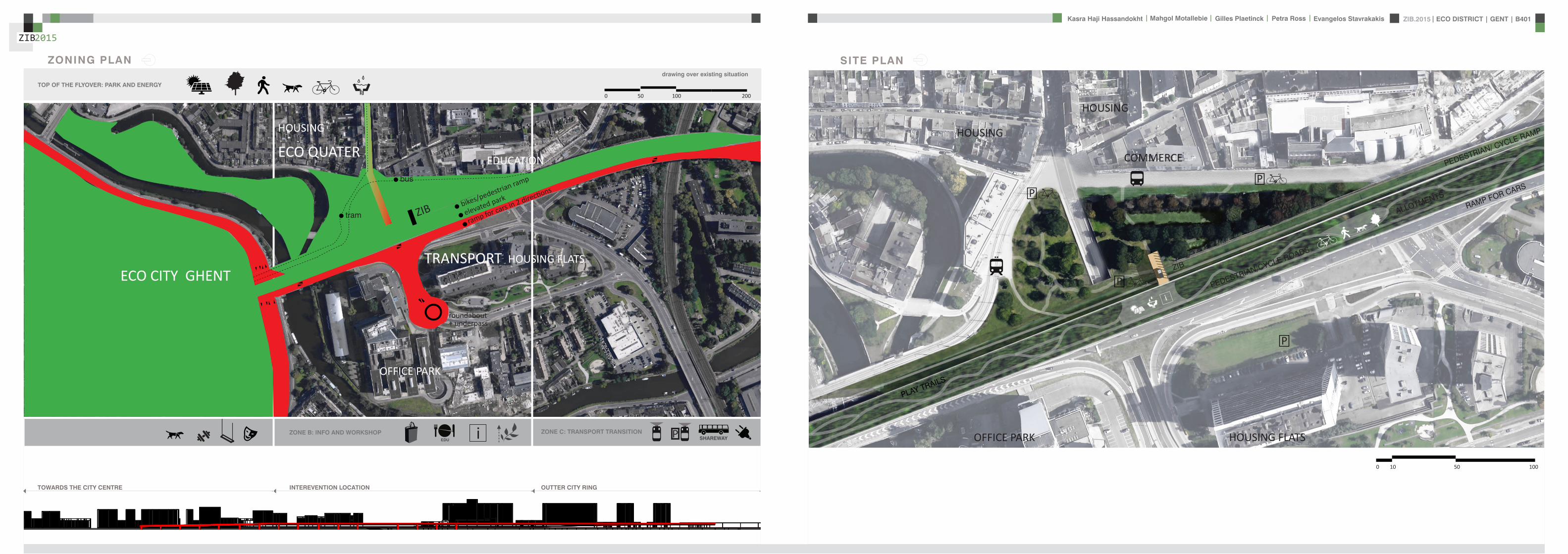
ZIB2015 ECO DISTRICT | GENT | B401Evangelos Stavrakakis | Petra Ross | Mahgol Motallebie | Gilles Plaetinck | Kasra Haji Hassandokht
ZIB2015
|
SITE PLAN
OUTTER CITY RINGINTEREVENTION LOCATIONTOWARDS THE CITY CENTRE
ZONE A SPORT AND CULTURE Pi ZONE C TRANSPORT TRANSITIONZONE B INFO AND WORKSHOP
TOP OF THE FLYOVER PARK AND ENERGY
TRANSPORT
bikespedestrian ramp
elevated park
ramp for cars in 2 directionsbus
tram
ECO QUATER
ZIB
drawing over existing situation
roundabout+ underpass
OFFICE PARK
EDUCATION
EDUCATION
HOUSING FLATS
HOUSING
HOUSING
ECO CITY GHENT
0 50 100 200
HOUSING FLATSOFFICE PARK
COMMERCE
HOUSING
HOUSING
0 10 50 100
P
P
P
PEDESTRIANCYCLE ROADS
P
i
PLAY TRAILS
ALLOTMENTS
PEDESTRIAN CYCLE RAMP
RAMP FOR CARS
ZIB
ZONING PLAN
ZIB2015 ECO DISTRICT | GENT | B401Evangelos Stavrakakis | Petra Ross | Mahgol Motallebie | Gilles Plaetinck | Kasra Haji Hassandokht
ZIB2015
|
GROUNDPLANS 1100
B-Bacute
A-Aacute
B-Bacute
A-Aacute
B-Bacute
A-Aacute
B-Bacute
A-Aacute
ZIB2015 ECO DISTRICT | GENT | B401Evangelos Stavrakakis | Petra Ross | Mahgol Motallebie | Gilles Plaetinck | Kasra Haji Hassandokht
ZIB2015
|
SECTIONS 1100
Section A-AacuteSection B-Bacute
AArsquo
AArsquo
Detai l 01
Detai l 02
Detai l 03
Detai l 04
Detai l 05
Detai l 06
ZIB2015 ECO DISTRICT | GENT | B401Evangelos Stavrakakis | Petra Ross | Mahgol Motallebie | Gilles Plaetinck | Kasra Haji Hassandokht
ZIB2015
|
DETAILS
DETAIL 01 DETAIL 02 DETAIL 03 DETAIL 04 DETAIL 05 DETAIL 06
AArsquo
PIR f loorGypsum plasterboardPIR 100 mmOSB 15 mmFJI beam cel lu lose 350 mmcel i t 4D woodf iber 18 mmfinish gypsum plasterboard
plato wood f in ishframework 30 mmcel i t 4D 18 mmwood structure SLS 38140Eurowal l 2x70 mmOSB Eurothane G 70 mmfinish gypsum plasterboard
ZIB2015 ECO DISTRICT | GENT | B401Evangelos Stavrakakis | Petra Ross | Mahgol Motallebie | Gilles Plaetinck | Kasra Haji Hassandokht
ZIB2015
|
ELEVATIONS 1100
South elevation
South Elevation
North Elevation
South Elevation
North Elevation
South Elevation
North Elevation
South Elevation
North Elevation
North elevation
ZIB2015 ECO DISTRICT | GENT | B401Evangelos Stavrakakis | Petra Ross | Mahgol Motallebie | Gilles Plaetinck | Kasra Haji Hassandokht
ZIB2015
|
VISUALIZATIONS
East Elevation
West Elevation
East Elevation
West Elevation
East Elevation
West Elevation East Elevation
West Elevation
ELEVATIONS 1100
West elevation East elevation
ZIB2015 ECO DISTRICT | GENT | B401Evangelos Stavrakakis | Petra Ross | Mahgol Motallebie | Gilles Plaetinck | Kasra Haji Hassandokht
ZIB2015
|
VISUALIZATIONS
ZIB2015 ECO DISTRICT | GENT | B401Evangelos Stavrakakis | Petra Ross | Mahgol Motallebie | Gilles Plaetinck | Kasra Haji Hassandokht
ZIB2015
|
MATERIALS WOOD FCS Certi f ied Suppliers Distance MATERIALS Building Structure
ZIB2015 ECO DISTRICT | GENT | B401Evangelos Stavrakakis | Petra Ross | Mahgol Motallebie | Gilles Plaetinck | Kasra Haji Hassandokht
ZIB2015
|
MATERIALS Specs InsulationMATERIALS Specs Solid amp Structural Wood
ZIB2015 ECO DISTRICT | GENT | B401Evangelos Stavrakakis | Petra Ross | Mahgol Motallebie | Gilles Plaetinck | Kasra Haji Hassandokht
ZIB2015
|
MATERIALS Life Cycle Assesment MATERIALS Embodied energy CO2 other materials
ZIB2015 ECO DISTRICT | GENT | B401Evangelos Stavrakakis | Petra Ross | Mahgol Motallebie | Gilles Plaetinck | Kasra Haji Hassandokht
ZIB2015
|
STRUCTURE
Gilles Plaetinck
schaal
ZIB BUILDINGEnter address here
7 _ Unnamed
Owner
begeleider Checker
3D Copy 11 Gilles Plaetinck
schaal
ZIB BUILDINGEnter address here
8 _ Unnamed
Owner
begeleider Checker
3D Copy 21
Gilles Plaetinck
schaal
ZIB BUILDINGEnter address here
8 _ Unnamed
Owner
begeleider Checker
3D Copy 31
Gilles Plaetinck
schaal
ZIB BUILDINGEnter address here
9 _ Unnamed
Owner
begeleider Checker3D Copy 4
1
ECONOMY - USIBILITY DURING THE DAY
i1000
ALWAYS
2000
ECONONY - USIBILITY DURING THE DAY
GENERAL PRINCIPLES OF THE BUILDING
ZERO IMPACT APPROACH
i
0 Food market in park Vertical harvesting Entrance
1 Workshop area technical room
2 Info center Entrance from highway
3 Roof terrace
ZIB2015 ECO DISTRICT | GENT | B401Evangelos Stavrakakis | Petra Ross | Mahgol Motallebie | Gilles Plaetinck | Kasra Haji Hassandokht
ZIB2015
|
Vertical Harvest places plants on carousels that keep them moving the length of the greenhouse giving them equal time in natural light and also al-lowing workers to pick and tand transfer the crops Using hydroponics Verti-cal Harvest will be capa-ble of producing over
Vertical Harvest places plants on carousels that keep them moving the length of the pulls giving them equal time in natu-ral light and also allowing workers and local people to pick and transfer the crops Using hydroponics Vertical Harvest will be capable of producing over greens and herbs
Vertical Harvest places plants on carousels that keep them moving the length of the greenhouse giving them equal time in natural light and also al-lowing workers to pick and tand transfer the crops Using hydroponics Verti-cal Harvest will be capa-ble of producing over
Vertical Harvest places plants on carousels that keep them moving the length of the pulls giving them equal time in natu-ral light and also allowing workers and local people to pick and transfer the crops Using hydroponics Vertical Harvest will be capable of producing over greens and herbs
VERTICAL HARVESTING
PLANT CABLE LIFT (PLC) SECTION
Sustainable Food zorkshop centerrsquos mission is to ldquocultivate a healthy community by strengthening the local food system and improving access to nu-tritious affordable foodrdquo The main goal of our design is to deliver skills and information for sus-tainability practioners in the organic food tradeThe program attempts to1) affect positive changes in shopping cooking eating habits and nutrition2) reduce diet-related diseases3) promote the health and development of young children 4) place emphasis on local seasonal and cultural-ly-appropriate foods5) integrate food systems concepts into its curric-ulumndash such as shopping at farmers markets and growing onersquos own food
Healthy food is a basic human right the ability to access healthy food is often related to multiple issues and not just a result of low income
FOOD TEAM = a group of people from the same neighbourhood who work for the direct purchase of regional and seasonal products They order food on internet via web page voedselteambe and it is then delivered once a week to the depot of a team
+ minimal transport requirements+ no returnable packaging+ fair p+ fair pricing+ high-quality local and seasonal food+ community initiative
Sustainable Food zorkshop centerrsquos mission is to ldquocultivate a healthy community by strengthening the local food system and improving access to nu-tritious affordable foodrdquo The main goal of our design is to deliver skills and information for sus-tainability practioners in the organic food tradeThe program attempts to1) affect positive changes in shopping cooking eating habits and nutrition2) reduce diet-related diseases3) promote the health and development of young children 4) place emphasis on local seasonal and cultural-ly-appropriate foods5) integrate food systems concepts into its curric-ulumndash such as shopping at farmers markets and growing onersquos own food
Healthy food is a basic human right the ability to access healthy food is often related to multiple issues and not just a result of low income
FOOD TEAM = a group of people from the same neighbourhood who work for the direct purchase of regional and seasonal products They order food on internet via web page voedselteambe and it is then delivered once a week to the depot of a team
+ minimal transport requirements+ no returnable packaging+ fair p+ fair pricing+ high-quality local and seasonal food+ community initiative
Sustainable Food zorkshop centerrsquos mission is to ldquocultivate a healthy community by strengthening the local food system and improving access to nu-tritious affordable foodrdquo The main goal of our design is to deliver skills and information for sus-tainability practioners in the organic food tradeThe program attempts to1) affect positive changes in shopping cooking eating habits and nutrition2) reduce diet-related diseases3) promote the health and development of young children 4) place emphasis on local seasonal and cultural-ly-appropriate foods5) integrate food systems concepts into its curric-ulumndash such as shopping at farmers markets and growing onersquos own food
Healthy food is a basic human right the ability to access healthy food is often related to multiple issues and not just a result of low income
FOOD TEAM = a group of people from the same neighbourhood who work for the direct purchase of regional and seasonal products They order food on internet via web page voedselteambe and it is then delivered once a week to the depot of a team
+ minimal transport requirements+ no returnable packaging+ fair p+ fair pricing+ high-quality local and seasonal food+ community initiative
Healthy food is a basic human right the ability to access healthy food is often related to multiple issues and not just a result of low income
Sustainable Food zorkshop centerrsquos mission is to ldquocultivate a healthy community by strengthening the local food system and improving access to nutritious affordable foodrdquo The main goal of our design is to deliver skills and information for sustainability practioners in the organic food tradeThe program attempts to
1) affect positive changes in shopping cookingeating habits and nutrition2) reduce diet-related diseases3) promote the health and development of youngchildren4) place emphasis on local seasonal and culturally-appropriate foods5) integrate food systems concepts into its curriculumndashsuch as shopping at farmers markets andgrowing onersquos own food
FOOD TEAM = a group of people from the same neighbourhood who work for the direct purchase of regional and seasonal products They order food on internet via web page voedselteambe and it is then delivered once a week to the depot of a team
+ minimal transport requirements+ no returnable packaging+ fair pricing+ high-quality local and seasonal food+ community initiative
WORKSHOP
ZIB2015 ECO DISTRICT | GENT | B401Evangelos Stavrakakis | Petra Ross | Mahgol Motallebie | Gilles Plaetinck | Kasra Haji Hassandokht
ZIB2015
|
Black coral pea
Factors should be considered when seleccng plants
- Quality of growth- Ability to adapt to the wall environment- Environmental Tolerances- Temperature Resistance- Drought Tolerance- Wind - Wind Tolerance- Solar Exposure Tolerance- Salt Tolerance in Seaside installacons- Air and Water Pollucon Tolerance- Pest and Disease Resistance- Arcficial Environment Tolerance- Transplantacon Tolerance- Pruning - Pruning Tolerance
- Ornamental Qualices- Design Purpose- Manageability Maintainability- Environmental and Societal Effects- Visual Effect- Feeling Effect
Blac
k co
ral p
eaSn
ake
vine
kidn
ey w
eed
purple coral peaBasil
Pandorea
Black coral pea
Factors should be considered when seleccng plants
- Quality of growth- Ability to adapt to the wall environment- Environmental Tolerances- Temperature Resistance- Drought Tolerance- Wind - Wind Tolerance- Solar Exposure Tolerance- Salt Tolerance in Seaside installacons- Air and Water Pollucon Tolerance- Pest and Disease Resistance- Arcficial Environment Tolerance- Transplantacon Tolerance- Pruning - Pruning Tolerance
- Ornamental Qualices- Design Purpose- Manageability Maintainability- Environmental and Societal Effects- Visual Effect- Feeling Effect
Blac
k co
ral p
eaSn
ake
vine
kidn
ey w
eed
purple coral peaBasil
Pandorea
Black coral pea
Factors should be considered when seleccng plants
- Quality of growth- Ability to adapt to the wall environment- Environmental Tolerances- Temperature Resistance- Drought Tolerance- Wind - Wind Tolerance- Solar Exposure Tolerance- Salt Tolerance in Seaside installacons- Air and Water Pollucon Tolerance- Pest and Disease Resistance- Arcficial Environment Tolerance- Transplantacon Tolerance- Pruning - Pruning Tolerance
- Ornamental Qualices- Design Purpose- Manageability Maintainability- Environmental and Societal Effects- Visual Effect- Feeling Effect
Blac
k co
ral p
eaSn
ake
vine
kidn
ey w
eed
purple coral peaBasil
Pandorea
GREEN WALLS
ZIB2015 ECO DISTRICT | GENT | B401Evangelos Stavrakakis | Petra Ross | Mahgol Motallebie | Gilles Plaetinck | Kasra Haji Hassandokht
ZIB2015
|
Extraction of air
Pulsion of airRecuperation unit
outdoor space
18 degC15 degC
18 degC
In-take Out-take of air
VENTILATION
Gilles Plaetinck
schaal 1 100
ZIB BUILDINGEnter address here
3 _ level 2
Owner
begeleider Checker
DN
Gilles Plaetinck
schaal 1 100
ZIB BUILDINGEnter address here
2 _ level 1
Owner
begeleider Checker
Extraction of air
Pulsion of air
VENTILATION IN GROUPLANS CALCULATION AND SYSTEM
level 01
level 02
T 42ECO DISTRICT | GENT | B401
ZIB2015Mechanical Ventilation with Heat Recovery (MVHR)
Up to 95 of the heat can be recovered The Heat Recovery Unit runs continu-ously on trickle and can and is boosted when higher rates of ventilation are required eg bathing cooking In warmer months a summer by-pass function helps ensure comfort levels are maintained in the home When summer by-pass is activated the dwelling contin-ues to be ventilaated and recieve fresh filtered air however the heat recovery process is intermittently switched off (heat recovery is by-passed)
Key BenefitsYear round removal of condensation and indoor pol-lutants A direct impact on the Dwelling Emission Rate re-quired in SAP helping reduce the carbon footprint of the property Fresh filtered air supplied to dwelling ideal for allergy sufferers and those with conditions such as asthma A balanced ventilation system for the whole house and recovering of heat that would have otherwise have been lost Low noise non-intrusive ventilation system ndash located away from the room however consideration should be given to duct runs to ensure cross-talk contamination doesnrsquot happen AND the unit is sized correctly so it is not running a high rate all of the time
Zehnder ComfoSystems Passive Haus accredited product suitable for large houses up to 300m2 Designed to ensure low noise excellent energy performance and heat exchange efficiency Choice of control options including LCD touch screen display Can be combine with ComfoCool for optional cooling of up to 5 degrees and humidity reduction by 20
Semi Rigid Ducting
With a manifold system the resistance caused by duct-ing is reduced therefore Semi-Rigid ducting resistance is very low The manifold takes mass airflow directly from the MVHR Heat Recovery Unit and allows lower rates to pass through to each individual room runDirecting mass flow to the manifold eliminates the need to increase the running speed of the MVHR Heat Re-covery unit to overcome the resistance of ducting which in turn causes noise for the homeowner
T 42ECO DISTRICT | GENT | B401
ZIB2015Mechanical Ventilation with Heat Recovery (MVHR)
Up to 95 of the heat can be recovered The Heat Recovery Unit runs continu-ously on trickle and can and is boosted when higher rates of ventilation are required eg bathing cooking In warmer months a summer by-pass function helps ensure comfort levels are maintained in the home When summer by-pass is activated the dwelling contin-ues to be ventilaated and recieve fresh filtered air however the heat recovery process is intermittently switched off (heat recovery is by-passed)
Key BenefitsYear round removal of condensation and indoor pol-lutants A direct impact on the Dwelling Emission Rate re-quired in SAP helping reduce the carbon footprint of the property Fresh filtered air supplied to dwelling ideal for allergy sufferers and those with conditions such as asthma A balanced ventilation system for the whole house and recovering of heat that would have otherwise have been lost Low noise non-intrusive ventilation system ndash located away from the room however consideration should be given to duct runs to ensure cross-talk contamination doesnrsquot happen AND the unit is sized correctly so it is not running a high rate all of the time
Zehnder ComfoSystems Passive Haus accredited product suitable for large houses up to 300m2 Designed to ensure low noise excellent energy performance and heat exchange efficiency Choice of control options including LCD touch screen display Can be combine with ComfoCool for optional cooling of up to 5 degrees and humidity reduction by 20
Semi Rigid Ducting
With a manifold system the resistance caused by duct-ing is reduced therefore Semi-Rigid ducting resistance is very low The manifold takes mass airflow directly from the MVHR Heat Recovery Unit and allows lower rates to pass through to each individual room runDirecting mass flow to the manifold eliminates the need to increase the running speed of the MVHR Heat Re-covery unit to overcome the resistance of ducting which in turn causes noise for the homeowner
MECHANICAL VENTILATION WITH HEAT RECOVERY (MVHR)
Up to 95 of the heat can be recoveredThe Heat Recovery Unit runs continuously on trickle and can and is boosted when higher rates of ventilation are required eg bathing cooking
In warmer months a summer by-pass function helps ensure comfort levels are maintained in the home When summer by-pass is activated the dwelling continues to be ventilaated and recieve fresh filtered air however the heat recovery process is intermittently switched off (heat recovery is by-passed)
EXTRACT VENTILATION RATES
T 42ECO DISTRICT | GENT | B401
ZIB2015Mechanical Ventilation with Heat Recovery (MVHR)
Up to 95 of the heat can be recovered The Heat Recovery Unit runs continu-ously on trickle and can and is boosted when higher rates of ventilation are required eg bathing cooking In warmer months a summer by-pass function helps ensure comfort levels are maintained in the home When summer by-pass is activated the dwelling contin-ues to be ventilaated and recieve fresh filtered air however the heat recovery process is intermittently switched off (heat recovery is by-passed)
Key BenefitsYear round removal of condensation and indoor pol-lutants A direct impact on the Dwelling Emission Rate re-quired in SAP helping reduce the carbon footprint of the property Fresh filtered air supplied to dwelling ideal for allergy sufferers and those with conditions such as asthma A balanced ventilation system for the whole house and recovering of heat that would have otherwise have been lost Low noise non-intrusive ventilation system ndash located away from the room however consideration should be given to duct runs to ensure cross-talk contamination doesnrsquot happen AND the unit is sized correctly so it is not running a high rate all of the time
Zehnder ComfoSystems Passive Haus accredited product suitable for large houses up to 300m2 Designed to ensure low noise excellent energy performance and heat exchange efficiency Choice of control options including LCD touch screen display Can be combine with ComfoCool for optional cooling of up to 5 degrees and humidity reduction by 20
Semi Rigid Ducting
With a manifold system the resistance caused by duct-ing is reduced therefore Semi-Rigid ducting resistance is very low The manifold takes mass airflow directly from the MVHR Heat Recovery Unit and allows lower rates to pass through to each individual room runDirecting mass flow to the manifold eliminates the need to increase the running speed of the MVHR Heat Re-covery unit to overcome the resistance of ducting which in turn causes noise for the homeowner
T 42ECO DISTRICT | GENT | B401
ZIB2015Mechanical Ventilation with Heat Recovery (MVHR)
Up to 95 of the heat can be recovered The Heat Recovery Unit runs continu-ously on trickle and can and is boosted when higher rates of ventilation are required eg bathing cooking In warmer months a summer by-pass function helps ensure comfort levels are maintained in the home When summer by-pass is activated the dwelling contin-ues to be ventilaated and recieve fresh filtered air however the heat recovery process is intermittently switched off (heat recovery is by-passed)
Key BenefitsYear round removal of condensation and indoor pol-lutants A direct impact on the Dwelling Emission Rate re-quired in SAP helping reduce the carbon footprint of the property Fresh filtered air supplied to dwelling ideal for allergy sufferers and those with conditions such as asthma A balanced ventilation system for the whole house and recovering of heat that would have otherwise have been lost Low noise non-intrusive ventilation system ndash located away from the room however consideration should be given to duct runs to ensure cross-talk contamination doesnrsquot happen AND the unit is sized correctly so it is not running a high rate all of the time
Zehnder ComfoSystems Passive Haus accredited product suitable for large houses up to 300m2 Designed to ensure low noise excellent energy performance and heat exchange efficiency Choice of control options including LCD touch screen display Can be combine with ComfoCool for optional cooling of up to 5 degrees and humidity reduction by 20
Semi Rigid Ducting
With a manifold system the resistance caused by duct-ing is reduced therefore Semi-Rigid ducting resistance is very low The manifold takes mass airflow directly from the MVHR Heat Recovery Unit and allows lower rates to pass through to each individual room runDirecting mass flow to the manifold eliminates the need to increase the running speed of the MVHR Heat Re-covery unit to overcome the resistance of ducting which in turn causes noise for the homeowner
Heating 10 kwh msup2aCooling 4 kWh msup2aOverheating 42
ZIB2015 ECO DISTRICT | GENT | B401Evangelos Stavrakakis | Petra Ross | Mahgol Motallebie | Gilles Plaetinck | Kasra Haji Hassandokht
ZIB2015
|
Shutters control system+ -
Solar roadways - PV panels
LED lights
Elevator Fuse box
ElectricityBattery withtransformator
ELECTRICITY
Summer night
cross- ventilation through building
Summer day
air through recuperation unit small change of temperature
15 degC 18 degC
+ groundplans
heated zone
not heated zone
ZONING ACCORDING TO TEMPERATURESSUMMER NIGHT - cross-ventilation through building
SUMMER DAY - air through recuperation unit small change of temperatureSHADING SYSTEM
As a shading was chozen system Renson Icarus Lamellas with angle 45deg made in wood
ZIB2015 ECO DISTRICT | GENT | B401Evangelos Stavrakakis | Petra Ross | Mahgol Motallebie | Gilles Plaetinck | Kasra Haji Hassandokht
ZIB2015
|
average only 4 hours of peak daylight hours per day (4 x 365 = 1460 hours per year)
- Surface area ( first part) Fly-over +- 20 000 msup2-gt 16 000 x 230 Watt = 3 680 000 Watt or 3680 kWonly 50 of fly-over covered with solar roadways
-gt 3680 kW x 4 h = 7360 kWh day-gt 3680 kW x 1460 h = 2 686 400 kWh year -gt +- 540 households (+- 5000 kWh year)
Tesla Powerwall Therersquos a 10 kWh unit at $3500 -gt 737 Tesla Batteries
gt the Solar Roadway has the ability to cut greenhouse gases by up to 75-percentgt A decentralized self-healing secure power grid
IN FRONT OF FLY-OVER
- Surface area Fly-over = 16 x 30 m = 480 msup2-gt 384 x 230 Watt = 88 320 Watt or 883 kWonly 50 of fly-over covered with solar roadways
-gt 44 kW x 4 h = 176 kWh day-gt 44 kW x 1460 h = 64 240 kWh year -gt +- 13 households (+- 5000 kWh year)
lightsshutters
elevator
2 fridges
2 coffeemakers
1 microwave
1 owen
2 cooking plates
stereo
ventilation unit
electricity transformer (AC to DC) for PV panels + batteries
summer 05 kWh daywinter 03 kWh day183 days x 05= 915 kWh182 days x 03 = 546 kWh = 1641 kWh
262 kWh
A++fridge 104 kWhyear104 x x2 = 208 kWh
900 W x 01 hours day = 09 kWhx 220 days x 2= 198 kWh a
67 kWh a
085x100 days= 85 kWh a
400 kWh x 2 = 800 kWh a
150 kWh a 419 kWha
68 kWh a
ENERGY DEMAND OVERVIEW ENERGY SUPPLY OVERVIEW - FLY-OVER
1 spot 56 W 10000 = 0056 KW4 hours per day 365 days a year = 1460 h0056 x 1460 = 8176 kWh10 spots x 8176= 8176 kWh a
1 spot 72 W 10000 = 0072 KW4 hours per day 365 days a year = 1460 h0072 x 1460 = 10512 kWh5 spots x 10512= 5256 kWh a
1 spot 52 W 10000 = 0052 KW4 hours per day 365 days a year = 1460 h0052 x 1460 = 7592 kWh21 spots x 7592= 159432 kWh a
1 spot 9 W 10000 = 0009 KW4 hours per day 365 days a year = 1460 h0009 x 1460 = 1314 kWh5 spots x 1314 = 657 kWh a
SOLAR ROADWAYS - PV PANELSEnergy from the sun
1 To generate energy for the ZIB building2 To generate energy for the surrounding houses3 To generate energy for lighting or signs on the road4 The panels will also have the capacity to charge electric vehicles while parked
ELECTRICITY SCHEME
5423 kWh a
ZIB2015 ECO DISTRICT | GENT | B401Evangelos Stavrakakis | Petra Ross | Mahgol Motallebie | Gilles Plaetinck | Kasra Haji Hassandokht
ZIB2015
|
SUMMER SUNNY 10-42 LUXWINTER SUNNY 10-42 LUX
DAYLIGHT - DIALuxLIGHTING SYSTEM - DIALux
Workplane 9 Results overview
Height of working plane 0800 m Wall zone 0000 m
Result Mean (target) Min Max Minaverage MinmaxPerpendicular illuminance [lx] 463 (500) 105 689 0227 0152
Profile Offices Writing typewriting reading data processing
B401-Gent 6222015
Site 1 Building 2 Zib Room 9 Workplane 9 Results overview
Page 70
Workplane 9 False coloursPerpendicular illuminance (adaptive)
Scale 1 200
Perpendicular illuminance (Surface)Mean (actual) 463 lx Min 105 lx Max 689 lx Minaverage 0227 Minmax 0152
B401-Gent 6222015
Site 1 Building 2 Zib Room 9 Workplane 9 False coloursPerpendicular illuminance (adaptive)
Page 72
Workplane 9 Value chartPerpendicular illuminance (adaptive)
Scale 1 200
Perpendicular illuminance (Surface)Mean (actual) 463 lx Min 105 lx Max 689 lx Minaverage 0227 Minmax 0152
B401-Gent 6222015
Site 1 Building 2 Zib Room 9 Workplane 9 Value chartPerpendicular illuminance (adaptive)
Page 73
Workplane 13 Results overview
Height of working plane 0800 m Wall zone 0000 m
Result Mean (target) Min Max Minaverage MinmaxPerpendicular illuminance [lx] 388 (500) 69 732 0178 0094
Profile Offices Writing typewriting reading data processing
B401-Gent 6222015
Site 1 Building 6 Storey 1 Room 13 Workplane 13 Results overview
Page 94
Workplane 13 False coloursPerpendicular illuminance (adaptive)
Scale 1 100
Perpendicular illuminance (Surface)Mean (actual) 388 lx Min 69 lx Max 732 lx Minaverage 0178 Minmax 0094
B401-Gent 6222015
Site 1 Building 6 Storey 1 Room 13 Workplane 13 False coloursPerpendicular illuminance (adaptive)
Page 96
Workplane 13 Value chartPerpendicular illuminance (adaptive)
Scale 1 100
Perpendicular illuminance (Surface)Mean (actual) 388 lx Min 69 lx Max 732 lx Minaverage 0178 Minmax 0094
B401-Gent 6222015
Site 1 Building 6 Storey 1 Room 13 Workplane 13 Value chartPerpendicular illuminance (adaptive)
Page 97
Workplane 9 False coloursPerpendicular illuminance (adaptive)
Scale 1 200
Perpendicular illuminance (Surface)Mean (actual) 463 lx Min 105 lx Max 689 lx Minaverage 0227 Minmax 0152
B401-Gent 6222015
Site 1 Building 2 Zib Room 9 Workplane 9 False coloursPerpendicular illuminance (adaptive)
Page 72
1st f loor 2nd f loor Site 1 Luminaire parts listQuantity Luminaire (Luminous emittance)10 3F Filippi 12736 P 202x24W LED OP 196x1231
Luminous emittance 1Fitting 1x24W 2xLEDLight output ratio 100Lamp luminous flux 5332 lmLuminaire Luminous Flux 5332 lmPower 560 WLight yield 952 lmW
200
300
400
cdklm η = 100C0 - C180 C90 - C270
0deg 15deg 30deg
45deg
60deg
75deg
90deg
105deg105deg
90deg
75deg
60deg
45deg
30deg 15deg 0deg
5 SFN Eclairages 0732360X CLFV 236Luminous emittance 1Fitting 2xT26 36W840Light output ratio 6889Lamp luminous flux 6700 lmLuminaire Luminous Flux 4615 lmPower 720 WLight yield 641 lmW
160
240
cdklm η = 69C0 - C180 C90 - C270
0deg 15deg 30deg
45deg
60deg
75deg
90deg
105deg105deg
90deg
75deg
60deg
45deg
30deg 15deg 0deg
21 SFN Eclairages 332226XX SAM F 2x26W BELuminous emittance 1Fitting 2xTC-DEL 26W840Light output ratio 3297Lamp luminous flux 3600 lmLuminaire Luminous Flux 1187 lmPower 520 WLight yield 228 lmW
40
60
80
100
120
140
cdklm η = 33C0 - C180 C90 - C270
0deg 15deg 30deg
45deg
60deg
75deg
90deg
105deg105deg
90deg
75deg
60deg
45deg
30deg 15deg 0deg
1 Signcomplex AR111-009-AW-W-06 AR111 COB 9W38deg WhiteLuminous emittance 1Fitting 1xAR111-009-AW-W-06Light output ratio 8078Lamp luminous flux 600 lmLuminaire Luminous Flux 485 lmPower 90 WLight yield 539 lmW
800
1200
cdklm η = 81C0 - C180 C90 - C270
0deg 15deg 30deg
45deg
60deg
75deg
90deg
105deg105deg
90deg
75deg
60deg
45deg
30deg 15deg 0deg
Total lamp luminous flux 163020 lm Total luminaire luminous flux 101807 lm Total Load 20210 W Light yield 504 lmW
B401-Gent 6222015
Site 1 Luminaire parts list
Page 19
10x
6x
21x
1x
types of l ights
Perpendicular i l luminance (Surface)Mean (actual ) 463 lx Min 105 lx Max 689 lx Minaverage 0 227 Minmax 0 152
Perpendicular i l luminance (Surface)Mean (actual ) 388 lx Min 69 lx Max 732 lx Minaverage 0 178 Minmax 0 094
ZIB2015 ECO DISTRICT | GENT | B401Evangelos Stavrakakis | Petra Ross | Mahgol Motallebie | Gilles Plaetinck | Kasra Haji Hassandokht
ZIB2015
|
Tube hybrid Solar panels
Hot water tank Water taps
City water supply
Rain water collection for vertical harvesting
City water supply
WADI
Rain water tank
WATER MANAGEMENT
Sinks
Available roof area
In Ghent avarage of 900mmm2year
3197 m2
09x 3197 = 28773 m3year
RAIN WATER GAIN
toilet - 3x - 03lskitchen -4x - 02ls
POTABLE WATER DEMAND
3 toiletsVertical gardening
Total
relative RW usage
300 l day150 l day = 450lday= 16425 m3 year
1407 lday100m2
RAIN WATER DEMAND
RAIN WATER TANK
Relative RWT volumeRain water tank volume
3m3 100 m2
9591 l gt 10 m3
DIMESION OF PIPES
City water supplyRainwater tank
178 mm (DN 18 - 15 - 12)165 mm (DN 17-15)
are composed of hexagonal tiles Rainwater can infiltrate between the gaps from where it goes to rainwatter collector which supplies the vegetation on fly-over
THE SOLAR ROADWAYS
WATER SUPPLY SCHEME AND CALCULATION
ZIB2015 ECO DISTRICT | GENT | B401Evangelos Stavrakakis | Petra Ross | Mahgol Motallebie | Gilles Plaetinck | Kasra Haji Hassandokht
ZIB2015
|
WADI
City water supply
Rain water tank
Sinks
Divided sewer systemwithin building
SEWAGE SYSTEM
ToiletToilet sinkKitchen sink
DU = 2 lsDU = 05 lsDU = 08 ls
WATER DRAINAGE OF DEVICES
Frequency of usage at the same time
K 05
DIMESION OF PIPES
Black waterGrey water
110 mm (DU 110)75 mm (DU 75 - 63)
WATER DRAINAGE SCHEME AND CALCULATION
ZIB2015 ECO DISTRICT | GENT | B401Evangelos Stavrakakis | Petra Ross | Mahgol Motallebie | Gilles Plaetinck | Kasra Haji Hassandokht
ZIB2015
|
DN
Gilles Plaetinck
schaal 1 100
ZIB BUILDINGEnter address here
2 _ level 1
Owner
begeleider Checker
Gilles Plaetinck
schaal 1 100
ZIB BUILDINGEnter address here
3 _ level 2
Owner
begeleider Checker
WATER SUPPLY
HOT WATER
WATER DRAINAGE
WATER SUPPLY AND DRAINAGE IN GROUPLANS
level 01
level 02
ENERGY
RAINWATER TANK
HELOPHYTE FILTER
IRRIGATION SYSTEM
BIO-ROTOR
MICRO TURBINE
PHOSPHOR
In this building a closed water system is applied which is based on reusing water in mullple wasRainRain water from the roof will be collected in a storage tank situated on the ground floor This water will be used to flush the toilet and irrigate crops in verlcal harveslng system In case of an overflow the water will be stored in the con-structed wetland near the building The rainwater can be fil-tered through a helophyte filter up to drinking water stan-dard The waste water system includes three types of water yellyellow black and grey waterThe yellow water will be stored for its phosphor while the black water will be purified into grey water This grey water is comparable to the quality of rain water aaer purificalon b means of a bio rotor The remaining residue from the bio rotor together with the organic waste from the harveslng is fermented into biogas that drives a micro turbine in order to produce some addilonal energy
TheThe waste product deriving from this process will be used as compost in verlcal harveslng This efficient yet complex system closes the ullizalon cycle of the building and turns it into an efficient vicious circle that can be considered au arkic
In this building a closed water system is applied which is based on reusing water in multiple was
Rain water from the roof will be collected in a storage tank situated on the ground floor This water will be used to flushthe toilet and irrigate crops in vertical harvesting system In case of an overflow the water will be stored in the constructed wetland near the building The rainwater can be filtered through a helophyte filter up to drinking water standard
The waste water system includes three types of water yellow black and grey water The yellow water will be stored for its phosphor while the black water will be purified into grey water This grey water is comparable to the quality of rain water after purification b means of a bio rotor The remaining residue from the bio rotor together with the organic waste from the harvesting is fermented into biogas that drives a micro turbine in order to produce some additional energy The waste product deriving from this process will be used ascompost in ver1048991cal harves1048991ng This efficient yet complexsystem closes the u1048991liza1048991on cycle of the building and turns itinto an efficient vicious circle that can be considered au arkic
WATER CYCLE
ZIB2015 ECO DISTRICT | GENT | B401Evangelos Stavrakakis | Petra Ross | Mahgol Motallebie | Gilles Plaetinck | Kasra Haji Hassandokht
ZIB2015
|
CALCULATIONS
Passive House verification
Photo or Drawing
Building Workshop + info pointStreet
PostcodeCityCountry
Building Type non-residentialClimate Ukkel
Home Owner(s) Client(s)Street
PostcodeCity
ArchitectStreet
PostcodeCity Calculation electricity Internal heat gains
Mechanical System Building type
StreetPostcodeCity Internal heat gains
Year of Construction 2015 Interior Temperature 200 degC Utilisation pattern
Number of Dwelling Units 1 Internal Heat Gains 20 Wm2 Type of values used Fill in worksheet IHG Non-Dom Enclosed Volume Ve 12442 Planned number of occupants
Number of Occupants 80 8 Design
Specific building demands with reference to the treated floor area use Annual method
Treated floor area 2840 msup2 Requirements Fulfilled Verification Annual method The monthly method should be used for building certification
Space heating Annual heating demand 10 kWh(m2a) 15 kWh(msup2a) yes Specific space heating demand annual method 103 kWh(msup2a)
Heating load 11 Wm2 10 Wmsup2 - Specific space heating demand monthly Method 120 kWh(msup2a)
Space cooling Overall specific space cooling demand kWh(m2a) 15 kWh(msup2a)
Cooling load Wm2 - -Frequency of overheating (gt 25 degC) - -
Primary Energy Space heating and dehumidification
cooling household electricity 73 kWh(m2a) 120 kWh(msup2a) yes
DHW space heating and auxiliary electricity 24 kWh(m2a) - -Specific primary energy reduction through solar electricity 21 kWh(m2a) - -
Airtightness Pressurization test result n50 06 1h 06 1h yes
PHPP Verification FINAL ZIB FILE CALCULTIONS PHPPxls
L B H VOLUME
main 1 226 7 4 6328main 2 184 7 35 4508
core 0 6 2 5 3 5 108 5core 0 62 5 35 1085core 3 62 3 28 521
12442
AREAmain 1 storage 35
wc big 35wc 2wc 2workshop 103
MAIN 2 infolounge 92
staircase 56storage technical 22
284
Floor_exterior 1582 31 1272
Roof_exterior 1582
Passive House verification
Photo or Drawing
Building Workshop + info pointStreet
PostcodeCityCountry
Building Type non-residentialClimate Ukkel
Home Owner(s) Client(s)Street
PostcodeCity
ArchitectStreet
PostcodeCity Calculation electricity Internal heat gains
Mechanical System Building type
StreetPostcodeCity Internal heat gains
Year of Construction 2015 Interior Temperature 200 degC Utilisation pattern
Number of Dwelling Units 1 Internal Heat Gains 20 Wm2 Type of values used Fill in worksheet IHG Non-Dom Enclosed Volume Ve 12442 Planned number of occupants
Number of Occupants 80 8 Design
Specific building demands with reference to the treated floor area use Annual method
Treated floor area 2840 msup2 Requirements Fulfilled Verification Annual method The monthly method should be used for building certification
Space heating Annual heating demand 10 kWh(m2a) 15 kWh(msup2a) yes Specific space heating demand annual method 103 kWh(msup2a)
Heating load 11 Wm2 10 Wmsup2 - Specific space heating demand monthly Method 120 kWh(msup2a)
Space cooling Overall specific space cooling demand kWh(m2a) 15 kWh(msup2a)
Cooling load Wm2 - -Frequency of overheating (gt 25 degC) - -
Primary Energy Space heating and dehumidification
cooling household electricity 73 kWh(m2a) 120 kWh(msup2a) yes
DHW space heating and auxiliary electricity 24 kWh(m2a) - -Specific primary energy reduction through solar electricity 21 kWh(m2a) - -
Airtightness Pressurization test result n50 06 1h 06 1h yes
PHPP Verification FINAL ZIB FILE CALCULTIONS PHPPxls
SURFACE AREAcurrent orientation only night ventilation
current orientation only night ventilation 6 windows less 52 msup2
current orientation only night ventilation 7 windows less 60msup2 (stays the same for each side)
current orientation only night ventilation 8 windows less 69 msup2
orientation turned 90deg only night ventilation 6 windows less 52 msup2
orientation turned 90deg only night ventilation 7 windows less 60msup2 (window less at SE side)
orientation turned 90deg only night ventilation 8 windows less 69 msup2
-gt orientation turned 90deg only night ventilation 9 windows less 77msup2 (window less at NW side althought theres less overheating in the case of a window less at SE side the heating demand exceeds 15)
CHANGE IN DESIGN
ZIB2015 ECO DISTRICT | GENT | B401Evangelos Stavrakakis | Petra Ross | Mahgol Motallebie | Gilles Plaetinck | Kasra Haji Hassandokht
ZIB2015
|
Passive House verificationS P E C I F I C A N N U A L H E A T I N G D E M A N D
Climate Ukkel Interior Temperature 200 degC
Building Workshop + info point Building TypeUse non-residentialTreated Floor Area ATFA 2840 msup2
per msup2Area U-Value Temp Factor ft Gt Treated Data for heating balance diagram
Building Element Temperature Zone msup2 W(msup2K) kKha kWha Floor Area Losses GainsExterior Wall - Ambient A 5595 0101 100 743 = 4181 1472 Exterior Wall - Ambient 147234373Exterior Wall - Ground B 069 = Exterior Wall - GroundRoofCeiling - Ambient A 1550 0094 100 743 = 1085 382 RoofCeiling - Ambient 381903529Floor slab basement ceiling B 310 0105 069 743 = 167 059 Floor slab basement ceiling 058811509
A 100 =A 100 =
unheated basement X 075 = unheated basementWindows A 1154 0648 100 743 = 5562 1958 Windows 195834732Exterior Door A 100 = Exterior DoorExterior TB (lengthm) A 1169 -0030 100 743 = -259 -091 Thermal Bridge Heat LossPerimeter TB (lengthm) P 069 = 000 not useful heat gains 365267499Ground TB (lengthm) B 069 =
Total of All Building Envelope Areas 8609 ndashndashndashndashndashndashndashndashndashndashndashndashndash- kWh(msup2a) Ventilation 395818713
Transmission Heat Losses QT Total 10736 378Annual Heating Demand 102516636
ATFA Clear Room Height internal gains 100951487msup2 m msup3 passive solar gains 250668423
Ventilation System Effective Air Volume VV 2840 280 = 7952 Thermal bridge credit 091126837Effective Heat Recovery Efficiency eff 81 Cross check sum 46324923 46324923of Heat Recovery
Efficiency of Subsoil Heat Exchanger SHX 0 nVsystem HR nVRes
1h 1h 1h
Energetically Effective Air Exchange nV 0105 (1 - 081 ) + 0038 = 0058
VV nV cAir Gt
msup3 1h Wh(msup3K) kKha kWha kWh(msup2a)
Ventilation Heat Losses QV 795 0058 033 743 = 1124 40
Reduction Factor QT QV NightWeekend
kWha kWha Saving kWha kWh(msup2a)
Total Heat Losses QL ( 10736 + 1124 ) 10 = 11860 418
Orientation Reduction Factor g-Value Area Radiation HPof the Area See Windows Sheet (perp radiation)
msup2 kWh(msup2a) kWha
1 North 054 050 2700 163 = 11822 East 058 000 440 197 = 03 South 056 050 4860 314 = 42874 West 032 050 3216 254 = 13275 Horizontal 063 050 324 317 = 323
kWh(msup2a)
Available Solar Heat Gains QS Total 7119 251
Length Heat Period Spec Power qI ATFA
khd da Wmsup2 msup2 kWha kWh(msup2a)
Internal Heat Gains QI 0024 209 201 2840 = 2867 101
kWha kWh(msup2a)
Free Heat QF QS + QI = 9986 352
Ratio of Free Heat to Losses QF QL = 084
Utilisation Factor Heat Gains G (1 - ( QF QL )5 ) (1 - ( QF QL )
6 ) = 90kWha kWh(msup2a)
Heat Gains QG G QF = 8949 315
kWha kWh(msup2a)
Annual Heating Demand QH QL - QG = 2911 10
kWh(msup2a) (YesNo)
Limiting Value 15 Requirement met yes
00
147
00
3806000000
196
00
40
37
09
103
101
251
0
5
10
15
20
25
30
35
40
45
50
Losses Gains
Hea
t flo
ws
[kW
h(m
sup2a)]
Heating energy balance
passive solar gains
internal gains
Annual Heating Demand
Thermal bridge credit
not useful heat gains
Ventilation
Exterior Door
Windows
unheated basement
Floor slab basement ceiling
RoofCeiling - Ambient
Exterior Wall - Ground
Exterior Wall - Ambient
Thermal Bridge Heat Loss
HPP Annual Heating Demand FINAL ZIB FILE CALCULTIONS PHPPxls
Passive House verification Passive House verificationS P E C I F I C U S E F U L C O O L I N G D E M A N D S P E C I F I C U S E F U L C O O L I N G D E M A N D
M O N T H L Y M E T H O D M O N T H L Y M E T H O D
(This page displays the sums of the monthly method over the cooling period))Climate Ukkel Interior Temperature Summer 25 degC Climate Ukkel Interior Temperature 25 degC
Building Workshop + info point Building TypeUse non-residential Building Workshop + info point Building TypeUse non-residential
Spec Capacity 60 Wh(msup2K) (Enter in Summer worksheet) Treated Floor Area ATFA 2840 msup2 Treated Floor Area ATFA 284 msup2
per msup2Temperature Zone Area U-Value Mon Red Fac Gt Treated Jan Feb Mar Apr May Jun Jul Aug Sep Oct Nov Dec Year
Building Element msup2 W(msup2K) kKha kWha Floor Area Heating Degree Hours - Ex 168 150 144 121 92 73 57 59 82 109 140 160 136 kKh1 Exterior Wall - Ambient A 5595 0101 100 103 = 5782 Heating Degree Hours - G 126 123 135 120 106 83 63 54 58 71 86 109 113 kKh2 Exterior Wall - Ground B 100 = Losses - Exterior 2553 2286 2189 1838 1393 1117 871 904 1245 1660 2123 2432 20612 kWh3 RoofCeiling - Ambient A 1550 0094 100 103 = 1500 Losses - Ground 41 40 44 39 35 27 21 18 19 23 28 36 370 kWh4 Floor slab basement ceil B 310 0105 100 90 = 294 Losses Summer Ventilatio 67 71 244 372 629 720 880 865 658 499 234 126 5366 kWh5 A 100 = Sum Spec Heat Losses 94 84 87 79 72 66 62 63 68 77 84 91 928 kWhmsup26 A 100 = Solar Load North 44 81 141 212 286 298 298 255 178 116 54 35 1998 kWh7 unheated basement X 075 = Solar Load East 0 0 0 0 0 0 0 0 0 0 0 0 0 kWh8 Windows A 1154 0648 100 103 = 7690 Solar Load South 218 315 464 577 681 644 681 658 532 416 242 171 5601 kWh9 Exterior Door A 100 = Solar Load West 79 125 213 303 385 378 370 347 256 177 91 60 2785 kWh
10 Exterior TB (lengthm) A 1169 -0030 100 103 = -358 Solar Load Horiz 11 21 37 57 79 79 80 69 47 30 14 9 533 kWh11 Perimeter TB (lengthm) P 100 = Solar Load Opaque 3 5 9 13 18 19 19 16 11 7 3 2 126 kWh12 Ground TB (lengthm) B 100 = Internal Heat Gains 425 384 425 411 425 411 425 425 411 425 411 425 5001 kWh
ndashndashndashndashndashndashndashndashndashndashndash kWh(msup2a) Sum Spec Loads Solar + 28 33 45 55 66 64 66 62 51 41 29 25 565 kWhmsup2
Transmission Losses QT (Negative Heat Loads) Total 14907 525 Utilisation Factor Losses 29 39 52 69 84 88 82 88 73 53 34 27 58Useful Cooling Energy Dem 0 0 4 30 142 192 417 192 40 4 0 0 1021 kWh
ATFA Clear Room Height Spec Cooling Demand 00 00 00 01 05 07 15 07 01 00 00 00 36 kWhmsup2Effective msup2 m msup3
Air Volume VV 284 280 = 795
Heat Transfer Coef Gt
WK kKha kWha kWh(msup2a)
Exterior 99 103 = 1013 36Ground 00 105 = 0 00
Additional Summer Ventilation
Select X Window Night Ventilation Manual Corresponding Air Change Rate 136 1h
Mechanical Automatically Controlled Ventilation (for window ventilation at 1 K temperature difference indoor - outdoor)
Minimum Acceptable Indoor Temperatu 220 degC
kWha kWh(msup2a)
Heat Losses Summer Ventilation 5172 182
QLext QLground QLsummer
kWha kWha kWha kWha kWh(msup2a)
Ventilation Heat Losses QV 1013 + 0 + 5172 = 6185 218
2
3
4
5
6
7
8
9
10
Spec
ific
loss
es l
oads
l c
oolin
g de
man
d [k
Wh
(msup2 m
onth
)] Spec Cooling Demand Sum Spec Heat Losses Sum Spec Loads Solar + Internal
QT QV
kWha kWha kWha kWh(msup2a)
Total Heat Losses QL 14907 + 6185 = 21092 743
Orientation Reduction Factor g-Value Area Global Radiationof the Area (perp radiation)
msup2 kWh(msup2a) kWha
1 North 031 050 270 462 = 19182 East 061 000 44 578 = 0 Temperature Amplitude Summer 82 K3 South 030 050 486 707 = 52114 West 025 050 322 654 = 2646 Month 1 2 3 4 5 6 7 8 9 10 11 12 Annual Total5 Horizontal 035 050 32 913 = 513 Days 31 28 31 30 31 30 31 31 30 31 30 31 3656 Sum Opaque Areas 121 Ambient Temp 250 270 572 828 1275 1487 1737 1707 1369 1039 568 356 96
kWh(msup2a) North Radiation 106 195 329 494 667 697 712 599 419 275 129 87 471
Available Solar Heat Gains QS Total 10409 367 East Radiation 146 266 452 698 937 940 988 851 574 382 179 123 654
South Radiation 311 440 645 786 912 858 898 885 733 579 341 241 763Length Heat Period Spec Power qI ATFA West Radiation 155 261 471 707 926 926 896 819 580 382 183 116 642
khd da Wmsup2 msup2 kWha kWh(msup2a) Hori Radiation 200 369 662 1021 1398 1410 1418 1234 842 535 243 156 949
Internal Heat Gains QI 0024 303 20 2840 = 4151 146 Tsky -750 -730 -428 -172 275 487 737 707 369 039 -432 -644 -04
Ground Temp 805 676 686 830 1072 1345 1647 1776 1696 1552 1310 1037 121kWha kWh(msup2a)
Sum Heat Loads QF QS + QI = 14560 513
Ratio of Losses to Free Heat Gains QL QF = 145
Utilisation Factor Heat Losses G = 64kWha kWh(msup2a)
Useful Heat Losses QVn G QL = 13539 477
kWha kWh(msup2a)
Useful Cooling Demand QK QF - QVn = 1021 4
kWh(msup2a) (YesNo)
Limiting Value 15 Requirement met yes
0
1
2
Jan Feb Mar Apr May Jun Jul Aug Sep Oct Nov Dec
usef
u
HPP Cooling FINAL ZIB FILE CALCULTIONS PHPPxls
Passive House verificationS P E C I F I C A N N U A L H E A T I N G D E M A N D
Climate Ukkel Interior Temperature 200 degC
Building Workshop + info point Building TypeUse non-residentialTreated Floor Area ATFA 2840 msup2
per msup2Area U-Value Temp Factor ft Gt Treated Data for heating balance diagram
Building Element Temperature Zone msup2 W(msup2K) kKha kWha Floor Area Losses GainsExterior Wall - Ambient A 5595 0101 100 743 = 4181 1472 Exterior Wall - Ambient 147234373Exterior Wall - Ground B 069 = Exterior Wall - GroundRoofCeiling - Ambient A 1550 0094 100 743 = 1085 382 RoofCeiling - Ambient 381903529Floor slab basement ceiling B 310 0105 069 743 = 167 059 Floor slab basement ceiling 058811509
A 100 =A 100 =
unheated basement X 075 = unheated basementWindows A 1154 0648 100 743 = 5562 1958 Windows 195834732Exterior Door A 100 = Exterior DoorExterior TB (lengthm) A 1169 -0030 100 743 = -259 -091 Thermal Bridge Heat LossPerimeter TB (lengthm) P 069 = 000 not useful heat gains 365267499Ground TB (lengthm) B 069 =
Total of All Building Envelope Areas 8609 ndashndashndashndashndashndashndashndashndashndashndashndashndash- kWh(msup2a) Ventilation 395818713
Transmission Heat Losses QT Total 10736 378Annual Heating Demand 102516636
ATFA Clear Room Height internal gains 100951487msup2 m msup3 passive solar gains 250668423
Ventilation System Effective Air Volume VV 2840 280 = 7952 Thermal bridge credit 091126837Effective Heat Recovery Efficiency eff 81 Cross check sum 46324923 46324923of Heat Recovery
Efficiency of Subsoil Heat Exchanger SHX 0 nVsystem HR nVRes
1h 1h 1h
Energetically Effective Air Exchange nV 0105 (1 - 081 ) + 0038 = 0058
VV nV cAir Gt
msup3 1h Wh(msup3K) kKha kWha kWh(msup2a)
Ventilation Heat Losses QV 795 0058 033 743 = 1124 40
Reduction Factor QT QV NightWeekend
kWha kWha Saving kWha kWh(msup2a)
Total Heat Losses QL ( 10736 + 1124 ) 10 = 11860 418
Orientation Reduction Factor g-Value Area Radiation HPof the Area See Windows Sheet (perp radiation)
msup2 kWh(msup2a) kWha
1 North 054 050 2700 163 = 11822 East 058 000 440 197 = 03 South 056 050 4860 314 = 42874 West 032 050 3216 254 = 13275 Horizontal 063 050 324 317 = 323
kWh(msup2a)
Available Solar Heat Gains QS Total 7119 251
Length Heat Period Spec Power qI ATFA
khd da Wmsup2 msup2 kWha kWh(msup2a)
Internal Heat Gains QI 0024 209 201 2840 = 2867 101
kWha kWh(msup2a)
Free Heat QF QS + QI = 9986 352
Ratio of Free Heat to Losses QF QL = 084
Utilisation Factor Heat Gains G (1 - ( QF QL )5 ) (1 - ( QF QL )
6 ) = 90kWha kWh(msup2a)
Heat Gains QG G QF = 8949 315
kWha kWh(msup2a)
Annual Heating Demand QH QL - QG = 2911 10
kWh(msup2a) (YesNo)
Limiting Value 15 Requirement met yes
00
147
00
3806000000
196
00
40
37
09
103
101
251
0
5
10
15
20
25
30
35
40
45
50
Losses Gains
Hea
t flo
ws
[kW
h(m
sup2a)]
Heating energy balance
passive solar gains
internal gains
Annual Heating Demand
Thermal bridge credit
not useful heat gains
Ventilation
Exterior Door
Windows
unheated basement
Floor slab basement ceiling
RoofCeiling - Ambient
Exterior Wall - Ground
Exterior Wall - Ambient
Thermal Bridge Heat Loss
HPP Annual Heating Demand FINAL ZIB FILE CALCULTIONS PHPPxls
factor 05Wd (ls) 088
nominal diameter 75 mmVERTICAL COLLECTOR sink toilets 3 05 15
sink kitchen 2 08 16Total 5 31factor 05
Wd (ls) 088nominal diameter 75 mm
Toevoerend ROOF SURFACE
horizontal roof surface (msup2) orientation coeff angle (deg) roofcover filter coeff toevoerend
444 1 0 08 09 3197
RAIN WATER USAGE
Type usage ( l usage) persons day frequency usageday yearly usage
toilet use small 3 20 3 180 65700toilet use big 6 20 1 120 43800VERTICAL GARDENING 150 54750TOTAL 450 164250 L year
16425 msup3 year
TOTAL RAINWATER USAGE 450 L dayRELATIVE RAINWATER USAGE 1407 L day100msup2
LEEGSTAND
relative rainwater usage 1407 L day 100 msup2LEEGSTAND 7 relative volume rainwater tank 3 msup3 100 msup2rainwater tank volume 9591 Liter
suggestion 50 msup2 02 m= 10 msup3
SUPPLYtype amount debiet Q total total WW
lsec lsec lsecMAIN LEVEL POTABLE
sink toilet 3 01 03 03sink kitchen 2 01 02 02
Total 5 05 05Gelijktijdigheid 05 05debiet Q (lsec) 025 025
diameter 178 178 cm
type amount debiet Q total total WWlsec lsec lsec
MAIN LEVEL RAIN WATER toilet 3 01 03 0
Total 3 03Gelijktijdigheid 071debiet Q (lsec) 0213
diameter 165 cm
FECALIEumlNtype amount value Total (ls)
COLLECTOR HORIZONTAL toilet 3 2Total 6factor 05
Wd (ls) 122nominal diameter 110 mm
type amount value Total (ls)COLLECTOR VERTICAL toilet 3 2
Total 6factor 05
Wd (ls) 122nominal diameter 110 mm
DRAINtype amount value Total (ls)
HORIZONTAL COLLECTOR sink toilets 3 05 15sink kitchen 2 08 16
Total 5 31
WATER
ZIB2015 ECO DISTRICT | GENT | B401Evangelos Stavrakakis | Petra Ross | Mahgol Motallebie | Gilles Plaetinck | Kasra Haji Hassandokht
ZIB2015
|
Passive House verificationS P E C I F I C S P A C E H E A T I N G L O A D Risk Determination of Group Heating for a Critical Room
Building Workshop + info point Building TypeUse non-residential Workshop room ( 1= Yes 0 = No)
Climate (HL) Ukkel Treated Floor Area ATFA 2840 msup2 Interior Temperature 20 degC Building Satisfies Passive House Criteria 1
Design Temperature Radiation North East South West Horizontal Room floor area 100 msup2 Supply Air per msup2 Living AreaWeather Condition 1 -31 degC 10 10 30 15 20 Wmsup2 Planned ambient air quantity for the room 150 msup3h 150 msup3hmsup2Weather Condition 2 -22 degC 5 5 20 10 10 Wmsup2 Planned ambient air quantities for the remaining rooms -67 msup3hGround Design Temp 68 degC Area U-Value Factor TempDiff 1 TempDiff 2 PT 1 PT 2
Building Element Temperature Zone msup2 W(msup2K) Always 1(except X) K K W W Building Element Temperature Zone msup2 W(msup2K) Always 1
(except X) K Room Trans Loss W
1 Exterior Wall - Ambient A 5595 0101 100 231 or 222 = 1299 or 1249 Aboveground Exterior Wall A 650 010 100 231 = 1512 Exterior Wall - Ground B 100 132 or 132 = or Belowground Exterior Wall B 00 100 132 =3 RoofCeiling - Ambient A 1550 0094 100 231 or 222 = 337 or 324 RoofCeiling D 880 009 100 231 = 1914 Floor slab basement ceiling B 310 0105 100 132 or 132 = 43 or 43 Underground Floor Slab B 00 011 100 132 = 05 A 100 231 or 222 = or A 100 231 =6 A 100 231 or 222 = or A 100 231 =7 unheated basement X 075 231 or 222 = or X 100 231 =8 Windows A 1154 0648 100 231 or 222 = 1728 or 1661 Windows A 480 065 100 231 = 7199 Exterior Door A 100 231 or 222 = or Exterior Door A 100 231 =
10 Exterior TB (lengthm) A 1169 -0030 100 231 or 222 = -80 or -77 Exterior thermal bridges (Lengthm) A 100 231 =11 Perimeter TB (lengthm) P 100 132 or 132 = or Perimeter Thermal Bridges (Lengthm) A 100 231 =12 Ground TB (lengthm) B 100 132 or 132 = or Floor Slab Thermal Bridges (Lengthm) A 50 100 231 =13 HouseDU Partition Wall I 100 30 or 30 = or HouseDU Partition Wall I 200 100 30 =
Transmission Heat Losses PT ndashndashndashndashndashndashndashndashndashndashndashndashndash- ndashndashndashndashndashndashndashndashndashndashndash-
Total = 3328 or 3200 = 1061
ATFA Clear Room HeightVentilation System msup2 m msup3 Risk
Effective Air Volume VV 2840 280 = 795 Enter 1 = Yes 0 = No PTRoom W PSupply Air W Ratio Summand
SHX 1 SHX 2 Transmission Heat Losses 1061 1386 077 -023Efficiency of Heat Recovery HR 81 Heat Recovery Efficiency SHX 0 Efficiency SHX 0 or 0 Concentrated leakages 0 000of the Heat Exchanger Insulation to other rooms better R = 15 msup2KW 1 ( 2 = no thermal contact except door) 050
nVRes (Heating Load) nVsystem HR HR Room is on the ground floor 0 0001h 1h 1h 1h open staircase 0 000
Energetically Effective Air Exchange nV 0094 + 0105 (1- 081 or 081 ) = 0114 or 0114 TOTAL of the Risk Summands 027Ventilation Heating Load PV
VL nL nL cAir TempDiff 1 TempDiff 2 PV 1 PV 2 Interior doors predominantly closed 1 Risk Factor 200msup3 1h 1h Wh(msup3K) K K W W
7952 0114 or 0114 033 231 or 222 = 691 or 664Total Room Risk 89
PL 1 PL 2
Total Heating Load PL W W Appraisal and Advice normally no problemPT + PV = 4019 or 3864
Orientation Area g-Value Reduction Factor Radiation 1 Radiation 2 PS 1 PS 2the Area msup2 (perp radiation) (see Windows worksheet) Wmsup2 Wmsup2 W W
1 North 270 05 05 11 or 6 = 77 or 412 East 44 00 06 8 or 3 = 0 or 03 South 486 05 06 28 or 18 = 378 or 2474 West 322 05 03 19 or 13 = 100 or 685 Horizontal 32 05 06 20 or 10 = 20 or 10
Solar heating power PS Total = 575 or 367
Spec Power ATFA PI 1 PI 2Internal heating power PI Wmsup2 msup2 W W
16 284 = 454 or 454
PG 1 PG 2
Heating power (gains) PG W W
PS + PI = 1029 or 821
PL - PG = 2989 or 3042
Heating Load PH = 3042 W
Specific Heating Load PH ATFA = 107 Wmsup2
Input Max Supply Air Temperature 48 degC degC degC
Max Supply Air Temperature SupplyMax 48 degC Supply Air Temperature Without Heating SupplyMin 156 157
For Comparison Heating Load Transportable by Supply Air PSupply AirMax = 886 W specific 31 Wmsup2
(YesNo)
Supply Air Heating Sufficient No
HPP Heating Load FINAL ZIB FILE CALCULTIONS PHPPxls
Passive House verificationU - V A L U E S O F B U I L D I N G E L E M E N T S
Wedge shaped building element layeBuilding Workshop + info point still air spaces -gt Secondary calculation to th
Assembly No Building assembly description Interior insulation1 Exterior wall x
Heat transfer resistance [msup2KW] interior Rsi 013exterior Rse 004
Area section 1 [W(mK)] Area section 2 (optional) [W(mK)] Area section 3 (optional) [W(mK)] Thickness [mm]
1 hout gevel 0160 17
2 regelwerk hout 0158 30
3 houtvezel celit 4D 0048 18
4 Eurowall 0023 hout FJI beam 0286 140
5 OSB -plaat 0130 15
6 Eurothane G 0023 70
7 Plaster insulating 0100 10
8Percentage of Sec 2 Percentage of Sec 3 Total
26 300
U-Value 0107 W(msup2K)
Assembly No Building assembly description Interior insulation2 Roof x
Heat transfer resistance [msup2KW] interior Rsi 010exterior Rse 004
Area section 1 [W(mK)] Area section 2 (optional) [W(mK)] Area section 3 (optional) [W(mK)] Thickness [mm]Area section 1 [W(mK)] Area section 2 (optional) [W(mK)] Area section 3 (optional) [W(mK)] Thickness [mm]
1 bitumenmembraam 0230 5
23 EPS 0036 70
4 OSB -plaat 0130 18
5 cellulose 0039 hout FJI beam 0286 350
6 OSB -plaat 0130 15
7 regelwerk hout 5 0177 30
8 gipskartonplaat 0290 12
Percentage of Sec 2 Percentage of Sec 3 Total
26 500
U-Value 0094 W(msup2K)
Assembly No Building assembly description Interior insulation3 Floor x
Heat transfer resistance [msup2KW] interior Rsi 017
exterior Rse 004
Area section 1 [W(mK)] Area section 2 (optional) [W(mK)] Area section 3 (optional) [W(mK)] Thickness [mm]
1 PIR dekvloer 0023 5
2 gipskartonplaat 0290 10
3 gespoten pur 0028 100
4 OSB -plaat 0130 15
5 cellulose 0039 hout FJI beam 0286 350
6 houtvezel Celit 4D 0048 15
7 regelwerk hout 6 0149 30
8 afwerking hout 0160 5
Percentage of Sec 2 Percentage of Sec 3 Total
26 530
U-Value 0078 W(msup2K)
PHPP U-Values FINAL ZIB FILE CALCULTIONS PHPPxls
ers and he right
n Secondary Calculation Equivalent Thermal Conductivity of Still Air Spaces
Air Layer Thickness 30 mm Direction of Upwards ha 125 W(msup2K) 016 W(mK)
Heat Flow X Horizontal hr 417 W(msup2K)
(check only one field) Downwards
cm
n
cm
n Secondary Calculation Equivalent Thermal Conductivity of Still Air Spaces
Air Layer Thickness 30 mm
Direction of Upwards ha 08333 W(msup2K) 015 W(mK)Heat Flow Horizontal hr 417 W(msup2K)
(check only one field) X Downwards
cm
PHPP U-Values FINAL ZIB FILE CALCULTIONS PHPPxls
ers and he right
n Secondary Calculation Equivalent Thermal Conductivity of Still Air Spaces
Air Layer Thickness 30 mm Direction of Upwards ha 125 W(msup2K) 016 W(mK)
Heat Flow X Horizontal hr 417 W(msup2K)
(check only one field) Downwards
cm
n
cm
n Secondary Calculation Equivalent Thermal Conductivity of Still Air Spaces
Air Layer Thickness 30 mm
Direction of Upwards ha 08333 W(msup2K) 015 W(mK)Heat Flow Horizontal hr 417 W(msup2K)
(check only one field) X Downwards
cm
PHPP U-Values FINAL ZIB FILE CALCULTIONS PHPPxls
ers and he right
n Secondary Calculation Equivalent Thermal Conductivity of Still Air Spaces
Air Layer Thickness 30 mm Direction of Upwards ha 125 W(msup2K) 016 W(mK)
Heat Flow X Horizontal hr 417 W(msup2K)
(check only one field) Downwards
cm
n
cm
n Secondary Calculation Equivalent Thermal Conductivity of Still Air Spaces
Air Layer Thickness 30 mm
Direction of Upwards ha 08333 W(msup2K) 015 W(mK)Heat Flow Horizontal hr 417 W(msup2K)
(check only one field) X Downwards
cm
PHPP U-Values FINAL ZIB FILE CALCULTIONS PHPPxls
Passive House verificationS U M M E R
Climate Ukkel Interior Temperature 20 degC
Building Workshop + info point Building TypeUse non-residentialTreated Floor Area ATFA 2840 msup2
Spec Capacity 60 WhK pro msup2 TFAOverheating
limit25 degC Area U-Value Red Factor fTSummer HSummer Heat Conductance
Building Element Temperature Zone msup2 W(msup2K)
1 Exterior Wall - Ambien A 5595 0101 100 = 5632 Exterior Wall - Ground B 100 =3 RoofCeiling - Ambient A 1550 0094 100 = 1464 Floor slab basement B 310 0105 100 = 335 A 100 =6 A 100 =7 unheated basement X 075 =8 Windows A 1154 0648 100 = 7489 Exterior Door A 100 =
10 Exterior TB (lengthm) A 1169 -0030 100 = -3511 Perimeter TB (lengthm P 100 =12 Ground TB (lengthm) B 100 =
ndashndashndashndashndashndashndashndashndashndashndashExterior Thermal Transmittance HTe 1422 WK
Ground Thermal Transmittance HTg 33 WK
ATFA Clear Room HeightEffective msup2 m msup3
Heat Recovery Efficiency HR 81 Air Volume VV 2840 280 = 795
SHX Efficiency SHX 0
Summer Ventilation continuous ventilation to provide sufficient indoor air quality
Air Change Rate by Natural (Windows amp Leakages) or Exhaust-Only Mechanical Ventilation Summer 000 1h
Mechanical Ventilation Summer 1h X with HR (check if applicable)
nLnat nVsystem HR nVRest
1h 1h 1h 1h
Energetically Effective Airchange Rate nV 0000 + 0000 (1 - 0808 ) + 0038 = 0038
VV nVequifraction cAir
msup3 1h Wh(msup3K)
Ventilation Transm Ambient HVe 795 0038 033 = 99 WK
Ventilation Transm Ground HVg 795 0000 033 = 00 WK
Additional Summer Ventilation for Cooling Temperature amplitude summer 82 K
Select X Window Night Ventilation Manual Corresponding Air Change Rate 136 1hMechanical Automatically Controlled Ventilation (for window ventilation at 1 K temperature difference indoor - outdoor)
Minimum Acceptable Indoor Temperature 220 degC
Orientation Angle Shading g-Value Area Portion of Glazing Apertureof the Area Factor Factor Dirt (perp radiation)
Summer Summer msup2 msup2
1 North 09 044 095 050 270 82 = 422 East 09 100 095 000 44 71 = 003 South 09 043 095 050 486 82 = 744 West 09 039 095 050 322 76 = 405 Horizontal 09 052 095 050 32 78 = 066 Sum Opaque Areas 03
msup2msup2
Solar Aperture Total 164 006
Specif Power qI ATFA
Wmsup2 msup2 W Wmsup2
Internal Heat Gains QI 201 284 = 571 20
Frequency of Overheating hmax 42 at the overheating limit max = 25 degC
If the frequency over 25degC exceeds 10 additional measures to protect against summer heat waves are necessary
Solar Load Spec Capacity ATFA
kWhd 1k Wh(msup2K) msup2
Daily Temperature Swing due to Solar Load 00 1000 ( 60 284 ) = 00 K
PHPP Summer FINAL ZIB FILE CALCULTIONS PHPPxls
Passive House verification Passive House verificationS P E C I F I C A N N U A L H E A T I N G D E M A N D S P E C I F I C A N N U A L H E A T D E M A N D
M O N T H L Y M E T H O D M O N T H L Y M E T H O D
(This page displays the sums of the monthly method over the heating period)Climate Ukkel Interior Temperature 20 degC Climate Ukkel Interior Temperature 20 degC
Building Workshop + info point Building TypeUse non-residential Building Workshop + info point Building TypeUse non-residentialSpec Capacity 60 Wh(msup2K) (Enter in Summer worksheet) Treated Floor Area ATFA 2840 msup2 Treated Floor Area ATFA 284 msup2
per msup2Temperature Zone Area U-Value Month Red Fac Gt Treated Jan Feb Mar Apr May Jun Jul Aug Sep Oct Nov Dec Year
Building Element msup2 W(msup2K) kKha kWha Floor Area Heating Degree Hours - E 131 117 107 85 54 37 20 22 46 72 104 123 92 kKhExterior Wall - Ambient A 5595 0101 100 78 = 4406 Heating Degree Hours - G 89 89 98 84 69 47 26 17 22 33 50 72 70 kKhExterior Wall - Ground B 100 = Losses - Exterior 2056 1836 1679 1335 856 589 316 350 722 1132 1630 1931 14433 kWhRoofCeiling - Ambient A 1550 0094 100 78 = 1143 Losses - Ground 29 29 32 28 23 15 9 5 7 11 16 23 227 kWhFloor slab basement ceiling B 310 0105 100 54 = 175 Sum Spec Losses 73 66 60 48 31 21 11 13 26 40 58 69 516 kWhmsup2
A 100 = Solar Gains - North 78 142 246 371 500 520 520 445 311 202 94 62 3490 kWhA 100 = Solar Gains - East 0 0 0 0 0 0 0 0 0 0 0 0 0 kWh
unheated basement X 075 = Solar Gains - South 405 583 860 1069 1261 1194 1263 1220 986 771 448 318 10377 kWhWindows A 1154 0648 100 78 = 5861 Solar Gains - West 103 162 275 391 497 489 478 448 331 229 118 77 3597 kWhExterior Door A 100 = Solar Gains - Horiz 20 38 68 104 143 144 145 126 86 55 25 16 968 kWhExterior TB (lengthm) A 1169 -0030 100 78 = -273 Solar Gains - Opaque 3 5 9 13 18 19 19 16 11 7 3 2 126 kWhPerimeter TB (lengthm) P 100 = Internal Heat Gains 425 384 425 411 425 411 425 425 411 425 411 425 5001 kWhGround TB (lengthm) B 100 = Sum Spec Gains Solar + 36 46 66 83 100 98 100 94 75 59 39 32 830 kWhmsup2
ndashndashndashndashndashndashndashndashndashndashndash kWh(msup2a) Utilisation Factor 100 98 84 57 31 22 11 13 34 67 98 100 48Transmission Heat Losses QT Total 11313 398 Annual Heating Demand 1055 580 134 9 0 0 0 0 0 19 564 1057 3419 kWh
Spec Heating Demand 37 20 05 00 00 00 00 00 00 01 20 37 120 kWhmsup2ATFA Clear Room Height
Effective msup2 m msup3
Air Volume VRAX 284 280 = 795
nVsystem SHX HR nVRes nVequifraction
1h 1h 1h
Effective Air Change Rate Ambient nVe 0105 (1- 0 )(1- 081 )+ 0038 = 0058Effective Air Change Rate Ground nVg 0105 0 (1- 081 ) = 0000
VRAX nVequifraction cAir Gt
msup3 1h Wh(msup3K) kKha kWha kWh(msup2a)
Ventilation Losses Ambient QV 795 0058 033 78 = 1185 42
Ventilation Losses Ground QVe 795 0000 033 55 = 0 00ndashndashndashndashndashndashndashndashndashndashndash
Ventilation Heat Losses QV Total 1185 42
Reduction Factor QT QV NightWeekend
kWha kWha Saving kWha kWh(msup2a)
Total Heat Losses QL ( 11313 + 1185 ) 10 = 12497 440
Orientation Reduction Factor g-Value Area Global Radiationof the Area See Windows worksheet (perp radiation)
msup2 kWh(msup2a) kWha
North 054 050 270 208 = 1505East 058 000 44 250 = 0South 056 050 486 398 = 5440West 032 050 322 323 = 1685Horizontal 063 050 32 403 = 411Sum Opaque Areas 55
kWh(msup2a)
Available Solar Heat Gains QS Total 9095 320 Annual Heating Demand Comparison
EN 13790 Monthly Method 3419 kWha 120 kWh(msup2a) Reference to habitable area
Length Heat Period Spec Power qI ATFA PHPP Heating Period Method 2911 kWha 103 kWh(msup2a) Reference to habitable area
khd da Wmsup2 msup2 kWha kWh(msup2a)
Internal Heat Gains QI 0024 242 20 2840 = 3315 117
kWha kWh(msup2a) Month 1 2 3 4 5 6 7 8 9 10 11 12 Annual Total Heating Period Method
Free Heat QF QS + QI = 12411 437 Days 31 28 31 30 31 30 31 31 30 31 30 31 365 209Ambient Temp 250 270 572 828 1275 1487 1737 1707 1369 1039 568 356 96 52
Ratio Free Heat to Losses QF QL = 099 North Radiation 106 195 329 494 667 697 712 599 419 275 129 87 471 163East Radiation 146 266 452 698 937 940 988 851 574 382 179 123 654 197
Utilisation Factor Heat Gains G = 73 South Radiation 311 440 645 786 912 858 898 885 733 579 341 241 763 314kWha kWh(msup2a) West Radiation 155 261 471 707 926 926 896 819 580 382 183 116 642 254
Heat Gains QG G QF = 9078 320 Hori Radiation 200 369 662 1021 1398 1410 1418 1234 842 535 243 156 949 317
Tsky -750 -730 -428 -172 275 487 737 707 369 039 -432 -644 -04kWha kWh(msup2a) Ground Temp 805 676 686 830 1072 1345 1647 1776 1696 1552 1310 1037 121 98
Annual Heating Demand QH QL - QG = 3419 12
kWh(msup2a) (YesNo)
Limiting Value 15 Requirement met yes
0
2
4
6
8
10
12
Jan Feb Mar Apr May Jun Jul Aug Sep Oct Nov Dec
Spec
ific
loss
es g
ains
he
atin
g de
man
d [k
Wh
(msup2 m
onth
)]
Spec Heating Demand Sum Spec Gains Solar + Internal Sum Spec Losses
HPP Monthly Method FINAL ZIB FILE CALCULTIONS PHPPxls
Passive House verification Passive House verificationS P E C I F I C A N N U A L H E A T I N G D E M A N D S P E C I F I C A N N U A L H E A T D E M A N D
M O N T H L Y M E T H O D M O N T H L Y M E T H O D
(This page displays the sums of the monthly method over the heating period)Climate Ukkel Interior Temperature 20 degC Climate Ukkel Interior Temperature 20 degC
Building Workshop + info point Building TypeUse non-residential Building Workshop + info point Building TypeUse non-residentialSpec Capacity 60 Wh(msup2K) (Enter in Summer worksheet) Treated Floor Area ATFA 2840 msup2 Treated Floor Area ATFA 284 msup2
per msup2Temperature Zone Area U-Value Month Red Fac Gt Treated Jan Feb Mar Apr May Jun Jul Aug Sep Oct Nov Dec Year
Building Element msup2 W(msup2K) kKha kWha Floor Area Heating Degree Hours - E 131 117 107 85 54 37 20 22 46 72 104 123 92 kKhExterior Wall - Ambient A 5595 0101 100 78 = 4406 Heating Degree Hours - G 89 89 98 84 69 47 26 17 22 33 50 72 70 kKhExterior Wall - Ground B 100 = Losses - Exterior 2056 1836 1679 1335 856 589 316 350 722 1132 1630 1931 14433 kWhRoofCeiling - Ambient A 1550 0094 100 78 = 1143 Losses - Ground 29 29 32 28 23 15 9 5 7 11 16 23 227 kWhFloor slab basement ceiling B 310 0105 100 54 = 175 Sum Spec Losses 73 66 60 48 31 21 11 13 26 40 58 69 516 kWhmsup2
A 100 = Solar Gains - North 78 142 246 371 500 520 520 445 311 202 94 62 3490 kWhA 100 = Solar Gains - East 0 0 0 0 0 0 0 0 0 0 0 0 0 kWh
unheated basement X 075 = Solar Gains - South 405 583 860 1069 1261 1194 1263 1220 986 771 448 318 10377 kWhWindows A 1154 0648 100 78 = 5861 Solar Gains - West 103 162 275 391 497 489 478 448 331 229 118 77 3597 kWhExterior Door A 100 = Solar Gains - Horiz 20 38 68 104 143 144 145 126 86 55 25 16 968 kWhExterior TB (lengthm) A 1169 -0030 100 78 = -273 Solar Gains - Opaque 3 5 9 13 18 19 19 16 11 7 3 2 126 kWhPerimeter TB (lengthm) P 100 = Internal Heat Gains 425 384 425 411 425 411 425 425 411 425 411 425 5001 kWhGround TB (lengthm) B 100 = Sum Spec Gains Solar + 36 46 66 83 100 98 100 94 75 59 39 32 830 kWhmsup2
ndashndashndashndashndashndashndashndashndashndashndash kWh(msup2a) Utilisation Factor 100 98 84 57 31 22 11 13 34 67 98 100 48Transmission Heat Losses QT Total 11313 398 Annual Heating Demand 1055 580 134 9 0 0 0 0 0 19 564 1057 3419 kWh
Spec Heating Demand 37 20 05 00 00 00 00 00 00 01 20 37 120 kWhmsup2ATFA Clear Room Height
Effective msup2 m msup3
Air Volume VRAX 284 280 = 795
nVsystem SHX HR nVRes nVequifraction
1h 1h 1h
Effective Air Change Rate Ambient nVe 0105 (1- 0 )(1- 081 )+ 0038 = 0058Effective Air Change Rate Ground nVg 0105 0 (1- 081 ) = 0000
VRAX nVequifraction cAir Gt
msup3 1h Wh(msup3K) kKha kWha kWh(msup2a)
Ventilation Losses Ambient QV 795 0058 033 78 = 1185 42
Ventilation Losses Ground QVe 795 0000 033 55 = 0 00ndashndashndashndashndashndashndashndashndashndashndash
Ventilation Heat Losses QV Total 1185 42
Reduction Factor QT QV NightWeekend
kWha kWha Saving kWha kWh(msup2a)
Total Heat Losses QL ( 11313 + 1185 ) 10 = 12497 440
Orientation Reduction Factor g-Value Area Global Radiationof the Area See Windows worksheet (perp radiation)
msup2 kWh(msup2a) kWha
North 054 050 270 208 = 1505East 058 000 44 250 = 0South 056 050 486 398 = 5440West 032 050 322 323 = 1685Horizontal 063 050 32 403 = 411Sum Opaque Areas 55
kWh(msup2a)
Available Solar Heat Gains QS Total 9095 320 Annual Heating Demand Comparison
EN 13790 Monthly Method 3419 kWha 120 kWh(msup2a) Reference to habitable area
Length Heat Period Spec Power qI ATFA PHPP Heating Period Method 2911 kWha 103 kWh(msup2a) Reference to habitable area
khd da Wmsup2 msup2 kWha kWh(msup2a)
Internal Heat Gains QI 0024 242 20 2840 = 3315 117
kWha kWh(msup2a) Month 1 2 3 4 5 6 7 8 9 10 11 12 Annual Total Heating Period Method
Free Heat QF QS + QI = 12411 437 Days 31 28 31 30 31 30 31 31 30 31 30 31 365 209Ambient Temp 250 270 572 828 1275 1487 1737 1707 1369 1039 568 356 96 52
Ratio Free Heat to Losses QF QL = 099 North Radiation 106 195 329 494 667 697 712 599 419 275 129 87 471 163East Radiation 146 266 452 698 937 940 988 851 574 382 179 123 654 197
Utilisation Factor Heat Gains G = 73 South Radiation 311 440 645 786 912 858 898 885 733 579 341 241 763 314kWha kWh(msup2a) West Radiation 155 261 471 707 926 926 896 819 580 382 183 116 642 254
Heat Gains QG G QF = 9078 320 Hori Radiation 200 369 662 1021 1398 1410 1418 1234 842 535 243 156 949 317
Tsky -750 -730 -428 -172 275 487 737 707 369 039 -432 -644 -04kWha kWh(msup2a) Ground Temp 805 676 686 830 1072 1345 1647 1776 1696 1552 1310 1037 121 98
Annual Heating Demand QH QL - QG = 3419 12
kWh(msup2a) (YesNo)
Limiting Value 15 Requirement met yes
0
2
4
6
8
10
12
Jan Feb Mar Apr May Jun Jul Aug Sep Oct Nov Dec
Spec
ific
loss
es g
ains
he
atin
g de
man
d [k
Wh
(msup2 m
onth
)]
Spec Heating Demand Sum Spec Gains Solar + Internal Sum Spec Losses
HPP Monthly Method FINAL ZIB FILE CALCULTIONS PHPPxls
ZIB2015 ECO DISTRICT | GENT | B401Evangelos Stavrakakis | Petra Ross | Mahgol Motallebie | Gilles Plaetinck | Kasra Haji Hassandokht
ZIB2015
|
Passive House verificationV E N T I L A T I O N D A T A
Building Workshop + info point
Treated floor area ATFA msup2 284 (Areas worksheet)
Room height h m 28 (Annual Heating Demand worksheet)
Room ventilation volume (ATFAh) = VV msup3 795 (Annual Heating Demand worksheet)
Type of ventilation systemx Balanced PH ventilation Please Check
Pure extract air
Infiltration air change rate
Wind protection coefficients e and f Several One
Coefficient e for screening class sides sideexposed exposed
No screening 010 003Moderate screening 007 002High screening 004 001Coefficient f 15 20
for Annual Demand for Heating Load
Wind protection coefficient e 004 010Wind protection coefficient f 15 15 Net Air Volume for
Press Test Vn50 Air permeability q50
Air Change Rate at Press Test n50 1h 060 060 1244 msup3 087 msup3(hmsup2)
for Annual Demand for Heating Load
Excess extract air 1h 000 000Infiltration air change rate nVRes 1h 0038 0094
Selection of ventilation data input - ResultsThe PHPP offers two methods for dimensioning the air quantities and choosing the ventilation unit Fresh air or extract air quantities for residential buildings and parameters for ventilation syscan be determined using the standard planning option in the Ventilation sheet The Additional Vent sheet has been created for more complex ventilation systems and allows up to 10 differenFurthermore air quantities can be determined on a room-by-room or zone-by-zone basis Please select your design method here
Extract air Effective heat Specific HeatVentilation unit Heat recovery efficiency design Mean Mean excess recovery power recovery
X Sheet Ventilation (Standard design) (Sheet Ventilation see below) Air exchange Air Change Rate (Extract air system) efficiency Unit input efficiency SHXSheet Extended ventilation (Sheet Additional Vent) msup3h 1h 1h [-] Whmsup3(Multiple ventilation units non-residential buildings) 83 010 000 818 029 00
SHX efficiency SHX 0
PHPP Ventilation FINAL ZIB FILE CALCULTIONS PHPPxls
SHX efficiency SHX 0
PHPP Ventilation FINAL ZIB FILE CALCULTIONS PHPPxls
S T A N D A R D I N P U T F O R B A L A N C E D V E N T I L A T I O NVentilation dimensioning for systems with one ventilation unit
Occupancy msup2P 36Number of occupants P 80Supply air per person msup3(Ph) 30Supply air requirement msup3h 240 BathroomExtract air rooms Kitchen Bathroom (shower only) WC 0Quantity 2 3 0Extract air requirement per room msup3h 60 40 20 20 0Total Extract Air Requirement msup3h 180
Design air flow rate (maximum) msup3h 240
Average air change rate calculationDaily operation Factors referenced to Air flow rate Air change rateduration maximum
Type of operation hd msup3h 1hMaximum 100 240 030Standard 80 077 185 023Basic 40 054 130 016Minimum 120 0 000
Average air flow rate (msup3h) Average air change rate (1h)Average value 035 83 010
Selection of ventilation unit with heat recovery
X Central unit within the thermal envelope
Central unit outside of the thermal envelope Heat recovery Specificefficiency power Application Frost UnitUnit input range protection noise levelHR [Whmsup3] [msup3h] required lt 35dB(A)
Ventilation unit selection 19 mfoAir 350 - Zehnder 084 029 71 - 293 yes no
Conductance value of outdoor air duct W(mK) 0338 See calculation belowLength of outdoor air duct m 08Conductance value of exhaust air duct W(mK) 0338 See calculation belowLength of exhaust air duct m 15 Room Temperature (degC) 20Temperature of mechanical services room degC Av Ambient Temp Heating P (degC) 59(Enter only if the central unit is outside of the thermal envelope) Av Ground Temp (degC) 106
ComfoAir 350 - Zehnder
PHPP Ventilation FINAL ZIB FILE CALCULTIONS PHPPxls
Effective heat recovery efficiency HReff 818
Effective heat recovery efficiency subsoil heat exchangerSHX efficiency SHX
Heat recovery efficiency SHX SHX 0
Secondary calculation Secondary calculation-value supply or ambient air duct -value extract or exhaust air duct
Nominal width 200 mm Nominal width 200 mmInsul Thickness 50 mm Insul Thickness 50 mm
Reflective Please mark with an x Reflective Please mark with an xx Yes x Yes
No NoThermal conductivity 003 W(mK) Thermal conductivity 003 W(mK)Nominal air flow rate 83 msup3h Nominal air flow rate 83 msup3h
14 K 14 KExterior duct diameter 0200 m Exterior duct diameter 0200 m
Exterior diameter 0300 m Exterior diameter 0300 m-Interior 416 W(msup2K) -Interior 416 W(msup2K)
Surface 252 W(msup2K) Surface 252 W(msup2K)-value 0338 W(mK) -value 0338 W(mK)
Surface temperature difference 2002 K Surface temperature difference 2002 K
ComfoAir 350 - Zehnder
PHPP Ventilation FINAL ZIB FILE CALCULTIONS PHPPxls
Passive House verificationR E D U C T I O N F A C T O R S O L A R R A D I A T I O N W I N D O W U - V A L U E
Building Workshop + info point Annual heating demand 10 kWh(msup2a) Heating degree hours
Climate Ukkel 743
Window area orientation
Global radiation (cardinal points)
Shading Dirt
Non-perpendicu-lar incident radiation
Glazing fraction g-Value Reduction factor
for solar radiationWindow
areaWindowU-Value
Glazingarea
Average global
radiation
Transmission losses
Heat gains solar radiation
maximum kWh(msup2a) 075 095 085 m2 W(m2K) m2 kWh(m2a) kWha kWhaNorth 160 081 095 085 0822 050 054 2700 062 222 163 1243 1182East 222 100 095 085 0714 000 058 440 129 31 197 423 0South 321 085 095 085 0822 050 056 4860 062 399 314 2237 4287West 225 053 095 085 0758 050 032 3216 063 244 254 1517 1327Horizontal 317 100 095 085 0780 050 063 324 059 25 317 143 323
Total or Average Value for All Windows 048 049 11540 065 921 5562 7119
Glazing inclination ne 90deg Please check Ug value manually Window rough openings Installed Glazing Frame g-Value U-Value -
SpacerInstallation Results
(unhide cells to make U- amp -values from WinType worksheet visible)
Quan-tity Description Deviation from
north
Angle of inclination from the
horizontal
Orientation Width Heightin Area in the
Areas worksheet
Nr
Select glazing from the WinType
worksheet
Nr
Select window from the WinType
worksheet
NrPerpen-dicular
RadiationGlazing Frames
(centre) spacer (centre)
Left10
Right10
Bottom10
Top10
installation left
installation right
installation bottom
installation top
installation Average value
Window Area
Glazing Area
U-ValueWindow
Glazed Fraction
per Window
Degrees Degrees m m Select Select Select - W(m2K) W(m2K) W(mK) W(mK) W(mK) W(mK) W(mK) W(mK) m2 m2 W(m2K) 3 Door glass 250 90 West 1200 2200 5 2 3 050 049 071 0028 0 0 1 1 0040 79 591 065 755 window_NW 340 90 North 1800 3000 5 2 3 050 049 071 0028 1 1 0 0 0040 270 2218 062 821 window_SW 250 90 West 0600 3000 5 2 3 050 049 071 0028 0 0 1 1 0040 18 109 070 609 window SE 160 90 South 1800 3000 5 2 3 050 049 071 0028 1 1 0 0 0040 486 3992 062 821 Door elev 250 90 West 1800 2200 5 2 3 050 049 071 0028 0 0 1 1 0040 40 316 062 80
2 Door glass 250 90 West 1200 2200 7 2 3 050 049 071 0028 0 0 1 1 0040 53 394 065 751 Door_Ext 70 90 East 1000 2200 7 1 2 000 140 059 0049 0 0 1 1 0005 22 157 129 711 Door elev 250 90 West 1800 2200 7 2 3 050 049 071 0028 0 0 1 1 0040 40 316 062 80
0 0 0
Wall main INTERPANE iplus batimet batiment TA
Wall main
Wall main
Wall main
Wall main
Wall core 0
Wall core 0
Wall core 0
INTERPANE iplus
INTERPANE iplus
INTERPANE iplus
INTERPANE iplus
INTERPANE iplus
Door _wooden
INTERPANE iplus
batimet batiment TA
batimet batiment TA
batimet batiment TA
batimet batiment TA
batimet batiment TA
Wooden frame
batimet batiment TA
0 0 0
2 Door glass 250 90 West 1200 2200 8 2 3 050 049 071 0028 0 0 1 0 0040 53 394 063 751 Door_Ext 70 90 East 1000 2200 8 1 2 000 140 059 0049 0 0 1 0 0005 22 157 129 711 Door elev 250 90 West 1800 2200 8 2 3 050 049 071 0028 0 0 1 0 0040 40 316 060 801 skylight 250 0 Horizontal 1800 1800 6 2 3 050 049 071 0028 0 0 0 0 0000 32 253 059 78
0 0 0
0 0 0
0 0 0
0 0 0
Wall core 3
Wall core 3
Wall core 3
Roof
INTERPANE iplus
Door _wooden
INTERPANE iplus
INTERPANE iplus
batimet batiment TA
Wooden frame
batimet batiment TA
batimet batiment TA
PHPP Windows FINAL ZIB FILE CALCULTIONS PHPPxls
Passive House verificationC A L C U L A T I N G S H A D I N G F A C T O R S
Climate Ukkel
Building Workshop + info point Orientation Glazing area Reduction factor
Latitude 508 deg msup2 rS
North 2218 81East 314 100
South 3992 85West 2437 53
Horizontal 253 100
Quantity Description Deviation from North
Angle of Inclination from the Horizontal
Orientation Glazing width Glazing height Glazing area Height of the shading object
Horizontal distance
Window reveal depth
Distance from glazing edge to
revealOverhang depth
Distance from upper glazing
edge to overhang
Additional shading reduction factor
Horizontal shading reduction factor
Reveal Shading Reduction Factor
Overhang shading reduction factor
Total shading reduction factor
Degrees Degrees m m m m m m m m wG hG AG hHori dHori oReveal dReveal oover dover rother rH rR rO rS
3 Door glass 250 90 West 099 199 59 0060 420 050 100 100 51 515 window_NW 340 90 North 159 279 222 060 0060 100 81 100 811 window_SW 250 90 West 039 279 11 0060 420 050 100 100 58 589 window SE 160 90 South 159 279 399 060 0060 100 85 100 851 Door elev 250 90 West 159 199 32 0060 420 100 100 39 39
2 Door glass 250 90 West 099 199 39 750 420 0060 420 100 26 100 60 161 Door_Ext 70 90 East 081 195 16 0060 1200 100 100 100 27 271 Door elev 250 90 West 159 199 32 750 420 0060 420 26 100 39 10
2 Door glass 250 90 West 099 199 39 0060 100 100 100 1001 Door_Ext 70 90 East 081 195 16 0060 100 100 100 1001 Door elev 250 90 West 159 199 32 0060 100 100 100 1001 skylight 250 0 Horizontal 159 159 25 0060 100 100 100 100
PHPP Shading FINAL ZIB FILE CALCULTIONS PHPPxls
ZIB2015 ECO DISTRICT | GENT | B401Evangelos Stavrakakis | Petra Ross | Mahgol Motallebie | Gilles Plaetinck | Kasra Haji Hassandokht
ZIB2015
|
Passive House verificationS O L A R H O T W A T E R G E N E R A T I O N
Building Workshop + info point Building TypeUse non-residential
Treated Floor Area ATFA 2840 msup2
Solar Fraction with DHW demand including washing and dish-washing
Heating Demand DHW qgDHW 5183 kWha from DHW+Distribution worksheet
Latitude 508 deg from Climate Data worksheet
Selection of collector from list (see below) 8 Selection 8 Vacuum Tube Collector VTC
Solar Collector Area 600 msup2
Deviation from North 180 deg
Angle of Inclination from the Horizontal 45 deg
Height of the Collector Field 05 m
Height of Horizon hHori m
Horizontal Distance aHori m
Additional Reduction Factor Shading rother
Occupancy 80 Persons
Specific Collector Area 08 msup2Pers
Estimated Solar Fraction of DHW Production 49Solar Contribution to Useful Heat 2545 kWha 9 kWh(msup2a)
Secondary Calculation of Storage Losses
Selection of DHW storage from list (see below) 2 Selection Zonneboiler 200
Total Storage Volume 200 litre
Volume Standby Part (above) 60 litre
Volume Solar Part (below) 140 litre
Specific Heat Losses Storage (total) 20 WK
Typical Temperature DHW 60 degC
Room Temperature 20 degC
Storage Heat Losses (Standby Part Only) 24 W
Total Storage Heat Losses 80 W
02
03
04
05
06
07
08
09
10
200
300
400
500
600
700
800
900
1000
Sola
r fra
ctio
n[-]
ion
hea
ting
load
DH
W g
ener
atio
n h
eatin
g lo
ad
co
vere
d by
sol
ar [k
Wh
mon
th]
Monthly Heating Load Covered by Solar
Total Monthly Heating Load DHW Production
Radiation on Tilted Collector Surface
Monthly Solar Fraction
8 Vacuum Tube Collector
Zonneboiler 200
Monthly Solar Fraction January February March April May June July August September October November December
Radiation on Tilted Collector Surface 198 326 535 725 883 835 864 835 643 453 230 153 kWhMonth
Monthly Solar Fraction 018 031 049 064 075 072 074 072 058 042 021 013 -
Total Monthly Heating Load DHW Production 432 432 432 432 432 432 432 432 432 432 432 432 kWhMonth
Monthly Heating Load Covered by Solar 77 133 212 277 325 311 319 310 250 181 92 58 kWhMonth
Selection List Solar Collectors 0 = FR(ta) k1 k2 C Kdir(50deg) Kdfu OutputModule Area
(Aperture)VTC FPC Comments
InsertManufacturer Brief Description - W(msup2K) W(msup2Ksup2) kJ(msup2K) - - kWh(msup2a) msup2 please enter new
1 Brink F3-Q 08 35 00 81 10 4880 20 FPC columns2 BEFORE3 this4 column56 6 Standard Flat Plate Collector 077 35 002 64 09 08 300 2 FPC FK AD7 7 Improved Flat Plate Collector 0854 337 00104 47 097 094 546 26 FPC FK AD AR8 8 Vacuum Tube Collector 062 0395 002 1153 095 09 487 12 VTC FK AD9 RK AD101112 Insert new rows ABOVE this row only in order to maintain the integrity of references
00
01
0
100
January February March April May June July August September October November December
Sola
rad
iati
HPP SolarDHW FINAL ZIB FILE CALCULTIONS PHPPxls
Passive House verificationE F F I C I E N C Y O F H E A T G E N E R A T I O N ( G A S O I L W O O D )
Building Workshop + info point Building TypeUse non-residential
Treated Floor Area ATFA 284 msup2
Covered Fraction of Space Heating Demand (PE Value worksheet) 100
Space Heating Demand + Distribution Losses QH+QHS (DHW+Distribution) 3021 kWh
Solar Fraction for Space Heat Solar H (Separate Calculation) 48
Effective Annual Heating Demand QHWi=QH(1-Solar H) 1571 kWh
Space Heating Demand without Distribution Losses QH (Verification sheet) 2911 kWh
Covered Fraction of DHW Demand (PE Value worksheet) 100
Total Heating Demand of DHW system QgDHW (DHW+Distribution) 5183 kWh
Solar Fraction for DHW Solar DHW (SolarDHW worksheet) 49
Effective DHW Demand QDHWWi=QDHW(1-Solar DHW) 2638 kWh
Boiler Type (Project) oved gas condensing boiler 2
Primary Energy Factor (Data worksheet) 11 kWhkWh
CO2-Emissions Factor (CO2-Equivalent) 250 gkWh
Useful Heat Provided QUse 4209 kWha
Max Heating Power Required for Heating the Building PBH (Heating Load worksheet) 304 kW
Length of the Heating Period tHP 5022 h
Length of DHW Heating Period tDHW 8760 h
Use characteristic values entered (check if appropriate)
Project Data Standard Values Input field
Design Output Pnominal (Rating Plate) 15 kW 15 kW 3
Installation of Boiler (Outdoor 0 Indoor 1) 0 0 1
Input Values (Oil and Gas Boiler) Project Data Standard Values Input field
Boiler Efficiency at 30 Load (Manufacturer) 104 104 99
Boiler Efficiency at Nominal Output 100 (Manufacturer) 95 95 95
Standby Heat Loss Boiler at 70 degC qB70 (Manufacturer) 14 14 20
Improved gas condensing boiler
Average Return Temperature Measured at 30 Load 30 (Manufacturer) 30 degC 30
Input Values (Biomass Heat Generator) Project Data Standard Values Input field
Efficiency of Heat Generator in Basic Cycle GZ (Manufacturer) 60
Efficiency of Heat Generator in Constant Operation SO (Manufacturer) 70
Average Fraction of Heat Output Released to Heating Circuit zHCm (Manufacturer) 04
Temperature Difference Betw Power-On and Power-Off (Manufacturer) K 30 K
For Interior Installations Area of Mechanical Room Ainstall (Project) msup2 0 msup2
Useful Heat Output per Basic Cycle QNGZ (Manufacturer) kWh 225 kWh
Average Power Output of the Heat Generator QNm (Manufacturer) kW 150 kW
Heat generator without pellets conveyor x
Unit with regulation (no fan no starting aid)
Heating energy demand for a basic machine cycle QHEGZ (Manufacturer) kWh kWh kWh
PelSB (Manufacturer) W W W
Utilisation Factor Heat Generator Heating Run hHgK =fk 86Utilisation Factor Heat Generator DHW Run hTWgK =100fTW 87Utilisation Factor Heat Generator DHW amp Heating hgK 87
kWha kWh(msup2a)
Final Energy Demand Space Heating QFinal HE QHwi eHgK 1821Final Energy Demand DHW QFinal DHW QWWwi eTWgK 3030Total Final Energy Demand QFinal QFinalDHW + QFinalHE 4851 171Annual Primary Energy Demand 5336 188
kga kg(msup2a)
Annual CO2-Equivalent Emissions 1213 43
PHPP Boiler FINAL ZIB FILE CALCULTIONS PHPPxls
Passive House verificationS U M M E R V E N T I L A T I O N
Building Workshop + info point Building TypeUse non-residential
Building Volume 795 msup3
Description Day_ NightFraction of Opening Duration 50 50
Climate Boundary ConditionsTemperature Diff Interior - Exterior 4 1 KWind Velocity 1 0 ms
Note for summer night ventilation please set a temperature difference of 1 K and a wind velocity of 0 msotherwise the cooling effects of the night ventilation will be overestimated
Window Group 1Quantity 16Clear Width 180 180 mClear Height 270 270 mTilting Windows XOpening Width (for tilting windows) 0200 0200 m
Window Group 2 (Cross Ventilation)QuantityClear Width mClear Height mTilting WindowsOpening Width (for Tilting Windows) mDifference in Height to Window 1 m
Single-Sided Ventilation 1 - Airflow Volume 0 0 2161 0 0 0 msup3hSingle-Sided Ventilation 2 - Airflow Volume 0 0 0 0 0 0 msup3h
Cross Ventilation Airflow Volume 0 0 2161 0 0 0 msup3hContribution to Air Change Rate 000 000 136 000 000 000 1h
Summary of Summer Ventilation Distribution
Description Ventilation Type Daily Average Air Change Rate
Night time Window Ventilation 136 1hDaytime Window Ventilation 000 1h
1h
PHPP SummVent FINAL ZIB FILE CALCULTIONS PHPPxls
Passive House verificationC O M P R E S S O R C O O L I N G U N I T S
Climate Ukkel Interior Temperature Summer 25 degC
Building Workshop + info point Building TypeUse non-residentialTreated Floor Area ATFA 2840 msup2
ATFA Clear Room HeightEffective msup2 m msup3
Air Volume VV 284 280 = 795
nVsystem HR
1h Efficiency Humidity Rec 1h
Hygrically Effective Mech Air Change Rate Summer 0000 (1 - 80 ) = 0000
nVnat nVRes nNightWindows nNightmechanical
1h 1h 1h 1h
Direct Ambient Air Change Rate Summer 0000 + 0038 + 2603 + 0000 = 2641
Ambient Air Change Rate Summer Total 264 1h
Supply Air Cooling
check as appropriateOnOff Mode (check as appropriate) XMinimum Temperature of Cooling Coil Surface 0 degC
Recirculation Cooling
check as appropriateOnOff Mode (check as appropriate) xMinimum Temperature of Cooling Coil Surface 10 degCVolume Flow Rate 150 msup3h
X Additional Dehumidificationcheck as appropriate
Max Humidity Ratio 12 gkgHumidity Sources 2 g(msup2h)
Humidity Capacity Building 700 g(gkg)msup2
Humidity at Beginning of Cooling Period 8 gkg
X Panel Coolingcheck as appropriate
sensible latent
Useful Cooling Demand 36 00Useful Cooling Demand 00of which Sensible Fraction
Supply Air Cooling kWh(msup2a)
Recirculation Cooling kWh(msup2a)
Dehumidification kWh(msup2a)
Remaining for Panel Cooling 36 kWh(msup2a)
Total 36 00 kWh(msup2a) 1000
Unsatisfied Demand 00 00 kWh(msup2a)
PHPP Cooling Units FINAL ZIB FILE CALCULTIONS PHPPxls
ZIB2015 ECO DISTRICT | GENT | B401Evangelos Stavrakakis | Petra Ross | Mahgol Motallebie | Gilles Plaetinck | Kasra Haji Hassandokht
ZIB2015
|
Passive House verificationBuilding Workshop + info point E L E C T R I C I T Y D E M A N D Non-Domestic Use
Treated Floor Area ATFA 2840 msup2 Window Properties (from Windows worksheet)
Auxiliary Electricity Demand 5103 kWha Shading Dirt FactorNon-
Perpendicular Radiation
Glazing Fraction
Primary Energy Factors North 081 095 085 082Electricity 26 kWhkWh East 100 071
Gas 11 kWhkWh South 085 082
Energy Carrier for DHW 07 kWhkWh West 053 076
Solar Fraction of DHW 49
Marginal Performance Ratio DHW
Room Geometry Input of a Typical Room or Room by Room
Lighting Non-Domestic
Frac
tion
of T
reat
ed
Floo
r Are
a
Roo
m C
ateg
ory
Roo
m C
ateg
ory
Nom
inal
Illu
min
ance
Le
vel
Dev
iatio
n fro
m
Nor
th
Orie
ntat
ion
Ligh
t Tra
nsm
issi
on
Gla
zing
Exis
ting
win
dow
(1
0)
Roo
m D
epth
Roo
m W
idth
Roo
m H
eigh
t
Lint
el H
eigh
t
Win
dow
Wid
th
Day
light
Util
isat
ion
Use
r Dat
a In
stal
led
Ligh
ting
Pow
er
Inst
alle
d Li
ghtin
g Po
wer
(S
tand
ard)
Ligh
ting
Con
trol
Mot
ion
Det
ecto
r w
ithw
ithou
t (1
0)
Util
isat
ion
Hou
rs p
er
Year
[ha
]
Use
r Det
erm
ined
Li
ghtin
g Fu
ll Lo
ad H
ours
Full
Load
Hou
rs o
f Li
ghtin
g
Elec
tric
ity D
eman
d (k
Wh
a)
Spec
Ele
ctric
ity
Dem
and
(kW
h(m
sup2a))
Prim
ary
Ener
gy
Dem
and
(kW
ha)
Room Zone Lux Degrees - m m m m m Wmsup2 Wmsup2 ha ha ha kWha kWh(msup2a) kWha
2 159
workshop room a 18 41 Workshop 500 70 East 50 1 35 105 28 27 100 good 12 120 3 1 Automatic not permanently on
WithMotion 2250 8 80 49 01 128
wc 6 35 WC Sanitary 200 0 0 20 45 28 27 none 12 120 3 1 Automatic not permanently on
WithMotion 2750 8 80 16 01 43
storage 15 34 Kitchen Storage Preparation
300 0 0 40 58 28 27 none 12 120 3 1 Automatic not permanently on
WithMotion 3900 8 80 41 01 106
circulation 1 9 38 Circulation Area 100 70 East 50 1 14 116 28 27 110 good 12 120 3 1 Automatic not permanently on
WithMotion 2750 8 80 25 01 64
technical room 7 39 Storage Services 100 0 0 18 55 28 27 none 12 120 3 1 Automatic not permanently on
WithMotion 2750 3 30 07 00 19
circulation 2 9 38 Circulation Area 100 250 West 50 1 14 116 28 27 110 good 12 120 3 1 Automatic not permanently on
WithMotion 2750 8 80 25 01 64
reception a 9 37 Secondary Areas 100 70 East 50 1 35 38 28 27 36 good 12 120 3 1 Automatic not permanently on
WithMotion 2750 8 80 25 01 64
workshop room b 18 41 Workshop 500 250 West 50 1 35 105 28 27 100 low 12 120 3 1 Automatic not permanently on
WithMotion 2250 8 80 49 01 128
reception b 9 37 Secondary Areas 100 250 West 50 1 35 38 28 27 36 low 12 120 3 1 Automatic not permanently on
WithMotion 2750 8 80 25 01 64
0 0 Manual Without 0 0
Facade with Windows
Ligh
ting
Con
trol
Inpu
t War
ning
00 ManualMotion 00
00 Manual WithoutMotion 00
00 Manual WithoutMotion 00
00 Manual WithoutMotion 00
00 Manual WithoutMotion 00
00 Manual WithoutMotion 00
00 Manual WithoutMotion 00
00 Manual WithoutMotion 00
00 Manual WithoutMotion 00
00 Manual WithoutMotion 00
00 Manual WithoutMotion 00
00 Manual WithoutMotion 00
00 Manual WithoutMotion 00
HPP Electricity Non-Dom FINAL ZIB FILE CALCULTIONS PHPPxls
Office Equipment
Roo
m C
ateg
ory
Roo
m C
ateg
ory
In th
e th
erm
al
enve
lope
(1
0)
Exis
ting
Plan
ned
(1
0)
Qua
ntity
Pow
er R
atin
g (W
)
Util
isat
ion
Hou
rs
per Y
ear (
ha)
rela
tive
abse
ntee
ism
Dur
atio
n of
U
tilis
atio
n in
Ene
rgy
Savi
ng M
ode
(ha
)
Use
ful E
nerg
y(k
Wh
a)
Elec
tric
ity
Dem
and
(kW
ha)
Prim
ary
Ener
gy
Dem
and
(kW
ha)
2 9 20 18PC 1 37 Secondary Areas 1 1 1 80 ( 2750 (1- 09 ) = 22 = 220 57
PC in Energy Saving Mode 1 1 20 2750 09 = 5 = 50 13Monitor 1 1 0 28 ( 0 (1- 0 ) = 0 = 00 0
Monitor in Energy Saving Mode 1 0 20 0 0 = 0 = 00 0PC 2 41 Workshop 1 1 1 80 ( 2250 (1- 0 ) = 180 = 1800 468
PC in Energy Saving Mode 1 1 20 2250 0 = 0 = 00 0Monitor 2 1 0 28 ( 0 (1- 0 ) = 0 = 00 0
Monitor in Energy Saving Mode 1 0 20 0 0 = 0 = 00 0Copier 1 1 400 ( 0 - 0 ) = 0 = 00 0
Copier in Energy Saving Mode 1 1 30 0 = 0 = 00 0Printer 1 2 300 ( 0 - 0 ) = 0 = 00 0
Printer in Energy Saving Mode 1 2 2 0 = 0 = 00 0Server 1 1 100 ( 0 = 0 = 00 0
Server in Energy Saving Mode 1 1 ( 8760 - 0 ) = 0 = 00 0Telephone System 8760 = 0 = 00 0
= 0 = 00 0 = 0 = 00 0 = 0 = 00 0 = 0 = 00 0 = 0 = 00 0
Kitchen Aux Electricity
Roo
m C
ateg
ory
Predominant Utilisation Pattern of
Building
In th
e th
erm
al
enve
lope
(1
0)
Exis
ting
Plan
ned
(1
0)
Util
isat
ion
Day
s pe
r Ye
ar (d
a)
Num
ber o
f Mea
ls
per U
tilis
atio
n D
ay
Nor
m
Con
sum
ptio
n
Use
ful E
nerg
y (k
Wh
a)
Non
-Ele
ctric
Fra
ctio
n
Elec
tric
Frac
tion
Addi
tiona
l D
eman
d
Mar
gina
l Pe
rform
ance
R
atio
Sola
r Fra
ctio
n
Oth
er P
rimar
y En
ergy
Dem
and
(kW
ha)
Elec
tric
ity
Dem
and
(kW
ha)
Prim
ary
Ener
gy
Dem
and
(kW
ha)
8kWh Meal
Cooking 41 Workshop 2 2 250 10 025 = 1250 100 = 12500 32501 kWh
Cover 0 = 0 0Dishwashing 250 10 0 10 = 0 100 = 0 0 0Electricity
Dishwashing 250 10 010 = 0 100 = 00 01 kWhd 0 (1+ 030 ) 120 (1- 049 ) = 0 0
Refrigerating 2 2 365 053 = 387 100 = 3869 1006030 0 100 = 00 0
coffee machine 1 1 250 000 1 100 = 08 2Mixer 1 1 200 000 1 100 = 06 2
0 100 = 00 0vacuum cleaner 1 1 35 020 7 100 = 70 18
0 100 = 00 00 100 = 00 00 100 = 00 0
Total Auxiliary Electricity 5103 1327
Total kWh 0 0 2389 kWha 6210 kWha
Specific Demand 00 00 8 kWh(msup2a) 22 kWh(msup2a)
2389
Hot
Wat
er N
on-
Elec
tric
Dis
hwas
hing
510
Cold Water Connection
HPP Electricity Non-Dom FINAL ZIB FILE CALCULTIONS PHPPxls
Passive House verificationBuilding Workshop + info point A U X I L I A R Y E L E C T R I C I T Y
1 Living Area 284 msup2 Operation Vent System Winter 502 kha Primary Energy Factor - Electricity 26 kWhkWh2 Heating Period 209 d Operation Vent System Summer 374 kha Annual Space Heating Demand 10 kWh(m2a)3 Air Volume 795 msup3 Air Change Rate 010 h-1 Boiler Rated Power 15 kW4 Dwelling Units 1 HH Defrosting HX from -20 degC DHW System Heating Demand 5183 kWha5 Enclosed Volume 1244 msup3 Design Flow Temperature 55 degC
Column Nr 1 2 3 4 5 6 7 8 9 10 11
Application
Use
d
(10
)
With
in th
e Th
erm
al
Env
elop
e (1
0)
Nor
m D
eman
d
Util
izat
ion
Fact
or
Per
iod
of O
pera
tion
Ref
eren
ce S
ize
Elec
tric
ity
Dem
and
(kW
ha)
Ava
ilabl
e as
Inte
rior
Hea
t
Use
d D
urin
g Ti
me
Per
iod
(kh
a)
Inte
rnal
Hea
t So
urce
(W)
Prim
ary
Ener
gy
Dem
and
(kW
ha)
Ventilation SystemWinter Ventilation 1 1 031 Whmsup3 010 h-1 50 kha 7952 msup3 = 130 considered in heat recovery efficiency 337Summer Ventilation 031 Whmsup3 000 h-1 37 kha 7952 msup3 = 0 no summer contribution to IHG 0Defroster HX 1 1 244 W 100 01 kha 1 = 32 10 502 = 6 82Heating System ControlledUncontrolled (10)
Enter the Rated Power of the Pump 36 W 1
Circulation Pump 1 0 36 W 07 50 kha 1 = 134 10 502 = 0 348Boiler Electricity Consumption at 30 Load 40 W
Aux Energy - Heat Boiler 1 0 40 W 1 00 0 35 kha 1 = 14 1 0 5 02 = 0 36Aux Energy Heat Boiler 1 0 40 W 100 035 kha 1 14 10 502 0 36Aux Energy - Wood firedpellet boiler 0 0 Data entries in worksheet Boiler Auxiliary energy demand including possible drinking water product 0 10 502 = 0 0
DHW systemEnter Average Power Consumption of Pump 29 W
Circulation Pump 1 0 29 W 100 55 kha 1 = 160 06 876 = 0 416Enter the Rated Power of the Pump W
Storage Load Pump DHW 1 0 67 W 100 03 kha 1 = 23 10 502 = 0 61Boiler Electricity Consumption at 100 Load 1 W
DHW Boiler Aux Energy 1 0 1 W 100 02 kha 1 = 0 10 502 = 0 0Enter the Rated Power of the Solar DHW Pump 15 W
Solar Aux Electricity 1 0 15 W 100 18 kha 1 = 26 06 876 = 0 68Misc Aux Electricity Misc Aux Electricity 0 0 30 kWha 100 10 1 HH = 0 10 876 = 0 0
Total 519 6 1349
Specific Demand kWh(msup2a) Divide by Living Area 18 47
PHPP Aux Electricity FINAL ZIB FILE CALCULTIONS PHPPxls
ZIB2015
Passive House verificationI N T E R N A L H E A T G A I N S Non-domestic Use
Building Workshop + info point
Utilisation Pattern 201 Wmsup2 217 Wmsup2 Carefully complete the Electricity Non-Dom worksheet
Type of Values Used Manual entry 20 Wmsup2
Calculation Persons 80 P Room Temperature 20 degCInternal Heat TF Area 284 msup2 Heating Period 2092693 da Internal Heat Gains Aux Electricity 63 W
Column Nr
Persons
Sel
ect
Util
isat
ion
Pat
tern
Sel
ect
Act
ivity
of P
erso
nsPlanning with the number
of persons or via floor area of utilisation zone
(planning via area only if the occupancy is available for this
utilisation pattern) PersArea (1 0) N
umbe
r of O
ccup
ants
Floo
r Are
a of
Util
isat
ion
Zone
(msup2)
Ave
rage
Occ
upan
cy
(Per
sons
m
sup2)
Hea
t Em
itted
per
Per
son
(W)
Util
isat
ion
Hou
rs p
er Y
ear
[ha
]
Rel
ativ
e P
rese
nce
Use
d in
Tim
e S
pan
(ha
)
Ave
rage
Hea
t Em
itted
by
Pers
ons
(W)
27 9 18
Persons A 41 Workshop 3 gt10 yr standing or light work 1 planning with of
persons 6 or no standard value 100 2250 100 8760 = 154
Persons B 3 gt10 yr standing or light work 1 Enter of persons
or floor area or no standard value 100 0 100 8760 = 0
Persons C 3 gt10 yr standing or light work 1 Enter of persons
or floor area or no standard value 100 0 100 8760 = 0
Persons D 3 gt10 yr standing or light work 1 Enter of persons
or floor area or no standard value 100 0 100 8760 = 0
Persons E 37 Secondary Areas 2 gt 10 yr sitting 1 planning with of persons 2 or no standard
value 80 2750 010 8760 = 5Persons F 2 gt 10 yr sitting 1 Enter of persons
or floor area or no standard value 80 0 100 8760 = 0
Persons G 2 gt 10 yr sitting 1 Enter of persons or floor area or no standard
value 80 0 100 8760 = 0Evaporation (person specific) 51 -15 2750 010 8760 = -24
ergy
] ity im
eh
a)
Hea
t e
Other
PHPP Calculation Non-residential buildings
Lighting Equipment Aux Electricity
Use
ful E
ne[k
Wh
a]
Ava
ilabi
li
Use
d in
Ti
Per
iod
(kh
Ave
rage
HR
elea
se
Lighting 3850 100 876 = 440Office Applications (Within Therm Envelope) 207 100 876 = 24Cooking (Within Therm Envelope) 625 050 876 = 36Dishwashing (Within Therm Envelope) 0 030 876 = 0Cooling (Within Therm Envelope) 0 100 876 = 0Other (Within Therm Envelope) 8 100 876 = 1Auxiliary Appliances (See Aux Electricity Worksheet) = 6
Heat Loss Due to Cold Water (calculation from column AJ)
ono
ff (1
0) Predominant
Utilisation Pattern of Building
(Data transfered from Electricity Non-Dom
worksheet input kitchen) Num
ber o
f WC
s (u
ser d
ata)
Num
ber o
f WC
s U
se
stan
dard
val
ue fo
r sc
hool
s (X
)
Num
ber o
f WC
s (c
alcu
latio
n va
lue)
T C
old
Wat
er
Tem
p -
Roo
m
Tem
p [K
]
Occ
upie
d D
ays
per Y
ear [
da]
Loss
Day
time
[W]
Loss
Nig
httim
e [W
]
Ava
ilabi
lity
Use
d in
Per
iod
(da
)
Ave
rage
Pow
er
Col
d W
ater
2 8
Cold Water Due to Flushing WC 1 41 Workshop 3 3 -8 250 ( -23 + -11 ) 100 365 = -24
Total W 618Specific Demand Wmsup2 22Heat Available From Internal Sources 209 da kWh(msup2a) 11
PHPP IHG Non-Dom FINAL ZIB FILE CALCULTIONS PHPPxls
Passive House verification Secondary Calculation -Values of Plumbing
H E A T D I S T R I B U T I O N A N D D H W S Y S T E M
Building Workshop + info point Nominal Width 18 mmInsulation Thickness mm
Interior Temperature 20 degC Reflective Please mark with an xBuilding TypeUsenon-residential x Yes
Treated Floor Area ATFA 284 msup2 NoOccupancy 80 Pers Thermal Conductivity 043 W(mK)
Number of Residences 1Annual Heating Demand qHeating 2911 kWha 30 K
Length of Heating Period 209 d Interior Pipe Diameter 001800 mAverage heating load Pave 06 kW Exterior Pipe Diameter 002025 m
Marginal Utilisability of Additional Heat Gains 59 Parts Exterior Pipe Diameter 002025 m
Warm Region Cold Region Total
Space Heat Distribution 1 2 3 Surface 551 W(msup2K)Length of Distribution Pipes LH (Project) 500 m -Value 0350 W(mK)Heat Loss Coefficient per m Pipe (Project) 0350 W(mK) Surface Temperature Difference 29996 K
Temperature of the Room Through Which the Pipes X Mechanical Room 20 degC
Design Flow Temperature dist Flow Design Value 550 degC
Design System heating load Pheating (existcalc) 30 kW
Flow Temperature Control (check) 5000Design Return Temperature R dist-20)+20 450 degCAnnual Heat Emission per m of Plumbing qHL mX) tHeating0024 53 Total 123 kWh(mmiddota)Possible Utilization Factor of Released Heat G 59 -
Annual Losses QHL = LH middot qHL middot (1-G) 109 0 0 109 kWha
Specif Losses qHL = QHL ATFA kWh(msup2a) 04Performance ratio of heat distribution eaHL = ( qH + qHL) qH 104 -
DHW Standard Useful HeatDHW Consumption per Person and Day (60 degC) VDHW (Project or Average Value 25 LitresPd) 120 LitrePersondAverage Cold Water Temperature of the Supply DW Temperature of Drinking Water (10deg) 106 degCDHW Non-Electric Wash and Dish (Electricity worksheet) 0 kWha
Useful Heat - DHW QDHW 2008 kWha
Specif Useful Heat - DHW qDHW = QDHW ATFA kWh(msup2a) 71
DHW Distribution and Storage Warm Region Cold Region Total
Length of Circulation Pipes (Flow + Return) LHS (Project) 15 00 m
Heat Loss Coefficient per m Pipe (Project) 0350 0000 WmK
Temperature of the Room Through Which the Pipes X Mechanical Room 20 00 degC
Design Flow Temperature dist Flow Design Value 600 00 degC
Daily circulation period of operation tdCirc (Project) 120 00 hdDesign Return Temperature R =0875(dist-20)+20 55 3 degCCirculation period of operation per year tCirc = 365 tdCirc 4380 0 haAnnual Heat Released per m of Pipe qZ mX) tCirc 57 0 kWhmaPossible Utilization Factor of Released Heat GDHW =theating365d G 34 0 -
Annual Heat Loss from Circulation Lines QZ = LHS middot qZ middot(1-GDHW) 57 0 57 kWha
Total Length of Individual Pipes LU (Project) 5000 mExterior Pipe Diameter dU_Pipe (Project) 0018 mHeat loss per tap opening qIndividual =(cpH2OVH2O+cpMatVMat)(dist-X) 04557 kWhtap openingAmount of tap openings per year nTap = nPers 3 365 nLU 8760 Tap openings per yearAnnual Heat Loss qU = nTap
qIndividual 3992 kWhaPossible Utilization Factor of Released Heat G_U =theating8760G 34 -
Annual Heat Loss of Individual Pipes QU = qU middot(1-G_U) 2652 2652 kWha
Total 123
Average Heat Released From Storage PS 80 W Secondary Calculation Storage LossesPossible Utilization Factor of Released Heat G_S =theating8760G 34
Annual Heat Losses from Storage QS = PSmiddot8760 khmiddot(1-G_S) 466 466 kWha Specific Heat Losses Storage (total) 25 WK
Total 123 Typical Temperature DHW 60 degC
Total Heat Losses of the DHW System QWL = QZ+QU+QS 3175 kWha Room Temperature 20 degC
Specif Losses of the DHW System qWL = QWL ATFA kWh(msup2a) 112 Total Storage Heat Losses 100 W
Performance ratio DHW-distribution + storage eaWL = (qTWW + qWV) qTWW 2581 -
Total Heating Demand of DHW system QgDHW = QDHW+QWL 5183 kWha
Total Spec Heating Demand of DHW System qgDHW = QgDHW ATFA kWh(msup2a) 183
PHPP DHW+Distribution FINAL ZIB FILE CALCULTIONS PHPPxlsPHPP DHW+Distribution FINAL ZIB FILE CALCULTIONS PHPPxls
Passive House verification Secondary Calculation -Values of Plumbing
H E A T D I S T R I B U T I O N A N D D H W S Y S T E M
Building Workshop + info point Nominal Width 18 mmInsulation Thickness mm
Interior Temperature 20 degC Reflective Please mark with an xBuilding TypeUsenon-residential x Yes
Treated Floor Area ATFA 284 msup2 NoOccupancy 80 Pers Thermal Conductivity 043 W(mK)
Number of Residences 1Annual Heating Demand qHeating 2911 kWha 30 K
Length of Heating Period 209 d Interior Pipe Diameter 001800 mAverage heating load Pave 06 kW Exterior Pipe Diameter 002025 m
Marginal Utilisability of Additional Heat Gains 59 Parts Exterior Pipe Diameter 002025 m
Warm Region Cold Region Total
Space Heat Distribution 1 2 3 Surface 551 W(msup2K)Length of Distribution Pipes LH (Project) 500 m -Value 0350 W(mK)Heat Loss Coefficient per m Pipe (Project) 0350 W(mK) Surface Temperature Difference 29996 K
Temperature of the Room Through Which the Pipes X Mechanical Room 20 degC
Design Flow Temperature dist Flow Design Value 550 degC
Design System heating load Pheating (existcalc) 30 kW
Flow Temperature Control (check) 5000Design Return Temperature R dist-20)+20 450 degCAnnual Heat Emission per m of Plumbing qHL mX) tHeating0024 53 Total 123 kWh(mmiddota)Possible Utilization Factor of Released Heat G 59 -
Annual Losses QHL = LH middot qHL middot (1-G) 109 0 0 109 kWha
Specif Losses qHL = QHL ATFA kWh(msup2a) 04Performance ratio of heat distribution eaHL = ( qH + qHL) qH 104 -
DHW Standard Useful HeatDHW Consumption per Person and Day (60 degC) VDHW (Project or Average Value 25 LitresPd) 120 LitrePersondAverage Cold Water Temperature of the Supply DW Temperature of Drinking Water (10deg) 106 degCDHW Non-Electric Wash and Dish (Electricity worksheet) 0 kWha
Useful Heat - DHW QDHW 2008 kWha
Specif Useful Heat - DHW qDHW = QDHW ATFA kWh(msup2a) 71
DHW Distribution and Storage Warm Region Cold Region Total
Length of Circulation Pipes (Flow + Return) LHS (Project) 15 00 m
Heat Loss Coefficient per m Pipe (Project) 0350 0000 WmK
Temperature of the Room Through Which the Pipes X Mechanical Room 20 00 degC
Design Flow Temperature dist Flow Design Value 600 00 degC
Daily circulation period of operation tdCirc (Project) 120 00 hdDesign Return Temperature R =0875(dist-20)+20 55 3 degCCirculation period of operation per year tCirc = 365 tdCirc 4380 0 haAnnual Heat Released per m of Pipe qZ mX) tCirc 57 0 kWhmaPossible Utilization Factor of Released Heat GDHW =theating365d G 34 0 -
Annual Heat Loss from Circulation Lines QZ = LHS middot qZ middot(1-GDHW) 57 0 57 kWha
Total Length of Individual Pipes LU (Project) 5000 mExterior Pipe Diameter dU_Pipe (Project) 0018 mHeat loss per tap opening qIndividual =(cpH2OVH2O+cpMatVMat)(dist-X) 04557 kWhtap openingAmount of tap openings per year nTap = nPers 3 365 nLU 8760 Tap openings per yearAnnual Heat Loss qU = nTap
qIndividual 3992 kWhaPossible Utilization Factor of Released Heat G_U =theating8760G 34 -
Annual Heat Loss of Individual Pipes QU = qU middot(1-G_U) 2652 2652 kWha
Total 123
Average Heat Released From Storage PS 80 W Secondary Calculation Storage LossesPossible Utilization Factor of Released Heat G_S =theating8760G 34
Annual Heat Losses from Storage QS = PSmiddot8760 khmiddot(1-G_S) 466 466 kWha Specific Heat Losses Storage (total) 25 WK
Total 123 Typical Temperature DHW 60 degC
Total Heat Losses of the DHW System QWL = QZ+QU+QS 3175 kWha Room Temperature 20 degC
Specif Losses of the DHW System qWL = QWL ATFA kWh(msup2a) 112 Total Storage Heat Losses 100 W
Performance ratio DHW-distribution + storage eaWL = (qTWW + qWV) qTWW 2581 -
Total Heating Demand of DHW system QgDHW = QDHW+QWL 5183 kWha
Total Spec Heating Demand of DHW System qgDHW = QgDHW ATFA kWh(msup2a) 183
PHPP DHW+Distribution FINAL ZIB FILE CALCULTIONS PHPPxlsPHPP DHW+Distribution FINAL ZIB FILE CALCULTIONS PHPPxls
Passive House verification Secondary Calculation -Values of Plumbing
H E A T D I S T R I B U T I O N A N D D H W S Y S T E M
Building Workshop + info point Nominal Width 18 mmInsulation Thickness mm
Interior Temperature 20 degC Reflective Please mark with an xBuilding TypeUsenon-residential x Yes
Treated Floor Area ATFA 284 msup2 NoOccupancy 80 Pers Thermal Conductivity 043 W(mK)
Number of Residences 1Annual Heating Demand qHeating 2911 kWha 30 K
Length of Heating Period 209 d Interior Pipe Diameter 001800 mAverage heating load Pave 06 kW Exterior Pipe Diameter 002025 m
Marginal Utilisability of Additional Heat Gains 59 Parts Exterior Pipe Diameter 002025 m
Warm Region Cold Region Total
Space Heat Distribution 1 2 3 Surface 551 W(msup2K)Length of Distribution Pipes LH (Project) 500 m -Value 0350 W(mK)Heat Loss Coefficient per m Pipe (Project) 0350 W(mK) Surface Temperature Difference 29996 K
Temperature of the Room Through Which the Pipes X Mechanical Room 20 degC
Design Flow Temperature dist Flow Design Value 550 degC
Design System heating load Pheating (existcalc) 30 kW
Flow Temperature Control (check) 5000Design Return Temperature R dist-20)+20 450 degCAnnual Heat Emission per m of Plumbing qHL mX) tHeating0024 53 Total 123 kWh(mmiddota)Possible Utilization Factor of Released Heat G 59 -
Annual Losses QHL = LH middot qHL middot (1-G) 109 0 0 109 kWha
Specif Losses qHL = QHL ATFA kWh(msup2a) 04Performance ratio of heat distribution eaHL = ( qH + qHL) qH 104 -
DHW Standard Useful HeatDHW Consumption per Person and Day (60 degC) VDHW (Project or Average Value 25 LitresPd) 120 LitrePersondAverage Cold Water Temperature of the Supply DW Temperature of Drinking Water (10deg) 106 degCDHW Non-Electric Wash and Dish (Electricity worksheet) 0 kWha
Useful Heat - DHW QDHW 2008 kWha
Specif Useful Heat - DHW qDHW = QDHW ATFA kWh(msup2a) 71
DHW Distribution and Storage Warm Region Cold Region Total
Length of Circulation Pipes (Flow + Return) LHS (Project) 15 00 m
Heat Loss Coefficient per m Pipe (Project) 0350 0000 WmK
Temperature of the Room Through Which the Pipes X Mechanical Room 20 00 degC
Design Flow Temperature dist Flow Design Value 600 00 degC
Daily circulation period of operation tdCirc (Project) 120 00 hdDesign Return Temperature R =0875(dist-20)+20 55 3 degCCirculation period of operation per year tCirc = 365 tdCirc 4380 0 haAnnual Heat Released per m of Pipe qZ mX) tCirc 57 0 kWhmaPossible Utilization Factor of Released Heat GDHW =theating365d G 34 0 -
Annual Heat Loss from Circulation Lines QZ = LHS middot qZ middot(1-GDHW) 57 0 57 kWha
Total Length of Individual Pipes LU (Project) 5000 mExterior Pipe Diameter dU_Pipe (Project) 0018 mHeat loss per tap opening qIndividual =(cpH2OVH2O+cpMatVMat)(dist-X) 04557 kWhtap openingAmount of tap openings per year nTap = nPers 3 365 nLU 8760 Tap openings per yearAnnual Heat Loss qU = nTap
qIndividual 3992 kWhaPossible Utilization Factor of Released Heat G_U =theating8760G 34 -
Annual Heat Loss of Individual Pipes QU = qU middot(1-G_U) 2652 2652 kWha
Total 123
Average Heat Released From Storage PS 80 W Secondary Calculation Storage LossesPossible Utilization Factor of Released Heat G_S =theating8760G 34
Annual Heat Losses from Storage QS = PSmiddot8760 khmiddot(1-G_S) 466 466 kWha Specific Heat Losses Storage (total) 25 WK
Total 123 Typical Temperature DHW 60 degC
Total Heat Losses of the DHW System QWL = QZ+QU+QS 3175 kWha Room Temperature 20 degC
Specif Losses of the DHW System qWL = QWL ATFA kWh(msup2a) 112 Total Storage Heat Losses 100 W
Performance ratio DHW-distribution + storage eaWL = (qTWW + qWV) qTWW 2581 -
Total Heating Demand of DHW system QgDHW = QDHW+QWL 5183 kWha
Total Spec Heating Demand of DHW System qgDHW = QgDHW ATFA kWh(msup2a) 183
PHPP DHW+Distribution FINAL ZIB FILE CALCULTIONS PHPPxlsPHPP DHW+Distribution FINAL ZIB FILE CALCULTIONS PHPPxls
ZERO IMPACT BUILDING MA (SCI) ARCHITECTUREKU LEUVEN middot SINT LUCAS GROUP 42 middot GENT copy2015
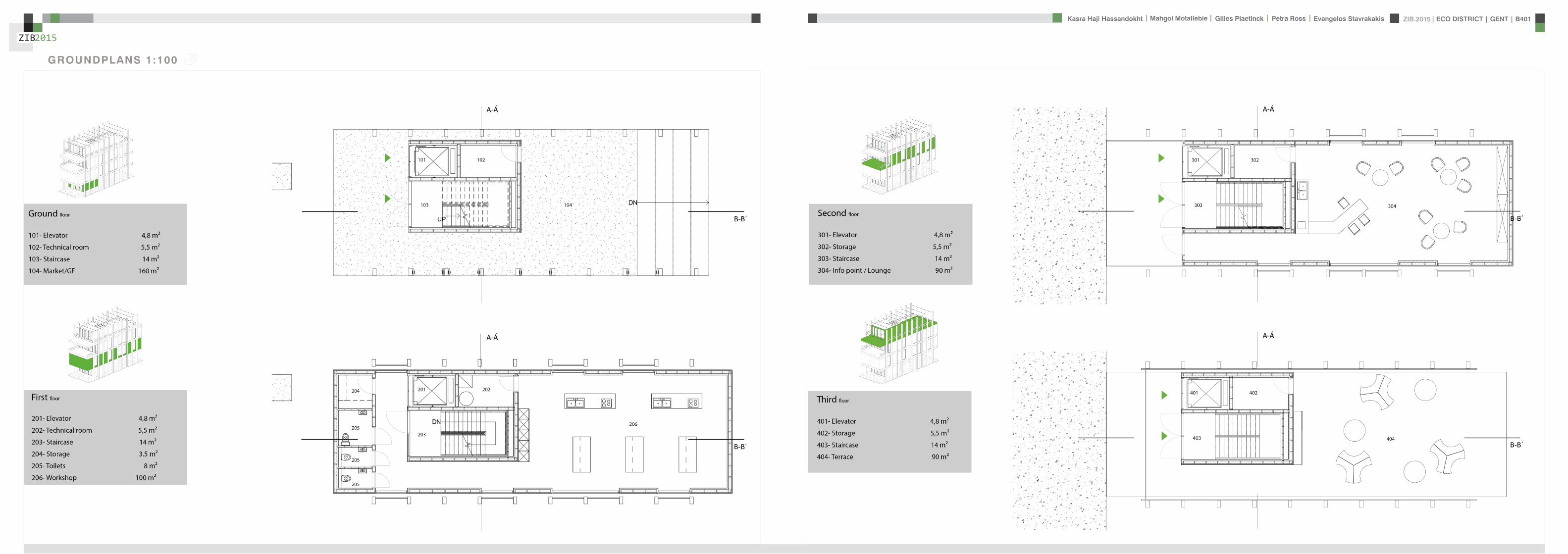
ZIB2015 ECO DISTRICT | GENT | B401Evangelos Stavrakakis | Petra Ross | Mahgol Motallebie | Gilles Plaetinck | Kasra Haji Hassandokht
ZIB2015
|
GROUNDPLANS 1100
B-Bacute
A-Aacute
B-Bacute
A-Aacute
B-Bacute
A-Aacute
B-Bacute
A-Aacute
ZIB2015 ECO DISTRICT | GENT | B401Evangelos Stavrakakis | Petra Ross | Mahgol Motallebie | Gilles Plaetinck | Kasra Haji Hassandokht
ZIB2015
|
SECTIONS 1100
Section A-AacuteSection B-Bacute
AArsquo
AArsquo
Detai l 01
Detai l 02
Detai l 03
Detai l 04
Detai l 05
Detai l 06
ZIB2015 ECO DISTRICT | GENT | B401Evangelos Stavrakakis | Petra Ross | Mahgol Motallebie | Gilles Plaetinck | Kasra Haji Hassandokht
ZIB2015
|
DETAILS
DETAIL 01 DETAIL 02 DETAIL 03 DETAIL 04 DETAIL 05 DETAIL 06
AArsquo
PIR f loorGypsum plasterboardPIR 100 mmOSB 15 mmFJI beam cel lu lose 350 mmcel i t 4D woodf iber 18 mmfinish gypsum plasterboard
plato wood f in ishframework 30 mmcel i t 4D 18 mmwood structure SLS 38140Eurowal l 2x70 mmOSB Eurothane G 70 mmfinish gypsum plasterboard
ZIB2015 ECO DISTRICT | GENT | B401Evangelos Stavrakakis | Petra Ross | Mahgol Motallebie | Gilles Plaetinck | Kasra Haji Hassandokht
ZIB2015
|
ELEVATIONS 1100
South elevation
South Elevation
North Elevation
South Elevation
North Elevation
South Elevation
North Elevation
South Elevation
North Elevation
North elevation
ZIB2015 ECO DISTRICT | GENT | B401Evangelos Stavrakakis | Petra Ross | Mahgol Motallebie | Gilles Plaetinck | Kasra Haji Hassandokht
ZIB2015
|
VISUALIZATIONS
East Elevation
West Elevation
East Elevation
West Elevation
East Elevation
West Elevation East Elevation
West Elevation
ELEVATIONS 1100
West elevation East elevation
ZIB2015 ECO DISTRICT | GENT | B401Evangelos Stavrakakis | Petra Ross | Mahgol Motallebie | Gilles Plaetinck | Kasra Haji Hassandokht
ZIB2015
|
VISUALIZATIONS
ZIB2015 ECO DISTRICT | GENT | B401Evangelos Stavrakakis | Petra Ross | Mahgol Motallebie | Gilles Plaetinck | Kasra Haji Hassandokht
ZIB2015
|
MATERIALS WOOD FCS Certi f ied Suppliers Distance MATERIALS Building Structure
ZIB2015 ECO DISTRICT | GENT | B401Evangelos Stavrakakis | Petra Ross | Mahgol Motallebie | Gilles Plaetinck | Kasra Haji Hassandokht
ZIB2015
|
MATERIALS Specs InsulationMATERIALS Specs Solid amp Structural Wood
ZIB2015 ECO DISTRICT | GENT | B401Evangelos Stavrakakis | Petra Ross | Mahgol Motallebie | Gilles Plaetinck | Kasra Haji Hassandokht
ZIB2015
|
MATERIALS Life Cycle Assesment MATERIALS Embodied energy CO2 other materials
ZIB2015 ECO DISTRICT | GENT | B401Evangelos Stavrakakis | Petra Ross | Mahgol Motallebie | Gilles Plaetinck | Kasra Haji Hassandokht
ZIB2015
|
STRUCTURE
Gilles Plaetinck
schaal
ZIB BUILDINGEnter address here
7 _ Unnamed
Owner
begeleider Checker
3D Copy 11 Gilles Plaetinck
schaal
ZIB BUILDINGEnter address here
8 _ Unnamed
Owner
begeleider Checker
3D Copy 21
Gilles Plaetinck
schaal
ZIB BUILDINGEnter address here
8 _ Unnamed
Owner
begeleider Checker
3D Copy 31
Gilles Plaetinck
schaal
ZIB BUILDINGEnter address here
9 _ Unnamed
Owner
begeleider Checker3D Copy 4
1
ECONOMY - USIBILITY DURING THE DAY
i1000
ALWAYS
2000
ECONONY - USIBILITY DURING THE DAY
GENERAL PRINCIPLES OF THE BUILDING
ZERO IMPACT APPROACH
i
0 Food market in park Vertical harvesting Entrance
1 Workshop area technical room
2 Info center Entrance from highway
3 Roof terrace
ZIB2015 ECO DISTRICT | GENT | B401Evangelos Stavrakakis | Petra Ross | Mahgol Motallebie | Gilles Plaetinck | Kasra Haji Hassandokht
ZIB2015
|
Vertical Harvest places plants on carousels that keep them moving the length of the greenhouse giving them equal time in natural light and also al-lowing workers to pick and tand transfer the crops Using hydroponics Verti-cal Harvest will be capa-ble of producing over
Vertical Harvest places plants on carousels that keep them moving the length of the pulls giving them equal time in natu-ral light and also allowing workers and local people to pick and transfer the crops Using hydroponics Vertical Harvest will be capable of producing over greens and herbs
Vertical Harvest places plants on carousels that keep them moving the length of the greenhouse giving them equal time in natural light and also al-lowing workers to pick and tand transfer the crops Using hydroponics Verti-cal Harvest will be capa-ble of producing over
Vertical Harvest places plants on carousels that keep them moving the length of the pulls giving them equal time in natu-ral light and also allowing workers and local people to pick and transfer the crops Using hydroponics Vertical Harvest will be capable of producing over greens and herbs
VERTICAL HARVESTING
PLANT CABLE LIFT (PLC) SECTION
Sustainable Food zorkshop centerrsquos mission is to ldquocultivate a healthy community by strengthening the local food system and improving access to nu-tritious affordable foodrdquo The main goal of our design is to deliver skills and information for sus-tainability practioners in the organic food tradeThe program attempts to1) affect positive changes in shopping cooking eating habits and nutrition2) reduce diet-related diseases3) promote the health and development of young children 4) place emphasis on local seasonal and cultural-ly-appropriate foods5) integrate food systems concepts into its curric-ulumndash such as shopping at farmers markets and growing onersquos own food
Healthy food is a basic human right the ability to access healthy food is often related to multiple issues and not just a result of low income
FOOD TEAM = a group of people from the same neighbourhood who work for the direct purchase of regional and seasonal products They order food on internet via web page voedselteambe and it is then delivered once a week to the depot of a team
+ minimal transport requirements+ no returnable packaging+ fair p+ fair pricing+ high-quality local and seasonal food+ community initiative
Sustainable Food zorkshop centerrsquos mission is to ldquocultivate a healthy community by strengthening the local food system and improving access to nu-tritious affordable foodrdquo The main goal of our design is to deliver skills and information for sus-tainability practioners in the organic food tradeThe program attempts to1) affect positive changes in shopping cooking eating habits and nutrition2) reduce diet-related diseases3) promote the health and development of young children 4) place emphasis on local seasonal and cultural-ly-appropriate foods5) integrate food systems concepts into its curric-ulumndash such as shopping at farmers markets and growing onersquos own food
Healthy food is a basic human right the ability to access healthy food is often related to multiple issues and not just a result of low income
FOOD TEAM = a group of people from the same neighbourhood who work for the direct purchase of regional and seasonal products They order food on internet via web page voedselteambe and it is then delivered once a week to the depot of a team
+ minimal transport requirements+ no returnable packaging+ fair p+ fair pricing+ high-quality local and seasonal food+ community initiative
Sustainable Food zorkshop centerrsquos mission is to ldquocultivate a healthy community by strengthening the local food system and improving access to nu-tritious affordable foodrdquo The main goal of our design is to deliver skills and information for sus-tainability practioners in the organic food tradeThe program attempts to1) affect positive changes in shopping cooking eating habits and nutrition2) reduce diet-related diseases3) promote the health and development of young children 4) place emphasis on local seasonal and cultural-ly-appropriate foods5) integrate food systems concepts into its curric-ulumndash such as shopping at farmers markets and growing onersquos own food
Healthy food is a basic human right the ability to access healthy food is often related to multiple issues and not just a result of low income
FOOD TEAM = a group of people from the same neighbourhood who work for the direct purchase of regional and seasonal products They order food on internet via web page voedselteambe and it is then delivered once a week to the depot of a team
+ minimal transport requirements+ no returnable packaging+ fair p+ fair pricing+ high-quality local and seasonal food+ community initiative
Healthy food is a basic human right the ability to access healthy food is often related to multiple issues and not just a result of low income
Sustainable Food zorkshop centerrsquos mission is to ldquocultivate a healthy community by strengthening the local food system and improving access to nutritious affordable foodrdquo The main goal of our design is to deliver skills and information for sustainability practioners in the organic food tradeThe program attempts to
1) affect positive changes in shopping cookingeating habits and nutrition2) reduce diet-related diseases3) promote the health and development of youngchildren4) place emphasis on local seasonal and culturally-appropriate foods5) integrate food systems concepts into its curriculumndashsuch as shopping at farmers markets andgrowing onersquos own food
FOOD TEAM = a group of people from the same neighbourhood who work for the direct purchase of regional and seasonal products They order food on internet via web page voedselteambe and it is then delivered once a week to the depot of a team
+ minimal transport requirements+ no returnable packaging+ fair pricing+ high-quality local and seasonal food+ community initiative
WORKSHOP
ZIB2015 ECO DISTRICT | GENT | B401Evangelos Stavrakakis | Petra Ross | Mahgol Motallebie | Gilles Plaetinck | Kasra Haji Hassandokht
ZIB2015
|
Black coral pea
Factors should be considered when seleccng plants
- Quality of growth- Ability to adapt to the wall environment- Environmental Tolerances- Temperature Resistance- Drought Tolerance- Wind - Wind Tolerance- Solar Exposure Tolerance- Salt Tolerance in Seaside installacons- Air and Water Pollucon Tolerance- Pest and Disease Resistance- Arcficial Environment Tolerance- Transplantacon Tolerance- Pruning - Pruning Tolerance
- Ornamental Qualices- Design Purpose- Manageability Maintainability- Environmental and Societal Effects- Visual Effect- Feeling Effect
Blac
k co
ral p
eaSn
ake
vine
kidn
ey w
eed
purple coral peaBasil
Pandorea
Black coral pea
Factors should be considered when seleccng plants
- Quality of growth- Ability to adapt to the wall environment- Environmental Tolerances- Temperature Resistance- Drought Tolerance- Wind - Wind Tolerance- Solar Exposure Tolerance- Salt Tolerance in Seaside installacons- Air and Water Pollucon Tolerance- Pest and Disease Resistance- Arcficial Environment Tolerance- Transplantacon Tolerance- Pruning - Pruning Tolerance
- Ornamental Qualices- Design Purpose- Manageability Maintainability- Environmental and Societal Effects- Visual Effect- Feeling Effect
Blac
k co
ral p
eaSn
ake
vine
kidn
ey w
eed
purple coral peaBasil
Pandorea
Black coral pea
Factors should be considered when seleccng plants
- Quality of growth- Ability to adapt to the wall environment- Environmental Tolerances- Temperature Resistance- Drought Tolerance- Wind - Wind Tolerance- Solar Exposure Tolerance- Salt Tolerance in Seaside installacons- Air and Water Pollucon Tolerance- Pest and Disease Resistance- Arcficial Environment Tolerance- Transplantacon Tolerance- Pruning - Pruning Tolerance
- Ornamental Qualices- Design Purpose- Manageability Maintainability- Environmental and Societal Effects- Visual Effect- Feeling Effect
Blac
k co
ral p
eaSn
ake
vine
kidn
ey w
eed
purple coral peaBasil
Pandorea
GREEN WALLS
ZIB2015 ECO DISTRICT | GENT | B401Evangelos Stavrakakis | Petra Ross | Mahgol Motallebie | Gilles Plaetinck | Kasra Haji Hassandokht
ZIB2015
|
Extraction of air
Pulsion of airRecuperation unit
outdoor space
18 degC15 degC
18 degC
In-take Out-take of air
VENTILATION
Gilles Plaetinck
schaal 1 100
ZIB BUILDINGEnter address here
3 _ level 2
Owner
begeleider Checker
DN
Gilles Plaetinck
schaal 1 100
ZIB BUILDINGEnter address here
2 _ level 1
Owner
begeleider Checker
Extraction of air
Pulsion of air
VENTILATION IN GROUPLANS CALCULATION AND SYSTEM
level 01
level 02
T 42ECO DISTRICT | GENT | B401
ZIB2015Mechanical Ventilation with Heat Recovery (MVHR)
Up to 95 of the heat can be recovered The Heat Recovery Unit runs continu-ously on trickle and can and is boosted when higher rates of ventilation are required eg bathing cooking In warmer months a summer by-pass function helps ensure comfort levels are maintained in the home When summer by-pass is activated the dwelling contin-ues to be ventilaated and recieve fresh filtered air however the heat recovery process is intermittently switched off (heat recovery is by-passed)
Key BenefitsYear round removal of condensation and indoor pol-lutants A direct impact on the Dwelling Emission Rate re-quired in SAP helping reduce the carbon footprint of the property Fresh filtered air supplied to dwelling ideal for allergy sufferers and those with conditions such as asthma A balanced ventilation system for the whole house and recovering of heat that would have otherwise have been lost Low noise non-intrusive ventilation system ndash located away from the room however consideration should be given to duct runs to ensure cross-talk contamination doesnrsquot happen AND the unit is sized correctly so it is not running a high rate all of the time
Zehnder ComfoSystems Passive Haus accredited product suitable for large houses up to 300m2 Designed to ensure low noise excellent energy performance and heat exchange efficiency Choice of control options including LCD touch screen display Can be combine with ComfoCool for optional cooling of up to 5 degrees and humidity reduction by 20
Semi Rigid Ducting
With a manifold system the resistance caused by duct-ing is reduced therefore Semi-Rigid ducting resistance is very low The manifold takes mass airflow directly from the MVHR Heat Recovery Unit and allows lower rates to pass through to each individual room runDirecting mass flow to the manifold eliminates the need to increase the running speed of the MVHR Heat Re-covery unit to overcome the resistance of ducting which in turn causes noise for the homeowner
T 42ECO DISTRICT | GENT | B401
ZIB2015Mechanical Ventilation with Heat Recovery (MVHR)
Up to 95 of the heat can be recovered The Heat Recovery Unit runs continu-ously on trickle and can and is boosted when higher rates of ventilation are required eg bathing cooking In warmer months a summer by-pass function helps ensure comfort levels are maintained in the home When summer by-pass is activated the dwelling contin-ues to be ventilaated and recieve fresh filtered air however the heat recovery process is intermittently switched off (heat recovery is by-passed)
Key BenefitsYear round removal of condensation and indoor pol-lutants A direct impact on the Dwelling Emission Rate re-quired in SAP helping reduce the carbon footprint of the property Fresh filtered air supplied to dwelling ideal for allergy sufferers and those with conditions such as asthma A balanced ventilation system for the whole house and recovering of heat that would have otherwise have been lost Low noise non-intrusive ventilation system ndash located away from the room however consideration should be given to duct runs to ensure cross-talk contamination doesnrsquot happen AND the unit is sized correctly so it is not running a high rate all of the time
Zehnder ComfoSystems Passive Haus accredited product suitable for large houses up to 300m2 Designed to ensure low noise excellent energy performance and heat exchange efficiency Choice of control options including LCD touch screen display Can be combine with ComfoCool for optional cooling of up to 5 degrees and humidity reduction by 20
Semi Rigid Ducting
With a manifold system the resistance caused by duct-ing is reduced therefore Semi-Rigid ducting resistance is very low The manifold takes mass airflow directly from the MVHR Heat Recovery Unit and allows lower rates to pass through to each individual room runDirecting mass flow to the manifold eliminates the need to increase the running speed of the MVHR Heat Re-covery unit to overcome the resistance of ducting which in turn causes noise for the homeowner
MECHANICAL VENTILATION WITH HEAT RECOVERY (MVHR)
Up to 95 of the heat can be recoveredThe Heat Recovery Unit runs continuously on trickle and can and is boosted when higher rates of ventilation are required eg bathing cooking
In warmer months a summer by-pass function helps ensure comfort levels are maintained in the home When summer by-pass is activated the dwelling continues to be ventilaated and recieve fresh filtered air however the heat recovery process is intermittently switched off (heat recovery is by-passed)
EXTRACT VENTILATION RATES
T 42ECO DISTRICT | GENT | B401
ZIB2015Mechanical Ventilation with Heat Recovery (MVHR)
Up to 95 of the heat can be recovered The Heat Recovery Unit runs continu-ously on trickle and can and is boosted when higher rates of ventilation are required eg bathing cooking In warmer months a summer by-pass function helps ensure comfort levels are maintained in the home When summer by-pass is activated the dwelling contin-ues to be ventilaated and recieve fresh filtered air however the heat recovery process is intermittently switched off (heat recovery is by-passed)
Key BenefitsYear round removal of condensation and indoor pol-lutants A direct impact on the Dwelling Emission Rate re-quired in SAP helping reduce the carbon footprint of the property Fresh filtered air supplied to dwelling ideal for allergy sufferers and those with conditions such as asthma A balanced ventilation system for the whole house and recovering of heat that would have otherwise have been lost Low noise non-intrusive ventilation system ndash located away from the room however consideration should be given to duct runs to ensure cross-talk contamination doesnrsquot happen AND the unit is sized correctly so it is not running a high rate all of the time
Zehnder ComfoSystems Passive Haus accredited product suitable for large houses up to 300m2 Designed to ensure low noise excellent energy performance and heat exchange efficiency Choice of control options including LCD touch screen display Can be combine with ComfoCool for optional cooling of up to 5 degrees and humidity reduction by 20
Semi Rigid Ducting
With a manifold system the resistance caused by duct-ing is reduced therefore Semi-Rigid ducting resistance is very low The manifold takes mass airflow directly from the MVHR Heat Recovery Unit and allows lower rates to pass through to each individual room runDirecting mass flow to the manifold eliminates the need to increase the running speed of the MVHR Heat Re-covery unit to overcome the resistance of ducting which in turn causes noise for the homeowner
T 42ECO DISTRICT | GENT | B401
ZIB2015Mechanical Ventilation with Heat Recovery (MVHR)
Up to 95 of the heat can be recovered The Heat Recovery Unit runs continu-ously on trickle and can and is boosted when higher rates of ventilation are required eg bathing cooking In warmer months a summer by-pass function helps ensure comfort levels are maintained in the home When summer by-pass is activated the dwelling contin-ues to be ventilaated and recieve fresh filtered air however the heat recovery process is intermittently switched off (heat recovery is by-passed)
Key BenefitsYear round removal of condensation and indoor pol-lutants A direct impact on the Dwelling Emission Rate re-quired in SAP helping reduce the carbon footprint of the property Fresh filtered air supplied to dwelling ideal for allergy sufferers and those with conditions such as asthma A balanced ventilation system for the whole house and recovering of heat that would have otherwise have been lost Low noise non-intrusive ventilation system ndash located away from the room however consideration should be given to duct runs to ensure cross-talk contamination doesnrsquot happen AND the unit is sized correctly so it is not running a high rate all of the time
Zehnder ComfoSystems Passive Haus accredited product suitable for large houses up to 300m2 Designed to ensure low noise excellent energy performance and heat exchange efficiency Choice of control options including LCD touch screen display Can be combine with ComfoCool for optional cooling of up to 5 degrees and humidity reduction by 20
Semi Rigid Ducting
With a manifold system the resistance caused by duct-ing is reduced therefore Semi-Rigid ducting resistance is very low The manifold takes mass airflow directly from the MVHR Heat Recovery Unit and allows lower rates to pass through to each individual room runDirecting mass flow to the manifold eliminates the need to increase the running speed of the MVHR Heat Re-covery unit to overcome the resistance of ducting which in turn causes noise for the homeowner
Heating 10 kwh msup2aCooling 4 kWh msup2aOverheating 42
ZIB2015 ECO DISTRICT | GENT | B401Evangelos Stavrakakis | Petra Ross | Mahgol Motallebie | Gilles Plaetinck | Kasra Haji Hassandokht
ZIB2015
|
Shutters control system+ -
Solar roadways - PV panels
LED lights
Elevator Fuse box
ElectricityBattery withtransformator
ELECTRICITY
Summer night
cross- ventilation through building
Summer day
air through recuperation unit small change of temperature
15 degC 18 degC
+ groundplans
heated zone
not heated zone
ZONING ACCORDING TO TEMPERATURESSUMMER NIGHT - cross-ventilation through building
SUMMER DAY - air through recuperation unit small change of temperatureSHADING SYSTEM
As a shading was chozen system Renson Icarus Lamellas with angle 45deg made in wood
ZIB2015 ECO DISTRICT | GENT | B401Evangelos Stavrakakis | Petra Ross | Mahgol Motallebie | Gilles Plaetinck | Kasra Haji Hassandokht
ZIB2015
|
average only 4 hours of peak daylight hours per day (4 x 365 = 1460 hours per year)
- Surface area ( first part) Fly-over +- 20 000 msup2-gt 16 000 x 230 Watt = 3 680 000 Watt or 3680 kWonly 50 of fly-over covered with solar roadways
-gt 3680 kW x 4 h = 7360 kWh day-gt 3680 kW x 1460 h = 2 686 400 kWh year -gt +- 540 households (+- 5000 kWh year)
Tesla Powerwall Therersquos a 10 kWh unit at $3500 -gt 737 Tesla Batteries
gt the Solar Roadway has the ability to cut greenhouse gases by up to 75-percentgt A decentralized self-healing secure power grid
IN FRONT OF FLY-OVER
- Surface area Fly-over = 16 x 30 m = 480 msup2-gt 384 x 230 Watt = 88 320 Watt or 883 kWonly 50 of fly-over covered with solar roadways
-gt 44 kW x 4 h = 176 kWh day-gt 44 kW x 1460 h = 64 240 kWh year -gt +- 13 households (+- 5000 kWh year)
lightsshutters
elevator
2 fridges
2 coffeemakers
1 microwave
1 owen
2 cooking plates
stereo
ventilation unit
electricity transformer (AC to DC) for PV panels + batteries
summer 05 kWh daywinter 03 kWh day183 days x 05= 915 kWh182 days x 03 = 546 kWh = 1641 kWh
262 kWh
A++fridge 104 kWhyear104 x x2 = 208 kWh
900 W x 01 hours day = 09 kWhx 220 days x 2= 198 kWh a
67 kWh a
085x100 days= 85 kWh a
400 kWh x 2 = 800 kWh a
150 kWh a 419 kWha
68 kWh a
ENERGY DEMAND OVERVIEW ENERGY SUPPLY OVERVIEW - FLY-OVER
1 spot 56 W 10000 = 0056 KW4 hours per day 365 days a year = 1460 h0056 x 1460 = 8176 kWh10 spots x 8176= 8176 kWh a
1 spot 72 W 10000 = 0072 KW4 hours per day 365 days a year = 1460 h0072 x 1460 = 10512 kWh5 spots x 10512= 5256 kWh a
1 spot 52 W 10000 = 0052 KW4 hours per day 365 days a year = 1460 h0052 x 1460 = 7592 kWh21 spots x 7592= 159432 kWh a
1 spot 9 W 10000 = 0009 KW4 hours per day 365 days a year = 1460 h0009 x 1460 = 1314 kWh5 spots x 1314 = 657 kWh a
SOLAR ROADWAYS - PV PANELSEnergy from the sun
1 To generate energy for the ZIB building2 To generate energy for the surrounding houses3 To generate energy for lighting or signs on the road4 The panels will also have the capacity to charge electric vehicles while parked
ELECTRICITY SCHEME
5423 kWh a
ZIB2015 ECO DISTRICT | GENT | B401Evangelos Stavrakakis | Petra Ross | Mahgol Motallebie | Gilles Plaetinck | Kasra Haji Hassandokht
ZIB2015
|
SUMMER SUNNY 10-42 LUXWINTER SUNNY 10-42 LUX
DAYLIGHT - DIALuxLIGHTING SYSTEM - DIALux
Workplane 9 Results overview
Height of working plane 0800 m Wall zone 0000 m
Result Mean (target) Min Max Minaverage MinmaxPerpendicular illuminance [lx] 463 (500) 105 689 0227 0152
Profile Offices Writing typewriting reading data processing
B401-Gent 6222015
Site 1 Building 2 Zib Room 9 Workplane 9 Results overview
Page 70
Workplane 9 False coloursPerpendicular illuminance (adaptive)
Scale 1 200
Perpendicular illuminance (Surface)Mean (actual) 463 lx Min 105 lx Max 689 lx Minaverage 0227 Minmax 0152
B401-Gent 6222015
Site 1 Building 2 Zib Room 9 Workplane 9 False coloursPerpendicular illuminance (adaptive)
Page 72
Workplane 9 Value chartPerpendicular illuminance (adaptive)
Scale 1 200
Perpendicular illuminance (Surface)Mean (actual) 463 lx Min 105 lx Max 689 lx Minaverage 0227 Minmax 0152
B401-Gent 6222015
Site 1 Building 2 Zib Room 9 Workplane 9 Value chartPerpendicular illuminance (adaptive)
Page 73
Workplane 13 Results overview
Height of working plane 0800 m Wall zone 0000 m
Result Mean (target) Min Max Minaverage MinmaxPerpendicular illuminance [lx] 388 (500) 69 732 0178 0094
Profile Offices Writing typewriting reading data processing
B401-Gent 6222015
Site 1 Building 6 Storey 1 Room 13 Workplane 13 Results overview
Page 94
Workplane 13 False coloursPerpendicular illuminance (adaptive)
Scale 1 100
Perpendicular illuminance (Surface)Mean (actual) 388 lx Min 69 lx Max 732 lx Minaverage 0178 Minmax 0094
B401-Gent 6222015
Site 1 Building 6 Storey 1 Room 13 Workplane 13 False coloursPerpendicular illuminance (adaptive)
Page 96
Workplane 13 Value chartPerpendicular illuminance (adaptive)
Scale 1 100
Perpendicular illuminance (Surface)Mean (actual) 388 lx Min 69 lx Max 732 lx Minaverage 0178 Minmax 0094
B401-Gent 6222015
Site 1 Building 6 Storey 1 Room 13 Workplane 13 Value chartPerpendicular illuminance (adaptive)
Page 97
Workplane 9 False coloursPerpendicular illuminance (adaptive)
Scale 1 200
Perpendicular illuminance (Surface)Mean (actual) 463 lx Min 105 lx Max 689 lx Minaverage 0227 Minmax 0152
B401-Gent 6222015
Site 1 Building 2 Zib Room 9 Workplane 9 False coloursPerpendicular illuminance (adaptive)
Page 72
1st f loor 2nd f loor Site 1 Luminaire parts listQuantity Luminaire (Luminous emittance)10 3F Filippi 12736 P 202x24W LED OP 196x1231
Luminous emittance 1Fitting 1x24W 2xLEDLight output ratio 100Lamp luminous flux 5332 lmLuminaire Luminous Flux 5332 lmPower 560 WLight yield 952 lmW
200
300
400
cdklm η = 100C0 - C180 C90 - C270
0deg 15deg 30deg
45deg
60deg
75deg
90deg
105deg105deg
90deg
75deg
60deg
45deg
30deg 15deg 0deg
5 SFN Eclairages 0732360X CLFV 236Luminous emittance 1Fitting 2xT26 36W840Light output ratio 6889Lamp luminous flux 6700 lmLuminaire Luminous Flux 4615 lmPower 720 WLight yield 641 lmW
160
240
cdklm η = 69C0 - C180 C90 - C270
0deg 15deg 30deg
45deg
60deg
75deg
90deg
105deg105deg
90deg
75deg
60deg
45deg
30deg 15deg 0deg
21 SFN Eclairages 332226XX SAM F 2x26W BELuminous emittance 1Fitting 2xTC-DEL 26W840Light output ratio 3297Lamp luminous flux 3600 lmLuminaire Luminous Flux 1187 lmPower 520 WLight yield 228 lmW
40
60
80
100
120
140
cdklm η = 33C0 - C180 C90 - C270
0deg 15deg 30deg
45deg
60deg
75deg
90deg
105deg105deg
90deg
75deg
60deg
45deg
30deg 15deg 0deg
1 Signcomplex AR111-009-AW-W-06 AR111 COB 9W38deg WhiteLuminous emittance 1Fitting 1xAR111-009-AW-W-06Light output ratio 8078Lamp luminous flux 600 lmLuminaire Luminous Flux 485 lmPower 90 WLight yield 539 lmW
800
1200
cdklm η = 81C0 - C180 C90 - C270
0deg 15deg 30deg
45deg
60deg
75deg
90deg
105deg105deg
90deg
75deg
60deg
45deg
30deg 15deg 0deg
Total lamp luminous flux 163020 lm Total luminaire luminous flux 101807 lm Total Load 20210 W Light yield 504 lmW
B401-Gent 6222015
Site 1 Luminaire parts list
Page 19
10x
6x
21x
1x
types of l ights
Perpendicular i l luminance (Surface)Mean (actual ) 463 lx Min 105 lx Max 689 lx Minaverage 0 227 Minmax 0 152
Perpendicular i l luminance (Surface)Mean (actual ) 388 lx Min 69 lx Max 732 lx Minaverage 0 178 Minmax 0 094
ZIB2015 ECO DISTRICT | GENT | B401Evangelos Stavrakakis | Petra Ross | Mahgol Motallebie | Gilles Plaetinck | Kasra Haji Hassandokht
ZIB2015
|
Tube hybrid Solar panels
Hot water tank Water taps
City water supply
Rain water collection for vertical harvesting
City water supply
WADI
Rain water tank
WATER MANAGEMENT
Sinks
Available roof area
In Ghent avarage of 900mmm2year
3197 m2
09x 3197 = 28773 m3year
RAIN WATER GAIN
toilet - 3x - 03lskitchen -4x - 02ls
POTABLE WATER DEMAND
3 toiletsVertical gardening
Total
relative RW usage
300 l day150 l day = 450lday= 16425 m3 year
1407 lday100m2
RAIN WATER DEMAND
RAIN WATER TANK
Relative RWT volumeRain water tank volume
3m3 100 m2
9591 l gt 10 m3
DIMESION OF PIPES
City water supplyRainwater tank
178 mm (DN 18 - 15 - 12)165 mm (DN 17-15)
are composed of hexagonal tiles Rainwater can infiltrate between the gaps from where it goes to rainwatter collector which supplies the vegetation on fly-over
THE SOLAR ROADWAYS
WATER SUPPLY SCHEME AND CALCULATION
ZIB2015 ECO DISTRICT | GENT | B401Evangelos Stavrakakis | Petra Ross | Mahgol Motallebie | Gilles Plaetinck | Kasra Haji Hassandokht
ZIB2015
|
WADI
City water supply
Rain water tank
Sinks
Divided sewer systemwithin building
SEWAGE SYSTEM
ToiletToilet sinkKitchen sink
DU = 2 lsDU = 05 lsDU = 08 ls
WATER DRAINAGE OF DEVICES
Frequency of usage at the same time
K 05
DIMESION OF PIPES
Black waterGrey water
110 mm (DU 110)75 mm (DU 75 - 63)
WATER DRAINAGE SCHEME AND CALCULATION
ZIB2015 ECO DISTRICT | GENT | B401Evangelos Stavrakakis | Petra Ross | Mahgol Motallebie | Gilles Plaetinck | Kasra Haji Hassandokht
ZIB2015
|
DN
Gilles Plaetinck
schaal 1 100
ZIB BUILDINGEnter address here
2 _ level 1
Owner
begeleider Checker
Gilles Plaetinck
schaal 1 100
ZIB BUILDINGEnter address here
3 _ level 2
Owner
begeleider Checker
WATER SUPPLY
HOT WATER
WATER DRAINAGE
WATER SUPPLY AND DRAINAGE IN GROUPLANS
level 01
level 02
ENERGY
RAINWATER TANK
HELOPHYTE FILTER
IRRIGATION SYSTEM
BIO-ROTOR
MICRO TURBINE
PHOSPHOR
In this building a closed water system is applied which is based on reusing water in mullple wasRainRain water from the roof will be collected in a storage tank situated on the ground floor This water will be used to flush the toilet and irrigate crops in verlcal harveslng system In case of an overflow the water will be stored in the con-structed wetland near the building The rainwater can be fil-tered through a helophyte filter up to drinking water stan-dard The waste water system includes three types of water yellyellow black and grey waterThe yellow water will be stored for its phosphor while the black water will be purified into grey water This grey water is comparable to the quality of rain water aaer purificalon b means of a bio rotor The remaining residue from the bio rotor together with the organic waste from the harveslng is fermented into biogas that drives a micro turbine in order to produce some addilonal energy
TheThe waste product deriving from this process will be used as compost in verlcal harveslng This efficient yet complex system closes the ullizalon cycle of the building and turns it into an efficient vicious circle that can be considered au arkic
In this building a closed water system is applied which is based on reusing water in multiple was
Rain water from the roof will be collected in a storage tank situated on the ground floor This water will be used to flushthe toilet and irrigate crops in vertical harvesting system In case of an overflow the water will be stored in the constructed wetland near the building The rainwater can be filtered through a helophyte filter up to drinking water standard
The waste water system includes three types of water yellow black and grey water The yellow water will be stored for its phosphor while the black water will be purified into grey water This grey water is comparable to the quality of rain water after purification b means of a bio rotor The remaining residue from the bio rotor together with the organic waste from the harvesting is fermented into biogas that drives a micro turbine in order to produce some additional energy The waste product deriving from this process will be used ascompost in ver1048991cal harves1048991ng This efficient yet complexsystem closes the u1048991liza1048991on cycle of the building and turns itinto an efficient vicious circle that can be considered au arkic
WATER CYCLE
ZIB2015 ECO DISTRICT | GENT | B401Evangelos Stavrakakis | Petra Ross | Mahgol Motallebie | Gilles Plaetinck | Kasra Haji Hassandokht
ZIB2015
|
CALCULATIONS
Passive House verification
Photo or Drawing
Building Workshop + info pointStreet
PostcodeCityCountry
Building Type non-residentialClimate Ukkel
Home Owner(s) Client(s)Street
PostcodeCity
ArchitectStreet
PostcodeCity Calculation electricity Internal heat gains
Mechanical System Building type
StreetPostcodeCity Internal heat gains
Year of Construction 2015 Interior Temperature 200 degC Utilisation pattern
Number of Dwelling Units 1 Internal Heat Gains 20 Wm2 Type of values used Fill in worksheet IHG Non-Dom Enclosed Volume Ve 12442 Planned number of occupants
Number of Occupants 80 8 Design
Specific building demands with reference to the treated floor area use Annual method
Treated floor area 2840 msup2 Requirements Fulfilled Verification Annual method The monthly method should be used for building certification
Space heating Annual heating demand 10 kWh(m2a) 15 kWh(msup2a) yes Specific space heating demand annual method 103 kWh(msup2a)
Heating load 11 Wm2 10 Wmsup2 - Specific space heating demand monthly Method 120 kWh(msup2a)
Space cooling Overall specific space cooling demand kWh(m2a) 15 kWh(msup2a)
Cooling load Wm2 - -Frequency of overheating (gt 25 degC) - -
Primary Energy Space heating and dehumidification
cooling household electricity 73 kWh(m2a) 120 kWh(msup2a) yes
DHW space heating and auxiliary electricity 24 kWh(m2a) - -Specific primary energy reduction through solar electricity 21 kWh(m2a) - -
Airtightness Pressurization test result n50 06 1h 06 1h yes
PHPP Verification FINAL ZIB FILE CALCULTIONS PHPPxls
L B H VOLUME
main 1 226 7 4 6328main 2 184 7 35 4508
core 0 6 2 5 3 5 108 5core 0 62 5 35 1085core 3 62 3 28 521
12442
AREAmain 1 storage 35
wc big 35wc 2wc 2workshop 103
MAIN 2 infolounge 92
staircase 56storage technical 22
284
Floor_exterior 1582 31 1272
Roof_exterior 1582
Passive House verification
Photo or Drawing
Building Workshop + info pointStreet
PostcodeCityCountry
Building Type non-residentialClimate Ukkel
Home Owner(s) Client(s)Street
PostcodeCity
ArchitectStreet
PostcodeCity Calculation electricity Internal heat gains
Mechanical System Building type
StreetPostcodeCity Internal heat gains
Year of Construction 2015 Interior Temperature 200 degC Utilisation pattern
Number of Dwelling Units 1 Internal Heat Gains 20 Wm2 Type of values used Fill in worksheet IHG Non-Dom Enclosed Volume Ve 12442 Planned number of occupants
Number of Occupants 80 8 Design
Specific building demands with reference to the treated floor area use Annual method
Treated floor area 2840 msup2 Requirements Fulfilled Verification Annual method The monthly method should be used for building certification
Space heating Annual heating demand 10 kWh(m2a) 15 kWh(msup2a) yes Specific space heating demand annual method 103 kWh(msup2a)
Heating load 11 Wm2 10 Wmsup2 - Specific space heating demand monthly Method 120 kWh(msup2a)
Space cooling Overall specific space cooling demand kWh(m2a) 15 kWh(msup2a)
Cooling load Wm2 - -Frequency of overheating (gt 25 degC) - -
Primary Energy Space heating and dehumidification
cooling household electricity 73 kWh(m2a) 120 kWh(msup2a) yes
DHW space heating and auxiliary electricity 24 kWh(m2a) - -Specific primary energy reduction through solar electricity 21 kWh(m2a) - -
Airtightness Pressurization test result n50 06 1h 06 1h yes
PHPP Verification FINAL ZIB FILE CALCULTIONS PHPPxls
SURFACE AREAcurrent orientation only night ventilation
current orientation only night ventilation 6 windows less 52 msup2
current orientation only night ventilation 7 windows less 60msup2 (stays the same for each side)
current orientation only night ventilation 8 windows less 69 msup2
orientation turned 90deg only night ventilation 6 windows less 52 msup2
orientation turned 90deg only night ventilation 7 windows less 60msup2 (window less at SE side)
orientation turned 90deg only night ventilation 8 windows less 69 msup2
-gt orientation turned 90deg only night ventilation 9 windows less 77msup2 (window less at NW side althought theres less overheating in the case of a window less at SE side the heating demand exceeds 15)
CHANGE IN DESIGN
ZIB2015 ECO DISTRICT | GENT | B401Evangelos Stavrakakis | Petra Ross | Mahgol Motallebie | Gilles Plaetinck | Kasra Haji Hassandokht
ZIB2015
|
Passive House verificationS P E C I F I C A N N U A L H E A T I N G D E M A N D
Climate Ukkel Interior Temperature 200 degC
Building Workshop + info point Building TypeUse non-residentialTreated Floor Area ATFA 2840 msup2
per msup2Area U-Value Temp Factor ft Gt Treated Data for heating balance diagram
Building Element Temperature Zone msup2 W(msup2K) kKha kWha Floor Area Losses GainsExterior Wall - Ambient A 5595 0101 100 743 = 4181 1472 Exterior Wall - Ambient 147234373Exterior Wall - Ground B 069 = Exterior Wall - GroundRoofCeiling - Ambient A 1550 0094 100 743 = 1085 382 RoofCeiling - Ambient 381903529Floor slab basement ceiling B 310 0105 069 743 = 167 059 Floor slab basement ceiling 058811509
A 100 =A 100 =
unheated basement X 075 = unheated basementWindows A 1154 0648 100 743 = 5562 1958 Windows 195834732Exterior Door A 100 = Exterior DoorExterior TB (lengthm) A 1169 -0030 100 743 = -259 -091 Thermal Bridge Heat LossPerimeter TB (lengthm) P 069 = 000 not useful heat gains 365267499Ground TB (lengthm) B 069 =
Total of All Building Envelope Areas 8609 ndashndashndashndashndashndashndashndashndashndashndashndashndash- kWh(msup2a) Ventilation 395818713
Transmission Heat Losses QT Total 10736 378Annual Heating Demand 102516636
ATFA Clear Room Height internal gains 100951487msup2 m msup3 passive solar gains 250668423
Ventilation System Effective Air Volume VV 2840 280 = 7952 Thermal bridge credit 091126837Effective Heat Recovery Efficiency eff 81 Cross check sum 46324923 46324923of Heat Recovery
Efficiency of Subsoil Heat Exchanger SHX 0 nVsystem HR nVRes
1h 1h 1h
Energetically Effective Air Exchange nV 0105 (1 - 081 ) + 0038 = 0058
VV nV cAir Gt
msup3 1h Wh(msup3K) kKha kWha kWh(msup2a)
Ventilation Heat Losses QV 795 0058 033 743 = 1124 40
Reduction Factor QT QV NightWeekend
kWha kWha Saving kWha kWh(msup2a)
Total Heat Losses QL ( 10736 + 1124 ) 10 = 11860 418
Orientation Reduction Factor g-Value Area Radiation HPof the Area See Windows Sheet (perp radiation)
msup2 kWh(msup2a) kWha
1 North 054 050 2700 163 = 11822 East 058 000 440 197 = 03 South 056 050 4860 314 = 42874 West 032 050 3216 254 = 13275 Horizontal 063 050 324 317 = 323
kWh(msup2a)
Available Solar Heat Gains QS Total 7119 251
Length Heat Period Spec Power qI ATFA
khd da Wmsup2 msup2 kWha kWh(msup2a)
Internal Heat Gains QI 0024 209 201 2840 = 2867 101
kWha kWh(msup2a)
Free Heat QF QS + QI = 9986 352
Ratio of Free Heat to Losses QF QL = 084
Utilisation Factor Heat Gains G (1 - ( QF QL )5 ) (1 - ( QF QL )
6 ) = 90kWha kWh(msup2a)
Heat Gains QG G QF = 8949 315
kWha kWh(msup2a)
Annual Heating Demand QH QL - QG = 2911 10
kWh(msup2a) (YesNo)
Limiting Value 15 Requirement met yes
00
147
00
3806000000
196
00
40
37
09
103
101
251
0
5
10
15
20
25
30
35
40
45
50
Losses Gains
Hea
t flo
ws
[kW
h(m
sup2a)]
Heating energy balance
passive solar gains
internal gains
Annual Heating Demand
Thermal bridge credit
not useful heat gains
Ventilation
Exterior Door
Windows
unheated basement
Floor slab basement ceiling
RoofCeiling - Ambient
Exterior Wall - Ground
Exterior Wall - Ambient
Thermal Bridge Heat Loss
HPP Annual Heating Demand FINAL ZIB FILE CALCULTIONS PHPPxls
Passive House verification Passive House verificationS P E C I F I C U S E F U L C O O L I N G D E M A N D S P E C I F I C U S E F U L C O O L I N G D E M A N D
M O N T H L Y M E T H O D M O N T H L Y M E T H O D
(This page displays the sums of the monthly method over the cooling period))Climate Ukkel Interior Temperature Summer 25 degC Climate Ukkel Interior Temperature 25 degC
Building Workshop + info point Building TypeUse non-residential Building Workshop + info point Building TypeUse non-residential
Spec Capacity 60 Wh(msup2K) (Enter in Summer worksheet) Treated Floor Area ATFA 2840 msup2 Treated Floor Area ATFA 284 msup2
per msup2Temperature Zone Area U-Value Mon Red Fac Gt Treated Jan Feb Mar Apr May Jun Jul Aug Sep Oct Nov Dec Year
Building Element msup2 W(msup2K) kKha kWha Floor Area Heating Degree Hours - Ex 168 150 144 121 92 73 57 59 82 109 140 160 136 kKh1 Exterior Wall - Ambient A 5595 0101 100 103 = 5782 Heating Degree Hours - G 126 123 135 120 106 83 63 54 58 71 86 109 113 kKh2 Exterior Wall - Ground B 100 = Losses - Exterior 2553 2286 2189 1838 1393 1117 871 904 1245 1660 2123 2432 20612 kWh3 RoofCeiling - Ambient A 1550 0094 100 103 = 1500 Losses - Ground 41 40 44 39 35 27 21 18 19 23 28 36 370 kWh4 Floor slab basement ceil B 310 0105 100 90 = 294 Losses Summer Ventilatio 67 71 244 372 629 720 880 865 658 499 234 126 5366 kWh5 A 100 = Sum Spec Heat Losses 94 84 87 79 72 66 62 63 68 77 84 91 928 kWhmsup26 A 100 = Solar Load North 44 81 141 212 286 298 298 255 178 116 54 35 1998 kWh7 unheated basement X 075 = Solar Load East 0 0 0 0 0 0 0 0 0 0 0 0 0 kWh8 Windows A 1154 0648 100 103 = 7690 Solar Load South 218 315 464 577 681 644 681 658 532 416 242 171 5601 kWh9 Exterior Door A 100 = Solar Load West 79 125 213 303 385 378 370 347 256 177 91 60 2785 kWh
10 Exterior TB (lengthm) A 1169 -0030 100 103 = -358 Solar Load Horiz 11 21 37 57 79 79 80 69 47 30 14 9 533 kWh11 Perimeter TB (lengthm) P 100 = Solar Load Opaque 3 5 9 13 18 19 19 16 11 7 3 2 126 kWh12 Ground TB (lengthm) B 100 = Internal Heat Gains 425 384 425 411 425 411 425 425 411 425 411 425 5001 kWh
ndashndashndashndashndashndashndashndashndashndashndash kWh(msup2a) Sum Spec Loads Solar + 28 33 45 55 66 64 66 62 51 41 29 25 565 kWhmsup2
Transmission Losses QT (Negative Heat Loads) Total 14907 525 Utilisation Factor Losses 29 39 52 69 84 88 82 88 73 53 34 27 58Useful Cooling Energy Dem 0 0 4 30 142 192 417 192 40 4 0 0 1021 kWh
ATFA Clear Room Height Spec Cooling Demand 00 00 00 01 05 07 15 07 01 00 00 00 36 kWhmsup2Effective msup2 m msup3
Air Volume VV 284 280 = 795
Heat Transfer Coef Gt
WK kKha kWha kWh(msup2a)
Exterior 99 103 = 1013 36Ground 00 105 = 0 00
Additional Summer Ventilation
Select X Window Night Ventilation Manual Corresponding Air Change Rate 136 1h
Mechanical Automatically Controlled Ventilation (for window ventilation at 1 K temperature difference indoor - outdoor)
Minimum Acceptable Indoor Temperatu 220 degC
kWha kWh(msup2a)
Heat Losses Summer Ventilation 5172 182
QLext QLground QLsummer
kWha kWha kWha kWha kWh(msup2a)
Ventilation Heat Losses QV 1013 + 0 + 5172 = 6185 218
2
3
4
5
6
7
8
9
10
Spec
ific
loss
es l
oads
l c
oolin
g de
man
d [k
Wh
(msup2 m
onth
)] Spec Cooling Demand Sum Spec Heat Losses Sum Spec Loads Solar + Internal
QT QV
kWha kWha kWha kWh(msup2a)
Total Heat Losses QL 14907 + 6185 = 21092 743
Orientation Reduction Factor g-Value Area Global Radiationof the Area (perp radiation)
msup2 kWh(msup2a) kWha
1 North 031 050 270 462 = 19182 East 061 000 44 578 = 0 Temperature Amplitude Summer 82 K3 South 030 050 486 707 = 52114 West 025 050 322 654 = 2646 Month 1 2 3 4 5 6 7 8 9 10 11 12 Annual Total5 Horizontal 035 050 32 913 = 513 Days 31 28 31 30 31 30 31 31 30 31 30 31 3656 Sum Opaque Areas 121 Ambient Temp 250 270 572 828 1275 1487 1737 1707 1369 1039 568 356 96
kWh(msup2a) North Radiation 106 195 329 494 667 697 712 599 419 275 129 87 471
Available Solar Heat Gains QS Total 10409 367 East Radiation 146 266 452 698 937 940 988 851 574 382 179 123 654
South Radiation 311 440 645 786 912 858 898 885 733 579 341 241 763Length Heat Period Spec Power qI ATFA West Radiation 155 261 471 707 926 926 896 819 580 382 183 116 642
khd da Wmsup2 msup2 kWha kWh(msup2a) Hori Radiation 200 369 662 1021 1398 1410 1418 1234 842 535 243 156 949
Internal Heat Gains QI 0024 303 20 2840 = 4151 146 Tsky -750 -730 -428 -172 275 487 737 707 369 039 -432 -644 -04
Ground Temp 805 676 686 830 1072 1345 1647 1776 1696 1552 1310 1037 121kWha kWh(msup2a)
Sum Heat Loads QF QS + QI = 14560 513
Ratio of Losses to Free Heat Gains QL QF = 145
Utilisation Factor Heat Losses G = 64kWha kWh(msup2a)
Useful Heat Losses QVn G QL = 13539 477
kWha kWh(msup2a)
Useful Cooling Demand QK QF - QVn = 1021 4
kWh(msup2a) (YesNo)
Limiting Value 15 Requirement met yes
0
1
2
Jan Feb Mar Apr May Jun Jul Aug Sep Oct Nov Dec
usef
u
HPP Cooling FINAL ZIB FILE CALCULTIONS PHPPxls
Passive House verificationS P E C I F I C A N N U A L H E A T I N G D E M A N D
Climate Ukkel Interior Temperature 200 degC
Building Workshop + info point Building TypeUse non-residentialTreated Floor Area ATFA 2840 msup2
per msup2Area U-Value Temp Factor ft Gt Treated Data for heating balance diagram
Building Element Temperature Zone msup2 W(msup2K) kKha kWha Floor Area Losses GainsExterior Wall - Ambient A 5595 0101 100 743 = 4181 1472 Exterior Wall - Ambient 147234373Exterior Wall - Ground B 069 = Exterior Wall - GroundRoofCeiling - Ambient A 1550 0094 100 743 = 1085 382 RoofCeiling - Ambient 381903529Floor slab basement ceiling B 310 0105 069 743 = 167 059 Floor slab basement ceiling 058811509
A 100 =A 100 =
unheated basement X 075 = unheated basementWindows A 1154 0648 100 743 = 5562 1958 Windows 195834732Exterior Door A 100 = Exterior DoorExterior TB (lengthm) A 1169 -0030 100 743 = -259 -091 Thermal Bridge Heat LossPerimeter TB (lengthm) P 069 = 000 not useful heat gains 365267499Ground TB (lengthm) B 069 =
Total of All Building Envelope Areas 8609 ndashndashndashndashndashndashndashndashndashndashndashndashndash- kWh(msup2a) Ventilation 395818713
Transmission Heat Losses QT Total 10736 378Annual Heating Demand 102516636
ATFA Clear Room Height internal gains 100951487msup2 m msup3 passive solar gains 250668423
Ventilation System Effective Air Volume VV 2840 280 = 7952 Thermal bridge credit 091126837Effective Heat Recovery Efficiency eff 81 Cross check sum 46324923 46324923of Heat Recovery
Efficiency of Subsoil Heat Exchanger SHX 0 nVsystem HR nVRes
1h 1h 1h
Energetically Effective Air Exchange nV 0105 (1 - 081 ) + 0038 = 0058
VV nV cAir Gt
msup3 1h Wh(msup3K) kKha kWha kWh(msup2a)
Ventilation Heat Losses QV 795 0058 033 743 = 1124 40
Reduction Factor QT QV NightWeekend
kWha kWha Saving kWha kWh(msup2a)
Total Heat Losses QL ( 10736 + 1124 ) 10 = 11860 418
Orientation Reduction Factor g-Value Area Radiation HPof the Area See Windows Sheet (perp radiation)
msup2 kWh(msup2a) kWha
1 North 054 050 2700 163 = 11822 East 058 000 440 197 = 03 South 056 050 4860 314 = 42874 West 032 050 3216 254 = 13275 Horizontal 063 050 324 317 = 323
kWh(msup2a)
Available Solar Heat Gains QS Total 7119 251
Length Heat Period Spec Power qI ATFA
khd da Wmsup2 msup2 kWha kWh(msup2a)
Internal Heat Gains QI 0024 209 201 2840 = 2867 101
kWha kWh(msup2a)
Free Heat QF QS + QI = 9986 352
Ratio of Free Heat to Losses QF QL = 084
Utilisation Factor Heat Gains G (1 - ( QF QL )5 ) (1 - ( QF QL )
6 ) = 90kWha kWh(msup2a)
Heat Gains QG G QF = 8949 315
kWha kWh(msup2a)
Annual Heating Demand QH QL - QG = 2911 10
kWh(msup2a) (YesNo)
Limiting Value 15 Requirement met yes
00
147
00
3806000000
196
00
40
37
09
103
101
251
0
5
10
15
20
25
30
35
40
45
50
Losses Gains
Hea
t flo
ws
[kW
h(m
sup2a)]
Heating energy balance
passive solar gains
internal gains
Annual Heating Demand
Thermal bridge credit
not useful heat gains
Ventilation
Exterior Door
Windows
unheated basement
Floor slab basement ceiling
RoofCeiling - Ambient
Exterior Wall - Ground
Exterior Wall - Ambient
Thermal Bridge Heat Loss
HPP Annual Heating Demand FINAL ZIB FILE CALCULTIONS PHPPxls
factor 05Wd (ls) 088
nominal diameter 75 mmVERTICAL COLLECTOR sink toilets 3 05 15
sink kitchen 2 08 16Total 5 31factor 05
Wd (ls) 088nominal diameter 75 mm
Toevoerend ROOF SURFACE
horizontal roof surface (msup2) orientation coeff angle (deg) roofcover filter coeff toevoerend
444 1 0 08 09 3197
RAIN WATER USAGE
Type usage ( l usage) persons day frequency usageday yearly usage
toilet use small 3 20 3 180 65700toilet use big 6 20 1 120 43800VERTICAL GARDENING 150 54750TOTAL 450 164250 L year
16425 msup3 year
TOTAL RAINWATER USAGE 450 L dayRELATIVE RAINWATER USAGE 1407 L day100msup2
LEEGSTAND
relative rainwater usage 1407 L day 100 msup2LEEGSTAND 7 relative volume rainwater tank 3 msup3 100 msup2rainwater tank volume 9591 Liter
suggestion 50 msup2 02 m= 10 msup3
SUPPLYtype amount debiet Q total total WW
lsec lsec lsecMAIN LEVEL POTABLE
sink toilet 3 01 03 03sink kitchen 2 01 02 02
Total 5 05 05Gelijktijdigheid 05 05debiet Q (lsec) 025 025
diameter 178 178 cm
type amount debiet Q total total WWlsec lsec lsec
MAIN LEVEL RAIN WATER toilet 3 01 03 0
Total 3 03Gelijktijdigheid 071debiet Q (lsec) 0213
diameter 165 cm
FECALIEumlNtype amount value Total (ls)
COLLECTOR HORIZONTAL toilet 3 2Total 6factor 05
Wd (ls) 122nominal diameter 110 mm
type amount value Total (ls)COLLECTOR VERTICAL toilet 3 2
Total 6factor 05
Wd (ls) 122nominal diameter 110 mm
DRAINtype amount value Total (ls)
HORIZONTAL COLLECTOR sink toilets 3 05 15sink kitchen 2 08 16
Total 5 31
WATER
ZIB2015 ECO DISTRICT | GENT | B401Evangelos Stavrakakis | Petra Ross | Mahgol Motallebie | Gilles Plaetinck | Kasra Haji Hassandokht
ZIB2015
|
Passive House verificationS P E C I F I C S P A C E H E A T I N G L O A D Risk Determination of Group Heating for a Critical Room
Building Workshop + info point Building TypeUse non-residential Workshop room ( 1= Yes 0 = No)
Climate (HL) Ukkel Treated Floor Area ATFA 2840 msup2 Interior Temperature 20 degC Building Satisfies Passive House Criteria 1
Design Temperature Radiation North East South West Horizontal Room floor area 100 msup2 Supply Air per msup2 Living AreaWeather Condition 1 -31 degC 10 10 30 15 20 Wmsup2 Planned ambient air quantity for the room 150 msup3h 150 msup3hmsup2Weather Condition 2 -22 degC 5 5 20 10 10 Wmsup2 Planned ambient air quantities for the remaining rooms -67 msup3hGround Design Temp 68 degC Area U-Value Factor TempDiff 1 TempDiff 2 PT 1 PT 2
Building Element Temperature Zone msup2 W(msup2K) Always 1(except X) K K W W Building Element Temperature Zone msup2 W(msup2K) Always 1
(except X) K Room Trans Loss W
1 Exterior Wall - Ambient A 5595 0101 100 231 or 222 = 1299 or 1249 Aboveground Exterior Wall A 650 010 100 231 = 1512 Exterior Wall - Ground B 100 132 or 132 = or Belowground Exterior Wall B 00 100 132 =3 RoofCeiling - Ambient A 1550 0094 100 231 or 222 = 337 or 324 RoofCeiling D 880 009 100 231 = 1914 Floor slab basement ceiling B 310 0105 100 132 or 132 = 43 or 43 Underground Floor Slab B 00 011 100 132 = 05 A 100 231 or 222 = or A 100 231 =6 A 100 231 or 222 = or A 100 231 =7 unheated basement X 075 231 or 222 = or X 100 231 =8 Windows A 1154 0648 100 231 or 222 = 1728 or 1661 Windows A 480 065 100 231 = 7199 Exterior Door A 100 231 or 222 = or Exterior Door A 100 231 =
10 Exterior TB (lengthm) A 1169 -0030 100 231 or 222 = -80 or -77 Exterior thermal bridges (Lengthm) A 100 231 =11 Perimeter TB (lengthm) P 100 132 or 132 = or Perimeter Thermal Bridges (Lengthm) A 100 231 =12 Ground TB (lengthm) B 100 132 or 132 = or Floor Slab Thermal Bridges (Lengthm) A 50 100 231 =13 HouseDU Partition Wall I 100 30 or 30 = or HouseDU Partition Wall I 200 100 30 =
Transmission Heat Losses PT ndashndashndashndashndashndashndashndashndashndashndashndashndash- ndashndashndashndashndashndashndashndashndashndashndash-
Total = 3328 or 3200 = 1061
ATFA Clear Room HeightVentilation System msup2 m msup3 Risk
Effective Air Volume VV 2840 280 = 795 Enter 1 = Yes 0 = No PTRoom W PSupply Air W Ratio Summand
SHX 1 SHX 2 Transmission Heat Losses 1061 1386 077 -023Efficiency of Heat Recovery HR 81 Heat Recovery Efficiency SHX 0 Efficiency SHX 0 or 0 Concentrated leakages 0 000of the Heat Exchanger Insulation to other rooms better R = 15 msup2KW 1 ( 2 = no thermal contact except door) 050
nVRes (Heating Load) nVsystem HR HR Room is on the ground floor 0 0001h 1h 1h 1h open staircase 0 000
Energetically Effective Air Exchange nV 0094 + 0105 (1- 081 or 081 ) = 0114 or 0114 TOTAL of the Risk Summands 027Ventilation Heating Load PV
VL nL nL cAir TempDiff 1 TempDiff 2 PV 1 PV 2 Interior doors predominantly closed 1 Risk Factor 200msup3 1h 1h Wh(msup3K) K K W W
7952 0114 or 0114 033 231 or 222 = 691 or 664Total Room Risk 89
PL 1 PL 2
Total Heating Load PL W W Appraisal and Advice normally no problemPT + PV = 4019 or 3864
Orientation Area g-Value Reduction Factor Radiation 1 Radiation 2 PS 1 PS 2the Area msup2 (perp radiation) (see Windows worksheet) Wmsup2 Wmsup2 W W
1 North 270 05 05 11 or 6 = 77 or 412 East 44 00 06 8 or 3 = 0 or 03 South 486 05 06 28 or 18 = 378 or 2474 West 322 05 03 19 or 13 = 100 or 685 Horizontal 32 05 06 20 or 10 = 20 or 10
Solar heating power PS Total = 575 or 367
Spec Power ATFA PI 1 PI 2Internal heating power PI Wmsup2 msup2 W W
16 284 = 454 or 454
PG 1 PG 2
Heating power (gains) PG W W
PS + PI = 1029 or 821
PL - PG = 2989 or 3042
Heating Load PH = 3042 W
Specific Heating Load PH ATFA = 107 Wmsup2
Input Max Supply Air Temperature 48 degC degC degC
Max Supply Air Temperature SupplyMax 48 degC Supply Air Temperature Without Heating SupplyMin 156 157
For Comparison Heating Load Transportable by Supply Air PSupply AirMax = 886 W specific 31 Wmsup2
(YesNo)
Supply Air Heating Sufficient No
HPP Heating Load FINAL ZIB FILE CALCULTIONS PHPPxls
Passive House verificationU - V A L U E S O F B U I L D I N G E L E M E N T S
Wedge shaped building element layeBuilding Workshop + info point still air spaces -gt Secondary calculation to th
Assembly No Building assembly description Interior insulation1 Exterior wall x
Heat transfer resistance [msup2KW] interior Rsi 013exterior Rse 004
Area section 1 [W(mK)] Area section 2 (optional) [W(mK)] Area section 3 (optional) [W(mK)] Thickness [mm]
1 hout gevel 0160 17
2 regelwerk hout 0158 30
3 houtvezel celit 4D 0048 18
4 Eurowall 0023 hout FJI beam 0286 140
5 OSB -plaat 0130 15
6 Eurothane G 0023 70
7 Plaster insulating 0100 10
8Percentage of Sec 2 Percentage of Sec 3 Total
26 300
U-Value 0107 W(msup2K)
Assembly No Building assembly description Interior insulation2 Roof x
Heat transfer resistance [msup2KW] interior Rsi 010exterior Rse 004
Area section 1 [W(mK)] Area section 2 (optional) [W(mK)] Area section 3 (optional) [W(mK)] Thickness [mm]Area section 1 [W(mK)] Area section 2 (optional) [W(mK)] Area section 3 (optional) [W(mK)] Thickness [mm]
1 bitumenmembraam 0230 5
23 EPS 0036 70
4 OSB -plaat 0130 18
5 cellulose 0039 hout FJI beam 0286 350
6 OSB -plaat 0130 15
7 regelwerk hout 5 0177 30
8 gipskartonplaat 0290 12
Percentage of Sec 2 Percentage of Sec 3 Total
26 500
U-Value 0094 W(msup2K)
Assembly No Building assembly description Interior insulation3 Floor x
Heat transfer resistance [msup2KW] interior Rsi 017
exterior Rse 004
Area section 1 [W(mK)] Area section 2 (optional) [W(mK)] Area section 3 (optional) [W(mK)] Thickness [mm]
1 PIR dekvloer 0023 5
2 gipskartonplaat 0290 10
3 gespoten pur 0028 100
4 OSB -plaat 0130 15
5 cellulose 0039 hout FJI beam 0286 350
6 houtvezel Celit 4D 0048 15
7 regelwerk hout 6 0149 30
8 afwerking hout 0160 5
Percentage of Sec 2 Percentage of Sec 3 Total
26 530
U-Value 0078 W(msup2K)
PHPP U-Values FINAL ZIB FILE CALCULTIONS PHPPxls
ers and he right
n Secondary Calculation Equivalent Thermal Conductivity of Still Air Spaces
Air Layer Thickness 30 mm Direction of Upwards ha 125 W(msup2K) 016 W(mK)
Heat Flow X Horizontal hr 417 W(msup2K)
(check only one field) Downwards
cm
n
cm
n Secondary Calculation Equivalent Thermal Conductivity of Still Air Spaces
Air Layer Thickness 30 mm
Direction of Upwards ha 08333 W(msup2K) 015 W(mK)Heat Flow Horizontal hr 417 W(msup2K)
(check only one field) X Downwards
cm
PHPP U-Values FINAL ZIB FILE CALCULTIONS PHPPxls
ers and he right
n Secondary Calculation Equivalent Thermal Conductivity of Still Air Spaces
Air Layer Thickness 30 mm Direction of Upwards ha 125 W(msup2K) 016 W(mK)
Heat Flow X Horizontal hr 417 W(msup2K)
(check only one field) Downwards
cm
n
cm
n Secondary Calculation Equivalent Thermal Conductivity of Still Air Spaces
Air Layer Thickness 30 mm
Direction of Upwards ha 08333 W(msup2K) 015 W(mK)Heat Flow Horizontal hr 417 W(msup2K)
(check only one field) X Downwards
cm
PHPP U-Values FINAL ZIB FILE CALCULTIONS PHPPxls
ers and he right
n Secondary Calculation Equivalent Thermal Conductivity of Still Air Spaces
Air Layer Thickness 30 mm Direction of Upwards ha 125 W(msup2K) 016 W(mK)
Heat Flow X Horizontal hr 417 W(msup2K)
(check only one field) Downwards
cm
n
cm
n Secondary Calculation Equivalent Thermal Conductivity of Still Air Spaces
Air Layer Thickness 30 mm
Direction of Upwards ha 08333 W(msup2K) 015 W(mK)Heat Flow Horizontal hr 417 W(msup2K)
(check only one field) X Downwards
cm
PHPP U-Values FINAL ZIB FILE CALCULTIONS PHPPxls
Passive House verificationS U M M E R
Climate Ukkel Interior Temperature 20 degC
Building Workshop + info point Building TypeUse non-residentialTreated Floor Area ATFA 2840 msup2
Spec Capacity 60 WhK pro msup2 TFAOverheating
limit25 degC Area U-Value Red Factor fTSummer HSummer Heat Conductance
Building Element Temperature Zone msup2 W(msup2K)
1 Exterior Wall - Ambien A 5595 0101 100 = 5632 Exterior Wall - Ground B 100 =3 RoofCeiling - Ambient A 1550 0094 100 = 1464 Floor slab basement B 310 0105 100 = 335 A 100 =6 A 100 =7 unheated basement X 075 =8 Windows A 1154 0648 100 = 7489 Exterior Door A 100 =
10 Exterior TB (lengthm) A 1169 -0030 100 = -3511 Perimeter TB (lengthm P 100 =12 Ground TB (lengthm) B 100 =
ndashndashndashndashndashndashndashndashndashndashndashExterior Thermal Transmittance HTe 1422 WK
Ground Thermal Transmittance HTg 33 WK
ATFA Clear Room HeightEffective msup2 m msup3
Heat Recovery Efficiency HR 81 Air Volume VV 2840 280 = 795
SHX Efficiency SHX 0
Summer Ventilation continuous ventilation to provide sufficient indoor air quality
Air Change Rate by Natural (Windows amp Leakages) or Exhaust-Only Mechanical Ventilation Summer 000 1h
Mechanical Ventilation Summer 1h X with HR (check if applicable)
nLnat nVsystem HR nVRest
1h 1h 1h 1h
Energetically Effective Airchange Rate nV 0000 + 0000 (1 - 0808 ) + 0038 = 0038
VV nVequifraction cAir
msup3 1h Wh(msup3K)
Ventilation Transm Ambient HVe 795 0038 033 = 99 WK
Ventilation Transm Ground HVg 795 0000 033 = 00 WK
Additional Summer Ventilation for Cooling Temperature amplitude summer 82 K
Select X Window Night Ventilation Manual Corresponding Air Change Rate 136 1hMechanical Automatically Controlled Ventilation (for window ventilation at 1 K temperature difference indoor - outdoor)
Minimum Acceptable Indoor Temperature 220 degC
Orientation Angle Shading g-Value Area Portion of Glazing Apertureof the Area Factor Factor Dirt (perp radiation)
Summer Summer msup2 msup2
1 North 09 044 095 050 270 82 = 422 East 09 100 095 000 44 71 = 003 South 09 043 095 050 486 82 = 744 West 09 039 095 050 322 76 = 405 Horizontal 09 052 095 050 32 78 = 066 Sum Opaque Areas 03
msup2msup2
Solar Aperture Total 164 006
Specif Power qI ATFA
Wmsup2 msup2 W Wmsup2
Internal Heat Gains QI 201 284 = 571 20
Frequency of Overheating hmax 42 at the overheating limit max = 25 degC
If the frequency over 25degC exceeds 10 additional measures to protect against summer heat waves are necessary
Solar Load Spec Capacity ATFA
kWhd 1k Wh(msup2K) msup2
Daily Temperature Swing due to Solar Load 00 1000 ( 60 284 ) = 00 K
PHPP Summer FINAL ZIB FILE CALCULTIONS PHPPxls
Passive House verification Passive House verificationS P E C I F I C A N N U A L H E A T I N G D E M A N D S P E C I F I C A N N U A L H E A T D E M A N D
M O N T H L Y M E T H O D M O N T H L Y M E T H O D
(This page displays the sums of the monthly method over the heating period)Climate Ukkel Interior Temperature 20 degC Climate Ukkel Interior Temperature 20 degC
Building Workshop + info point Building TypeUse non-residential Building Workshop + info point Building TypeUse non-residentialSpec Capacity 60 Wh(msup2K) (Enter in Summer worksheet) Treated Floor Area ATFA 2840 msup2 Treated Floor Area ATFA 284 msup2
per msup2Temperature Zone Area U-Value Month Red Fac Gt Treated Jan Feb Mar Apr May Jun Jul Aug Sep Oct Nov Dec Year
Building Element msup2 W(msup2K) kKha kWha Floor Area Heating Degree Hours - E 131 117 107 85 54 37 20 22 46 72 104 123 92 kKhExterior Wall - Ambient A 5595 0101 100 78 = 4406 Heating Degree Hours - G 89 89 98 84 69 47 26 17 22 33 50 72 70 kKhExterior Wall - Ground B 100 = Losses - Exterior 2056 1836 1679 1335 856 589 316 350 722 1132 1630 1931 14433 kWhRoofCeiling - Ambient A 1550 0094 100 78 = 1143 Losses - Ground 29 29 32 28 23 15 9 5 7 11 16 23 227 kWhFloor slab basement ceiling B 310 0105 100 54 = 175 Sum Spec Losses 73 66 60 48 31 21 11 13 26 40 58 69 516 kWhmsup2
A 100 = Solar Gains - North 78 142 246 371 500 520 520 445 311 202 94 62 3490 kWhA 100 = Solar Gains - East 0 0 0 0 0 0 0 0 0 0 0 0 0 kWh
unheated basement X 075 = Solar Gains - South 405 583 860 1069 1261 1194 1263 1220 986 771 448 318 10377 kWhWindows A 1154 0648 100 78 = 5861 Solar Gains - West 103 162 275 391 497 489 478 448 331 229 118 77 3597 kWhExterior Door A 100 = Solar Gains - Horiz 20 38 68 104 143 144 145 126 86 55 25 16 968 kWhExterior TB (lengthm) A 1169 -0030 100 78 = -273 Solar Gains - Opaque 3 5 9 13 18 19 19 16 11 7 3 2 126 kWhPerimeter TB (lengthm) P 100 = Internal Heat Gains 425 384 425 411 425 411 425 425 411 425 411 425 5001 kWhGround TB (lengthm) B 100 = Sum Spec Gains Solar + 36 46 66 83 100 98 100 94 75 59 39 32 830 kWhmsup2
ndashndashndashndashndashndashndashndashndashndashndash kWh(msup2a) Utilisation Factor 100 98 84 57 31 22 11 13 34 67 98 100 48Transmission Heat Losses QT Total 11313 398 Annual Heating Demand 1055 580 134 9 0 0 0 0 0 19 564 1057 3419 kWh
Spec Heating Demand 37 20 05 00 00 00 00 00 00 01 20 37 120 kWhmsup2ATFA Clear Room Height
Effective msup2 m msup3
Air Volume VRAX 284 280 = 795
nVsystem SHX HR nVRes nVequifraction
1h 1h 1h
Effective Air Change Rate Ambient nVe 0105 (1- 0 )(1- 081 )+ 0038 = 0058Effective Air Change Rate Ground nVg 0105 0 (1- 081 ) = 0000
VRAX nVequifraction cAir Gt
msup3 1h Wh(msup3K) kKha kWha kWh(msup2a)
Ventilation Losses Ambient QV 795 0058 033 78 = 1185 42
Ventilation Losses Ground QVe 795 0000 033 55 = 0 00ndashndashndashndashndashndashndashndashndashndashndash
Ventilation Heat Losses QV Total 1185 42
Reduction Factor QT QV NightWeekend
kWha kWha Saving kWha kWh(msup2a)
Total Heat Losses QL ( 11313 + 1185 ) 10 = 12497 440
Orientation Reduction Factor g-Value Area Global Radiationof the Area See Windows worksheet (perp radiation)
msup2 kWh(msup2a) kWha
North 054 050 270 208 = 1505East 058 000 44 250 = 0South 056 050 486 398 = 5440West 032 050 322 323 = 1685Horizontal 063 050 32 403 = 411Sum Opaque Areas 55
kWh(msup2a)
Available Solar Heat Gains QS Total 9095 320 Annual Heating Demand Comparison
EN 13790 Monthly Method 3419 kWha 120 kWh(msup2a) Reference to habitable area
Length Heat Period Spec Power qI ATFA PHPP Heating Period Method 2911 kWha 103 kWh(msup2a) Reference to habitable area
khd da Wmsup2 msup2 kWha kWh(msup2a)
Internal Heat Gains QI 0024 242 20 2840 = 3315 117
kWha kWh(msup2a) Month 1 2 3 4 5 6 7 8 9 10 11 12 Annual Total Heating Period Method
Free Heat QF QS + QI = 12411 437 Days 31 28 31 30 31 30 31 31 30 31 30 31 365 209Ambient Temp 250 270 572 828 1275 1487 1737 1707 1369 1039 568 356 96 52
Ratio Free Heat to Losses QF QL = 099 North Radiation 106 195 329 494 667 697 712 599 419 275 129 87 471 163East Radiation 146 266 452 698 937 940 988 851 574 382 179 123 654 197
Utilisation Factor Heat Gains G = 73 South Radiation 311 440 645 786 912 858 898 885 733 579 341 241 763 314kWha kWh(msup2a) West Radiation 155 261 471 707 926 926 896 819 580 382 183 116 642 254
Heat Gains QG G QF = 9078 320 Hori Radiation 200 369 662 1021 1398 1410 1418 1234 842 535 243 156 949 317
Tsky -750 -730 -428 -172 275 487 737 707 369 039 -432 -644 -04kWha kWh(msup2a) Ground Temp 805 676 686 830 1072 1345 1647 1776 1696 1552 1310 1037 121 98
Annual Heating Demand QH QL - QG = 3419 12
kWh(msup2a) (YesNo)
Limiting Value 15 Requirement met yes
0
2
4
6
8
10
12
Jan Feb Mar Apr May Jun Jul Aug Sep Oct Nov Dec
Spec
ific
loss
es g
ains
he
atin
g de
man
d [k
Wh
(msup2 m
onth
)]
Spec Heating Demand Sum Spec Gains Solar + Internal Sum Spec Losses
HPP Monthly Method FINAL ZIB FILE CALCULTIONS PHPPxls
Passive House verification Passive House verificationS P E C I F I C A N N U A L H E A T I N G D E M A N D S P E C I F I C A N N U A L H E A T D E M A N D
M O N T H L Y M E T H O D M O N T H L Y M E T H O D
(This page displays the sums of the monthly method over the heating period)Climate Ukkel Interior Temperature 20 degC Climate Ukkel Interior Temperature 20 degC
Building Workshop + info point Building TypeUse non-residential Building Workshop + info point Building TypeUse non-residentialSpec Capacity 60 Wh(msup2K) (Enter in Summer worksheet) Treated Floor Area ATFA 2840 msup2 Treated Floor Area ATFA 284 msup2
per msup2Temperature Zone Area U-Value Month Red Fac Gt Treated Jan Feb Mar Apr May Jun Jul Aug Sep Oct Nov Dec Year
Building Element msup2 W(msup2K) kKha kWha Floor Area Heating Degree Hours - E 131 117 107 85 54 37 20 22 46 72 104 123 92 kKhExterior Wall - Ambient A 5595 0101 100 78 = 4406 Heating Degree Hours - G 89 89 98 84 69 47 26 17 22 33 50 72 70 kKhExterior Wall - Ground B 100 = Losses - Exterior 2056 1836 1679 1335 856 589 316 350 722 1132 1630 1931 14433 kWhRoofCeiling - Ambient A 1550 0094 100 78 = 1143 Losses - Ground 29 29 32 28 23 15 9 5 7 11 16 23 227 kWhFloor slab basement ceiling B 310 0105 100 54 = 175 Sum Spec Losses 73 66 60 48 31 21 11 13 26 40 58 69 516 kWhmsup2
A 100 = Solar Gains - North 78 142 246 371 500 520 520 445 311 202 94 62 3490 kWhA 100 = Solar Gains - East 0 0 0 0 0 0 0 0 0 0 0 0 0 kWh
unheated basement X 075 = Solar Gains - South 405 583 860 1069 1261 1194 1263 1220 986 771 448 318 10377 kWhWindows A 1154 0648 100 78 = 5861 Solar Gains - West 103 162 275 391 497 489 478 448 331 229 118 77 3597 kWhExterior Door A 100 = Solar Gains - Horiz 20 38 68 104 143 144 145 126 86 55 25 16 968 kWhExterior TB (lengthm) A 1169 -0030 100 78 = -273 Solar Gains - Opaque 3 5 9 13 18 19 19 16 11 7 3 2 126 kWhPerimeter TB (lengthm) P 100 = Internal Heat Gains 425 384 425 411 425 411 425 425 411 425 411 425 5001 kWhGround TB (lengthm) B 100 = Sum Spec Gains Solar + 36 46 66 83 100 98 100 94 75 59 39 32 830 kWhmsup2
ndashndashndashndashndashndashndashndashndashndashndash kWh(msup2a) Utilisation Factor 100 98 84 57 31 22 11 13 34 67 98 100 48Transmission Heat Losses QT Total 11313 398 Annual Heating Demand 1055 580 134 9 0 0 0 0 0 19 564 1057 3419 kWh
Spec Heating Demand 37 20 05 00 00 00 00 00 00 01 20 37 120 kWhmsup2ATFA Clear Room Height
Effective msup2 m msup3
Air Volume VRAX 284 280 = 795
nVsystem SHX HR nVRes nVequifraction
1h 1h 1h
Effective Air Change Rate Ambient nVe 0105 (1- 0 )(1- 081 )+ 0038 = 0058Effective Air Change Rate Ground nVg 0105 0 (1- 081 ) = 0000
VRAX nVequifraction cAir Gt
msup3 1h Wh(msup3K) kKha kWha kWh(msup2a)
Ventilation Losses Ambient QV 795 0058 033 78 = 1185 42
Ventilation Losses Ground QVe 795 0000 033 55 = 0 00ndashndashndashndashndashndashndashndashndashndashndash
Ventilation Heat Losses QV Total 1185 42
Reduction Factor QT QV NightWeekend
kWha kWha Saving kWha kWh(msup2a)
Total Heat Losses QL ( 11313 + 1185 ) 10 = 12497 440
Orientation Reduction Factor g-Value Area Global Radiationof the Area See Windows worksheet (perp radiation)
msup2 kWh(msup2a) kWha
North 054 050 270 208 = 1505East 058 000 44 250 = 0South 056 050 486 398 = 5440West 032 050 322 323 = 1685Horizontal 063 050 32 403 = 411Sum Opaque Areas 55
kWh(msup2a)
Available Solar Heat Gains QS Total 9095 320 Annual Heating Demand Comparison
EN 13790 Monthly Method 3419 kWha 120 kWh(msup2a) Reference to habitable area
Length Heat Period Spec Power qI ATFA PHPP Heating Period Method 2911 kWha 103 kWh(msup2a) Reference to habitable area
khd da Wmsup2 msup2 kWha kWh(msup2a)
Internal Heat Gains QI 0024 242 20 2840 = 3315 117
kWha kWh(msup2a) Month 1 2 3 4 5 6 7 8 9 10 11 12 Annual Total Heating Period Method
Free Heat QF QS + QI = 12411 437 Days 31 28 31 30 31 30 31 31 30 31 30 31 365 209Ambient Temp 250 270 572 828 1275 1487 1737 1707 1369 1039 568 356 96 52
Ratio Free Heat to Losses QF QL = 099 North Radiation 106 195 329 494 667 697 712 599 419 275 129 87 471 163East Radiation 146 266 452 698 937 940 988 851 574 382 179 123 654 197
Utilisation Factor Heat Gains G = 73 South Radiation 311 440 645 786 912 858 898 885 733 579 341 241 763 314kWha kWh(msup2a) West Radiation 155 261 471 707 926 926 896 819 580 382 183 116 642 254
Heat Gains QG G QF = 9078 320 Hori Radiation 200 369 662 1021 1398 1410 1418 1234 842 535 243 156 949 317
Tsky -750 -730 -428 -172 275 487 737 707 369 039 -432 -644 -04kWha kWh(msup2a) Ground Temp 805 676 686 830 1072 1345 1647 1776 1696 1552 1310 1037 121 98
Annual Heating Demand QH QL - QG = 3419 12
kWh(msup2a) (YesNo)
Limiting Value 15 Requirement met yes
0
2
4
6
8
10
12
Jan Feb Mar Apr May Jun Jul Aug Sep Oct Nov Dec
Spec
ific
loss
es g
ains
he
atin
g de
man
d [k
Wh
(msup2 m
onth
)]
Spec Heating Demand Sum Spec Gains Solar + Internal Sum Spec Losses
HPP Monthly Method FINAL ZIB FILE CALCULTIONS PHPPxls
ZIB2015 ECO DISTRICT | GENT | B401Evangelos Stavrakakis | Petra Ross | Mahgol Motallebie | Gilles Plaetinck | Kasra Haji Hassandokht
ZIB2015
|
Passive House verificationV E N T I L A T I O N D A T A
Building Workshop + info point
Treated floor area ATFA msup2 284 (Areas worksheet)
Room height h m 28 (Annual Heating Demand worksheet)
Room ventilation volume (ATFAh) = VV msup3 795 (Annual Heating Demand worksheet)
Type of ventilation systemx Balanced PH ventilation Please Check
Pure extract air
Infiltration air change rate
Wind protection coefficients e and f Several One
Coefficient e for screening class sides sideexposed exposed
No screening 010 003Moderate screening 007 002High screening 004 001Coefficient f 15 20
for Annual Demand for Heating Load
Wind protection coefficient e 004 010Wind protection coefficient f 15 15 Net Air Volume for
Press Test Vn50 Air permeability q50
Air Change Rate at Press Test n50 1h 060 060 1244 msup3 087 msup3(hmsup2)
for Annual Demand for Heating Load
Excess extract air 1h 000 000Infiltration air change rate nVRes 1h 0038 0094
Selection of ventilation data input - ResultsThe PHPP offers two methods for dimensioning the air quantities and choosing the ventilation unit Fresh air or extract air quantities for residential buildings and parameters for ventilation syscan be determined using the standard planning option in the Ventilation sheet The Additional Vent sheet has been created for more complex ventilation systems and allows up to 10 differenFurthermore air quantities can be determined on a room-by-room or zone-by-zone basis Please select your design method here
Extract air Effective heat Specific HeatVentilation unit Heat recovery efficiency design Mean Mean excess recovery power recovery
X Sheet Ventilation (Standard design) (Sheet Ventilation see below) Air exchange Air Change Rate (Extract air system) efficiency Unit input efficiency SHXSheet Extended ventilation (Sheet Additional Vent) msup3h 1h 1h [-] Whmsup3(Multiple ventilation units non-residential buildings) 83 010 000 818 029 00
SHX efficiency SHX 0
PHPP Ventilation FINAL ZIB FILE CALCULTIONS PHPPxls
SHX efficiency SHX 0
PHPP Ventilation FINAL ZIB FILE CALCULTIONS PHPPxls
S T A N D A R D I N P U T F O R B A L A N C E D V E N T I L A T I O NVentilation dimensioning for systems with one ventilation unit
Occupancy msup2P 36Number of occupants P 80Supply air per person msup3(Ph) 30Supply air requirement msup3h 240 BathroomExtract air rooms Kitchen Bathroom (shower only) WC 0Quantity 2 3 0Extract air requirement per room msup3h 60 40 20 20 0Total Extract Air Requirement msup3h 180
Design air flow rate (maximum) msup3h 240
Average air change rate calculationDaily operation Factors referenced to Air flow rate Air change rateduration maximum
Type of operation hd msup3h 1hMaximum 100 240 030Standard 80 077 185 023Basic 40 054 130 016Minimum 120 0 000
Average air flow rate (msup3h) Average air change rate (1h)Average value 035 83 010
Selection of ventilation unit with heat recovery
X Central unit within the thermal envelope
Central unit outside of the thermal envelope Heat recovery Specificefficiency power Application Frost UnitUnit input range protection noise levelHR [Whmsup3] [msup3h] required lt 35dB(A)
Ventilation unit selection 19 mfoAir 350 - Zehnder 084 029 71 - 293 yes no
Conductance value of outdoor air duct W(mK) 0338 See calculation belowLength of outdoor air duct m 08Conductance value of exhaust air duct W(mK) 0338 See calculation belowLength of exhaust air duct m 15 Room Temperature (degC) 20Temperature of mechanical services room degC Av Ambient Temp Heating P (degC) 59(Enter only if the central unit is outside of the thermal envelope) Av Ground Temp (degC) 106
ComfoAir 350 - Zehnder
PHPP Ventilation FINAL ZIB FILE CALCULTIONS PHPPxls
Effective heat recovery efficiency HReff 818
Effective heat recovery efficiency subsoil heat exchangerSHX efficiency SHX
Heat recovery efficiency SHX SHX 0
Secondary calculation Secondary calculation-value supply or ambient air duct -value extract or exhaust air duct
Nominal width 200 mm Nominal width 200 mmInsul Thickness 50 mm Insul Thickness 50 mm
Reflective Please mark with an x Reflective Please mark with an xx Yes x Yes
No NoThermal conductivity 003 W(mK) Thermal conductivity 003 W(mK)Nominal air flow rate 83 msup3h Nominal air flow rate 83 msup3h
14 K 14 KExterior duct diameter 0200 m Exterior duct diameter 0200 m
Exterior diameter 0300 m Exterior diameter 0300 m-Interior 416 W(msup2K) -Interior 416 W(msup2K)
Surface 252 W(msup2K) Surface 252 W(msup2K)-value 0338 W(mK) -value 0338 W(mK)
Surface temperature difference 2002 K Surface temperature difference 2002 K
ComfoAir 350 - Zehnder
PHPP Ventilation FINAL ZIB FILE CALCULTIONS PHPPxls
Passive House verificationR E D U C T I O N F A C T O R S O L A R R A D I A T I O N W I N D O W U - V A L U E
Building Workshop + info point Annual heating demand 10 kWh(msup2a) Heating degree hours
Climate Ukkel 743
Window area orientation
Global radiation (cardinal points)
Shading Dirt
Non-perpendicu-lar incident radiation
Glazing fraction g-Value Reduction factor
for solar radiationWindow
areaWindowU-Value
Glazingarea
Average global
radiation
Transmission losses
Heat gains solar radiation
maximum kWh(msup2a) 075 095 085 m2 W(m2K) m2 kWh(m2a) kWha kWhaNorth 160 081 095 085 0822 050 054 2700 062 222 163 1243 1182East 222 100 095 085 0714 000 058 440 129 31 197 423 0South 321 085 095 085 0822 050 056 4860 062 399 314 2237 4287West 225 053 095 085 0758 050 032 3216 063 244 254 1517 1327Horizontal 317 100 095 085 0780 050 063 324 059 25 317 143 323
Total or Average Value for All Windows 048 049 11540 065 921 5562 7119
Glazing inclination ne 90deg Please check Ug value manually Window rough openings Installed Glazing Frame g-Value U-Value -
SpacerInstallation Results
(unhide cells to make U- amp -values from WinType worksheet visible)
Quan-tity Description Deviation from
north
Angle of inclination from the
horizontal
Orientation Width Heightin Area in the
Areas worksheet
Nr
Select glazing from the WinType
worksheet
Nr
Select window from the WinType
worksheet
NrPerpen-dicular
RadiationGlazing Frames
(centre) spacer (centre)
Left10
Right10
Bottom10
Top10
installation left
installation right
installation bottom
installation top
installation Average value
Window Area
Glazing Area
U-ValueWindow
Glazed Fraction
per Window
Degrees Degrees m m Select Select Select - W(m2K) W(m2K) W(mK) W(mK) W(mK) W(mK) W(mK) W(mK) m2 m2 W(m2K) 3 Door glass 250 90 West 1200 2200 5 2 3 050 049 071 0028 0 0 1 1 0040 79 591 065 755 window_NW 340 90 North 1800 3000 5 2 3 050 049 071 0028 1 1 0 0 0040 270 2218 062 821 window_SW 250 90 West 0600 3000 5 2 3 050 049 071 0028 0 0 1 1 0040 18 109 070 609 window SE 160 90 South 1800 3000 5 2 3 050 049 071 0028 1 1 0 0 0040 486 3992 062 821 Door elev 250 90 West 1800 2200 5 2 3 050 049 071 0028 0 0 1 1 0040 40 316 062 80
2 Door glass 250 90 West 1200 2200 7 2 3 050 049 071 0028 0 0 1 1 0040 53 394 065 751 Door_Ext 70 90 East 1000 2200 7 1 2 000 140 059 0049 0 0 1 1 0005 22 157 129 711 Door elev 250 90 West 1800 2200 7 2 3 050 049 071 0028 0 0 1 1 0040 40 316 062 80
0 0 0
Wall main INTERPANE iplus batimet batiment TA
Wall main
Wall main
Wall main
Wall main
Wall core 0
Wall core 0
Wall core 0
INTERPANE iplus
INTERPANE iplus
INTERPANE iplus
INTERPANE iplus
INTERPANE iplus
Door _wooden
INTERPANE iplus
batimet batiment TA
batimet batiment TA
batimet batiment TA
batimet batiment TA
batimet batiment TA
Wooden frame
batimet batiment TA
0 0 0
2 Door glass 250 90 West 1200 2200 8 2 3 050 049 071 0028 0 0 1 0 0040 53 394 063 751 Door_Ext 70 90 East 1000 2200 8 1 2 000 140 059 0049 0 0 1 0 0005 22 157 129 711 Door elev 250 90 West 1800 2200 8 2 3 050 049 071 0028 0 0 1 0 0040 40 316 060 801 skylight 250 0 Horizontal 1800 1800 6 2 3 050 049 071 0028 0 0 0 0 0000 32 253 059 78
0 0 0
0 0 0
0 0 0
0 0 0
Wall core 3
Wall core 3
Wall core 3
Roof
INTERPANE iplus
Door _wooden
INTERPANE iplus
INTERPANE iplus
batimet batiment TA
Wooden frame
batimet batiment TA
batimet batiment TA
PHPP Windows FINAL ZIB FILE CALCULTIONS PHPPxls
Passive House verificationC A L C U L A T I N G S H A D I N G F A C T O R S
Climate Ukkel
Building Workshop + info point Orientation Glazing area Reduction factor
Latitude 508 deg msup2 rS
North 2218 81East 314 100
South 3992 85West 2437 53
Horizontal 253 100
Quantity Description Deviation from North
Angle of Inclination from the Horizontal
Orientation Glazing width Glazing height Glazing area Height of the shading object
Horizontal distance
Window reveal depth
Distance from glazing edge to
revealOverhang depth
Distance from upper glazing
edge to overhang
Additional shading reduction factor
Horizontal shading reduction factor
Reveal Shading Reduction Factor
Overhang shading reduction factor
Total shading reduction factor
Degrees Degrees m m m m m m m m wG hG AG hHori dHori oReveal dReveal oover dover rother rH rR rO rS
3 Door glass 250 90 West 099 199 59 0060 420 050 100 100 51 515 window_NW 340 90 North 159 279 222 060 0060 100 81 100 811 window_SW 250 90 West 039 279 11 0060 420 050 100 100 58 589 window SE 160 90 South 159 279 399 060 0060 100 85 100 851 Door elev 250 90 West 159 199 32 0060 420 100 100 39 39
2 Door glass 250 90 West 099 199 39 750 420 0060 420 100 26 100 60 161 Door_Ext 70 90 East 081 195 16 0060 1200 100 100 100 27 271 Door elev 250 90 West 159 199 32 750 420 0060 420 26 100 39 10
2 Door glass 250 90 West 099 199 39 0060 100 100 100 1001 Door_Ext 70 90 East 081 195 16 0060 100 100 100 1001 Door elev 250 90 West 159 199 32 0060 100 100 100 1001 skylight 250 0 Horizontal 159 159 25 0060 100 100 100 100
PHPP Shading FINAL ZIB FILE CALCULTIONS PHPPxls
ZIB2015 ECO DISTRICT | GENT | B401Evangelos Stavrakakis | Petra Ross | Mahgol Motallebie | Gilles Plaetinck | Kasra Haji Hassandokht
ZIB2015
|
Passive House verificationS O L A R H O T W A T E R G E N E R A T I O N
Building Workshop + info point Building TypeUse non-residential
Treated Floor Area ATFA 2840 msup2
Solar Fraction with DHW demand including washing and dish-washing
Heating Demand DHW qgDHW 5183 kWha from DHW+Distribution worksheet
Latitude 508 deg from Climate Data worksheet
Selection of collector from list (see below) 8 Selection 8 Vacuum Tube Collector VTC
Solar Collector Area 600 msup2
Deviation from North 180 deg
Angle of Inclination from the Horizontal 45 deg
Height of the Collector Field 05 m
Height of Horizon hHori m
Horizontal Distance aHori m
Additional Reduction Factor Shading rother
Occupancy 80 Persons
Specific Collector Area 08 msup2Pers
Estimated Solar Fraction of DHW Production 49Solar Contribution to Useful Heat 2545 kWha 9 kWh(msup2a)
Secondary Calculation of Storage Losses
Selection of DHW storage from list (see below) 2 Selection Zonneboiler 200
Total Storage Volume 200 litre
Volume Standby Part (above) 60 litre
Volume Solar Part (below) 140 litre
Specific Heat Losses Storage (total) 20 WK
Typical Temperature DHW 60 degC
Room Temperature 20 degC
Storage Heat Losses (Standby Part Only) 24 W
Total Storage Heat Losses 80 W
02
03
04
05
06
07
08
09
10
200
300
400
500
600
700
800
900
1000
Sola
r fra
ctio
n[-]
ion
hea
ting
load
DH
W g
ener
atio
n h
eatin
g lo
ad
co
vere
d by
sol
ar [k
Wh
mon
th]
Monthly Heating Load Covered by Solar
Total Monthly Heating Load DHW Production
Radiation on Tilted Collector Surface
Monthly Solar Fraction
8 Vacuum Tube Collector
Zonneboiler 200
Monthly Solar Fraction January February March April May June July August September October November December
Radiation on Tilted Collector Surface 198 326 535 725 883 835 864 835 643 453 230 153 kWhMonth
Monthly Solar Fraction 018 031 049 064 075 072 074 072 058 042 021 013 -
Total Monthly Heating Load DHW Production 432 432 432 432 432 432 432 432 432 432 432 432 kWhMonth
Monthly Heating Load Covered by Solar 77 133 212 277 325 311 319 310 250 181 92 58 kWhMonth
Selection List Solar Collectors 0 = FR(ta) k1 k2 C Kdir(50deg) Kdfu OutputModule Area
(Aperture)VTC FPC Comments
InsertManufacturer Brief Description - W(msup2K) W(msup2Ksup2) kJ(msup2K) - - kWh(msup2a) msup2 please enter new
1 Brink F3-Q 08 35 00 81 10 4880 20 FPC columns2 BEFORE3 this4 column56 6 Standard Flat Plate Collector 077 35 002 64 09 08 300 2 FPC FK AD7 7 Improved Flat Plate Collector 0854 337 00104 47 097 094 546 26 FPC FK AD AR8 8 Vacuum Tube Collector 062 0395 002 1153 095 09 487 12 VTC FK AD9 RK AD101112 Insert new rows ABOVE this row only in order to maintain the integrity of references
00
01
0
100
January February March April May June July August September October November December
Sola
rad
iati
HPP SolarDHW FINAL ZIB FILE CALCULTIONS PHPPxls
Passive House verificationE F F I C I E N C Y O F H E A T G E N E R A T I O N ( G A S O I L W O O D )
Building Workshop + info point Building TypeUse non-residential
Treated Floor Area ATFA 284 msup2
Covered Fraction of Space Heating Demand (PE Value worksheet) 100
Space Heating Demand + Distribution Losses QH+QHS (DHW+Distribution) 3021 kWh
Solar Fraction for Space Heat Solar H (Separate Calculation) 48
Effective Annual Heating Demand QHWi=QH(1-Solar H) 1571 kWh
Space Heating Demand without Distribution Losses QH (Verification sheet) 2911 kWh
Covered Fraction of DHW Demand (PE Value worksheet) 100
Total Heating Demand of DHW system QgDHW (DHW+Distribution) 5183 kWh
Solar Fraction for DHW Solar DHW (SolarDHW worksheet) 49
Effective DHW Demand QDHWWi=QDHW(1-Solar DHW) 2638 kWh
Boiler Type (Project) oved gas condensing boiler 2
Primary Energy Factor (Data worksheet) 11 kWhkWh
CO2-Emissions Factor (CO2-Equivalent) 250 gkWh
Useful Heat Provided QUse 4209 kWha
Max Heating Power Required for Heating the Building PBH (Heating Load worksheet) 304 kW
Length of the Heating Period tHP 5022 h
Length of DHW Heating Period tDHW 8760 h
Use characteristic values entered (check if appropriate)
Project Data Standard Values Input field
Design Output Pnominal (Rating Plate) 15 kW 15 kW 3
Installation of Boiler (Outdoor 0 Indoor 1) 0 0 1
Input Values (Oil and Gas Boiler) Project Data Standard Values Input field
Boiler Efficiency at 30 Load (Manufacturer) 104 104 99
Boiler Efficiency at Nominal Output 100 (Manufacturer) 95 95 95
Standby Heat Loss Boiler at 70 degC qB70 (Manufacturer) 14 14 20
Improved gas condensing boiler
Average Return Temperature Measured at 30 Load 30 (Manufacturer) 30 degC 30
Input Values (Biomass Heat Generator) Project Data Standard Values Input field
Efficiency of Heat Generator in Basic Cycle GZ (Manufacturer) 60
Efficiency of Heat Generator in Constant Operation SO (Manufacturer) 70
Average Fraction of Heat Output Released to Heating Circuit zHCm (Manufacturer) 04
Temperature Difference Betw Power-On and Power-Off (Manufacturer) K 30 K
For Interior Installations Area of Mechanical Room Ainstall (Project) msup2 0 msup2
Useful Heat Output per Basic Cycle QNGZ (Manufacturer) kWh 225 kWh
Average Power Output of the Heat Generator QNm (Manufacturer) kW 150 kW
Heat generator without pellets conveyor x
Unit with regulation (no fan no starting aid)
Heating energy demand for a basic machine cycle QHEGZ (Manufacturer) kWh kWh kWh
PelSB (Manufacturer) W W W
Utilisation Factor Heat Generator Heating Run hHgK =fk 86Utilisation Factor Heat Generator DHW Run hTWgK =100fTW 87Utilisation Factor Heat Generator DHW amp Heating hgK 87
kWha kWh(msup2a)
Final Energy Demand Space Heating QFinal HE QHwi eHgK 1821Final Energy Demand DHW QFinal DHW QWWwi eTWgK 3030Total Final Energy Demand QFinal QFinalDHW + QFinalHE 4851 171Annual Primary Energy Demand 5336 188
kga kg(msup2a)
Annual CO2-Equivalent Emissions 1213 43
PHPP Boiler FINAL ZIB FILE CALCULTIONS PHPPxls
Passive House verificationS U M M E R V E N T I L A T I O N
Building Workshop + info point Building TypeUse non-residential
Building Volume 795 msup3
Description Day_ NightFraction of Opening Duration 50 50
Climate Boundary ConditionsTemperature Diff Interior - Exterior 4 1 KWind Velocity 1 0 ms
Note for summer night ventilation please set a temperature difference of 1 K and a wind velocity of 0 msotherwise the cooling effects of the night ventilation will be overestimated
Window Group 1Quantity 16Clear Width 180 180 mClear Height 270 270 mTilting Windows XOpening Width (for tilting windows) 0200 0200 m
Window Group 2 (Cross Ventilation)QuantityClear Width mClear Height mTilting WindowsOpening Width (for Tilting Windows) mDifference in Height to Window 1 m
Single-Sided Ventilation 1 - Airflow Volume 0 0 2161 0 0 0 msup3hSingle-Sided Ventilation 2 - Airflow Volume 0 0 0 0 0 0 msup3h
Cross Ventilation Airflow Volume 0 0 2161 0 0 0 msup3hContribution to Air Change Rate 000 000 136 000 000 000 1h
Summary of Summer Ventilation Distribution
Description Ventilation Type Daily Average Air Change Rate
Night time Window Ventilation 136 1hDaytime Window Ventilation 000 1h
1h
PHPP SummVent FINAL ZIB FILE CALCULTIONS PHPPxls
Passive House verificationC O M P R E S S O R C O O L I N G U N I T S
Climate Ukkel Interior Temperature Summer 25 degC
Building Workshop + info point Building TypeUse non-residentialTreated Floor Area ATFA 2840 msup2
ATFA Clear Room HeightEffective msup2 m msup3
Air Volume VV 284 280 = 795
nVsystem HR
1h Efficiency Humidity Rec 1h
Hygrically Effective Mech Air Change Rate Summer 0000 (1 - 80 ) = 0000
nVnat nVRes nNightWindows nNightmechanical
1h 1h 1h 1h
Direct Ambient Air Change Rate Summer 0000 + 0038 + 2603 + 0000 = 2641
Ambient Air Change Rate Summer Total 264 1h
Supply Air Cooling
check as appropriateOnOff Mode (check as appropriate) XMinimum Temperature of Cooling Coil Surface 0 degC
Recirculation Cooling
check as appropriateOnOff Mode (check as appropriate) xMinimum Temperature of Cooling Coil Surface 10 degCVolume Flow Rate 150 msup3h
X Additional Dehumidificationcheck as appropriate
Max Humidity Ratio 12 gkgHumidity Sources 2 g(msup2h)
Humidity Capacity Building 700 g(gkg)msup2
Humidity at Beginning of Cooling Period 8 gkg
X Panel Coolingcheck as appropriate
sensible latent
Useful Cooling Demand 36 00Useful Cooling Demand 00of which Sensible Fraction
Supply Air Cooling kWh(msup2a)
Recirculation Cooling kWh(msup2a)
Dehumidification kWh(msup2a)
Remaining for Panel Cooling 36 kWh(msup2a)
Total 36 00 kWh(msup2a) 1000
Unsatisfied Demand 00 00 kWh(msup2a)
PHPP Cooling Units FINAL ZIB FILE CALCULTIONS PHPPxls
ZIB2015 ECO DISTRICT | GENT | B401Evangelos Stavrakakis | Petra Ross | Mahgol Motallebie | Gilles Plaetinck | Kasra Haji Hassandokht
ZIB2015
|
Passive House verificationBuilding Workshop + info point E L E C T R I C I T Y D E M A N D Non-Domestic Use
Treated Floor Area ATFA 2840 msup2 Window Properties (from Windows worksheet)
Auxiliary Electricity Demand 5103 kWha Shading Dirt FactorNon-
Perpendicular Radiation
Glazing Fraction
Primary Energy Factors North 081 095 085 082Electricity 26 kWhkWh East 100 071
Gas 11 kWhkWh South 085 082
Energy Carrier for DHW 07 kWhkWh West 053 076
Solar Fraction of DHW 49
Marginal Performance Ratio DHW
Room Geometry Input of a Typical Room or Room by Room
Lighting Non-Domestic
Frac
tion
of T
reat
ed
Floo
r Are
a
Roo
m C
ateg
ory
Roo
m C
ateg
ory
Nom
inal
Illu
min
ance
Le
vel
Dev
iatio
n fro
m
Nor
th
Orie
ntat
ion
Ligh
t Tra
nsm
issi
on
Gla
zing
Exis
ting
win
dow
(1
0)
Roo
m D
epth
Roo
m W
idth
Roo
m H
eigh
t
Lint
el H
eigh
t
Win
dow
Wid
th
Day
light
Util
isat
ion
Use
r Dat
a In
stal
led
Ligh
ting
Pow
er
Inst
alle
d Li
ghtin
g Po
wer
(S
tand
ard)
Ligh
ting
Con
trol
Mot
ion
Det
ecto
r w
ithw
ithou
t (1
0)
Util
isat
ion
Hou
rs p
er
Year
[ha
]
Use
r Det
erm
ined
Li
ghtin
g Fu
ll Lo
ad H
ours
Full
Load
Hou
rs o
f Li
ghtin
g
Elec
tric
ity D
eman
d (k
Wh
a)
Spec
Ele
ctric
ity
Dem
and
(kW
h(m
sup2a))
Prim
ary
Ener
gy
Dem
and
(kW
ha)
Room Zone Lux Degrees - m m m m m Wmsup2 Wmsup2 ha ha ha kWha kWh(msup2a) kWha
2 159
workshop room a 18 41 Workshop 500 70 East 50 1 35 105 28 27 100 good 12 120 3 1 Automatic not permanently on
WithMotion 2250 8 80 49 01 128
wc 6 35 WC Sanitary 200 0 0 20 45 28 27 none 12 120 3 1 Automatic not permanently on
WithMotion 2750 8 80 16 01 43
storage 15 34 Kitchen Storage Preparation
300 0 0 40 58 28 27 none 12 120 3 1 Automatic not permanently on
WithMotion 3900 8 80 41 01 106
circulation 1 9 38 Circulation Area 100 70 East 50 1 14 116 28 27 110 good 12 120 3 1 Automatic not permanently on
WithMotion 2750 8 80 25 01 64
technical room 7 39 Storage Services 100 0 0 18 55 28 27 none 12 120 3 1 Automatic not permanently on
WithMotion 2750 3 30 07 00 19
circulation 2 9 38 Circulation Area 100 250 West 50 1 14 116 28 27 110 good 12 120 3 1 Automatic not permanently on
WithMotion 2750 8 80 25 01 64
reception a 9 37 Secondary Areas 100 70 East 50 1 35 38 28 27 36 good 12 120 3 1 Automatic not permanently on
WithMotion 2750 8 80 25 01 64
workshop room b 18 41 Workshop 500 250 West 50 1 35 105 28 27 100 low 12 120 3 1 Automatic not permanently on
WithMotion 2250 8 80 49 01 128
reception b 9 37 Secondary Areas 100 250 West 50 1 35 38 28 27 36 low 12 120 3 1 Automatic not permanently on
WithMotion 2750 8 80 25 01 64
0 0 Manual Without 0 0
Facade with Windows
Ligh
ting
Con
trol
Inpu
t War
ning
00 ManualMotion 00
00 Manual WithoutMotion 00
00 Manual WithoutMotion 00
00 Manual WithoutMotion 00
00 Manual WithoutMotion 00
00 Manual WithoutMotion 00
00 Manual WithoutMotion 00
00 Manual WithoutMotion 00
00 Manual WithoutMotion 00
00 Manual WithoutMotion 00
00 Manual WithoutMotion 00
00 Manual WithoutMotion 00
00 Manual WithoutMotion 00
HPP Electricity Non-Dom FINAL ZIB FILE CALCULTIONS PHPPxls
Office Equipment
Roo
m C
ateg
ory
Roo
m C
ateg
ory
In th
e th
erm
al
enve
lope
(1
0)
Exis
ting
Plan
ned
(1
0)
Qua
ntity
Pow
er R
atin
g (W
)
Util
isat
ion
Hou
rs
per Y
ear (
ha)
rela
tive
abse
ntee
ism
Dur
atio
n of
U
tilis
atio
n in
Ene
rgy
Savi
ng M
ode
(ha
)
Use
ful E
nerg
y(k
Wh
a)
Elec
tric
ity
Dem
and
(kW
ha)
Prim
ary
Ener
gy
Dem
and
(kW
ha)
2 9 20 18PC 1 37 Secondary Areas 1 1 1 80 ( 2750 (1- 09 ) = 22 = 220 57
PC in Energy Saving Mode 1 1 20 2750 09 = 5 = 50 13Monitor 1 1 0 28 ( 0 (1- 0 ) = 0 = 00 0
Monitor in Energy Saving Mode 1 0 20 0 0 = 0 = 00 0PC 2 41 Workshop 1 1 1 80 ( 2250 (1- 0 ) = 180 = 1800 468
PC in Energy Saving Mode 1 1 20 2250 0 = 0 = 00 0Monitor 2 1 0 28 ( 0 (1- 0 ) = 0 = 00 0
Monitor in Energy Saving Mode 1 0 20 0 0 = 0 = 00 0Copier 1 1 400 ( 0 - 0 ) = 0 = 00 0
Copier in Energy Saving Mode 1 1 30 0 = 0 = 00 0Printer 1 2 300 ( 0 - 0 ) = 0 = 00 0
Printer in Energy Saving Mode 1 2 2 0 = 0 = 00 0Server 1 1 100 ( 0 = 0 = 00 0
Server in Energy Saving Mode 1 1 ( 8760 - 0 ) = 0 = 00 0Telephone System 8760 = 0 = 00 0
= 0 = 00 0 = 0 = 00 0 = 0 = 00 0 = 0 = 00 0 = 0 = 00 0
Kitchen Aux Electricity
Roo
m C
ateg
ory
Predominant Utilisation Pattern of
Building
In th
e th
erm
al
enve
lope
(1
0)
Exis
ting
Plan
ned
(1
0)
Util
isat
ion
Day
s pe
r Ye
ar (d
a)
Num
ber o
f Mea
ls
per U
tilis
atio
n D
ay
Nor
m
Con
sum
ptio
n
Use
ful E
nerg
y (k
Wh
a)
Non
-Ele
ctric
Fra
ctio
n
Elec
tric
Frac
tion
Addi
tiona
l D
eman
d
Mar
gina
l Pe
rform
ance
R
atio
Sola
r Fra
ctio
n
Oth
er P
rimar
y En
ergy
Dem
and
(kW
ha)
Elec
tric
ity
Dem
and
(kW
ha)
Prim
ary
Ener
gy
Dem
and
(kW
ha)
8kWh Meal
Cooking 41 Workshop 2 2 250 10 025 = 1250 100 = 12500 32501 kWh
Cover 0 = 0 0Dishwashing 250 10 0 10 = 0 100 = 0 0 0Electricity
Dishwashing 250 10 010 = 0 100 = 00 01 kWhd 0 (1+ 030 ) 120 (1- 049 ) = 0 0
Refrigerating 2 2 365 053 = 387 100 = 3869 1006030 0 100 = 00 0
coffee machine 1 1 250 000 1 100 = 08 2Mixer 1 1 200 000 1 100 = 06 2
0 100 = 00 0vacuum cleaner 1 1 35 020 7 100 = 70 18
0 100 = 00 00 100 = 00 00 100 = 00 0
Total Auxiliary Electricity 5103 1327
Total kWh 0 0 2389 kWha 6210 kWha
Specific Demand 00 00 8 kWh(msup2a) 22 kWh(msup2a)
2389
Hot
Wat
er N
on-
Elec
tric
Dis
hwas
hing
510
Cold Water Connection
HPP Electricity Non-Dom FINAL ZIB FILE CALCULTIONS PHPPxls
Passive House verificationBuilding Workshop + info point A U X I L I A R Y E L E C T R I C I T Y
1 Living Area 284 msup2 Operation Vent System Winter 502 kha Primary Energy Factor - Electricity 26 kWhkWh2 Heating Period 209 d Operation Vent System Summer 374 kha Annual Space Heating Demand 10 kWh(m2a)3 Air Volume 795 msup3 Air Change Rate 010 h-1 Boiler Rated Power 15 kW4 Dwelling Units 1 HH Defrosting HX from -20 degC DHW System Heating Demand 5183 kWha5 Enclosed Volume 1244 msup3 Design Flow Temperature 55 degC
Column Nr 1 2 3 4 5 6 7 8 9 10 11
Application
Use
d
(10
)
With
in th
e Th
erm
al
Env
elop
e (1
0)
Nor
m D
eman
d
Util
izat
ion
Fact
or
Per
iod
of O
pera
tion
Ref
eren
ce S
ize
Elec
tric
ity
Dem
and
(kW
ha)
Ava
ilabl
e as
Inte
rior
Hea
t
Use
d D
urin
g Ti
me
Per
iod
(kh
a)
Inte
rnal
Hea
t So
urce
(W)
Prim
ary
Ener
gy
Dem
and
(kW
ha)
Ventilation SystemWinter Ventilation 1 1 031 Whmsup3 010 h-1 50 kha 7952 msup3 = 130 considered in heat recovery efficiency 337Summer Ventilation 031 Whmsup3 000 h-1 37 kha 7952 msup3 = 0 no summer contribution to IHG 0Defroster HX 1 1 244 W 100 01 kha 1 = 32 10 502 = 6 82Heating System ControlledUncontrolled (10)
Enter the Rated Power of the Pump 36 W 1
Circulation Pump 1 0 36 W 07 50 kha 1 = 134 10 502 = 0 348Boiler Electricity Consumption at 30 Load 40 W
Aux Energy - Heat Boiler 1 0 40 W 1 00 0 35 kha 1 = 14 1 0 5 02 = 0 36Aux Energy Heat Boiler 1 0 40 W 100 035 kha 1 14 10 502 0 36Aux Energy - Wood firedpellet boiler 0 0 Data entries in worksheet Boiler Auxiliary energy demand including possible drinking water product 0 10 502 = 0 0
DHW systemEnter Average Power Consumption of Pump 29 W
Circulation Pump 1 0 29 W 100 55 kha 1 = 160 06 876 = 0 416Enter the Rated Power of the Pump W
Storage Load Pump DHW 1 0 67 W 100 03 kha 1 = 23 10 502 = 0 61Boiler Electricity Consumption at 100 Load 1 W
DHW Boiler Aux Energy 1 0 1 W 100 02 kha 1 = 0 10 502 = 0 0Enter the Rated Power of the Solar DHW Pump 15 W
Solar Aux Electricity 1 0 15 W 100 18 kha 1 = 26 06 876 = 0 68Misc Aux Electricity Misc Aux Electricity 0 0 30 kWha 100 10 1 HH = 0 10 876 = 0 0
Total 519 6 1349
Specific Demand kWh(msup2a) Divide by Living Area 18 47
PHPP Aux Electricity FINAL ZIB FILE CALCULTIONS PHPPxls
ZIB2015
Passive House verificationI N T E R N A L H E A T G A I N S Non-domestic Use
Building Workshop + info point
Utilisation Pattern 201 Wmsup2 217 Wmsup2 Carefully complete the Electricity Non-Dom worksheet
Type of Values Used Manual entry 20 Wmsup2
Calculation Persons 80 P Room Temperature 20 degCInternal Heat TF Area 284 msup2 Heating Period 2092693 da Internal Heat Gains Aux Electricity 63 W
Column Nr
Persons
Sel
ect
Util
isat
ion
Pat
tern
Sel
ect
Act
ivity
of P
erso
nsPlanning with the number
of persons or via floor area of utilisation zone
(planning via area only if the occupancy is available for this
utilisation pattern) PersArea (1 0) N
umbe
r of O
ccup
ants
Floo
r Are
a of
Util
isat
ion
Zone
(msup2)
Ave
rage
Occ
upan
cy
(Per
sons
m
sup2)
Hea
t Em
itted
per
Per
son
(W)
Util
isat
ion
Hou
rs p
er Y
ear
[ha
]
Rel
ativ
e P
rese
nce
Use
d in
Tim
e S
pan
(ha
)
Ave
rage
Hea
t Em
itted
by
Pers
ons
(W)
27 9 18
Persons A 41 Workshop 3 gt10 yr standing or light work 1 planning with of
persons 6 or no standard value 100 2250 100 8760 = 154
Persons B 3 gt10 yr standing or light work 1 Enter of persons
or floor area or no standard value 100 0 100 8760 = 0
Persons C 3 gt10 yr standing or light work 1 Enter of persons
or floor area or no standard value 100 0 100 8760 = 0
Persons D 3 gt10 yr standing or light work 1 Enter of persons
or floor area or no standard value 100 0 100 8760 = 0
Persons E 37 Secondary Areas 2 gt 10 yr sitting 1 planning with of persons 2 or no standard
value 80 2750 010 8760 = 5Persons F 2 gt 10 yr sitting 1 Enter of persons
or floor area or no standard value 80 0 100 8760 = 0
Persons G 2 gt 10 yr sitting 1 Enter of persons or floor area or no standard
value 80 0 100 8760 = 0Evaporation (person specific) 51 -15 2750 010 8760 = -24
ergy
] ity im
eh
a)
Hea
t e
Other
PHPP Calculation Non-residential buildings
Lighting Equipment Aux Electricity
Use
ful E
ne[k
Wh
a]
Ava
ilabi
li
Use
d in
Ti
Per
iod
(kh
Ave
rage
HR
elea
se
Lighting 3850 100 876 = 440Office Applications (Within Therm Envelope) 207 100 876 = 24Cooking (Within Therm Envelope) 625 050 876 = 36Dishwashing (Within Therm Envelope) 0 030 876 = 0Cooling (Within Therm Envelope) 0 100 876 = 0Other (Within Therm Envelope) 8 100 876 = 1Auxiliary Appliances (See Aux Electricity Worksheet) = 6
Heat Loss Due to Cold Water (calculation from column AJ)
ono
ff (1
0) Predominant
Utilisation Pattern of Building
(Data transfered from Electricity Non-Dom
worksheet input kitchen) Num
ber o
f WC
s (u
ser d
ata)
Num
ber o
f WC
s U
se
stan
dard
val
ue fo
r sc
hool
s (X
)
Num
ber o
f WC
s (c
alcu
latio
n va
lue)
T C
old
Wat
er
Tem
p -
Roo
m
Tem
p [K
]
Occ
upie
d D
ays
per Y
ear [
da]
Loss
Day
time
[W]
Loss
Nig
httim
e [W
]
Ava
ilabi
lity
Use
d in
Per
iod
(da
)
Ave
rage
Pow
er
Col
d W
ater
2 8
Cold Water Due to Flushing WC 1 41 Workshop 3 3 -8 250 ( -23 + -11 ) 100 365 = -24
Total W 618Specific Demand Wmsup2 22Heat Available From Internal Sources 209 da kWh(msup2a) 11
PHPP IHG Non-Dom FINAL ZIB FILE CALCULTIONS PHPPxls
Passive House verification Secondary Calculation -Values of Plumbing
H E A T D I S T R I B U T I O N A N D D H W S Y S T E M
Building Workshop + info point Nominal Width 18 mmInsulation Thickness mm
Interior Temperature 20 degC Reflective Please mark with an xBuilding TypeUsenon-residential x Yes
Treated Floor Area ATFA 284 msup2 NoOccupancy 80 Pers Thermal Conductivity 043 W(mK)
Number of Residences 1Annual Heating Demand qHeating 2911 kWha 30 K
Length of Heating Period 209 d Interior Pipe Diameter 001800 mAverage heating load Pave 06 kW Exterior Pipe Diameter 002025 m
Marginal Utilisability of Additional Heat Gains 59 Parts Exterior Pipe Diameter 002025 m
Warm Region Cold Region Total
Space Heat Distribution 1 2 3 Surface 551 W(msup2K)Length of Distribution Pipes LH (Project) 500 m -Value 0350 W(mK)Heat Loss Coefficient per m Pipe (Project) 0350 W(mK) Surface Temperature Difference 29996 K
Temperature of the Room Through Which the Pipes X Mechanical Room 20 degC
Design Flow Temperature dist Flow Design Value 550 degC
Design System heating load Pheating (existcalc) 30 kW
Flow Temperature Control (check) 5000Design Return Temperature R dist-20)+20 450 degCAnnual Heat Emission per m of Plumbing qHL mX) tHeating0024 53 Total 123 kWh(mmiddota)Possible Utilization Factor of Released Heat G 59 -
Annual Losses QHL = LH middot qHL middot (1-G) 109 0 0 109 kWha
Specif Losses qHL = QHL ATFA kWh(msup2a) 04Performance ratio of heat distribution eaHL = ( qH + qHL) qH 104 -
DHW Standard Useful HeatDHW Consumption per Person and Day (60 degC) VDHW (Project or Average Value 25 LitresPd) 120 LitrePersondAverage Cold Water Temperature of the Supply DW Temperature of Drinking Water (10deg) 106 degCDHW Non-Electric Wash and Dish (Electricity worksheet) 0 kWha
Useful Heat - DHW QDHW 2008 kWha
Specif Useful Heat - DHW qDHW = QDHW ATFA kWh(msup2a) 71
DHW Distribution and Storage Warm Region Cold Region Total
Length of Circulation Pipes (Flow + Return) LHS (Project) 15 00 m
Heat Loss Coefficient per m Pipe (Project) 0350 0000 WmK
Temperature of the Room Through Which the Pipes X Mechanical Room 20 00 degC
Design Flow Temperature dist Flow Design Value 600 00 degC
Daily circulation period of operation tdCirc (Project) 120 00 hdDesign Return Temperature R =0875(dist-20)+20 55 3 degCCirculation period of operation per year tCirc = 365 tdCirc 4380 0 haAnnual Heat Released per m of Pipe qZ mX) tCirc 57 0 kWhmaPossible Utilization Factor of Released Heat GDHW =theating365d G 34 0 -
Annual Heat Loss from Circulation Lines QZ = LHS middot qZ middot(1-GDHW) 57 0 57 kWha
Total Length of Individual Pipes LU (Project) 5000 mExterior Pipe Diameter dU_Pipe (Project) 0018 mHeat loss per tap opening qIndividual =(cpH2OVH2O+cpMatVMat)(dist-X) 04557 kWhtap openingAmount of tap openings per year nTap = nPers 3 365 nLU 8760 Tap openings per yearAnnual Heat Loss qU = nTap
qIndividual 3992 kWhaPossible Utilization Factor of Released Heat G_U =theating8760G 34 -
Annual Heat Loss of Individual Pipes QU = qU middot(1-G_U) 2652 2652 kWha
Total 123
Average Heat Released From Storage PS 80 W Secondary Calculation Storage LossesPossible Utilization Factor of Released Heat G_S =theating8760G 34
Annual Heat Losses from Storage QS = PSmiddot8760 khmiddot(1-G_S) 466 466 kWha Specific Heat Losses Storage (total) 25 WK
Total 123 Typical Temperature DHW 60 degC
Total Heat Losses of the DHW System QWL = QZ+QU+QS 3175 kWha Room Temperature 20 degC
Specif Losses of the DHW System qWL = QWL ATFA kWh(msup2a) 112 Total Storage Heat Losses 100 W
Performance ratio DHW-distribution + storage eaWL = (qTWW + qWV) qTWW 2581 -
Total Heating Demand of DHW system QgDHW = QDHW+QWL 5183 kWha
Total Spec Heating Demand of DHW System qgDHW = QgDHW ATFA kWh(msup2a) 183
PHPP DHW+Distribution FINAL ZIB FILE CALCULTIONS PHPPxlsPHPP DHW+Distribution FINAL ZIB FILE CALCULTIONS PHPPxls
Passive House verification Secondary Calculation -Values of Plumbing
H E A T D I S T R I B U T I O N A N D D H W S Y S T E M
Building Workshop + info point Nominal Width 18 mmInsulation Thickness mm
Interior Temperature 20 degC Reflective Please mark with an xBuilding TypeUsenon-residential x Yes
Treated Floor Area ATFA 284 msup2 NoOccupancy 80 Pers Thermal Conductivity 043 W(mK)
Number of Residences 1Annual Heating Demand qHeating 2911 kWha 30 K
Length of Heating Period 209 d Interior Pipe Diameter 001800 mAverage heating load Pave 06 kW Exterior Pipe Diameter 002025 m
Marginal Utilisability of Additional Heat Gains 59 Parts Exterior Pipe Diameter 002025 m
Warm Region Cold Region Total
Space Heat Distribution 1 2 3 Surface 551 W(msup2K)Length of Distribution Pipes LH (Project) 500 m -Value 0350 W(mK)Heat Loss Coefficient per m Pipe (Project) 0350 W(mK) Surface Temperature Difference 29996 K
Temperature of the Room Through Which the Pipes X Mechanical Room 20 degC
Design Flow Temperature dist Flow Design Value 550 degC
Design System heating load Pheating (existcalc) 30 kW
Flow Temperature Control (check) 5000Design Return Temperature R dist-20)+20 450 degCAnnual Heat Emission per m of Plumbing qHL mX) tHeating0024 53 Total 123 kWh(mmiddota)Possible Utilization Factor of Released Heat G 59 -
Annual Losses QHL = LH middot qHL middot (1-G) 109 0 0 109 kWha
Specif Losses qHL = QHL ATFA kWh(msup2a) 04Performance ratio of heat distribution eaHL = ( qH + qHL) qH 104 -
DHW Standard Useful HeatDHW Consumption per Person and Day (60 degC) VDHW (Project or Average Value 25 LitresPd) 120 LitrePersondAverage Cold Water Temperature of the Supply DW Temperature of Drinking Water (10deg) 106 degCDHW Non-Electric Wash and Dish (Electricity worksheet) 0 kWha
Useful Heat - DHW QDHW 2008 kWha
Specif Useful Heat - DHW qDHW = QDHW ATFA kWh(msup2a) 71
DHW Distribution and Storage Warm Region Cold Region Total
Length of Circulation Pipes (Flow + Return) LHS (Project) 15 00 m
Heat Loss Coefficient per m Pipe (Project) 0350 0000 WmK
Temperature of the Room Through Which the Pipes X Mechanical Room 20 00 degC
Design Flow Temperature dist Flow Design Value 600 00 degC
Daily circulation period of operation tdCirc (Project) 120 00 hdDesign Return Temperature R =0875(dist-20)+20 55 3 degCCirculation period of operation per year tCirc = 365 tdCirc 4380 0 haAnnual Heat Released per m of Pipe qZ mX) tCirc 57 0 kWhmaPossible Utilization Factor of Released Heat GDHW =theating365d G 34 0 -
Annual Heat Loss from Circulation Lines QZ = LHS middot qZ middot(1-GDHW) 57 0 57 kWha
Total Length of Individual Pipes LU (Project) 5000 mExterior Pipe Diameter dU_Pipe (Project) 0018 mHeat loss per tap opening qIndividual =(cpH2OVH2O+cpMatVMat)(dist-X) 04557 kWhtap openingAmount of tap openings per year nTap = nPers 3 365 nLU 8760 Tap openings per yearAnnual Heat Loss qU = nTap
qIndividual 3992 kWhaPossible Utilization Factor of Released Heat G_U =theating8760G 34 -
Annual Heat Loss of Individual Pipes QU = qU middot(1-G_U) 2652 2652 kWha
Total 123
Average Heat Released From Storage PS 80 W Secondary Calculation Storage LossesPossible Utilization Factor of Released Heat G_S =theating8760G 34
Annual Heat Losses from Storage QS = PSmiddot8760 khmiddot(1-G_S) 466 466 kWha Specific Heat Losses Storage (total) 25 WK
Total 123 Typical Temperature DHW 60 degC
Total Heat Losses of the DHW System QWL = QZ+QU+QS 3175 kWha Room Temperature 20 degC
Specif Losses of the DHW System qWL = QWL ATFA kWh(msup2a) 112 Total Storage Heat Losses 100 W
Performance ratio DHW-distribution + storage eaWL = (qTWW + qWV) qTWW 2581 -
Total Heating Demand of DHW system QgDHW = QDHW+QWL 5183 kWha
Total Spec Heating Demand of DHW System qgDHW = QgDHW ATFA kWh(msup2a) 183
PHPP DHW+Distribution FINAL ZIB FILE CALCULTIONS PHPPxlsPHPP DHW+Distribution FINAL ZIB FILE CALCULTIONS PHPPxls
Passive House verification Secondary Calculation -Values of Plumbing
H E A T D I S T R I B U T I O N A N D D H W S Y S T E M
Building Workshop + info point Nominal Width 18 mmInsulation Thickness mm
Interior Temperature 20 degC Reflective Please mark with an xBuilding TypeUsenon-residential x Yes
Treated Floor Area ATFA 284 msup2 NoOccupancy 80 Pers Thermal Conductivity 043 W(mK)
Number of Residences 1Annual Heating Demand qHeating 2911 kWha 30 K
Length of Heating Period 209 d Interior Pipe Diameter 001800 mAverage heating load Pave 06 kW Exterior Pipe Diameter 002025 m
Marginal Utilisability of Additional Heat Gains 59 Parts Exterior Pipe Diameter 002025 m
Warm Region Cold Region Total
Space Heat Distribution 1 2 3 Surface 551 W(msup2K)Length of Distribution Pipes LH (Project) 500 m -Value 0350 W(mK)Heat Loss Coefficient per m Pipe (Project) 0350 W(mK) Surface Temperature Difference 29996 K
Temperature of the Room Through Which the Pipes X Mechanical Room 20 degC
Design Flow Temperature dist Flow Design Value 550 degC
Design System heating load Pheating (existcalc) 30 kW
Flow Temperature Control (check) 5000Design Return Temperature R dist-20)+20 450 degCAnnual Heat Emission per m of Plumbing qHL mX) tHeating0024 53 Total 123 kWh(mmiddota)Possible Utilization Factor of Released Heat G 59 -
Annual Losses QHL = LH middot qHL middot (1-G) 109 0 0 109 kWha
Specif Losses qHL = QHL ATFA kWh(msup2a) 04Performance ratio of heat distribution eaHL = ( qH + qHL) qH 104 -
DHW Standard Useful HeatDHW Consumption per Person and Day (60 degC) VDHW (Project or Average Value 25 LitresPd) 120 LitrePersondAverage Cold Water Temperature of the Supply DW Temperature of Drinking Water (10deg) 106 degCDHW Non-Electric Wash and Dish (Electricity worksheet) 0 kWha
Useful Heat - DHW QDHW 2008 kWha
Specif Useful Heat - DHW qDHW = QDHW ATFA kWh(msup2a) 71
DHW Distribution and Storage Warm Region Cold Region Total
Length of Circulation Pipes (Flow + Return) LHS (Project) 15 00 m
Heat Loss Coefficient per m Pipe (Project) 0350 0000 WmK
Temperature of the Room Through Which the Pipes X Mechanical Room 20 00 degC
Design Flow Temperature dist Flow Design Value 600 00 degC
Daily circulation period of operation tdCirc (Project) 120 00 hdDesign Return Temperature R =0875(dist-20)+20 55 3 degCCirculation period of operation per year tCirc = 365 tdCirc 4380 0 haAnnual Heat Released per m of Pipe qZ mX) tCirc 57 0 kWhmaPossible Utilization Factor of Released Heat GDHW =theating365d G 34 0 -
Annual Heat Loss from Circulation Lines QZ = LHS middot qZ middot(1-GDHW) 57 0 57 kWha
Total Length of Individual Pipes LU (Project) 5000 mExterior Pipe Diameter dU_Pipe (Project) 0018 mHeat loss per tap opening qIndividual =(cpH2OVH2O+cpMatVMat)(dist-X) 04557 kWhtap openingAmount of tap openings per year nTap = nPers 3 365 nLU 8760 Tap openings per yearAnnual Heat Loss qU = nTap
qIndividual 3992 kWhaPossible Utilization Factor of Released Heat G_U =theating8760G 34 -
Annual Heat Loss of Individual Pipes QU = qU middot(1-G_U) 2652 2652 kWha
Total 123
Average Heat Released From Storage PS 80 W Secondary Calculation Storage LossesPossible Utilization Factor of Released Heat G_S =theating8760G 34
Annual Heat Losses from Storage QS = PSmiddot8760 khmiddot(1-G_S) 466 466 kWha Specific Heat Losses Storage (total) 25 WK
Total 123 Typical Temperature DHW 60 degC
Total Heat Losses of the DHW System QWL = QZ+QU+QS 3175 kWha Room Temperature 20 degC
Specif Losses of the DHW System qWL = QWL ATFA kWh(msup2a) 112 Total Storage Heat Losses 100 W
Performance ratio DHW-distribution + storage eaWL = (qTWW + qWV) qTWW 2581 -
Total Heating Demand of DHW system QgDHW = QDHW+QWL 5183 kWha
Total Spec Heating Demand of DHW System qgDHW = QgDHW ATFA kWh(msup2a) 183
PHPP DHW+Distribution FINAL ZIB FILE CALCULTIONS PHPPxlsPHPP DHW+Distribution FINAL ZIB FILE CALCULTIONS PHPPxls
ZERO IMPACT BUILDING MA (SCI) ARCHITECTUREKU LEUVEN middot SINT LUCAS GROUP 42 middot GENT copy2015
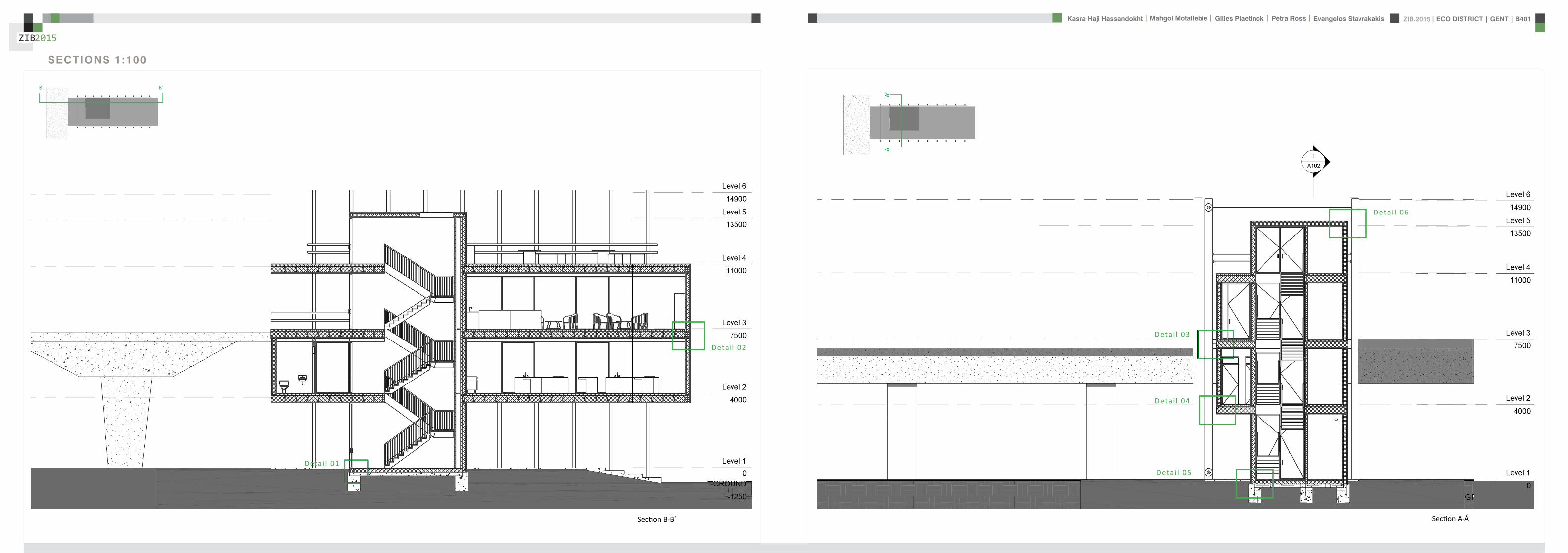
ZIB2015 ECO DISTRICT | GENT | B401Evangelos Stavrakakis | Petra Ross | Mahgol Motallebie | Gilles Plaetinck | Kasra Haji Hassandokht
ZIB2015
|
SECTIONS 1100
Section A-AacuteSection B-Bacute
AArsquo
AArsquo
Detai l 01
Detai l 02
Detai l 03
Detai l 04
Detai l 05
Detai l 06
ZIB2015 ECO DISTRICT | GENT | B401Evangelos Stavrakakis | Petra Ross | Mahgol Motallebie | Gilles Plaetinck | Kasra Haji Hassandokht
ZIB2015
|
DETAILS
DETAIL 01 DETAIL 02 DETAIL 03 DETAIL 04 DETAIL 05 DETAIL 06
AArsquo
PIR f loorGypsum plasterboardPIR 100 mmOSB 15 mmFJI beam cel lu lose 350 mmcel i t 4D woodf iber 18 mmfinish gypsum plasterboard
plato wood f in ishframework 30 mmcel i t 4D 18 mmwood structure SLS 38140Eurowal l 2x70 mmOSB Eurothane G 70 mmfinish gypsum plasterboard
ZIB2015 ECO DISTRICT | GENT | B401Evangelos Stavrakakis | Petra Ross | Mahgol Motallebie | Gilles Plaetinck | Kasra Haji Hassandokht
ZIB2015
|
ELEVATIONS 1100
South elevation
South Elevation
North Elevation
South Elevation
North Elevation
South Elevation
North Elevation
South Elevation
North Elevation
North elevation
ZIB2015 ECO DISTRICT | GENT | B401Evangelos Stavrakakis | Petra Ross | Mahgol Motallebie | Gilles Plaetinck | Kasra Haji Hassandokht
ZIB2015
|
VISUALIZATIONS
East Elevation
West Elevation
East Elevation
West Elevation
East Elevation
West Elevation East Elevation
West Elevation
ELEVATIONS 1100
West elevation East elevation
ZIB2015 ECO DISTRICT | GENT | B401Evangelos Stavrakakis | Petra Ross | Mahgol Motallebie | Gilles Plaetinck | Kasra Haji Hassandokht
ZIB2015
|
VISUALIZATIONS
ZIB2015 ECO DISTRICT | GENT | B401Evangelos Stavrakakis | Petra Ross | Mahgol Motallebie | Gilles Plaetinck | Kasra Haji Hassandokht
ZIB2015
|
MATERIALS WOOD FCS Certi f ied Suppliers Distance MATERIALS Building Structure
ZIB2015 ECO DISTRICT | GENT | B401Evangelos Stavrakakis | Petra Ross | Mahgol Motallebie | Gilles Plaetinck | Kasra Haji Hassandokht
ZIB2015
|
MATERIALS Specs InsulationMATERIALS Specs Solid amp Structural Wood
ZIB2015 ECO DISTRICT | GENT | B401Evangelos Stavrakakis | Petra Ross | Mahgol Motallebie | Gilles Plaetinck | Kasra Haji Hassandokht
ZIB2015
|
MATERIALS Life Cycle Assesment MATERIALS Embodied energy CO2 other materials
ZIB2015 ECO DISTRICT | GENT | B401Evangelos Stavrakakis | Petra Ross | Mahgol Motallebie | Gilles Plaetinck | Kasra Haji Hassandokht
ZIB2015
|
STRUCTURE
Gilles Plaetinck
schaal
ZIB BUILDINGEnter address here
7 _ Unnamed
Owner
begeleider Checker
3D Copy 11 Gilles Plaetinck
schaal
ZIB BUILDINGEnter address here
8 _ Unnamed
Owner
begeleider Checker
3D Copy 21
Gilles Plaetinck
schaal
ZIB BUILDINGEnter address here
8 _ Unnamed
Owner
begeleider Checker
3D Copy 31
Gilles Plaetinck
schaal
ZIB BUILDINGEnter address here
9 _ Unnamed
Owner
begeleider Checker3D Copy 4
1
ECONOMY - USIBILITY DURING THE DAY
i1000
ALWAYS
2000
ECONONY - USIBILITY DURING THE DAY
GENERAL PRINCIPLES OF THE BUILDING
ZERO IMPACT APPROACH
i
0 Food market in park Vertical harvesting Entrance
1 Workshop area technical room
2 Info center Entrance from highway
3 Roof terrace
ZIB2015 ECO DISTRICT | GENT | B401Evangelos Stavrakakis | Petra Ross | Mahgol Motallebie | Gilles Plaetinck | Kasra Haji Hassandokht
ZIB2015
|
Vertical Harvest places plants on carousels that keep them moving the length of the greenhouse giving them equal time in natural light and also al-lowing workers to pick and tand transfer the crops Using hydroponics Verti-cal Harvest will be capa-ble of producing over
Vertical Harvest places plants on carousels that keep them moving the length of the pulls giving them equal time in natu-ral light and also allowing workers and local people to pick and transfer the crops Using hydroponics Vertical Harvest will be capable of producing over greens and herbs
Vertical Harvest places plants on carousels that keep them moving the length of the greenhouse giving them equal time in natural light and also al-lowing workers to pick and tand transfer the crops Using hydroponics Verti-cal Harvest will be capa-ble of producing over
Vertical Harvest places plants on carousels that keep them moving the length of the pulls giving them equal time in natu-ral light and also allowing workers and local people to pick and transfer the crops Using hydroponics Vertical Harvest will be capable of producing over greens and herbs
VERTICAL HARVESTING
PLANT CABLE LIFT (PLC) SECTION
Sustainable Food zorkshop centerrsquos mission is to ldquocultivate a healthy community by strengthening the local food system and improving access to nu-tritious affordable foodrdquo The main goal of our design is to deliver skills and information for sus-tainability practioners in the organic food tradeThe program attempts to1) affect positive changes in shopping cooking eating habits and nutrition2) reduce diet-related diseases3) promote the health and development of young children 4) place emphasis on local seasonal and cultural-ly-appropriate foods5) integrate food systems concepts into its curric-ulumndash such as shopping at farmers markets and growing onersquos own food
Healthy food is a basic human right the ability to access healthy food is often related to multiple issues and not just a result of low income
FOOD TEAM = a group of people from the same neighbourhood who work for the direct purchase of regional and seasonal products They order food on internet via web page voedselteambe and it is then delivered once a week to the depot of a team
+ minimal transport requirements+ no returnable packaging+ fair p+ fair pricing+ high-quality local and seasonal food+ community initiative
Sustainable Food zorkshop centerrsquos mission is to ldquocultivate a healthy community by strengthening the local food system and improving access to nu-tritious affordable foodrdquo The main goal of our design is to deliver skills and information for sus-tainability practioners in the organic food tradeThe program attempts to1) affect positive changes in shopping cooking eating habits and nutrition2) reduce diet-related diseases3) promote the health and development of young children 4) place emphasis on local seasonal and cultural-ly-appropriate foods5) integrate food systems concepts into its curric-ulumndash such as shopping at farmers markets and growing onersquos own food
Healthy food is a basic human right the ability to access healthy food is often related to multiple issues and not just a result of low income
FOOD TEAM = a group of people from the same neighbourhood who work for the direct purchase of regional and seasonal products They order food on internet via web page voedselteambe and it is then delivered once a week to the depot of a team
+ minimal transport requirements+ no returnable packaging+ fair p+ fair pricing+ high-quality local and seasonal food+ community initiative
Sustainable Food zorkshop centerrsquos mission is to ldquocultivate a healthy community by strengthening the local food system and improving access to nu-tritious affordable foodrdquo The main goal of our design is to deliver skills and information for sus-tainability practioners in the organic food tradeThe program attempts to1) affect positive changes in shopping cooking eating habits and nutrition2) reduce diet-related diseases3) promote the health and development of young children 4) place emphasis on local seasonal and cultural-ly-appropriate foods5) integrate food systems concepts into its curric-ulumndash such as shopping at farmers markets and growing onersquos own food
Healthy food is a basic human right the ability to access healthy food is often related to multiple issues and not just a result of low income
FOOD TEAM = a group of people from the same neighbourhood who work for the direct purchase of regional and seasonal products They order food on internet via web page voedselteambe and it is then delivered once a week to the depot of a team
+ minimal transport requirements+ no returnable packaging+ fair p+ fair pricing+ high-quality local and seasonal food+ community initiative
Healthy food is a basic human right the ability to access healthy food is often related to multiple issues and not just a result of low income
Sustainable Food zorkshop centerrsquos mission is to ldquocultivate a healthy community by strengthening the local food system and improving access to nutritious affordable foodrdquo The main goal of our design is to deliver skills and information for sustainability practioners in the organic food tradeThe program attempts to
1) affect positive changes in shopping cookingeating habits and nutrition2) reduce diet-related diseases3) promote the health and development of youngchildren4) place emphasis on local seasonal and culturally-appropriate foods5) integrate food systems concepts into its curriculumndashsuch as shopping at farmers markets andgrowing onersquos own food
FOOD TEAM = a group of people from the same neighbourhood who work for the direct purchase of regional and seasonal products They order food on internet via web page voedselteambe and it is then delivered once a week to the depot of a team
+ minimal transport requirements+ no returnable packaging+ fair pricing+ high-quality local and seasonal food+ community initiative
WORKSHOP
ZIB2015 ECO DISTRICT | GENT | B401Evangelos Stavrakakis | Petra Ross | Mahgol Motallebie | Gilles Plaetinck | Kasra Haji Hassandokht
ZIB2015
|
Black coral pea
Factors should be considered when seleccng plants
- Quality of growth- Ability to adapt to the wall environment- Environmental Tolerances- Temperature Resistance- Drought Tolerance- Wind - Wind Tolerance- Solar Exposure Tolerance- Salt Tolerance in Seaside installacons- Air and Water Pollucon Tolerance- Pest and Disease Resistance- Arcficial Environment Tolerance- Transplantacon Tolerance- Pruning - Pruning Tolerance
- Ornamental Qualices- Design Purpose- Manageability Maintainability- Environmental and Societal Effects- Visual Effect- Feeling Effect
Blac
k co
ral p
eaSn
ake
vine
kidn
ey w
eed
purple coral peaBasil
Pandorea
Black coral pea
Factors should be considered when seleccng plants
- Quality of growth- Ability to adapt to the wall environment- Environmental Tolerances- Temperature Resistance- Drought Tolerance- Wind - Wind Tolerance- Solar Exposure Tolerance- Salt Tolerance in Seaside installacons- Air and Water Pollucon Tolerance- Pest and Disease Resistance- Arcficial Environment Tolerance- Transplantacon Tolerance- Pruning - Pruning Tolerance
- Ornamental Qualices- Design Purpose- Manageability Maintainability- Environmental and Societal Effects- Visual Effect- Feeling Effect
Blac
k co
ral p
eaSn
ake
vine
kidn
ey w
eed
purple coral peaBasil
Pandorea
Black coral pea
Factors should be considered when seleccng plants
- Quality of growth- Ability to adapt to the wall environment- Environmental Tolerances- Temperature Resistance- Drought Tolerance- Wind - Wind Tolerance- Solar Exposure Tolerance- Salt Tolerance in Seaside installacons- Air and Water Pollucon Tolerance- Pest and Disease Resistance- Arcficial Environment Tolerance- Transplantacon Tolerance- Pruning - Pruning Tolerance
- Ornamental Qualices- Design Purpose- Manageability Maintainability- Environmental and Societal Effects- Visual Effect- Feeling Effect
Blac
k co
ral p
eaSn
ake
vine
kidn
ey w
eed
purple coral peaBasil
Pandorea
GREEN WALLS
ZIB2015 ECO DISTRICT | GENT | B401Evangelos Stavrakakis | Petra Ross | Mahgol Motallebie | Gilles Plaetinck | Kasra Haji Hassandokht
ZIB2015
|
Extraction of air
Pulsion of airRecuperation unit
outdoor space
18 degC15 degC
18 degC
In-take Out-take of air
VENTILATION
Gilles Plaetinck
schaal 1 100
ZIB BUILDINGEnter address here
3 _ level 2
Owner
begeleider Checker
DN
Gilles Plaetinck
schaal 1 100
ZIB BUILDINGEnter address here
2 _ level 1
Owner
begeleider Checker
Extraction of air
Pulsion of air
VENTILATION IN GROUPLANS CALCULATION AND SYSTEM
level 01
level 02
T 42ECO DISTRICT | GENT | B401
ZIB2015Mechanical Ventilation with Heat Recovery (MVHR)
Up to 95 of the heat can be recovered The Heat Recovery Unit runs continu-ously on trickle and can and is boosted when higher rates of ventilation are required eg bathing cooking In warmer months a summer by-pass function helps ensure comfort levels are maintained in the home When summer by-pass is activated the dwelling contin-ues to be ventilaated and recieve fresh filtered air however the heat recovery process is intermittently switched off (heat recovery is by-passed)
Key BenefitsYear round removal of condensation and indoor pol-lutants A direct impact on the Dwelling Emission Rate re-quired in SAP helping reduce the carbon footprint of the property Fresh filtered air supplied to dwelling ideal for allergy sufferers and those with conditions such as asthma A balanced ventilation system for the whole house and recovering of heat that would have otherwise have been lost Low noise non-intrusive ventilation system ndash located away from the room however consideration should be given to duct runs to ensure cross-talk contamination doesnrsquot happen AND the unit is sized correctly so it is not running a high rate all of the time
Zehnder ComfoSystems Passive Haus accredited product suitable for large houses up to 300m2 Designed to ensure low noise excellent energy performance and heat exchange efficiency Choice of control options including LCD touch screen display Can be combine with ComfoCool for optional cooling of up to 5 degrees and humidity reduction by 20
Semi Rigid Ducting
With a manifold system the resistance caused by duct-ing is reduced therefore Semi-Rigid ducting resistance is very low The manifold takes mass airflow directly from the MVHR Heat Recovery Unit and allows lower rates to pass through to each individual room runDirecting mass flow to the manifold eliminates the need to increase the running speed of the MVHR Heat Re-covery unit to overcome the resistance of ducting which in turn causes noise for the homeowner
T 42ECO DISTRICT | GENT | B401
ZIB2015Mechanical Ventilation with Heat Recovery (MVHR)
Up to 95 of the heat can be recovered The Heat Recovery Unit runs continu-ously on trickle and can and is boosted when higher rates of ventilation are required eg bathing cooking In warmer months a summer by-pass function helps ensure comfort levels are maintained in the home When summer by-pass is activated the dwelling contin-ues to be ventilaated and recieve fresh filtered air however the heat recovery process is intermittently switched off (heat recovery is by-passed)
Key BenefitsYear round removal of condensation and indoor pol-lutants A direct impact on the Dwelling Emission Rate re-quired in SAP helping reduce the carbon footprint of the property Fresh filtered air supplied to dwelling ideal for allergy sufferers and those with conditions such as asthma A balanced ventilation system for the whole house and recovering of heat that would have otherwise have been lost Low noise non-intrusive ventilation system ndash located away from the room however consideration should be given to duct runs to ensure cross-talk contamination doesnrsquot happen AND the unit is sized correctly so it is not running a high rate all of the time
Zehnder ComfoSystems Passive Haus accredited product suitable for large houses up to 300m2 Designed to ensure low noise excellent energy performance and heat exchange efficiency Choice of control options including LCD touch screen display Can be combine with ComfoCool for optional cooling of up to 5 degrees and humidity reduction by 20
Semi Rigid Ducting
With a manifold system the resistance caused by duct-ing is reduced therefore Semi-Rigid ducting resistance is very low The manifold takes mass airflow directly from the MVHR Heat Recovery Unit and allows lower rates to pass through to each individual room runDirecting mass flow to the manifold eliminates the need to increase the running speed of the MVHR Heat Re-covery unit to overcome the resistance of ducting which in turn causes noise for the homeowner
MECHANICAL VENTILATION WITH HEAT RECOVERY (MVHR)
Up to 95 of the heat can be recoveredThe Heat Recovery Unit runs continuously on trickle and can and is boosted when higher rates of ventilation are required eg bathing cooking
In warmer months a summer by-pass function helps ensure comfort levels are maintained in the home When summer by-pass is activated the dwelling continues to be ventilaated and recieve fresh filtered air however the heat recovery process is intermittently switched off (heat recovery is by-passed)
EXTRACT VENTILATION RATES
T 42ECO DISTRICT | GENT | B401
ZIB2015Mechanical Ventilation with Heat Recovery (MVHR)
Up to 95 of the heat can be recovered The Heat Recovery Unit runs continu-ously on trickle and can and is boosted when higher rates of ventilation are required eg bathing cooking In warmer months a summer by-pass function helps ensure comfort levels are maintained in the home When summer by-pass is activated the dwelling contin-ues to be ventilaated and recieve fresh filtered air however the heat recovery process is intermittently switched off (heat recovery is by-passed)
Key BenefitsYear round removal of condensation and indoor pol-lutants A direct impact on the Dwelling Emission Rate re-quired in SAP helping reduce the carbon footprint of the property Fresh filtered air supplied to dwelling ideal for allergy sufferers and those with conditions such as asthma A balanced ventilation system for the whole house and recovering of heat that would have otherwise have been lost Low noise non-intrusive ventilation system ndash located away from the room however consideration should be given to duct runs to ensure cross-talk contamination doesnrsquot happen AND the unit is sized correctly so it is not running a high rate all of the time
Zehnder ComfoSystems Passive Haus accredited product suitable for large houses up to 300m2 Designed to ensure low noise excellent energy performance and heat exchange efficiency Choice of control options including LCD touch screen display Can be combine with ComfoCool for optional cooling of up to 5 degrees and humidity reduction by 20
Semi Rigid Ducting
With a manifold system the resistance caused by duct-ing is reduced therefore Semi-Rigid ducting resistance is very low The manifold takes mass airflow directly from the MVHR Heat Recovery Unit and allows lower rates to pass through to each individual room runDirecting mass flow to the manifold eliminates the need to increase the running speed of the MVHR Heat Re-covery unit to overcome the resistance of ducting which in turn causes noise for the homeowner
T 42ECO DISTRICT | GENT | B401
ZIB2015Mechanical Ventilation with Heat Recovery (MVHR)
Up to 95 of the heat can be recovered The Heat Recovery Unit runs continu-ously on trickle and can and is boosted when higher rates of ventilation are required eg bathing cooking In warmer months a summer by-pass function helps ensure comfort levels are maintained in the home When summer by-pass is activated the dwelling contin-ues to be ventilaated and recieve fresh filtered air however the heat recovery process is intermittently switched off (heat recovery is by-passed)
Key BenefitsYear round removal of condensation and indoor pol-lutants A direct impact on the Dwelling Emission Rate re-quired in SAP helping reduce the carbon footprint of the property Fresh filtered air supplied to dwelling ideal for allergy sufferers and those with conditions such as asthma A balanced ventilation system for the whole house and recovering of heat that would have otherwise have been lost Low noise non-intrusive ventilation system ndash located away from the room however consideration should be given to duct runs to ensure cross-talk contamination doesnrsquot happen AND the unit is sized correctly so it is not running a high rate all of the time
Zehnder ComfoSystems Passive Haus accredited product suitable for large houses up to 300m2 Designed to ensure low noise excellent energy performance and heat exchange efficiency Choice of control options including LCD touch screen display Can be combine with ComfoCool for optional cooling of up to 5 degrees and humidity reduction by 20
Semi Rigid Ducting
With a manifold system the resistance caused by duct-ing is reduced therefore Semi-Rigid ducting resistance is very low The manifold takes mass airflow directly from the MVHR Heat Recovery Unit and allows lower rates to pass through to each individual room runDirecting mass flow to the manifold eliminates the need to increase the running speed of the MVHR Heat Re-covery unit to overcome the resistance of ducting which in turn causes noise for the homeowner
Heating 10 kwh msup2aCooling 4 kWh msup2aOverheating 42
ZIB2015 ECO DISTRICT | GENT | B401Evangelos Stavrakakis | Petra Ross | Mahgol Motallebie | Gilles Plaetinck | Kasra Haji Hassandokht
ZIB2015
|
Shutters control system+ -
Solar roadways - PV panels
LED lights
Elevator Fuse box
ElectricityBattery withtransformator
ELECTRICITY
Summer night
cross- ventilation through building
Summer day
air through recuperation unit small change of temperature
15 degC 18 degC
+ groundplans
heated zone
not heated zone
ZONING ACCORDING TO TEMPERATURESSUMMER NIGHT - cross-ventilation through building
SUMMER DAY - air through recuperation unit small change of temperatureSHADING SYSTEM
As a shading was chozen system Renson Icarus Lamellas with angle 45deg made in wood
ZIB2015 ECO DISTRICT | GENT | B401Evangelos Stavrakakis | Petra Ross | Mahgol Motallebie | Gilles Plaetinck | Kasra Haji Hassandokht
ZIB2015
|
average only 4 hours of peak daylight hours per day (4 x 365 = 1460 hours per year)
- Surface area ( first part) Fly-over +- 20 000 msup2-gt 16 000 x 230 Watt = 3 680 000 Watt or 3680 kWonly 50 of fly-over covered with solar roadways
-gt 3680 kW x 4 h = 7360 kWh day-gt 3680 kW x 1460 h = 2 686 400 kWh year -gt +- 540 households (+- 5000 kWh year)
Tesla Powerwall Therersquos a 10 kWh unit at $3500 -gt 737 Tesla Batteries
gt the Solar Roadway has the ability to cut greenhouse gases by up to 75-percentgt A decentralized self-healing secure power grid
IN FRONT OF FLY-OVER
- Surface area Fly-over = 16 x 30 m = 480 msup2-gt 384 x 230 Watt = 88 320 Watt or 883 kWonly 50 of fly-over covered with solar roadways
-gt 44 kW x 4 h = 176 kWh day-gt 44 kW x 1460 h = 64 240 kWh year -gt +- 13 households (+- 5000 kWh year)
lightsshutters
elevator
2 fridges
2 coffeemakers
1 microwave
1 owen
2 cooking plates
stereo
ventilation unit
electricity transformer (AC to DC) for PV panels + batteries
summer 05 kWh daywinter 03 kWh day183 days x 05= 915 kWh182 days x 03 = 546 kWh = 1641 kWh
262 kWh
A++fridge 104 kWhyear104 x x2 = 208 kWh
900 W x 01 hours day = 09 kWhx 220 days x 2= 198 kWh a
67 kWh a
085x100 days= 85 kWh a
400 kWh x 2 = 800 kWh a
150 kWh a 419 kWha
68 kWh a
ENERGY DEMAND OVERVIEW ENERGY SUPPLY OVERVIEW - FLY-OVER
1 spot 56 W 10000 = 0056 KW4 hours per day 365 days a year = 1460 h0056 x 1460 = 8176 kWh10 spots x 8176= 8176 kWh a
1 spot 72 W 10000 = 0072 KW4 hours per day 365 days a year = 1460 h0072 x 1460 = 10512 kWh5 spots x 10512= 5256 kWh a
1 spot 52 W 10000 = 0052 KW4 hours per day 365 days a year = 1460 h0052 x 1460 = 7592 kWh21 spots x 7592= 159432 kWh a
1 spot 9 W 10000 = 0009 KW4 hours per day 365 days a year = 1460 h0009 x 1460 = 1314 kWh5 spots x 1314 = 657 kWh a
SOLAR ROADWAYS - PV PANELSEnergy from the sun
1 To generate energy for the ZIB building2 To generate energy for the surrounding houses3 To generate energy for lighting or signs on the road4 The panels will also have the capacity to charge electric vehicles while parked
ELECTRICITY SCHEME
5423 kWh a
ZIB2015 ECO DISTRICT | GENT | B401Evangelos Stavrakakis | Petra Ross | Mahgol Motallebie | Gilles Plaetinck | Kasra Haji Hassandokht
ZIB2015
|
SUMMER SUNNY 10-42 LUXWINTER SUNNY 10-42 LUX
DAYLIGHT - DIALuxLIGHTING SYSTEM - DIALux
Workplane 9 Results overview
Height of working plane 0800 m Wall zone 0000 m
Result Mean (target) Min Max Minaverage MinmaxPerpendicular illuminance [lx] 463 (500) 105 689 0227 0152
Profile Offices Writing typewriting reading data processing
B401-Gent 6222015
Site 1 Building 2 Zib Room 9 Workplane 9 Results overview
Page 70
Workplane 9 False coloursPerpendicular illuminance (adaptive)
Scale 1 200
Perpendicular illuminance (Surface)Mean (actual) 463 lx Min 105 lx Max 689 lx Minaverage 0227 Minmax 0152
B401-Gent 6222015
Site 1 Building 2 Zib Room 9 Workplane 9 False coloursPerpendicular illuminance (adaptive)
Page 72
Workplane 9 Value chartPerpendicular illuminance (adaptive)
Scale 1 200
Perpendicular illuminance (Surface)Mean (actual) 463 lx Min 105 lx Max 689 lx Minaverage 0227 Minmax 0152
B401-Gent 6222015
Site 1 Building 2 Zib Room 9 Workplane 9 Value chartPerpendicular illuminance (adaptive)
Page 73
Workplane 13 Results overview
Height of working plane 0800 m Wall zone 0000 m
Result Mean (target) Min Max Minaverage MinmaxPerpendicular illuminance [lx] 388 (500) 69 732 0178 0094
Profile Offices Writing typewriting reading data processing
B401-Gent 6222015
Site 1 Building 6 Storey 1 Room 13 Workplane 13 Results overview
Page 94
Workplane 13 False coloursPerpendicular illuminance (adaptive)
Scale 1 100
Perpendicular illuminance (Surface)Mean (actual) 388 lx Min 69 lx Max 732 lx Minaverage 0178 Minmax 0094
B401-Gent 6222015
Site 1 Building 6 Storey 1 Room 13 Workplane 13 False coloursPerpendicular illuminance (adaptive)
Page 96
Workplane 13 Value chartPerpendicular illuminance (adaptive)
Scale 1 100
Perpendicular illuminance (Surface)Mean (actual) 388 lx Min 69 lx Max 732 lx Minaverage 0178 Minmax 0094
B401-Gent 6222015
Site 1 Building 6 Storey 1 Room 13 Workplane 13 Value chartPerpendicular illuminance (adaptive)
Page 97
Workplane 9 False coloursPerpendicular illuminance (adaptive)
Scale 1 200
Perpendicular illuminance (Surface)Mean (actual) 463 lx Min 105 lx Max 689 lx Minaverage 0227 Minmax 0152
B401-Gent 6222015
Site 1 Building 2 Zib Room 9 Workplane 9 False coloursPerpendicular illuminance (adaptive)
Page 72
1st f loor 2nd f loor Site 1 Luminaire parts listQuantity Luminaire (Luminous emittance)10 3F Filippi 12736 P 202x24W LED OP 196x1231
Luminous emittance 1Fitting 1x24W 2xLEDLight output ratio 100Lamp luminous flux 5332 lmLuminaire Luminous Flux 5332 lmPower 560 WLight yield 952 lmW
200
300
400
cdklm η = 100C0 - C180 C90 - C270
0deg 15deg 30deg
45deg
60deg
75deg
90deg
105deg105deg
90deg
75deg
60deg
45deg
30deg 15deg 0deg
5 SFN Eclairages 0732360X CLFV 236Luminous emittance 1Fitting 2xT26 36W840Light output ratio 6889Lamp luminous flux 6700 lmLuminaire Luminous Flux 4615 lmPower 720 WLight yield 641 lmW
160
240
cdklm η = 69C0 - C180 C90 - C270
0deg 15deg 30deg
45deg
60deg
75deg
90deg
105deg105deg
90deg
75deg
60deg
45deg
30deg 15deg 0deg
21 SFN Eclairages 332226XX SAM F 2x26W BELuminous emittance 1Fitting 2xTC-DEL 26W840Light output ratio 3297Lamp luminous flux 3600 lmLuminaire Luminous Flux 1187 lmPower 520 WLight yield 228 lmW
40
60
80
100
120
140
cdklm η = 33C0 - C180 C90 - C270
0deg 15deg 30deg
45deg
60deg
75deg
90deg
105deg105deg
90deg
75deg
60deg
45deg
30deg 15deg 0deg
1 Signcomplex AR111-009-AW-W-06 AR111 COB 9W38deg WhiteLuminous emittance 1Fitting 1xAR111-009-AW-W-06Light output ratio 8078Lamp luminous flux 600 lmLuminaire Luminous Flux 485 lmPower 90 WLight yield 539 lmW
800
1200
cdklm η = 81C0 - C180 C90 - C270
0deg 15deg 30deg
45deg
60deg
75deg
90deg
105deg105deg
90deg
75deg
60deg
45deg
30deg 15deg 0deg
Total lamp luminous flux 163020 lm Total luminaire luminous flux 101807 lm Total Load 20210 W Light yield 504 lmW
B401-Gent 6222015
Site 1 Luminaire parts list
Page 19
10x
6x
21x
1x
types of l ights
Perpendicular i l luminance (Surface)Mean (actual ) 463 lx Min 105 lx Max 689 lx Minaverage 0 227 Minmax 0 152
Perpendicular i l luminance (Surface)Mean (actual ) 388 lx Min 69 lx Max 732 lx Minaverage 0 178 Minmax 0 094
ZIB2015 ECO DISTRICT | GENT | B401Evangelos Stavrakakis | Petra Ross | Mahgol Motallebie | Gilles Plaetinck | Kasra Haji Hassandokht
ZIB2015
|
Tube hybrid Solar panels
Hot water tank Water taps
City water supply
Rain water collection for vertical harvesting
City water supply
WADI
Rain water tank
WATER MANAGEMENT
Sinks
Available roof area
In Ghent avarage of 900mmm2year
3197 m2
09x 3197 = 28773 m3year
RAIN WATER GAIN
toilet - 3x - 03lskitchen -4x - 02ls
POTABLE WATER DEMAND
3 toiletsVertical gardening
Total
relative RW usage
300 l day150 l day = 450lday= 16425 m3 year
1407 lday100m2
RAIN WATER DEMAND
RAIN WATER TANK
Relative RWT volumeRain water tank volume
3m3 100 m2
9591 l gt 10 m3
DIMESION OF PIPES
City water supplyRainwater tank
178 mm (DN 18 - 15 - 12)165 mm (DN 17-15)
are composed of hexagonal tiles Rainwater can infiltrate between the gaps from where it goes to rainwatter collector which supplies the vegetation on fly-over
THE SOLAR ROADWAYS
WATER SUPPLY SCHEME AND CALCULATION
ZIB2015 ECO DISTRICT | GENT | B401Evangelos Stavrakakis | Petra Ross | Mahgol Motallebie | Gilles Plaetinck | Kasra Haji Hassandokht
ZIB2015
|
WADI
City water supply
Rain water tank
Sinks
Divided sewer systemwithin building
SEWAGE SYSTEM
ToiletToilet sinkKitchen sink
DU = 2 lsDU = 05 lsDU = 08 ls
WATER DRAINAGE OF DEVICES
Frequency of usage at the same time
K 05
DIMESION OF PIPES
Black waterGrey water
110 mm (DU 110)75 mm (DU 75 - 63)
WATER DRAINAGE SCHEME AND CALCULATION
ZIB2015 ECO DISTRICT | GENT | B401Evangelos Stavrakakis | Petra Ross | Mahgol Motallebie | Gilles Plaetinck | Kasra Haji Hassandokht
ZIB2015
|
DN
Gilles Plaetinck
schaal 1 100
ZIB BUILDINGEnter address here
2 _ level 1
Owner
begeleider Checker
Gilles Plaetinck
schaal 1 100
ZIB BUILDINGEnter address here
3 _ level 2
Owner
begeleider Checker
WATER SUPPLY
HOT WATER
WATER DRAINAGE
WATER SUPPLY AND DRAINAGE IN GROUPLANS
level 01
level 02
ENERGY
RAINWATER TANK
HELOPHYTE FILTER
IRRIGATION SYSTEM
BIO-ROTOR
MICRO TURBINE
PHOSPHOR
In this building a closed water system is applied which is based on reusing water in mullple wasRainRain water from the roof will be collected in a storage tank situated on the ground floor This water will be used to flush the toilet and irrigate crops in verlcal harveslng system In case of an overflow the water will be stored in the con-structed wetland near the building The rainwater can be fil-tered through a helophyte filter up to drinking water stan-dard The waste water system includes three types of water yellyellow black and grey waterThe yellow water will be stored for its phosphor while the black water will be purified into grey water This grey water is comparable to the quality of rain water aaer purificalon b means of a bio rotor The remaining residue from the bio rotor together with the organic waste from the harveslng is fermented into biogas that drives a micro turbine in order to produce some addilonal energy
TheThe waste product deriving from this process will be used as compost in verlcal harveslng This efficient yet complex system closes the ullizalon cycle of the building and turns it into an efficient vicious circle that can be considered au arkic
In this building a closed water system is applied which is based on reusing water in multiple was
Rain water from the roof will be collected in a storage tank situated on the ground floor This water will be used to flushthe toilet and irrigate crops in vertical harvesting system In case of an overflow the water will be stored in the constructed wetland near the building The rainwater can be filtered through a helophyte filter up to drinking water standard
The waste water system includes three types of water yellow black and grey water The yellow water will be stored for its phosphor while the black water will be purified into grey water This grey water is comparable to the quality of rain water after purification b means of a bio rotor The remaining residue from the bio rotor together with the organic waste from the harvesting is fermented into biogas that drives a micro turbine in order to produce some additional energy The waste product deriving from this process will be used ascompost in ver1048991cal harves1048991ng This efficient yet complexsystem closes the u1048991liza1048991on cycle of the building and turns itinto an efficient vicious circle that can be considered au arkic
WATER CYCLE
ZIB2015 ECO DISTRICT | GENT | B401Evangelos Stavrakakis | Petra Ross | Mahgol Motallebie | Gilles Plaetinck | Kasra Haji Hassandokht
ZIB2015
|
CALCULATIONS
Passive House verification
Photo or Drawing
Building Workshop + info pointStreet
PostcodeCityCountry
Building Type non-residentialClimate Ukkel
Home Owner(s) Client(s)Street
PostcodeCity
ArchitectStreet
PostcodeCity Calculation electricity Internal heat gains
Mechanical System Building type
StreetPostcodeCity Internal heat gains
Year of Construction 2015 Interior Temperature 200 degC Utilisation pattern
Number of Dwelling Units 1 Internal Heat Gains 20 Wm2 Type of values used Fill in worksheet IHG Non-Dom Enclosed Volume Ve 12442 Planned number of occupants
Number of Occupants 80 8 Design
Specific building demands with reference to the treated floor area use Annual method
Treated floor area 2840 msup2 Requirements Fulfilled Verification Annual method The monthly method should be used for building certification
Space heating Annual heating demand 10 kWh(m2a) 15 kWh(msup2a) yes Specific space heating demand annual method 103 kWh(msup2a)
Heating load 11 Wm2 10 Wmsup2 - Specific space heating demand monthly Method 120 kWh(msup2a)
Space cooling Overall specific space cooling demand kWh(m2a) 15 kWh(msup2a)
Cooling load Wm2 - -Frequency of overheating (gt 25 degC) - -
Primary Energy Space heating and dehumidification
cooling household electricity 73 kWh(m2a) 120 kWh(msup2a) yes
DHW space heating and auxiliary electricity 24 kWh(m2a) - -Specific primary energy reduction through solar electricity 21 kWh(m2a) - -
Airtightness Pressurization test result n50 06 1h 06 1h yes
PHPP Verification FINAL ZIB FILE CALCULTIONS PHPPxls
L B H VOLUME
main 1 226 7 4 6328main 2 184 7 35 4508
core 0 6 2 5 3 5 108 5core 0 62 5 35 1085core 3 62 3 28 521
12442
AREAmain 1 storage 35
wc big 35wc 2wc 2workshop 103
MAIN 2 infolounge 92
staircase 56storage technical 22
284
Floor_exterior 1582 31 1272
Roof_exterior 1582
Passive House verification
Photo or Drawing
Building Workshop + info pointStreet
PostcodeCityCountry
Building Type non-residentialClimate Ukkel
Home Owner(s) Client(s)Street
PostcodeCity
ArchitectStreet
PostcodeCity Calculation electricity Internal heat gains
Mechanical System Building type
StreetPostcodeCity Internal heat gains
Year of Construction 2015 Interior Temperature 200 degC Utilisation pattern
Number of Dwelling Units 1 Internal Heat Gains 20 Wm2 Type of values used Fill in worksheet IHG Non-Dom Enclosed Volume Ve 12442 Planned number of occupants
Number of Occupants 80 8 Design
Specific building demands with reference to the treated floor area use Annual method
Treated floor area 2840 msup2 Requirements Fulfilled Verification Annual method The monthly method should be used for building certification
Space heating Annual heating demand 10 kWh(m2a) 15 kWh(msup2a) yes Specific space heating demand annual method 103 kWh(msup2a)
Heating load 11 Wm2 10 Wmsup2 - Specific space heating demand monthly Method 120 kWh(msup2a)
Space cooling Overall specific space cooling demand kWh(m2a) 15 kWh(msup2a)
Cooling load Wm2 - -Frequency of overheating (gt 25 degC) - -
Primary Energy Space heating and dehumidification
cooling household electricity 73 kWh(m2a) 120 kWh(msup2a) yes
DHW space heating and auxiliary electricity 24 kWh(m2a) - -Specific primary energy reduction through solar electricity 21 kWh(m2a) - -
Airtightness Pressurization test result n50 06 1h 06 1h yes
PHPP Verification FINAL ZIB FILE CALCULTIONS PHPPxls
SURFACE AREAcurrent orientation only night ventilation
current orientation only night ventilation 6 windows less 52 msup2
current orientation only night ventilation 7 windows less 60msup2 (stays the same for each side)
current orientation only night ventilation 8 windows less 69 msup2
orientation turned 90deg only night ventilation 6 windows less 52 msup2
orientation turned 90deg only night ventilation 7 windows less 60msup2 (window less at SE side)
orientation turned 90deg only night ventilation 8 windows less 69 msup2
-gt orientation turned 90deg only night ventilation 9 windows less 77msup2 (window less at NW side althought theres less overheating in the case of a window less at SE side the heating demand exceeds 15)
CHANGE IN DESIGN
ZIB2015 ECO DISTRICT | GENT | B401Evangelos Stavrakakis | Petra Ross | Mahgol Motallebie | Gilles Plaetinck | Kasra Haji Hassandokht
ZIB2015
|
Passive House verificationS P E C I F I C A N N U A L H E A T I N G D E M A N D
Climate Ukkel Interior Temperature 200 degC
Building Workshop + info point Building TypeUse non-residentialTreated Floor Area ATFA 2840 msup2
per msup2Area U-Value Temp Factor ft Gt Treated Data for heating balance diagram
Building Element Temperature Zone msup2 W(msup2K) kKha kWha Floor Area Losses GainsExterior Wall - Ambient A 5595 0101 100 743 = 4181 1472 Exterior Wall - Ambient 147234373Exterior Wall - Ground B 069 = Exterior Wall - GroundRoofCeiling - Ambient A 1550 0094 100 743 = 1085 382 RoofCeiling - Ambient 381903529Floor slab basement ceiling B 310 0105 069 743 = 167 059 Floor slab basement ceiling 058811509
A 100 =A 100 =
unheated basement X 075 = unheated basementWindows A 1154 0648 100 743 = 5562 1958 Windows 195834732Exterior Door A 100 = Exterior DoorExterior TB (lengthm) A 1169 -0030 100 743 = -259 -091 Thermal Bridge Heat LossPerimeter TB (lengthm) P 069 = 000 not useful heat gains 365267499Ground TB (lengthm) B 069 =
Total of All Building Envelope Areas 8609 ndashndashndashndashndashndashndashndashndashndashndashndashndash- kWh(msup2a) Ventilation 395818713
Transmission Heat Losses QT Total 10736 378Annual Heating Demand 102516636
ATFA Clear Room Height internal gains 100951487msup2 m msup3 passive solar gains 250668423
Ventilation System Effective Air Volume VV 2840 280 = 7952 Thermal bridge credit 091126837Effective Heat Recovery Efficiency eff 81 Cross check sum 46324923 46324923of Heat Recovery
Efficiency of Subsoil Heat Exchanger SHX 0 nVsystem HR nVRes
1h 1h 1h
Energetically Effective Air Exchange nV 0105 (1 - 081 ) + 0038 = 0058
VV nV cAir Gt
msup3 1h Wh(msup3K) kKha kWha kWh(msup2a)
Ventilation Heat Losses QV 795 0058 033 743 = 1124 40
Reduction Factor QT QV NightWeekend
kWha kWha Saving kWha kWh(msup2a)
Total Heat Losses QL ( 10736 + 1124 ) 10 = 11860 418
Orientation Reduction Factor g-Value Area Radiation HPof the Area See Windows Sheet (perp radiation)
msup2 kWh(msup2a) kWha
1 North 054 050 2700 163 = 11822 East 058 000 440 197 = 03 South 056 050 4860 314 = 42874 West 032 050 3216 254 = 13275 Horizontal 063 050 324 317 = 323
kWh(msup2a)
Available Solar Heat Gains QS Total 7119 251
Length Heat Period Spec Power qI ATFA
khd da Wmsup2 msup2 kWha kWh(msup2a)
Internal Heat Gains QI 0024 209 201 2840 = 2867 101
kWha kWh(msup2a)
Free Heat QF QS + QI = 9986 352
Ratio of Free Heat to Losses QF QL = 084
Utilisation Factor Heat Gains G (1 - ( QF QL )5 ) (1 - ( QF QL )
6 ) = 90kWha kWh(msup2a)
Heat Gains QG G QF = 8949 315
kWha kWh(msup2a)
Annual Heating Demand QH QL - QG = 2911 10
kWh(msup2a) (YesNo)
Limiting Value 15 Requirement met yes
00
147
00
3806000000
196
00
40
37
09
103
101
251
0
5
10
15
20
25
30
35
40
45
50
Losses Gains
Hea
t flo
ws
[kW
h(m
sup2a)]
Heating energy balance
passive solar gains
internal gains
Annual Heating Demand
Thermal bridge credit
not useful heat gains
Ventilation
Exterior Door
Windows
unheated basement
Floor slab basement ceiling
RoofCeiling - Ambient
Exterior Wall - Ground
Exterior Wall - Ambient
Thermal Bridge Heat Loss
HPP Annual Heating Demand FINAL ZIB FILE CALCULTIONS PHPPxls
Passive House verification Passive House verificationS P E C I F I C U S E F U L C O O L I N G D E M A N D S P E C I F I C U S E F U L C O O L I N G D E M A N D
M O N T H L Y M E T H O D M O N T H L Y M E T H O D
(This page displays the sums of the monthly method over the cooling period))Climate Ukkel Interior Temperature Summer 25 degC Climate Ukkel Interior Temperature 25 degC
Building Workshop + info point Building TypeUse non-residential Building Workshop + info point Building TypeUse non-residential
Spec Capacity 60 Wh(msup2K) (Enter in Summer worksheet) Treated Floor Area ATFA 2840 msup2 Treated Floor Area ATFA 284 msup2
per msup2Temperature Zone Area U-Value Mon Red Fac Gt Treated Jan Feb Mar Apr May Jun Jul Aug Sep Oct Nov Dec Year
Building Element msup2 W(msup2K) kKha kWha Floor Area Heating Degree Hours - Ex 168 150 144 121 92 73 57 59 82 109 140 160 136 kKh1 Exterior Wall - Ambient A 5595 0101 100 103 = 5782 Heating Degree Hours - G 126 123 135 120 106 83 63 54 58 71 86 109 113 kKh2 Exterior Wall - Ground B 100 = Losses - Exterior 2553 2286 2189 1838 1393 1117 871 904 1245 1660 2123 2432 20612 kWh3 RoofCeiling - Ambient A 1550 0094 100 103 = 1500 Losses - Ground 41 40 44 39 35 27 21 18 19 23 28 36 370 kWh4 Floor slab basement ceil B 310 0105 100 90 = 294 Losses Summer Ventilatio 67 71 244 372 629 720 880 865 658 499 234 126 5366 kWh5 A 100 = Sum Spec Heat Losses 94 84 87 79 72 66 62 63 68 77 84 91 928 kWhmsup26 A 100 = Solar Load North 44 81 141 212 286 298 298 255 178 116 54 35 1998 kWh7 unheated basement X 075 = Solar Load East 0 0 0 0 0 0 0 0 0 0 0 0 0 kWh8 Windows A 1154 0648 100 103 = 7690 Solar Load South 218 315 464 577 681 644 681 658 532 416 242 171 5601 kWh9 Exterior Door A 100 = Solar Load West 79 125 213 303 385 378 370 347 256 177 91 60 2785 kWh
10 Exterior TB (lengthm) A 1169 -0030 100 103 = -358 Solar Load Horiz 11 21 37 57 79 79 80 69 47 30 14 9 533 kWh11 Perimeter TB (lengthm) P 100 = Solar Load Opaque 3 5 9 13 18 19 19 16 11 7 3 2 126 kWh12 Ground TB (lengthm) B 100 = Internal Heat Gains 425 384 425 411 425 411 425 425 411 425 411 425 5001 kWh
ndashndashndashndashndashndashndashndashndashndashndash kWh(msup2a) Sum Spec Loads Solar + 28 33 45 55 66 64 66 62 51 41 29 25 565 kWhmsup2
Transmission Losses QT (Negative Heat Loads) Total 14907 525 Utilisation Factor Losses 29 39 52 69 84 88 82 88 73 53 34 27 58Useful Cooling Energy Dem 0 0 4 30 142 192 417 192 40 4 0 0 1021 kWh
ATFA Clear Room Height Spec Cooling Demand 00 00 00 01 05 07 15 07 01 00 00 00 36 kWhmsup2Effective msup2 m msup3
Air Volume VV 284 280 = 795
Heat Transfer Coef Gt
WK kKha kWha kWh(msup2a)
Exterior 99 103 = 1013 36Ground 00 105 = 0 00
Additional Summer Ventilation
Select X Window Night Ventilation Manual Corresponding Air Change Rate 136 1h
Mechanical Automatically Controlled Ventilation (for window ventilation at 1 K temperature difference indoor - outdoor)
Minimum Acceptable Indoor Temperatu 220 degC
kWha kWh(msup2a)
Heat Losses Summer Ventilation 5172 182
QLext QLground QLsummer
kWha kWha kWha kWha kWh(msup2a)
Ventilation Heat Losses QV 1013 + 0 + 5172 = 6185 218
2
3
4
5
6
7
8
9
10
Spec
ific
loss
es l
oads
l c
oolin
g de
man
d [k
Wh
(msup2 m
onth
)] Spec Cooling Demand Sum Spec Heat Losses Sum Spec Loads Solar + Internal
QT QV
kWha kWha kWha kWh(msup2a)
Total Heat Losses QL 14907 + 6185 = 21092 743
Orientation Reduction Factor g-Value Area Global Radiationof the Area (perp radiation)
msup2 kWh(msup2a) kWha
1 North 031 050 270 462 = 19182 East 061 000 44 578 = 0 Temperature Amplitude Summer 82 K3 South 030 050 486 707 = 52114 West 025 050 322 654 = 2646 Month 1 2 3 4 5 6 7 8 9 10 11 12 Annual Total5 Horizontal 035 050 32 913 = 513 Days 31 28 31 30 31 30 31 31 30 31 30 31 3656 Sum Opaque Areas 121 Ambient Temp 250 270 572 828 1275 1487 1737 1707 1369 1039 568 356 96
kWh(msup2a) North Radiation 106 195 329 494 667 697 712 599 419 275 129 87 471
Available Solar Heat Gains QS Total 10409 367 East Radiation 146 266 452 698 937 940 988 851 574 382 179 123 654
South Radiation 311 440 645 786 912 858 898 885 733 579 341 241 763Length Heat Period Spec Power qI ATFA West Radiation 155 261 471 707 926 926 896 819 580 382 183 116 642
khd da Wmsup2 msup2 kWha kWh(msup2a) Hori Radiation 200 369 662 1021 1398 1410 1418 1234 842 535 243 156 949
Internal Heat Gains QI 0024 303 20 2840 = 4151 146 Tsky -750 -730 -428 -172 275 487 737 707 369 039 -432 -644 -04
Ground Temp 805 676 686 830 1072 1345 1647 1776 1696 1552 1310 1037 121kWha kWh(msup2a)
Sum Heat Loads QF QS + QI = 14560 513
Ratio of Losses to Free Heat Gains QL QF = 145
Utilisation Factor Heat Losses G = 64kWha kWh(msup2a)
Useful Heat Losses QVn G QL = 13539 477
kWha kWh(msup2a)
Useful Cooling Demand QK QF - QVn = 1021 4
kWh(msup2a) (YesNo)
Limiting Value 15 Requirement met yes
0
1
2
Jan Feb Mar Apr May Jun Jul Aug Sep Oct Nov Dec
usef
u
HPP Cooling FINAL ZIB FILE CALCULTIONS PHPPxls
Passive House verificationS P E C I F I C A N N U A L H E A T I N G D E M A N D
Climate Ukkel Interior Temperature 200 degC
Building Workshop + info point Building TypeUse non-residentialTreated Floor Area ATFA 2840 msup2
per msup2Area U-Value Temp Factor ft Gt Treated Data for heating balance diagram
Building Element Temperature Zone msup2 W(msup2K) kKha kWha Floor Area Losses GainsExterior Wall - Ambient A 5595 0101 100 743 = 4181 1472 Exterior Wall - Ambient 147234373Exterior Wall - Ground B 069 = Exterior Wall - GroundRoofCeiling - Ambient A 1550 0094 100 743 = 1085 382 RoofCeiling - Ambient 381903529Floor slab basement ceiling B 310 0105 069 743 = 167 059 Floor slab basement ceiling 058811509
A 100 =A 100 =
unheated basement X 075 = unheated basementWindows A 1154 0648 100 743 = 5562 1958 Windows 195834732Exterior Door A 100 = Exterior DoorExterior TB (lengthm) A 1169 -0030 100 743 = -259 -091 Thermal Bridge Heat LossPerimeter TB (lengthm) P 069 = 000 not useful heat gains 365267499Ground TB (lengthm) B 069 =
Total of All Building Envelope Areas 8609 ndashndashndashndashndashndashndashndashndashndashndashndashndash- kWh(msup2a) Ventilation 395818713
Transmission Heat Losses QT Total 10736 378Annual Heating Demand 102516636
ATFA Clear Room Height internal gains 100951487msup2 m msup3 passive solar gains 250668423
Ventilation System Effective Air Volume VV 2840 280 = 7952 Thermal bridge credit 091126837Effective Heat Recovery Efficiency eff 81 Cross check sum 46324923 46324923of Heat Recovery
Efficiency of Subsoil Heat Exchanger SHX 0 nVsystem HR nVRes
1h 1h 1h
Energetically Effective Air Exchange nV 0105 (1 - 081 ) + 0038 = 0058
VV nV cAir Gt
msup3 1h Wh(msup3K) kKha kWha kWh(msup2a)
Ventilation Heat Losses QV 795 0058 033 743 = 1124 40
Reduction Factor QT QV NightWeekend
kWha kWha Saving kWha kWh(msup2a)
Total Heat Losses QL ( 10736 + 1124 ) 10 = 11860 418
Orientation Reduction Factor g-Value Area Radiation HPof the Area See Windows Sheet (perp radiation)
msup2 kWh(msup2a) kWha
1 North 054 050 2700 163 = 11822 East 058 000 440 197 = 03 South 056 050 4860 314 = 42874 West 032 050 3216 254 = 13275 Horizontal 063 050 324 317 = 323
kWh(msup2a)
Available Solar Heat Gains QS Total 7119 251
Length Heat Period Spec Power qI ATFA
khd da Wmsup2 msup2 kWha kWh(msup2a)
Internal Heat Gains QI 0024 209 201 2840 = 2867 101
kWha kWh(msup2a)
Free Heat QF QS + QI = 9986 352
Ratio of Free Heat to Losses QF QL = 084
Utilisation Factor Heat Gains G (1 - ( QF QL )5 ) (1 - ( QF QL )
6 ) = 90kWha kWh(msup2a)
Heat Gains QG G QF = 8949 315
kWha kWh(msup2a)
Annual Heating Demand QH QL - QG = 2911 10
kWh(msup2a) (YesNo)
Limiting Value 15 Requirement met yes
00
147
00
3806000000
196
00
40
37
09
103
101
251
0
5
10
15
20
25
30
35
40
45
50
Losses Gains
Hea
t flo
ws
[kW
h(m
sup2a)]
Heating energy balance
passive solar gains
internal gains
Annual Heating Demand
Thermal bridge credit
not useful heat gains
Ventilation
Exterior Door
Windows
unheated basement
Floor slab basement ceiling
RoofCeiling - Ambient
Exterior Wall - Ground
Exterior Wall - Ambient
Thermal Bridge Heat Loss
HPP Annual Heating Demand FINAL ZIB FILE CALCULTIONS PHPPxls
factor 05Wd (ls) 088
nominal diameter 75 mmVERTICAL COLLECTOR sink toilets 3 05 15
sink kitchen 2 08 16Total 5 31factor 05
Wd (ls) 088nominal diameter 75 mm
Toevoerend ROOF SURFACE
horizontal roof surface (msup2) orientation coeff angle (deg) roofcover filter coeff toevoerend
444 1 0 08 09 3197
RAIN WATER USAGE
Type usage ( l usage) persons day frequency usageday yearly usage
toilet use small 3 20 3 180 65700toilet use big 6 20 1 120 43800VERTICAL GARDENING 150 54750TOTAL 450 164250 L year
16425 msup3 year
TOTAL RAINWATER USAGE 450 L dayRELATIVE RAINWATER USAGE 1407 L day100msup2
LEEGSTAND
relative rainwater usage 1407 L day 100 msup2LEEGSTAND 7 relative volume rainwater tank 3 msup3 100 msup2rainwater tank volume 9591 Liter
suggestion 50 msup2 02 m= 10 msup3
SUPPLYtype amount debiet Q total total WW
lsec lsec lsecMAIN LEVEL POTABLE
sink toilet 3 01 03 03sink kitchen 2 01 02 02
Total 5 05 05Gelijktijdigheid 05 05debiet Q (lsec) 025 025
diameter 178 178 cm
type amount debiet Q total total WWlsec lsec lsec
MAIN LEVEL RAIN WATER toilet 3 01 03 0
Total 3 03Gelijktijdigheid 071debiet Q (lsec) 0213
diameter 165 cm
FECALIEumlNtype amount value Total (ls)
COLLECTOR HORIZONTAL toilet 3 2Total 6factor 05
Wd (ls) 122nominal diameter 110 mm
type amount value Total (ls)COLLECTOR VERTICAL toilet 3 2
Total 6factor 05
Wd (ls) 122nominal diameter 110 mm
DRAINtype amount value Total (ls)
HORIZONTAL COLLECTOR sink toilets 3 05 15sink kitchen 2 08 16
Total 5 31
WATER
ZIB2015 ECO DISTRICT | GENT | B401Evangelos Stavrakakis | Petra Ross | Mahgol Motallebie | Gilles Plaetinck | Kasra Haji Hassandokht
ZIB2015
|
Passive House verificationS P E C I F I C S P A C E H E A T I N G L O A D Risk Determination of Group Heating for a Critical Room
Building Workshop + info point Building TypeUse non-residential Workshop room ( 1= Yes 0 = No)
Climate (HL) Ukkel Treated Floor Area ATFA 2840 msup2 Interior Temperature 20 degC Building Satisfies Passive House Criteria 1
Design Temperature Radiation North East South West Horizontal Room floor area 100 msup2 Supply Air per msup2 Living AreaWeather Condition 1 -31 degC 10 10 30 15 20 Wmsup2 Planned ambient air quantity for the room 150 msup3h 150 msup3hmsup2Weather Condition 2 -22 degC 5 5 20 10 10 Wmsup2 Planned ambient air quantities for the remaining rooms -67 msup3hGround Design Temp 68 degC Area U-Value Factor TempDiff 1 TempDiff 2 PT 1 PT 2
Building Element Temperature Zone msup2 W(msup2K) Always 1(except X) K K W W Building Element Temperature Zone msup2 W(msup2K) Always 1
(except X) K Room Trans Loss W
1 Exterior Wall - Ambient A 5595 0101 100 231 or 222 = 1299 or 1249 Aboveground Exterior Wall A 650 010 100 231 = 1512 Exterior Wall - Ground B 100 132 or 132 = or Belowground Exterior Wall B 00 100 132 =3 RoofCeiling - Ambient A 1550 0094 100 231 or 222 = 337 or 324 RoofCeiling D 880 009 100 231 = 1914 Floor slab basement ceiling B 310 0105 100 132 or 132 = 43 or 43 Underground Floor Slab B 00 011 100 132 = 05 A 100 231 or 222 = or A 100 231 =6 A 100 231 or 222 = or A 100 231 =7 unheated basement X 075 231 or 222 = or X 100 231 =8 Windows A 1154 0648 100 231 or 222 = 1728 or 1661 Windows A 480 065 100 231 = 7199 Exterior Door A 100 231 or 222 = or Exterior Door A 100 231 =
10 Exterior TB (lengthm) A 1169 -0030 100 231 or 222 = -80 or -77 Exterior thermal bridges (Lengthm) A 100 231 =11 Perimeter TB (lengthm) P 100 132 or 132 = or Perimeter Thermal Bridges (Lengthm) A 100 231 =12 Ground TB (lengthm) B 100 132 or 132 = or Floor Slab Thermal Bridges (Lengthm) A 50 100 231 =13 HouseDU Partition Wall I 100 30 or 30 = or HouseDU Partition Wall I 200 100 30 =
Transmission Heat Losses PT ndashndashndashndashndashndashndashndashndashndashndashndashndash- ndashndashndashndashndashndashndashndashndashndashndash-
Total = 3328 or 3200 = 1061
ATFA Clear Room HeightVentilation System msup2 m msup3 Risk
Effective Air Volume VV 2840 280 = 795 Enter 1 = Yes 0 = No PTRoom W PSupply Air W Ratio Summand
SHX 1 SHX 2 Transmission Heat Losses 1061 1386 077 -023Efficiency of Heat Recovery HR 81 Heat Recovery Efficiency SHX 0 Efficiency SHX 0 or 0 Concentrated leakages 0 000of the Heat Exchanger Insulation to other rooms better R = 15 msup2KW 1 ( 2 = no thermal contact except door) 050
nVRes (Heating Load) nVsystem HR HR Room is on the ground floor 0 0001h 1h 1h 1h open staircase 0 000
Energetically Effective Air Exchange nV 0094 + 0105 (1- 081 or 081 ) = 0114 or 0114 TOTAL of the Risk Summands 027Ventilation Heating Load PV
VL nL nL cAir TempDiff 1 TempDiff 2 PV 1 PV 2 Interior doors predominantly closed 1 Risk Factor 200msup3 1h 1h Wh(msup3K) K K W W
7952 0114 or 0114 033 231 or 222 = 691 or 664Total Room Risk 89
PL 1 PL 2
Total Heating Load PL W W Appraisal and Advice normally no problemPT + PV = 4019 or 3864
Orientation Area g-Value Reduction Factor Radiation 1 Radiation 2 PS 1 PS 2the Area msup2 (perp radiation) (see Windows worksheet) Wmsup2 Wmsup2 W W
1 North 270 05 05 11 or 6 = 77 or 412 East 44 00 06 8 or 3 = 0 or 03 South 486 05 06 28 or 18 = 378 or 2474 West 322 05 03 19 or 13 = 100 or 685 Horizontal 32 05 06 20 or 10 = 20 or 10
Solar heating power PS Total = 575 or 367
Spec Power ATFA PI 1 PI 2Internal heating power PI Wmsup2 msup2 W W
16 284 = 454 or 454
PG 1 PG 2
Heating power (gains) PG W W
PS + PI = 1029 or 821
PL - PG = 2989 or 3042
Heating Load PH = 3042 W
Specific Heating Load PH ATFA = 107 Wmsup2
Input Max Supply Air Temperature 48 degC degC degC
Max Supply Air Temperature SupplyMax 48 degC Supply Air Temperature Without Heating SupplyMin 156 157
For Comparison Heating Load Transportable by Supply Air PSupply AirMax = 886 W specific 31 Wmsup2
(YesNo)
Supply Air Heating Sufficient No
HPP Heating Load FINAL ZIB FILE CALCULTIONS PHPPxls
Passive House verificationU - V A L U E S O F B U I L D I N G E L E M E N T S
Wedge shaped building element layeBuilding Workshop + info point still air spaces -gt Secondary calculation to th
Assembly No Building assembly description Interior insulation1 Exterior wall x
Heat transfer resistance [msup2KW] interior Rsi 013exterior Rse 004
Area section 1 [W(mK)] Area section 2 (optional) [W(mK)] Area section 3 (optional) [W(mK)] Thickness [mm]
1 hout gevel 0160 17
2 regelwerk hout 0158 30
3 houtvezel celit 4D 0048 18
4 Eurowall 0023 hout FJI beam 0286 140
5 OSB -plaat 0130 15
6 Eurothane G 0023 70
7 Plaster insulating 0100 10
8Percentage of Sec 2 Percentage of Sec 3 Total
26 300
U-Value 0107 W(msup2K)
Assembly No Building assembly description Interior insulation2 Roof x
Heat transfer resistance [msup2KW] interior Rsi 010exterior Rse 004
Area section 1 [W(mK)] Area section 2 (optional) [W(mK)] Area section 3 (optional) [W(mK)] Thickness [mm]Area section 1 [W(mK)] Area section 2 (optional) [W(mK)] Area section 3 (optional) [W(mK)] Thickness [mm]
1 bitumenmembraam 0230 5
23 EPS 0036 70
4 OSB -plaat 0130 18
5 cellulose 0039 hout FJI beam 0286 350
6 OSB -plaat 0130 15
7 regelwerk hout 5 0177 30
8 gipskartonplaat 0290 12
Percentage of Sec 2 Percentage of Sec 3 Total
26 500
U-Value 0094 W(msup2K)
Assembly No Building assembly description Interior insulation3 Floor x
Heat transfer resistance [msup2KW] interior Rsi 017
exterior Rse 004
Area section 1 [W(mK)] Area section 2 (optional) [W(mK)] Area section 3 (optional) [W(mK)] Thickness [mm]
1 PIR dekvloer 0023 5
2 gipskartonplaat 0290 10
3 gespoten pur 0028 100
4 OSB -plaat 0130 15
5 cellulose 0039 hout FJI beam 0286 350
6 houtvezel Celit 4D 0048 15
7 regelwerk hout 6 0149 30
8 afwerking hout 0160 5
Percentage of Sec 2 Percentage of Sec 3 Total
26 530
U-Value 0078 W(msup2K)
PHPP U-Values FINAL ZIB FILE CALCULTIONS PHPPxls
ers and he right
n Secondary Calculation Equivalent Thermal Conductivity of Still Air Spaces
Air Layer Thickness 30 mm Direction of Upwards ha 125 W(msup2K) 016 W(mK)
Heat Flow X Horizontal hr 417 W(msup2K)
(check only one field) Downwards
cm
n
cm
n Secondary Calculation Equivalent Thermal Conductivity of Still Air Spaces
Air Layer Thickness 30 mm
Direction of Upwards ha 08333 W(msup2K) 015 W(mK)Heat Flow Horizontal hr 417 W(msup2K)
(check only one field) X Downwards
cm
PHPP U-Values FINAL ZIB FILE CALCULTIONS PHPPxls
ers and he right
n Secondary Calculation Equivalent Thermal Conductivity of Still Air Spaces
Air Layer Thickness 30 mm Direction of Upwards ha 125 W(msup2K) 016 W(mK)
Heat Flow X Horizontal hr 417 W(msup2K)
(check only one field) Downwards
cm
n
cm
n Secondary Calculation Equivalent Thermal Conductivity of Still Air Spaces
Air Layer Thickness 30 mm
Direction of Upwards ha 08333 W(msup2K) 015 W(mK)Heat Flow Horizontal hr 417 W(msup2K)
(check only one field) X Downwards
cm
PHPP U-Values FINAL ZIB FILE CALCULTIONS PHPPxls
ers and he right
n Secondary Calculation Equivalent Thermal Conductivity of Still Air Spaces
Air Layer Thickness 30 mm Direction of Upwards ha 125 W(msup2K) 016 W(mK)
Heat Flow X Horizontal hr 417 W(msup2K)
(check only one field) Downwards
cm
n
cm
n Secondary Calculation Equivalent Thermal Conductivity of Still Air Spaces
Air Layer Thickness 30 mm
Direction of Upwards ha 08333 W(msup2K) 015 W(mK)Heat Flow Horizontal hr 417 W(msup2K)
(check only one field) X Downwards
cm
PHPP U-Values FINAL ZIB FILE CALCULTIONS PHPPxls
Passive House verificationS U M M E R
Climate Ukkel Interior Temperature 20 degC
Building Workshop + info point Building TypeUse non-residentialTreated Floor Area ATFA 2840 msup2
Spec Capacity 60 WhK pro msup2 TFAOverheating
limit25 degC Area U-Value Red Factor fTSummer HSummer Heat Conductance
Building Element Temperature Zone msup2 W(msup2K)
1 Exterior Wall - Ambien A 5595 0101 100 = 5632 Exterior Wall - Ground B 100 =3 RoofCeiling - Ambient A 1550 0094 100 = 1464 Floor slab basement B 310 0105 100 = 335 A 100 =6 A 100 =7 unheated basement X 075 =8 Windows A 1154 0648 100 = 7489 Exterior Door A 100 =
10 Exterior TB (lengthm) A 1169 -0030 100 = -3511 Perimeter TB (lengthm P 100 =12 Ground TB (lengthm) B 100 =
ndashndashndashndashndashndashndashndashndashndashndashExterior Thermal Transmittance HTe 1422 WK
Ground Thermal Transmittance HTg 33 WK
ATFA Clear Room HeightEffective msup2 m msup3
Heat Recovery Efficiency HR 81 Air Volume VV 2840 280 = 795
SHX Efficiency SHX 0
Summer Ventilation continuous ventilation to provide sufficient indoor air quality
Air Change Rate by Natural (Windows amp Leakages) or Exhaust-Only Mechanical Ventilation Summer 000 1h
Mechanical Ventilation Summer 1h X with HR (check if applicable)
nLnat nVsystem HR nVRest
1h 1h 1h 1h
Energetically Effective Airchange Rate nV 0000 + 0000 (1 - 0808 ) + 0038 = 0038
VV nVequifraction cAir
msup3 1h Wh(msup3K)
Ventilation Transm Ambient HVe 795 0038 033 = 99 WK
Ventilation Transm Ground HVg 795 0000 033 = 00 WK
Additional Summer Ventilation for Cooling Temperature amplitude summer 82 K
Select X Window Night Ventilation Manual Corresponding Air Change Rate 136 1hMechanical Automatically Controlled Ventilation (for window ventilation at 1 K temperature difference indoor - outdoor)
Minimum Acceptable Indoor Temperature 220 degC
Orientation Angle Shading g-Value Area Portion of Glazing Apertureof the Area Factor Factor Dirt (perp radiation)
Summer Summer msup2 msup2
1 North 09 044 095 050 270 82 = 422 East 09 100 095 000 44 71 = 003 South 09 043 095 050 486 82 = 744 West 09 039 095 050 322 76 = 405 Horizontal 09 052 095 050 32 78 = 066 Sum Opaque Areas 03
msup2msup2
Solar Aperture Total 164 006
Specif Power qI ATFA
Wmsup2 msup2 W Wmsup2
Internal Heat Gains QI 201 284 = 571 20
Frequency of Overheating hmax 42 at the overheating limit max = 25 degC
If the frequency over 25degC exceeds 10 additional measures to protect against summer heat waves are necessary
Solar Load Spec Capacity ATFA
kWhd 1k Wh(msup2K) msup2
Daily Temperature Swing due to Solar Load 00 1000 ( 60 284 ) = 00 K
PHPP Summer FINAL ZIB FILE CALCULTIONS PHPPxls
Passive House verification Passive House verificationS P E C I F I C A N N U A L H E A T I N G D E M A N D S P E C I F I C A N N U A L H E A T D E M A N D
M O N T H L Y M E T H O D M O N T H L Y M E T H O D
(This page displays the sums of the monthly method over the heating period)Climate Ukkel Interior Temperature 20 degC Climate Ukkel Interior Temperature 20 degC
Building Workshop + info point Building TypeUse non-residential Building Workshop + info point Building TypeUse non-residentialSpec Capacity 60 Wh(msup2K) (Enter in Summer worksheet) Treated Floor Area ATFA 2840 msup2 Treated Floor Area ATFA 284 msup2
per msup2Temperature Zone Area U-Value Month Red Fac Gt Treated Jan Feb Mar Apr May Jun Jul Aug Sep Oct Nov Dec Year
Building Element msup2 W(msup2K) kKha kWha Floor Area Heating Degree Hours - E 131 117 107 85 54 37 20 22 46 72 104 123 92 kKhExterior Wall - Ambient A 5595 0101 100 78 = 4406 Heating Degree Hours - G 89 89 98 84 69 47 26 17 22 33 50 72 70 kKhExterior Wall - Ground B 100 = Losses - Exterior 2056 1836 1679 1335 856 589 316 350 722 1132 1630 1931 14433 kWhRoofCeiling - Ambient A 1550 0094 100 78 = 1143 Losses - Ground 29 29 32 28 23 15 9 5 7 11 16 23 227 kWhFloor slab basement ceiling B 310 0105 100 54 = 175 Sum Spec Losses 73 66 60 48 31 21 11 13 26 40 58 69 516 kWhmsup2
A 100 = Solar Gains - North 78 142 246 371 500 520 520 445 311 202 94 62 3490 kWhA 100 = Solar Gains - East 0 0 0 0 0 0 0 0 0 0 0 0 0 kWh
unheated basement X 075 = Solar Gains - South 405 583 860 1069 1261 1194 1263 1220 986 771 448 318 10377 kWhWindows A 1154 0648 100 78 = 5861 Solar Gains - West 103 162 275 391 497 489 478 448 331 229 118 77 3597 kWhExterior Door A 100 = Solar Gains - Horiz 20 38 68 104 143 144 145 126 86 55 25 16 968 kWhExterior TB (lengthm) A 1169 -0030 100 78 = -273 Solar Gains - Opaque 3 5 9 13 18 19 19 16 11 7 3 2 126 kWhPerimeter TB (lengthm) P 100 = Internal Heat Gains 425 384 425 411 425 411 425 425 411 425 411 425 5001 kWhGround TB (lengthm) B 100 = Sum Spec Gains Solar + 36 46 66 83 100 98 100 94 75 59 39 32 830 kWhmsup2
ndashndashndashndashndashndashndashndashndashndashndash kWh(msup2a) Utilisation Factor 100 98 84 57 31 22 11 13 34 67 98 100 48Transmission Heat Losses QT Total 11313 398 Annual Heating Demand 1055 580 134 9 0 0 0 0 0 19 564 1057 3419 kWh
Spec Heating Demand 37 20 05 00 00 00 00 00 00 01 20 37 120 kWhmsup2ATFA Clear Room Height
Effective msup2 m msup3
Air Volume VRAX 284 280 = 795
nVsystem SHX HR nVRes nVequifraction
1h 1h 1h
Effective Air Change Rate Ambient nVe 0105 (1- 0 )(1- 081 )+ 0038 = 0058Effective Air Change Rate Ground nVg 0105 0 (1- 081 ) = 0000
VRAX nVequifraction cAir Gt
msup3 1h Wh(msup3K) kKha kWha kWh(msup2a)
Ventilation Losses Ambient QV 795 0058 033 78 = 1185 42
Ventilation Losses Ground QVe 795 0000 033 55 = 0 00ndashndashndashndashndashndashndashndashndashndashndash
Ventilation Heat Losses QV Total 1185 42
Reduction Factor QT QV NightWeekend
kWha kWha Saving kWha kWh(msup2a)
Total Heat Losses QL ( 11313 + 1185 ) 10 = 12497 440
Orientation Reduction Factor g-Value Area Global Radiationof the Area See Windows worksheet (perp radiation)
msup2 kWh(msup2a) kWha
North 054 050 270 208 = 1505East 058 000 44 250 = 0South 056 050 486 398 = 5440West 032 050 322 323 = 1685Horizontal 063 050 32 403 = 411Sum Opaque Areas 55
kWh(msup2a)
Available Solar Heat Gains QS Total 9095 320 Annual Heating Demand Comparison
EN 13790 Monthly Method 3419 kWha 120 kWh(msup2a) Reference to habitable area
Length Heat Period Spec Power qI ATFA PHPP Heating Period Method 2911 kWha 103 kWh(msup2a) Reference to habitable area
khd da Wmsup2 msup2 kWha kWh(msup2a)
Internal Heat Gains QI 0024 242 20 2840 = 3315 117
kWha kWh(msup2a) Month 1 2 3 4 5 6 7 8 9 10 11 12 Annual Total Heating Period Method
Free Heat QF QS + QI = 12411 437 Days 31 28 31 30 31 30 31 31 30 31 30 31 365 209Ambient Temp 250 270 572 828 1275 1487 1737 1707 1369 1039 568 356 96 52
Ratio Free Heat to Losses QF QL = 099 North Radiation 106 195 329 494 667 697 712 599 419 275 129 87 471 163East Radiation 146 266 452 698 937 940 988 851 574 382 179 123 654 197
Utilisation Factor Heat Gains G = 73 South Radiation 311 440 645 786 912 858 898 885 733 579 341 241 763 314kWha kWh(msup2a) West Radiation 155 261 471 707 926 926 896 819 580 382 183 116 642 254
Heat Gains QG G QF = 9078 320 Hori Radiation 200 369 662 1021 1398 1410 1418 1234 842 535 243 156 949 317
Tsky -750 -730 -428 -172 275 487 737 707 369 039 -432 -644 -04kWha kWh(msup2a) Ground Temp 805 676 686 830 1072 1345 1647 1776 1696 1552 1310 1037 121 98
Annual Heating Demand QH QL - QG = 3419 12
kWh(msup2a) (YesNo)
Limiting Value 15 Requirement met yes
0
2
4
6
8
10
12
Jan Feb Mar Apr May Jun Jul Aug Sep Oct Nov Dec
Spec
ific
loss
es g
ains
he
atin
g de
man
d [k
Wh
(msup2 m
onth
)]
Spec Heating Demand Sum Spec Gains Solar + Internal Sum Spec Losses
HPP Monthly Method FINAL ZIB FILE CALCULTIONS PHPPxls
Passive House verification Passive House verificationS P E C I F I C A N N U A L H E A T I N G D E M A N D S P E C I F I C A N N U A L H E A T D E M A N D
M O N T H L Y M E T H O D M O N T H L Y M E T H O D
(This page displays the sums of the monthly method over the heating period)Climate Ukkel Interior Temperature 20 degC Climate Ukkel Interior Temperature 20 degC
Building Workshop + info point Building TypeUse non-residential Building Workshop + info point Building TypeUse non-residentialSpec Capacity 60 Wh(msup2K) (Enter in Summer worksheet) Treated Floor Area ATFA 2840 msup2 Treated Floor Area ATFA 284 msup2
per msup2Temperature Zone Area U-Value Month Red Fac Gt Treated Jan Feb Mar Apr May Jun Jul Aug Sep Oct Nov Dec Year
Building Element msup2 W(msup2K) kKha kWha Floor Area Heating Degree Hours - E 131 117 107 85 54 37 20 22 46 72 104 123 92 kKhExterior Wall - Ambient A 5595 0101 100 78 = 4406 Heating Degree Hours - G 89 89 98 84 69 47 26 17 22 33 50 72 70 kKhExterior Wall - Ground B 100 = Losses - Exterior 2056 1836 1679 1335 856 589 316 350 722 1132 1630 1931 14433 kWhRoofCeiling - Ambient A 1550 0094 100 78 = 1143 Losses - Ground 29 29 32 28 23 15 9 5 7 11 16 23 227 kWhFloor slab basement ceiling B 310 0105 100 54 = 175 Sum Spec Losses 73 66 60 48 31 21 11 13 26 40 58 69 516 kWhmsup2
A 100 = Solar Gains - North 78 142 246 371 500 520 520 445 311 202 94 62 3490 kWhA 100 = Solar Gains - East 0 0 0 0 0 0 0 0 0 0 0 0 0 kWh
unheated basement X 075 = Solar Gains - South 405 583 860 1069 1261 1194 1263 1220 986 771 448 318 10377 kWhWindows A 1154 0648 100 78 = 5861 Solar Gains - West 103 162 275 391 497 489 478 448 331 229 118 77 3597 kWhExterior Door A 100 = Solar Gains - Horiz 20 38 68 104 143 144 145 126 86 55 25 16 968 kWhExterior TB (lengthm) A 1169 -0030 100 78 = -273 Solar Gains - Opaque 3 5 9 13 18 19 19 16 11 7 3 2 126 kWhPerimeter TB (lengthm) P 100 = Internal Heat Gains 425 384 425 411 425 411 425 425 411 425 411 425 5001 kWhGround TB (lengthm) B 100 = Sum Spec Gains Solar + 36 46 66 83 100 98 100 94 75 59 39 32 830 kWhmsup2
ndashndashndashndashndashndashndashndashndashndashndash kWh(msup2a) Utilisation Factor 100 98 84 57 31 22 11 13 34 67 98 100 48Transmission Heat Losses QT Total 11313 398 Annual Heating Demand 1055 580 134 9 0 0 0 0 0 19 564 1057 3419 kWh
Spec Heating Demand 37 20 05 00 00 00 00 00 00 01 20 37 120 kWhmsup2ATFA Clear Room Height
Effective msup2 m msup3
Air Volume VRAX 284 280 = 795
nVsystem SHX HR nVRes nVequifraction
1h 1h 1h
Effective Air Change Rate Ambient nVe 0105 (1- 0 )(1- 081 )+ 0038 = 0058Effective Air Change Rate Ground nVg 0105 0 (1- 081 ) = 0000
VRAX nVequifraction cAir Gt
msup3 1h Wh(msup3K) kKha kWha kWh(msup2a)
Ventilation Losses Ambient QV 795 0058 033 78 = 1185 42
Ventilation Losses Ground QVe 795 0000 033 55 = 0 00ndashndashndashndashndashndashndashndashndashndashndash
Ventilation Heat Losses QV Total 1185 42
Reduction Factor QT QV NightWeekend
kWha kWha Saving kWha kWh(msup2a)
Total Heat Losses QL ( 11313 + 1185 ) 10 = 12497 440
Orientation Reduction Factor g-Value Area Global Radiationof the Area See Windows worksheet (perp radiation)
msup2 kWh(msup2a) kWha
North 054 050 270 208 = 1505East 058 000 44 250 = 0South 056 050 486 398 = 5440West 032 050 322 323 = 1685Horizontal 063 050 32 403 = 411Sum Opaque Areas 55
kWh(msup2a)
Available Solar Heat Gains QS Total 9095 320 Annual Heating Demand Comparison
EN 13790 Monthly Method 3419 kWha 120 kWh(msup2a) Reference to habitable area
Length Heat Period Spec Power qI ATFA PHPP Heating Period Method 2911 kWha 103 kWh(msup2a) Reference to habitable area
khd da Wmsup2 msup2 kWha kWh(msup2a)
Internal Heat Gains QI 0024 242 20 2840 = 3315 117
kWha kWh(msup2a) Month 1 2 3 4 5 6 7 8 9 10 11 12 Annual Total Heating Period Method
Free Heat QF QS + QI = 12411 437 Days 31 28 31 30 31 30 31 31 30 31 30 31 365 209Ambient Temp 250 270 572 828 1275 1487 1737 1707 1369 1039 568 356 96 52
Ratio Free Heat to Losses QF QL = 099 North Radiation 106 195 329 494 667 697 712 599 419 275 129 87 471 163East Radiation 146 266 452 698 937 940 988 851 574 382 179 123 654 197
Utilisation Factor Heat Gains G = 73 South Radiation 311 440 645 786 912 858 898 885 733 579 341 241 763 314kWha kWh(msup2a) West Radiation 155 261 471 707 926 926 896 819 580 382 183 116 642 254
Heat Gains QG G QF = 9078 320 Hori Radiation 200 369 662 1021 1398 1410 1418 1234 842 535 243 156 949 317
Tsky -750 -730 -428 -172 275 487 737 707 369 039 -432 -644 -04kWha kWh(msup2a) Ground Temp 805 676 686 830 1072 1345 1647 1776 1696 1552 1310 1037 121 98
Annual Heating Demand QH QL - QG = 3419 12
kWh(msup2a) (YesNo)
Limiting Value 15 Requirement met yes
0
2
4
6
8
10
12
Jan Feb Mar Apr May Jun Jul Aug Sep Oct Nov Dec
Spec
ific
loss
es g
ains
he
atin
g de
man
d [k
Wh
(msup2 m
onth
)]
Spec Heating Demand Sum Spec Gains Solar + Internal Sum Spec Losses
HPP Monthly Method FINAL ZIB FILE CALCULTIONS PHPPxls
ZIB2015 ECO DISTRICT | GENT | B401Evangelos Stavrakakis | Petra Ross | Mahgol Motallebie | Gilles Plaetinck | Kasra Haji Hassandokht
ZIB2015
|
Passive House verificationV E N T I L A T I O N D A T A
Building Workshop + info point
Treated floor area ATFA msup2 284 (Areas worksheet)
Room height h m 28 (Annual Heating Demand worksheet)
Room ventilation volume (ATFAh) = VV msup3 795 (Annual Heating Demand worksheet)
Type of ventilation systemx Balanced PH ventilation Please Check
Pure extract air
Infiltration air change rate
Wind protection coefficients e and f Several One
Coefficient e for screening class sides sideexposed exposed
No screening 010 003Moderate screening 007 002High screening 004 001Coefficient f 15 20
for Annual Demand for Heating Load
Wind protection coefficient e 004 010Wind protection coefficient f 15 15 Net Air Volume for
Press Test Vn50 Air permeability q50
Air Change Rate at Press Test n50 1h 060 060 1244 msup3 087 msup3(hmsup2)
for Annual Demand for Heating Load
Excess extract air 1h 000 000Infiltration air change rate nVRes 1h 0038 0094
Selection of ventilation data input - ResultsThe PHPP offers two methods for dimensioning the air quantities and choosing the ventilation unit Fresh air or extract air quantities for residential buildings and parameters for ventilation syscan be determined using the standard planning option in the Ventilation sheet The Additional Vent sheet has been created for more complex ventilation systems and allows up to 10 differenFurthermore air quantities can be determined on a room-by-room or zone-by-zone basis Please select your design method here
Extract air Effective heat Specific HeatVentilation unit Heat recovery efficiency design Mean Mean excess recovery power recovery
X Sheet Ventilation (Standard design) (Sheet Ventilation see below) Air exchange Air Change Rate (Extract air system) efficiency Unit input efficiency SHXSheet Extended ventilation (Sheet Additional Vent) msup3h 1h 1h [-] Whmsup3(Multiple ventilation units non-residential buildings) 83 010 000 818 029 00
SHX efficiency SHX 0
PHPP Ventilation FINAL ZIB FILE CALCULTIONS PHPPxls
SHX efficiency SHX 0
PHPP Ventilation FINAL ZIB FILE CALCULTIONS PHPPxls
S T A N D A R D I N P U T F O R B A L A N C E D V E N T I L A T I O NVentilation dimensioning for systems with one ventilation unit
Occupancy msup2P 36Number of occupants P 80Supply air per person msup3(Ph) 30Supply air requirement msup3h 240 BathroomExtract air rooms Kitchen Bathroom (shower only) WC 0Quantity 2 3 0Extract air requirement per room msup3h 60 40 20 20 0Total Extract Air Requirement msup3h 180
Design air flow rate (maximum) msup3h 240
Average air change rate calculationDaily operation Factors referenced to Air flow rate Air change rateduration maximum
Type of operation hd msup3h 1hMaximum 100 240 030Standard 80 077 185 023Basic 40 054 130 016Minimum 120 0 000
Average air flow rate (msup3h) Average air change rate (1h)Average value 035 83 010
Selection of ventilation unit with heat recovery
X Central unit within the thermal envelope
Central unit outside of the thermal envelope Heat recovery Specificefficiency power Application Frost UnitUnit input range protection noise levelHR [Whmsup3] [msup3h] required lt 35dB(A)
Ventilation unit selection 19 mfoAir 350 - Zehnder 084 029 71 - 293 yes no
Conductance value of outdoor air duct W(mK) 0338 See calculation belowLength of outdoor air duct m 08Conductance value of exhaust air duct W(mK) 0338 See calculation belowLength of exhaust air duct m 15 Room Temperature (degC) 20Temperature of mechanical services room degC Av Ambient Temp Heating P (degC) 59(Enter only if the central unit is outside of the thermal envelope) Av Ground Temp (degC) 106
ComfoAir 350 - Zehnder
PHPP Ventilation FINAL ZIB FILE CALCULTIONS PHPPxls
Effective heat recovery efficiency HReff 818
Effective heat recovery efficiency subsoil heat exchangerSHX efficiency SHX
Heat recovery efficiency SHX SHX 0
Secondary calculation Secondary calculation-value supply or ambient air duct -value extract or exhaust air duct
Nominal width 200 mm Nominal width 200 mmInsul Thickness 50 mm Insul Thickness 50 mm
Reflective Please mark with an x Reflective Please mark with an xx Yes x Yes
No NoThermal conductivity 003 W(mK) Thermal conductivity 003 W(mK)Nominal air flow rate 83 msup3h Nominal air flow rate 83 msup3h
14 K 14 KExterior duct diameter 0200 m Exterior duct diameter 0200 m
Exterior diameter 0300 m Exterior diameter 0300 m-Interior 416 W(msup2K) -Interior 416 W(msup2K)
Surface 252 W(msup2K) Surface 252 W(msup2K)-value 0338 W(mK) -value 0338 W(mK)
Surface temperature difference 2002 K Surface temperature difference 2002 K
ComfoAir 350 - Zehnder
PHPP Ventilation FINAL ZIB FILE CALCULTIONS PHPPxls
Passive House verificationR E D U C T I O N F A C T O R S O L A R R A D I A T I O N W I N D O W U - V A L U E
Building Workshop + info point Annual heating demand 10 kWh(msup2a) Heating degree hours
Climate Ukkel 743
Window area orientation
Global radiation (cardinal points)
Shading Dirt
Non-perpendicu-lar incident radiation
Glazing fraction g-Value Reduction factor
for solar radiationWindow
areaWindowU-Value
Glazingarea
Average global
radiation
Transmission losses
Heat gains solar radiation
maximum kWh(msup2a) 075 095 085 m2 W(m2K) m2 kWh(m2a) kWha kWhaNorth 160 081 095 085 0822 050 054 2700 062 222 163 1243 1182East 222 100 095 085 0714 000 058 440 129 31 197 423 0South 321 085 095 085 0822 050 056 4860 062 399 314 2237 4287West 225 053 095 085 0758 050 032 3216 063 244 254 1517 1327Horizontal 317 100 095 085 0780 050 063 324 059 25 317 143 323
Total or Average Value for All Windows 048 049 11540 065 921 5562 7119
Glazing inclination ne 90deg Please check Ug value manually Window rough openings Installed Glazing Frame g-Value U-Value -
SpacerInstallation Results
(unhide cells to make U- amp -values from WinType worksheet visible)
Quan-tity Description Deviation from
north
Angle of inclination from the
horizontal
Orientation Width Heightin Area in the
Areas worksheet
Nr
Select glazing from the WinType
worksheet
Nr
Select window from the WinType
worksheet
NrPerpen-dicular
RadiationGlazing Frames
(centre) spacer (centre)
Left10
Right10
Bottom10
Top10
installation left
installation right
installation bottom
installation top
installation Average value
Window Area
Glazing Area
U-ValueWindow
Glazed Fraction
per Window
Degrees Degrees m m Select Select Select - W(m2K) W(m2K) W(mK) W(mK) W(mK) W(mK) W(mK) W(mK) m2 m2 W(m2K) 3 Door glass 250 90 West 1200 2200 5 2 3 050 049 071 0028 0 0 1 1 0040 79 591 065 755 window_NW 340 90 North 1800 3000 5 2 3 050 049 071 0028 1 1 0 0 0040 270 2218 062 821 window_SW 250 90 West 0600 3000 5 2 3 050 049 071 0028 0 0 1 1 0040 18 109 070 609 window SE 160 90 South 1800 3000 5 2 3 050 049 071 0028 1 1 0 0 0040 486 3992 062 821 Door elev 250 90 West 1800 2200 5 2 3 050 049 071 0028 0 0 1 1 0040 40 316 062 80
2 Door glass 250 90 West 1200 2200 7 2 3 050 049 071 0028 0 0 1 1 0040 53 394 065 751 Door_Ext 70 90 East 1000 2200 7 1 2 000 140 059 0049 0 0 1 1 0005 22 157 129 711 Door elev 250 90 West 1800 2200 7 2 3 050 049 071 0028 0 0 1 1 0040 40 316 062 80
0 0 0
Wall main INTERPANE iplus batimet batiment TA
Wall main
Wall main
Wall main
Wall main
Wall core 0
Wall core 0
Wall core 0
INTERPANE iplus
INTERPANE iplus
INTERPANE iplus
INTERPANE iplus
INTERPANE iplus
Door _wooden
INTERPANE iplus
batimet batiment TA
batimet batiment TA
batimet batiment TA
batimet batiment TA
batimet batiment TA
Wooden frame
batimet batiment TA
0 0 0
2 Door glass 250 90 West 1200 2200 8 2 3 050 049 071 0028 0 0 1 0 0040 53 394 063 751 Door_Ext 70 90 East 1000 2200 8 1 2 000 140 059 0049 0 0 1 0 0005 22 157 129 711 Door elev 250 90 West 1800 2200 8 2 3 050 049 071 0028 0 0 1 0 0040 40 316 060 801 skylight 250 0 Horizontal 1800 1800 6 2 3 050 049 071 0028 0 0 0 0 0000 32 253 059 78
0 0 0
0 0 0
0 0 0
0 0 0
Wall core 3
Wall core 3
Wall core 3
Roof
INTERPANE iplus
Door _wooden
INTERPANE iplus
INTERPANE iplus
batimet batiment TA
Wooden frame
batimet batiment TA
batimet batiment TA
PHPP Windows FINAL ZIB FILE CALCULTIONS PHPPxls
Passive House verificationC A L C U L A T I N G S H A D I N G F A C T O R S
Climate Ukkel
Building Workshop + info point Orientation Glazing area Reduction factor
Latitude 508 deg msup2 rS
North 2218 81East 314 100
South 3992 85West 2437 53
Horizontal 253 100
Quantity Description Deviation from North
Angle of Inclination from the Horizontal
Orientation Glazing width Glazing height Glazing area Height of the shading object
Horizontal distance
Window reveal depth
Distance from glazing edge to
revealOverhang depth
Distance from upper glazing
edge to overhang
Additional shading reduction factor
Horizontal shading reduction factor
Reveal Shading Reduction Factor
Overhang shading reduction factor
Total shading reduction factor
Degrees Degrees m m m m m m m m wG hG AG hHori dHori oReveal dReveal oover dover rother rH rR rO rS
3 Door glass 250 90 West 099 199 59 0060 420 050 100 100 51 515 window_NW 340 90 North 159 279 222 060 0060 100 81 100 811 window_SW 250 90 West 039 279 11 0060 420 050 100 100 58 589 window SE 160 90 South 159 279 399 060 0060 100 85 100 851 Door elev 250 90 West 159 199 32 0060 420 100 100 39 39
2 Door glass 250 90 West 099 199 39 750 420 0060 420 100 26 100 60 161 Door_Ext 70 90 East 081 195 16 0060 1200 100 100 100 27 271 Door elev 250 90 West 159 199 32 750 420 0060 420 26 100 39 10
2 Door glass 250 90 West 099 199 39 0060 100 100 100 1001 Door_Ext 70 90 East 081 195 16 0060 100 100 100 1001 Door elev 250 90 West 159 199 32 0060 100 100 100 1001 skylight 250 0 Horizontal 159 159 25 0060 100 100 100 100
PHPP Shading FINAL ZIB FILE CALCULTIONS PHPPxls
ZIB2015 ECO DISTRICT | GENT | B401Evangelos Stavrakakis | Petra Ross | Mahgol Motallebie | Gilles Plaetinck | Kasra Haji Hassandokht
ZIB2015
|
Passive House verificationS O L A R H O T W A T E R G E N E R A T I O N
Building Workshop + info point Building TypeUse non-residential
Treated Floor Area ATFA 2840 msup2
Solar Fraction with DHW demand including washing and dish-washing
Heating Demand DHW qgDHW 5183 kWha from DHW+Distribution worksheet
Latitude 508 deg from Climate Data worksheet
Selection of collector from list (see below) 8 Selection 8 Vacuum Tube Collector VTC
Solar Collector Area 600 msup2
Deviation from North 180 deg
Angle of Inclination from the Horizontal 45 deg
Height of the Collector Field 05 m
Height of Horizon hHori m
Horizontal Distance aHori m
Additional Reduction Factor Shading rother
Occupancy 80 Persons
Specific Collector Area 08 msup2Pers
Estimated Solar Fraction of DHW Production 49Solar Contribution to Useful Heat 2545 kWha 9 kWh(msup2a)
Secondary Calculation of Storage Losses
Selection of DHW storage from list (see below) 2 Selection Zonneboiler 200
Total Storage Volume 200 litre
Volume Standby Part (above) 60 litre
Volume Solar Part (below) 140 litre
Specific Heat Losses Storage (total) 20 WK
Typical Temperature DHW 60 degC
Room Temperature 20 degC
Storage Heat Losses (Standby Part Only) 24 W
Total Storage Heat Losses 80 W
02
03
04
05
06
07
08
09
10
200
300
400
500
600
700
800
900
1000
Sola
r fra
ctio
n[-]
ion
hea
ting
load
DH
W g
ener
atio
n h
eatin
g lo
ad
co
vere
d by
sol
ar [k
Wh
mon
th]
Monthly Heating Load Covered by Solar
Total Monthly Heating Load DHW Production
Radiation on Tilted Collector Surface
Monthly Solar Fraction
8 Vacuum Tube Collector
Zonneboiler 200
Monthly Solar Fraction January February March April May June July August September October November December
Radiation on Tilted Collector Surface 198 326 535 725 883 835 864 835 643 453 230 153 kWhMonth
Monthly Solar Fraction 018 031 049 064 075 072 074 072 058 042 021 013 -
Total Monthly Heating Load DHW Production 432 432 432 432 432 432 432 432 432 432 432 432 kWhMonth
Monthly Heating Load Covered by Solar 77 133 212 277 325 311 319 310 250 181 92 58 kWhMonth
Selection List Solar Collectors 0 = FR(ta) k1 k2 C Kdir(50deg) Kdfu OutputModule Area
(Aperture)VTC FPC Comments
InsertManufacturer Brief Description - W(msup2K) W(msup2Ksup2) kJ(msup2K) - - kWh(msup2a) msup2 please enter new
1 Brink F3-Q 08 35 00 81 10 4880 20 FPC columns2 BEFORE3 this4 column56 6 Standard Flat Plate Collector 077 35 002 64 09 08 300 2 FPC FK AD7 7 Improved Flat Plate Collector 0854 337 00104 47 097 094 546 26 FPC FK AD AR8 8 Vacuum Tube Collector 062 0395 002 1153 095 09 487 12 VTC FK AD9 RK AD101112 Insert new rows ABOVE this row only in order to maintain the integrity of references
00
01
0
100
January February March April May June July August September October November December
Sola
rad
iati
HPP SolarDHW FINAL ZIB FILE CALCULTIONS PHPPxls
Passive House verificationE F F I C I E N C Y O F H E A T G E N E R A T I O N ( G A S O I L W O O D )
Building Workshop + info point Building TypeUse non-residential
Treated Floor Area ATFA 284 msup2
Covered Fraction of Space Heating Demand (PE Value worksheet) 100
Space Heating Demand + Distribution Losses QH+QHS (DHW+Distribution) 3021 kWh
Solar Fraction for Space Heat Solar H (Separate Calculation) 48
Effective Annual Heating Demand QHWi=QH(1-Solar H) 1571 kWh
Space Heating Demand without Distribution Losses QH (Verification sheet) 2911 kWh
Covered Fraction of DHW Demand (PE Value worksheet) 100
Total Heating Demand of DHW system QgDHW (DHW+Distribution) 5183 kWh
Solar Fraction for DHW Solar DHW (SolarDHW worksheet) 49
Effective DHW Demand QDHWWi=QDHW(1-Solar DHW) 2638 kWh
Boiler Type (Project) oved gas condensing boiler 2
Primary Energy Factor (Data worksheet) 11 kWhkWh
CO2-Emissions Factor (CO2-Equivalent) 250 gkWh
Useful Heat Provided QUse 4209 kWha
Max Heating Power Required for Heating the Building PBH (Heating Load worksheet) 304 kW
Length of the Heating Period tHP 5022 h
Length of DHW Heating Period tDHW 8760 h
Use characteristic values entered (check if appropriate)
Project Data Standard Values Input field
Design Output Pnominal (Rating Plate) 15 kW 15 kW 3
Installation of Boiler (Outdoor 0 Indoor 1) 0 0 1
Input Values (Oil and Gas Boiler) Project Data Standard Values Input field
Boiler Efficiency at 30 Load (Manufacturer) 104 104 99
Boiler Efficiency at Nominal Output 100 (Manufacturer) 95 95 95
Standby Heat Loss Boiler at 70 degC qB70 (Manufacturer) 14 14 20
Improved gas condensing boiler
Average Return Temperature Measured at 30 Load 30 (Manufacturer) 30 degC 30
Input Values (Biomass Heat Generator) Project Data Standard Values Input field
Efficiency of Heat Generator in Basic Cycle GZ (Manufacturer) 60
Efficiency of Heat Generator in Constant Operation SO (Manufacturer) 70
Average Fraction of Heat Output Released to Heating Circuit zHCm (Manufacturer) 04
Temperature Difference Betw Power-On and Power-Off (Manufacturer) K 30 K
For Interior Installations Area of Mechanical Room Ainstall (Project) msup2 0 msup2
Useful Heat Output per Basic Cycle QNGZ (Manufacturer) kWh 225 kWh
Average Power Output of the Heat Generator QNm (Manufacturer) kW 150 kW
Heat generator without pellets conveyor x
Unit with regulation (no fan no starting aid)
Heating energy demand for a basic machine cycle QHEGZ (Manufacturer) kWh kWh kWh
PelSB (Manufacturer) W W W
Utilisation Factor Heat Generator Heating Run hHgK =fk 86Utilisation Factor Heat Generator DHW Run hTWgK =100fTW 87Utilisation Factor Heat Generator DHW amp Heating hgK 87
kWha kWh(msup2a)
Final Energy Demand Space Heating QFinal HE QHwi eHgK 1821Final Energy Demand DHW QFinal DHW QWWwi eTWgK 3030Total Final Energy Demand QFinal QFinalDHW + QFinalHE 4851 171Annual Primary Energy Demand 5336 188
kga kg(msup2a)
Annual CO2-Equivalent Emissions 1213 43
PHPP Boiler FINAL ZIB FILE CALCULTIONS PHPPxls
Passive House verificationS U M M E R V E N T I L A T I O N
Building Workshop + info point Building TypeUse non-residential
Building Volume 795 msup3
Description Day_ NightFraction of Opening Duration 50 50
Climate Boundary ConditionsTemperature Diff Interior - Exterior 4 1 KWind Velocity 1 0 ms
Note for summer night ventilation please set a temperature difference of 1 K and a wind velocity of 0 msotherwise the cooling effects of the night ventilation will be overestimated
Window Group 1Quantity 16Clear Width 180 180 mClear Height 270 270 mTilting Windows XOpening Width (for tilting windows) 0200 0200 m
Window Group 2 (Cross Ventilation)QuantityClear Width mClear Height mTilting WindowsOpening Width (for Tilting Windows) mDifference in Height to Window 1 m
Single-Sided Ventilation 1 - Airflow Volume 0 0 2161 0 0 0 msup3hSingle-Sided Ventilation 2 - Airflow Volume 0 0 0 0 0 0 msup3h
Cross Ventilation Airflow Volume 0 0 2161 0 0 0 msup3hContribution to Air Change Rate 000 000 136 000 000 000 1h
Summary of Summer Ventilation Distribution
Description Ventilation Type Daily Average Air Change Rate
Night time Window Ventilation 136 1hDaytime Window Ventilation 000 1h
1h
PHPP SummVent FINAL ZIB FILE CALCULTIONS PHPPxls
Passive House verificationC O M P R E S S O R C O O L I N G U N I T S
Climate Ukkel Interior Temperature Summer 25 degC
Building Workshop + info point Building TypeUse non-residentialTreated Floor Area ATFA 2840 msup2
ATFA Clear Room HeightEffective msup2 m msup3
Air Volume VV 284 280 = 795
nVsystem HR
1h Efficiency Humidity Rec 1h
Hygrically Effective Mech Air Change Rate Summer 0000 (1 - 80 ) = 0000
nVnat nVRes nNightWindows nNightmechanical
1h 1h 1h 1h
Direct Ambient Air Change Rate Summer 0000 + 0038 + 2603 + 0000 = 2641
Ambient Air Change Rate Summer Total 264 1h
Supply Air Cooling
check as appropriateOnOff Mode (check as appropriate) XMinimum Temperature of Cooling Coil Surface 0 degC
Recirculation Cooling
check as appropriateOnOff Mode (check as appropriate) xMinimum Temperature of Cooling Coil Surface 10 degCVolume Flow Rate 150 msup3h
X Additional Dehumidificationcheck as appropriate
Max Humidity Ratio 12 gkgHumidity Sources 2 g(msup2h)
Humidity Capacity Building 700 g(gkg)msup2
Humidity at Beginning of Cooling Period 8 gkg
X Panel Coolingcheck as appropriate
sensible latent
Useful Cooling Demand 36 00Useful Cooling Demand 00of which Sensible Fraction
Supply Air Cooling kWh(msup2a)
Recirculation Cooling kWh(msup2a)
Dehumidification kWh(msup2a)
Remaining for Panel Cooling 36 kWh(msup2a)
Total 36 00 kWh(msup2a) 1000
Unsatisfied Demand 00 00 kWh(msup2a)
PHPP Cooling Units FINAL ZIB FILE CALCULTIONS PHPPxls
ZIB2015 ECO DISTRICT | GENT | B401Evangelos Stavrakakis | Petra Ross | Mahgol Motallebie | Gilles Plaetinck | Kasra Haji Hassandokht
ZIB2015
|
Passive House verificationBuilding Workshop + info point E L E C T R I C I T Y D E M A N D Non-Domestic Use
Treated Floor Area ATFA 2840 msup2 Window Properties (from Windows worksheet)
Auxiliary Electricity Demand 5103 kWha Shading Dirt FactorNon-
Perpendicular Radiation
Glazing Fraction
Primary Energy Factors North 081 095 085 082Electricity 26 kWhkWh East 100 071
Gas 11 kWhkWh South 085 082
Energy Carrier for DHW 07 kWhkWh West 053 076
Solar Fraction of DHW 49
Marginal Performance Ratio DHW
Room Geometry Input of a Typical Room or Room by Room
Lighting Non-Domestic
Frac
tion
of T
reat
ed
Floo
r Are
a
Roo
m C
ateg
ory
Roo
m C
ateg
ory
Nom
inal
Illu
min
ance
Le
vel
Dev
iatio
n fro
m
Nor
th
Orie
ntat
ion
Ligh
t Tra
nsm
issi
on
Gla
zing
Exis
ting
win
dow
(1
0)
Roo
m D
epth
Roo
m W
idth
Roo
m H
eigh
t
Lint
el H
eigh
t
Win
dow
Wid
th
Day
light
Util
isat
ion
Use
r Dat
a In
stal
led
Ligh
ting
Pow
er
Inst
alle
d Li
ghtin
g Po
wer
(S
tand
ard)
Ligh
ting
Con
trol
Mot
ion
Det
ecto
r w
ithw
ithou
t (1
0)
Util
isat
ion
Hou
rs p
er
Year
[ha
]
Use
r Det
erm
ined
Li
ghtin
g Fu
ll Lo
ad H
ours
Full
Load
Hou
rs o
f Li
ghtin
g
Elec
tric
ity D
eman
d (k
Wh
a)
Spec
Ele
ctric
ity
Dem
and
(kW
h(m
sup2a))
Prim
ary
Ener
gy
Dem
and
(kW
ha)
Room Zone Lux Degrees - m m m m m Wmsup2 Wmsup2 ha ha ha kWha kWh(msup2a) kWha
2 159
workshop room a 18 41 Workshop 500 70 East 50 1 35 105 28 27 100 good 12 120 3 1 Automatic not permanently on
WithMotion 2250 8 80 49 01 128
wc 6 35 WC Sanitary 200 0 0 20 45 28 27 none 12 120 3 1 Automatic not permanently on
WithMotion 2750 8 80 16 01 43
storage 15 34 Kitchen Storage Preparation
300 0 0 40 58 28 27 none 12 120 3 1 Automatic not permanently on
WithMotion 3900 8 80 41 01 106
circulation 1 9 38 Circulation Area 100 70 East 50 1 14 116 28 27 110 good 12 120 3 1 Automatic not permanently on
WithMotion 2750 8 80 25 01 64
technical room 7 39 Storage Services 100 0 0 18 55 28 27 none 12 120 3 1 Automatic not permanently on
WithMotion 2750 3 30 07 00 19
circulation 2 9 38 Circulation Area 100 250 West 50 1 14 116 28 27 110 good 12 120 3 1 Automatic not permanently on
WithMotion 2750 8 80 25 01 64
reception a 9 37 Secondary Areas 100 70 East 50 1 35 38 28 27 36 good 12 120 3 1 Automatic not permanently on
WithMotion 2750 8 80 25 01 64
workshop room b 18 41 Workshop 500 250 West 50 1 35 105 28 27 100 low 12 120 3 1 Automatic not permanently on
WithMotion 2250 8 80 49 01 128
reception b 9 37 Secondary Areas 100 250 West 50 1 35 38 28 27 36 low 12 120 3 1 Automatic not permanently on
WithMotion 2750 8 80 25 01 64
0 0 Manual Without 0 0
Facade with Windows
Ligh
ting
Con
trol
Inpu
t War
ning
00 ManualMotion 00
00 Manual WithoutMotion 00
00 Manual WithoutMotion 00
00 Manual WithoutMotion 00
00 Manual WithoutMotion 00
00 Manual WithoutMotion 00
00 Manual WithoutMotion 00
00 Manual WithoutMotion 00
00 Manual WithoutMotion 00
00 Manual WithoutMotion 00
00 Manual WithoutMotion 00
00 Manual WithoutMotion 00
00 Manual WithoutMotion 00
HPP Electricity Non-Dom FINAL ZIB FILE CALCULTIONS PHPPxls
Office Equipment
Roo
m C
ateg
ory
Roo
m C
ateg
ory
In th
e th
erm
al
enve
lope
(1
0)
Exis
ting
Plan
ned
(1
0)
Qua
ntity
Pow
er R
atin
g (W
)
Util
isat
ion
Hou
rs
per Y
ear (
ha)
rela
tive
abse
ntee
ism
Dur
atio
n of
U
tilis
atio
n in
Ene
rgy
Savi
ng M
ode
(ha
)
Use
ful E
nerg
y(k
Wh
a)
Elec
tric
ity
Dem
and
(kW
ha)
Prim
ary
Ener
gy
Dem
and
(kW
ha)
2 9 20 18PC 1 37 Secondary Areas 1 1 1 80 ( 2750 (1- 09 ) = 22 = 220 57
PC in Energy Saving Mode 1 1 20 2750 09 = 5 = 50 13Monitor 1 1 0 28 ( 0 (1- 0 ) = 0 = 00 0
Monitor in Energy Saving Mode 1 0 20 0 0 = 0 = 00 0PC 2 41 Workshop 1 1 1 80 ( 2250 (1- 0 ) = 180 = 1800 468
PC in Energy Saving Mode 1 1 20 2250 0 = 0 = 00 0Monitor 2 1 0 28 ( 0 (1- 0 ) = 0 = 00 0
Monitor in Energy Saving Mode 1 0 20 0 0 = 0 = 00 0Copier 1 1 400 ( 0 - 0 ) = 0 = 00 0
Copier in Energy Saving Mode 1 1 30 0 = 0 = 00 0Printer 1 2 300 ( 0 - 0 ) = 0 = 00 0
Printer in Energy Saving Mode 1 2 2 0 = 0 = 00 0Server 1 1 100 ( 0 = 0 = 00 0
Server in Energy Saving Mode 1 1 ( 8760 - 0 ) = 0 = 00 0Telephone System 8760 = 0 = 00 0
= 0 = 00 0 = 0 = 00 0 = 0 = 00 0 = 0 = 00 0 = 0 = 00 0
Kitchen Aux Electricity
Roo
m C
ateg
ory
Predominant Utilisation Pattern of
Building
In th
e th
erm
al
enve
lope
(1
0)
Exis
ting
Plan
ned
(1
0)
Util
isat
ion
Day
s pe
r Ye
ar (d
a)
Num
ber o
f Mea
ls
per U
tilis
atio
n D
ay
Nor
m
Con
sum
ptio
n
Use
ful E
nerg
y (k
Wh
a)
Non
-Ele
ctric
Fra
ctio
n
Elec
tric
Frac
tion
Addi
tiona
l D
eman
d
Mar
gina
l Pe
rform
ance
R
atio
Sola
r Fra
ctio
n
Oth
er P
rimar
y En
ergy
Dem
and
(kW
ha)
Elec
tric
ity
Dem
and
(kW
ha)
Prim
ary
Ener
gy
Dem
and
(kW
ha)
8kWh Meal
Cooking 41 Workshop 2 2 250 10 025 = 1250 100 = 12500 32501 kWh
Cover 0 = 0 0Dishwashing 250 10 0 10 = 0 100 = 0 0 0Electricity
Dishwashing 250 10 010 = 0 100 = 00 01 kWhd 0 (1+ 030 ) 120 (1- 049 ) = 0 0
Refrigerating 2 2 365 053 = 387 100 = 3869 1006030 0 100 = 00 0
coffee machine 1 1 250 000 1 100 = 08 2Mixer 1 1 200 000 1 100 = 06 2
0 100 = 00 0vacuum cleaner 1 1 35 020 7 100 = 70 18
0 100 = 00 00 100 = 00 00 100 = 00 0
Total Auxiliary Electricity 5103 1327
Total kWh 0 0 2389 kWha 6210 kWha
Specific Demand 00 00 8 kWh(msup2a) 22 kWh(msup2a)
2389
Hot
Wat
er N
on-
Elec
tric
Dis
hwas
hing
510
Cold Water Connection
HPP Electricity Non-Dom FINAL ZIB FILE CALCULTIONS PHPPxls
Passive House verificationBuilding Workshop + info point A U X I L I A R Y E L E C T R I C I T Y
1 Living Area 284 msup2 Operation Vent System Winter 502 kha Primary Energy Factor - Electricity 26 kWhkWh2 Heating Period 209 d Operation Vent System Summer 374 kha Annual Space Heating Demand 10 kWh(m2a)3 Air Volume 795 msup3 Air Change Rate 010 h-1 Boiler Rated Power 15 kW4 Dwelling Units 1 HH Defrosting HX from -20 degC DHW System Heating Demand 5183 kWha5 Enclosed Volume 1244 msup3 Design Flow Temperature 55 degC
Column Nr 1 2 3 4 5 6 7 8 9 10 11
Application
Use
d
(10
)
With
in th
e Th
erm
al
Env
elop
e (1
0)
Nor
m D
eman
d
Util
izat
ion
Fact
or
Per
iod
of O
pera
tion
Ref
eren
ce S
ize
Elec
tric
ity
Dem
and
(kW
ha)
Ava
ilabl
e as
Inte
rior
Hea
t
Use
d D
urin
g Ti
me
Per
iod
(kh
a)
Inte
rnal
Hea
t So
urce
(W)
Prim
ary
Ener
gy
Dem
and
(kW
ha)
Ventilation SystemWinter Ventilation 1 1 031 Whmsup3 010 h-1 50 kha 7952 msup3 = 130 considered in heat recovery efficiency 337Summer Ventilation 031 Whmsup3 000 h-1 37 kha 7952 msup3 = 0 no summer contribution to IHG 0Defroster HX 1 1 244 W 100 01 kha 1 = 32 10 502 = 6 82Heating System ControlledUncontrolled (10)
Enter the Rated Power of the Pump 36 W 1
Circulation Pump 1 0 36 W 07 50 kha 1 = 134 10 502 = 0 348Boiler Electricity Consumption at 30 Load 40 W
Aux Energy - Heat Boiler 1 0 40 W 1 00 0 35 kha 1 = 14 1 0 5 02 = 0 36Aux Energy Heat Boiler 1 0 40 W 100 035 kha 1 14 10 502 0 36Aux Energy - Wood firedpellet boiler 0 0 Data entries in worksheet Boiler Auxiliary energy demand including possible drinking water product 0 10 502 = 0 0
DHW systemEnter Average Power Consumption of Pump 29 W
Circulation Pump 1 0 29 W 100 55 kha 1 = 160 06 876 = 0 416Enter the Rated Power of the Pump W
Storage Load Pump DHW 1 0 67 W 100 03 kha 1 = 23 10 502 = 0 61Boiler Electricity Consumption at 100 Load 1 W
DHW Boiler Aux Energy 1 0 1 W 100 02 kha 1 = 0 10 502 = 0 0Enter the Rated Power of the Solar DHW Pump 15 W
Solar Aux Electricity 1 0 15 W 100 18 kha 1 = 26 06 876 = 0 68Misc Aux Electricity Misc Aux Electricity 0 0 30 kWha 100 10 1 HH = 0 10 876 = 0 0
Total 519 6 1349
Specific Demand kWh(msup2a) Divide by Living Area 18 47
PHPP Aux Electricity FINAL ZIB FILE CALCULTIONS PHPPxls
ZIB2015
Passive House verificationI N T E R N A L H E A T G A I N S Non-domestic Use
Building Workshop + info point
Utilisation Pattern 201 Wmsup2 217 Wmsup2 Carefully complete the Electricity Non-Dom worksheet
Type of Values Used Manual entry 20 Wmsup2
Calculation Persons 80 P Room Temperature 20 degCInternal Heat TF Area 284 msup2 Heating Period 2092693 da Internal Heat Gains Aux Electricity 63 W
Column Nr
Persons
Sel
ect
Util
isat
ion
Pat
tern
Sel
ect
Act
ivity
of P
erso
nsPlanning with the number
of persons or via floor area of utilisation zone
(planning via area only if the occupancy is available for this
utilisation pattern) PersArea (1 0) N
umbe
r of O
ccup
ants
Floo
r Are
a of
Util
isat
ion
Zone
(msup2)
Ave
rage
Occ
upan
cy
(Per
sons
m
sup2)
Hea
t Em
itted
per
Per
son
(W)
Util
isat
ion
Hou
rs p
er Y
ear
[ha
]
Rel
ativ
e P
rese
nce
Use
d in
Tim
e S
pan
(ha
)
Ave
rage
Hea
t Em
itted
by
Pers
ons
(W)
27 9 18
Persons A 41 Workshop 3 gt10 yr standing or light work 1 planning with of
persons 6 or no standard value 100 2250 100 8760 = 154
Persons B 3 gt10 yr standing or light work 1 Enter of persons
or floor area or no standard value 100 0 100 8760 = 0
Persons C 3 gt10 yr standing or light work 1 Enter of persons
or floor area or no standard value 100 0 100 8760 = 0
Persons D 3 gt10 yr standing or light work 1 Enter of persons
or floor area or no standard value 100 0 100 8760 = 0
Persons E 37 Secondary Areas 2 gt 10 yr sitting 1 planning with of persons 2 or no standard
value 80 2750 010 8760 = 5Persons F 2 gt 10 yr sitting 1 Enter of persons
or floor area or no standard value 80 0 100 8760 = 0
Persons G 2 gt 10 yr sitting 1 Enter of persons or floor area or no standard
value 80 0 100 8760 = 0Evaporation (person specific) 51 -15 2750 010 8760 = -24
ergy
] ity im
eh
a)
Hea
t e
Other
PHPP Calculation Non-residential buildings
Lighting Equipment Aux Electricity
Use
ful E
ne[k
Wh
a]
Ava
ilabi
li
Use
d in
Ti
Per
iod
(kh
Ave
rage
HR
elea
se
Lighting 3850 100 876 = 440Office Applications (Within Therm Envelope) 207 100 876 = 24Cooking (Within Therm Envelope) 625 050 876 = 36Dishwashing (Within Therm Envelope) 0 030 876 = 0Cooling (Within Therm Envelope) 0 100 876 = 0Other (Within Therm Envelope) 8 100 876 = 1Auxiliary Appliances (See Aux Electricity Worksheet) = 6
Heat Loss Due to Cold Water (calculation from column AJ)
ono
ff (1
0) Predominant
Utilisation Pattern of Building
(Data transfered from Electricity Non-Dom
worksheet input kitchen) Num
ber o
f WC
s (u
ser d
ata)
Num
ber o
f WC
s U
se
stan
dard
val
ue fo
r sc
hool
s (X
)
Num
ber o
f WC
s (c
alcu
latio
n va
lue)
T C
old
Wat
er
Tem
p -
Roo
m
Tem
p [K
]
Occ
upie
d D
ays
per Y
ear [
da]
Loss
Day
time
[W]
Loss
Nig
httim
e [W
]
Ava
ilabi
lity
Use
d in
Per
iod
(da
)
Ave
rage
Pow
er
Col
d W
ater
2 8
Cold Water Due to Flushing WC 1 41 Workshop 3 3 -8 250 ( -23 + -11 ) 100 365 = -24
Total W 618Specific Demand Wmsup2 22Heat Available From Internal Sources 209 da kWh(msup2a) 11
PHPP IHG Non-Dom FINAL ZIB FILE CALCULTIONS PHPPxls
Passive House verification Secondary Calculation -Values of Plumbing
H E A T D I S T R I B U T I O N A N D D H W S Y S T E M
Building Workshop + info point Nominal Width 18 mmInsulation Thickness mm
Interior Temperature 20 degC Reflective Please mark with an xBuilding TypeUsenon-residential x Yes
Treated Floor Area ATFA 284 msup2 NoOccupancy 80 Pers Thermal Conductivity 043 W(mK)
Number of Residences 1Annual Heating Demand qHeating 2911 kWha 30 K
Length of Heating Period 209 d Interior Pipe Diameter 001800 mAverage heating load Pave 06 kW Exterior Pipe Diameter 002025 m
Marginal Utilisability of Additional Heat Gains 59 Parts Exterior Pipe Diameter 002025 m
Warm Region Cold Region Total
Space Heat Distribution 1 2 3 Surface 551 W(msup2K)Length of Distribution Pipes LH (Project) 500 m -Value 0350 W(mK)Heat Loss Coefficient per m Pipe (Project) 0350 W(mK) Surface Temperature Difference 29996 K
Temperature of the Room Through Which the Pipes X Mechanical Room 20 degC
Design Flow Temperature dist Flow Design Value 550 degC
Design System heating load Pheating (existcalc) 30 kW
Flow Temperature Control (check) 5000Design Return Temperature R dist-20)+20 450 degCAnnual Heat Emission per m of Plumbing qHL mX) tHeating0024 53 Total 123 kWh(mmiddota)Possible Utilization Factor of Released Heat G 59 -
Annual Losses QHL = LH middot qHL middot (1-G) 109 0 0 109 kWha
Specif Losses qHL = QHL ATFA kWh(msup2a) 04Performance ratio of heat distribution eaHL = ( qH + qHL) qH 104 -
DHW Standard Useful HeatDHW Consumption per Person and Day (60 degC) VDHW (Project or Average Value 25 LitresPd) 120 LitrePersondAverage Cold Water Temperature of the Supply DW Temperature of Drinking Water (10deg) 106 degCDHW Non-Electric Wash and Dish (Electricity worksheet) 0 kWha
Useful Heat - DHW QDHW 2008 kWha
Specif Useful Heat - DHW qDHW = QDHW ATFA kWh(msup2a) 71
DHW Distribution and Storage Warm Region Cold Region Total
Length of Circulation Pipes (Flow + Return) LHS (Project) 15 00 m
Heat Loss Coefficient per m Pipe (Project) 0350 0000 WmK
Temperature of the Room Through Which the Pipes X Mechanical Room 20 00 degC
Design Flow Temperature dist Flow Design Value 600 00 degC
Daily circulation period of operation tdCirc (Project) 120 00 hdDesign Return Temperature R =0875(dist-20)+20 55 3 degCCirculation period of operation per year tCirc = 365 tdCirc 4380 0 haAnnual Heat Released per m of Pipe qZ mX) tCirc 57 0 kWhmaPossible Utilization Factor of Released Heat GDHW =theating365d G 34 0 -
Annual Heat Loss from Circulation Lines QZ = LHS middot qZ middot(1-GDHW) 57 0 57 kWha
Total Length of Individual Pipes LU (Project) 5000 mExterior Pipe Diameter dU_Pipe (Project) 0018 mHeat loss per tap opening qIndividual =(cpH2OVH2O+cpMatVMat)(dist-X) 04557 kWhtap openingAmount of tap openings per year nTap = nPers 3 365 nLU 8760 Tap openings per yearAnnual Heat Loss qU = nTap
qIndividual 3992 kWhaPossible Utilization Factor of Released Heat G_U =theating8760G 34 -
Annual Heat Loss of Individual Pipes QU = qU middot(1-G_U) 2652 2652 kWha
Total 123
Average Heat Released From Storage PS 80 W Secondary Calculation Storage LossesPossible Utilization Factor of Released Heat G_S =theating8760G 34
Annual Heat Losses from Storage QS = PSmiddot8760 khmiddot(1-G_S) 466 466 kWha Specific Heat Losses Storage (total) 25 WK
Total 123 Typical Temperature DHW 60 degC
Total Heat Losses of the DHW System QWL = QZ+QU+QS 3175 kWha Room Temperature 20 degC
Specif Losses of the DHW System qWL = QWL ATFA kWh(msup2a) 112 Total Storage Heat Losses 100 W
Performance ratio DHW-distribution + storage eaWL = (qTWW + qWV) qTWW 2581 -
Total Heating Demand of DHW system QgDHW = QDHW+QWL 5183 kWha
Total Spec Heating Demand of DHW System qgDHW = QgDHW ATFA kWh(msup2a) 183
PHPP DHW+Distribution FINAL ZIB FILE CALCULTIONS PHPPxlsPHPP DHW+Distribution FINAL ZIB FILE CALCULTIONS PHPPxls
Passive House verification Secondary Calculation -Values of Plumbing
H E A T D I S T R I B U T I O N A N D D H W S Y S T E M
Building Workshop + info point Nominal Width 18 mmInsulation Thickness mm
Interior Temperature 20 degC Reflective Please mark with an xBuilding TypeUsenon-residential x Yes
Treated Floor Area ATFA 284 msup2 NoOccupancy 80 Pers Thermal Conductivity 043 W(mK)
Number of Residences 1Annual Heating Demand qHeating 2911 kWha 30 K
Length of Heating Period 209 d Interior Pipe Diameter 001800 mAverage heating load Pave 06 kW Exterior Pipe Diameter 002025 m
Marginal Utilisability of Additional Heat Gains 59 Parts Exterior Pipe Diameter 002025 m
Warm Region Cold Region Total
Space Heat Distribution 1 2 3 Surface 551 W(msup2K)Length of Distribution Pipes LH (Project) 500 m -Value 0350 W(mK)Heat Loss Coefficient per m Pipe (Project) 0350 W(mK) Surface Temperature Difference 29996 K
Temperature of the Room Through Which the Pipes X Mechanical Room 20 degC
Design Flow Temperature dist Flow Design Value 550 degC
Design System heating load Pheating (existcalc) 30 kW
Flow Temperature Control (check) 5000Design Return Temperature R dist-20)+20 450 degCAnnual Heat Emission per m of Plumbing qHL mX) tHeating0024 53 Total 123 kWh(mmiddota)Possible Utilization Factor of Released Heat G 59 -
Annual Losses QHL = LH middot qHL middot (1-G) 109 0 0 109 kWha
Specif Losses qHL = QHL ATFA kWh(msup2a) 04Performance ratio of heat distribution eaHL = ( qH + qHL) qH 104 -
DHW Standard Useful HeatDHW Consumption per Person and Day (60 degC) VDHW (Project or Average Value 25 LitresPd) 120 LitrePersondAverage Cold Water Temperature of the Supply DW Temperature of Drinking Water (10deg) 106 degCDHW Non-Electric Wash and Dish (Electricity worksheet) 0 kWha
Useful Heat - DHW QDHW 2008 kWha
Specif Useful Heat - DHW qDHW = QDHW ATFA kWh(msup2a) 71
DHW Distribution and Storage Warm Region Cold Region Total
Length of Circulation Pipes (Flow + Return) LHS (Project) 15 00 m
Heat Loss Coefficient per m Pipe (Project) 0350 0000 WmK
Temperature of the Room Through Which the Pipes X Mechanical Room 20 00 degC
Design Flow Temperature dist Flow Design Value 600 00 degC
Daily circulation period of operation tdCirc (Project) 120 00 hdDesign Return Temperature R =0875(dist-20)+20 55 3 degCCirculation period of operation per year tCirc = 365 tdCirc 4380 0 haAnnual Heat Released per m of Pipe qZ mX) tCirc 57 0 kWhmaPossible Utilization Factor of Released Heat GDHW =theating365d G 34 0 -
Annual Heat Loss from Circulation Lines QZ = LHS middot qZ middot(1-GDHW) 57 0 57 kWha
Total Length of Individual Pipes LU (Project) 5000 mExterior Pipe Diameter dU_Pipe (Project) 0018 mHeat loss per tap opening qIndividual =(cpH2OVH2O+cpMatVMat)(dist-X) 04557 kWhtap openingAmount of tap openings per year nTap = nPers 3 365 nLU 8760 Tap openings per yearAnnual Heat Loss qU = nTap
qIndividual 3992 kWhaPossible Utilization Factor of Released Heat G_U =theating8760G 34 -
Annual Heat Loss of Individual Pipes QU = qU middot(1-G_U) 2652 2652 kWha
Total 123
Average Heat Released From Storage PS 80 W Secondary Calculation Storage LossesPossible Utilization Factor of Released Heat G_S =theating8760G 34
Annual Heat Losses from Storage QS = PSmiddot8760 khmiddot(1-G_S) 466 466 kWha Specific Heat Losses Storage (total) 25 WK
Total 123 Typical Temperature DHW 60 degC
Total Heat Losses of the DHW System QWL = QZ+QU+QS 3175 kWha Room Temperature 20 degC
Specif Losses of the DHW System qWL = QWL ATFA kWh(msup2a) 112 Total Storage Heat Losses 100 W
Performance ratio DHW-distribution + storage eaWL = (qTWW + qWV) qTWW 2581 -
Total Heating Demand of DHW system QgDHW = QDHW+QWL 5183 kWha
Total Spec Heating Demand of DHW System qgDHW = QgDHW ATFA kWh(msup2a) 183
PHPP DHW+Distribution FINAL ZIB FILE CALCULTIONS PHPPxlsPHPP DHW+Distribution FINAL ZIB FILE CALCULTIONS PHPPxls
Passive House verification Secondary Calculation -Values of Plumbing
H E A T D I S T R I B U T I O N A N D D H W S Y S T E M
Building Workshop + info point Nominal Width 18 mmInsulation Thickness mm
Interior Temperature 20 degC Reflective Please mark with an xBuilding TypeUsenon-residential x Yes
Treated Floor Area ATFA 284 msup2 NoOccupancy 80 Pers Thermal Conductivity 043 W(mK)
Number of Residences 1Annual Heating Demand qHeating 2911 kWha 30 K
Length of Heating Period 209 d Interior Pipe Diameter 001800 mAverage heating load Pave 06 kW Exterior Pipe Diameter 002025 m
Marginal Utilisability of Additional Heat Gains 59 Parts Exterior Pipe Diameter 002025 m
Warm Region Cold Region Total
Space Heat Distribution 1 2 3 Surface 551 W(msup2K)Length of Distribution Pipes LH (Project) 500 m -Value 0350 W(mK)Heat Loss Coefficient per m Pipe (Project) 0350 W(mK) Surface Temperature Difference 29996 K
Temperature of the Room Through Which the Pipes X Mechanical Room 20 degC
Design Flow Temperature dist Flow Design Value 550 degC
Design System heating load Pheating (existcalc) 30 kW
Flow Temperature Control (check) 5000Design Return Temperature R dist-20)+20 450 degCAnnual Heat Emission per m of Plumbing qHL mX) tHeating0024 53 Total 123 kWh(mmiddota)Possible Utilization Factor of Released Heat G 59 -
Annual Losses QHL = LH middot qHL middot (1-G) 109 0 0 109 kWha
Specif Losses qHL = QHL ATFA kWh(msup2a) 04Performance ratio of heat distribution eaHL = ( qH + qHL) qH 104 -
DHW Standard Useful HeatDHW Consumption per Person and Day (60 degC) VDHW (Project or Average Value 25 LitresPd) 120 LitrePersondAverage Cold Water Temperature of the Supply DW Temperature of Drinking Water (10deg) 106 degCDHW Non-Electric Wash and Dish (Electricity worksheet) 0 kWha
Useful Heat - DHW QDHW 2008 kWha
Specif Useful Heat - DHW qDHW = QDHW ATFA kWh(msup2a) 71
DHW Distribution and Storage Warm Region Cold Region Total
Length of Circulation Pipes (Flow + Return) LHS (Project) 15 00 m
Heat Loss Coefficient per m Pipe (Project) 0350 0000 WmK
Temperature of the Room Through Which the Pipes X Mechanical Room 20 00 degC
Design Flow Temperature dist Flow Design Value 600 00 degC
Daily circulation period of operation tdCirc (Project) 120 00 hdDesign Return Temperature R =0875(dist-20)+20 55 3 degCCirculation period of operation per year tCirc = 365 tdCirc 4380 0 haAnnual Heat Released per m of Pipe qZ mX) tCirc 57 0 kWhmaPossible Utilization Factor of Released Heat GDHW =theating365d G 34 0 -
Annual Heat Loss from Circulation Lines QZ = LHS middot qZ middot(1-GDHW) 57 0 57 kWha
Total Length of Individual Pipes LU (Project) 5000 mExterior Pipe Diameter dU_Pipe (Project) 0018 mHeat loss per tap opening qIndividual =(cpH2OVH2O+cpMatVMat)(dist-X) 04557 kWhtap openingAmount of tap openings per year nTap = nPers 3 365 nLU 8760 Tap openings per yearAnnual Heat Loss qU = nTap
qIndividual 3992 kWhaPossible Utilization Factor of Released Heat G_U =theating8760G 34 -
Annual Heat Loss of Individual Pipes QU = qU middot(1-G_U) 2652 2652 kWha
Total 123
Average Heat Released From Storage PS 80 W Secondary Calculation Storage LossesPossible Utilization Factor of Released Heat G_S =theating8760G 34
Annual Heat Losses from Storage QS = PSmiddot8760 khmiddot(1-G_S) 466 466 kWha Specific Heat Losses Storage (total) 25 WK
Total 123 Typical Temperature DHW 60 degC
Total Heat Losses of the DHW System QWL = QZ+QU+QS 3175 kWha Room Temperature 20 degC
Specif Losses of the DHW System qWL = QWL ATFA kWh(msup2a) 112 Total Storage Heat Losses 100 W
Performance ratio DHW-distribution + storage eaWL = (qTWW + qWV) qTWW 2581 -
Total Heating Demand of DHW system QgDHW = QDHW+QWL 5183 kWha
Total Spec Heating Demand of DHW System qgDHW = QgDHW ATFA kWh(msup2a) 183
PHPP DHW+Distribution FINAL ZIB FILE CALCULTIONS PHPPxlsPHPP DHW+Distribution FINAL ZIB FILE CALCULTIONS PHPPxls
ZERO IMPACT BUILDING MA (SCI) ARCHITECTUREKU LEUVEN middot SINT LUCAS GROUP 42 middot GENT copy2015
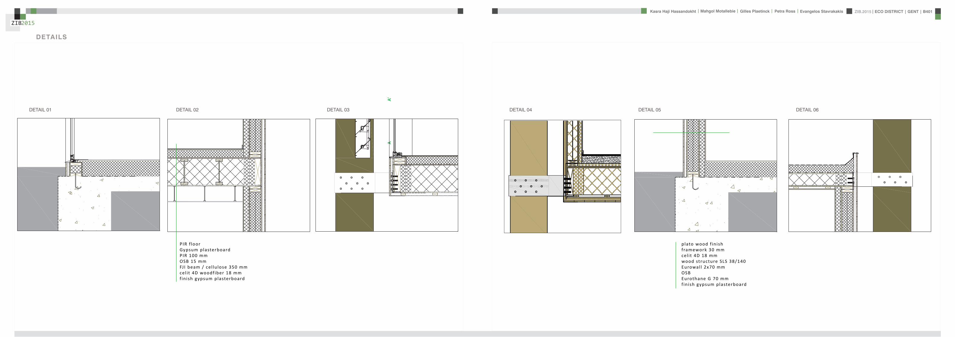
ZIB2015 ECO DISTRICT | GENT | B401Evangelos Stavrakakis | Petra Ross | Mahgol Motallebie | Gilles Plaetinck | Kasra Haji Hassandokht
ZIB2015
|
ELEVATIONS 1100
South elevation
South Elevation
North Elevation
South Elevation
North Elevation
South Elevation
North Elevation
South Elevation
North Elevation
North elevation
ZIB2015 ECO DISTRICT | GENT | B401Evangelos Stavrakakis | Petra Ross | Mahgol Motallebie | Gilles Plaetinck | Kasra Haji Hassandokht
ZIB2015
|
VISUALIZATIONS
East Elevation
West Elevation
East Elevation
West Elevation
East Elevation
West Elevation East Elevation
West Elevation
ELEVATIONS 1100
West elevation East elevation
ZIB2015 ECO DISTRICT | GENT | B401Evangelos Stavrakakis | Petra Ross | Mahgol Motallebie | Gilles Plaetinck | Kasra Haji Hassandokht
ZIB2015
|
VISUALIZATIONS
ZIB2015 ECO DISTRICT | GENT | B401Evangelos Stavrakakis | Petra Ross | Mahgol Motallebie | Gilles Plaetinck | Kasra Haji Hassandokht
ZIB2015
|
MATERIALS WOOD FCS Certi f ied Suppliers Distance MATERIALS Building Structure
ZIB2015 ECO DISTRICT | GENT | B401Evangelos Stavrakakis | Petra Ross | Mahgol Motallebie | Gilles Plaetinck | Kasra Haji Hassandokht
ZIB2015
|
MATERIALS Specs InsulationMATERIALS Specs Solid amp Structural Wood
ZIB2015 ECO DISTRICT | GENT | B401Evangelos Stavrakakis | Petra Ross | Mahgol Motallebie | Gilles Plaetinck | Kasra Haji Hassandokht
ZIB2015
|
MATERIALS Life Cycle Assesment MATERIALS Embodied energy CO2 other materials
ZIB2015 ECO DISTRICT | GENT | B401Evangelos Stavrakakis | Petra Ross | Mahgol Motallebie | Gilles Plaetinck | Kasra Haji Hassandokht
ZIB2015
|
STRUCTURE
Gilles Plaetinck
schaal
ZIB BUILDINGEnter address here
7 _ Unnamed
Owner
begeleider Checker
3D Copy 11 Gilles Plaetinck
schaal
ZIB BUILDINGEnter address here
8 _ Unnamed
Owner
begeleider Checker
3D Copy 21
Gilles Plaetinck
schaal
ZIB BUILDINGEnter address here
8 _ Unnamed
Owner
begeleider Checker
3D Copy 31
Gilles Plaetinck
schaal
ZIB BUILDINGEnter address here
9 _ Unnamed
Owner
begeleider Checker3D Copy 4
1
ECONOMY - USIBILITY DURING THE DAY
i1000
ALWAYS
2000
ECONONY - USIBILITY DURING THE DAY
GENERAL PRINCIPLES OF THE BUILDING
ZERO IMPACT APPROACH
i
0 Food market in park Vertical harvesting Entrance
1 Workshop area technical room
2 Info center Entrance from highway
3 Roof terrace
ZIB2015 ECO DISTRICT | GENT | B401Evangelos Stavrakakis | Petra Ross | Mahgol Motallebie | Gilles Plaetinck | Kasra Haji Hassandokht
ZIB2015
|
Vertical Harvest places plants on carousels that keep them moving the length of the greenhouse giving them equal time in natural light and also al-lowing workers to pick and tand transfer the crops Using hydroponics Verti-cal Harvest will be capa-ble of producing over
Vertical Harvest places plants on carousels that keep them moving the length of the pulls giving them equal time in natu-ral light and also allowing workers and local people to pick and transfer the crops Using hydroponics Vertical Harvest will be capable of producing over greens and herbs
Vertical Harvest places plants on carousels that keep them moving the length of the greenhouse giving them equal time in natural light and also al-lowing workers to pick and tand transfer the crops Using hydroponics Verti-cal Harvest will be capa-ble of producing over
Vertical Harvest places plants on carousels that keep them moving the length of the pulls giving them equal time in natu-ral light and also allowing workers and local people to pick and transfer the crops Using hydroponics Vertical Harvest will be capable of producing over greens and herbs
VERTICAL HARVESTING
PLANT CABLE LIFT (PLC) SECTION
Sustainable Food zorkshop centerrsquos mission is to ldquocultivate a healthy community by strengthening the local food system and improving access to nu-tritious affordable foodrdquo The main goal of our design is to deliver skills and information for sus-tainability practioners in the organic food tradeThe program attempts to1) affect positive changes in shopping cooking eating habits and nutrition2) reduce diet-related diseases3) promote the health and development of young children 4) place emphasis on local seasonal and cultural-ly-appropriate foods5) integrate food systems concepts into its curric-ulumndash such as shopping at farmers markets and growing onersquos own food
Healthy food is a basic human right the ability to access healthy food is often related to multiple issues and not just a result of low income
FOOD TEAM = a group of people from the same neighbourhood who work for the direct purchase of regional and seasonal products They order food on internet via web page voedselteambe and it is then delivered once a week to the depot of a team
+ minimal transport requirements+ no returnable packaging+ fair p+ fair pricing+ high-quality local and seasonal food+ community initiative
Sustainable Food zorkshop centerrsquos mission is to ldquocultivate a healthy community by strengthening the local food system and improving access to nu-tritious affordable foodrdquo The main goal of our design is to deliver skills and information for sus-tainability practioners in the organic food tradeThe program attempts to1) affect positive changes in shopping cooking eating habits and nutrition2) reduce diet-related diseases3) promote the health and development of young children 4) place emphasis on local seasonal and cultural-ly-appropriate foods5) integrate food systems concepts into its curric-ulumndash such as shopping at farmers markets and growing onersquos own food
Healthy food is a basic human right the ability to access healthy food is often related to multiple issues and not just a result of low income
FOOD TEAM = a group of people from the same neighbourhood who work for the direct purchase of regional and seasonal products They order food on internet via web page voedselteambe and it is then delivered once a week to the depot of a team
+ minimal transport requirements+ no returnable packaging+ fair p+ fair pricing+ high-quality local and seasonal food+ community initiative
Sustainable Food zorkshop centerrsquos mission is to ldquocultivate a healthy community by strengthening the local food system and improving access to nu-tritious affordable foodrdquo The main goal of our design is to deliver skills and information for sus-tainability practioners in the organic food tradeThe program attempts to1) affect positive changes in shopping cooking eating habits and nutrition2) reduce diet-related diseases3) promote the health and development of young children 4) place emphasis on local seasonal and cultural-ly-appropriate foods5) integrate food systems concepts into its curric-ulumndash such as shopping at farmers markets and growing onersquos own food
Healthy food is a basic human right the ability to access healthy food is often related to multiple issues and not just a result of low income
FOOD TEAM = a group of people from the same neighbourhood who work for the direct purchase of regional and seasonal products They order food on internet via web page voedselteambe and it is then delivered once a week to the depot of a team
+ minimal transport requirements+ no returnable packaging+ fair p+ fair pricing+ high-quality local and seasonal food+ community initiative
Healthy food is a basic human right the ability to access healthy food is often related to multiple issues and not just a result of low income
Sustainable Food zorkshop centerrsquos mission is to ldquocultivate a healthy community by strengthening the local food system and improving access to nutritious affordable foodrdquo The main goal of our design is to deliver skills and information for sustainability practioners in the organic food tradeThe program attempts to
1) affect positive changes in shopping cookingeating habits and nutrition2) reduce diet-related diseases3) promote the health and development of youngchildren4) place emphasis on local seasonal and culturally-appropriate foods5) integrate food systems concepts into its curriculumndashsuch as shopping at farmers markets andgrowing onersquos own food
FOOD TEAM = a group of people from the same neighbourhood who work for the direct purchase of regional and seasonal products They order food on internet via web page voedselteambe and it is then delivered once a week to the depot of a team
+ minimal transport requirements+ no returnable packaging+ fair pricing+ high-quality local and seasonal food+ community initiative
WORKSHOP
ZIB2015 ECO DISTRICT | GENT | B401Evangelos Stavrakakis | Petra Ross | Mahgol Motallebie | Gilles Plaetinck | Kasra Haji Hassandokht
ZIB2015
|
Black coral pea
Factors should be considered when seleccng plants
- Quality of growth- Ability to adapt to the wall environment- Environmental Tolerances- Temperature Resistance- Drought Tolerance- Wind - Wind Tolerance- Solar Exposure Tolerance- Salt Tolerance in Seaside installacons- Air and Water Pollucon Tolerance- Pest and Disease Resistance- Arcficial Environment Tolerance- Transplantacon Tolerance- Pruning - Pruning Tolerance
- Ornamental Qualices- Design Purpose- Manageability Maintainability- Environmental and Societal Effects- Visual Effect- Feeling Effect
Blac
k co
ral p
eaSn
ake
vine
kidn
ey w
eed
purple coral peaBasil
Pandorea
Black coral pea
Factors should be considered when seleccng plants
- Quality of growth- Ability to adapt to the wall environment- Environmental Tolerances- Temperature Resistance- Drought Tolerance- Wind - Wind Tolerance- Solar Exposure Tolerance- Salt Tolerance in Seaside installacons- Air and Water Pollucon Tolerance- Pest and Disease Resistance- Arcficial Environment Tolerance- Transplantacon Tolerance- Pruning - Pruning Tolerance
- Ornamental Qualices- Design Purpose- Manageability Maintainability- Environmental and Societal Effects- Visual Effect- Feeling Effect
Blac
k co
ral p
eaSn
ake
vine
kidn
ey w
eed
purple coral peaBasil
Pandorea
Black coral pea
Factors should be considered when seleccng plants
- Quality of growth- Ability to adapt to the wall environment- Environmental Tolerances- Temperature Resistance- Drought Tolerance- Wind - Wind Tolerance- Solar Exposure Tolerance- Salt Tolerance in Seaside installacons- Air and Water Pollucon Tolerance- Pest and Disease Resistance- Arcficial Environment Tolerance- Transplantacon Tolerance- Pruning - Pruning Tolerance
- Ornamental Qualices- Design Purpose- Manageability Maintainability- Environmental and Societal Effects- Visual Effect- Feeling Effect
Blac
k co
ral p
eaSn
ake
vine
kidn
ey w
eed
purple coral peaBasil
Pandorea
GREEN WALLS
ZIB2015 ECO DISTRICT | GENT | B401Evangelos Stavrakakis | Petra Ross | Mahgol Motallebie | Gilles Plaetinck | Kasra Haji Hassandokht
ZIB2015
|
Extraction of air
Pulsion of airRecuperation unit
outdoor space
18 degC15 degC
18 degC
In-take Out-take of air
VENTILATION
Gilles Plaetinck
schaal 1 100
ZIB BUILDINGEnter address here
3 _ level 2
Owner
begeleider Checker
DN
Gilles Plaetinck
schaal 1 100
ZIB BUILDINGEnter address here
2 _ level 1
Owner
begeleider Checker
Extraction of air
Pulsion of air
VENTILATION IN GROUPLANS CALCULATION AND SYSTEM
level 01
level 02
T 42ECO DISTRICT | GENT | B401
ZIB2015Mechanical Ventilation with Heat Recovery (MVHR)
Up to 95 of the heat can be recovered The Heat Recovery Unit runs continu-ously on trickle and can and is boosted when higher rates of ventilation are required eg bathing cooking In warmer months a summer by-pass function helps ensure comfort levels are maintained in the home When summer by-pass is activated the dwelling contin-ues to be ventilaated and recieve fresh filtered air however the heat recovery process is intermittently switched off (heat recovery is by-passed)
Key BenefitsYear round removal of condensation and indoor pol-lutants A direct impact on the Dwelling Emission Rate re-quired in SAP helping reduce the carbon footprint of the property Fresh filtered air supplied to dwelling ideal for allergy sufferers and those with conditions such as asthma A balanced ventilation system for the whole house and recovering of heat that would have otherwise have been lost Low noise non-intrusive ventilation system ndash located away from the room however consideration should be given to duct runs to ensure cross-talk contamination doesnrsquot happen AND the unit is sized correctly so it is not running a high rate all of the time
Zehnder ComfoSystems Passive Haus accredited product suitable for large houses up to 300m2 Designed to ensure low noise excellent energy performance and heat exchange efficiency Choice of control options including LCD touch screen display Can be combine with ComfoCool for optional cooling of up to 5 degrees and humidity reduction by 20
Semi Rigid Ducting
With a manifold system the resistance caused by duct-ing is reduced therefore Semi-Rigid ducting resistance is very low The manifold takes mass airflow directly from the MVHR Heat Recovery Unit and allows lower rates to pass through to each individual room runDirecting mass flow to the manifold eliminates the need to increase the running speed of the MVHR Heat Re-covery unit to overcome the resistance of ducting which in turn causes noise for the homeowner
T 42ECO DISTRICT | GENT | B401
ZIB2015Mechanical Ventilation with Heat Recovery (MVHR)
Up to 95 of the heat can be recovered The Heat Recovery Unit runs continu-ously on trickle and can and is boosted when higher rates of ventilation are required eg bathing cooking In warmer months a summer by-pass function helps ensure comfort levels are maintained in the home When summer by-pass is activated the dwelling contin-ues to be ventilaated and recieve fresh filtered air however the heat recovery process is intermittently switched off (heat recovery is by-passed)
Key BenefitsYear round removal of condensation and indoor pol-lutants A direct impact on the Dwelling Emission Rate re-quired in SAP helping reduce the carbon footprint of the property Fresh filtered air supplied to dwelling ideal for allergy sufferers and those with conditions such as asthma A balanced ventilation system for the whole house and recovering of heat that would have otherwise have been lost Low noise non-intrusive ventilation system ndash located away from the room however consideration should be given to duct runs to ensure cross-talk contamination doesnrsquot happen AND the unit is sized correctly so it is not running a high rate all of the time
Zehnder ComfoSystems Passive Haus accredited product suitable for large houses up to 300m2 Designed to ensure low noise excellent energy performance and heat exchange efficiency Choice of control options including LCD touch screen display Can be combine with ComfoCool for optional cooling of up to 5 degrees and humidity reduction by 20
Semi Rigid Ducting
With a manifold system the resistance caused by duct-ing is reduced therefore Semi-Rigid ducting resistance is very low The manifold takes mass airflow directly from the MVHR Heat Recovery Unit and allows lower rates to pass through to each individual room runDirecting mass flow to the manifold eliminates the need to increase the running speed of the MVHR Heat Re-covery unit to overcome the resistance of ducting which in turn causes noise for the homeowner
MECHANICAL VENTILATION WITH HEAT RECOVERY (MVHR)
Up to 95 of the heat can be recoveredThe Heat Recovery Unit runs continuously on trickle and can and is boosted when higher rates of ventilation are required eg bathing cooking
In warmer months a summer by-pass function helps ensure comfort levels are maintained in the home When summer by-pass is activated the dwelling continues to be ventilaated and recieve fresh filtered air however the heat recovery process is intermittently switched off (heat recovery is by-passed)
EXTRACT VENTILATION RATES
T 42ECO DISTRICT | GENT | B401
ZIB2015Mechanical Ventilation with Heat Recovery (MVHR)
Up to 95 of the heat can be recovered The Heat Recovery Unit runs continu-ously on trickle and can and is boosted when higher rates of ventilation are required eg bathing cooking In warmer months a summer by-pass function helps ensure comfort levels are maintained in the home When summer by-pass is activated the dwelling contin-ues to be ventilaated and recieve fresh filtered air however the heat recovery process is intermittently switched off (heat recovery is by-passed)
Key BenefitsYear round removal of condensation and indoor pol-lutants A direct impact on the Dwelling Emission Rate re-quired in SAP helping reduce the carbon footprint of the property Fresh filtered air supplied to dwelling ideal for allergy sufferers and those with conditions such as asthma A balanced ventilation system for the whole house and recovering of heat that would have otherwise have been lost Low noise non-intrusive ventilation system ndash located away from the room however consideration should be given to duct runs to ensure cross-talk contamination doesnrsquot happen AND the unit is sized correctly so it is not running a high rate all of the time
Zehnder ComfoSystems Passive Haus accredited product suitable for large houses up to 300m2 Designed to ensure low noise excellent energy performance and heat exchange efficiency Choice of control options including LCD touch screen display Can be combine with ComfoCool for optional cooling of up to 5 degrees and humidity reduction by 20
Semi Rigid Ducting
With a manifold system the resistance caused by duct-ing is reduced therefore Semi-Rigid ducting resistance is very low The manifold takes mass airflow directly from the MVHR Heat Recovery Unit and allows lower rates to pass through to each individual room runDirecting mass flow to the manifold eliminates the need to increase the running speed of the MVHR Heat Re-covery unit to overcome the resistance of ducting which in turn causes noise for the homeowner
T 42ECO DISTRICT | GENT | B401
ZIB2015Mechanical Ventilation with Heat Recovery (MVHR)
Up to 95 of the heat can be recovered The Heat Recovery Unit runs continu-ously on trickle and can and is boosted when higher rates of ventilation are required eg bathing cooking In warmer months a summer by-pass function helps ensure comfort levels are maintained in the home When summer by-pass is activated the dwelling contin-ues to be ventilaated and recieve fresh filtered air however the heat recovery process is intermittently switched off (heat recovery is by-passed)
Key BenefitsYear round removal of condensation and indoor pol-lutants A direct impact on the Dwelling Emission Rate re-quired in SAP helping reduce the carbon footprint of the property Fresh filtered air supplied to dwelling ideal for allergy sufferers and those with conditions such as asthma A balanced ventilation system for the whole house and recovering of heat that would have otherwise have been lost Low noise non-intrusive ventilation system ndash located away from the room however consideration should be given to duct runs to ensure cross-talk contamination doesnrsquot happen AND the unit is sized correctly so it is not running a high rate all of the time
Zehnder ComfoSystems Passive Haus accredited product suitable for large houses up to 300m2 Designed to ensure low noise excellent energy performance and heat exchange efficiency Choice of control options including LCD touch screen display Can be combine with ComfoCool for optional cooling of up to 5 degrees and humidity reduction by 20
Semi Rigid Ducting
With a manifold system the resistance caused by duct-ing is reduced therefore Semi-Rigid ducting resistance is very low The manifold takes mass airflow directly from the MVHR Heat Recovery Unit and allows lower rates to pass through to each individual room runDirecting mass flow to the manifold eliminates the need to increase the running speed of the MVHR Heat Re-covery unit to overcome the resistance of ducting which in turn causes noise for the homeowner
Heating 10 kwh msup2aCooling 4 kWh msup2aOverheating 42
ZIB2015 ECO DISTRICT | GENT | B401Evangelos Stavrakakis | Petra Ross | Mahgol Motallebie | Gilles Plaetinck | Kasra Haji Hassandokht
ZIB2015
|
Shutters control system+ -
Solar roadways - PV panels
LED lights
Elevator Fuse box
ElectricityBattery withtransformator
ELECTRICITY
Summer night
cross- ventilation through building
Summer day
air through recuperation unit small change of temperature
15 degC 18 degC
+ groundplans
heated zone
not heated zone
ZONING ACCORDING TO TEMPERATURESSUMMER NIGHT - cross-ventilation through building
SUMMER DAY - air through recuperation unit small change of temperatureSHADING SYSTEM
As a shading was chozen system Renson Icarus Lamellas with angle 45deg made in wood
ZIB2015 ECO DISTRICT | GENT | B401Evangelos Stavrakakis | Petra Ross | Mahgol Motallebie | Gilles Plaetinck | Kasra Haji Hassandokht
ZIB2015
|
average only 4 hours of peak daylight hours per day (4 x 365 = 1460 hours per year)
- Surface area ( first part) Fly-over +- 20 000 msup2-gt 16 000 x 230 Watt = 3 680 000 Watt or 3680 kWonly 50 of fly-over covered with solar roadways
-gt 3680 kW x 4 h = 7360 kWh day-gt 3680 kW x 1460 h = 2 686 400 kWh year -gt +- 540 households (+- 5000 kWh year)
Tesla Powerwall Therersquos a 10 kWh unit at $3500 -gt 737 Tesla Batteries
gt the Solar Roadway has the ability to cut greenhouse gases by up to 75-percentgt A decentralized self-healing secure power grid
IN FRONT OF FLY-OVER
- Surface area Fly-over = 16 x 30 m = 480 msup2-gt 384 x 230 Watt = 88 320 Watt or 883 kWonly 50 of fly-over covered with solar roadways
-gt 44 kW x 4 h = 176 kWh day-gt 44 kW x 1460 h = 64 240 kWh year -gt +- 13 households (+- 5000 kWh year)
lightsshutters
elevator
2 fridges
2 coffeemakers
1 microwave
1 owen
2 cooking plates
stereo
ventilation unit
electricity transformer (AC to DC) for PV panels + batteries
summer 05 kWh daywinter 03 kWh day183 days x 05= 915 kWh182 days x 03 = 546 kWh = 1641 kWh
262 kWh
A++fridge 104 kWhyear104 x x2 = 208 kWh
900 W x 01 hours day = 09 kWhx 220 days x 2= 198 kWh a
67 kWh a
085x100 days= 85 kWh a
400 kWh x 2 = 800 kWh a
150 kWh a 419 kWha
68 kWh a
ENERGY DEMAND OVERVIEW ENERGY SUPPLY OVERVIEW - FLY-OVER
1 spot 56 W 10000 = 0056 KW4 hours per day 365 days a year = 1460 h0056 x 1460 = 8176 kWh10 spots x 8176= 8176 kWh a
1 spot 72 W 10000 = 0072 KW4 hours per day 365 days a year = 1460 h0072 x 1460 = 10512 kWh5 spots x 10512= 5256 kWh a
1 spot 52 W 10000 = 0052 KW4 hours per day 365 days a year = 1460 h0052 x 1460 = 7592 kWh21 spots x 7592= 159432 kWh a
1 spot 9 W 10000 = 0009 KW4 hours per day 365 days a year = 1460 h0009 x 1460 = 1314 kWh5 spots x 1314 = 657 kWh a
SOLAR ROADWAYS - PV PANELSEnergy from the sun
1 To generate energy for the ZIB building2 To generate energy for the surrounding houses3 To generate energy for lighting or signs on the road4 The panels will also have the capacity to charge electric vehicles while parked
ELECTRICITY SCHEME
5423 kWh a
ZIB2015 ECO DISTRICT | GENT | B401Evangelos Stavrakakis | Petra Ross | Mahgol Motallebie | Gilles Plaetinck | Kasra Haji Hassandokht
ZIB2015
|
SUMMER SUNNY 10-42 LUXWINTER SUNNY 10-42 LUX
DAYLIGHT - DIALuxLIGHTING SYSTEM - DIALux
Workplane 9 Results overview
Height of working plane 0800 m Wall zone 0000 m
Result Mean (target) Min Max Minaverage MinmaxPerpendicular illuminance [lx] 463 (500) 105 689 0227 0152
Profile Offices Writing typewriting reading data processing
B401-Gent 6222015
Site 1 Building 2 Zib Room 9 Workplane 9 Results overview
Page 70
Workplane 9 False coloursPerpendicular illuminance (adaptive)
Scale 1 200
Perpendicular illuminance (Surface)Mean (actual) 463 lx Min 105 lx Max 689 lx Minaverage 0227 Minmax 0152
B401-Gent 6222015
Site 1 Building 2 Zib Room 9 Workplane 9 False coloursPerpendicular illuminance (adaptive)
Page 72
Workplane 9 Value chartPerpendicular illuminance (adaptive)
Scale 1 200
Perpendicular illuminance (Surface)Mean (actual) 463 lx Min 105 lx Max 689 lx Minaverage 0227 Minmax 0152
B401-Gent 6222015
Site 1 Building 2 Zib Room 9 Workplane 9 Value chartPerpendicular illuminance (adaptive)
Page 73
Workplane 13 Results overview
Height of working plane 0800 m Wall zone 0000 m
Result Mean (target) Min Max Minaverage MinmaxPerpendicular illuminance [lx] 388 (500) 69 732 0178 0094
Profile Offices Writing typewriting reading data processing
B401-Gent 6222015
Site 1 Building 6 Storey 1 Room 13 Workplane 13 Results overview
Page 94
Workplane 13 False coloursPerpendicular illuminance (adaptive)
Scale 1 100
Perpendicular illuminance (Surface)Mean (actual) 388 lx Min 69 lx Max 732 lx Minaverage 0178 Minmax 0094
B401-Gent 6222015
Site 1 Building 6 Storey 1 Room 13 Workplane 13 False coloursPerpendicular illuminance (adaptive)
Page 96
Workplane 13 Value chartPerpendicular illuminance (adaptive)
Scale 1 100
Perpendicular illuminance (Surface)Mean (actual) 388 lx Min 69 lx Max 732 lx Minaverage 0178 Minmax 0094
B401-Gent 6222015
Site 1 Building 6 Storey 1 Room 13 Workplane 13 Value chartPerpendicular illuminance (adaptive)
Page 97
Workplane 9 False coloursPerpendicular illuminance (adaptive)
Scale 1 200
Perpendicular illuminance (Surface)Mean (actual) 463 lx Min 105 lx Max 689 lx Minaverage 0227 Minmax 0152
B401-Gent 6222015
Site 1 Building 2 Zib Room 9 Workplane 9 False coloursPerpendicular illuminance (adaptive)
Page 72
1st f loor 2nd f loor Site 1 Luminaire parts listQuantity Luminaire (Luminous emittance)10 3F Filippi 12736 P 202x24W LED OP 196x1231
Luminous emittance 1Fitting 1x24W 2xLEDLight output ratio 100Lamp luminous flux 5332 lmLuminaire Luminous Flux 5332 lmPower 560 WLight yield 952 lmW
200
300
400
cdklm η = 100C0 - C180 C90 - C270
0deg 15deg 30deg
45deg
60deg
75deg
90deg
105deg105deg
90deg
75deg
60deg
45deg
30deg 15deg 0deg
5 SFN Eclairages 0732360X CLFV 236Luminous emittance 1Fitting 2xT26 36W840Light output ratio 6889Lamp luminous flux 6700 lmLuminaire Luminous Flux 4615 lmPower 720 WLight yield 641 lmW
160
240
cdklm η = 69C0 - C180 C90 - C270
0deg 15deg 30deg
45deg
60deg
75deg
90deg
105deg105deg
90deg
75deg
60deg
45deg
30deg 15deg 0deg
21 SFN Eclairages 332226XX SAM F 2x26W BELuminous emittance 1Fitting 2xTC-DEL 26W840Light output ratio 3297Lamp luminous flux 3600 lmLuminaire Luminous Flux 1187 lmPower 520 WLight yield 228 lmW
40
60
80
100
120
140
cdklm η = 33C0 - C180 C90 - C270
0deg 15deg 30deg
45deg
60deg
75deg
90deg
105deg105deg
90deg
75deg
60deg
45deg
30deg 15deg 0deg
1 Signcomplex AR111-009-AW-W-06 AR111 COB 9W38deg WhiteLuminous emittance 1Fitting 1xAR111-009-AW-W-06Light output ratio 8078Lamp luminous flux 600 lmLuminaire Luminous Flux 485 lmPower 90 WLight yield 539 lmW
800
1200
cdklm η = 81C0 - C180 C90 - C270
0deg 15deg 30deg
45deg
60deg
75deg
90deg
105deg105deg
90deg
75deg
60deg
45deg
30deg 15deg 0deg
Total lamp luminous flux 163020 lm Total luminaire luminous flux 101807 lm Total Load 20210 W Light yield 504 lmW
B401-Gent 6222015
Site 1 Luminaire parts list
Page 19
10x
6x
21x
1x
types of l ights
Perpendicular i l luminance (Surface)Mean (actual ) 463 lx Min 105 lx Max 689 lx Minaverage 0 227 Minmax 0 152
Perpendicular i l luminance (Surface)Mean (actual ) 388 lx Min 69 lx Max 732 lx Minaverage 0 178 Minmax 0 094
ZIB2015 ECO DISTRICT | GENT | B401Evangelos Stavrakakis | Petra Ross | Mahgol Motallebie | Gilles Plaetinck | Kasra Haji Hassandokht
ZIB2015
|
Tube hybrid Solar panels
Hot water tank Water taps
City water supply
Rain water collection for vertical harvesting
City water supply
WADI
Rain water tank
WATER MANAGEMENT
Sinks
Available roof area
In Ghent avarage of 900mmm2year
3197 m2
09x 3197 = 28773 m3year
RAIN WATER GAIN
toilet - 3x - 03lskitchen -4x - 02ls
POTABLE WATER DEMAND
3 toiletsVertical gardening
Total
relative RW usage
300 l day150 l day = 450lday= 16425 m3 year
1407 lday100m2
RAIN WATER DEMAND
RAIN WATER TANK
Relative RWT volumeRain water tank volume
3m3 100 m2
9591 l gt 10 m3
DIMESION OF PIPES
City water supplyRainwater tank
178 mm (DN 18 - 15 - 12)165 mm (DN 17-15)
are composed of hexagonal tiles Rainwater can infiltrate between the gaps from where it goes to rainwatter collector which supplies the vegetation on fly-over
THE SOLAR ROADWAYS
WATER SUPPLY SCHEME AND CALCULATION
ZIB2015 ECO DISTRICT | GENT | B401Evangelos Stavrakakis | Petra Ross | Mahgol Motallebie | Gilles Plaetinck | Kasra Haji Hassandokht
ZIB2015
|
WADI
City water supply
Rain water tank
Sinks
Divided sewer systemwithin building
SEWAGE SYSTEM
ToiletToilet sinkKitchen sink
DU = 2 lsDU = 05 lsDU = 08 ls
WATER DRAINAGE OF DEVICES
Frequency of usage at the same time
K 05
DIMESION OF PIPES
Black waterGrey water
110 mm (DU 110)75 mm (DU 75 - 63)
WATER DRAINAGE SCHEME AND CALCULATION
ZIB2015 ECO DISTRICT | GENT | B401Evangelos Stavrakakis | Petra Ross | Mahgol Motallebie | Gilles Plaetinck | Kasra Haji Hassandokht
ZIB2015
|
DN
Gilles Plaetinck
schaal 1 100
ZIB BUILDINGEnter address here
2 _ level 1
Owner
begeleider Checker
Gilles Plaetinck
schaal 1 100
ZIB BUILDINGEnter address here
3 _ level 2
Owner
begeleider Checker
WATER SUPPLY
HOT WATER
WATER DRAINAGE
WATER SUPPLY AND DRAINAGE IN GROUPLANS
level 01
level 02
ENERGY
RAINWATER TANK
HELOPHYTE FILTER
IRRIGATION SYSTEM
BIO-ROTOR
MICRO TURBINE
PHOSPHOR
In this building a closed water system is applied which is based on reusing water in mullple wasRainRain water from the roof will be collected in a storage tank situated on the ground floor This water will be used to flush the toilet and irrigate crops in verlcal harveslng system In case of an overflow the water will be stored in the con-structed wetland near the building The rainwater can be fil-tered through a helophyte filter up to drinking water stan-dard The waste water system includes three types of water yellyellow black and grey waterThe yellow water will be stored for its phosphor while the black water will be purified into grey water This grey water is comparable to the quality of rain water aaer purificalon b means of a bio rotor The remaining residue from the bio rotor together with the organic waste from the harveslng is fermented into biogas that drives a micro turbine in order to produce some addilonal energy
TheThe waste product deriving from this process will be used as compost in verlcal harveslng This efficient yet complex system closes the ullizalon cycle of the building and turns it into an efficient vicious circle that can be considered au arkic
In this building a closed water system is applied which is based on reusing water in multiple was
Rain water from the roof will be collected in a storage tank situated on the ground floor This water will be used to flushthe toilet and irrigate crops in vertical harvesting system In case of an overflow the water will be stored in the constructed wetland near the building The rainwater can be filtered through a helophyte filter up to drinking water standard
The waste water system includes three types of water yellow black and grey water The yellow water will be stored for its phosphor while the black water will be purified into grey water This grey water is comparable to the quality of rain water after purification b means of a bio rotor The remaining residue from the bio rotor together with the organic waste from the harvesting is fermented into biogas that drives a micro turbine in order to produce some additional energy The waste product deriving from this process will be used ascompost in ver1048991cal harves1048991ng This efficient yet complexsystem closes the u1048991liza1048991on cycle of the building and turns itinto an efficient vicious circle that can be considered au arkic
WATER CYCLE
ZIB2015 ECO DISTRICT | GENT | B401Evangelos Stavrakakis | Petra Ross | Mahgol Motallebie | Gilles Plaetinck | Kasra Haji Hassandokht
ZIB2015
|
CALCULATIONS
Passive House verification
Photo or Drawing
Building Workshop + info pointStreet
PostcodeCityCountry
Building Type non-residentialClimate Ukkel
Home Owner(s) Client(s)Street
PostcodeCity
ArchitectStreet
PostcodeCity Calculation electricity Internal heat gains
Mechanical System Building type
StreetPostcodeCity Internal heat gains
Year of Construction 2015 Interior Temperature 200 degC Utilisation pattern
Number of Dwelling Units 1 Internal Heat Gains 20 Wm2 Type of values used Fill in worksheet IHG Non-Dom Enclosed Volume Ve 12442 Planned number of occupants
Number of Occupants 80 8 Design
Specific building demands with reference to the treated floor area use Annual method
Treated floor area 2840 msup2 Requirements Fulfilled Verification Annual method The monthly method should be used for building certification
Space heating Annual heating demand 10 kWh(m2a) 15 kWh(msup2a) yes Specific space heating demand annual method 103 kWh(msup2a)
Heating load 11 Wm2 10 Wmsup2 - Specific space heating demand monthly Method 120 kWh(msup2a)
Space cooling Overall specific space cooling demand kWh(m2a) 15 kWh(msup2a)
Cooling load Wm2 - -Frequency of overheating (gt 25 degC) - -
Primary Energy Space heating and dehumidification
cooling household electricity 73 kWh(m2a) 120 kWh(msup2a) yes
DHW space heating and auxiliary electricity 24 kWh(m2a) - -Specific primary energy reduction through solar electricity 21 kWh(m2a) - -
Airtightness Pressurization test result n50 06 1h 06 1h yes
PHPP Verification FINAL ZIB FILE CALCULTIONS PHPPxls
L B H VOLUME
main 1 226 7 4 6328main 2 184 7 35 4508
core 0 6 2 5 3 5 108 5core 0 62 5 35 1085core 3 62 3 28 521
12442
AREAmain 1 storage 35
wc big 35wc 2wc 2workshop 103
MAIN 2 infolounge 92
staircase 56storage technical 22
284
Floor_exterior 1582 31 1272
Roof_exterior 1582
Passive House verification
Photo or Drawing
Building Workshop + info pointStreet
PostcodeCityCountry
Building Type non-residentialClimate Ukkel
Home Owner(s) Client(s)Street
PostcodeCity
ArchitectStreet
PostcodeCity Calculation electricity Internal heat gains
Mechanical System Building type
StreetPostcodeCity Internal heat gains
Year of Construction 2015 Interior Temperature 200 degC Utilisation pattern
Number of Dwelling Units 1 Internal Heat Gains 20 Wm2 Type of values used Fill in worksheet IHG Non-Dom Enclosed Volume Ve 12442 Planned number of occupants
Number of Occupants 80 8 Design
Specific building demands with reference to the treated floor area use Annual method
Treated floor area 2840 msup2 Requirements Fulfilled Verification Annual method The monthly method should be used for building certification
Space heating Annual heating demand 10 kWh(m2a) 15 kWh(msup2a) yes Specific space heating demand annual method 103 kWh(msup2a)
Heating load 11 Wm2 10 Wmsup2 - Specific space heating demand monthly Method 120 kWh(msup2a)
Space cooling Overall specific space cooling demand kWh(m2a) 15 kWh(msup2a)
Cooling load Wm2 - -Frequency of overheating (gt 25 degC) - -
Primary Energy Space heating and dehumidification
cooling household electricity 73 kWh(m2a) 120 kWh(msup2a) yes
DHW space heating and auxiliary electricity 24 kWh(m2a) - -Specific primary energy reduction through solar electricity 21 kWh(m2a) - -
Airtightness Pressurization test result n50 06 1h 06 1h yes
PHPP Verification FINAL ZIB FILE CALCULTIONS PHPPxls
SURFACE AREAcurrent orientation only night ventilation
current orientation only night ventilation 6 windows less 52 msup2
current orientation only night ventilation 7 windows less 60msup2 (stays the same for each side)
current orientation only night ventilation 8 windows less 69 msup2
orientation turned 90deg only night ventilation 6 windows less 52 msup2
orientation turned 90deg only night ventilation 7 windows less 60msup2 (window less at SE side)
orientation turned 90deg only night ventilation 8 windows less 69 msup2
-gt orientation turned 90deg only night ventilation 9 windows less 77msup2 (window less at NW side althought theres less overheating in the case of a window less at SE side the heating demand exceeds 15)
CHANGE IN DESIGN
ZIB2015 ECO DISTRICT | GENT | B401Evangelos Stavrakakis | Petra Ross | Mahgol Motallebie | Gilles Plaetinck | Kasra Haji Hassandokht
ZIB2015
|
Passive House verificationS P E C I F I C A N N U A L H E A T I N G D E M A N D
Climate Ukkel Interior Temperature 200 degC
Building Workshop + info point Building TypeUse non-residentialTreated Floor Area ATFA 2840 msup2
per msup2Area U-Value Temp Factor ft Gt Treated Data for heating balance diagram
Building Element Temperature Zone msup2 W(msup2K) kKha kWha Floor Area Losses GainsExterior Wall - Ambient A 5595 0101 100 743 = 4181 1472 Exterior Wall - Ambient 147234373Exterior Wall - Ground B 069 = Exterior Wall - GroundRoofCeiling - Ambient A 1550 0094 100 743 = 1085 382 RoofCeiling - Ambient 381903529Floor slab basement ceiling B 310 0105 069 743 = 167 059 Floor slab basement ceiling 058811509
A 100 =A 100 =
unheated basement X 075 = unheated basementWindows A 1154 0648 100 743 = 5562 1958 Windows 195834732Exterior Door A 100 = Exterior DoorExterior TB (lengthm) A 1169 -0030 100 743 = -259 -091 Thermal Bridge Heat LossPerimeter TB (lengthm) P 069 = 000 not useful heat gains 365267499Ground TB (lengthm) B 069 =
Total of All Building Envelope Areas 8609 ndashndashndashndashndashndashndashndashndashndashndashndashndash- kWh(msup2a) Ventilation 395818713
Transmission Heat Losses QT Total 10736 378Annual Heating Demand 102516636
ATFA Clear Room Height internal gains 100951487msup2 m msup3 passive solar gains 250668423
Ventilation System Effective Air Volume VV 2840 280 = 7952 Thermal bridge credit 091126837Effective Heat Recovery Efficiency eff 81 Cross check sum 46324923 46324923of Heat Recovery
Efficiency of Subsoil Heat Exchanger SHX 0 nVsystem HR nVRes
1h 1h 1h
Energetically Effective Air Exchange nV 0105 (1 - 081 ) + 0038 = 0058
VV nV cAir Gt
msup3 1h Wh(msup3K) kKha kWha kWh(msup2a)
Ventilation Heat Losses QV 795 0058 033 743 = 1124 40
Reduction Factor QT QV NightWeekend
kWha kWha Saving kWha kWh(msup2a)
Total Heat Losses QL ( 10736 + 1124 ) 10 = 11860 418
Orientation Reduction Factor g-Value Area Radiation HPof the Area See Windows Sheet (perp radiation)
msup2 kWh(msup2a) kWha
1 North 054 050 2700 163 = 11822 East 058 000 440 197 = 03 South 056 050 4860 314 = 42874 West 032 050 3216 254 = 13275 Horizontal 063 050 324 317 = 323
kWh(msup2a)
Available Solar Heat Gains QS Total 7119 251
Length Heat Period Spec Power qI ATFA
khd da Wmsup2 msup2 kWha kWh(msup2a)
Internal Heat Gains QI 0024 209 201 2840 = 2867 101
kWha kWh(msup2a)
Free Heat QF QS + QI = 9986 352
Ratio of Free Heat to Losses QF QL = 084
Utilisation Factor Heat Gains G (1 - ( QF QL )5 ) (1 - ( QF QL )
6 ) = 90kWha kWh(msup2a)
Heat Gains QG G QF = 8949 315
kWha kWh(msup2a)
Annual Heating Demand QH QL - QG = 2911 10
kWh(msup2a) (YesNo)
Limiting Value 15 Requirement met yes
00
147
00
3806000000
196
00
40
37
09
103
101
251
0
5
10
15
20
25
30
35
40
45
50
Losses Gains
Hea
t flo
ws
[kW
h(m
sup2a)]
Heating energy balance
passive solar gains
internal gains
Annual Heating Demand
Thermal bridge credit
not useful heat gains
Ventilation
Exterior Door
Windows
unheated basement
Floor slab basement ceiling
RoofCeiling - Ambient
Exterior Wall - Ground
Exterior Wall - Ambient
Thermal Bridge Heat Loss
HPP Annual Heating Demand FINAL ZIB FILE CALCULTIONS PHPPxls
Passive House verification Passive House verificationS P E C I F I C U S E F U L C O O L I N G D E M A N D S P E C I F I C U S E F U L C O O L I N G D E M A N D
M O N T H L Y M E T H O D M O N T H L Y M E T H O D
(This page displays the sums of the monthly method over the cooling period))Climate Ukkel Interior Temperature Summer 25 degC Climate Ukkel Interior Temperature 25 degC
Building Workshop + info point Building TypeUse non-residential Building Workshop + info point Building TypeUse non-residential
Spec Capacity 60 Wh(msup2K) (Enter in Summer worksheet) Treated Floor Area ATFA 2840 msup2 Treated Floor Area ATFA 284 msup2
per msup2Temperature Zone Area U-Value Mon Red Fac Gt Treated Jan Feb Mar Apr May Jun Jul Aug Sep Oct Nov Dec Year
Building Element msup2 W(msup2K) kKha kWha Floor Area Heating Degree Hours - Ex 168 150 144 121 92 73 57 59 82 109 140 160 136 kKh1 Exterior Wall - Ambient A 5595 0101 100 103 = 5782 Heating Degree Hours - G 126 123 135 120 106 83 63 54 58 71 86 109 113 kKh2 Exterior Wall - Ground B 100 = Losses - Exterior 2553 2286 2189 1838 1393 1117 871 904 1245 1660 2123 2432 20612 kWh3 RoofCeiling - Ambient A 1550 0094 100 103 = 1500 Losses - Ground 41 40 44 39 35 27 21 18 19 23 28 36 370 kWh4 Floor slab basement ceil B 310 0105 100 90 = 294 Losses Summer Ventilatio 67 71 244 372 629 720 880 865 658 499 234 126 5366 kWh5 A 100 = Sum Spec Heat Losses 94 84 87 79 72 66 62 63 68 77 84 91 928 kWhmsup26 A 100 = Solar Load North 44 81 141 212 286 298 298 255 178 116 54 35 1998 kWh7 unheated basement X 075 = Solar Load East 0 0 0 0 0 0 0 0 0 0 0 0 0 kWh8 Windows A 1154 0648 100 103 = 7690 Solar Load South 218 315 464 577 681 644 681 658 532 416 242 171 5601 kWh9 Exterior Door A 100 = Solar Load West 79 125 213 303 385 378 370 347 256 177 91 60 2785 kWh
10 Exterior TB (lengthm) A 1169 -0030 100 103 = -358 Solar Load Horiz 11 21 37 57 79 79 80 69 47 30 14 9 533 kWh11 Perimeter TB (lengthm) P 100 = Solar Load Opaque 3 5 9 13 18 19 19 16 11 7 3 2 126 kWh12 Ground TB (lengthm) B 100 = Internal Heat Gains 425 384 425 411 425 411 425 425 411 425 411 425 5001 kWh
ndashndashndashndashndashndashndashndashndashndashndash kWh(msup2a) Sum Spec Loads Solar + 28 33 45 55 66 64 66 62 51 41 29 25 565 kWhmsup2
Transmission Losses QT (Negative Heat Loads) Total 14907 525 Utilisation Factor Losses 29 39 52 69 84 88 82 88 73 53 34 27 58Useful Cooling Energy Dem 0 0 4 30 142 192 417 192 40 4 0 0 1021 kWh
ATFA Clear Room Height Spec Cooling Demand 00 00 00 01 05 07 15 07 01 00 00 00 36 kWhmsup2Effective msup2 m msup3
Air Volume VV 284 280 = 795
Heat Transfer Coef Gt
WK kKha kWha kWh(msup2a)
Exterior 99 103 = 1013 36Ground 00 105 = 0 00
Additional Summer Ventilation
Select X Window Night Ventilation Manual Corresponding Air Change Rate 136 1h
Mechanical Automatically Controlled Ventilation (for window ventilation at 1 K temperature difference indoor - outdoor)
Minimum Acceptable Indoor Temperatu 220 degC
kWha kWh(msup2a)
Heat Losses Summer Ventilation 5172 182
QLext QLground QLsummer
kWha kWha kWha kWha kWh(msup2a)
Ventilation Heat Losses QV 1013 + 0 + 5172 = 6185 218
2
3
4
5
6
7
8
9
10
Spec
ific
loss
es l
oads
l c
oolin
g de
man
d [k
Wh
(msup2 m
onth
)] Spec Cooling Demand Sum Spec Heat Losses Sum Spec Loads Solar + Internal
QT QV
kWha kWha kWha kWh(msup2a)
Total Heat Losses QL 14907 + 6185 = 21092 743
Orientation Reduction Factor g-Value Area Global Radiationof the Area (perp radiation)
msup2 kWh(msup2a) kWha
1 North 031 050 270 462 = 19182 East 061 000 44 578 = 0 Temperature Amplitude Summer 82 K3 South 030 050 486 707 = 52114 West 025 050 322 654 = 2646 Month 1 2 3 4 5 6 7 8 9 10 11 12 Annual Total5 Horizontal 035 050 32 913 = 513 Days 31 28 31 30 31 30 31 31 30 31 30 31 3656 Sum Opaque Areas 121 Ambient Temp 250 270 572 828 1275 1487 1737 1707 1369 1039 568 356 96
kWh(msup2a) North Radiation 106 195 329 494 667 697 712 599 419 275 129 87 471
Available Solar Heat Gains QS Total 10409 367 East Radiation 146 266 452 698 937 940 988 851 574 382 179 123 654
South Radiation 311 440 645 786 912 858 898 885 733 579 341 241 763Length Heat Period Spec Power qI ATFA West Radiation 155 261 471 707 926 926 896 819 580 382 183 116 642
khd da Wmsup2 msup2 kWha kWh(msup2a) Hori Radiation 200 369 662 1021 1398 1410 1418 1234 842 535 243 156 949
Internal Heat Gains QI 0024 303 20 2840 = 4151 146 Tsky -750 -730 -428 -172 275 487 737 707 369 039 -432 -644 -04
Ground Temp 805 676 686 830 1072 1345 1647 1776 1696 1552 1310 1037 121kWha kWh(msup2a)
Sum Heat Loads QF QS + QI = 14560 513
Ratio of Losses to Free Heat Gains QL QF = 145
Utilisation Factor Heat Losses G = 64kWha kWh(msup2a)
Useful Heat Losses QVn G QL = 13539 477
kWha kWh(msup2a)
Useful Cooling Demand QK QF - QVn = 1021 4
kWh(msup2a) (YesNo)
Limiting Value 15 Requirement met yes
0
1
2
Jan Feb Mar Apr May Jun Jul Aug Sep Oct Nov Dec
usef
u
HPP Cooling FINAL ZIB FILE CALCULTIONS PHPPxls
Passive House verificationS P E C I F I C A N N U A L H E A T I N G D E M A N D
Climate Ukkel Interior Temperature 200 degC
Building Workshop + info point Building TypeUse non-residentialTreated Floor Area ATFA 2840 msup2
per msup2Area U-Value Temp Factor ft Gt Treated Data for heating balance diagram
Building Element Temperature Zone msup2 W(msup2K) kKha kWha Floor Area Losses GainsExterior Wall - Ambient A 5595 0101 100 743 = 4181 1472 Exterior Wall - Ambient 147234373Exterior Wall - Ground B 069 = Exterior Wall - GroundRoofCeiling - Ambient A 1550 0094 100 743 = 1085 382 RoofCeiling - Ambient 381903529Floor slab basement ceiling B 310 0105 069 743 = 167 059 Floor slab basement ceiling 058811509
A 100 =A 100 =
unheated basement X 075 = unheated basementWindows A 1154 0648 100 743 = 5562 1958 Windows 195834732Exterior Door A 100 = Exterior DoorExterior TB (lengthm) A 1169 -0030 100 743 = -259 -091 Thermal Bridge Heat LossPerimeter TB (lengthm) P 069 = 000 not useful heat gains 365267499Ground TB (lengthm) B 069 =
Total of All Building Envelope Areas 8609 ndashndashndashndashndashndashndashndashndashndashndashndashndash- kWh(msup2a) Ventilation 395818713
Transmission Heat Losses QT Total 10736 378Annual Heating Demand 102516636
ATFA Clear Room Height internal gains 100951487msup2 m msup3 passive solar gains 250668423
Ventilation System Effective Air Volume VV 2840 280 = 7952 Thermal bridge credit 091126837Effective Heat Recovery Efficiency eff 81 Cross check sum 46324923 46324923of Heat Recovery
Efficiency of Subsoil Heat Exchanger SHX 0 nVsystem HR nVRes
1h 1h 1h
Energetically Effective Air Exchange nV 0105 (1 - 081 ) + 0038 = 0058
VV nV cAir Gt
msup3 1h Wh(msup3K) kKha kWha kWh(msup2a)
Ventilation Heat Losses QV 795 0058 033 743 = 1124 40
Reduction Factor QT QV NightWeekend
kWha kWha Saving kWha kWh(msup2a)
Total Heat Losses QL ( 10736 + 1124 ) 10 = 11860 418
Orientation Reduction Factor g-Value Area Radiation HPof the Area See Windows Sheet (perp radiation)
msup2 kWh(msup2a) kWha
1 North 054 050 2700 163 = 11822 East 058 000 440 197 = 03 South 056 050 4860 314 = 42874 West 032 050 3216 254 = 13275 Horizontal 063 050 324 317 = 323
kWh(msup2a)
Available Solar Heat Gains QS Total 7119 251
Length Heat Period Spec Power qI ATFA
khd da Wmsup2 msup2 kWha kWh(msup2a)
Internal Heat Gains QI 0024 209 201 2840 = 2867 101
kWha kWh(msup2a)
Free Heat QF QS + QI = 9986 352
Ratio of Free Heat to Losses QF QL = 084
Utilisation Factor Heat Gains G (1 - ( QF QL )5 ) (1 - ( QF QL )
6 ) = 90kWha kWh(msup2a)
Heat Gains QG G QF = 8949 315
kWha kWh(msup2a)
Annual Heating Demand QH QL - QG = 2911 10
kWh(msup2a) (YesNo)
Limiting Value 15 Requirement met yes
00
147
00
3806000000
196
00
40
37
09
103
101
251
0
5
10
15
20
25
30
35
40
45
50
Losses Gains
Hea
t flo
ws
[kW
h(m
sup2a)]
Heating energy balance
passive solar gains
internal gains
Annual Heating Demand
Thermal bridge credit
not useful heat gains
Ventilation
Exterior Door
Windows
unheated basement
Floor slab basement ceiling
RoofCeiling - Ambient
Exterior Wall - Ground
Exterior Wall - Ambient
Thermal Bridge Heat Loss
HPP Annual Heating Demand FINAL ZIB FILE CALCULTIONS PHPPxls
factor 05Wd (ls) 088
nominal diameter 75 mmVERTICAL COLLECTOR sink toilets 3 05 15
sink kitchen 2 08 16Total 5 31factor 05
Wd (ls) 088nominal diameter 75 mm
Toevoerend ROOF SURFACE
horizontal roof surface (msup2) orientation coeff angle (deg) roofcover filter coeff toevoerend
444 1 0 08 09 3197
RAIN WATER USAGE
Type usage ( l usage) persons day frequency usageday yearly usage
toilet use small 3 20 3 180 65700toilet use big 6 20 1 120 43800VERTICAL GARDENING 150 54750TOTAL 450 164250 L year
16425 msup3 year
TOTAL RAINWATER USAGE 450 L dayRELATIVE RAINWATER USAGE 1407 L day100msup2
LEEGSTAND
relative rainwater usage 1407 L day 100 msup2LEEGSTAND 7 relative volume rainwater tank 3 msup3 100 msup2rainwater tank volume 9591 Liter
suggestion 50 msup2 02 m= 10 msup3
SUPPLYtype amount debiet Q total total WW
lsec lsec lsecMAIN LEVEL POTABLE
sink toilet 3 01 03 03sink kitchen 2 01 02 02
Total 5 05 05Gelijktijdigheid 05 05debiet Q (lsec) 025 025
diameter 178 178 cm
type amount debiet Q total total WWlsec lsec lsec
MAIN LEVEL RAIN WATER toilet 3 01 03 0
Total 3 03Gelijktijdigheid 071debiet Q (lsec) 0213
diameter 165 cm
FECALIEumlNtype amount value Total (ls)
COLLECTOR HORIZONTAL toilet 3 2Total 6factor 05
Wd (ls) 122nominal diameter 110 mm
type amount value Total (ls)COLLECTOR VERTICAL toilet 3 2
Total 6factor 05
Wd (ls) 122nominal diameter 110 mm
DRAINtype amount value Total (ls)
HORIZONTAL COLLECTOR sink toilets 3 05 15sink kitchen 2 08 16
Total 5 31
WATER
ZIB2015 ECO DISTRICT | GENT | B401Evangelos Stavrakakis | Petra Ross | Mahgol Motallebie | Gilles Plaetinck | Kasra Haji Hassandokht
ZIB2015
|
Passive House verificationS P E C I F I C S P A C E H E A T I N G L O A D Risk Determination of Group Heating for a Critical Room
Building Workshop + info point Building TypeUse non-residential Workshop room ( 1= Yes 0 = No)
Climate (HL) Ukkel Treated Floor Area ATFA 2840 msup2 Interior Temperature 20 degC Building Satisfies Passive House Criteria 1
Design Temperature Radiation North East South West Horizontal Room floor area 100 msup2 Supply Air per msup2 Living AreaWeather Condition 1 -31 degC 10 10 30 15 20 Wmsup2 Planned ambient air quantity for the room 150 msup3h 150 msup3hmsup2Weather Condition 2 -22 degC 5 5 20 10 10 Wmsup2 Planned ambient air quantities for the remaining rooms -67 msup3hGround Design Temp 68 degC Area U-Value Factor TempDiff 1 TempDiff 2 PT 1 PT 2
Building Element Temperature Zone msup2 W(msup2K) Always 1(except X) K K W W Building Element Temperature Zone msup2 W(msup2K) Always 1
(except X) K Room Trans Loss W
1 Exterior Wall - Ambient A 5595 0101 100 231 or 222 = 1299 or 1249 Aboveground Exterior Wall A 650 010 100 231 = 1512 Exterior Wall - Ground B 100 132 or 132 = or Belowground Exterior Wall B 00 100 132 =3 RoofCeiling - Ambient A 1550 0094 100 231 or 222 = 337 or 324 RoofCeiling D 880 009 100 231 = 1914 Floor slab basement ceiling B 310 0105 100 132 or 132 = 43 or 43 Underground Floor Slab B 00 011 100 132 = 05 A 100 231 or 222 = or A 100 231 =6 A 100 231 or 222 = or A 100 231 =7 unheated basement X 075 231 or 222 = or X 100 231 =8 Windows A 1154 0648 100 231 or 222 = 1728 or 1661 Windows A 480 065 100 231 = 7199 Exterior Door A 100 231 or 222 = or Exterior Door A 100 231 =
10 Exterior TB (lengthm) A 1169 -0030 100 231 or 222 = -80 or -77 Exterior thermal bridges (Lengthm) A 100 231 =11 Perimeter TB (lengthm) P 100 132 or 132 = or Perimeter Thermal Bridges (Lengthm) A 100 231 =12 Ground TB (lengthm) B 100 132 or 132 = or Floor Slab Thermal Bridges (Lengthm) A 50 100 231 =13 HouseDU Partition Wall I 100 30 or 30 = or HouseDU Partition Wall I 200 100 30 =
Transmission Heat Losses PT ndashndashndashndashndashndashndashndashndashndashndashndashndash- ndashndashndashndashndashndashndashndashndashndashndash-
Total = 3328 or 3200 = 1061
ATFA Clear Room HeightVentilation System msup2 m msup3 Risk
Effective Air Volume VV 2840 280 = 795 Enter 1 = Yes 0 = No PTRoom W PSupply Air W Ratio Summand
SHX 1 SHX 2 Transmission Heat Losses 1061 1386 077 -023Efficiency of Heat Recovery HR 81 Heat Recovery Efficiency SHX 0 Efficiency SHX 0 or 0 Concentrated leakages 0 000of the Heat Exchanger Insulation to other rooms better R = 15 msup2KW 1 ( 2 = no thermal contact except door) 050
nVRes (Heating Load) nVsystem HR HR Room is on the ground floor 0 0001h 1h 1h 1h open staircase 0 000
Energetically Effective Air Exchange nV 0094 + 0105 (1- 081 or 081 ) = 0114 or 0114 TOTAL of the Risk Summands 027Ventilation Heating Load PV
VL nL nL cAir TempDiff 1 TempDiff 2 PV 1 PV 2 Interior doors predominantly closed 1 Risk Factor 200msup3 1h 1h Wh(msup3K) K K W W
7952 0114 or 0114 033 231 or 222 = 691 or 664Total Room Risk 89
PL 1 PL 2
Total Heating Load PL W W Appraisal and Advice normally no problemPT + PV = 4019 or 3864
Orientation Area g-Value Reduction Factor Radiation 1 Radiation 2 PS 1 PS 2the Area msup2 (perp radiation) (see Windows worksheet) Wmsup2 Wmsup2 W W
1 North 270 05 05 11 or 6 = 77 or 412 East 44 00 06 8 or 3 = 0 or 03 South 486 05 06 28 or 18 = 378 or 2474 West 322 05 03 19 or 13 = 100 or 685 Horizontal 32 05 06 20 or 10 = 20 or 10
Solar heating power PS Total = 575 or 367
Spec Power ATFA PI 1 PI 2Internal heating power PI Wmsup2 msup2 W W
16 284 = 454 or 454
PG 1 PG 2
Heating power (gains) PG W W
PS + PI = 1029 or 821
PL - PG = 2989 or 3042
Heating Load PH = 3042 W
Specific Heating Load PH ATFA = 107 Wmsup2
Input Max Supply Air Temperature 48 degC degC degC
Max Supply Air Temperature SupplyMax 48 degC Supply Air Temperature Without Heating SupplyMin 156 157
For Comparison Heating Load Transportable by Supply Air PSupply AirMax = 886 W specific 31 Wmsup2
(YesNo)
Supply Air Heating Sufficient No
HPP Heating Load FINAL ZIB FILE CALCULTIONS PHPPxls
Passive House verificationU - V A L U E S O F B U I L D I N G E L E M E N T S
Wedge shaped building element layeBuilding Workshop + info point still air spaces -gt Secondary calculation to th
Assembly No Building assembly description Interior insulation1 Exterior wall x
Heat transfer resistance [msup2KW] interior Rsi 013exterior Rse 004
Area section 1 [W(mK)] Area section 2 (optional) [W(mK)] Area section 3 (optional) [W(mK)] Thickness [mm]
1 hout gevel 0160 17
2 regelwerk hout 0158 30
3 houtvezel celit 4D 0048 18
4 Eurowall 0023 hout FJI beam 0286 140
5 OSB -plaat 0130 15
6 Eurothane G 0023 70
7 Plaster insulating 0100 10
8Percentage of Sec 2 Percentage of Sec 3 Total
26 300
U-Value 0107 W(msup2K)
Assembly No Building assembly description Interior insulation2 Roof x
Heat transfer resistance [msup2KW] interior Rsi 010exterior Rse 004
Area section 1 [W(mK)] Area section 2 (optional) [W(mK)] Area section 3 (optional) [W(mK)] Thickness [mm]Area section 1 [W(mK)] Area section 2 (optional) [W(mK)] Area section 3 (optional) [W(mK)] Thickness [mm]
1 bitumenmembraam 0230 5
23 EPS 0036 70
4 OSB -plaat 0130 18
5 cellulose 0039 hout FJI beam 0286 350
6 OSB -plaat 0130 15
7 regelwerk hout 5 0177 30
8 gipskartonplaat 0290 12
Percentage of Sec 2 Percentage of Sec 3 Total
26 500
U-Value 0094 W(msup2K)
Assembly No Building assembly description Interior insulation3 Floor x
Heat transfer resistance [msup2KW] interior Rsi 017
exterior Rse 004
Area section 1 [W(mK)] Area section 2 (optional) [W(mK)] Area section 3 (optional) [W(mK)] Thickness [mm]
1 PIR dekvloer 0023 5
2 gipskartonplaat 0290 10
3 gespoten pur 0028 100
4 OSB -plaat 0130 15
5 cellulose 0039 hout FJI beam 0286 350
6 houtvezel Celit 4D 0048 15
7 regelwerk hout 6 0149 30
8 afwerking hout 0160 5
Percentage of Sec 2 Percentage of Sec 3 Total
26 530
U-Value 0078 W(msup2K)
PHPP U-Values FINAL ZIB FILE CALCULTIONS PHPPxls
ers and he right
n Secondary Calculation Equivalent Thermal Conductivity of Still Air Spaces
Air Layer Thickness 30 mm Direction of Upwards ha 125 W(msup2K) 016 W(mK)
Heat Flow X Horizontal hr 417 W(msup2K)
(check only one field) Downwards
cm
n
cm
n Secondary Calculation Equivalent Thermal Conductivity of Still Air Spaces
Air Layer Thickness 30 mm
Direction of Upwards ha 08333 W(msup2K) 015 W(mK)Heat Flow Horizontal hr 417 W(msup2K)
(check only one field) X Downwards
cm
PHPP U-Values FINAL ZIB FILE CALCULTIONS PHPPxls
ers and he right
n Secondary Calculation Equivalent Thermal Conductivity of Still Air Spaces
Air Layer Thickness 30 mm Direction of Upwards ha 125 W(msup2K) 016 W(mK)
Heat Flow X Horizontal hr 417 W(msup2K)
(check only one field) Downwards
cm
n
cm
n Secondary Calculation Equivalent Thermal Conductivity of Still Air Spaces
Air Layer Thickness 30 mm
Direction of Upwards ha 08333 W(msup2K) 015 W(mK)Heat Flow Horizontal hr 417 W(msup2K)
(check only one field) X Downwards
cm
PHPP U-Values FINAL ZIB FILE CALCULTIONS PHPPxls
ers and he right
n Secondary Calculation Equivalent Thermal Conductivity of Still Air Spaces
Air Layer Thickness 30 mm Direction of Upwards ha 125 W(msup2K) 016 W(mK)
Heat Flow X Horizontal hr 417 W(msup2K)
(check only one field) Downwards
cm
n
cm
n Secondary Calculation Equivalent Thermal Conductivity of Still Air Spaces
Air Layer Thickness 30 mm
Direction of Upwards ha 08333 W(msup2K) 015 W(mK)Heat Flow Horizontal hr 417 W(msup2K)
(check only one field) X Downwards
cm
PHPP U-Values FINAL ZIB FILE CALCULTIONS PHPPxls
Passive House verificationS U M M E R
Climate Ukkel Interior Temperature 20 degC
Building Workshop + info point Building TypeUse non-residentialTreated Floor Area ATFA 2840 msup2
Spec Capacity 60 WhK pro msup2 TFAOverheating
limit25 degC Area U-Value Red Factor fTSummer HSummer Heat Conductance
Building Element Temperature Zone msup2 W(msup2K)
1 Exterior Wall - Ambien A 5595 0101 100 = 5632 Exterior Wall - Ground B 100 =3 RoofCeiling - Ambient A 1550 0094 100 = 1464 Floor slab basement B 310 0105 100 = 335 A 100 =6 A 100 =7 unheated basement X 075 =8 Windows A 1154 0648 100 = 7489 Exterior Door A 100 =
10 Exterior TB (lengthm) A 1169 -0030 100 = -3511 Perimeter TB (lengthm P 100 =12 Ground TB (lengthm) B 100 =
ndashndashndashndashndashndashndashndashndashndashndashExterior Thermal Transmittance HTe 1422 WK
Ground Thermal Transmittance HTg 33 WK
ATFA Clear Room HeightEffective msup2 m msup3
Heat Recovery Efficiency HR 81 Air Volume VV 2840 280 = 795
SHX Efficiency SHX 0
Summer Ventilation continuous ventilation to provide sufficient indoor air quality
Air Change Rate by Natural (Windows amp Leakages) or Exhaust-Only Mechanical Ventilation Summer 000 1h
Mechanical Ventilation Summer 1h X with HR (check if applicable)
nLnat nVsystem HR nVRest
1h 1h 1h 1h
Energetically Effective Airchange Rate nV 0000 + 0000 (1 - 0808 ) + 0038 = 0038
VV nVequifraction cAir
msup3 1h Wh(msup3K)
Ventilation Transm Ambient HVe 795 0038 033 = 99 WK
Ventilation Transm Ground HVg 795 0000 033 = 00 WK
Additional Summer Ventilation for Cooling Temperature amplitude summer 82 K
Select X Window Night Ventilation Manual Corresponding Air Change Rate 136 1hMechanical Automatically Controlled Ventilation (for window ventilation at 1 K temperature difference indoor - outdoor)
Minimum Acceptable Indoor Temperature 220 degC
Orientation Angle Shading g-Value Area Portion of Glazing Apertureof the Area Factor Factor Dirt (perp radiation)
Summer Summer msup2 msup2
1 North 09 044 095 050 270 82 = 422 East 09 100 095 000 44 71 = 003 South 09 043 095 050 486 82 = 744 West 09 039 095 050 322 76 = 405 Horizontal 09 052 095 050 32 78 = 066 Sum Opaque Areas 03
msup2msup2
Solar Aperture Total 164 006
Specif Power qI ATFA
Wmsup2 msup2 W Wmsup2
Internal Heat Gains QI 201 284 = 571 20
Frequency of Overheating hmax 42 at the overheating limit max = 25 degC
If the frequency over 25degC exceeds 10 additional measures to protect against summer heat waves are necessary
Solar Load Spec Capacity ATFA
kWhd 1k Wh(msup2K) msup2
Daily Temperature Swing due to Solar Load 00 1000 ( 60 284 ) = 00 K
PHPP Summer FINAL ZIB FILE CALCULTIONS PHPPxls
Passive House verification Passive House verificationS P E C I F I C A N N U A L H E A T I N G D E M A N D S P E C I F I C A N N U A L H E A T D E M A N D
M O N T H L Y M E T H O D M O N T H L Y M E T H O D
(This page displays the sums of the monthly method over the heating period)Climate Ukkel Interior Temperature 20 degC Climate Ukkel Interior Temperature 20 degC
Building Workshop + info point Building TypeUse non-residential Building Workshop + info point Building TypeUse non-residentialSpec Capacity 60 Wh(msup2K) (Enter in Summer worksheet) Treated Floor Area ATFA 2840 msup2 Treated Floor Area ATFA 284 msup2
per msup2Temperature Zone Area U-Value Month Red Fac Gt Treated Jan Feb Mar Apr May Jun Jul Aug Sep Oct Nov Dec Year
Building Element msup2 W(msup2K) kKha kWha Floor Area Heating Degree Hours - E 131 117 107 85 54 37 20 22 46 72 104 123 92 kKhExterior Wall - Ambient A 5595 0101 100 78 = 4406 Heating Degree Hours - G 89 89 98 84 69 47 26 17 22 33 50 72 70 kKhExterior Wall - Ground B 100 = Losses - Exterior 2056 1836 1679 1335 856 589 316 350 722 1132 1630 1931 14433 kWhRoofCeiling - Ambient A 1550 0094 100 78 = 1143 Losses - Ground 29 29 32 28 23 15 9 5 7 11 16 23 227 kWhFloor slab basement ceiling B 310 0105 100 54 = 175 Sum Spec Losses 73 66 60 48 31 21 11 13 26 40 58 69 516 kWhmsup2
A 100 = Solar Gains - North 78 142 246 371 500 520 520 445 311 202 94 62 3490 kWhA 100 = Solar Gains - East 0 0 0 0 0 0 0 0 0 0 0 0 0 kWh
unheated basement X 075 = Solar Gains - South 405 583 860 1069 1261 1194 1263 1220 986 771 448 318 10377 kWhWindows A 1154 0648 100 78 = 5861 Solar Gains - West 103 162 275 391 497 489 478 448 331 229 118 77 3597 kWhExterior Door A 100 = Solar Gains - Horiz 20 38 68 104 143 144 145 126 86 55 25 16 968 kWhExterior TB (lengthm) A 1169 -0030 100 78 = -273 Solar Gains - Opaque 3 5 9 13 18 19 19 16 11 7 3 2 126 kWhPerimeter TB (lengthm) P 100 = Internal Heat Gains 425 384 425 411 425 411 425 425 411 425 411 425 5001 kWhGround TB (lengthm) B 100 = Sum Spec Gains Solar + 36 46 66 83 100 98 100 94 75 59 39 32 830 kWhmsup2
ndashndashndashndashndashndashndashndashndashndashndash kWh(msup2a) Utilisation Factor 100 98 84 57 31 22 11 13 34 67 98 100 48Transmission Heat Losses QT Total 11313 398 Annual Heating Demand 1055 580 134 9 0 0 0 0 0 19 564 1057 3419 kWh
Spec Heating Demand 37 20 05 00 00 00 00 00 00 01 20 37 120 kWhmsup2ATFA Clear Room Height
Effective msup2 m msup3
Air Volume VRAX 284 280 = 795
nVsystem SHX HR nVRes nVequifraction
1h 1h 1h
Effective Air Change Rate Ambient nVe 0105 (1- 0 )(1- 081 )+ 0038 = 0058Effective Air Change Rate Ground nVg 0105 0 (1- 081 ) = 0000
VRAX nVequifraction cAir Gt
msup3 1h Wh(msup3K) kKha kWha kWh(msup2a)
Ventilation Losses Ambient QV 795 0058 033 78 = 1185 42
Ventilation Losses Ground QVe 795 0000 033 55 = 0 00ndashndashndashndashndashndashndashndashndashndashndash
Ventilation Heat Losses QV Total 1185 42
Reduction Factor QT QV NightWeekend
kWha kWha Saving kWha kWh(msup2a)
Total Heat Losses QL ( 11313 + 1185 ) 10 = 12497 440
Orientation Reduction Factor g-Value Area Global Radiationof the Area See Windows worksheet (perp radiation)
msup2 kWh(msup2a) kWha
North 054 050 270 208 = 1505East 058 000 44 250 = 0South 056 050 486 398 = 5440West 032 050 322 323 = 1685Horizontal 063 050 32 403 = 411Sum Opaque Areas 55
kWh(msup2a)
Available Solar Heat Gains QS Total 9095 320 Annual Heating Demand Comparison
EN 13790 Monthly Method 3419 kWha 120 kWh(msup2a) Reference to habitable area
Length Heat Period Spec Power qI ATFA PHPP Heating Period Method 2911 kWha 103 kWh(msup2a) Reference to habitable area
khd da Wmsup2 msup2 kWha kWh(msup2a)
Internal Heat Gains QI 0024 242 20 2840 = 3315 117
kWha kWh(msup2a) Month 1 2 3 4 5 6 7 8 9 10 11 12 Annual Total Heating Period Method
Free Heat QF QS + QI = 12411 437 Days 31 28 31 30 31 30 31 31 30 31 30 31 365 209Ambient Temp 250 270 572 828 1275 1487 1737 1707 1369 1039 568 356 96 52
Ratio Free Heat to Losses QF QL = 099 North Radiation 106 195 329 494 667 697 712 599 419 275 129 87 471 163East Radiation 146 266 452 698 937 940 988 851 574 382 179 123 654 197
Utilisation Factor Heat Gains G = 73 South Radiation 311 440 645 786 912 858 898 885 733 579 341 241 763 314kWha kWh(msup2a) West Radiation 155 261 471 707 926 926 896 819 580 382 183 116 642 254
Heat Gains QG G QF = 9078 320 Hori Radiation 200 369 662 1021 1398 1410 1418 1234 842 535 243 156 949 317
Tsky -750 -730 -428 -172 275 487 737 707 369 039 -432 -644 -04kWha kWh(msup2a) Ground Temp 805 676 686 830 1072 1345 1647 1776 1696 1552 1310 1037 121 98
Annual Heating Demand QH QL - QG = 3419 12
kWh(msup2a) (YesNo)
Limiting Value 15 Requirement met yes
0
2
4
6
8
10
12
Jan Feb Mar Apr May Jun Jul Aug Sep Oct Nov Dec
Spec
ific
loss
es g
ains
he
atin
g de
man
d [k
Wh
(msup2 m
onth
)]
Spec Heating Demand Sum Spec Gains Solar + Internal Sum Spec Losses
HPP Monthly Method FINAL ZIB FILE CALCULTIONS PHPPxls
Passive House verification Passive House verificationS P E C I F I C A N N U A L H E A T I N G D E M A N D S P E C I F I C A N N U A L H E A T D E M A N D
M O N T H L Y M E T H O D M O N T H L Y M E T H O D
(This page displays the sums of the monthly method over the heating period)Climate Ukkel Interior Temperature 20 degC Climate Ukkel Interior Temperature 20 degC
Building Workshop + info point Building TypeUse non-residential Building Workshop + info point Building TypeUse non-residentialSpec Capacity 60 Wh(msup2K) (Enter in Summer worksheet) Treated Floor Area ATFA 2840 msup2 Treated Floor Area ATFA 284 msup2
per msup2Temperature Zone Area U-Value Month Red Fac Gt Treated Jan Feb Mar Apr May Jun Jul Aug Sep Oct Nov Dec Year
Building Element msup2 W(msup2K) kKha kWha Floor Area Heating Degree Hours - E 131 117 107 85 54 37 20 22 46 72 104 123 92 kKhExterior Wall - Ambient A 5595 0101 100 78 = 4406 Heating Degree Hours - G 89 89 98 84 69 47 26 17 22 33 50 72 70 kKhExterior Wall - Ground B 100 = Losses - Exterior 2056 1836 1679 1335 856 589 316 350 722 1132 1630 1931 14433 kWhRoofCeiling - Ambient A 1550 0094 100 78 = 1143 Losses - Ground 29 29 32 28 23 15 9 5 7 11 16 23 227 kWhFloor slab basement ceiling B 310 0105 100 54 = 175 Sum Spec Losses 73 66 60 48 31 21 11 13 26 40 58 69 516 kWhmsup2
A 100 = Solar Gains - North 78 142 246 371 500 520 520 445 311 202 94 62 3490 kWhA 100 = Solar Gains - East 0 0 0 0 0 0 0 0 0 0 0 0 0 kWh
unheated basement X 075 = Solar Gains - South 405 583 860 1069 1261 1194 1263 1220 986 771 448 318 10377 kWhWindows A 1154 0648 100 78 = 5861 Solar Gains - West 103 162 275 391 497 489 478 448 331 229 118 77 3597 kWhExterior Door A 100 = Solar Gains - Horiz 20 38 68 104 143 144 145 126 86 55 25 16 968 kWhExterior TB (lengthm) A 1169 -0030 100 78 = -273 Solar Gains - Opaque 3 5 9 13 18 19 19 16 11 7 3 2 126 kWhPerimeter TB (lengthm) P 100 = Internal Heat Gains 425 384 425 411 425 411 425 425 411 425 411 425 5001 kWhGround TB (lengthm) B 100 = Sum Spec Gains Solar + 36 46 66 83 100 98 100 94 75 59 39 32 830 kWhmsup2
ndashndashndashndashndashndashndashndashndashndashndash kWh(msup2a) Utilisation Factor 100 98 84 57 31 22 11 13 34 67 98 100 48Transmission Heat Losses QT Total 11313 398 Annual Heating Demand 1055 580 134 9 0 0 0 0 0 19 564 1057 3419 kWh
Spec Heating Demand 37 20 05 00 00 00 00 00 00 01 20 37 120 kWhmsup2ATFA Clear Room Height
Effective msup2 m msup3
Air Volume VRAX 284 280 = 795
nVsystem SHX HR nVRes nVequifraction
1h 1h 1h
Effective Air Change Rate Ambient nVe 0105 (1- 0 )(1- 081 )+ 0038 = 0058Effective Air Change Rate Ground nVg 0105 0 (1- 081 ) = 0000
VRAX nVequifraction cAir Gt
msup3 1h Wh(msup3K) kKha kWha kWh(msup2a)
Ventilation Losses Ambient QV 795 0058 033 78 = 1185 42
Ventilation Losses Ground QVe 795 0000 033 55 = 0 00ndashndashndashndashndashndashndashndashndashndashndash
Ventilation Heat Losses QV Total 1185 42
Reduction Factor QT QV NightWeekend
kWha kWha Saving kWha kWh(msup2a)
Total Heat Losses QL ( 11313 + 1185 ) 10 = 12497 440
Orientation Reduction Factor g-Value Area Global Radiationof the Area See Windows worksheet (perp radiation)
msup2 kWh(msup2a) kWha
North 054 050 270 208 = 1505East 058 000 44 250 = 0South 056 050 486 398 = 5440West 032 050 322 323 = 1685Horizontal 063 050 32 403 = 411Sum Opaque Areas 55
kWh(msup2a)
Available Solar Heat Gains QS Total 9095 320 Annual Heating Demand Comparison
EN 13790 Monthly Method 3419 kWha 120 kWh(msup2a) Reference to habitable area
Length Heat Period Spec Power qI ATFA PHPP Heating Period Method 2911 kWha 103 kWh(msup2a) Reference to habitable area
khd da Wmsup2 msup2 kWha kWh(msup2a)
Internal Heat Gains QI 0024 242 20 2840 = 3315 117
kWha kWh(msup2a) Month 1 2 3 4 5 6 7 8 9 10 11 12 Annual Total Heating Period Method
Free Heat QF QS + QI = 12411 437 Days 31 28 31 30 31 30 31 31 30 31 30 31 365 209Ambient Temp 250 270 572 828 1275 1487 1737 1707 1369 1039 568 356 96 52
Ratio Free Heat to Losses QF QL = 099 North Radiation 106 195 329 494 667 697 712 599 419 275 129 87 471 163East Radiation 146 266 452 698 937 940 988 851 574 382 179 123 654 197
Utilisation Factor Heat Gains G = 73 South Radiation 311 440 645 786 912 858 898 885 733 579 341 241 763 314kWha kWh(msup2a) West Radiation 155 261 471 707 926 926 896 819 580 382 183 116 642 254
Heat Gains QG G QF = 9078 320 Hori Radiation 200 369 662 1021 1398 1410 1418 1234 842 535 243 156 949 317
Tsky -750 -730 -428 -172 275 487 737 707 369 039 -432 -644 -04kWha kWh(msup2a) Ground Temp 805 676 686 830 1072 1345 1647 1776 1696 1552 1310 1037 121 98
Annual Heating Demand QH QL - QG = 3419 12
kWh(msup2a) (YesNo)
Limiting Value 15 Requirement met yes
0
2
4
6
8
10
12
Jan Feb Mar Apr May Jun Jul Aug Sep Oct Nov Dec
Spec
ific
loss
es g
ains
he
atin
g de
man
d [k
Wh
(msup2 m
onth
)]
Spec Heating Demand Sum Spec Gains Solar + Internal Sum Spec Losses
HPP Monthly Method FINAL ZIB FILE CALCULTIONS PHPPxls
ZIB2015 ECO DISTRICT | GENT | B401Evangelos Stavrakakis | Petra Ross | Mahgol Motallebie | Gilles Plaetinck | Kasra Haji Hassandokht
ZIB2015
|
Passive House verificationV E N T I L A T I O N D A T A
Building Workshop + info point
Treated floor area ATFA msup2 284 (Areas worksheet)
Room height h m 28 (Annual Heating Demand worksheet)
Room ventilation volume (ATFAh) = VV msup3 795 (Annual Heating Demand worksheet)
Type of ventilation systemx Balanced PH ventilation Please Check
Pure extract air
Infiltration air change rate
Wind protection coefficients e and f Several One
Coefficient e for screening class sides sideexposed exposed
No screening 010 003Moderate screening 007 002High screening 004 001Coefficient f 15 20
for Annual Demand for Heating Load
Wind protection coefficient e 004 010Wind protection coefficient f 15 15 Net Air Volume for
Press Test Vn50 Air permeability q50
Air Change Rate at Press Test n50 1h 060 060 1244 msup3 087 msup3(hmsup2)
for Annual Demand for Heating Load
Excess extract air 1h 000 000Infiltration air change rate nVRes 1h 0038 0094
Selection of ventilation data input - ResultsThe PHPP offers two methods for dimensioning the air quantities and choosing the ventilation unit Fresh air or extract air quantities for residential buildings and parameters for ventilation syscan be determined using the standard planning option in the Ventilation sheet The Additional Vent sheet has been created for more complex ventilation systems and allows up to 10 differenFurthermore air quantities can be determined on a room-by-room or zone-by-zone basis Please select your design method here
Extract air Effective heat Specific HeatVentilation unit Heat recovery efficiency design Mean Mean excess recovery power recovery
X Sheet Ventilation (Standard design) (Sheet Ventilation see below) Air exchange Air Change Rate (Extract air system) efficiency Unit input efficiency SHXSheet Extended ventilation (Sheet Additional Vent) msup3h 1h 1h [-] Whmsup3(Multiple ventilation units non-residential buildings) 83 010 000 818 029 00
SHX efficiency SHX 0
PHPP Ventilation FINAL ZIB FILE CALCULTIONS PHPPxls
SHX efficiency SHX 0
PHPP Ventilation FINAL ZIB FILE CALCULTIONS PHPPxls
S T A N D A R D I N P U T F O R B A L A N C E D V E N T I L A T I O NVentilation dimensioning for systems with one ventilation unit
Occupancy msup2P 36Number of occupants P 80Supply air per person msup3(Ph) 30Supply air requirement msup3h 240 BathroomExtract air rooms Kitchen Bathroom (shower only) WC 0Quantity 2 3 0Extract air requirement per room msup3h 60 40 20 20 0Total Extract Air Requirement msup3h 180
Design air flow rate (maximum) msup3h 240
Average air change rate calculationDaily operation Factors referenced to Air flow rate Air change rateduration maximum
Type of operation hd msup3h 1hMaximum 100 240 030Standard 80 077 185 023Basic 40 054 130 016Minimum 120 0 000
Average air flow rate (msup3h) Average air change rate (1h)Average value 035 83 010
Selection of ventilation unit with heat recovery
X Central unit within the thermal envelope
Central unit outside of the thermal envelope Heat recovery Specificefficiency power Application Frost UnitUnit input range protection noise levelHR [Whmsup3] [msup3h] required lt 35dB(A)
Ventilation unit selection 19 mfoAir 350 - Zehnder 084 029 71 - 293 yes no
Conductance value of outdoor air duct W(mK) 0338 See calculation belowLength of outdoor air duct m 08Conductance value of exhaust air duct W(mK) 0338 See calculation belowLength of exhaust air duct m 15 Room Temperature (degC) 20Temperature of mechanical services room degC Av Ambient Temp Heating P (degC) 59(Enter only if the central unit is outside of the thermal envelope) Av Ground Temp (degC) 106
ComfoAir 350 - Zehnder
PHPP Ventilation FINAL ZIB FILE CALCULTIONS PHPPxls
Effective heat recovery efficiency HReff 818
Effective heat recovery efficiency subsoil heat exchangerSHX efficiency SHX
Heat recovery efficiency SHX SHX 0
Secondary calculation Secondary calculation-value supply or ambient air duct -value extract or exhaust air duct
Nominal width 200 mm Nominal width 200 mmInsul Thickness 50 mm Insul Thickness 50 mm
Reflective Please mark with an x Reflective Please mark with an xx Yes x Yes
No NoThermal conductivity 003 W(mK) Thermal conductivity 003 W(mK)Nominal air flow rate 83 msup3h Nominal air flow rate 83 msup3h
14 K 14 KExterior duct diameter 0200 m Exterior duct diameter 0200 m
Exterior diameter 0300 m Exterior diameter 0300 m-Interior 416 W(msup2K) -Interior 416 W(msup2K)
Surface 252 W(msup2K) Surface 252 W(msup2K)-value 0338 W(mK) -value 0338 W(mK)
Surface temperature difference 2002 K Surface temperature difference 2002 K
ComfoAir 350 - Zehnder
PHPP Ventilation FINAL ZIB FILE CALCULTIONS PHPPxls
Passive House verificationR E D U C T I O N F A C T O R S O L A R R A D I A T I O N W I N D O W U - V A L U E
Building Workshop + info point Annual heating demand 10 kWh(msup2a) Heating degree hours
Climate Ukkel 743
Window area orientation
Global radiation (cardinal points)
Shading Dirt
Non-perpendicu-lar incident radiation
Glazing fraction g-Value Reduction factor
for solar radiationWindow
areaWindowU-Value
Glazingarea
Average global
radiation
Transmission losses
Heat gains solar radiation
maximum kWh(msup2a) 075 095 085 m2 W(m2K) m2 kWh(m2a) kWha kWhaNorth 160 081 095 085 0822 050 054 2700 062 222 163 1243 1182East 222 100 095 085 0714 000 058 440 129 31 197 423 0South 321 085 095 085 0822 050 056 4860 062 399 314 2237 4287West 225 053 095 085 0758 050 032 3216 063 244 254 1517 1327Horizontal 317 100 095 085 0780 050 063 324 059 25 317 143 323
Total or Average Value for All Windows 048 049 11540 065 921 5562 7119
Glazing inclination ne 90deg Please check Ug value manually Window rough openings Installed Glazing Frame g-Value U-Value -
SpacerInstallation Results
(unhide cells to make U- amp -values from WinType worksheet visible)
Quan-tity Description Deviation from
north
Angle of inclination from the
horizontal
Orientation Width Heightin Area in the
Areas worksheet
Nr
Select glazing from the WinType
worksheet
Nr
Select window from the WinType
worksheet
NrPerpen-dicular
RadiationGlazing Frames
(centre) spacer (centre)
Left10
Right10
Bottom10
Top10
installation left
installation right
installation bottom
installation top
installation Average value
Window Area
Glazing Area
U-ValueWindow
Glazed Fraction
per Window
Degrees Degrees m m Select Select Select - W(m2K) W(m2K) W(mK) W(mK) W(mK) W(mK) W(mK) W(mK) m2 m2 W(m2K) 3 Door glass 250 90 West 1200 2200 5 2 3 050 049 071 0028 0 0 1 1 0040 79 591 065 755 window_NW 340 90 North 1800 3000 5 2 3 050 049 071 0028 1 1 0 0 0040 270 2218 062 821 window_SW 250 90 West 0600 3000 5 2 3 050 049 071 0028 0 0 1 1 0040 18 109 070 609 window SE 160 90 South 1800 3000 5 2 3 050 049 071 0028 1 1 0 0 0040 486 3992 062 821 Door elev 250 90 West 1800 2200 5 2 3 050 049 071 0028 0 0 1 1 0040 40 316 062 80
2 Door glass 250 90 West 1200 2200 7 2 3 050 049 071 0028 0 0 1 1 0040 53 394 065 751 Door_Ext 70 90 East 1000 2200 7 1 2 000 140 059 0049 0 0 1 1 0005 22 157 129 711 Door elev 250 90 West 1800 2200 7 2 3 050 049 071 0028 0 0 1 1 0040 40 316 062 80
0 0 0
Wall main INTERPANE iplus batimet batiment TA
Wall main
Wall main
Wall main
Wall main
Wall core 0
Wall core 0
Wall core 0
INTERPANE iplus
INTERPANE iplus
INTERPANE iplus
INTERPANE iplus
INTERPANE iplus
Door _wooden
INTERPANE iplus
batimet batiment TA
batimet batiment TA
batimet batiment TA
batimet batiment TA
batimet batiment TA
Wooden frame
batimet batiment TA
0 0 0
2 Door glass 250 90 West 1200 2200 8 2 3 050 049 071 0028 0 0 1 0 0040 53 394 063 751 Door_Ext 70 90 East 1000 2200 8 1 2 000 140 059 0049 0 0 1 0 0005 22 157 129 711 Door elev 250 90 West 1800 2200 8 2 3 050 049 071 0028 0 0 1 0 0040 40 316 060 801 skylight 250 0 Horizontal 1800 1800 6 2 3 050 049 071 0028 0 0 0 0 0000 32 253 059 78
0 0 0
0 0 0
0 0 0
0 0 0
Wall core 3
Wall core 3
Wall core 3
Roof
INTERPANE iplus
Door _wooden
INTERPANE iplus
INTERPANE iplus
batimet batiment TA
Wooden frame
batimet batiment TA
batimet batiment TA
PHPP Windows FINAL ZIB FILE CALCULTIONS PHPPxls
Passive House verificationC A L C U L A T I N G S H A D I N G F A C T O R S
Climate Ukkel
Building Workshop + info point Orientation Glazing area Reduction factor
Latitude 508 deg msup2 rS
North 2218 81East 314 100
South 3992 85West 2437 53
Horizontal 253 100
Quantity Description Deviation from North
Angle of Inclination from the Horizontal
Orientation Glazing width Glazing height Glazing area Height of the shading object
Horizontal distance
Window reveal depth
Distance from glazing edge to
revealOverhang depth
Distance from upper glazing
edge to overhang
Additional shading reduction factor
Horizontal shading reduction factor
Reveal Shading Reduction Factor
Overhang shading reduction factor
Total shading reduction factor
Degrees Degrees m m m m m m m m wG hG AG hHori dHori oReveal dReveal oover dover rother rH rR rO rS
3 Door glass 250 90 West 099 199 59 0060 420 050 100 100 51 515 window_NW 340 90 North 159 279 222 060 0060 100 81 100 811 window_SW 250 90 West 039 279 11 0060 420 050 100 100 58 589 window SE 160 90 South 159 279 399 060 0060 100 85 100 851 Door elev 250 90 West 159 199 32 0060 420 100 100 39 39
2 Door glass 250 90 West 099 199 39 750 420 0060 420 100 26 100 60 161 Door_Ext 70 90 East 081 195 16 0060 1200 100 100 100 27 271 Door elev 250 90 West 159 199 32 750 420 0060 420 26 100 39 10
2 Door glass 250 90 West 099 199 39 0060 100 100 100 1001 Door_Ext 70 90 East 081 195 16 0060 100 100 100 1001 Door elev 250 90 West 159 199 32 0060 100 100 100 1001 skylight 250 0 Horizontal 159 159 25 0060 100 100 100 100
PHPP Shading FINAL ZIB FILE CALCULTIONS PHPPxls
ZIB2015 ECO DISTRICT | GENT | B401Evangelos Stavrakakis | Petra Ross | Mahgol Motallebie | Gilles Plaetinck | Kasra Haji Hassandokht
ZIB2015
|
Passive House verificationS O L A R H O T W A T E R G E N E R A T I O N
Building Workshop + info point Building TypeUse non-residential
Treated Floor Area ATFA 2840 msup2
Solar Fraction with DHW demand including washing and dish-washing
Heating Demand DHW qgDHW 5183 kWha from DHW+Distribution worksheet
Latitude 508 deg from Climate Data worksheet
Selection of collector from list (see below) 8 Selection 8 Vacuum Tube Collector VTC
Solar Collector Area 600 msup2
Deviation from North 180 deg
Angle of Inclination from the Horizontal 45 deg
Height of the Collector Field 05 m
Height of Horizon hHori m
Horizontal Distance aHori m
Additional Reduction Factor Shading rother
Occupancy 80 Persons
Specific Collector Area 08 msup2Pers
Estimated Solar Fraction of DHW Production 49Solar Contribution to Useful Heat 2545 kWha 9 kWh(msup2a)
Secondary Calculation of Storage Losses
Selection of DHW storage from list (see below) 2 Selection Zonneboiler 200
Total Storage Volume 200 litre
Volume Standby Part (above) 60 litre
Volume Solar Part (below) 140 litre
Specific Heat Losses Storage (total) 20 WK
Typical Temperature DHW 60 degC
Room Temperature 20 degC
Storage Heat Losses (Standby Part Only) 24 W
Total Storage Heat Losses 80 W
02
03
04
05
06
07
08
09
10
200
300
400
500
600
700
800
900
1000
Sola
r fra
ctio
n[-]
ion
hea
ting
load
DH
W g
ener
atio
n h
eatin
g lo
ad
co
vere
d by
sol
ar [k
Wh
mon
th]
Monthly Heating Load Covered by Solar
Total Monthly Heating Load DHW Production
Radiation on Tilted Collector Surface
Monthly Solar Fraction
8 Vacuum Tube Collector
Zonneboiler 200
Monthly Solar Fraction January February March April May June July August September October November December
Radiation on Tilted Collector Surface 198 326 535 725 883 835 864 835 643 453 230 153 kWhMonth
Monthly Solar Fraction 018 031 049 064 075 072 074 072 058 042 021 013 -
Total Monthly Heating Load DHW Production 432 432 432 432 432 432 432 432 432 432 432 432 kWhMonth
Monthly Heating Load Covered by Solar 77 133 212 277 325 311 319 310 250 181 92 58 kWhMonth
Selection List Solar Collectors 0 = FR(ta) k1 k2 C Kdir(50deg) Kdfu OutputModule Area
(Aperture)VTC FPC Comments
InsertManufacturer Brief Description - W(msup2K) W(msup2Ksup2) kJ(msup2K) - - kWh(msup2a) msup2 please enter new
1 Brink F3-Q 08 35 00 81 10 4880 20 FPC columns2 BEFORE3 this4 column56 6 Standard Flat Plate Collector 077 35 002 64 09 08 300 2 FPC FK AD7 7 Improved Flat Plate Collector 0854 337 00104 47 097 094 546 26 FPC FK AD AR8 8 Vacuum Tube Collector 062 0395 002 1153 095 09 487 12 VTC FK AD9 RK AD101112 Insert new rows ABOVE this row only in order to maintain the integrity of references
00
01
0
100
January February March April May June July August September October November December
Sola
rad
iati
HPP SolarDHW FINAL ZIB FILE CALCULTIONS PHPPxls
Passive House verificationE F F I C I E N C Y O F H E A T G E N E R A T I O N ( G A S O I L W O O D )
Building Workshop + info point Building TypeUse non-residential
Treated Floor Area ATFA 284 msup2
Covered Fraction of Space Heating Demand (PE Value worksheet) 100
Space Heating Demand + Distribution Losses QH+QHS (DHW+Distribution) 3021 kWh
Solar Fraction for Space Heat Solar H (Separate Calculation) 48
Effective Annual Heating Demand QHWi=QH(1-Solar H) 1571 kWh
Space Heating Demand without Distribution Losses QH (Verification sheet) 2911 kWh
Covered Fraction of DHW Demand (PE Value worksheet) 100
Total Heating Demand of DHW system QgDHW (DHW+Distribution) 5183 kWh
Solar Fraction for DHW Solar DHW (SolarDHW worksheet) 49
Effective DHW Demand QDHWWi=QDHW(1-Solar DHW) 2638 kWh
Boiler Type (Project) oved gas condensing boiler 2
Primary Energy Factor (Data worksheet) 11 kWhkWh
CO2-Emissions Factor (CO2-Equivalent) 250 gkWh
Useful Heat Provided QUse 4209 kWha
Max Heating Power Required for Heating the Building PBH (Heating Load worksheet) 304 kW
Length of the Heating Period tHP 5022 h
Length of DHW Heating Period tDHW 8760 h
Use characteristic values entered (check if appropriate)
Project Data Standard Values Input field
Design Output Pnominal (Rating Plate) 15 kW 15 kW 3
Installation of Boiler (Outdoor 0 Indoor 1) 0 0 1
Input Values (Oil and Gas Boiler) Project Data Standard Values Input field
Boiler Efficiency at 30 Load (Manufacturer) 104 104 99
Boiler Efficiency at Nominal Output 100 (Manufacturer) 95 95 95
Standby Heat Loss Boiler at 70 degC qB70 (Manufacturer) 14 14 20
Improved gas condensing boiler
Average Return Temperature Measured at 30 Load 30 (Manufacturer) 30 degC 30
Input Values (Biomass Heat Generator) Project Data Standard Values Input field
Efficiency of Heat Generator in Basic Cycle GZ (Manufacturer) 60
Efficiency of Heat Generator in Constant Operation SO (Manufacturer) 70
Average Fraction of Heat Output Released to Heating Circuit zHCm (Manufacturer) 04
Temperature Difference Betw Power-On and Power-Off (Manufacturer) K 30 K
For Interior Installations Area of Mechanical Room Ainstall (Project) msup2 0 msup2
Useful Heat Output per Basic Cycle QNGZ (Manufacturer) kWh 225 kWh
Average Power Output of the Heat Generator QNm (Manufacturer) kW 150 kW
Heat generator without pellets conveyor x
Unit with regulation (no fan no starting aid)
Heating energy demand for a basic machine cycle QHEGZ (Manufacturer) kWh kWh kWh
PelSB (Manufacturer) W W W
Utilisation Factor Heat Generator Heating Run hHgK =fk 86Utilisation Factor Heat Generator DHW Run hTWgK =100fTW 87Utilisation Factor Heat Generator DHW amp Heating hgK 87
kWha kWh(msup2a)
Final Energy Demand Space Heating QFinal HE QHwi eHgK 1821Final Energy Demand DHW QFinal DHW QWWwi eTWgK 3030Total Final Energy Demand QFinal QFinalDHW + QFinalHE 4851 171Annual Primary Energy Demand 5336 188
kga kg(msup2a)
Annual CO2-Equivalent Emissions 1213 43
PHPP Boiler FINAL ZIB FILE CALCULTIONS PHPPxls
Passive House verificationS U M M E R V E N T I L A T I O N
Building Workshop + info point Building TypeUse non-residential
Building Volume 795 msup3
Description Day_ NightFraction of Opening Duration 50 50
Climate Boundary ConditionsTemperature Diff Interior - Exterior 4 1 KWind Velocity 1 0 ms
Note for summer night ventilation please set a temperature difference of 1 K and a wind velocity of 0 msotherwise the cooling effects of the night ventilation will be overestimated
Window Group 1Quantity 16Clear Width 180 180 mClear Height 270 270 mTilting Windows XOpening Width (for tilting windows) 0200 0200 m
Window Group 2 (Cross Ventilation)QuantityClear Width mClear Height mTilting WindowsOpening Width (for Tilting Windows) mDifference in Height to Window 1 m
Single-Sided Ventilation 1 - Airflow Volume 0 0 2161 0 0 0 msup3hSingle-Sided Ventilation 2 - Airflow Volume 0 0 0 0 0 0 msup3h
Cross Ventilation Airflow Volume 0 0 2161 0 0 0 msup3hContribution to Air Change Rate 000 000 136 000 000 000 1h
Summary of Summer Ventilation Distribution
Description Ventilation Type Daily Average Air Change Rate
Night time Window Ventilation 136 1hDaytime Window Ventilation 000 1h
1h
PHPP SummVent FINAL ZIB FILE CALCULTIONS PHPPxls
Passive House verificationC O M P R E S S O R C O O L I N G U N I T S
Climate Ukkel Interior Temperature Summer 25 degC
Building Workshop + info point Building TypeUse non-residentialTreated Floor Area ATFA 2840 msup2
ATFA Clear Room HeightEffective msup2 m msup3
Air Volume VV 284 280 = 795
nVsystem HR
1h Efficiency Humidity Rec 1h
Hygrically Effective Mech Air Change Rate Summer 0000 (1 - 80 ) = 0000
nVnat nVRes nNightWindows nNightmechanical
1h 1h 1h 1h
Direct Ambient Air Change Rate Summer 0000 + 0038 + 2603 + 0000 = 2641
Ambient Air Change Rate Summer Total 264 1h
Supply Air Cooling
check as appropriateOnOff Mode (check as appropriate) XMinimum Temperature of Cooling Coil Surface 0 degC
Recirculation Cooling
check as appropriateOnOff Mode (check as appropriate) xMinimum Temperature of Cooling Coil Surface 10 degCVolume Flow Rate 150 msup3h
X Additional Dehumidificationcheck as appropriate
Max Humidity Ratio 12 gkgHumidity Sources 2 g(msup2h)
Humidity Capacity Building 700 g(gkg)msup2
Humidity at Beginning of Cooling Period 8 gkg
X Panel Coolingcheck as appropriate
sensible latent
Useful Cooling Demand 36 00Useful Cooling Demand 00of which Sensible Fraction
Supply Air Cooling kWh(msup2a)
Recirculation Cooling kWh(msup2a)
Dehumidification kWh(msup2a)
Remaining for Panel Cooling 36 kWh(msup2a)
Total 36 00 kWh(msup2a) 1000
Unsatisfied Demand 00 00 kWh(msup2a)
PHPP Cooling Units FINAL ZIB FILE CALCULTIONS PHPPxls
ZIB2015 ECO DISTRICT | GENT | B401Evangelos Stavrakakis | Petra Ross | Mahgol Motallebie | Gilles Plaetinck | Kasra Haji Hassandokht
ZIB2015
|
Passive House verificationBuilding Workshop + info point E L E C T R I C I T Y D E M A N D Non-Domestic Use
Treated Floor Area ATFA 2840 msup2 Window Properties (from Windows worksheet)
Auxiliary Electricity Demand 5103 kWha Shading Dirt FactorNon-
Perpendicular Radiation
Glazing Fraction
Primary Energy Factors North 081 095 085 082Electricity 26 kWhkWh East 100 071
Gas 11 kWhkWh South 085 082
Energy Carrier for DHW 07 kWhkWh West 053 076
Solar Fraction of DHW 49
Marginal Performance Ratio DHW
Room Geometry Input of a Typical Room or Room by Room
Lighting Non-Domestic
Frac
tion
of T
reat
ed
Floo
r Are
a
Roo
m C
ateg
ory
Roo
m C
ateg
ory
Nom
inal
Illu
min
ance
Le
vel
Dev
iatio
n fro
m
Nor
th
Orie
ntat
ion
Ligh
t Tra
nsm
issi
on
Gla
zing
Exis
ting
win
dow
(1
0)
Roo
m D
epth
Roo
m W
idth
Roo
m H
eigh
t
Lint
el H
eigh
t
Win
dow
Wid
th
Day
light
Util
isat
ion
Use
r Dat
a In
stal
led
Ligh
ting
Pow
er
Inst
alle
d Li
ghtin
g Po
wer
(S
tand
ard)
Ligh
ting
Con
trol
Mot
ion
Det
ecto
r w
ithw
ithou
t (1
0)
Util
isat
ion
Hou
rs p
er
Year
[ha
]
Use
r Det
erm
ined
Li
ghtin
g Fu
ll Lo
ad H
ours
Full
Load
Hou
rs o
f Li
ghtin
g
Elec
tric
ity D
eman
d (k
Wh
a)
Spec
Ele
ctric
ity
Dem
and
(kW
h(m
sup2a))
Prim
ary
Ener
gy
Dem
and
(kW
ha)
Room Zone Lux Degrees - m m m m m Wmsup2 Wmsup2 ha ha ha kWha kWh(msup2a) kWha
2 159
workshop room a 18 41 Workshop 500 70 East 50 1 35 105 28 27 100 good 12 120 3 1 Automatic not permanently on
WithMotion 2250 8 80 49 01 128
wc 6 35 WC Sanitary 200 0 0 20 45 28 27 none 12 120 3 1 Automatic not permanently on
WithMotion 2750 8 80 16 01 43
storage 15 34 Kitchen Storage Preparation
300 0 0 40 58 28 27 none 12 120 3 1 Automatic not permanently on
WithMotion 3900 8 80 41 01 106
circulation 1 9 38 Circulation Area 100 70 East 50 1 14 116 28 27 110 good 12 120 3 1 Automatic not permanently on
WithMotion 2750 8 80 25 01 64
technical room 7 39 Storage Services 100 0 0 18 55 28 27 none 12 120 3 1 Automatic not permanently on
WithMotion 2750 3 30 07 00 19
circulation 2 9 38 Circulation Area 100 250 West 50 1 14 116 28 27 110 good 12 120 3 1 Automatic not permanently on
WithMotion 2750 8 80 25 01 64
reception a 9 37 Secondary Areas 100 70 East 50 1 35 38 28 27 36 good 12 120 3 1 Automatic not permanently on
WithMotion 2750 8 80 25 01 64
workshop room b 18 41 Workshop 500 250 West 50 1 35 105 28 27 100 low 12 120 3 1 Automatic not permanently on
WithMotion 2250 8 80 49 01 128
reception b 9 37 Secondary Areas 100 250 West 50 1 35 38 28 27 36 low 12 120 3 1 Automatic not permanently on
WithMotion 2750 8 80 25 01 64
0 0 Manual Without 0 0
Facade with Windows
Ligh
ting
Con
trol
Inpu
t War
ning
00 ManualMotion 00
00 Manual WithoutMotion 00
00 Manual WithoutMotion 00
00 Manual WithoutMotion 00
00 Manual WithoutMotion 00
00 Manual WithoutMotion 00
00 Manual WithoutMotion 00
00 Manual WithoutMotion 00
00 Manual WithoutMotion 00
00 Manual WithoutMotion 00
00 Manual WithoutMotion 00
00 Manual WithoutMotion 00
00 Manual WithoutMotion 00
HPP Electricity Non-Dom FINAL ZIB FILE CALCULTIONS PHPPxls
Office Equipment
Roo
m C
ateg
ory
Roo
m C
ateg
ory
In th
e th
erm
al
enve
lope
(1
0)
Exis
ting
Plan
ned
(1
0)
Qua
ntity
Pow
er R
atin
g (W
)
Util
isat
ion
Hou
rs
per Y
ear (
ha)
rela
tive
abse
ntee
ism
Dur
atio
n of
U
tilis
atio
n in
Ene
rgy
Savi
ng M
ode
(ha
)
Use
ful E
nerg
y(k
Wh
a)
Elec
tric
ity
Dem
and
(kW
ha)
Prim
ary
Ener
gy
Dem
and
(kW
ha)
2 9 20 18PC 1 37 Secondary Areas 1 1 1 80 ( 2750 (1- 09 ) = 22 = 220 57
PC in Energy Saving Mode 1 1 20 2750 09 = 5 = 50 13Monitor 1 1 0 28 ( 0 (1- 0 ) = 0 = 00 0
Monitor in Energy Saving Mode 1 0 20 0 0 = 0 = 00 0PC 2 41 Workshop 1 1 1 80 ( 2250 (1- 0 ) = 180 = 1800 468
PC in Energy Saving Mode 1 1 20 2250 0 = 0 = 00 0Monitor 2 1 0 28 ( 0 (1- 0 ) = 0 = 00 0
Monitor in Energy Saving Mode 1 0 20 0 0 = 0 = 00 0Copier 1 1 400 ( 0 - 0 ) = 0 = 00 0
Copier in Energy Saving Mode 1 1 30 0 = 0 = 00 0Printer 1 2 300 ( 0 - 0 ) = 0 = 00 0
Printer in Energy Saving Mode 1 2 2 0 = 0 = 00 0Server 1 1 100 ( 0 = 0 = 00 0
Server in Energy Saving Mode 1 1 ( 8760 - 0 ) = 0 = 00 0Telephone System 8760 = 0 = 00 0
= 0 = 00 0 = 0 = 00 0 = 0 = 00 0 = 0 = 00 0 = 0 = 00 0
Kitchen Aux Electricity
Roo
m C
ateg
ory
Predominant Utilisation Pattern of
Building
In th
e th
erm
al
enve
lope
(1
0)
Exis
ting
Plan
ned
(1
0)
Util
isat
ion
Day
s pe
r Ye
ar (d
a)
Num
ber o
f Mea
ls
per U
tilis
atio
n D
ay
Nor
m
Con
sum
ptio
n
Use
ful E
nerg
y (k
Wh
a)
Non
-Ele
ctric
Fra
ctio
n
Elec
tric
Frac
tion
Addi
tiona
l D
eman
d
Mar
gina
l Pe
rform
ance
R
atio
Sola
r Fra
ctio
n
Oth
er P
rimar
y En
ergy
Dem
and
(kW
ha)
Elec
tric
ity
Dem
and
(kW
ha)
Prim
ary
Ener
gy
Dem
and
(kW
ha)
8kWh Meal
Cooking 41 Workshop 2 2 250 10 025 = 1250 100 = 12500 32501 kWh
Cover 0 = 0 0Dishwashing 250 10 0 10 = 0 100 = 0 0 0Electricity
Dishwashing 250 10 010 = 0 100 = 00 01 kWhd 0 (1+ 030 ) 120 (1- 049 ) = 0 0
Refrigerating 2 2 365 053 = 387 100 = 3869 1006030 0 100 = 00 0
coffee machine 1 1 250 000 1 100 = 08 2Mixer 1 1 200 000 1 100 = 06 2
0 100 = 00 0vacuum cleaner 1 1 35 020 7 100 = 70 18
0 100 = 00 00 100 = 00 00 100 = 00 0
Total Auxiliary Electricity 5103 1327
Total kWh 0 0 2389 kWha 6210 kWha
Specific Demand 00 00 8 kWh(msup2a) 22 kWh(msup2a)
2389
Hot
Wat
er N
on-
Elec
tric
Dis
hwas
hing
510
Cold Water Connection
HPP Electricity Non-Dom FINAL ZIB FILE CALCULTIONS PHPPxls
Passive House verificationBuilding Workshop + info point A U X I L I A R Y E L E C T R I C I T Y
1 Living Area 284 msup2 Operation Vent System Winter 502 kha Primary Energy Factor - Electricity 26 kWhkWh2 Heating Period 209 d Operation Vent System Summer 374 kha Annual Space Heating Demand 10 kWh(m2a)3 Air Volume 795 msup3 Air Change Rate 010 h-1 Boiler Rated Power 15 kW4 Dwelling Units 1 HH Defrosting HX from -20 degC DHW System Heating Demand 5183 kWha5 Enclosed Volume 1244 msup3 Design Flow Temperature 55 degC
Column Nr 1 2 3 4 5 6 7 8 9 10 11
Application
Use
d
(10
)
With
in th
e Th
erm
al
Env
elop
e (1
0)
Nor
m D
eman
d
Util
izat
ion
Fact
or
Per
iod
of O
pera
tion
Ref
eren
ce S
ize
Elec
tric
ity
Dem
and
(kW
ha)
Ava
ilabl
e as
Inte
rior
Hea
t
Use
d D
urin
g Ti
me
Per
iod
(kh
a)
Inte
rnal
Hea
t So
urce
(W)
Prim
ary
Ener
gy
Dem
and
(kW
ha)
Ventilation SystemWinter Ventilation 1 1 031 Whmsup3 010 h-1 50 kha 7952 msup3 = 130 considered in heat recovery efficiency 337Summer Ventilation 031 Whmsup3 000 h-1 37 kha 7952 msup3 = 0 no summer contribution to IHG 0Defroster HX 1 1 244 W 100 01 kha 1 = 32 10 502 = 6 82Heating System ControlledUncontrolled (10)
Enter the Rated Power of the Pump 36 W 1
Circulation Pump 1 0 36 W 07 50 kha 1 = 134 10 502 = 0 348Boiler Electricity Consumption at 30 Load 40 W
Aux Energy - Heat Boiler 1 0 40 W 1 00 0 35 kha 1 = 14 1 0 5 02 = 0 36Aux Energy Heat Boiler 1 0 40 W 100 035 kha 1 14 10 502 0 36Aux Energy - Wood firedpellet boiler 0 0 Data entries in worksheet Boiler Auxiliary energy demand including possible drinking water product 0 10 502 = 0 0
DHW systemEnter Average Power Consumption of Pump 29 W
Circulation Pump 1 0 29 W 100 55 kha 1 = 160 06 876 = 0 416Enter the Rated Power of the Pump W
Storage Load Pump DHW 1 0 67 W 100 03 kha 1 = 23 10 502 = 0 61Boiler Electricity Consumption at 100 Load 1 W
DHW Boiler Aux Energy 1 0 1 W 100 02 kha 1 = 0 10 502 = 0 0Enter the Rated Power of the Solar DHW Pump 15 W
Solar Aux Electricity 1 0 15 W 100 18 kha 1 = 26 06 876 = 0 68Misc Aux Electricity Misc Aux Electricity 0 0 30 kWha 100 10 1 HH = 0 10 876 = 0 0
Total 519 6 1349
Specific Demand kWh(msup2a) Divide by Living Area 18 47
PHPP Aux Electricity FINAL ZIB FILE CALCULTIONS PHPPxls
ZIB2015
Passive House verificationI N T E R N A L H E A T G A I N S Non-domestic Use
Building Workshop + info point
Utilisation Pattern 201 Wmsup2 217 Wmsup2 Carefully complete the Electricity Non-Dom worksheet
Type of Values Used Manual entry 20 Wmsup2
Calculation Persons 80 P Room Temperature 20 degCInternal Heat TF Area 284 msup2 Heating Period 2092693 da Internal Heat Gains Aux Electricity 63 W
Column Nr
Persons
Sel
ect
Util
isat
ion
Pat
tern
Sel
ect
Act
ivity
of P
erso
nsPlanning with the number
of persons or via floor area of utilisation zone
(planning via area only if the occupancy is available for this
utilisation pattern) PersArea (1 0) N
umbe
r of O
ccup
ants
Floo
r Are
a of
Util
isat
ion
Zone
(msup2)
Ave
rage
Occ
upan
cy
(Per
sons
m
sup2)
Hea
t Em
itted
per
Per
son
(W)
Util
isat
ion
Hou
rs p
er Y
ear
[ha
]
Rel
ativ
e P
rese
nce
Use
d in
Tim
e S
pan
(ha
)
Ave
rage
Hea
t Em
itted
by
Pers
ons
(W)
27 9 18
Persons A 41 Workshop 3 gt10 yr standing or light work 1 planning with of
persons 6 or no standard value 100 2250 100 8760 = 154
Persons B 3 gt10 yr standing or light work 1 Enter of persons
or floor area or no standard value 100 0 100 8760 = 0
Persons C 3 gt10 yr standing or light work 1 Enter of persons
or floor area or no standard value 100 0 100 8760 = 0
Persons D 3 gt10 yr standing or light work 1 Enter of persons
or floor area or no standard value 100 0 100 8760 = 0
Persons E 37 Secondary Areas 2 gt 10 yr sitting 1 planning with of persons 2 or no standard
value 80 2750 010 8760 = 5Persons F 2 gt 10 yr sitting 1 Enter of persons
or floor area or no standard value 80 0 100 8760 = 0
Persons G 2 gt 10 yr sitting 1 Enter of persons or floor area or no standard
value 80 0 100 8760 = 0Evaporation (person specific) 51 -15 2750 010 8760 = -24
ergy
] ity im
eh
a)
Hea
t e
Other
PHPP Calculation Non-residential buildings
Lighting Equipment Aux Electricity
Use
ful E
ne[k
Wh
a]
Ava
ilabi
li
Use
d in
Ti
Per
iod
(kh
Ave
rage
HR
elea
se
Lighting 3850 100 876 = 440Office Applications (Within Therm Envelope) 207 100 876 = 24Cooking (Within Therm Envelope) 625 050 876 = 36Dishwashing (Within Therm Envelope) 0 030 876 = 0Cooling (Within Therm Envelope) 0 100 876 = 0Other (Within Therm Envelope) 8 100 876 = 1Auxiliary Appliances (See Aux Electricity Worksheet) = 6
Heat Loss Due to Cold Water (calculation from column AJ)
ono
ff (1
0) Predominant
Utilisation Pattern of Building
(Data transfered from Electricity Non-Dom
worksheet input kitchen) Num
ber o
f WC
s (u
ser d
ata)
Num
ber o
f WC
s U
se
stan
dard
val
ue fo
r sc
hool
s (X
)
Num
ber o
f WC
s (c
alcu
latio
n va
lue)
T C
old
Wat
er
Tem
p -
Roo
m
Tem
p [K
]
Occ
upie
d D
ays
per Y
ear [
da]
Loss
Day
time
[W]
Loss
Nig
httim
e [W
]
Ava
ilabi
lity
Use
d in
Per
iod
(da
)
Ave
rage
Pow
er
Col
d W
ater
2 8
Cold Water Due to Flushing WC 1 41 Workshop 3 3 -8 250 ( -23 + -11 ) 100 365 = -24
Total W 618Specific Demand Wmsup2 22Heat Available From Internal Sources 209 da kWh(msup2a) 11
PHPP IHG Non-Dom FINAL ZIB FILE CALCULTIONS PHPPxls
Passive House verification Secondary Calculation -Values of Plumbing
H E A T D I S T R I B U T I O N A N D D H W S Y S T E M
Building Workshop + info point Nominal Width 18 mmInsulation Thickness mm
Interior Temperature 20 degC Reflective Please mark with an xBuilding TypeUsenon-residential x Yes
Treated Floor Area ATFA 284 msup2 NoOccupancy 80 Pers Thermal Conductivity 043 W(mK)
Number of Residences 1Annual Heating Demand qHeating 2911 kWha 30 K
Length of Heating Period 209 d Interior Pipe Diameter 001800 mAverage heating load Pave 06 kW Exterior Pipe Diameter 002025 m
Marginal Utilisability of Additional Heat Gains 59 Parts Exterior Pipe Diameter 002025 m
Warm Region Cold Region Total
Space Heat Distribution 1 2 3 Surface 551 W(msup2K)Length of Distribution Pipes LH (Project) 500 m -Value 0350 W(mK)Heat Loss Coefficient per m Pipe (Project) 0350 W(mK) Surface Temperature Difference 29996 K
Temperature of the Room Through Which the Pipes X Mechanical Room 20 degC
Design Flow Temperature dist Flow Design Value 550 degC
Design System heating load Pheating (existcalc) 30 kW
Flow Temperature Control (check) 5000Design Return Temperature R dist-20)+20 450 degCAnnual Heat Emission per m of Plumbing qHL mX) tHeating0024 53 Total 123 kWh(mmiddota)Possible Utilization Factor of Released Heat G 59 -
Annual Losses QHL = LH middot qHL middot (1-G) 109 0 0 109 kWha
Specif Losses qHL = QHL ATFA kWh(msup2a) 04Performance ratio of heat distribution eaHL = ( qH + qHL) qH 104 -
DHW Standard Useful HeatDHW Consumption per Person and Day (60 degC) VDHW (Project or Average Value 25 LitresPd) 120 LitrePersondAverage Cold Water Temperature of the Supply DW Temperature of Drinking Water (10deg) 106 degCDHW Non-Electric Wash and Dish (Electricity worksheet) 0 kWha
Useful Heat - DHW QDHW 2008 kWha
Specif Useful Heat - DHW qDHW = QDHW ATFA kWh(msup2a) 71
DHW Distribution and Storage Warm Region Cold Region Total
Length of Circulation Pipes (Flow + Return) LHS (Project) 15 00 m
Heat Loss Coefficient per m Pipe (Project) 0350 0000 WmK
Temperature of the Room Through Which the Pipes X Mechanical Room 20 00 degC
Design Flow Temperature dist Flow Design Value 600 00 degC
Daily circulation period of operation tdCirc (Project) 120 00 hdDesign Return Temperature R =0875(dist-20)+20 55 3 degCCirculation period of operation per year tCirc = 365 tdCirc 4380 0 haAnnual Heat Released per m of Pipe qZ mX) tCirc 57 0 kWhmaPossible Utilization Factor of Released Heat GDHW =theating365d G 34 0 -
Annual Heat Loss from Circulation Lines QZ = LHS middot qZ middot(1-GDHW) 57 0 57 kWha
Total Length of Individual Pipes LU (Project) 5000 mExterior Pipe Diameter dU_Pipe (Project) 0018 mHeat loss per tap opening qIndividual =(cpH2OVH2O+cpMatVMat)(dist-X) 04557 kWhtap openingAmount of tap openings per year nTap = nPers 3 365 nLU 8760 Tap openings per yearAnnual Heat Loss qU = nTap
qIndividual 3992 kWhaPossible Utilization Factor of Released Heat G_U =theating8760G 34 -
Annual Heat Loss of Individual Pipes QU = qU middot(1-G_U) 2652 2652 kWha
Total 123
Average Heat Released From Storage PS 80 W Secondary Calculation Storage LossesPossible Utilization Factor of Released Heat G_S =theating8760G 34
Annual Heat Losses from Storage QS = PSmiddot8760 khmiddot(1-G_S) 466 466 kWha Specific Heat Losses Storage (total) 25 WK
Total 123 Typical Temperature DHW 60 degC
Total Heat Losses of the DHW System QWL = QZ+QU+QS 3175 kWha Room Temperature 20 degC
Specif Losses of the DHW System qWL = QWL ATFA kWh(msup2a) 112 Total Storage Heat Losses 100 W
Performance ratio DHW-distribution + storage eaWL = (qTWW + qWV) qTWW 2581 -
Total Heating Demand of DHW system QgDHW = QDHW+QWL 5183 kWha
Total Spec Heating Demand of DHW System qgDHW = QgDHW ATFA kWh(msup2a) 183
PHPP DHW+Distribution FINAL ZIB FILE CALCULTIONS PHPPxlsPHPP DHW+Distribution FINAL ZIB FILE CALCULTIONS PHPPxls
Passive House verification Secondary Calculation -Values of Plumbing
H E A T D I S T R I B U T I O N A N D D H W S Y S T E M
Building Workshop + info point Nominal Width 18 mmInsulation Thickness mm
Interior Temperature 20 degC Reflective Please mark with an xBuilding TypeUsenon-residential x Yes
Treated Floor Area ATFA 284 msup2 NoOccupancy 80 Pers Thermal Conductivity 043 W(mK)
Number of Residences 1Annual Heating Demand qHeating 2911 kWha 30 K
Length of Heating Period 209 d Interior Pipe Diameter 001800 mAverage heating load Pave 06 kW Exterior Pipe Diameter 002025 m
Marginal Utilisability of Additional Heat Gains 59 Parts Exterior Pipe Diameter 002025 m
Warm Region Cold Region Total
Space Heat Distribution 1 2 3 Surface 551 W(msup2K)Length of Distribution Pipes LH (Project) 500 m -Value 0350 W(mK)Heat Loss Coefficient per m Pipe (Project) 0350 W(mK) Surface Temperature Difference 29996 K
Temperature of the Room Through Which the Pipes X Mechanical Room 20 degC
Design Flow Temperature dist Flow Design Value 550 degC
Design System heating load Pheating (existcalc) 30 kW
Flow Temperature Control (check) 5000Design Return Temperature R dist-20)+20 450 degCAnnual Heat Emission per m of Plumbing qHL mX) tHeating0024 53 Total 123 kWh(mmiddota)Possible Utilization Factor of Released Heat G 59 -
Annual Losses QHL = LH middot qHL middot (1-G) 109 0 0 109 kWha
Specif Losses qHL = QHL ATFA kWh(msup2a) 04Performance ratio of heat distribution eaHL = ( qH + qHL) qH 104 -
DHW Standard Useful HeatDHW Consumption per Person and Day (60 degC) VDHW (Project or Average Value 25 LitresPd) 120 LitrePersondAverage Cold Water Temperature of the Supply DW Temperature of Drinking Water (10deg) 106 degCDHW Non-Electric Wash and Dish (Electricity worksheet) 0 kWha
Useful Heat - DHW QDHW 2008 kWha
Specif Useful Heat - DHW qDHW = QDHW ATFA kWh(msup2a) 71
DHW Distribution and Storage Warm Region Cold Region Total
Length of Circulation Pipes (Flow + Return) LHS (Project) 15 00 m
Heat Loss Coefficient per m Pipe (Project) 0350 0000 WmK
Temperature of the Room Through Which the Pipes X Mechanical Room 20 00 degC
Design Flow Temperature dist Flow Design Value 600 00 degC
Daily circulation period of operation tdCirc (Project) 120 00 hdDesign Return Temperature R =0875(dist-20)+20 55 3 degCCirculation period of operation per year tCirc = 365 tdCirc 4380 0 haAnnual Heat Released per m of Pipe qZ mX) tCirc 57 0 kWhmaPossible Utilization Factor of Released Heat GDHW =theating365d G 34 0 -
Annual Heat Loss from Circulation Lines QZ = LHS middot qZ middot(1-GDHW) 57 0 57 kWha
Total Length of Individual Pipes LU (Project) 5000 mExterior Pipe Diameter dU_Pipe (Project) 0018 mHeat loss per tap opening qIndividual =(cpH2OVH2O+cpMatVMat)(dist-X) 04557 kWhtap openingAmount of tap openings per year nTap = nPers 3 365 nLU 8760 Tap openings per yearAnnual Heat Loss qU = nTap
qIndividual 3992 kWhaPossible Utilization Factor of Released Heat G_U =theating8760G 34 -
Annual Heat Loss of Individual Pipes QU = qU middot(1-G_U) 2652 2652 kWha
Total 123
Average Heat Released From Storage PS 80 W Secondary Calculation Storage LossesPossible Utilization Factor of Released Heat G_S =theating8760G 34
Annual Heat Losses from Storage QS = PSmiddot8760 khmiddot(1-G_S) 466 466 kWha Specific Heat Losses Storage (total) 25 WK
Total 123 Typical Temperature DHW 60 degC
Total Heat Losses of the DHW System QWL = QZ+QU+QS 3175 kWha Room Temperature 20 degC
Specif Losses of the DHW System qWL = QWL ATFA kWh(msup2a) 112 Total Storage Heat Losses 100 W
Performance ratio DHW-distribution + storage eaWL = (qTWW + qWV) qTWW 2581 -
Total Heating Demand of DHW system QgDHW = QDHW+QWL 5183 kWha
Total Spec Heating Demand of DHW System qgDHW = QgDHW ATFA kWh(msup2a) 183
PHPP DHW+Distribution FINAL ZIB FILE CALCULTIONS PHPPxlsPHPP DHW+Distribution FINAL ZIB FILE CALCULTIONS PHPPxls
Passive House verification Secondary Calculation -Values of Plumbing
H E A T D I S T R I B U T I O N A N D D H W S Y S T E M
Building Workshop + info point Nominal Width 18 mmInsulation Thickness mm
Interior Temperature 20 degC Reflective Please mark with an xBuilding TypeUsenon-residential x Yes
Treated Floor Area ATFA 284 msup2 NoOccupancy 80 Pers Thermal Conductivity 043 W(mK)
Number of Residences 1Annual Heating Demand qHeating 2911 kWha 30 K
Length of Heating Period 209 d Interior Pipe Diameter 001800 mAverage heating load Pave 06 kW Exterior Pipe Diameter 002025 m
Marginal Utilisability of Additional Heat Gains 59 Parts Exterior Pipe Diameter 002025 m
Warm Region Cold Region Total
Space Heat Distribution 1 2 3 Surface 551 W(msup2K)Length of Distribution Pipes LH (Project) 500 m -Value 0350 W(mK)Heat Loss Coefficient per m Pipe (Project) 0350 W(mK) Surface Temperature Difference 29996 K
Temperature of the Room Through Which the Pipes X Mechanical Room 20 degC
Design Flow Temperature dist Flow Design Value 550 degC
Design System heating load Pheating (existcalc) 30 kW
Flow Temperature Control (check) 5000Design Return Temperature R dist-20)+20 450 degCAnnual Heat Emission per m of Plumbing qHL mX) tHeating0024 53 Total 123 kWh(mmiddota)Possible Utilization Factor of Released Heat G 59 -
Annual Losses QHL = LH middot qHL middot (1-G) 109 0 0 109 kWha
Specif Losses qHL = QHL ATFA kWh(msup2a) 04Performance ratio of heat distribution eaHL = ( qH + qHL) qH 104 -
DHW Standard Useful HeatDHW Consumption per Person and Day (60 degC) VDHW (Project or Average Value 25 LitresPd) 120 LitrePersondAverage Cold Water Temperature of the Supply DW Temperature of Drinking Water (10deg) 106 degCDHW Non-Electric Wash and Dish (Electricity worksheet) 0 kWha
Useful Heat - DHW QDHW 2008 kWha
Specif Useful Heat - DHW qDHW = QDHW ATFA kWh(msup2a) 71
DHW Distribution and Storage Warm Region Cold Region Total
Length of Circulation Pipes (Flow + Return) LHS (Project) 15 00 m
Heat Loss Coefficient per m Pipe (Project) 0350 0000 WmK
Temperature of the Room Through Which the Pipes X Mechanical Room 20 00 degC
Design Flow Temperature dist Flow Design Value 600 00 degC
Daily circulation period of operation tdCirc (Project) 120 00 hdDesign Return Temperature R =0875(dist-20)+20 55 3 degCCirculation period of operation per year tCirc = 365 tdCirc 4380 0 haAnnual Heat Released per m of Pipe qZ mX) tCirc 57 0 kWhmaPossible Utilization Factor of Released Heat GDHW =theating365d G 34 0 -
Annual Heat Loss from Circulation Lines QZ = LHS middot qZ middot(1-GDHW) 57 0 57 kWha
Total Length of Individual Pipes LU (Project) 5000 mExterior Pipe Diameter dU_Pipe (Project) 0018 mHeat loss per tap opening qIndividual =(cpH2OVH2O+cpMatVMat)(dist-X) 04557 kWhtap openingAmount of tap openings per year nTap = nPers 3 365 nLU 8760 Tap openings per yearAnnual Heat Loss qU = nTap
qIndividual 3992 kWhaPossible Utilization Factor of Released Heat G_U =theating8760G 34 -
Annual Heat Loss of Individual Pipes QU = qU middot(1-G_U) 2652 2652 kWha
Total 123
Average Heat Released From Storage PS 80 W Secondary Calculation Storage LossesPossible Utilization Factor of Released Heat G_S =theating8760G 34
Annual Heat Losses from Storage QS = PSmiddot8760 khmiddot(1-G_S) 466 466 kWha Specific Heat Losses Storage (total) 25 WK
Total 123 Typical Temperature DHW 60 degC
Total Heat Losses of the DHW System QWL = QZ+QU+QS 3175 kWha Room Temperature 20 degC
Specif Losses of the DHW System qWL = QWL ATFA kWh(msup2a) 112 Total Storage Heat Losses 100 W
Performance ratio DHW-distribution + storage eaWL = (qTWW + qWV) qTWW 2581 -
Total Heating Demand of DHW system QgDHW = QDHW+QWL 5183 kWha
Total Spec Heating Demand of DHW System qgDHW = QgDHW ATFA kWh(msup2a) 183
PHPP DHW+Distribution FINAL ZIB FILE CALCULTIONS PHPPxlsPHPP DHW+Distribution FINAL ZIB FILE CALCULTIONS PHPPxls
ZERO IMPACT BUILDING MA (SCI) ARCHITECTUREKU LEUVEN middot SINT LUCAS GROUP 42 middot GENT copy2015

ZIB2015 ECO DISTRICT | GENT | B401Evangelos Stavrakakis | Petra Ross | Mahgol Motallebie | Gilles Plaetinck | Kasra Haji Hassandokht
ZIB2015
|
VISUALIZATIONS
East Elevation
West Elevation
East Elevation
West Elevation
East Elevation
West Elevation East Elevation
West Elevation
ELEVATIONS 1100
West elevation East elevation
ZIB2015 ECO DISTRICT | GENT | B401Evangelos Stavrakakis | Petra Ross | Mahgol Motallebie | Gilles Plaetinck | Kasra Haji Hassandokht
ZIB2015
|
VISUALIZATIONS
ZIB2015 ECO DISTRICT | GENT | B401Evangelos Stavrakakis | Petra Ross | Mahgol Motallebie | Gilles Plaetinck | Kasra Haji Hassandokht
ZIB2015
|
MATERIALS WOOD FCS Certi f ied Suppliers Distance MATERIALS Building Structure
ZIB2015 ECO DISTRICT | GENT | B401Evangelos Stavrakakis | Petra Ross | Mahgol Motallebie | Gilles Plaetinck | Kasra Haji Hassandokht
ZIB2015
|
MATERIALS Specs InsulationMATERIALS Specs Solid amp Structural Wood
ZIB2015 ECO DISTRICT | GENT | B401Evangelos Stavrakakis | Petra Ross | Mahgol Motallebie | Gilles Plaetinck | Kasra Haji Hassandokht
ZIB2015
|
MATERIALS Life Cycle Assesment MATERIALS Embodied energy CO2 other materials
ZIB2015 ECO DISTRICT | GENT | B401Evangelos Stavrakakis | Petra Ross | Mahgol Motallebie | Gilles Plaetinck | Kasra Haji Hassandokht
ZIB2015
|
STRUCTURE
Gilles Plaetinck
schaal
ZIB BUILDINGEnter address here
7 _ Unnamed
Owner
begeleider Checker
3D Copy 11 Gilles Plaetinck
schaal
ZIB BUILDINGEnter address here
8 _ Unnamed
Owner
begeleider Checker
3D Copy 21
Gilles Plaetinck
schaal
ZIB BUILDINGEnter address here
8 _ Unnamed
Owner
begeleider Checker
3D Copy 31
Gilles Plaetinck
schaal
ZIB BUILDINGEnter address here
9 _ Unnamed
Owner
begeleider Checker3D Copy 4
1
ECONOMY - USIBILITY DURING THE DAY
i1000
ALWAYS
2000
ECONONY - USIBILITY DURING THE DAY
GENERAL PRINCIPLES OF THE BUILDING
ZERO IMPACT APPROACH
i
0 Food market in park Vertical harvesting Entrance
1 Workshop area technical room
2 Info center Entrance from highway
3 Roof terrace
ZIB2015 ECO DISTRICT | GENT | B401Evangelos Stavrakakis | Petra Ross | Mahgol Motallebie | Gilles Plaetinck | Kasra Haji Hassandokht
ZIB2015
|
Vertical Harvest places plants on carousels that keep them moving the length of the greenhouse giving them equal time in natural light and also al-lowing workers to pick and tand transfer the crops Using hydroponics Verti-cal Harvest will be capa-ble of producing over
Vertical Harvest places plants on carousels that keep them moving the length of the pulls giving them equal time in natu-ral light and also allowing workers and local people to pick and transfer the crops Using hydroponics Vertical Harvest will be capable of producing over greens and herbs
Vertical Harvest places plants on carousels that keep them moving the length of the greenhouse giving them equal time in natural light and also al-lowing workers to pick and tand transfer the crops Using hydroponics Verti-cal Harvest will be capa-ble of producing over
Vertical Harvest places plants on carousels that keep them moving the length of the pulls giving them equal time in natu-ral light and also allowing workers and local people to pick and transfer the crops Using hydroponics Vertical Harvest will be capable of producing over greens and herbs
VERTICAL HARVESTING
PLANT CABLE LIFT (PLC) SECTION
Sustainable Food zorkshop centerrsquos mission is to ldquocultivate a healthy community by strengthening the local food system and improving access to nu-tritious affordable foodrdquo The main goal of our design is to deliver skills and information for sus-tainability practioners in the organic food tradeThe program attempts to1) affect positive changes in shopping cooking eating habits and nutrition2) reduce diet-related diseases3) promote the health and development of young children 4) place emphasis on local seasonal and cultural-ly-appropriate foods5) integrate food systems concepts into its curric-ulumndash such as shopping at farmers markets and growing onersquos own food
Healthy food is a basic human right the ability to access healthy food is often related to multiple issues and not just a result of low income
FOOD TEAM = a group of people from the same neighbourhood who work for the direct purchase of regional and seasonal products They order food on internet via web page voedselteambe and it is then delivered once a week to the depot of a team
+ minimal transport requirements+ no returnable packaging+ fair p+ fair pricing+ high-quality local and seasonal food+ community initiative
Sustainable Food zorkshop centerrsquos mission is to ldquocultivate a healthy community by strengthening the local food system and improving access to nu-tritious affordable foodrdquo The main goal of our design is to deliver skills and information for sus-tainability practioners in the organic food tradeThe program attempts to1) affect positive changes in shopping cooking eating habits and nutrition2) reduce diet-related diseases3) promote the health and development of young children 4) place emphasis on local seasonal and cultural-ly-appropriate foods5) integrate food systems concepts into its curric-ulumndash such as shopping at farmers markets and growing onersquos own food
Healthy food is a basic human right the ability to access healthy food is often related to multiple issues and not just a result of low income
FOOD TEAM = a group of people from the same neighbourhood who work for the direct purchase of regional and seasonal products They order food on internet via web page voedselteambe and it is then delivered once a week to the depot of a team
+ minimal transport requirements+ no returnable packaging+ fair p+ fair pricing+ high-quality local and seasonal food+ community initiative
Sustainable Food zorkshop centerrsquos mission is to ldquocultivate a healthy community by strengthening the local food system and improving access to nu-tritious affordable foodrdquo The main goal of our design is to deliver skills and information for sus-tainability practioners in the organic food tradeThe program attempts to1) affect positive changes in shopping cooking eating habits and nutrition2) reduce diet-related diseases3) promote the health and development of young children 4) place emphasis on local seasonal and cultural-ly-appropriate foods5) integrate food systems concepts into its curric-ulumndash such as shopping at farmers markets and growing onersquos own food
Healthy food is a basic human right the ability to access healthy food is often related to multiple issues and not just a result of low income
FOOD TEAM = a group of people from the same neighbourhood who work for the direct purchase of regional and seasonal products They order food on internet via web page voedselteambe and it is then delivered once a week to the depot of a team
+ minimal transport requirements+ no returnable packaging+ fair p+ fair pricing+ high-quality local and seasonal food+ community initiative
Healthy food is a basic human right the ability to access healthy food is often related to multiple issues and not just a result of low income
Sustainable Food zorkshop centerrsquos mission is to ldquocultivate a healthy community by strengthening the local food system and improving access to nutritious affordable foodrdquo The main goal of our design is to deliver skills and information for sustainability practioners in the organic food tradeThe program attempts to
1) affect positive changes in shopping cookingeating habits and nutrition2) reduce diet-related diseases3) promote the health and development of youngchildren4) place emphasis on local seasonal and culturally-appropriate foods5) integrate food systems concepts into its curriculumndashsuch as shopping at farmers markets andgrowing onersquos own food
FOOD TEAM = a group of people from the same neighbourhood who work for the direct purchase of regional and seasonal products They order food on internet via web page voedselteambe and it is then delivered once a week to the depot of a team
+ minimal transport requirements+ no returnable packaging+ fair pricing+ high-quality local and seasonal food+ community initiative
WORKSHOP
ZIB2015 ECO DISTRICT | GENT | B401Evangelos Stavrakakis | Petra Ross | Mahgol Motallebie | Gilles Plaetinck | Kasra Haji Hassandokht
ZIB2015
|
Black coral pea
Factors should be considered when seleccng plants
- Quality of growth- Ability to adapt to the wall environment- Environmental Tolerances- Temperature Resistance- Drought Tolerance- Wind - Wind Tolerance- Solar Exposure Tolerance- Salt Tolerance in Seaside installacons- Air and Water Pollucon Tolerance- Pest and Disease Resistance- Arcficial Environment Tolerance- Transplantacon Tolerance- Pruning - Pruning Tolerance
- Ornamental Qualices- Design Purpose- Manageability Maintainability- Environmental and Societal Effects- Visual Effect- Feeling Effect
Blac
k co
ral p
eaSn
ake
vine
kidn
ey w
eed
purple coral peaBasil
Pandorea
Black coral pea
Factors should be considered when seleccng plants
- Quality of growth- Ability to adapt to the wall environment- Environmental Tolerances- Temperature Resistance- Drought Tolerance- Wind - Wind Tolerance- Solar Exposure Tolerance- Salt Tolerance in Seaside installacons- Air and Water Pollucon Tolerance- Pest and Disease Resistance- Arcficial Environment Tolerance- Transplantacon Tolerance- Pruning - Pruning Tolerance
- Ornamental Qualices- Design Purpose- Manageability Maintainability- Environmental and Societal Effects- Visual Effect- Feeling Effect
Blac
k co
ral p
eaSn
ake
vine
kidn
ey w
eed
purple coral peaBasil
Pandorea
Black coral pea
Factors should be considered when seleccng plants
- Quality of growth- Ability to adapt to the wall environment- Environmental Tolerances- Temperature Resistance- Drought Tolerance- Wind - Wind Tolerance- Solar Exposure Tolerance- Salt Tolerance in Seaside installacons- Air and Water Pollucon Tolerance- Pest and Disease Resistance- Arcficial Environment Tolerance- Transplantacon Tolerance- Pruning - Pruning Tolerance
- Ornamental Qualices- Design Purpose- Manageability Maintainability- Environmental and Societal Effects- Visual Effect- Feeling Effect
Blac
k co
ral p
eaSn
ake
vine
kidn
ey w
eed
purple coral peaBasil
Pandorea
GREEN WALLS
ZIB2015 ECO DISTRICT | GENT | B401Evangelos Stavrakakis | Petra Ross | Mahgol Motallebie | Gilles Plaetinck | Kasra Haji Hassandokht
ZIB2015
|
Extraction of air
Pulsion of airRecuperation unit
outdoor space
18 degC15 degC
18 degC
In-take Out-take of air
VENTILATION
Gilles Plaetinck
schaal 1 100
ZIB BUILDINGEnter address here
3 _ level 2
Owner
begeleider Checker
DN
Gilles Plaetinck
schaal 1 100
ZIB BUILDINGEnter address here
2 _ level 1
Owner
begeleider Checker
Extraction of air
Pulsion of air
VENTILATION IN GROUPLANS CALCULATION AND SYSTEM
level 01
level 02
T 42ECO DISTRICT | GENT | B401
ZIB2015Mechanical Ventilation with Heat Recovery (MVHR)
Up to 95 of the heat can be recovered The Heat Recovery Unit runs continu-ously on trickle and can and is boosted when higher rates of ventilation are required eg bathing cooking In warmer months a summer by-pass function helps ensure comfort levels are maintained in the home When summer by-pass is activated the dwelling contin-ues to be ventilaated and recieve fresh filtered air however the heat recovery process is intermittently switched off (heat recovery is by-passed)
Key BenefitsYear round removal of condensation and indoor pol-lutants A direct impact on the Dwelling Emission Rate re-quired in SAP helping reduce the carbon footprint of the property Fresh filtered air supplied to dwelling ideal for allergy sufferers and those with conditions such as asthma A balanced ventilation system for the whole house and recovering of heat that would have otherwise have been lost Low noise non-intrusive ventilation system ndash located away from the room however consideration should be given to duct runs to ensure cross-talk contamination doesnrsquot happen AND the unit is sized correctly so it is not running a high rate all of the time
Zehnder ComfoSystems Passive Haus accredited product suitable for large houses up to 300m2 Designed to ensure low noise excellent energy performance and heat exchange efficiency Choice of control options including LCD touch screen display Can be combine with ComfoCool for optional cooling of up to 5 degrees and humidity reduction by 20
Semi Rigid Ducting
With a manifold system the resistance caused by duct-ing is reduced therefore Semi-Rigid ducting resistance is very low The manifold takes mass airflow directly from the MVHR Heat Recovery Unit and allows lower rates to pass through to each individual room runDirecting mass flow to the manifold eliminates the need to increase the running speed of the MVHR Heat Re-covery unit to overcome the resistance of ducting which in turn causes noise for the homeowner
T 42ECO DISTRICT | GENT | B401
ZIB2015Mechanical Ventilation with Heat Recovery (MVHR)
Up to 95 of the heat can be recovered The Heat Recovery Unit runs continu-ously on trickle and can and is boosted when higher rates of ventilation are required eg bathing cooking In warmer months a summer by-pass function helps ensure comfort levels are maintained in the home When summer by-pass is activated the dwelling contin-ues to be ventilaated and recieve fresh filtered air however the heat recovery process is intermittently switched off (heat recovery is by-passed)
Key BenefitsYear round removal of condensation and indoor pol-lutants A direct impact on the Dwelling Emission Rate re-quired in SAP helping reduce the carbon footprint of the property Fresh filtered air supplied to dwelling ideal for allergy sufferers and those with conditions such as asthma A balanced ventilation system for the whole house and recovering of heat that would have otherwise have been lost Low noise non-intrusive ventilation system ndash located away from the room however consideration should be given to duct runs to ensure cross-talk contamination doesnrsquot happen AND the unit is sized correctly so it is not running a high rate all of the time
Zehnder ComfoSystems Passive Haus accredited product suitable for large houses up to 300m2 Designed to ensure low noise excellent energy performance and heat exchange efficiency Choice of control options including LCD touch screen display Can be combine with ComfoCool for optional cooling of up to 5 degrees and humidity reduction by 20
Semi Rigid Ducting
With a manifold system the resistance caused by duct-ing is reduced therefore Semi-Rigid ducting resistance is very low The manifold takes mass airflow directly from the MVHR Heat Recovery Unit and allows lower rates to pass through to each individual room runDirecting mass flow to the manifold eliminates the need to increase the running speed of the MVHR Heat Re-covery unit to overcome the resistance of ducting which in turn causes noise for the homeowner
MECHANICAL VENTILATION WITH HEAT RECOVERY (MVHR)
Up to 95 of the heat can be recoveredThe Heat Recovery Unit runs continuously on trickle and can and is boosted when higher rates of ventilation are required eg bathing cooking
In warmer months a summer by-pass function helps ensure comfort levels are maintained in the home When summer by-pass is activated the dwelling continues to be ventilaated and recieve fresh filtered air however the heat recovery process is intermittently switched off (heat recovery is by-passed)
EXTRACT VENTILATION RATES
T 42ECO DISTRICT | GENT | B401
ZIB2015Mechanical Ventilation with Heat Recovery (MVHR)
Up to 95 of the heat can be recovered The Heat Recovery Unit runs continu-ously on trickle and can and is boosted when higher rates of ventilation are required eg bathing cooking In warmer months a summer by-pass function helps ensure comfort levels are maintained in the home When summer by-pass is activated the dwelling contin-ues to be ventilaated and recieve fresh filtered air however the heat recovery process is intermittently switched off (heat recovery is by-passed)
Key BenefitsYear round removal of condensation and indoor pol-lutants A direct impact on the Dwelling Emission Rate re-quired in SAP helping reduce the carbon footprint of the property Fresh filtered air supplied to dwelling ideal for allergy sufferers and those with conditions such as asthma A balanced ventilation system for the whole house and recovering of heat that would have otherwise have been lost Low noise non-intrusive ventilation system ndash located away from the room however consideration should be given to duct runs to ensure cross-talk contamination doesnrsquot happen AND the unit is sized correctly so it is not running a high rate all of the time
Zehnder ComfoSystems Passive Haus accredited product suitable for large houses up to 300m2 Designed to ensure low noise excellent energy performance and heat exchange efficiency Choice of control options including LCD touch screen display Can be combine with ComfoCool for optional cooling of up to 5 degrees and humidity reduction by 20
Semi Rigid Ducting
With a manifold system the resistance caused by duct-ing is reduced therefore Semi-Rigid ducting resistance is very low The manifold takes mass airflow directly from the MVHR Heat Recovery Unit and allows lower rates to pass through to each individual room runDirecting mass flow to the manifold eliminates the need to increase the running speed of the MVHR Heat Re-covery unit to overcome the resistance of ducting which in turn causes noise for the homeowner
T 42ECO DISTRICT | GENT | B401
ZIB2015Mechanical Ventilation with Heat Recovery (MVHR)
Up to 95 of the heat can be recovered The Heat Recovery Unit runs continu-ously on trickle and can and is boosted when higher rates of ventilation are required eg bathing cooking In warmer months a summer by-pass function helps ensure comfort levels are maintained in the home When summer by-pass is activated the dwelling contin-ues to be ventilaated and recieve fresh filtered air however the heat recovery process is intermittently switched off (heat recovery is by-passed)
Key BenefitsYear round removal of condensation and indoor pol-lutants A direct impact on the Dwelling Emission Rate re-quired in SAP helping reduce the carbon footprint of the property Fresh filtered air supplied to dwelling ideal for allergy sufferers and those with conditions such as asthma A balanced ventilation system for the whole house and recovering of heat that would have otherwise have been lost Low noise non-intrusive ventilation system ndash located away from the room however consideration should be given to duct runs to ensure cross-talk contamination doesnrsquot happen AND the unit is sized correctly so it is not running a high rate all of the time
Zehnder ComfoSystems Passive Haus accredited product suitable for large houses up to 300m2 Designed to ensure low noise excellent energy performance and heat exchange efficiency Choice of control options including LCD touch screen display Can be combine with ComfoCool for optional cooling of up to 5 degrees and humidity reduction by 20
Semi Rigid Ducting
With a manifold system the resistance caused by duct-ing is reduced therefore Semi-Rigid ducting resistance is very low The manifold takes mass airflow directly from the MVHR Heat Recovery Unit and allows lower rates to pass through to each individual room runDirecting mass flow to the manifold eliminates the need to increase the running speed of the MVHR Heat Re-covery unit to overcome the resistance of ducting which in turn causes noise for the homeowner
Heating 10 kwh msup2aCooling 4 kWh msup2aOverheating 42
ZIB2015 ECO DISTRICT | GENT | B401Evangelos Stavrakakis | Petra Ross | Mahgol Motallebie | Gilles Plaetinck | Kasra Haji Hassandokht
ZIB2015
|
Shutters control system+ -
Solar roadways - PV panels
LED lights
Elevator Fuse box
ElectricityBattery withtransformator
ELECTRICITY
Summer night
cross- ventilation through building
Summer day
air through recuperation unit small change of temperature
15 degC 18 degC
+ groundplans
heated zone
not heated zone
ZONING ACCORDING TO TEMPERATURESSUMMER NIGHT - cross-ventilation through building
SUMMER DAY - air through recuperation unit small change of temperatureSHADING SYSTEM
As a shading was chozen system Renson Icarus Lamellas with angle 45deg made in wood
ZIB2015 ECO DISTRICT | GENT | B401Evangelos Stavrakakis | Petra Ross | Mahgol Motallebie | Gilles Plaetinck | Kasra Haji Hassandokht
ZIB2015
|
average only 4 hours of peak daylight hours per day (4 x 365 = 1460 hours per year)
- Surface area ( first part) Fly-over +- 20 000 msup2-gt 16 000 x 230 Watt = 3 680 000 Watt or 3680 kWonly 50 of fly-over covered with solar roadways
-gt 3680 kW x 4 h = 7360 kWh day-gt 3680 kW x 1460 h = 2 686 400 kWh year -gt +- 540 households (+- 5000 kWh year)
Tesla Powerwall Therersquos a 10 kWh unit at $3500 -gt 737 Tesla Batteries
gt the Solar Roadway has the ability to cut greenhouse gases by up to 75-percentgt A decentralized self-healing secure power grid
IN FRONT OF FLY-OVER
- Surface area Fly-over = 16 x 30 m = 480 msup2-gt 384 x 230 Watt = 88 320 Watt or 883 kWonly 50 of fly-over covered with solar roadways
-gt 44 kW x 4 h = 176 kWh day-gt 44 kW x 1460 h = 64 240 kWh year -gt +- 13 households (+- 5000 kWh year)
lightsshutters
elevator
2 fridges
2 coffeemakers
1 microwave
1 owen
2 cooking plates
stereo
ventilation unit
electricity transformer (AC to DC) for PV panels + batteries
summer 05 kWh daywinter 03 kWh day183 days x 05= 915 kWh182 days x 03 = 546 kWh = 1641 kWh
262 kWh
A++fridge 104 kWhyear104 x x2 = 208 kWh
900 W x 01 hours day = 09 kWhx 220 days x 2= 198 kWh a
67 kWh a
085x100 days= 85 kWh a
400 kWh x 2 = 800 kWh a
150 kWh a 419 kWha
68 kWh a
ENERGY DEMAND OVERVIEW ENERGY SUPPLY OVERVIEW - FLY-OVER
1 spot 56 W 10000 = 0056 KW4 hours per day 365 days a year = 1460 h0056 x 1460 = 8176 kWh10 spots x 8176= 8176 kWh a
1 spot 72 W 10000 = 0072 KW4 hours per day 365 days a year = 1460 h0072 x 1460 = 10512 kWh5 spots x 10512= 5256 kWh a
1 spot 52 W 10000 = 0052 KW4 hours per day 365 days a year = 1460 h0052 x 1460 = 7592 kWh21 spots x 7592= 159432 kWh a
1 spot 9 W 10000 = 0009 KW4 hours per day 365 days a year = 1460 h0009 x 1460 = 1314 kWh5 spots x 1314 = 657 kWh a
SOLAR ROADWAYS - PV PANELSEnergy from the sun
1 To generate energy for the ZIB building2 To generate energy for the surrounding houses3 To generate energy for lighting or signs on the road4 The panels will also have the capacity to charge electric vehicles while parked
ELECTRICITY SCHEME
5423 kWh a
ZIB2015 ECO DISTRICT | GENT | B401Evangelos Stavrakakis | Petra Ross | Mahgol Motallebie | Gilles Plaetinck | Kasra Haji Hassandokht
ZIB2015
|
SUMMER SUNNY 10-42 LUXWINTER SUNNY 10-42 LUX
DAYLIGHT - DIALuxLIGHTING SYSTEM - DIALux
Workplane 9 Results overview
Height of working plane 0800 m Wall zone 0000 m
Result Mean (target) Min Max Minaverage MinmaxPerpendicular illuminance [lx] 463 (500) 105 689 0227 0152
Profile Offices Writing typewriting reading data processing
B401-Gent 6222015
Site 1 Building 2 Zib Room 9 Workplane 9 Results overview
Page 70
Workplane 9 False coloursPerpendicular illuminance (adaptive)
Scale 1 200
Perpendicular illuminance (Surface)Mean (actual) 463 lx Min 105 lx Max 689 lx Minaverage 0227 Minmax 0152
B401-Gent 6222015
Site 1 Building 2 Zib Room 9 Workplane 9 False coloursPerpendicular illuminance (adaptive)
Page 72
Workplane 9 Value chartPerpendicular illuminance (adaptive)
Scale 1 200
Perpendicular illuminance (Surface)Mean (actual) 463 lx Min 105 lx Max 689 lx Minaverage 0227 Minmax 0152
B401-Gent 6222015
Site 1 Building 2 Zib Room 9 Workplane 9 Value chartPerpendicular illuminance (adaptive)
Page 73
Workplane 13 Results overview
Height of working plane 0800 m Wall zone 0000 m
Result Mean (target) Min Max Minaverage MinmaxPerpendicular illuminance [lx] 388 (500) 69 732 0178 0094
Profile Offices Writing typewriting reading data processing
B401-Gent 6222015
Site 1 Building 6 Storey 1 Room 13 Workplane 13 Results overview
Page 94
Workplane 13 False coloursPerpendicular illuminance (adaptive)
Scale 1 100
Perpendicular illuminance (Surface)Mean (actual) 388 lx Min 69 lx Max 732 lx Minaverage 0178 Minmax 0094
B401-Gent 6222015
Site 1 Building 6 Storey 1 Room 13 Workplane 13 False coloursPerpendicular illuminance (adaptive)
Page 96
Workplane 13 Value chartPerpendicular illuminance (adaptive)
Scale 1 100
Perpendicular illuminance (Surface)Mean (actual) 388 lx Min 69 lx Max 732 lx Minaverage 0178 Minmax 0094
B401-Gent 6222015
Site 1 Building 6 Storey 1 Room 13 Workplane 13 Value chartPerpendicular illuminance (adaptive)
Page 97
Workplane 9 False coloursPerpendicular illuminance (adaptive)
Scale 1 200
Perpendicular illuminance (Surface)Mean (actual) 463 lx Min 105 lx Max 689 lx Minaverage 0227 Minmax 0152
B401-Gent 6222015
Site 1 Building 2 Zib Room 9 Workplane 9 False coloursPerpendicular illuminance (adaptive)
Page 72
1st f loor 2nd f loor Site 1 Luminaire parts listQuantity Luminaire (Luminous emittance)10 3F Filippi 12736 P 202x24W LED OP 196x1231
Luminous emittance 1Fitting 1x24W 2xLEDLight output ratio 100Lamp luminous flux 5332 lmLuminaire Luminous Flux 5332 lmPower 560 WLight yield 952 lmW
200
300
400
cdklm η = 100C0 - C180 C90 - C270
0deg 15deg 30deg
45deg
60deg
75deg
90deg
105deg105deg
90deg
75deg
60deg
45deg
30deg 15deg 0deg
5 SFN Eclairages 0732360X CLFV 236Luminous emittance 1Fitting 2xT26 36W840Light output ratio 6889Lamp luminous flux 6700 lmLuminaire Luminous Flux 4615 lmPower 720 WLight yield 641 lmW
160
240
cdklm η = 69C0 - C180 C90 - C270
0deg 15deg 30deg
45deg
60deg
75deg
90deg
105deg105deg
90deg
75deg
60deg
45deg
30deg 15deg 0deg
21 SFN Eclairages 332226XX SAM F 2x26W BELuminous emittance 1Fitting 2xTC-DEL 26W840Light output ratio 3297Lamp luminous flux 3600 lmLuminaire Luminous Flux 1187 lmPower 520 WLight yield 228 lmW
40
60
80
100
120
140
cdklm η = 33C0 - C180 C90 - C270
0deg 15deg 30deg
45deg
60deg
75deg
90deg
105deg105deg
90deg
75deg
60deg
45deg
30deg 15deg 0deg
1 Signcomplex AR111-009-AW-W-06 AR111 COB 9W38deg WhiteLuminous emittance 1Fitting 1xAR111-009-AW-W-06Light output ratio 8078Lamp luminous flux 600 lmLuminaire Luminous Flux 485 lmPower 90 WLight yield 539 lmW
800
1200
cdklm η = 81C0 - C180 C90 - C270
0deg 15deg 30deg
45deg
60deg
75deg
90deg
105deg105deg
90deg
75deg
60deg
45deg
30deg 15deg 0deg
Total lamp luminous flux 163020 lm Total luminaire luminous flux 101807 lm Total Load 20210 W Light yield 504 lmW
B401-Gent 6222015
Site 1 Luminaire parts list
Page 19
10x
6x
21x
1x
types of l ights
Perpendicular i l luminance (Surface)Mean (actual ) 463 lx Min 105 lx Max 689 lx Minaverage 0 227 Minmax 0 152
Perpendicular i l luminance (Surface)Mean (actual ) 388 lx Min 69 lx Max 732 lx Minaverage 0 178 Minmax 0 094
ZIB2015 ECO DISTRICT | GENT | B401Evangelos Stavrakakis | Petra Ross | Mahgol Motallebie | Gilles Plaetinck | Kasra Haji Hassandokht
ZIB2015
|
Tube hybrid Solar panels
Hot water tank Water taps
City water supply
Rain water collection for vertical harvesting
City water supply
WADI
Rain water tank
WATER MANAGEMENT
Sinks
Available roof area
In Ghent avarage of 900mmm2year
3197 m2
09x 3197 = 28773 m3year
RAIN WATER GAIN
toilet - 3x - 03lskitchen -4x - 02ls
POTABLE WATER DEMAND
3 toiletsVertical gardening
Total
relative RW usage
300 l day150 l day = 450lday= 16425 m3 year
1407 lday100m2
RAIN WATER DEMAND
RAIN WATER TANK
Relative RWT volumeRain water tank volume
3m3 100 m2
9591 l gt 10 m3
DIMESION OF PIPES
City water supplyRainwater tank
178 mm (DN 18 - 15 - 12)165 mm (DN 17-15)
are composed of hexagonal tiles Rainwater can infiltrate between the gaps from where it goes to rainwatter collector which supplies the vegetation on fly-over
THE SOLAR ROADWAYS
WATER SUPPLY SCHEME AND CALCULATION
ZIB2015 ECO DISTRICT | GENT | B401Evangelos Stavrakakis | Petra Ross | Mahgol Motallebie | Gilles Plaetinck | Kasra Haji Hassandokht
ZIB2015
|
WADI
City water supply
Rain water tank
Sinks
Divided sewer systemwithin building
SEWAGE SYSTEM
ToiletToilet sinkKitchen sink
DU = 2 lsDU = 05 lsDU = 08 ls
WATER DRAINAGE OF DEVICES
Frequency of usage at the same time
K 05
DIMESION OF PIPES
Black waterGrey water
110 mm (DU 110)75 mm (DU 75 - 63)
WATER DRAINAGE SCHEME AND CALCULATION
ZIB2015 ECO DISTRICT | GENT | B401Evangelos Stavrakakis | Petra Ross | Mahgol Motallebie | Gilles Plaetinck | Kasra Haji Hassandokht
ZIB2015
|
DN
Gilles Plaetinck
schaal 1 100
ZIB BUILDINGEnter address here
2 _ level 1
Owner
begeleider Checker
Gilles Plaetinck
schaal 1 100
ZIB BUILDINGEnter address here
3 _ level 2
Owner
begeleider Checker
WATER SUPPLY
HOT WATER
WATER DRAINAGE
WATER SUPPLY AND DRAINAGE IN GROUPLANS
level 01
level 02
ENERGY
RAINWATER TANK
HELOPHYTE FILTER
IRRIGATION SYSTEM
BIO-ROTOR
MICRO TURBINE
PHOSPHOR
In this building a closed water system is applied which is based on reusing water in mullple wasRainRain water from the roof will be collected in a storage tank situated on the ground floor This water will be used to flush the toilet and irrigate crops in verlcal harveslng system In case of an overflow the water will be stored in the con-structed wetland near the building The rainwater can be fil-tered through a helophyte filter up to drinking water stan-dard The waste water system includes three types of water yellyellow black and grey waterThe yellow water will be stored for its phosphor while the black water will be purified into grey water This grey water is comparable to the quality of rain water aaer purificalon b means of a bio rotor The remaining residue from the bio rotor together with the organic waste from the harveslng is fermented into biogas that drives a micro turbine in order to produce some addilonal energy
TheThe waste product deriving from this process will be used as compost in verlcal harveslng This efficient yet complex system closes the ullizalon cycle of the building and turns it into an efficient vicious circle that can be considered au arkic
In this building a closed water system is applied which is based on reusing water in multiple was
Rain water from the roof will be collected in a storage tank situated on the ground floor This water will be used to flushthe toilet and irrigate crops in vertical harvesting system In case of an overflow the water will be stored in the constructed wetland near the building The rainwater can be filtered through a helophyte filter up to drinking water standard
The waste water system includes three types of water yellow black and grey water The yellow water will be stored for its phosphor while the black water will be purified into grey water This grey water is comparable to the quality of rain water after purification b means of a bio rotor The remaining residue from the bio rotor together with the organic waste from the harvesting is fermented into biogas that drives a micro turbine in order to produce some additional energy The waste product deriving from this process will be used ascompost in ver1048991cal harves1048991ng This efficient yet complexsystem closes the u1048991liza1048991on cycle of the building and turns itinto an efficient vicious circle that can be considered au arkic
WATER CYCLE
ZIB2015 ECO DISTRICT | GENT | B401Evangelos Stavrakakis | Petra Ross | Mahgol Motallebie | Gilles Plaetinck | Kasra Haji Hassandokht
ZIB2015
|
CALCULATIONS
Passive House verification
Photo or Drawing
Building Workshop + info pointStreet
PostcodeCityCountry
Building Type non-residentialClimate Ukkel
Home Owner(s) Client(s)Street
PostcodeCity
ArchitectStreet
PostcodeCity Calculation electricity Internal heat gains
Mechanical System Building type
StreetPostcodeCity Internal heat gains
Year of Construction 2015 Interior Temperature 200 degC Utilisation pattern
Number of Dwelling Units 1 Internal Heat Gains 20 Wm2 Type of values used Fill in worksheet IHG Non-Dom Enclosed Volume Ve 12442 Planned number of occupants
Number of Occupants 80 8 Design
Specific building demands with reference to the treated floor area use Annual method
Treated floor area 2840 msup2 Requirements Fulfilled Verification Annual method The monthly method should be used for building certification
Space heating Annual heating demand 10 kWh(m2a) 15 kWh(msup2a) yes Specific space heating demand annual method 103 kWh(msup2a)
Heating load 11 Wm2 10 Wmsup2 - Specific space heating demand monthly Method 120 kWh(msup2a)
Space cooling Overall specific space cooling demand kWh(m2a) 15 kWh(msup2a)
Cooling load Wm2 - -Frequency of overheating (gt 25 degC) - -
Primary Energy Space heating and dehumidification
cooling household electricity 73 kWh(m2a) 120 kWh(msup2a) yes
DHW space heating and auxiliary electricity 24 kWh(m2a) - -Specific primary energy reduction through solar electricity 21 kWh(m2a) - -
Airtightness Pressurization test result n50 06 1h 06 1h yes
PHPP Verification FINAL ZIB FILE CALCULTIONS PHPPxls
L B H VOLUME
main 1 226 7 4 6328main 2 184 7 35 4508
core 0 6 2 5 3 5 108 5core 0 62 5 35 1085core 3 62 3 28 521
12442
AREAmain 1 storage 35
wc big 35wc 2wc 2workshop 103
MAIN 2 infolounge 92
staircase 56storage technical 22
284
Floor_exterior 1582 31 1272
Roof_exterior 1582
Passive House verification
Photo or Drawing
Building Workshop + info pointStreet
PostcodeCityCountry
Building Type non-residentialClimate Ukkel
Home Owner(s) Client(s)Street
PostcodeCity
ArchitectStreet
PostcodeCity Calculation electricity Internal heat gains
Mechanical System Building type
StreetPostcodeCity Internal heat gains
Year of Construction 2015 Interior Temperature 200 degC Utilisation pattern
Number of Dwelling Units 1 Internal Heat Gains 20 Wm2 Type of values used Fill in worksheet IHG Non-Dom Enclosed Volume Ve 12442 Planned number of occupants
Number of Occupants 80 8 Design
Specific building demands with reference to the treated floor area use Annual method
Treated floor area 2840 msup2 Requirements Fulfilled Verification Annual method The monthly method should be used for building certification
Space heating Annual heating demand 10 kWh(m2a) 15 kWh(msup2a) yes Specific space heating demand annual method 103 kWh(msup2a)
Heating load 11 Wm2 10 Wmsup2 - Specific space heating demand monthly Method 120 kWh(msup2a)
Space cooling Overall specific space cooling demand kWh(m2a) 15 kWh(msup2a)
Cooling load Wm2 - -Frequency of overheating (gt 25 degC) - -
Primary Energy Space heating and dehumidification
cooling household electricity 73 kWh(m2a) 120 kWh(msup2a) yes
DHW space heating and auxiliary electricity 24 kWh(m2a) - -Specific primary energy reduction through solar electricity 21 kWh(m2a) - -
Airtightness Pressurization test result n50 06 1h 06 1h yes
PHPP Verification FINAL ZIB FILE CALCULTIONS PHPPxls
SURFACE AREAcurrent orientation only night ventilation
current orientation only night ventilation 6 windows less 52 msup2
current orientation only night ventilation 7 windows less 60msup2 (stays the same for each side)
current orientation only night ventilation 8 windows less 69 msup2
orientation turned 90deg only night ventilation 6 windows less 52 msup2
orientation turned 90deg only night ventilation 7 windows less 60msup2 (window less at SE side)
orientation turned 90deg only night ventilation 8 windows less 69 msup2
-gt orientation turned 90deg only night ventilation 9 windows less 77msup2 (window less at NW side althought theres less overheating in the case of a window less at SE side the heating demand exceeds 15)
CHANGE IN DESIGN
ZIB2015 ECO DISTRICT | GENT | B401Evangelos Stavrakakis | Petra Ross | Mahgol Motallebie | Gilles Plaetinck | Kasra Haji Hassandokht
ZIB2015
|
Passive House verificationS P E C I F I C A N N U A L H E A T I N G D E M A N D
Climate Ukkel Interior Temperature 200 degC
Building Workshop + info point Building TypeUse non-residentialTreated Floor Area ATFA 2840 msup2
per msup2Area U-Value Temp Factor ft Gt Treated Data for heating balance diagram
Building Element Temperature Zone msup2 W(msup2K) kKha kWha Floor Area Losses GainsExterior Wall - Ambient A 5595 0101 100 743 = 4181 1472 Exterior Wall - Ambient 147234373Exterior Wall - Ground B 069 = Exterior Wall - GroundRoofCeiling - Ambient A 1550 0094 100 743 = 1085 382 RoofCeiling - Ambient 381903529Floor slab basement ceiling B 310 0105 069 743 = 167 059 Floor slab basement ceiling 058811509
A 100 =A 100 =
unheated basement X 075 = unheated basementWindows A 1154 0648 100 743 = 5562 1958 Windows 195834732Exterior Door A 100 = Exterior DoorExterior TB (lengthm) A 1169 -0030 100 743 = -259 -091 Thermal Bridge Heat LossPerimeter TB (lengthm) P 069 = 000 not useful heat gains 365267499Ground TB (lengthm) B 069 =
Total of All Building Envelope Areas 8609 ndashndashndashndashndashndashndashndashndashndashndashndashndash- kWh(msup2a) Ventilation 395818713
Transmission Heat Losses QT Total 10736 378Annual Heating Demand 102516636
ATFA Clear Room Height internal gains 100951487msup2 m msup3 passive solar gains 250668423
Ventilation System Effective Air Volume VV 2840 280 = 7952 Thermal bridge credit 091126837Effective Heat Recovery Efficiency eff 81 Cross check sum 46324923 46324923of Heat Recovery
Efficiency of Subsoil Heat Exchanger SHX 0 nVsystem HR nVRes
1h 1h 1h
Energetically Effective Air Exchange nV 0105 (1 - 081 ) + 0038 = 0058
VV nV cAir Gt
msup3 1h Wh(msup3K) kKha kWha kWh(msup2a)
Ventilation Heat Losses QV 795 0058 033 743 = 1124 40
Reduction Factor QT QV NightWeekend
kWha kWha Saving kWha kWh(msup2a)
Total Heat Losses QL ( 10736 + 1124 ) 10 = 11860 418
Orientation Reduction Factor g-Value Area Radiation HPof the Area See Windows Sheet (perp radiation)
msup2 kWh(msup2a) kWha
1 North 054 050 2700 163 = 11822 East 058 000 440 197 = 03 South 056 050 4860 314 = 42874 West 032 050 3216 254 = 13275 Horizontal 063 050 324 317 = 323
kWh(msup2a)
Available Solar Heat Gains QS Total 7119 251
Length Heat Period Spec Power qI ATFA
khd da Wmsup2 msup2 kWha kWh(msup2a)
Internal Heat Gains QI 0024 209 201 2840 = 2867 101
kWha kWh(msup2a)
Free Heat QF QS + QI = 9986 352
Ratio of Free Heat to Losses QF QL = 084
Utilisation Factor Heat Gains G (1 - ( QF QL )5 ) (1 - ( QF QL )
6 ) = 90kWha kWh(msup2a)
Heat Gains QG G QF = 8949 315
kWha kWh(msup2a)
Annual Heating Demand QH QL - QG = 2911 10
kWh(msup2a) (YesNo)
Limiting Value 15 Requirement met yes
00
147
00
3806000000
196
00
40
37
09
103
101
251
0
5
10
15
20
25
30
35
40
45
50
Losses Gains
Hea
t flo
ws
[kW
h(m
sup2a)]
Heating energy balance
passive solar gains
internal gains
Annual Heating Demand
Thermal bridge credit
not useful heat gains
Ventilation
Exterior Door
Windows
unheated basement
Floor slab basement ceiling
RoofCeiling - Ambient
Exterior Wall - Ground
Exterior Wall - Ambient
Thermal Bridge Heat Loss
HPP Annual Heating Demand FINAL ZIB FILE CALCULTIONS PHPPxls
Passive House verification Passive House verificationS P E C I F I C U S E F U L C O O L I N G D E M A N D S P E C I F I C U S E F U L C O O L I N G D E M A N D
M O N T H L Y M E T H O D M O N T H L Y M E T H O D
(This page displays the sums of the monthly method over the cooling period))Climate Ukkel Interior Temperature Summer 25 degC Climate Ukkel Interior Temperature 25 degC
Building Workshop + info point Building TypeUse non-residential Building Workshop + info point Building TypeUse non-residential
Spec Capacity 60 Wh(msup2K) (Enter in Summer worksheet) Treated Floor Area ATFA 2840 msup2 Treated Floor Area ATFA 284 msup2
per msup2Temperature Zone Area U-Value Mon Red Fac Gt Treated Jan Feb Mar Apr May Jun Jul Aug Sep Oct Nov Dec Year
Building Element msup2 W(msup2K) kKha kWha Floor Area Heating Degree Hours - Ex 168 150 144 121 92 73 57 59 82 109 140 160 136 kKh1 Exterior Wall - Ambient A 5595 0101 100 103 = 5782 Heating Degree Hours - G 126 123 135 120 106 83 63 54 58 71 86 109 113 kKh2 Exterior Wall - Ground B 100 = Losses - Exterior 2553 2286 2189 1838 1393 1117 871 904 1245 1660 2123 2432 20612 kWh3 RoofCeiling - Ambient A 1550 0094 100 103 = 1500 Losses - Ground 41 40 44 39 35 27 21 18 19 23 28 36 370 kWh4 Floor slab basement ceil B 310 0105 100 90 = 294 Losses Summer Ventilatio 67 71 244 372 629 720 880 865 658 499 234 126 5366 kWh5 A 100 = Sum Spec Heat Losses 94 84 87 79 72 66 62 63 68 77 84 91 928 kWhmsup26 A 100 = Solar Load North 44 81 141 212 286 298 298 255 178 116 54 35 1998 kWh7 unheated basement X 075 = Solar Load East 0 0 0 0 0 0 0 0 0 0 0 0 0 kWh8 Windows A 1154 0648 100 103 = 7690 Solar Load South 218 315 464 577 681 644 681 658 532 416 242 171 5601 kWh9 Exterior Door A 100 = Solar Load West 79 125 213 303 385 378 370 347 256 177 91 60 2785 kWh
10 Exterior TB (lengthm) A 1169 -0030 100 103 = -358 Solar Load Horiz 11 21 37 57 79 79 80 69 47 30 14 9 533 kWh11 Perimeter TB (lengthm) P 100 = Solar Load Opaque 3 5 9 13 18 19 19 16 11 7 3 2 126 kWh12 Ground TB (lengthm) B 100 = Internal Heat Gains 425 384 425 411 425 411 425 425 411 425 411 425 5001 kWh
ndashndashndashndashndashndashndashndashndashndashndash kWh(msup2a) Sum Spec Loads Solar + 28 33 45 55 66 64 66 62 51 41 29 25 565 kWhmsup2
Transmission Losses QT (Negative Heat Loads) Total 14907 525 Utilisation Factor Losses 29 39 52 69 84 88 82 88 73 53 34 27 58Useful Cooling Energy Dem 0 0 4 30 142 192 417 192 40 4 0 0 1021 kWh
ATFA Clear Room Height Spec Cooling Demand 00 00 00 01 05 07 15 07 01 00 00 00 36 kWhmsup2Effective msup2 m msup3
Air Volume VV 284 280 = 795
Heat Transfer Coef Gt
WK kKha kWha kWh(msup2a)
Exterior 99 103 = 1013 36Ground 00 105 = 0 00
Additional Summer Ventilation
Select X Window Night Ventilation Manual Corresponding Air Change Rate 136 1h
Mechanical Automatically Controlled Ventilation (for window ventilation at 1 K temperature difference indoor - outdoor)
Minimum Acceptable Indoor Temperatu 220 degC
kWha kWh(msup2a)
Heat Losses Summer Ventilation 5172 182
QLext QLground QLsummer
kWha kWha kWha kWha kWh(msup2a)
Ventilation Heat Losses QV 1013 + 0 + 5172 = 6185 218
2
3
4
5
6
7
8
9
10
Spec
ific
loss
es l
oads
l c
oolin
g de
man
d [k
Wh
(msup2 m
onth
)] Spec Cooling Demand Sum Spec Heat Losses Sum Spec Loads Solar + Internal
QT QV
kWha kWha kWha kWh(msup2a)
Total Heat Losses QL 14907 + 6185 = 21092 743
Orientation Reduction Factor g-Value Area Global Radiationof the Area (perp radiation)
msup2 kWh(msup2a) kWha
1 North 031 050 270 462 = 19182 East 061 000 44 578 = 0 Temperature Amplitude Summer 82 K3 South 030 050 486 707 = 52114 West 025 050 322 654 = 2646 Month 1 2 3 4 5 6 7 8 9 10 11 12 Annual Total5 Horizontal 035 050 32 913 = 513 Days 31 28 31 30 31 30 31 31 30 31 30 31 3656 Sum Opaque Areas 121 Ambient Temp 250 270 572 828 1275 1487 1737 1707 1369 1039 568 356 96
kWh(msup2a) North Radiation 106 195 329 494 667 697 712 599 419 275 129 87 471
Available Solar Heat Gains QS Total 10409 367 East Radiation 146 266 452 698 937 940 988 851 574 382 179 123 654
South Radiation 311 440 645 786 912 858 898 885 733 579 341 241 763Length Heat Period Spec Power qI ATFA West Radiation 155 261 471 707 926 926 896 819 580 382 183 116 642
khd da Wmsup2 msup2 kWha kWh(msup2a) Hori Radiation 200 369 662 1021 1398 1410 1418 1234 842 535 243 156 949
Internal Heat Gains QI 0024 303 20 2840 = 4151 146 Tsky -750 -730 -428 -172 275 487 737 707 369 039 -432 -644 -04
Ground Temp 805 676 686 830 1072 1345 1647 1776 1696 1552 1310 1037 121kWha kWh(msup2a)
Sum Heat Loads QF QS + QI = 14560 513
Ratio of Losses to Free Heat Gains QL QF = 145
Utilisation Factor Heat Losses G = 64kWha kWh(msup2a)
Useful Heat Losses QVn G QL = 13539 477
kWha kWh(msup2a)
Useful Cooling Demand QK QF - QVn = 1021 4
kWh(msup2a) (YesNo)
Limiting Value 15 Requirement met yes
0
1
2
Jan Feb Mar Apr May Jun Jul Aug Sep Oct Nov Dec
usef
u
HPP Cooling FINAL ZIB FILE CALCULTIONS PHPPxls
Passive House verificationS P E C I F I C A N N U A L H E A T I N G D E M A N D
Climate Ukkel Interior Temperature 200 degC
Building Workshop + info point Building TypeUse non-residentialTreated Floor Area ATFA 2840 msup2
per msup2Area U-Value Temp Factor ft Gt Treated Data for heating balance diagram
Building Element Temperature Zone msup2 W(msup2K) kKha kWha Floor Area Losses GainsExterior Wall - Ambient A 5595 0101 100 743 = 4181 1472 Exterior Wall - Ambient 147234373Exterior Wall - Ground B 069 = Exterior Wall - GroundRoofCeiling - Ambient A 1550 0094 100 743 = 1085 382 RoofCeiling - Ambient 381903529Floor slab basement ceiling B 310 0105 069 743 = 167 059 Floor slab basement ceiling 058811509
A 100 =A 100 =
unheated basement X 075 = unheated basementWindows A 1154 0648 100 743 = 5562 1958 Windows 195834732Exterior Door A 100 = Exterior DoorExterior TB (lengthm) A 1169 -0030 100 743 = -259 -091 Thermal Bridge Heat LossPerimeter TB (lengthm) P 069 = 000 not useful heat gains 365267499Ground TB (lengthm) B 069 =
Total of All Building Envelope Areas 8609 ndashndashndashndashndashndashndashndashndashndashndashndashndash- kWh(msup2a) Ventilation 395818713
Transmission Heat Losses QT Total 10736 378Annual Heating Demand 102516636
ATFA Clear Room Height internal gains 100951487msup2 m msup3 passive solar gains 250668423
Ventilation System Effective Air Volume VV 2840 280 = 7952 Thermal bridge credit 091126837Effective Heat Recovery Efficiency eff 81 Cross check sum 46324923 46324923of Heat Recovery
Efficiency of Subsoil Heat Exchanger SHX 0 nVsystem HR nVRes
1h 1h 1h
Energetically Effective Air Exchange nV 0105 (1 - 081 ) + 0038 = 0058
VV nV cAir Gt
msup3 1h Wh(msup3K) kKha kWha kWh(msup2a)
Ventilation Heat Losses QV 795 0058 033 743 = 1124 40
Reduction Factor QT QV NightWeekend
kWha kWha Saving kWha kWh(msup2a)
Total Heat Losses QL ( 10736 + 1124 ) 10 = 11860 418
Orientation Reduction Factor g-Value Area Radiation HPof the Area See Windows Sheet (perp radiation)
msup2 kWh(msup2a) kWha
1 North 054 050 2700 163 = 11822 East 058 000 440 197 = 03 South 056 050 4860 314 = 42874 West 032 050 3216 254 = 13275 Horizontal 063 050 324 317 = 323
kWh(msup2a)
Available Solar Heat Gains QS Total 7119 251
Length Heat Period Spec Power qI ATFA
khd da Wmsup2 msup2 kWha kWh(msup2a)
Internal Heat Gains QI 0024 209 201 2840 = 2867 101
kWha kWh(msup2a)
Free Heat QF QS + QI = 9986 352
Ratio of Free Heat to Losses QF QL = 084
Utilisation Factor Heat Gains G (1 - ( QF QL )5 ) (1 - ( QF QL )
6 ) = 90kWha kWh(msup2a)
Heat Gains QG G QF = 8949 315
kWha kWh(msup2a)
Annual Heating Demand QH QL - QG = 2911 10
kWh(msup2a) (YesNo)
Limiting Value 15 Requirement met yes
00
147
00
3806000000
196
00
40
37
09
103
101
251
0
5
10
15
20
25
30
35
40
45
50
Losses Gains
Hea
t flo
ws
[kW
h(m
sup2a)]
Heating energy balance
passive solar gains
internal gains
Annual Heating Demand
Thermal bridge credit
not useful heat gains
Ventilation
Exterior Door
Windows
unheated basement
Floor slab basement ceiling
RoofCeiling - Ambient
Exterior Wall - Ground
Exterior Wall - Ambient
Thermal Bridge Heat Loss
HPP Annual Heating Demand FINAL ZIB FILE CALCULTIONS PHPPxls
factor 05Wd (ls) 088
nominal diameter 75 mmVERTICAL COLLECTOR sink toilets 3 05 15
sink kitchen 2 08 16Total 5 31factor 05
Wd (ls) 088nominal diameter 75 mm
Toevoerend ROOF SURFACE
horizontal roof surface (msup2) orientation coeff angle (deg) roofcover filter coeff toevoerend
444 1 0 08 09 3197
RAIN WATER USAGE
Type usage ( l usage) persons day frequency usageday yearly usage
toilet use small 3 20 3 180 65700toilet use big 6 20 1 120 43800VERTICAL GARDENING 150 54750TOTAL 450 164250 L year
16425 msup3 year
TOTAL RAINWATER USAGE 450 L dayRELATIVE RAINWATER USAGE 1407 L day100msup2
LEEGSTAND
relative rainwater usage 1407 L day 100 msup2LEEGSTAND 7 relative volume rainwater tank 3 msup3 100 msup2rainwater tank volume 9591 Liter
suggestion 50 msup2 02 m= 10 msup3
SUPPLYtype amount debiet Q total total WW
lsec lsec lsecMAIN LEVEL POTABLE
sink toilet 3 01 03 03sink kitchen 2 01 02 02
Total 5 05 05Gelijktijdigheid 05 05debiet Q (lsec) 025 025
diameter 178 178 cm
type amount debiet Q total total WWlsec lsec lsec
MAIN LEVEL RAIN WATER toilet 3 01 03 0
Total 3 03Gelijktijdigheid 071debiet Q (lsec) 0213
diameter 165 cm
FECALIEumlNtype amount value Total (ls)
COLLECTOR HORIZONTAL toilet 3 2Total 6factor 05
Wd (ls) 122nominal diameter 110 mm
type amount value Total (ls)COLLECTOR VERTICAL toilet 3 2
Total 6factor 05
Wd (ls) 122nominal diameter 110 mm
DRAINtype amount value Total (ls)
HORIZONTAL COLLECTOR sink toilets 3 05 15sink kitchen 2 08 16
Total 5 31
WATER
ZIB2015 ECO DISTRICT | GENT | B401Evangelos Stavrakakis | Petra Ross | Mahgol Motallebie | Gilles Plaetinck | Kasra Haji Hassandokht
ZIB2015
|
Passive House verificationS P E C I F I C S P A C E H E A T I N G L O A D Risk Determination of Group Heating for a Critical Room
Building Workshop + info point Building TypeUse non-residential Workshop room ( 1= Yes 0 = No)
Climate (HL) Ukkel Treated Floor Area ATFA 2840 msup2 Interior Temperature 20 degC Building Satisfies Passive House Criteria 1
Design Temperature Radiation North East South West Horizontal Room floor area 100 msup2 Supply Air per msup2 Living AreaWeather Condition 1 -31 degC 10 10 30 15 20 Wmsup2 Planned ambient air quantity for the room 150 msup3h 150 msup3hmsup2Weather Condition 2 -22 degC 5 5 20 10 10 Wmsup2 Planned ambient air quantities for the remaining rooms -67 msup3hGround Design Temp 68 degC Area U-Value Factor TempDiff 1 TempDiff 2 PT 1 PT 2
Building Element Temperature Zone msup2 W(msup2K) Always 1(except X) K K W W Building Element Temperature Zone msup2 W(msup2K) Always 1
(except X) K Room Trans Loss W
1 Exterior Wall - Ambient A 5595 0101 100 231 or 222 = 1299 or 1249 Aboveground Exterior Wall A 650 010 100 231 = 1512 Exterior Wall - Ground B 100 132 or 132 = or Belowground Exterior Wall B 00 100 132 =3 RoofCeiling - Ambient A 1550 0094 100 231 or 222 = 337 or 324 RoofCeiling D 880 009 100 231 = 1914 Floor slab basement ceiling B 310 0105 100 132 or 132 = 43 or 43 Underground Floor Slab B 00 011 100 132 = 05 A 100 231 or 222 = or A 100 231 =6 A 100 231 or 222 = or A 100 231 =7 unheated basement X 075 231 or 222 = or X 100 231 =8 Windows A 1154 0648 100 231 or 222 = 1728 or 1661 Windows A 480 065 100 231 = 7199 Exterior Door A 100 231 or 222 = or Exterior Door A 100 231 =
10 Exterior TB (lengthm) A 1169 -0030 100 231 or 222 = -80 or -77 Exterior thermal bridges (Lengthm) A 100 231 =11 Perimeter TB (lengthm) P 100 132 or 132 = or Perimeter Thermal Bridges (Lengthm) A 100 231 =12 Ground TB (lengthm) B 100 132 or 132 = or Floor Slab Thermal Bridges (Lengthm) A 50 100 231 =13 HouseDU Partition Wall I 100 30 or 30 = or HouseDU Partition Wall I 200 100 30 =
Transmission Heat Losses PT ndashndashndashndashndashndashndashndashndashndashndashndashndash- ndashndashndashndashndashndashndashndashndashndashndash-
Total = 3328 or 3200 = 1061
ATFA Clear Room HeightVentilation System msup2 m msup3 Risk
Effective Air Volume VV 2840 280 = 795 Enter 1 = Yes 0 = No PTRoom W PSupply Air W Ratio Summand
SHX 1 SHX 2 Transmission Heat Losses 1061 1386 077 -023Efficiency of Heat Recovery HR 81 Heat Recovery Efficiency SHX 0 Efficiency SHX 0 or 0 Concentrated leakages 0 000of the Heat Exchanger Insulation to other rooms better R = 15 msup2KW 1 ( 2 = no thermal contact except door) 050
nVRes (Heating Load) nVsystem HR HR Room is on the ground floor 0 0001h 1h 1h 1h open staircase 0 000
Energetically Effective Air Exchange nV 0094 + 0105 (1- 081 or 081 ) = 0114 or 0114 TOTAL of the Risk Summands 027Ventilation Heating Load PV
VL nL nL cAir TempDiff 1 TempDiff 2 PV 1 PV 2 Interior doors predominantly closed 1 Risk Factor 200msup3 1h 1h Wh(msup3K) K K W W
7952 0114 or 0114 033 231 or 222 = 691 or 664Total Room Risk 89
PL 1 PL 2
Total Heating Load PL W W Appraisal and Advice normally no problemPT + PV = 4019 or 3864
Orientation Area g-Value Reduction Factor Radiation 1 Radiation 2 PS 1 PS 2the Area msup2 (perp radiation) (see Windows worksheet) Wmsup2 Wmsup2 W W
1 North 270 05 05 11 or 6 = 77 or 412 East 44 00 06 8 or 3 = 0 or 03 South 486 05 06 28 or 18 = 378 or 2474 West 322 05 03 19 or 13 = 100 or 685 Horizontal 32 05 06 20 or 10 = 20 or 10
Solar heating power PS Total = 575 or 367
Spec Power ATFA PI 1 PI 2Internal heating power PI Wmsup2 msup2 W W
16 284 = 454 or 454
PG 1 PG 2
Heating power (gains) PG W W
PS + PI = 1029 or 821
PL - PG = 2989 or 3042
Heating Load PH = 3042 W
Specific Heating Load PH ATFA = 107 Wmsup2
Input Max Supply Air Temperature 48 degC degC degC
Max Supply Air Temperature SupplyMax 48 degC Supply Air Temperature Without Heating SupplyMin 156 157
For Comparison Heating Load Transportable by Supply Air PSupply AirMax = 886 W specific 31 Wmsup2
(YesNo)
Supply Air Heating Sufficient No
HPP Heating Load FINAL ZIB FILE CALCULTIONS PHPPxls
Passive House verificationU - V A L U E S O F B U I L D I N G E L E M E N T S
Wedge shaped building element layeBuilding Workshop + info point still air spaces -gt Secondary calculation to th
Assembly No Building assembly description Interior insulation1 Exterior wall x
Heat transfer resistance [msup2KW] interior Rsi 013exterior Rse 004
Area section 1 [W(mK)] Area section 2 (optional) [W(mK)] Area section 3 (optional) [W(mK)] Thickness [mm]
1 hout gevel 0160 17
2 regelwerk hout 0158 30
3 houtvezel celit 4D 0048 18
4 Eurowall 0023 hout FJI beam 0286 140
5 OSB -plaat 0130 15
6 Eurothane G 0023 70
7 Plaster insulating 0100 10
8Percentage of Sec 2 Percentage of Sec 3 Total
26 300
U-Value 0107 W(msup2K)
Assembly No Building assembly description Interior insulation2 Roof x
Heat transfer resistance [msup2KW] interior Rsi 010exterior Rse 004
Area section 1 [W(mK)] Area section 2 (optional) [W(mK)] Area section 3 (optional) [W(mK)] Thickness [mm]Area section 1 [W(mK)] Area section 2 (optional) [W(mK)] Area section 3 (optional) [W(mK)] Thickness [mm]
1 bitumenmembraam 0230 5
23 EPS 0036 70
4 OSB -plaat 0130 18
5 cellulose 0039 hout FJI beam 0286 350
6 OSB -plaat 0130 15
7 regelwerk hout 5 0177 30
8 gipskartonplaat 0290 12
Percentage of Sec 2 Percentage of Sec 3 Total
26 500
U-Value 0094 W(msup2K)
Assembly No Building assembly description Interior insulation3 Floor x
Heat transfer resistance [msup2KW] interior Rsi 017
exterior Rse 004
Area section 1 [W(mK)] Area section 2 (optional) [W(mK)] Area section 3 (optional) [W(mK)] Thickness [mm]
1 PIR dekvloer 0023 5
2 gipskartonplaat 0290 10
3 gespoten pur 0028 100
4 OSB -plaat 0130 15
5 cellulose 0039 hout FJI beam 0286 350
6 houtvezel Celit 4D 0048 15
7 regelwerk hout 6 0149 30
8 afwerking hout 0160 5
Percentage of Sec 2 Percentage of Sec 3 Total
26 530
U-Value 0078 W(msup2K)
PHPP U-Values FINAL ZIB FILE CALCULTIONS PHPPxls
ers and he right
n Secondary Calculation Equivalent Thermal Conductivity of Still Air Spaces
Air Layer Thickness 30 mm Direction of Upwards ha 125 W(msup2K) 016 W(mK)
Heat Flow X Horizontal hr 417 W(msup2K)
(check only one field) Downwards
cm
n
cm
n Secondary Calculation Equivalent Thermal Conductivity of Still Air Spaces
Air Layer Thickness 30 mm
Direction of Upwards ha 08333 W(msup2K) 015 W(mK)Heat Flow Horizontal hr 417 W(msup2K)
(check only one field) X Downwards
cm
PHPP U-Values FINAL ZIB FILE CALCULTIONS PHPPxls
ers and he right
n Secondary Calculation Equivalent Thermal Conductivity of Still Air Spaces
Air Layer Thickness 30 mm Direction of Upwards ha 125 W(msup2K) 016 W(mK)
Heat Flow X Horizontal hr 417 W(msup2K)
(check only one field) Downwards
cm
n
cm
n Secondary Calculation Equivalent Thermal Conductivity of Still Air Spaces
Air Layer Thickness 30 mm
Direction of Upwards ha 08333 W(msup2K) 015 W(mK)Heat Flow Horizontal hr 417 W(msup2K)
(check only one field) X Downwards
cm
PHPP U-Values FINAL ZIB FILE CALCULTIONS PHPPxls
ers and he right
n Secondary Calculation Equivalent Thermal Conductivity of Still Air Spaces
Air Layer Thickness 30 mm Direction of Upwards ha 125 W(msup2K) 016 W(mK)
Heat Flow X Horizontal hr 417 W(msup2K)
(check only one field) Downwards
cm
n
cm
n Secondary Calculation Equivalent Thermal Conductivity of Still Air Spaces
Air Layer Thickness 30 mm
Direction of Upwards ha 08333 W(msup2K) 015 W(mK)Heat Flow Horizontal hr 417 W(msup2K)
(check only one field) X Downwards
cm
PHPP U-Values FINAL ZIB FILE CALCULTIONS PHPPxls
Passive House verificationS U M M E R
Climate Ukkel Interior Temperature 20 degC
Building Workshop + info point Building TypeUse non-residentialTreated Floor Area ATFA 2840 msup2
Spec Capacity 60 WhK pro msup2 TFAOverheating
limit25 degC Area U-Value Red Factor fTSummer HSummer Heat Conductance
Building Element Temperature Zone msup2 W(msup2K)
1 Exterior Wall - Ambien A 5595 0101 100 = 5632 Exterior Wall - Ground B 100 =3 RoofCeiling - Ambient A 1550 0094 100 = 1464 Floor slab basement B 310 0105 100 = 335 A 100 =6 A 100 =7 unheated basement X 075 =8 Windows A 1154 0648 100 = 7489 Exterior Door A 100 =
10 Exterior TB (lengthm) A 1169 -0030 100 = -3511 Perimeter TB (lengthm P 100 =12 Ground TB (lengthm) B 100 =
ndashndashndashndashndashndashndashndashndashndashndashExterior Thermal Transmittance HTe 1422 WK
Ground Thermal Transmittance HTg 33 WK
ATFA Clear Room HeightEffective msup2 m msup3
Heat Recovery Efficiency HR 81 Air Volume VV 2840 280 = 795
SHX Efficiency SHX 0
Summer Ventilation continuous ventilation to provide sufficient indoor air quality
Air Change Rate by Natural (Windows amp Leakages) or Exhaust-Only Mechanical Ventilation Summer 000 1h
Mechanical Ventilation Summer 1h X with HR (check if applicable)
nLnat nVsystem HR nVRest
1h 1h 1h 1h
Energetically Effective Airchange Rate nV 0000 + 0000 (1 - 0808 ) + 0038 = 0038
VV nVequifraction cAir
msup3 1h Wh(msup3K)
Ventilation Transm Ambient HVe 795 0038 033 = 99 WK
Ventilation Transm Ground HVg 795 0000 033 = 00 WK
Additional Summer Ventilation for Cooling Temperature amplitude summer 82 K
Select X Window Night Ventilation Manual Corresponding Air Change Rate 136 1hMechanical Automatically Controlled Ventilation (for window ventilation at 1 K temperature difference indoor - outdoor)
Minimum Acceptable Indoor Temperature 220 degC
Orientation Angle Shading g-Value Area Portion of Glazing Apertureof the Area Factor Factor Dirt (perp radiation)
Summer Summer msup2 msup2
1 North 09 044 095 050 270 82 = 422 East 09 100 095 000 44 71 = 003 South 09 043 095 050 486 82 = 744 West 09 039 095 050 322 76 = 405 Horizontal 09 052 095 050 32 78 = 066 Sum Opaque Areas 03
msup2msup2
Solar Aperture Total 164 006
Specif Power qI ATFA
Wmsup2 msup2 W Wmsup2
Internal Heat Gains QI 201 284 = 571 20
Frequency of Overheating hmax 42 at the overheating limit max = 25 degC
If the frequency over 25degC exceeds 10 additional measures to protect against summer heat waves are necessary
Solar Load Spec Capacity ATFA
kWhd 1k Wh(msup2K) msup2
Daily Temperature Swing due to Solar Load 00 1000 ( 60 284 ) = 00 K
PHPP Summer FINAL ZIB FILE CALCULTIONS PHPPxls
Passive House verification Passive House verificationS P E C I F I C A N N U A L H E A T I N G D E M A N D S P E C I F I C A N N U A L H E A T D E M A N D
M O N T H L Y M E T H O D M O N T H L Y M E T H O D
(This page displays the sums of the monthly method over the heating period)Climate Ukkel Interior Temperature 20 degC Climate Ukkel Interior Temperature 20 degC
Building Workshop + info point Building TypeUse non-residential Building Workshop + info point Building TypeUse non-residentialSpec Capacity 60 Wh(msup2K) (Enter in Summer worksheet) Treated Floor Area ATFA 2840 msup2 Treated Floor Area ATFA 284 msup2
per msup2Temperature Zone Area U-Value Month Red Fac Gt Treated Jan Feb Mar Apr May Jun Jul Aug Sep Oct Nov Dec Year
Building Element msup2 W(msup2K) kKha kWha Floor Area Heating Degree Hours - E 131 117 107 85 54 37 20 22 46 72 104 123 92 kKhExterior Wall - Ambient A 5595 0101 100 78 = 4406 Heating Degree Hours - G 89 89 98 84 69 47 26 17 22 33 50 72 70 kKhExterior Wall - Ground B 100 = Losses - Exterior 2056 1836 1679 1335 856 589 316 350 722 1132 1630 1931 14433 kWhRoofCeiling - Ambient A 1550 0094 100 78 = 1143 Losses - Ground 29 29 32 28 23 15 9 5 7 11 16 23 227 kWhFloor slab basement ceiling B 310 0105 100 54 = 175 Sum Spec Losses 73 66 60 48 31 21 11 13 26 40 58 69 516 kWhmsup2
A 100 = Solar Gains - North 78 142 246 371 500 520 520 445 311 202 94 62 3490 kWhA 100 = Solar Gains - East 0 0 0 0 0 0 0 0 0 0 0 0 0 kWh
unheated basement X 075 = Solar Gains - South 405 583 860 1069 1261 1194 1263 1220 986 771 448 318 10377 kWhWindows A 1154 0648 100 78 = 5861 Solar Gains - West 103 162 275 391 497 489 478 448 331 229 118 77 3597 kWhExterior Door A 100 = Solar Gains - Horiz 20 38 68 104 143 144 145 126 86 55 25 16 968 kWhExterior TB (lengthm) A 1169 -0030 100 78 = -273 Solar Gains - Opaque 3 5 9 13 18 19 19 16 11 7 3 2 126 kWhPerimeter TB (lengthm) P 100 = Internal Heat Gains 425 384 425 411 425 411 425 425 411 425 411 425 5001 kWhGround TB (lengthm) B 100 = Sum Spec Gains Solar + 36 46 66 83 100 98 100 94 75 59 39 32 830 kWhmsup2
ndashndashndashndashndashndashndashndashndashndashndash kWh(msup2a) Utilisation Factor 100 98 84 57 31 22 11 13 34 67 98 100 48Transmission Heat Losses QT Total 11313 398 Annual Heating Demand 1055 580 134 9 0 0 0 0 0 19 564 1057 3419 kWh
Spec Heating Demand 37 20 05 00 00 00 00 00 00 01 20 37 120 kWhmsup2ATFA Clear Room Height
Effective msup2 m msup3
Air Volume VRAX 284 280 = 795
nVsystem SHX HR nVRes nVequifraction
1h 1h 1h
Effective Air Change Rate Ambient nVe 0105 (1- 0 )(1- 081 )+ 0038 = 0058Effective Air Change Rate Ground nVg 0105 0 (1- 081 ) = 0000
VRAX nVequifraction cAir Gt
msup3 1h Wh(msup3K) kKha kWha kWh(msup2a)
Ventilation Losses Ambient QV 795 0058 033 78 = 1185 42
Ventilation Losses Ground QVe 795 0000 033 55 = 0 00ndashndashndashndashndashndashndashndashndashndashndash
Ventilation Heat Losses QV Total 1185 42
Reduction Factor QT QV NightWeekend
kWha kWha Saving kWha kWh(msup2a)
Total Heat Losses QL ( 11313 + 1185 ) 10 = 12497 440
Orientation Reduction Factor g-Value Area Global Radiationof the Area See Windows worksheet (perp radiation)
msup2 kWh(msup2a) kWha
North 054 050 270 208 = 1505East 058 000 44 250 = 0South 056 050 486 398 = 5440West 032 050 322 323 = 1685Horizontal 063 050 32 403 = 411Sum Opaque Areas 55
kWh(msup2a)
Available Solar Heat Gains QS Total 9095 320 Annual Heating Demand Comparison
EN 13790 Monthly Method 3419 kWha 120 kWh(msup2a) Reference to habitable area
Length Heat Period Spec Power qI ATFA PHPP Heating Period Method 2911 kWha 103 kWh(msup2a) Reference to habitable area
khd da Wmsup2 msup2 kWha kWh(msup2a)
Internal Heat Gains QI 0024 242 20 2840 = 3315 117
kWha kWh(msup2a) Month 1 2 3 4 5 6 7 8 9 10 11 12 Annual Total Heating Period Method
Free Heat QF QS + QI = 12411 437 Days 31 28 31 30 31 30 31 31 30 31 30 31 365 209Ambient Temp 250 270 572 828 1275 1487 1737 1707 1369 1039 568 356 96 52
Ratio Free Heat to Losses QF QL = 099 North Radiation 106 195 329 494 667 697 712 599 419 275 129 87 471 163East Radiation 146 266 452 698 937 940 988 851 574 382 179 123 654 197
Utilisation Factor Heat Gains G = 73 South Radiation 311 440 645 786 912 858 898 885 733 579 341 241 763 314kWha kWh(msup2a) West Radiation 155 261 471 707 926 926 896 819 580 382 183 116 642 254
Heat Gains QG G QF = 9078 320 Hori Radiation 200 369 662 1021 1398 1410 1418 1234 842 535 243 156 949 317
Tsky -750 -730 -428 -172 275 487 737 707 369 039 -432 -644 -04kWha kWh(msup2a) Ground Temp 805 676 686 830 1072 1345 1647 1776 1696 1552 1310 1037 121 98
Annual Heating Demand QH QL - QG = 3419 12
kWh(msup2a) (YesNo)
Limiting Value 15 Requirement met yes
0
2
4
6
8
10
12
Jan Feb Mar Apr May Jun Jul Aug Sep Oct Nov Dec
Spec
ific
loss
es g
ains
he
atin
g de
man
d [k
Wh
(msup2 m
onth
)]
Spec Heating Demand Sum Spec Gains Solar + Internal Sum Spec Losses
HPP Monthly Method FINAL ZIB FILE CALCULTIONS PHPPxls
Passive House verification Passive House verificationS P E C I F I C A N N U A L H E A T I N G D E M A N D S P E C I F I C A N N U A L H E A T D E M A N D
M O N T H L Y M E T H O D M O N T H L Y M E T H O D
(This page displays the sums of the monthly method over the heating period)Climate Ukkel Interior Temperature 20 degC Climate Ukkel Interior Temperature 20 degC
Building Workshop + info point Building TypeUse non-residential Building Workshop + info point Building TypeUse non-residentialSpec Capacity 60 Wh(msup2K) (Enter in Summer worksheet) Treated Floor Area ATFA 2840 msup2 Treated Floor Area ATFA 284 msup2
per msup2Temperature Zone Area U-Value Month Red Fac Gt Treated Jan Feb Mar Apr May Jun Jul Aug Sep Oct Nov Dec Year
Building Element msup2 W(msup2K) kKha kWha Floor Area Heating Degree Hours - E 131 117 107 85 54 37 20 22 46 72 104 123 92 kKhExterior Wall - Ambient A 5595 0101 100 78 = 4406 Heating Degree Hours - G 89 89 98 84 69 47 26 17 22 33 50 72 70 kKhExterior Wall - Ground B 100 = Losses - Exterior 2056 1836 1679 1335 856 589 316 350 722 1132 1630 1931 14433 kWhRoofCeiling - Ambient A 1550 0094 100 78 = 1143 Losses - Ground 29 29 32 28 23 15 9 5 7 11 16 23 227 kWhFloor slab basement ceiling B 310 0105 100 54 = 175 Sum Spec Losses 73 66 60 48 31 21 11 13 26 40 58 69 516 kWhmsup2
A 100 = Solar Gains - North 78 142 246 371 500 520 520 445 311 202 94 62 3490 kWhA 100 = Solar Gains - East 0 0 0 0 0 0 0 0 0 0 0 0 0 kWh
unheated basement X 075 = Solar Gains - South 405 583 860 1069 1261 1194 1263 1220 986 771 448 318 10377 kWhWindows A 1154 0648 100 78 = 5861 Solar Gains - West 103 162 275 391 497 489 478 448 331 229 118 77 3597 kWhExterior Door A 100 = Solar Gains - Horiz 20 38 68 104 143 144 145 126 86 55 25 16 968 kWhExterior TB (lengthm) A 1169 -0030 100 78 = -273 Solar Gains - Opaque 3 5 9 13 18 19 19 16 11 7 3 2 126 kWhPerimeter TB (lengthm) P 100 = Internal Heat Gains 425 384 425 411 425 411 425 425 411 425 411 425 5001 kWhGround TB (lengthm) B 100 = Sum Spec Gains Solar + 36 46 66 83 100 98 100 94 75 59 39 32 830 kWhmsup2
ndashndashndashndashndashndashndashndashndashndashndash kWh(msup2a) Utilisation Factor 100 98 84 57 31 22 11 13 34 67 98 100 48Transmission Heat Losses QT Total 11313 398 Annual Heating Demand 1055 580 134 9 0 0 0 0 0 19 564 1057 3419 kWh
Spec Heating Demand 37 20 05 00 00 00 00 00 00 01 20 37 120 kWhmsup2ATFA Clear Room Height
Effective msup2 m msup3
Air Volume VRAX 284 280 = 795
nVsystem SHX HR nVRes nVequifraction
1h 1h 1h
Effective Air Change Rate Ambient nVe 0105 (1- 0 )(1- 081 )+ 0038 = 0058Effective Air Change Rate Ground nVg 0105 0 (1- 081 ) = 0000
VRAX nVequifraction cAir Gt
msup3 1h Wh(msup3K) kKha kWha kWh(msup2a)
Ventilation Losses Ambient QV 795 0058 033 78 = 1185 42
Ventilation Losses Ground QVe 795 0000 033 55 = 0 00ndashndashndashndashndashndashndashndashndashndashndash
Ventilation Heat Losses QV Total 1185 42
Reduction Factor QT QV NightWeekend
kWha kWha Saving kWha kWh(msup2a)
Total Heat Losses QL ( 11313 + 1185 ) 10 = 12497 440
Orientation Reduction Factor g-Value Area Global Radiationof the Area See Windows worksheet (perp radiation)
msup2 kWh(msup2a) kWha
North 054 050 270 208 = 1505East 058 000 44 250 = 0South 056 050 486 398 = 5440West 032 050 322 323 = 1685Horizontal 063 050 32 403 = 411Sum Opaque Areas 55
kWh(msup2a)
Available Solar Heat Gains QS Total 9095 320 Annual Heating Demand Comparison
EN 13790 Monthly Method 3419 kWha 120 kWh(msup2a) Reference to habitable area
Length Heat Period Spec Power qI ATFA PHPP Heating Period Method 2911 kWha 103 kWh(msup2a) Reference to habitable area
khd da Wmsup2 msup2 kWha kWh(msup2a)
Internal Heat Gains QI 0024 242 20 2840 = 3315 117
kWha kWh(msup2a) Month 1 2 3 4 5 6 7 8 9 10 11 12 Annual Total Heating Period Method
Free Heat QF QS + QI = 12411 437 Days 31 28 31 30 31 30 31 31 30 31 30 31 365 209Ambient Temp 250 270 572 828 1275 1487 1737 1707 1369 1039 568 356 96 52
Ratio Free Heat to Losses QF QL = 099 North Radiation 106 195 329 494 667 697 712 599 419 275 129 87 471 163East Radiation 146 266 452 698 937 940 988 851 574 382 179 123 654 197
Utilisation Factor Heat Gains G = 73 South Radiation 311 440 645 786 912 858 898 885 733 579 341 241 763 314kWha kWh(msup2a) West Radiation 155 261 471 707 926 926 896 819 580 382 183 116 642 254
Heat Gains QG G QF = 9078 320 Hori Radiation 200 369 662 1021 1398 1410 1418 1234 842 535 243 156 949 317
Tsky -750 -730 -428 -172 275 487 737 707 369 039 -432 -644 -04kWha kWh(msup2a) Ground Temp 805 676 686 830 1072 1345 1647 1776 1696 1552 1310 1037 121 98
Annual Heating Demand QH QL - QG = 3419 12
kWh(msup2a) (YesNo)
Limiting Value 15 Requirement met yes
0
2
4
6
8
10
12
Jan Feb Mar Apr May Jun Jul Aug Sep Oct Nov Dec
Spec
ific
loss
es g
ains
he
atin
g de
man
d [k
Wh
(msup2 m
onth
)]
Spec Heating Demand Sum Spec Gains Solar + Internal Sum Spec Losses
HPP Monthly Method FINAL ZIB FILE CALCULTIONS PHPPxls
ZIB2015 ECO DISTRICT | GENT | B401Evangelos Stavrakakis | Petra Ross | Mahgol Motallebie | Gilles Plaetinck | Kasra Haji Hassandokht
ZIB2015
|
Passive House verificationV E N T I L A T I O N D A T A
Building Workshop + info point
Treated floor area ATFA msup2 284 (Areas worksheet)
Room height h m 28 (Annual Heating Demand worksheet)
Room ventilation volume (ATFAh) = VV msup3 795 (Annual Heating Demand worksheet)
Type of ventilation systemx Balanced PH ventilation Please Check
Pure extract air
Infiltration air change rate
Wind protection coefficients e and f Several One
Coefficient e for screening class sides sideexposed exposed
No screening 010 003Moderate screening 007 002High screening 004 001Coefficient f 15 20
for Annual Demand for Heating Load
Wind protection coefficient e 004 010Wind protection coefficient f 15 15 Net Air Volume for
Press Test Vn50 Air permeability q50
Air Change Rate at Press Test n50 1h 060 060 1244 msup3 087 msup3(hmsup2)
for Annual Demand for Heating Load
Excess extract air 1h 000 000Infiltration air change rate nVRes 1h 0038 0094
Selection of ventilation data input - ResultsThe PHPP offers two methods for dimensioning the air quantities and choosing the ventilation unit Fresh air or extract air quantities for residential buildings and parameters for ventilation syscan be determined using the standard planning option in the Ventilation sheet The Additional Vent sheet has been created for more complex ventilation systems and allows up to 10 differenFurthermore air quantities can be determined on a room-by-room or zone-by-zone basis Please select your design method here
Extract air Effective heat Specific HeatVentilation unit Heat recovery efficiency design Mean Mean excess recovery power recovery
X Sheet Ventilation (Standard design) (Sheet Ventilation see below) Air exchange Air Change Rate (Extract air system) efficiency Unit input efficiency SHXSheet Extended ventilation (Sheet Additional Vent) msup3h 1h 1h [-] Whmsup3(Multiple ventilation units non-residential buildings) 83 010 000 818 029 00
SHX efficiency SHX 0
PHPP Ventilation FINAL ZIB FILE CALCULTIONS PHPPxls
SHX efficiency SHX 0
PHPP Ventilation FINAL ZIB FILE CALCULTIONS PHPPxls
S T A N D A R D I N P U T F O R B A L A N C E D V E N T I L A T I O NVentilation dimensioning for systems with one ventilation unit
Occupancy msup2P 36Number of occupants P 80Supply air per person msup3(Ph) 30Supply air requirement msup3h 240 BathroomExtract air rooms Kitchen Bathroom (shower only) WC 0Quantity 2 3 0Extract air requirement per room msup3h 60 40 20 20 0Total Extract Air Requirement msup3h 180
Design air flow rate (maximum) msup3h 240
Average air change rate calculationDaily operation Factors referenced to Air flow rate Air change rateduration maximum
Type of operation hd msup3h 1hMaximum 100 240 030Standard 80 077 185 023Basic 40 054 130 016Minimum 120 0 000
Average air flow rate (msup3h) Average air change rate (1h)Average value 035 83 010
Selection of ventilation unit with heat recovery
X Central unit within the thermal envelope
Central unit outside of the thermal envelope Heat recovery Specificefficiency power Application Frost UnitUnit input range protection noise levelHR [Whmsup3] [msup3h] required lt 35dB(A)
Ventilation unit selection 19 mfoAir 350 - Zehnder 084 029 71 - 293 yes no
Conductance value of outdoor air duct W(mK) 0338 See calculation belowLength of outdoor air duct m 08Conductance value of exhaust air duct W(mK) 0338 See calculation belowLength of exhaust air duct m 15 Room Temperature (degC) 20Temperature of mechanical services room degC Av Ambient Temp Heating P (degC) 59(Enter only if the central unit is outside of the thermal envelope) Av Ground Temp (degC) 106
ComfoAir 350 - Zehnder
PHPP Ventilation FINAL ZIB FILE CALCULTIONS PHPPxls
Effective heat recovery efficiency HReff 818
Effective heat recovery efficiency subsoil heat exchangerSHX efficiency SHX
Heat recovery efficiency SHX SHX 0
Secondary calculation Secondary calculation-value supply or ambient air duct -value extract or exhaust air duct
Nominal width 200 mm Nominal width 200 mmInsul Thickness 50 mm Insul Thickness 50 mm
Reflective Please mark with an x Reflective Please mark with an xx Yes x Yes
No NoThermal conductivity 003 W(mK) Thermal conductivity 003 W(mK)Nominal air flow rate 83 msup3h Nominal air flow rate 83 msup3h
14 K 14 KExterior duct diameter 0200 m Exterior duct diameter 0200 m
Exterior diameter 0300 m Exterior diameter 0300 m-Interior 416 W(msup2K) -Interior 416 W(msup2K)
Surface 252 W(msup2K) Surface 252 W(msup2K)-value 0338 W(mK) -value 0338 W(mK)
Surface temperature difference 2002 K Surface temperature difference 2002 K
ComfoAir 350 - Zehnder
PHPP Ventilation FINAL ZIB FILE CALCULTIONS PHPPxls
Passive House verificationR E D U C T I O N F A C T O R S O L A R R A D I A T I O N W I N D O W U - V A L U E
Building Workshop + info point Annual heating demand 10 kWh(msup2a) Heating degree hours
Climate Ukkel 743
Window area orientation
Global radiation (cardinal points)
Shading Dirt
Non-perpendicu-lar incident radiation
Glazing fraction g-Value Reduction factor
for solar radiationWindow
areaWindowU-Value
Glazingarea
Average global
radiation
Transmission losses
Heat gains solar radiation
maximum kWh(msup2a) 075 095 085 m2 W(m2K) m2 kWh(m2a) kWha kWhaNorth 160 081 095 085 0822 050 054 2700 062 222 163 1243 1182East 222 100 095 085 0714 000 058 440 129 31 197 423 0South 321 085 095 085 0822 050 056 4860 062 399 314 2237 4287West 225 053 095 085 0758 050 032 3216 063 244 254 1517 1327Horizontal 317 100 095 085 0780 050 063 324 059 25 317 143 323
Total or Average Value for All Windows 048 049 11540 065 921 5562 7119
Glazing inclination ne 90deg Please check Ug value manually Window rough openings Installed Glazing Frame g-Value U-Value -
SpacerInstallation Results
(unhide cells to make U- amp -values from WinType worksheet visible)
Quan-tity Description Deviation from
north
Angle of inclination from the
horizontal
Orientation Width Heightin Area in the
Areas worksheet
Nr
Select glazing from the WinType
worksheet
Nr
Select window from the WinType
worksheet
NrPerpen-dicular
RadiationGlazing Frames
(centre) spacer (centre)
Left10
Right10
Bottom10
Top10
installation left
installation right
installation bottom
installation top
installation Average value
Window Area
Glazing Area
U-ValueWindow
Glazed Fraction
per Window
Degrees Degrees m m Select Select Select - W(m2K) W(m2K) W(mK) W(mK) W(mK) W(mK) W(mK) W(mK) m2 m2 W(m2K) 3 Door glass 250 90 West 1200 2200 5 2 3 050 049 071 0028 0 0 1 1 0040 79 591 065 755 window_NW 340 90 North 1800 3000 5 2 3 050 049 071 0028 1 1 0 0 0040 270 2218 062 821 window_SW 250 90 West 0600 3000 5 2 3 050 049 071 0028 0 0 1 1 0040 18 109 070 609 window SE 160 90 South 1800 3000 5 2 3 050 049 071 0028 1 1 0 0 0040 486 3992 062 821 Door elev 250 90 West 1800 2200 5 2 3 050 049 071 0028 0 0 1 1 0040 40 316 062 80
2 Door glass 250 90 West 1200 2200 7 2 3 050 049 071 0028 0 0 1 1 0040 53 394 065 751 Door_Ext 70 90 East 1000 2200 7 1 2 000 140 059 0049 0 0 1 1 0005 22 157 129 711 Door elev 250 90 West 1800 2200 7 2 3 050 049 071 0028 0 0 1 1 0040 40 316 062 80
0 0 0
Wall main INTERPANE iplus batimet batiment TA
Wall main
Wall main
Wall main
Wall main
Wall core 0
Wall core 0
Wall core 0
INTERPANE iplus
INTERPANE iplus
INTERPANE iplus
INTERPANE iplus
INTERPANE iplus
Door _wooden
INTERPANE iplus
batimet batiment TA
batimet batiment TA
batimet batiment TA
batimet batiment TA
batimet batiment TA
Wooden frame
batimet batiment TA
0 0 0
2 Door glass 250 90 West 1200 2200 8 2 3 050 049 071 0028 0 0 1 0 0040 53 394 063 751 Door_Ext 70 90 East 1000 2200 8 1 2 000 140 059 0049 0 0 1 0 0005 22 157 129 711 Door elev 250 90 West 1800 2200 8 2 3 050 049 071 0028 0 0 1 0 0040 40 316 060 801 skylight 250 0 Horizontal 1800 1800 6 2 3 050 049 071 0028 0 0 0 0 0000 32 253 059 78
0 0 0
0 0 0
0 0 0
0 0 0
Wall core 3
Wall core 3
Wall core 3
Roof
INTERPANE iplus
Door _wooden
INTERPANE iplus
INTERPANE iplus
batimet batiment TA
Wooden frame
batimet batiment TA
batimet batiment TA
PHPP Windows FINAL ZIB FILE CALCULTIONS PHPPxls
Passive House verificationC A L C U L A T I N G S H A D I N G F A C T O R S
Climate Ukkel
Building Workshop + info point Orientation Glazing area Reduction factor
Latitude 508 deg msup2 rS
North 2218 81East 314 100
South 3992 85West 2437 53
Horizontal 253 100
Quantity Description Deviation from North
Angle of Inclination from the Horizontal
Orientation Glazing width Glazing height Glazing area Height of the shading object
Horizontal distance
Window reveal depth
Distance from glazing edge to
revealOverhang depth
Distance from upper glazing
edge to overhang
Additional shading reduction factor
Horizontal shading reduction factor
Reveal Shading Reduction Factor
Overhang shading reduction factor
Total shading reduction factor
Degrees Degrees m m m m m m m m wG hG AG hHori dHori oReveal dReveal oover dover rother rH rR rO rS
3 Door glass 250 90 West 099 199 59 0060 420 050 100 100 51 515 window_NW 340 90 North 159 279 222 060 0060 100 81 100 811 window_SW 250 90 West 039 279 11 0060 420 050 100 100 58 589 window SE 160 90 South 159 279 399 060 0060 100 85 100 851 Door elev 250 90 West 159 199 32 0060 420 100 100 39 39
2 Door glass 250 90 West 099 199 39 750 420 0060 420 100 26 100 60 161 Door_Ext 70 90 East 081 195 16 0060 1200 100 100 100 27 271 Door elev 250 90 West 159 199 32 750 420 0060 420 26 100 39 10
2 Door glass 250 90 West 099 199 39 0060 100 100 100 1001 Door_Ext 70 90 East 081 195 16 0060 100 100 100 1001 Door elev 250 90 West 159 199 32 0060 100 100 100 1001 skylight 250 0 Horizontal 159 159 25 0060 100 100 100 100
PHPP Shading FINAL ZIB FILE CALCULTIONS PHPPxls
ZIB2015 ECO DISTRICT | GENT | B401Evangelos Stavrakakis | Petra Ross | Mahgol Motallebie | Gilles Plaetinck | Kasra Haji Hassandokht
ZIB2015
|
Passive House verificationS O L A R H O T W A T E R G E N E R A T I O N
Building Workshop + info point Building TypeUse non-residential
Treated Floor Area ATFA 2840 msup2
Solar Fraction with DHW demand including washing and dish-washing
Heating Demand DHW qgDHW 5183 kWha from DHW+Distribution worksheet
Latitude 508 deg from Climate Data worksheet
Selection of collector from list (see below) 8 Selection 8 Vacuum Tube Collector VTC
Solar Collector Area 600 msup2
Deviation from North 180 deg
Angle of Inclination from the Horizontal 45 deg
Height of the Collector Field 05 m
Height of Horizon hHori m
Horizontal Distance aHori m
Additional Reduction Factor Shading rother
Occupancy 80 Persons
Specific Collector Area 08 msup2Pers
Estimated Solar Fraction of DHW Production 49Solar Contribution to Useful Heat 2545 kWha 9 kWh(msup2a)
Secondary Calculation of Storage Losses
Selection of DHW storage from list (see below) 2 Selection Zonneboiler 200
Total Storage Volume 200 litre
Volume Standby Part (above) 60 litre
Volume Solar Part (below) 140 litre
Specific Heat Losses Storage (total) 20 WK
Typical Temperature DHW 60 degC
Room Temperature 20 degC
Storage Heat Losses (Standby Part Only) 24 W
Total Storage Heat Losses 80 W
02
03
04
05
06
07
08
09
10
200
300
400
500
600
700
800
900
1000
Sola
r fra
ctio
n[-]
ion
hea
ting
load
DH
W g
ener
atio
n h
eatin
g lo
ad
co
vere
d by
sol
ar [k
Wh
mon
th]
Monthly Heating Load Covered by Solar
Total Monthly Heating Load DHW Production
Radiation on Tilted Collector Surface
Monthly Solar Fraction
8 Vacuum Tube Collector
Zonneboiler 200
Monthly Solar Fraction January February March April May June July August September October November December
Radiation on Tilted Collector Surface 198 326 535 725 883 835 864 835 643 453 230 153 kWhMonth
Monthly Solar Fraction 018 031 049 064 075 072 074 072 058 042 021 013 -
Total Monthly Heating Load DHW Production 432 432 432 432 432 432 432 432 432 432 432 432 kWhMonth
Monthly Heating Load Covered by Solar 77 133 212 277 325 311 319 310 250 181 92 58 kWhMonth
Selection List Solar Collectors 0 = FR(ta) k1 k2 C Kdir(50deg) Kdfu OutputModule Area
(Aperture)VTC FPC Comments
InsertManufacturer Brief Description - W(msup2K) W(msup2Ksup2) kJ(msup2K) - - kWh(msup2a) msup2 please enter new
1 Brink F3-Q 08 35 00 81 10 4880 20 FPC columns2 BEFORE3 this4 column56 6 Standard Flat Plate Collector 077 35 002 64 09 08 300 2 FPC FK AD7 7 Improved Flat Plate Collector 0854 337 00104 47 097 094 546 26 FPC FK AD AR8 8 Vacuum Tube Collector 062 0395 002 1153 095 09 487 12 VTC FK AD9 RK AD101112 Insert new rows ABOVE this row only in order to maintain the integrity of references
00
01
0
100
January February March April May June July August September October November December
Sola
rad
iati
HPP SolarDHW FINAL ZIB FILE CALCULTIONS PHPPxls
Passive House verificationE F F I C I E N C Y O F H E A T G E N E R A T I O N ( G A S O I L W O O D )
Building Workshop + info point Building TypeUse non-residential
Treated Floor Area ATFA 284 msup2
Covered Fraction of Space Heating Demand (PE Value worksheet) 100
Space Heating Demand + Distribution Losses QH+QHS (DHW+Distribution) 3021 kWh
Solar Fraction for Space Heat Solar H (Separate Calculation) 48
Effective Annual Heating Demand QHWi=QH(1-Solar H) 1571 kWh
Space Heating Demand without Distribution Losses QH (Verification sheet) 2911 kWh
Covered Fraction of DHW Demand (PE Value worksheet) 100
Total Heating Demand of DHW system QgDHW (DHW+Distribution) 5183 kWh
Solar Fraction for DHW Solar DHW (SolarDHW worksheet) 49
Effective DHW Demand QDHWWi=QDHW(1-Solar DHW) 2638 kWh
Boiler Type (Project) oved gas condensing boiler 2
Primary Energy Factor (Data worksheet) 11 kWhkWh
CO2-Emissions Factor (CO2-Equivalent) 250 gkWh
Useful Heat Provided QUse 4209 kWha
Max Heating Power Required for Heating the Building PBH (Heating Load worksheet) 304 kW
Length of the Heating Period tHP 5022 h
Length of DHW Heating Period tDHW 8760 h
Use characteristic values entered (check if appropriate)
Project Data Standard Values Input field
Design Output Pnominal (Rating Plate) 15 kW 15 kW 3
Installation of Boiler (Outdoor 0 Indoor 1) 0 0 1
Input Values (Oil and Gas Boiler) Project Data Standard Values Input field
Boiler Efficiency at 30 Load (Manufacturer) 104 104 99
Boiler Efficiency at Nominal Output 100 (Manufacturer) 95 95 95
Standby Heat Loss Boiler at 70 degC qB70 (Manufacturer) 14 14 20
Improved gas condensing boiler
Average Return Temperature Measured at 30 Load 30 (Manufacturer) 30 degC 30
Input Values (Biomass Heat Generator) Project Data Standard Values Input field
Efficiency of Heat Generator in Basic Cycle GZ (Manufacturer) 60
Efficiency of Heat Generator in Constant Operation SO (Manufacturer) 70
Average Fraction of Heat Output Released to Heating Circuit zHCm (Manufacturer) 04
Temperature Difference Betw Power-On and Power-Off (Manufacturer) K 30 K
For Interior Installations Area of Mechanical Room Ainstall (Project) msup2 0 msup2
Useful Heat Output per Basic Cycle QNGZ (Manufacturer) kWh 225 kWh
Average Power Output of the Heat Generator QNm (Manufacturer) kW 150 kW
Heat generator without pellets conveyor x
Unit with regulation (no fan no starting aid)
Heating energy demand for a basic machine cycle QHEGZ (Manufacturer) kWh kWh kWh
PelSB (Manufacturer) W W W
Utilisation Factor Heat Generator Heating Run hHgK =fk 86Utilisation Factor Heat Generator DHW Run hTWgK =100fTW 87Utilisation Factor Heat Generator DHW amp Heating hgK 87
kWha kWh(msup2a)
Final Energy Demand Space Heating QFinal HE QHwi eHgK 1821Final Energy Demand DHW QFinal DHW QWWwi eTWgK 3030Total Final Energy Demand QFinal QFinalDHW + QFinalHE 4851 171Annual Primary Energy Demand 5336 188
kga kg(msup2a)
Annual CO2-Equivalent Emissions 1213 43
PHPP Boiler FINAL ZIB FILE CALCULTIONS PHPPxls
Passive House verificationS U M M E R V E N T I L A T I O N
Building Workshop + info point Building TypeUse non-residential
Building Volume 795 msup3
Description Day_ NightFraction of Opening Duration 50 50
Climate Boundary ConditionsTemperature Diff Interior - Exterior 4 1 KWind Velocity 1 0 ms
Note for summer night ventilation please set a temperature difference of 1 K and a wind velocity of 0 msotherwise the cooling effects of the night ventilation will be overestimated
Window Group 1Quantity 16Clear Width 180 180 mClear Height 270 270 mTilting Windows XOpening Width (for tilting windows) 0200 0200 m
Window Group 2 (Cross Ventilation)QuantityClear Width mClear Height mTilting WindowsOpening Width (for Tilting Windows) mDifference in Height to Window 1 m
Single-Sided Ventilation 1 - Airflow Volume 0 0 2161 0 0 0 msup3hSingle-Sided Ventilation 2 - Airflow Volume 0 0 0 0 0 0 msup3h
Cross Ventilation Airflow Volume 0 0 2161 0 0 0 msup3hContribution to Air Change Rate 000 000 136 000 000 000 1h
Summary of Summer Ventilation Distribution
Description Ventilation Type Daily Average Air Change Rate
Night time Window Ventilation 136 1hDaytime Window Ventilation 000 1h
1h
PHPP SummVent FINAL ZIB FILE CALCULTIONS PHPPxls
Passive House verificationC O M P R E S S O R C O O L I N G U N I T S
Climate Ukkel Interior Temperature Summer 25 degC
Building Workshop + info point Building TypeUse non-residentialTreated Floor Area ATFA 2840 msup2
ATFA Clear Room HeightEffective msup2 m msup3
Air Volume VV 284 280 = 795
nVsystem HR
1h Efficiency Humidity Rec 1h
Hygrically Effective Mech Air Change Rate Summer 0000 (1 - 80 ) = 0000
nVnat nVRes nNightWindows nNightmechanical
1h 1h 1h 1h
Direct Ambient Air Change Rate Summer 0000 + 0038 + 2603 + 0000 = 2641
Ambient Air Change Rate Summer Total 264 1h
Supply Air Cooling
check as appropriateOnOff Mode (check as appropriate) XMinimum Temperature of Cooling Coil Surface 0 degC
Recirculation Cooling
check as appropriateOnOff Mode (check as appropriate) xMinimum Temperature of Cooling Coil Surface 10 degCVolume Flow Rate 150 msup3h
X Additional Dehumidificationcheck as appropriate
Max Humidity Ratio 12 gkgHumidity Sources 2 g(msup2h)
Humidity Capacity Building 700 g(gkg)msup2
Humidity at Beginning of Cooling Period 8 gkg
X Panel Coolingcheck as appropriate
sensible latent
Useful Cooling Demand 36 00Useful Cooling Demand 00of which Sensible Fraction
Supply Air Cooling kWh(msup2a)
Recirculation Cooling kWh(msup2a)
Dehumidification kWh(msup2a)
Remaining for Panel Cooling 36 kWh(msup2a)
Total 36 00 kWh(msup2a) 1000
Unsatisfied Demand 00 00 kWh(msup2a)
PHPP Cooling Units FINAL ZIB FILE CALCULTIONS PHPPxls
ZIB2015 ECO DISTRICT | GENT | B401Evangelos Stavrakakis | Petra Ross | Mahgol Motallebie | Gilles Plaetinck | Kasra Haji Hassandokht
ZIB2015
|
Passive House verificationBuilding Workshop + info point E L E C T R I C I T Y D E M A N D Non-Domestic Use
Treated Floor Area ATFA 2840 msup2 Window Properties (from Windows worksheet)
Auxiliary Electricity Demand 5103 kWha Shading Dirt FactorNon-
Perpendicular Radiation
Glazing Fraction
Primary Energy Factors North 081 095 085 082Electricity 26 kWhkWh East 100 071
Gas 11 kWhkWh South 085 082
Energy Carrier for DHW 07 kWhkWh West 053 076
Solar Fraction of DHW 49
Marginal Performance Ratio DHW
Room Geometry Input of a Typical Room or Room by Room
Lighting Non-Domestic
Frac
tion
of T
reat
ed
Floo
r Are
a
Roo
m C
ateg
ory
Roo
m C
ateg
ory
Nom
inal
Illu
min
ance
Le
vel
Dev
iatio
n fro
m
Nor
th
Orie
ntat
ion
Ligh
t Tra
nsm
issi
on
Gla
zing
Exis
ting
win
dow
(1
0)
Roo
m D
epth
Roo
m W
idth
Roo
m H
eigh
t
Lint
el H
eigh
t
Win
dow
Wid
th
Day
light
Util
isat
ion
Use
r Dat
a In
stal
led
Ligh
ting
Pow
er
Inst
alle
d Li
ghtin
g Po
wer
(S
tand
ard)
Ligh
ting
Con
trol
Mot
ion
Det
ecto
r w
ithw
ithou
t (1
0)
Util
isat
ion
Hou
rs p
er
Year
[ha
]
Use
r Det
erm
ined
Li
ghtin
g Fu
ll Lo
ad H
ours
Full
Load
Hou
rs o
f Li
ghtin
g
Elec
tric
ity D
eman
d (k
Wh
a)
Spec
Ele
ctric
ity
Dem
and
(kW
h(m
sup2a))
Prim
ary
Ener
gy
Dem
and
(kW
ha)
Room Zone Lux Degrees - m m m m m Wmsup2 Wmsup2 ha ha ha kWha kWh(msup2a) kWha
2 159
workshop room a 18 41 Workshop 500 70 East 50 1 35 105 28 27 100 good 12 120 3 1 Automatic not permanently on
WithMotion 2250 8 80 49 01 128
wc 6 35 WC Sanitary 200 0 0 20 45 28 27 none 12 120 3 1 Automatic not permanently on
WithMotion 2750 8 80 16 01 43
storage 15 34 Kitchen Storage Preparation
300 0 0 40 58 28 27 none 12 120 3 1 Automatic not permanently on
WithMotion 3900 8 80 41 01 106
circulation 1 9 38 Circulation Area 100 70 East 50 1 14 116 28 27 110 good 12 120 3 1 Automatic not permanently on
WithMotion 2750 8 80 25 01 64
technical room 7 39 Storage Services 100 0 0 18 55 28 27 none 12 120 3 1 Automatic not permanently on
WithMotion 2750 3 30 07 00 19
circulation 2 9 38 Circulation Area 100 250 West 50 1 14 116 28 27 110 good 12 120 3 1 Automatic not permanently on
WithMotion 2750 8 80 25 01 64
reception a 9 37 Secondary Areas 100 70 East 50 1 35 38 28 27 36 good 12 120 3 1 Automatic not permanently on
WithMotion 2750 8 80 25 01 64
workshop room b 18 41 Workshop 500 250 West 50 1 35 105 28 27 100 low 12 120 3 1 Automatic not permanently on
WithMotion 2250 8 80 49 01 128
reception b 9 37 Secondary Areas 100 250 West 50 1 35 38 28 27 36 low 12 120 3 1 Automatic not permanently on
WithMotion 2750 8 80 25 01 64
0 0 Manual Without 0 0
Facade with Windows
Ligh
ting
Con
trol
Inpu
t War
ning
00 ManualMotion 00
00 Manual WithoutMotion 00
00 Manual WithoutMotion 00
00 Manual WithoutMotion 00
00 Manual WithoutMotion 00
00 Manual WithoutMotion 00
00 Manual WithoutMotion 00
00 Manual WithoutMotion 00
00 Manual WithoutMotion 00
00 Manual WithoutMotion 00
00 Manual WithoutMotion 00
00 Manual WithoutMotion 00
00 Manual WithoutMotion 00
HPP Electricity Non-Dom FINAL ZIB FILE CALCULTIONS PHPPxls
Office Equipment
Roo
m C
ateg
ory
Roo
m C
ateg
ory
In th
e th
erm
al
enve
lope
(1
0)
Exis
ting
Plan
ned
(1
0)
Qua
ntity
Pow
er R
atin
g (W
)
Util
isat
ion
Hou
rs
per Y
ear (
ha)
rela
tive
abse
ntee
ism
Dur
atio
n of
U
tilis
atio
n in
Ene
rgy
Savi
ng M
ode
(ha
)
Use
ful E
nerg
y(k
Wh
a)
Elec
tric
ity
Dem
and
(kW
ha)
Prim
ary
Ener
gy
Dem
and
(kW
ha)
2 9 20 18PC 1 37 Secondary Areas 1 1 1 80 ( 2750 (1- 09 ) = 22 = 220 57
PC in Energy Saving Mode 1 1 20 2750 09 = 5 = 50 13Monitor 1 1 0 28 ( 0 (1- 0 ) = 0 = 00 0
Monitor in Energy Saving Mode 1 0 20 0 0 = 0 = 00 0PC 2 41 Workshop 1 1 1 80 ( 2250 (1- 0 ) = 180 = 1800 468
PC in Energy Saving Mode 1 1 20 2250 0 = 0 = 00 0Monitor 2 1 0 28 ( 0 (1- 0 ) = 0 = 00 0
Monitor in Energy Saving Mode 1 0 20 0 0 = 0 = 00 0Copier 1 1 400 ( 0 - 0 ) = 0 = 00 0
Copier in Energy Saving Mode 1 1 30 0 = 0 = 00 0Printer 1 2 300 ( 0 - 0 ) = 0 = 00 0
Printer in Energy Saving Mode 1 2 2 0 = 0 = 00 0Server 1 1 100 ( 0 = 0 = 00 0
Server in Energy Saving Mode 1 1 ( 8760 - 0 ) = 0 = 00 0Telephone System 8760 = 0 = 00 0
= 0 = 00 0 = 0 = 00 0 = 0 = 00 0 = 0 = 00 0 = 0 = 00 0
Kitchen Aux Electricity
Roo
m C
ateg
ory
Predominant Utilisation Pattern of
Building
In th
e th
erm
al
enve
lope
(1
0)
Exis
ting
Plan
ned
(1
0)
Util
isat
ion
Day
s pe
r Ye
ar (d
a)
Num
ber o
f Mea
ls
per U
tilis
atio
n D
ay
Nor
m
Con
sum
ptio
n
Use
ful E
nerg
y (k
Wh
a)
Non
-Ele
ctric
Fra
ctio
n
Elec
tric
Frac
tion
Addi
tiona
l D
eman
d
Mar
gina
l Pe
rform
ance
R
atio
Sola
r Fra
ctio
n
Oth
er P
rimar
y En
ergy
Dem
and
(kW
ha)
Elec
tric
ity
Dem
and
(kW
ha)
Prim
ary
Ener
gy
Dem
and
(kW
ha)
8kWh Meal
Cooking 41 Workshop 2 2 250 10 025 = 1250 100 = 12500 32501 kWh
Cover 0 = 0 0Dishwashing 250 10 0 10 = 0 100 = 0 0 0Electricity
Dishwashing 250 10 010 = 0 100 = 00 01 kWhd 0 (1+ 030 ) 120 (1- 049 ) = 0 0
Refrigerating 2 2 365 053 = 387 100 = 3869 1006030 0 100 = 00 0
coffee machine 1 1 250 000 1 100 = 08 2Mixer 1 1 200 000 1 100 = 06 2
0 100 = 00 0vacuum cleaner 1 1 35 020 7 100 = 70 18
0 100 = 00 00 100 = 00 00 100 = 00 0
Total Auxiliary Electricity 5103 1327
Total kWh 0 0 2389 kWha 6210 kWha
Specific Demand 00 00 8 kWh(msup2a) 22 kWh(msup2a)
2389
Hot
Wat
er N
on-
Elec
tric
Dis
hwas
hing
510
Cold Water Connection
HPP Electricity Non-Dom FINAL ZIB FILE CALCULTIONS PHPPxls
Passive House verificationBuilding Workshop + info point A U X I L I A R Y E L E C T R I C I T Y
1 Living Area 284 msup2 Operation Vent System Winter 502 kha Primary Energy Factor - Electricity 26 kWhkWh2 Heating Period 209 d Operation Vent System Summer 374 kha Annual Space Heating Demand 10 kWh(m2a)3 Air Volume 795 msup3 Air Change Rate 010 h-1 Boiler Rated Power 15 kW4 Dwelling Units 1 HH Defrosting HX from -20 degC DHW System Heating Demand 5183 kWha5 Enclosed Volume 1244 msup3 Design Flow Temperature 55 degC
Column Nr 1 2 3 4 5 6 7 8 9 10 11
Application
Use
d
(10
)
With
in th
e Th
erm
al
Env
elop
e (1
0)
Nor
m D
eman
d
Util
izat
ion
Fact
or
Per
iod
of O
pera
tion
Ref
eren
ce S
ize
Elec
tric
ity
Dem
and
(kW
ha)
Ava
ilabl
e as
Inte
rior
Hea
t
Use
d D
urin
g Ti
me
Per
iod
(kh
a)
Inte
rnal
Hea
t So
urce
(W)
Prim
ary
Ener
gy
Dem
and
(kW
ha)
Ventilation SystemWinter Ventilation 1 1 031 Whmsup3 010 h-1 50 kha 7952 msup3 = 130 considered in heat recovery efficiency 337Summer Ventilation 031 Whmsup3 000 h-1 37 kha 7952 msup3 = 0 no summer contribution to IHG 0Defroster HX 1 1 244 W 100 01 kha 1 = 32 10 502 = 6 82Heating System ControlledUncontrolled (10)
Enter the Rated Power of the Pump 36 W 1
Circulation Pump 1 0 36 W 07 50 kha 1 = 134 10 502 = 0 348Boiler Electricity Consumption at 30 Load 40 W
Aux Energy - Heat Boiler 1 0 40 W 1 00 0 35 kha 1 = 14 1 0 5 02 = 0 36Aux Energy Heat Boiler 1 0 40 W 100 035 kha 1 14 10 502 0 36Aux Energy - Wood firedpellet boiler 0 0 Data entries in worksheet Boiler Auxiliary energy demand including possible drinking water product 0 10 502 = 0 0
DHW systemEnter Average Power Consumption of Pump 29 W
Circulation Pump 1 0 29 W 100 55 kha 1 = 160 06 876 = 0 416Enter the Rated Power of the Pump W
Storage Load Pump DHW 1 0 67 W 100 03 kha 1 = 23 10 502 = 0 61Boiler Electricity Consumption at 100 Load 1 W
DHW Boiler Aux Energy 1 0 1 W 100 02 kha 1 = 0 10 502 = 0 0Enter the Rated Power of the Solar DHW Pump 15 W
Solar Aux Electricity 1 0 15 W 100 18 kha 1 = 26 06 876 = 0 68Misc Aux Electricity Misc Aux Electricity 0 0 30 kWha 100 10 1 HH = 0 10 876 = 0 0
Total 519 6 1349
Specific Demand kWh(msup2a) Divide by Living Area 18 47
PHPP Aux Electricity FINAL ZIB FILE CALCULTIONS PHPPxls
ZIB2015
Passive House verificationI N T E R N A L H E A T G A I N S Non-domestic Use
Building Workshop + info point
Utilisation Pattern 201 Wmsup2 217 Wmsup2 Carefully complete the Electricity Non-Dom worksheet
Type of Values Used Manual entry 20 Wmsup2
Calculation Persons 80 P Room Temperature 20 degCInternal Heat TF Area 284 msup2 Heating Period 2092693 da Internal Heat Gains Aux Electricity 63 W
Column Nr
Persons
Sel
ect
Util
isat
ion
Pat
tern
Sel
ect
Act
ivity
of P
erso
nsPlanning with the number
of persons or via floor area of utilisation zone
(planning via area only if the occupancy is available for this
utilisation pattern) PersArea (1 0) N
umbe
r of O
ccup
ants
Floo
r Are
a of
Util
isat
ion
Zone
(msup2)
Ave
rage
Occ
upan
cy
(Per
sons
m
sup2)
Hea
t Em
itted
per
Per
son
(W)
Util
isat
ion
Hou
rs p
er Y
ear
[ha
]
Rel
ativ
e P
rese
nce
Use
d in
Tim
e S
pan
(ha
)
Ave
rage
Hea
t Em
itted
by
Pers
ons
(W)
27 9 18
Persons A 41 Workshop 3 gt10 yr standing or light work 1 planning with of
persons 6 or no standard value 100 2250 100 8760 = 154
Persons B 3 gt10 yr standing or light work 1 Enter of persons
or floor area or no standard value 100 0 100 8760 = 0
Persons C 3 gt10 yr standing or light work 1 Enter of persons
or floor area or no standard value 100 0 100 8760 = 0
Persons D 3 gt10 yr standing or light work 1 Enter of persons
or floor area or no standard value 100 0 100 8760 = 0
Persons E 37 Secondary Areas 2 gt 10 yr sitting 1 planning with of persons 2 or no standard
value 80 2750 010 8760 = 5Persons F 2 gt 10 yr sitting 1 Enter of persons
or floor area or no standard value 80 0 100 8760 = 0
Persons G 2 gt 10 yr sitting 1 Enter of persons or floor area or no standard
value 80 0 100 8760 = 0Evaporation (person specific) 51 -15 2750 010 8760 = -24
ergy
] ity im
eh
a)
Hea
t e
Other
PHPP Calculation Non-residential buildings
Lighting Equipment Aux Electricity
Use
ful E
ne[k
Wh
a]
Ava
ilabi
li
Use
d in
Ti
Per
iod
(kh
Ave
rage
HR
elea
se
Lighting 3850 100 876 = 440Office Applications (Within Therm Envelope) 207 100 876 = 24Cooking (Within Therm Envelope) 625 050 876 = 36Dishwashing (Within Therm Envelope) 0 030 876 = 0Cooling (Within Therm Envelope) 0 100 876 = 0Other (Within Therm Envelope) 8 100 876 = 1Auxiliary Appliances (See Aux Electricity Worksheet) = 6
Heat Loss Due to Cold Water (calculation from column AJ)
ono
ff (1
0) Predominant
Utilisation Pattern of Building
(Data transfered from Electricity Non-Dom
worksheet input kitchen) Num
ber o
f WC
s (u
ser d
ata)
Num
ber o
f WC
s U
se
stan
dard
val
ue fo
r sc
hool
s (X
)
Num
ber o
f WC
s (c
alcu
latio
n va
lue)
T C
old
Wat
er
Tem
p -
Roo
m
Tem
p [K
]
Occ
upie
d D
ays
per Y
ear [
da]
Loss
Day
time
[W]
Loss
Nig
httim
e [W
]
Ava
ilabi
lity
Use
d in
Per
iod
(da
)
Ave
rage
Pow
er
Col
d W
ater
2 8
Cold Water Due to Flushing WC 1 41 Workshop 3 3 -8 250 ( -23 + -11 ) 100 365 = -24
Total W 618Specific Demand Wmsup2 22Heat Available From Internal Sources 209 da kWh(msup2a) 11
PHPP IHG Non-Dom FINAL ZIB FILE CALCULTIONS PHPPxls
Passive House verification Secondary Calculation -Values of Plumbing
H E A T D I S T R I B U T I O N A N D D H W S Y S T E M
Building Workshop + info point Nominal Width 18 mmInsulation Thickness mm
Interior Temperature 20 degC Reflective Please mark with an xBuilding TypeUsenon-residential x Yes
Treated Floor Area ATFA 284 msup2 NoOccupancy 80 Pers Thermal Conductivity 043 W(mK)
Number of Residences 1Annual Heating Demand qHeating 2911 kWha 30 K
Length of Heating Period 209 d Interior Pipe Diameter 001800 mAverage heating load Pave 06 kW Exterior Pipe Diameter 002025 m
Marginal Utilisability of Additional Heat Gains 59 Parts Exterior Pipe Diameter 002025 m
Warm Region Cold Region Total
Space Heat Distribution 1 2 3 Surface 551 W(msup2K)Length of Distribution Pipes LH (Project) 500 m -Value 0350 W(mK)Heat Loss Coefficient per m Pipe (Project) 0350 W(mK) Surface Temperature Difference 29996 K
Temperature of the Room Through Which the Pipes X Mechanical Room 20 degC
Design Flow Temperature dist Flow Design Value 550 degC
Design System heating load Pheating (existcalc) 30 kW
Flow Temperature Control (check) 5000Design Return Temperature R dist-20)+20 450 degCAnnual Heat Emission per m of Plumbing qHL mX) tHeating0024 53 Total 123 kWh(mmiddota)Possible Utilization Factor of Released Heat G 59 -
Annual Losses QHL = LH middot qHL middot (1-G) 109 0 0 109 kWha
Specif Losses qHL = QHL ATFA kWh(msup2a) 04Performance ratio of heat distribution eaHL = ( qH + qHL) qH 104 -
DHW Standard Useful HeatDHW Consumption per Person and Day (60 degC) VDHW (Project or Average Value 25 LitresPd) 120 LitrePersondAverage Cold Water Temperature of the Supply DW Temperature of Drinking Water (10deg) 106 degCDHW Non-Electric Wash and Dish (Electricity worksheet) 0 kWha
Useful Heat - DHW QDHW 2008 kWha
Specif Useful Heat - DHW qDHW = QDHW ATFA kWh(msup2a) 71
DHW Distribution and Storage Warm Region Cold Region Total
Length of Circulation Pipes (Flow + Return) LHS (Project) 15 00 m
Heat Loss Coefficient per m Pipe (Project) 0350 0000 WmK
Temperature of the Room Through Which the Pipes X Mechanical Room 20 00 degC
Design Flow Temperature dist Flow Design Value 600 00 degC
Daily circulation period of operation tdCirc (Project) 120 00 hdDesign Return Temperature R =0875(dist-20)+20 55 3 degCCirculation period of operation per year tCirc = 365 tdCirc 4380 0 haAnnual Heat Released per m of Pipe qZ mX) tCirc 57 0 kWhmaPossible Utilization Factor of Released Heat GDHW =theating365d G 34 0 -
Annual Heat Loss from Circulation Lines QZ = LHS middot qZ middot(1-GDHW) 57 0 57 kWha
Total Length of Individual Pipes LU (Project) 5000 mExterior Pipe Diameter dU_Pipe (Project) 0018 mHeat loss per tap opening qIndividual =(cpH2OVH2O+cpMatVMat)(dist-X) 04557 kWhtap openingAmount of tap openings per year nTap = nPers 3 365 nLU 8760 Tap openings per yearAnnual Heat Loss qU = nTap
qIndividual 3992 kWhaPossible Utilization Factor of Released Heat G_U =theating8760G 34 -
Annual Heat Loss of Individual Pipes QU = qU middot(1-G_U) 2652 2652 kWha
Total 123
Average Heat Released From Storage PS 80 W Secondary Calculation Storage LossesPossible Utilization Factor of Released Heat G_S =theating8760G 34
Annual Heat Losses from Storage QS = PSmiddot8760 khmiddot(1-G_S) 466 466 kWha Specific Heat Losses Storage (total) 25 WK
Total 123 Typical Temperature DHW 60 degC
Total Heat Losses of the DHW System QWL = QZ+QU+QS 3175 kWha Room Temperature 20 degC
Specif Losses of the DHW System qWL = QWL ATFA kWh(msup2a) 112 Total Storage Heat Losses 100 W
Performance ratio DHW-distribution + storage eaWL = (qTWW + qWV) qTWW 2581 -
Total Heating Demand of DHW system QgDHW = QDHW+QWL 5183 kWha
Total Spec Heating Demand of DHW System qgDHW = QgDHW ATFA kWh(msup2a) 183
PHPP DHW+Distribution FINAL ZIB FILE CALCULTIONS PHPPxlsPHPP DHW+Distribution FINAL ZIB FILE CALCULTIONS PHPPxls
Passive House verification Secondary Calculation -Values of Plumbing
H E A T D I S T R I B U T I O N A N D D H W S Y S T E M
Building Workshop + info point Nominal Width 18 mmInsulation Thickness mm
Interior Temperature 20 degC Reflective Please mark with an xBuilding TypeUsenon-residential x Yes
Treated Floor Area ATFA 284 msup2 NoOccupancy 80 Pers Thermal Conductivity 043 W(mK)
Number of Residences 1Annual Heating Demand qHeating 2911 kWha 30 K
Length of Heating Period 209 d Interior Pipe Diameter 001800 mAverage heating load Pave 06 kW Exterior Pipe Diameter 002025 m
Marginal Utilisability of Additional Heat Gains 59 Parts Exterior Pipe Diameter 002025 m
Warm Region Cold Region Total
Space Heat Distribution 1 2 3 Surface 551 W(msup2K)Length of Distribution Pipes LH (Project) 500 m -Value 0350 W(mK)Heat Loss Coefficient per m Pipe (Project) 0350 W(mK) Surface Temperature Difference 29996 K
Temperature of the Room Through Which the Pipes X Mechanical Room 20 degC
Design Flow Temperature dist Flow Design Value 550 degC
Design System heating load Pheating (existcalc) 30 kW
Flow Temperature Control (check) 5000Design Return Temperature R dist-20)+20 450 degCAnnual Heat Emission per m of Plumbing qHL mX) tHeating0024 53 Total 123 kWh(mmiddota)Possible Utilization Factor of Released Heat G 59 -
Annual Losses QHL = LH middot qHL middot (1-G) 109 0 0 109 kWha
Specif Losses qHL = QHL ATFA kWh(msup2a) 04Performance ratio of heat distribution eaHL = ( qH + qHL) qH 104 -
DHW Standard Useful HeatDHW Consumption per Person and Day (60 degC) VDHW (Project or Average Value 25 LitresPd) 120 LitrePersondAverage Cold Water Temperature of the Supply DW Temperature of Drinking Water (10deg) 106 degCDHW Non-Electric Wash and Dish (Electricity worksheet) 0 kWha
Useful Heat - DHW QDHW 2008 kWha
Specif Useful Heat - DHW qDHW = QDHW ATFA kWh(msup2a) 71
DHW Distribution and Storage Warm Region Cold Region Total
Length of Circulation Pipes (Flow + Return) LHS (Project) 15 00 m
Heat Loss Coefficient per m Pipe (Project) 0350 0000 WmK
Temperature of the Room Through Which the Pipes X Mechanical Room 20 00 degC
Design Flow Temperature dist Flow Design Value 600 00 degC
Daily circulation period of operation tdCirc (Project) 120 00 hdDesign Return Temperature R =0875(dist-20)+20 55 3 degCCirculation period of operation per year tCirc = 365 tdCirc 4380 0 haAnnual Heat Released per m of Pipe qZ mX) tCirc 57 0 kWhmaPossible Utilization Factor of Released Heat GDHW =theating365d G 34 0 -
Annual Heat Loss from Circulation Lines QZ = LHS middot qZ middot(1-GDHW) 57 0 57 kWha
Total Length of Individual Pipes LU (Project) 5000 mExterior Pipe Diameter dU_Pipe (Project) 0018 mHeat loss per tap opening qIndividual =(cpH2OVH2O+cpMatVMat)(dist-X) 04557 kWhtap openingAmount of tap openings per year nTap = nPers 3 365 nLU 8760 Tap openings per yearAnnual Heat Loss qU = nTap
qIndividual 3992 kWhaPossible Utilization Factor of Released Heat G_U =theating8760G 34 -
Annual Heat Loss of Individual Pipes QU = qU middot(1-G_U) 2652 2652 kWha
Total 123
Average Heat Released From Storage PS 80 W Secondary Calculation Storage LossesPossible Utilization Factor of Released Heat G_S =theating8760G 34
Annual Heat Losses from Storage QS = PSmiddot8760 khmiddot(1-G_S) 466 466 kWha Specific Heat Losses Storage (total) 25 WK
Total 123 Typical Temperature DHW 60 degC
Total Heat Losses of the DHW System QWL = QZ+QU+QS 3175 kWha Room Temperature 20 degC
Specif Losses of the DHW System qWL = QWL ATFA kWh(msup2a) 112 Total Storage Heat Losses 100 W
Performance ratio DHW-distribution + storage eaWL = (qTWW + qWV) qTWW 2581 -
Total Heating Demand of DHW system QgDHW = QDHW+QWL 5183 kWha
Total Spec Heating Demand of DHW System qgDHW = QgDHW ATFA kWh(msup2a) 183
PHPP DHW+Distribution FINAL ZIB FILE CALCULTIONS PHPPxlsPHPP DHW+Distribution FINAL ZIB FILE CALCULTIONS PHPPxls
Passive House verification Secondary Calculation -Values of Plumbing
H E A T D I S T R I B U T I O N A N D D H W S Y S T E M
Building Workshop + info point Nominal Width 18 mmInsulation Thickness mm
Interior Temperature 20 degC Reflective Please mark with an xBuilding TypeUsenon-residential x Yes
Treated Floor Area ATFA 284 msup2 NoOccupancy 80 Pers Thermal Conductivity 043 W(mK)
Number of Residences 1Annual Heating Demand qHeating 2911 kWha 30 K
Length of Heating Period 209 d Interior Pipe Diameter 001800 mAverage heating load Pave 06 kW Exterior Pipe Diameter 002025 m
Marginal Utilisability of Additional Heat Gains 59 Parts Exterior Pipe Diameter 002025 m
Warm Region Cold Region Total
Space Heat Distribution 1 2 3 Surface 551 W(msup2K)Length of Distribution Pipes LH (Project) 500 m -Value 0350 W(mK)Heat Loss Coefficient per m Pipe (Project) 0350 W(mK) Surface Temperature Difference 29996 K
Temperature of the Room Through Which the Pipes X Mechanical Room 20 degC
Design Flow Temperature dist Flow Design Value 550 degC
Design System heating load Pheating (existcalc) 30 kW
Flow Temperature Control (check) 5000Design Return Temperature R dist-20)+20 450 degCAnnual Heat Emission per m of Plumbing qHL mX) tHeating0024 53 Total 123 kWh(mmiddota)Possible Utilization Factor of Released Heat G 59 -
Annual Losses QHL = LH middot qHL middot (1-G) 109 0 0 109 kWha
Specif Losses qHL = QHL ATFA kWh(msup2a) 04Performance ratio of heat distribution eaHL = ( qH + qHL) qH 104 -
DHW Standard Useful HeatDHW Consumption per Person and Day (60 degC) VDHW (Project or Average Value 25 LitresPd) 120 LitrePersondAverage Cold Water Temperature of the Supply DW Temperature of Drinking Water (10deg) 106 degCDHW Non-Electric Wash and Dish (Electricity worksheet) 0 kWha
Useful Heat - DHW QDHW 2008 kWha
Specif Useful Heat - DHW qDHW = QDHW ATFA kWh(msup2a) 71
DHW Distribution and Storage Warm Region Cold Region Total
Length of Circulation Pipes (Flow + Return) LHS (Project) 15 00 m
Heat Loss Coefficient per m Pipe (Project) 0350 0000 WmK
Temperature of the Room Through Which the Pipes X Mechanical Room 20 00 degC
Design Flow Temperature dist Flow Design Value 600 00 degC
Daily circulation period of operation tdCirc (Project) 120 00 hdDesign Return Temperature R =0875(dist-20)+20 55 3 degCCirculation period of operation per year tCirc = 365 tdCirc 4380 0 haAnnual Heat Released per m of Pipe qZ mX) tCirc 57 0 kWhmaPossible Utilization Factor of Released Heat GDHW =theating365d G 34 0 -
Annual Heat Loss from Circulation Lines QZ = LHS middot qZ middot(1-GDHW) 57 0 57 kWha
Total Length of Individual Pipes LU (Project) 5000 mExterior Pipe Diameter dU_Pipe (Project) 0018 mHeat loss per tap opening qIndividual =(cpH2OVH2O+cpMatVMat)(dist-X) 04557 kWhtap openingAmount of tap openings per year nTap = nPers 3 365 nLU 8760 Tap openings per yearAnnual Heat Loss qU = nTap
qIndividual 3992 kWhaPossible Utilization Factor of Released Heat G_U =theating8760G 34 -
Annual Heat Loss of Individual Pipes QU = qU middot(1-G_U) 2652 2652 kWha
Total 123
Average Heat Released From Storage PS 80 W Secondary Calculation Storage LossesPossible Utilization Factor of Released Heat G_S =theating8760G 34
Annual Heat Losses from Storage QS = PSmiddot8760 khmiddot(1-G_S) 466 466 kWha Specific Heat Losses Storage (total) 25 WK
Total 123 Typical Temperature DHW 60 degC
Total Heat Losses of the DHW System QWL = QZ+QU+QS 3175 kWha Room Temperature 20 degC
Specif Losses of the DHW System qWL = QWL ATFA kWh(msup2a) 112 Total Storage Heat Losses 100 W
Performance ratio DHW-distribution + storage eaWL = (qTWW + qWV) qTWW 2581 -
Total Heating Demand of DHW system QgDHW = QDHW+QWL 5183 kWha
Total Spec Heating Demand of DHW System qgDHW = QgDHW ATFA kWh(msup2a) 183
PHPP DHW+Distribution FINAL ZIB FILE CALCULTIONS PHPPxlsPHPP DHW+Distribution FINAL ZIB FILE CALCULTIONS PHPPxls
ZERO IMPACT BUILDING MA (SCI) ARCHITECTUREKU LEUVEN middot SINT LUCAS GROUP 42 middot GENT copy2015

ZIB2015 ECO DISTRICT | GENT | B401Evangelos Stavrakakis | Petra Ross | Mahgol Motallebie | Gilles Plaetinck | Kasra Haji Hassandokht
ZIB2015
|
VISUALIZATIONS
ZIB2015 ECO DISTRICT | GENT | B401Evangelos Stavrakakis | Petra Ross | Mahgol Motallebie | Gilles Plaetinck | Kasra Haji Hassandokht
ZIB2015
|
MATERIALS WOOD FCS Certi f ied Suppliers Distance MATERIALS Building Structure
ZIB2015 ECO DISTRICT | GENT | B401Evangelos Stavrakakis | Petra Ross | Mahgol Motallebie | Gilles Plaetinck | Kasra Haji Hassandokht
ZIB2015
|
MATERIALS Specs InsulationMATERIALS Specs Solid amp Structural Wood
ZIB2015 ECO DISTRICT | GENT | B401Evangelos Stavrakakis | Petra Ross | Mahgol Motallebie | Gilles Plaetinck | Kasra Haji Hassandokht
ZIB2015
|
MATERIALS Life Cycle Assesment MATERIALS Embodied energy CO2 other materials
ZIB2015 ECO DISTRICT | GENT | B401Evangelos Stavrakakis | Petra Ross | Mahgol Motallebie | Gilles Plaetinck | Kasra Haji Hassandokht
ZIB2015
|
STRUCTURE
Gilles Plaetinck
schaal
ZIB BUILDINGEnter address here
7 _ Unnamed
Owner
begeleider Checker
3D Copy 11 Gilles Plaetinck
schaal
ZIB BUILDINGEnter address here
8 _ Unnamed
Owner
begeleider Checker
3D Copy 21
Gilles Plaetinck
schaal
ZIB BUILDINGEnter address here
8 _ Unnamed
Owner
begeleider Checker
3D Copy 31
Gilles Plaetinck
schaal
ZIB BUILDINGEnter address here
9 _ Unnamed
Owner
begeleider Checker3D Copy 4
1
ECONOMY - USIBILITY DURING THE DAY
i1000
ALWAYS
2000
ECONONY - USIBILITY DURING THE DAY
GENERAL PRINCIPLES OF THE BUILDING
ZERO IMPACT APPROACH
i
0 Food market in park Vertical harvesting Entrance
1 Workshop area technical room
2 Info center Entrance from highway
3 Roof terrace
ZIB2015 ECO DISTRICT | GENT | B401Evangelos Stavrakakis | Petra Ross | Mahgol Motallebie | Gilles Plaetinck | Kasra Haji Hassandokht
ZIB2015
|
Vertical Harvest places plants on carousels that keep them moving the length of the greenhouse giving them equal time in natural light and also al-lowing workers to pick and tand transfer the crops Using hydroponics Verti-cal Harvest will be capa-ble of producing over
Vertical Harvest places plants on carousels that keep them moving the length of the pulls giving them equal time in natu-ral light and also allowing workers and local people to pick and transfer the crops Using hydroponics Vertical Harvest will be capable of producing over greens and herbs
Vertical Harvest places plants on carousels that keep them moving the length of the greenhouse giving them equal time in natural light and also al-lowing workers to pick and tand transfer the crops Using hydroponics Verti-cal Harvest will be capa-ble of producing over
Vertical Harvest places plants on carousels that keep them moving the length of the pulls giving them equal time in natu-ral light and also allowing workers and local people to pick and transfer the crops Using hydroponics Vertical Harvest will be capable of producing over greens and herbs
VERTICAL HARVESTING
PLANT CABLE LIFT (PLC) SECTION
Sustainable Food zorkshop centerrsquos mission is to ldquocultivate a healthy community by strengthening the local food system and improving access to nu-tritious affordable foodrdquo The main goal of our design is to deliver skills and information for sus-tainability practioners in the organic food tradeThe program attempts to1) affect positive changes in shopping cooking eating habits and nutrition2) reduce diet-related diseases3) promote the health and development of young children 4) place emphasis on local seasonal and cultural-ly-appropriate foods5) integrate food systems concepts into its curric-ulumndash such as shopping at farmers markets and growing onersquos own food
Healthy food is a basic human right the ability to access healthy food is often related to multiple issues and not just a result of low income
FOOD TEAM = a group of people from the same neighbourhood who work for the direct purchase of regional and seasonal products They order food on internet via web page voedselteambe and it is then delivered once a week to the depot of a team
+ minimal transport requirements+ no returnable packaging+ fair p+ fair pricing+ high-quality local and seasonal food+ community initiative
Sustainable Food zorkshop centerrsquos mission is to ldquocultivate a healthy community by strengthening the local food system and improving access to nu-tritious affordable foodrdquo The main goal of our design is to deliver skills and information for sus-tainability practioners in the organic food tradeThe program attempts to1) affect positive changes in shopping cooking eating habits and nutrition2) reduce diet-related diseases3) promote the health and development of young children 4) place emphasis on local seasonal and cultural-ly-appropriate foods5) integrate food systems concepts into its curric-ulumndash such as shopping at farmers markets and growing onersquos own food
Healthy food is a basic human right the ability to access healthy food is often related to multiple issues and not just a result of low income
FOOD TEAM = a group of people from the same neighbourhood who work for the direct purchase of regional and seasonal products They order food on internet via web page voedselteambe and it is then delivered once a week to the depot of a team
+ minimal transport requirements+ no returnable packaging+ fair p+ fair pricing+ high-quality local and seasonal food+ community initiative
Sustainable Food zorkshop centerrsquos mission is to ldquocultivate a healthy community by strengthening the local food system and improving access to nu-tritious affordable foodrdquo The main goal of our design is to deliver skills and information for sus-tainability practioners in the organic food tradeThe program attempts to1) affect positive changes in shopping cooking eating habits and nutrition2) reduce diet-related diseases3) promote the health and development of young children 4) place emphasis on local seasonal and cultural-ly-appropriate foods5) integrate food systems concepts into its curric-ulumndash such as shopping at farmers markets and growing onersquos own food
Healthy food is a basic human right the ability to access healthy food is often related to multiple issues and not just a result of low income
FOOD TEAM = a group of people from the same neighbourhood who work for the direct purchase of regional and seasonal products They order food on internet via web page voedselteambe and it is then delivered once a week to the depot of a team
+ minimal transport requirements+ no returnable packaging+ fair p+ fair pricing+ high-quality local and seasonal food+ community initiative
Healthy food is a basic human right the ability to access healthy food is often related to multiple issues and not just a result of low income
Sustainable Food zorkshop centerrsquos mission is to ldquocultivate a healthy community by strengthening the local food system and improving access to nutritious affordable foodrdquo The main goal of our design is to deliver skills and information for sustainability practioners in the organic food tradeThe program attempts to
1) affect positive changes in shopping cookingeating habits and nutrition2) reduce diet-related diseases3) promote the health and development of youngchildren4) place emphasis on local seasonal and culturally-appropriate foods5) integrate food systems concepts into its curriculumndashsuch as shopping at farmers markets andgrowing onersquos own food
FOOD TEAM = a group of people from the same neighbourhood who work for the direct purchase of regional and seasonal products They order food on internet via web page voedselteambe and it is then delivered once a week to the depot of a team
+ minimal transport requirements+ no returnable packaging+ fair pricing+ high-quality local and seasonal food+ community initiative
WORKSHOP
ZIB2015 ECO DISTRICT | GENT | B401Evangelos Stavrakakis | Petra Ross | Mahgol Motallebie | Gilles Plaetinck | Kasra Haji Hassandokht
ZIB2015
|
Black coral pea
Factors should be considered when seleccng plants
- Quality of growth- Ability to adapt to the wall environment- Environmental Tolerances- Temperature Resistance- Drought Tolerance- Wind - Wind Tolerance- Solar Exposure Tolerance- Salt Tolerance in Seaside installacons- Air and Water Pollucon Tolerance- Pest and Disease Resistance- Arcficial Environment Tolerance- Transplantacon Tolerance- Pruning - Pruning Tolerance
- Ornamental Qualices- Design Purpose- Manageability Maintainability- Environmental and Societal Effects- Visual Effect- Feeling Effect
Blac
k co
ral p
eaSn
ake
vine
kidn
ey w
eed
purple coral peaBasil
Pandorea
Black coral pea
Factors should be considered when seleccng plants
- Quality of growth- Ability to adapt to the wall environment- Environmental Tolerances- Temperature Resistance- Drought Tolerance- Wind - Wind Tolerance- Solar Exposure Tolerance- Salt Tolerance in Seaside installacons- Air and Water Pollucon Tolerance- Pest and Disease Resistance- Arcficial Environment Tolerance- Transplantacon Tolerance- Pruning - Pruning Tolerance
- Ornamental Qualices- Design Purpose- Manageability Maintainability- Environmental and Societal Effects- Visual Effect- Feeling Effect
Blac
k co
ral p
eaSn
ake
vine
kidn
ey w
eed
purple coral peaBasil
Pandorea
Black coral pea
Factors should be considered when seleccng plants
- Quality of growth- Ability to adapt to the wall environment- Environmental Tolerances- Temperature Resistance- Drought Tolerance- Wind - Wind Tolerance- Solar Exposure Tolerance- Salt Tolerance in Seaside installacons- Air and Water Pollucon Tolerance- Pest and Disease Resistance- Arcficial Environment Tolerance- Transplantacon Tolerance- Pruning - Pruning Tolerance
- Ornamental Qualices- Design Purpose- Manageability Maintainability- Environmental and Societal Effects- Visual Effect- Feeling Effect
Blac
k co
ral p
eaSn
ake
vine
kidn
ey w
eed
purple coral peaBasil
Pandorea
GREEN WALLS
ZIB2015 ECO DISTRICT | GENT | B401Evangelos Stavrakakis | Petra Ross | Mahgol Motallebie | Gilles Plaetinck | Kasra Haji Hassandokht
ZIB2015
|
Extraction of air
Pulsion of airRecuperation unit
outdoor space
18 degC15 degC
18 degC
In-take Out-take of air
VENTILATION
Gilles Plaetinck
schaal 1 100
ZIB BUILDINGEnter address here
3 _ level 2
Owner
begeleider Checker
DN
Gilles Plaetinck
schaal 1 100
ZIB BUILDINGEnter address here
2 _ level 1
Owner
begeleider Checker
Extraction of air
Pulsion of air
VENTILATION IN GROUPLANS CALCULATION AND SYSTEM
level 01
level 02
T 42ECO DISTRICT | GENT | B401
ZIB2015Mechanical Ventilation with Heat Recovery (MVHR)
Up to 95 of the heat can be recovered The Heat Recovery Unit runs continu-ously on trickle and can and is boosted when higher rates of ventilation are required eg bathing cooking In warmer months a summer by-pass function helps ensure comfort levels are maintained in the home When summer by-pass is activated the dwelling contin-ues to be ventilaated and recieve fresh filtered air however the heat recovery process is intermittently switched off (heat recovery is by-passed)
Key BenefitsYear round removal of condensation and indoor pol-lutants A direct impact on the Dwelling Emission Rate re-quired in SAP helping reduce the carbon footprint of the property Fresh filtered air supplied to dwelling ideal for allergy sufferers and those with conditions such as asthma A balanced ventilation system for the whole house and recovering of heat that would have otherwise have been lost Low noise non-intrusive ventilation system ndash located away from the room however consideration should be given to duct runs to ensure cross-talk contamination doesnrsquot happen AND the unit is sized correctly so it is not running a high rate all of the time
Zehnder ComfoSystems Passive Haus accredited product suitable for large houses up to 300m2 Designed to ensure low noise excellent energy performance and heat exchange efficiency Choice of control options including LCD touch screen display Can be combine with ComfoCool for optional cooling of up to 5 degrees and humidity reduction by 20
Semi Rigid Ducting
With a manifold system the resistance caused by duct-ing is reduced therefore Semi-Rigid ducting resistance is very low The manifold takes mass airflow directly from the MVHR Heat Recovery Unit and allows lower rates to pass through to each individual room runDirecting mass flow to the manifold eliminates the need to increase the running speed of the MVHR Heat Re-covery unit to overcome the resistance of ducting which in turn causes noise for the homeowner
T 42ECO DISTRICT | GENT | B401
ZIB2015Mechanical Ventilation with Heat Recovery (MVHR)
Up to 95 of the heat can be recovered The Heat Recovery Unit runs continu-ously on trickle and can and is boosted when higher rates of ventilation are required eg bathing cooking In warmer months a summer by-pass function helps ensure comfort levels are maintained in the home When summer by-pass is activated the dwelling contin-ues to be ventilaated and recieve fresh filtered air however the heat recovery process is intermittently switched off (heat recovery is by-passed)
Key BenefitsYear round removal of condensation and indoor pol-lutants A direct impact on the Dwelling Emission Rate re-quired in SAP helping reduce the carbon footprint of the property Fresh filtered air supplied to dwelling ideal for allergy sufferers and those with conditions such as asthma A balanced ventilation system for the whole house and recovering of heat that would have otherwise have been lost Low noise non-intrusive ventilation system ndash located away from the room however consideration should be given to duct runs to ensure cross-talk contamination doesnrsquot happen AND the unit is sized correctly so it is not running a high rate all of the time
Zehnder ComfoSystems Passive Haus accredited product suitable for large houses up to 300m2 Designed to ensure low noise excellent energy performance and heat exchange efficiency Choice of control options including LCD touch screen display Can be combine with ComfoCool for optional cooling of up to 5 degrees and humidity reduction by 20
Semi Rigid Ducting
With a manifold system the resistance caused by duct-ing is reduced therefore Semi-Rigid ducting resistance is very low The manifold takes mass airflow directly from the MVHR Heat Recovery Unit and allows lower rates to pass through to each individual room runDirecting mass flow to the manifold eliminates the need to increase the running speed of the MVHR Heat Re-covery unit to overcome the resistance of ducting which in turn causes noise for the homeowner
MECHANICAL VENTILATION WITH HEAT RECOVERY (MVHR)
Up to 95 of the heat can be recoveredThe Heat Recovery Unit runs continuously on trickle and can and is boosted when higher rates of ventilation are required eg bathing cooking
In warmer months a summer by-pass function helps ensure comfort levels are maintained in the home When summer by-pass is activated the dwelling continues to be ventilaated and recieve fresh filtered air however the heat recovery process is intermittently switched off (heat recovery is by-passed)
EXTRACT VENTILATION RATES
T 42ECO DISTRICT | GENT | B401
ZIB2015Mechanical Ventilation with Heat Recovery (MVHR)
Up to 95 of the heat can be recovered The Heat Recovery Unit runs continu-ously on trickle and can and is boosted when higher rates of ventilation are required eg bathing cooking In warmer months a summer by-pass function helps ensure comfort levels are maintained in the home When summer by-pass is activated the dwelling contin-ues to be ventilaated and recieve fresh filtered air however the heat recovery process is intermittently switched off (heat recovery is by-passed)
Key BenefitsYear round removal of condensation and indoor pol-lutants A direct impact on the Dwelling Emission Rate re-quired in SAP helping reduce the carbon footprint of the property Fresh filtered air supplied to dwelling ideal for allergy sufferers and those with conditions such as asthma A balanced ventilation system for the whole house and recovering of heat that would have otherwise have been lost Low noise non-intrusive ventilation system ndash located away from the room however consideration should be given to duct runs to ensure cross-talk contamination doesnrsquot happen AND the unit is sized correctly so it is not running a high rate all of the time
Zehnder ComfoSystems Passive Haus accredited product suitable for large houses up to 300m2 Designed to ensure low noise excellent energy performance and heat exchange efficiency Choice of control options including LCD touch screen display Can be combine with ComfoCool for optional cooling of up to 5 degrees and humidity reduction by 20
Semi Rigid Ducting
With a manifold system the resistance caused by duct-ing is reduced therefore Semi-Rigid ducting resistance is very low The manifold takes mass airflow directly from the MVHR Heat Recovery Unit and allows lower rates to pass through to each individual room runDirecting mass flow to the manifold eliminates the need to increase the running speed of the MVHR Heat Re-covery unit to overcome the resistance of ducting which in turn causes noise for the homeowner
T 42ECO DISTRICT | GENT | B401
ZIB2015Mechanical Ventilation with Heat Recovery (MVHR)
Up to 95 of the heat can be recovered The Heat Recovery Unit runs continu-ously on trickle and can and is boosted when higher rates of ventilation are required eg bathing cooking In warmer months a summer by-pass function helps ensure comfort levels are maintained in the home When summer by-pass is activated the dwelling contin-ues to be ventilaated and recieve fresh filtered air however the heat recovery process is intermittently switched off (heat recovery is by-passed)
Key BenefitsYear round removal of condensation and indoor pol-lutants A direct impact on the Dwelling Emission Rate re-quired in SAP helping reduce the carbon footprint of the property Fresh filtered air supplied to dwelling ideal for allergy sufferers and those with conditions such as asthma A balanced ventilation system for the whole house and recovering of heat that would have otherwise have been lost Low noise non-intrusive ventilation system ndash located away from the room however consideration should be given to duct runs to ensure cross-talk contamination doesnrsquot happen AND the unit is sized correctly so it is not running a high rate all of the time
Zehnder ComfoSystems Passive Haus accredited product suitable for large houses up to 300m2 Designed to ensure low noise excellent energy performance and heat exchange efficiency Choice of control options including LCD touch screen display Can be combine with ComfoCool for optional cooling of up to 5 degrees and humidity reduction by 20
Semi Rigid Ducting
With a manifold system the resistance caused by duct-ing is reduced therefore Semi-Rigid ducting resistance is very low The manifold takes mass airflow directly from the MVHR Heat Recovery Unit and allows lower rates to pass through to each individual room runDirecting mass flow to the manifold eliminates the need to increase the running speed of the MVHR Heat Re-covery unit to overcome the resistance of ducting which in turn causes noise for the homeowner
Heating 10 kwh msup2aCooling 4 kWh msup2aOverheating 42
ZIB2015 ECO DISTRICT | GENT | B401Evangelos Stavrakakis | Petra Ross | Mahgol Motallebie | Gilles Plaetinck | Kasra Haji Hassandokht
ZIB2015
|
Shutters control system+ -
Solar roadways - PV panels
LED lights
Elevator Fuse box
ElectricityBattery withtransformator
ELECTRICITY
Summer night
cross- ventilation through building
Summer day
air through recuperation unit small change of temperature
15 degC 18 degC
+ groundplans
heated zone
not heated zone
ZONING ACCORDING TO TEMPERATURESSUMMER NIGHT - cross-ventilation through building
SUMMER DAY - air through recuperation unit small change of temperatureSHADING SYSTEM
As a shading was chozen system Renson Icarus Lamellas with angle 45deg made in wood
ZIB2015 ECO DISTRICT | GENT | B401Evangelos Stavrakakis | Petra Ross | Mahgol Motallebie | Gilles Plaetinck | Kasra Haji Hassandokht
ZIB2015
|
average only 4 hours of peak daylight hours per day (4 x 365 = 1460 hours per year)
- Surface area ( first part) Fly-over +- 20 000 msup2-gt 16 000 x 230 Watt = 3 680 000 Watt or 3680 kWonly 50 of fly-over covered with solar roadways
-gt 3680 kW x 4 h = 7360 kWh day-gt 3680 kW x 1460 h = 2 686 400 kWh year -gt +- 540 households (+- 5000 kWh year)
Tesla Powerwall Therersquos a 10 kWh unit at $3500 -gt 737 Tesla Batteries
gt the Solar Roadway has the ability to cut greenhouse gases by up to 75-percentgt A decentralized self-healing secure power grid
IN FRONT OF FLY-OVER
- Surface area Fly-over = 16 x 30 m = 480 msup2-gt 384 x 230 Watt = 88 320 Watt or 883 kWonly 50 of fly-over covered with solar roadways
-gt 44 kW x 4 h = 176 kWh day-gt 44 kW x 1460 h = 64 240 kWh year -gt +- 13 households (+- 5000 kWh year)
lightsshutters
elevator
2 fridges
2 coffeemakers
1 microwave
1 owen
2 cooking plates
stereo
ventilation unit
electricity transformer (AC to DC) for PV panels + batteries
summer 05 kWh daywinter 03 kWh day183 days x 05= 915 kWh182 days x 03 = 546 kWh = 1641 kWh
262 kWh
A++fridge 104 kWhyear104 x x2 = 208 kWh
900 W x 01 hours day = 09 kWhx 220 days x 2= 198 kWh a
67 kWh a
085x100 days= 85 kWh a
400 kWh x 2 = 800 kWh a
150 kWh a 419 kWha
68 kWh a
ENERGY DEMAND OVERVIEW ENERGY SUPPLY OVERVIEW - FLY-OVER
1 spot 56 W 10000 = 0056 KW4 hours per day 365 days a year = 1460 h0056 x 1460 = 8176 kWh10 spots x 8176= 8176 kWh a
1 spot 72 W 10000 = 0072 KW4 hours per day 365 days a year = 1460 h0072 x 1460 = 10512 kWh5 spots x 10512= 5256 kWh a
1 spot 52 W 10000 = 0052 KW4 hours per day 365 days a year = 1460 h0052 x 1460 = 7592 kWh21 spots x 7592= 159432 kWh a
1 spot 9 W 10000 = 0009 KW4 hours per day 365 days a year = 1460 h0009 x 1460 = 1314 kWh5 spots x 1314 = 657 kWh a
SOLAR ROADWAYS - PV PANELSEnergy from the sun
1 To generate energy for the ZIB building2 To generate energy for the surrounding houses3 To generate energy for lighting or signs on the road4 The panels will also have the capacity to charge electric vehicles while parked
ELECTRICITY SCHEME
5423 kWh a
ZIB2015 ECO DISTRICT | GENT | B401Evangelos Stavrakakis | Petra Ross | Mahgol Motallebie | Gilles Plaetinck | Kasra Haji Hassandokht
ZIB2015
|
SUMMER SUNNY 10-42 LUXWINTER SUNNY 10-42 LUX
DAYLIGHT - DIALuxLIGHTING SYSTEM - DIALux
Workplane 9 Results overview
Height of working plane 0800 m Wall zone 0000 m
Result Mean (target) Min Max Minaverage MinmaxPerpendicular illuminance [lx] 463 (500) 105 689 0227 0152
Profile Offices Writing typewriting reading data processing
B401-Gent 6222015
Site 1 Building 2 Zib Room 9 Workplane 9 Results overview
Page 70
Workplane 9 False coloursPerpendicular illuminance (adaptive)
Scale 1 200
Perpendicular illuminance (Surface)Mean (actual) 463 lx Min 105 lx Max 689 lx Minaverage 0227 Minmax 0152
B401-Gent 6222015
Site 1 Building 2 Zib Room 9 Workplane 9 False coloursPerpendicular illuminance (adaptive)
Page 72
Workplane 9 Value chartPerpendicular illuminance (adaptive)
Scale 1 200
Perpendicular illuminance (Surface)Mean (actual) 463 lx Min 105 lx Max 689 lx Minaverage 0227 Minmax 0152
B401-Gent 6222015
Site 1 Building 2 Zib Room 9 Workplane 9 Value chartPerpendicular illuminance (adaptive)
Page 73
Workplane 13 Results overview
Height of working plane 0800 m Wall zone 0000 m
Result Mean (target) Min Max Minaverage MinmaxPerpendicular illuminance [lx] 388 (500) 69 732 0178 0094
Profile Offices Writing typewriting reading data processing
B401-Gent 6222015
Site 1 Building 6 Storey 1 Room 13 Workplane 13 Results overview
Page 94
Workplane 13 False coloursPerpendicular illuminance (adaptive)
Scale 1 100
Perpendicular illuminance (Surface)Mean (actual) 388 lx Min 69 lx Max 732 lx Minaverage 0178 Minmax 0094
B401-Gent 6222015
Site 1 Building 6 Storey 1 Room 13 Workplane 13 False coloursPerpendicular illuminance (adaptive)
Page 96
Workplane 13 Value chartPerpendicular illuminance (adaptive)
Scale 1 100
Perpendicular illuminance (Surface)Mean (actual) 388 lx Min 69 lx Max 732 lx Minaverage 0178 Minmax 0094
B401-Gent 6222015
Site 1 Building 6 Storey 1 Room 13 Workplane 13 Value chartPerpendicular illuminance (adaptive)
Page 97
Workplane 9 False coloursPerpendicular illuminance (adaptive)
Scale 1 200
Perpendicular illuminance (Surface)Mean (actual) 463 lx Min 105 lx Max 689 lx Minaverage 0227 Minmax 0152
B401-Gent 6222015
Site 1 Building 2 Zib Room 9 Workplane 9 False coloursPerpendicular illuminance (adaptive)
Page 72
1st f loor 2nd f loor Site 1 Luminaire parts listQuantity Luminaire (Luminous emittance)10 3F Filippi 12736 P 202x24W LED OP 196x1231
Luminous emittance 1Fitting 1x24W 2xLEDLight output ratio 100Lamp luminous flux 5332 lmLuminaire Luminous Flux 5332 lmPower 560 WLight yield 952 lmW
200
300
400
cdklm η = 100C0 - C180 C90 - C270
0deg 15deg 30deg
45deg
60deg
75deg
90deg
105deg105deg
90deg
75deg
60deg
45deg
30deg 15deg 0deg
5 SFN Eclairages 0732360X CLFV 236Luminous emittance 1Fitting 2xT26 36W840Light output ratio 6889Lamp luminous flux 6700 lmLuminaire Luminous Flux 4615 lmPower 720 WLight yield 641 lmW
160
240
cdklm η = 69C0 - C180 C90 - C270
0deg 15deg 30deg
45deg
60deg
75deg
90deg
105deg105deg
90deg
75deg
60deg
45deg
30deg 15deg 0deg
21 SFN Eclairages 332226XX SAM F 2x26W BELuminous emittance 1Fitting 2xTC-DEL 26W840Light output ratio 3297Lamp luminous flux 3600 lmLuminaire Luminous Flux 1187 lmPower 520 WLight yield 228 lmW
40
60
80
100
120
140
cdklm η = 33C0 - C180 C90 - C270
0deg 15deg 30deg
45deg
60deg
75deg
90deg
105deg105deg
90deg
75deg
60deg
45deg
30deg 15deg 0deg
1 Signcomplex AR111-009-AW-W-06 AR111 COB 9W38deg WhiteLuminous emittance 1Fitting 1xAR111-009-AW-W-06Light output ratio 8078Lamp luminous flux 600 lmLuminaire Luminous Flux 485 lmPower 90 WLight yield 539 lmW
800
1200
cdklm η = 81C0 - C180 C90 - C270
0deg 15deg 30deg
45deg
60deg
75deg
90deg
105deg105deg
90deg
75deg
60deg
45deg
30deg 15deg 0deg
Total lamp luminous flux 163020 lm Total luminaire luminous flux 101807 lm Total Load 20210 W Light yield 504 lmW
B401-Gent 6222015
Site 1 Luminaire parts list
Page 19
10x
6x
21x
1x
types of l ights
Perpendicular i l luminance (Surface)Mean (actual ) 463 lx Min 105 lx Max 689 lx Minaverage 0 227 Minmax 0 152
Perpendicular i l luminance (Surface)Mean (actual ) 388 lx Min 69 lx Max 732 lx Minaverage 0 178 Minmax 0 094
ZIB2015 ECO DISTRICT | GENT | B401Evangelos Stavrakakis | Petra Ross | Mahgol Motallebie | Gilles Plaetinck | Kasra Haji Hassandokht
ZIB2015
|
Tube hybrid Solar panels
Hot water tank Water taps
City water supply
Rain water collection for vertical harvesting
City water supply
WADI
Rain water tank
WATER MANAGEMENT
Sinks
Available roof area
In Ghent avarage of 900mmm2year
3197 m2
09x 3197 = 28773 m3year
RAIN WATER GAIN
toilet - 3x - 03lskitchen -4x - 02ls
POTABLE WATER DEMAND
3 toiletsVertical gardening
Total
relative RW usage
300 l day150 l day = 450lday= 16425 m3 year
1407 lday100m2
RAIN WATER DEMAND
RAIN WATER TANK
Relative RWT volumeRain water tank volume
3m3 100 m2
9591 l gt 10 m3
DIMESION OF PIPES
City water supplyRainwater tank
178 mm (DN 18 - 15 - 12)165 mm (DN 17-15)
are composed of hexagonal tiles Rainwater can infiltrate between the gaps from where it goes to rainwatter collector which supplies the vegetation on fly-over
THE SOLAR ROADWAYS
WATER SUPPLY SCHEME AND CALCULATION
ZIB2015 ECO DISTRICT | GENT | B401Evangelos Stavrakakis | Petra Ross | Mahgol Motallebie | Gilles Plaetinck | Kasra Haji Hassandokht
ZIB2015
|
WADI
City water supply
Rain water tank
Sinks
Divided sewer systemwithin building
SEWAGE SYSTEM
ToiletToilet sinkKitchen sink
DU = 2 lsDU = 05 lsDU = 08 ls
WATER DRAINAGE OF DEVICES
Frequency of usage at the same time
K 05
DIMESION OF PIPES
Black waterGrey water
110 mm (DU 110)75 mm (DU 75 - 63)
WATER DRAINAGE SCHEME AND CALCULATION
ZIB2015 ECO DISTRICT | GENT | B401Evangelos Stavrakakis | Petra Ross | Mahgol Motallebie | Gilles Plaetinck | Kasra Haji Hassandokht
ZIB2015
|
DN
Gilles Plaetinck
schaal 1 100
ZIB BUILDINGEnter address here
2 _ level 1
Owner
begeleider Checker
Gilles Plaetinck
schaal 1 100
ZIB BUILDINGEnter address here
3 _ level 2
Owner
begeleider Checker
WATER SUPPLY
HOT WATER
WATER DRAINAGE
WATER SUPPLY AND DRAINAGE IN GROUPLANS
level 01
level 02
ENERGY
RAINWATER TANK
HELOPHYTE FILTER
IRRIGATION SYSTEM
BIO-ROTOR
MICRO TURBINE
PHOSPHOR
In this building a closed water system is applied which is based on reusing water in mullple wasRainRain water from the roof will be collected in a storage tank situated on the ground floor This water will be used to flush the toilet and irrigate crops in verlcal harveslng system In case of an overflow the water will be stored in the con-structed wetland near the building The rainwater can be fil-tered through a helophyte filter up to drinking water stan-dard The waste water system includes three types of water yellyellow black and grey waterThe yellow water will be stored for its phosphor while the black water will be purified into grey water This grey water is comparable to the quality of rain water aaer purificalon b means of a bio rotor The remaining residue from the bio rotor together with the organic waste from the harveslng is fermented into biogas that drives a micro turbine in order to produce some addilonal energy
TheThe waste product deriving from this process will be used as compost in verlcal harveslng This efficient yet complex system closes the ullizalon cycle of the building and turns it into an efficient vicious circle that can be considered au arkic
In this building a closed water system is applied which is based on reusing water in multiple was
Rain water from the roof will be collected in a storage tank situated on the ground floor This water will be used to flushthe toilet and irrigate crops in vertical harvesting system In case of an overflow the water will be stored in the constructed wetland near the building The rainwater can be filtered through a helophyte filter up to drinking water standard
The waste water system includes three types of water yellow black and grey water The yellow water will be stored for its phosphor while the black water will be purified into grey water This grey water is comparable to the quality of rain water after purification b means of a bio rotor The remaining residue from the bio rotor together with the organic waste from the harvesting is fermented into biogas that drives a micro turbine in order to produce some additional energy The waste product deriving from this process will be used ascompost in ver1048991cal harves1048991ng This efficient yet complexsystem closes the u1048991liza1048991on cycle of the building and turns itinto an efficient vicious circle that can be considered au arkic
WATER CYCLE
ZIB2015 ECO DISTRICT | GENT | B401Evangelos Stavrakakis | Petra Ross | Mahgol Motallebie | Gilles Plaetinck | Kasra Haji Hassandokht
ZIB2015
|
CALCULATIONS
Passive House verification
Photo or Drawing
Building Workshop + info pointStreet
PostcodeCityCountry
Building Type non-residentialClimate Ukkel
Home Owner(s) Client(s)Street
PostcodeCity
ArchitectStreet
PostcodeCity Calculation electricity Internal heat gains
Mechanical System Building type
StreetPostcodeCity Internal heat gains
Year of Construction 2015 Interior Temperature 200 degC Utilisation pattern
Number of Dwelling Units 1 Internal Heat Gains 20 Wm2 Type of values used Fill in worksheet IHG Non-Dom Enclosed Volume Ve 12442 Planned number of occupants
Number of Occupants 80 8 Design
Specific building demands with reference to the treated floor area use Annual method
Treated floor area 2840 msup2 Requirements Fulfilled Verification Annual method The monthly method should be used for building certification
Space heating Annual heating demand 10 kWh(m2a) 15 kWh(msup2a) yes Specific space heating demand annual method 103 kWh(msup2a)
Heating load 11 Wm2 10 Wmsup2 - Specific space heating demand monthly Method 120 kWh(msup2a)
Space cooling Overall specific space cooling demand kWh(m2a) 15 kWh(msup2a)
Cooling load Wm2 - -Frequency of overheating (gt 25 degC) - -
Primary Energy Space heating and dehumidification
cooling household electricity 73 kWh(m2a) 120 kWh(msup2a) yes
DHW space heating and auxiliary electricity 24 kWh(m2a) - -Specific primary energy reduction through solar electricity 21 kWh(m2a) - -
Airtightness Pressurization test result n50 06 1h 06 1h yes
PHPP Verification FINAL ZIB FILE CALCULTIONS PHPPxls
L B H VOLUME
main 1 226 7 4 6328main 2 184 7 35 4508
core 0 6 2 5 3 5 108 5core 0 62 5 35 1085core 3 62 3 28 521
12442
AREAmain 1 storage 35
wc big 35wc 2wc 2workshop 103
MAIN 2 infolounge 92
staircase 56storage technical 22
284
Floor_exterior 1582 31 1272
Roof_exterior 1582
Passive House verification
Photo or Drawing
Building Workshop + info pointStreet
PostcodeCityCountry
Building Type non-residentialClimate Ukkel
Home Owner(s) Client(s)Street
PostcodeCity
ArchitectStreet
PostcodeCity Calculation electricity Internal heat gains
Mechanical System Building type
StreetPostcodeCity Internal heat gains
Year of Construction 2015 Interior Temperature 200 degC Utilisation pattern
Number of Dwelling Units 1 Internal Heat Gains 20 Wm2 Type of values used Fill in worksheet IHG Non-Dom Enclosed Volume Ve 12442 Planned number of occupants
Number of Occupants 80 8 Design
Specific building demands with reference to the treated floor area use Annual method
Treated floor area 2840 msup2 Requirements Fulfilled Verification Annual method The monthly method should be used for building certification
Space heating Annual heating demand 10 kWh(m2a) 15 kWh(msup2a) yes Specific space heating demand annual method 103 kWh(msup2a)
Heating load 11 Wm2 10 Wmsup2 - Specific space heating demand monthly Method 120 kWh(msup2a)
Space cooling Overall specific space cooling demand kWh(m2a) 15 kWh(msup2a)
Cooling load Wm2 - -Frequency of overheating (gt 25 degC) - -
Primary Energy Space heating and dehumidification
cooling household electricity 73 kWh(m2a) 120 kWh(msup2a) yes
DHW space heating and auxiliary electricity 24 kWh(m2a) - -Specific primary energy reduction through solar electricity 21 kWh(m2a) - -
Airtightness Pressurization test result n50 06 1h 06 1h yes
PHPP Verification FINAL ZIB FILE CALCULTIONS PHPPxls
SURFACE AREAcurrent orientation only night ventilation
current orientation only night ventilation 6 windows less 52 msup2
current orientation only night ventilation 7 windows less 60msup2 (stays the same for each side)
current orientation only night ventilation 8 windows less 69 msup2
orientation turned 90deg only night ventilation 6 windows less 52 msup2
orientation turned 90deg only night ventilation 7 windows less 60msup2 (window less at SE side)
orientation turned 90deg only night ventilation 8 windows less 69 msup2
-gt orientation turned 90deg only night ventilation 9 windows less 77msup2 (window less at NW side althought theres less overheating in the case of a window less at SE side the heating demand exceeds 15)
CHANGE IN DESIGN
ZIB2015 ECO DISTRICT | GENT | B401Evangelos Stavrakakis | Petra Ross | Mahgol Motallebie | Gilles Plaetinck | Kasra Haji Hassandokht
ZIB2015
|
Passive House verificationS P E C I F I C A N N U A L H E A T I N G D E M A N D
Climate Ukkel Interior Temperature 200 degC
Building Workshop + info point Building TypeUse non-residentialTreated Floor Area ATFA 2840 msup2
per msup2Area U-Value Temp Factor ft Gt Treated Data for heating balance diagram
Building Element Temperature Zone msup2 W(msup2K) kKha kWha Floor Area Losses GainsExterior Wall - Ambient A 5595 0101 100 743 = 4181 1472 Exterior Wall - Ambient 147234373Exterior Wall - Ground B 069 = Exterior Wall - GroundRoofCeiling - Ambient A 1550 0094 100 743 = 1085 382 RoofCeiling - Ambient 381903529Floor slab basement ceiling B 310 0105 069 743 = 167 059 Floor slab basement ceiling 058811509
A 100 =A 100 =
unheated basement X 075 = unheated basementWindows A 1154 0648 100 743 = 5562 1958 Windows 195834732Exterior Door A 100 = Exterior DoorExterior TB (lengthm) A 1169 -0030 100 743 = -259 -091 Thermal Bridge Heat LossPerimeter TB (lengthm) P 069 = 000 not useful heat gains 365267499Ground TB (lengthm) B 069 =
Total of All Building Envelope Areas 8609 ndashndashndashndashndashndashndashndashndashndashndashndashndash- kWh(msup2a) Ventilation 395818713
Transmission Heat Losses QT Total 10736 378Annual Heating Demand 102516636
ATFA Clear Room Height internal gains 100951487msup2 m msup3 passive solar gains 250668423
Ventilation System Effective Air Volume VV 2840 280 = 7952 Thermal bridge credit 091126837Effective Heat Recovery Efficiency eff 81 Cross check sum 46324923 46324923of Heat Recovery
Efficiency of Subsoil Heat Exchanger SHX 0 nVsystem HR nVRes
1h 1h 1h
Energetically Effective Air Exchange nV 0105 (1 - 081 ) + 0038 = 0058
VV nV cAir Gt
msup3 1h Wh(msup3K) kKha kWha kWh(msup2a)
Ventilation Heat Losses QV 795 0058 033 743 = 1124 40
Reduction Factor QT QV NightWeekend
kWha kWha Saving kWha kWh(msup2a)
Total Heat Losses QL ( 10736 + 1124 ) 10 = 11860 418
Orientation Reduction Factor g-Value Area Radiation HPof the Area See Windows Sheet (perp radiation)
msup2 kWh(msup2a) kWha
1 North 054 050 2700 163 = 11822 East 058 000 440 197 = 03 South 056 050 4860 314 = 42874 West 032 050 3216 254 = 13275 Horizontal 063 050 324 317 = 323
kWh(msup2a)
Available Solar Heat Gains QS Total 7119 251
Length Heat Period Spec Power qI ATFA
khd da Wmsup2 msup2 kWha kWh(msup2a)
Internal Heat Gains QI 0024 209 201 2840 = 2867 101
kWha kWh(msup2a)
Free Heat QF QS + QI = 9986 352
Ratio of Free Heat to Losses QF QL = 084
Utilisation Factor Heat Gains G (1 - ( QF QL )5 ) (1 - ( QF QL )
6 ) = 90kWha kWh(msup2a)
Heat Gains QG G QF = 8949 315
kWha kWh(msup2a)
Annual Heating Demand QH QL - QG = 2911 10
kWh(msup2a) (YesNo)
Limiting Value 15 Requirement met yes
00
147
00
3806000000
196
00
40
37
09
103
101
251
0
5
10
15
20
25
30
35
40
45
50
Losses Gains
Hea
t flo
ws
[kW
h(m
sup2a)]
Heating energy balance
passive solar gains
internal gains
Annual Heating Demand
Thermal bridge credit
not useful heat gains
Ventilation
Exterior Door
Windows
unheated basement
Floor slab basement ceiling
RoofCeiling - Ambient
Exterior Wall - Ground
Exterior Wall - Ambient
Thermal Bridge Heat Loss
HPP Annual Heating Demand FINAL ZIB FILE CALCULTIONS PHPPxls
Passive House verification Passive House verificationS P E C I F I C U S E F U L C O O L I N G D E M A N D S P E C I F I C U S E F U L C O O L I N G D E M A N D
M O N T H L Y M E T H O D M O N T H L Y M E T H O D
(This page displays the sums of the monthly method over the cooling period))Climate Ukkel Interior Temperature Summer 25 degC Climate Ukkel Interior Temperature 25 degC
Building Workshop + info point Building TypeUse non-residential Building Workshop + info point Building TypeUse non-residential
Spec Capacity 60 Wh(msup2K) (Enter in Summer worksheet) Treated Floor Area ATFA 2840 msup2 Treated Floor Area ATFA 284 msup2
per msup2Temperature Zone Area U-Value Mon Red Fac Gt Treated Jan Feb Mar Apr May Jun Jul Aug Sep Oct Nov Dec Year
Building Element msup2 W(msup2K) kKha kWha Floor Area Heating Degree Hours - Ex 168 150 144 121 92 73 57 59 82 109 140 160 136 kKh1 Exterior Wall - Ambient A 5595 0101 100 103 = 5782 Heating Degree Hours - G 126 123 135 120 106 83 63 54 58 71 86 109 113 kKh2 Exterior Wall - Ground B 100 = Losses - Exterior 2553 2286 2189 1838 1393 1117 871 904 1245 1660 2123 2432 20612 kWh3 RoofCeiling - Ambient A 1550 0094 100 103 = 1500 Losses - Ground 41 40 44 39 35 27 21 18 19 23 28 36 370 kWh4 Floor slab basement ceil B 310 0105 100 90 = 294 Losses Summer Ventilatio 67 71 244 372 629 720 880 865 658 499 234 126 5366 kWh5 A 100 = Sum Spec Heat Losses 94 84 87 79 72 66 62 63 68 77 84 91 928 kWhmsup26 A 100 = Solar Load North 44 81 141 212 286 298 298 255 178 116 54 35 1998 kWh7 unheated basement X 075 = Solar Load East 0 0 0 0 0 0 0 0 0 0 0 0 0 kWh8 Windows A 1154 0648 100 103 = 7690 Solar Load South 218 315 464 577 681 644 681 658 532 416 242 171 5601 kWh9 Exterior Door A 100 = Solar Load West 79 125 213 303 385 378 370 347 256 177 91 60 2785 kWh
10 Exterior TB (lengthm) A 1169 -0030 100 103 = -358 Solar Load Horiz 11 21 37 57 79 79 80 69 47 30 14 9 533 kWh11 Perimeter TB (lengthm) P 100 = Solar Load Opaque 3 5 9 13 18 19 19 16 11 7 3 2 126 kWh12 Ground TB (lengthm) B 100 = Internal Heat Gains 425 384 425 411 425 411 425 425 411 425 411 425 5001 kWh
ndashndashndashndashndashndashndashndashndashndashndash kWh(msup2a) Sum Spec Loads Solar + 28 33 45 55 66 64 66 62 51 41 29 25 565 kWhmsup2
Transmission Losses QT (Negative Heat Loads) Total 14907 525 Utilisation Factor Losses 29 39 52 69 84 88 82 88 73 53 34 27 58Useful Cooling Energy Dem 0 0 4 30 142 192 417 192 40 4 0 0 1021 kWh
ATFA Clear Room Height Spec Cooling Demand 00 00 00 01 05 07 15 07 01 00 00 00 36 kWhmsup2Effective msup2 m msup3
Air Volume VV 284 280 = 795
Heat Transfer Coef Gt
WK kKha kWha kWh(msup2a)
Exterior 99 103 = 1013 36Ground 00 105 = 0 00
Additional Summer Ventilation
Select X Window Night Ventilation Manual Corresponding Air Change Rate 136 1h
Mechanical Automatically Controlled Ventilation (for window ventilation at 1 K temperature difference indoor - outdoor)
Minimum Acceptable Indoor Temperatu 220 degC
kWha kWh(msup2a)
Heat Losses Summer Ventilation 5172 182
QLext QLground QLsummer
kWha kWha kWha kWha kWh(msup2a)
Ventilation Heat Losses QV 1013 + 0 + 5172 = 6185 218
2
3
4
5
6
7
8
9
10
Spec
ific
loss
es l
oads
l c
oolin
g de
man
d [k
Wh
(msup2 m
onth
)] Spec Cooling Demand Sum Spec Heat Losses Sum Spec Loads Solar + Internal
QT QV
kWha kWha kWha kWh(msup2a)
Total Heat Losses QL 14907 + 6185 = 21092 743
Orientation Reduction Factor g-Value Area Global Radiationof the Area (perp radiation)
msup2 kWh(msup2a) kWha
1 North 031 050 270 462 = 19182 East 061 000 44 578 = 0 Temperature Amplitude Summer 82 K3 South 030 050 486 707 = 52114 West 025 050 322 654 = 2646 Month 1 2 3 4 5 6 7 8 9 10 11 12 Annual Total5 Horizontal 035 050 32 913 = 513 Days 31 28 31 30 31 30 31 31 30 31 30 31 3656 Sum Opaque Areas 121 Ambient Temp 250 270 572 828 1275 1487 1737 1707 1369 1039 568 356 96
kWh(msup2a) North Radiation 106 195 329 494 667 697 712 599 419 275 129 87 471
Available Solar Heat Gains QS Total 10409 367 East Radiation 146 266 452 698 937 940 988 851 574 382 179 123 654
South Radiation 311 440 645 786 912 858 898 885 733 579 341 241 763Length Heat Period Spec Power qI ATFA West Radiation 155 261 471 707 926 926 896 819 580 382 183 116 642
khd da Wmsup2 msup2 kWha kWh(msup2a) Hori Radiation 200 369 662 1021 1398 1410 1418 1234 842 535 243 156 949
Internal Heat Gains QI 0024 303 20 2840 = 4151 146 Tsky -750 -730 -428 -172 275 487 737 707 369 039 -432 -644 -04
Ground Temp 805 676 686 830 1072 1345 1647 1776 1696 1552 1310 1037 121kWha kWh(msup2a)
Sum Heat Loads QF QS + QI = 14560 513
Ratio of Losses to Free Heat Gains QL QF = 145
Utilisation Factor Heat Losses G = 64kWha kWh(msup2a)
Useful Heat Losses QVn G QL = 13539 477
kWha kWh(msup2a)
Useful Cooling Demand QK QF - QVn = 1021 4
kWh(msup2a) (YesNo)
Limiting Value 15 Requirement met yes
0
1
2
Jan Feb Mar Apr May Jun Jul Aug Sep Oct Nov Dec
usef
u
HPP Cooling FINAL ZIB FILE CALCULTIONS PHPPxls
Passive House verificationS P E C I F I C A N N U A L H E A T I N G D E M A N D
Climate Ukkel Interior Temperature 200 degC
Building Workshop + info point Building TypeUse non-residentialTreated Floor Area ATFA 2840 msup2
per msup2Area U-Value Temp Factor ft Gt Treated Data for heating balance diagram
Building Element Temperature Zone msup2 W(msup2K) kKha kWha Floor Area Losses GainsExterior Wall - Ambient A 5595 0101 100 743 = 4181 1472 Exterior Wall - Ambient 147234373Exterior Wall - Ground B 069 = Exterior Wall - GroundRoofCeiling - Ambient A 1550 0094 100 743 = 1085 382 RoofCeiling - Ambient 381903529Floor slab basement ceiling B 310 0105 069 743 = 167 059 Floor slab basement ceiling 058811509
A 100 =A 100 =
unheated basement X 075 = unheated basementWindows A 1154 0648 100 743 = 5562 1958 Windows 195834732Exterior Door A 100 = Exterior DoorExterior TB (lengthm) A 1169 -0030 100 743 = -259 -091 Thermal Bridge Heat LossPerimeter TB (lengthm) P 069 = 000 not useful heat gains 365267499Ground TB (lengthm) B 069 =
Total of All Building Envelope Areas 8609 ndashndashndashndashndashndashndashndashndashndashndashndashndash- kWh(msup2a) Ventilation 395818713
Transmission Heat Losses QT Total 10736 378Annual Heating Demand 102516636
ATFA Clear Room Height internal gains 100951487msup2 m msup3 passive solar gains 250668423
Ventilation System Effective Air Volume VV 2840 280 = 7952 Thermal bridge credit 091126837Effective Heat Recovery Efficiency eff 81 Cross check sum 46324923 46324923of Heat Recovery
Efficiency of Subsoil Heat Exchanger SHX 0 nVsystem HR nVRes
1h 1h 1h
Energetically Effective Air Exchange nV 0105 (1 - 081 ) + 0038 = 0058
VV nV cAir Gt
msup3 1h Wh(msup3K) kKha kWha kWh(msup2a)
Ventilation Heat Losses QV 795 0058 033 743 = 1124 40
Reduction Factor QT QV NightWeekend
kWha kWha Saving kWha kWh(msup2a)
Total Heat Losses QL ( 10736 + 1124 ) 10 = 11860 418
Orientation Reduction Factor g-Value Area Radiation HPof the Area See Windows Sheet (perp radiation)
msup2 kWh(msup2a) kWha
1 North 054 050 2700 163 = 11822 East 058 000 440 197 = 03 South 056 050 4860 314 = 42874 West 032 050 3216 254 = 13275 Horizontal 063 050 324 317 = 323
kWh(msup2a)
Available Solar Heat Gains QS Total 7119 251
Length Heat Period Spec Power qI ATFA
khd da Wmsup2 msup2 kWha kWh(msup2a)
Internal Heat Gains QI 0024 209 201 2840 = 2867 101
kWha kWh(msup2a)
Free Heat QF QS + QI = 9986 352
Ratio of Free Heat to Losses QF QL = 084
Utilisation Factor Heat Gains G (1 - ( QF QL )5 ) (1 - ( QF QL )
6 ) = 90kWha kWh(msup2a)
Heat Gains QG G QF = 8949 315
kWha kWh(msup2a)
Annual Heating Demand QH QL - QG = 2911 10
kWh(msup2a) (YesNo)
Limiting Value 15 Requirement met yes
00
147
00
3806000000
196
00
40
37
09
103
101
251
0
5
10
15
20
25
30
35
40
45
50
Losses Gains
Hea
t flo
ws
[kW
h(m
sup2a)]
Heating energy balance
passive solar gains
internal gains
Annual Heating Demand
Thermal bridge credit
not useful heat gains
Ventilation
Exterior Door
Windows
unheated basement
Floor slab basement ceiling
RoofCeiling - Ambient
Exterior Wall - Ground
Exterior Wall - Ambient
Thermal Bridge Heat Loss
HPP Annual Heating Demand FINAL ZIB FILE CALCULTIONS PHPPxls
factor 05Wd (ls) 088
nominal diameter 75 mmVERTICAL COLLECTOR sink toilets 3 05 15
sink kitchen 2 08 16Total 5 31factor 05
Wd (ls) 088nominal diameter 75 mm
Toevoerend ROOF SURFACE
horizontal roof surface (msup2) orientation coeff angle (deg) roofcover filter coeff toevoerend
444 1 0 08 09 3197
RAIN WATER USAGE
Type usage ( l usage) persons day frequency usageday yearly usage
toilet use small 3 20 3 180 65700toilet use big 6 20 1 120 43800VERTICAL GARDENING 150 54750TOTAL 450 164250 L year
16425 msup3 year
TOTAL RAINWATER USAGE 450 L dayRELATIVE RAINWATER USAGE 1407 L day100msup2
LEEGSTAND
relative rainwater usage 1407 L day 100 msup2LEEGSTAND 7 relative volume rainwater tank 3 msup3 100 msup2rainwater tank volume 9591 Liter
suggestion 50 msup2 02 m= 10 msup3
SUPPLYtype amount debiet Q total total WW
lsec lsec lsecMAIN LEVEL POTABLE
sink toilet 3 01 03 03sink kitchen 2 01 02 02
Total 5 05 05Gelijktijdigheid 05 05debiet Q (lsec) 025 025
diameter 178 178 cm
type amount debiet Q total total WWlsec lsec lsec
MAIN LEVEL RAIN WATER toilet 3 01 03 0
Total 3 03Gelijktijdigheid 071debiet Q (lsec) 0213
diameter 165 cm
FECALIEumlNtype amount value Total (ls)
COLLECTOR HORIZONTAL toilet 3 2Total 6factor 05
Wd (ls) 122nominal diameter 110 mm
type amount value Total (ls)COLLECTOR VERTICAL toilet 3 2
Total 6factor 05
Wd (ls) 122nominal diameter 110 mm
DRAINtype amount value Total (ls)
HORIZONTAL COLLECTOR sink toilets 3 05 15sink kitchen 2 08 16
Total 5 31
WATER
ZIB2015 ECO DISTRICT | GENT | B401Evangelos Stavrakakis | Petra Ross | Mahgol Motallebie | Gilles Plaetinck | Kasra Haji Hassandokht
ZIB2015
|
Passive House verificationS P E C I F I C S P A C E H E A T I N G L O A D Risk Determination of Group Heating for a Critical Room
Building Workshop + info point Building TypeUse non-residential Workshop room ( 1= Yes 0 = No)
Climate (HL) Ukkel Treated Floor Area ATFA 2840 msup2 Interior Temperature 20 degC Building Satisfies Passive House Criteria 1
Design Temperature Radiation North East South West Horizontal Room floor area 100 msup2 Supply Air per msup2 Living AreaWeather Condition 1 -31 degC 10 10 30 15 20 Wmsup2 Planned ambient air quantity for the room 150 msup3h 150 msup3hmsup2Weather Condition 2 -22 degC 5 5 20 10 10 Wmsup2 Planned ambient air quantities for the remaining rooms -67 msup3hGround Design Temp 68 degC Area U-Value Factor TempDiff 1 TempDiff 2 PT 1 PT 2
Building Element Temperature Zone msup2 W(msup2K) Always 1(except X) K K W W Building Element Temperature Zone msup2 W(msup2K) Always 1
(except X) K Room Trans Loss W
1 Exterior Wall - Ambient A 5595 0101 100 231 or 222 = 1299 or 1249 Aboveground Exterior Wall A 650 010 100 231 = 1512 Exterior Wall - Ground B 100 132 or 132 = or Belowground Exterior Wall B 00 100 132 =3 RoofCeiling - Ambient A 1550 0094 100 231 or 222 = 337 or 324 RoofCeiling D 880 009 100 231 = 1914 Floor slab basement ceiling B 310 0105 100 132 or 132 = 43 or 43 Underground Floor Slab B 00 011 100 132 = 05 A 100 231 or 222 = or A 100 231 =6 A 100 231 or 222 = or A 100 231 =7 unheated basement X 075 231 or 222 = or X 100 231 =8 Windows A 1154 0648 100 231 or 222 = 1728 or 1661 Windows A 480 065 100 231 = 7199 Exterior Door A 100 231 or 222 = or Exterior Door A 100 231 =
10 Exterior TB (lengthm) A 1169 -0030 100 231 or 222 = -80 or -77 Exterior thermal bridges (Lengthm) A 100 231 =11 Perimeter TB (lengthm) P 100 132 or 132 = or Perimeter Thermal Bridges (Lengthm) A 100 231 =12 Ground TB (lengthm) B 100 132 or 132 = or Floor Slab Thermal Bridges (Lengthm) A 50 100 231 =13 HouseDU Partition Wall I 100 30 or 30 = or HouseDU Partition Wall I 200 100 30 =
Transmission Heat Losses PT ndashndashndashndashndashndashndashndashndashndashndashndashndash- ndashndashndashndashndashndashndashndashndashndashndash-
Total = 3328 or 3200 = 1061
ATFA Clear Room HeightVentilation System msup2 m msup3 Risk
Effective Air Volume VV 2840 280 = 795 Enter 1 = Yes 0 = No PTRoom W PSupply Air W Ratio Summand
SHX 1 SHX 2 Transmission Heat Losses 1061 1386 077 -023Efficiency of Heat Recovery HR 81 Heat Recovery Efficiency SHX 0 Efficiency SHX 0 or 0 Concentrated leakages 0 000of the Heat Exchanger Insulation to other rooms better R = 15 msup2KW 1 ( 2 = no thermal contact except door) 050
nVRes (Heating Load) nVsystem HR HR Room is on the ground floor 0 0001h 1h 1h 1h open staircase 0 000
Energetically Effective Air Exchange nV 0094 + 0105 (1- 081 or 081 ) = 0114 or 0114 TOTAL of the Risk Summands 027Ventilation Heating Load PV
VL nL nL cAir TempDiff 1 TempDiff 2 PV 1 PV 2 Interior doors predominantly closed 1 Risk Factor 200msup3 1h 1h Wh(msup3K) K K W W
7952 0114 or 0114 033 231 or 222 = 691 or 664Total Room Risk 89
PL 1 PL 2
Total Heating Load PL W W Appraisal and Advice normally no problemPT + PV = 4019 or 3864
Orientation Area g-Value Reduction Factor Radiation 1 Radiation 2 PS 1 PS 2the Area msup2 (perp radiation) (see Windows worksheet) Wmsup2 Wmsup2 W W
1 North 270 05 05 11 or 6 = 77 or 412 East 44 00 06 8 or 3 = 0 or 03 South 486 05 06 28 or 18 = 378 or 2474 West 322 05 03 19 or 13 = 100 or 685 Horizontal 32 05 06 20 or 10 = 20 or 10
Solar heating power PS Total = 575 or 367
Spec Power ATFA PI 1 PI 2Internal heating power PI Wmsup2 msup2 W W
16 284 = 454 or 454
PG 1 PG 2
Heating power (gains) PG W W
PS + PI = 1029 or 821
PL - PG = 2989 or 3042
Heating Load PH = 3042 W
Specific Heating Load PH ATFA = 107 Wmsup2
Input Max Supply Air Temperature 48 degC degC degC
Max Supply Air Temperature SupplyMax 48 degC Supply Air Temperature Without Heating SupplyMin 156 157
For Comparison Heating Load Transportable by Supply Air PSupply AirMax = 886 W specific 31 Wmsup2
(YesNo)
Supply Air Heating Sufficient No
HPP Heating Load FINAL ZIB FILE CALCULTIONS PHPPxls
Passive House verificationU - V A L U E S O F B U I L D I N G E L E M E N T S
Wedge shaped building element layeBuilding Workshop + info point still air spaces -gt Secondary calculation to th
Assembly No Building assembly description Interior insulation1 Exterior wall x
Heat transfer resistance [msup2KW] interior Rsi 013exterior Rse 004
Area section 1 [W(mK)] Area section 2 (optional) [W(mK)] Area section 3 (optional) [W(mK)] Thickness [mm]
1 hout gevel 0160 17
2 regelwerk hout 0158 30
3 houtvezel celit 4D 0048 18
4 Eurowall 0023 hout FJI beam 0286 140
5 OSB -plaat 0130 15
6 Eurothane G 0023 70
7 Plaster insulating 0100 10
8Percentage of Sec 2 Percentage of Sec 3 Total
26 300
U-Value 0107 W(msup2K)
Assembly No Building assembly description Interior insulation2 Roof x
Heat transfer resistance [msup2KW] interior Rsi 010exterior Rse 004
Area section 1 [W(mK)] Area section 2 (optional) [W(mK)] Area section 3 (optional) [W(mK)] Thickness [mm]Area section 1 [W(mK)] Area section 2 (optional) [W(mK)] Area section 3 (optional) [W(mK)] Thickness [mm]
1 bitumenmembraam 0230 5
23 EPS 0036 70
4 OSB -plaat 0130 18
5 cellulose 0039 hout FJI beam 0286 350
6 OSB -plaat 0130 15
7 regelwerk hout 5 0177 30
8 gipskartonplaat 0290 12
Percentage of Sec 2 Percentage of Sec 3 Total
26 500
U-Value 0094 W(msup2K)
Assembly No Building assembly description Interior insulation3 Floor x
Heat transfer resistance [msup2KW] interior Rsi 017
exterior Rse 004
Area section 1 [W(mK)] Area section 2 (optional) [W(mK)] Area section 3 (optional) [W(mK)] Thickness [mm]
1 PIR dekvloer 0023 5
2 gipskartonplaat 0290 10
3 gespoten pur 0028 100
4 OSB -plaat 0130 15
5 cellulose 0039 hout FJI beam 0286 350
6 houtvezel Celit 4D 0048 15
7 regelwerk hout 6 0149 30
8 afwerking hout 0160 5
Percentage of Sec 2 Percentage of Sec 3 Total
26 530
U-Value 0078 W(msup2K)
PHPP U-Values FINAL ZIB FILE CALCULTIONS PHPPxls
ers and he right
n Secondary Calculation Equivalent Thermal Conductivity of Still Air Spaces
Air Layer Thickness 30 mm Direction of Upwards ha 125 W(msup2K) 016 W(mK)
Heat Flow X Horizontal hr 417 W(msup2K)
(check only one field) Downwards
cm
n
cm
n Secondary Calculation Equivalent Thermal Conductivity of Still Air Spaces
Air Layer Thickness 30 mm
Direction of Upwards ha 08333 W(msup2K) 015 W(mK)Heat Flow Horizontal hr 417 W(msup2K)
(check only one field) X Downwards
cm
PHPP U-Values FINAL ZIB FILE CALCULTIONS PHPPxls
ers and he right
n Secondary Calculation Equivalent Thermal Conductivity of Still Air Spaces
Air Layer Thickness 30 mm Direction of Upwards ha 125 W(msup2K) 016 W(mK)
Heat Flow X Horizontal hr 417 W(msup2K)
(check only one field) Downwards
cm
n
cm
n Secondary Calculation Equivalent Thermal Conductivity of Still Air Spaces
Air Layer Thickness 30 mm
Direction of Upwards ha 08333 W(msup2K) 015 W(mK)Heat Flow Horizontal hr 417 W(msup2K)
(check only one field) X Downwards
cm
PHPP U-Values FINAL ZIB FILE CALCULTIONS PHPPxls
ers and he right
n Secondary Calculation Equivalent Thermal Conductivity of Still Air Spaces
Air Layer Thickness 30 mm Direction of Upwards ha 125 W(msup2K) 016 W(mK)
Heat Flow X Horizontal hr 417 W(msup2K)
(check only one field) Downwards
cm
n
cm
n Secondary Calculation Equivalent Thermal Conductivity of Still Air Spaces
Air Layer Thickness 30 mm
Direction of Upwards ha 08333 W(msup2K) 015 W(mK)Heat Flow Horizontal hr 417 W(msup2K)
(check only one field) X Downwards
cm
PHPP U-Values FINAL ZIB FILE CALCULTIONS PHPPxls
Passive House verificationS U M M E R
Climate Ukkel Interior Temperature 20 degC
Building Workshop + info point Building TypeUse non-residentialTreated Floor Area ATFA 2840 msup2
Spec Capacity 60 WhK pro msup2 TFAOverheating
limit25 degC Area U-Value Red Factor fTSummer HSummer Heat Conductance
Building Element Temperature Zone msup2 W(msup2K)
1 Exterior Wall - Ambien A 5595 0101 100 = 5632 Exterior Wall - Ground B 100 =3 RoofCeiling - Ambient A 1550 0094 100 = 1464 Floor slab basement B 310 0105 100 = 335 A 100 =6 A 100 =7 unheated basement X 075 =8 Windows A 1154 0648 100 = 7489 Exterior Door A 100 =
10 Exterior TB (lengthm) A 1169 -0030 100 = -3511 Perimeter TB (lengthm P 100 =12 Ground TB (lengthm) B 100 =
ndashndashndashndashndashndashndashndashndashndashndashExterior Thermal Transmittance HTe 1422 WK
Ground Thermal Transmittance HTg 33 WK
ATFA Clear Room HeightEffective msup2 m msup3
Heat Recovery Efficiency HR 81 Air Volume VV 2840 280 = 795
SHX Efficiency SHX 0
Summer Ventilation continuous ventilation to provide sufficient indoor air quality
Air Change Rate by Natural (Windows amp Leakages) or Exhaust-Only Mechanical Ventilation Summer 000 1h
Mechanical Ventilation Summer 1h X with HR (check if applicable)
nLnat nVsystem HR nVRest
1h 1h 1h 1h
Energetically Effective Airchange Rate nV 0000 + 0000 (1 - 0808 ) + 0038 = 0038
VV nVequifraction cAir
msup3 1h Wh(msup3K)
Ventilation Transm Ambient HVe 795 0038 033 = 99 WK
Ventilation Transm Ground HVg 795 0000 033 = 00 WK
Additional Summer Ventilation for Cooling Temperature amplitude summer 82 K
Select X Window Night Ventilation Manual Corresponding Air Change Rate 136 1hMechanical Automatically Controlled Ventilation (for window ventilation at 1 K temperature difference indoor - outdoor)
Minimum Acceptable Indoor Temperature 220 degC
Orientation Angle Shading g-Value Area Portion of Glazing Apertureof the Area Factor Factor Dirt (perp radiation)
Summer Summer msup2 msup2
1 North 09 044 095 050 270 82 = 422 East 09 100 095 000 44 71 = 003 South 09 043 095 050 486 82 = 744 West 09 039 095 050 322 76 = 405 Horizontal 09 052 095 050 32 78 = 066 Sum Opaque Areas 03
msup2msup2
Solar Aperture Total 164 006
Specif Power qI ATFA
Wmsup2 msup2 W Wmsup2
Internal Heat Gains QI 201 284 = 571 20
Frequency of Overheating hmax 42 at the overheating limit max = 25 degC
If the frequency over 25degC exceeds 10 additional measures to protect against summer heat waves are necessary
Solar Load Spec Capacity ATFA
kWhd 1k Wh(msup2K) msup2
Daily Temperature Swing due to Solar Load 00 1000 ( 60 284 ) = 00 K
PHPP Summer FINAL ZIB FILE CALCULTIONS PHPPxls
Passive House verification Passive House verificationS P E C I F I C A N N U A L H E A T I N G D E M A N D S P E C I F I C A N N U A L H E A T D E M A N D
M O N T H L Y M E T H O D M O N T H L Y M E T H O D
(This page displays the sums of the monthly method over the heating period)Climate Ukkel Interior Temperature 20 degC Climate Ukkel Interior Temperature 20 degC
Building Workshop + info point Building TypeUse non-residential Building Workshop + info point Building TypeUse non-residentialSpec Capacity 60 Wh(msup2K) (Enter in Summer worksheet) Treated Floor Area ATFA 2840 msup2 Treated Floor Area ATFA 284 msup2
per msup2Temperature Zone Area U-Value Month Red Fac Gt Treated Jan Feb Mar Apr May Jun Jul Aug Sep Oct Nov Dec Year
Building Element msup2 W(msup2K) kKha kWha Floor Area Heating Degree Hours - E 131 117 107 85 54 37 20 22 46 72 104 123 92 kKhExterior Wall - Ambient A 5595 0101 100 78 = 4406 Heating Degree Hours - G 89 89 98 84 69 47 26 17 22 33 50 72 70 kKhExterior Wall - Ground B 100 = Losses - Exterior 2056 1836 1679 1335 856 589 316 350 722 1132 1630 1931 14433 kWhRoofCeiling - Ambient A 1550 0094 100 78 = 1143 Losses - Ground 29 29 32 28 23 15 9 5 7 11 16 23 227 kWhFloor slab basement ceiling B 310 0105 100 54 = 175 Sum Spec Losses 73 66 60 48 31 21 11 13 26 40 58 69 516 kWhmsup2
A 100 = Solar Gains - North 78 142 246 371 500 520 520 445 311 202 94 62 3490 kWhA 100 = Solar Gains - East 0 0 0 0 0 0 0 0 0 0 0 0 0 kWh
unheated basement X 075 = Solar Gains - South 405 583 860 1069 1261 1194 1263 1220 986 771 448 318 10377 kWhWindows A 1154 0648 100 78 = 5861 Solar Gains - West 103 162 275 391 497 489 478 448 331 229 118 77 3597 kWhExterior Door A 100 = Solar Gains - Horiz 20 38 68 104 143 144 145 126 86 55 25 16 968 kWhExterior TB (lengthm) A 1169 -0030 100 78 = -273 Solar Gains - Opaque 3 5 9 13 18 19 19 16 11 7 3 2 126 kWhPerimeter TB (lengthm) P 100 = Internal Heat Gains 425 384 425 411 425 411 425 425 411 425 411 425 5001 kWhGround TB (lengthm) B 100 = Sum Spec Gains Solar + 36 46 66 83 100 98 100 94 75 59 39 32 830 kWhmsup2
ndashndashndashndashndashndashndashndashndashndashndash kWh(msup2a) Utilisation Factor 100 98 84 57 31 22 11 13 34 67 98 100 48Transmission Heat Losses QT Total 11313 398 Annual Heating Demand 1055 580 134 9 0 0 0 0 0 19 564 1057 3419 kWh
Spec Heating Demand 37 20 05 00 00 00 00 00 00 01 20 37 120 kWhmsup2ATFA Clear Room Height
Effective msup2 m msup3
Air Volume VRAX 284 280 = 795
nVsystem SHX HR nVRes nVequifraction
1h 1h 1h
Effective Air Change Rate Ambient nVe 0105 (1- 0 )(1- 081 )+ 0038 = 0058Effective Air Change Rate Ground nVg 0105 0 (1- 081 ) = 0000
VRAX nVequifraction cAir Gt
msup3 1h Wh(msup3K) kKha kWha kWh(msup2a)
Ventilation Losses Ambient QV 795 0058 033 78 = 1185 42
Ventilation Losses Ground QVe 795 0000 033 55 = 0 00ndashndashndashndashndashndashndashndashndashndashndash
Ventilation Heat Losses QV Total 1185 42
Reduction Factor QT QV NightWeekend
kWha kWha Saving kWha kWh(msup2a)
Total Heat Losses QL ( 11313 + 1185 ) 10 = 12497 440
Orientation Reduction Factor g-Value Area Global Radiationof the Area See Windows worksheet (perp radiation)
msup2 kWh(msup2a) kWha
North 054 050 270 208 = 1505East 058 000 44 250 = 0South 056 050 486 398 = 5440West 032 050 322 323 = 1685Horizontal 063 050 32 403 = 411Sum Opaque Areas 55
kWh(msup2a)
Available Solar Heat Gains QS Total 9095 320 Annual Heating Demand Comparison
EN 13790 Monthly Method 3419 kWha 120 kWh(msup2a) Reference to habitable area
Length Heat Period Spec Power qI ATFA PHPP Heating Period Method 2911 kWha 103 kWh(msup2a) Reference to habitable area
khd da Wmsup2 msup2 kWha kWh(msup2a)
Internal Heat Gains QI 0024 242 20 2840 = 3315 117
kWha kWh(msup2a) Month 1 2 3 4 5 6 7 8 9 10 11 12 Annual Total Heating Period Method
Free Heat QF QS + QI = 12411 437 Days 31 28 31 30 31 30 31 31 30 31 30 31 365 209Ambient Temp 250 270 572 828 1275 1487 1737 1707 1369 1039 568 356 96 52
Ratio Free Heat to Losses QF QL = 099 North Radiation 106 195 329 494 667 697 712 599 419 275 129 87 471 163East Radiation 146 266 452 698 937 940 988 851 574 382 179 123 654 197
Utilisation Factor Heat Gains G = 73 South Radiation 311 440 645 786 912 858 898 885 733 579 341 241 763 314kWha kWh(msup2a) West Radiation 155 261 471 707 926 926 896 819 580 382 183 116 642 254
Heat Gains QG G QF = 9078 320 Hori Radiation 200 369 662 1021 1398 1410 1418 1234 842 535 243 156 949 317
Tsky -750 -730 -428 -172 275 487 737 707 369 039 -432 -644 -04kWha kWh(msup2a) Ground Temp 805 676 686 830 1072 1345 1647 1776 1696 1552 1310 1037 121 98
Annual Heating Demand QH QL - QG = 3419 12
kWh(msup2a) (YesNo)
Limiting Value 15 Requirement met yes
0
2
4
6
8
10
12
Jan Feb Mar Apr May Jun Jul Aug Sep Oct Nov Dec
Spec
ific
loss
es g
ains
he
atin
g de
man
d [k
Wh
(msup2 m
onth
)]
Spec Heating Demand Sum Spec Gains Solar + Internal Sum Spec Losses
HPP Monthly Method FINAL ZIB FILE CALCULTIONS PHPPxls
Passive House verification Passive House verificationS P E C I F I C A N N U A L H E A T I N G D E M A N D S P E C I F I C A N N U A L H E A T D E M A N D
M O N T H L Y M E T H O D M O N T H L Y M E T H O D
(This page displays the sums of the monthly method over the heating period)Climate Ukkel Interior Temperature 20 degC Climate Ukkel Interior Temperature 20 degC
Building Workshop + info point Building TypeUse non-residential Building Workshop + info point Building TypeUse non-residentialSpec Capacity 60 Wh(msup2K) (Enter in Summer worksheet) Treated Floor Area ATFA 2840 msup2 Treated Floor Area ATFA 284 msup2
per msup2Temperature Zone Area U-Value Month Red Fac Gt Treated Jan Feb Mar Apr May Jun Jul Aug Sep Oct Nov Dec Year
Building Element msup2 W(msup2K) kKha kWha Floor Area Heating Degree Hours - E 131 117 107 85 54 37 20 22 46 72 104 123 92 kKhExterior Wall - Ambient A 5595 0101 100 78 = 4406 Heating Degree Hours - G 89 89 98 84 69 47 26 17 22 33 50 72 70 kKhExterior Wall - Ground B 100 = Losses - Exterior 2056 1836 1679 1335 856 589 316 350 722 1132 1630 1931 14433 kWhRoofCeiling - Ambient A 1550 0094 100 78 = 1143 Losses - Ground 29 29 32 28 23 15 9 5 7 11 16 23 227 kWhFloor slab basement ceiling B 310 0105 100 54 = 175 Sum Spec Losses 73 66 60 48 31 21 11 13 26 40 58 69 516 kWhmsup2
A 100 = Solar Gains - North 78 142 246 371 500 520 520 445 311 202 94 62 3490 kWhA 100 = Solar Gains - East 0 0 0 0 0 0 0 0 0 0 0 0 0 kWh
unheated basement X 075 = Solar Gains - South 405 583 860 1069 1261 1194 1263 1220 986 771 448 318 10377 kWhWindows A 1154 0648 100 78 = 5861 Solar Gains - West 103 162 275 391 497 489 478 448 331 229 118 77 3597 kWhExterior Door A 100 = Solar Gains - Horiz 20 38 68 104 143 144 145 126 86 55 25 16 968 kWhExterior TB (lengthm) A 1169 -0030 100 78 = -273 Solar Gains - Opaque 3 5 9 13 18 19 19 16 11 7 3 2 126 kWhPerimeter TB (lengthm) P 100 = Internal Heat Gains 425 384 425 411 425 411 425 425 411 425 411 425 5001 kWhGround TB (lengthm) B 100 = Sum Spec Gains Solar + 36 46 66 83 100 98 100 94 75 59 39 32 830 kWhmsup2
ndashndashndashndashndashndashndashndashndashndashndash kWh(msup2a) Utilisation Factor 100 98 84 57 31 22 11 13 34 67 98 100 48Transmission Heat Losses QT Total 11313 398 Annual Heating Demand 1055 580 134 9 0 0 0 0 0 19 564 1057 3419 kWh
Spec Heating Demand 37 20 05 00 00 00 00 00 00 01 20 37 120 kWhmsup2ATFA Clear Room Height
Effective msup2 m msup3
Air Volume VRAX 284 280 = 795
nVsystem SHX HR nVRes nVequifraction
1h 1h 1h
Effective Air Change Rate Ambient nVe 0105 (1- 0 )(1- 081 )+ 0038 = 0058Effective Air Change Rate Ground nVg 0105 0 (1- 081 ) = 0000
VRAX nVequifraction cAir Gt
msup3 1h Wh(msup3K) kKha kWha kWh(msup2a)
Ventilation Losses Ambient QV 795 0058 033 78 = 1185 42
Ventilation Losses Ground QVe 795 0000 033 55 = 0 00ndashndashndashndashndashndashndashndashndashndashndash
Ventilation Heat Losses QV Total 1185 42
Reduction Factor QT QV NightWeekend
kWha kWha Saving kWha kWh(msup2a)
Total Heat Losses QL ( 11313 + 1185 ) 10 = 12497 440
Orientation Reduction Factor g-Value Area Global Radiationof the Area See Windows worksheet (perp radiation)
msup2 kWh(msup2a) kWha
North 054 050 270 208 = 1505East 058 000 44 250 = 0South 056 050 486 398 = 5440West 032 050 322 323 = 1685Horizontal 063 050 32 403 = 411Sum Opaque Areas 55
kWh(msup2a)
Available Solar Heat Gains QS Total 9095 320 Annual Heating Demand Comparison
EN 13790 Monthly Method 3419 kWha 120 kWh(msup2a) Reference to habitable area
Length Heat Period Spec Power qI ATFA PHPP Heating Period Method 2911 kWha 103 kWh(msup2a) Reference to habitable area
khd da Wmsup2 msup2 kWha kWh(msup2a)
Internal Heat Gains QI 0024 242 20 2840 = 3315 117
kWha kWh(msup2a) Month 1 2 3 4 5 6 7 8 9 10 11 12 Annual Total Heating Period Method
Free Heat QF QS + QI = 12411 437 Days 31 28 31 30 31 30 31 31 30 31 30 31 365 209Ambient Temp 250 270 572 828 1275 1487 1737 1707 1369 1039 568 356 96 52
Ratio Free Heat to Losses QF QL = 099 North Radiation 106 195 329 494 667 697 712 599 419 275 129 87 471 163East Radiation 146 266 452 698 937 940 988 851 574 382 179 123 654 197
Utilisation Factor Heat Gains G = 73 South Radiation 311 440 645 786 912 858 898 885 733 579 341 241 763 314kWha kWh(msup2a) West Radiation 155 261 471 707 926 926 896 819 580 382 183 116 642 254
Heat Gains QG G QF = 9078 320 Hori Radiation 200 369 662 1021 1398 1410 1418 1234 842 535 243 156 949 317
Tsky -750 -730 -428 -172 275 487 737 707 369 039 -432 -644 -04kWha kWh(msup2a) Ground Temp 805 676 686 830 1072 1345 1647 1776 1696 1552 1310 1037 121 98
Annual Heating Demand QH QL - QG = 3419 12
kWh(msup2a) (YesNo)
Limiting Value 15 Requirement met yes
0
2
4
6
8
10
12
Jan Feb Mar Apr May Jun Jul Aug Sep Oct Nov Dec
Spec
ific
loss
es g
ains
he
atin
g de
man
d [k
Wh
(msup2 m
onth
)]
Spec Heating Demand Sum Spec Gains Solar + Internal Sum Spec Losses
HPP Monthly Method FINAL ZIB FILE CALCULTIONS PHPPxls
ZIB2015 ECO DISTRICT | GENT | B401Evangelos Stavrakakis | Petra Ross | Mahgol Motallebie | Gilles Plaetinck | Kasra Haji Hassandokht
ZIB2015
|
Passive House verificationV E N T I L A T I O N D A T A
Building Workshop + info point
Treated floor area ATFA msup2 284 (Areas worksheet)
Room height h m 28 (Annual Heating Demand worksheet)
Room ventilation volume (ATFAh) = VV msup3 795 (Annual Heating Demand worksheet)
Type of ventilation systemx Balanced PH ventilation Please Check
Pure extract air
Infiltration air change rate
Wind protection coefficients e and f Several One
Coefficient e for screening class sides sideexposed exposed
No screening 010 003Moderate screening 007 002High screening 004 001Coefficient f 15 20
for Annual Demand for Heating Load
Wind protection coefficient e 004 010Wind protection coefficient f 15 15 Net Air Volume for
Press Test Vn50 Air permeability q50
Air Change Rate at Press Test n50 1h 060 060 1244 msup3 087 msup3(hmsup2)
for Annual Demand for Heating Load
Excess extract air 1h 000 000Infiltration air change rate nVRes 1h 0038 0094
Selection of ventilation data input - ResultsThe PHPP offers two methods for dimensioning the air quantities and choosing the ventilation unit Fresh air or extract air quantities for residential buildings and parameters for ventilation syscan be determined using the standard planning option in the Ventilation sheet The Additional Vent sheet has been created for more complex ventilation systems and allows up to 10 differenFurthermore air quantities can be determined on a room-by-room or zone-by-zone basis Please select your design method here
Extract air Effective heat Specific HeatVentilation unit Heat recovery efficiency design Mean Mean excess recovery power recovery
X Sheet Ventilation (Standard design) (Sheet Ventilation see below) Air exchange Air Change Rate (Extract air system) efficiency Unit input efficiency SHXSheet Extended ventilation (Sheet Additional Vent) msup3h 1h 1h [-] Whmsup3(Multiple ventilation units non-residential buildings) 83 010 000 818 029 00
SHX efficiency SHX 0
PHPP Ventilation FINAL ZIB FILE CALCULTIONS PHPPxls
SHX efficiency SHX 0
PHPP Ventilation FINAL ZIB FILE CALCULTIONS PHPPxls
S T A N D A R D I N P U T F O R B A L A N C E D V E N T I L A T I O NVentilation dimensioning for systems with one ventilation unit
Occupancy msup2P 36Number of occupants P 80Supply air per person msup3(Ph) 30Supply air requirement msup3h 240 BathroomExtract air rooms Kitchen Bathroom (shower only) WC 0Quantity 2 3 0Extract air requirement per room msup3h 60 40 20 20 0Total Extract Air Requirement msup3h 180
Design air flow rate (maximum) msup3h 240
Average air change rate calculationDaily operation Factors referenced to Air flow rate Air change rateduration maximum
Type of operation hd msup3h 1hMaximum 100 240 030Standard 80 077 185 023Basic 40 054 130 016Minimum 120 0 000
Average air flow rate (msup3h) Average air change rate (1h)Average value 035 83 010
Selection of ventilation unit with heat recovery
X Central unit within the thermal envelope
Central unit outside of the thermal envelope Heat recovery Specificefficiency power Application Frost UnitUnit input range protection noise levelHR [Whmsup3] [msup3h] required lt 35dB(A)
Ventilation unit selection 19 mfoAir 350 - Zehnder 084 029 71 - 293 yes no
Conductance value of outdoor air duct W(mK) 0338 See calculation belowLength of outdoor air duct m 08Conductance value of exhaust air duct W(mK) 0338 See calculation belowLength of exhaust air duct m 15 Room Temperature (degC) 20Temperature of mechanical services room degC Av Ambient Temp Heating P (degC) 59(Enter only if the central unit is outside of the thermal envelope) Av Ground Temp (degC) 106
ComfoAir 350 - Zehnder
PHPP Ventilation FINAL ZIB FILE CALCULTIONS PHPPxls
Effective heat recovery efficiency HReff 818
Effective heat recovery efficiency subsoil heat exchangerSHX efficiency SHX
Heat recovery efficiency SHX SHX 0
Secondary calculation Secondary calculation-value supply or ambient air duct -value extract or exhaust air duct
Nominal width 200 mm Nominal width 200 mmInsul Thickness 50 mm Insul Thickness 50 mm
Reflective Please mark with an x Reflective Please mark with an xx Yes x Yes
No NoThermal conductivity 003 W(mK) Thermal conductivity 003 W(mK)Nominal air flow rate 83 msup3h Nominal air flow rate 83 msup3h
14 K 14 KExterior duct diameter 0200 m Exterior duct diameter 0200 m
Exterior diameter 0300 m Exterior diameter 0300 m-Interior 416 W(msup2K) -Interior 416 W(msup2K)
Surface 252 W(msup2K) Surface 252 W(msup2K)-value 0338 W(mK) -value 0338 W(mK)
Surface temperature difference 2002 K Surface temperature difference 2002 K
ComfoAir 350 - Zehnder
PHPP Ventilation FINAL ZIB FILE CALCULTIONS PHPPxls
Passive House verificationR E D U C T I O N F A C T O R S O L A R R A D I A T I O N W I N D O W U - V A L U E
Building Workshop + info point Annual heating demand 10 kWh(msup2a) Heating degree hours
Climate Ukkel 743
Window area orientation
Global radiation (cardinal points)
Shading Dirt
Non-perpendicu-lar incident radiation
Glazing fraction g-Value Reduction factor
for solar radiationWindow
areaWindowU-Value
Glazingarea
Average global
radiation
Transmission losses
Heat gains solar radiation
maximum kWh(msup2a) 075 095 085 m2 W(m2K) m2 kWh(m2a) kWha kWhaNorth 160 081 095 085 0822 050 054 2700 062 222 163 1243 1182East 222 100 095 085 0714 000 058 440 129 31 197 423 0South 321 085 095 085 0822 050 056 4860 062 399 314 2237 4287West 225 053 095 085 0758 050 032 3216 063 244 254 1517 1327Horizontal 317 100 095 085 0780 050 063 324 059 25 317 143 323
Total or Average Value for All Windows 048 049 11540 065 921 5562 7119
Glazing inclination ne 90deg Please check Ug value manually Window rough openings Installed Glazing Frame g-Value U-Value -
SpacerInstallation Results
(unhide cells to make U- amp -values from WinType worksheet visible)
Quan-tity Description Deviation from
north
Angle of inclination from the
horizontal
Orientation Width Heightin Area in the
Areas worksheet
Nr
Select glazing from the WinType
worksheet
Nr
Select window from the WinType
worksheet
NrPerpen-dicular
RadiationGlazing Frames
(centre) spacer (centre)
Left10
Right10
Bottom10
Top10
installation left
installation right
installation bottom
installation top
installation Average value
Window Area
Glazing Area
U-ValueWindow
Glazed Fraction
per Window
Degrees Degrees m m Select Select Select - W(m2K) W(m2K) W(mK) W(mK) W(mK) W(mK) W(mK) W(mK) m2 m2 W(m2K) 3 Door glass 250 90 West 1200 2200 5 2 3 050 049 071 0028 0 0 1 1 0040 79 591 065 755 window_NW 340 90 North 1800 3000 5 2 3 050 049 071 0028 1 1 0 0 0040 270 2218 062 821 window_SW 250 90 West 0600 3000 5 2 3 050 049 071 0028 0 0 1 1 0040 18 109 070 609 window SE 160 90 South 1800 3000 5 2 3 050 049 071 0028 1 1 0 0 0040 486 3992 062 821 Door elev 250 90 West 1800 2200 5 2 3 050 049 071 0028 0 0 1 1 0040 40 316 062 80
2 Door glass 250 90 West 1200 2200 7 2 3 050 049 071 0028 0 0 1 1 0040 53 394 065 751 Door_Ext 70 90 East 1000 2200 7 1 2 000 140 059 0049 0 0 1 1 0005 22 157 129 711 Door elev 250 90 West 1800 2200 7 2 3 050 049 071 0028 0 0 1 1 0040 40 316 062 80
0 0 0
Wall main INTERPANE iplus batimet batiment TA
Wall main
Wall main
Wall main
Wall main
Wall core 0
Wall core 0
Wall core 0
INTERPANE iplus
INTERPANE iplus
INTERPANE iplus
INTERPANE iplus
INTERPANE iplus
Door _wooden
INTERPANE iplus
batimet batiment TA
batimet batiment TA
batimet batiment TA
batimet batiment TA
batimet batiment TA
Wooden frame
batimet batiment TA
0 0 0
2 Door glass 250 90 West 1200 2200 8 2 3 050 049 071 0028 0 0 1 0 0040 53 394 063 751 Door_Ext 70 90 East 1000 2200 8 1 2 000 140 059 0049 0 0 1 0 0005 22 157 129 711 Door elev 250 90 West 1800 2200 8 2 3 050 049 071 0028 0 0 1 0 0040 40 316 060 801 skylight 250 0 Horizontal 1800 1800 6 2 3 050 049 071 0028 0 0 0 0 0000 32 253 059 78
0 0 0
0 0 0
0 0 0
0 0 0
Wall core 3
Wall core 3
Wall core 3
Roof
INTERPANE iplus
Door _wooden
INTERPANE iplus
INTERPANE iplus
batimet batiment TA
Wooden frame
batimet batiment TA
batimet batiment TA
PHPP Windows FINAL ZIB FILE CALCULTIONS PHPPxls
Passive House verificationC A L C U L A T I N G S H A D I N G F A C T O R S
Climate Ukkel
Building Workshop + info point Orientation Glazing area Reduction factor
Latitude 508 deg msup2 rS
North 2218 81East 314 100
South 3992 85West 2437 53
Horizontal 253 100
Quantity Description Deviation from North
Angle of Inclination from the Horizontal
Orientation Glazing width Glazing height Glazing area Height of the shading object
Horizontal distance
Window reveal depth
Distance from glazing edge to
revealOverhang depth
Distance from upper glazing
edge to overhang
Additional shading reduction factor
Horizontal shading reduction factor
Reveal Shading Reduction Factor
Overhang shading reduction factor
Total shading reduction factor
Degrees Degrees m m m m m m m m wG hG AG hHori dHori oReveal dReveal oover dover rother rH rR rO rS
3 Door glass 250 90 West 099 199 59 0060 420 050 100 100 51 515 window_NW 340 90 North 159 279 222 060 0060 100 81 100 811 window_SW 250 90 West 039 279 11 0060 420 050 100 100 58 589 window SE 160 90 South 159 279 399 060 0060 100 85 100 851 Door elev 250 90 West 159 199 32 0060 420 100 100 39 39
2 Door glass 250 90 West 099 199 39 750 420 0060 420 100 26 100 60 161 Door_Ext 70 90 East 081 195 16 0060 1200 100 100 100 27 271 Door elev 250 90 West 159 199 32 750 420 0060 420 26 100 39 10
2 Door glass 250 90 West 099 199 39 0060 100 100 100 1001 Door_Ext 70 90 East 081 195 16 0060 100 100 100 1001 Door elev 250 90 West 159 199 32 0060 100 100 100 1001 skylight 250 0 Horizontal 159 159 25 0060 100 100 100 100
PHPP Shading FINAL ZIB FILE CALCULTIONS PHPPxls
ZIB2015 ECO DISTRICT | GENT | B401Evangelos Stavrakakis | Petra Ross | Mahgol Motallebie | Gilles Plaetinck | Kasra Haji Hassandokht
ZIB2015
|
Passive House verificationS O L A R H O T W A T E R G E N E R A T I O N
Building Workshop + info point Building TypeUse non-residential
Treated Floor Area ATFA 2840 msup2
Solar Fraction with DHW demand including washing and dish-washing
Heating Demand DHW qgDHW 5183 kWha from DHW+Distribution worksheet
Latitude 508 deg from Climate Data worksheet
Selection of collector from list (see below) 8 Selection 8 Vacuum Tube Collector VTC
Solar Collector Area 600 msup2
Deviation from North 180 deg
Angle of Inclination from the Horizontal 45 deg
Height of the Collector Field 05 m
Height of Horizon hHori m
Horizontal Distance aHori m
Additional Reduction Factor Shading rother
Occupancy 80 Persons
Specific Collector Area 08 msup2Pers
Estimated Solar Fraction of DHW Production 49Solar Contribution to Useful Heat 2545 kWha 9 kWh(msup2a)
Secondary Calculation of Storage Losses
Selection of DHW storage from list (see below) 2 Selection Zonneboiler 200
Total Storage Volume 200 litre
Volume Standby Part (above) 60 litre
Volume Solar Part (below) 140 litre
Specific Heat Losses Storage (total) 20 WK
Typical Temperature DHW 60 degC
Room Temperature 20 degC
Storage Heat Losses (Standby Part Only) 24 W
Total Storage Heat Losses 80 W
02
03
04
05
06
07
08
09
10
200
300
400
500
600
700
800
900
1000
Sola
r fra
ctio
n[-]
ion
hea
ting
load
DH
W g
ener
atio
n h
eatin
g lo
ad
co
vere
d by
sol
ar [k
Wh
mon
th]
Monthly Heating Load Covered by Solar
Total Monthly Heating Load DHW Production
Radiation on Tilted Collector Surface
Monthly Solar Fraction
8 Vacuum Tube Collector
Zonneboiler 200
Monthly Solar Fraction January February March April May June July August September October November December
Radiation on Tilted Collector Surface 198 326 535 725 883 835 864 835 643 453 230 153 kWhMonth
Monthly Solar Fraction 018 031 049 064 075 072 074 072 058 042 021 013 -
Total Monthly Heating Load DHW Production 432 432 432 432 432 432 432 432 432 432 432 432 kWhMonth
Monthly Heating Load Covered by Solar 77 133 212 277 325 311 319 310 250 181 92 58 kWhMonth
Selection List Solar Collectors 0 = FR(ta) k1 k2 C Kdir(50deg) Kdfu OutputModule Area
(Aperture)VTC FPC Comments
InsertManufacturer Brief Description - W(msup2K) W(msup2Ksup2) kJ(msup2K) - - kWh(msup2a) msup2 please enter new
1 Brink F3-Q 08 35 00 81 10 4880 20 FPC columns2 BEFORE3 this4 column56 6 Standard Flat Plate Collector 077 35 002 64 09 08 300 2 FPC FK AD7 7 Improved Flat Plate Collector 0854 337 00104 47 097 094 546 26 FPC FK AD AR8 8 Vacuum Tube Collector 062 0395 002 1153 095 09 487 12 VTC FK AD9 RK AD101112 Insert new rows ABOVE this row only in order to maintain the integrity of references
00
01
0
100
January February March April May June July August September October November December
Sola
rad
iati
HPP SolarDHW FINAL ZIB FILE CALCULTIONS PHPPxls
Passive House verificationE F F I C I E N C Y O F H E A T G E N E R A T I O N ( G A S O I L W O O D )
Building Workshop + info point Building TypeUse non-residential
Treated Floor Area ATFA 284 msup2
Covered Fraction of Space Heating Demand (PE Value worksheet) 100
Space Heating Demand + Distribution Losses QH+QHS (DHW+Distribution) 3021 kWh
Solar Fraction for Space Heat Solar H (Separate Calculation) 48
Effective Annual Heating Demand QHWi=QH(1-Solar H) 1571 kWh
Space Heating Demand without Distribution Losses QH (Verification sheet) 2911 kWh
Covered Fraction of DHW Demand (PE Value worksheet) 100
Total Heating Demand of DHW system QgDHW (DHW+Distribution) 5183 kWh
Solar Fraction for DHW Solar DHW (SolarDHW worksheet) 49
Effective DHW Demand QDHWWi=QDHW(1-Solar DHW) 2638 kWh
Boiler Type (Project) oved gas condensing boiler 2
Primary Energy Factor (Data worksheet) 11 kWhkWh
CO2-Emissions Factor (CO2-Equivalent) 250 gkWh
Useful Heat Provided QUse 4209 kWha
Max Heating Power Required for Heating the Building PBH (Heating Load worksheet) 304 kW
Length of the Heating Period tHP 5022 h
Length of DHW Heating Period tDHW 8760 h
Use characteristic values entered (check if appropriate)
Project Data Standard Values Input field
Design Output Pnominal (Rating Plate) 15 kW 15 kW 3
Installation of Boiler (Outdoor 0 Indoor 1) 0 0 1
Input Values (Oil and Gas Boiler) Project Data Standard Values Input field
Boiler Efficiency at 30 Load (Manufacturer) 104 104 99
Boiler Efficiency at Nominal Output 100 (Manufacturer) 95 95 95
Standby Heat Loss Boiler at 70 degC qB70 (Manufacturer) 14 14 20
Improved gas condensing boiler
Average Return Temperature Measured at 30 Load 30 (Manufacturer) 30 degC 30
Input Values (Biomass Heat Generator) Project Data Standard Values Input field
Efficiency of Heat Generator in Basic Cycle GZ (Manufacturer) 60
Efficiency of Heat Generator in Constant Operation SO (Manufacturer) 70
Average Fraction of Heat Output Released to Heating Circuit zHCm (Manufacturer) 04
Temperature Difference Betw Power-On and Power-Off (Manufacturer) K 30 K
For Interior Installations Area of Mechanical Room Ainstall (Project) msup2 0 msup2
Useful Heat Output per Basic Cycle QNGZ (Manufacturer) kWh 225 kWh
Average Power Output of the Heat Generator QNm (Manufacturer) kW 150 kW
Heat generator without pellets conveyor x
Unit with regulation (no fan no starting aid)
Heating energy demand for a basic machine cycle QHEGZ (Manufacturer) kWh kWh kWh
PelSB (Manufacturer) W W W
Utilisation Factor Heat Generator Heating Run hHgK =fk 86Utilisation Factor Heat Generator DHW Run hTWgK =100fTW 87Utilisation Factor Heat Generator DHW amp Heating hgK 87
kWha kWh(msup2a)
Final Energy Demand Space Heating QFinal HE QHwi eHgK 1821Final Energy Demand DHW QFinal DHW QWWwi eTWgK 3030Total Final Energy Demand QFinal QFinalDHW + QFinalHE 4851 171Annual Primary Energy Demand 5336 188
kga kg(msup2a)
Annual CO2-Equivalent Emissions 1213 43
PHPP Boiler FINAL ZIB FILE CALCULTIONS PHPPxls
Passive House verificationS U M M E R V E N T I L A T I O N
Building Workshop + info point Building TypeUse non-residential
Building Volume 795 msup3
Description Day_ NightFraction of Opening Duration 50 50
Climate Boundary ConditionsTemperature Diff Interior - Exterior 4 1 KWind Velocity 1 0 ms
Note for summer night ventilation please set a temperature difference of 1 K and a wind velocity of 0 msotherwise the cooling effects of the night ventilation will be overestimated
Window Group 1Quantity 16Clear Width 180 180 mClear Height 270 270 mTilting Windows XOpening Width (for tilting windows) 0200 0200 m
Window Group 2 (Cross Ventilation)QuantityClear Width mClear Height mTilting WindowsOpening Width (for Tilting Windows) mDifference in Height to Window 1 m
Single-Sided Ventilation 1 - Airflow Volume 0 0 2161 0 0 0 msup3hSingle-Sided Ventilation 2 - Airflow Volume 0 0 0 0 0 0 msup3h
Cross Ventilation Airflow Volume 0 0 2161 0 0 0 msup3hContribution to Air Change Rate 000 000 136 000 000 000 1h
Summary of Summer Ventilation Distribution
Description Ventilation Type Daily Average Air Change Rate
Night time Window Ventilation 136 1hDaytime Window Ventilation 000 1h
1h
PHPP SummVent FINAL ZIB FILE CALCULTIONS PHPPxls
Passive House verificationC O M P R E S S O R C O O L I N G U N I T S
Climate Ukkel Interior Temperature Summer 25 degC
Building Workshop + info point Building TypeUse non-residentialTreated Floor Area ATFA 2840 msup2
ATFA Clear Room HeightEffective msup2 m msup3
Air Volume VV 284 280 = 795
nVsystem HR
1h Efficiency Humidity Rec 1h
Hygrically Effective Mech Air Change Rate Summer 0000 (1 - 80 ) = 0000
nVnat nVRes nNightWindows nNightmechanical
1h 1h 1h 1h
Direct Ambient Air Change Rate Summer 0000 + 0038 + 2603 + 0000 = 2641
Ambient Air Change Rate Summer Total 264 1h
Supply Air Cooling
check as appropriateOnOff Mode (check as appropriate) XMinimum Temperature of Cooling Coil Surface 0 degC
Recirculation Cooling
check as appropriateOnOff Mode (check as appropriate) xMinimum Temperature of Cooling Coil Surface 10 degCVolume Flow Rate 150 msup3h
X Additional Dehumidificationcheck as appropriate
Max Humidity Ratio 12 gkgHumidity Sources 2 g(msup2h)
Humidity Capacity Building 700 g(gkg)msup2
Humidity at Beginning of Cooling Period 8 gkg
X Panel Coolingcheck as appropriate
sensible latent
Useful Cooling Demand 36 00Useful Cooling Demand 00of which Sensible Fraction
Supply Air Cooling kWh(msup2a)
Recirculation Cooling kWh(msup2a)
Dehumidification kWh(msup2a)
Remaining for Panel Cooling 36 kWh(msup2a)
Total 36 00 kWh(msup2a) 1000
Unsatisfied Demand 00 00 kWh(msup2a)
PHPP Cooling Units FINAL ZIB FILE CALCULTIONS PHPPxls
ZIB2015 ECO DISTRICT | GENT | B401Evangelos Stavrakakis | Petra Ross | Mahgol Motallebie | Gilles Plaetinck | Kasra Haji Hassandokht
ZIB2015
|
Passive House verificationBuilding Workshop + info point E L E C T R I C I T Y D E M A N D Non-Domestic Use
Treated Floor Area ATFA 2840 msup2 Window Properties (from Windows worksheet)
Auxiliary Electricity Demand 5103 kWha Shading Dirt FactorNon-
Perpendicular Radiation
Glazing Fraction
Primary Energy Factors North 081 095 085 082Electricity 26 kWhkWh East 100 071
Gas 11 kWhkWh South 085 082
Energy Carrier for DHW 07 kWhkWh West 053 076
Solar Fraction of DHW 49
Marginal Performance Ratio DHW
Room Geometry Input of a Typical Room or Room by Room
Lighting Non-Domestic
Frac
tion
of T
reat
ed
Floo
r Are
a
Roo
m C
ateg
ory
Roo
m C
ateg
ory
Nom
inal
Illu
min
ance
Le
vel
Dev
iatio
n fro
m
Nor
th
Orie
ntat
ion
Ligh
t Tra
nsm
issi
on
Gla
zing
Exis
ting
win
dow
(1
0)
Roo
m D
epth
Roo
m W
idth
Roo
m H
eigh
t
Lint
el H
eigh
t
Win
dow
Wid
th
Day
light
Util
isat
ion
Use
r Dat
a In
stal
led
Ligh
ting
Pow
er
Inst
alle
d Li
ghtin
g Po
wer
(S
tand
ard)
Ligh
ting
Con
trol
Mot
ion
Det
ecto
r w
ithw
ithou
t (1
0)
Util
isat
ion
Hou
rs p
er
Year
[ha
]
Use
r Det
erm
ined
Li
ghtin
g Fu
ll Lo
ad H
ours
Full
Load
Hou
rs o
f Li
ghtin
g
Elec
tric
ity D
eman
d (k
Wh
a)
Spec
Ele
ctric
ity
Dem
and
(kW
h(m
sup2a))
Prim
ary
Ener
gy
Dem
and
(kW
ha)
Room Zone Lux Degrees - m m m m m Wmsup2 Wmsup2 ha ha ha kWha kWh(msup2a) kWha
2 159
workshop room a 18 41 Workshop 500 70 East 50 1 35 105 28 27 100 good 12 120 3 1 Automatic not permanently on
WithMotion 2250 8 80 49 01 128
wc 6 35 WC Sanitary 200 0 0 20 45 28 27 none 12 120 3 1 Automatic not permanently on
WithMotion 2750 8 80 16 01 43
storage 15 34 Kitchen Storage Preparation
300 0 0 40 58 28 27 none 12 120 3 1 Automatic not permanently on
WithMotion 3900 8 80 41 01 106
circulation 1 9 38 Circulation Area 100 70 East 50 1 14 116 28 27 110 good 12 120 3 1 Automatic not permanently on
WithMotion 2750 8 80 25 01 64
technical room 7 39 Storage Services 100 0 0 18 55 28 27 none 12 120 3 1 Automatic not permanently on
WithMotion 2750 3 30 07 00 19
circulation 2 9 38 Circulation Area 100 250 West 50 1 14 116 28 27 110 good 12 120 3 1 Automatic not permanently on
WithMotion 2750 8 80 25 01 64
reception a 9 37 Secondary Areas 100 70 East 50 1 35 38 28 27 36 good 12 120 3 1 Automatic not permanently on
WithMotion 2750 8 80 25 01 64
workshop room b 18 41 Workshop 500 250 West 50 1 35 105 28 27 100 low 12 120 3 1 Automatic not permanently on
WithMotion 2250 8 80 49 01 128
reception b 9 37 Secondary Areas 100 250 West 50 1 35 38 28 27 36 low 12 120 3 1 Automatic not permanently on
WithMotion 2750 8 80 25 01 64
0 0 Manual Without 0 0
Facade with Windows
Ligh
ting
Con
trol
Inpu
t War
ning
00 ManualMotion 00
00 Manual WithoutMotion 00
00 Manual WithoutMotion 00
00 Manual WithoutMotion 00
00 Manual WithoutMotion 00
00 Manual WithoutMotion 00
00 Manual WithoutMotion 00
00 Manual WithoutMotion 00
00 Manual WithoutMotion 00
00 Manual WithoutMotion 00
00 Manual WithoutMotion 00
00 Manual WithoutMotion 00
00 Manual WithoutMotion 00
HPP Electricity Non-Dom FINAL ZIB FILE CALCULTIONS PHPPxls
Office Equipment
Roo
m C
ateg
ory
Roo
m C
ateg
ory
In th
e th
erm
al
enve
lope
(1
0)
Exis
ting
Plan
ned
(1
0)
Qua
ntity
Pow
er R
atin
g (W
)
Util
isat
ion
Hou
rs
per Y
ear (
ha)
rela
tive
abse
ntee
ism
Dur
atio
n of
U
tilis
atio
n in
Ene
rgy
Savi
ng M
ode
(ha
)
Use
ful E
nerg
y(k
Wh
a)
Elec
tric
ity
Dem
and
(kW
ha)
Prim
ary
Ener
gy
Dem
and
(kW
ha)
2 9 20 18PC 1 37 Secondary Areas 1 1 1 80 ( 2750 (1- 09 ) = 22 = 220 57
PC in Energy Saving Mode 1 1 20 2750 09 = 5 = 50 13Monitor 1 1 0 28 ( 0 (1- 0 ) = 0 = 00 0
Monitor in Energy Saving Mode 1 0 20 0 0 = 0 = 00 0PC 2 41 Workshop 1 1 1 80 ( 2250 (1- 0 ) = 180 = 1800 468
PC in Energy Saving Mode 1 1 20 2250 0 = 0 = 00 0Monitor 2 1 0 28 ( 0 (1- 0 ) = 0 = 00 0
Monitor in Energy Saving Mode 1 0 20 0 0 = 0 = 00 0Copier 1 1 400 ( 0 - 0 ) = 0 = 00 0
Copier in Energy Saving Mode 1 1 30 0 = 0 = 00 0Printer 1 2 300 ( 0 - 0 ) = 0 = 00 0
Printer in Energy Saving Mode 1 2 2 0 = 0 = 00 0Server 1 1 100 ( 0 = 0 = 00 0
Server in Energy Saving Mode 1 1 ( 8760 - 0 ) = 0 = 00 0Telephone System 8760 = 0 = 00 0
= 0 = 00 0 = 0 = 00 0 = 0 = 00 0 = 0 = 00 0 = 0 = 00 0
Kitchen Aux Electricity
Roo
m C
ateg
ory
Predominant Utilisation Pattern of
Building
In th
e th
erm
al
enve
lope
(1
0)
Exis
ting
Plan
ned
(1
0)
Util
isat
ion
Day
s pe
r Ye
ar (d
a)
Num
ber o
f Mea
ls
per U
tilis
atio
n D
ay
Nor
m
Con
sum
ptio
n
Use
ful E
nerg
y (k
Wh
a)
Non
-Ele
ctric
Fra
ctio
n
Elec
tric
Frac
tion
Addi
tiona
l D
eman
d
Mar
gina
l Pe
rform
ance
R
atio
Sola
r Fra
ctio
n
Oth
er P
rimar
y En
ergy
Dem
and
(kW
ha)
Elec
tric
ity
Dem
and
(kW
ha)
Prim
ary
Ener
gy
Dem
and
(kW
ha)
8kWh Meal
Cooking 41 Workshop 2 2 250 10 025 = 1250 100 = 12500 32501 kWh
Cover 0 = 0 0Dishwashing 250 10 0 10 = 0 100 = 0 0 0Electricity
Dishwashing 250 10 010 = 0 100 = 00 01 kWhd 0 (1+ 030 ) 120 (1- 049 ) = 0 0
Refrigerating 2 2 365 053 = 387 100 = 3869 1006030 0 100 = 00 0
coffee machine 1 1 250 000 1 100 = 08 2Mixer 1 1 200 000 1 100 = 06 2
0 100 = 00 0vacuum cleaner 1 1 35 020 7 100 = 70 18
0 100 = 00 00 100 = 00 00 100 = 00 0
Total Auxiliary Electricity 5103 1327
Total kWh 0 0 2389 kWha 6210 kWha
Specific Demand 00 00 8 kWh(msup2a) 22 kWh(msup2a)
2389
Hot
Wat
er N
on-
Elec
tric
Dis
hwas
hing
510
Cold Water Connection
HPP Electricity Non-Dom FINAL ZIB FILE CALCULTIONS PHPPxls
Passive House verificationBuilding Workshop + info point A U X I L I A R Y E L E C T R I C I T Y
1 Living Area 284 msup2 Operation Vent System Winter 502 kha Primary Energy Factor - Electricity 26 kWhkWh2 Heating Period 209 d Operation Vent System Summer 374 kha Annual Space Heating Demand 10 kWh(m2a)3 Air Volume 795 msup3 Air Change Rate 010 h-1 Boiler Rated Power 15 kW4 Dwelling Units 1 HH Defrosting HX from -20 degC DHW System Heating Demand 5183 kWha5 Enclosed Volume 1244 msup3 Design Flow Temperature 55 degC
Column Nr 1 2 3 4 5 6 7 8 9 10 11
Application
Use
d
(10
)
With
in th
e Th
erm
al
Env
elop
e (1
0)
Nor
m D
eman
d
Util
izat
ion
Fact
or
Per
iod
of O
pera
tion
Ref
eren
ce S
ize
Elec
tric
ity
Dem
and
(kW
ha)
Ava
ilabl
e as
Inte
rior
Hea
t
Use
d D
urin
g Ti
me
Per
iod
(kh
a)
Inte
rnal
Hea
t So
urce
(W)
Prim
ary
Ener
gy
Dem
and
(kW
ha)
Ventilation SystemWinter Ventilation 1 1 031 Whmsup3 010 h-1 50 kha 7952 msup3 = 130 considered in heat recovery efficiency 337Summer Ventilation 031 Whmsup3 000 h-1 37 kha 7952 msup3 = 0 no summer contribution to IHG 0Defroster HX 1 1 244 W 100 01 kha 1 = 32 10 502 = 6 82Heating System ControlledUncontrolled (10)
Enter the Rated Power of the Pump 36 W 1
Circulation Pump 1 0 36 W 07 50 kha 1 = 134 10 502 = 0 348Boiler Electricity Consumption at 30 Load 40 W
Aux Energy - Heat Boiler 1 0 40 W 1 00 0 35 kha 1 = 14 1 0 5 02 = 0 36Aux Energy Heat Boiler 1 0 40 W 100 035 kha 1 14 10 502 0 36Aux Energy - Wood firedpellet boiler 0 0 Data entries in worksheet Boiler Auxiliary energy demand including possible drinking water product 0 10 502 = 0 0
DHW systemEnter Average Power Consumption of Pump 29 W
Circulation Pump 1 0 29 W 100 55 kha 1 = 160 06 876 = 0 416Enter the Rated Power of the Pump W
Storage Load Pump DHW 1 0 67 W 100 03 kha 1 = 23 10 502 = 0 61Boiler Electricity Consumption at 100 Load 1 W
DHW Boiler Aux Energy 1 0 1 W 100 02 kha 1 = 0 10 502 = 0 0Enter the Rated Power of the Solar DHW Pump 15 W
Solar Aux Electricity 1 0 15 W 100 18 kha 1 = 26 06 876 = 0 68Misc Aux Electricity Misc Aux Electricity 0 0 30 kWha 100 10 1 HH = 0 10 876 = 0 0
Total 519 6 1349
Specific Demand kWh(msup2a) Divide by Living Area 18 47
PHPP Aux Electricity FINAL ZIB FILE CALCULTIONS PHPPxls
ZIB2015
Passive House verificationI N T E R N A L H E A T G A I N S Non-domestic Use
Building Workshop + info point
Utilisation Pattern 201 Wmsup2 217 Wmsup2 Carefully complete the Electricity Non-Dom worksheet
Type of Values Used Manual entry 20 Wmsup2
Calculation Persons 80 P Room Temperature 20 degCInternal Heat TF Area 284 msup2 Heating Period 2092693 da Internal Heat Gains Aux Electricity 63 W
Column Nr
Persons
Sel
ect
Util
isat
ion
Pat
tern
Sel
ect
Act
ivity
of P
erso
nsPlanning with the number
of persons or via floor area of utilisation zone
(planning via area only if the occupancy is available for this
utilisation pattern) PersArea (1 0) N
umbe
r of O
ccup
ants
Floo
r Are
a of
Util
isat
ion
Zone
(msup2)
Ave
rage
Occ
upan
cy
(Per
sons
m
sup2)
Hea
t Em
itted
per
Per
son
(W)
Util
isat
ion
Hou
rs p
er Y
ear
[ha
]
Rel
ativ
e P
rese
nce
Use
d in
Tim
e S
pan
(ha
)
Ave
rage
Hea
t Em
itted
by
Pers
ons
(W)
27 9 18
Persons A 41 Workshop 3 gt10 yr standing or light work 1 planning with of
persons 6 or no standard value 100 2250 100 8760 = 154
Persons B 3 gt10 yr standing or light work 1 Enter of persons
or floor area or no standard value 100 0 100 8760 = 0
Persons C 3 gt10 yr standing or light work 1 Enter of persons
or floor area or no standard value 100 0 100 8760 = 0
Persons D 3 gt10 yr standing or light work 1 Enter of persons
or floor area or no standard value 100 0 100 8760 = 0
Persons E 37 Secondary Areas 2 gt 10 yr sitting 1 planning with of persons 2 or no standard
value 80 2750 010 8760 = 5Persons F 2 gt 10 yr sitting 1 Enter of persons
or floor area or no standard value 80 0 100 8760 = 0
Persons G 2 gt 10 yr sitting 1 Enter of persons or floor area or no standard
value 80 0 100 8760 = 0Evaporation (person specific) 51 -15 2750 010 8760 = -24
ergy
] ity im
eh
a)
Hea
t e
Other
PHPP Calculation Non-residential buildings
Lighting Equipment Aux Electricity
Use
ful E
ne[k
Wh
a]
Ava
ilabi
li
Use
d in
Ti
Per
iod
(kh
Ave
rage
HR
elea
se
Lighting 3850 100 876 = 440Office Applications (Within Therm Envelope) 207 100 876 = 24Cooking (Within Therm Envelope) 625 050 876 = 36Dishwashing (Within Therm Envelope) 0 030 876 = 0Cooling (Within Therm Envelope) 0 100 876 = 0Other (Within Therm Envelope) 8 100 876 = 1Auxiliary Appliances (See Aux Electricity Worksheet) = 6
Heat Loss Due to Cold Water (calculation from column AJ)
ono
ff (1
0) Predominant
Utilisation Pattern of Building
(Data transfered from Electricity Non-Dom
worksheet input kitchen) Num
ber o
f WC
s (u
ser d
ata)
Num
ber o
f WC
s U
se
stan
dard
val
ue fo
r sc
hool
s (X
)
Num
ber o
f WC
s (c
alcu
latio
n va
lue)
T C
old
Wat
er
Tem
p -
Roo
m
Tem
p [K
]
Occ
upie
d D
ays
per Y
ear [
da]
Loss
Day
time
[W]
Loss
Nig
httim
e [W
]
Ava
ilabi
lity
Use
d in
Per
iod
(da
)
Ave
rage
Pow
er
Col
d W
ater
2 8
Cold Water Due to Flushing WC 1 41 Workshop 3 3 -8 250 ( -23 + -11 ) 100 365 = -24
Total W 618Specific Demand Wmsup2 22Heat Available From Internal Sources 209 da kWh(msup2a) 11
PHPP IHG Non-Dom FINAL ZIB FILE CALCULTIONS PHPPxls
Passive House verification Secondary Calculation -Values of Plumbing
H E A T D I S T R I B U T I O N A N D D H W S Y S T E M
Building Workshop + info point Nominal Width 18 mmInsulation Thickness mm
Interior Temperature 20 degC Reflective Please mark with an xBuilding TypeUsenon-residential x Yes
Treated Floor Area ATFA 284 msup2 NoOccupancy 80 Pers Thermal Conductivity 043 W(mK)
Number of Residences 1Annual Heating Demand qHeating 2911 kWha 30 K
Length of Heating Period 209 d Interior Pipe Diameter 001800 mAverage heating load Pave 06 kW Exterior Pipe Diameter 002025 m
Marginal Utilisability of Additional Heat Gains 59 Parts Exterior Pipe Diameter 002025 m
Warm Region Cold Region Total
Space Heat Distribution 1 2 3 Surface 551 W(msup2K)Length of Distribution Pipes LH (Project) 500 m -Value 0350 W(mK)Heat Loss Coefficient per m Pipe (Project) 0350 W(mK) Surface Temperature Difference 29996 K
Temperature of the Room Through Which the Pipes X Mechanical Room 20 degC
Design Flow Temperature dist Flow Design Value 550 degC
Design System heating load Pheating (existcalc) 30 kW
Flow Temperature Control (check) 5000Design Return Temperature R dist-20)+20 450 degCAnnual Heat Emission per m of Plumbing qHL mX) tHeating0024 53 Total 123 kWh(mmiddota)Possible Utilization Factor of Released Heat G 59 -
Annual Losses QHL = LH middot qHL middot (1-G) 109 0 0 109 kWha
Specif Losses qHL = QHL ATFA kWh(msup2a) 04Performance ratio of heat distribution eaHL = ( qH + qHL) qH 104 -
DHW Standard Useful HeatDHW Consumption per Person and Day (60 degC) VDHW (Project or Average Value 25 LitresPd) 120 LitrePersondAverage Cold Water Temperature of the Supply DW Temperature of Drinking Water (10deg) 106 degCDHW Non-Electric Wash and Dish (Electricity worksheet) 0 kWha
Useful Heat - DHW QDHW 2008 kWha
Specif Useful Heat - DHW qDHW = QDHW ATFA kWh(msup2a) 71
DHW Distribution and Storage Warm Region Cold Region Total
Length of Circulation Pipes (Flow + Return) LHS (Project) 15 00 m
Heat Loss Coefficient per m Pipe (Project) 0350 0000 WmK
Temperature of the Room Through Which the Pipes X Mechanical Room 20 00 degC
Design Flow Temperature dist Flow Design Value 600 00 degC
Daily circulation period of operation tdCirc (Project) 120 00 hdDesign Return Temperature R =0875(dist-20)+20 55 3 degCCirculation period of operation per year tCirc = 365 tdCirc 4380 0 haAnnual Heat Released per m of Pipe qZ mX) tCirc 57 0 kWhmaPossible Utilization Factor of Released Heat GDHW =theating365d G 34 0 -
Annual Heat Loss from Circulation Lines QZ = LHS middot qZ middot(1-GDHW) 57 0 57 kWha
Total Length of Individual Pipes LU (Project) 5000 mExterior Pipe Diameter dU_Pipe (Project) 0018 mHeat loss per tap opening qIndividual =(cpH2OVH2O+cpMatVMat)(dist-X) 04557 kWhtap openingAmount of tap openings per year nTap = nPers 3 365 nLU 8760 Tap openings per yearAnnual Heat Loss qU = nTap
qIndividual 3992 kWhaPossible Utilization Factor of Released Heat G_U =theating8760G 34 -
Annual Heat Loss of Individual Pipes QU = qU middot(1-G_U) 2652 2652 kWha
Total 123
Average Heat Released From Storage PS 80 W Secondary Calculation Storage LossesPossible Utilization Factor of Released Heat G_S =theating8760G 34
Annual Heat Losses from Storage QS = PSmiddot8760 khmiddot(1-G_S) 466 466 kWha Specific Heat Losses Storage (total) 25 WK
Total 123 Typical Temperature DHW 60 degC
Total Heat Losses of the DHW System QWL = QZ+QU+QS 3175 kWha Room Temperature 20 degC
Specif Losses of the DHW System qWL = QWL ATFA kWh(msup2a) 112 Total Storage Heat Losses 100 W
Performance ratio DHW-distribution + storage eaWL = (qTWW + qWV) qTWW 2581 -
Total Heating Demand of DHW system QgDHW = QDHW+QWL 5183 kWha
Total Spec Heating Demand of DHW System qgDHW = QgDHW ATFA kWh(msup2a) 183
PHPP DHW+Distribution FINAL ZIB FILE CALCULTIONS PHPPxlsPHPP DHW+Distribution FINAL ZIB FILE CALCULTIONS PHPPxls
Passive House verification Secondary Calculation -Values of Plumbing
H E A T D I S T R I B U T I O N A N D D H W S Y S T E M
Building Workshop + info point Nominal Width 18 mmInsulation Thickness mm
Interior Temperature 20 degC Reflective Please mark with an xBuilding TypeUsenon-residential x Yes
Treated Floor Area ATFA 284 msup2 NoOccupancy 80 Pers Thermal Conductivity 043 W(mK)
Number of Residences 1Annual Heating Demand qHeating 2911 kWha 30 K
Length of Heating Period 209 d Interior Pipe Diameter 001800 mAverage heating load Pave 06 kW Exterior Pipe Diameter 002025 m
Marginal Utilisability of Additional Heat Gains 59 Parts Exterior Pipe Diameter 002025 m
Warm Region Cold Region Total
Space Heat Distribution 1 2 3 Surface 551 W(msup2K)Length of Distribution Pipes LH (Project) 500 m -Value 0350 W(mK)Heat Loss Coefficient per m Pipe (Project) 0350 W(mK) Surface Temperature Difference 29996 K
Temperature of the Room Through Which the Pipes X Mechanical Room 20 degC
Design Flow Temperature dist Flow Design Value 550 degC
Design System heating load Pheating (existcalc) 30 kW
Flow Temperature Control (check) 5000Design Return Temperature R dist-20)+20 450 degCAnnual Heat Emission per m of Plumbing qHL mX) tHeating0024 53 Total 123 kWh(mmiddota)Possible Utilization Factor of Released Heat G 59 -
Annual Losses QHL = LH middot qHL middot (1-G) 109 0 0 109 kWha
Specif Losses qHL = QHL ATFA kWh(msup2a) 04Performance ratio of heat distribution eaHL = ( qH + qHL) qH 104 -
DHW Standard Useful HeatDHW Consumption per Person and Day (60 degC) VDHW (Project or Average Value 25 LitresPd) 120 LitrePersondAverage Cold Water Temperature of the Supply DW Temperature of Drinking Water (10deg) 106 degCDHW Non-Electric Wash and Dish (Electricity worksheet) 0 kWha
Useful Heat - DHW QDHW 2008 kWha
Specif Useful Heat - DHW qDHW = QDHW ATFA kWh(msup2a) 71
DHW Distribution and Storage Warm Region Cold Region Total
Length of Circulation Pipes (Flow + Return) LHS (Project) 15 00 m
Heat Loss Coefficient per m Pipe (Project) 0350 0000 WmK
Temperature of the Room Through Which the Pipes X Mechanical Room 20 00 degC
Design Flow Temperature dist Flow Design Value 600 00 degC
Daily circulation period of operation tdCirc (Project) 120 00 hdDesign Return Temperature R =0875(dist-20)+20 55 3 degCCirculation period of operation per year tCirc = 365 tdCirc 4380 0 haAnnual Heat Released per m of Pipe qZ mX) tCirc 57 0 kWhmaPossible Utilization Factor of Released Heat GDHW =theating365d G 34 0 -
Annual Heat Loss from Circulation Lines QZ = LHS middot qZ middot(1-GDHW) 57 0 57 kWha
Total Length of Individual Pipes LU (Project) 5000 mExterior Pipe Diameter dU_Pipe (Project) 0018 mHeat loss per tap opening qIndividual =(cpH2OVH2O+cpMatVMat)(dist-X) 04557 kWhtap openingAmount of tap openings per year nTap = nPers 3 365 nLU 8760 Tap openings per yearAnnual Heat Loss qU = nTap
qIndividual 3992 kWhaPossible Utilization Factor of Released Heat G_U =theating8760G 34 -
Annual Heat Loss of Individual Pipes QU = qU middot(1-G_U) 2652 2652 kWha
Total 123
Average Heat Released From Storage PS 80 W Secondary Calculation Storage LossesPossible Utilization Factor of Released Heat G_S =theating8760G 34
Annual Heat Losses from Storage QS = PSmiddot8760 khmiddot(1-G_S) 466 466 kWha Specific Heat Losses Storage (total) 25 WK
Total 123 Typical Temperature DHW 60 degC
Total Heat Losses of the DHW System QWL = QZ+QU+QS 3175 kWha Room Temperature 20 degC
Specif Losses of the DHW System qWL = QWL ATFA kWh(msup2a) 112 Total Storage Heat Losses 100 W
Performance ratio DHW-distribution + storage eaWL = (qTWW + qWV) qTWW 2581 -
Total Heating Demand of DHW system QgDHW = QDHW+QWL 5183 kWha
Total Spec Heating Demand of DHW System qgDHW = QgDHW ATFA kWh(msup2a) 183
PHPP DHW+Distribution FINAL ZIB FILE CALCULTIONS PHPPxlsPHPP DHW+Distribution FINAL ZIB FILE CALCULTIONS PHPPxls
Passive House verification Secondary Calculation -Values of Plumbing
H E A T D I S T R I B U T I O N A N D D H W S Y S T E M
Building Workshop + info point Nominal Width 18 mmInsulation Thickness mm
Interior Temperature 20 degC Reflective Please mark with an xBuilding TypeUsenon-residential x Yes
Treated Floor Area ATFA 284 msup2 NoOccupancy 80 Pers Thermal Conductivity 043 W(mK)
Number of Residences 1Annual Heating Demand qHeating 2911 kWha 30 K
Length of Heating Period 209 d Interior Pipe Diameter 001800 mAverage heating load Pave 06 kW Exterior Pipe Diameter 002025 m
Marginal Utilisability of Additional Heat Gains 59 Parts Exterior Pipe Diameter 002025 m
Warm Region Cold Region Total
Space Heat Distribution 1 2 3 Surface 551 W(msup2K)Length of Distribution Pipes LH (Project) 500 m -Value 0350 W(mK)Heat Loss Coefficient per m Pipe (Project) 0350 W(mK) Surface Temperature Difference 29996 K
Temperature of the Room Through Which the Pipes X Mechanical Room 20 degC
Design Flow Temperature dist Flow Design Value 550 degC
Design System heating load Pheating (existcalc) 30 kW
Flow Temperature Control (check) 5000Design Return Temperature R dist-20)+20 450 degCAnnual Heat Emission per m of Plumbing qHL mX) tHeating0024 53 Total 123 kWh(mmiddota)Possible Utilization Factor of Released Heat G 59 -
Annual Losses QHL = LH middot qHL middot (1-G) 109 0 0 109 kWha
Specif Losses qHL = QHL ATFA kWh(msup2a) 04Performance ratio of heat distribution eaHL = ( qH + qHL) qH 104 -
DHW Standard Useful HeatDHW Consumption per Person and Day (60 degC) VDHW (Project or Average Value 25 LitresPd) 120 LitrePersondAverage Cold Water Temperature of the Supply DW Temperature of Drinking Water (10deg) 106 degCDHW Non-Electric Wash and Dish (Electricity worksheet) 0 kWha
Useful Heat - DHW QDHW 2008 kWha
Specif Useful Heat - DHW qDHW = QDHW ATFA kWh(msup2a) 71
DHW Distribution and Storage Warm Region Cold Region Total
Length of Circulation Pipes (Flow + Return) LHS (Project) 15 00 m
Heat Loss Coefficient per m Pipe (Project) 0350 0000 WmK
Temperature of the Room Through Which the Pipes X Mechanical Room 20 00 degC
Design Flow Temperature dist Flow Design Value 600 00 degC
Daily circulation period of operation tdCirc (Project) 120 00 hdDesign Return Temperature R =0875(dist-20)+20 55 3 degCCirculation period of operation per year tCirc = 365 tdCirc 4380 0 haAnnual Heat Released per m of Pipe qZ mX) tCirc 57 0 kWhmaPossible Utilization Factor of Released Heat GDHW =theating365d G 34 0 -
Annual Heat Loss from Circulation Lines QZ = LHS middot qZ middot(1-GDHW) 57 0 57 kWha
Total Length of Individual Pipes LU (Project) 5000 mExterior Pipe Diameter dU_Pipe (Project) 0018 mHeat loss per tap opening qIndividual =(cpH2OVH2O+cpMatVMat)(dist-X) 04557 kWhtap openingAmount of tap openings per year nTap = nPers 3 365 nLU 8760 Tap openings per yearAnnual Heat Loss qU = nTap
qIndividual 3992 kWhaPossible Utilization Factor of Released Heat G_U =theating8760G 34 -
Annual Heat Loss of Individual Pipes QU = qU middot(1-G_U) 2652 2652 kWha
Total 123
Average Heat Released From Storage PS 80 W Secondary Calculation Storage LossesPossible Utilization Factor of Released Heat G_S =theating8760G 34
Annual Heat Losses from Storage QS = PSmiddot8760 khmiddot(1-G_S) 466 466 kWha Specific Heat Losses Storage (total) 25 WK
Total 123 Typical Temperature DHW 60 degC
Total Heat Losses of the DHW System QWL = QZ+QU+QS 3175 kWha Room Temperature 20 degC
Specif Losses of the DHW System qWL = QWL ATFA kWh(msup2a) 112 Total Storage Heat Losses 100 W
Performance ratio DHW-distribution + storage eaWL = (qTWW + qWV) qTWW 2581 -
Total Heating Demand of DHW system QgDHW = QDHW+QWL 5183 kWha
Total Spec Heating Demand of DHW System qgDHW = QgDHW ATFA kWh(msup2a) 183
PHPP DHW+Distribution FINAL ZIB FILE CALCULTIONS PHPPxlsPHPP DHW+Distribution FINAL ZIB FILE CALCULTIONS PHPPxls
ZERO IMPACT BUILDING MA (SCI) ARCHITECTUREKU LEUVEN middot SINT LUCAS GROUP 42 middot GENT copy2015

ZIB2015 ECO DISTRICT | GENT | B401Evangelos Stavrakakis | Petra Ross | Mahgol Motallebie | Gilles Plaetinck | Kasra Haji Hassandokht
ZIB2015
|
MATERIALS Life Cycle Assesment MATERIALS Embodied energy CO2 other materials
ZIB2015 ECO DISTRICT | GENT | B401Evangelos Stavrakakis | Petra Ross | Mahgol Motallebie | Gilles Plaetinck | Kasra Haji Hassandokht
ZIB2015
|
STRUCTURE
Gilles Plaetinck
schaal
ZIB BUILDINGEnter address here
7 _ Unnamed
Owner
begeleider Checker
3D Copy 11 Gilles Plaetinck
schaal
ZIB BUILDINGEnter address here
8 _ Unnamed
Owner
begeleider Checker
3D Copy 21
Gilles Plaetinck
schaal
ZIB BUILDINGEnter address here
8 _ Unnamed
Owner
begeleider Checker
3D Copy 31
Gilles Plaetinck
schaal
ZIB BUILDINGEnter address here
9 _ Unnamed
Owner
begeleider Checker3D Copy 4
1
ECONOMY - USIBILITY DURING THE DAY
i1000
ALWAYS
2000
ECONONY - USIBILITY DURING THE DAY
GENERAL PRINCIPLES OF THE BUILDING
ZERO IMPACT APPROACH
i
0 Food market in park Vertical harvesting Entrance
1 Workshop area technical room
2 Info center Entrance from highway
3 Roof terrace
ZIB2015 ECO DISTRICT | GENT | B401Evangelos Stavrakakis | Petra Ross | Mahgol Motallebie | Gilles Plaetinck | Kasra Haji Hassandokht
ZIB2015
|
Vertical Harvest places plants on carousels that keep them moving the length of the greenhouse giving them equal time in natural light and also al-lowing workers to pick and tand transfer the crops Using hydroponics Verti-cal Harvest will be capa-ble of producing over
Vertical Harvest places plants on carousels that keep them moving the length of the pulls giving them equal time in natu-ral light and also allowing workers and local people to pick and transfer the crops Using hydroponics Vertical Harvest will be capable of producing over greens and herbs
Vertical Harvest places plants on carousels that keep them moving the length of the greenhouse giving them equal time in natural light and also al-lowing workers to pick and tand transfer the crops Using hydroponics Verti-cal Harvest will be capa-ble of producing over
Vertical Harvest places plants on carousels that keep them moving the length of the pulls giving them equal time in natu-ral light and also allowing workers and local people to pick and transfer the crops Using hydroponics Vertical Harvest will be capable of producing over greens and herbs
VERTICAL HARVESTING
PLANT CABLE LIFT (PLC) SECTION
Sustainable Food zorkshop centerrsquos mission is to ldquocultivate a healthy community by strengthening the local food system and improving access to nu-tritious affordable foodrdquo The main goal of our design is to deliver skills and information for sus-tainability practioners in the organic food tradeThe program attempts to1) affect positive changes in shopping cooking eating habits and nutrition2) reduce diet-related diseases3) promote the health and development of young children 4) place emphasis on local seasonal and cultural-ly-appropriate foods5) integrate food systems concepts into its curric-ulumndash such as shopping at farmers markets and growing onersquos own food
Healthy food is a basic human right the ability to access healthy food is often related to multiple issues and not just a result of low income
FOOD TEAM = a group of people from the same neighbourhood who work for the direct purchase of regional and seasonal products They order food on internet via web page voedselteambe and it is then delivered once a week to the depot of a team
+ minimal transport requirements+ no returnable packaging+ fair p+ fair pricing+ high-quality local and seasonal food+ community initiative
Sustainable Food zorkshop centerrsquos mission is to ldquocultivate a healthy community by strengthening the local food system and improving access to nu-tritious affordable foodrdquo The main goal of our design is to deliver skills and information for sus-tainability practioners in the organic food tradeThe program attempts to1) affect positive changes in shopping cooking eating habits and nutrition2) reduce diet-related diseases3) promote the health and development of young children 4) place emphasis on local seasonal and cultural-ly-appropriate foods5) integrate food systems concepts into its curric-ulumndash such as shopping at farmers markets and growing onersquos own food
Healthy food is a basic human right the ability to access healthy food is often related to multiple issues and not just a result of low income
FOOD TEAM = a group of people from the same neighbourhood who work for the direct purchase of regional and seasonal products They order food on internet via web page voedselteambe and it is then delivered once a week to the depot of a team
+ minimal transport requirements+ no returnable packaging+ fair p+ fair pricing+ high-quality local and seasonal food+ community initiative
Sustainable Food zorkshop centerrsquos mission is to ldquocultivate a healthy community by strengthening the local food system and improving access to nu-tritious affordable foodrdquo The main goal of our design is to deliver skills and information for sus-tainability practioners in the organic food tradeThe program attempts to1) affect positive changes in shopping cooking eating habits and nutrition2) reduce diet-related diseases3) promote the health and development of young children 4) place emphasis on local seasonal and cultural-ly-appropriate foods5) integrate food systems concepts into its curric-ulumndash such as shopping at farmers markets and growing onersquos own food
Healthy food is a basic human right the ability to access healthy food is often related to multiple issues and not just a result of low income
FOOD TEAM = a group of people from the same neighbourhood who work for the direct purchase of regional and seasonal products They order food on internet via web page voedselteambe and it is then delivered once a week to the depot of a team
+ minimal transport requirements+ no returnable packaging+ fair p+ fair pricing+ high-quality local and seasonal food+ community initiative
Healthy food is a basic human right the ability to access healthy food is often related to multiple issues and not just a result of low income
Sustainable Food zorkshop centerrsquos mission is to ldquocultivate a healthy community by strengthening the local food system and improving access to nutritious affordable foodrdquo The main goal of our design is to deliver skills and information for sustainability practioners in the organic food tradeThe program attempts to
1) affect positive changes in shopping cookingeating habits and nutrition2) reduce diet-related diseases3) promote the health and development of youngchildren4) place emphasis on local seasonal and culturally-appropriate foods5) integrate food systems concepts into its curriculumndashsuch as shopping at farmers markets andgrowing onersquos own food
FOOD TEAM = a group of people from the same neighbourhood who work for the direct purchase of regional and seasonal products They order food on internet via web page voedselteambe and it is then delivered once a week to the depot of a team
+ minimal transport requirements+ no returnable packaging+ fair pricing+ high-quality local and seasonal food+ community initiative
WORKSHOP
ZIB2015 ECO DISTRICT | GENT | B401Evangelos Stavrakakis | Petra Ross | Mahgol Motallebie | Gilles Plaetinck | Kasra Haji Hassandokht
ZIB2015
|
Black coral pea
Factors should be considered when seleccng plants
- Quality of growth- Ability to adapt to the wall environment- Environmental Tolerances- Temperature Resistance- Drought Tolerance- Wind - Wind Tolerance- Solar Exposure Tolerance- Salt Tolerance in Seaside installacons- Air and Water Pollucon Tolerance- Pest and Disease Resistance- Arcficial Environment Tolerance- Transplantacon Tolerance- Pruning - Pruning Tolerance
- Ornamental Qualices- Design Purpose- Manageability Maintainability- Environmental and Societal Effects- Visual Effect- Feeling Effect
Blac
k co
ral p
eaSn
ake
vine
kidn
ey w
eed
purple coral peaBasil
Pandorea
Black coral pea
Factors should be considered when seleccng plants
- Quality of growth- Ability to adapt to the wall environment- Environmental Tolerances- Temperature Resistance- Drought Tolerance- Wind - Wind Tolerance- Solar Exposure Tolerance- Salt Tolerance in Seaside installacons- Air and Water Pollucon Tolerance- Pest and Disease Resistance- Arcficial Environment Tolerance- Transplantacon Tolerance- Pruning - Pruning Tolerance
- Ornamental Qualices- Design Purpose- Manageability Maintainability- Environmental and Societal Effects- Visual Effect- Feeling Effect
Blac
k co
ral p
eaSn
ake
vine
kidn
ey w
eed
purple coral peaBasil
Pandorea
Black coral pea
Factors should be considered when seleccng plants
- Quality of growth- Ability to adapt to the wall environment- Environmental Tolerances- Temperature Resistance- Drought Tolerance- Wind - Wind Tolerance- Solar Exposure Tolerance- Salt Tolerance in Seaside installacons- Air and Water Pollucon Tolerance- Pest and Disease Resistance- Arcficial Environment Tolerance- Transplantacon Tolerance- Pruning - Pruning Tolerance
- Ornamental Qualices- Design Purpose- Manageability Maintainability- Environmental and Societal Effects- Visual Effect- Feeling Effect
Blac
k co
ral p
eaSn
ake
vine
kidn
ey w
eed
purple coral peaBasil
Pandorea
GREEN WALLS
ZIB2015 ECO DISTRICT | GENT | B401Evangelos Stavrakakis | Petra Ross | Mahgol Motallebie | Gilles Plaetinck | Kasra Haji Hassandokht
ZIB2015
|
Extraction of air
Pulsion of airRecuperation unit
outdoor space
18 degC15 degC
18 degC
In-take Out-take of air
VENTILATION
Gilles Plaetinck
schaal 1 100
ZIB BUILDINGEnter address here
3 _ level 2
Owner
begeleider Checker
DN
Gilles Plaetinck
schaal 1 100
ZIB BUILDINGEnter address here
2 _ level 1
Owner
begeleider Checker
Extraction of air
Pulsion of air
VENTILATION IN GROUPLANS CALCULATION AND SYSTEM
level 01
level 02
T 42ECO DISTRICT | GENT | B401
ZIB2015Mechanical Ventilation with Heat Recovery (MVHR)
Up to 95 of the heat can be recovered The Heat Recovery Unit runs continu-ously on trickle and can and is boosted when higher rates of ventilation are required eg bathing cooking In warmer months a summer by-pass function helps ensure comfort levels are maintained in the home When summer by-pass is activated the dwelling contin-ues to be ventilaated and recieve fresh filtered air however the heat recovery process is intermittently switched off (heat recovery is by-passed)
Key BenefitsYear round removal of condensation and indoor pol-lutants A direct impact on the Dwelling Emission Rate re-quired in SAP helping reduce the carbon footprint of the property Fresh filtered air supplied to dwelling ideal for allergy sufferers and those with conditions such as asthma A balanced ventilation system for the whole house and recovering of heat that would have otherwise have been lost Low noise non-intrusive ventilation system ndash located away from the room however consideration should be given to duct runs to ensure cross-talk contamination doesnrsquot happen AND the unit is sized correctly so it is not running a high rate all of the time
Zehnder ComfoSystems Passive Haus accredited product suitable for large houses up to 300m2 Designed to ensure low noise excellent energy performance and heat exchange efficiency Choice of control options including LCD touch screen display Can be combine with ComfoCool for optional cooling of up to 5 degrees and humidity reduction by 20
Semi Rigid Ducting
With a manifold system the resistance caused by duct-ing is reduced therefore Semi-Rigid ducting resistance is very low The manifold takes mass airflow directly from the MVHR Heat Recovery Unit and allows lower rates to pass through to each individual room runDirecting mass flow to the manifold eliminates the need to increase the running speed of the MVHR Heat Re-covery unit to overcome the resistance of ducting which in turn causes noise for the homeowner
T 42ECO DISTRICT | GENT | B401
ZIB2015Mechanical Ventilation with Heat Recovery (MVHR)
Up to 95 of the heat can be recovered The Heat Recovery Unit runs continu-ously on trickle and can and is boosted when higher rates of ventilation are required eg bathing cooking In warmer months a summer by-pass function helps ensure comfort levels are maintained in the home When summer by-pass is activated the dwelling contin-ues to be ventilaated and recieve fresh filtered air however the heat recovery process is intermittently switched off (heat recovery is by-passed)
Key BenefitsYear round removal of condensation and indoor pol-lutants A direct impact on the Dwelling Emission Rate re-quired in SAP helping reduce the carbon footprint of the property Fresh filtered air supplied to dwelling ideal for allergy sufferers and those with conditions such as asthma A balanced ventilation system for the whole house and recovering of heat that would have otherwise have been lost Low noise non-intrusive ventilation system ndash located away from the room however consideration should be given to duct runs to ensure cross-talk contamination doesnrsquot happen AND the unit is sized correctly so it is not running a high rate all of the time
Zehnder ComfoSystems Passive Haus accredited product suitable for large houses up to 300m2 Designed to ensure low noise excellent energy performance and heat exchange efficiency Choice of control options including LCD touch screen display Can be combine with ComfoCool for optional cooling of up to 5 degrees and humidity reduction by 20
Semi Rigid Ducting
With a manifold system the resistance caused by duct-ing is reduced therefore Semi-Rigid ducting resistance is very low The manifold takes mass airflow directly from the MVHR Heat Recovery Unit and allows lower rates to pass through to each individual room runDirecting mass flow to the manifold eliminates the need to increase the running speed of the MVHR Heat Re-covery unit to overcome the resistance of ducting which in turn causes noise for the homeowner
MECHANICAL VENTILATION WITH HEAT RECOVERY (MVHR)
Up to 95 of the heat can be recoveredThe Heat Recovery Unit runs continuously on trickle and can and is boosted when higher rates of ventilation are required eg bathing cooking
In warmer months a summer by-pass function helps ensure comfort levels are maintained in the home When summer by-pass is activated the dwelling continues to be ventilaated and recieve fresh filtered air however the heat recovery process is intermittently switched off (heat recovery is by-passed)
EXTRACT VENTILATION RATES
T 42ECO DISTRICT | GENT | B401
ZIB2015Mechanical Ventilation with Heat Recovery (MVHR)
Up to 95 of the heat can be recovered The Heat Recovery Unit runs continu-ously on trickle and can and is boosted when higher rates of ventilation are required eg bathing cooking In warmer months a summer by-pass function helps ensure comfort levels are maintained in the home When summer by-pass is activated the dwelling contin-ues to be ventilaated and recieve fresh filtered air however the heat recovery process is intermittently switched off (heat recovery is by-passed)
Key BenefitsYear round removal of condensation and indoor pol-lutants A direct impact on the Dwelling Emission Rate re-quired in SAP helping reduce the carbon footprint of the property Fresh filtered air supplied to dwelling ideal for allergy sufferers and those with conditions such as asthma A balanced ventilation system for the whole house and recovering of heat that would have otherwise have been lost Low noise non-intrusive ventilation system ndash located away from the room however consideration should be given to duct runs to ensure cross-talk contamination doesnrsquot happen AND the unit is sized correctly so it is not running a high rate all of the time
Zehnder ComfoSystems Passive Haus accredited product suitable for large houses up to 300m2 Designed to ensure low noise excellent energy performance and heat exchange efficiency Choice of control options including LCD touch screen display Can be combine with ComfoCool for optional cooling of up to 5 degrees and humidity reduction by 20
Semi Rigid Ducting
With a manifold system the resistance caused by duct-ing is reduced therefore Semi-Rigid ducting resistance is very low The manifold takes mass airflow directly from the MVHR Heat Recovery Unit and allows lower rates to pass through to each individual room runDirecting mass flow to the manifold eliminates the need to increase the running speed of the MVHR Heat Re-covery unit to overcome the resistance of ducting which in turn causes noise for the homeowner
T 42ECO DISTRICT | GENT | B401
ZIB2015Mechanical Ventilation with Heat Recovery (MVHR)
Up to 95 of the heat can be recovered The Heat Recovery Unit runs continu-ously on trickle and can and is boosted when higher rates of ventilation are required eg bathing cooking In warmer months a summer by-pass function helps ensure comfort levels are maintained in the home When summer by-pass is activated the dwelling contin-ues to be ventilaated and recieve fresh filtered air however the heat recovery process is intermittently switched off (heat recovery is by-passed)
Key BenefitsYear round removal of condensation and indoor pol-lutants A direct impact on the Dwelling Emission Rate re-quired in SAP helping reduce the carbon footprint of the property Fresh filtered air supplied to dwelling ideal for allergy sufferers and those with conditions such as asthma A balanced ventilation system for the whole house and recovering of heat that would have otherwise have been lost Low noise non-intrusive ventilation system ndash located away from the room however consideration should be given to duct runs to ensure cross-talk contamination doesnrsquot happen AND the unit is sized correctly so it is not running a high rate all of the time
Zehnder ComfoSystems Passive Haus accredited product suitable for large houses up to 300m2 Designed to ensure low noise excellent energy performance and heat exchange efficiency Choice of control options including LCD touch screen display Can be combine with ComfoCool for optional cooling of up to 5 degrees and humidity reduction by 20
Semi Rigid Ducting
With a manifold system the resistance caused by duct-ing is reduced therefore Semi-Rigid ducting resistance is very low The manifold takes mass airflow directly from the MVHR Heat Recovery Unit and allows lower rates to pass through to each individual room runDirecting mass flow to the manifold eliminates the need to increase the running speed of the MVHR Heat Re-covery unit to overcome the resistance of ducting which in turn causes noise for the homeowner
Heating 10 kwh msup2aCooling 4 kWh msup2aOverheating 42
ZIB2015 ECO DISTRICT | GENT | B401Evangelos Stavrakakis | Petra Ross | Mahgol Motallebie | Gilles Plaetinck | Kasra Haji Hassandokht
ZIB2015
|
Shutters control system+ -
Solar roadways - PV panels
LED lights
Elevator Fuse box
ElectricityBattery withtransformator
ELECTRICITY
Summer night
cross- ventilation through building
Summer day
air through recuperation unit small change of temperature
15 degC 18 degC
+ groundplans
heated zone
not heated zone
ZONING ACCORDING TO TEMPERATURESSUMMER NIGHT - cross-ventilation through building
SUMMER DAY - air through recuperation unit small change of temperatureSHADING SYSTEM
As a shading was chozen system Renson Icarus Lamellas with angle 45deg made in wood
ZIB2015 ECO DISTRICT | GENT | B401Evangelos Stavrakakis | Petra Ross | Mahgol Motallebie | Gilles Plaetinck | Kasra Haji Hassandokht
ZIB2015
|
average only 4 hours of peak daylight hours per day (4 x 365 = 1460 hours per year)
- Surface area ( first part) Fly-over +- 20 000 msup2-gt 16 000 x 230 Watt = 3 680 000 Watt or 3680 kWonly 50 of fly-over covered with solar roadways
-gt 3680 kW x 4 h = 7360 kWh day-gt 3680 kW x 1460 h = 2 686 400 kWh year -gt +- 540 households (+- 5000 kWh year)
Tesla Powerwall Therersquos a 10 kWh unit at $3500 -gt 737 Tesla Batteries
gt the Solar Roadway has the ability to cut greenhouse gases by up to 75-percentgt A decentralized self-healing secure power grid
IN FRONT OF FLY-OVER
- Surface area Fly-over = 16 x 30 m = 480 msup2-gt 384 x 230 Watt = 88 320 Watt or 883 kWonly 50 of fly-over covered with solar roadways
-gt 44 kW x 4 h = 176 kWh day-gt 44 kW x 1460 h = 64 240 kWh year -gt +- 13 households (+- 5000 kWh year)
lightsshutters
elevator
2 fridges
2 coffeemakers
1 microwave
1 owen
2 cooking plates
stereo
ventilation unit
electricity transformer (AC to DC) for PV panels + batteries
summer 05 kWh daywinter 03 kWh day183 days x 05= 915 kWh182 days x 03 = 546 kWh = 1641 kWh
262 kWh
A++fridge 104 kWhyear104 x x2 = 208 kWh
900 W x 01 hours day = 09 kWhx 220 days x 2= 198 kWh a
67 kWh a
085x100 days= 85 kWh a
400 kWh x 2 = 800 kWh a
150 kWh a 419 kWha
68 kWh a
ENERGY DEMAND OVERVIEW ENERGY SUPPLY OVERVIEW - FLY-OVER
1 spot 56 W 10000 = 0056 KW4 hours per day 365 days a year = 1460 h0056 x 1460 = 8176 kWh10 spots x 8176= 8176 kWh a
1 spot 72 W 10000 = 0072 KW4 hours per day 365 days a year = 1460 h0072 x 1460 = 10512 kWh5 spots x 10512= 5256 kWh a
1 spot 52 W 10000 = 0052 KW4 hours per day 365 days a year = 1460 h0052 x 1460 = 7592 kWh21 spots x 7592= 159432 kWh a
1 spot 9 W 10000 = 0009 KW4 hours per day 365 days a year = 1460 h0009 x 1460 = 1314 kWh5 spots x 1314 = 657 kWh a
SOLAR ROADWAYS - PV PANELSEnergy from the sun
1 To generate energy for the ZIB building2 To generate energy for the surrounding houses3 To generate energy for lighting or signs on the road4 The panels will also have the capacity to charge electric vehicles while parked
ELECTRICITY SCHEME
5423 kWh a
ZIB2015 ECO DISTRICT | GENT | B401Evangelos Stavrakakis | Petra Ross | Mahgol Motallebie | Gilles Plaetinck | Kasra Haji Hassandokht
ZIB2015
|
SUMMER SUNNY 10-42 LUXWINTER SUNNY 10-42 LUX
DAYLIGHT - DIALuxLIGHTING SYSTEM - DIALux
Workplane 9 Results overview
Height of working plane 0800 m Wall zone 0000 m
Result Mean (target) Min Max Minaverage MinmaxPerpendicular illuminance [lx] 463 (500) 105 689 0227 0152
Profile Offices Writing typewriting reading data processing
B401-Gent 6222015
Site 1 Building 2 Zib Room 9 Workplane 9 Results overview
Page 70
Workplane 9 False coloursPerpendicular illuminance (adaptive)
Scale 1 200
Perpendicular illuminance (Surface)Mean (actual) 463 lx Min 105 lx Max 689 lx Minaverage 0227 Minmax 0152
B401-Gent 6222015
Site 1 Building 2 Zib Room 9 Workplane 9 False coloursPerpendicular illuminance (adaptive)
Page 72
Workplane 9 Value chartPerpendicular illuminance (adaptive)
Scale 1 200
Perpendicular illuminance (Surface)Mean (actual) 463 lx Min 105 lx Max 689 lx Minaverage 0227 Minmax 0152
B401-Gent 6222015
Site 1 Building 2 Zib Room 9 Workplane 9 Value chartPerpendicular illuminance (adaptive)
Page 73
Workplane 13 Results overview
Height of working plane 0800 m Wall zone 0000 m
Result Mean (target) Min Max Minaverage MinmaxPerpendicular illuminance [lx] 388 (500) 69 732 0178 0094
Profile Offices Writing typewriting reading data processing
B401-Gent 6222015
Site 1 Building 6 Storey 1 Room 13 Workplane 13 Results overview
Page 94
Workplane 13 False coloursPerpendicular illuminance (adaptive)
Scale 1 100
Perpendicular illuminance (Surface)Mean (actual) 388 lx Min 69 lx Max 732 lx Minaverage 0178 Minmax 0094
B401-Gent 6222015
Site 1 Building 6 Storey 1 Room 13 Workplane 13 False coloursPerpendicular illuminance (adaptive)
Page 96
Workplane 13 Value chartPerpendicular illuminance (adaptive)
Scale 1 100
Perpendicular illuminance (Surface)Mean (actual) 388 lx Min 69 lx Max 732 lx Minaverage 0178 Minmax 0094
B401-Gent 6222015
Site 1 Building 6 Storey 1 Room 13 Workplane 13 Value chartPerpendicular illuminance (adaptive)
Page 97
Workplane 9 False coloursPerpendicular illuminance (adaptive)
Scale 1 200
Perpendicular illuminance (Surface)Mean (actual) 463 lx Min 105 lx Max 689 lx Minaverage 0227 Minmax 0152
B401-Gent 6222015
Site 1 Building 2 Zib Room 9 Workplane 9 False coloursPerpendicular illuminance (adaptive)
Page 72
1st f loor 2nd f loor Site 1 Luminaire parts listQuantity Luminaire (Luminous emittance)10 3F Filippi 12736 P 202x24W LED OP 196x1231
Luminous emittance 1Fitting 1x24W 2xLEDLight output ratio 100Lamp luminous flux 5332 lmLuminaire Luminous Flux 5332 lmPower 560 WLight yield 952 lmW
200
300
400
cdklm η = 100C0 - C180 C90 - C270
0deg 15deg 30deg
45deg
60deg
75deg
90deg
105deg105deg
90deg
75deg
60deg
45deg
30deg 15deg 0deg
5 SFN Eclairages 0732360X CLFV 236Luminous emittance 1Fitting 2xT26 36W840Light output ratio 6889Lamp luminous flux 6700 lmLuminaire Luminous Flux 4615 lmPower 720 WLight yield 641 lmW
160
240
cdklm η = 69C0 - C180 C90 - C270
0deg 15deg 30deg
45deg
60deg
75deg
90deg
105deg105deg
90deg
75deg
60deg
45deg
30deg 15deg 0deg
21 SFN Eclairages 332226XX SAM F 2x26W BELuminous emittance 1Fitting 2xTC-DEL 26W840Light output ratio 3297Lamp luminous flux 3600 lmLuminaire Luminous Flux 1187 lmPower 520 WLight yield 228 lmW
40
60
80
100
120
140
cdklm η = 33C0 - C180 C90 - C270
0deg 15deg 30deg
45deg
60deg
75deg
90deg
105deg105deg
90deg
75deg
60deg
45deg
30deg 15deg 0deg
1 Signcomplex AR111-009-AW-W-06 AR111 COB 9W38deg WhiteLuminous emittance 1Fitting 1xAR111-009-AW-W-06Light output ratio 8078Lamp luminous flux 600 lmLuminaire Luminous Flux 485 lmPower 90 WLight yield 539 lmW
800
1200
cdklm η = 81C0 - C180 C90 - C270
0deg 15deg 30deg
45deg
60deg
75deg
90deg
105deg105deg
90deg
75deg
60deg
45deg
30deg 15deg 0deg
Total lamp luminous flux 163020 lm Total luminaire luminous flux 101807 lm Total Load 20210 W Light yield 504 lmW
B401-Gent 6222015
Site 1 Luminaire parts list
Page 19
10x
6x
21x
1x
types of l ights
Perpendicular i l luminance (Surface)Mean (actual ) 463 lx Min 105 lx Max 689 lx Minaverage 0 227 Minmax 0 152
Perpendicular i l luminance (Surface)Mean (actual ) 388 lx Min 69 lx Max 732 lx Minaverage 0 178 Minmax 0 094
ZIB2015 ECO DISTRICT | GENT | B401Evangelos Stavrakakis | Petra Ross | Mahgol Motallebie | Gilles Plaetinck | Kasra Haji Hassandokht
ZIB2015
|
Tube hybrid Solar panels
Hot water tank Water taps
City water supply
Rain water collection for vertical harvesting
City water supply
WADI
Rain water tank
WATER MANAGEMENT
Sinks
Available roof area
In Ghent avarage of 900mmm2year
3197 m2
09x 3197 = 28773 m3year
RAIN WATER GAIN
toilet - 3x - 03lskitchen -4x - 02ls
POTABLE WATER DEMAND
3 toiletsVertical gardening
Total
relative RW usage
300 l day150 l day = 450lday= 16425 m3 year
1407 lday100m2
RAIN WATER DEMAND
RAIN WATER TANK
Relative RWT volumeRain water tank volume
3m3 100 m2
9591 l gt 10 m3
DIMESION OF PIPES
City water supplyRainwater tank
178 mm (DN 18 - 15 - 12)165 mm (DN 17-15)
are composed of hexagonal tiles Rainwater can infiltrate between the gaps from where it goes to rainwatter collector which supplies the vegetation on fly-over
THE SOLAR ROADWAYS
WATER SUPPLY SCHEME AND CALCULATION
ZIB2015 ECO DISTRICT | GENT | B401Evangelos Stavrakakis | Petra Ross | Mahgol Motallebie | Gilles Plaetinck | Kasra Haji Hassandokht
ZIB2015
|
WADI
City water supply
Rain water tank
Sinks
Divided sewer systemwithin building
SEWAGE SYSTEM
ToiletToilet sinkKitchen sink
DU = 2 lsDU = 05 lsDU = 08 ls
WATER DRAINAGE OF DEVICES
Frequency of usage at the same time
K 05
DIMESION OF PIPES
Black waterGrey water
110 mm (DU 110)75 mm (DU 75 - 63)
WATER DRAINAGE SCHEME AND CALCULATION
ZIB2015 ECO DISTRICT | GENT | B401Evangelos Stavrakakis | Petra Ross | Mahgol Motallebie | Gilles Plaetinck | Kasra Haji Hassandokht
ZIB2015
|
DN
Gilles Plaetinck
schaal 1 100
ZIB BUILDINGEnter address here
2 _ level 1
Owner
begeleider Checker
Gilles Plaetinck
schaal 1 100
ZIB BUILDINGEnter address here
3 _ level 2
Owner
begeleider Checker
WATER SUPPLY
HOT WATER
WATER DRAINAGE
WATER SUPPLY AND DRAINAGE IN GROUPLANS
level 01
level 02
ENERGY
RAINWATER TANK
HELOPHYTE FILTER
IRRIGATION SYSTEM
BIO-ROTOR
MICRO TURBINE
PHOSPHOR
In this building a closed water system is applied which is based on reusing water in mullple wasRainRain water from the roof will be collected in a storage tank situated on the ground floor This water will be used to flush the toilet and irrigate crops in verlcal harveslng system In case of an overflow the water will be stored in the con-structed wetland near the building The rainwater can be fil-tered through a helophyte filter up to drinking water stan-dard The waste water system includes three types of water yellyellow black and grey waterThe yellow water will be stored for its phosphor while the black water will be purified into grey water This grey water is comparable to the quality of rain water aaer purificalon b means of a bio rotor The remaining residue from the bio rotor together with the organic waste from the harveslng is fermented into biogas that drives a micro turbine in order to produce some addilonal energy
TheThe waste product deriving from this process will be used as compost in verlcal harveslng This efficient yet complex system closes the ullizalon cycle of the building and turns it into an efficient vicious circle that can be considered au arkic
In this building a closed water system is applied which is based on reusing water in multiple was
Rain water from the roof will be collected in a storage tank situated on the ground floor This water will be used to flushthe toilet and irrigate crops in vertical harvesting system In case of an overflow the water will be stored in the constructed wetland near the building The rainwater can be filtered through a helophyte filter up to drinking water standard
The waste water system includes three types of water yellow black and grey water The yellow water will be stored for its phosphor while the black water will be purified into grey water This grey water is comparable to the quality of rain water after purification b means of a bio rotor The remaining residue from the bio rotor together with the organic waste from the harvesting is fermented into biogas that drives a micro turbine in order to produce some additional energy The waste product deriving from this process will be used ascompost in ver1048991cal harves1048991ng This efficient yet complexsystem closes the u1048991liza1048991on cycle of the building and turns itinto an efficient vicious circle that can be considered au arkic
WATER CYCLE
ZIB2015 ECO DISTRICT | GENT | B401Evangelos Stavrakakis | Petra Ross | Mahgol Motallebie | Gilles Plaetinck | Kasra Haji Hassandokht
ZIB2015
|
CALCULATIONS
Passive House verification
Photo or Drawing
Building Workshop + info pointStreet
PostcodeCityCountry
Building Type non-residentialClimate Ukkel
Home Owner(s) Client(s)Street
PostcodeCity
ArchitectStreet
PostcodeCity Calculation electricity Internal heat gains
Mechanical System Building type
StreetPostcodeCity Internal heat gains
Year of Construction 2015 Interior Temperature 200 degC Utilisation pattern
Number of Dwelling Units 1 Internal Heat Gains 20 Wm2 Type of values used Fill in worksheet IHG Non-Dom Enclosed Volume Ve 12442 Planned number of occupants
Number of Occupants 80 8 Design
Specific building demands with reference to the treated floor area use Annual method
Treated floor area 2840 msup2 Requirements Fulfilled Verification Annual method The monthly method should be used for building certification
Space heating Annual heating demand 10 kWh(m2a) 15 kWh(msup2a) yes Specific space heating demand annual method 103 kWh(msup2a)
Heating load 11 Wm2 10 Wmsup2 - Specific space heating demand monthly Method 120 kWh(msup2a)
Space cooling Overall specific space cooling demand kWh(m2a) 15 kWh(msup2a)
Cooling load Wm2 - -Frequency of overheating (gt 25 degC) - -
Primary Energy Space heating and dehumidification
cooling household electricity 73 kWh(m2a) 120 kWh(msup2a) yes
DHW space heating and auxiliary electricity 24 kWh(m2a) - -Specific primary energy reduction through solar electricity 21 kWh(m2a) - -
Airtightness Pressurization test result n50 06 1h 06 1h yes
PHPP Verification FINAL ZIB FILE CALCULTIONS PHPPxls
L B H VOLUME
main 1 226 7 4 6328main 2 184 7 35 4508
core 0 6 2 5 3 5 108 5core 0 62 5 35 1085core 3 62 3 28 521
12442
AREAmain 1 storage 35
wc big 35wc 2wc 2workshop 103
MAIN 2 infolounge 92
staircase 56storage technical 22
284
Floor_exterior 1582 31 1272
Roof_exterior 1582
Passive House verification
Photo or Drawing
Building Workshop + info pointStreet
PostcodeCityCountry
Building Type non-residentialClimate Ukkel
Home Owner(s) Client(s)Street
PostcodeCity
ArchitectStreet
PostcodeCity Calculation electricity Internal heat gains
Mechanical System Building type
StreetPostcodeCity Internal heat gains
Year of Construction 2015 Interior Temperature 200 degC Utilisation pattern
Number of Dwelling Units 1 Internal Heat Gains 20 Wm2 Type of values used Fill in worksheet IHG Non-Dom Enclosed Volume Ve 12442 Planned number of occupants
Number of Occupants 80 8 Design
Specific building demands with reference to the treated floor area use Annual method
Treated floor area 2840 msup2 Requirements Fulfilled Verification Annual method The monthly method should be used for building certification
Space heating Annual heating demand 10 kWh(m2a) 15 kWh(msup2a) yes Specific space heating demand annual method 103 kWh(msup2a)
Heating load 11 Wm2 10 Wmsup2 - Specific space heating demand monthly Method 120 kWh(msup2a)
Space cooling Overall specific space cooling demand kWh(m2a) 15 kWh(msup2a)
Cooling load Wm2 - -Frequency of overheating (gt 25 degC) - -
Primary Energy Space heating and dehumidification
cooling household electricity 73 kWh(m2a) 120 kWh(msup2a) yes
DHW space heating and auxiliary electricity 24 kWh(m2a) - -Specific primary energy reduction through solar electricity 21 kWh(m2a) - -
Airtightness Pressurization test result n50 06 1h 06 1h yes
PHPP Verification FINAL ZIB FILE CALCULTIONS PHPPxls
SURFACE AREAcurrent orientation only night ventilation
current orientation only night ventilation 6 windows less 52 msup2
current orientation only night ventilation 7 windows less 60msup2 (stays the same for each side)
current orientation only night ventilation 8 windows less 69 msup2
orientation turned 90deg only night ventilation 6 windows less 52 msup2
orientation turned 90deg only night ventilation 7 windows less 60msup2 (window less at SE side)
orientation turned 90deg only night ventilation 8 windows less 69 msup2
-gt orientation turned 90deg only night ventilation 9 windows less 77msup2 (window less at NW side althought theres less overheating in the case of a window less at SE side the heating demand exceeds 15)
CHANGE IN DESIGN
ZIB2015 ECO DISTRICT | GENT | B401Evangelos Stavrakakis | Petra Ross | Mahgol Motallebie | Gilles Plaetinck | Kasra Haji Hassandokht
ZIB2015
|
Passive House verificationS P E C I F I C A N N U A L H E A T I N G D E M A N D
Climate Ukkel Interior Temperature 200 degC
Building Workshop + info point Building TypeUse non-residentialTreated Floor Area ATFA 2840 msup2
per msup2Area U-Value Temp Factor ft Gt Treated Data for heating balance diagram
Building Element Temperature Zone msup2 W(msup2K) kKha kWha Floor Area Losses GainsExterior Wall - Ambient A 5595 0101 100 743 = 4181 1472 Exterior Wall - Ambient 147234373Exterior Wall - Ground B 069 = Exterior Wall - GroundRoofCeiling - Ambient A 1550 0094 100 743 = 1085 382 RoofCeiling - Ambient 381903529Floor slab basement ceiling B 310 0105 069 743 = 167 059 Floor slab basement ceiling 058811509
A 100 =A 100 =
unheated basement X 075 = unheated basementWindows A 1154 0648 100 743 = 5562 1958 Windows 195834732Exterior Door A 100 = Exterior DoorExterior TB (lengthm) A 1169 -0030 100 743 = -259 -091 Thermal Bridge Heat LossPerimeter TB (lengthm) P 069 = 000 not useful heat gains 365267499Ground TB (lengthm) B 069 =
Total of All Building Envelope Areas 8609 ndashndashndashndashndashndashndashndashndashndashndashndashndash- kWh(msup2a) Ventilation 395818713
Transmission Heat Losses QT Total 10736 378Annual Heating Demand 102516636
ATFA Clear Room Height internal gains 100951487msup2 m msup3 passive solar gains 250668423
Ventilation System Effective Air Volume VV 2840 280 = 7952 Thermal bridge credit 091126837Effective Heat Recovery Efficiency eff 81 Cross check sum 46324923 46324923of Heat Recovery
Efficiency of Subsoil Heat Exchanger SHX 0 nVsystem HR nVRes
1h 1h 1h
Energetically Effective Air Exchange nV 0105 (1 - 081 ) + 0038 = 0058
VV nV cAir Gt
msup3 1h Wh(msup3K) kKha kWha kWh(msup2a)
Ventilation Heat Losses QV 795 0058 033 743 = 1124 40
Reduction Factor QT QV NightWeekend
kWha kWha Saving kWha kWh(msup2a)
Total Heat Losses QL ( 10736 + 1124 ) 10 = 11860 418
Orientation Reduction Factor g-Value Area Radiation HPof the Area See Windows Sheet (perp radiation)
msup2 kWh(msup2a) kWha
1 North 054 050 2700 163 = 11822 East 058 000 440 197 = 03 South 056 050 4860 314 = 42874 West 032 050 3216 254 = 13275 Horizontal 063 050 324 317 = 323
kWh(msup2a)
Available Solar Heat Gains QS Total 7119 251
Length Heat Period Spec Power qI ATFA
khd da Wmsup2 msup2 kWha kWh(msup2a)
Internal Heat Gains QI 0024 209 201 2840 = 2867 101
kWha kWh(msup2a)
Free Heat QF QS + QI = 9986 352
Ratio of Free Heat to Losses QF QL = 084
Utilisation Factor Heat Gains G (1 - ( QF QL )5 ) (1 - ( QF QL )
6 ) = 90kWha kWh(msup2a)
Heat Gains QG G QF = 8949 315
kWha kWh(msup2a)
Annual Heating Demand QH QL - QG = 2911 10
kWh(msup2a) (YesNo)
Limiting Value 15 Requirement met yes
00
147
00
3806000000
196
00
40
37
09
103
101
251
0
5
10
15
20
25
30
35
40
45
50
Losses Gains
Hea
t flo
ws
[kW
h(m
sup2a)]
Heating energy balance
passive solar gains
internal gains
Annual Heating Demand
Thermal bridge credit
not useful heat gains
Ventilation
Exterior Door
Windows
unheated basement
Floor slab basement ceiling
RoofCeiling - Ambient
Exterior Wall - Ground
Exterior Wall - Ambient
Thermal Bridge Heat Loss
HPP Annual Heating Demand FINAL ZIB FILE CALCULTIONS PHPPxls
Passive House verification Passive House verificationS P E C I F I C U S E F U L C O O L I N G D E M A N D S P E C I F I C U S E F U L C O O L I N G D E M A N D
M O N T H L Y M E T H O D M O N T H L Y M E T H O D
(This page displays the sums of the monthly method over the cooling period))Climate Ukkel Interior Temperature Summer 25 degC Climate Ukkel Interior Temperature 25 degC
Building Workshop + info point Building TypeUse non-residential Building Workshop + info point Building TypeUse non-residential
Spec Capacity 60 Wh(msup2K) (Enter in Summer worksheet) Treated Floor Area ATFA 2840 msup2 Treated Floor Area ATFA 284 msup2
per msup2Temperature Zone Area U-Value Mon Red Fac Gt Treated Jan Feb Mar Apr May Jun Jul Aug Sep Oct Nov Dec Year
Building Element msup2 W(msup2K) kKha kWha Floor Area Heating Degree Hours - Ex 168 150 144 121 92 73 57 59 82 109 140 160 136 kKh1 Exterior Wall - Ambient A 5595 0101 100 103 = 5782 Heating Degree Hours - G 126 123 135 120 106 83 63 54 58 71 86 109 113 kKh2 Exterior Wall - Ground B 100 = Losses - Exterior 2553 2286 2189 1838 1393 1117 871 904 1245 1660 2123 2432 20612 kWh3 RoofCeiling - Ambient A 1550 0094 100 103 = 1500 Losses - Ground 41 40 44 39 35 27 21 18 19 23 28 36 370 kWh4 Floor slab basement ceil B 310 0105 100 90 = 294 Losses Summer Ventilatio 67 71 244 372 629 720 880 865 658 499 234 126 5366 kWh5 A 100 = Sum Spec Heat Losses 94 84 87 79 72 66 62 63 68 77 84 91 928 kWhmsup26 A 100 = Solar Load North 44 81 141 212 286 298 298 255 178 116 54 35 1998 kWh7 unheated basement X 075 = Solar Load East 0 0 0 0 0 0 0 0 0 0 0 0 0 kWh8 Windows A 1154 0648 100 103 = 7690 Solar Load South 218 315 464 577 681 644 681 658 532 416 242 171 5601 kWh9 Exterior Door A 100 = Solar Load West 79 125 213 303 385 378 370 347 256 177 91 60 2785 kWh
10 Exterior TB (lengthm) A 1169 -0030 100 103 = -358 Solar Load Horiz 11 21 37 57 79 79 80 69 47 30 14 9 533 kWh11 Perimeter TB (lengthm) P 100 = Solar Load Opaque 3 5 9 13 18 19 19 16 11 7 3 2 126 kWh12 Ground TB (lengthm) B 100 = Internal Heat Gains 425 384 425 411 425 411 425 425 411 425 411 425 5001 kWh
ndashndashndashndashndashndashndashndashndashndashndash kWh(msup2a) Sum Spec Loads Solar + 28 33 45 55 66 64 66 62 51 41 29 25 565 kWhmsup2
Transmission Losses QT (Negative Heat Loads) Total 14907 525 Utilisation Factor Losses 29 39 52 69 84 88 82 88 73 53 34 27 58Useful Cooling Energy Dem 0 0 4 30 142 192 417 192 40 4 0 0 1021 kWh
ATFA Clear Room Height Spec Cooling Demand 00 00 00 01 05 07 15 07 01 00 00 00 36 kWhmsup2Effective msup2 m msup3
Air Volume VV 284 280 = 795
Heat Transfer Coef Gt
WK kKha kWha kWh(msup2a)
Exterior 99 103 = 1013 36Ground 00 105 = 0 00
Additional Summer Ventilation
Select X Window Night Ventilation Manual Corresponding Air Change Rate 136 1h
Mechanical Automatically Controlled Ventilation (for window ventilation at 1 K temperature difference indoor - outdoor)
Minimum Acceptable Indoor Temperatu 220 degC
kWha kWh(msup2a)
Heat Losses Summer Ventilation 5172 182
QLext QLground QLsummer
kWha kWha kWha kWha kWh(msup2a)
Ventilation Heat Losses QV 1013 + 0 + 5172 = 6185 218
2
3
4
5
6
7
8
9
10
Spec
ific
loss
es l
oads
l c
oolin
g de
man
d [k
Wh
(msup2 m
onth
)] Spec Cooling Demand Sum Spec Heat Losses Sum Spec Loads Solar + Internal
QT QV
kWha kWha kWha kWh(msup2a)
Total Heat Losses QL 14907 + 6185 = 21092 743
Orientation Reduction Factor g-Value Area Global Radiationof the Area (perp radiation)
msup2 kWh(msup2a) kWha
1 North 031 050 270 462 = 19182 East 061 000 44 578 = 0 Temperature Amplitude Summer 82 K3 South 030 050 486 707 = 52114 West 025 050 322 654 = 2646 Month 1 2 3 4 5 6 7 8 9 10 11 12 Annual Total5 Horizontal 035 050 32 913 = 513 Days 31 28 31 30 31 30 31 31 30 31 30 31 3656 Sum Opaque Areas 121 Ambient Temp 250 270 572 828 1275 1487 1737 1707 1369 1039 568 356 96
kWh(msup2a) North Radiation 106 195 329 494 667 697 712 599 419 275 129 87 471
Available Solar Heat Gains QS Total 10409 367 East Radiation 146 266 452 698 937 940 988 851 574 382 179 123 654
South Radiation 311 440 645 786 912 858 898 885 733 579 341 241 763Length Heat Period Spec Power qI ATFA West Radiation 155 261 471 707 926 926 896 819 580 382 183 116 642
khd da Wmsup2 msup2 kWha kWh(msup2a) Hori Radiation 200 369 662 1021 1398 1410 1418 1234 842 535 243 156 949
Internal Heat Gains QI 0024 303 20 2840 = 4151 146 Tsky -750 -730 -428 -172 275 487 737 707 369 039 -432 -644 -04
Ground Temp 805 676 686 830 1072 1345 1647 1776 1696 1552 1310 1037 121kWha kWh(msup2a)
Sum Heat Loads QF QS + QI = 14560 513
Ratio of Losses to Free Heat Gains QL QF = 145
Utilisation Factor Heat Losses G = 64kWha kWh(msup2a)
Useful Heat Losses QVn G QL = 13539 477
kWha kWh(msup2a)
Useful Cooling Demand QK QF - QVn = 1021 4
kWh(msup2a) (YesNo)
Limiting Value 15 Requirement met yes
0
1
2
Jan Feb Mar Apr May Jun Jul Aug Sep Oct Nov Dec
usef
u
HPP Cooling FINAL ZIB FILE CALCULTIONS PHPPxls
Passive House verificationS P E C I F I C A N N U A L H E A T I N G D E M A N D
Climate Ukkel Interior Temperature 200 degC
Building Workshop + info point Building TypeUse non-residentialTreated Floor Area ATFA 2840 msup2
per msup2Area U-Value Temp Factor ft Gt Treated Data for heating balance diagram
Building Element Temperature Zone msup2 W(msup2K) kKha kWha Floor Area Losses GainsExterior Wall - Ambient A 5595 0101 100 743 = 4181 1472 Exterior Wall - Ambient 147234373Exterior Wall - Ground B 069 = Exterior Wall - GroundRoofCeiling - Ambient A 1550 0094 100 743 = 1085 382 RoofCeiling - Ambient 381903529Floor slab basement ceiling B 310 0105 069 743 = 167 059 Floor slab basement ceiling 058811509
A 100 =A 100 =
unheated basement X 075 = unheated basementWindows A 1154 0648 100 743 = 5562 1958 Windows 195834732Exterior Door A 100 = Exterior DoorExterior TB (lengthm) A 1169 -0030 100 743 = -259 -091 Thermal Bridge Heat LossPerimeter TB (lengthm) P 069 = 000 not useful heat gains 365267499Ground TB (lengthm) B 069 =
Total of All Building Envelope Areas 8609 ndashndashndashndashndashndashndashndashndashndashndashndashndash- kWh(msup2a) Ventilation 395818713
Transmission Heat Losses QT Total 10736 378Annual Heating Demand 102516636
ATFA Clear Room Height internal gains 100951487msup2 m msup3 passive solar gains 250668423
Ventilation System Effective Air Volume VV 2840 280 = 7952 Thermal bridge credit 091126837Effective Heat Recovery Efficiency eff 81 Cross check sum 46324923 46324923of Heat Recovery
Efficiency of Subsoil Heat Exchanger SHX 0 nVsystem HR nVRes
1h 1h 1h
Energetically Effective Air Exchange nV 0105 (1 - 081 ) + 0038 = 0058
VV nV cAir Gt
msup3 1h Wh(msup3K) kKha kWha kWh(msup2a)
Ventilation Heat Losses QV 795 0058 033 743 = 1124 40
Reduction Factor QT QV NightWeekend
kWha kWha Saving kWha kWh(msup2a)
Total Heat Losses QL ( 10736 + 1124 ) 10 = 11860 418
Orientation Reduction Factor g-Value Area Radiation HPof the Area See Windows Sheet (perp radiation)
msup2 kWh(msup2a) kWha
1 North 054 050 2700 163 = 11822 East 058 000 440 197 = 03 South 056 050 4860 314 = 42874 West 032 050 3216 254 = 13275 Horizontal 063 050 324 317 = 323
kWh(msup2a)
Available Solar Heat Gains QS Total 7119 251
Length Heat Period Spec Power qI ATFA
khd da Wmsup2 msup2 kWha kWh(msup2a)
Internal Heat Gains QI 0024 209 201 2840 = 2867 101
kWha kWh(msup2a)
Free Heat QF QS + QI = 9986 352
Ratio of Free Heat to Losses QF QL = 084
Utilisation Factor Heat Gains G (1 - ( QF QL )5 ) (1 - ( QF QL )
6 ) = 90kWha kWh(msup2a)
Heat Gains QG G QF = 8949 315
kWha kWh(msup2a)
Annual Heating Demand QH QL - QG = 2911 10
kWh(msup2a) (YesNo)
Limiting Value 15 Requirement met yes
00
147
00
3806000000
196
00
40
37
09
103
101
251
0
5
10
15
20
25
30
35
40
45
50
Losses Gains
Hea
t flo
ws
[kW
h(m
sup2a)]
Heating energy balance
passive solar gains
internal gains
Annual Heating Demand
Thermal bridge credit
not useful heat gains
Ventilation
Exterior Door
Windows
unheated basement
Floor slab basement ceiling
RoofCeiling - Ambient
Exterior Wall - Ground
Exterior Wall - Ambient
Thermal Bridge Heat Loss
HPP Annual Heating Demand FINAL ZIB FILE CALCULTIONS PHPPxls
factor 05Wd (ls) 088
nominal diameter 75 mmVERTICAL COLLECTOR sink toilets 3 05 15
sink kitchen 2 08 16Total 5 31factor 05
Wd (ls) 088nominal diameter 75 mm
Toevoerend ROOF SURFACE
horizontal roof surface (msup2) orientation coeff angle (deg) roofcover filter coeff toevoerend
444 1 0 08 09 3197
RAIN WATER USAGE
Type usage ( l usage) persons day frequency usageday yearly usage
toilet use small 3 20 3 180 65700toilet use big 6 20 1 120 43800VERTICAL GARDENING 150 54750TOTAL 450 164250 L year
16425 msup3 year
TOTAL RAINWATER USAGE 450 L dayRELATIVE RAINWATER USAGE 1407 L day100msup2
LEEGSTAND
relative rainwater usage 1407 L day 100 msup2LEEGSTAND 7 relative volume rainwater tank 3 msup3 100 msup2rainwater tank volume 9591 Liter
suggestion 50 msup2 02 m= 10 msup3
SUPPLYtype amount debiet Q total total WW
lsec lsec lsecMAIN LEVEL POTABLE
sink toilet 3 01 03 03sink kitchen 2 01 02 02
Total 5 05 05Gelijktijdigheid 05 05debiet Q (lsec) 025 025
diameter 178 178 cm
type amount debiet Q total total WWlsec lsec lsec
MAIN LEVEL RAIN WATER toilet 3 01 03 0
Total 3 03Gelijktijdigheid 071debiet Q (lsec) 0213
diameter 165 cm
FECALIEumlNtype amount value Total (ls)
COLLECTOR HORIZONTAL toilet 3 2Total 6factor 05
Wd (ls) 122nominal diameter 110 mm
type amount value Total (ls)COLLECTOR VERTICAL toilet 3 2
Total 6factor 05
Wd (ls) 122nominal diameter 110 mm
DRAINtype amount value Total (ls)
HORIZONTAL COLLECTOR sink toilets 3 05 15sink kitchen 2 08 16
Total 5 31
WATER
ZIB2015 ECO DISTRICT | GENT | B401Evangelos Stavrakakis | Petra Ross | Mahgol Motallebie | Gilles Plaetinck | Kasra Haji Hassandokht
ZIB2015
|
Passive House verificationS P E C I F I C S P A C E H E A T I N G L O A D Risk Determination of Group Heating for a Critical Room
Building Workshop + info point Building TypeUse non-residential Workshop room ( 1= Yes 0 = No)
Climate (HL) Ukkel Treated Floor Area ATFA 2840 msup2 Interior Temperature 20 degC Building Satisfies Passive House Criteria 1
Design Temperature Radiation North East South West Horizontal Room floor area 100 msup2 Supply Air per msup2 Living AreaWeather Condition 1 -31 degC 10 10 30 15 20 Wmsup2 Planned ambient air quantity for the room 150 msup3h 150 msup3hmsup2Weather Condition 2 -22 degC 5 5 20 10 10 Wmsup2 Planned ambient air quantities for the remaining rooms -67 msup3hGround Design Temp 68 degC Area U-Value Factor TempDiff 1 TempDiff 2 PT 1 PT 2
Building Element Temperature Zone msup2 W(msup2K) Always 1(except X) K K W W Building Element Temperature Zone msup2 W(msup2K) Always 1
(except X) K Room Trans Loss W
1 Exterior Wall - Ambient A 5595 0101 100 231 or 222 = 1299 or 1249 Aboveground Exterior Wall A 650 010 100 231 = 1512 Exterior Wall - Ground B 100 132 or 132 = or Belowground Exterior Wall B 00 100 132 =3 RoofCeiling - Ambient A 1550 0094 100 231 or 222 = 337 or 324 RoofCeiling D 880 009 100 231 = 1914 Floor slab basement ceiling B 310 0105 100 132 or 132 = 43 or 43 Underground Floor Slab B 00 011 100 132 = 05 A 100 231 or 222 = or A 100 231 =6 A 100 231 or 222 = or A 100 231 =7 unheated basement X 075 231 or 222 = or X 100 231 =8 Windows A 1154 0648 100 231 or 222 = 1728 or 1661 Windows A 480 065 100 231 = 7199 Exterior Door A 100 231 or 222 = or Exterior Door A 100 231 =
10 Exterior TB (lengthm) A 1169 -0030 100 231 or 222 = -80 or -77 Exterior thermal bridges (Lengthm) A 100 231 =11 Perimeter TB (lengthm) P 100 132 or 132 = or Perimeter Thermal Bridges (Lengthm) A 100 231 =12 Ground TB (lengthm) B 100 132 or 132 = or Floor Slab Thermal Bridges (Lengthm) A 50 100 231 =13 HouseDU Partition Wall I 100 30 or 30 = or HouseDU Partition Wall I 200 100 30 =
Transmission Heat Losses PT ndashndashndashndashndashndashndashndashndashndashndashndashndash- ndashndashndashndashndashndashndashndashndashndashndash-
Total = 3328 or 3200 = 1061
ATFA Clear Room HeightVentilation System msup2 m msup3 Risk
Effective Air Volume VV 2840 280 = 795 Enter 1 = Yes 0 = No PTRoom W PSupply Air W Ratio Summand
SHX 1 SHX 2 Transmission Heat Losses 1061 1386 077 -023Efficiency of Heat Recovery HR 81 Heat Recovery Efficiency SHX 0 Efficiency SHX 0 or 0 Concentrated leakages 0 000of the Heat Exchanger Insulation to other rooms better R = 15 msup2KW 1 ( 2 = no thermal contact except door) 050
nVRes (Heating Load) nVsystem HR HR Room is on the ground floor 0 0001h 1h 1h 1h open staircase 0 000
Energetically Effective Air Exchange nV 0094 + 0105 (1- 081 or 081 ) = 0114 or 0114 TOTAL of the Risk Summands 027Ventilation Heating Load PV
VL nL nL cAir TempDiff 1 TempDiff 2 PV 1 PV 2 Interior doors predominantly closed 1 Risk Factor 200msup3 1h 1h Wh(msup3K) K K W W
7952 0114 or 0114 033 231 or 222 = 691 or 664Total Room Risk 89
PL 1 PL 2
Total Heating Load PL W W Appraisal and Advice normally no problemPT + PV = 4019 or 3864
Orientation Area g-Value Reduction Factor Radiation 1 Radiation 2 PS 1 PS 2the Area msup2 (perp radiation) (see Windows worksheet) Wmsup2 Wmsup2 W W
1 North 270 05 05 11 or 6 = 77 or 412 East 44 00 06 8 or 3 = 0 or 03 South 486 05 06 28 or 18 = 378 or 2474 West 322 05 03 19 or 13 = 100 or 685 Horizontal 32 05 06 20 or 10 = 20 or 10
Solar heating power PS Total = 575 or 367
Spec Power ATFA PI 1 PI 2Internal heating power PI Wmsup2 msup2 W W
16 284 = 454 or 454
PG 1 PG 2
Heating power (gains) PG W W
PS + PI = 1029 or 821
PL - PG = 2989 or 3042
Heating Load PH = 3042 W
Specific Heating Load PH ATFA = 107 Wmsup2
Input Max Supply Air Temperature 48 degC degC degC
Max Supply Air Temperature SupplyMax 48 degC Supply Air Temperature Without Heating SupplyMin 156 157
For Comparison Heating Load Transportable by Supply Air PSupply AirMax = 886 W specific 31 Wmsup2
(YesNo)
Supply Air Heating Sufficient No
HPP Heating Load FINAL ZIB FILE CALCULTIONS PHPPxls
Passive House verificationU - V A L U E S O F B U I L D I N G E L E M E N T S
Wedge shaped building element layeBuilding Workshop + info point still air spaces -gt Secondary calculation to th
Assembly No Building assembly description Interior insulation1 Exterior wall x
Heat transfer resistance [msup2KW] interior Rsi 013exterior Rse 004
Area section 1 [W(mK)] Area section 2 (optional) [W(mK)] Area section 3 (optional) [W(mK)] Thickness [mm]
1 hout gevel 0160 17
2 regelwerk hout 0158 30
3 houtvezel celit 4D 0048 18
4 Eurowall 0023 hout FJI beam 0286 140
5 OSB -plaat 0130 15
6 Eurothane G 0023 70
7 Plaster insulating 0100 10
8Percentage of Sec 2 Percentage of Sec 3 Total
26 300
U-Value 0107 W(msup2K)
Assembly No Building assembly description Interior insulation2 Roof x
Heat transfer resistance [msup2KW] interior Rsi 010exterior Rse 004
Area section 1 [W(mK)] Area section 2 (optional) [W(mK)] Area section 3 (optional) [W(mK)] Thickness [mm]Area section 1 [W(mK)] Area section 2 (optional) [W(mK)] Area section 3 (optional) [W(mK)] Thickness [mm]
1 bitumenmembraam 0230 5
23 EPS 0036 70
4 OSB -plaat 0130 18
5 cellulose 0039 hout FJI beam 0286 350
6 OSB -plaat 0130 15
7 regelwerk hout 5 0177 30
8 gipskartonplaat 0290 12
Percentage of Sec 2 Percentage of Sec 3 Total
26 500
U-Value 0094 W(msup2K)
Assembly No Building assembly description Interior insulation3 Floor x
Heat transfer resistance [msup2KW] interior Rsi 017
exterior Rse 004
Area section 1 [W(mK)] Area section 2 (optional) [W(mK)] Area section 3 (optional) [W(mK)] Thickness [mm]
1 PIR dekvloer 0023 5
2 gipskartonplaat 0290 10
3 gespoten pur 0028 100
4 OSB -plaat 0130 15
5 cellulose 0039 hout FJI beam 0286 350
6 houtvezel Celit 4D 0048 15
7 regelwerk hout 6 0149 30
8 afwerking hout 0160 5
Percentage of Sec 2 Percentage of Sec 3 Total
26 530
U-Value 0078 W(msup2K)
PHPP U-Values FINAL ZIB FILE CALCULTIONS PHPPxls
ers and he right
n Secondary Calculation Equivalent Thermal Conductivity of Still Air Spaces
Air Layer Thickness 30 mm Direction of Upwards ha 125 W(msup2K) 016 W(mK)
Heat Flow X Horizontal hr 417 W(msup2K)
(check only one field) Downwards
cm
n
cm
n Secondary Calculation Equivalent Thermal Conductivity of Still Air Spaces
Air Layer Thickness 30 mm
Direction of Upwards ha 08333 W(msup2K) 015 W(mK)Heat Flow Horizontal hr 417 W(msup2K)
(check only one field) X Downwards
cm
PHPP U-Values FINAL ZIB FILE CALCULTIONS PHPPxls
ers and he right
n Secondary Calculation Equivalent Thermal Conductivity of Still Air Spaces
Air Layer Thickness 30 mm Direction of Upwards ha 125 W(msup2K) 016 W(mK)
Heat Flow X Horizontal hr 417 W(msup2K)
(check only one field) Downwards
cm
n
cm
n Secondary Calculation Equivalent Thermal Conductivity of Still Air Spaces
Air Layer Thickness 30 mm
Direction of Upwards ha 08333 W(msup2K) 015 W(mK)Heat Flow Horizontal hr 417 W(msup2K)
(check only one field) X Downwards
cm
PHPP U-Values FINAL ZIB FILE CALCULTIONS PHPPxls
ers and he right
n Secondary Calculation Equivalent Thermal Conductivity of Still Air Spaces
Air Layer Thickness 30 mm Direction of Upwards ha 125 W(msup2K) 016 W(mK)
Heat Flow X Horizontal hr 417 W(msup2K)
(check only one field) Downwards
cm
n
cm
n Secondary Calculation Equivalent Thermal Conductivity of Still Air Spaces
Air Layer Thickness 30 mm
Direction of Upwards ha 08333 W(msup2K) 015 W(mK)Heat Flow Horizontal hr 417 W(msup2K)
(check only one field) X Downwards
cm
PHPP U-Values FINAL ZIB FILE CALCULTIONS PHPPxls
Passive House verificationS U M M E R
Climate Ukkel Interior Temperature 20 degC
Building Workshop + info point Building TypeUse non-residentialTreated Floor Area ATFA 2840 msup2
Spec Capacity 60 WhK pro msup2 TFAOverheating
limit25 degC Area U-Value Red Factor fTSummer HSummer Heat Conductance
Building Element Temperature Zone msup2 W(msup2K)
1 Exterior Wall - Ambien A 5595 0101 100 = 5632 Exterior Wall - Ground B 100 =3 RoofCeiling - Ambient A 1550 0094 100 = 1464 Floor slab basement B 310 0105 100 = 335 A 100 =6 A 100 =7 unheated basement X 075 =8 Windows A 1154 0648 100 = 7489 Exterior Door A 100 =
10 Exterior TB (lengthm) A 1169 -0030 100 = -3511 Perimeter TB (lengthm P 100 =12 Ground TB (lengthm) B 100 =
ndashndashndashndashndashndashndashndashndashndashndashExterior Thermal Transmittance HTe 1422 WK
Ground Thermal Transmittance HTg 33 WK
ATFA Clear Room HeightEffective msup2 m msup3
Heat Recovery Efficiency HR 81 Air Volume VV 2840 280 = 795
SHX Efficiency SHX 0
Summer Ventilation continuous ventilation to provide sufficient indoor air quality
Air Change Rate by Natural (Windows amp Leakages) or Exhaust-Only Mechanical Ventilation Summer 000 1h
Mechanical Ventilation Summer 1h X with HR (check if applicable)
nLnat nVsystem HR nVRest
1h 1h 1h 1h
Energetically Effective Airchange Rate nV 0000 + 0000 (1 - 0808 ) + 0038 = 0038
VV nVequifraction cAir
msup3 1h Wh(msup3K)
Ventilation Transm Ambient HVe 795 0038 033 = 99 WK
Ventilation Transm Ground HVg 795 0000 033 = 00 WK
Additional Summer Ventilation for Cooling Temperature amplitude summer 82 K
Select X Window Night Ventilation Manual Corresponding Air Change Rate 136 1hMechanical Automatically Controlled Ventilation (for window ventilation at 1 K temperature difference indoor - outdoor)
Minimum Acceptable Indoor Temperature 220 degC
Orientation Angle Shading g-Value Area Portion of Glazing Apertureof the Area Factor Factor Dirt (perp radiation)
Summer Summer msup2 msup2
1 North 09 044 095 050 270 82 = 422 East 09 100 095 000 44 71 = 003 South 09 043 095 050 486 82 = 744 West 09 039 095 050 322 76 = 405 Horizontal 09 052 095 050 32 78 = 066 Sum Opaque Areas 03
msup2msup2
Solar Aperture Total 164 006
Specif Power qI ATFA
Wmsup2 msup2 W Wmsup2
Internal Heat Gains QI 201 284 = 571 20
Frequency of Overheating hmax 42 at the overheating limit max = 25 degC
If the frequency over 25degC exceeds 10 additional measures to protect against summer heat waves are necessary
Solar Load Spec Capacity ATFA
kWhd 1k Wh(msup2K) msup2
Daily Temperature Swing due to Solar Load 00 1000 ( 60 284 ) = 00 K
PHPP Summer FINAL ZIB FILE CALCULTIONS PHPPxls
Passive House verification Passive House verificationS P E C I F I C A N N U A L H E A T I N G D E M A N D S P E C I F I C A N N U A L H E A T D E M A N D
M O N T H L Y M E T H O D M O N T H L Y M E T H O D
(This page displays the sums of the monthly method over the heating period)Climate Ukkel Interior Temperature 20 degC Climate Ukkel Interior Temperature 20 degC
Building Workshop + info point Building TypeUse non-residential Building Workshop + info point Building TypeUse non-residentialSpec Capacity 60 Wh(msup2K) (Enter in Summer worksheet) Treated Floor Area ATFA 2840 msup2 Treated Floor Area ATFA 284 msup2
per msup2Temperature Zone Area U-Value Month Red Fac Gt Treated Jan Feb Mar Apr May Jun Jul Aug Sep Oct Nov Dec Year
Building Element msup2 W(msup2K) kKha kWha Floor Area Heating Degree Hours - E 131 117 107 85 54 37 20 22 46 72 104 123 92 kKhExterior Wall - Ambient A 5595 0101 100 78 = 4406 Heating Degree Hours - G 89 89 98 84 69 47 26 17 22 33 50 72 70 kKhExterior Wall - Ground B 100 = Losses - Exterior 2056 1836 1679 1335 856 589 316 350 722 1132 1630 1931 14433 kWhRoofCeiling - Ambient A 1550 0094 100 78 = 1143 Losses - Ground 29 29 32 28 23 15 9 5 7 11 16 23 227 kWhFloor slab basement ceiling B 310 0105 100 54 = 175 Sum Spec Losses 73 66 60 48 31 21 11 13 26 40 58 69 516 kWhmsup2
A 100 = Solar Gains - North 78 142 246 371 500 520 520 445 311 202 94 62 3490 kWhA 100 = Solar Gains - East 0 0 0 0 0 0 0 0 0 0 0 0 0 kWh
unheated basement X 075 = Solar Gains - South 405 583 860 1069 1261 1194 1263 1220 986 771 448 318 10377 kWhWindows A 1154 0648 100 78 = 5861 Solar Gains - West 103 162 275 391 497 489 478 448 331 229 118 77 3597 kWhExterior Door A 100 = Solar Gains - Horiz 20 38 68 104 143 144 145 126 86 55 25 16 968 kWhExterior TB (lengthm) A 1169 -0030 100 78 = -273 Solar Gains - Opaque 3 5 9 13 18 19 19 16 11 7 3 2 126 kWhPerimeter TB (lengthm) P 100 = Internal Heat Gains 425 384 425 411 425 411 425 425 411 425 411 425 5001 kWhGround TB (lengthm) B 100 = Sum Spec Gains Solar + 36 46 66 83 100 98 100 94 75 59 39 32 830 kWhmsup2
ndashndashndashndashndashndashndashndashndashndashndash kWh(msup2a) Utilisation Factor 100 98 84 57 31 22 11 13 34 67 98 100 48Transmission Heat Losses QT Total 11313 398 Annual Heating Demand 1055 580 134 9 0 0 0 0 0 19 564 1057 3419 kWh
Spec Heating Demand 37 20 05 00 00 00 00 00 00 01 20 37 120 kWhmsup2ATFA Clear Room Height
Effective msup2 m msup3
Air Volume VRAX 284 280 = 795
nVsystem SHX HR nVRes nVequifraction
1h 1h 1h
Effective Air Change Rate Ambient nVe 0105 (1- 0 )(1- 081 )+ 0038 = 0058Effective Air Change Rate Ground nVg 0105 0 (1- 081 ) = 0000
VRAX nVequifraction cAir Gt
msup3 1h Wh(msup3K) kKha kWha kWh(msup2a)
Ventilation Losses Ambient QV 795 0058 033 78 = 1185 42
Ventilation Losses Ground QVe 795 0000 033 55 = 0 00ndashndashndashndashndashndashndashndashndashndashndash
Ventilation Heat Losses QV Total 1185 42
Reduction Factor QT QV NightWeekend
kWha kWha Saving kWha kWh(msup2a)
Total Heat Losses QL ( 11313 + 1185 ) 10 = 12497 440
Orientation Reduction Factor g-Value Area Global Radiationof the Area See Windows worksheet (perp radiation)
msup2 kWh(msup2a) kWha
North 054 050 270 208 = 1505East 058 000 44 250 = 0South 056 050 486 398 = 5440West 032 050 322 323 = 1685Horizontal 063 050 32 403 = 411Sum Opaque Areas 55
kWh(msup2a)
Available Solar Heat Gains QS Total 9095 320 Annual Heating Demand Comparison
EN 13790 Monthly Method 3419 kWha 120 kWh(msup2a) Reference to habitable area
Length Heat Period Spec Power qI ATFA PHPP Heating Period Method 2911 kWha 103 kWh(msup2a) Reference to habitable area
khd da Wmsup2 msup2 kWha kWh(msup2a)
Internal Heat Gains QI 0024 242 20 2840 = 3315 117
kWha kWh(msup2a) Month 1 2 3 4 5 6 7 8 9 10 11 12 Annual Total Heating Period Method
Free Heat QF QS + QI = 12411 437 Days 31 28 31 30 31 30 31 31 30 31 30 31 365 209Ambient Temp 250 270 572 828 1275 1487 1737 1707 1369 1039 568 356 96 52
Ratio Free Heat to Losses QF QL = 099 North Radiation 106 195 329 494 667 697 712 599 419 275 129 87 471 163East Radiation 146 266 452 698 937 940 988 851 574 382 179 123 654 197
Utilisation Factor Heat Gains G = 73 South Radiation 311 440 645 786 912 858 898 885 733 579 341 241 763 314kWha kWh(msup2a) West Radiation 155 261 471 707 926 926 896 819 580 382 183 116 642 254
Heat Gains QG G QF = 9078 320 Hori Radiation 200 369 662 1021 1398 1410 1418 1234 842 535 243 156 949 317
Tsky -750 -730 -428 -172 275 487 737 707 369 039 -432 -644 -04kWha kWh(msup2a) Ground Temp 805 676 686 830 1072 1345 1647 1776 1696 1552 1310 1037 121 98
Annual Heating Demand QH QL - QG = 3419 12
kWh(msup2a) (YesNo)
Limiting Value 15 Requirement met yes
0
2
4
6
8
10
12
Jan Feb Mar Apr May Jun Jul Aug Sep Oct Nov Dec
Spec
ific
loss
es g
ains
he
atin
g de
man
d [k
Wh
(msup2 m
onth
)]
Spec Heating Demand Sum Spec Gains Solar + Internal Sum Spec Losses
HPP Monthly Method FINAL ZIB FILE CALCULTIONS PHPPxls
Passive House verification Passive House verificationS P E C I F I C A N N U A L H E A T I N G D E M A N D S P E C I F I C A N N U A L H E A T D E M A N D
M O N T H L Y M E T H O D M O N T H L Y M E T H O D
(This page displays the sums of the monthly method over the heating period)Climate Ukkel Interior Temperature 20 degC Climate Ukkel Interior Temperature 20 degC
Building Workshop + info point Building TypeUse non-residential Building Workshop + info point Building TypeUse non-residentialSpec Capacity 60 Wh(msup2K) (Enter in Summer worksheet) Treated Floor Area ATFA 2840 msup2 Treated Floor Area ATFA 284 msup2
per msup2Temperature Zone Area U-Value Month Red Fac Gt Treated Jan Feb Mar Apr May Jun Jul Aug Sep Oct Nov Dec Year
Building Element msup2 W(msup2K) kKha kWha Floor Area Heating Degree Hours - E 131 117 107 85 54 37 20 22 46 72 104 123 92 kKhExterior Wall - Ambient A 5595 0101 100 78 = 4406 Heating Degree Hours - G 89 89 98 84 69 47 26 17 22 33 50 72 70 kKhExterior Wall - Ground B 100 = Losses - Exterior 2056 1836 1679 1335 856 589 316 350 722 1132 1630 1931 14433 kWhRoofCeiling - Ambient A 1550 0094 100 78 = 1143 Losses - Ground 29 29 32 28 23 15 9 5 7 11 16 23 227 kWhFloor slab basement ceiling B 310 0105 100 54 = 175 Sum Spec Losses 73 66 60 48 31 21 11 13 26 40 58 69 516 kWhmsup2
A 100 = Solar Gains - North 78 142 246 371 500 520 520 445 311 202 94 62 3490 kWhA 100 = Solar Gains - East 0 0 0 0 0 0 0 0 0 0 0 0 0 kWh
unheated basement X 075 = Solar Gains - South 405 583 860 1069 1261 1194 1263 1220 986 771 448 318 10377 kWhWindows A 1154 0648 100 78 = 5861 Solar Gains - West 103 162 275 391 497 489 478 448 331 229 118 77 3597 kWhExterior Door A 100 = Solar Gains - Horiz 20 38 68 104 143 144 145 126 86 55 25 16 968 kWhExterior TB (lengthm) A 1169 -0030 100 78 = -273 Solar Gains - Opaque 3 5 9 13 18 19 19 16 11 7 3 2 126 kWhPerimeter TB (lengthm) P 100 = Internal Heat Gains 425 384 425 411 425 411 425 425 411 425 411 425 5001 kWhGround TB (lengthm) B 100 = Sum Spec Gains Solar + 36 46 66 83 100 98 100 94 75 59 39 32 830 kWhmsup2
ndashndashndashndashndashndashndashndashndashndashndash kWh(msup2a) Utilisation Factor 100 98 84 57 31 22 11 13 34 67 98 100 48Transmission Heat Losses QT Total 11313 398 Annual Heating Demand 1055 580 134 9 0 0 0 0 0 19 564 1057 3419 kWh
Spec Heating Demand 37 20 05 00 00 00 00 00 00 01 20 37 120 kWhmsup2ATFA Clear Room Height
Effective msup2 m msup3
Air Volume VRAX 284 280 = 795
nVsystem SHX HR nVRes nVequifraction
1h 1h 1h
Effective Air Change Rate Ambient nVe 0105 (1- 0 )(1- 081 )+ 0038 = 0058Effective Air Change Rate Ground nVg 0105 0 (1- 081 ) = 0000
VRAX nVequifraction cAir Gt
msup3 1h Wh(msup3K) kKha kWha kWh(msup2a)
Ventilation Losses Ambient QV 795 0058 033 78 = 1185 42
Ventilation Losses Ground QVe 795 0000 033 55 = 0 00ndashndashndashndashndashndashndashndashndashndashndash
Ventilation Heat Losses QV Total 1185 42
Reduction Factor QT QV NightWeekend
kWha kWha Saving kWha kWh(msup2a)
Total Heat Losses QL ( 11313 + 1185 ) 10 = 12497 440
Orientation Reduction Factor g-Value Area Global Radiationof the Area See Windows worksheet (perp radiation)
msup2 kWh(msup2a) kWha
North 054 050 270 208 = 1505East 058 000 44 250 = 0South 056 050 486 398 = 5440West 032 050 322 323 = 1685Horizontal 063 050 32 403 = 411Sum Opaque Areas 55
kWh(msup2a)
Available Solar Heat Gains QS Total 9095 320 Annual Heating Demand Comparison
EN 13790 Monthly Method 3419 kWha 120 kWh(msup2a) Reference to habitable area
Length Heat Period Spec Power qI ATFA PHPP Heating Period Method 2911 kWha 103 kWh(msup2a) Reference to habitable area
khd da Wmsup2 msup2 kWha kWh(msup2a)
Internal Heat Gains QI 0024 242 20 2840 = 3315 117
kWha kWh(msup2a) Month 1 2 3 4 5 6 7 8 9 10 11 12 Annual Total Heating Period Method
Free Heat QF QS + QI = 12411 437 Days 31 28 31 30 31 30 31 31 30 31 30 31 365 209Ambient Temp 250 270 572 828 1275 1487 1737 1707 1369 1039 568 356 96 52
Ratio Free Heat to Losses QF QL = 099 North Radiation 106 195 329 494 667 697 712 599 419 275 129 87 471 163East Radiation 146 266 452 698 937 940 988 851 574 382 179 123 654 197
Utilisation Factor Heat Gains G = 73 South Radiation 311 440 645 786 912 858 898 885 733 579 341 241 763 314kWha kWh(msup2a) West Radiation 155 261 471 707 926 926 896 819 580 382 183 116 642 254
Heat Gains QG G QF = 9078 320 Hori Radiation 200 369 662 1021 1398 1410 1418 1234 842 535 243 156 949 317
Tsky -750 -730 -428 -172 275 487 737 707 369 039 -432 -644 -04kWha kWh(msup2a) Ground Temp 805 676 686 830 1072 1345 1647 1776 1696 1552 1310 1037 121 98
Annual Heating Demand QH QL - QG = 3419 12
kWh(msup2a) (YesNo)
Limiting Value 15 Requirement met yes
0
2
4
6
8
10
12
Jan Feb Mar Apr May Jun Jul Aug Sep Oct Nov Dec
Spec
ific
loss
es g
ains
he
atin
g de
man
d [k
Wh
(msup2 m
onth
)]
Spec Heating Demand Sum Spec Gains Solar + Internal Sum Spec Losses
HPP Monthly Method FINAL ZIB FILE CALCULTIONS PHPPxls
ZIB2015 ECO DISTRICT | GENT | B401Evangelos Stavrakakis | Petra Ross | Mahgol Motallebie | Gilles Plaetinck | Kasra Haji Hassandokht
ZIB2015
|
Passive House verificationV E N T I L A T I O N D A T A
Building Workshop + info point
Treated floor area ATFA msup2 284 (Areas worksheet)
Room height h m 28 (Annual Heating Demand worksheet)
Room ventilation volume (ATFAh) = VV msup3 795 (Annual Heating Demand worksheet)
Type of ventilation systemx Balanced PH ventilation Please Check
Pure extract air
Infiltration air change rate
Wind protection coefficients e and f Several One
Coefficient e for screening class sides sideexposed exposed
No screening 010 003Moderate screening 007 002High screening 004 001Coefficient f 15 20
for Annual Demand for Heating Load
Wind protection coefficient e 004 010Wind protection coefficient f 15 15 Net Air Volume for
Press Test Vn50 Air permeability q50
Air Change Rate at Press Test n50 1h 060 060 1244 msup3 087 msup3(hmsup2)
for Annual Demand for Heating Load
Excess extract air 1h 000 000Infiltration air change rate nVRes 1h 0038 0094
Selection of ventilation data input - ResultsThe PHPP offers two methods for dimensioning the air quantities and choosing the ventilation unit Fresh air or extract air quantities for residential buildings and parameters for ventilation syscan be determined using the standard planning option in the Ventilation sheet The Additional Vent sheet has been created for more complex ventilation systems and allows up to 10 differenFurthermore air quantities can be determined on a room-by-room or zone-by-zone basis Please select your design method here
Extract air Effective heat Specific HeatVentilation unit Heat recovery efficiency design Mean Mean excess recovery power recovery
X Sheet Ventilation (Standard design) (Sheet Ventilation see below) Air exchange Air Change Rate (Extract air system) efficiency Unit input efficiency SHXSheet Extended ventilation (Sheet Additional Vent) msup3h 1h 1h [-] Whmsup3(Multiple ventilation units non-residential buildings) 83 010 000 818 029 00
SHX efficiency SHX 0
PHPP Ventilation FINAL ZIB FILE CALCULTIONS PHPPxls
SHX efficiency SHX 0
PHPP Ventilation FINAL ZIB FILE CALCULTIONS PHPPxls
S T A N D A R D I N P U T F O R B A L A N C E D V E N T I L A T I O NVentilation dimensioning for systems with one ventilation unit
Occupancy msup2P 36Number of occupants P 80Supply air per person msup3(Ph) 30Supply air requirement msup3h 240 BathroomExtract air rooms Kitchen Bathroom (shower only) WC 0Quantity 2 3 0Extract air requirement per room msup3h 60 40 20 20 0Total Extract Air Requirement msup3h 180
Design air flow rate (maximum) msup3h 240
Average air change rate calculationDaily operation Factors referenced to Air flow rate Air change rateduration maximum
Type of operation hd msup3h 1hMaximum 100 240 030Standard 80 077 185 023Basic 40 054 130 016Minimum 120 0 000
Average air flow rate (msup3h) Average air change rate (1h)Average value 035 83 010
Selection of ventilation unit with heat recovery
X Central unit within the thermal envelope
Central unit outside of the thermal envelope Heat recovery Specificefficiency power Application Frost UnitUnit input range protection noise levelHR [Whmsup3] [msup3h] required lt 35dB(A)
Ventilation unit selection 19 mfoAir 350 - Zehnder 084 029 71 - 293 yes no
Conductance value of outdoor air duct W(mK) 0338 See calculation belowLength of outdoor air duct m 08Conductance value of exhaust air duct W(mK) 0338 See calculation belowLength of exhaust air duct m 15 Room Temperature (degC) 20Temperature of mechanical services room degC Av Ambient Temp Heating P (degC) 59(Enter only if the central unit is outside of the thermal envelope) Av Ground Temp (degC) 106
ComfoAir 350 - Zehnder
PHPP Ventilation FINAL ZIB FILE CALCULTIONS PHPPxls
Effective heat recovery efficiency HReff 818
Effective heat recovery efficiency subsoil heat exchangerSHX efficiency SHX
Heat recovery efficiency SHX SHX 0
Secondary calculation Secondary calculation-value supply or ambient air duct -value extract or exhaust air duct
Nominal width 200 mm Nominal width 200 mmInsul Thickness 50 mm Insul Thickness 50 mm
Reflective Please mark with an x Reflective Please mark with an xx Yes x Yes
No NoThermal conductivity 003 W(mK) Thermal conductivity 003 W(mK)Nominal air flow rate 83 msup3h Nominal air flow rate 83 msup3h
14 K 14 KExterior duct diameter 0200 m Exterior duct diameter 0200 m
Exterior diameter 0300 m Exterior diameter 0300 m-Interior 416 W(msup2K) -Interior 416 W(msup2K)
Surface 252 W(msup2K) Surface 252 W(msup2K)-value 0338 W(mK) -value 0338 W(mK)
Surface temperature difference 2002 K Surface temperature difference 2002 K
ComfoAir 350 - Zehnder
PHPP Ventilation FINAL ZIB FILE CALCULTIONS PHPPxls
Passive House verificationR E D U C T I O N F A C T O R S O L A R R A D I A T I O N W I N D O W U - V A L U E
Building Workshop + info point Annual heating demand 10 kWh(msup2a) Heating degree hours
Climate Ukkel 743
Window area orientation
Global radiation (cardinal points)
Shading Dirt
Non-perpendicu-lar incident radiation
Glazing fraction g-Value Reduction factor
for solar radiationWindow
areaWindowU-Value
Glazingarea
Average global
radiation
Transmission losses
Heat gains solar radiation
maximum kWh(msup2a) 075 095 085 m2 W(m2K) m2 kWh(m2a) kWha kWhaNorth 160 081 095 085 0822 050 054 2700 062 222 163 1243 1182East 222 100 095 085 0714 000 058 440 129 31 197 423 0South 321 085 095 085 0822 050 056 4860 062 399 314 2237 4287West 225 053 095 085 0758 050 032 3216 063 244 254 1517 1327Horizontal 317 100 095 085 0780 050 063 324 059 25 317 143 323
Total or Average Value for All Windows 048 049 11540 065 921 5562 7119
Glazing inclination ne 90deg Please check Ug value manually Window rough openings Installed Glazing Frame g-Value U-Value -
SpacerInstallation Results
(unhide cells to make U- amp -values from WinType worksheet visible)
Quan-tity Description Deviation from
north
Angle of inclination from the
horizontal
Orientation Width Heightin Area in the
Areas worksheet
Nr
Select glazing from the WinType
worksheet
Nr
Select window from the WinType
worksheet
NrPerpen-dicular
RadiationGlazing Frames
(centre) spacer (centre)
Left10
Right10
Bottom10
Top10
installation left
installation right
installation bottom
installation top
installation Average value
Window Area
Glazing Area
U-ValueWindow
Glazed Fraction
per Window
Degrees Degrees m m Select Select Select - W(m2K) W(m2K) W(mK) W(mK) W(mK) W(mK) W(mK) W(mK) m2 m2 W(m2K) 3 Door glass 250 90 West 1200 2200 5 2 3 050 049 071 0028 0 0 1 1 0040 79 591 065 755 window_NW 340 90 North 1800 3000 5 2 3 050 049 071 0028 1 1 0 0 0040 270 2218 062 821 window_SW 250 90 West 0600 3000 5 2 3 050 049 071 0028 0 0 1 1 0040 18 109 070 609 window SE 160 90 South 1800 3000 5 2 3 050 049 071 0028 1 1 0 0 0040 486 3992 062 821 Door elev 250 90 West 1800 2200 5 2 3 050 049 071 0028 0 0 1 1 0040 40 316 062 80
2 Door glass 250 90 West 1200 2200 7 2 3 050 049 071 0028 0 0 1 1 0040 53 394 065 751 Door_Ext 70 90 East 1000 2200 7 1 2 000 140 059 0049 0 0 1 1 0005 22 157 129 711 Door elev 250 90 West 1800 2200 7 2 3 050 049 071 0028 0 0 1 1 0040 40 316 062 80
0 0 0
Wall main INTERPANE iplus batimet batiment TA
Wall main
Wall main
Wall main
Wall main
Wall core 0
Wall core 0
Wall core 0
INTERPANE iplus
INTERPANE iplus
INTERPANE iplus
INTERPANE iplus
INTERPANE iplus
Door _wooden
INTERPANE iplus
batimet batiment TA
batimet batiment TA
batimet batiment TA
batimet batiment TA
batimet batiment TA
Wooden frame
batimet batiment TA
0 0 0
2 Door glass 250 90 West 1200 2200 8 2 3 050 049 071 0028 0 0 1 0 0040 53 394 063 751 Door_Ext 70 90 East 1000 2200 8 1 2 000 140 059 0049 0 0 1 0 0005 22 157 129 711 Door elev 250 90 West 1800 2200 8 2 3 050 049 071 0028 0 0 1 0 0040 40 316 060 801 skylight 250 0 Horizontal 1800 1800 6 2 3 050 049 071 0028 0 0 0 0 0000 32 253 059 78
0 0 0
0 0 0
0 0 0
0 0 0
Wall core 3
Wall core 3
Wall core 3
Roof
INTERPANE iplus
Door _wooden
INTERPANE iplus
INTERPANE iplus
batimet batiment TA
Wooden frame
batimet batiment TA
batimet batiment TA
PHPP Windows FINAL ZIB FILE CALCULTIONS PHPPxls
Passive House verificationC A L C U L A T I N G S H A D I N G F A C T O R S
Climate Ukkel
Building Workshop + info point Orientation Glazing area Reduction factor
Latitude 508 deg msup2 rS
North 2218 81East 314 100
South 3992 85West 2437 53
Horizontal 253 100
Quantity Description Deviation from North
Angle of Inclination from the Horizontal
Orientation Glazing width Glazing height Glazing area Height of the shading object
Horizontal distance
Window reveal depth
Distance from glazing edge to
revealOverhang depth
Distance from upper glazing
edge to overhang
Additional shading reduction factor
Horizontal shading reduction factor
Reveal Shading Reduction Factor
Overhang shading reduction factor
Total shading reduction factor
Degrees Degrees m m m m m m m m wG hG AG hHori dHori oReveal dReveal oover dover rother rH rR rO rS
3 Door glass 250 90 West 099 199 59 0060 420 050 100 100 51 515 window_NW 340 90 North 159 279 222 060 0060 100 81 100 811 window_SW 250 90 West 039 279 11 0060 420 050 100 100 58 589 window SE 160 90 South 159 279 399 060 0060 100 85 100 851 Door elev 250 90 West 159 199 32 0060 420 100 100 39 39
2 Door glass 250 90 West 099 199 39 750 420 0060 420 100 26 100 60 161 Door_Ext 70 90 East 081 195 16 0060 1200 100 100 100 27 271 Door elev 250 90 West 159 199 32 750 420 0060 420 26 100 39 10
2 Door glass 250 90 West 099 199 39 0060 100 100 100 1001 Door_Ext 70 90 East 081 195 16 0060 100 100 100 1001 Door elev 250 90 West 159 199 32 0060 100 100 100 1001 skylight 250 0 Horizontal 159 159 25 0060 100 100 100 100
PHPP Shading FINAL ZIB FILE CALCULTIONS PHPPxls
ZIB2015 ECO DISTRICT | GENT | B401Evangelos Stavrakakis | Petra Ross | Mahgol Motallebie | Gilles Plaetinck | Kasra Haji Hassandokht
ZIB2015
|
Passive House verificationS O L A R H O T W A T E R G E N E R A T I O N
Building Workshop + info point Building TypeUse non-residential
Treated Floor Area ATFA 2840 msup2
Solar Fraction with DHW demand including washing and dish-washing
Heating Demand DHW qgDHW 5183 kWha from DHW+Distribution worksheet
Latitude 508 deg from Climate Data worksheet
Selection of collector from list (see below) 8 Selection 8 Vacuum Tube Collector VTC
Solar Collector Area 600 msup2
Deviation from North 180 deg
Angle of Inclination from the Horizontal 45 deg
Height of the Collector Field 05 m
Height of Horizon hHori m
Horizontal Distance aHori m
Additional Reduction Factor Shading rother
Occupancy 80 Persons
Specific Collector Area 08 msup2Pers
Estimated Solar Fraction of DHW Production 49Solar Contribution to Useful Heat 2545 kWha 9 kWh(msup2a)
Secondary Calculation of Storage Losses
Selection of DHW storage from list (see below) 2 Selection Zonneboiler 200
Total Storage Volume 200 litre
Volume Standby Part (above) 60 litre
Volume Solar Part (below) 140 litre
Specific Heat Losses Storage (total) 20 WK
Typical Temperature DHW 60 degC
Room Temperature 20 degC
Storage Heat Losses (Standby Part Only) 24 W
Total Storage Heat Losses 80 W
02
03
04
05
06
07
08
09
10
200
300
400
500
600
700
800
900
1000
Sola
r fra
ctio
n[-]
ion
hea
ting
load
DH
W g
ener
atio
n h
eatin
g lo
ad
co
vere
d by
sol
ar [k
Wh
mon
th]
Monthly Heating Load Covered by Solar
Total Monthly Heating Load DHW Production
Radiation on Tilted Collector Surface
Monthly Solar Fraction
8 Vacuum Tube Collector
Zonneboiler 200
Monthly Solar Fraction January February March April May June July August September October November December
Radiation on Tilted Collector Surface 198 326 535 725 883 835 864 835 643 453 230 153 kWhMonth
Monthly Solar Fraction 018 031 049 064 075 072 074 072 058 042 021 013 -
Total Monthly Heating Load DHW Production 432 432 432 432 432 432 432 432 432 432 432 432 kWhMonth
Monthly Heating Load Covered by Solar 77 133 212 277 325 311 319 310 250 181 92 58 kWhMonth
Selection List Solar Collectors 0 = FR(ta) k1 k2 C Kdir(50deg) Kdfu OutputModule Area
(Aperture)VTC FPC Comments
InsertManufacturer Brief Description - W(msup2K) W(msup2Ksup2) kJ(msup2K) - - kWh(msup2a) msup2 please enter new
1 Brink F3-Q 08 35 00 81 10 4880 20 FPC columns2 BEFORE3 this4 column56 6 Standard Flat Plate Collector 077 35 002 64 09 08 300 2 FPC FK AD7 7 Improved Flat Plate Collector 0854 337 00104 47 097 094 546 26 FPC FK AD AR8 8 Vacuum Tube Collector 062 0395 002 1153 095 09 487 12 VTC FK AD9 RK AD101112 Insert new rows ABOVE this row only in order to maintain the integrity of references
00
01
0
100
January February March April May June July August September October November December
Sola
rad
iati
HPP SolarDHW FINAL ZIB FILE CALCULTIONS PHPPxls
Passive House verificationE F F I C I E N C Y O F H E A T G E N E R A T I O N ( G A S O I L W O O D )
Building Workshop + info point Building TypeUse non-residential
Treated Floor Area ATFA 284 msup2
Covered Fraction of Space Heating Demand (PE Value worksheet) 100
Space Heating Demand + Distribution Losses QH+QHS (DHW+Distribution) 3021 kWh
Solar Fraction for Space Heat Solar H (Separate Calculation) 48
Effective Annual Heating Demand QHWi=QH(1-Solar H) 1571 kWh
Space Heating Demand without Distribution Losses QH (Verification sheet) 2911 kWh
Covered Fraction of DHW Demand (PE Value worksheet) 100
Total Heating Demand of DHW system QgDHW (DHW+Distribution) 5183 kWh
Solar Fraction for DHW Solar DHW (SolarDHW worksheet) 49
Effective DHW Demand QDHWWi=QDHW(1-Solar DHW) 2638 kWh
Boiler Type (Project) oved gas condensing boiler 2
Primary Energy Factor (Data worksheet) 11 kWhkWh
CO2-Emissions Factor (CO2-Equivalent) 250 gkWh
Useful Heat Provided QUse 4209 kWha
Max Heating Power Required for Heating the Building PBH (Heating Load worksheet) 304 kW
Length of the Heating Period tHP 5022 h
Length of DHW Heating Period tDHW 8760 h
Use characteristic values entered (check if appropriate)
Project Data Standard Values Input field
Design Output Pnominal (Rating Plate) 15 kW 15 kW 3
Installation of Boiler (Outdoor 0 Indoor 1) 0 0 1
Input Values (Oil and Gas Boiler) Project Data Standard Values Input field
Boiler Efficiency at 30 Load (Manufacturer) 104 104 99
Boiler Efficiency at Nominal Output 100 (Manufacturer) 95 95 95
Standby Heat Loss Boiler at 70 degC qB70 (Manufacturer) 14 14 20
Improved gas condensing boiler
Average Return Temperature Measured at 30 Load 30 (Manufacturer) 30 degC 30
Input Values (Biomass Heat Generator) Project Data Standard Values Input field
Efficiency of Heat Generator in Basic Cycle GZ (Manufacturer) 60
Efficiency of Heat Generator in Constant Operation SO (Manufacturer) 70
Average Fraction of Heat Output Released to Heating Circuit zHCm (Manufacturer) 04
Temperature Difference Betw Power-On and Power-Off (Manufacturer) K 30 K
For Interior Installations Area of Mechanical Room Ainstall (Project) msup2 0 msup2
Useful Heat Output per Basic Cycle QNGZ (Manufacturer) kWh 225 kWh
Average Power Output of the Heat Generator QNm (Manufacturer) kW 150 kW
Heat generator without pellets conveyor x
Unit with regulation (no fan no starting aid)
Heating energy demand for a basic machine cycle QHEGZ (Manufacturer) kWh kWh kWh
PelSB (Manufacturer) W W W
Utilisation Factor Heat Generator Heating Run hHgK =fk 86Utilisation Factor Heat Generator DHW Run hTWgK =100fTW 87Utilisation Factor Heat Generator DHW amp Heating hgK 87
kWha kWh(msup2a)
Final Energy Demand Space Heating QFinal HE QHwi eHgK 1821Final Energy Demand DHW QFinal DHW QWWwi eTWgK 3030Total Final Energy Demand QFinal QFinalDHW + QFinalHE 4851 171Annual Primary Energy Demand 5336 188
kga kg(msup2a)
Annual CO2-Equivalent Emissions 1213 43
PHPP Boiler FINAL ZIB FILE CALCULTIONS PHPPxls
Passive House verificationS U M M E R V E N T I L A T I O N
Building Workshop + info point Building TypeUse non-residential
Building Volume 795 msup3
Description Day_ NightFraction of Opening Duration 50 50
Climate Boundary ConditionsTemperature Diff Interior - Exterior 4 1 KWind Velocity 1 0 ms
Note for summer night ventilation please set a temperature difference of 1 K and a wind velocity of 0 msotherwise the cooling effects of the night ventilation will be overestimated
Window Group 1Quantity 16Clear Width 180 180 mClear Height 270 270 mTilting Windows XOpening Width (for tilting windows) 0200 0200 m
Window Group 2 (Cross Ventilation)QuantityClear Width mClear Height mTilting WindowsOpening Width (for Tilting Windows) mDifference in Height to Window 1 m
Single-Sided Ventilation 1 - Airflow Volume 0 0 2161 0 0 0 msup3hSingle-Sided Ventilation 2 - Airflow Volume 0 0 0 0 0 0 msup3h
Cross Ventilation Airflow Volume 0 0 2161 0 0 0 msup3hContribution to Air Change Rate 000 000 136 000 000 000 1h
Summary of Summer Ventilation Distribution
Description Ventilation Type Daily Average Air Change Rate
Night time Window Ventilation 136 1hDaytime Window Ventilation 000 1h
1h
PHPP SummVent FINAL ZIB FILE CALCULTIONS PHPPxls
Passive House verificationC O M P R E S S O R C O O L I N G U N I T S
Climate Ukkel Interior Temperature Summer 25 degC
Building Workshop + info point Building TypeUse non-residentialTreated Floor Area ATFA 2840 msup2
ATFA Clear Room HeightEffective msup2 m msup3
Air Volume VV 284 280 = 795
nVsystem HR
1h Efficiency Humidity Rec 1h
Hygrically Effective Mech Air Change Rate Summer 0000 (1 - 80 ) = 0000
nVnat nVRes nNightWindows nNightmechanical
1h 1h 1h 1h
Direct Ambient Air Change Rate Summer 0000 + 0038 + 2603 + 0000 = 2641
Ambient Air Change Rate Summer Total 264 1h
Supply Air Cooling
check as appropriateOnOff Mode (check as appropriate) XMinimum Temperature of Cooling Coil Surface 0 degC
Recirculation Cooling
check as appropriateOnOff Mode (check as appropriate) xMinimum Temperature of Cooling Coil Surface 10 degCVolume Flow Rate 150 msup3h
X Additional Dehumidificationcheck as appropriate
Max Humidity Ratio 12 gkgHumidity Sources 2 g(msup2h)
Humidity Capacity Building 700 g(gkg)msup2
Humidity at Beginning of Cooling Period 8 gkg
X Panel Coolingcheck as appropriate
sensible latent
Useful Cooling Demand 36 00Useful Cooling Demand 00of which Sensible Fraction
Supply Air Cooling kWh(msup2a)
Recirculation Cooling kWh(msup2a)
Dehumidification kWh(msup2a)
Remaining for Panel Cooling 36 kWh(msup2a)
Total 36 00 kWh(msup2a) 1000
Unsatisfied Demand 00 00 kWh(msup2a)
PHPP Cooling Units FINAL ZIB FILE CALCULTIONS PHPPxls
ZIB2015 ECO DISTRICT | GENT | B401Evangelos Stavrakakis | Petra Ross | Mahgol Motallebie | Gilles Plaetinck | Kasra Haji Hassandokht
ZIB2015
|
Passive House verificationBuilding Workshop + info point E L E C T R I C I T Y D E M A N D Non-Domestic Use
Treated Floor Area ATFA 2840 msup2 Window Properties (from Windows worksheet)
Auxiliary Electricity Demand 5103 kWha Shading Dirt FactorNon-
Perpendicular Radiation
Glazing Fraction
Primary Energy Factors North 081 095 085 082Electricity 26 kWhkWh East 100 071
Gas 11 kWhkWh South 085 082
Energy Carrier for DHW 07 kWhkWh West 053 076
Solar Fraction of DHW 49
Marginal Performance Ratio DHW
Room Geometry Input of a Typical Room or Room by Room
Lighting Non-Domestic
Frac
tion
of T
reat
ed
Floo
r Are
a
Roo
m C
ateg
ory
Roo
m C
ateg
ory
Nom
inal
Illu
min
ance
Le
vel
Dev
iatio
n fro
m
Nor
th
Orie
ntat
ion
Ligh
t Tra
nsm
issi
on
Gla
zing
Exis
ting
win
dow
(1
0)
Roo
m D
epth
Roo
m W
idth
Roo
m H
eigh
t
Lint
el H
eigh
t
Win
dow
Wid
th
Day
light
Util
isat
ion
Use
r Dat
a In
stal
led
Ligh
ting
Pow
er
Inst
alle
d Li
ghtin
g Po
wer
(S
tand
ard)
Ligh
ting
Con
trol
Mot
ion
Det
ecto
r w
ithw
ithou
t (1
0)
Util
isat
ion
Hou
rs p
er
Year
[ha
]
Use
r Det
erm
ined
Li
ghtin
g Fu
ll Lo
ad H
ours
Full
Load
Hou
rs o
f Li
ghtin
g
Elec
tric
ity D
eman
d (k
Wh
a)
Spec
Ele
ctric
ity
Dem
and
(kW
h(m
sup2a))
Prim
ary
Ener
gy
Dem
and
(kW
ha)
Room Zone Lux Degrees - m m m m m Wmsup2 Wmsup2 ha ha ha kWha kWh(msup2a) kWha
2 159
workshop room a 18 41 Workshop 500 70 East 50 1 35 105 28 27 100 good 12 120 3 1 Automatic not permanently on
WithMotion 2250 8 80 49 01 128
wc 6 35 WC Sanitary 200 0 0 20 45 28 27 none 12 120 3 1 Automatic not permanently on
WithMotion 2750 8 80 16 01 43
storage 15 34 Kitchen Storage Preparation
300 0 0 40 58 28 27 none 12 120 3 1 Automatic not permanently on
WithMotion 3900 8 80 41 01 106
circulation 1 9 38 Circulation Area 100 70 East 50 1 14 116 28 27 110 good 12 120 3 1 Automatic not permanently on
WithMotion 2750 8 80 25 01 64
technical room 7 39 Storage Services 100 0 0 18 55 28 27 none 12 120 3 1 Automatic not permanently on
WithMotion 2750 3 30 07 00 19
circulation 2 9 38 Circulation Area 100 250 West 50 1 14 116 28 27 110 good 12 120 3 1 Automatic not permanently on
WithMotion 2750 8 80 25 01 64
reception a 9 37 Secondary Areas 100 70 East 50 1 35 38 28 27 36 good 12 120 3 1 Automatic not permanently on
WithMotion 2750 8 80 25 01 64
workshop room b 18 41 Workshop 500 250 West 50 1 35 105 28 27 100 low 12 120 3 1 Automatic not permanently on
WithMotion 2250 8 80 49 01 128
reception b 9 37 Secondary Areas 100 250 West 50 1 35 38 28 27 36 low 12 120 3 1 Automatic not permanently on
WithMotion 2750 8 80 25 01 64
0 0 Manual Without 0 0
Facade with Windows
Ligh
ting
Con
trol
Inpu
t War
ning
00 ManualMotion 00
00 Manual WithoutMotion 00
00 Manual WithoutMotion 00
00 Manual WithoutMotion 00
00 Manual WithoutMotion 00
00 Manual WithoutMotion 00
00 Manual WithoutMotion 00
00 Manual WithoutMotion 00
00 Manual WithoutMotion 00
00 Manual WithoutMotion 00
00 Manual WithoutMotion 00
00 Manual WithoutMotion 00
00 Manual WithoutMotion 00
HPP Electricity Non-Dom FINAL ZIB FILE CALCULTIONS PHPPxls
Office Equipment
Roo
m C
ateg
ory
Roo
m C
ateg
ory
In th
e th
erm
al
enve
lope
(1
0)
Exis
ting
Plan
ned
(1
0)
Qua
ntity
Pow
er R
atin
g (W
)
Util
isat
ion
Hou
rs
per Y
ear (
ha)
rela
tive
abse
ntee
ism
Dur
atio
n of
U
tilis
atio
n in
Ene
rgy
Savi
ng M
ode
(ha
)
Use
ful E
nerg
y(k
Wh
a)
Elec
tric
ity
Dem
and
(kW
ha)
Prim
ary
Ener
gy
Dem
and
(kW
ha)
2 9 20 18PC 1 37 Secondary Areas 1 1 1 80 ( 2750 (1- 09 ) = 22 = 220 57
PC in Energy Saving Mode 1 1 20 2750 09 = 5 = 50 13Monitor 1 1 0 28 ( 0 (1- 0 ) = 0 = 00 0
Monitor in Energy Saving Mode 1 0 20 0 0 = 0 = 00 0PC 2 41 Workshop 1 1 1 80 ( 2250 (1- 0 ) = 180 = 1800 468
PC in Energy Saving Mode 1 1 20 2250 0 = 0 = 00 0Monitor 2 1 0 28 ( 0 (1- 0 ) = 0 = 00 0
Monitor in Energy Saving Mode 1 0 20 0 0 = 0 = 00 0Copier 1 1 400 ( 0 - 0 ) = 0 = 00 0
Copier in Energy Saving Mode 1 1 30 0 = 0 = 00 0Printer 1 2 300 ( 0 - 0 ) = 0 = 00 0
Printer in Energy Saving Mode 1 2 2 0 = 0 = 00 0Server 1 1 100 ( 0 = 0 = 00 0
Server in Energy Saving Mode 1 1 ( 8760 - 0 ) = 0 = 00 0Telephone System 8760 = 0 = 00 0
= 0 = 00 0 = 0 = 00 0 = 0 = 00 0 = 0 = 00 0 = 0 = 00 0
Kitchen Aux Electricity
Roo
m C
ateg
ory
Predominant Utilisation Pattern of
Building
In th
e th
erm
al
enve
lope
(1
0)
Exis
ting
Plan
ned
(1
0)
Util
isat
ion
Day
s pe
r Ye
ar (d
a)
Num
ber o
f Mea
ls
per U
tilis
atio
n D
ay
Nor
m
Con
sum
ptio
n
Use
ful E
nerg
y (k
Wh
a)
Non
-Ele
ctric
Fra
ctio
n
Elec
tric
Frac
tion
Addi
tiona
l D
eman
d
Mar
gina
l Pe
rform
ance
R
atio
Sola
r Fra
ctio
n
Oth
er P
rimar
y En
ergy
Dem
and
(kW
ha)
Elec
tric
ity
Dem
and
(kW
ha)
Prim
ary
Ener
gy
Dem
and
(kW
ha)
8kWh Meal
Cooking 41 Workshop 2 2 250 10 025 = 1250 100 = 12500 32501 kWh
Cover 0 = 0 0Dishwashing 250 10 0 10 = 0 100 = 0 0 0Electricity
Dishwashing 250 10 010 = 0 100 = 00 01 kWhd 0 (1+ 030 ) 120 (1- 049 ) = 0 0
Refrigerating 2 2 365 053 = 387 100 = 3869 1006030 0 100 = 00 0
coffee machine 1 1 250 000 1 100 = 08 2Mixer 1 1 200 000 1 100 = 06 2
0 100 = 00 0vacuum cleaner 1 1 35 020 7 100 = 70 18
0 100 = 00 00 100 = 00 00 100 = 00 0
Total Auxiliary Electricity 5103 1327
Total kWh 0 0 2389 kWha 6210 kWha
Specific Demand 00 00 8 kWh(msup2a) 22 kWh(msup2a)
2389
Hot
Wat
er N
on-
Elec
tric
Dis
hwas
hing
510
Cold Water Connection
HPP Electricity Non-Dom FINAL ZIB FILE CALCULTIONS PHPPxls
Passive House verificationBuilding Workshop + info point A U X I L I A R Y E L E C T R I C I T Y
1 Living Area 284 msup2 Operation Vent System Winter 502 kha Primary Energy Factor - Electricity 26 kWhkWh2 Heating Period 209 d Operation Vent System Summer 374 kha Annual Space Heating Demand 10 kWh(m2a)3 Air Volume 795 msup3 Air Change Rate 010 h-1 Boiler Rated Power 15 kW4 Dwelling Units 1 HH Defrosting HX from -20 degC DHW System Heating Demand 5183 kWha5 Enclosed Volume 1244 msup3 Design Flow Temperature 55 degC
Column Nr 1 2 3 4 5 6 7 8 9 10 11
Application
Use
d
(10
)
With
in th
e Th
erm
al
Env
elop
e (1
0)
Nor
m D
eman
d
Util
izat
ion
Fact
or
Per
iod
of O
pera
tion
Ref
eren
ce S
ize
Elec
tric
ity
Dem
and
(kW
ha)
Ava
ilabl
e as
Inte
rior
Hea
t
Use
d D
urin
g Ti
me
Per
iod
(kh
a)
Inte
rnal
Hea
t So
urce
(W)
Prim
ary
Ener
gy
Dem
and
(kW
ha)
Ventilation SystemWinter Ventilation 1 1 031 Whmsup3 010 h-1 50 kha 7952 msup3 = 130 considered in heat recovery efficiency 337Summer Ventilation 031 Whmsup3 000 h-1 37 kha 7952 msup3 = 0 no summer contribution to IHG 0Defroster HX 1 1 244 W 100 01 kha 1 = 32 10 502 = 6 82Heating System ControlledUncontrolled (10)
Enter the Rated Power of the Pump 36 W 1
Circulation Pump 1 0 36 W 07 50 kha 1 = 134 10 502 = 0 348Boiler Electricity Consumption at 30 Load 40 W
Aux Energy - Heat Boiler 1 0 40 W 1 00 0 35 kha 1 = 14 1 0 5 02 = 0 36Aux Energy Heat Boiler 1 0 40 W 100 035 kha 1 14 10 502 0 36Aux Energy - Wood firedpellet boiler 0 0 Data entries in worksheet Boiler Auxiliary energy demand including possible drinking water product 0 10 502 = 0 0
DHW systemEnter Average Power Consumption of Pump 29 W
Circulation Pump 1 0 29 W 100 55 kha 1 = 160 06 876 = 0 416Enter the Rated Power of the Pump W
Storage Load Pump DHW 1 0 67 W 100 03 kha 1 = 23 10 502 = 0 61Boiler Electricity Consumption at 100 Load 1 W
DHW Boiler Aux Energy 1 0 1 W 100 02 kha 1 = 0 10 502 = 0 0Enter the Rated Power of the Solar DHW Pump 15 W
Solar Aux Electricity 1 0 15 W 100 18 kha 1 = 26 06 876 = 0 68Misc Aux Electricity Misc Aux Electricity 0 0 30 kWha 100 10 1 HH = 0 10 876 = 0 0
Total 519 6 1349
Specific Demand kWh(msup2a) Divide by Living Area 18 47
PHPP Aux Electricity FINAL ZIB FILE CALCULTIONS PHPPxls
ZIB2015
Passive House verificationI N T E R N A L H E A T G A I N S Non-domestic Use
Building Workshop + info point
Utilisation Pattern 201 Wmsup2 217 Wmsup2 Carefully complete the Electricity Non-Dom worksheet
Type of Values Used Manual entry 20 Wmsup2
Calculation Persons 80 P Room Temperature 20 degCInternal Heat TF Area 284 msup2 Heating Period 2092693 da Internal Heat Gains Aux Electricity 63 W
Column Nr
Persons
Sel
ect
Util
isat
ion
Pat
tern
Sel
ect
Act
ivity
of P
erso
nsPlanning with the number
of persons or via floor area of utilisation zone
(planning via area only if the occupancy is available for this
utilisation pattern) PersArea (1 0) N
umbe
r of O
ccup
ants
Floo
r Are
a of
Util
isat
ion
Zone
(msup2)
Ave
rage
Occ
upan
cy
(Per
sons
m
sup2)
Hea
t Em
itted
per
Per
son
(W)
Util
isat
ion
Hou
rs p
er Y
ear
[ha
]
Rel
ativ
e P
rese
nce
Use
d in
Tim
e S
pan
(ha
)
Ave
rage
Hea
t Em
itted
by
Pers
ons
(W)
27 9 18
Persons A 41 Workshop 3 gt10 yr standing or light work 1 planning with of
persons 6 or no standard value 100 2250 100 8760 = 154
Persons B 3 gt10 yr standing or light work 1 Enter of persons
or floor area or no standard value 100 0 100 8760 = 0
Persons C 3 gt10 yr standing or light work 1 Enter of persons
or floor area or no standard value 100 0 100 8760 = 0
Persons D 3 gt10 yr standing or light work 1 Enter of persons
or floor area or no standard value 100 0 100 8760 = 0
Persons E 37 Secondary Areas 2 gt 10 yr sitting 1 planning with of persons 2 or no standard
value 80 2750 010 8760 = 5Persons F 2 gt 10 yr sitting 1 Enter of persons
or floor area or no standard value 80 0 100 8760 = 0
Persons G 2 gt 10 yr sitting 1 Enter of persons or floor area or no standard
value 80 0 100 8760 = 0Evaporation (person specific) 51 -15 2750 010 8760 = -24
ergy
] ity im
eh
a)
Hea
t e
Other
PHPP Calculation Non-residential buildings
Lighting Equipment Aux Electricity
Use
ful E
ne[k
Wh
a]
Ava
ilabi
li
Use
d in
Ti
Per
iod
(kh
Ave
rage
HR
elea
se
Lighting 3850 100 876 = 440Office Applications (Within Therm Envelope) 207 100 876 = 24Cooking (Within Therm Envelope) 625 050 876 = 36Dishwashing (Within Therm Envelope) 0 030 876 = 0Cooling (Within Therm Envelope) 0 100 876 = 0Other (Within Therm Envelope) 8 100 876 = 1Auxiliary Appliances (See Aux Electricity Worksheet) = 6
Heat Loss Due to Cold Water (calculation from column AJ)
ono
ff (1
0) Predominant
Utilisation Pattern of Building
(Data transfered from Electricity Non-Dom
worksheet input kitchen) Num
ber o
f WC
s (u
ser d
ata)
Num
ber o
f WC
s U
se
stan
dard
val
ue fo
r sc
hool
s (X
)
Num
ber o
f WC
s (c
alcu
latio
n va
lue)
T C
old
Wat
er
Tem
p -
Roo
m
Tem
p [K
]
Occ
upie
d D
ays
per Y
ear [
da]
Loss
Day
time
[W]
Loss
Nig
httim
e [W
]
Ava
ilabi
lity
Use
d in
Per
iod
(da
)
Ave
rage
Pow
er
Col
d W
ater
2 8
Cold Water Due to Flushing WC 1 41 Workshop 3 3 -8 250 ( -23 + -11 ) 100 365 = -24
Total W 618Specific Demand Wmsup2 22Heat Available From Internal Sources 209 da kWh(msup2a) 11
PHPP IHG Non-Dom FINAL ZIB FILE CALCULTIONS PHPPxls
Passive House verification Secondary Calculation -Values of Plumbing
H E A T D I S T R I B U T I O N A N D D H W S Y S T E M
Building Workshop + info point Nominal Width 18 mmInsulation Thickness mm
Interior Temperature 20 degC Reflective Please mark with an xBuilding TypeUsenon-residential x Yes
Treated Floor Area ATFA 284 msup2 NoOccupancy 80 Pers Thermal Conductivity 043 W(mK)
Number of Residences 1Annual Heating Demand qHeating 2911 kWha 30 K
Length of Heating Period 209 d Interior Pipe Diameter 001800 mAverage heating load Pave 06 kW Exterior Pipe Diameter 002025 m
Marginal Utilisability of Additional Heat Gains 59 Parts Exterior Pipe Diameter 002025 m
Warm Region Cold Region Total
Space Heat Distribution 1 2 3 Surface 551 W(msup2K)Length of Distribution Pipes LH (Project) 500 m -Value 0350 W(mK)Heat Loss Coefficient per m Pipe (Project) 0350 W(mK) Surface Temperature Difference 29996 K
Temperature of the Room Through Which the Pipes X Mechanical Room 20 degC
Design Flow Temperature dist Flow Design Value 550 degC
Design System heating load Pheating (existcalc) 30 kW
Flow Temperature Control (check) 5000Design Return Temperature R dist-20)+20 450 degCAnnual Heat Emission per m of Plumbing qHL mX) tHeating0024 53 Total 123 kWh(mmiddota)Possible Utilization Factor of Released Heat G 59 -
Annual Losses QHL = LH middot qHL middot (1-G) 109 0 0 109 kWha
Specif Losses qHL = QHL ATFA kWh(msup2a) 04Performance ratio of heat distribution eaHL = ( qH + qHL) qH 104 -
DHW Standard Useful HeatDHW Consumption per Person and Day (60 degC) VDHW (Project or Average Value 25 LitresPd) 120 LitrePersondAverage Cold Water Temperature of the Supply DW Temperature of Drinking Water (10deg) 106 degCDHW Non-Electric Wash and Dish (Electricity worksheet) 0 kWha
Useful Heat - DHW QDHW 2008 kWha
Specif Useful Heat - DHW qDHW = QDHW ATFA kWh(msup2a) 71
DHW Distribution and Storage Warm Region Cold Region Total
Length of Circulation Pipes (Flow + Return) LHS (Project) 15 00 m
Heat Loss Coefficient per m Pipe (Project) 0350 0000 WmK
Temperature of the Room Through Which the Pipes X Mechanical Room 20 00 degC
Design Flow Temperature dist Flow Design Value 600 00 degC
Daily circulation period of operation tdCirc (Project) 120 00 hdDesign Return Temperature R =0875(dist-20)+20 55 3 degCCirculation period of operation per year tCirc = 365 tdCirc 4380 0 haAnnual Heat Released per m of Pipe qZ mX) tCirc 57 0 kWhmaPossible Utilization Factor of Released Heat GDHW =theating365d G 34 0 -
Annual Heat Loss from Circulation Lines QZ = LHS middot qZ middot(1-GDHW) 57 0 57 kWha
Total Length of Individual Pipes LU (Project) 5000 mExterior Pipe Diameter dU_Pipe (Project) 0018 mHeat loss per tap opening qIndividual =(cpH2OVH2O+cpMatVMat)(dist-X) 04557 kWhtap openingAmount of tap openings per year nTap = nPers 3 365 nLU 8760 Tap openings per yearAnnual Heat Loss qU = nTap
qIndividual 3992 kWhaPossible Utilization Factor of Released Heat G_U =theating8760G 34 -
Annual Heat Loss of Individual Pipes QU = qU middot(1-G_U) 2652 2652 kWha
Total 123
Average Heat Released From Storage PS 80 W Secondary Calculation Storage LossesPossible Utilization Factor of Released Heat G_S =theating8760G 34
Annual Heat Losses from Storage QS = PSmiddot8760 khmiddot(1-G_S) 466 466 kWha Specific Heat Losses Storage (total) 25 WK
Total 123 Typical Temperature DHW 60 degC
Total Heat Losses of the DHW System QWL = QZ+QU+QS 3175 kWha Room Temperature 20 degC
Specif Losses of the DHW System qWL = QWL ATFA kWh(msup2a) 112 Total Storage Heat Losses 100 W
Performance ratio DHW-distribution + storage eaWL = (qTWW + qWV) qTWW 2581 -
Total Heating Demand of DHW system QgDHW = QDHW+QWL 5183 kWha
Total Spec Heating Demand of DHW System qgDHW = QgDHW ATFA kWh(msup2a) 183
PHPP DHW+Distribution FINAL ZIB FILE CALCULTIONS PHPPxlsPHPP DHW+Distribution FINAL ZIB FILE CALCULTIONS PHPPxls
Passive House verification Secondary Calculation -Values of Plumbing
H E A T D I S T R I B U T I O N A N D D H W S Y S T E M
Building Workshop + info point Nominal Width 18 mmInsulation Thickness mm
Interior Temperature 20 degC Reflective Please mark with an xBuilding TypeUsenon-residential x Yes
Treated Floor Area ATFA 284 msup2 NoOccupancy 80 Pers Thermal Conductivity 043 W(mK)
Number of Residences 1Annual Heating Demand qHeating 2911 kWha 30 K
Length of Heating Period 209 d Interior Pipe Diameter 001800 mAverage heating load Pave 06 kW Exterior Pipe Diameter 002025 m
Marginal Utilisability of Additional Heat Gains 59 Parts Exterior Pipe Diameter 002025 m
Warm Region Cold Region Total
Space Heat Distribution 1 2 3 Surface 551 W(msup2K)Length of Distribution Pipes LH (Project) 500 m -Value 0350 W(mK)Heat Loss Coefficient per m Pipe (Project) 0350 W(mK) Surface Temperature Difference 29996 K
Temperature of the Room Through Which the Pipes X Mechanical Room 20 degC
Design Flow Temperature dist Flow Design Value 550 degC
Design System heating load Pheating (existcalc) 30 kW
Flow Temperature Control (check) 5000Design Return Temperature R dist-20)+20 450 degCAnnual Heat Emission per m of Plumbing qHL mX) tHeating0024 53 Total 123 kWh(mmiddota)Possible Utilization Factor of Released Heat G 59 -
Annual Losses QHL = LH middot qHL middot (1-G) 109 0 0 109 kWha
Specif Losses qHL = QHL ATFA kWh(msup2a) 04Performance ratio of heat distribution eaHL = ( qH + qHL) qH 104 -
DHW Standard Useful HeatDHW Consumption per Person and Day (60 degC) VDHW (Project or Average Value 25 LitresPd) 120 LitrePersondAverage Cold Water Temperature of the Supply DW Temperature of Drinking Water (10deg) 106 degCDHW Non-Electric Wash and Dish (Electricity worksheet) 0 kWha
Useful Heat - DHW QDHW 2008 kWha
Specif Useful Heat - DHW qDHW = QDHW ATFA kWh(msup2a) 71
DHW Distribution and Storage Warm Region Cold Region Total
Length of Circulation Pipes (Flow + Return) LHS (Project) 15 00 m
Heat Loss Coefficient per m Pipe (Project) 0350 0000 WmK
Temperature of the Room Through Which the Pipes X Mechanical Room 20 00 degC
Design Flow Temperature dist Flow Design Value 600 00 degC
Daily circulation period of operation tdCirc (Project) 120 00 hdDesign Return Temperature R =0875(dist-20)+20 55 3 degCCirculation period of operation per year tCirc = 365 tdCirc 4380 0 haAnnual Heat Released per m of Pipe qZ mX) tCirc 57 0 kWhmaPossible Utilization Factor of Released Heat GDHW =theating365d G 34 0 -
Annual Heat Loss from Circulation Lines QZ = LHS middot qZ middot(1-GDHW) 57 0 57 kWha
Total Length of Individual Pipes LU (Project) 5000 mExterior Pipe Diameter dU_Pipe (Project) 0018 mHeat loss per tap opening qIndividual =(cpH2OVH2O+cpMatVMat)(dist-X) 04557 kWhtap openingAmount of tap openings per year nTap = nPers 3 365 nLU 8760 Tap openings per yearAnnual Heat Loss qU = nTap
qIndividual 3992 kWhaPossible Utilization Factor of Released Heat G_U =theating8760G 34 -
Annual Heat Loss of Individual Pipes QU = qU middot(1-G_U) 2652 2652 kWha
Total 123
Average Heat Released From Storage PS 80 W Secondary Calculation Storage LossesPossible Utilization Factor of Released Heat G_S =theating8760G 34
Annual Heat Losses from Storage QS = PSmiddot8760 khmiddot(1-G_S) 466 466 kWha Specific Heat Losses Storage (total) 25 WK
Total 123 Typical Temperature DHW 60 degC
Total Heat Losses of the DHW System QWL = QZ+QU+QS 3175 kWha Room Temperature 20 degC
Specif Losses of the DHW System qWL = QWL ATFA kWh(msup2a) 112 Total Storage Heat Losses 100 W
Performance ratio DHW-distribution + storage eaWL = (qTWW + qWV) qTWW 2581 -
Total Heating Demand of DHW system QgDHW = QDHW+QWL 5183 kWha
Total Spec Heating Demand of DHW System qgDHW = QgDHW ATFA kWh(msup2a) 183
PHPP DHW+Distribution FINAL ZIB FILE CALCULTIONS PHPPxlsPHPP DHW+Distribution FINAL ZIB FILE CALCULTIONS PHPPxls
Passive House verification Secondary Calculation -Values of Plumbing
H E A T D I S T R I B U T I O N A N D D H W S Y S T E M
Building Workshop + info point Nominal Width 18 mmInsulation Thickness mm
Interior Temperature 20 degC Reflective Please mark with an xBuilding TypeUsenon-residential x Yes
Treated Floor Area ATFA 284 msup2 NoOccupancy 80 Pers Thermal Conductivity 043 W(mK)
Number of Residences 1Annual Heating Demand qHeating 2911 kWha 30 K
Length of Heating Period 209 d Interior Pipe Diameter 001800 mAverage heating load Pave 06 kW Exterior Pipe Diameter 002025 m
Marginal Utilisability of Additional Heat Gains 59 Parts Exterior Pipe Diameter 002025 m
Warm Region Cold Region Total
Space Heat Distribution 1 2 3 Surface 551 W(msup2K)Length of Distribution Pipes LH (Project) 500 m -Value 0350 W(mK)Heat Loss Coefficient per m Pipe (Project) 0350 W(mK) Surface Temperature Difference 29996 K
Temperature of the Room Through Which the Pipes X Mechanical Room 20 degC
Design Flow Temperature dist Flow Design Value 550 degC
Design System heating load Pheating (existcalc) 30 kW
Flow Temperature Control (check) 5000Design Return Temperature R dist-20)+20 450 degCAnnual Heat Emission per m of Plumbing qHL mX) tHeating0024 53 Total 123 kWh(mmiddota)Possible Utilization Factor of Released Heat G 59 -
Annual Losses QHL = LH middot qHL middot (1-G) 109 0 0 109 kWha
Specif Losses qHL = QHL ATFA kWh(msup2a) 04Performance ratio of heat distribution eaHL = ( qH + qHL) qH 104 -
DHW Standard Useful HeatDHW Consumption per Person and Day (60 degC) VDHW (Project or Average Value 25 LitresPd) 120 LitrePersondAverage Cold Water Temperature of the Supply DW Temperature of Drinking Water (10deg) 106 degCDHW Non-Electric Wash and Dish (Electricity worksheet) 0 kWha
Useful Heat - DHW QDHW 2008 kWha
Specif Useful Heat - DHW qDHW = QDHW ATFA kWh(msup2a) 71
DHW Distribution and Storage Warm Region Cold Region Total
Length of Circulation Pipes (Flow + Return) LHS (Project) 15 00 m
Heat Loss Coefficient per m Pipe (Project) 0350 0000 WmK
Temperature of the Room Through Which the Pipes X Mechanical Room 20 00 degC
Design Flow Temperature dist Flow Design Value 600 00 degC
Daily circulation period of operation tdCirc (Project) 120 00 hdDesign Return Temperature R =0875(dist-20)+20 55 3 degCCirculation period of operation per year tCirc = 365 tdCirc 4380 0 haAnnual Heat Released per m of Pipe qZ mX) tCirc 57 0 kWhmaPossible Utilization Factor of Released Heat GDHW =theating365d G 34 0 -
Annual Heat Loss from Circulation Lines QZ = LHS middot qZ middot(1-GDHW) 57 0 57 kWha
Total Length of Individual Pipes LU (Project) 5000 mExterior Pipe Diameter dU_Pipe (Project) 0018 mHeat loss per tap opening qIndividual =(cpH2OVH2O+cpMatVMat)(dist-X) 04557 kWhtap openingAmount of tap openings per year nTap = nPers 3 365 nLU 8760 Tap openings per yearAnnual Heat Loss qU = nTap
qIndividual 3992 kWhaPossible Utilization Factor of Released Heat G_U =theating8760G 34 -
Annual Heat Loss of Individual Pipes QU = qU middot(1-G_U) 2652 2652 kWha
Total 123
Average Heat Released From Storage PS 80 W Secondary Calculation Storage LossesPossible Utilization Factor of Released Heat G_S =theating8760G 34
Annual Heat Losses from Storage QS = PSmiddot8760 khmiddot(1-G_S) 466 466 kWha Specific Heat Losses Storage (total) 25 WK
Total 123 Typical Temperature DHW 60 degC
Total Heat Losses of the DHW System QWL = QZ+QU+QS 3175 kWha Room Temperature 20 degC
Specif Losses of the DHW System qWL = QWL ATFA kWh(msup2a) 112 Total Storage Heat Losses 100 W
Performance ratio DHW-distribution + storage eaWL = (qTWW + qWV) qTWW 2581 -
Total Heating Demand of DHW system QgDHW = QDHW+QWL 5183 kWha
Total Spec Heating Demand of DHW System qgDHW = QgDHW ATFA kWh(msup2a) 183
PHPP DHW+Distribution FINAL ZIB FILE CALCULTIONS PHPPxlsPHPP DHW+Distribution FINAL ZIB FILE CALCULTIONS PHPPxls
ZERO IMPACT BUILDING MA (SCI) ARCHITECTUREKU LEUVEN middot SINT LUCAS GROUP 42 middot GENT copy2015
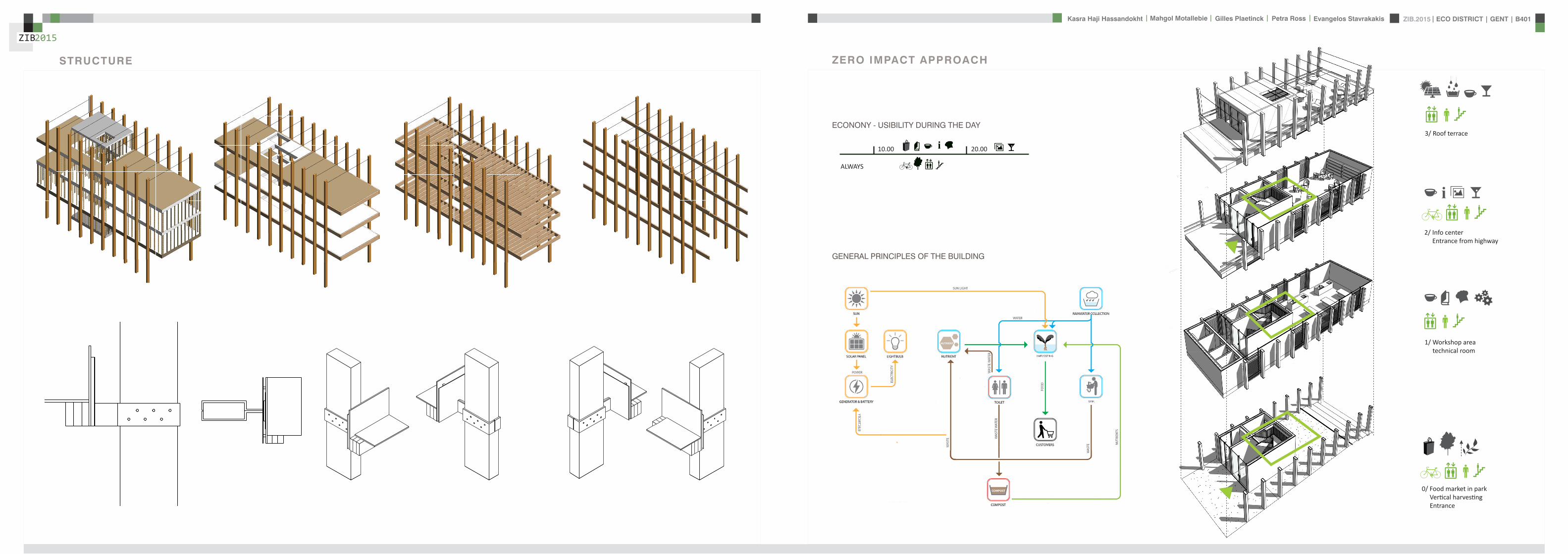
ZIB2015 ECO DISTRICT | GENT | B401Evangelos Stavrakakis | Petra Ross | Mahgol Motallebie | Gilles Plaetinck | Kasra Haji Hassandokht
ZIB2015
|
Vertical Harvest places plants on carousels that keep them moving the length of the greenhouse giving them equal time in natural light and also al-lowing workers to pick and tand transfer the crops Using hydroponics Verti-cal Harvest will be capa-ble of producing over
Vertical Harvest places plants on carousels that keep them moving the length of the pulls giving them equal time in natu-ral light and also allowing workers and local people to pick and transfer the crops Using hydroponics Vertical Harvest will be capable of producing over greens and herbs
VERTICAL HARVESTING
PLANT CABLE LIFT (PLC) SECTION
Sustainable Food zorkshop centerrsquos mission is to ldquocultivate a healthy community by strengthening the local food system and improving access to nu-tritious affordable foodrdquo The main goal of our design is to deliver skills and information for sus-tainability practioners in the organic food tradeThe program attempts to1) affect positive changes in shopping cooking eating habits and nutrition2) reduce diet-related diseases3) promote the health and development of young children 4) place emphasis on local seasonal and cultural-ly-appropriate foods5) integrate food systems concepts into its curric-ulumndash such as shopping at farmers markets and growing onersquos own food
Healthy food is a basic human right the ability to access healthy food is often related to multiple issues and not just a result of low income
FOOD TEAM = a group of people from the same neighbourhood who work for the direct purchase of regional and seasonal products They order food on internet via web page voedselteambe and it is then delivered once a week to the depot of a team
+ minimal transport requirements+ no returnable packaging+ fair p+ fair pricing+ high-quality local and seasonal food+ community initiative
Sustainable Food zorkshop centerrsquos mission is to ldquocultivate a healthy community by strengthening the local food system and improving access to nu-tritious affordable foodrdquo The main goal of our design is to deliver skills and information for sus-tainability practioners in the organic food tradeThe program attempts to1) affect positive changes in shopping cooking eating habits and nutrition2) reduce diet-related diseases3) promote the health and development of young children 4) place emphasis on local seasonal and cultural-ly-appropriate foods5) integrate food systems concepts into its curric-ulumndash such as shopping at farmers markets and growing onersquos own food
Healthy food is a basic human right the ability to access healthy food is often related to multiple issues and not just a result of low income
FOOD TEAM = a group of people from the same neighbourhood who work for the direct purchase of regional and seasonal products They order food on internet via web page voedselteambe and it is then delivered once a week to the depot of a team
+ minimal transport requirements+ no returnable packaging+ fair p+ fair pricing+ high-quality local and seasonal food+ community initiative
Sustainable Food zorkshop centerrsquos mission is to ldquocultivate a healthy community by strengthening the local food system and improving access to nu-tritious affordable foodrdquo The main goal of our design is to deliver skills and information for sus-tainability practioners in the organic food tradeThe program attempts to1) affect positive changes in shopping cooking eating habits and nutrition2) reduce diet-related diseases3) promote the health and development of young children 4) place emphasis on local seasonal and cultural-ly-appropriate foods5) integrate food systems concepts into its curric-ulumndash such as shopping at farmers markets and growing onersquos own food
Healthy food is a basic human right the ability to access healthy food is often related to multiple issues and not just a result of low income
FOOD TEAM = a group of people from the same neighbourhood who work for the direct purchase of regional and seasonal products They order food on internet via web page voedselteambe and it is then delivered once a week to the depot of a team
+ minimal transport requirements+ no returnable packaging+ fair p+ fair pricing+ high-quality local and seasonal food+ community initiative
Healthy food is a basic human right the ability to access healthy food is often related to multiple issues and not just a result of low income
Sustainable Food zorkshop centerrsquos mission is to ldquocultivate a healthy community by strengthening the local food system and improving access to nutritious affordable foodrdquo The main goal of our design is to deliver skills and information for sustainability practioners in the organic food tradeThe program attempts to
1) affect positive changes in shopping cookingeating habits and nutrition2) reduce diet-related diseases3) promote the health and development of youngchildren4) place emphasis on local seasonal and culturally-appropriate foods5) integrate food systems concepts into its curriculumndashsuch as shopping at farmers markets andgrowing onersquos own food
FOOD TEAM = a group of people from the same neighbourhood who work for the direct purchase of regional and seasonal products They order food on internet via web page voedselteambe and it is then delivered once a week to the depot of a team
+ minimal transport requirements+ no returnable packaging+ fair pricing+ high-quality local and seasonal food+ community initiative
WORKSHOP
ZIB2015 ECO DISTRICT | GENT | B401Evangelos Stavrakakis | Petra Ross | Mahgol Motallebie | Gilles Plaetinck | Kasra Haji Hassandokht
ZIB2015
|
Black coral pea
Factors should be considered when seleccng plants
- Quality of growth- Ability to adapt to the wall environment- Environmental Tolerances- Temperature Resistance- Drought Tolerance- Wind - Wind Tolerance- Solar Exposure Tolerance- Salt Tolerance in Seaside installacons- Air and Water Pollucon Tolerance- Pest and Disease Resistance- Arcficial Environment Tolerance- Transplantacon Tolerance- Pruning - Pruning Tolerance
- Ornamental Qualices- Design Purpose- Manageability Maintainability- Environmental and Societal Effects- Visual Effect- Feeling Effect
Blac
k co
ral p
eaSn
ake
vine
kidn
ey w
eed
purple coral peaBasil
Pandorea
Black coral pea
Factors should be considered when seleccng plants
- Quality of growth- Ability to adapt to the wall environment- Environmental Tolerances- Temperature Resistance- Drought Tolerance- Wind - Wind Tolerance- Solar Exposure Tolerance- Salt Tolerance in Seaside installacons- Air and Water Pollucon Tolerance- Pest and Disease Resistance- Arcficial Environment Tolerance- Transplantacon Tolerance- Pruning - Pruning Tolerance
- Ornamental Qualices- Design Purpose- Manageability Maintainability- Environmental and Societal Effects- Visual Effect- Feeling Effect
Blac
k co
ral p
eaSn
ake
vine
kidn
ey w
eed
purple coral peaBasil
Pandorea
Black coral pea
Factors should be considered when seleccng plants
- Quality of growth- Ability to adapt to the wall environment- Environmental Tolerances- Temperature Resistance- Drought Tolerance- Wind - Wind Tolerance- Solar Exposure Tolerance- Salt Tolerance in Seaside installacons- Air and Water Pollucon Tolerance- Pest and Disease Resistance- Arcficial Environment Tolerance- Transplantacon Tolerance- Pruning - Pruning Tolerance
- Ornamental Qualices- Design Purpose- Manageability Maintainability- Environmental and Societal Effects- Visual Effect- Feeling Effect
Blac
k co
ral p
eaSn
ake
vine
kidn
ey w
eed
purple coral peaBasil
Pandorea
GREEN WALLS
ZIB2015 ECO DISTRICT | GENT | B401Evangelos Stavrakakis | Petra Ross | Mahgol Motallebie | Gilles Plaetinck | Kasra Haji Hassandokht
ZIB2015
|
Extraction of air
Pulsion of airRecuperation unit
outdoor space
18 degC15 degC
18 degC
In-take Out-take of air
VENTILATION
Gilles Plaetinck
schaal 1 100
ZIB BUILDINGEnter address here
3 _ level 2
Owner
begeleider Checker
DN
Gilles Plaetinck
schaal 1 100
ZIB BUILDINGEnter address here
2 _ level 1
Owner
begeleider Checker
Extraction of air
Pulsion of air
VENTILATION IN GROUPLANS CALCULATION AND SYSTEM
level 01
level 02
T 42ECO DISTRICT | GENT | B401
ZIB2015Mechanical Ventilation with Heat Recovery (MVHR)
Up to 95 of the heat can be recovered The Heat Recovery Unit runs continu-ously on trickle and can and is boosted when higher rates of ventilation are required eg bathing cooking In warmer months a summer by-pass function helps ensure comfort levels are maintained in the home When summer by-pass is activated the dwelling contin-ues to be ventilaated and recieve fresh filtered air however the heat recovery process is intermittently switched off (heat recovery is by-passed)
Key BenefitsYear round removal of condensation and indoor pol-lutants A direct impact on the Dwelling Emission Rate re-quired in SAP helping reduce the carbon footprint of the property Fresh filtered air supplied to dwelling ideal for allergy sufferers and those with conditions such as asthma A balanced ventilation system for the whole house and recovering of heat that would have otherwise have been lost Low noise non-intrusive ventilation system ndash located away from the room however consideration should be given to duct runs to ensure cross-talk contamination doesnrsquot happen AND the unit is sized correctly so it is not running a high rate all of the time
Zehnder ComfoSystems Passive Haus accredited product suitable for large houses up to 300m2 Designed to ensure low noise excellent energy performance and heat exchange efficiency Choice of control options including LCD touch screen display Can be combine with ComfoCool for optional cooling of up to 5 degrees and humidity reduction by 20
Semi Rigid Ducting
With a manifold system the resistance caused by duct-ing is reduced therefore Semi-Rigid ducting resistance is very low The manifold takes mass airflow directly from the MVHR Heat Recovery Unit and allows lower rates to pass through to each individual room runDirecting mass flow to the manifold eliminates the need to increase the running speed of the MVHR Heat Re-covery unit to overcome the resistance of ducting which in turn causes noise for the homeowner
T 42ECO DISTRICT | GENT | B401
ZIB2015Mechanical Ventilation with Heat Recovery (MVHR)
Up to 95 of the heat can be recovered The Heat Recovery Unit runs continu-ously on trickle and can and is boosted when higher rates of ventilation are required eg bathing cooking In warmer months a summer by-pass function helps ensure comfort levels are maintained in the home When summer by-pass is activated the dwelling contin-ues to be ventilaated and recieve fresh filtered air however the heat recovery process is intermittently switched off (heat recovery is by-passed)
Key BenefitsYear round removal of condensation and indoor pol-lutants A direct impact on the Dwelling Emission Rate re-quired in SAP helping reduce the carbon footprint of the property Fresh filtered air supplied to dwelling ideal for allergy sufferers and those with conditions such as asthma A balanced ventilation system for the whole house and recovering of heat that would have otherwise have been lost Low noise non-intrusive ventilation system ndash located away from the room however consideration should be given to duct runs to ensure cross-talk contamination doesnrsquot happen AND the unit is sized correctly so it is not running a high rate all of the time
Zehnder ComfoSystems Passive Haus accredited product suitable for large houses up to 300m2 Designed to ensure low noise excellent energy performance and heat exchange efficiency Choice of control options including LCD touch screen display Can be combine with ComfoCool for optional cooling of up to 5 degrees and humidity reduction by 20
Semi Rigid Ducting
With a manifold system the resistance caused by duct-ing is reduced therefore Semi-Rigid ducting resistance is very low The manifold takes mass airflow directly from the MVHR Heat Recovery Unit and allows lower rates to pass through to each individual room runDirecting mass flow to the manifold eliminates the need to increase the running speed of the MVHR Heat Re-covery unit to overcome the resistance of ducting which in turn causes noise for the homeowner
MECHANICAL VENTILATION WITH HEAT RECOVERY (MVHR)
Up to 95 of the heat can be recoveredThe Heat Recovery Unit runs continuously on trickle and can and is boosted when higher rates of ventilation are required eg bathing cooking
In warmer months a summer by-pass function helps ensure comfort levels are maintained in the home When summer by-pass is activated the dwelling continues to be ventilaated and recieve fresh filtered air however the heat recovery process is intermittently switched off (heat recovery is by-passed)
EXTRACT VENTILATION RATES
T 42ECO DISTRICT | GENT | B401
ZIB2015Mechanical Ventilation with Heat Recovery (MVHR)
Up to 95 of the heat can be recovered The Heat Recovery Unit runs continu-ously on trickle and can and is boosted when higher rates of ventilation are required eg bathing cooking In warmer months a summer by-pass function helps ensure comfort levels are maintained in the home When summer by-pass is activated the dwelling contin-ues to be ventilaated and recieve fresh filtered air however the heat recovery process is intermittently switched off (heat recovery is by-passed)
Key BenefitsYear round removal of condensation and indoor pol-lutants A direct impact on the Dwelling Emission Rate re-quired in SAP helping reduce the carbon footprint of the property Fresh filtered air supplied to dwelling ideal for allergy sufferers and those with conditions such as asthma A balanced ventilation system for the whole house and recovering of heat that would have otherwise have been lost Low noise non-intrusive ventilation system ndash located away from the room however consideration should be given to duct runs to ensure cross-talk contamination doesnrsquot happen AND the unit is sized correctly so it is not running a high rate all of the time
Zehnder ComfoSystems Passive Haus accredited product suitable for large houses up to 300m2 Designed to ensure low noise excellent energy performance and heat exchange efficiency Choice of control options including LCD touch screen display Can be combine with ComfoCool for optional cooling of up to 5 degrees and humidity reduction by 20
Semi Rigid Ducting
With a manifold system the resistance caused by duct-ing is reduced therefore Semi-Rigid ducting resistance is very low The manifold takes mass airflow directly from the MVHR Heat Recovery Unit and allows lower rates to pass through to each individual room runDirecting mass flow to the manifold eliminates the need to increase the running speed of the MVHR Heat Re-covery unit to overcome the resistance of ducting which in turn causes noise for the homeowner
T 42ECO DISTRICT | GENT | B401
ZIB2015Mechanical Ventilation with Heat Recovery (MVHR)
Up to 95 of the heat can be recovered The Heat Recovery Unit runs continu-ously on trickle and can and is boosted when higher rates of ventilation are required eg bathing cooking In warmer months a summer by-pass function helps ensure comfort levels are maintained in the home When summer by-pass is activated the dwelling contin-ues to be ventilaated and recieve fresh filtered air however the heat recovery process is intermittently switched off (heat recovery is by-passed)
Key BenefitsYear round removal of condensation and indoor pol-lutants A direct impact on the Dwelling Emission Rate re-quired in SAP helping reduce the carbon footprint of the property Fresh filtered air supplied to dwelling ideal for allergy sufferers and those with conditions such as asthma A balanced ventilation system for the whole house and recovering of heat that would have otherwise have been lost Low noise non-intrusive ventilation system ndash located away from the room however consideration should be given to duct runs to ensure cross-talk contamination doesnrsquot happen AND the unit is sized correctly so it is not running a high rate all of the time
Zehnder ComfoSystems Passive Haus accredited product suitable for large houses up to 300m2 Designed to ensure low noise excellent energy performance and heat exchange efficiency Choice of control options including LCD touch screen display Can be combine with ComfoCool for optional cooling of up to 5 degrees and humidity reduction by 20
Semi Rigid Ducting
With a manifold system the resistance caused by duct-ing is reduced therefore Semi-Rigid ducting resistance is very low The manifold takes mass airflow directly from the MVHR Heat Recovery Unit and allows lower rates to pass through to each individual room runDirecting mass flow to the manifold eliminates the need to increase the running speed of the MVHR Heat Re-covery unit to overcome the resistance of ducting which in turn causes noise for the homeowner
Heating 10 kwh msup2aCooling 4 kWh msup2aOverheating 42
ZIB2015 ECO DISTRICT | GENT | B401Evangelos Stavrakakis | Petra Ross | Mahgol Motallebie | Gilles Plaetinck | Kasra Haji Hassandokht
ZIB2015
|
Shutters control system+ -
Solar roadways - PV panels
LED lights
Elevator Fuse box
ElectricityBattery withtransformator
ELECTRICITY
Summer night
cross- ventilation through building
Summer day
air through recuperation unit small change of temperature
15 degC 18 degC
+ groundplans
heated zone
not heated zone
ZONING ACCORDING TO TEMPERATURESSUMMER NIGHT - cross-ventilation through building
SUMMER DAY - air through recuperation unit small change of temperatureSHADING SYSTEM
As a shading was chozen system Renson Icarus Lamellas with angle 45deg made in wood
ZIB2015 ECO DISTRICT | GENT | B401Evangelos Stavrakakis | Petra Ross | Mahgol Motallebie | Gilles Plaetinck | Kasra Haji Hassandokht
ZIB2015
|
average only 4 hours of peak daylight hours per day (4 x 365 = 1460 hours per year)
- Surface area ( first part) Fly-over +- 20 000 msup2-gt 16 000 x 230 Watt = 3 680 000 Watt or 3680 kWonly 50 of fly-over covered with solar roadways
-gt 3680 kW x 4 h = 7360 kWh day-gt 3680 kW x 1460 h = 2 686 400 kWh year -gt +- 540 households (+- 5000 kWh year)
Tesla Powerwall Therersquos a 10 kWh unit at $3500 -gt 737 Tesla Batteries
gt the Solar Roadway has the ability to cut greenhouse gases by up to 75-percentgt A decentralized self-healing secure power grid
IN FRONT OF FLY-OVER
- Surface area Fly-over = 16 x 30 m = 480 msup2-gt 384 x 230 Watt = 88 320 Watt or 883 kWonly 50 of fly-over covered with solar roadways
-gt 44 kW x 4 h = 176 kWh day-gt 44 kW x 1460 h = 64 240 kWh year -gt +- 13 households (+- 5000 kWh year)
lightsshutters
elevator
2 fridges
2 coffeemakers
1 microwave
1 owen
2 cooking plates
stereo
ventilation unit
electricity transformer (AC to DC) for PV panels + batteries
summer 05 kWh daywinter 03 kWh day183 days x 05= 915 kWh182 days x 03 = 546 kWh = 1641 kWh
262 kWh
A++fridge 104 kWhyear104 x x2 = 208 kWh
900 W x 01 hours day = 09 kWhx 220 days x 2= 198 kWh a
67 kWh a
085x100 days= 85 kWh a
400 kWh x 2 = 800 kWh a
150 kWh a 419 kWha
68 kWh a
ENERGY DEMAND OVERVIEW ENERGY SUPPLY OVERVIEW - FLY-OVER
1 spot 56 W 10000 = 0056 KW4 hours per day 365 days a year = 1460 h0056 x 1460 = 8176 kWh10 spots x 8176= 8176 kWh a
1 spot 72 W 10000 = 0072 KW4 hours per day 365 days a year = 1460 h0072 x 1460 = 10512 kWh5 spots x 10512= 5256 kWh a
1 spot 52 W 10000 = 0052 KW4 hours per day 365 days a year = 1460 h0052 x 1460 = 7592 kWh21 spots x 7592= 159432 kWh a
1 spot 9 W 10000 = 0009 KW4 hours per day 365 days a year = 1460 h0009 x 1460 = 1314 kWh5 spots x 1314 = 657 kWh a
SOLAR ROADWAYS - PV PANELSEnergy from the sun
1 To generate energy for the ZIB building2 To generate energy for the surrounding houses3 To generate energy for lighting or signs on the road4 The panels will also have the capacity to charge electric vehicles while parked
ELECTRICITY SCHEME
5423 kWh a
ZIB2015 ECO DISTRICT | GENT | B401Evangelos Stavrakakis | Petra Ross | Mahgol Motallebie | Gilles Plaetinck | Kasra Haji Hassandokht
ZIB2015
|
SUMMER SUNNY 10-42 LUXWINTER SUNNY 10-42 LUX
DAYLIGHT - DIALuxLIGHTING SYSTEM - DIALux
Workplane 9 Results overview
Height of working plane 0800 m Wall zone 0000 m
Result Mean (target) Min Max Minaverage MinmaxPerpendicular illuminance [lx] 463 (500) 105 689 0227 0152
Profile Offices Writing typewriting reading data processing
B401-Gent 6222015
Site 1 Building 2 Zib Room 9 Workplane 9 Results overview
Page 70
Workplane 9 False coloursPerpendicular illuminance (adaptive)
Scale 1 200
Perpendicular illuminance (Surface)Mean (actual) 463 lx Min 105 lx Max 689 lx Minaverage 0227 Minmax 0152
B401-Gent 6222015
Site 1 Building 2 Zib Room 9 Workplane 9 False coloursPerpendicular illuminance (adaptive)
Page 72
Workplane 9 Value chartPerpendicular illuminance (adaptive)
Scale 1 200
Perpendicular illuminance (Surface)Mean (actual) 463 lx Min 105 lx Max 689 lx Minaverage 0227 Minmax 0152
B401-Gent 6222015
Site 1 Building 2 Zib Room 9 Workplane 9 Value chartPerpendicular illuminance (adaptive)
Page 73
Workplane 13 Results overview
Height of working plane 0800 m Wall zone 0000 m
Result Mean (target) Min Max Minaverage MinmaxPerpendicular illuminance [lx] 388 (500) 69 732 0178 0094
Profile Offices Writing typewriting reading data processing
B401-Gent 6222015
Site 1 Building 6 Storey 1 Room 13 Workplane 13 Results overview
Page 94
Workplane 13 False coloursPerpendicular illuminance (adaptive)
Scale 1 100
Perpendicular illuminance (Surface)Mean (actual) 388 lx Min 69 lx Max 732 lx Minaverage 0178 Minmax 0094
B401-Gent 6222015
Site 1 Building 6 Storey 1 Room 13 Workplane 13 False coloursPerpendicular illuminance (adaptive)
Page 96
Workplane 13 Value chartPerpendicular illuminance (adaptive)
Scale 1 100
Perpendicular illuminance (Surface)Mean (actual) 388 lx Min 69 lx Max 732 lx Minaverage 0178 Minmax 0094
B401-Gent 6222015
Site 1 Building 6 Storey 1 Room 13 Workplane 13 Value chartPerpendicular illuminance (adaptive)
Page 97
Workplane 9 False coloursPerpendicular illuminance (adaptive)
Scale 1 200
Perpendicular illuminance (Surface)Mean (actual) 463 lx Min 105 lx Max 689 lx Minaverage 0227 Minmax 0152
B401-Gent 6222015
Site 1 Building 2 Zib Room 9 Workplane 9 False coloursPerpendicular illuminance (adaptive)
Page 72
1st f loor 2nd f loor Site 1 Luminaire parts listQuantity Luminaire (Luminous emittance)10 3F Filippi 12736 P 202x24W LED OP 196x1231
Luminous emittance 1Fitting 1x24W 2xLEDLight output ratio 100Lamp luminous flux 5332 lmLuminaire Luminous Flux 5332 lmPower 560 WLight yield 952 lmW
200
300
400
cdklm η = 100C0 - C180 C90 - C270
0deg 15deg 30deg
45deg
60deg
75deg
90deg
105deg105deg
90deg
75deg
60deg
45deg
30deg 15deg 0deg
5 SFN Eclairages 0732360X CLFV 236Luminous emittance 1Fitting 2xT26 36W840Light output ratio 6889Lamp luminous flux 6700 lmLuminaire Luminous Flux 4615 lmPower 720 WLight yield 641 lmW
160
240
cdklm η = 69C0 - C180 C90 - C270
0deg 15deg 30deg
45deg
60deg
75deg
90deg
105deg105deg
90deg
75deg
60deg
45deg
30deg 15deg 0deg
21 SFN Eclairages 332226XX SAM F 2x26W BELuminous emittance 1Fitting 2xTC-DEL 26W840Light output ratio 3297Lamp luminous flux 3600 lmLuminaire Luminous Flux 1187 lmPower 520 WLight yield 228 lmW
40
60
80
100
120
140
cdklm η = 33C0 - C180 C90 - C270
0deg 15deg 30deg
45deg
60deg
75deg
90deg
105deg105deg
90deg
75deg
60deg
45deg
30deg 15deg 0deg
1 Signcomplex AR111-009-AW-W-06 AR111 COB 9W38deg WhiteLuminous emittance 1Fitting 1xAR111-009-AW-W-06Light output ratio 8078Lamp luminous flux 600 lmLuminaire Luminous Flux 485 lmPower 90 WLight yield 539 lmW
800
1200
cdklm η = 81C0 - C180 C90 - C270
0deg 15deg 30deg
45deg
60deg
75deg
90deg
105deg105deg
90deg
75deg
60deg
45deg
30deg 15deg 0deg
Total lamp luminous flux 163020 lm Total luminaire luminous flux 101807 lm Total Load 20210 W Light yield 504 lmW
B401-Gent 6222015
Site 1 Luminaire parts list
Page 19
10x
6x
21x
1x
types of l ights
Perpendicular i l luminance (Surface)Mean (actual ) 463 lx Min 105 lx Max 689 lx Minaverage 0 227 Minmax 0 152
Perpendicular i l luminance (Surface)Mean (actual ) 388 lx Min 69 lx Max 732 lx Minaverage 0 178 Minmax 0 094
ZIB2015 ECO DISTRICT | GENT | B401Evangelos Stavrakakis | Petra Ross | Mahgol Motallebie | Gilles Plaetinck | Kasra Haji Hassandokht
ZIB2015
|
Tube hybrid Solar panels
Hot water tank Water taps
City water supply
Rain water collection for vertical harvesting
City water supply
WADI
Rain water tank
WATER MANAGEMENT
Sinks
Available roof area
In Ghent avarage of 900mmm2year
3197 m2
09x 3197 = 28773 m3year
RAIN WATER GAIN
toilet - 3x - 03lskitchen -4x - 02ls
POTABLE WATER DEMAND
3 toiletsVertical gardening
Total
relative RW usage
300 l day150 l day = 450lday= 16425 m3 year
1407 lday100m2
RAIN WATER DEMAND
RAIN WATER TANK
Relative RWT volumeRain water tank volume
3m3 100 m2
9591 l gt 10 m3
DIMESION OF PIPES
City water supplyRainwater tank
178 mm (DN 18 - 15 - 12)165 mm (DN 17-15)
are composed of hexagonal tiles Rainwater can infiltrate between the gaps from where it goes to rainwatter collector which supplies the vegetation on fly-over
THE SOLAR ROADWAYS
WATER SUPPLY SCHEME AND CALCULATION
ZIB2015 ECO DISTRICT | GENT | B401Evangelos Stavrakakis | Petra Ross | Mahgol Motallebie | Gilles Plaetinck | Kasra Haji Hassandokht
ZIB2015
|
WADI
City water supply
Rain water tank
Sinks
Divided sewer systemwithin building
SEWAGE SYSTEM
ToiletToilet sinkKitchen sink
DU = 2 lsDU = 05 lsDU = 08 ls
WATER DRAINAGE OF DEVICES
Frequency of usage at the same time
K 05
DIMESION OF PIPES
Black waterGrey water
110 mm (DU 110)75 mm (DU 75 - 63)
WATER DRAINAGE SCHEME AND CALCULATION
ZIB2015 ECO DISTRICT | GENT | B401Evangelos Stavrakakis | Petra Ross | Mahgol Motallebie | Gilles Plaetinck | Kasra Haji Hassandokht
ZIB2015
|
DN
Gilles Plaetinck
schaal 1 100
ZIB BUILDINGEnter address here
2 _ level 1
Owner
begeleider Checker
Gilles Plaetinck
schaal 1 100
ZIB BUILDINGEnter address here
3 _ level 2
Owner
begeleider Checker
WATER SUPPLY
HOT WATER
WATER DRAINAGE
WATER SUPPLY AND DRAINAGE IN GROUPLANS
level 01
level 02
ENERGY
RAINWATER TANK
HELOPHYTE FILTER
IRRIGATION SYSTEM
BIO-ROTOR
MICRO TURBINE
PHOSPHOR
In this building a closed water system is applied which is based on reusing water in mullple wasRainRain water from the roof will be collected in a storage tank situated on the ground floor This water will be used to flush the toilet and irrigate crops in verlcal harveslng system In case of an overflow the water will be stored in the con-structed wetland near the building The rainwater can be fil-tered through a helophyte filter up to drinking water stan-dard The waste water system includes three types of water yellyellow black and grey waterThe yellow water will be stored for its phosphor while the black water will be purified into grey water This grey water is comparable to the quality of rain water aaer purificalon b means of a bio rotor The remaining residue from the bio rotor together with the organic waste from the harveslng is fermented into biogas that drives a micro turbine in order to produce some addilonal energy
TheThe waste product deriving from this process will be used as compost in verlcal harveslng This efficient yet complex system closes the ullizalon cycle of the building and turns it into an efficient vicious circle that can be considered au arkic
In this building a closed water system is applied which is based on reusing water in multiple was
Rain water from the roof will be collected in a storage tank situated on the ground floor This water will be used to flushthe toilet and irrigate crops in vertical harvesting system In case of an overflow the water will be stored in the constructed wetland near the building The rainwater can be filtered through a helophyte filter up to drinking water standard
The waste water system includes three types of water yellow black and grey water The yellow water will be stored for its phosphor while the black water will be purified into grey water This grey water is comparable to the quality of rain water after purification b means of a bio rotor The remaining residue from the bio rotor together with the organic waste from the harvesting is fermented into biogas that drives a micro turbine in order to produce some additional energy The waste product deriving from this process will be used ascompost in ver1048991cal harves1048991ng This efficient yet complexsystem closes the u1048991liza1048991on cycle of the building and turns itinto an efficient vicious circle that can be considered au arkic
WATER CYCLE
ZIB2015 ECO DISTRICT | GENT | B401Evangelos Stavrakakis | Petra Ross | Mahgol Motallebie | Gilles Plaetinck | Kasra Haji Hassandokht
ZIB2015
|
CALCULATIONS
Passive House verification
Photo or Drawing
Building Workshop + info pointStreet
PostcodeCityCountry
Building Type non-residentialClimate Ukkel
Home Owner(s) Client(s)Street
PostcodeCity
ArchitectStreet
PostcodeCity Calculation electricity Internal heat gains
Mechanical System Building type
StreetPostcodeCity Internal heat gains
Year of Construction 2015 Interior Temperature 200 degC Utilisation pattern
Number of Dwelling Units 1 Internal Heat Gains 20 Wm2 Type of values used Fill in worksheet IHG Non-Dom Enclosed Volume Ve 12442 Planned number of occupants
Number of Occupants 80 8 Design
Specific building demands with reference to the treated floor area use Annual method
Treated floor area 2840 msup2 Requirements Fulfilled Verification Annual method The monthly method should be used for building certification
Space heating Annual heating demand 10 kWh(m2a) 15 kWh(msup2a) yes Specific space heating demand annual method 103 kWh(msup2a)
Heating load 11 Wm2 10 Wmsup2 - Specific space heating demand monthly Method 120 kWh(msup2a)
Space cooling Overall specific space cooling demand kWh(m2a) 15 kWh(msup2a)
Cooling load Wm2 - -Frequency of overheating (gt 25 degC) - -
Primary Energy Space heating and dehumidification
cooling household electricity 73 kWh(m2a) 120 kWh(msup2a) yes
DHW space heating and auxiliary electricity 24 kWh(m2a) - -Specific primary energy reduction through solar electricity 21 kWh(m2a) - -
Airtightness Pressurization test result n50 06 1h 06 1h yes
PHPP Verification FINAL ZIB FILE CALCULTIONS PHPPxls
L B H VOLUME
main 1 226 7 4 6328main 2 184 7 35 4508
core 0 6 2 5 3 5 108 5core 0 62 5 35 1085core 3 62 3 28 521
12442
AREAmain 1 storage 35
wc big 35wc 2wc 2workshop 103
MAIN 2 infolounge 92
staircase 56storage technical 22
284
Floor_exterior 1582 31 1272
Roof_exterior 1582
Passive House verification
Photo or Drawing
Building Workshop + info pointStreet
PostcodeCityCountry
Building Type non-residentialClimate Ukkel
Home Owner(s) Client(s)Street
PostcodeCity
ArchitectStreet
PostcodeCity Calculation electricity Internal heat gains
Mechanical System Building type
StreetPostcodeCity Internal heat gains
Year of Construction 2015 Interior Temperature 200 degC Utilisation pattern
Number of Dwelling Units 1 Internal Heat Gains 20 Wm2 Type of values used Fill in worksheet IHG Non-Dom Enclosed Volume Ve 12442 Planned number of occupants
Number of Occupants 80 8 Design
Specific building demands with reference to the treated floor area use Annual method
Treated floor area 2840 msup2 Requirements Fulfilled Verification Annual method The monthly method should be used for building certification
Space heating Annual heating demand 10 kWh(m2a) 15 kWh(msup2a) yes Specific space heating demand annual method 103 kWh(msup2a)
Heating load 11 Wm2 10 Wmsup2 - Specific space heating demand monthly Method 120 kWh(msup2a)
Space cooling Overall specific space cooling demand kWh(m2a) 15 kWh(msup2a)
Cooling load Wm2 - -Frequency of overheating (gt 25 degC) - -
Primary Energy Space heating and dehumidification
cooling household electricity 73 kWh(m2a) 120 kWh(msup2a) yes
DHW space heating and auxiliary electricity 24 kWh(m2a) - -Specific primary energy reduction through solar electricity 21 kWh(m2a) - -
Airtightness Pressurization test result n50 06 1h 06 1h yes
PHPP Verification FINAL ZIB FILE CALCULTIONS PHPPxls
SURFACE AREAcurrent orientation only night ventilation
current orientation only night ventilation 6 windows less 52 msup2
current orientation only night ventilation 7 windows less 60msup2 (stays the same for each side)
current orientation only night ventilation 8 windows less 69 msup2
orientation turned 90deg only night ventilation 6 windows less 52 msup2
orientation turned 90deg only night ventilation 7 windows less 60msup2 (window less at SE side)
orientation turned 90deg only night ventilation 8 windows less 69 msup2
-gt orientation turned 90deg only night ventilation 9 windows less 77msup2 (window less at NW side althought theres less overheating in the case of a window less at SE side the heating demand exceeds 15)
CHANGE IN DESIGN
ZIB2015 ECO DISTRICT | GENT | B401Evangelos Stavrakakis | Petra Ross | Mahgol Motallebie | Gilles Plaetinck | Kasra Haji Hassandokht
ZIB2015
|
Passive House verificationS P E C I F I C A N N U A L H E A T I N G D E M A N D
Climate Ukkel Interior Temperature 200 degC
Building Workshop + info point Building TypeUse non-residentialTreated Floor Area ATFA 2840 msup2
per msup2Area U-Value Temp Factor ft Gt Treated Data for heating balance diagram
Building Element Temperature Zone msup2 W(msup2K) kKha kWha Floor Area Losses GainsExterior Wall - Ambient A 5595 0101 100 743 = 4181 1472 Exterior Wall - Ambient 147234373Exterior Wall - Ground B 069 = Exterior Wall - GroundRoofCeiling - Ambient A 1550 0094 100 743 = 1085 382 RoofCeiling - Ambient 381903529Floor slab basement ceiling B 310 0105 069 743 = 167 059 Floor slab basement ceiling 058811509
A 100 =A 100 =
unheated basement X 075 = unheated basementWindows A 1154 0648 100 743 = 5562 1958 Windows 195834732Exterior Door A 100 = Exterior DoorExterior TB (lengthm) A 1169 -0030 100 743 = -259 -091 Thermal Bridge Heat LossPerimeter TB (lengthm) P 069 = 000 not useful heat gains 365267499Ground TB (lengthm) B 069 =
Total of All Building Envelope Areas 8609 ndashndashndashndashndashndashndashndashndashndashndashndashndash- kWh(msup2a) Ventilation 395818713
Transmission Heat Losses QT Total 10736 378Annual Heating Demand 102516636
ATFA Clear Room Height internal gains 100951487msup2 m msup3 passive solar gains 250668423
Ventilation System Effective Air Volume VV 2840 280 = 7952 Thermal bridge credit 091126837Effective Heat Recovery Efficiency eff 81 Cross check sum 46324923 46324923of Heat Recovery
Efficiency of Subsoil Heat Exchanger SHX 0 nVsystem HR nVRes
1h 1h 1h
Energetically Effective Air Exchange nV 0105 (1 - 081 ) + 0038 = 0058
VV nV cAir Gt
msup3 1h Wh(msup3K) kKha kWha kWh(msup2a)
Ventilation Heat Losses QV 795 0058 033 743 = 1124 40
Reduction Factor QT QV NightWeekend
kWha kWha Saving kWha kWh(msup2a)
Total Heat Losses QL ( 10736 + 1124 ) 10 = 11860 418
Orientation Reduction Factor g-Value Area Radiation HPof the Area See Windows Sheet (perp radiation)
msup2 kWh(msup2a) kWha
1 North 054 050 2700 163 = 11822 East 058 000 440 197 = 03 South 056 050 4860 314 = 42874 West 032 050 3216 254 = 13275 Horizontal 063 050 324 317 = 323
kWh(msup2a)
Available Solar Heat Gains QS Total 7119 251
Length Heat Period Spec Power qI ATFA
khd da Wmsup2 msup2 kWha kWh(msup2a)
Internal Heat Gains QI 0024 209 201 2840 = 2867 101
kWha kWh(msup2a)
Free Heat QF QS + QI = 9986 352
Ratio of Free Heat to Losses QF QL = 084
Utilisation Factor Heat Gains G (1 - ( QF QL )5 ) (1 - ( QF QL )
6 ) = 90kWha kWh(msup2a)
Heat Gains QG G QF = 8949 315
kWha kWh(msup2a)
Annual Heating Demand QH QL - QG = 2911 10
kWh(msup2a) (YesNo)
Limiting Value 15 Requirement met yes
00
147
00
3806000000
196
00
40
37
09
103
101
251
0
5
10
15
20
25
30
35
40
45
50
Losses Gains
Hea
t flo
ws
[kW
h(m
sup2a)]
Heating energy balance
passive solar gains
internal gains
Annual Heating Demand
Thermal bridge credit
not useful heat gains
Ventilation
Exterior Door
Windows
unheated basement
Floor slab basement ceiling
RoofCeiling - Ambient
Exterior Wall - Ground
Exterior Wall - Ambient
Thermal Bridge Heat Loss
HPP Annual Heating Demand FINAL ZIB FILE CALCULTIONS PHPPxls
Passive House verification Passive House verificationS P E C I F I C U S E F U L C O O L I N G D E M A N D S P E C I F I C U S E F U L C O O L I N G D E M A N D
M O N T H L Y M E T H O D M O N T H L Y M E T H O D
(This page displays the sums of the monthly method over the cooling period))Climate Ukkel Interior Temperature Summer 25 degC Climate Ukkel Interior Temperature 25 degC
Building Workshop + info point Building TypeUse non-residential Building Workshop + info point Building TypeUse non-residential
Spec Capacity 60 Wh(msup2K) (Enter in Summer worksheet) Treated Floor Area ATFA 2840 msup2 Treated Floor Area ATFA 284 msup2
per msup2Temperature Zone Area U-Value Mon Red Fac Gt Treated Jan Feb Mar Apr May Jun Jul Aug Sep Oct Nov Dec Year
Building Element msup2 W(msup2K) kKha kWha Floor Area Heating Degree Hours - Ex 168 150 144 121 92 73 57 59 82 109 140 160 136 kKh1 Exterior Wall - Ambient A 5595 0101 100 103 = 5782 Heating Degree Hours - G 126 123 135 120 106 83 63 54 58 71 86 109 113 kKh2 Exterior Wall - Ground B 100 = Losses - Exterior 2553 2286 2189 1838 1393 1117 871 904 1245 1660 2123 2432 20612 kWh3 RoofCeiling - Ambient A 1550 0094 100 103 = 1500 Losses - Ground 41 40 44 39 35 27 21 18 19 23 28 36 370 kWh4 Floor slab basement ceil B 310 0105 100 90 = 294 Losses Summer Ventilatio 67 71 244 372 629 720 880 865 658 499 234 126 5366 kWh5 A 100 = Sum Spec Heat Losses 94 84 87 79 72 66 62 63 68 77 84 91 928 kWhmsup26 A 100 = Solar Load North 44 81 141 212 286 298 298 255 178 116 54 35 1998 kWh7 unheated basement X 075 = Solar Load East 0 0 0 0 0 0 0 0 0 0 0 0 0 kWh8 Windows A 1154 0648 100 103 = 7690 Solar Load South 218 315 464 577 681 644 681 658 532 416 242 171 5601 kWh9 Exterior Door A 100 = Solar Load West 79 125 213 303 385 378 370 347 256 177 91 60 2785 kWh
10 Exterior TB (lengthm) A 1169 -0030 100 103 = -358 Solar Load Horiz 11 21 37 57 79 79 80 69 47 30 14 9 533 kWh11 Perimeter TB (lengthm) P 100 = Solar Load Opaque 3 5 9 13 18 19 19 16 11 7 3 2 126 kWh12 Ground TB (lengthm) B 100 = Internal Heat Gains 425 384 425 411 425 411 425 425 411 425 411 425 5001 kWh
ndashndashndashndashndashndashndashndashndashndashndash kWh(msup2a) Sum Spec Loads Solar + 28 33 45 55 66 64 66 62 51 41 29 25 565 kWhmsup2
Transmission Losses QT (Negative Heat Loads) Total 14907 525 Utilisation Factor Losses 29 39 52 69 84 88 82 88 73 53 34 27 58Useful Cooling Energy Dem 0 0 4 30 142 192 417 192 40 4 0 0 1021 kWh
ATFA Clear Room Height Spec Cooling Demand 00 00 00 01 05 07 15 07 01 00 00 00 36 kWhmsup2Effective msup2 m msup3
Air Volume VV 284 280 = 795
Heat Transfer Coef Gt
WK kKha kWha kWh(msup2a)
Exterior 99 103 = 1013 36Ground 00 105 = 0 00
Additional Summer Ventilation
Select X Window Night Ventilation Manual Corresponding Air Change Rate 136 1h
Mechanical Automatically Controlled Ventilation (for window ventilation at 1 K temperature difference indoor - outdoor)
Minimum Acceptable Indoor Temperatu 220 degC
kWha kWh(msup2a)
Heat Losses Summer Ventilation 5172 182
QLext QLground QLsummer
kWha kWha kWha kWha kWh(msup2a)
Ventilation Heat Losses QV 1013 + 0 + 5172 = 6185 218
2
3
4
5
6
7
8
9
10
Spec
ific
loss
es l
oads
l c
oolin
g de
man
d [k
Wh
(msup2 m
onth
)] Spec Cooling Demand Sum Spec Heat Losses Sum Spec Loads Solar + Internal
QT QV
kWha kWha kWha kWh(msup2a)
Total Heat Losses QL 14907 + 6185 = 21092 743
Orientation Reduction Factor g-Value Area Global Radiationof the Area (perp radiation)
msup2 kWh(msup2a) kWha
1 North 031 050 270 462 = 19182 East 061 000 44 578 = 0 Temperature Amplitude Summer 82 K3 South 030 050 486 707 = 52114 West 025 050 322 654 = 2646 Month 1 2 3 4 5 6 7 8 9 10 11 12 Annual Total5 Horizontal 035 050 32 913 = 513 Days 31 28 31 30 31 30 31 31 30 31 30 31 3656 Sum Opaque Areas 121 Ambient Temp 250 270 572 828 1275 1487 1737 1707 1369 1039 568 356 96
kWh(msup2a) North Radiation 106 195 329 494 667 697 712 599 419 275 129 87 471
Available Solar Heat Gains QS Total 10409 367 East Radiation 146 266 452 698 937 940 988 851 574 382 179 123 654
South Radiation 311 440 645 786 912 858 898 885 733 579 341 241 763Length Heat Period Spec Power qI ATFA West Radiation 155 261 471 707 926 926 896 819 580 382 183 116 642
khd da Wmsup2 msup2 kWha kWh(msup2a) Hori Radiation 200 369 662 1021 1398 1410 1418 1234 842 535 243 156 949
Internal Heat Gains QI 0024 303 20 2840 = 4151 146 Tsky -750 -730 -428 -172 275 487 737 707 369 039 -432 -644 -04
Ground Temp 805 676 686 830 1072 1345 1647 1776 1696 1552 1310 1037 121kWha kWh(msup2a)
Sum Heat Loads QF QS + QI = 14560 513
Ratio of Losses to Free Heat Gains QL QF = 145
Utilisation Factor Heat Losses G = 64kWha kWh(msup2a)
Useful Heat Losses QVn G QL = 13539 477
kWha kWh(msup2a)
Useful Cooling Demand QK QF - QVn = 1021 4
kWh(msup2a) (YesNo)
Limiting Value 15 Requirement met yes
0
1
2
Jan Feb Mar Apr May Jun Jul Aug Sep Oct Nov Dec
usef
u
HPP Cooling FINAL ZIB FILE CALCULTIONS PHPPxls
Passive House verificationS P E C I F I C A N N U A L H E A T I N G D E M A N D
Climate Ukkel Interior Temperature 200 degC
Building Workshop + info point Building TypeUse non-residentialTreated Floor Area ATFA 2840 msup2
per msup2Area U-Value Temp Factor ft Gt Treated Data for heating balance diagram
Building Element Temperature Zone msup2 W(msup2K) kKha kWha Floor Area Losses GainsExterior Wall - Ambient A 5595 0101 100 743 = 4181 1472 Exterior Wall - Ambient 147234373Exterior Wall - Ground B 069 = Exterior Wall - GroundRoofCeiling - Ambient A 1550 0094 100 743 = 1085 382 RoofCeiling - Ambient 381903529Floor slab basement ceiling B 310 0105 069 743 = 167 059 Floor slab basement ceiling 058811509
A 100 =A 100 =
unheated basement X 075 = unheated basementWindows A 1154 0648 100 743 = 5562 1958 Windows 195834732Exterior Door A 100 = Exterior DoorExterior TB (lengthm) A 1169 -0030 100 743 = -259 -091 Thermal Bridge Heat LossPerimeter TB (lengthm) P 069 = 000 not useful heat gains 365267499Ground TB (lengthm) B 069 =
Total of All Building Envelope Areas 8609 ndashndashndashndashndashndashndashndashndashndashndashndashndash- kWh(msup2a) Ventilation 395818713
Transmission Heat Losses QT Total 10736 378Annual Heating Demand 102516636
ATFA Clear Room Height internal gains 100951487msup2 m msup3 passive solar gains 250668423
Ventilation System Effective Air Volume VV 2840 280 = 7952 Thermal bridge credit 091126837Effective Heat Recovery Efficiency eff 81 Cross check sum 46324923 46324923of Heat Recovery
Efficiency of Subsoil Heat Exchanger SHX 0 nVsystem HR nVRes
1h 1h 1h
Energetically Effective Air Exchange nV 0105 (1 - 081 ) + 0038 = 0058
VV nV cAir Gt
msup3 1h Wh(msup3K) kKha kWha kWh(msup2a)
Ventilation Heat Losses QV 795 0058 033 743 = 1124 40
Reduction Factor QT QV NightWeekend
kWha kWha Saving kWha kWh(msup2a)
Total Heat Losses QL ( 10736 + 1124 ) 10 = 11860 418
Orientation Reduction Factor g-Value Area Radiation HPof the Area See Windows Sheet (perp radiation)
msup2 kWh(msup2a) kWha
1 North 054 050 2700 163 = 11822 East 058 000 440 197 = 03 South 056 050 4860 314 = 42874 West 032 050 3216 254 = 13275 Horizontal 063 050 324 317 = 323
kWh(msup2a)
Available Solar Heat Gains QS Total 7119 251
Length Heat Period Spec Power qI ATFA
khd da Wmsup2 msup2 kWha kWh(msup2a)
Internal Heat Gains QI 0024 209 201 2840 = 2867 101
kWha kWh(msup2a)
Free Heat QF QS + QI = 9986 352
Ratio of Free Heat to Losses QF QL = 084
Utilisation Factor Heat Gains G (1 - ( QF QL )5 ) (1 - ( QF QL )
6 ) = 90kWha kWh(msup2a)
Heat Gains QG G QF = 8949 315
kWha kWh(msup2a)
Annual Heating Demand QH QL - QG = 2911 10
kWh(msup2a) (YesNo)
Limiting Value 15 Requirement met yes
00
147
00
3806000000
196
00
40
37
09
103
101
251
0
5
10
15
20
25
30
35
40
45
50
Losses Gains
Hea
t flo
ws
[kW
h(m
sup2a)]
Heating energy balance
passive solar gains
internal gains
Annual Heating Demand
Thermal bridge credit
not useful heat gains
Ventilation
Exterior Door
Windows
unheated basement
Floor slab basement ceiling
RoofCeiling - Ambient
Exterior Wall - Ground
Exterior Wall - Ambient
Thermal Bridge Heat Loss
HPP Annual Heating Demand FINAL ZIB FILE CALCULTIONS PHPPxls
factor 05Wd (ls) 088
nominal diameter 75 mmVERTICAL COLLECTOR sink toilets 3 05 15
sink kitchen 2 08 16Total 5 31factor 05
Wd (ls) 088nominal diameter 75 mm
Toevoerend ROOF SURFACE
horizontal roof surface (msup2) orientation coeff angle (deg) roofcover filter coeff toevoerend
444 1 0 08 09 3197
RAIN WATER USAGE
Type usage ( l usage) persons day frequency usageday yearly usage
toilet use small 3 20 3 180 65700toilet use big 6 20 1 120 43800VERTICAL GARDENING 150 54750TOTAL 450 164250 L year
16425 msup3 year
TOTAL RAINWATER USAGE 450 L dayRELATIVE RAINWATER USAGE 1407 L day100msup2
LEEGSTAND
relative rainwater usage 1407 L day 100 msup2LEEGSTAND 7 relative volume rainwater tank 3 msup3 100 msup2rainwater tank volume 9591 Liter
suggestion 50 msup2 02 m= 10 msup3
SUPPLYtype amount debiet Q total total WW
lsec lsec lsecMAIN LEVEL POTABLE
sink toilet 3 01 03 03sink kitchen 2 01 02 02
Total 5 05 05Gelijktijdigheid 05 05debiet Q (lsec) 025 025
diameter 178 178 cm
type amount debiet Q total total WWlsec lsec lsec
MAIN LEVEL RAIN WATER toilet 3 01 03 0
Total 3 03Gelijktijdigheid 071debiet Q (lsec) 0213
diameter 165 cm
FECALIEumlNtype amount value Total (ls)
COLLECTOR HORIZONTAL toilet 3 2Total 6factor 05
Wd (ls) 122nominal diameter 110 mm
type amount value Total (ls)COLLECTOR VERTICAL toilet 3 2
Total 6factor 05
Wd (ls) 122nominal diameter 110 mm
DRAINtype amount value Total (ls)
HORIZONTAL COLLECTOR sink toilets 3 05 15sink kitchen 2 08 16
Total 5 31
WATER
ZIB2015 ECO DISTRICT | GENT | B401Evangelos Stavrakakis | Petra Ross | Mahgol Motallebie | Gilles Plaetinck | Kasra Haji Hassandokht
ZIB2015
|
Passive House verificationS P E C I F I C S P A C E H E A T I N G L O A D Risk Determination of Group Heating for a Critical Room
Building Workshop + info point Building TypeUse non-residential Workshop room ( 1= Yes 0 = No)
Climate (HL) Ukkel Treated Floor Area ATFA 2840 msup2 Interior Temperature 20 degC Building Satisfies Passive House Criteria 1
Design Temperature Radiation North East South West Horizontal Room floor area 100 msup2 Supply Air per msup2 Living AreaWeather Condition 1 -31 degC 10 10 30 15 20 Wmsup2 Planned ambient air quantity for the room 150 msup3h 150 msup3hmsup2Weather Condition 2 -22 degC 5 5 20 10 10 Wmsup2 Planned ambient air quantities for the remaining rooms -67 msup3hGround Design Temp 68 degC Area U-Value Factor TempDiff 1 TempDiff 2 PT 1 PT 2
Building Element Temperature Zone msup2 W(msup2K) Always 1(except X) K K W W Building Element Temperature Zone msup2 W(msup2K) Always 1
(except X) K Room Trans Loss W
1 Exterior Wall - Ambient A 5595 0101 100 231 or 222 = 1299 or 1249 Aboveground Exterior Wall A 650 010 100 231 = 1512 Exterior Wall - Ground B 100 132 or 132 = or Belowground Exterior Wall B 00 100 132 =3 RoofCeiling - Ambient A 1550 0094 100 231 or 222 = 337 or 324 RoofCeiling D 880 009 100 231 = 1914 Floor slab basement ceiling B 310 0105 100 132 or 132 = 43 or 43 Underground Floor Slab B 00 011 100 132 = 05 A 100 231 or 222 = or A 100 231 =6 A 100 231 or 222 = or A 100 231 =7 unheated basement X 075 231 or 222 = or X 100 231 =8 Windows A 1154 0648 100 231 or 222 = 1728 or 1661 Windows A 480 065 100 231 = 7199 Exterior Door A 100 231 or 222 = or Exterior Door A 100 231 =
10 Exterior TB (lengthm) A 1169 -0030 100 231 or 222 = -80 or -77 Exterior thermal bridges (Lengthm) A 100 231 =11 Perimeter TB (lengthm) P 100 132 or 132 = or Perimeter Thermal Bridges (Lengthm) A 100 231 =12 Ground TB (lengthm) B 100 132 or 132 = or Floor Slab Thermal Bridges (Lengthm) A 50 100 231 =13 HouseDU Partition Wall I 100 30 or 30 = or HouseDU Partition Wall I 200 100 30 =
Transmission Heat Losses PT ndashndashndashndashndashndashndashndashndashndashndashndashndash- ndashndashndashndashndashndashndashndashndashndashndash-
Total = 3328 or 3200 = 1061
ATFA Clear Room HeightVentilation System msup2 m msup3 Risk
Effective Air Volume VV 2840 280 = 795 Enter 1 = Yes 0 = No PTRoom W PSupply Air W Ratio Summand
SHX 1 SHX 2 Transmission Heat Losses 1061 1386 077 -023Efficiency of Heat Recovery HR 81 Heat Recovery Efficiency SHX 0 Efficiency SHX 0 or 0 Concentrated leakages 0 000of the Heat Exchanger Insulation to other rooms better R = 15 msup2KW 1 ( 2 = no thermal contact except door) 050
nVRes (Heating Load) nVsystem HR HR Room is on the ground floor 0 0001h 1h 1h 1h open staircase 0 000
Energetically Effective Air Exchange nV 0094 + 0105 (1- 081 or 081 ) = 0114 or 0114 TOTAL of the Risk Summands 027Ventilation Heating Load PV
VL nL nL cAir TempDiff 1 TempDiff 2 PV 1 PV 2 Interior doors predominantly closed 1 Risk Factor 200msup3 1h 1h Wh(msup3K) K K W W
7952 0114 or 0114 033 231 or 222 = 691 or 664Total Room Risk 89
PL 1 PL 2
Total Heating Load PL W W Appraisal and Advice normally no problemPT + PV = 4019 or 3864
Orientation Area g-Value Reduction Factor Radiation 1 Radiation 2 PS 1 PS 2the Area msup2 (perp radiation) (see Windows worksheet) Wmsup2 Wmsup2 W W
1 North 270 05 05 11 or 6 = 77 or 412 East 44 00 06 8 or 3 = 0 or 03 South 486 05 06 28 or 18 = 378 or 2474 West 322 05 03 19 or 13 = 100 or 685 Horizontal 32 05 06 20 or 10 = 20 or 10
Solar heating power PS Total = 575 or 367
Spec Power ATFA PI 1 PI 2Internal heating power PI Wmsup2 msup2 W W
16 284 = 454 or 454
PG 1 PG 2
Heating power (gains) PG W W
PS + PI = 1029 or 821
PL - PG = 2989 or 3042
Heating Load PH = 3042 W
Specific Heating Load PH ATFA = 107 Wmsup2
Input Max Supply Air Temperature 48 degC degC degC
Max Supply Air Temperature SupplyMax 48 degC Supply Air Temperature Without Heating SupplyMin 156 157
For Comparison Heating Load Transportable by Supply Air PSupply AirMax = 886 W specific 31 Wmsup2
(YesNo)
Supply Air Heating Sufficient No
HPP Heating Load FINAL ZIB FILE CALCULTIONS PHPPxls
Passive House verificationU - V A L U E S O F B U I L D I N G E L E M E N T S
Wedge shaped building element layeBuilding Workshop + info point still air spaces -gt Secondary calculation to th
Assembly No Building assembly description Interior insulation1 Exterior wall x
Heat transfer resistance [msup2KW] interior Rsi 013exterior Rse 004
Area section 1 [W(mK)] Area section 2 (optional) [W(mK)] Area section 3 (optional) [W(mK)] Thickness [mm]
1 hout gevel 0160 17
2 regelwerk hout 0158 30
3 houtvezel celit 4D 0048 18
4 Eurowall 0023 hout FJI beam 0286 140
5 OSB -plaat 0130 15
6 Eurothane G 0023 70
7 Plaster insulating 0100 10
8Percentage of Sec 2 Percentage of Sec 3 Total
26 300
U-Value 0107 W(msup2K)
Assembly No Building assembly description Interior insulation2 Roof x
Heat transfer resistance [msup2KW] interior Rsi 010exterior Rse 004
Area section 1 [W(mK)] Area section 2 (optional) [W(mK)] Area section 3 (optional) [W(mK)] Thickness [mm]Area section 1 [W(mK)] Area section 2 (optional) [W(mK)] Area section 3 (optional) [W(mK)] Thickness [mm]
1 bitumenmembraam 0230 5
23 EPS 0036 70
4 OSB -plaat 0130 18
5 cellulose 0039 hout FJI beam 0286 350
6 OSB -plaat 0130 15
7 regelwerk hout 5 0177 30
8 gipskartonplaat 0290 12
Percentage of Sec 2 Percentage of Sec 3 Total
26 500
U-Value 0094 W(msup2K)
Assembly No Building assembly description Interior insulation3 Floor x
Heat transfer resistance [msup2KW] interior Rsi 017
exterior Rse 004
Area section 1 [W(mK)] Area section 2 (optional) [W(mK)] Area section 3 (optional) [W(mK)] Thickness [mm]
1 PIR dekvloer 0023 5
2 gipskartonplaat 0290 10
3 gespoten pur 0028 100
4 OSB -plaat 0130 15
5 cellulose 0039 hout FJI beam 0286 350
6 houtvezel Celit 4D 0048 15
7 regelwerk hout 6 0149 30
8 afwerking hout 0160 5
Percentage of Sec 2 Percentage of Sec 3 Total
26 530
U-Value 0078 W(msup2K)
PHPP U-Values FINAL ZIB FILE CALCULTIONS PHPPxls
ers and he right
n Secondary Calculation Equivalent Thermal Conductivity of Still Air Spaces
Air Layer Thickness 30 mm Direction of Upwards ha 125 W(msup2K) 016 W(mK)
Heat Flow X Horizontal hr 417 W(msup2K)
(check only one field) Downwards
cm
n
cm
n Secondary Calculation Equivalent Thermal Conductivity of Still Air Spaces
Air Layer Thickness 30 mm
Direction of Upwards ha 08333 W(msup2K) 015 W(mK)Heat Flow Horizontal hr 417 W(msup2K)
(check only one field) X Downwards
cm
PHPP U-Values FINAL ZIB FILE CALCULTIONS PHPPxls
ers and he right
n Secondary Calculation Equivalent Thermal Conductivity of Still Air Spaces
Air Layer Thickness 30 mm Direction of Upwards ha 125 W(msup2K) 016 W(mK)
Heat Flow X Horizontal hr 417 W(msup2K)
(check only one field) Downwards
cm
n
cm
n Secondary Calculation Equivalent Thermal Conductivity of Still Air Spaces
Air Layer Thickness 30 mm
Direction of Upwards ha 08333 W(msup2K) 015 W(mK)Heat Flow Horizontal hr 417 W(msup2K)
(check only one field) X Downwards
cm
PHPP U-Values FINAL ZIB FILE CALCULTIONS PHPPxls
ers and he right
n Secondary Calculation Equivalent Thermal Conductivity of Still Air Spaces
Air Layer Thickness 30 mm Direction of Upwards ha 125 W(msup2K) 016 W(mK)
Heat Flow X Horizontal hr 417 W(msup2K)
(check only one field) Downwards
cm
n
cm
n Secondary Calculation Equivalent Thermal Conductivity of Still Air Spaces
Air Layer Thickness 30 mm
Direction of Upwards ha 08333 W(msup2K) 015 W(mK)Heat Flow Horizontal hr 417 W(msup2K)
(check only one field) X Downwards
cm
PHPP U-Values FINAL ZIB FILE CALCULTIONS PHPPxls
Passive House verificationS U M M E R
Climate Ukkel Interior Temperature 20 degC
Building Workshop + info point Building TypeUse non-residentialTreated Floor Area ATFA 2840 msup2
Spec Capacity 60 WhK pro msup2 TFAOverheating
limit25 degC Area U-Value Red Factor fTSummer HSummer Heat Conductance
Building Element Temperature Zone msup2 W(msup2K)
1 Exterior Wall - Ambien A 5595 0101 100 = 5632 Exterior Wall - Ground B 100 =3 RoofCeiling - Ambient A 1550 0094 100 = 1464 Floor slab basement B 310 0105 100 = 335 A 100 =6 A 100 =7 unheated basement X 075 =8 Windows A 1154 0648 100 = 7489 Exterior Door A 100 =
10 Exterior TB (lengthm) A 1169 -0030 100 = -3511 Perimeter TB (lengthm P 100 =12 Ground TB (lengthm) B 100 =
ndashndashndashndashndashndashndashndashndashndashndashExterior Thermal Transmittance HTe 1422 WK
Ground Thermal Transmittance HTg 33 WK
ATFA Clear Room HeightEffective msup2 m msup3
Heat Recovery Efficiency HR 81 Air Volume VV 2840 280 = 795
SHX Efficiency SHX 0
Summer Ventilation continuous ventilation to provide sufficient indoor air quality
Air Change Rate by Natural (Windows amp Leakages) or Exhaust-Only Mechanical Ventilation Summer 000 1h
Mechanical Ventilation Summer 1h X with HR (check if applicable)
nLnat nVsystem HR nVRest
1h 1h 1h 1h
Energetically Effective Airchange Rate nV 0000 + 0000 (1 - 0808 ) + 0038 = 0038
VV nVequifraction cAir
msup3 1h Wh(msup3K)
Ventilation Transm Ambient HVe 795 0038 033 = 99 WK
Ventilation Transm Ground HVg 795 0000 033 = 00 WK
Additional Summer Ventilation for Cooling Temperature amplitude summer 82 K
Select X Window Night Ventilation Manual Corresponding Air Change Rate 136 1hMechanical Automatically Controlled Ventilation (for window ventilation at 1 K temperature difference indoor - outdoor)
Minimum Acceptable Indoor Temperature 220 degC
Orientation Angle Shading g-Value Area Portion of Glazing Apertureof the Area Factor Factor Dirt (perp radiation)
Summer Summer msup2 msup2
1 North 09 044 095 050 270 82 = 422 East 09 100 095 000 44 71 = 003 South 09 043 095 050 486 82 = 744 West 09 039 095 050 322 76 = 405 Horizontal 09 052 095 050 32 78 = 066 Sum Opaque Areas 03
msup2msup2
Solar Aperture Total 164 006
Specif Power qI ATFA
Wmsup2 msup2 W Wmsup2
Internal Heat Gains QI 201 284 = 571 20
Frequency of Overheating hmax 42 at the overheating limit max = 25 degC
If the frequency over 25degC exceeds 10 additional measures to protect against summer heat waves are necessary
Solar Load Spec Capacity ATFA
kWhd 1k Wh(msup2K) msup2
Daily Temperature Swing due to Solar Load 00 1000 ( 60 284 ) = 00 K
PHPP Summer FINAL ZIB FILE CALCULTIONS PHPPxls
Passive House verification Passive House verificationS P E C I F I C A N N U A L H E A T I N G D E M A N D S P E C I F I C A N N U A L H E A T D E M A N D
M O N T H L Y M E T H O D M O N T H L Y M E T H O D
(This page displays the sums of the monthly method over the heating period)Climate Ukkel Interior Temperature 20 degC Climate Ukkel Interior Temperature 20 degC
Building Workshop + info point Building TypeUse non-residential Building Workshop + info point Building TypeUse non-residentialSpec Capacity 60 Wh(msup2K) (Enter in Summer worksheet) Treated Floor Area ATFA 2840 msup2 Treated Floor Area ATFA 284 msup2
per msup2Temperature Zone Area U-Value Month Red Fac Gt Treated Jan Feb Mar Apr May Jun Jul Aug Sep Oct Nov Dec Year
Building Element msup2 W(msup2K) kKha kWha Floor Area Heating Degree Hours - E 131 117 107 85 54 37 20 22 46 72 104 123 92 kKhExterior Wall - Ambient A 5595 0101 100 78 = 4406 Heating Degree Hours - G 89 89 98 84 69 47 26 17 22 33 50 72 70 kKhExterior Wall - Ground B 100 = Losses - Exterior 2056 1836 1679 1335 856 589 316 350 722 1132 1630 1931 14433 kWhRoofCeiling - Ambient A 1550 0094 100 78 = 1143 Losses - Ground 29 29 32 28 23 15 9 5 7 11 16 23 227 kWhFloor slab basement ceiling B 310 0105 100 54 = 175 Sum Spec Losses 73 66 60 48 31 21 11 13 26 40 58 69 516 kWhmsup2
A 100 = Solar Gains - North 78 142 246 371 500 520 520 445 311 202 94 62 3490 kWhA 100 = Solar Gains - East 0 0 0 0 0 0 0 0 0 0 0 0 0 kWh
unheated basement X 075 = Solar Gains - South 405 583 860 1069 1261 1194 1263 1220 986 771 448 318 10377 kWhWindows A 1154 0648 100 78 = 5861 Solar Gains - West 103 162 275 391 497 489 478 448 331 229 118 77 3597 kWhExterior Door A 100 = Solar Gains - Horiz 20 38 68 104 143 144 145 126 86 55 25 16 968 kWhExterior TB (lengthm) A 1169 -0030 100 78 = -273 Solar Gains - Opaque 3 5 9 13 18 19 19 16 11 7 3 2 126 kWhPerimeter TB (lengthm) P 100 = Internal Heat Gains 425 384 425 411 425 411 425 425 411 425 411 425 5001 kWhGround TB (lengthm) B 100 = Sum Spec Gains Solar + 36 46 66 83 100 98 100 94 75 59 39 32 830 kWhmsup2
ndashndashndashndashndashndashndashndashndashndashndash kWh(msup2a) Utilisation Factor 100 98 84 57 31 22 11 13 34 67 98 100 48Transmission Heat Losses QT Total 11313 398 Annual Heating Demand 1055 580 134 9 0 0 0 0 0 19 564 1057 3419 kWh
Spec Heating Demand 37 20 05 00 00 00 00 00 00 01 20 37 120 kWhmsup2ATFA Clear Room Height
Effective msup2 m msup3
Air Volume VRAX 284 280 = 795
nVsystem SHX HR nVRes nVequifraction
1h 1h 1h
Effective Air Change Rate Ambient nVe 0105 (1- 0 )(1- 081 )+ 0038 = 0058Effective Air Change Rate Ground nVg 0105 0 (1- 081 ) = 0000
VRAX nVequifraction cAir Gt
msup3 1h Wh(msup3K) kKha kWha kWh(msup2a)
Ventilation Losses Ambient QV 795 0058 033 78 = 1185 42
Ventilation Losses Ground QVe 795 0000 033 55 = 0 00ndashndashndashndashndashndashndashndashndashndashndash
Ventilation Heat Losses QV Total 1185 42
Reduction Factor QT QV NightWeekend
kWha kWha Saving kWha kWh(msup2a)
Total Heat Losses QL ( 11313 + 1185 ) 10 = 12497 440
Orientation Reduction Factor g-Value Area Global Radiationof the Area See Windows worksheet (perp radiation)
msup2 kWh(msup2a) kWha
North 054 050 270 208 = 1505East 058 000 44 250 = 0South 056 050 486 398 = 5440West 032 050 322 323 = 1685Horizontal 063 050 32 403 = 411Sum Opaque Areas 55
kWh(msup2a)
Available Solar Heat Gains QS Total 9095 320 Annual Heating Demand Comparison
EN 13790 Monthly Method 3419 kWha 120 kWh(msup2a) Reference to habitable area
Length Heat Period Spec Power qI ATFA PHPP Heating Period Method 2911 kWha 103 kWh(msup2a) Reference to habitable area
khd da Wmsup2 msup2 kWha kWh(msup2a)
Internal Heat Gains QI 0024 242 20 2840 = 3315 117
kWha kWh(msup2a) Month 1 2 3 4 5 6 7 8 9 10 11 12 Annual Total Heating Period Method
Free Heat QF QS + QI = 12411 437 Days 31 28 31 30 31 30 31 31 30 31 30 31 365 209Ambient Temp 250 270 572 828 1275 1487 1737 1707 1369 1039 568 356 96 52
Ratio Free Heat to Losses QF QL = 099 North Radiation 106 195 329 494 667 697 712 599 419 275 129 87 471 163East Radiation 146 266 452 698 937 940 988 851 574 382 179 123 654 197
Utilisation Factor Heat Gains G = 73 South Radiation 311 440 645 786 912 858 898 885 733 579 341 241 763 314kWha kWh(msup2a) West Radiation 155 261 471 707 926 926 896 819 580 382 183 116 642 254
Heat Gains QG G QF = 9078 320 Hori Radiation 200 369 662 1021 1398 1410 1418 1234 842 535 243 156 949 317
Tsky -750 -730 -428 -172 275 487 737 707 369 039 -432 -644 -04kWha kWh(msup2a) Ground Temp 805 676 686 830 1072 1345 1647 1776 1696 1552 1310 1037 121 98
Annual Heating Demand QH QL - QG = 3419 12
kWh(msup2a) (YesNo)
Limiting Value 15 Requirement met yes
0
2
4
6
8
10
12
Jan Feb Mar Apr May Jun Jul Aug Sep Oct Nov Dec
Spec
ific
loss
es g
ains
he
atin
g de
man
d [k
Wh
(msup2 m
onth
)]
Spec Heating Demand Sum Spec Gains Solar + Internal Sum Spec Losses
HPP Monthly Method FINAL ZIB FILE CALCULTIONS PHPPxls
Passive House verification Passive House verificationS P E C I F I C A N N U A L H E A T I N G D E M A N D S P E C I F I C A N N U A L H E A T D E M A N D
M O N T H L Y M E T H O D M O N T H L Y M E T H O D
(This page displays the sums of the monthly method over the heating period)Climate Ukkel Interior Temperature 20 degC Climate Ukkel Interior Temperature 20 degC
Building Workshop + info point Building TypeUse non-residential Building Workshop + info point Building TypeUse non-residentialSpec Capacity 60 Wh(msup2K) (Enter in Summer worksheet) Treated Floor Area ATFA 2840 msup2 Treated Floor Area ATFA 284 msup2
per msup2Temperature Zone Area U-Value Month Red Fac Gt Treated Jan Feb Mar Apr May Jun Jul Aug Sep Oct Nov Dec Year
Building Element msup2 W(msup2K) kKha kWha Floor Area Heating Degree Hours - E 131 117 107 85 54 37 20 22 46 72 104 123 92 kKhExterior Wall - Ambient A 5595 0101 100 78 = 4406 Heating Degree Hours - G 89 89 98 84 69 47 26 17 22 33 50 72 70 kKhExterior Wall - Ground B 100 = Losses - Exterior 2056 1836 1679 1335 856 589 316 350 722 1132 1630 1931 14433 kWhRoofCeiling - Ambient A 1550 0094 100 78 = 1143 Losses - Ground 29 29 32 28 23 15 9 5 7 11 16 23 227 kWhFloor slab basement ceiling B 310 0105 100 54 = 175 Sum Spec Losses 73 66 60 48 31 21 11 13 26 40 58 69 516 kWhmsup2
A 100 = Solar Gains - North 78 142 246 371 500 520 520 445 311 202 94 62 3490 kWhA 100 = Solar Gains - East 0 0 0 0 0 0 0 0 0 0 0 0 0 kWh
unheated basement X 075 = Solar Gains - South 405 583 860 1069 1261 1194 1263 1220 986 771 448 318 10377 kWhWindows A 1154 0648 100 78 = 5861 Solar Gains - West 103 162 275 391 497 489 478 448 331 229 118 77 3597 kWhExterior Door A 100 = Solar Gains - Horiz 20 38 68 104 143 144 145 126 86 55 25 16 968 kWhExterior TB (lengthm) A 1169 -0030 100 78 = -273 Solar Gains - Opaque 3 5 9 13 18 19 19 16 11 7 3 2 126 kWhPerimeter TB (lengthm) P 100 = Internal Heat Gains 425 384 425 411 425 411 425 425 411 425 411 425 5001 kWhGround TB (lengthm) B 100 = Sum Spec Gains Solar + 36 46 66 83 100 98 100 94 75 59 39 32 830 kWhmsup2
ndashndashndashndashndashndashndashndashndashndashndash kWh(msup2a) Utilisation Factor 100 98 84 57 31 22 11 13 34 67 98 100 48Transmission Heat Losses QT Total 11313 398 Annual Heating Demand 1055 580 134 9 0 0 0 0 0 19 564 1057 3419 kWh
Spec Heating Demand 37 20 05 00 00 00 00 00 00 01 20 37 120 kWhmsup2ATFA Clear Room Height
Effective msup2 m msup3
Air Volume VRAX 284 280 = 795
nVsystem SHX HR nVRes nVequifraction
1h 1h 1h
Effective Air Change Rate Ambient nVe 0105 (1- 0 )(1- 081 )+ 0038 = 0058Effective Air Change Rate Ground nVg 0105 0 (1- 081 ) = 0000
VRAX nVequifraction cAir Gt
msup3 1h Wh(msup3K) kKha kWha kWh(msup2a)
Ventilation Losses Ambient QV 795 0058 033 78 = 1185 42
Ventilation Losses Ground QVe 795 0000 033 55 = 0 00ndashndashndashndashndashndashndashndashndashndashndash
Ventilation Heat Losses QV Total 1185 42
Reduction Factor QT QV NightWeekend
kWha kWha Saving kWha kWh(msup2a)
Total Heat Losses QL ( 11313 + 1185 ) 10 = 12497 440
Orientation Reduction Factor g-Value Area Global Radiationof the Area See Windows worksheet (perp radiation)
msup2 kWh(msup2a) kWha
North 054 050 270 208 = 1505East 058 000 44 250 = 0South 056 050 486 398 = 5440West 032 050 322 323 = 1685Horizontal 063 050 32 403 = 411Sum Opaque Areas 55
kWh(msup2a)
Available Solar Heat Gains QS Total 9095 320 Annual Heating Demand Comparison
EN 13790 Monthly Method 3419 kWha 120 kWh(msup2a) Reference to habitable area
Length Heat Period Spec Power qI ATFA PHPP Heating Period Method 2911 kWha 103 kWh(msup2a) Reference to habitable area
khd da Wmsup2 msup2 kWha kWh(msup2a)
Internal Heat Gains QI 0024 242 20 2840 = 3315 117
kWha kWh(msup2a) Month 1 2 3 4 5 6 7 8 9 10 11 12 Annual Total Heating Period Method
Free Heat QF QS + QI = 12411 437 Days 31 28 31 30 31 30 31 31 30 31 30 31 365 209Ambient Temp 250 270 572 828 1275 1487 1737 1707 1369 1039 568 356 96 52
Ratio Free Heat to Losses QF QL = 099 North Radiation 106 195 329 494 667 697 712 599 419 275 129 87 471 163East Radiation 146 266 452 698 937 940 988 851 574 382 179 123 654 197
Utilisation Factor Heat Gains G = 73 South Radiation 311 440 645 786 912 858 898 885 733 579 341 241 763 314kWha kWh(msup2a) West Radiation 155 261 471 707 926 926 896 819 580 382 183 116 642 254
Heat Gains QG G QF = 9078 320 Hori Radiation 200 369 662 1021 1398 1410 1418 1234 842 535 243 156 949 317
Tsky -750 -730 -428 -172 275 487 737 707 369 039 -432 -644 -04kWha kWh(msup2a) Ground Temp 805 676 686 830 1072 1345 1647 1776 1696 1552 1310 1037 121 98
Annual Heating Demand QH QL - QG = 3419 12
kWh(msup2a) (YesNo)
Limiting Value 15 Requirement met yes
0
2
4
6
8
10
12
Jan Feb Mar Apr May Jun Jul Aug Sep Oct Nov Dec
Spec
ific
loss
es g
ains
he
atin
g de
man
d [k
Wh
(msup2 m
onth
)]
Spec Heating Demand Sum Spec Gains Solar + Internal Sum Spec Losses
HPP Monthly Method FINAL ZIB FILE CALCULTIONS PHPPxls
ZIB2015 ECO DISTRICT | GENT | B401Evangelos Stavrakakis | Petra Ross | Mahgol Motallebie | Gilles Plaetinck | Kasra Haji Hassandokht
ZIB2015
|
Passive House verificationV E N T I L A T I O N D A T A
Building Workshop + info point
Treated floor area ATFA msup2 284 (Areas worksheet)
Room height h m 28 (Annual Heating Demand worksheet)
Room ventilation volume (ATFAh) = VV msup3 795 (Annual Heating Demand worksheet)
Type of ventilation systemx Balanced PH ventilation Please Check
Pure extract air
Infiltration air change rate
Wind protection coefficients e and f Several One
Coefficient e for screening class sides sideexposed exposed
No screening 010 003Moderate screening 007 002High screening 004 001Coefficient f 15 20
for Annual Demand for Heating Load
Wind protection coefficient e 004 010Wind protection coefficient f 15 15 Net Air Volume for
Press Test Vn50 Air permeability q50
Air Change Rate at Press Test n50 1h 060 060 1244 msup3 087 msup3(hmsup2)
for Annual Demand for Heating Load
Excess extract air 1h 000 000Infiltration air change rate nVRes 1h 0038 0094
Selection of ventilation data input - ResultsThe PHPP offers two methods for dimensioning the air quantities and choosing the ventilation unit Fresh air or extract air quantities for residential buildings and parameters for ventilation syscan be determined using the standard planning option in the Ventilation sheet The Additional Vent sheet has been created for more complex ventilation systems and allows up to 10 differenFurthermore air quantities can be determined on a room-by-room or zone-by-zone basis Please select your design method here
Extract air Effective heat Specific HeatVentilation unit Heat recovery efficiency design Mean Mean excess recovery power recovery
X Sheet Ventilation (Standard design) (Sheet Ventilation see below) Air exchange Air Change Rate (Extract air system) efficiency Unit input efficiency SHXSheet Extended ventilation (Sheet Additional Vent) msup3h 1h 1h [-] Whmsup3(Multiple ventilation units non-residential buildings) 83 010 000 818 029 00
SHX efficiency SHX 0
PHPP Ventilation FINAL ZIB FILE CALCULTIONS PHPPxls
SHX efficiency SHX 0
PHPP Ventilation FINAL ZIB FILE CALCULTIONS PHPPxls
S T A N D A R D I N P U T F O R B A L A N C E D V E N T I L A T I O NVentilation dimensioning for systems with one ventilation unit
Occupancy msup2P 36Number of occupants P 80Supply air per person msup3(Ph) 30Supply air requirement msup3h 240 BathroomExtract air rooms Kitchen Bathroom (shower only) WC 0Quantity 2 3 0Extract air requirement per room msup3h 60 40 20 20 0Total Extract Air Requirement msup3h 180
Design air flow rate (maximum) msup3h 240
Average air change rate calculationDaily operation Factors referenced to Air flow rate Air change rateduration maximum
Type of operation hd msup3h 1hMaximum 100 240 030Standard 80 077 185 023Basic 40 054 130 016Minimum 120 0 000
Average air flow rate (msup3h) Average air change rate (1h)Average value 035 83 010
Selection of ventilation unit with heat recovery
X Central unit within the thermal envelope
Central unit outside of the thermal envelope Heat recovery Specificefficiency power Application Frost UnitUnit input range protection noise levelHR [Whmsup3] [msup3h] required lt 35dB(A)
Ventilation unit selection 19 mfoAir 350 - Zehnder 084 029 71 - 293 yes no
Conductance value of outdoor air duct W(mK) 0338 See calculation belowLength of outdoor air duct m 08Conductance value of exhaust air duct W(mK) 0338 See calculation belowLength of exhaust air duct m 15 Room Temperature (degC) 20Temperature of mechanical services room degC Av Ambient Temp Heating P (degC) 59(Enter only if the central unit is outside of the thermal envelope) Av Ground Temp (degC) 106
ComfoAir 350 - Zehnder
PHPP Ventilation FINAL ZIB FILE CALCULTIONS PHPPxls
Effective heat recovery efficiency HReff 818
Effective heat recovery efficiency subsoil heat exchangerSHX efficiency SHX
Heat recovery efficiency SHX SHX 0
Secondary calculation Secondary calculation-value supply or ambient air duct -value extract or exhaust air duct
Nominal width 200 mm Nominal width 200 mmInsul Thickness 50 mm Insul Thickness 50 mm
Reflective Please mark with an x Reflective Please mark with an xx Yes x Yes
No NoThermal conductivity 003 W(mK) Thermal conductivity 003 W(mK)Nominal air flow rate 83 msup3h Nominal air flow rate 83 msup3h
14 K 14 KExterior duct diameter 0200 m Exterior duct diameter 0200 m
Exterior diameter 0300 m Exterior diameter 0300 m-Interior 416 W(msup2K) -Interior 416 W(msup2K)
Surface 252 W(msup2K) Surface 252 W(msup2K)-value 0338 W(mK) -value 0338 W(mK)
Surface temperature difference 2002 K Surface temperature difference 2002 K
ComfoAir 350 - Zehnder
PHPP Ventilation FINAL ZIB FILE CALCULTIONS PHPPxls
Passive House verificationR E D U C T I O N F A C T O R S O L A R R A D I A T I O N W I N D O W U - V A L U E
Building Workshop + info point Annual heating demand 10 kWh(msup2a) Heating degree hours
Climate Ukkel 743
Window area orientation
Global radiation (cardinal points)
Shading Dirt
Non-perpendicu-lar incident radiation
Glazing fraction g-Value Reduction factor
for solar radiationWindow
areaWindowU-Value
Glazingarea
Average global
radiation
Transmission losses
Heat gains solar radiation
maximum kWh(msup2a) 075 095 085 m2 W(m2K) m2 kWh(m2a) kWha kWhaNorth 160 081 095 085 0822 050 054 2700 062 222 163 1243 1182East 222 100 095 085 0714 000 058 440 129 31 197 423 0South 321 085 095 085 0822 050 056 4860 062 399 314 2237 4287West 225 053 095 085 0758 050 032 3216 063 244 254 1517 1327Horizontal 317 100 095 085 0780 050 063 324 059 25 317 143 323
Total or Average Value for All Windows 048 049 11540 065 921 5562 7119
Glazing inclination ne 90deg Please check Ug value manually Window rough openings Installed Glazing Frame g-Value U-Value -
SpacerInstallation Results
(unhide cells to make U- amp -values from WinType worksheet visible)
Quan-tity Description Deviation from
north
Angle of inclination from the
horizontal
Orientation Width Heightin Area in the
Areas worksheet
Nr
Select glazing from the WinType
worksheet
Nr
Select window from the WinType
worksheet
NrPerpen-dicular
RadiationGlazing Frames
(centre) spacer (centre)
Left10
Right10
Bottom10
Top10
installation left
installation right
installation bottom
installation top
installation Average value
Window Area
Glazing Area
U-ValueWindow
Glazed Fraction
per Window
Degrees Degrees m m Select Select Select - W(m2K) W(m2K) W(mK) W(mK) W(mK) W(mK) W(mK) W(mK) m2 m2 W(m2K) 3 Door glass 250 90 West 1200 2200 5 2 3 050 049 071 0028 0 0 1 1 0040 79 591 065 755 window_NW 340 90 North 1800 3000 5 2 3 050 049 071 0028 1 1 0 0 0040 270 2218 062 821 window_SW 250 90 West 0600 3000 5 2 3 050 049 071 0028 0 0 1 1 0040 18 109 070 609 window SE 160 90 South 1800 3000 5 2 3 050 049 071 0028 1 1 0 0 0040 486 3992 062 821 Door elev 250 90 West 1800 2200 5 2 3 050 049 071 0028 0 0 1 1 0040 40 316 062 80
2 Door glass 250 90 West 1200 2200 7 2 3 050 049 071 0028 0 0 1 1 0040 53 394 065 751 Door_Ext 70 90 East 1000 2200 7 1 2 000 140 059 0049 0 0 1 1 0005 22 157 129 711 Door elev 250 90 West 1800 2200 7 2 3 050 049 071 0028 0 0 1 1 0040 40 316 062 80
0 0 0
Wall main INTERPANE iplus batimet batiment TA
Wall main
Wall main
Wall main
Wall main
Wall core 0
Wall core 0
Wall core 0
INTERPANE iplus
INTERPANE iplus
INTERPANE iplus
INTERPANE iplus
INTERPANE iplus
Door _wooden
INTERPANE iplus
batimet batiment TA
batimet batiment TA
batimet batiment TA
batimet batiment TA
batimet batiment TA
Wooden frame
batimet batiment TA
0 0 0
2 Door glass 250 90 West 1200 2200 8 2 3 050 049 071 0028 0 0 1 0 0040 53 394 063 751 Door_Ext 70 90 East 1000 2200 8 1 2 000 140 059 0049 0 0 1 0 0005 22 157 129 711 Door elev 250 90 West 1800 2200 8 2 3 050 049 071 0028 0 0 1 0 0040 40 316 060 801 skylight 250 0 Horizontal 1800 1800 6 2 3 050 049 071 0028 0 0 0 0 0000 32 253 059 78
0 0 0
0 0 0
0 0 0
0 0 0
Wall core 3
Wall core 3
Wall core 3
Roof
INTERPANE iplus
Door _wooden
INTERPANE iplus
INTERPANE iplus
batimet batiment TA
Wooden frame
batimet batiment TA
batimet batiment TA
PHPP Windows FINAL ZIB FILE CALCULTIONS PHPPxls
Passive House verificationC A L C U L A T I N G S H A D I N G F A C T O R S
Climate Ukkel
Building Workshop + info point Orientation Glazing area Reduction factor
Latitude 508 deg msup2 rS
North 2218 81East 314 100
South 3992 85West 2437 53
Horizontal 253 100
Quantity Description Deviation from North
Angle of Inclination from the Horizontal
Orientation Glazing width Glazing height Glazing area Height of the shading object
Horizontal distance
Window reveal depth
Distance from glazing edge to
revealOverhang depth
Distance from upper glazing
edge to overhang
Additional shading reduction factor
Horizontal shading reduction factor
Reveal Shading Reduction Factor
Overhang shading reduction factor
Total shading reduction factor
Degrees Degrees m m m m m m m m wG hG AG hHori dHori oReveal dReveal oover dover rother rH rR rO rS
3 Door glass 250 90 West 099 199 59 0060 420 050 100 100 51 515 window_NW 340 90 North 159 279 222 060 0060 100 81 100 811 window_SW 250 90 West 039 279 11 0060 420 050 100 100 58 589 window SE 160 90 South 159 279 399 060 0060 100 85 100 851 Door elev 250 90 West 159 199 32 0060 420 100 100 39 39
2 Door glass 250 90 West 099 199 39 750 420 0060 420 100 26 100 60 161 Door_Ext 70 90 East 081 195 16 0060 1200 100 100 100 27 271 Door elev 250 90 West 159 199 32 750 420 0060 420 26 100 39 10
2 Door glass 250 90 West 099 199 39 0060 100 100 100 1001 Door_Ext 70 90 East 081 195 16 0060 100 100 100 1001 Door elev 250 90 West 159 199 32 0060 100 100 100 1001 skylight 250 0 Horizontal 159 159 25 0060 100 100 100 100
PHPP Shading FINAL ZIB FILE CALCULTIONS PHPPxls
ZIB2015 ECO DISTRICT | GENT | B401Evangelos Stavrakakis | Petra Ross | Mahgol Motallebie | Gilles Plaetinck | Kasra Haji Hassandokht
ZIB2015
|
Passive House verificationS O L A R H O T W A T E R G E N E R A T I O N
Building Workshop + info point Building TypeUse non-residential
Treated Floor Area ATFA 2840 msup2
Solar Fraction with DHW demand including washing and dish-washing
Heating Demand DHW qgDHW 5183 kWha from DHW+Distribution worksheet
Latitude 508 deg from Climate Data worksheet
Selection of collector from list (see below) 8 Selection 8 Vacuum Tube Collector VTC
Solar Collector Area 600 msup2
Deviation from North 180 deg
Angle of Inclination from the Horizontal 45 deg
Height of the Collector Field 05 m
Height of Horizon hHori m
Horizontal Distance aHori m
Additional Reduction Factor Shading rother
Occupancy 80 Persons
Specific Collector Area 08 msup2Pers
Estimated Solar Fraction of DHW Production 49Solar Contribution to Useful Heat 2545 kWha 9 kWh(msup2a)
Secondary Calculation of Storage Losses
Selection of DHW storage from list (see below) 2 Selection Zonneboiler 200
Total Storage Volume 200 litre
Volume Standby Part (above) 60 litre
Volume Solar Part (below) 140 litre
Specific Heat Losses Storage (total) 20 WK
Typical Temperature DHW 60 degC
Room Temperature 20 degC
Storage Heat Losses (Standby Part Only) 24 W
Total Storage Heat Losses 80 W
02
03
04
05
06
07
08
09
10
200
300
400
500
600
700
800
900
1000
Sola
r fra
ctio
n[-]
ion
hea
ting
load
DH
W g
ener
atio
n h
eatin
g lo
ad
co
vere
d by
sol
ar [k
Wh
mon
th]
Monthly Heating Load Covered by Solar
Total Monthly Heating Load DHW Production
Radiation on Tilted Collector Surface
Monthly Solar Fraction
8 Vacuum Tube Collector
Zonneboiler 200
Monthly Solar Fraction January February March April May June July August September October November December
Radiation on Tilted Collector Surface 198 326 535 725 883 835 864 835 643 453 230 153 kWhMonth
Monthly Solar Fraction 018 031 049 064 075 072 074 072 058 042 021 013 -
Total Monthly Heating Load DHW Production 432 432 432 432 432 432 432 432 432 432 432 432 kWhMonth
Monthly Heating Load Covered by Solar 77 133 212 277 325 311 319 310 250 181 92 58 kWhMonth
Selection List Solar Collectors 0 = FR(ta) k1 k2 C Kdir(50deg) Kdfu OutputModule Area
(Aperture)VTC FPC Comments
InsertManufacturer Brief Description - W(msup2K) W(msup2Ksup2) kJ(msup2K) - - kWh(msup2a) msup2 please enter new
1 Brink F3-Q 08 35 00 81 10 4880 20 FPC columns2 BEFORE3 this4 column56 6 Standard Flat Plate Collector 077 35 002 64 09 08 300 2 FPC FK AD7 7 Improved Flat Plate Collector 0854 337 00104 47 097 094 546 26 FPC FK AD AR8 8 Vacuum Tube Collector 062 0395 002 1153 095 09 487 12 VTC FK AD9 RK AD101112 Insert new rows ABOVE this row only in order to maintain the integrity of references
00
01
0
100
January February March April May June July August September October November December
Sola
rad
iati
HPP SolarDHW FINAL ZIB FILE CALCULTIONS PHPPxls
Passive House verificationE F F I C I E N C Y O F H E A T G E N E R A T I O N ( G A S O I L W O O D )
Building Workshop + info point Building TypeUse non-residential
Treated Floor Area ATFA 284 msup2
Covered Fraction of Space Heating Demand (PE Value worksheet) 100
Space Heating Demand + Distribution Losses QH+QHS (DHW+Distribution) 3021 kWh
Solar Fraction for Space Heat Solar H (Separate Calculation) 48
Effective Annual Heating Demand QHWi=QH(1-Solar H) 1571 kWh
Space Heating Demand without Distribution Losses QH (Verification sheet) 2911 kWh
Covered Fraction of DHW Demand (PE Value worksheet) 100
Total Heating Demand of DHW system QgDHW (DHW+Distribution) 5183 kWh
Solar Fraction for DHW Solar DHW (SolarDHW worksheet) 49
Effective DHW Demand QDHWWi=QDHW(1-Solar DHW) 2638 kWh
Boiler Type (Project) oved gas condensing boiler 2
Primary Energy Factor (Data worksheet) 11 kWhkWh
CO2-Emissions Factor (CO2-Equivalent) 250 gkWh
Useful Heat Provided QUse 4209 kWha
Max Heating Power Required for Heating the Building PBH (Heating Load worksheet) 304 kW
Length of the Heating Period tHP 5022 h
Length of DHW Heating Period tDHW 8760 h
Use characteristic values entered (check if appropriate)
Project Data Standard Values Input field
Design Output Pnominal (Rating Plate) 15 kW 15 kW 3
Installation of Boiler (Outdoor 0 Indoor 1) 0 0 1
Input Values (Oil and Gas Boiler) Project Data Standard Values Input field
Boiler Efficiency at 30 Load (Manufacturer) 104 104 99
Boiler Efficiency at Nominal Output 100 (Manufacturer) 95 95 95
Standby Heat Loss Boiler at 70 degC qB70 (Manufacturer) 14 14 20
Improved gas condensing boiler
Average Return Temperature Measured at 30 Load 30 (Manufacturer) 30 degC 30
Input Values (Biomass Heat Generator) Project Data Standard Values Input field
Efficiency of Heat Generator in Basic Cycle GZ (Manufacturer) 60
Efficiency of Heat Generator in Constant Operation SO (Manufacturer) 70
Average Fraction of Heat Output Released to Heating Circuit zHCm (Manufacturer) 04
Temperature Difference Betw Power-On and Power-Off (Manufacturer) K 30 K
For Interior Installations Area of Mechanical Room Ainstall (Project) msup2 0 msup2
Useful Heat Output per Basic Cycle QNGZ (Manufacturer) kWh 225 kWh
Average Power Output of the Heat Generator QNm (Manufacturer) kW 150 kW
Heat generator without pellets conveyor x
Unit with regulation (no fan no starting aid)
Heating energy demand for a basic machine cycle QHEGZ (Manufacturer) kWh kWh kWh
PelSB (Manufacturer) W W W
Utilisation Factor Heat Generator Heating Run hHgK =fk 86Utilisation Factor Heat Generator DHW Run hTWgK =100fTW 87Utilisation Factor Heat Generator DHW amp Heating hgK 87
kWha kWh(msup2a)
Final Energy Demand Space Heating QFinal HE QHwi eHgK 1821Final Energy Demand DHW QFinal DHW QWWwi eTWgK 3030Total Final Energy Demand QFinal QFinalDHW + QFinalHE 4851 171Annual Primary Energy Demand 5336 188
kga kg(msup2a)
Annual CO2-Equivalent Emissions 1213 43
PHPP Boiler FINAL ZIB FILE CALCULTIONS PHPPxls
Passive House verificationS U M M E R V E N T I L A T I O N
Building Workshop + info point Building TypeUse non-residential
Building Volume 795 msup3
Description Day_ NightFraction of Opening Duration 50 50
Climate Boundary ConditionsTemperature Diff Interior - Exterior 4 1 KWind Velocity 1 0 ms
Note for summer night ventilation please set a temperature difference of 1 K and a wind velocity of 0 msotherwise the cooling effects of the night ventilation will be overestimated
Window Group 1Quantity 16Clear Width 180 180 mClear Height 270 270 mTilting Windows XOpening Width (for tilting windows) 0200 0200 m
Window Group 2 (Cross Ventilation)QuantityClear Width mClear Height mTilting WindowsOpening Width (for Tilting Windows) mDifference in Height to Window 1 m
Single-Sided Ventilation 1 - Airflow Volume 0 0 2161 0 0 0 msup3hSingle-Sided Ventilation 2 - Airflow Volume 0 0 0 0 0 0 msup3h
Cross Ventilation Airflow Volume 0 0 2161 0 0 0 msup3hContribution to Air Change Rate 000 000 136 000 000 000 1h
Summary of Summer Ventilation Distribution
Description Ventilation Type Daily Average Air Change Rate
Night time Window Ventilation 136 1hDaytime Window Ventilation 000 1h
1h
PHPP SummVent FINAL ZIB FILE CALCULTIONS PHPPxls
Passive House verificationC O M P R E S S O R C O O L I N G U N I T S
Climate Ukkel Interior Temperature Summer 25 degC
Building Workshop + info point Building TypeUse non-residentialTreated Floor Area ATFA 2840 msup2
ATFA Clear Room HeightEffective msup2 m msup3
Air Volume VV 284 280 = 795
nVsystem HR
1h Efficiency Humidity Rec 1h
Hygrically Effective Mech Air Change Rate Summer 0000 (1 - 80 ) = 0000
nVnat nVRes nNightWindows nNightmechanical
1h 1h 1h 1h
Direct Ambient Air Change Rate Summer 0000 + 0038 + 2603 + 0000 = 2641
Ambient Air Change Rate Summer Total 264 1h
Supply Air Cooling
check as appropriateOnOff Mode (check as appropriate) XMinimum Temperature of Cooling Coil Surface 0 degC
Recirculation Cooling
check as appropriateOnOff Mode (check as appropriate) xMinimum Temperature of Cooling Coil Surface 10 degCVolume Flow Rate 150 msup3h
X Additional Dehumidificationcheck as appropriate
Max Humidity Ratio 12 gkgHumidity Sources 2 g(msup2h)
Humidity Capacity Building 700 g(gkg)msup2
Humidity at Beginning of Cooling Period 8 gkg
X Panel Coolingcheck as appropriate
sensible latent
Useful Cooling Demand 36 00Useful Cooling Demand 00of which Sensible Fraction
Supply Air Cooling kWh(msup2a)
Recirculation Cooling kWh(msup2a)
Dehumidification kWh(msup2a)
Remaining for Panel Cooling 36 kWh(msup2a)
Total 36 00 kWh(msup2a) 1000
Unsatisfied Demand 00 00 kWh(msup2a)
PHPP Cooling Units FINAL ZIB FILE CALCULTIONS PHPPxls
ZIB2015 ECO DISTRICT | GENT | B401Evangelos Stavrakakis | Petra Ross | Mahgol Motallebie | Gilles Plaetinck | Kasra Haji Hassandokht
ZIB2015
|
Passive House verificationBuilding Workshop + info point E L E C T R I C I T Y D E M A N D Non-Domestic Use
Treated Floor Area ATFA 2840 msup2 Window Properties (from Windows worksheet)
Auxiliary Electricity Demand 5103 kWha Shading Dirt FactorNon-
Perpendicular Radiation
Glazing Fraction
Primary Energy Factors North 081 095 085 082Electricity 26 kWhkWh East 100 071
Gas 11 kWhkWh South 085 082
Energy Carrier for DHW 07 kWhkWh West 053 076
Solar Fraction of DHW 49
Marginal Performance Ratio DHW
Room Geometry Input of a Typical Room or Room by Room
Lighting Non-Domestic
Frac
tion
of T
reat
ed
Floo
r Are
a
Roo
m C
ateg
ory
Roo
m C
ateg
ory
Nom
inal
Illu
min
ance
Le
vel
Dev
iatio
n fro
m
Nor
th
Orie
ntat
ion
Ligh
t Tra
nsm
issi
on
Gla
zing
Exis
ting
win
dow
(1
0)
Roo
m D
epth
Roo
m W
idth
Roo
m H
eigh
t
Lint
el H
eigh
t
Win
dow
Wid
th
Day
light
Util
isat
ion
Use
r Dat
a In
stal
led
Ligh
ting
Pow
er
Inst
alle
d Li
ghtin
g Po
wer
(S
tand
ard)
Ligh
ting
Con
trol
Mot
ion
Det
ecto
r w
ithw
ithou
t (1
0)
Util
isat
ion
Hou
rs p
er
Year
[ha
]
Use
r Det
erm
ined
Li
ghtin
g Fu
ll Lo
ad H
ours
Full
Load
Hou
rs o
f Li
ghtin
g
Elec
tric
ity D
eman
d (k
Wh
a)
Spec
Ele
ctric
ity
Dem
and
(kW
h(m
sup2a))
Prim
ary
Ener
gy
Dem
and
(kW
ha)
Room Zone Lux Degrees - m m m m m Wmsup2 Wmsup2 ha ha ha kWha kWh(msup2a) kWha
2 159
workshop room a 18 41 Workshop 500 70 East 50 1 35 105 28 27 100 good 12 120 3 1 Automatic not permanently on
WithMotion 2250 8 80 49 01 128
wc 6 35 WC Sanitary 200 0 0 20 45 28 27 none 12 120 3 1 Automatic not permanently on
WithMotion 2750 8 80 16 01 43
storage 15 34 Kitchen Storage Preparation
300 0 0 40 58 28 27 none 12 120 3 1 Automatic not permanently on
WithMotion 3900 8 80 41 01 106
circulation 1 9 38 Circulation Area 100 70 East 50 1 14 116 28 27 110 good 12 120 3 1 Automatic not permanently on
WithMotion 2750 8 80 25 01 64
technical room 7 39 Storage Services 100 0 0 18 55 28 27 none 12 120 3 1 Automatic not permanently on
WithMotion 2750 3 30 07 00 19
circulation 2 9 38 Circulation Area 100 250 West 50 1 14 116 28 27 110 good 12 120 3 1 Automatic not permanently on
WithMotion 2750 8 80 25 01 64
reception a 9 37 Secondary Areas 100 70 East 50 1 35 38 28 27 36 good 12 120 3 1 Automatic not permanently on
WithMotion 2750 8 80 25 01 64
workshop room b 18 41 Workshop 500 250 West 50 1 35 105 28 27 100 low 12 120 3 1 Automatic not permanently on
WithMotion 2250 8 80 49 01 128
reception b 9 37 Secondary Areas 100 250 West 50 1 35 38 28 27 36 low 12 120 3 1 Automatic not permanently on
WithMotion 2750 8 80 25 01 64
0 0 Manual Without 0 0
Facade with Windows
Ligh
ting
Con
trol
Inpu
t War
ning
00 ManualMotion 00
00 Manual WithoutMotion 00
00 Manual WithoutMotion 00
00 Manual WithoutMotion 00
00 Manual WithoutMotion 00
00 Manual WithoutMotion 00
00 Manual WithoutMotion 00
00 Manual WithoutMotion 00
00 Manual WithoutMotion 00
00 Manual WithoutMotion 00
00 Manual WithoutMotion 00
00 Manual WithoutMotion 00
00 Manual WithoutMotion 00
HPP Electricity Non-Dom FINAL ZIB FILE CALCULTIONS PHPPxls
Office Equipment
Roo
m C
ateg
ory
Roo
m C
ateg
ory
In th
e th
erm
al
enve
lope
(1
0)
Exis
ting
Plan
ned
(1
0)
Qua
ntity
Pow
er R
atin
g (W
)
Util
isat
ion
Hou
rs
per Y
ear (
ha)
rela
tive
abse
ntee
ism
Dur
atio
n of
U
tilis
atio
n in
Ene
rgy
Savi
ng M
ode
(ha
)
Use
ful E
nerg
y(k
Wh
a)
Elec
tric
ity
Dem
and
(kW
ha)
Prim
ary
Ener
gy
Dem
and
(kW
ha)
2 9 20 18PC 1 37 Secondary Areas 1 1 1 80 ( 2750 (1- 09 ) = 22 = 220 57
PC in Energy Saving Mode 1 1 20 2750 09 = 5 = 50 13Monitor 1 1 0 28 ( 0 (1- 0 ) = 0 = 00 0
Monitor in Energy Saving Mode 1 0 20 0 0 = 0 = 00 0PC 2 41 Workshop 1 1 1 80 ( 2250 (1- 0 ) = 180 = 1800 468
PC in Energy Saving Mode 1 1 20 2250 0 = 0 = 00 0Monitor 2 1 0 28 ( 0 (1- 0 ) = 0 = 00 0
Monitor in Energy Saving Mode 1 0 20 0 0 = 0 = 00 0Copier 1 1 400 ( 0 - 0 ) = 0 = 00 0
Copier in Energy Saving Mode 1 1 30 0 = 0 = 00 0Printer 1 2 300 ( 0 - 0 ) = 0 = 00 0
Printer in Energy Saving Mode 1 2 2 0 = 0 = 00 0Server 1 1 100 ( 0 = 0 = 00 0
Server in Energy Saving Mode 1 1 ( 8760 - 0 ) = 0 = 00 0Telephone System 8760 = 0 = 00 0
= 0 = 00 0 = 0 = 00 0 = 0 = 00 0 = 0 = 00 0 = 0 = 00 0
Kitchen Aux Electricity
Roo
m C
ateg
ory
Predominant Utilisation Pattern of
Building
In th
e th
erm
al
enve
lope
(1
0)
Exis
ting
Plan
ned
(1
0)
Util
isat
ion
Day
s pe
r Ye
ar (d
a)
Num
ber o
f Mea
ls
per U
tilis
atio
n D
ay
Nor
m
Con
sum
ptio
n
Use
ful E
nerg
y (k
Wh
a)
Non
-Ele
ctric
Fra
ctio
n
Elec
tric
Frac
tion
Addi
tiona
l D
eman
d
Mar
gina
l Pe
rform
ance
R
atio
Sola
r Fra
ctio
n
Oth
er P
rimar
y En
ergy
Dem
and
(kW
ha)
Elec
tric
ity
Dem
and
(kW
ha)
Prim
ary
Ener
gy
Dem
and
(kW
ha)
8kWh Meal
Cooking 41 Workshop 2 2 250 10 025 = 1250 100 = 12500 32501 kWh
Cover 0 = 0 0Dishwashing 250 10 0 10 = 0 100 = 0 0 0Electricity
Dishwashing 250 10 010 = 0 100 = 00 01 kWhd 0 (1+ 030 ) 120 (1- 049 ) = 0 0
Refrigerating 2 2 365 053 = 387 100 = 3869 1006030 0 100 = 00 0
coffee machine 1 1 250 000 1 100 = 08 2Mixer 1 1 200 000 1 100 = 06 2
0 100 = 00 0vacuum cleaner 1 1 35 020 7 100 = 70 18
0 100 = 00 00 100 = 00 00 100 = 00 0
Total Auxiliary Electricity 5103 1327
Total kWh 0 0 2389 kWha 6210 kWha
Specific Demand 00 00 8 kWh(msup2a) 22 kWh(msup2a)
2389
Hot
Wat
er N
on-
Elec
tric
Dis
hwas
hing
510
Cold Water Connection
HPP Electricity Non-Dom FINAL ZIB FILE CALCULTIONS PHPPxls
Passive House verificationBuilding Workshop + info point A U X I L I A R Y E L E C T R I C I T Y
1 Living Area 284 msup2 Operation Vent System Winter 502 kha Primary Energy Factor - Electricity 26 kWhkWh2 Heating Period 209 d Operation Vent System Summer 374 kha Annual Space Heating Demand 10 kWh(m2a)3 Air Volume 795 msup3 Air Change Rate 010 h-1 Boiler Rated Power 15 kW4 Dwelling Units 1 HH Defrosting HX from -20 degC DHW System Heating Demand 5183 kWha5 Enclosed Volume 1244 msup3 Design Flow Temperature 55 degC
Column Nr 1 2 3 4 5 6 7 8 9 10 11
Application
Use
d
(10
)
With
in th
e Th
erm
al
Env
elop
e (1
0)
Nor
m D
eman
d
Util
izat
ion
Fact
or
Per
iod
of O
pera
tion
Ref
eren
ce S
ize
Elec
tric
ity
Dem
and
(kW
ha)
Ava
ilabl
e as
Inte
rior
Hea
t
Use
d D
urin
g Ti
me
Per
iod
(kh
a)
Inte
rnal
Hea
t So
urce
(W)
Prim
ary
Ener
gy
Dem
and
(kW
ha)
Ventilation SystemWinter Ventilation 1 1 031 Whmsup3 010 h-1 50 kha 7952 msup3 = 130 considered in heat recovery efficiency 337Summer Ventilation 031 Whmsup3 000 h-1 37 kha 7952 msup3 = 0 no summer contribution to IHG 0Defroster HX 1 1 244 W 100 01 kha 1 = 32 10 502 = 6 82Heating System ControlledUncontrolled (10)
Enter the Rated Power of the Pump 36 W 1
Circulation Pump 1 0 36 W 07 50 kha 1 = 134 10 502 = 0 348Boiler Electricity Consumption at 30 Load 40 W
Aux Energy - Heat Boiler 1 0 40 W 1 00 0 35 kha 1 = 14 1 0 5 02 = 0 36Aux Energy Heat Boiler 1 0 40 W 100 035 kha 1 14 10 502 0 36Aux Energy - Wood firedpellet boiler 0 0 Data entries in worksheet Boiler Auxiliary energy demand including possible drinking water product 0 10 502 = 0 0
DHW systemEnter Average Power Consumption of Pump 29 W
Circulation Pump 1 0 29 W 100 55 kha 1 = 160 06 876 = 0 416Enter the Rated Power of the Pump W
Storage Load Pump DHW 1 0 67 W 100 03 kha 1 = 23 10 502 = 0 61Boiler Electricity Consumption at 100 Load 1 W
DHW Boiler Aux Energy 1 0 1 W 100 02 kha 1 = 0 10 502 = 0 0Enter the Rated Power of the Solar DHW Pump 15 W
Solar Aux Electricity 1 0 15 W 100 18 kha 1 = 26 06 876 = 0 68Misc Aux Electricity Misc Aux Electricity 0 0 30 kWha 100 10 1 HH = 0 10 876 = 0 0
Total 519 6 1349
Specific Demand kWh(msup2a) Divide by Living Area 18 47
PHPP Aux Electricity FINAL ZIB FILE CALCULTIONS PHPPxls
ZIB2015
Passive House verificationI N T E R N A L H E A T G A I N S Non-domestic Use
Building Workshop + info point
Utilisation Pattern 201 Wmsup2 217 Wmsup2 Carefully complete the Electricity Non-Dom worksheet
Type of Values Used Manual entry 20 Wmsup2
Calculation Persons 80 P Room Temperature 20 degCInternal Heat TF Area 284 msup2 Heating Period 2092693 da Internal Heat Gains Aux Electricity 63 W
Column Nr
Persons
Sel
ect
Util
isat
ion
Pat
tern
Sel
ect
Act
ivity
of P
erso
nsPlanning with the number
of persons or via floor area of utilisation zone
(planning via area only if the occupancy is available for this
utilisation pattern) PersArea (1 0) N
umbe
r of O
ccup
ants
Floo
r Are
a of
Util
isat
ion
Zone
(msup2)
Ave
rage
Occ
upan
cy
(Per
sons
m
sup2)
Hea
t Em
itted
per
Per
son
(W)
Util
isat
ion
Hou
rs p
er Y
ear
[ha
]
Rel
ativ
e P
rese
nce
Use
d in
Tim
e S
pan
(ha
)
Ave
rage
Hea
t Em
itted
by
Pers
ons
(W)
27 9 18
Persons A 41 Workshop 3 gt10 yr standing or light work 1 planning with of
persons 6 or no standard value 100 2250 100 8760 = 154
Persons B 3 gt10 yr standing or light work 1 Enter of persons
or floor area or no standard value 100 0 100 8760 = 0
Persons C 3 gt10 yr standing or light work 1 Enter of persons
or floor area or no standard value 100 0 100 8760 = 0
Persons D 3 gt10 yr standing or light work 1 Enter of persons
or floor area or no standard value 100 0 100 8760 = 0
Persons E 37 Secondary Areas 2 gt 10 yr sitting 1 planning with of persons 2 or no standard
value 80 2750 010 8760 = 5Persons F 2 gt 10 yr sitting 1 Enter of persons
or floor area or no standard value 80 0 100 8760 = 0
Persons G 2 gt 10 yr sitting 1 Enter of persons or floor area or no standard
value 80 0 100 8760 = 0Evaporation (person specific) 51 -15 2750 010 8760 = -24
ergy
] ity im
eh
a)
Hea
t e
Other
PHPP Calculation Non-residential buildings
Lighting Equipment Aux Electricity
Use
ful E
ne[k
Wh
a]
Ava
ilabi
li
Use
d in
Ti
Per
iod
(kh
Ave
rage
HR
elea
se
Lighting 3850 100 876 = 440Office Applications (Within Therm Envelope) 207 100 876 = 24Cooking (Within Therm Envelope) 625 050 876 = 36Dishwashing (Within Therm Envelope) 0 030 876 = 0Cooling (Within Therm Envelope) 0 100 876 = 0Other (Within Therm Envelope) 8 100 876 = 1Auxiliary Appliances (See Aux Electricity Worksheet) = 6
Heat Loss Due to Cold Water (calculation from column AJ)
ono
ff (1
0) Predominant
Utilisation Pattern of Building
(Data transfered from Electricity Non-Dom
worksheet input kitchen) Num
ber o
f WC
s (u
ser d
ata)
Num
ber o
f WC
s U
se
stan
dard
val
ue fo
r sc
hool
s (X
)
Num
ber o
f WC
s (c
alcu
latio
n va
lue)
T C
old
Wat
er
Tem
p -
Roo
m
Tem
p [K
]
Occ
upie
d D
ays
per Y
ear [
da]
Loss
Day
time
[W]
Loss
Nig
httim
e [W
]
Ava
ilabi
lity
Use
d in
Per
iod
(da
)
Ave
rage
Pow
er
Col
d W
ater
2 8
Cold Water Due to Flushing WC 1 41 Workshop 3 3 -8 250 ( -23 + -11 ) 100 365 = -24
Total W 618Specific Demand Wmsup2 22Heat Available From Internal Sources 209 da kWh(msup2a) 11
PHPP IHG Non-Dom FINAL ZIB FILE CALCULTIONS PHPPxls
Passive House verification Secondary Calculation -Values of Plumbing
H E A T D I S T R I B U T I O N A N D D H W S Y S T E M
Building Workshop + info point Nominal Width 18 mmInsulation Thickness mm
Interior Temperature 20 degC Reflective Please mark with an xBuilding TypeUsenon-residential x Yes
Treated Floor Area ATFA 284 msup2 NoOccupancy 80 Pers Thermal Conductivity 043 W(mK)
Number of Residences 1Annual Heating Demand qHeating 2911 kWha 30 K
Length of Heating Period 209 d Interior Pipe Diameter 001800 mAverage heating load Pave 06 kW Exterior Pipe Diameter 002025 m
Marginal Utilisability of Additional Heat Gains 59 Parts Exterior Pipe Diameter 002025 m
Warm Region Cold Region Total
Space Heat Distribution 1 2 3 Surface 551 W(msup2K)Length of Distribution Pipes LH (Project) 500 m -Value 0350 W(mK)Heat Loss Coefficient per m Pipe (Project) 0350 W(mK) Surface Temperature Difference 29996 K
Temperature of the Room Through Which the Pipes X Mechanical Room 20 degC
Design Flow Temperature dist Flow Design Value 550 degC
Design System heating load Pheating (existcalc) 30 kW
Flow Temperature Control (check) 5000Design Return Temperature R dist-20)+20 450 degCAnnual Heat Emission per m of Plumbing qHL mX) tHeating0024 53 Total 123 kWh(mmiddota)Possible Utilization Factor of Released Heat G 59 -
Annual Losses QHL = LH middot qHL middot (1-G) 109 0 0 109 kWha
Specif Losses qHL = QHL ATFA kWh(msup2a) 04Performance ratio of heat distribution eaHL = ( qH + qHL) qH 104 -
DHW Standard Useful HeatDHW Consumption per Person and Day (60 degC) VDHW (Project or Average Value 25 LitresPd) 120 LitrePersondAverage Cold Water Temperature of the Supply DW Temperature of Drinking Water (10deg) 106 degCDHW Non-Electric Wash and Dish (Electricity worksheet) 0 kWha
Useful Heat - DHW QDHW 2008 kWha
Specif Useful Heat - DHW qDHW = QDHW ATFA kWh(msup2a) 71
DHW Distribution and Storage Warm Region Cold Region Total
Length of Circulation Pipes (Flow + Return) LHS (Project) 15 00 m
Heat Loss Coefficient per m Pipe (Project) 0350 0000 WmK
Temperature of the Room Through Which the Pipes X Mechanical Room 20 00 degC
Design Flow Temperature dist Flow Design Value 600 00 degC
Daily circulation period of operation tdCirc (Project) 120 00 hdDesign Return Temperature R =0875(dist-20)+20 55 3 degCCirculation period of operation per year tCirc = 365 tdCirc 4380 0 haAnnual Heat Released per m of Pipe qZ mX) tCirc 57 0 kWhmaPossible Utilization Factor of Released Heat GDHW =theating365d G 34 0 -
Annual Heat Loss from Circulation Lines QZ = LHS middot qZ middot(1-GDHW) 57 0 57 kWha
Total Length of Individual Pipes LU (Project) 5000 mExterior Pipe Diameter dU_Pipe (Project) 0018 mHeat loss per tap opening qIndividual =(cpH2OVH2O+cpMatVMat)(dist-X) 04557 kWhtap openingAmount of tap openings per year nTap = nPers 3 365 nLU 8760 Tap openings per yearAnnual Heat Loss qU = nTap
qIndividual 3992 kWhaPossible Utilization Factor of Released Heat G_U =theating8760G 34 -
Annual Heat Loss of Individual Pipes QU = qU middot(1-G_U) 2652 2652 kWha
Total 123
Average Heat Released From Storage PS 80 W Secondary Calculation Storage LossesPossible Utilization Factor of Released Heat G_S =theating8760G 34
Annual Heat Losses from Storage QS = PSmiddot8760 khmiddot(1-G_S) 466 466 kWha Specific Heat Losses Storage (total) 25 WK
Total 123 Typical Temperature DHW 60 degC
Total Heat Losses of the DHW System QWL = QZ+QU+QS 3175 kWha Room Temperature 20 degC
Specif Losses of the DHW System qWL = QWL ATFA kWh(msup2a) 112 Total Storage Heat Losses 100 W
Performance ratio DHW-distribution + storage eaWL = (qTWW + qWV) qTWW 2581 -
Total Heating Demand of DHW system QgDHW = QDHW+QWL 5183 kWha
Total Spec Heating Demand of DHW System qgDHW = QgDHW ATFA kWh(msup2a) 183
PHPP DHW+Distribution FINAL ZIB FILE CALCULTIONS PHPPxlsPHPP DHW+Distribution FINAL ZIB FILE CALCULTIONS PHPPxls
Passive House verification Secondary Calculation -Values of Plumbing
H E A T D I S T R I B U T I O N A N D D H W S Y S T E M
Building Workshop + info point Nominal Width 18 mmInsulation Thickness mm
Interior Temperature 20 degC Reflective Please mark with an xBuilding TypeUsenon-residential x Yes
Treated Floor Area ATFA 284 msup2 NoOccupancy 80 Pers Thermal Conductivity 043 W(mK)
Number of Residences 1Annual Heating Demand qHeating 2911 kWha 30 K
Length of Heating Period 209 d Interior Pipe Diameter 001800 mAverage heating load Pave 06 kW Exterior Pipe Diameter 002025 m
Marginal Utilisability of Additional Heat Gains 59 Parts Exterior Pipe Diameter 002025 m
Warm Region Cold Region Total
Space Heat Distribution 1 2 3 Surface 551 W(msup2K)Length of Distribution Pipes LH (Project) 500 m -Value 0350 W(mK)Heat Loss Coefficient per m Pipe (Project) 0350 W(mK) Surface Temperature Difference 29996 K
Temperature of the Room Through Which the Pipes X Mechanical Room 20 degC
Design Flow Temperature dist Flow Design Value 550 degC
Design System heating load Pheating (existcalc) 30 kW
Flow Temperature Control (check) 5000Design Return Temperature R dist-20)+20 450 degCAnnual Heat Emission per m of Plumbing qHL mX) tHeating0024 53 Total 123 kWh(mmiddota)Possible Utilization Factor of Released Heat G 59 -
Annual Losses QHL = LH middot qHL middot (1-G) 109 0 0 109 kWha
Specif Losses qHL = QHL ATFA kWh(msup2a) 04Performance ratio of heat distribution eaHL = ( qH + qHL) qH 104 -
DHW Standard Useful HeatDHW Consumption per Person and Day (60 degC) VDHW (Project or Average Value 25 LitresPd) 120 LitrePersondAverage Cold Water Temperature of the Supply DW Temperature of Drinking Water (10deg) 106 degCDHW Non-Electric Wash and Dish (Electricity worksheet) 0 kWha
Useful Heat - DHW QDHW 2008 kWha
Specif Useful Heat - DHW qDHW = QDHW ATFA kWh(msup2a) 71
DHW Distribution and Storage Warm Region Cold Region Total
Length of Circulation Pipes (Flow + Return) LHS (Project) 15 00 m
Heat Loss Coefficient per m Pipe (Project) 0350 0000 WmK
Temperature of the Room Through Which the Pipes X Mechanical Room 20 00 degC
Design Flow Temperature dist Flow Design Value 600 00 degC
Daily circulation period of operation tdCirc (Project) 120 00 hdDesign Return Temperature R =0875(dist-20)+20 55 3 degCCirculation period of operation per year tCirc = 365 tdCirc 4380 0 haAnnual Heat Released per m of Pipe qZ mX) tCirc 57 0 kWhmaPossible Utilization Factor of Released Heat GDHW =theating365d G 34 0 -
Annual Heat Loss from Circulation Lines QZ = LHS middot qZ middot(1-GDHW) 57 0 57 kWha
Total Length of Individual Pipes LU (Project) 5000 mExterior Pipe Diameter dU_Pipe (Project) 0018 mHeat loss per tap opening qIndividual =(cpH2OVH2O+cpMatVMat)(dist-X) 04557 kWhtap openingAmount of tap openings per year nTap = nPers 3 365 nLU 8760 Tap openings per yearAnnual Heat Loss qU = nTap
qIndividual 3992 kWhaPossible Utilization Factor of Released Heat G_U =theating8760G 34 -
Annual Heat Loss of Individual Pipes QU = qU middot(1-G_U) 2652 2652 kWha
Total 123
Average Heat Released From Storage PS 80 W Secondary Calculation Storage LossesPossible Utilization Factor of Released Heat G_S =theating8760G 34
Annual Heat Losses from Storage QS = PSmiddot8760 khmiddot(1-G_S) 466 466 kWha Specific Heat Losses Storage (total) 25 WK
Total 123 Typical Temperature DHW 60 degC
Total Heat Losses of the DHW System QWL = QZ+QU+QS 3175 kWha Room Temperature 20 degC
Specif Losses of the DHW System qWL = QWL ATFA kWh(msup2a) 112 Total Storage Heat Losses 100 W
Performance ratio DHW-distribution + storage eaWL = (qTWW + qWV) qTWW 2581 -
Total Heating Demand of DHW system QgDHW = QDHW+QWL 5183 kWha
Total Spec Heating Demand of DHW System qgDHW = QgDHW ATFA kWh(msup2a) 183
PHPP DHW+Distribution FINAL ZIB FILE CALCULTIONS PHPPxlsPHPP DHW+Distribution FINAL ZIB FILE CALCULTIONS PHPPxls
Passive House verification Secondary Calculation -Values of Plumbing
H E A T D I S T R I B U T I O N A N D D H W S Y S T E M
Building Workshop + info point Nominal Width 18 mmInsulation Thickness mm
Interior Temperature 20 degC Reflective Please mark with an xBuilding TypeUsenon-residential x Yes
Treated Floor Area ATFA 284 msup2 NoOccupancy 80 Pers Thermal Conductivity 043 W(mK)
Number of Residences 1Annual Heating Demand qHeating 2911 kWha 30 K
Length of Heating Period 209 d Interior Pipe Diameter 001800 mAverage heating load Pave 06 kW Exterior Pipe Diameter 002025 m
Marginal Utilisability of Additional Heat Gains 59 Parts Exterior Pipe Diameter 002025 m
Warm Region Cold Region Total
Space Heat Distribution 1 2 3 Surface 551 W(msup2K)Length of Distribution Pipes LH (Project) 500 m -Value 0350 W(mK)Heat Loss Coefficient per m Pipe (Project) 0350 W(mK) Surface Temperature Difference 29996 K
Temperature of the Room Through Which the Pipes X Mechanical Room 20 degC
Design Flow Temperature dist Flow Design Value 550 degC
Design System heating load Pheating (existcalc) 30 kW
Flow Temperature Control (check) 5000Design Return Temperature R dist-20)+20 450 degCAnnual Heat Emission per m of Plumbing qHL mX) tHeating0024 53 Total 123 kWh(mmiddota)Possible Utilization Factor of Released Heat G 59 -
Annual Losses QHL = LH middot qHL middot (1-G) 109 0 0 109 kWha
Specif Losses qHL = QHL ATFA kWh(msup2a) 04Performance ratio of heat distribution eaHL = ( qH + qHL) qH 104 -
DHW Standard Useful HeatDHW Consumption per Person and Day (60 degC) VDHW (Project or Average Value 25 LitresPd) 120 LitrePersondAverage Cold Water Temperature of the Supply DW Temperature of Drinking Water (10deg) 106 degCDHW Non-Electric Wash and Dish (Electricity worksheet) 0 kWha
Useful Heat - DHW QDHW 2008 kWha
Specif Useful Heat - DHW qDHW = QDHW ATFA kWh(msup2a) 71
DHW Distribution and Storage Warm Region Cold Region Total
Length of Circulation Pipes (Flow + Return) LHS (Project) 15 00 m
Heat Loss Coefficient per m Pipe (Project) 0350 0000 WmK
Temperature of the Room Through Which the Pipes X Mechanical Room 20 00 degC
Design Flow Temperature dist Flow Design Value 600 00 degC
Daily circulation period of operation tdCirc (Project) 120 00 hdDesign Return Temperature R =0875(dist-20)+20 55 3 degCCirculation period of operation per year tCirc = 365 tdCirc 4380 0 haAnnual Heat Released per m of Pipe qZ mX) tCirc 57 0 kWhmaPossible Utilization Factor of Released Heat GDHW =theating365d G 34 0 -
Annual Heat Loss from Circulation Lines QZ = LHS middot qZ middot(1-GDHW) 57 0 57 kWha
Total Length of Individual Pipes LU (Project) 5000 mExterior Pipe Diameter dU_Pipe (Project) 0018 mHeat loss per tap opening qIndividual =(cpH2OVH2O+cpMatVMat)(dist-X) 04557 kWhtap openingAmount of tap openings per year nTap = nPers 3 365 nLU 8760 Tap openings per yearAnnual Heat Loss qU = nTap
qIndividual 3992 kWhaPossible Utilization Factor of Released Heat G_U =theating8760G 34 -
Annual Heat Loss of Individual Pipes QU = qU middot(1-G_U) 2652 2652 kWha
Total 123
Average Heat Released From Storage PS 80 W Secondary Calculation Storage LossesPossible Utilization Factor of Released Heat G_S =theating8760G 34
Annual Heat Losses from Storage QS = PSmiddot8760 khmiddot(1-G_S) 466 466 kWha Specific Heat Losses Storage (total) 25 WK
Total 123 Typical Temperature DHW 60 degC
Total Heat Losses of the DHW System QWL = QZ+QU+QS 3175 kWha Room Temperature 20 degC
Specif Losses of the DHW System qWL = QWL ATFA kWh(msup2a) 112 Total Storage Heat Losses 100 W
Performance ratio DHW-distribution + storage eaWL = (qTWW + qWV) qTWW 2581 -
Total Heating Demand of DHW system QgDHW = QDHW+QWL 5183 kWha
Total Spec Heating Demand of DHW System qgDHW = QgDHW ATFA kWh(msup2a) 183
PHPP DHW+Distribution FINAL ZIB FILE CALCULTIONS PHPPxlsPHPP DHW+Distribution FINAL ZIB FILE CALCULTIONS PHPPxls
ZERO IMPACT BUILDING MA (SCI) ARCHITECTUREKU LEUVEN middot SINT LUCAS GROUP 42 middot GENT copy2015
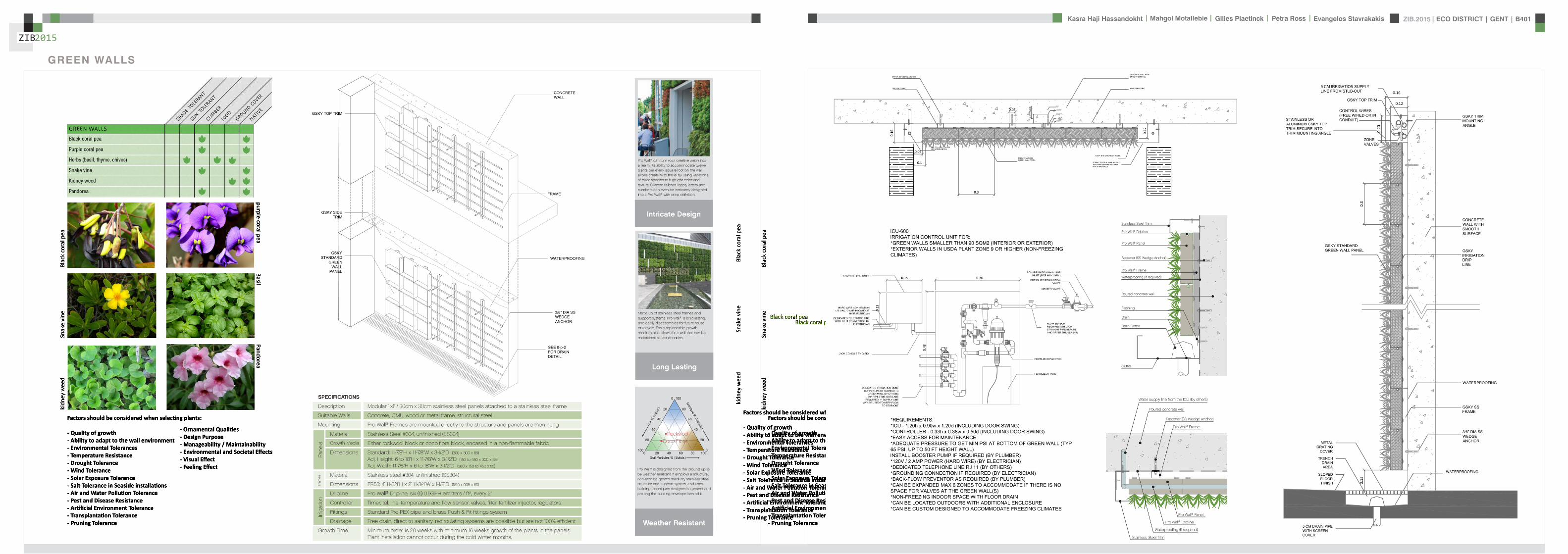
ZIB2015 ECO DISTRICT | GENT | B401Evangelos Stavrakakis | Petra Ross | Mahgol Motallebie | Gilles Plaetinck | Kasra Haji Hassandokht
ZIB2015
|
Black coral pea
Factors should be considered when seleccng plants
- Quality of growth- Ability to adapt to the wall environment- Environmental Tolerances- Temperature Resistance- Drought Tolerance- Wind - Wind Tolerance- Solar Exposure Tolerance- Salt Tolerance in Seaside installacons- Air and Water Pollucon Tolerance- Pest and Disease Resistance- Arcficial Environment Tolerance- Transplantacon Tolerance- Pruning - Pruning Tolerance
- Ornamental Qualices- Design Purpose- Manageability Maintainability- Environmental and Societal Effects- Visual Effect- Feeling Effect
Blac
k co
ral p
eaSn
ake
vine
kidn
ey w
eed
purple coral peaBasil
Pandorea
GREEN WALLS
ZIB2015 ECO DISTRICT | GENT | B401Evangelos Stavrakakis | Petra Ross | Mahgol Motallebie | Gilles Plaetinck | Kasra Haji Hassandokht
ZIB2015
|
Extraction of air
Pulsion of airRecuperation unit
outdoor space
18 degC15 degC
18 degC
In-take Out-take of air
VENTILATION
Gilles Plaetinck
schaal 1 100
ZIB BUILDINGEnter address here
3 _ level 2
Owner
begeleider Checker
DN
Gilles Plaetinck
schaal 1 100
ZIB BUILDINGEnter address here
2 _ level 1
Owner
begeleider Checker
Extraction of air
Pulsion of air
VENTILATION IN GROUPLANS CALCULATION AND SYSTEM
level 01
level 02
T 42ECO DISTRICT | GENT | B401
ZIB2015Mechanical Ventilation with Heat Recovery (MVHR)
Up to 95 of the heat can be recovered The Heat Recovery Unit runs continu-ously on trickle and can and is boosted when higher rates of ventilation are required eg bathing cooking In warmer months a summer by-pass function helps ensure comfort levels are maintained in the home When summer by-pass is activated the dwelling contin-ues to be ventilaated and recieve fresh filtered air however the heat recovery process is intermittently switched off (heat recovery is by-passed)
Key BenefitsYear round removal of condensation and indoor pol-lutants A direct impact on the Dwelling Emission Rate re-quired in SAP helping reduce the carbon footprint of the property Fresh filtered air supplied to dwelling ideal for allergy sufferers and those with conditions such as asthma A balanced ventilation system for the whole house and recovering of heat that would have otherwise have been lost Low noise non-intrusive ventilation system ndash located away from the room however consideration should be given to duct runs to ensure cross-talk contamination doesnrsquot happen AND the unit is sized correctly so it is not running a high rate all of the time
Zehnder ComfoSystems Passive Haus accredited product suitable for large houses up to 300m2 Designed to ensure low noise excellent energy performance and heat exchange efficiency Choice of control options including LCD touch screen display Can be combine with ComfoCool for optional cooling of up to 5 degrees and humidity reduction by 20
Semi Rigid Ducting
With a manifold system the resistance caused by duct-ing is reduced therefore Semi-Rigid ducting resistance is very low The manifold takes mass airflow directly from the MVHR Heat Recovery Unit and allows lower rates to pass through to each individual room runDirecting mass flow to the manifold eliminates the need to increase the running speed of the MVHR Heat Re-covery unit to overcome the resistance of ducting which in turn causes noise for the homeowner
T 42ECO DISTRICT | GENT | B401
ZIB2015Mechanical Ventilation with Heat Recovery (MVHR)
Up to 95 of the heat can be recovered The Heat Recovery Unit runs continu-ously on trickle and can and is boosted when higher rates of ventilation are required eg bathing cooking In warmer months a summer by-pass function helps ensure comfort levels are maintained in the home When summer by-pass is activated the dwelling contin-ues to be ventilaated and recieve fresh filtered air however the heat recovery process is intermittently switched off (heat recovery is by-passed)
Key BenefitsYear round removal of condensation and indoor pol-lutants A direct impact on the Dwelling Emission Rate re-quired in SAP helping reduce the carbon footprint of the property Fresh filtered air supplied to dwelling ideal for allergy sufferers and those with conditions such as asthma A balanced ventilation system for the whole house and recovering of heat that would have otherwise have been lost Low noise non-intrusive ventilation system ndash located away from the room however consideration should be given to duct runs to ensure cross-talk contamination doesnrsquot happen AND the unit is sized correctly so it is not running a high rate all of the time
Zehnder ComfoSystems Passive Haus accredited product suitable for large houses up to 300m2 Designed to ensure low noise excellent energy performance and heat exchange efficiency Choice of control options including LCD touch screen display Can be combine with ComfoCool for optional cooling of up to 5 degrees and humidity reduction by 20
Semi Rigid Ducting
With a manifold system the resistance caused by duct-ing is reduced therefore Semi-Rigid ducting resistance is very low The manifold takes mass airflow directly from the MVHR Heat Recovery Unit and allows lower rates to pass through to each individual room runDirecting mass flow to the manifold eliminates the need to increase the running speed of the MVHR Heat Re-covery unit to overcome the resistance of ducting which in turn causes noise for the homeowner
MECHANICAL VENTILATION WITH HEAT RECOVERY (MVHR)
Up to 95 of the heat can be recoveredThe Heat Recovery Unit runs continuously on trickle and can and is boosted when higher rates of ventilation are required eg bathing cooking
In warmer months a summer by-pass function helps ensure comfort levels are maintained in the home When summer by-pass is activated the dwelling continues to be ventilaated and recieve fresh filtered air however the heat recovery process is intermittently switched off (heat recovery is by-passed)
EXTRACT VENTILATION RATES
T 42ECO DISTRICT | GENT | B401
ZIB2015Mechanical Ventilation with Heat Recovery (MVHR)
Up to 95 of the heat can be recovered The Heat Recovery Unit runs continu-ously on trickle and can and is boosted when higher rates of ventilation are required eg bathing cooking In warmer months a summer by-pass function helps ensure comfort levels are maintained in the home When summer by-pass is activated the dwelling contin-ues to be ventilaated and recieve fresh filtered air however the heat recovery process is intermittently switched off (heat recovery is by-passed)
Key BenefitsYear round removal of condensation and indoor pol-lutants A direct impact on the Dwelling Emission Rate re-quired in SAP helping reduce the carbon footprint of the property Fresh filtered air supplied to dwelling ideal for allergy sufferers and those with conditions such as asthma A balanced ventilation system for the whole house and recovering of heat that would have otherwise have been lost Low noise non-intrusive ventilation system ndash located away from the room however consideration should be given to duct runs to ensure cross-talk contamination doesnrsquot happen AND the unit is sized correctly so it is not running a high rate all of the time
Zehnder ComfoSystems Passive Haus accredited product suitable for large houses up to 300m2 Designed to ensure low noise excellent energy performance and heat exchange efficiency Choice of control options including LCD touch screen display Can be combine with ComfoCool for optional cooling of up to 5 degrees and humidity reduction by 20
Semi Rigid Ducting
With a manifold system the resistance caused by duct-ing is reduced therefore Semi-Rigid ducting resistance is very low The manifold takes mass airflow directly from the MVHR Heat Recovery Unit and allows lower rates to pass through to each individual room runDirecting mass flow to the manifold eliminates the need to increase the running speed of the MVHR Heat Re-covery unit to overcome the resistance of ducting which in turn causes noise for the homeowner
T 42ECO DISTRICT | GENT | B401
ZIB2015Mechanical Ventilation with Heat Recovery (MVHR)
Up to 95 of the heat can be recovered The Heat Recovery Unit runs continu-ously on trickle and can and is boosted when higher rates of ventilation are required eg bathing cooking In warmer months a summer by-pass function helps ensure comfort levels are maintained in the home When summer by-pass is activated the dwelling contin-ues to be ventilaated and recieve fresh filtered air however the heat recovery process is intermittently switched off (heat recovery is by-passed)
Key BenefitsYear round removal of condensation and indoor pol-lutants A direct impact on the Dwelling Emission Rate re-quired in SAP helping reduce the carbon footprint of the property Fresh filtered air supplied to dwelling ideal for allergy sufferers and those with conditions such as asthma A balanced ventilation system for the whole house and recovering of heat that would have otherwise have been lost Low noise non-intrusive ventilation system ndash located away from the room however consideration should be given to duct runs to ensure cross-talk contamination doesnrsquot happen AND the unit is sized correctly so it is not running a high rate all of the time
Zehnder ComfoSystems Passive Haus accredited product suitable for large houses up to 300m2 Designed to ensure low noise excellent energy performance and heat exchange efficiency Choice of control options including LCD touch screen display Can be combine with ComfoCool for optional cooling of up to 5 degrees and humidity reduction by 20
Semi Rigid Ducting
With a manifold system the resistance caused by duct-ing is reduced therefore Semi-Rigid ducting resistance is very low The manifold takes mass airflow directly from the MVHR Heat Recovery Unit and allows lower rates to pass through to each individual room runDirecting mass flow to the manifold eliminates the need to increase the running speed of the MVHR Heat Re-covery unit to overcome the resistance of ducting which in turn causes noise for the homeowner
Heating 10 kwh msup2aCooling 4 kWh msup2aOverheating 42
ZIB2015 ECO DISTRICT | GENT | B401Evangelos Stavrakakis | Petra Ross | Mahgol Motallebie | Gilles Plaetinck | Kasra Haji Hassandokht
ZIB2015
|
Shutters control system+ -
Solar roadways - PV panels
LED lights
Elevator Fuse box
ElectricityBattery withtransformator
ELECTRICITY
Summer night
cross- ventilation through building
Summer day
air through recuperation unit small change of temperature
15 degC 18 degC
+ groundplans
heated zone
not heated zone
ZONING ACCORDING TO TEMPERATURESSUMMER NIGHT - cross-ventilation through building
SUMMER DAY - air through recuperation unit small change of temperatureSHADING SYSTEM
As a shading was chozen system Renson Icarus Lamellas with angle 45deg made in wood
ZIB2015 ECO DISTRICT | GENT | B401Evangelos Stavrakakis | Petra Ross | Mahgol Motallebie | Gilles Plaetinck | Kasra Haji Hassandokht
ZIB2015
|
average only 4 hours of peak daylight hours per day (4 x 365 = 1460 hours per year)
- Surface area ( first part) Fly-over +- 20 000 msup2-gt 16 000 x 230 Watt = 3 680 000 Watt or 3680 kWonly 50 of fly-over covered with solar roadways
-gt 3680 kW x 4 h = 7360 kWh day-gt 3680 kW x 1460 h = 2 686 400 kWh year -gt +- 540 households (+- 5000 kWh year)
Tesla Powerwall Therersquos a 10 kWh unit at $3500 -gt 737 Tesla Batteries
gt the Solar Roadway has the ability to cut greenhouse gases by up to 75-percentgt A decentralized self-healing secure power grid
IN FRONT OF FLY-OVER
- Surface area Fly-over = 16 x 30 m = 480 msup2-gt 384 x 230 Watt = 88 320 Watt or 883 kWonly 50 of fly-over covered with solar roadways
-gt 44 kW x 4 h = 176 kWh day-gt 44 kW x 1460 h = 64 240 kWh year -gt +- 13 households (+- 5000 kWh year)
lightsshutters
elevator
2 fridges
2 coffeemakers
1 microwave
1 owen
2 cooking plates
stereo
ventilation unit
electricity transformer (AC to DC) for PV panels + batteries
summer 05 kWh daywinter 03 kWh day183 days x 05= 915 kWh182 days x 03 = 546 kWh = 1641 kWh
262 kWh
A++fridge 104 kWhyear104 x x2 = 208 kWh
900 W x 01 hours day = 09 kWhx 220 days x 2= 198 kWh a
67 kWh a
085x100 days= 85 kWh a
400 kWh x 2 = 800 kWh a
150 kWh a 419 kWha
68 kWh a
ENERGY DEMAND OVERVIEW ENERGY SUPPLY OVERVIEW - FLY-OVER
1 spot 56 W 10000 = 0056 KW4 hours per day 365 days a year = 1460 h0056 x 1460 = 8176 kWh10 spots x 8176= 8176 kWh a
1 spot 72 W 10000 = 0072 KW4 hours per day 365 days a year = 1460 h0072 x 1460 = 10512 kWh5 spots x 10512= 5256 kWh a
1 spot 52 W 10000 = 0052 KW4 hours per day 365 days a year = 1460 h0052 x 1460 = 7592 kWh21 spots x 7592= 159432 kWh a
1 spot 9 W 10000 = 0009 KW4 hours per day 365 days a year = 1460 h0009 x 1460 = 1314 kWh5 spots x 1314 = 657 kWh a
SOLAR ROADWAYS - PV PANELSEnergy from the sun
1 To generate energy for the ZIB building2 To generate energy for the surrounding houses3 To generate energy for lighting or signs on the road4 The panels will also have the capacity to charge electric vehicles while parked
ELECTRICITY SCHEME
5423 kWh a
ZIB2015 ECO DISTRICT | GENT | B401Evangelos Stavrakakis | Petra Ross | Mahgol Motallebie | Gilles Plaetinck | Kasra Haji Hassandokht
ZIB2015
|
SUMMER SUNNY 10-42 LUXWINTER SUNNY 10-42 LUX
DAYLIGHT - DIALuxLIGHTING SYSTEM - DIALux
Workplane 9 Results overview
Height of working plane 0800 m Wall zone 0000 m
Result Mean (target) Min Max Minaverage MinmaxPerpendicular illuminance [lx] 463 (500) 105 689 0227 0152
Profile Offices Writing typewriting reading data processing
B401-Gent 6222015
Site 1 Building 2 Zib Room 9 Workplane 9 Results overview
Page 70
Workplane 9 False coloursPerpendicular illuminance (adaptive)
Scale 1 200
Perpendicular illuminance (Surface)Mean (actual) 463 lx Min 105 lx Max 689 lx Minaverage 0227 Minmax 0152
B401-Gent 6222015
Site 1 Building 2 Zib Room 9 Workplane 9 False coloursPerpendicular illuminance (adaptive)
Page 72
Workplane 9 Value chartPerpendicular illuminance (adaptive)
Scale 1 200
Perpendicular illuminance (Surface)Mean (actual) 463 lx Min 105 lx Max 689 lx Minaverage 0227 Minmax 0152
B401-Gent 6222015
Site 1 Building 2 Zib Room 9 Workplane 9 Value chartPerpendicular illuminance (adaptive)
Page 73
Workplane 13 Results overview
Height of working plane 0800 m Wall zone 0000 m
Result Mean (target) Min Max Minaverage MinmaxPerpendicular illuminance [lx] 388 (500) 69 732 0178 0094
Profile Offices Writing typewriting reading data processing
B401-Gent 6222015
Site 1 Building 6 Storey 1 Room 13 Workplane 13 Results overview
Page 94
Workplane 13 False coloursPerpendicular illuminance (adaptive)
Scale 1 100
Perpendicular illuminance (Surface)Mean (actual) 388 lx Min 69 lx Max 732 lx Minaverage 0178 Minmax 0094
B401-Gent 6222015
Site 1 Building 6 Storey 1 Room 13 Workplane 13 False coloursPerpendicular illuminance (adaptive)
Page 96
Workplane 13 Value chartPerpendicular illuminance (adaptive)
Scale 1 100
Perpendicular illuminance (Surface)Mean (actual) 388 lx Min 69 lx Max 732 lx Minaverage 0178 Minmax 0094
B401-Gent 6222015
Site 1 Building 6 Storey 1 Room 13 Workplane 13 Value chartPerpendicular illuminance (adaptive)
Page 97
Workplane 9 False coloursPerpendicular illuminance (adaptive)
Scale 1 200
Perpendicular illuminance (Surface)Mean (actual) 463 lx Min 105 lx Max 689 lx Minaverage 0227 Minmax 0152
B401-Gent 6222015
Site 1 Building 2 Zib Room 9 Workplane 9 False coloursPerpendicular illuminance (adaptive)
Page 72
1st f loor 2nd f loor Site 1 Luminaire parts listQuantity Luminaire (Luminous emittance)10 3F Filippi 12736 P 202x24W LED OP 196x1231
Luminous emittance 1Fitting 1x24W 2xLEDLight output ratio 100Lamp luminous flux 5332 lmLuminaire Luminous Flux 5332 lmPower 560 WLight yield 952 lmW
200
300
400
cdklm η = 100C0 - C180 C90 - C270
0deg 15deg 30deg
45deg
60deg
75deg
90deg
105deg105deg
90deg
75deg
60deg
45deg
30deg 15deg 0deg
5 SFN Eclairages 0732360X CLFV 236Luminous emittance 1Fitting 2xT26 36W840Light output ratio 6889Lamp luminous flux 6700 lmLuminaire Luminous Flux 4615 lmPower 720 WLight yield 641 lmW
160
240
cdklm η = 69C0 - C180 C90 - C270
0deg 15deg 30deg
45deg
60deg
75deg
90deg
105deg105deg
90deg
75deg
60deg
45deg
30deg 15deg 0deg
21 SFN Eclairages 332226XX SAM F 2x26W BELuminous emittance 1Fitting 2xTC-DEL 26W840Light output ratio 3297Lamp luminous flux 3600 lmLuminaire Luminous Flux 1187 lmPower 520 WLight yield 228 lmW
40
60
80
100
120
140
cdklm η = 33C0 - C180 C90 - C270
0deg 15deg 30deg
45deg
60deg
75deg
90deg
105deg105deg
90deg
75deg
60deg
45deg
30deg 15deg 0deg
1 Signcomplex AR111-009-AW-W-06 AR111 COB 9W38deg WhiteLuminous emittance 1Fitting 1xAR111-009-AW-W-06Light output ratio 8078Lamp luminous flux 600 lmLuminaire Luminous Flux 485 lmPower 90 WLight yield 539 lmW
800
1200
cdklm η = 81C0 - C180 C90 - C270
0deg 15deg 30deg
45deg
60deg
75deg
90deg
105deg105deg
90deg
75deg
60deg
45deg
30deg 15deg 0deg
Total lamp luminous flux 163020 lm Total luminaire luminous flux 101807 lm Total Load 20210 W Light yield 504 lmW
B401-Gent 6222015
Site 1 Luminaire parts list
Page 19
10x
6x
21x
1x
types of l ights
Perpendicular i l luminance (Surface)Mean (actual ) 463 lx Min 105 lx Max 689 lx Minaverage 0 227 Minmax 0 152
Perpendicular i l luminance (Surface)Mean (actual ) 388 lx Min 69 lx Max 732 lx Minaverage 0 178 Minmax 0 094
ZIB2015 ECO DISTRICT | GENT | B401Evangelos Stavrakakis | Petra Ross | Mahgol Motallebie | Gilles Plaetinck | Kasra Haji Hassandokht
ZIB2015
|
Tube hybrid Solar panels
Hot water tank Water taps
City water supply
Rain water collection for vertical harvesting
City water supply
WADI
Rain water tank
WATER MANAGEMENT
Sinks
Available roof area
In Ghent avarage of 900mmm2year
3197 m2
09x 3197 = 28773 m3year
RAIN WATER GAIN
toilet - 3x - 03lskitchen -4x - 02ls
POTABLE WATER DEMAND
3 toiletsVertical gardening
Total
relative RW usage
300 l day150 l day = 450lday= 16425 m3 year
1407 lday100m2
RAIN WATER DEMAND
RAIN WATER TANK
Relative RWT volumeRain water tank volume
3m3 100 m2
9591 l gt 10 m3
DIMESION OF PIPES
City water supplyRainwater tank
178 mm (DN 18 - 15 - 12)165 mm (DN 17-15)
are composed of hexagonal tiles Rainwater can infiltrate between the gaps from where it goes to rainwatter collector which supplies the vegetation on fly-over
THE SOLAR ROADWAYS
WATER SUPPLY SCHEME AND CALCULATION
ZIB2015 ECO DISTRICT | GENT | B401Evangelos Stavrakakis | Petra Ross | Mahgol Motallebie | Gilles Plaetinck | Kasra Haji Hassandokht
ZIB2015
|
WADI
City water supply
Rain water tank
Sinks
Divided sewer systemwithin building
SEWAGE SYSTEM
ToiletToilet sinkKitchen sink
DU = 2 lsDU = 05 lsDU = 08 ls
WATER DRAINAGE OF DEVICES
Frequency of usage at the same time
K 05
DIMESION OF PIPES
Black waterGrey water
110 mm (DU 110)75 mm (DU 75 - 63)
WATER DRAINAGE SCHEME AND CALCULATION
ZIB2015 ECO DISTRICT | GENT | B401Evangelos Stavrakakis | Petra Ross | Mahgol Motallebie | Gilles Plaetinck | Kasra Haji Hassandokht
ZIB2015
|
DN
Gilles Plaetinck
schaal 1 100
ZIB BUILDINGEnter address here
2 _ level 1
Owner
begeleider Checker
Gilles Plaetinck
schaal 1 100
ZIB BUILDINGEnter address here
3 _ level 2
Owner
begeleider Checker
WATER SUPPLY
HOT WATER
WATER DRAINAGE
WATER SUPPLY AND DRAINAGE IN GROUPLANS
level 01
level 02
ENERGY
RAINWATER TANK
HELOPHYTE FILTER
IRRIGATION SYSTEM
BIO-ROTOR
MICRO TURBINE
PHOSPHOR
In this building a closed water system is applied which is based on reusing water in mullple wasRainRain water from the roof will be collected in a storage tank situated on the ground floor This water will be used to flush the toilet and irrigate crops in verlcal harveslng system In case of an overflow the water will be stored in the con-structed wetland near the building The rainwater can be fil-tered through a helophyte filter up to drinking water stan-dard The waste water system includes three types of water yellyellow black and grey waterThe yellow water will be stored for its phosphor while the black water will be purified into grey water This grey water is comparable to the quality of rain water aaer purificalon b means of a bio rotor The remaining residue from the bio rotor together with the organic waste from the harveslng is fermented into biogas that drives a micro turbine in order to produce some addilonal energy
TheThe waste product deriving from this process will be used as compost in verlcal harveslng This efficient yet complex system closes the ullizalon cycle of the building and turns it into an efficient vicious circle that can be considered au arkic
In this building a closed water system is applied which is based on reusing water in multiple was
Rain water from the roof will be collected in a storage tank situated on the ground floor This water will be used to flushthe toilet and irrigate crops in vertical harvesting system In case of an overflow the water will be stored in the constructed wetland near the building The rainwater can be filtered through a helophyte filter up to drinking water standard
The waste water system includes three types of water yellow black and grey water The yellow water will be stored for its phosphor while the black water will be purified into grey water This grey water is comparable to the quality of rain water after purification b means of a bio rotor The remaining residue from the bio rotor together with the organic waste from the harvesting is fermented into biogas that drives a micro turbine in order to produce some additional energy The waste product deriving from this process will be used ascompost in ver1048991cal harves1048991ng This efficient yet complexsystem closes the u1048991liza1048991on cycle of the building and turns itinto an efficient vicious circle that can be considered au arkic
WATER CYCLE
ZIB2015 ECO DISTRICT | GENT | B401Evangelos Stavrakakis | Petra Ross | Mahgol Motallebie | Gilles Plaetinck | Kasra Haji Hassandokht
ZIB2015
|
CALCULATIONS
Passive House verification
Photo or Drawing
Building Workshop + info pointStreet
PostcodeCityCountry
Building Type non-residentialClimate Ukkel
Home Owner(s) Client(s)Street
PostcodeCity
ArchitectStreet
PostcodeCity Calculation electricity Internal heat gains
Mechanical System Building type
StreetPostcodeCity Internal heat gains
Year of Construction 2015 Interior Temperature 200 degC Utilisation pattern
Number of Dwelling Units 1 Internal Heat Gains 20 Wm2 Type of values used Fill in worksheet IHG Non-Dom Enclosed Volume Ve 12442 Planned number of occupants
Number of Occupants 80 8 Design
Specific building demands with reference to the treated floor area use Annual method
Treated floor area 2840 msup2 Requirements Fulfilled Verification Annual method The monthly method should be used for building certification
Space heating Annual heating demand 10 kWh(m2a) 15 kWh(msup2a) yes Specific space heating demand annual method 103 kWh(msup2a)
Heating load 11 Wm2 10 Wmsup2 - Specific space heating demand monthly Method 120 kWh(msup2a)
Space cooling Overall specific space cooling demand kWh(m2a) 15 kWh(msup2a)
Cooling load Wm2 - -Frequency of overheating (gt 25 degC) - -
Primary Energy Space heating and dehumidification
cooling household electricity 73 kWh(m2a) 120 kWh(msup2a) yes
DHW space heating and auxiliary electricity 24 kWh(m2a) - -Specific primary energy reduction through solar electricity 21 kWh(m2a) - -
Airtightness Pressurization test result n50 06 1h 06 1h yes
PHPP Verification FINAL ZIB FILE CALCULTIONS PHPPxls
L B H VOLUME
main 1 226 7 4 6328main 2 184 7 35 4508
core 0 6 2 5 3 5 108 5core 0 62 5 35 1085core 3 62 3 28 521
12442
AREAmain 1 storage 35
wc big 35wc 2wc 2workshop 103
MAIN 2 infolounge 92
staircase 56storage technical 22
284
Floor_exterior 1582 31 1272
Roof_exterior 1582
Passive House verification
Photo or Drawing
Building Workshop + info pointStreet
PostcodeCityCountry
Building Type non-residentialClimate Ukkel
Home Owner(s) Client(s)Street
PostcodeCity
ArchitectStreet
PostcodeCity Calculation electricity Internal heat gains
Mechanical System Building type
StreetPostcodeCity Internal heat gains
Year of Construction 2015 Interior Temperature 200 degC Utilisation pattern
Number of Dwelling Units 1 Internal Heat Gains 20 Wm2 Type of values used Fill in worksheet IHG Non-Dom Enclosed Volume Ve 12442 Planned number of occupants
Number of Occupants 80 8 Design
Specific building demands with reference to the treated floor area use Annual method
Treated floor area 2840 msup2 Requirements Fulfilled Verification Annual method The monthly method should be used for building certification
Space heating Annual heating demand 10 kWh(m2a) 15 kWh(msup2a) yes Specific space heating demand annual method 103 kWh(msup2a)
Heating load 11 Wm2 10 Wmsup2 - Specific space heating demand monthly Method 120 kWh(msup2a)
Space cooling Overall specific space cooling demand kWh(m2a) 15 kWh(msup2a)
Cooling load Wm2 - -Frequency of overheating (gt 25 degC) - -
Primary Energy Space heating and dehumidification
cooling household electricity 73 kWh(m2a) 120 kWh(msup2a) yes
DHW space heating and auxiliary electricity 24 kWh(m2a) - -Specific primary energy reduction through solar electricity 21 kWh(m2a) - -
Airtightness Pressurization test result n50 06 1h 06 1h yes
PHPP Verification FINAL ZIB FILE CALCULTIONS PHPPxls
SURFACE AREAcurrent orientation only night ventilation
current orientation only night ventilation 6 windows less 52 msup2
current orientation only night ventilation 7 windows less 60msup2 (stays the same for each side)
current orientation only night ventilation 8 windows less 69 msup2
orientation turned 90deg only night ventilation 6 windows less 52 msup2
orientation turned 90deg only night ventilation 7 windows less 60msup2 (window less at SE side)
orientation turned 90deg only night ventilation 8 windows less 69 msup2
-gt orientation turned 90deg only night ventilation 9 windows less 77msup2 (window less at NW side althought theres less overheating in the case of a window less at SE side the heating demand exceeds 15)
CHANGE IN DESIGN
ZIB2015 ECO DISTRICT | GENT | B401Evangelos Stavrakakis | Petra Ross | Mahgol Motallebie | Gilles Plaetinck | Kasra Haji Hassandokht
ZIB2015
|
Passive House verificationS P E C I F I C A N N U A L H E A T I N G D E M A N D
Climate Ukkel Interior Temperature 200 degC
Building Workshop + info point Building TypeUse non-residentialTreated Floor Area ATFA 2840 msup2
per msup2Area U-Value Temp Factor ft Gt Treated Data for heating balance diagram
Building Element Temperature Zone msup2 W(msup2K) kKha kWha Floor Area Losses GainsExterior Wall - Ambient A 5595 0101 100 743 = 4181 1472 Exterior Wall - Ambient 147234373Exterior Wall - Ground B 069 = Exterior Wall - GroundRoofCeiling - Ambient A 1550 0094 100 743 = 1085 382 RoofCeiling - Ambient 381903529Floor slab basement ceiling B 310 0105 069 743 = 167 059 Floor slab basement ceiling 058811509
A 100 =A 100 =
unheated basement X 075 = unheated basementWindows A 1154 0648 100 743 = 5562 1958 Windows 195834732Exterior Door A 100 = Exterior DoorExterior TB (lengthm) A 1169 -0030 100 743 = -259 -091 Thermal Bridge Heat LossPerimeter TB (lengthm) P 069 = 000 not useful heat gains 365267499Ground TB (lengthm) B 069 =
Total of All Building Envelope Areas 8609 ndashndashndashndashndashndashndashndashndashndashndashndashndash- kWh(msup2a) Ventilation 395818713
Transmission Heat Losses QT Total 10736 378Annual Heating Demand 102516636
ATFA Clear Room Height internal gains 100951487msup2 m msup3 passive solar gains 250668423
Ventilation System Effective Air Volume VV 2840 280 = 7952 Thermal bridge credit 091126837Effective Heat Recovery Efficiency eff 81 Cross check sum 46324923 46324923of Heat Recovery
Efficiency of Subsoil Heat Exchanger SHX 0 nVsystem HR nVRes
1h 1h 1h
Energetically Effective Air Exchange nV 0105 (1 - 081 ) + 0038 = 0058
VV nV cAir Gt
msup3 1h Wh(msup3K) kKha kWha kWh(msup2a)
Ventilation Heat Losses QV 795 0058 033 743 = 1124 40
Reduction Factor QT QV NightWeekend
kWha kWha Saving kWha kWh(msup2a)
Total Heat Losses QL ( 10736 + 1124 ) 10 = 11860 418
Orientation Reduction Factor g-Value Area Radiation HPof the Area See Windows Sheet (perp radiation)
msup2 kWh(msup2a) kWha
1 North 054 050 2700 163 = 11822 East 058 000 440 197 = 03 South 056 050 4860 314 = 42874 West 032 050 3216 254 = 13275 Horizontal 063 050 324 317 = 323
kWh(msup2a)
Available Solar Heat Gains QS Total 7119 251
Length Heat Period Spec Power qI ATFA
khd da Wmsup2 msup2 kWha kWh(msup2a)
Internal Heat Gains QI 0024 209 201 2840 = 2867 101
kWha kWh(msup2a)
Free Heat QF QS + QI = 9986 352
Ratio of Free Heat to Losses QF QL = 084
Utilisation Factor Heat Gains G (1 - ( QF QL )5 ) (1 - ( QF QL )
6 ) = 90kWha kWh(msup2a)
Heat Gains QG G QF = 8949 315
kWha kWh(msup2a)
Annual Heating Demand QH QL - QG = 2911 10
kWh(msup2a) (YesNo)
Limiting Value 15 Requirement met yes
00
147
00
3806000000
196
00
40
37
09
103
101
251
0
5
10
15
20
25
30
35
40
45
50
Losses Gains
Hea
t flo
ws
[kW
h(m
sup2a)]
Heating energy balance
passive solar gains
internal gains
Annual Heating Demand
Thermal bridge credit
not useful heat gains
Ventilation
Exterior Door
Windows
unheated basement
Floor slab basement ceiling
RoofCeiling - Ambient
Exterior Wall - Ground
Exterior Wall - Ambient
Thermal Bridge Heat Loss
HPP Annual Heating Demand FINAL ZIB FILE CALCULTIONS PHPPxls
Passive House verification Passive House verificationS P E C I F I C U S E F U L C O O L I N G D E M A N D S P E C I F I C U S E F U L C O O L I N G D E M A N D
M O N T H L Y M E T H O D M O N T H L Y M E T H O D
(This page displays the sums of the monthly method over the cooling period))Climate Ukkel Interior Temperature Summer 25 degC Climate Ukkel Interior Temperature 25 degC
Building Workshop + info point Building TypeUse non-residential Building Workshop + info point Building TypeUse non-residential
Spec Capacity 60 Wh(msup2K) (Enter in Summer worksheet) Treated Floor Area ATFA 2840 msup2 Treated Floor Area ATFA 284 msup2
per msup2Temperature Zone Area U-Value Mon Red Fac Gt Treated Jan Feb Mar Apr May Jun Jul Aug Sep Oct Nov Dec Year
Building Element msup2 W(msup2K) kKha kWha Floor Area Heating Degree Hours - Ex 168 150 144 121 92 73 57 59 82 109 140 160 136 kKh1 Exterior Wall - Ambient A 5595 0101 100 103 = 5782 Heating Degree Hours - G 126 123 135 120 106 83 63 54 58 71 86 109 113 kKh2 Exterior Wall - Ground B 100 = Losses - Exterior 2553 2286 2189 1838 1393 1117 871 904 1245 1660 2123 2432 20612 kWh3 RoofCeiling - Ambient A 1550 0094 100 103 = 1500 Losses - Ground 41 40 44 39 35 27 21 18 19 23 28 36 370 kWh4 Floor slab basement ceil B 310 0105 100 90 = 294 Losses Summer Ventilatio 67 71 244 372 629 720 880 865 658 499 234 126 5366 kWh5 A 100 = Sum Spec Heat Losses 94 84 87 79 72 66 62 63 68 77 84 91 928 kWhmsup26 A 100 = Solar Load North 44 81 141 212 286 298 298 255 178 116 54 35 1998 kWh7 unheated basement X 075 = Solar Load East 0 0 0 0 0 0 0 0 0 0 0 0 0 kWh8 Windows A 1154 0648 100 103 = 7690 Solar Load South 218 315 464 577 681 644 681 658 532 416 242 171 5601 kWh9 Exterior Door A 100 = Solar Load West 79 125 213 303 385 378 370 347 256 177 91 60 2785 kWh
10 Exterior TB (lengthm) A 1169 -0030 100 103 = -358 Solar Load Horiz 11 21 37 57 79 79 80 69 47 30 14 9 533 kWh11 Perimeter TB (lengthm) P 100 = Solar Load Opaque 3 5 9 13 18 19 19 16 11 7 3 2 126 kWh12 Ground TB (lengthm) B 100 = Internal Heat Gains 425 384 425 411 425 411 425 425 411 425 411 425 5001 kWh
ndashndashndashndashndashndashndashndashndashndashndash kWh(msup2a) Sum Spec Loads Solar + 28 33 45 55 66 64 66 62 51 41 29 25 565 kWhmsup2
Transmission Losses QT (Negative Heat Loads) Total 14907 525 Utilisation Factor Losses 29 39 52 69 84 88 82 88 73 53 34 27 58Useful Cooling Energy Dem 0 0 4 30 142 192 417 192 40 4 0 0 1021 kWh
ATFA Clear Room Height Spec Cooling Demand 00 00 00 01 05 07 15 07 01 00 00 00 36 kWhmsup2Effective msup2 m msup3
Air Volume VV 284 280 = 795
Heat Transfer Coef Gt
WK kKha kWha kWh(msup2a)
Exterior 99 103 = 1013 36Ground 00 105 = 0 00
Additional Summer Ventilation
Select X Window Night Ventilation Manual Corresponding Air Change Rate 136 1h
Mechanical Automatically Controlled Ventilation (for window ventilation at 1 K temperature difference indoor - outdoor)
Minimum Acceptable Indoor Temperatu 220 degC
kWha kWh(msup2a)
Heat Losses Summer Ventilation 5172 182
QLext QLground QLsummer
kWha kWha kWha kWha kWh(msup2a)
Ventilation Heat Losses QV 1013 + 0 + 5172 = 6185 218
2
3
4
5
6
7
8
9
10
Spec
ific
loss
es l
oads
l c
oolin
g de
man
d [k
Wh
(msup2 m
onth
)] Spec Cooling Demand Sum Spec Heat Losses Sum Spec Loads Solar + Internal
QT QV
kWha kWha kWha kWh(msup2a)
Total Heat Losses QL 14907 + 6185 = 21092 743
Orientation Reduction Factor g-Value Area Global Radiationof the Area (perp radiation)
msup2 kWh(msup2a) kWha
1 North 031 050 270 462 = 19182 East 061 000 44 578 = 0 Temperature Amplitude Summer 82 K3 South 030 050 486 707 = 52114 West 025 050 322 654 = 2646 Month 1 2 3 4 5 6 7 8 9 10 11 12 Annual Total5 Horizontal 035 050 32 913 = 513 Days 31 28 31 30 31 30 31 31 30 31 30 31 3656 Sum Opaque Areas 121 Ambient Temp 250 270 572 828 1275 1487 1737 1707 1369 1039 568 356 96
kWh(msup2a) North Radiation 106 195 329 494 667 697 712 599 419 275 129 87 471
Available Solar Heat Gains QS Total 10409 367 East Radiation 146 266 452 698 937 940 988 851 574 382 179 123 654
South Radiation 311 440 645 786 912 858 898 885 733 579 341 241 763Length Heat Period Spec Power qI ATFA West Radiation 155 261 471 707 926 926 896 819 580 382 183 116 642
khd da Wmsup2 msup2 kWha kWh(msup2a) Hori Radiation 200 369 662 1021 1398 1410 1418 1234 842 535 243 156 949
Internal Heat Gains QI 0024 303 20 2840 = 4151 146 Tsky -750 -730 -428 -172 275 487 737 707 369 039 -432 -644 -04
Ground Temp 805 676 686 830 1072 1345 1647 1776 1696 1552 1310 1037 121kWha kWh(msup2a)
Sum Heat Loads QF QS + QI = 14560 513
Ratio of Losses to Free Heat Gains QL QF = 145
Utilisation Factor Heat Losses G = 64kWha kWh(msup2a)
Useful Heat Losses QVn G QL = 13539 477
kWha kWh(msup2a)
Useful Cooling Demand QK QF - QVn = 1021 4
kWh(msup2a) (YesNo)
Limiting Value 15 Requirement met yes
0
1
2
Jan Feb Mar Apr May Jun Jul Aug Sep Oct Nov Dec
usef
u
HPP Cooling FINAL ZIB FILE CALCULTIONS PHPPxls
Passive House verificationS P E C I F I C A N N U A L H E A T I N G D E M A N D
Climate Ukkel Interior Temperature 200 degC
Building Workshop + info point Building TypeUse non-residentialTreated Floor Area ATFA 2840 msup2
per msup2Area U-Value Temp Factor ft Gt Treated Data for heating balance diagram
Building Element Temperature Zone msup2 W(msup2K) kKha kWha Floor Area Losses GainsExterior Wall - Ambient A 5595 0101 100 743 = 4181 1472 Exterior Wall - Ambient 147234373Exterior Wall - Ground B 069 = Exterior Wall - GroundRoofCeiling - Ambient A 1550 0094 100 743 = 1085 382 RoofCeiling - Ambient 381903529Floor slab basement ceiling B 310 0105 069 743 = 167 059 Floor slab basement ceiling 058811509
A 100 =A 100 =
unheated basement X 075 = unheated basementWindows A 1154 0648 100 743 = 5562 1958 Windows 195834732Exterior Door A 100 = Exterior DoorExterior TB (lengthm) A 1169 -0030 100 743 = -259 -091 Thermal Bridge Heat LossPerimeter TB (lengthm) P 069 = 000 not useful heat gains 365267499Ground TB (lengthm) B 069 =
Total of All Building Envelope Areas 8609 ndashndashndashndashndashndashndashndashndashndashndashndashndash- kWh(msup2a) Ventilation 395818713
Transmission Heat Losses QT Total 10736 378Annual Heating Demand 102516636
ATFA Clear Room Height internal gains 100951487msup2 m msup3 passive solar gains 250668423
Ventilation System Effective Air Volume VV 2840 280 = 7952 Thermal bridge credit 091126837Effective Heat Recovery Efficiency eff 81 Cross check sum 46324923 46324923of Heat Recovery
Efficiency of Subsoil Heat Exchanger SHX 0 nVsystem HR nVRes
1h 1h 1h
Energetically Effective Air Exchange nV 0105 (1 - 081 ) + 0038 = 0058
VV nV cAir Gt
msup3 1h Wh(msup3K) kKha kWha kWh(msup2a)
Ventilation Heat Losses QV 795 0058 033 743 = 1124 40
Reduction Factor QT QV NightWeekend
kWha kWha Saving kWha kWh(msup2a)
Total Heat Losses QL ( 10736 + 1124 ) 10 = 11860 418
Orientation Reduction Factor g-Value Area Radiation HPof the Area See Windows Sheet (perp radiation)
msup2 kWh(msup2a) kWha
1 North 054 050 2700 163 = 11822 East 058 000 440 197 = 03 South 056 050 4860 314 = 42874 West 032 050 3216 254 = 13275 Horizontal 063 050 324 317 = 323
kWh(msup2a)
Available Solar Heat Gains QS Total 7119 251
Length Heat Period Spec Power qI ATFA
khd da Wmsup2 msup2 kWha kWh(msup2a)
Internal Heat Gains QI 0024 209 201 2840 = 2867 101
kWha kWh(msup2a)
Free Heat QF QS + QI = 9986 352
Ratio of Free Heat to Losses QF QL = 084
Utilisation Factor Heat Gains G (1 - ( QF QL )5 ) (1 - ( QF QL )
6 ) = 90kWha kWh(msup2a)
Heat Gains QG G QF = 8949 315
kWha kWh(msup2a)
Annual Heating Demand QH QL - QG = 2911 10
kWh(msup2a) (YesNo)
Limiting Value 15 Requirement met yes
00
147
00
3806000000
196
00
40
37
09
103
101
251
0
5
10
15
20
25
30
35
40
45
50
Losses Gains
Hea
t flo
ws
[kW
h(m
sup2a)]
Heating energy balance
passive solar gains
internal gains
Annual Heating Demand
Thermal bridge credit
not useful heat gains
Ventilation
Exterior Door
Windows
unheated basement
Floor slab basement ceiling
RoofCeiling - Ambient
Exterior Wall - Ground
Exterior Wall - Ambient
Thermal Bridge Heat Loss
HPP Annual Heating Demand FINAL ZIB FILE CALCULTIONS PHPPxls
factor 05Wd (ls) 088
nominal diameter 75 mmVERTICAL COLLECTOR sink toilets 3 05 15
sink kitchen 2 08 16Total 5 31factor 05
Wd (ls) 088nominal diameter 75 mm
Toevoerend ROOF SURFACE
horizontal roof surface (msup2) orientation coeff angle (deg) roofcover filter coeff toevoerend
444 1 0 08 09 3197
RAIN WATER USAGE
Type usage ( l usage) persons day frequency usageday yearly usage
toilet use small 3 20 3 180 65700toilet use big 6 20 1 120 43800VERTICAL GARDENING 150 54750TOTAL 450 164250 L year
16425 msup3 year
TOTAL RAINWATER USAGE 450 L dayRELATIVE RAINWATER USAGE 1407 L day100msup2
LEEGSTAND
relative rainwater usage 1407 L day 100 msup2LEEGSTAND 7 relative volume rainwater tank 3 msup3 100 msup2rainwater tank volume 9591 Liter
suggestion 50 msup2 02 m= 10 msup3
SUPPLYtype amount debiet Q total total WW
lsec lsec lsecMAIN LEVEL POTABLE
sink toilet 3 01 03 03sink kitchen 2 01 02 02
Total 5 05 05Gelijktijdigheid 05 05debiet Q (lsec) 025 025
diameter 178 178 cm
type amount debiet Q total total WWlsec lsec lsec
MAIN LEVEL RAIN WATER toilet 3 01 03 0
Total 3 03Gelijktijdigheid 071debiet Q (lsec) 0213
diameter 165 cm
FECALIEumlNtype amount value Total (ls)
COLLECTOR HORIZONTAL toilet 3 2Total 6factor 05
Wd (ls) 122nominal diameter 110 mm
type amount value Total (ls)COLLECTOR VERTICAL toilet 3 2
Total 6factor 05
Wd (ls) 122nominal diameter 110 mm
DRAINtype amount value Total (ls)
HORIZONTAL COLLECTOR sink toilets 3 05 15sink kitchen 2 08 16
Total 5 31
WATER
ZIB2015 ECO DISTRICT | GENT | B401Evangelos Stavrakakis | Petra Ross | Mahgol Motallebie | Gilles Plaetinck | Kasra Haji Hassandokht
ZIB2015
|
Passive House verificationS P E C I F I C S P A C E H E A T I N G L O A D Risk Determination of Group Heating for a Critical Room
Building Workshop + info point Building TypeUse non-residential Workshop room ( 1= Yes 0 = No)
Climate (HL) Ukkel Treated Floor Area ATFA 2840 msup2 Interior Temperature 20 degC Building Satisfies Passive House Criteria 1
Design Temperature Radiation North East South West Horizontal Room floor area 100 msup2 Supply Air per msup2 Living AreaWeather Condition 1 -31 degC 10 10 30 15 20 Wmsup2 Planned ambient air quantity for the room 150 msup3h 150 msup3hmsup2Weather Condition 2 -22 degC 5 5 20 10 10 Wmsup2 Planned ambient air quantities for the remaining rooms -67 msup3hGround Design Temp 68 degC Area U-Value Factor TempDiff 1 TempDiff 2 PT 1 PT 2
Building Element Temperature Zone msup2 W(msup2K) Always 1(except X) K K W W Building Element Temperature Zone msup2 W(msup2K) Always 1
(except X) K Room Trans Loss W
1 Exterior Wall - Ambient A 5595 0101 100 231 or 222 = 1299 or 1249 Aboveground Exterior Wall A 650 010 100 231 = 1512 Exterior Wall - Ground B 100 132 or 132 = or Belowground Exterior Wall B 00 100 132 =3 RoofCeiling - Ambient A 1550 0094 100 231 or 222 = 337 or 324 RoofCeiling D 880 009 100 231 = 1914 Floor slab basement ceiling B 310 0105 100 132 or 132 = 43 or 43 Underground Floor Slab B 00 011 100 132 = 05 A 100 231 or 222 = or A 100 231 =6 A 100 231 or 222 = or A 100 231 =7 unheated basement X 075 231 or 222 = or X 100 231 =8 Windows A 1154 0648 100 231 or 222 = 1728 or 1661 Windows A 480 065 100 231 = 7199 Exterior Door A 100 231 or 222 = or Exterior Door A 100 231 =
10 Exterior TB (lengthm) A 1169 -0030 100 231 or 222 = -80 or -77 Exterior thermal bridges (Lengthm) A 100 231 =11 Perimeter TB (lengthm) P 100 132 or 132 = or Perimeter Thermal Bridges (Lengthm) A 100 231 =12 Ground TB (lengthm) B 100 132 or 132 = or Floor Slab Thermal Bridges (Lengthm) A 50 100 231 =13 HouseDU Partition Wall I 100 30 or 30 = or HouseDU Partition Wall I 200 100 30 =
Transmission Heat Losses PT ndashndashndashndashndashndashndashndashndashndashndashndashndash- ndashndashndashndashndashndashndashndashndashndashndash-
Total = 3328 or 3200 = 1061
ATFA Clear Room HeightVentilation System msup2 m msup3 Risk
Effective Air Volume VV 2840 280 = 795 Enter 1 = Yes 0 = No PTRoom W PSupply Air W Ratio Summand
SHX 1 SHX 2 Transmission Heat Losses 1061 1386 077 -023Efficiency of Heat Recovery HR 81 Heat Recovery Efficiency SHX 0 Efficiency SHX 0 or 0 Concentrated leakages 0 000of the Heat Exchanger Insulation to other rooms better R = 15 msup2KW 1 ( 2 = no thermal contact except door) 050
nVRes (Heating Load) nVsystem HR HR Room is on the ground floor 0 0001h 1h 1h 1h open staircase 0 000
Energetically Effective Air Exchange nV 0094 + 0105 (1- 081 or 081 ) = 0114 or 0114 TOTAL of the Risk Summands 027Ventilation Heating Load PV
VL nL nL cAir TempDiff 1 TempDiff 2 PV 1 PV 2 Interior doors predominantly closed 1 Risk Factor 200msup3 1h 1h Wh(msup3K) K K W W
7952 0114 or 0114 033 231 or 222 = 691 or 664Total Room Risk 89
PL 1 PL 2
Total Heating Load PL W W Appraisal and Advice normally no problemPT + PV = 4019 or 3864
Orientation Area g-Value Reduction Factor Radiation 1 Radiation 2 PS 1 PS 2the Area msup2 (perp radiation) (see Windows worksheet) Wmsup2 Wmsup2 W W
1 North 270 05 05 11 or 6 = 77 or 412 East 44 00 06 8 or 3 = 0 or 03 South 486 05 06 28 or 18 = 378 or 2474 West 322 05 03 19 or 13 = 100 or 685 Horizontal 32 05 06 20 or 10 = 20 or 10
Solar heating power PS Total = 575 or 367
Spec Power ATFA PI 1 PI 2Internal heating power PI Wmsup2 msup2 W W
16 284 = 454 or 454
PG 1 PG 2
Heating power (gains) PG W W
PS + PI = 1029 or 821
PL - PG = 2989 or 3042
Heating Load PH = 3042 W
Specific Heating Load PH ATFA = 107 Wmsup2
Input Max Supply Air Temperature 48 degC degC degC
Max Supply Air Temperature SupplyMax 48 degC Supply Air Temperature Without Heating SupplyMin 156 157
For Comparison Heating Load Transportable by Supply Air PSupply AirMax = 886 W specific 31 Wmsup2
(YesNo)
Supply Air Heating Sufficient No
HPP Heating Load FINAL ZIB FILE CALCULTIONS PHPPxls
Passive House verificationU - V A L U E S O F B U I L D I N G E L E M E N T S
Wedge shaped building element layeBuilding Workshop + info point still air spaces -gt Secondary calculation to th
Assembly No Building assembly description Interior insulation1 Exterior wall x
Heat transfer resistance [msup2KW] interior Rsi 013exterior Rse 004
Area section 1 [W(mK)] Area section 2 (optional) [W(mK)] Area section 3 (optional) [W(mK)] Thickness [mm]
1 hout gevel 0160 17
2 regelwerk hout 0158 30
3 houtvezel celit 4D 0048 18
4 Eurowall 0023 hout FJI beam 0286 140
5 OSB -plaat 0130 15
6 Eurothane G 0023 70
7 Plaster insulating 0100 10
8Percentage of Sec 2 Percentage of Sec 3 Total
26 300
U-Value 0107 W(msup2K)
Assembly No Building assembly description Interior insulation2 Roof x
Heat transfer resistance [msup2KW] interior Rsi 010exterior Rse 004
Area section 1 [W(mK)] Area section 2 (optional) [W(mK)] Area section 3 (optional) [W(mK)] Thickness [mm]Area section 1 [W(mK)] Area section 2 (optional) [W(mK)] Area section 3 (optional) [W(mK)] Thickness [mm]
1 bitumenmembraam 0230 5
23 EPS 0036 70
4 OSB -plaat 0130 18
5 cellulose 0039 hout FJI beam 0286 350
6 OSB -plaat 0130 15
7 regelwerk hout 5 0177 30
8 gipskartonplaat 0290 12
Percentage of Sec 2 Percentage of Sec 3 Total
26 500
U-Value 0094 W(msup2K)
Assembly No Building assembly description Interior insulation3 Floor x
Heat transfer resistance [msup2KW] interior Rsi 017
exterior Rse 004
Area section 1 [W(mK)] Area section 2 (optional) [W(mK)] Area section 3 (optional) [W(mK)] Thickness [mm]
1 PIR dekvloer 0023 5
2 gipskartonplaat 0290 10
3 gespoten pur 0028 100
4 OSB -plaat 0130 15
5 cellulose 0039 hout FJI beam 0286 350
6 houtvezel Celit 4D 0048 15
7 regelwerk hout 6 0149 30
8 afwerking hout 0160 5
Percentage of Sec 2 Percentage of Sec 3 Total
26 530
U-Value 0078 W(msup2K)
PHPP U-Values FINAL ZIB FILE CALCULTIONS PHPPxls
ers and he right
n Secondary Calculation Equivalent Thermal Conductivity of Still Air Spaces
Air Layer Thickness 30 mm Direction of Upwards ha 125 W(msup2K) 016 W(mK)
Heat Flow X Horizontal hr 417 W(msup2K)
(check only one field) Downwards
cm
n
cm
n Secondary Calculation Equivalent Thermal Conductivity of Still Air Spaces
Air Layer Thickness 30 mm
Direction of Upwards ha 08333 W(msup2K) 015 W(mK)Heat Flow Horizontal hr 417 W(msup2K)
(check only one field) X Downwards
cm
PHPP U-Values FINAL ZIB FILE CALCULTIONS PHPPxls
ers and he right
n Secondary Calculation Equivalent Thermal Conductivity of Still Air Spaces
Air Layer Thickness 30 mm Direction of Upwards ha 125 W(msup2K) 016 W(mK)
Heat Flow X Horizontal hr 417 W(msup2K)
(check only one field) Downwards
cm
n
cm
n Secondary Calculation Equivalent Thermal Conductivity of Still Air Spaces
Air Layer Thickness 30 mm
Direction of Upwards ha 08333 W(msup2K) 015 W(mK)Heat Flow Horizontal hr 417 W(msup2K)
(check only one field) X Downwards
cm
PHPP U-Values FINAL ZIB FILE CALCULTIONS PHPPxls
ers and he right
n Secondary Calculation Equivalent Thermal Conductivity of Still Air Spaces
Air Layer Thickness 30 mm Direction of Upwards ha 125 W(msup2K) 016 W(mK)
Heat Flow X Horizontal hr 417 W(msup2K)
(check only one field) Downwards
cm
n
cm
n Secondary Calculation Equivalent Thermal Conductivity of Still Air Spaces
Air Layer Thickness 30 mm
Direction of Upwards ha 08333 W(msup2K) 015 W(mK)Heat Flow Horizontal hr 417 W(msup2K)
(check only one field) X Downwards
cm
PHPP U-Values FINAL ZIB FILE CALCULTIONS PHPPxls
Passive House verificationS U M M E R
Climate Ukkel Interior Temperature 20 degC
Building Workshop + info point Building TypeUse non-residentialTreated Floor Area ATFA 2840 msup2
Spec Capacity 60 WhK pro msup2 TFAOverheating
limit25 degC Area U-Value Red Factor fTSummer HSummer Heat Conductance
Building Element Temperature Zone msup2 W(msup2K)
1 Exterior Wall - Ambien A 5595 0101 100 = 5632 Exterior Wall - Ground B 100 =3 RoofCeiling - Ambient A 1550 0094 100 = 1464 Floor slab basement B 310 0105 100 = 335 A 100 =6 A 100 =7 unheated basement X 075 =8 Windows A 1154 0648 100 = 7489 Exterior Door A 100 =
10 Exterior TB (lengthm) A 1169 -0030 100 = -3511 Perimeter TB (lengthm P 100 =12 Ground TB (lengthm) B 100 =
ndashndashndashndashndashndashndashndashndashndashndashExterior Thermal Transmittance HTe 1422 WK
Ground Thermal Transmittance HTg 33 WK
ATFA Clear Room HeightEffective msup2 m msup3
Heat Recovery Efficiency HR 81 Air Volume VV 2840 280 = 795
SHX Efficiency SHX 0
Summer Ventilation continuous ventilation to provide sufficient indoor air quality
Air Change Rate by Natural (Windows amp Leakages) or Exhaust-Only Mechanical Ventilation Summer 000 1h
Mechanical Ventilation Summer 1h X with HR (check if applicable)
nLnat nVsystem HR nVRest
1h 1h 1h 1h
Energetically Effective Airchange Rate nV 0000 + 0000 (1 - 0808 ) + 0038 = 0038
VV nVequifraction cAir
msup3 1h Wh(msup3K)
Ventilation Transm Ambient HVe 795 0038 033 = 99 WK
Ventilation Transm Ground HVg 795 0000 033 = 00 WK
Additional Summer Ventilation for Cooling Temperature amplitude summer 82 K
Select X Window Night Ventilation Manual Corresponding Air Change Rate 136 1hMechanical Automatically Controlled Ventilation (for window ventilation at 1 K temperature difference indoor - outdoor)
Minimum Acceptable Indoor Temperature 220 degC
Orientation Angle Shading g-Value Area Portion of Glazing Apertureof the Area Factor Factor Dirt (perp radiation)
Summer Summer msup2 msup2
1 North 09 044 095 050 270 82 = 422 East 09 100 095 000 44 71 = 003 South 09 043 095 050 486 82 = 744 West 09 039 095 050 322 76 = 405 Horizontal 09 052 095 050 32 78 = 066 Sum Opaque Areas 03
msup2msup2
Solar Aperture Total 164 006
Specif Power qI ATFA
Wmsup2 msup2 W Wmsup2
Internal Heat Gains QI 201 284 = 571 20
Frequency of Overheating hmax 42 at the overheating limit max = 25 degC
If the frequency over 25degC exceeds 10 additional measures to protect against summer heat waves are necessary
Solar Load Spec Capacity ATFA
kWhd 1k Wh(msup2K) msup2
Daily Temperature Swing due to Solar Load 00 1000 ( 60 284 ) = 00 K
PHPP Summer FINAL ZIB FILE CALCULTIONS PHPPxls
Passive House verification Passive House verificationS P E C I F I C A N N U A L H E A T I N G D E M A N D S P E C I F I C A N N U A L H E A T D E M A N D
M O N T H L Y M E T H O D M O N T H L Y M E T H O D
(This page displays the sums of the monthly method over the heating period)Climate Ukkel Interior Temperature 20 degC Climate Ukkel Interior Temperature 20 degC
Building Workshop + info point Building TypeUse non-residential Building Workshop + info point Building TypeUse non-residentialSpec Capacity 60 Wh(msup2K) (Enter in Summer worksheet) Treated Floor Area ATFA 2840 msup2 Treated Floor Area ATFA 284 msup2
per msup2Temperature Zone Area U-Value Month Red Fac Gt Treated Jan Feb Mar Apr May Jun Jul Aug Sep Oct Nov Dec Year
Building Element msup2 W(msup2K) kKha kWha Floor Area Heating Degree Hours - E 131 117 107 85 54 37 20 22 46 72 104 123 92 kKhExterior Wall - Ambient A 5595 0101 100 78 = 4406 Heating Degree Hours - G 89 89 98 84 69 47 26 17 22 33 50 72 70 kKhExterior Wall - Ground B 100 = Losses - Exterior 2056 1836 1679 1335 856 589 316 350 722 1132 1630 1931 14433 kWhRoofCeiling - Ambient A 1550 0094 100 78 = 1143 Losses - Ground 29 29 32 28 23 15 9 5 7 11 16 23 227 kWhFloor slab basement ceiling B 310 0105 100 54 = 175 Sum Spec Losses 73 66 60 48 31 21 11 13 26 40 58 69 516 kWhmsup2
A 100 = Solar Gains - North 78 142 246 371 500 520 520 445 311 202 94 62 3490 kWhA 100 = Solar Gains - East 0 0 0 0 0 0 0 0 0 0 0 0 0 kWh
unheated basement X 075 = Solar Gains - South 405 583 860 1069 1261 1194 1263 1220 986 771 448 318 10377 kWhWindows A 1154 0648 100 78 = 5861 Solar Gains - West 103 162 275 391 497 489 478 448 331 229 118 77 3597 kWhExterior Door A 100 = Solar Gains - Horiz 20 38 68 104 143 144 145 126 86 55 25 16 968 kWhExterior TB (lengthm) A 1169 -0030 100 78 = -273 Solar Gains - Opaque 3 5 9 13 18 19 19 16 11 7 3 2 126 kWhPerimeter TB (lengthm) P 100 = Internal Heat Gains 425 384 425 411 425 411 425 425 411 425 411 425 5001 kWhGround TB (lengthm) B 100 = Sum Spec Gains Solar + 36 46 66 83 100 98 100 94 75 59 39 32 830 kWhmsup2
ndashndashndashndashndashndashndashndashndashndashndash kWh(msup2a) Utilisation Factor 100 98 84 57 31 22 11 13 34 67 98 100 48Transmission Heat Losses QT Total 11313 398 Annual Heating Demand 1055 580 134 9 0 0 0 0 0 19 564 1057 3419 kWh
Spec Heating Demand 37 20 05 00 00 00 00 00 00 01 20 37 120 kWhmsup2ATFA Clear Room Height
Effective msup2 m msup3
Air Volume VRAX 284 280 = 795
nVsystem SHX HR nVRes nVequifraction
1h 1h 1h
Effective Air Change Rate Ambient nVe 0105 (1- 0 )(1- 081 )+ 0038 = 0058Effective Air Change Rate Ground nVg 0105 0 (1- 081 ) = 0000
VRAX nVequifraction cAir Gt
msup3 1h Wh(msup3K) kKha kWha kWh(msup2a)
Ventilation Losses Ambient QV 795 0058 033 78 = 1185 42
Ventilation Losses Ground QVe 795 0000 033 55 = 0 00ndashndashndashndashndashndashndashndashndashndashndash
Ventilation Heat Losses QV Total 1185 42
Reduction Factor QT QV NightWeekend
kWha kWha Saving kWha kWh(msup2a)
Total Heat Losses QL ( 11313 + 1185 ) 10 = 12497 440
Orientation Reduction Factor g-Value Area Global Radiationof the Area See Windows worksheet (perp radiation)
msup2 kWh(msup2a) kWha
North 054 050 270 208 = 1505East 058 000 44 250 = 0South 056 050 486 398 = 5440West 032 050 322 323 = 1685Horizontal 063 050 32 403 = 411Sum Opaque Areas 55
kWh(msup2a)
Available Solar Heat Gains QS Total 9095 320 Annual Heating Demand Comparison
EN 13790 Monthly Method 3419 kWha 120 kWh(msup2a) Reference to habitable area
Length Heat Period Spec Power qI ATFA PHPP Heating Period Method 2911 kWha 103 kWh(msup2a) Reference to habitable area
khd da Wmsup2 msup2 kWha kWh(msup2a)
Internal Heat Gains QI 0024 242 20 2840 = 3315 117
kWha kWh(msup2a) Month 1 2 3 4 5 6 7 8 9 10 11 12 Annual Total Heating Period Method
Free Heat QF QS + QI = 12411 437 Days 31 28 31 30 31 30 31 31 30 31 30 31 365 209Ambient Temp 250 270 572 828 1275 1487 1737 1707 1369 1039 568 356 96 52
Ratio Free Heat to Losses QF QL = 099 North Radiation 106 195 329 494 667 697 712 599 419 275 129 87 471 163East Radiation 146 266 452 698 937 940 988 851 574 382 179 123 654 197
Utilisation Factor Heat Gains G = 73 South Radiation 311 440 645 786 912 858 898 885 733 579 341 241 763 314kWha kWh(msup2a) West Radiation 155 261 471 707 926 926 896 819 580 382 183 116 642 254
Heat Gains QG G QF = 9078 320 Hori Radiation 200 369 662 1021 1398 1410 1418 1234 842 535 243 156 949 317
Tsky -750 -730 -428 -172 275 487 737 707 369 039 -432 -644 -04kWha kWh(msup2a) Ground Temp 805 676 686 830 1072 1345 1647 1776 1696 1552 1310 1037 121 98
Annual Heating Demand QH QL - QG = 3419 12
kWh(msup2a) (YesNo)
Limiting Value 15 Requirement met yes
0
2
4
6
8
10
12
Jan Feb Mar Apr May Jun Jul Aug Sep Oct Nov Dec
Spec
ific
loss
es g
ains
he
atin
g de
man
d [k
Wh
(msup2 m
onth
)]
Spec Heating Demand Sum Spec Gains Solar + Internal Sum Spec Losses
HPP Monthly Method FINAL ZIB FILE CALCULTIONS PHPPxls
Passive House verification Passive House verificationS P E C I F I C A N N U A L H E A T I N G D E M A N D S P E C I F I C A N N U A L H E A T D E M A N D
M O N T H L Y M E T H O D M O N T H L Y M E T H O D
(This page displays the sums of the monthly method over the heating period)Climate Ukkel Interior Temperature 20 degC Climate Ukkel Interior Temperature 20 degC
Building Workshop + info point Building TypeUse non-residential Building Workshop + info point Building TypeUse non-residentialSpec Capacity 60 Wh(msup2K) (Enter in Summer worksheet) Treated Floor Area ATFA 2840 msup2 Treated Floor Area ATFA 284 msup2
per msup2Temperature Zone Area U-Value Month Red Fac Gt Treated Jan Feb Mar Apr May Jun Jul Aug Sep Oct Nov Dec Year
Building Element msup2 W(msup2K) kKha kWha Floor Area Heating Degree Hours - E 131 117 107 85 54 37 20 22 46 72 104 123 92 kKhExterior Wall - Ambient A 5595 0101 100 78 = 4406 Heating Degree Hours - G 89 89 98 84 69 47 26 17 22 33 50 72 70 kKhExterior Wall - Ground B 100 = Losses - Exterior 2056 1836 1679 1335 856 589 316 350 722 1132 1630 1931 14433 kWhRoofCeiling - Ambient A 1550 0094 100 78 = 1143 Losses - Ground 29 29 32 28 23 15 9 5 7 11 16 23 227 kWhFloor slab basement ceiling B 310 0105 100 54 = 175 Sum Spec Losses 73 66 60 48 31 21 11 13 26 40 58 69 516 kWhmsup2
A 100 = Solar Gains - North 78 142 246 371 500 520 520 445 311 202 94 62 3490 kWhA 100 = Solar Gains - East 0 0 0 0 0 0 0 0 0 0 0 0 0 kWh
unheated basement X 075 = Solar Gains - South 405 583 860 1069 1261 1194 1263 1220 986 771 448 318 10377 kWhWindows A 1154 0648 100 78 = 5861 Solar Gains - West 103 162 275 391 497 489 478 448 331 229 118 77 3597 kWhExterior Door A 100 = Solar Gains - Horiz 20 38 68 104 143 144 145 126 86 55 25 16 968 kWhExterior TB (lengthm) A 1169 -0030 100 78 = -273 Solar Gains - Opaque 3 5 9 13 18 19 19 16 11 7 3 2 126 kWhPerimeter TB (lengthm) P 100 = Internal Heat Gains 425 384 425 411 425 411 425 425 411 425 411 425 5001 kWhGround TB (lengthm) B 100 = Sum Spec Gains Solar + 36 46 66 83 100 98 100 94 75 59 39 32 830 kWhmsup2
ndashndashndashndashndashndashndashndashndashndashndash kWh(msup2a) Utilisation Factor 100 98 84 57 31 22 11 13 34 67 98 100 48Transmission Heat Losses QT Total 11313 398 Annual Heating Demand 1055 580 134 9 0 0 0 0 0 19 564 1057 3419 kWh
Spec Heating Demand 37 20 05 00 00 00 00 00 00 01 20 37 120 kWhmsup2ATFA Clear Room Height
Effective msup2 m msup3
Air Volume VRAX 284 280 = 795
nVsystem SHX HR nVRes nVequifraction
1h 1h 1h
Effective Air Change Rate Ambient nVe 0105 (1- 0 )(1- 081 )+ 0038 = 0058Effective Air Change Rate Ground nVg 0105 0 (1- 081 ) = 0000
VRAX nVequifraction cAir Gt
msup3 1h Wh(msup3K) kKha kWha kWh(msup2a)
Ventilation Losses Ambient QV 795 0058 033 78 = 1185 42
Ventilation Losses Ground QVe 795 0000 033 55 = 0 00ndashndashndashndashndashndashndashndashndashndashndash
Ventilation Heat Losses QV Total 1185 42
Reduction Factor QT QV NightWeekend
kWha kWha Saving kWha kWh(msup2a)
Total Heat Losses QL ( 11313 + 1185 ) 10 = 12497 440
Orientation Reduction Factor g-Value Area Global Radiationof the Area See Windows worksheet (perp radiation)
msup2 kWh(msup2a) kWha
North 054 050 270 208 = 1505East 058 000 44 250 = 0South 056 050 486 398 = 5440West 032 050 322 323 = 1685Horizontal 063 050 32 403 = 411Sum Opaque Areas 55
kWh(msup2a)
Available Solar Heat Gains QS Total 9095 320 Annual Heating Demand Comparison
EN 13790 Monthly Method 3419 kWha 120 kWh(msup2a) Reference to habitable area
Length Heat Period Spec Power qI ATFA PHPP Heating Period Method 2911 kWha 103 kWh(msup2a) Reference to habitable area
khd da Wmsup2 msup2 kWha kWh(msup2a)
Internal Heat Gains QI 0024 242 20 2840 = 3315 117
kWha kWh(msup2a) Month 1 2 3 4 5 6 7 8 9 10 11 12 Annual Total Heating Period Method
Free Heat QF QS + QI = 12411 437 Days 31 28 31 30 31 30 31 31 30 31 30 31 365 209Ambient Temp 250 270 572 828 1275 1487 1737 1707 1369 1039 568 356 96 52
Ratio Free Heat to Losses QF QL = 099 North Radiation 106 195 329 494 667 697 712 599 419 275 129 87 471 163East Radiation 146 266 452 698 937 940 988 851 574 382 179 123 654 197
Utilisation Factor Heat Gains G = 73 South Radiation 311 440 645 786 912 858 898 885 733 579 341 241 763 314kWha kWh(msup2a) West Radiation 155 261 471 707 926 926 896 819 580 382 183 116 642 254
Heat Gains QG G QF = 9078 320 Hori Radiation 200 369 662 1021 1398 1410 1418 1234 842 535 243 156 949 317
Tsky -750 -730 -428 -172 275 487 737 707 369 039 -432 -644 -04kWha kWh(msup2a) Ground Temp 805 676 686 830 1072 1345 1647 1776 1696 1552 1310 1037 121 98
Annual Heating Demand QH QL - QG = 3419 12
kWh(msup2a) (YesNo)
Limiting Value 15 Requirement met yes
0
2
4
6
8
10
12
Jan Feb Mar Apr May Jun Jul Aug Sep Oct Nov Dec
Spec
ific
loss
es g
ains
he
atin
g de
man
d [k
Wh
(msup2 m
onth
)]
Spec Heating Demand Sum Spec Gains Solar + Internal Sum Spec Losses
HPP Monthly Method FINAL ZIB FILE CALCULTIONS PHPPxls
ZIB2015 ECO DISTRICT | GENT | B401Evangelos Stavrakakis | Petra Ross | Mahgol Motallebie | Gilles Plaetinck | Kasra Haji Hassandokht
ZIB2015
|
Passive House verificationV E N T I L A T I O N D A T A
Building Workshop + info point
Treated floor area ATFA msup2 284 (Areas worksheet)
Room height h m 28 (Annual Heating Demand worksheet)
Room ventilation volume (ATFAh) = VV msup3 795 (Annual Heating Demand worksheet)
Type of ventilation systemx Balanced PH ventilation Please Check
Pure extract air
Infiltration air change rate
Wind protection coefficients e and f Several One
Coefficient e for screening class sides sideexposed exposed
No screening 010 003Moderate screening 007 002High screening 004 001Coefficient f 15 20
for Annual Demand for Heating Load
Wind protection coefficient e 004 010Wind protection coefficient f 15 15 Net Air Volume for
Press Test Vn50 Air permeability q50
Air Change Rate at Press Test n50 1h 060 060 1244 msup3 087 msup3(hmsup2)
for Annual Demand for Heating Load
Excess extract air 1h 000 000Infiltration air change rate nVRes 1h 0038 0094
Selection of ventilation data input - ResultsThe PHPP offers two methods for dimensioning the air quantities and choosing the ventilation unit Fresh air or extract air quantities for residential buildings and parameters for ventilation syscan be determined using the standard planning option in the Ventilation sheet The Additional Vent sheet has been created for more complex ventilation systems and allows up to 10 differenFurthermore air quantities can be determined on a room-by-room or zone-by-zone basis Please select your design method here
Extract air Effective heat Specific HeatVentilation unit Heat recovery efficiency design Mean Mean excess recovery power recovery
X Sheet Ventilation (Standard design) (Sheet Ventilation see below) Air exchange Air Change Rate (Extract air system) efficiency Unit input efficiency SHXSheet Extended ventilation (Sheet Additional Vent) msup3h 1h 1h [-] Whmsup3(Multiple ventilation units non-residential buildings) 83 010 000 818 029 00
SHX efficiency SHX 0
PHPP Ventilation FINAL ZIB FILE CALCULTIONS PHPPxls
SHX efficiency SHX 0
PHPP Ventilation FINAL ZIB FILE CALCULTIONS PHPPxls
S T A N D A R D I N P U T F O R B A L A N C E D V E N T I L A T I O NVentilation dimensioning for systems with one ventilation unit
Occupancy msup2P 36Number of occupants P 80Supply air per person msup3(Ph) 30Supply air requirement msup3h 240 BathroomExtract air rooms Kitchen Bathroom (shower only) WC 0Quantity 2 3 0Extract air requirement per room msup3h 60 40 20 20 0Total Extract Air Requirement msup3h 180
Design air flow rate (maximum) msup3h 240
Average air change rate calculationDaily operation Factors referenced to Air flow rate Air change rateduration maximum
Type of operation hd msup3h 1hMaximum 100 240 030Standard 80 077 185 023Basic 40 054 130 016Minimum 120 0 000
Average air flow rate (msup3h) Average air change rate (1h)Average value 035 83 010
Selection of ventilation unit with heat recovery
X Central unit within the thermal envelope
Central unit outside of the thermal envelope Heat recovery Specificefficiency power Application Frost UnitUnit input range protection noise levelHR [Whmsup3] [msup3h] required lt 35dB(A)
Ventilation unit selection 19 mfoAir 350 - Zehnder 084 029 71 - 293 yes no
Conductance value of outdoor air duct W(mK) 0338 See calculation belowLength of outdoor air duct m 08Conductance value of exhaust air duct W(mK) 0338 See calculation belowLength of exhaust air duct m 15 Room Temperature (degC) 20Temperature of mechanical services room degC Av Ambient Temp Heating P (degC) 59(Enter only if the central unit is outside of the thermal envelope) Av Ground Temp (degC) 106
ComfoAir 350 - Zehnder
PHPP Ventilation FINAL ZIB FILE CALCULTIONS PHPPxls
Effective heat recovery efficiency HReff 818
Effective heat recovery efficiency subsoil heat exchangerSHX efficiency SHX
Heat recovery efficiency SHX SHX 0
Secondary calculation Secondary calculation-value supply or ambient air duct -value extract or exhaust air duct
Nominal width 200 mm Nominal width 200 mmInsul Thickness 50 mm Insul Thickness 50 mm
Reflective Please mark with an x Reflective Please mark with an xx Yes x Yes
No NoThermal conductivity 003 W(mK) Thermal conductivity 003 W(mK)Nominal air flow rate 83 msup3h Nominal air flow rate 83 msup3h
14 K 14 KExterior duct diameter 0200 m Exterior duct diameter 0200 m
Exterior diameter 0300 m Exterior diameter 0300 m-Interior 416 W(msup2K) -Interior 416 W(msup2K)
Surface 252 W(msup2K) Surface 252 W(msup2K)-value 0338 W(mK) -value 0338 W(mK)
Surface temperature difference 2002 K Surface temperature difference 2002 K
ComfoAir 350 - Zehnder
PHPP Ventilation FINAL ZIB FILE CALCULTIONS PHPPxls
Passive House verificationR E D U C T I O N F A C T O R S O L A R R A D I A T I O N W I N D O W U - V A L U E
Building Workshop + info point Annual heating demand 10 kWh(msup2a) Heating degree hours
Climate Ukkel 743
Window area orientation
Global radiation (cardinal points)
Shading Dirt
Non-perpendicu-lar incident radiation
Glazing fraction g-Value Reduction factor
for solar radiationWindow
areaWindowU-Value
Glazingarea
Average global
radiation
Transmission losses
Heat gains solar radiation
maximum kWh(msup2a) 075 095 085 m2 W(m2K) m2 kWh(m2a) kWha kWhaNorth 160 081 095 085 0822 050 054 2700 062 222 163 1243 1182East 222 100 095 085 0714 000 058 440 129 31 197 423 0South 321 085 095 085 0822 050 056 4860 062 399 314 2237 4287West 225 053 095 085 0758 050 032 3216 063 244 254 1517 1327Horizontal 317 100 095 085 0780 050 063 324 059 25 317 143 323
Total or Average Value for All Windows 048 049 11540 065 921 5562 7119
Glazing inclination ne 90deg Please check Ug value manually Window rough openings Installed Glazing Frame g-Value U-Value -
SpacerInstallation Results
(unhide cells to make U- amp -values from WinType worksheet visible)
Quan-tity Description Deviation from
north
Angle of inclination from the
horizontal
Orientation Width Heightin Area in the
Areas worksheet
Nr
Select glazing from the WinType
worksheet
Nr
Select window from the WinType
worksheet
NrPerpen-dicular
RadiationGlazing Frames
(centre) spacer (centre)
Left10
Right10
Bottom10
Top10
installation left
installation right
installation bottom
installation top
installation Average value
Window Area
Glazing Area
U-ValueWindow
Glazed Fraction
per Window
Degrees Degrees m m Select Select Select - W(m2K) W(m2K) W(mK) W(mK) W(mK) W(mK) W(mK) W(mK) m2 m2 W(m2K) 3 Door glass 250 90 West 1200 2200 5 2 3 050 049 071 0028 0 0 1 1 0040 79 591 065 755 window_NW 340 90 North 1800 3000 5 2 3 050 049 071 0028 1 1 0 0 0040 270 2218 062 821 window_SW 250 90 West 0600 3000 5 2 3 050 049 071 0028 0 0 1 1 0040 18 109 070 609 window SE 160 90 South 1800 3000 5 2 3 050 049 071 0028 1 1 0 0 0040 486 3992 062 821 Door elev 250 90 West 1800 2200 5 2 3 050 049 071 0028 0 0 1 1 0040 40 316 062 80
2 Door glass 250 90 West 1200 2200 7 2 3 050 049 071 0028 0 0 1 1 0040 53 394 065 751 Door_Ext 70 90 East 1000 2200 7 1 2 000 140 059 0049 0 0 1 1 0005 22 157 129 711 Door elev 250 90 West 1800 2200 7 2 3 050 049 071 0028 0 0 1 1 0040 40 316 062 80
0 0 0
Wall main INTERPANE iplus batimet batiment TA
Wall main
Wall main
Wall main
Wall main
Wall core 0
Wall core 0
Wall core 0
INTERPANE iplus
INTERPANE iplus
INTERPANE iplus
INTERPANE iplus
INTERPANE iplus
Door _wooden
INTERPANE iplus
batimet batiment TA
batimet batiment TA
batimet batiment TA
batimet batiment TA
batimet batiment TA
Wooden frame
batimet batiment TA
0 0 0
2 Door glass 250 90 West 1200 2200 8 2 3 050 049 071 0028 0 0 1 0 0040 53 394 063 751 Door_Ext 70 90 East 1000 2200 8 1 2 000 140 059 0049 0 0 1 0 0005 22 157 129 711 Door elev 250 90 West 1800 2200 8 2 3 050 049 071 0028 0 0 1 0 0040 40 316 060 801 skylight 250 0 Horizontal 1800 1800 6 2 3 050 049 071 0028 0 0 0 0 0000 32 253 059 78
0 0 0
0 0 0
0 0 0
0 0 0
Wall core 3
Wall core 3
Wall core 3
Roof
INTERPANE iplus
Door _wooden
INTERPANE iplus
INTERPANE iplus
batimet batiment TA
Wooden frame
batimet batiment TA
batimet batiment TA
PHPP Windows FINAL ZIB FILE CALCULTIONS PHPPxls
Passive House verificationC A L C U L A T I N G S H A D I N G F A C T O R S
Climate Ukkel
Building Workshop + info point Orientation Glazing area Reduction factor
Latitude 508 deg msup2 rS
North 2218 81East 314 100
South 3992 85West 2437 53
Horizontal 253 100
Quantity Description Deviation from North
Angle of Inclination from the Horizontal
Orientation Glazing width Glazing height Glazing area Height of the shading object
Horizontal distance
Window reveal depth
Distance from glazing edge to
revealOverhang depth
Distance from upper glazing
edge to overhang
Additional shading reduction factor
Horizontal shading reduction factor
Reveal Shading Reduction Factor
Overhang shading reduction factor
Total shading reduction factor
Degrees Degrees m m m m m m m m wG hG AG hHori dHori oReveal dReveal oover dover rother rH rR rO rS
3 Door glass 250 90 West 099 199 59 0060 420 050 100 100 51 515 window_NW 340 90 North 159 279 222 060 0060 100 81 100 811 window_SW 250 90 West 039 279 11 0060 420 050 100 100 58 589 window SE 160 90 South 159 279 399 060 0060 100 85 100 851 Door elev 250 90 West 159 199 32 0060 420 100 100 39 39
2 Door glass 250 90 West 099 199 39 750 420 0060 420 100 26 100 60 161 Door_Ext 70 90 East 081 195 16 0060 1200 100 100 100 27 271 Door elev 250 90 West 159 199 32 750 420 0060 420 26 100 39 10
2 Door glass 250 90 West 099 199 39 0060 100 100 100 1001 Door_Ext 70 90 East 081 195 16 0060 100 100 100 1001 Door elev 250 90 West 159 199 32 0060 100 100 100 1001 skylight 250 0 Horizontal 159 159 25 0060 100 100 100 100
PHPP Shading FINAL ZIB FILE CALCULTIONS PHPPxls
ZIB2015 ECO DISTRICT | GENT | B401Evangelos Stavrakakis | Petra Ross | Mahgol Motallebie | Gilles Plaetinck | Kasra Haji Hassandokht
ZIB2015
|
Passive House verificationS O L A R H O T W A T E R G E N E R A T I O N
Building Workshop + info point Building TypeUse non-residential
Treated Floor Area ATFA 2840 msup2
Solar Fraction with DHW demand including washing and dish-washing
Heating Demand DHW qgDHW 5183 kWha from DHW+Distribution worksheet
Latitude 508 deg from Climate Data worksheet
Selection of collector from list (see below) 8 Selection 8 Vacuum Tube Collector VTC
Solar Collector Area 600 msup2
Deviation from North 180 deg
Angle of Inclination from the Horizontal 45 deg
Height of the Collector Field 05 m
Height of Horizon hHori m
Horizontal Distance aHori m
Additional Reduction Factor Shading rother
Occupancy 80 Persons
Specific Collector Area 08 msup2Pers
Estimated Solar Fraction of DHW Production 49Solar Contribution to Useful Heat 2545 kWha 9 kWh(msup2a)
Secondary Calculation of Storage Losses
Selection of DHW storage from list (see below) 2 Selection Zonneboiler 200
Total Storage Volume 200 litre
Volume Standby Part (above) 60 litre
Volume Solar Part (below) 140 litre
Specific Heat Losses Storage (total) 20 WK
Typical Temperature DHW 60 degC
Room Temperature 20 degC
Storage Heat Losses (Standby Part Only) 24 W
Total Storage Heat Losses 80 W
02
03
04
05
06
07
08
09
10
200
300
400
500
600
700
800
900
1000
Sola
r fra
ctio
n[-]
ion
hea
ting
load
DH
W g
ener
atio
n h
eatin
g lo
ad
co
vere
d by
sol
ar [k
Wh
mon
th]
Monthly Heating Load Covered by Solar
Total Monthly Heating Load DHW Production
Radiation on Tilted Collector Surface
Monthly Solar Fraction
8 Vacuum Tube Collector
Zonneboiler 200
Monthly Solar Fraction January February March April May June July August September October November December
Radiation on Tilted Collector Surface 198 326 535 725 883 835 864 835 643 453 230 153 kWhMonth
Monthly Solar Fraction 018 031 049 064 075 072 074 072 058 042 021 013 -
Total Monthly Heating Load DHW Production 432 432 432 432 432 432 432 432 432 432 432 432 kWhMonth
Monthly Heating Load Covered by Solar 77 133 212 277 325 311 319 310 250 181 92 58 kWhMonth
Selection List Solar Collectors 0 = FR(ta) k1 k2 C Kdir(50deg) Kdfu OutputModule Area
(Aperture)VTC FPC Comments
InsertManufacturer Brief Description - W(msup2K) W(msup2Ksup2) kJ(msup2K) - - kWh(msup2a) msup2 please enter new
1 Brink F3-Q 08 35 00 81 10 4880 20 FPC columns2 BEFORE3 this4 column56 6 Standard Flat Plate Collector 077 35 002 64 09 08 300 2 FPC FK AD7 7 Improved Flat Plate Collector 0854 337 00104 47 097 094 546 26 FPC FK AD AR8 8 Vacuum Tube Collector 062 0395 002 1153 095 09 487 12 VTC FK AD9 RK AD101112 Insert new rows ABOVE this row only in order to maintain the integrity of references
00
01
0
100
January February March April May June July August September October November December
Sola
rad
iati
HPP SolarDHW FINAL ZIB FILE CALCULTIONS PHPPxls
Passive House verificationE F F I C I E N C Y O F H E A T G E N E R A T I O N ( G A S O I L W O O D )
Building Workshop + info point Building TypeUse non-residential
Treated Floor Area ATFA 284 msup2
Covered Fraction of Space Heating Demand (PE Value worksheet) 100
Space Heating Demand + Distribution Losses QH+QHS (DHW+Distribution) 3021 kWh
Solar Fraction for Space Heat Solar H (Separate Calculation) 48
Effective Annual Heating Demand QHWi=QH(1-Solar H) 1571 kWh
Space Heating Demand without Distribution Losses QH (Verification sheet) 2911 kWh
Covered Fraction of DHW Demand (PE Value worksheet) 100
Total Heating Demand of DHW system QgDHW (DHW+Distribution) 5183 kWh
Solar Fraction for DHW Solar DHW (SolarDHW worksheet) 49
Effective DHW Demand QDHWWi=QDHW(1-Solar DHW) 2638 kWh
Boiler Type (Project) oved gas condensing boiler 2
Primary Energy Factor (Data worksheet) 11 kWhkWh
CO2-Emissions Factor (CO2-Equivalent) 250 gkWh
Useful Heat Provided QUse 4209 kWha
Max Heating Power Required for Heating the Building PBH (Heating Load worksheet) 304 kW
Length of the Heating Period tHP 5022 h
Length of DHW Heating Period tDHW 8760 h
Use characteristic values entered (check if appropriate)
Project Data Standard Values Input field
Design Output Pnominal (Rating Plate) 15 kW 15 kW 3
Installation of Boiler (Outdoor 0 Indoor 1) 0 0 1
Input Values (Oil and Gas Boiler) Project Data Standard Values Input field
Boiler Efficiency at 30 Load (Manufacturer) 104 104 99
Boiler Efficiency at Nominal Output 100 (Manufacturer) 95 95 95
Standby Heat Loss Boiler at 70 degC qB70 (Manufacturer) 14 14 20
Improved gas condensing boiler
Average Return Temperature Measured at 30 Load 30 (Manufacturer) 30 degC 30
Input Values (Biomass Heat Generator) Project Data Standard Values Input field
Efficiency of Heat Generator in Basic Cycle GZ (Manufacturer) 60
Efficiency of Heat Generator in Constant Operation SO (Manufacturer) 70
Average Fraction of Heat Output Released to Heating Circuit zHCm (Manufacturer) 04
Temperature Difference Betw Power-On and Power-Off (Manufacturer) K 30 K
For Interior Installations Area of Mechanical Room Ainstall (Project) msup2 0 msup2
Useful Heat Output per Basic Cycle QNGZ (Manufacturer) kWh 225 kWh
Average Power Output of the Heat Generator QNm (Manufacturer) kW 150 kW
Heat generator without pellets conveyor x
Unit with regulation (no fan no starting aid)
Heating energy demand for a basic machine cycle QHEGZ (Manufacturer) kWh kWh kWh
PelSB (Manufacturer) W W W
Utilisation Factor Heat Generator Heating Run hHgK =fk 86Utilisation Factor Heat Generator DHW Run hTWgK =100fTW 87Utilisation Factor Heat Generator DHW amp Heating hgK 87
kWha kWh(msup2a)
Final Energy Demand Space Heating QFinal HE QHwi eHgK 1821Final Energy Demand DHW QFinal DHW QWWwi eTWgK 3030Total Final Energy Demand QFinal QFinalDHW + QFinalHE 4851 171Annual Primary Energy Demand 5336 188
kga kg(msup2a)
Annual CO2-Equivalent Emissions 1213 43
PHPP Boiler FINAL ZIB FILE CALCULTIONS PHPPxls
Passive House verificationS U M M E R V E N T I L A T I O N
Building Workshop + info point Building TypeUse non-residential
Building Volume 795 msup3
Description Day_ NightFraction of Opening Duration 50 50
Climate Boundary ConditionsTemperature Diff Interior - Exterior 4 1 KWind Velocity 1 0 ms
Note for summer night ventilation please set a temperature difference of 1 K and a wind velocity of 0 msotherwise the cooling effects of the night ventilation will be overestimated
Window Group 1Quantity 16Clear Width 180 180 mClear Height 270 270 mTilting Windows XOpening Width (for tilting windows) 0200 0200 m
Window Group 2 (Cross Ventilation)QuantityClear Width mClear Height mTilting WindowsOpening Width (for Tilting Windows) mDifference in Height to Window 1 m
Single-Sided Ventilation 1 - Airflow Volume 0 0 2161 0 0 0 msup3hSingle-Sided Ventilation 2 - Airflow Volume 0 0 0 0 0 0 msup3h
Cross Ventilation Airflow Volume 0 0 2161 0 0 0 msup3hContribution to Air Change Rate 000 000 136 000 000 000 1h
Summary of Summer Ventilation Distribution
Description Ventilation Type Daily Average Air Change Rate
Night time Window Ventilation 136 1hDaytime Window Ventilation 000 1h
1h
PHPP SummVent FINAL ZIB FILE CALCULTIONS PHPPxls
Passive House verificationC O M P R E S S O R C O O L I N G U N I T S
Climate Ukkel Interior Temperature Summer 25 degC
Building Workshop + info point Building TypeUse non-residentialTreated Floor Area ATFA 2840 msup2
ATFA Clear Room HeightEffective msup2 m msup3
Air Volume VV 284 280 = 795
nVsystem HR
1h Efficiency Humidity Rec 1h
Hygrically Effective Mech Air Change Rate Summer 0000 (1 - 80 ) = 0000
nVnat nVRes nNightWindows nNightmechanical
1h 1h 1h 1h
Direct Ambient Air Change Rate Summer 0000 + 0038 + 2603 + 0000 = 2641
Ambient Air Change Rate Summer Total 264 1h
Supply Air Cooling
check as appropriateOnOff Mode (check as appropriate) XMinimum Temperature of Cooling Coil Surface 0 degC
Recirculation Cooling
check as appropriateOnOff Mode (check as appropriate) xMinimum Temperature of Cooling Coil Surface 10 degCVolume Flow Rate 150 msup3h
X Additional Dehumidificationcheck as appropriate
Max Humidity Ratio 12 gkgHumidity Sources 2 g(msup2h)
Humidity Capacity Building 700 g(gkg)msup2
Humidity at Beginning of Cooling Period 8 gkg
X Panel Coolingcheck as appropriate
sensible latent
Useful Cooling Demand 36 00Useful Cooling Demand 00of which Sensible Fraction
Supply Air Cooling kWh(msup2a)
Recirculation Cooling kWh(msup2a)
Dehumidification kWh(msup2a)
Remaining for Panel Cooling 36 kWh(msup2a)
Total 36 00 kWh(msup2a) 1000
Unsatisfied Demand 00 00 kWh(msup2a)
PHPP Cooling Units FINAL ZIB FILE CALCULTIONS PHPPxls
ZIB2015 ECO DISTRICT | GENT | B401Evangelos Stavrakakis | Petra Ross | Mahgol Motallebie | Gilles Plaetinck | Kasra Haji Hassandokht
ZIB2015
|
Passive House verificationBuilding Workshop + info point E L E C T R I C I T Y D E M A N D Non-Domestic Use
Treated Floor Area ATFA 2840 msup2 Window Properties (from Windows worksheet)
Auxiliary Electricity Demand 5103 kWha Shading Dirt FactorNon-
Perpendicular Radiation
Glazing Fraction
Primary Energy Factors North 081 095 085 082Electricity 26 kWhkWh East 100 071
Gas 11 kWhkWh South 085 082
Energy Carrier for DHW 07 kWhkWh West 053 076
Solar Fraction of DHW 49
Marginal Performance Ratio DHW
Room Geometry Input of a Typical Room or Room by Room
Lighting Non-Domestic
Frac
tion
of T
reat
ed
Floo
r Are
a
Roo
m C
ateg
ory
Roo
m C
ateg
ory
Nom
inal
Illu
min
ance
Le
vel
Dev
iatio
n fro
m
Nor
th
Orie
ntat
ion
Ligh
t Tra
nsm
issi
on
Gla
zing
Exis
ting
win
dow
(1
0)
Roo
m D
epth
Roo
m W
idth
Roo
m H
eigh
t
Lint
el H
eigh
t
Win
dow
Wid
th
Day
light
Util
isat
ion
Use
r Dat
a In
stal
led
Ligh
ting
Pow
er
Inst
alle
d Li
ghtin
g Po
wer
(S
tand
ard)
Ligh
ting
Con
trol
Mot
ion
Det
ecto
r w
ithw
ithou
t (1
0)
Util
isat
ion
Hou
rs p
er
Year
[ha
]
Use
r Det
erm
ined
Li
ghtin
g Fu
ll Lo
ad H
ours
Full
Load
Hou
rs o
f Li
ghtin
g
Elec
tric
ity D
eman
d (k
Wh
a)
Spec
Ele
ctric
ity
Dem
and
(kW
h(m
sup2a))
Prim
ary
Ener
gy
Dem
and
(kW
ha)
Room Zone Lux Degrees - m m m m m Wmsup2 Wmsup2 ha ha ha kWha kWh(msup2a) kWha
2 159
workshop room a 18 41 Workshop 500 70 East 50 1 35 105 28 27 100 good 12 120 3 1 Automatic not permanently on
WithMotion 2250 8 80 49 01 128
wc 6 35 WC Sanitary 200 0 0 20 45 28 27 none 12 120 3 1 Automatic not permanently on
WithMotion 2750 8 80 16 01 43
storage 15 34 Kitchen Storage Preparation
300 0 0 40 58 28 27 none 12 120 3 1 Automatic not permanently on
WithMotion 3900 8 80 41 01 106
circulation 1 9 38 Circulation Area 100 70 East 50 1 14 116 28 27 110 good 12 120 3 1 Automatic not permanently on
WithMotion 2750 8 80 25 01 64
technical room 7 39 Storage Services 100 0 0 18 55 28 27 none 12 120 3 1 Automatic not permanently on
WithMotion 2750 3 30 07 00 19
circulation 2 9 38 Circulation Area 100 250 West 50 1 14 116 28 27 110 good 12 120 3 1 Automatic not permanently on
WithMotion 2750 8 80 25 01 64
reception a 9 37 Secondary Areas 100 70 East 50 1 35 38 28 27 36 good 12 120 3 1 Automatic not permanently on
WithMotion 2750 8 80 25 01 64
workshop room b 18 41 Workshop 500 250 West 50 1 35 105 28 27 100 low 12 120 3 1 Automatic not permanently on
WithMotion 2250 8 80 49 01 128
reception b 9 37 Secondary Areas 100 250 West 50 1 35 38 28 27 36 low 12 120 3 1 Automatic not permanently on
WithMotion 2750 8 80 25 01 64
0 0 Manual Without 0 0
Facade with Windows
Ligh
ting
Con
trol
Inpu
t War
ning
00 ManualMotion 00
00 Manual WithoutMotion 00
00 Manual WithoutMotion 00
00 Manual WithoutMotion 00
00 Manual WithoutMotion 00
00 Manual WithoutMotion 00
00 Manual WithoutMotion 00
00 Manual WithoutMotion 00
00 Manual WithoutMotion 00
00 Manual WithoutMotion 00
00 Manual WithoutMotion 00
00 Manual WithoutMotion 00
00 Manual WithoutMotion 00
HPP Electricity Non-Dom FINAL ZIB FILE CALCULTIONS PHPPxls
Office Equipment
Roo
m C
ateg
ory
Roo
m C
ateg
ory
In th
e th
erm
al
enve
lope
(1
0)
Exis
ting
Plan
ned
(1
0)
Qua
ntity
Pow
er R
atin
g (W
)
Util
isat
ion
Hou
rs
per Y
ear (
ha)
rela
tive
abse
ntee
ism
Dur
atio
n of
U
tilis
atio
n in
Ene
rgy
Savi
ng M
ode
(ha
)
Use
ful E
nerg
y(k
Wh
a)
Elec
tric
ity
Dem
and
(kW
ha)
Prim
ary
Ener
gy
Dem
and
(kW
ha)
2 9 20 18PC 1 37 Secondary Areas 1 1 1 80 ( 2750 (1- 09 ) = 22 = 220 57
PC in Energy Saving Mode 1 1 20 2750 09 = 5 = 50 13Monitor 1 1 0 28 ( 0 (1- 0 ) = 0 = 00 0
Monitor in Energy Saving Mode 1 0 20 0 0 = 0 = 00 0PC 2 41 Workshop 1 1 1 80 ( 2250 (1- 0 ) = 180 = 1800 468
PC in Energy Saving Mode 1 1 20 2250 0 = 0 = 00 0Monitor 2 1 0 28 ( 0 (1- 0 ) = 0 = 00 0
Monitor in Energy Saving Mode 1 0 20 0 0 = 0 = 00 0Copier 1 1 400 ( 0 - 0 ) = 0 = 00 0
Copier in Energy Saving Mode 1 1 30 0 = 0 = 00 0Printer 1 2 300 ( 0 - 0 ) = 0 = 00 0
Printer in Energy Saving Mode 1 2 2 0 = 0 = 00 0Server 1 1 100 ( 0 = 0 = 00 0
Server in Energy Saving Mode 1 1 ( 8760 - 0 ) = 0 = 00 0Telephone System 8760 = 0 = 00 0
= 0 = 00 0 = 0 = 00 0 = 0 = 00 0 = 0 = 00 0 = 0 = 00 0
Kitchen Aux Electricity
Roo
m C
ateg
ory
Predominant Utilisation Pattern of
Building
In th
e th
erm
al
enve
lope
(1
0)
Exis
ting
Plan
ned
(1
0)
Util
isat
ion
Day
s pe
r Ye
ar (d
a)
Num
ber o
f Mea
ls
per U
tilis
atio
n D
ay
Nor
m
Con
sum
ptio
n
Use
ful E
nerg
y (k
Wh
a)
Non
-Ele
ctric
Fra
ctio
n
Elec
tric
Frac
tion
Addi
tiona
l D
eman
d
Mar
gina
l Pe
rform
ance
R
atio
Sola
r Fra
ctio
n
Oth
er P
rimar
y En
ergy
Dem
and
(kW
ha)
Elec
tric
ity
Dem
and
(kW
ha)
Prim
ary
Ener
gy
Dem
and
(kW
ha)
8kWh Meal
Cooking 41 Workshop 2 2 250 10 025 = 1250 100 = 12500 32501 kWh
Cover 0 = 0 0Dishwashing 250 10 0 10 = 0 100 = 0 0 0Electricity
Dishwashing 250 10 010 = 0 100 = 00 01 kWhd 0 (1+ 030 ) 120 (1- 049 ) = 0 0
Refrigerating 2 2 365 053 = 387 100 = 3869 1006030 0 100 = 00 0
coffee machine 1 1 250 000 1 100 = 08 2Mixer 1 1 200 000 1 100 = 06 2
0 100 = 00 0vacuum cleaner 1 1 35 020 7 100 = 70 18
0 100 = 00 00 100 = 00 00 100 = 00 0
Total Auxiliary Electricity 5103 1327
Total kWh 0 0 2389 kWha 6210 kWha
Specific Demand 00 00 8 kWh(msup2a) 22 kWh(msup2a)
2389
Hot
Wat
er N
on-
Elec
tric
Dis
hwas
hing
510
Cold Water Connection
HPP Electricity Non-Dom FINAL ZIB FILE CALCULTIONS PHPPxls
Passive House verificationBuilding Workshop + info point A U X I L I A R Y E L E C T R I C I T Y
1 Living Area 284 msup2 Operation Vent System Winter 502 kha Primary Energy Factor - Electricity 26 kWhkWh2 Heating Period 209 d Operation Vent System Summer 374 kha Annual Space Heating Demand 10 kWh(m2a)3 Air Volume 795 msup3 Air Change Rate 010 h-1 Boiler Rated Power 15 kW4 Dwelling Units 1 HH Defrosting HX from -20 degC DHW System Heating Demand 5183 kWha5 Enclosed Volume 1244 msup3 Design Flow Temperature 55 degC
Column Nr 1 2 3 4 5 6 7 8 9 10 11
Application
Use
d
(10
)
With
in th
e Th
erm
al
Env
elop
e (1
0)
Nor
m D
eman
d
Util
izat
ion
Fact
or
Per
iod
of O
pera
tion
Ref
eren
ce S
ize
Elec
tric
ity
Dem
and
(kW
ha)
Ava
ilabl
e as
Inte
rior
Hea
t
Use
d D
urin
g Ti
me
Per
iod
(kh
a)
Inte
rnal
Hea
t So
urce
(W)
Prim
ary
Ener
gy
Dem
and
(kW
ha)
Ventilation SystemWinter Ventilation 1 1 031 Whmsup3 010 h-1 50 kha 7952 msup3 = 130 considered in heat recovery efficiency 337Summer Ventilation 031 Whmsup3 000 h-1 37 kha 7952 msup3 = 0 no summer contribution to IHG 0Defroster HX 1 1 244 W 100 01 kha 1 = 32 10 502 = 6 82Heating System ControlledUncontrolled (10)
Enter the Rated Power of the Pump 36 W 1
Circulation Pump 1 0 36 W 07 50 kha 1 = 134 10 502 = 0 348Boiler Electricity Consumption at 30 Load 40 W
Aux Energy - Heat Boiler 1 0 40 W 1 00 0 35 kha 1 = 14 1 0 5 02 = 0 36Aux Energy Heat Boiler 1 0 40 W 100 035 kha 1 14 10 502 0 36Aux Energy - Wood firedpellet boiler 0 0 Data entries in worksheet Boiler Auxiliary energy demand including possible drinking water product 0 10 502 = 0 0
DHW systemEnter Average Power Consumption of Pump 29 W
Circulation Pump 1 0 29 W 100 55 kha 1 = 160 06 876 = 0 416Enter the Rated Power of the Pump W
Storage Load Pump DHW 1 0 67 W 100 03 kha 1 = 23 10 502 = 0 61Boiler Electricity Consumption at 100 Load 1 W
DHW Boiler Aux Energy 1 0 1 W 100 02 kha 1 = 0 10 502 = 0 0Enter the Rated Power of the Solar DHW Pump 15 W
Solar Aux Electricity 1 0 15 W 100 18 kha 1 = 26 06 876 = 0 68Misc Aux Electricity Misc Aux Electricity 0 0 30 kWha 100 10 1 HH = 0 10 876 = 0 0
Total 519 6 1349
Specific Demand kWh(msup2a) Divide by Living Area 18 47
PHPP Aux Electricity FINAL ZIB FILE CALCULTIONS PHPPxls
ZIB2015
Passive House verificationI N T E R N A L H E A T G A I N S Non-domestic Use
Building Workshop + info point
Utilisation Pattern 201 Wmsup2 217 Wmsup2 Carefully complete the Electricity Non-Dom worksheet
Type of Values Used Manual entry 20 Wmsup2
Calculation Persons 80 P Room Temperature 20 degCInternal Heat TF Area 284 msup2 Heating Period 2092693 da Internal Heat Gains Aux Electricity 63 W
Column Nr
Persons
Sel
ect
Util
isat
ion
Pat
tern
Sel
ect
Act
ivity
of P
erso
nsPlanning with the number
of persons or via floor area of utilisation zone
(planning via area only if the occupancy is available for this
utilisation pattern) PersArea (1 0) N
umbe
r of O
ccup
ants
Floo
r Are
a of
Util
isat
ion
Zone
(msup2)
Ave
rage
Occ
upan
cy
(Per
sons
m
sup2)
Hea
t Em
itted
per
Per
son
(W)
Util
isat
ion
Hou
rs p
er Y
ear
[ha
]
Rel
ativ
e P
rese
nce
Use
d in
Tim
e S
pan
(ha
)
Ave
rage
Hea
t Em
itted
by
Pers
ons
(W)
27 9 18
Persons A 41 Workshop 3 gt10 yr standing or light work 1 planning with of
persons 6 or no standard value 100 2250 100 8760 = 154
Persons B 3 gt10 yr standing or light work 1 Enter of persons
or floor area or no standard value 100 0 100 8760 = 0
Persons C 3 gt10 yr standing or light work 1 Enter of persons
or floor area or no standard value 100 0 100 8760 = 0
Persons D 3 gt10 yr standing or light work 1 Enter of persons
or floor area or no standard value 100 0 100 8760 = 0
Persons E 37 Secondary Areas 2 gt 10 yr sitting 1 planning with of persons 2 or no standard
value 80 2750 010 8760 = 5Persons F 2 gt 10 yr sitting 1 Enter of persons
or floor area or no standard value 80 0 100 8760 = 0
Persons G 2 gt 10 yr sitting 1 Enter of persons or floor area or no standard
value 80 0 100 8760 = 0Evaporation (person specific) 51 -15 2750 010 8760 = -24
ergy
] ity im
eh
a)
Hea
t e
Other
PHPP Calculation Non-residential buildings
Lighting Equipment Aux Electricity
Use
ful E
ne[k
Wh
a]
Ava
ilabi
li
Use
d in
Ti
Per
iod
(kh
Ave
rage
HR
elea
se
Lighting 3850 100 876 = 440Office Applications (Within Therm Envelope) 207 100 876 = 24Cooking (Within Therm Envelope) 625 050 876 = 36Dishwashing (Within Therm Envelope) 0 030 876 = 0Cooling (Within Therm Envelope) 0 100 876 = 0Other (Within Therm Envelope) 8 100 876 = 1Auxiliary Appliances (See Aux Electricity Worksheet) = 6
Heat Loss Due to Cold Water (calculation from column AJ)
ono
ff (1
0) Predominant
Utilisation Pattern of Building
(Data transfered from Electricity Non-Dom
worksheet input kitchen) Num
ber o
f WC
s (u
ser d
ata)
Num
ber o
f WC
s U
se
stan
dard
val
ue fo
r sc
hool
s (X
)
Num
ber o
f WC
s (c
alcu
latio
n va
lue)
T C
old
Wat
er
Tem
p -
Roo
m
Tem
p [K
]
Occ
upie
d D
ays
per Y
ear [
da]
Loss
Day
time
[W]
Loss
Nig
httim
e [W
]
Ava
ilabi
lity
Use
d in
Per
iod
(da
)
Ave
rage
Pow
er
Col
d W
ater
2 8
Cold Water Due to Flushing WC 1 41 Workshop 3 3 -8 250 ( -23 + -11 ) 100 365 = -24
Total W 618Specific Demand Wmsup2 22Heat Available From Internal Sources 209 da kWh(msup2a) 11
PHPP IHG Non-Dom FINAL ZIB FILE CALCULTIONS PHPPxls
Passive House verification Secondary Calculation -Values of Plumbing
H E A T D I S T R I B U T I O N A N D D H W S Y S T E M
Building Workshop + info point Nominal Width 18 mmInsulation Thickness mm
Interior Temperature 20 degC Reflective Please mark with an xBuilding TypeUsenon-residential x Yes
Treated Floor Area ATFA 284 msup2 NoOccupancy 80 Pers Thermal Conductivity 043 W(mK)
Number of Residences 1Annual Heating Demand qHeating 2911 kWha 30 K
Length of Heating Period 209 d Interior Pipe Diameter 001800 mAverage heating load Pave 06 kW Exterior Pipe Diameter 002025 m
Marginal Utilisability of Additional Heat Gains 59 Parts Exterior Pipe Diameter 002025 m
Warm Region Cold Region Total
Space Heat Distribution 1 2 3 Surface 551 W(msup2K)Length of Distribution Pipes LH (Project) 500 m -Value 0350 W(mK)Heat Loss Coefficient per m Pipe (Project) 0350 W(mK) Surface Temperature Difference 29996 K
Temperature of the Room Through Which the Pipes X Mechanical Room 20 degC
Design Flow Temperature dist Flow Design Value 550 degC
Design System heating load Pheating (existcalc) 30 kW
Flow Temperature Control (check) 5000Design Return Temperature R dist-20)+20 450 degCAnnual Heat Emission per m of Plumbing qHL mX) tHeating0024 53 Total 123 kWh(mmiddota)Possible Utilization Factor of Released Heat G 59 -
Annual Losses QHL = LH middot qHL middot (1-G) 109 0 0 109 kWha
Specif Losses qHL = QHL ATFA kWh(msup2a) 04Performance ratio of heat distribution eaHL = ( qH + qHL) qH 104 -
DHW Standard Useful HeatDHW Consumption per Person and Day (60 degC) VDHW (Project or Average Value 25 LitresPd) 120 LitrePersondAverage Cold Water Temperature of the Supply DW Temperature of Drinking Water (10deg) 106 degCDHW Non-Electric Wash and Dish (Electricity worksheet) 0 kWha
Useful Heat - DHW QDHW 2008 kWha
Specif Useful Heat - DHW qDHW = QDHW ATFA kWh(msup2a) 71
DHW Distribution and Storage Warm Region Cold Region Total
Length of Circulation Pipes (Flow + Return) LHS (Project) 15 00 m
Heat Loss Coefficient per m Pipe (Project) 0350 0000 WmK
Temperature of the Room Through Which the Pipes X Mechanical Room 20 00 degC
Design Flow Temperature dist Flow Design Value 600 00 degC
Daily circulation period of operation tdCirc (Project) 120 00 hdDesign Return Temperature R =0875(dist-20)+20 55 3 degCCirculation period of operation per year tCirc = 365 tdCirc 4380 0 haAnnual Heat Released per m of Pipe qZ mX) tCirc 57 0 kWhmaPossible Utilization Factor of Released Heat GDHW =theating365d G 34 0 -
Annual Heat Loss from Circulation Lines QZ = LHS middot qZ middot(1-GDHW) 57 0 57 kWha
Total Length of Individual Pipes LU (Project) 5000 mExterior Pipe Diameter dU_Pipe (Project) 0018 mHeat loss per tap opening qIndividual =(cpH2OVH2O+cpMatVMat)(dist-X) 04557 kWhtap openingAmount of tap openings per year nTap = nPers 3 365 nLU 8760 Tap openings per yearAnnual Heat Loss qU = nTap
qIndividual 3992 kWhaPossible Utilization Factor of Released Heat G_U =theating8760G 34 -
Annual Heat Loss of Individual Pipes QU = qU middot(1-G_U) 2652 2652 kWha
Total 123
Average Heat Released From Storage PS 80 W Secondary Calculation Storage LossesPossible Utilization Factor of Released Heat G_S =theating8760G 34
Annual Heat Losses from Storage QS = PSmiddot8760 khmiddot(1-G_S) 466 466 kWha Specific Heat Losses Storage (total) 25 WK
Total 123 Typical Temperature DHW 60 degC
Total Heat Losses of the DHW System QWL = QZ+QU+QS 3175 kWha Room Temperature 20 degC
Specif Losses of the DHW System qWL = QWL ATFA kWh(msup2a) 112 Total Storage Heat Losses 100 W
Performance ratio DHW-distribution + storage eaWL = (qTWW + qWV) qTWW 2581 -
Total Heating Demand of DHW system QgDHW = QDHW+QWL 5183 kWha
Total Spec Heating Demand of DHW System qgDHW = QgDHW ATFA kWh(msup2a) 183
PHPP DHW+Distribution FINAL ZIB FILE CALCULTIONS PHPPxlsPHPP DHW+Distribution FINAL ZIB FILE CALCULTIONS PHPPxls
Passive House verification Secondary Calculation -Values of Plumbing
H E A T D I S T R I B U T I O N A N D D H W S Y S T E M
Building Workshop + info point Nominal Width 18 mmInsulation Thickness mm
Interior Temperature 20 degC Reflective Please mark with an xBuilding TypeUsenon-residential x Yes
Treated Floor Area ATFA 284 msup2 NoOccupancy 80 Pers Thermal Conductivity 043 W(mK)
Number of Residences 1Annual Heating Demand qHeating 2911 kWha 30 K
Length of Heating Period 209 d Interior Pipe Diameter 001800 mAverage heating load Pave 06 kW Exterior Pipe Diameter 002025 m
Marginal Utilisability of Additional Heat Gains 59 Parts Exterior Pipe Diameter 002025 m
Warm Region Cold Region Total
Space Heat Distribution 1 2 3 Surface 551 W(msup2K)Length of Distribution Pipes LH (Project) 500 m -Value 0350 W(mK)Heat Loss Coefficient per m Pipe (Project) 0350 W(mK) Surface Temperature Difference 29996 K
Temperature of the Room Through Which the Pipes X Mechanical Room 20 degC
Design Flow Temperature dist Flow Design Value 550 degC
Design System heating load Pheating (existcalc) 30 kW
Flow Temperature Control (check) 5000Design Return Temperature R dist-20)+20 450 degCAnnual Heat Emission per m of Plumbing qHL mX) tHeating0024 53 Total 123 kWh(mmiddota)Possible Utilization Factor of Released Heat G 59 -
Annual Losses QHL = LH middot qHL middot (1-G) 109 0 0 109 kWha
Specif Losses qHL = QHL ATFA kWh(msup2a) 04Performance ratio of heat distribution eaHL = ( qH + qHL) qH 104 -
DHW Standard Useful HeatDHW Consumption per Person and Day (60 degC) VDHW (Project or Average Value 25 LitresPd) 120 LitrePersondAverage Cold Water Temperature of the Supply DW Temperature of Drinking Water (10deg) 106 degCDHW Non-Electric Wash and Dish (Electricity worksheet) 0 kWha
Useful Heat - DHW QDHW 2008 kWha
Specif Useful Heat - DHW qDHW = QDHW ATFA kWh(msup2a) 71
DHW Distribution and Storage Warm Region Cold Region Total
Length of Circulation Pipes (Flow + Return) LHS (Project) 15 00 m
Heat Loss Coefficient per m Pipe (Project) 0350 0000 WmK
Temperature of the Room Through Which the Pipes X Mechanical Room 20 00 degC
Design Flow Temperature dist Flow Design Value 600 00 degC
Daily circulation period of operation tdCirc (Project) 120 00 hdDesign Return Temperature R =0875(dist-20)+20 55 3 degCCirculation period of operation per year tCirc = 365 tdCirc 4380 0 haAnnual Heat Released per m of Pipe qZ mX) tCirc 57 0 kWhmaPossible Utilization Factor of Released Heat GDHW =theating365d G 34 0 -
Annual Heat Loss from Circulation Lines QZ = LHS middot qZ middot(1-GDHW) 57 0 57 kWha
Total Length of Individual Pipes LU (Project) 5000 mExterior Pipe Diameter dU_Pipe (Project) 0018 mHeat loss per tap opening qIndividual =(cpH2OVH2O+cpMatVMat)(dist-X) 04557 kWhtap openingAmount of tap openings per year nTap = nPers 3 365 nLU 8760 Tap openings per yearAnnual Heat Loss qU = nTap
qIndividual 3992 kWhaPossible Utilization Factor of Released Heat G_U =theating8760G 34 -
Annual Heat Loss of Individual Pipes QU = qU middot(1-G_U) 2652 2652 kWha
Total 123
Average Heat Released From Storage PS 80 W Secondary Calculation Storage LossesPossible Utilization Factor of Released Heat G_S =theating8760G 34
Annual Heat Losses from Storage QS = PSmiddot8760 khmiddot(1-G_S) 466 466 kWha Specific Heat Losses Storage (total) 25 WK
Total 123 Typical Temperature DHW 60 degC
Total Heat Losses of the DHW System QWL = QZ+QU+QS 3175 kWha Room Temperature 20 degC
Specif Losses of the DHW System qWL = QWL ATFA kWh(msup2a) 112 Total Storage Heat Losses 100 W
Performance ratio DHW-distribution + storage eaWL = (qTWW + qWV) qTWW 2581 -
Total Heating Demand of DHW system QgDHW = QDHW+QWL 5183 kWha
Total Spec Heating Demand of DHW System qgDHW = QgDHW ATFA kWh(msup2a) 183
PHPP DHW+Distribution FINAL ZIB FILE CALCULTIONS PHPPxlsPHPP DHW+Distribution FINAL ZIB FILE CALCULTIONS PHPPxls
Passive House verification Secondary Calculation -Values of Plumbing
H E A T D I S T R I B U T I O N A N D D H W S Y S T E M
Building Workshop + info point Nominal Width 18 mmInsulation Thickness mm
Interior Temperature 20 degC Reflective Please mark with an xBuilding TypeUsenon-residential x Yes
Treated Floor Area ATFA 284 msup2 NoOccupancy 80 Pers Thermal Conductivity 043 W(mK)
Number of Residences 1Annual Heating Demand qHeating 2911 kWha 30 K
Length of Heating Period 209 d Interior Pipe Diameter 001800 mAverage heating load Pave 06 kW Exterior Pipe Diameter 002025 m
Marginal Utilisability of Additional Heat Gains 59 Parts Exterior Pipe Diameter 002025 m
Warm Region Cold Region Total
Space Heat Distribution 1 2 3 Surface 551 W(msup2K)Length of Distribution Pipes LH (Project) 500 m -Value 0350 W(mK)Heat Loss Coefficient per m Pipe (Project) 0350 W(mK) Surface Temperature Difference 29996 K
Temperature of the Room Through Which the Pipes X Mechanical Room 20 degC
Design Flow Temperature dist Flow Design Value 550 degC
Design System heating load Pheating (existcalc) 30 kW
Flow Temperature Control (check) 5000Design Return Temperature R dist-20)+20 450 degCAnnual Heat Emission per m of Plumbing qHL mX) tHeating0024 53 Total 123 kWh(mmiddota)Possible Utilization Factor of Released Heat G 59 -
Annual Losses QHL = LH middot qHL middot (1-G) 109 0 0 109 kWha
Specif Losses qHL = QHL ATFA kWh(msup2a) 04Performance ratio of heat distribution eaHL = ( qH + qHL) qH 104 -
DHW Standard Useful HeatDHW Consumption per Person and Day (60 degC) VDHW (Project or Average Value 25 LitresPd) 120 LitrePersondAverage Cold Water Temperature of the Supply DW Temperature of Drinking Water (10deg) 106 degCDHW Non-Electric Wash and Dish (Electricity worksheet) 0 kWha
Useful Heat - DHW QDHW 2008 kWha
Specif Useful Heat - DHW qDHW = QDHW ATFA kWh(msup2a) 71
DHW Distribution and Storage Warm Region Cold Region Total
Length of Circulation Pipes (Flow + Return) LHS (Project) 15 00 m
Heat Loss Coefficient per m Pipe (Project) 0350 0000 WmK
Temperature of the Room Through Which the Pipes X Mechanical Room 20 00 degC
Design Flow Temperature dist Flow Design Value 600 00 degC
Daily circulation period of operation tdCirc (Project) 120 00 hdDesign Return Temperature R =0875(dist-20)+20 55 3 degCCirculation period of operation per year tCirc = 365 tdCirc 4380 0 haAnnual Heat Released per m of Pipe qZ mX) tCirc 57 0 kWhmaPossible Utilization Factor of Released Heat GDHW =theating365d G 34 0 -
Annual Heat Loss from Circulation Lines QZ = LHS middot qZ middot(1-GDHW) 57 0 57 kWha
Total Length of Individual Pipes LU (Project) 5000 mExterior Pipe Diameter dU_Pipe (Project) 0018 mHeat loss per tap opening qIndividual =(cpH2OVH2O+cpMatVMat)(dist-X) 04557 kWhtap openingAmount of tap openings per year nTap = nPers 3 365 nLU 8760 Tap openings per yearAnnual Heat Loss qU = nTap
qIndividual 3992 kWhaPossible Utilization Factor of Released Heat G_U =theating8760G 34 -
Annual Heat Loss of Individual Pipes QU = qU middot(1-G_U) 2652 2652 kWha
Total 123
Average Heat Released From Storage PS 80 W Secondary Calculation Storage LossesPossible Utilization Factor of Released Heat G_S =theating8760G 34
Annual Heat Losses from Storage QS = PSmiddot8760 khmiddot(1-G_S) 466 466 kWha Specific Heat Losses Storage (total) 25 WK
Total 123 Typical Temperature DHW 60 degC
Total Heat Losses of the DHW System QWL = QZ+QU+QS 3175 kWha Room Temperature 20 degC
Specif Losses of the DHW System qWL = QWL ATFA kWh(msup2a) 112 Total Storage Heat Losses 100 W
Performance ratio DHW-distribution + storage eaWL = (qTWW + qWV) qTWW 2581 -
Total Heating Demand of DHW system QgDHW = QDHW+QWL 5183 kWha
Total Spec Heating Demand of DHW System qgDHW = QgDHW ATFA kWh(msup2a) 183
PHPP DHW+Distribution FINAL ZIB FILE CALCULTIONS PHPPxlsPHPP DHW+Distribution FINAL ZIB FILE CALCULTIONS PHPPxls
ZERO IMPACT BUILDING MA (SCI) ARCHITECTUREKU LEUVEN middot SINT LUCAS GROUP 42 middot GENT copy2015
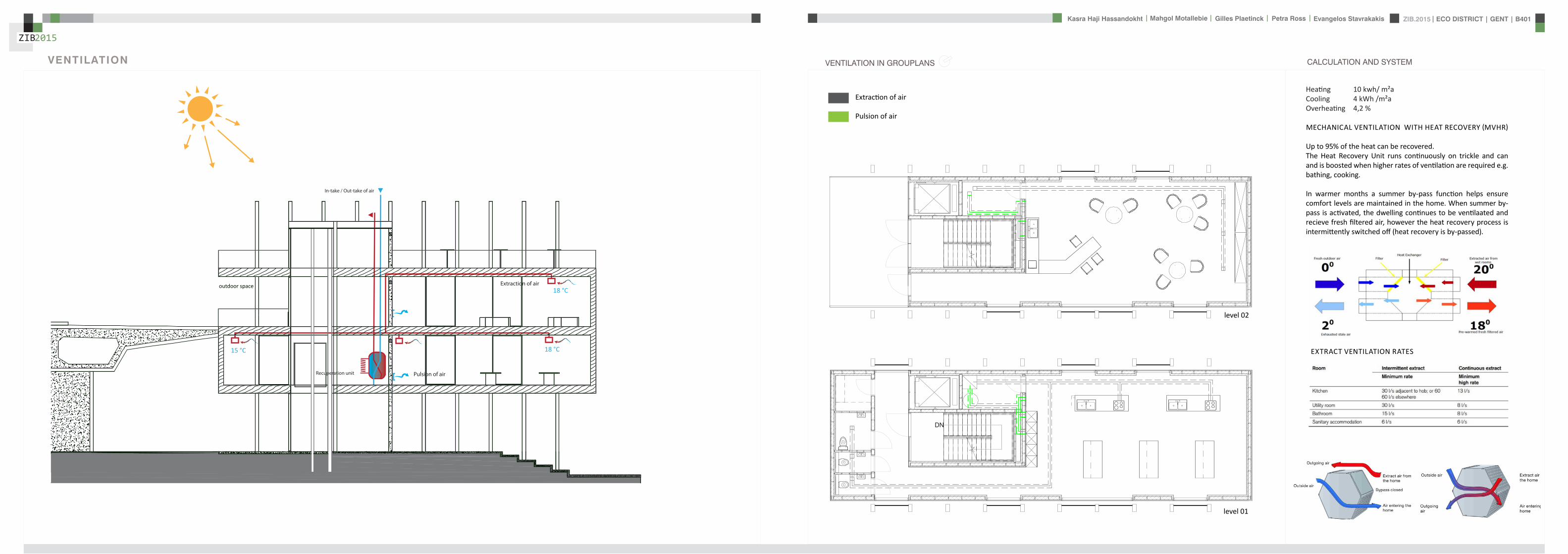
ZIB2015 ECO DISTRICT | GENT | B401Evangelos Stavrakakis | Petra Ross | Mahgol Motallebie | Gilles Plaetinck | Kasra Haji Hassandokht
ZIB2015
|
Extraction of air
Pulsion of airRecuperation unit
outdoor space
18 degC15 degC
18 degC
In-take Out-take of air
VENTILATION
Gilles Plaetinck
schaal 1 100
ZIB BUILDINGEnter address here
3 _ level 2
Owner
begeleider Checker
DN
Gilles Plaetinck
schaal 1 100
ZIB BUILDINGEnter address here
2 _ level 1
Owner
begeleider Checker
Extraction of air
Pulsion of air
VENTILATION IN GROUPLANS CALCULATION AND SYSTEM
level 01
level 02
T 42ECO DISTRICT | GENT | B401
ZIB2015Mechanical Ventilation with Heat Recovery (MVHR)
Up to 95 of the heat can be recovered The Heat Recovery Unit runs continu-ously on trickle and can and is boosted when higher rates of ventilation are required eg bathing cooking In warmer months a summer by-pass function helps ensure comfort levels are maintained in the home When summer by-pass is activated the dwelling contin-ues to be ventilaated and recieve fresh filtered air however the heat recovery process is intermittently switched off (heat recovery is by-passed)
Key BenefitsYear round removal of condensation and indoor pol-lutants A direct impact on the Dwelling Emission Rate re-quired in SAP helping reduce the carbon footprint of the property Fresh filtered air supplied to dwelling ideal for allergy sufferers and those with conditions such as asthma A balanced ventilation system for the whole house and recovering of heat that would have otherwise have been lost Low noise non-intrusive ventilation system ndash located away from the room however consideration should be given to duct runs to ensure cross-talk contamination doesnrsquot happen AND the unit is sized correctly so it is not running a high rate all of the time
Zehnder ComfoSystems Passive Haus accredited product suitable for large houses up to 300m2 Designed to ensure low noise excellent energy performance and heat exchange efficiency Choice of control options including LCD touch screen display Can be combine with ComfoCool for optional cooling of up to 5 degrees and humidity reduction by 20
Semi Rigid Ducting
With a manifold system the resistance caused by duct-ing is reduced therefore Semi-Rigid ducting resistance is very low The manifold takes mass airflow directly from the MVHR Heat Recovery Unit and allows lower rates to pass through to each individual room runDirecting mass flow to the manifold eliminates the need to increase the running speed of the MVHR Heat Re-covery unit to overcome the resistance of ducting which in turn causes noise for the homeowner
T 42ECO DISTRICT | GENT | B401
ZIB2015Mechanical Ventilation with Heat Recovery (MVHR)
Up to 95 of the heat can be recovered The Heat Recovery Unit runs continu-ously on trickle and can and is boosted when higher rates of ventilation are required eg bathing cooking In warmer months a summer by-pass function helps ensure comfort levels are maintained in the home When summer by-pass is activated the dwelling contin-ues to be ventilaated and recieve fresh filtered air however the heat recovery process is intermittently switched off (heat recovery is by-passed)
Key BenefitsYear round removal of condensation and indoor pol-lutants A direct impact on the Dwelling Emission Rate re-quired in SAP helping reduce the carbon footprint of the property Fresh filtered air supplied to dwelling ideal for allergy sufferers and those with conditions such as asthma A balanced ventilation system for the whole house and recovering of heat that would have otherwise have been lost Low noise non-intrusive ventilation system ndash located away from the room however consideration should be given to duct runs to ensure cross-talk contamination doesnrsquot happen AND the unit is sized correctly so it is not running a high rate all of the time
Zehnder ComfoSystems Passive Haus accredited product suitable for large houses up to 300m2 Designed to ensure low noise excellent energy performance and heat exchange efficiency Choice of control options including LCD touch screen display Can be combine with ComfoCool for optional cooling of up to 5 degrees and humidity reduction by 20
Semi Rigid Ducting
With a manifold system the resistance caused by duct-ing is reduced therefore Semi-Rigid ducting resistance is very low The manifold takes mass airflow directly from the MVHR Heat Recovery Unit and allows lower rates to pass through to each individual room runDirecting mass flow to the manifold eliminates the need to increase the running speed of the MVHR Heat Re-covery unit to overcome the resistance of ducting which in turn causes noise for the homeowner
MECHANICAL VENTILATION WITH HEAT RECOVERY (MVHR)
Up to 95 of the heat can be recoveredThe Heat Recovery Unit runs continuously on trickle and can and is boosted when higher rates of ventilation are required eg bathing cooking
In warmer months a summer by-pass function helps ensure comfort levels are maintained in the home When summer by-pass is activated the dwelling continues to be ventilaated and recieve fresh filtered air however the heat recovery process is intermittently switched off (heat recovery is by-passed)
EXTRACT VENTILATION RATES
T 42ECO DISTRICT | GENT | B401
ZIB2015Mechanical Ventilation with Heat Recovery (MVHR)
Up to 95 of the heat can be recovered The Heat Recovery Unit runs continu-ously on trickle and can and is boosted when higher rates of ventilation are required eg bathing cooking In warmer months a summer by-pass function helps ensure comfort levels are maintained in the home When summer by-pass is activated the dwelling contin-ues to be ventilaated and recieve fresh filtered air however the heat recovery process is intermittently switched off (heat recovery is by-passed)
Key BenefitsYear round removal of condensation and indoor pol-lutants A direct impact on the Dwelling Emission Rate re-quired in SAP helping reduce the carbon footprint of the property Fresh filtered air supplied to dwelling ideal for allergy sufferers and those with conditions such as asthma A balanced ventilation system for the whole house and recovering of heat that would have otherwise have been lost Low noise non-intrusive ventilation system ndash located away from the room however consideration should be given to duct runs to ensure cross-talk contamination doesnrsquot happen AND the unit is sized correctly so it is not running a high rate all of the time
Zehnder ComfoSystems Passive Haus accredited product suitable for large houses up to 300m2 Designed to ensure low noise excellent energy performance and heat exchange efficiency Choice of control options including LCD touch screen display Can be combine with ComfoCool for optional cooling of up to 5 degrees and humidity reduction by 20
Semi Rigid Ducting
With a manifold system the resistance caused by duct-ing is reduced therefore Semi-Rigid ducting resistance is very low The manifold takes mass airflow directly from the MVHR Heat Recovery Unit and allows lower rates to pass through to each individual room runDirecting mass flow to the manifold eliminates the need to increase the running speed of the MVHR Heat Re-covery unit to overcome the resistance of ducting which in turn causes noise for the homeowner
T 42ECO DISTRICT | GENT | B401
ZIB2015Mechanical Ventilation with Heat Recovery (MVHR)
Up to 95 of the heat can be recovered The Heat Recovery Unit runs continu-ously on trickle and can and is boosted when higher rates of ventilation are required eg bathing cooking In warmer months a summer by-pass function helps ensure comfort levels are maintained in the home When summer by-pass is activated the dwelling contin-ues to be ventilaated and recieve fresh filtered air however the heat recovery process is intermittently switched off (heat recovery is by-passed)
Key BenefitsYear round removal of condensation and indoor pol-lutants A direct impact on the Dwelling Emission Rate re-quired in SAP helping reduce the carbon footprint of the property Fresh filtered air supplied to dwelling ideal for allergy sufferers and those with conditions such as asthma A balanced ventilation system for the whole house and recovering of heat that would have otherwise have been lost Low noise non-intrusive ventilation system ndash located away from the room however consideration should be given to duct runs to ensure cross-talk contamination doesnrsquot happen AND the unit is sized correctly so it is not running a high rate all of the time
Zehnder ComfoSystems Passive Haus accredited product suitable for large houses up to 300m2 Designed to ensure low noise excellent energy performance and heat exchange efficiency Choice of control options including LCD touch screen display Can be combine with ComfoCool for optional cooling of up to 5 degrees and humidity reduction by 20
Semi Rigid Ducting
With a manifold system the resistance caused by duct-ing is reduced therefore Semi-Rigid ducting resistance is very low The manifold takes mass airflow directly from the MVHR Heat Recovery Unit and allows lower rates to pass through to each individual room runDirecting mass flow to the manifold eliminates the need to increase the running speed of the MVHR Heat Re-covery unit to overcome the resistance of ducting which in turn causes noise for the homeowner
Heating 10 kwh msup2aCooling 4 kWh msup2aOverheating 42
ZIB2015 ECO DISTRICT | GENT | B401Evangelos Stavrakakis | Petra Ross | Mahgol Motallebie | Gilles Plaetinck | Kasra Haji Hassandokht
ZIB2015
|
Shutters control system+ -
Solar roadways - PV panels
LED lights
Elevator Fuse box
ElectricityBattery withtransformator
ELECTRICITY
Summer night
cross- ventilation through building
Summer day
air through recuperation unit small change of temperature
15 degC 18 degC
+ groundplans
heated zone
not heated zone
ZONING ACCORDING TO TEMPERATURESSUMMER NIGHT - cross-ventilation through building
SUMMER DAY - air through recuperation unit small change of temperatureSHADING SYSTEM
As a shading was chozen system Renson Icarus Lamellas with angle 45deg made in wood
ZIB2015 ECO DISTRICT | GENT | B401Evangelos Stavrakakis | Petra Ross | Mahgol Motallebie | Gilles Plaetinck | Kasra Haji Hassandokht
ZIB2015
|
average only 4 hours of peak daylight hours per day (4 x 365 = 1460 hours per year)
- Surface area ( first part) Fly-over +- 20 000 msup2-gt 16 000 x 230 Watt = 3 680 000 Watt or 3680 kWonly 50 of fly-over covered with solar roadways
-gt 3680 kW x 4 h = 7360 kWh day-gt 3680 kW x 1460 h = 2 686 400 kWh year -gt +- 540 households (+- 5000 kWh year)
Tesla Powerwall Therersquos a 10 kWh unit at $3500 -gt 737 Tesla Batteries
gt the Solar Roadway has the ability to cut greenhouse gases by up to 75-percentgt A decentralized self-healing secure power grid
IN FRONT OF FLY-OVER
- Surface area Fly-over = 16 x 30 m = 480 msup2-gt 384 x 230 Watt = 88 320 Watt or 883 kWonly 50 of fly-over covered with solar roadways
-gt 44 kW x 4 h = 176 kWh day-gt 44 kW x 1460 h = 64 240 kWh year -gt +- 13 households (+- 5000 kWh year)
lightsshutters
elevator
2 fridges
2 coffeemakers
1 microwave
1 owen
2 cooking plates
stereo
ventilation unit
electricity transformer (AC to DC) for PV panels + batteries
summer 05 kWh daywinter 03 kWh day183 days x 05= 915 kWh182 days x 03 = 546 kWh = 1641 kWh
262 kWh
A++fridge 104 kWhyear104 x x2 = 208 kWh
900 W x 01 hours day = 09 kWhx 220 days x 2= 198 kWh a
67 kWh a
085x100 days= 85 kWh a
400 kWh x 2 = 800 kWh a
150 kWh a 419 kWha
68 kWh a
ENERGY DEMAND OVERVIEW ENERGY SUPPLY OVERVIEW - FLY-OVER
1 spot 56 W 10000 = 0056 KW4 hours per day 365 days a year = 1460 h0056 x 1460 = 8176 kWh10 spots x 8176= 8176 kWh a
1 spot 72 W 10000 = 0072 KW4 hours per day 365 days a year = 1460 h0072 x 1460 = 10512 kWh5 spots x 10512= 5256 kWh a
1 spot 52 W 10000 = 0052 KW4 hours per day 365 days a year = 1460 h0052 x 1460 = 7592 kWh21 spots x 7592= 159432 kWh a
1 spot 9 W 10000 = 0009 KW4 hours per day 365 days a year = 1460 h0009 x 1460 = 1314 kWh5 spots x 1314 = 657 kWh a
SOLAR ROADWAYS - PV PANELSEnergy from the sun
1 To generate energy for the ZIB building2 To generate energy for the surrounding houses3 To generate energy for lighting or signs on the road4 The panels will also have the capacity to charge electric vehicles while parked
ELECTRICITY SCHEME
5423 kWh a
ZIB2015 ECO DISTRICT | GENT | B401Evangelos Stavrakakis | Petra Ross | Mahgol Motallebie | Gilles Plaetinck | Kasra Haji Hassandokht
ZIB2015
|
SUMMER SUNNY 10-42 LUXWINTER SUNNY 10-42 LUX
DAYLIGHT - DIALuxLIGHTING SYSTEM - DIALux
Workplane 9 Results overview
Height of working plane 0800 m Wall zone 0000 m
Result Mean (target) Min Max Minaverage MinmaxPerpendicular illuminance [lx] 463 (500) 105 689 0227 0152
Profile Offices Writing typewriting reading data processing
B401-Gent 6222015
Site 1 Building 2 Zib Room 9 Workplane 9 Results overview
Page 70
Workplane 9 False coloursPerpendicular illuminance (adaptive)
Scale 1 200
Perpendicular illuminance (Surface)Mean (actual) 463 lx Min 105 lx Max 689 lx Minaverage 0227 Minmax 0152
B401-Gent 6222015
Site 1 Building 2 Zib Room 9 Workplane 9 False coloursPerpendicular illuminance (adaptive)
Page 72
Workplane 9 Value chartPerpendicular illuminance (adaptive)
Scale 1 200
Perpendicular illuminance (Surface)Mean (actual) 463 lx Min 105 lx Max 689 lx Minaverage 0227 Minmax 0152
B401-Gent 6222015
Site 1 Building 2 Zib Room 9 Workplane 9 Value chartPerpendicular illuminance (adaptive)
Page 73
Workplane 13 Results overview
Height of working plane 0800 m Wall zone 0000 m
Result Mean (target) Min Max Minaverage MinmaxPerpendicular illuminance [lx] 388 (500) 69 732 0178 0094
Profile Offices Writing typewriting reading data processing
B401-Gent 6222015
Site 1 Building 6 Storey 1 Room 13 Workplane 13 Results overview
Page 94
Workplane 13 False coloursPerpendicular illuminance (adaptive)
Scale 1 100
Perpendicular illuminance (Surface)Mean (actual) 388 lx Min 69 lx Max 732 lx Minaverage 0178 Minmax 0094
B401-Gent 6222015
Site 1 Building 6 Storey 1 Room 13 Workplane 13 False coloursPerpendicular illuminance (adaptive)
Page 96
Workplane 13 Value chartPerpendicular illuminance (adaptive)
Scale 1 100
Perpendicular illuminance (Surface)Mean (actual) 388 lx Min 69 lx Max 732 lx Minaverage 0178 Minmax 0094
B401-Gent 6222015
Site 1 Building 6 Storey 1 Room 13 Workplane 13 Value chartPerpendicular illuminance (adaptive)
Page 97
Workplane 9 False coloursPerpendicular illuminance (adaptive)
Scale 1 200
Perpendicular illuminance (Surface)Mean (actual) 463 lx Min 105 lx Max 689 lx Minaverage 0227 Minmax 0152
B401-Gent 6222015
Site 1 Building 2 Zib Room 9 Workplane 9 False coloursPerpendicular illuminance (adaptive)
Page 72
1st f loor 2nd f loor Site 1 Luminaire parts listQuantity Luminaire (Luminous emittance)10 3F Filippi 12736 P 202x24W LED OP 196x1231
Luminous emittance 1Fitting 1x24W 2xLEDLight output ratio 100Lamp luminous flux 5332 lmLuminaire Luminous Flux 5332 lmPower 560 WLight yield 952 lmW
200
300
400
cdklm η = 100C0 - C180 C90 - C270
0deg 15deg 30deg
45deg
60deg
75deg
90deg
105deg105deg
90deg
75deg
60deg
45deg
30deg 15deg 0deg
5 SFN Eclairages 0732360X CLFV 236Luminous emittance 1Fitting 2xT26 36W840Light output ratio 6889Lamp luminous flux 6700 lmLuminaire Luminous Flux 4615 lmPower 720 WLight yield 641 lmW
160
240
cdklm η = 69C0 - C180 C90 - C270
0deg 15deg 30deg
45deg
60deg
75deg
90deg
105deg105deg
90deg
75deg
60deg
45deg
30deg 15deg 0deg
21 SFN Eclairages 332226XX SAM F 2x26W BELuminous emittance 1Fitting 2xTC-DEL 26W840Light output ratio 3297Lamp luminous flux 3600 lmLuminaire Luminous Flux 1187 lmPower 520 WLight yield 228 lmW
40
60
80
100
120
140
cdklm η = 33C0 - C180 C90 - C270
0deg 15deg 30deg
45deg
60deg
75deg
90deg
105deg105deg
90deg
75deg
60deg
45deg
30deg 15deg 0deg
1 Signcomplex AR111-009-AW-W-06 AR111 COB 9W38deg WhiteLuminous emittance 1Fitting 1xAR111-009-AW-W-06Light output ratio 8078Lamp luminous flux 600 lmLuminaire Luminous Flux 485 lmPower 90 WLight yield 539 lmW
800
1200
cdklm η = 81C0 - C180 C90 - C270
0deg 15deg 30deg
45deg
60deg
75deg
90deg
105deg105deg
90deg
75deg
60deg
45deg
30deg 15deg 0deg
Total lamp luminous flux 163020 lm Total luminaire luminous flux 101807 lm Total Load 20210 W Light yield 504 lmW
B401-Gent 6222015
Site 1 Luminaire parts list
Page 19
10x
6x
21x
1x
types of l ights
Perpendicular i l luminance (Surface)Mean (actual ) 463 lx Min 105 lx Max 689 lx Minaverage 0 227 Minmax 0 152
Perpendicular i l luminance (Surface)Mean (actual ) 388 lx Min 69 lx Max 732 lx Minaverage 0 178 Minmax 0 094
ZIB2015 ECO DISTRICT | GENT | B401Evangelos Stavrakakis | Petra Ross | Mahgol Motallebie | Gilles Plaetinck | Kasra Haji Hassandokht
ZIB2015
|
Tube hybrid Solar panels
Hot water tank Water taps
City water supply
Rain water collection for vertical harvesting
City water supply
WADI
Rain water tank
WATER MANAGEMENT
Sinks
Available roof area
In Ghent avarage of 900mmm2year
3197 m2
09x 3197 = 28773 m3year
RAIN WATER GAIN
toilet - 3x - 03lskitchen -4x - 02ls
POTABLE WATER DEMAND
3 toiletsVertical gardening
Total
relative RW usage
300 l day150 l day = 450lday= 16425 m3 year
1407 lday100m2
RAIN WATER DEMAND
RAIN WATER TANK
Relative RWT volumeRain water tank volume
3m3 100 m2
9591 l gt 10 m3
DIMESION OF PIPES
City water supplyRainwater tank
178 mm (DN 18 - 15 - 12)165 mm (DN 17-15)
are composed of hexagonal tiles Rainwater can infiltrate between the gaps from where it goes to rainwatter collector which supplies the vegetation on fly-over
THE SOLAR ROADWAYS
WATER SUPPLY SCHEME AND CALCULATION
ZIB2015 ECO DISTRICT | GENT | B401Evangelos Stavrakakis | Petra Ross | Mahgol Motallebie | Gilles Plaetinck | Kasra Haji Hassandokht
ZIB2015
|
WADI
City water supply
Rain water tank
Sinks
Divided sewer systemwithin building
SEWAGE SYSTEM
ToiletToilet sinkKitchen sink
DU = 2 lsDU = 05 lsDU = 08 ls
WATER DRAINAGE OF DEVICES
Frequency of usage at the same time
K 05
DIMESION OF PIPES
Black waterGrey water
110 mm (DU 110)75 mm (DU 75 - 63)
WATER DRAINAGE SCHEME AND CALCULATION
ZIB2015 ECO DISTRICT | GENT | B401Evangelos Stavrakakis | Petra Ross | Mahgol Motallebie | Gilles Plaetinck | Kasra Haji Hassandokht
ZIB2015
|
DN
Gilles Plaetinck
schaal 1 100
ZIB BUILDINGEnter address here
2 _ level 1
Owner
begeleider Checker
Gilles Plaetinck
schaal 1 100
ZIB BUILDINGEnter address here
3 _ level 2
Owner
begeleider Checker
WATER SUPPLY
HOT WATER
WATER DRAINAGE
WATER SUPPLY AND DRAINAGE IN GROUPLANS
level 01
level 02
ENERGY
RAINWATER TANK
HELOPHYTE FILTER
IRRIGATION SYSTEM
BIO-ROTOR
MICRO TURBINE
PHOSPHOR
In this building a closed water system is applied which is based on reusing water in mullple wasRainRain water from the roof will be collected in a storage tank situated on the ground floor This water will be used to flush the toilet and irrigate crops in verlcal harveslng system In case of an overflow the water will be stored in the con-structed wetland near the building The rainwater can be fil-tered through a helophyte filter up to drinking water stan-dard The waste water system includes three types of water yellyellow black and grey waterThe yellow water will be stored for its phosphor while the black water will be purified into grey water This grey water is comparable to the quality of rain water aaer purificalon b means of a bio rotor The remaining residue from the bio rotor together with the organic waste from the harveslng is fermented into biogas that drives a micro turbine in order to produce some addilonal energy
TheThe waste product deriving from this process will be used as compost in verlcal harveslng This efficient yet complex system closes the ullizalon cycle of the building and turns it into an efficient vicious circle that can be considered au arkic
In this building a closed water system is applied which is based on reusing water in multiple was
Rain water from the roof will be collected in a storage tank situated on the ground floor This water will be used to flushthe toilet and irrigate crops in vertical harvesting system In case of an overflow the water will be stored in the constructed wetland near the building The rainwater can be filtered through a helophyte filter up to drinking water standard
The waste water system includes three types of water yellow black and grey water The yellow water will be stored for its phosphor while the black water will be purified into grey water This grey water is comparable to the quality of rain water after purification b means of a bio rotor The remaining residue from the bio rotor together with the organic waste from the harvesting is fermented into biogas that drives a micro turbine in order to produce some additional energy The waste product deriving from this process will be used ascompost in ver1048991cal harves1048991ng This efficient yet complexsystem closes the u1048991liza1048991on cycle of the building and turns itinto an efficient vicious circle that can be considered au arkic
WATER CYCLE
ZIB2015 ECO DISTRICT | GENT | B401Evangelos Stavrakakis | Petra Ross | Mahgol Motallebie | Gilles Plaetinck | Kasra Haji Hassandokht
ZIB2015
|
CALCULATIONS
Passive House verification
Photo or Drawing
Building Workshop + info pointStreet
PostcodeCityCountry
Building Type non-residentialClimate Ukkel
Home Owner(s) Client(s)Street
PostcodeCity
ArchitectStreet
PostcodeCity Calculation electricity Internal heat gains
Mechanical System Building type
StreetPostcodeCity Internal heat gains
Year of Construction 2015 Interior Temperature 200 degC Utilisation pattern
Number of Dwelling Units 1 Internal Heat Gains 20 Wm2 Type of values used Fill in worksheet IHG Non-Dom Enclosed Volume Ve 12442 Planned number of occupants
Number of Occupants 80 8 Design
Specific building demands with reference to the treated floor area use Annual method
Treated floor area 2840 msup2 Requirements Fulfilled Verification Annual method The monthly method should be used for building certification
Space heating Annual heating demand 10 kWh(m2a) 15 kWh(msup2a) yes Specific space heating demand annual method 103 kWh(msup2a)
Heating load 11 Wm2 10 Wmsup2 - Specific space heating demand monthly Method 120 kWh(msup2a)
Space cooling Overall specific space cooling demand kWh(m2a) 15 kWh(msup2a)
Cooling load Wm2 - -Frequency of overheating (gt 25 degC) - -
Primary Energy Space heating and dehumidification
cooling household electricity 73 kWh(m2a) 120 kWh(msup2a) yes
DHW space heating and auxiliary electricity 24 kWh(m2a) - -Specific primary energy reduction through solar electricity 21 kWh(m2a) - -
Airtightness Pressurization test result n50 06 1h 06 1h yes
PHPP Verification FINAL ZIB FILE CALCULTIONS PHPPxls
L B H VOLUME
main 1 226 7 4 6328main 2 184 7 35 4508
core 0 6 2 5 3 5 108 5core 0 62 5 35 1085core 3 62 3 28 521
12442
AREAmain 1 storage 35
wc big 35wc 2wc 2workshop 103
MAIN 2 infolounge 92
staircase 56storage technical 22
284
Floor_exterior 1582 31 1272
Roof_exterior 1582
Passive House verification
Photo or Drawing
Building Workshop + info pointStreet
PostcodeCityCountry
Building Type non-residentialClimate Ukkel
Home Owner(s) Client(s)Street
PostcodeCity
ArchitectStreet
PostcodeCity Calculation electricity Internal heat gains
Mechanical System Building type
StreetPostcodeCity Internal heat gains
Year of Construction 2015 Interior Temperature 200 degC Utilisation pattern
Number of Dwelling Units 1 Internal Heat Gains 20 Wm2 Type of values used Fill in worksheet IHG Non-Dom Enclosed Volume Ve 12442 Planned number of occupants
Number of Occupants 80 8 Design
Specific building demands with reference to the treated floor area use Annual method
Treated floor area 2840 msup2 Requirements Fulfilled Verification Annual method The monthly method should be used for building certification
Space heating Annual heating demand 10 kWh(m2a) 15 kWh(msup2a) yes Specific space heating demand annual method 103 kWh(msup2a)
Heating load 11 Wm2 10 Wmsup2 - Specific space heating demand monthly Method 120 kWh(msup2a)
Space cooling Overall specific space cooling demand kWh(m2a) 15 kWh(msup2a)
Cooling load Wm2 - -Frequency of overheating (gt 25 degC) - -
Primary Energy Space heating and dehumidification
cooling household electricity 73 kWh(m2a) 120 kWh(msup2a) yes
DHW space heating and auxiliary electricity 24 kWh(m2a) - -Specific primary energy reduction through solar electricity 21 kWh(m2a) - -
Airtightness Pressurization test result n50 06 1h 06 1h yes
PHPP Verification FINAL ZIB FILE CALCULTIONS PHPPxls
SURFACE AREAcurrent orientation only night ventilation
current orientation only night ventilation 6 windows less 52 msup2
current orientation only night ventilation 7 windows less 60msup2 (stays the same for each side)
current orientation only night ventilation 8 windows less 69 msup2
orientation turned 90deg only night ventilation 6 windows less 52 msup2
orientation turned 90deg only night ventilation 7 windows less 60msup2 (window less at SE side)
orientation turned 90deg only night ventilation 8 windows less 69 msup2
-gt orientation turned 90deg only night ventilation 9 windows less 77msup2 (window less at NW side althought theres less overheating in the case of a window less at SE side the heating demand exceeds 15)
CHANGE IN DESIGN
ZIB2015 ECO DISTRICT | GENT | B401Evangelos Stavrakakis | Petra Ross | Mahgol Motallebie | Gilles Plaetinck | Kasra Haji Hassandokht
ZIB2015
|
Passive House verificationS P E C I F I C A N N U A L H E A T I N G D E M A N D
Climate Ukkel Interior Temperature 200 degC
Building Workshop + info point Building TypeUse non-residentialTreated Floor Area ATFA 2840 msup2
per msup2Area U-Value Temp Factor ft Gt Treated Data for heating balance diagram
Building Element Temperature Zone msup2 W(msup2K) kKha kWha Floor Area Losses GainsExterior Wall - Ambient A 5595 0101 100 743 = 4181 1472 Exterior Wall - Ambient 147234373Exterior Wall - Ground B 069 = Exterior Wall - GroundRoofCeiling - Ambient A 1550 0094 100 743 = 1085 382 RoofCeiling - Ambient 381903529Floor slab basement ceiling B 310 0105 069 743 = 167 059 Floor slab basement ceiling 058811509
A 100 =A 100 =
unheated basement X 075 = unheated basementWindows A 1154 0648 100 743 = 5562 1958 Windows 195834732Exterior Door A 100 = Exterior DoorExterior TB (lengthm) A 1169 -0030 100 743 = -259 -091 Thermal Bridge Heat LossPerimeter TB (lengthm) P 069 = 000 not useful heat gains 365267499Ground TB (lengthm) B 069 =
Total of All Building Envelope Areas 8609 ndashndashndashndashndashndashndashndashndashndashndashndashndash- kWh(msup2a) Ventilation 395818713
Transmission Heat Losses QT Total 10736 378Annual Heating Demand 102516636
ATFA Clear Room Height internal gains 100951487msup2 m msup3 passive solar gains 250668423
Ventilation System Effective Air Volume VV 2840 280 = 7952 Thermal bridge credit 091126837Effective Heat Recovery Efficiency eff 81 Cross check sum 46324923 46324923of Heat Recovery
Efficiency of Subsoil Heat Exchanger SHX 0 nVsystem HR nVRes
1h 1h 1h
Energetically Effective Air Exchange nV 0105 (1 - 081 ) + 0038 = 0058
VV nV cAir Gt
msup3 1h Wh(msup3K) kKha kWha kWh(msup2a)
Ventilation Heat Losses QV 795 0058 033 743 = 1124 40
Reduction Factor QT QV NightWeekend
kWha kWha Saving kWha kWh(msup2a)
Total Heat Losses QL ( 10736 + 1124 ) 10 = 11860 418
Orientation Reduction Factor g-Value Area Radiation HPof the Area See Windows Sheet (perp radiation)
msup2 kWh(msup2a) kWha
1 North 054 050 2700 163 = 11822 East 058 000 440 197 = 03 South 056 050 4860 314 = 42874 West 032 050 3216 254 = 13275 Horizontal 063 050 324 317 = 323
kWh(msup2a)
Available Solar Heat Gains QS Total 7119 251
Length Heat Period Spec Power qI ATFA
khd da Wmsup2 msup2 kWha kWh(msup2a)
Internal Heat Gains QI 0024 209 201 2840 = 2867 101
kWha kWh(msup2a)
Free Heat QF QS + QI = 9986 352
Ratio of Free Heat to Losses QF QL = 084
Utilisation Factor Heat Gains G (1 - ( QF QL )5 ) (1 - ( QF QL )
6 ) = 90kWha kWh(msup2a)
Heat Gains QG G QF = 8949 315
kWha kWh(msup2a)
Annual Heating Demand QH QL - QG = 2911 10
kWh(msup2a) (YesNo)
Limiting Value 15 Requirement met yes
00
147
00
3806000000
196
00
40
37
09
103
101
251
0
5
10
15
20
25
30
35
40
45
50
Losses Gains
Hea
t flo
ws
[kW
h(m
sup2a)]
Heating energy balance
passive solar gains
internal gains
Annual Heating Demand
Thermal bridge credit
not useful heat gains
Ventilation
Exterior Door
Windows
unheated basement
Floor slab basement ceiling
RoofCeiling - Ambient
Exterior Wall - Ground
Exterior Wall - Ambient
Thermal Bridge Heat Loss
HPP Annual Heating Demand FINAL ZIB FILE CALCULTIONS PHPPxls
Passive House verification Passive House verificationS P E C I F I C U S E F U L C O O L I N G D E M A N D S P E C I F I C U S E F U L C O O L I N G D E M A N D
M O N T H L Y M E T H O D M O N T H L Y M E T H O D
(This page displays the sums of the monthly method over the cooling period))Climate Ukkel Interior Temperature Summer 25 degC Climate Ukkel Interior Temperature 25 degC
Building Workshop + info point Building TypeUse non-residential Building Workshop + info point Building TypeUse non-residential
Spec Capacity 60 Wh(msup2K) (Enter in Summer worksheet) Treated Floor Area ATFA 2840 msup2 Treated Floor Area ATFA 284 msup2
per msup2Temperature Zone Area U-Value Mon Red Fac Gt Treated Jan Feb Mar Apr May Jun Jul Aug Sep Oct Nov Dec Year
Building Element msup2 W(msup2K) kKha kWha Floor Area Heating Degree Hours - Ex 168 150 144 121 92 73 57 59 82 109 140 160 136 kKh1 Exterior Wall - Ambient A 5595 0101 100 103 = 5782 Heating Degree Hours - G 126 123 135 120 106 83 63 54 58 71 86 109 113 kKh2 Exterior Wall - Ground B 100 = Losses - Exterior 2553 2286 2189 1838 1393 1117 871 904 1245 1660 2123 2432 20612 kWh3 RoofCeiling - Ambient A 1550 0094 100 103 = 1500 Losses - Ground 41 40 44 39 35 27 21 18 19 23 28 36 370 kWh4 Floor slab basement ceil B 310 0105 100 90 = 294 Losses Summer Ventilatio 67 71 244 372 629 720 880 865 658 499 234 126 5366 kWh5 A 100 = Sum Spec Heat Losses 94 84 87 79 72 66 62 63 68 77 84 91 928 kWhmsup26 A 100 = Solar Load North 44 81 141 212 286 298 298 255 178 116 54 35 1998 kWh7 unheated basement X 075 = Solar Load East 0 0 0 0 0 0 0 0 0 0 0 0 0 kWh8 Windows A 1154 0648 100 103 = 7690 Solar Load South 218 315 464 577 681 644 681 658 532 416 242 171 5601 kWh9 Exterior Door A 100 = Solar Load West 79 125 213 303 385 378 370 347 256 177 91 60 2785 kWh
10 Exterior TB (lengthm) A 1169 -0030 100 103 = -358 Solar Load Horiz 11 21 37 57 79 79 80 69 47 30 14 9 533 kWh11 Perimeter TB (lengthm) P 100 = Solar Load Opaque 3 5 9 13 18 19 19 16 11 7 3 2 126 kWh12 Ground TB (lengthm) B 100 = Internal Heat Gains 425 384 425 411 425 411 425 425 411 425 411 425 5001 kWh
ndashndashndashndashndashndashndashndashndashndashndash kWh(msup2a) Sum Spec Loads Solar + 28 33 45 55 66 64 66 62 51 41 29 25 565 kWhmsup2
Transmission Losses QT (Negative Heat Loads) Total 14907 525 Utilisation Factor Losses 29 39 52 69 84 88 82 88 73 53 34 27 58Useful Cooling Energy Dem 0 0 4 30 142 192 417 192 40 4 0 0 1021 kWh
ATFA Clear Room Height Spec Cooling Demand 00 00 00 01 05 07 15 07 01 00 00 00 36 kWhmsup2Effective msup2 m msup3
Air Volume VV 284 280 = 795
Heat Transfer Coef Gt
WK kKha kWha kWh(msup2a)
Exterior 99 103 = 1013 36Ground 00 105 = 0 00
Additional Summer Ventilation
Select X Window Night Ventilation Manual Corresponding Air Change Rate 136 1h
Mechanical Automatically Controlled Ventilation (for window ventilation at 1 K temperature difference indoor - outdoor)
Minimum Acceptable Indoor Temperatu 220 degC
kWha kWh(msup2a)
Heat Losses Summer Ventilation 5172 182
QLext QLground QLsummer
kWha kWha kWha kWha kWh(msup2a)
Ventilation Heat Losses QV 1013 + 0 + 5172 = 6185 218
2
3
4
5
6
7
8
9
10
Spec
ific
loss
es l
oads
l c
oolin
g de
man
d [k
Wh
(msup2 m
onth
)] Spec Cooling Demand Sum Spec Heat Losses Sum Spec Loads Solar + Internal
QT QV
kWha kWha kWha kWh(msup2a)
Total Heat Losses QL 14907 + 6185 = 21092 743
Orientation Reduction Factor g-Value Area Global Radiationof the Area (perp radiation)
msup2 kWh(msup2a) kWha
1 North 031 050 270 462 = 19182 East 061 000 44 578 = 0 Temperature Amplitude Summer 82 K3 South 030 050 486 707 = 52114 West 025 050 322 654 = 2646 Month 1 2 3 4 5 6 7 8 9 10 11 12 Annual Total5 Horizontal 035 050 32 913 = 513 Days 31 28 31 30 31 30 31 31 30 31 30 31 3656 Sum Opaque Areas 121 Ambient Temp 250 270 572 828 1275 1487 1737 1707 1369 1039 568 356 96
kWh(msup2a) North Radiation 106 195 329 494 667 697 712 599 419 275 129 87 471
Available Solar Heat Gains QS Total 10409 367 East Radiation 146 266 452 698 937 940 988 851 574 382 179 123 654
South Radiation 311 440 645 786 912 858 898 885 733 579 341 241 763Length Heat Period Spec Power qI ATFA West Radiation 155 261 471 707 926 926 896 819 580 382 183 116 642
khd da Wmsup2 msup2 kWha kWh(msup2a) Hori Radiation 200 369 662 1021 1398 1410 1418 1234 842 535 243 156 949
Internal Heat Gains QI 0024 303 20 2840 = 4151 146 Tsky -750 -730 -428 -172 275 487 737 707 369 039 -432 -644 -04
Ground Temp 805 676 686 830 1072 1345 1647 1776 1696 1552 1310 1037 121kWha kWh(msup2a)
Sum Heat Loads QF QS + QI = 14560 513
Ratio of Losses to Free Heat Gains QL QF = 145
Utilisation Factor Heat Losses G = 64kWha kWh(msup2a)
Useful Heat Losses QVn G QL = 13539 477
kWha kWh(msup2a)
Useful Cooling Demand QK QF - QVn = 1021 4
kWh(msup2a) (YesNo)
Limiting Value 15 Requirement met yes
0
1
2
Jan Feb Mar Apr May Jun Jul Aug Sep Oct Nov Dec
usef
u
HPP Cooling FINAL ZIB FILE CALCULTIONS PHPPxls
Passive House verificationS P E C I F I C A N N U A L H E A T I N G D E M A N D
Climate Ukkel Interior Temperature 200 degC
Building Workshop + info point Building TypeUse non-residentialTreated Floor Area ATFA 2840 msup2
per msup2Area U-Value Temp Factor ft Gt Treated Data for heating balance diagram
Building Element Temperature Zone msup2 W(msup2K) kKha kWha Floor Area Losses GainsExterior Wall - Ambient A 5595 0101 100 743 = 4181 1472 Exterior Wall - Ambient 147234373Exterior Wall - Ground B 069 = Exterior Wall - GroundRoofCeiling - Ambient A 1550 0094 100 743 = 1085 382 RoofCeiling - Ambient 381903529Floor slab basement ceiling B 310 0105 069 743 = 167 059 Floor slab basement ceiling 058811509
A 100 =A 100 =
unheated basement X 075 = unheated basementWindows A 1154 0648 100 743 = 5562 1958 Windows 195834732Exterior Door A 100 = Exterior DoorExterior TB (lengthm) A 1169 -0030 100 743 = -259 -091 Thermal Bridge Heat LossPerimeter TB (lengthm) P 069 = 000 not useful heat gains 365267499Ground TB (lengthm) B 069 =
Total of All Building Envelope Areas 8609 ndashndashndashndashndashndashndashndashndashndashndashndashndash- kWh(msup2a) Ventilation 395818713
Transmission Heat Losses QT Total 10736 378Annual Heating Demand 102516636
ATFA Clear Room Height internal gains 100951487msup2 m msup3 passive solar gains 250668423
Ventilation System Effective Air Volume VV 2840 280 = 7952 Thermal bridge credit 091126837Effective Heat Recovery Efficiency eff 81 Cross check sum 46324923 46324923of Heat Recovery
Efficiency of Subsoil Heat Exchanger SHX 0 nVsystem HR nVRes
1h 1h 1h
Energetically Effective Air Exchange nV 0105 (1 - 081 ) + 0038 = 0058
VV nV cAir Gt
msup3 1h Wh(msup3K) kKha kWha kWh(msup2a)
Ventilation Heat Losses QV 795 0058 033 743 = 1124 40
Reduction Factor QT QV NightWeekend
kWha kWha Saving kWha kWh(msup2a)
Total Heat Losses QL ( 10736 + 1124 ) 10 = 11860 418
Orientation Reduction Factor g-Value Area Radiation HPof the Area See Windows Sheet (perp radiation)
msup2 kWh(msup2a) kWha
1 North 054 050 2700 163 = 11822 East 058 000 440 197 = 03 South 056 050 4860 314 = 42874 West 032 050 3216 254 = 13275 Horizontal 063 050 324 317 = 323
kWh(msup2a)
Available Solar Heat Gains QS Total 7119 251
Length Heat Period Spec Power qI ATFA
khd da Wmsup2 msup2 kWha kWh(msup2a)
Internal Heat Gains QI 0024 209 201 2840 = 2867 101
kWha kWh(msup2a)
Free Heat QF QS + QI = 9986 352
Ratio of Free Heat to Losses QF QL = 084
Utilisation Factor Heat Gains G (1 - ( QF QL )5 ) (1 - ( QF QL )
6 ) = 90kWha kWh(msup2a)
Heat Gains QG G QF = 8949 315
kWha kWh(msup2a)
Annual Heating Demand QH QL - QG = 2911 10
kWh(msup2a) (YesNo)
Limiting Value 15 Requirement met yes
00
147
00
3806000000
196
00
40
37
09
103
101
251
0
5
10
15
20
25
30
35
40
45
50
Losses Gains
Hea
t flo
ws
[kW
h(m
sup2a)]
Heating energy balance
passive solar gains
internal gains
Annual Heating Demand
Thermal bridge credit
not useful heat gains
Ventilation
Exterior Door
Windows
unheated basement
Floor slab basement ceiling
RoofCeiling - Ambient
Exterior Wall - Ground
Exterior Wall - Ambient
Thermal Bridge Heat Loss
HPP Annual Heating Demand FINAL ZIB FILE CALCULTIONS PHPPxls
factor 05Wd (ls) 088
nominal diameter 75 mmVERTICAL COLLECTOR sink toilets 3 05 15
sink kitchen 2 08 16Total 5 31factor 05
Wd (ls) 088nominal diameter 75 mm
Toevoerend ROOF SURFACE
horizontal roof surface (msup2) orientation coeff angle (deg) roofcover filter coeff toevoerend
444 1 0 08 09 3197
RAIN WATER USAGE
Type usage ( l usage) persons day frequency usageday yearly usage
toilet use small 3 20 3 180 65700toilet use big 6 20 1 120 43800VERTICAL GARDENING 150 54750TOTAL 450 164250 L year
16425 msup3 year
TOTAL RAINWATER USAGE 450 L dayRELATIVE RAINWATER USAGE 1407 L day100msup2
LEEGSTAND
relative rainwater usage 1407 L day 100 msup2LEEGSTAND 7 relative volume rainwater tank 3 msup3 100 msup2rainwater tank volume 9591 Liter
suggestion 50 msup2 02 m= 10 msup3
SUPPLYtype amount debiet Q total total WW
lsec lsec lsecMAIN LEVEL POTABLE
sink toilet 3 01 03 03sink kitchen 2 01 02 02
Total 5 05 05Gelijktijdigheid 05 05debiet Q (lsec) 025 025
diameter 178 178 cm
type amount debiet Q total total WWlsec lsec lsec
MAIN LEVEL RAIN WATER toilet 3 01 03 0
Total 3 03Gelijktijdigheid 071debiet Q (lsec) 0213
diameter 165 cm
FECALIEumlNtype amount value Total (ls)
COLLECTOR HORIZONTAL toilet 3 2Total 6factor 05
Wd (ls) 122nominal diameter 110 mm
type amount value Total (ls)COLLECTOR VERTICAL toilet 3 2
Total 6factor 05
Wd (ls) 122nominal diameter 110 mm
DRAINtype amount value Total (ls)
HORIZONTAL COLLECTOR sink toilets 3 05 15sink kitchen 2 08 16
Total 5 31
WATER
ZIB2015 ECO DISTRICT | GENT | B401Evangelos Stavrakakis | Petra Ross | Mahgol Motallebie | Gilles Plaetinck | Kasra Haji Hassandokht
ZIB2015
|
Passive House verificationS P E C I F I C S P A C E H E A T I N G L O A D Risk Determination of Group Heating for a Critical Room
Building Workshop + info point Building TypeUse non-residential Workshop room ( 1= Yes 0 = No)
Climate (HL) Ukkel Treated Floor Area ATFA 2840 msup2 Interior Temperature 20 degC Building Satisfies Passive House Criteria 1
Design Temperature Radiation North East South West Horizontal Room floor area 100 msup2 Supply Air per msup2 Living AreaWeather Condition 1 -31 degC 10 10 30 15 20 Wmsup2 Planned ambient air quantity for the room 150 msup3h 150 msup3hmsup2Weather Condition 2 -22 degC 5 5 20 10 10 Wmsup2 Planned ambient air quantities for the remaining rooms -67 msup3hGround Design Temp 68 degC Area U-Value Factor TempDiff 1 TempDiff 2 PT 1 PT 2
Building Element Temperature Zone msup2 W(msup2K) Always 1(except X) K K W W Building Element Temperature Zone msup2 W(msup2K) Always 1
(except X) K Room Trans Loss W
1 Exterior Wall - Ambient A 5595 0101 100 231 or 222 = 1299 or 1249 Aboveground Exterior Wall A 650 010 100 231 = 1512 Exterior Wall - Ground B 100 132 or 132 = or Belowground Exterior Wall B 00 100 132 =3 RoofCeiling - Ambient A 1550 0094 100 231 or 222 = 337 or 324 RoofCeiling D 880 009 100 231 = 1914 Floor slab basement ceiling B 310 0105 100 132 or 132 = 43 or 43 Underground Floor Slab B 00 011 100 132 = 05 A 100 231 or 222 = or A 100 231 =6 A 100 231 or 222 = or A 100 231 =7 unheated basement X 075 231 or 222 = or X 100 231 =8 Windows A 1154 0648 100 231 or 222 = 1728 or 1661 Windows A 480 065 100 231 = 7199 Exterior Door A 100 231 or 222 = or Exterior Door A 100 231 =
10 Exterior TB (lengthm) A 1169 -0030 100 231 or 222 = -80 or -77 Exterior thermal bridges (Lengthm) A 100 231 =11 Perimeter TB (lengthm) P 100 132 or 132 = or Perimeter Thermal Bridges (Lengthm) A 100 231 =12 Ground TB (lengthm) B 100 132 or 132 = or Floor Slab Thermal Bridges (Lengthm) A 50 100 231 =13 HouseDU Partition Wall I 100 30 or 30 = or HouseDU Partition Wall I 200 100 30 =
Transmission Heat Losses PT ndashndashndashndashndashndashndashndashndashndashndashndashndash- ndashndashndashndashndashndashndashndashndashndashndash-
Total = 3328 or 3200 = 1061
ATFA Clear Room HeightVentilation System msup2 m msup3 Risk
Effective Air Volume VV 2840 280 = 795 Enter 1 = Yes 0 = No PTRoom W PSupply Air W Ratio Summand
SHX 1 SHX 2 Transmission Heat Losses 1061 1386 077 -023Efficiency of Heat Recovery HR 81 Heat Recovery Efficiency SHX 0 Efficiency SHX 0 or 0 Concentrated leakages 0 000of the Heat Exchanger Insulation to other rooms better R = 15 msup2KW 1 ( 2 = no thermal contact except door) 050
nVRes (Heating Load) nVsystem HR HR Room is on the ground floor 0 0001h 1h 1h 1h open staircase 0 000
Energetically Effective Air Exchange nV 0094 + 0105 (1- 081 or 081 ) = 0114 or 0114 TOTAL of the Risk Summands 027Ventilation Heating Load PV
VL nL nL cAir TempDiff 1 TempDiff 2 PV 1 PV 2 Interior doors predominantly closed 1 Risk Factor 200msup3 1h 1h Wh(msup3K) K K W W
7952 0114 or 0114 033 231 or 222 = 691 or 664Total Room Risk 89
PL 1 PL 2
Total Heating Load PL W W Appraisal and Advice normally no problemPT + PV = 4019 or 3864
Orientation Area g-Value Reduction Factor Radiation 1 Radiation 2 PS 1 PS 2the Area msup2 (perp radiation) (see Windows worksheet) Wmsup2 Wmsup2 W W
1 North 270 05 05 11 or 6 = 77 or 412 East 44 00 06 8 or 3 = 0 or 03 South 486 05 06 28 or 18 = 378 or 2474 West 322 05 03 19 or 13 = 100 or 685 Horizontal 32 05 06 20 or 10 = 20 or 10
Solar heating power PS Total = 575 or 367
Spec Power ATFA PI 1 PI 2Internal heating power PI Wmsup2 msup2 W W
16 284 = 454 or 454
PG 1 PG 2
Heating power (gains) PG W W
PS + PI = 1029 or 821
PL - PG = 2989 or 3042
Heating Load PH = 3042 W
Specific Heating Load PH ATFA = 107 Wmsup2
Input Max Supply Air Temperature 48 degC degC degC
Max Supply Air Temperature SupplyMax 48 degC Supply Air Temperature Without Heating SupplyMin 156 157
For Comparison Heating Load Transportable by Supply Air PSupply AirMax = 886 W specific 31 Wmsup2
(YesNo)
Supply Air Heating Sufficient No
HPP Heating Load FINAL ZIB FILE CALCULTIONS PHPPxls
Passive House verificationU - V A L U E S O F B U I L D I N G E L E M E N T S
Wedge shaped building element layeBuilding Workshop + info point still air spaces -gt Secondary calculation to th
Assembly No Building assembly description Interior insulation1 Exterior wall x
Heat transfer resistance [msup2KW] interior Rsi 013exterior Rse 004
Area section 1 [W(mK)] Area section 2 (optional) [W(mK)] Area section 3 (optional) [W(mK)] Thickness [mm]
1 hout gevel 0160 17
2 regelwerk hout 0158 30
3 houtvezel celit 4D 0048 18
4 Eurowall 0023 hout FJI beam 0286 140
5 OSB -plaat 0130 15
6 Eurothane G 0023 70
7 Plaster insulating 0100 10
8Percentage of Sec 2 Percentage of Sec 3 Total
26 300
U-Value 0107 W(msup2K)
Assembly No Building assembly description Interior insulation2 Roof x
Heat transfer resistance [msup2KW] interior Rsi 010exterior Rse 004
Area section 1 [W(mK)] Area section 2 (optional) [W(mK)] Area section 3 (optional) [W(mK)] Thickness [mm]Area section 1 [W(mK)] Area section 2 (optional) [W(mK)] Area section 3 (optional) [W(mK)] Thickness [mm]
1 bitumenmembraam 0230 5
23 EPS 0036 70
4 OSB -plaat 0130 18
5 cellulose 0039 hout FJI beam 0286 350
6 OSB -plaat 0130 15
7 regelwerk hout 5 0177 30
8 gipskartonplaat 0290 12
Percentage of Sec 2 Percentage of Sec 3 Total
26 500
U-Value 0094 W(msup2K)
Assembly No Building assembly description Interior insulation3 Floor x
Heat transfer resistance [msup2KW] interior Rsi 017
exterior Rse 004
Area section 1 [W(mK)] Area section 2 (optional) [W(mK)] Area section 3 (optional) [W(mK)] Thickness [mm]
1 PIR dekvloer 0023 5
2 gipskartonplaat 0290 10
3 gespoten pur 0028 100
4 OSB -plaat 0130 15
5 cellulose 0039 hout FJI beam 0286 350
6 houtvezel Celit 4D 0048 15
7 regelwerk hout 6 0149 30
8 afwerking hout 0160 5
Percentage of Sec 2 Percentage of Sec 3 Total
26 530
U-Value 0078 W(msup2K)
PHPP U-Values FINAL ZIB FILE CALCULTIONS PHPPxls
ers and he right
n Secondary Calculation Equivalent Thermal Conductivity of Still Air Spaces
Air Layer Thickness 30 mm Direction of Upwards ha 125 W(msup2K) 016 W(mK)
Heat Flow X Horizontal hr 417 W(msup2K)
(check only one field) Downwards
cm
n
cm
n Secondary Calculation Equivalent Thermal Conductivity of Still Air Spaces
Air Layer Thickness 30 mm
Direction of Upwards ha 08333 W(msup2K) 015 W(mK)Heat Flow Horizontal hr 417 W(msup2K)
(check only one field) X Downwards
cm
PHPP U-Values FINAL ZIB FILE CALCULTIONS PHPPxls
ers and he right
n Secondary Calculation Equivalent Thermal Conductivity of Still Air Spaces
Air Layer Thickness 30 mm Direction of Upwards ha 125 W(msup2K) 016 W(mK)
Heat Flow X Horizontal hr 417 W(msup2K)
(check only one field) Downwards
cm
n
cm
n Secondary Calculation Equivalent Thermal Conductivity of Still Air Spaces
Air Layer Thickness 30 mm
Direction of Upwards ha 08333 W(msup2K) 015 W(mK)Heat Flow Horizontal hr 417 W(msup2K)
(check only one field) X Downwards
cm
PHPP U-Values FINAL ZIB FILE CALCULTIONS PHPPxls
ers and he right
n Secondary Calculation Equivalent Thermal Conductivity of Still Air Spaces
Air Layer Thickness 30 mm Direction of Upwards ha 125 W(msup2K) 016 W(mK)
Heat Flow X Horizontal hr 417 W(msup2K)
(check only one field) Downwards
cm
n
cm
n Secondary Calculation Equivalent Thermal Conductivity of Still Air Spaces
Air Layer Thickness 30 mm
Direction of Upwards ha 08333 W(msup2K) 015 W(mK)Heat Flow Horizontal hr 417 W(msup2K)
(check only one field) X Downwards
cm
PHPP U-Values FINAL ZIB FILE CALCULTIONS PHPPxls
Passive House verificationS U M M E R
Climate Ukkel Interior Temperature 20 degC
Building Workshop + info point Building TypeUse non-residentialTreated Floor Area ATFA 2840 msup2
Spec Capacity 60 WhK pro msup2 TFAOverheating
limit25 degC Area U-Value Red Factor fTSummer HSummer Heat Conductance
Building Element Temperature Zone msup2 W(msup2K)
1 Exterior Wall - Ambien A 5595 0101 100 = 5632 Exterior Wall - Ground B 100 =3 RoofCeiling - Ambient A 1550 0094 100 = 1464 Floor slab basement B 310 0105 100 = 335 A 100 =6 A 100 =7 unheated basement X 075 =8 Windows A 1154 0648 100 = 7489 Exterior Door A 100 =
10 Exterior TB (lengthm) A 1169 -0030 100 = -3511 Perimeter TB (lengthm P 100 =12 Ground TB (lengthm) B 100 =
ndashndashndashndashndashndashndashndashndashndashndashExterior Thermal Transmittance HTe 1422 WK
Ground Thermal Transmittance HTg 33 WK
ATFA Clear Room HeightEffective msup2 m msup3
Heat Recovery Efficiency HR 81 Air Volume VV 2840 280 = 795
SHX Efficiency SHX 0
Summer Ventilation continuous ventilation to provide sufficient indoor air quality
Air Change Rate by Natural (Windows amp Leakages) or Exhaust-Only Mechanical Ventilation Summer 000 1h
Mechanical Ventilation Summer 1h X with HR (check if applicable)
nLnat nVsystem HR nVRest
1h 1h 1h 1h
Energetically Effective Airchange Rate nV 0000 + 0000 (1 - 0808 ) + 0038 = 0038
VV nVequifraction cAir
msup3 1h Wh(msup3K)
Ventilation Transm Ambient HVe 795 0038 033 = 99 WK
Ventilation Transm Ground HVg 795 0000 033 = 00 WK
Additional Summer Ventilation for Cooling Temperature amplitude summer 82 K
Select X Window Night Ventilation Manual Corresponding Air Change Rate 136 1hMechanical Automatically Controlled Ventilation (for window ventilation at 1 K temperature difference indoor - outdoor)
Minimum Acceptable Indoor Temperature 220 degC
Orientation Angle Shading g-Value Area Portion of Glazing Apertureof the Area Factor Factor Dirt (perp radiation)
Summer Summer msup2 msup2
1 North 09 044 095 050 270 82 = 422 East 09 100 095 000 44 71 = 003 South 09 043 095 050 486 82 = 744 West 09 039 095 050 322 76 = 405 Horizontal 09 052 095 050 32 78 = 066 Sum Opaque Areas 03
msup2msup2
Solar Aperture Total 164 006
Specif Power qI ATFA
Wmsup2 msup2 W Wmsup2
Internal Heat Gains QI 201 284 = 571 20
Frequency of Overheating hmax 42 at the overheating limit max = 25 degC
If the frequency over 25degC exceeds 10 additional measures to protect against summer heat waves are necessary
Solar Load Spec Capacity ATFA
kWhd 1k Wh(msup2K) msup2
Daily Temperature Swing due to Solar Load 00 1000 ( 60 284 ) = 00 K
PHPP Summer FINAL ZIB FILE CALCULTIONS PHPPxls
Passive House verification Passive House verificationS P E C I F I C A N N U A L H E A T I N G D E M A N D S P E C I F I C A N N U A L H E A T D E M A N D
M O N T H L Y M E T H O D M O N T H L Y M E T H O D
(This page displays the sums of the monthly method over the heating period)Climate Ukkel Interior Temperature 20 degC Climate Ukkel Interior Temperature 20 degC
Building Workshop + info point Building TypeUse non-residential Building Workshop + info point Building TypeUse non-residentialSpec Capacity 60 Wh(msup2K) (Enter in Summer worksheet) Treated Floor Area ATFA 2840 msup2 Treated Floor Area ATFA 284 msup2
per msup2Temperature Zone Area U-Value Month Red Fac Gt Treated Jan Feb Mar Apr May Jun Jul Aug Sep Oct Nov Dec Year
Building Element msup2 W(msup2K) kKha kWha Floor Area Heating Degree Hours - E 131 117 107 85 54 37 20 22 46 72 104 123 92 kKhExterior Wall - Ambient A 5595 0101 100 78 = 4406 Heating Degree Hours - G 89 89 98 84 69 47 26 17 22 33 50 72 70 kKhExterior Wall - Ground B 100 = Losses - Exterior 2056 1836 1679 1335 856 589 316 350 722 1132 1630 1931 14433 kWhRoofCeiling - Ambient A 1550 0094 100 78 = 1143 Losses - Ground 29 29 32 28 23 15 9 5 7 11 16 23 227 kWhFloor slab basement ceiling B 310 0105 100 54 = 175 Sum Spec Losses 73 66 60 48 31 21 11 13 26 40 58 69 516 kWhmsup2
A 100 = Solar Gains - North 78 142 246 371 500 520 520 445 311 202 94 62 3490 kWhA 100 = Solar Gains - East 0 0 0 0 0 0 0 0 0 0 0 0 0 kWh
unheated basement X 075 = Solar Gains - South 405 583 860 1069 1261 1194 1263 1220 986 771 448 318 10377 kWhWindows A 1154 0648 100 78 = 5861 Solar Gains - West 103 162 275 391 497 489 478 448 331 229 118 77 3597 kWhExterior Door A 100 = Solar Gains - Horiz 20 38 68 104 143 144 145 126 86 55 25 16 968 kWhExterior TB (lengthm) A 1169 -0030 100 78 = -273 Solar Gains - Opaque 3 5 9 13 18 19 19 16 11 7 3 2 126 kWhPerimeter TB (lengthm) P 100 = Internal Heat Gains 425 384 425 411 425 411 425 425 411 425 411 425 5001 kWhGround TB (lengthm) B 100 = Sum Spec Gains Solar + 36 46 66 83 100 98 100 94 75 59 39 32 830 kWhmsup2
ndashndashndashndashndashndashndashndashndashndashndash kWh(msup2a) Utilisation Factor 100 98 84 57 31 22 11 13 34 67 98 100 48Transmission Heat Losses QT Total 11313 398 Annual Heating Demand 1055 580 134 9 0 0 0 0 0 19 564 1057 3419 kWh
Spec Heating Demand 37 20 05 00 00 00 00 00 00 01 20 37 120 kWhmsup2ATFA Clear Room Height
Effective msup2 m msup3
Air Volume VRAX 284 280 = 795
nVsystem SHX HR nVRes nVequifraction
1h 1h 1h
Effective Air Change Rate Ambient nVe 0105 (1- 0 )(1- 081 )+ 0038 = 0058Effective Air Change Rate Ground nVg 0105 0 (1- 081 ) = 0000
VRAX nVequifraction cAir Gt
msup3 1h Wh(msup3K) kKha kWha kWh(msup2a)
Ventilation Losses Ambient QV 795 0058 033 78 = 1185 42
Ventilation Losses Ground QVe 795 0000 033 55 = 0 00ndashndashndashndashndashndashndashndashndashndashndash
Ventilation Heat Losses QV Total 1185 42
Reduction Factor QT QV NightWeekend
kWha kWha Saving kWha kWh(msup2a)
Total Heat Losses QL ( 11313 + 1185 ) 10 = 12497 440
Orientation Reduction Factor g-Value Area Global Radiationof the Area See Windows worksheet (perp radiation)
msup2 kWh(msup2a) kWha
North 054 050 270 208 = 1505East 058 000 44 250 = 0South 056 050 486 398 = 5440West 032 050 322 323 = 1685Horizontal 063 050 32 403 = 411Sum Opaque Areas 55
kWh(msup2a)
Available Solar Heat Gains QS Total 9095 320 Annual Heating Demand Comparison
EN 13790 Monthly Method 3419 kWha 120 kWh(msup2a) Reference to habitable area
Length Heat Period Spec Power qI ATFA PHPP Heating Period Method 2911 kWha 103 kWh(msup2a) Reference to habitable area
khd da Wmsup2 msup2 kWha kWh(msup2a)
Internal Heat Gains QI 0024 242 20 2840 = 3315 117
kWha kWh(msup2a) Month 1 2 3 4 5 6 7 8 9 10 11 12 Annual Total Heating Period Method
Free Heat QF QS + QI = 12411 437 Days 31 28 31 30 31 30 31 31 30 31 30 31 365 209Ambient Temp 250 270 572 828 1275 1487 1737 1707 1369 1039 568 356 96 52
Ratio Free Heat to Losses QF QL = 099 North Radiation 106 195 329 494 667 697 712 599 419 275 129 87 471 163East Radiation 146 266 452 698 937 940 988 851 574 382 179 123 654 197
Utilisation Factor Heat Gains G = 73 South Radiation 311 440 645 786 912 858 898 885 733 579 341 241 763 314kWha kWh(msup2a) West Radiation 155 261 471 707 926 926 896 819 580 382 183 116 642 254
Heat Gains QG G QF = 9078 320 Hori Radiation 200 369 662 1021 1398 1410 1418 1234 842 535 243 156 949 317
Tsky -750 -730 -428 -172 275 487 737 707 369 039 -432 -644 -04kWha kWh(msup2a) Ground Temp 805 676 686 830 1072 1345 1647 1776 1696 1552 1310 1037 121 98
Annual Heating Demand QH QL - QG = 3419 12
kWh(msup2a) (YesNo)
Limiting Value 15 Requirement met yes
0
2
4
6
8
10
12
Jan Feb Mar Apr May Jun Jul Aug Sep Oct Nov Dec
Spec
ific
loss
es g
ains
he
atin
g de
man
d [k
Wh
(msup2 m
onth
)]
Spec Heating Demand Sum Spec Gains Solar + Internal Sum Spec Losses
HPP Monthly Method FINAL ZIB FILE CALCULTIONS PHPPxls
Passive House verification Passive House verificationS P E C I F I C A N N U A L H E A T I N G D E M A N D S P E C I F I C A N N U A L H E A T D E M A N D
M O N T H L Y M E T H O D M O N T H L Y M E T H O D
(This page displays the sums of the monthly method over the heating period)Climate Ukkel Interior Temperature 20 degC Climate Ukkel Interior Temperature 20 degC
Building Workshop + info point Building TypeUse non-residential Building Workshop + info point Building TypeUse non-residentialSpec Capacity 60 Wh(msup2K) (Enter in Summer worksheet) Treated Floor Area ATFA 2840 msup2 Treated Floor Area ATFA 284 msup2
per msup2Temperature Zone Area U-Value Month Red Fac Gt Treated Jan Feb Mar Apr May Jun Jul Aug Sep Oct Nov Dec Year
Building Element msup2 W(msup2K) kKha kWha Floor Area Heating Degree Hours - E 131 117 107 85 54 37 20 22 46 72 104 123 92 kKhExterior Wall - Ambient A 5595 0101 100 78 = 4406 Heating Degree Hours - G 89 89 98 84 69 47 26 17 22 33 50 72 70 kKhExterior Wall - Ground B 100 = Losses - Exterior 2056 1836 1679 1335 856 589 316 350 722 1132 1630 1931 14433 kWhRoofCeiling - Ambient A 1550 0094 100 78 = 1143 Losses - Ground 29 29 32 28 23 15 9 5 7 11 16 23 227 kWhFloor slab basement ceiling B 310 0105 100 54 = 175 Sum Spec Losses 73 66 60 48 31 21 11 13 26 40 58 69 516 kWhmsup2
A 100 = Solar Gains - North 78 142 246 371 500 520 520 445 311 202 94 62 3490 kWhA 100 = Solar Gains - East 0 0 0 0 0 0 0 0 0 0 0 0 0 kWh
unheated basement X 075 = Solar Gains - South 405 583 860 1069 1261 1194 1263 1220 986 771 448 318 10377 kWhWindows A 1154 0648 100 78 = 5861 Solar Gains - West 103 162 275 391 497 489 478 448 331 229 118 77 3597 kWhExterior Door A 100 = Solar Gains - Horiz 20 38 68 104 143 144 145 126 86 55 25 16 968 kWhExterior TB (lengthm) A 1169 -0030 100 78 = -273 Solar Gains - Opaque 3 5 9 13 18 19 19 16 11 7 3 2 126 kWhPerimeter TB (lengthm) P 100 = Internal Heat Gains 425 384 425 411 425 411 425 425 411 425 411 425 5001 kWhGround TB (lengthm) B 100 = Sum Spec Gains Solar + 36 46 66 83 100 98 100 94 75 59 39 32 830 kWhmsup2
ndashndashndashndashndashndashndashndashndashndashndash kWh(msup2a) Utilisation Factor 100 98 84 57 31 22 11 13 34 67 98 100 48Transmission Heat Losses QT Total 11313 398 Annual Heating Demand 1055 580 134 9 0 0 0 0 0 19 564 1057 3419 kWh
Spec Heating Demand 37 20 05 00 00 00 00 00 00 01 20 37 120 kWhmsup2ATFA Clear Room Height
Effective msup2 m msup3
Air Volume VRAX 284 280 = 795
nVsystem SHX HR nVRes nVequifraction
1h 1h 1h
Effective Air Change Rate Ambient nVe 0105 (1- 0 )(1- 081 )+ 0038 = 0058Effective Air Change Rate Ground nVg 0105 0 (1- 081 ) = 0000
VRAX nVequifraction cAir Gt
msup3 1h Wh(msup3K) kKha kWha kWh(msup2a)
Ventilation Losses Ambient QV 795 0058 033 78 = 1185 42
Ventilation Losses Ground QVe 795 0000 033 55 = 0 00ndashndashndashndashndashndashndashndashndashndashndash
Ventilation Heat Losses QV Total 1185 42
Reduction Factor QT QV NightWeekend
kWha kWha Saving kWha kWh(msup2a)
Total Heat Losses QL ( 11313 + 1185 ) 10 = 12497 440
Orientation Reduction Factor g-Value Area Global Radiationof the Area See Windows worksheet (perp radiation)
msup2 kWh(msup2a) kWha
North 054 050 270 208 = 1505East 058 000 44 250 = 0South 056 050 486 398 = 5440West 032 050 322 323 = 1685Horizontal 063 050 32 403 = 411Sum Opaque Areas 55
kWh(msup2a)
Available Solar Heat Gains QS Total 9095 320 Annual Heating Demand Comparison
EN 13790 Monthly Method 3419 kWha 120 kWh(msup2a) Reference to habitable area
Length Heat Period Spec Power qI ATFA PHPP Heating Period Method 2911 kWha 103 kWh(msup2a) Reference to habitable area
khd da Wmsup2 msup2 kWha kWh(msup2a)
Internal Heat Gains QI 0024 242 20 2840 = 3315 117
kWha kWh(msup2a) Month 1 2 3 4 5 6 7 8 9 10 11 12 Annual Total Heating Period Method
Free Heat QF QS + QI = 12411 437 Days 31 28 31 30 31 30 31 31 30 31 30 31 365 209Ambient Temp 250 270 572 828 1275 1487 1737 1707 1369 1039 568 356 96 52
Ratio Free Heat to Losses QF QL = 099 North Radiation 106 195 329 494 667 697 712 599 419 275 129 87 471 163East Radiation 146 266 452 698 937 940 988 851 574 382 179 123 654 197
Utilisation Factor Heat Gains G = 73 South Radiation 311 440 645 786 912 858 898 885 733 579 341 241 763 314kWha kWh(msup2a) West Radiation 155 261 471 707 926 926 896 819 580 382 183 116 642 254
Heat Gains QG G QF = 9078 320 Hori Radiation 200 369 662 1021 1398 1410 1418 1234 842 535 243 156 949 317
Tsky -750 -730 -428 -172 275 487 737 707 369 039 -432 -644 -04kWha kWh(msup2a) Ground Temp 805 676 686 830 1072 1345 1647 1776 1696 1552 1310 1037 121 98
Annual Heating Demand QH QL - QG = 3419 12
kWh(msup2a) (YesNo)
Limiting Value 15 Requirement met yes
0
2
4
6
8
10
12
Jan Feb Mar Apr May Jun Jul Aug Sep Oct Nov Dec
Spec
ific
loss
es g
ains
he
atin
g de
man
d [k
Wh
(msup2 m
onth
)]
Spec Heating Demand Sum Spec Gains Solar + Internal Sum Spec Losses
HPP Monthly Method FINAL ZIB FILE CALCULTIONS PHPPxls
ZIB2015 ECO DISTRICT | GENT | B401Evangelos Stavrakakis | Petra Ross | Mahgol Motallebie | Gilles Plaetinck | Kasra Haji Hassandokht
ZIB2015
|
Passive House verificationV E N T I L A T I O N D A T A
Building Workshop + info point
Treated floor area ATFA msup2 284 (Areas worksheet)
Room height h m 28 (Annual Heating Demand worksheet)
Room ventilation volume (ATFAh) = VV msup3 795 (Annual Heating Demand worksheet)
Type of ventilation systemx Balanced PH ventilation Please Check
Pure extract air
Infiltration air change rate
Wind protection coefficients e and f Several One
Coefficient e for screening class sides sideexposed exposed
No screening 010 003Moderate screening 007 002High screening 004 001Coefficient f 15 20
for Annual Demand for Heating Load
Wind protection coefficient e 004 010Wind protection coefficient f 15 15 Net Air Volume for
Press Test Vn50 Air permeability q50
Air Change Rate at Press Test n50 1h 060 060 1244 msup3 087 msup3(hmsup2)
for Annual Demand for Heating Load
Excess extract air 1h 000 000Infiltration air change rate nVRes 1h 0038 0094
Selection of ventilation data input - ResultsThe PHPP offers two methods for dimensioning the air quantities and choosing the ventilation unit Fresh air or extract air quantities for residential buildings and parameters for ventilation syscan be determined using the standard planning option in the Ventilation sheet The Additional Vent sheet has been created for more complex ventilation systems and allows up to 10 differenFurthermore air quantities can be determined on a room-by-room or zone-by-zone basis Please select your design method here
Extract air Effective heat Specific HeatVentilation unit Heat recovery efficiency design Mean Mean excess recovery power recovery
X Sheet Ventilation (Standard design) (Sheet Ventilation see below) Air exchange Air Change Rate (Extract air system) efficiency Unit input efficiency SHXSheet Extended ventilation (Sheet Additional Vent) msup3h 1h 1h [-] Whmsup3(Multiple ventilation units non-residential buildings) 83 010 000 818 029 00
SHX efficiency SHX 0
PHPP Ventilation FINAL ZIB FILE CALCULTIONS PHPPxls
SHX efficiency SHX 0
PHPP Ventilation FINAL ZIB FILE CALCULTIONS PHPPxls
S T A N D A R D I N P U T F O R B A L A N C E D V E N T I L A T I O NVentilation dimensioning for systems with one ventilation unit
Occupancy msup2P 36Number of occupants P 80Supply air per person msup3(Ph) 30Supply air requirement msup3h 240 BathroomExtract air rooms Kitchen Bathroom (shower only) WC 0Quantity 2 3 0Extract air requirement per room msup3h 60 40 20 20 0Total Extract Air Requirement msup3h 180
Design air flow rate (maximum) msup3h 240
Average air change rate calculationDaily operation Factors referenced to Air flow rate Air change rateduration maximum
Type of operation hd msup3h 1hMaximum 100 240 030Standard 80 077 185 023Basic 40 054 130 016Minimum 120 0 000
Average air flow rate (msup3h) Average air change rate (1h)Average value 035 83 010
Selection of ventilation unit with heat recovery
X Central unit within the thermal envelope
Central unit outside of the thermal envelope Heat recovery Specificefficiency power Application Frost UnitUnit input range protection noise levelHR [Whmsup3] [msup3h] required lt 35dB(A)
Ventilation unit selection 19 mfoAir 350 - Zehnder 084 029 71 - 293 yes no
Conductance value of outdoor air duct W(mK) 0338 See calculation belowLength of outdoor air duct m 08Conductance value of exhaust air duct W(mK) 0338 See calculation belowLength of exhaust air duct m 15 Room Temperature (degC) 20Temperature of mechanical services room degC Av Ambient Temp Heating P (degC) 59(Enter only if the central unit is outside of the thermal envelope) Av Ground Temp (degC) 106
ComfoAir 350 - Zehnder
PHPP Ventilation FINAL ZIB FILE CALCULTIONS PHPPxls
Effective heat recovery efficiency HReff 818
Effective heat recovery efficiency subsoil heat exchangerSHX efficiency SHX
Heat recovery efficiency SHX SHX 0
Secondary calculation Secondary calculation-value supply or ambient air duct -value extract or exhaust air duct
Nominal width 200 mm Nominal width 200 mmInsul Thickness 50 mm Insul Thickness 50 mm
Reflective Please mark with an x Reflective Please mark with an xx Yes x Yes
No NoThermal conductivity 003 W(mK) Thermal conductivity 003 W(mK)Nominal air flow rate 83 msup3h Nominal air flow rate 83 msup3h
14 K 14 KExterior duct diameter 0200 m Exterior duct diameter 0200 m
Exterior diameter 0300 m Exterior diameter 0300 m-Interior 416 W(msup2K) -Interior 416 W(msup2K)
Surface 252 W(msup2K) Surface 252 W(msup2K)-value 0338 W(mK) -value 0338 W(mK)
Surface temperature difference 2002 K Surface temperature difference 2002 K
ComfoAir 350 - Zehnder
PHPP Ventilation FINAL ZIB FILE CALCULTIONS PHPPxls
Passive House verificationR E D U C T I O N F A C T O R S O L A R R A D I A T I O N W I N D O W U - V A L U E
Building Workshop + info point Annual heating demand 10 kWh(msup2a) Heating degree hours
Climate Ukkel 743
Window area orientation
Global radiation (cardinal points)
Shading Dirt
Non-perpendicu-lar incident radiation
Glazing fraction g-Value Reduction factor
for solar radiationWindow
areaWindowU-Value
Glazingarea
Average global
radiation
Transmission losses
Heat gains solar radiation
maximum kWh(msup2a) 075 095 085 m2 W(m2K) m2 kWh(m2a) kWha kWhaNorth 160 081 095 085 0822 050 054 2700 062 222 163 1243 1182East 222 100 095 085 0714 000 058 440 129 31 197 423 0South 321 085 095 085 0822 050 056 4860 062 399 314 2237 4287West 225 053 095 085 0758 050 032 3216 063 244 254 1517 1327Horizontal 317 100 095 085 0780 050 063 324 059 25 317 143 323
Total or Average Value for All Windows 048 049 11540 065 921 5562 7119
Glazing inclination ne 90deg Please check Ug value manually Window rough openings Installed Glazing Frame g-Value U-Value -
SpacerInstallation Results
(unhide cells to make U- amp -values from WinType worksheet visible)
Quan-tity Description Deviation from
north
Angle of inclination from the
horizontal
Orientation Width Heightin Area in the
Areas worksheet
Nr
Select glazing from the WinType
worksheet
Nr
Select window from the WinType
worksheet
NrPerpen-dicular
RadiationGlazing Frames
(centre) spacer (centre)
Left10
Right10
Bottom10
Top10
installation left
installation right
installation bottom
installation top
installation Average value
Window Area
Glazing Area
U-ValueWindow
Glazed Fraction
per Window
Degrees Degrees m m Select Select Select - W(m2K) W(m2K) W(mK) W(mK) W(mK) W(mK) W(mK) W(mK) m2 m2 W(m2K) 3 Door glass 250 90 West 1200 2200 5 2 3 050 049 071 0028 0 0 1 1 0040 79 591 065 755 window_NW 340 90 North 1800 3000 5 2 3 050 049 071 0028 1 1 0 0 0040 270 2218 062 821 window_SW 250 90 West 0600 3000 5 2 3 050 049 071 0028 0 0 1 1 0040 18 109 070 609 window SE 160 90 South 1800 3000 5 2 3 050 049 071 0028 1 1 0 0 0040 486 3992 062 821 Door elev 250 90 West 1800 2200 5 2 3 050 049 071 0028 0 0 1 1 0040 40 316 062 80
2 Door glass 250 90 West 1200 2200 7 2 3 050 049 071 0028 0 0 1 1 0040 53 394 065 751 Door_Ext 70 90 East 1000 2200 7 1 2 000 140 059 0049 0 0 1 1 0005 22 157 129 711 Door elev 250 90 West 1800 2200 7 2 3 050 049 071 0028 0 0 1 1 0040 40 316 062 80
0 0 0
Wall main INTERPANE iplus batimet batiment TA
Wall main
Wall main
Wall main
Wall main
Wall core 0
Wall core 0
Wall core 0
INTERPANE iplus
INTERPANE iplus
INTERPANE iplus
INTERPANE iplus
INTERPANE iplus
Door _wooden
INTERPANE iplus
batimet batiment TA
batimet batiment TA
batimet batiment TA
batimet batiment TA
batimet batiment TA
Wooden frame
batimet batiment TA
0 0 0
2 Door glass 250 90 West 1200 2200 8 2 3 050 049 071 0028 0 0 1 0 0040 53 394 063 751 Door_Ext 70 90 East 1000 2200 8 1 2 000 140 059 0049 0 0 1 0 0005 22 157 129 711 Door elev 250 90 West 1800 2200 8 2 3 050 049 071 0028 0 0 1 0 0040 40 316 060 801 skylight 250 0 Horizontal 1800 1800 6 2 3 050 049 071 0028 0 0 0 0 0000 32 253 059 78
0 0 0
0 0 0
0 0 0
0 0 0
Wall core 3
Wall core 3
Wall core 3
Roof
INTERPANE iplus
Door _wooden
INTERPANE iplus
INTERPANE iplus
batimet batiment TA
Wooden frame
batimet batiment TA
batimet batiment TA
PHPP Windows FINAL ZIB FILE CALCULTIONS PHPPxls
Passive House verificationC A L C U L A T I N G S H A D I N G F A C T O R S
Climate Ukkel
Building Workshop + info point Orientation Glazing area Reduction factor
Latitude 508 deg msup2 rS
North 2218 81East 314 100
South 3992 85West 2437 53
Horizontal 253 100
Quantity Description Deviation from North
Angle of Inclination from the Horizontal
Orientation Glazing width Glazing height Glazing area Height of the shading object
Horizontal distance
Window reveal depth
Distance from glazing edge to
revealOverhang depth
Distance from upper glazing
edge to overhang
Additional shading reduction factor
Horizontal shading reduction factor
Reveal Shading Reduction Factor
Overhang shading reduction factor
Total shading reduction factor
Degrees Degrees m m m m m m m m wG hG AG hHori dHori oReveal dReveal oover dover rother rH rR rO rS
3 Door glass 250 90 West 099 199 59 0060 420 050 100 100 51 515 window_NW 340 90 North 159 279 222 060 0060 100 81 100 811 window_SW 250 90 West 039 279 11 0060 420 050 100 100 58 589 window SE 160 90 South 159 279 399 060 0060 100 85 100 851 Door elev 250 90 West 159 199 32 0060 420 100 100 39 39
2 Door glass 250 90 West 099 199 39 750 420 0060 420 100 26 100 60 161 Door_Ext 70 90 East 081 195 16 0060 1200 100 100 100 27 271 Door elev 250 90 West 159 199 32 750 420 0060 420 26 100 39 10
2 Door glass 250 90 West 099 199 39 0060 100 100 100 1001 Door_Ext 70 90 East 081 195 16 0060 100 100 100 1001 Door elev 250 90 West 159 199 32 0060 100 100 100 1001 skylight 250 0 Horizontal 159 159 25 0060 100 100 100 100
PHPP Shading FINAL ZIB FILE CALCULTIONS PHPPxls
ZIB2015 ECO DISTRICT | GENT | B401Evangelos Stavrakakis | Petra Ross | Mahgol Motallebie | Gilles Plaetinck | Kasra Haji Hassandokht
ZIB2015
|
Passive House verificationS O L A R H O T W A T E R G E N E R A T I O N
Building Workshop + info point Building TypeUse non-residential
Treated Floor Area ATFA 2840 msup2
Solar Fraction with DHW demand including washing and dish-washing
Heating Demand DHW qgDHW 5183 kWha from DHW+Distribution worksheet
Latitude 508 deg from Climate Data worksheet
Selection of collector from list (see below) 8 Selection 8 Vacuum Tube Collector VTC
Solar Collector Area 600 msup2
Deviation from North 180 deg
Angle of Inclination from the Horizontal 45 deg
Height of the Collector Field 05 m
Height of Horizon hHori m
Horizontal Distance aHori m
Additional Reduction Factor Shading rother
Occupancy 80 Persons
Specific Collector Area 08 msup2Pers
Estimated Solar Fraction of DHW Production 49Solar Contribution to Useful Heat 2545 kWha 9 kWh(msup2a)
Secondary Calculation of Storage Losses
Selection of DHW storage from list (see below) 2 Selection Zonneboiler 200
Total Storage Volume 200 litre
Volume Standby Part (above) 60 litre
Volume Solar Part (below) 140 litre
Specific Heat Losses Storage (total) 20 WK
Typical Temperature DHW 60 degC
Room Temperature 20 degC
Storage Heat Losses (Standby Part Only) 24 W
Total Storage Heat Losses 80 W
02
03
04
05
06
07
08
09
10
200
300
400
500
600
700
800
900
1000
Sola
r fra
ctio
n[-]
ion
hea
ting
load
DH
W g
ener
atio
n h
eatin
g lo
ad
co
vere
d by
sol
ar [k
Wh
mon
th]
Monthly Heating Load Covered by Solar
Total Monthly Heating Load DHW Production
Radiation on Tilted Collector Surface
Monthly Solar Fraction
8 Vacuum Tube Collector
Zonneboiler 200
Monthly Solar Fraction January February March April May June July August September October November December
Radiation on Tilted Collector Surface 198 326 535 725 883 835 864 835 643 453 230 153 kWhMonth
Monthly Solar Fraction 018 031 049 064 075 072 074 072 058 042 021 013 -
Total Monthly Heating Load DHW Production 432 432 432 432 432 432 432 432 432 432 432 432 kWhMonth
Monthly Heating Load Covered by Solar 77 133 212 277 325 311 319 310 250 181 92 58 kWhMonth
Selection List Solar Collectors 0 = FR(ta) k1 k2 C Kdir(50deg) Kdfu OutputModule Area
(Aperture)VTC FPC Comments
InsertManufacturer Brief Description - W(msup2K) W(msup2Ksup2) kJ(msup2K) - - kWh(msup2a) msup2 please enter new
1 Brink F3-Q 08 35 00 81 10 4880 20 FPC columns2 BEFORE3 this4 column56 6 Standard Flat Plate Collector 077 35 002 64 09 08 300 2 FPC FK AD7 7 Improved Flat Plate Collector 0854 337 00104 47 097 094 546 26 FPC FK AD AR8 8 Vacuum Tube Collector 062 0395 002 1153 095 09 487 12 VTC FK AD9 RK AD101112 Insert new rows ABOVE this row only in order to maintain the integrity of references
00
01
0
100
January February March April May June July August September October November December
Sola
rad
iati
HPP SolarDHW FINAL ZIB FILE CALCULTIONS PHPPxls
Passive House verificationE F F I C I E N C Y O F H E A T G E N E R A T I O N ( G A S O I L W O O D )
Building Workshop + info point Building TypeUse non-residential
Treated Floor Area ATFA 284 msup2
Covered Fraction of Space Heating Demand (PE Value worksheet) 100
Space Heating Demand + Distribution Losses QH+QHS (DHW+Distribution) 3021 kWh
Solar Fraction for Space Heat Solar H (Separate Calculation) 48
Effective Annual Heating Demand QHWi=QH(1-Solar H) 1571 kWh
Space Heating Demand without Distribution Losses QH (Verification sheet) 2911 kWh
Covered Fraction of DHW Demand (PE Value worksheet) 100
Total Heating Demand of DHW system QgDHW (DHW+Distribution) 5183 kWh
Solar Fraction for DHW Solar DHW (SolarDHW worksheet) 49
Effective DHW Demand QDHWWi=QDHW(1-Solar DHW) 2638 kWh
Boiler Type (Project) oved gas condensing boiler 2
Primary Energy Factor (Data worksheet) 11 kWhkWh
CO2-Emissions Factor (CO2-Equivalent) 250 gkWh
Useful Heat Provided QUse 4209 kWha
Max Heating Power Required for Heating the Building PBH (Heating Load worksheet) 304 kW
Length of the Heating Period tHP 5022 h
Length of DHW Heating Period tDHW 8760 h
Use characteristic values entered (check if appropriate)
Project Data Standard Values Input field
Design Output Pnominal (Rating Plate) 15 kW 15 kW 3
Installation of Boiler (Outdoor 0 Indoor 1) 0 0 1
Input Values (Oil and Gas Boiler) Project Data Standard Values Input field
Boiler Efficiency at 30 Load (Manufacturer) 104 104 99
Boiler Efficiency at Nominal Output 100 (Manufacturer) 95 95 95
Standby Heat Loss Boiler at 70 degC qB70 (Manufacturer) 14 14 20
Improved gas condensing boiler
Average Return Temperature Measured at 30 Load 30 (Manufacturer) 30 degC 30
Input Values (Biomass Heat Generator) Project Data Standard Values Input field
Efficiency of Heat Generator in Basic Cycle GZ (Manufacturer) 60
Efficiency of Heat Generator in Constant Operation SO (Manufacturer) 70
Average Fraction of Heat Output Released to Heating Circuit zHCm (Manufacturer) 04
Temperature Difference Betw Power-On and Power-Off (Manufacturer) K 30 K
For Interior Installations Area of Mechanical Room Ainstall (Project) msup2 0 msup2
Useful Heat Output per Basic Cycle QNGZ (Manufacturer) kWh 225 kWh
Average Power Output of the Heat Generator QNm (Manufacturer) kW 150 kW
Heat generator without pellets conveyor x
Unit with regulation (no fan no starting aid)
Heating energy demand for a basic machine cycle QHEGZ (Manufacturer) kWh kWh kWh
PelSB (Manufacturer) W W W
Utilisation Factor Heat Generator Heating Run hHgK =fk 86Utilisation Factor Heat Generator DHW Run hTWgK =100fTW 87Utilisation Factor Heat Generator DHW amp Heating hgK 87
kWha kWh(msup2a)
Final Energy Demand Space Heating QFinal HE QHwi eHgK 1821Final Energy Demand DHW QFinal DHW QWWwi eTWgK 3030Total Final Energy Demand QFinal QFinalDHW + QFinalHE 4851 171Annual Primary Energy Demand 5336 188
kga kg(msup2a)
Annual CO2-Equivalent Emissions 1213 43
PHPP Boiler FINAL ZIB FILE CALCULTIONS PHPPxls
Passive House verificationS U M M E R V E N T I L A T I O N
Building Workshop + info point Building TypeUse non-residential
Building Volume 795 msup3
Description Day_ NightFraction of Opening Duration 50 50
Climate Boundary ConditionsTemperature Diff Interior - Exterior 4 1 KWind Velocity 1 0 ms
Note for summer night ventilation please set a temperature difference of 1 K and a wind velocity of 0 msotherwise the cooling effects of the night ventilation will be overestimated
Window Group 1Quantity 16Clear Width 180 180 mClear Height 270 270 mTilting Windows XOpening Width (for tilting windows) 0200 0200 m
Window Group 2 (Cross Ventilation)QuantityClear Width mClear Height mTilting WindowsOpening Width (for Tilting Windows) mDifference in Height to Window 1 m
Single-Sided Ventilation 1 - Airflow Volume 0 0 2161 0 0 0 msup3hSingle-Sided Ventilation 2 - Airflow Volume 0 0 0 0 0 0 msup3h
Cross Ventilation Airflow Volume 0 0 2161 0 0 0 msup3hContribution to Air Change Rate 000 000 136 000 000 000 1h
Summary of Summer Ventilation Distribution
Description Ventilation Type Daily Average Air Change Rate
Night time Window Ventilation 136 1hDaytime Window Ventilation 000 1h
1h
PHPP SummVent FINAL ZIB FILE CALCULTIONS PHPPxls
Passive House verificationC O M P R E S S O R C O O L I N G U N I T S
Climate Ukkel Interior Temperature Summer 25 degC
Building Workshop + info point Building TypeUse non-residentialTreated Floor Area ATFA 2840 msup2
ATFA Clear Room HeightEffective msup2 m msup3
Air Volume VV 284 280 = 795
nVsystem HR
1h Efficiency Humidity Rec 1h
Hygrically Effective Mech Air Change Rate Summer 0000 (1 - 80 ) = 0000
nVnat nVRes nNightWindows nNightmechanical
1h 1h 1h 1h
Direct Ambient Air Change Rate Summer 0000 + 0038 + 2603 + 0000 = 2641
Ambient Air Change Rate Summer Total 264 1h
Supply Air Cooling
check as appropriateOnOff Mode (check as appropriate) XMinimum Temperature of Cooling Coil Surface 0 degC
Recirculation Cooling
check as appropriateOnOff Mode (check as appropriate) xMinimum Temperature of Cooling Coil Surface 10 degCVolume Flow Rate 150 msup3h
X Additional Dehumidificationcheck as appropriate
Max Humidity Ratio 12 gkgHumidity Sources 2 g(msup2h)
Humidity Capacity Building 700 g(gkg)msup2
Humidity at Beginning of Cooling Period 8 gkg
X Panel Coolingcheck as appropriate
sensible latent
Useful Cooling Demand 36 00Useful Cooling Demand 00of which Sensible Fraction
Supply Air Cooling kWh(msup2a)
Recirculation Cooling kWh(msup2a)
Dehumidification kWh(msup2a)
Remaining for Panel Cooling 36 kWh(msup2a)
Total 36 00 kWh(msup2a) 1000
Unsatisfied Demand 00 00 kWh(msup2a)
PHPP Cooling Units FINAL ZIB FILE CALCULTIONS PHPPxls
ZIB2015 ECO DISTRICT | GENT | B401Evangelos Stavrakakis | Petra Ross | Mahgol Motallebie | Gilles Plaetinck | Kasra Haji Hassandokht
ZIB2015
|
Passive House verificationBuilding Workshop + info point E L E C T R I C I T Y D E M A N D Non-Domestic Use
Treated Floor Area ATFA 2840 msup2 Window Properties (from Windows worksheet)
Auxiliary Electricity Demand 5103 kWha Shading Dirt FactorNon-
Perpendicular Radiation
Glazing Fraction
Primary Energy Factors North 081 095 085 082Electricity 26 kWhkWh East 100 071
Gas 11 kWhkWh South 085 082
Energy Carrier for DHW 07 kWhkWh West 053 076
Solar Fraction of DHW 49
Marginal Performance Ratio DHW
Room Geometry Input of a Typical Room or Room by Room
Lighting Non-Domestic
Frac
tion
of T
reat
ed
Floo
r Are
a
Roo
m C
ateg
ory
Roo
m C
ateg
ory
Nom
inal
Illu
min
ance
Le
vel
Dev
iatio
n fro
m
Nor
th
Orie
ntat
ion
Ligh
t Tra
nsm
issi
on
Gla
zing
Exis
ting
win
dow
(1
0)
Roo
m D
epth
Roo
m W
idth
Roo
m H
eigh
t
Lint
el H
eigh
t
Win
dow
Wid
th
Day
light
Util
isat
ion
Use
r Dat
a In
stal
led
Ligh
ting
Pow
er
Inst
alle
d Li
ghtin
g Po
wer
(S
tand
ard)
Ligh
ting
Con
trol
Mot
ion
Det
ecto
r w
ithw
ithou
t (1
0)
Util
isat
ion
Hou
rs p
er
Year
[ha
]
Use
r Det
erm
ined
Li
ghtin
g Fu
ll Lo
ad H
ours
Full
Load
Hou
rs o
f Li
ghtin
g
Elec
tric
ity D
eman
d (k
Wh
a)
Spec
Ele
ctric
ity
Dem
and
(kW
h(m
sup2a))
Prim
ary
Ener
gy
Dem
and
(kW
ha)
Room Zone Lux Degrees - m m m m m Wmsup2 Wmsup2 ha ha ha kWha kWh(msup2a) kWha
2 159
workshop room a 18 41 Workshop 500 70 East 50 1 35 105 28 27 100 good 12 120 3 1 Automatic not permanently on
WithMotion 2250 8 80 49 01 128
wc 6 35 WC Sanitary 200 0 0 20 45 28 27 none 12 120 3 1 Automatic not permanently on
WithMotion 2750 8 80 16 01 43
storage 15 34 Kitchen Storage Preparation
300 0 0 40 58 28 27 none 12 120 3 1 Automatic not permanently on
WithMotion 3900 8 80 41 01 106
circulation 1 9 38 Circulation Area 100 70 East 50 1 14 116 28 27 110 good 12 120 3 1 Automatic not permanently on
WithMotion 2750 8 80 25 01 64
technical room 7 39 Storage Services 100 0 0 18 55 28 27 none 12 120 3 1 Automatic not permanently on
WithMotion 2750 3 30 07 00 19
circulation 2 9 38 Circulation Area 100 250 West 50 1 14 116 28 27 110 good 12 120 3 1 Automatic not permanently on
WithMotion 2750 8 80 25 01 64
reception a 9 37 Secondary Areas 100 70 East 50 1 35 38 28 27 36 good 12 120 3 1 Automatic not permanently on
WithMotion 2750 8 80 25 01 64
workshop room b 18 41 Workshop 500 250 West 50 1 35 105 28 27 100 low 12 120 3 1 Automatic not permanently on
WithMotion 2250 8 80 49 01 128
reception b 9 37 Secondary Areas 100 250 West 50 1 35 38 28 27 36 low 12 120 3 1 Automatic not permanently on
WithMotion 2750 8 80 25 01 64
0 0 Manual Without 0 0
Facade with Windows
Ligh
ting
Con
trol
Inpu
t War
ning
00 ManualMotion 00
00 Manual WithoutMotion 00
00 Manual WithoutMotion 00
00 Manual WithoutMotion 00
00 Manual WithoutMotion 00
00 Manual WithoutMotion 00
00 Manual WithoutMotion 00
00 Manual WithoutMotion 00
00 Manual WithoutMotion 00
00 Manual WithoutMotion 00
00 Manual WithoutMotion 00
00 Manual WithoutMotion 00
00 Manual WithoutMotion 00
HPP Electricity Non-Dom FINAL ZIB FILE CALCULTIONS PHPPxls
Office Equipment
Roo
m C
ateg
ory
Roo
m C
ateg
ory
In th
e th
erm
al
enve
lope
(1
0)
Exis
ting
Plan
ned
(1
0)
Qua
ntity
Pow
er R
atin
g (W
)
Util
isat
ion
Hou
rs
per Y
ear (
ha)
rela
tive
abse
ntee
ism
Dur
atio
n of
U
tilis
atio
n in
Ene
rgy
Savi
ng M
ode
(ha
)
Use
ful E
nerg
y(k
Wh
a)
Elec
tric
ity
Dem
and
(kW
ha)
Prim
ary
Ener
gy
Dem
and
(kW
ha)
2 9 20 18PC 1 37 Secondary Areas 1 1 1 80 ( 2750 (1- 09 ) = 22 = 220 57
PC in Energy Saving Mode 1 1 20 2750 09 = 5 = 50 13Monitor 1 1 0 28 ( 0 (1- 0 ) = 0 = 00 0
Monitor in Energy Saving Mode 1 0 20 0 0 = 0 = 00 0PC 2 41 Workshop 1 1 1 80 ( 2250 (1- 0 ) = 180 = 1800 468
PC in Energy Saving Mode 1 1 20 2250 0 = 0 = 00 0Monitor 2 1 0 28 ( 0 (1- 0 ) = 0 = 00 0
Monitor in Energy Saving Mode 1 0 20 0 0 = 0 = 00 0Copier 1 1 400 ( 0 - 0 ) = 0 = 00 0
Copier in Energy Saving Mode 1 1 30 0 = 0 = 00 0Printer 1 2 300 ( 0 - 0 ) = 0 = 00 0
Printer in Energy Saving Mode 1 2 2 0 = 0 = 00 0Server 1 1 100 ( 0 = 0 = 00 0
Server in Energy Saving Mode 1 1 ( 8760 - 0 ) = 0 = 00 0Telephone System 8760 = 0 = 00 0
= 0 = 00 0 = 0 = 00 0 = 0 = 00 0 = 0 = 00 0 = 0 = 00 0
Kitchen Aux Electricity
Roo
m C
ateg
ory
Predominant Utilisation Pattern of
Building
In th
e th
erm
al
enve
lope
(1
0)
Exis
ting
Plan
ned
(1
0)
Util
isat
ion
Day
s pe
r Ye
ar (d
a)
Num
ber o
f Mea
ls
per U
tilis
atio
n D
ay
Nor
m
Con
sum
ptio
n
Use
ful E
nerg
y (k
Wh
a)
Non
-Ele
ctric
Fra
ctio
n
Elec
tric
Frac
tion
Addi
tiona
l D
eman
d
Mar
gina
l Pe
rform
ance
R
atio
Sola
r Fra
ctio
n
Oth
er P
rimar
y En
ergy
Dem
and
(kW
ha)
Elec
tric
ity
Dem
and
(kW
ha)
Prim
ary
Ener
gy
Dem
and
(kW
ha)
8kWh Meal
Cooking 41 Workshop 2 2 250 10 025 = 1250 100 = 12500 32501 kWh
Cover 0 = 0 0Dishwashing 250 10 0 10 = 0 100 = 0 0 0Electricity
Dishwashing 250 10 010 = 0 100 = 00 01 kWhd 0 (1+ 030 ) 120 (1- 049 ) = 0 0
Refrigerating 2 2 365 053 = 387 100 = 3869 1006030 0 100 = 00 0
coffee machine 1 1 250 000 1 100 = 08 2Mixer 1 1 200 000 1 100 = 06 2
0 100 = 00 0vacuum cleaner 1 1 35 020 7 100 = 70 18
0 100 = 00 00 100 = 00 00 100 = 00 0
Total Auxiliary Electricity 5103 1327
Total kWh 0 0 2389 kWha 6210 kWha
Specific Demand 00 00 8 kWh(msup2a) 22 kWh(msup2a)
2389
Hot
Wat
er N
on-
Elec
tric
Dis
hwas
hing
510
Cold Water Connection
HPP Electricity Non-Dom FINAL ZIB FILE CALCULTIONS PHPPxls
Passive House verificationBuilding Workshop + info point A U X I L I A R Y E L E C T R I C I T Y
1 Living Area 284 msup2 Operation Vent System Winter 502 kha Primary Energy Factor - Electricity 26 kWhkWh2 Heating Period 209 d Operation Vent System Summer 374 kha Annual Space Heating Demand 10 kWh(m2a)3 Air Volume 795 msup3 Air Change Rate 010 h-1 Boiler Rated Power 15 kW4 Dwelling Units 1 HH Defrosting HX from -20 degC DHW System Heating Demand 5183 kWha5 Enclosed Volume 1244 msup3 Design Flow Temperature 55 degC
Column Nr 1 2 3 4 5 6 7 8 9 10 11
Application
Use
d
(10
)
With
in th
e Th
erm
al
Env
elop
e (1
0)
Nor
m D
eman
d
Util
izat
ion
Fact
or
Per
iod
of O
pera
tion
Ref
eren
ce S
ize
Elec
tric
ity
Dem
and
(kW
ha)
Ava
ilabl
e as
Inte
rior
Hea
t
Use
d D
urin
g Ti
me
Per
iod
(kh
a)
Inte
rnal
Hea
t So
urce
(W)
Prim
ary
Ener
gy
Dem
and
(kW
ha)
Ventilation SystemWinter Ventilation 1 1 031 Whmsup3 010 h-1 50 kha 7952 msup3 = 130 considered in heat recovery efficiency 337Summer Ventilation 031 Whmsup3 000 h-1 37 kha 7952 msup3 = 0 no summer contribution to IHG 0Defroster HX 1 1 244 W 100 01 kha 1 = 32 10 502 = 6 82Heating System ControlledUncontrolled (10)
Enter the Rated Power of the Pump 36 W 1
Circulation Pump 1 0 36 W 07 50 kha 1 = 134 10 502 = 0 348Boiler Electricity Consumption at 30 Load 40 W
Aux Energy - Heat Boiler 1 0 40 W 1 00 0 35 kha 1 = 14 1 0 5 02 = 0 36Aux Energy Heat Boiler 1 0 40 W 100 035 kha 1 14 10 502 0 36Aux Energy - Wood firedpellet boiler 0 0 Data entries in worksheet Boiler Auxiliary energy demand including possible drinking water product 0 10 502 = 0 0
DHW systemEnter Average Power Consumption of Pump 29 W
Circulation Pump 1 0 29 W 100 55 kha 1 = 160 06 876 = 0 416Enter the Rated Power of the Pump W
Storage Load Pump DHW 1 0 67 W 100 03 kha 1 = 23 10 502 = 0 61Boiler Electricity Consumption at 100 Load 1 W
DHW Boiler Aux Energy 1 0 1 W 100 02 kha 1 = 0 10 502 = 0 0Enter the Rated Power of the Solar DHW Pump 15 W
Solar Aux Electricity 1 0 15 W 100 18 kha 1 = 26 06 876 = 0 68Misc Aux Electricity Misc Aux Electricity 0 0 30 kWha 100 10 1 HH = 0 10 876 = 0 0
Total 519 6 1349
Specific Demand kWh(msup2a) Divide by Living Area 18 47
PHPP Aux Electricity FINAL ZIB FILE CALCULTIONS PHPPxls
ZIB2015
Passive House verificationI N T E R N A L H E A T G A I N S Non-domestic Use
Building Workshop + info point
Utilisation Pattern 201 Wmsup2 217 Wmsup2 Carefully complete the Electricity Non-Dom worksheet
Type of Values Used Manual entry 20 Wmsup2
Calculation Persons 80 P Room Temperature 20 degCInternal Heat TF Area 284 msup2 Heating Period 2092693 da Internal Heat Gains Aux Electricity 63 W
Column Nr
Persons
Sel
ect
Util
isat
ion
Pat
tern
Sel
ect
Act
ivity
of P
erso
nsPlanning with the number
of persons or via floor area of utilisation zone
(planning via area only if the occupancy is available for this
utilisation pattern) PersArea (1 0) N
umbe
r of O
ccup
ants
Floo
r Are
a of
Util
isat
ion
Zone
(msup2)
Ave
rage
Occ
upan
cy
(Per
sons
m
sup2)
Hea
t Em
itted
per
Per
son
(W)
Util
isat
ion
Hou
rs p
er Y
ear
[ha
]
Rel
ativ
e P
rese
nce
Use
d in
Tim
e S
pan
(ha
)
Ave
rage
Hea
t Em
itted
by
Pers
ons
(W)
27 9 18
Persons A 41 Workshop 3 gt10 yr standing or light work 1 planning with of
persons 6 or no standard value 100 2250 100 8760 = 154
Persons B 3 gt10 yr standing or light work 1 Enter of persons
or floor area or no standard value 100 0 100 8760 = 0
Persons C 3 gt10 yr standing or light work 1 Enter of persons
or floor area or no standard value 100 0 100 8760 = 0
Persons D 3 gt10 yr standing or light work 1 Enter of persons
or floor area or no standard value 100 0 100 8760 = 0
Persons E 37 Secondary Areas 2 gt 10 yr sitting 1 planning with of persons 2 or no standard
value 80 2750 010 8760 = 5Persons F 2 gt 10 yr sitting 1 Enter of persons
or floor area or no standard value 80 0 100 8760 = 0
Persons G 2 gt 10 yr sitting 1 Enter of persons or floor area or no standard
value 80 0 100 8760 = 0Evaporation (person specific) 51 -15 2750 010 8760 = -24
ergy
] ity im
eh
a)
Hea
t e
Other
PHPP Calculation Non-residential buildings
Lighting Equipment Aux Electricity
Use
ful E
ne[k
Wh
a]
Ava
ilabi
li
Use
d in
Ti
Per
iod
(kh
Ave
rage
HR
elea
se
Lighting 3850 100 876 = 440Office Applications (Within Therm Envelope) 207 100 876 = 24Cooking (Within Therm Envelope) 625 050 876 = 36Dishwashing (Within Therm Envelope) 0 030 876 = 0Cooling (Within Therm Envelope) 0 100 876 = 0Other (Within Therm Envelope) 8 100 876 = 1Auxiliary Appliances (See Aux Electricity Worksheet) = 6
Heat Loss Due to Cold Water (calculation from column AJ)
ono
ff (1
0) Predominant
Utilisation Pattern of Building
(Data transfered from Electricity Non-Dom
worksheet input kitchen) Num
ber o
f WC
s (u
ser d
ata)
Num
ber o
f WC
s U
se
stan
dard
val
ue fo
r sc
hool
s (X
)
Num
ber o
f WC
s (c
alcu
latio
n va
lue)
T C
old
Wat
er
Tem
p -
Roo
m
Tem
p [K
]
Occ
upie
d D
ays
per Y
ear [
da]
Loss
Day
time
[W]
Loss
Nig
httim
e [W
]
Ava
ilabi
lity
Use
d in
Per
iod
(da
)
Ave
rage
Pow
er
Col
d W
ater
2 8
Cold Water Due to Flushing WC 1 41 Workshop 3 3 -8 250 ( -23 + -11 ) 100 365 = -24
Total W 618Specific Demand Wmsup2 22Heat Available From Internal Sources 209 da kWh(msup2a) 11
PHPP IHG Non-Dom FINAL ZIB FILE CALCULTIONS PHPPxls
Passive House verification Secondary Calculation -Values of Plumbing
H E A T D I S T R I B U T I O N A N D D H W S Y S T E M
Building Workshop + info point Nominal Width 18 mmInsulation Thickness mm
Interior Temperature 20 degC Reflective Please mark with an xBuilding TypeUsenon-residential x Yes
Treated Floor Area ATFA 284 msup2 NoOccupancy 80 Pers Thermal Conductivity 043 W(mK)
Number of Residences 1Annual Heating Demand qHeating 2911 kWha 30 K
Length of Heating Period 209 d Interior Pipe Diameter 001800 mAverage heating load Pave 06 kW Exterior Pipe Diameter 002025 m
Marginal Utilisability of Additional Heat Gains 59 Parts Exterior Pipe Diameter 002025 m
Warm Region Cold Region Total
Space Heat Distribution 1 2 3 Surface 551 W(msup2K)Length of Distribution Pipes LH (Project) 500 m -Value 0350 W(mK)Heat Loss Coefficient per m Pipe (Project) 0350 W(mK) Surface Temperature Difference 29996 K
Temperature of the Room Through Which the Pipes X Mechanical Room 20 degC
Design Flow Temperature dist Flow Design Value 550 degC
Design System heating load Pheating (existcalc) 30 kW
Flow Temperature Control (check) 5000Design Return Temperature R dist-20)+20 450 degCAnnual Heat Emission per m of Plumbing qHL mX) tHeating0024 53 Total 123 kWh(mmiddota)Possible Utilization Factor of Released Heat G 59 -
Annual Losses QHL = LH middot qHL middot (1-G) 109 0 0 109 kWha
Specif Losses qHL = QHL ATFA kWh(msup2a) 04Performance ratio of heat distribution eaHL = ( qH + qHL) qH 104 -
DHW Standard Useful HeatDHW Consumption per Person and Day (60 degC) VDHW (Project or Average Value 25 LitresPd) 120 LitrePersondAverage Cold Water Temperature of the Supply DW Temperature of Drinking Water (10deg) 106 degCDHW Non-Electric Wash and Dish (Electricity worksheet) 0 kWha
Useful Heat - DHW QDHW 2008 kWha
Specif Useful Heat - DHW qDHW = QDHW ATFA kWh(msup2a) 71
DHW Distribution and Storage Warm Region Cold Region Total
Length of Circulation Pipes (Flow + Return) LHS (Project) 15 00 m
Heat Loss Coefficient per m Pipe (Project) 0350 0000 WmK
Temperature of the Room Through Which the Pipes X Mechanical Room 20 00 degC
Design Flow Temperature dist Flow Design Value 600 00 degC
Daily circulation period of operation tdCirc (Project) 120 00 hdDesign Return Temperature R =0875(dist-20)+20 55 3 degCCirculation period of operation per year tCirc = 365 tdCirc 4380 0 haAnnual Heat Released per m of Pipe qZ mX) tCirc 57 0 kWhmaPossible Utilization Factor of Released Heat GDHW =theating365d G 34 0 -
Annual Heat Loss from Circulation Lines QZ = LHS middot qZ middot(1-GDHW) 57 0 57 kWha
Total Length of Individual Pipes LU (Project) 5000 mExterior Pipe Diameter dU_Pipe (Project) 0018 mHeat loss per tap opening qIndividual =(cpH2OVH2O+cpMatVMat)(dist-X) 04557 kWhtap openingAmount of tap openings per year nTap = nPers 3 365 nLU 8760 Tap openings per yearAnnual Heat Loss qU = nTap
qIndividual 3992 kWhaPossible Utilization Factor of Released Heat G_U =theating8760G 34 -
Annual Heat Loss of Individual Pipes QU = qU middot(1-G_U) 2652 2652 kWha
Total 123
Average Heat Released From Storage PS 80 W Secondary Calculation Storage LossesPossible Utilization Factor of Released Heat G_S =theating8760G 34
Annual Heat Losses from Storage QS = PSmiddot8760 khmiddot(1-G_S) 466 466 kWha Specific Heat Losses Storage (total) 25 WK
Total 123 Typical Temperature DHW 60 degC
Total Heat Losses of the DHW System QWL = QZ+QU+QS 3175 kWha Room Temperature 20 degC
Specif Losses of the DHW System qWL = QWL ATFA kWh(msup2a) 112 Total Storage Heat Losses 100 W
Performance ratio DHW-distribution + storage eaWL = (qTWW + qWV) qTWW 2581 -
Total Heating Demand of DHW system QgDHW = QDHW+QWL 5183 kWha
Total Spec Heating Demand of DHW System qgDHW = QgDHW ATFA kWh(msup2a) 183
PHPP DHW+Distribution FINAL ZIB FILE CALCULTIONS PHPPxlsPHPP DHW+Distribution FINAL ZIB FILE CALCULTIONS PHPPxls
Passive House verification Secondary Calculation -Values of Plumbing
H E A T D I S T R I B U T I O N A N D D H W S Y S T E M
Building Workshop + info point Nominal Width 18 mmInsulation Thickness mm
Interior Temperature 20 degC Reflective Please mark with an xBuilding TypeUsenon-residential x Yes
Treated Floor Area ATFA 284 msup2 NoOccupancy 80 Pers Thermal Conductivity 043 W(mK)
Number of Residences 1Annual Heating Demand qHeating 2911 kWha 30 K
Length of Heating Period 209 d Interior Pipe Diameter 001800 mAverage heating load Pave 06 kW Exterior Pipe Diameter 002025 m
Marginal Utilisability of Additional Heat Gains 59 Parts Exterior Pipe Diameter 002025 m
Warm Region Cold Region Total
Space Heat Distribution 1 2 3 Surface 551 W(msup2K)Length of Distribution Pipes LH (Project) 500 m -Value 0350 W(mK)Heat Loss Coefficient per m Pipe (Project) 0350 W(mK) Surface Temperature Difference 29996 K
Temperature of the Room Through Which the Pipes X Mechanical Room 20 degC
Design Flow Temperature dist Flow Design Value 550 degC
Design System heating load Pheating (existcalc) 30 kW
Flow Temperature Control (check) 5000Design Return Temperature R dist-20)+20 450 degCAnnual Heat Emission per m of Plumbing qHL mX) tHeating0024 53 Total 123 kWh(mmiddota)Possible Utilization Factor of Released Heat G 59 -
Annual Losses QHL = LH middot qHL middot (1-G) 109 0 0 109 kWha
Specif Losses qHL = QHL ATFA kWh(msup2a) 04Performance ratio of heat distribution eaHL = ( qH + qHL) qH 104 -
DHW Standard Useful HeatDHW Consumption per Person and Day (60 degC) VDHW (Project or Average Value 25 LitresPd) 120 LitrePersondAverage Cold Water Temperature of the Supply DW Temperature of Drinking Water (10deg) 106 degCDHW Non-Electric Wash and Dish (Electricity worksheet) 0 kWha
Useful Heat - DHW QDHW 2008 kWha
Specif Useful Heat - DHW qDHW = QDHW ATFA kWh(msup2a) 71
DHW Distribution and Storage Warm Region Cold Region Total
Length of Circulation Pipes (Flow + Return) LHS (Project) 15 00 m
Heat Loss Coefficient per m Pipe (Project) 0350 0000 WmK
Temperature of the Room Through Which the Pipes X Mechanical Room 20 00 degC
Design Flow Temperature dist Flow Design Value 600 00 degC
Daily circulation period of operation tdCirc (Project) 120 00 hdDesign Return Temperature R =0875(dist-20)+20 55 3 degCCirculation period of operation per year tCirc = 365 tdCirc 4380 0 haAnnual Heat Released per m of Pipe qZ mX) tCirc 57 0 kWhmaPossible Utilization Factor of Released Heat GDHW =theating365d G 34 0 -
Annual Heat Loss from Circulation Lines QZ = LHS middot qZ middot(1-GDHW) 57 0 57 kWha
Total Length of Individual Pipes LU (Project) 5000 mExterior Pipe Diameter dU_Pipe (Project) 0018 mHeat loss per tap opening qIndividual =(cpH2OVH2O+cpMatVMat)(dist-X) 04557 kWhtap openingAmount of tap openings per year nTap = nPers 3 365 nLU 8760 Tap openings per yearAnnual Heat Loss qU = nTap
qIndividual 3992 kWhaPossible Utilization Factor of Released Heat G_U =theating8760G 34 -
Annual Heat Loss of Individual Pipes QU = qU middot(1-G_U) 2652 2652 kWha
Total 123
Average Heat Released From Storage PS 80 W Secondary Calculation Storage LossesPossible Utilization Factor of Released Heat G_S =theating8760G 34
Annual Heat Losses from Storage QS = PSmiddot8760 khmiddot(1-G_S) 466 466 kWha Specific Heat Losses Storage (total) 25 WK
Total 123 Typical Temperature DHW 60 degC
Total Heat Losses of the DHW System QWL = QZ+QU+QS 3175 kWha Room Temperature 20 degC
Specif Losses of the DHW System qWL = QWL ATFA kWh(msup2a) 112 Total Storage Heat Losses 100 W
Performance ratio DHW-distribution + storage eaWL = (qTWW + qWV) qTWW 2581 -
Total Heating Demand of DHW system QgDHW = QDHW+QWL 5183 kWha
Total Spec Heating Demand of DHW System qgDHW = QgDHW ATFA kWh(msup2a) 183
PHPP DHW+Distribution FINAL ZIB FILE CALCULTIONS PHPPxlsPHPP DHW+Distribution FINAL ZIB FILE CALCULTIONS PHPPxls
Passive House verification Secondary Calculation -Values of Plumbing
H E A T D I S T R I B U T I O N A N D D H W S Y S T E M
Building Workshop + info point Nominal Width 18 mmInsulation Thickness mm
Interior Temperature 20 degC Reflective Please mark with an xBuilding TypeUsenon-residential x Yes
Treated Floor Area ATFA 284 msup2 NoOccupancy 80 Pers Thermal Conductivity 043 W(mK)
Number of Residences 1Annual Heating Demand qHeating 2911 kWha 30 K
Length of Heating Period 209 d Interior Pipe Diameter 001800 mAverage heating load Pave 06 kW Exterior Pipe Diameter 002025 m
Marginal Utilisability of Additional Heat Gains 59 Parts Exterior Pipe Diameter 002025 m
Warm Region Cold Region Total
Space Heat Distribution 1 2 3 Surface 551 W(msup2K)Length of Distribution Pipes LH (Project) 500 m -Value 0350 W(mK)Heat Loss Coefficient per m Pipe (Project) 0350 W(mK) Surface Temperature Difference 29996 K
Temperature of the Room Through Which the Pipes X Mechanical Room 20 degC
Design Flow Temperature dist Flow Design Value 550 degC
Design System heating load Pheating (existcalc) 30 kW
Flow Temperature Control (check) 5000Design Return Temperature R dist-20)+20 450 degCAnnual Heat Emission per m of Plumbing qHL mX) tHeating0024 53 Total 123 kWh(mmiddota)Possible Utilization Factor of Released Heat G 59 -
Annual Losses QHL = LH middot qHL middot (1-G) 109 0 0 109 kWha
Specif Losses qHL = QHL ATFA kWh(msup2a) 04Performance ratio of heat distribution eaHL = ( qH + qHL) qH 104 -
DHW Standard Useful HeatDHW Consumption per Person and Day (60 degC) VDHW (Project or Average Value 25 LitresPd) 120 LitrePersondAverage Cold Water Temperature of the Supply DW Temperature of Drinking Water (10deg) 106 degCDHW Non-Electric Wash and Dish (Electricity worksheet) 0 kWha
Useful Heat - DHW QDHW 2008 kWha
Specif Useful Heat - DHW qDHW = QDHW ATFA kWh(msup2a) 71
DHW Distribution and Storage Warm Region Cold Region Total
Length of Circulation Pipes (Flow + Return) LHS (Project) 15 00 m
Heat Loss Coefficient per m Pipe (Project) 0350 0000 WmK
Temperature of the Room Through Which the Pipes X Mechanical Room 20 00 degC
Design Flow Temperature dist Flow Design Value 600 00 degC
Daily circulation period of operation tdCirc (Project) 120 00 hdDesign Return Temperature R =0875(dist-20)+20 55 3 degCCirculation period of operation per year tCirc = 365 tdCirc 4380 0 haAnnual Heat Released per m of Pipe qZ mX) tCirc 57 0 kWhmaPossible Utilization Factor of Released Heat GDHW =theating365d G 34 0 -
Annual Heat Loss from Circulation Lines QZ = LHS middot qZ middot(1-GDHW) 57 0 57 kWha
Total Length of Individual Pipes LU (Project) 5000 mExterior Pipe Diameter dU_Pipe (Project) 0018 mHeat loss per tap opening qIndividual =(cpH2OVH2O+cpMatVMat)(dist-X) 04557 kWhtap openingAmount of tap openings per year nTap = nPers 3 365 nLU 8760 Tap openings per yearAnnual Heat Loss qU = nTap
qIndividual 3992 kWhaPossible Utilization Factor of Released Heat G_U =theating8760G 34 -
Annual Heat Loss of Individual Pipes QU = qU middot(1-G_U) 2652 2652 kWha
Total 123
Average Heat Released From Storage PS 80 W Secondary Calculation Storage LossesPossible Utilization Factor of Released Heat G_S =theating8760G 34
Annual Heat Losses from Storage QS = PSmiddot8760 khmiddot(1-G_S) 466 466 kWha Specific Heat Losses Storage (total) 25 WK
Total 123 Typical Temperature DHW 60 degC
Total Heat Losses of the DHW System QWL = QZ+QU+QS 3175 kWha Room Temperature 20 degC
Specif Losses of the DHW System qWL = QWL ATFA kWh(msup2a) 112 Total Storage Heat Losses 100 W
Performance ratio DHW-distribution + storage eaWL = (qTWW + qWV) qTWW 2581 -
Total Heating Demand of DHW system QgDHW = QDHW+QWL 5183 kWha
Total Spec Heating Demand of DHW System qgDHW = QgDHW ATFA kWh(msup2a) 183
PHPP DHW+Distribution FINAL ZIB FILE CALCULTIONS PHPPxlsPHPP DHW+Distribution FINAL ZIB FILE CALCULTIONS PHPPxls
ZERO IMPACT BUILDING MA (SCI) ARCHITECTUREKU LEUVEN middot SINT LUCAS GROUP 42 middot GENT copy2015
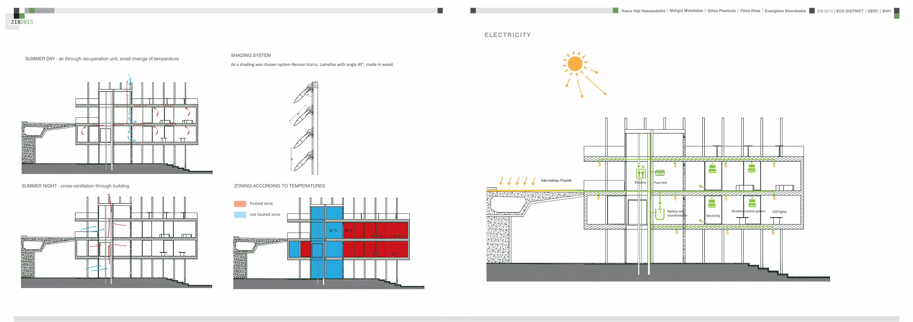
ZIB2015 ECO DISTRICT | GENT | B401Evangelos Stavrakakis | Petra Ross | Mahgol Motallebie | Gilles Plaetinck | Kasra Haji Hassandokht
ZIB2015
|
Shutters control system+ -
Solar roadways - PV panels
LED lights
Elevator Fuse box
ElectricityBattery withtransformator
ELECTRICITY
Summer night
cross- ventilation through building
Summer day
air through recuperation unit small change of temperature
15 degC 18 degC
+ groundplans
heated zone
not heated zone
ZONING ACCORDING TO TEMPERATURESSUMMER NIGHT - cross-ventilation through building
SUMMER DAY - air through recuperation unit small change of temperatureSHADING SYSTEM
As a shading was chozen system Renson Icarus Lamellas with angle 45deg made in wood
ZIB2015 ECO DISTRICT | GENT | B401Evangelos Stavrakakis | Petra Ross | Mahgol Motallebie | Gilles Plaetinck | Kasra Haji Hassandokht
ZIB2015
|
average only 4 hours of peak daylight hours per day (4 x 365 = 1460 hours per year)
- Surface area ( first part) Fly-over +- 20 000 msup2-gt 16 000 x 230 Watt = 3 680 000 Watt or 3680 kWonly 50 of fly-over covered with solar roadways
-gt 3680 kW x 4 h = 7360 kWh day-gt 3680 kW x 1460 h = 2 686 400 kWh year -gt +- 540 households (+- 5000 kWh year)
Tesla Powerwall Therersquos a 10 kWh unit at $3500 -gt 737 Tesla Batteries
gt the Solar Roadway has the ability to cut greenhouse gases by up to 75-percentgt A decentralized self-healing secure power grid
IN FRONT OF FLY-OVER
- Surface area Fly-over = 16 x 30 m = 480 msup2-gt 384 x 230 Watt = 88 320 Watt or 883 kWonly 50 of fly-over covered with solar roadways
-gt 44 kW x 4 h = 176 kWh day-gt 44 kW x 1460 h = 64 240 kWh year -gt +- 13 households (+- 5000 kWh year)
lightsshutters
elevator
2 fridges
2 coffeemakers
1 microwave
1 owen
2 cooking plates
stereo
ventilation unit
electricity transformer (AC to DC) for PV panels + batteries
summer 05 kWh daywinter 03 kWh day183 days x 05= 915 kWh182 days x 03 = 546 kWh = 1641 kWh
262 kWh
A++fridge 104 kWhyear104 x x2 = 208 kWh
900 W x 01 hours day = 09 kWhx 220 days x 2= 198 kWh a
67 kWh a
085x100 days= 85 kWh a
400 kWh x 2 = 800 kWh a
150 kWh a 419 kWha
68 kWh a
ENERGY DEMAND OVERVIEW ENERGY SUPPLY OVERVIEW - FLY-OVER
1 spot 56 W 10000 = 0056 KW4 hours per day 365 days a year = 1460 h0056 x 1460 = 8176 kWh10 spots x 8176= 8176 kWh a
1 spot 72 W 10000 = 0072 KW4 hours per day 365 days a year = 1460 h0072 x 1460 = 10512 kWh5 spots x 10512= 5256 kWh a
1 spot 52 W 10000 = 0052 KW4 hours per day 365 days a year = 1460 h0052 x 1460 = 7592 kWh21 spots x 7592= 159432 kWh a
1 spot 9 W 10000 = 0009 KW4 hours per day 365 days a year = 1460 h0009 x 1460 = 1314 kWh5 spots x 1314 = 657 kWh a
SOLAR ROADWAYS - PV PANELSEnergy from the sun
1 To generate energy for the ZIB building2 To generate energy for the surrounding houses3 To generate energy for lighting or signs on the road4 The panels will also have the capacity to charge electric vehicles while parked
ELECTRICITY SCHEME
5423 kWh a
ZIB2015 ECO DISTRICT | GENT | B401Evangelos Stavrakakis | Petra Ross | Mahgol Motallebie | Gilles Plaetinck | Kasra Haji Hassandokht
ZIB2015
|
SUMMER SUNNY 10-42 LUXWINTER SUNNY 10-42 LUX
DAYLIGHT - DIALuxLIGHTING SYSTEM - DIALux
Workplane 9 Results overview
Height of working plane 0800 m Wall zone 0000 m
Result Mean (target) Min Max Minaverage MinmaxPerpendicular illuminance [lx] 463 (500) 105 689 0227 0152
Profile Offices Writing typewriting reading data processing
B401-Gent 6222015
Site 1 Building 2 Zib Room 9 Workplane 9 Results overview
Page 70
Workplane 9 False coloursPerpendicular illuminance (adaptive)
Scale 1 200
Perpendicular illuminance (Surface)Mean (actual) 463 lx Min 105 lx Max 689 lx Minaverage 0227 Minmax 0152
B401-Gent 6222015
Site 1 Building 2 Zib Room 9 Workplane 9 False coloursPerpendicular illuminance (adaptive)
Page 72
Workplane 9 Value chartPerpendicular illuminance (adaptive)
Scale 1 200
Perpendicular illuminance (Surface)Mean (actual) 463 lx Min 105 lx Max 689 lx Minaverage 0227 Minmax 0152
B401-Gent 6222015
Site 1 Building 2 Zib Room 9 Workplane 9 Value chartPerpendicular illuminance (adaptive)
Page 73
Workplane 13 Results overview
Height of working plane 0800 m Wall zone 0000 m
Result Mean (target) Min Max Minaverage MinmaxPerpendicular illuminance [lx] 388 (500) 69 732 0178 0094
Profile Offices Writing typewriting reading data processing
B401-Gent 6222015
Site 1 Building 6 Storey 1 Room 13 Workplane 13 Results overview
Page 94
Workplane 13 False coloursPerpendicular illuminance (adaptive)
Scale 1 100
Perpendicular illuminance (Surface)Mean (actual) 388 lx Min 69 lx Max 732 lx Minaverage 0178 Minmax 0094
B401-Gent 6222015
Site 1 Building 6 Storey 1 Room 13 Workplane 13 False coloursPerpendicular illuminance (adaptive)
Page 96
Workplane 13 Value chartPerpendicular illuminance (adaptive)
Scale 1 100
Perpendicular illuminance (Surface)Mean (actual) 388 lx Min 69 lx Max 732 lx Minaverage 0178 Minmax 0094
B401-Gent 6222015
Site 1 Building 6 Storey 1 Room 13 Workplane 13 Value chartPerpendicular illuminance (adaptive)
Page 97
Workplane 9 False coloursPerpendicular illuminance (adaptive)
Scale 1 200
Perpendicular illuminance (Surface)Mean (actual) 463 lx Min 105 lx Max 689 lx Minaverage 0227 Minmax 0152
B401-Gent 6222015
Site 1 Building 2 Zib Room 9 Workplane 9 False coloursPerpendicular illuminance (adaptive)
Page 72
1st f loor 2nd f loor Site 1 Luminaire parts listQuantity Luminaire (Luminous emittance)10 3F Filippi 12736 P 202x24W LED OP 196x1231
Luminous emittance 1Fitting 1x24W 2xLEDLight output ratio 100Lamp luminous flux 5332 lmLuminaire Luminous Flux 5332 lmPower 560 WLight yield 952 lmW
200
300
400
cdklm η = 100C0 - C180 C90 - C270
0deg 15deg 30deg
45deg
60deg
75deg
90deg
105deg105deg
90deg
75deg
60deg
45deg
30deg 15deg 0deg
5 SFN Eclairages 0732360X CLFV 236Luminous emittance 1Fitting 2xT26 36W840Light output ratio 6889Lamp luminous flux 6700 lmLuminaire Luminous Flux 4615 lmPower 720 WLight yield 641 lmW
160
240
cdklm η = 69C0 - C180 C90 - C270
0deg 15deg 30deg
45deg
60deg
75deg
90deg
105deg105deg
90deg
75deg
60deg
45deg
30deg 15deg 0deg
21 SFN Eclairages 332226XX SAM F 2x26W BELuminous emittance 1Fitting 2xTC-DEL 26W840Light output ratio 3297Lamp luminous flux 3600 lmLuminaire Luminous Flux 1187 lmPower 520 WLight yield 228 lmW
40
60
80
100
120
140
cdklm η = 33C0 - C180 C90 - C270
0deg 15deg 30deg
45deg
60deg
75deg
90deg
105deg105deg
90deg
75deg
60deg
45deg
30deg 15deg 0deg
1 Signcomplex AR111-009-AW-W-06 AR111 COB 9W38deg WhiteLuminous emittance 1Fitting 1xAR111-009-AW-W-06Light output ratio 8078Lamp luminous flux 600 lmLuminaire Luminous Flux 485 lmPower 90 WLight yield 539 lmW
800
1200
cdklm η = 81C0 - C180 C90 - C270
0deg 15deg 30deg
45deg
60deg
75deg
90deg
105deg105deg
90deg
75deg
60deg
45deg
30deg 15deg 0deg
Total lamp luminous flux 163020 lm Total luminaire luminous flux 101807 lm Total Load 20210 W Light yield 504 lmW
B401-Gent 6222015
Site 1 Luminaire parts list
Page 19
10x
6x
21x
1x
types of l ights
Perpendicular i l luminance (Surface)Mean (actual ) 463 lx Min 105 lx Max 689 lx Minaverage 0 227 Minmax 0 152
Perpendicular i l luminance (Surface)Mean (actual ) 388 lx Min 69 lx Max 732 lx Minaverage 0 178 Minmax 0 094
ZIB2015 ECO DISTRICT | GENT | B401Evangelos Stavrakakis | Petra Ross | Mahgol Motallebie | Gilles Plaetinck | Kasra Haji Hassandokht
ZIB2015
|
Tube hybrid Solar panels
Hot water tank Water taps
City water supply
Rain water collection for vertical harvesting
City water supply
WADI
Rain water tank
WATER MANAGEMENT
Sinks
Available roof area
In Ghent avarage of 900mmm2year
3197 m2
09x 3197 = 28773 m3year
RAIN WATER GAIN
toilet - 3x - 03lskitchen -4x - 02ls
POTABLE WATER DEMAND
3 toiletsVertical gardening
Total
relative RW usage
300 l day150 l day = 450lday= 16425 m3 year
1407 lday100m2
RAIN WATER DEMAND
RAIN WATER TANK
Relative RWT volumeRain water tank volume
3m3 100 m2
9591 l gt 10 m3
DIMESION OF PIPES
City water supplyRainwater tank
178 mm (DN 18 - 15 - 12)165 mm (DN 17-15)
are composed of hexagonal tiles Rainwater can infiltrate between the gaps from where it goes to rainwatter collector which supplies the vegetation on fly-over
THE SOLAR ROADWAYS
WATER SUPPLY SCHEME AND CALCULATION
ZIB2015 ECO DISTRICT | GENT | B401Evangelos Stavrakakis | Petra Ross | Mahgol Motallebie | Gilles Plaetinck | Kasra Haji Hassandokht
ZIB2015
|
WADI
City water supply
Rain water tank
Sinks
Divided sewer systemwithin building
SEWAGE SYSTEM
ToiletToilet sinkKitchen sink
DU = 2 lsDU = 05 lsDU = 08 ls
WATER DRAINAGE OF DEVICES
Frequency of usage at the same time
K 05
DIMESION OF PIPES
Black waterGrey water
110 mm (DU 110)75 mm (DU 75 - 63)
WATER DRAINAGE SCHEME AND CALCULATION
ZIB2015 ECO DISTRICT | GENT | B401Evangelos Stavrakakis | Petra Ross | Mahgol Motallebie | Gilles Plaetinck | Kasra Haji Hassandokht
ZIB2015
|
DN
Gilles Plaetinck
schaal 1 100
ZIB BUILDINGEnter address here
2 _ level 1
Owner
begeleider Checker
Gilles Plaetinck
schaal 1 100
ZIB BUILDINGEnter address here
3 _ level 2
Owner
begeleider Checker
WATER SUPPLY
HOT WATER
WATER DRAINAGE
WATER SUPPLY AND DRAINAGE IN GROUPLANS
level 01
level 02
ENERGY
RAINWATER TANK
HELOPHYTE FILTER
IRRIGATION SYSTEM
BIO-ROTOR
MICRO TURBINE
PHOSPHOR
In this building a closed water system is applied which is based on reusing water in mullple wasRainRain water from the roof will be collected in a storage tank situated on the ground floor This water will be used to flush the toilet and irrigate crops in verlcal harveslng system In case of an overflow the water will be stored in the con-structed wetland near the building The rainwater can be fil-tered through a helophyte filter up to drinking water stan-dard The waste water system includes three types of water yellyellow black and grey waterThe yellow water will be stored for its phosphor while the black water will be purified into grey water This grey water is comparable to the quality of rain water aaer purificalon b means of a bio rotor The remaining residue from the bio rotor together with the organic waste from the harveslng is fermented into biogas that drives a micro turbine in order to produce some addilonal energy
TheThe waste product deriving from this process will be used as compost in verlcal harveslng This efficient yet complex system closes the ullizalon cycle of the building and turns it into an efficient vicious circle that can be considered au arkic
In this building a closed water system is applied which is based on reusing water in multiple was
Rain water from the roof will be collected in a storage tank situated on the ground floor This water will be used to flushthe toilet and irrigate crops in vertical harvesting system In case of an overflow the water will be stored in the constructed wetland near the building The rainwater can be filtered through a helophyte filter up to drinking water standard
The waste water system includes three types of water yellow black and grey water The yellow water will be stored for its phosphor while the black water will be purified into grey water This grey water is comparable to the quality of rain water after purification b means of a bio rotor The remaining residue from the bio rotor together with the organic waste from the harvesting is fermented into biogas that drives a micro turbine in order to produce some additional energy The waste product deriving from this process will be used ascompost in ver1048991cal harves1048991ng This efficient yet complexsystem closes the u1048991liza1048991on cycle of the building and turns itinto an efficient vicious circle that can be considered au arkic
WATER CYCLE
ZIB2015 ECO DISTRICT | GENT | B401Evangelos Stavrakakis | Petra Ross | Mahgol Motallebie | Gilles Plaetinck | Kasra Haji Hassandokht
ZIB2015
|
CALCULATIONS
Passive House verification
Photo or Drawing
Building Workshop + info pointStreet
PostcodeCityCountry
Building Type non-residentialClimate Ukkel
Home Owner(s) Client(s)Street
PostcodeCity
ArchitectStreet
PostcodeCity Calculation electricity Internal heat gains
Mechanical System Building type
StreetPostcodeCity Internal heat gains
Year of Construction 2015 Interior Temperature 200 degC Utilisation pattern
Number of Dwelling Units 1 Internal Heat Gains 20 Wm2 Type of values used Fill in worksheet IHG Non-Dom Enclosed Volume Ve 12442 Planned number of occupants
Number of Occupants 80 8 Design
Specific building demands with reference to the treated floor area use Annual method
Treated floor area 2840 msup2 Requirements Fulfilled Verification Annual method The monthly method should be used for building certification
Space heating Annual heating demand 10 kWh(m2a) 15 kWh(msup2a) yes Specific space heating demand annual method 103 kWh(msup2a)
Heating load 11 Wm2 10 Wmsup2 - Specific space heating demand monthly Method 120 kWh(msup2a)
Space cooling Overall specific space cooling demand kWh(m2a) 15 kWh(msup2a)
Cooling load Wm2 - -Frequency of overheating (gt 25 degC) - -
Primary Energy Space heating and dehumidification
cooling household electricity 73 kWh(m2a) 120 kWh(msup2a) yes
DHW space heating and auxiliary electricity 24 kWh(m2a) - -Specific primary energy reduction through solar electricity 21 kWh(m2a) - -
Airtightness Pressurization test result n50 06 1h 06 1h yes
PHPP Verification FINAL ZIB FILE CALCULTIONS PHPPxls
L B H VOLUME
main 1 226 7 4 6328main 2 184 7 35 4508
core 0 6 2 5 3 5 108 5core 0 62 5 35 1085core 3 62 3 28 521
12442
AREAmain 1 storage 35
wc big 35wc 2wc 2workshop 103
MAIN 2 infolounge 92
staircase 56storage technical 22
284
Floor_exterior 1582 31 1272
Roof_exterior 1582
Passive House verification
Photo or Drawing
Building Workshop + info pointStreet
PostcodeCityCountry
Building Type non-residentialClimate Ukkel
Home Owner(s) Client(s)Street
PostcodeCity
ArchitectStreet
PostcodeCity Calculation electricity Internal heat gains
Mechanical System Building type
StreetPostcodeCity Internal heat gains
Year of Construction 2015 Interior Temperature 200 degC Utilisation pattern
Number of Dwelling Units 1 Internal Heat Gains 20 Wm2 Type of values used Fill in worksheet IHG Non-Dom Enclosed Volume Ve 12442 Planned number of occupants
Number of Occupants 80 8 Design
Specific building demands with reference to the treated floor area use Annual method
Treated floor area 2840 msup2 Requirements Fulfilled Verification Annual method The monthly method should be used for building certification
Space heating Annual heating demand 10 kWh(m2a) 15 kWh(msup2a) yes Specific space heating demand annual method 103 kWh(msup2a)
Heating load 11 Wm2 10 Wmsup2 - Specific space heating demand monthly Method 120 kWh(msup2a)
Space cooling Overall specific space cooling demand kWh(m2a) 15 kWh(msup2a)
Cooling load Wm2 - -Frequency of overheating (gt 25 degC) - -
Primary Energy Space heating and dehumidification
cooling household electricity 73 kWh(m2a) 120 kWh(msup2a) yes
DHW space heating and auxiliary electricity 24 kWh(m2a) - -Specific primary energy reduction through solar electricity 21 kWh(m2a) - -
Airtightness Pressurization test result n50 06 1h 06 1h yes
PHPP Verification FINAL ZIB FILE CALCULTIONS PHPPxls
SURFACE AREAcurrent orientation only night ventilation
current orientation only night ventilation 6 windows less 52 msup2
current orientation only night ventilation 7 windows less 60msup2 (stays the same for each side)
current orientation only night ventilation 8 windows less 69 msup2
orientation turned 90deg only night ventilation 6 windows less 52 msup2
orientation turned 90deg only night ventilation 7 windows less 60msup2 (window less at SE side)
orientation turned 90deg only night ventilation 8 windows less 69 msup2
-gt orientation turned 90deg only night ventilation 9 windows less 77msup2 (window less at NW side althought theres less overheating in the case of a window less at SE side the heating demand exceeds 15)
CHANGE IN DESIGN
ZIB2015 ECO DISTRICT | GENT | B401Evangelos Stavrakakis | Petra Ross | Mahgol Motallebie | Gilles Plaetinck | Kasra Haji Hassandokht
ZIB2015
|
Passive House verificationS P E C I F I C A N N U A L H E A T I N G D E M A N D
Climate Ukkel Interior Temperature 200 degC
Building Workshop + info point Building TypeUse non-residentialTreated Floor Area ATFA 2840 msup2
per msup2Area U-Value Temp Factor ft Gt Treated Data for heating balance diagram
Building Element Temperature Zone msup2 W(msup2K) kKha kWha Floor Area Losses GainsExterior Wall - Ambient A 5595 0101 100 743 = 4181 1472 Exterior Wall - Ambient 147234373Exterior Wall - Ground B 069 = Exterior Wall - GroundRoofCeiling - Ambient A 1550 0094 100 743 = 1085 382 RoofCeiling - Ambient 381903529Floor slab basement ceiling B 310 0105 069 743 = 167 059 Floor slab basement ceiling 058811509
A 100 =A 100 =
unheated basement X 075 = unheated basementWindows A 1154 0648 100 743 = 5562 1958 Windows 195834732Exterior Door A 100 = Exterior DoorExterior TB (lengthm) A 1169 -0030 100 743 = -259 -091 Thermal Bridge Heat LossPerimeter TB (lengthm) P 069 = 000 not useful heat gains 365267499Ground TB (lengthm) B 069 =
Total of All Building Envelope Areas 8609 ndashndashndashndashndashndashndashndashndashndashndashndashndash- kWh(msup2a) Ventilation 395818713
Transmission Heat Losses QT Total 10736 378Annual Heating Demand 102516636
ATFA Clear Room Height internal gains 100951487msup2 m msup3 passive solar gains 250668423
Ventilation System Effective Air Volume VV 2840 280 = 7952 Thermal bridge credit 091126837Effective Heat Recovery Efficiency eff 81 Cross check sum 46324923 46324923of Heat Recovery
Efficiency of Subsoil Heat Exchanger SHX 0 nVsystem HR nVRes
1h 1h 1h
Energetically Effective Air Exchange nV 0105 (1 - 081 ) + 0038 = 0058
VV nV cAir Gt
msup3 1h Wh(msup3K) kKha kWha kWh(msup2a)
Ventilation Heat Losses QV 795 0058 033 743 = 1124 40
Reduction Factor QT QV NightWeekend
kWha kWha Saving kWha kWh(msup2a)
Total Heat Losses QL ( 10736 + 1124 ) 10 = 11860 418
Orientation Reduction Factor g-Value Area Radiation HPof the Area See Windows Sheet (perp radiation)
msup2 kWh(msup2a) kWha
1 North 054 050 2700 163 = 11822 East 058 000 440 197 = 03 South 056 050 4860 314 = 42874 West 032 050 3216 254 = 13275 Horizontal 063 050 324 317 = 323
kWh(msup2a)
Available Solar Heat Gains QS Total 7119 251
Length Heat Period Spec Power qI ATFA
khd da Wmsup2 msup2 kWha kWh(msup2a)
Internal Heat Gains QI 0024 209 201 2840 = 2867 101
kWha kWh(msup2a)
Free Heat QF QS + QI = 9986 352
Ratio of Free Heat to Losses QF QL = 084
Utilisation Factor Heat Gains G (1 - ( QF QL )5 ) (1 - ( QF QL )
6 ) = 90kWha kWh(msup2a)
Heat Gains QG G QF = 8949 315
kWha kWh(msup2a)
Annual Heating Demand QH QL - QG = 2911 10
kWh(msup2a) (YesNo)
Limiting Value 15 Requirement met yes
00
147
00
3806000000
196
00
40
37
09
103
101
251
0
5
10
15
20
25
30
35
40
45
50
Losses Gains
Hea
t flo
ws
[kW
h(m
sup2a)]
Heating energy balance
passive solar gains
internal gains
Annual Heating Demand
Thermal bridge credit
not useful heat gains
Ventilation
Exterior Door
Windows
unheated basement
Floor slab basement ceiling
RoofCeiling - Ambient
Exterior Wall - Ground
Exterior Wall - Ambient
Thermal Bridge Heat Loss
HPP Annual Heating Demand FINAL ZIB FILE CALCULTIONS PHPPxls
Passive House verification Passive House verificationS P E C I F I C U S E F U L C O O L I N G D E M A N D S P E C I F I C U S E F U L C O O L I N G D E M A N D
M O N T H L Y M E T H O D M O N T H L Y M E T H O D
(This page displays the sums of the monthly method over the cooling period))Climate Ukkel Interior Temperature Summer 25 degC Climate Ukkel Interior Temperature 25 degC
Building Workshop + info point Building TypeUse non-residential Building Workshop + info point Building TypeUse non-residential
Spec Capacity 60 Wh(msup2K) (Enter in Summer worksheet) Treated Floor Area ATFA 2840 msup2 Treated Floor Area ATFA 284 msup2
per msup2Temperature Zone Area U-Value Mon Red Fac Gt Treated Jan Feb Mar Apr May Jun Jul Aug Sep Oct Nov Dec Year
Building Element msup2 W(msup2K) kKha kWha Floor Area Heating Degree Hours - Ex 168 150 144 121 92 73 57 59 82 109 140 160 136 kKh1 Exterior Wall - Ambient A 5595 0101 100 103 = 5782 Heating Degree Hours - G 126 123 135 120 106 83 63 54 58 71 86 109 113 kKh2 Exterior Wall - Ground B 100 = Losses - Exterior 2553 2286 2189 1838 1393 1117 871 904 1245 1660 2123 2432 20612 kWh3 RoofCeiling - Ambient A 1550 0094 100 103 = 1500 Losses - Ground 41 40 44 39 35 27 21 18 19 23 28 36 370 kWh4 Floor slab basement ceil B 310 0105 100 90 = 294 Losses Summer Ventilatio 67 71 244 372 629 720 880 865 658 499 234 126 5366 kWh5 A 100 = Sum Spec Heat Losses 94 84 87 79 72 66 62 63 68 77 84 91 928 kWhmsup26 A 100 = Solar Load North 44 81 141 212 286 298 298 255 178 116 54 35 1998 kWh7 unheated basement X 075 = Solar Load East 0 0 0 0 0 0 0 0 0 0 0 0 0 kWh8 Windows A 1154 0648 100 103 = 7690 Solar Load South 218 315 464 577 681 644 681 658 532 416 242 171 5601 kWh9 Exterior Door A 100 = Solar Load West 79 125 213 303 385 378 370 347 256 177 91 60 2785 kWh
10 Exterior TB (lengthm) A 1169 -0030 100 103 = -358 Solar Load Horiz 11 21 37 57 79 79 80 69 47 30 14 9 533 kWh11 Perimeter TB (lengthm) P 100 = Solar Load Opaque 3 5 9 13 18 19 19 16 11 7 3 2 126 kWh12 Ground TB (lengthm) B 100 = Internal Heat Gains 425 384 425 411 425 411 425 425 411 425 411 425 5001 kWh
ndashndashndashndashndashndashndashndashndashndashndash kWh(msup2a) Sum Spec Loads Solar + 28 33 45 55 66 64 66 62 51 41 29 25 565 kWhmsup2
Transmission Losses QT (Negative Heat Loads) Total 14907 525 Utilisation Factor Losses 29 39 52 69 84 88 82 88 73 53 34 27 58Useful Cooling Energy Dem 0 0 4 30 142 192 417 192 40 4 0 0 1021 kWh
ATFA Clear Room Height Spec Cooling Demand 00 00 00 01 05 07 15 07 01 00 00 00 36 kWhmsup2Effective msup2 m msup3
Air Volume VV 284 280 = 795
Heat Transfer Coef Gt
WK kKha kWha kWh(msup2a)
Exterior 99 103 = 1013 36Ground 00 105 = 0 00
Additional Summer Ventilation
Select X Window Night Ventilation Manual Corresponding Air Change Rate 136 1h
Mechanical Automatically Controlled Ventilation (for window ventilation at 1 K temperature difference indoor - outdoor)
Minimum Acceptable Indoor Temperatu 220 degC
kWha kWh(msup2a)
Heat Losses Summer Ventilation 5172 182
QLext QLground QLsummer
kWha kWha kWha kWha kWh(msup2a)
Ventilation Heat Losses QV 1013 + 0 + 5172 = 6185 218
2
3
4
5
6
7
8
9
10
Spec
ific
loss
es l
oads
l c
oolin
g de
man
d [k
Wh
(msup2 m
onth
)] Spec Cooling Demand Sum Spec Heat Losses Sum Spec Loads Solar + Internal
QT QV
kWha kWha kWha kWh(msup2a)
Total Heat Losses QL 14907 + 6185 = 21092 743
Orientation Reduction Factor g-Value Area Global Radiationof the Area (perp radiation)
msup2 kWh(msup2a) kWha
1 North 031 050 270 462 = 19182 East 061 000 44 578 = 0 Temperature Amplitude Summer 82 K3 South 030 050 486 707 = 52114 West 025 050 322 654 = 2646 Month 1 2 3 4 5 6 7 8 9 10 11 12 Annual Total5 Horizontal 035 050 32 913 = 513 Days 31 28 31 30 31 30 31 31 30 31 30 31 3656 Sum Opaque Areas 121 Ambient Temp 250 270 572 828 1275 1487 1737 1707 1369 1039 568 356 96
kWh(msup2a) North Radiation 106 195 329 494 667 697 712 599 419 275 129 87 471
Available Solar Heat Gains QS Total 10409 367 East Radiation 146 266 452 698 937 940 988 851 574 382 179 123 654
South Radiation 311 440 645 786 912 858 898 885 733 579 341 241 763Length Heat Period Spec Power qI ATFA West Radiation 155 261 471 707 926 926 896 819 580 382 183 116 642
khd da Wmsup2 msup2 kWha kWh(msup2a) Hori Radiation 200 369 662 1021 1398 1410 1418 1234 842 535 243 156 949
Internal Heat Gains QI 0024 303 20 2840 = 4151 146 Tsky -750 -730 -428 -172 275 487 737 707 369 039 -432 -644 -04
Ground Temp 805 676 686 830 1072 1345 1647 1776 1696 1552 1310 1037 121kWha kWh(msup2a)
Sum Heat Loads QF QS + QI = 14560 513
Ratio of Losses to Free Heat Gains QL QF = 145
Utilisation Factor Heat Losses G = 64kWha kWh(msup2a)
Useful Heat Losses QVn G QL = 13539 477
kWha kWh(msup2a)
Useful Cooling Demand QK QF - QVn = 1021 4
kWh(msup2a) (YesNo)
Limiting Value 15 Requirement met yes
0
1
2
Jan Feb Mar Apr May Jun Jul Aug Sep Oct Nov Dec
usef
u
HPP Cooling FINAL ZIB FILE CALCULTIONS PHPPxls
Passive House verificationS P E C I F I C A N N U A L H E A T I N G D E M A N D
Climate Ukkel Interior Temperature 200 degC
Building Workshop + info point Building TypeUse non-residentialTreated Floor Area ATFA 2840 msup2
per msup2Area U-Value Temp Factor ft Gt Treated Data for heating balance diagram
Building Element Temperature Zone msup2 W(msup2K) kKha kWha Floor Area Losses GainsExterior Wall - Ambient A 5595 0101 100 743 = 4181 1472 Exterior Wall - Ambient 147234373Exterior Wall - Ground B 069 = Exterior Wall - GroundRoofCeiling - Ambient A 1550 0094 100 743 = 1085 382 RoofCeiling - Ambient 381903529Floor slab basement ceiling B 310 0105 069 743 = 167 059 Floor slab basement ceiling 058811509
A 100 =A 100 =
unheated basement X 075 = unheated basementWindows A 1154 0648 100 743 = 5562 1958 Windows 195834732Exterior Door A 100 = Exterior DoorExterior TB (lengthm) A 1169 -0030 100 743 = -259 -091 Thermal Bridge Heat LossPerimeter TB (lengthm) P 069 = 000 not useful heat gains 365267499Ground TB (lengthm) B 069 =
Total of All Building Envelope Areas 8609 ndashndashndashndashndashndashndashndashndashndashndashndashndash- kWh(msup2a) Ventilation 395818713
Transmission Heat Losses QT Total 10736 378Annual Heating Demand 102516636
ATFA Clear Room Height internal gains 100951487msup2 m msup3 passive solar gains 250668423
Ventilation System Effective Air Volume VV 2840 280 = 7952 Thermal bridge credit 091126837Effective Heat Recovery Efficiency eff 81 Cross check sum 46324923 46324923of Heat Recovery
Efficiency of Subsoil Heat Exchanger SHX 0 nVsystem HR nVRes
1h 1h 1h
Energetically Effective Air Exchange nV 0105 (1 - 081 ) + 0038 = 0058
VV nV cAir Gt
msup3 1h Wh(msup3K) kKha kWha kWh(msup2a)
Ventilation Heat Losses QV 795 0058 033 743 = 1124 40
Reduction Factor QT QV NightWeekend
kWha kWha Saving kWha kWh(msup2a)
Total Heat Losses QL ( 10736 + 1124 ) 10 = 11860 418
Orientation Reduction Factor g-Value Area Radiation HPof the Area See Windows Sheet (perp radiation)
msup2 kWh(msup2a) kWha
1 North 054 050 2700 163 = 11822 East 058 000 440 197 = 03 South 056 050 4860 314 = 42874 West 032 050 3216 254 = 13275 Horizontal 063 050 324 317 = 323
kWh(msup2a)
Available Solar Heat Gains QS Total 7119 251
Length Heat Period Spec Power qI ATFA
khd da Wmsup2 msup2 kWha kWh(msup2a)
Internal Heat Gains QI 0024 209 201 2840 = 2867 101
kWha kWh(msup2a)
Free Heat QF QS + QI = 9986 352
Ratio of Free Heat to Losses QF QL = 084
Utilisation Factor Heat Gains G (1 - ( QF QL )5 ) (1 - ( QF QL )
6 ) = 90kWha kWh(msup2a)
Heat Gains QG G QF = 8949 315
kWha kWh(msup2a)
Annual Heating Demand QH QL - QG = 2911 10
kWh(msup2a) (YesNo)
Limiting Value 15 Requirement met yes
00
147
00
3806000000
196
00
40
37
09
103
101
251
0
5
10
15
20
25
30
35
40
45
50
Losses Gains
Hea
t flo
ws
[kW
h(m
sup2a)]
Heating energy balance
passive solar gains
internal gains
Annual Heating Demand
Thermal bridge credit
not useful heat gains
Ventilation
Exterior Door
Windows
unheated basement
Floor slab basement ceiling
RoofCeiling - Ambient
Exterior Wall - Ground
Exterior Wall - Ambient
Thermal Bridge Heat Loss
HPP Annual Heating Demand FINAL ZIB FILE CALCULTIONS PHPPxls
factor 05Wd (ls) 088
nominal diameter 75 mmVERTICAL COLLECTOR sink toilets 3 05 15
sink kitchen 2 08 16Total 5 31factor 05
Wd (ls) 088nominal diameter 75 mm
Toevoerend ROOF SURFACE
horizontal roof surface (msup2) orientation coeff angle (deg) roofcover filter coeff toevoerend
444 1 0 08 09 3197
RAIN WATER USAGE
Type usage ( l usage) persons day frequency usageday yearly usage
toilet use small 3 20 3 180 65700toilet use big 6 20 1 120 43800VERTICAL GARDENING 150 54750TOTAL 450 164250 L year
16425 msup3 year
TOTAL RAINWATER USAGE 450 L dayRELATIVE RAINWATER USAGE 1407 L day100msup2
LEEGSTAND
relative rainwater usage 1407 L day 100 msup2LEEGSTAND 7 relative volume rainwater tank 3 msup3 100 msup2rainwater tank volume 9591 Liter
suggestion 50 msup2 02 m= 10 msup3
SUPPLYtype amount debiet Q total total WW
lsec lsec lsecMAIN LEVEL POTABLE
sink toilet 3 01 03 03sink kitchen 2 01 02 02
Total 5 05 05Gelijktijdigheid 05 05debiet Q (lsec) 025 025
diameter 178 178 cm
type amount debiet Q total total WWlsec lsec lsec
MAIN LEVEL RAIN WATER toilet 3 01 03 0
Total 3 03Gelijktijdigheid 071debiet Q (lsec) 0213
diameter 165 cm
FECALIEumlNtype amount value Total (ls)
COLLECTOR HORIZONTAL toilet 3 2Total 6factor 05
Wd (ls) 122nominal diameter 110 mm
type amount value Total (ls)COLLECTOR VERTICAL toilet 3 2
Total 6factor 05
Wd (ls) 122nominal diameter 110 mm
DRAINtype amount value Total (ls)
HORIZONTAL COLLECTOR sink toilets 3 05 15sink kitchen 2 08 16
Total 5 31
WATER
ZIB2015 ECO DISTRICT | GENT | B401Evangelos Stavrakakis | Petra Ross | Mahgol Motallebie | Gilles Plaetinck | Kasra Haji Hassandokht
ZIB2015
|
Passive House verificationS P E C I F I C S P A C E H E A T I N G L O A D Risk Determination of Group Heating for a Critical Room
Building Workshop + info point Building TypeUse non-residential Workshop room ( 1= Yes 0 = No)
Climate (HL) Ukkel Treated Floor Area ATFA 2840 msup2 Interior Temperature 20 degC Building Satisfies Passive House Criteria 1
Design Temperature Radiation North East South West Horizontal Room floor area 100 msup2 Supply Air per msup2 Living AreaWeather Condition 1 -31 degC 10 10 30 15 20 Wmsup2 Planned ambient air quantity for the room 150 msup3h 150 msup3hmsup2Weather Condition 2 -22 degC 5 5 20 10 10 Wmsup2 Planned ambient air quantities for the remaining rooms -67 msup3hGround Design Temp 68 degC Area U-Value Factor TempDiff 1 TempDiff 2 PT 1 PT 2
Building Element Temperature Zone msup2 W(msup2K) Always 1(except X) K K W W Building Element Temperature Zone msup2 W(msup2K) Always 1
(except X) K Room Trans Loss W
1 Exterior Wall - Ambient A 5595 0101 100 231 or 222 = 1299 or 1249 Aboveground Exterior Wall A 650 010 100 231 = 1512 Exterior Wall - Ground B 100 132 or 132 = or Belowground Exterior Wall B 00 100 132 =3 RoofCeiling - Ambient A 1550 0094 100 231 or 222 = 337 or 324 RoofCeiling D 880 009 100 231 = 1914 Floor slab basement ceiling B 310 0105 100 132 or 132 = 43 or 43 Underground Floor Slab B 00 011 100 132 = 05 A 100 231 or 222 = or A 100 231 =6 A 100 231 or 222 = or A 100 231 =7 unheated basement X 075 231 or 222 = or X 100 231 =8 Windows A 1154 0648 100 231 or 222 = 1728 or 1661 Windows A 480 065 100 231 = 7199 Exterior Door A 100 231 or 222 = or Exterior Door A 100 231 =
10 Exterior TB (lengthm) A 1169 -0030 100 231 or 222 = -80 or -77 Exterior thermal bridges (Lengthm) A 100 231 =11 Perimeter TB (lengthm) P 100 132 or 132 = or Perimeter Thermal Bridges (Lengthm) A 100 231 =12 Ground TB (lengthm) B 100 132 or 132 = or Floor Slab Thermal Bridges (Lengthm) A 50 100 231 =13 HouseDU Partition Wall I 100 30 or 30 = or HouseDU Partition Wall I 200 100 30 =
Transmission Heat Losses PT ndashndashndashndashndashndashndashndashndashndashndashndashndash- ndashndashndashndashndashndashndashndashndashndashndash-
Total = 3328 or 3200 = 1061
ATFA Clear Room HeightVentilation System msup2 m msup3 Risk
Effective Air Volume VV 2840 280 = 795 Enter 1 = Yes 0 = No PTRoom W PSupply Air W Ratio Summand
SHX 1 SHX 2 Transmission Heat Losses 1061 1386 077 -023Efficiency of Heat Recovery HR 81 Heat Recovery Efficiency SHX 0 Efficiency SHX 0 or 0 Concentrated leakages 0 000of the Heat Exchanger Insulation to other rooms better R = 15 msup2KW 1 ( 2 = no thermal contact except door) 050
nVRes (Heating Load) nVsystem HR HR Room is on the ground floor 0 0001h 1h 1h 1h open staircase 0 000
Energetically Effective Air Exchange nV 0094 + 0105 (1- 081 or 081 ) = 0114 or 0114 TOTAL of the Risk Summands 027Ventilation Heating Load PV
VL nL nL cAir TempDiff 1 TempDiff 2 PV 1 PV 2 Interior doors predominantly closed 1 Risk Factor 200msup3 1h 1h Wh(msup3K) K K W W
7952 0114 or 0114 033 231 or 222 = 691 or 664Total Room Risk 89
PL 1 PL 2
Total Heating Load PL W W Appraisal and Advice normally no problemPT + PV = 4019 or 3864
Orientation Area g-Value Reduction Factor Radiation 1 Radiation 2 PS 1 PS 2the Area msup2 (perp radiation) (see Windows worksheet) Wmsup2 Wmsup2 W W
1 North 270 05 05 11 or 6 = 77 or 412 East 44 00 06 8 or 3 = 0 or 03 South 486 05 06 28 or 18 = 378 or 2474 West 322 05 03 19 or 13 = 100 or 685 Horizontal 32 05 06 20 or 10 = 20 or 10
Solar heating power PS Total = 575 or 367
Spec Power ATFA PI 1 PI 2Internal heating power PI Wmsup2 msup2 W W
16 284 = 454 or 454
PG 1 PG 2
Heating power (gains) PG W W
PS + PI = 1029 or 821
PL - PG = 2989 or 3042
Heating Load PH = 3042 W
Specific Heating Load PH ATFA = 107 Wmsup2
Input Max Supply Air Temperature 48 degC degC degC
Max Supply Air Temperature SupplyMax 48 degC Supply Air Temperature Without Heating SupplyMin 156 157
For Comparison Heating Load Transportable by Supply Air PSupply AirMax = 886 W specific 31 Wmsup2
(YesNo)
Supply Air Heating Sufficient No
HPP Heating Load FINAL ZIB FILE CALCULTIONS PHPPxls
Passive House verificationU - V A L U E S O F B U I L D I N G E L E M E N T S
Wedge shaped building element layeBuilding Workshop + info point still air spaces -gt Secondary calculation to th
Assembly No Building assembly description Interior insulation1 Exterior wall x
Heat transfer resistance [msup2KW] interior Rsi 013exterior Rse 004
Area section 1 [W(mK)] Area section 2 (optional) [W(mK)] Area section 3 (optional) [W(mK)] Thickness [mm]
1 hout gevel 0160 17
2 regelwerk hout 0158 30
3 houtvezel celit 4D 0048 18
4 Eurowall 0023 hout FJI beam 0286 140
5 OSB -plaat 0130 15
6 Eurothane G 0023 70
7 Plaster insulating 0100 10
8Percentage of Sec 2 Percentage of Sec 3 Total
26 300
U-Value 0107 W(msup2K)
Assembly No Building assembly description Interior insulation2 Roof x
Heat transfer resistance [msup2KW] interior Rsi 010exterior Rse 004
Area section 1 [W(mK)] Area section 2 (optional) [W(mK)] Area section 3 (optional) [W(mK)] Thickness [mm]Area section 1 [W(mK)] Area section 2 (optional) [W(mK)] Area section 3 (optional) [W(mK)] Thickness [mm]
1 bitumenmembraam 0230 5
23 EPS 0036 70
4 OSB -plaat 0130 18
5 cellulose 0039 hout FJI beam 0286 350
6 OSB -plaat 0130 15
7 regelwerk hout 5 0177 30
8 gipskartonplaat 0290 12
Percentage of Sec 2 Percentage of Sec 3 Total
26 500
U-Value 0094 W(msup2K)
Assembly No Building assembly description Interior insulation3 Floor x
Heat transfer resistance [msup2KW] interior Rsi 017
exterior Rse 004
Area section 1 [W(mK)] Area section 2 (optional) [W(mK)] Area section 3 (optional) [W(mK)] Thickness [mm]
1 PIR dekvloer 0023 5
2 gipskartonplaat 0290 10
3 gespoten pur 0028 100
4 OSB -plaat 0130 15
5 cellulose 0039 hout FJI beam 0286 350
6 houtvezel Celit 4D 0048 15
7 regelwerk hout 6 0149 30
8 afwerking hout 0160 5
Percentage of Sec 2 Percentage of Sec 3 Total
26 530
U-Value 0078 W(msup2K)
PHPP U-Values FINAL ZIB FILE CALCULTIONS PHPPxls
ers and he right
n Secondary Calculation Equivalent Thermal Conductivity of Still Air Spaces
Air Layer Thickness 30 mm Direction of Upwards ha 125 W(msup2K) 016 W(mK)
Heat Flow X Horizontal hr 417 W(msup2K)
(check only one field) Downwards
cm
n
cm
n Secondary Calculation Equivalent Thermal Conductivity of Still Air Spaces
Air Layer Thickness 30 mm
Direction of Upwards ha 08333 W(msup2K) 015 W(mK)Heat Flow Horizontal hr 417 W(msup2K)
(check only one field) X Downwards
cm
PHPP U-Values FINAL ZIB FILE CALCULTIONS PHPPxls
ers and he right
n Secondary Calculation Equivalent Thermal Conductivity of Still Air Spaces
Air Layer Thickness 30 mm Direction of Upwards ha 125 W(msup2K) 016 W(mK)
Heat Flow X Horizontal hr 417 W(msup2K)
(check only one field) Downwards
cm
n
cm
n Secondary Calculation Equivalent Thermal Conductivity of Still Air Spaces
Air Layer Thickness 30 mm
Direction of Upwards ha 08333 W(msup2K) 015 W(mK)Heat Flow Horizontal hr 417 W(msup2K)
(check only one field) X Downwards
cm
PHPP U-Values FINAL ZIB FILE CALCULTIONS PHPPxls
ers and he right
n Secondary Calculation Equivalent Thermal Conductivity of Still Air Spaces
Air Layer Thickness 30 mm Direction of Upwards ha 125 W(msup2K) 016 W(mK)
Heat Flow X Horizontal hr 417 W(msup2K)
(check only one field) Downwards
cm
n
cm
n Secondary Calculation Equivalent Thermal Conductivity of Still Air Spaces
Air Layer Thickness 30 mm
Direction of Upwards ha 08333 W(msup2K) 015 W(mK)Heat Flow Horizontal hr 417 W(msup2K)
(check only one field) X Downwards
cm
PHPP U-Values FINAL ZIB FILE CALCULTIONS PHPPxls
Passive House verificationS U M M E R
Climate Ukkel Interior Temperature 20 degC
Building Workshop + info point Building TypeUse non-residentialTreated Floor Area ATFA 2840 msup2
Spec Capacity 60 WhK pro msup2 TFAOverheating
limit25 degC Area U-Value Red Factor fTSummer HSummer Heat Conductance
Building Element Temperature Zone msup2 W(msup2K)
1 Exterior Wall - Ambien A 5595 0101 100 = 5632 Exterior Wall - Ground B 100 =3 RoofCeiling - Ambient A 1550 0094 100 = 1464 Floor slab basement B 310 0105 100 = 335 A 100 =6 A 100 =7 unheated basement X 075 =8 Windows A 1154 0648 100 = 7489 Exterior Door A 100 =
10 Exterior TB (lengthm) A 1169 -0030 100 = -3511 Perimeter TB (lengthm P 100 =12 Ground TB (lengthm) B 100 =
ndashndashndashndashndashndashndashndashndashndashndashExterior Thermal Transmittance HTe 1422 WK
Ground Thermal Transmittance HTg 33 WK
ATFA Clear Room HeightEffective msup2 m msup3
Heat Recovery Efficiency HR 81 Air Volume VV 2840 280 = 795
SHX Efficiency SHX 0
Summer Ventilation continuous ventilation to provide sufficient indoor air quality
Air Change Rate by Natural (Windows amp Leakages) or Exhaust-Only Mechanical Ventilation Summer 000 1h
Mechanical Ventilation Summer 1h X with HR (check if applicable)
nLnat nVsystem HR nVRest
1h 1h 1h 1h
Energetically Effective Airchange Rate nV 0000 + 0000 (1 - 0808 ) + 0038 = 0038
VV nVequifraction cAir
msup3 1h Wh(msup3K)
Ventilation Transm Ambient HVe 795 0038 033 = 99 WK
Ventilation Transm Ground HVg 795 0000 033 = 00 WK
Additional Summer Ventilation for Cooling Temperature amplitude summer 82 K
Select X Window Night Ventilation Manual Corresponding Air Change Rate 136 1hMechanical Automatically Controlled Ventilation (for window ventilation at 1 K temperature difference indoor - outdoor)
Minimum Acceptable Indoor Temperature 220 degC
Orientation Angle Shading g-Value Area Portion of Glazing Apertureof the Area Factor Factor Dirt (perp radiation)
Summer Summer msup2 msup2
1 North 09 044 095 050 270 82 = 422 East 09 100 095 000 44 71 = 003 South 09 043 095 050 486 82 = 744 West 09 039 095 050 322 76 = 405 Horizontal 09 052 095 050 32 78 = 066 Sum Opaque Areas 03
msup2msup2
Solar Aperture Total 164 006
Specif Power qI ATFA
Wmsup2 msup2 W Wmsup2
Internal Heat Gains QI 201 284 = 571 20
Frequency of Overheating hmax 42 at the overheating limit max = 25 degC
If the frequency over 25degC exceeds 10 additional measures to protect against summer heat waves are necessary
Solar Load Spec Capacity ATFA
kWhd 1k Wh(msup2K) msup2
Daily Temperature Swing due to Solar Load 00 1000 ( 60 284 ) = 00 K
PHPP Summer FINAL ZIB FILE CALCULTIONS PHPPxls
Passive House verification Passive House verificationS P E C I F I C A N N U A L H E A T I N G D E M A N D S P E C I F I C A N N U A L H E A T D E M A N D
M O N T H L Y M E T H O D M O N T H L Y M E T H O D
(This page displays the sums of the monthly method over the heating period)Climate Ukkel Interior Temperature 20 degC Climate Ukkel Interior Temperature 20 degC
Building Workshop + info point Building TypeUse non-residential Building Workshop + info point Building TypeUse non-residentialSpec Capacity 60 Wh(msup2K) (Enter in Summer worksheet) Treated Floor Area ATFA 2840 msup2 Treated Floor Area ATFA 284 msup2
per msup2Temperature Zone Area U-Value Month Red Fac Gt Treated Jan Feb Mar Apr May Jun Jul Aug Sep Oct Nov Dec Year
Building Element msup2 W(msup2K) kKha kWha Floor Area Heating Degree Hours - E 131 117 107 85 54 37 20 22 46 72 104 123 92 kKhExterior Wall - Ambient A 5595 0101 100 78 = 4406 Heating Degree Hours - G 89 89 98 84 69 47 26 17 22 33 50 72 70 kKhExterior Wall - Ground B 100 = Losses - Exterior 2056 1836 1679 1335 856 589 316 350 722 1132 1630 1931 14433 kWhRoofCeiling - Ambient A 1550 0094 100 78 = 1143 Losses - Ground 29 29 32 28 23 15 9 5 7 11 16 23 227 kWhFloor slab basement ceiling B 310 0105 100 54 = 175 Sum Spec Losses 73 66 60 48 31 21 11 13 26 40 58 69 516 kWhmsup2
A 100 = Solar Gains - North 78 142 246 371 500 520 520 445 311 202 94 62 3490 kWhA 100 = Solar Gains - East 0 0 0 0 0 0 0 0 0 0 0 0 0 kWh
unheated basement X 075 = Solar Gains - South 405 583 860 1069 1261 1194 1263 1220 986 771 448 318 10377 kWhWindows A 1154 0648 100 78 = 5861 Solar Gains - West 103 162 275 391 497 489 478 448 331 229 118 77 3597 kWhExterior Door A 100 = Solar Gains - Horiz 20 38 68 104 143 144 145 126 86 55 25 16 968 kWhExterior TB (lengthm) A 1169 -0030 100 78 = -273 Solar Gains - Opaque 3 5 9 13 18 19 19 16 11 7 3 2 126 kWhPerimeter TB (lengthm) P 100 = Internal Heat Gains 425 384 425 411 425 411 425 425 411 425 411 425 5001 kWhGround TB (lengthm) B 100 = Sum Spec Gains Solar + 36 46 66 83 100 98 100 94 75 59 39 32 830 kWhmsup2
ndashndashndashndashndashndashndashndashndashndashndash kWh(msup2a) Utilisation Factor 100 98 84 57 31 22 11 13 34 67 98 100 48Transmission Heat Losses QT Total 11313 398 Annual Heating Demand 1055 580 134 9 0 0 0 0 0 19 564 1057 3419 kWh
Spec Heating Demand 37 20 05 00 00 00 00 00 00 01 20 37 120 kWhmsup2ATFA Clear Room Height
Effective msup2 m msup3
Air Volume VRAX 284 280 = 795
nVsystem SHX HR nVRes nVequifraction
1h 1h 1h
Effective Air Change Rate Ambient nVe 0105 (1- 0 )(1- 081 )+ 0038 = 0058Effective Air Change Rate Ground nVg 0105 0 (1- 081 ) = 0000
VRAX nVequifraction cAir Gt
msup3 1h Wh(msup3K) kKha kWha kWh(msup2a)
Ventilation Losses Ambient QV 795 0058 033 78 = 1185 42
Ventilation Losses Ground QVe 795 0000 033 55 = 0 00ndashndashndashndashndashndashndashndashndashndashndash
Ventilation Heat Losses QV Total 1185 42
Reduction Factor QT QV NightWeekend
kWha kWha Saving kWha kWh(msup2a)
Total Heat Losses QL ( 11313 + 1185 ) 10 = 12497 440
Orientation Reduction Factor g-Value Area Global Radiationof the Area See Windows worksheet (perp radiation)
msup2 kWh(msup2a) kWha
North 054 050 270 208 = 1505East 058 000 44 250 = 0South 056 050 486 398 = 5440West 032 050 322 323 = 1685Horizontal 063 050 32 403 = 411Sum Opaque Areas 55
kWh(msup2a)
Available Solar Heat Gains QS Total 9095 320 Annual Heating Demand Comparison
EN 13790 Monthly Method 3419 kWha 120 kWh(msup2a) Reference to habitable area
Length Heat Period Spec Power qI ATFA PHPP Heating Period Method 2911 kWha 103 kWh(msup2a) Reference to habitable area
khd da Wmsup2 msup2 kWha kWh(msup2a)
Internal Heat Gains QI 0024 242 20 2840 = 3315 117
kWha kWh(msup2a) Month 1 2 3 4 5 6 7 8 9 10 11 12 Annual Total Heating Period Method
Free Heat QF QS + QI = 12411 437 Days 31 28 31 30 31 30 31 31 30 31 30 31 365 209Ambient Temp 250 270 572 828 1275 1487 1737 1707 1369 1039 568 356 96 52
Ratio Free Heat to Losses QF QL = 099 North Radiation 106 195 329 494 667 697 712 599 419 275 129 87 471 163East Radiation 146 266 452 698 937 940 988 851 574 382 179 123 654 197
Utilisation Factor Heat Gains G = 73 South Radiation 311 440 645 786 912 858 898 885 733 579 341 241 763 314kWha kWh(msup2a) West Radiation 155 261 471 707 926 926 896 819 580 382 183 116 642 254
Heat Gains QG G QF = 9078 320 Hori Radiation 200 369 662 1021 1398 1410 1418 1234 842 535 243 156 949 317
Tsky -750 -730 -428 -172 275 487 737 707 369 039 -432 -644 -04kWha kWh(msup2a) Ground Temp 805 676 686 830 1072 1345 1647 1776 1696 1552 1310 1037 121 98
Annual Heating Demand QH QL - QG = 3419 12
kWh(msup2a) (YesNo)
Limiting Value 15 Requirement met yes
0
2
4
6
8
10
12
Jan Feb Mar Apr May Jun Jul Aug Sep Oct Nov Dec
Spec
ific
loss
es g
ains
he
atin
g de
man
d [k
Wh
(msup2 m
onth
)]
Spec Heating Demand Sum Spec Gains Solar + Internal Sum Spec Losses
HPP Monthly Method FINAL ZIB FILE CALCULTIONS PHPPxls
Passive House verification Passive House verificationS P E C I F I C A N N U A L H E A T I N G D E M A N D S P E C I F I C A N N U A L H E A T D E M A N D
M O N T H L Y M E T H O D M O N T H L Y M E T H O D
(This page displays the sums of the monthly method over the heating period)Climate Ukkel Interior Temperature 20 degC Climate Ukkel Interior Temperature 20 degC
Building Workshop + info point Building TypeUse non-residential Building Workshop + info point Building TypeUse non-residentialSpec Capacity 60 Wh(msup2K) (Enter in Summer worksheet) Treated Floor Area ATFA 2840 msup2 Treated Floor Area ATFA 284 msup2
per msup2Temperature Zone Area U-Value Month Red Fac Gt Treated Jan Feb Mar Apr May Jun Jul Aug Sep Oct Nov Dec Year
Building Element msup2 W(msup2K) kKha kWha Floor Area Heating Degree Hours - E 131 117 107 85 54 37 20 22 46 72 104 123 92 kKhExterior Wall - Ambient A 5595 0101 100 78 = 4406 Heating Degree Hours - G 89 89 98 84 69 47 26 17 22 33 50 72 70 kKhExterior Wall - Ground B 100 = Losses - Exterior 2056 1836 1679 1335 856 589 316 350 722 1132 1630 1931 14433 kWhRoofCeiling - Ambient A 1550 0094 100 78 = 1143 Losses - Ground 29 29 32 28 23 15 9 5 7 11 16 23 227 kWhFloor slab basement ceiling B 310 0105 100 54 = 175 Sum Spec Losses 73 66 60 48 31 21 11 13 26 40 58 69 516 kWhmsup2
A 100 = Solar Gains - North 78 142 246 371 500 520 520 445 311 202 94 62 3490 kWhA 100 = Solar Gains - East 0 0 0 0 0 0 0 0 0 0 0 0 0 kWh
unheated basement X 075 = Solar Gains - South 405 583 860 1069 1261 1194 1263 1220 986 771 448 318 10377 kWhWindows A 1154 0648 100 78 = 5861 Solar Gains - West 103 162 275 391 497 489 478 448 331 229 118 77 3597 kWhExterior Door A 100 = Solar Gains - Horiz 20 38 68 104 143 144 145 126 86 55 25 16 968 kWhExterior TB (lengthm) A 1169 -0030 100 78 = -273 Solar Gains - Opaque 3 5 9 13 18 19 19 16 11 7 3 2 126 kWhPerimeter TB (lengthm) P 100 = Internal Heat Gains 425 384 425 411 425 411 425 425 411 425 411 425 5001 kWhGround TB (lengthm) B 100 = Sum Spec Gains Solar + 36 46 66 83 100 98 100 94 75 59 39 32 830 kWhmsup2
ndashndashndashndashndashndashndashndashndashndashndash kWh(msup2a) Utilisation Factor 100 98 84 57 31 22 11 13 34 67 98 100 48Transmission Heat Losses QT Total 11313 398 Annual Heating Demand 1055 580 134 9 0 0 0 0 0 19 564 1057 3419 kWh
Spec Heating Demand 37 20 05 00 00 00 00 00 00 01 20 37 120 kWhmsup2ATFA Clear Room Height
Effective msup2 m msup3
Air Volume VRAX 284 280 = 795
nVsystem SHX HR nVRes nVequifraction
1h 1h 1h
Effective Air Change Rate Ambient nVe 0105 (1- 0 )(1- 081 )+ 0038 = 0058Effective Air Change Rate Ground nVg 0105 0 (1- 081 ) = 0000
VRAX nVequifraction cAir Gt
msup3 1h Wh(msup3K) kKha kWha kWh(msup2a)
Ventilation Losses Ambient QV 795 0058 033 78 = 1185 42
Ventilation Losses Ground QVe 795 0000 033 55 = 0 00ndashndashndashndashndashndashndashndashndashndashndash
Ventilation Heat Losses QV Total 1185 42
Reduction Factor QT QV NightWeekend
kWha kWha Saving kWha kWh(msup2a)
Total Heat Losses QL ( 11313 + 1185 ) 10 = 12497 440
Orientation Reduction Factor g-Value Area Global Radiationof the Area See Windows worksheet (perp radiation)
msup2 kWh(msup2a) kWha
North 054 050 270 208 = 1505East 058 000 44 250 = 0South 056 050 486 398 = 5440West 032 050 322 323 = 1685Horizontal 063 050 32 403 = 411Sum Opaque Areas 55
kWh(msup2a)
Available Solar Heat Gains QS Total 9095 320 Annual Heating Demand Comparison
EN 13790 Monthly Method 3419 kWha 120 kWh(msup2a) Reference to habitable area
Length Heat Period Spec Power qI ATFA PHPP Heating Period Method 2911 kWha 103 kWh(msup2a) Reference to habitable area
khd da Wmsup2 msup2 kWha kWh(msup2a)
Internal Heat Gains QI 0024 242 20 2840 = 3315 117
kWha kWh(msup2a) Month 1 2 3 4 5 6 7 8 9 10 11 12 Annual Total Heating Period Method
Free Heat QF QS + QI = 12411 437 Days 31 28 31 30 31 30 31 31 30 31 30 31 365 209Ambient Temp 250 270 572 828 1275 1487 1737 1707 1369 1039 568 356 96 52
Ratio Free Heat to Losses QF QL = 099 North Radiation 106 195 329 494 667 697 712 599 419 275 129 87 471 163East Radiation 146 266 452 698 937 940 988 851 574 382 179 123 654 197
Utilisation Factor Heat Gains G = 73 South Radiation 311 440 645 786 912 858 898 885 733 579 341 241 763 314kWha kWh(msup2a) West Radiation 155 261 471 707 926 926 896 819 580 382 183 116 642 254
Heat Gains QG G QF = 9078 320 Hori Radiation 200 369 662 1021 1398 1410 1418 1234 842 535 243 156 949 317
Tsky -750 -730 -428 -172 275 487 737 707 369 039 -432 -644 -04kWha kWh(msup2a) Ground Temp 805 676 686 830 1072 1345 1647 1776 1696 1552 1310 1037 121 98
Annual Heating Demand QH QL - QG = 3419 12
kWh(msup2a) (YesNo)
Limiting Value 15 Requirement met yes
0
2
4
6
8
10
12
Jan Feb Mar Apr May Jun Jul Aug Sep Oct Nov Dec
Spec
ific
loss
es g
ains
he
atin
g de
man
d [k
Wh
(msup2 m
onth
)]
Spec Heating Demand Sum Spec Gains Solar + Internal Sum Spec Losses
HPP Monthly Method FINAL ZIB FILE CALCULTIONS PHPPxls
ZIB2015 ECO DISTRICT | GENT | B401Evangelos Stavrakakis | Petra Ross | Mahgol Motallebie | Gilles Plaetinck | Kasra Haji Hassandokht
ZIB2015
|
Passive House verificationV E N T I L A T I O N D A T A
Building Workshop + info point
Treated floor area ATFA msup2 284 (Areas worksheet)
Room height h m 28 (Annual Heating Demand worksheet)
Room ventilation volume (ATFAh) = VV msup3 795 (Annual Heating Demand worksheet)
Type of ventilation systemx Balanced PH ventilation Please Check
Pure extract air
Infiltration air change rate
Wind protection coefficients e and f Several One
Coefficient e for screening class sides sideexposed exposed
No screening 010 003Moderate screening 007 002High screening 004 001Coefficient f 15 20
for Annual Demand for Heating Load
Wind protection coefficient e 004 010Wind protection coefficient f 15 15 Net Air Volume for
Press Test Vn50 Air permeability q50
Air Change Rate at Press Test n50 1h 060 060 1244 msup3 087 msup3(hmsup2)
for Annual Demand for Heating Load
Excess extract air 1h 000 000Infiltration air change rate nVRes 1h 0038 0094
Selection of ventilation data input - ResultsThe PHPP offers two methods for dimensioning the air quantities and choosing the ventilation unit Fresh air or extract air quantities for residential buildings and parameters for ventilation syscan be determined using the standard planning option in the Ventilation sheet The Additional Vent sheet has been created for more complex ventilation systems and allows up to 10 differenFurthermore air quantities can be determined on a room-by-room or zone-by-zone basis Please select your design method here
Extract air Effective heat Specific HeatVentilation unit Heat recovery efficiency design Mean Mean excess recovery power recovery
X Sheet Ventilation (Standard design) (Sheet Ventilation see below) Air exchange Air Change Rate (Extract air system) efficiency Unit input efficiency SHXSheet Extended ventilation (Sheet Additional Vent) msup3h 1h 1h [-] Whmsup3(Multiple ventilation units non-residential buildings) 83 010 000 818 029 00
SHX efficiency SHX 0
PHPP Ventilation FINAL ZIB FILE CALCULTIONS PHPPxls
SHX efficiency SHX 0
PHPP Ventilation FINAL ZIB FILE CALCULTIONS PHPPxls
S T A N D A R D I N P U T F O R B A L A N C E D V E N T I L A T I O NVentilation dimensioning for systems with one ventilation unit
Occupancy msup2P 36Number of occupants P 80Supply air per person msup3(Ph) 30Supply air requirement msup3h 240 BathroomExtract air rooms Kitchen Bathroom (shower only) WC 0Quantity 2 3 0Extract air requirement per room msup3h 60 40 20 20 0Total Extract Air Requirement msup3h 180
Design air flow rate (maximum) msup3h 240
Average air change rate calculationDaily operation Factors referenced to Air flow rate Air change rateduration maximum
Type of operation hd msup3h 1hMaximum 100 240 030Standard 80 077 185 023Basic 40 054 130 016Minimum 120 0 000
Average air flow rate (msup3h) Average air change rate (1h)Average value 035 83 010
Selection of ventilation unit with heat recovery
X Central unit within the thermal envelope
Central unit outside of the thermal envelope Heat recovery Specificefficiency power Application Frost UnitUnit input range protection noise levelHR [Whmsup3] [msup3h] required lt 35dB(A)
Ventilation unit selection 19 mfoAir 350 - Zehnder 084 029 71 - 293 yes no
Conductance value of outdoor air duct W(mK) 0338 See calculation belowLength of outdoor air duct m 08Conductance value of exhaust air duct W(mK) 0338 See calculation belowLength of exhaust air duct m 15 Room Temperature (degC) 20Temperature of mechanical services room degC Av Ambient Temp Heating P (degC) 59(Enter only if the central unit is outside of the thermal envelope) Av Ground Temp (degC) 106
ComfoAir 350 - Zehnder
PHPP Ventilation FINAL ZIB FILE CALCULTIONS PHPPxls
Effective heat recovery efficiency HReff 818
Effective heat recovery efficiency subsoil heat exchangerSHX efficiency SHX
Heat recovery efficiency SHX SHX 0
Secondary calculation Secondary calculation-value supply or ambient air duct -value extract or exhaust air duct
Nominal width 200 mm Nominal width 200 mmInsul Thickness 50 mm Insul Thickness 50 mm
Reflective Please mark with an x Reflective Please mark with an xx Yes x Yes
No NoThermal conductivity 003 W(mK) Thermal conductivity 003 W(mK)Nominal air flow rate 83 msup3h Nominal air flow rate 83 msup3h
14 K 14 KExterior duct diameter 0200 m Exterior duct diameter 0200 m
Exterior diameter 0300 m Exterior diameter 0300 m-Interior 416 W(msup2K) -Interior 416 W(msup2K)
Surface 252 W(msup2K) Surface 252 W(msup2K)-value 0338 W(mK) -value 0338 W(mK)
Surface temperature difference 2002 K Surface temperature difference 2002 K
ComfoAir 350 - Zehnder
PHPP Ventilation FINAL ZIB FILE CALCULTIONS PHPPxls
Passive House verificationR E D U C T I O N F A C T O R S O L A R R A D I A T I O N W I N D O W U - V A L U E
Building Workshop + info point Annual heating demand 10 kWh(msup2a) Heating degree hours
Climate Ukkel 743
Window area orientation
Global radiation (cardinal points)
Shading Dirt
Non-perpendicu-lar incident radiation
Glazing fraction g-Value Reduction factor
for solar radiationWindow
areaWindowU-Value
Glazingarea
Average global
radiation
Transmission losses
Heat gains solar radiation
maximum kWh(msup2a) 075 095 085 m2 W(m2K) m2 kWh(m2a) kWha kWhaNorth 160 081 095 085 0822 050 054 2700 062 222 163 1243 1182East 222 100 095 085 0714 000 058 440 129 31 197 423 0South 321 085 095 085 0822 050 056 4860 062 399 314 2237 4287West 225 053 095 085 0758 050 032 3216 063 244 254 1517 1327Horizontal 317 100 095 085 0780 050 063 324 059 25 317 143 323
Total or Average Value for All Windows 048 049 11540 065 921 5562 7119
Glazing inclination ne 90deg Please check Ug value manually Window rough openings Installed Glazing Frame g-Value U-Value -
SpacerInstallation Results
(unhide cells to make U- amp -values from WinType worksheet visible)
Quan-tity Description Deviation from
north
Angle of inclination from the
horizontal
Orientation Width Heightin Area in the
Areas worksheet
Nr
Select glazing from the WinType
worksheet
Nr
Select window from the WinType
worksheet
NrPerpen-dicular
RadiationGlazing Frames
(centre) spacer (centre)
Left10
Right10
Bottom10
Top10
installation left
installation right
installation bottom
installation top
installation Average value
Window Area
Glazing Area
U-ValueWindow
Glazed Fraction
per Window
Degrees Degrees m m Select Select Select - W(m2K) W(m2K) W(mK) W(mK) W(mK) W(mK) W(mK) W(mK) m2 m2 W(m2K) 3 Door glass 250 90 West 1200 2200 5 2 3 050 049 071 0028 0 0 1 1 0040 79 591 065 755 window_NW 340 90 North 1800 3000 5 2 3 050 049 071 0028 1 1 0 0 0040 270 2218 062 821 window_SW 250 90 West 0600 3000 5 2 3 050 049 071 0028 0 0 1 1 0040 18 109 070 609 window SE 160 90 South 1800 3000 5 2 3 050 049 071 0028 1 1 0 0 0040 486 3992 062 821 Door elev 250 90 West 1800 2200 5 2 3 050 049 071 0028 0 0 1 1 0040 40 316 062 80
2 Door glass 250 90 West 1200 2200 7 2 3 050 049 071 0028 0 0 1 1 0040 53 394 065 751 Door_Ext 70 90 East 1000 2200 7 1 2 000 140 059 0049 0 0 1 1 0005 22 157 129 711 Door elev 250 90 West 1800 2200 7 2 3 050 049 071 0028 0 0 1 1 0040 40 316 062 80
0 0 0
Wall main INTERPANE iplus batimet batiment TA
Wall main
Wall main
Wall main
Wall main
Wall core 0
Wall core 0
Wall core 0
INTERPANE iplus
INTERPANE iplus
INTERPANE iplus
INTERPANE iplus
INTERPANE iplus
Door _wooden
INTERPANE iplus
batimet batiment TA
batimet batiment TA
batimet batiment TA
batimet batiment TA
batimet batiment TA
Wooden frame
batimet batiment TA
0 0 0
2 Door glass 250 90 West 1200 2200 8 2 3 050 049 071 0028 0 0 1 0 0040 53 394 063 751 Door_Ext 70 90 East 1000 2200 8 1 2 000 140 059 0049 0 0 1 0 0005 22 157 129 711 Door elev 250 90 West 1800 2200 8 2 3 050 049 071 0028 0 0 1 0 0040 40 316 060 801 skylight 250 0 Horizontal 1800 1800 6 2 3 050 049 071 0028 0 0 0 0 0000 32 253 059 78
0 0 0
0 0 0
0 0 0
0 0 0
Wall core 3
Wall core 3
Wall core 3
Roof
INTERPANE iplus
Door _wooden
INTERPANE iplus
INTERPANE iplus
batimet batiment TA
Wooden frame
batimet batiment TA
batimet batiment TA
PHPP Windows FINAL ZIB FILE CALCULTIONS PHPPxls
Passive House verificationC A L C U L A T I N G S H A D I N G F A C T O R S
Climate Ukkel
Building Workshop + info point Orientation Glazing area Reduction factor
Latitude 508 deg msup2 rS
North 2218 81East 314 100
South 3992 85West 2437 53
Horizontal 253 100
Quantity Description Deviation from North
Angle of Inclination from the Horizontal
Orientation Glazing width Glazing height Glazing area Height of the shading object
Horizontal distance
Window reveal depth
Distance from glazing edge to
revealOverhang depth
Distance from upper glazing
edge to overhang
Additional shading reduction factor
Horizontal shading reduction factor
Reveal Shading Reduction Factor
Overhang shading reduction factor
Total shading reduction factor
Degrees Degrees m m m m m m m m wG hG AG hHori dHori oReveal dReveal oover dover rother rH rR rO rS
3 Door glass 250 90 West 099 199 59 0060 420 050 100 100 51 515 window_NW 340 90 North 159 279 222 060 0060 100 81 100 811 window_SW 250 90 West 039 279 11 0060 420 050 100 100 58 589 window SE 160 90 South 159 279 399 060 0060 100 85 100 851 Door elev 250 90 West 159 199 32 0060 420 100 100 39 39
2 Door glass 250 90 West 099 199 39 750 420 0060 420 100 26 100 60 161 Door_Ext 70 90 East 081 195 16 0060 1200 100 100 100 27 271 Door elev 250 90 West 159 199 32 750 420 0060 420 26 100 39 10
2 Door glass 250 90 West 099 199 39 0060 100 100 100 1001 Door_Ext 70 90 East 081 195 16 0060 100 100 100 1001 Door elev 250 90 West 159 199 32 0060 100 100 100 1001 skylight 250 0 Horizontal 159 159 25 0060 100 100 100 100
PHPP Shading FINAL ZIB FILE CALCULTIONS PHPPxls
ZIB2015 ECO DISTRICT | GENT | B401Evangelos Stavrakakis | Petra Ross | Mahgol Motallebie | Gilles Plaetinck | Kasra Haji Hassandokht
ZIB2015
|
Passive House verificationS O L A R H O T W A T E R G E N E R A T I O N
Building Workshop + info point Building TypeUse non-residential
Treated Floor Area ATFA 2840 msup2
Solar Fraction with DHW demand including washing and dish-washing
Heating Demand DHW qgDHW 5183 kWha from DHW+Distribution worksheet
Latitude 508 deg from Climate Data worksheet
Selection of collector from list (see below) 8 Selection 8 Vacuum Tube Collector VTC
Solar Collector Area 600 msup2
Deviation from North 180 deg
Angle of Inclination from the Horizontal 45 deg
Height of the Collector Field 05 m
Height of Horizon hHori m
Horizontal Distance aHori m
Additional Reduction Factor Shading rother
Occupancy 80 Persons
Specific Collector Area 08 msup2Pers
Estimated Solar Fraction of DHW Production 49Solar Contribution to Useful Heat 2545 kWha 9 kWh(msup2a)
Secondary Calculation of Storage Losses
Selection of DHW storage from list (see below) 2 Selection Zonneboiler 200
Total Storage Volume 200 litre
Volume Standby Part (above) 60 litre
Volume Solar Part (below) 140 litre
Specific Heat Losses Storage (total) 20 WK
Typical Temperature DHW 60 degC
Room Temperature 20 degC
Storage Heat Losses (Standby Part Only) 24 W
Total Storage Heat Losses 80 W
02
03
04
05
06
07
08
09
10
200
300
400
500
600
700
800
900
1000
Sola
r fra
ctio
n[-]
ion
hea
ting
load
DH
W g
ener
atio
n h
eatin
g lo
ad
co
vere
d by
sol
ar [k
Wh
mon
th]
Monthly Heating Load Covered by Solar
Total Monthly Heating Load DHW Production
Radiation on Tilted Collector Surface
Monthly Solar Fraction
8 Vacuum Tube Collector
Zonneboiler 200
Monthly Solar Fraction January February March April May June July August September October November December
Radiation on Tilted Collector Surface 198 326 535 725 883 835 864 835 643 453 230 153 kWhMonth
Monthly Solar Fraction 018 031 049 064 075 072 074 072 058 042 021 013 -
Total Monthly Heating Load DHW Production 432 432 432 432 432 432 432 432 432 432 432 432 kWhMonth
Monthly Heating Load Covered by Solar 77 133 212 277 325 311 319 310 250 181 92 58 kWhMonth
Selection List Solar Collectors 0 = FR(ta) k1 k2 C Kdir(50deg) Kdfu OutputModule Area
(Aperture)VTC FPC Comments
InsertManufacturer Brief Description - W(msup2K) W(msup2Ksup2) kJ(msup2K) - - kWh(msup2a) msup2 please enter new
1 Brink F3-Q 08 35 00 81 10 4880 20 FPC columns2 BEFORE3 this4 column56 6 Standard Flat Plate Collector 077 35 002 64 09 08 300 2 FPC FK AD7 7 Improved Flat Plate Collector 0854 337 00104 47 097 094 546 26 FPC FK AD AR8 8 Vacuum Tube Collector 062 0395 002 1153 095 09 487 12 VTC FK AD9 RK AD101112 Insert new rows ABOVE this row only in order to maintain the integrity of references
00
01
0
100
January February March April May June July August September October November December
Sola
rad
iati
HPP SolarDHW FINAL ZIB FILE CALCULTIONS PHPPxls
Passive House verificationE F F I C I E N C Y O F H E A T G E N E R A T I O N ( G A S O I L W O O D )
Building Workshop + info point Building TypeUse non-residential
Treated Floor Area ATFA 284 msup2
Covered Fraction of Space Heating Demand (PE Value worksheet) 100
Space Heating Demand + Distribution Losses QH+QHS (DHW+Distribution) 3021 kWh
Solar Fraction for Space Heat Solar H (Separate Calculation) 48
Effective Annual Heating Demand QHWi=QH(1-Solar H) 1571 kWh
Space Heating Demand without Distribution Losses QH (Verification sheet) 2911 kWh
Covered Fraction of DHW Demand (PE Value worksheet) 100
Total Heating Demand of DHW system QgDHW (DHW+Distribution) 5183 kWh
Solar Fraction for DHW Solar DHW (SolarDHW worksheet) 49
Effective DHW Demand QDHWWi=QDHW(1-Solar DHW) 2638 kWh
Boiler Type (Project) oved gas condensing boiler 2
Primary Energy Factor (Data worksheet) 11 kWhkWh
CO2-Emissions Factor (CO2-Equivalent) 250 gkWh
Useful Heat Provided QUse 4209 kWha
Max Heating Power Required for Heating the Building PBH (Heating Load worksheet) 304 kW
Length of the Heating Period tHP 5022 h
Length of DHW Heating Period tDHW 8760 h
Use characteristic values entered (check if appropriate)
Project Data Standard Values Input field
Design Output Pnominal (Rating Plate) 15 kW 15 kW 3
Installation of Boiler (Outdoor 0 Indoor 1) 0 0 1
Input Values (Oil and Gas Boiler) Project Data Standard Values Input field
Boiler Efficiency at 30 Load (Manufacturer) 104 104 99
Boiler Efficiency at Nominal Output 100 (Manufacturer) 95 95 95
Standby Heat Loss Boiler at 70 degC qB70 (Manufacturer) 14 14 20
Improved gas condensing boiler
Average Return Temperature Measured at 30 Load 30 (Manufacturer) 30 degC 30
Input Values (Biomass Heat Generator) Project Data Standard Values Input field
Efficiency of Heat Generator in Basic Cycle GZ (Manufacturer) 60
Efficiency of Heat Generator in Constant Operation SO (Manufacturer) 70
Average Fraction of Heat Output Released to Heating Circuit zHCm (Manufacturer) 04
Temperature Difference Betw Power-On and Power-Off (Manufacturer) K 30 K
For Interior Installations Area of Mechanical Room Ainstall (Project) msup2 0 msup2
Useful Heat Output per Basic Cycle QNGZ (Manufacturer) kWh 225 kWh
Average Power Output of the Heat Generator QNm (Manufacturer) kW 150 kW
Heat generator without pellets conveyor x
Unit with regulation (no fan no starting aid)
Heating energy demand for a basic machine cycle QHEGZ (Manufacturer) kWh kWh kWh
PelSB (Manufacturer) W W W
Utilisation Factor Heat Generator Heating Run hHgK =fk 86Utilisation Factor Heat Generator DHW Run hTWgK =100fTW 87Utilisation Factor Heat Generator DHW amp Heating hgK 87
kWha kWh(msup2a)
Final Energy Demand Space Heating QFinal HE QHwi eHgK 1821Final Energy Demand DHW QFinal DHW QWWwi eTWgK 3030Total Final Energy Demand QFinal QFinalDHW + QFinalHE 4851 171Annual Primary Energy Demand 5336 188
kga kg(msup2a)
Annual CO2-Equivalent Emissions 1213 43
PHPP Boiler FINAL ZIB FILE CALCULTIONS PHPPxls
Passive House verificationS U M M E R V E N T I L A T I O N
Building Workshop + info point Building TypeUse non-residential
Building Volume 795 msup3
Description Day_ NightFraction of Opening Duration 50 50
Climate Boundary ConditionsTemperature Diff Interior - Exterior 4 1 KWind Velocity 1 0 ms
Note for summer night ventilation please set a temperature difference of 1 K and a wind velocity of 0 msotherwise the cooling effects of the night ventilation will be overestimated
Window Group 1Quantity 16Clear Width 180 180 mClear Height 270 270 mTilting Windows XOpening Width (for tilting windows) 0200 0200 m
Window Group 2 (Cross Ventilation)QuantityClear Width mClear Height mTilting WindowsOpening Width (for Tilting Windows) mDifference in Height to Window 1 m
Single-Sided Ventilation 1 - Airflow Volume 0 0 2161 0 0 0 msup3hSingle-Sided Ventilation 2 - Airflow Volume 0 0 0 0 0 0 msup3h
Cross Ventilation Airflow Volume 0 0 2161 0 0 0 msup3hContribution to Air Change Rate 000 000 136 000 000 000 1h
Summary of Summer Ventilation Distribution
Description Ventilation Type Daily Average Air Change Rate
Night time Window Ventilation 136 1hDaytime Window Ventilation 000 1h
1h
PHPP SummVent FINAL ZIB FILE CALCULTIONS PHPPxls
Passive House verificationC O M P R E S S O R C O O L I N G U N I T S
Climate Ukkel Interior Temperature Summer 25 degC
Building Workshop + info point Building TypeUse non-residentialTreated Floor Area ATFA 2840 msup2
ATFA Clear Room HeightEffective msup2 m msup3
Air Volume VV 284 280 = 795
nVsystem HR
1h Efficiency Humidity Rec 1h
Hygrically Effective Mech Air Change Rate Summer 0000 (1 - 80 ) = 0000
nVnat nVRes nNightWindows nNightmechanical
1h 1h 1h 1h
Direct Ambient Air Change Rate Summer 0000 + 0038 + 2603 + 0000 = 2641
Ambient Air Change Rate Summer Total 264 1h
Supply Air Cooling
check as appropriateOnOff Mode (check as appropriate) XMinimum Temperature of Cooling Coil Surface 0 degC
Recirculation Cooling
check as appropriateOnOff Mode (check as appropriate) xMinimum Temperature of Cooling Coil Surface 10 degCVolume Flow Rate 150 msup3h
X Additional Dehumidificationcheck as appropriate
Max Humidity Ratio 12 gkgHumidity Sources 2 g(msup2h)
Humidity Capacity Building 700 g(gkg)msup2
Humidity at Beginning of Cooling Period 8 gkg
X Panel Coolingcheck as appropriate
sensible latent
Useful Cooling Demand 36 00Useful Cooling Demand 00of which Sensible Fraction
Supply Air Cooling kWh(msup2a)
Recirculation Cooling kWh(msup2a)
Dehumidification kWh(msup2a)
Remaining for Panel Cooling 36 kWh(msup2a)
Total 36 00 kWh(msup2a) 1000
Unsatisfied Demand 00 00 kWh(msup2a)
PHPP Cooling Units FINAL ZIB FILE CALCULTIONS PHPPxls
ZIB2015 ECO DISTRICT | GENT | B401Evangelos Stavrakakis | Petra Ross | Mahgol Motallebie | Gilles Plaetinck | Kasra Haji Hassandokht
ZIB2015
|
Passive House verificationBuilding Workshop + info point E L E C T R I C I T Y D E M A N D Non-Domestic Use
Treated Floor Area ATFA 2840 msup2 Window Properties (from Windows worksheet)
Auxiliary Electricity Demand 5103 kWha Shading Dirt FactorNon-
Perpendicular Radiation
Glazing Fraction
Primary Energy Factors North 081 095 085 082Electricity 26 kWhkWh East 100 071
Gas 11 kWhkWh South 085 082
Energy Carrier for DHW 07 kWhkWh West 053 076
Solar Fraction of DHW 49
Marginal Performance Ratio DHW
Room Geometry Input of a Typical Room or Room by Room
Lighting Non-Domestic
Frac
tion
of T
reat
ed
Floo
r Are
a
Roo
m C
ateg
ory
Roo
m C
ateg
ory
Nom
inal
Illu
min
ance
Le
vel
Dev
iatio
n fro
m
Nor
th
Orie
ntat
ion
Ligh
t Tra
nsm
issi
on
Gla
zing
Exis
ting
win
dow
(1
0)
Roo
m D
epth
Roo
m W
idth
Roo
m H
eigh
t
Lint
el H
eigh
t
Win
dow
Wid
th
Day
light
Util
isat
ion
Use
r Dat
a In
stal
led
Ligh
ting
Pow
er
Inst
alle
d Li
ghtin
g Po
wer
(S
tand
ard)
Ligh
ting
Con
trol
Mot
ion
Det
ecto
r w
ithw
ithou
t (1
0)
Util
isat
ion
Hou
rs p
er
Year
[ha
]
Use
r Det
erm
ined
Li
ghtin
g Fu
ll Lo
ad H
ours
Full
Load
Hou
rs o
f Li
ghtin
g
Elec
tric
ity D
eman
d (k
Wh
a)
Spec
Ele
ctric
ity
Dem
and
(kW
h(m
sup2a))
Prim
ary
Ener
gy
Dem
and
(kW
ha)
Room Zone Lux Degrees - m m m m m Wmsup2 Wmsup2 ha ha ha kWha kWh(msup2a) kWha
2 159
workshop room a 18 41 Workshop 500 70 East 50 1 35 105 28 27 100 good 12 120 3 1 Automatic not permanently on
WithMotion 2250 8 80 49 01 128
wc 6 35 WC Sanitary 200 0 0 20 45 28 27 none 12 120 3 1 Automatic not permanently on
WithMotion 2750 8 80 16 01 43
storage 15 34 Kitchen Storage Preparation
300 0 0 40 58 28 27 none 12 120 3 1 Automatic not permanently on
WithMotion 3900 8 80 41 01 106
circulation 1 9 38 Circulation Area 100 70 East 50 1 14 116 28 27 110 good 12 120 3 1 Automatic not permanently on
WithMotion 2750 8 80 25 01 64
technical room 7 39 Storage Services 100 0 0 18 55 28 27 none 12 120 3 1 Automatic not permanently on
WithMotion 2750 3 30 07 00 19
circulation 2 9 38 Circulation Area 100 250 West 50 1 14 116 28 27 110 good 12 120 3 1 Automatic not permanently on
WithMotion 2750 8 80 25 01 64
reception a 9 37 Secondary Areas 100 70 East 50 1 35 38 28 27 36 good 12 120 3 1 Automatic not permanently on
WithMotion 2750 8 80 25 01 64
workshop room b 18 41 Workshop 500 250 West 50 1 35 105 28 27 100 low 12 120 3 1 Automatic not permanently on
WithMotion 2250 8 80 49 01 128
reception b 9 37 Secondary Areas 100 250 West 50 1 35 38 28 27 36 low 12 120 3 1 Automatic not permanently on
WithMotion 2750 8 80 25 01 64
0 0 Manual Without 0 0
Facade with Windows
Ligh
ting
Con
trol
Inpu
t War
ning
00 ManualMotion 00
00 Manual WithoutMotion 00
00 Manual WithoutMotion 00
00 Manual WithoutMotion 00
00 Manual WithoutMotion 00
00 Manual WithoutMotion 00
00 Manual WithoutMotion 00
00 Manual WithoutMotion 00
00 Manual WithoutMotion 00
00 Manual WithoutMotion 00
00 Manual WithoutMotion 00
00 Manual WithoutMotion 00
00 Manual WithoutMotion 00
HPP Electricity Non-Dom FINAL ZIB FILE CALCULTIONS PHPPxls
Office Equipment
Roo
m C
ateg
ory
Roo
m C
ateg
ory
In th
e th
erm
al
enve
lope
(1
0)
Exis
ting
Plan
ned
(1
0)
Qua
ntity
Pow
er R
atin
g (W
)
Util
isat
ion
Hou
rs
per Y
ear (
ha)
rela
tive
abse
ntee
ism
Dur
atio
n of
U
tilis
atio
n in
Ene
rgy
Savi
ng M
ode
(ha
)
Use
ful E
nerg
y(k
Wh
a)
Elec
tric
ity
Dem
and
(kW
ha)
Prim
ary
Ener
gy
Dem
and
(kW
ha)
2 9 20 18PC 1 37 Secondary Areas 1 1 1 80 ( 2750 (1- 09 ) = 22 = 220 57
PC in Energy Saving Mode 1 1 20 2750 09 = 5 = 50 13Monitor 1 1 0 28 ( 0 (1- 0 ) = 0 = 00 0
Monitor in Energy Saving Mode 1 0 20 0 0 = 0 = 00 0PC 2 41 Workshop 1 1 1 80 ( 2250 (1- 0 ) = 180 = 1800 468
PC in Energy Saving Mode 1 1 20 2250 0 = 0 = 00 0Monitor 2 1 0 28 ( 0 (1- 0 ) = 0 = 00 0
Monitor in Energy Saving Mode 1 0 20 0 0 = 0 = 00 0Copier 1 1 400 ( 0 - 0 ) = 0 = 00 0
Copier in Energy Saving Mode 1 1 30 0 = 0 = 00 0Printer 1 2 300 ( 0 - 0 ) = 0 = 00 0
Printer in Energy Saving Mode 1 2 2 0 = 0 = 00 0Server 1 1 100 ( 0 = 0 = 00 0
Server in Energy Saving Mode 1 1 ( 8760 - 0 ) = 0 = 00 0Telephone System 8760 = 0 = 00 0
= 0 = 00 0 = 0 = 00 0 = 0 = 00 0 = 0 = 00 0 = 0 = 00 0
Kitchen Aux Electricity
Roo
m C
ateg
ory
Predominant Utilisation Pattern of
Building
In th
e th
erm
al
enve
lope
(1
0)
Exis
ting
Plan
ned
(1
0)
Util
isat
ion
Day
s pe
r Ye
ar (d
a)
Num
ber o
f Mea
ls
per U
tilis
atio
n D
ay
Nor
m
Con
sum
ptio
n
Use
ful E
nerg
y (k
Wh
a)
Non
-Ele
ctric
Fra
ctio
n
Elec
tric
Frac
tion
Addi
tiona
l D
eman
d
Mar
gina
l Pe
rform
ance
R
atio
Sola
r Fra
ctio
n
Oth
er P
rimar
y En
ergy
Dem
and
(kW
ha)
Elec
tric
ity
Dem
and
(kW
ha)
Prim
ary
Ener
gy
Dem
and
(kW
ha)
8kWh Meal
Cooking 41 Workshop 2 2 250 10 025 = 1250 100 = 12500 32501 kWh
Cover 0 = 0 0Dishwashing 250 10 0 10 = 0 100 = 0 0 0Electricity
Dishwashing 250 10 010 = 0 100 = 00 01 kWhd 0 (1+ 030 ) 120 (1- 049 ) = 0 0
Refrigerating 2 2 365 053 = 387 100 = 3869 1006030 0 100 = 00 0
coffee machine 1 1 250 000 1 100 = 08 2Mixer 1 1 200 000 1 100 = 06 2
0 100 = 00 0vacuum cleaner 1 1 35 020 7 100 = 70 18
0 100 = 00 00 100 = 00 00 100 = 00 0
Total Auxiliary Electricity 5103 1327
Total kWh 0 0 2389 kWha 6210 kWha
Specific Demand 00 00 8 kWh(msup2a) 22 kWh(msup2a)
2389
Hot
Wat
er N
on-
Elec
tric
Dis
hwas
hing
510
Cold Water Connection
HPP Electricity Non-Dom FINAL ZIB FILE CALCULTIONS PHPPxls
Passive House verificationBuilding Workshop + info point A U X I L I A R Y E L E C T R I C I T Y
1 Living Area 284 msup2 Operation Vent System Winter 502 kha Primary Energy Factor - Electricity 26 kWhkWh2 Heating Period 209 d Operation Vent System Summer 374 kha Annual Space Heating Demand 10 kWh(m2a)3 Air Volume 795 msup3 Air Change Rate 010 h-1 Boiler Rated Power 15 kW4 Dwelling Units 1 HH Defrosting HX from -20 degC DHW System Heating Demand 5183 kWha5 Enclosed Volume 1244 msup3 Design Flow Temperature 55 degC
Column Nr 1 2 3 4 5 6 7 8 9 10 11
Application
Use
d
(10
)
With
in th
e Th
erm
al
Env
elop
e (1
0)
Nor
m D
eman
d
Util
izat
ion
Fact
or
Per
iod
of O
pera
tion
Ref
eren
ce S
ize
Elec
tric
ity
Dem
and
(kW
ha)
Ava
ilabl
e as
Inte
rior
Hea
t
Use
d D
urin
g Ti
me
Per
iod
(kh
a)
Inte
rnal
Hea
t So
urce
(W)
Prim
ary
Ener
gy
Dem
and
(kW
ha)
Ventilation SystemWinter Ventilation 1 1 031 Whmsup3 010 h-1 50 kha 7952 msup3 = 130 considered in heat recovery efficiency 337Summer Ventilation 031 Whmsup3 000 h-1 37 kha 7952 msup3 = 0 no summer contribution to IHG 0Defroster HX 1 1 244 W 100 01 kha 1 = 32 10 502 = 6 82Heating System ControlledUncontrolled (10)
Enter the Rated Power of the Pump 36 W 1
Circulation Pump 1 0 36 W 07 50 kha 1 = 134 10 502 = 0 348Boiler Electricity Consumption at 30 Load 40 W
Aux Energy - Heat Boiler 1 0 40 W 1 00 0 35 kha 1 = 14 1 0 5 02 = 0 36Aux Energy Heat Boiler 1 0 40 W 100 035 kha 1 14 10 502 0 36Aux Energy - Wood firedpellet boiler 0 0 Data entries in worksheet Boiler Auxiliary energy demand including possible drinking water product 0 10 502 = 0 0
DHW systemEnter Average Power Consumption of Pump 29 W
Circulation Pump 1 0 29 W 100 55 kha 1 = 160 06 876 = 0 416Enter the Rated Power of the Pump W
Storage Load Pump DHW 1 0 67 W 100 03 kha 1 = 23 10 502 = 0 61Boiler Electricity Consumption at 100 Load 1 W
DHW Boiler Aux Energy 1 0 1 W 100 02 kha 1 = 0 10 502 = 0 0Enter the Rated Power of the Solar DHW Pump 15 W
Solar Aux Electricity 1 0 15 W 100 18 kha 1 = 26 06 876 = 0 68Misc Aux Electricity Misc Aux Electricity 0 0 30 kWha 100 10 1 HH = 0 10 876 = 0 0
Total 519 6 1349
Specific Demand kWh(msup2a) Divide by Living Area 18 47
PHPP Aux Electricity FINAL ZIB FILE CALCULTIONS PHPPxls
ZIB2015
Passive House verificationI N T E R N A L H E A T G A I N S Non-domestic Use
Building Workshop + info point
Utilisation Pattern 201 Wmsup2 217 Wmsup2 Carefully complete the Electricity Non-Dom worksheet
Type of Values Used Manual entry 20 Wmsup2
Calculation Persons 80 P Room Temperature 20 degCInternal Heat TF Area 284 msup2 Heating Period 2092693 da Internal Heat Gains Aux Electricity 63 W
Column Nr
Persons
Sel
ect
Util
isat
ion
Pat
tern
Sel
ect
Act
ivity
of P
erso
nsPlanning with the number
of persons or via floor area of utilisation zone
(planning via area only if the occupancy is available for this
utilisation pattern) PersArea (1 0) N
umbe
r of O
ccup
ants
Floo
r Are
a of
Util
isat
ion
Zone
(msup2)
Ave
rage
Occ
upan
cy
(Per
sons
m
sup2)
Hea
t Em
itted
per
Per
son
(W)
Util
isat
ion
Hou
rs p
er Y
ear
[ha
]
Rel
ativ
e P
rese
nce
Use
d in
Tim
e S
pan
(ha
)
Ave
rage
Hea
t Em
itted
by
Pers
ons
(W)
27 9 18
Persons A 41 Workshop 3 gt10 yr standing or light work 1 planning with of
persons 6 or no standard value 100 2250 100 8760 = 154
Persons B 3 gt10 yr standing or light work 1 Enter of persons
or floor area or no standard value 100 0 100 8760 = 0
Persons C 3 gt10 yr standing or light work 1 Enter of persons
or floor area or no standard value 100 0 100 8760 = 0
Persons D 3 gt10 yr standing or light work 1 Enter of persons
or floor area or no standard value 100 0 100 8760 = 0
Persons E 37 Secondary Areas 2 gt 10 yr sitting 1 planning with of persons 2 or no standard
value 80 2750 010 8760 = 5Persons F 2 gt 10 yr sitting 1 Enter of persons
or floor area or no standard value 80 0 100 8760 = 0
Persons G 2 gt 10 yr sitting 1 Enter of persons or floor area or no standard
value 80 0 100 8760 = 0Evaporation (person specific) 51 -15 2750 010 8760 = -24
ergy
] ity im
eh
a)
Hea
t e
Other
PHPP Calculation Non-residential buildings
Lighting Equipment Aux Electricity
Use
ful E
ne[k
Wh
a]
Ava
ilabi
li
Use
d in
Ti
Per
iod
(kh
Ave
rage
HR
elea
se
Lighting 3850 100 876 = 440Office Applications (Within Therm Envelope) 207 100 876 = 24Cooking (Within Therm Envelope) 625 050 876 = 36Dishwashing (Within Therm Envelope) 0 030 876 = 0Cooling (Within Therm Envelope) 0 100 876 = 0Other (Within Therm Envelope) 8 100 876 = 1Auxiliary Appliances (See Aux Electricity Worksheet) = 6
Heat Loss Due to Cold Water (calculation from column AJ)
ono
ff (1
0) Predominant
Utilisation Pattern of Building
(Data transfered from Electricity Non-Dom
worksheet input kitchen) Num
ber o
f WC
s (u
ser d
ata)
Num
ber o
f WC
s U
se
stan
dard
val
ue fo
r sc
hool
s (X
)
Num
ber o
f WC
s (c
alcu
latio
n va
lue)
T C
old
Wat
er
Tem
p -
Roo
m
Tem
p [K
]
Occ
upie
d D
ays
per Y
ear [
da]
Loss
Day
time
[W]
Loss
Nig
httim
e [W
]
Ava
ilabi
lity
Use
d in
Per
iod
(da
)
Ave
rage
Pow
er
Col
d W
ater
2 8
Cold Water Due to Flushing WC 1 41 Workshop 3 3 -8 250 ( -23 + -11 ) 100 365 = -24
Total W 618Specific Demand Wmsup2 22Heat Available From Internal Sources 209 da kWh(msup2a) 11
PHPP IHG Non-Dom FINAL ZIB FILE CALCULTIONS PHPPxls
Passive House verification Secondary Calculation -Values of Plumbing
H E A T D I S T R I B U T I O N A N D D H W S Y S T E M
Building Workshop + info point Nominal Width 18 mmInsulation Thickness mm
Interior Temperature 20 degC Reflective Please mark with an xBuilding TypeUsenon-residential x Yes
Treated Floor Area ATFA 284 msup2 NoOccupancy 80 Pers Thermal Conductivity 043 W(mK)
Number of Residences 1Annual Heating Demand qHeating 2911 kWha 30 K
Length of Heating Period 209 d Interior Pipe Diameter 001800 mAverage heating load Pave 06 kW Exterior Pipe Diameter 002025 m
Marginal Utilisability of Additional Heat Gains 59 Parts Exterior Pipe Diameter 002025 m
Warm Region Cold Region Total
Space Heat Distribution 1 2 3 Surface 551 W(msup2K)Length of Distribution Pipes LH (Project) 500 m -Value 0350 W(mK)Heat Loss Coefficient per m Pipe (Project) 0350 W(mK) Surface Temperature Difference 29996 K
Temperature of the Room Through Which the Pipes X Mechanical Room 20 degC
Design Flow Temperature dist Flow Design Value 550 degC
Design System heating load Pheating (existcalc) 30 kW
Flow Temperature Control (check) 5000Design Return Temperature R dist-20)+20 450 degCAnnual Heat Emission per m of Plumbing qHL mX) tHeating0024 53 Total 123 kWh(mmiddota)Possible Utilization Factor of Released Heat G 59 -
Annual Losses QHL = LH middot qHL middot (1-G) 109 0 0 109 kWha
Specif Losses qHL = QHL ATFA kWh(msup2a) 04Performance ratio of heat distribution eaHL = ( qH + qHL) qH 104 -
DHW Standard Useful HeatDHW Consumption per Person and Day (60 degC) VDHW (Project or Average Value 25 LitresPd) 120 LitrePersondAverage Cold Water Temperature of the Supply DW Temperature of Drinking Water (10deg) 106 degCDHW Non-Electric Wash and Dish (Electricity worksheet) 0 kWha
Useful Heat - DHW QDHW 2008 kWha
Specif Useful Heat - DHW qDHW = QDHW ATFA kWh(msup2a) 71
DHW Distribution and Storage Warm Region Cold Region Total
Length of Circulation Pipes (Flow + Return) LHS (Project) 15 00 m
Heat Loss Coefficient per m Pipe (Project) 0350 0000 WmK
Temperature of the Room Through Which the Pipes X Mechanical Room 20 00 degC
Design Flow Temperature dist Flow Design Value 600 00 degC
Daily circulation period of operation tdCirc (Project) 120 00 hdDesign Return Temperature R =0875(dist-20)+20 55 3 degCCirculation period of operation per year tCirc = 365 tdCirc 4380 0 haAnnual Heat Released per m of Pipe qZ mX) tCirc 57 0 kWhmaPossible Utilization Factor of Released Heat GDHW =theating365d G 34 0 -
Annual Heat Loss from Circulation Lines QZ = LHS middot qZ middot(1-GDHW) 57 0 57 kWha
Total Length of Individual Pipes LU (Project) 5000 mExterior Pipe Diameter dU_Pipe (Project) 0018 mHeat loss per tap opening qIndividual =(cpH2OVH2O+cpMatVMat)(dist-X) 04557 kWhtap openingAmount of tap openings per year nTap = nPers 3 365 nLU 8760 Tap openings per yearAnnual Heat Loss qU = nTap
qIndividual 3992 kWhaPossible Utilization Factor of Released Heat G_U =theating8760G 34 -
Annual Heat Loss of Individual Pipes QU = qU middot(1-G_U) 2652 2652 kWha
Total 123
Average Heat Released From Storage PS 80 W Secondary Calculation Storage LossesPossible Utilization Factor of Released Heat G_S =theating8760G 34
Annual Heat Losses from Storage QS = PSmiddot8760 khmiddot(1-G_S) 466 466 kWha Specific Heat Losses Storage (total) 25 WK
Total 123 Typical Temperature DHW 60 degC
Total Heat Losses of the DHW System QWL = QZ+QU+QS 3175 kWha Room Temperature 20 degC
Specif Losses of the DHW System qWL = QWL ATFA kWh(msup2a) 112 Total Storage Heat Losses 100 W
Performance ratio DHW-distribution + storage eaWL = (qTWW + qWV) qTWW 2581 -
Total Heating Demand of DHW system QgDHW = QDHW+QWL 5183 kWha
Total Spec Heating Demand of DHW System qgDHW = QgDHW ATFA kWh(msup2a) 183
PHPP DHW+Distribution FINAL ZIB FILE CALCULTIONS PHPPxlsPHPP DHW+Distribution FINAL ZIB FILE CALCULTIONS PHPPxls
Passive House verification Secondary Calculation -Values of Plumbing
H E A T D I S T R I B U T I O N A N D D H W S Y S T E M
Building Workshop + info point Nominal Width 18 mmInsulation Thickness mm
Interior Temperature 20 degC Reflective Please mark with an xBuilding TypeUsenon-residential x Yes
Treated Floor Area ATFA 284 msup2 NoOccupancy 80 Pers Thermal Conductivity 043 W(mK)
Number of Residences 1Annual Heating Demand qHeating 2911 kWha 30 K
Length of Heating Period 209 d Interior Pipe Diameter 001800 mAverage heating load Pave 06 kW Exterior Pipe Diameter 002025 m
Marginal Utilisability of Additional Heat Gains 59 Parts Exterior Pipe Diameter 002025 m
Warm Region Cold Region Total
Space Heat Distribution 1 2 3 Surface 551 W(msup2K)Length of Distribution Pipes LH (Project) 500 m -Value 0350 W(mK)Heat Loss Coefficient per m Pipe (Project) 0350 W(mK) Surface Temperature Difference 29996 K
Temperature of the Room Through Which the Pipes X Mechanical Room 20 degC
Design Flow Temperature dist Flow Design Value 550 degC
Design System heating load Pheating (existcalc) 30 kW
Flow Temperature Control (check) 5000Design Return Temperature R dist-20)+20 450 degCAnnual Heat Emission per m of Plumbing qHL mX) tHeating0024 53 Total 123 kWh(mmiddota)Possible Utilization Factor of Released Heat G 59 -
Annual Losses QHL = LH middot qHL middot (1-G) 109 0 0 109 kWha
Specif Losses qHL = QHL ATFA kWh(msup2a) 04Performance ratio of heat distribution eaHL = ( qH + qHL) qH 104 -
DHW Standard Useful HeatDHW Consumption per Person and Day (60 degC) VDHW (Project or Average Value 25 LitresPd) 120 LitrePersondAverage Cold Water Temperature of the Supply DW Temperature of Drinking Water (10deg) 106 degCDHW Non-Electric Wash and Dish (Electricity worksheet) 0 kWha
Useful Heat - DHW QDHW 2008 kWha
Specif Useful Heat - DHW qDHW = QDHW ATFA kWh(msup2a) 71
DHW Distribution and Storage Warm Region Cold Region Total
Length of Circulation Pipes (Flow + Return) LHS (Project) 15 00 m
Heat Loss Coefficient per m Pipe (Project) 0350 0000 WmK
Temperature of the Room Through Which the Pipes X Mechanical Room 20 00 degC
Design Flow Temperature dist Flow Design Value 600 00 degC
Daily circulation period of operation tdCirc (Project) 120 00 hdDesign Return Temperature R =0875(dist-20)+20 55 3 degCCirculation period of operation per year tCirc = 365 tdCirc 4380 0 haAnnual Heat Released per m of Pipe qZ mX) tCirc 57 0 kWhmaPossible Utilization Factor of Released Heat GDHW =theating365d G 34 0 -
Annual Heat Loss from Circulation Lines QZ = LHS middot qZ middot(1-GDHW) 57 0 57 kWha
Total Length of Individual Pipes LU (Project) 5000 mExterior Pipe Diameter dU_Pipe (Project) 0018 mHeat loss per tap opening qIndividual =(cpH2OVH2O+cpMatVMat)(dist-X) 04557 kWhtap openingAmount of tap openings per year nTap = nPers 3 365 nLU 8760 Tap openings per yearAnnual Heat Loss qU = nTap
qIndividual 3992 kWhaPossible Utilization Factor of Released Heat G_U =theating8760G 34 -
Annual Heat Loss of Individual Pipes QU = qU middot(1-G_U) 2652 2652 kWha
Total 123
Average Heat Released From Storage PS 80 W Secondary Calculation Storage LossesPossible Utilization Factor of Released Heat G_S =theating8760G 34
Annual Heat Losses from Storage QS = PSmiddot8760 khmiddot(1-G_S) 466 466 kWha Specific Heat Losses Storage (total) 25 WK
Total 123 Typical Temperature DHW 60 degC
Total Heat Losses of the DHW System QWL = QZ+QU+QS 3175 kWha Room Temperature 20 degC
Specif Losses of the DHW System qWL = QWL ATFA kWh(msup2a) 112 Total Storage Heat Losses 100 W
Performance ratio DHW-distribution + storage eaWL = (qTWW + qWV) qTWW 2581 -
Total Heating Demand of DHW system QgDHW = QDHW+QWL 5183 kWha
Total Spec Heating Demand of DHW System qgDHW = QgDHW ATFA kWh(msup2a) 183
PHPP DHW+Distribution FINAL ZIB FILE CALCULTIONS PHPPxlsPHPP DHW+Distribution FINAL ZIB FILE CALCULTIONS PHPPxls
Passive House verification Secondary Calculation -Values of Plumbing
H E A T D I S T R I B U T I O N A N D D H W S Y S T E M
Building Workshop + info point Nominal Width 18 mmInsulation Thickness mm
Interior Temperature 20 degC Reflective Please mark with an xBuilding TypeUsenon-residential x Yes
Treated Floor Area ATFA 284 msup2 NoOccupancy 80 Pers Thermal Conductivity 043 W(mK)
Number of Residences 1Annual Heating Demand qHeating 2911 kWha 30 K
Length of Heating Period 209 d Interior Pipe Diameter 001800 mAverage heating load Pave 06 kW Exterior Pipe Diameter 002025 m
Marginal Utilisability of Additional Heat Gains 59 Parts Exterior Pipe Diameter 002025 m
Warm Region Cold Region Total
Space Heat Distribution 1 2 3 Surface 551 W(msup2K)Length of Distribution Pipes LH (Project) 500 m -Value 0350 W(mK)Heat Loss Coefficient per m Pipe (Project) 0350 W(mK) Surface Temperature Difference 29996 K
Temperature of the Room Through Which the Pipes X Mechanical Room 20 degC
Design Flow Temperature dist Flow Design Value 550 degC
Design System heating load Pheating (existcalc) 30 kW
Flow Temperature Control (check) 5000Design Return Temperature R dist-20)+20 450 degCAnnual Heat Emission per m of Plumbing qHL mX) tHeating0024 53 Total 123 kWh(mmiddota)Possible Utilization Factor of Released Heat G 59 -
Annual Losses QHL = LH middot qHL middot (1-G) 109 0 0 109 kWha
Specif Losses qHL = QHL ATFA kWh(msup2a) 04Performance ratio of heat distribution eaHL = ( qH + qHL) qH 104 -
DHW Standard Useful HeatDHW Consumption per Person and Day (60 degC) VDHW (Project or Average Value 25 LitresPd) 120 LitrePersondAverage Cold Water Temperature of the Supply DW Temperature of Drinking Water (10deg) 106 degCDHW Non-Electric Wash and Dish (Electricity worksheet) 0 kWha
Useful Heat - DHW QDHW 2008 kWha
Specif Useful Heat - DHW qDHW = QDHW ATFA kWh(msup2a) 71
DHW Distribution and Storage Warm Region Cold Region Total
Length of Circulation Pipes (Flow + Return) LHS (Project) 15 00 m
Heat Loss Coefficient per m Pipe (Project) 0350 0000 WmK
Temperature of the Room Through Which the Pipes X Mechanical Room 20 00 degC
Design Flow Temperature dist Flow Design Value 600 00 degC
Daily circulation period of operation tdCirc (Project) 120 00 hdDesign Return Temperature R =0875(dist-20)+20 55 3 degCCirculation period of operation per year tCirc = 365 tdCirc 4380 0 haAnnual Heat Released per m of Pipe qZ mX) tCirc 57 0 kWhmaPossible Utilization Factor of Released Heat GDHW =theating365d G 34 0 -
Annual Heat Loss from Circulation Lines QZ = LHS middot qZ middot(1-GDHW) 57 0 57 kWha
Total Length of Individual Pipes LU (Project) 5000 mExterior Pipe Diameter dU_Pipe (Project) 0018 mHeat loss per tap opening qIndividual =(cpH2OVH2O+cpMatVMat)(dist-X) 04557 kWhtap openingAmount of tap openings per year nTap = nPers 3 365 nLU 8760 Tap openings per yearAnnual Heat Loss qU = nTap
qIndividual 3992 kWhaPossible Utilization Factor of Released Heat G_U =theating8760G 34 -
Annual Heat Loss of Individual Pipes QU = qU middot(1-G_U) 2652 2652 kWha
Total 123
Average Heat Released From Storage PS 80 W Secondary Calculation Storage LossesPossible Utilization Factor of Released Heat G_S =theating8760G 34
Annual Heat Losses from Storage QS = PSmiddot8760 khmiddot(1-G_S) 466 466 kWha Specific Heat Losses Storage (total) 25 WK
Total 123 Typical Temperature DHW 60 degC
Total Heat Losses of the DHW System QWL = QZ+QU+QS 3175 kWha Room Temperature 20 degC
Specif Losses of the DHW System qWL = QWL ATFA kWh(msup2a) 112 Total Storage Heat Losses 100 W
Performance ratio DHW-distribution + storage eaWL = (qTWW + qWV) qTWW 2581 -
Total Heating Demand of DHW system QgDHW = QDHW+QWL 5183 kWha
Total Spec Heating Demand of DHW System qgDHW = QgDHW ATFA kWh(msup2a) 183
PHPP DHW+Distribution FINAL ZIB FILE CALCULTIONS PHPPxlsPHPP DHW+Distribution FINAL ZIB FILE CALCULTIONS PHPPxls
ZERO IMPACT BUILDING MA (SCI) ARCHITECTUREKU LEUVEN middot SINT LUCAS GROUP 42 middot GENT copy2015
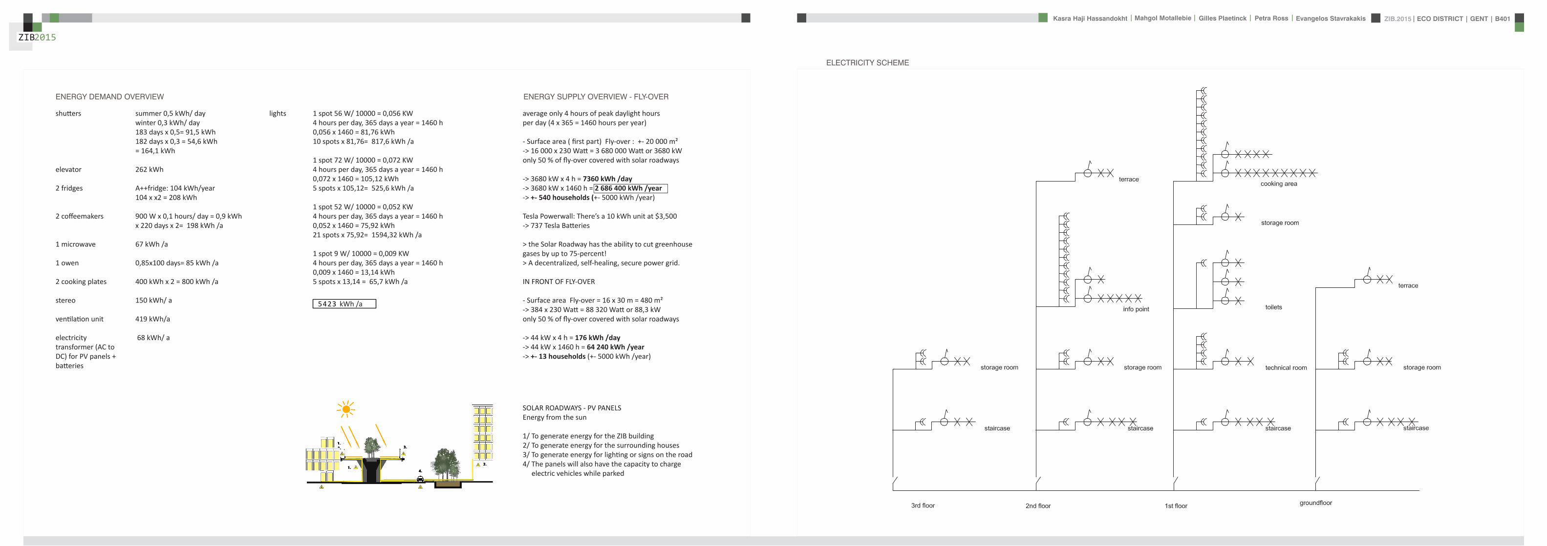
ZIB2015 ECO DISTRICT | GENT | B401Evangelos Stavrakakis | Petra Ross | Mahgol Motallebie | Gilles Plaetinck | Kasra Haji Hassandokht
ZIB2015
|
average only 4 hours of peak daylight hours per day (4 x 365 = 1460 hours per year)
- Surface area ( first part) Fly-over +- 20 000 msup2-gt 16 000 x 230 Watt = 3 680 000 Watt or 3680 kWonly 50 of fly-over covered with solar roadways
-gt 3680 kW x 4 h = 7360 kWh day-gt 3680 kW x 1460 h = 2 686 400 kWh year -gt +- 540 households (+- 5000 kWh year)
Tesla Powerwall Therersquos a 10 kWh unit at $3500 -gt 737 Tesla Batteries
gt the Solar Roadway has the ability to cut greenhouse gases by up to 75-percentgt A decentralized self-healing secure power grid
IN FRONT OF FLY-OVER
- Surface area Fly-over = 16 x 30 m = 480 msup2-gt 384 x 230 Watt = 88 320 Watt or 883 kWonly 50 of fly-over covered with solar roadways
-gt 44 kW x 4 h = 176 kWh day-gt 44 kW x 1460 h = 64 240 kWh year -gt +- 13 households (+- 5000 kWh year)
lightsshutters
elevator
2 fridges
2 coffeemakers
1 microwave
1 owen
2 cooking plates
stereo
ventilation unit
electricity transformer (AC to DC) for PV panels + batteries
summer 05 kWh daywinter 03 kWh day183 days x 05= 915 kWh182 days x 03 = 546 kWh = 1641 kWh
262 kWh
A++fridge 104 kWhyear104 x x2 = 208 kWh
900 W x 01 hours day = 09 kWhx 220 days x 2= 198 kWh a
67 kWh a
085x100 days= 85 kWh a
400 kWh x 2 = 800 kWh a
150 kWh a 419 kWha
68 kWh a
ENERGY DEMAND OVERVIEW ENERGY SUPPLY OVERVIEW - FLY-OVER
1 spot 56 W 10000 = 0056 KW4 hours per day 365 days a year = 1460 h0056 x 1460 = 8176 kWh10 spots x 8176= 8176 kWh a
1 spot 72 W 10000 = 0072 KW4 hours per day 365 days a year = 1460 h0072 x 1460 = 10512 kWh5 spots x 10512= 5256 kWh a
1 spot 52 W 10000 = 0052 KW4 hours per day 365 days a year = 1460 h0052 x 1460 = 7592 kWh21 spots x 7592= 159432 kWh a
1 spot 9 W 10000 = 0009 KW4 hours per day 365 days a year = 1460 h0009 x 1460 = 1314 kWh5 spots x 1314 = 657 kWh a
SOLAR ROADWAYS - PV PANELSEnergy from the sun
1 To generate energy for the ZIB building2 To generate energy for the surrounding houses3 To generate energy for lighting or signs on the road4 The panels will also have the capacity to charge electric vehicles while parked
ELECTRICITY SCHEME
5423 kWh a
ZIB2015 ECO DISTRICT | GENT | B401Evangelos Stavrakakis | Petra Ross | Mahgol Motallebie | Gilles Plaetinck | Kasra Haji Hassandokht
ZIB2015
|
SUMMER SUNNY 10-42 LUXWINTER SUNNY 10-42 LUX
DAYLIGHT - DIALuxLIGHTING SYSTEM - DIALux
Workplane 9 Results overview
Height of working plane 0800 m Wall zone 0000 m
Result Mean (target) Min Max Minaverage MinmaxPerpendicular illuminance [lx] 463 (500) 105 689 0227 0152
Profile Offices Writing typewriting reading data processing
B401-Gent 6222015
Site 1 Building 2 Zib Room 9 Workplane 9 Results overview
Page 70
Workplane 9 False coloursPerpendicular illuminance (adaptive)
Scale 1 200
Perpendicular illuminance (Surface)Mean (actual) 463 lx Min 105 lx Max 689 lx Minaverage 0227 Minmax 0152
B401-Gent 6222015
Site 1 Building 2 Zib Room 9 Workplane 9 False coloursPerpendicular illuminance (adaptive)
Page 72
Workplane 9 Value chartPerpendicular illuminance (adaptive)
Scale 1 200
Perpendicular illuminance (Surface)Mean (actual) 463 lx Min 105 lx Max 689 lx Minaverage 0227 Minmax 0152
B401-Gent 6222015
Site 1 Building 2 Zib Room 9 Workplane 9 Value chartPerpendicular illuminance (adaptive)
Page 73
Workplane 13 Results overview
Height of working plane 0800 m Wall zone 0000 m
Result Mean (target) Min Max Minaverage MinmaxPerpendicular illuminance [lx] 388 (500) 69 732 0178 0094
Profile Offices Writing typewriting reading data processing
B401-Gent 6222015
Site 1 Building 6 Storey 1 Room 13 Workplane 13 Results overview
Page 94
Workplane 13 False coloursPerpendicular illuminance (adaptive)
Scale 1 100
Perpendicular illuminance (Surface)Mean (actual) 388 lx Min 69 lx Max 732 lx Minaverage 0178 Minmax 0094
B401-Gent 6222015
Site 1 Building 6 Storey 1 Room 13 Workplane 13 False coloursPerpendicular illuminance (adaptive)
Page 96
Workplane 13 Value chartPerpendicular illuminance (adaptive)
Scale 1 100
Perpendicular illuminance (Surface)Mean (actual) 388 lx Min 69 lx Max 732 lx Minaverage 0178 Minmax 0094
B401-Gent 6222015
Site 1 Building 6 Storey 1 Room 13 Workplane 13 Value chartPerpendicular illuminance (adaptive)
Page 97
Workplane 9 False coloursPerpendicular illuminance (adaptive)
Scale 1 200
Perpendicular illuminance (Surface)Mean (actual) 463 lx Min 105 lx Max 689 lx Minaverage 0227 Minmax 0152
B401-Gent 6222015
Site 1 Building 2 Zib Room 9 Workplane 9 False coloursPerpendicular illuminance (adaptive)
Page 72
1st f loor 2nd f loor Site 1 Luminaire parts listQuantity Luminaire (Luminous emittance)10 3F Filippi 12736 P 202x24W LED OP 196x1231
Luminous emittance 1Fitting 1x24W 2xLEDLight output ratio 100Lamp luminous flux 5332 lmLuminaire Luminous Flux 5332 lmPower 560 WLight yield 952 lmW
200
300
400
cdklm η = 100C0 - C180 C90 - C270
0deg 15deg 30deg
45deg
60deg
75deg
90deg
105deg105deg
90deg
75deg
60deg
45deg
30deg 15deg 0deg
5 SFN Eclairages 0732360X CLFV 236Luminous emittance 1Fitting 2xT26 36W840Light output ratio 6889Lamp luminous flux 6700 lmLuminaire Luminous Flux 4615 lmPower 720 WLight yield 641 lmW
160
240
cdklm η = 69C0 - C180 C90 - C270
0deg 15deg 30deg
45deg
60deg
75deg
90deg
105deg105deg
90deg
75deg
60deg
45deg
30deg 15deg 0deg
21 SFN Eclairages 332226XX SAM F 2x26W BELuminous emittance 1Fitting 2xTC-DEL 26W840Light output ratio 3297Lamp luminous flux 3600 lmLuminaire Luminous Flux 1187 lmPower 520 WLight yield 228 lmW
40
60
80
100
120
140
cdklm η = 33C0 - C180 C90 - C270
0deg 15deg 30deg
45deg
60deg
75deg
90deg
105deg105deg
90deg
75deg
60deg
45deg
30deg 15deg 0deg
1 Signcomplex AR111-009-AW-W-06 AR111 COB 9W38deg WhiteLuminous emittance 1Fitting 1xAR111-009-AW-W-06Light output ratio 8078Lamp luminous flux 600 lmLuminaire Luminous Flux 485 lmPower 90 WLight yield 539 lmW
800
1200
cdklm η = 81C0 - C180 C90 - C270
0deg 15deg 30deg
45deg
60deg
75deg
90deg
105deg105deg
90deg
75deg
60deg
45deg
30deg 15deg 0deg
Total lamp luminous flux 163020 lm Total luminaire luminous flux 101807 lm Total Load 20210 W Light yield 504 lmW
B401-Gent 6222015
Site 1 Luminaire parts list
Page 19
10x
6x
21x
1x
types of l ights
Perpendicular i l luminance (Surface)Mean (actual ) 463 lx Min 105 lx Max 689 lx Minaverage 0 227 Minmax 0 152
Perpendicular i l luminance (Surface)Mean (actual ) 388 lx Min 69 lx Max 732 lx Minaverage 0 178 Minmax 0 094
ZIB2015 ECO DISTRICT | GENT | B401Evangelos Stavrakakis | Petra Ross | Mahgol Motallebie | Gilles Plaetinck | Kasra Haji Hassandokht
ZIB2015
|
Tube hybrid Solar panels
Hot water tank Water taps
City water supply
Rain water collection for vertical harvesting
City water supply
WADI
Rain water tank
WATER MANAGEMENT
Sinks
Available roof area
In Ghent avarage of 900mmm2year
3197 m2
09x 3197 = 28773 m3year
RAIN WATER GAIN
toilet - 3x - 03lskitchen -4x - 02ls
POTABLE WATER DEMAND
3 toiletsVertical gardening
Total
relative RW usage
300 l day150 l day = 450lday= 16425 m3 year
1407 lday100m2
RAIN WATER DEMAND
RAIN WATER TANK
Relative RWT volumeRain water tank volume
3m3 100 m2
9591 l gt 10 m3
DIMESION OF PIPES
City water supplyRainwater tank
178 mm (DN 18 - 15 - 12)165 mm (DN 17-15)
are composed of hexagonal tiles Rainwater can infiltrate between the gaps from where it goes to rainwatter collector which supplies the vegetation on fly-over
THE SOLAR ROADWAYS
WATER SUPPLY SCHEME AND CALCULATION
ZIB2015 ECO DISTRICT | GENT | B401Evangelos Stavrakakis | Petra Ross | Mahgol Motallebie | Gilles Plaetinck | Kasra Haji Hassandokht
ZIB2015
|
WADI
City water supply
Rain water tank
Sinks
Divided sewer systemwithin building
SEWAGE SYSTEM
ToiletToilet sinkKitchen sink
DU = 2 lsDU = 05 lsDU = 08 ls
WATER DRAINAGE OF DEVICES
Frequency of usage at the same time
K 05
DIMESION OF PIPES
Black waterGrey water
110 mm (DU 110)75 mm (DU 75 - 63)
WATER DRAINAGE SCHEME AND CALCULATION
ZIB2015 ECO DISTRICT | GENT | B401Evangelos Stavrakakis | Petra Ross | Mahgol Motallebie | Gilles Plaetinck | Kasra Haji Hassandokht
ZIB2015
|
DN
Gilles Plaetinck
schaal 1 100
ZIB BUILDINGEnter address here
2 _ level 1
Owner
begeleider Checker
Gilles Plaetinck
schaal 1 100
ZIB BUILDINGEnter address here
3 _ level 2
Owner
begeleider Checker
WATER SUPPLY
HOT WATER
WATER DRAINAGE
WATER SUPPLY AND DRAINAGE IN GROUPLANS
level 01
level 02
ENERGY
RAINWATER TANK
HELOPHYTE FILTER
IRRIGATION SYSTEM
BIO-ROTOR
MICRO TURBINE
PHOSPHOR
In this building a closed water system is applied which is based on reusing water in mullple wasRainRain water from the roof will be collected in a storage tank situated on the ground floor This water will be used to flush the toilet and irrigate crops in verlcal harveslng system In case of an overflow the water will be stored in the con-structed wetland near the building The rainwater can be fil-tered through a helophyte filter up to drinking water stan-dard The waste water system includes three types of water yellyellow black and grey waterThe yellow water will be stored for its phosphor while the black water will be purified into grey water This grey water is comparable to the quality of rain water aaer purificalon b means of a bio rotor The remaining residue from the bio rotor together with the organic waste from the harveslng is fermented into biogas that drives a micro turbine in order to produce some addilonal energy
TheThe waste product deriving from this process will be used as compost in verlcal harveslng This efficient yet complex system closes the ullizalon cycle of the building and turns it into an efficient vicious circle that can be considered au arkic
In this building a closed water system is applied which is based on reusing water in multiple was
Rain water from the roof will be collected in a storage tank situated on the ground floor This water will be used to flushthe toilet and irrigate crops in vertical harvesting system In case of an overflow the water will be stored in the constructed wetland near the building The rainwater can be filtered through a helophyte filter up to drinking water standard
The waste water system includes three types of water yellow black and grey water The yellow water will be stored for its phosphor while the black water will be purified into grey water This grey water is comparable to the quality of rain water after purification b means of a bio rotor The remaining residue from the bio rotor together with the organic waste from the harvesting is fermented into biogas that drives a micro turbine in order to produce some additional energy The waste product deriving from this process will be used ascompost in ver1048991cal harves1048991ng This efficient yet complexsystem closes the u1048991liza1048991on cycle of the building and turns itinto an efficient vicious circle that can be considered au arkic
WATER CYCLE
ZIB2015 ECO DISTRICT | GENT | B401Evangelos Stavrakakis | Petra Ross | Mahgol Motallebie | Gilles Plaetinck | Kasra Haji Hassandokht
ZIB2015
|
CALCULATIONS
Passive House verification
Photo or Drawing
Building Workshop + info pointStreet
PostcodeCityCountry
Building Type non-residentialClimate Ukkel
Home Owner(s) Client(s)Street
PostcodeCity
ArchitectStreet
PostcodeCity Calculation electricity Internal heat gains
Mechanical System Building type
StreetPostcodeCity Internal heat gains
Year of Construction 2015 Interior Temperature 200 degC Utilisation pattern
Number of Dwelling Units 1 Internal Heat Gains 20 Wm2 Type of values used Fill in worksheet IHG Non-Dom Enclosed Volume Ve 12442 Planned number of occupants
Number of Occupants 80 8 Design
Specific building demands with reference to the treated floor area use Annual method
Treated floor area 2840 msup2 Requirements Fulfilled Verification Annual method The monthly method should be used for building certification
Space heating Annual heating demand 10 kWh(m2a) 15 kWh(msup2a) yes Specific space heating demand annual method 103 kWh(msup2a)
Heating load 11 Wm2 10 Wmsup2 - Specific space heating demand monthly Method 120 kWh(msup2a)
Space cooling Overall specific space cooling demand kWh(m2a) 15 kWh(msup2a)
Cooling load Wm2 - -Frequency of overheating (gt 25 degC) - -
Primary Energy Space heating and dehumidification
cooling household electricity 73 kWh(m2a) 120 kWh(msup2a) yes
DHW space heating and auxiliary electricity 24 kWh(m2a) - -Specific primary energy reduction through solar electricity 21 kWh(m2a) - -
Airtightness Pressurization test result n50 06 1h 06 1h yes
PHPP Verification FINAL ZIB FILE CALCULTIONS PHPPxls
L B H VOLUME
main 1 226 7 4 6328main 2 184 7 35 4508
core 0 6 2 5 3 5 108 5core 0 62 5 35 1085core 3 62 3 28 521
12442
AREAmain 1 storage 35
wc big 35wc 2wc 2workshop 103
MAIN 2 infolounge 92
staircase 56storage technical 22
284
Floor_exterior 1582 31 1272
Roof_exterior 1582
Passive House verification
Photo or Drawing
Building Workshop + info pointStreet
PostcodeCityCountry
Building Type non-residentialClimate Ukkel
Home Owner(s) Client(s)Street
PostcodeCity
ArchitectStreet
PostcodeCity Calculation electricity Internal heat gains
Mechanical System Building type
StreetPostcodeCity Internal heat gains
Year of Construction 2015 Interior Temperature 200 degC Utilisation pattern
Number of Dwelling Units 1 Internal Heat Gains 20 Wm2 Type of values used Fill in worksheet IHG Non-Dom Enclosed Volume Ve 12442 Planned number of occupants
Number of Occupants 80 8 Design
Specific building demands with reference to the treated floor area use Annual method
Treated floor area 2840 msup2 Requirements Fulfilled Verification Annual method The monthly method should be used for building certification
Space heating Annual heating demand 10 kWh(m2a) 15 kWh(msup2a) yes Specific space heating demand annual method 103 kWh(msup2a)
Heating load 11 Wm2 10 Wmsup2 - Specific space heating demand monthly Method 120 kWh(msup2a)
Space cooling Overall specific space cooling demand kWh(m2a) 15 kWh(msup2a)
Cooling load Wm2 - -Frequency of overheating (gt 25 degC) - -
Primary Energy Space heating and dehumidification
cooling household electricity 73 kWh(m2a) 120 kWh(msup2a) yes
DHW space heating and auxiliary electricity 24 kWh(m2a) - -Specific primary energy reduction through solar electricity 21 kWh(m2a) - -
Airtightness Pressurization test result n50 06 1h 06 1h yes
PHPP Verification FINAL ZIB FILE CALCULTIONS PHPPxls
SURFACE AREAcurrent orientation only night ventilation
current orientation only night ventilation 6 windows less 52 msup2
current orientation only night ventilation 7 windows less 60msup2 (stays the same for each side)
current orientation only night ventilation 8 windows less 69 msup2
orientation turned 90deg only night ventilation 6 windows less 52 msup2
orientation turned 90deg only night ventilation 7 windows less 60msup2 (window less at SE side)
orientation turned 90deg only night ventilation 8 windows less 69 msup2
-gt orientation turned 90deg only night ventilation 9 windows less 77msup2 (window less at NW side althought theres less overheating in the case of a window less at SE side the heating demand exceeds 15)
CHANGE IN DESIGN
ZIB2015 ECO DISTRICT | GENT | B401Evangelos Stavrakakis | Petra Ross | Mahgol Motallebie | Gilles Plaetinck | Kasra Haji Hassandokht
ZIB2015
|
Passive House verificationS P E C I F I C A N N U A L H E A T I N G D E M A N D
Climate Ukkel Interior Temperature 200 degC
Building Workshop + info point Building TypeUse non-residentialTreated Floor Area ATFA 2840 msup2
per msup2Area U-Value Temp Factor ft Gt Treated Data for heating balance diagram
Building Element Temperature Zone msup2 W(msup2K) kKha kWha Floor Area Losses GainsExterior Wall - Ambient A 5595 0101 100 743 = 4181 1472 Exterior Wall - Ambient 147234373Exterior Wall - Ground B 069 = Exterior Wall - GroundRoofCeiling - Ambient A 1550 0094 100 743 = 1085 382 RoofCeiling - Ambient 381903529Floor slab basement ceiling B 310 0105 069 743 = 167 059 Floor slab basement ceiling 058811509
A 100 =A 100 =
unheated basement X 075 = unheated basementWindows A 1154 0648 100 743 = 5562 1958 Windows 195834732Exterior Door A 100 = Exterior DoorExterior TB (lengthm) A 1169 -0030 100 743 = -259 -091 Thermal Bridge Heat LossPerimeter TB (lengthm) P 069 = 000 not useful heat gains 365267499Ground TB (lengthm) B 069 =
Total of All Building Envelope Areas 8609 ndashndashndashndashndashndashndashndashndashndashndashndashndash- kWh(msup2a) Ventilation 395818713
Transmission Heat Losses QT Total 10736 378Annual Heating Demand 102516636
ATFA Clear Room Height internal gains 100951487msup2 m msup3 passive solar gains 250668423
Ventilation System Effective Air Volume VV 2840 280 = 7952 Thermal bridge credit 091126837Effective Heat Recovery Efficiency eff 81 Cross check sum 46324923 46324923of Heat Recovery
Efficiency of Subsoil Heat Exchanger SHX 0 nVsystem HR nVRes
1h 1h 1h
Energetically Effective Air Exchange nV 0105 (1 - 081 ) + 0038 = 0058
VV nV cAir Gt
msup3 1h Wh(msup3K) kKha kWha kWh(msup2a)
Ventilation Heat Losses QV 795 0058 033 743 = 1124 40
Reduction Factor QT QV NightWeekend
kWha kWha Saving kWha kWh(msup2a)
Total Heat Losses QL ( 10736 + 1124 ) 10 = 11860 418
Orientation Reduction Factor g-Value Area Radiation HPof the Area See Windows Sheet (perp radiation)
msup2 kWh(msup2a) kWha
1 North 054 050 2700 163 = 11822 East 058 000 440 197 = 03 South 056 050 4860 314 = 42874 West 032 050 3216 254 = 13275 Horizontal 063 050 324 317 = 323
kWh(msup2a)
Available Solar Heat Gains QS Total 7119 251
Length Heat Period Spec Power qI ATFA
khd da Wmsup2 msup2 kWha kWh(msup2a)
Internal Heat Gains QI 0024 209 201 2840 = 2867 101
kWha kWh(msup2a)
Free Heat QF QS + QI = 9986 352
Ratio of Free Heat to Losses QF QL = 084
Utilisation Factor Heat Gains G (1 - ( QF QL )5 ) (1 - ( QF QL )
6 ) = 90kWha kWh(msup2a)
Heat Gains QG G QF = 8949 315
kWha kWh(msup2a)
Annual Heating Demand QH QL - QG = 2911 10
kWh(msup2a) (YesNo)
Limiting Value 15 Requirement met yes
00
147
00
3806000000
196
00
40
37
09
103
101
251
0
5
10
15
20
25
30
35
40
45
50
Losses Gains
Hea
t flo
ws
[kW
h(m
sup2a)]
Heating energy balance
passive solar gains
internal gains
Annual Heating Demand
Thermal bridge credit
not useful heat gains
Ventilation
Exterior Door
Windows
unheated basement
Floor slab basement ceiling
RoofCeiling - Ambient
Exterior Wall - Ground
Exterior Wall - Ambient
Thermal Bridge Heat Loss
HPP Annual Heating Demand FINAL ZIB FILE CALCULTIONS PHPPxls
Passive House verification Passive House verificationS P E C I F I C U S E F U L C O O L I N G D E M A N D S P E C I F I C U S E F U L C O O L I N G D E M A N D
M O N T H L Y M E T H O D M O N T H L Y M E T H O D
(This page displays the sums of the monthly method over the cooling period))Climate Ukkel Interior Temperature Summer 25 degC Climate Ukkel Interior Temperature 25 degC
Building Workshop + info point Building TypeUse non-residential Building Workshop + info point Building TypeUse non-residential
Spec Capacity 60 Wh(msup2K) (Enter in Summer worksheet) Treated Floor Area ATFA 2840 msup2 Treated Floor Area ATFA 284 msup2
per msup2Temperature Zone Area U-Value Mon Red Fac Gt Treated Jan Feb Mar Apr May Jun Jul Aug Sep Oct Nov Dec Year
Building Element msup2 W(msup2K) kKha kWha Floor Area Heating Degree Hours - Ex 168 150 144 121 92 73 57 59 82 109 140 160 136 kKh1 Exterior Wall - Ambient A 5595 0101 100 103 = 5782 Heating Degree Hours - G 126 123 135 120 106 83 63 54 58 71 86 109 113 kKh2 Exterior Wall - Ground B 100 = Losses - Exterior 2553 2286 2189 1838 1393 1117 871 904 1245 1660 2123 2432 20612 kWh3 RoofCeiling - Ambient A 1550 0094 100 103 = 1500 Losses - Ground 41 40 44 39 35 27 21 18 19 23 28 36 370 kWh4 Floor slab basement ceil B 310 0105 100 90 = 294 Losses Summer Ventilatio 67 71 244 372 629 720 880 865 658 499 234 126 5366 kWh5 A 100 = Sum Spec Heat Losses 94 84 87 79 72 66 62 63 68 77 84 91 928 kWhmsup26 A 100 = Solar Load North 44 81 141 212 286 298 298 255 178 116 54 35 1998 kWh7 unheated basement X 075 = Solar Load East 0 0 0 0 0 0 0 0 0 0 0 0 0 kWh8 Windows A 1154 0648 100 103 = 7690 Solar Load South 218 315 464 577 681 644 681 658 532 416 242 171 5601 kWh9 Exterior Door A 100 = Solar Load West 79 125 213 303 385 378 370 347 256 177 91 60 2785 kWh
10 Exterior TB (lengthm) A 1169 -0030 100 103 = -358 Solar Load Horiz 11 21 37 57 79 79 80 69 47 30 14 9 533 kWh11 Perimeter TB (lengthm) P 100 = Solar Load Opaque 3 5 9 13 18 19 19 16 11 7 3 2 126 kWh12 Ground TB (lengthm) B 100 = Internal Heat Gains 425 384 425 411 425 411 425 425 411 425 411 425 5001 kWh
ndashndashndashndashndashndashndashndashndashndashndash kWh(msup2a) Sum Spec Loads Solar + 28 33 45 55 66 64 66 62 51 41 29 25 565 kWhmsup2
Transmission Losses QT (Negative Heat Loads) Total 14907 525 Utilisation Factor Losses 29 39 52 69 84 88 82 88 73 53 34 27 58Useful Cooling Energy Dem 0 0 4 30 142 192 417 192 40 4 0 0 1021 kWh
ATFA Clear Room Height Spec Cooling Demand 00 00 00 01 05 07 15 07 01 00 00 00 36 kWhmsup2Effective msup2 m msup3
Air Volume VV 284 280 = 795
Heat Transfer Coef Gt
WK kKha kWha kWh(msup2a)
Exterior 99 103 = 1013 36Ground 00 105 = 0 00
Additional Summer Ventilation
Select X Window Night Ventilation Manual Corresponding Air Change Rate 136 1h
Mechanical Automatically Controlled Ventilation (for window ventilation at 1 K temperature difference indoor - outdoor)
Minimum Acceptable Indoor Temperatu 220 degC
kWha kWh(msup2a)
Heat Losses Summer Ventilation 5172 182
QLext QLground QLsummer
kWha kWha kWha kWha kWh(msup2a)
Ventilation Heat Losses QV 1013 + 0 + 5172 = 6185 218
2
3
4
5
6
7
8
9
10
Spec
ific
loss
es l
oads
l c
oolin
g de
man
d [k
Wh
(msup2 m
onth
)] Spec Cooling Demand Sum Spec Heat Losses Sum Spec Loads Solar + Internal
QT QV
kWha kWha kWha kWh(msup2a)
Total Heat Losses QL 14907 + 6185 = 21092 743
Orientation Reduction Factor g-Value Area Global Radiationof the Area (perp radiation)
msup2 kWh(msup2a) kWha
1 North 031 050 270 462 = 19182 East 061 000 44 578 = 0 Temperature Amplitude Summer 82 K3 South 030 050 486 707 = 52114 West 025 050 322 654 = 2646 Month 1 2 3 4 5 6 7 8 9 10 11 12 Annual Total5 Horizontal 035 050 32 913 = 513 Days 31 28 31 30 31 30 31 31 30 31 30 31 3656 Sum Opaque Areas 121 Ambient Temp 250 270 572 828 1275 1487 1737 1707 1369 1039 568 356 96
kWh(msup2a) North Radiation 106 195 329 494 667 697 712 599 419 275 129 87 471
Available Solar Heat Gains QS Total 10409 367 East Radiation 146 266 452 698 937 940 988 851 574 382 179 123 654
South Radiation 311 440 645 786 912 858 898 885 733 579 341 241 763Length Heat Period Spec Power qI ATFA West Radiation 155 261 471 707 926 926 896 819 580 382 183 116 642
khd da Wmsup2 msup2 kWha kWh(msup2a) Hori Radiation 200 369 662 1021 1398 1410 1418 1234 842 535 243 156 949
Internal Heat Gains QI 0024 303 20 2840 = 4151 146 Tsky -750 -730 -428 -172 275 487 737 707 369 039 -432 -644 -04
Ground Temp 805 676 686 830 1072 1345 1647 1776 1696 1552 1310 1037 121kWha kWh(msup2a)
Sum Heat Loads QF QS + QI = 14560 513
Ratio of Losses to Free Heat Gains QL QF = 145
Utilisation Factor Heat Losses G = 64kWha kWh(msup2a)
Useful Heat Losses QVn G QL = 13539 477
kWha kWh(msup2a)
Useful Cooling Demand QK QF - QVn = 1021 4
kWh(msup2a) (YesNo)
Limiting Value 15 Requirement met yes
0
1
2
Jan Feb Mar Apr May Jun Jul Aug Sep Oct Nov Dec
usef
u
HPP Cooling FINAL ZIB FILE CALCULTIONS PHPPxls
Passive House verificationS P E C I F I C A N N U A L H E A T I N G D E M A N D
Climate Ukkel Interior Temperature 200 degC
Building Workshop + info point Building TypeUse non-residentialTreated Floor Area ATFA 2840 msup2
per msup2Area U-Value Temp Factor ft Gt Treated Data for heating balance diagram
Building Element Temperature Zone msup2 W(msup2K) kKha kWha Floor Area Losses GainsExterior Wall - Ambient A 5595 0101 100 743 = 4181 1472 Exterior Wall - Ambient 147234373Exterior Wall - Ground B 069 = Exterior Wall - GroundRoofCeiling - Ambient A 1550 0094 100 743 = 1085 382 RoofCeiling - Ambient 381903529Floor slab basement ceiling B 310 0105 069 743 = 167 059 Floor slab basement ceiling 058811509
A 100 =A 100 =
unheated basement X 075 = unheated basementWindows A 1154 0648 100 743 = 5562 1958 Windows 195834732Exterior Door A 100 = Exterior DoorExterior TB (lengthm) A 1169 -0030 100 743 = -259 -091 Thermal Bridge Heat LossPerimeter TB (lengthm) P 069 = 000 not useful heat gains 365267499Ground TB (lengthm) B 069 =
Total of All Building Envelope Areas 8609 ndashndashndashndashndashndashndashndashndashndashndashndashndash- kWh(msup2a) Ventilation 395818713
Transmission Heat Losses QT Total 10736 378Annual Heating Demand 102516636
ATFA Clear Room Height internal gains 100951487msup2 m msup3 passive solar gains 250668423
Ventilation System Effective Air Volume VV 2840 280 = 7952 Thermal bridge credit 091126837Effective Heat Recovery Efficiency eff 81 Cross check sum 46324923 46324923of Heat Recovery
Efficiency of Subsoil Heat Exchanger SHX 0 nVsystem HR nVRes
1h 1h 1h
Energetically Effective Air Exchange nV 0105 (1 - 081 ) + 0038 = 0058
VV nV cAir Gt
msup3 1h Wh(msup3K) kKha kWha kWh(msup2a)
Ventilation Heat Losses QV 795 0058 033 743 = 1124 40
Reduction Factor QT QV NightWeekend
kWha kWha Saving kWha kWh(msup2a)
Total Heat Losses QL ( 10736 + 1124 ) 10 = 11860 418
Orientation Reduction Factor g-Value Area Radiation HPof the Area See Windows Sheet (perp radiation)
msup2 kWh(msup2a) kWha
1 North 054 050 2700 163 = 11822 East 058 000 440 197 = 03 South 056 050 4860 314 = 42874 West 032 050 3216 254 = 13275 Horizontal 063 050 324 317 = 323
kWh(msup2a)
Available Solar Heat Gains QS Total 7119 251
Length Heat Period Spec Power qI ATFA
khd da Wmsup2 msup2 kWha kWh(msup2a)
Internal Heat Gains QI 0024 209 201 2840 = 2867 101
kWha kWh(msup2a)
Free Heat QF QS + QI = 9986 352
Ratio of Free Heat to Losses QF QL = 084
Utilisation Factor Heat Gains G (1 - ( QF QL )5 ) (1 - ( QF QL )
6 ) = 90kWha kWh(msup2a)
Heat Gains QG G QF = 8949 315
kWha kWh(msup2a)
Annual Heating Demand QH QL - QG = 2911 10
kWh(msup2a) (YesNo)
Limiting Value 15 Requirement met yes
00
147
00
3806000000
196
00
40
37
09
103
101
251
0
5
10
15
20
25
30
35
40
45
50
Losses Gains
Hea
t flo
ws
[kW
h(m
sup2a)]
Heating energy balance
passive solar gains
internal gains
Annual Heating Demand
Thermal bridge credit
not useful heat gains
Ventilation
Exterior Door
Windows
unheated basement
Floor slab basement ceiling
RoofCeiling - Ambient
Exterior Wall - Ground
Exterior Wall - Ambient
Thermal Bridge Heat Loss
HPP Annual Heating Demand FINAL ZIB FILE CALCULTIONS PHPPxls
factor 05Wd (ls) 088
nominal diameter 75 mmVERTICAL COLLECTOR sink toilets 3 05 15
sink kitchen 2 08 16Total 5 31factor 05
Wd (ls) 088nominal diameter 75 mm
Toevoerend ROOF SURFACE
horizontal roof surface (msup2) orientation coeff angle (deg) roofcover filter coeff toevoerend
444 1 0 08 09 3197
RAIN WATER USAGE
Type usage ( l usage) persons day frequency usageday yearly usage
toilet use small 3 20 3 180 65700toilet use big 6 20 1 120 43800VERTICAL GARDENING 150 54750TOTAL 450 164250 L year
16425 msup3 year
TOTAL RAINWATER USAGE 450 L dayRELATIVE RAINWATER USAGE 1407 L day100msup2
LEEGSTAND
relative rainwater usage 1407 L day 100 msup2LEEGSTAND 7 relative volume rainwater tank 3 msup3 100 msup2rainwater tank volume 9591 Liter
suggestion 50 msup2 02 m= 10 msup3
SUPPLYtype amount debiet Q total total WW
lsec lsec lsecMAIN LEVEL POTABLE
sink toilet 3 01 03 03sink kitchen 2 01 02 02
Total 5 05 05Gelijktijdigheid 05 05debiet Q (lsec) 025 025
diameter 178 178 cm
type amount debiet Q total total WWlsec lsec lsec
MAIN LEVEL RAIN WATER toilet 3 01 03 0
Total 3 03Gelijktijdigheid 071debiet Q (lsec) 0213
diameter 165 cm
FECALIEumlNtype amount value Total (ls)
COLLECTOR HORIZONTAL toilet 3 2Total 6factor 05
Wd (ls) 122nominal diameter 110 mm
type amount value Total (ls)COLLECTOR VERTICAL toilet 3 2
Total 6factor 05
Wd (ls) 122nominal diameter 110 mm
DRAINtype amount value Total (ls)
HORIZONTAL COLLECTOR sink toilets 3 05 15sink kitchen 2 08 16
Total 5 31
WATER
ZIB2015 ECO DISTRICT | GENT | B401Evangelos Stavrakakis | Petra Ross | Mahgol Motallebie | Gilles Plaetinck | Kasra Haji Hassandokht
ZIB2015
|
Passive House verificationS P E C I F I C S P A C E H E A T I N G L O A D Risk Determination of Group Heating for a Critical Room
Building Workshop + info point Building TypeUse non-residential Workshop room ( 1= Yes 0 = No)
Climate (HL) Ukkel Treated Floor Area ATFA 2840 msup2 Interior Temperature 20 degC Building Satisfies Passive House Criteria 1
Design Temperature Radiation North East South West Horizontal Room floor area 100 msup2 Supply Air per msup2 Living AreaWeather Condition 1 -31 degC 10 10 30 15 20 Wmsup2 Planned ambient air quantity for the room 150 msup3h 150 msup3hmsup2Weather Condition 2 -22 degC 5 5 20 10 10 Wmsup2 Planned ambient air quantities for the remaining rooms -67 msup3hGround Design Temp 68 degC Area U-Value Factor TempDiff 1 TempDiff 2 PT 1 PT 2
Building Element Temperature Zone msup2 W(msup2K) Always 1(except X) K K W W Building Element Temperature Zone msup2 W(msup2K) Always 1
(except X) K Room Trans Loss W
1 Exterior Wall - Ambient A 5595 0101 100 231 or 222 = 1299 or 1249 Aboveground Exterior Wall A 650 010 100 231 = 1512 Exterior Wall - Ground B 100 132 or 132 = or Belowground Exterior Wall B 00 100 132 =3 RoofCeiling - Ambient A 1550 0094 100 231 or 222 = 337 or 324 RoofCeiling D 880 009 100 231 = 1914 Floor slab basement ceiling B 310 0105 100 132 or 132 = 43 or 43 Underground Floor Slab B 00 011 100 132 = 05 A 100 231 or 222 = or A 100 231 =6 A 100 231 or 222 = or A 100 231 =7 unheated basement X 075 231 or 222 = or X 100 231 =8 Windows A 1154 0648 100 231 or 222 = 1728 or 1661 Windows A 480 065 100 231 = 7199 Exterior Door A 100 231 or 222 = or Exterior Door A 100 231 =
10 Exterior TB (lengthm) A 1169 -0030 100 231 or 222 = -80 or -77 Exterior thermal bridges (Lengthm) A 100 231 =11 Perimeter TB (lengthm) P 100 132 or 132 = or Perimeter Thermal Bridges (Lengthm) A 100 231 =12 Ground TB (lengthm) B 100 132 or 132 = or Floor Slab Thermal Bridges (Lengthm) A 50 100 231 =13 HouseDU Partition Wall I 100 30 or 30 = or HouseDU Partition Wall I 200 100 30 =
Transmission Heat Losses PT ndashndashndashndashndashndashndashndashndashndashndashndashndash- ndashndashndashndashndashndashndashndashndashndashndash-
Total = 3328 or 3200 = 1061
ATFA Clear Room HeightVentilation System msup2 m msup3 Risk
Effective Air Volume VV 2840 280 = 795 Enter 1 = Yes 0 = No PTRoom W PSupply Air W Ratio Summand
SHX 1 SHX 2 Transmission Heat Losses 1061 1386 077 -023Efficiency of Heat Recovery HR 81 Heat Recovery Efficiency SHX 0 Efficiency SHX 0 or 0 Concentrated leakages 0 000of the Heat Exchanger Insulation to other rooms better R = 15 msup2KW 1 ( 2 = no thermal contact except door) 050
nVRes (Heating Load) nVsystem HR HR Room is on the ground floor 0 0001h 1h 1h 1h open staircase 0 000
Energetically Effective Air Exchange nV 0094 + 0105 (1- 081 or 081 ) = 0114 or 0114 TOTAL of the Risk Summands 027Ventilation Heating Load PV
VL nL nL cAir TempDiff 1 TempDiff 2 PV 1 PV 2 Interior doors predominantly closed 1 Risk Factor 200msup3 1h 1h Wh(msup3K) K K W W
7952 0114 or 0114 033 231 or 222 = 691 or 664Total Room Risk 89
PL 1 PL 2
Total Heating Load PL W W Appraisal and Advice normally no problemPT + PV = 4019 or 3864
Orientation Area g-Value Reduction Factor Radiation 1 Radiation 2 PS 1 PS 2the Area msup2 (perp radiation) (see Windows worksheet) Wmsup2 Wmsup2 W W
1 North 270 05 05 11 or 6 = 77 or 412 East 44 00 06 8 or 3 = 0 or 03 South 486 05 06 28 or 18 = 378 or 2474 West 322 05 03 19 or 13 = 100 or 685 Horizontal 32 05 06 20 or 10 = 20 or 10
Solar heating power PS Total = 575 or 367
Spec Power ATFA PI 1 PI 2Internal heating power PI Wmsup2 msup2 W W
16 284 = 454 or 454
PG 1 PG 2
Heating power (gains) PG W W
PS + PI = 1029 or 821
PL - PG = 2989 or 3042
Heating Load PH = 3042 W
Specific Heating Load PH ATFA = 107 Wmsup2
Input Max Supply Air Temperature 48 degC degC degC
Max Supply Air Temperature SupplyMax 48 degC Supply Air Temperature Without Heating SupplyMin 156 157
For Comparison Heating Load Transportable by Supply Air PSupply AirMax = 886 W specific 31 Wmsup2
(YesNo)
Supply Air Heating Sufficient No
HPP Heating Load FINAL ZIB FILE CALCULTIONS PHPPxls
Passive House verificationU - V A L U E S O F B U I L D I N G E L E M E N T S
Wedge shaped building element layeBuilding Workshop + info point still air spaces -gt Secondary calculation to th
Assembly No Building assembly description Interior insulation1 Exterior wall x
Heat transfer resistance [msup2KW] interior Rsi 013exterior Rse 004
Area section 1 [W(mK)] Area section 2 (optional) [W(mK)] Area section 3 (optional) [W(mK)] Thickness [mm]
1 hout gevel 0160 17
2 regelwerk hout 0158 30
3 houtvezel celit 4D 0048 18
4 Eurowall 0023 hout FJI beam 0286 140
5 OSB -plaat 0130 15
6 Eurothane G 0023 70
7 Plaster insulating 0100 10
8Percentage of Sec 2 Percentage of Sec 3 Total
26 300
U-Value 0107 W(msup2K)
Assembly No Building assembly description Interior insulation2 Roof x
Heat transfer resistance [msup2KW] interior Rsi 010exterior Rse 004
Area section 1 [W(mK)] Area section 2 (optional) [W(mK)] Area section 3 (optional) [W(mK)] Thickness [mm]Area section 1 [W(mK)] Area section 2 (optional) [W(mK)] Area section 3 (optional) [W(mK)] Thickness [mm]
1 bitumenmembraam 0230 5
23 EPS 0036 70
4 OSB -plaat 0130 18
5 cellulose 0039 hout FJI beam 0286 350
6 OSB -plaat 0130 15
7 regelwerk hout 5 0177 30
8 gipskartonplaat 0290 12
Percentage of Sec 2 Percentage of Sec 3 Total
26 500
U-Value 0094 W(msup2K)
Assembly No Building assembly description Interior insulation3 Floor x
Heat transfer resistance [msup2KW] interior Rsi 017
exterior Rse 004
Area section 1 [W(mK)] Area section 2 (optional) [W(mK)] Area section 3 (optional) [W(mK)] Thickness [mm]
1 PIR dekvloer 0023 5
2 gipskartonplaat 0290 10
3 gespoten pur 0028 100
4 OSB -plaat 0130 15
5 cellulose 0039 hout FJI beam 0286 350
6 houtvezel Celit 4D 0048 15
7 regelwerk hout 6 0149 30
8 afwerking hout 0160 5
Percentage of Sec 2 Percentage of Sec 3 Total
26 530
U-Value 0078 W(msup2K)
PHPP U-Values FINAL ZIB FILE CALCULTIONS PHPPxls
ers and he right
n Secondary Calculation Equivalent Thermal Conductivity of Still Air Spaces
Air Layer Thickness 30 mm Direction of Upwards ha 125 W(msup2K) 016 W(mK)
Heat Flow X Horizontal hr 417 W(msup2K)
(check only one field) Downwards
cm
n
cm
n Secondary Calculation Equivalent Thermal Conductivity of Still Air Spaces
Air Layer Thickness 30 mm
Direction of Upwards ha 08333 W(msup2K) 015 W(mK)Heat Flow Horizontal hr 417 W(msup2K)
(check only one field) X Downwards
cm
PHPP U-Values FINAL ZIB FILE CALCULTIONS PHPPxls
ers and he right
n Secondary Calculation Equivalent Thermal Conductivity of Still Air Spaces
Air Layer Thickness 30 mm Direction of Upwards ha 125 W(msup2K) 016 W(mK)
Heat Flow X Horizontal hr 417 W(msup2K)
(check only one field) Downwards
cm
n
cm
n Secondary Calculation Equivalent Thermal Conductivity of Still Air Spaces
Air Layer Thickness 30 mm
Direction of Upwards ha 08333 W(msup2K) 015 W(mK)Heat Flow Horizontal hr 417 W(msup2K)
(check only one field) X Downwards
cm
PHPP U-Values FINAL ZIB FILE CALCULTIONS PHPPxls
ers and he right
n Secondary Calculation Equivalent Thermal Conductivity of Still Air Spaces
Air Layer Thickness 30 mm Direction of Upwards ha 125 W(msup2K) 016 W(mK)
Heat Flow X Horizontal hr 417 W(msup2K)
(check only one field) Downwards
cm
n
cm
n Secondary Calculation Equivalent Thermal Conductivity of Still Air Spaces
Air Layer Thickness 30 mm
Direction of Upwards ha 08333 W(msup2K) 015 W(mK)Heat Flow Horizontal hr 417 W(msup2K)
(check only one field) X Downwards
cm
PHPP U-Values FINAL ZIB FILE CALCULTIONS PHPPxls
Passive House verificationS U M M E R
Climate Ukkel Interior Temperature 20 degC
Building Workshop + info point Building TypeUse non-residentialTreated Floor Area ATFA 2840 msup2
Spec Capacity 60 WhK pro msup2 TFAOverheating
limit25 degC Area U-Value Red Factor fTSummer HSummer Heat Conductance
Building Element Temperature Zone msup2 W(msup2K)
1 Exterior Wall - Ambien A 5595 0101 100 = 5632 Exterior Wall - Ground B 100 =3 RoofCeiling - Ambient A 1550 0094 100 = 1464 Floor slab basement B 310 0105 100 = 335 A 100 =6 A 100 =7 unheated basement X 075 =8 Windows A 1154 0648 100 = 7489 Exterior Door A 100 =
10 Exterior TB (lengthm) A 1169 -0030 100 = -3511 Perimeter TB (lengthm P 100 =12 Ground TB (lengthm) B 100 =
ndashndashndashndashndashndashndashndashndashndashndashExterior Thermal Transmittance HTe 1422 WK
Ground Thermal Transmittance HTg 33 WK
ATFA Clear Room HeightEffective msup2 m msup3
Heat Recovery Efficiency HR 81 Air Volume VV 2840 280 = 795
SHX Efficiency SHX 0
Summer Ventilation continuous ventilation to provide sufficient indoor air quality
Air Change Rate by Natural (Windows amp Leakages) or Exhaust-Only Mechanical Ventilation Summer 000 1h
Mechanical Ventilation Summer 1h X with HR (check if applicable)
nLnat nVsystem HR nVRest
1h 1h 1h 1h
Energetically Effective Airchange Rate nV 0000 + 0000 (1 - 0808 ) + 0038 = 0038
VV nVequifraction cAir
msup3 1h Wh(msup3K)
Ventilation Transm Ambient HVe 795 0038 033 = 99 WK
Ventilation Transm Ground HVg 795 0000 033 = 00 WK
Additional Summer Ventilation for Cooling Temperature amplitude summer 82 K
Select X Window Night Ventilation Manual Corresponding Air Change Rate 136 1hMechanical Automatically Controlled Ventilation (for window ventilation at 1 K temperature difference indoor - outdoor)
Minimum Acceptable Indoor Temperature 220 degC
Orientation Angle Shading g-Value Area Portion of Glazing Apertureof the Area Factor Factor Dirt (perp radiation)
Summer Summer msup2 msup2
1 North 09 044 095 050 270 82 = 422 East 09 100 095 000 44 71 = 003 South 09 043 095 050 486 82 = 744 West 09 039 095 050 322 76 = 405 Horizontal 09 052 095 050 32 78 = 066 Sum Opaque Areas 03
msup2msup2
Solar Aperture Total 164 006
Specif Power qI ATFA
Wmsup2 msup2 W Wmsup2
Internal Heat Gains QI 201 284 = 571 20
Frequency of Overheating hmax 42 at the overheating limit max = 25 degC
If the frequency over 25degC exceeds 10 additional measures to protect against summer heat waves are necessary
Solar Load Spec Capacity ATFA
kWhd 1k Wh(msup2K) msup2
Daily Temperature Swing due to Solar Load 00 1000 ( 60 284 ) = 00 K
PHPP Summer FINAL ZIB FILE CALCULTIONS PHPPxls
Passive House verification Passive House verificationS P E C I F I C A N N U A L H E A T I N G D E M A N D S P E C I F I C A N N U A L H E A T D E M A N D
M O N T H L Y M E T H O D M O N T H L Y M E T H O D
(This page displays the sums of the monthly method over the heating period)Climate Ukkel Interior Temperature 20 degC Climate Ukkel Interior Temperature 20 degC
Building Workshop + info point Building TypeUse non-residential Building Workshop + info point Building TypeUse non-residentialSpec Capacity 60 Wh(msup2K) (Enter in Summer worksheet) Treated Floor Area ATFA 2840 msup2 Treated Floor Area ATFA 284 msup2
per msup2Temperature Zone Area U-Value Month Red Fac Gt Treated Jan Feb Mar Apr May Jun Jul Aug Sep Oct Nov Dec Year
Building Element msup2 W(msup2K) kKha kWha Floor Area Heating Degree Hours - E 131 117 107 85 54 37 20 22 46 72 104 123 92 kKhExterior Wall - Ambient A 5595 0101 100 78 = 4406 Heating Degree Hours - G 89 89 98 84 69 47 26 17 22 33 50 72 70 kKhExterior Wall - Ground B 100 = Losses - Exterior 2056 1836 1679 1335 856 589 316 350 722 1132 1630 1931 14433 kWhRoofCeiling - Ambient A 1550 0094 100 78 = 1143 Losses - Ground 29 29 32 28 23 15 9 5 7 11 16 23 227 kWhFloor slab basement ceiling B 310 0105 100 54 = 175 Sum Spec Losses 73 66 60 48 31 21 11 13 26 40 58 69 516 kWhmsup2
A 100 = Solar Gains - North 78 142 246 371 500 520 520 445 311 202 94 62 3490 kWhA 100 = Solar Gains - East 0 0 0 0 0 0 0 0 0 0 0 0 0 kWh
unheated basement X 075 = Solar Gains - South 405 583 860 1069 1261 1194 1263 1220 986 771 448 318 10377 kWhWindows A 1154 0648 100 78 = 5861 Solar Gains - West 103 162 275 391 497 489 478 448 331 229 118 77 3597 kWhExterior Door A 100 = Solar Gains - Horiz 20 38 68 104 143 144 145 126 86 55 25 16 968 kWhExterior TB (lengthm) A 1169 -0030 100 78 = -273 Solar Gains - Opaque 3 5 9 13 18 19 19 16 11 7 3 2 126 kWhPerimeter TB (lengthm) P 100 = Internal Heat Gains 425 384 425 411 425 411 425 425 411 425 411 425 5001 kWhGround TB (lengthm) B 100 = Sum Spec Gains Solar + 36 46 66 83 100 98 100 94 75 59 39 32 830 kWhmsup2
ndashndashndashndashndashndashndashndashndashndashndash kWh(msup2a) Utilisation Factor 100 98 84 57 31 22 11 13 34 67 98 100 48Transmission Heat Losses QT Total 11313 398 Annual Heating Demand 1055 580 134 9 0 0 0 0 0 19 564 1057 3419 kWh
Spec Heating Demand 37 20 05 00 00 00 00 00 00 01 20 37 120 kWhmsup2ATFA Clear Room Height
Effective msup2 m msup3
Air Volume VRAX 284 280 = 795
nVsystem SHX HR nVRes nVequifraction
1h 1h 1h
Effective Air Change Rate Ambient nVe 0105 (1- 0 )(1- 081 )+ 0038 = 0058Effective Air Change Rate Ground nVg 0105 0 (1- 081 ) = 0000
VRAX nVequifraction cAir Gt
msup3 1h Wh(msup3K) kKha kWha kWh(msup2a)
Ventilation Losses Ambient QV 795 0058 033 78 = 1185 42
Ventilation Losses Ground QVe 795 0000 033 55 = 0 00ndashndashndashndashndashndashndashndashndashndashndash
Ventilation Heat Losses QV Total 1185 42
Reduction Factor QT QV NightWeekend
kWha kWha Saving kWha kWh(msup2a)
Total Heat Losses QL ( 11313 + 1185 ) 10 = 12497 440
Orientation Reduction Factor g-Value Area Global Radiationof the Area See Windows worksheet (perp radiation)
msup2 kWh(msup2a) kWha
North 054 050 270 208 = 1505East 058 000 44 250 = 0South 056 050 486 398 = 5440West 032 050 322 323 = 1685Horizontal 063 050 32 403 = 411Sum Opaque Areas 55
kWh(msup2a)
Available Solar Heat Gains QS Total 9095 320 Annual Heating Demand Comparison
EN 13790 Monthly Method 3419 kWha 120 kWh(msup2a) Reference to habitable area
Length Heat Period Spec Power qI ATFA PHPP Heating Period Method 2911 kWha 103 kWh(msup2a) Reference to habitable area
khd da Wmsup2 msup2 kWha kWh(msup2a)
Internal Heat Gains QI 0024 242 20 2840 = 3315 117
kWha kWh(msup2a) Month 1 2 3 4 5 6 7 8 9 10 11 12 Annual Total Heating Period Method
Free Heat QF QS + QI = 12411 437 Days 31 28 31 30 31 30 31 31 30 31 30 31 365 209Ambient Temp 250 270 572 828 1275 1487 1737 1707 1369 1039 568 356 96 52
Ratio Free Heat to Losses QF QL = 099 North Radiation 106 195 329 494 667 697 712 599 419 275 129 87 471 163East Radiation 146 266 452 698 937 940 988 851 574 382 179 123 654 197
Utilisation Factor Heat Gains G = 73 South Radiation 311 440 645 786 912 858 898 885 733 579 341 241 763 314kWha kWh(msup2a) West Radiation 155 261 471 707 926 926 896 819 580 382 183 116 642 254
Heat Gains QG G QF = 9078 320 Hori Radiation 200 369 662 1021 1398 1410 1418 1234 842 535 243 156 949 317
Tsky -750 -730 -428 -172 275 487 737 707 369 039 -432 -644 -04kWha kWh(msup2a) Ground Temp 805 676 686 830 1072 1345 1647 1776 1696 1552 1310 1037 121 98
Annual Heating Demand QH QL - QG = 3419 12
kWh(msup2a) (YesNo)
Limiting Value 15 Requirement met yes
0
2
4
6
8
10
12
Jan Feb Mar Apr May Jun Jul Aug Sep Oct Nov Dec
Spec
ific
loss
es g
ains
he
atin
g de
man
d [k
Wh
(msup2 m
onth
)]
Spec Heating Demand Sum Spec Gains Solar + Internal Sum Spec Losses
HPP Monthly Method FINAL ZIB FILE CALCULTIONS PHPPxls
Passive House verification Passive House verificationS P E C I F I C A N N U A L H E A T I N G D E M A N D S P E C I F I C A N N U A L H E A T D E M A N D
M O N T H L Y M E T H O D M O N T H L Y M E T H O D
(This page displays the sums of the monthly method over the heating period)Climate Ukkel Interior Temperature 20 degC Climate Ukkel Interior Temperature 20 degC
Building Workshop + info point Building TypeUse non-residential Building Workshop + info point Building TypeUse non-residentialSpec Capacity 60 Wh(msup2K) (Enter in Summer worksheet) Treated Floor Area ATFA 2840 msup2 Treated Floor Area ATFA 284 msup2
per msup2Temperature Zone Area U-Value Month Red Fac Gt Treated Jan Feb Mar Apr May Jun Jul Aug Sep Oct Nov Dec Year
Building Element msup2 W(msup2K) kKha kWha Floor Area Heating Degree Hours - E 131 117 107 85 54 37 20 22 46 72 104 123 92 kKhExterior Wall - Ambient A 5595 0101 100 78 = 4406 Heating Degree Hours - G 89 89 98 84 69 47 26 17 22 33 50 72 70 kKhExterior Wall - Ground B 100 = Losses - Exterior 2056 1836 1679 1335 856 589 316 350 722 1132 1630 1931 14433 kWhRoofCeiling - Ambient A 1550 0094 100 78 = 1143 Losses - Ground 29 29 32 28 23 15 9 5 7 11 16 23 227 kWhFloor slab basement ceiling B 310 0105 100 54 = 175 Sum Spec Losses 73 66 60 48 31 21 11 13 26 40 58 69 516 kWhmsup2
A 100 = Solar Gains - North 78 142 246 371 500 520 520 445 311 202 94 62 3490 kWhA 100 = Solar Gains - East 0 0 0 0 0 0 0 0 0 0 0 0 0 kWh
unheated basement X 075 = Solar Gains - South 405 583 860 1069 1261 1194 1263 1220 986 771 448 318 10377 kWhWindows A 1154 0648 100 78 = 5861 Solar Gains - West 103 162 275 391 497 489 478 448 331 229 118 77 3597 kWhExterior Door A 100 = Solar Gains - Horiz 20 38 68 104 143 144 145 126 86 55 25 16 968 kWhExterior TB (lengthm) A 1169 -0030 100 78 = -273 Solar Gains - Opaque 3 5 9 13 18 19 19 16 11 7 3 2 126 kWhPerimeter TB (lengthm) P 100 = Internal Heat Gains 425 384 425 411 425 411 425 425 411 425 411 425 5001 kWhGround TB (lengthm) B 100 = Sum Spec Gains Solar + 36 46 66 83 100 98 100 94 75 59 39 32 830 kWhmsup2
ndashndashndashndashndashndashndashndashndashndashndash kWh(msup2a) Utilisation Factor 100 98 84 57 31 22 11 13 34 67 98 100 48Transmission Heat Losses QT Total 11313 398 Annual Heating Demand 1055 580 134 9 0 0 0 0 0 19 564 1057 3419 kWh
Spec Heating Demand 37 20 05 00 00 00 00 00 00 01 20 37 120 kWhmsup2ATFA Clear Room Height
Effective msup2 m msup3
Air Volume VRAX 284 280 = 795
nVsystem SHX HR nVRes nVequifraction
1h 1h 1h
Effective Air Change Rate Ambient nVe 0105 (1- 0 )(1- 081 )+ 0038 = 0058Effective Air Change Rate Ground nVg 0105 0 (1- 081 ) = 0000
VRAX nVequifraction cAir Gt
msup3 1h Wh(msup3K) kKha kWha kWh(msup2a)
Ventilation Losses Ambient QV 795 0058 033 78 = 1185 42
Ventilation Losses Ground QVe 795 0000 033 55 = 0 00ndashndashndashndashndashndashndashndashndashndashndash
Ventilation Heat Losses QV Total 1185 42
Reduction Factor QT QV NightWeekend
kWha kWha Saving kWha kWh(msup2a)
Total Heat Losses QL ( 11313 + 1185 ) 10 = 12497 440
Orientation Reduction Factor g-Value Area Global Radiationof the Area See Windows worksheet (perp radiation)
msup2 kWh(msup2a) kWha
North 054 050 270 208 = 1505East 058 000 44 250 = 0South 056 050 486 398 = 5440West 032 050 322 323 = 1685Horizontal 063 050 32 403 = 411Sum Opaque Areas 55
kWh(msup2a)
Available Solar Heat Gains QS Total 9095 320 Annual Heating Demand Comparison
EN 13790 Monthly Method 3419 kWha 120 kWh(msup2a) Reference to habitable area
Length Heat Period Spec Power qI ATFA PHPP Heating Period Method 2911 kWha 103 kWh(msup2a) Reference to habitable area
khd da Wmsup2 msup2 kWha kWh(msup2a)
Internal Heat Gains QI 0024 242 20 2840 = 3315 117
kWha kWh(msup2a) Month 1 2 3 4 5 6 7 8 9 10 11 12 Annual Total Heating Period Method
Free Heat QF QS + QI = 12411 437 Days 31 28 31 30 31 30 31 31 30 31 30 31 365 209Ambient Temp 250 270 572 828 1275 1487 1737 1707 1369 1039 568 356 96 52
Ratio Free Heat to Losses QF QL = 099 North Radiation 106 195 329 494 667 697 712 599 419 275 129 87 471 163East Radiation 146 266 452 698 937 940 988 851 574 382 179 123 654 197
Utilisation Factor Heat Gains G = 73 South Radiation 311 440 645 786 912 858 898 885 733 579 341 241 763 314kWha kWh(msup2a) West Radiation 155 261 471 707 926 926 896 819 580 382 183 116 642 254
Heat Gains QG G QF = 9078 320 Hori Radiation 200 369 662 1021 1398 1410 1418 1234 842 535 243 156 949 317
Tsky -750 -730 -428 -172 275 487 737 707 369 039 -432 -644 -04kWha kWh(msup2a) Ground Temp 805 676 686 830 1072 1345 1647 1776 1696 1552 1310 1037 121 98
Annual Heating Demand QH QL - QG = 3419 12
kWh(msup2a) (YesNo)
Limiting Value 15 Requirement met yes
0
2
4
6
8
10
12
Jan Feb Mar Apr May Jun Jul Aug Sep Oct Nov Dec
Spec
ific
loss
es g
ains
he
atin
g de
man
d [k
Wh
(msup2 m
onth
)]
Spec Heating Demand Sum Spec Gains Solar + Internal Sum Spec Losses
HPP Monthly Method FINAL ZIB FILE CALCULTIONS PHPPxls
ZIB2015 ECO DISTRICT | GENT | B401Evangelos Stavrakakis | Petra Ross | Mahgol Motallebie | Gilles Plaetinck | Kasra Haji Hassandokht
ZIB2015
|
Passive House verificationV E N T I L A T I O N D A T A
Building Workshop + info point
Treated floor area ATFA msup2 284 (Areas worksheet)
Room height h m 28 (Annual Heating Demand worksheet)
Room ventilation volume (ATFAh) = VV msup3 795 (Annual Heating Demand worksheet)
Type of ventilation systemx Balanced PH ventilation Please Check
Pure extract air
Infiltration air change rate
Wind protection coefficients e and f Several One
Coefficient e for screening class sides sideexposed exposed
No screening 010 003Moderate screening 007 002High screening 004 001Coefficient f 15 20
for Annual Demand for Heating Load
Wind protection coefficient e 004 010Wind protection coefficient f 15 15 Net Air Volume for
Press Test Vn50 Air permeability q50
Air Change Rate at Press Test n50 1h 060 060 1244 msup3 087 msup3(hmsup2)
for Annual Demand for Heating Load
Excess extract air 1h 000 000Infiltration air change rate nVRes 1h 0038 0094
Selection of ventilation data input - ResultsThe PHPP offers two methods for dimensioning the air quantities and choosing the ventilation unit Fresh air or extract air quantities for residential buildings and parameters for ventilation syscan be determined using the standard planning option in the Ventilation sheet The Additional Vent sheet has been created for more complex ventilation systems and allows up to 10 differenFurthermore air quantities can be determined on a room-by-room or zone-by-zone basis Please select your design method here
Extract air Effective heat Specific HeatVentilation unit Heat recovery efficiency design Mean Mean excess recovery power recovery
X Sheet Ventilation (Standard design) (Sheet Ventilation see below) Air exchange Air Change Rate (Extract air system) efficiency Unit input efficiency SHXSheet Extended ventilation (Sheet Additional Vent) msup3h 1h 1h [-] Whmsup3(Multiple ventilation units non-residential buildings) 83 010 000 818 029 00
SHX efficiency SHX 0
PHPP Ventilation FINAL ZIB FILE CALCULTIONS PHPPxls
SHX efficiency SHX 0
PHPP Ventilation FINAL ZIB FILE CALCULTIONS PHPPxls
S T A N D A R D I N P U T F O R B A L A N C E D V E N T I L A T I O NVentilation dimensioning for systems with one ventilation unit
Occupancy msup2P 36Number of occupants P 80Supply air per person msup3(Ph) 30Supply air requirement msup3h 240 BathroomExtract air rooms Kitchen Bathroom (shower only) WC 0Quantity 2 3 0Extract air requirement per room msup3h 60 40 20 20 0Total Extract Air Requirement msup3h 180
Design air flow rate (maximum) msup3h 240
Average air change rate calculationDaily operation Factors referenced to Air flow rate Air change rateduration maximum
Type of operation hd msup3h 1hMaximum 100 240 030Standard 80 077 185 023Basic 40 054 130 016Minimum 120 0 000
Average air flow rate (msup3h) Average air change rate (1h)Average value 035 83 010
Selection of ventilation unit with heat recovery
X Central unit within the thermal envelope
Central unit outside of the thermal envelope Heat recovery Specificefficiency power Application Frost UnitUnit input range protection noise levelHR [Whmsup3] [msup3h] required lt 35dB(A)
Ventilation unit selection 19 mfoAir 350 - Zehnder 084 029 71 - 293 yes no
Conductance value of outdoor air duct W(mK) 0338 See calculation belowLength of outdoor air duct m 08Conductance value of exhaust air duct W(mK) 0338 See calculation belowLength of exhaust air duct m 15 Room Temperature (degC) 20Temperature of mechanical services room degC Av Ambient Temp Heating P (degC) 59(Enter only if the central unit is outside of the thermal envelope) Av Ground Temp (degC) 106
ComfoAir 350 - Zehnder
PHPP Ventilation FINAL ZIB FILE CALCULTIONS PHPPxls
Effective heat recovery efficiency HReff 818
Effective heat recovery efficiency subsoil heat exchangerSHX efficiency SHX
Heat recovery efficiency SHX SHX 0
Secondary calculation Secondary calculation-value supply or ambient air duct -value extract or exhaust air duct
Nominal width 200 mm Nominal width 200 mmInsul Thickness 50 mm Insul Thickness 50 mm
Reflective Please mark with an x Reflective Please mark with an xx Yes x Yes
No NoThermal conductivity 003 W(mK) Thermal conductivity 003 W(mK)Nominal air flow rate 83 msup3h Nominal air flow rate 83 msup3h
14 K 14 KExterior duct diameter 0200 m Exterior duct diameter 0200 m
Exterior diameter 0300 m Exterior diameter 0300 m-Interior 416 W(msup2K) -Interior 416 W(msup2K)
Surface 252 W(msup2K) Surface 252 W(msup2K)-value 0338 W(mK) -value 0338 W(mK)
Surface temperature difference 2002 K Surface temperature difference 2002 K
ComfoAir 350 - Zehnder
PHPP Ventilation FINAL ZIB FILE CALCULTIONS PHPPxls
Passive House verificationR E D U C T I O N F A C T O R S O L A R R A D I A T I O N W I N D O W U - V A L U E
Building Workshop + info point Annual heating demand 10 kWh(msup2a) Heating degree hours
Climate Ukkel 743
Window area orientation
Global radiation (cardinal points)
Shading Dirt
Non-perpendicu-lar incident radiation
Glazing fraction g-Value Reduction factor
for solar radiationWindow
areaWindowU-Value
Glazingarea
Average global
radiation
Transmission losses
Heat gains solar radiation
maximum kWh(msup2a) 075 095 085 m2 W(m2K) m2 kWh(m2a) kWha kWhaNorth 160 081 095 085 0822 050 054 2700 062 222 163 1243 1182East 222 100 095 085 0714 000 058 440 129 31 197 423 0South 321 085 095 085 0822 050 056 4860 062 399 314 2237 4287West 225 053 095 085 0758 050 032 3216 063 244 254 1517 1327Horizontal 317 100 095 085 0780 050 063 324 059 25 317 143 323
Total or Average Value for All Windows 048 049 11540 065 921 5562 7119
Glazing inclination ne 90deg Please check Ug value manually Window rough openings Installed Glazing Frame g-Value U-Value -
SpacerInstallation Results
(unhide cells to make U- amp -values from WinType worksheet visible)
Quan-tity Description Deviation from
north
Angle of inclination from the
horizontal
Orientation Width Heightin Area in the
Areas worksheet
Nr
Select glazing from the WinType
worksheet
Nr
Select window from the WinType
worksheet
NrPerpen-dicular
RadiationGlazing Frames
(centre) spacer (centre)
Left10
Right10
Bottom10
Top10
installation left
installation right
installation bottom
installation top
installation Average value
Window Area
Glazing Area
U-ValueWindow
Glazed Fraction
per Window
Degrees Degrees m m Select Select Select - W(m2K) W(m2K) W(mK) W(mK) W(mK) W(mK) W(mK) W(mK) m2 m2 W(m2K) 3 Door glass 250 90 West 1200 2200 5 2 3 050 049 071 0028 0 0 1 1 0040 79 591 065 755 window_NW 340 90 North 1800 3000 5 2 3 050 049 071 0028 1 1 0 0 0040 270 2218 062 821 window_SW 250 90 West 0600 3000 5 2 3 050 049 071 0028 0 0 1 1 0040 18 109 070 609 window SE 160 90 South 1800 3000 5 2 3 050 049 071 0028 1 1 0 0 0040 486 3992 062 821 Door elev 250 90 West 1800 2200 5 2 3 050 049 071 0028 0 0 1 1 0040 40 316 062 80
2 Door glass 250 90 West 1200 2200 7 2 3 050 049 071 0028 0 0 1 1 0040 53 394 065 751 Door_Ext 70 90 East 1000 2200 7 1 2 000 140 059 0049 0 0 1 1 0005 22 157 129 711 Door elev 250 90 West 1800 2200 7 2 3 050 049 071 0028 0 0 1 1 0040 40 316 062 80
0 0 0
Wall main INTERPANE iplus batimet batiment TA
Wall main
Wall main
Wall main
Wall main
Wall core 0
Wall core 0
Wall core 0
INTERPANE iplus
INTERPANE iplus
INTERPANE iplus
INTERPANE iplus
INTERPANE iplus
Door _wooden
INTERPANE iplus
batimet batiment TA
batimet batiment TA
batimet batiment TA
batimet batiment TA
batimet batiment TA
Wooden frame
batimet batiment TA
0 0 0
2 Door glass 250 90 West 1200 2200 8 2 3 050 049 071 0028 0 0 1 0 0040 53 394 063 751 Door_Ext 70 90 East 1000 2200 8 1 2 000 140 059 0049 0 0 1 0 0005 22 157 129 711 Door elev 250 90 West 1800 2200 8 2 3 050 049 071 0028 0 0 1 0 0040 40 316 060 801 skylight 250 0 Horizontal 1800 1800 6 2 3 050 049 071 0028 0 0 0 0 0000 32 253 059 78
0 0 0
0 0 0
0 0 0
0 0 0
Wall core 3
Wall core 3
Wall core 3
Roof
INTERPANE iplus
Door _wooden
INTERPANE iplus
INTERPANE iplus
batimet batiment TA
Wooden frame
batimet batiment TA
batimet batiment TA
PHPP Windows FINAL ZIB FILE CALCULTIONS PHPPxls
Passive House verificationC A L C U L A T I N G S H A D I N G F A C T O R S
Climate Ukkel
Building Workshop + info point Orientation Glazing area Reduction factor
Latitude 508 deg msup2 rS
North 2218 81East 314 100
South 3992 85West 2437 53
Horizontal 253 100
Quantity Description Deviation from North
Angle of Inclination from the Horizontal
Orientation Glazing width Glazing height Glazing area Height of the shading object
Horizontal distance
Window reveal depth
Distance from glazing edge to
revealOverhang depth
Distance from upper glazing
edge to overhang
Additional shading reduction factor
Horizontal shading reduction factor
Reveal Shading Reduction Factor
Overhang shading reduction factor
Total shading reduction factor
Degrees Degrees m m m m m m m m wG hG AG hHori dHori oReveal dReveal oover dover rother rH rR rO rS
3 Door glass 250 90 West 099 199 59 0060 420 050 100 100 51 515 window_NW 340 90 North 159 279 222 060 0060 100 81 100 811 window_SW 250 90 West 039 279 11 0060 420 050 100 100 58 589 window SE 160 90 South 159 279 399 060 0060 100 85 100 851 Door elev 250 90 West 159 199 32 0060 420 100 100 39 39
2 Door glass 250 90 West 099 199 39 750 420 0060 420 100 26 100 60 161 Door_Ext 70 90 East 081 195 16 0060 1200 100 100 100 27 271 Door elev 250 90 West 159 199 32 750 420 0060 420 26 100 39 10
2 Door glass 250 90 West 099 199 39 0060 100 100 100 1001 Door_Ext 70 90 East 081 195 16 0060 100 100 100 1001 Door elev 250 90 West 159 199 32 0060 100 100 100 1001 skylight 250 0 Horizontal 159 159 25 0060 100 100 100 100
PHPP Shading FINAL ZIB FILE CALCULTIONS PHPPxls
ZIB2015 ECO DISTRICT | GENT | B401Evangelos Stavrakakis | Petra Ross | Mahgol Motallebie | Gilles Plaetinck | Kasra Haji Hassandokht
ZIB2015
|
Passive House verificationS O L A R H O T W A T E R G E N E R A T I O N
Building Workshop + info point Building TypeUse non-residential
Treated Floor Area ATFA 2840 msup2
Solar Fraction with DHW demand including washing and dish-washing
Heating Demand DHW qgDHW 5183 kWha from DHW+Distribution worksheet
Latitude 508 deg from Climate Data worksheet
Selection of collector from list (see below) 8 Selection 8 Vacuum Tube Collector VTC
Solar Collector Area 600 msup2
Deviation from North 180 deg
Angle of Inclination from the Horizontal 45 deg
Height of the Collector Field 05 m
Height of Horizon hHori m
Horizontal Distance aHori m
Additional Reduction Factor Shading rother
Occupancy 80 Persons
Specific Collector Area 08 msup2Pers
Estimated Solar Fraction of DHW Production 49Solar Contribution to Useful Heat 2545 kWha 9 kWh(msup2a)
Secondary Calculation of Storage Losses
Selection of DHW storage from list (see below) 2 Selection Zonneboiler 200
Total Storage Volume 200 litre
Volume Standby Part (above) 60 litre
Volume Solar Part (below) 140 litre
Specific Heat Losses Storage (total) 20 WK
Typical Temperature DHW 60 degC
Room Temperature 20 degC
Storage Heat Losses (Standby Part Only) 24 W
Total Storage Heat Losses 80 W
02
03
04
05
06
07
08
09
10
200
300
400
500
600
700
800
900
1000
Sola
r fra
ctio
n[-]
ion
hea
ting
load
DH
W g
ener
atio
n h
eatin
g lo
ad
co
vere
d by
sol
ar [k
Wh
mon
th]
Monthly Heating Load Covered by Solar
Total Monthly Heating Load DHW Production
Radiation on Tilted Collector Surface
Monthly Solar Fraction
8 Vacuum Tube Collector
Zonneboiler 200
Monthly Solar Fraction January February March April May June July August September October November December
Radiation on Tilted Collector Surface 198 326 535 725 883 835 864 835 643 453 230 153 kWhMonth
Monthly Solar Fraction 018 031 049 064 075 072 074 072 058 042 021 013 -
Total Monthly Heating Load DHW Production 432 432 432 432 432 432 432 432 432 432 432 432 kWhMonth
Monthly Heating Load Covered by Solar 77 133 212 277 325 311 319 310 250 181 92 58 kWhMonth
Selection List Solar Collectors 0 = FR(ta) k1 k2 C Kdir(50deg) Kdfu OutputModule Area
(Aperture)VTC FPC Comments
InsertManufacturer Brief Description - W(msup2K) W(msup2Ksup2) kJ(msup2K) - - kWh(msup2a) msup2 please enter new
1 Brink F3-Q 08 35 00 81 10 4880 20 FPC columns2 BEFORE3 this4 column56 6 Standard Flat Plate Collector 077 35 002 64 09 08 300 2 FPC FK AD7 7 Improved Flat Plate Collector 0854 337 00104 47 097 094 546 26 FPC FK AD AR8 8 Vacuum Tube Collector 062 0395 002 1153 095 09 487 12 VTC FK AD9 RK AD101112 Insert new rows ABOVE this row only in order to maintain the integrity of references
00
01
0
100
January February March April May June July August September October November December
Sola
rad
iati
HPP SolarDHW FINAL ZIB FILE CALCULTIONS PHPPxls
Passive House verificationE F F I C I E N C Y O F H E A T G E N E R A T I O N ( G A S O I L W O O D )
Building Workshop + info point Building TypeUse non-residential
Treated Floor Area ATFA 284 msup2
Covered Fraction of Space Heating Demand (PE Value worksheet) 100
Space Heating Demand + Distribution Losses QH+QHS (DHW+Distribution) 3021 kWh
Solar Fraction for Space Heat Solar H (Separate Calculation) 48
Effective Annual Heating Demand QHWi=QH(1-Solar H) 1571 kWh
Space Heating Demand without Distribution Losses QH (Verification sheet) 2911 kWh
Covered Fraction of DHW Demand (PE Value worksheet) 100
Total Heating Demand of DHW system QgDHW (DHW+Distribution) 5183 kWh
Solar Fraction for DHW Solar DHW (SolarDHW worksheet) 49
Effective DHW Demand QDHWWi=QDHW(1-Solar DHW) 2638 kWh
Boiler Type (Project) oved gas condensing boiler 2
Primary Energy Factor (Data worksheet) 11 kWhkWh
CO2-Emissions Factor (CO2-Equivalent) 250 gkWh
Useful Heat Provided QUse 4209 kWha
Max Heating Power Required for Heating the Building PBH (Heating Load worksheet) 304 kW
Length of the Heating Period tHP 5022 h
Length of DHW Heating Period tDHW 8760 h
Use characteristic values entered (check if appropriate)
Project Data Standard Values Input field
Design Output Pnominal (Rating Plate) 15 kW 15 kW 3
Installation of Boiler (Outdoor 0 Indoor 1) 0 0 1
Input Values (Oil and Gas Boiler) Project Data Standard Values Input field
Boiler Efficiency at 30 Load (Manufacturer) 104 104 99
Boiler Efficiency at Nominal Output 100 (Manufacturer) 95 95 95
Standby Heat Loss Boiler at 70 degC qB70 (Manufacturer) 14 14 20
Improved gas condensing boiler
Average Return Temperature Measured at 30 Load 30 (Manufacturer) 30 degC 30
Input Values (Biomass Heat Generator) Project Data Standard Values Input field
Efficiency of Heat Generator in Basic Cycle GZ (Manufacturer) 60
Efficiency of Heat Generator in Constant Operation SO (Manufacturer) 70
Average Fraction of Heat Output Released to Heating Circuit zHCm (Manufacturer) 04
Temperature Difference Betw Power-On and Power-Off (Manufacturer) K 30 K
For Interior Installations Area of Mechanical Room Ainstall (Project) msup2 0 msup2
Useful Heat Output per Basic Cycle QNGZ (Manufacturer) kWh 225 kWh
Average Power Output of the Heat Generator QNm (Manufacturer) kW 150 kW
Heat generator without pellets conveyor x
Unit with regulation (no fan no starting aid)
Heating energy demand for a basic machine cycle QHEGZ (Manufacturer) kWh kWh kWh
PelSB (Manufacturer) W W W
Utilisation Factor Heat Generator Heating Run hHgK =fk 86Utilisation Factor Heat Generator DHW Run hTWgK =100fTW 87Utilisation Factor Heat Generator DHW amp Heating hgK 87
kWha kWh(msup2a)
Final Energy Demand Space Heating QFinal HE QHwi eHgK 1821Final Energy Demand DHW QFinal DHW QWWwi eTWgK 3030Total Final Energy Demand QFinal QFinalDHW + QFinalHE 4851 171Annual Primary Energy Demand 5336 188
kga kg(msup2a)
Annual CO2-Equivalent Emissions 1213 43
PHPP Boiler FINAL ZIB FILE CALCULTIONS PHPPxls
Passive House verificationS U M M E R V E N T I L A T I O N
Building Workshop + info point Building TypeUse non-residential
Building Volume 795 msup3
Description Day_ NightFraction of Opening Duration 50 50
Climate Boundary ConditionsTemperature Diff Interior - Exterior 4 1 KWind Velocity 1 0 ms
Note for summer night ventilation please set a temperature difference of 1 K and a wind velocity of 0 msotherwise the cooling effects of the night ventilation will be overestimated
Window Group 1Quantity 16Clear Width 180 180 mClear Height 270 270 mTilting Windows XOpening Width (for tilting windows) 0200 0200 m
Window Group 2 (Cross Ventilation)QuantityClear Width mClear Height mTilting WindowsOpening Width (for Tilting Windows) mDifference in Height to Window 1 m
Single-Sided Ventilation 1 - Airflow Volume 0 0 2161 0 0 0 msup3hSingle-Sided Ventilation 2 - Airflow Volume 0 0 0 0 0 0 msup3h
Cross Ventilation Airflow Volume 0 0 2161 0 0 0 msup3hContribution to Air Change Rate 000 000 136 000 000 000 1h
Summary of Summer Ventilation Distribution
Description Ventilation Type Daily Average Air Change Rate
Night time Window Ventilation 136 1hDaytime Window Ventilation 000 1h
1h
PHPP SummVent FINAL ZIB FILE CALCULTIONS PHPPxls
Passive House verificationC O M P R E S S O R C O O L I N G U N I T S
Climate Ukkel Interior Temperature Summer 25 degC
Building Workshop + info point Building TypeUse non-residentialTreated Floor Area ATFA 2840 msup2
ATFA Clear Room HeightEffective msup2 m msup3
Air Volume VV 284 280 = 795
nVsystem HR
1h Efficiency Humidity Rec 1h
Hygrically Effective Mech Air Change Rate Summer 0000 (1 - 80 ) = 0000
nVnat nVRes nNightWindows nNightmechanical
1h 1h 1h 1h
Direct Ambient Air Change Rate Summer 0000 + 0038 + 2603 + 0000 = 2641
Ambient Air Change Rate Summer Total 264 1h
Supply Air Cooling
check as appropriateOnOff Mode (check as appropriate) XMinimum Temperature of Cooling Coil Surface 0 degC
Recirculation Cooling
check as appropriateOnOff Mode (check as appropriate) xMinimum Temperature of Cooling Coil Surface 10 degCVolume Flow Rate 150 msup3h
X Additional Dehumidificationcheck as appropriate
Max Humidity Ratio 12 gkgHumidity Sources 2 g(msup2h)
Humidity Capacity Building 700 g(gkg)msup2
Humidity at Beginning of Cooling Period 8 gkg
X Panel Coolingcheck as appropriate
sensible latent
Useful Cooling Demand 36 00Useful Cooling Demand 00of which Sensible Fraction
Supply Air Cooling kWh(msup2a)
Recirculation Cooling kWh(msup2a)
Dehumidification kWh(msup2a)
Remaining for Panel Cooling 36 kWh(msup2a)
Total 36 00 kWh(msup2a) 1000
Unsatisfied Demand 00 00 kWh(msup2a)
PHPP Cooling Units FINAL ZIB FILE CALCULTIONS PHPPxls
ZIB2015 ECO DISTRICT | GENT | B401Evangelos Stavrakakis | Petra Ross | Mahgol Motallebie | Gilles Plaetinck | Kasra Haji Hassandokht
ZIB2015
|
Passive House verificationBuilding Workshop + info point E L E C T R I C I T Y D E M A N D Non-Domestic Use
Treated Floor Area ATFA 2840 msup2 Window Properties (from Windows worksheet)
Auxiliary Electricity Demand 5103 kWha Shading Dirt FactorNon-
Perpendicular Radiation
Glazing Fraction
Primary Energy Factors North 081 095 085 082Electricity 26 kWhkWh East 100 071
Gas 11 kWhkWh South 085 082
Energy Carrier for DHW 07 kWhkWh West 053 076
Solar Fraction of DHW 49
Marginal Performance Ratio DHW
Room Geometry Input of a Typical Room or Room by Room
Lighting Non-Domestic
Frac
tion
of T
reat
ed
Floo
r Are
a
Roo
m C
ateg
ory
Roo
m C
ateg
ory
Nom
inal
Illu
min
ance
Le
vel
Dev
iatio
n fro
m
Nor
th
Orie
ntat
ion
Ligh
t Tra
nsm
issi
on
Gla
zing
Exis
ting
win
dow
(1
0)
Roo
m D
epth
Roo
m W
idth
Roo
m H
eigh
t
Lint
el H
eigh
t
Win
dow
Wid
th
Day
light
Util
isat
ion
Use
r Dat
a In
stal
led
Ligh
ting
Pow
er
Inst
alle
d Li
ghtin
g Po
wer
(S
tand
ard)
Ligh
ting
Con
trol
Mot
ion
Det
ecto
r w
ithw
ithou
t (1
0)
Util
isat
ion
Hou
rs p
er
Year
[ha
]
Use
r Det
erm
ined
Li
ghtin
g Fu
ll Lo
ad H
ours
Full
Load
Hou
rs o
f Li
ghtin
g
Elec
tric
ity D
eman
d (k
Wh
a)
Spec
Ele
ctric
ity
Dem
and
(kW
h(m
sup2a))
Prim
ary
Ener
gy
Dem
and
(kW
ha)
Room Zone Lux Degrees - m m m m m Wmsup2 Wmsup2 ha ha ha kWha kWh(msup2a) kWha
2 159
workshop room a 18 41 Workshop 500 70 East 50 1 35 105 28 27 100 good 12 120 3 1 Automatic not permanently on
WithMotion 2250 8 80 49 01 128
wc 6 35 WC Sanitary 200 0 0 20 45 28 27 none 12 120 3 1 Automatic not permanently on
WithMotion 2750 8 80 16 01 43
storage 15 34 Kitchen Storage Preparation
300 0 0 40 58 28 27 none 12 120 3 1 Automatic not permanently on
WithMotion 3900 8 80 41 01 106
circulation 1 9 38 Circulation Area 100 70 East 50 1 14 116 28 27 110 good 12 120 3 1 Automatic not permanently on
WithMotion 2750 8 80 25 01 64
technical room 7 39 Storage Services 100 0 0 18 55 28 27 none 12 120 3 1 Automatic not permanently on
WithMotion 2750 3 30 07 00 19
circulation 2 9 38 Circulation Area 100 250 West 50 1 14 116 28 27 110 good 12 120 3 1 Automatic not permanently on
WithMotion 2750 8 80 25 01 64
reception a 9 37 Secondary Areas 100 70 East 50 1 35 38 28 27 36 good 12 120 3 1 Automatic not permanently on
WithMotion 2750 8 80 25 01 64
workshop room b 18 41 Workshop 500 250 West 50 1 35 105 28 27 100 low 12 120 3 1 Automatic not permanently on
WithMotion 2250 8 80 49 01 128
reception b 9 37 Secondary Areas 100 250 West 50 1 35 38 28 27 36 low 12 120 3 1 Automatic not permanently on
WithMotion 2750 8 80 25 01 64
0 0 Manual Without 0 0
Facade with Windows
Ligh
ting
Con
trol
Inpu
t War
ning
00 ManualMotion 00
00 Manual WithoutMotion 00
00 Manual WithoutMotion 00
00 Manual WithoutMotion 00
00 Manual WithoutMotion 00
00 Manual WithoutMotion 00
00 Manual WithoutMotion 00
00 Manual WithoutMotion 00
00 Manual WithoutMotion 00
00 Manual WithoutMotion 00
00 Manual WithoutMotion 00
00 Manual WithoutMotion 00
00 Manual WithoutMotion 00
HPP Electricity Non-Dom FINAL ZIB FILE CALCULTIONS PHPPxls
Office Equipment
Roo
m C
ateg
ory
Roo
m C
ateg
ory
In th
e th
erm
al
enve
lope
(1
0)
Exis
ting
Plan
ned
(1
0)
Qua
ntity
Pow
er R
atin
g (W
)
Util
isat
ion
Hou
rs
per Y
ear (
ha)
rela
tive
abse
ntee
ism
Dur
atio
n of
U
tilis
atio
n in
Ene
rgy
Savi
ng M
ode
(ha
)
Use
ful E
nerg
y(k
Wh
a)
Elec
tric
ity
Dem
and
(kW
ha)
Prim
ary
Ener
gy
Dem
and
(kW
ha)
2 9 20 18PC 1 37 Secondary Areas 1 1 1 80 ( 2750 (1- 09 ) = 22 = 220 57
PC in Energy Saving Mode 1 1 20 2750 09 = 5 = 50 13Monitor 1 1 0 28 ( 0 (1- 0 ) = 0 = 00 0
Monitor in Energy Saving Mode 1 0 20 0 0 = 0 = 00 0PC 2 41 Workshop 1 1 1 80 ( 2250 (1- 0 ) = 180 = 1800 468
PC in Energy Saving Mode 1 1 20 2250 0 = 0 = 00 0Monitor 2 1 0 28 ( 0 (1- 0 ) = 0 = 00 0
Monitor in Energy Saving Mode 1 0 20 0 0 = 0 = 00 0Copier 1 1 400 ( 0 - 0 ) = 0 = 00 0
Copier in Energy Saving Mode 1 1 30 0 = 0 = 00 0Printer 1 2 300 ( 0 - 0 ) = 0 = 00 0
Printer in Energy Saving Mode 1 2 2 0 = 0 = 00 0Server 1 1 100 ( 0 = 0 = 00 0
Server in Energy Saving Mode 1 1 ( 8760 - 0 ) = 0 = 00 0Telephone System 8760 = 0 = 00 0
= 0 = 00 0 = 0 = 00 0 = 0 = 00 0 = 0 = 00 0 = 0 = 00 0
Kitchen Aux Electricity
Roo
m C
ateg
ory
Predominant Utilisation Pattern of
Building
In th
e th
erm
al
enve
lope
(1
0)
Exis
ting
Plan
ned
(1
0)
Util
isat
ion
Day
s pe
r Ye
ar (d
a)
Num
ber o
f Mea
ls
per U
tilis
atio
n D
ay
Nor
m
Con
sum
ptio
n
Use
ful E
nerg
y (k
Wh
a)
Non
-Ele
ctric
Fra
ctio
n
Elec
tric
Frac
tion
Addi
tiona
l D
eman
d
Mar
gina
l Pe
rform
ance
R
atio
Sola
r Fra
ctio
n
Oth
er P
rimar
y En
ergy
Dem
and
(kW
ha)
Elec
tric
ity
Dem
and
(kW
ha)
Prim
ary
Ener
gy
Dem
and
(kW
ha)
8kWh Meal
Cooking 41 Workshop 2 2 250 10 025 = 1250 100 = 12500 32501 kWh
Cover 0 = 0 0Dishwashing 250 10 0 10 = 0 100 = 0 0 0Electricity
Dishwashing 250 10 010 = 0 100 = 00 01 kWhd 0 (1+ 030 ) 120 (1- 049 ) = 0 0
Refrigerating 2 2 365 053 = 387 100 = 3869 1006030 0 100 = 00 0
coffee machine 1 1 250 000 1 100 = 08 2Mixer 1 1 200 000 1 100 = 06 2
0 100 = 00 0vacuum cleaner 1 1 35 020 7 100 = 70 18
0 100 = 00 00 100 = 00 00 100 = 00 0
Total Auxiliary Electricity 5103 1327
Total kWh 0 0 2389 kWha 6210 kWha
Specific Demand 00 00 8 kWh(msup2a) 22 kWh(msup2a)
2389
Hot
Wat
er N
on-
Elec
tric
Dis
hwas
hing
510
Cold Water Connection
HPP Electricity Non-Dom FINAL ZIB FILE CALCULTIONS PHPPxls
Passive House verificationBuilding Workshop + info point A U X I L I A R Y E L E C T R I C I T Y
1 Living Area 284 msup2 Operation Vent System Winter 502 kha Primary Energy Factor - Electricity 26 kWhkWh2 Heating Period 209 d Operation Vent System Summer 374 kha Annual Space Heating Demand 10 kWh(m2a)3 Air Volume 795 msup3 Air Change Rate 010 h-1 Boiler Rated Power 15 kW4 Dwelling Units 1 HH Defrosting HX from -20 degC DHW System Heating Demand 5183 kWha5 Enclosed Volume 1244 msup3 Design Flow Temperature 55 degC
Column Nr 1 2 3 4 5 6 7 8 9 10 11
Application
Use
d
(10
)
With
in th
e Th
erm
al
Env
elop
e (1
0)
Nor
m D
eman
d
Util
izat
ion
Fact
or
Per
iod
of O
pera
tion
Ref
eren
ce S
ize
Elec
tric
ity
Dem
and
(kW
ha)
Ava
ilabl
e as
Inte
rior
Hea
t
Use
d D
urin
g Ti
me
Per
iod
(kh
a)
Inte
rnal
Hea
t So
urce
(W)
Prim
ary
Ener
gy
Dem
and
(kW
ha)
Ventilation SystemWinter Ventilation 1 1 031 Whmsup3 010 h-1 50 kha 7952 msup3 = 130 considered in heat recovery efficiency 337Summer Ventilation 031 Whmsup3 000 h-1 37 kha 7952 msup3 = 0 no summer contribution to IHG 0Defroster HX 1 1 244 W 100 01 kha 1 = 32 10 502 = 6 82Heating System ControlledUncontrolled (10)
Enter the Rated Power of the Pump 36 W 1
Circulation Pump 1 0 36 W 07 50 kha 1 = 134 10 502 = 0 348Boiler Electricity Consumption at 30 Load 40 W
Aux Energy - Heat Boiler 1 0 40 W 1 00 0 35 kha 1 = 14 1 0 5 02 = 0 36Aux Energy Heat Boiler 1 0 40 W 100 035 kha 1 14 10 502 0 36Aux Energy - Wood firedpellet boiler 0 0 Data entries in worksheet Boiler Auxiliary energy demand including possible drinking water product 0 10 502 = 0 0
DHW systemEnter Average Power Consumption of Pump 29 W
Circulation Pump 1 0 29 W 100 55 kha 1 = 160 06 876 = 0 416Enter the Rated Power of the Pump W
Storage Load Pump DHW 1 0 67 W 100 03 kha 1 = 23 10 502 = 0 61Boiler Electricity Consumption at 100 Load 1 W
DHW Boiler Aux Energy 1 0 1 W 100 02 kha 1 = 0 10 502 = 0 0Enter the Rated Power of the Solar DHW Pump 15 W
Solar Aux Electricity 1 0 15 W 100 18 kha 1 = 26 06 876 = 0 68Misc Aux Electricity Misc Aux Electricity 0 0 30 kWha 100 10 1 HH = 0 10 876 = 0 0
Total 519 6 1349
Specific Demand kWh(msup2a) Divide by Living Area 18 47
PHPP Aux Electricity FINAL ZIB FILE CALCULTIONS PHPPxls
ZIB2015
Passive House verificationI N T E R N A L H E A T G A I N S Non-domestic Use
Building Workshop + info point
Utilisation Pattern 201 Wmsup2 217 Wmsup2 Carefully complete the Electricity Non-Dom worksheet
Type of Values Used Manual entry 20 Wmsup2
Calculation Persons 80 P Room Temperature 20 degCInternal Heat TF Area 284 msup2 Heating Period 2092693 da Internal Heat Gains Aux Electricity 63 W
Column Nr
Persons
Sel
ect
Util
isat
ion
Pat
tern
Sel
ect
Act
ivity
of P
erso
nsPlanning with the number
of persons or via floor area of utilisation zone
(planning via area only if the occupancy is available for this
utilisation pattern) PersArea (1 0) N
umbe
r of O
ccup
ants
Floo
r Are
a of
Util
isat
ion
Zone
(msup2)
Ave
rage
Occ
upan
cy
(Per
sons
m
sup2)
Hea
t Em
itted
per
Per
son
(W)
Util
isat
ion
Hou
rs p
er Y
ear
[ha
]
Rel
ativ
e P
rese
nce
Use
d in
Tim
e S
pan
(ha
)
Ave
rage
Hea
t Em
itted
by
Pers
ons
(W)
27 9 18
Persons A 41 Workshop 3 gt10 yr standing or light work 1 planning with of
persons 6 or no standard value 100 2250 100 8760 = 154
Persons B 3 gt10 yr standing or light work 1 Enter of persons
or floor area or no standard value 100 0 100 8760 = 0
Persons C 3 gt10 yr standing or light work 1 Enter of persons
or floor area or no standard value 100 0 100 8760 = 0
Persons D 3 gt10 yr standing or light work 1 Enter of persons
or floor area or no standard value 100 0 100 8760 = 0
Persons E 37 Secondary Areas 2 gt 10 yr sitting 1 planning with of persons 2 or no standard
value 80 2750 010 8760 = 5Persons F 2 gt 10 yr sitting 1 Enter of persons
or floor area or no standard value 80 0 100 8760 = 0
Persons G 2 gt 10 yr sitting 1 Enter of persons or floor area or no standard
value 80 0 100 8760 = 0Evaporation (person specific) 51 -15 2750 010 8760 = -24
ergy
] ity im
eh
a)
Hea
t e
Other
PHPP Calculation Non-residential buildings
Lighting Equipment Aux Electricity
Use
ful E
ne[k
Wh
a]
Ava
ilabi
li
Use
d in
Ti
Per
iod
(kh
Ave
rage
HR
elea
se
Lighting 3850 100 876 = 440Office Applications (Within Therm Envelope) 207 100 876 = 24Cooking (Within Therm Envelope) 625 050 876 = 36Dishwashing (Within Therm Envelope) 0 030 876 = 0Cooling (Within Therm Envelope) 0 100 876 = 0Other (Within Therm Envelope) 8 100 876 = 1Auxiliary Appliances (See Aux Electricity Worksheet) = 6
Heat Loss Due to Cold Water (calculation from column AJ)
ono
ff (1
0) Predominant
Utilisation Pattern of Building
(Data transfered from Electricity Non-Dom
worksheet input kitchen) Num
ber o
f WC
s (u
ser d
ata)
Num
ber o
f WC
s U
se
stan
dard
val
ue fo
r sc
hool
s (X
)
Num
ber o
f WC
s (c
alcu
latio
n va
lue)
T C
old
Wat
er
Tem
p -
Roo
m
Tem
p [K
]
Occ
upie
d D
ays
per Y
ear [
da]
Loss
Day
time
[W]
Loss
Nig
httim
e [W
]
Ava
ilabi
lity
Use
d in
Per
iod
(da
)
Ave
rage
Pow
er
Col
d W
ater
2 8
Cold Water Due to Flushing WC 1 41 Workshop 3 3 -8 250 ( -23 + -11 ) 100 365 = -24
Total W 618Specific Demand Wmsup2 22Heat Available From Internal Sources 209 da kWh(msup2a) 11
PHPP IHG Non-Dom FINAL ZIB FILE CALCULTIONS PHPPxls
Passive House verification Secondary Calculation -Values of Plumbing
H E A T D I S T R I B U T I O N A N D D H W S Y S T E M
Building Workshop + info point Nominal Width 18 mmInsulation Thickness mm
Interior Temperature 20 degC Reflective Please mark with an xBuilding TypeUsenon-residential x Yes
Treated Floor Area ATFA 284 msup2 NoOccupancy 80 Pers Thermal Conductivity 043 W(mK)
Number of Residences 1Annual Heating Demand qHeating 2911 kWha 30 K
Length of Heating Period 209 d Interior Pipe Diameter 001800 mAverage heating load Pave 06 kW Exterior Pipe Diameter 002025 m
Marginal Utilisability of Additional Heat Gains 59 Parts Exterior Pipe Diameter 002025 m
Warm Region Cold Region Total
Space Heat Distribution 1 2 3 Surface 551 W(msup2K)Length of Distribution Pipes LH (Project) 500 m -Value 0350 W(mK)Heat Loss Coefficient per m Pipe (Project) 0350 W(mK) Surface Temperature Difference 29996 K
Temperature of the Room Through Which the Pipes X Mechanical Room 20 degC
Design Flow Temperature dist Flow Design Value 550 degC
Design System heating load Pheating (existcalc) 30 kW
Flow Temperature Control (check) 5000Design Return Temperature R dist-20)+20 450 degCAnnual Heat Emission per m of Plumbing qHL mX) tHeating0024 53 Total 123 kWh(mmiddota)Possible Utilization Factor of Released Heat G 59 -
Annual Losses QHL = LH middot qHL middot (1-G) 109 0 0 109 kWha
Specif Losses qHL = QHL ATFA kWh(msup2a) 04Performance ratio of heat distribution eaHL = ( qH + qHL) qH 104 -
DHW Standard Useful HeatDHW Consumption per Person and Day (60 degC) VDHW (Project or Average Value 25 LitresPd) 120 LitrePersondAverage Cold Water Temperature of the Supply DW Temperature of Drinking Water (10deg) 106 degCDHW Non-Electric Wash and Dish (Electricity worksheet) 0 kWha
Useful Heat - DHW QDHW 2008 kWha
Specif Useful Heat - DHW qDHW = QDHW ATFA kWh(msup2a) 71
DHW Distribution and Storage Warm Region Cold Region Total
Length of Circulation Pipes (Flow + Return) LHS (Project) 15 00 m
Heat Loss Coefficient per m Pipe (Project) 0350 0000 WmK
Temperature of the Room Through Which the Pipes X Mechanical Room 20 00 degC
Design Flow Temperature dist Flow Design Value 600 00 degC
Daily circulation period of operation tdCirc (Project) 120 00 hdDesign Return Temperature R =0875(dist-20)+20 55 3 degCCirculation period of operation per year tCirc = 365 tdCirc 4380 0 haAnnual Heat Released per m of Pipe qZ mX) tCirc 57 0 kWhmaPossible Utilization Factor of Released Heat GDHW =theating365d G 34 0 -
Annual Heat Loss from Circulation Lines QZ = LHS middot qZ middot(1-GDHW) 57 0 57 kWha
Total Length of Individual Pipes LU (Project) 5000 mExterior Pipe Diameter dU_Pipe (Project) 0018 mHeat loss per tap opening qIndividual =(cpH2OVH2O+cpMatVMat)(dist-X) 04557 kWhtap openingAmount of tap openings per year nTap = nPers 3 365 nLU 8760 Tap openings per yearAnnual Heat Loss qU = nTap
qIndividual 3992 kWhaPossible Utilization Factor of Released Heat G_U =theating8760G 34 -
Annual Heat Loss of Individual Pipes QU = qU middot(1-G_U) 2652 2652 kWha
Total 123
Average Heat Released From Storage PS 80 W Secondary Calculation Storage LossesPossible Utilization Factor of Released Heat G_S =theating8760G 34
Annual Heat Losses from Storage QS = PSmiddot8760 khmiddot(1-G_S) 466 466 kWha Specific Heat Losses Storage (total) 25 WK
Total 123 Typical Temperature DHW 60 degC
Total Heat Losses of the DHW System QWL = QZ+QU+QS 3175 kWha Room Temperature 20 degC
Specif Losses of the DHW System qWL = QWL ATFA kWh(msup2a) 112 Total Storage Heat Losses 100 W
Performance ratio DHW-distribution + storage eaWL = (qTWW + qWV) qTWW 2581 -
Total Heating Demand of DHW system QgDHW = QDHW+QWL 5183 kWha
Total Spec Heating Demand of DHW System qgDHW = QgDHW ATFA kWh(msup2a) 183
PHPP DHW+Distribution FINAL ZIB FILE CALCULTIONS PHPPxlsPHPP DHW+Distribution FINAL ZIB FILE CALCULTIONS PHPPxls
Passive House verification Secondary Calculation -Values of Plumbing
H E A T D I S T R I B U T I O N A N D D H W S Y S T E M
Building Workshop + info point Nominal Width 18 mmInsulation Thickness mm
Interior Temperature 20 degC Reflective Please mark with an xBuilding TypeUsenon-residential x Yes
Treated Floor Area ATFA 284 msup2 NoOccupancy 80 Pers Thermal Conductivity 043 W(mK)
Number of Residences 1Annual Heating Demand qHeating 2911 kWha 30 K
Length of Heating Period 209 d Interior Pipe Diameter 001800 mAverage heating load Pave 06 kW Exterior Pipe Diameter 002025 m
Marginal Utilisability of Additional Heat Gains 59 Parts Exterior Pipe Diameter 002025 m
Warm Region Cold Region Total
Space Heat Distribution 1 2 3 Surface 551 W(msup2K)Length of Distribution Pipes LH (Project) 500 m -Value 0350 W(mK)Heat Loss Coefficient per m Pipe (Project) 0350 W(mK) Surface Temperature Difference 29996 K
Temperature of the Room Through Which the Pipes X Mechanical Room 20 degC
Design Flow Temperature dist Flow Design Value 550 degC
Design System heating load Pheating (existcalc) 30 kW
Flow Temperature Control (check) 5000Design Return Temperature R dist-20)+20 450 degCAnnual Heat Emission per m of Plumbing qHL mX) tHeating0024 53 Total 123 kWh(mmiddota)Possible Utilization Factor of Released Heat G 59 -
Annual Losses QHL = LH middot qHL middot (1-G) 109 0 0 109 kWha
Specif Losses qHL = QHL ATFA kWh(msup2a) 04Performance ratio of heat distribution eaHL = ( qH + qHL) qH 104 -
DHW Standard Useful HeatDHW Consumption per Person and Day (60 degC) VDHW (Project or Average Value 25 LitresPd) 120 LitrePersondAverage Cold Water Temperature of the Supply DW Temperature of Drinking Water (10deg) 106 degCDHW Non-Electric Wash and Dish (Electricity worksheet) 0 kWha
Useful Heat - DHW QDHW 2008 kWha
Specif Useful Heat - DHW qDHW = QDHW ATFA kWh(msup2a) 71
DHW Distribution and Storage Warm Region Cold Region Total
Length of Circulation Pipes (Flow + Return) LHS (Project) 15 00 m
Heat Loss Coefficient per m Pipe (Project) 0350 0000 WmK
Temperature of the Room Through Which the Pipes X Mechanical Room 20 00 degC
Design Flow Temperature dist Flow Design Value 600 00 degC
Daily circulation period of operation tdCirc (Project) 120 00 hdDesign Return Temperature R =0875(dist-20)+20 55 3 degCCirculation period of operation per year tCirc = 365 tdCirc 4380 0 haAnnual Heat Released per m of Pipe qZ mX) tCirc 57 0 kWhmaPossible Utilization Factor of Released Heat GDHW =theating365d G 34 0 -
Annual Heat Loss from Circulation Lines QZ = LHS middot qZ middot(1-GDHW) 57 0 57 kWha
Total Length of Individual Pipes LU (Project) 5000 mExterior Pipe Diameter dU_Pipe (Project) 0018 mHeat loss per tap opening qIndividual =(cpH2OVH2O+cpMatVMat)(dist-X) 04557 kWhtap openingAmount of tap openings per year nTap = nPers 3 365 nLU 8760 Tap openings per yearAnnual Heat Loss qU = nTap
qIndividual 3992 kWhaPossible Utilization Factor of Released Heat G_U =theating8760G 34 -
Annual Heat Loss of Individual Pipes QU = qU middot(1-G_U) 2652 2652 kWha
Total 123
Average Heat Released From Storage PS 80 W Secondary Calculation Storage LossesPossible Utilization Factor of Released Heat G_S =theating8760G 34
Annual Heat Losses from Storage QS = PSmiddot8760 khmiddot(1-G_S) 466 466 kWha Specific Heat Losses Storage (total) 25 WK
Total 123 Typical Temperature DHW 60 degC
Total Heat Losses of the DHW System QWL = QZ+QU+QS 3175 kWha Room Temperature 20 degC
Specif Losses of the DHW System qWL = QWL ATFA kWh(msup2a) 112 Total Storage Heat Losses 100 W
Performance ratio DHW-distribution + storage eaWL = (qTWW + qWV) qTWW 2581 -
Total Heating Demand of DHW system QgDHW = QDHW+QWL 5183 kWha
Total Spec Heating Demand of DHW System qgDHW = QgDHW ATFA kWh(msup2a) 183
PHPP DHW+Distribution FINAL ZIB FILE CALCULTIONS PHPPxlsPHPP DHW+Distribution FINAL ZIB FILE CALCULTIONS PHPPxls
Passive House verification Secondary Calculation -Values of Plumbing
H E A T D I S T R I B U T I O N A N D D H W S Y S T E M
Building Workshop + info point Nominal Width 18 mmInsulation Thickness mm
Interior Temperature 20 degC Reflective Please mark with an xBuilding TypeUsenon-residential x Yes
Treated Floor Area ATFA 284 msup2 NoOccupancy 80 Pers Thermal Conductivity 043 W(mK)
Number of Residences 1Annual Heating Demand qHeating 2911 kWha 30 K
Length of Heating Period 209 d Interior Pipe Diameter 001800 mAverage heating load Pave 06 kW Exterior Pipe Diameter 002025 m
Marginal Utilisability of Additional Heat Gains 59 Parts Exterior Pipe Diameter 002025 m
Warm Region Cold Region Total
Space Heat Distribution 1 2 3 Surface 551 W(msup2K)Length of Distribution Pipes LH (Project) 500 m -Value 0350 W(mK)Heat Loss Coefficient per m Pipe (Project) 0350 W(mK) Surface Temperature Difference 29996 K
Temperature of the Room Through Which the Pipes X Mechanical Room 20 degC
Design Flow Temperature dist Flow Design Value 550 degC
Design System heating load Pheating (existcalc) 30 kW
Flow Temperature Control (check) 5000Design Return Temperature R dist-20)+20 450 degCAnnual Heat Emission per m of Plumbing qHL mX) tHeating0024 53 Total 123 kWh(mmiddota)Possible Utilization Factor of Released Heat G 59 -
Annual Losses QHL = LH middot qHL middot (1-G) 109 0 0 109 kWha
Specif Losses qHL = QHL ATFA kWh(msup2a) 04Performance ratio of heat distribution eaHL = ( qH + qHL) qH 104 -
DHW Standard Useful HeatDHW Consumption per Person and Day (60 degC) VDHW (Project or Average Value 25 LitresPd) 120 LitrePersondAverage Cold Water Temperature of the Supply DW Temperature of Drinking Water (10deg) 106 degCDHW Non-Electric Wash and Dish (Electricity worksheet) 0 kWha
Useful Heat - DHW QDHW 2008 kWha
Specif Useful Heat - DHW qDHW = QDHW ATFA kWh(msup2a) 71
DHW Distribution and Storage Warm Region Cold Region Total
Length of Circulation Pipes (Flow + Return) LHS (Project) 15 00 m
Heat Loss Coefficient per m Pipe (Project) 0350 0000 WmK
Temperature of the Room Through Which the Pipes X Mechanical Room 20 00 degC
Design Flow Temperature dist Flow Design Value 600 00 degC
Daily circulation period of operation tdCirc (Project) 120 00 hdDesign Return Temperature R =0875(dist-20)+20 55 3 degCCirculation period of operation per year tCirc = 365 tdCirc 4380 0 haAnnual Heat Released per m of Pipe qZ mX) tCirc 57 0 kWhmaPossible Utilization Factor of Released Heat GDHW =theating365d G 34 0 -
Annual Heat Loss from Circulation Lines QZ = LHS middot qZ middot(1-GDHW) 57 0 57 kWha
Total Length of Individual Pipes LU (Project) 5000 mExterior Pipe Diameter dU_Pipe (Project) 0018 mHeat loss per tap opening qIndividual =(cpH2OVH2O+cpMatVMat)(dist-X) 04557 kWhtap openingAmount of tap openings per year nTap = nPers 3 365 nLU 8760 Tap openings per yearAnnual Heat Loss qU = nTap
qIndividual 3992 kWhaPossible Utilization Factor of Released Heat G_U =theating8760G 34 -
Annual Heat Loss of Individual Pipes QU = qU middot(1-G_U) 2652 2652 kWha
Total 123
Average Heat Released From Storage PS 80 W Secondary Calculation Storage LossesPossible Utilization Factor of Released Heat G_S =theating8760G 34
Annual Heat Losses from Storage QS = PSmiddot8760 khmiddot(1-G_S) 466 466 kWha Specific Heat Losses Storage (total) 25 WK
Total 123 Typical Temperature DHW 60 degC
Total Heat Losses of the DHW System QWL = QZ+QU+QS 3175 kWha Room Temperature 20 degC
Specif Losses of the DHW System qWL = QWL ATFA kWh(msup2a) 112 Total Storage Heat Losses 100 W
Performance ratio DHW-distribution + storage eaWL = (qTWW + qWV) qTWW 2581 -
Total Heating Demand of DHW system QgDHW = QDHW+QWL 5183 kWha
Total Spec Heating Demand of DHW System qgDHW = QgDHW ATFA kWh(msup2a) 183
PHPP DHW+Distribution FINAL ZIB FILE CALCULTIONS PHPPxlsPHPP DHW+Distribution FINAL ZIB FILE CALCULTIONS PHPPxls
ZERO IMPACT BUILDING MA (SCI) ARCHITECTUREKU LEUVEN middot SINT LUCAS GROUP 42 middot GENT copy2015
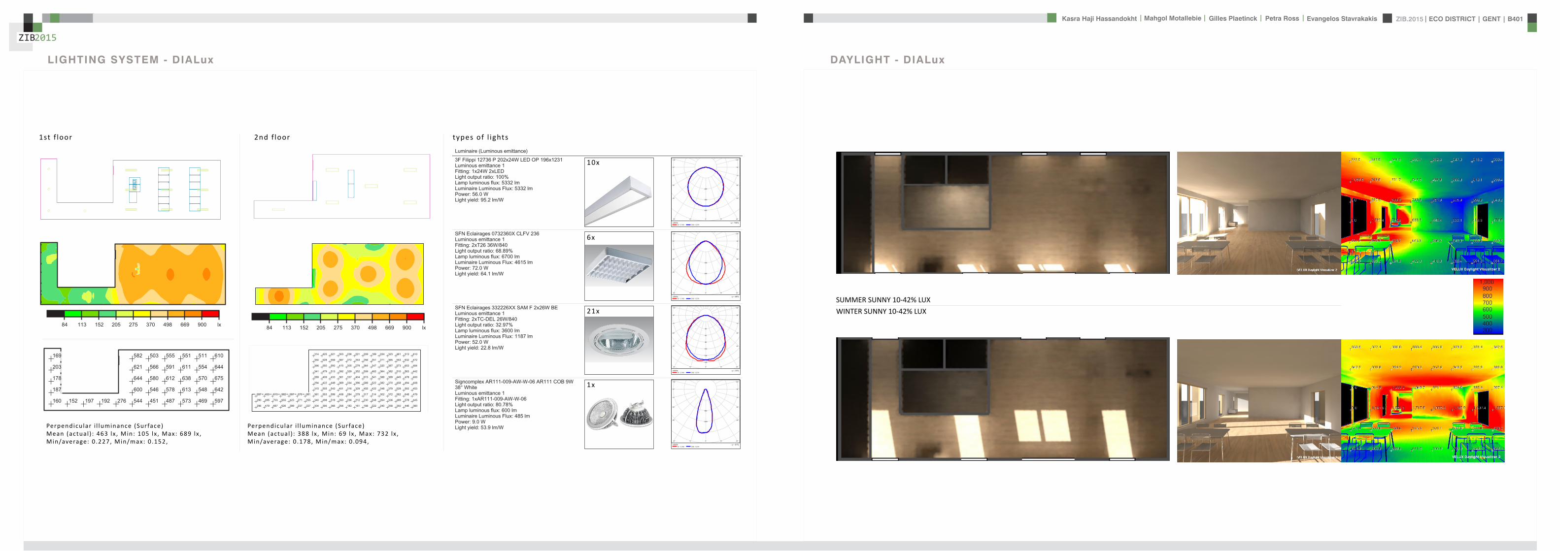
ZIB2015 ECO DISTRICT | GENT | B401Evangelos Stavrakakis | Petra Ross | Mahgol Motallebie | Gilles Plaetinck | Kasra Haji Hassandokht
ZIB2015
|
Tube hybrid Solar panels
Hot water tank Water taps
City water supply
Rain water collection for vertical harvesting
City water supply
WADI
Rain water tank
WATER MANAGEMENT
Sinks
Available roof area
In Ghent avarage of 900mmm2year
3197 m2
09x 3197 = 28773 m3year
RAIN WATER GAIN
toilet - 3x - 03lskitchen -4x - 02ls
POTABLE WATER DEMAND
3 toiletsVertical gardening
Total
relative RW usage
300 l day150 l day = 450lday= 16425 m3 year
1407 lday100m2
RAIN WATER DEMAND
RAIN WATER TANK
Relative RWT volumeRain water tank volume
3m3 100 m2
9591 l gt 10 m3
DIMESION OF PIPES
City water supplyRainwater tank
178 mm (DN 18 - 15 - 12)165 mm (DN 17-15)
are composed of hexagonal tiles Rainwater can infiltrate between the gaps from where it goes to rainwatter collector which supplies the vegetation on fly-over
THE SOLAR ROADWAYS
WATER SUPPLY SCHEME AND CALCULATION
ZIB2015 ECO DISTRICT | GENT | B401Evangelos Stavrakakis | Petra Ross | Mahgol Motallebie | Gilles Plaetinck | Kasra Haji Hassandokht
ZIB2015
|
WADI
City water supply
Rain water tank
Sinks
Divided sewer systemwithin building
SEWAGE SYSTEM
ToiletToilet sinkKitchen sink
DU = 2 lsDU = 05 lsDU = 08 ls
WATER DRAINAGE OF DEVICES
Frequency of usage at the same time
K 05
DIMESION OF PIPES
Black waterGrey water
110 mm (DU 110)75 mm (DU 75 - 63)
WATER DRAINAGE SCHEME AND CALCULATION
ZIB2015 ECO DISTRICT | GENT | B401Evangelos Stavrakakis | Petra Ross | Mahgol Motallebie | Gilles Plaetinck | Kasra Haji Hassandokht
ZIB2015
|
DN
Gilles Plaetinck
schaal 1 100
ZIB BUILDINGEnter address here
2 _ level 1
Owner
begeleider Checker
Gilles Plaetinck
schaal 1 100
ZIB BUILDINGEnter address here
3 _ level 2
Owner
begeleider Checker
WATER SUPPLY
HOT WATER
WATER DRAINAGE
WATER SUPPLY AND DRAINAGE IN GROUPLANS
level 01
level 02
ENERGY
RAINWATER TANK
HELOPHYTE FILTER
IRRIGATION SYSTEM
BIO-ROTOR
MICRO TURBINE
PHOSPHOR
In this building a closed water system is applied which is based on reusing water in mullple wasRainRain water from the roof will be collected in a storage tank situated on the ground floor This water will be used to flush the toilet and irrigate crops in verlcal harveslng system In case of an overflow the water will be stored in the con-structed wetland near the building The rainwater can be fil-tered through a helophyte filter up to drinking water stan-dard The waste water system includes three types of water yellyellow black and grey waterThe yellow water will be stored for its phosphor while the black water will be purified into grey water This grey water is comparable to the quality of rain water aaer purificalon b means of a bio rotor The remaining residue from the bio rotor together with the organic waste from the harveslng is fermented into biogas that drives a micro turbine in order to produce some addilonal energy
TheThe waste product deriving from this process will be used as compost in verlcal harveslng This efficient yet complex system closes the ullizalon cycle of the building and turns it into an efficient vicious circle that can be considered au arkic
In this building a closed water system is applied which is based on reusing water in multiple was
Rain water from the roof will be collected in a storage tank situated on the ground floor This water will be used to flushthe toilet and irrigate crops in vertical harvesting system In case of an overflow the water will be stored in the constructed wetland near the building The rainwater can be filtered through a helophyte filter up to drinking water standard
The waste water system includes three types of water yellow black and grey water The yellow water will be stored for its phosphor while the black water will be purified into grey water This grey water is comparable to the quality of rain water after purification b means of a bio rotor The remaining residue from the bio rotor together with the organic waste from the harvesting is fermented into biogas that drives a micro turbine in order to produce some additional energy The waste product deriving from this process will be used ascompost in ver1048991cal harves1048991ng This efficient yet complexsystem closes the u1048991liza1048991on cycle of the building and turns itinto an efficient vicious circle that can be considered au arkic
WATER CYCLE
ZIB2015 ECO DISTRICT | GENT | B401Evangelos Stavrakakis | Petra Ross | Mahgol Motallebie | Gilles Plaetinck | Kasra Haji Hassandokht
ZIB2015
|
CALCULATIONS
Passive House verification
Photo or Drawing
Building Workshop + info pointStreet
PostcodeCityCountry
Building Type non-residentialClimate Ukkel
Home Owner(s) Client(s)Street
PostcodeCity
ArchitectStreet
PostcodeCity Calculation electricity Internal heat gains
Mechanical System Building type
StreetPostcodeCity Internal heat gains
Year of Construction 2015 Interior Temperature 200 degC Utilisation pattern
Number of Dwelling Units 1 Internal Heat Gains 20 Wm2 Type of values used Fill in worksheet IHG Non-Dom Enclosed Volume Ve 12442 Planned number of occupants
Number of Occupants 80 8 Design
Specific building demands with reference to the treated floor area use Annual method
Treated floor area 2840 msup2 Requirements Fulfilled Verification Annual method The monthly method should be used for building certification
Space heating Annual heating demand 10 kWh(m2a) 15 kWh(msup2a) yes Specific space heating demand annual method 103 kWh(msup2a)
Heating load 11 Wm2 10 Wmsup2 - Specific space heating demand monthly Method 120 kWh(msup2a)
Space cooling Overall specific space cooling demand kWh(m2a) 15 kWh(msup2a)
Cooling load Wm2 - -Frequency of overheating (gt 25 degC) - -
Primary Energy Space heating and dehumidification
cooling household electricity 73 kWh(m2a) 120 kWh(msup2a) yes
DHW space heating and auxiliary electricity 24 kWh(m2a) - -Specific primary energy reduction through solar electricity 21 kWh(m2a) - -
Airtightness Pressurization test result n50 06 1h 06 1h yes
PHPP Verification FINAL ZIB FILE CALCULTIONS PHPPxls
L B H VOLUME
main 1 226 7 4 6328main 2 184 7 35 4508
core 0 6 2 5 3 5 108 5core 0 62 5 35 1085core 3 62 3 28 521
12442
AREAmain 1 storage 35
wc big 35wc 2wc 2workshop 103
MAIN 2 infolounge 92
staircase 56storage technical 22
284
Floor_exterior 1582 31 1272
Roof_exterior 1582
Passive House verification
Photo or Drawing
Building Workshop + info pointStreet
PostcodeCityCountry
Building Type non-residentialClimate Ukkel
Home Owner(s) Client(s)Street
PostcodeCity
ArchitectStreet
PostcodeCity Calculation electricity Internal heat gains
Mechanical System Building type
StreetPostcodeCity Internal heat gains
Year of Construction 2015 Interior Temperature 200 degC Utilisation pattern
Number of Dwelling Units 1 Internal Heat Gains 20 Wm2 Type of values used Fill in worksheet IHG Non-Dom Enclosed Volume Ve 12442 Planned number of occupants
Number of Occupants 80 8 Design
Specific building demands with reference to the treated floor area use Annual method
Treated floor area 2840 msup2 Requirements Fulfilled Verification Annual method The monthly method should be used for building certification
Space heating Annual heating demand 10 kWh(m2a) 15 kWh(msup2a) yes Specific space heating demand annual method 103 kWh(msup2a)
Heating load 11 Wm2 10 Wmsup2 - Specific space heating demand monthly Method 120 kWh(msup2a)
Space cooling Overall specific space cooling demand kWh(m2a) 15 kWh(msup2a)
Cooling load Wm2 - -Frequency of overheating (gt 25 degC) - -
Primary Energy Space heating and dehumidification
cooling household electricity 73 kWh(m2a) 120 kWh(msup2a) yes
DHW space heating and auxiliary electricity 24 kWh(m2a) - -Specific primary energy reduction through solar electricity 21 kWh(m2a) - -
Airtightness Pressurization test result n50 06 1h 06 1h yes
PHPP Verification FINAL ZIB FILE CALCULTIONS PHPPxls
SURFACE AREAcurrent orientation only night ventilation
current orientation only night ventilation 6 windows less 52 msup2
current orientation only night ventilation 7 windows less 60msup2 (stays the same for each side)
current orientation only night ventilation 8 windows less 69 msup2
orientation turned 90deg only night ventilation 6 windows less 52 msup2
orientation turned 90deg only night ventilation 7 windows less 60msup2 (window less at SE side)
orientation turned 90deg only night ventilation 8 windows less 69 msup2
-gt orientation turned 90deg only night ventilation 9 windows less 77msup2 (window less at NW side althought theres less overheating in the case of a window less at SE side the heating demand exceeds 15)
CHANGE IN DESIGN
ZIB2015 ECO DISTRICT | GENT | B401Evangelos Stavrakakis | Petra Ross | Mahgol Motallebie | Gilles Plaetinck | Kasra Haji Hassandokht
ZIB2015
|
Passive House verificationS P E C I F I C A N N U A L H E A T I N G D E M A N D
Climate Ukkel Interior Temperature 200 degC
Building Workshop + info point Building TypeUse non-residentialTreated Floor Area ATFA 2840 msup2
per msup2Area U-Value Temp Factor ft Gt Treated Data for heating balance diagram
Building Element Temperature Zone msup2 W(msup2K) kKha kWha Floor Area Losses GainsExterior Wall - Ambient A 5595 0101 100 743 = 4181 1472 Exterior Wall - Ambient 147234373Exterior Wall - Ground B 069 = Exterior Wall - GroundRoofCeiling - Ambient A 1550 0094 100 743 = 1085 382 RoofCeiling - Ambient 381903529Floor slab basement ceiling B 310 0105 069 743 = 167 059 Floor slab basement ceiling 058811509
A 100 =A 100 =
unheated basement X 075 = unheated basementWindows A 1154 0648 100 743 = 5562 1958 Windows 195834732Exterior Door A 100 = Exterior DoorExterior TB (lengthm) A 1169 -0030 100 743 = -259 -091 Thermal Bridge Heat LossPerimeter TB (lengthm) P 069 = 000 not useful heat gains 365267499Ground TB (lengthm) B 069 =
Total of All Building Envelope Areas 8609 ndashndashndashndashndashndashndashndashndashndashndashndashndash- kWh(msup2a) Ventilation 395818713
Transmission Heat Losses QT Total 10736 378Annual Heating Demand 102516636
ATFA Clear Room Height internal gains 100951487msup2 m msup3 passive solar gains 250668423
Ventilation System Effective Air Volume VV 2840 280 = 7952 Thermal bridge credit 091126837Effective Heat Recovery Efficiency eff 81 Cross check sum 46324923 46324923of Heat Recovery
Efficiency of Subsoil Heat Exchanger SHX 0 nVsystem HR nVRes
1h 1h 1h
Energetically Effective Air Exchange nV 0105 (1 - 081 ) + 0038 = 0058
VV nV cAir Gt
msup3 1h Wh(msup3K) kKha kWha kWh(msup2a)
Ventilation Heat Losses QV 795 0058 033 743 = 1124 40
Reduction Factor QT QV NightWeekend
kWha kWha Saving kWha kWh(msup2a)
Total Heat Losses QL ( 10736 + 1124 ) 10 = 11860 418
Orientation Reduction Factor g-Value Area Radiation HPof the Area See Windows Sheet (perp radiation)
msup2 kWh(msup2a) kWha
1 North 054 050 2700 163 = 11822 East 058 000 440 197 = 03 South 056 050 4860 314 = 42874 West 032 050 3216 254 = 13275 Horizontal 063 050 324 317 = 323
kWh(msup2a)
Available Solar Heat Gains QS Total 7119 251
Length Heat Period Spec Power qI ATFA
khd da Wmsup2 msup2 kWha kWh(msup2a)
Internal Heat Gains QI 0024 209 201 2840 = 2867 101
kWha kWh(msup2a)
Free Heat QF QS + QI = 9986 352
Ratio of Free Heat to Losses QF QL = 084
Utilisation Factor Heat Gains G (1 - ( QF QL )5 ) (1 - ( QF QL )
6 ) = 90kWha kWh(msup2a)
Heat Gains QG G QF = 8949 315
kWha kWh(msup2a)
Annual Heating Demand QH QL - QG = 2911 10
kWh(msup2a) (YesNo)
Limiting Value 15 Requirement met yes
00
147
00
3806000000
196
00
40
37
09
103
101
251
0
5
10
15
20
25
30
35
40
45
50
Losses Gains
Hea
t flo
ws
[kW
h(m
sup2a)]
Heating energy balance
passive solar gains
internal gains
Annual Heating Demand
Thermal bridge credit
not useful heat gains
Ventilation
Exterior Door
Windows
unheated basement
Floor slab basement ceiling
RoofCeiling - Ambient
Exterior Wall - Ground
Exterior Wall - Ambient
Thermal Bridge Heat Loss
HPP Annual Heating Demand FINAL ZIB FILE CALCULTIONS PHPPxls
Passive House verification Passive House verificationS P E C I F I C U S E F U L C O O L I N G D E M A N D S P E C I F I C U S E F U L C O O L I N G D E M A N D
M O N T H L Y M E T H O D M O N T H L Y M E T H O D
(This page displays the sums of the monthly method over the cooling period))Climate Ukkel Interior Temperature Summer 25 degC Climate Ukkel Interior Temperature 25 degC
Building Workshop + info point Building TypeUse non-residential Building Workshop + info point Building TypeUse non-residential
Spec Capacity 60 Wh(msup2K) (Enter in Summer worksheet) Treated Floor Area ATFA 2840 msup2 Treated Floor Area ATFA 284 msup2
per msup2Temperature Zone Area U-Value Mon Red Fac Gt Treated Jan Feb Mar Apr May Jun Jul Aug Sep Oct Nov Dec Year
Building Element msup2 W(msup2K) kKha kWha Floor Area Heating Degree Hours - Ex 168 150 144 121 92 73 57 59 82 109 140 160 136 kKh1 Exterior Wall - Ambient A 5595 0101 100 103 = 5782 Heating Degree Hours - G 126 123 135 120 106 83 63 54 58 71 86 109 113 kKh2 Exterior Wall - Ground B 100 = Losses - Exterior 2553 2286 2189 1838 1393 1117 871 904 1245 1660 2123 2432 20612 kWh3 RoofCeiling - Ambient A 1550 0094 100 103 = 1500 Losses - Ground 41 40 44 39 35 27 21 18 19 23 28 36 370 kWh4 Floor slab basement ceil B 310 0105 100 90 = 294 Losses Summer Ventilatio 67 71 244 372 629 720 880 865 658 499 234 126 5366 kWh5 A 100 = Sum Spec Heat Losses 94 84 87 79 72 66 62 63 68 77 84 91 928 kWhmsup26 A 100 = Solar Load North 44 81 141 212 286 298 298 255 178 116 54 35 1998 kWh7 unheated basement X 075 = Solar Load East 0 0 0 0 0 0 0 0 0 0 0 0 0 kWh8 Windows A 1154 0648 100 103 = 7690 Solar Load South 218 315 464 577 681 644 681 658 532 416 242 171 5601 kWh9 Exterior Door A 100 = Solar Load West 79 125 213 303 385 378 370 347 256 177 91 60 2785 kWh
10 Exterior TB (lengthm) A 1169 -0030 100 103 = -358 Solar Load Horiz 11 21 37 57 79 79 80 69 47 30 14 9 533 kWh11 Perimeter TB (lengthm) P 100 = Solar Load Opaque 3 5 9 13 18 19 19 16 11 7 3 2 126 kWh12 Ground TB (lengthm) B 100 = Internal Heat Gains 425 384 425 411 425 411 425 425 411 425 411 425 5001 kWh
ndashndashndashndashndashndashndashndashndashndashndash kWh(msup2a) Sum Spec Loads Solar + 28 33 45 55 66 64 66 62 51 41 29 25 565 kWhmsup2
Transmission Losses QT (Negative Heat Loads) Total 14907 525 Utilisation Factor Losses 29 39 52 69 84 88 82 88 73 53 34 27 58Useful Cooling Energy Dem 0 0 4 30 142 192 417 192 40 4 0 0 1021 kWh
ATFA Clear Room Height Spec Cooling Demand 00 00 00 01 05 07 15 07 01 00 00 00 36 kWhmsup2Effective msup2 m msup3
Air Volume VV 284 280 = 795
Heat Transfer Coef Gt
WK kKha kWha kWh(msup2a)
Exterior 99 103 = 1013 36Ground 00 105 = 0 00
Additional Summer Ventilation
Select X Window Night Ventilation Manual Corresponding Air Change Rate 136 1h
Mechanical Automatically Controlled Ventilation (for window ventilation at 1 K temperature difference indoor - outdoor)
Minimum Acceptable Indoor Temperatu 220 degC
kWha kWh(msup2a)
Heat Losses Summer Ventilation 5172 182
QLext QLground QLsummer
kWha kWha kWha kWha kWh(msup2a)
Ventilation Heat Losses QV 1013 + 0 + 5172 = 6185 218
2
3
4
5
6
7
8
9
10
Spec
ific
loss
es l
oads
l c
oolin
g de
man
d [k
Wh
(msup2 m
onth
)] Spec Cooling Demand Sum Spec Heat Losses Sum Spec Loads Solar + Internal
QT QV
kWha kWha kWha kWh(msup2a)
Total Heat Losses QL 14907 + 6185 = 21092 743
Orientation Reduction Factor g-Value Area Global Radiationof the Area (perp radiation)
msup2 kWh(msup2a) kWha
1 North 031 050 270 462 = 19182 East 061 000 44 578 = 0 Temperature Amplitude Summer 82 K3 South 030 050 486 707 = 52114 West 025 050 322 654 = 2646 Month 1 2 3 4 5 6 7 8 9 10 11 12 Annual Total5 Horizontal 035 050 32 913 = 513 Days 31 28 31 30 31 30 31 31 30 31 30 31 3656 Sum Opaque Areas 121 Ambient Temp 250 270 572 828 1275 1487 1737 1707 1369 1039 568 356 96
kWh(msup2a) North Radiation 106 195 329 494 667 697 712 599 419 275 129 87 471
Available Solar Heat Gains QS Total 10409 367 East Radiation 146 266 452 698 937 940 988 851 574 382 179 123 654
South Radiation 311 440 645 786 912 858 898 885 733 579 341 241 763Length Heat Period Spec Power qI ATFA West Radiation 155 261 471 707 926 926 896 819 580 382 183 116 642
khd da Wmsup2 msup2 kWha kWh(msup2a) Hori Radiation 200 369 662 1021 1398 1410 1418 1234 842 535 243 156 949
Internal Heat Gains QI 0024 303 20 2840 = 4151 146 Tsky -750 -730 -428 -172 275 487 737 707 369 039 -432 -644 -04
Ground Temp 805 676 686 830 1072 1345 1647 1776 1696 1552 1310 1037 121kWha kWh(msup2a)
Sum Heat Loads QF QS + QI = 14560 513
Ratio of Losses to Free Heat Gains QL QF = 145
Utilisation Factor Heat Losses G = 64kWha kWh(msup2a)
Useful Heat Losses QVn G QL = 13539 477
kWha kWh(msup2a)
Useful Cooling Demand QK QF - QVn = 1021 4
kWh(msup2a) (YesNo)
Limiting Value 15 Requirement met yes
0
1
2
Jan Feb Mar Apr May Jun Jul Aug Sep Oct Nov Dec
usef
u
HPP Cooling FINAL ZIB FILE CALCULTIONS PHPPxls
Passive House verificationS P E C I F I C A N N U A L H E A T I N G D E M A N D
Climate Ukkel Interior Temperature 200 degC
Building Workshop + info point Building TypeUse non-residentialTreated Floor Area ATFA 2840 msup2
per msup2Area U-Value Temp Factor ft Gt Treated Data for heating balance diagram
Building Element Temperature Zone msup2 W(msup2K) kKha kWha Floor Area Losses GainsExterior Wall - Ambient A 5595 0101 100 743 = 4181 1472 Exterior Wall - Ambient 147234373Exterior Wall - Ground B 069 = Exterior Wall - GroundRoofCeiling - Ambient A 1550 0094 100 743 = 1085 382 RoofCeiling - Ambient 381903529Floor slab basement ceiling B 310 0105 069 743 = 167 059 Floor slab basement ceiling 058811509
A 100 =A 100 =
unheated basement X 075 = unheated basementWindows A 1154 0648 100 743 = 5562 1958 Windows 195834732Exterior Door A 100 = Exterior DoorExterior TB (lengthm) A 1169 -0030 100 743 = -259 -091 Thermal Bridge Heat LossPerimeter TB (lengthm) P 069 = 000 not useful heat gains 365267499Ground TB (lengthm) B 069 =
Total of All Building Envelope Areas 8609 ndashndashndashndashndashndashndashndashndashndashndashndashndash- kWh(msup2a) Ventilation 395818713
Transmission Heat Losses QT Total 10736 378Annual Heating Demand 102516636
ATFA Clear Room Height internal gains 100951487msup2 m msup3 passive solar gains 250668423
Ventilation System Effective Air Volume VV 2840 280 = 7952 Thermal bridge credit 091126837Effective Heat Recovery Efficiency eff 81 Cross check sum 46324923 46324923of Heat Recovery
Efficiency of Subsoil Heat Exchanger SHX 0 nVsystem HR nVRes
1h 1h 1h
Energetically Effective Air Exchange nV 0105 (1 - 081 ) + 0038 = 0058
VV nV cAir Gt
msup3 1h Wh(msup3K) kKha kWha kWh(msup2a)
Ventilation Heat Losses QV 795 0058 033 743 = 1124 40
Reduction Factor QT QV NightWeekend
kWha kWha Saving kWha kWh(msup2a)
Total Heat Losses QL ( 10736 + 1124 ) 10 = 11860 418
Orientation Reduction Factor g-Value Area Radiation HPof the Area See Windows Sheet (perp radiation)
msup2 kWh(msup2a) kWha
1 North 054 050 2700 163 = 11822 East 058 000 440 197 = 03 South 056 050 4860 314 = 42874 West 032 050 3216 254 = 13275 Horizontal 063 050 324 317 = 323
kWh(msup2a)
Available Solar Heat Gains QS Total 7119 251
Length Heat Period Spec Power qI ATFA
khd da Wmsup2 msup2 kWha kWh(msup2a)
Internal Heat Gains QI 0024 209 201 2840 = 2867 101
kWha kWh(msup2a)
Free Heat QF QS + QI = 9986 352
Ratio of Free Heat to Losses QF QL = 084
Utilisation Factor Heat Gains G (1 - ( QF QL )5 ) (1 - ( QF QL )
6 ) = 90kWha kWh(msup2a)
Heat Gains QG G QF = 8949 315
kWha kWh(msup2a)
Annual Heating Demand QH QL - QG = 2911 10
kWh(msup2a) (YesNo)
Limiting Value 15 Requirement met yes
00
147
00
3806000000
196
00
40
37
09
103
101
251
0
5
10
15
20
25
30
35
40
45
50
Losses Gains
Hea
t flo
ws
[kW
h(m
sup2a)]
Heating energy balance
passive solar gains
internal gains
Annual Heating Demand
Thermal bridge credit
not useful heat gains
Ventilation
Exterior Door
Windows
unheated basement
Floor slab basement ceiling
RoofCeiling - Ambient
Exterior Wall - Ground
Exterior Wall - Ambient
Thermal Bridge Heat Loss
HPP Annual Heating Demand FINAL ZIB FILE CALCULTIONS PHPPxls
factor 05Wd (ls) 088
nominal diameter 75 mmVERTICAL COLLECTOR sink toilets 3 05 15
sink kitchen 2 08 16Total 5 31factor 05
Wd (ls) 088nominal diameter 75 mm
Toevoerend ROOF SURFACE
horizontal roof surface (msup2) orientation coeff angle (deg) roofcover filter coeff toevoerend
444 1 0 08 09 3197
RAIN WATER USAGE
Type usage ( l usage) persons day frequency usageday yearly usage
toilet use small 3 20 3 180 65700toilet use big 6 20 1 120 43800VERTICAL GARDENING 150 54750TOTAL 450 164250 L year
16425 msup3 year
TOTAL RAINWATER USAGE 450 L dayRELATIVE RAINWATER USAGE 1407 L day100msup2
LEEGSTAND
relative rainwater usage 1407 L day 100 msup2LEEGSTAND 7 relative volume rainwater tank 3 msup3 100 msup2rainwater tank volume 9591 Liter
suggestion 50 msup2 02 m= 10 msup3
SUPPLYtype amount debiet Q total total WW
lsec lsec lsecMAIN LEVEL POTABLE
sink toilet 3 01 03 03sink kitchen 2 01 02 02
Total 5 05 05Gelijktijdigheid 05 05debiet Q (lsec) 025 025
diameter 178 178 cm
type amount debiet Q total total WWlsec lsec lsec
MAIN LEVEL RAIN WATER toilet 3 01 03 0
Total 3 03Gelijktijdigheid 071debiet Q (lsec) 0213
diameter 165 cm
FECALIEumlNtype amount value Total (ls)
COLLECTOR HORIZONTAL toilet 3 2Total 6factor 05
Wd (ls) 122nominal diameter 110 mm
type amount value Total (ls)COLLECTOR VERTICAL toilet 3 2
Total 6factor 05
Wd (ls) 122nominal diameter 110 mm
DRAINtype amount value Total (ls)
HORIZONTAL COLLECTOR sink toilets 3 05 15sink kitchen 2 08 16
Total 5 31
WATER
ZIB2015 ECO DISTRICT | GENT | B401Evangelos Stavrakakis | Petra Ross | Mahgol Motallebie | Gilles Plaetinck | Kasra Haji Hassandokht
ZIB2015
|
Passive House verificationS P E C I F I C S P A C E H E A T I N G L O A D Risk Determination of Group Heating for a Critical Room
Building Workshop + info point Building TypeUse non-residential Workshop room ( 1= Yes 0 = No)
Climate (HL) Ukkel Treated Floor Area ATFA 2840 msup2 Interior Temperature 20 degC Building Satisfies Passive House Criteria 1
Design Temperature Radiation North East South West Horizontal Room floor area 100 msup2 Supply Air per msup2 Living AreaWeather Condition 1 -31 degC 10 10 30 15 20 Wmsup2 Planned ambient air quantity for the room 150 msup3h 150 msup3hmsup2Weather Condition 2 -22 degC 5 5 20 10 10 Wmsup2 Planned ambient air quantities for the remaining rooms -67 msup3hGround Design Temp 68 degC Area U-Value Factor TempDiff 1 TempDiff 2 PT 1 PT 2
Building Element Temperature Zone msup2 W(msup2K) Always 1(except X) K K W W Building Element Temperature Zone msup2 W(msup2K) Always 1
(except X) K Room Trans Loss W
1 Exterior Wall - Ambient A 5595 0101 100 231 or 222 = 1299 or 1249 Aboveground Exterior Wall A 650 010 100 231 = 1512 Exterior Wall - Ground B 100 132 or 132 = or Belowground Exterior Wall B 00 100 132 =3 RoofCeiling - Ambient A 1550 0094 100 231 or 222 = 337 or 324 RoofCeiling D 880 009 100 231 = 1914 Floor slab basement ceiling B 310 0105 100 132 or 132 = 43 or 43 Underground Floor Slab B 00 011 100 132 = 05 A 100 231 or 222 = or A 100 231 =6 A 100 231 or 222 = or A 100 231 =7 unheated basement X 075 231 or 222 = or X 100 231 =8 Windows A 1154 0648 100 231 or 222 = 1728 or 1661 Windows A 480 065 100 231 = 7199 Exterior Door A 100 231 or 222 = or Exterior Door A 100 231 =
10 Exterior TB (lengthm) A 1169 -0030 100 231 or 222 = -80 or -77 Exterior thermal bridges (Lengthm) A 100 231 =11 Perimeter TB (lengthm) P 100 132 or 132 = or Perimeter Thermal Bridges (Lengthm) A 100 231 =12 Ground TB (lengthm) B 100 132 or 132 = or Floor Slab Thermal Bridges (Lengthm) A 50 100 231 =13 HouseDU Partition Wall I 100 30 or 30 = or HouseDU Partition Wall I 200 100 30 =
Transmission Heat Losses PT ndashndashndashndashndashndashndashndashndashndashndashndashndash- ndashndashndashndashndashndashndashndashndashndashndash-
Total = 3328 or 3200 = 1061
ATFA Clear Room HeightVentilation System msup2 m msup3 Risk
Effective Air Volume VV 2840 280 = 795 Enter 1 = Yes 0 = No PTRoom W PSupply Air W Ratio Summand
SHX 1 SHX 2 Transmission Heat Losses 1061 1386 077 -023Efficiency of Heat Recovery HR 81 Heat Recovery Efficiency SHX 0 Efficiency SHX 0 or 0 Concentrated leakages 0 000of the Heat Exchanger Insulation to other rooms better R = 15 msup2KW 1 ( 2 = no thermal contact except door) 050
nVRes (Heating Load) nVsystem HR HR Room is on the ground floor 0 0001h 1h 1h 1h open staircase 0 000
Energetically Effective Air Exchange nV 0094 + 0105 (1- 081 or 081 ) = 0114 or 0114 TOTAL of the Risk Summands 027Ventilation Heating Load PV
VL nL nL cAir TempDiff 1 TempDiff 2 PV 1 PV 2 Interior doors predominantly closed 1 Risk Factor 200msup3 1h 1h Wh(msup3K) K K W W
7952 0114 or 0114 033 231 or 222 = 691 or 664Total Room Risk 89
PL 1 PL 2
Total Heating Load PL W W Appraisal and Advice normally no problemPT + PV = 4019 or 3864
Orientation Area g-Value Reduction Factor Radiation 1 Radiation 2 PS 1 PS 2the Area msup2 (perp radiation) (see Windows worksheet) Wmsup2 Wmsup2 W W
1 North 270 05 05 11 or 6 = 77 or 412 East 44 00 06 8 or 3 = 0 or 03 South 486 05 06 28 or 18 = 378 or 2474 West 322 05 03 19 or 13 = 100 or 685 Horizontal 32 05 06 20 or 10 = 20 or 10
Solar heating power PS Total = 575 or 367
Spec Power ATFA PI 1 PI 2Internal heating power PI Wmsup2 msup2 W W
16 284 = 454 or 454
PG 1 PG 2
Heating power (gains) PG W W
PS + PI = 1029 or 821
PL - PG = 2989 or 3042
Heating Load PH = 3042 W
Specific Heating Load PH ATFA = 107 Wmsup2
Input Max Supply Air Temperature 48 degC degC degC
Max Supply Air Temperature SupplyMax 48 degC Supply Air Temperature Without Heating SupplyMin 156 157
For Comparison Heating Load Transportable by Supply Air PSupply AirMax = 886 W specific 31 Wmsup2
(YesNo)
Supply Air Heating Sufficient No
HPP Heating Load FINAL ZIB FILE CALCULTIONS PHPPxls
Passive House verificationU - V A L U E S O F B U I L D I N G E L E M E N T S
Wedge shaped building element layeBuilding Workshop + info point still air spaces -gt Secondary calculation to th
Assembly No Building assembly description Interior insulation1 Exterior wall x
Heat transfer resistance [msup2KW] interior Rsi 013exterior Rse 004
Area section 1 [W(mK)] Area section 2 (optional) [W(mK)] Area section 3 (optional) [W(mK)] Thickness [mm]
1 hout gevel 0160 17
2 regelwerk hout 0158 30
3 houtvezel celit 4D 0048 18
4 Eurowall 0023 hout FJI beam 0286 140
5 OSB -plaat 0130 15
6 Eurothane G 0023 70
7 Plaster insulating 0100 10
8Percentage of Sec 2 Percentage of Sec 3 Total
26 300
U-Value 0107 W(msup2K)
Assembly No Building assembly description Interior insulation2 Roof x
Heat transfer resistance [msup2KW] interior Rsi 010exterior Rse 004
Area section 1 [W(mK)] Area section 2 (optional) [W(mK)] Area section 3 (optional) [W(mK)] Thickness [mm]Area section 1 [W(mK)] Area section 2 (optional) [W(mK)] Area section 3 (optional) [W(mK)] Thickness [mm]
1 bitumenmembraam 0230 5
23 EPS 0036 70
4 OSB -plaat 0130 18
5 cellulose 0039 hout FJI beam 0286 350
6 OSB -plaat 0130 15
7 regelwerk hout 5 0177 30
8 gipskartonplaat 0290 12
Percentage of Sec 2 Percentage of Sec 3 Total
26 500
U-Value 0094 W(msup2K)
Assembly No Building assembly description Interior insulation3 Floor x
Heat transfer resistance [msup2KW] interior Rsi 017
exterior Rse 004
Area section 1 [W(mK)] Area section 2 (optional) [W(mK)] Area section 3 (optional) [W(mK)] Thickness [mm]
1 PIR dekvloer 0023 5
2 gipskartonplaat 0290 10
3 gespoten pur 0028 100
4 OSB -plaat 0130 15
5 cellulose 0039 hout FJI beam 0286 350
6 houtvezel Celit 4D 0048 15
7 regelwerk hout 6 0149 30
8 afwerking hout 0160 5
Percentage of Sec 2 Percentage of Sec 3 Total
26 530
U-Value 0078 W(msup2K)
PHPP U-Values FINAL ZIB FILE CALCULTIONS PHPPxls
ers and he right
n Secondary Calculation Equivalent Thermal Conductivity of Still Air Spaces
Air Layer Thickness 30 mm Direction of Upwards ha 125 W(msup2K) 016 W(mK)
Heat Flow X Horizontal hr 417 W(msup2K)
(check only one field) Downwards
cm
n
cm
n Secondary Calculation Equivalent Thermal Conductivity of Still Air Spaces
Air Layer Thickness 30 mm
Direction of Upwards ha 08333 W(msup2K) 015 W(mK)Heat Flow Horizontal hr 417 W(msup2K)
(check only one field) X Downwards
cm
PHPP U-Values FINAL ZIB FILE CALCULTIONS PHPPxls
ers and he right
n Secondary Calculation Equivalent Thermal Conductivity of Still Air Spaces
Air Layer Thickness 30 mm Direction of Upwards ha 125 W(msup2K) 016 W(mK)
Heat Flow X Horizontal hr 417 W(msup2K)
(check only one field) Downwards
cm
n
cm
n Secondary Calculation Equivalent Thermal Conductivity of Still Air Spaces
Air Layer Thickness 30 mm
Direction of Upwards ha 08333 W(msup2K) 015 W(mK)Heat Flow Horizontal hr 417 W(msup2K)
(check only one field) X Downwards
cm
PHPP U-Values FINAL ZIB FILE CALCULTIONS PHPPxls
ers and he right
n Secondary Calculation Equivalent Thermal Conductivity of Still Air Spaces
Air Layer Thickness 30 mm Direction of Upwards ha 125 W(msup2K) 016 W(mK)
Heat Flow X Horizontal hr 417 W(msup2K)
(check only one field) Downwards
cm
n
cm
n Secondary Calculation Equivalent Thermal Conductivity of Still Air Spaces
Air Layer Thickness 30 mm
Direction of Upwards ha 08333 W(msup2K) 015 W(mK)Heat Flow Horizontal hr 417 W(msup2K)
(check only one field) X Downwards
cm
PHPP U-Values FINAL ZIB FILE CALCULTIONS PHPPxls
Passive House verificationS U M M E R
Climate Ukkel Interior Temperature 20 degC
Building Workshop + info point Building TypeUse non-residentialTreated Floor Area ATFA 2840 msup2
Spec Capacity 60 WhK pro msup2 TFAOverheating
limit25 degC Area U-Value Red Factor fTSummer HSummer Heat Conductance
Building Element Temperature Zone msup2 W(msup2K)
1 Exterior Wall - Ambien A 5595 0101 100 = 5632 Exterior Wall - Ground B 100 =3 RoofCeiling - Ambient A 1550 0094 100 = 1464 Floor slab basement B 310 0105 100 = 335 A 100 =6 A 100 =7 unheated basement X 075 =8 Windows A 1154 0648 100 = 7489 Exterior Door A 100 =
10 Exterior TB (lengthm) A 1169 -0030 100 = -3511 Perimeter TB (lengthm P 100 =12 Ground TB (lengthm) B 100 =
ndashndashndashndashndashndashndashndashndashndashndashExterior Thermal Transmittance HTe 1422 WK
Ground Thermal Transmittance HTg 33 WK
ATFA Clear Room HeightEffective msup2 m msup3
Heat Recovery Efficiency HR 81 Air Volume VV 2840 280 = 795
SHX Efficiency SHX 0
Summer Ventilation continuous ventilation to provide sufficient indoor air quality
Air Change Rate by Natural (Windows amp Leakages) or Exhaust-Only Mechanical Ventilation Summer 000 1h
Mechanical Ventilation Summer 1h X with HR (check if applicable)
nLnat nVsystem HR nVRest
1h 1h 1h 1h
Energetically Effective Airchange Rate nV 0000 + 0000 (1 - 0808 ) + 0038 = 0038
VV nVequifraction cAir
msup3 1h Wh(msup3K)
Ventilation Transm Ambient HVe 795 0038 033 = 99 WK
Ventilation Transm Ground HVg 795 0000 033 = 00 WK
Additional Summer Ventilation for Cooling Temperature amplitude summer 82 K
Select X Window Night Ventilation Manual Corresponding Air Change Rate 136 1hMechanical Automatically Controlled Ventilation (for window ventilation at 1 K temperature difference indoor - outdoor)
Minimum Acceptable Indoor Temperature 220 degC
Orientation Angle Shading g-Value Area Portion of Glazing Apertureof the Area Factor Factor Dirt (perp radiation)
Summer Summer msup2 msup2
1 North 09 044 095 050 270 82 = 422 East 09 100 095 000 44 71 = 003 South 09 043 095 050 486 82 = 744 West 09 039 095 050 322 76 = 405 Horizontal 09 052 095 050 32 78 = 066 Sum Opaque Areas 03
msup2msup2
Solar Aperture Total 164 006
Specif Power qI ATFA
Wmsup2 msup2 W Wmsup2
Internal Heat Gains QI 201 284 = 571 20
Frequency of Overheating hmax 42 at the overheating limit max = 25 degC
If the frequency over 25degC exceeds 10 additional measures to protect against summer heat waves are necessary
Solar Load Spec Capacity ATFA
kWhd 1k Wh(msup2K) msup2
Daily Temperature Swing due to Solar Load 00 1000 ( 60 284 ) = 00 K
PHPP Summer FINAL ZIB FILE CALCULTIONS PHPPxls
Passive House verification Passive House verificationS P E C I F I C A N N U A L H E A T I N G D E M A N D S P E C I F I C A N N U A L H E A T D E M A N D
M O N T H L Y M E T H O D M O N T H L Y M E T H O D
(This page displays the sums of the monthly method over the heating period)Climate Ukkel Interior Temperature 20 degC Climate Ukkel Interior Temperature 20 degC
Building Workshop + info point Building TypeUse non-residential Building Workshop + info point Building TypeUse non-residentialSpec Capacity 60 Wh(msup2K) (Enter in Summer worksheet) Treated Floor Area ATFA 2840 msup2 Treated Floor Area ATFA 284 msup2
per msup2Temperature Zone Area U-Value Month Red Fac Gt Treated Jan Feb Mar Apr May Jun Jul Aug Sep Oct Nov Dec Year
Building Element msup2 W(msup2K) kKha kWha Floor Area Heating Degree Hours - E 131 117 107 85 54 37 20 22 46 72 104 123 92 kKhExterior Wall - Ambient A 5595 0101 100 78 = 4406 Heating Degree Hours - G 89 89 98 84 69 47 26 17 22 33 50 72 70 kKhExterior Wall - Ground B 100 = Losses - Exterior 2056 1836 1679 1335 856 589 316 350 722 1132 1630 1931 14433 kWhRoofCeiling - Ambient A 1550 0094 100 78 = 1143 Losses - Ground 29 29 32 28 23 15 9 5 7 11 16 23 227 kWhFloor slab basement ceiling B 310 0105 100 54 = 175 Sum Spec Losses 73 66 60 48 31 21 11 13 26 40 58 69 516 kWhmsup2
A 100 = Solar Gains - North 78 142 246 371 500 520 520 445 311 202 94 62 3490 kWhA 100 = Solar Gains - East 0 0 0 0 0 0 0 0 0 0 0 0 0 kWh
unheated basement X 075 = Solar Gains - South 405 583 860 1069 1261 1194 1263 1220 986 771 448 318 10377 kWhWindows A 1154 0648 100 78 = 5861 Solar Gains - West 103 162 275 391 497 489 478 448 331 229 118 77 3597 kWhExterior Door A 100 = Solar Gains - Horiz 20 38 68 104 143 144 145 126 86 55 25 16 968 kWhExterior TB (lengthm) A 1169 -0030 100 78 = -273 Solar Gains - Opaque 3 5 9 13 18 19 19 16 11 7 3 2 126 kWhPerimeter TB (lengthm) P 100 = Internal Heat Gains 425 384 425 411 425 411 425 425 411 425 411 425 5001 kWhGround TB (lengthm) B 100 = Sum Spec Gains Solar + 36 46 66 83 100 98 100 94 75 59 39 32 830 kWhmsup2
ndashndashndashndashndashndashndashndashndashndashndash kWh(msup2a) Utilisation Factor 100 98 84 57 31 22 11 13 34 67 98 100 48Transmission Heat Losses QT Total 11313 398 Annual Heating Demand 1055 580 134 9 0 0 0 0 0 19 564 1057 3419 kWh
Spec Heating Demand 37 20 05 00 00 00 00 00 00 01 20 37 120 kWhmsup2ATFA Clear Room Height
Effective msup2 m msup3
Air Volume VRAX 284 280 = 795
nVsystem SHX HR nVRes nVequifraction
1h 1h 1h
Effective Air Change Rate Ambient nVe 0105 (1- 0 )(1- 081 )+ 0038 = 0058Effective Air Change Rate Ground nVg 0105 0 (1- 081 ) = 0000
VRAX nVequifraction cAir Gt
msup3 1h Wh(msup3K) kKha kWha kWh(msup2a)
Ventilation Losses Ambient QV 795 0058 033 78 = 1185 42
Ventilation Losses Ground QVe 795 0000 033 55 = 0 00ndashndashndashndashndashndashndashndashndashndashndash
Ventilation Heat Losses QV Total 1185 42
Reduction Factor QT QV NightWeekend
kWha kWha Saving kWha kWh(msup2a)
Total Heat Losses QL ( 11313 + 1185 ) 10 = 12497 440
Orientation Reduction Factor g-Value Area Global Radiationof the Area See Windows worksheet (perp radiation)
msup2 kWh(msup2a) kWha
North 054 050 270 208 = 1505East 058 000 44 250 = 0South 056 050 486 398 = 5440West 032 050 322 323 = 1685Horizontal 063 050 32 403 = 411Sum Opaque Areas 55
kWh(msup2a)
Available Solar Heat Gains QS Total 9095 320 Annual Heating Demand Comparison
EN 13790 Monthly Method 3419 kWha 120 kWh(msup2a) Reference to habitable area
Length Heat Period Spec Power qI ATFA PHPP Heating Period Method 2911 kWha 103 kWh(msup2a) Reference to habitable area
khd da Wmsup2 msup2 kWha kWh(msup2a)
Internal Heat Gains QI 0024 242 20 2840 = 3315 117
kWha kWh(msup2a) Month 1 2 3 4 5 6 7 8 9 10 11 12 Annual Total Heating Period Method
Free Heat QF QS + QI = 12411 437 Days 31 28 31 30 31 30 31 31 30 31 30 31 365 209Ambient Temp 250 270 572 828 1275 1487 1737 1707 1369 1039 568 356 96 52
Ratio Free Heat to Losses QF QL = 099 North Radiation 106 195 329 494 667 697 712 599 419 275 129 87 471 163East Radiation 146 266 452 698 937 940 988 851 574 382 179 123 654 197
Utilisation Factor Heat Gains G = 73 South Radiation 311 440 645 786 912 858 898 885 733 579 341 241 763 314kWha kWh(msup2a) West Radiation 155 261 471 707 926 926 896 819 580 382 183 116 642 254
Heat Gains QG G QF = 9078 320 Hori Radiation 200 369 662 1021 1398 1410 1418 1234 842 535 243 156 949 317
Tsky -750 -730 -428 -172 275 487 737 707 369 039 -432 -644 -04kWha kWh(msup2a) Ground Temp 805 676 686 830 1072 1345 1647 1776 1696 1552 1310 1037 121 98
Annual Heating Demand QH QL - QG = 3419 12
kWh(msup2a) (YesNo)
Limiting Value 15 Requirement met yes
0
2
4
6
8
10
12
Jan Feb Mar Apr May Jun Jul Aug Sep Oct Nov Dec
Spec
ific
loss
es g
ains
he
atin
g de
man
d [k
Wh
(msup2 m
onth
)]
Spec Heating Demand Sum Spec Gains Solar + Internal Sum Spec Losses
HPP Monthly Method FINAL ZIB FILE CALCULTIONS PHPPxls
Passive House verification Passive House verificationS P E C I F I C A N N U A L H E A T I N G D E M A N D S P E C I F I C A N N U A L H E A T D E M A N D
M O N T H L Y M E T H O D M O N T H L Y M E T H O D
(This page displays the sums of the monthly method over the heating period)Climate Ukkel Interior Temperature 20 degC Climate Ukkel Interior Temperature 20 degC
Building Workshop + info point Building TypeUse non-residential Building Workshop + info point Building TypeUse non-residentialSpec Capacity 60 Wh(msup2K) (Enter in Summer worksheet) Treated Floor Area ATFA 2840 msup2 Treated Floor Area ATFA 284 msup2
per msup2Temperature Zone Area U-Value Month Red Fac Gt Treated Jan Feb Mar Apr May Jun Jul Aug Sep Oct Nov Dec Year
Building Element msup2 W(msup2K) kKha kWha Floor Area Heating Degree Hours - E 131 117 107 85 54 37 20 22 46 72 104 123 92 kKhExterior Wall - Ambient A 5595 0101 100 78 = 4406 Heating Degree Hours - G 89 89 98 84 69 47 26 17 22 33 50 72 70 kKhExterior Wall - Ground B 100 = Losses - Exterior 2056 1836 1679 1335 856 589 316 350 722 1132 1630 1931 14433 kWhRoofCeiling - Ambient A 1550 0094 100 78 = 1143 Losses - Ground 29 29 32 28 23 15 9 5 7 11 16 23 227 kWhFloor slab basement ceiling B 310 0105 100 54 = 175 Sum Spec Losses 73 66 60 48 31 21 11 13 26 40 58 69 516 kWhmsup2
A 100 = Solar Gains - North 78 142 246 371 500 520 520 445 311 202 94 62 3490 kWhA 100 = Solar Gains - East 0 0 0 0 0 0 0 0 0 0 0 0 0 kWh
unheated basement X 075 = Solar Gains - South 405 583 860 1069 1261 1194 1263 1220 986 771 448 318 10377 kWhWindows A 1154 0648 100 78 = 5861 Solar Gains - West 103 162 275 391 497 489 478 448 331 229 118 77 3597 kWhExterior Door A 100 = Solar Gains - Horiz 20 38 68 104 143 144 145 126 86 55 25 16 968 kWhExterior TB (lengthm) A 1169 -0030 100 78 = -273 Solar Gains - Opaque 3 5 9 13 18 19 19 16 11 7 3 2 126 kWhPerimeter TB (lengthm) P 100 = Internal Heat Gains 425 384 425 411 425 411 425 425 411 425 411 425 5001 kWhGround TB (lengthm) B 100 = Sum Spec Gains Solar + 36 46 66 83 100 98 100 94 75 59 39 32 830 kWhmsup2
ndashndashndashndashndashndashndashndashndashndashndash kWh(msup2a) Utilisation Factor 100 98 84 57 31 22 11 13 34 67 98 100 48Transmission Heat Losses QT Total 11313 398 Annual Heating Demand 1055 580 134 9 0 0 0 0 0 19 564 1057 3419 kWh
Spec Heating Demand 37 20 05 00 00 00 00 00 00 01 20 37 120 kWhmsup2ATFA Clear Room Height
Effective msup2 m msup3
Air Volume VRAX 284 280 = 795
nVsystem SHX HR nVRes nVequifraction
1h 1h 1h
Effective Air Change Rate Ambient nVe 0105 (1- 0 )(1- 081 )+ 0038 = 0058Effective Air Change Rate Ground nVg 0105 0 (1- 081 ) = 0000
VRAX nVequifraction cAir Gt
msup3 1h Wh(msup3K) kKha kWha kWh(msup2a)
Ventilation Losses Ambient QV 795 0058 033 78 = 1185 42
Ventilation Losses Ground QVe 795 0000 033 55 = 0 00ndashndashndashndashndashndashndashndashndashndashndash
Ventilation Heat Losses QV Total 1185 42
Reduction Factor QT QV NightWeekend
kWha kWha Saving kWha kWh(msup2a)
Total Heat Losses QL ( 11313 + 1185 ) 10 = 12497 440
Orientation Reduction Factor g-Value Area Global Radiationof the Area See Windows worksheet (perp radiation)
msup2 kWh(msup2a) kWha
North 054 050 270 208 = 1505East 058 000 44 250 = 0South 056 050 486 398 = 5440West 032 050 322 323 = 1685Horizontal 063 050 32 403 = 411Sum Opaque Areas 55
kWh(msup2a)
Available Solar Heat Gains QS Total 9095 320 Annual Heating Demand Comparison
EN 13790 Monthly Method 3419 kWha 120 kWh(msup2a) Reference to habitable area
Length Heat Period Spec Power qI ATFA PHPP Heating Period Method 2911 kWha 103 kWh(msup2a) Reference to habitable area
khd da Wmsup2 msup2 kWha kWh(msup2a)
Internal Heat Gains QI 0024 242 20 2840 = 3315 117
kWha kWh(msup2a) Month 1 2 3 4 5 6 7 8 9 10 11 12 Annual Total Heating Period Method
Free Heat QF QS + QI = 12411 437 Days 31 28 31 30 31 30 31 31 30 31 30 31 365 209Ambient Temp 250 270 572 828 1275 1487 1737 1707 1369 1039 568 356 96 52
Ratio Free Heat to Losses QF QL = 099 North Radiation 106 195 329 494 667 697 712 599 419 275 129 87 471 163East Radiation 146 266 452 698 937 940 988 851 574 382 179 123 654 197
Utilisation Factor Heat Gains G = 73 South Radiation 311 440 645 786 912 858 898 885 733 579 341 241 763 314kWha kWh(msup2a) West Radiation 155 261 471 707 926 926 896 819 580 382 183 116 642 254
Heat Gains QG G QF = 9078 320 Hori Radiation 200 369 662 1021 1398 1410 1418 1234 842 535 243 156 949 317
Tsky -750 -730 -428 -172 275 487 737 707 369 039 -432 -644 -04kWha kWh(msup2a) Ground Temp 805 676 686 830 1072 1345 1647 1776 1696 1552 1310 1037 121 98
Annual Heating Demand QH QL - QG = 3419 12
kWh(msup2a) (YesNo)
Limiting Value 15 Requirement met yes
0
2
4
6
8
10
12
Jan Feb Mar Apr May Jun Jul Aug Sep Oct Nov Dec
Spec
ific
loss
es g
ains
he
atin
g de
man
d [k
Wh
(msup2 m
onth
)]
Spec Heating Demand Sum Spec Gains Solar + Internal Sum Spec Losses
HPP Monthly Method FINAL ZIB FILE CALCULTIONS PHPPxls
ZIB2015 ECO DISTRICT | GENT | B401Evangelos Stavrakakis | Petra Ross | Mahgol Motallebie | Gilles Plaetinck | Kasra Haji Hassandokht
ZIB2015
|
Passive House verificationV E N T I L A T I O N D A T A
Building Workshop + info point
Treated floor area ATFA msup2 284 (Areas worksheet)
Room height h m 28 (Annual Heating Demand worksheet)
Room ventilation volume (ATFAh) = VV msup3 795 (Annual Heating Demand worksheet)
Type of ventilation systemx Balanced PH ventilation Please Check
Pure extract air
Infiltration air change rate
Wind protection coefficients e and f Several One
Coefficient e for screening class sides sideexposed exposed
No screening 010 003Moderate screening 007 002High screening 004 001Coefficient f 15 20
for Annual Demand for Heating Load
Wind protection coefficient e 004 010Wind protection coefficient f 15 15 Net Air Volume for
Press Test Vn50 Air permeability q50
Air Change Rate at Press Test n50 1h 060 060 1244 msup3 087 msup3(hmsup2)
for Annual Demand for Heating Load
Excess extract air 1h 000 000Infiltration air change rate nVRes 1h 0038 0094
Selection of ventilation data input - ResultsThe PHPP offers two methods for dimensioning the air quantities and choosing the ventilation unit Fresh air or extract air quantities for residential buildings and parameters for ventilation syscan be determined using the standard planning option in the Ventilation sheet The Additional Vent sheet has been created for more complex ventilation systems and allows up to 10 differenFurthermore air quantities can be determined on a room-by-room or zone-by-zone basis Please select your design method here
Extract air Effective heat Specific HeatVentilation unit Heat recovery efficiency design Mean Mean excess recovery power recovery
X Sheet Ventilation (Standard design) (Sheet Ventilation see below) Air exchange Air Change Rate (Extract air system) efficiency Unit input efficiency SHXSheet Extended ventilation (Sheet Additional Vent) msup3h 1h 1h [-] Whmsup3(Multiple ventilation units non-residential buildings) 83 010 000 818 029 00
SHX efficiency SHX 0
PHPP Ventilation FINAL ZIB FILE CALCULTIONS PHPPxls
SHX efficiency SHX 0
PHPP Ventilation FINAL ZIB FILE CALCULTIONS PHPPxls
S T A N D A R D I N P U T F O R B A L A N C E D V E N T I L A T I O NVentilation dimensioning for systems with one ventilation unit
Occupancy msup2P 36Number of occupants P 80Supply air per person msup3(Ph) 30Supply air requirement msup3h 240 BathroomExtract air rooms Kitchen Bathroom (shower only) WC 0Quantity 2 3 0Extract air requirement per room msup3h 60 40 20 20 0Total Extract Air Requirement msup3h 180
Design air flow rate (maximum) msup3h 240
Average air change rate calculationDaily operation Factors referenced to Air flow rate Air change rateduration maximum
Type of operation hd msup3h 1hMaximum 100 240 030Standard 80 077 185 023Basic 40 054 130 016Minimum 120 0 000
Average air flow rate (msup3h) Average air change rate (1h)Average value 035 83 010
Selection of ventilation unit with heat recovery
X Central unit within the thermal envelope
Central unit outside of the thermal envelope Heat recovery Specificefficiency power Application Frost UnitUnit input range protection noise levelHR [Whmsup3] [msup3h] required lt 35dB(A)
Ventilation unit selection 19 mfoAir 350 - Zehnder 084 029 71 - 293 yes no
Conductance value of outdoor air duct W(mK) 0338 See calculation belowLength of outdoor air duct m 08Conductance value of exhaust air duct W(mK) 0338 See calculation belowLength of exhaust air duct m 15 Room Temperature (degC) 20Temperature of mechanical services room degC Av Ambient Temp Heating P (degC) 59(Enter only if the central unit is outside of the thermal envelope) Av Ground Temp (degC) 106
ComfoAir 350 - Zehnder
PHPP Ventilation FINAL ZIB FILE CALCULTIONS PHPPxls
Effective heat recovery efficiency HReff 818
Effective heat recovery efficiency subsoil heat exchangerSHX efficiency SHX
Heat recovery efficiency SHX SHX 0
Secondary calculation Secondary calculation-value supply or ambient air duct -value extract or exhaust air duct
Nominal width 200 mm Nominal width 200 mmInsul Thickness 50 mm Insul Thickness 50 mm
Reflective Please mark with an x Reflective Please mark with an xx Yes x Yes
No NoThermal conductivity 003 W(mK) Thermal conductivity 003 W(mK)Nominal air flow rate 83 msup3h Nominal air flow rate 83 msup3h
14 K 14 KExterior duct diameter 0200 m Exterior duct diameter 0200 m
Exterior diameter 0300 m Exterior diameter 0300 m-Interior 416 W(msup2K) -Interior 416 W(msup2K)
Surface 252 W(msup2K) Surface 252 W(msup2K)-value 0338 W(mK) -value 0338 W(mK)
Surface temperature difference 2002 K Surface temperature difference 2002 K
ComfoAir 350 - Zehnder
PHPP Ventilation FINAL ZIB FILE CALCULTIONS PHPPxls
Passive House verificationR E D U C T I O N F A C T O R S O L A R R A D I A T I O N W I N D O W U - V A L U E
Building Workshop + info point Annual heating demand 10 kWh(msup2a) Heating degree hours
Climate Ukkel 743
Window area orientation
Global radiation (cardinal points)
Shading Dirt
Non-perpendicu-lar incident radiation
Glazing fraction g-Value Reduction factor
for solar radiationWindow
areaWindowU-Value
Glazingarea
Average global
radiation
Transmission losses
Heat gains solar radiation
maximum kWh(msup2a) 075 095 085 m2 W(m2K) m2 kWh(m2a) kWha kWhaNorth 160 081 095 085 0822 050 054 2700 062 222 163 1243 1182East 222 100 095 085 0714 000 058 440 129 31 197 423 0South 321 085 095 085 0822 050 056 4860 062 399 314 2237 4287West 225 053 095 085 0758 050 032 3216 063 244 254 1517 1327Horizontal 317 100 095 085 0780 050 063 324 059 25 317 143 323
Total or Average Value for All Windows 048 049 11540 065 921 5562 7119
Glazing inclination ne 90deg Please check Ug value manually Window rough openings Installed Glazing Frame g-Value U-Value -
SpacerInstallation Results
(unhide cells to make U- amp -values from WinType worksheet visible)
Quan-tity Description Deviation from
north
Angle of inclination from the
horizontal
Orientation Width Heightin Area in the
Areas worksheet
Nr
Select glazing from the WinType
worksheet
Nr
Select window from the WinType
worksheet
NrPerpen-dicular
RadiationGlazing Frames
(centre) spacer (centre)
Left10
Right10
Bottom10
Top10
installation left
installation right
installation bottom
installation top
installation Average value
Window Area
Glazing Area
U-ValueWindow
Glazed Fraction
per Window
Degrees Degrees m m Select Select Select - W(m2K) W(m2K) W(mK) W(mK) W(mK) W(mK) W(mK) W(mK) m2 m2 W(m2K) 3 Door glass 250 90 West 1200 2200 5 2 3 050 049 071 0028 0 0 1 1 0040 79 591 065 755 window_NW 340 90 North 1800 3000 5 2 3 050 049 071 0028 1 1 0 0 0040 270 2218 062 821 window_SW 250 90 West 0600 3000 5 2 3 050 049 071 0028 0 0 1 1 0040 18 109 070 609 window SE 160 90 South 1800 3000 5 2 3 050 049 071 0028 1 1 0 0 0040 486 3992 062 821 Door elev 250 90 West 1800 2200 5 2 3 050 049 071 0028 0 0 1 1 0040 40 316 062 80
2 Door glass 250 90 West 1200 2200 7 2 3 050 049 071 0028 0 0 1 1 0040 53 394 065 751 Door_Ext 70 90 East 1000 2200 7 1 2 000 140 059 0049 0 0 1 1 0005 22 157 129 711 Door elev 250 90 West 1800 2200 7 2 3 050 049 071 0028 0 0 1 1 0040 40 316 062 80
0 0 0
Wall main INTERPANE iplus batimet batiment TA
Wall main
Wall main
Wall main
Wall main
Wall core 0
Wall core 0
Wall core 0
INTERPANE iplus
INTERPANE iplus
INTERPANE iplus
INTERPANE iplus
INTERPANE iplus
Door _wooden
INTERPANE iplus
batimet batiment TA
batimet batiment TA
batimet batiment TA
batimet batiment TA
batimet batiment TA
Wooden frame
batimet batiment TA
0 0 0
2 Door glass 250 90 West 1200 2200 8 2 3 050 049 071 0028 0 0 1 0 0040 53 394 063 751 Door_Ext 70 90 East 1000 2200 8 1 2 000 140 059 0049 0 0 1 0 0005 22 157 129 711 Door elev 250 90 West 1800 2200 8 2 3 050 049 071 0028 0 0 1 0 0040 40 316 060 801 skylight 250 0 Horizontal 1800 1800 6 2 3 050 049 071 0028 0 0 0 0 0000 32 253 059 78
0 0 0
0 0 0
0 0 0
0 0 0
Wall core 3
Wall core 3
Wall core 3
Roof
INTERPANE iplus
Door _wooden
INTERPANE iplus
INTERPANE iplus
batimet batiment TA
Wooden frame
batimet batiment TA
batimet batiment TA
PHPP Windows FINAL ZIB FILE CALCULTIONS PHPPxls
Passive House verificationC A L C U L A T I N G S H A D I N G F A C T O R S
Climate Ukkel
Building Workshop + info point Orientation Glazing area Reduction factor
Latitude 508 deg msup2 rS
North 2218 81East 314 100
South 3992 85West 2437 53
Horizontal 253 100
Quantity Description Deviation from North
Angle of Inclination from the Horizontal
Orientation Glazing width Glazing height Glazing area Height of the shading object
Horizontal distance
Window reveal depth
Distance from glazing edge to
revealOverhang depth
Distance from upper glazing
edge to overhang
Additional shading reduction factor
Horizontal shading reduction factor
Reveal Shading Reduction Factor
Overhang shading reduction factor
Total shading reduction factor
Degrees Degrees m m m m m m m m wG hG AG hHori dHori oReveal dReveal oover dover rother rH rR rO rS
3 Door glass 250 90 West 099 199 59 0060 420 050 100 100 51 515 window_NW 340 90 North 159 279 222 060 0060 100 81 100 811 window_SW 250 90 West 039 279 11 0060 420 050 100 100 58 589 window SE 160 90 South 159 279 399 060 0060 100 85 100 851 Door elev 250 90 West 159 199 32 0060 420 100 100 39 39
2 Door glass 250 90 West 099 199 39 750 420 0060 420 100 26 100 60 161 Door_Ext 70 90 East 081 195 16 0060 1200 100 100 100 27 271 Door elev 250 90 West 159 199 32 750 420 0060 420 26 100 39 10
2 Door glass 250 90 West 099 199 39 0060 100 100 100 1001 Door_Ext 70 90 East 081 195 16 0060 100 100 100 1001 Door elev 250 90 West 159 199 32 0060 100 100 100 1001 skylight 250 0 Horizontal 159 159 25 0060 100 100 100 100
PHPP Shading FINAL ZIB FILE CALCULTIONS PHPPxls
ZIB2015 ECO DISTRICT | GENT | B401Evangelos Stavrakakis | Petra Ross | Mahgol Motallebie | Gilles Plaetinck | Kasra Haji Hassandokht
ZIB2015
|
Passive House verificationS O L A R H O T W A T E R G E N E R A T I O N
Building Workshop + info point Building TypeUse non-residential
Treated Floor Area ATFA 2840 msup2
Solar Fraction with DHW demand including washing and dish-washing
Heating Demand DHW qgDHW 5183 kWha from DHW+Distribution worksheet
Latitude 508 deg from Climate Data worksheet
Selection of collector from list (see below) 8 Selection 8 Vacuum Tube Collector VTC
Solar Collector Area 600 msup2
Deviation from North 180 deg
Angle of Inclination from the Horizontal 45 deg
Height of the Collector Field 05 m
Height of Horizon hHori m
Horizontal Distance aHori m
Additional Reduction Factor Shading rother
Occupancy 80 Persons
Specific Collector Area 08 msup2Pers
Estimated Solar Fraction of DHW Production 49Solar Contribution to Useful Heat 2545 kWha 9 kWh(msup2a)
Secondary Calculation of Storage Losses
Selection of DHW storage from list (see below) 2 Selection Zonneboiler 200
Total Storage Volume 200 litre
Volume Standby Part (above) 60 litre
Volume Solar Part (below) 140 litre
Specific Heat Losses Storage (total) 20 WK
Typical Temperature DHW 60 degC
Room Temperature 20 degC
Storage Heat Losses (Standby Part Only) 24 W
Total Storage Heat Losses 80 W
02
03
04
05
06
07
08
09
10
200
300
400
500
600
700
800
900
1000
Sola
r fra
ctio
n[-]
ion
hea
ting
load
DH
W g
ener
atio
n h
eatin
g lo
ad
co
vere
d by
sol
ar [k
Wh
mon
th]
Monthly Heating Load Covered by Solar
Total Monthly Heating Load DHW Production
Radiation on Tilted Collector Surface
Monthly Solar Fraction
8 Vacuum Tube Collector
Zonneboiler 200
Monthly Solar Fraction January February March April May June July August September October November December
Radiation on Tilted Collector Surface 198 326 535 725 883 835 864 835 643 453 230 153 kWhMonth
Monthly Solar Fraction 018 031 049 064 075 072 074 072 058 042 021 013 -
Total Monthly Heating Load DHW Production 432 432 432 432 432 432 432 432 432 432 432 432 kWhMonth
Monthly Heating Load Covered by Solar 77 133 212 277 325 311 319 310 250 181 92 58 kWhMonth
Selection List Solar Collectors 0 = FR(ta) k1 k2 C Kdir(50deg) Kdfu OutputModule Area
(Aperture)VTC FPC Comments
InsertManufacturer Brief Description - W(msup2K) W(msup2Ksup2) kJ(msup2K) - - kWh(msup2a) msup2 please enter new
1 Brink F3-Q 08 35 00 81 10 4880 20 FPC columns2 BEFORE3 this4 column56 6 Standard Flat Plate Collector 077 35 002 64 09 08 300 2 FPC FK AD7 7 Improved Flat Plate Collector 0854 337 00104 47 097 094 546 26 FPC FK AD AR8 8 Vacuum Tube Collector 062 0395 002 1153 095 09 487 12 VTC FK AD9 RK AD101112 Insert new rows ABOVE this row only in order to maintain the integrity of references
00
01
0
100
January February March April May June July August September October November December
Sola
rad
iati
HPP SolarDHW FINAL ZIB FILE CALCULTIONS PHPPxls
Passive House verificationE F F I C I E N C Y O F H E A T G E N E R A T I O N ( G A S O I L W O O D )
Building Workshop + info point Building TypeUse non-residential
Treated Floor Area ATFA 284 msup2
Covered Fraction of Space Heating Demand (PE Value worksheet) 100
Space Heating Demand + Distribution Losses QH+QHS (DHW+Distribution) 3021 kWh
Solar Fraction for Space Heat Solar H (Separate Calculation) 48
Effective Annual Heating Demand QHWi=QH(1-Solar H) 1571 kWh
Space Heating Demand without Distribution Losses QH (Verification sheet) 2911 kWh
Covered Fraction of DHW Demand (PE Value worksheet) 100
Total Heating Demand of DHW system QgDHW (DHW+Distribution) 5183 kWh
Solar Fraction for DHW Solar DHW (SolarDHW worksheet) 49
Effective DHW Demand QDHWWi=QDHW(1-Solar DHW) 2638 kWh
Boiler Type (Project) oved gas condensing boiler 2
Primary Energy Factor (Data worksheet) 11 kWhkWh
CO2-Emissions Factor (CO2-Equivalent) 250 gkWh
Useful Heat Provided QUse 4209 kWha
Max Heating Power Required for Heating the Building PBH (Heating Load worksheet) 304 kW
Length of the Heating Period tHP 5022 h
Length of DHW Heating Period tDHW 8760 h
Use characteristic values entered (check if appropriate)
Project Data Standard Values Input field
Design Output Pnominal (Rating Plate) 15 kW 15 kW 3
Installation of Boiler (Outdoor 0 Indoor 1) 0 0 1
Input Values (Oil and Gas Boiler) Project Data Standard Values Input field
Boiler Efficiency at 30 Load (Manufacturer) 104 104 99
Boiler Efficiency at Nominal Output 100 (Manufacturer) 95 95 95
Standby Heat Loss Boiler at 70 degC qB70 (Manufacturer) 14 14 20
Improved gas condensing boiler
Average Return Temperature Measured at 30 Load 30 (Manufacturer) 30 degC 30
Input Values (Biomass Heat Generator) Project Data Standard Values Input field
Efficiency of Heat Generator in Basic Cycle GZ (Manufacturer) 60
Efficiency of Heat Generator in Constant Operation SO (Manufacturer) 70
Average Fraction of Heat Output Released to Heating Circuit zHCm (Manufacturer) 04
Temperature Difference Betw Power-On and Power-Off (Manufacturer) K 30 K
For Interior Installations Area of Mechanical Room Ainstall (Project) msup2 0 msup2
Useful Heat Output per Basic Cycle QNGZ (Manufacturer) kWh 225 kWh
Average Power Output of the Heat Generator QNm (Manufacturer) kW 150 kW
Heat generator without pellets conveyor x
Unit with regulation (no fan no starting aid)
Heating energy demand for a basic machine cycle QHEGZ (Manufacturer) kWh kWh kWh
PelSB (Manufacturer) W W W
Utilisation Factor Heat Generator Heating Run hHgK =fk 86Utilisation Factor Heat Generator DHW Run hTWgK =100fTW 87Utilisation Factor Heat Generator DHW amp Heating hgK 87
kWha kWh(msup2a)
Final Energy Demand Space Heating QFinal HE QHwi eHgK 1821Final Energy Demand DHW QFinal DHW QWWwi eTWgK 3030Total Final Energy Demand QFinal QFinalDHW + QFinalHE 4851 171Annual Primary Energy Demand 5336 188
kga kg(msup2a)
Annual CO2-Equivalent Emissions 1213 43
PHPP Boiler FINAL ZIB FILE CALCULTIONS PHPPxls
Passive House verificationS U M M E R V E N T I L A T I O N
Building Workshop + info point Building TypeUse non-residential
Building Volume 795 msup3
Description Day_ NightFraction of Opening Duration 50 50
Climate Boundary ConditionsTemperature Diff Interior - Exterior 4 1 KWind Velocity 1 0 ms
Note for summer night ventilation please set a temperature difference of 1 K and a wind velocity of 0 msotherwise the cooling effects of the night ventilation will be overestimated
Window Group 1Quantity 16Clear Width 180 180 mClear Height 270 270 mTilting Windows XOpening Width (for tilting windows) 0200 0200 m
Window Group 2 (Cross Ventilation)QuantityClear Width mClear Height mTilting WindowsOpening Width (for Tilting Windows) mDifference in Height to Window 1 m
Single-Sided Ventilation 1 - Airflow Volume 0 0 2161 0 0 0 msup3hSingle-Sided Ventilation 2 - Airflow Volume 0 0 0 0 0 0 msup3h
Cross Ventilation Airflow Volume 0 0 2161 0 0 0 msup3hContribution to Air Change Rate 000 000 136 000 000 000 1h
Summary of Summer Ventilation Distribution
Description Ventilation Type Daily Average Air Change Rate
Night time Window Ventilation 136 1hDaytime Window Ventilation 000 1h
1h
PHPP SummVent FINAL ZIB FILE CALCULTIONS PHPPxls
Passive House verificationC O M P R E S S O R C O O L I N G U N I T S
Climate Ukkel Interior Temperature Summer 25 degC
Building Workshop + info point Building TypeUse non-residentialTreated Floor Area ATFA 2840 msup2
ATFA Clear Room HeightEffective msup2 m msup3
Air Volume VV 284 280 = 795
nVsystem HR
1h Efficiency Humidity Rec 1h
Hygrically Effective Mech Air Change Rate Summer 0000 (1 - 80 ) = 0000
nVnat nVRes nNightWindows nNightmechanical
1h 1h 1h 1h
Direct Ambient Air Change Rate Summer 0000 + 0038 + 2603 + 0000 = 2641
Ambient Air Change Rate Summer Total 264 1h
Supply Air Cooling
check as appropriateOnOff Mode (check as appropriate) XMinimum Temperature of Cooling Coil Surface 0 degC
Recirculation Cooling
check as appropriateOnOff Mode (check as appropriate) xMinimum Temperature of Cooling Coil Surface 10 degCVolume Flow Rate 150 msup3h
X Additional Dehumidificationcheck as appropriate
Max Humidity Ratio 12 gkgHumidity Sources 2 g(msup2h)
Humidity Capacity Building 700 g(gkg)msup2
Humidity at Beginning of Cooling Period 8 gkg
X Panel Coolingcheck as appropriate
sensible latent
Useful Cooling Demand 36 00Useful Cooling Demand 00of which Sensible Fraction
Supply Air Cooling kWh(msup2a)
Recirculation Cooling kWh(msup2a)
Dehumidification kWh(msup2a)
Remaining for Panel Cooling 36 kWh(msup2a)
Total 36 00 kWh(msup2a) 1000
Unsatisfied Demand 00 00 kWh(msup2a)
PHPP Cooling Units FINAL ZIB FILE CALCULTIONS PHPPxls
ZIB2015 ECO DISTRICT | GENT | B401Evangelos Stavrakakis | Petra Ross | Mahgol Motallebie | Gilles Plaetinck | Kasra Haji Hassandokht
ZIB2015
|
Passive House verificationBuilding Workshop + info point E L E C T R I C I T Y D E M A N D Non-Domestic Use
Treated Floor Area ATFA 2840 msup2 Window Properties (from Windows worksheet)
Auxiliary Electricity Demand 5103 kWha Shading Dirt FactorNon-
Perpendicular Radiation
Glazing Fraction
Primary Energy Factors North 081 095 085 082Electricity 26 kWhkWh East 100 071
Gas 11 kWhkWh South 085 082
Energy Carrier for DHW 07 kWhkWh West 053 076
Solar Fraction of DHW 49
Marginal Performance Ratio DHW
Room Geometry Input of a Typical Room or Room by Room
Lighting Non-Domestic
Frac
tion
of T
reat
ed
Floo
r Are
a
Roo
m C
ateg
ory
Roo
m C
ateg
ory
Nom
inal
Illu
min
ance
Le
vel
Dev
iatio
n fro
m
Nor
th
Orie
ntat
ion
Ligh
t Tra
nsm
issi
on
Gla
zing
Exis
ting
win
dow
(1
0)
Roo
m D
epth
Roo
m W
idth
Roo
m H
eigh
t
Lint
el H
eigh
t
Win
dow
Wid
th
Day
light
Util
isat
ion
Use
r Dat
a In
stal
led
Ligh
ting
Pow
er
Inst
alle
d Li
ghtin
g Po
wer
(S
tand
ard)
Ligh
ting
Con
trol
Mot
ion
Det
ecto
r w
ithw
ithou
t (1
0)
Util
isat
ion
Hou
rs p
er
Year
[ha
]
Use
r Det
erm
ined
Li
ghtin
g Fu
ll Lo
ad H
ours
Full
Load
Hou
rs o
f Li
ghtin
g
Elec
tric
ity D
eman
d (k
Wh
a)
Spec
Ele
ctric
ity
Dem
and
(kW
h(m
sup2a))
Prim
ary
Ener
gy
Dem
and
(kW
ha)
Room Zone Lux Degrees - m m m m m Wmsup2 Wmsup2 ha ha ha kWha kWh(msup2a) kWha
2 159
workshop room a 18 41 Workshop 500 70 East 50 1 35 105 28 27 100 good 12 120 3 1 Automatic not permanently on
WithMotion 2250 8 80 49 01 128
wc 6 35 WC Sanitary 200 0 0 20 45 28 27 none 12 120 3 1 Automatic not permanently on
WithMotion 2750 8 80 16 01 43
storage 15 34 Kitchen Storage Preparation
300 0 0 40 58 28 27 none 12 120 3 1 Automatic not permanently on
WithMotion 3900 8 80 41 01 106
circulation 1 9 38 Circulation Area 100 70 East 50 1 14 116 28 27 110 good 12 120 3 1 Automatic not permanently on
WithMotion 2750 8 80 25 01 64
technical room 7 39 Storage Services 100 0 0 18 55 28 27 none 12 120 3 1 Automatic not permanently on
WithMotion 2750 3 30 07 00 19
circulation 2 9 38 Circulation Area 100 250 West 50 1 14 116 28 27 110 good 12 120 3 1 Automatic not permanently on
WithMotion 2750 8 80 25 01 64
reception a 9 37 Secondary Areas 100 70 East 50 1 35 38 28 27 36 good 12 120 3 1 Automatic not permanently on
WithMotion 2750 8 80 25 01 64
workshop room b 18 41 Workshop 500 250 West 50 1 35 105 28 27 100 low 12 120 3 1 Automatic not permanently on
WithMotion 2250 8 80 49 01 128
reception b 9 37 Secondary Areas 100 250 West 50 1 35 38 28 27 36 low 12 120 3 1 Automatic not permanently on
WithMotion 2750 8 80 25 01 64
0 0 Manual Without 0 0
Facade with Windows
Ligh
ting
Con
trol
Inpu
t War
ning
00 ManualMotion 00
00 Manual WithoutMotion 00
00 Manual WithoutMotion 00
00 Manual WithoutMotion 00
00 Manual WithoutMotion 00
00 Manual WithoutMotion 00
00 Manual WithoutMotion 00
00 Manual WithoutMotion 00
00 Manual WithoutMotion 00
00 Manual WithoutMotion 00
00 Manual WithoutMotion 00
00 Manual WithoutMotion 00
00 Manual WithoutMotion 00
HPP Electricity Non-Dom FINAL ZIB FILE CALCULTIONS PHPPxls
Office Equipment
Roo
m C
ateg
ory
Roo
m C
ateg
ory
In th
e th
erm
al
enve
lope
(1
0)
Exis
ting
Plan
ned
(1
0)
Qua
ntity
Pow
er R
atin
g (W
)
Util
isat
ion
Hou
rs
per Y
ear (
ha)
rela
tive
abse
ntee
ism
Dur
atio
n of
U
tilis
atio
n in
Ene
rgy
Savi
ng M
ode
(ha
)
Use
ful E
nerg
y(k
Wh
a)
Elec
tric
ity
Dem
and
(kW
ha)
Prim
ary
Ener
gy
Dem
and
(kW
ha)
2 9 20 18PC 1 37 Secondary Areas 1 1 1 80 ( 2750 (1- 09 ) = 22 = 220 57
PC in Energy Saving Mode 1 1 20 2750 09 = 5 = 50 13Monitor 1 1 0 28 ( 0 (1- 0 ) = 0 = 00 0
Monitor in Energy Saving Mode 1 0 20 0 0 = 0 = 00 0PC 2 41 Workshop 1 1 1 80 ( 2250 (1- 0 ) = 180 = 1800 468
PC in Energy Saving Mode 1 1 20 2250 0 = 0 = 00 0Monitor 2 1 0 28 ( 0 (1- 0 ) = 0 = 00 0
Monitor in Energy Saving Mode 1 0 20 0 0 = 0 = 00 0Copier 1 1 400 ( 0 - 0 ) = 0 = 00 0
Copier in Energy Saving Mode 1 1 30 0 = 0 = 00 0Printer 1 2 300 ( 0 - 0 ) = 0 = 00 0
Printer in Energy Saving Mode 1 2 2 0 = 0 = 00 0Server 1 1 100 ( 0 = 0 = 00 0
Server in Energy Saving Mode 1 1 ( 8760 - 0 ) = 0 = 00 0Telephone System 8760 = 0 = 00 0
= 0 = 00 0 = 0 = 00 0 = 0 = 00 0 = 0 = 00 0 = 0 = 00 0
Kitchen Aux Electricity
Roo
m C
ateg
ory
Predominant Utilisation Pattern of
Building
In th
e th
erm
al
enve
lope
(1
0)
Exis
ting
Plan
ned
(1
0)
Util
isat
ion
Day
s pe
r Ye
ar (d
a)
Num
ber o
f Mea
ls
per U
tilis
atio
n D
ay
Nor
m
Con
sum
ptio
n
Use
ful E
nerg
y (k
Wh
a)
Non
-Ele
ctric
Fra
ctio
n
Elec
tric
Frac
tion
Addi
tiona
l D
eman
d
Mar
gina
l Pe
rform
ance
R
atio
Sola
r Fra
ctio
n
Oth
er P
rimar
y En
ergy
Dem
and
(kW
ha)
Elec
tric
ity
Dem
and
(kW
ha)
Prim
ary
Ener
gy
Dem
and
(kW
ha)
8kWh Meal
Cooking 41 Workshop 2 2 250 10 025 = 1250 100 = 12500 32501 kWh
Cover 0 = 0 0Dishwashing 250 10 0 10 = 0 100 = 0 0 0Electricity
Dishwashing 250 10 010 = 0 100 = 00 01 kWhd 0 (1+ 030 ) 120 (1- 049 ) = 0 0
Refrigerating 2 2 365 053 = 387 100 = 3869 1006030 0 100 = 00 0
coffee machine 1 1 250 000 1 100 = 08 2Mixer 1 1 200 000 1 100 = 06 2
0 100 = 00 0vacuum cleaner 1 1 35 020 7 100 = 70 18
0 100 = 00 00 100 = 00 00 100 = 00 0
Total Auxiliary Electricity 5103 1327
Total kWh 0 0 2389 kWha 6210 kWha
Specific Demand 00 00 8 kWh(msup2a) 22 kWh(msup2a)
2389
Hot
Wat
er N
on-
Elec
tric
Dis
hwas
hing
510
Cold Water Connection
HPP Electricity Non-Dom FINAL ZIB FILE CALCULTIONS PHPPxls
Passive House verificationBuilding Workshop + info point A U X I L I A R Y E L E C T R I C I T Y
1 Living Area 284 msup2 Operation Vent System Winter 502 kha Primary Energy Factor - Electricity 26 kWhkWh2 Heating Period 209 d Operation Vent System Summer 374 kha Annual Space Heating Demand 10 kWh(m2a)3 Air Volume 795 msup3 Air Change Rate 010 h-1 Boiler Rated Power 15 kW4 Dwelling Units 1 HH Defrosting HX from -20 degC DHW System Heating Demand 5183 kWha5 Enclosed Volume 1244 msup3 Design Flow Temperature 55 degC
Column Nr 1 2 3 4 5 6 7 8 9 10 11
Application
Use
d
(10
)
With
in th
e Th
erm
al
Env
elop
e (1
0)
Nor
m D
eman
d
Util
izat
ion
Fact
or
Per
iod
of O
pera
tion
Ref
eren
ce S
ize
Elec
tric
ity
Dem
and
(kW
ha)
Ava
ilabl
e as
Inte
rior
Hea
t
Use
d D
urin
g Ti
me
Per
iod
(kh
a)
Inte
rnal
Hea
t So
urce
(W)
Prim
ary
Ener
gy
Dem
and
(kW
ha)
Ventilation SystemWinter Ventilation 1 1 031 Whmsup3 010 h-1 50 kha 7952 msup3 = 130 considered in heat recovery efficiency 337Summer Ventilation 031 Whmsup3 000 h-1 37 kha 7952 msup3 = 0 no summer contribution to IHG 0Defroster HX 1 1 244 W 100 01 kha 1 = 32 10 502 = 6 82Heating System ControlledUncontrolled (10)
Enter the Rated Power of the Pump 36 W 1
Circulation Pump 1 0 36 W 07 50 kha 1 = 134 10 502 = 0 348Boiler Electricity Consumption at 30 Load 40 W
Aux Energy - Heat Boiler 1 0 40 W 1 00 0 35 kha 1 = 14 1 0 5 02 = 0 36Aux Energy Heat Boiler 1 0 40 W 100 035 kha 1 14 10 502 0 36Aux Energy - Wood firedpellet boiler 0 0 Data entries in worksheet Boiler Auxiliary energy demand including possible drinking water product 0 10 502 = 0 0
DHW systemEnter Average Power Consumption of Pump 29 W
Circulation Pump 1 0 29 W 100 55 kha 1 = 160 06 876 = 0 416Enter the Rated Power of the Pump W
Storage Load Pump DHW 1 0 67 W 100 03 kha 1 = 23 10 502 = 0 61Boiler Electricity Consumption at 100 Load 1 W
DHW Boiler Aux Energy 1 0 1 W 100 02 kha 1 = 0 10 502 = 0 0Enter the Rated Power of the Solar DHW Pump 15 W
Solar Aux Electricity 1 0 15 W 100 18 kha 1 = 26 06 876 = 0 68Misc Aux Electricity Misc Aux Electricity 0 0 30 kWha 100 10 1 HH = 0 10 876 = 0 0
Total 519 6 1349
Specific Demand kWh(msup2a) Divide by Living Area 18 47
PHPP Aux Electricity FINAL ZIB FILE CALCULTIONS PHPPxls
ZIB2015
Passive House verificationI N T E R N A L H E A T G A I N S Non-domestic Use
Building Workshop + info point
Utilisation Pattern 201 Wmsup2 217 Wmsup2 Carefully complete the Electricity Non-Dom worksheet
Type of Values Used Manual entry 20 Wmsup2
Calculation Persons 80 P Room Temperature 20 degCInternal Heat TF Area 284 msup2 Heating Period 2092693 da Internal Heat Gains Aux Electricity 63 W
Column Nr
Persons
Sel
ect
Util
isat
ion
Pat
tern
Sel
ect
Act
ivity
of P
erso
nsPlanning with the number
of persons or via floor area of utilisation zone
(planning via area only if the occupancy is available for this
utilisation pattern) PersArea (1 0) N
umbe
r of O
ccup
ants
Floo
r Are
a of
Util
isat
ion
Zone
(msup2)
Ave
rage
Occ
upan
cy
(Per
sons
m
sup2)
Hea
t Em
itted
per
Per
son
(W)
Util
isat
ion
Hou
rs p
er Y
ear
[ha
]
Rel
ativ
e P
rese
nce
Use
d in
Tim
e S
pan
(ha
)
Ave
rage
Hea
t Em
itted
by
Pers
ons
(W)
27 9 18
Persons A 41 Workshop 3 gt10 yr standing or light work 1 planning with of
persons 6 or no standard value 100 2250 100 8760 = 154
Persons B 3 gt10 yr standing or light work 1 Enter of persons
or floor area or no standard value 100 0 100 8760 = 0
Persons C 3 gt10 yr standing or light work 1 Enter of persons
or floor area or no standard value 100 0 100 8760 = 0
Persons D 3 gt10 yr standing or light work 1 Enter of persons
or floor area or no standard value 100 0 100 8760 = 0
Persons E 37 Secondary Areas 2 gt 10 yr sitting 1 planning with of persons 2 or no standard
value 80 2750 010 8760 = 5Persons F 2 gt 10 yr sitting 1 Enter of persons
or floor area or no standard value 80 0 100 8760 = 0
Persons G 2 gt 10 yr sitting 1 Enter of persons or floor area or no standard
value 80 0 100 8760 = 0Evaporation (person specific) 51 -15 2750 010 8760 = -24
ergy
] ity im
eh
a)
Hea
t e
Other
PHPP Calculation Non-residential buildings
Lighting Equipment Aux Electricity
Use
ful E
ne[k
Wh
a]
Ava
ilabi
li
Use
d in
Ti
Per
iod
(kh
Ave
rage
HR
elea
se
Lighting 3850 100 876 = 440Office Applications (Within Therm Envelope) 207 100 876 = 24Cooking (Within Therm Envelope) 625 050 876 = 36Dishwashing (Within Therm Envelope) 0 030 876 = 0Cooling (Within Therm Envelope) 0 100 876 = 0Other (Within Therm Envelope) 8 100 876 = 1Auxiliary Appliances (See Aux Electricity Worksheet) = 6
Heat Loss Due to Cold Water (calculation from column AJ)
ono
ff (1
0) Predominant
Utilisation Pattern of Building
(Data transfered from Electricity Non-Dom
worksheet input kitchen) Num
ber o
f WC
s (u
ser d
ata)
Num
ber o
f WC
s U
se
stan
dard
val
ue fo
r sc
hool
s (X
)
Num
ber o
f WC
s (c
alcu
latio
n va
lue)
T C
old
Wat
er
Tem
p -
Roo
m
Tem
p [K
]
Occ
upie
d D
ays
per Y
ear [
da]
Loss
Day
time
[W]
Loss
Nig
httim
e [W
]
Ava
ilabi
lity
Use
d in
Per
iod
(da
)
Ave
rage
Pow
er
Col
d W
ater
2 8
Cold Water Due to Flushing WC 1 41 Workshop 3 3 -8 250 ( -23 + -11 ) 100 365 = -24
Total W 618Specific Demand Wmsup2 22Heat Available From Internal Sources 209 da kWh(msup2a) 11
PHPP IHG Non-Dom FINAL ZIB FILE CALCULTIONS PHPPxls
Passive House verification Secondary Calculation -Values of Plumbing
H E A T D I S T R I B U T I O N A N D D H W S Y S T E M
Building Workshop + info point Nominal Width 18 mmInsulation Thickness mm
Interior Temperature 20 degC Reflective Please mark with an xBuilding TypeUsenon-residential x Yes
Treated Floor Area ATFA 284 msup2 NoOccupancy 80 Pers Thermal Conductivity 043 W(mK)
Number of Residences 1Annual Heating Demand qHeating 2911 kWha 30 K
Length of Heating Period 209 d Interior Pipe Diameter 001800 mAverage heating load Pave 06 kW Exterior Pipe Diameter 002025 m
Marginal Utilisability of Additional Heat Gains 59 Parts Exterior Pipe Diameter 002025 m
Warm Region Cold Region Total
Space Heat Distribution 1 2 3 Surface 551 W(msup2K)Length of Distribution Pipes LH (Project) 500 m -Value 0350 W(mK)Heat Loss Coefficient per m Pipe (Project) 0350 W(mK) Surface Temperature Difference 29996 K
Temperature of the Room Through Which the Pipes X Mechanical Room 20 degC
Design Flow Temperature dist Flow Design Value 550 degC
Design System heating load Pheating (existcalc) 30 kW
Flow Temperature Control (check) 5000Design Return Temperature R dist-20)+20 450 degCAnnual Heat Emission per m of Plumbing qHL mX) tHeating0024 53 Total 123 kWh(mmiddota)Possible Utilization Factor of Released Heat G 59 -
Annual Losses QHL = LH middot qHL middot (1-G) 109 0 0 109 kWha
Specif Losses qHL = QHL ATFA kWh(msup2a) 04Performance ratio of heat distribution eaHL = ( qH + qHL) qH 104 -
DHW Standard Useful HeatDHW Consumption per Person and Day (60 degC) VDHW (Project or Average Value 25 LitresPd) 120 LitrePersondAverage Cold Water Temperature of the Supply DW Temperature of Drinking Water (10deg) 106 degCDHW Non-Electric Wash and Dish (Electricity worksheet) 0 kWha
Useful Heat - DHW QDHW 2008 kWha
Specif Useful Heat - DHW qDHW = QDHW ATFA kWh(msup2a) 71
DHW Distribution and Storage Warm Region Cold Region Total
Length of Circulation Pipes (Flow + Return) LHS (Project) 15 00 m
Heat Loss Coefficient per m Pipe (Project) 0350 0000 WmK
Temperature of the Room Through Which the Pipes X Mechanical Room 20 00 degC
Design Flow Temperature dist Flow Design Value 600 00 degC
Daily circulation period of operation tdCirc (Project) 120 00 hdDesign Return Temperature R =0875(dist-20)+20 55 3 degCCirculation period of operation per year tCirc = 365 tdCirc 4380 0 haAnnual Heat Released per m of Pipe qZ mX) tCirc 57 0 kWhmaPossible Utilization Factor of Released Heat GDHW =theating365d G 34 0 -
Annual Heat Loss from Circulation Lines QZ = LHS middot qZ middot(1-GDHW) 57 0 57 kWha
Total Length of Individual Pipes LU (Project) 5000 mExterior Pipe Diameter dU_Pipe (Project) 0018 mHeat loss per tap opening qIndividual =(cpH2OVH2O+cpMatVMat)(dist-X) 04557 kWhtap openingAmount of tap openings per year nTap = nPers 3 365 nLU 8760 Tap openings per yearAnnual Heat Loss qU = nTap
qIndividual 3992 kWhaPossible Utilization Factor of Released Heat G_U =theating8760G 34 -
Annual Heat Loss of Individual Pipes QU = qU middot(1-G_U) 2652 2652 kWha
Total 123
Average Heat Released From Storage PS 80 W Secondary Calculation Storage LossesPossible Utilization Factor of Released Heat G_S =theating8760G 34
Annual Heat Losses from Storage QS = PSmiddot8760 khmiddot(1-G_S) 466 466 kWha Specific Heat Losses Storage (total) 25 WK
Total 123 Typical Temperature DHW 60 degC
Total Heat Losses of the DHW System QWL = QZ+QU+QS 3175 kWha Room Temperature 20 degC
Specif Losses of the DHW System qWL = QWL ATFA kWh(msup2a) 112 Total Storage Heat Losses 100 W
Performance ratio DHW-distribution + storage eaWL = (qTWW + qWV) qTWW 2581 -
Total Heating Demand of DHW system QgDHW = QDHW+QWL 5183 kWha
Total Spec Heating Demand of DHW System qgDHW = QgDHW ATFA kWh(msup2a) 183
PHPP DHW+Distribution FINAL ZIB FILE CALCULTIONS PHPPxlsPHPP DHW+Distribution FINAL ZIB FILE CALCULTIONS PHPPxls
Passive House verification Secondary Calculation -Values of Plumbing
H E A T D I S T R I B U T I O N A N D D H W S Y S T E M
Building Workshop + info point Nominal Width 18 mmInsulation Thickness mm
Interior Temperature 20 degC Reflective Please mark with an xBuilding TypeUsenon-residential x Yes
Treated Floor Area ATFA 284 msup2 NoOccupancy 80 Pers Thermal Conductivity 043 W(mK)
Number of Residences 1Annual Heating Demand qHeating 2911 kWha 30 K
Length of Heating Period 209 d Interior Pipe Diameter 001800 mAverage heating load Pave 06 kW Exterior Pipe Diameter 002025 m
Marginal Utilisability of Additional Heat Gains 59 Parts Exterior Pipe Diameter 002025 m
Warm Region Cold Region Total
Space Heat Distribution 1 2 3 Surface 551 W(msup2K)Length of Distribution Pipes LH (Project) 500 m -Value 0350 W(mK)Heat Loss Coefficient per m Pipe (Project) 0350 W(mK) Surface Temperature Difference 29996 K
Temperature of the Room Through Which the Pipes X Mechanical Room 20 degC
Design Flow Temperature dist Flow Design Value 550 degC
Design System heating load Pheating (existcalc) 30 kW
Flow Temperature Control (check) 5000Design Return Temperature R dist-20)+20 450 degCAnnual Heat Emission per m of Plumbing qHL mX) tHeating0024 53 Total 123 kWh(mmiddota)Possible Utilization Factor of Released Heat G 59 -
Annual Losses QHL = LH middot qHL middot (1-G) 109 0 0 109 kWha
Specif Losses qHL = QHL ATFA kWh(msup2a) 04Performance ratio of heat distribution eaHL = ( qH + qHL) qH 104 -
DHW Standard Useful HeatDHW Consumption per Person and Day (60 degC) VDHW (Project or Average Value 25 LitresPd) 120 LitrePersondAverage Cold Water Temperature of the Supply DW Temperature of Drinking Water (10deg) 106 degCDHW Non-Electric Wash and Dish (Electricity worksheet) 0 kWha
Useful Heat - DHW QDHW 2008 kWha
Specif Useful Heat - DHW qDHW = QDHW ATFA kWh(msup2a) 71
DHW Distribution and Storage Warm Region Cold Region Total
Length of Circulation Pipes (Flow + Return) LHS (Project) 15 00 m
Heat Loss Coefficient per m Pipe (Project) 0350 0000 WmK
Temperature of the Room Through Which the Pipes X Mechanical Room 20 00 degC
Design Flow Temperature dist Flow Design Value 600 00 degC
Daily circulation period of operation tdCirc (Project) 120 00 hdDesign Return Temperature R =0875(dist-20)+20 55 3 degCCirculation period of operation per year tCirc = 365 tdCirc 4380 0 haAnnual Heat Released per m of Pipe qZ mX) tCirc 57 0 kWhmaPossible Utilization Factor of Released Heat GDHW =theating365d G 34 0 -
Annual Heat Loss from Circulation Lines QZ = LHS middot qZ middot(1-GDHW) 57 0 57 kWha
Total Length of Individual Pipes LU (Project) 5000 mExterior Pipe Diameter dU_Pipe (Project) 0018 mHeat loss per tap opening qIndividual =(cpH2OVH2O+cpMatVMat)(dist-X) 04557 kWhtap openingAmount of tap openings per year nTap = nPers 3 365 nLU 8760 Tap openings per yearAnnual Heat Loss qU = nTap
qIndividual 3992 kWhaPossible Utilization Factor of Released Heat G_U =theating8760G 34 -
Annual Heat Loss of Individual Pipes QU = qU middot(1-G_U) 2652 2652 kWha
Total 123
Average Heat Released From Storage PS 80 W Secondary Calculation Storage LossesPossible Utilization Factor of Released Heat G_S =theating8760G 34
Annual Heat Losses from Storage QS = PSmiddot8760 khmiddot(1-G_S) 466 466 kWha Specific Heat Losses Storage (total) 25 WK
Total 123 Typical Temperature DHW 60 degC
Total Heat Losses of the DHW System QWL = QZ+QU+QS 3175 kWha Room Temperature 20 degC
Specif Losses of the DHW System qWL = QWL ATFA kWh(msup2a) 112 Total Storage Heat Losses 100 W
Performance ratio DHW-distribution + storage eaWL = (qTWW + qWV) qTWW 2581 -
Total Heating Demand of DHW system QgDHW = QDHW+QWL 5183 kWha
Total Spec Heating Demand of DHW System qgDHW = QgDHW ATFA kWh(msup2a) 183
PHPP DHW+Distribution FINAL ZIB FILE CALCULTIONS PHPPxlsPHPP DHW+Distribution FINAL ZIB FILE CALCULTIONS PHPPxls
Passive House verification Secondary Calculation -Values of Plumbing
H E A T D I S T R I B U T I O N A N D D H W S Y S T E M
Building Workshop + info point Nominal Width 18 mmInsulation Thickness mm
Interior Temperature 20 degC Reflective Please mark with an xBuilding TypeUsenon-residential x Yes
Treated Floor Area ATFA 284 msup2 NoOccupancy 80 Pers Thermal Conductivity 043 W(mK)
Number of Residences 1Annual Heating Demand qHeating 2911 kWha 30 K
Length of Heating Period 209 d Interior Pipe Diameter 001800 mAverage heating load Pave 06 kW Exterior Pipe Diameter 002025 m
Marginal Utilisability of Additional Heat Gains 59 Parts Exterior Pipe Diameter 002025 m
Warm Region Cold Region Total
Space Heat Distribution 1 2 3 Surface 551 W(msup2K)Length of Distribution Pipes LH (Project) 500 m -Value 0350 W(mK)Heat Loss Coefficient per m Pipe (Project) 0350 W(mK) Surface Temperature Difference 29996 K
Temperature of the Room Through Which the Pipes X Mechanical Room 20 degC
Design Flow Temperature dist Flow Design Value 550 degC
Design System heating load Pheating (existcalc) 30 kW
Flow Temperature Control (check) 5000Design Return Temperature R dist-20)+20 450 degCAnnual Heat Emission per m of Plumbing qHL mX) tHeating0024 53 Total 123 kWh(mmiddota)Possible Utilization Factor of Released Heat G 59 -
Annual Losses QHL = LH middot qHL middot (1-G) 109 0 0 109 kWha
Specif Losses qHL = QHL ATFA kWh(msup2a) 04Performance ratio of heat distribution eaHL = ( qH + qHL) qH 104 -
DHW Standard Useful HeatDHW Consumption per Person and Day (60 degC) VDHW (Project or Average Value 25 LitresPd) 120 LitrePersondAverage Cold Water Temperature of the Supply DW Temperature of Drinking Water (10deg) 106 degCDHW Non-Electric Wash and Dish (Electricity worksheet) 0 kWha
Useful Heat - DHW QDHW 2008 kWha
Specif Useful Heat - DHW qDHW = QDHW ATFA kWh(msup2a) 71
DHW Distribution and Storage Warm Region Cold Region Total
Length of Circulation Pipes (Flow + Return) LHS (Project) 15 00 m
Heat Loss Coefficient per m Pipe (Project) 0350 0000 WmK
Temperature of the Room Through Which the Pipes X Mechanical Room 20 00 degC
Design Flow Temperature dist Flow Design Value 600 00 degC
Daily circulation period of operation tdCirc (Project) 120 00 hdDesign Return Temperature R =0875(dist-20)+20 55 3 degCCirculation period of operation per year tCirc = 365 tdCirc 4380 0 haAnnual Heat Released per m of Pipe qZ mX) tCirc 57 0 kWhmaPossible Utilization Factor of Released Heat GDHW =theating365d G 34 0 -
Annual Heat Loss from Circulation Lines QZ = LHS middot qZ middot(1-GDHW) 57 0 57 kWha
Total Length of Individual Pipes LU (Project) 5000 mExterior Pipe Diameter dU_Pipe (Project) 0018 mHeat loss per tap opening qIndividual =(cpH2OVH2O+cpMatVMat)(dist-X) 04557 kWhtap openingAmount of tap openings per year nTap = nPers 3 365 nLU 8760 Tap openings per yearAnnual Heat Loss qU = nTap
qIndividual 3992 kWhaPossible Utilization Factor of Released Heat G_U =theating8760G 34 -
Annual Heat Loss of Individual Pipes QU = qU middot(1-G_U) 2652 2652 kWha
Total 123
Average Heat Released From Storage PS 80 W Secondary Calculation Storage LossesPossible Utilization Factor of Released Heat G_S =theating8760G 34
Annual Heat Losses from Storage QS = PSmiddot8760 khmiddot(1-G_S) 466 466 kWha Specific Heat Losses Storage (total) 25 WK
Total 123 Typical Temperature DHW 60 degC
Total Heat Losses of the DHW System QWL = QZ+QU+QS 3175 kWha Room Temperature 20 degC
Specif Losses of the DHW System qWL = QWL ATFA kWh(msup2a) 112 Total Storage Heat Losses 100 W
Performance ratio DHW-distribution + storage eaWL = (qTWW + qWV) qTWW 2581 -
Total Heating Demand of DHW system QgDHW = QDHW+QWL 5183 kWha
Total Spec Heating Demand of DHW System qgDHW = QgDHW ATFA kWh(msup2a) 183
PHPP DHW+Distribution FINAL ZIB FILE CALCULTIONS PHPPxlsPHPP DHW+Distribution FINAL ZIB FILE CALCULTIONS PHPPxls
ZERO IMPACT BUILDING MA (SCI) ARCHITECTUREKU LEUVEN middot SINT LUCAS GROUP 42 middot GENT copy2015
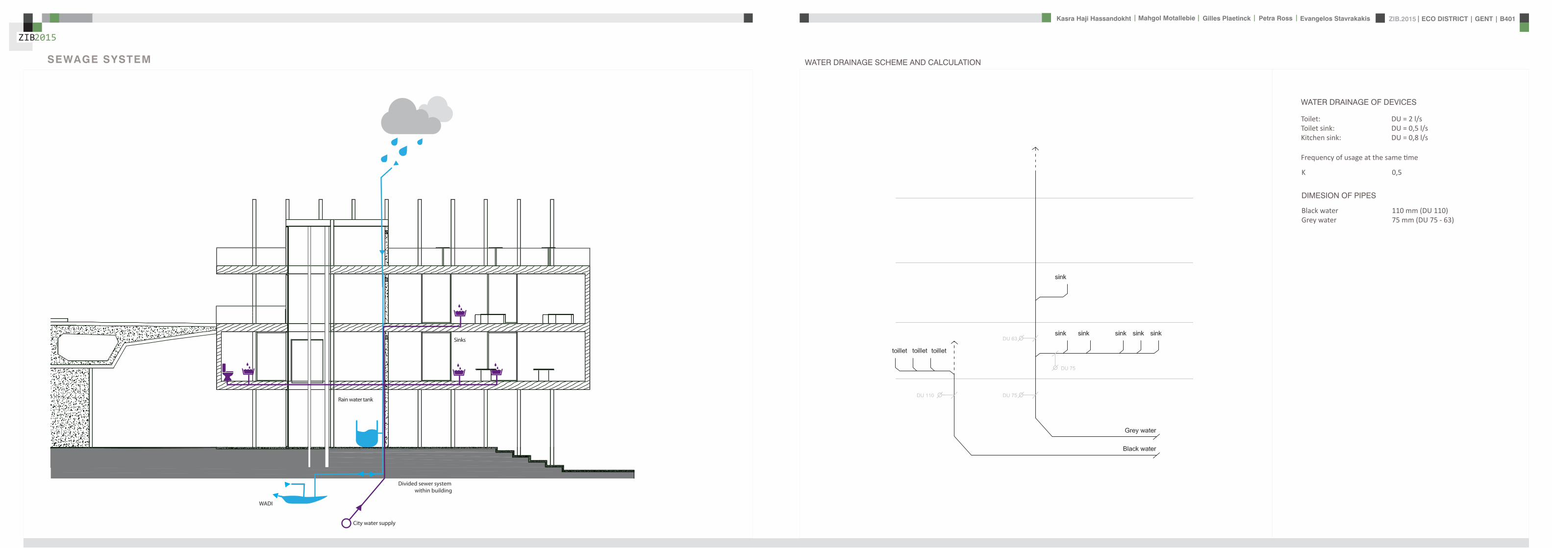
ZIB2015 ECO DISTRICT | GENT | B401Evangelos Stavrakakis | Petra Ross | Mahgol Motallebie | Gilles Plaetinck | Kasra Haji Hassandokht
ZIB2015
|
WADI
City water supply
Rain water tank
Sinks
Divided sewer systemwithin building
SEWAGE SYSTEM
ToiletToilet sinkKitchen sink
DU = 2 lsDU = 05 lsDU = 08 ls
WATER DRAINAGE OF DEVICES
Frequency of usage at the same time
K 05
DIMESION OF PIPES
Black waterGrey water
110 mm (DU 110)75 mm (DU 75 - 63)
WATER DRAINAGE SCHEME AND CALCULATION
ZIB2015 ECO DISTRICT | GENT | B401Evangelos Stavrakakis | Petra Ross | Mahgol Motallebie | Gilles Plaetinck | Kasra Haji Hassandokht
ZIB2015
|
DN
Gilles Plaetinck
schaal 1 100
ZIB BUILDINGEnter address here
2 _ level 1
Owner
begeleider Checker
Gilles Plaetinck
schaal 1 100
ZIB BUILDINGEnter address here
3 _ level 2
Owner
begeleider Checker
WATER SUPPLY
HOT WATER
WATER DRAINAGE
WATER SUPPLY AND DRAINAGE IN GROUPLANS
level 01
level 02
ENERGY
RAINWATER TANK
HELOPHYTE FILTER
IRRIGATION SYSTEM
BIO-ROTOR
MICRO TURBINE
PHOSPHOR
In this building a closed water system is applied which is based on reusing water in mullple wasRainRain water from the roof will be collected in a storage tank situated on the ground floor This water will be used to flush the toilet and irrigate crops in verlcal harveslng system In case of an overflow the water will be stored in the con-structed wetland near the building The rainwater can be fil-tered through a helophyte filter up to drinking water stan-dard The waste water system includes three types of water yellyellow black and grey waterThe yellow water will be stored for its phosphor while the black water will be purified into grey water This grey water is comparable to the quality of rain water aaer purificalon b means of a bio rotor The remaining residue from the bio rotor together with the organic waste from the harveslng is fermented into biogas that drives a micro turbine in order to produce some addilonal energy
TheThe waste product deriving from this process will be used as compost in verlcal harveslng This efficient yet complex system closes the ullizalon cycle of the building and turns it into an efficient vicious circle that can be considered au arkic
In this building a closed water system is applied which is based on reusing water in multiple was
Rain water from the roof will be collected in a storage tank situated on the ground floor This water will be used to flushthe toilet and irrigate crops in vertical harvesting system In case of an overflow the water will be stored in the constructed wetland near the building The rainwater can be filtered through a helophyte filter up to drinking water standard
The waste water system includes three types of water yellow black and grey water The yellow water will be stored for its phosphor while the black water will be purified into grey water This grey water is comparable to the quality of rain water after purification b means of a bio rotor The remaining residue from the bio rotor together with the organic waste from the harvesting is fermented into biogas that drives a micro turbine in order to produce some additional energy The waste product deriving from this process will be used ascompost in ver1048991cal harves1048991ng This efficient yet complexsystem closes the u1048991liza1048991on cycle of the building and turns itinto an efficient vicious circle that can be considered au arkic
WATER CYCLE
ZIB2015 ECO DISTRICT | GENT | B401Evangelos Stavrakakis | Petra Ross | Mahgol Motallebie | Gilles Plaetinck | Kasra Haji Hassandokht
ZIB2015
|
CALCULATIONS
Passive House verification
Photo or Drawing
Building Workshop + info pointStreet
PostcodeCityCountry
Building Type non-residentialClimate Ukkel
Home Owner(s) Client(s)Street
PostcodeCity
ArchitectStreet
PostcodeCity Calculation electricity Internal heat gains
Mechanical System Building type
StreetPostcodeCity Internal heat gains
Year of Construction 2015 Interior Temperature 200 degC Utilisation pattern
Number of Dwelling Units 1 Internal Heat Gains 20 Wm2 Type of values used Fill in worksheet IHG Non-Dom Enclosed Volume Ve 12442 Planned number of occupants
Number of Occupants 80 8 Design
Specific building demands with reference to the treated floor area use Annual method
Treated floor area 2840 msup2 Requirements Fulfilled Verification Annual method The monthly method should be used for building certification
Space heating Annual heating demand 10 kWh(m2a) 15 kWh(msup2a) yes Specific space heating demand annual method 103 kWh(msup2a)
Heating load 11 Wm2 10 Wmsup2 - Specific space heating demand monthly Method 120 kWh(msup2a)
Space cooling Overall specific space cooling demand kWh(m2a) 15 kWh(msup2a)
Cooling load Wm2 - -Frequency of overheating (gt 25 degC) - -
Primary Energy Space heating and dehumidification
cooling household electricity 73 kWh(m2a) 120 kWh(msup2a) yes
DHW space heating and auxiliary electricity 24 kWh(m2a) - -Specific primary energy reduction through solar electricity 21 kWh(m2a) - -
Airtightness Pressurization test result n50 06 1h 06 1h yes
PHPP Verification FINAL ZIB FILE CALCULTIONS PHPPxls
L B H VOLUME
main 1 226 7 4 6328main 2 184 7 35 4508
core 0 6 2 5 3 5 108 5core 0 62 5 35 1085core 3 62 3 28 521
12442
AREAmain 1 storage 35
wc big 35wc 2wc 2workshop 103
MAIN 2 infolounge 92
staircase 56storage technical 22
284
Floor_exterior 1582 31 1272
Roof_exterior 1582
Passive House verification
Photo or Drawing
Building Workshop + info pointStreet
PostcodeCityCountry
Building Type non-residentialClimate Ukkel
Home Owner(s) Client(s)Street
PostcodeCity
ArchitectStreet
PostcodeCity Calculation electricity Internal heat gains
Mechanical System Building type
StreetPostcodeCity Internal heat gains
Year of Construction 2015 Interior Temperature 200 degC Utilisation pattern
Number of Dwelling Units 1 Internal Heat Gains 20 Wm2 Type of values used Fill in worksheet IHG Non-Dom Enclosed Volume Ve 12442 Planned number of occupants
Number of Occupants 80 8 Design
Specific building demands with reference to the treated floor area use Annual method
Treated floor area 2840 msup2 Requirements Fulfilled Verification Annual method The monthly method should be used for building certification
Space heating Annual heating demand 10 kWh(m2a) 15 kWh(msup2a) yes Specific space heating demand annual method 103 kWh(msup2a)
Heating load 11 Wm2 10 Wmsup2 - Specific space heating demand monthly Method 120 kWh(msup2a)
Space cooling Overall specific space cooling demand kWh(m2a) 15 kWh(msup2a)
Cooling load Wm2 - -Frequency of overheating (gt 25 degC) - -
Primary Energy Space heating and dehumidification
cooling household electricity 73 kWh(m2a) 120 kWh(msup2a) yes
DHW space heating and auxiliary electricity 24 kWh(m2a) - -Specific primary energy reduction through solar electricity 21 kWh(m2a) - -
Airtightness Pressurization test result n50 06 1h 06 1h yes
PHPP Verification FINAL ZIB FILE CALCULTIONS PHPPxls
SURFACE AREAcurrent orientation only night ventilation
current orientation only night ventilation 6 windows less 52 msup2
current orientation only night ventilation 7 windows less 60msup2 (stays the same for each side)
current orientation only night ventilation 8 windows less 69 msup2
orientation turned 90deg only night ventilation 6 windows less 52 msup2
orientation turned 90deg only night ventilation 7 windows less 60msup2 (window less at SE side)
orientation turned 90deg only night ventilation 8 windows less 69 msup2
-gt orientation turned 90deg only night ventilation 9 windows less 77msup2 (window less at NW side althought theres less overheating in the case of a window less at SE side the heating demand exceeds 15)
CHANGE IN DESIGN
ZIB2015 ECO DISTRICT | GENT | B401Evangelos Stavrakakis | Petra Ross | Mahgol Motallebie | Gilles Plaetinck | Kasra Haji Hassandokht
ZIB2015
|
Passive House verificationS P E C I F I C A N N U A L H E A T I N G D E M A N D
Climate Ukkel Interior Temperature 200 degC
Building Workshop + info point Building TypeUse non-residentialTreated Floor Area ATFA 2840 msup2
per msup2Area U-Value Temp Factor ft Gt Treated Data for heating balance diagram
Building Element Temperature Zone msup2 W(msup2K) kKha kWha Floor Area Losses GainsExterior Wall - Ambient A 5595 0101 100 743 = 4181 1472 Exterior Wall - Ambient 147234373Exterior Wall - Ground B 069 = Exterior Wall - GroundRoofCeiling - Ambient A 1550 0094 100 743 = 1085 382 RoofCeiling - Ambient 381903529Floor slab basement ceiling B 310 0105 069 743 = 167 059 Floor slab basement ceiling 058811509
A 100 =A 100 =
unheated basement X 075 = unheated basementWindows A 1154 0648 100 743 = 5562 1958 Windows 195834732Exterior Door A 100 = Exterior DoorExterior TB (lengthm) A 1169 -0030 100 743 = -259 -091 Thermal Bridge Heat LossPerimeter TB (lengthm) P 069 = 000 not useful heat gains 365267499Ground TB (lengthm) B 069 =
Total of All Building Envelope Areas 8609 ndashndashndashndashndashndashndashndashndashndashndashndashndash- kWh(msup2a) Ventilation 395818713
Transmission Heat Losses QT Total 10736 378Annual Heating Demand 102516636
ATFA Clear Room Height internal gains 100951487msup2 m msup3 passive solar gains 250668423
Ventilation System Effective Air Volume VV 2840 280 = 7952 Thermal bridge credit 091126837Effective Heat Recovery Efficiency eff 81 Cross check sum 46324923 46324923of Heat Recovery
Efficiency of Subsoil Heat Exchanger SHX 0 nVsystem HR nVRes
1h 1h 1h
Energetically Effective Air Exchange nV 0105 (1 - 081 ) + 0038 = 0058
VV nV cAir Gt
msup3 1h Wh(msup3K) kKha kWha kWh(msup2a)
Ventilation Heat Losses QV 795 0058 033 743 = 1124 40
Reduction Factor QT QV NightWeekend
kWha kWha Saving kWha kWh(msup2a)
Total Heat Losses QL ( 10736 + 1124 ) 10 = 11860 418
Orientation Reduction Factor g-Value Area Radiation HPof the Area See Windows Sheet (perp radiation)
msup2 kWh(msup2a) kWha
1 North 054 050 2700 163 = 11822 East 058 000 440 197 = 03 South 056 050 4860 314 = 42874 West 032 050 3216 254 = 13275 Horizontal 063 050 324 317 = 323
kWh(msup2a)
Available Solar Heat Gains QS Total 7119 251
Length Heat Period Spec Power qI ATFA
khd da Wmsup2 msup2 kWha kWh(msup2a)
Internal Heat Gains QI 0024 209 201 2840 = 2867 101
kWha kWh(msup2a)
Free Heat QF QS + QI = 9986 352
Ratio of Free Heat to Losses QF QL = 084
Utilisation Factor Heat Gains G (1 - ( QF QL )5 ) (1 - ( QF QL )
6 ) = 90kWha kWh(msup2a)
Heat Gains QG G QF = 8949 315
kWha kWh(msup2a)
Annual Heating Demand QH QL - QG = 2911 10
kWh(msup2a) (YesNo)
Limiting Value 15 Requirement met yes
00
147
00
3806000000
196
00
40
37
09
103
101
251
0
5
10
15
20
25
30
35
40
45
50
Losses Gains
Hea
t flo
ws
[kW
h(m
sup2a)]
Heating energy balance
passive solar gains
internal gains
Annual Heating Demand
Thermal bridge credit
not useful heat gains
Ventilation
Exterior Door
Windows
unheated basement
Floor slab basement ceiling
RoofCeiling - Ambient
Exterior Wall - Ground
Exterior Wall - Ambient
Thermal Bridge Heat Loss
HPP Annual Heating Demand FINAL ZIB FILE CALCULTIONS PHPPxls
Passive House verification Passive House verificationS P E C I F I C U S E F U L C O O L I N G D E M A N D S P E C I F I C U S E F U L C O O L I N G D E M A N D
M O N T H L Y M E T H O D M O N T H L Y M E T H O D
(This page displays the sums of the monthly method over the cooling period))Climate Ukkel Interior Temperature Summer 25 degC Climate Ukkel Interior Temperature 25 degC
Building Workshop + info point Building TypeUse non-residential Building Workshop + info point Building TypeUse non-residential
Spec Capacity 60 Wh(msup2K) (Enter in Summer worksheet) Treated Floor Area ATFA 2840 msup2 Treated Floor Area ATFA 284 msup2
per msup2Temperature Zone Area U-Value Mon Red Fac Gt Treated Jan Feb Mar Apr May Jun Jul Aug Sep Oct Nov Dec Year
Building Element msup2 W(msup2K) kKha kWha Floor Area Heating Degree Hours - Ex 168 150 144 121 92 73 57 59 82 109 140 160 136 kKh1 Exterior Wall - Ambient A 5595 0101 100 103 = 5782 Heating Degree Hours - G 126 123 135 120 106 83 63 54 58 71 86 109 113 kKh2 Exterior Wall - Ground B 100 = Losses - Exterior 2553 2286 2189 1838 1393 1117 871 904 1245 1660 2123 2432 20612 kWh3 RoofCeiling - Ambient A 1550 0094 100 103 = 1500 Losses - Ground 41 40 44 39 35 27 21 18 19 23 28 36 370 kWh4 Floor slab basement ceil B 310 0105 100 90 = 294 Losses Summer Ventilatio 67 71 244 372 629 720 880 865 658 499 234 126 5366 kWh5 A 100 = Sum Spec Heat Losses 94 84 87 79 72 66 62 63 68 77 84 91 928 kWhmsup26 A 100 = Solar Load North 44 81 141 212 286 298 298 255 178 116 54 35 1998 kWh7 unheated basement X 075 = Solar Load East 0 0 0 0 0 0 0 0 0 0 0 0 0 kWh8 Windows A 1154 0648 100 103 = 7690 Solar Load South 218 315 464 577 681 644 681 658 532 416 242 171 5601 kWh9 Exterior Door A 100 = Solar Load West 79 125 213 303 385 378 370 347 256 177 91 60 2785 kWh
10 Exterior TB (lengthm) A 1169 -0030 100 103 = -358 Solar Load Horiz 11 21 37 57 79 79 80 69 47 30 14 9 533 kWh11 Perimeter TB (lengthm) P 100 = Solar Load Opaque 3 5 9 13 18 19 19 16 11 7 3 2 126 kWh12 Ground TB (lengthm) B 100 = Internal Heat Gains 425 384 425 411 425 411 425 425 411 425 411 425 5001 kWh
ndashndashndashndashndashndashndashndashndashndashndash kWh(msup2a) Sum Spec Loads Solar + 28 33 45 55 66 64 66 62 51 41 29 25 565 kWhmsup2
Transmission Losses QT (Negative Heat Loads) Total 14907 525 Utilisation Factor Losses 29 39 52 69 84 88 82 88 73 53 34 27 58Useful Cooling Energy Dem 0 0 4 30 142 192 417 192 40 4 0 0 1021 kWh
ATFA Clear Room Height Spec Cooling Demand 00 00 00 01 05 07 15 07 01 00 00 00 36 kWhmsup2Effective msup2 m msup3
Air Volume VV 284 280 = 795
Heat Transfer Coef Gt
WK kKha kWha kWh(msup2a)
Exterior 99 103 = 1013 36Ground 00 105 = 0 00
Additional Summer Ventilation
Select X Window Night Ventilation Manual Corresponding Air Change Rate 136 1h
Mechanical Automatically Controlled Ventilation (for window ventilation at 1 K temperature difference indoor - outdoor)
Minimum Acceptable Indoor Temperatu 220 degC
kWha kWh(msup2a)
Heat Losses Summer Ventilation 5172 182
QLext QLground QLsummer
kWha kWha kWha kWha kWh(msup2a)
Ventilation Heat Losses QV 1013 + 0 + 5172 = 6185 218
2
3
4
5
6
7
8
9
10
Spec
ific
loss
es l
oads
l c
oolin
g de
man
d [k
Wh
(msup2 m
onth
)] Spec Cooling Demand Sum Spec Heat Losses Sum Spec Loads Solar + Internal
QT QV
kWha kWha kWha kWh(msup2a)
Total Heat Losses QL 14907 + 6185 = 21092 743
Orientation Reduction Factor g-Value Area Global Radiationof the Area (perp radiation)
msup2 kWh(msup2a) kWha
1 North 031 050 270 462 = 19182 East 061 000 44 578 = 0 Temperature Amplitude Summer 82 K3 South 030 050 486 707 = 52114 West 025 050 322 654 = 2646 Month 1 2 3 4 5 6 7 8 9 10 11 12 Annual Total5 Horizontal 035 050 32 913 = 513 Days 31 28 31 30 31 30 31 31 30 31 30 31 3656 Sum Opaque Areas 121 Ambient Temp 250 270 572 828 1275 1487 1737 1707 1369 1039 568 356 96
kWh(msup2a) North Radiation 106 195 329 494 667 697 712 599 419 275 129 87 471
Available Solar Heat Gains QS Total 10409 367 East Radiation 146 266 452 698 937 940 988 851 574 382 179 123 654
South Radiation 311 440 645 786 912 858 898 885 733 579 341 241 763Length Heat Period Spec Power qI ATFA West Radiation 155 261 471 707 926 926 896 819 580 382 183 116 642
khd da Wmsup2 msup2 kWha kWh(msup2a) Hori Radiation 200 369 662 1021 1398 1410 1418 1234 842 535 243 156 949
Internal Heat Gains QI 0024 303 20 2840 = 4151 146 Tsky -750 -730 -428 -172 275 487 737 707 369 039 -432 -644 -04
Ground Temp 805 676 686 830 1072 1345 1647 1776 1696 1552 1310 1037 121kWha kWh(msup2a)
Sum Heat Loads QF QS + QI = 14560 513
Ratio of Losses to Free Heat Gains QL QF = 145
Utilisation Factor Heat Losses G = 64kWha kWh(msup2a)
Useful Heat Losses QVn G QL = 13539 477
kWha kWh(msup2a)
Useful Cooling Demand QK QF - QVn = 1021 4
kWh(msup2a) (YesNo)
Limiting Value 15 Requirement met yes
0
1
2
Jan Feb Mar Apr May Jun Jul Aug Sep Oct Nov Dec
usef
u
HPP Cooling FINAL ZIB FILE CALCULTIONS PHPPxls
Passive House verificationS P E C I F I C A N N U A L H E A T I N G D E M A N D
Climate Ukkel Interior Temperature 200 degC
Building Workshop + info point Building TypeUse non-residentialTreated Floor Area ATFA 2840 msup2
per msup2Area U-Value Temp Factor ft Gt Treated Data for heating balance diagram
Building Element Temperature Zone msup2 W(msup2K) kKha kWha Floor Area Losses GainsExterior Wall - Ambient A 5595 0101 100 743 = 4181 1472 Exterior Wall - Ambient 147234373Exterior Wall - Ground B 069 = Exterior Wall - GroundRoofCeiling - Ambient A 1550 0094 100 743 = 1085 382 RoofCeiling - Ambient 381903529Floor slab basement ceiling B 310 0105 069 743 = 167 059 Floor slab basement ceiling 058811509
A 100 =A 100 =
unheated basement X 075 = unheated basementWindows A 1154 0648 100 743 = 5562 1958 Windows 195834732Exterior Door A 100 = Exterior DoorExterior TB (lengthm) A 1169 -0030 100 743 = -259 -091 Thermal Bridge Heat LossPerimeter TB (lengthm) P 069 = 000 not useful heat gains 365267499Ground TB (lengthm) B 069 =
Total of All Building Envelope Areas 8609 ndashndashndashndashndashndashndashndashndashndashndashndashndash- kWh(msup2a) Ventilation 395818713
Transmission Heat Losses QT Total 10736 378Annual Heating Demand 102516636
ATFA Clear Room Height internal gains 100951487msup2 m msup3 passive solar gains 250668423
Ventilation System Effective Air Volume VV 2840 280 = 7952 Thermal bridge credit 091126837Effective Heat Recovery Efficiency eff 81 Cross check sum 46324923 46324923of Heat Recovery
Efficiency of Subsoil Heat Exchanger SHX 0 nVsystem HR nVRes
1h 1h 1h
Energetically Effective Air Exchange nV 0105 (1 - 081 ) + 0038 = 0058
VV nV cAir Gt
msup3 1h Wh(msup3K) kKha kWha kWh(msup2a)
Ventilation Heat Losses QV 795 0058 033 743 = 1124 40
Reduction Factor QT QV NightWeekend
kWha kWha Saving kWha kWh(msup2a)
Total Heat Losses QL ( 10736 + 1124 ) 10 = 11860 418
Orientation Reduction Factor g-Value Area Radiation HPof the Area See Windows Sheet (perp radiation)
msup2 kWh(msup2a) kWha
1 North 054 050 2700 163 = 11822 East 058 000 440 197 = 03 South 056 050 4860 314 = 42874 West 032 050 3216 254 = 13275 Horizontal 063 050 324 317 = 323
kWh(msup2a)
Available Solar Heat Gains QS Total 7119 251
Length Heat Period Spec Power qI ATFA
khd da Wmsup2 msup2 kWha kWh(msup2a)
Internal Heat Gains QI 0024 209 201 2840 = 2867 101
kWha kWh(msup2a)
Free Heat QF QS + QI = 9986 352
Ratio of Free Heat to Losses QF QL = 084
Utilisation Factor Heat Gains G (1 - ( QF QL )5 ) (1 - ( QF QL )
6 ) = 90kWha kWh(msup2a)
Heat Gains QG G QF = 8949 315
kWha kWh(msup2a)
Annual Heating Demand QH QL - QG = 2911 10
kWh(msup2a) (YesNo)
Limiting Value 15 Requirement met yes
00
147
00
3806000000
196
00
40
37
09
103
101
251
0
5
10
15
20
25
30
35
40
45
50
Losses Gains
Hea
t flo
ws
[kW
h(m
sup2a)]
Heating energy balance
passive solar gains
internal gains
Annual Heating Demand
Thermal bridge credit
not useful heat gains
Ventilation
Exterior Door
Windows
unheated basement
Floor slab basement ceiling
RoofCeiling - Ambient
Exterior Wall - Ground
Exterior Wall - Ambient
Thermal Bridge Heat Loss
HPP Annual Heating Demand FINAL ZIB FILE CALCULTIONS PHPPxls
factor 05Wd (ls) 088
nominal diameter 75 mmVERTICAL COLLECTOR sink toilets 3 05 15
sink kitchen 2 08 16Total 5 31factor 05
Wd (ls) 088nominal diameter 75 mm
Toevoerend ROOF SURFACE
horizontal roof surface (msup2) orientation coeff angle (deg) roofcover filter coeff toevoerend
444 1 0 08 09 3197
RAIN WATER USAGE
Type usage ( l usage) persons day frequency usageday yearly usage
toilet use small 3 20 3 180 65700toilet use big 6 20 1 120 43800VERTICAL GARDENING 150 54750TOTAL 450 164250 L year
16425 msup3 year
TOTAL RAINWATER USAGE 450 L dayRELATIVE RAINWATER USAGE 1407 L day100msup2
LEEGSTAND
relative rainwater usage 1407 L day 100 msup2LEEGSTAND 7 relative volume rainwater tank 3 msup3 100 msup2rainwater tank volume 9591 Liter
suggestion 50 msup2 02 m= 10 msup3
SUPPLYtype amount debiet Q total total WW
lsec lsec lsecMAIN LEVEL POTABLE
sink toilet 3 01 03 03sink kitchen 2 01 02 02
Total 5 05 05Gelijktijdigheid 05 05debiet Q (lsec) 025 025
diameter 178 178 cm
type amount debiet Q total total WWlsec lsec lsec
MAIN LEVEL RAIN WATER toilet 3 01 03 0
Total 3 03Gelijktijdigheid 071debiet Q (lsec) 0213
diameter 165 cm
FECALIEumlNtype amount value Total (ls)
COLLECTOR HORIZONTAL toilet 3 2Total 6factor 05
Wd (ls) 122nominal diameter 110 mm
type amount value Total (ls)COLLECTOR VERTICAL toilet 3 2
Total 6factor 05
Wd (ls) 122nominal diameter 110 mm
DRAINtype amount value Total (ls)
HORIZONTAL COLLECTOR sink toilets 3 05 15sink kitchen 2 08 16
Total 5 31
WATER
ZIB2015 ECO DISTRICT | GENT | B401Evangelos Stavrakakis | Petra Ross | Mahgol Motallebie | Gilles Plaetinck | Kasra Haji Hassandokht
ZIB2015
|
Passive House verificationS P E C I F I C S P A C E H E A T I N G L O A D Risk Determination of Group Heating for a Critical Room
Building Workshop + info point Building TypeUse non-residential Workshop room ( 1= Yes 0 = No)
Climate (HL) Ukkel Treated Floor Area ATFA 2840 msup2 Interior Temperature 20 degC Building Satisfies Passive House Criteria 1
Design Temperature Radiation North East South West Horizontal Room floor area 100 msup2 Supply Air per msup2 Living AreaWeather Condition 1 -31 degC 10 10 30 15 20 Wmsup2 Planned ambient air quantity for the room 150 msup3h 150 msup3hmsup2Weather Condition 2 -22 degC 5 5 20 10 10 Wmsup2 Planned ambient air quantities for the remaining rooms -67 msup3hGround Design Temp 68 degC Area U-Value Factor TempDiff 1 TempDiff 2 PT 1 PT 2
Building Element Temperature Zone msup2 W(msup2K) Always 1(except X) K K W W Building Element Temperature Zone msup2 W(msup2K) Always 1
(except X) K Room Trans Loss W
1 Exterior Wall - Ambient A 5595 0101 100 231 or 222 = 1299 or 1249 Aboveground Exterior Wall A 650 010 100 231 = 1512 Exterior Wall - Ground B 100 132 or 132 = or Belowground Exterior Wall B 00 100 132 =3 RoofCeiling - Ambient A 1550 0094 100 231 or 222 = 337 or 324 RoofCeiling D 880 009 100 231 = 1914 Floor slab basement ceiling B 310 0105 100 132 or 132 = 43 or 43 Underground Floor Slab B 00 011 100 132 = 05 A 100 231 or 222 = or A 100 231 =6 A 100 231 or 222 = or A 100 231 =7 unheated basement X 075 231 or 222 = or X 100 231 =8 Windows A 1154 0648 100 231 or 222 = 1728 or 1661 Windows A 480 065 100 231 = 7199 Exterior Door A 100 231 or 222 = or Exterior Door A 100 231 =
10 Exterior TB (lengthm) A 1169 -0030 100 231 or 222 = -80 or -77 Exterior thermal bridges (Lengthm) A 100 231 =11 Perimeter TB (lengthm) P 100 132 or 132 = or Perimeter Thermal Bridges (Lengthm) A 100 231 =12 Ground TB (lengthm) B 100 132 or 132 = or Floor Slab Thermal Bridges (Lengthm) A 50 100 231 =13 HouseDU Partition Wall I 100 30 or 30 = or HouseDU Partition Wall I 200 100 30 =
Transmission Heat Losses PT ndashndashndashndashndashndashndashndashndashndashndashndashndash- ndashndashndashndashndashndashndashndashndashndashndash-
Total = 3328 or 3200 = 1061
ATFA Clear Room HeightVentilation System msup2 m msup3 Risk
Effective Air Volume VV 2840 280 = 795 Enter 1 = Yes 0 = No PTRoom W PSupply Air W Ratio Summand
SHX 1 SHX 2 Transmission Heat Losses 1061 1386 077 -023Efficiency of Heat Recovery HR 81 Heat Recovery Efficiency SHX 0 Efficiency SHX 0 or 0 Concentrated leakages 0 000of the Heat Exchanger Insulation to other rooms better R = 15 msup2KW 1 ( 2 = no thermal contact except door) 050
nVRes (Heating Load) nVsystem HR HR Room is on the ground floor 0 0001h 1h 1h 1h open staircase 0 000
Energetically Effective Air Exchange nV 0094 + 0105 (1- 081 or 081 ) = 0114 or 0114 TOTAL of the Risk Summands 027Ventilation Heating Load PV
VL nL nL cAir TempDiff 1 TempDiff 2 PV 1 PV 2 Interior doors predominantly closed 1 Risk Factor 200msup3 1h 1h Wh(msup3K) K K W W
7952 0114 or 0114 033 231 or 222 = 691 or 664Total Room Risk 89
PL 1 PL 2
Total Heating Load PL W W Appraisal and Advice normally no problemPT + PV = 4019 or 3864
Orientation Area g-Value Reduction Factor Radiation 1 Radiation 2 PS 1 PS 2the Area msup2 (perp radiation) (see Windows worksheet) Wmsup2 Wmsup2 W W
1 North 270 05 05 11 or 6 = 77 or 412 East 44 00 06 8 or 3 = 0 or 03 South 486 05 06 28 or 18 = 378 or 2474 West 322 05 03 19 or 13 = 100 or 685 Horizontal 32 05 06 20 or 10 = 20 or 10
Solar heating power PS Total = 575 or 367
Spec Power ATFA PI 1 PI 2Internal heating power PI Wmsup2 msup2 W W
16 284 = 454 or 454
PG 1 PG 2
Heating power (gains) PG W W
PS + PI = 1029 or 821
PL - PG = 2989 or 3042
Heating Load PH = 3042 W
Specific Heating Load PH ATFA = 107 Wmsup2
Input Max Supply Air Temperature 48 degC degC degC
Max Supply Air Temperature SupplyMax 48 degC Supply Air Temperature Without Heating SupplyMin 156 157
For Comparison Heating Load Transportable by Supply Air PSupply AirMax = 886 W specific 31 Wmsup2
(YesNo)
Supply Air Heating Sufficient No
HPP Heating Load FINAL ZIB FILE CALCULTIONS PHPPxls
Passive House verificationU - V A L U E S O F B U I L D I N G E L E M E N T S
Wedge shaped building element layeBuilding Workshop + info point still air spaces -gt Secondary calculation to th
Assembly No Building assembly description Interior insulation1 Exterior wall x
Heat transfer resistance [msup2KW] interior Rsi 013exterior Rse 004
Area section 1 [W(mK)] Area section 2 (optional) [W(mK)] Area section 3 (optional) [W(mK)] Thickness [mm]
1 hout gevel 0160 17
2 regelwerk hout 0158 30
3 houtvezel celit 4D 0048 18
4 Eurowall 0023 hout FJI beam 0286 140
5 OSB -plaat 0130 15
6 Eurothane G 0023 70
7 Plaster insulating 0100 10
8Percentage of Sec 2 Percentage of Sec 3 Total
26 300
U-Value 0107 W(msup2K)
Assembly No Building assembly description Interior insulation2 Roof x
Heat transfer resistance [msup2KW] interior Rsi 010exterior Rse 004
Area section 1 [W(mK)] Area section 2 (optional) [W(mK)] Area section 3 (optional) [W(mK)] Thickness [mm]Area section 1 [W(mK)] Area section 2 (optional) [W(mK)] Area section 3 (optional) [W(mK)] Thickness [mm]
1 bitumenmembraam 0230 5
23 EPS 0036 70
4 OSB -plaat 0130 18
5 cellulose 0039 hout FJI beam 0286 350
6 OSB -plaat 0130 15
7 regelwerk hout 5 0177 30
8 gipskartonplaat 0290 12
Percentage of Sec 2 Percentage of Sec 3 Total
26 500
U-Value 0094 W(msup2K)
Assembly No Building assembly description Interior insulation3 Floor x
Heat transfer resistance [msup2KW] interior Rsi 017
exterior Rse 004
Area section 1 [W(mK)] Area section 2 (optional) [W(mK)] Area section 3 (optional) [W(mK)] Thickness [mm]
1 PIR dekvloer 0023 5
2 gipskartonplaat 0290 10
3 gespoten pur 0028 100
4 OSB -plaat 0130 15
5 cellulose 0039 hout FJI beam 0286 350
6 houtvezel Celit 4D 0048 15
7 regelwerk hout 6 0149 30
8 afwerking hout 0160 5
Percentage of Sec 2 Percentage of Sec 3 Total
26 530
U-Value 0078 W(msup2K)
PHPP U-Values FINAL ZIB FILE CALCULTIONS PHPPxls
ers and he right
n Secondary Calculation Equivalent Thermal Conductivity of Still Air Spaces
Air Layer Thickness 30 mm Direction of Upwards ha 125 W(msup2K) 016 W(mK)
Heat Flow X Horizontal hr 417 W(msup2K)
(check only one field) Downwards
cm
n
cm
n Secondary Calculation Equivalent Thermal Conductivity of Still Air Spaces
Air Layer Thickness 30 mm
Direction of Upwards ha 08333 W(msup2K) 015 W(mK)Heat Flow Horizontal hr 417 W(msup2K)
(check only one field) X Downwards
cm
PHPP U-Values FINAL ZIB FILE CALCULTIONS PHPPxls
ers and he right
n Secondary Calculation Equivalent Thermal Conductivity of Still Air Spaces
Air Layer Thickness 30 mm Direction of Upwards ha 125 W(msup2K) 016 W(mK)
Heat Flow X Horizontal hr 417 W(msup2K)
(check only one field) Downwards
cm
n
cm
n Secondary Calculation Equivalent Thermal Conductivity of Still Air Spaces
Air Layer Thickness 30 mm
Direction of Upwards ha 08333 W(msup2K) 015 W(mK)Heat Flow Horizontal hr 417 W(msup2K)
(check only one field) X Downwards
cm
PHPP U-Values FINAL ZIB FILE CALCULTIONS PHPPxls
ers and he right
n Secondary Calculation Equivalent Thermal Conductivity of Still Air Spaces
Air Layer Thickness 30 mm Direction of Upwards ha 125 W(msup2K) 016 W(mK)
Heat Flow X Horizontal hr 417 W(msup2K)
(check only one field) Downwards
cm
n
cm
n Secondary Calculation Equivalent Thermal Conductivity of Still Air Spaces
Air Layer Thickness 30 mm
Direction of Upwards ha 08333 W(msup2K) 015 W(mK)Heat Flow Horizontal hr 417 W(msup2K)
(check only one field) X Downwards
cm
PHPP U-Values FINAL ZIB FILE CALCULTIONS PHPPxls
Passive House verificationS U M M E R
Climate Ukkel Interior Temperature 20 degC
Building Workshop + info point Building TypeUse non-residentialTreated Floor Area ATFA 2840 msup2
Spec Capacity 60 WhK pro msup2 TFAOverheating
limit25 degC Area U-Value Red Factor fTSummer HSummer Heat Conductance
Building Element Temperature Zone msup2 W(msup2K)
1 Exterior Wall - Ambien A 5595 0101 100 = 5632 Exterior Wall - Ground B 100 =3 RoofCeiling - Ambient A 1550 0094 100 = 1464 Floor slab basement B 310 0105 100 = 335 A 100 =6 A 100 =7 unheated basement X 075 =8 Windows A 1154 0648 100 = 7489 Exterior Door A 100 =
10 Exterior TB (lengthm) A 1169 -0030 100 = -3511 Perimeter TB (lengthm P 100 =12 Ground TB (lengthm) B 100 =
ndashndashndashndashndashndashndashndashndashndashndashExterior Thermal Transmittance HTe 1422 WK
Ground Thermal Transmittance HTg 33 WK
ATFA Clear Room HeightEffective msup2 m msup3
Heat Recovery Efficiency HR 81 Air Volume VV 2840 280 = 795
SHX Efficiency SHX 0
Summer Ventilation continuous ventilation to provide sufficient indoor air quality
Air Change Rate by Natural (Windows amp Leakages) or Exhaust-Only Mechanical Ventilation Summer 000 1h
Mechanical Ventilation Summer 1h X with HR (check if applicable)
nLnat nVsystem HR nVRest
1h 1h 1h 1h
Energetically Effective Airchange Rate nV 0000 + 0000 (1 - 0808 ) + 0038 = 0038
VV nVequifraction cAir
msup3 1h Wh(msup3K)
Ventilation Transm Ambient HVe 795 0038 033 = 99 WK
Ventilation Transm Ground HVg 795 0000 033 = 00 WK
Additional Summer Ventilation for Cooling Temperature amplitude summer 82 K
Select X Window Night Ventilation Manual Corresponding Air Change Rate 136 1hMechanical Automatically Controlled Ventilation (for window ventilation at 1 K temperature difference indoor - outdoor)
Minimum Acceptable Indoor Temperature 220 degC
Orientation Angle Shading g-Value Area Portion of Glazing Apertureof the Area Factor Factor Dirt (perp radiation)
Summer Summer msup2 msup2
1 North 09 044 095 050 270 82 = 422 East 09 100 095 000 44 71 = 003 South 09 043 095 050 486 82 = 744 West 09 039 095 050 322 76 = 405 Horizontal 09 052 095 050 32 78 = 066 Sum Opaque Areas 03
msup2msup2
Solar Aperture Total 164 006
Specif Power qI ATFA
Wmsup2 msup2 W Wmsup2
Internal Heat Gains QI 201 284 = 571 20
Frequency of Overheating hmax 42 at the overheating limit max = 25 degC
If the frequency over 25degC exceeds 10 additional measures to protect against summer heat waves are necessary
Solar Load Spec Capacity ATFA
kWhd 1k Wh(msup2K) msup2
Daily Temperature Swing due to Solar Load 00 1000 ( 60 284 ) = 00 K
PHPP Summer FINAL ZIB FILE CALCULTIONS PHPPxls
Passive House verification Passive House verificationS P E C I F I C A N N U A L H E A T I N G D E M A N D S P E C I F I C A N N U A L H E A T D E M A N D
M O N T H L Y M E T H O D M O N T H L Y M E T H O D
(This page displays the sums of the monthly method over the heating period)Climate Ukkel Interior Temperature 20 degC Climate Ukkel Interior Temperature 20 degC
Building Workshop + info point Building TypeUse non-residential Building Workshop + info point Building TypeUse non-residentialSpec Capacity 60 Wh(msup2K) (Enter in Summer worksheet) Treated Floor Area ATFA 2840 msup2 Treated Floor Area ATFA 284 msup2
per msup2Temperature Zone Area U-Value Month Red Fac Gt Treated Jan Feb Mar Apr May Jun Jul Aug Sep Oct Nov Dec Year
Building Element msup2 W(msup2K) kKha kWha Floor Area Heating Degree Hours - E 131 117 107 85 54 37 20 22 46 72 104 123 92 kKhExterior Wall - Ambient A 5595 0101 100 78 = 4406 Heating Degree Hours - G 89 89 98 84 69 47 26 17 22 33 50 72 70 kKhExterior Wall - Ground B 100 = Losses - Exterior 2056 1836 1679 1335 856 589 316 350 722 1132 1630 1931 14433 kWhRoofCeiling - Ambient A 1550 0094 100 78 = 1143 Losses - Ground 29 29 32 28 23 15 9 5 7 11 16 23 227 kWhFloor slab basement ceiling B 310 0105 100 54 = 175 Sum Spec Losses 73 66 60 48 31 21 11 13 26 40 58 69 516 kWhmsup2
A 100 = Solar Gains - North 78 142 246 371 500 520 520 445 311 202 94 62 3490 kWhA 100 = Solar Gains - East 0 0 0 0 0 0 0 0 0 0 0 0 0 kWh
unheated basement X 075 = Solar Gains - South 405 583 860 1069 1261 1194 1263 1220 986 771 448 318 10377 kWhWindows A 1154 0648 100 78 = 5861 Solar Gains - West 103 162 275 391 497 489 478 448 331 229 118 77 3597 kWhExterior Door A 100 = Solar Gains - Horiz 20 38 68 104 143 144 145 126 86 55 25 16 968 kWhExterior TB (lengthm) A 1169 -0030 100 78 = -273 Solar Gains - Opaque 3 5 9 13 18 19 19 16 11 7 3 2 126 kWhPerimeter TB (lengthm) P 100 = Internal Heat Gains 425 384 425 411 425 411 425 425 411 425 411 425 5001 kWhGround TB (lengthm) B 100 = Sum Spec Gains Solar + 36 46 66 83 100 98 100 94 75 59 39 32 830 kWhmsup2
ndashndashndashndashndashndashndashndashndashndashndash kWh(msup2a) Utilisation Factor 100 98 84 57 31 22 11 13 34 67 98 100 48Transmission Heat Losses QT Total 11313 398 Annual Heating Demand 1055 580 134 9 0 0 0 0 0 19 564 1057 3419 kWh
Spec Heating Demand 37 20 05 00 00 00 00 00 00 01 20 37 120 kWhmsup2ATFA Clear Room Height
Effective msup2 m msup3
Air Volume VRAX 284 280 = 795
nVsystem SHX HR nVRes nVequifraction
1h 1h 1h
Effective Air Change Rate Ambient nVe 0105 (1- 0 )(1- 081 )+ 0038 = 0058Effective Air Change Rate Ground nVg 0105 0 (1- 081 ) = 0000
VRAX nVequifraction cAir Gt
msup3 1h Wh(msup3K) kKha kWha kWh(msup2a)
Ventilation Losses Ambient QV 795 0058 033 78 = 1185 42
Ventilation Losses Ground QVe 795 0000 033 55 = 0 00ndashndashndashndashndashndashndashndashndashndashndash
Ventilation Heat Losses QV Total 1185 42
Reduction Factor QT QV NightWeekend
kWha kWha Saving kWha kWh(msup2a)
Total Heat Losses QL ( 11313 + 1185 ) 10 = 12497 440
Orientation Reduction Factor g-Value Area Global Radiationof the Area See Windows worksheet (perp radiation)
msup2 kWh(msup2a) kWha
North 054 050 270 208 = 1505East 058 000 44 250 = 0South 056 050 486 398 = 5440West 032 050 322 323 = 1685Horizontal 063 050 32 403 = 411Sum Opaque Areas 55
kWh(msup2a)
Available Solar Heat Gains QS Total 9095 320 Annual Heating Demand Comparison
EN 13790 Monthly Method 3419 kWha 120 kWh(msup2a) Reference to habitable area
Length Heat Period Spec Power qI ATFA PHPP Heating Period Method 2911 kWha 103 kWh(msup2a) Reference to habitable area
khd da Wmsup2 msup2 kWha kWh(msup2a)
Internal Heat Gains QI 0024 242 20 2840 = 3315 117
kWha kWh(msup2a) Month 1 2 3 4 5 6 7 8 9 10 11 12 Annual Total Heating Period Method
Free Heat QF QS + QI = 12411 437 Days 31 28 31 30 31 30 31 31 30 31 30 31 365 209Ambient Temp 250 270 572 828 1275 1487 1737 1707 1369 1039 568 356 96 52
Ratio Free Heat to Losses QF QL = 099 North Radiation 106 195 329 494 667 697 712 599 419 275 129 87 471 163East Radiation 146 266 452 698 937 940 988 851 574 382 179 123 654 197
Utilisation Factor Heat Gains G = 73 South Radiation 311 440 645 786 912 858 898 885 733 579 341 241 763 314kWha kWh(msup2a) West Radiation 155 261 471 707 926 926 896 819 580 382 183 116 642 254
Heat Gains QG G QF = 9078 320 Hori Radiation 200 369 662 1021 1398 1410 1418 1234 842 535 243 156 949 317
Tsky -750 -730 -428 -172 275 487 737 707 369 039 -432 -644 -04kWha kWh(msup2a) Ground Temp 805 676 686 830 1072 1345 1647 1776 1696 1552 1310 1037 121 98
Annual Heating Demand QH QL - QG = 3419 12
kWh(msup2a) (YesNo)
Limiting Value 15 Requirement met yes
0
2
4
6
8
10
12
Jan Feb Mar Apr May Jun Jul Aug Sep Oct Nov Dec
Spec
ific
loss
es g
ains
he
atin
g de
man
d [k
Wh
(msup2 m
onth
)]
Spec Heating Demand Sum Spec Gains Solar + Internal Sum Spec Losses
HPP Monthly Method FINAL ZIB FILE CALCULTIONS PHPPxls
Passive House verification Passive House verificationS P E C I F I C A N N U A L H E A T I N G D E M A N D S P E C I F I C A N N U A L H E A T D E M A N D
M O N T H L Y M E T H O D M O N T H L Y M E T H O D
(This page displays the sums of the monthly method over the heating period)Climate Ukkel Interior Temperature 20 degC Climate Ukkel Interior Temperature 20 degC
Building Workshop + info point Building TypeUse non-residential Building Workshop + info point Building TypeUse non-residentialSpec Capacity 60 Wh(msup2K) (Enter in Summer worksheet) Treated Floor Area ATFA 2840 msup2 Treated Floor Area ATFA 284 msup2
per msup2Temperature Zone Area U-Value Month Red Fac Gt Treated Jan Feb Mar Apr May Jun Jul Aug Sep Oct Nov Dec Year
Building Element msup2 W(msup2K) kKha kWha Floor Area Heating Degree Hours - E 131 117 107 85 54 37 20 22 46 72 104 123 92 kKhExterior Wall - Ambient A 5595 0101 100 78 = 4406 Heating Degree Hours - G 89 89 98 84 69 47 26 17 22 33 50 72 70 kKhExterior Wall - Ground B 100 = Losses - Exterior 2056 1836 1679 1335 856 589 316 350 722 1132 1630 1931 14433 kWhRoofCeiling - Ambient A 1550 0094 100 78 = 1143 Losses - Ground 29 29 32 28 23 15 9 5 7 11 16 23 227 kWhFloor slab basement ceiling B 310 0105 100 54 = 175 Sum Spec Losses 73 66 60 48 31 21 11 13 26 40 58 69 516 kWhmsup2
A 100 = Solar Gains - North 78 142 246 371 500 520 520 445 311 202 94 62 3490 kWhA 100 = Solar Gains - East 0 0 0 0 0 0 0 0 0 0 0 0 0 kWh
unheated basement X 075 = Solar Gains - South 405 583 860 1069 1261 1194 1263 1220 986 771 448 318 10377 kWhWindows A 1154 0648 100 78 = 5861 Solar Gains - West 103 162 275 391 497 489 478 448 331 229 118 77 3597 kWhExterior Door A 100 = Solar Gains - Horiz 20 38 68 104 143 144 145 126 86 55 25 16 968 kWhExterior TB (lengthm) A 1169 -0030 100 78 = -273 Solar Gains - Opaque 3 5 9 13 18 19 19 16 11 7 3 2 126 kWhPerimeter TB (lengthm) P 100 = Internal Heat Gains 425 384 425 411 425 411 425 425 411 425 411 425 5001 kWhGround TB (lengthm) B 100 = Sum Spec Gains Solar + 36 46 66 83 100 98 100 94 75 59 39 32 830 kWhmsup2
ndashndashndashndashndashndashndashndashndashndashndash kWh(msup2a) Utilisation Factor 100 98 84 57 31 22 11 13 34 67 98 100 48Transmission Heat Losses QT Total 11313 398 Annual Heating Demand 1055 580 134 9 0 0 0 0 0 19 564 1057 3419 kWh
Spec Heating Demand 37 20 05 00 00 00 00 00 00 01 20 37 120 kWhmsup2ATFA Clear Room Height
Effective msup2 m msup3
Air Volume VRAX 284 280 = 795
nVsystem SHX HR nVRes nVequifraction
1h 1h 1h
Effective Air Change Rate Ambient nVe 0105 (1- 0 )(1- 081 )+ 0038 = 0058Effective Air Change Rate Ground nVg 0105 0 (1- 081 ) = 0000
VRAX nVequifraction cAir Gt
msup3 1h Wh(msup3K) kKha kWha kWh(msup2a)
Ventilation Losses Ambient QV 795 0058 033 78 = 1185 42
Ventilation Losses Ground QVe 795 0000 033 55 = 0 00ndashndashndashndashndashndashndashndashndashndashndash
Ventilation Heat Losses QV Total 1185 42
Reduction Factor QT QV NightWeekend
kWha kWha Saving kWha kWh(msup2a)
Total Heat Losses QL ( 11313 + 1185 ) 10 = 12497 440
Orientation Reduction Factor g-Value Area Global Radiationof the Area See Windows worksheet (perp radiation)
msup2 kWh(msup2a) kWha
North 054 050 270 208 = 1505East 058 000 44 250 = 0South 056 050 486 398 = 5440West 032 050 322 323 = 1685Horizontal 063 050 32 403 = 411Sum Opaque Areas 55
kWh(msup2a)
Available Solar Heat Gains QS Total 9095 320 Annual Heating Demand Comparison
EN 13790 Monthly Method 3419 kWha 120 kWh(msup2a) Reference to habitable area
Length Heat Period Spec Power qI ATFA PHPP Heating Period Method 2911 kWha 103 kWh(msup2a) Reference to habitable area
khd da Wmsup2 msup2 kWha kWh(msup2a)
Internal Heat Gains QI 0024 242 20 2840 = 3315 117
kWha kWh(msup2a) Month 1 2 3 4 5 6 7 8 9 10 11 12 Annual Total Heating Period Method
Free Heat QF QS + QI = 12411 437 Days 31 28 31 30 31 30 31 31 30 31 30 31 365 209Ambient Temp 250 270 572 828 1275 1487 1737 1707 1369 1039 568 356 96 52
Ratio Free Heat to Losses QF QL = 099 North Radiation 106 195 329 494 667 697 712 599 419 275 129 87 471 163East Radiation 146 266 452 698 937 940 988 851 574 382 179 123 654 197
Utilisation Factor Heat Gains G = 73 South Radiation 311 440 645 786 912 858 898 885 733 579 341 241 763 314kWha kWh(msup2a) West Radiation 155 261 471 707 926 926 896 819 580 382 183 116 642 254
Heat Gains QG G QF = 9078 320 Hori Radiation 200 369 662 1021 1398 1410 1418 1234 842 535 243 156 949 317
Tsky -750 -730 -428 -172 275 487 737 707 369 039 -432 -644 -04kWha kWh(msup2a) Ground Temp 805 676 686 830 1072 1345 1647 1776 1696 1552 1310 1037 121 98
Annual Heating Demand QH QL - QG = 3419 12
kWh(msup2a) (YesNo)
Limiting Value 15 Requirement met yes
0
2
4
6
8
10
12
Jan Feb Mar Apr May Jun Jul Aug Sep Oct Nov Dec
Spec
ific
loss
es g
ains
he
atin
g de
man
d [k
Wh
(msup2 m
onth
)]
Spec Heating Demand Sum Spec Gains Solar + Internal Sum Spec Losses
HPP Monthly Method FINAL ZIB FILE CALCULTIONS PHPPxls
ZIB2015 ECO DISTRICT | GENT | B401Evangelos Stavrakakis | Petra Ross | Mahgol Motallebie | Gilles Plaetinck | Kasra Haji Hassandokht
ZIB2015
|
Passive House verificationV E N T I L A T I O N D A T A
Building Workshop + info point
Treated floor area ATFA msup2 284 (Areas worksheet)
Room height h m 28 (Annual Heating Demand worksheet)
Room ventilation volume (ATFAh) = VV msup3 795 (Annual Heating Demand worksheet)
Type of ventilation systemx Balanced PH ventilation Please Check
Pure extract air
Infiltration air change rate
Wind protection coefficients e and f Several One
Coefficient e for screening class sides sideexposed exposed
No screening 010 003Moderate screening 007 002High screening 004 001Coefficient f 15 20
for Annual Demand for Heating Load
Wind protection coefficient e 004 010Wind protection coefficient f 15 15 Net Air Volume for
Press Test Vn50 Air permeability q50
Air Change Rate at Press Test n50 1h 060 060 1244 msup3 087 msup3(hmsup2)
for Annual Demand for Heating Load
Excess extract air 1h 000 000Infiltration air change rate nVRes 1h 0038 0094
Selection of ventilation data input - ResultsThe PHPP offers two methods for dimensioning the air quantities and choosing the ventilation unit Fresh air or extract air quantities for residential buildings and parameters for ventilation syscan be determined using the standard planning option in the Ventilation sheet The Additional Vent sheet has been created for more complex ventilation systems and allows up to 10 differenFurthermore air quantities can be determined on a room-by-room or zone-by-zone basis Please select your design method here
Extract air Effective heat Specific HeatVentilation unit Heat recovery efficiency design Mean Mean excess recovery power recovery
X Sheet Ventilation (Standard design) (Sheet Ventilation see below) Air exchange Air Change Rate (Extract air system) efficiency Unit input efficiency SHXSheet Extended ventilation (Sheet Additional Vent) msup3h 1h 1h [-] Whmsup3(Multiple ventilation units non-residential buildings) 83 010 000 818 029 00
SHX efficiency SHX 0
PHPP Ventilation FINAL ZIB FILE CALCULTIONS PHPPxls
SHX efficiency SHX 0
PHPP Ventilation FINAL ZIB FILE CALCULTIONS PHPPxls
S T A N D A R D I N P U T F O R B A L A N C E D V E N T I L A T I O NVentilation dimensioning for systems with one ventilation unit
Occupancy msup2P 36Number of occupants P 80Supply air per person msup3(Ph) 30Supply air requirement msup3h 240 BathroomExtract air rooms Kitchen Bathroom (shower only) WC 0Quantity 2 3 0Extract air requirement per room msup3h 60 40 20 20 0Total Extract Air Requirement msup3h 180
Design air flow rate (maximum) msup3h 240
Average air change rate calculationDaily operation Factors referenced to Air flow rate Air change rateduration maximum
Type of operation hd msup3h 1hMaximum 100 240 030Standard 80 077 185 023Basic 40 054 130 016Minimum 120 0 000
Average air flow rate (msup3h) Average air change rate (1h)Average value 035 83 010
Selection of ventilation unit with heat recovery
X Central unit within the thermal envelope
Central unit outside of the thermal envelope Heat recovery Specificefficiency power Application Frost UnitUnit input range protection noise levelHR [Whmsup3] [msup3h] required lt 35dB(A)
Ventilation unit selection 19 mfoAir 350 - Zehnder 084 029 71 - 293 yes no
Conductance value of outdoor air duct W(mK) 0338 See calculation belowLength of outdoor air duct m 08Conductance value of exhaust air duct W(mK) 0338 See calculation belowLength of exhaust air duct m 15 Room Temperature (degC) 20Temperature of mechanical services room degC Av Ambient Temp Heating P (degC) 59(Enter only if the central unit is outside of the thermal envelope) Av Ground Temp (degC) 106
ComfoAir 350 - Zehnder
PHPP Ventilation FINAL ZIB FILE CALCULTIONS PHPPxls
Effective heat recovery efficiency HReff 818
Effective heat recovery efficiency subsoil heat exchangerSHX efficiency SHX
Heat recovery efficiency SHX SHX 0
Secondary calculation Secondary calculation-value supply or ambient air duct -value extract or exhaust air duct
Nominal width 200 mm Nominal width 200 mmInsul Thickness 50 mm Insul Thickness 50 mm
Reflective Please mark with an x Reflective Please mark with an xx Yes x Yes
No NoThermal conductivity 003 W(mK) Thermal conductivity 003 W(mK)Nominal air flow rate 83 msup3h Nominal air flow rate 83 msup3h
14 K 14 KExterior duct diameter 0200 m Exterior duct diameter 0200 m
Exterior diameter 0300 m Exterior diameter 0300 m-Interior 416 W(msup2K) -Interior 416 W(msup2K)
Surface 252 W(msup2K) Surface 252 W(msup2K)-value 0338 W(mK) -value 0338 W(mK)
Surface temperature difference 2002 K Surface temperature difference 2002 K
ComfoAir 350 - Zehnder
PHPP Ventilation FINAL ZIB FILE CALCULTIONS PHPPxls
Passive House verificationR E D U C T I O N F A C T O R S O L A R R A D I A T I O N W I N D O W U - V A L U E
Building Workshop + info point Annual heating demand 10 kWh(msup2a) Heating degree hours
Climate Ukkel 743
Window area orientation
Global radiation (cardinal points)
Shading Dirt
Non-perpendicu-lar incident radiation
Glazing fraction g-Value Reduction factor
for solar radiationWindow
areaWindowU-Value
Glazingarea
Average global
radiation
Transmission losses
Heat gains solar radiation
maximum kWh(msup2a) 075 095 085 m2 W(m2K) m2 kWh(m2a) kWha kWhaNorth 160 081 095 085 0822 050 054 2700 062 222 163 1243 1182East 222 100 095 085 0714 000 058 440 129 31 197 423 0South 321 085 095 085 0822 050 056 4860 062 399 314 2237 4287West 225 053 095 085 0758 050 032 3216 063 244 254 1517 1327Horizontal 317 100 095 085 0780 050 063 324 059 25 317 143 323
Total or Average Value for All Windows 048 049 11540 065 921 5562 7119
Glazing inclination ne 90deg Please check Ug value manually Window rough openings Installed Glazing Frame g-Value U-Value -
SpacerInstallation Results
(unhide cells to make U- amp -values from WinType worksheet visible)
Quan-tity Description Deviation from
north
Angle of inclination from the
horizontal
Orientation Width Heightin Area in the
Areas worksheet
Nr
Select glazing from the WinType
worksheet
Nr
Select window from the WinType
worksheet
NrPerpen-dicular
RadiationGlazing Frames
(centre) spacer (centre)
Left10
Right10
Bottom10
Top10
installation left
installation right
installation bottom
installation top
installation Average value
Window Area
Glazing Area
U-ValueWindow
Glazed Fraction
per Window
Degrees Degrees m m Select Select Select - W(m2K) W(m2K) W(mK) W(mK) W(mK) W(mK) W(mK) W(mK) m2 m2 W(m2K) 3 Door glass 250 90 West 1200 2200 5 2 3 050 049 071 0028 0 0 1 1 0040 79 591 065 755 window_NW 340 90 North 1800 3000 5 2 3 050 049 071 0028 1 1 0 0 0040 270 2218 062 821 window_SW 250 90 West 0600 3000 5 2 3 050 049 071 0028 0 0 1 1 0040 18 109 070 609 window SE 160 90 South 1800 3000 5 2 3 050 049 071 0028 1 1 0 0 0040 486 3992 062 821 Door elev 250 90 West 1800 2200 5 2 3 050 049 071 0028 0 0 1 1 0040 40 316 062 80
2 Door glass 250 90 West 1200 2200 7 2 3 050 049 071 0028 0 0 1 1 0040 53 394 065 751 Door_Ext 70 90 East 1000 2200 7 1 2 000 140 059 0049 0 0 1 1 0005 22 157 129 711 Door elev 250 90 West 1800 2200 7 2 3 050 049 071 0028 0 0 1 1 0040 40 316 062 80
0 0 0
Wall main INTERPANE iplus batimet batiment TA
Wall main
Wall main
Wall main
Wall main
Wall core 0
Wall core 0
Wall core 0
INTERPANE iplus
INTERPANE iplus
INTERPANE iplus
INTERPANE iplus
INTERPANE iplus
Door _wooden
INTERPANE iplus
batimet batiment TA
batimet batiment TA
batimet batiment TA
batimet batiment TA
batimet batiment TA
Wooden frame
batimet batiment TA
0 0 0
2 Door glass 250 90 West 1200 2200 8 2 3 050 049 071 0028 0 0 1 0 0040 53 394 063 751 Door_Ext 70 90 East 1000 2200 8 1 2 000 140 059 0049 0 0 1 0 0005 22 157 129 711 Door elev 250 90 West 1800 2200 8 2 3 050 049 071 0028 0 0 1 0 0040 40 316 060 801 skylight 250 0 Horizontal 1800 1800 6 2 3 050 049 071 0028 0 0 0 0 0000 32 253 059 78
0 0 0
0 0 0
0 0 0
0 0 0
Wall core 3
Wall core 3
Wall core 3
Roof
INTERPANE iplus
Door _wooden
INTERPANE iplus
INTERPANE iplus
batimet batiment TA
Wooden frame
batimet batiment TA
batimet batiment TA
PHPP Windows FINAL ZIB FILE CALCULTIONS PHPPxls
Passive House verificationC A L C U L A T I N G S H A D I N G F A C T O R S
Climate Ukkel
Building Workshop + info point Orientation Glazing area Reduction factor
Latitude 508 deg msup2 rS
North 2218 81East 314 100
South 3992 85West 2437 53
Horizontal 253 100
Quantity Description Deviation from North
Angle of Inclination from the Horizontal
Orientation Glazing width Glazing height Glazing area Height of the shading object
Horizontal distance
Window reveal depth
Distance from glazing edge to
revealOverhang depth
Distance from upper glazing
edge to overhang
Additional shading reduction factor
Horizontal shading reduction factor
Reveal Shading Reduction Factor
Overhang shading reduction factor
Total shading reduction factor
Degrees Degrees m m m m m m m m wG hG AG hHori dHori oReveal dReveal oover dover rother rH rR rO rS
3 Door glass 250 90 West 099 199 59 0060 420 050 100 100 51 515 window_NW 340 90 North 159 279 222 060 0060 100 81 100 811 window_SW 250 90 West 039 279 11 0060 420 050 100 100 58 589 window SE 160 90 South 159 279 399 060 0060 100 85 100 851 Door elev 250 90 West 159 199 32 0060 420 100 100 39 39
2 Door glass 250 90 West 099 199 39 750 420 0060 420 100 26 100 60 161 Door_Ext 70 90 East 081 195 16 0060 1200 100 100 100 27 271 Door elev 250 90 West 159 199 32 750 420 0060 420 26 100 39 10
2 Door glass 250 90 West 099 199 39 0060 100 100 100 1001 Door_Ext 70 90 East 081 195 16 0060 100 100 100 1001 Door elev 250 90 West 159 199 32 0060 100 100 100 1001 skylight 250 0 Horizontal 159 159 25 0060 100 100 100 100
PHPP Shading FINAL ZIB FILE CALCULTIONS PHPPxls
ZIB2015 ECO DISTRICT | GENT | B401Evangelos Stavrakakis | Petra Ross | Mahgol Motallebie | Gilles Plaetinck | Kasra Haji Hassandokht
ZIB2015
|
Passive House verificationS O L A R H O T W A T E R G E N E R A T I O N
Building Workshop + info point Building TypeUse non-residential
Treated Floor Area ATFA 2840 msup2
Solar Fraction with DHW demand including washing and dish-washing
Heating Demand DHW qgDHW 5183 kWha from DHW+Distribution worksheet
Latitude 508 deg from Climate Data worksheet
Selection of collector from list (see below) 8 Selection 8 Vacuum Tube Collector VTC
Solar Collector Area 600 msup2
Deviation from North 180 deg
Angle of Inclination from the Horizontal 45 deg
Height of the Collector Field 05 m
Height of Horizon hHori m
Horizontal Distance aHori m
Additional Reduction Factor Shading rother
Occupancy 80 Persons
Specific Collector Area 08 msup2Pers
Estimated Solar Fraction of DHW Production 49Solar Contribution to Useful Heat 2545 kWha 9 kWh(msup2a)
Secondary Calculation of Storage Losses
Selection of DHW storage from list (see below) 2 Selection Zonneboiler 200
Total Storage Volume 200 litre
Volume Standby Part (above) 60 litre
Volume Solar Part (below) 140 litre
Specific Heat Losses Storage (total) 20 WK
Typical Temperature DHW 60 degC
Room Temperature 20 degC
Storage Heat Losses (Standby Part Only) 24 W
Total Storage Heat Losses 80 W
02
03
04
05
06
07
08
09
10
200
300
400
500
600
700
800
900
1000
Sola
r fra
ctio
n[-]
ion
hea
ting
load
DH
W g
ener
atio
n h
eatin
g lo
ad
co
vere
d by
sol
ar [k
Wh
mon
th]
Monthly Heating Load Covered by Solar
Total Monthly Heating Load DHW Production
Radiation on Tilted Collector Surface
Monthly Solar Fraction
8 Vacuum Tube Collector
Zonneboiler 200
Monthly Solar Fraction January February March April May June July August September October November December
Radiation on Tilted Collector Surface 198 326 535 725 883 835 864 835 643 453 230 153 kWhMonth
Monthly Solar Fraction 018 031 049 064 075 072 074 072 058 042 021 013 -
Total Monthly Heating Load DHW Production 432 432 432 432 432 432 432 432 432 432 432 432 kWhMonth
Monthly Heating Load Covered by Solar 77 133 212 277 325 311 319 310 250 181 92 58 kWhMonth
Selection List Solar Collectors 0 = FR(ta) k1 k2 C Kdir(50deg) Kdfu OutputModule Area
(Aperture)VTC FPC Comments
InsertManufacturer Brief Description - W(msup2K) W(msup2Ksup2) kJ(msup2K) - - kWh(msup2a) msup2 please enter new
1 Brink F3-Q 08 35 00 81 10 4880 20 FPC columns2 BEFORE3 this4 column56 6 Standard Flat Plate Collector 077 35 002 64 09 08 300 2 FPC FK AD7 7 Improved Flat Plate Collector 0854 337 00104 47 097 094 546 26 FPC FK AD AR8 8 Vacuum Tube Collector 062 0395 002 1153 095 09 487 12 VTC FK AD9 RK AD101112 Insert new rows ABOVE this row only in order to maintain the integrity of references
00
01
0
100
January February March April May June July August September October November December
Sola
rad
iati
HPP SolarDHW FINAL ZIB FILE CALCULTIONS PHPPxls
Passive House verificationE F F I C I E N C Y O F H E A T G E N E R A T I O N ( G A S O I L W O O D )
Building Workshop + info point Building TypeUse non-residential
Treated Floor Area ATFA 284 msup2
Covered Fraction of Space Heating Demand (PE Value worksheet) 100
Space Heating Demand + Distribution Losses QH+QHS (DHW+Distribution) 3021 kWh
Solar Fraction for Space Heat Solar H (Separate Calculation) 48
Effective Annual Heating Demand QHWi=QH(1-Solar H) 1571 kWh
Space Heating Demand without Distribution Losses QH (Verification sheet) 2911 kWh
Covered Fraction of DHW Demand (PE Value worksheet) 100
Total Heating Demand of DHW system QgDHW (DHW+Distribution) 5183 kWh
Solar Fraction for DHW Solar DHW (SolarDHW worksheet) 49
Effective DHW Demand QDHWWi=QDHW(1-Solar DHW) 2638 kWh
Boiler Type (Project) oved gas condensing boiler 2
Primary Energy Factor (Data worksheet) 11 kWhkWh
CO2-Emissions Factor (CO2-Equivalent) 250 gkWh
Useful Heat Provided QUse 4209 kWha
Max Heating Power Required for Heating the Building PBH (Heating Load worksheet) 304 kW
Length of the Heating Period tHP 5022 h
Length of DHW Heating Period tDHW 8760 h
Use characteristic values entered (check if appropriate)
Project Data Standard Values Input field
Design Output Pnominal (Rating Plate) 15 kW 15 kW 3
Installation of Boiler (Outdoor 0 Indoor 1) 0 0 1
Input Values (Oil and Gas Boiler) Project Data Standard Values Input field
Boiler Efficiency at 30 Load (Manufacturer) 104 104 99
Boiler Efficiency at Nominal Output 100 (Manufacturer) 95 95 95
Standby Heat Loss Boiler at 70 degC qB70 (Manufacturer) 14 14 20
Improved gas condensing boiler
Average Return Temperature Measured at 30 Load 30 (Manufacturer) 30 degC 30
Input Values (Biomass Heat Generator) Project Data Standard Values Input field
Efficiency of Heat Generator in Basic Cycle GZ (Manufacturer) 60
Efficiency of Heat Generator in Constant Operation SO (Manufacturer) 70
Average Fraction of Heat Output Released to Heating Circuit zHCm (Manufacturer) 04
Temperature Difference Betw Power-On and Power-Off (Manufacturer) K 30 K
For Interior Installations Area of Mechanical Room Ainstall (Project) msup2 0 msup2
Useful Heat Output per Basic Cycle QNGZ (Manufacturer) kWh 225 kWh
Average Power Output of the Heat Generator QNm (Manufacturer) kW 150 kW
Heat generator without pellets conveyor x
Unit with regulation (no fan no starting aid)
Heating energy demand for a basic machine cycle QHEGZ (Manufacturer) kWh kWh kWh
PelSB (Manufacturer) W W W
Utilisation Factor Heat Generator Heating Run hHgK =fk 86Utilisation Factor Heat Generator DHW Run hTWgK =100fTW 87Utilisation Factor Heat Generator DHW amp Heating hgK 87
kWha kWh(msup2a)
Final Energy Demand Space Heating QFinal HE QHwi eHgK 1821Final Energy Demand DHW QFinal DHW QWWwi eTWgK 3030Total Final Energy Demand QFinal QFinalDHW + QFinalHE 4851 171Annual Primary Energy Demand 5336 188
kga kg(msup2a)
Annual CO2-Equivalent Emissions 1213 43
PHPP Boiler FINAL ZIB FILE CALCULTIONS PHPPxls
Passive House verificationS U M M E R V E N T I L A T I O N
Building Workshop + info point Building TypeUse non-residential
Building Volume 795 msup3
Description Day_ NightFraction of Opening Duration 50 50
Climate Boundary ConditionsTemperature Diff Interior - Exterior 4 1 KWind Velocity 1 0 ms
Note for summer night ventilation please set a temperature difference of 1 K and a wind velocity of 0 msotherwise the cooling effects of the night ventilation will be overestimated
Window Group 1Quantity 16Clear Width 180 180 mClear Height 270 270 mTilting Windows XOpening Width (for tilting windows) 0200 0200 m
Window Group 2 (Cross Ventilation)QuantityClear Width mClear Height mTilting WindowsOpening Width (for Tilting Windows) mDifference in Height to Window 1 m
Single-Sided Ventilation 1 - Airflow Volume 0 0 2161 0 0 0 msup3hSingle-Sided Ventilation 2 - Airflow Volume 0 0 0 0 0 0 msup3h
Cross Ventilation Airflow Volume 0 0 2161 0 0 0 msup3hContribution to Air Change Rate 000 000 136 000 000 000 1h
Summary of Summer Ventilation Distribution
Description Ventilation Type Daily Average Air Change Rate
Night time Window Ventilation 136 1hDaytime Window Ventilation 000 1h
1h
PHPP SummVent FINAL ZIB FILE CALCULTIONS PHPPxls
Passive House verificationC O M P R E S S O R C O O L I N G U N I T S
Climate Ukkel Interior Temperature Summer 25 degC
Building Workshop + info point Building TypeUse non-residentialTreated Floor Area ATFA 2840 msup2
ATFA Clear Room HeightEffective msup2 m msup3
Air Volume VV 284 280 = 795
nVsystem HR
1h Efficiency Humidity Rec 1h
Hygrically Effective Mech Air Change Rate Summer 0000 (1 - 80 ) = 0000
nVnat nVRes nNightWindows nNightmechanical
1h 1h 1h 1h
Direct Ambient Air Change Rate Summer 0000 + 0038 + 2603 + 0000 = 2641
Ambient Air Change Rate Summer Total 264 1h
Supply Air Cooling
check as appropriateOnOff Mode (check as appropriate) XMinimum Temperature of Cooling Coil Surface 0 degC
Recirculation Cooling
check as appropriateOnOff Mode (check as appropriate) xMinimum Temperature of Cooling Coil Surface 10 degCVolume Flow Rate 150 msup3h
X Additional Dehumidificationcheck as appropriate
Max Humidity Ratio 12 gkgHumidity Sources 2 g(msup2h)
Humidity Capacity Building 700 g(gkg)msup2
Humidity at Beginning of Cooling Period 8 gkg
X Panel Coolingcheck as appropriate
sensible latent
Useful Cooling Demand 36 00Useful Cooling Demand 00of which Sensible Fraction
Supply Air Cooling kWh(msup2a)
Recirculation Cooling kWh(msup2a)
Dehumidification kWh(msup2a)
Remaining for Panel Cooling 36 kWh(msup2a)
Total 36 00 kWh(msup2a) 1000
Unsatisfied Demand 00 00 kWh(msup2a)
PHPP Cooling Units FINAL ZIB FILE CALCULTIONS PHPPxls
ZIB2015 ECO DISTRICT | GENT | B401Evangelos Stavrakakis | Petra Ross | Mahgol Motallebie | Gilles Plaetinck | Kasra Haji Hassandokht
ZIB2015
|
Passive House verificationBuilding Workshop + info point E L E C T R I C I T Y D E M A N D Non-Domestic Use
Treated Floor Area ATFA 2840 msup2 Window Properties (from Windows worksheet)
Auxiliary Electricity Demand 5103 kWha Shading Dirt FactorNon-
Perpendicular Radiation
Glazing Fraction
Primary Energy Factors North 081 095 085 082Electricity 26 kWhkWh East 100 071
Gas 11 kWhkWh South 085 082
Energy Carrier for DHW 07 kWhkWh West 053 076
Solar Fraction of DHW 49
Marginal Performance Ratio DHW
Room Geometry Input of a Typical Room or Room by Room
Lighting Non-Domestic
Frac
tion
of T
reat
ed
Floo
r Are
a
Roo
m C
ateg
ory
Roo
m C
ateg
ory
Nom
inal
Illu
min
ance
Le
vel
Dev
iatio
n fro
m
Nor
th
Orie
ntat
ion
Ligh
t Tra
nsm
issi
on
Gla
zing
Exis
ting
win
dow
(1
0)
Roo
m D
epth
Roo
m W
idth
Roo
m H
eigh
t
Lint
el H
eigh
t
Win
dow
Wid
th
Day
light
Util
isat
ion
Use
r Dat
a In
stal
led
Ligh
ting
Pow
er
Inst
alle
d Li
ghtin
g Po
wer
(S
tand
ard)
Ligh
ting
Con
trol
Mot
ion
Det
ecto
r w
ithw
ithou
t (1
0)
Util
isat
ion
Hou
rs p
er
Year
[ha
]
Use
r Det
erm
ined
Li
ghtin
g Fu
ll Lo
ad H
ours
Full
Load
Hou
rs o
f Li
ghtin
g
Elec
tric
ity D
eman
d (k
Wh
a)
Spec
Ele
ctric
ity
Dem
and
(kW
h(m
sup2a))
Prim
ary
Ener
gy
Dem
and
(kW
ha)
Room Zone Lux Degrees - m m m m m Wmsup2 Wmsup2 ha ha ha kWha kWh(msup2a) kWha
2 159
workshop room a 18 41 Workshop 500 70 East 50 1 35 105 28 27 100 good 12 120 3 1 Automatic not permanently on
WithMotion 2250 8 80 49 01 128
wc 6 35 WC Sanitary 200 0 0 20 45 28 27 none 12 120 3 1 Automatic not permanently on
WithMotion 2750 8 80 16 01 43
storage 15 34 Kitchen Storage Preparation
300 0 0 40 58 28 27 none 12 120 3 1 Automatic not permanently on
WithMotion 3900 8 80 41 01 106
circulation 1 9 38 Circulation Area 100 70 East 50 1 14 116 28 27 110 good 12 120 3 1 Automatic not permanently on
WithMotion 2750 8 80 25 01 64
technical room 7 39 Storage Services 100 0 0 18 55 28 27 none 12 120 3 1 Automatic not permanently on
WithMotion 2750 3 30 07 00 19
circulation 2 9 38 Circulation Area 100 250 West 50 1 14 116 28 27 110 good 12 120 3 1 Automatic not permanently on
WithMotion 2750 8 80 25 01 64
reception a 9 37 Secondary Areas 100 70 East 50 1 35 38 28 27 36 good 12 120 3 1 Automatic not permanently on
WithMotion 2750 8 80 25 01 64
workshop room b 18 41 Workshop 500 250 West 50 1 35 105 28 27 100 low 12 120 3 1 Automatic not permanently on
WithMotion 2250 8 80 49 01 128
reception b 9 37 Secondary Areas 100 250 West 50 1 35 38 28 27 36 low 12 120 3 1 Automatic not permanently on
WithMotion 2750 8 80 25 01 64
0 0 Manual Without 0 0
Facade with Windows
Ligh
ting
Con
trol
Inpu
t War
ning
00 ManualMotion 00
00 Manual WithoutMotion 00
00 Manual WithoutMotion 00
00 Manual WithoutMotion 00
00 Manual WithoutMotion 00
00 Manual WithoutMotion 00
00 Manual WithoutMotion 00
00 Manual WithoutMotion 00
00 Manual WithoutMotion 00
00 Manual WithoutMotion 00
00 Manual WithoutMotion 00
00 Manual WithoutMotion 00
00 Manual WithoutMotion 00
HPP Electricity Non-Dom FINAL ZIB FILE CALCULTIONS PHPPxls
Office Equipment
Roo
m C
ateg
ory
Roo
m C
ateg
ory
In th
e th
erm
al
enve
lope
(1
0)
Exis
ting
Plan
ned
(1
0)
Qua
ntity
Pow
er R
atin
g (W
)
Util
isat
ion
Hou
rs
per Y
ear (
ha)
rela
tive
abse
ntee
ism
Dur
atio
n of
U
tilis
atio
n in
Ene
rgy
Savi
ng M
ode
(ha
)
Use
ful E
nerg
y(k
Wh
a)
Elec
tric
ity
Dem
and
(kW
ha)
Prim
ary
Ener
gy
Dem
and
(kW
ha)
2 9 20 18PC 1 37 Secondary Areas 1 1 1 80 ( 2750 (1- 09 ) = 22 = 220 57
PC in Energy Saving Mode 1 1 20 2750 09 = 5 = 50 13Monitor 1 1 0 28 ( 0 (1- 0 ) = 0 = 00 0
Monitor in Energy Saving Mode 1 0 20 0 0 = 0 = 00 0PC 2 41 Workshop 1 1 1 80 ( 2250 (1- 0 ) = 180 = 1800 468
PC in Energy Saving Mode 1 1 20 2250 0 = 0 = 00 0Monitor 2 1 0 28 ( 0 (1- 0 ) = 0 = 00 0
Monitor in Energy Saving Mode 1 0 20 0 0 = 0 = 00 0Copier 1 1 400 ( 0 - 0 ) = 0 = 00 0
Copier in Energy Saving Mode 1 1 30 0 = 0 = 00 0Printer 1 2 300 ( 0 - 0 ) = 0 = 00 0
Printer in Energy Saving Mode 1 2 2 0 = 0 = 00 0Server 1 1 100 ( 0 = 0 = 00 0
Server in Energy Saving Mode 1 1 ( 8760 - 0 ) = 0 = 00 0Telephone System 8760 = 0 = 00 0
= 0 = 00 0 = 0 = 00 0 = 0 = 00 0 = 0 = 00 0 = 0 = 00 0
Kitchen Aux Electricity
Roo
m C
ateg
ory
Predominant Utilisation Pattern of
Building
In th
e th
erm
al
enve
lope
(1
0)
Exis
ting
Plan
ned
(1
0)
Util
isat
ion
Day
s pe
r Ye
ar (d
a)
Num
ber o
f Mea
ls
per U
tilis
atio
n D
ay
Nor
m
Con
sum
ptio
n
Use
ful E
nerg
y (k
Wh
a)
Non
-Ele
ctric
Fra
ctio
n
Elec
tric
Frac
tion
Addi
tiona
l D
eman
d
Mar
gina
l Pe
rform
ance
R
atio
Sola
r Fra
ctio
n
Oth
er P
rimar
y En
ergy
Dem
and
(kW
ha)
Elec
tric
ity
Dem
and
(kW
ha)
Prim
ary
Ener
gy
Dem
and
(kW
ha)
8kWh Meal
Cooking 41 Workshop 2 2 250 10 025 = 1250 100 = 12500 32501 kWh
Cover 0 = 0 0Dishwashing 250 10 0 10 = 0 100 = 0 0 0Electricity
Dishwashing 250 10 010 = 0 100 = 00 01 kWhd 0 (1+ 030 ) 120 (1- 049 ) = 0 0
Refrigerating 2 2 365 053 = 387 100 = 3869 1006030 0 100 = 00 0
coffee machine 1 1 250 000 1 100 = 08 2Mixer 1 1 200 000 1 100 = 06 2
0 100 = 00 0vacuum cleaner 1 1 35 020 7 100 = 70 18
0 100 = 00 00 100 = 00 00 100 = 00 0
Total Auxiliary Electricity 5103 1327
Total kWh 0 0 2389 kWha 6210 kWha
Specific Demand 00 00 8 kWh(msup2a) 22 kWh(msup2a)
2389
Hot
Wat
er N
on-
Elec
tric
Dis
hwas
hing
510
Cold Water Connection
HPP Electricity Non-Dom FINAL ZIB FILE CALCULTIONS PHPPxls
Passive House verificationBuilding Workshop + info point A U X I L I A R Y E L E C T R I C I T Y
1 Living Area 284 msup2 Operation Vent System Winter 502 kha Primary Energy Factor - Electricity 26 kWhkWh2 Heating Period 209 d Operation Vent System Summer 374 kha Annual Space Heating Demand 10 kWh(m2a)3 Air Volume 795 msup3 Air Change Rate 010 h-1 Boiler Rated Power 15 kW4 Dwelling Units 1 HH Defrosting HX from -20 degC DHW System Heating Demand 5183 kWha5 Enclosed Volume 1244 msup3 Design Flow Temperature 55 degC
Column Nr 1 2 3 4 5 6 7 8 9 10 11
Application
Use
d
(10
)
With
in th
e Th
erm
al
Env
elop
e (1
0)
Nor
m D
eman
d
Util
izat
ion
Fact
or
Per
iod
of O
pera
tion
Ref
eren
ce S
ize
Elec
tric
ity
Dem
and
(kW
ha)
Ava
ilabl
e as
Inte
rior
Hea
t
Use
d D
urin
g Ti
me
Per
iod
(kh
a)
Inte
rnal
Hea
t So
urce
(W)
Prim
ary
Ener
gy
Dem
and
(kW
ha)
Ventilation SystemWinter Ventilation 1 1 031 Whmsup3 010 h-1 50 kha 7952 msup3 = 130 considered in heat recovery efficiency 337Summer Ventilation 031 Whmsup3 000 h-1 37 kha 7952 msup3 = 0 no summer contribution to IHG 0Defroster HX 1 1 244 W 100 01 kha 1 = 32 10 502 = 6 82Heating System ControlledUncontrolled (10)
Enter the Rated Power of the Pump 36 W 1
Circulation Pump 1 0 36 W 07 50 kha 1 = 134 10 502 = 0 348Boiler Electricity Consumption at 30 Load 40 W
Aux Energy - Heat Boiler 1 0 40 W 1 00 0 35 kha 1 = 14 1 0 5 02 = 0 36Aux Energy Heat Boiler 1 0 40 W 100 035 kha 1 14 10 502 0 36Aux Energy - Wood firedpellet boiler 0 0 Data entries in worksheet Boiler Auxiliary energy demand including possible drinking water product 0 10 502 = 0 0
DHW systemEnter Average Power Consumption of Pump 29 W
Circulation Pump 1 0 29 W 100 55 kha 1 = 160 06 876 = 0 416Enter the Rated Power of the Pump W
Storage Load Pump DHW 1 0 67 W 100 03 kha 1 = 23 10 502 = 0 61Boiler Electricity Consumption at 100 Load 1 W
DHW Boiler Aux Energy 1 0 1 W 100 02 kha 1 = 0 10 502 = 0 0Enter the Rated Power of the Solar DHW Pump 15 W
Solar Aux Electricity 1 0 15 W 100 18 kha 1 = 26 06 876 = 0 68Misc Aux Electricity Misc Aux Electricity 0 0 30 kWha 100 10 1 HH = 0 10 876 = 0 0
Total 519 6 1349
Specific Demand kWh(msup2a) Divide by Living Area 18 47
PHPP Aux Electricity FINAL ZIB FILE CALCULTIONS PHPPxls
ZIB2015
Passive House verificationI N T E R N A L H E A T G A I N S Non-domestic Use
Building Workshop + info point
Utilisation Pattern 201 Wmsup2 217 Wmsup2 Carefully complete the Electricity Non-Dom worksheet
Type of Values Used Manual entry 20 Wmsup2
Calculation Persons 80 P Room Temperature 20 degCInternal Heat TF Area 284 msup2 Heating Period 2092693 da Internal Heat Gains Aux Electricity 63 W
Column Nr
Persons
Sel
ect
Util
isat
ion
Pat
tern
Sel
ect
Act
ivity
of P
erso
nsPlanning with the number
of persons or via floor area of utilisation zone
(planning via area only if the occupancy is available for this
utilisation pattern) PersArea (1 0) N
umbe
r of O
ccup
ants
Floo
r Are
a of
Util
isat
ion
Zone
(msup2)
Ave
rage
Occ
upan
cy
(Per
sons
m
sup2)
Hea
t Em
itted
per
Per
son
(W)
Util
isat
ion
Hou
rs p
er Y
ear
[ha
]
Rel
ativ
e P
rese
nce
Use
d in
Tim
e S
pan
(ha
)
Ave
rage
Hea
t Em
itted
by
Pers
ons
(W)
27 9 18
Persons A 41 Workshop 3 gt10 yr standing or light work 1 planning with of
persons 6 or no standard value 100 2250 100 8760 = 154
Persons B 3 gt10 yr standing or light work 1 Enter of persons
or floor area or no standard value 100 0 100 8760 = 0
Persons C 3 gt10 yr standing or light work 1 Enter of persons
or floor area or no standard value 100 0 100 8760 = 0
Persons D 3 gt10 yr standing or light work 1 Enter of persons
or floor area or no standard value 100 0 100 8760 = 0
Persons E 37 Secondary Areas 2 gt 10 yr sitting 1 planning with of persons 2 or no standard
value 80 2750 010 8760 = 5Persons F 2 gt 10 yr sitting 1 Enter of persons
or floor area or no standard value 80 0 100 8760 = 0
Persons G 2 gt 10 yr sitting 1 Enter of persons or floor area or no standard
value 80 0 100 8760 = 0Evaporation (person specific) 51 -15 2750 010 8760 = -24
ergy
] ity im
eh
a)
Hea
t e
Other
PHPP Calculation Non-residential buildings
Lighting Equipment Aux Electricity
Use
ful E
ne[k
Wh
a]
Ava
ilabi
li
Use
d in
Ti
Per
iod
(kh
Ave
rage
HR
elea
se
Lighting 3850 100 876 = 440Office Applications (Within Therm Envelope) 207 100 876 = 24Cooking (Within Therm Envelope) 625 050 876 = 36Dishwashing (Within Therm Envelope) 0 030 876 = 0Cooling (Within Therm Envelope) 0 100 876 = 0Other (Within Therm Envelope) 8 100 876 = 1Auxiliary Appliances (See Aux Electricity Worksheet) = 6
Heat Loss Due to Cold Water (calculation from column AJ)
ono
ff (1
0) Predominant
Utilisation Pattern of Building
(Data transfered from Electricity Non-Dom
worksheet input kitchen) Num
ber o
f WC
s (u
ser d
ata)
Num
ber o
f WC
s U
se
stan
dard
val
ue fo
r sc
hool
s (X
)
Num
ber o
f WC
s (c
alcu
latio
n va
lue)
T C
old
Wat
er
Tem
p -
Roo
m
Tem
p [K
]
Occ
upie
d D
ays
per Y
ear [
da]
Loss
Day
time
[W]
Loss
Nig
httim
e [W
]
Ava
ilabi
lity
Use
d in
Per
iod
(da
)
Ave
rage
Pow
er
Col
d W
ater
2 8
Cold Water Due to Flushing WC 1 41 Workshop 3 3 -8 250 ( -23 + -11 ) 100 365 = -24
Total W 618Specific Demand Wmsup2 22Heat Available From Internal Sources 209 da kWh(msup2a) 11
PHPP IHG Non-Dom FINAL ZIB FILE CALCULTIONS PHPPxls
Passive House verification Secondary Calculation -Values of Plumbing
H E A T D I S T R I B U T I O N A N D D H W S Y S T E M
Building Workshop + info point Nominal Width 18 mmInsulation Thickness mm
Interior Temperature 20 degC Reflective Please mark with an xBuilding TypeUsenon-residential x Yes
Treated Floor Area ATFA 284 msup2 NoOccupancy 80 Pers Thermal Conductivity 043 W(mK)
Number of Residences 1Annual Heating Demand qHeating 2911 kWha 30 K
Length of Heating Period 209 d Interior Pipe Diameter 001800 mAverage heating load Pave 06 kW Exterior Pipe Diameter 002025 m
Marginal Utilisability of Additional Heat Gains 59 Parts Exterior Pipe Diameter 002025 m
Warm Region Cold Region Total
Space Heat Distribution 1 2 3 Surface 551 W(msup2K)Length of Distribution Pipes LH (Project) 500 m -Value 0350 W(mK)Heat Loss Coefficient per m Pipe (Project) 0350 W(mK) Surface Temperature Difference 29996 K
Temperature of the Room Through Which the Pipes X Mechanical Room 20 degC
Design Flow Temperature dist Flow Design Value 550 degC
Design System heating load Pheating (existcalc) 30 kW
Flow Temperature Control (check) 5000Design Return Temperature R dist-20)+20 450 degCAnnual Heat Emission per m of Plumbing qHL mX) tHeating0024 53 Total 123 kWh(mmiddota)Possible Utilization Factor of Released Heat G 59 -
Annual Losses QHL = LH middot qHL middot (1-G) 109 0 0 109 kWha
Specif Losses qHL = QHL ATFA kWh(msup2a) 04Performance ratio of heat distribution eaHL = ( qH + qHL) qH 104 -
DHW Standard Useful HeatDHW Consumption per Person and Day (60 degC) VDHW (Project or Average Value 25 LitresPd) 120 LitrePersondAverage Cold Water Temperature of the Supply DW Temperature of Drinking Water (10deg) 106 degCDHW Non-Electric Wash and Dish (Electricity worksheet) 0 kWha
Useful Heat - DHW QDHW 2008 kWha
Specif Useful Heat - DHW qDHW = QDHW ATFA kWh(msup2a) 71
DHW Distribution and Storage Warm Region Cold Region Total
Length of Circulation Pipes (Flow + Return) LHS (Project) 15 00 m
Heat Loss Coefficient per m Pipe (Project) 0350 0000 WmK
Temperature of the Room Through Which the Pipes X Mechanical Room 20 00 degC
Design Flow Temperature dist Flow Design Value 600 00 degC
Daily circulation period of operation tdCirc (Project) 120 00 hdDesign Return Temperature R =0875(dist-20)+20 55 3 degCCirculation period of operation per year tCirc = 365 tdCirc 4380 0 haAnnual Heat Released per m of Pipe qZ mX) tCirc 57 0 kWhmaPossible Utilization Factor of Released Heat GDHW =theating365d G 34 0 -
Annual Heat Loss from Circulation Lines QZ = LHS middot qZ middot(1-GDHW) 57 0 57 kWha
Total Length of Individual Pipes LU (Project) 5000 mExterior Pipe Diameter dU_Pipe (Project) 0018 mHeat loss per tap opening qIndividual =(cpH2OVH2O+cpMatVMat)(dist-X) 04557 kWhtap openingAmount of tap openings per year nTap = nPers 3 365 nLU 8760 Tap openings per yearAnnual Heat Loss qU = nTap
qIndividual 3992 kWhaPossible Utilization Factor of Released Heat G_U =theating8760G 34 -
Annual Heat Loss of Individual Pipes QU = qU middot(1-G_U) 2652 2652 kWha
Total 123
Average Heat Released From Storage PS 80 W Secondary Calculation Storage LossesPossible Utilization Factor of Released Heat G_S =theating8760G 34
Annual Heat Losses from Storage QS = PSmiddot8760 khmiddot(1-G_S) 466 466 kWha Specific Heat Losses Storage (total) 25 WK
Total 123 Typical Temperature DHW 60 degC
Total Heat Losses of the DHW System QWL = QZ+QU+QS 3175 kWha Room Temperature 20 degC
Specif Losses of the DHW System qWL = QWL ATFA kWh(msup2a) 112 Total Storage Heat Losses 100 W
Performance ratio DHW-distribution + storage eaWL = (qTWW + qWV) qTWW 2581 -
Total Heating Demand of DHW system QgDHW = QDHW+QWL 5183 kWha
Total Spec Heating Demand of DHW System qgDHW = QgDHW ATFA kWh(msup2a) 183
PHPP DHW+Distribution FINAL ZIB FILE CALCULTIONS PHPPxlsPHPP DHW+Distribution FINAL ZIB FILE CALCULTIONS PHPPxls
Passive House verification Secondary Calculation -Values of Plumbing
H E A T D I S T R I B U T I O N A N D D H W S Y S T E M
Building Workshop + info point Nominal Width 18 mmInsulation Thickness mm
Interior Temperature 20 degC Reflective Please mark with an xBuilding TypeUsenon-residential x Yes
Treated Floor Area ATFA 284 msup2 NoOccupancy 80 Pers Thermal Conductivity 043 W(mK)
Number of Residences 1Annual Heating Demand qHeating 2911 kWha 30 K
Length of Heating Period 209 d Interior Pipe Diameter 001800 mAverage heating load Pave 06 kW Exterior Pipe Diameter 002025 m
Marginal Utilisability of Additional Heat Gains 59 Parts Exterior Pipe Diameter 002025 m
Warm Region Cold Region Total
Space Heat Distribution 1 2 3 Surface 551 W(msup2K)Length of Distribution Pipes LH (Project) 500 m -Value 0350 W(mK)Heat Loss Coefficient per m Pipe (Project) 0350 W(mK) Surface Temperature Difference 29996 K
Temperature of the Room Through Which the Pipes X Mechanical Room 20 degC
Design Flow Temperature dist Flow Design Value 550 degC
Design System heating load Pheating (existcalc) 30 kW
Flow Temperature Control (check) 5000Design Return Temperature R dist-20)+20 450 degCAnnual Heat Emission per m of Plumbing qHL mX) tHeating0024 53 Total 123 kWh(mmiddota)Possible Utilization Factor of Released Heat G 59 -
Annual Losses QHL = LH middot qHL middot (1-G) 109 0 0 109 kWha
Specif Losses qHL = QHL ATFA kWh(msup2a) 04Performance ratio of heat distribution eaHL = ( qH + qHL) qH 104 -
DHW Standard Useful HeatDHW Consumption per Person and Day (60 degC) VDHW (Project or Average Value 25 LitresPd) 120 LitrePersondAverage Cold Water Temperature of the Supply DW Temperature of Drinking Water (10deg) 106 degCDHW Non-Electric Wash and Dish (Electricity worksheet) 0 kWha
Useful Heat - DHW QDHW 2008 kWha
Specif Useful Heat - DHW qDHW = QDHW ATFA kWh(msup2a) 71
DHW Distribution and Storage Warm Region Cold Region Total
Length of Circulation Pipes (Flow + Return) LHS (Project) 15 00 m
Heat Loss Coefficient per m Pipe (Project) 0350 0000 WmK
Temperature of the Room Through Which the Pipes X Mechanical Room 20 00 degC
Design Flow Temperature dist Flow Design Value 600 00 degC
Daily circulation period of operation tdCirc (Project) 120 00 hdDesign Return Temperature R =0875(dist-20)+20 55 3 degCCirculation period of operation per year tCirc = 365 tdCirc 4380 0 haAnnual Heat Released per m of Pipe qZ mX) tCirc 57 0 kWhmaPossible Utilization Factor of Released Heat GDHW =theating365d G 34 0 -
Annual Heat Loss from Circulation Lines QZ = LHS middot qZ middot(1-GDHW) 57 0 57 kWha
Total Length of Individual Pipes LU (Project) 5000 mExterior Pipe Diameter dU_Pipe (Project) 0018 mHeat loss per tap opening qIndividual =(cpH2OVH2O+cpMatVMat)(dist-X) 04557 kWhtap openingAmount of tap openings per year nTap = nPers 3 365 nLU 8760 Tap openings per yearAnnual Heat Loss qU = nTap
qIndividual 3992 kWhaPossible Utilization Factor of Released Heat G_U =theating8760G 34 -
Annual Heat Loss of Individual Pipes QU = qU middot(1-G_U) 2652 2652 kWha
Total 123
Average Heat Released From Storage PS 80 W Secondary Calculation Storage LossesPossible Utilization Factor of Released Heat G_S =theating8760G 34
Annual Heat Losses from Storage QS = PSmiddot8760 khmiddot(1-G_S) 466 466 kWha Specific Heat Losses Storage (total) 25 WK
Total 123 Typical Temperature DHW 60 degC
Total Heat Losses of the DHW System QWL = QZ+QU+QS 3175 kWha Room Temperature 20 degC
Specif Losses of the DHW System qWL = QWL ATFA kWh(msup2a) 112 Total Storage Heat Losses 100 W
Performance ratio DHW-distribution + storage eaWL = (qTWW + qWV) qTWW 2581 -
Total Heating Demand of DHW system QgDHW = QDHW+QWL 5183 kWha
Total Spec Heating Demand of DHW System qgDHW = QgDHW ATFA kWh(msup2a) 183
PHPP DHW+Distribution FINAL ZIB FILE CALCULTIONS PHPPxlsPHPP DHW+Distribution FINAL ZIB FILE CALCULTIONS PHPPxls
Passive House verification Secondary Calculation -Values of Plumbing
H E A T D I S T R I B U T I O N A N D D H W S Y S T E M
Building Workshop + info point Nominal Width 18 mmInsulation Thickness mm
Interior Temperature 20 degC Reflective Please mark with an xBuilding TypeUsenon-residential x Yes
Treated Floor Area ATFA 284 msup2 NoOccupancy 80 Pers Thermal Conductivity 043 W(mK)
Number of Residences 1Annual Heating Demand qHeating 2911 kWha 30 K
Length of Heating Period 209 d Interior Pipe Diameter 001800 mAverage heating load Pave 06 kW Exterior Pipe Diameter 002025 m
Marginal Utilisability of Additional Heat Gains 59 Parts Exterior Pipe Diameter 002025 m
Warm Region Cold Region Total
Space Heat Distribution 1 2 3 Surface 551 W(msup2K)Length of Distribution Pipes LH (Project) 500 m -Value 0350 W(mK)Heat Loss Coefficient per m Pipe (Project) 0350 W(mK) Surface Temperature Difference 29996 K
Temperature of the Room Through Which the Pipes X Mechanical Room 20 degC
Design Flow Temperature dist Flow Design Value 550 degC
Design System heating load Pheating (existcalc) 30 kW
Flow Temperature Control (check) 5000Design Return Temperature R dist-20)+20 450 degCAnnual Heat Emission per m of Plumbing qHL mX) tHeating0024 53 Total 123 kWh(mmiddota)Possible Utilization Factor of Released Heat G 59 -
Annual Losses QHL = LH middot qHL middot (1-G) 109 0 0 109 kWha
Specif Losses qHL = QHL ATFA kWh(msup2a) 04Performance ratio of heat distribution eaHL = ( qH + qHL) qH 104 -
DHW Standard Useful HeatDHW Consumption per Person and Day (60 degC) VDHW (Project or Average Value 25 LitresPd) 120 LitrePersondAverage Cold Water Temperature of the Supply DW Temperature of Drinking Water (10deg) 106 degCDHW Non-Electric Wash and Dish (Electricity worksheet) 0 kWha
Useful Heat - DHW QDHW 2008 kWha
Specif Useful Heat - DHW qDHW = QDHW ATFA kWh(msup2a) 71
DHW Distribution and Storage Warm Region Cold Region Total
Length of Circulation Pipes (Flow + Return) LHS (Project) 15 00 m
Heat Loss Coefficient per m Pipe (Project) 0350 0000 WmK
Temperature of the Room Through Which the Pipes X Mechanical Room 20 00 degC
Design Flow Temperature dist Flow Design Value 600 00 degC
Daily circulation period of operation tdCirc (Project) 120 00 hdDesign Return Temperature R =0875(dist-20)+20 55 3 degCCirculation period of operation per year tCirc = 365 tdCirc 4380 0 haAnnual Heat Released per m of Pipe qZ mX) tCirc 57 0 kWhmaPossible Utilization Factor of Released Heat GDHW =theating365d G 34 0 -
Annual Heat Loss from Circulation Lines QZ = LHS middot qZ middot(1-GDHW) 57 0 57 kWha
Total Length of Individual Pipes LU (Project) 5000 mExterior Pipe Diameter dU_Pipe (Project) 0018 mHeat loss per tap opening qIndividual =(cpH2OVH2O+cpMatVMat)(dist-X) 04557 kWhtap openingAmount of tap openings per year nTap = nPers 3 365 nLU 8760 Tap openings per yearAnnual Heat Loss qU = nTap
qIndividual 3992 kWhaPossible Utilization Factor of Released Heat G_U =theating8760G 34 -
Annual Heat Loss of Individual Pipes QU = qU middot(1-G_U) 2652 2652 kWha
Total 123
Average Heat Released From Storage PS 80 W Secondary Calculation Storage LossesPossible Utilization Factor of Released Heat G_S =theating8760G 34
Annual Heat Losses from Storage QS = PSmiddot8760 khmiddot(1-G_S) 466 466 kWha Specific Heat Losses Storage (total) 25 WK
Total 123 Typical Temperature DHW 60 degC
Total Heat Losses of the DHW System QWL = QZ+QU+QS 3175 kWha Room Temperature 20 degC
Specif Losses of the DHW System qWL = QWL ATFA kWh(msup2a) 112 Total Storage Heat Losses 100 W
Performance ratio DHW-distribution + storage eaWL = (qTWW + qWV) qTWW 2581 -
Total Heating Demand of DHW system QgDHW = QDHW+QWL 5183 kWha
Total Spec Heating Demand of DHW System qgDHW = QgDHW ATFA kWh(msup2a) 183
PHPP DHW+Distribution FINAL ZIB FILE CALCULTIONS PHPPxlsPHPP DHW+Distribution FINAL ZIB FILE CALCULTIONS PHPPxls
ZERO IMPACT BUILDING MA (SCI) ARCHITECTUREKU LEUVEN middot SINT LUCAS GROUP 42 middot GENT copy2015
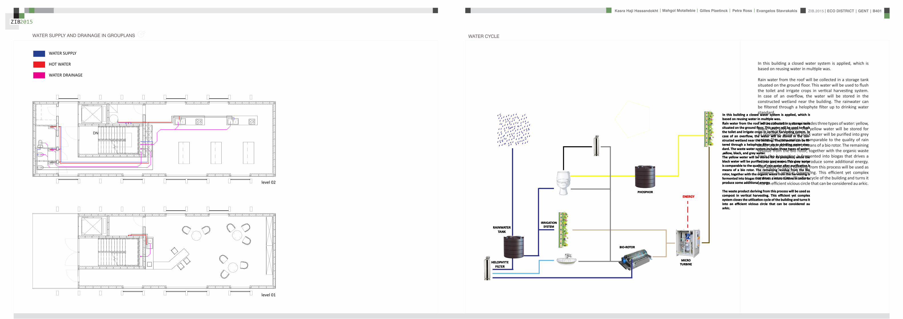
ZIB2015 ECO DISTRICT | GENT | B401Evangelos Stavrakakis | Petra Ross | Mahgol Motallebie | Gilles Plaetinck | Kasra Haji Hassandokht
ZIB2015
|
CALCULATIONS
Passive House verification
Photo or Drawing
Building Workshop + info pointStreet
PostcodeCityCountry
Building Type non-residentialClimate Ukkel
Home Owner(s) Client(s)Street
PostcodeCity
ArchitectStreet
PostcodeCity Calculation electricity Internal heat gains
Mechanical System Building type
StreetPostcodeCity Internal heat gains
Year of Construction 2015 Interior Temperature 200 degC Utilisation pattern
Number of Dwelling Units 1 Internal Heat Gains 20 Wm2 Type of values used Fill in worksheet IHG Non-Dom Enclosed Volume Ve 12442 Planned number of occupants
Number of Occupants 80 8 Design
Specific building demands with reference to the treated floor area use Annual method
Treated floor area 2840 msup2 Requirements Fulfilled Verification Annual method The monthly method should be used for building certification
Space heating Annual heating demand 10 kWh(m2a) 15 kWh(msup2a) yes Specific space heating demand annual method 103 kWh(msup2a)
Heating load 11 Wm2 10 Wmsup2 - Specific space heating demand monthly Method 120 kWh(msup2a)
Space cooling Overall specific space cooling demand kWh(m2a) 15 kWh(msup2a)
Cooling load Wm2 - -Frequency of overheating (gt 25 degC) - -
Primary Energy Space heating and dehumidification
cooling household electricity 73 kWh(m2a) 120 kWh(msup2a) yes
DHW space heating and auxiliary electricity 24 kWh(m2a) - -Specific primary energy reduction through solar electricity 21 kWh(m2a) - -
Airtightness Pressurization test result n50 06 1h 06 1h yes
PHPP Verification FINAL ZIB FILE CALCULTIONS PHPPxls
L B H VOLUME
main 1 226 7 4 6328main 2 184 7 35 4508
core 0 6 2 5 3 5 108 5core 0 62 5 35 1085core 3 62 3 28 521
12442
AREAmain 1 storage 35
wc big 35wc 2wc 2workshop 103
MAIN 2 infolounge 92
staircase 56storage technical 22
284
Floor_exterior 1582 31 1272
Roof_exterior 1582
Passive House verification
Photo or Drawing
Building Workshop + info pointStreet
PostcodeCityCountry
Building Type non-residentialClimate Ukkel
Home Owner(s) Client(s)Street
PostcodeCity
ArchitectStreet
PostcodeCity Calculation electricity Internal heat gains
Mechanical System Building type
StreetPostcodeCity Internal heat gains
Year of Construction 2015 Interior Temperature 200 degC Utilisation pattern
Number of Dwelling Units 1 Internal Heat Gains 20 Wm2 Type of values used Fill in worksheet IHG Non-Dom Enclosed Volume Ve 12442 Planned number of occupants
Number of Occupants 80 8 Design
Specific building demands with reference to the treated floor area use Annual method
Treated floor area 2840 msup2 Requirements Fulfilled Verification Annual method The monthly method should be used for building certification
Space heating Annual heating demand 10 kWh(m2a) 15 kWh(msup2a) yes Specific space heating demand annual method 103 kWh(msup2a)
Heating load 11 Wm2 10 Wmsup2 - Specific space heating demand monthly Method 120 kWh(msup2a)
Space cooling Overall specific space cooling demand kWh(m2a) 15 kWh(msup2a)
Cooling load Wm2 - -Frequency of overheating (gt 25 degC) - -
Primary Energy Space heating and dehumidification
cooling household electricity 73 kWh(m2a) 120 kWh(msup2a) yes
DHW space heating and auxiliary electricity 24 kWh(m2a) - -Specific primary energy reduction through solar electricity 21 kWh(m2a) - -
Airtightness Pressurization test result n50 06 1h 06 1h yes
PHPP Verification FINAL ZIB FILE CALCULTIONS PHPPxls
SURFACE AREAcurrent orientation only night ventilation
current orientation only night ventilation 6 windows less 52 msup2
current orientation only night ventilation 7 windows less 60msup2 (stays the same for each side)
current orientation only night ventilation 8 windows less 69 msup2
orientation turned 90deg only night ventilation 6 windows less 52 msup2
orientation turned 90deg only night ventilation 7 windows less 60msup2 (window less at SE side)
orientation turned 90deg only night ventilation 8 windows less 69 msup2
-gt orientation turned 90deg only night ventilation 9 windows less 77msup2 (window less at NW side althought theres less overheating in the case of a window less at SE side the heating demand exceeds 15)
CHANGE IN DESIGN
ZIB2015 ECO DISTRICT | GENT | B401Evangelos Stavrakakis | Petra Ross | Mahgol Motallebie | Gilles Plaetinck | Kasra Haji Hassandokht
ZIB2015
|
Passive House verificationS P E C I F I C A N N U A L H E A T I N G D E M A N D
Climate Ukkel Interior Temperature 200 degC
Building Workshop + info point Building TypeUse non-residentialTreated Floor Area ATFA 2840 msup2
per msup2Area U-Value Temp Factor ft Gt Treated Data for heating balance diagram
Building Element Temperature Zone msup2 W(msup2K) kKha kWha Floor Area Losses GainsExterior Wall - Ambient A 5595 0101 100 743 = 4181 1472 Exterior Wall - Ambient 147234373Exterior Wall - Ground B 069 = Exterior Wall - GroundRoofCeiling - Ambient A 1550 0094 100 743 = 1085 382 RoofCeiling - Ambient 381903529Floor slab basement ceiling B 310 0105 069 743 = 167 059 Floor slab basement ceiling 058811509
A 100 =A 100 =
unheated basement X 075 = unheated basementWindows A 1154 0648 100 743 = 5562 1958 Windows 195834732Exterior Door A 100 = Exterior DoorExterior TB (lengthm) A 1169 -0030 100 743 = -259 -091 Thermal Bridge Heat LossPerimeter TB (lengthm) P 069 = 000 not useful heat gains 365267499Ground TB (lengthm) B 069 =
Total of All Building Envelope Areas 8609 ndashndashndashndashndashndashndashndashndashndashndashndashndash- kWh(msup2a) Ventilation 395818713
Transmission Heat Losses QT Total 10736 378Annual Heating Demand 102516636
ATFA Clear Room Height internal gains 100951487msup2 m msup3 passive solar gains 250668423
Ventilation System Effective Air Volume VV 2840 280 = 7952 Thermal bridge credit 091126837Effective Heat Recovery Efficiency eff 81 Cross check sum 46324923 46324923of Heat Recovery
Efficiency of Subsoil Heat Exchanger SHX 0 nVsystem HR nVRes
1h 1h 1h
Energetically Effective Air Exchange nV 0105 (1 - 081 ) + 0038 = 0058
VV nV cAir Gt
msup3 1h Wh(msup3K) kKha kWha kWh(msup2a)
Ventilation Heat Losses QV 795 0058 033 743 = 1124 40
Reduction Factor QT QV NightWeekend
kWha kWha Saving kWha kWh(msup2a)
Total Heat Losses QL ( 10736 + 1124 ) 10 = 11860 418
Orientation Reduction Factor g-Value Area Radiation HPof the Area See Windows Sheet (perp radiation)
msup2 kWh(msup2a) kWha
1 North 054 050 2700 163 = 11822 East 058 000 440 197 = 03 South 056 050 4860 314 = 42874 West 032 050 3216 254 = 13275 Horizontal 063 050 324 317 = 323
kWh(msup2a)
Available Solar Heat Gains QS Total 7119 251
Length Heat Period Spec Power qI ATFA
khd da Wmsup2 msup2 kWha kWh(msup2a)
Internal Heat Gains QI 0024 209 201 2840 = 2867 101
kWha kWh(msup2a)
Free Heat QF QS + QI = 9986 352
Ratio of Free Heat to Losses QF QL = 084
Utilisation Factor Heat Gains G (1 - ( QF QL )5 ) (1 - ( QF QL )
6 ) = 90kWha kWh(msup2a)
Heat Gains QG G QF = 8949 315
kWha kWh(msup2a)
Annual Heating Demand QH QL - QG = 2911 10
kWh(msup2a) (YesNo)
Limiting Value 15 Requirement met yes
00
147
00
3806000000
196
00
40
37
09
103
101
251
0
5
10
15
20
25
30
35
40
45
50
Losses Gains
Hea
t flo
ws
[kW
h(m
sup2a)]
Heating energy balance
passive solar gains
internal gains
Annual Heating Demand
Thermal bridge credit
not useful heat gains
Ventilation
Exterior Door
Windows
unheated basement
Floor slab basement ceiling
RoofCeiling - Ambient
Exterior Wall - Ground
Exterior Wall - Ambient
Thermal Bridge Heat Loss
HPP Annual Heating Demand FINAL ZIB FILE CALCULTIONS PHPPxls
Passive House verification Passive House verificationS P E C I F I C U S E F U L C O O L I N G D E M A N D S P E C I F I C U S E F U L C O O L I N G D E M A N D
M O N T H L Y M E T H O D M O N T H L Y M E T H O D
(This page displays the sums of the monthly method over the cooling period))Climate Ukkel Interior Temperature Summer 25 degC Climate Ukkel Interior Temperature 25 degC
Building Workshop + info point Building TypeUse non-residential Building Workshop + info point Building TypeUse non-residential
Spec Capacity 60 Wh(msup2K) (Enter in Summer worksheet) Treated Floor Area ATFA 2840 msup2 Treated Floor Area ATFA 284 msup2
per msup2Temperature Zone Area U-Value Mon Red Fac Gt Treated Jan Feb Mar Apr May Jun Jul Aug Sep Oct Nov Dec Year
Building Element msup2 W(msup2K) kKha kWha Floor Area Heating Degree Hours - Ex 168 150 144 121 92 73 57 59 82 109 140 160 136 kKh1 Exterior Wall - Ambient A 5595 0101 100 103 = 5782 Heating Degree Hours - G 126 123 135 120 106 83 63 54 58 71 86 109 113 kKh2 Exterior Wall - Ground B 100 = Losses - Exterior 2553 2286 2189 1838 1393 1117 871 904 1245 1660 2123 2432 20612 kWh3 RoofCeiling - Ambient A 1550 0094 100 103 = 1500 Losses - Ground 41 40 44 39 35 27 21 18 19 23 28 36 370 kWh4 Floor slab basement ceil B 310 0105 100 90 = 294 Losses Summer Ventilatio 67 71 244 372 629 720 880 865 658 499 234 126 5366 kWh5 A 100 = Sum Spec Heat Losses 94 84 87 79 72 66 62 63 68 77 84 91 928 kWhmsup26 A 100 = Solar Load North 44 81 141 212 286 298 298 255 178 116 54 35 1998 kWh7 unheated basement X 075 = Solar Load East 0 0 0 0 0 0 0 0 0 0 0 0 0 kWh8 Windows A 1154 0648 100 103 = 7690 Solar Load South 218 315 464 577 681 644 681 658 532 416 242 171 5601 kWh9 Exterior Door A 100 = Solar Load West 79 125 213 303 385 378 370 347 256 177 91 60 2785 kWh
10 Exterior TB (lengthm) A 1169 -0030 100 103 = -358 Solar Load Horiz 11 21 37 57 79 79 80 69 47 30 14 9 533 kWh11 Perimeter TB (lengthm) P 100 = Solar Load Opaque 3 5 9 13 18 19 19 16 11 7 3 2 126 kWh12 Ground TB (lengthm) B 100 = Internal Heat Gains 425 384 425 411 425 411 425 425 411 425 411 425 5001 kWh
ndashndashndashndashndashndashndashndashndashndashndash kWh(msup2a) Sum Spec Loads Solar + 28 33 45 55 66 64 66 62 51 41 29 25 565 kWhmsup2
Transmission Losses QT (Negative Heat Loads) Total 14907 525 Utilisation Factor Losses 29 39 52 69 84 88 82 88 73 53 34 27 58Useful Cooling Energy Dem 0 0 4 30 142 192 417 192 40 4 0 0 1021 kWh
ATFA Clear Room Height Spec Cooling Demand 00 00 00 01 05 07 15 07 01 00 00 00 36 kWhmsup2Effective msup2 m msup3
Air Volume VV 284 280 = 795
Heat Transfer Coef Gt
WK kKha kWha kWh(msup2a)
Exterior 99 103 = 1013 36Ground 00 105 = 0 00
Additional Summer Ventilation
Select X Window Night Ventilation Manual Corresponding Air Change Rate 136 1h
Mechanical Automatically Controlled Ventilation (for window ventilation at 1 K temperature difference indoor - outdoor)
Minimum Acceptable Indoor Temperatu 220 degC
kWha kWh(msup2a)
Heat Losses Summer Ventilation 5172 182
QLext QLground QLsummer
kWha kWha kWha kWha kWh(msup2a)
Ventilation Heat Losses QV 1013 + 0 + 5172 = 6185 218
2
3
4
5
6
7
8
9
10
Spec
ific
loss
es l
oads
l c
oolin
g de
man
d [k
Wh
(msup2 m
onth
)] Spec Cooling Demand Sum Spec Heat Losses Sum Spec Loads Solar + Internal
QT QV
kWha kWha kWha kWh(msup2a)
Total Heat Losses QL 14907 + 6185 = 21092 743
Orientation Reduction Factor g-Value Area Global Radiationof the Area (perp radiation)
msup2 kWh(msup2a) kWha
1 North 031 050 270 462 = 19182 East 061 000 44 578 = 0 Temperature Amplitude Summer 82 K3 South 030 050 486 707 = 52114 West 025 050 322 654 = 2646 Month 1 2 3 4 5 6 7 8 9 10 11 12 Annual Total5 Horizontal 035 050 32 913 = 513 Days 31 28 31 30 31 30 31 31 30 31 30 31 3656 Sum Opaque Areas 121 Ambient Temp 250 270 572 828 1275 1487 1737 1707 1369 1039 568 356 96
kWh(msup2a) North Radiation 106 195 329 494 667 697 712 599 419 275 129 87 471
Available Solar Heat Gains QS Total 10409 367 East Radiation 146 266 452 698 937 940 988 851 574 382 179 123 654
South Radiation 311 440 645 786 912 858 898 885 733 579 341 241 763Length Heat Period Spec Power qI ATFA West Radiation 155 261 471 707 926 926 896 819 580 382 183 116 642
khd da Wmsup2 msup2 kWha kWh(msup2a) Hori Radiation 200 369 662 1021 1398 1410 1418 1234 842 535 243 156 949
Internal Heat Gains QI 0024 303 20 2840 = 4151 146 Tsky -750 -730 -428 -172 275 487 737 707 369 039 -432 -644 -04
Ground Temp 805 676 686 830 1072 1345 1647 1776 1696 1552 1310 1037 121kWha kWh(msup2a)
Sum Heat Loads QF QS + QI = 14560 513
Ratio of Losses to Free Heat Gains QL QF = 145
Utilisation Factor Heat Losses G = 64kWha kWh(msup2a)
Useful Heat Losses QVn G QL = 13539 477
kWha kWh(msup2a)
Useful Cooling Demand QK QF - QVn = 1021 4
kWh(msup2a) (YesNo)
Limiting Value 15 Requirement met yes
0
1
2
Jan Feb Mar Apr May Jun Jul Aug Sep Oct Nov Dec
usef
u
HPP Cooling FINAL ZIB FILE CALCULTIONS PHPPxls
Passive House verificationS P E C I F I C A N N U A L H E A T I N G D E M A N D
Climate Ukkel Interior Temperature 200 degC
Building Workshop + info point Building TypeUse non-residentialTreated Floor Area ATFA 2840 msup2
per msup2Area U-Value Temp Factor ft Gt Treated Data for heating balance diagram
Building Element Temperature Zone msup2 W(msup2K) kKha kWha Floor Area Losses GainsExterior Wall - Ambient A 5595 0101 100 743 = 4181 1472 Exterior Wall - Ambient 147234373Exterior Wall - Ground B 069 = Exterior Wall - GroundRoofCeiling - Ambient A 1550 0094 100 743 = 1085 382 RoofCeiling - Ambient 381903529Floor slab basement ceiling B 310 0105 069 743 = 167 059 Floor slab basement ceiling 058811509
A 100 =A 100 =
unheated basement X 075 = unheated basementWindows A 1154 0648 100 743 = 5562 1958 Windows 195834732Exterior Door A 100 = Exterior DoorExterior TB (lengthm) A 1169 -0030 100 743 = -259 -091 Thermal Bridge Heat LossPerimeter TB (lengthm) P 069 = 000 not useful heat gains 365267499Ground TB (lengthm) B 069 =
Total of All Building Envelope Areas 8609 ndashndashndashndashndashndashndashndashndashndashndashndashndash- kWh(msup2a) Ventilation 395818713
Transmission Heat Losses QT Total 10736 378Annual Heating Demand 102516636
ATFA Clear Room Height internal gains 100951487msup2 m msup3 passive solar gains 250668423
Ventilation System Effective Air Volume VV 2840 280 = 7952 Thermal bridge credit 091126837Effective Heat Recovery Efficiency eff 81 Cross check sum 46324923 46324923of Heat Recovery
Efficiency of Subsoil Heat Exchanger SHX 0 nVsystem HR nVRes
1h 1h 1h
Energetically Effective Air Exchange nV 0105 (1 - 081 ) + 0038 = 0058
VV nV cAir Gt
msup3 1h Wh(msup3K) kKha kWha kWh(msup2a)
Ventilation Heat Losses QV 795 0058 033 743 = 1124 40
Reduction Factor QT QV NightWeekend
kWha kWha Saving kWha kWh(msup2a)
Total Heat Losses QL ( 10736 + 1124 ) 10 = 11860 418
Orientation Reduction Factor g-Value Area Radiation HPof the Area See Windows Sheet (perp radiation)
msup2 kWh(msup2a) kWha
1 North 054 050 2700 163 = 11822 East 058 000 440 197 = 03 South 056 050 4860 314 = 42874 West 032 050 3216 254 = 13275 Horizontal 063 050 324 317 = 323
kWh(msup2a)
Available Solar Heat Gains QS Total 7119 251
Length Heat Period Spec Power qI ATFA
khd da Wmsup2 msup2 kWha kWh(msup2a)
Internal Heat Gains QI 0024 209 201 2840 = 2867 101
kWha kWh(msup2a)
Free Heat QF QS + QI = 9986 352
Ratio of Free Heat to Losses QF QL = 084
Utilisation Factor Heat Gains G (1 - ( QF QL )5 ) (1 - ( QF QL )
6 ) = 90kWha kWh(msup2a)
Heat Gains QG G QF = 8949 315
kWha kWh(msup2a)
Annual Heating Demand QH QL - QG = 2911 10
kWh(msup2a) (YesNo)
Limiting Value 15 Requirement met yes
00
147
00
3806000000
196
00
40
37
09
103
101
251
0
5
10
15
20
25
30
35
40
45
50
Losses Gains
Hea
t flo
ws
[kW
h(m
sup2a)]
Heating energy balance
passive solar gains
internal gains
Annual Heating Demand
Thermal bridge credit
not useful heat gains
Ventilation
Exterior Door
Windows
unheated basement
Floor slab basement ceiling
RoofCeiling - Ambient
Exterior Wall - Ground
Exterior Wall - Ambient
Thermal Bridge Heat Loss
HPP Annual Heating Demand FINAL ZIB FILE CALCULTIONS PHPPxls
factor 05Wd (ls) 088
nominal diameter 75 mmVERTICAL COLLECTOR sink toilets 3 05 15
sink kitchen 2 08 16Total 5 31factor 05
Wd (ls) 088nominal diameter 75 mm
Toevoerend ROOF SURFACE
horizontal roof surface (msup2) orientation coeff angle (deg) roofcover filter coeff toevoerend
444 1 0 08 09 3197
RAIN WATER USAGE
Type usage ( l usage) persons day frequency usageday yearly usage
toilet use small 3 20 3 180 65700toilet use big 6 20 1 120 43800VERTICAL GARDENING 150 54750TOTAL 450 164250 L year
16425 msup3 year
TOTAL RAINWATER USAGE 450 L dayRELATIVE RAINWATER USAGE 1407 L day100msup2
LEEGSTAND
relative rainwater usage 1407 L day 100 msup2LEEGSTAND 7 relative volume rainwater tank 3 msup3 100 msup2rainwater tank volume 9591 Liter
suggestion 50 msup2 02 m= 10 msup3
SUPPLYtype amount debiet Q total total WW
lsec lsec lsecMAIN LEVEL POTABLE
sink toilet 3 01 03 03sink kitchen 2 01 02 02
Total 5 05 05Gelijktijdigheid 05 05debiet Q (lsec) 025 025
diameter 178 178 cm
type amount debiet Q total total WWlsec lsec lsec
MAIN LEVEL RAIN WATER toilet 3 01 03 0
Total 3 03Gelijktijdigheid 071debiet Q (lsec) 0213
diameter 165 cm
FECALIEumlNtype amount value Total (ls)
COLLECTOR HORIZONTAL toilet 3 2Total 6factor 05
Wd (ls) 122nominal diameter 110 mm
type amount value Total (ls)COLLECTOR VERTICAL toilet 3 2
Total 6factor 05
Wd (ls) 122nominal diameter 110 mm
DRAINtype amount value Total (ls)
HORIZONTAL COLLECTOR sink toilets 3 05 15sink kitchen 2 08 16
Total 5 31
WATER
ZIB2015 ECO DISTRICT | GENT | B401Evangelos Stavrakakis | Petra Ross | Mahgol Motallebie | Gilles Plaetinck | Kasra Haji Hassandokht
ZIB2015
|
Passive House verificationS P E C I F I C S P A C E H E A T I N G L O A D Risk Determination of Group Heating for a Critical Room
Building Workshop + info point Building TypeUse non-residential Workshop room ( 1= Yes 0 = No)
Climate (HL) Ukkel Treated Floor Area ATFA 2840 msup2 Interior Temperature 20 degC Building Satisfies Passive House Criteria 1
Design Temperature Radiation North East South West Horizontal Room floor area 100 msup2 Supply Air per msup2 Living AreaWeather Condition 1 -31 degC 10 10 30 15 20 Wmsup2 Planned ambient air quantity for the room 150 msup3h 150 msup3hmsup2Weather Condition 2 -22 degC 5 5 20 10 10 Wmsup2 Planned ambient air quantities for the remaining rooms -67 msup3hGround Design Temp 68 degC Area U-Value Factor TempDiff 1 TempDiff 2 PT 1 PT 2
Building Element Temperature Zone msup2 W(msup2K) Always 1(except X) K K W W Building Element Temperature Zone msup2 W(msup2K) Always 1
(except X) K Room Trans Loss W
1 Exterior Wall - Ambient A 5595 0101 100 231 or 222 = 1299 or 1249 Aboveground Exterior Wall A 650 010 100 231 = 1512 Exterior Wall - Ground B 100 132 or 132 = or Belowground Exterior Wall B 00 100 132 =3 RoofCeiling - Ambient A 1550 0094 100 231 or 222 = 337 or 324 RoofCeiling D 880 009 100 231 = 1914 Floor slab basement ceiling B 310 0105 100 132 or 132 = 43 or 43 Underground Floor Slab B 00 011 100 132 = 05 A 100 231 or 222 = or A 100 231 =6 A 100 231 or 222 = or A 100 231 =7 unheated basement X 075 231 or 222 = or X 100 231 =8 Windows A 1154 0648 100 231 or 222 = 1728 or 1661 Windows A 480 065 100 231 = 7199 Exterior Door A 100 231 or 222 = or Exterior Door A 100 231 =
10 Exterior TB (lengthm) A 1169 -0030 100 231 or 222 = -80 or -77 Exterior thermal bridges (Lengthm) A 100 231 =11 Perimeter TB (lengthm) P 100 132 or 132 = or Perimeter Thermal Bridges (Lengthm) A 100 231 =12 Ground TB (lengthm) B 100 132 or 132 = or Floor Slab Thermal Bridges (Lengthm) A 50 100 231 =13 HouseDU Partition Wall I 100 30 or 30 = or HouseDU Partition Wall I 200 100 30 =
Transmission Heat Losses PT ndashndashndashndashndashndashndashndashndashndashndashndashndash- ndashndashndashndashndashndashndashndashndashndashndash-
Total = 3328 or 3200 = 1061
ATFA Clear Room HeightVentilation System msup2 m msup3 Risk
Effective Air Volume VV 2840 280 = 795 Enter 1 = Yes 0 = No PTRoom W PSupply Air W Ratio Summand
SHX 1 SHX 2 Transmission Heat Losses 1061 1386 077 -023Efficiency of Heat Recovery HR 81 Heat Recovery Efficiency SHX 0 Efficiency SHX 0 or 0 Concentrated leakages 0 000of the Heat Exchanger Insulation to other rooms better R = 15 msup2KW 1 ( 2 = no thermal contact except door) 050
nVRes (Heating Load) nVsystem HR HR Room is on the ground floor 0 0001h 1h 1h 1h open staircase 0 000
Energetically Effective Air Exchange nV 0094 + 0105 (1- 081 or 081 ) = 0114 or 0114 TOTAL of the Risk Summands 027Ventilation Heating Load PV
VL nL nL cAir TempDiff 1 TempDiff 2 PV 1 PV 2 Interior doors predominantly closed 1 Risk Factor 200msup3 1h 1h Wh(msup3K) K K W W
7952 0114 or 0114 033 231 or 222 = 691 or 664Total Room Risk 89
PL 1 PL 2
Total Heating Load PL W W Appraisal and Advice normally no problemPT + PV = 4019 or 3864
Orientation Area g-Value Reduction Factor Radiation 1 Radiation 2 PS 1 PS 2the Area msup2 (perp radiation) (see Windows worksheet) Wmsup2 Wmsup2 W W
1 North 270 05 05 11 or 6 = 77 or 412 East 44 00 06 8 or 3 = 0 or 03 South 486 05 06 28 or 18 = 378 or 2474 West 322 05 03 19 or 13 = 100 or 685 Horizontal 32 05 06 20 or 10 = 20 or 10
Solar heating power PS Total = 575 or 367
Spec Power ATFA PI 1 PI 2Internal heating power PI Wmsup2 msup2 W W
16 284 = 454 or 454
PG 1 PG 2
Heating power (gains) PG W W
PS + PI = 1029 or 821
PL - PG = 2989 or 3042
Heating Load PH = 3042 W
Specific Heating Load PH ATFA = 107 Wmsup2
Input Max Supply Air Temperature 48 degC degC degC
Max Supply Air Temperature SupplyMax 48 degC Supply Air Temperature Without Heating SupplyMin 156 157
For Comparison Heating Load Transportable by Supply Air PSupply AirMax = 886 W specific 31 Wmsup2
(YesNo)
Supply Air Heating Sufficient No
HPP Heating Load FINAL ZIB FILE CALCULTIONS PHPPxls
Passive House verificationU - V A L U E S O F B U I L D I N G E L E M E N T S
Wedge shaped building element layeBuilding Workshop + info point still air spaces -gt Secondary calculation to th
Assembly No Building assembly description Interior insulation1 Exterior wall x
Heat transfer resistance [msup2KW] interior Rsi 013exterior Rse 004
Area section 1 [W(mK)] Area section 2 (optional) [W(mK)] Area section 3 (optional) [W(mK)] Thickness [mm]
1 hout gevel 0160 17
2 regelwerk hout 0158 30
3 houtvezel celit 4D 0048 18
4 Eurowall 0023 hout FJI beam 0286 140
5 OSB -plaat 0130 15
6 Eurothane G 0023 70
7 Plaster insulating 0100 10
8Percentage of Sec 2 Percentage of Sec 3 Total
26 300
U-Value 0107 W(msup2K)
Assembly No Building assembly description Interior insulation2 Roof x
Heat transfer resistance [msup2KW] interior Rsi 010exterior Rse 004
Area section 1 [W(mK)] Area section 2 (optional) [W(mK)] Area section 3 (optional) [W(mK)] Thickness [mm]Area section 1 [W(mK)] Area section 2 (optional) [W(mK)] Area section 3 (optional) [W(mK)] Thickness [mm]
1 bitumenmembraam 0230 5
23 EPS 0036 70
4 OSB -plaat 0130 18
5 cellulose 0039 hout FJI beam 0286 350
6 OSB -plaat 0130 15
7 regelwerk hout 5 0177 30
8 gipskartonplaat 0290 12
Percentage of Sec 2 Percentage of Sec 3 Total
26 500
U-Value 0094 W(msup2K)
Assembly No Building assembly description Interior insulation3 Floor x
Heat transfer resistance [msup2KW] interior Rsi 017
exterior Rse 004
Area section 1 [W(mK)] Area section 2 (optional) [W(mK)] Area section 3 (optional) [W(mK)] Thickness [mm]
1 PIR dekvloer 0023 5
2 gipskartonplaat 0290 10
3 gespoten pur 0028 100
4 OSB -plaat 0130 15
5 cellulose 0039 hout FJI beam 0286 350
6 houtvezel Celit 4D 0048 15
7 regelwerk hout 6 0149 30
8 afwerking hout 0160 5
Percentage of Sec 2 Percentage of Sec 3 Total
26 530
U-Value 0078 W(msup2K)
PHPP U-Values FINAL ZIB FILE CALCULTIONS PHPPxls
ers and he right
n Secondary Calculation Equivalent Thermal Conductivity of Still Air Spaces
Air Layer Thickness 30 mm Direction of Upwards ha 125 W(msup2K) 016 W(mK)
Heat Flow X Horizontal hr 417 W(msup2K)
(check only one field) Downwards
cm
n
cm
n Secondary Calculation Equivalent Thermal Conductivity of Still Air Spaces
Air Layer Thickness 30 mm
Direction of Upwards ha 08333 W(msup2K) 015 W(mK)Heat Flow Horizontal hr 417 W(msup2K)
(check only one field) X Downwards
cm
PHPP U-Values FINAL ZIB FILE CALCULTIONS PHPPxls
ers and he right
n Secondary Calculation Equivalent Thermal Conductivity of Still Air Spaces
Air Layer Thickness 30 mm Direction of Upwards ha 125 W(msup2K) 016 W(mK)
Heat Flow X Horizontal hr 417 W(msup2K)
(check only one field) Downwards
cm
n
cm
n Secondary Calculation Equivalent Thermal Conductivity of Still Air Spaces
Air Layer Thickness 30 mm
Direction of Upwards ha 08333 W(msup2K) 015 W(mK)Heat Flow Horizontal hr 417 W(msup2K)
(check only one field) X Downwards
cm
PHPP U-Values FINAL ZIB FILE CALCULTIONS PHPPxls
ers and he right
n Secondary Calculation Equivalent Thermal Conductivity of Still Air Spaces
Air Layer Thickness 30 mm Direction of Upwards ha 125 W(msup2K) 016 W(mK)
Heat Flow X Horizontal hr 417 W(msup2K)
(check only one field) Downwards
cm
n
cm
n Secondary Calculation Equivalent Thermal Conductivity of Still Air Spaces
Air Layer Thickness 30 mm
Direction of Upwards ha 08333 W(msup2K) 015 W(mK)Heat Flow Horizontal hr 417 W(msup2K)
(check only one field) X Downwards
cm
PHPP U-Values FINAL ZIB FILE CALCULTIONS PHPPxls
Passive House verificationS U M M E R
Climate Ukkel Interior Temperature 20 degC
Building Workshop + info point Building TypeUse non-residentialTreated Floor Area ATFA 2840 msup2
Spec Capacity 60 WhK pro msup2 TFAOverheating
limit25 degC Area U-Value Red Factor fTSummer HSummer Heat Conductance
Building Element Temperature Zone msup2 W(msup2K)
1 Exterior Wall - Ambien A 5595 0101 100 = 5632 Exterior Wall - Ground B 100 =3 RoofCeiling - Ambient A 1550 0094 100 = 1464 Floor slab basement B 310 0105 100 = 335 A 100 =6 A 100 =7 unheated basement X 075 =8 Windows A 1154 0648 100 = 7489 Exterior Door A 100 =
10 Exterior TB (lengthm) A 1169 -0030 100 = -3511 Perimeter TB (lengthm P 100 =12 Ground TB (lengthm) B 100 =
ndashndashndashndashndashndashndashndashndashndashndashExterior Thermal Transmittance HTe 1422 WK
Ground Thermal Transmittance HTg 33 WK
ATFA Clear Room HeightEffective msup2 m msup3
Heat Recovery Efficiency HR 81 Air Volume VV 2840 280 = 795
SHX Efficiency SHX 0
Summer Ventilation continuous ventilation to provide sufficient indoor air quality
Air Change Rate by Natural (Windows amp Leakages) or Exhaust-Only Mechanical Ventilation Summer 000 1h
Mechanical Ventilation Summer 1h X with HR (check if applicable)
nLnat nVsystem HR nVRest
1h 1h 1h 1h
Energetically Effective Airchange Rate nV 0000 + 0000 (1 - 0808 ) + 0038 = 0038
VV nVequifraction cAir
msup3 1h Wh(msup3K)
Ventilation Transm Ambient HVe 795 0038 033 = 99 WK
Ventilation Transm Ground HVg 795 0000 033 = 00 WK
Additional Summer Ventilation for Cooling Temperature amplitude summer 82 K
Select X Window Night Ventilation Manual Corresponding Air Change Rate 136 1hMechanical Automatically Controlled Ventilation (for window ventilation at 1 K temperature difference indoor - outdoor)
Minimum Acceptable Indoor Temperature 220 degC
Orientation Angle Shading g-Value Area Portion of Glazing Apertureof the Area Factor Factor Dirt (perp radiation)
Summer Summer msup2 msup2
1 North 09 044 095 050 270 82 = 422 East 09 100 095 000 44 71 = 003 South 09 043 095 050 486 82 = 744 West 09 039 095 050 322 76 = 405 Horizontal 09 052 095 050 32 78 = 066 Sum Opaque Areas 03
msup2msup2
Solar Aperture Total 164 006
Specif Power qI ATFA
Wmsup2 msup2 W Wmsup2
Internal Heat Gains QI 201 284 = 571 20
Frequency of Overheating hmax 42 at the overheating limit max = 25 degC
If the frequency over 25degC exceeds 10 additional measures to protect against summer heat waves are necessary
Solar Load Spec Capacity ATFA
kWhd 1k Wh(msup2K) msup2
Daily Temperature Swing due to Solar Load 00 1000 ( 60 284 ) = 00 K
PHPP Summer FINAL ZIB FILE CALCULTIONS PHPPxls
Passive House verification Passive House verificationS P E C I F I C A N N U A L H E A T I N G D E M A N D S P E C I F I C A N N U A L H E A T D E M A N D
M O N T H L Y M E T H O D M O N T H L Y M E T H O D
(This page displays the sums of the monthly method over the heating period)Climate Ukkel Interior Temperature 20 degC Climate Ukkel Interior Temperature 20 degC
Building Workshop + info point Building TypeUse non-residential Building Workshop + info point Building TypeUse non-residentialSpec Capacity 60 Wh(msup2K) (Enter in Summer worksheet) Treated Floor Area ATFA 2840 msup2 Treated Floor Area ATFA 284 msup2
per msup2Temperature Zone Area U-Value Month Red Fac Gt Treated Jan Feb Mar Apr May Jun Jul Aug Sep Oct Nov Dec Year
Building Element msup2 W(msup2K) kKha kWha Floor Area Heating Degree Hours - E 131 117 107 85 54 37 20 22 46 72 104 123 92 kKhExterior Wall - Ambient A 5595 0101 100 78 = 4406 Heating Degree Hours - G 89 89 98 84 69 47 26 17 22 33 50 72 70 kKhExterior Wall - Ground B 100 = Losses - Exterior 2056 1836 1679 1335 856 589 316 350 722 1132 1630 1931 14433 kWhRoofCeiling - Ambient A 1550 0094 100 78 = 1143 Losses - Ground 29 29 32 28 23 15 9 5 7 11 16 23 227 kWhFloor slab basement ceiling B 310 0105 100 54 = 175 Sum Spec Losses 73 66 60 48 31 21 11 13 26 40 58 69 516 kWhmsup2
A 100 = Solar Gains - North 78 142 246 371 500 520 520 445 311 202 94 62 3490 kWhA 100 = Solar Gains - East 0 0 0 0 0 0 0 0 0 0 0 0 0 kWh
unheated basement X 075 = Solar Gains - South 405 583 860 1069 1261 1194 1263 1220 986 771 448 318 10377 kWhWindows A 1154 0648 100 78 = 5861 Solar Gains - West 103 162 275 391 497 489 478 448 331 229 118 77 3597 kWhExterior Door A 100 = Solar Gains - Horiz 20 38 68 104 143 144 145 126 86 55 25 16 968 kWhExterior TB (lengthm) A 1169 -0030 100 78 = -273 Solar Gains - Opaque 3 5 9 13 18 19 19 16 11 7 3 2 126 kWhPerimeter TB (lengthm) P 100 = Internal Heat Gains 425 384 425 411 425 411 425 425 411 425 411 425 5001 kWhGround TB (lengthm) B 100 = Sum Spec Gains Solar + 36 46 66 83 100 98 100 94 75 59 39 32 830 kWhmsup2
ndashndashndashndashndashndashndashndashndashndashndash kWh(msup2a) Utilisation Factor 100 98 84 57 31 22 11 13 34 67 98 100 48Transmission Heat Losses QT Total 11313 398 Annual Heating Demand 1055 580 134 9 0 0 0 0 0 19 564 1057 3419 kWh
Spec Heating Demand 37 20 05 00 00 00 00 00 00 01 20 37 120 kWhmsup2ATFA Clear Room Height
Effective msup2 m msup3
Air Volume VRAX 284 280 = 795
nVsystem SHX HR nVRes nVequifraction
1h 1h 1h
Effective Air Change Rate Ambient nVe 0105 (1- 0 )(1- 081 )+ 0038 = 0058Effective Air Change Rate Ground nVg 0105 0 (1- 081 ) = 0000
VRAX nVequifraction cAir Gt
msup3 1h Wh(msup3K) kKha kWha kWh(msup2a)
Ventilation Losses Ambient QV 795 0058 033 78 = 1185 42
Ventilation Losses Ground QVe 795 0000 033 55 = 0 00ndashndashndashndashndashndashndashndashndashndashndash
Ventilation Heat Losses QV Total 1185 42
Reduction Factor QT QV NightWeekend
kWha kWha Saving kWha kWh(msup2a)
Total Heat Losses QL ( 11313 + 1185 ) 10 = 12497 440
Orientation Reduction Factor g-Value Area Global Radiationof the Area See Windows worksheet (perp radiation)
msup2 kWh(msup2a) kWha
North 054 050 270 208 = 1505East 058 000 44 250 = 0South 056 050 486 398 = 5440West 032 050 322 323 = 1685Horizontal 063 050 32 403 = 411Sum Opaque Areas 55
kWh(msup2a)
Available Solar Heat Gains QS Total 9095 320 Annual Heating Demand Comparison
EN 13790 Monthly Method 3419 kWha 120 kWh(msup2a) Reference to habitable area
Length Heat Period Spec Power qI ATFA PHPP Heating Period Method 2911 kWha 103 kWh(msup2a) Reference to habitable area
khd da Wmsup2 msup2 kWha kWh(msup2a)
Internal Heat Gains QI 0024 242 20 2840 = 3315 117
kWha kWh(msup2a) Month 1 2 3 4 5 6 7 8 9 10 11 12 Annual Total Heating Period Method
Free Heat QF QS + QI = 12411 437 Days 31 28 31 30 31 30 31 31 30 31 30 31 365 209Ambient Temp 250 270 572 828 1275 1487 1737 1707 1369 1039 568 356 96 52
Ratio Free Heat to Losses QF QL = 099 North Radiation 106 195 329 494 667 697 712 599 419 275 129 87 471 163East Radiation 146 266 452 698 937 940 988 851 574 382 179 123 654 197
Utilisation Factor Heat Gains G = 73 South Radiation 311 440 645 786 912 858 898 885 733 579 341 241 763 314kWha kWh(msup2a) West Radiation 155 261 471 707 926 926 896 819 580 382 183 116 642 254
Heat Gains QG G QF = 9078 320 Hori Radiation 200 369 662 1021 1398 1410 1418 1234 842 535 243 156 949 317
Tsky -750 -730 -428 -172 275 487 737 707 369 039 -432 -644 -04kWha kWh(msup2a) Ground Temp 805 676 686 830 1072 1345 1647 1776 1696 1552 1310 1037 121 98
Annual Heating Demand QH QL - QG = 3419 12
kWh(msup2a) (YesNo)
Limiting Value 15 Requirement met yes
0
2
4
6
8
10
12
Jan Feb Mar Apr May Jun Jul Aug Sep Oct Nov Dec
Spec
ific
loss
es g
ains
he
atin
g de
man
d [k
Wh
(msup2 m
onth
)]
Spec Heating Demand Sum Spec Gains Solar + Internal Sum Spec Losses
HPP Monthly Method FINAL ZIB FILE CALCULTIONS PHPPxls
Passive House verification Passive House verificationS P E C I F I C A N N U A L H E A T I N G D E M A N D S P E C I F I C A N N U A L H E A T D E M A N D
M O N T H L Y M E T H O D M O N T H L Y M E T H O D
(This page displays the sums of the monthly method over the heating period)Climate Ukkel Interior Temperature 20 degC Climate Ukkel Interior Temperature 20 degC
Building Workshop + info point Building TypeUse non-residential Building Workshop + info point Building TypeUse non-residentialSpec Capacity 60 Wh(msup2K) (Enter in Summer worksheet) Treated Floor Area ATFA 2840 msup2 Treated Floor Area ATFA 284 msup2
per msup2Temperature Zone Area U-Value Month Red Fac Gt Treated Jan Feb Mar Apr May Jun Jul Aug Sep Oct Nov Dec Year
Building Element msup2 W(msup2K) kKha kWha Floor Area Heating Degree Hours - E 131 117 107 85 54 37 20 22 46 72 104 123 92 kKhExterior Wall - Ambient A 5595 0101 100 78 = 4406 Heating Degree Hours - G 89 89 98 84 69 47 26 17 22 33 50 72 70 kKhExterior Wall - Ground B 100 = Losses - Exterior 2056 1836 1679 1335 856 589 316 350 722 1132 1630 1931 14433 kWhRoofCeiling - Ambient A 1550 0094 100 78 = 1143 Losses - Ground 29 29 32 28 23 15 9 5 7 11 16 23 227 kWhFloor slab basement ceiling B 310 0105 100 54 = 175 Sum Spec Losses 73 66 60 48 31 21 11 13 26 40 58 69 516 kWhmsup2
A 100 = Solar Gains - North 78 142 246 371 500 520 520 445 311 202 94 62 3490 kWhA 100 = Solar Gains - East 0 0 0 0 0 0 0 0 0 0 0 0 0 kWh
unheated basement X 075 = Solar Gains - South 405 583 860 1069 1261 1194 1263 1220 986 771 448 318 10377 kWhWindows A 1154 0648 100 78 = 5861 Solar Gains - West 103 162 275 391 497 489 478 448 331 229 118 77 3597 kWhExterior Door A 100 = Solar Gains - Horiz 20 38 68 104 143 144 145 126 86 55 25 16 968 kWhExterior TB (lengthm) A 1169 -0030 100 78 = -273 Solar Gains - Opaque 3 5 9 13 18 19 19 16 11 7 3 2 126 kWhPerimeter TB (lengthm) P 100 = Internal Heat Gains 425 384 425 411 425 411 425 425 411 425 411 425 5001 kWhGround TB (lengthm) B 100 = Sum Spec Gains Solar + 36 46 66 83 100 98 100 94 75 59 39 32 830 kWhmsup2
ndashndashndashndashndashndashndashndashndashndashndash kWh(msup2a) Utilisation Factor 100 98 84 57 31 22 11 13 34 67 98 100 48Transmission Heat Losses QT Total 11313 398 Annual Heating Demand 1055 580 134 9 0 0 0 0 0 19 564 1057 3419 kWh
Spec Heating Demand 37 20 05 00 00 00 00 00 00 01 20 37 120 kWhmsup2ATFA Clear Room Height
Effective msup2 m msup3
Air Volume VRAX 284 280 = 795
nVsystem SHX HR nVRes nVequifraction
1h 1h 1h
Effective Air Change Rate Ambient nVe 0105 (1- 0 )(1- 081 )+ 0038 = 0058Effective Air Change Rate Ground nVg 0105 0 (1- 081 ) = 0000
VRAX nVequifraction cAir Gt
msup3 1h Wh(msup3K) kKha kWha kWh(msup2a)
Ventilation Losses Ambient QV 795 0058 033 78 = 1185 42
Ventilation Losses Ground QVe 795 0000 033 55 = 0 00ndashndashndashndashndashndashndashndashndashndashndash
Ventilation Heat Losses QV Total 1185 42
Reduction Factor QT QV NightWeekend
kWha kWha Saving kWha kWh(msup2a)
Total Heat Losses QL ( 11313 + 1185 ) 10 = 12497 440
Orientation Reduction Factor g-Value Area Global Radiationof the Area See Windows worksheet (perp radiation)
msup2 kWh(msup2a) kWha
North 054 050 270 208 = 1505East 058 000 44 250 = 0South 056 050 486 398 = 5440West 032 050 322 323 = 1685Horizontal 063 050 32 403 = 411Sum Opaque Areas 55
kWh(msup2a)
Available Solar Heat Gains QS Total 9095 320 Annual Heating Demand Comparison
EN 13790 Monthly Method 3419 kWha 120 kWh(msup2a) Reference to habitable area
Length Heat Period Spec Power qI ATFA PHPP Heating Period Method 2911 kWha 103 kWh(msup2a) Reference to habitable area
khd da Wmsup2 msup2 kWha kWh(msup2a)
Internal Heat Gains QI 0024 242 20 2840 = 3315 117
kWha kWh(msup2a) Month 1 2 3 4 5 6 7 8 9 10 11 12 Annual Total Heating Period Method
Free Heat QF QS + QI = 12411 437 Days 31 28 31 30 31 30 31 31 30 31 30 31 365 209Ambient Temp 250 270 572 828 1275 1487 1737 1707 1369 1039 568 356 96 52
Ratio Free Heat to Losses QF QL = 099 North Radiation 106 195 329 494 667 697 712 599 419 275 129 87 471 163East Radiation 146 266 452 698 937 940 988 851 574 382 179 123 654 197
Utilisation Factor Heat Gains G = 73 South Radiation 311 440 645 786 912 858 898 885 733 579 341 241 763 314kWha kWh(msup2a) West Radiation 155 261 471 707 926 926 896 819 580 382 183 116 642 254
Heat Gains QG G QF = 9078 320 Hori Radiation 200 369 662 1021 1398 1410 1418 1234 842 535 243 156 949 317
Tsky -750 -730 -428 -172 275 487 737 707 369 039 -432 -644 -04kWha kWh(msup2a) Ground Temp 805 676 686 830 1072 1345 1647 1776 1696 1552 1310 1037 121 98
Annual Heating Demand QH QL - QG = 3419 12
kWh(msup2a) (YesNo)
Limiting Value 15 Requirement met yes
0
2
4
6
8
10
12
Jan Feb Mar Apr May Jun Jul Aug Sep Oct Nov Dec
Spec
ific
loss
es g
ains
he
atin
g de
man
d [k
Wh
(msup2 m
onth
)]
Spec Heating Demand Sum Spec Gains Solar + Internal Sum Spec Losses
HPP Monthly Method FINAL ZIB FILE CALCULTIONS PHPPxls
ZIB2015 ECO DISTRICT | GENT | B401Evangelos Stavrakakis | Petra Ross | Mahgol Motallebie | Gilles Plaetinck | Kasra Haji Hassandokht
ZIB2015
|
Passive House verificationV E N T I L A T I O N D A T A
Building Workshop + info point
Treated floor area ATFA msup2 284 (Areas worksheet)
Room height h m 28 (Annual Heating Demand worksheet)
Room ventilation volume (ATFAh) = VV msup3 795 (Annual Heating Demand worksheet)
Type of ventilation systemx Balanced PH ventilation Please Check
Pure extract air
Infiltration air change rate
Wind protection coefficients e and f Several One
Coefficient e for screening class sides sideexposed exposed
No screening 010 003Moderate screening 007 002High screening 004 001Coefficient f 15 20
for Annual Demand for Heating Load
Wind protection coefficient e 004 010Wind protection coefficient f 15 15 Net Air Volume for
Press Test Vn50 Air permeability q50
Air Change Rate at Press Test n50 1h 060 060 1244 msup3 087 msup3(hmsup2)
for Annual Demand for Heating Load
Excess extract air 1h 000 000Infiltration air change rate nVRes 1h 0038 0094
Selection of ventilation data input - ResultsThe PHPP offers two methods for dimensioning the air quantities and choosing the ventilation unit Fresh air or extract air quantities for residential buildings and parameters for ventilation syscan be determined using the standard planning option in the Ventilation sheet The Additional Vent sheet has been created for more complex ventilation systems and allows up to 10 differenFurthermore air quantities can be determined on a room-by-room or zone-by-zone basis Please select your design method here
Extract air Effective heat Specific HeatVentilation unit Heat recovery efficiency design Mean Mean excess recovery power recovery
X Sheet Ventilation (Standard design) (Sheet Ventilation see below) Air exchange Air Change Rate (Extract air system) efficiency Unit input efficiency SHXSheet Extended ventilation (Sheet Additional Vent) msup3h 1h 1h [-] Whmsup3(Multiple ventilation units non-residential buildings) 83 010 000 818 029 00
SHX efficiency SHX 0
PHPP Ventilation FINAL ZIB FILE CALCULTIONS PHPPxls
SHX efficiency SHX 0
PHPP Ventilation FINAL ZIB FILE CALCULTIONS PHPPxls
S T A N D A R D I N P U T F O R B A L A N C E D V E N T I L A T I O NVentilation dimensioning for systems with one ventilation unit
Occupancy msup2P 36Number of occupants P 80Supply air per person msup3(Ph) 30Supply air requirement msup3h 240 BathroomExtract air rooms Kitchen Bathroom (shower only) WC 0Quantity 2 3 0Extract air requirement per room msup3h 60 40 20 20 0Total Extract Air Requirement msup3h 180
Design air flow rate (maximum) msup3h 240
Average air change rate calculationDaily operation Factors referenced to Air flow rate Air change rateduration maximum
Type of operation hd msup3h 1hMaximum 100 240 030Standard 80 077 185 023Basic 40 054 130 016Minimum 120 0 000
Average air flow rate (msup3h) Average air change rate (1h)Average value 035 83 010
Selection of ventilation unit with heat recovery
X Central unit within the thermal envelope
Central unit outside of the thermal envelope Heat recovery Specificefficiency power Application Frost UnitUnit input range protection noise levelHR [Whmsup3] [msup3h] required lt 35dB(A)
Ventilation unit selection 19 mfoAir 350 - Zehnder 084 029 71 - 293 yes no
Conductance value of outdoor air duct W(mK) 0338 See calculation belowLength of outdoor air duct m 08Conductance value of exhaust air duct W(mK) 0338 See calculation belowLength of exhaust air duct m 15 Room Temperature (degC) 20Temperature of mechanical services room degC Av Ambient Temp Heating P (degC) 59(Enter only if the central unit is outside of the thermal envelope) Av Ground Temp (degC) 106
ComfoAir 350 - Zehnder
PHPP Ventilation FINAL ZIB FILE CALCULTIONS PHPPxls
Effective heat recovery efficiency HReff 818
Effective heat recovery efficiency subsoil heat exchangerSHX efficiency SHX
Heat recovery efficiency SHX SHX 0
Secondary calculation Secondary calculation-value supply or ambient air duct -value extract or exhaust air duct
Nominal width 200 mm Nominal width 200 mmInsul Thickness 50 mm Insul Thickness 50 mm
Reflective Please mark with an x Reflective Please mark with an xx Yes x Yes
No NoThermal conductivity 003 W(mK) Thermal conductivity 003 W(mK)Nominal air flow rate 83 msup3h Nominal air flow rate 83 msup3h
14 K 14 KExterior duct diameter 0200 m Exterior duct diameter 0200 m
Exterior diameter 0300 m Exterior diameter 0300 m-Interior 416 W(msup2K) -Interior 416 W(msup2K)
Surface 252 W(msup2K) Surface 252 W(msup2K)-value 0338 W(mK) -value 0338 W(mK)
Surface temperature difference 2002 K Surface temperature difference 2002 K
ComfoAir 350 - Zehnder
PHPP Ventilation FINAL ZIB FILE CALCULTIONS PHPPxls
Passive House verificationR E D U C T I O N F A C T O R S O L A R R A D I A T I O N W I N D O W U - V A L U E
Building Workshop + info point Annual heating demand 10 kWh(msup2a) Heating degree hours
Climate Ukkel 743
Window area orientation
Global radiation (cardinal points)
Shading Dirt
Non-perpendicu-lar incident radiation
Glazing fraction g-Value Reduction factor
for solar radiationWindow
areaWindowU-Value
Glazingarea
Average global
radiation
Transmission losses
Heat gains solar radiation
maximum kWh(msup2a) 075 095 085 m2 W(m2K) m2 kWh(m2a) kWha kWhaNorth 160 081 095 085 0822 050 054 2700 062 222 163 1243 1182East 222 100 095 085 0714 000 058 440 129 31 197 423 0South 321 085 095 085 0822 050 056 4860 062 399 314 2237 4287West 225 053 095 085 0758 050 032 3216 063 244 254 1517 1327Horizontal 317 100 095 085 0780 050 063 324 059 25 317 143 323
Total or Average Value for All Windows 048 049 11540 065 921 5562 7119
Glazing inclination ne 90deg Please check Ug value manually Window rough openings Installed Glazing Frame g-Value U-Value -
SpacerInstallation Results
(unhide cells to make U- amp -values from WinType worksheet visible)
Quan-tity Description Deviation from
north
Angle of inclination from the
horizontal
Orientation Width Heightin Area in the
Areas worksheet
Nr
Select glazing from the WinType
worksheet
Nr
Select window from the WinType
worksheet
NrPerpen-dicular
RadiationGlazing Frames
(centre) spacer (centre)
Left10
Right10
Bottom10
Top10
installation left
installation right
installation bottom
installation top
installation Average value
Window Area
Glazing Area
U-ValueWindow
Glazed Fraction
per Window
Degrees Degrees m m Select Select Select - W(m2K) W(m2K) W(mK) W(mK) W(mK) W(mK) W(mK) W(mK) m2 m2 W(m2K) 3 Door glass 250 90 West 1200 2200 5 2 3 050 049 071 0028 0 0 1 1 0040 79 591 065 755 window_NW 340 90 North 1800 3000 5 2 3 050 049 071 0028 1 1 0 0 0040 270 2218 062 821 window_SW 250 90 West 0600 3000 5 2 3 050 049 071 0028 0 0 1 1 0040 18 109 070 609 window SE 160 90 South 1800 3000 5 2 3 050 049 071 0028 1 1 0 0 0040 486 3992 062 821 Door elev 250 90 West 1800 2200 5 2 3 050 049 071 0028 0 0 1 1 0040 40 316 062 80
2 Door glass 250 90 West 1200 2200 7 2 3 050 049 071 0028 0 0 1 1 0040 53 394 065 751 Door_Ext 70 90 East 1000 2200 7 1 2 000 140 059 0049 0 0 1 1 0005 22 157 129 711 Door elev 250 90 West 1800 2200 7 2 3 050 049 071 0028 0 0 1 1 0040 40 316 062 80
0 0 0
Wall main INTERPANE iplus batimet batiment TA
Wall main
Wall main
Wall main
Wall main
Wall core 0
Wall core 0
Wall core 0
INTERPANE iplus
INTERPANE iplus
INTERPANE iplus
INTERPANE iplus
INTERPANE iplus
Door _wooden
INTERPANE iplus
batimet batiment TA
batimet batiment TA
batimet batiment TA
batimet batiment TA
batimet batiment TA
Wooden frame
batimet batiment TA
0 0 0
2 Door glass 250 90 West 1200 2200 8 2 3 050 049 071 0028 0 0 1 0 0040 53 394 063 751 Door_Ext 70 90 East 1000 2200 8 1 2 000 140 059 0049 0 0 1 0 0005 22 157 129 711 Door elev 250 90 West 1800 2200 8 2 3 050 049 071 0028 0 0 1 0 0040 40 316 060 801 skylight 250 0 Horizontal 1800 1800 6 2 3 050 049 071 0028 0 0 0 0 0000 32 253 059 78
0 0 0
0 0 0
0 0 0
0 0 0
Wall core 3
Wall core 3
Wall core 3
Roof
INTERPANE iplus
Door _wooden
INTERPANE iplus
INTERPANE iplus
batimet batiment TA
Wooden frame
batimet batiment TA
batimet batiment TA
PHPP Windows FINAL ZIB FILE CALCULTIONS PHPPxls
Passive House verificationC A L C U L A T I N G S H A D I N G F A C T O R S
Climate Ukkel
Building Workshop + info point Orientation Glazing area Reduction factor
Latitude 508 deg msup2 rS
North 2218 81East 314 100
South 3992 85West 2437 53
Horizontal 253 100
Quantity Description Deviation from North
Angle of Inclination from the Horizontal
Orientation Glazing width Glazing height Glazing area Height of the shading object
Horizontal distance
Window reveal depth
Distance from glazing edge to
revealOverhang depth
Distance from upper glazing
edge to overhang
Additional shading reduction factor
Horizontal shading reduction factor
Reveal Shading Reduction Factor
Overhang shading reduction factor
Total shading reduction factor
Degrees Degrees m m m m m m m m wG hG AG hHori dHori oReveal dReveal oover dover rother rH rR rO rS
3 Door glass 250 90 West 099 199 59 0060 420 050 100 100 51 515 window_NW 340 90 North 159 279 222 060 0060 100 81 100 811 window_SW 250 90 West 039 279 11 0060 420 050 100 100 58 589 window SE 160 90 South 159 279 399 060 0060 100 85 100 851 Door elev 250 90 West 159 199 32 0060 420 100 100 39 39
2 Door glass 250 90 West 099 199 39 750 420 0060 420 100 26 100 60 161 Door_Ext 70 90 East 081 195 16 0060 1200 100 100 100 27 271 Door elev 250 90 West 159 199 32 750 420 0060 420 26 100 39 10
2 Door glass 250 90 West 099 199 39 0060 100 100 100 1001 Door_Ext 70 90 East 081 195 16 0060 100 100 100 1001 Door elev 250 90 West 159 199 32 0060 100 100 100 1001 skylight 250 0 Horizontal 159 159 25 0060 100 100 100 100
PHPP Shading FINAL ZIB FILE CALCULTIONS PHPPxls
ZIB2015 ECO DISTRICT | GENT | B401Evangelos Stavrakakis | Petra Ross | Mahgol Motallebie | Gilles Plaetinck | Kasra Haji Hassandokht
ZIB2015
|
Passive House verificationS O L A R H O T W A T E R G E N E R A T I O N
Building Workshop + info point Building TypeUse non-residential
Treated Floor Area ATFA 2840 msup2
Solar Fraction with DHW demand including washing and dish-washing
Heating Demand DHW qgDHW 5183 kWha from DHW+Distribution worksheet
Latitude 508 deg from Climate Data worksheet
Selection of collector from list (see below) 8 Selection 8 Vacuum Tube Collector VTC
Solar Collector Area 600 msup2
Deviation from North 180 deg
Angle of Inclination from the Horizontal 45 deg
Height of the Collector Field 05 m
Height of Horizon hHori m
Horizontal Distance aHori m
Additional Reduction Factor Shading rother
Occupancy 80 Persons
Specific Collector Area 08 msup2Pers
Estimated Solar Fraction of DHW Production 49Solar Contribution to Useful Heat 2545 kWha 9 kWh(msup2a)
Secondary Calculation of Storage Losses
Selection of DHW storage from list (see below) 2 Selection Zonneboiler 200
Total Storage Volume 200 litre
Volume Standby Part (above) 60 litre
Volume Solar Part (below) 140 litre
Specific Heat Losses Storage (total) 20 WK
Typical Temperature DHW 60 degC
Room Temperature 20 degC
Storage Heat Losses (Standby Part Only) 24 W
Total Storage Heat Losses 80 W
02
03
04
05
06
07
08
09
10
200
300
400
500
600
700
800
900
1000
Sola
r fra
ctio
n[-]
ion
hea
ting
load
DH
W g
ener
atio
n h
eatin
g lo
ad
co
vere
d by
sol
ar [k
Wh
mon
th]
Monthly Heating Load Covered by Solar
Total Monthly Heating Load DHW Production
Radiation on Tilted Collector Surface
Monthly Solar Fraction
8 Vacuum Tube Collector
Zonneboiler 200
Monthly Solar Fraction January February March April May June July August September October November December
Radiation on Tilted Collector Surface 198 326 535 725 883 835 864 835 643 453 230 153 kWhMonth
Monthly Solar Fraction 018 031 049 064 075 072 074 072 058 042 021 013 -
Total Monthly Heating Load DHW Production 432 432 432 432 432 432 432 432 432 432 432 432 kWhMonth
Monthly Heating Load Covered by Solar 77 133 212 277 325 311 319 310 250 181 92 58 kWhMonth
Selection List Solar Collectors 0 = FR(ta) k1 k2 C Kdir(50deg) Kdfu OutputModule Area
(Aperture)VTC FPC Comments
InsertManufacturer Brief Description - W(msup2K) W(msup2Ksup2) kJ(msup2K) - - kWh(msup2a) msup2 please enter new
1 Brink F3-Q 08 35 00 81 10 4880 20 FPC columns2 BEFORE3 this4 column56 6 Standard Flat Plate Collector 077 35 002 64 09 08 300 2 FPC FK AD7 7 Improved Flat Plate Collector 0854 337 00104 47 097 094 546 26 FPC FK AD AR8 8 Vacuum Tube Collector 062 0395 002 1153 095 09 487 12 VTC FK AD9 RK AD101112 Insert new rows ABOVE this row only in order to maintain the integrity of references
00
01
0
100
January February March April May June July August September October November December
Sola
rad
iati
HPP SolarDHW FINAL ZIB FILE CALCULTIONS PHPPxls
Passive House verificationE F F I C I E N C Y O F H E A T G E N E R A T I O N ( G A S O I L W O O D )
Building Workshop + info point Building TypeUse non-residential
Treated Floor Area ATFA 284 msup2
Covered Fraction of Space Heating Demand (PE Value worksheet) 100
Space Heating Demand + Distribution Losses QH+QHS (DHW+Distribution) 3021 kWh
Solar Fraction for Space Heat Solar H (Separate Calculation) 48
Effective Annual Heating Demand QHWi=QH(1-Solar H) 1571 kWh
Space Heating Demand without Distribution Losses QH (Verification sheet) 2911 kWh
Covered Fraction of DHW Demand (PE Value worksheet) 100
Total Heating Demand of DHW system QgDHW (DHW+Distribution) 5183 kWh
Solar Fraction for DHW Solar DHW (SolarDHW worksheet) 49
Effective DHW Demand QDHWWi=QDHW(1-Solar DHW) 2638 kWh
Boiler Type (Project) oved gas condensing boiler 2
Primary Energy Factor (Data worksheet) 11 kWhkWh
CO2-Emissions Factor (CO2-Equivalent) 250 gkWh
Useful Heat Provided QUse 4209 kWha
Max Heating Power Required for Heating the Building PBH (Heating Load worksheet) 304 kW
Length of the Heating Period tHP 5022 h
Length of DHW Heating Period tDHW 8760 h
Use characteristic values entered (check if appropriate)
Project Data Standard Values Input field
Design Output Pnominal (Rating Plate) 15 kW 15 kW 3
Installation of Boiler (Outdoor 0 Indoor 1) 0 0 1
Input Values (Oil and Gas Boiler) Project Data Standard Values Input field
Boiler Efficiency at 30 Load (Manufacturer) 104 104 99
Boiler Efficiency at Nominal Output 100 (Manufacturer) 95 95 95
Standby Heat Loss Boiler at 70 degC qB70 (Manufacturer) 14 14 20
Improved gas condensing boiler
Average Return Temperature Measured at 30 Load 30 (Manufacturer) 30 degC 30
Input Values (Biomass Heat Generator) Project Data Standard Values Input field
Efficiency of Heat Generator in Basic Cycle GZ (Manufacturer) 60
Efficiency of Heat Generator in Constant Operation SO (Manufacturer) 70
Average Fraction of Heat Output Released to Heating Circuit zHCm (Manufacturer) 04
Temperature Difference Betw Power-On and Power-Off (Manufacturer) K 30 K
For Interior Installations Area of Mechanical Room Ainstall (Project) msup2 0 msup2
Useful Heat Output per Basic Cycle QNGZ (Manufacturer) kWh 225 kWh
Average Power Output of the Heat Generator QNm (Manufacturer) kW 150 kW
Heat generator without pellets conveyor x
Unit with regulation (no fan no starting aid)
Heating energy demand for a basic machine cycle QHEGZ (Manufacturer) kWh kWh kWh
PelSB (Manufacturer) W W W
Utilisation Factor Heat Generator Heating Run hHgK =fk 86Utilisation Factor Heat Generator DHW Run hTWgK =100fTW 87Utilisation Factor Heat Generator DHW amp Heating hgK 87
kWha kWh(msup2a)
Final Energy Demand Space Heating QFinal HE QHwi eHgK 1821Final Energy Demand DHW QFinal DHW QWWwi eTWgK 3030Total Final Energy Demand QFinal QFinalDHW + QFinalHE 4851 171Annual Primary Energy Demand 5336 188
kga kg(msup2a)
Annual CO2-Equivalent Emissions 1213 43
PHPP Boiler FINAL ZIB FILE CALCULTIONS PHPPxls
Passive House verificationS U M M E R V E N T I L A T I O N
Building Workshop + info point Building TypeUse non-residential
Building Volume 795 msup3
Description Day_ NightFraction of Opening Duration 50 50
Climate Boundary ConditionsTemperature Diff Interior - Exterior 4 1 KWind Velocity 1 0 ms
Note for summer night ventilation please set a temperature difference of 1 K and a wind velocity of 0 msotherwise the cooling effects of the night ventilation will be overestimated
Window Group 1Quantity 16Clear Width 180 180 mClear Height 270 270 mTilting Windows XOpening Width (for tilting windows) 0200 0200 m
Window Group 2 (Cross Ventilation)QuantityClear Width mClear Height mTilting WindowsOpening Width (for Tilting Windows) mDifference in Height to Window 1 m
Single-Sided Ventilation 1 - Airflow Volume 0 0 2161 0 0 0 msup3hSingle-Sided Ventilation 2 - Airflow Volume 0 0 0 0 0 0 msup3h
Cross Ventilation Airflow Volume 0 0 2161 0 0 0 msup3hContribution to Air Change Rate 000 000 136 000 000 000 1h
Summary of Summer Ventilation Distribution
Description Ventilation Type Daily Average Air Change Rate
Night time Window Ventilation 136 1hDaytime Window Ventilation 000 1h
1h
PHPP SummVent FINAL ZIB FILE CALCULTIONS PHPPxls
Passive House verificationC O M P R E S S O R C O O L I N G U N I T S
Climate Ukkel Interior Temperature Summer 25 degC
Building Workshop + info point Building TypeUse non-residentialTreated Floor Area ATFA 2840 msup2
ATFA Clear Room HeightEffective msup2 m msup3
Air Volume VV 284 280 = 795
nVsystem HR
1h Efficiency Humidity Rec 1h
Hygrically Effective Mech Air Change Rate Summer 0000 (1 - 80 ) = 0000
nVnat nVRes nNightWindows nNightmechanical
1h 1h 1h 1h
Direct Ambient Air Change Rate Summer 0000 + 0038 + 2603 + 0000 = 2641
Ambient Air Change Rate Summer Total 264 1h
Supply Air Cooling
check as appropriateOnOff Mode (check as appropriate) XMinimum Temperature of Cooling Coil Surface 0 degC
Recirculation Cooling
check as appropriateOnOff Mode (check as appropriate) xMinimum Temperature of Cooling Coil Surface 10 degCVolume Flow Rate 150 msup3h
X Additional Dehumidificationcheck as appropriate
Max Humidity Ratio 12 gkgHumidity Sources 2 g(msup2h)
Humidity Capacity Building 700 g(gkg)msup2
Humidity at Beginning of Cooling Period 8 gkg
X Panel Coolingcheck as appropriate
sensible latent
Useful Cooling Demand 36 00Useful Cooling Demand 00of which Sensible Fraction
Supply Air Cooling kWh(msup2a)
Recirculation Cooling kWh(msup2a)
Dehumidification kWh(msup2a)
Remaining for Panel Cooling 36 kWh(msup2a)
Total 36 00 kWh(msup2a) 1000
Unsatisfied Demand 00 00 kWh(msup2a)
PHPP Cooling Units FINAL ZIB FILE CALCULTIONS PHPPxls
ZIB2015 ECO DISTRICT | GENT | B401Evangelos Stavrakakis | Petra Ross | Mahgol Motallebie | Gilles Plaetinck | Kasra Haji Hassandokht
ZIB2015
|
Passive House verificationBuilding Workshop + info point E L E C T R I C I T Y D E M A N D Non-Domestic Use
Treated Floor Area ATFA 2840 msup2 Window Properties (from Windows worksheet)
Auxiliary Electricity Demand 5103 kWha Shading Dirt FactorNon-
Perpendicular Radiation
Glazing Fraction
Primary Energy Factors North 081 095 085 082Electricity 26 kWhkWh East 100 071
Gas 11 kWhkWh South 085 082
Energy Carrier for DHW 07 kWhkWh West 053 076
Solar Fraction of DHW 49
Marginal Performance Ratio DHW
Room Geometry Input of a Typical Room or Room by Room
Lighting Non-Domestic
Frac
tion
of T
reat
ed
Floo
r Are
a
Roo
m C
ateg
ory
Roo
m C
ateg
ory
Nom
inal
Illu
min
ance
Le
vel
Dev
iatio
n fro
m
Nor
th
Orie
ntat
ion
Ligh
t Tra
nsm
issi
on
Gla
zing
Exis
ting
win
dow
(1
0)
Roo
m D
epth
Roo
m W
idth
Roo
m H
eigh
t
Lint
el H
eigh
t
Win
dow
Wid
th
Day
light
Util
isat
ion
Use
r Dat
a In
stal
led
Ligh
ting
Pow
er
Inst
alle
d Li
ghtin
g Po
wer
(S
tand
ard)
Ligh
ting
Con
trol
Mot
ion
Det
ecto
r w
ithw
ithou
t (1
0)
Util
isat
ion
Hou
rs p
er
Year
[ha
]
Use
r Det
erm
ined
Li
ghtin
g Fu
ll Lo
ad H
ours
Full
Load
Hou
rs o
f Li
ghtin
g
Elec
tric
ity D
eman
d (k
Wh
a)
Spec
Ele
ctric
ity
Dem
and
(kW
h(m
sup2a))
Prim
ary
Ener
gy
Dem
and
(kW
ha)
Room Zone Lux Degrees - m m m m m Wmsup2 Wmsup2 ha ha ha kWha kWh(msup2a) kWha
2 159
workshop room a 18 41 Workshop 500 70 East 50 1 35 105 28 27 100 good 12 120 3 1 Automatic not permanently on
WithMotion 2250 8 80 49 01 128
wc 6 35 WC Sanitary 200 0 0 20 45 28 27 none 12 120 3 1 Automatic not permanently on
WithMotion 2750 8 80 16 01 43
storage 15 34 Kitchen Storage Preparation
300 0 0 40 58 28 27 none 12 120 3 1 Automatic not permanently on
WithMotion 3900 8 80 41 01 106
circulation 1 9 38 Circulation Area 100 70 East 50 1 14 116 28 27 110 good 12 120 3 1 Automatic not permanently on
WithMotion 2750 8 80 25 01 64
technical room 7 39 Storage Services 100 0 0 18 55 28 27 none 12 120 3 1 Automatic not permanently on
WithMotion 2750 3 30 07 00 19
circulation 2 9 38 Circulation Area 100 250 West 50 1 14 116 28 27 110 good 12 120 3 1 Automatic not permanently on
WithMotion 2750 8 80 25 01 64
reception a 9 37 Secondary Areas 100 70 East 50 1 35 38 28 27 36 good 12 120 3 1 Automatic not permanently on
WithMotion 2750 8 80 25 01 64
workshop room b 18 41 Workshop 500 250 West 50 1 35 105 28 27 100 low 12 120 3 1 Automatic not permanently on
WithMotion 2250 8 80 49 01 128
reception b 9 37 Secondary Areas 100 250 West 50 1 35 38 28 27 36 low 12 120 3 1 Automatic not permanently on
WithMotion 2750 8 80 25 01 64
0 0 Manual Without 0 0
Facade with Windows
Ligh
ting
Con
trol
Inpu
t War
ning
00 ManualMotion 00
00 Manual WithoutMotion 00
00 Manual WithoutMotion 00
00 Manual WithoutMotion 00
00 Manual WithoutMotion 00
00 Manual WithoutMotion 00
00 Manual WithoutMotion 00
00 Manual WithoutMotion 00
00 Manual WithoutMotion 00
00 Manual WithoutMotion 00
00 Manual WithoutMotion 00
00 Manual WithoutMotion 00
00 Manual WithoutMotion 00
HPP Electricity Non-Dom FINAL ZIB FILE CALCULTIONS PHPPxls
Office Equipment
Roo
m C
ateg
ory
Roo
m C
ateg
ory
In th
e th
erm
al
enve
lope
(1
0)
Exis
ting
Plan
ned
(1
0)
Qua
ntity
Pow
er R
atin
g (W
)
Util
isat
ion
Hou
rs
per Y
ear (
ha)
rela
tive
abse
ntee
ism
Dur
atio
n of
U
tilis
atio
n in
Ene
rgy
Savi
ng M
ode
(ha
)
Use
ful E
nerg
y(k
Wh
a)
Elec
tric
ity
Dem
and
(kW
ha)
Prim
ary
Ener
gy
Dem
and
(kW
ha)
2 9 20 18PC 1 37 Secondary Areas 1 1 1 80 ( 2750 (1- 09 ) = 22 = 220 57
PC in Energy Saving Mode 1 1 20 2750 09 = 5 = 50 13Monitor 1 1 0 28 ( 0 (1- 0 ) = 0 = 00 0
Monitor in Energy Saving Mode 1 0 20 0 0 = 0 = 00 0PC 2 41 Workshop 1 1 1 80 ( 2250 (1- 0 ) = 180 = 1800 468
PC in Energy Saving Mode 1 1 20 2250 0 = 0 = 00 0Monitor 2 1 0 28 ( 0 (1- 0 ) = 0 = 00 0
Monitor in Energy Saving Mode 1 0 20 0 0 = 0 = 00 0Copier 1 1 400 ( 0 - 0 ) = 0 = 00 0
Copier in Energy Saving Mode 1 1 30 0 = 0 = 00 0Printer 1 2 300 ( 0 - 0 ) = 0 = 00 0
Printer in Energy Saving Mode 1 2 2 0 = 0 = 00 0Server 1 1 100 ( 0 = 0 = 00 0
Server in Energy Saving Mode 1 1 ( 8760 - 0 ) = 0 = 00 0Telephone System 8760 = 0 = 00 0
= 0 = 00 0 = 0 = 00 0 = 0 = 00 0 = 0 = 00 0 = 0 = 00 0
Kitchen Aux Electricity
Roo
m C
ateg
ory
Predominant Utilisation Pattern of
Building
In th
e th
erm
al
enve
lope
(1
0)
Exis
ting
Plan
ned
(1
0)
Util
isat
ion
Day
s pe
r Ye
ar (d
a)
Num
ber o
f Mea
ls
per U
tilis
atio
n D
ay
Nor
m
Con
sum
ptio
n
Use
ful E
nerg
y (k
Wh
a)
Non
-Ele
ctric
Fra
ctio
n
Elec
tric
Frac
tion
Addi
tiona
l D
eman
d
Mar
gina
l Pe
rform
ance
R
atio
Sola
r Fra
ctio
n
Oth
er P
rimar
y En
ergy
Dem
and
(kW
ha)
Elec
tric
ity
Dem
and
(kW
ha)
Prim
ary
Ener
gy
Dem
and
(kW
ha)
8kWh Meal
Cooking 41 Workshop 2 2 250 10 025 = 1250 100 = 12500 32501 kWh
Cover 0 = 0 0Dishwashing 250 10 0 10 = 0 100 = 0 0 0Electricity
Dishwashing 250 10 010 = 0 100 = 00 01 kWhd 0 (1+ 030 ) 120 (1- 049 ) = 0 0
Refrigerating 2 2 365 053 = 387 100 = 3869 1006030 0 100 = 00 0
coffee machine 1 1 250 000 1 100 = 08 2Mixer 1 1 200 000 1 100 = 06 2
0 100 = 00 0vacuum cleaner 1 1 35 020 7 100 = 70 18
0 100 = 00 00 100 = 00 00 100 = 00 0
Total Auxiliary Electricity 5103 1327
Total kWh 0 0 2389 kWha 6210 kWha
Specific Demand 00 00 8 kWh(msup2a) 22 kWh(msup2a)
2389
Hot
Wat
er N
on-
Elec
tric
Dis
hwas
hing
510
Cold Water Connection
HPP Electricity Non-Dom FINAL ZIB FILE CALCULTIONS PHPPxls
Passive House verificationBuilding Workshop + info point A U X I L I A R Y E L E C T R I C I T Y
1 Living Area 284 msup2 Operation Vent System Winter 502 kha Primary Energy Factor - Electricity 26 kWhkWh2 Heating Period 209 d Operation Vent System Summer 374 kha Annual Space Heating Demand 10 kWh(m2a)3 Air Volume 795 msup3 Air Change Rate 010 h-1 Boiler Rated Power 15 kW4 Dwelling Units 1 HH Defrosting HX from -20 degC DHW System Heating Demand 5183 kWha5 Enclosed Volume 1244 msup3 Design Flow Temperature 55 degC
Column Nr 1 2 3 4 5 6 7 8 9 10 11
Application
Use
d
(10
)
With
in th
e Th
erm
al
Env
elop
e (1
0)
Nor
m D
eman
d
Util
izat
ion
Fact
or
Per
iod
of O
pera
tion
Ref
eren
ce S
ize
Elec
tric
ity
Dem
and
(kW
ha)
Ava
ilabl
e as
Inte
rior
Hea
t
Use
d D
urin
g Ti
me
Per
iod
(kh
a)
Inte
rnal
Hea
t So
urce
(W)
Prim
ary
Ener
gy
Dem
and
(kW
ha)
Ventilation SystemWinter Ventilation 1 1 031 Whmsup3 010 h-1 50 kha 7952 msup3 = 130 considered in heat recovery efficiency 337Summer Ventilation 031 Whmsup3 000 h-1 37 kha 7952 msup3 = 0 no summer contribution to IHG 0Defroster HX 1 1 244 W 100 01 kha 1 = 32 10 502 = 6 82Heating System ControlledUncontrolled (10)
Enter the Rated Power of the Pump 36 W 1
Circulation Pump 1 0 36 W 07 50 kha 1 = 134 10 502 = 0 348Boiler Electricity Consumption at 30 Load 40 W
Aux Energy - Heat Boiler 1 0 40 W 1 00 0 35 kha 1 = 14 1 0 5 02 = 0 36Aux Energy Heat Boiler 1 0 40 W 100 035 kha 1 14 10 502 0 36Aux Energy - Wood firedpellet boiler 0 0 Data entries in worksheet Boiler Auxiliary energy demand including possible drinking water product 0 10 502 = 0 0
DHW systemEnter Average Power Consumption of Pump 29 W
Circulation Pump 1 0 29 W 100 55 kha 1 = 160 06 876 = 0 416Enter the Rated Power of the Pump W
Storage Load Pump DHW 1 0 67 W 100 03 kha 1 = 23 10 502 = 0 61Boiler Electricity Consumption at 100 Load 1 W
DHW Boiler Aux Energy 1 0 1 W 100 02 kha 1 = 0 10 502 = 0 0Enter the Rated Power of the Solar DHW Pump 15 W
Solar Aux Electricity 1 0 15 W 100 18 kha 1 = 26 06 876 = 0 68Misc Aux Electricity Misc Aux Electricity 0 0 30 kWha 100 10 1 HH = 0 10 876 = 0 0
Total 519 6 1349
Specific Demand kWh(msup2a) Divide by Living Area 18 47
PHPP Aux Electricity FINAL ZIB FILE CALCULTIONS PHPPxls
ZIB2015
Passive House verificationI N T E R N A L H E A T G A I N S Non-domestic Use
Building Workshop + info point
Utilisation Pattern 201 Wmsup2 217 Wmsup2 Carefully complete the Electricity Non-Dom worksheet
Type of Values Used Manual entry 20 Wmsup2
Calculation Persons 80 P Room Temperature 20 degCInternal Heat TF Area 284 msup2 Heating Period 2092693 da Internal Heat Gains Aux Electricity 63 W
Column Nr
Persons
Sel
ect
Util
isat
ion
Pat
tern
Sel
ect
Act
ivity
of P
erso
nsPlanning with the number
of persons or via floor area of utilisation zone
(planning via area only if the occupancy is available for this
utilisation pattern) PersArea (1 0) N
umbe
r of O
ccup
ants
Floo
r Are
a of
Util
isat
ion
Zone
(msup2)
Ave
rage
Occ
upan
cy
(Per
sons
m
sup2)
Hea
t Em
itted
per
Per
son
(W)
Util
isat
ion
Hou
rs p
er Y
ear
[ha
]
Rel
ativ
e P
rese
nce
Use
d in
Tim
e S
pan
(ha
)
Ave
rage
Hea
t Em
itted
by
Pers
ons
(W)
27 9 18
Persons A 41 Workshop 3 gt10 yr standing or light work 1 planning with of
persons 6 or no standard value 100 2250 100 8760 = 154
Persons B 3 gt10 yr standing or light work 1 Enter of persons
or floor area or no standard value 100 0 100 8760 = 0
Persons C 3 gt10 yr standing or light work 1 Enter of persons
or floor area or no standard value 100 0 100 8760 = 0
Persons D 3 gt10 yr standing or light work 1 Enter of persons
or floor area or no standard value 100 0 100 8760 = 0
Persons E 37 Secondary Areas 2 gt 10 yr sitting 1 planning with of persons 2 or no standard
value 80 2750 010 8760 = 5Persons F 2 gt 10 yr sitting 1 Enter of persons
or floor area or no standard value 80 0 100 8760 = 0
Persons G 2 gt 10 yr sitting 1 Enter of persons or floor area or no standard
value 80 0 100 8760 = 0Evaporation (person specific) 51 -15 2750 010 8760 = -24
ergy
] ity im
eh
a)
Hea
t e
Other
PHPP Calculation Non-residential buildings
Lighting Equipment Aux Electricity
Use
ful E
ne[k
Wh
a]
Ava
ilabi
li
Use
d in
Ti
Per
iod
(kh
Ave
rage
HR
elea
se
Lighting 3850 100 876 = 440Office Applications (Within Therm Envelope) 207 100 876 = 24Cooking (Within Therm Envelope) 625 050 876 = 36Dishwashing (Within Therm Envelope) 0 030 876 = 0Cooling (Within Therm Envelope) 0 100 876 = 0Other (Within Therm Envelope) 8 100 876 = 1Auxiliary Appliances (See Aux Electricity Worksheet) = 6
Heat Loss Due to Cold Water (calculation from column AJ)
ono
ff (1
0) Predominant
Utilisation Pattern of Building
(Data transfered from Electricity Non-Dom
worksheet input kitchen) Num
ber o
f WC
s (u
ser d
ata)
Num
ber o
f WC
s U
se
stan
dard
val
ue fo
r sc
hool
s (X
)
Num
ber o
f WC
s (c
alcu
latio
n va
lue)
T C
old
Wat
er
Tem
p -
Roo
m
Tem
p [K
]
Occ
upie
d D
ays
per Y
ear [
da]
Loss
Day
time
[W]
Loss
Nig
httim
e [W
]
Ava
ilabi
lity
Use
d in
Per
iod
(da
)
Ave
rage
Pow
er
Col
d W
ater
2 8
Cold Water Due to Flushing WC 1 41 Workshop 3 3 -8 250 ( -23 + -11 ) 100 365 = -24
Total W 618Specific Demand Wmsup2 22Heat Available From Internal Sources 209 da kWh(msup2a) 11
PHPP IHG Non-Dom FINAL ZIB FILE CALCULTIONS PHPPxls
Passive House verification Secondary Calculation -Values of Plumbing
H E A T D I S T R I B U T I O N A N D D H W S Y S T E M
Building Workshop + info point Nominal Width 18 mmInsulation Thickness mm
Interior Temperature 20 degC Reflective Please mark with an xBuilding TypeUsenon-residential x Yes
Treated Floor Area ATFA 284 msup2 NoOccupancy 80 Pers Thermal Conductivity 043 W(mK)
Number of Residences 1Annual Heating Demand qHeating 2911 kWha 30 K
Length of Heating Period 209 d Interior Pipe Diameter 001800 mAverage heating load Pave 06 kW Exterior Pipe Diameter 002025 m
Marginal Utilisability of Additional Heat Gains 59 Parts Exterior Pipe Diameter 002025 m
Warm Region Cold Region Total
Space Heat Distribution 1 2 3 Surface 551 W(msup2K)Length of Distribution Pipes LH (Project) 500 m -Value 0350 W(mK)Heat Loss Coefficient per m Pipe (Project) 0350 W(mK) Surface Temperature Difference 29996 K
Temperature of the Room Through Which the Pipes X Mechanical Room 20 degC
Design Flow Temperature dist Flow Design Value 550 degC
Design System heating load Pheating (existcalc) 30 kW
Flow Temperature Control (check) 5000Design Return Temperature R dist-20)+20 450 degCAnnual Heat Emission per m of Plumbing qHL mX) tHeating0024 53 Total 123 kWh(mmiddota)Possible Utilization Factor of Released Heat G 59 -
Annual Losses QHL = LH middot qHL middot (1-G) 109 0 0 109 kWha
Specif Losses qHL = QHL ATFA kWh(msup2a) 04Performance ratio of heat distribution eaHL = ( qH + qHL) qH 104 -
DHW Standard Useful HeatDHW Consumption per Person and Day (60 degC) VDHW (Project or Average Value 25 LitresPd) 120 LitrePersondAverage Cold Water Temperature of the Supply DW Temperature of Drinking Water (10deg) 106 degCDHW Non-Electric Wash and Dish (Electricity worksheet) 0 kWha
Useful Heat - DHW QDHW 2008 kWha
Specif Useful Heat - DHW qDHW = QDHW ATFA kWh(msup2a) 71
DHW Distribution and Storage Warm Region Cold Region Total
Length of Circulation Pipes (Flow + Return) LHS (Project) 15 00 m
Heat Loss Coefficient per m Pipe (Project) 0350 0000 WmK
Temperature of the Room Through Which the Pipes X Mechanical Room 20 00 degC
Design Flow Temperature dist Flow Design Value 600 00 degC
Daily circulation period of operation tdCirc (Project) 120 00 hdDesign Return Temperature R =0875(dist-20)+20 55 3 degCCirculation period of operation per year tCirc = 365 tdCirc 4380 0 haAnnual Heat Released per m of Pipe qZ mX) tCirc 57 0 kWhmaPossible Utilization Factor of Released Heat GDHW =theating365d G 34 0 -
Annual Heat Loss from Circulation Lines QZ = LHS middot qZ middot(1-GDHW) 57 0 57 kWha
Total Length of Individual Pipes LU (Project) 5000 mExterior Pipe Diameter dU_Pipe (Project) 0018 mHeat loss per tap opening qIndividual =(cpH2OVH2O+cpMatVMat)(dist-X) 04557 kWhtap openingAmount of tap openings per year nTap = nPers 3 365 nLU 8760 Tap openings per yearAnnual Heat Loss qU = nTap
qIndividual 3992 kWhaPossible Utilization Factor of Released Heat G_U =theating8760G 34 -
Annual Heat Loss of Individual Pipes QU = qU middot(1-G_U) 2652 2652 kWha
Total 123
Average Heat Released From Storage PS 80 W Secondary Calculation Storage LossesPossible Utilization Factor of Released Heat G_S =theating8760G 34
Annual Heat Losses from Storage QS = PSmiddot8760 khmiddot(1-G_S) 466 466 kWha Specific Heat Losses Storage (total) 25 WK
Total 123 Typical Temperature DHW 60 degC
Total Heat Losses of the DHW System QWL = QZ+QU+QS 3175 kWha Room Temperature 20 degC
Specif Losses of the DHW System qWL = QWL ATFA kWh(msup2a) 112 Total Storage Heat Losses 100 W
Performance ratio DHW-distribution + storage eaWL = (qTWW + qWV) qTWW 2581 -
Total Heating Demand of DHW system QgDHW = QDHW+QWL 5183 kWha
Total Spec Heating Demand of DHW System qgDHW = QgDHW ATFA kWh(msup2a) 183
PHPP DHW+Distribution FINAL ZIB FILE CALCULTIONS PHPPxlsPHPP DHW+Distribution FINAL ZIB FILE CALCULTIONS PHPPxls
Passive House verification Secondary Calculation -Values of Plumbing
H E A T D I S T R I B U T I O N A N D D H W S Y S T E M
Building Workshop + info point Nominal Width 18 mmInsulation Thickness mm
Interior Temperature 20 degC Reflective Please mark with an xBuilding TypeUsenon-residential x Yes
Treated Floor Area ATFA 284 msup2 NoOccupancy 80 Pers Thermal Conductivity 043 W(mK)
Number of Residences 1Annual Heating Demand qHeating 2911 kWha 30 K
Length of Heating Period 209 d Interior Pipe Diameter 001800 mAverage heating load Pave 06 kW Exterior Pipe Diameter 002025 m
Marginal Utilisability of Additional Heat Gains 59 Parts Exterior Pipe Diameter 002025 m
Warm Region Cold Region Total
Space Heat Distribution 1 2 3 Surface 551 W(msup2K)Length of Distribution Pipes LH (Project) 500 m -Value 0350 W(mK)Heat Loss Coefficient per m Pipe (Project) 0350 W(mK) Surface Temperature Difference 29996 K
Temperature of the Room Through Which the Pipes X Mechanical Room 20 degC
Design Flow Temperature dist Flow Design Value 550 degC
Design System heating load Pheating (existcalc) 30 kW
Flow Temperature Control (check) 5000Design Return Temperature R dist-20)+20 450 degCAnnual Heat Emission per m of Plumbing qHL mX) tHeating0024 53 Total 123 kWh(mmiddota)Possible Utilization Factor of Released Heat G 59 -
Annual Losses QHL = LH middot qHL middot (1-G) 109 0 0 109 kWha
Specif Losses qHL = QHL ATFA kWh(msup2a) 04Performance ratio of heat distribution eaHL = ( qH + qHL) qH 104 -
DHW Standard Useful HeatDHW Consumption per Person and Day (60 degC) VDHW (Project or Average Value 25 LitresPd) 120 LitrePersondAverage Cold Water Temperature of the Supply DW Temperature of Drinking Water (10deg) 106 degCDHW Non-Electric Wash and Dish (Electricity worksheet) 0 kWha
Useful Heat - DHW QDHW 2008 kWha
Specif Useful Heat - DHW qDHW = QDHW ATFA kWh(msup2a) 71
DHW Distribution and Storage Warm Region Cold Region Total
Length of Circulation Pipes (Flow + Return) LHS (Project) 15 00 m
Heat Loss Coefficient per m Pipe (Project) 0350 0000 WmK
Temperature of the Room Through Which the Pipes X Mechanical Room 20 00 degC
Design Flow Temperature dist Flow Design Value 600 00 degC
Daily circulation period of operation tdCirc (Project) 120 00 hdDesign Return Temperature R =0875(dist-20)+20 55 3 degCCirculation period of operation per year tCirc = 365 tdCirc 4380 0 haAnnual Heat Released per m of Pipe qZ mX) tCirc 57 0 kWhmaPossible Utilization Factor of Released Heat GDHW =theating365d G 34 0 -
Annual Heat Loss from Circulation Lines QZ = LHS middot qZ middot(1-GDHW) 57 0 57 kWha
Total Length of Individual Pipes LU (Project) 5000 mExterior Pipe Diameter dU_Pipe (Project) 0018 mHeat loss per tap opening qIndividual =(cpH2OVH2O+cpMatVMat)(dist-X) 04557 kWhtap openingAmount of tap openings per year nTap = nPers 3 365 nLU 8760 Tap openings per yearAnnual Heat Loss qU = nTap
qIndividual 3992 kWhaPossible Utilization Factor of Released Heat G_U =theating8760G 34 -
Annual Heat Loss of Individual Pipes QU = qU middot(1-G_U) 2652 2652 kWha
Total 123
Average Heat Released From Storage PS 80 W Secondary Calculation Storage LossesPossible Utilization Factor of Released Heat G_S =theating8760G 34
Annual Heat Losses from Storage QS = PSmiddot8760 khmiddot(1-G_S) 466 466 kWha Specific Heat Losses Storage (total) 25 WK
Total 123 Typical Temperature DHW 60 degC
Total Heat Losses of the DHW System QWL = QZ+QU+QS 3175 kWha Room Temperature 20 degC
Specif Losses of the DHW System qWL = QWL ATFA kWh(msup2a) 112 Total Storage Heat Losses 100 W
Performance ratio DHW-distribution + storage eaWL = (qTWW + qWV) qTWW 2581 -
Total Heating Demand of DHW system QgDHW = QDHW+QWL 5183 kWha
Total Spec Heating Demand of DHW System qgDHW = QgDHW ATFA kWh(msup2a) 183
PHPP DHW+Distribution FINAL ZIB FILE CALCULTIONS PHPPxlsPHPP DHW+Distribution FINAL ZIB FILE CALCULTIONS PHPPxls
Passive House verification Secondary Calculation -Values of Plumbing
H E A T D I S T R I B U T I O N A N D D H W S Y S T E M
Building Workshop + info point Nominal Width 18 mmInsulation Thickness mm
Interior Temperature 20 degC Reflective Please mark with an xBuilding TypeUsenon-residential x Yes
Treated Floor Area ATFA 284 msup2 NoOccupancy 80 Pers Thermal Conductivity 043 W(mK)
Number of Residences 1Annual Heating Demand qHeating 2911 kWha 30 K
Length of Heating Period 209 d Interior Pipe Diameter 001800 mAverage heating load Pave 06 kW Exterior Pipe Diameter 002025 m
Marginal Utilisability of Additional Heat Gains 59 Parts Exterior Pipe Diameter 002025 m
Warm Region Cold Region Total
Space Heat Distribution 1 2 3 Surface 551 W(msup2K)Length of Distribution Pipes LH (Project) 500 m -Value 0350 W(mK)Heat Loss Coefficient per m Pipe (Project) 0350 W(mK) Surface Temperature Difference 29996 K
Temperature of the Room Through Which the Pipes X Mechanical Room 20 degC
Design Flow Temperature dist Flow Design Value 550 degC
Design System heating load Pheating (existcalc) 30 kW
Flow Temperature Control (check) 5000Design Return Temperature R dist-20)+20 450 degCAnnual Heat Emission per m of Plumbing qHL mX) tHeating0024 53 Total 123 kWh(mmiddota)Possible Utilization Factor of Released Heat G 59 -
Annual Losses QHL = LH middot qHL middot (1-G) 109 0 0 109 kWha
Specif Losses qHL = QHL ATFA kWh(msup2a) 04Performance ratio of heat distribution eaHL = ( qH + qHL) qH 104 -
DHW Standard Useful HeatDHW Consumption per Person and Day (60 degC) VDHW (Project or Average Value 25 LitresPd) 120 LitrePersondAverage Cold Water Temperature of the Supply DW Temperature of Drinking Water (10deg) 106 degCDHW Non-Electric Wash and Dish (Electricity worksheet) 0 kWha
Useful Heat - DHW QDHW 2008 kWha
Specif Useful Heat - DHW qDHW = QDHW ATFA kWh(msup2a) 71
DHW Distribution and Storage Warm Region Cold Region Total
Length of Circulation Pipes (Flow + Return) LHS (Project) 15 00 m
Heat Loss Coefficient per m Pipe (Project) 0350 0000 WmK
Temperature of the Room Through Which the Pipes X Mechanical Room 20 00 degC
Design Flow Temperature dist Flow Design Value 600 00 degC
Daily circulation period of operation tdCirc (Project) 120 00 hdDesign Return Temperature R =0875(dist-20)+20 55 3 degCCirculation period of operation per year tCirc = 365 tdCirc 4380 0 haAnnual Heat Released per m of Pipe qZ mX) tCirc 57 0 kWhmaPossible Utilization Factor of Released Heat GDHW =theating365d G 34 0 -
Annual Heat Loss from Circulation Lines QZ = LHS middot qZ middot(1-GDHW) 57 0 57 kWha
Total Length of Individual Pipes LU (Project) 5000 mExterior Pipe Diameter dU_Pipe (Project) 0018 mHeat loss per tap opening qIndividual =(cpH2OVH2O+cpMatVMat)(dist-X) 04557 kWhtap openingAmount of tap openings per year nTap = nPers 3 365 nLU 8760 Tap openings per yearAnnual Heat Loss qU = nTap
qIndividual 3992 kWhaPossible Utilization Factor of Released Heat G_U =theating8760G 34 -
Annual Heat Loss of Individual Pipes QU = qU middot(1-G_U) 2652 2652 kWha
Total 123
Average Heat Released From Storage PS 80 W Secondary Calculation Storage LossesPossible Utilization Factor of Released Heat G_S =theating8760G 34
Annual Heat Losses from Storage QS = PSmiddot8760 khmiddot(1-G_S) 466 466 kWha Specific Heat Losses Storage (total) 25 WK
Total 123 Typical Temperature DHW 60 degC
Total Heat Losses of the DHW System QWL = QZ+QU+QS 3175 kWha Room Temperature 20 degC
Specif Losses of the DHW System qWL = QWL ATFA kWh(msup2a) 112 Total Storage Heat Losses 100 W
Performance ratio DHW-distribution + storage eaWL = (qTWW + qWV) qTWW 2581 -
Total Heating Demand of DHW system QgDHW = QDHW+QWL 5183 kWha
Total Spec Heating Demand of DHW System qgDHW = QgDHW ATFA kWh(msup2a) 183
PHPP DHW+Distribution FINAL ZIB FILE CALCULTIONS PHPPxlsPHPP DHW+Distribution FINAL ZIB FILE CALCULTIONS PHPPxls
ZERO IMPACT BUILDING MA (SCI) ARCHITECTUREKU LEUVEN middot SINT LUCAS GROUP 42 middot GENT copy2015
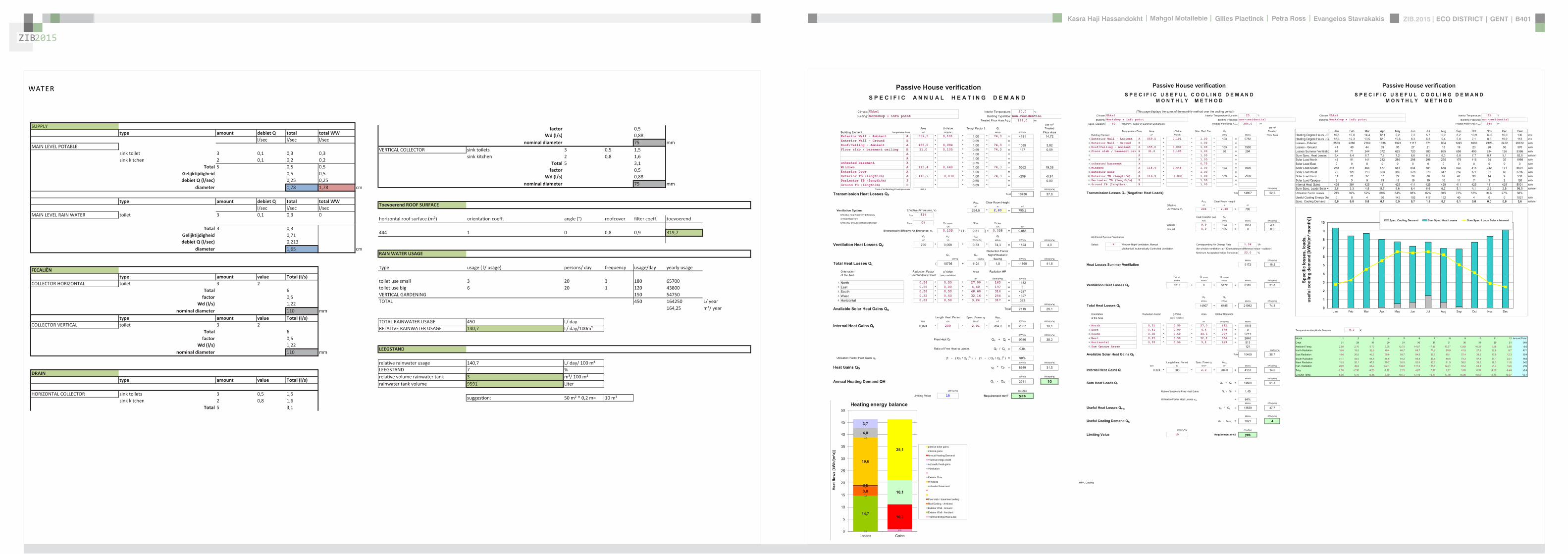
ZIB2015 ECO DISTRICT | GENT | B401Evangelos Stavrakakis | Petra Ross | Mahgol Motallebie | Gilles Plaetinck | Kasra Haji Hassandokht
ZIB2015
|
Passive House verificationS P E C I F I C A N N U A L H E A T I N G D E M A N D
Climate Ukkel Interior Temperature 200 degC
Building Workshop + info point Building TypeUse non-residentialTreated Floor Area ATFA 2840 msup2
per msup2Area U-Value Temp Factor ft Gt Treated Data for heating balance diagram
Building Element Temperature Zone msup2 W(msup2K) kKha kWha Floor Area Losses GainsExterior Wall - Ambient A 5595 0101 100 743 = 4181 1472 Exterior Wall - Ambient 147234373Exterior Wall - Ground B 069 = Exterior Wall - GroundRoofCeiling - Ambient A 1550 0094 100 743 = 1085 382 RoofCeiling - Ambient 381903529Floor slab basement ceiling B 310 0105 069 743 = 167 059 Floor slab basement ceiling 058811509
A 100 =A 100 =
unheated basement X 075 = unheated basementWindows A 1154 0648 100 743 = 5562 1958 Windows 195834732Exterior Door A 100 = Exterior DoorExterior TB (lengthm) A 1169 -0030 100 743 = -259 -091 Thermal Bridge Heat LossPerimeter TB (lengthm) P 069 = 000 not useful heat gains 365267499Ground TB (lengthm) B 069 =
Total of All Building Envelope Areas 8609 ndashndashndashndashndashndashndashndashndashndashndashndashndash- kWh(msup2a) Ventilation 395818713
Transmission Heat Losses QT Total 10736 378Annual Heating Demand 102516636
ATFA Clear Room Height internal gains 100951487msup2 m msup3 passive solar gains 250668423
Ventilation System Effective Air Volume VV 2840 280 = 7952 Thermal bridge credit 091126837Effective Heat Recovery Efficiency eff 81 Cross check sum 46324923 46324923of Heat Recovery
Efficiency of Subsoil Heat Exchanger SHX 0 nVsystem HR nVRes
1h 1h 1h
Energetically Effective Air Exchange nV 0105 (1 - 081 ) + 0038 = 0058
VV nV cAir Gt
msup3 1h Wh(msup3K) kKha kWha kWh(msup2a)
Ventilation Heat Losses QV 795 0058 033 743 = 1124 40
Reduction Factor QT QV NightWeekend
kWha kWha Saving kWha kWh(msup2a)
Total Heat Losses QL ( 10736 + 1124 ) 10 = 11860 418
Orientation Reduction Factor g-Value Area Radiation HPof the Area See Windows Sheet (perp radiation)
msup2 kWh(msup2a) kWha
1 North 054 050 2700 163 = 11822 East 058 000 440 197 = 03 South 056 050 4860 314 = 42874 West 032 050 3216 254 = 13275 Horizontal 063 050 324 317 = 323
kWh(msup2a)
Available Solar Heat Gains QS Total 7119 251
Length Heat Period Spec Power qI ATFA
khd da Wmsup2 msup2 kWha kWh(msup2a)
Internal Heat Gains QI 0024 209 201 2840 = 2867 101
kWha kWh(msup2a)
Free Heat QF QS + QI = 9986 352
Ratio of Free Heat to Losses QF QL = 084
Utilisation Factor Heat Gains G (1 - ( QF QL )5 ) (1 - ( QF QL )
6 ) = 90kWha kWh(msup2a)
Heat Gains QG G QF = 8949 315
kWha kWh(msup2a)
Annual Heating Demand QH QL - QG = 2911 10
kWh(msup2a) (YesNo)
Limiting Value 15 Requirement met yes
00
147
00
3806000000
196
00
40
37
09
103
101
251
0
5
10
15
20
25
30
35
40
45
50
Losses Gains
Hea
t flo
ws
[kW
h(m
sup2a)]
Heating energy balance
passive solar gains
internal gains
Annual Heating Demand
Thermal bridge credit
not useful heat gains
Ventilation
Exterior Door
Windows
unheated basement
Floor slab basement ceiling
RoofCeiling - Ambient
Exterior Wall - Ground
Exterior Wall - Ambient
Thermal Bridge Heat Loss
HPP Annual Heating Demand FINAL ZIB FILE CALCULTIONS PHPPxls
Passive House verification Passive House verificationS P E C I F I C U S E F U L C O O L I N G D E M A N D S P E C I F I C U S E F U L C O O L I N G D E M A N D
M O N T H L Y M E T H O D M O N T H L Y M E T H O D
(This page displays the sums of the monthly method over the cooling period))Climate Ukkel Interior Temperature Summer 25 degC Climate Ukkel Interior Temperature 25 degC
Building Workshop + info point Building TypeUse non-residential Building Workshop + info point Building TypeUse non-residential
Spec Capacity 60 Wh(msup2K) (Enter in Summer worksheet) Treated Floor Area ATFA 2840 msup2 Treated Floor Area ATFA 284 msup2
per msup2Temperature Zone Area U-Value Mon Red Fac Gt Treated Jan Feb Mar Apr May Jun Jul Aug Sep Oct Nov Dec Year
Building Element msup2 W(msup2K) kKha kWha Floor Area Heating Degree Hours - Ex 168 150 144 121 92 73 57 59 82 109 140 160 136 kKh1 Exterior Wall - Ambient A 5595 0101 100 103 = 5782 Heating Degree Hours - G 126 123 135 120 106 83 63 54 58 71 86 109 113 kKh2 Exterior Wall - Ground B 100 = Losses - Exterior 2553 2286 2189 1838 1393 1117 871 904 1245 1660 2123 2432 20612 kWh3 RoofCeiling - Ambient A 1550 0094 100 103 = 1500 Losses - Ground 41 40 44 39 35 27 21 18 19 23 28 36 370 kWh4 Floor slab basement ceil B 310 0105 100 90 = 294 Losses Summer Ventilatio 67 71 244 372 629 720 880 865 658 499 234 126 5366 kWh5 A 100 = Sum Spec Heat Losses 94 84 87 79 72 66 62 63 68 77 84 91 928 kWhmsup26 A 100 = Solar Load North 44 81 141 212 286 298 298 255 178 116 54 35 1998 kWh7 unheated basement X 075 = Solar Load East 0 0 0 0 0 0 0 0 0 0 0 0 0 kWh8 Windows A 1154 0648 100 103 = 7690 Solar Load South 218 315 464 577 681 644 681 658 532 416 242 171 5601 kWh9 Exterior Door A 100 = Solar Load West 79 125 213 303 385 378 370 347 256 177 91 60 2785 kWh
10 Exterior TB (lengthm) A 1169 -0030 100 103 = -358 Solar Load Horiz 11 21 37 57 79 79 80 69 47 30 14 9 533 kWh11 Perimeter TB (lengthm) P 100 = Solar Load Opaque 3 5 9 13 18 19 19 16 11 7 3 2 126 kWh12 Ground TB (lengthm) B 100 = Internal Heat Gains 425 384 425 411 425 411 425 425 411 425 411 425 5001 kWh
ndashndashndashndashndashndashndashndashndashndashndash kWh(msup2a) Sum Spec Loads Solar + 28 33 45 55 66 64 66 62 51 41 29 25 565 kWhmsup2
Transmission Losses QT (Negative Heat Loads) Total 14907 525 Utilisation Factor Losses 29 39 52 69 84 88 82 88 73 53 34 27 58Useful Cooling Energy Dem 0 0 4 30 142 192 417 192 40 4 0 0 1021 kWh
ATFA Clear Room Height Spec Cooling Demand 00 00 00 01 05 07 15 07 01 00 00 00 36 kWhmsup2Effective msup2 m msup3
Air Volume VV 284 280 = 795
Heat Transfer Coef Gt
WK kKha kWha kWh(msup2a)
Exterior 99 103 = 1013 36Ground 00 105 = 0 00
Additional Summer Ventilation
Select X Window Night Ventilation Manual Corresponding Air Change Rate 136 1h
Mechanical Automatically Controlled Ventilation (for window ventilation at 1 K temperature difference indoor - outdoor)
Minimum Acceptable Indoor Temperatu 220 degC
kWha kWh(msup2a)
Heat Losses Summer Ventilation 5172 182
QLext QLground QLsummer
kWha kWha kWha kWha kWh(msup2a)
Ventilation Heat Losses QV 1013 + 0 + 5172 = 6185 218
2
3
4
5
6
7
8
9
10
Spec
ific
loss
es l
oads
l c
oolin
g de
man
d [k
Wh
(msup2 m
onth
)] Spec Cooling Demand Sum Spec Heat Losses Sum Spec Loads Solar + Internal
QT QV
kWha kWha kWha kWh(msup2a)
Total Heat Losses QL 14907 + 6185 = 21092 743
Orientation Reduction Factor g-Value Area Global Radiationof the Area (perp radiation)
msup2 kWh(msup2a) kWha
1 North 031 050 270 462 = 19182 East 061 000 44 578 = 0 Temperature Amplitude Summer 82 K3 South 030 050 486 707 = 52114 West 025 050 322 654 = 2646 Month 1 2 3 4 5 6 7 8 9 10 11 12 Annual Total5 Horizontal 035 050 32 913 = 513 Days 31 28 31 30 31 30 31 31 30 31 30 31 3656 Sum Opaque Areas 121 Ambient Temp 250 270 572 828 1275 1487 1737 1707 1369 1039 568 356 96
kWh(msup2a) North Radiation 106 195 329 494 667 697 712 599 419 275 129 87 471
Available Solar Heat Gains QS Total 10409 367 East Radiation 146 266 452 698 937 940 988 851 574 382 179 123 654
South Radiation 311 440 645 786 912 858 898 885 733 579 341 241 763Length Heat Period Spec Power qI ATFA West Radiation 155 261 471 707 926 926 896 819 580 382 183 116 642
khd da Wmsup2 msup2 kWha kWh(msup2a) Hori Radiation 200 369 662 1021 1398 1410 1418 1234 842 535 243 156 949
Internal Heat Gains QI 0024 303 20 2840 = 4151 146 Tsky -750 -730 -428 -172 275 487 737 707 369 039 -432 -644 -04
Ground Temp 805 676 686 830 1072 1345 1647 1776 1696 1552 1310 1037 121kWha kWh(msup2a)
Sum Heat Loads QF QS + QI = 14560 513
Ratio of Losses to Free Heat Gains QL QF = 145
Utilisation Factor Heat Losses G = 64kWha kWh(msup2a)
Useful Heat Losses QVn G QL = 13539 477
kWha kWh(msup2a)
Useful Cooling Demand QK QF - QVn = 1021 4
kWh(msup2a) (YesNo)
Limiting Value 15 Requirement met yes
0
1
2
Jan Feb Mar Apr May Jun Jul Aug Sep Oct Nov Dec
usef
u
HPP Cooling FINAL ZIB FILE CALCULTIONS PHPPxls
Passive House verificationS P E C I F I C A N N U A L H E A T I N G D E M A N D
Climate Ukkel Interior Temperature 200 degC
Building Workshop + info point Building TypeUse non-residentialTreated Floor Area ATFA 2840 msup2
per msup2Area U-Value Temp Factor ft Gt Treated Data for heating balance diagram
Building Element Temperature Zone msup2 W(msup2K) kKha kWha Floor Area Losses GainsExterior Wall - Ambient A 5595 0101 100 743 = 4181 1472 Exterior Wall - Ambient 147234373Exterior Wall - Ground B 069 = Exterior Wall - GroundRoofCeiling - Ambient A 1550 0094 100 743 = 1085 382 RoofCeiling - Ambient 381903529Floor slab basement ceiling B 310 0105 069 743 = 167 059 Floor slab basement ceiling 058811509
A 100 =A 100 =
unheated basement X 075 = unheated basementWindows A 1154 0648 100 743 = 5562 1958 Windows 195834732Exterior Door A 100 = Exterior DoorExterior TB (lengthm) A 1169 -0030 100 743 = -259 -091 Thermal Bridge Heat LossPerimeter TB (lengthm) P 069 = 000 not useful heat gains 365267499Ground TB (lengthm) B 069 =
Total of All Building Envelope Areas 8609 ndashndashndashndashndashndashndashndashndashndashndashndashndash- kWh(msup2a) Ventilation 395818713
Transmission Heat Losses QT Total 10736 378Annual Heating Demand 102516636
ATFA Clear Room Height internal gains 100951487msup2 m msup3 passive solar gains 250668423
Ventilation System Effective Air Volume VV 2840 280 = 7952 Thermal bridge credit 091126837Effective Heat Recovery Efficiency eff 81 Cross check sum 46324923 46324923of Heat Recovery
Efficiency of Subsoil Heat Exchanger SHX 0 nVsystem HR nVRes
1h 1h 1h
Energetically Effective Air Exchange nV 0105 (1 - 081 ) + 0038 = 0058
VV nV cAir Gt
msup3 1h Wh(msup3K) kKha kWha kWh(msup2a)
Ventilation Heat Losses QV 795 0058 033 743 = 1124 40
Reduction Factor QT QV NightWeekend
kWha kWha Saving kWha kWh(msup2a)
Total Heat Losses QL ( 10736 + 1124 ) 10 = 11860 418
Orientation Reduction Factor g-Value Area Radiation HPof the Area See Windows Sheet (perp radiation)
msup2 kWh(msup2a) kWha
1 North 054 050 2700 163 = 11822 East 058 000 440 197 = 03 South 056 050 4860 314 = 42874 West 032 050 3216 254 = 13275 Horizontal 063 050 324 317 = 323
kWh(msup2a)
Available Solar Heat Gains QS Total 7119 251
Length Heat Period Spec Power qI ATFA
khd da Wmsup2 msup2 kWha kWh(msup2a)
Internal Heat Gains QI 0024 209 201 2840 = 2867 101
kWha kWh(msup2a)
Free Heat QF QS + QI = 9986 352
Ratio of Free Heat to Losses QF QL = 084
Utilisation Factor Heat Gains G (1 - ( QF QL )5 ) (1 - ( QF QL )
6 ) = 90kWha kWh(msup2a)
Heat Gains QG G QF = 8949 315
kWha kWh(msup2a)
Annual Heating Demand QH QL - QG = 2911 10
kWh(msup2a) (YesNo)
Limiting Value 15 Requirement met yes
00
147
00
3806000000
196
00
40
37
09
103
101
251
0
5
10
15
20
25
30
35
40
45
50
Losses Gains
Hea
t flo
ws
[kW
h(m
sup2a)]
Heating energy balance
passive solar gains
internal gains
Annual Heating Demand
Thermal bridge credit
not useful heat gains
Ventilation
Exterior Door
Windows
unheated basement
Floor slab basement ceiling
RoofCeiling - Ambient
Exterior Wall - Ground
Exterior Wall - Ambient
Thermal Bridge Heat Loss
HPP Annual Heating Demand FINAL ZIB FILE CALCULTIONS PHPPxls
factor 05Wd (ls) 088
nominal diameter 75 mmVERTICAL COLLECTOR sink toilets 3 05 15
sink kitchen 2 08 16Total 5 31factor 05
Wd (ls) 088nominal diameter 75 mm
Toevoerend ROOF SURFACE
horizontal roof surface (msup2) orientation coeff angle (deg) roofcover filter coeff toevoerend
444 1 0 08 09 3197
RAIN WATER USAGE
Type usage ( l usage) persons day frequency usageday yearly usage
toilet use small 3 20 3 180 65700toilet use big 6 20 1 120 43800VERTICAL GARDENING 150 54750TOTAL 450 164250 L year
16425 msup3 year
TOTAL RAINWATER USAGE 450 L dayRELATIVE RAINWATER USAGE 1407 L day100msup2
LEEGSTAND
relative rainwater usage 1407 L day 100 msup2LEEGSTAND 7 relative volume rainwater tank 3 msup3 100 msup2rainwater tank volume 9591 Liter
suggestion 50 msup2 02 m= 10 msup3
SUPPLYtype amount debiet Q total total WW
lsec lsec lsecMAIN LEVEL POTABLE
sink toilet 3 01 03 03sink kitchen 2 01 02 02
Total 5 05 05Gelijktijdigheid 05 05debiet Q (lsec) 025 025
diameter 178 178 cm
type amount debiet Q total total WWlsec lsec lsec
MAIN LEVEL RAIN WATER toilet 3 01 03 0
Total 3 03Gelijktijdigheid 071debiet Q (lsec) 0213
diameter 165 cm
FECALIEumlNtype amount value Total (ls)
COLLECTOR HORIZONTAL toilet 3 2Total 6factor 05
Wd (ls) 122nominal diameter 110 mm
type amount value Total (ls)COLLECTOR VERTICAL toilet 3 2
Total 6factor 05
Wd (ls) 122nominal diameter 110 mm
DRAINtype amount value Total (ls)
HORIZONTAL COLLECTOR sink toilets 3 05 15sink kitchen 2 08 16
Total 5 31
WATER
ZIB2015 ECO DISTRICT | GENT | B401Evangelos Stavrakakis | Petra Ross | Mahgol Motallebie | Gilles Plaetinck | Kasra Haji Hassandokht
ZIB2015
|
Passive House verificationS P E C I F I C S P A C E H E A T I N G L O A D Risk Determination of Group Heating for a Critical Room
Building Workshop + info point Building TypeUse non-residential Workshop room ( 1= Yes 0 = No)
Climate (HL) Ukkel Treated Floor Area ATFA 2840 msup2 Interior Temperature 20 degC Building Satisfies Passive House Criteria 1
Design Temperature Radiation North East South West Horizontal Room floor area 100 msup2 Supply Air per msup2 Living AreaWeather Condition 1 -31 degC 10 10 30 15 20 Wmsup2 Planned ambient air quantity for the room 150 msup3h 150 msup3hmsup2Weather Condition 2 -22 degC 5 5 20 10 10 Wmsup2 Planned ambient air quantities for the remaining rooms -67 msup3hGround Design Temp 68 degC Area U-Value Factor TempDiff 1 TempDiff 2 PT 1 PT 2
Building Element Temperature Zone msup2 W(msup2K) Always 1(except X) K K W W Building Element Temperature Zone msup2 W(msup2K) Always 1
(except X) K Room Trans Loss W
1 Exterior Wall - Ambient A 5595 0101 100 231 or 222 = 1299 or 1249 Aboveground Exterior Wall A 650 010 100 231 = 1512 Exterior Wall - Ground B 100 132 or 132 = or Belowground Exterior Wall B 00 100 132 =3 RoofCeiling - Ambient A 1550 0094 100 231 or 222 = 337 or 324 RoofCeiling D 880 009 100 231 = 1914 Floor slab basement ceiling B 310 0105 100 132 or 132 = 43 or 43 Underground Floor Slab B 00 011 100 132 = 05 A 100 231 or 222 = or A 100 231 =6 A 100 231 or 222 = or A 100 231 =7 unheated basement X 075 231 or 222 = or X 100 231 =8 Windows A 1154 0648 100 231 or 222 = 1728 or 1661 Windows A 480 065 100 231 = 7199 Exterior Door A 100 231 or 222 = or Exterior Door A 100 231 =
10 Exterior TB (lengthm) A 1169 -0030 100 231 or 222 = -80 or -77 Exterior thermal bridges (Lengthm) A 100 231 =11 Perimeter TB (lengthm) P 100 132 or 132 = or Perimeter Thermal Bridges (Lengthm) A 100 231 =12 Ground TB (lengthm) B 100 132 or 132 = or Floor Slab Thermal Bridges (Lengthm) A 50 100 231 =13 HouseDU Partition Wall I 100 30 or 30 = or HouseDU Partition Wall I 200 100 30 =
Transmission Heat Losses PT ndashndashndashndashndashndashndashndashndashndashndashndashndash- ndashndashndashndashndashndashndashndashndashndashndash-
Total = 3328 or 3200 = 1061
ATFA Clear Room HeightVentilation System msup2 m msup3 Risk
Effective Air Volume VV 2840 280 = 795 Enter 1 = Yes 0 = No PTRoom W PSupply Air W Ratio Summand
SHX 1 SHX 2 Transmission Heat Losses 1061 1386 077 -023Efficiency of Heat Recovery HR 81 Heat Recovery Efficiency SHX 0 Efficiency SHX 0 or 0 Concentrated leakages 0 000of the Heat Exchanger Insulation to other rooms better R = 15 msup2KW 1 ( 2 = no thermal contact except door) 050
nVRes (Heating Load) nVsystem HR HR Room is on the ground floor 0 0001h 1h 1h 1h open staircase 0 000
Energetically Effective Air Exchange nV 0094 + 0105 (1- 081 or 081 ) = 0114 or 0114 TOTAL of the Risk Summands 027Ventilation Heating Load PV
VL nL nL cAir TempDiff 1 TempDiff 2 PV 1 PV 2 Interior doors predominantly closed 1 Risk Factor 200msup3 1h 1h Wh(msup3K) K K W W
7952 0114 or 0114 033 231 or 222 = 691 or 664Total Room Risk 89
PL 1 PL 2
Total Heating Load PL W W Appraisal and Advice normally no problemPT + PV = 4019 or 3864
Orientation Area g-Value Reduction Factor Radiation 1 Radiation 2 PS 1 PS 2the Area msup2 (perp radiation) (see Windows worksheet) Wmsup2 Wmsup2 W W
1 North 270 05 05 11 or 6 = 77 or 412 East 44 00 06 8 or 3 = 0 or 03 South 486 05 06 28 or 18 = 378 or 2474 West 322 05 03 19 or 13 = 100 or 685 Horizontal 32 05 06 20 or 10 = 20 or 10
Solar heating power PS Total = 575 or 367
Spec Power ATFA PI 1 PI 2Internal heating power PI Wmsup2 msup2 W W
16 284 = 454 or 454
PG 1 PG 2
Heating power (gains) PG W W
PS + PI = 1029 or 821
PL - PG = 2989 or 3042
Heating Load PH = 3042 W
Specific Heating Load PH ATFA = 107 Wmsup2
Input Max Supply Air Temperature 48 degC degC degC
Max Supply Air Temperature SupplyMax 48 degC Supply Air Temperature Without Heating SupplyMin 156 157
For Comparison Heating Load Transportable by Supply Air PSupply AirMax = 886 W specific 31 Wmsup2
(YesNo)
Supply Air Heating Sufficient No
HPP Heating Load FINAL ZIB FILE CALCULTIONS PHPPxls
Passive House verificationU - V A L U E S O F B U I L D I N G E L E M E N T S
Wedge shaped building element layeBuilding Workshop + info point still air spaces -gt Secondary calculation to th
Assembly No Building assembly description Interior insulation1 Exterior wall x
Heat transfer resistance [msup2KW] interior Rsi 013exterior Rse 004
Area section 1 [W(mK)] Area section 2 (optional) [W(mK)] Area section 3 (optional) [W(mK)] Thickness [mm]
1 hout gevel 0160 17
2 regelwerk hout 0158 30
3 houtvezel celit 4D 0048 18
4 Eurowall 0023 hout FJI beam 0286 140
5 OSB -plaat 0130 15
6 Eurothane G 0023 70
7 Plaster insulating 0100 10
8Percentage of Sec 2 Percentage of Sec 3 Total
26 300
U-Value 0107 W(msup2K)
Assembly No Building assembly description Interior insulation2 Roof x
Heat transfer resistance [msup2KW] interior Rsi 010exterior Rse 004
Area section 1 [W(mK)] Area section 2 (optional) [W(mK)] Area section 3 (optional) [W(mK)] Thickness [mm]Area section 1 [W(mK)] Area section 2 (optional) [W(mK)] Area section 3 (optional) [W(mK)] Thickness [mm]
1 bitumenmembraam 0230 5
23 EPS 0036 70
4 OSB -plaat 0130 18
5 cellulose 0039 hout FJI beam 0286 350
6 OSB -plaat 0130 15
7 regelwerk hout 5 0177 30
8 gipskartonplaat 0290 12
Percentage of Sec 2 Percentage of Sec 3 Total
26 500
U-Value 0094 W(msup2K)
Assembly No Building assembly description Interior insulation3 Floor x
Heat transfer resistance [msup2KW] interior Rsi 017
exterior Rse 004
Area section 1 [W(mK)] Area section 2 (optional) [W(mK)] Area section 3 (optional) [W(mK)] Thickness [mm]
1 PIR dekvloer 0023 5
2 gipskartonplaat 0290 10
3 gespoten pur 0028 100
4 OSB -plaat 0130 15
5 cellulose 0039 hout FJI beam 0286 350
6 houtvezel Celit 4D 0048 15
7 regelwerk hout 6 0149 30
8 afwerking hout 0160 5
Percentage of Sec 2 Percentage of Sec 3 Total
26 530
U-Value 0078 W(msup2K)
PHPP U-Values FINAL ZIB FILE CALCULTIONS PHPPxls
ers and he right
n Secondary Calculation Equivalent Thermal Conductivity of Still Air Spaces
Air Layer Thickness 30 mm Direction of Upwards ha 125 W(msup2K) 016 W(mK)
Heat Flow X Horizontal hr 417 W(msup2K)
(check only one field) Downwards
cm
n
cm
n Secondary Calculation Equivalent Thermal Conductivity of Still Air Spaces
Air Layer Thickness 30 mm
Direction of Upwards ha 08333 W(msup2K) 015 W(mK)Heat Flow Horizontal hr 417 W(msup2K)
(check only one field) X Downwards
cm
PHPP U-Values FINAL ZIB FILE CALCULTIONS PHPPxls
ers and he right
n Secondary Calculation Equivalent Thermal Conductivity of Still Air Spaces
Air Layer Thickness 30 mm Direction of Upwards ha 125 W(msup2K) 016 W(mK)
Heat Flow X Horizontal hr 417 W(msup2K)
(check only one field) Downwards
cm
n
cm
n Secondary Calculation Equivalent Thermal Conductivity of Still Air Spaces
Air Layer Thickness 30 mm
Direction of Upwards ha 08333 W(msup2K) 015 W(mK)Heat Flow Horizontal hr 417 W(msup2K)
(check only one field) X Downwards
cm
PHPP U-Values FINAL ZIB FILE CALCULTIONS PHPPxls
ers and he right
n Secondary Calculation Equivalent Thermal Conductivity of Still Air Spaces
Air Layer Thickness 30 mm Direction of Upwards ha 125 W(msup2K) 016 W(mK)
Heat Flow X Horizontal hr 417 W(msup2K)
(check only one field) Downwards
cm
n
cm
n Secondary Calculation Equivalent Thermal Conductivity of Still Air Spaces
Air Layer Thickness 30 mm
Direction of Upwards ha 08333 W(msup2K) 015 W(mK)Heat Flow Horizontal hr 417 W(msup2K)
(check only one field) X Downwards
cm
PHPP U-Values FINAL ZIB FILE CALCULTIONS PHPPxls
Passive House verificationS U M M E R
Climate Ukkel Interior Temperature 20 degC
Building Workshop + info point Building TypeUse non-residentialTreated Floor Area ATFA 2840 msup2
Spec Capacity 60 WhK pro msup2 TFAOverheating
limit25 degC Area U-Value Red Factor fTSummer HSummer Heat Conductance
Building Element Temperature Zone msup2 W(msup2K)
1 Exterior Wall - Ambien A 5595 0101 100 = 5632 Exterior Wall - Ground B 100 =3 RoofCeiling - Ambient A 1550 0094 100 = 1464 Floor slab basement B 310 0105 100 = 335 A 100 =6 A 100 =7 unheated basement X 075 =8 Windows A 1154 0648 100 = 7489 Exterior Door A 100 =
10 Exterior TB (lengthm) A 1169 -0030 100 = -3511 Perimeter TB (lengthm P 100 =12 Ground TB (lengthm) B 100 =
ndashndashndashndashndashndashndashndashndashndashndashExterior Thermal Transmittance HTe 1422 WK
Ground Thermal Transmittance HTg 33 WK
ATFA Clear Room HeightEffective msup2 m msup3
Heat Recovery Efficiency HR 81 Air Volume VV 2840 280 = 795
SHX Efficiency SHX 0
Summer Ventilation continuous ventilation to provide sufficient indoor air quality
Air Change Rate by Natural (Windows amp Leakages) or Exhaust-Only Mechanical Ventilation Summer 000 1h
Mechanical Ventilation Summer 1h X with HR (check if applicable)
nLnat nVsystem HR nVRest
1h 1h 1h 1h
Energetically Effective Airchange Rate nV 0000 + 0000 (1 - 0808 ) + 0038 = 0038
VV nVequifraction cAir
msup3 1h Wh(msup3K)
Ventilation Transm Ambient HVe 795 0038 033 = 99 WK
Ventilation Transm Ground HVg 795 0000 033 = 00 WK
Additional Summer Ventilation for Cooling Temperature amplitude summer 82 K
Select X Window Night Ventilation Manual Corresponding Air Change Rate 136 1hMechanical Automatically Controlled Ventilation (for window ventilation at 1 K temperature difference indoor - outdoor)
Minimum Acceptable Indoor Temperature 220 degC
Orientation Angle Shading g-Value Area Portion of Glazing Apertureof the Area Factor Factor Dirt (perp radiation)
Summer Summer msup2 msup2
1 North 09 044 095 050 270 82 = 422 East 09 100 095 000 44 71 = 003 South 09 043 095 050 486 82 = 744 West 09 039 095 050 322 76 = 405 Horizontal 09 052 095 050 32 78 = 066 Sum Opaque Areas 03
msup2msup2
Solar Aperture Total 164 006
Specif Power qI ATFA
Wmsup2 msup2 W Wmsup2
Internal Heat Gains QI 201 284 = 571 20
Frequency of Overheating hmax 42 at the overheating limit max = 25 degC
If the frequency over 25degC exceeds 10 additional measures to protect against summer heat waves are necessary
Solar Load Spec Capacity ATFA
kWhd 1k Wh(msup2K) msup2
Daily Temperature Swing due to Solar Load 00 1000 ( 60 284 ) = 00 K
PHPP Summer FINAL ZIB FILE CALCULTIONS PHPPxls
Passive House verification Passive House verificationS P E C I F I C A N N U A L H E A T I N G D E M A N D S P E C I F I C A N N U A L H E A T D E M A N D
M O N T H L Y M E T H O D M O N T H L Y M E T H O D
(This page displays the sums of the monthly method over the heating period)Climate Ukkel Interior Temperature 20 degC Climate Ukkel Interior Temperature 20 degC
Building Workshop + info point Building TypeUse non-residential Building Workshop + info point Building TypeUse non-residentialSpec Capacity 60 Wh(msup2K) (Enter in Summer worksheet) Treated Floor Area ATFA 2840 msup2 Treated Floor Area ATFA 284 msup2
per msup2Temperature Zone Area U-Value Month Red Fac Gt Treated Jan Feb Mar Apr May Jun Jul Aug Sep Oct Nov Dec Year
Building Element msup2 W(msup2K) kKha kWha Floor Area Heating Degree Hours - E 131 117 107 85 54 37 20 22 46 72 104 123 92 kKhExterior Wall - Ambient A 5595 0101 100 78 = 4406 Heating Degree Hours - G 89 89 98 84 69 47 26 17 22 33 50 72 70 kKhExterior Wall - Ground B 100 = Losses - Exterior 2056 1836 1679 1335 856 589 316 350 722 1132 1630 1931 14433 kWhRoofCeiling - Ambient A 1550 0094 100 78 = 1143 Losses - Ground 29 29 32 28 23 15 9 5 7 11 16 23 227 kWhFloor slab basement ceiling B 310 0105 100 54 = 175 Sum Spec Losses 73 66 60 48 31 21 11 13 26 40 58 69 516 kWhmsup2
A 100 = Solar Gains - North 78 142 246 371 500 520 520 445 311 202 94 62 3490 kWhA 100 = Solar Gains - East 0 0 0 0 0 0 0 0 0 0 0 0 0 kWh
unheated basement X 075 = Solar Gains - South 405 583 860 1069 1261 1194 1263 1220 986 771 448 318 10377 kWhWindows A 1154 0648 100 78 = 5861 Solar Gains - West 103 162 275 391 497 489 478 448 331 229 118 77 3597 kWhExterior Door A 100 = Solar Gains - Horiz 20 38 68 104 143 144 145 126 86 55 25 16 968 kWhExterior TB (lengthm) A 1169 -0030 100 78 = -273 Solar Gains - Opaque 3 5 9 13 18 19 19 16 11 7 3 2 126 kWhPerimeter TB (lengthm) P 100 = Internal Heat Gains 425 384 425 411 425 411 425 425 411 425 411 425 5001 kWhGround TB (lengthm) B 100 = Sum Spec Gains Solar + 36 46 66 83 100 98 100 94 75 59 39 32 830 kWhmsup2
ndashndashndashndashndashndashndashndashndashndashndash kWh(msup2a) Utilisation Factor 100 98 84 57 31 22 11 13 34 67 98 100 48Transmission Heat Losses QT Total 11313 398 Annual Heating Demand 1055 580 134 9 0 0 0 0 0 19 564 1057 3419 kWh
Spec Heating Demand 37 20 05 00 00 00 00 00 00 01 20 37 120 kWhmsup2ATFA Clear Room Height
Effective msup2 m msup3
Air Volume VRAX 284 280 = 795
nVsystem SHX HR nVRes nVequifraction
1h 1h 1h
Effective Air Change Rate Ambient nVe 0105 (1- 0 )(1- 081 )+ 0038 = 0058Effective Air Change Rate Ground nVg 0105 0 (1- 081 ) = 0000
VRAX nVequifraction cAir Gt
msup3 1h Wh(msup3K) kKha kWha kWh(msup2a)
Ventilation Losses Ambient QV 795 0058 033 78 = 1185 42
Ventilation Losses Ground QVe 795 0000 033 55 = 0 00ndashndashndashndashndashndashndashndashndashndashndash
Ventilation Heat Losses QV Total 1185 42
Reduction Factor QT QV NightWeekend
kWha kWha Saving kWha kWh(msup2a)
Total Heat Losses QL ( 11313 + 1185 ) 10 = 12497 440
Orientation Reduction Factor g-Value Area Global Radiationof the Area See Windows worksheet (perp radiation)
msup2 kWh(msup2a) kWha
North 054 050 270 208 = 1505East 058 000 44 250 = 0South 056 050 486 398 = 5440West 032 050 322 323 = 1685Horizontal 063 050 32 403 = 411Sum Opaque Areas 55
kWh(msup2a)
Available Solar Heat Gains QS Total 9095 320 Annual Heating Demand Comparison
EN 13790 Monthly Method 3419 kWha 120 kWh(msup2a) Reference to habitable area
Length Heat Period Spec Power qI ATFA PHPP Heating Period Method 2911 kWha 103 kWh(msup2a) Reference to habitable area
khd da Wmsup2 msup2 kWha kWh(msup2a)
Internal Heat Gains QI 0024 242 20 2840 = 3315 117
kWha kWh(msup2a) Month 1 2 3 4 5 6 7 8 9 10 11 12 Annual Total Heating Period Method
Free Heat QF QS + QI = 12411 437 Days 31 28 31 30 31 30 31 31 30 31 30 31 365 209Ambient Temp 250 270 572 828 1275 1487 1737 1707 1369 1039 568 356 96 52
Ratio Free Heat to Losses QF QL = 099 North Radiation 106 195 329 494 667 697 712 599 419 275 129 87 471 163East Radiation 146 266 452 698 937 940 988 851 574 382 179 123 654 197
Utilisation Factor Heat Gains G = 73 South Radiation 311 440 645 786 912 858 898 885 733 579 341 241 763 314kWha kWh(msup2a) West Radiation 155 261 471 707 926 926 896 819 580 382 183 116 642 254
Heat Gains QG G QF = 9078 320 Hori Radiation 200 369 662 1021 1398 1410 1418 1234 842 535 243 156 949 317
Tsky -750 -730 -428 -172 275 487 737 707 369 039 -432 -644 -04kWha kWh(msup2a) Ground Temp 805 676 686 830 1072 1345 1647 1776 1696 1552 1310 1037 121 98
Annual Heating Demand QH QL - QG = 3419 12
kWh(msup2a) (YesNo)
Limiting Value 15 Requirement met yes
0
2
4
6
8
10
12
Jan Feb Mar Apr May Jun Jul Aug Sep Oct Nov Dec
Spec
ific
loss
es g
ains
he
atin
g de
man
d [k
Wh
(msup2 m
onth
)]
Spec Heating Demand Sum Spec Gains Solar + Internal Sum Spec Losses
HPP Monthly Method FINAL ZIB FILE CALCULTIONS PHPPxls
Passive House verification Passive House verificationS P E C I F I C A N N U A L H E A T I N G D E M A N D S P E C I F I C A N N U A L H E A T D E M A N D
M O N T H L Y M E T H O D M O N T H L Y M E T H O D
(This page displays the sums of the monthly method over the heating period)Climate Ukkel Interior Temperature 20 degC Climate Ukkel Interior Temperature 20 degC
Building Workshop + info point Building TypeUse non-residential Building Workshop + info point Building TypeUse non-residentialSpec Capacity 60 Wh(msup2K) (Enter in Summer worksheet) Treated Floor Area ATFA 2840 msup2 Treated Floor Area ATFA 284 msup2
per msup2Temperature Zone Area U-Value Month Red Fac Gt Treated Jan Feb Mar Apr May Jun Jul Aug Sep Oct Nov Dec Year
Building Element msup2 W(msup2K) kKha kWha Floor Area Heating Degree Hours - E 131 117 107 85 54 37 20 22 46 72 104 123 92 kKhExterior Wall - Ambient A 5595 0101 100 78 = 4406 Heating Degree Hours - G 89 89 98 84 69 47 26 17 22 33 50 72 70 kKhExterior Wall - Ground B 100 = Losses - Exterior 2056 1836 1679 1335 856 589 316 350 722 1132 1630 1931 14433 kWhRoofCeiling - Ambient A 1550 0094 100 78 = 1143 Losses - Ground 29 29 32 28 23 15 9 5 7 11 16 23 227 kWhFloor slab basement ceiling B 310 0105 100 54 = 175 Sum Spec Losses 73 66 60 48 31 21 11 13 26 40 58 69 516 kWhmsup2
A 100 = Solar Gains - North 78 142 246 371 500 520 520 445 311 202 94 62 3490 kWhA 100 = Solar Gains - East 0 0 0 0 0 0 0 0 0 0 0 0 0 kWh
unheated basement X 075 = Solar Gains - South 405 583 860 1069 1261 1194 1263 1220 986 771 448 318 10377 kWhWindows A 1154 0648 100 78 = 5861 Solar Gains - West 103 162 275 391 497 489 478 448 331 229 118 77 3597 kWhExterior Door A 100 = Solar Gains - Horiz 20 38 68 104 143 144 145 126 86 55 25 16 968 kWhExterior TB (lengthm) A 1169 -0030 100 78 = -273 Solar Gains - Opaque 3 5 9 13 18 19 19 16 11 7 3 2 126 kWhPerimeter TB (lengthm) P 100 = Internal Heat Gains 425 384 425 411 425 411 425 425 411 425 411 425 5001 kWhGround TB (lengthm) B 100 = Sum Spec Gains Solar + 36 46 66 83 100 98 100 94 75 59 39 32 830 kWhmsup2
ndashndashndashndashndashndashndashndashndashndashndash kWh(msup2a) Utilisation Factor 100 98 84 57 31 22 11 13 34 67 98 100 48Transmission Heat Losses QT Total 11313 398 Annual Heating Demand 1055 580 134 9 0 0 0 0 0 19 564 1057 3419 kWh
Spec Heating Demand 37 20 05 00 00 00 00 00 00 01 20 37 120 kWhmsup2ATFA Clear Room Height
Effective msup2 m msup3
Air Volume VRAX 284 280 = 795
nVsystem SHX HR nVRes nVequifraction
1h 1h 1h
Effective Air Change Rate Ambient nVe 0105 (1- 0 )(1- 081 )+ 0038 = 0058Effective Air Change Rate Ground nVg 0105 0 (1- 081 ) = 0000
VRAX nVequifraction cAir Gt
msup3 1h Wh(msup3K) kKha kWha kWh(msup2a)
Ventilation Losses Ambient QV 795 0058 033 78 = 1185 42
Ventilation Losses Ground QVe 795 0000 033 55 = 0 00ndashndashndashndashndashndashndashndashndashndashndash
Ventilation Heat Losses QV Total 1185 42
Reduction Factor QT QV NightWeekend
kWha kWha Saving kWha kWh(msup2a)
Total Heat Losses QL ( 11313 + 1185 ) 10 = 12497 440
Orientation Reduction Factor g-Value Area Global Radiationof the Area See Windows worksheet (perp radiation)
msup2 kWh(msup2a) kWha
North 054 050 270 208 = 1505East 058 000 44 250 = 0South 056 050 486 398 = 5440West 032 050 322 323 = 1685Horizontal 063 050 32 403 = 411Sum Opaque Areas 55
kWh(msup2a)
Available Solar Heat Gains QS Total 9095 320 Annual Heating Demand Comparison
EN 13790 Monthly Method 3419 kWha 120 kWh(msup2a) Reference to habitable area
Length Heat Period Spec Power qI ATFA PHPP Heating Period Method 2911 kWha 103 kWh(msup2a) Reference to habitable area
khd da Wmsup2 msup2 kWha kWh(msup2a)
Internal Heat Gains QI 0024 242 20 2840 = 3315 117
kWha kWh(msup2a) Month 1 2 3 4 5 6 7 8 9 10 11 12 Annual Total Heating Period Method
Free Heat QF QS + QI = 12411 437 Days 31 28 31 30 31 30 31 31 30 31 30 31 365 209Ambient Temp 250 270 572 828 1275 1487 1737 1707 1369 1039 568 356 96 52
Ratio Free Heat to Losses QF QL = 099 North Radiation 106 195 329 494 667 697 712 599 419 275 129 87 471 163East Radiation 146 266 452 698 937 940 988 851 574 382 179 123 654 197
Utilisation Factor Heat Gains G = 73 South Radiation 311 440 645 786 912 858 898 885 733 579 341 241 763 314kWha kWh(msup2a) West Radiation 155 261 471 707 926 926 896 819 580 382 183 116 642 254
Heat Gains QG G QF = 9078 320 Hori Radiation 200 369 662 1021 1398 1410 1418 1234 842 535 243 156 949 317
Tsky -750 -730 -428 -172 275 487 737 707 369 039 -432 -644 -04kWha kWh(msup2a) Ground Temp 805 676 686 830 1072 1345 1647 1776 1696 1552 1310 1037 121 98
Annual Heating Demand QH QL - QG = 3419 12
kWh(msup2a) (YesNo)
Limiting Value 15 Requirement met yes
0
2
4
6
8
10
12
Jan Feb Mar Apr May Jun Jul Aug Sep Oct Nov Dec
Spec
ific
loss
es g
ains
he
atin
g de
man
d [k
Wh
(msup2 m
onth
)]
Spec Heating Demand Sum Spec Gains Solar + Internal Sum Spec Losses
HPP Monthly Method FINAL ZIB FILE CALCULTIONS PHPPxls
ZIB2015 ECO DISTRICT | GENT | B401Evangelos Stavrakakis | Petra Ross | Mahgol Motallebie | Gilles Plaetinck | Kasra Haji Hassandokht
ZIB2015
|
Passive House verificationV E N T I L A T I O N D A T A
Building Workshop + info point
Treated floor area ATFA msup2 284 (Areas worksheet)
Room height h m 28 (Annual Heating Demand worksheet)
Room ventilation volume (ATFAh) = VV msup3 795 (Annual Heating Demand worksheet)
Type of ventilation systemx Balanced PH ventilation Please Check
Pure extract air
Infiltration air change rate
Wind protection coefficients e and f Several One
Coefficient e for screening class sides sideexposed exposed
No screening 010 003Moderate screening 007 002High screening 004 001Coefficient f 15 20
for Annual Demand for Heating Load
Wind protection coefficient e 004 010Wind protection coefficient f 15 15 Net Air Volume for
Press Test Vn50 Air permeability q50
Air Change Rate at Press Test n50 1h 060 060 1244 msup3 087 msup3(hmsup2)
for Annual Demand for Heating Load
Excess extract air 1h 000 000Infiltration air change rate nVRes 1h 0038 0094
Selection of ventilation data input - ResultsThe PHPP offers two methods for dimensioning the air quantities and choosing the ventilation unit Fresh air or extract air quantities for residential buildings and parameters for ventilation syscan be determined using the standard planning option in the Ventilation sheet The Additional Vent sheet has been created for more complex ventilation systems and allows up to 10 differenFurthermore air quantities can be determined on a room-by-room or zone-by-zone basis Please select your design method here
Extract air Effective heat Specific HeatVentilation unit Heat recovery efficiency design Mean Mean excess recovery power recovery
X Sheet Ventilation (Standard design) (Sheet Ventilation see below) Air exchange Air Change Rate (Extract air system) efficiency Unit input efficiency SHXSheet Extended ventilation (Sheet Additional Vent) msup3h 1h 1h [-] Whmsup3(Multiple ventilation units non-residential buildings) 83 010 000 818 029 00
SHX efficiency SHX 0
PHPP Ventilation FINAL ZIB FILE CALCULTIONS PHPPxls
SHX efficiency SHX 0
PHPP Ventilation FINAL ZIB FILE CALCULTIONS PHPPxls
S T A N D A R D I N P U T F O R B A L A N C E D V E N T I L A T I O NVentilation dimensioning for systems with one ventilation unit
Occupancy msup2P 36Number of occupants P 80Supply air per person msup3(Ph) 30Supply air requirement msup3h 240 BathroomExtract air rooms Kitchen Bathroom (shower only) WC 0Quantity 2 3 0Extract air requirement per room msup3h 60 40 20 20 0Total Extract Air Requirement msup3h 180
Design air flow rate (maximum) msup3h 240
Average air change rate calculationDaily operation Factors referenced to Air flow rate Air change rateduration maximum
Type of operation hd msup3h 1hMaximum 100 240 030Standard 80 077 185 023Basic 40 054 130 016Minimum 120 0 000
Average air flow rate (msup3h) Average air change rate (1h)Average value 035 83 010
Selection of ventilation unit with heat recovery
X Central unit within the thermal envelope
Central unit outside of the thermal envelope Heat recovery Specificefficiency power Application Frost UnitUnit input range protection noise levelHR [Whmsup3] [msup3h] required lt 35dB(A)
Ventilation unit selection 19 mfoAir 350 - Zehnder 084 029 71 - 293 yes no
Conductance value of outdoor air duct W(mK) 0338 See calculation belowLength of outdoor air duct m 08Conductance value of exhaust air duct W(mK) 0338 See calculation belowLength of exhaust air duct m 15 Room Temperature (degC) 20Temperature of mechanical services room degC Av Ambient Temp Heating P (degC) 59(Enter only if the central unit is outside of the thermal envelope) Av Ground Temp (degC) 106
ComfoAir 350 - Zehnder
PHPP Ventilation FINAL ZIB FILE CALCULTIONS PHPPxls
Effective heat recovery efficiency HReff 818
Effective heat recovery efficiency subsoil heat exchangerSHX efficiency SHX
Heat recovery efficiency SHX SHX 0
Secondary calculation Secondary calculation-value supply or ambient air duct -value extract or exhaust air duct
Nominal width 200 mm Nominal width 200 mmInsul Thickness 50 mm Insul Thickness 50 mm
Reflective Please mark with an x Reflective Please mark with an xx Yes x Yes
No NoThermal conductivity 003 W(mK) Thermal conductivity 003 W(mK)Nominal air flow rate 83 msup3h Nominal air flow rate 83 msup3h
14 K 14 KExterior duct diameter 0200 m Exterior duct diameter 0200 m
Exterior diameter 0300 m Exterior diameter 0300 m-Interior 416 W(msup2K) -Interior 416 W(msup2K)
Surface 252 W(msup2K) Surface 252 W(msup2K)-value 0338 W(mK) -value 0338 W(mK)
Surface temperature difference 2002 K Surface temperature difference 2002 K
ComfoAir 350 - Zehnder
PHPP Ventilation FINAL ZIB FILE CALCULTIONS PHPPxls
Passive House verificationR E D U C T I O N F A C T O R S O L A R R A D I A T I O N W I N D O W U - V A L U E
Building Workshop + info point Annual heating demand 10 kWh(msup2a) Heating degree hours
Climate Ukkel 743
Window area orientation
Global radiation (cardinal points)
Shading Dirt
Non-perpendicu-lar incident radiation
Glazing fraction g-Value Reduction factor
for solar radiationWindow
areaWindowU-Value
Glazingarea
Average global
radiation
Transmission losses
Heat gains solar radiation
maximum kWh(msup2a) 075 095 085 m2 W(m2K) m2 kWh(m2a) kWha kWhaNorth 160 081 095 085 0822 050 054 2700 062 222 163 1243 1182East 222 100 095 085 0714 000 058 440 129 31 197 423 0South 321 085 095 085 0822 050 056 4860 062 399 314 2237 4287West 225 053 095 085 0758 050 032 3216 063 244 254 1517 1327Horizontal 317 100 095 085 0780 050 063 324 059 25 317 143 323
Total or Average Value for All Windows 048 049 11540 065 921 5562 7119
Glazing inclination ne 90deg Please check Ug value manually Window rough openings Installed Glazing Frame g-Value U-Value -
SpacerInstallation Results
(unhide cells to make U- amp -values from WinType worksheet visible)
Quan-tity Description Deviation from
north
Angle of inclination from the
horizontal
Orientation Width Heightin Area in the
Areas worksheet
Nr
Select glazing from the WinType
worksheet
Nr
Select window from the WinType
worksheet
NrPerpen-dicular
RadiationGlazing Frames
(centre) spacer (centre)
Left10
Right10
Bottom10
Top10
installation left
installation right
installation bottom
installation top
installation Average value
Window Area
Glazing Area
U-ValueWindow
Glazed Fraction
per Window
Degrees Degrees m m Select Select Select - W(m2K) W(m2K) W(mK) W(mK) W(mK) W(mK) W(mK) W(mK) m2 m2 W(m2K) 3 Door glass 250 90 West 1200 2200 5 2 3 050 049 071 0028 0 0 1 1 0040 79 591 065 755 window_NW 340 90 North 1800 3000 5 2 3 050 049 071 0028 1 1 0 0 0040 270 2218 062 821 window_SW 250 90 West 0600 3000 5 2 3 050 049 071 0028 0 0 1 1 0040 18 109 070 609 window SE 160 90 South 1800 3000 5 2 3 050 049 071 0028 1 1 0 0 0040 486 3992 062 821 Door elev 250 90 West 1800 2200 5 2 3 050 049 071 0028 0 0 1 1 0040 40 316 062 80
2 Door glass 250 90 West 1200 2200 7 2 3 050 049 071 0028 0 0 1 1 0040 53 394 065 751 Door_Ext 70 90 East 1000 2200 7 1 2 000 140 059 0049 0 0 1 1 0005 22 157 129 711 Door elev 250 90 West 1800 2200 7 2 3 050 049 071 0028 0 0 1 1 0040 40 316 062 80
0 0 0
Wall main INTERPANE iplus batimet batiment TA
Wall main
Wall main
Wall main
Wall main
Wall core 0
Wall core 0
Wall core 0
INTERPANE iplus
INTERPANE iplus
INTERPANE iplus
INTERPANE iplus
INTERPANE iplus
Door _wooden
INTERPANE iplus
batimet batiment TA
batimet batiment TA
batimet batiment TA
batimet batiment TA
batimet batiment TA
Wooden frame
batimet batiment TA
0 0 0
2 Door glass 250 90 West 1200 2200 8 2 3 050 049 071 0028 0 0 1 0 0040 53 394 063 751 Door_Ext 70 90 East 1000 2200 8 1 2 000 140 059 0049 0 0 1 0 0005 22 157 129 711 Door elev 250 90 West 1800 2200 8 2 3 050 049 071 0028 0 0 1 0 0040 40 316 060 801 skylight 250 0 Horizontal 1800 1800 6 2 3 050 049 071 0028 0 0 0 0 0000 32 253 059 78
0 0 0
0 0 0
0 0 0
0 0 0
Wall core 3
Wall core 3
Wall core 3
Roof
INTERPANE iplus
Door _wooden
INTERPANE iplus
INTERPANE iplus
batimet batiment TA
Wooden frame
batimet batiment TA
batimet batiment TA
PHPP Windows FINAL ZIB FILE CALCULTIONS PHPPxls
Passive House verificationC A L C U L A T I N G S H A D I N G F A C T O R S
Climate Ukkel
Building Workshop + info point Orientation Glazing area Reduction factor
Latitude 508 deg msup2 rS
North 2218 81East 314 100
South 3992 85West 2437 53
Horizontal 253 100
Quantity Description Deviation from North
Angle of Inclination from the Horizontal
Orientation Glazing width Glazing height Glazing area Height of the shading object
Horizontal distance
Window reveal depth
Distance from glazing edge to
revealOverhang depth
Distance from upper glazing
edge to overhang
Additional shading reduction factor
Horizontal shading reduction factor
Reveal Shading Reduction Factor
Overhang shading reduction factor
Total shading reduction factor
Degrees Degrees m m m m m m m m wG hG AG hHori dHori oReveal dReveal oover dover rother rH rR rO rS
3 Door glass 250 90 West 099 199 59 0060 420 050 100 100 51 515 window_NW 340 90 North 159 279 222 060 0060 100 81 100 811 window_SW 250 90 West 039 279 11 0060 420 050 100 100 58 589 window SE 160 90 South 159 279 399 060 0060 100 85 100 851 Door elev 250 90 West 159 199 32 0060 420 100 100 39 39
2 Door glass 250 90 West 099 199 39 750 420 0060 420 100 26 100 60 161 Door_Ext 70 90 East 081 195 16 0060 1200 100 100 100 27 271 Door elev 250 90 West 159 199 32 750 420 0060 420 26 100 39 10
2 Door glass 250 90 West 099 199 39 0060 100 100 100 1001 Door_Ext 70 90 East 081 195 16 0060 100 100 100 1001 Door elev 250 90 West 159 199 32 0060 100 100 100 1001 skylight 250 0 Horizontal 159 159 25 0060 100 100 100 100
PHPP Shading FINAL ZIB FILE CALCULTIONS PHPPxls
ZIB2015 ECO DISTRICT | GENT | B401Evangelos Stavrakakis | Petra Ross | Mahgol Motallebie | Gilles Plaetinck | Kasra Haji Hassandokht
ZIB2015
|
Passive House verificationS O L A R H O T W A T E R G E N E R A T I O N
Building Workshop + info point Building TypeUse non-residential
Treated Floor Area ATFA 2840 msup2
Solar Fraction with DHW demand including washing and dish-washing
Heating Demand DHW qgDHW 5183 kWha from DHW+Distribution worksheet
Latitude 508 deg from Climate Data worksheet
Selection of collector from list (see below) 8 Selection 8 Vacuum Tube Collector VTC
Solar Collector Area 600 msup2
Deviation from North 180 deg
Angle of Inclination from the Horizontal 45 deg
Height of the Collector Field 05 m
Height of Horizon hHori m
Horizontal Distance aHori m
Additional Reduction Factor Shading rother
Occupancy 80 Persons
Specific Collector Area 08 msup2Pers
Estimated Solar Fraction of DHW Production 49Solar Contribution to Useful Heat 2545 kWha 9 kWh(msup2a)
Secondary Calculation of Storage Losses
Selection of DHW storage from list (see below) 2 Selection Zonneboiler 200
Total Storage Volume 200 litre
Volume Standby Part (above) 60 litre
Volume Solar Part (below) 140 litre
Specific Heat Losses Storage (total) 20 WK
Typical Temperature DHW 60 degC
Room Temperature 20 degC
Storage Heat Losses (Standby Part Only) 24 W
Total Storage Heat Losses 80 W
02
03
04
05
06
07
08
09
10
200
300
400
500
600
700
800
900
1000
Sola
r fra
ctio
n[-]
ion
hea
ting
load
DH
W g
ener
atio
n h
eatin
g lo
ad
co
vere
d by
sol
ar [k
Wh
mon
th]
Monthly Heating Load Covered by Solar
Total Monthly Heating Load DHW Production
Radiation on Tilted Collector Surface
Monthly Solar Fraction
8 Vacuum Tube Collector
Zonneboiler 200
Monthly Solar Fraction January February March April May June July August September October November December
Radiation on Tilted Collector Surface 198 326 535 725 883 835 864 835 643 453 230 153 kWhMonth
Monthly Solar Fraction 018 031 049 064 075 072 074 072 058 042 021 013 -
Total Monthly Heating Load DHW Production 432 432 432 432 432 432 432 432 432 432 432 432 kWhMonth
Monthly Heating Load Covered by Solar 77 133 212 277 325 311 319 310 250 181 92 58 kWhMonth
Selection List Solar Collectors 0 = FR(ta) k1 k2 C Kdir(50deg) Kdfu OutputModule Area
(Aperture)VTC FPC Comments
InsertManufacturer Brief Description - W(msup2K) W(msup2Ksup2) kJ(msup2K) - - kWh(msup2a) msup2 please enter new
1 Brink F3-Q 08 35 00 81 10 4880 20 FPC columns2 BEFORE3 this4 column56 6 Standard Flat Plate Collector 077 35 002 64 09 08 300 2 FPC FK AD7 7 Improved Flat Plate Collector 0854 337 00104 47 097 094 546 26 FPC FK AD AR8 8 Vacuum Tube Collector 062 0395 002 1153 095 09 487 12 VTC FK AD9 RK AD101112 Insert new rows ABOVE this row only in order to maintain the integrity of references
00
01
0
100
January February March April May June July August September October November December
Sola
rad
iati
HPP SolarDHW FINAL ZIB FILE CALCULTIONS PHPPxls
Passive House verificationE F F I C I E N C Y O F H E A T G E N E R A T I O N ( G A S O I L W O O D )
Building Workshop + info point Building TypeUse non-residential
Treated Floor Area ATFA 284 msup2
Covered Fraction of Space Heating Demand (PE Value worksheet) 100
Space Heating Demand + Distribution Losses QH+QHS (DHW+Distribution) 3021 kWh
Solar Fraction for Space Heat Solar H (Separate Calculation) 48
Effective Annual Heating Demand QHWi=QH(1-Solar H) 1571 kWh
Space Heating Demand without Distribution Losses QH (Verification sheet) 2911 kWh
Covered Fraction of DHW Demand (PE Value worksheet) 100
Total Heating Demand of DHW system QgDHW (DHW+Distribution) 5183 kWh
Solar Fraction for DHW Solar DHW (SolarDHW worksheet) 49
Effective DHW Demand QDHWWi=QDHW(1-Solar DHW) 2638 kWh
Boiler Type (Project) oved gas condensing boiler 2
Primary Energy Factor (Data worksheet) 11 kWhkWh
CO2-Emissions Factor (CO2-Equivalent) 250 gkWh
Useful Heat Provided QUse 4209 kWha
Max Heating Power Required for Heating the Building PBH (Heating Load worksheet) 304 kW
Length of the Heating Period tHP 5022 h
Length of DHW Heating Period tDHW 8760 h
Use characteristic values entered (check if appropriate)
Project Data Standard Values Input field
Design Output Pnominal (Rating Plate) 15 kW 15 kW 3
Installation of Boiler (Outdoor 0 Indoor 1) 0 0 1
Input Values (Oil and Gas Boiler) Project Data Standard Values Input field
Boiler Efficiency at 30 Load (Manufacturer) 104 104 99
Boiler Efficiency at Nominal Output 100 (Manufacturer) 95 95 95
Standby Heat Loss Boiler at 70 degC qB70 (Manufacturer) 14 14 20
Improved gas condensing boiler
Average Return Temperature Measured at 30 Load 30 (Manufacturer) 30 degC 30
Input Values (Biomass Heat Generator) Project Data Standard Values Input field
Efficiency of Heat Generator in Basic Cycle GZ (Manufacturer) 60
Efficiency of Heat Generator in Constant Operation SO (Manufacturer) 70
Average Fraction of Heat Output Released to Heating Circuit zHCm (Manufacturer) 04
Temperature Difference Betw Power-On and Power-Off (Manufacturer) K 30 K
For Interior Installations Area of Mechanical Room Ainstall (Project) msup2 0 msup2
Useful Heat Output per Basic Cycle QNGZ (Manufacturer) kWh 225 kWh
Average Power Output of the Heat Generator QNm (Manufacturer) kW 150 kW
Heat generator without pellets conveyor x
Unit with regulation (no fan no starting aid)
Heating energy demand for a basic machine cycle QHEGZ (Manufacturer) kWh kWh kWh
PelSB (Manufacturer) W W W
Utilisation Factor Heat Generator Heating Run hHgK =fk 86Utilisation Factor Heat Generator DHW Run hTWgK =100fTW 87Utilisation Factor Heat Generator DHW amp Heating hgK 87
kWha kWh(msup2a)
Final Energy Demand Space Heating QFinal HE QHwi eHgK 1821Final Energy Demand DHW QFinal DHW QWWwi eTWgK 3030Total Final Energy Demand QFinal QFinalDHW + QFinalHE 4851 171Annual Primary Energy Demand 5336 188
kga kg(msup2a)
Annual CO2-Equivalent Emissions 1213 43
PHPP Boiler FINAL ZIB FILE CALCULTIONS PHPPxls
Passive House verificationS U M M E R V E N T I L A T I O N
Building Workshop + info point Building TypeUse non-residential
Building Volume 795 msup3
Description Day_ NightFraction of Opening Duration 50 50
Climate Boundary ConditionsTemperature Diff Interior - Exterior 4 1 KWind Velocity 1 0 ms
Note for summer night ventilation please set a temperature difference of 1 K and a wind velocity of 0 msotherwise the cooling effects of the night ventilation will be overestimated
Window Group 1Quantity 16Clear Width 180 180 mClear Height 270 270 mTilting Windows XOpening Width (for tilting windows) 0200 0200 m
Window Group 2 (Cross Ventilation)QuantityClear Width mClear Height mTilting WindowsOpening Width (for Tilting Windows) mDifference in Height to Window 1 m
Single-Sided Ventilation 1 - Airflow Volume 0 0 2161 0 0 0 msup3hSingle-Sided Ventilation 2 - Airflow Volume 0 0 0 0 0 0 msup3h
Cross Ventilation Airflow Volume 0 0 2161 0 0 0 msup3hContribution to Air Change Rate 000 000 136 000 000 000 1h
Summary of Summer Ventilation Distribution
Description Ventilation Type Daily Average Air Change Rate
Night time Window Ventilation 136 1hDaytime Window Ventilation 000 1h
1h
PHPP SummVent FINAL ZIB FILE CALCULTIONS PHPPxls
Passive House verificationC O M P R E S S O R C O O L I N G U N I T S
Climate Ukkel Interior Temperature Summer 25 degC
Building Workshop + info point Building TypeUse non-residentialTreated Floor Area ATFA 2840 msup2
ATFA Clear Room HeightEffective msup2 m msup3
Air Volume VV 284 280 = 795
nVsystem HR
1h Efficiency Humidity Rec 1h
Hygrically Effective Mech Air Change Rate Summer 0000 (1 - 80 ) = 0000
nVnat nVRes nNightWindows nNightmechanical
1h 1h 1h 1h
Direct Ambient Air Change Rate Summer 0000 + 0038 + 2603 + 0000 = 2641
Ambient Air Change Rate Summer Total 264 1h
Supply Air Cooling
check as appropriateOnOff Mode (check as appropriate) XMinimum Temperature of Cooling Coil Surface 0 degC
Recirculation Cooling
check as appropriateOnOff Mode (check as appropriate) xMinimum Temperature of Cooling Coil Surface 10 degCVolume Flow Rate 150 msup3h
X Additional Dehumidificationcheck as appropriate
Max Humidity Ratio 12 gkgHumidity Sources 2 g(msup2h)
Humidity Capacity Building 700 g(gkg)msup2
Humidity at Beginning of Cooling Period 8 gkg
X Panel Coolingcheck as appropriate
sensible latent
Useful Cooling Demand 36 00Useful Cooling Demand 00of which Sensible Fraction
Supply Air Cooling kWh(msup2a)
Recirculation Cooling kWh(msup2a)
Dehumidification kWh(msup2a)
Remaining for Panel Cooling 36 kWh(msup2a)
Total 36 00 kWh(msup2a) 1000
Unsatisfied Demand 00 00 kWh(msup2a)
PHPP Cooling Units FINAL ZIB FILE CALCULTIONS PHPPxls
ZIB2015 ECO DISTRICT | GENT | B401Evangelos Stavrakakis | Petra Ross | Mahgol Motallebie | Gilles Plaetinck | Kasra Haji Hassandokht
ZIB2015
|
Passive House verificationBuilding Workshop + info point E L E C T R I C I T Y D E M A N D Non-Domestic Use
Treated Floor Area ATFA 2840 msup2 Window Properties (from Windows worksheet)
Auxiliary Electricity Demand 5103 kWha Shading Dirt FactorNon-
Perpendicular Radiation
Glazing Fraction
Primary Energy Factors North 081 095 085 082Electricity 26 kWhkWh East 100 071
Gas 11 kWhkWh South 085 082
Energy Carrier for DHW 07 kWhkWh West 053 076
Solar Fraction of DHW 49
Marginal Performance Ratio DHW
Room Geometry Input of a Typical Room or Room by Room
Lighting Non-Domestic
Frac
tion
of T
reat
ed
Floo
r Are
a
Roo
m C
ateg
ory
Roo
m C
ateg
ory
Nom
inal
Illu
min
ance
Le
vel
Dev
iatio
n fro
m
Nor
th
Orie
ntat
ion
Ligh
t Tra
nsm
issi
on
Gla
zing
Exis
ting
win
dow
(1
0)
Roo
m D
epth
Roo
m W
idth
Roo
m H
eigh
t
Lint
el H
eigh
t
Win
dow
Wid
th
Day
light
Util
isat
ion
Use
r Dat
a In
stal
led
Ligh
ting
Pow
er
Inst
alle
d Li
ghtin
g Po
wer
(S
tand
ard)
Ligh
ting
Con
trol
Mot
ion
Det
ecto
r w
ithw
ithou
t (1
0)
Util
isat
ion
Hou
rs p
er
Year
[ha
]
Use
r Det
erm
ined
Li
ghtin
g Fu
ll Lo
ad H
ours
Full
Load
Hou
rs o
f Li
ghtin
g
Elec
tric
ity D
eman
d (k
Wh
a)
Spec
Ele
ctric
ity
Dem
and
(kW
h(m
sup2a))
Prim
ary
Ener
gy
Dem
and
(kW
ha)
Room Zone Lux Degrees - m m m m m Wmsup2 Wmsup2 ha ha ha kWha kWh(msup2a) kWha
2 159
workshop room a 18 41 Workshop 500 70 East 50 1 35 105 28 27 100 good 12 120 3 1 Automatic not permanently on
WithMotion 2250 8 80 49 01 128
wc 6 35 WC Sanitary 200 0 0 20 45 28 27 none 12 120 3 1 Automatic not permanently on
WithMotion 2750 8 80 16 01 43
storage 15 34 Kitchen Storage Preparation
300 0 0 40 58 28 27 none 12 120 3 1 Automatic not permanently on
WithMotion 3900 8 80 41 01 106
circulation 1 9 38 Circulation Area 100 70 East 50 1 14 116 28 27 110 good 12 120 3 1 Automatic not permanently on
WithMotion 2750 8 80 25 01 64
technical room 7 39 Storage Services 100 0 0 18 55 28 27 none 12 120 3 1 Automatic not permanently on
WithMotion 2750 3 30 07 00 19
circulation 2 9 38 Circulation Area 100 250 West 50 1 14 116 28 27 110 good 12 120 3 1 Automatic not permanently on
WithMotion 2750 8 80 25 01 64
reception a 9 37 Secondary Areas 100 70 East 50 1 35 38 28 27 36 good 12 120 3 1 Automatic not permanently on
WithMotion 2750 8 80 25 01 64
workshop room b 18 41 Workshop 500 250 West 50 1 35 105 28 27 100 low 12 120 3 1 Automatic not permanently on
WithMotion 2250 8 80 49 01 128
reception b 9 37 Secondary Areas 100 250 West 50 1 35 38 28 27 36 low 12 120 3 1 Automatic not permanently on
WithMotion 2750 8 80 25 01 64
0 0 Manual Without 0 0
Facade with Windows
Ligh
ting
Con
trol
Inpu
t War
ning
00 ManualMotion 00
00 Manual WithoutMotion 00
00 Manual WithoutMotion 00
00 Manual WithoutMotion 00
00 Manual WithoutMotion 00
00 Manual WithoutMotion 00
00 Manual WithoutMotion 00
00 Manual WithoutMotion 00
00 Manual WithoutMotion 00
00 Manual WithoutMotion 00
00 Manual WithoutMotion 00
00 Manual WithoutMotion 00
00 Manual WithoutMotion 00
HPP Electricity Non-Dom FINAL ZIB FILE CALCULTIONS PHPPxls
Office Equipment
Roo
m C
ateg
ory
Roo
m C
ateg
ory
In th
e th
erm
al
enve
lope
(1
0)
Exis
ting
Plan
ned
(1
0)
Qua
ntity
Pow
er R
atin
g (W
)
Util
isat
ion
Hou
rs
per Y
ear (
ha)
rela
tive
abse
ntee
ism
Dur
atio
n of
U
tilis
atio
n in
Ene
rgy
Savi
ng M
ode
(ha
)
Use
ful E
nerg
y(k
Wh
a)
Elec
tric
ity
Dem
and
(kW
ha)
Prim
ary
Ener
gy
Dem
and
(kW
ha)
2 9 20 18PC 1 37 Secondary Areas 1 1 1 80 ( 2750 (1- 09 ) = 22 = 220 57
PC in Energy Saving Mode 1 1 20 2750 09 = 5 = 50 13Monitor 1 1 0 28 ( 0 (1- 0 ) = 0 = 00 0
Monitor in Energy Saving Mode 1 0 20 0 0 = 0 = 00 0PC 2 41 Workshop 1 1 1 80 ( 2250 (1- 0 ) = 180 = 1800 468
PC in Energy Saving Mode 1 1 20 2250 0 = 0 = 00 0Monitor 2 1 0 28 ( 0 (1- 0 ) = 0 = 00 0
Monitor in Energy Saving Mode 1 0 20 0 0 = 0 = 00 0Copier 1 1 400 ( 0 - 0 ) = 0 = 00 0
Copier in Energy Saving Mode 1 1 30 0 = 0 = 00 0Printer 1 2 300 ( 0 - 0 ) = 0 = 00 0
Printer in Energy Saving Mode 1 2 2 0 = 0 = 00 0Server 1 1 100 ( 0 = 0 = 00 0
Server in Energy Saving Mode 1 1 ( 8760 - 0 ) = 0 = 00 0Telephone System 8760 = 0 = 00 0
= 0 = 00 0 = 0 = 00 0 = 0 = 00 0 = 0 = 00 0 = 0 = 00 0
Kitchen Aux Electricity
Roo
m C
ateg
ory
Predominant Utilisation Pattern of
Building
In th
e th
erm
al
enve
lope
(1
0)
Exis
ting
Plan
ned
(1
0)
Util
isat
ion
Day
s pe
r Ye
ar (d
a)
Num
ber o
f Mea
ls
per U
tilis
atio
n D
ay
Nor
m
Con
sum
ptio
n
Use
ful E
nerg
y (k
Wh
a)
Non
-Ele
ctric
Fra
ctio
n
Elec
tric
Frac
tion
Addi
tiona
l D
eman
d
Mar
gina
l Pe
rform
ance
R
atio
Sola
r Fra
ctio
n
Oth
er P
rimar
y En
ergy
Dem
and
(kW
ha)
Elec
tric
ity
Dem
and
(kW
ha)
Prim
ary
Ener
gy
Dem
and
(kW
ha)
8kWh Meal
Cooking 41 Workshop 2 2 250 10 025 = 1250 100 = 12500 32501 kWh
Cover 0 = 0 0Dishwashing 250 10 0 10 = 0 100 = 0 0 0Electricity
Dishwashing 250 10 010 = 0 100 = 00 01 kWhd 0 (1+ 030 ) 120 (1- 049 ) = 0 0
Refrigerating 2 2 365 053 = 387 100 = 3869 1006030 0 100 = 00 0
coffee machine 1 1 250 000 1 100 = 08 2Mixer 1 1 200 000 1 100 = 06 2
0 100 = 00 0vacuum cleaner 1 1 35 020 7 100 = 70 18
0 100 = 00 00 100 = 00 00 100 = 00 0
Total Auxiliary Electricity 5103 1327
Total kWh 0 0 2389 kWha 6210 kWha
Specific Demand 00 00 8 kWh(msup2a) 22 kWh(msup2a)
2389
Hot
Wat
er N
on-
Elec
tric
Dis
hwas
hing
510
Cold Water Connection
HPP Electricity Non-Dom FINAL ZIB FILE CALCULTIONS PHPPxls
Passive House verificationBuilding Workshop + info point A U X I L I A R Y E L E C T R I C I T Y
1 Living Area 284 msup2 Operation Vent System Winter 502 kha Primary Energy Factor - Electricity 26 kWhkWh2 Heating Period 209 d Operation Vent System Summer 374 kha Annual Space Heating Demand 10 kWh(m2a)3 Air Volume 795 msup3 Air Change Rate 010 h-1 Boiler Rated Power 15 kW4 Dwelling Units 1 HH Defrosting HX from -20 degC DHW System Heating Demand 5183 kWha5 Enclosed Volume 1244 msup3 Design Flow Temperature 55 degC
Column Nr 1 2 3 4 5 6 7 8 9 10 11
Application
Use
d
(10
)
With
in th
e Th
erm
al
Env
elop
e (1
0)
Nor
m D
eman
d
Util
izat
ion
Fact
or
Per
iod
of O
pera
tion
Ref
eren
ce S
ize
Elec
tric
ity
Dem
and
(kW
ha)
Ava
ilabl
e as
Inte
rior
Hea
t
Use
d D
urin
g Ti
me
Per
iod
(kh
a)
Inte
rnal
Hea
t So
urce
(W)
Prim
ary
Ener
gy
Dem
and
(kW
ha)
Ventilation SystemWinter Ventilation 1 1 031 Whmsup3 010 h-1 50 kha 7952 msup3 = 130 considered in heat recovery efficiency 337Summer Ventilation 031 Whmsup3 000 h-1 37 kha 7952 msup3 = 0 no summer contribution to IHG 0Defroster HX 1 1 244 W 100 01 kha 1 = 32 10 502 = 6 82Heating System ControlledUncontrolled (10)
Enter the Rated Power of the Pump 36 W 1
Circulation Pump 1 0 36 W 07 50 kha 1 = 134 10 502 = 0 348Boiler Electricity Consumption at 30 Load 40 W
Aux Energy - Heat Boiler 1 0 40 W 1 00 0 35 kha 1 = 14 1 0 5 02 = 0 36Aux Energy Heat Boiler 1 0 40 W 100 035 kha 1 14 10 502 0 36Aux Energy - Wood firedpellet boiler 0 0 Data entries in worksheet Boiler Auxiliary energy demand including possible drinking water product 0 10 502 = 0 0
DHW systemEnter Average Power Consumption of Pump 29 W
Circulation Pump 1 0 29 W 100 55 kha 1 = 160 06 876 = 0 416Enter the Rated Power of the Pump W
Storage Load Pump DHW 1 0 67 W 100 03 kha 1 = 23 10 502 = 0 61Boiler Electricity Consumption at 100 Load 1 W
DHW Boiler Aux Energy 1 0 1 W 100 02 kha 1 = 0 10 502 = 0 0Enter the Rated Power of the Solar DHW Pump 15 W
Solar Aux Electricity 1 0 15 W 100 18 kha 1 = 26 06 876 = 0 68Misc Aux Electricity Misc Aux Electricity 0 0 30 kWha 100 10 1 HH = 0 10 876 = 0 0
Total 519 6 1349
Specific Demand kWh(msup2a) Divide by Living Area 18 47
PHPP Aux Electricity FINAL ZIB FILE CALCULTIONS PHPPxls
ZIB2015
Passive House verificationI N T E R N A L H E A T G A I N S Non-domestic Use
Building Workshop + info point
Utilisation Pattern 201 Wmsup2 217 Wmsup2 Carefully complete the Electricity Non-Dom worksheet
Type of Values Used Manual entry 20 Wmsup2
Calculation Persons 80 P Room Temperature 20 degCInternal Heat TF Area 284 msup2 Heating Period 2092693 da Internal Heat Gains Aux Electricity 63 W
Column Nr
Persons
Sel
ect
Util
isat
ion
Pat
tern
Sel
ect
Act
ivity
of P
erso
nsPlanning with the number
of persons or via floor area of utilisation zone
(planning via area only if the occupancy is available for this
utilisation pattern) PersArea (1 0) N
umbe
r of O
ccup
ants
Floo
r Are
a of
Util
isat
ion
Zone
(msup2)
Ave
rage
Occ
upan
cy
(Per
sons
m
sup2)
Hea
t Em
itted
per
Per
son
(W)
Util
isat
ion
Hou
rs p
er Y
ear
[ha
]
Rel
ativ
e P
rese
nce
Use
d in
Tim
e S
pan
(ha
)
Ave
rage
Hea
t Em
itted
by
Pers
ons
(W)
27 9 18
Persons A 41 Workshop 3 gt10 yr standing or light work 1 planning with of
persons 6 or no standard value 100 2250 100 8760 = 154
Persons B 3 gt10 yr standing or light work 1 Enter of persons
or floor area or no standard value 100 0 100 8760 = 0
Persons C 3 gt10 yr standing or light work 1 Enter of persons
or floor area or no standard value 100 0 100 8760 = 0
Persons D 3 gt10 yr standing or light work 1 Enter of persons
or floor area or no standard value 100 0 100 8760 = 0
Persons E 37 Secondary Areas 2 gt 10 yr sitting 1 planning with of persons 2 or no standard
value 80 2750 010 8760 = 5Persons F 2 gt 10 yr sitting 1 Enter of persons
or floor area or no standard value 80 0 100 8760 = 0
Persons G 2 gt 10 yr sitting 1 Enter of persons or floor area or no standard
value 80 0 100 8760 = 0Evaporation (person specific) 51 -15 2750 010 8760 = -24
ergy
] ity im
eh
a)
Hea
t e
Other
PHPP Calculation Non-residential buildings
Lighting Equipment Aux Electricity
Use
ful E
ne[k
Wh
a]
Ava
ilabi
li
Use
d in
Ti
Per
iod
(kh
Ave
rage
HR
elea
se
Lighting 3850 100 876 = 440Office Applications (Within Therm Envelope) 207 100 876 = 24Cooking (Within Therm Envelope) 625 050 876 = 36Dishwashing (Within Therm Envelope) 0 030 876 = 0Cooling (Within Therm Envelope) 0 100 876 = 0Other (Within Therm Envelope) 8 100 876 = 1Auxiliary Appliances (See Aux Electricity Worksheet) = 6
Heat Loss Due to Cold Water (calculation from column AJ)
ono
ff (1
0) Predominant
Utilisation Pattern of Building
(Data transfered from Electricity Non-Dom
worksheet input kitchen) Num
ber o
f WC
s (u
ser d
ata)
Num
ber o
f WC
s U
se
stan
dard
val
ue fo
r sc
hool
s (X
)
Num
ber o
f WC
s (c
alcu
latio
n va
lue)
T C
old
Wat
er
Tem
p -
Roo
m
Tem
p [K
]
Occ
upie
d D
ays
per Y
ear [
da]
Loss
Day
time
[W]
Loss
Nig
httim
e [W
]
Ava
ilabi
lity
Use
d in
Per
iod
(da
)
Ave
rage
Pow
er
Col
d W
ater
2 8
Cold Water Due to Flushing WC 1 41 Workshop 3 3 -8 250 ( -23 + -11 ) 100 365 = -24
Total W 618Specific Demand Wmsup2 22Heat Available From Internal Sources 209 da kWh(msup2a) 11
PHPP IHG Non-Dom FINAL ZIB FILE CALCULTIONS PHPPxls
Passive House verification Secondary Calculation -Values of Plumbing
H E A T D I S T R I B U T I O N A N D D H W S Y S T E M
Building Workshop + info point Nominal Width 18 mmInsulation Thickness mm
Interior Temperature 20 degC Reflective Please mark with an xBuilding TypeUsenon-residential x Yes
Treated Floor Area ATFA 284 msup2 NoOccupancy 80 Pers Thermal Conductivity 043 W(mK)
Number of Residences 1Annual Heating Demand qHeating 2911 kWha 30 K
Length of Heating Period 209 d Interior Pipe Diameter 001800 mAverage heating load Pave 06 kW Exterior Pipe Diameter 002025 m
Marginal Utilisability of Additional Heat Gains 59 Parts Exterior Pipe Diameter 002025 m
Warm Region Cold Region Total
Space Heat Distribution 1 2 3 Surface 551 W(msup2K)Length of Distribution Pipes LH (Project) 500 m -Value 0350 W(mK)Heat Loss Coefficient per m Pipe (Project) 0350 W(mK) Surface Temperature Difference 29996 K
Temperature of the Room Through Which the Pipes X Mechanical Room 20 degC
Design Flow Temperature dist Flow Design Value 550 degC
Design System heating load Pheating (existcalc) 30 kW
Flow Temperature Control (check) 5000Design Return Temperature R dist-20)+20 450 degCAnnual Heat Emission per m of Plumbing qHL mX) tHeating0024 53 Total 123 kWh(mmiddota)Possible Utilization Factor of Released Heat G 59 -
Annual Losses QHL = LH middot qHL middot (1-G) 109 0 0 109 kWha
Specif Losses qHL = QHL ATFA kWh(msup2a) 04Performance ratio of heat distribution eaHL = ( qH + qHL) qH 104 -
DHW Standard Useful HeatDHW Consumption per Person and Day (60 degC) VDHW (Project or Average Value 25 LitresPd) 120 LitrePersondAverage Cold Water Temperature of the Supply DW Temperature of Drinking Water (10deg) 106 degCDHW Non-Electric Wash and Dish (Electricity worksheet) 0 kWha
Useful Heat - DHW QDHW 2008 kWha
Specif Useful Heat - DHW qDHW = QDHW ATFA kWh(msup2a) 71
DHW Distribution and Storage Warm Region Cold Region Total
Length of Circulation Pipes (Flow + Return) LHS (Project) 15 00 m
Heat Loss Coefficient per m Pipe (Project) 0350 0000 WmK
Temperature of the Room Through Which the Pipes X Mechanical Room 20 00 degC
Design Flow Temperature dist Flow Design Value 600 00 degC
Daily circulation period of operation tdCirc (Project) 120 00 hdDesign Return Temperature R =0875(dist-20)+20 55 3 degCCirculation period of operation per year tCirc = 365 tdCirc 4380 0 haAnnual Heat Released per m of Pipe qZ mX) tCirc 57 0 kWhmaPossible Utilization Factor of Released Heat GDHW =theating365d G 34 0 -
Annual Heat Loss from Circulation Lines QZ = LHS middot qZ middot(1-GDHW) 57 0 57 kWha
Total Length of Individual Pipes LU (Project) 5000 mExterior Pipe Diameter dU_Pipe (Project) 0018 mHeat loss per tap opening qIndividual =(cpH2OVH2O+cpMatVMat)(dist-X) 04557 kWhtap openingAmount of tap openings per year nTap = nPers 3 365 nLU 8760 Tap openings per yearAnnual Heat Loss qU = nTap
qIndividual 3992 kWhaPossible Utilization Factor of Released Heat G_U =theating8760G 34 -
Annual Heat Loss of Individual Pipes QU = qU middot(1-G_U) 2652 2652 kWha
Total 123
Average Heat Released From Storage PS 80 W Secondary Calculation Storage LossesPossible Utilization Factor of Released Heat G_S =theating8760G 34
Annual Heat Losses from Storage QS = PSmiddot8760 khmiddot(1-G_S) 466 466 kWha Specific Heat Losses Storage (total) 25 WK
Total 123 Typical Temperature DHW 60 degC
Total Heat Losses of the DHW System QWL = QZ+QU+QS 3175 kWha Room Temperature 20 degC
Specif Losses of the DHW System qWL = QWL ATFA kWh(msup2a) 112 Total Storage Heat Losses 100 W
Performance ratio DHW-distribution + storage eaWL = (qTWW + qWV) qTWW 2581 -
Total Heating Demand of DHW system QgDHW = QDHW+QWL 5183 kWha
Total Spec Heating Demand of DHW System qgDHW = QgDHW ATFA kWh(msup2a) 183
PHPP DHW+Distribution FINAL ZIB FILE CALCULTIONS PHPPxlsPHPP DHW+Distribution FINAL ZIB FILE CALCULTIONS PHPPxls
Passive House verification Secondary Calculation -Values of Plumbing
H E A T D I S T R I B U T I O N A N D D H W S Y S T E M
Building Workshop + info point Nominal Width 18 mmInsulation Thickness mm
Interior Temperature 20 degC Reflective Please mark with an xBuilding TypeUsenon-residential x Yes
Treated Floor Area ATFA 284 msup2 NoOccupancy 80 Pers Thermal Conductivity 043 W(mK)
Number of Residences 1Annual Heating Demand qHeating 2911 kWha 30 K
Length of Heating Period 209 d Interior Pipe Diameter 001800 mAverage heating load Pave 06 kW Exterior Pipe Diameter 002025 m
Marginal Utilisability of Additional Heat Gains 59 Parts Exterior Pipe Diameter 002025 m
Warm Region Cold Region Total
Space Heat Distribution 1 2 3 Surface 551 W(msup2K)Length of Distribution Pipes LH (Project) 500 m -Value 0350 W(mK)Heat Loss Coefficient per m Pipe (Project) 0350 W(mK) Surface Temperature Difference 29996 K
Temperature of the Room Through Which the Pipes X Mechanical Room 20 degC
Design Flow Temperature dist Flow Design Value 550 degC
Design System heating load Pheating (existcalc) 30 kW
Flow Temperature Control (check) 5000Design Return Temperature R dist-20)+20 450 degCAnnual Heat Emission per m of Plumbing qHL mX) tHeating0024 53 Total 123 kWh(mmiddota)Possible Utilization Factor of Released Heat G 59 -
Annual Losses QHL = LH middot qHL middot (1-G) 109 0 0 109 kWha
Specif Losses qHL = QHL ATFA kWh(msup2a) 04Performance ratio of heat distribution eaHL = ( qH + qHL) qH 104 -
DHW Standard Useful HeatDHW Consumption per Person and Day (60 degC) VDHW (Project or Average Value 25 LitresPd) 120 LitrePersondAverage Cold Water Temperature of the Supply DW Temperature of Drinking Water (10deg) 106 degCDHW Non-Electric Wash and Dish (Electricity worksheet) 0 kWha
Useful Heat - DHW QDHW 2008 kWha
Specif Useful Heat - DHW qDHW = QDHW ATFA kWh(msup2a) 71
DHW Distribution and Storage Warm Region Cold Region Total
Length of Circulation Pipes (Flow + Return) LHS (Project) 15 00 m
Heat Loss Coefficient per m Pipe (Project) 0350 0000 WmK
Temperature of the Room Through Which the Pipes X Mechanical Room 20 00 degC
Design Flow Temperature dist Flow Design Value 600 00 degC
Daily circulation period of operation tdCirc (Project) 120 00 hdDesign Return Temperature R =0875(dist-20)+20 55 3 degCCirculation period of operation per year tCirc = 365 tdCirc 4380 0 haAnnual Heat Released per m of Pipe qZ mX) tCirc 57 0 kWhmaPossible Utilization Factor of Released Heat GDHW =theating365d G 34 0 -
Annual Heat Loss from Circulation Lines QZ = LHS middot qZ middot(1-GDHW) 57 0 57 kWha
Total Length of Individual Pipes LU (Project) 5000 mExterior Pipe Diameter dU_Pipe (Project) 0018 mHeat loss per tap opening qIndividual =(cpH2OVH2O+cpMatVMat)(dist-X) 04557 kWhtap openingAmount of tap openings per year nTap = nPers 3 365 nLU 8760 Tap openings per yearAnnual Heat Loss qU = nTap
qIndividual 3992 kWhaPossible Utilization Factor of Released Heat G_U =theating8760G 34 -
Annual Heat Loss of Individual Pipes QU = qU middot(1-G_U) 2652 2652 kWha
Total 123
Average Heat Released From Storage PS 80 W Secondary Calculation Storage LossesPossible Utilization Factor of Released Heat G_S =theating8760G 34
Annual Heat Losses from Storage QS = PSmiddot8760 khmiddot(1-G_S) 466 466 kWha Specific Heat Losses Storage (total) 25 WK
Total 123 Typical Temperature DHW 60 degC
Total Heat Losses of the DHW System QWL = QZ+QU+QS 3175 kWha Room Temperature 20 degC
Specif Losses of the DHW System qWL = QWL ATFA kWh(msup2a) 112 Total Storage Heat Losses 100 W
Performance ratio DHW-distribution + storage eaWL = (qTWW + qWV) qTWW 2581 -
Total Heating Demand of DHW system QgDHW = QDHW+QWL 5183 kWha
Total Spec Heating Demand of DHW System qgDHW = QgDHW ATFA kWh(msup2a) 183
PHPP DHW+Distribution FINAL ZIB FILE CALCULTIONS PHPPxlsPHPP DHW+Distribution FINAL ZIB FILE CALCULTIONS PHPPxls
Passive House verification Secondary Calculation -Values of Plumbing
H E A T D I S T R I B U T I O N A N D D H W S Y S T E M
Building Workshop + info point Nominal Width 18 mmInsulation Thickness mm
Interior Temperature 20 degC Reflective Please mark with an xBuilding TypeUsenon-residential x Yes
Treated Floor Area ATFA 284 msup2 NoOccupancy 80 Pers Thermal Conductivity 043 W(mK)
Number of Residences 1Annual Heating Demand qHeating 2911 kWha 30 K
Length of Heating Period 209 d Interior Pipe Diameter 001800 mAverage heating load Pave 06 kW Exterior Pipe Diameter 002025 m
Marginal Utilisability of Additional Heat Gains 59 Parts Exterior Pipe Diameter 002025 m
Warm Region Cold Region Total
Space Heat Distribution 1 2 3 Surface 551 W(msup2K)Length of Distribution Pipes LH (Project) 500 m -Value 0350 W(mK)Heat Loss Coefficient per m Pipe (Project) 0350 W(mK) Surface Temperature Difference 29996 K
Temperature of the Room Through Which the Pipes X Mechanical Room 20 degC
Design Flow Temperature dist Flow Design Value 550 degC
Design System heating load Pheating (existcalc) 30 kW
Flow Temperature Control (check) 5000Design Return Temperature R dist-20)+20 450 degCAnnual Heat Emission per m of Plumbing qHL mX) tHeating0024 53 Total 123 kWh(mmiddota)Possible Utilization Factor of Released Heat G 59 -
Annual Losses QHL = LH middot qHL middot (1-G) 109 0 0 109 kWha
Specif Losses qHL = QHL ATFA kWh(msup2a) 04Performance ratio of heat distribution eaHL = ( qH + qHL) qH 104 -
DHW Standard Useful HeatDHW Consumption per Person and Day (60 degC) VDHW (Project or Average Value 25 LitresPd) 120 LitrePersondAverage Cold Water Temperature of the Supply DW Temperature of Drinking Water (10deg) 106 degCDHW Non-Electric Wash and Dish (Electricity worksheet) 0 kWha
Useful Heat - DHW QDHW 2008 kWha
Specif Useful Heat - DHW qDHW = QDHW ATFA kWh(msup2a) 71
DHW Distribution and Storage Warm Region Cold Region Total
Length of Circulation Pipes (Flow + Return) LHS (Project) 15 00 m
Heat Loss Coefficient per m Pipe (Project) 0350 0000 WmK
Temperature of the Room Through Which the Pipes X Mechanical Room 20 00 degC
Design Flow Temperature dist Flow Design Value 600 00 degC
Daily circulation period of operation tdCirc (Project) 120 00 hdDesign Return Temperature R =0875(dist-20)+20 55 3 degCCirculation period of operation per year tCirc = 365 tdCirc 4380 0 haAnnual Heat Released per m of Pipe qZ mX) tCirc 57 0 kWhmaPossible Utilization Factor of Released Heat GDHW =theating365d G 34 0 -
Annual Heat Loss from Circulation Lines QZ = LHS middot qZ middot(1-GDHW) 57 0 57 kWha
Total Length of Individual Pipes LU (Project) 5000 mExterior Pipe Diameter dU_Pipe (Project) 0018 mHeat loss per tap opening qIndividual =(cpH2OVH2O+cpMatVMat)(dist-X) 04557 kWhtap openingAmount of tap openings per year nTap = nPers 3 365 nLU 8760 Tap openings per yearAnnual Heat Loss qU = nTap
qIndividual 3992 kWhaPossible Utilization Factor of Released Heat G_U =theating8760G 34 -
Annual Heat Loss of Individual Pipes QU = qU middot(1-G_U) 2652 2652 kWha
Total 123
Average Heat Released From Storage PS 80 W Secondary Calculation Storage LossesPossible Utilization Factor of Released Heat G_S =theating8760G 34
Annual Heat Losses from Storage QS = PSmiddot8760 khmiddot(1-G_S) 466 466 kWha Specific Heat Losses Storage (total) 25 WK
Total 123 Typical Temperature DHW 60 degC
Total Heat Losses of the DHW System QWL = QZ+QU+QS 3175 kWha Room Temperature 20 degC
Specif Losses of the DHW System qWL = QWL ATFA kWh(msup2a) 112 Total Storage Heat Losses 100 W
Performance ratio DHW-distribution + storage eaWL = (qTWW + qWV) qTWW 2581 -
Total Heating Demand of DHW system QgDHW = QDHW+QWL 5183 kWha
Total Spec Heating Demand of DHW System qgDHW = QgDHW ATFA kWh(msup2a) 183
PHPP DHW+Distribution FINAL ZIB FILE CALCULTIONS PHPPxlsPHPP DHW+Distribution FINAL ZIB FILE CALCULTIONS PHPPxls
ZERO IMPACT BUILDING MA (SCI) ARCHITECTUREKU LEUVEN middot SINT LUCAS GROUP 42 middot GENT copy2015
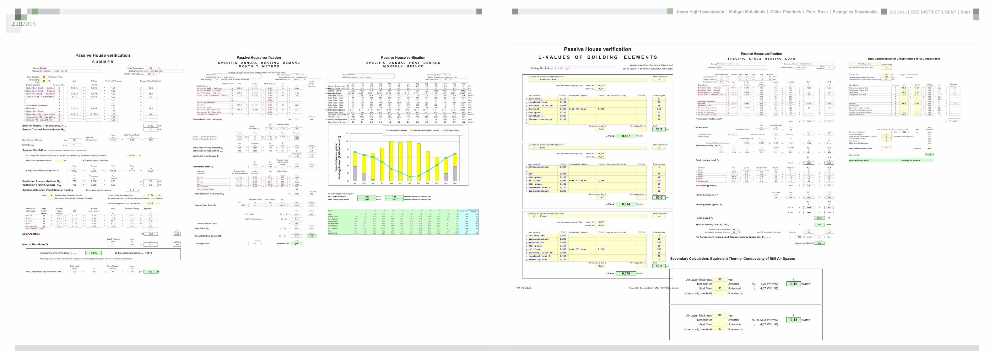
ZIB2015 ECO DISTRICT | GENT | B401Evangelos Stavrakakis | Petra Ross | Mahgol Motallebie | Gilles Plaetinck | Kasra Haji Hassandokht
ZIB2015
|
Passive House verificationS P E C I F I C S P A C E H E A T I N G L O A D Risk Determination of Group Heating for a Critical Room
Building Workshop + info point Building TypeUse non-residential Workshop room ( 1= Yes 0 = No)
Climate (HL) Ukkel Treated Floor Area ATFA 2840 msup2 Interior Temperature 20 degC Building Satisfies Passive House Criteria 1
Design Temperature Radiation North East South West Horizontal Room floor area 100 msup2 Supply Air per msup2 Living AreaWeather Condition 1 -31 degC 10 10 30 15 20 Wmsup2 Planned ambient air quantity for the room 150 msup3h 150 msup3hmsup2Weather Condition 2 -22 degC 5 5 20 10 10 Wmsup2 Planned ambient air quantities for the remaining rooms -67 msup3hGround Design Temp 68 degC Area U-Value Factor TempDiff 1 TempDiff 2 PT 1 PT 2
Building Element Temperature Zone msup2 W(msup2K) Always 1(except X) K K W W Building Element Temperature Zone msup2 W(msup2K) Always 1
(except X) K Room Trans Loss W
1 Exterior Wall - Ambient A 5595 0101 100 231 or 222 = 1299 or 1249 Aboveground Exterior Wall A 650 010 100 231 = 1512 Exterior Wall - Ground B 100 132 or 132 = or Belowground Exterior Wall B 00 100 132 =3 RoofCeiling - Ambient A 1550 0094 100 231 or 222 = 337 or 324 RoofCeiling D 880 009 100 231 = 1914 Floor slab basement ceiling B 310 0105 100 132 or 132 = 43 or 43 Underground Floor Slab B 00 011 100 132 = 05 A 100 231 or 222 = or A 100 231 =6 A 100 231 or 222 = or A 100 231 =7 unheated basement X 075 231 or 222 = or X 100 231 =8 Windows A 1154 0648 100 231 or 222 = 1728 or 1661 Windows A 480 065 100 231 = 7199 Exterior Door A 100 231 or 222 = or Exterior Door A 100 231 =
10 Exterior TB (lengthm) A 1169 -0030 100 231 or 222 = -80 or -77 Exterior thermal bridges (Lengthm) A 100 231 =11 Perimeter TB (lengthm) P 100 132 or 132 = or Perimeter Thermal Bridges (Lengthm) A 100 231 =12 Ground TB (lengthm) B 100 132 or 132 = or Floor Slab Thermal Bridges (Lengthm) A 50 100 231 =13 HouseDU Partition Wall I 100 30 or 30 = or HouseDU Partition Wall I 200 100 30 =
Transmission Heat Losses PT ndashndashndashndashndashndashndashndashndashndashndashndashndash- ndashndashndashndashndashndashndashndashndashndashndash-
Total = 3328 or 3200 = 1061
ATFA Clear Room HeightVentilation System msup2 m msup3 Risk
Effective Air Volume VV 2840 280 = 795 Enter 1 = Yes 0 = No PTRoom W PSupply Air W Ratio Summand
SHX 1 SHX 2 Transmission Heat Losses 1061 1386 077 -023Efficiency of Heat Recovery HR 81 Heat Recovery Efficiency SHX 0 Efficiency SHX 0 or 0 Concentrated leakages 0 000of the Heat Exchanger Insulation to other rooms better R = 15 msup2KW 1 ( 2 = no thermal contact except door) 050
nVRes (Heating Load) nVsystem HR HR Room is on the ground floor 0 0001h 1h 1h 1h open staircase 0 000
Energetically Effective Air Exchange nV 0094 + 0105 (1- 081 or 081 ) = 0114 or 0114 TOTAL of the Risk Summands 027Ventilation Heating Load PV
VL nL nL cAir TempDiff 1 TempDiff 2 PV 1 PV 2 Interior doors predominantly closed 1 Risk Factor 200msup3 1h 1h Wh(msup3K) K K W W
7952 0114 or 0114 033 231 or 222 = 691 or 664Total Room Risk 89
PL 1 PL 2
Total Heating Load PL W W Appraisal and Advice normally no problemPT + PV = 4019 or 3864
Orientation Area g-Value Reduction Factor Radiation 1 Radiation 2 PS 1 PS 2the Area msup2 (perp radiation) (see Windows worksheet) Wmsup2 Wmsup2 W W
1 North 270 05 05 11 or 6 = 77 or 412 East 44 00 06 8 or 3 = 0 or 03 South 486 05 06 28 or 18 = 378 or 2474 West 322 05 03 19 or 13 = 100 or 685 Horizontal 32 05 06 20 or 10 = 20 or 10
Solar heating power PS Total = 575 or 367
Spec Power ATFA PI 1 PI 2Internal heating power PI Wmsup2 msup2 W W
16 284 = 454 or 454
PG 1 PG 2
Heating power (gains) PG W W
PS + PI = 1029 or 821
PL - PG = 2989 or 3042
Heating Load PH = 3042 W
Specific Heating Load PH ATFA = 107 Wmsup2
Input Max Supply Air Temperature 48 degC degC degC
Max Supply Air Temperature SupplyMax 48 degC Supply Air Temperature Without Heating SupplyMin 156 157
For Comparison Heating Load Transportable by Supply Air PSupply AirMax = 886 W specific 31 Wmsup2
(YesNo)
Supply Air Heating Sufficient No
HPP Heating Load FINAL ZIB FILE CALCULTIONS PHPPxls
Passive House verificationU - V A L U E S O F B U I L D I N G E L E M E N T S
Wedge shaped building element layeBuilding Workshop + info point still air spaces -gt Secondary calculation to th
Assembly No Building assembly description Interior insulation1 Exterior wall x
Heat transfer resistance [msup2KW] interior Rsi 013exterior Rse 004
Area section 1 [W(mK)] Area section 2 (optional) [W(mK)] Area section 3 (optional) [W(mK)] Thickness [mm]
1 hout gevel 0160 17
2 regelwerk hout 0158 30
3 houtvezel celit 4D 0048 18
4 Eurowall 0023 hout FJI beam 0286 140
5 OSB -plaat 0130 15
6 Eurothane G 0023 70
7 Plaster insulating 0100 10
8Percentage of Sec 2 Percentage of Sec 3 Total
26 300
U-Value 0107 W(msup2K)
Assembly No Building assembly description Interior insulation2 Roof x
Heat transfer resistance [msup2KW] interior Rsi 010exterior Rse 004
Area section 1 [W(mK)] Area section 2 (optional) [W(mK)] Area section 3 (optional) [W(mK)] Thickness [mm]Area section 1 [W(mK)] Area section 2 (optional) [W(mK)] Area section 3 (optional) [W(mK)] Thickness [mm]
1 bitumenmembraam 0230 5
23 EPS 0036 70
4 OSB -plaat 0130 18
5 cellulose 0039 hout FJI beam 0286 350
6 OSB -plaat 0130 15
7 regelwerk hout 5 0177 30
8 gipskartonplaat 0290 12
Percentage of Sec 2 Percentage of Sec 3 Total
26 500
U-Value 0094 W(msup2K)
Assembly No Building assembly description Interior insulation3 Floor x
Heat transfer resistance [msup2KW] interior Rsi 017
exterior Rse 004
Area section 1 [W(mK)] Area section 2 (optional) [W(mK)] Area section 3 (optional) [W(mK)] Thickness [mm]
1 PIR dekvloer 0023 5
2 gipskartonplaat 0290 10
3 gespoten pur 0028 100
4 OSB -plaat 0130 15
5 cellulose 0039 hout FJI beam 0286 350
6 houtvezel Celit 4D 0048 15
7 regelwerk hout 6 0149 30
8 afwerking hout 0160 5
Percentage of Sec 2 Percentage of Sec 3 Total
26 530
U-Value 0078 W(msup2K)
PHPP U-Values FINAL ZIB FILE CALCULTIONS PHPPxls
ers and he right
n Secondary Calculation Equivalent Thermal Conductivity of Still Air Spaces
Air Layer Thickness 30 mm Direction of Upwards ha 125 W(msup2K) 016 W(mK)
Heat Flow X Horizontal hr 417 W(msup2K)
(check only one field) Downwards
cm
n
cm
n Secondary Calculation Equivalent Thermal Conductivity of Still Air Spaces
Air Layer Thickness 30 mm
Direction of Upwards ha 08333 W(msup2K) 015 W(mK)Heat Flow Horizontal hr 417 W(msup2K)
(check only one field) X Downwards
cm
PHPP U-Values FINAL ZIB FILE CALCULTIONS PHPPxls
ers and he right
n Secondary Calculation Equivalent Thermal Conductivity of Still Air Spaces
Air Layer Thickness 30 mm Direction of Upwards ha 125 W(msup2K) 016 W(mK)
Heat Flow X Horizontal hr 417 W(msup2K)
(check only one field) Downwards
cm
n
cm
n Secondary Calculation Equivalent Thermal Conductivity of Still Air Spaces
Air Layer Thickness 30 mm
Direction of Upwards ha 08333 W(msup2K) 015 W(mK)Heat Flow Horizontal hr 417 W(msup2K)
(check only one field) X Downwards
cm
PHPP U-Values FINAL ZIB FILE CALCULTIONS PHPPxls
ers and he right
n Secondary Calculation Equivalent Thermal Conductivity of Still Air Spaces
Air Layer Thickness 30 mm Direction of Upwards ha 125 W(msup2K) 016 W(mK)
Heat Flow X Horizontal hr 417 W(msup2K)
(check only one field) Downwards
cm
n
cm
n Secondary Calculation Equivalent Thermal Conductivity of Still Air Spaces
Air Layer Thickness 30 mm
Direction of Upwards ha 08333 W(msup2K) 015 W(mK)Heat Flow Horizontal hr 417 W(msup2K)
(check only one field) X Downwards
cm
PHPP U-Values FINAL ZIB FILE CALCULTIONS PHPPxls
Passive House verificationS U M M E R
Climate Ukkel Interior Temperature 20 degC
Building Workshop + info point Building TypeUse non-residentialTreated Floor Area ATFA 2840 msup2
Spec Capacity 60 WhK pro msup2 TFAOverheating
limit25 degC Area U-Value Red Factor fTSummer HSummer Heat Conductance
Building Element Temperature Zone msup2 W(msup2K)
1 Exterior Wall - Ambien A 5595 0101 100 = 5632 Exterior Wall - Ground B 100 =3 RoofCeiling - Ambient A 1550 0094 100 = 1464 Floor slab basement B 310 0105 100 = 335 A 100 =6 A 100 =7 unheated basement X 075 =8 Windows A 1154 0648 100 = 7489 Exterior Door A 100 =
10 Exterior TB (lengthm) A 1169 -0030 100 = -3511 Perimeter TB (lengthm P 100 =12 Ground TB (lengthm) B 100 =
ndashndashndashndashndashndashndashndashndashndashndashExterior Thermal Transmittance HTe 1422 WK
Ground Thermal Transmittance HTg 33 WK
ATFA Clear Room HeightEffective msup2 m msup3
Heat Recovery Efficiency HR 81 Air Volume VV 2840 280 = 795
SHX Efficiency SHX 0
Summer Ventilation continuous ventilation to provide sufficient indoor air quality
Air Change Rate by Natural (Windows amp Leakages) or Exhaust-Only Mechanical Ventilation Summer 000 1h
Mechanical Ventilation Summer 1h X with HR (check if applicable)
nLnat nVsystem HR nVRest
1h 1h 1h 1h
Energetically Effective Airchange Rate nV 0000 + 0000 (1 - 0808 ) + 0038 = 0038
VV nVequifraction cAir
msup3 1h Wh(msup3K)
Ventilation Transm Ambient HVe 795 0038 033 = 99 WK
Ventilation Transm Ground HVg 795 0000 033 = 00 WK
Additional Summer Ventilation for Cooling Temperature amplitude summer 82 K
Select X Window Night Ventilation Manual Corresponding Air Change Rate 136 1hMechanical Automatically Controlled Ventilation (for window ventilation at 1 K temperature difference indoor - outdoor)
Minimum Acceptable Indoor Temperature 220 degC
Orientation Angle Shading g-Value Area Portion of Glazing Apertureof the Area Factor Factor Dirt (perp radiation)
Summer Summer msup2 msup2
1 North 09 044 095 050 270 82 = 422 East 09 100 095 000 44 71 = 003 South 09 043 095 050 486 82 = 744 West 09 039 095 050 322 76 = 405 Horizontal 09 052 095 050 32 78 = 066 Sum Opaque Areas 03
msup2msup2
Solar Aperture Total 164 006
Specif Power qI ATFA
Wmsup2 msup2 W Wmsup2
Internal Heat Gains QI 201 284 = 571 20
Frequency of Overheating hmax 42 at the overheating limit max = 25 degC
If the frequency over 25degC exceeds 10 additional measures to protect against summer heat waves are necessary
Solar Load Spec Capacity ATFA
kWhd 1k Wh(msup2K) msup2
Daily Temperature Swing due to Solar Load 00 1000 ( 60 284 ) = 00 K
PHPP Summer FINAL ZIB FILE CALCULTIONS PHPPxls
Passive House verification Passive House verificationS P E C I F I C A N N U A L H E A T I N G D E M A N D S P E C I F I C A N N U A L H E A T D E M A N D
M O N T H L Y M E T H O D M O N T H L Y M E T H O D
(This page displays the sums of the monthly method over the heating period)Climate Ukkel Interior Temperature 20 degC Climate Ukkel Interior Temperature 20 degC
Building Workshop + info point Building TypeUse non-residential Building Workshop + info point Building TypeUse non-residentialSpec Capacity 60 Wh(msup2K) (Enter in Summer worksheet) Treated Floor Area ATFA 2840 msup2 Treated Floor Area ATFA 284 msup2
per msup2Temperature Zone Area U-Value Month Red Fac Gt Treated Jan Feb Mar Apr May Jun Jul Aug Sep Oct Nov Dec Year
Building Element msup2 W(msup2K) kKha kWha Floor Area Heating Degree Hours - E 131 117 107 85 54 37 20 22 46 72 104 123 92 kKhExterior Wall - Ambient A 5595 0101 100 78 = 4406 Heating Degree Hours - G 89 89 98 84 69 47 26 17 22 33 50 72 70 kKhExterior Wall - Ground B 100 = Losses - Exterior 2056 1836 1679 1335 856 589 316 350 722 1132 1630 1931 14433 kWhRoofCeiling - Ambient A 1550 0094 100 78 = 1143 Losses - Ground 29 29 32 28 23 15 9 5 7 11 16 23 227 kWhFloor slab basement ceiling B 310 0105 100 54 = 175 Sum Spec Losses 73 66 60 48 31 21 11 13 26 40 58 69 516 kWhmsup2
A 100 = Solar Gains - North 78 142 246 371 500 520 520 445 311 202 94 62 3490 kWhA 100 = Solar Gains - East 0 0 0 0 0 0 0 0 0 0 0 0 0 kWh
unheated basement X 075 = Solar Gains - South 405 583 860 1069 1261 1194 1263 1220 986 771 448 318 10377 kWhWindows A 1154 0648 100 78 = 5861 Solar Gains - West 103 162 275 391 497 489 478 448 331 229 118 77 3597 kWhExterior Door A 100 = Solar Gains - Horiz 20 38 68 104 143 144 145 126 86 55 25 16 968 kWhExterior TB (lengthm) A 1169 -0030 100 78 = -273 Solar Gains - Opaque 3 5 9 13 18 19 19 16 11 7 3 2 126 kWhPerimeter TB (lengthm) P 100 = Internal Heat Gains 425 384 425 411 425 411 425 425 411 425 411 425 5001 kWhGround TB (lengthm) B 100 = Sum Spec Gains Solar + 36 46 66 83 100 98 100 94 75 59 39 32 830 kWhmsup2
ndashndashndashndashndashndashndashndashndashndashndash kWh(msup2a) Utilisation Factor 100 98 84 57 31 22 11 13 34 67 98 100 48Transmission Heat Losses QT Total 11313 398 Annual Heating Demand 1055 580 134 9 0 0 0 0 0 19 564 1057 3419 kWh
Spec Heating Demand 37 20 05 00 00 00 00 00 00 01 20 37 120 kWhmsup2ATFA Clear Room Height
Effective msup2 m msup3
Air Volume VRAX 284 280 = 795
nVsystem SHX HR nVRes nVequifraction
1h 1h 1h
Effective Air Change Rate Ambient nVe 0105 (1- 0 )(1- 081 )+ 0038 = 0058Effective Air Change Rate Ground nVg 0105 0 (1- 081 ) = 0000
VRAX nVequifraction cAir Gt
msup3 1h Wh(msup3K) kKha kWha kWh(msup2a)
Ventilation Losses Ambient QV 795 0058 033 78 = 1185 42
Ventilation Losses Ground QVe 795 0000 033 55 = 0 00ndashndashndashndashndashndashndashndashndashndashndash
Ventilation Heat Losses QV Total 1185 42
Reduction Factor QT QV NightWeekend
kWha kWha Saving kWha kWh(msup2a)
Total Heat Losses QL ( 11313 + 1185 ) 10 = 12497 440
Orientation Reduction Factor g-Value Area Global Radiationof the Area See Windows worksheet (perp radiation)
msup2 kWh(msup2a) kWha
North 054 050 270 208 = 1505East 058 000 44 250 = 0South 056 050 486 398 = 5440West 032 050 322 323 = 1685Horizontal 063 050 32 403 = 411Sum Opaque Areas 55
kWh(msup2a)
Available Solar Heat Gains QS Total 9095 320 Annual Heating Demand Comparison
EN 13790 Monthly Method 3419 kWha 120 kWh(msup2a) Reference to habitable area
Length Heat Period Spec Power qI ATFA PHPP Heating Period Method 2911 kWha 103 kWh(msup2a) Reference to habitable area
khd da Wmsup2 msup2 kWha kWh(msup2a)
Internal Heat Gains QI 0024 242 20 2840 = 3315 117
kWha kWh(msup2a) Month 1 2 3 4 5 6 7 8 9 10 11 12 Annual Total Heating Period Method
Free Heat QF QS + QI = 12411 437 Days 31 28 31 30 31 30 31 31 30 31 30 31 365 209Ambient Temp 250 270 572 828 1275 1487 1737 1707 1369 1039 568 356 96 52
Ratio Free Heat to Losses QF QL = 099 North Radiation 106 195 329 494 667 697 712 599 419 275 129 87 471 163East Radiation 146 266 452 698 937 940 988 851 574 382 179 123 654 197
Utilisation Factor Heat Gains G = 73 South Radiation 311 440 645 786 912 858 898 885 733 579 341 241 763 314kWha kWh(msup2a) West Radiation 155 261 471 707 926 926 896 819 580 382 183 116 642 254
Heat Gains QG G QF = 9078 320 Hori Radiation 200 369 662 1021 1398 1410 1418 1234 842 535 243 156 949 317
Tsky -750 -730 -428 -172 275 487 737 707 369 039 -432 -644 -04kWha kWh(msup2a) Ground Temp 805 676 686 830 1072 1345 1647 1776 1696 1552 1310 1037 121 98
Annual Heating Demand QH QL - QG = 3419 12
kWh(msup2a) (YesNo)
Limiting Value 15 Requirement met yes
0
2
4
6
8
10
12
Jan Feb Mar Apr May Jun Jul Aug Sep Oct Nov Dec
Spec
ific
loss
es g
ains
he
atin
g de
man
d [k
Wh
(msup2 m
onth
)]
Spec Heating Demand Sum Spec Gains Solar + Internal Sum Spec Losses
HPP Monthly Method FINAL ZIB FILE CALCULTIONS PHPPxls
Passive House verification Passive House verificationS P E C I F I C A N N U A L H E A T I N G D E M A N D S P E C I F I C A N N U A L H E A T D E M A N D
M O N T H L Y M E T H O D M O N T H L Y M E T H O D
(This page displays the sums of the monthly method over the heating period)Climate Ukkel Interior Temperature 20 degC Climate Ukkel Interior Temperature 20 degC
Building Workshop + info point Building TypeUse non-residential Building Workshop + info point Building TypeUse non-residentialSpec Capacity 60 Wh(msup2K) (Enter in Summer worksheet) Treated Floor Area ATFA 2840 msup2 Treated Floor Area ATFA 284 msup2
per msup2Temperature Zone Area U-Value Month Red Fac Gt Treated Jan Feb Mar Apr May Jun Jul Aug Sep Oct Nov Dec Year
Building Element msup2 W(msup2K) kKha kWha Floor Area Heating Degree Hours - E 131 117 107 85 54 37 20 22 46 72 104 123 92 kKhExterior Wall - Ambient A 5595 0101 100 78 = 4406 Heating Degree Hours - G 89 89 98 84 69 47 26 17 22 33 50 72 70 kKhExterior Wall - Ground B 100 = Losses - Exterior 2056 1836 1679 1335 856 589 316 350 722 1132 1630 1931 14433 kWhRoofCeiling - Ambient A 1550 0094 100 78 = 1143 Losses - Ground 29 29 32 28 23 15 9 5 7 11 16 23 227 kWhFloor slab basement ceiling B 310 0105 100 54 = 175 Sum Spec Losses 73 66 60 48 31 21 11 13 26 40 58 69 516 kWhmsup2
A 100 = Solar Gains - North 78 142 246 371 500 520 520 445 311 202 94 62 3490 kWhA 100 = Solar Gains - East 0 0 0 0 0 0 0 0 0 0 0 0 0 kWh
unheated basement X 075 = Solar Gains - South 405 583 860 1069 1261 1194 1263 1220 986 771 448 318 10377 kWhWindows A 1154 0648 100 78 = 5861 Solar Gains - West 103 162 275 391 497 489 478 448 331 229 118 77 3597 kWhExterior Door A 100 = Solar Gains - Horiz 20 38 68 104 143 144 145 126 86 55 25 16 968 kWhExterior TB (lengthm) A 1169 -0030 100 78 = -273 Solar Gains - Opaque 3 5 9 13 18 19 19 16 11 7 3 2 126 kWhPerimeter TB (lengthm) P 100 = Internal Heat Gains 425 384 425 411 425 411 425 425 411 425 411 425 5001 kWhGround TB (lengthm) B 100 = Sum Spec Gains Solar + 36 46 66 83 100 98 100 94 75 59 39 32 830 kWhmsup2
ndashndashndashndashndashndashndashndashndashndashndash kWh(msup2a) Utilisation Factor 100 98 84 57 31 22 11 13 34 67 98 100 48Transmission Heat Losses QT Total 11313 398 Annual Heating Demand 1055 580 134 9 0 0 0 0 0 19 564 1057 3419 kWh
Spec Heating Demand 37 20 05 00 00 00 00 00 00 01 20 37 120 kWhmsup2ATFA Clear Room Height
Effective msup2 m msup3
Air Volume VRAX 284 280 = 795
nVsystem SHX HR nVRes nVequifraction
1h 1h 1h
Effective Air Change Rate Ambient nVe 0105 (1- 0 )(1- 081 )+ 0038 = 0058Effective Air Change Rate Ground nVg 0105 0 (1- 081 ) = 0000
VRAX nVequifraction cAir Gt
msup3 1h Wh(msup3K) kKha kWha kWh(msup2a)
Ventilation Losses Ambient QV 795 0058 033 78 = 1185 42
Ventilation Losses Ground QVe 795 0000 033 55 = 0 00ndashndashndashndashndashndashndashndashndashndashndash
Ventilation Heat Losses QV Total 1185 42
Reduction Factor QT QV NightWeekend
kWha kWha Saving kWha kWh(msup2a)
Total Heat Losses QL ( 11313 + 1185 ) 10 = 12497 440
Orientation Reduction Factor g-Value Area Global Radiationof the Area See Windows worksheet (perp radiation)
msup2 kWh(msup2a) kWha
North 054 050 270 208 = 1505East 058 000 44 250 = 0South 056 050 486 398 = 5440West 032 050 322 323 = 1685Horizontal 063 050 32 403 = 411Sum Opaque Areas 55
kWh(msup2a)
Available Solar Heat Gains QS Total 9095 320 Annual Heating Demand Comparison
EN 13790 Monthly Method 3419 kWha 120 kWh(msup2a) Reference to habitable area
Length Heat Period Spec Power qI ATFA PHPP Heating Period Method 2911 kWha 103 kWh(msup2a) Reference to habitable area
khd da Wmsup2 msup2 kWha kWh(msup2a)
Internal Heat Gains QI 0024 242 20 2840 = 3315 117
kWha kWh(msup2a) Month 1 2 3 4 5 6 7 8 9 10 11 12 Annual Total Heating Period Method
Free Heat QF QS + QI = 12411 437 Days 31 28 31 30 31 30 31 31 30 31 30 31 365 209Ambient Temp 250 270 572 828 1275 1487 1737 1707 1369 1039 568 356 96 52
Ratio Free Heat to Losses QF QL = 099 North Radiation 106 195 329 494 667 697 712 599 419 275 129 87 471 163East Radiation 146 266 452 698 937 940 988 851 574 382 179 123 654 197
Utilisation Factor Heat Gains G = 73 South Radiation 311 440 645 786 912 858 898 885 733 579 341 241 763 314kWha kWh(msup2a) West Radiation 155 261 471 707 926 926 896 819 580 382 183 116 642 254
Heat Gains QG G QF = 9078 320 Hori Radiation 200 369 662 1021 1398 1410 1418 1234 842 535 243 156 949 317
Tsky -750 -730 -428 -172 275 487 737 707 369 039 -432 -644 -04kWha kWh(msup2a) Ground Temp 805 676 686 830 1072 1345 1647 1776 1696 1552 1310 1037 121 98
Annual Heating Demand QH QL - QG = 3419 12
kWh(msup2a) (YesNo)
Limiting Value 15 Requirement met yes
0
2
4
6
8
10
12
Jan Feb Mar Apr May Jun Jul Aug Sep Oct Nov Dec
Spec
ific
loss
es g
ains
he
atin
g de
man
d [k
Wh
(msup2 m
onth
)]
Spec Heating Demand Sum Spec Gains Solar + Internal Sum Spec Losses
HPP Monthly Method FINAL ZIB FILE CALCULTIONS PHPPxls
ZIB2015 ECO DISTRICT | GENT | B401Evangelos Stavrakakis | Petra Ross | Mahgol Motallebie | Gilles Plaetinck | Kasra Haji Hassandokht
ZIB2015
|
Passive House verificationV E N T I L A T I O N D A T A
Building Workshop + info point
Treated floor area ATFA msup2 284 (Areas worksheet)
Room height h m 28 (Annual Heating Demand worksheet)
Room ventilation volume (ATFAh) = VV msup3 795 (Annual Heating Demand worksheet)
Type of ventilation systemx Balanced PH ventilation Please Check
Pure extract air
Infiltration air change rate
Wind protection coefficients e and f Several One
Coefficient e for screening class sides sideexposed exposed
No screening 010 003Moderate screening 007 002High screening 004 001Coefficient f 15 20
for Annual Demand for Heating Load
Wind protection coefficient e 004 010Wind protection coefficient f 15 15 Net Air Volume for
Press Test Vn50 Air permeability q50
Air Change Rate at Press Test n50 1h 060 060 1244 msup3 087 msup3(hmsup2)
for Annual Demand for Heating Load
Excess extract air 1h 000 000Infiltration air change rate nVRes 1h 0038 0094
Selection of ventilation data input - ResultsThe PHPP offers two methods for dimensioning the air quantities and choosing the ventilation unit Fresh air or extract air quantities for residential buildings and parameters for ventilation syscan be determined using the standard planning option in the Ventilation sheet The Additional Vent sheet has been created for more complex ventilation systems and allows up to 10 differenFurthermore air quantities can be determined on a room-by-room or zone-by-zone basis Please select your design method here
Extract air Effective heat Specific HeatVentilation unit Heat recovery efficiency design Mean Mean excess recovery power recovery
X Sheet Ventilation (Standard design) (Sheet Ventilation see below) Air exchange Air Change Rate (Extract air system) efficiency Unit input efficiency SHXSheet Extended ventilation (Sheet Additional Vent) msup3h 1h 1h [-] Whmsup3(Multiple ventilation units non-residential buildings) 83 010 000 818 029 00
SHX efficiency SHX 0
PHPP Ventilation FINAL ZIB FILE CALCULTIONS PHPPxls
SHX efficiency SHX 0
PHPP Ventilation FINAL ZIB FILE CALCULTIONS PHPPxls
S T A N D A R D I N P U T F O R B A L A N C E D V E N T I L A T I O NVentilation dimensioning for systems with one ventilation unit
Occupancy msup2P 36Number of occupants P 80Supply air per person msup3(Ph) 30Supply air requirement msup3h 240 BathroomExtract air rooms Kitchen Bathroom (shower only) WC 0Quantity 2 3 0Extract air requirement per room msup3h 60 40 20 20 0Total Extract Air Requirement msup3h 180
Design air flow rate (maximum) msup3h 240
Average air change rate calculationDaily operation Factors referenced to Air flow rate Air change rateduration maximum
Type of operation hd msup3h 1hMaximum 100 240 030Standard 80 077 185 023Basic 40 054 130 016Minimum 120 0 000
Average air flow rate (msup3h) Average air change rate (1h)Average value 035 83 010
Selection of ventilation unit with heat recovery
X Central unit within the thermal envelope
Central unit outside of the thermal envelope Heat recovery Specificefficiency power Application Frost UnitUnit input range protection noise levelHR [Whmsup3] [msup3h] required lt 35dB(A)
Ventilation unit selection 19 mfoAir 350 - Zehnder 084 029 71 - 293 yes no
Conductance value of outdoor air duct W(mK) 0338 See calculation belowLength of outdoor air duct m 08Conductance value of exhaust air duct W(mK) 0338 See calculation belowLength of exhaust air duct m 15 Room Temperature (degC) 20Temperature of mechanical services room degC Av Ambient Temp Heating P (degC) 59(Enter only if the central unit is outside of the thermal envelope) Av Ground Temp (degC) 106
ComfoAir 350 - Zehnder
PHPP Ventilation FINAL ZIB FILE CALCULTIONS PHPPxls
Effective heat recovery efficiency HReff 818
Effective heat recovery efficiency subsoil heat exchangerSHX efficiency SHX
Heat recovery efficiency SHX SHX 0
Secondary calculation Secondary calculation-value supply or ambient air duct -value extract or exhaust air duct
Nominal width 200 mm Nominal width 200 mmInsul Thickness 50 mm Insul Thickness 50 mm
Reflective Please mark with an x Reflective Please mark with an xx Yes x Yes
No NoThermal conductivity 003 W(mK) Thermal conductivity 003 W(mK)Nominal air flow rate 83 msup3h Nominal air flow rate 83 msup3h
14 K 14 KExterior duct diameter 0200 m Exterior duct diameter 0200 m
Exterior diameter 0300 m Exterior diameter 0300 m-Interior 416 W(msup2K) -Interior 416 W(msup2K)
Surface 252 W(msup2K) Surface 252 W(msup2K)-value 0338 W(mK) -value 0338 W(mK)
Surface temperature difference 2002 K Surface temperature difference 2002 K
ComfoAir 350 - Zehnder
PHPP Ventilation FINAL ZIB FILE CALCULTIONS PHPPxls
Passive House verificationR E D U C T I O N F A C T O R S O L A R R A D I A T I O N W I N D O W U - V A L U E
Building Workshop + info point Annual heating demand 10 kWh(msup2a) Heating degree hours
Climate Ukkel 743
Window area orientation
Global radiation (cardinal points)
Shading Dirt
Non-perpendicu-lar incident radiation
Glazing fraction g-Value Reduction factor
for solar radiationWindow
areaWindowU-Value
Glazingarea
Average global
radiation
Transmission losses
Heat gains solar radiation
maximum kWh(msup2a) 075 095 085 m2 W(m2K) m2 kWh(m2a) kWha kWhaNorth 160 081 095 085 0822 050 054 2700 062 222 163 1243 1182East 222 100 095 085 0714 000 058 440 129 31 197 423 0South 321 085 095 085 0822 050 056 4860 062 399 314 2237 4287West 225 053 095 085 0758 050 032 3216 063 244 254 1517 1327Horizontal 317 100 095 085 0780 050 063 324 059 25 317 143 323
Total or Average Value for All Windows 048 049 11540 065 921 5562 7119
Glazing inclination ne 90deg Please check Ug value manually Window rough openings Installed Glazing Frame g-Value U-Value -
SpacerInstallation Results
(unhide cells to make U- amp -values from WinType worksheet visible)
Quan-tity Description Deviation from
north
Angle of inclination from the
horizontal
Orientation Width Heightin Area in the
Areas worksheet
Nr
Select glazing from the WinType
worksheet
Nr
Select window from the WinType
worksheet
NrPerpen-dicular
RadiationGlazing Frames
(centre) spacer (centre)
Left10
Right10
Bottom10
Top10
installation left
installation right
installation bottom
installation top
installation Average value
Window Area
Glazing Area
U-ValueWindow
Glazed Fraction
per Window
Degrees Degrees m m Select Select Select - W(m2K) W(m2K) W(mK) W(mK) W(mK) W(mK) W(mK) W(mK) m2 m2 W(m2K) 3 Door glass 250 90 West 1200 2200 5 2 3 050 049 071 0028 0 0 1 1 0040 79 591 065 755 window_NW 340 90 North 1800 3000 5 2 3 050 049 071 0028 1 1 0 0 0040 270 2218 062 821 window_SW 250 90 West 0600 3000 5 2 3 050 049 071 0028 0 0 1 1 0040 18 109 070 609 window SE 160 90 South 1800 3000 5 2 3 050 049 071 0028 1 1 0 0 0040 486 3992 062 821 Door elev 250 90 West 1800 2200 5 2 3 050 049 071 0028 0 0 1 1 0040 40 316 062 80
2 Door glass 250 90 West 1200 2200 7 2 3 050 049 071 0028 0 0 1 1 0040 53 394 065 751 Door_Ext 70 90 East 1000 2200 7 1 2 000 140 059 0049 0 0 1 1 0005 22 157 129 711 Door elev 250 90 West 1800 2200 7 2 3 050 049 071 0028 0 0 1 1 0040 40 316 062 80
0 0 0
Wall main INTERPANE iplus batimet batiment TA
Wall main
Wall main
Wall main
Wall main
Wall core 0
Wall core 0
Wall core 0
INTERPANE iplus
INTERPANE iplus
INTERPANE iplus
INTERPANE iplus
INTERPANE iplus
Door _wooden
INTERPANE iplus
batimet batiment TA
batimet batiment TA
batimet batiment TA
batimet batiment TA
batimet batiment TA
Wooden frame
batimet batiment TA
0 0 0
2 Door glass 250 90 West 1200 2200 8 2 3 050 049 071 0028 0 0 1 0 0040 53 394 063 751 Door_Ext 70 90 East 1000 2200 8 1 2 000 140 059 0049 0 0 1 0 0005 22 157 129 711 Door elev 250 90 West 1800 2200 8 2 3 050 049 071 0028 0 0 1 0 0040 40 316 060 801 skylight 250 0 Horizontal 1800 1800 6 2 3 050 049 071 0028 0 0 0 0 0000 32 253 059 78
0 0 0
0 0 0
0 0 0
0 0 0
Wall core 3
Wall core 3
Wall core 3
Roof
INTERPANE iplus
Door _wooden
INTERPANE iplus
INTERPANE iplus
batimet batiment TA
Wooden frame
batimet batiment TA
batimet batiment TA
PHPP Windows FINAL ZIB FILE CALCULTIONS PHPPxls
Passive House verificationC A L C U L A T I N G S H A D I N G F A C T O R S
Climate Ukkel
Building Workshop + info point Orientation Glazing area Reduction factor
Latitude 508 deg msup2 rS
North 2218 81East 314 100
South 3992 85West 2437 53
Horizontal 253 100
Quantity Description Deviation from North
Angle of Inclination from the Horizontal
Orientation Glazing width Glazing height Glazing area Height of the shading object
Horizontal distance
Window reveal depth
Distance from glazing edge to
revealOverhang depth
Distance from upper glazing
edge to overhang
Additional shading reduction factor
Horizontal shading reduction factor
Reveal Shading Reduction Factor
Overhang shading reduction factor
Total shading reduction factor
Degrees Degrees m m m m m m m m wG hG AG hHori dHori oReveal dReveal oover dover rother rH rR rO rS
3 Door glass 250 90 West 099 199 59 0060 420 050 100 100 51 515 window_NW 340 90 North 159 279 222 060 0060 100 81 100 811 window_SW 250 90 West 039 279 11 0060 420 050 100 100 58 589 window SE 160 90 South 159 279 399 060 0060 100 85 100 851 Door elev 250 90 West 159 199 32 0060 420 100 100 39 39
2 Door glass 250 90 West 099 199 39 750 420 0060 420 100 26 100 60 161 Door_Ext 70 90 East 081 195 16 0060 1200 100 100 100 27 271 Door elev 250 90 West 159 199 32 750 420 0060 420 26 100 39 10
2 Door glass 250 90 West 099 199 39 0060 100 100 100 1001 Door_Ext 70 90 East 081 195 16 0060 100 100 100 1001 Door elev 250 90 West 159 199 32 0060 100 100 100 1001 skylight 250 0 Horizontal 159 159 25 0060 100 100 100 100
PHPP Shading FINAL ZIB FILE CALCULTIONS PHPPxls
ZIB2015 ECO DISTRICT | GENT | B401Evangelos Stavrakakis | Petra Ross | Mahgol Motallebie | Gilles Plaetinck | Kasra Haji Hassandokht
ZIB2015
|
Passive House verificationS O L A R H O T W A T E R G E N E R A T I O N
Building Workshop + info point Building TypeUse non-residential
Treated Floor Area ATFA 2840 msup2
Solar Fraction with DHW demand including washing and dish-washing
Heating Demand DHW qgDHW 5183 kWha from DHW+Distribution worksheet
Latitude 508 deg from Climate Data worksheet
Selection of collector from list (see below) 8 Selection 8 Vacuum Tube Collector VTC
Solar Collector Area 600 msup2
Deviation from North 180 deg
Angle of Inclination from the Horizontal 45 deg
Height of the Collector Field 05 m
Height of Horizon hHori m
Horizontal Distance aHori m
Additional Reduction Factor Shading rother
Occupancy 80 Persons
Specific Collector Area 08 msup2Pers
Estimated Solar Fraction of DHW Production 49Solar Contribution to Useful Heat 2545 kWha 9 kWh(msup2a)
Secondary Calculation of Storage Losses
Selection of DHW storage from list (see below) 2 Selection Zonneboiler 200
Total Storage Volume 200 litre
Volume Standby Part (above) 60 litre
Volume Solar Part (below) 140 litre
Specific Heat Losses Storage (total) 20 WK
Typical Temperature DHW 60 degC
Room Temperature 20 degC
Storage Heat Losses (Standby Part Only) 24 W
Total Storage Heat Losses 80 W
02
03
04
05
06
07
08
09
10
200
300
400
500
600
700
800
900
1000
Sola
r fra
ctio
n[-]
ion
hea
ting
load
DH
W g
ener
atio
n h
eatin
g lo
ad
co
vere
d by
sol
ar [k
Wh
mon
th]
Monthly Heating Load Covered by Solar
Total Monthly Heating Load DHW Production
Radiation on Tilted Collector Surface
Monthly Solar Fraction
8 Vacuum Tube Collector
Zonneboiler 200
Monthly Solar Fraction January February March April May June July August September October November December
Radiation on Tilted Collector Surface 198 326 535 725 883 835 864 835 643 453 230 153 kWhMonth
Monthly Solar Fraction 018 031 049 064 075 072 074 072 058 042 021 013 -
Total Monthly Heating Load DHW Production 432 432 432 432 432 432 432 432 432 432 432 432 kWhMonth
Monthly Heating Load Covered by Solar 77 133 212 277 325 311 319 310 250 181 92 58 kWhMonth
Selection List Solar Collectors 0 = FR(ta) k1 k2 C Kdir(50deg) Kdfu OutputModule Area
(Aperture)VTC FPC Comments
InsertManufacturer Brief Description - W(msup2K) W(msup2Ksup2) kJ(msup2K) - - kWh(msup2a) msup2 please enter new
1 Brink F3-Q 08 35 00 81 10 4880 20 FPC columns2 BEFORE3 this4 column56 6 Standard Flat Plate Collector 077 35 002 64 09 08 300 2 FPC FK AD7 7 Improved Flat Plate Collector 0854 337 00104 47 097 094 546 26 FPC FK AD AR8 8 Vacuum Tube Collector 062 0395 002 1153 095 09 487 12 VTC FK AD9 RK AD101112 Insert new rows ABOVE this row only in order to maintain the integrity of references
00
01
0
100
January February March April May June July August September October November December
Sola
rad
iati
HPP SolarDHW FINAL ZIB FILE CALCULTIONS PHPPxls
Passive House verificationE F F I C I E N C Y O F H E A T G E N E R A T I O N ( G A S O I L W O O D )
Building Workshop + info point Building TypeUse non-residential
Treated Floor Area ATFA 284 msup2
Covered Fraction of Space Heating Demand (PE Value worksheet) 100
Space Heating Demand + Distribution Losses QH+QHS (DHW+Distribution) 3021 kWh
Solar Fraction for Space Heat Solar H (Separate Calculation) 48
Effective Annual Heating Demand QHWi=QH(1-Solar H) 1571 kWh
Space Heating Demand without Distribution Losses QH (Verification sheet) 2911 kWh
Covered Fraction of DHW Demand (PE Value worksheet) 100
Total Heating Demand of DHW system QgDHW (DHW+Distribution) 5183 kWh
Solar Fraction for DHW Solar DHW (SolarDHW worksheet) 49
Effective DHW Demand QDHWWi=QDHW(1-Solar DHW) 2638 kWh
Boiler Type (Project) oved gas condensing boiler 2
Primary Energy Factor (Data worksheet) 11 kWhkWh
CO2-Emissions Factor (CO2-Equivalent) 250 gkWh
Useful Heat Provided QUse 4209 kWha
Max Heating Power Required for Heating the Building PBH (Heating Load worksheet) 304 kW
Length of the Heating Period tHP 5022 h
Length of DHW Heating Period tDHW 8760 h
Use characteristic values entered (check if appropriate)
Project Data Standard Values Input field
Design Output Pnominal (Rating Plate) 15 kW 15 kW 3
Installation of Boiler (Outdoor 0 Indoor 1) 0 0 1
Input Values (Oil and Gas Boiler) Project Data Standard Values Input field
Boiler Efficiency at 30 Load (Manufacturer) 104 104 99
Boiler Efficiency at Nominal Output 100 (Manufacturer) 95 95 95
Standby Heat Loss Boiler at 70 degC qB70 (Manufacturer) 14 14 20
Improved gas condensing boiler
Average Return Temperature Measured at 30 Load 30 (Manufacturer) 30 degC 30
Input Values (Biomass Heat Generator) Project Data Standard Values Input field
Efficiency of Heat Generator in Basic Cycle GZ (Manufacturer) 60
Efficiency of Heat Generator in Constant Operation SO (Manufacturer) 70
Average Fraction of Heat Output Released to Heating Circuit zHCm (Manufacturer) 04
Temperature Difference Betw Power-On and Power-Off (Manufacturer) K 30 K
For Interior Installations Area of Mechanical Room Ainstall (Project) msup2 0 msup2
Useful Heat Output per Basic Cycle QNGZ (Manufacturer) kWh 225 kWh
Average Power Output of the Heat Generator QNm (Manufacturer) kW 150 kW
Heat generator without pellets conveyor x
Unit with regulation (no fan no starting aid)
Heating energy demand for a basic machine cycle QHEGZ (Manufacturer) kWh kWh kWh
PelSB (Manufacturer) W W W
Utilisation Factor Heat Generator Heating Run hHgK =fk 86Utilisation Factor Heat Generator DHW Run hTWgK =100fTW 87Utilisation Factor Heat Generator DHW amp Heating hgK 87
kWha kWh(msup2a)
Final Energy Demand Space Heating QFinal HE QHwi eHgK 1821Final Energy Demand DHW QFinal DHW QWWwi eTWgK 3030Total Final Energy Demand QFinal QFinalDHW + QFinalHE 4851 171Annual Primary Energy Demand 5336 188
kga kg(msup2a)
Annual CO2-Equivalent Emissions 1213 43
PHPP Boiler FINAL ZIB FILE CALCULTIONS PHPPxls
Passive House verificationS U M M E R V E N T I L A T I O N
Building Workshop + info point Building TypeUse non-residential
Building Volume 795 msup3
Description Day_ NightFraction of Opening Duration 50 50
Climate Boundary ConditionsTemperature Diff Interior - Exterior 4 1 KWind Velocity 1 0 ms
Note for summer night ventilation please set a temperature difference of 1 K and a wind velocity of 0 msotherwise the cooling effects of the night ventilation will be overestimated
Window Group 1Quantity 16Clear Width 180 180 mClear Height 270 270 mTilting Windows XOpening Width (for tilting windows) 0200 0200 m
Window Group 2 (Cross Ventilation)QuantityClear Width mClear Height mTilting WindowsOpening Width (for Tilting Windows) mDifference in Height to Window 1 m
Single-Sided Ventilation 1 - Airflow Volume 0 0 2161 0 0 0 msup3hSingle-Sided Ventilation 2 - Airflow Volume 0 0 0 0 0 0 msup3h
Cross Ventilation Airflow Volume 0 0 2161 0 0 0 msup3hContribution to Air Change Rate 000 000 136 000 000 000 1h
Summary of Summer Ventilation Distribution
Description Ventilation Type Daily Average Air Change Rate
Night time Window Ventilation 136 1hDaytime Window Ventilation 000 1h
1h
PHPP SummVent FINAL ZIB FILE CALCULTIONS PHPPxls
Passive House verificationC O M P R E S S O R C O O L I N G U N I T S
Climate Ukkel Interior Temperature Summer 25 degC
Building Workshop + info point Building TypeUse non-residentialTreated Floor Area ATFA 2840 msup2
ATFA Clear Room HeightEffective msup2 m msup3
Air Volume VV 284 280 = 795
nVsystem HR
1h Efficiency Humidity Rec 1h
Hygrically Effective Mech Air Change Rate Summer 0000 (1 - 80 ) = 0000
nVnat nVRes nNightWindows nNightmechanical
1h 1h 1h 1h
Direct Ambient Air Change Rate Summer 0000 + 0038 + 2603 + 0000 = 2641
Ambient Air Change Rate Summer Total 264 1h
Supply Air Cooling
check as appropriateOnOff Mode (check as appropriate) XMinimum Temperature of Cooling Coil Surface 0 degC
Recirculation Cooling
check as appropriateOnOff Mode (check as appropriate) xMinimum Temperature of Cooling Coil Surface 10 degCVolume Flow Rate 150 msup3h
X Additional Dehumidificationcheck as appropriate
Max Humidity Ratio 12 gkgHumidity Sources 2 g(msup2h)
Humidity Capacity Building 700 g(gkg)msup2
Humidity at Beginning of Cooling Period 8 gkg
X Panel Coolingcheck as appropriate
sensible latent
Useful Cooling Demand 36 00Useful Cooling Demand 00of which Sensible Fraction
Supply Air Cooling kWh(msup2a)
Recirculation Cooling kWh(msup2a)
Dehumidification kWh(msup2a)
Remaining for Panel Cooling 36 kWh(msup2a)
Total 36 00 kWh(msup2a) 1000
Unsatisfied Demand 00 00 kWh(msup2a)
PHPP Cooling Units FINAL ZIB FILE CALCULTIONS PHPPxls
ZIB2015 ECO DISTRICT | GENT | B401Evangelos Stavrakakis | Petra Ross | Mahgol Motallebie | Gilles Plaetinck | Kasra Haji Hassandokht
ZIB2015
|
Passive House verificationBuilding Workshop + info point E L E C T R I C I T Y D E M A N D Non-Domestic Use
Treated Floor Area ATFA 2840 msup2 Window Properties (from Windows worksheet)
Auxiliary Electricity Demand 5103 kWha Shading Dirt FactorNon-
Perpendicular Radiation
Glazing Fraction
Primary Energy Factors North 081 095 085 082Electricity 26 kWhkWh East 100 071
Gas 11 kWhkWh South 085 082
Energy Carrier for DHW 07 kWhkWh West 053 076
Solar Fraction of DHW 49
Marginal Performance Ratio DHW
Room Geometry Input of a Typical Room or Room by Room
Lighting Non-Domestic
Frac
tion
of T
reat
ed
Floo
r Are
a
Roo
m C
ateg
ory
Roo
m C
ateg
ory
Nom
inal
Illu
min
ance
Le
vel
Dev
iatio
n fro
m
Nor
th
Orie
ntat
ion
Ligh
t Tra
nsm
issi
on
Gla
zing
Exis
ting
win
dow
(1
0)
Roo
m D
epth
Roo
m W
idth
Roo
m H
eigh
t
Lint
el H
eigh
t
Win
dow
Wid
th
Day
light
Util
isat
ion
Use
r Dat
a In
stal
led
Ligh
ting
Pow
er
Inst
alle
d Li
ghtin
g Po
wer
(S
tand
ard)
Ligh
ting
Con
trol
Mot
ion
Det
ecto
r w
ithw
ithou
t (1
0)
Util
isat
ion
Hou
rs p
er
Year
[ha
]
Use
r Det
erm
ined
Li
ghtin
g Fu
ll Lo
ad H
ours
Full
Load
Hou
rs o
f Li
ghtin
g
Elec
tric
ity D
eman
d (k
Wh
a)
Spec
Ele
ctric
ity
Dem
and
(kW
h(m
sup2a))
Prim
ary
Ener
gy
Dem
and
(kW
ha)
Room Zone Lux Degrees - m m m m m Wmsup2 Wmsup2 ha ha ha kWha kWh(msup2a) kWha
2 159
workshop room a 18 41 Workshop 500 70 East 50 1 35 105 28 27 100 good 12 120 3 1 Automatic not permanently on
WithMotion 2250 8 80 49 01 128
wc 6 35 WC Sanitary 200 0 0 20 45 28 27 none 12 120 3 1 Automatic not permanently on
WithMotion 2750 8 80 16 01 43
storage 15 34 Kitchen Storage Preparation
300 0 0 40 58 28 27 none 12 120 3 1 Automatic not permanently on
WithMotion 3900 8 80 41 01 106
circulation 1 9 38 Circulation Area 100 70 East 50 1 14 116 28 27 110 good 12 120 3 1 Automatic not permanently on
WithMotion 2750 8 80 25 01 64
technical room 7 39 Storage Services 100 0 0 18 55 28 27 none 12 120 3 1 Automatic not permanently on
WithMotion 2750 3 30 07 00 19
circulation 2 9 38 Circulation Area 100 250 West 50 1 14 116 28 27 110 good 12 120 3 1 Automatic not permanently on
WithMotion 2750 8 80 25 01 64
reception a 9 37 Secondary Areas 100 70 East 50 1 35 38 28 27 36 good 12 120 3 1 Automatic not permanently on
WithMotion 2750 8 80 25 01 64
workshop room b 18 41 Workshop 500 250 West 50 1 35 105 28 27 100 low 12 120 3 1 Automatic not permanently on
WithMotion 2250 8 80 49 01 128
reception b 9 37 Secondary Areas 100 250 West 50 1 35 38 28 27 36 low 12 120 3 1 Automatic not permanently on
WithMotion 2750 8 80 25 01 64
0 0 Manual Without 0 0
Facade with Windows
Ligh
ting
Con
trol
Inpu
t War
ning
00 ManualMotion 00
00 Manual WithoutMotion 00
00 Manual WithoutMotion 00
00 Manual WithoutMotion 00
00 Manual WithoutMotion 00
00 Manual WithoutMotion 00
00 Manual WithoutMotion 00
00 Manual WithoutMotion 00
00 Manual WithoutMotion 00
00 Manual WithoutMotion 00
00 Manual WithoutMotion 00
00 Manual WithoutMotion 00
00 Manual WithoutMotion 00
HPP Electricity Non-Dom FINAL ZIB FILE CALCULTIONS PHPPxls
Office Equipment
Roo
m C
ateg
ory
Roo
m C
ateg
ory
In th
e th
erm
al
enve
lope
(1
0)
Exis
ting
Plan
ned
(1
0)
Qua
ntity
Pow
er R
atin
g (W
)
Util
isat
ion
Hou
rs
per Y
ear (
ha)
rela
tive
abse
ntee
ism
Dur
atio
n of
U
tilis
atio
n in
Ene
rgy
Savi
ng M
ode
(ha
)
Use
ful E
nerg
y(k
Wh
a)
Elec
tric
ity
Dem
and
(kW
ha)
Prim
ary
Ener
gy
Dem
and
(kW
ha)
2 9 20 18PC 1 37 Secondary Areas 1 1 1 80 ( 2750 (1- 09 ) = 22 = 220 57
PC in Energy Saving Mode 1 1 20 2750 09 = 5 = 50 13Monitor 1 1 0 28 ( 0 (1- 0 ) = 0 = 00 0
Monitor in Energy Saving Mode 1 0 20 0 0 = 0 = 00 0PC 2 41 Workshop 1 1 1 80 ( 2250 (1- 0 ) = 180 = 1800 468
PC in Energy Saving Mode 1 1 20 2250 0 = 0 = 00 0Monitor 2 1 0 28 ( 0 (1- 0 ) = 0 = 00 0
Monitor in Energy Saving Mode 1 0 20 0 0 = 0 = 00 0Copier 1 1 400 ( 0 - 0 ) = 0 = 00 0
Copier in Energy Saving Mode 1 1 30 0 = 0 = 00 0Printer 1 2 300 ( 0 - 0 ) = 0 = 00 0
Printer in Energy Saving Mode 1 2 2 0 = 0 = 00 0Server 1 1 100 ( 0 = 0 = 00 0
Server in Energy Saving Mode 1 1 ( 8760 - 0 ) = 0 = 00 0Telephone System 8760 = 0 = 00 0
= 0 = 00 0 = 0 = 00 0 = 0 = 00 0 = 0 = 00 0 = 0 = 00 0
Kitchen Aux Electricity
Roo
m C
ateg
ory
Predominant Utilisation Pattern of
Building
In th
e th
erm
al
enve
lope
(1
0)
Exis
ting
Plan
ned
(1
0)
Util
isat
ion
Day
s pe
r Ye
ar (d
a)
Num
ber o
f Mea
ls
per U
tilis
atio
n D
ay
Nor
m
Con
sum
ptio
n
Use
ful E
nerg
y (k
Wh
a)
Non
-Ele
ctric
Fra
ctio
n
Elec
tric
Frac
tion
Addi
tiona
l D
eman
d
Mar
gina
l Pe
rform
ance
R
atio
Sola
r Fra
ctio
n
Oth
er P
rimar
y En
ergy
Dem
and
(kW
ha)
Elec
tric
ity
Dem
and
(kW
ha)
Prim
ary
Ener
gy
Dem
and
(kW
ha)
8kWh Meal
Cooking 41 Workshop 2 2 250 10 025 = 1250 100 = 12500 32501 kWh
Cover 0 = 0 0Dishwashing 250 10 0 10 = 0 100 = 0 0 0Electricity
Dishwashing 250 10 010 = 0 100 = 00 01 kWhd 0 (1+ 030 ) 120 (1- 049 ) = 0 0
Refrigerating 2 2 365 053 = 387 100 = 3869 1006030 0 100 = 00 0
coffee machine 1 1 250 000 1 100 = 08 2Mixer 1 1 200 000 1 100 = 06 2
0 100 = 00 0vacuum cleaner 1 1 35 020 7 100 = 70 18
0 100 = 00 00 100 = 00 00 100 = 00 0
Total Auxiliary Electricity 5103 1327
Total kWh 0 0 2389 kWha 6210 kWha
Specific Demand 00 00 8 kWh(msup2a) 22 kWh(msup2a)
2389
Hot
Wat
er N
on-
Elec
tric
Dis
hwas
hing
510
Cold Water Connection
HPP Electricity Non-Dom FINAL ZIB FILE CALCULTIONS PHPPxls
Passive House verificationBuilding Workshop + info point A U X I L I A R Y E L E C T R I C I T Y
1 Living Area 284 msup2 Operation Vent System Winter 502 kha Primary Energy Factor - Electricity 26 kWhkWh2 Heating Period 209 d Operation Vent System Summer 374 kha Annual Space Heating Demand 10 kWh(m2a)3 Air Volume 795 msup3 Air Change Rate 010 h-1 Boiler Rated Power 15 kW4 Dwelling Units 1 HH Defrosting HX from -20 degC DHW System Heating Demand 5183 kWha5 Enclosed Volume 1244 msup3 Design Flow Temperature 55 degC
Column Nr 1 2 3 4 5 6 7 8 9 10 11
Application
Use
d
(10
)
With
in th
e Th
erm
al
Env
elop
e (1
0)
Nor
m D
eman
d
Util
izat
ion
Fact
or
Per
iod
of O
pera
tion
Ref
eren
ce S
ize
Elec
tric
ity
Dem
and
(kW
ha)
Ava
ilabl
e as
Inte
rior
Hea
t
Use
d D
urin
g Ti
me
Per
iod
(kh
a)
Inte
rnal
Hea
t So
urce
(W)
Prim
ary
Ener
gy
Dem
and
(kW
ha)
Ventilation SystemWinter Ventilation 1 1 031 Whmsup3 010 h-1 50 kha 7952 msup3 = 130 considered in heat recovery efficiency 337Summer Ventilation 031 Whmsup3 000 h-1 37 kha 7952 msup3 = 0 no summer contribution to IHG 0Defroster HX 1 1 244 W 100 01 kha 1 = 32 10 502 = 6 82Heating System ControlledUncontrolled (10)
Enter the Rated Power of the Pump 36 W 1
Circulation Pump 1 0 36 W 07 50 kha 1 = 134 10 502 = 0 348Boiler Electricity Consumption at 30 Load 40 W
Aux Energy - Heat Boiler 1 0 40 W 1 00 0 35 kha 1 = 14 1 0 5 02 = 0 36Aux Energy Heat Boiler 1 0 40 W 100 035 kha 1 14 10 502 0 36Aux Energy - Wood firedpellet boiler 0 0 Data entries in worksheet Boiler Auxiliary energy demand including possible drinking water product 0 10 502 = 0 0
DHW systemEnter Average Power Consumption of Pump 29 W
Circulation Pump 1 0 29 W 100 55 kha 1 = 160 06 876 = 0 416Enter the Rated Power of the Pump W
Storage Load Pump DHW 1 0 67 W 100 03 kha 1 = 23 10 502 = 0 61Boiler Electricity Consumption at 100 Load 1 W
DHW Boiler Aux Energy 1 0 1 W 100 02 kha 1 = 0 10 502 = 0 0Enter the Rated Power of the Solar DHW Pump 15 W
Solar Aux Electricity 1 0 15 W 100 18 kha 1 = 26 06 876 = 0 68Misc Aux Electricity Misc Aux Electricity 0 0 30 kWha 100 10 1 HH = 0 10 876 = 0 0
Total 519 6 1349
Specific Demand kWh(msup2a) Divide by Living Area 18 47
PHPP Aux Electricity FINAL ZIB FILE CALCULTIONS PHPPxls
ZIB2015
Passive House verificationI N T E R N A L H E A T G A I N S Non-domestic Use
Building Workshop + info point
Utilisation Pattern 201 Wmsup2 217 Wmsup2 Carefully complete the Electricity Non-Dom worksheet
Type of Values Used Manual entry 20 Wmsup2
Calculation Persons 80 P Room Temperature 20 degCInternal Heat TF Area 284 msup2 Heating Period 2092693 da Internal Heat Gains Aux Electricity 63 W
Column Nr
Persons
Sel
ect
Util
isat
ion
Pat
tern
Sel
ect
Act
ivity
of P
erso
nsPlanning with the number
of persons or via floor area of utilisation zone
(planning via area only if the occupancy is available for this
utilisation pattern) PersArea (1 0) N
umbe
r of O
ccup
ants
Floo
r Are
a of
Util
isat
ion
Zone
(msup2)
Ave
rage
Occ
upan
cy
(Per
sons
m
sup2)
Hea
t Em
itted
per
Per
son
(W)
Util
isat
ion
Hou
rs p
er Y
ear
[ha
]
Rel
ativ
e P
rese
nce
Use
d in
Tim
e S
pan
(ha
)
Ave
rage
Hea
t Em
itted
by
Pers
ons
(W)
27 9 18
Persons A 41 Workshop 3 gt10 yr standing or light work 1 planning with of
persons 6 or no standard value 100 2250 100 8760 = 154
Persons B 3 gt10 yr standing or light work 1 Enter of persons
or floor area or no standard value 100 0 100 8760 = 0
Persons C 3 gt10 yr standing or light work 1 Enter of persons
or floor area or no standard value 100 0 100 8760 = 0
Persons D 3 gt10 yr standing or light work 1 Enter of persons
or floor area or no standard value 100 0 100 8760 = 0
Persons E 37 Secondary Areas 2 gt 10 yr sitting 1 planning with of persons 2 or no standard
value 80 2750 010 8760 = 5Persons F 2 gt 10 yr sitting 1 Enter of persons
or floor area or no standard value 80 0 100 8760 = 0
Persons G 2 gt 10 yr sitting 1 Enter of persons or floor area or no standard
value 80 0 100 8760 = 0Evaporation (person specific) 51 -15 2750 010 8760 = -24
ergy
] ity im
eh
a)
Hea
t e
Other
PHPP Calculation Non-residential buildings
Lighting Equipment Aux Electricity
Use
ful E
ne[k
Wh
a]
Ava
ilabi
li
Use
d in
Ti
Per
iod
(kh
Ave
rage
HR
elea
se
Lighting 3850 100 876 = 440Office Applications (Within Therm Envelope) 207 100 876 = 24Cooking (Within Therm Envelope) 625 050 876 = 36Dishwashing (Within Therm Envelope) 0 030 876 = 0Cooling (Within Therm Envelope) 0 100 876 = 0Other (Within Therm Envelope) 8 100 876 = 1Auxiliary Appliances (See Aux Electricity Worksheet) = 6
Heat Loss Due to Cold Water (calculation from column AJ)
ono
ff (1
0) Predominant
Utilisation Pattern of Building
(Data transfered from Electricity Non-Dom
worksheet input kitchen) Num
ber o
f WC
s (u
ser d
ata)
Num
ber o
f WC
s U
se
stan
dard
val
ue fo
r sc
hool
s (X
)
Num
ber o
f WC
s (c
alcu
latio
n va
lue)
T C
old
Wat
er
Tem
p -
Roo
m
Tem
p [K
]
Occ
upie
d D
ays
per Y
ear [
da]
Loss
Day
time
[W]
Loss
Nig
httim
e [W
]
Ava
ilabi
lity
Use
d in
Per
iod
(da
)
Ave
rage
Pow
er
Col
d W
ater
2 8
Cold Water Due to Flushing WC 1 41 Workshop 3 3 -8 250 ( -23 + -11 ) 100 365 = -24
Total W 618Specific Demand Wmsup2 22Heat Available From Internal Sources 209 da kWh(msup2a) 11
PHPP IHG Non-Dom FINAL ZIB FILE CALCULTIONS PHPPxls
Passive House verification Secondary Calculation -Values of Plumbing
H E A T D I S T R I B U T I O N A N D D H W S Y S T E M
Building Workshop + info point Nominal Width 18 mmInsulation Thickness mm
Interior Temperature 20 degC Reflective Please mark with an xBuilding TypeUsenon-residential x Yes
Treated Floor Area ATFA 284 msup2 NoOccupancy 80 Pers Thermal Conductivity 043 W(mK)
Number of Residences 1Annual Heating Demand qHeating 2911 kWha 30 K
Length of Heating Period 209 d Interior Pipe Diameter 001800 mAverage heating load Pave 06 kW Exterior Pipe Diameter 002025 m
Marginal Utilisability of Additional Heat Gains 59 Parts Exterior Pipe Diameter 002025 m
Warm Region Cold Region Total
Space Heat Distribution 1 2 3 Surface 551 W(msup2K)Length of Distribution Pipes LH (Project) 500 m -Value 0350 W(mK)Heat Loss Coefficient per m Pipe (Project) 0350 W(mK) Surface Temperature Difference 29996 K
Temperature of the Room Through Which the Pipes X Mechanical Room 20 degC
Design Flow Temperature dist Flow Design Value 550 degC
Design System heating load Pheating (existcalc) 30 kW
Flow Temperature Control (check) 5000Design Return Temperature R dist-20)+20 450 degCAnnual Heat Emission per m of Plumbing qHL mX) tHeating0024 53 Total 123 kWh(mmiddota)Possible Utilization Factor of Released Heat G 59 -
Annual Losses QHL = LH middot qHL middot (1-G) 109 0 0 109 kWha
Specif Losses qHL = QHL ATFA kWh(msup2a) 04Performance ratio of heat distribution eaHL = ( qH + qHL) qH 104 -
DHW Standard Useful HeatDHW Consumption per Person and Day (60 degC) VDHW (Project or Average Value 25 LitresPd) 120 LitrePersondAverage Cold Water Temperature of the Supply DW Temperature of Drinking Water (10deg) 106 degCDHW Non-Electric Wash and Dish (Electricity worksheet) 0 kWha
Useful Heat - DHW QDHW 2008 kWha
Specif Useful Heat - DHW qDHW = QDHW ATFA kWh(msup2a) 71
DHW Distribution and Storage Warm Region Cold Region Total
Length of Circulation Pipes (Flow + Return) LHS (Project) 15 00 m
Heat Loss Coefficient per m Pipe (Project) 0350 0000 WmK
Temperature of the Room Through Which the Pipes X Mechanical Room 20 00 degC
Design Flow Temperature dist Flow Design Value 600 00 degC
Daily circulation period of operation tdCirc (Project) 120 00 hdDesign Return Temperature R =0875(dist-20)+20 55 3 degCCirculation period of operation per year tCirc = 365 tdCirc 4380 0 haAnnual Heat Released per m of Pipe qZ mX) tCirc 57 0 kWhmaPossible Utilization Factor of Released Heat GDHW =theating365d G 34 0 -
Annual Heat Loss from Circulation Lines QZ = LHS middot qZ middot(1-GDHW) 57 0 57 kWha
Total Length of Individual Pipes LU (Project) 5000 mExterior Pipe Diameter dU_Pipe (Project) 0018 mHeat loss per tap opening qIndividual =(cpH2OVH2O+cpMatVMat)(dist-X) 04557 kWhtap openingAmount of tap openings per year nTap = nPers 3 365 nLU 8760 Tap openings per yearAnnual Heat Loss qU = nTap
qIndividual 3992 kWhaPossible Utilization Factor of Released Heat G_U =theating8760G 34 -
Annual Heat Loss of Individual Pipes QU = qU middot(1-G_U) 2652 2652 kWha
Total 123
Average Heat Released From Storage PS 80 W Secondary Calculation Storage LossesPossible Utilization Factor of Released Heat G_S =theating8760G 34
Annual Heat Losses from Storage QS = PSmiddot8760 khmiddot(1-G_S) 466 466 kWha Specific Heat Losses Storage (total) 25 WK
Total 123 Typical Temperature DHW 60 degC
Total Heat Losses of the DHW System QWL = QZ+QU+QS 3175 kWha Room Temperature 20 degC
Specif Losses of the DHW System qWL = QWL ATFA kWh(msup2a) 112 Total Storage Heat Losses 100 W
Performance ratio DHW-distribution + storage eaWL = (qTWW + qWV) qTWW 2581 -
Total Heating Demand of DHW system QgDHW = QDHW+QWL 5183 kWha
Total Spec Heating Demand of DHW System qgDHW = QgDHW ATFA kWh(msup2a) 183
PHPP DHW+Distribution FINAL ZIB FILE CALCULTIONS PHPPxlsPHPP DHW+Distribution FINAL ZIB FILE CALCULTIONS PHPPxls
Passive House verification Secondary Calculation -Values of Plumbing
H E A T D I S T R I B U T I O N A N D D H W S Y S T E M
Building Workshop + info point Nominal Width 18 mmInsulation Thickness mm
Interior Temperature 20 degC Reflective Please mark with an xBuilding TypeUsenon-residential x Yes
Treated Floor Area ATFA 284 msup2 NoOccupancy 80 Pers Thermal Conductivity 043 W(mK)
Number of Residences 1Annual Heating Demand qHeating 2911 kWha 30 K
Length of Heating Period 209 d Interior Pipe Diameter 001800 mAverage heating load Pave 06 kW Exterior Pipe Diameter 002025 m
Marginal Utilisability of Additional Heat Gains 59 Parts Exterior Pipe Diameter 002025 m
Warm Region Cold Region Total
Space Heat Distribution 1 2 3 Surface 551 W(msup2K)Length of Distribution Pipes LH (Project) 500 m -Value 0350 W(mK)Heat Loss Coefficient per m Pipe (Project) 0350 W(mK) Surface Temperature Difference 29996 K
Temperature of the Room Through Which the Pipes X Mechanical Room 20 degC
Design Flow Temperature dist Flow Design Value 550 degC
Design System heating load Pheating (existcalc) 30 kW
Flow Temperature Control (check) 5000Design Return Temperature R dist-20)+20 450 degCAnnual Heat Emission per m of Plumbing qHL mX) tHeating0024 53 Total 123 kWh(mmiddota)Possible Utilization Factor of Released Heat G 59 -
Annual Losses QHL = LH middot qHL middot (1-G) 109 0 0 109 kWha
Specif Losses qHL = QHL ATFA kWh(msup2a) 04Performance ratio of heat distribution eaHL = ( qH + qHL) qH 104 -
DHW Standard Useful HeatDHW Consumption per Person and Day (60 degC) VDHW (Project or Average Value 25 LitresPd) 120 LitrePersondAverage Cold Water Temperature of the Supply DW Temperature of Drinking Water (10deg) 106 degCDHW Non-Electric Wash and Dish (Electricity worksheet) 0 kWha
Useful Heat - DHW QDHW 2008 kWha
Specif Useful Heat - DHW qDHW = QDHW ATFA kWh(msup2a) 71
DHW Distribution and Storage Warm Region Cold Region Total
Length of Circulation Pipes (Flow + Return) LHS (Project) 15 00 m
Heat Loss Coefficient per m Pipe (Project) 0350 0000 WmK
Temperature of the Room Through Which the Pipes X Mechanical Room 20 00 degC
Design Flow Temperature dist Flow Design Value 600 00 degC
Daily circulation period of operation tdCirc (Project) 120 00 hdDesign Return Temperature R =0875(dist-20)+20 55 3 degCCirculation period of operation per year tCirc = 365 tdCirc 4380 0 haAnnual Heat Released per m of Pipe qZ mX) tCirc 57 0 kWhmaPossible Utilization Factor of Released Heat GDHW =theating365d G 34 0 -
Annual Heat Loss from Circulation Lines QZ = LHS middot qZ middot(1-GDHW) 57 0 57 kWha
Total Length of Individual Pipes LU (Project) 5000 mExterior Pipe Diameter dU_Pipe (Project) 0018 mHeat loss per tap opening qIndividual =(cpH2OVH2O+cpMatVMat)(dist-X) 04557 kWhtap openingAmount of tap openings per year nTap = nPers 3 365 nLU 8760 Tap openings per yearAnnual Heat Loss qU = nTap
qIndividual 3992 kWhaPossible Utilization Factor of Released Heat G_U =theating8760G 34 -
Annual Heat Loss of Individual Pipes QU = qU middot(1-G_U) 2652 2652 kWha
Total 123
Average Heat Released From Storage PS 80 W Secondary Calculation Storage LossesPossible Utilization Factor of Released Heat G_S =theating8760G 34
Annual Heat Losses from Storage QS = PSmiddot8760 khmiddot(1-G_S) 466 466 kWha Specific Heat Losses Storage (total) 25 WK
Total 123 Typical Temperature DHW 60 degC
Total Heat Losses of the DHW System QWL = QZ+QU+QS 3175 kWha Room Temperature 20 degC
Specif Losses of the DHW System qWL = QWL ATFA kWh(msup2a) 112 Total Storage Heat Losses 100 W
Performance ratio DHW-distribution + storage eaWL = (qTWW + qWV) qTWW 2581 -
Total Heating Demand of DHW system QgDHW = QDHW+QWL 5183 kWha
Total Spec Heating Demand of DHW System qgDHW = QgDHW ATFA kWh(msup2a) 183
PHPP DHW+Distribution FINAL ZIB FILE CALCULTIONS PHPPxlsPHPP DHW+Distribution FINAL ZIB FILE CALCULTIONS PHPPxls
Passive House verification Secondary Calculation -Values of Plumbing
H E A T D I S T R I B U T I O N A N D D H W S Y S T E M
Building Workshop + info point Nominal Width 18 mmInsulation Thickness mm
Interior Temperature 20 degC Reflective Please mark with an xBuilding TypeUsenon-residential x Yes
Treated Floor Area ATFA 284 msup2 NoOccupancy 80 Pers Thermal Conductivity 043 W(mK)
Number of Residences 1Annual Heating Demand qHeating 2911 kWha 30 K
Length of Heating Period 209 d Interior Pipe Diameter 001800 mAverage heating load Pave 06 kW Exterior Pipe Diameter 002025 m
Marginal Utilisability of Additional Heat Gains 59 Parts Exterior Pipe Diameter 002025 m
Warm Region Cold Region Total
Space Heat Distribution 1 2 3 Surface 551 W(msup2K)Length of Distribution Pipes LH (Project) 500 m -Value 0350 W(mK)Heat Loss Coefficient per m Pipe (Project) 0350 W(mK) Surface Temperature Difference 29996 K
Temperature of the Room Through Which the Pipes X Mechanical Room 20 degC
Design Flow Temperature dist Flow Design Value 550 degC
Design System heating load Pheating (existcalc) 30 kW
Flow Temperature Control (check) 5000Design Return Temperature R dist-20)+20 450 degCAnnual Heat Emission per m of Plumbing qHL mX) tHeating0024 53 Total 123 kWh(mmiddota)Possible Utilization Factor of Released Heat G 59 -
Annual Losses QHL = LH middot qHL middot (1-G) 109 0 0 109 kWha
Specif Losses qHL = QHL ATFA kWh(msup2a) 04Performance ratio of heat distribution eaHL = ( qH + qHL) qH 104 -
DHW Standard Useful HeatDHW Consumption per Person and Day (60 degC) VDHW (Project or Average Value 25 LitresPd) 120 LitrePersondAverage Cold Water Temperature of the Supply DW Temperature of Drinking Water (10deg) 106 degCDHW Non-Electric Wash and Dish (Electricity worksheet) 0 kWha
Useful Heat - DHW QDHW 2008 kWha
Specif Useful Heat - DHW qDHW = QDHW ATFA kWh(msup2a) 71
DHW Distribution and Storage Warm Region Cold Region Total
Length of Circulation Pipes (Flow + Return) LHS (Project) 15 00 m
Heat Loss Coefficient per m Pipe (Project) 0350 0000 WmK
Temperature of the Room Through Which the Pipes X Mechanical Room 20 00 degC
Design Flow Temperature dist Flow Design Value 600 00 degC
Daily circulation period of operation tdCirc (Project) 120 00 hdDesign Return Temperature R =0875(dist-20)+20 55 3 degCCirculation period of operation per year tCirc = 365 tdCirc 4380 0 haAnnual Heat Released per m of Pipe qZ mX) tCirc 57 0 kWhmaPossible Utilization Factor of Released Heat GDHW =theating365d G 34 0 -
Annual Heat Loss from Circulation Lines QZ = LHS middot qZ middot(1-GDHW) 57 0 57 kWha
Total Length of Individual Pipes LU (Project) 5000 mExterior Pipe Diameter dU_Pipe (Project) 0018 mHeat loss per tap opening qIndividual =(cpH2OVH2O+cpMatVMat)(dist-X) 04557 kWhtap openingAmount of tap openings per year nTap = nPers 3 365 nLU 8760 Tap openings per yearAnnual Heat Loss qU = nTap
qIndividual 3992 kWhaPossible Utilization Factor of Released Heat G_U =theating8760G 34 -
Annual Heat Loss of Individual Pipes QU = qU middot(1-G_U) 2652 2652 kWha
Total 123
Average Heat Released From Storage PS 80 W Secondary Calculation Storage LossesPossible Utilization Factor of Released Heat G_S =theating8760G 34
Annual Heat Losses from Storage QS = PSmiddot8760 khmiddot(1-G_S) 466 466 kWha Specific Heat Losses Storage (total) 25 WK
Total 123 Typical Temperature DHW 60 degC
Total Heat Losses of the DHW System QWL = QZ+QU+QS 3175 kWha Room Temperature 20 degC
Specif Losses of the DHW System qWL = QWL ATFA kWh(msup2a) 112 Total Storage Heat Losses 100 W
Performance ratio DHW-distribution + storage eaWL = (qTWW + qWV) qTWW 2581 -
Total Heating Demand of DHW system QgDHW = QDHW+QWL 5183 kWha
Total Spec Heating Demand of DHW System qgDHW = QgDHW ATFA kWh(msup2a) 183
PHPP DHW+Distribution FINAL ZIB FILE CALCULTIONS PHPPxlsPHPP DHW+Distribution FINAL ZIB FILE CALCULTIONS PHPPxls
ZERO IMPACT BUILDING MA (SCI) ARCHITECTUREKU LEUVEN middot SINT LUCAS GROUP 42 middot GENT copy2015
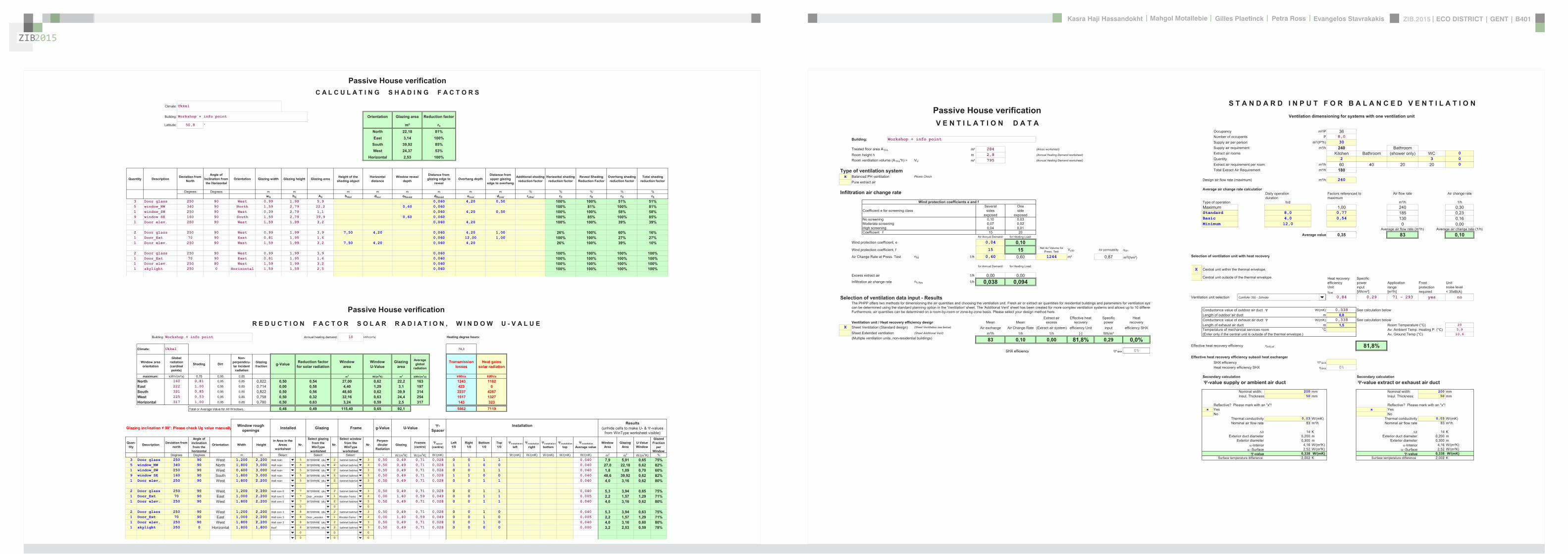
ZIB2015 ECO DISTRICT | GENT | B401Evangelos Stavrakakis | Petra Ross | Mahgol Motallebie | Gilles Plaetinck | Kasra Haji Hassandokht
ZIB2015
|
Passive House verificationV E N T I L A T I O N D A T A
Building Workshop + info point
Treated floor area ATFA msup2 284 (Areas worksheet)
Room height h m 28 (Annual Heating Demand worksheet)
Room ventilation volume (ATFAh) = VV msup3 795 (Annual Heating Demand worksheet)
Type of ventilation systemx Balanced PH ventilation Please Check
Pure extract air
Infiltration air change rate
Wind protection coefficients e and f Several One
Coefficient e for screening class sides sideexposed exposed
No screening 010 003Moderate screening 007 002High screening 004 001Coefficient f 15 20
for Annual Demand for Heating Load
Wind protection coefficient e 004 010Wind protection coefficient f 15 15 Net Air Volume for
Press Test Vn50 Air permeability q50
Air Change Rate at Press Test n50 1h 060 060 1244 msup3 087 msup3(hmsup2)
for Annual Demand for Heating Load
Excess extract air 1h 000 000Infiltration air change rate nVRes 1h 0038 0094
Selection of ventilation data input - ResultsThe PHPP offers two methods for dimensioning the air quantities and choosing the ventilation unit Fresh air or extract air quantities for residential buildings and parameters for ventilation syscan be determined using the standard planning option in the Ventilation sheet The Additional Vent sheet has been created for more complex ventilation systems and allows up to 10 differenFurthermore air quantities can be determined on a room-by-room or zone-by-zone basis Please select your design method here
Extract air Effective heat Specific HeatVentilation unit Heat recovery efficiency design Mean Mean excess recovery power recovery
X Sheet Ventilation (Standard design) (Sheet Ventilation see below) Air exchange Air Change Rate (Extract air system) efficiency Unit input efficiency SHXSheet Extended ventilation (Sheet Additional Vent) msup3h 1h 1h [-] Whmsup3(Multiple ventilation units non-residential buildings) 83 010 000 818 029 00
SHX efficiency SHX 0
PHPP Ventilation FINAL ZIB FILE CALCULTIONS PHPPxls
SHX efficiency SHX 0
PHPP Ventilation FINAL ZIB FILE CALCULTIONS PHPPxls
S T A N D A R D I N P U T F O R B A L A N C E D V E N T I L A T I O NVentilation dimensioning for systems with one ventilation unit
Occupancy msup2P 36Number of occupants P 80Supply air per person msup3(Ph) 30Supply air requirement msup3h 240 BathroomExtract air rooms Kitchen Bathroom (shower only) WC 0Quantity 2 3 0Extract air requirement per room msup3h 60 40 20 20 0Total Extract Air Requirement msup3h 180
Design air flow rate (maximum) msup3h 240
Average air change rate calculationDaily operation Factors referenced to Air flow rate Air change rateduration maximum
Type of operation hd msup3h 1hMaximum 100 240 030Standard 80 077 185 023Basic 40 054 130 016Minimum 120 0 000
Average air flow rate (msup3h) Average air change rate (1h)Average value 035 83 010
Selection of ventilation unit with heat recovery
X Central unit within the thermal envelope
Central unit outside of the thermal envelope Heat recovery Specificefficiency power Application Frost UnitUnit input range protection noise levelHR [Whmsup3] [msup3h] required lt 35dB(A)
Ventilation unit selection 19 mfoAir 350 - Zehnder 084 029 71 - 293 yes no
Conductance value of outdoor air duct W(mK) 0338 See calculation belowLength of outdoor air duct m 08Conductance value of exhaust air duct W(mK) 0338 See calculation belowLength of exhaust air duct m 15 Room Temperature (degC) 20Temperature of mechanical services room degC Av Ambient Temp Heating P (degC) 59(Enter only if the central unit is outside of the thermal envelope) Av Ground Temp (degC) 106
ComfoAir 350 - Zehnder
PHPP Ventilation FINAL ZIB FILE CALCULTIONS PHPPxls
Effective heat recovery efficiency HReff 818
Effective heat recovery efficiency subsoil heat exchangerSHX efficiency SHX
Heat recovery efficiency SHX SHX 0
Secondary calculation Secondary calculation-value supply or ambient air duct -value extract or exhaust air duct
Nominal width 200 mm Nominal width 200 mmInsul Thickness 50 mm Insul Thickness 50 mm
Reflective Please mark with an x Reflective Please mark with an xx Yes x Yes
No NoThermal conductivity 003 W(mK) Thermal conductivity 003 W(mK)Nominal air flow rate 83 msup3h Nominal air flow rate 83 msup3h
14 K 14 KExterior duct diameter 0200 m Exterior duct diameter 0200 m
Exterior diameter 0300 m Exterior diameter 0300 m-Interior 416 W(msup2K) -Interior 416 W(msup2K)
Surface 252 W(msup2K) Surface 252 W(msup2K)-value 0338 W(mK) -value 0338 W(mK)
Surface temperature difference 2002 K Surface temperature difference 2002 K
ComfoAir 350 - Zehnder
PHPP Ventilation FINAL ZIB FILE CALCULTIONS PHPPxls
Passive House verificationR E D U C T I O N F A C T O R S O L A R R A D I A T I O N W I N D O W U - V A L U E
Building Workshop + info point Annual heating demand 10 kWh(msup2a) Heating degree hours
Climate Ukkel 743
Window area orientation
Global radiation (cardinal points)
Shading Dirt
Non-perpendicu-lar incident radiation
Glazing fraction g-Value Reduction factor
for solar radiationWindow
areaWindowU-Value
Glazingarea
Average global
radiation
Transmission losses
Heat gains solar radiation
maximum kWh(msup2a) 075 095 085 m2 W(m2K) m2 kWh(m2a) kWha kWhaNorth 160 081 095 085 0822 050 054 2700 062 222 163 1243 1182East 222 100 095 085 0714 000 058 440 129 31 197 423 0South 321 085 095 085 0822 050 056 4860 062 399 314 2237 4287West 225 053 095 085 0758 050 032 3216 063 244 254 1517 1327Horizontal 317 100 095 085 0780 050 063 324 059 25 317 143 323
Total or Average Value for All Windows 048 049 11540 065 921 5562 7119
Glazing inclination ne 90deg Please check Ug value manually Window rough openings Installed Glazing Frame g-Value U-Value -
SpacerInstallation Results
(unhide cells to make U- amp -values from WinType worksheet visible)
Quan-tity Description Deviation from
north
Angle of inclination from the
horizontal
Orientation Width Heightin Area in the
Areas worksheet
Nr
Select glazing from the WinType
worksheet
Nr
Select window from the WinType
worksheet
NrPerpen-dicular
RadiationGlazing Frames
(centre) spacer (centre)
Left10
Right10
Bottom10
Top10
installation left
installation right
installation bottom
installation top
installation Average value
Window Area
Glazing Area
U-ValueWindow
Glazed Fraction
per Window
Degrees Degrees m m Select Select Select - W(m2K) W(m2K) W(mK) W(mK) W(mK) W(mK) W(mK) W(mK) m2 m2 W(m2K) 3 Door glass 250 90 West 1200 2200 5 2 3 050 049 071 0028 0 0 1 1 0040 79 591 065 755 window_NW 340 90 North 1800 3000 5 2 3 050 049 071 0028 1 1 0 0 0040 270 2218 062 821 window_SW 250 90 West 0600 3000 5 2 3 050 049 071 0028 0 0 1 1 0040 18 109 070 609 window SE 160 90 South 1800 3000 5 2 3 050 049 071 0028 1 1 0 0 0040 486 3992 062 821 Door elev 250 90 West 1800 2200 5 2 3 050 049 071 0028 0 0 1 1 0040 40 316 062 80
2 Door glass 250 90 West 1200 2200 7 2 3 050 049 071 0028 0 0 1 1 0040 53 394 065 751 Door_Ext 70 90 East 1000 2200 7 1 2 000 140 059 0049 0 0 1 1 0005 22 157 129 711 Door elev 250 90 West 1800 2200 7 2 3 050 049 071 0028 0 0 1 1 0040 40 316 062 80
0 0 0
Wall main INTERPANE iplus batimet batiment TA
Wall main
Wall main
Wall main
Wall main
Wall core 0
Wall core 0
Wall core 0
INTERPANE iplus
INTERPANE iplus
INTERPANE iplus
INTERPANE iplus
INTERPANE iplus
Door _wooden
INTERPANE iplus
batimet batiment TA
batimet batiment TA
batimet batiment TA
batimet batiment TA
batimet batiment TA
Wooden frame
batimet batiment TA
0 0 0
2 Door glass 250 90 West 1200 2200 8 2 3 050 049 071 0028 0 0 1 0 0040 53 394 063 751 Door_Ext 70 90 East 1000 2200 8 1 2 000 140 059 0049 0 0 1 0 0005 22 157 129 711 Door elev 250 90 West 1800 2200 8 2 3 050 049 071 0028 0 0 1 0 0040 40 316 060 801 skylight 250 0 Horizontal 1800 1800 6 2 3 050 049 071 0028 0 0 0 0 0000 32 253 059 78
0 0 0
0 0 0
0 0 0
0 0 0
Wall core 3
Wall core 3
Wall core 3
Roof
INTERPANE iplus
Door _wooden
INTERPANE iplus
INTERPANE iplus
batimet batiment TA
Wooden frame
batimet batiment TA
batimet batiment TA
PHPP Windows FINAL ZIB FILE CALCULTIONS PHPPxls
Passive House verificationC A L C U L A T I N G S H A D I N G F A C T O R S
Climate Ukkel
Building Workshop + info point Orientation Glazing area Reduction factor
Latitude 508 deg msup2 rS
North 2218 81East 314 100
South 3992 85West 2437 53
Horizontal 253 100
Quantity Description Deviation from North
Angle of Inclination from the Horizontal
Orientation Glazing width Glazing height Glazing area Height of the shading object
Horizontal distance
Window reveal depth
Distance from glazing edge to
revealOverhang depth
Distance from upper glazing
edge to overhang
Additional shading reduction factor
Horizontal shading reduction factor
Reveal Shading Reduction Factor
Overhang shading reduction factor
Total shading reduction factor
Degrees Degrees m m m m m m m m wG hG AG hHori dHori oReveal dReveal oover dover rother rH rR rO rS
3 Door glass 250 90 West 099 199 59 0060 420 050 100 100 51 515 window_NW 340 90 North 159 279 222 060 0060 100 81 100 811 window_SW 250 90 West 039 279 11 0060 420 050 100 100 58 589 window SE 160 90 South 159 279 399 060 0060 100 85 100 851 Door elev 250 90 West 159 199 32 0060 420 100 100 39 39
2 Door glass 250 90 West 099 199 39 750 420 0060 420 100 26 100 60 161 Door_Ext 70 90 East 081 195 16 0060 1200 100 100 100 27 271 Door elev 250 90 West 159 199 32 750 420 0060 420 26 100 39 10
2 Door glass 250 90 West 099 199 39 0060 100 100 100 1001 Door_Ext 70 90 East 081 195 16 0060 100 100 100 1001 Door elev 250 90 West 159 199 32 0060 100 100 100 1001 skylight 250 0 Horizontal 159 159 25 0060 100 100 100 100
PHPP Shading FINAL ZIB FILE CALCULTIONS PHPPxls
ZIB2015 ECO DISTRICT | GENT | B401Evangelos Stavrakakis | Petra Ross | Mahgol Motallebie | Gilles Plaetinck | Kasra Haji Hassandokht
ZIB2015
|
Passive House verificationS O L A R H O T W A T E R G E N E R A T I O N
Building Workshop + info point Building TypeUse non-residential
Treated Floor Area ATFA 2840 msup2
Solar Fraction with DHW demand including washing and dish-washing
Heating Demand DHW qgDHW 5183 kWha from DHW+Distribution worksheet
Latitude 508 deg from Climate Data worksheet
Selection of collector from list (see below) 8 Selection 8 Vacuum Tube Collector VTC
Solar Collector Area 600 msup2
Deviation from North 180 deg
Angle of Inclination from the Horizontal 45 deg
Height of the Collector Field 05 m
Height of Horizon hHori m
Horizontal Distance aHori m
Additional Reduction Factor Shading rother
Occupancy 80 Persons
Specific Collector Area 08 msup2Pers
Estimated Solar Fraction of DHW Production 49Solar Contribution to Useful Heat 2545 kWha 9 kWh(msup2a)
Secondary Calculation of Storage Losses
Selection of DHW storage from list (see below) 2 Selection Zonneboiler 200
Total Storage Volume 200 litre
Volume Standby Part (above) 60 litre
Volume Solar Part (below) 140 litre
Specific Heat Losses Storage (total) 20 WK
Typical Temperature DHW 60 degC
Room Temperature 20 degC
Storage Heat Losses (Standby Part Only) 24 W
Total Storage Heat Losses 80 W
02
03
04
05
06
07
08
09
10
200
300
400
500
600
700
800
900
1000
Sola
r fra
ctio
n[-]
ion
hea
ting
load
DH
W g
ener
atio
n h
eatin
g lo
ad
co
vere
d by
sol
ar [k
Wh
mon
th]
Monthly Heating Load Covered by Solar
Total Monthly Heating Load DHW Production
Radiation on Tilted Collector Surface
Monthly Solar Fraction
8 Vacuum Tube Collector
Zonneboiler 200
Monthly Solar Fraction January February March April May June July August September October November December
Radiation on Tilted Collector Surface 198 326 535 725 883 835 864 835 643 453 230 153 kWhMonth
Monthly Solar Fraction 018 031 049 064 075 072 074 072 058 042 021 013 -
Total Monthly Heating Load DHW Production 432 432 432 432 432 432 432 432 432 432 432 432 kWhMonth
Monthly Heating Load Covered by Solar 77 133 212 277 325 311 319 310 250 181 92 58 kWhMonth
Selection List Solar Collectors 0 = FR(ta) k1 k2 C Kdir(50deg) Kdfu OutputModule Area
(Aperture)VTC FPC Comments
InsertManufacturer Brief Description - W(msup2K) W(msup2Ksup2) kJ(msup2K) - - kWh(msup2a) msup2 please enter new
1 Brink F3-Q 08 35 00 81 10 4880 20 FPC columns2 BEFORE3 this4 column56 6 Standard Flat Plate Collector 077 35 002 64 09 08 300 2 FPC FK AD7 7 Improved Flat Plate Collector 0854 337 00104 47 097 094 546 26 FPC FK AD AR8 8 Vacuum Tube Collector 062 0395 002 1153 095 09 487 12 VTC FK AD9 RK AD101112 Insert new rows ABOVE this row only in order to maintain the integrity of references
00
01
0
100
January February March April May June July August September October November December
Sola
rad
iati
HPP SolarDHW FINAL ZIB FILE CALCULTIONS PHPPxls
Passive House verificationE F F I C I E N C Y O F H E A T G E N E R A T I O N ( G A S O I L W O O D )
Building Workshop + info point Building TypeUse non-residential
Treated Floor Area ATFA 284 msup2
Covered Fraction of Space Heating Demand (PE Value worksheet) 100
Space Heating Demand + Distribution Losses QH+QHS (DHW+Distribution) 3021 kWh
Solar Fraction for Space Heat Solar H (Separate Calculation) 48
Effective Annual Heating Demand QHWi=QH(1-Solar H) 1571 kWh
Space Heating Demand without Distribution Losses QH (Verification sheet) 2911 kWh
Covered Fraction of DHW Demand (PE Value worksheet) 100
Total Heating Demand of DHW system QgDHW (DHW+Distribution) 5183 kWh
Solar Fraction for DHW Solar DHW (SolarDHW worksheet) 49
Effective DHW Demand QDHWWi=QDHW(1-Solar DHW) 2638 kWh
Boiler Type (Project) oved gas condensing boiler 2
Primary Energy Factor (Data worksheet) 11 kWhkWh
CO2-Emissions Factor (CO2-Equivalent) 250 gkWh
Useful Heat Provided QUse 4209 kWha
Max Heating Power Required for Heating the Building PBH (Heating Load worksheet) 304 kW
Length of the Heating Period tHP 5022 h
Length of DHW Heating Period tDHW 8760 h
Use characteristic values entered (check if appropriate)
Project Data Standard Values Input field
Design Output Pnominal (Rating Plate) 15 kW 15 kW 3
Installation of Boiler (Outdoor 0 Indoor 1) 0 0 1
Input Values (Oil and Gas Boiler) Project Data Standard Values Input field
Boiler Efficiency at 30 Load (Manufacturer) 104 104 99
Boiler Efficiency at Nominal Output 100 (Manufacturer) 95 95 95
Standby Heat Loss Boiler at 70 degC qB70 (Manufacturer) 14 14 20
Improved gas condensing boiler
Average Return Temperature Measured at 30 Load 30 (Manufacturer) 30 degC 30
Input Values (Biomass Heat Generator) Project Data Standard Values Input field
Efficiency of Heat Generator in Basic Cycle GZ (Manufacturer) 60
Efficiency of Heat Generator in Constant Operation SO (Manufacturer) 70
Average Fraction of Heat Output Released to Heating Circuit zHCm (Manufacturer) 04
Temperature Difference Betw Power-On and Power-Off (Manufacturer) K 30 K
For Interior Installations Area of Mechanical Room Ainstall (Project) msup2 0 msup2
Useful Heat Output per Basic Cycle QNGZ (Manufacturer) kWh 225 kWh
Average Power Output of the Heat Generator QNm (Manufacturer) kW 150 kW
Heat generator without pellets conveyor x
Unit with regulation (no fan no starting aid)
Heating energy demand for a basic machine cycle QHEGZ (Manufacturer) kWh kWh kWh
PelSB (Manufacturer) W W W
Utilisation Factor Heat Generator Heating Run hHgK =fk 86Utilisation Factor Heat Generator DHW Run hTWgK =100fTW 87Utilisation Factor Heat Generator DHW amp Heating hgK 87
kWha kWh(msup2a)
Final Energy Demand Space Heating QFinal HE QHwi eHgK 1821Final Energy Demand DHW QFinal DHW QWWwi eTWgK 3030Total Final Energy Demand QFinal QFinalDHW + QFinalHE 4851 171Annual Primary Energy Demand 5336 188
kga kg(msup2a)
Annual CO2-Equivalent Emissions 1213 43
PHPP Boiler FINAL ZIB FILE CALCULTIONS PHPPxls
Passive House verificationS U M M E R V E N T I L A T I O N
Building Workshop + info point Building TypeUse non-residential
Building Volume 795 msup3
Description Day_ NightFraction of Opening Duration 50 50
Climate Boundary ConditionsTemperature Diff Interior - Exterior 4 1 KWind Velocity 1 0 ms
Note for summer night ventilation please set a temperature difference of 1 K and a wind velocity of 0 msotherwise the cooling effects of the night ventilation will be overestimated
Window Group 1Quantity 16Clear Width 180 180 mClear Height 270 270 mTilting Windows XOpening Width (for tilting windows) 0200 0200 m
Window Group 2 (Cross Ventilation)QuantityClear Width mClear Height mTilting WindowsOpening Width (for Tilting Windows) mDifference in Height to Window 1 m
Single-Sided Ventilation 1 - Airflow Volume 0 0 2161 0 0 0 msup3hSingle-Sided Ventilation 2 - Airflow Volume 0 0 0 0 0 0 msup3h
Cross Ventilation Airflow Volume 0 0 2161 0 0 0 msup3hContribution to Air Change Rate 000 000 136 000 000 000 1h
Summary of Summer Ventilation Distribution
Description Ventilation Type Daily Average Air Change Rate
Night time Window Ventilation 136 1hDaytime Window Ventilation 000 1h
1h
PHPP SummVent FINAL ZIB FILE CALCULTIONS PHPPxls
Passive House verificationC O M P R E S S O R C O O L I N G U N I T S
Climate Ukkel Interior Temperature Summer 25 degC
Building Workshop + info point Building TypeUse non-residentialTreated Floor Area ATFA 2840 msup2
ATFA Clear Room HeightEffective msup2 m msup3
Air Volume VV 284 280 = 795
nVsystem HR
1h Efficiency Humidity Rec 1h
Hygrically Effective Mech Air Change Rate Summer 0000 (1 - 80 ) = 0000
nVnat nVRes nNightWindows nNightmechanical
1h 1h 1h 1h
Direct Ambient Air Change Rate Summer 0000 + 0038 + 2603 + 0000 = 2641
Ambient Air Change Rate Summer Total 264 1h
Supply Air Cooling
check as appropriateOnOff Mode (check as appropriate) XMinimum Temperature of Cooling Coil Surface 0 degC
Recirculation Cooling
check as appropriateOnOff Mode (check as appropriate) xMinimum Temperature of Cooling Coil Surface 10 degCVolume Flow Rate 150 msup3h
X Additional Dehumidificationcheck as appropriate
Max Humidity Ratio 12 gkgHumidity Sources 2 g(msup2h)
Humidity Capacity Building 700 g(gkg)msup2
Humidity at Beginning of Cooling Period 8 gkg
X Panel Coolingcheck as appropriate
sensible latent
Useful Cooling Demand 36 00Useful Cooling Demand 00of which Sensible Fraction
Supply Air Cooling kWh(msup2a)
Recirculation Cooling kWh(msup2a)
Dehumidification kWh(msup2a)
Remaining for Panel Cooling 36 kWh(msup2a)
Total 36 00 kWh(msup2a) 1000
Unsatisfied Demand 00 00 kWh(msup2a)
PHPP Cooling Units FINAL ZIB FILE CALCULTIONS PHPPxls
ZIB2015 ECO DISTRICT | GENT | B401Evangelos Stavrakakis | Petra Ross | Mahgol Motallebie | Gilles Plaetinck | Kasra Haji Hassandokht
ZIB2015
|
Passive House verificationBuilding Workshop + info point E L E C T R I C I T Y D E M A N D Non-Domestic Use
Treated Floor Area ATFA 2840 msup2 Window Properties (from Windows worksheet)
Auxiliary Electricity Demand 5103 kWha Shading Dirt FactorNon-
Perpendicular Radiation
Glazing Fraction
Primary Energy Factors North 081 095 085 082Electricity 26 kWhkWh East 100 071
Gas 11 kWhkWh South 085 082
Energy Carrier for DHW 07 kWhkWh West 053 076
Solar Fraction of DHW 49
Marginal Performance Ratio DHW
Room Geometry Input of a Typical Room or Room by Room
Lighting Non-Domestic
Frac
tion
of T
reat
ed
Floo
r Are
a
Roo
m C
ateg
ory
Roo
m C
ateg
ory
Nom
inal
Illu
min
ance
Le
vel
Dev
iatio
n fro
m
Nor
th
Orie
ntat
ion
Ligh
t Tra
nsm
issi
on
Gla
zing
Exis
ting
win
dow
(1
0)
Roo
m D
epth
Roo
m W
idth
Roo
m H
eigh
t
Lint
el H
eigh
t
Win
dow
Wid
th
Day
light
Util
isat
ion
Use
r Dat
a In
stal
led
Ligh
ting
Pow
er
Inst
alle
d Li
ghtin
g Po
wer
(S
tand
ard)
Ligh
ting
Con
trol
Mot
ion
Det
ecto
r w
ithw
ithou
t (1
0)
Util
isat
ion
Hou
rs p
er
Year
[ha
]
Use
r Det
erm
ined
Li
ghtin
g Fu
ll Lo
ad H
ours
Full
Load
Hou
rs o
f Li
ghtin
g
Elec
tric
ity D
eman
d (k
Wh
a)
Spec
Ele
ctric
ity
Dem
and
(kW
h(m
sup2a))
Prim
ary
Ener
gy
Dem
and
(kW
ha)
Room Zone Lux Degrees - m m m m m Wmsup2 Wmsup2 ha ha ha kWha kWh(msup2a) kWha
2 159
workshop room a 18 41 Workshop 500 70 East 50 1 35 105 28 27 100 good 12 120 3 1 Automatic not permanently on
WithMotion 2250 8 80 49 01 128
wc 6 35 WC Sanitary 200 0 0 20 45 28 27 none 12 120 3 1 Automatic not permanently on
WithMotion 2750 8 80 16 01 43
storage 15 34 Kitchen Storage Preparation
300 0 0 40 58 28 27 none 12 120 3 1 Automatic not permanently on
WithMotion 3900 8 80 41 01 106
circulation 1 9 38 Circulation Area 100 70 East 50 1 14 116 28 27 110 good 12 120 3 1 Automatic not permanently on
WithMotion 2750 8 80 25 01 64
technical room 7 39 Storage Services 100 0 0 18 55 28 27 none 12 120 3 1 Automatic not permanently on
WithMotion 2750 3 30 07 00 19
circulation 2 9 38 Circulation Area 100 250 West 50 1 14 116 28 27 110 good 12 120 3 1 Automatic not permanently on
WithMotion 2750 8 80 25 01 64
reception a 9 37 Secondary Areas 100 70 East 50 1 35 38 28 27 36 good 12 120 3 1 Automatic not permanently on
WithMotion 2750 8 80 25 01 64
workshop room b 18 41 Workshop 500 250 West 50 1 35 105 28 27 100 low 12 120 3 1 Automatic not permanently on
WithMotion 2250 8 80 49 01 128
reception b 9 37 Secondary Areas 100 250 West 50 1 35 38 28 27 36 low 12 120 3 1 Automatic not permanently on
WithMotion 2750 8 80 25 01 64
0 0 Manual Without 0 0
Facade with Windows
Ligh
ting
Con
trol
Inpu
t War
ning
00 ManualMotion 00
00 Manual WithoutMotion 00
00 Manual WithoutMotion 00
00 Manual WithoutMotion 00
00 Manual WithoutMotion 00
00 Manual WithoutMotion 00
00 Manual WithoutMotion 00
00 Manual WithoutMotion 00
00 Manual WithoutMotion 00
00 Manual WithoutMotion 00
00 Manual WithoutMotion 00
00 Manual WithoutMotion 00
00 Manual WithoutMotion 00
HPP Electricity Non-Dom FINAL ZIB FILE CALCULTIONS PHPPxls
Office Equipment
Roo
m C
ateg
ory
Roo
m C
ateg
ory
In th
e th
erm
al
enve
lope
(1
0)
Exis
ting
Plan
ned
(1
0)
Qua
ntity
Pow
er R
atin
g (W
)
Util
isat
ion
Hou
rs
per Y
ear (
ha)
rela
tive
abse
ntee
ism
Dur
atio
n of
U
tilis
atio
n in
Ene
rgy
Savi
ng M
ode
(ha
)
Use
ful E
nerg
y(k
Wh
a)
Elec
tric
ity
Dem
and
(kW
ha)
Prim
ary
Ener
gy
Dem
and
(kW
ha)
2 9 20 18PC 1 37 Secondary Areas 1 1 1 80 ( 2750 (1- 09 ) = 22 = 220 57
PC in Energy Saving Mode 1 1 20 2750 09 = 5 = 50 13Monitor 1 1 0 28 ( 0 (1- 0 ) = 0 = 00 0
Monitor in Energy Saving Mode 1 0 20 0 0 = 0 = 00 0PC 2 41 Workshop 1 1 1 80 ( 2250 (1- 0 ) = 180 = 1800 468
PC in Energy Saving Mode 1 1 20 2250 0 = 0 = 00 0Monitor 2 1 0 28 ( 0 (1- 0 ) = 0 = 00 0
Monitor in Energy Saving Mode 1 0 20 0 0 = 0 = 00 0Copier 1 1 400 ( 0 - 0 ) = 0 = 00 0
Copier in Energy Saving Mode 1 1 30 0 = 0 = 00 0Printer 1 2 300 ( 0 - 0 ) = 0 = 00 0
Printer in Energy Saving Mode 1 2 2 0 = 0 = 00 0Server 1 1 100 ( 0 = 0 = 00 0
Server in Energy Saving Mode 1 1 ( 8760 - 0 ) = 0 = 00 0Telephone System 8760 = 0 = 00 0
= 0 = 00 0 = 0 = 00 0 = 0 = 00 0 = 0 = 00 0 = 0 = 00 0
Kitchen Aux Electricity
Roo
m C
ateg
ory
Predominant Utilisation Pattern of
Building
In th
e th
erm
al
enve
lope
(1
0)
Exis
ting
Plan
ned
(1
0)
Util
isat
ion
Day
s pe
r Ye
ar (d
a)
Num
ber o
f Mea
ls
per U
tilis
atio
n D
ay
Nor
m
Con
sum
ptio
n
Use
ful E
nerg
y (k
Wh
a)
Non
-Ele
ctric
Fra
ctio
n
Elec
tric
Frac
tion
Addi
tiona
l D
eman
d
Mar
gina
l Pe
rform
ance
R
atio
Sola
r Fra
ctio
n
Oth
er P
rimar
y En
ergy
Dem
and
(kW
ha)
Elec
tric
ity
Dem
and
(kW
ha)
Prim
ary
Ener
gy
Dem
and
(kW
ha)
8kWh Meal
Cooking 41 Workshop 2 2 250 10 025 = 1250 100 = 12500 32501 kWh
Cover 0 = 0 0Dishwashing 250 10 0 10 = 0 100 = 0 0 0Electricity
Dishwashing 250 10 010 = 0 100 = 00 01 kWhd 0 (1+ 030 ) 120 (1- 049 ) = 0 0
Refrigerating 2 2 365 053 = 387 100 = 3869 1006030 0 100 = 00 0
coffee machine 1 1 250 000 1 100 = 08 2Mixer 1 1 200 000 1 100 = 06 2
0 100 = 00 0vacuum cleaner 1 1 35 020 7 100 = 70 18
0 100 = 00 00 100 = 00 00 100 = 00 0
Total Auxiliary Electricity 5103 1327
Total kWh 0 0 2389 kWha 6210 kWha
Specific Demand 00 00 8 kWh(msup2a) 22 kWh(msup2a)
2389
Hot
Wat
er N
on-
Elec
tric
Dis
hwas
hing
510
Cold Water Connection
HPP Electricity Non-Dom FINAL ZIB FILE CALCULTIONS PHPPxls
Passive House verificationBuilding Workshop + info point A U X I L I A R Y E L E C T R I C I T Y
1 Living Area 284 msup2 Operation Vent System Winter 502 kha Primary Energy Factor - Electricity 26 kWhkWh2 Heating Period 209 d Operation Vent System Summer 374 kha Annual Space Heating Demand 10 kWh(m2a)3 Air Volume 795 msup3 Air Change Rate 010 h-1 Boiler Rated Power 15 kW4 Dwelling Units 1 HH Defrosting HX from -20 degC DHW System Heating Demand 5183 kWha5 Enclosed Volume 1244 msup3 Design Flow Temperature 55 degC
Column Nr 1 2 3 4 5 6 7 8 9 10 11
Application
Use
d
(10
)
With
in th
e Th
erm
al
Env
elop
e (1
0)
Nor
m D
eman
d
Util
izat
ion
Fact
or
Per
iod
of O
pera
tion
Ref
eren
ce S
ize
Elec
tric
ity
Dem
and
(kW
ha)
Ava
ilabl
e as
Inte
rior
Hea
t
Use
d D
urin
g Ti
me
Per
iod
(kh
a)
Inte
rnal
Hea
t So
urce
(W)
Prim
ary
Ener
gy
Dem
and
(kW
ha)
Ventilation SystemWinter Ventilation 1 1 031 Whmsup3 010 h-1 50 kha 7952 msup3 = 130 considered in heat recovery efficiency 337Summer Ventilation 031 Whmsup3 000 h-1 37 kha 7952 msup3 = 0 no summer contribution to IHG 0Defroster HX 1 1 244 W 100 01 kha 1 = 32 10 502 = 6 82Heating System ControlledUncontrolled (10)
Enter the Rated Power of the Pump 36 W 1
Circulation Pump 1 0 36 W 07 50 kha 1 = 134 10 502 = 0 348Boiler Electricity Consumption at 30 Load 40 W
Aux Energy - Heat Boiler 1 0 40 W 1 00 0 35 kha 1 = 14 1 0 5 02 = 0 36Aux Energy Heat Boiler 1 0 40 W 100 035 kha 1 14 10 502 0 36Aux Energy - Wood firedpellet boiler 0 0 Data entries in worksheet Boiler Auxiliary energy demand including possible drinking water product 0 10 502 = 0 0
DHW systemEnter Average Power Consumption of Pump 29 W
Circulation Pump 1 0 29 W 100 55 kha 1 = 160 06 876 = 0 416Enter the Rated Power of the Pump W
Storage Load Pump DHW 1 0 67 W 100 03 kha 1 = 23 10 502 = 0 61Boiler Electricity Consumption at 100 Load 1 W
DHW Boiler Aux Energy 1 0 1 W 100 02 kha 1 = 0 10 502 = 0 0Enter the Rated Power of the Solar DHW Pump 15 W
Solar Aux Electricity 1 0 15 W 100 18 kha 1 = 26 06 876 = 0 68Misc Aux Electricity Misc Aux Electricity 0 0 30 kWha 100 10 1 HH = 0 10 876 = 0 0
Total 519 6 1349
Specific Demand kWh(msup2a) Divide by Living Area 18 47
PHPP Aux Electricity FINAL ZIB FILE CALCULTIONS PHPPxls
ZIB2015
Passive House verificationI N T E R N A L H E A T G A I N S Non-domestic Use
Building Workshop + info point
Utilisation Pattern 201 Wmsup2 217 Wmsup2 Carefully complete the Electricity Non-Dom worksheet
Type of Values Used Manual entry 20 Wmsup2
Calculation Persons 80 P Room Temperature 20 degCInternal Heat TF Area 284 msup2 Heating Period 2092693 da Internal Heat Gains Aux Electricity 63 W
Column Nr
Persons
Sel
ect
Util
isat
ion
Pat
tern
Sel
ect
Act
ivity
of P
erso
nsPlanning with the number
of persons or via floor area of utilisation zone
(planning via area only if the occupancy is available for this
utilisation pattern) PersArea (1 0) N
umbe
r of O
ccup
ants
Floo
r Are
a of
Util
isat
ion
Zone
(msup2)
Ave
rage
Occ
upan
cy
(Per
sons
m
sup2)
Hea
t Em
itted
per
Per
son
(W)
Util
isat
ion
Hou
rs p
er Y
ear
[ha
]
Rel
ativ
e P
rese
nce
Use
d in
Tim
e S
pan
(ha
)
Ave
rage
Hea
t Em
itted
by
Pers
ons
(W)
27 9 18
Persons A 41 Workshop 3 gt10 yr standing or light work 1 planning with of
persons 6 or no standard value 100 2250 100 8760 = 154
Persons B 3 gt10 yr standing or light work 1 Enter of persons
or floor area or no standard value 100 0 100 8760 = 0
Persons C 3 gt10 yr standing or light work 1 Enter of persons
or floor area or no standard value 100 0 100 8760 = 0
Persons D 3 gt10 yr standing or light work 1 Enter of persons
or floor area or no standard value 100 0 100 8760 = 0
Persons E 37 Secondary Areas 2 gt 10 yr sitting 1 planning with of persons 2 or no standard
value 80 2750 010 8760 = 5Persons F 2 gt 10 yr sitting 1 Enter of persons
or floor area or no standard value 80 0 100 8760 = 0
Persons G 2 gt 10 yr sitting 1 Enter of persons or floor area or no standard
value 80 0 100 8760 = 0Evaporation (person specific) 51 -15 2750 010 8760 = -24
ergy
] ity im
eh
a)
Hea
t e
Other
PHPP Calculation Non-residential buildings
Lighting Equipment Aux Electricity
Use
ful E
ne[k
Wh
a]
Ava
ilabi
li
Use
d in
Ti
Per
iod
(kh
Ave
rage
HR
elea
se
Lighting 3850 100 876 = 440Office Applications (Within Therm Envelope) 207 100 876 = 24Cooking (Within Therm Envelope) 625 050 876 = 36Dishwashing (Within Therm Envelope) 0 030 876 = 0Cooling (Within Therm Envelope) 0 100 876 = 0Other (Within Therm Envelope) 8 100 876 = 1Auxiliary Appliances (See Aux Electricity Worksheet) = 6
Heat Loss Due to Cold Water (calculation from column AJ)
ono
ff (1
0) Predominant
Utilisation Pattern of Building
(Data transfered from Electricity Non-Dom
worksheet input kitchen) Num
ber o
f WC
s (u
ser d
ata)
Num
ber o
f WC
s U
se
stan
dard
val
ue fo
r sc
hool
s (X
)
Num
ber o
f WC
s (c
alcu
latio
n va
lue)
T C
old
Wat
er
Tem
p -
Roo
m
Tem
p [K
]
Occ
upie
d D
ays
per Y
ear [
da]
Loss
Day
time
[W]
Loss
Nig
httim
e [W
]
Ava
ilabi
lity
Use
d in
Per
iod
(da
)
Ave
rage
Pow
er
Col
d W
ater
2 8
Cold Water Due to Flushing WC 1 41 Workshop 3 3 -8 250 ( -23 + -11 ) 100 365 = -24
Total W 618Specific Demand Wmsup2 22Heat Available From Internal Sources 209 da kWh(msup2a) 11
PHPP IHG Non-Dom FINAL ZIB FILE CALCULTIONS PHPPxls
Passive House verification Secondary Calculation -Values of Plumbing
H E A T D I S T R I B U T I O N A N D D H W S Y S T E M
Building Workshop + info point Nominal Width 18 mmInsulation Thickness mm
Interior Temperature 20 degC Reflective Please mark with an xBuilding TypeUsenon-residential x Yes
Treated Floor Area ATFA 284 msup2 NoOccupancy 80 Pers Thermal Conductivity 043 W(mK)
Number of Residences 1Annual Heating Demand qHeating 2911 kWha 30 K
Length of Heating Period 209 d Interior Pipe Diameter 001800 mAverage heating load Pave 06 kW Exterior Pipe Diameter 002025 m
Marginal Utilisability of Additional Heat Gains 59 Parts Exterior Pipe Diameter 002025 m
Warm Region Cold Region Total
Space Heat Distribution 1 2 3 Surface 551 W(msup2K)Length of Distribution Pipes LH (Project) 500 m -Value 0350 W(mK)Heat Loss Coefficient per m Pipe (Project) 0350 W(mK) Surface Temperature Difference 29996 K
Temperature of the Room Through Which the Pipes X Mechanical Room 20 degC
Design Flow Temperature dist Flow Design Value 550 degC
Design System heating load Pheating (existcalc) 30 kW
Flow Temperature Control (check) 5000Design Return Temperature R dist-20)+20 450 degCAnnual Heat Emission per m of Plumbing qHL mX) tHeating0024 53 Total 123 kWh(mmiddota)Possible Utilization Factor of Released Heat G 59 -
Annual Losses QHL = LH middot qHL middot (1-G) 109 0 0 109 kWha
Specif Losses qHL = QHL ATFA kWh(msup2a) 04Performance ratio of heat distribution eaHL = ( qH + qHL) qH 104 -
DHW Standard Useful HeatDHW Consumption per Person and Day (60 degC) VDHW (Project or Average Value 25 LitresPd) 120 LitrePersondAverage Cold Water Temperature of the Supply DW Temperature of Drinking Water (10deg) 106 degCDHW Non-Electric Wash and Dish (Electricity worksheet) 0 kWha
Useful Heat - DHW QDHW 2008 kWha
Specif Useful Heat - DHW qDHW = QDHW ATFA kWh(msup2a) 71
DHW Distribution and Storage Warm Region Cold Region Total
Length of Circulation Pipes (Flow + Return) LHS (Project) 15 00 m
Heat Loss Coefficient per m Pipe (Project) 0350 0000 WmK
Temperature of the Room Through Which the Pipes X Mechanical Room 20 00 degC
Design Flow Temperature dist Flow Design Value 600 00 degC
Daily circulation period of operation tdCirc (Project) 120 00 hdDesign Return Temperature R =0875(dist-20)+20 55 3 degCCirculation period of operation per year tCirc = 365 tdCirc 4380 0 haAnnual Heat Released per m of Pipe qZ mX) tCirc 57 0 kWhmaPossible Utilization Factor of Released Heat GDHW =theating365d G 34 0 -
Annual Heat Loss from Circulation Lines QZ = LHS middot qZ middot(1-GDHW) 57 0 57 kWha
Total Length of Individual Pipes LU (Project) 5000 mExterior Pipe Diameter dU_Pipe (Project) 0018 mHeat loss per tap opening qIndividual =(cpH2OVH2O+cpMatVMat)(dist-X) 04557 kWhtap openingAmount of tap openings per year nTap = nPers 3 365 nLU 8760 Tap openings per yearAnnual Heat Loss qU = nTap
qIndividual 3992 kWhaPossible Utilization Factor of Released Heat G_U =theating8760G 34 -
Annual Heat Loss of Individual Pipes QU = qU middot(1-G_U) 2652 2652 kWha
Total 123
Average Heat Released From Storage PS 80 W Secondary Calculation Storage LossesPossible Utilization Factor of Released Heat G_S =theating8760G 34
Annual Heat Losses from Storage QS = PSmiddot8760 khmiddot(1-G_S) 466 466 kWha Specific Heat Losses Storage (total) 25 WK
Total 123 Typical Temperature DHW 60 degC
Total Heat Losses of the DHW System QWL = QZ+QU+QS 3175 kWha Room Temperature 20 degC
Specif Losses of the DHW System qWL = QWL ATFA kWh(msup2a) 112 Total Storage Heat Losses 100 W
Performance ratio DHW-distribution + storage eaWL = (qTWW + qWV) qTWW 2581 -
Total Heating Demand of DHW system QgDHW = QDHW+QWL 5183 kWha
Total Spec Heating Demand of DHW System qgDHW = QgDHW ATFA kWh(msup2a) 183
PHPP DHW+Distribution FINAL ZIB FILE CALCULTIONS PHPPxlsPHPP DHW+Distribution FINAL ZIB FILE CALCULTIONS PHPPxls
Passive House verification Secondary Calculation -Values of Plumbing
H E A T D I S T R I B U T I O N A N D D H W S Y S T E M
Building Workshop + info point Nominal Width 18 mmInsulation Thickness mm
Interior Temperature 20 degC Reflective Please mark with an xBuilding TypeUsenon-residential x Yes
Treated Floor Area ATFA 284 msup2 NoOccupancy 80 Pers Thermal Conductivity 043 W(mK)
Number of Residences 1Annual Heating Demand qHeating 2911 kWha 30 K
Length of Heating Period 209 d Interior Pipe Diameter 001800 mAverage heating load Pave 06 kW Exterior Pipe Diameter 002025 m
Marginal Utilisability of Additional Heat Gains 59 Parts Exterior Pipe Diameter 002025 m
Warm Region Cold Region Total
Space Heat Distribution 1 2 3 Surface 551 W(msup2K)Length of Distribution Pipes LH (Project) 500 m -Value 0350 W(mK)Heat Loss Coefficient per m Pipe (Project) 0350 W(mK) Surface Temperature Difference 29996 K
Temperature of the Room Through Which the Pipes X Mechanical Room 20 degC
Design Flow Temperature dist Flow Design Value 550 degC
Design System heating load Pheating (existcalc) 30 kW
Flow Temperature Control (check) 5000Design Return Temperature R dist-20)+20 450 degCAnnual Heat Emission per m of Plumbing qHL mX) tHeating0024 53 Total 123 kWh(mmiddota)Possible Utilization Factor of Released Heat G 59 -
Annual Losses QHL = LH middot qHL middot (1-G) 109 0 0 109 kWha
Specif Losses qHL = QHL ATFA kWh(msup2a) 04Performance ratio of heat distribution eaHL = ( qH + qHL) qH 104 -
DHW Standard Useful HeatDHW Consumption per Person and Day (60 degC) VDHW (Project or Average Value 25 LitresPd) 120 LitrePersondAverage Cold Water Temperature of the Supply DW Temperature of Drinking Water (10deg) 106 degCDHW Non-Electric Wash and Dish (Electricity worksheet) 0 kWha
Useful Heat - DHW QDHW 2008 kWha
Specif Useful Heat - DHW qDHW = QDHW ATFA kWh(msup2a) 71
DHW Distribution and Storage Warm Region Cold Region Total
Length of Circulation Pipes (Flow + Return) LHS (Project) 15 00 m
Heat Loss Coefficient per m Pipe (Project) 0350 0000 WmK
Temperature of the Room Through Which the Pipes X Mechanical Room 20 00 degC
Design Flow Temperature dist Flow Design Value 600 00 degC
Daily circulation period of operation tdCirc (Project) 120 00 hdDesign Return Temperature R =0875(dist-20)+20 55 3 degCCirculation period of operation per year tCirc = 365 tdCirc 4380 0 haAnnual Heat Released per m of Pipe qZ mX) tCirc 57 0 kWhmaPossible Utilization Factor of Released Heat GDHW =theating365d G 34 0 -
Annual Heat Loss from Circulation Lines QZ = LHS middot qZ middot(1-GDHW) 57 0 57 kWha
Total Length of Individual Pipes LU (Project) 5000 mExterior Pipe Diameter dU_Pipe (Project) 0018 mHeat loss per tap opening qIndividual =(cpH2OVH2O+cpMatVMat)(dist-X) 04557 kWhtap openingAmount of tap openings per year nTap = nPers 3 365 nLU 8760 Tap openings per yearAnnual Heat Loss qU = nTap
qIndividual 3992 kWhaPossible Utilization Factor of Released Heat G_U =theating8760G 34 -
Annual Heat Loss of Individual Pipes QU = qU middot(1-G_U) 2652 2652 kWha
Total 123
Average Heat Released From Storage PS 80 W Secondary Calculation Storage LossesPossible Utilization Factor of Released Heat G_S =theating8760G 34
Annual Heat Losses from Storage QS = PSmiddot8760 khmiddot(1-G_S) 466 466 kWha Specific Heat Losses Storage (total) 25 WK
Total 123 Typical Temperature DHW 60 degC
Total Heat Losses of the DHW System QWL = QZ+QU+QS 3175 kWha Room Temperature 20 degC
Specif Losses of the DHW System qWL = QWL ATFA kWh(msup2a) 112 Total Storage Heat Losses 100 W
Performance ratio DHW-distribution + storage eaWL = (qTWW + qWV) qTWW 2581 -
Total Heating Demand of DHW system QgDHW = QDHW+QWL 5183 kWha
Total Spec Heating Demand of DHW System qgDHW = QgDHW ATFA kWh(msup2a) 183
PHPP DHW+Distribution FINAL ZIB FILE CALCULTIONS PHPPxlsPHPP DHW+Distribution FINAL ZIB FILE CALCULTIONS PHPPxls
Passive House verification Secondary Calculation -Values of Plumbing
H E A T D I S T R I B U T I O N A N D D H W S Y S T E M
Building Workshop + info point Nominal Width 18 mmInsulation Thickness mm
Interior Temperature 20 degC Reflective Please mark with an xBuilding TypeUsenon-residential x Yes
Treated Floor Area ATFA 284 msup2 NoOccupancy 80 Pers Thermal Conductivity 043 W(mK)
Number of Residences 1Annual Heating Demand qHeating 2911 kWha 30 K
Length of Heating Period 209 d Interior Pipe Diameter 001800 mAverage heating load Pave 06 kW Exterior Pipe Diameter 002025 m
Marginal Utilisability of Additional Heat Gains 59 Parts Exterior Pipe Diameter 002025 m
Warm Region Cold Region Total
Space Heat Distribution 1 2 3 Surface 551 W(msup2K)Length of Distribution Pipes LH (Project) 500 m -Value 0350 W(mK)Heat Loss Coefficient per m Pipe (Project) 0350 W(mK) Surface Temperature Difference 29996 K
Temperature of the Room Through Which the Pipes X Mechanical Room 20 degC
Design Flow Temperature dist Flow Design Value 550 degC
Design System heating load Pheating (existcalc) 30 kW
Flow Temperature Control (check) 5000Design Return Temperature R dist-20)+20 450 degCAnnual Heat Emission per m of Plumbing qHL mX) tHeating0024 53 Total 123 kWh(mmiddota)Possible Utilization Factor of Released Heat G 59 -
Annual Losses QHL = LH middot qHL middot (1-G) 109 0 0 109 kWha
Specif Losses qHL = QHL ATFA kWh(msup2a) 04Performance ratio of heat distribution eaHL = ( qH + qHL) qH 104 -
DHW Standard Useful HeatDHW Consumption per Person and Day (60 degC) VDHW (Project or Average Value 25 LitresPd) 120 LitrePersondAverage Cold Water Temperature of the Supply DW Temperature of Drinking Water (10deg) 106 degCDHW Non-Electric Wash and Dish (Electricity worksheet) 0 kWha
Useful Heat - DHW QDHW 2008 kWha
Specif Useful Heat - DHW qDHW = QDHW ATFA kWh(msup2a) 71
DHW Distribution and Storage Warm Region Cold Region Total
Length of Circulation Pipes (Flow + Return) LHS (Project) 15 00 m
Heat Loss Coefficient per m Pipe (Project) 0350 0000 WmK
Temperature of the Room Through Which the Pipes X Mechanical Room 20 00 degC
Design Flow Temperature dist Flow Design Value 600 00 degC
Daily circulation period of operation tdCirc (Project) 120 00 hdDesign Return Temperature R =0875(dist-20)+20 55 3 degCCirculation period of operation per year tCirc = 365 tdCirc 4380 0 haAnnual Heat Released per m of Pipe qZ mX) tCirc 57 0 kWhmaPossible Utilization Factor of Released Heat GDHW =theating365d G 34 0 -
Annual Heat Loss from Circulation Lines QZ = LHS middot qZ middot(1-GDHW) 57 0 57 kWha
Total Length of Individual Pipes LU (Project) 5000 mExterior Pipe Diameter dU_Pipe (Project) 0018 mHeat loss per tap opening qIndividual =(cpH2OVH2O+cpMatVMat)(dist-X) 04557 kWhtap openingAmount of tap openings per year nTap = nPers 3 365 nLU 8760 Tap openings per yearAnnual Heat Loss qU = nTap
qIndividual 3992 kWhaPossible Utilization Factor of Released Heat G_U =theating8760G 34 -
Annual Heat Loss of Individual Pipes QU = qU middot(1-G_U) 2652 2652 kWha
Total 123
Average Heat Released From Storage PS 80 W Secondary Calculation Storage LossesPossible Utilization Factor of Released Heat G_S =theating8760G 34
Annual Heat Losses from Storage QS = PSmiddot8760 khmiddot(1-G_S) 466 466 kWha Specific Heat Losses Storage (total) 25 WK
Total 123 Typical Temperature DHW 60 degC
Total Heat Losses of the DHW System QWL = QZ+QU+QS 3175 kWha Room Temperature 20 degC
Specif Losses of the DHW System qWL = QWL ATFA kWh(msup2a) 112 Total Storage Heat Losses 100 W
Performance ratio DHW-distribution + storage eaWL = (qTWW + qWV) qTWW 2581 -
Total Heating Demand of DHW system QgDHW = QDHW+QWL 5183 kWha
Total Spec Heating Demand of DHW System qgDHW = QgDHW ATFA kWh(msup2a) 183
PHPP DHW+Distribution FINAL ZIB FILE CALCULTIONS PHPPxlsPHPP DHW+Distribution FINAL ZIB FILE CALCULTIONS PHPPxls
ZERO IMPACT BUILDING MA (SCI) ARCHITECTUREKU LEUVEN middot SINT LUCAS GROUP 42 middot GENT copy2015
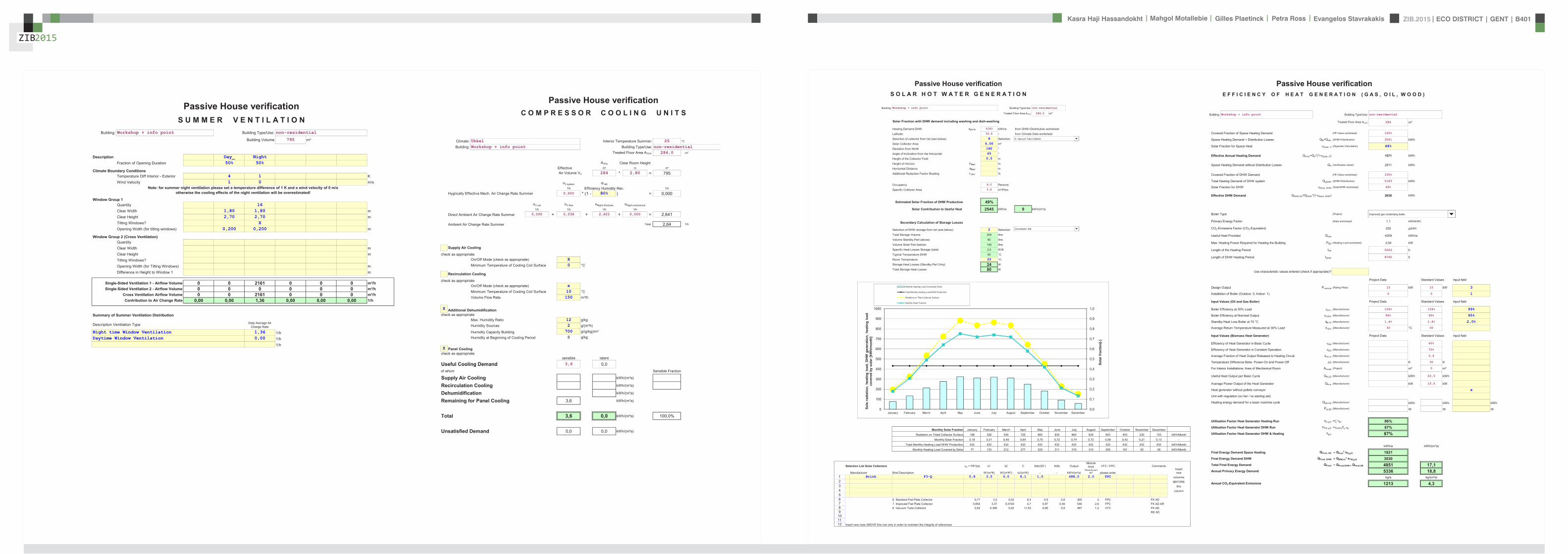
ZIB2015 ECO DISTRICT | GENT | B401Evangelos Stavrakakis | Petra Ross | Mahgol Motallebie | Gilles Plaetinck | Kasra Haji Hassandokht
ZIB2015
|
Passive House verificationS O L A R H O T W A T E R G E N E R A T I O N
Building Workshop + info point Building TypeUse non-residential
Treated Floor Area ATFA 2840 msup2
Solar Fraction with DHW demand including washing and dish-washing
Heating Demand DHW qgDHW 5183 kWha from DHW+Distribution worksheet
Latitude 508 deg from Climate Data worksheet
Selection of collector from list (see below) 8 Selection 8 Vacuum Tube Collector VTC
Solar Collector Area 600 msup2
Deviation from North 180 deg
Angle of Inclination from the Horizontal 45 deg
Height of the Collector Field 05 m
Height of Horizon hHori m
Horizontal Distance aHori m
Additional Reduction Factor Shading rother
Occupancy 80 Persons
Specific Collector Area 08 msup2Pers
Estimated Solar Fraction of DHW Production 49Solar Contribution to Useful Heat 2545 kWha 9 kWh(msup2a)
Secondary Calculation of Storage Losses
Selection of DHW storage from list (see below) 2 Selection Zonneboiler 200
Total Storage Volume 200 litre
Volume Standby Part (above) 60 litre
Volume Solar Part (below) 140 litre
Specific Heat Losses Storage (total) 20 WK
Typical Temperature DHW 60 degC
Room Temperature 20 degC
Storage Heat Losses (Standby Part Only) 24 W
Total Storage Heat Losses 80 W
02
03
04
05
06
07
08
09
10
200
300
400
500
600
700
800
900
1000
Sola
r fra
ctio
n[-]
ion
hea
ting
load
DH
W g
ener
atio
n h
eatin
g lo
ad
co
vere
d by
sol
ar [k
Wh
mon
th]
Monthly Heating Load Covered by Solar
Total Monthly Heating Load DHW Production
Radiation on Tilted Collector Surface
Monthly Solar Fraction
8 Vacuum Tube Collector
Zonneboiler 200
Monthly Solar Fraction January February March April May June July August September October November December
Radiation on Tilted Collector Surface 198 326 535 725 883 835 864 835 643 453 230 153 kWhMonth
Monthly Solar Fraction 018 031 049 064 075 072 074 072 058 042 021 013 -
Total Monthly Heating Load DHW Production 432 432 432 432 432 432 432 432 432 432 432 432 kWhMonth
Monthly Heating Load Covered by Solar 77 133 212 277 325 311 319 310 250 181 92 58 kWhMonth
Selection List Solar Collectors 0 = FR(ta) k1 k2 C Kdir(50deg) Kdfu OutputModule Area
(Aperture)VTC FPC Comments
InsertManufacturer Brief Description - W(msup2K) W(msup2Ksup2) kJ(msup2K) - - kWh(msup2a) msup2 please enter new
1 Brink F3-Q 08 35 00 81 10 4880 20 FPC columns2 BEFORE3 this4 column56 6 Standard Flat Plate Collector 077 35 002 64 09 08 300 2 FPC FK AD7 7 Improved Flat Plate Collector 0854 337 00104 47 097 094 546 26 FPC FK AD AR8 8 Vacuum Tube Collector 062 0395 002 1153 095 09 487 12 VTC FK AD9 RK AD101112 Insert new rows ABOVE this row only in order to maintain the integrity of references
00
01
0
100
January February March April May June July August September October November December
Sola
rad
iati
HPP SolarDHW FINAL ZIB FILE CALCULTIONS PHPPxls
Passive House verificationE F F I C I E N C Y O F H E A T G E N E R A T I O N ( G A S O I L W O O D )
Building Workshop + info point Building TypeUse non-residential
Treated Floor Area ATFA 284 msup2
Covered Fraction of Space Heating Demand (PE Value worksheet) 100
Space Heating Demand + Distribution Losses QH+QHS (DHW+Distribution) 3021 kWh
Solar Fraction for Space Heat Solar H (Separate Calculation) 48
Effective Annual Heating Demand QHWi=QH(1-Solar H) 1571 kWh
Space Heating Demand without Distribution Losses QH (Verification sheet) 2911 kWh
Covered Fraction of DHW Demand (PE Value worksheet) 100
Total Heating Demand of DHW system QgDHW (DHW+Distribution) 5183 kWh
Solar Fraction for DHW Solar DHW (SolarDHW worksheet) 49
Effective DHW Demand QDHWWi=QDHW(1-Solar DHW) 2638 kWh
Boiler Type (Project) oved gas condensing boiler 2
Primary Energy Factor (Data worksheet) 11 kWhkWh
CO2-Emissions Factor (CO2-Equivalent) 250 gkWh
Useful Heat Provided QUse 4209 kWha
Max Heating Power Required for Heating the Building PBH (Heating Load worksheet) 304 kW
Length of the Heating Period tHP 5022 h
Length of DHW Heating Period tDHW 8760 h
Use characteristic values entered (check if appropriate)
Project Data Standard Values Input field
Design Output Pnominal (Rating Plate) 15 kW 15 kW 3
Installation of Boiler (Outdoor 0 Indoor 1) 0 0 1
Input Values (Oil and Gas Boiler) Project Data Standard Values Input field
Boiler Efficiency at 30 Load (Manufacturer) 104 104 99
Boiler Efficiency at Nominal Output 100 (Manufacturer) 95 95 95
Standby Heat Loss Boiler at 70 degC qB70 (Manufacturer) 14 14 20
Improved gas condensing boiler
Average Return Temperature Measured at 30 Load 30 (Manufacturer) 30 degC 30
Input Values (Biomass Heat Generator) Project Data Standard Values Input field
Efficiency of Heat Generator in Basic Cycle GZ (Manufacturer) 60
Efficiency of Heat Generator in Constant Operation SO (Manufacturer) 70
Average Fraction of Heat Output Released to Heating Circuit zHCm (Manufacturer) 04
Temperature Difference Betw Power-On and Power-Off (Manufacturer) K 30 K
For Interior Installations Area of Mechanical Room Ainstall (Project) msup2 0 msup2
Useful Heat Output per Basic Cycle QNGZ (Manufacturer) kWh 225 kWh
Average Power Output of the Heat Generator QNm (Manufacturer) kW 150 kW
Heat generator without pellets conveyor x
Unit with regulation (no fan no starting aid)
Heating energy demand for a basic machine cycle QHEGZ (Manufacturer) kWh kWh kWh
PelSB (Manufacturer) W W W
Utilisation Factor Heat Generator Heating Run hHgK =fk 86Utilisation Factor Heat Generator DHW Run hTWgK =100fTW 87Utilisation Factor Heat Generator DHW amp Heating hgK 87
kWha kWh(msup2a)
Final Energy Demand Space Heating QFinal HE QHwi eHgK 1821Final Energy Demand DHW QFinal DHW QWWwi eTWgK 3030Total Final Energy Demand QFinal QFinalDHW + QFinalHE 4851 171Annual Primary Energy Demand 5336 188
kga kg(msup2a)
Annual CO2-Equivalent Emissions 1213 43
PHPP Boiler FINAL ZIB FILE CALCULTIONS PHPPxls
Passive House verificationS U M M E R V E N T I L A T I O N
Building Workshop + info point Building TypeUse non-residential
Building Volume 795 msup3
Description Day_ NightFraction of Opening Duration 50 50
Climate Boundary ConditionsTemperature Diff Interior - Exterior 4 1 KWind Velocity 1 0 ms
Note for summer night ventilation please set a temperature difference of 1 K and a wind velocity of 0 msotherwise the cooling effects of the night ventilation will be overestimated
Window Group 1Quantity 16Clear Width 180 180 mClear Height 270 270 mTilting Windows XOpening Width (for tilting windows) 0200 0200 m
Window Group 2 (Cross Ventilation)QuantityClear Width mClear Height mTilting WindowsOpening Width (for Tilting Windows) mDifference in Height to Window 1 m
Single-Sided Ventilation 1 - Airflow Volume 0 0 2161 0 0 0 msup3hSingle-Sided Ventilation 2 - Airflow Volume 0 0 0 0 0 0 msup3h
Cross Ventilation Airflow Volume 0 0 2161 0 0 0 msup3hContribution to Air Change Rate 000 000 136 000 000 000 1h
Summary of Summer Ventilation Distribution
Description Ventilation Type Daily Average Air Change Rate
Night time Window Ventilation 136 1hDaytime Window Ventilation 000 1h
1h
PHPP SummVent FINAL ZIB FILE CALCULTIONS PHPPxls
Passive House verificationC O M P R E S S O R C O O L I N G U N I T S
Climate Ukkel Interior Temperature Summer 25 degC
Building Workshop + info point Building TypeUse non-residentialTreated Floor Area ATFA 2840 msup2
ATFA Clear Room HeightEffective msup2 m msup3
Air Volume VV 284 280 = 795
nVsystem HR
1h Efficiency Humidity Rec 1h
Hygrically Effective Mech Air Change Rate Summer 0000 (1 - 80 ) = 0000
nVnat nVRes nNightWindows nNightmechanical
1h 1h 1h 1h
Direct Ambient Air Change Rate Summer 0000 + 0038 + 2603 + 0000 = 2641
Ambient Air Change Rate Summer Total 264 1h
Supply Air Cooling
check as appropriateOnOff Mode (check as appropriate) XMinimum Temperature of Cooling Coil Surface 0 degC
Recirculation Cooling
check as appropriateOnOff Mode (check as appropriate) xMinimum Temperature of Cooling Coil Surface 10 degCVolume Flow Rate 150 msup3h
X Additional Dehumidificationcheck as appropriate
Max Humidity Ratio 12 gkgHumidity Sources 2 g(msup2h)
Humidity Capacity Building 700 g(gkg)msup2
Humidity at Beginning of Cooling Period 8 gkg
X Panel Coolingcheck as appropriate
sensible latent
Useful Cooling Demand 36 00Useful Cooling Demand 00of which Sensible Fraction
Supply Air Cooling kWh(msup2a)
Recirculation Cooling kWh(msup2a)
Dehumidification kWh(msup2a)
Remaining for Panel Cooling 36 kWh(msup2a)
Total 36 00 kWh(msup2a) 1000
Unsatisfied Demand 00 00 kWh(msup2a)
PHPP Cooling Units FINAL ZIB FILE CALCULTIONS PHPPxls
ZIB2015 ECO DISTRICT | GENT | B401Evangelos Stavrakakis | Petra Ross | Mahgol Motallebie | Gilles Plaetinck | Kasra Haji Hassandokht
ZIB2015
|
Passive House verificationBuilding Workshop + info point E L E C T R I C I T Y D E M A N D Non-Domestic Use
Treated Floor Area ATFA 2840 msup2 Window Properties (from Windows worksheet)
Auxiliary Electricity Demand 5103 kWha Shading Dirt FactorNon-
Perpendicular Radiation
Glazing Fraction
Primary Energy Factors North 081 095 085 082Electricity 26 kWhkWh East 100 071
Gas 11 kWhkWh South 085 082
Energy Carrier for DHW 07 kWhkWh West 053 076
Solar Fraction of DHW 49
Marginal Performance Ratio DHW
Room Geometry Input of a Typical Room or Room by Room
Lighting Non-Domestic
Frac
tion
of T
reat
ed
Floo
r Are
a
Roo
m C
ateg
ory
Roo
m C
ateg
ory
Nom
inal
Illu
min
ance
Le
vel
Dev
iatio
n fro
m
Nor
th
Orie
ntat
ion
Ligh
t Tra
nsm
issi
on
Gla
zing
Exis
ting
win
dow
(1
0)
Roo
m D
epth
Roo
m W
idth
Roo
m H
eigh
t
Lint
el H
eigh
t
Win
dow
Wid
th
Day
light
Util
isat
ion
Use
r Dat
a In
stal
led
Ligh
ting
Pow
er
Inst
alle
d Li
ghtin
g Po
wer
(S
tand
ard)
Ligh
ting
Con
trol
Mot
ion
Det
ecto
r w
ithw
ithou
t (1
0)
Util
isat
ion
Hou
rs p
er
Year
[ha
]
Use
r Det
erm
ined
Li
ghtin
g Fu
ll Lo
ad H
ours
Full
Load
Hou
rs o
f Li
ghtin
g
Elec
tric
ity D
eman
d (k
Wh
a)
Spec
Ele
ctric
ity
Dem
and
(kW
h(m
sup2a))
Prim
ary
Ener
gy
Dem
and
(kW
ha)
Room Zone Lux Degrees - m m m m m Wmsup2 Wmsup2 ha ha ha kWha kWh(msup2a) kWha
2 159
workshop room a 18 41 Workshop 500 70 East 50 1 35 105 28 27 100 good 12 120 3 1 Automatic not permanently on
WithMotion 2250 8 80 49 01 128
wc 6 35 WC Sanitary 200 0 0 20 45 28 27 none 12 120 3 1 Automatic not permanently on
WithMotion 2750 8 80 16 01 43
storage 15 34 Kitchen Storage Preparation
300 0 0 40 58 28 27 none 12 120 3 1 Automatic not permanently on
WithMotion 3900 8 80 41 01 106
circulation 1 9 38 Circulation Area 100 70 East 50 1 14 116 28 27 110 good 12 120 3 1 Automatic not permanently on
WithMotion 2750 8 80 25 01 64
technical room 7 39 Storage Services 100 0 0 18 55 28 27 none 12 120 3 1 Automatic not permanently on
WithMotion 2750 3 30 07 00 19
circulation 2 9 38 Circulation Area 100 250 West 50 1 14 116 28 27 110 good 12 120 3 1 Automatic not permanently on
WithMotion 2750 8 80 25 01 64
reception a 9 37 Secondary Areas 100 70 East 50 1 35 38 28 27 36 good 12 120 3 1 Automatic not permanently on
WithMotion 2750 8 80 25 01 64
workshop room b 18 41 Workshop 500 250 West 50 1 35 105 28 27 100 low 12 120 3 1 Automatic not permanently on
WithMotion 2250 8 80 49 01 128
reception b 9 37 Secondary Areas 100 250 West 50 1 35 38 28 27 36 low 12 120 3 1 Automatic not permanently on
WithMotion 2750 8 80 25 01 64
0 0 Manual Without 0 0
Facade with Windows
Ligh
ting
Con
trol
Inpu
t War
ning
00 ManualMotion 00
00 Manual WithoutMotion 00
00 Manual WithoutMotion 00
00 Manual WithoutMotion 00
00 Manual WithoutMotion 00
00 Manual WithoutMotion 00
00 Manual WithoutMotion 00
00 Manual WithoutMotion 00
00 Manual WithoutMotion 00
00 Manual WithoutMotion 00
00 Manual WithoutMotion 00
00 Manual WithoutMotion 00
00 Manual WithoutMotion 00
HPP Electricity Non-Dom FINAL ZIB FILE CALCULTIONS PHPPxls
Office Equipment
Roo
m C
ateg
ory
Roo
m C
ateg
ory
In th
e th
erm
al
enve
lope
(1
0)
Exis
ting
Plan
ned
(1
0)
Qua
ntity
Pow
er R
atin
g (W
)
Util
isat
ion
Hou
rs
per Y
ear (
ha)
rela
tive
abse
ntee
ism
Dur
atio
n of
U
tilis
atio
n in
Ene
rgy
Savi
ng M
ode
(ha
)
Use
ful E
nerg
y(k
Wh
a)
Elec
tric
ity
Dem
and
(kW
ha)
Prim
ary
Ener
gy
Dem
and
(kW
ha)
2 9 20 18PC 1 37 Secondary Areas 1 1 1 80 ( 2750 (1- 09 ) = 22 = 220 57
PC in Energy Saving Mode 1 1 20 2750 09 = 5 = 50 13Monitor 1 1 0 28 ( 0 (1- 0 ) = 0 = 00 0
Monitor in Energy Saving Mode 1 0 20 0 0 = 0 = 00 0PC 2 41 Workshop 1 1 1 80 ( 2250 (1- 0 ) = 180 = 1800 468
PC in Energy Saving Mode 1 1 20 2250 0 = 0 = 00 0Monitor 2 1 0 28 ( 0 (1- 0 ) = 0 = 00 0
Monitor in Energy Saving Mode 1 0 20 0 0 = 0 = 00 0Copier 1 1 400 ( 0 - 0 ) = 0 = 00 0
Copier in Energy Saving Mode 1 1 30 0 = 0 = 00 0Printer 1 2 300 ( 0 - 0 ) = 0 = 00 0
Printer in Energy Saving Mode 1 2 2 0 = 0 = 00 0Server 1 1 100 ( 0 = 0 = 00 0
Server in Energy Saving Mode 1 1 ( 8760 - 0 ) = 0 = 00 0Telephone System 8760 = 0 = 00 0
= 0 = 00 0 = 0 = 00 0 = 0 = 00 0 = 0 = 00 0 = 0 = 00 0
Kitchen Aux Electricity
Roo
m C
ateg
ory
Predominant Utilisation Pattern of
Building
In th
e th
erm
al
enve
lope
(1
0)
Exis
ting
Plan
ned
(1
0)
Util
isat
ion
Day
s pe
r Ye
ar (d
a)
Num
ber o
f Mea
ls
per U
tilis
atio
n D
ay
Nor
m
Con
sum
ptio
n
Use
ful E
nerg
y (k
Wh
a)
Non
-Ele
ctric
Fra
ctio
n
Elec
tric
Frac
tion
Addi
tiona
l D
eman
d
Mar
gina
l Pe
rform
ance
R
atio
Sola
r Fra
ctio
n
Oth
er P
rimar
y En
ergy
Dem
and
(kW
ha)
Elec
tric
ity
Dem
and
(kW
ha)
Prim
ary
Ener
gy
Dem
and
(kW
ha)
8kWh Meal
Cooking 41 Workshop 2 2 250 10 025 = 1250 100 = 12500 32501 kWh
Cover 0 = 0 0Dishwashing 250 10 0 10 = 0 100 = 0 0 0Electricity
Dishwashing 250 10 010 = 0 100 = 00 01 kWhd 0 (1+ 030 ) 120 (1- 049 ) = 0 0
Refrigerating 2 2 365 053 = 387 100 = 3869 1006030 0 100 = 00 0
coffee machine 1 1 250 000 1 100 = 08 2Mixer 1 1 200 000 1 100 = 06 2
0 100 = 00 0vacuum cleaner 1 1 35 020 7 100 = 70 18
0 100 = 00 00 100 = 00 00 100 = 00 0
Total Auxiliary Electricity 5103 1327
Total kWh 0 0 2389 kWha 6210 kWha
Specific Demand 00 00 8 kWh(msup2a) 22 kWh(msup2a)
2389
Hot
Wat
er N
on-
Elec
tric
Dis
hwas
hing
510
Cold Water Connection
HPP Electricity Non-Dom FINAL ZIB FILE CALCULTIONS PHPPxls
Passive House verificationBuilding Workshop + info point A U X I L I A R Y E L E C T R I C I T Y
1 Living Area 284 msup2 Operation Vent System Winter 502 kha Primary Energy Factor - Electricity 26 kWhkWh2 Heating Period 209 d Operation Vent System Summer 374 kha Annual Space Heating Demand 10 kWh(m2a)3 Air Volume 795 msup3 Air Change Rate 010 h-1 Boiler Rated Power 15 kW4 Dwelling Units 1 HH Defrosting HX from -20 degC DHW System Heating Demand 5183 kWha5 Enclosed Volume 1244 msup3 Design Flow Temperature 55 degC
Column Nr 1 2 3 4 5 6 7 8 9 10 11
Application
Use
d
(10
)
With
in th
e Th
erm
al
Env
elop
e (1
0)
Nor
m D
eman
d
Util
izat
ion
Fact
or
Per
iod
of O
pera
tion
Ref
eren
ce S
ize
Elec
tric
ity
Dem
and
(kW
ha)
Ava
ilabl
e as
Inte
rior
Hea
t
Use
d D
urin
g Ti
me
Per
iod
(kh
a)
Inte
rnal
Hea
t So
urce
(W)
Prim
ary
Ener
gy
Dem
and
(kW
ha)
Ventilation SystemWinter Ventilation 1 1 031 Whmsup3 010 h-1 50 kha 7952 msup3 = 130 considered in heat recovery efficiency 337Summer Ventilation 031 Whmsup3 000 h-1 37 kha 7952 msup3 = 0 no summer contribution to IHG 0Defroster HX 1 1 244 W 100 01 kha 1 = 32 10 502 = 6 82Heating System ControlledUncontrolled (10)
Enter the Rated Power of the Pump 36 W 1
Circulation Pump 1 0 36 W 07 50 kha 1 = 134 10 502 = 0 348Boiler Electricity Consumption at 30 Load 40 W
Aux Energy - Heat Boiler 1 0 40 W 1 00 0 35 kha 1 = 14 1 0 5 02 = 0 36Aux Energy Heat Boiler 1 0 40 W 100 035 kha 1 14 10 502 0 36Aux Energy - Wood firedpellet boiler 0 0 Data entries in worksheet Boiler Auxiliary energy demand including possible drinking water product 0 10 502 = 0 0
DHW systemEnter Average Power Consumption of Pump 29 W
Circulation Pump 1 0 29 W 100 55 kha 1 = 160 06 876 = 0 416Enter the Rated Power of the Pump W
Storage Load Pump DHW 1 0 67 W 100 03 kha 1 = 23 10 502 = 0 61Boiler Electricity Consumption at 100 Load 1 W
DHW Boiler Aux Energy 1 0 1 W 100 02 kha 1 = 0 10 502 = 0 0Enter the Rated Power of the Solar DHW Pump 15 W
Solar Aux Electricity 1 0 15 W 100 18 kha 1 = 26 06 876 = 0 68Misc Aux Electricity Misc Aux Electricity 0 0 30 kWha 100 10 1 HH = 0 10 876 = 0 0
Total 519 6 1349
Specific Demand kWh(msup2a) Divide by Living Area 18 47
PHPP Aux Electricity FINAL ZIB FILE CALCULTIONS PHPPxls
ZIB2015
Passive House verificationI N T E R N A L H E A T G A I N S Non-domestic Use
Building Workshop + info point
Utilisation Pattern 201 Wmsup2 217 Wmsup2 Carefully complete the Electricity Non-Dom worksheet
Type of Values Used Manual entry 20 Wmsup2
Calculation Persons 80 P Room Temperature 20 degCInternal Heat TF Area 284 msup2 Heating Period 2092693 da Internal Heat Gains Aux Electricity 63 W
Column Nr
Persons
Sel
ect
Util
isat
ion
Pat
tern
Sel
ect
Act
ivity
of P
erso
nsPlanning with the number
of persons or via floor area of utilisation zone
(planning via area only if the occupancy is available for this
utilisation pattern) PersArea (1 0) N
umbe
r of O
ccup
ants
Floo
r Are
a of
Util
isat
ion
Zone
(msup2)
Ave
rage
Occ
upan
cy
(Per
sons
m
sup2)
Hea
t Em
itted
per
Per
son
(W)
Util
isat
ion
Hou
rs p
er Y
ear
[ha
]
Rel
ativ
e P
rese
nce
Use
d in
Tim
e S
pan
(ha
)
Ave
rage
Hea
t Em
itted
by
Pers
ons
(W)
27 9 18
Persons A 41 Workshop 3 gt10 yr standing or light work 1 planning with of
persons 6 or no standard value 100 2250 100 8760 = 154
Persons B 3 gt10 yr standing or light work 1 Enter of persons
or floor area or no standard value 100 0 100 8760 = 0
Persons C 3 gt10 yr standing or light work 1 Enter of persons
or floor area or no standard value 100 0 100 8760 = 0
Persons D 3 gt10 yr standing or light work 1 Enter of persons
or floor area or no standard value 100 0 100 8760 = 0
Persons E 37 Secondary Areas 2 gt 10 yr sitting 1 planning with of persons 2 or no standard
value 80 2750 010 8760 = 5Persons F 2 gt 10 yr sitting 1 Enter of persons
or floor area or no standard value 80 0 100 8760 = 0
Persons G 2 gt 10 yr sitting 1 Enter of persons or floor area or no standard
value 80 0 100 8760 = 0Evaporation (person specific) 51 -15 2750 010 8760 = -24
ergy
] ity im
eh
a)
Hea
t e
Other
PHPP Calculation Non-residential buildings
Lighting Equipment Aux Electricity
Use
ful E
ne[k
Wh
a]
Ava
ilabi
li
Use
d in
Ti
Per
iod
(kh
Ave
rage
HR
elea
se
Lighting 3850 100 876 = 440Office Applications (Within Therm Envelope) 207 100 876 = 24Cooking (Within Therm Envelope) 625 050 876 = 36Dishwashing (Within Therm Envelope) 0 030 876 = 0Cooling (Within Therm Envelope) 0 100 876 = 0Other (Within Therm Envelope) 8 100 876 = 1Auxiliary Appliances (See Aux Electricity Worksheet) = 6
Heat Loss Due to Cold Water (calculation from column AJ)
ono
ff (1
0) Predominant
Utilisation Pattern of Building
(Data transfered from Electricity Non-Dom
worksheet input kitchen) Num
ber o
f WC
s (u
ser d
ata)
Num
ber o
f WC
s U
se
stan
dard
val
ue fo
r sc
hool
s (X
)
Num
ber o
f WC
s (c
alcu
latio
n va
lue)
T C
old
Wat
er
Tem
p -
Roo
m
Tem
p [K
]
Occ
upie
d D
ays
per Y
ear [
da]
Loss
Day
time
[W]
Loss
Nig
httim
e [W
]
Ava
ilabi
lity
Use
d in
Per
iod
(da
)
Ave
rage
Pow
er
Col
d W
ater
2 8
Cold Water Due to Flushing WC 1 41 Workshop 3 3 -8 250 ( -23 + -11 ) 100 365 = -24
Total W 618Specific Demand Wmsup2 22Heat Available From Internal Sources 209 da kWh(msup2a) 11
PHPP IHG Non-Dom FINAL ZIB FILE CALCULTIONS PHPPxls
Passive House verification Secondary Calculation -Values of Plumbing
H E A T D I S T R I B U T I O N A N D D H W S Y S T E M
Building Workshop + info point Nominal Width 18 mmInsulation Thickness mm
Interior Temperature 20 degC Reflective Please mark with an xBuilding TypeUsenon-residential x Yes
Treated Floor Area ATFA 284 msup2 NoOccupancy 80 Pers Thermal Conductivity 043 W(mK)
Number of Residences 1Annual Heating Demand qHeating 2911 kWha 30 K
Length of Heating Period 209 d Interior Pipe Diameter 001800 mAverage heating load Pave 06 kW Exterior Pipe Diameter 002025 m
Marginal Utilisability of Additional Heat Gains 59 Parts Exterior Pipe Diameter 002025 m
Warm Region Cold Region Total
Space Heat Distribution 1 2 3 Surface 551 W(msup2K)Length of Distribution Pipes LH (Project) 500 m -Value 0350 W(mK)Heat Loss Coefficient per m Pipe (Project) 0350 W(mK) Surface Temperature Difference 29996 K
Temperature of the Room Through Which the Pipes X Mechanical Room 20 degC
Design Flow Temperature dist Flow Design Value 550 degC
Design System heating load Pheating (existcalc) 30 kW
Flow Temperature Control (check) 5000Design Return Temperature R dist-20)+20 450 degCAnnual Heat Emission per m of Plumbing qHL mX) tHeating0024 53 Total 123 kWh(mmiddota)Possible Utilization Factor of Released Heat G 59 -
Annual Losses QHL = LH middot qHL middot (1-G) 109 0 0 109 kWha
Specif Losses qHL = QHL ATFA kWh(msup2a) 04Performance ratio of heat distribution eaHL = ( qH + qHL) qH 104 -
DHW Standard Useful HeatDHW Consumption per Person and Day (60 degC) VDHW (Project or Average Value 25 LitresPd) 120 LitrePersondAverage Cold Water Temperature of the Supply DW Temperature of Drinking Water (10deg) 106 degCDHW Non-Electric Wash and Dish (Electricity worksheet) 0 kWha
Useful Heat - DHW QDHW 2008 kWha
Specif Useful Heat - DHW qDHW = QDHW ATFA kWh(msup2a) 71
DHW Distribution and Storage Warm Region Cold Region Total
Length of Circulation Pipes (Flow + Return) LHS (Project) 15 00 m
Heat Loss Coefficient per m Pipe (Project) 0350 0000 WmK
Temperature of the Room Through Which the Pipes X Mechanical Room 20 00 degC
Design Flow Temperature dist Flow Design Value 600 00 degC
Daily circulation period of operation tdCirc (Project) 120 00 hdDesign Return Temperature R =0875(dist-20)+20 55 3 degCCirculation period of operation per year tCirc = 365 tdCirc 4380 0 haAnnual Heat Released per m of Pipe qZ mX) tCirc 57 0 kWhmaPossible Utilization Factor of Released Heat GDHW =theating365d G 34 0 -
Annual Heat Loss from Circulation Lines QZ = LHS middot qZ middot(1-GDHW) 57 0 57 kWha
Total Length of Individual Pipes LU (Project) 5000 mExterior Pipe Diameter dU_Pipe (Project) 0018 mHeat loss per tap opening qIndividual =(cpH2OVH2O+cpMatVMat)(dist-X) 04557 kWhtap openingAmount of tap openings per year nTap = nPers 3 365 nLU 8760 Tap openings per yearAnnual Heat Loss qU = nTap
qIndividual 3992 kWhaPossible Utilization Factor of Released Heat G_U =theating8760G 34 -
Annual Heat Loss of Individual Pipes QU = qU middot(1-G_U) 2652 2652 kWha
Total 123
Average Heat Released From Storage PS 80 W Secondary Calculation Storage LossesPossible Utilization Factor of Released Heat G_S =theating8760G 34
Annual Heat Losses from Storage QS = PSmiddot8760 khmiddot(1-G_S) 466 466 kWha Specific Heat Losses Storage (total) 25 WK
Total 123 Typical Temperature DHW 60 degC
Total Heat Losses of the DHW System QWL = QZ+QU+QS 3175 kWha Room Temperature 20 degC
Specif Losses of the DHW System qWL = QWL ATFA kWh(msup2a) 112 Total Storage Heat Losses 100 W
Performance ratio DHW-distribution + storage eaWL = (qTWW + qWV) qTWW 2581 -
Total Heating Demand of DHW system QgDHW = QDHW+QWL 5183 kWha
Total Spec Heating Demand of DHW System qgDHW = QgDHW ATFA kWh(msup2a) 183
PHPP DHW+Distribution FINAL ZIB FILE CALCULTIONS PHPPxlsPHPP DHW+Distribution FINAL ZIB FILE CALCULTIONS PHPPxls
Passive House verification Secondary Calculation -Values of Plumbing
H E A T D I S T R I B U T I O N A N D D H W S Y S T E M
Building Workshop + info point Nominal Width 18 mmInsulation Thickness mm
Interior Temperature 20 degC Reflective Please mark with an xBuilding TypeUsenon-residential x Yes
Treated Floor Area ATFA 284 msup2 NoOccupancy 80 Pers Thermal Conductivity 043 W(mK)
Number of Residences 1Annual Heating Demand qHeating 2911 kWha 30 K
Length of Heating Period 209 d Interior Pipe Diameter 001800 mAverage heating load Pave 06 kW Exterior Pipe Diameter 002025 m
Marginal Utilisability of Additional Heat Gains 59 Parts Exterior Pipe Diameter 002025 m
Warm Region Cold Region Total
Space Heat Distribution 1 2 3 Surface 551 W(msup2K)Length of Distribution Pipes LH (Project) 500 m -Value 0350 W(mK)Heat Loss Coefficient per m Pipe (Project) 0350 W(mK) Surface Temperature Difference 29996 K
Temperature of the Room Through Which the Pipes X Mechanical Room 20 degC
Design Flow Temperature dist Flow Design Value 550 degC
Design System heating load Pheating (existcalc) 30 kW
Flow Temperature Control (check) 5000Design Return Temperature R dist-20)+20 450 degCAnnual Heat Emission per m of Plumbing qHL mX) tHeating0024 53 Total 123 kWh(mmiddota)Possible Utilization Factor of Released Heat G 59 -
Annual Losses QHL = LH middot qHL middot (1-G) 109 0 0 109 kWha
Specif Losses qHL = QHL ATFA kWh(msup2a) 04Performance ratio of heat distribution eaHL = ( qH + qHL) qH 104 -
DHW Standard Useful HeatDHW Consumption per Person and Day (60 degC) VDHW (Project or Average Value 25 LitresPd) 120 LitrePersondAverage Cold Water Temperature of the Supply DW Temperature of Drinking Water (10deg) 106 degCDHW Non-Electric Wash and Dish (Electricity worksheet) 0 kWha
Useful Heat - DHW QDHW 2008 kWha
Specif Useful Heat - DHW qDHW = QDHW ATFA kWh(msup2a) 71
DHW Distribution and Storage Warm Region Cold Region Total
Length of Circulation Pipes (Flow + Return) LHS (Project) 15 00 m
Heat Loss Coefficient per m Pipe (Project) 0350 0000 WmK
Temperature of the Room Through Which the Pipes X Mechanical Room 20 00 degC
Design Flow Temperature dist Flow Design Value 600 00 degC
Daily circulation period of operation tdCirc (Project) 120 00 hdDesign Return Temperature R =0875(dist-20)+20 55 3 degCCirculation period of operation per year tCirc = 365 tdCirc 4380 0 haAnnual Heat Released per m of Pipe qZ mX) tCirc 57 0 kWhmaPossible Utilization Factor of Released Heat GDHW =theating365d G 34 0 -
Annual Heat Loss from Circulation Lines QZ = LHS middot qZ middot(1-GDHW) 57 0 57 kWha
Total Length of Individual Pipes LU (Project) 5000 mExterior Pipe Diameter dU_Pipe (Project) 0018 mHeat loss per tap opening qIndividual =(cpH2OVH2O+cpMatVMat)(dist-X) 04557 kWhtap openingAmount of tap openings per year nTap = nPers 3 365 nLU 8760 Tap openings per yearAnnual Heat Loss qU = nTap
qIndividual 3992 kWhaPossible Utilization Factor of Released Heat G_U =theating8760G 34 -
Annual Heat Loss of Individual Pipes QU = qU middot(1-G_U) 2652 2652 kWha
Total 123
Average Heat Released From Storage PS 80 W Secondary Calculation Storage LossesPossible Utilization Factor of Released Heat G_S =theating8760G 34
Annual Heat Losses from Storage QS = PSmiddot8760 khmiddot(1-G_S) 466 466 kWha Specific Heat Losses Storage (total) 25 WK
Total 123 Typical Temperature DHW 60 degC
Total Heat Losses of the DHW System QWL = QZ+QU+QS 3175 kWha Room Temperature 20 degC
Specif Losses of the DHW System qWL = QWL ATFA kWh(msup2a) 112 Total Storage Heat Losses 100 W
Performance ratio DHW-distribution + storage eaWL = (qTWW + qWV) qTWW 2581 -
Total Heating Demand of DHW system QgDHW = QDHW+QWL 5183 kWha
Total Spec Heating Demand of DHW System qgDHW = QgDHW ATFA kWh(msup2a) 183
PHPP DHW+Distribution FINAL ZIB FILE CALCULTIONS PHPPxlsPHPP DHW+Distribution FINAL ZIB FILE CALCULTIONS PHPPxls
Passive House verification Secondary Calculation -Values of Plumbing
H E A T D I S T R I B U T I O N A N D D H W S Y S T E M
Building Workshop + info point Nominal Width 18 mmInsulation Thickness mm
Interior Temperature 20 degC Reflective Please mark with an xBuilding TypeUsenon-residential x Yes
Treated Floor Area ATFA 284 msup2 NoOccupancy 80 Pers Thermal Conductivity 043 W(mK)
Number of Residences 1Annual Heating Demand qHeating 2911 kWha 30 K
Length of Heating Period 209 d Interior Pipe Diameter 001800 mAverage heating load Pave 06 kW Exterior Pipe Diameter 002025 m
Marginal Utilisability of Additional Heat Gains 59 Parts Exterior Pipe Diameter 002025 m
Warm Region Cold Region Total
Space Heat Distribution 1 2 3 Surface 551 W(msup2K)Length of Distribution Pipes LH (Project) 500 m -Value 0350 W(mK)Heat Loss Coefficient per m Pipe (Project) 0350 W(mK) Surface Temperature Difference 29996 K
Temperature of the Room Through Which the Pipes X Mechanical Room 20 degC
Design Flow Temperature dist Flow Design Value 550 degC
Design System heating load Pheating (existcalc) 30 kW
Flow Temperature Control (check) 5000Design Return Temperature R dist-20)+20 450 degCAnnual Heat Emission per m of Plumbing qHL mX) tHeating0024 53 Total 123 kWh(mmiddota)Possible Utilization Factor of Released Heat G 59 -
Annual Losses QHL = LH middot qHL middot (1-G) 109 0 0 109 kWha
Specif Losses qHL = QHL ATFA kWh(msup2a) 04Performance ratio of heat distribution eaHL = ( qH + qHL) qH 104 -
DHW Standard Useful HeatDHW Consumption per Person and Day (60 degC) VDHW (Project or Average Value 25 LitresPd) 120 LitrePersondAverage Cold Water Temperature of the Supply DW Temperature of Drinking Water (10deg) 106 degCDHW Non-Electric Wash and Dish (Electricity worksheet) 0 kWha
Useful Heat - DHW QDHW 2008 kWha
Specif Useful Heat - DHW qDHW = QDHW ATFA kWh(msup2a) 71
DHW Distribution and Storage Warm Region Cold Region Total
Length of Circulation Pipes (Flow + Return) LHS (Project) 15 00 m
Heat Loss Coefficient per m Pipe (Project) 0350 0000 WmK
Temperature of the Room Through Which the Pipes X Mechanical Room 20 00 degC
Design Flow Temperature dist Flow Design Value 600 00 degC
Daily circulation period of operation tdCirc (Project) 120 00 hdDesign Return Temperature R =0875(dist-20)+20 55 3 degCCirculation period of operation per year tCirc = 365 tdCirc 4380 0 haAnnual Heat Released per m of Pipe qZ mX) tCirc 57 0 kWhmaPossible Utilization Factor of Released Heat GDHW =theating365d G 34 0 -
Annual Heat Loss from Circulation Lines QZ = LHS middot qZ middot(1-GDHW) 57 0 57 kWha
Total Length of Individual Pipes LU (Project) 5000 mExterior Pipe Diameter dU_Pipe (Project) 0018 mHeat loss per tap opening qIndividual =(cpH2OVH2O+cpMatVMat)(dist-X) 04557 kWhtap openingAmount of tap openings per year nTap = nPers 3 365 nLU 8760 Tap openings per yearAnnual Heat Loss qU = nTap
qIndividual 3992 kWhaPossible Utilization Factor of Released Heat G_U =theating8760G 34 -
Annual Heat Loss of Individual Pipes QU = qU middot(1-G_U) 2652 2652 kWha
Total 123
Average Heat Released From Storage PS 80 W Secondary Calculation Storage LossesPossible Utilization Factor of Released Heat G_S =theating8760G 34
Annual Heat Losses from Storage QS = PSmiddot8760 khmiddot(1-G_S) 466 466 kWha Specific Heat Losses Storage (total) 25 WK
Total 123 Typical Temperature DHW 60 degC
Total Heat Losses of the DHW System QWL = QZ+QU+QS 3175 kWha Room Temperature 20 degC
Specif Losses of the DHW System qWL = QWL ATFA kWh(msup2a) 112 Total Storage Heat Losses 100 W
Performance ratio DHW-distribution + storage eaWL = (qTWW + qWV) qTWW 2581 -
Total Heating Demand of DHW system QgDHW = QDHW+QWL 5183 kWha
Total Spec Heating Demand of DHW System qgDHW = QgDHW ATFA kWh(msup2a) 183
PHPP DHW+Distribution FINAL ZIB FILE CALCULTIONS PHPPxlsPHPP DHW+Distribution FINAL ZIB FILE CALCULTIONS PHPPxls
ZERO IMPACT BUILDING MA (SCI) ARCHITECTUREKU LEUVEN middot SINT LUCAS GROUP 42 middot GENT copy2015
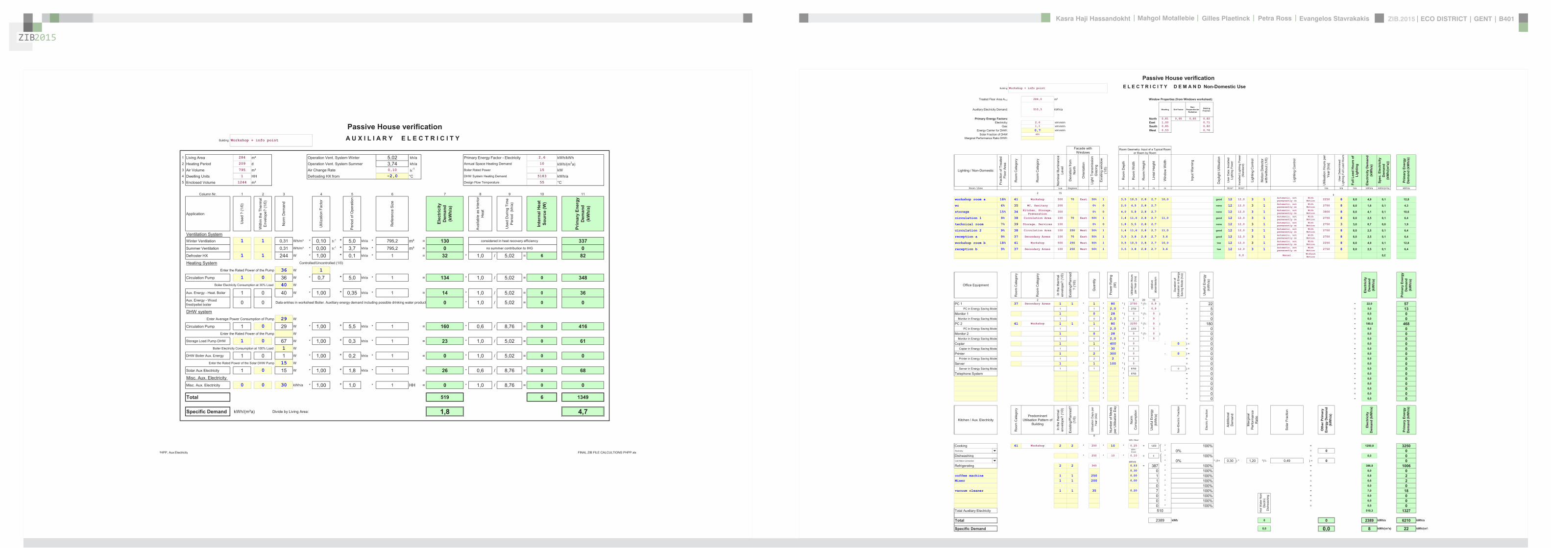
ZIB2015 ECO DISTRICT | GENT | B401Evangelos Stavrakakis | Petra Ross | Mahgol Motallebie | Gilles Plaetinck | Kasra Haji Hassandokht
ZIB2015
|
Passive House verificationBuilding Workshop + info point E L E C T R I C I T Y D E M A N D Non-Domestic Use
Treated Floor Area ATFA 2840 msup2 Window Properties (from Windows worksheet)
Auxiliary Electricity Demand 5103 kWha Shading Dirt FactorNon-
Perpendicular Radiation
Glazing Fraction
Primary Energy Factors North 081 095 085 082Electricity 26 kWhkWh East 100 071
Gas 11 kWhkWh South 085 082
Energy Carrier for DHW 07 kWhkWh West 053 076
Solar Fraction of DHW 49
Marginal Performance Ratio DHW
Room Geometry Input of a Typical Room or Room by Room
Lighting Non-Domestic
Frac
tion
of T
reat
ed
Floo
r Are
a
Roo
m C
ateg
ory
Roo
m C
ateg
ory
Nom
inal
Illu
min
ance
Le
vel
Dev
iatio
n fro
m
Nor
th
Orie
ntat
ion
Ligh
t Tra
nsm
issi
on
Gla
zing
Exis
ting
win
dow
(1
0)
Roo
m D
epth
Roo
m W
idth
Roo
m H
eigh
t
Lint
el H
eigh
t
Win
dow
Wid
th
Day
light
Util
isat
ion
Use
r Dat
a In
stal
led
Ligh
ting
Pow
er
Inst
alle
d Li
ghtin
g Po
wer
(S
tand
ard)
Ligh
ting
Con
trol
Mot
ion
Det
ecto
r w
ithw
ithou
t (1
0)
Util
isat
ion
Hou
rs p
er
Year
[ha
]
Use
r Det
erm
ined
Li
ghtin
g Fu
ll Lo
ad H
ours
Full
Load
Hou
rs o
f Li
ghtin
g
Elec
tric
ity D
eman
d (k
Wh
a)
Spec
Ele
ctric
ity
Dem
and
(kW
h(m
sup2a))
Prim
ary
Ener
gy
Dem
and
(kW
ha)
Room Zone Lux Degrees - m m m m m Wmsup2 Wmsup2 ha ha ha kWha kWh(msup2a) kWha
2 159
workshop room a 18 41 Workshop 500 70 East 50 1 35 105 28 27 100 good 12 120 3 1 Automatic not permanently on
WithMotion 2250 8 80 49 01 128
wc 6 35 WC Sanitary 200 0 0 20 45 28 27 none 12 120 3 1 Automatic not permanently on
WithMotion 2750 8 80 16 01 43
storage 15 34 Kitchen Storage Preparation
300 0 0 40 58 28 27 none 12 120 3 1 Automatic not permanently on
WithMotion 3900 8 80 41 01 106
circulation 1 9 38 Circulation Area 100 70 East 50 1 14 116 28 27 110 good 12 120 3 1 Automatic not permanently on
WithMotion 2750 8 80 25 01 64
technical room 7 39 Storage Services 100 0 0 18 55 28 27 none 12 120 3 1 Automatic not permanently on
WithMotion 2750 3 30 07 00 19
circulation 2 9 38 Circulation Area 100 250 West 50 1 14 116 28 27 110 good 12 120 3 1 Automatic not permanently on
WithMotion 2750 8 80 25 01 64
reception a 9 37 Secondary Areas 100 70 East 50 1 35 38 28 27 36 good 12 120 3 1 Automatic not permanently on
WithMotion 2750 8 80 25 01 64
workshop room b 18 41 Workshop 500 250 West 50 1 35 105 28 27 100 low 12 120 3 1 Automatic not permanently on
WithMotion 2250 8 80 49 01 128
reception b 9 37 Secondary Areas 100 250 West 50 1 35 38 28 27 36 low 12 120 3 1 Automatic not permanently on
WithMotion 2750 8 80 25 01 64
0 0 Manual Without 0 0
Facade with Windows
Ligh
ting
Con
trol
Inpu
t War
ning
00 ManualMotion 00
00 Manual WithoutMotion 00
00 Manual WithoutMotion 00
00 Manual WithoutMotion 00
00 Manual WithoutMotion 00
00 Manual WithoutMotion 00
00 Manual WithoutMotion 00
00 Manual WithoutMotion 00
00 Manual WithoutMotion 00
00 Manual WithoutMotion 00
00 Manual WithoutMotion 00
00 Manual WithoutMotion 00
00 Manual WithoutMotion 00
HPP Electricity Non-Dom FINAL ZIB FILE CALCULTIONS PHPPxls
Office Equipment
Roo
m C
ateg
ory
Roo
m C
ateg
ory
In th
e th
erm
al
enve
lope
(1
0)
Exis
ting
Plan
ned
(1
0)
Qua
ntity
Pow
er R
atin
g (W
)
Util
isat
ion
Hou
rs
per Y
ear (
ha)
rela
tive
abse
ntee
ism
Dur
atio
n of
U
tilis
atio
n in
Ene
rgy
Savi
ng M
ode
(ha
)
Use
ful E
nerg
y(k
Wh
a)
Elec
tric
ity
Dem
and
(kW
ha)
Prim
ary
Ener
gy
Dem
and
(kW
ha)
2 9 20 18PC 1 37 Secondary Areas 1 1 1 80 ( 2750 (1- 09 ) = 22 = 220 57
PC in Energy Saving Mode 1 1 20 2750 09 = 5 = 50 13Monitor 1 1 0 28 ( 0 (1- 0 ) = 0 = 00 0
Monitor in Energy Saving Mode 1 0 20 0 0 = 0 = 00 0PC 2 41 Workshop 1 1 1 80 ( 2250 (1- 0 ) = 180 = 1800 468
PC in Energy Saving Mode 1 1 20 2250 0 = 0 = 00 0Monitor 2 1 0 28 ( 0 (1- 0 ) = 0 = 00 0
Monitor in Energy Saving Mode 1 0 20 0 0 = 0 = 00 0Copier 1 1 400 ( 0 - 0 ) = 0 = 00 0
Copier in Energy Saving Mode 1 1 30 0 = 0 = 00 0Printer 1 2 300 ( 0 - 0 ) = 0 = 00 0
Printer in Energy Saving Mode 1 2 2 0 = 0 = 00 0Server 1 1 100 ( 0 = 0 = 00 0
Server in Energy Saving Mode 1 1 ( 8760 - 0 ) = 0 = 00 0Telephone System 8760 = 0 = 00 0
= 0 = 00 0 = 0 = 00 0 = 0 = 00 0 = 0 = 00 0 = 0 = 00 0
Kitchen Aux Electricity
Roo
m C
ateg
ory
Predominant Utilisation Pattern of
Building
In th
e th
erm
al
enve
lope
(1
0)
Exis
ting
Plan
ned
(1
0)
Util
isat
ion
Day
s pe
r Ye
ar (d
a)
Num
ber o
f Mea
ls
per U
tilis
atio
n D
ay
Nor
m
Con
sum
ptio
n
Use
ful E
nerg
y (k
Wh
a)
Non
-Ele
ctric
Fra
ctio
n
Elec
tric
Frac
tion
Addi
tiona
l D
eman
d
Mar
gina
l Pe
rform
ance
R
atio
Sola
r Fra
ctio
n
Oth
er P
rimar
y En
ergy
Dem
and
(kW
ha)
Elec
tric
ity
Dem
and
(kW
ha)
Prim
ary
Ener
gy
Dem
and
(kW
ha)
8kWh Meal
Cooking 41 Workshop 2 2 250 10 025 = 1250 100 = 12500 32501 kWh
Cover 0 = 0 0Dishwashing 250 10 0 10 = 0 100 = 0 0 0Electricity
Dishwashing 250 10 010 = 0 100 = 00 01 kWhd 0 (1+ 030 ) 120 (1- 049 ) = 0 0
Refrigerating 2 2 365 053 = 387 100 = 3869 1006030 0 100 = 00 0
coffee machine 1 1 250 000 1 100 = 08 2Mixer 1 1 200 000 1 100 = 06 2
0 100 = 00 0vacuum cleaner 1 1 35 020 7 100 = 70 18
0 100 = 00 00 100 = 00 00 100 = 00 0
Total Auxiliary Electricity 5103 1327
Total kWh 0 0 2389 kWha 6210 kWha
Specific Demand 00 00 8 kWh(msup2a) 22 kWh(msup2a)
2389
Hot
Wat
er N
on-
Elec
tric
Dis
hwas
hing
510
Cold Water Connection
HPP Electricity Non-Dom FINAL ZIB FILE CALCULTIONS PHPPxls
Passive House verificationBuilding Workshop + info point A U X I L I A R Y E L E C T R I C I T Y
1 Living Area 284 msup2 Operation Vent System Winter 502 kha Primary Energy Factor - Electricity 26 kWhkWh2 Heating Period 209 d Operation Vent System Summer 374 kha Annual Space Heating Demand 10 kWh(m2a)3 Air Volume 795 msup3 Air Change Rate 010 h-1 Boiler Rated Power 15 kW4 Dwelling Units 1 HH Defrosting HX from -20 degC DHW System Heating Demand 5183 kWha5 Enclosed Volume 1244 msup3 Design Flow Temperature 55 degC
Column Nr 1 2 3 4 5 6 7 8 9 10 11
Application
Use
d
(10
)
With
in th
e Th
erm
al
Env
elop
e (1
0)
Nor
m D
eman
d
Util
izat
ion
Fact
or
Per
iod
of O
pera
tion
Ref
eren
ce S
ize
Elec
tric
ity
Dem
and
(kW
ha)
Ava
ilabl
e as
Inte
rior
Hea
t
Use
d D
urin
g Ti
me
Per
iod
(kh
a)
Inte
rnal
Hea
t So
urce
(W)
Prim
ary
Ener
gy
Dem
and
(kW
ha)
Ventilation SystemWinter Ventilation 1 1 031 Whmsup3 010 h-1 50 kha 7952 msup3 = 130 considered in heat recovery efficiency 337Summer Ventilation 031 Whmsup3 000 h-1 37 kha 7952 msup3 = 0 no summer contribution to IHG 0Defroster HX 1 1 244 W 100 01 kha 1 = 32 10 502 = 6 82Heating System ControlledUncontrolled (10)
Enter the Rated Power of the Pump 36 W 1
Circulation Pump 1 0 36 W 07 50 kha 1 = 134 10 502 = 0 348Boiler Electricity Consumption at 30 Load 40 W
Aux Energy - Heat Boiler 1 0 40 W 1 00 0 35 kha 1 = 14 1 0 5 02 = 0 36Aux Energy Heat Boiler 1 0 40 W 100 035 kha 1 14 10 502 0 36Aux Energy - Wood firedpellet boiler 0 0 Data entries in worksheet Boiler Auxiliary energy demand including possible drinking water product 0 10 502 = 0 0
DHW systemEnter Average Power Consumption of Pump 29 W
Circulation Pump 1 0 29 W 100 55 kha 1 = 160 06 876 = 0 416Enter the Rated Power of the Pump W
Storage Load Pump DHW 1 0 67 W 100 03 kha 1 = 23 10 502 = 0 61Boiler Electricity Consumption at 100 Load 1 W
DHW Boiler Aux Energy 1 0 1 W 100 02 kha 1 = 0 10 502 = 0 0Enter the Rated Power of the Solar DHW Pump 15 W
Solar Aux Electricity 1 0 15 W 100 18 kha 1 = 26 06 876 = 0 68Misc Aux Electricity Misc Aux Electricity 0 0 30 kWha 100 10 1 HH = 0 10 876 = 0 0
Total 519 6 1349
Specific Demand kWh(msup2a) Divide by Living Area 18 47
PHPP Aux Electricity FINAL ZIB FILE CALCULTIONS PHPPxls
ZIB2015
Passive House verificationI N T E R N A L H E A T G A I N S Non-domestic Use
Building Workshop + info point
Utilisation Pattern 201 Wmsup2 217 Wmsup2 Carefully complete the Electricity Non-Dom worksheet
Type of Values Used Manual entry 20 Wmsup2
Calculation Persons 80 P Room Temperature 20 degCInternal Heat TF Area 284 msup2 Heating Period 2092693 da Internal Heat Gains Aux Electricity 63 W
Column Nr
Persons
Sel
ect
Util
isat
ion
Pat
tern
Sel
ect
Act
ivity
of P
erso
nsPlanning with the number
of persons or via floor area of utilisation zone
(planning via area only if the occupancy is available for this
utilisation pattern) PersArea (1 0) N
umbe
r of O
ccup
ants
Floo
r Are
a of
Util
isat
ion
Zone
(msup2)
Ave
rage
Occ
upan
cy
(Per
sons
m
sup2)
Hea
t Em
itted
per
Per
son
(W)
Util
isat
ion
Hou
rs p
er Y
ear
[ha
]
Rel
ativ
e P
rese
nce
Use
d in
Tim
e S
pan
(ha
)
Ave
rage
Hea
t Em
itted
by
Pers
ons
(W)
27 9 18
Persons A 41 Workshop 3 gt10 yr standing or light work 1 planning with of
persons 6 or no standard value 100 2250 100 8760 = 154
Persons B 3 gt10 yr standing or light work 1 Enter of persons
or floor area or no standard value 100 0 100 8760 = 0
Persons C 3 gt10 yr standing or light work 1 Enter of persons
or floor area or no standard value 100 0 100 8760 = 0
Persons D 3 gt10 yr standing or light work 1 Enter of persons
or floor area or no standard value 100 0 100 8760 = 0
Persons E 37 Secondary Areas 2 gt 10 yr sitting 1 planning with of persons 2 or no standard
value 80 2750 010 8760 = 5Persons F 2 gt 10 yr sitting 1 Enter of persons
or floor area or no standard value 80 0 100 8760 = 0
Persons G 2 gt 10 yr sitting 1 Enter of persons or floor area or no standard
value 80 0 100 8760 = 0Evaporation (person specific) 51 -15 2750 010 8760 = -24
ergy
] ity im
eh
a)
Hea
t e
Other
PHPP Calculation Non-residential buildings
Lighting Equipment Aux Electricity
Use
ful E
ne[k
Wh
a]
Ava
ilabi
li
Use
d in
Ti
Per
iod
(kh
Ave
rage
HR
elea
se
Lighting 3850 100 876 = 440Office Applications (Within Therm Envelope) 207 100 876 = 24Cooking (Within Therm Envelope) 625 050 876 = 36Dishwashing (Within Therm Envelope) 0 030 876 = 0Cooling (Within Therm Envelope) 0 100 876 = 0Other (Within Therm Envelope) 8 100 876 = 1Auxiliary Appliances (See Aux Electricity Worksheet) = 6
Heat Loss Due to Cold Water (calculation from column AJ)
ono
ff (1
0) Predominant
Utilisation Pattern of Building
(Data transfered from Electricity Non-Dom
worksheet input kitchen) Num
ber o
f WC
s (u
ser d
ata)
Num
ber o
f WC
s U
se
stan
dard
val
ue fo
r sc
hool
s (X
)
Num
ber o
f WC
s (c
alcu
latio
n va
lue)
T C
old
Wat
er
Tem
p -
Roo
m
Tem
p [K
]
Occ
upie
d D
ays
per Y
ear [
da]
Loss
Day
time
[W]
Loss
Nig
httim
e [W
]
Ava
ilabi
lity
Use
d in
Per
iod
(da
)
Ave
rage
Pow
er
Col
d W
ater
2 8
Cold Water Due to Flushing WC 1 41 Workshop 3 3 -8 250 ( -23 + -11 ) 100 365 = -24
Total W 618Specific Demand Wmsup2 22Heat Available From Internal Sources 209 da kWh(msup2a) 11
PHPP IHG Non-Dom FINAL ZIB FILE CALCULTIONS PHPPxls
Passive House verification Secondary Calculation -Values of Plumbing
H E A T D I S T R I B U T I O N A N D D H W S Y S T E M
Building Workshop + info point Nominal Width 18 mmInsulation Thickness mm
Interior Temperature 20 degC Reflective Please mark with an xBuilding TypeUsenon-residential x Yes
Treated Floor Area ATFA 284 msup2 NoOccupancy 80 Pers Thermal Conductivity 043 W(mK)
Number of Residences 1Annual Heating Demand qHeating 2911 kWha 30 K
Length of Heating Period 209 d Interior Pipe Diameter 001800 mAverage heating load Pave 06 kW Exterior Pipe Diameter 002025 m
Marginal Utilisability of Additional Heat Gains 59 Parts Exterior Pipe Diameter 002025 m
Warm Region Cold Region Total
Space Heat Distribution 1 2 3 Surface 551 W(msup2K)Length of Distribution Pipes LH (Project) 500 m -Value 0350 W(mK)Heat Loss Coefficient per m Pipe (Project) 0350 W(mK) Surface Temperature Difference 29996 K
Temperature of the Room Through Which the Pipes X Mechanical Room 20 degC
Design Flow Temperature dist Flow Design Value 550 degC
Design System heating load Pheating (existcalc) 30 kW
Flow Temperature Control (check) 5000Design Return Temperature R dist-20)+20 450 degCAnnual Heat Emission per m of Plumbing qHL mX) tHeating0024 53 Total 123 kWh(mmiddota)Possible Utilization Factor of Released Heat G 59 -
Annual Losses QHL = LH middot qHL middot (1-G) 109 0 0 109 kWha
Specif Losses qHL = QHL ATFA kWh(msup2a) 04Performance ratio of heat distribution eaHL = ( qH + qHL) qH 104 -
DHW Standard Useful HeatDHW Consumption per Person and Day (60 degC) VDHW (Project or Average Value 25 LitresPd) 120 LitrePersondAverage Cold Water Temperature of the Supply DW Temperature of Drinking Water (10deg) 106 degCDHW Non-Electric Wash and Dish (Electricity worksheet) 0 kWha
Useful Heat - DHW QDHW 2008 kWha
Specif Useful Heat - DHW qDHW = QDHW ATFA kWh(msup2a) 71
DHW Distribution and Storage Warm Region Cold Region Total
Length of Circulation Pipes (Flow + Return) LHS (Project) 15 00 m
Heat Loss Coefficient per m Pipe (Project) 0350 0000 WmK
Temperature of the Room Through Which the Pipes X Mechanical Room 20 00 degC
Design Flow Temperature dist Flow Design Value 600 00 degC
Daily circulation period of operation tdCirc (Project) 120 00 hdDesign Return Temperature R =0875(dist-20)+20 55 3 degCCirculation period of operation per year tCirc = 365 tdCirc 4380 0 haAnnual Heat Released per m of Pipe qZ mX) tCirc 57 0 kWhmaPossible Utilization Factor of Released Heat GDHW =theating365d G 34 0 -
Annual Heat Loss from Circulation Lines QZ = LHS middot qZ middot(1-GDHW) 57 0 57 kWha
Total Length of Individual Pipes LU (Project) 5000 mExterior Pipe Diameter dU_Pipe (Project) 0018 mHeat loss per tap opening qIndividual =(cpH2OVH2O+cpMatVMat)(dist-X) 04557 kWhtap openingAmount of tap openings per year nTap = nPers 3 365 nLU 8760 Tap openings per yearAnnual Heat Loss qU = nTap
qIndividual 3992 kWhaPossible Utilization Factor of Released Heat G_U =theating8760G 34 -
Annual Heat Loss of Individual Pipes QU = qU middot(1-G_U) 2652 2652 kWha
Total 123
Average Heat Released From Storage PS 80 W Secondary Calculation Storage LossesPossible Utilization Factor of Released Heat G_S =theating8760G 34
Annual Heat Losses from Storage QS = PSmiddot8760 khmiddot(1-G_S) 466 466 kWha Specific Heat Losses Storage (total) 25 WK
Total 123 Typical Temperature DHW 60 degC
Total Heat Losses of the DHW System QWL = QZ+QU+QS 3175 kWha Room Temperature 20 degC
Specif Losses of the DHW System qWL = QWL ATFA kWh(msup2a) 112 Total Storage Heat Losses 100 W
Performance ratio DHW-distribution + storage eaWL = (qTWW + qWV) qTWW 2581 -
Total Heating Demand of DHW system QgDHW = QDHW+QWL 5183 kWha
Total Spec Heating Demand of DHW System qgDHW = QgDHW ATFA kWh(msup2a) 183
PHPP DHW+Distribution FINAL ZIB FILE CALCULTIONS PHPPxlsPHPP DHW+Distribution FINAL ZIB FILE CALCULTIONS PHPPxls
Passive House verification Secondary Calculation -Values of Plumbing
H E A T D I S T R I B U T I O N A N D D H W S Y S T E M
Building Workshop + info point Nominal Width 18 mmInsulation Thickness mm
Interior Temperature 20 degC Reflective Please mark with an xBuilding TypeUsenon-residential x Yes
Treated Floor Area ATFA 284 msup2 NoOccupancy 80 Pers Thermal Conductivity 043 W(mK)
Number of Residences 1Annual Heating Demand qHeating 2911 kWha 30 K
Length of Heating Period 209 d Interior Pipe Diameter 001800 mAverage heating load Pave 06 kW Exterior Pipe Diameter 002025 m
Marginal Utilisability of Additional Heat Gains 59 Parts Exterior Pipe Diameter 002025 m
Warm Region Cold Region Total
Space Heat Distribution 1 2 3 Surface 551 W(msup2K)Length of Distribution Pipes LH (Project) 500 m -Value 0350 W(mK)Heat Loss Coefficient per m Pipe (Project) 0350 W(mK) Surface Temperature Difference 29996 K
Temperature of the Room Through Which the Pipes X Mechanical Room 20 degC
Design Flow Temperature dist Flow Design Value 550 degC
Design System heating load Pheating (existcalc) 30 kW
Flow Temperature Control (check) 5000Design Return Temperature R dist-20)+20 450 degCAnnual Heat Emission per m of Plumbing qHL mX) tHeating0024 53 Total 123 kWh(mmiddota)Possible Utilization Factor of Released Heat G 59 -
Annual Losses QHL = LH middot qHL middot (1-G) 109 0 0 109 kWha
Specif Losses qHL = QHL ATFA kWh(msup2a) 04Performance ratio of heat distribution eaHL = ( qH + qHL) qH 104 -
DHW Standard Useful HeatDHW Consumption per Person and Day (60 degC) VDHW (Project or Average Value 25 LitresPd) 120 LitrePersondAverage Cold Water Temperature of the Supply DW Temperature of Drinking Water (10deg) 106 degCDHW Non-Electric Wash and Dish (Electricity worksheet) 0 kWha
Useful Heat - DHW QDHW 2008 kWha
Specif Useful Heat - DHW qDHW = QDHW ATFA kWh(msup2a) 71
DHW Distribution and Storage Warm Region Cold Region Total
Length of Circulation Pipes (Flow + Return) LHS (Project) 15 00 m
Heat Loss Coefficient per m Pipe (Project) 0350 0000 WmK
Temperature of the Room Through Which the Pipes X Mechanical Room 20 00 degC
Design Flow Temperature dist Flow Design Value 600 00 degC
Daily circulation period of operation tdCirc (Project) 120 00 hdDesign Return Temperature R =0875(dist-20)+20 55 3 degCCirculation period of operation per year tCirc = 365 tdCirc 4380 0 haAnnual Heat Released per m of Pipe qZ mX) tCirc 57 0 kWhmaPossible Utilization Factor of Released Heat GDHW =theating365d G 34 0 -
Annual Heat Loss from Circulation Lines QZ = LHS middot qZ middot(1-GDHW) 57 0 57 kWha
Total Length of Individual Pipes LU (Project) 5000 mExterior Pipe Diameter dU_Pipe (Project) 0018 mHeat loss per tap opening qIndividual =(cpH2OVH2O+cpMatVMat)(dist-X) 04557 kWhtap openingAmount of tap openings per year nTap = nPers 3 365 nLU 8760 Tap openings per yearAnnual Heat Loss qU = nTap
qIndividual 3992 kWhaPossible Utilization Factor of Released Heat G_U =theating8760G 34 -
Annual Heat Loss of Individual Pipes QU = qU middot(1-G_U) 2652 2652 kWha
Total 123
Average Heat Released From Storage PS 80 W Secondary Calculation Storage LossesPossible Utilization Factor of Released Heat G_S =theating8760G 34
Annual Heat Losses from Storage QS = PSmiddot8760 khmiddot(1-G_S) 466 466 kWha Specific Heat Losses Storage (total) 25 WK
Total 123 Typical Temperature DHW 60 degC
Total Heat Losses of the DHW System QWL = QZ+QU+QS 3175 kWha Room Temperature 20 degC
Specif Losses of the DHW System qWL = QWL ATFA kWh(msup2a) 112 Total Storage Heat Losses 100 W
Performance ratio DHW-distribution + storage eaWL = (qTWW + qWV) qTWW 2581 -
Total Heating Demand of DHW system QgDHW = QDHW+QWL 5183 kWha
Total Spec Heating Demand of DHW System qgDHW = QgDHW ATFA kWh(msup2a) 183
PHPP DHW+Distribution FINAL ZIB FILE CALCULTIONS PHPPxlsPHPP DHW+Distribution FINAL ZIB FILE CALCULTIONS PHPPxls
Passive House verification Secondary Calculation -Values of Plumbing
H E A T D I S T R I B U T I O N A N D D H W S Y S T E M
Building Workshop + info point Nominal Width 18 mmInsulation Thickness mm
Interior Temperature 20 degC Reflective Please mark with an xBuilding TypeUsenon-residential x Yes
Treated Floor Area ATFA 284 msup2 NoOccupancy 80 Pers Thermal Conductivity 043 W(mK)
Number of Residences 1Annual Heating Demand qHeating 2911 kWha 30 K
Length of Heating Period 209 d Interior Pipe Diameter 001800 mAverage heating load Pave 06 kW Exterior Pipe Diameter 002025 m
Marginal Utilisability of Additional Heat Gains 59 Parts Exterior Pipe Diameter 002025 m
Warm Region Cold Region Total
Space Heat Distribution 1 2 3 Surface 551 W(msup2K)Length of Distribution Pipes LH (Project) 500 m -Value 0350 W(mK)Heat Loss Coefficient per m Pipe (Project) 0350 W(mK) Surface Temperature Difference 29996 K
Temperature of the Room Through Which the Pipes X Mechanical Room 20 degC
Design Flow Temperature dist Flow Design Value 550 degC
Design System heating load Pheating (existcalc) 30 kW
Flow Temperature Control (check) 5000Design Return Temperature R dist-20)+20 450 degCAnnual Heat Emission per m of Plumbing qHL mX) tHeating0024 53 Total 123 kWh(mmiddota)Possible Utilization Factor of Released Heat G 59 -
Annual Losses QHL = LH middot qHL middot (1-G) 109 0 0 109 kWha
Specif Losses qHL = QHL ATFA kWh(msup2a) 04Performance ratio of heat distribution eaHL = ( qH + qHL) qH 104 -
DHW Standard Useful HeatDHW Consumption per Person and Day (60 degC) VDHW (Project or Average Value 25 LitresPd) 120 LitrePersondAverage Cold Water Temperature of the Supply DW Temperature of Drinking Water (10deg) 106 degCDHW Non-Electric Wash and Dish (Electricity worksheet) 0 kWha
Useful Heat - DHW QDHW 2008 kWha
Specif Useful Heat - DHW qDHW = QDHW ATFA kWh(msup2a) 71
DHW Distribution and Storage Warm Region Cold Region Total
Length of Circulation Pipes (Flow + Return) LHS (Project) 15 00 m
Heat Loss Coefficient per m Pipe (Project) 0350 0000 WmK
Temperature of the Room Through Which the Pipes X Mechanical Room 20 00 degC
Design Flow Temperature dist Flow Design Value 600 00 degC
Daily circulation period of operation tdCirc (Project) 120 00 hdDesign Return Temperature R =0875(dist-20)+20 55 3 degCCirculation period of operation per year tCirc = 365 tdCirc 4380 0 haAnnual Heat Released per m of Pipe qZ mX) tCirc 57 0 kWhmaPossible Utilization Factor of Released Heat GDHW =theating365d G 34 0 -
Annual Heat Loss from Circulation Lines QZ = LHS middot qZ middot(1-GDHW) 57 0 57 kWha
Total Length of Individual Pipes LU (Project) 5000 mExterior Pipe Diameter dU_Pipe (Project) 0018 mHeat loss per tap opening qIndividual =(cpH2OVH2O+cpMatVMat)(dist-X) 04557 kWhtap openingAmount of tap openings per year nTap = nPers 3 365 nLU 8760 Tap openings per yearAnnual Heat Loss qU = nTap
qIndividual 3992 kWhaPossible Utilization Factor of Released Heat G_U =theating8760G 34 -
Annual Heat Loss of Individual Pipes QU = qU middot(1-G_U) 2652 2652 kWha
Total 123
Average Heat Released From Storage PS 80 W Secondary Calculation Storage LossesPossible Utilization Factor of Released Heat G_S =theating8760G 34
Annual Heat Losses from Storage QS = PSmiddot8760 khmiddot(1-G_S) 466 466 kWha Specific Heat Losses Storage (total) 25 WK
Total 123 Typical Temperature DHW 60 degC
Total Heat Losses of the DHW System QWL = QZ+QU+QS 3175 kWha Room Temperature 20 degC
Specif Losses of the DHW System qWL = QWL ATFA kWh(msup2a) 112 Total Storage Heat Losses 100 W
Performance ratio DHW-distribution + storage eaWL = (qTWW + qWV) qTWW 2581 -
Total Heating Demand of DHW system QgDHW = QDHW+QWL 5183 kWha
Total Spec Heating Demand of DHW System qgDHW = QgDHW ATFA kWh(msup2a) 183
PHPP DHW+Distribution FINAL ZIB FILE CALCULTIONS PHPPxlsPHPP DHW+Distribution FINAL ZIB FILE CALCULTIONS PHPPxls
ZERO IMPACT BUILDING MA (SCI) ARCHITECTUREKU LEUVEN middot SINT LUCAS GROUP 42 middot GENT copy2015

ZERO IMPACT BUILDING MA (SCI) ARCHITECTUREKU LEUVEN middot SINT LUCAS GROUP 42 middot GENT copy2015