Embed Size (px)
Citation preview

Confidential. Not to be copied, distributed, or reproduced without prior approval. Confidential. Not to be copied, distributed, or reproduced without prior approval.
Zero Liquid Discharge in Power Plants
December 23, 2016
Himanshu Gupta – Sales Director
Confidential. Not to be copied, distributed, or reproduced without prior approval.

Confidential. Not to be copied, distributed, or reproduced without prior
approval.
Why Zero Liquid Discharge (ZLD) in Power Plants?
• Pressure to improve operational efficiency
• Managing downtime and aging assets Productivity
• Growing population and industrial use
• Climate change and drought Availability
• Increased industrial pollution
• Deteriorating water qualityQuality
• Stricter regulation on discharge/withdrawal
• Water reuse incentives and policy mandates
Zero discharge of liquids is now in many cases
mandatory for industry & Power Plants
Policy
2
Global water challenges
ZLD systems enable reuse of waste water and minimization of
discharges

Confidential. Not to be copied, distributed, or reproduced without prior
approval.
Drivers for Zero Liquid Discharge
Tightening national & local environmental discharge limits
o Tighter limitations on heavy metal discharge limits
o Stricter limitations on selenium, mercury, arsenic, nitrate
o Physical/chemical precipitation & biological process unable to reduce
Total dissolved solids (TDS)
Specific contaminants (including chlorides, sulfates, boron)
o Co-mingling of waste streams may not be permitted
Treat & discharge may not be permitted or unable to meet limits
“Future Proofing”
- long term environmental risks minimized due to elimination of discharge
- enable range of coals to be used
In some countries ZLD is mandated for new plants

Confidential. Not to be copied, distributed, or reproduced without prior
approval.
• Cooling tower blowdown
• Demineralizer waste
• Process wastewater
• Ash pond blowdown
• Scrubber blowdown
• Plant drains
• FGD Blowdown
• Gasification wastes
• Boiler blowdown
• Reverse osmosis reject
• Electrodialysis reject
Typical Power Plant Waste Streams Treated by
ZLD

Confidential. Not to be copied, distributed, or reproduced without prior
approval.
Confidential. Not to be copied, distributed, or reproduced without prior
approval.
ZLD Solutions for CTBG & FGD

Confidential. Not to be copied, distributed, or reproduced without prior
approval.
ZLD Solutions for CTBD & FGD WastewaterVolume Reduction ZLD Waste Salt ZLD Solidification
• Brine Concentrator Only
• Does not achieve full ZLD
• Used to reduce the volume of waste to storage or disposal
• BC ideal for high TDS waste streams
• Achieves high conc. factors of up to 100x
• Achieves water recoveries of 75%-99%
• Typically use Seeded slurry technology to allow concentration without scaling of surfaces
• Typically uses vapor compression reduces energy consumption - either steam (TVR) or mechanical (MVR)
• Produces high quality distillate for reuse
• Brine Concentrator + Crystallizer
• Produces a soluble crystalline solid salt for landfill disposal
• Achieves zero liquid discharge
• Achieves water recoveries of 85%-99%
• Typically concentrator uses Seed Slurry BC design to allow high concentration without scaling
• Typically uses steam (TVR) or mechanical (MVR) vapor compression to reduce energy
• May require pre-treatment including clarification and/or softening depending on feed water chemistry.
• Produces high quality distillate for reuse
• Brine Concentrator + SDE
• Evaporates highly concentrated waste water from Brine Concentrator to produce dry solids
• Uses flue gas from boiler to evaporate waste water to produce solid by-product
• The dried solids are captured in the downstream particulate collection device, such as the electrostatic precipitator (ESP) or fabric filter.
• Either Inline (Integrated) or Slipstream configuration
• Simple, cost-effective design.
• Ability to integrate the SDE system to existing power plants by using a slipstream of the boiler hot flue gas.
• Recovers high quality distillate for reuse
• Brine Concentrator + Solidification
• Produces a solid waste suitable for long term disposal
• Uses a pozzolanic reaction, combining FGD wastewater with fly ash + reagents to produce an “engineered” solid material
• Produces a stable solid product with
o High structural strength able to bear weight (able to supports heavy earth moving equipment), providing long term stability in a land fill
o low hydraulic permeability (sheds water)
o non-leachable (reduces landfill leachate contamination).
• “Reduced Capex and Opex of 30-50% compared to ZLD Waste Salt.
ZLD SDE
Suitable for - CTBD (depending on
storage/disposal options)
Suitable for - CTBD, FGD Suitable for - FGD Suitable for – (CTBD), FGD

Confidential. Not to be copied, distributed, or reproduced without prior
approval.
Confidential. Not to be copied, distributed, or reproduced without prior
approval.
ZLD Technologies

Confidential. Not to be copied, distributed, or reproduced without prior
approval.
Salt Removal and Recovery in Brine Wastewaters
• ZLD typically requires thermal or evaporative technologies to achieve solids and max recovery of water
• Evaporation is generally expensive and has high power requirement
• Pre-concentration enables reduction in size/capacity and therefore capex and opex of evaporator and crystallizer units
• ZLD systems integrate both conventional and membrane systems to pre-concentrate wastewater prior to thermal systems

Confidential. Not to be copied, distributed, or reproduced without prior
approval.
• Used to reduce the volume of waste (to reduce size of downstream equipment, eg crystallizers)
• Seeded and unseeded designs
• Seeded slurry technology allows concentration without scaling of surfaces
• Vapor compression reduces energy consumption,
• either using steam (TVR) or mechanical (MVR)
• Ideal for high TDS waste streams
• 2 - 275 m3/hr evaporation per unit
• 13 - 26 kWh/m3 specific power consumption
• Recoveries of 75%-99% (CF=4x-100x)
• Produces high quality distillate for reuseSeeded Slurry Technology uses preferential
precipitation of calcium sulfate upon existing
seed crystals and silica to prevent scaling of heat
surfaces.
ZLD Brine Concentrator
Confidential. Not to be copied, distributed, or reproduced without prior
approval.
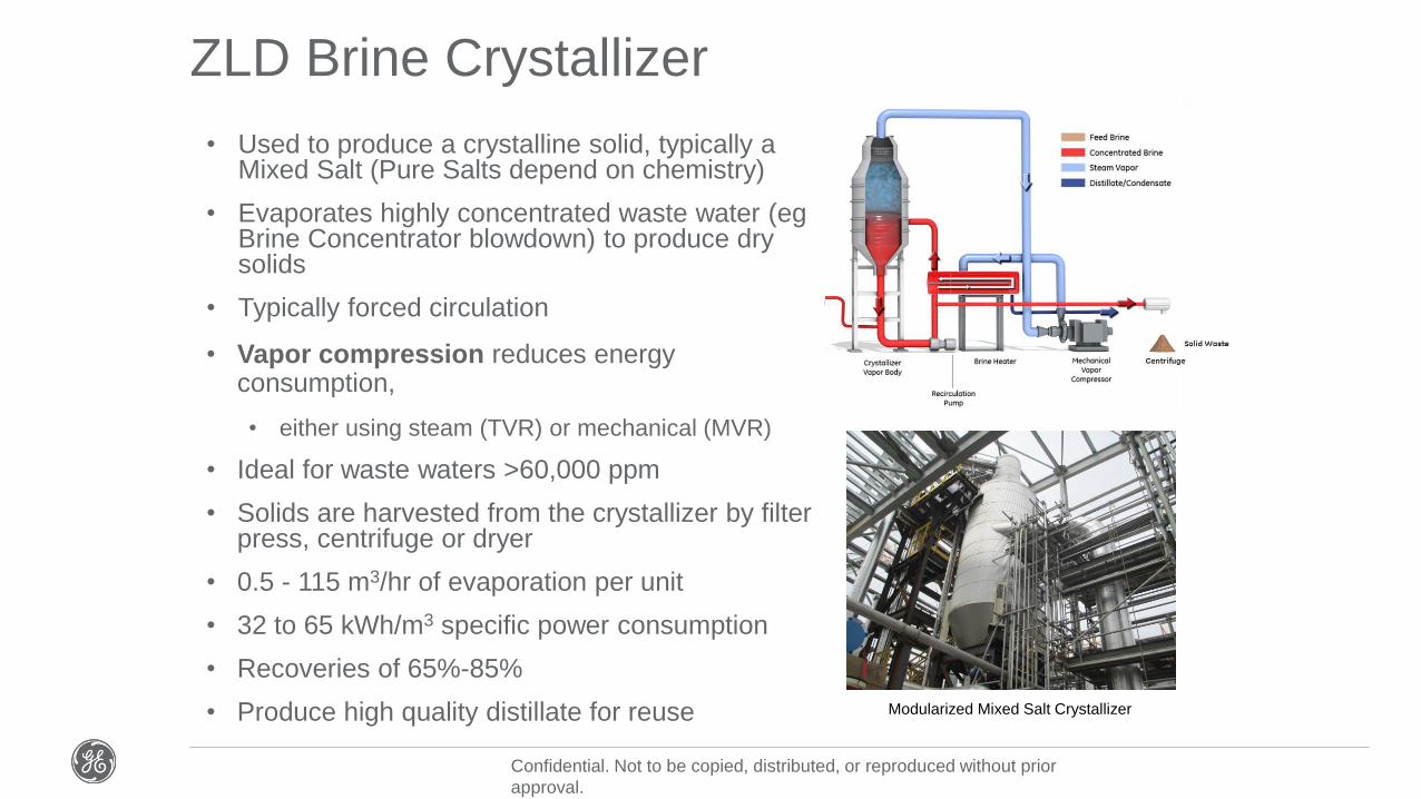
Modularized Mixed Salt Crystallizer
ZLD Brine Crystallizer
• Used to produce a crystalline solid, typically a Mixed Salt (Pure Salts depend on chemistry)
• Evaporates highly concentrated waste water (egBrine Concentrator blowdown) to produce dry solids
• Typically forced circulation
• Vapor compression reduces energy consumption,
• either using steam (TVR) or mechanical (MVR)
• Ideal for waste waters >60,000 ppm
• Solids are harvested from the crystallizer by filter press, centrifuge or dryer
• 0.5 - 115 m3/hr of evaporation per unit
• 32 to 65 kWh/m3 specific power consumption
• Recoveries of 65%-85%
• Produce high quality distillate for reuse

Confidential. Not to be copied, distributed, or reproduced without prior
approval.
ZLD Spray Dryer Evaporator (SDE)
• Evaporates highly concentrated waste water from Brine Concentrator to produce dry solids
• Uses flue gas from boiler to evaporate waste water to produce solid by-product.
• The dried solids are captured in the downstream particulate collection device, such as the electrostatic precipitator (ESP) or fabric filter.
• Either Inline (Integrated) or Slipstream configuration
• Simple, cost-effective design.
• Lime conditioning offers acid gas capture co-benefit and mitigates downstream corrosion.
• Ability to integrate the SDE system to existing power plants by using a slipstream of the boiler hot flue gas.

Confidential. Not to be copied, distributed, or reproduced without prior
approval.
ZLD Solidification
• Produces a solid waste suitable for long term disposal
• Uses a pozzolanic reaction, combining FGD wastewater with fly ash and reagents to produce an “engineered” solid material.
• Produces a stable product with
o High structural strength able to bear weight (able to supports heavy earth moving equipment), providing long term stability in a land fill
o low hydraulic permeability (sheds water)
o non-leachable (reduces landfill leachate contamination).
• “Engineered” solid material was established following collaboration with a leading landfill engineer & operator.
• Reduced Capex and Opex of 30-50%.
Engineered stable solid waste

Confidential. Not to be copied, distributed, or reproduced without prior
approval.
Confidential. Not to be copied, distributed, or reproduced without prior
approval.
Sox Control - Challenges

Confidential. Not to be copied, distributed, or reproduced without prior
approval.
Challenges in Sox Control
• Limited space availability for FGDs in existing power stations
• Limitations in logistics for lime/limestone and gypsum storage and conveying systems in boiler area
List of Equipment for a Wet FGD in a 660 MWe TPS
1. Sox Absorber
2. Gas-Gas Heat Exchanger
3. Booster Fan
4. Recycle Pumps
5. Oxy-Blowers
6. Dewatering Area (Building)
7. Limestone Area (Building)
8 . Electrical Building
9. Limestone Silos and Conveyor
10. Gypsum Conveyor
11. Belt Filter
12. Hydro-cyclones
13. Pumping Systems
• Solution
• Install FGD behind the Chimney area
• Water Recycling – ZLD system can be located away from Boiler area

Confidential. Not to be copied, distributed, or reproduced without prior
approval.
Foot Print
Approx. 145m x 115 m is required for Wet FGD system in a typical 660 MW TPS.

Confidential. Not to be copied, distributed, or reproduced without prior
approval.
Confidential. Not to be copied, distributed, or reproduced without prior
approval.
Case Studies

Confidential. Not to be copied, distributed, or reproduced without prior
approval.
Mt Piper Power Station, Australia
• 1400 MW Coal Fired Power Plant
• 2x 700 MW units
• Challenge:
Limits on supply water & waste water discharge
• Solution:
Integrated ZLD system into original power plant design to recover waste water for reuse in Cooling Tower
ZLD system
• Treats 7000 m3/d of CTBD, Ash Washdown & Demin’ waste streams
• Streams segregated via dedicated ponds for SS settling before Brine Concentration
• ZLD combined feed TDS = 2250 mg/l
• 2x 50% ZLD Seeded Slurry Brine Concentrators
• Achieve 98% recovery of <10 mg/L TDS water for reuse
• Power consumption <22 kW/m3 of feed
Mt Piper 2x 3.5 ML/d Brine Concentrators

Confidential. Not to be copied, distributed, or reproduced without prior
approval.
Zepak Adamów Power Station, Poland
• 2738 MW coal fired power plant
• Challenge:
Waste water could no longer be discharged into old
mine shafts
• Solution:
ZLD selected vs RO & EDR, due to high scaling nature
of waste water (Sr, Ba) and increasing TDS of waste
water reservoir
Adamów ZLD Brine Concentrator
ZLD system
• Treats 7000 m3/d of CTBD, Ash Washdown & Demin’ waste streams
• Streams segregated via dedicated ponds for SS settling before Brine Concentration
• ZLD combined feed TDS = 2250 mg/l
• 2x 50% ZLD Seeded Slurry Brine Concentrators
• Achieve 98% recovery of <10 mg/L TDS water for reuse
• Power consumption <22 kW/m3 of feed

Confidential. Not to be copied, distributed, or reproduced without prior
approval.
Orlando Utilities Commission, USA
• Coal fired & Combined Cycle power plant
• 4x power generation units (2x coal, 2x gas)
• Challenge: New regulations limited availability of make-up water and increased waste water discharge guidelines. OUC also required low energy consumption and >95% reliability
• Solution: ZLD system to treat CTBD to recover water for reuse in CT and produce waste salt for off-site disposal
OUC Mixed Salt Crystallizer
ZLD system
• Treats 11000 m3/d of CTDB
• Feed = 3600 mg/L TDS
• Original 1986 ZLD system
– 1x 3200 m3/d Evaporator , 2x 140 m3/d Crystallizers
• Today 11000 m3/d ZLD system;
– 4x Evaporators; 3200 m3/d, 2700 m3/d, 2x 1600 m3/d, 4x 140 m3/d Crystallizers
• Achieves 99% recovery

Confidential. Not to be copied, distributed, or reproduced without prior
approval.
AES Ironwood Power Plant, USA
• 700MW CCGT Power Plant
• Challenge:
To re-use CTBD for supply to demineralizer (EDI) plant & CT make-up
• Solution:
A fully integrated water/ waste water system with simplified design incorporating ZLD
Ironwood ZLD Brine
Concentrator & Mixed Salt
CrystallizerZLD system
• Treats 1100 m3/d of CTBD
• Feed = xx mg/l TDS
• 1x 1100 m3/d Brine Concentrator + 1x 100 m3/d Crystallizer
• Achieves 97% recovery
• Crystallizer solids produced are dewatered and sent to landfill.
• Optimized recirculating CT treatment program with 15x cycles
• Simplified treatment system with few unit operations, but flexible enough to accommodate chemistry variations in the make-up water

Confidential. Not to be copied, distributed, or reproduced without prior
approval.
Confidential. Not to be copied, distributed, or reproduced without prior
approval.
Experience

Confidential. Not to be copied, distributed, or reproduced without prior
approval.
Extensive Design DatabaseCurrently Operating Brine Concentrator Systems
Based on more than 40 years experience

Confidential. Not to be copied, distributed, or reproduced without prior
approval.
Location Startup m3/hr
Arizona 1974 318
Utah 1974 45
New Mexico 1974 750
Colorado 1976 57
Montana 1977 80
Colorado 1978 159
New Mexico 1979 91
Colorado 1980 102
Colorado 1980 80
S.Dakota 1980 136
Florida 1981 68
Texas 1982 57
Nevada 1982 136
Texas 1983 114
Florida 2004 114
California 2004 64
Mississippi 2005 24
Florida 2008 136
California 2010 **625/68
California 2013 91
South Africa 2014 50
Texas 2014 102
Texas 2014 102
Texas 2015 102
Maryland 2016 4.5
Indiana 2017 68
Location Startup m3/hr MW
New Mexico 1974 750 1848
Arizona 1974 45 2250
New Mexico 1979 91 2040
Texas 1982 57 1880
Texas 1983 114 2250
New York 1993 7 300
Japan 1995 1 1000
Indiana 2002 23 1165
North Carolina 2012 45 1435
Mpumalanga 2015 50 4800
Kansas 2016 11 1555
Indiana 2017 68 1760
Power Industry Experience FGD Installations
*SDE-based solutions
Power & FGD Industry ZLD Experience
More than 65 power installations over 40 years
Proven Reliability & Performance
• Huntington, UTInstalled 1974
Operated for 30 years
New Thermal Products
Unit installed in 2005
• San Juan, NM
Installed 1974
Still Operating
• Pawnee Station, CO
Installed 1980
Still Operating

Confidential. Not to be copied, distributed, or reproduced without prior
approval.
Advantages of GE Zero Liquid Discharge
Environmental & Regulatory Compliance
o Reduced environmental discharge
o Minimized long term environmental risks due to elimination of discharge
“Future Proof”
o avoid future treat & discharge limits when discharge limits tighten
o ability to use wide range of coal fuels
Reduced Long Term Risk
o Sustainable long term management of solid residuals
Recover water for reuse
o reduced operating costs

Confidential. Not to be copied, distributed, or reproduced without prior
approval.
Expertiseprocess & waste
water expertise to understand &
develop solution
Experience>40 years,
>275 ZLD installations,
>65 power plant installations
Comprehensive BAT
Portfolio
integrated solutions from pretreatment
to advanced treatment
Modularization reduced field
installation costs
Proven performance robust designs, full process guarantee
Proven designs
extensive knowledge base
Demonstrated reliability
operating plants>30 years old
Schedule certainty experienced project team
Partneringcollaborative approach to
achieving best for client outcomes
Why GE?
Delivering outcomes for our clients through certainty of performance