Embed Size (px)
Citation preview

ZetaFrameTM
ZetaFrameTM Cabinet User’s Manual
While every effort has been made to ensure the accuracy of all information, CPI does not
accept liability for any errors or omissions and reserves the right to change information and descriptions of listed services and products.
©2021 Chatsworth Products, Inc. All rights reserved. Chatsworth Products, Clik-Nut, CPI,
CPI Passive Cooling, CUBE-iT, Secure Array, eConnect, Evolution, GlobalFrame, MegaFrame, QuadraRack, RMR, Saf-T-Grip, Seismic Frame, SlimFrame, TeraFrame,
Motive and Velocity are federally registered trademarks of Chatsworth Products. Simply Efficient and ZetaFrame are trademarks of Chatsworth Products.
All other trademarks belong to their respective companies. Rev.2 11/21 MKT-60020-751
www.chatsworth.com

Contents ZetaFrame Cabinet Overview ...................................................................................................................... 3
Introduction to the ZetaFrame Cabinet ..................................................................................................... 3
Conventions Used In This Manual ............................................................................................................. 3
Safety Information .................................................................................................................................... 4
Intended Use ............................................................................................................................................ 6
Components of the ZetaFrame Cabinet .................................................................................................... 7
Included Hardware ................................................................................................................................... 8
Tools Required........................................................................................................................................ 10
Unpacking A New Cabinet....................................................................................................................... 10
Unpacking A Loaded Cabinet .................................................................................................................. 12
Moving Loaded Cabinets on Casters ....................................................................................................... 13
Installation................................................................................................................................................. 14
Moving the Cabinet ................................................................................................................................ 14
Leveling the Cabinet ............................................................................................................................... 14
Anchoring the Cabinet to the Floor ......................................................................................................... 16
Bonding the Cabinet to the Telecommunications Busbar ........................................................................ 16
Cleaning the Cabinet............................................................................................................................... 17
Configuring the Cabinet ............................................................................................................................. 17
Removing and Installing the Front Door .................................................................................................. 17
Removing and Installing the Rear Doors.................................................................................................. 19
Removing and Installing the Top Panel ................................................................................................... 20
Removing and Installing the Side Panels ................................................................................................. 21
Adjusting the Equipment Rails ................................................................................................................ 22
Installing the Standard PDU Brackets ...................................................................................................... 23
Installing Equipment ............................................................................................................................... 23
Cable Management ................................................................................................................................ 24
Accessories ................................................................................................................................................ 25
Cable Management ................................................................................................................................ 25
Power Management ............................................................................................................................... 27
Thermal Management ............................................................................................................................ 28
Shelves, Trays and other accessories ...................................................................................................... 30

3
ZetaFrame Cabinet Overview
Introduction to the ZetaFrame Cabinet
The ZetaFrameTM Cabinet from Chatsworth Products (CPI) has been developed to meet a wide range of application needs. The ZetaFrame is available in multiple widths, heights, and depths, allowing for precise alignment with the size and capacity requirements for most installations. The ZetaFrame cabinet accessories, including cable management, power management, thermal management and more, offer additional flexibility, enabling the cabinet to be further configured to support many different applications.
Conventions Used In This Manual
This manual provides general safety guidelines to be observed when planning for, installing, and operating your ZetaFrame Cabinet.
Special messages used throughout this manual are explained below:
WARNING: Text highlighted in this manner indicates that failure to follow directions in the warning could result in bodily harm or loss of life. Obey all safety messages that follow this symbol to avoid possible injury or death.
CAUTION: Text highlighted in this manner indicates that failure to follow instructions could result in damage to equipment or data.
NOTES: Text set off in this manner present clarifying information, commentary or other specific instruction.
✓

4
Safety Information
Keep a printed copy of this User’s Manual, especially the following safety information, in or near the cabinet.
WARNINGS:
• Improper use of this product or failure to follow these instructions may result in equipment damage, personal injury, or death. Read and understand all instructions for proper installation and use of this product.
• Only trained service personnel or licensed electricians shall install the equipment.
• Be sure to use sufficient personnel to safely remove the cabinet from the pallet.
• Do not attempt to move large cabinets by yourself. Obtain adequate assistance
to stabilize the cabinet during movement or hire professional equipment riggers.
• Move cabinets on installed casters with extreme care. Sudden stops, excessive force, and uneven surfaces may cause the cabinet to overturn. Move the cabinet with the back as the leading edge. Never push on the sides.
• The cabinet shall be level, stable, bolted and appropriately secured to the building structure. Castors are only provided to transport the cabinet from the receiving location to its install location.
• The cabinet shall be installed in a Restricted Access Location and only used by trained service personnel.
• Suitable for mounting on concrete or other noncombustible surface only.

5
Safety Information
WARNINGS:
• Two or more cabinets can be bayed together (coupled) to enhance their stability. Each cabinet should be anchored to the floor.
• Before loading equipment in the cabinet, be sure to adjust and lock the leveling feet
to level the cabinet. Do not use casters to stabilize the cabinet; always anchor the leveling feet or the cabinet frame to the floor.
• Always load heavy equipment, such as a UPS, at the bottom of the cabinet first, and add lighter equipment on higher levels.
• A safety risk exists when equipment is mounted on a shelf installed more than 30 inches (760 mm) above the floor in a cabinet without doors and/or side panels. The equipment may accidentally slide or be accidentally pushed off the shelf and fall on personnel. When equipment is mounted on a shelf in this condition, securely fasten the equipment to the shelf or cabinet frame in a manner that will prevent the equipment from accidentally sliding off the shelf. The seismic equipment tie-down bracket (P/N 14061-719) may be used to secure certain equipment on shelves.
• The cabinet can support many system configurations. The amount of force required
to tip or make the cabinet unstable differs with each. Read and follow your equipment manufacturer’s specific assembly, installation, and safety instructions.
• When servicing slide-mounted equipment such as servers:
- Secure all equipment, other than the unit being serviced, in position to prevent it from sliding out and destabilizing the cabinet.
- Slowly extend only one unit at a time. Extending multiple units may cause the cabinet to tip over. Rapid deployment of the unit could cause the cabinet to tip.
• For protection of the equipment and personnel, bond each cabinet individually to the Telecommunications Equipment Bonding Conductor (TEBC) or Signal Reference Structure (SRS).
• Provide the minimum spacing between the accessories/components and the housing that shall be maintained for safe operation of the equipment when installed in accordance with the National Electric Code, ANSI/NFPA 70, or adopted regional electrical code.
• As appropriate, all wiring and equipment should be installed in accordance with NFPA 70, “National Electrical Code,” and the applicable sections of ANSI C2, “National Electrical Safety Code", or adopted regional electrical safety code(s).

6
Intended Use Keep a printed copy of the Preface of this User’s Manual in or near the cabinet.
• Install the cabinet only in a Restricted Access Location, such as a data center.
• Use indoors only, in environmentally controlled areas; do not use outdoors, in harsh environments, or in air-handling spaces.
• Use the cabinet for information and communications technology (ICT) equipment, including servers, data storage, network switches and peripherals.
• Allow only qualified service personnel to use the cabinet.
• For rolling on casters, install equipment so Center of Gravity does not rise above 22.5 RMU by placing equipment at the bottom of the cabinet.
• The cabinets must be anchored to the floor to ensure stability and a safe working environment.
• The load-bearing capacity of the ZetaFrame cabinet is:
Static on levelers: 5,000 lb (2268 kg) per UL 2416 *Rolling on casters: 4,000 lb (1814 kg) per UL 2416 for depths 1000mm or greater
Shipping load on shock pallet: 4,000 lb (1814 kg) *Cabinets 1000D and greater only. For cabinets <1000D, remove equipment before moving.
Certifications:
• EIA-310 Compliant
• UL Listed 2416, NWIN Transportation Tests:
• Transportation tests apply to Shock Pallet option
• Meets requirements per the International Safe Transit Association (ISTA) 2B
• ASTM D4169 Truck Assurance Levels: low, medium and high
• ASTM D4169 Air Assurance Levels: I, II and III

7
Components of the ZetaFrame Cabinet
1. Frame 7. Double rear door
2. Front door 8. Single solid rear door (used with duct)
3. Equipment mounting rails 9. Air Director (accessory)
4. Standard top panel 10. Bottom Panel
5. Vertical Exhaust Duct top panel 11. Standard PDU bracket
6. Side Panel
2 3
4
5 6
7
8
9
10
11 1

8
Included Hardware
1. (2) Keys
2. (50) M6 Cage Nuts and Screws
3. (2) Standard PDU Brackets + (4) M6x16 Screw and Front Mount Nut
4. (2) Baying Brackets, (4) M8x16 Hex Head Screws, + (4) M8 Hex Nuts
x 2
x 50
x 50
x 2
x 4
x 2
x 4 x 4

9
5. (4) Anchor Brackets + (4) M8x20 Hex Head Screws + (4) M8 Washers
6. (1) Ground Terminal Block + (4) M6x12 Screw + Antioxidant Compound
7. (1) T25 TORX Bit
x 4 x 4
x 4
x 1
x 4
x 1

10
Getting Started
Tools Required
1. Utility Knife
a. For removing stretch wrap from around cabinet
2. 13 mm Socket Wrench
a. For removing shipping brackets securing cabinet to pallet b. For adjusting equipment mounting rail c. For installing baying brackets
3. 13 mm Open End Wrench
a. For adjusting leveling feet
4. T25 Torx Screwdriver
a. For installing ground terminal block b. For removing and installing door hinges c. For installation and removal of PDU brackets d. For installation of optional cable management accessories
5. #2 Phillips Screwdriver
a. For installing M6 screws into cage nuts to secure equipment in mounting rails
6. 5mm Ball Hex Driver
a. For adjusting leveling feet
Unpacking A New Cabinet
CAUTION: The ZetaFrame cabinet is heavy. Use a minimum of two (2) people to unpack and remove the cabinet from the pallet.
CAUTION: The ZetaFrame casters are for moving the cabinet short distances over smooth floor surfaces only. Move shipping pallet as close as possible to the final installation location before unpacking.
CAUTION: The ZetaFrame casters are not intended to support cabinet loads for extended periods of time. Always level and anchor the cabinet after positioning.
11
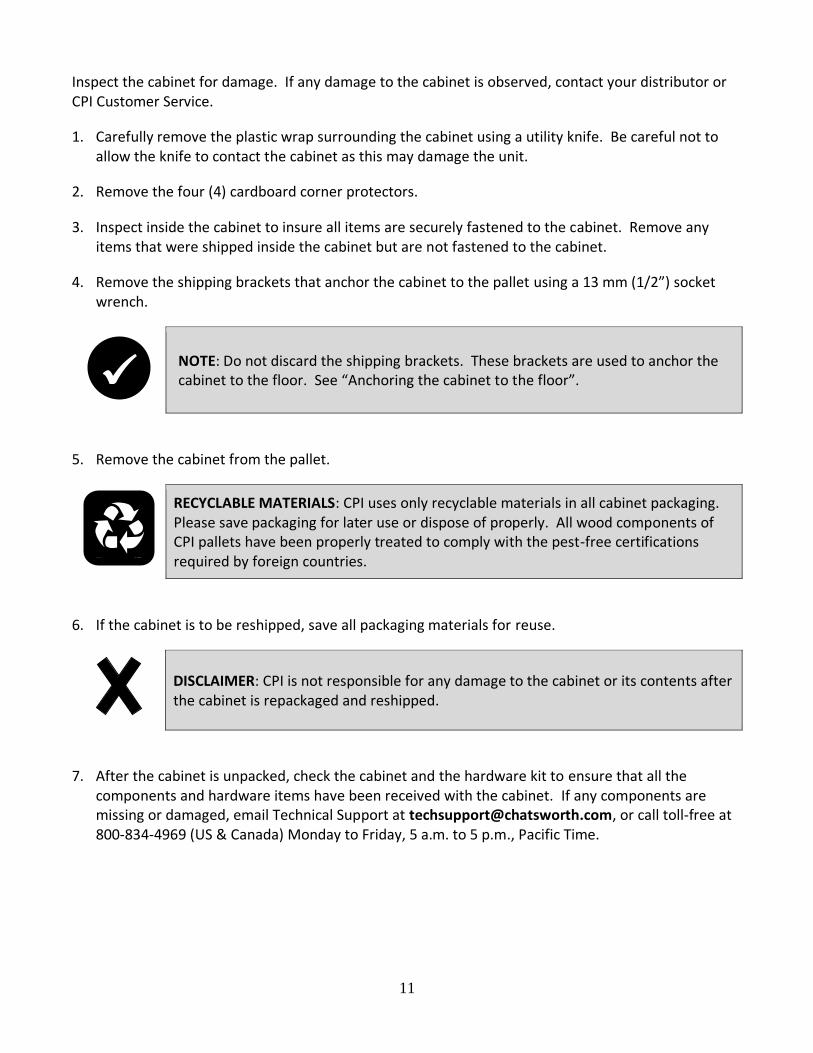
Inspect the cabinet for damage. If any damage to the cabinet is observed, contact your distributor or CPI Customer Service.
1. Carefully remove the plastic wrap surrounding the cabinet using a utility knife. Be careful not to allow the knife to contact the cabinet as this may damage the unit.
2. Remove the four (4) cardboard corner protectors.
3. Inspect inside the cabinet to insure all items are securely fastened to the cabinet. Remove any items that were shipped inside the cabinet but are not fastened to the cabinet.
4. Remove the shipping brackets that anchor the cabinet to the pallet using a 13 mm (1/2”) socket wrench.
NOTE: Do not discard the shipping brackets. These brackets are used to anchor the cabinet to the floor. See “Anchoring the cabinet to the floor”.
5. Remove the cabinet from the pallet.
RECYCLABLE MATERIALS: CPI uses only recyclable materials in all cabinet packaging. Please save packaging for later use or dispose of properly. All wood components of CPI pallets have been properly treated to comply with the pest-free certifications required by foreign countries.
6. If the cabinet is to be reshipped, save all packaging materials for reuse.
DISCLAIMER: CPI is not responsible for any damage to the cabinet or its contents after the cabinet is repackaged and reshipped.
7. After the cabinet is unpacked, check the cabinet and the hardware kit to ensure that all the components and hardware items have been received with the cabinet. If any components are missing or damaged, email Technical Support at [email protected], or call toll-free at 800-834-4969 (US & Canada) Monday to Friday, 5 a.m. to 5 p.m., Pacific Time.
✓

12
Unpacking A Loaded Cabinet This section describes the system unpacking procedure for a cabinet shipped with installed equipment on a shock pallet.
WARNING: Handling wooden parts such as the pallet can cause splinters. Wear gloves when handling the pallets.
CAUTION: Position pallet loaded with cabinet to allow 20 feet of clearance between the pallet/ramp interface and final stopping point for cabinet to roll off ramp and come to a complete stop.
1. Check pallet deck height versus ramp. If pallet deck is too low to properly align with ramp,
carefully lift pallet with appropriate equipment (pallet jack, forklift, etc.) and add spacers on
floor under front and rear edges of pallet as required to raise and level the pallet deck to align
with the ramp.
2. Remove front shipping brackets anchoring cabinet to pallet.
WARNING: Do not remove rear shipping brackets anchoring cabinet to pallet.
3. Align metal ramp to pallet and bolt the ramp to the pallet.
4. Remove bolts securing rear shipping brackets to the cabinet frame, but do not remove the bolts
securing the rear shipping brackets to the pallet.
WARNING: Do not remove bolts securing rear shipping brace to pallet.
5. Due to extremely heavy load, use a minimum of three individuals to move cabinet towards
ramp and walk adjacent to or behind cabinet.
WARNING: Do not allow anyone in front of cabinet during movement.
6. Once clearance is assured, move cabinet onto ramp and allow it to roll down.

13
WARNING: Do not attempt to stop cabinet during movement.
7. Once cabinet has stopped rolling, it is OK to maneuver cabinet as required.
CAUTION: It is recommended to move the cabinet with swivel casters at the rear.
CAUTION:
• The engineered shock pallet is designed to be used only once. The
pallet should not be reused after the cabinet reaches its destination.
• Reusing a shock pallet may not protect the cabinet and installed
equipment. If a cabinet with installed equipment needs to be shipped
to a new destination, a new shock pallet must be used.
Moving Loaded Cabinets on Casters
WARNING:
• Install equipment so Center of Gravity does not rise above
22.5 RMU by placing heavy equipment at the bottom of the cabinet.
• If the Center of Gravity rises above 22.5 RMU, the cabinet may become
unstable and tip while moving the cabinet.
CAUTION:
• Cabinets with casters should be moved with care.
• Sudden stops, excessive force, and uneven surfaces may cause the
product to overturn.
• When rolling the cabinet, make sure to push firmly on the door frame
and not the door mesh.
• Never push on the sides of the cabinet, which could cause the cabinet
to overturn.
• Customer is responsible for assuring that floor surface is free of
obstructions and other obstacles that would impede safe movement of
the cabinet. Concentrated, ultimate and rolling load floor loading
capacities must be carefully observed. All ramps and thresholds must
be safely and properly addressed.

14
Installation
Moving the Cabinet
CAUTION: The ZetaFrame cabinet ships on casters. Move the cabinet by pushing on the front or the rear of the cabinet. Do not push the cabinet from the sides.
The ZetaFrame cabinet has been provided with four (4) casters to allow the cabinet to be rolled into position. Once the cabinet has been moved to the final location, level and anchor the cabinet per the instructions below.
Leveling the Cabinet Ensure that the cabinet has been properly leveled. All four (4) leveling feet should be in firm contact with the floor and the cabinet should not rock in any direction. A level placed on the cabinet frame should confirm that the cabinet is level. Once the cabinet is positioned, lower the leveling feet with a 12” (300 mm) long 5 mm hex ball driver (CPI P/N 39150-001, ordered separately) until they just contact the floor. The ball driver should not be used to try to lift/level the cabinet when it is loaded. Then, adjust leveling feet with 13 mm open-end wrench until the cabinet is level and the cabinet will not rock in any direction.
5mm Ball Hex Driver Access
13mm Open-Ended Wrench Access

15
Baying Cabinets Together
ZetaFrame Cabinets can be bayed (fastened) together with solid side panels in place, with a shared solid or brush side panel between cabinets, or with no side panels, depending on installation requirements. Cabinets must be the same height and depth. 1. Use the supplied hardware and a 13mm Socket wrench to attach the top baying bracket (included
in the hardware kit) to the first cabinet. Make sure to use the correct set of holes for the desired cabinet spacing (24” or 600 mm). The 24” spacing will center two 600 mm wide cabinets over a 24” access floor tile – spaces cabinets approximately 0.4” (10 mm) apart. The 600 mm spacing will bay any two cabinets side-by-side.
2. Move the second cabinet so that the cabinets are aligned. This may also require adjusting the leveling feet if the second cabinet was not set at the same level as the first cabinet.
3. Use the supplied hardware to attach the top baying bracket to the second cabinet.
4. For 600 mm spacing, use one floor anchor to bay two cabinets at the bottom. For 24” spacing, no baying available using floor anchors at bottom, so each cabinet requires two floor anchors on both front and rear.
5. Repeat steps 1-3 for the other end of the cabinet.
24”
600mm

16
Anchoring the Cabinet to the Floor ZetaFrame Cabinets, whether bayed together or standing alone, should be anchored to the floor. The anchor brackets that secured the cabinet to the pallet (shown below) are used to anchor the cabinet to the floor. The brackets attach to the outside of the frame (as they were on the pallet). Installation requires four anchors, either 3/8” or M10 hardware.
Anchor Bracket
The mounting locations for the anchor brackets are shown in the figure below. If used as part of an aisle containment solution, install the Floor Seal Kits (P/Ns 39996-XXX and 39997-XXX) before attaching the anchor brackets.
Attach the cabinet to the floor with 3/8” or M10 hardware appropriate for your type of flooring.
Bonding the Cabinet to the Telecommunications Busbar ZetaFrame Cabinets should be bonded to the telecommunications busbar. The top panel, side panels, doors and mounting rails on the ZetaFrame cabinet are electrically bonded to the frame. In order to bond the cabinet to the telecommunications busbar, use the Ground Terminal Block (included) to connect a bonding conductor to the telecommunications busbar or signal reference grid. Secure bonding wire to the terminal block. Apply generous coating of gray antioxidant to the ribbed section on the block with threaded holes to mount to cabinet. Attach the block to the cabinet frame (bottom or top) with a T25 Torx screwdriver and two M6 Torx scews.

17
Cleaning the Cabinet
CAUTION: ZetaFrame cabinets are constructed and finished with a variety of materials. A dry or damp cloth is recommended for light-duty cleaning. A vacuum may be necessary to remove heavy dust accumulation. Avoid use of chemical-based products as they may damage some cabinet finishes. Color-matched touch-up paint is available to cover minor scrapes and scuffs.
Configuring the Cabinet The ZetaFrame Cabinet can easily be configured for a variety of applications. Not only can the standard cabinet components be adjusted or removed, but a broad range of accessories can be installed to create a cabinet solution that meets all the needs of your installation requirements.
Removing and Installing the Front Door
CAUTION: To avoid personal injury and reduce the risk of damaging the door or the cabinet, one person should support the door while another person retracts the hinge pins and removes the door from the frame.
Removing the Front Door: 1. Open the front door to 90 degrees so that it is perpendicular to the cabinet. The door is
perpendicular to the cabinet when it is parallel with the side of the cabinet.

18
2. While supporting the door, retract the hinge pin from the upper hinge. Note: the door, hinge pin and/or hinge may be damaged if the door is not properly supported while being removed. Hold the door so that it does not lean.
3. Retract the hinge pin from the lower hinge. Lift the door off the bottom hinge and move toward the side of the cabinet. Support the door while lifting and moving the door. The hinge is captive in a pocket on the door.
4. Once the door is free of the hinges, move the door away from the frame.
Installing the Front Door:
1. Hold the door so that it is perpendicular to the cabinet and align the hinge pins on the door with the hinge barrels on the cabinet. The door is perpendicular to the cabinet when it is parallel with the side of the cabinet.
2. Lift the door and move it toward the hinges. Align the lower hinge pin with the lower hinge barrel. Insert the lower hinge pin into the lower hinge barrel. Continue to support the door, keeping it vertical and perpendicular to the cabinet frame. The door must be supported to prevent damage to the hinges.
3. While supporting the door, retract the upper hinge pin, and then align and insert the pin into the
upper hinge barrel. Check that both hinge pins are inserted into the hinge barrels before releasing the door. Note: on tall cabinets, you may need to insert the upper hinge pin first.
4. Close the front door.
1
3
2
4

19
Removing and Installing the Rear Doors
Removing the Rear Doors: 1. With the doors closed, lift and remove the hinge pins from both the upper and lower hinges on the
door that you want to remove.
2. Open the door to exactly 90 degrees and pull the door away from the cabinet frame.
Installing the Rear Doors:
1. Hold the door in a 90-degree open position.
2. Align the hinges on the door with the hinges on the frame and slide the hinges together.
1
4
2
3

20
3. Rotate the door to the closed position.
4. Insert the hinge pins (from the top of the hinge) into both the upper and lower door hinges.
Removing and Installing the Top Panel
Removing the One-Piece Top Panel: 1. Open the rear door(s) of the cabinet.
2. Depress and hold the two (2) spring retainers that hold the top panel to the frame.
3. Push up on the top panel and remove.
Installing the Top Panel: 1. Align the front edge of the top panel with the frame.
2. Lower the top panel onto the frame.

21
3. Pull the four (4) spring retainers until the top panel has snapped in place and secure the top panel from lifting.
Note: There are two spring clips (one centered per top cross member) on the interior ledge of the frame that supports the top panel. These clips create the bonded connection between the frame and the top panel. Be careful when lowering the top panel to not bend or damage the clip.
Removing and Installing the Side Panels
Removing the Side Panels: 1. Unlock the side panel latches with the key (if necessary).
2. Retract the side panel latches by pushing towards the center and allow the side panel to tilt away from the cabinet.
3. Lift up on the side panel and remove it from the cabinet.
Spring Bonding Clip

22
Installing the Side Panels: 1. Align the side panel with the cabinet frame and slip the side panel into the side of the frame. Allow
the side panel to move downwards so that the tabs on the bottom of the panel engage the front-to-rear frame member below the side panel.
2. Rotate the side panel up to meet the frame and push until the side panel latches engage the vertical frame members next to the side panel.
3. Lock the side panel with the key (if necessary).
Adjusting the Equipment Rails 1. Use a 13 mm socket wrench to loosen (but do not remove) the nuts securing the equipment rail to
the frame in three (3) locations on the cabinet.
2. Move the equipment rail forward or backward to the desired location.
3. Tighten the nuts in all three (3) locations on the cabinet.

23
Note: To insert support hardware turn the captive nut to align with the groove in the support, insert into the groove and turn 90 degrees to lock into the groove. Adjust to location and attach the mounting rail.
Installing the Standard PDU Brackets 1. Choose the desired corner of the cabinet to install the PDU Brackets and install front mount cage
nuts in square holes.
2. Position PDU bracket against vertical frame member and install 2 screws through holes into cage nuts. Torque screws to 168 in-lb (19 Nm) using a Phillips screw driver.
3. Repeat for second PDU Bracket.
Installing Equipment The ZetaFrame Cabinet supports all manufacturers’ equipment that conforms to the EIA/ECA-310E standard. Most equipment attaches directly to the equipment mounting rails; however, some manufacturers may provide brackets or slide assemblies that require additional installation. Rack-mount unit (U) markings are clearly printed on the equipment rails to simplify installation of components. Align equipment with the U markings on each side of the cabinet before securing the equipment.
NOTE: Equipment rails should be adjusted to the desired location (front to rear) prior to installing equipment. See “Adjusting the Equipment Rails” on page 22.
The ZetaFrame Cabinet is provided with hardware to secure equipment to the mounting rails. This hardware includes 50 sets of M6 cage nuts and screws. Additional hardware is available for purchase (see “Other Accessories” on page 29).
✓

24
Cable Management CPI cable management products provide the proper cable bend radii for better data transmission; fewer tangled cords and cable damage; and ease in moving, adding, and changing connections. The products assist in complying with ANSI/TIA installation of Category 5/5e/6/6a and fiber cables. Separate the cables by type, gather into bundles, and fasten loosely with hook and loop fasteners. CPI offers Saf-T-Grip Straps to fasten cable bundles (P/N 0200X-series). See “Accessories – Cable Management” on page 24 for more information.

25
Accessories
Cable Management
Vertical Cable Manager, Short Finger 42U x 600 - 39835-X00 For 23.6” (600 mm) wide cabinets 45U x 600 - 39835-X03 Fingers, attaches to equipment rail 48U x 600 - 39835-X06 (Fits other width cabinets also.) 52U x 600 - 39835-X10
Finger Cable Manager, Short Finger 42U x 700 - 38646-X11 For 27.6” (700 mm) wide cabinets 45U x 700 - 38646-X14 Fingers, Attaches to equipment rail 48U x 700 - 38646-X17 52U x 700 - 38646-X21 Finger Cable Manager, Short Finger 42U x 750 - 38646-X22 For 29.5” (750 mm) wide cabinets 45U x 750 - 38646-X25 Fingers, Attaches to equipment rail 48U x 750 - 38646-X28 52U x 750 - 38646-X32
Finger Cable Manager, Short Finger 42U x 800 - 38646-X33 For 31.5” (800 mm) wide cabinets 45U x 800 - 38646-X36 Fingers, Attaches to equipment rail 48U x 800 - 38646-X39 52U x 800 - 38646-X43
Finger Cable Manager, Long Finger 42U x 700 - 38647-X11 For 27.6” (700 mm) wide cabinets 45U x 700 - 38647-X14 Fingers, Attaches to equipment rail 48U x 700 - 38647-X17 52U x 700 - 38647-X21
Finger Cable Manager, Long Finger 42U x 750 - 38647-X22 For 29.5” (750 mm) wide cabinets 45U x 750 - 38647-X25 Fingers, Attaches to equipment rail 48U x 750 - 38647-X28 52U x 750 - 38647-X32
Finger Cable Manager, Long Finger 42U x 800 - 38647-X33 For 31.5” (800 mm) wide cabinets 45U x 800 - 38647-X36 Fingers, Attaches to equipment rail 48U x 800 - 38647-X39 52U x 800 - 38647-X43
X = Color (7=Black, E=Glacier White)
39835-XXX 38646-XXX
38647-XXX

26
Cable Management (cont’d)
Cable Lashing Panel, 2.75in 42U - 38634-X00 Two (2) half-height panels 45U - 38634-X03 Attaches to the cabinet frame 48U - 38634-X06 52U - 38634-X10
Cable Lashing Panel, 4.5in 42U - 38635-X00 Two (2) half-height panels 45U - 38635-X03 Attaches to the cabinet frame 48U - 38635-X06 52U - 38635-X10
Cable Lashing Panel, 7in 42U - 38636-X00 Two (2) half-height panels 45U - 38636-X03 Attaches to the cabinet frame 48U - 38636-X06 52U - 38636-X10
Front-to-Rear Cable Manager 700W - 38648-X01 Attaches to the mounting rails 750W - 38648-X02 800W - 38648-X03
X = Color (7=Black, E=Glacier White)
38634-XXX 38635-XXX 38636-XXX

27
Power Management One set of standard PDU brackets is included with the ZetaFrame Cabinet. Additional PDU brackets are available as well as a wide range of power strips and PDU’s, including monitored and switched versions.
Standard PDU Brackets 38645-700 Two (2) brackets Attaches to the cabinet vertical frame member
Full Height PDU Bracket, Single 42U x 2.2in - 38637-X00 Attaches to the cabinet frame 45U x 2.2in - 38637-X03 48U x 2.2in - 38637-X06 52U x 2.2in - 38637-X10 42U x 2.7in - 38637-X11 45U x 2.7in - 38637-X14 48U x 2.7in - 38637-X17 52U x 2.7in - 38637-X21
Full Height PDU Bracket, Dual 42U x 2.2in - 38638-X00 Attaches to the cabinet frame 45U x 2.2in - 38638-X03 48U x 2.2in - 38638-X06 52U x 2.2in - 38638-X10 42U x 2.7in - 38638-X11 45U x 2.7in - 38638-X14 48U x 2.7in - 38638-X17 52U x 2.7in - 38638-X21
X = Color (7=Black, E=Glacier White)

28
Thermal Management
Vertical Exhaust Duct 600W - 39873-X00 15” – 20” (381 – 508 mm) 700W - 39873-X01 750W - 39873-X02 800W - 39873-X03
Vertical Exhaust Duct 600W - 39873-X04 20” – 34” (508 – 863 mm) 700W - 39873-X05 750W - 39873-X06 800W - 39873-X07
Vertical Exhaust Duct 600W - 39873-X08 34” – 60” (863 – 1523 mm) 700W - 39873-X09 750W - 39873-X10 800W - 39873-X11
42U x 800D - 39774-X00 42U x 1000D - 39774-X08
42U x 1050D - 39774-X10 42U x 1100D - 39774-X12 42U x 1200D - 39774-X16 Side Panel with Grommet Sealed 45U x 800D - 39774-X51 Cable Openings 45U x 1000D - 39774-X59 Pair of Panels 45U x 1050D - 39774-X61 For one side of cabinet 45U x 1100D - 39774-X63 Includes one (1) key 45U x 1200D - 39774-X67 48U x 800D - 39774-XAC 48U x 1000D - 39774-XAL
48U x 1050D - 39774-XAN 48U x 1100D - 39774-XAR 48U x 1200D - 39774-XAW 52U x 800D - 39774-XDL 52U x 1000D - 39774-XDW
52U x 1050D - 39774-XEA 52U x 1100D - 39774-XEC 52U x 1200D - 39774-XEG
Airflow Director 600W - 39802-X00 Use in conjunction with 700W - 39802-X01 Vertical Exhaust Duct 750W - 39802-X02 800W - 39802-X03
X = Color (7=Black, E=Glacier White)

29
Thermal Management (cont’d)
Air Dam 42U x 600 - 38649-X44 For 23.6” (600 mm), 27.6” (700 mm), 45U x 600 - 38649-X47 29.5” (750 mm), and 31.5” (800 mm) 48U x 600 - 38649-X50 wide cabinets 52U x 600 - 38649-X54 42U x 700 - 38649-X55 45U x 700 - 38649-X58 48U x 700 - 38649-X61 52U x 700 - 38649-X65
42U x 750 - 38649-X66 45U x 750 - 38649-X69 48U x 750 - 38649-X72 52U x 750 - 38649-X76
42U x 800 - 38649-X77 45U x 800 - 38649-X80 48U x 800 - 38649-X83 52U x 800 - 38649-X87
Equipment Mounting Rail Grommet Kit 700/750 - 39731-001 Set of 8 grommets, black 800 - 39731-002
1U X19, Black, 6 EA - 34537-001 Snap-In Filler Panel 2U X19, Black, 6 EA - 34538-001 1U X19, Black, 50 EA - 34537-002 2U X19, Black, 50 EA - 34538-002
Cable Port Brush Kit Brushes for two (2) large cable knock-outs 25190-001 in cabinet top panel
X = Color (7=Black, E=Glacier White)

30
Shelves, Trays and other accessories
Clik-Nuts & Screws 76543-001 (25) M6 cage nuts and screws
Low Profile Fixed Shelf 12610-719 1U x 19”W Telescopes 20”- 36” (510 mm - 910 mm) in depth
Rack-Mount Cable Shelf 13517-701 1U x 19”W brush sealed openings on front for cable pass-through
Concrete Floor Installation Kit 3/8” - 40604-001 Four (4) floor anchors M10 - 40604-004