Embed Size (px)
Citation preview
Page 1 © 2018.
Corp. 1807-L2
ZGB SERIESService Literature 3, 4, 5 and 6 ton
10.6 to 20.3kW
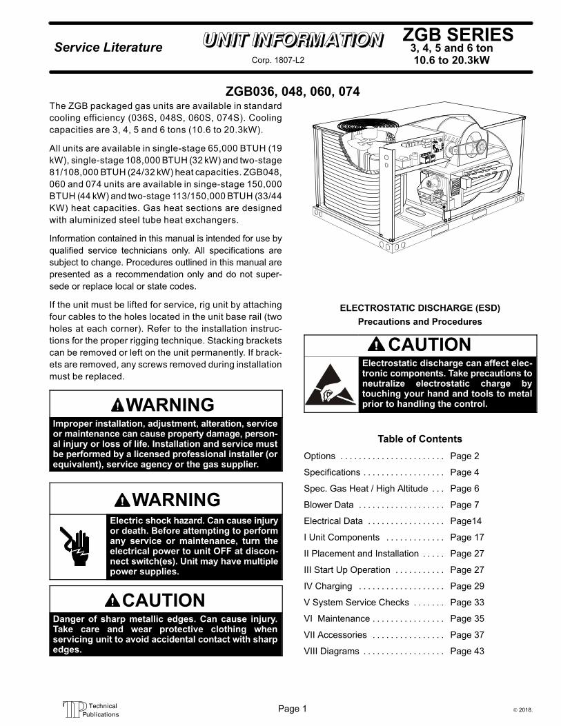
ZGB036, 048, 060, 074The ZGB packaged gas units are available in standard
cooling efficiency (036S, 048S, 060S, 074S). Cooling
capacities are 3, 4, 5 and 6 tons (10.6 to 20.3kW).
All units are available in single-stage 65,000 BTUH (19
kW), single-stage 108,000 BTUH (32 kW) and two-stage
81/108,000 BTUH (24/32 kW) heat capacities. ZGB048,
060 and 074 units are available in singe-stage 150,000
BTUH (44 kW) and two-stage 113/150,000 BTUH (33/44
KW) heat capacities. Gas heat sections are designed
with aluminized steel tube heat exchangers.
Information contained in this manual is intended for use by
qualified service technicians only. All specifications are
subject to change. Procedures outlined in this manual are
presented as a recommendation only and do not super
sede or replace local or state codes.
If the unit must be lifted for service, rig unit by attaching
four cables to the holes located in the unit base rail (two
holes at each corner). Refer to the installation instruc
tions for the proper rigging technique. Stacking brackets
can be removed or left on the unit permanently. If brack
ets are removed, any screws removed during installation
must be replaced.
WARNINGImproper installation, adjustment, alteration, serviceor maintenance can cause property damage, personal injury or loss of life. Installation and service mustbe performed by a licensed professional installer (orequivalent), service agency or the gas supplier.
WARNINGElectric shock hazard. Can cause injuryor death. Before attempting to performany service or maintenance, turn theelectrical power to unit OFF at disconnect switch(es). Unit may have multiplepower supplies.
CAUTIONDanger of sharp metallic edges. Can cause injury.Take care and wear protective clothing whenservicing unit to avoid accidental contact with sharpedges.
ELECTROSTATIC DISCHARGE (ESD)
Precautions and Procedures
CAUTIONElectrostatic discharge can affect electronic components. Take precautions toneutralize electrostatic charge bytouching your hand and tools to metalprior to handling the control.
Table of Contents
Options Page 2. . . . . . . . . . . . . . . . . . . . . . .
Specifications Page 4. . . . . . . . . . . . . . . . . .
Spec. Gas Heat / High Altitude Page 6. . .
Blower Data Page 7. . . . . . . . . . . . . . . . . . .
Electrical Data Page14. . . . . . . . . . . . . . . . .
I Unit Components Page 17. . . . . . . . . . . . .
II Placement and Installation Page 27. . . . .
III Start Up Operation Page 27. . . . . . . . . . .
IV Charging Page 29. . . . . . . . . . . . . . . . . . .
V System Service Checks Page 33. . . . . . .
VI Maintenance Page 35. . . . . . . . . . . . . . . .
VII Accessories Page 37. . . . . . . . . . . . . . . .
VIII Diagrams Page 43. . . . . . . . . . . . . . . . . .
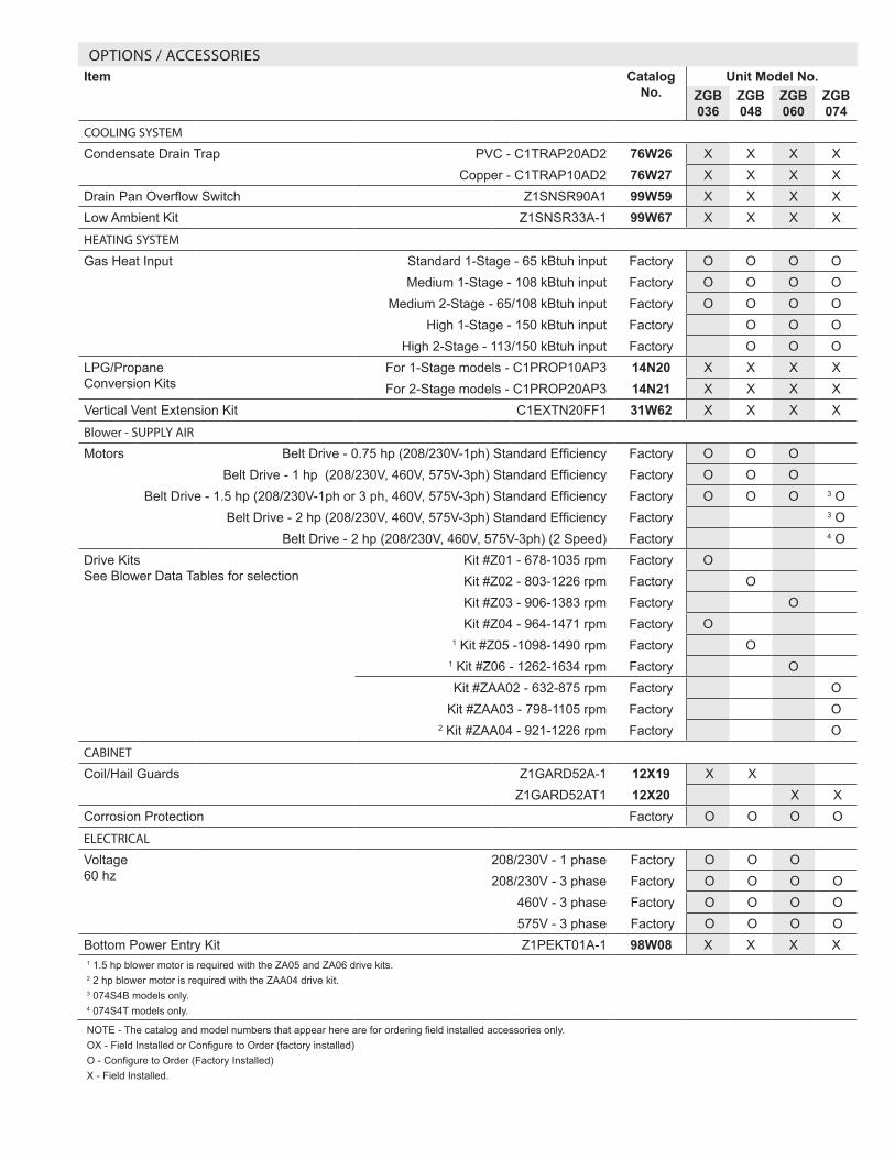
OPTIONS / ACCESSORIESItem Catalog
No.Unit Model No.
ZGB 036
ZGB 048
ZGB 060
ZGB 074
COOLING SYSTEM
Condensate Drain Trap PVC - C1TRAP20AD2 76W26 X X X XCopper - C1TRAP10AD2 76W27 X X X X
Drain Pan Overflow Switch Z1SNSR90A1 99W59 X X X XLow Ambient Kit Z1SNSR33A-1 99W67 X X X X
HEATING SYSTEM
Gas Heat Input Standard 1-Stage - 65 kBtuh input Factory O O O OMedium 1-Stage - 108 kBtuh input Factory O O O O
Medium 2-Stage - 65/108 kBtuh input Factory O O O OHigh 1-Stage - 150 kBtuh input Factory O O O
High 2-Stage - 113/150 kBtuh input Factory O O OLPG/Propane Conversion Kits
For 1-Stage models - C1PROP10AP3 14N20 X X X XFor 2-Stage models - C1PROP20AP3 14N21 X X X X
Vertical Vent Extension Kit C1EXTN20FF1 31W62 X X X X
Blower - SUPPLY AIR
Motors Belt Drive - 0.75 hp (208/230V-1ph) Standard Efficiency Factory O O OBelt Drive - 1 hp (208/230V, 460V, 575V-3ph) Standard Efficiency Factory O O O
Belt Drive - 1.5 hp (208/230V-1ph or 3 ph, 460V, 575V-3ph) Standard Efficiency Factory O O O 3 OBelt Drive - 2 hp (208/230V, 460V, 575V-3ph) Standard Efficiency Factory 3 O
Belt Drive - 2 hp (208/230V, 460V, 575V-3ph) (2 Speed) Factory 4 ODrive Kits See Blower Data Tables for selection
Kit #Z01 - 678-1035 rpm Factory OKit #Z02 - 803-1226 rpm Factory OKit #Z03 - 906-1383 rpm Factory OKit #Z04 - 964-1471 rpm Factory O
1 Kit #Z05 -1098-1490 rpm Factory O1 Kit #Z06 - 1262-1634 rpm Factory OKit #ZAA02 - 632-875 rpm Factory O
Kit #ZAA03 - 798-1105 rpm Factory O2 Kit #ZAA04 - 921-1226 rpm Factory O
CABINET
Coil/Hail Guards Z1GARD52A-1 12X19 X X Z1GARD52AT1 12X20 X X
Corrosion Protection Factory O O O O
ELECTRICAL
Voltage 60 hz
208/230V - 1 phase Factory O O O208/230V - 3 phase Factory O O O O
460V - 3 phase Factory O O O O575V - 3 phase Factory O O O O
Bottom Power Entry Kit Z1PEKT01A-1 98W08 X X X X1 1.5 hp blower motor is required with the ZA05 and ZA06 drive kits.2 2 hp blower motor is required with the ZAA04 drive kit.3 074S4B models only.4 074S4T models only.
NOTE - The catalog and model numbers that appear here are for ordering field installed accessories only.OX - Field Installed or Configure to Order (factory installed)O - Configure to Order (Factory Installed)X - Field Installed.
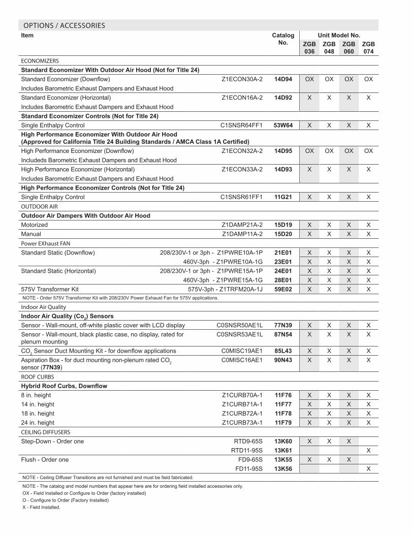
OPTIONS / ACCESSORIESItem Catalog
No.Unit Model No.
ZGB 036
ZGB 048
ZGB 060
ZGB 074
ECONOMIZERS
Standard Economizer With Outdoor Air Hood (Not for Title 24)Standard Economizer (Downflow)Includes Barometric Exhaust Dampers and Exhaust Hood
Z1ECON30A-2 14D94 OX OX OX OX
Standard Economizer (Horizontal)Includes Barometric Exhaust Dampers and Exhaust Hood
Z1ECON16A-2 14D92 X X X X
Standard Economizer Controls (Not for Title 24)Single Enthalpy Control C1SNSR64FF1 53W64 X X X XHigh Performance Economizer With Outdoor Air Hood (Approved for California Title 24 Building Standards / AMCA Class 1A Certified)High Performance Economizer (Downflow)Includeds Barometric Exhaust Dampers and Exhaust Hood
Z1ECON32A-2 14D95 OX OX OX OX
High Performance Economizer (Horizontal)Includes Barometric Exhaust Dampers and Exhaust Hood
Z1ECON33A-2 14D93 X X X X
High Performance Economizer Controls (Not for Title 24)Single Enthalpy Control C1SNSR61FF1 11G21 X X X XOUTDOOR AIR
Outdoor Air Dampers With Outdoor Air HoodMotorized Z1DAMP21A-2 15D19 X X X XManual Z1DAMP11A-2 15D20 X X X XPower EXhaust FAN
Standard Static (Downflow) 208/230V-1 or 3ph - Z1PWRE10A-1P 21E01 X X X X460V-3ph - Z1PWRE10A-1G 23E01 X X X X
Standard Static (Horizontal) 208/230V-1 or 3ph - Z1PWRE15A-1P 24E01 X X X X460V-3ph - Z1PWRE15A-1G 28E01 X X X X
575V Transformer Kit 575V-3ph - Z1TRFM20A-1J 59E02 X X X XNOTE - Order 575V Transformer Kit with 208/230V Power Exhaust Fan for 575V applications.
Indoor Air Quality
Indoor Air Quality (Co2) SensorsSensor - Wall-mount, off-white plastic cover with LCD display C0SNSR50AE1L 77N39 X X X XSensor - Wall-mount, black plastic case, no display, rated for plenum mounting
C0SNSR53AE1L 87N54 X X X X
CO2 Sensor Duct Mounting Kit - for downflow applications C0MISC19AE1 85L43 X X X XAspiration Box - for duct mounting non-plenum rated CO2 sensor (77N39)
C0MISC16AE1 90N43 X X X X
ROOF CURBS
Hybrid Roof Curbs, Downflow8 in. height Z1CURB70A-1 11F76 X X X X14 in. height Z1CURB71A-1 11F77 X X X X18 in. height Z1CURB72A-1 11F78 X X X X24 in. height Z1CURB73A-1 11F79 X X X XCEILING DIFFUSERS
Step-Down - Order one RTD9-65S 13K60 X X XRTD11-95S 13K61 X
Flush - Order one FD9-65S 13K55 X X XFD11-95S 13K56 X
NOTE - Ceiling Diffuser Transitions are not furnished and must be field fabricated.
NOTE - The catalog and model numbers that appear here are for ordering field installed accessories only.OX - Field Installed or Configure to Order (factory installed)O - Configure to Order (Factory Installed)X - Field Installed.
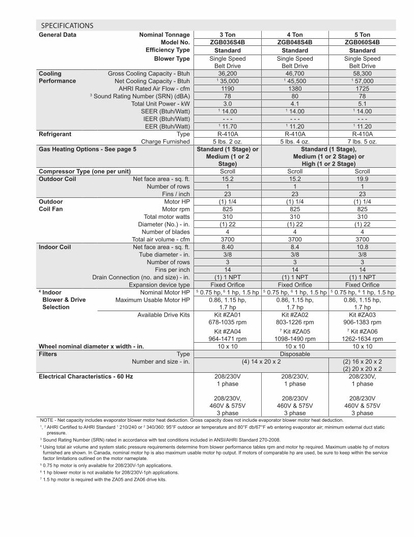
SPECIFICATIONSGeneral Data Nominal Tonnage 3 Ton 4 Ton 5 Ton
Model No. ZGB036S4B ZGB048S4B ZGB060S4BEfficiency Type Standard Standard Standard
Blower Type Single Speed Belt Drive
Single Speed Belt Drive
Single Speed Belt Drive
Cooling Performance
Gross Cooling Capacity - Btuh 36,200 46,700 58,300Net Cooling Capacity - Btuh 1 35,000 1 45,500 1 57,000
AHRI Rated Air Flow - cfm 1190 1380 17253 Sound Rating Number (SRN) (dBA) 78 80 78
Total Unit Power - kW 3.0 4.1 5.1SEER (Btuh/Watt) 1 14.00 1 14.00 1 14.00IEER (Btuh/Watt) - - - - - - - - -EER (Btuh/Watt) 1 11.70 1 11.20 1 11.20
Refrigerant Type R-410A R-410A R-410ACharge Furnished 5 lbs. 2 oz. 5 lbs. 4 oz. 7 lbs. 5 oz.
Gas Heating Options - See page 5 Standard (1 Stage) or Medium (1 or 2
Stage)
Standard (1 Stage), Medium (1 or 2 Stage) or
High (1 or 2 Stage)Compressor Type (one per unit) Scroll Scroll ScrollOutdoor Coil Net face area - sq. ft. 15.2 15.2 19.9
Number of rows 1 1 1Fins / inch 23 23 23
Outdoor Coil Fan
Motor HP (1) 1/4 (1) 1/4 (1) 1/4Motor rpm 825 825 825
Total motor watts 310 310 310Diameter (No.) - in. (1) 22 (1) 22 (1) 22
Number of blades 4 4 4Total air volume - cfm 3700 3700 3700
Indoor Coil Net face area - sq. ft. 8.40 8.4 10.8Tube diameter - in. 3/8 3/8 3/8
Number of rows 3 3 3Fins per inch 14 14 14
Drain Connection (no. and size) - in. (1) 1 NPT (1) 1 NPT (1) 1 NPTExpansion device type Fixed Orifice Fixed Orifice Fixed Orifice
4 Indoor Blower & Drive Selection
Nominal Motor HP 5 0.75 hp, 6 1 hp, 1.5 hp 5 0.75 hp, 6 1 hp, 1.5 hp 5 0.75 hp, 6 1 hp, 1.5 hpMaximum Usable Motor HP 0.86, 1.15 hp,
1.7 hp0.86, 1.15 hp,
1.7 hp0.86, 1.15 hp,
1.7 hpAvailable Drive Kits Kit #ZA01
678-1035 rpmKit #ZA04
964-1471 rpm
Kit #ZA02 803-1226 rpm
7 Kit #ZA05 1098-1490 rpm
Kit #ZA03 906-1383 rpm
7 Kit #ZA06 1262-1634 rpm
Wheel nominal diameter x width - in. 10 x 10 10 x 10 10 x 10Filters Type Disposable
Number and size - in. (4) 14 x 20 x 2 (2) 16 x 20 x 2 (2) 20 x 20 x 2
Electrical Characteristics - 60 Hz 208/230V 1 phase
208/230V,
460V & 575V 3 phase
208/230V, 1 phase
208/230V
460V & 575V 3 phase
208/230V, 1 phase
208/230V
460V & 575V 3 phase
NOTE - Net capacity includes evaporator blower motor heat deduction. Gross capacity does not include evaporator blower motor heat deduction.1, 2 AHRI Certified to AHRI Standard 1 210/240 or 2 340/360: 95°F outdoor air temperature and 80°F db/67°F wb entering evaporator air; minimum external duct static
pressure.3 Sound Rating Number (SRN) rated in accordance with test conditions included in ANSI/AHRI Standard 270-2008.4 Using total air volume and system static pressure requirements determine from blower performance tables rpm and motor hp required. Maximum usable hp of motors
furnished are shown. In Canada, nominal motor hp is also maximum usable motor hp output. If motors of comparable hp are used, be sure to keep within the service factor limitations outlined on the motor nameplate.
5 0.75 hp motor is only available for 208/230V-1ph applications. 6 1 hp blower motor is not available for 208/230V-1ph applications.7 1.5 hp motor is required with the ZA05 and ZA06 drive kits.
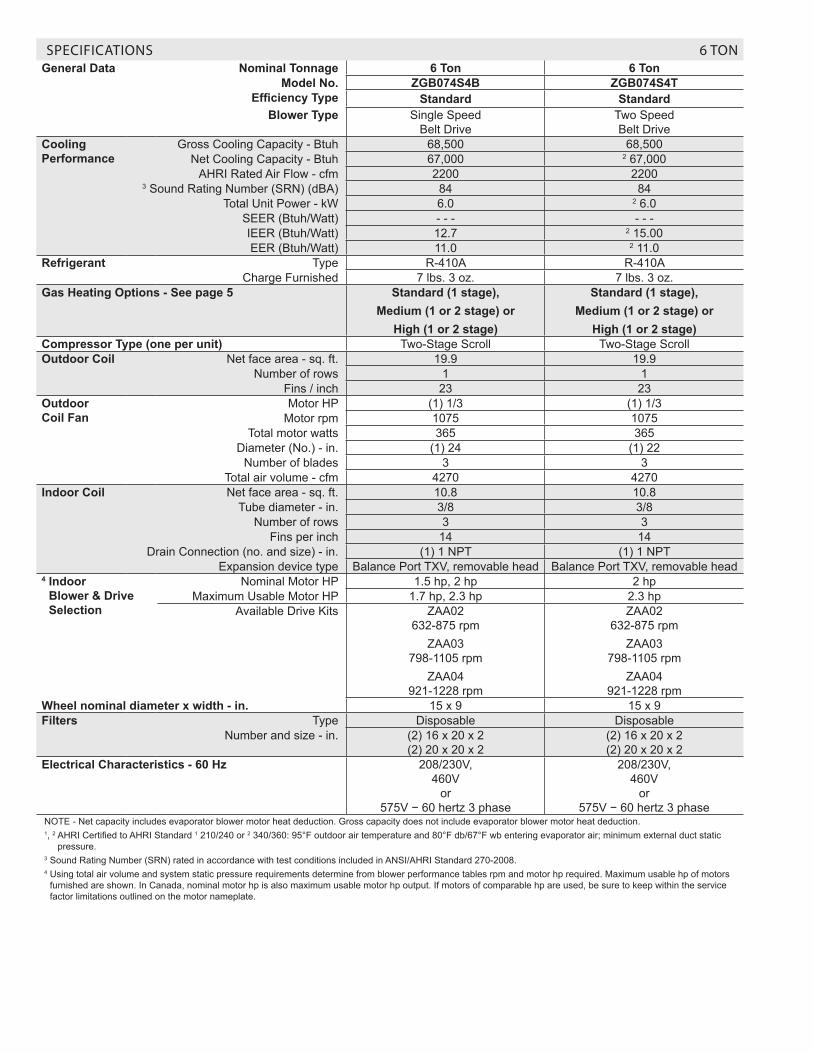
SPECIFICATIONS 6 TONGeneral Data Nominal Tonnage 6 Ton 6 Ton
Model No. ZGB074S4B ZGB074S4TEfficiency Type Standard Standard
Blower Type Single Speed Belt Drive
Two Speed Belt Drive
Cooling Performance
Gross Cooling Capacity - Btuh 68,500 68,500Net Cooling Capacity - Btuh 67,000 2 67,000
AHRI Rated Air Flow - cfm 2200 22003 Sound Rating Number (SRN) (dBA) 84 84
Total Unit Power - kW 6.0 2 6.0SEER (Btuh/Watt) - - - - - -IEER (Btuh/Watt) 12.7 2 15.00EER (Btuh/Watt) 11.0 2 11.0
Refrigerant Type R-410A R-410ACharge Furnished 7 lbs. 3 oz. 7 lbs. 3 oz.
Gas Heating Options - See page 5 Standard (1 stage), Medium (1 or 2 stage) or
High (1 or 2 stage)
Standard (1 stage), Medium (1 or 2 stage) or
High (1 or 2 stage)Compressor Type (one per unit) Two-Stage Scroll Two-Stage ScrollOutdoor Coil Net face area - sq. ft. 19.9 19.9
Number of rows 1 1Fins / inch 23 23
Outdoor Coil Fan
Motor HP (1) 1/3 (1) 1/3Motor rpm 1075 1075
Total motor watts 365 365Diameter (No.) - in. (1) 24 (1) 22
Number of blades 3 3Total air volume - cfm 4270 4270
Indoor Coil Net face area - sq. ft. 10.8 10.8Tube diameter - in. 3/8 3/8
Number of rows 3 3Fins per inch 14 14
Drain Connection (no. and size) - in. (1) 1 NPT (1) 1 NPTExpansion device type Balance Port TXV, removable head Balance Port TXV, removable head
4 Indoor Blower & Drive Selection
Nominal Motor HP 1.5 hp, 2 hp 2 hpMaximum Usable Motor HP 1.7 hp, 2.3 hp 2.3 hp
Available Drive Kits ZAA02 632-875 rpm
ZAA03 798-1105 rpm
ZAA04 921-1228 rpm
ZAA02 632-875 rpm
ZAA03 798-1105 rpm
ZAA04 921-1228 rpm
Wheel nominal diameter x width - in. 15 x 9 15 x 9Filters Type Disposable Disposable
Number and size - in. (2) 16 x 20 x 2 (2) 20 x 20 x 2
(2) 16 x 20 x 2 (2) 20 x 20 x 2
Electrical Characteristics - 60 Hz 208/230V, 460V
or 575V − 60 hertz 3 phase
208/230V, 460V
or 575V − 60 hertz 3 phase
NOTE - Net capacity includes evaporator blower motor heat deduction. Gross capacity does not include evaporator blower motor heat deduction.1, 2 AHRI Certified to AHRI Standard 1 210/240 or 2 340/360: 95°F outdoor air temperature and 80°F db/67°F wb entering evaporator air; minimum external duct static
pressure.3 Sound Rating Number (SRN) rated in accordance with test conditions included in ANSI/AHRI Standard 270-2008.4 Using total air volume and system static pressure requirements determine from blower performance tables rpm and motor hp required. Maximum usable hp of motors
furnished are shown. In Canada, nominal motor hp is also maximum usable motor hp output. If motors of comparable hp are used, be sure to keep within the service factor limitations outlined on the motor nameplate.

SPECIFICATIONS - LOW NOX GAS HEAT - SINGLE AND THREE PHASE MODELSModel No. 036,
048, 060
074 036, 048, 060
074 036, 048, 060
074 048, 060
074 048, 060
074
Heat Input Type Standard (1 Stage)
Medium (1 Stage)
Medium (2 Stage)
High (1 Stage)
High (2 Stage)
Input Btuh
1st Stage 65,000 108,000 81,000 150,000 113,0002nd Stage - - - - - - 108,000 - - - 150,000
Output Btuh
1st Stage 52,000 87,000 66,000 121,000 92,0002nd Stage - - - - - - 87,000 - - - 121,000
Temperature Rise Range - °F
1st stage 15 - 45 5 - 35 35 - 65 20 - 50 20 - 50 10 - 40 45 - 75 35 - 65 30 - 60 25 - 552nd Stage - - - - - - - - - - - - 35 - 65 20 - 50 - - - - - - 45 - 75 35 - 65
1 AFUE (single phase) 81% 81% 81% - - - 81% - - - 81% - - - 81% - - -2 Thermal Efficiency
(three phase)- - - 81% 81% 81% 81% 81% 81% 81% 81% 81%
Gas Supply Connections 1/2 in. NPTRec. Gas Supply Pressure - Nat./ LPG
7 in.w.g. / 11 in.w.g.
1 Annual Fuel Utilization Efficiency based on U.S. DOE test procedures and FTC labeling regulations - 1 phase models only.2 Thermal Efficiency at full input.
SPECIFICATIONS - STANDARD GAS HEAT - THREE PHASE MODELSModel No. 036,
048, 060
074 036, 048, 060
074 036, 048, 060
074 048, 060
074 048, 060
074
Heat Input Type Standard (1 Stage)
Medium (1 Stage)
Medium (2 Stage)
High (1 Stage)
High (2 Stage)
Input Btuh
1st Stage 65,000 108,000 81,000 150,000 113,0002nd Stage - - - - - - 108,000 - - - 150,000
Output Btuh
1st Stage 52,000 86,000 65,000 120,000 90,0002nd Stage - - - - - - 86,000 - - - 120,000
Temperature Rise Range - °F
1st stage 15 - 45 5 - 35 35 - 65 20 - 50 20 - 50 10 - 40 45 - 75 35 - 55 30 - 60 25 - 552nd
Stage- - - - - - - - - - - - 35 - 65 20 - 50 - - - - - - 45 - 75 35 - 65
1 Thermal Efficiency
Standard 80% 80% 80% 80% 80% 80% 80% 80% 80% 80%
Gas Supply Connections 1/2 in. NPTRec. Gas Supply Pressure - Nat./ LPG
7 in.w.g. / 11 in.w.g.
1 Thermal Efficiency at full input.
HIGH ALTITUDE DERATE
NOTE - Units may be installed at altitudes up to 2000 ft. above sea level without any modifications. At altitudes above 2000 ft. units must be derated to match information in the table shown. At altitudes above 4500 ft. unit must be derated 2% for each 1000 ft. above sea level. NOTE - This is the only permissible derate for these units.
Heat Input Type Altitude Feet Gas Manifold Pressure
in. w.g. Input Rate (Btuh) Natural Gas LPG/ Propane
Standard (1 stage) 2001 - 4500 3.0 9.0 60,000
Medium (1 stage) 2001 - 4500 3.0 9.0 100,000
Medium (2 stage) 2001 - 4500 3.0/1.7 9.0/5.1 100,000 / 75,000
High (1 stage) 2001 - 4500 3.0 9.0 139,000
High (2 stage) 2001 - 4500 3.0/1.7 9.0/5.1 139,000 / 104,000
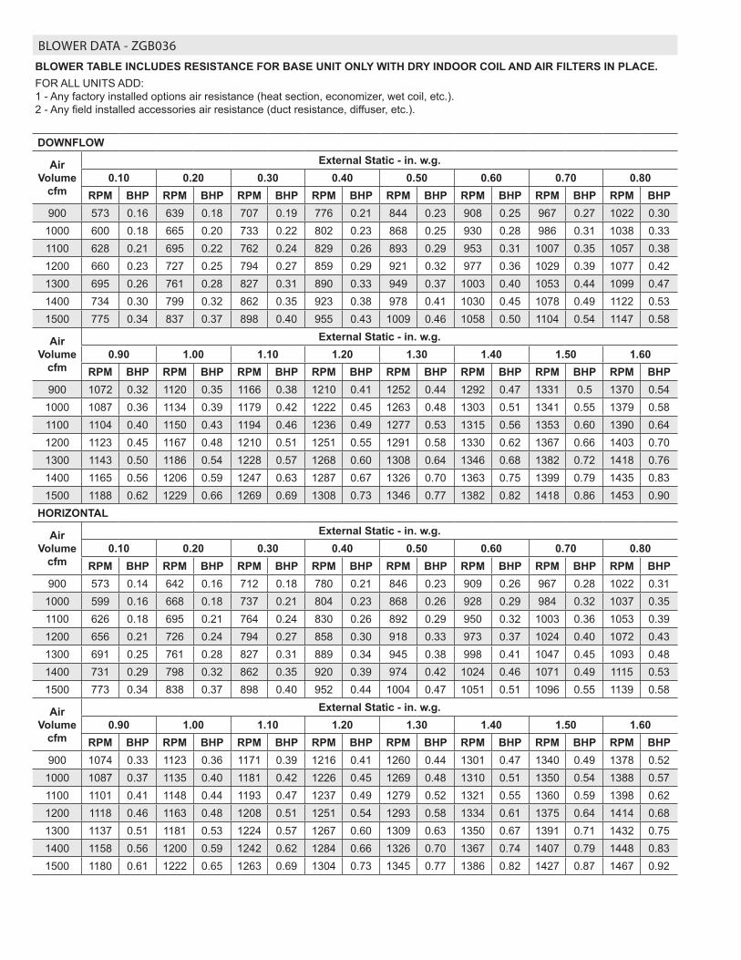
BLOWER DATA - ZGB036
BLOWER TABLE INCLUDES RESISTANCE FOR BASE UNIT ONLY WITH DRY INDOOR COIL AND AIR FILTERS IN PLACE.FOR ALL UNITS ADD: 1 - Any factory installed options air resistance (heat section, economizer, wet coil, etc.). 2 - Any field installed accessories air resistance (duct resistance, diffuser, etc.).
DOWNFLOW
Air Volume
cfm
External Static - in. w.g.0.10 0.20 0.30 0.40 0.50 0.60 0.70 0.80
RPM BHP RPM BHP RPM BHP RPM BHP RPM BHP RPM BHP RPM BHP RPM BHP900 573 0.16 639 0.18 707 0.19 776 0.21 844 0.23 908 0.25 967 0.27 1022 0.30
1000 600 0.18 665 0.20 733 0.22 802 0.23 868 0.25 930 0.28 986 0.31 1038 0.331100 628 0.21 695 0.22 762 0.24 829 0.26 893 0.29 953 0.31 1007 0.35 1057 0.381200 660 0.23 727 0.25 794 0.27 859 0.29 921 0.32 977 0.36 1029 0.39 1077 0.421300 695 0.26 761 0.28 827 0.31 890 0.33 949 0.37 1003 0.40 1053 0.44 1099 0.471400 734 0.30 799 0.32 862 0.35 923 0.38 978 0.41 1030 0.45 1078 0.49 1122 0.531500 775 0.34 837 0.37 898 0.40 955 0.43 1009 0.46 1058 0.50 1104 0.54 1147 0.58
Air Volume
cfm
External Static - in. w.g.0.90 1.00 1.10 1.20 1.30 1.40 1.50 1.60
RPM BHP RPM BHP RPM BHP RPM BHP RPM BHP RPM BHP RPM BHP RPM BHP900 1072 0.32 1120 0.35 1166 0.38 1210 0.41 1252 0.44 1292 0.47 1331 0.5 1370 0.54
1000 1087 0.36 1134 0.39 1179 0.42 1222 0.45 1263 0.48 1303 0.51 1341 0.55 1379 0.581100 1104 0.40 1150 0.43 1194 0.46 1236 0.49 1277 0.53 1315 0.56 1353 0.60 1390 0.641200 1123 0.45 1167 0.48 1210 0.51 1251 0.55 1291 0.58 1330 0.62 1367 0.66 1403 0.701300 1143 0.50 1186 0.54 1228 0.57 1268 0.60 1308 0.64 1346 0.68 1382 0.72 1418 0.761400 1165 0.56 1206 0.59 1247 0.63 1287 0.67 1326 0.70 1363 0.75 1399 0.79 1435 0.831500 1188 0.62 1229 0.66 1269 0.69 1308 0.73 1346 0.77 1382 0.82 1418 0.86 1453 0.90
HORIZONTAL
Air Volume
cfm
External Static - in. w.g.0.10 0.20 0.30 0.40 0.50 0.60 0.70 0.80
RPM BHP RPM BHP RPM BHP RPM BHP RPM BHP RPM BHP RPM BHP RPM BHP900 573 0.14 642 0.16 712 0.18 780 0.21 846 0.23 909 0.26 967 0.28 1022 0.31
1000 599 0.16 668 0.18 737 0.21 804 0.23 868 0.26 928 0.29 984 0.32 1037 0.351100 626 0.18 695 0.21 764 0.24 830 0.26 892 0.29 950 0.32 1003 0.36 1053 0.391200 656 0.21 726 0.24 794 0.27 858 0.30 918 0.33 973 0.37 1024 0.40 1072 0.431300 691 0.25 761 0.28 827 0.31 889 0.34 945 0.38 998 0.41 1047 0.45 1093 0.481400 731 0.29 798 0.32 862 0.35 920 0.39 974 0.42 1024 0.46 1071 0.49 1115 0.531500 773 0.34 838 0.37 898 0.40 952 0.44 1004 0.47 1051 0.51 1096 0.55 1139 0.58
Air Volume
cfm
External Static - in. w.g.0.90 1.00 1.10 1.20 1.30 1.40 1.50 1.60
RPM BHP RPM BHP RPM BHP RPM BHP RPM BHP RPM BHP RPM BHP RPM BHP900 1074 0.33 1123 0.36 1171 0.39 1216 0.41 1260 0.44 1301 0.47 1340 0.49 1378 0.52
1000 1087 0.37 1135 0.40 1181 0.42 1226 0.45 1269 0.48 1310 0.51 1350 0.54 1388 0.571100 1101 0.41 1148 0.44 1193 0.47 1237 0.49 1279 0.52 1321 0.55 1360 0.59 1398 0.621200 1118 0.46 1163 0.48 1208 0.51 1251 0.54 1293 0.58 1334 0.61 1375 0.64 1414 0.681300 1137 0.51 1181 0.53 1224 0.57 1267 0.60 1309 0.63 1350 0.67 1391 0.71 1432 0.751400 1158 0.56 1200 0.59 1242 0.62 1284 0.66 1326 0.70 1367 0.74 1407 0.79 1448 0.831500 1180 0.61 1222 0.65 1263 0.69 1304 0.73 1345 0.77 1386 0.82 1427 0.87 1467 0.92
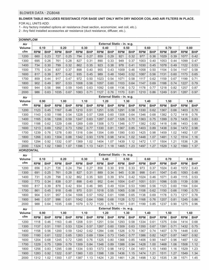
BLOWER DATA - ZGB048
BLOWER TABLE INCLUDES RESISTANCE FOR BASE UNIT ONLY WITH DRY INDOOR COIL AND AIR FILTERS IN PLACE.FOR ALL UNITS ADD: 1 - Any factory installed options air resistance (heat section, economizer, wet coil, etc.). 2 - Any field installed accessories air resistance (duct resistance, diffuser, etc.).
DOWNFLOWAir
Volume cfm
External Static - in. w.g.0.10 0.20 0.30 0.40 0.50 0.60 0.70 0.80
RPM BHP RPM BHP RPM BHP RPM BHP RPM BHP RPM BHP RPM BHP RPM BHP1200 660 0.23 727 0.25 794 0.27 859 0.29 921 0.32 977 0.36 1029 0.39 1077 0.421300 695 0.26 761 0.28 827 0.31 890 0.33 949 0.37 1003 0.40 1053 0.44 1099 0.471400 734 0.30 799 0.32 862 0.35 923 0.38 978 0.41 1030 0.45 1078 0.49 1122 0.531500 775 0.34 837 0.37 898 0.40 955 0.43 1009 0.46 1058 0.50 1104 0.54 1147 0.581600 817 0.39 877 0.42 935 0.45 989 0.48 1040 0.52 1087 0.56 1131 0.60 1173 0.651700 859 0.44 917 0.47 972 0.50 1023 0.54 1071 0.58 1117 0.62 1159 0.67 1199 0.711800 902 0.49 957 0.53 1008 0.56 1057 0.60 1103 0.64 1147 0.69 1188 0.74 1227 0.791900 944 0.56 996 0.59 1045 0.63 1092 0.68 1136 0.72 1178 0.77 1218 0.82 1257 0.872000 986 0.63 1035 0.67 1083 0.71 1127 0.76 1170 0.81 1210 0.86 1249 0.91 1287 0.97
Air Volume
cfm
External Static - in. w.g.0.90 1.00 1.10 1.20 1.30 1.40 1.50 1.60
RPM BHP RPM BHP RPM BHP RPM BHP RPM BHP RPM BHP RPM BHP RPM BHP1200 1123 0.45 1167 0.48 1210 0.51 1251 0.55 1291 0.58 1330 0.62 1367 0.66 1403 0.701300 1143 0.50 1186 0.54 1228 0.57 1268 0.60 1308 0.64 1346 0.68 1382 0.72 1418 0.761400 1165 0.56 1206 0.59 1247 0.63 1287 0.67 1326 0.70 1363 0.75 1399 0.79 1435 0.831500 1188 0.62 1229 0.66 1269 0.69 1308 0.73 1346 0.77 1382 0.82 1418 0.86 1453 0.901600 1213 0.69 1252 0.73 1292 0.77 1330 0.81 1367 0.85 1403 0.89 1438 0.94 1472 0.981700 1239 0.76 1278 0.80 1316 0.84 1354 0.89 1390 0.93 1425 0.98 1459 1.02 1492 1.071800 1266 0.83 1304 0.88 1342 0.93 1378 0.98 1414 1.02 1448 1.07 1481 1.12 1514 1.161900 1294 0.92 1332 0.97 1369 1.02 1404 1.07 1439 1.12 1472 1.17 1504 1.21 1536 1.262000 1324 1.02 1360 1.07 1396 1.13 1431 1.18 1465 1.23 1497 1.27 1529 1.32 1560 1.37
HORIZONTALAir
Volume cfm
External Static - in. w.g.0.10 0.20 0.30 0.40 0.50 0.60 0.70 0.80
RPM BHP RPM BHP RPM BHP RPM BHP RPM BHP RPM BHP RPM BHP RPM BHP1200 656 0.21 726 0.24 794 0.27 858 0.30 918 0.33 973 0.37 1024 0.40 1072 0.431300 691 0.25 761 0.28 827 0.31 889 0.34 945 0.38 998 0.41 1047 0.45 1093 0.481400 731 0.29 798 0.32 862 0.35 920 0.39 974 0.42 1024 0.46 1071 0.49 1115 0.531500 773 0.34 838 0.37 898 0.40 952 0.44 1004 0.47 1051 0.51 1096 0.55 1139 0.581600 817 0.39 878 0.42 934 0.46 985 0.49 1034 0.53 1080 0.56 1123 0.60 1164 0.641700 861 0.45 918 0.48 970 0.51 1018 0.55 1065 0.58 1108 0.62 1150 0.66 1190 0.701800 904 0.51 957 0.54 1006 0.57 1052 0.61 1096 0.65 1138 0.69 1178 0.73 1217 0.781900 946 0.57 996 0.61 1042 0.64 1086 0.68 1128 0.72 1168 0.76 1207 0.81 1245 0.862000 988 0.64 1035 0.68 1079 0.72 1120 0.76 1161 0.81 1199 0.85 1237 0.90 1275 0.96
Air Volume
cfm
External Static - in. w.g.0.90 1.00 1.10 1.20 1.30 1.40 1.50 1.60
RPM BHP RPM BHP RPM BHP RPM BHP RPM BHP RPM BHP RPM BHP RPM BHP1200 1118 0.46 1163 0.48 1208 0.51 1251 0.54 1293 0.58 1334 0.61 1375 0.64 1414 0.681300 1137 0.51 1181 0.53 1224 0.57 1267 0.60 1309 0.63 1350 0.67 1391 0.71 1432 0.751400 1158 0.56 1200 0.59 1242 0.62 1284 0.66 1326 0.70 1367 0.74 1407 0.79 1448 0.831500 1180 0.61 1222 0.65 1263 0.69 1304 0.73 1345 0.77 1386 0.82 1427 0.87 1467 0.921600 1204 0.68 1245 0.72 1285 0.76 1325 0.80 1366 0.85 1406 0.90 1447 0.96 1487 1.021700 1229 0.75 1269 0.79 1309 0.84 1348 0.89 1388 0.94 1428 1.00 1468 1.06 1508 1.121800 1256 0.83 1295 0.88 1334 0.93 1373 0.98 1412 1.04 1451 1.10 1490 1.16 1529 1.231900 1283 0.92 1322 0.97 1360 1.03 1398 1.09 1436 1.15 1474 1.21 1511 1.27 1549 1.342000 1312 1.02 1350 1.07 1387 1.13 1424 1.20 1461 1.26 1498 1.32 1535 1.38 1571 1.45
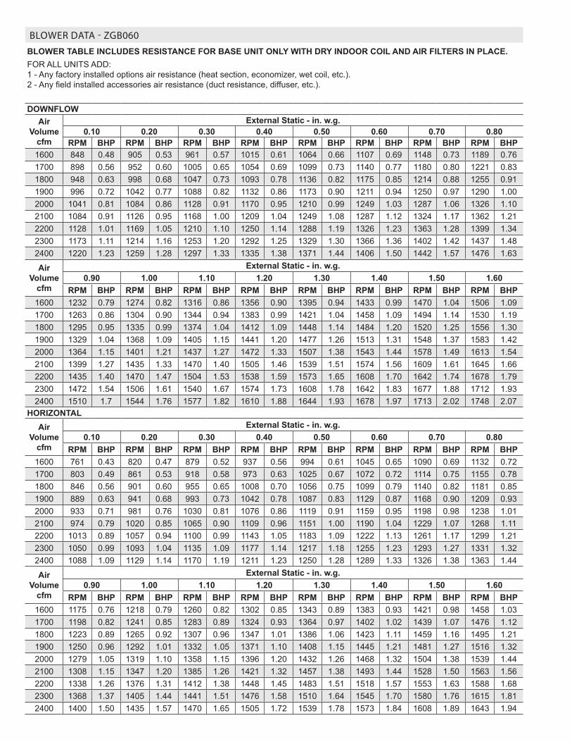
BLOWER DATA - ZGB060
BLOWER TABLE INCLUDES RESISTANCE FOR BASE UNIT ONLY WITH DRY INDOOR COIL AND AIR FILTERS IN PLACE.FOR ALL UNITS ADD: 1 - Any factory installed options air resistance (heat section, economizer, wet coil, etc.). 2 - Any field installed accessories air resistance (duct resistance, diffuser, etc.).
DOWNFLOWAir
Volume cfm
External Static - in. w.g.0.10 0.20 0.30 0.40 0.50 0.60 0.70 0.80
RPM BHP RPM BHP RPM BHP RPM BHP RPM BHP RPM BHP RPM BHP RPM BHP1600 848 0.48 905 0.53 961 0.57 1015 0.61 1064 0.66 1107 0.69 1148 0.73 1189 0.761700 898 0.56 952 0.60 1005 0.65 1054 0.69 1099 0.73 1140 0.77 1180 0.80 1221 0.831800 948 0.63 998 0.68 1047 0.73 1093 0.78 1136 0.82 1175 0.85 1214 0.88 1255 0.911900 996 0.72 1042 0.77 1088 0.82 1132 0.86 1173 0.90 1211 0.94 1250 0.97 1290 1.002000 1041 0.81 1084 0.86 1128 0.91 1170 0.95 1210 0.99 1249 1.03 1287 1.06 1326 1.102100 1084 0.91 1126 0.95 1168 1.00 1209 1.04 1249 1.08 1287 1.12 1324 1.17 1362 1.212200 1128 1.01 1169 1.05 1210 1.10 1250 1.14 1288 1.19 1326 1.23 1363 1.28 1399 1.342300 1173 1.11 1214 1.16 1253 1.20 1292 1.25 1329 1.30 1366 1.36 1402 1.42 1437 1.482400 1220 1.23 1259 1.28 1297 1.33 1335 1.38 1371 1.44 1406 1.50 1442 1.57 1476 1.63
Air Volume
cfm
External Static - in. w.g.0.90 1.00 1.10 1.20 1.30 1.40 1.50 1.60
RPM BHP RPM BHP RPM BHP RPM BHP RPM BHP RPM BHP RPM BHP RPM BHP1600 1232 0.79 1274 0.82 1316 0.86 1356 0.90 1395 0.94 1433 0.99 1470 1.04 1506 1.091700 1263 0.86 1304 0.90 1344 0.94 1383 0.99 1421 1.04 1458 1.09 1494 1.14 1530 1.191800 1295 0.95 1335 0.99 1374 1.04 1412 1.09 1448 1.14 1484 1.20 1520 1.25 1556 1.301900 1329 1.04 1368 1.09 1405 1.15 1441 1.20 1477 1.26 1513 1.31 1548 1.37 1583 1.422000 1364 1.15 1401 1.21 1437 1.27 1472 1.33 1507 1.38 1543 1.44 1578 1.49 1613 1.542100 1399 1.27 1435 1.33 1470 1.40 1505 1.46 1539 1.51 1574 1.56 1609 1.61 1645 1.662200 1435 1.40 1470 1.47 1504 1.53 1538 1.59 1573 1.65 1608 1.70 1642 1.74 1678 1.792300 1472 1.54 1506 1.61 1540 1.67 1574 1.73 1608 1.78 1642 1.83 1677 1.88 1712 1.932400 1510 1.7 1544 1.76 1577 1.82 1610 1.88 1644 1.93 1678 1.97 1713 2.02 1748 2.07
HORIZONTALAir
Volume cfm
External Static - in. w.g.0.10 0.20 0.30 0.40 0.50 0.60 0.70 0.80
RPM BHP RPM BHP RPM BHP RPM BHP RPM BHP RPM BHP RPM BHP RPM BHP1600 761 0.43 820 0.47 879 0.52 937 0.56 994 0.61 1045 0.65 1090 0.69 1132 0.721700 803 0.49 861 0.53 918 0.58 973 0.63 1025 0.67 1072 0.72 1114 0.75 1155 0.781800 846 0.56 901 0.60 955 0.65 1008 0.70 1056 0.75 1099 0.79 1140 0.82 1181 0.851900 889 0.63 941 0.68 993 0.73 1042 0.78 1087 0.83 1129 0.87 1168 0.90 1209 0.932000 933 0.71 981 0.76 1030 0.81 1076 0.86 1119 0.91 1159 0.95 1198 0.98 1238 1.012100 974 0.79 1020 0.85 1065 0.90 1109 0.96 1151 1.00 1190 1.04 1229 1.07 1268 1.112200 1013 0.89 1057 0.94 1100 0.99 1143 1.05 1183 1.09 1222 1.13 1261 1.17 1299 1.212300 1050 0.99 1093 1.04 1135 1.09 1177 1.14 1217 1.18 1255 1.23 1293 1.27 1331 1.322400 1088 1.09 1129 1.14 1170 1.19 1211 1.23 1250 1.28 1289 1.33 1326 1.38 1363 1.44
Air Volume
cfm
External Static - in. w.g.0.90 1.00 1.10 1.20 1.30 1.40 1.50 1.60
RPM BHP RPM BHP RPM BHP RPM BHP RPM BHP RPM BHP RPM BHP RPM BHP1600 1175 0.76 1218 0.79 1260 0.82 1302 0.85 1343 0.89 1383 0.93 1421 0.98 1458 1.031700 1198 0.82 1241 0.85 1283 0.89 1324 0.93 1364 0.97 1402 1.02 1439 1.07 1476 1.121800 1223 0.89 1265 0.92 1307 0.96 1347 1.01 1386 1.06 1423 1.11 1459 1.16 1495 1.211900 1250 0.96 1292 1.01 1332 1.05 1371 1.10 1408 1.15 1445 1.21 1481 1.27 1516 1.322000 1279 1.05 1319 1.10 1358 1.15 1396 1.20 1432 1.26 1468 1.32 1504 1.38 1539 1.442100 1308 1.15 1347 1.20 1385 1.26 1421 1.32 1457 1.38 1493 1.44 1528 1.50 1563 1.562200 1338 1.26 1376 1.31 1412 1.38 1448 1.45 1483 1.51 1518 1.57 1553 1.63 1588 1.682300 1368 1.37 1405 1.44 1441 1.51 1476 1.58 1510 1.64 1545 1.70 1580 1.76 1615 1.812400 1400 1.50 1435 1.57 1470 1.65 1505 1.72 1539 1.78 1573 1.84 1608 1.89 1643 1.94
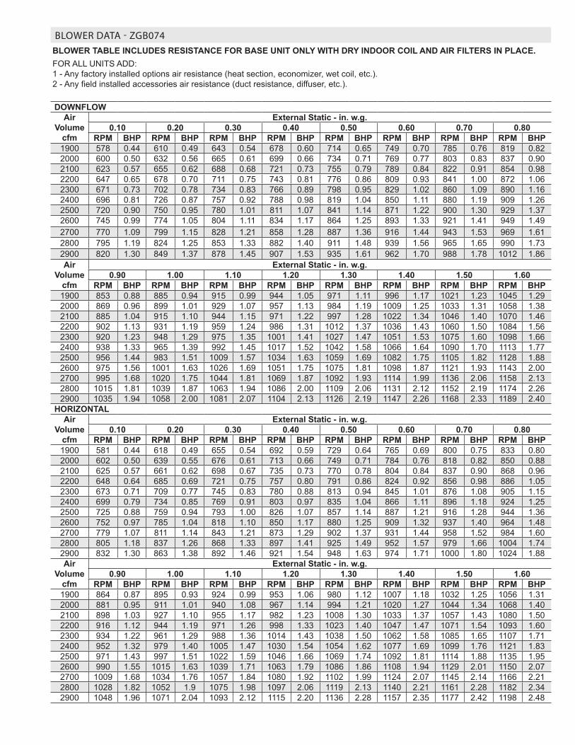
BLOWER DATA - ZGB074BLOWER TABLE INCLUDES RESISTANCE FOR BASE UNIT ONLY WITH DRY INDOOR COIL AND AIR FILTERS IN PLACE.FOR ALL UNITS ADD: 1 - Any factory installed options air resistance (heat section, economizer, wet coil, etc.). 2 - Any field installed accessories air resistance (duct resistance, diffuser, etc.).
DOWNFLOWAir
Volume cfm
External Static - in. w.g.0.10 0.20 0.30 0.40 0.50 0.60 0.70 0.80
RPM BHP RPM BHP RPM BHP RPM BHP RPM BHP RPM BHP RPM BHP RPM BHP1900 578 0.44 610 0.49 643 0.54 678 0.60 714 0.65 749 0.70 785 0.76 819 0.822000 600 0.50 632 0.56 665 0.61 699 0.66 734 0.71 769 0.77 803 0.83 837 0.902100 623 0.57 655 0.62 688 0.68 721 0.73 755 0.79 789 0.84 822 0.91 854 0.982200 647 0.65 678 0.70 711 0.75 743 0.81 776 0.86 809 0.93 841 1.00 872 1.062300 671 0.73 702 0.78 734 0.83 766 0.89 798 0.95 829 1.02 860 1.09 890 1.162400 696 0.81 726 0.87 757 0.92 788 0.98 819 1.04 850 1.11 880 1.19 909 1.262500 720 0.90 750 0.95 780 1.01 811 1.07 841 1.14 871 1.22 900 1.30 929 1.372600 745 0.99 774 1.05 804 1.11 834 1.17 864 1.25 893 1.33 921 1.41 949 1.492700 770 1.09 799 1.15 828 1.21 858 1.28 887 1.36 916 1.44 943 1.53 969 1.612800 795 1.19 824 1.25 853 1.33 882 1.40 911 1.48 939 1.56 965 1.65 990 1.732900 820 1.30 849 1.37 878 1.45 907 1.53 935 1.61 962 1.70 988 1.78 1012 1.86Air
Volume cfm
External Static - in. w.g.0.90 1.00 1.10 1.20 1.30 1.40 1.50 1.60
RPM BHP RPM BHP RPM BHP RPM BHP RPM BHP RPM BHP RPM BHP RPM BHP1900 853 0.88 885 0.94 915 0.99 944 1.05 971 1.11 996 1.17 1021 1.23 1045 1.292000 869 0.96 899 1.01 929 1.07 957 1.13 984 1.19 1009 1.25 1033 1.31 1058 1.382100 885 1.04 915 1.10 944 1.15 971 1.22 997 1.28 1022 1.34 1046 1.40 1070 1.462200 902 1.13 931 1.19 959 1.24 986 1.31 1012 1.37 1036 1.43 1060 1.50 1084 1.562300 920 1.23 948 1.29 975 1.35 1001 1.41 1027 1.47 1051 1.53 1075 1.60 1098 1.662400 938 1.33 965 1.39 992 1.45 1017 1.52 1042 1.58 1066 1.64 1090 1.70 1113 1.772500 956 1.44 983 1.51 1009 1.57 1034 1.63 1059 1.69 1082 1.75 1105 1.82 1128 1.882600 975 1.56 1001 1.63 1026 1.69 1051 1.75 1075 1.81 1098 1.87 1121 1.93 1143 2.002700 995 1.68 1020 1.75 1044 1.81 1069 1.87 1092 1.93 1114 1.99 1136 2.06 1158 2.132800 1015 1.81 1039 1.87 1063 1.94 1086 2.00 1109 2.06 1131 2.12 1152 2.19 1174 2.262900 1035 1.94 1058 2.00 1081 2.07 1104 2.13 1126 2.19 1147 2.26 1168 2.33 1189 2.40
HORIZONTALAir
Volume cfm
External Static - in. w.g.0.10 0.20 0.30 0.40 0.50 0.60 0.70 0.80
RPM BHP RPM BHP RPM BHP RPM BHP RPM BHP RPM BHP RPM BHP RPM BHP1900 581 0.44 618 0.49 655 0.54 692 0.59 729 0.64 765 0.69 800 0.75 833 0.802000 602 0.50 639 0.55 676 0.61 713 0.66 749 0.71 784 0.76 818 0.82 850 0.882100 625 0.57 661 0.62 698 0.67 735 0.73 770 0.78 804 0.84 837 0.90 868 0.962200 648 0.64 685 0.69 721 0.75 757 0.80 791 0.86 824 0.92 856 0.98 886 1.052300 673 0.71 709 0.77 745 0.83 780 0.88 813 0.94 845 1.01 876 1.08 905 1.152400 699 0.79 734 0.85 769 0.91 803 0.97 835 1.04 866 1.11 896 1.18 924 1.252500 725 0.88 759 0.94 793 1.00 826 1.07 857 1.14 887 1.21 916 1.28 944 1.362600 752 0.97 785 1.04 818 1.10 850 1.17 880 1.25 909 1.32 937 1.40 964 1.482700 779 1.07 811 1.14 843 1.21 873 1.29 902 1.37 931 1.44 958 1.52 984 1.602800 805 1.18 837 1.26 868 1.33 897 1.41 925 1.49 952 1.57 979 1.66 1004 1.742900 832 1.30 863 1.38 892 1.46 921 1.54 948 1.63 974 1.71 1000 1.80 1024 1.88Air
Volume cfm
External Static - in. w.g.0.90 1.00 1.10 1.20 1.30 1.40 1.50 1.60
RPM BHP RPM BHP RPM BHP RPM BHP RPM BHP RPM BHP RPM BHP RPM BHP1900 864 0.87 895 0.93 924 0.99 953 1.06 980 1.12 1007 1.18 1032 1.25 1056 1.312000 881 0.95 911 1.01 940 1.08 967 1.14 994 1.21 1020 1.27 1044 1.34 1068 1.402100 898 1.03 927 1.10 955 1.17 982 1.23 1008 1.30 1033 1.37 1057 1.43 1080 1.502200 916 1.12 944 1.19 971 1.26 998 1.33 1023 1.40 1047 1.47 1071 1.54 1093 1.602300 934 1.22 961 1.29 988 1.36 1014 1.43 1038 1.50 1062 1.58 1085 1.65 1107 1.712400 952 1.32 979 1.40 1005 1.47 1030 1.54 1054 1.62 1077 1.69 1099 1.76 1121 1.832500 971 1.43 997 1.51 1022 1.59 1046 1.66 1069 1.74 1092 1.81 1114 1.88 1135 1.952600 990 1.55 1015 1.63 1039 1.71 1063 1.79 1086 1.86 1108 1.94 1129 2.01 1150 2.072700 1009 1.68 1034 1.76 1057 1.84 1080 1.92 1102 1.99 1124 2.07 1145 2.14 1166 2.212800 1028 1.82 1052 1.9 1075 1.98 1097 2.06 1119 2.13 1140 2.21 1161 2.28 1182 2.342900 1048 1.96 1071 2.04 1093 2.12 1115 2.20 1136 2.28 1157 2.35 1177 2.42 1198 2.48
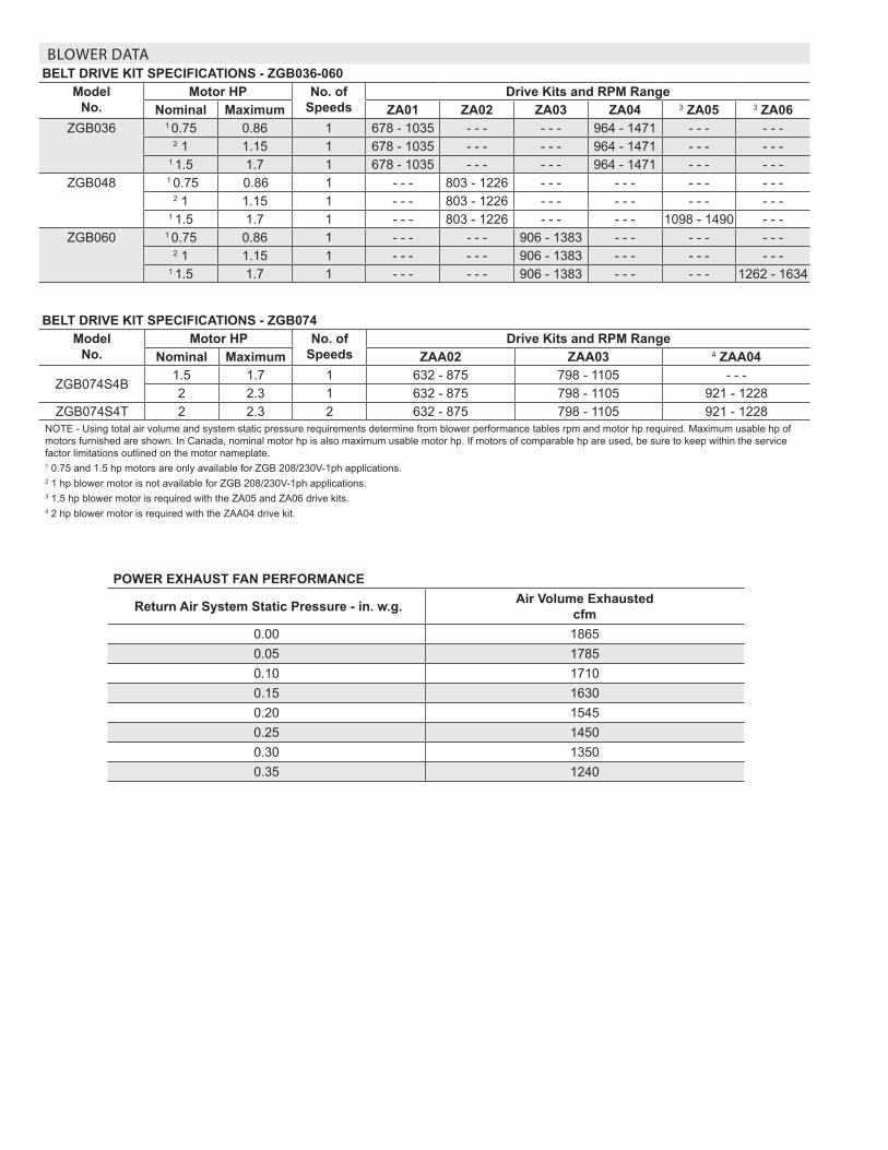
POWER EXHAUST FAN PERFORMANCE
Return Air System Static Pressure - in. w.g. Air Volume Exhausted cfm
0.00 18650.05 17850.10 17100.15 16300.20 15450.25 14500.30 13500.35 1240
BLOWER DATABELT DRIVE KIT SPECIFICATIONS - ZGB036-060
Model No.
Motor HP No. of Speeds
Drive Kits and RPM RangeNominal Maximum ZA01 ZA02 ZA03 ZA04 3 ZA05 3 ZA06
ZGB036 1 0.75 0.86 1 678 - 1035 - - - - - - 964 - 1471 - - - - - -2 1 1.15 1 678 - 1035 - - - - - - 964 - 1471 - - - - - -
1 1.5 1.7 1 678 - 1035 - - - - - - 964 - 1471 - - - - - -ZGB048 1 0.75 0.86 1 - - - 803 - 1226 - - - - - - - - - - - -
2 1 1.15 1 - - - 803 - 1226 - - - - - - - - - - - -1 1.5 1.7 1 - - - 803 - 1226 - - - - - - 1098 - 1490 - - -
ZGB060 1 0.75 0.86 1 - - - - - - 906 - 1383 - - - - - - - - -2 1 1.15 1 - - - - - - 906 - 1383 - - - - - - - - -
1 1.5 1.7 1 - - - - - - 906 - 1383 - - - - - - 1262 - 1634
BELT DRIVE KIT SPECIFICATIONS - ZGB074Model
No.Motor HP No. of
SpeedsDrive Kits and RPM Range
Nominal Maximum ZAA02 ZAA03 4 ZAA04
ZGB074S4B1.5 1.7 1 632 - 875 798 - 1105 - - -2 2.3 1 632 - 875 798 - 1105 921 - 1228
ZGB074S4T 2 2.3 2 632 - 875 798 - 1105 921 - 1228NOTE - Using total air volume and system static pressure requirements determine from blower performance tables rpm and motor hp required. Maximum usable hp of motors furnished are shown. In Canada, nominal motor hp is also maximum usable motor hp. If motors of comparable hp are used, be sure to keep within the service factor limitations outlined on the motor nameplate.1 0.75 and 1.5 hp motors are only available for ZGB 208/230V-1ph applications. 2 1 hp blower motor is not available for ZGB 208/230V-1ph applications.3 1.5 hp blower motor is required with the ZA05 and ZA06 drive kits.4 2 hp blower motor is required with the ZAA04 drive kit.
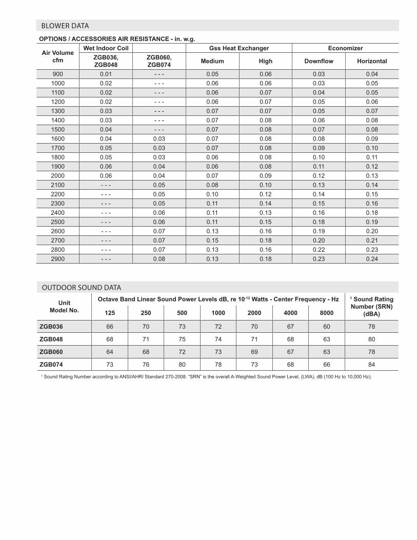
OPTIONS / ACCESSORIES AIR RESISTANCE - in. w.g.
Air Volume cfm
Wet Indoor Coil Gss Heat Exchanger EconomizerZGB036, ZGB048
ZGB060, ZGB074 Medium High Downflow Horizontal
900 0.01 - - - 0.05 0.06 0.03 0.041000 0.02 - - - 0.06 0.06 0.03 0.051100 0.02 - - - 0.06 0.07 0.04 0.051200 0.02 - - - 0.06 0.07 0.05 0.061300 0.03 - - - 0.07 0.07 0.05 0.071400 0.03 - - - 0.07 0.08 0.06 0.081500 0.04 - - - 0.07 0.08 0.07 0.081600 0.04 0.03 0.07 0.08 0.08 0.091700 0.05 0.03 0.07 0.08 0.09 0.101800 0.05 0.03 0.06 0.08 0.10 0.111900 0.06 0.04 0.06 0.08 0.11 0.122000 0.06 0.04 0.07 0.09 0.12 0.132100 - - - 0.05 0.08 0.10 0.13 0.142200 - - - 0.05 0.10 0.12 0.14 0.152300 - - - 0.05 0.11 0.14 0.15 0.162400 - - - 0.06 0.11 0.13 0.16 0.182500 - - - 0.06 0.11 0.15 0.18 0.192600 - - - 0.07 0.13 0.16 0.19 0.202700 - - - 0.07 0.15 0.18 0.20 0.212800 - - - 0.07 0.13 0.16 0.22 0.232900 - - - 0.08 0.13 0.18 0.23 0.24
BLOWER DATA
OUTDOOR SOUND DATA
Unit Model No.
Octave Band Linear Sound Power Levels dB, re 10-12 Watts - Center Frequency - Hz 1 Sound Rating Number (SRN)
(dBA)125 250 500 1000 2000 4000 8000
ZGB036 66 70 73 72 70 67 60 78
ZGB048 68 71 75 74 71 68 63 80
ZGB060 64 68 72 73 69 67 63 78
ZGB074 73 76 80 78 73 68 66 841 Sound Rating Number according to ANSI/AHRI Standard 270-2008. “SRN” is the overall A-Weighted Sound Power Level, (LWA), dB (100 Hz to 10,000 Hz).
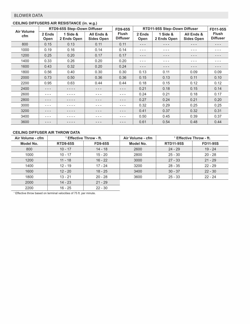
BLOWER DATA
CEILING DIFFUSERS AIR RESISTANCE (in. w.g.)
Air Volume cfm
RTD9-65S Step–Down Diffuser FD9-65S Flush
Diffuser
RTD11-95S Step–Down Diffuser FD11-95S Flush
Diffuser2 Ends Open
1 Side & 2 Ends Open
All Ends & Sides Open
2 Ends Open
1 Side & 2 Ends Open
All Ends & Sides Open
800 0.15 0.13 0.11 0.11 - - - - - - - - - - - -1000 0.19 0.16 0.14 0.14 - - - - - - - - - - - -1200 0.25 0.20 0.17 0.17 - - - - - - - - - - - -1400 0.33 0.26 0.20 0.20 - - - - - - - - - - - -1600 0.43 0.32 0.20 0.24 - - - - - - - - - - - -1800 0.56 0.40 0.30 0.30 0.13 0.11 0.09 0.092000 0.73 0.50 0.36 0.36 0.15 0.13 0.11 0.102200 0.95 0.63 0.44 0.44 0.18 0.15 0.12 0.122400 - - - - - - - - - - - - - 0.21 0.18 0.15 0.142600 - - - - - - - - - - - - - 0.24 0.21 0.18 0.172800 - - - - - - - - - - - - - 0.27 0.24 0.21 0.203000 - - - - - - - - - - - - - 0.32 0.29 0.25 0.253200 - - - - - - - - - - - - - 0.41 0.37 0.32 0.313400 - - - - - - - - - - - - - 0.50 0.45 0.39 0.373600 - - - - - - - - - - - - - 0.61 0.54 0.48 0.44
CEILING DIFFUSER AIR THROW DATAAir Volume - cfm 1 Effective Throw - ft. Air Volume - cfm 1 Effective Throw - ft.
Model No. RTD9-65S FD9-65S Model No. RTD11-95S FD11-95S800 10 - 17 14 - 18 2600 24 - 29 19 - 24
1000 10 - 17 15 - 20 2800 25 - 30 20 - 281200 11 - 18 16 - 22 3000 27 - 33 21 - 291400 12 - 19 17 - 24 3200 28 - 35 22 - 291600 12 - 20 18 - 25 3400 30 - 37 22 - 301800 13 - 21 20 - 28 3600 25 - 33 22 - 242000 14 - 23 21 - 292200 16 - 25 22 - 30
1 Effective throw based on terminal velocities of 75 ft. per minute.
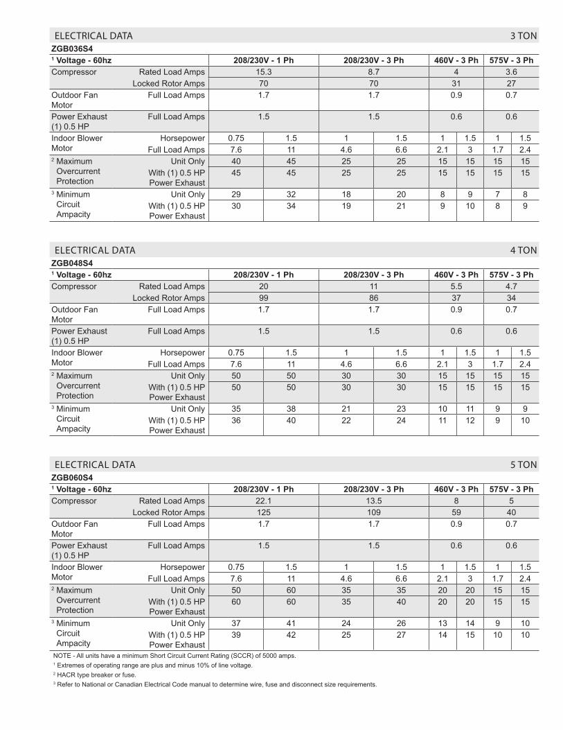
ELECTRICAL DATA 3 TONZGB036S41 Voltage - 60hz 208/230V - 1 Ph 208/230V - 3 Ph 460V - 3 Ph 575V - 3 PhCompressor Rated Load Amps 15.3 8.7 4 3.6
Locked Rotor Amps 70 70 31 27Outdoor Fan Motor
Full Load Amps 1.7 1.7 0.9 0.7
Power Exhaust (1) 0.5 HP
Full Load Amps 1.5 1.5 0.6 0.6
Indoor Blower Motor
Horsepower 0.75 1.5 1 1.5 1 1.5 1 1.5Full Load Amps 7.6 11 4.6 6.6 2.1 3 1.7 2.4
2 Maximum Overcurrent Protection
Unit Only 40 45 25 25 15 15 15 15With (1) 0.5 HP Power Exhaust
45 45 25 25 15 15 15 15
3 Minimum Circuit Ampacity
Unit Only 29 32 18 20 8 9 7 8With (1) 0.5 HP Power Exhaust
30 34 19 21 9 10 8 9
ELECTRICAL DATA 4 TONZGB048S41 Voltage - 60hz 208/230V - 1 Ph 208/230V - 3 Ph 460V - 3 Ph 575V - 3 PhCompressor Rated Load Amps 20 11 5.5 4.7
Locked Rotor Amps 99 86 37 34Outdoor Fan Motor
Full Load Amps 1.7 1.7 0.9 0.7
Power Exhaust (1) 0.5 HP
Full Load Amps 1.5 1.5 0.6 0.6
Indoor Blower Motor
Horsepower 0.75 1.5 1 1.5 1 1.5 1 1.5Full Load Amps 7.6 11 4.6 6.6 2.1 3 1.7 2.4
2 Maximum Overcurrent Protection
Unit Only 50 50 30 30 15 15 15 15With (1) 0.5 HP Power Exhaust
50 50 30 30 15 15 15 15
3 Minimum Circuit Ampacity
Unit Only 35 38 21 23 10 11 9 9With (1) 0.5 HP Power Exhaust
36 40 22 24 11 12 9 10
ELECTRICAL DATA 5 TONZGB060S41 Voltage - 60hz 208/230V - 1 Ph 208/230V - 3 Ph 460V - 3 Ph 575V - 3 PhCompressor Rated Load Amps 22.1 13.5 8 5
Locked Rotor Amps 125 109 59 40Outdoor Fan Motor
Full Load Amps 1.7 1.7 0.9 0.7
Power Exhaust (1) 0.5 HP
Full Load Amps 1.5 1.5 0.6 0.6
Indoor Blower Motor
Horsepower 0.75 1.5 1 1.5 1 1.5 1 1.5Full Load Amps 7.6 11 4.6 6.6 2.1 3 1.7 2.4
2 Maximum Overcurrent Protection
Unit Only 50 60 35 35 20 20 15 15With (1) 0.5 HP Power Exhaust
60 60 35 40 20 20 15 15
3 Minimum Circuit Ampacity
Unit Only 37 41 24 26 13 14 9 10With (1) 0.5 HP Power Exhaust
39 42 25 27 14 15 10 10
NOTE - All units have a minimum Short Circuit Current Rating (SCCR) of 5000 amps. 1 Extremes of operating range are plus and minus 10% of line voltage.2 HACR type breaker or fuse.3 Refer to National or Canadian Electrical Code manual to determine wire, fuse and disconnect size requirements.
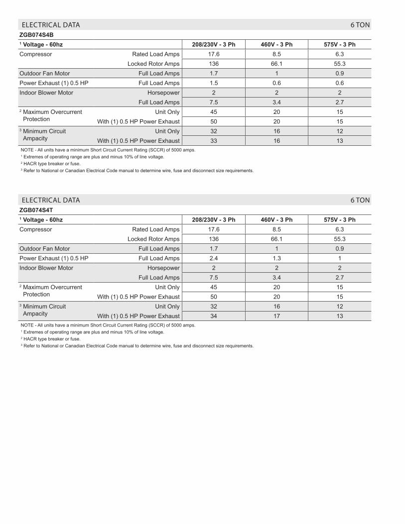
ELECTRICAL DATA 6 TONZGB074S4T1 Voltage - 60hz 208/230V - 3 Ph 460V - 3 Ph 575V - 3 PhCompressor Rated Load Amps 17.6 8.5 6.3
Locked Rotor Amps 136 66.1 55.3Outdoor Fan Motor Full Load Amps 1.7 1 0.9Power Exhaust (1) 0.5 HP Full Load Amps 2.4 1.3 1Indoor Blower Motor Horsepower 2 2 2
Full Load Amps 7.5 3.4 2.72 Maximum Overcurrent
ProtectionUnit Only 45 20 15
With (1) 0.5 HP Power Exhaust 50 20 153 Minimum Circuit
AmpacityUnit Only 32 16 12
With (1) 0.5 HP Power Exhaust 34 17 13NOTE - All units have a minimum Short Circuit Current Rating (SCCR) of 5000 amps. 1 Extremes of operating range are plus and minus 10% of line voltage.2 HACR type breaker or fuse.3 Refer to National or Canadian Electrical Code manual to determine wire, fuse and disconnect size requirements.
ELECTRICAL DATA 6 TONZGB074S4B1 Voltage - 60hz 208/230V - 3 Ph 460V - 3 Ph 575V - 3 PhCompressor Rated Load Amps 17.6 8.5 6.3
Locked Rotor Amps 136 66.1 55.3Outdoor Fan Motor Full Load Amps 1.7 1 0.9Power Exhaust (1) 0.5 HP Full Load Amps 1.5 0.6 0.6Indoor Blower Motor Horsepower 2 2 2
Full Load Amps 7.5 3.4 2.72 Maximum Overcurrent
ProtectionUnit Only 45 20 15
With (1) 0.5 HP Power Exhaust 50 20 153 Minimum Circuit
AmpacityUnit Only 32 16 12
With (1) 0.5 HP Power Exhaust 33 16 13NOTE - All units have a minimum Short Circuit Current Rating (SCCR) of 5000 amps. 1 Extremes of operating range are plus and minus 10% of line voltage.2 HACR type breaker or fuse.3 Refer to National or Canadian Electrical Code manual to determine wire, fuse and disconnect size requirements.
Page 16
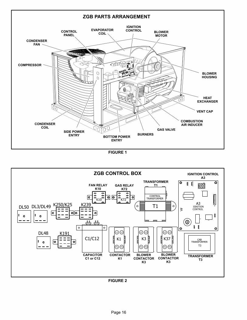
ZGB PARTS ARRANGEMENT
FIGURE 1
EVAPORATORCOIL
CONDENSERFAN
CONDENSERCOIL
COMPRESSOR
GAS VALVE
BURNERS
COMBUSTIONAIR INDUCER
BLOWERMOTOR
BOTTOM POWERENTRY
HEATEXCHANGER
IGNITIONCONTROL
BLOWERHOUSING
SIDE POWERENTRY
CONTROLPANEL
VENT CAP
ZGB CONTROL BOX
FIGURE 2
IGNITION CONTROLA3
FAN RELAYK10
TRANSFORMERT1
BLOWERCONTACTOR
K3
CONTACTORK1
CAPACITORC1 or C12
TRANSFORMERT3
GAS RELAYK72
T1
TRANSFORMERCONTROL
K10
1 3
4 6
7 9
A BK72
1 3
4 6
7 9
A B
C1/C12 K1 K3
L2 L3
T2 T3
L1 L2
T1 T2
12
6 45
324VAC
GRO
UN
D
CM
B_BLW
R
CM
B_L1
P2
J1
K1
W2_O
UT
K25
K2
1
FLAM
E
A3IGNITIONCONTROL
T3
TRANSFORMERCAB
DL48 K191
K37
L2 L3
T2 T3
DL50 DL3/DL49 K250/K25 K239
BLOWERCONTACTOR
K3
Page 17
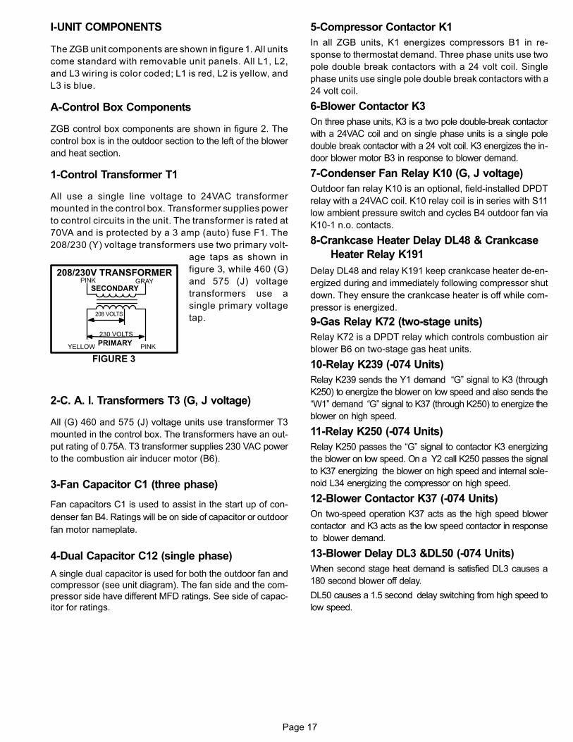
I-UNIT COMPONENTS
The ZGB unit components are shown in figure 1. All units
come standard with removable unit panels. All L1, L2,
and L3 wiring is color coded; L1 is red, L2 is yellow, and
L3 is blue.
A-Control Box Components
ZGB control box components are shown in figure 2. The
control box is in the outdoor section to the left of the blower
and heat section.
1-Control Transformer T1
All use a single line voltage to 24VAC transformer
mounted in the control box. Transformer supplies power
to control circuits in the unit. The transformer is rated at
70VA and is protected by a 3 amp (auto) fuse F1. The
208/230 (Y) voltage transformers use two primary volt
age taps as shown in
figure 3, while 460 (G)
and 575 (J) voltage
transformers use a
single primary voltage
tap.
2-C. A. I. Transformers T3 (G, J voltage)
All (G) 460 and 575 (J) voltage units use transformer T3
mounted in the control box. The transformers have an out
put rating of 0.75A. T3 transformer supplies 230 VAC power
to the combustion air inducer motor (B6).
3-Fan Capacitor C1 (three phase)
Fan capacitors C1 is used to assist in the start up of con
denser fan B4. Ratings will be on side of capacitor or outdoor
fan motor nameplate.
4-Dual Capacitor C12 (single phase)
A single dual capacitor is used for both the outdoor fan and
compressor (see unit diagram). The fan side and the com
pressor side have different MFD ratings. See side of capac
itor for ratings.
5-Compressor Contactor K1
In all ZGB units, K1 energizes compressors B1 in re
sponse to thermostat demand. Three phase units use two
pole double break contactors with a 24 volt coil. Single
phase units use single pole double break contactors with a
24 volt coil.
6-Blower Contactor K3
On three phase units, K3 is a two pole double‐break contactor
with a 24VAC coil and on single phase units is a single pole
double break contactor with a 24 volt coil. K3 energizes the in
door blower motor B3 in response to blower demand.
7-Condenser Fan Relay K10 (G, J voltage)
Outdoor fan relay K10 is an optional, field-installed DPDT
relay with a 24VAC coil. K10 relay coil is in series with S11
low ambient pressure switch and cycles B4 outdoor fan via
K10-1 n.o. contacts.
8-Crankcase Heater Delay DL48 & Crankcase
Heater Relay K191
Delay DL48 and relay K191 keep crankcase heater de-en
ergized during and immediately following compressor shut
down. They ensure the crankcase heater is off while com
pressor is energized.
9-Gas Relay K72 (two-stage units)
Relay K72 is a DPDT relay which controls combustion air
blower B6 on two-stage gas heat units.
10-Relay K239 (-074 Units)
Relay K239 sends the Y1 demand “G” signal to K3 (through
K250) to energize the blower on low speed and also sends the
“W1” demand “G” signal to K37 (through K250) to energize the
blower on high speed.
11-Relay K250 (-074 Units)
Relay K250 passes the “G” signal to contactor K3 energizing
the blower on low speed. On a Y2 call K250 passes the signal
to K37 energizing the blower on high speed and internal sole
noid L34 energizing the compressor on high speed.
12-Blower Contactor K37 (-074 Units)
On two-speed operation K37 acts as the high speed blower
contactor and K3 acts as the low speed contactor in response
to blower demand.
13-Blower Delay DL3 &DL50 (-074 Units)
When second stage heat demand is satisfied DL3 causes a
180 second blower off delay.
DL50 causes a 1.5 second delay switching from high speed to
low speed.
FIGURE 3
PINK GRAY
YELLOW PINK
230 VOLTS
208 VOLTS
PRIMARY
SECONDARY
208/230V TRANSFORMER
Page 18
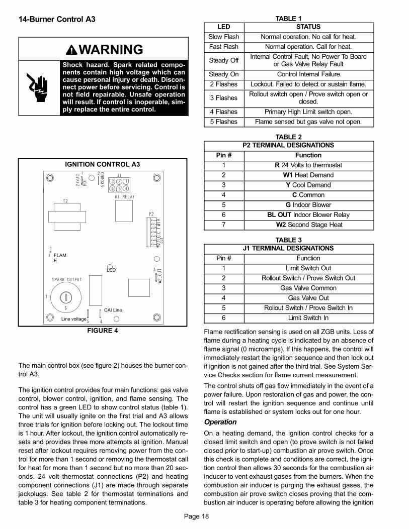
14-Burner Control A3
WARNINGShock hazard. Spark related components contain high voltage which cancause personal injury or death. Disconnect power before servicing. Control isnot field repairable. Unsafe operationwill result. If control is inoperable, simply replace the entire control.
FIGURE 4
FLAME
CAI Line
Line voltage
LED
IGNITION CONTROL A3
The main control box (see figure 2) houses the burner con
trol A3.
The ignition control provides four main functions: gas valve
control, blower control, ignition, and flame sensing. The
control has a green LED to show control status (table 1).
The unit will usually ignite on the first trial and A3 allows
three trials for ignition before locking out. The lockout time
is 1 hour. After lockout, the ignition control automatically re
sets and provides three more attempts at ignition. Manual
reset after lockout requires removing power from the con
trol for more than 1 second or removing the thermostat call
for heat for more than 1 second but no more than 20 sec
onds. 24 volt thermostat connections (P2) and heating
component connections (J1) are made through separate
jackplugs. See table 2 for thermostat terminations and
table 3 for heating component terminations.
TABLE 1
LED STATUS
Slow Flash Normal operation. No call for heat.
Fast Flash Normal operation. Call for heat.
Steady OffInternal Control Fault, No Power To Board
or Gas Valve Relay Fault
Steady On Control Internal Failure.
2 Flashes Lockout. Failed to detect or sustain flame.
3 FlashesRollout switch open / Prove switch open or
closed.
4 Flashes Primary High Limit switch open.
5 Flashes Flame sensed but gas valve not open.
TABLE 2
P2 TERMINAL DESIGNATIONS
Pin # Function
1 R 24 Volts to thermostat
2 W1 Heat Demand
3 Y Cool Demand
4 C Common
5 G Indoor Blower
6 BL OUT Indoor Blower Relay
7 W2 Second Stage Heat
TABLE 3
J1 TERMINAL DESIGNATIONS
Pin # Function
1 Limit Switch Out
2 Rollout Switch / Prove Switch Out
3 Gas Valve Common
4 Gas Valve Out
5 Rollout Switch / Prove Switch In
6 Limit Switch In
Flame rectification sensing is used on all ZGB units. Loss of
flame during a heating cycle is indicated by an absence of
flame signal (0 microamps). If this happens, the control will
immediately restart the ignition sequence and then lock out
if ignition is not gained after the third trial. See System Ser
vice Checks section for flame current measurement.
The control shuts off gas flow immediately in the event of a
power failure. Upon restoration of gas and power, the con
trol will restart the ignition sequence and continue until
flame is established or system locks out for one hour.
Operation
On a heating demand, the ignition control checks for a
closed limit switch and open (to prove switch is not failed
closed prior to start-up) combustion air prove switch. Once
this check is complete and conditions are correct, the igni
tion control then allows 30 seconds for the combustion air
inducer to vent exhaust gases from the burners. When the
combustion air inducer is purging the exhaust gases, the
combustion air prove switch closes proving that the com
bustion air inducer is operating before allowing the ignition
Page 19
control to energize. When the combustion air prove switch
is closed and the delay is over, the ignition control activates
the gas valve, the spark electrode and the flame sensing
electrode. Once the gas valve is energized the non-adjust
able 40 second indoor blower delay period begins. Spark
ing stops immediately after flame is sensed or at the end of
the 8 second trial for ignition.
The control then proceeds to “steady state” mode where all
inputs are monitored to ensure the limit switch, rollout
switch and prove switch are closed as well as flame is pres
ent. When the heat call is satisfied and the gas valve is de-
energized, a combustion air inducer post purge period of 5
seconds begins along with a 120 second blower off delay.
10-Power Exhaust Transformer T10 (J volt)
Transformer T10 is a field-installed 600/230V transformer
which provides power to the 208/230V power exhaust fan in
575V applications.
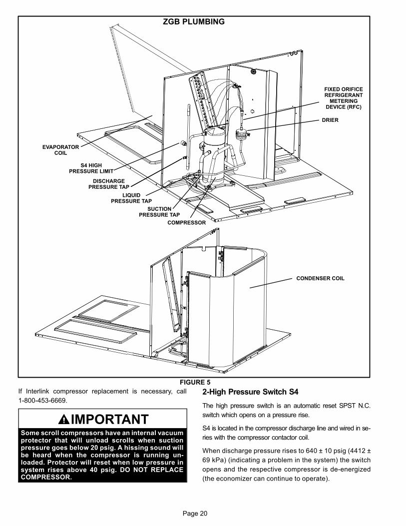
B-Cooling Components
All units use a cooling circuit consisting of compressor, con
denser coil and evaporator coil. See figure 5. One draw-
through type condenser fan is used in ZGB units. Units are
equipped with belt‐drive blowers which draw air across the
evaporator during unit operation.
Cooling may be supplemented by a factory- or field‐in
stalled economizer. The evaporator coil is slab type and
uses a fixed orifice refrigerant metering device. Each evapo
rator is also equipped with enhanced fins and rifled tubing. In all
units each compressor is protected by a high pressure switch
(S4) on the discharge line. See figure 5.
1-Compressor B1
IMPORTANTThe Clean Air Act of 1990 bans the intentional venting of refrigerant (CFC's and HCFC's) as of July 1,1992. Approved methods of recovery, recycling or reclaiming must be followed. Fines and/or incarceration may be levied for non-compliance.
All units use one scroll compressor. See “SPECIFI
CATIONS” and “ELECTRICAL DATA” (table of contents) or
compressor nameplate for compressor specifications.
WARNINGElectrical shock hazard. Compressor must begrounded. Do not operate without protective coverover terminals. Disconnect power before removingprotective cover. Discharge capacitors before servicing unit. Failure to follow these precautions couldcause electrical shock resulting in injury or death.
The compressor is energized by a compressor contactor.
NOTE-Refer to the wiring diagram section for specific unit
operation.
Page 20
ZGB PLUMBING
FIGURE 5
EVAPORATORCOIL
DRIER
COMPRESSOR
S4 HIGHPRESSURE LIMIT
DISCHARGEPRESSURE TAP
LIQUIDPRESSURE TAP
FIXED ORIFICEREFRIGERANT
METERINGDEVICE (RFC)
CONDENSER COIL
SUCTIONPRESSURE TAP
If Interlink compressor replacement is necessary, call
1-800-453-6669.
IMPORTANTSome scroll compressors have an internal vacuumprotector that will unload scrolls when suctionpressure goes below 20 psig. A hissing sound willbe heard when the compressor is running unloaded. Protector will reset when low pressure insystem rises above 40 psig. DO NOT REPLACECOMPRESSOR.
2-High Pressure Switch S4
The high pressure switch is an automatic reset SPST N.C.
switch which opens on a pressure rise.
S4 is located in the compressor discharge line and wired in se
ries with the compressor contactor coil.
When discharge pressure rises to 640 ± 10 psig (4412 ±
69 kPa) (indicating a problem in the system) the switch
opens and the respective compressor is de-energized
(the economizer can continue to operate).
Page 21
When discharge pressure drops to 475 ± 20 (3275 ± 138
kPa) psig, the switch closes and the compressor is ener
gized. The CMC1 board monitors the pressure switch when
the compressor demand Y1 is active, allowing five strike
lockout. The compressor is shut down indefinitely in this
condition. A pressure switch may open and close again four
times during a current demand cycle without causing a
lockout condition by resetting the count at the end of the de
mand cycle (CMC1 Y1 input OFF). The five-strike lockout
can only be reset by one of the following actions:
-Power cycle the controller
-Apply the TEST mode
3-Low Ambient Switches S11 (field-installed
option)
The low ambient switch is an auto‐reset SPST N.O. pres
sure switch which allows for mechanical cooling opera
tion at low outdoor temperatures. The switch is located
in the liquid line in the compressor section.
On P and Y volt units, S11 is wired in series with the com
mon (black) lead to K10 outdoor fan motor.
On G and J volt units, S11 is wired in series with outdoor fan
relay K10 coil and when opened breaks 24 volts to the coil,
de-energizing outdoor fan B4.
When liquid pressure rises to 450 ± 10 psig (3102 ± 69
kPa), the switch closes and the condenser fan is ener
gized. When discharge pressure in drops to 240 ± 10 psig
(1655 ± 69 kPa), the switch opens and the condenser fan is
de-energized. This intermittent fan operation results in
higher evaporating temperature allowing the system to op
erate without icing the evaporator coil and losing capacity.
4-Compressor Low Discharge Temperat
ure Limit S3 (field-supplied option)
S3 is a thermostat which opens on temperature drop. It is
wired in line with the 24VAC compressor contactor.
5-Compressor High Temperature Limit S5
The compressor thermal protector is located on top of the
compressor. S5 is wired in series with S4 high pressure
limit. The protector opens at 248°F + 9°F (120°C + 5°C)
and closes at 169°F + 18°F (76°C + 10°C).
C-Blower Compartment
All units are equipped with belt drive blowers. See unit
nameplate for blower type.
1-Blower Wheels
ZGB-036, -048 and -060 belt drive units use 10” x 10” (254
mm x 254 mm) blower wheels. ZGB -074 units use 15 x 9
(381 x 229 mm) blower wheels.
2-Indoor Blower Motor B3
Belt drive units use single or three phase motors (same as
supply voltage). CFM adjustments are made by adjusting
the motor pulley (sheave). Motors are equipped with sealed
ball bearings. All motor specifications are listed in the Spec
ifications (see table of contents) section in the front of this
manual. Units may be equipped with motors manufactured
by various manufacturers, therefore electrical FLA and
LRA specifications will vary. See unit rating plate for infor
mation specific to your unit.
IMPORTANTThree phase scroll compressors must be phased sequentially for correct compressor and blower rotation. Follow “COOLING START-UP” section of installation instructions to ensure proper compressor andblower operation.
A-Blower Operation
Initiate blower demand at thermostat according to instruc
tions provided with thermostat. Unit will cycle on thermostat
demand. The following steps apply to applications using a
typical electro-mechanical thermostat.
1- Blower operation is manually set at the thermostat sub
base fan switch. With fan switch in ON position, blow
ers will operate continuously.
2- With fan switch in AUTO position, the blowers will cycle
with demand. Blowers and entire unit will be off when
system switch is in OFF position.
B-Determining Unit CFM
IMPORTANT - ZGB074S4T blower (G thermostat) CFM
MUST BE ADJUSTED IN HIGH SPEED. Disconnect
factory-installed J350 low speed connector from P350.
Connectors are located near the bottom of the control
box. Connect J351 high speed connector to P350. Once
blower CFM is set, J350 can be reconnected to operate
the blower on low during ventilation only demands. See
table 4.
TABLE 4TWO-SPEED BLOWER OPERATION
ZGB074S4T UNITS
Thermostat Blower Speed
G (P350/J350)* Low
G (P350/J351) High
W1 High
W2 High
Y1 Low
Y2 High
*Factory-installed jack/plug connection.
Page 22
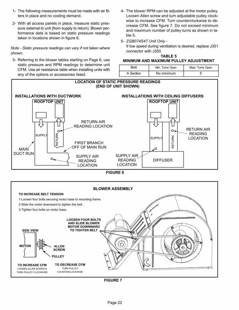
1- The following measurements must be made with air fil
ters in place and no cooling demand.
2- With all access panels in place, measure static pres
sure external to unit (from supply to return). Blower per
formance data is based on static pressure readings
taken in locations shown in figure 6.
Note - Static pressure readings can vary if not taken where
shown.
3- Referring to the blower tables starting on Page 6, use
static pressure and RPM readings to determine unit
CFM. Use air resistance table when installing units with
any of the options or accessories listed.
4- The blower RPM can be adjusted at the motor pulley.
Loosen Allen screw and turn adjustable pulley clock
wise to increase CFM. Turn counterclockwise to de
crease CFM. See figure 7. Do not exceed minimum
and maximum number of pulley turns as shown in ta
ble 5.
5- ZGB074S4T Unit Only -
If low speed during ventilation is desired, replace J351
connector with J350.
TABLE 5MINIMUM AND MAXIMUM PULLEY ADJUSTMENT
Belt Min. Turns Open Maxi. Turns Open
A Section No minimum 5
ROOFTOP UNIT ROOFTOP UNIT
FIGURE 6
LOCATION OF STATIC PRESSURE READINGS(END OF UNIT SHOWN)
INSTALLATIONS WITH DUCTWORK
SUPPLY
INSTALLATIONS WITH CEILING DIFFUSERS
DIFFUSERSUPPLY AIR
READINGLOCATION
RETURN AIRREADINGLOCATION
SUPPLY AIRREADINGLOCATION
SUPPLY
MAINDUCT RUN
FIRST BRANCHOFF OF MAIN RUN
RETURN AIRREADING LOCATION
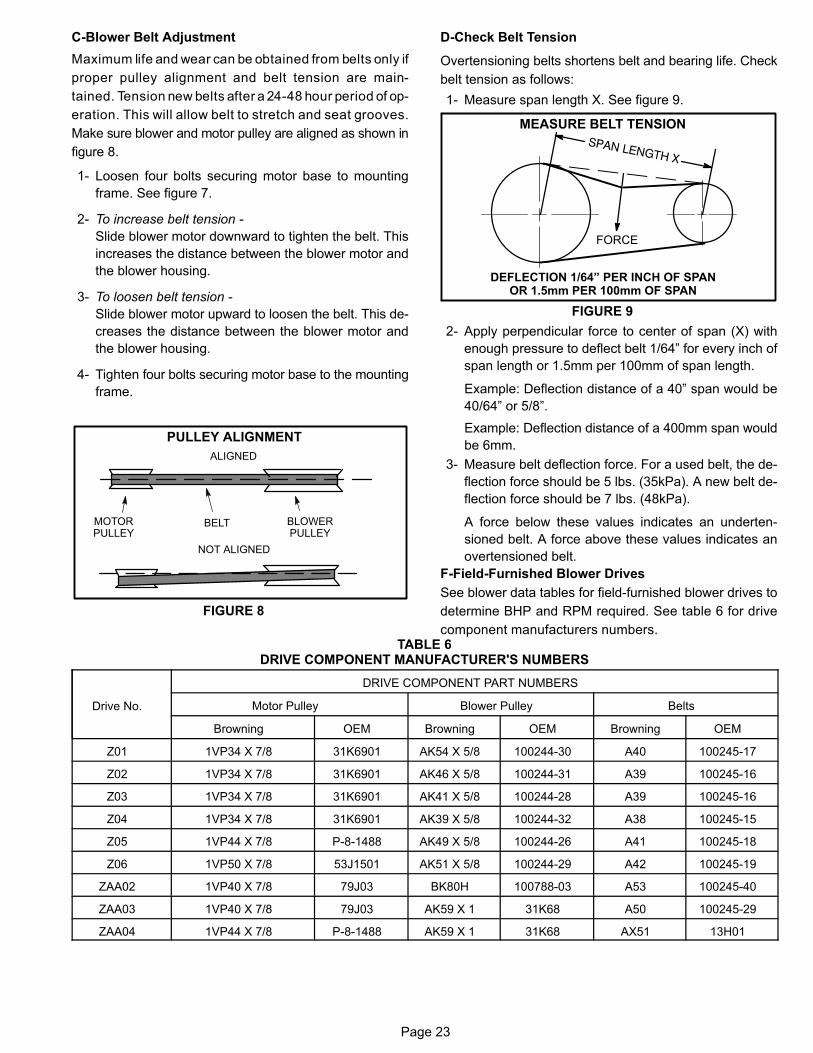
BLOWER ASSEMBLY
TO INCREASE BELT TENSION
1-Loosen four bolts securing motor base to mounting frame.
2-Slide the motor downward to tighten the belt.
3-Tighten four bolts on motor base.
TO INCREASE CFMLOOSEN ALLEN SCREW &
TURN PULLEY CLOCKWISE
TO DECREASE CFMTURN PULLEY
COUNTERCLOCKWISE
FIGURE 7
PULLEY
MOTOR
SIDE VIEW
ALLENSCREW
LOOSEN FOUR BOLTSAND SLIDE BLOWERMOTOR DOWNWARD
TO TIGHTEN BELT
Page 23
C-Blower Belt Adjustment
Maximum life and wear can be obtained from belts only if
proper pulley alignment and belt tension are main
tained. Tension new belts after a 24-48 hour period of op
eration. This will allow belt to stretch and seat grooves.
Make sure blower and motor pulley are aligned as shown in
figure 8.
1- Loosen four bolts securing motor base to mounting
frame. See figure 7.
2- To increase belt tension -
Slide blower motor downward to tighten the belt. This
increases the distance between the blower motor and
the blower housing.
3- To loosen belt tension -
Slide blower motor upward to loosen the belt. This de
creases the distance between the blower motor and
the blower housing.
4- Tighten four bolts securing motor base to the mounting
frame.
FIGURE 8
PULLEY ALIGNMENT
BELT BLOWERPULLEY
MOTORPULLEY
NOT ALIGNED
ALIGNED
D-Check Belt Tension
Overtensioning belts shortens belt and bearing life. Check
belt tension as follows:
1- Measure span length X. See figure 9.
MEASURE BELT TENSION
FIGURE 9
DEFLECTION 1/64” PER INCH OF SPANOR 1.5mm PER 100mm OF SPAN
FORCE
2- Apply perpendicular force to center of span (X) with
enough pressure to deflect belt 1/64” for every inch of
span length or 1.5mm per 100mm of span length.
Example: Deflection distance of a 40” span would be
40/64” or 5/8”.
Example: Deflection distance of a 400mm span would
be 6mm.
3- Measure belt deflection force. For a used belt, the de
flection force should be 5 lbs. (35kPa). A new belt de
flection force should be 7 lbs. (48kPa).
A force below these values indicates an underten
sioned belt. A force above these values indicates an
overtensioned belt.
F-Field-Furnished Blower Drives
See blower data tables for field-furnished blower drives to
determine BHP and RPM required. See table 6 for drive
component manufacturers numbers.TABLE 6
DRIVE COMPONENT MANUFACTURER'S NUMBERS
Drive No.
DRIVE COMPONENT PART NUMBERS
Motor Pulley Blower Pulley Belts
Browning OEM Browning OEM Browning OEM
Z01 1VP34 X 7/8 31K6901 AK54 X 5/8 10024430 A40 10024517
Z02 1VP34 X 7/8 31K6901 AK46 X 5/8 10024431 A39 10024516
Z03 1VP34 X 7/8 31K6901 AK41 X 5/8 10024428 A39 10024516
Z04 1VP34 X 7/8 31K6901 AK39 X 5/8 10024432 A38 10024515
Z05 1VP44 X 7/8 P81488 AK49 X 5/8 10024426 A41 10024518
Z06 1VP50 X 7/8 53J1501 AK51 X 5/8 10024429 A42 10024519
ZAA02 1VP40 X 7/8 79J03 BK80H 100788-03 A53 100245-40
ZAA03 1VP40 X 7/8 79J03 AK59 X 1 31K68 A50 100245-29
ZAA04 1VP44 X 7/8 P-8-1488 AK59 X 1 31K68 AX51 13H01
Page 24
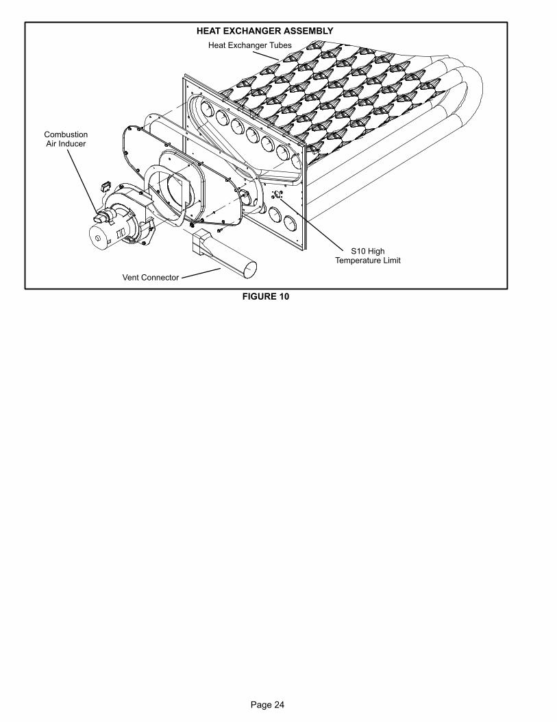
HEAT EXCHANGER ASSEMBLY
FIGURE 10
Heat Exchanger Tubes
CombustionAir Inducer
Vent Connector
S10 HighTemperature Limit
Page 25
D-GAS HEAT COMPONENTS
036, 048, 060,074
Std gas heat; 1-stage 65Kbtuh input
036, 048, 060,074
Med gas heat; 1-stage 108Kbtuh input
036, 048, 060,074
Med gas heat; 2-stage 81/108Kbtu input
048, 060, 074 High gas heat; 1-stage 150Kbtu input
048, 060, 074 High gas heat; 2-stage 113/150Kbtu input
See Gas Heat Specifications on Page 5 for more detail.
1-Heat Exchanger Figure 10
The ZGB units use aluminized steel inshot burners with
tubular aluminized steel heat exchangers and redundant
gas valve. Burners in all units use a burner venturi to mix
gas and air for proper combustion. Combustion takes
place at each tube entrance. As hot combustion gases
are drawn upward through each tube by the combustion
air inducer, exhaust gases are drawn out the top and
fresh air/gas mixture is drawn in at the bottom. Heat is
transferred to the air stream from all surfaces of the heat
exchanger tubes. The supply air blower forces air across
the tubes to extract the heat of combustion. The shape of
the tubes ensures maximum heat exchange.
The gas valves on two stage units accomplish staging by
allowing more or less gas to the burners as called for by
heating demand.
Low NOx models are available that meet the California Air
Quality Management NOx requirement of 40 nanogram/
joule. Stainless steel burner inserts are used to control flame
temperatures to meet this emission level. See figure
NO TAG.
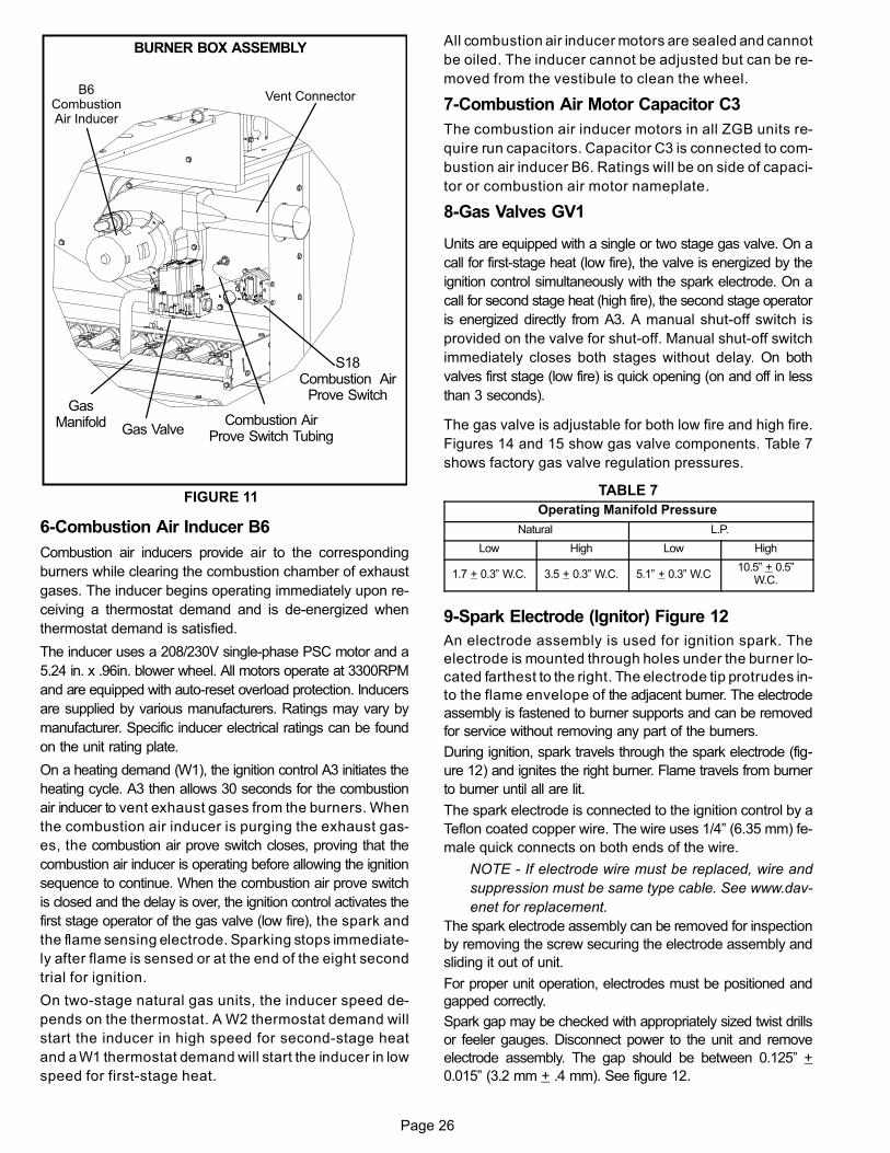
2-Burner Box Assembly Figure 11
The burner assembly consists of a spark electrode, flame
sensing electrode and gas valve. Ignition board A3 controls all
functions of the assembly.
Burners
All units use inshot burners. Burners are factory-set and
do not require adjustment. A peep hole with cover is fur
nished in the heating access panel for flame viewing.
Always operate the unit with the access panel in place.
Burners can be removed as a one piece assembly for
service. Do not try to separate.
OrificeEach burner uses an orifice which is matched to the
burner input. The orifice is threaded into the burner
manifold. The burner is supported by the orifice and will
easily slide off for service once the mounting screws are
removed from the burners.
NOTE-Do not use thread sealing compound on the
orifices. Using thread sealing compound may plug
the orifices.
Each orifice and burner are sized specifically to the
unit. Refer to Product Zone at www.davenet.com for
correct sizing information.
3-Primary High Temperature Limit S10
S10 is a SPST N.C. high temperature primary limit for gas
heat in all units. S10 is located on the vestibule panel. See
figure 10.
Primary limit S10 is wired to the ignition control A3. Its
N.C. contacts open to de-energize the ignition control when
excessive temperature is reached in the blower compartment.
If the limit trips the blower relay coil K3 will be energized
by ignition control A3. Limit setpoints are factory set and
cannot be adjusted. See www.davenet.com for setpoint
and replacement.
4-Flame Rollout Limit Switch S47
Flame rollout limit switch S47 is a SPST N.C. high temper
ature limit located just above the burner air intake opening in
the burner enclosures (see figure NO TAG ). S47 is wired to
the ignition control A3. When S47 senses flame rollout (in
dicating a blockage in the combustion air passages), the
flame rollout limit trips, and the ignition control immedi
ately closes the gas valve.
Limit S47 is factory preset to open at 350�F + 14�F on a
temperature rise on all units. All flame rollout limits are manu
al reset.
5-Combustion Air Prove Switch S18
Prove switch S18 is a SPST N.O. switch located to the right
of the induced draft assembly. See figure 11. S18 monitors
combustion air inducer operation. Switch S18 is wired to
the ignition control A3. The switch closes at negative
0.25”W.C. + 0.05” (62.2 Pa + 12.4 Pa) on pressure fall. This
negative pressure fall and switch actuation allows the igni
tion sequence to continue (proves, by closing, that the com
bustion air inducer is operating before allowing the gas
valve to open.) The combustion air prove switch is factory
set and not adjustable.
Page 26
FIGURE 11
BURNER BOX ASSEMBLY
S18Combustion Air
Prove Switch
Gas Valve
GasManifold
Vent ConnectorB6
CombustionAir Inducer
Combustion AirProve Switch Tubing
6-Combustion Air Inducer B6
Combustion air inducers provide air to the corresponding
burners while clearing the combustion chamber of exhaust
gases. The inducer begins operating immediately upon re
ceiving a thermostat demand and is de-energized when
thermostat demand is satisfied.
The inducer uses a 208/230V single‐phase PSC motor and a
5.24 in. x .96in. blower wheel. All motors operate at 3300RPM
and are equipped with auto‐reset overload protection. Inducers
are supplied by various manufacturers. Ratings may vary by
manufacturer. Specific inducer electrical ratings can be found
on the unit rating plate.
On a heating demand (W1), the ignition control A3 initiates the
heating cycle. A3 then allows 30 seconds for the combustion
air inducer to vent exhaust gases from the burners. When
the combustion air inducer is purging the exhaust gas
es, the combustion air prove switch closes, proving that the
combustion air inducer is operating before allowing the ignition
sequence to continue. When the combustion air prove switch
is closed and the delay is over, the ignition control activates the
first stage operator of the gas valve (low fire), the spark and
the flame sensing electrode. Sparking stops immediate
ly after flame is sensed or at the end of the eight second
trial for ignition.
On two-stage natural gas units, the inducer speed de
pends on the thermostat. A W2 thermostat demand will
start the inducer in high speed for second-stage heat
and a W1 thermostat demand will start the inducer in low
speed for first-stage heat.
All combustion air inducer motors are sealed and cannot
be oiled. The inducer cannot be adjusted but can be re
moved from the vestibule to clean the wheel.
7-Combustion Air Motor Capacitor C3
The combustion air inducer motors in all ZGB units re
quire run capacitors. Capacitor C3 is connected to com
bustion air inducer B6. Ratings will be on side of capaci
tor or combustion air motor nameplate.
8-Gas Valves GV1
Units are equipped with a single or two stage gas valve. On a
call for first-stage heat (low fire), the valve is energized by the
ignition control simultaneously with the spark electrode. On a
call for second stage heat (high fire), the second stage operator
is energized directly from A3. A manual shut-off switch is
provided on the valve for shut-off. Manual shut‐off switch
immediately closes both stages without delay. On both
valves first stage (low fire) is quick opening (on and off in less
than 3 seconds).
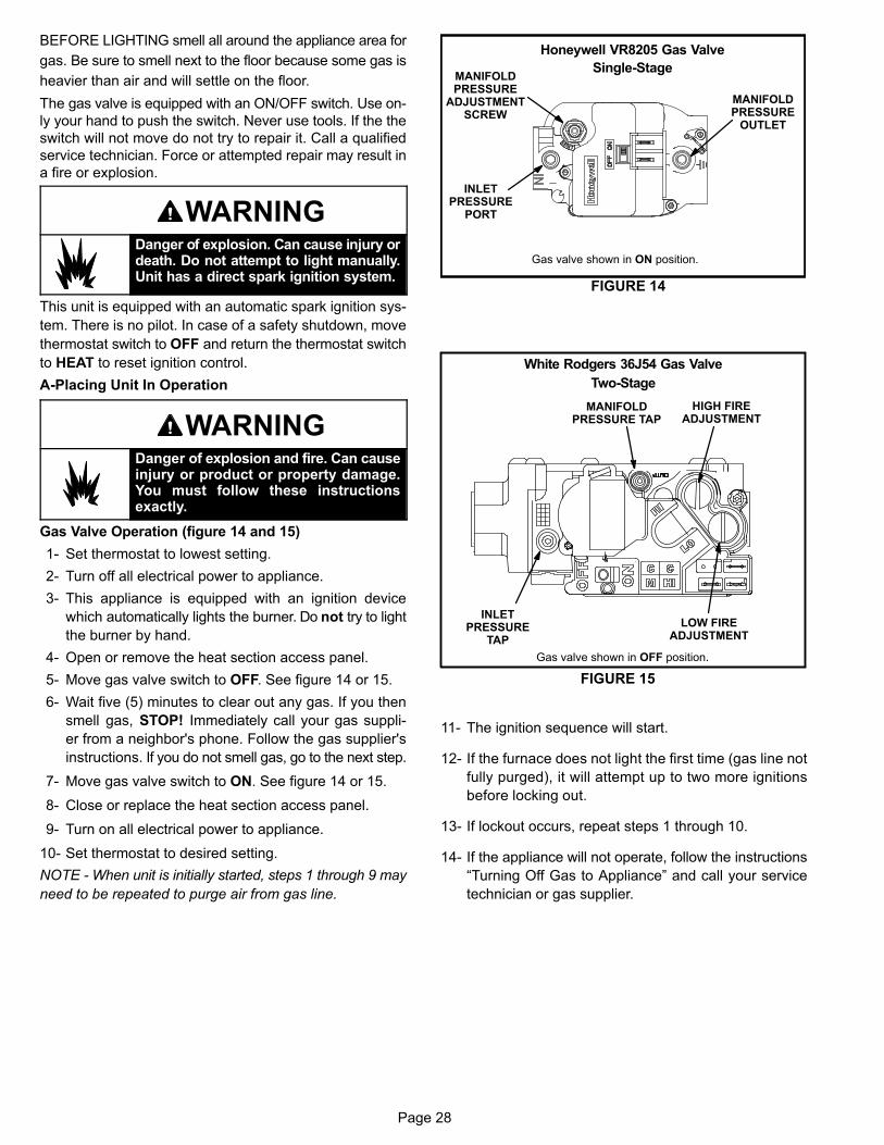
The gas valve is adjustable for both low fire and high fire.
Figures 14 and 15 show gas valve components. Table 7
shows factory gas valve regulation pressures.
TABLE 7
Operating Manifold Pressure
Natural L.P.
Low High Low High
1.7 + 0.3” W.C. 3.5 + 0.3” W.C. 5.1” + 0.3” W.C10.5” + 0.5”
W.C.
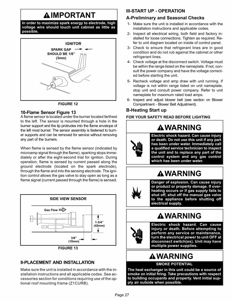
9-Spark Electrode (Ignitor) Figure 12
An electrode assembly is used for ignition spark. The
electrode is mounted through holes under the burner lo
cated farthest to the right. The electrode tip protrudes in
to the flame envelope of the adjacent burner. The electrode
assembly is fastened to burner supports and can be removed
for service without removing any part of the burners.
During ignition, spark travels through the spark electrode (fig
ure 12) and ignites the right burner. Flame travels from burner
to burner until all are lit.
The spark electrode is connected to the ignition control by a
Teflon coated copper wire. The wire uses 1/4” (6.35 mm) fe
male quick connects on both ends of the wire.
NOTE - If electrode wire must be replaced, wire and
suppression must be same type cable. See www.dav
enet for replacement.
The spark electrode assembly can be removed for inspection
by removing the screw securing the electrode assembly and
sliding it out of unit.
For proper unit operation, electrodes must be positioned and
gapped correctly.
Spark gap may be checked with appropriately sized twist drills
or feeler gauges. Disconnect power to the unit and remove
electrode assembly. The gap should be between 0.125” +
0.015” (3.2 mm + .4 mm). See figure 12.
Page 27
IMPORTANTIn order to maximize spark energy to electrode, highvoltage wire should touch unit cabinet as little aspossible.
FIGURE 12
IGNITOR
SPARK GAP
SHOULD BE 1/8”
(3mm)
10-Flame Sensor Figure 13A flame sensor is located under the burner located farthest
to the left. The sensor is mounted through a hole in the
burner support and the tip protrudes into the flame envelope of
the left most burner. The sensor assembly is fastened to burn
er supports and can be removed for service without removing
any part of the burners.
When flame is sensed by the flame sensor (indicated by
microamp signal through the flame), sparking stops imme
diately or after the eight-second trial for ignition. During
operation, flame is sensed by current passed along the
ground electrode (located on the spark electrode),
through the flame and into the sensing electrode. The igni
tion control allows the gas valve to stay open as long as a
flame signal (current passed through the flame) is sensed.
FIGURE 13
SIDE VIEW SENSOR
1-3/4”(45mm)
3/8”(10mm)
Gas Flow
II-PLACEMENT AND INSTALLATION
Make sure the unit is installed in accordance with the in
stallation instructions and all applicable codes. See ac
cessories section for conditions requiring use of the op
tional roof mounting frame (Z1CURB).
III-START UP - OPERATION
A-Preliminary and Seasonal Checks
1- Make sure the unit is installed in accordance with the
installation instructions and applicable codes.
2- Inspect all electrical wiring, both field and factory in
stalled for loose connections. Tighten as required. Re
fer to unit diagram located on inside of control panel.
3- Check to ensure that refrigerant lines are in good
condition and do not rub against the cabinet or other
refrigerant lines.
4- Check voltage at the disconnect switch. Voltage must
be within the range listed on the nameplate. If not, con
sult the power company and have the voltage correct
ed before starting the unit.
5- Recheck voltage and amp draw with unit running. If
voltage is not within range listed on unit nameplate,
stop unit and consult power company. Refer to unit
nameplate for maximum rated load amps.
6- Inspect and adjust blower belt (see section on Blower
Compartment - Blower Belt Adjustment).
B-Heating Start up
FOR YOUR SAFETY READ BEFORE LIGHTING
WARNINGElectric shock hazard. Can cause injuryor death. Do not use this unit if any parthas been under water. Immediately calla qualified service technician to inspectthe unit and to replace any part of thecontrol system and any gas controlwhich has been under water.
WARNINGDanger of explosion. Can cause injuryor product or property damage. If overheating occurs or if gas supply fails toshut off, shut off the manual gas valveto the appliance before shutting offelectrical supply.
WARNINGElectric shock hazard. Can causeinjury or death. Before attempting toperform any service or maintenance,turn the electrical power to unit OFF atdisconnect switch(es). Unit may havemultiple power supplies.
WARNINGSMOKE POTENTIAL
The heat exchanger in this unit could be a source ofsmoke on initial firing. Take precautions with respectto building occupants and property. Vent initial supply air outside when possible.
Page 28
BEFORE LIGHTING smell all around the appliance area for
gas. Be sure to smell next to the floor because some gas is
heavier than air and will settle on the floor.
The gas valve is equipped with an ON/OFF switch. Use on
ly your hand to push the switch. Never use tools. If the the
switch will not move do not try to repair it. Call a qualified
service technician. Force or attempted repair may result in
a fire or explosion.
WARNINGDanger of explosion. Can cause injury ordeath. Do not attempt to light manually.Unit has a direct spark ignition system.
This unit is equipped with an automatic spark ignition sys
tem. There is no pilot. In case of a safety shutdown, move
thermostat switch to OFF and return the thermostat switch
to HEAT to reset ignition control.
A-Placing Unit In Operation
WARNINGDanger of explosion and fire. Can causeinjury or product or property damage.You must follow these instructionsexactly.
Gas Valve Operation (figure 14 and 15)
1- Set thermostat to lowest setting.
2- Turn off all electrical power to appliance.
3- This appliance is equipped with an ignition device
which automatically lights the burner. Do not try to light
the burner by hand.
4- Open or remove the heat section access panel.
5- Move gas valve switch to OFF. See figure 14 or 15.
6- Wait five (5) minutes to clear out any gas. If you then
smell gas, STOP! Immediately call your gas suppli
er from a neighbor's phone. Follow the gas supplier's
instructions. If you do not smell gas, go to the next step.
7- Move gas valve switch to ON. See figure 14 or 15.
8- Close or replace the heat section access panel.
9- Turn on all electrical power to appliance.
10- Set thermostat to desired setting.
NOTE - When unit is initially started, steps 1 through 9 may
need to be repeated to purge air from gas line.
Gas valve shown in ON position.
Honeywell VR8205 Gas Valve
Single-Stage
MANIFOLDPRESSURE
OUTLET
INLETPRESSURE
PORT
MANIFOLDPRESSURE
ADJUSTMENTSCREW
FIGURE 14
FIGURE 15
White Rodgers 36J54 Gas Valve
Two-Stage
Gas valve shown in OFF position.
LOW FIREADJUSTMENT
HIGH FIREADJUSTMENT
INLETPRESSURE
TAP
MANIFOLDPRESSURE TAP
11- The ignition sequence will start.
12- If the furnace does not light the first time (gas line not
fully purged), it will attempt up to two more ignitions
before locking out.
13- If lockout occurs, repeat steps 1 through 10.
14- If the appliance will not operate, follow the instructions
“Turning Off Gas to Appliance” and call your service
technician or gas supplier.

Page 29
C-Cooling Start-Up
A-Operation
1- Initiate first and second stage cooling demands ac
cording to instructions provided with thermostat.
Note - ZGB074 units are equipped with two-stage com
pressors.
2- No Economizer Installed in Unit -
A first-stage cooling demand (Y1) will energize com
pressor 1 and the condenser fan. An increased cool
ing demand (Y2) will not change operation.
Units Equipped With Economizer -
When outdoor air is acceptable, a first-stage cooling
demand (Y1) will energize the economizer. An in
creased cooling demand (Y2) will energize com
pressor 1 and the condenser fan. When outdoor air
is not acceptable unit will operate as though no
economizer is installed.
074 Units With No Economizer Installed
A first-stage cooling demand (Y1) will energize com
pressor on low speed (67% capacity) and the con
denser fan. An increased cooling demand (Y2) will
energize the compressor to high speed (full capaci
ty)
074 Units Equipped With Economizer -
When outdoor air is acceptable, a first-stage cooling
demand (Y1) will energize the economizer. An in
creased cooling demand (Y2) will energize compres
sor on low speed (67% capacity) and the condenser
fan. When outdoor air is not acceptable unit will oper
ate as though no economizer is installed.
3- Units contain one refrigerant circuit or stage.
4- Unit is charged with R-410A refrigerant. See unit rating
plate for correct amount of charge.
5- Refer to Refrigerant Charge and Check section for prop
er method to check refrigerant charge.
B-Three Phase Scroll Compressor Voltage Phasing
Three phase scroll compressors must be phased sequen
tially to ensure correct compressor and blower rotation and
operation. Compressor and blower are wired in phase at
the factory. Power wires are color-coded as follows: line
1-red, line 2-yellow, line 3-blue.
1- Observe suction and discharge pressures and blower
rotation on unit start-up.
2- Suction pressure must drop, discharge pressure must
rise and blower rotation must match rotation marking.
If pressure differential is not observed or blower rotation is
not correct:
3- Disconnect all remote electrical power supplies.
4- Reverse any two field-installed wires connected to the
line side of K1 contactor. Do not reverse wires at blower
contactor.
5- Make sure the connections are tight.
Discharge and suction pressures should operate at their
normal start‐up ranges.
D-Safety or Emergency ShutdownTurn off power to unit. Close manual and main gas valves.
IV-CHARGING WARNING-Do not exceed nameplate charge under any
condition.
This unit is factory charged and should require no further
adjustment. If the system requires additional refrigerant, re
claim the charge, evacuate the system, and add required
nameplate charge.
NOTE - System charging is not recommended below 60°F
(15°C). In temperatures below 60°F (15°C), the charge
must be weighed into the system.
If weighing facilities are not available, or to check the
charge, use the following procedure:
IMPORTANT - Charge unit in standard cooling mode
high stage only.
1- Make sure outdoor coil is clean. Attach gauge manifolds
and operate unit at full CFM in cooling mode with econo
mizer disabled until system stabilizes (approximately five
minutes). Make sure all outdoor air dampers are closed.
2- Compare the normal operating pressures (see tables
8 - 11) to the pressures obtained from the gauges.
Check unit components if there are significant differ
ences.
3- Measure the outdoor ambient temperature and the suc
tion pressure. Refer to the appropriate circuit charging
curve to determine a target liquid temperature.
Note - Pressures are listed for sea level applications.
4- Use the same thermometer to accurately measure the
liquid temperature (in the outdoor section).
� If measured liquid temperature is higher than the
target liquid temperature, add refrigerant to the
system.
� If measured liquid temperature is lower than the
target liquid temperature, recover some refrigerant
from the system.
5- Add or remove charge in increments. Allow the system
to stabilize each time refrigerant is added or removed.
6- Continue the process until measured liquid tempera
ture agrees with the target liquid temperature. Do not
go below the target liquid temperature when adjusting
charge. Note that suction pressure can change as
charge is adjusted.
7- Example ZGB036: At 95°F outdoor ambient and a
measured suction pressure of 130psig, the target liquid
temperature is 102°F. For a measured liquid tempera
ture of 106°F, add charge in increments until measured
liquid temperature agrees with the target liquid temper
ature.

Page 30
TABLE 8ZGB036 NORMAL OPERATING PRESSURES - ALL-ALUMINUM COIL
Outdoor Coil Entering Air Temperature
65 °F 75 °F 85 °F 95 °F 105 °F 115 °FSuct(psig)
Disc(psig)
Suct(psig)
Disc(psig)
Suct(psig)
Disc(psig)
Suct(psig)
Disc(psig)
Suct(psig)
Disc(psig)
Suct(psig)
Disc(psig)
116 231 119 269 122 311 126 356 129 405 132 458
123 234 127 271 130 313 133 359 137 408 140 462
140 245 144 280 147 321 151 368 155 417 159 171
156 261 160 297 167 338 170 383 173 433 178 489
TABLE 9ZGB048 NORMAL OPERATING PRESSURES - ALL-ALUMINUM COIL
Outdoor Coil Entering Air Temperature
65 °F 75 °F 85 °F 95 °F 105 °F 115 °FSuct(psig)
Disc(psig)
Suct(psig)
Disc(psig)
Suct(psig)
Disc(psig)
Suct(psig)
Disc(psig)
Suct(psig)
Disc(psig)
Suct(psig)
Disc(psig)
112 244 115 283 118 326 121 373 124 423 127 480
118 248 122 288 126 331 130 379 133 429 136 177
135 258 138 298 142 341 145 389 150 441 153 496
149 272 154 311 158 355 162 402 166 455 171 193
TABLE 10ZGB060 NORMAL OPERATING PRESSURES - ALL-ALUMINUM COIL
Outdoor Coil Entering Air Temperature
65 °F 75 °F 85 °F 95 °F 105 °F 115 °FSuct(psig)
Disc(psig)
Suct(psig)
Disc(psig)
Suct(psig)
Disc(psig)
Suct(psig)
Disc(psig)
Suct(psig)
Disc(psig)
Suct(psig)
Disc(psig)
106 248 110 288 114 331 118 378 123 428 126 483
114 254 118 292 122 336 125 384 129 435 133 493
130 267 134 308 138 353 142 401 146 455 151 511
147 290 151 329 155 372 159 420 164 477 169 533
TABLE 11ZGB074 NORMAL OPERATING PRESSURES - ALL-ALUMINUM COIL
Outdoor Coil Entering Air Temperature
65 °F 75 °F 85 °F 95 °F 105 °F 115 °FSuct(psig)
Disc(psig)
Suct(psig)
Disc(psig)
Suct(psig)
Disc(psig)
Suct(psig)
Disc(psig)
Suct(psig)
Disc(psig)
Suct(psig)
Disc(psig)
113 255 116 295 119 340 121 386 125 438 127 493
121 260 124 301 127 345 130 394 133 446 136 502
136 271 140 311 143 353 147 403 150 455 154 512
151 288 157 327 162 372 166 422 169 474 174 540
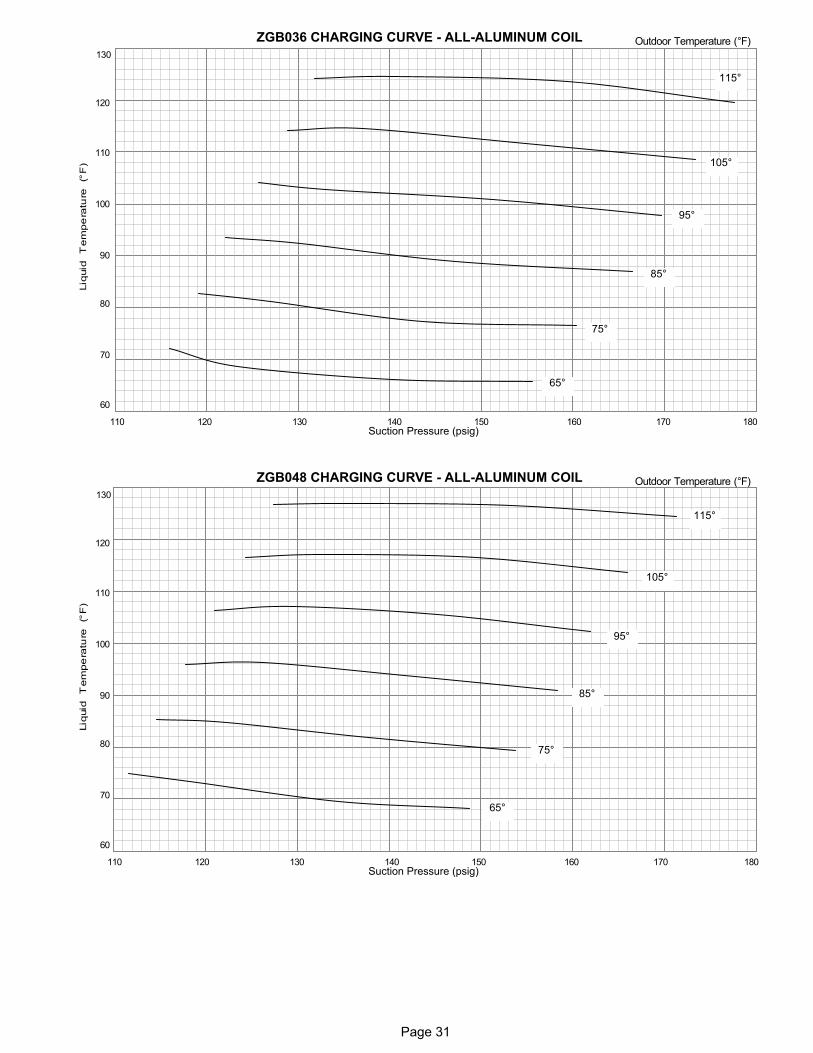
Page 31
ZGB036 CHARGING CURVE - ALL-ALUMINUM COIL
60
70
80
90
100
110
120
130
110 120 130 140 150 160 170
Outdoor Temperature (°F)
Suction Pressure (psig)
105°
95°
115°
85°
75°
65°
180
ZGB048 CHARGING CURVE - ALL-ALUMINUM COIL
60
70
80
90
100
110
120
130
110 120 130 140 150 160 170
Outdoor Temperature (°F)
Suction Pressure (psig)
105°
95°
115°
85°
75°
65°
180
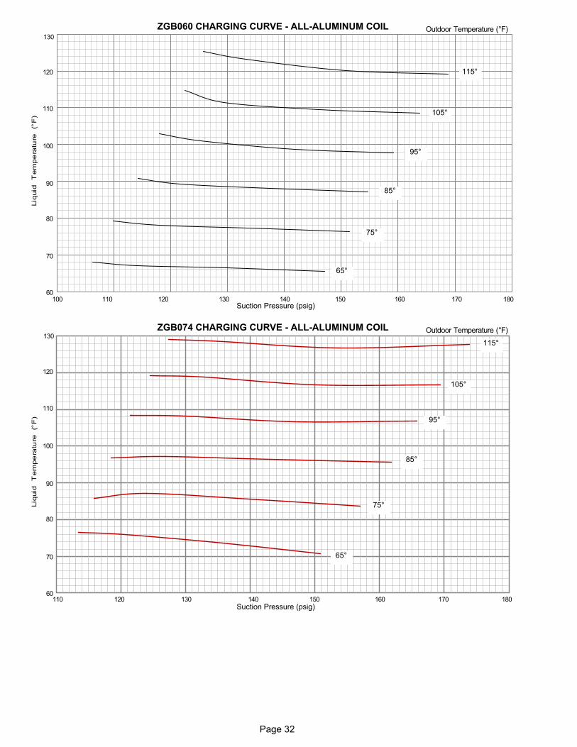
Page 32
ZGB060 CHARGING CURVE - ALL-ALUMINUM COIL
60
70
80
90
100
110
120
130
110 120 130 140 150 160 170
Outdoor Temperature (°F)
Suction Pressure (psig)
105°
95°
115°
85°
75°
65°
100 180
ZGB074 CHARGING CURVE - ALL-ALUMINUM COIL
60
70
80
90
100
110
120
130
110 120 130 140 150 160 170
Outdoor Temperature (°F)
Suction Pressure (psig)
105°
95°
115°
85°
75°
65°
180
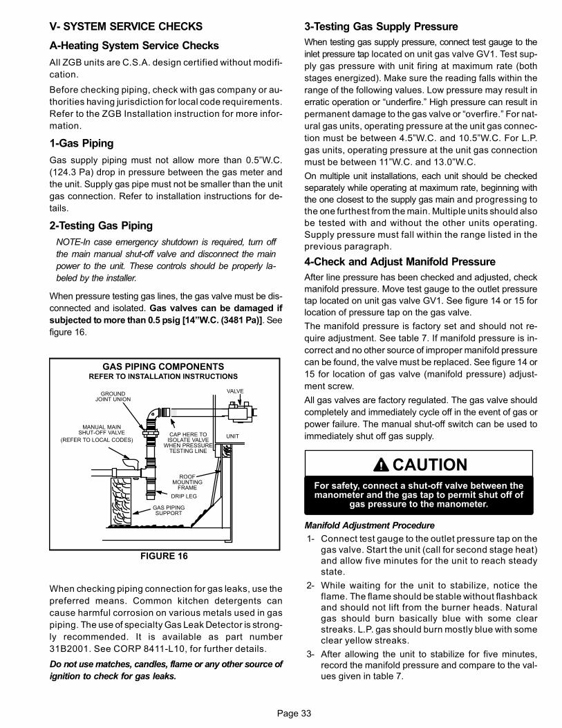
Page 33
V- SYSTEM SERVICE CHECKS
A-Heating System Service Checks
All ZGB units are C.S.A. design certified without modifi
cation.
Before checking piping, check with gas company or au
thorities having jurisdiction for local code requirements.
Refer to the ZGB Installation instruction for more infor
mation.
1-Gas Piping
Gas supply piping must not allow more than 0.5”W.C.
(124.3 Pa) drop in pressure between the gas meter and
the unit. Supply gas pipe must not be smaller than the unit
gas connection. Refer to installation instructions for de
tails.
2-Testing Gas Piping
NOTE-In case emergency shutdown is required, turn off
the main manual shut‐off valve and disconnect the main
power to the unit. These controls should be properly la
beled by the installer.
When pressure testing gas lines, the gas valve must be dis
connected and isolated. Gas valves can be damaged if
subjected to more than 0.5 psig [14”W.C. (3481 Pa)]. See
figure 16.
UNIT
GROUNDJOINT UNION
MANUAL MAINSHUT-OFF VALVE
(REFER TO LOCAL CODES)
GAS PIPINGSUPPORT
DRIP LEG
ROOFMOUNTING
FRAME
GAS PIPING COMPONENTSREFER TO INSTALLATION INSTRUCTIONS
VALVE
CAP HERE TOISOLATE VALVE
WHEN PRESSURETESTING LINE
FIGURE 16
When checking piping connection for gas leaks, use the
preferred means. Common kitchen detergents can
cause harmful corrosion on various metals used in gas
piping. The use of specialty Gas Leak Detector is strong
ly recommended. It is available as part number
31B2001. See CORP 8411-L10, for further details.
Do not use matches, candles, flame or any other source of
ignition to check for gas leaks.
3-Testing Gas Supply Pressure
When testing gas supply pressure, connect test gauge to the
inlet pressure tap located on unit gas valve GV1. Test sup
ply gas pressure with unit firing at maximum rate (both
stages energized). Make sure the reading falls within the
range of the following values. Low pressure may result in
erratic operation or “underfire.” High pressure can result in
permanent damage to the gas valve or “overfire.” For nat
ural gas units, operating pressure at the unit gas connec
tion must be between 4.5”W.C. and 10.5”W.C. For L.P.
gas units, operating pressure at the unit gas connection
must be between 11”W.C. and 13.0”W.C.
On multiple unit installations, each unit should be checked
separately while operating at maximum rate, beginning with
the one closest to the supply gas main and progressing to
the one furthest from the main. Multiple units should also
be tested with and without the other units operating.
Supply pressure must fall within the range listed in the
previous paragraph.
4-Check and Adjust Manifold Pressure
After line pressure has been checked and adjusted, check
manifold pressure. Move test gauge to the outlet pressure
tap located on unit gas valve GV1. See figure 14 or 15 for
location of pressure tap on the gas valve.
The manifold pressure is factory set and should not re
quire adjustment. See table 7. If manifold pressure is in
correct and no other source of improper manifold pressure
can be found, the valve must be replaced. See figure 14 or
15 for location of gas valve (manifold pressure) adjust
ment screw.
All gas valves are factory regulated. The gas valve should
completely and immediately cycle off in the event of gas or
power failure. The manual shut‐off switch can be used to
immediately shut off gas supply.
CAUTIONFor safety, connect a shut‐off valve between themanometer and the gas tap to permit shut off of
gas pressure to the manometer.
Manifold Adjustment Procedure
1- Connect test gauge to the outlet pressure tap on the
gas valve. Start the unit (call for second stage heat)
and allow five minutes for the unit to reach steady
state.
2- While waiting for the unit to stabilize, notice the
flame. The flame should be stable without flashback
and should not lift from the burner heads. Natural
gas should burn basically blue with some clear
streaks. L.P. gas should burn mostly blue with some
clear yellow streaks.
3- After allowing the unit to stabilize for five minutes,
record the manifold pressure and compare to the val
ues given in table 7.
Page 34
5-Proper Gas Flow
Furnace should operate at least 5 minutes before checking
gas flow. Determine time in seconds for two revolutions of
gas through the meter. (Two revolutions assures a more ac
curate time.) Divide by two and compare to time in table 12.
Seconds in table 12 are based on a 1 cu.ft. dial and gas val
ue of 1000 btu/ft3 for natural and 2500 btu/ft3' for LP. Adjust
manifold pressure on gas valve to match time needed.
NOTE - To obtain accurate reading, shut off all other gas
appliances connected to meter.
TABLE 12
GAS METER CLOCKING CHART
UnitInputRate
(Btuh)
Seconds for One Revolution
Natural LP
1 cu ftDial
2 cu ftDial
1 cu ftDial
2 cu ftDial
65,000 55 111 138 277
81,000 44 88 111 222
108,000 33 67 83 167
113,000 31 62 79 158
130,000 28 55 69 138
150,000 24 48 60 120
169,000 21 43 53 107
180,000 20 40 50 100
240,000 15 30 38 75
260,000 14 28 35 69
360,000 10 20 30 50
480,000 8 15 19 38
Natural-1000 btu/cu ft LP-2500 btu/cu ft
Note: Table assumes standard temperature (60°F), pressure
(30in.Hg.), and fuel heating values (Btuh/Ft.3). Apply pressure
corrections in altitudes above 2000 ft.
IMPORTANTDisconnect heating demand as soon as an
accurate reading has been obtained.
6-Heat Exchanger
Visually inspect heat exchanger. If replacement is necessary
refer to the instruction provided with the replacement kit.
7-Flame Sensing
Flame current is an electrical current which passes from the
ignition control through the sensor electrode during unit op
eration. The current passes from the sensor through the
flame to the ground electrode (located on the flame elec
trode) to complete a safety circuit. The electrodes should be
located so the tips are at least 1/2” (12.7 mm) inside the
flame envelope. Do not bend electrodes. To measure flame
current, use the following procedure:
NOTE-Electrodes are not field adjustable. Any alter
ations to the electrode may create a hazardous con
dition that can cause property or personal injury.
1- Disconnect power to unit.
2- Remove lead from sensing electrode and install a
0-50DC microamp meter in series between the sens
ing electrode and the sensing lead.
3- Reconnect power and adjust thermostat for
heating demand.
4- When flame is established, microamp reading should
be 0.5 to 1.0. Do not bend electrodes.
Drop out signal is .09 or less.
5- Disconnect power to unit before disconnecting meter.
Make sure sensor wire is securely reconnected
before reconnecting power to unit.
NOTE-If the meter scale reads 0, the leads are re
versed. Disconnect power and reconnect leads for
proper polarity.
B-Cooling System Service Checks
ZGB units are factory charged and require no further adjust
ment; however, charge should be checked periodically. See
section IV- CHARGING.
NOTE-When unit is properly charged discharge and
suction pressures should approximate those in tables
8 through 11.
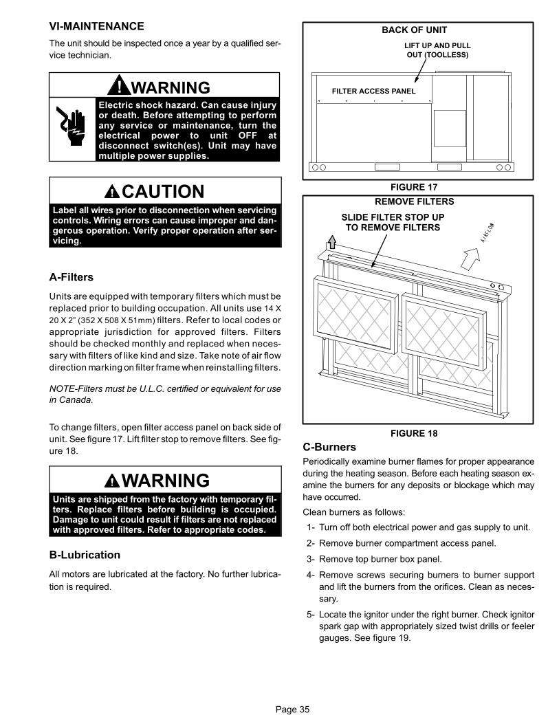
Page 35
VI-MAINTENANCE
The unit should be inspected once a year by a qualified ser
vice technician.
Electric shock hazard. Can cause injuryor death. Before attempting to performany service or maintenance, turn theelectrical power to unit OFF atdisconnect switch(es). Unit may havemultiple power supplies.
WARNING!
CAUTIONLabel all wires prior to disconnection when servicingcontrols. Wiring errors can cause improper and dangerous operation. Verify proper operation after servicing.
A-Filters
Units are equipped with temporary filters which must be
replaced prior to building occupation. All units use 14 X
20 X 2” (352 X 508 X 51mm) filters. Refer to local codes or
appropriate jurisdiction for approved filters. Filters
should be checked monthly and replaced when neces
sary with filters of like kind and size. Take note of air flow
direction marking on filter frame when reinstalling filters.
NOTE-Filters must be U.L.C. certified or equivalent for use
in Canada.
To change filters, open filter access panel on back side of
unit. See figure 17. Lift filter stop to remove filters. See fig
ure 18.
WARNINGUnits are shipped from the factory with temporary filters. Replace filters before building is occupied.Damage to unit could result if filters are not replacedwith approved filters. Refer to appropriate codes.
B-Lubrication
All motors are lubricated at the factory. No further lubrica
tion is required.
FIGURE 17
BACK OF UNIT
FILTER ACCESS PANEL
LIFT UP AND PULL
OUT (TOOLLESS)
FIGURE 18
REMOVE FILTERS
SLIDE FILTER STOP UPTO REMOVE FILTERS
C-Burners
Periodically examine burner flames for proper appearance
during the heating season. Before each heating season ex
amine the burners for any deposits or blockage which may
have occurred.
Clean burners as follows:
1- Turn off both electrical power and gas supply to unit.
2- Remove burner compartment access panel.
3- Remove top burner box panel.
4- Remove screws securing burners to burner support
and lift the burners from the orifices. Clean as neces
sary.
5- Locate the ignitor under the right burner. Check ignitor
spark gap with appropriately sized twist drills or feeler
gauges. See figure 19.
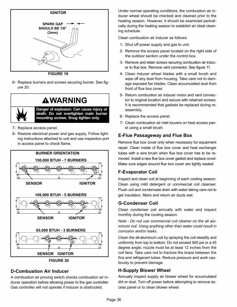
Page 36
FIGURE 19
IGNITOR
SPARK GAP
SHOULD BE 1/8”
(3mm)
6- Replace burners and screws securing burner. See fig
ure 20.
WARNINGDanger of explosion. Can cause injury ordeath. Do not overtighten main burnermounting screws. Snug tighten only.
7- Replace access panel.
8- Restore electrical power and gas supply. Follow light
ing instructions attached to unit and use inspection port
in access panel to check flame.
FIGURE 20
BURNER ORIENTATION
150,000 BTUH - 7 BURNERS
108,000 BTUH - 5 BURNERS
65,000 BTUH - 3 BURNERS
SENSOR IGNITOR
SENSOR IGNITOR
SENSOR IGNITOR
D-Combustion Air Inducer
A combustion air proving switch checks combustion air in
ducer operation before allowing power to the gas controller.
Gas controller will not operate if inducer is obstructed.
Under normal operating conditions, the combustion air in
ducer wheel should be checked and cleaned prior to the
heating season. However, it should be examined periodi
cally during the heating season to establish an ideal clean
ing schedule.
Clean combustion air inducer as follows:
1- Shut off power supply and gas to unit.
2- Remove the access panel located on the right side of
the outdoor section under the control box.
3- Remove and retain screws securing combustion air induc
er to flue box. Remove vent connector. See figure 11.
4- Clean inducer wheel blades with a small brush and
wipe off any dust from housing. Take care not to dam
age exposed fan blades. Clean accumulated dust from
front of flue box cover.
5- Return combustion air inducer motor and vent connec
tor to original location and secure with retained screws.
It is recommended that gaskets be replaced during re
assembly.
6- Replace the access panel.
7- Clean combustion air inlet louvers on heat access pan
el using a small brush.
E-Flue Passageway and Flue Box
Remove flue box cover only when necessary for equipment
repair. Clean inside of flue box cover and heat exchanger
tubes with a wire brush when flue box cover has to be re
moved. Install a new flue box cover gasket and replace cover.
Make sure edges around flue box cover are tightly sealed.
F-Evaporator Coil
Inspect and clean coil at beginning of each cooling season.
Clean using mild detergent or commercial coil cleanser.
Flush coil and condensate drain with water taking care not to
get insulation, filters and return air ducts wet.
G-Condenser Coil
Clean condenser coil annually with water and inspect
monthly during the cooling season.
Note - Do not use commercial coil cleaner on the all alu
minum coil. Using anything other than water could result in
corrosion and/or leaks.
Clean the all-aluminum coil by spraying the coil steadily and
uniformly from top to bottom. Do not exceed 900 psi or a 45
degree angle; nozzle must be at least 12 inches from the
coil face. Take care not to fracture the braze between the
fins and refrigerant tubes. Reduce pressure and work cau
tiously to prevent damage.
H-Supply Blower Wheel
Annually inspect supply air blower wheel for accumulated
dirt or dust. Turn off power before attempting to remove ac
cess panel or to clean blower wheel.
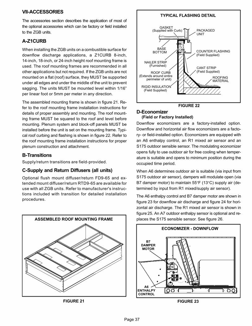
Page 37
VII-ACCESSORIES
The accessories section describes the application of most of
the optional accessories which can be factory or field installed
to the ZGB units.
A-Z1CURB
When installing the ZGB units on a combustible surface for
downflow discharge applications, a Z1CURB 8-inch,
14‐inch, 18-inch, or 24‐inch height roof mounting frame is
used. The roof mounting frames are recommended in all
other applications but not required. If the ZGB units are not
mounted on a flat (roof) surface, they MUST be supported
under all edges and under the middle of the unit to prevent
sagging. The units MUST be mounted level within 1/16”
per linear foot or 5mm per meter in any direction.
The assembled mounting frame is shown in figure 21. Re
fer to the roof mounting frame installation instructions for
details of proper assembly and mounting. The roof mount
ing frame MUST be squared to the roof and level before
mounting. Plenum system and block-off panels MUST be
installed before the unit is set on the mounting frame. Typi
cal roof curbing and flashing is shown in figure 22. Refer to
the roof mounting frame installation instructions for proper
plenum construction and attachment.
B-Transitions
Supply/return transitions are field-provided.
C-Supply and Return Diffusers (all units)
Optional flush mount diffuser/return FD9-65 and ex
tended mount diffuser/return RTD9-65 are available for
use with all ZGB units. Refer to manufacturer's instruc
tions included with transition for detailed installation
procedures.
FIGURE 21
ASSEMBLED ROOF MOUNTING FRAME
FIGURE 22
TYPICAL FLASHING DETAIL
ROOF CURB(Extends around entire
perimeter of unit)
GASKET(Supplied with Curb)
COUNTER FLASHING(Field Supplied)
BASEBOTTOM
RIGID INSULATION(Field Supplied)
CANT STRIP(Field Supplied)
PACKAGEDUNIT
NAILER STRIP(Furnished)
ROOFINGMATERIAL
D-Economizer(Field or Factory Installed)
Downflow economizers are a factory-installed option.
Downflow and horizontal air flow economizers are a facto
ry- or field-installed option. Economizers are equipped with
an A6 enthalpy control, an R1 mixed air sensor and an
S175 outdoor sensible sensor. The modulating economizer
opens fully to use outdoor air for free cooling when temper
ature is suitable and opens to minimum position during the
occupied time period.
When A6 determines outdoor air is suitable (via input from
S175 outdoor air sensor), dampers will modulate open (via
B7 damper motor) to maintain 55°F (13°C) supply air (de
termined by input from R1 mixed/supply air sensor).
The A6 enthalpy control and B7 damper motor are shown in
figure 23 for downflow air discharge and figure 24 for hori
zontal air discharge. The R1 mixed air sensor is shown in
figure 25. An A7 outdoor enthalpy sensor is optional and re
places the S175 sensible sensor. See figure 26.
FIGURE 23
ECONOMIZER - DOWNFLOW
B7DAMPERMOTOR
A6ENTHALPYCONTROL
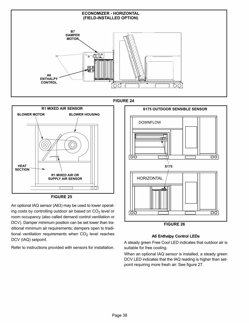
Page 38
FIGURE 24
ECONOMIZER - HORIZONTAL(FIELD-INSTALLED OPTION)
B7DAMPERMOTOR
A6ENTHALPYCONTROL
R1 MIXED AIR SENSOR
FIGURE 25
R1 MIXED AIR ORSUPPLY AIR SENSOR
BLOWER HOUSINGBLOWER MOTOR
HEATSECTION
An optional IAQ sensor (A63) may be used to lower operat
ing costs by controlling outdoor air based on CO2 level or
room occupancy (also called demand control ventilation or
DCV). Damper minimum position can be set lower than tra
ditional minimum air requirements; dampers open to tradi
tional ventilation requirements when CO2 level reaches
DCV (IAQ) setpoint.
Refer to instructions provided with sensors for installation.
S175 OUTDOOR SENSIBLE SENSOR
FIGURE 26
HORIZONTAL
DOWNFLOW
S175
A6 Enthalpy Control LEDs
A steady green Free Cool LED indicates that outdoor air is
suitable for free cooling.
When an optional IAQ sensor is installed, a steady green
DCV LED indicates that the IAQ reading is higher than set
point requiring more fresh air. See figure 27.
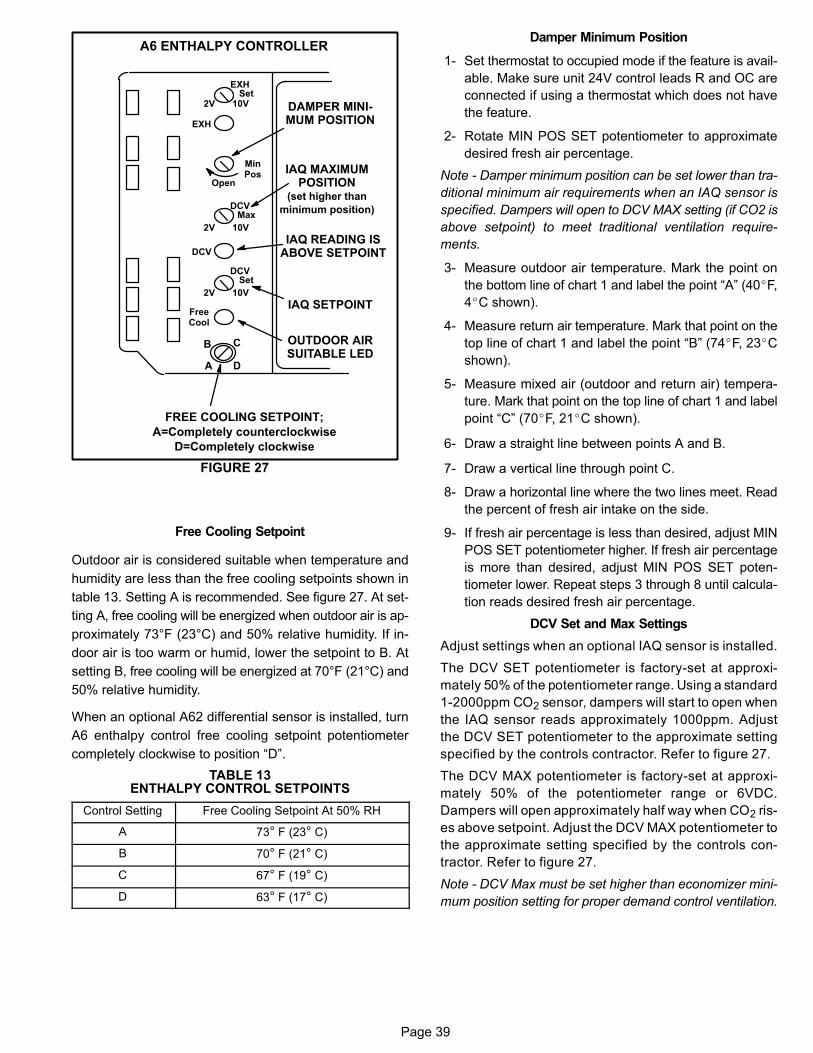
Page 39
FIGURE 27
A6 ENTHALPY CONTROLLER
A
B C
D
Open
MinPos
FREE COOLING SETPOINT;
A=Completely counterclockwise
D=Completely clockwise
OUTDOOR AIRSUITABLE LED
FreeCool
DCV
EXH
EXHSet
2V 10V
DCVMax
2V 10V
DCVSet
2V 10V
IAQ SETPOINT
IAQ READING ISABOVE SETPOINT
DAMPER MINIMUM POSITION
IAQ MAXIMUMPOSITION
(set higher than
minimum position)
Free Cooling Setpoint
Outdoor air is considered suitable when temperature and
humidity are less than the free cooling setpoints shown in
table 13. Setting A is recommended. See figure 27. At set
ting A, free cooling will be energized when outdoor air is ap
proximately 73°F (23°C) and 50% relative humidity. If in
door air is too warm or humid, lower the setpoint to B. At
setting B, free cooling will be energized at 70°F (21°C) and
50% relative humidity.
When an optional A62 differential sensor is installed, turn
A6 enthalpy control free cooling setpoint potentiometer
completely clockwise to position “D”.
TABLE 13ENTHALPY CONTROL SETPOINTS
Control Setting Free Cooling Setpoint At 50% RH
A 73° F (23° C)
B 70° F (21° C)
C 67° F (19° C)
D 63° F (17° C)
Damper Minimum Position
1- Set thermostat to occupied mode if the feature is avail
able. Make sure unit 24V control leads R and OC are
connected if using a thermostat which does not have
the feature.
2- Rotate MIN POS SET potentiometer to approximate
desired fresh air percentage.
Note - Damper minimum position can be set lower than tra
ditional minimum air requirements when an IAQ sensor is
specified. Dampers will open to DCV MAX setting (if CO2 is
above setpoint) to meet traditional ventilation require
ments.
3- Measure outdoor air temperature. Mark the point on
the bottom line of chart 1 and label the point “A” (40�F,
4�C shown).
4- Measure return air temperature. Mark that point on the
top line of chart 1 and label the point “B” (74�F, 23�C
shown).
5- Measure mixed air (outdoor and return air) tempera
ture. Mark that point on the top line of chart 1 and label
point “C” (70�F, 21�C shown).
6- Draw a straight line between points A and B.
7- Draw a vertical line through point C.
8- Draw a horizontal line where the two lines meet. Read
the percent of fresh air intake on the side.
9- If fresh air percentage is less than desired, adjust MIN
POS SET potentiometer higher. If fresh air percentage
is more than desired, adjust MIN POS SET poten
tiometer lower. Repeat steps 3 through 8 until calcula
tion reads desired fresh air percentage.
DCV Set and Max Settings
Adjust settings when an optional IAQ sensor is installed.
The DCV SET potentiometer is factory-set at approxi
mately 50% of the potentiometer range. Using a standard
1-2000ppm CO2 sensor, dampers will start to open when
the IAQ sensor reads approximately 1000ppm. Adjust
the DCV SET potentiometer to the approximate setting
specified by the controls contractor. Refer to figure 27.
The DCV MAX potentiometer is factory-set at approxi
mately 50% of the potentiometer range or 6VDC.
Dampers will open approximately half way when CO2 ris
es above setpoint. Adjust the DCV MAX potentiometer to
the approximate setting specified by the controls con
tractor. Refer to figure 27.
Note - DCV Max must be set higher than economizer mini
mum position setting for proper demand control ventilation.
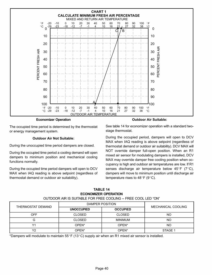
Page 40
-20-29
-10-23
0-18
10-12
20-7
30-1
404
5010
6016
7021
8027
9032
10038
0
10
30
40
50
60
70
80
90
100
20
OUTDOOR AIR TEMPERATURE
0
10
30
40
50
60
70
80
90
100
20
MIXED AND RETURN AIR TEMPERATURE
CHART 1CALCULATE MINIMUM FRESH AIR PERCENTAGE
A
BC
�F�C
�F�C
-20-29
-10-23
0-18
10-12
20-7
30-1
404
5010
6016
7021
8027
9032
10038
�F�C
�F�C
Economizer Operation
The occupied time period is determined by the thermostat
or energy management system.
Outdoor Air Not Suitable:
During the unoccupied time period dampers are closed.
During the occupied time period a cooling demand will open
dampers to minimum position and mechanical cooling
functions normally.
During the occupied time period dampers will open to DCV
MAX when IAQ reading is above setpoint (regardless of
thermostat demand or outdoor air suitability).
Outdoor Air Suitable:
See table 14 for economizer operation with a standard two-
stage thermostat.
During the occupied period, dampers will open to DCV
MAX when IAQ reading is above setpoint (regardless of
thermostat demand or outdoor air suitability). DCV MAX will
NOT override damper full-open position. When an R1
mixed air sensor for modulating dampers is installed, DCV
MAX may override damper free cooling position when oc
cupancy is high and outdoor air temperatures are low. If R1
senses discharge air temperature below 45�F (7�C),
dampers will move to minimum position until discharge air
temperature rises to 48�F (9�C).
TABLE 14
ECONOMIZER OPERATION
OUTDOOR AIR IS SUITABLE FOR FREE COOLING -- FREE COOL LED “ON”ÁÁÁÁÁÁÁÁÁÁÁÁÁÁÁÁÁÁÁÁÁÁÁÁÁÁÁÁÁÁÁÁÁ
THERMOSTAT DEMAND
ÁÁÁÁÁÁÁÁÁÁÁÁÁÁÁÁÁÁÁÁÁÁÁÁÁÁÁÁÁÁÁÁÁÁ
DAMPER POSITIONÁÁÁÁÁÁÁÁÁÁÁÁÁÁÁÁÁÁÁÁÁÁÁÁÁÁÁÁÁÁ
MECHANICAL COOLINGÁÁÁÁÁÁÁÁÁÁÁÁÁÁÁÁÁÁ
UNOCCUPIEDÁÁÁÁÁÁÁÁÁÁÁÁÁÁÁÁÁÁ
OCCUPIEDÁÁÁÁÁÁÁÁÁÁÁÁÁÁÁÁÁÁÁÁÁÁ
OFFÁÁÁÁÁÁÁÁÁÁÁÁÁÁÁÁÁÁ
CLOSEDÁÁÁÁÁÁÁÁÁÁÁÁÁÁÁÁÁÁ
CLOSEDÁÁÁÁÁÁÁÁÁÁÁÁÁÁÁÁÁÁÁÁ
NOÁÁÁÁÁÁÁÁÁÁÁÁÁÁÁÁÁÁÁÁÁÁ
GÁÁÁÁÁÁÁÁÁÁÁÁÁÁÁÁÁÁ
CLOSEDÁÁÁÁÁÁÁÁÁÁÁÁÁÁÁÁÁÁ
MINIMUMÁÁÁÁÁÁÁÁÁÁÁÁÁÁÁÁÁÁÁÁ
NOÁÁÁÁÁÁÁÁÁÁÁÁÁÁÁÁÁÁÁÁÁÁ
Y1ÁÁÁÁÁÁÁÁÁÁÁÁÁÁÁÁÁÁ
OPEN*ÁÁÁÁÁÁÁÁÁÁÁÁÁÁÁÁÁÁ
OPEN*ÁÁÁÁÁÁÁÁÁÁÁÁÁÁÁÁÁÁÁÁ
NOÁÁÁÁÁÁÁÁÁÁÁÁÁÁÁÁÁÁÁÁÁÁ
Y2ÁÁÁÁÁÁÁÁÁÁÁÁÁÁÁÁÁÁ
OPEN*ÁÁÁÁÁÁÁÁÁÁÁÁÁÁÁÁÁÁ
OPEN*ÁÁÁÁÁÁÁÁÁÁÁÁÁÁÁÁÁÁÁÁ
STAGE 1
*Dampers will modulate to maintain 55�F (13�C) supply air when an R1 mixed air sensor is installed.
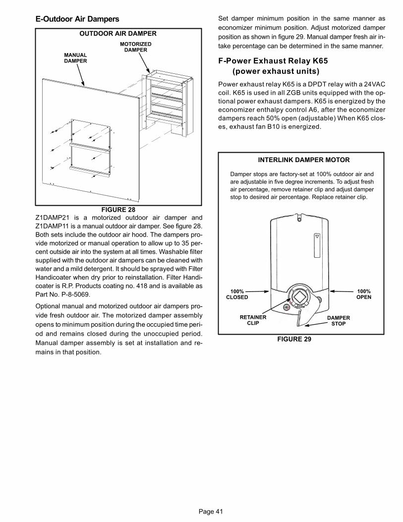
Page 41
E-Outdoor Air Dampers
FIGURE 28
OUTDOOR AIR DAMPER
MANUALDAMPER
MOTORIZEDDAMPER
Z1DAMP21 is a motorized outdoor air damper and
Z1DAMP11 is a manual outdoor air damper. See figure 28.
Both sets include the outdoor air hood. The dampers pro
vide motorized or manual operation to allow up to 35 per
cent outside air into the system at all times. Washable filter
supplied with the outdoor air dampers can be cleaned with
water and a mild detergent. It should be sprayed with Filter
Handicoater when dry prior to reinstallation. Filter Handi
coater is R.P. Products coating no. 418 and is available as
Part No. P-8-5069.
Optional manual and motorized outdoor air dampers pro
vide fresh outdoor air. The motorized damper assembly
opens to minimum position during the occupied time peri
od and remains closed during the unoccupied period.
Manual damper assembly is set at installation and re
mains in that position.
Set damper minimum position in the same manner as
economizer minimum position. Adjust motorized damper
position as shown in figure 29. Manual damper fresh air in
take percentage can be determined in the same manner.
F-Power Exhaust Relay K65
(power exhaust units)
Power exhaust relay K65 is a DPDT relay with a 24VAC
coil. K65 is used in all ZGB units equipped with the op
tional power exhaust dampers. K65 is energized by the
economizer enthalpy control A6, after the economizer
dampers reach 50% open (adjustable) When K65 clos
es, exhaust fan B10 is energized.
FIGURE 29
INTERLINK DAMPER MOTOR
100%OPEN
RETAINERCLIP
DAMPERSTOP
100%CLOSED
Damper stops are factory-set at 100% outdoor air and
are adjustable in five degree increments. To adjust fresh
air percentage, remove retainer clip and adjust damper
stop to desired air percentage. Replace retainer clip.
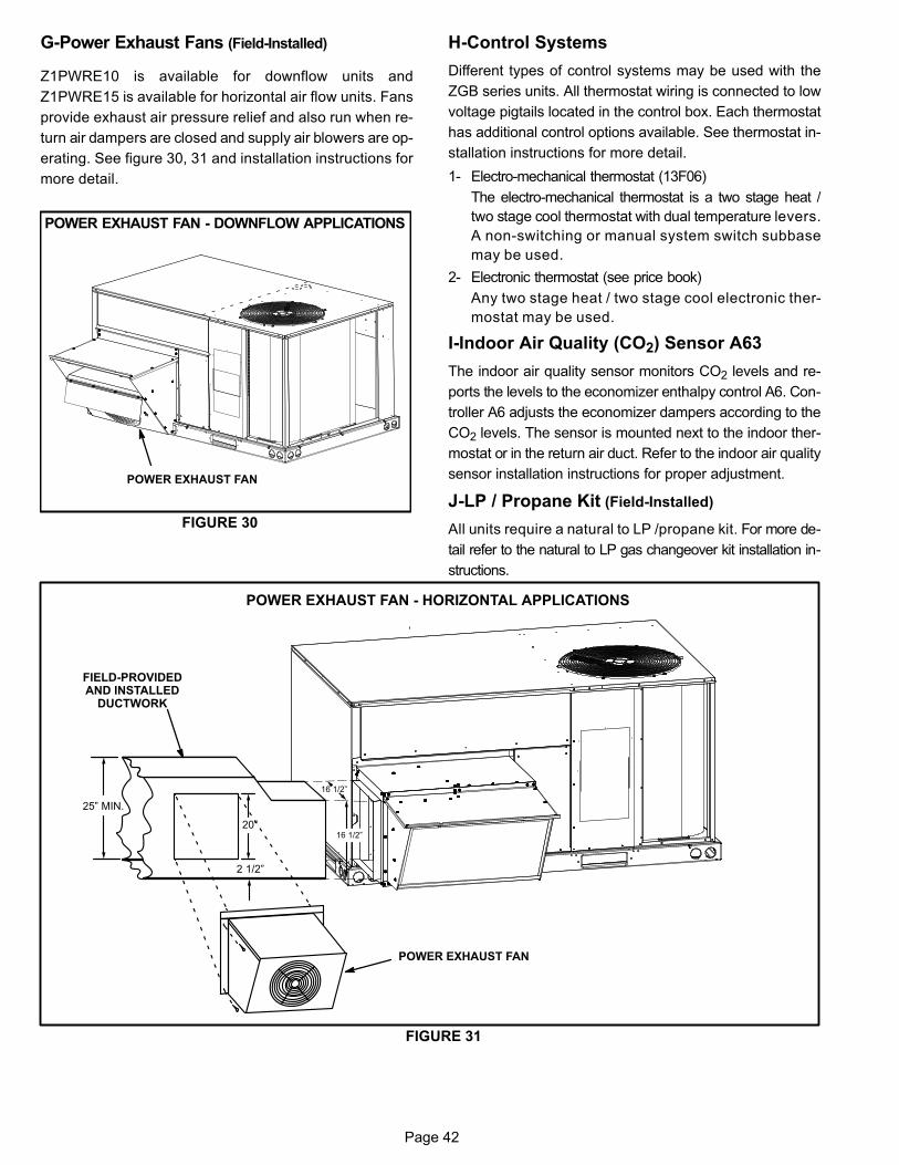
Page 42
G-Power Exhaust Fans (Field-Installed)
Z1PWRE10 is available for downflow units and
Z1PWRE15 is available for horizontal air flow units. Fans
provide exhaust air pressure relief and also run when re
turn air dampers are closed and supply air blowers are op
erating. See figure 30, 31 and installation instructions for
more detail.
FIGURE 30
POWER EXHAUST FAN - DOWNFLOW APPLICATIONS
POWER EXHAUST FAN
H-Control Systems
Different types of control systems may be used with the
ZGB series units. All thermostat wiring is connected to low
voltage pigtails located in the control box. Each thermostat
has additional control options available. See thermostat in
stallation instructions for more detail.
1- Electro‐mechanical thermostat (13F06)
The electro‐mechanical thermostat is a two stage heat /
two stage cool thermostat with dual temperature levers.
A non‐switching or manual system switch subbase
may be used.
2- Electronic thermostat (see price book)
Any two stage heat / two stage cool electronic ther
mostat may be used.
I-Indoor Air Quality (CO2) Sensor A63
The indoor air quality sensor monitors CO2 levels and re
ports the levels to the economizer enthalpy control A6. Con
troller A6 adjusts the economizer dampers according to the
CO2 levels. The sensor is mounted next to the indoor ther
mostat or in the return air duct. Refer to the indoor air quality
sensor installation instructions for proper adjustment.
J-LP / Propane Kit (Field-Installed)
All units require a natural to LP /propane kit. For more de
tail refer to the natural to LP gas changeover kit installation in
structions.
25” MIN.
20”
2 1/2”
16 1/2”
16 1/2”
FIGURE 31
POWER EXHAUST FAN - HORIZONTAL APPLICATIONS
FIELD-PROVIDEDAND INSTALLED
DUCTWORK
POWER EXHAUST FAN
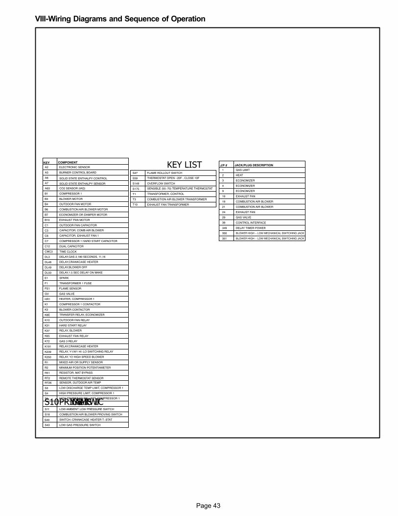
Page 43
VIII-Wiring Diagrams and Sequence of Operation
KEY LIST
SWITCH−CRANKCASE HEATER T−STATS40
PRIMARY GAS LIMIT SWITCS10
KEY COMPONENT
COMPRESSOR 1 CONTACTORK1
BLOWER CONTACTORK3
K10
HEATER, COMPRESSOR 1HR1
K31
R51
R1
K65
R2
S3
S4
S5
S11
A2 ELECTRONIC SENSOR
C1 OUTDOOR FAN CAPACITOR
COMPRESSOR 1B1
BLOWER MOTORB3
OUTDOOR FAN MOTORB4
EXHAUST FAN MOTORB10
ECONOMIZER OR DAMPER MOTORB7
A6
A7
A63
C7 COMPRESSOR 1 HARD START CAPACITOR
C12
CMC3
FLAME SENSORFS1
F1
S18
A3 BURNER CONTROL BOARD
B6
C3 CAPACITOR, COMB AIR BLOWER
E1
GAS VALVEGV
K72
SOLID STATE ENTHALPY CONTROL
SOLID STATE ENTHALPY SENSOR
CO2 SENSOR (IAQ)
J/P # JACK/PLUG DESCRIPTION
2
GAS LIMIT
3
4
9
1
19
HEAT
ECONOMIZER
ECONOMIZER
ECONOMIZER
EXHAUST FAN
COMBUSTION AIR BLOWER
COMBUSTION AIR BLOWER 21
EXHAUST FAN 24
GAS VALVE 29
CONTROL INTERFACE 39
18
DUAL CAPACITOR
OUTDOOR FAN RELAY
TIME CLOCK
TRANSFORMER 1 FUSE
HARD START RELAY
RESISTOR, MAT BYPASS
MIXED AIR OR SUPPLY SENSOR
MINIMUM POSITION POTENTIAMETER
EXHAUST FAN RELAY
LOW DISCHARGE TEMP LIMIT, COMPRESSOR 1
HIGH PRESSURE LIMIT, COMPRESSOR 1
HIGH TEMPERATURE LIMIT, COMPRESSOR 1
LOW AMBIENT LOW PRESSURE SWITCH
COMBUSTION AIR BLOWER MOTOR
SPARK
GAS 3 RELAY
COMBUSTION AIR BLOWER PROVING SWITCH
C6 CAPACITOR, EXHAUST FAN 1
K8E TRANSFER RELAY, ECONOMIZER
RT2 REMOTE THERMOSTAT SENSOR
RT26 SENSOR, OUTDOOR AIR TEMP
DL48 DELAY,CRANKCASE HEATER
K191 RELAY,CRANKCASE HEATER
T3
TRANSFORMER, CONTROLT1
T10 EXHAUST FAN TRANSFORMER
COMBUSTION AIR BLOWER TRANSFORMER
DELAY TIMER POWER 349
DL3 DELAY,GAS 2,180 SECONDS, 11,16
DL50 DELAY,1.5 SEC DELAY ON MAKE
DL49 DELAY,BLOWER OFF
S47 FLAME ROLLOUT SWITCH
S59
S149
S175
OVERFLOW SWITCH
SENSIBLE (55−70) TEMPERATURE THERMOSTAT
THERMOSTAT OPEN −20F , CLOSE 10F
K37 RELAY, BLOWER
K250 RELAY, Y2 HIGH SPEED BLOWER
K239 RELAY, Y1/W1 HI−LO SWITCHING RELAY
BLOWER HIGH − LOW MECHANICAL SWITCHING JACK 350
BLOWER HIGH − LOW MECHANICAL SWITCHING JACK 351
LOW GAS PRESSURE SWITCHS43
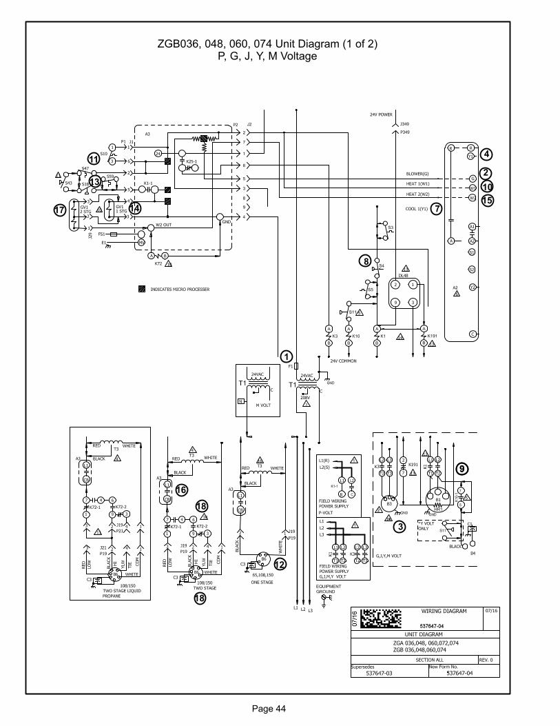
Page 44
14
13
ZGB036, 048, 060, 074 Unit Diagram (1 of 2)P, G, J, Y, M Voltage
1
2
3
4
7
8
99
10
11
12
15
16
17
18
18
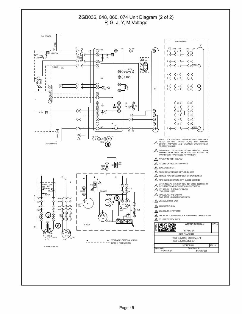
Page 45
ZGB036, 048, 060, 074 Unit Diagram (2 of 2)P, G, J, Y, M Voltage
6
5
9
5
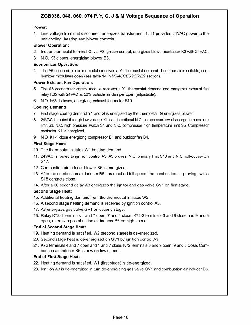
Page 46
Power:
1. Line voltage from unit disconnect energizes transformer T1. T1 provides 24VAC power to the
unit cooling, heating and blower controls.
Blower Operation:
2. Indoor thermostat terminal G, via A3 ignition control, energizes blower contactor K3 with 24VAC.
3. N.O. K3 closes, energizing blower B3.
Economizer Operation:
4. The A6 economizer control module receives a Y1 thermostat demand. If outdoor air is suitable, eco
nomizer modulates open (see table 14 in VII-ACCESSORIES section).
Power Exhaust Fan Operation:
5. The A6 economizer control module receives a Y1 thermostat demand and energizes exhaust fan
relay K65 with 24VAC at 50% outside air damper open (adjustable).
6. N.O. K65-1 closes, energizing exhaust fan motor B10.
Cooling Demand
7. First stage cooling demand Y1 and G is energized by the thermostat. G energizes blower.
8. 24VAC is routed through low voltage Y1 lead to optional N.C. compressor low discharge temperature
limit S3, N.C. high pressure switch S4 and N.C. compressor high temperature limit S5. Compressor
contactor K1 is energized.
9. N.O. K1-1 close energizing compressor B1 and outdoor fan B4.
First Stage Heat:
10. The thermostat initiates W1 heating demand.
11. 24VAC is routed to ignition control A3. A3 proves N.C. primary limit S10 and N.C. roll-out switch
S47.
12. Combustion air inducer blower B6 is energized.
13. After the combustion air inducer B6 has reached full speed, the combustion air proving switch
S18 contacts close.
14. After a 30 second delay A3 energizes the ignitor and gas valve GV1 on first stage.
Second Stage Heat:
15. Additional heating demand from the thermostat initiates W2.
16. A second stage heating demand is received by ignition control A3.
17. A3 energizes gas valve GV1 on second stage.
18. Relay K72-1 terminals 1 and 7 open, 7 and 4 close. K72-2 terminals 6 and 9 close and 9 and 3
open, energizing combustion air inducer B6 on high speed.
End of Second Stage Heat:
19. Heating demand is satisfied. W2 (second stage) is de-energized.
20. Second stage heat is de-energized on GV1 by ignition control A3.
21. K72 terminals 4 and 7 open and 1 and 7 close. K72 terminals 6 and 9 open, 9 and 3 close. Com
bustion air inducer B6 is now on low speed.
End of First Stage Heat:
22. Heating demand is satisfied. W1 (first stage) is de-energized.
23. Ignition A3 is de-energized in turn de-energizing gas valve GV1 and combustion air inducer B6.
ZGB036, 048, 060, 074 P, Y, G, J & M Voltage Sequence of Operation


![Kh^ j`Zgb - vayenshtefan.ruvayenshtefan.ru/vvt/gazeta_aprel_2018.pdf1 Bggh\ZpbhggZyBgl_jg_l - ]Za_lZ©](https://img.pdfslide.net/doc/110x75/60acde33c730523c464f6f81/-kh-jzgb-1-bgghzpbhggzybgljgl-zalz.jpg)


![Zgb dgb] - saha-skazka.tvoysadik.ru](https://img.pdfslide.net/doc/110x75/61c511e6eefbc96698429df2/zgb-dgb-saha-.jpg)