Embed Size (px)
Citation preview
Page 1 of 16
Conveyor Belt Bottom Cover Failure from Idlers and Pulleys
Yijun Zhang, Ph.D, P.E., Conveyor Dynamics, Inc.
Abstract
Excessive belt bottom cover wear from improper idler arrangement and ceramic pulley
lagging can lead to early belt failure and unplanned downtime. This article discusses several
failure modes and related field examples: bottom cover damage at idler junction due to
severe bending, belt cover damage due to high normal and shear stress, accelerated bottom
cover wear from misaligned idlers, and cover damage from problematic ceramic pulley
lagging tiles. The idler junction bending is analyzed using finite element modeling. The idler
junction pressure index is introduced as a design tool to limit the idler junction stress during
the engineering stage.
Introduction
Belt conveyors are efficient and reliable material handling systems. The rubber belt with
synthetic fabric or steel cord carcass is typically the most expensive single component of a
conveyor. The belt also plays a dominating role in the ownership cost and reliability of a
conveyor (1). While conveyor belts with more than 15 years of service life are not unusual,
premature belt failure can also happen due to accidents, engineering or maintenance issues.
The top cover, carcass and bottom cover can all be subject to premature failure or damage.
The top cover usually suffers from damage related to transport material or tramp metal. The
belt carcass may suffer from steel cord breakage and carcass penetration. The belt bottom
cover does not contact transport material, instead the bottom cover makes countless rolling
contact with idlers and pulleys. As a result, premature bottom cover failure typically starts
from the interaction between the belt and the idlers and pulleys. This article discusses
several scenarios of early belt bottom cover failure.
Page 2 of 16
Cover Failure at Idler Junction
General Analysis
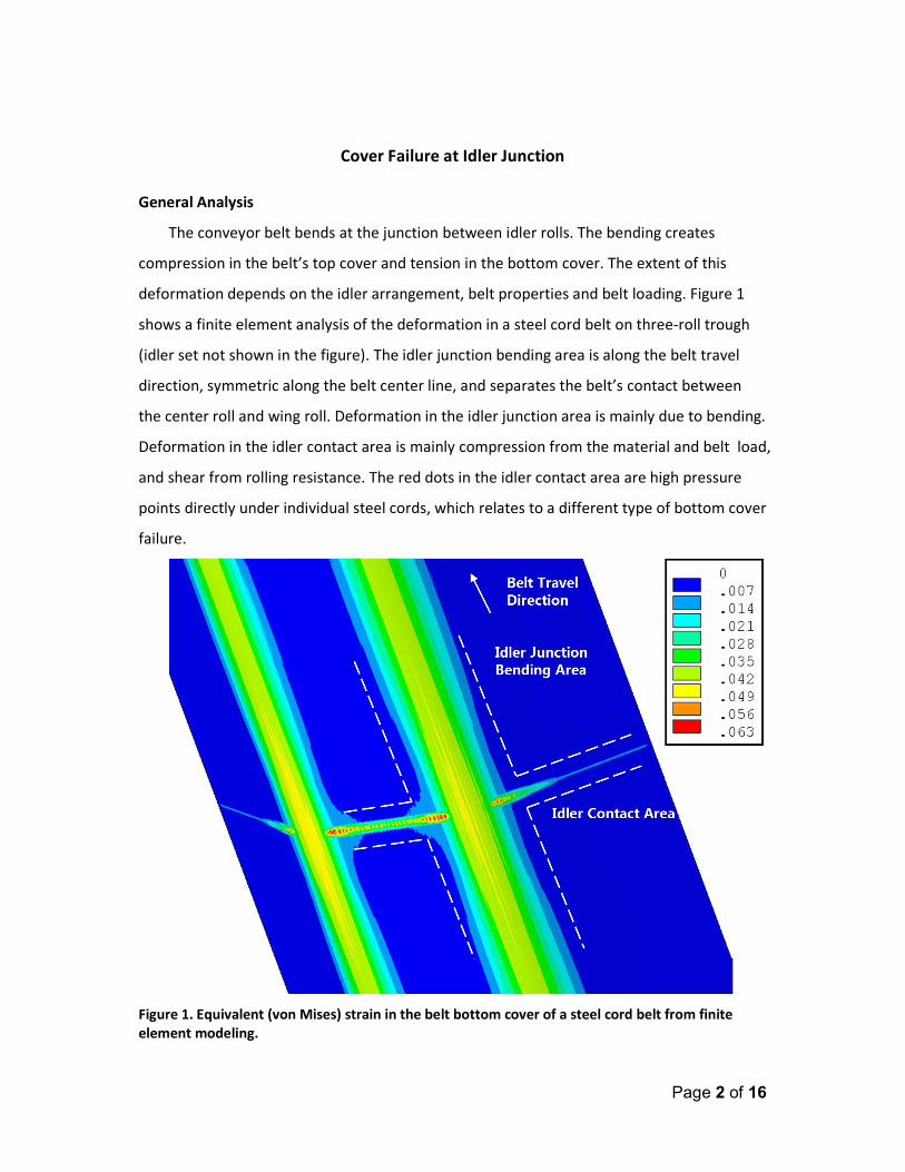
The conveyor belt bends at the junction between idler rolls. The bending creates
compression in the belt’s top cover and tension in the bottom cover. The extent of this
deformation depends on the idler arrangement, belt properties and belt loading. Figure 1
shows a finite element analysis of the deformation in a steel cord belt on three-roll trough
(idler set not shown in the figure). The idler junction bending area is along the belt travel
direction, symmetric along the belt center line, and separates the belt’s contact between
the center roll and wing roll. Deformation in the idler junction area is mainly due to bending.
Deformation in the idler contact area is mainly compression from the material and belt load,
and shear from rolling resistance. The red dots in the idler contact area are high pressure
points directly under individual steel cords, which relates to a different type of bottom cover
failure.
Figure 1. Equivalent (von Mises) strain in the belt bottom cover of a steel cord belt from finite
element modeling.
Page 3 of 16
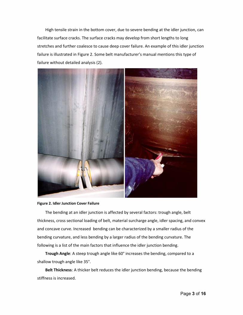
High tensile strain in the bottom cover, due to severe bending at the idler junction, can
facilitate surface cracks. The surface cracks may develop from short lengths to long
stretches and further coalesce to cause deep cover failure. An example of this idler junction
failure is illustrated in Figure 2. Some belt manufacturer’s manual mentions this type of
failure without detailed analysis (2).
Figure 2. Idler Junction Cover Failure
The bending at an idler junction is affected by several factors: trough angle, belt
thickness, cross sectional loading of belt, material surcharge angle, idler spacing, and convex
and concave curve. Increased bending can be characterized by a smaller radius of the
bending curvature, and less bending by a larger radius of the bending curvature. The
following is a list of the main factors that influence the idler junction bending.
Trough Angle: A steep trough angle like 60° increases the bending, compared to a
shallow trough angle like 35°.
Belt Thickness: A thicker belt reduces the idler junction bending, because the bending
stiffness is increased.
Page 4 of 16
Material Cross Sectional Loading and Idler Spacing: Heavier combined weight of
material loading and belt, for which the weight of material is typically the dominating
component, increases the idler junction bending. The bending strain in the idler junction is
highest when the belt is right on top of idler rolls. The bending relaxes between idler
stations. This relaxation is referred as the belt flexure (3). By the same argument, because
idlers provide support to the belt, wide idler spacing increases the idler junction bending.
Material Surcharge Angle: The material surcharge angle affects the idler junction
bending. High angles create a heaped pile of material in the trough belt, which increases the
material loading pressure at the middle of the center roll and reduces the loading pressure
around the idler junction and vice versa.
Vertical Curves: At vertical convex curves, a component of belt tension is added to the
belt weight and material loading in the gravitational direction, pushing the belt against idler
rolls, so the idler junction bending is increased. A concave curve reduces the idler junction
bending because the vertical component of belt tension is subtracted from the weight load.
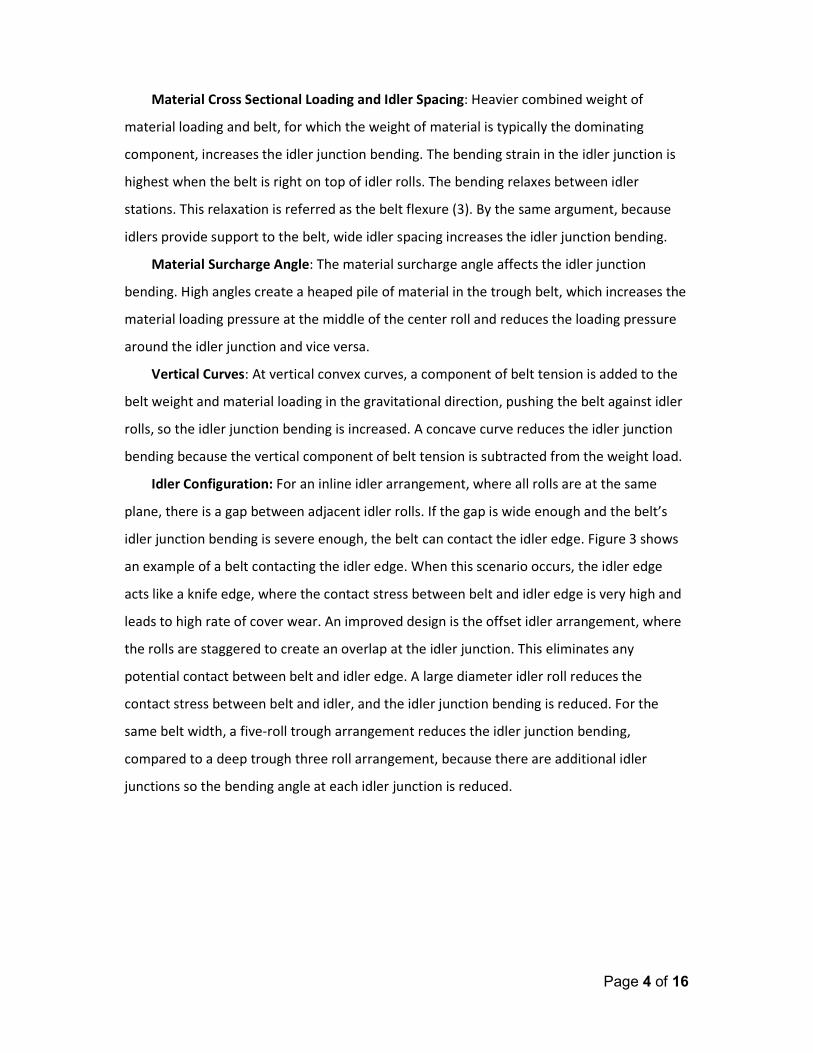
Idler Configuration: For an inline idler arrangement, where all rolls are at the same
plane, there is a gap between adjacent idler rolls. If the gap is wide enough and the belt’s
idler junction bending is severe enough, the belt can contact the idler edge. Figure 3 shows
an example of a belt contacting the idler edge. When this scenario occurs, the idler edge
acts like a knife edge, where the contact stress between belt and idler edge is very high and
leads to high rate of cover wear. An improved design is the offset idler arrangement, where
the rolls are staggered to create an overlap at the idler junction. This eliminates any
potential contact between belt and idler edge. A large diameter idler roll reduces the
contact stress between belt and idler, and the idler junction bending is reduced. For the
same belt width, a five-roll trough arrangement reduces the idler junction bending,
compared to a deep trough three roll arrangement, because there are additional idler
junctions so the bending angle at each idler junction is reduced.
Page 5 of 16
Figure 3. Belt Contacting Idler Edge
The length of an idler roll can affect the idler junction bending. For a typical three or
five roll trough, the idler length is equal. Non-equal roll lengths are also implemented in
overland conveyors (4). One reason is to change the load distribution between the wing roll
and the center roll to a more optimal level. The material cross sectional loading capacity is
also affected by the length of the idler roll. If the center roll length is decreased, the idler
junction bending is increased.
Idler Junction Pressure Index
CDI developed the Idler Junction Pressure Index (IJPI) as a quantitative tool to indicate
the idler junction bending stress. The IJPI allows the designer to explore various conveyor
and belt parameters like idler spacing, diameter, roll lengths, belt speed, belt thickness, etc.,
to arrive at an optimized design while maintaining allowable idler junction bending. Higher
IJPI values mean more bending deformation. As a general design criterion, the IJPI should
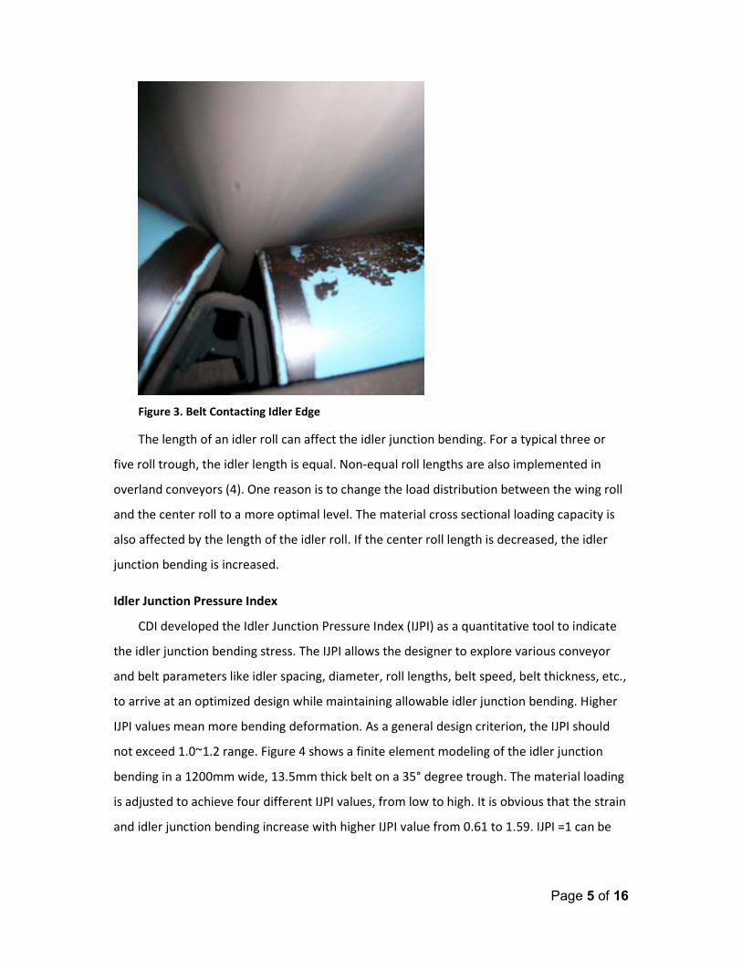
not exceed 1.0~1.2 range. Figure 4 shows a finite element modeling of the idler junction
bending in a 1200mm wide, 13.5mm thick belt on a 35° degree trough. The material loading
is adjusted to achieve four different IJPI values, from low to high. It is obvious that the strain
and idler junction bending increase with higher IJPI value from 0.61 to 1.59. IJPI =1 can be
Page 6 of 16
viewed as a relatively conservative limit. When IJPI exceeds 1.2, the belt bending becomes
severe. At IJPI=1.59, the belt starts to contact the idler edge.
Figure 4. Finite element modeling of belt deformation with Idler Junction Pressure Index (IJPI). The
top four graphs show the cut plane of a belt near the idler junction area. The bottom four graphs
are the corresponding view of the belt bottom cover (looking from beneath the belt bottom cover)
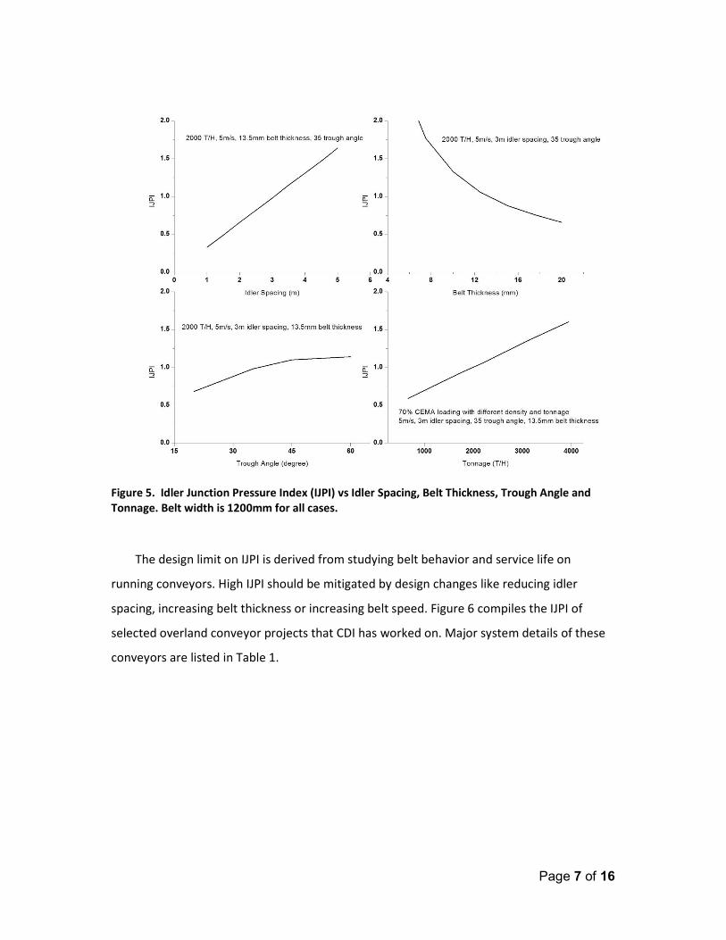
To illustrate the relationship of IJPI to conveyor and belt parameters, Figure 5 shows
different IJPI on the same 1200mm wide belt, at 70% CEMA loading and 5m/s belt speed,
but with varying idler spacing, belt thickness, trough angle and tonnage. Some weight
related factors, like idler spacing and tonnage, show a linear relation to IJPI. Some bending
related factors, like belt thickness and trough angle, show a non linear relation to IJPI. For
example, the IJPI increases beyond a linear relationship with reducing belt thickness.
Page 7 of 16
Figure 5. Idler Junction Pressure Index (IJPI) vs Idler Spacing, Belt Thickness, Trough Angle and
Tonnage. Belt width is 1200mm for all cases.
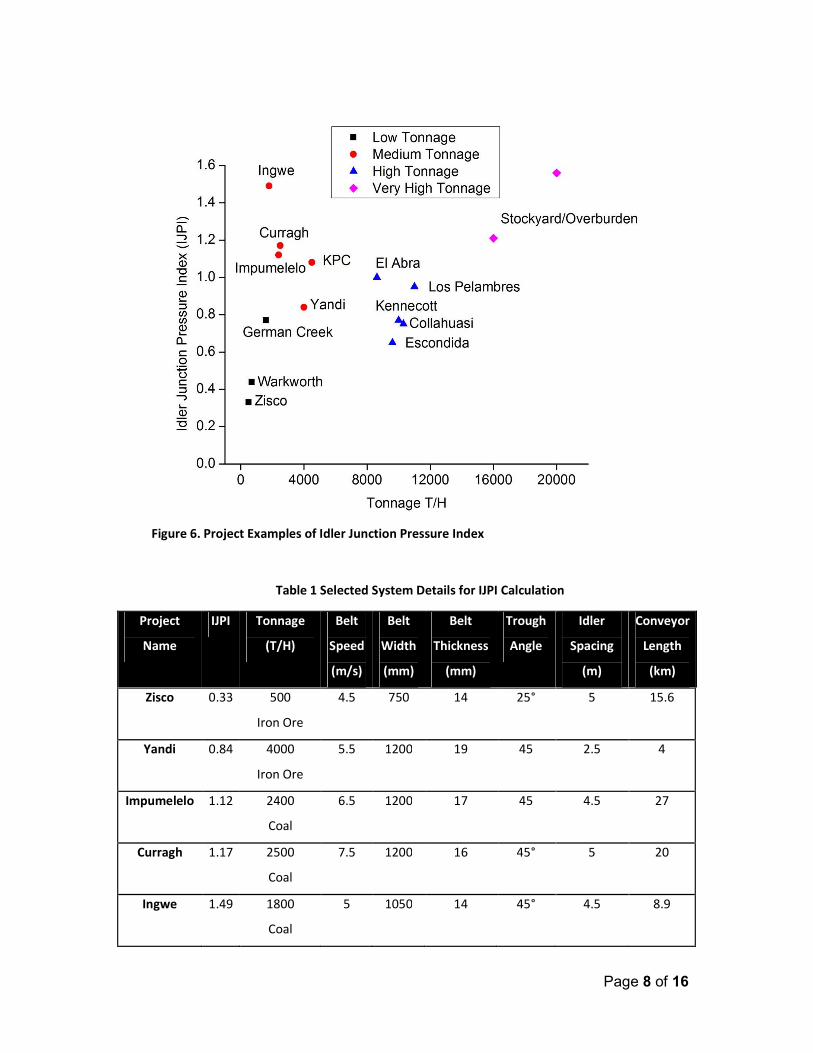
The design limit on IJPI is derived from studying belt behavior and service life on
running conveyors. High IJPI should be mitigated by design changes like reducing idler
spacing, increasing belt thickness or increasing belt speed. Figure 6 compiles the IJPI of
selected overland conveyor projects that CDI has worked on. Major system details of these
conveyors are listed in Table 1.
Page 8 of 16
Figure 6. Project Examples of Idler Junction Pressure Index
Table 1 Selected System Details for IJPI Calculation
Project
Name
IJPI Tonnage
(T/H)
Belt
Speed
(m/s)
Belt
Width
(mm)
Belt
Thickness
(mm)
Trough
Angle
Idler
Spacing
(m)
Conveyor
Length
(km)
Zisco 0.33 500
Iron Ore
4.5 750 14 25° 5 15.6
Yandi 0.84 4000
Iron Ore
5.5 1200 19 45 2.5 4
Impumelelo 1.12 2400
Coal
6.5 1200 17 45 4.5 27
Curragh 1.17 2500
Coal
7.5 1200 16 45° 5 20
Ingwe 1.49 1800
Coal
5 1050 14 45° 4.5 8.9
Page 9 of 16
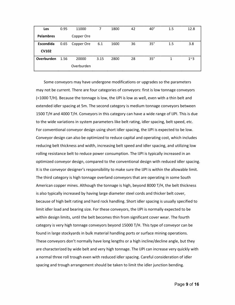
Los
Pelambres
0.95 11000
Copper Ore
7 1800 42 40° 1.5 12.8
Escondida
CV102
0.65 Copper Ore 6.1 1600 36 35° 1.5 3.8
Overburden 1.56 20000
Overburden
3.15 2800 28 35° 1 1~3
Some conveyors may have undergone modifications or upgrades so the parameters
may not be current. There are four categories of conveyors: first is low tonnage conveyors
(<1000 T/H). Because the tonnage is low, the IJPI is low as well, even with a thin belt and
extended idler spacing at 5m. The second category is medium tonnage conveyors between
1500 T/H and 4000 T/H. Conveyors in this category can have a wide range of IJPI. This is due
to the wide variations in system parameters like belt rating, idler spacing, belt speed, etc.
For conventional conveyor design using short idler spacing, the IJPI is expected to be low.
Conveyor design can also be optimized to reduce capital and operating cost, which includes
reducing belt thickness and width, increasing belt speed and idler spacing, and utilizing low
rolling resistance belt to reduce power consumption. The IJPI is typically increased in an
optimized conveyor design, compared to the conventional design with reduced idler spacing.
It is the conveyor designer’s responsibility to make sure the IJPI is within the allowable limit.
The third category is high tonnage overland conveyors that are operating in some South
American copper mines. Although the tonnage is high, beyond 8000 T/H, the belt thickness
is also typically increased by having large diameter steel cords and thicker belt cover,
because of high belt rating and hard rock handling. Short idler spacing is usually specified to
limit idler load and bearing size. For these conveyors, the IJPI is normally expected to be
within design limits, until the belt becomes thin from significant cover wear. The fourth
category is very high tonnage conveyors beyond 15000 T/H. This type of conveyor can be
found in large stockyards in bulk material handling ports or surface mining operations.
These conveyors don’t normally have long lengths or a high incline/decline angle, but they
are characterized by wide belt and very high tonnage. The IJPI can increase very quickly with
a normal three roll trough even with reduced idler spacing. Careful consideration of idler
spacing and trough arrangement should be taken to limit the idler junction bending.
Page 10 of 16
Accelerated Cover Wear from Sliding Friction and High Normal and Shear Stress
In Figure 1, the idler contact area shows high deformation areas (red dots) which are
under individual steel cords. The contact pressure is relaxed under the rubber gap between
adjacent steel cords. Also the contact pressure near the edge of the wing roll and center roll
is higher than the rest. Combining the two effects, the localized contact stress can be
significantly higher than the average contact stress over the entire contact area.
The contact stress is composed of shear and normal stress. The shear stress is from
indentation rolling resistance. The normal stress is from the belt and material weight. In
addition, convex curves, whether created intentionally to change the belt direction or
unintentionally by idler misalignment, apply part of the belt tension as a vertical load on the
idler to further increase the normal contact stress and deformation. For a typical three roll
trough configuration, the pressure on the center idler roll is higher than the wing roll.
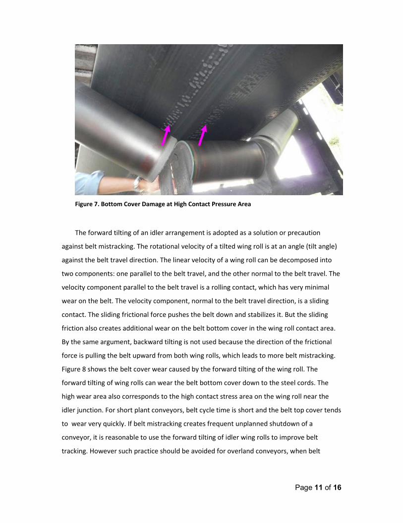
High normal and shear stress can potentially cause accelerated belt cover wear. One
example is shown in Figure 7. This particular belt is traveling at a high speed with heavy
material load, so both normal and shear contact stress is high. The contact stress further
increases around the idler edges and directly under individual steel cords. In Figure 7, the
spacing of the circular damage spots matches the spacing of steel cords in belt, which is
exactly the high stress area. If the bottom cover rubber’s mechanical property is not strong
enough to withstand the stress or strain level, premature bottom cover belt failure will
occur.
Page 11 of 16
Figure 7. Bottom Cover Damage at High Contact Pressure Area
The forward tilting of an idler arrangement is adopted as a solution or precaution
against belt mistracking. The rotational velocity of a tilted wing roll is at an angle (tilt angle)
against the belt travel direction. The linear velocity of a wing roll can be decomposed into
two components: one parallel to the belt travel, and the other normal to the belt travel. The
velocity component parallel to the belt travel is a rolling contact, which has very minimal
wear on the belt. The velocity component, normal to the belt travel direction, is a sliding
contact. The sliding frictional force pushes the belt down and stabilizes it. But the sliding
friction also creates additional wear on the belt bottom cover in the wing roll contact area.
By the same argument, backward tilting is not used because the direction of the frictional
force is pulling the belt upward from both wing rolls, which leads to more belt mistracking.
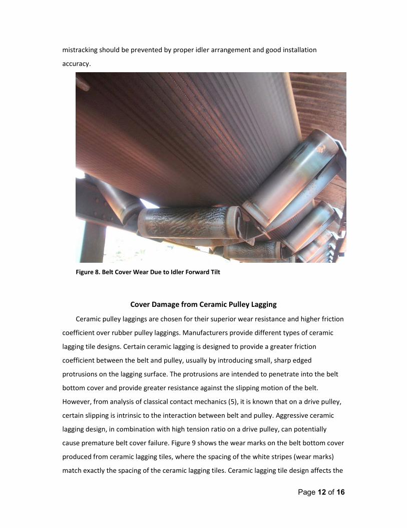
Figure 8 shows the belt cover wear caused by the forward tilting of the wing roll. The
forward tilting of wing rolls can wear the belt bottom cover down to the steel cords. The
high wear area also corresponds to the high contact stress area on the wing roll near the
idler junction. For short plant conveyors, belt cycle time is short and the belt top cover tends
to wear very quickly. If belt mistracking creates frequent unplanned shutdown of a
conveyor, it is reasonable to use the forward tilting of idler wing rolls to improve belt
tracking. However such practice should be avoided for overland conveyors, when belt
Page 12 of 16
mistracking should be prevented by proper idler arrangement and good installation
accuracy.
Figure 8. Belt Cover Wear Due to Idler Forward Tilt
Cover Damage from Ceramic Pulley Lagging
Ceramic pulley laggings are chosen for their superior wear resistance and higher friction
coefficient over rubber pulley laggings. Manufacturers provide different types of ceramic
lagging tile designs. Certain ceramic lagging is designed to provide a greater friction
coefficient between the belt and pulley, usually by introducing small, sharp edged
protrusions on the lagging surface. The protrusions are intended to penetrate into the belt
bottom cover and provide greater resistance against the slipping motion of the belt.
However, from analysis of classical contact mechanics (5), it is known that on a drive pulley,
certain slipping is intrinsic to the interaction between belt and pulley. Aggressive ceramic
lagging design, in combination with high tension ratio on a drive pulley, can potentially
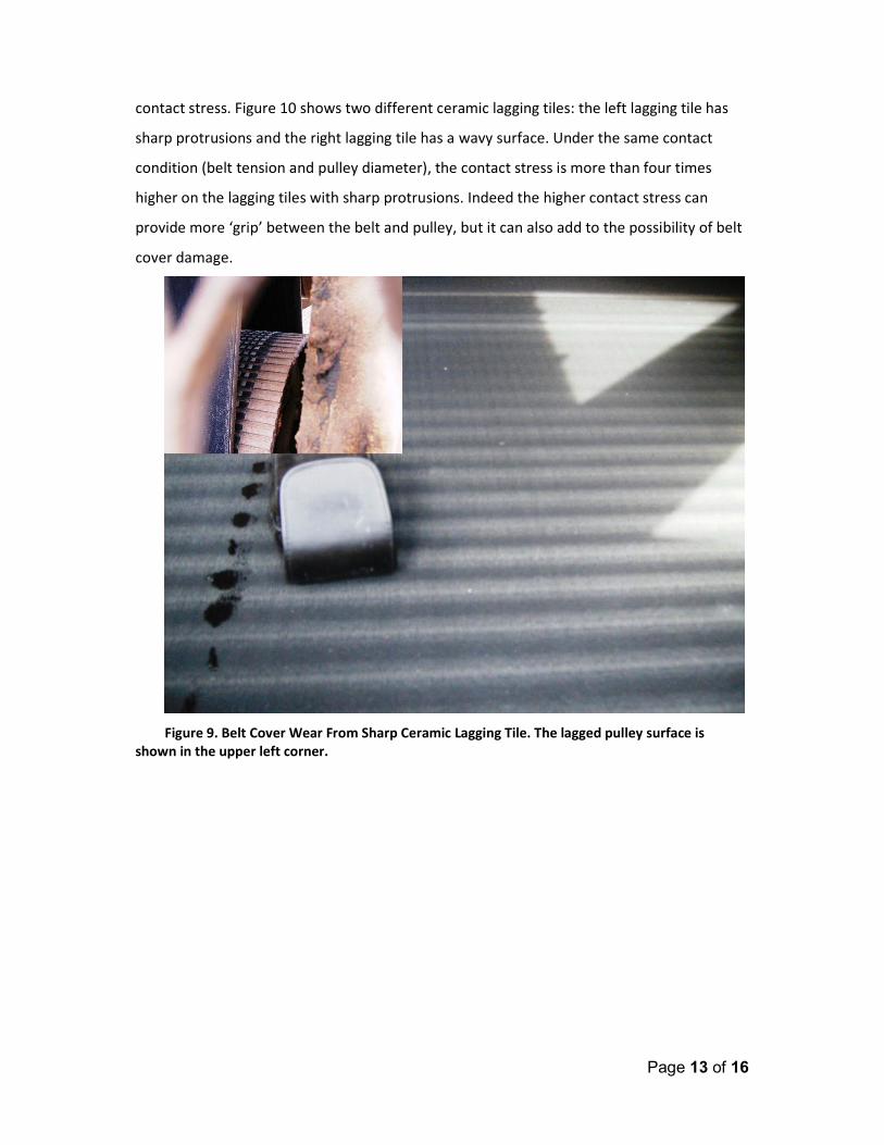
cause premature belt cover failure. Figure 9 shows the wear marks on the belt bottom cover
produced from ceramic lagging tiles, where the spacing of the white stripes (wear marks)
match exactly the spacing of the ceramic lagging tiles. Ceramic lagging tile design affects the
Page 13 of 16
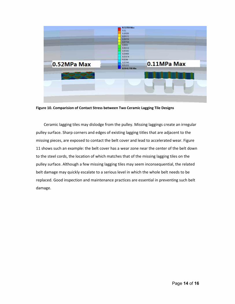
contact stress. Figure 10 shows two different ceramic lagging tiles: the left lagging tile has
sharp protrusions and the right lagging tile has a wavy surface. Under the same contact
condition (belt tension and pulley diameter), the contact stress is more than four times
higher on the lagging tiles with sharp protrusions. Indeed the higher contact stress can
provide more ‘grip’ between the belt and pulley, but it can also add to the possibility of belt
cover damage.
Figure 9. Belt Cover Wear From Sharp Ceramic Lagging Tile. The lagged pulley surface is
shown in the upper left corner.
Page 14 of 16
Figure 10. Comparision of Contact Stress between Two Ceramic Lagging Tile Designs
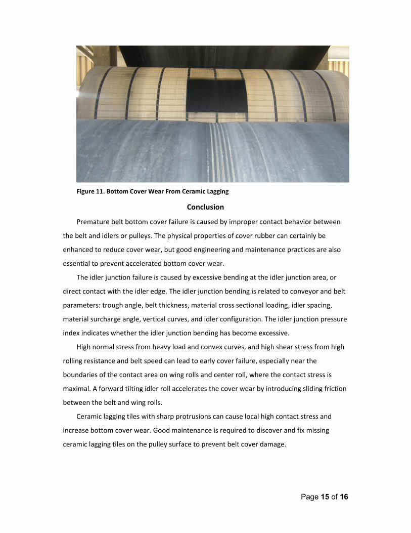
Ceramic lagging tiles may dislodge from the pulley. Missing laggings create an irregular
pulley surface. Sharp corners and edges of existing lagging titles that are adjacent to the
missing pieces, are exposed to contact the belt cover and lead to accelerated wear. Figure
11 shows such an example: the belt cover has a wear zone near the center of the belt down
to the steel cords, the location of which matches that of the missing lagging tiles on the
pulley surface. Although a few missing lagging tiles may seem inconsequential, the related
belt damage may quickly escalate to a serious level in which the whole belt needs to be
replaced. Good inspection and maintenance practices are essential in preventing such belt
damage.
Page 15 of 16
Figure 11. Bottom Cover Wear From Ceramic Lagging
Conclusion
Premature belt bottom cover failure is caused by improper contact behavior between
the belt and idlers or pulleys. The physical properties of cover rubber can certainly be
enhanced to reduce cover wear, but good engineering and maintenance practices are also
essential to prevent accelerated bottom cover wear.
The idler junction failure is caused by excessive bending at the idler junction area, or
direct contact with the idler edge. The idler junction bending is related to conveyor and belt
parameters: trough angle, belt thickness, material cross sectional loading, idler spacing,
material surcharge angle, vertical curves, and idler configuration. The idler junction pressure
index indicates whether the idler junction bending has become excessive.
High normal stress from heavy load and convex curves, and high shear stress from high
rolling resistance and belt speed can lead to early cover failure, especially near the
boundaries of the contact area on wing rolls and center roll, where the contact stress is
maximal. A forward tilting idler roll accelerates the cover wear by introducing sliding friction
between the belt and wing rolls.
Ceramic lagging tiles with sharp protrusions can cause local high contact stress and
increase bottom cover wear. Good maintenance is required to discover and fix missing
ceramic lagging tiles on the pulley surface to prevent belt cover damage.
Page 16 of 16
Acknowledgement
The author would like to thank the excellent team at Veyance Technologies, Inc. for
their support and collaboration, and ELB Engineering Services Limited for their initiative and
coordination in bringing this paper to the Beltcon 18 Conference.
Reference
1. Nordell, L., “Overland Conveyors Designed For Efficient Cost & Performance”,
Beltcon 12, Johannesburg, South Africa, 2003
2. “Installation, Maintenance & Troubleshooting Guide”, Goodyear Engineered
Products, Veyance Technologies, Inc.
3. Wheeler, C., Roberts, A., Jones, M., “Calculating the Flexure Resistance of Bulk Solids
Transported on Belt Conveyors”, Particle & Particle Systems Characterization, Vol. 21,
Is. 4, 2004
4. Steven, R., “Belting the Worlds’ Longest Single Flight Conventional Conveyor”, Bulk
Solids Handling, Vol.28, No.3, 2008
5. Johnson, K.L., “Contact Mechanics”, Cambridge University Press, 2003, ISBN
0521347963


![1 SERIES Belt Conveyor System B090 - Bett Sistemi Srl€¦ · CONVEYOR BELT DEVELOPMENT CALCULATION FORMULA Conveyor belt length = 300 + {[(L-94)-(2• Conveyor belt thick. )]•2}](https://img.pdfslide.net/doc/110x75/5ad3c4047f8b9a48398b7ae4/1-series-belt-conveyor-system-b090-bett-sistemi-conveyor-belt-development-calculation.jpg)