Embed Size (px)
Citation preview

Telegesis
TG-PM-510 ZigBee Communications Gateway
ZigBee Communications Gateway
Product Manual 0510r4
Telegesis ZigBee Communications Gateway
Product Manual
Rev: 4
Date: April 2014

ZigBee Communications Gateway
©2014 Telegesis (UK) Ltd -2- ZigBee Communications Gateway
Table of Contents
1 Change Log ............................................................................................................................... 4
2 Abbreviations ............................................................................................................................. 4
3 Package Contents ...................................................................................................................... 5
4 Specifications ............................................................................................................................. 6
4.1 Order Codes ....................................................................................................................... 6
4.2 Examples ............................................................................................................................ 6
4.3 Power ............................................................................................................................... 10
4.4 LED Indicators .................................................................................................................. 11
4.5 Buttons Actions ................................................................................................................. 12
4.5.1 Restore factory defaults ............................................................................................. 12
4.5.2 Gateway reboot ......................................................................................................... 12
4.5.3 Gateway recovery mode ............................................................................................ 12
4.5.4 Issue ZigBee command ............................................................................................. 12
5 Functionality ............................................................................................................................. 13
5.1 Start-up ............................................................................................................................. 13
5.2 Gateway Discovery ........................................................................................................... 13
5.2.1 Discovery on a windows-7 PC ................................................................................... 13
5.2.2 Discovery on other platforms: .................................................................................... 14
5.3 Gateway Webserver ......................................................................................................... 15
5.3.1 Authentication ............................................................................................................ 15
5.3.2 Web Pages ................................................................................................................ 16
6 Appendix A .............................................................................................................................. 29
6.1 Bootloading ETRX3 ZigBee module .................................................................................. 29
7 Warranty .................................................................................................................................. 32
7.1 Caution ............................................................................................................................. 33
7.2 Cleaning ........................................................................................................................... 33
8 Compliance with Laws and Regulations ................................................................................... 34
9 Disclaimer ................................................................................................................................ 34
10 Software License: ................................................................................................................. 34
11 Contact Information .............................................................................................................. 34
ZigBee Communications Gateway
©2014 Telegesis (UK) Ltd -3- ZigBee Communications Gateway
Table of Figures
Figure 1: Package contents............................................................................................................... 5
Figure 2: Gateway front view ............................................................................................................. 7
Figure 3: Gateway without RS232/RS485 back view......................................................................... 7
Figure 4: Gateway with RS232/RS485 back view ............................................................................. 8
Figure 5: Gateway bottom view ......................................................................................................... 9
Figure 6: Top label ............................................................................................................................ 9
Figure 7: Bottom label ..................................................................................................................... 10
Figure 8: Device Discovery ............................................................................................................. 13
Figure 9: Discovery Python Script ................................................................................................... 14
Figure 10: Discovery Output ............................................................................................................ 14
Figure 11: HTTP server authentication ............................................................................................ 15
Figure 12: Configurations Page ....................................................................................................... 16
Figure 13: ZigBee Interface Configurations page ............................................................................ 23
Figure 14: Web Terminal page ........................................................................................................ 24
Figure 15: Firmware Upgrade page ................................................................................................. 25
Figure 16: Logout page ................................................................................................................... 28
Figure 17: Dialin socket connection ................................................................................................. 29
Figure 18: ETRX3 Bootload prompt ................................................................................................ 30
Figure 19: Ready to receive upgrade image file via XMODEM ........................................................ 31
ZigBee Communications Gateway
©2014 Telegesis (UK) Ltd -4- ZigBee Communications Gateway
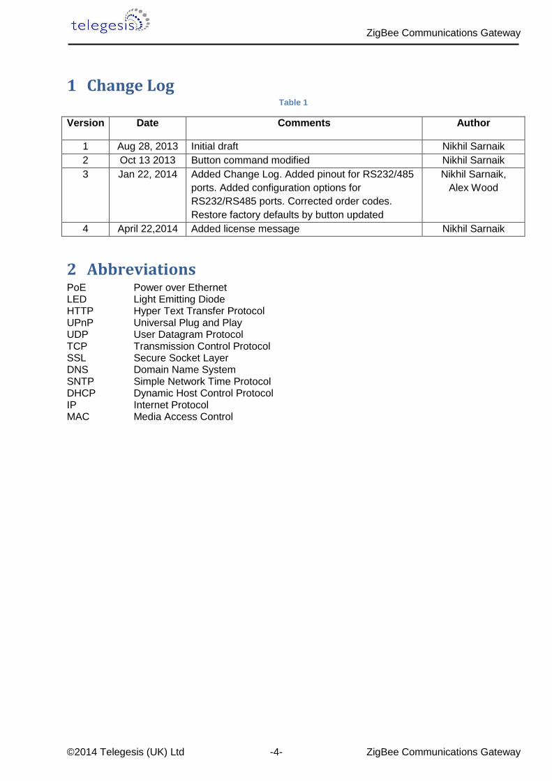
1 Change Log Table 1
Version Date Comments Author
1 Aug 28, 2013 Initial draft Nikhil Sarnaik
2 Oct 13 2013 Button command modified Nikhil Sarnaik
3 Jan 22, 2014 Added Change Log. Added pinout for RS232/485
ports. Added configuration options for
RS232/RS485 ports. Corrected order codes.
Restore factory defaults by button updated
Nikhil Sarnaik,
Alex Wood
4 April 22,2014 Added license message Nikhil Sarnaik
2 Abbreviations PoE Power over Ethernet LED Light Emitting Diode HTTP Hyper Text Transfer Protocol UPnP Universal Plug and Play UDP User Datagram Protocol TCP Transmission Control Protocol SSL Secure Socket Layer DNS Domain Name System SNTP Simple Network Time Protocol DHCP Dynamic Host Control Protocol IP Internet Protocol MAC Media Access Control

ZigBee Communications Gateway
©2014 Telegesis (UK) Ltd -5- ZigBee Communications Gateway
3 Package Contents The package contains the following items,
Figure 1: Package contents
a. ZigBee Communications Gateway
b. Micro USB power cable
c. Mounting screws
(a) (b) (c)
ZigBee Communications Gateway
©2014 Telegesis (UK) Ltd -6- ZigBee Communications Gateway
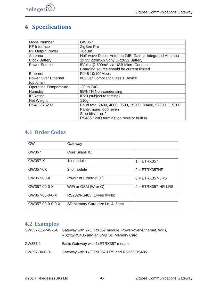
4 Specifications
Model Number GW357
RF Interface ZigBee Pro
RF Output Power +8dBm
Antenna Half-wave Dipole Antenna 2dBi Gain or Integrated Antenna
Clock Battery 1x 3V 220mAh Sony CR2032 Battery
Power Source 5Volts @ 500mA via USB Micro Connector Charging source should be current limited
Ethernet RJ45 10/100Mbps
Power Over Ethernet (optional)
802.3af Compliant Class 1 Device
Operating Temperature -20 to 70C
Humidity 95% TH Non-condensing
IP Rating IP20 (subject to testing)
Net Weight 110g
RS485/RS232 Baud rate: 2400, 4800, 9600, 19200, 38400, 57600, 115200 Parity: none, odd, even Stop bits: 1 or 2 RS485 120Ω termination resistor built in
4.1 Order Codes
4.2 Examples GW357-11-P-W-1-8 Gateway with 2xETRX357 module, Power-over-Ethernet, WiFi,
RS232/RS485 and an 8MB SD Memory Card
GW357-1 Basic Gateway with 1xETRX357 module
GW357-30-0-0-1 Gateway with 1xETRX357-LRS and RS232/RS485
GW Gateway
GW357 Core Silabs IC
GW357-X 1st module 1 = ETRX357
2 = ETRX357HR
3 = ETRX357-LRS
4 = ETRX357-HR-LRS
GW357-0X 2nd module
GW357-00-X Power of Ethernet (P)
GW357-00-0-X WiFi or GSM (W or G)
GW357-00-0-0-X RS232/RS485 (1=yes 0=No)
GW357-00-0-0-0-X SD Memory Card size i.e. 4, 8 etc.
(a) (b)
ZigBee Communications Gateway
©2014 Telegesis (UK) Ltd -7- ZigBee Communications Gateway
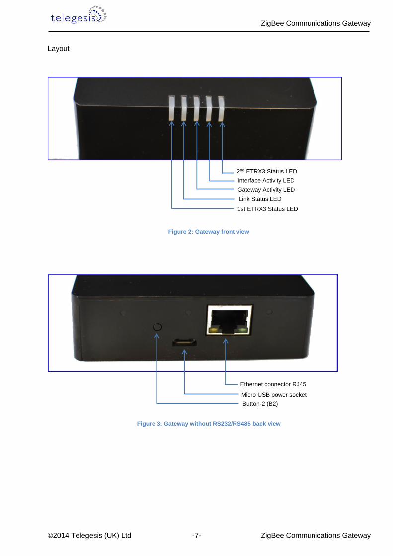
Layout
Figure 2: Gateway front view
Figure 3: Gateway without RS232/RS485 back view
Ethernet connector RJ45
Micro USB power socket
Button-2 (B2)
2nd ETRX3 Status LED
Interface Activity LED
Gateway Activity LED
Link Status LED
1st ETRX3 Status LED

ZigBee Communications Gateway
©2014 Telegesis (UK) Ltd -8- ZigBee Communications Gateway
Figure 4: Gateway with RS232/RS485 back view1
1 Compatible connectors for RS232/RS485 port MULTICOMP - MC000099 MULTICOMP - MC000107 MULTICOMP - MC000115
RS485 D-
RS485 D+
RS232 RX
GND
RS232 TX Ethernet connector RJ45
Micro USB power socket
Button-2 (B2)
ZigBee Communications Gateway
©2014 Telegesis (UK) Ltd -9- ZigBee Communications Gateway
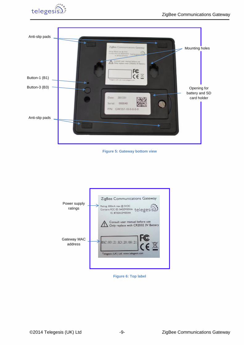
Figure 5: Gateway bottom view
Figure 6: Top label
Mounting holes
Opening for
battery and SD
card holder
Button-1 (B1)
Button-3 (B3)
Anti-slip pads
Anti-slip pads
Power supply
ratings
Gateway MAC
address

ZigBee Communications Gateway
©2014 Telegesis (UK) Ltd -10- ZigBee Communications Gateway
Figure 7: Bottom label
4.3 Power The Gateway can be powered ON by plugging in the micro USB cable in the socket provided as
shown in figure-3 with power source as specified in the Specifications. Selected models of gateway
incorporating Power over Ethernet (PoE) can be powered on using the PoE injector through RJ45
cable.
Manufacture date
Gateway serial number
Gateway model number

ZigBee Communications Gateway
©2014 Telegesis (UK) Ltd -11- ZigBee Communications Gateway
4.4 LED Indicators
Sequence Number
Gateway State 1st ETRX3 Status LED
Link Status LED
Gateway Activity LED
Interface Active LED
2nd ETRX3 Status LED
1 Power UP Sequence ON Red + Green
Blinking Amber for
5 sec
OFF ON
All LEDs will turn ON and then following blink one after the other twice except for the ETRX3 Status LEDs which are controlled by ETRX3 ZigBee modules
2 Ethernet link inactive - Red Blinking Amber
- -
3 Ethernet link active - Green OFF - -
4 Any socket connected to either ZigBee module
OR Web Terminal connected
- - - Green -
5 Any communication with ZigBee modules
OR Any communications on
Ethernet lines
- - Blinking Amber
- -
Table 2: LED Sequence table
2nd ETRX3 Status LED Interface Active LED Gateway Activity LED Link Status LED 1st ETRX3 Status LED
ZigBee Communications Gateway
©2014 Telegesis (UK) Ltd -12- ZigBee Communications Gateway
4.5 Buttons Actions The Gateway has three hardware buttons as shown in the Layout which can perform multiple
functions as described in this section.
1. Button 1 (B1)
2. Button 2 (B2)
3. Button 3 (B3)
4.5.1 Restore factory defaults Follow the following procedure with buttons in order to restore the factory default configuration
settings on the Gateway using B3 and B1.
1. Press and hold B3
2. Then with B3 pressed, press and hold B1 for approximately 3 seconds after which the
Gateway reboots and LED power up sequence is seen.
4.5.2 Gateway reboot Press B3 and hold for 5 seconds to reboot the Gateway.
4.5.3 Gateway recovery mode Perform following procedure to put the Gateway in recovery mode2.
1. Press and hold B3 until gateway reboots.
2. At power up hold B2 and wait for 3 seconds.
3. The Gateway will be in recovery mode now.
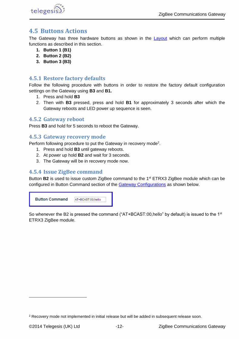
4.5.4 Issue ZigBee command Button B2 is used to issue custom ZigBee command to the 1st ETRX3 ZigBee module which can be
configured in Button Command section of the Gateway Configurations as shown below.
So whenever the B2 is pressed the command (“AT+BCAST:00,hello” by default) is issued to the 1st
ETRX3 ZigBee module.
2 Recovery mode not implemented in initial release but will be added in subsequent release soon.
ZigBee Communications Gateway
©2014 Telegesis (UK) Ltd -13- ZigBee Communications Gateway
5 Functionality
5.1 Start-up Turn ON the ZigBee Communications Gateway by inserting the micro USB power cable into the
socket shown in figure 3. The LEDs on the front panel will light up as described in the LED’s
Sequence table. Once the Start-up LED sequence is complete the gateway will continuously look for
an Ethernet link which is indicated by LED sequence-3. Insert the Ethernet cable in the RJ45 socket
shown in figure 3. The gateway will try to obtain an IP address by using DCHP (by default DHCP is
enabled but the user can also set static IP address for the Gateway). Once an IP address is
allocated successfully the LED sequence-4 is displayed on the LED panel.
5.2 Gateway Discovery
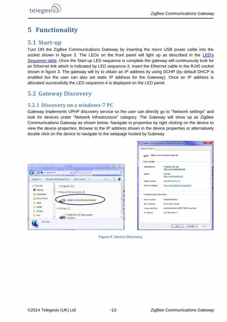
5.2.1 Discovery on a windows-7 PC Gateway implements UPnP discovery service so the user can directly go to “Network settings” and
look for devices under “Network Infrastructure” category. The Gateway will show up as ZigBee
Communications Gateway as shown below. Navigate to properties by right clicking on the device to
view the device properties. Browse to the IP address shown in the device properties or alternatively
double click on the device to navigate to the webpage hosted by Gateway.
Figure 8: Device Discovery

ZigBee Communications Gateway
©2014 Telegesis (UK) Ltd -14- ZigBee Communications Gateway
5.2.2 Discovery on other platforms: On other platforms where UPnP services are not available, the device can be discovered using the
following python script which basically listens to the UDP broadcast on port 14099 by the gateway
once every minute.
Run the above script from command line and the output window would show the IP addresses of the
ZigBee Communications Gateways in the network as shown below
Figure 10: Discovery Output
import socket, traceback, commands
host = '' # Bind to all interfaces
port = 14099
#start a udp socket server to listen on port 14099
s = socket.socket(socket.AF_INET, socket.SOCK_DGRAM)
s.setsockopt(socket.SOL_SOCKET, socket.SO_REUSEADDR, 1)
s.setsockopt(socket.SOL_SOCKET, socket.SO_BROADCAST, 1)
s.bind((host, port))
print "Waiting for Telegesis Gateway:"
while 1:
try:
message, address = s.recvfrom(8192)
print "Telegesis Gateway Found on IP Address:
%r"%(address[0])
except (KeyboardInterrupt, SystemExit):
raise
Figure 6: Discovery Script Figure 9: Discovery Python Script

ZigBee Communications Gateway
©2014 Telegesis (UK) Ltd -15- ZigBee Communications Gateway
5.3 Gateway Webserver ZigBee Communication Gateway hosts a http webserver to serve webpages which help the user to
configure the Gateway and communicate with the ZigBee device via a simple web interface.
5.3.1 Authentication The http webserver is protected by basic authentication hence a valid username “admin” and
password “password” must be provided when prompted to access the webpages. The password
can be changed through the GW357 Configuration webpage as explained in the later section.
Figure 11: HTTP server authentication
ZigBee Communications Gateway
©2014 Telegesis (UK) Ltd -16- ZigBee Communications Gateway
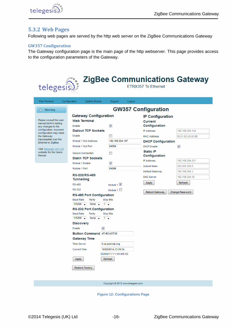
5.3.2 Web Pages Following web pages are served by the http web server on the ZigBee Communications Gateway
GW357 Configuration
The Gateway configuration page is the main page of the http webserver. This page provides access
to the configuration parameters of the Gateway.
Figure 12: Configurations Page

ZigBee Communications Gateway
©2014 Telegesis (UK) Ltd -17- ZigBee Communications Gateway
Gateway Configuration
a. Web Terminal
This option enables or disables the access to ZigBee module via the web terminal. The
Gateway provides an access to the ZigBee module via Web Terminal page which can be
used to issue commands to the ZigBee module and monitor the response of the module. The
Web Terminal only supports communication in ASCII.
Default value is enabled.
b. Dialout TCP Sockets
Enable
The Gateway can establish an outgoing TCP socket connections to a specified dialout
addresses and port numbers. This option can enable or disable the outgoing socket
connections for both the ZigBee modules.
Default value is disabled.
Out 1 Address
The address specified in this option is used by the gateway to establish the outgoing socket
connection for the 1st ETRX3 ZigBee module. The dialout address can either be an IP
address or a host name.
Out 1 port
This item specifies the port number for the dialout connection from 1st ETRX3 ZigBee
module.
Out 2 Address3
The address specified in this option is used by the gateway to establish the outgoing socket
connection from the 2nd ETRX3 ZigBee module. The dialout address can either be an IP
address or a host name.
Out 2 port3
This item specifies the port number for the dialout connection from 2nd ETRX3 ZigBee
module.
3 This option only available in Gateway models with two ZigBee modules on-board. Please refer order codes
ZigBee Communications Gateway
©2014 Telegesis (UK) Ltd -18- ZigBee Communications Gateway
Secure Connection
This option enables the SSL on the outgoing socket connection4.
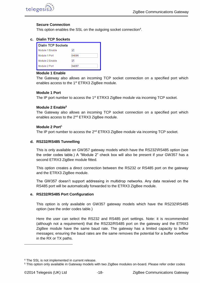
c. Dialin TCP Sockets
Module 1 Enable
The Gateway also allows an incoming TCP socket connection on a specified port which
enables access to the 1st ETRX3 ZigBee module.
Module 1 Port
The IP port number to access the 1st ETRX3 ZigBee module via incoming TCP socket.
Module 2 Enable5
The Gateway also allows an incoming TCP socket connection on a specified port which
enables access to the 2nd ETRX3 ZigBee module.
Module 2 Port5
The IP port number to access the 2nd ETRX3 ZigBee module via incoming TCP socket.
d. RS232/RS485 Tunnelling
This is only available on GW357 gateway models which have the RS232\RS485 option (see
the order codes table.) A “Module 2” check box will also be present if your GW357 has a
second ETRX3 ZigBee module fitted.
This option creates a direct connection between the RS232 or RS485 port on the gateway
and the ETRX3 ZigBee module.
The GW357 doesn’t support addressing in multidrop networks. Any data received on the
RS485 port will be automatically forwarded to the ETRX3 ZigBee module.
e. RS232/RS485 Port Configuration
This option is only available on GW357 gateway models which have the RS232\RS485
option (see the order codes table.)
Here the user can select the RS232 and RS485 port settings. Note: it is recommended
(although not a requirement) that the RS232/RS485 port on the gateway and the ETRX3
ZigBee module have the same baud rate. The gateway has a limited capacity to buffer
messages; ensuring the baud rates are the same removes the potential for a buffer overflow
in the RX or TX paths.
4 The SSL is not implemented in current release. 5 This option only available in Gateway models with two ZigBee modules on-board. Please refer order codes
ZigBee Communications Gateway
©2014 Telegesis (UK) Ltd -19- ZigBee Communications Gateway
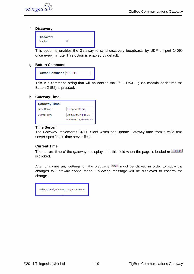
f. Discovery
This option is enables the Gateway to send discovery broadcasts by UDP on port 14099
once every minute. This option is enabled by default.
g. Button Command
This is a command string that will be sent to the 1st ETRX3 ZigBee module each time the
Button-2 (B2) is pressed.
h. Gateway Time
Time Server
The Gateway implements SNTP client which can update Gateway time from a valid time
server specified in time server field.
Current Time
The current time of the gateway is displayed in this field when the page is loaded or
is clicked.
After changing any settings on the webpage must be clicked in order to apply the
changes to Gateway configuration. Following message will be displayed to confirm the
change.
ZigBee Communications Gateway
©2014 Telegesis (UK) Ltd -20- ZigBee Communications Gateway
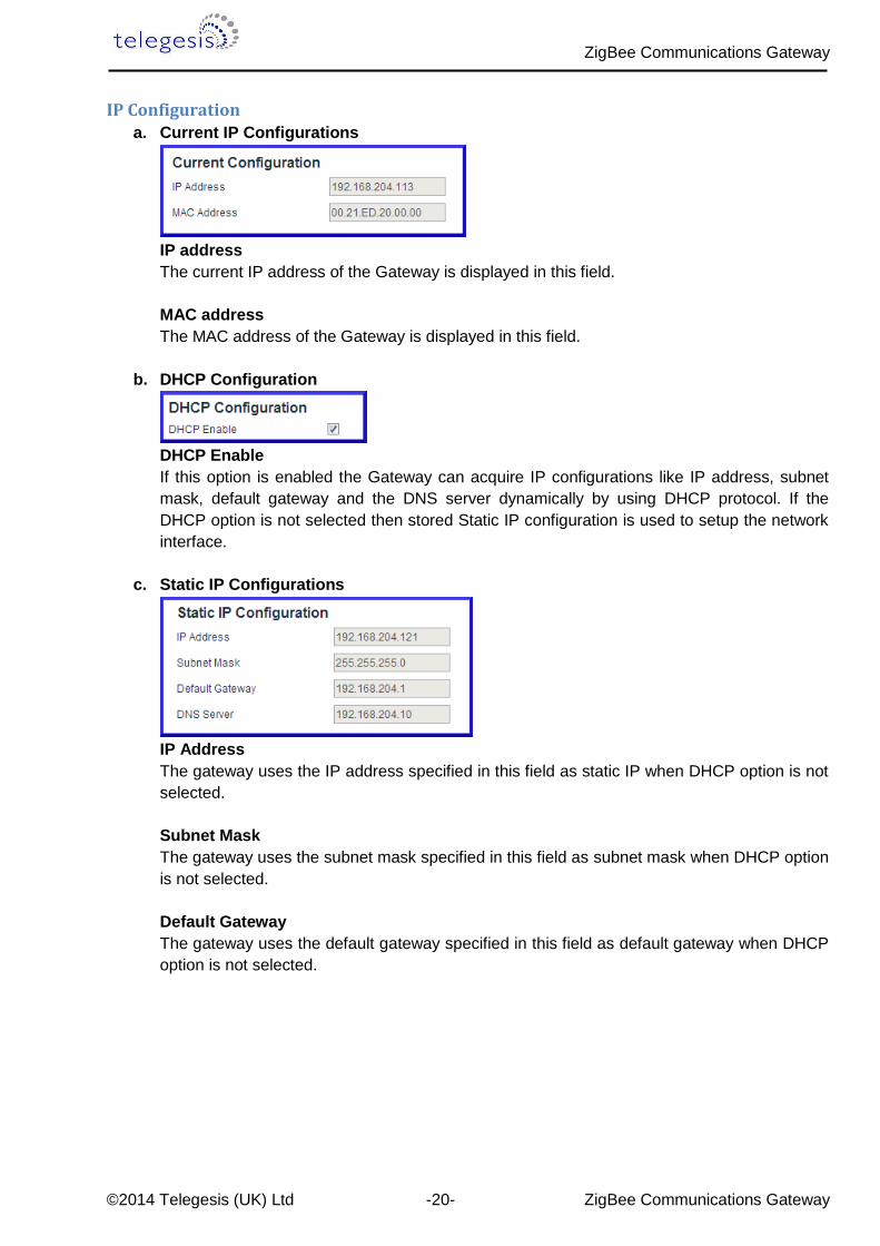
IP Configuration
a. Current IP Configurations
IP address
The current IP address of the Gateway is displayed in this field.
MAC address
The MAC address of the Gateway is displayed in this field.
b. DHCP Configuration
DHCP Enable
If this option is enabled the Gateway can acquire IP configurations like IP address, subnet
mask, default gateway and the DNS server dynamically by using DHCP protocol. If the
DHCP option is not selected then stored Static IP configuration is used to setup the network
interface.
c. Static IP Configurations
IP Address
The gateway uses the IP address specified in this field as static IP when DHCP option is not
selected.
Subnet Mask
The gateway uses the subnet mask specified in this field as subnet mask when DHCP option
is not selected.
Default Gateway
The gateway uses the default gateway specified in this field as default gateway when DHCP
option is not selected.
ZigBee Communications Gateway
©2014 Telegesis (UK) Ltd -21- ZigBee Communications Gateway
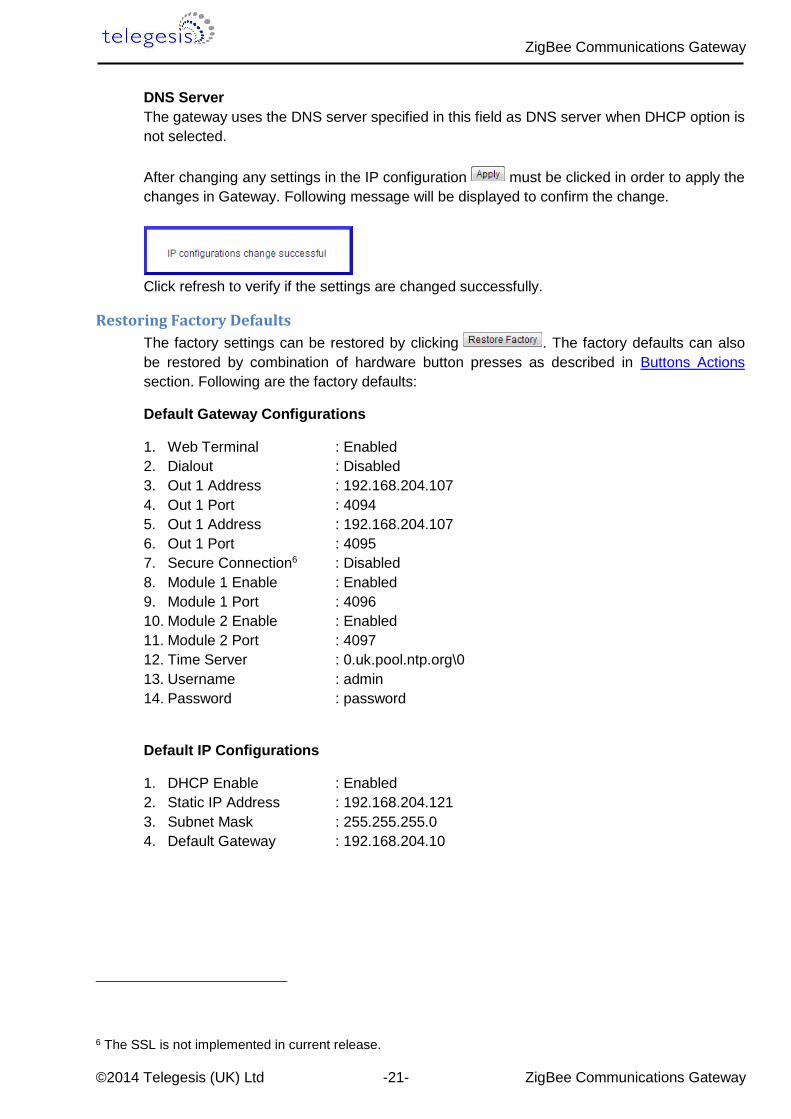
DNS Server
The gateway uses the DNS server specified in this field as DNS server when DHCP option is
not selected.
After changing any settings in the IP configuration must be clicked in order to apply the
changes in Gateway. Following message will be displayed to confirm the change.
Click refresh to verify if the settings are changed successfully.
Restoring Factory Defaults
The factory settings can be restored by clicking . The factory defaults can also
be restored by combination of hardware button presses as described in Buttons Actions
section. Following are the factory defaults:
Default Gateway Configurations
1. Web Terminal : Enabled
2. Dialout : Disabled
3. Out 1 Address : 192.168.204.107
4. Out 1 Port : 4094
5. Out 1 Address : 192.168.204.107
6. Out 1 Port : 4095
7. Secure Connection6 : Disabled
8. Module 1 Enable : Enabled
9. Module 1 Port : 4096
10. Module 2 Enable : Enabled
11. Module 2 Port : 4097
12. Time Server : 0.uk.pool.ntp.org\0
13. Username : admin
14. Password : password
Default IP Configurations
1. DHCP Enable : Enabled
2. Static IP Address : 192.168.204.121
3. Subnet Mask : 255.255.255.0
4. Default Gateway : 192.168.204.10
6 The SSL is not implemented in current release.

ZigBee Communications Gateway
©2014 Telegesis (UK) Ltd -22- ZigBee Communications Gateway
Changing the Admin Password
User can change the Gateway’s default password by clicking which will display
following fields on the configurations page. Fill in all the fields and hit change to apply new
password.
Once the password is changed successfully the following message will be displayed.
Password can also be reset to factory default by restoring factory default configurations
mentioned in Buttons Actions.
ZigBee Communications Gateway
©2014 Telegesis (UK) Ltd -23- ZigBee Communications Gateway
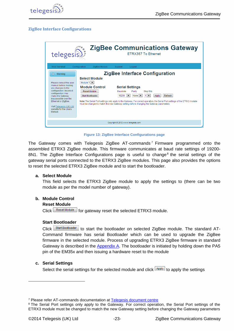
ZigBee Interface Configurations
Figure 13: ZigBee Interface Configurations page
The Gateway comes with Telegesis ZigBee AT-commands 7 Firmware programmed onto the
assembled ETRX3 ZigBee module. This firmware communicates at baud rate settings of 19200-
8N1. The ZigBee Interface Configurations page is useful to change8 the serial settings of the
gateway serial ports connected to the ETRX3 ZigBee modules. This page also provides the options
to reset the selected ETRX3 ZigBee module and to start the bootloader.
a. Select Module
This field selects the ETRX3 ZigBee module to apply the settings to (there can be two
module as per the model number of gateway).
b. Module Control
Reset Module
Click for gateway reset the selected ETRX3 module.
Start Bootloader
Click to start the bootloader on selected ZigBee module. The standard AT-
Command firmware has serial Bootloader which can be used to upgrade the ZigBee
firmware in the selected module. Process of upgrading ETRX3 ZigBee firmware in standard
Gateway is described in the Appendix A. The bootloader is initiated by holding down the PA5
pin of the EM35x and then issuing a hardware reset to the module
c. Serial Settings
Select the serial settings for the selected module and click to apply the settings
7 Please refer AT-commands documentation at Telegesis document centre 8 The Serial Port settings only apply to the Gateway. For correct operation, the Serial Port settings of the ETRX3 module must be changed to match the new Gateway setting before changing the Gateway parameters

ZigBee Communications Gateway
©2014 Telegesis (UK) Ltd -24- ZigBee Communications Gateway
Web-Terminal
`
Figure 14: Web Terminal page
The Web Terminal is a simple web interface to communicate with the 1st ETRX3 ZigBee module on
the Gateway. User can issue AT-Commands9 to the module in ZigBee input command box, click
and monitor the response in the ZigBee output window.
The Terminal status shows the current status of the web terminal and the Gateway time is also
displayed in the top right of the ZigBee output window,
Terminal Disabled Status:
If the Web Terminal option is disabled in the Configurations page Terminal status as shown above
will be displayed. No commands can be issued to the ZigBee module via Web Terminal if this status
is been displayed.
Terminal Enabled Status:
When the Web Terminal connects successfully to the ZigBee module above status will be displayed.
The Gateway time will also start updating once every second. Now, the user may enter an AT-
Command in ZigBee input box and click issue the command10 to the ZigBee module and
expect the response in approximately one sec.
9 Please refer AT-commands documentation at Telegesis document centre 10 Note: Pressing Enter Key on Keyboard will NOT send the command but will refresh the page.
Terminal Status
ZigBee output
Gateway Time
ZigBee input

ZigBee Communications Gateway
©2014 Telegesis (UK) Ltd -25- ZigBee Communications Gateway
Firmware Upgrade
The Gateway firmware can be updated over Ethernet. To perform Gateway firmware upgrade,
navigate to “http://<gateway_ip_address>/bootload.html” page which looks like below.
Figure 15: Firmware Upgrade page
Stored Image Info
This section gives the information of the Gateway firmware image stored in the Gateway.
Image Header
Each image stored in the Gateway has an Image Header for identifying the type of image. This field
displays the image header of selected Image type.
Firmware Version
This field displays the firmware version of image stored.
Image Size
This field displays the size of stored image in bytes.
ZigBee Communications Gateway
©2014 Telegesis (UK) Ltd -26- ZigBee Communications Gateway
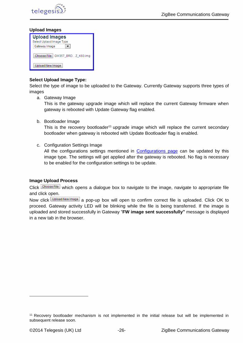
Upload Images
Select Upload Image Type:
Select the type of image to be uploaded to the Gateway. Currently Gateway supports three types of
images
a. Gateway Image
This is the gateway upgrade image which will replace the current Gateway firmware when
gateway is rebooted with Update Gateway flag enabled.
b. Bootloader Image
This is the recovery bootloader11 upgrade image which will replace the current secondary
bootloader when gateway is rebooted with Update Bootloader flag is enabled.
c. Configuration Settings Image
All the configurations settings mentioned in Configurations page can be updated by this
image type. The settings will get applied after the gateway is rebooted. No flag is necessary
to be enabled for the configuration settings to be update.
Image Upload Process
Click which opens a dialogue box to navigate to the image, navigate to appropriate file
and click open.
Now click a pop-up box will open to confirm correct file is uploaded. Click OK to
proceed. Gateway activity LED will be blinking while the file is being transferred. If the image is
uploaded and stored successfully in Gateway “FW image sent successfully” message is displayed
in a new tab in the browser.
11 Recovery bootloader mechanism is not implemented in the initial release but will be implemented in subsequent release soon.

ZigBee Communications Gateway
©2014 Telegesis (UK) Ltd -27- ZigBee Communications Gateway
Update Flags and Reboot
Update Gateway
If this flag is enabled upon reboot the gateway will validate the Gateway Image stored by image
upload process mentioned above and updates the gateway firmware if a valid image is present.
Update Bootloader
If this flag is enabled upon reboot the gateway will validate the Bootloader Image stored by the
image upload process mentioned above and updates the recovery bootloader firmware if a valid
image is present.
Wait for Serial Commands
The Gateway can accept some serial commands at start-up (available only on models with RS232-
RS485 port present). If this flag is enabled the gateway will wait for 5 sec to accept any serial
commands on the RS232 lines and then jump to the main gateway application.
Enable the appropriate flags and click buttons to upgrade the gateway with
stored image.
Upgrading may take few minutes, be patient and do not interrupt the upgrade process until power
up sequence is indicated on the LED panel. The upgrade process will be indicated by blinking of
gateway activity LED.

ZigBee Communications Gateway
©2014 Telegesis (UK) Ltd -28- ZigBee Communications Gateway
Support
Support link will redirect to telegesis Support page on the internet http://www.telegesis.com/support/
Logout
Logout will end current session and “Logged out successfully” message will be displayed and the
user will need to authenticate with username and password at the next login.
Figure 16: Logout page
ZigBee Communications Gateway
©2014 Telegesis (UK) Ltd -29- ZigBee Communications Gateway
6 Appendix A
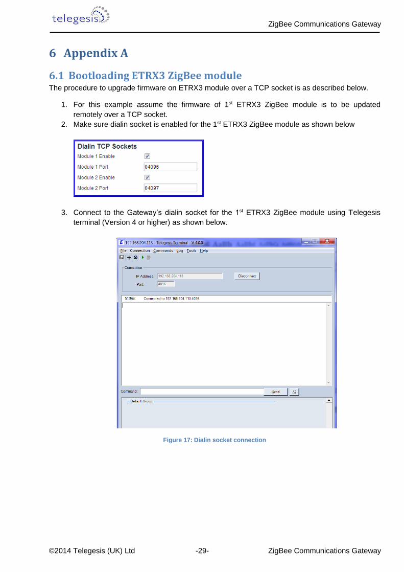
6.1 Bootloading ETRX3 ZigBee module The procedure to upgrade firmware on ETRX3 module over a TCP socket is as described below.
1. For this example assume the firmware of 1st ETRX3 ZigBee module is to be updated
remotely over a TCP socket.
2. Make sure dialin socket is enabled for the 1st ETRX3 ZigBee module as shown below
3. Connect to the Gateway’s dialin socket for the 1st ETRX3 ZigBee module using Telegesis
terminal (Version 4 or higher) as shown below.
Figure 17: Dialin socket connection

ZigBee Communications Gateway
©2014 Telegesis (UK) Ltd -30- ZigBee Communications Gateway
4. The LED sequence 4 should be indicated by LED panel.
5. Navigate to ZigBee Interface Configuration and Select Module 1 as shown below.
6. Click to start the bootloader on selected ZigBee module.
7. Change the baudrate to 115200 and click .
8. On Telegesis terminal hit Enter key to see following prompt
Figure 18: ETRX3 Bootload prompt

ZigBee Communications Gateway
©2014 Telegesis (UK) Ltd -31- ZigBee Communications Gateway
9. Press “1” to see character ‘C’ displayed periodically as shown which indicates the ZigBee
module is ready to receive upgrade image file via XMODEM
Figure 19: Ready to receive upgrade image file via XMODEM
10. Go to Tools->Transfer File (XMODEM) and send the appropriate upgrade image file.
11. Once successful change the baudrate of module according to upgraded firmware and the
ZigBee module will communicate according to the new firmware. For Telegesis R3xx
firmware the default baud rate is 19200-8N1
ZigBee Communications Gateway
©2014 Telegesis (UK) Ltd -32- ZigBee Communications Gateway
7 Warranty 1. Telegesis warrants that at the date of delivery the Goods will conform in all material respects
to any written specification published or provided by Telegesis and that for the periods set
out below in respect of each product type the Goods will be free from defects in
workmanship and materials under normal use and service. The Buyer must notify Telegesis
of any defect in writing. Telegesis’ obligation under this warranty will not arise until the Buyer
returns the defective Goods at its own expense and risk, to Telegesis. Telegesis’ sole
obligation under this warranty shall be at its option to replace or repair without charge such
defective Goods or component parts thereof. Any replacement of Goods or component parts
under this warranty shall not extend the period of warranty beyond that of the goods or
component parts so replaced.
2. All Hardware is supplied with one year return to base warranty unless indicated otherwise.
All Software is supplied with a 90-day warranty period.
3. With respect to any computer software comprised in the Goods supplied by Telegesis any
defects arising after expiry of the warranty period referred to above should be notified to
Telegesis in writing, Telegesis may at its discretion endeavour to correct any such defects
but Telegesis gives no warranty that any such defects can be corrected or that defects will
be corrected within a particular time.
4. Telegesis shall not be liable hereunder:
a) If the Goods alleged to be defective have been repaired or altered by any person other
than Telegesis designated personnel or authorised representative or other person
approved by Telegesis in writing; or
b) Where testing or examination by Telegesis reveals any alleged defect in the goods to
have been caused by the buyers misuse, neglect, improper installation, failure to follow
instructions (whether oral or in writing), or the supply by the Buyer of incorrect or
inadequate instructions or information with the regards to the design of any Goods or to
have been caused by any similar equipment to which the Goods are attached or in which
the Goods are incorporated or any cause beyond the range of intended use of the Goods
or by accident, fire or other hazard; or
c) Where component parts alleged to be defective were not manufactured by Telegesis but
were included in the Goods at the request of the Buyer, in which case the Buyer shall
only be entitled to the benefit of any such warranty or guarantee as is given by the
manufacturer or supplier of such parts to Telegesis.
ZigBee Communications Gateway
©2014 Telegesis (UK) Ltd -33- ZigBee Communications Gateway
5. If the goods are to be manufactured or any process is to be applied to them by Telegesis in
accordance with a specification submitted by the Buyer, the Buyer shall indemnify Telegesis
against all loss, damages, costs and expenses awarded against or incurred by Telegesis in
connection with or paid or agreed to be paid by Telegesis in settlement of any claim which
results from Telegesis’ use of the Buyer’s specification, including but not limited to any claim
for infringement of any patent, copyright, design, trade mark or other intellectual property
rights of any other person.
6. Telegesis’ liability hereunder shall be in lieu of any other representation (unless fraudulent),
warranty or condition, expressed or implied by law or otherwise with respect to the goods or
any liability imposed by common law, statute or otherwise and Telegesis hereby excludes all
such representations (unless fraudulent), warranties and conditions and shall not be liable to
the Buyer for any loss or damage whatsoever (including without prejudice to generality of the
foregoing any liability in contract, negligence, or any other tort for indirect consequential or
economic loss or for loss of profit or opportunity of any kind) arising directly or indirectly in
connection with the contract, the Goods or otherwise except insofar as any exclusion or
limitations of Telegesis’ liability hereunder is prohibited, void or enforceable by law.
7. Telegesis shall not be responsible in any manner whatsoever for any software, information
or memory data stored on or integrated with any of the Goods returned to Telegesis for
repair or replacement under this warranty.
8. Without prejudice to any other provision in these Terms, in any event Telegesis’ total liability
for any one claim or for the total of all claims arising from one act of default on Telegesis’
part (whether arising from Telegesis’ negligence or otherwise) shall not exceed the purchase
price of the Goods the subject matter of any claim but nothing herein shall limit or exclude
Telegesis’ liability for death or personal injury caused by Telegesis’ negligence or Telegesis’
liability for fraudulent misrepresentation.
9. Where the buyer deals as a consumer within the meaning of the unfair contract Terms Act
1977 nothing in these terms shall restrict or exclude any liability of Telegesis for breach of its
implied undertakings as to conformity of the goods with description or sample or as to their
quality or fitness for the purpose.
10. In the case of a consumer transaction nothing in these terms shall affect the statutory rights
of the Buyer as defined in the Consumer Transaction (Restrictions on Statements) Order
1976 (as mentioned).
11. The period or terms of the warranty contained in this clause shall only be varied or extended
where Telegesis has granted the Buyer an Extended Warranty.
7.1 Caution The user must read through the user manual and learn to use the equipment appropriately.
Telegesis (UK) Ltd will not accept any liability arising from using the equipment in the manner not
specified by the documentation accompanied by the equipment.
7.2 Cleaning Dust or wipe only with damp cloth; do not allow moisture to penetrate the enclosure. Do not use
aggressive cleaning agents
ZigBee Communications Gateway
©2014 Telegesis (UK) Ltd -34- ZigBee Communications Gateway
8 Compliance with Laws and Regulations The Buyer hereby certifies that no Goods will be exported directly or indirectly outside the United
Kingdom unless, where necessary, the appropriate prior authorisation to such export has been
obtained from the Department of Trade and Industry, London, and/or (where applicable) the Office
of Export Administration of the US Department of Commerce.
9 Disclaimer Product and Company names and logos referenced may either be trademarks or registered
trademarks of their respective companies. We reserve the right to make modifications and/or
improvements without prior notification. All information is correct at time of issue. Telegesis (UK)
Ltd. does not convey any license under its patent rights or assume any responsibility for the use of
the described product.
This device should not be used without proper consideration and design of associated system
architecture and redundant safety features in applications where failure may result in death or injury.
The manufacturer accepts no responsibility for injury, death or loss human or material caused by the
use or misuse of this device
10 Software License: This product is licensed under the wireless network patent portfolio license for use by a consumer or
other uses for which there is no remuneration. Any other use of this product in any manner is not
licensed and is expressly prohibited without a license under applicable patents in the wireless
network patent portfolio, which license is available from MPEG LA, LLC,4600 S. Ulster St., Suite
400, Denver, Colorado 80237 U.S.A. see http://www.mpegla.com
11 Contact Information Website: www.telegesis.com E-mail [email protected] Telegesis (UK) Limited Abbey Barn Business Centre Abbey Barn Lane High Wycombe Bucks HP10 9QQ