Embed Size (px)
Citation preview

ZigBee Operator Quick Start
ZigBee Operator is a professional tool for Digi’s ZigBee/XBee module researching, learning, developing and testing. It implements both API's encoder and decoder for Digi’s ZigBee/XBee Mesh and 802.15.4. Both AT and API commands are supported.
Features• Support all Digi’s ZigBee/XBee firmware
• Support both AT and API model
• Decode API frame in details
• Work with Digi’s ZigBee/XBee remotely through network
• Store ZigBee/XBee module’s properties in database
• Read & Write most used properties of ZigBee/XBee
• Select destination address from database
• Explorer all modules in searching range
• Show mesh’s topology in graphic mode
• List all available serial port on computer with friendly name
• Show data in Text, Hex and Decimal mode
• View data Sent & Received in list
• Multi list view supported
• Load & Save list data in file
Basic Concept1. It is a serial port
ZigBee/XBee can be thought as wireless serial port. At least two ZigBee/XBee modules are needed to make them communicate with each other. ZigBee/XBee modules are connected with computer through serial port. Although most used adapters have USB interface, computer still treats them as serial port.
2. Data is sent to specific address
Each ZigBee/XBee module has an address. It also talks to a specific destination address. The destination address can be the broadcast address. That is all modules in same network can receive the data.
Address can be found in back of the module. The address for the module below is 0013A200-400A2A93.

3. They are grouped by Pan ID
ZigBee/XBee network can be simple as just include two modules. It is also possible that the network contains a coordinator and many routers and end devices. The most important thing is that they must share the same Pan ID.
4. AT vs API
AT mode is transparent. Raw data is sent and received. In API mode, data will be wrapped in packages with API header and followed by a checksum. AT mode is easy to use, while API mode has more control for transfer.
5. About X-CTU
X-CTU is a free utility from Digi. It can read & write all properties of ZigBee/XBee modules as well as burn the firmware. It also can work as simple terminate to send and receive data in AT mode.
Part I: Mesh Network AT Mode
1. Basic Communication Requirement
Prepare a module with end device AT firmware and a module with coordinator AT firmware. For end device, the firmware 2864 is recommended. For coordinator, the firmware 2064 is recommended. Plug both modules in USB adapter and connect them with the computer.
2. Setup End Device Module
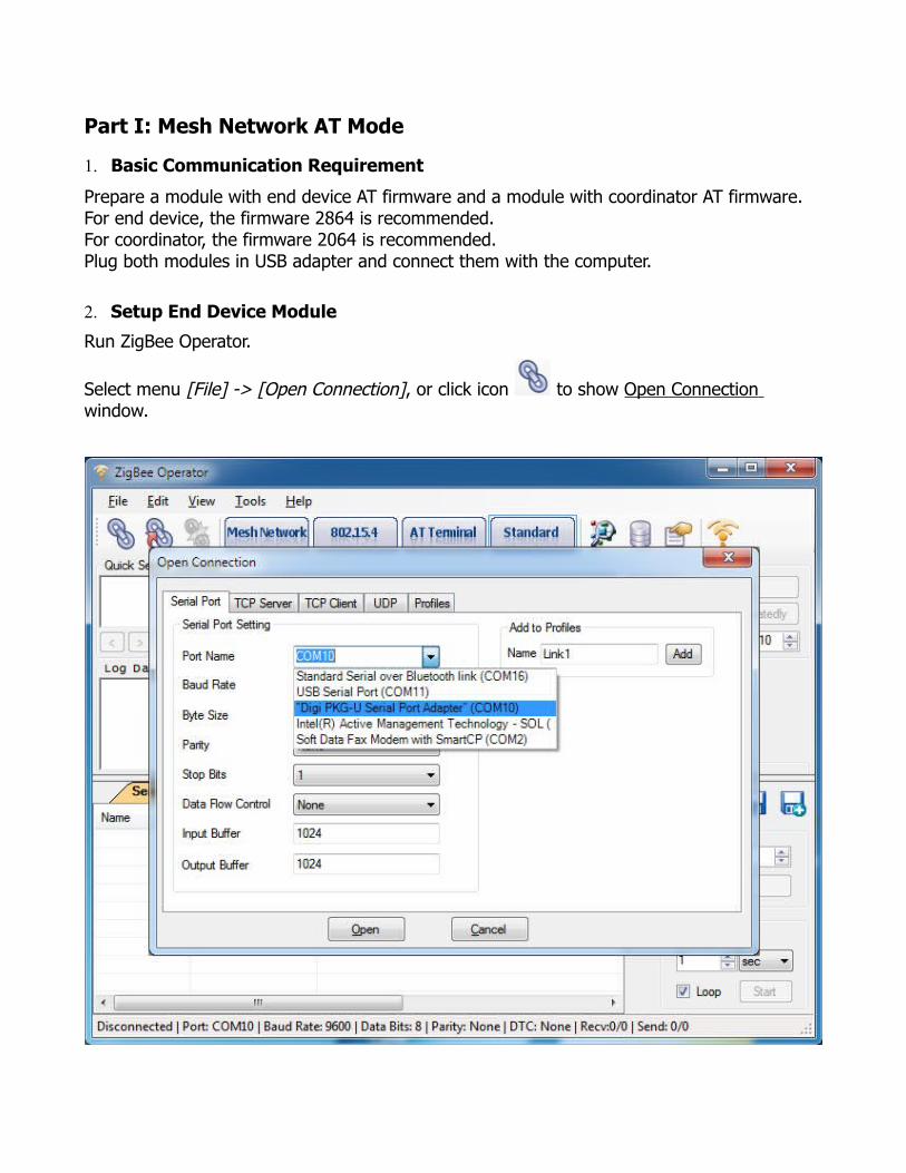
Run ZigBee Operator.
Select menu [File] -> [Open Connection], or click icon to show Open Connection window.
Click Serial Port tab page on Open Connection window and select the serial port that connected with end device ZigBee module. Use the default values. The baud rate is 9600.
It’s very important to open the correct serial port with right parameters for later steps.
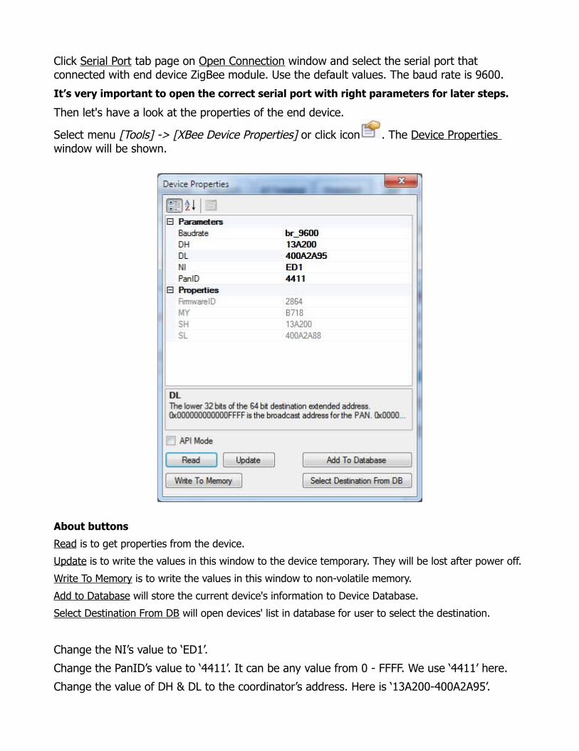
Then let's have a look at the properties of the end device.
Select menu [Tools] -> [XBee Device Properties] or click icon . The Device Properties window will be shown.
About buttons
Read is to get properties from the device.
Update is to write the values in this window to the device temporary. They will be lost after power off.
Write To Memory is to write the values in this window to non-volatile memory.
Add to Database will store the current device's information to Device Database.
Select Destination From DB will open devices' list in database for user to select the destination.
Change the NI’s value to ‘ED1’.
Change the PanID’s value to ‘4411’. It can be any value from 0 - FFFF. We use ‘4411’ here.
Change the value of DH & DL to the coordinator’s address. Here is ‘13A200-400A2A95’.
Click Write To Memory button to write the values in the device.
Click Add To Database button to store the current end device information to database.
Close the Device Properties window.
From now, we call ‘ED1’ for the ZigBee module with end device firmware.
3. Setup Coordinator Module
Select menu [File] -> [Close Connection] or click icon to close the current connection.
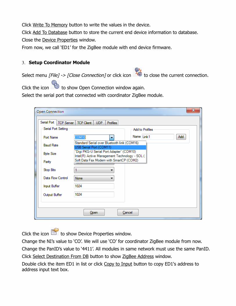
Click the icon to show Open Connection window again.
Select the serial port that connected with coordinator ZigBee module.
Click the icon to show Device Properties window.
Change the NI’s value to ‘CO’. We will use ‘CO’ for coordinator ZigBee module from now.
Change the PanID’s value to ‘4411’. All modules in same network must use the same PanID.
Click Select Destination From DB button to show ZigBee Address window.
Double click the item ED1 in list or click Copy to Input button to copy ED1's address to address input text box.
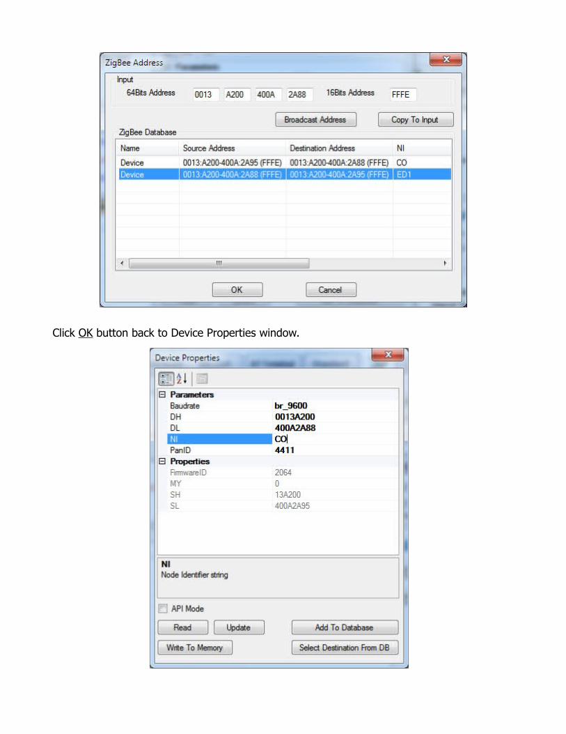
Click OK button back to Device Properties window.
Click Write to Memory button to write the values to CO non-volatile memory.
Click Add to Database button to store CO's information to database.
Close the Device Properties window.
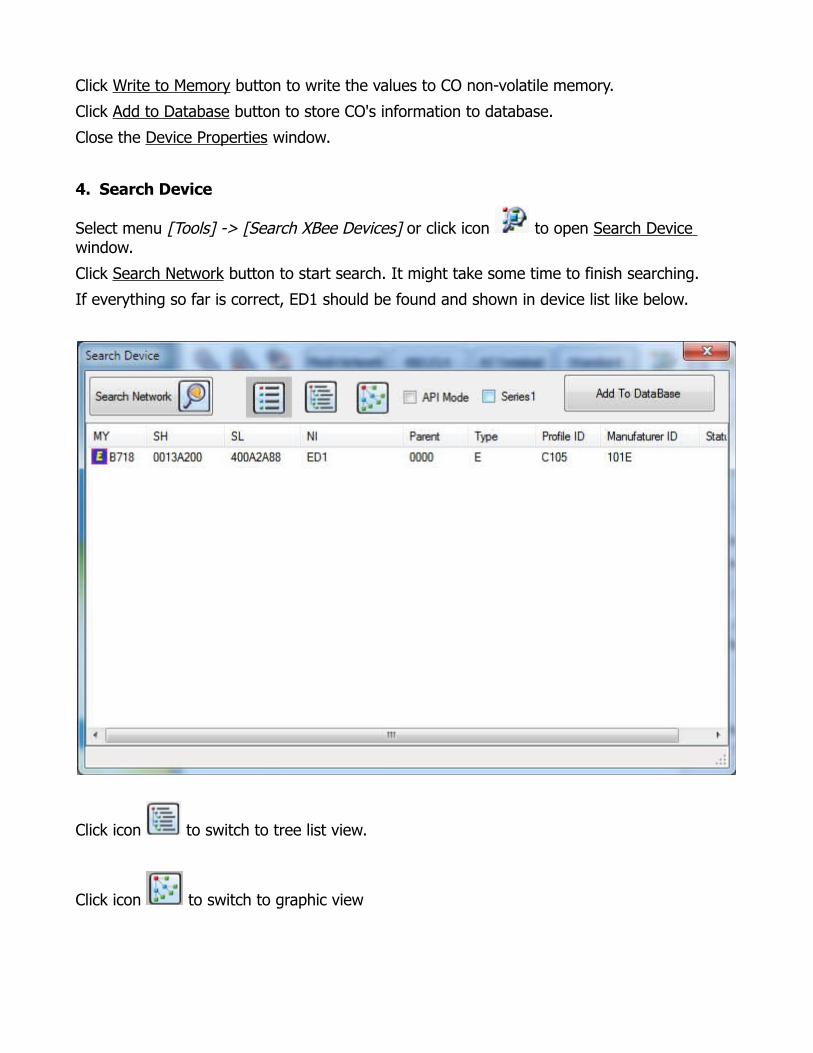
4. Search Device
Select menu [Tools] -> [Search XBee Devices] or click icon to open Search Device window.
Click Search Network button to start search. It might take some time to finish searching.
If everything so far is correct, ED1 should be found and shown in device list like below.
Click icon to switch to tree list view.
Click icon to switch to graphic view
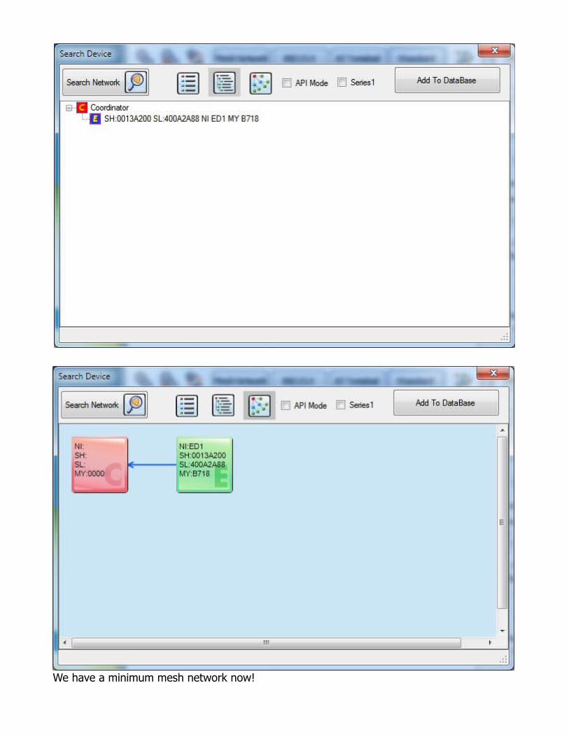
We have a minimum mesh network now!

5. Transfer data between CO and ED1
We call ‘Z1’ for ZigBee Operator instance that we are using.
Select menu [File] -> [New ZigBee Operator] or click icon to run a new instance of ZigBee Operator.
We call ‘Z2’ for the new Zigbee Operator instance.
In Z2, open the connection for ED1 as we did in beginning.
Select menu [View] -> [Standard] or click icon for both Z1 and Z2 to switch to Quick Send -Standard input panel.
Type the text “Hello ED1” in Z1’s input panel.
Click Send button.
Z2 will receive this message. You will see it in Z2's Log Data panel.
Type message in Z2's Quick Send panel and click Send button. The message will also be shown in Z1's Log Data panel.
This is how ZigBee mesh network transfer data in AT mode.
Z1
Z2
About Quick Send – Standard Panel
ZigBee Operator's Quick Send - Standard panel supports data in both Text, Decimal and Hex format.
Click Send button to send the current data to the connected serial port.
Keep pressing button Send Repeatedly to send the current data at the fixed rate repeatedly.
Check checkbox Clear will delete the data in panel after each sending.
Check checkbox Add to List will add the sent data to current Send Data List automatically.
Check checkbox Add CR will add carriage return at the end of content automatically.
Check checkbox Check Sum will add check sum at the end of the content automatically.
The check sum method can be selected from menu [Tools] -> [Options] -> [Checksum] tab page.
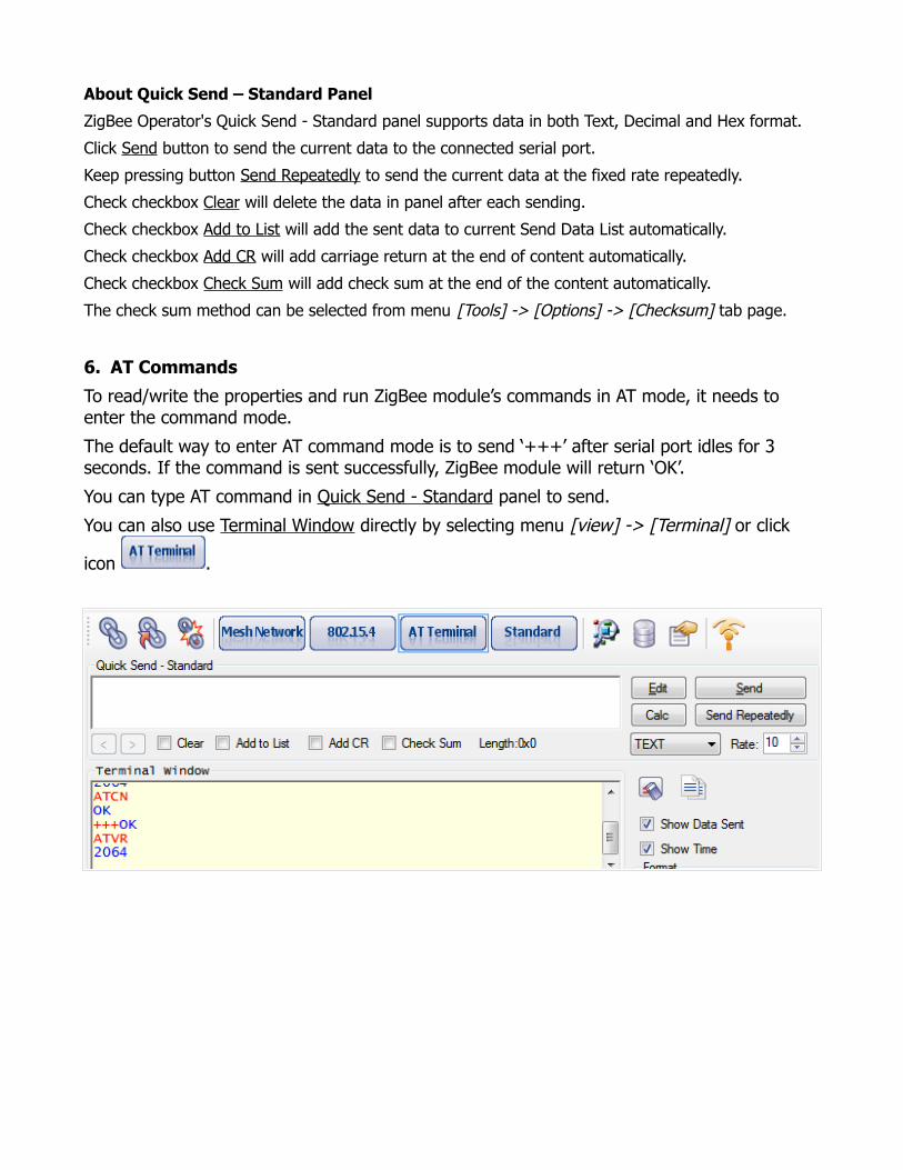
6. AT Commands
To read/write the properties and run ZigBee module’s commands in AT mode, it needs to enter the command mode.
The default way to enter AT command mode is to send ‘+++’ after serial port idles for 3 seconds. If the command is sent successfully, ZigBee module will return ‘OK’.
You can type AT command in Quick Send - Standard panel to send.
You can also use Terminal Window directly by selecting menu [view] -> [Terminal] or click
icon .
Part II: Mesh Network API Mode
1. Basic Communication Requirement
Prepare a module with end device API firmware. The firmware 2941 is recommended. The CO and ED1 in Part I will also be used here.Plug the three modules in USB adapters and connect them with the computer.Close both Z1 and Z2 opened previous steps in Part I. 2. Setup End Device Module
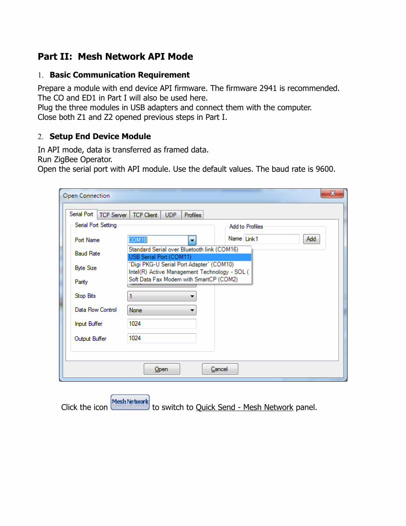
In API mode, data is transferred as framed data. Run ZigBee Operator.Open the serial port with API module. Use the default values. The baud rate is 9600.
Click the icon to switch to Quick Send - Mesh Network panel.

Click the icon to open Device Properties window.
Check checkbox API Mode and click Read Button.
Change the NI’s value to ‘ED2’. We will call ‘ED2’ the module with API firmware from now.
Change the PanID’ value to ‘4411’. Same PanID makes ED2 join the same mesh network as CO and ED1.
Click Update and Write To Memory buttons to save the changes to non-volatile memory.
Click Add to Database button to save ED2's information to database.
Close the Device Properties window.
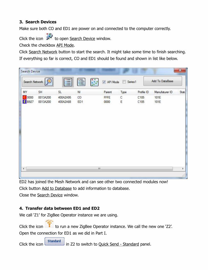
3. Search Devices
Make sure both CO and ED1 are power on and connected to the computer correctly.
Click the icon to open Search Device window.
Check the checkbox API Mode.
Click Search Network button to start the search. It might take some time to finish searching.
If everything so far is correct, CO and ED1 should be found and shown in list like below.
ED2 has joined the Mesh Network and can see other two connected modules now!
Click button Add to Database to add information to database.
Close the Search Device window.
4. Transfer data between ED1 and ED2
We call ‘Z1’ for ZigBee Operator instance we are using.
Click the icon to run a new ZigBee Operator instance. We call the new one ‘Z2’.
Open the connection for ED1 as we did in Part I.
Click the icon in Z2 to switch to Quick Send - Standard panel.

To make ED1 talk with ED2, we need to set ED1’s destination to ED2’s address.
Click the icon to show Device Properties window.
Click button Select Destination From DB to show ZigBee Address window.
Double click the item ED2 in list to copy ED2’s address to address input box.
Click OK button back to Device Properties window.
Click button Update and Write to Memory to store changes to non-volatile memory.
Click Add To Database to update the ED1's information in database.
Close the Device Properties window.
Now ED1 has been setup to talk with ED2.
Send data from AT firmware ED1 in Z2 is same as what we did in Part I.
Type “Hello ED2” in quick send panel and click Send button.
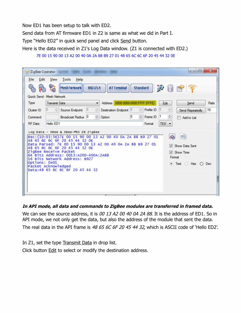
Here is the data received in Z1's Log Data window. (Z1 is connected with ED2.) 7E 00 15 90 00 13 A2 00 40 0A 2A 88 B9 27 01 48 65 6C 6C 6F 20 45 44 32 0E
In API mode, all data and commands to ZigBee modules are transferred in framed data.
We can see the source address, it is 00 13 A2 00 40 0A 2A 88. It is the address of ED1. So in API mode, we not only get the data, but also the address of the module that sent the data.
The real data in the API frame is 48 65 6C 6F 20 45 44 32, which is ASCII code of ‘Hello ED2’.
In Z1, set the type Transmit Data in drop list.
Click button Edit to select or modify the destination address.

Double click the item ED1 to copy ED1’s address to input text.
Click button OK back to Z1 window.
Type the text ‘Hello ED1’ in RF Data field and click button Send.
The following data will be shown in Log Data panel in Z1.
Send:(10:24:27) 7E 00 17 10 01 00 13 A2 00 40 0A 2A 88 FF FE 00 00 48 65 6C 6C 6F 20 45 44 31 72
Data Parsed: 7E 00 17 10 01 00 13 A2 00 40 0A 2A 88 FF FE 00 00 48 65 6C 6C 6F 20 45 44 31 72
ZigBee Transmit Request
Frame ID: 0x01
64Bits Destination Address: 0013:A200-400A:2A88
16Bits Destination Network Address: FFFE
Broadcast Radius: 0x00
Options: 0x00
Data:48 65 6C 6C 6F 20 45 44 31
Unlike AT firmware, API firmware will create a package for the data sent.
The package contains the destination information. It is 00 13 A2 00 40 0A 2A 88.
The data 48 65 6C 6C 6F 20 45 44 31 is the ASCII code of ‘Hello ED1’.
In Z1's Log Data panel, you will also see other data received.
Rec:(10:24:27)7E 00 07 8B 01 B9 27 00 00 01 92
Data Parsed: 7E 00 07 8B 01 B9 27 00 00 01 92
Transmit Status
Frame ID: 1
Network Address :0xB927
Retries: 0x00
Delivery Status: 0x0 = Success
Discovery Status: 0x1 = Address Discovery
The data above indicates the transmit status. The delivery status is success here.
In Z2's Log Data panel, it will show the text like below.Rec:(10:24:27) Hello ED1
Now we have ED1 and ED2 talk to each other successful!
One cool thing for ZigBee is that API and AT firmware can work together seamlessly. The data can be transferred between AT and API firmware. This feature gives the end users flexibility in their application.
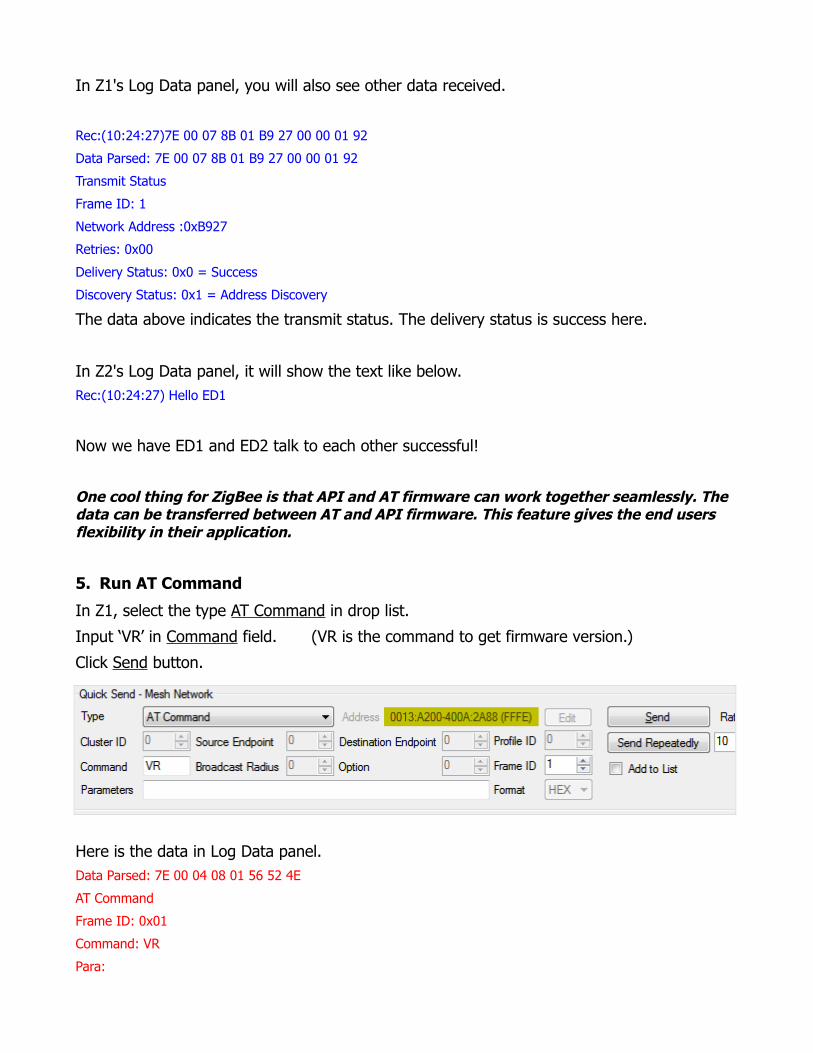
5. Run AT Command
In Z1, select the type AT Command in drop list.
Input ‘VR’ in Command field. (VR is the command to get firmware version.)
Click Send button.
Here is the data in Log Data panel.Data Parsed: 7E 00 04 08 01 56 52 4E
AT Command
Frame ID: 0x01
Command: VR
Para:
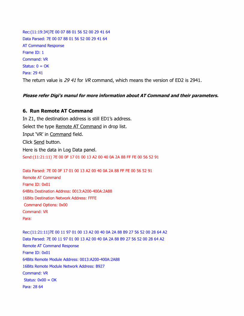
Rec:(11:19:34)7E 00 07 88 01 56 52 00 29 41 64
Data Parsed: 7E 00 07 88 01 56 52 00 29 41 64
AT Command Response
Frame ID: 1
Command: VR
Status: 0 = OK
Para: 29 41
The return value is 29 41 for VR command, which means the version of ED2 is 2941.
Please refer Digi's manul for more information about AT Command and their parameters.
6. Run Remote AT Command
In Z1, the destination address is still ED1’s address.
Select the type Remote AT Command in drop list.
Input ‘VR’ in Command field.
Click Send button.
Here is the data in Log Data panel.Send:(11:21:11) 7E 00 0F 17 01 00 13 A2 00 40 0A 2A 88 FF FE 00 56 52 91
Data Parsed: 7E 00 0F 17 01 00 13 A2 00 40 0A 2A 88 FF FE 00 56 52 91
Remote AT Command
Frame ID: 0x01
64Bits Destination Address: 0013:A200-400A:2A88
16Bits Destination Network Address: FFFE
Command Options: 0x00
Command: VR
Para:
Rec:(11:21:11)7E 00 11 97 01 00 13 A2 00 40 0A 2A 88 B9 27 56 52 00 28 64 A2
Data Parsed: 7E 00 11 97 01 00 13 A2 00 40 0A 2A 88 B9 27 56 52 00 28 64 A2
Remote AT Command Response
Frame ID: 0x01
64Bits Remote Module Address: 0013:A200-400A:2A88
16Bits Remote Module Network Address: B927
Command: VR
Status: 0x00 = OK
Para: 28 64
The VR command is issued to ED1 and return value is 2864. It is the version of ED1.
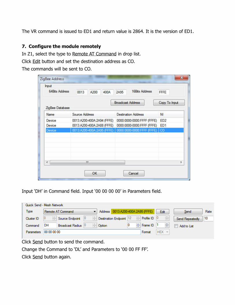
7. Configure the module remotely
In Z1, select the type to Remote AT Command in drop list.
Click Edit button and set the destination address as CO.
The commands will be sent to CO.
Input ‘DH’ in Command field. Input ‘00 00 00 00’ in Parameters field.
Click Send button to send the command.
Change the Command to ‘DL’ and Parameters to ‘00 00 FF FF’.
Click Send button again.

The destination address of CO has been set to 0x0000FFFF, which is broadcast address.
We can verify the command result on CO.
Click the icon to run a new instance of ZigBee Operator. We call it ‘Z3’.
Open the serial port with CO module in Z3.
Click the icon to open the Device Properties window.
You can see the destination address has been changed to 0x0000FFFF.
Close the Device Properties window in Z3.
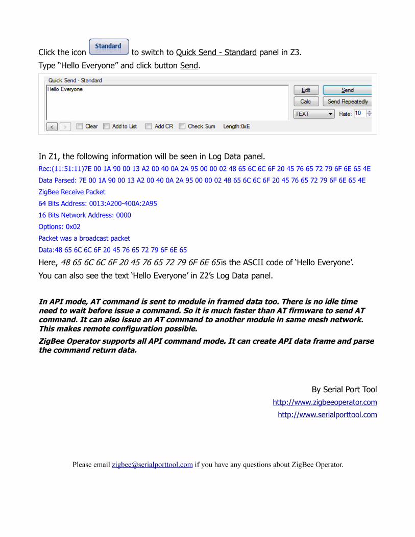
Click the icon to switch to Quick Send - Standard panel in Z3.
Type “Hello Everyone” and click button Send.
In Z1, the following information will be seen in Log Data panel.Rec:(11:51:11)7E 00 1A 90 00 13 A2 00 40 0A 2A 95 00 00 02 48 65 6C 6C 6F 20 45 76 65 72 79 6F 6E 65 4E
Data Parsed: 7E 00 1A 90 00 13 A2 00 40 0A 2A 95 00 00 02 48 65 6C 6C 6F 20 45 76 65 72 79 6F 6E 65 4E
ZigBee Receive Packet
64 Bits Address: 0013:A200-400A:2A95
16 Bits Network Address: 0000
Options: 0x02
Packet was a broadcast packet
Data:48 65 6C 6C 6F 20 45 76 65 72 79 6F 6E 65
Here, 48 65 6C 6C 6F 20 45 76 65 72 79 6F 6E 65 is the ASCII code of ‘Hello Everyone’.
You can also see the text ‘Hello Everyone’ in Z2’s Log Data panel.
In API mode, AT command is sent to module in framed data too. There is no idle time need to wait before issue a command. So it is much faster than AT firmware to send AT command. It can also issue an AT command to another module in same mesh network. This makes remote configuration possible.
ZigBee Operator supports all API command mode. It can create API data frame and parse the command return data.
By Serial Port Tool
http://www.zigbeeoperator.com
http://www.serialporttool.com
Please email [email protected] if you have any questions about ZigBee Operator.


![AT08550: ZigBee Attribute Reporting · ZigBee Attribute Reporting [APPLICATION NOTE] Atmel-42334A-ZigBee-Attribute-Reporting -ApplicationNote_012015 3 1 Overview The ZigBee Specification](https://img.pdfslide.net/doc/110x75/5f43d267b58b3c15740a0db6/at08550-zigbee-attribute-reporting-zigbee-attribute-reporting-application-note.jpg)
![ZigBee Stack Profile: Platform restrictions for compliant ...read.pudn.com/.../3...ZigBee-Feature-Set-Profile.pdf · 11 [R2] ZigBee 04140r05, ZigBee Protocol Stack Settable Values](https://img.pdfslide.net/doc/110x75/5f183a7d6417c0751a61665e/zigbee-stack-profile-platform-restrictions-for-compliant-readpudncom3zigbee-feature-set-.jpg)