Embed Size (px)
Citation preview
S
Z
JC
a
ARRA
KZHCP
1
saem[mbpba
pntefsss
cctMm
0d
Materials Science and Engineering B 172 (2010) 96–100
Contents lists available at ScienceDirect
Materials Science and Engineering B
journa l homepage: www.e lsev ier .com/ locate /mseb
hort communication
nO cages with tunable shell thickness and photoluminescence properties
ie Zhou, Dapeng Wu, Huajie Guo, Ning Liu, Ying Xiao, Kai Jiang ∗
hemistry and Environmental College, Henan Normal University, Jianshe Road No. 47, Xinxiang 453007, PR China
r t i c l e i n f o
rticle history:eceived 4 November 2009
a b s t r a c t
Uniform ZnO cages were fabricated via using colloidal carbon spheres as sacrificing template. ZnO pre-cursor could be easily coated on the carbon spheres by soaking the template into Zn(CH3COO)2 aqueous
eceived in revised form 5 March 2010ccepted 10 April 2010
eywords:inc oxideollow structure
solution. After calcination, the average diameter of the cages was 200 nm which experienced a largeshrinkage from the initial carbon template (600 nm). The shell thickness of the cages could be manipu-lated from 20 nm to 40 nm by adjusting the concentration of Zn(CH3COO)2. The correlation between theshell thickness and photoluminescence (PL) performances of these cages was also investigated. More-over, this facile method could be potentially adopted as a general way to fabricate hollow structures of
hemical synthesishotoluminescence
other metal oxides.
. Introduction
Owing to their low densities, high specific surface areas, andcale-dependent properties, hollow structures could be potentiallypplied in different territories such as photonic devices, drug deliv-ry, lightweight fillers, catalysts carries and so on [1–5]. Recently,any methods have been developed to fabricate hollow structures
6–9]. Among these methods, the template-directing route was theost effective one. The template-based synthesis strategy could
e further divided into two categories: hard templates (such as:olymer latex particles, silica spheres, carbon spheres and sphericalacterium) and soft templates (such as: emulsion droplets, micellesnd gas bubbles) [10–16].
Zinc oxide, as an important wide band gap semiconductor, hasotential applications in catalysts, solar cell, electro and photolumi-escence devices and chemical and biological sensors [17–20]. Dueo the unique structural advantages, ZnO hollow structures exhibitnhanced properties when compared with bulk materials. There-ore, many efforts have been made to prepare different ZnO hollowtructures recently [21–23]. However, preparation of ZnO hollowtructures with uniform diameter and controllable shell thicknesstill remains a challenge.
Herein, a facile method was proposed to fabricate uniform ZnOages. The shell thickness could be manipulated by changing theoncentration of the Zn(CH3COO)2 solution. The variation of shell
hickness was found to have a great influence on their PL properties.oreover, this method could be further exploited to fabricate otheretal oxides with hollow interior and controllable thickness.
∗ Corresponding author. Tel.: +86 373 3326209; fax: +86 373 3326209.E-mail address: [email protected] (K. Jiang).
921-5107/$ – see front matter © 2010 Elsevier B.V. All rights reserved.oi:10.1016/j.mseb.2010.04.010
© 2010 Elsevier B.V. All rights reserved.
2. Experiments
2.1. Preparation of carbon spheres
In a typical synthesis [24], 25 mL 0.5 M glucose solution wassealed in a 30 mL Teflon-lined autoclave and maintained at 180 ◦Cfor 7 h. The final black products were centrifuged, washed with dou-ble distilled water and absolute ethanol several times and finallydried at 80 ◦C for 4 h. The average diameter of as-prepared monodis-perse colloidal carbon spheres is 600 nm.
2.2. Preparation of ZnO cages
0.2 g carbon spheres were homogeneously dispersed in 0.2 M20 mL Zn(CH3COO)2 solution by ultrasonication. The suspensionwas then aged at room temperature for 24 h. The precipitate wascentrifuged, washed with distilled water and ethanol several times,then dried in vacuum at 80 ◦C for 5 h and finally annealed at 650 ◦Cfor 2 h to yield uniform ZnO cages. To synthesize ZnO cages withdifferent shell thickness, the concentration of Zn(CH3COO)2 solu-tion was adjusted to 0.1 M and 0.5 M respectively and the otherexperimental parameters were kept unchanged.
2.3. Preparation of hollow structures of other oxides
Similarly, 0.2 g carbon spheres were respectively dispersed in0.2 M 20 mL Fe(NO3)3, Ga(NO3)3, Ce(NO3)3 and MgCl2 solutions
by ultrasonication. The suspensions were then aged at room tem-perature for 24 h. The precipitates were centrifuged, washed withdistilled water and ethanol several times, then dried in vacuum at80 ◦C for 5 h and finally annealed at 650 ◦C for 2 h to yield hollowstructures of �-Fe2O3, Ga2O3, CeO2 and MgO.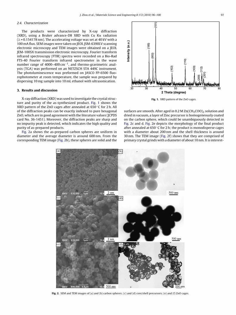
and Engineering B 172 (2010) 96–100 97
2
((1eJiFnyTrd
3
tXoZcnp
dc
J. Zhou et al. / Materials Science
.4. Characterization
The products were characterized by X-ray diffractionXRD), using a Bruker advance-D8 XRD with Cu K� radiation� = 0.154178 nm). The accelerating voltage was set at 40 kV with a00 mA flux. SEM images were taken on JEOL JSM-6390LV scanninglectronic microscopy and TEM images were obtained on a JEOLEM-100SX transmission electronic microscopy. Fourier transformnfrared spectroscopy (FTIR) spectra were recorded on a Bio-RadTS-40 Fourier transform infrared spectrometer in the waveumber range of 4000–400 cm−1, and thermo-gravimetric anal-sis (TGA) was performed on an NETZSCH STA 449C instrument.he photoluminescence was preformed on JASCO FP-6500 fluo-ophotometer at room temperature, the sample was prepared byispersing 10 mg sample into 10 mL ethanol with ultrasonication.
. Results and discussion
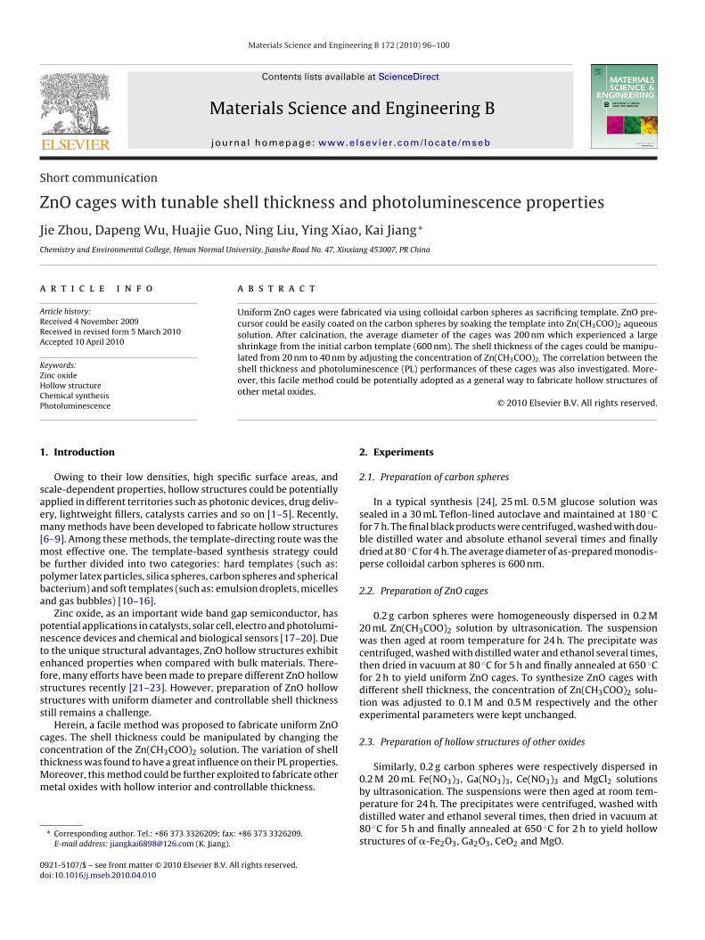
X-ray diffraction (XRD) was used to investigate the crystal struc-ure and purity of the as-synthesized product. Fig. 1 shows theRD pattern of the ZnO cages after annealed at 650 ◦C for 2 h. Allf the diffraction peaks can be exactly indexed to pure hexagonalnO, which are in good agreement with the literature values (JCPDSard No. 36-1451). Moreover, the diffraction peaks are sharp and
o impurity peak is detected, which indicates the high quality andurity of as-prepared products.Fig. 2a shows the as-prepared carbon spheres are uniform iniameter and the average diameter is around 600 nm. From theorresponding TEM image (Fig. 2b), these spheres are solid and the
Fig. 2. SEM and TEM images of (a) and (b) carbon spheres; (
Fig. 1. XRD pattern of the ZnO cages.
surfaces are smooth. After aged in 0.2 M Zn(CH3COO)2 solution anddried in vacuum, a layer of Zinc precursor is homogeneously coatedon the carbon sphere, which could be unambiguously detected inFig. 2c and d. Fig. 2e depicts the morphology of the final product
after annealed at 650 ◦C for 2 h; the product is monodisperse cageswith a diameter about 200 nm and the shell thickness is around30 nm. The TEM image (Fig. 2f) shows that they are comprised ofprimary crystal grinds with a diameter of about 10 nm. It is interest-c) and (d) core/shell precursors; (e) and (f) ZnO cages.
98 J. Zhou et al. / Materials Science and Engineering B 172 (2010) 96–100
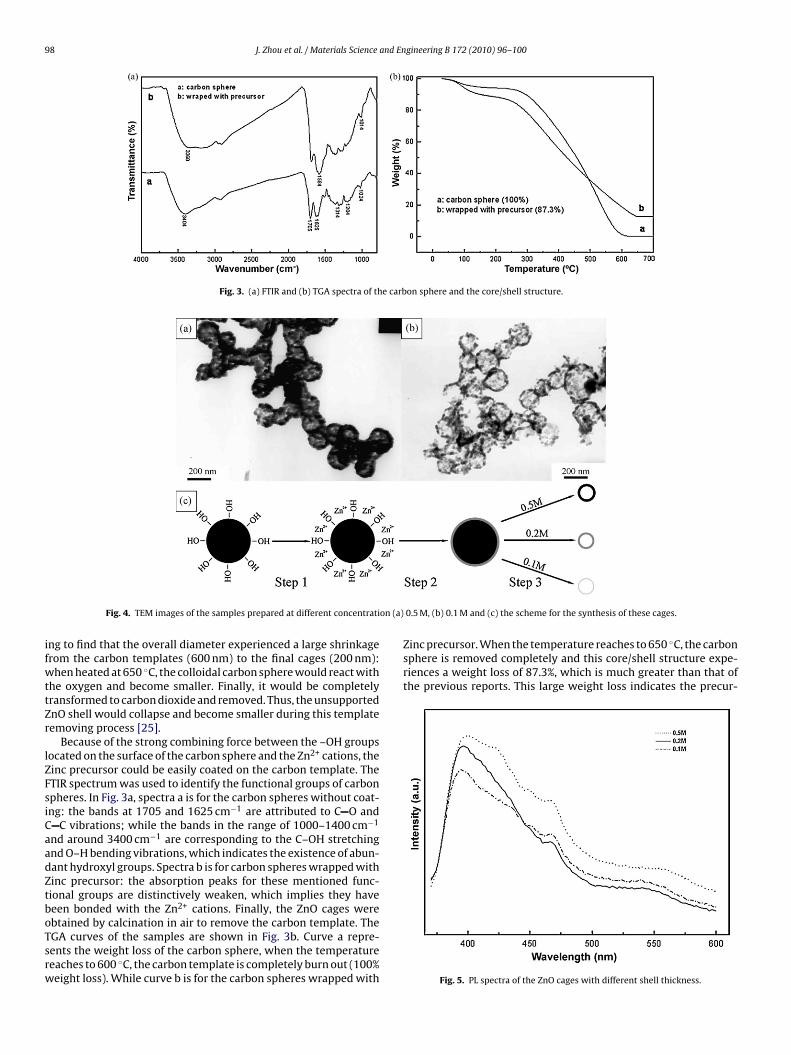
Fig. 3. (a) FTIR and (b) TGA spectra of the carbon sphere and the core/shell structure.
on (a)
ifwttZr
lZFsiCaadZtboTsrw
Zinc precursor. When the temperature reaches to 650 ◦C, the carbonsphere is removed completely and this core/shell structure expe-riences a weight loss of 87.3%, which is much greater than that ofthe previous reports. This large weight loss indicates the precur-
Fig. 4. TEM images of the samples prepared at different concentrati
ng to find that the overall diameter experienced a large shrinkagerom the carbon templates (600 nm) to the final cages (200 nm):hen heated at 650 ◦C, the colloidal carbon sphere would react with
he oxygen and become smaller. Finally, it would be completelyransformed to carbon dioxide and removed. Thus, the unsupportednO shell would collapse and become smaller during this templateemoving process [25].
Because of the strong combining force between the –OH groupsocated on the surface of the carbon sphere and the Zn2+ cations, theinc precursor could be easily coated on the carbon template. TheTIR spectrum was used to identify the functional groups of carbonpheres. In Fig. 3a, spectra a is for the carbon spheres without coat-ng: the bands at 1705 and 1625 cm−1 are attributed to C O and
C vibrations; while the bands in the range of 1000–1400 cm−1
nd around 3400 cm−1 are corresponding to the C–OH stretchingnd O–H bending vibrations, which indicates the existence of abun-ant hydroxyl groups. Spectra b is for carbon spheres wrapped withinc precursor: the absorption peaks for these mentioned func-ional groups are distinctively weaken, which implies they haveeen bonded with the Zn2+ cations. Finally, the ZnO cages were
btained by calcination in air to remove the carbon template. TheGA curves of the samples are shown in Fig. 3b. Curve a repre-ents the weight loss of the carbon sphere, when the temperatureeaches to 600 ◦C, the carbon template is completely burn out (100%eight loss). While curve b is for the carbon spheres wrapped with0.5 M, (b) 0.1 M and (c) the scheme for the synthesis of these cages.
Fig. 5. PL spectra of the ZnO cages with different shell thickness.
J. Zhou et al. / Materials Science and Engineering B 172 (2010) 96–100 99
throu
sst
Zttcicdctcctttmt
esiatcavtcto
m
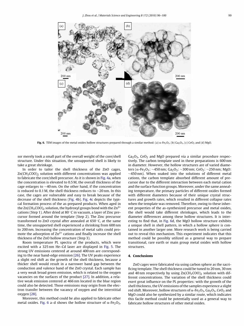
Fig. 6. TEM images of the metal oxides hollow structures prepared
or merely took a small part of the overall weight of the core/shelltructure. Under this situation, the unsupported shell is likely toake a great shrinkage.
In order to tailor the shell thickness of the ZnO cages,n(CH3COO)2 solution with different concentrations was appliedo fabricate the core/shell precursor. As it is shown in Fig. 4a, whenhe concentration is elevated to 0.5 M, the overall thickness of theage enlarges to ∼40 nm. On the other hand, if the concentrations reduced to 0.1 M, the shell thickness reduces to ∼20 nm. In thisase, the cages are vulnerable and easy to break because of theecrease of the shell thickness (Fig. 4b). Fig. 4c depicts the typi-al formation process of the as-prepared products. When aged inhe Zn(CH3COO)2 solution, the hydroxyl groups bond with the Zn2+
ations (Step 1). After dried at 80 ◦C in vacuum, a layer of Zinc pre-ursor formed around the template (Step 2). The Zinc precursorransformed to ZnO crystal after annealed at 650 ◦C, at the sameime, the unsupported shell experienced a shrinking from 600 nmo 200 nm. Increasing the concentration of metal salts could pro-
ote the adsorption of Zn2+ cations and finally increase the shellhickness of the ZnO hollow structure (Step 3).
Room temperature PL spectra of the products, which werexcited with a 325 nm He–Cd laser are displayed in Fig. 5. Thetrong UV emissions centered at around 400 nm are correspond-ng to the near band-edge emission [26]. The UV peaks experience
slight red shift as the growth of the shell thickness, because ahicker shell would result in a narrower band gap between theonduction and valence band of the ZnO crystal. Each sample hasvery weak broad green emission, which is related to the oxygenacancies on the surfaces of the product [27]. In addition, a rela-ive weak emission centered at 466 nm located in the blue region
ould also be detected. Those emissions may origin from the elec-ron transfer between the vacancy of oxygen and the interstitialxygen [28].Moreover, this method could be also applied to fabricate otheretal oxides. Fig. 6 a–d shows the hollow structure of �-Fe2O3,
gh a similar method: (a) �-Fe2O3, (b) Ga2O3, (c) CeO2 and (d) MgO.
Ga2O3, CeO2 and MgO prepared via a similar procedure respec-tively. The carbon template used in these preparations is 600 nmin diameter. However, the hollow structures are of varied diame-ters (�-Fe2O3: ∼450 nm; Ga2O3: ∼300 nm; CeO2: ∼250 nm; MgO:∼450 nm). When soaked into the solutions of different metalcations, the carbon template absorbed different amount of pre-cursor due to the different interaction between each metal cationand the surface function groups. Moreover, under the same anneal-ing temperature, the primary particles of different oxides formedwith different diameters because of their unique crystal struc-tures and growth rates, which resulted in different collapse rateswhen the template was removed. Therefore, owing to these inher-ent properties of the as-synthesized precursor and metal oxides,the shell would take different shrinkages, which leads to thediameter differences among these hollow structures. It is inter-esting to find that, in Fig. 6d, the MgO hollow structure exhibitsa unique shell in shell pattern, in which a hollow sphere is con-tained in another larger one. More research work is being carriedout to reveal this mechanism. This experiment indicates that thismethod could be possibly utilized as a general way to preparetransitional, rare earth or main group metal oxides with hollowstructures.
4. Conclusions
ZnO cages were fabricated via using carbon sphere as the sacri-ficing template. The shell thickness could be tuned to 20 nm, 30 nmand 40 nm respectively by using Zn(CH3COO)2 solution with dif-ferent concentrations. The variation of the shell thickness couldexert great influence on the PL properties: with the growth of the
shell thickness, the UV emissions of the samples experience a slightred shift. Moreover, hollow structures of �-Fe2O3, Ga2O3, CeO2 andMgO could also be synthesized by a similar route, which indicatesthis facile method could be potentially used as a general way tofabricate hollow structures of other metal oxides.
1 and En
A
dU
R
[
[
[
[[
[[[[
[
[
[
[
[[[
00 J. Zhou et al. / Materials Science
cknowledgements
This work was supported by the National Natural Science Foun-ation of China (20571025) and Henan Innovation Project forniversity Prominent Research Talents (2005KYCX005).
eferences
[1] S.W. Kim, M. Kim, W.Y. Lee, T. Hyeon, J. Am. Chem. Soc. 124 (2002) 7642–7643.[2] X.L. Li, T.J. Lou, X.M. Sun, Y.D. Li, Inorg. Chem. 43 (2004) 5442–5449.[3] J. Yang, J. Lee, J. Kang, J.S. Suh, H.G. Yoon, Y.M. Huh, S. Haam, Langmuir 24 (2008)
3417–3421.[4] J.Z. Du, Y.M. Chen, Macromolecules 37 (2004) 5710–5716.[5] J.S. Hu, Y.G. Guo, H.P. Liang, L.J. Wan, C.L. Bai, Y.G. Wang, J. Phys. Chem. B 108
(2004) 9734–9738.[6] N. Wang, X. Cao, D.S. Kong, W.M. Chen, L. Guo, C.P. Chen, J. Phys. Chem. C 112
(2008) 6613–6619.[7] J.G. Wang, F. Li, H.J. Zhou, P.C. Sun, D.T. Ding, T.H. Chen, Chem. Mater. 21 (2009)
612–620.
[8] H.G. Yang, H.C. Zeng, J. Phys. Chem. B 108 (2004) 3492–3495.[9] Y.F. Huang, H.N. Xiao, S.G. Chen, C. Wang, Ceram. Int. 35 (2009) 905–907.10] A.G. Dong, N. Ren, Y. Tang, Y.J. Wang, Y.H. Zhang, W.M. Hua, Z. Gao, J. Am. Chem.Soc. 125 (2003) 4976–4977.11] F. Zhang, Y.S. Li, D.C. Niu, L. Li, W. Zhao, H.R. Chen, Chem. Commun. (2008)
2629–2631.
[
[
[
gineering B 172 (2010) 96–100
12] H.X. Li, Z.F. Bian, J. Zhu, D.Q. Zhang, G.S. Li, Y.N. Huo, H. Li, Y.F. Lu, J. Am. Chem.Soc. 129 (2007) 8406–8407.
13] Z.Y. Guo, F.F. Jian, F.L. Du, Scr. Mater. 61 (2009) 48–51.14] A.G. Yan, X.H. Liu, R. Yi, R.R. Shi, N. Zhang, G.Z. Qiu, J. Phys. Chem. C 112 (2008)
8558–8563.15] W.J. Li, M.O. Coppens, Chem. Mater. 17 (2005) 2241–2246.16] Z.X. Wang, M. Chen, L.M. Wu, Chem. Mater. 30 (2008) 3251–3253.17] N.S. Norberg, D.R. Gamelin, J. Phys. Chem. B 109 (2005) 20810–20816.18] H.B. Zeng, P.S. Liu, W.P. Cai, S.K. Yang, X.X. Xu, J. Phys. Chem. C 112 (2008)
19620–19624.19] Z.X. Zhang, L.F. Sun, Y.C. Zhao, Z. Liu, D.F. Liu, L. Cao, B.S. Zou, W.Y. Zhou, C.Z.
Gu, S. Xie, Nano. Lett. 8 (2008) 652–655.20] Y.J. Lee, D.S. Ruby, D.W. Peters, B.B. McKenzie, J.W.P. Hsu, Nano. Lett. 8 (2008)
1501–1505.21] Z.W. Deng, M. Chen, G.X. Gu, L.M. Wu, J. Phys. Chem. B 112 (2008) 16–
22.22] H.B. Zeng, W.P. Cai, P.S. Liu, X.X. Xu, H.J. Zhou, C. Klingshirn, H. Kalt, ACS Nano
2 (2008) 1661–1670.23] X. Wang, P. Hu, Y.F. Li, L.G. Yu, J. Phys. Chem. C 111 (2007) 6706–6712.24] X.M. Sun, Y.D. Li, Angew. Chem. 116 (2004) 607–611.25] X.M. Sun, Y.D. Li, Angew. Chem. 43 (2004) 3827–3831.
26] Y.C. Kong, D.P. Yu, B. Zhang, W. Fang, S.Q. Feng, Appl. Phys. Lett. 78 (2001)407–409.27] K. Vanheusden, W.L. Warren, C.H. Seager, D.R. Tallant, J.A. Voigt, J. Appl. Phys.
79 (1996) 7983–7990.28] S. Mahamuni, K. Borgohain, B.S. Bendre, V.J. Leppert, S.H. Risbuda, J. Appl. Phys.
85 (1999) 2861–2865.