Embed Size (px)
Citation preview
Zs
Pa
b
a
ARRAA
KCIMDPHM
1
icbcmpatiwa
P
(
0d
Journal of Chromatography A, 1218 (2011) 5071– 5078
Contents lists available at ScienceDirect
Journal of Chromatography A
jou rn al h om epage: www.elsev ier .com/ locat e/chroma
onal rate model for stacked membrane chromatography. I: Characterizingolute dispersion under flow-through conditions�
atrick Francisa, Eric von Lieresb,∗, Charles A. Haynesa,∗∗
Michael Smith Laboratories and the Department of Chemical and Biological Engineering, University of British Columbia, Vancouver V6T 1Z4, CanadaInstitut für Biotechnologie 2, Forschungszentrum Jülich GmbH, 52425 Jülich, Germany
r t i c l e i n f o
rticle history:eceived 29 October 2010eceived in revised form 21 February 2011ccepted 9 May 2011vailable online 14 May 2011
eywords:hromatography
on-exchange chromatographyembrane chromatographyispersionrotein purification
a b s t r a c t
Conventional models of both packed-bed and stacked-membrane chromatography typically attribute elu-tion band broadening to non-idealities within the column. However, when the column length to diameterratio is greatly reduced, as in stacked-membrane chromatography, variations in solute residence timeswithin the feed-distribution (inlet) and eluent-collection (outlet) manifolds can also contribute to bandbroadening. We report on a new zonal rate model (ZRM) for stacked-membrane chromatography thatimproves on existing hold-up volume models that rely on one plug-flow reactor and one stirred-tankreactor in series to describe dispersion of solute during transport into and out of the column. The ZRMradially partitions the membrane stack and the hold-up volumes within the inlet and outlet manifolds intozones to better capture non-uniform flow distribution effects associated with the large column diameterto height ratio. Breakthrough curves from a scaled-down anion-exchange membrane chromatographymodule using ovalbumin as a model protein were collected at flow rates ranging from 1.5 to 20 mL min−1
ydrodynamicsass transfer
under non-binding conditions and used to evaluate the ZRM as well as previous models. The ZRM wasshown to be significantly more accurate in describing protein dispersion and breakthrough. The modelwas then used to decompose breakthrough data, where it was found that variations in solute residencetime distributions within the inlet and outlet manifolds make the dominant contribution to solute dis-persion over the recommended range of feed flow rates. The ZRM therefore identifies manifold design asa critical contributor to separation quality within stacked-membrane chromatography units.
. Introduction
Packed-bed chromatography has remained a cornerstone ofndustrial and therapeutic protein purification for over a halfentury due to its good capacity and outstanding resolving capa-ility. However, cost and throughput concerns associated withonventional preparative-scale chromatography, due in part toass transfer resistances within the columns (particularly intra-
ore diffusion resistances), have motivated the development oflternative purification technologies offering higher rates of massransfer while maintaining high binding capacities and resolv-
ng power. One such technology is membrane chromatography,hich is gradually gaining industrial acceptance as an attractivelternative to packed bed chromatography for the capture and
� Presented at the 30th International Symposium on Proteins, Peptides andolynucleotides (ISPPP), Bologna, Italy, 5–8 September 2010.∗ Corresponding author.
∗∗ Corresponding author. Tel.: +1 604 822 5136; fax: +1 604 822 2114.E-mail addresses: [email protected] (E. von Lieres), [email protected]
C.A. Haynes).
021-9673/$ – see front matter © 2011 Elsevier B.V. All rights reserved.oi:10.1016/j.chroma.2011.05.017
© 2011 Elsevier B.V. All rights reserved.
downstream processing of protein products [1–3]. The intercon-nected pore architecture of the stacked or monolithic membranecolumn allows solutes to be convected across binding sites. Masstransfer is therefore enhanced, limited primarily by the rate of filmdiffusion or, most often, the intrinsic adsorption kinetics of theprotein–sorbent complex [4]. By greatly reducing diffusion limitedtransport, membrane chromatography offers the well-documentedpotential [5–7] to increase throughput and performance providedthe column design meets capacity and resolution requirements.
In most commercially available membrane chromatographyunits, the membranes are either axially stacked or spirally woundin order to achieve sufficient capacities [4,2,8]. To date, membranechromatography modules with axial flow have proven more suit-able for miniaturization. As a result, they provide a more easilyscaled-down path to analysis and design of a particular separa-tion provided an appropriate model is available. Several modelingapproaches exist for the quantitative description of breakthroughcurves from membrane chromatography modules. Most are based
on a combination of the continuity equation and a kinetic equationdescribing protein binding and desorption [e.g. 10–14], hereafterreferred to as the 1D rate theory of chromatography. Some of thesemodels also account for dispersion in external hold-up volumes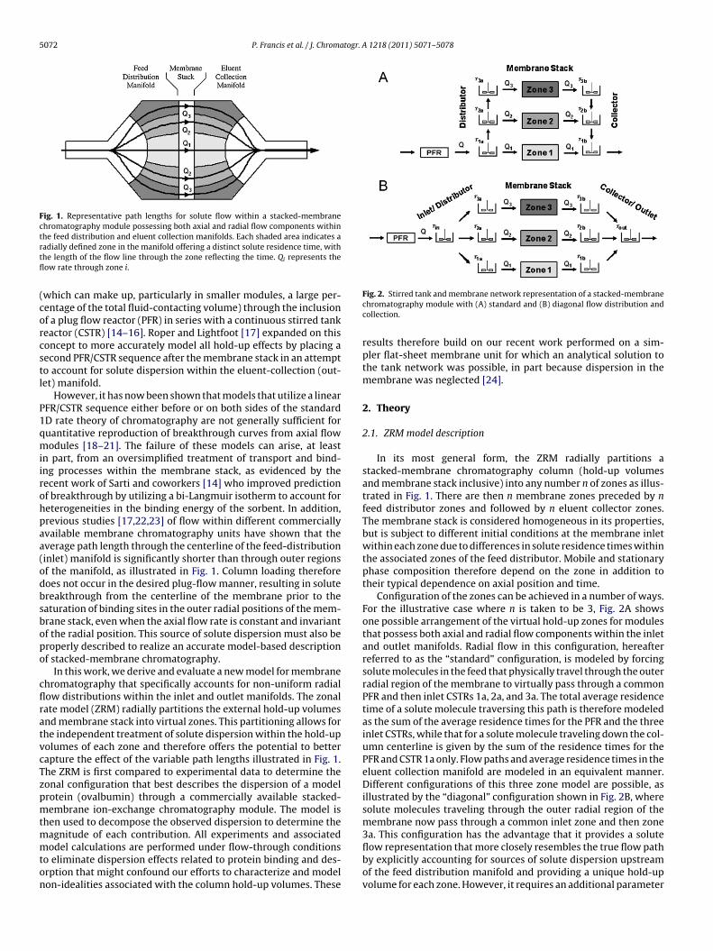
5072 P. Francis et al. / J. Chromatogr. A 1218 (2011) 5071– 5078
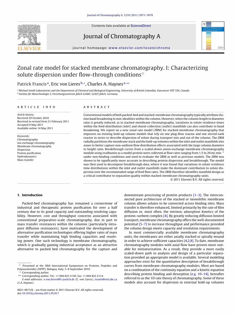
Fig. 1. Representative path lengths for solute flow within a stacked-membranechromatography module possessing both axial and radial flow components withinthe feed distribution and eluent collection manifolds. Each shaded area indicates artfl
(corcstl
P1qmiirohpaa(odbsbopo
cflratvcTzpmtmmton
adially defined zone in the manifold offering a distinct solute residence time, withhe length of the flow line through the zone reflecting the time. Qi represents theow rate through zone i.
which can make up, particularly in smaller modules, a large per-entage of the total fluid-contacting volume) through the inclusionf a plug flow reactor (PFR) in series with a continuous stirred tankeactor (CSTR) [14–16]. Roper and Lightfoot [17] expanded on thisoncept to more accurately model all hold-up effects by placing aecond PFR/CSTR sequence after the membrane stack in an attempto account for solute dispersion within the eluent-collection (out-et) manifold.
However, it has now been shown that models that utilize a linearFR/CSTR sequence either before or on both sides of the standardD rate theory of chromatography are not generally sufficient foruantitative reproduction of breakthrough curves from axial flowodules [18–21]. The failure of these models can arise, at least
n part, from an oversimplified treatment of transport and bind-ng processes within the membrane stack, as evidenced by theecent work of Sarti and coworkers [14] who improved predictionf breakthrough by utilizing a bi-Langmuir isotherm to account foreterogeneities in the binding energy of the sorbent. In addition,revious studies [17,22,23] of flow within different commerciallyvailable membrane chromatography units have shown that theverage path length through the centerline of the feed-distributioninlet) manifold is significantly shorter than through outer regionsf the manifold, as illustrated in Fig. 1. Column loading thereforeoes not occur in the desired plug-flow manner, resulting in solutereakthrough from the centerline of the membrane prior to theaturation of binding sites in the outer radial positions of the mem-rane stack, even when the axial flow rate is constant and invariantf the radial position. This source of solute dispersion must also beroperly described to realize an accurate model-based descriptionf stacked-membrane chromatography.
In this work, we derive and evaluate a new model for membranehromatography that specifically accounts for non-uniform radialow distributions within the inlet and outlet manifolds. The zonalate model (ZRM) radially partitions the external hold-up volumesnd membrane stack into virtual zones. This partitioning allows forhe independent treatment of solute dispersion within the hold-upolumes of each zone and therefore offers the potential to betterapture the effect of the variable path lengths illustrated in Fig. 1.he ZRM is first compared to experimental data to determine theonal configuration that best describes the dispersion of a modelrotein (ovalbumin) through a commercially available stacked-embrane ion-exchange chromatography module. The model is
hen used to decompose the observed dispersion to determine theagnitude of each contribution. All experiments and associated
odel calculations are performed under flow-through conditionso eliminate dispersion effects related to protein binding and des-rption that might confound our efforts to characterize and modelon-idealities associated with the column hold-up volumes. These
Fig. 2. Stirred tank and membrane network representation of a stacked-membranechromatography module with (A) standard and (B) diagonal flow distribution andcollection.
results therefore build on our recent work performed on a sim-pler flat-sheet membrane unit for which an analytical solution tothe tank network was possible, in part because dispersion in themembrane was neglected [24].
2. Theory
2.1. ZRM model description
In its most general form, the ZRM radially partitions astacked-membrane chromatography column (hold-up volumesand membrane stack inclusive) into any number n of zones as illus-trated in Fig. 1. There are then n membrane zones preceded by nfeed distributor zones and followed by n eluent collector zones.The membrane stack is considered homogeneous in its properties,but is subject to different initial conditions at the membrane inletwithin each zone due to differences in solute residence times withinthe associated zones of the feed distributor. Mobile and stationaryphase composition therefore depend on the zone in addition totheir typical dependence on axial position and time.
Configuration of the zones can be achieved in a number of ways.For the illustrative case where n is taken to be 3, Fig. 2A showsone possible arrangement of the virtual hold-up zones for modulesthat possess both axial and radial flow components within the inletand outlet manifolds. Radial flow in this configuration, hereafterreferred to as the “standard” configuration, is modeled by forcingsolute molecules in the feed that physically travel through the outerradial region of the membrane to virtually pass through a commonPFR and then inlet CSTRs 1a, 2a, and 3a. The total average residencetime of a solute molecule traversing this path is therefore modeledas the sum of the average residence times for the PFR and the threeinlet CSTRs, while that for a solute molecule traveling down the col-umn centerline is given by the sum of the residence times for thePFR and CSTR 1a only. Flow paths and average residence times in theeluent collection manifold are modeled in an equivalent manner.Different configurations of this three zone model are possible, asillustrated by the “diagonal” configuration shown in Fig. 2B, wheresolute molecules traveling through the outer radial region of themembrane now pass through a common inlet zone and then zone3a. This configuration has the advantage that it provides a solute
flow representation that more closely resembles the true flow pathby explicitly accounting for sources of solute dispersion upstreamof the feed distribution manifold and providing a unique hold-upvolume for each zone. However, it requires an additional parameter
togr. A
tfta
camtzcc
d
woVt
c
iaHspmaan
otwatf[
Htctbo
v
cEt
utpio
P. Francis et al. / J. Chroma
o do so, which unnecessarily complicates the model, and we there-ore first focused on the standard ZRM configuration in Fig. 2A withhe aim of minimizing both the number of regressed parametersnd overall model complexity.
The required number of zones is optimized for the membranehromatography module under investigation and should reflect
good compromise between complexity and accuracy of theodel. An insufficient number of zones will violate the assump-
ion that concentrations are radially homogeneous within a givenone, whereas an excessive number of zones result in insignificantoncentration differences between the zones and an unnecessaryomplexity to the model.
Each virtual hold-up zone is modeled as a CSTR using the stan-ard mass balance relation
dcCSTR
dt= 1
�(cCSTR
in − cCSTR) (1)
here � is the residence time of the tank and is equal to the ratiof the volumetric flow rate through the tank Qi to the tank volumeCSTR(� = Qi/VCSTR); cCSTR
inand cCSTR are the solute concentrations in
he tank inlet and outlet, respectively. A PFR modeled as
PFRout (t) =
{0 t < tlag
cPFRin
t > tlag(2)
s placed in series within the flow network and accounts for andditional time lag that is uncoupled from the system dispersion.ere, the time lag, tlag, is equal to VPFR/Q. It should be noted that
ince the PFR provides a time lag but no dispersion, its relativeosition in the flow network is not important. Moreover, two orore such dead volumes within the network can be modeled with
single PFR. In the ZRM, the total time lag in the system is thereforeccounted for by a single PFR placed before the tank/membraneetwork.
The membrane zones are modeled as isolated membrane stacksf defined cross-sectional area embedded in the network of stirredanks. All experiments and model calculations reported in thisork are for non-binding conditions, and solute convection and
xial dispersion within a membrane stack are therefore modeled inhe traditional manner with a simple continuity equation derivedrom a solute mass balance within an infinitesimal control volume4,9,20]:
∂c
∂t+ v
∂c
∂z= Da
∂2c
∂z2(3)
ere c(z,t) is the solute concentration in the mobile phase at time and distance z from the column inlet, Da is the axial dispersionoefficient, and v is the interstitial velocity given by the ratio ofhe superficial velocity u to the membrane porosity ε. Danckwerts’oundary conditions are applied at the inlet (z = 0) and outlet (z = L)f each membrane stack [25]:
· cin(t) = v · c(0, t) − Da∂c
∂t
∣∣∣∣z=0
(4)
∂c
∂z
∣∣∣∣z=L
= 0 (5)
Initial conditions assume a step concentration increase fromin = 0 to cin = co at the root inlet of the tank network at time t = 0. Asqs. (1)–(5) apply to flow-through conditions, they can be appliedo any solute component introduced into the network.
The flexibility inherent in partitioning both the external hold-p volumes and column volume itself allows the ZRM to be applied
o a variety of flow phenomena. In the membrane chromatogra-hy system modeled here, each zone within the membrane stacks treated identically and all flow non-uniformities are the resultf the external volumes, but this does not necessarily have to be
1218 (2011) 5071– 5078 5073
the case. Hydrodynamic, structural and mass-transfer propertieswithin the column can be treated as zone dependent. For example,axial velocities and/or porosities can differ among column zones toaccount for the type of radial heterogeneity of interstitial velocitiessometimes seen in packed bed chromatography due to wall effects[26–28].
2.2. Computational methods
The complete zonally segregated upstream hold-up volume,membrane stack and downstream hold-up volume network couldbe solved in a standard sequential manner by first solving theupstream hold-up volumes, then solving the membrane zonesone by one with the upstream results giving the required initialconditions, and so on. However, that approach requires adaptivetime stepping of the differential equation solver that necessarilycomplicates treatment of the initial and boundary conditions. Wetherefore chose to simultaneously solve the entire system of cou-pled model equations in a novel and much more computationallyefficient manner as follows.
In the forward problem, where a breakthrough curve is com-puted for a given set of model parameters and specified columnoperating conditions, the partial differential equations for themembrane zones are first discretized along the axial coordinateby the method of lines [29]. The membrane zones are then cou-pled with the hold-up volume network as described in AppendixA, resulting in a large system of differential equations (ODE). TheMATLAB solver ode15s [30] is used for time integration and mustbe restarted at any step discontinuity in the boundary conditionsof the root tank.
With default settings the ode15s solver is predominantly occu-pied with numerically computing the system Jacobian, which is amatrix of size m by m that contains the partial derivatives of theright hand side of the nonlinear ODE system with respect to them state variables of the spatially discretized model. We computethis matrix several orders of magnitude faster and more accuratelyby explicit differentiation of the corresponding model equations.Performance of the ode15s solver is further improved by a variabletransformation that yields a diagonal mass matrix on the left handside of the ODE system.
In the inverse problem, unknown model parameters areestimated from chromatogram data by repeatedly solving andupdating the entire equation system using MATLAB’s iterative opti-mization function lsqnonlin that uses an algorithm based on theinterior-reflective Newton method [31,32]. Unknown parametersin the ZRM that must be regressed include those appearing inthe PFR model (tlag) and possibly the continuity equation (Da)if a value is not already available. The ZRM as configured inFig. 2A also requires values for two residence times per zone.This number can be halved if the chromatography module can betreated as axially symmetric, meaning the feed-distribution tankand eluent-collection tank within a given zone have identical aver-age residence times (i.e. �1a = �1b, �2a = �2b, etc.). Additionally, asderived in Appendix A, a flow fraction ˚i value is required for eachadditional zone beyond zone 1.
The need to develop the highly efficient solution algorithmdescribed above arises because a typical system with one solutecomponent, three zones, and 1000 axial knots is describedby a system of k = 1 × 2 × 3 × 1000 = 6000 equations, and onewith three components, four zones and 1000 axial knots yieldsk = 3 × 3 × 4 × 1000 = 36,000 equations. Since the computational
effort increases nonlinearly with both the number of equations andunknown model parameters, a high computation speed is crucialfor the practical applicability of the ZRM. The implementation ofthe computational algorithm described above enables a 2.20 GHz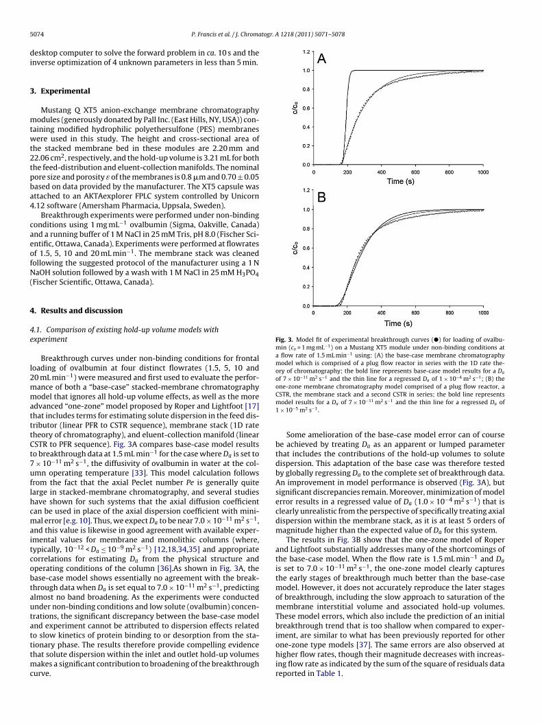
5 togr. A 1218 (2011) 5071– 5078
di
3
mtwt2tpba4
caeofN(
4
4e
l2mmatttCt7uflhcmaitcobtautatttmc
Fig. 3. Model fit of experimental breakthrough curves (�) for loading of ovalbu-min (co = 1 mg mL−1) on a Mustang XT5 module under non-binding conditions ata flow rate of 1.5 mL min−1 using: (A) the base-case membrane chromatographymodel which is comprised of a plug flow reactor in series with the 1D rate the-ory of chromatography; the bold line represents base-case model results for a Da
of 7 × 10⁻¹¹ m2 s−1 and the thin line for a regressed Da of 1 × 10⁻⁴ m2 s−1; (B) theone-zone membrane chromatography model comprised of a plug flow reactor, aCSTR, the membrane stack and a second CSTR in series; the bold line represents
074 P. Francis et al. / J. Chroma
esktop computer to solve the forward problem in ca. 10 s and thenverse optimization of 4 unknown parameters in less than 5 min.
. Experimental
Mustang Q XT5 anion-exchange membrane chromatographyodules (generously donated by Pall Inc. (East Hills, NY, USA)) con-
aining modified hydrophilic polyethersulfone (PES) membranesere used in this study. The height and cross-sectional area of
he stacked membrane bed in these modules are 2.20 mm and2.06 cm2, respectively, and the hold-up volume is 3.21 mL for bothhe feed-distribution and eluent-collection manifolds. The nominalore size and porosity ε of the membranes is 0.8 �m and 0.70 ± 0.05ased on data provided by the manufacturer. The XT5 capsule wasttached to an AKTAexplorer FPLC system controlled by Unicorn.12 software (Amersham Pharmacia, Uppsala, Sweden).
Breakthrough experiments were performed under non-bindingonditions using 1 mg mL−1 ovalbumin (Sigma, Oakville, Canada)nd a running buffer of 1 M NaCl in 25 mM Tris, pH 8.0 (Fischer Sci-ntific, Ottawa, Canada). Experiments were performed at flowratesf 1.5, 5, 10 and 20 mL min−1. The membrane stack was cleanedollowing the suggested protocol of the manufacturer using a 1 NaOH solution followed by a wash with 1 M NaCl in 25 mM H3PO4
Fischer Scientific, Ottawa, Canada).
. Results and discussion
.1. Comparison of existing hold-up volume models withxperiment
Breakthrough curves under non-binding conditions for frontaloading of ovalbumin at four distinct flowrates (1.5, 5, 10 and0 mL min−1) were measured and first used to evaluate the perfor-ance of both a “base-case” stacked-membrane chromatographyodel that ignores all hold-up volume effects, as well as the more
dvanced “one-zone” model proposed by Roper and Lightfoot [17]hat includes terms for estimating solute dispersion in the feed dis-ributor (linear PFR to CSTR sequence), membrane stack (1D rateheory of chromatography), and eluent-collection manifold (linearSTR to PFR sequence). Fig. 3A compares base-case model resultso breakthrough data at 1.5 mL min−1 for the case where Da is set to
× 10−11 m2 s−1, the diffusivity of ovalbumin in water at the col-mn operating temperature [33]. This model calculation followsrom the fact that the axial Peclet number Pe is generally quitearge in stacked-membrane chromatography, and several studiesave shown for such systems that the axial diffusion coefficientan be used in place of the axial dispersion coefficient with mini-al error [e.g. 10]. Thus, we expect Da to be near 7.0 × 10⁻¹¹ m2 s−1,
nd this value is likewise in good agreement with available exper-mental values for membrane and monolithic columns (where,ypically, 10−12 < Da ≤ 10−9 m2 s−1) [12,18,34,35] and appropriateorrelations for estimating Da from the physical structure andperating conditions of the column [36].As shown in Fig. 3A, thease-case model shows essentially no agreement with the break-hrough data when Da is set equal to 7.0 × 10⁻¹¹ m2 s−1, predictinglmost no band broadening. As the experiments were conductednder non-binding conditions and low solute (ovalbumin) concen-rations, the significant discrepancy between the base-case modelnd experiment cannot be attributed to dispersion effects relatedo slow kinetics of protein binding to or desorption from the sta-
ionary phase. The results therefore provide compelling evidencehat solute dispersion within the inlet and outlet hold-up volumesakes a significant contribution to broadening of the breakthroughurve.
model results for a Da of 7 × 10⁻¹¹ m2 s−1 and the thin line for a regressed Da of1 × 10−5 m2 s−1.
Some amelioration of the base-case model error can of coursebe achieved by treating Da as an apparent or lumped parameterthat includes the contributions of the hold-up volumes to solutedispersion. This adaptation of the base case was therefore testedby globally regressing Da to the complete set of breakthrough data.An improvement in model performance is observed (Fig. 3A), butsignificant discrepancies remain. Moreover, minimization of modelerror results in a regressed value of Da (1.0 × 10⁻⁴ m2 s−1) that isclearly unrealistic from the perspective of specifically treating axialdispersion within the membrane stack, as it is at least 5 orders ofmagnitude higher than the expected value of Da for this system.
The results in Fig. 3B show that the one-zone model of Roperand Lightfoot substantially addresses many of the shortcomings ofthe base-case model. When the flow rate is 1.5 mL min−1 and Da
is set to 7.0 × 10⁻¹¹ m2 s−1, the one-zone model clearly capturesthe early stages of breakthrough much better than the base-casemodel. However, it does not accurately reproduce the later stagesof breakthrough, including the slow approach to saturation of themembrane interstitial volume and associated hold-up volumes.These model errors, which also include the prediction of an initialbreakthrough trend that is too shallow when compared to exper-iment, are similar to what has been previously reported for other
one-zone type models [37]. The same errors are also observed athigher flow rates, though their magnitude decreases with increas-ing flow rate as indicated by the sum of the square of residuals datareported in Table 1.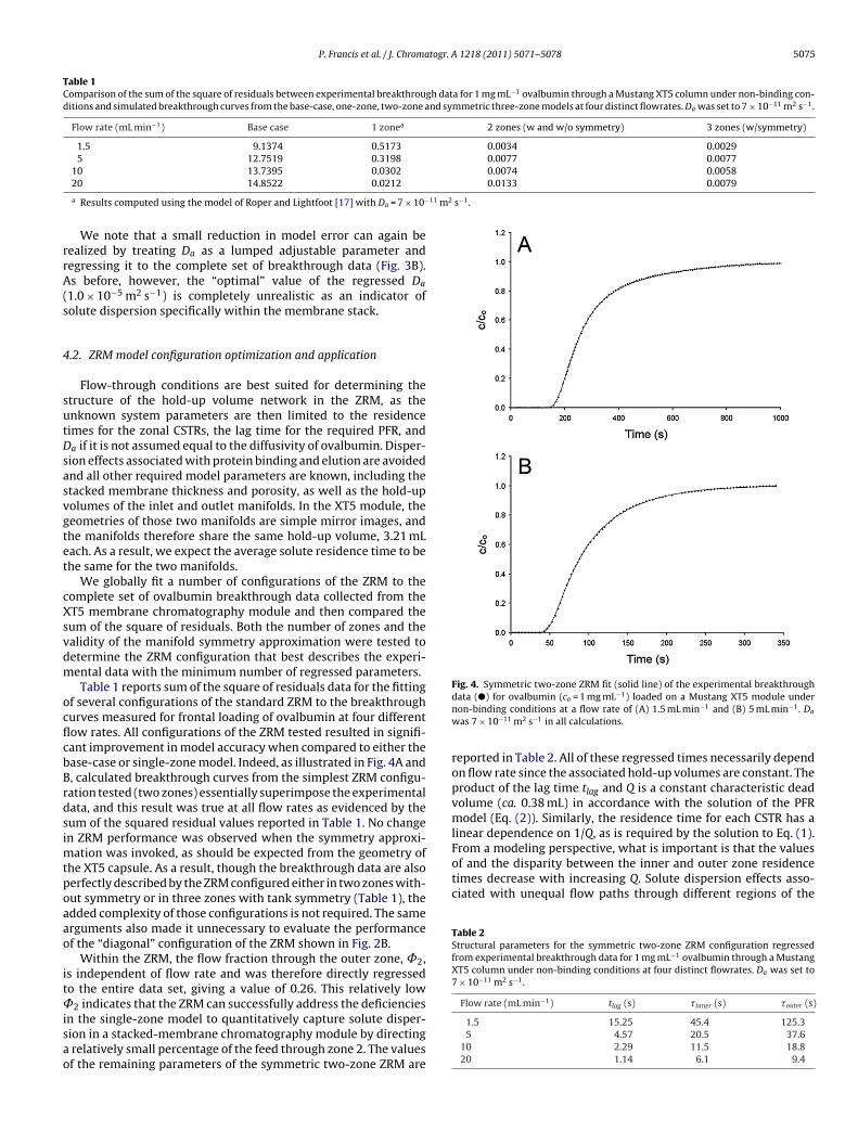
P. Francis et al. / J. Chromatogr. A 1218 (2011) 5071– 5078 5075
Table 1Comparison of the sum of the square of residuals between experimental breakthrough data for 1 mg mL−1 ovalbumin through a Mustang XT5 column under non-binding con-ditions and simulated breakthrough curves from the base-case, one-zone, two-zone and symmetric three-zone models at four distinct flowrates. Da was set to 7 × 10⁻¹¹ m2 s−1.
Flow rate (mL min−1) Base case 1 zonea 2 zones (w and w/o symmetry) 3 zones (w/symmetry)
1.5 9.1374 0.5173 0.0034 0.00295 12.7519 0.3198 0.0077 0.0077
10 13.7395 0.0302 0.0074 0.00580.0133 0.0079
11 m2 s−1.
rrA(s
4
sutDsasvgtet
cXsvdm
ocflcbBrdsimtpoaao
it˚isao
Fig. 4. Symmetric two-zone ZRM fit (solid line) of the experimental breakthrough−1
of and the disparity between the inner and outer zone residencetimes decrease with increasing Q. Solute dispersion effects asso-ciated with unequal flow paths through different regions of the
Table 2Structural parameters for the symmetric two-zone ZRM configuration regressedfrom experimental breakthrough data for 1 mg mL−1 ovalbumin through a MustangXT5 column under non-binding conditions at four distinct flowrates. Da was set to7 × 10−11 m2 s−1.
Flow rate (mL min−1) tlag (s) � inner (s) �outer (s)
20 14.8522 0.0212
a Results computed using the model of Roper and Lightfoot [17] with Da = 7 × 10−
We note that a small reduction in model error can again beealized by treating Da as a lumped adjustable parameter andegressing it to the complete set of breakthrough data (Fig. 3B).s before, however, the “optimal” value of the regressed Da
1.0 × 10⁻⁵ m2 s−1) is completely unrealistic as an indicator ofolute dispersion specifically within the membrane stack.
.2. ZRM model configuration optimization and application
Flow-through conditions are best suited for determining thetructure of the hold-up volume network in the ZRM, as thenknown system parameters are then limited to the residenceimes for the zonal CSTRs, the lag time for the required PFR, anda if it is not assumed equal to the diffusivity of ovalbumin. Disper-ion effects associated with protein binding and elution are avoidednd all other required model parameters are known, including thetacked membrane thickness and porosity, as well as the hold-upolumes of the inlet and outlet manifolds. In the XT5 module, theeometries of those two manifolds are simple mirror images, andhe manifolds therefore share the same hold-up volume, 3.21 mLach. As a result, we expect the average solute residence time to behe same for the two manifolds.
We globally fit a number of configurations of the ZRM to theomplete set of ovalbumin breakthrough data collected from theT5 membrane chromatography module and then compared theum of the square of residuals. Both the number of zones and thealidity of the manifold symmetry approximation were tested toetermine the ZRM configuration that best describes the experi-ental data with the minimum number of regressed parameters.Table 1 reports sum of the square of residuals data for the fitting
f several configurations of the standard ZRM to the breakthroughurves measured for frontal loading of ovalbumin at four differentow rates. All configurations of the ZRM tested resulted in signifi-ant improvement in model accuracy when compared to either thease-case or single-zone model. Indeed, as illustrated in Fig. 4A and, calculated breakthrough curves from the simplest ZRM configu-ation tested (two zones) essentially superimpose the experimentalata, and this result was true at all flow rates as evidenced by theum of the squared residual values reported in Table 1. No changen ZRM performance was observed when the symmetry approxi-
ation was invoked, as should be expected from the geometry ofhe XT5 capsule. As a result, though the breakthrough data are alsoerfectly described by the ZRM configured either in two zones with-ut symmetry or in three zones with tank symmetry (Table 1), thedded complexity of those configurations is not required. The samerguments also made it unnecessary to evaluate the performancef the “diagonal” configuration of the ZRM shown in Fig. 2B.
Within the ZRM, the flow fraction through the outer zone, ˚2,s independent of flow rate and was therefore directly regressedo the entire data set, giving a value of 0.26. This relatively low
2 indicates that the ZRM can successfully address the deficiencies
n the single-zone model to quantitatively capture solute disper-ion in a stacked-membrane chromatography module by directingrelatively small percentage of the feed through zone 2. The valuesf the remaining parameters of the symmetric two-zone ZRM are
data (�) for ovalbumin (co = 1 mg mL ) loaded on a Mustang XT5 module undernon-binding conditions at a flow rate of (A) 1.5 mL min−1 and (B) 5 mL min−1. Da
was 7 × 10⁻¹¹ m2 s−1 in all calculations.
reported in Table 2. All of these regressed times necessarily dependon flow rate since the associated hold-up volumes are constant. Theproduct of the lag time tlag and Q is a constant characteristic deadvolume (ca. 0.38 mL) in accordance with the solution of the PFRmodel (Eq. (2)). Similarly, the residence time for each CSTR has alinear dependence on 1/Q, as is required by the solution to Eq. (1).From a modeling perspective, what is important is that the values
1.5 15.25 45.4 125.35 4.57 20.5 37.6
10 2.29 11.5 18.820 1.14 6.1 9.4
5076 P. Francis et al. / J. Chromatogr. A 1218 (2011) 5071– 5078
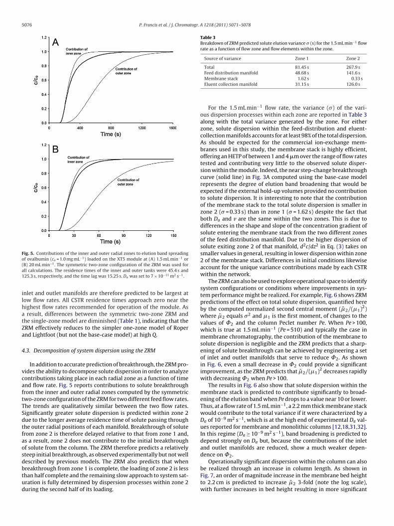
Fig. 5. Contributions of the inner and outer radial zones to elution band spreadingof ovalbumin (co = 1.0 mg mL−1) loaded on the XT5 module at (A) 1.5 mL min−1 or( −1
a1
ilhatZa
4
vcaftTSdtfaosdbtud
Table 3Breakdown of ZRM predicted solute elution variance � (s) for the 1.5 mL min−1 flowrate as a function of flow zone and flow elements within the zone.
Source of variance Zone 1 Zone 2
Total 81.45 s 267.9 sFeed distribution manifold 48.68 s 141.6 s
B) 20 mL min . The symmetric two-zone configuration of the ZRM was used forll calculations. The residence times of the inner and outer tanks were 45.4 s and25.3 s, respectively, and the time lag was 15.25 s. Da was set to 7 × 10⁻¹¹ m2 s−1.
nlet and outlet manifolds are therefore predicted to be largest atow flow rates. All CSTR residence times approach zero near theighest flow rates recommended for operation of the module. As
result, differences between the symmetric two-zone ZRM andhe single-zone model are diminished (Table 1), indicating that theRM effectively reduces to the simpler one-zone model of Ropernd Lightfoot (but not the base-case model) at high Q.
.3. Decomposition of system dispersion using the ZRM
In addition to accurate prediction of breakthrough, the ZRM pro-ides the ability to decompose solute dispersion in order to analyzeontributions taking place in each radial zone as a function of timend flow rate. Fig. 5 reports contributions to solute breakthroughrom the inner and outer radial zones computed by the symmetricwo-zone configuration of the ZRM for two different feed flow rates.he trends are qualitatively similar between the two flow rates.ignificantly greater solute dispersion is predicted within zone 2ue to the longer average residence time of solute passing throughhe outer radial positions of each manifold. Breakthrough of soluterom zone 2 is therefore delayed relative to that from zone 1 and,s a result, zone 2 does not contribute to the initial breakthroughf solute from the column. The ZRM therefore predicts a relativelyteep initial breakthrough, as observed experimentally but not wellescribed by previous models. The ZRM also predicts that when
reakthrough from zone 1 is complete, the loading of zone 2 is lesshan half complete and the remaining slow approach to system sat-ration is fully determined by dispersion processes within zone 2uring the second half of its loading.Membrane stack 1.62 s 0.33 sEluent collection manifold 31.15 s 126.0 s
For the 1.5 mL min−1 flow rate, the variance (�) of the vari-ous dispersion processes within each zone are reported in Table 3along with the total variance generated by the zone. For eitherzone, solute dispersion within the feed-distribution and eluent-collection manifolds accounts for at least 98% of the total dispersion.As should be expected for the commercial ion-exchange mem-branes used in this study, the membrane stack is highly efficient,offering an HETP of between 1 and 4 �m over the range of flow ratestested and contributing very little to the observed solute disper-sion within the module. Indeed, the near step-change breakthroughcurve (solid line) in Fig. 3A computed using the base-case modelrepresents the degree of elution band broadening that would beexpected if the external hold-up volumes provided no contributionto solute dispersion. It is interesting to note that the contributionof the membrane stack to the total solute dispersion is smaller inzone 2 (� = 0.33 s) than in zone 1 (� = 1.62 s) despite the fact thatboth Da and v are the same within the two zones. This is due todifferences in the shape and slope of the concentration gradient ofsolute entering the membrane stack from the two different zonesof the feed distribution manifold. Due to the higher dispersion ofsolute exiting zone 2 of that manifold, d2c/dz2 in Eq. (3) takes onsmaller values in general, resulting in lower dispersion within zone2 of the membrane stack. Differences in initial conditions likewiseaccount for the unique variance contributions made by each CSTRwithin the network.
The ZRM can also be used to explore operational space to identifysystem configurations or conditions where improvements in sys-tem performance might be realized. For example, Fig. 6 shows ZRMpredictions of the effect on total solute dispersion, quantified hereby the computed normalized second central moment ( �̄2/(�1)2)where �̄2 equals �2 and �1 is the first moment, of changes to thevalues of ˚2 and the column Peclet number Pe. When Pe > 100,which is true at 1.5 mL min−1 (Pe = 510) and typically the case inmembrane chromatography, the contribution of the membrane tosolute dispersion is negligible and the ZRM predicts that a sharp-ening of solute breakthrough can be achieved by engineering a setof inlet and outlet manifolds that serve to reduce ˚2. As shownin Fig. 6, even a small decrease in ˚2 could provide a significantimprovement, as the ZRM predicts that �̄2/(�1)2 decreases rapidlywith decreasing ˚2 when Pe > 100.
The results in Fig. 6 also show that solute dispersion within themembrane stack is predicted to contribute significantly to broad-ening of the elution band when Pe drops to a value near 10 or lower.Thus, at a flow rate of 1.5 mL min−1, a 2.2 mm thick membrane stackwould contribute to the total variance if it were characterized by aDa of 10−9 m2 s−1, which is at the high end of experimental Da val-ues reported for membrane and monolithic columns [12,18,31,32].In this regime (Da ≥ 10−9 m2 s−1), band broadening is predicted todepend strongly on Da but, because the contributions of the inletand outlet manifolds are reduced, show a much weaker depen-dence on ˚2.
Operationally significant dispersion within the column can alsobe realized through an increase in column length. As shown in
Fig. 7, an order of magnitude increase in the membrane bed heightto 2.2 cm is predicted to increase �̄2 3-fold (note the log scale),with further increases in bed height resulting in more significant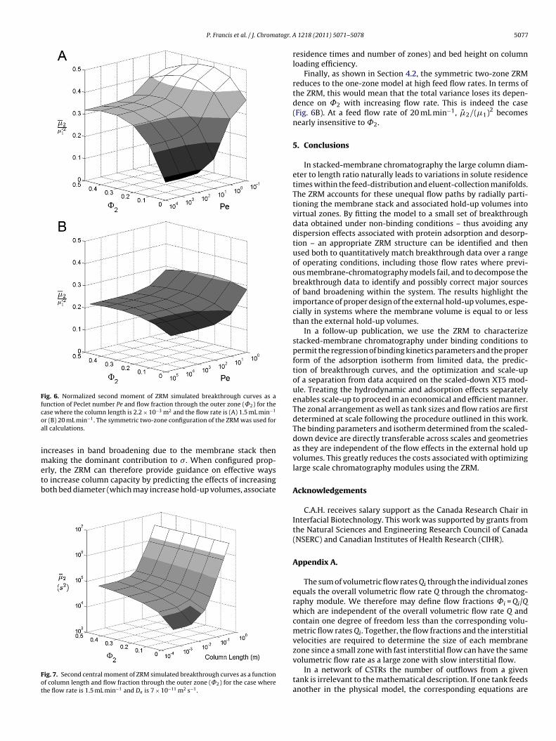
P. Francis et al. / J. Chromatogr. A
Fig. 6. Normalized second moment of ZRM simulated breakthrough curves as afunction of Peclet number Pe and flow fraction through the outer zone (˚2) for thecoa
imetb
Fot
ase where the column length is 2.2 × 10⁻³ m2 and the flow rate is (A) 1.5 mL min−1
r (B) 20 mL min−1. The symmetric two-zone configuration of the ZRM was used forll calculations.
ncreases in band broadening due to the membrane stack thenaking the dominant contribution to �. When configured prop-
rly, the ZRM can therefore provide guidance on effective wayso increase column capacity by predicting the effects of increasingoth bed diameter (which may increase hold-up volumes, associate
ig. 7. Second central moment of ZRM simulated breakthrough curves as a functionf column length and flow fraction through the outer zone (˚2) for the case wherehe flow rate is 1.5 mL min−1 and Da is 7 × 10⁻¹¹ m2 s−1.
1218 (2011) 5071– 5078 5077
residence times and number of zones) and bed height on columnloading efficiency.
Finally, as shown in Section 4.2, the symmetric two-zone ZRMreduces to the one-zone model at high feed flow rates. In terms ofthe ZRM, this would mean that the total variance loses its depen-dence on ˚2 with increasing flow rate. This is indeed the case(Fig. 6B). At a feed flow rate of 20 mL min−1, �̄2/(�1)2 becomesnearly insensitive to ˚2.
5. Conclusions
In stacked-membrane chromatography the large column diam-eter to length ratio naturally leads to variations in solute residencetimes within the feed-distribution and eluent-collection manifolds.The ZRM accounts for these unequal flow paths by radially parti-tioning the membrane stack and associated hold-up volumes intovirtual zones. By fitting the model to a small set of breakthroughdata obtained under non-binding conditions – thus avoiding anydispersion effects associated with protein adsorption and desorp-tion – an appropriate ZRM structure can be identified and thenused both to quantitatively match breakthrough data over a rangeof operating conditions, including those flow rates where previ-ous membrane-chromatography models fail, and to decompose thebreakthrough data to identify and possibly correct major sourcesof band broadening within the system. The results highlight theimportance of proper design of the external hold-up volumes, espe-cially in systems where the membrane volume is equal to or lessthan the external hold-up volumes.
In a follow-up publication, we use the ZRM to characterizestacked-membrane chromatography under binding conditions topermit the regression of binding kinetics parameters and the properform of the adsorption isotherm from limited data, the predic-tion of breakthrough curves, and the optimization and scale-upof a separation from data acquired on the scaled-down XT5 mod-ule. Treating the hydrodynamic and adsorption effects separatelyenables scale-up to proceed in an economical and efficient manner.The zonal arrangement as well as tank sizes and flow ratios are firstdetermined at scale following the procedure outlined in this work.The binding parameters and isotherm determined from the scaled-down device are directly transferable across scales and geometriesas they are independent of the flow effects in the external hold upvolumes. This greatly reduces the costs associated with optimizinglarge scale chromatography modules using the ZRM.
Acknowledgements
C.A.H. receives salary support as the Canada Research Chair inInterfacial Biotechnology. This work was supported by grants fromthe Natural Sciences and Engineering Research Council of Canada(NSERC) and Canadian Institutes of Health Research (CIHR).
Appendix A.
The sum of volumetric flow rates Qi through the individual zonesequals the overall volumetric flow rate Q through the chromatog-raphy module. We therefore may define flow fractions ˚i = Qi/Qwhich are independent of the overall volumetric flow rate Q andcontain one degree of freedom less than the corresponding volu-metric flow rates Qi. Together, the flow fractions and the interstitialvelocities are required to determine the size of each membranezone since a small zone with fast interstitial flow can have the same
volumetric flow rate as a large zone with slow interstitial flow.In a network of CSTRs the number of outflows from a giventank is irrelevant to the mathematical description. If one tank feedsanother in the physical model, the corresponding equations are

5078 P. Francis et al. / J. Chromatogr.
cifetE
w
Ht
ma˚z˚1ea
[[[[[[[[[[[
[
[
[[[[[[[
[[[[33] M.T. Tyn, T.W. Guzek, Biotechnol. Bioeng. 35 (1990) 327.
Fig. A1. Junction of flows through three zones in a cascade of CSTRs.
oupled by taking the concentration within the feeding tank as thenlet concentration of the fed tank. The same rule holds when a tankeeds a membrane zone. Downstream of the membrane stack how-ver, the model includes tanks with multiple inflows (see Fig. 2). Aank with j inflows is mathematically described by an instance ofq. (A.1).
∂cCSTR
∂t=
j∑i=1
cCSTRin,i
�i− cCSTR
�(A.1)
here
1�
=j∑
i=1
1�i
(A.2)
ere cCSTR denotes the concentration in the respective tank, cCSTRin
he corresponding inlet concentration and � the residence time.A set of flow fractions must be defined for each tank with
ore than one inlet. Fig. A1 illustrates this situation in more detailnd represents the collector tanks from Fig. 2A. The set ˚1 to3 with ˚1 + ˚2 + ˚3 = 1 refers to the flow fraction through each
one, while the sets ˚1b,1 and ˚1b,2 with ˚1b,1 + ˚1b,2 = 1 as well as
2b,1 and ˚2b,2 with ˚2b,1 + ˚2b,2 = 1 refer to the inlets of tanksb and 2b, respectively. An instance of Eq. (A.1) is set up forach of these tanks with residence times 1/�1b,1 + 1/�1b,2 = 1/�1bnd 1/�2b,1 + 1/�2b,2 = 1/�2b, and with flow fractions ˚1b,i = �1b/�1b,i
[[[[
A 1218 (2011) 5071– 5078
and ˚2b,i = �2b/�2b, for 1 ≤ i ≤ 2. The flow fractions through themembrane zones are then uniquely determined by ˚1 = ˚1b,1,˚2 = ˚1b,2·˚2b,1 and ˚3 = ˚1b,2·˚2b,2. Analogous relations can bederived for complex networks with more membrane zones or withexchange flows between the tanks.
References
[1] E. Klein, J. Membr. Sci. 179 (2000) 1.[2] D.K. Roper, E.N. Lightfoot, J. Chromatogr. A 702 (1995) 3.[3] R. Ghosh, J. Chromatogr. A 952 (2002) 13.[4] J. Thömmes, M.-R. Kula, Biotechnol. Prog. 11 (1995) 357.[5] C. Charcosset, Biotechnol. Adv. 24 (2006) 482.[6] R. Van Reis, A. Zydney, J. Membr. Sci. 297 (2007) 16.[7] A. Saxena, B.P. Tripathi, M. Kumar, V.K. Shahi, Adv. Colloid Interface Sci. 145
(2009) 1.[8] J.X. Zhou, T. Tressel, U. Gottschalk, F. Solamo, A. Pastor, S. Dermawan, S.T. Hong,
O. Reif, J. Mora, F. Hutchison, M. Murphy, J. Chromatogr. A 1134 (2006) 66.[9] S.-Y. Suen, M.R. Etzel, Chem. Eng. Sci. 47 (1992) 1355.10] K.G. Briefs, M.-R. Kula, Chem. Eng. Sci. 47 (1992) 141.11] H.C. Liu, J.R. Fried, AIChE J. 40 (1994) 40.12] K.H. Gebauer, J. Thömmes, M.R. Kula, Chem. Eng. Sci. 52 (1997) 405.13] S.-Y. Suen, M.R. Etzel, J. Chromatogr. A 686 (1994) 179.14] C. Boi, S. Dimartino, G.C. Sarti, J. Chromatogr. A 1162 (2007) 24.15] J. Wang, F. Dismer, J. Hubbuch, M. Ulbricht, J. Membr. Sci. 320 (2008) 456.16] H. Yang, M.R. Etzel, Ind. Eng. Chem. Res. 42 (2003) 890.17] D.K. Roper, E.N. Lightfoot, J. Chromatogr. A 702 (1995) 69.18] F.T. Sarfert, M.R. Etzel, J. Chromatogr. A 764 (1997) 3.19] H. Yang, M. Bitzer, M.R. Etzel, Ind. Eng. Chem. Res. 38 (1999) 4044.20] R.M. Montesinos-Cisneros, J. de la Vega Olivas, J. Ortega, R. Guzmán, A. Tejeda-
Mansir, Biotechnol. Prog. 23 (2007) 881.21] T. Vicente, M.F.Q. Sousa, C. Peixoto, J.P.B. Mota, P.M. Alves, M.J.T. Carrondo, J.
Membr. Sci. 311 (2008) 270.22] E.N. Lightfoot, A.M. Athalye, J.L. Coffman, D.K. Roper, T.W. Root, J. Chromatogr.
A 707 (1995) 45.23] R. Ghosh, T. Wong, J. Membr. Sci. 281 (2006) 532.24] E. von Lieres, J. Wang, M. Ulbricht, Chem. Eng. Technol. 33 (2010) 960.25] J.A. Barber, J.D. Perkins, R.W.H. Sargent, Chem. Eng. Sci. 53 (1998) 1463.26] T. Farkas, G. Guiochon, Anal. Chem. 69 (1997) 4592.27] T. Yun, G. Guiochon, J. Chromatogr. A 760 (1997) 17.28] R.A. Shalliker, B.S. Broyles, G. Guiochon, J. Chromatogr. A 888 (2000) 1.29] W.E. Schiesser, The Numerical Method of Lines, Academic Press, San Diego,
1991.30] L.F. Shampine, M.W. Reichelt, SIAM J. Sci. Comput. 18 (1997) 1.31] T.F. Coleman, Y. Li, SIAM J. Opt. 6 (1996) 418.32] T.F. Coleman, Y. Li, Math. Prog. 67 (1994) 189.
34] J. Yun, H. Kirsebom, I.Y. Galaev, B. Mattiasson, J. Sep. Sci. 32 (2009) 2601.35] F. Gritti, W. Piatkowski, G. Guiochon, J. Chromatogr. A 983 (2003) 51.36] C.L. de Ligny, Chem. Eng. Sci. 47 (1970) 253.37] J.E. Kochan, Y.-J. Wu, M.R. Etzel, Ind. Eng. Chem. Res. 35 (1996) 1150.