Embed Size (px)
Citation preview
Tel.: +49-(0)2762-9756-0 Simo17 paper02.doc Fax: -7 page 1/15
Ductile Metal Flakes based on [Au], [Ag], [Al], [Cu], [Ti], [Zn] and [Fe] Materials by High Energy Milling (HEM) – Part I
H. Zoz1, H. Ren1, R. Reichardt1, H.U. Benz1, A. Nadkarni2, G. Wagner3
1 Zoz GmbH, D-57482 Wenden, Germany
2 OMG Americas, Research Triangle Park, NC 27709-2166, USA 3 C.Hafner GmbH + Co., D-75137 Pforzheim, Germany
Abstract The High Energy (ball) Milling (HEM) technique has been found to be an efficient way to produce fine metal flakes. HEM follows the same principle as Mechanical Alloying (MA) where powder particles are permanently exposed to deformation, fracture and welding processes originated by a high kinetic energy transfer to the powder by highly energetic (fast) ball collisions. Metals like Au, Ag, Al, Cu, Ti and Zn exhibit a high ductility. By plastic deformation, cold welding and fracture during the milling procedure, the powder particles can therefore be formed to the desired flaky shape and size within short milling times (3-30 min), where a processing time not exceeding 10 min can be considered for a semi-continuous processing route [1]. Due to the application of Cycle Operation which is an operating model with permanently varying rotary speed [2], the processing was in general carried out without any fluid process control agent. The produced flakes have a dimension of a thickness (t) < 0.5 µm and diameters (d) from 20 to 200 µm, consequently a ratio d/t up to 1000. The flake-geometry can be controlled by the variation of process parameters such as rotary speed of the rotor, ratio of powder/ball charge, filling ratio of the system, process temperature and operating model. In other words by varying the kinetic. The addition of a process control agent (PCA) has an influence on the kinetic as well as on the product, too.
1. Introduction
Metal flakes are an excellent pigment-base for metallic paints, in particular due to their metallic luster. Al-flakes can be found in sprays and lacquers for coating on metal surfaces with large applications in particular in automotive. Flakes based on Au, Cu, Ni and Au-Ag-Cu-alloys are mostly utilized for decoration purposes, e. g. on surface of ceramic or synthetic materials to make the golden color effect. The metal-flake is most frequently coated with a metal-oxide by CVD-process in order to increase the shiny effect. Metal-flakes can also be used to produce conductive thin-layers. This enables the production of special soldering material for micro-electronics, printable flake-pastes for computer-keyboards and high-quality screen-heating systems in automotive industry [3]. Additionally, flakes can be used in the liquid phase sintering (LPS) technique as a suitable starting geometry for coating the to be sintered component. A similar application is possible in soft magnetic materials, which consist of two different “overlay” and “core” materials. The encapsulation of a magnetic [4] by a nonmagnetic can be obtained by adding nonmagnetic and
Tel.: +49-(0)2762-9756-0 Simo17 paper02.doc Fax: -7 page 2/15
ductile flakes to spherical and less ductile magnetic powder in a correspondingly tuned milling process. The conventional processing route is accomplished by a low kinetic milling process in a (drum) ball mill either in wet condition often using alcohol or in dry condition using stearic acid or other organic PCA`s. This leads to milling times in the range of 5 hours up to several days. In comparison, the HEM-route is 100 to 1000 times faster and therefore shows a large potential to become the future technique for an economic production of ductile metal powder flakes. In particular processing in liquid condition under alcohol is very expensive with respect to environment costs due to later cleaning needs.
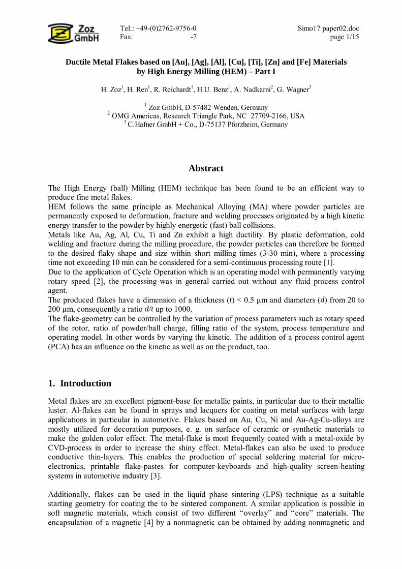
2. HEM device and processing The principle of the High Energy Mill (Figure 1) is based on a horizontally borne rotor which allows an energy transfer in a homogeneous and highly efficient way, from supplied power to kinetic energy of balls (grinding media). The milling balls are accelerated by the rotating rotor and collide with each other at a relative velocity up to 14 m/s. The impact put mainly pressure, but also minor shear and friction on the powder particles which are located between two balls during the collision. By this way, the powder particles are deformed, broken or recombined by cold welding and/or a combination of all.
The parameters of the milling process do influence the geometry and the size of the final flakes. The important parameters are:
• rotary speed of the rotor; • powder/ball ratio; • total filling ratio; • process temperature; • process atmosphere; • operating model; • milling time;
Fig. 1: Simoloyer CM01-2l
Furthermore, the starting powder particle size is very important. As an example, in case of chemically precipitated and nanoscaled Au-starting powder, the theoretical calculation [5] indicates that one single metal flake with a dimension of d = 100 µm, t = 0.2 µm consists in minimum from 500.000 theoretical starting particles with a theoretical minimum number of 50 interfaces. Consequently, a stacked structure of the powder particles which possess a high density of displacement caused by deformation was produced. This leads to an increase of the hardness and brittleness of the powder particles, which is not wanted in general.
Tel.: +49-(0)2762-9756-0 Simo17 paper02.doc Fax: -7 page 3/15
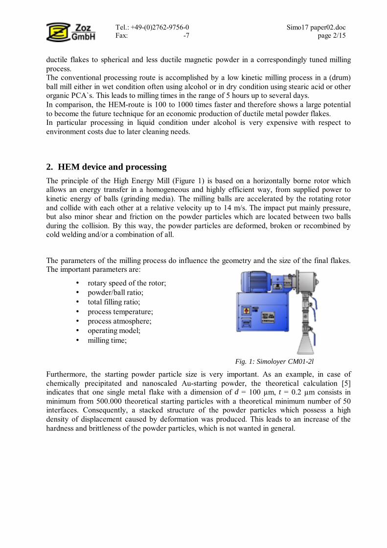
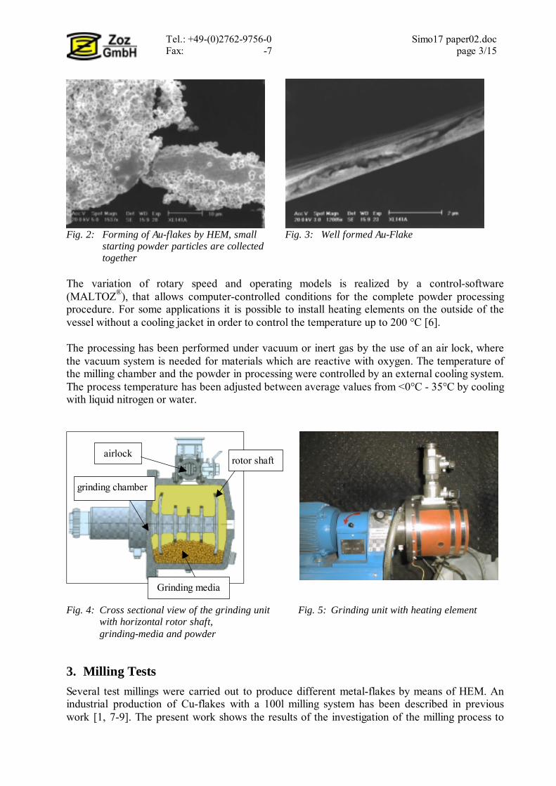
Fig. 2: Forming of Au-flakes by HEM, small Fig. 3: Well formed Au-Flake starting powder particles are collected together The variation of rotary speed and operating models is realized by a control-software (MALTOZ®), that allows computer-controlled conditions for the complete powder processing procedure. For some applications it is possible to install heating elements on the outside of the vessel without a cooling jacket in order to control the temperature up to 200 °C [6]. The processing has been performed under vacuum or inert gas by the use of an air lock, where the vacuum system is needed for materials which are reactive with oxygen. The temperature of the milling chamber and the powder in processing were controlled by an external cooling system. The process temperature has been adjusted between average values from <0°C - 35°C by cooling with liquid nitrogen or water.
Fig. 4: Cross sectional view of the grinding unit Fig. 5: Grinding unit with heating element with horizontal rotor shaft, grinding-media and powder
3. Milling Tests Several test millings were carried out to produce different metal-flakes by means of HEM. An industrial production of Cu-flakes with a 100l milling system has been described in previous work [1, 7-9]. The present work shows the results of the investigation of the milling process to
Grinding media
rotor shaft
grinding chamber
airlock

Tel.: +49-(0)2762-9756-0 Simo17 paper02.doc Fax: -7 page 4/15
produce Au-, Ag-, Al-, Cu-, brass, Ti-, Zn- and steel-flakes by a Simoloyer CM01-2l system with a grinding chamber volume of 2 liters, which is shown in Figure 5.
Fig. 6: Grinding Unit of Simoloyer CM01-2l, grinding media Different experiments were carried out to optimize the process to produce flakes. The Grinding unit, including the rotor, the vessel and milling balls was cleaned before and after each test milling (dry/wet-cleaning). The experimental parameters for several of the milling tests are shown in Table 1 and 2. In consideration of the properties of Aluminum which is characterized as light, easy deformable with a high affinity to oxygen, an inert atmosphere using argon was chosen. The procedure was carried out with the addition of 0.5 wt % stearic acid, in order to create the Al-flakes without oxidation, without sticking among the particles and without “coating” on the milling tools. As for aluminum the processing of Ti-flakes and Zn-flakes require an atmosphere of Argon. Au-, Ag-, and Cu-flakes can be processed under air. In particular if Cu shall finally be used for a conductive application, processing under argon is suitable in order to avoid oxidation, on the contrary in case of color application, oxidation is wanted. Therefore here both has been investigated. The conditions are given in tables 1-2. Table 1: Equipment of the milling tests: Simoloyer: CM01-2l milling balls: material steel (100Cr6) diameter: 4.762 mm ball mass: 2000 g powder mass: 200g powder/ball mass ratio: 1:10 milling-atmosphere: air, argon cooling – grinding unit: water

Tel.: +49-(0)2762-9756-0 Simo17 paper02.doc Fax: -7 page 5/15
Table 2: Process parameters to produce Al-, Cu-, brass, Au, Ag-, Ti-, Zn- and Fe-flakes
Material Processing time Rotary Speed Operating
model Temp. Atmosphere PCA
Al-flakes 5-30min 1300rpm/48sec 1000rpm/12sec cycle RT argon (preceeding
evacuation) 0.5w% stearic acid
Cu-flakes 5-30min 1300rpm constant or cycle RT air or argon, (pre-
ceeding evacuation) 0.5w% stearic acid
Brass flakes 5–30min 1300rpm constant or cycle RT air or argon (pre-
ceeding evacuation) 0.5w% stearic acid
Au-flakes (CM01-½l) 1-40min 1500rpm constant or
cycle RT air 0.5w% stearic acid
Ag-flakes 1-10min 1200rpm constant or cycle RT air 0.5w%
stearic acid
Ti-flakes 5-30min 1300rpm/48sec 900rpm/12sec cycle RT argon, (preceeding
evacuation) 0.5w% stearic acid
Zn-flakes 5-15min 1300rpm/48sec 900rpm/12sec cycles RT air,
diluted with argon 0.5w% stearic acid
Fe-flakes 10min-2h 500rpm constant RT air, diluted with argon no
4. Results of processing
4.1 Al-flakes
The starting Al-powder has a spherical geometry and a particle size of ≤30µm. Scanning electron microscopy (SEM) image of the starting powder by a Philips XL30 is shown in Figure 7. Previous experiments showed that the Al-flakes under air without stearic acid could not be formed but, instead, "Al-nuggets" up to 10mm were found after the milling process. Furthermore, the inside of the grinding chamber and the grinding media were coated with Al powder (see Figure 8).
Fig. 7: SEM of Al - Starting powder Fig. 8: Al-powder after 5min milling time under air, without stearic acid
Al starting powder
Al-nuggets
Tel.: +49-(0)2762-9756-0 Simo17 paper02.doc Fax: -7 page 6/15
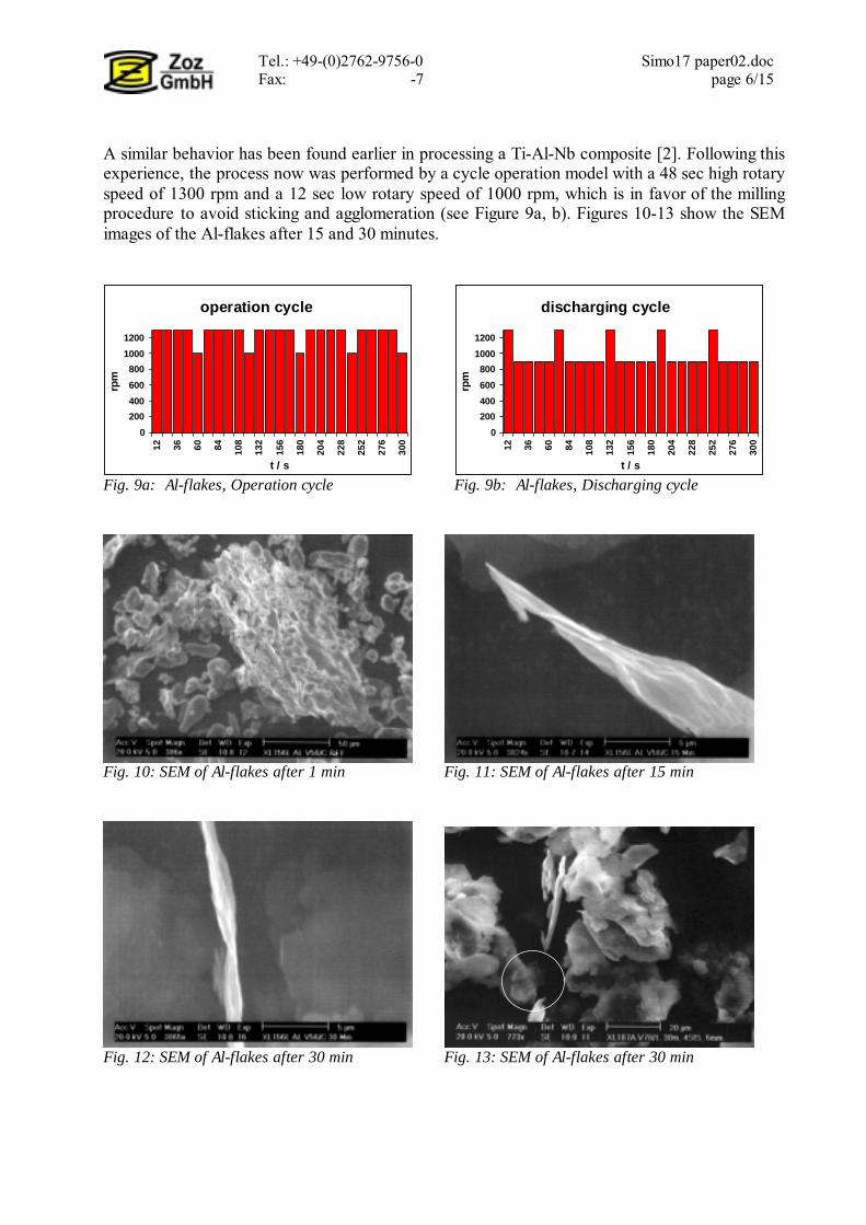
A similar behavior has been found earlier in processing a Ti-Al-Nb composite [2]. Following this experience, the process now was performed by a cycle operation model with a 48 sec high rotary speed of 1300 rpm and a 12 sec low rotary speed of 1000 rpm, which is in favor of the milling procedure to avoid sticking and agglomeration (see Figure 9a, b). Figures 10-13 show the SEM images of the Al-flakes after 15 and 30 minutes.
operation cycle
0200400600800
10001200
12 36 60 84 108
132
156
180
204
228
252
276
300
t / s
rpm
discharging cycle
0200400600800
10001200
12 36 60 84 108
132
156
180
204
228
252
276
300
t / srp
m
Fig. 9a: Al-flakes, Operation cycle Fig. 9b: Al-flakes, Discharging cycle
Fig. 10: SEM of Al-flakes after 1 min Fig. 11: SEM of Al-flakes after 15 min
Fig. 12: SEM of Al-flakes after 30 min Fig. 13: SEM of Al-flakes after 30 min

Tel.: +49-(0)2762-9756-0 Simo17 paper02.doc Fax: -7 page 7/15
It could be observed that after 1min the Al particles are partly deformed under the condition of cycle operation, argon atmosphere and addition of stearic acid. After 15min well formed thin Al-flakes could be obtained. They show a thickness far below 1 µm and a diameter of 50-80µm. The thickness of the Al-flakes was further reduced with increasing milling time up to 30min. Fig. 13 shows a very thin flake (in circle) with a t < 0,1µm which seems to be transparent, however in this stage this is not proved at all.
4.2 Cu-Flakes The starting Cu-powder was characterised by SEM (Figure 14) and had a particle sizes of d<50µm. The change of particle size and geometry could be observed in SEM images 14-17. The particles were deformed after 3min and changed to flakes after 5min. After 10min well formed flakes with different diameters could clearly be observed. The flakes have a thickness of < 1µm. After 20min the diameter of flakes become more homogeneous. An average diameter of 100-150µm and a thickness of < 0.8µm could be evaluated. Hardly any variation in size and geometric form of flakes was observed with the further increasing of milling time up to 30min. The thickness of as-milled flakes after 30min was <0.6µm (Figure 16). Figure 17 shows the Cu-flakes milled under argon with had a thinner thickness as those milled under air. Less oxidation of the Cu during the milling process are expected to be the reason to reduce the thickness, conductive testing of both materials is applied but not finished yet.
Fig. 14: SEM of Cu - Starting powder Fig. 15: SEM of Cu-flakes after 20min under air using stearic acid
Fig. 16: SEM of Cu-flakes after 30min Fig. 17: SEM of Cu-flakes after 30min under air using stearic acid under argon using stearic acid
Tel.: +49-(0)2762-9756-0 Simo17 paper02.doc Fax: -7 page 8/15
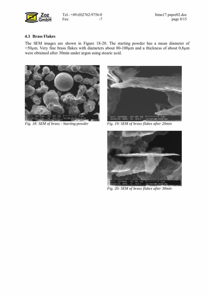
4.3 Brass Flakes The SEM images are shown in Figure 18-20. The starting powder has a mean diameter of <50µm. Very fine brass flakes with diameters about 80-100µm and a thickness of about 0,8µm were obtained after 30min under argon using stearic acid.
Fig. 18: SEM of brass - Starting-powder Fig. 19: SEM of brass flakes after 20min
Fig. 20: SEM of brass flakes after 30min
Tel.: +49-(0)2762-9756-0 Simo17 paper02.doc Fax: -7 page 9/15
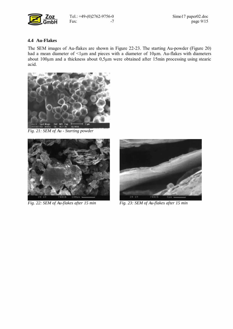
4.4 Au-Flakes The SEM images of Au-flakes are shown in Figure 22-23. The starting Au-powder (Figure 20) had a mean diameter of <1µm and pieces with a diameter of 10µm. Au-flakes with diameters about 100µm and a thickness about 0,5µm were obtained after 15min processing using stearic acid.
Fig. 21: SEM of Au - Starting powder
Fig. 22: SEM of Au-flakes after 15 min Fig. 23: SEM of Au-flakes after 15 min

Tel.: +49-(0)2762-9756-0 Simo17 paper02.doc Fax: -7 page 10/15
4.5 Ag-Flakes The SEM images are shown in Figure 24-25. The starting Ag-powder has a mean diameter of <50µm. After 9min processing under air using stearic acid, Ag-flakes with a diameter about 60-80µm and a thickness <0,4µm were obtained.
Fig. 24: SEM of Ag - Starting powder Fig. 25: SEM of Ag-flakes after 9min
4.6 Ti-Flakes The SEM images are shown in Figure 26-27. The starting Ti-powder has a mean diameter of <45µm. After 30min processing under argon using stearic acid, Ti-flakes with a diameter about 80-100µm and a thickness <2µm were obtained.
Fig. 26: SEM of Ti-flakes after 20 min Fig. 27: SEM of Ti-flakes after 30 min

Tel.: +49-(0)2762-9756-0 Simo17 paper02.doc Fax: -7 page 11/15
4.7 Zn-Flakes The SEM images are shown in Figure 28-29. The starting Zn-powder has a mean diameter of < 500 µm. After 15 min processing under argon using stearic acid, Ti-flakes with a diameter about 1200-1300µm and a thickness <15µm were obtained.
Fig. 28: SEM of Zn - Starting powder Fig. 29: SEM of Zn-flakes after 15 min
4.8 Fe-Flakes The SEM images of 410 steel starting powder and flakes are presented in Figure 30-31. The starting powder has a mean diameter of <30µm. Well formed flakes with diameter about 60-80µm and a thickness <3µm could obtained after 2h under the condition shown in Table 2.
Fig. 30: SEM of 410 steel - Starting powder Fig. 31: SEM of 410 steel flakes after 2h

Tel.: +49-(0)2762-9756-0 Simo17 paper02.doc Fax: -7 page 12/15
5. Comparison Summarily, a comparative list of the different metal flakes made by the laboratory high energy ball mill relating to the mechanical properties were established in Table 3 and Figure 32. Table 3: A comparison of different metal flakes made by HEM [10]
Flakes Al Ag Cu Brass Au Ti 410 steel Zn starting powder
size [µm] ≤ 30 < 50 < 50 < 50 ≈ 1 < 45 < 30 < 500
Diameter d [µm] 50-80 60-80 100-150 80-100 100 80-100 60-80 1200-
1300 Thickness t [µm] < 0,5 < 0,4 < 0,6 < 0,8 0,5 < 2 < 2,2 < 11
d/t > 100 > 150 > 160 > 100 200 > 40 > 30 > 110 Hardness of metal [HB] 47 25.7 35-47 60-160 18.5 120-
160 200-300 35-38
Fig. 32: Relation between hardness and cross ratio d/t
The hardness of the powders plays an important part of influencing the size and geometry of the flakes. It could be seen that the ratio of d/t is connected with the hardness of the powder. A high hardness (steel, Ti) leads to a low ratio of d/t, as the plastic deformation of the particles which was served by dislocation of crystal lattice becomes more difficult with the increasing of hardness. A low hardness favors the forming of flakes with a high d/t ratio such as Au, Cu, Al and Zn. The HEM process to produce metal flakes can be described as a micro pressing process where a changing shock load by the balls is put on the particles. In order to form one flake thousands of collisions of balls are needed. The dependency between the thickness of the as-milled flakes and the starting particle size and geometry has been calculated [5]. This theoretical calculation indicates that the thickness of the flakes increases with the increasing of diameter of starting powder and number of interlayer. Based on experimental results, the interactions, such as the cold welding among the powder particles are too large to be neglected. The recombination of the
0
50
100
150
200
250
250140110474136,525,618,5
Hardness of metal (HB)
Rat
io d
iam
eter
/thic
knes
s Au
Ag Zn
Cu
Al Brass
Ti410 Fe
Tel.: +49-(0)2762-9756-0 Simo17 paper02.doc Fax: -7 page 13/15
particles due to cold welding can lead to an increasing of thickness of flakes however, the possibility of recombination depends on physical properties of the powder and process parameters. The rotary speed of the rotor varies the velocity of the balls, which changes the value of kinetic ball load onto the powder particles and the energy balance during the milling procedure. The local temperature at the moment of impacting is certainly higher than the measured mean value, this enhances the tendency of recombination of the small particles. Therefore, a complex function among the size of flakes and the process parameters must be expected. The total filling ratio of grinding media has also an important influence on the kinetic of the system. Fundamentally, a minimum filling quantity of the balls is needed to set up a movement of balls in the vessel. At first, increasing the quantity of milling balls increases the kinetic energy up to a maximum value, then the kinetic energy goes down, because the free moving space of the balls is reduced. Furthermore, the powder/ball ratio plays a similar role with respect to the kinetic in the process. A smaller ratio of powder leads to a smaller dumping effect of the powder itself, more powder decreases the kinetic energy and leads to a higher tendency of friction between powder and balls. An optimum of the ratio is defined between 1:20 and 1:5, which depends on the powder material properties.
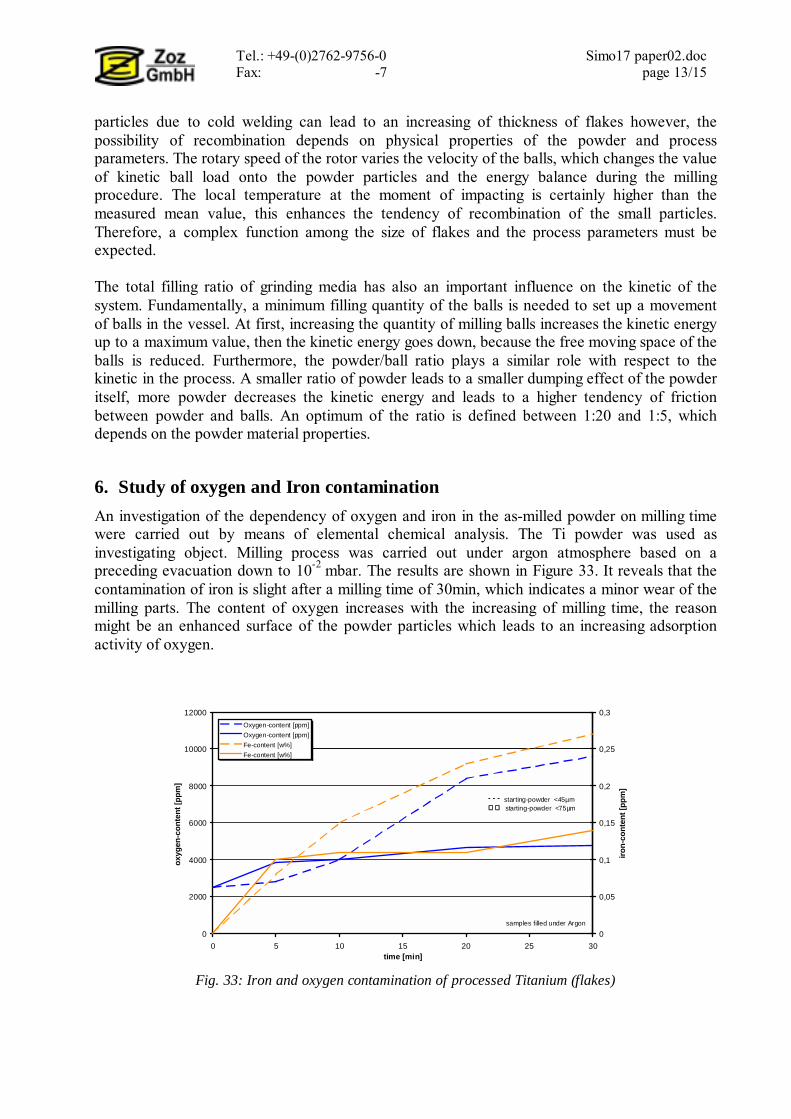
6. Study of oxygen and Iron contamination An investigation of the dependency of oxygen and iron in the as-milled powder on milling time were carried out by means of elemental chemical analysis. The Ti powder was used as investigating object. Milling process was carried out under argon atmosphere based on a preceding evacuation down to 10-2 mbar. The results are shown in Figure 33. It reveals that the contamination of iron is slight after a milling time of 30min, which indicates a minor wear of the milling parts. The content of oxygen increases with the increasing of milling time, the reason might be an enhanced surface of the powder particles which leads to an increasing adsorption activity of oxygen.
Fig. 33: Iron and oxygen contamination of processed Titanium (flakes)
0
2000
4000
6000
8000
10000
12000
0 5 10 15 20 25 30time [min]
oxyg
en-c
onte
nt [p
pm]
0
0,05
0,1
0,15
0,2
0,25
0,3
iron-
cont
ent [
ppm
]
Oxygen-content [ppm]Oxygen-content [ppm]Fe-content [w%]Fe-content [w%]
samples filled under Argon
- - - starting-powder <45µm starting-powder <75µm
Tel.: +49-(0)2762-9756-0 Simo17 paper02.doc Fax: -7 page 14/15
7. Conclusions All of the tested powders, the Au-, Ag-, Al-, Cu-, brass, Ti-, Zn- and steel-flakes have been produced by means of HEM within 30 min. From the technological point of view, a semi-continuous processing route for the industrial production is possible if the processing time can be reduced below or to 5 – 10 min. The HEM process for the production of the metal flakes has been carried out under an atmosphere of air as well as argon. For Al-, Ti- and Zn-flakes, processing under vacuum or inert gas is necessary in order to avoid oxidation of the powder particles. For Au-, and Ag-flakes, processing under air is suitable. For Cu-flakes both is recommended depending on the application (color >> air, conductive >> argon). Stearic acid is favorable for anti-adhesion of the powder particles. The final metal-flakes possess different particle sizes and sharps which depend on the properties of processed material. A thickness of the flakes t < 0.5µm and a diameter d ≈ 60 - 200µm are practically to be obtained. A qualitative relation between ratio d/t and hardness could be observed, a low hardness of the starting powder favors a increasing of the ratio d/t. Au, Al, and Cu possess a higher d/t values than that of Ti, brass and steel. Due to a highly and popularly interest in metal-flakes the work will be carried out continuously in order to optimize the process parameters. A theoretical calculation describing the correlation between flake size and geometry, dependent on the process parameters, starting powder size and material property should be performed. An investigation of energy balance during the milling process should be carried out in order to explain the mechanisms of the milling process. References [1] H. Zoz, D. Ernst, T. Mizutani, H. Okouchi, Simoloyer* CM100s, semi-continuously
Mechanical Alloying in a production scale using Cycle Operation-Part I, Advances in Powder Metallurgy & Particulate Materials–1997, PM2Tech´97, Chicago, Vol.2 (1997), p.11-35
[2] H. Zoz, D. Ernst, H. Weiss, M. Magini, C. Powell, C. Suryanarayana, F.H. Froes: Mechanical Alloying of Ti-24Al-11Nb (at%) using the Simoloyer ( Zoz - horizontal rotary ball mill), Metall, Vol. 50, 9 (1996), p. 575-579
[3] K. Lutz: Edelmetallpulver, Innovative Produkte durch Pulver - Pulvermetallurgie in Wissenschaft und Praxis, Herausgegeben von Hans Kolaska, Band 14, 19/20 November (1998), p. 117-136
[4] Authors discussion with Robert W. Ward, Anderson, Indiana, June – August 1998 [5] H.U. Benz, H. Zoz: Particle deformation (V=const) – Investigation and Production of the
CMB-metal-flakes Au, Ag, Cu, Ti, Ni, Al, Internal Report Zoz GmbH, 1998 [6] H. Zoz, H. Ren, N. Späth: Improved Ag-SnO2 Electrical Contact Material Produced by
Mechanical Alloying, Proceeding of 1998 Powder Metallurgy World Congress & Exhibition, Granada, Spain, October 18-22, 1998

Tel.: +49-(0)2762-9756-0 Simo17 paper02.doc Fax: -7 page 15/15
[7] H. Zoz, R. Reichardt, D. Ernst, Simoloyer CM100s, semi-continuously Mechanical Alloying in a production scale using Cycle Operation - Part II, Metall Vol. 51. 9 (1998), p. 521-527.
[8] H. Zoz: Performance of the Simoloyer, 4th International Conference on Powder Metallurgy in Aerospace, Defense and Demanding Applications, eds. P.S. Goodwin, R.B. Schwarz, in Annaheim, Los Angeles, USA, May 08-10, 1995
[9] H. Zoz, D. Ernst: Mechanical Alloying using Cycle Operation - A New Way to Synthesize CMB-Materials, 5th International Conference on Advanced Particulate Materials and Processes, West Palm Beach, Florida, USA, April 07-09, 1997
[10] K.H. Harbig, Verschleiß und Härte von Werkstoffen, Carl hanser Verlag , Müchen, Wien, 1980


![Reactive Dry-Milling for Environmental Protectiongmbh.zoz.de/_AKTUELL/pdf_content/publications/v40.pdf · 2016-08-10 · Reactive Dry-Milling for Environmental Protection ... [2-4]](https://img.pdfslide.net/doc/110x75/5f0f0b427e708231d44235e0/reactive-dry-milling-for-environmental-2016-08-10-reactive-dry-milling-for-environmental.jpg)