Embed Size (px)
Citation preview
ZS8.4Air-insulated medium voltage switchgear

2 | ZS8.4 Air-insulated medium voltage switchgear
Power products from ABB
Future-proof solutionsABB provides utility, industrial and commercial customers with safe, reliable and smart technologies for the distribution of electricity. This extensive global offering includes distribution automation products, switching, limiting, measuring and sensing devices, switchgear, modular substation packages and related services.
ABB offers innovative and fully-integrated compact medium voltage switchgear concepts that enable customers operating in today’s increasingly competitive demanding markets to receive the maximum return on investment in their vital network assets.
Air-insulated switchpanels from ABBABB’s ZS8.4 range is designed to provide maximum flexibility and the highest possible safety for circuit-breaker systems or switch-disconnector installations, using either conventional instrument transformers or modern sensor technology. Deve-loped to meet the specific needs of medium voltage switch-gear users in every respect, ZS8.4 delivers perfect power distribution.
A strong solution for every marketCustomers throughout Europe rely on ABB’s ZS8.4 family of air-insulated switchgear to provide the ideal, flexible solution for virtually any application.

ZS8.4 Air-insulated medium voltage switchgear | 3
Simply universal
Flexible – safe – economicalThe main scope of application for ZS8.4 switchgear has, in re-cent years, shifted increasingly to the primary distribution level with circuit-breakers. It is an independent product line targe-ted at the interface between secondary and primary distribu-tion level. The majority of ZS8.4 installations are for industrial customers, however it is also specified for power supply and municipal services applications.In a wide range of situations, including metros, shopping malls, manufacturing facilities and offices ZS8.4 with vacuum circuit-breaker, switch-disconnector or vacuum contactor is the cost-effective route to ensuring a safe and reliable power supply.
Today there is an installed base of more than 20.000 ZS8.4-panels in Central Europe, Asia and the Gulf States, with the majority found in Germany. ZS8.4 combines mature, well-established switchgear technology with modern manufacturing processes to deliver the optimum cost-effective solution. ABB’s ongoing product development process has resulted in the addition of a contactor panel as well as panels with expanded automatic protection against accidental contact.

4 | ZS8.4 Air-insulated medium voltage switchgear
Details in focus
With comprehensive interlocks and integrated protection against accidental contact with the busbars, ZS8.4 offers a unique safety concept. For example, mutual interlocking of the devices practically precludes maloperation.
Maintenance-free switching devices and the sealed encapsu-lation ensure permanently reliable operation.

ZS8.4 Air-insulated medium voltage switchgear | 5
Automatic protection against accidental contact: By shutter in panels with tee-off partitioning, and by sliding plate in panels without tee-off partitioning.
Three function areas are mutually partitioned - low voltage area, busbar area and MV area with circuit-breaker area, switch-disconnector area, con-tactor area and cable termination area.

6 | ZS8.4 Air-insulated medium voltage switchgear
Details in focus
The safety and availability of the ZS8.4 switchgear are further enhanced by use of the tee-off partitioning which protects the busbar area in case of internal faults in the device and cable termination areas.
The optimal solution:
- Vacuum circuit-breaker
- Switch-disconnector
- Vacuum contactor
- Earthing switch
Rod-type switch-disconnector type C4- High breaking and making capacity- Reliable arc quenching by combining the air blasting and the hard gas principle- Low maintenance- Capable of switching capacitive currents under earth fault conditions

ZS8.4 Air-insulated medium voltage switchgear | 7
Circuit-breaker (VD4 / VM1)- VD4 minimum-maintenance- VM1 maintenance-free- High availability- High number of operating cycles- Very compact dimensions- Poles sealed for lifetime
Vacuum contactor- Up to 1.000.000 switching operations- Actuator with permanent magnets- Maintenance-free- Specific vacuum arcing chambers

8 | ZS8.4 Air-insulated medium voltage switchgear
Peripherals
Controlling and operation - Combined protection and control device, e.g. REF542 plus - Conventional control engineering as desired for - Electromechanical bar position indication - Illuminated LED bar position indication - Customer specified multifunction device
Protection relaying - Multifunctional protection of DMT by differential protection up to distance protection- Discrete protection units, e.g. REF610
Protection and control with 615 series relay - Circuit-breaker control at the protection unit - Comprehensive feeder protection function from feeder protection REF 615 to pilot-wire differential relay RED615, further devices - 11 user-programmable LEDs - Up to 17 binary inputs and 12 binary outputs - Interlocking function - Three-channel arc protection against personnel injury - IEC 61850 communication with GOOSE or conventional messaging - Practical withdrawable component - Optimal solution for ZS8.4 for manually driven earthing switch and cut-off

ZS8.4 Air-insulated medium voltage switchgear | 9
Current and voltage metering - Voltage transformer for permanent mounting or withdrawable component with lock and release device - Dimensions in accordance with DIN 42600 restricted type - Electrical characteristics in accordance with IEC-standards 60044-2 - Sensors are short-circuit proof and insensitive to ferroresonance and to DC-component
Combined sensor or current transformerThe uniform box frame can be equipped with a combined sensor consisting of a Rogowski coil and a potentiometer-type resistor, with current transformer cores or combination of Rogowski coil and potentiometer.
Link to control and protection system - The link available to a superimposed control and protection system depends on the kind of protection and control device

10 | ZS8.4 Air-insulated medium voltage switchgear
Delivery - Complete panels- Are factory-checked - Transport units are individual panels- For crane or fork-lift truck
Erection- Easy and fast erection- Suitable height of switchgear room from 2.40 metres - LSC 2A / PI panels from 2.70 metres - LSC 2A + LSC 2B / PM panels from 2.70 metres - Panels LSC 2A / PI + PM and LSC 2B / PM with pressure release duct from 2.40 metres- Installation to the frame or to the intermediate plate- Easy erection of the panels by simple busbar connections- Cable termination with standard sealing end
Commissioning - Must be performed by trained specialists - Door interlock can be cancelled, for instance for visual inspection
Inspection and servicing - Must be by trained personnel in accordance with safety regulations to DIN/VDE and of professional associations having liability for industrial safety and insurance.- The inspection and servicing intervals for some of the equipment/components are determined by fixed criteria such as switching frequency. The length of the intervals may depend on the different modes of operation in individual cases, such as the degree of loading, and also environmental influences
Over the past 40 years, ABB has developed an outstanding reputation for the design and construction of air-insulated switchgear. The ZS8.4 switchgear series has built on this reputation to establish a leading position in the global market.
Peripherals

ZS8.4 Air-insulated medium voltage switchgear | 11
Loss of service continuity LSC 2A, Partition class PI
Circuit-breaker panel A Busbar areaB Circuit-breaker areaC Cable termination areaD Low voltage compartment
1 Busbars 2 Circuit-breaker VM1/VD4 3 Automatic sliding plate 4 Earthing switch 5 Current transformer 6 Voltage transformer 7 Installation contacts 8 Bay control and protection unit REF542 plus10 Capacitive voltage indication
Circuit-breaker panel - bus sectionaliser panel A Busbar areaB Circuit-breaker areaC Tie bus areaD Low voltage compartment
1 Busbars 2 Circuit-breaker VM1/VD4 3 Automatic sliding plate 4 Earthing switch 5 Current transformer 6 Tie bus 7 Installation contacts 8 Bay control and protection unit REF542 plus10 Capacitive voltage indication
Switch-disconnector panel A Busbar areaB Switch-disconnector areaC Cable termination areaD Low voltage compartment
1 Busbars2 Switch-disconnector C43 Automatic sliding plate4 Earthing switch
Switch-disconnector panel with fuseA Busbar areaB Switch-disconnector areaC Cable termination areaD Low voltage compartment
1 Busbars 2 Switch-disconnector C4 3 Automatic sliding plate 4 Earthing switch11 Fuse
Fig. 12 kV Fig. 12 kV
Fig. 12 kV Fig. 12 kV

12 | ZS8.4 Air-insulated medium voltage switchgear
Switch-disconnector - bus sectionaliser panelA Busbar areaB Switch-disconnector areaC Tie bus areaD Low voltage compartment
1 Busbars1.2 Tie bus2 Switch-disconnector C43 Automatic sliding plate4 Earthing switch
Riser panelA Busbar areaC Transformer areaD Low voltage compartment
1 Busbars1.2 Tie bus5 Current transformer6 Voltage transformer
Loss of service continuity LSC 2A, Partition class PI
When the earthing switch is closed, the automatic sliding plate moves between the isolating contact of the circuit-breaker to guarantee protection against contact between live parts and the busbar area.
Partition class PI – metal-enclosed medium-voltage switchgear with one or additional non-metallic intermediate walls and/or shutter between accessible compartments and parts of the main circuit, which are energized.
Operating availability LSC 2A, Partition class PI - Dimension
Ur lk Height Width Depth
kV kA mm mm mm
12 25 2100*) 650 1000
17.5 25**) 2100*) 650 1000
24 25**) 2100*) 800 1200*) Low voltage compartment h = 730 mm --> h = 2100 mm Low voltage compartment h = 530 mm + cover h = 200 mm --> h = 2100 mm **) only CB-panels, SD-panels 17.5 kV/20 kA and 24 kV/16 kA!
Fig. 12 kV Fig. 12 kV

ZS8.4 Air-insulated medium voltage switchgear | 13
Loss of service continuity LSC 2A, Partition class PM
Circuit-breaker panel A Busbar areaB Circuit-breaker areaC Cable termination area D Low voltage compartment
1 Busbars 2 Circuit-breaker VM1/VD4 3 Automatic shutter 4 Earthing switch 5 Current transformer 6 Voltage transformer 7 Installation contacts 8 Bay control and protection unit REF542 plus 9 Isolating tulip / tee-off partitioning 10 Capacitive voltage indication
Contactor panelA Busbar area B Vacuum contactor areaC Cable termination areaD Low voltage compartment
1 Busbars 2 Vacuum contactor 3 Automatic shutter 4 Earthing switch 5 Current transformer 6 Voltage transformer 7 Installation contacts 8 Bay control and protection unit REF542 plus 9 Isolating tulip/tee-off partitioning10 Capacitive voltage indication
Switch-disconnector panel A Busbar areaB Switch-disconnector areaC Cable termination areaD Low voltage area
2.1 Moveable isolating contact2.2 Switch-disconnector3 Automatic shutter4 Earthing switch
Switch-disconnector panel with fuseA Busbar areaB Switch-disconnector areaC Cable termination areaD Low voltage area
2.1 Moveable isolating contact2.2 Switch-disconnector3 Automatic shutter4 Earthing switch11 Fuse
Fig. 12 kV
Fig. 12 kV Fig. 12 kV
Fig. 12 kV
14 | ZS8.4 Air-insulated medium voltage switchgear
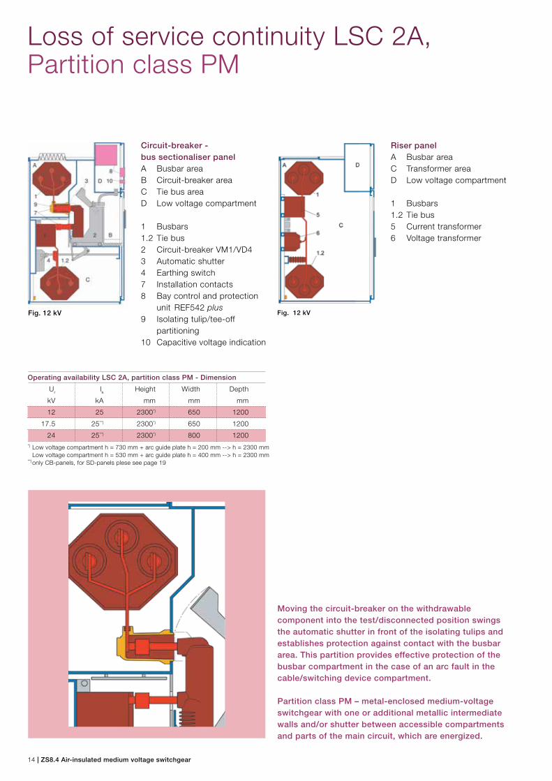
Circuit-breaker - bus sectionaliser panelA Busbar areaB Circuit-breaker areaC Tie bus areaD Low voltage compartment
1 Busbars1.2 Tie bus2 Circuit-breaker VM1/VD43 Automatic shutter4 Earthing switch7 Installation contacts8 Bay control and protection unit REF542 plus9 Isolating tulip/tee-off partitioning10 Capacitive voltage indication
Riser panelA Busbar areaC Transformer areaD Low voltage compartment
1 Busbars1.2 Tie bus5 Current transformer6 Voltage transformer
Loss of service continuity LSC 2A, Partition class PM
Moving the circuit-breaker on the withdrawable component into the test/disconnected position swings the automatic shutter in front of the isolating tulips and establishes protection against contact with the busbar area. This partition provides effective protection of the busbar compartment in the case of an arc fault in the cable/switching device compartment.
Partition class PM – metal-enclosed medium-voltage switchgear with one or additional metallic intermediate walls and/or shutter between accessible compartments and parts of the main circuit, which are energized.
Fig. 12 kV Fig. 12 kV
Operating availability LSC 2A, partition class PM - Dimension
Ur lk Height Width Depth
kV kA mm mm mm
12 25 2300*) 650 1200
17.5 25**) 2300*) 650 1200
24 25**) 2300*) 800 1200*) Low voltage compartment h = 730 mm + arc guide plate h = 200 mm --> h = 2300 mm Low voltage compartment h = 530 mm + arc guide plate h = 400 mm --> h = 2300 mm **) only CB-panels, for SD-panels plese see page 19

ZS8.4 Air-insulated medium voltage switchgear | 15
Loss of service continuity LSC 2B, Partition class PM
Circuit-breaker panel A Busbar areaB Circuit-breaker areaC Cable termination areaD Low voltage compartment
1 Busbars 2 Circuit-breaker VM1/VD4 3 Automatic sliding plate 4 Earthing switch 5 Current transformer 6 Voltage transformer 7 Installation contacts 8 Bay control and protection unit REF542 plus 9 Isolating tulip / tee-off partition10 Capacitive indication
Contactor panel (LSC 2A)A Busbar areaB Vacuum contactor areaC Cable termination areaD Low voltage compartment
1 Busbars 2 Vacuum contactor 3 Automatic shutter 4 Earthing switch 5 Current transformer 6 Voltage transformer 7 Installation contacts 9 Isolating tulip / tee-off partition10 Capacitive indication
Switch-disconnector panel with fuse (LSC 2A)A Busbar areaB Switch-disconnector areaC Cable termination areaD Low voltage compartment 2.1 Moveable isolating contact 2.2 Switch-disconnector 3 Automatic shutter 4 Earthing switch11 Fuse
Fig. 12 kV
3D-view-circuit-breaker panel
Fig. 12 kV Fig. 12 kV

16 | ZS8.4 Air-insulated medium voltage switchgear
Circuit-breaker - bus sectionaliser panelA Busbar areaB Circuit-breaker areaC Tie bus areaD Low voltage compartment
1 Busbars1.2 Tie bus2 Circuit-breaker VM1/VD43 Automatic sliding plate4 Earthing switch5 Current transformer7 Installation contacts8 Bay controller and protection unit REF542 plus9 Isolating tulip / tee-off partitioning10 Capacitive indication
Riser panelA Busbar areaC Transformer areaD Low voltage compartment
1 Busbars1.2 Tie bus5 Current transformer6 Voltage transformer
Loss of service continuity LSC 2B, Partition class PM
Moving the circuit-breaker withdrawable component into the test/disconnected position swings the automatic shutter in front of the isolating tulips and establishes protection against contact with the busbar area. The busbar area partition provides effective protection of the busbar compartment in the case of an arc fault in the cable/ switching device compartment. The busbar compartment is separated by a withdrawable metal partition from the switching device/cable termination compartment behind the front door. The shutter is withdrawable for cable installation. Protection against contact is realized in 3 areas: busbar areacircuit-breaker areatransformer/cable termination area
Fig. 12 kV Fig. 12 kV
Operating availability LSC 2B, Partition class PM - Dimension
Ur lk Height Width Depth
kV kA mm mm mm
12 25 2300*) 650 1200
*) Low voltage compartment h = 730 mm + arc guide plate h = 200 mm --> h = 2300 mm Low voltage compartment h = 530 mm + arc guide plate h = 400 mm --> h = 2300 mm

ZS8.4 Air-insulated medium voltage switchgear | 17
Special panel solutions and top-mounted boxes
Switch-disconnector panel Partition class PI with fuse, current and voltage transformer for energy metering measuring
Duplex-circuit-breaker panelFig. 24 kV
Top-mounted box 12/24 kV with voltage transformer
Special panels and top-mounted boxes - Dimension
Ur lk Height Width Depth
kV kA mm mm mm
12***) 25 2300*) 800 2400
24***) 25**) 2300*) 800 2400*) Low voltage compartment h = 730 mm + arc guide plate h = 200 mm --> h = 2300 mm Low voltage compartment h = 530 mm + arc guide plate h = 400 mm --> h = 2300 mm **) 24 kV switchgear modified for 12 kV ! ***) only CB-panels, for SD-panels plese see page 19
Top-mounted box 12/24 kV with earthing switch
18 | ZS8.4 Air-insulated medium voltage switchgear
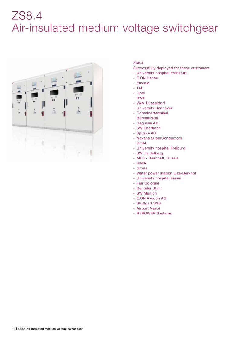
ZS8.4Air-insulated medium voltage switchgear
ZS8.4Successfully deployed for these customers- University hospital Frankfurt- E.ON Hanse - EnviaM - TAL- Opel- RWE- V&M Düsseldorf- University Hannover- Containerterminal Burchardkai- Degussa AG- SW Eberbach- Spitzke AG- Nexans SuperConductors GmbH- University hospital Freiburg- SW Heidelberg - MES - Bashneft, Russia- KIMA- Grona- Water power station Elze-Berkhof- University hospital Essen- Fair Cologne- Benteler Stahl- SW Munich- E.ON Avacon AG- Stuttgart SSB- Airport Navoi- REPOWER Systems

ZS8.4 Air-insulated medium voltage switchgear | 19
Technical data
Circuit-breaker panels, contactor panels and corresponding switch-disconnector panels
Rated voltage Ur kV 12 17.5 24
Highest operating voltage kV 12 17.5 24
Rated power frequency withstand voltage Ud kV 28 38 50
Rated lightning impulse withstand voltage Up kV 75 95 125
Rated frequency fr Hz 50/60 50/60 50/60
Rated current, busbars Ir A …1250 …1250 …1250
Rated current, feeder
Switch-disconnector panel Ir A 630 1) 630 1) 630 2)
Contactor panel A 220 3) 5)
Circuit-breaker panel A 1250 1250 1250
Rated peak withstand current Ip kA …63 … 63 6) …63 8)
Rated short time current 3 s Ik kA 16/20/25 16/20/25 7) 16/20/25 7)
Rated load breaking current
of the switch-disconnector A …630 …630 …630
Rated short-circuit making current
of the switch-disconnector kA …63 …50 …40 8)
Rated short-circuit breaking current
of the circuit-breaker kA …25 …25 …25
Rated short-circuit making current
of the circuit-breaker kA …63 …63 …63
Rated operating sequence O - 0.3 s - CO - 15 s - CO O - 0.3 s - CO - 15 s - CO O - 0.3 s - CO - 15 s - CO
Total break time ms 50 … 75 50 … 75 50 … 75
Operating time ms 60 … 80 60 … 80 60 … 80
Degree of protection
of the switchgear IP4X IP4X IP4X
of the compartments to one another IP2X IP2X IP2X
Ambient temperature
Maximum °C +40 +40 +40
24-h-mean value °C +35 +35 +35
Minimum °C -5 -5 -5
Site altitude m 1000 1000 1000
Height of cable connection: mm 341 - 582 4) 341 - 582 4) 341 - 7671) 1000 A available on request2) 800 A available on request3) Rated current at max. fuse size 400 A (SIBA) 6 kV4) Cable connection height depends on panel type5) Max. service voltage 7,2 kV6) 17.5 kV switch-disconnector panel up to 50 kA7) 17.5 kV switch-disconnector panel only 20 kA / 24 kV switch-disconnector panel 20 kA or 25 kA for switch-disconnector with fuse (max. fuse size 40 A)8) 24 kV switch-disconnector panel 50 kA or 63 kA for switch disconnector with fuse (max. fuse size 40A)

Contact us
Your sales contact: www.abb.com/contacts 1VLC
0000
52 -
Rev
. B
, en
- B
roch
ure
- 20
18-0
3 -
(ZS
8.4)
(gs)
More product information: www.abb.com/productguide
The data and illustrations are not binding. We reserve the right to make changes without notice in the course of technical development of the product.
© Copyright 2018 ABB.All rights reserved.