Embed Size (px)
Citation preview
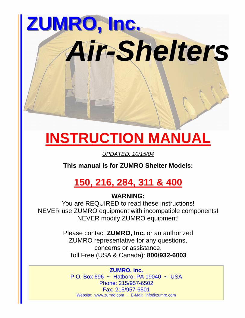
ZUMRO, Inc.ZUMRO, Inc. AirAirAir---SheltersSheltersShelters
INSTRUCTION MANUAL
UPDATED: 10/15/04
This manual is for ZUMRO Shelter Models:
150, 216, 284, 311 & 400
WARNING: You are REQUIRED to read these instructions!
NEVER use ZUMRO equipment with incompatible components! NEVER modify ZUMRO equipment!
Please contact ZUMRO, Inc. or an authorized
ZUMRO representative for any questions, concerns or assistance.
Toll Free (USA & Canada): 800/932-6003
ZUMRO, Inc. P.O. Box 696 ~ Hatboro, PA 19040 ~ USA
Phone: 215/957-6502 Fax: 215/957-6501
Website: www.zumro.com ~ E-Mail: [email protected]
CONTENTS Page 1 QUICK GUIDE 1.1 Basic Set-Up Procedure .......................................1 1.2 Deflate Procedure ................................................1 1.3 Packing Procedure ...............................................1
2 BASIC SHELTER INFO 2.1 Receiving your new Shelter .................................2 2.2 Basic Info.............................................................2 2.3 Air requirements ..................................................2 2.4 Valve System .......................................................3 2.5 Inflation System...................................................3 2.6 Removable Floor..................................................3 2.7 Utility Straps ........................................................3 2.8 Tie Downs............................................................3 2.9 Carrying Case ......................................................4 2.10 Floor Space Requirements ...................................4
3 PARTS & ACCESSORIES 3.1 Electric Inflator/Deflator......................................5 3.2 Air Bottle Connection Hose.................................5 3.3 Inflate/Deflate Valve............................................6 3.4 Pressure Relief Valve...........................................6
4 SHELTER DEPLOYMENT 4.1 Set-up procedures.................................................7 4.2 Floor Removal .....................................................7 4.3 Strike and packing procedure...............................8
5 MAINTENANCE 5.1 General.................................................................9 5.2 Replacing Inflate/Deflate Valve ..........................9 5.3 Cleaning Valve Insert ..........................................9
6 WARRANTY Statement and Registration Card
7 ADDITIONAL INSTRUCTION DIAGRAMS
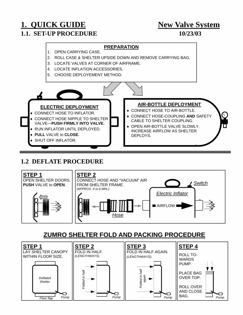
1. QUICK GUIDE 1.1. SET-UP PROCEDURE
1.2 DEFLATE PROCEDURE
STEP 1 OPEN SHELTER DOORS. PUSH VALVE to OPEN.
AIR-BOTTLE DEPLOYMENT ♦ CONNECT HOSE TO AIR-BOTTLE. ♦ CONNECT HOSE-COUPLING AND SAFETY
CABLE TO SHELTER COUPLING. ♦ OPEN AIR-BOTTLE VALVE SLOWLY.
INCREASE AIRFLOW AS SHELTER DEPLOYS.
STEP 4
Pump
ROLL TO-WARDS PUMP. PLACE BAG OVER TOP. ROLL OVER AND CLOSE BAG.
STEP 1 LAY SHELTER CANOPY WITHIN FLOOR SIZE.
Floor flap Pump
Deflated Shelter
STEP 2 FOLD IN HALF.(LENGTHWAYS)
Pump
Fold
ed in
hal
f
STEP 3 FOLD IN HALF AGAIN.(LENGTHWAYS).
Pump
Fold
ed in
hal
f ag
ain
STEP 2 CONNECT HOSE AND “VACUUM” AIR FROM SHELTER FRAME . (APPROX. 4 to 6 MIN.)
Switch
Electric Inflator
AIRFLOW
Hose
ELECTRIC DEPLOYMENT ♦ CONNECT HOSE TO INFLATOR. ♦ CONNECT HOSE NIPPLE TO SHELTER
VALVE—PUSH FIRMLY INTO VALVE. ♦ RUN INFLATOR UNTIL DEPLOYED. ♦ PULL VALVE to CLOSE. ♦ SHUT OFF INFLATOR.
PREPARATION 1. OPEN CARRYING CASE. 2. ROLL CASE & SHELTER UPSIDE DOWN AND REMOVE CARRYING BAG. 3. LOCATE VALVES AT CORNER OF AIRFRAME. 4. LOCATE INFLATION ACCESSORIES. 5. CHOOSE DEPLOYEMENT METHOD.
ZUMRO SHELTER FOLD AND PACKING PROCEDURE
New Valve System 10/23/03
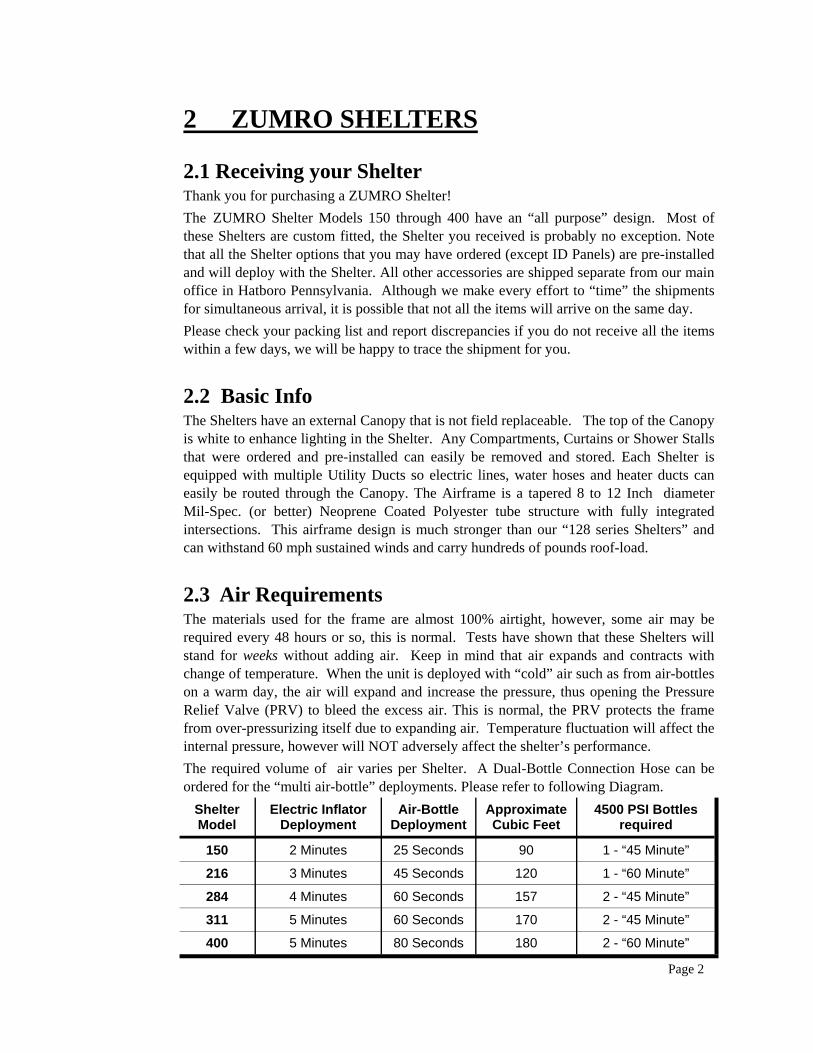
2 ZUMRO SHELTERS
2.1 Receiving your Shelter Thank you for purchasing a ZUMRO Shelter! The ZUMRO Shelter Models 150 through 400 have an “all purpose” design. Most of these Shelters are custom fitted, the Shelter you received is probably no exception. Note that all the Shelter options that you may have ordered (except ID Panels) are pre-installed and will deploy with the Shelter. All other accessories are shipped separate from our main office in Hatboro Pennsylvania. Although we make every effort to “time” the shipments for simultaneous arrival, it is possible that not all the items will arrive on the same day. Please check your packing list and report discrepancies if you do not receive all the items within a few days, we will be happy to trace the shipment for you.
2.2 Basic Info The Shelters have an external Canopy that is not field replaceable. The top of the Canopy is white to enhance lighting in the Shelter. Any Compartments, Curtains or Shower Stalls that were ordered and pre-installed can easily be removed and stored. Each Shelter is equipped with multiple Utility Ducts so electric lines, water hoses and heater ducts can easily be routed through the Canopy. The Airframe is a tapered 8 to 12 Inch diameter Mil-Spec. (or better) Neoprene Coated Polyester tube structure with fully integrated intersections. This airframe design is much stronger than our “128 series Shelters” and can withstand 60 mph sustained winds and carry hundreds of pounds roof-load.
2.3 Air Requirements The materials used for the frame are almost 100% airtight, however, some air may be required every 48 hours or so, this is normal. Tests have shown that these Shelters will stand for weeks without adding air. Keep in mind that air expands and contracts with change of temperature. When the unit is deployed with “cold” air such as from air-bottles on a warm day, the air will expand and increase the pressure, thus opening the Pressure Relief Valve (PRV) to bleed the excess air. This is normal, the PRV protects the frame from over-pressurizing itself due to expanding air. Temperature fluctuation will affect the internal pressure, however will NOT adversely affect the shelter’s performance. The required volume of air varies per Shelter. A Dual-Bottle Connection Hose can be ordered for the “multi air-bottle” deployments. Please refer to following Diagram.
Page 2
Shelter Model
Electric Inflator Deployment
Air-Bottle Deployment
Approximate Cubic Feet
4500 PSI Bottles required
150 2 Minutes 25 Seconds 90 1 - “45 Minute”
216 3 Minutes 45 Seconds 120 1 - “60 Minute”
284 4 Minutes 60 Seconds 157 2 - “45 Minute”
400 5 Minutes 80 Seconds 180 2 - “60 Minute”
311 5 Minutes 60 Seconds 170 2 - “45 Minute”
2.4 Valve System The Shelter is equipped with a special high volume Valve System, custom manufactured for ZUMRO Shelters only. The valves are replacable, however, never replace any Valve or Valve Component with anything other than a ZUMRO part. The Valve System is located at the right front corner air beam of the Shelter. There are one Inflate/Deflate Valve (Push-Pull type) and an Air-Bottle Hose Connection located on the outside and an Inflate Valve and Pressure Relief Valve on the inside. Located above the Pressure Relief Valve is the Shelter Serial Number. Please record the number on the Warranty Card with your information and return it to ZUMRO, Inc.
2.5 Inflation System Each Shelter is shipped with an 110 Volt AC Electric Inflator/Deflator (part #9900) and a single Air-Bottle Connection Hose (part #7400) unless specifically ordered otherwise. For the larger Shelters (model 284 and up) a “Dual-Bottle” hose may have been ordered under part #7432 or merely as an “upgrade” under part #7476. When using a “Dual Bot-tle” Hose both Air-Bottles must be connected for proper operation.
2.6 Removable Floor. All Shelters are equipped with a laced removable floor for added versatility. The Shelter without the floor can be placed over an incident such as a trench operation or vehicle accident simply by carrying it at all 4 corners. We recommend to always re-install the floor prior to storage since it makes rolling the Shelter and re-deploying it later much easier. More detailed information can be found on page 7.
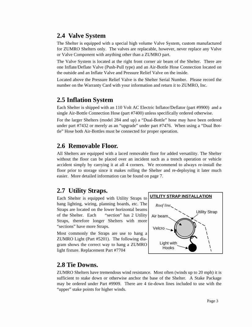
2.7 Utility Straps. Each Shelter is equipped with Utility Straps to hang lighting, wiring, planning boards, etc. The Straps are located on the lower horizontal beams of the Shelter. Each “section” has 2 Utility Straps, therefore longer Shelters with more “sections” have more Straps. Most commonly the Straps are use to hang a ZUMRO Light (Part #5201). The following dia-gram shows the correct way to hang a ZUMRO light fixture. Replacement Part #7704
2.8 Tie Downs. ZUMRO Shelters have tremendous wind resistance. Most often (winds up to 20 mph) it is sufficient to stake down or otherwise anchor the base of the Shelter. A Stake Package may be ordered under Part #9909. There are 4 tie-down lines included to use with the “upper” stake points for higher winds.
Page 3
UTILITY STRAP INSTALLATION
Air beam Utility Strap
Light with Hooks
Velcro
Roof line
2.9 Carrying Case. The Shelter is stored in a heavy duty vinyl Carrying Case with six reinforced carrying handles and multiple adjustable closure straps. Shelters are heavy and depending on installed options and accessories can weigh from 120 Lbs. to as much as 300 Lbs. Please use caution when moving the Shelter be sure to have enough personnel.
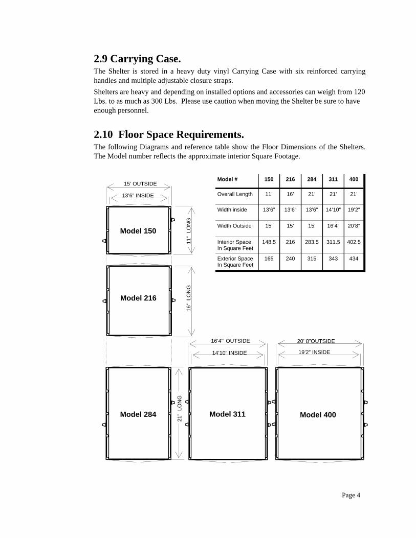
2.10 Floor Space Requirements. The following Diagrams and reference table show the Floor Dimensions of the Shelters. The Model number reflects the approximate interior Square Footage.
Page 4
Model 150
Model 284
13’6” INSIDE
15’ OUTSIDE 11
” LO
NG
Model 216
16”
LON
G
21”
LON
G
Model 400
19’2” INSIDE
20’ 8”OUTSIDE
Model 311
14’10” INSIDE
16’4”’ OUTSIDE
Model # 150 216 284 311 400
Overall Length 11’ 16’ 21’ 21’ 21’
Width inside 13’6” 13’6” 13’6” 14’10” 19’2”
Width Outside 15’ 15’ 15’ 16’4” 20’8”
Interior Space In Square Feet
148.5 216 283.5 311.5 402.5
Exterior Space In Square Feet
165 240 315 343 434
3. PARTS & ACCESSORIES
3.1 Electric Inflator The 110 Volt inflator (or 220 Volt) is used to inflate and deflate the Shelters. The pump is capable of pressurizing the Shelter up to 3.5 PSI which is within the normal operating pressure. The hose has a connector fitting with an ‘O’ Ring that fits into the Shelter Inflate/Deflate Valve. Be sure to snap the fitting all the way into the valve or it will disconnect itself as the inflation pressure increases during deployment. The inflator will deploy and pressurize the Shelters in approximately 2 to 5 minutes depending on the Shelter size. Deflation time is approximately 5 minutes.
NOTE: 1. The electric blower is NOT powerful enough to open the pressure relief valve in the Airframe. NOTE: 2. Do not operate the pump more than 20 minutes continuously since overheating may occur. WARNING: The pump is an electrical device operating on high voltage. Danger of electric shock exists. Use only on Ground Fault Protected Outlets. Observe all applicable safety precautions.
3.2 Air Bottle Connection Hose Each Shelter is supplied with an Air Bottle Connection Hose (PART #7400). This hose can be connected directly to an air bottle. The air bottle connection is “CGA 347” and will connect with 4500 PSI bottles and most 2216 PSI bottles. The “Shelter-end” has a quick coupler with safety chain. ALWAYS attach safety chain to the D-Ring on the Shelter
See also Diagram on next page.
WARNING: ALWAYS attach safety chain. DO NOT remove or change any fittings, couplings or any other parts of the Air-Bottle Connection Hose assembly. DO NOT in any way modify or replace the Air-Bottle Connection Hose, contact ZUMRO, Inc. for repair if required. DO NOT use with ANY OTHER component, product or equipment! Serious Injury or product damage will result if any changes are made!
110V INFLATOR DIAGRAM
Page 5
On-Off Switch Inflate Fitting with O-Ring
Hose
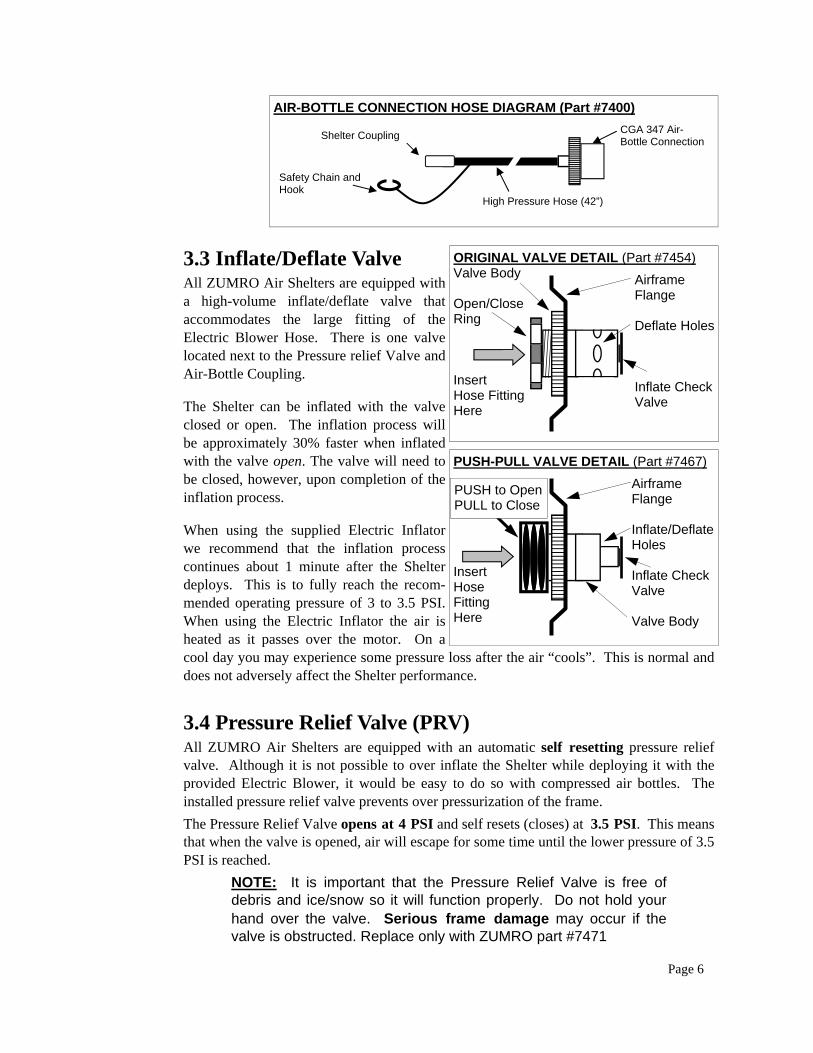
AIR-BOTTLE CONNECTION HOSE DIAGRAM (Part #7400)
3.3 Inflate/Deflate Valve All ZUMRO Air Shelters are equipped with a high-volume inflate/deflate valve that accommodates the large fitting of the Electric Blower Hose. There is one valve located next to the Pressure relief Valve and Air-Bottle Coupling.
The Shelter can be inflated with the valve closed or open. The inflation process will be approximately 30% faster when inflated with the valve open. The valve will need to be closed, however, upon completion of the inflation process.
When using the supplied Electric Inflator we recommend that the inflation process continues about 1 minute after the Shelter deploys. This is to fully reach the recom-mended operating pressure of 3 to 3.5 PSI. When using the Electric Inflator the air is heated as it passes over the motor. On a cool day you may experience some pressure loss after the air “cools”. This is normal and does not adversely affect the Shelter performance.
3.4 Pressure Relief Valve (PRV) All ZUMRO Air Shelters are equipped with an automatic self resetting pressure relief valve. Although it is not possible to over inflate the Shelter while deploying it with the provided Electric Blower, it would be easy to do so with compressed air bottles. The installed pressure relief valve prevents over pressurization of the frame. The Pressure Relief Valve opens at 4 PSI and self resets (closes) at 3.5 PSI. This means that when the valve is opened, air will escape for some time until the lower pressure of 3.5 PSI is reached.
NOTE: It is important that the Pressure Relief Valve is free of debris and ice/snow so it will function properly. Do not hold your hand over the valve. Serious frame damage may occur if the valve is obstructed. Replace only with ZUMRO part #7471
Page 6
Safety Chain and Hook
CGA 347 Air-Bottle Connection
High Pressure Hose (42”)
Shelter Coupling
ORIGINAL VALVE DETAIL (Part #7454) Valve Body Open/Close Ring Insert Hose Fitting Here
Airframe Flange Deflate Holes Inflate Check Valve
PUSH-PULL VALVE DETAIL (Part #7467)
Insert Hose Fitting Here
Airframe Flange Inflate/Deflate Holes Inflate Check Valve Valve Body
PUSH to Open PULL to Close
4. SHELTER DEPLOYMENT
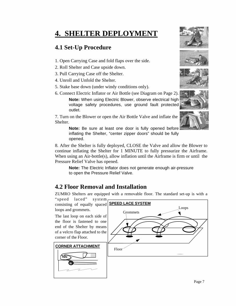
4.1 Set-Up Procedure 1. Open Carrying Case and fold flaps over the side. 2. Roll Shelter and Case upside down. 3. Pull Carrying Case off the Shelter. 4. Unroll and Unfold the Shelter. 5. Stake base down (under windy conditions only). 6. Connect Electric Inflator or Air Bottle (see Diagram on Page 2). Note: When using Electric Blower, observe electrical high
voltage safety procedures, use ground fault protected outlet.
7. Turn on the Blower or open the Air Bottle Valve and inflate the Shelter. Note: Be sure at least one door is fully opened before
inflating the Shelter, “center zipper doors” should be fully opened.
8. After the Shelter is fully deployed, CLOSE the Valve and allow the Blower to continue inflating the Shelter for 1 MINUTE to fully pressurize the Airframe. When using an Air-bottle(s), allow inflation until the Airframe is firm or until the Pressure Relief Valve has opened.
Note: The Electric Inflator does not generate enough air-pressure to open the Pressure Relief Valve.
4.2 Floor Removal and Installation ZUMRO Shelters are equipped with a removable floor. The standard set-up is with a “speed laced” system consisting of equally spaced loops and grommets. The last loop on each side of the floor is fastened to one end of the Shelter by means of a velcro flap attached to the corner of the Floor.
SPEED LACE SYSTEM Loops Grommets
Floor
Page 7
CORNER ATTACHMENT
To remove the Floor follow these steps: 1. Detach last Loop on one or both sides of the Floor. 2. Pull Floor away from Shelter Frame. Loops will pull out of Grommets. To install Floor follow these steps: 1. Position Floor Loops facing up. 2. Insert first Loop through Grommet. 3. Insert next Loop through grommet and then through previous Loop.
(See diagram on previous page.) 4. Repeat step 3 until Floor is installed. 5. Tie off last Loop or use provided Velcro Tab. When using the Velcro Tab,
feed the last Loop through the eyelet at the bottom corner of the Floor near the Airframe, then tie back with the Velcro Tab.
4.3 Strike and Packing Procedure To strike the Shelter follow these steps: 1. Connect Inflation Hose to Shelter Intake Valve. 2. Connect “deflate” side of blower to the Hose. 3. Open intake valve until approximately 2 threads of the “open/close” ring
show. (Original valve) or PUSH to OPEN for new style valve. 4. Run Inflator until all the air is removed from the Airframe, approximately 5 to
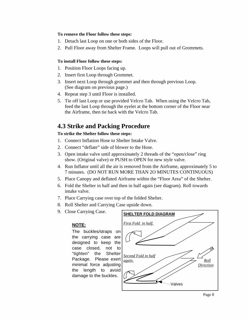
7 minutes. (DO NOT RUN MORE THAN 2O MINUTES CONTINUOUS) 5. Place Canopy and deflated Airframe within the “Floor Area” of the Shelter. 6. Fold the Shelter in half and then in half again (see diagram). Roll towards
intake valve. 7. Place Carrying case over top of the folded Shelter. 8. Roll Shelter and Carrying Case upside down. 9. Close Carrying Case.
NOTE: The buckles/straps on the carrying case are designed to keep the case closed, not to “tighten” the Shelter Package. Please exert minimal force adjusting the length to avoid damage to the buckles.
Page 8
SHELTER FOLD DIAGRAM First Fold in half.
Second Fold in half again. Roll Direction
Valves
5. MAINTENANCE
5.1 General
ZUMRO Shelters require virtually no maintenance. All the materials used are state-of-the-art fabrics often used in Military style Life Rafts. The product is designed to be packed for extended periods of time and function perfectly when deployed.
RECOMMENDATIONS: 1. Although mildew resistant, we recommend that the shelter is not stored for extended
periods while wet. The Shelter should be re-deployed within a few days of a “wet” deployment to dry out and then stored properly to reduce the chance of mildew.
2. Always remove large particles such as rocks and sticks from the floor prior to packing the Shelter.
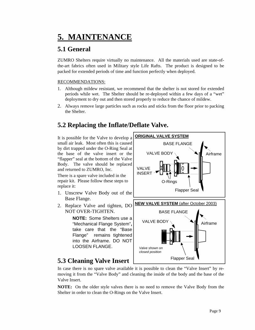
5.2 Replacing the Inflate/Deflate Valve. It is possible for the Valve to develop a small air leak. Most often this is caused by dirt trapped under the O-Ring Seal at the base of the valve insert or the “flapper” seal at the bottom of the Valve Body. The valve should be replaced and returned to ZUMRO, Inc. There is a spare valve included in the repair kit. Please follow these steps to replace it: 1. Unscrew Valve Body out of the
Base Flange. 2. Replace Valve and tighten, DO
NOT OVER-TIGHTEN. NOTE: Some Shelters use a “Mechanical Flange System”, take care that the “Base Flange” remains tightened into the Airframe. DO NOT LOOSEN FLANGE.
5.3 Cleaning Valve Insert In case there is no spare valve available it is possible to clean the “Valve Insert” by re-moving it from the “Valve Body” and cleaning the inside of the body and the base of the Valve Insert. NOTE: On the older style valves there is no need to remove the Valve Body from the Shelter in order to clean the O-Rings on the Valve Insert.
Page 9
VALVE BODY
ORIGINAL VALVE SYSTEM
BASE FLANGE
VALVE INSERT
Airframe
O-Rings
Flapper Seal
NEW VALVE SYSTEM (after October 2003)
VALVE BODY
BASE FLANGE
Airframe
Flapper Seal
Valve shown on closed position
LIMITED WARRANTY Amended 7/1/04
THE ENCLOSED WARRANTY REGISTRATION CARD MUST BE COMPLETED AND RETURNED TO ZUMRO, Inc. WITHIN THIRTY (6O) DAYS OF DELIVERY OF THE PRODUCTS. ZUMRO, Inc. warrants to the original purchaser that the Shelter described on the warranty registration card will be free of defects in material and workmanship for a period of five (5) years from the date of shipment to such purchaser. This includes the installed “Shelter Options” such as partitions, shower stalls, doors, windows, pre-plumbed shower components etc. This warranty shall take effect no later than 7 days from the date of shipment to address shown on purchase order. NOT covered under this warranty are any damages caused by using the Shelter with components other than purchased from and/or approved for safe use with the Shelter or its components by ZUMRO, Inc. NOT covered under this warranty are leaks (airframe or canopy) caused by wear and tear and/or miss-use of the Product. ZUMRO Shelters are designed for temporary use, minor color fading of the Canopy can be expected with prolonged exposure to sunlight. Normal Color fading is NOT covered under this warranty. Any related accessories not manufactured by ZUMRO, Inc. such as Tent Heaters, Water Heaters, Lighting, Showers, Containment Pools, Decon Equipment, etc. will be subject to the manufacturers warranty of such product. Accessory items purchased from ZUMRO, Inc. or one of its authorized Dealers as part of the ZUMRO Shelter/Decon System are subject to a limited extended warranty of up to 2 Years from the date of delivery. In the event that a manufacturing defect occurs during the warranty period, the defective Product will be repaired or replaced, or the purchase price will be refunded, at the sole option of ZUMRO, Inc., provided that the Product is returned, transportation prepaid, to ZUMRO, Inc. Costs for freight charges outside the United States are NOT covered under this warranty and the sole responsibility of the purchaser. The Product must be accompanied by a Return Goods Authorization Number, which must be obtained prior to shipment by contacting ZUMRO, Inc., P.O. Box 696, Hatboro, PA 19040. This warranty shall not apply to damage caused by misuse, negligence, misapplication or accidental damage or damage resulting from the use of the Product with any device other than components supplied by or approved in writing by ZUMRO, Inc. ZUMRO, Inc. DISCLAIMS ALL OTHER WARRANTIES, EXPRESSED OR IMPLIED, INCLUDING, BUT NOT LIMITED, TO ANY IMPLIED WARRANTIES OF MERCHANTABILITY AND FITNESS FOR A PARTICULAR PURPOSE. THE REMEDIES PROVIDED IN THIS WARRANTY SHALL BE THE EXCLUSIVE REMEDIES FOR ANY CLAIM RELATING TO THE PRODUCT, AND IN NO EVENT SHALL ZUMRO, Inc. BE LIABLE FOR INCIDENTAL OR CONSEQUENTIAL DAMAGES. Please record your Shelter Serial Number below! Shelter Model # ______________ Serial #__________


![Architectural Shelters Canopies and Cycle Shelters[1]](https://img.pdfslide.net/doc/110x75/577d24da1a28ab4e1e9d8f13/architectural-shelters-canopies-and-cycle-shelters1.jpg)