Embed Size (px)
Citation preview
ZWS 881:2013
W.10301 1
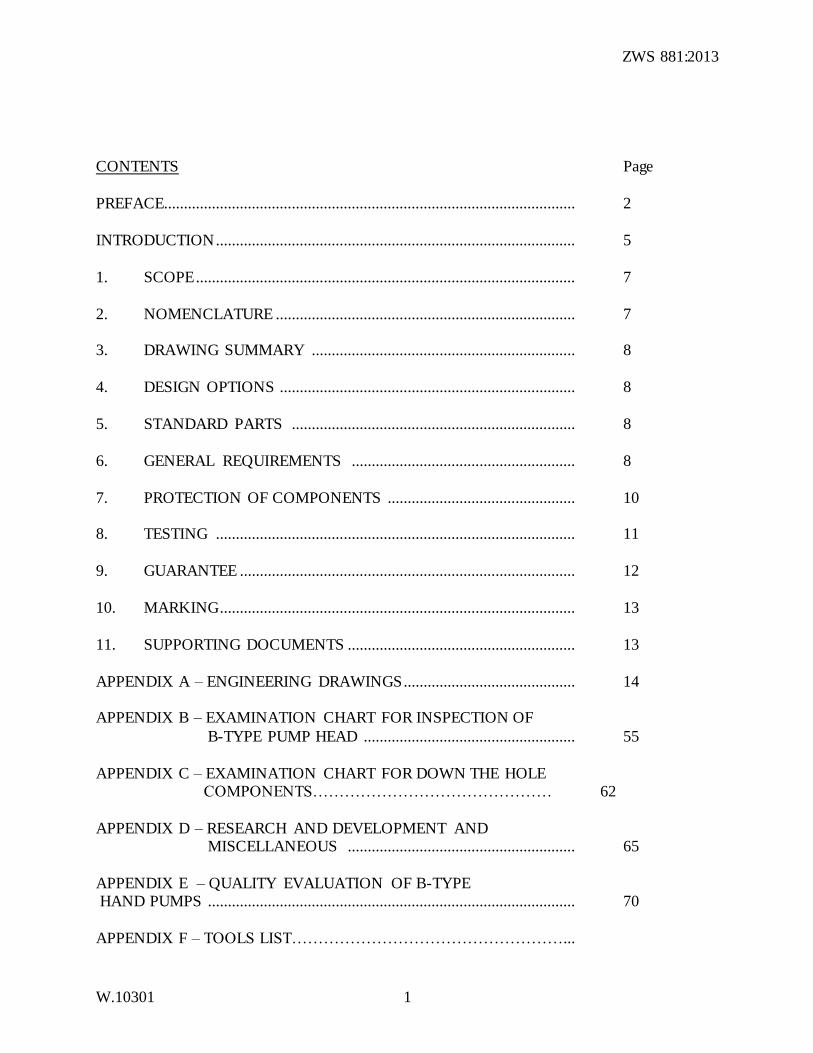
CONTENTS Page
PREFACE....................................................................................................... 2
INTRODUCTION .......................................................................................... 5
1. SCOPE ............................................................................................... 7
2. NOMENCLATURE ........................................................................... 7 3. DRAWING SUMMARY .................................................................. 8
4. DESIGN OPTIONS .......................................................................... 8
5. STANDARD PARTS ....................................................................... 8
6. GENERAL REQUIREMENTS ........................................................ 8
7. PROTECTION OF COMPONENTS ............................................... 10 8. TESTING .......................................................................................... 11
9. GUARANTEE .................................................................................... 12
10. MARKING ......................................................................................... 13
11. SUPPORTING DOCUMENTS ......................................................... 13
APPENDIX A – ENGINEERING DRAWINGS ........................................... 14 APPENDIX B – EXAMINATION CHART FOR INSPECTION OF
B-TYPE PUMP HEAD ..................................................... 55
APPENDIX C – EXAMINATION CHART FOR DOWN THE HOLE COMPONENTS……………………………………… 62
APPENDIX D – RESEARCH AND DEVELOPMENT AND MISCELLANEOUS ......................................................... 65
APPENDIX E – QUALITY EVALUATION OF B-TYPE HAND PUMPS ............................................................................................ 70
APPENDIX F – TOOLS LIST……………………………………………...
ZWS 881:2013
W.10301 2
PREFACE
This Zimbabwe Standard Specification: ZWS 881:2013: B-type Hand Pump (Bush pump), is based on the Swiss Centre for Development Cooperation in Technology and Management – Hand Pump Technology Network (SKAT-HTN),Bush Pump Deep Well Hand Pump
Specification published in 1999.
The Zimbabwe “B” Type Bush Pump and all its predecessors were designed and tested by the Government of Zimbabwe.
This standard was prepared by Technical Committee ME 22: Bush Pumps, under the general direction of the Building and Civil EngineeringStandards Council.
This standard makes reference to the following publications:
BS 2751 : General purpose acrylonitrile-butadiene rubber compounds.
EN 10278 : Dimensions and tolerances of bright steel products. EN 12168 : Copper and copper alloys – Hollow rod for free machining purposes.
EN 12449 : Copper and copper alloys – Seamless round tubes for general purposes.
EN 12451 : Copper alloys – Seamless, round tubes for heat exchangers.
EN 12452 : Copper and copper alloys – Rolled, fused seamless tubes for heat exchangers.
ISO 60 : Plastics – Determination of apparent density of material that can be poured
from specified funnel.
ISO 559 : Steel tubes for water and sewage.
ISO 630 : Structural steels – Plates, wide flats, bars, sections and profiles.
ISO 683 : Heat-treatable steels, alloy steels and free-cutting steels.
Part 11 : Wrought case-hardening steels. ISO 4032 : Hexagon nuts, style 1 – Product grades A and B.
ISO 2081 : Metal coatings – Electroplated coatings of zinc on iron or steel.
ISO 2082 : Metal coatings – Electroplated coatings of cadmium on iron or steel.
ISO 4014 : Hexagon head bolts – Product grades A and B.
ISO 4017 : Hexagon head screws – Product grades A and B.
ZWS 881:2013
W.10301 3
ISO 4200 : Plain end steel tubes, welded and seamless – General tables of dimensions
and masses per unit length. ISO 4520 : Chromate conversion coatings on electroplated zinc and cadmium
coatings.
ISO 7089 : Plain washers – Normal series – Product grade A. ISO 9330 : Welded steel tubes for pressure purposes – Technical conditions
Part 1 : Chromate conversion coatings on electroplated zinc and cadmium
coatings. ISO 9692 : Metal-arc welding with covered electrode, gas-shielded metal-arc welding
and gas welding – Joint preparations for steel.
ISO 1461 : Hot-dip galvanized coatings on iron and steel articles. ZWS ISO 2859: Sampling procedures for inspection by attributes.
Part 1 : Sampling schemes indexed by acceptance quality limit (AQL) for lot-by-
lot inspection. SAZ ISO 9001: Quality management systems – Requirements.
The following interests were represented on the technical committee entrusted with the preparation of this standard.
Ministry of Water Resources Development and Management. Dept of Water Resources Planning and Development……….. Mr T Mutazu(Chairman)
Aquamor……………………………………………………… Dr P Morgan
District Development Fund…………………………………….. Mr T Fred
Farm Serve Distribution……………………………………… .Mr B Mashanda Mr T Mhuriro
Institute of Water and Sanitation Development………………….Ms N Neseni
Min of Water Resources Development & Management…………Mr S Bunya Standards Assocation of Zimbabwe…………………………… Mr T Mukurazhizha
V&W Engineering and Installation…………………………… .Ms N Solanki
Mr D Mashiri
ZWS 881:2013
W.10301 4
WASH Consultant …………………………………………… Mr G Nhunhama
Ministry of Water Resources Development & Management National Coordination Unit…………………………………… Mr LDhoba Mr N Shirihuru
Ministry of Water Resources Development & Management
ZimbabweNational Water Authority………………………..… Mr S Sunguro
Zimbabwe Local Government Assocation…………………… Mr R Mozhenty
Standards Association of Zimbabwe………………………… Mr P Chindara (Technical Secretary)
ZWS 881:2013
W.10301 5
ZIMBABWE STANDARD
FOR
B-TYPE DEEPWELL HAND PUMP (BUSH PUMP)
INTRODUCTION
The Bush Pump has been used in Zimbabwe for over 60 years. It was first
designed in 1933 by Tommy Murgatroyd, a water supply officer working in Plumtree, Matabeleland, and some of his early pumps survive to this day. This
original masterpiece, known as the “Murgatroyd Pump”, combined the use of a hardwood block as a bearing and lever mechanism, with a stout steel pump stand and a handle made from standard 50 mm steel pipe. These basic components
have been retained ever since.
Murgotroyd’s original pump was concreted into the ground next to the borehole and a shackle arrangement was used to connect the wooden block to the pump rods. This pump was conceived during a “blacksmithing era” when all the parts
were bolted together – there was no welding. Murgatoyd’s pump was first restyled by Cecil Anderson in the 1960s but retained most of the original features,
the most characteristic being the use of a hardwood block, strong pump stand and steel pipe handle. The main refinement was the introduction of two large U bolts which were used to attach the pump stand to the steel borehole casing. This was a
major step forward, since the pump could now be removed from the site for repair or refurbishing in district workshops. Anderson also used a sleeve pipe
mechanism for linking the wooden block to the pump rod system. Parts were welded together. It was this pump that Zimbabwe inherited at independence in 1980.
The Government of Zimbabwe (GOZ) was determined to retain the “Bush Pump”
as its national standard hand pump for use in the National Rural Water Supply Programme. By the mid 1980’s the earlier single standard (Anderson type) Bush Pump, had been joined by a considerable range of alternative “Bush Pumps”
made by different manufacturers, NGO’s and by the government itself. By 1987 the National Action Committee (NAC) of the GOZ decided that the national
pump should be re-standardized and initiated a study of locally made hand pumps. This study, undertaken on behalf of the NAC Technical Subcommittee, made recommendations for the adoption of a new standard Bush Pump head which was
called the “B” type Bush Pump. This second restyling of the Bush Pump was undertaken by Peter Morgan of the Ministry of Health’s Blair Institute in 1987,
and field tested between 1987 and 1989 by the Blair Institute in collaboration with the Department of Water Development and The District Development Fund. This design combined the best features of earlier Bush Pumps together with new
features which reduced the number of wearing parts, reduced friction and also made pumping easier. The “B type” pump head was adopted by the Government
of Zimbabwe as the new national standard in 1989 after the two years of field testing and refinement and has remained the national standard ever since.
ZWS 881:2013
W.10301 6
This pump head, in common with all other “Bush Pumps” uses standard “down the hole” components, comprising 50 mm nominal bore galvanized steel rising
main, 16 mm mild steel pump rods, a 75 mm diameter brass cylinder operating with a piston fitted with two high quality leather seals and a heavy duty brass foot valve. These components, which have been available and used in Zimbabwe for
several generations are well tested, durable and well known in the sector.
In view of world trends towards developing hand pumps which are easier to maintain, the Government of Zimbabwe (Blair Institute) initiated a research programme of developing Bush Pumps with “open top cylinders” through which
the piston and seals could be extracted without the need to lift the “rising main.” This concept made routine replacement of seals much easier. This work was
performed by the GOZ in collaboration with E. H. W. Von Elling of V&W Engineering, who also developed an effective mass production technique for the pump head.
The first official drawings of the “B” type pump head were drawn on 26 th May
1989 by the Ministry of Energy and Water Resources and Development. These drawings were computerized in 1996 by Santana Design Studio, Harare. The computerized drawings were later adopted and redrawn by Karl Erpf of the Swiss
Centre for Development Cooperation in Technology and Management (The SKAT Foundation), when the pump became a Public Domain Hand Pump in
1999. SKAT’s new drawings became the International Specifications for the Zimbabwe Bush Pump. These drawings have been refined and updated again for use in this standard. The drawings and general information have also been
reassembled into a format which can easily be used by manufacturers and those examining the pump.
The Zimbabwe ‘Bush Pump’ is almost unique on the African continent, in that it
was conceived and designed and is wholly manufactured within Zimbabwe itself.
The family of ‘Bush Pumps’ owe their success to a simplicity of design and rugged construction, which originated from Murgatroyd’s pioneering work. The
Bush Pump continues to serve the people of Zimbabwe, eighty years after the first pumps of the family were designed, built and put to use.
ZWS 881:2013
W.10301 7
1. SCOPE
This Zimbabwe Standard specifies the requirements for;
The B-type deep well hand pump suitable for lifting water from depths of 3 to 80 m. However, pumps can be operated when installed up to 100 m depth,
although this puts a greater strain on the parts. For very deep installations the pump head is modified with 16mm side arms and modified pivot pins with a longer 3m handle.
This draft standard specifies four variations for “down the hole” components
which can be used with the “B type” head. a) Ø75 mm Non Extractable System (NES)
b) Ø50 mm Extractable System (ES) c) Ø63,5 mm Extractable System (ES); and
d) Ø75 mm Extractable System (ES) NOTE 1. Pumps with extractable systems are known as either “User friendly” or
“Open top cylinder versions”.
The pump is designed to be clamped direct onto a steel casing pipe of 150 mm nominal bore (NB).
NOTE 2. If the pump is to be used in dug wells, suitable provision shall be made for casting a well cover with a piece of a steel casing pipe of nominal diameter of
150 mm. (refer to the Bush Pump Installation and Maintenance Manual supplied by the manufacturer).
NOTE 3. The titles of the publications referred to in this standard are listed in the Preface.
2. NOMENCLATURE
A brief description of the major pump components which comprises the general arrangement, pump stand assembly, discharge arrangement, pumprod
arrangements and cylinder arrangements, is given below:
The Numbering System. The following numbering system of technical drawings
has been adopted:
Every component shall have a number prefixed by a capital letter. The letters shall have the following meanings:
A - Components of pumphead
B - Components of discharge unit
ZWS 881:2013
W.10301 8
C - Components of rising main (pipes, rods and casing)
D - Components of cylinder and foot valve.
3. DRAWING SUMMARY
The detailed drawings of the pumps are given in Appendix A.
4. DESIGN OPTIONS
4.1 Pump rods. Ø16 mm pump rods should always be used for the Ø75 mm Non
Extractable System (NES) pumps and all Extractable Systems.
4.2 Handle 4.2.1 For pump settings up to 60 m it is recommended to use the Ø50 mm handle with a
length of 2.5 m. This is the standard pump handle.
4.2.2 For pump settings between 1 to 20 m. a Ø40 mm handle can be used with a length of 2.5 m.
4.2.3 For pump settings of over 60 m, it is recommended to use the Ø50 mm handle with an increased in length to 3 m. If necessary the pipe can be filled with
concrete, to counterbalance the rod weight. 4.2.4 Handles and rising main should use pipe with a wall thickness of at least 3.2mm.
SABS 62. Part 1 is recommended with OD of 60mm and ID 50mm with a minimum wall thickness of 3.2mm.
5. STANDARD PARTS
Detailed drawings of standard parts are shown in Appendix A.
6. GENERAL REQUIREMENTS
6.1 The material, tolerances, etc. shall be as given in the respective detail drawings and parts list.
6.2 The bolts and nuts used for the pump shall conform to relevant parts of ISO 4014
or ISO 4017 for bolts and ISO 4032 for nuts.
6.3 The washers shall conform to ISO 7089.
6.4 The rising main pipe and the sockets shall conform to ISO 50 and ISO 60
respectively.
NOTE. Where the 50mm open top cylinder is used, the surface of the inside
diameter of the Ø50 mm ES rising main needs to be cleaned to avoid damaging of
ZWS 881:2013
W.10301 9
the seal during installation and withdrawal of the plunger (see also Appendix
C).SABS 62 part 1.
The steel plates, sheets, angle iron, square and round bars for the construction of the bush pump parts shall conform to ISO 630 or shall have the following properties:
a) Chemical properties of test pieces:
C = 0,21 % max; P = 0,065 % max; S = 0,065 % max; N = 0,010 % max
b) Physical properties:
i) Tensile strength: 340 – 470 N/mm2
ii) Yield strength: 235 N/mm2.
6.5 The steel pipes for the construction of pump parts shall conform to ISO 559 and ISO 9330 or shall have the following properties:
Tensile strength: 250 – 540 N/mm2 Yield strength: 175 N/mm2.
Dimensions shall conform to ISO 4200.
6.6 The different cylinders shall be made of seamless brass tubing conforming to EN 12449. For increased resistance to the dezincification in corrosive waters
(with high chloride content for example), CuZn2OAℓ2 or CuZn2OSn may be specified.
6.7 The brass parts and brass castings, for different plungers and footvalves, mechanical properties and technical delivery conditions shall conform to
EN 12449, EN 12168, EN 12451 and EN 12452. 6.8 Rubber components like bobbin, rubber buffer and cup seal shall be made of
rubber conforming to BS 2751.Nitrite rubber components are used in the 50mm piston used with the 50mm open top cylinder.
6.9 For leather cup seals there is no international standard. For processing details see
also Appendix C.
6.10 Pump rods are to be manufactured from cold drawn bright steel conforming to
EN 10278. 6.11 The welding of all steel parts shall be done in accordance with ISO 9692.
6.12 Heat treatment of hook and eye components shall be in accordance with ISO 683:
Part 11. For details on the case-hardening process see also Appendix C.
ZWS 881:2013
W.10301 10
7. PROTECTION OF COMPONENTS
7.1 Anti-corrosion Treatment. The pump shall be given the anti-corrosion treatment
as specified below:
7.2 Hot-dip Galvanizing. The following pump assemblies shall be galvanized
according to ZWS ISO 1461. The coating thickness should be between an average of 70 to 80 µm.
i) Discharge body assembly ii) Spout assembly
iii) Spacer ring iv) Housing cover v) Floating washer
vi) Socket 2” vii) Socket Ø50mm and Ø 65mm
viii) Rising main pipe Ø 50mm and Ø 65mm ix) Discharge body assembly x) Socket Ø75mm
xi) Rising main pipe Ø75mm
NOTE. All threads have to be cleaned of excessive zinc in order to avoid difficulties during installation.
7.3 Electroplating. The following pump assemblies and parts shall be electroplated and passivated to ISO 2081 or ISO 2082.
The coating thickness shall be between 15 to 18 µm for the connecting parts like bolts, washers, spring washers, couplers etc. For all other parts the average
coating thickness shall be approximately 38 µm.
i) Top rod assembly (see Figures B 3248, B3351, B3371) ii) Pump rod assembly (see Figures B3254, B3353, B3372) iii) Plunger rod assembly (see Figures B3256, B3355, C3232)
iv) Plug (see Figure C3253) v) Washer special and all bolts, washers, spring washers, couplers and
adaptors. The electroplated parts shall be given chromate conversion coating type C to
ISO 4520.
7.4 Painting. The following pump assemblies and parts shall be primed and painted. All parts which have to be treated shall be cleaned thoroughly of grease or oil and any corrosion products have to be eliminated with sanding paper.
i) Frame ii) U-bracket
iii) Handle
ZWS 881:2013
W.10301 11
Thereafter a red oxide primer shall be applied for rust protection and for
adherence of the paint.
Finally one or two layers of darkish royal blue colour gloss enamel paint shall be applied.
7.5 Protection of the block
The block shall be boiled in oil for 4 hours and cooled overnight in the oil to penetrate.(Old engine oil)
8. TESTING
8.1 Sampling. Unless otherwise specified in the contract or order, the procedure given in SAZS ISO 2859: Part 1 shall be followed for sampling inspection. For the characteristics given in Clause 8.5, the single sampling plan with general
inspection Level 1, in Table 1 and acceptable quality level of 1 % in Table 2A of ZWS ISO 2859: Part 1 shall be used.
8.2 Visual and Dimensional Tests. The following characteristics shall be checked:
8.2.1 One hundred percent interchangeability of subassemblies and components is an essential requirement.
8.2.2 All pumps shall be examined for welding, workmanship, finish, visual defects and
surface coating.
8.2.3 All dimensions of the assemblies and subassemblies shall be checked for
conformity with the drawings. 8.2.4 The following dimensions shall be specially checked:
a) Stroke length of 226mm± 10 mm at 28°
b) The measurement between the leading edge of the floating washer housing
and the front face of the pump rod. This is an important measurement
which should be 73±2 mm when the pump handle is horizontal i.e. the
pump rod in its most forward position.
c) All riser pipes and the cylinder shall be checked for the 15o chamfer on both ends of the inside diameter, especially its correct size and the rounded edges, in order to give good guiding to the plunger during
installation and dismantling.
d) Inside diameter of the cylinders to be checked closely; Ø50±0,3mm,
Ø63,5±0,3mm, and Ø75±0,3mm.
8.2.5 Top rod, pump rod and plunger rod shall be examined for diameter fitment of
hooks.
ZWS 881:2013
W.10301 12
8.2.6 Connection threads of the threaded pump rods shall be tested for their fitment.
8.2.7 The following check shall be carried out on the cylinder assembly in addition to
dimensional checks:
Leakage test of 1,0 and 10,0 bar hydraulic pressure.
8.3 Routine Test. Unless otherwise specified in the contract or order, a minimum of
two complete pumps from the selected sample shall be subjected to the following tests, in addition to the tests in 8.2 above:
8.3.1 The pumps and cylinders selected shall be dismantled and the components checked in detail for dimensional conformity to the drawings, general
requirements and additional requirements.
However the dimension conformity should be checked for critical dimensions
only if they affect the performance of the pump. Any slight variation in dimensions which are not critical should not be treated as non-compliance.
8.4 Pump Test
8.4.1 Performance of the pump shall be checked after placing the cylinder in a borehole at a maximum depth for which the pump has been recommended.
8.4.2 At the end of type test the pump shall be opened and critical components
examined for undue wear and tear.
8.4.3 The manufacturer shall furnish the list of critical components of pump to the
testing authority. 8.4.4 The type test shall be repeated if any change in critical component(s) is carried
out.
8.5 Criteria for Conformity. The lot shall be considered conforming to the requirements of this specification, if the pumps selected according to 8.1 and 8.3 satisfy the following requirements:
a) The number of pumps not meeting the requirements of characteristics
inspected under 8.2 does not exceed the corresponding acceptable number as specified in ZWS ISO 2859: Part 1.
b) The pumps inspected according to 8.3 meet the requirements given in 8.3.1 and 8.4.1.
9. GUARANTEE
Unless otherwise specified in the contract or order, the pump and its accessories shall be guaranteed for 12 months from the date of installation, or 18 months from
the date of supply, whichever is earlier, against faulty workmanship and/or materials.
ZWS 881:2013
W.10301 13
10. MARKING 10.1 The nameplate shall be permanently attached to the pump stand, preferably on a
protected place (Metal Plate and Stamped on Steel Channel)
The nameplate shall have the following information:
a) Manufacturer’s name and address;
b) Serial number:
c) Year and month of manufacture.
d) Telephone Numbers
10.2 The bottom flange of the discharge assembly shall also be punch marked with the manufacturer’s name, serial number and year of production.
10.3 The cylinder body shall have the manufacturer’s name, serial number and year of production marked by suitable and permanent means.
11. SUPPORTING DOCUMENTS
11.1 Examination chart for inspection of “B” Type Bush Pump Head (see Appendix B) 11.2 Examination chart of the “B” Type Bush Pump “Down the Hole” components
(see Appendix C)
12. The manufacturer shall supply the customer with the following documents: 12.1 Bush pump installation and maintenance manual;
ZWS 881:2013
W.10301 14
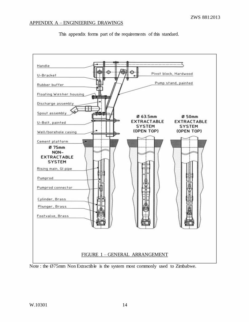
APPENDIX A – ENGINEERING DRAWINGS
This appendix forms part of the requirements of this standard.
FIGURE 1 – GENERAL ARRANGEMENT
Note : the Ø75mm Non Extractible is the system most commonly used to Zimbabwe.
ZWS 881:2013
W.10301 15
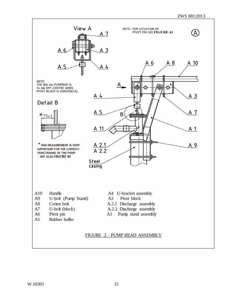
A10 Handle A4 U-bracket assembly A9 U-bolt (Pump Stand) A3 Pivot block
A8 Centre bolt A.2.1 Discharge assembly A7 U-bolt (block) A.2.2 Discharge assembly A6 Pivot pin A1 Pump stand assembly
A5 Rubber buffer
FIGURE 2 – PUMP HEAD ASSEMBLY
ZWS 881:2013
W.10301 16
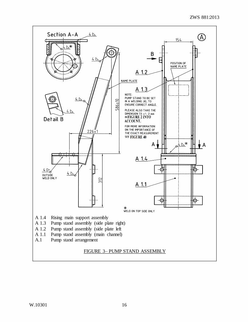
A 1.4 Rising main support assembly A 1.3 Pump stand assembly (side plate right)
A 1.2 Pump stand assembly (side plate left A 1.1 Pump stand assembly (main channel) A.1 Pump stand arrangement
FIGURE 3– PUMP STAND ASSEMBLY
ZWS 881:2013
W.10301 17
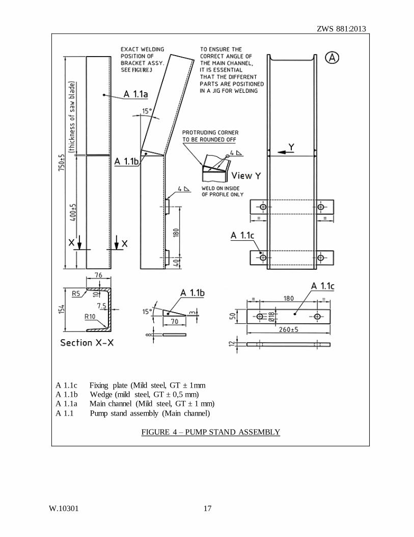
A 1.1c Fixing plate (Mild steel, GT ± 1mm A 1.1b Wedge (mild steel, GT ± 0,5 mm) A 1.1a Main channel (Mild steel, GT ± 1 mm)
A 1.1 Pump stand assembly (Main channel)
FIGURE 4 – PUMP STAND ASSEMBLY
ZWS 881:2013
W.10301 18
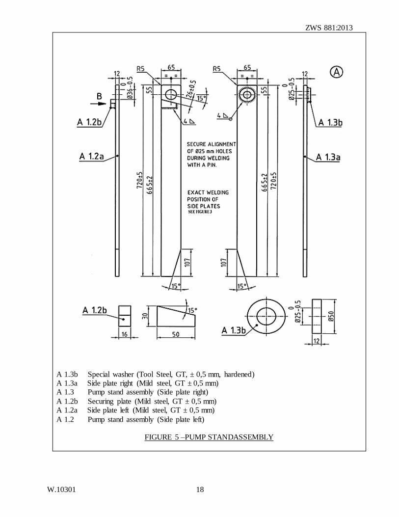
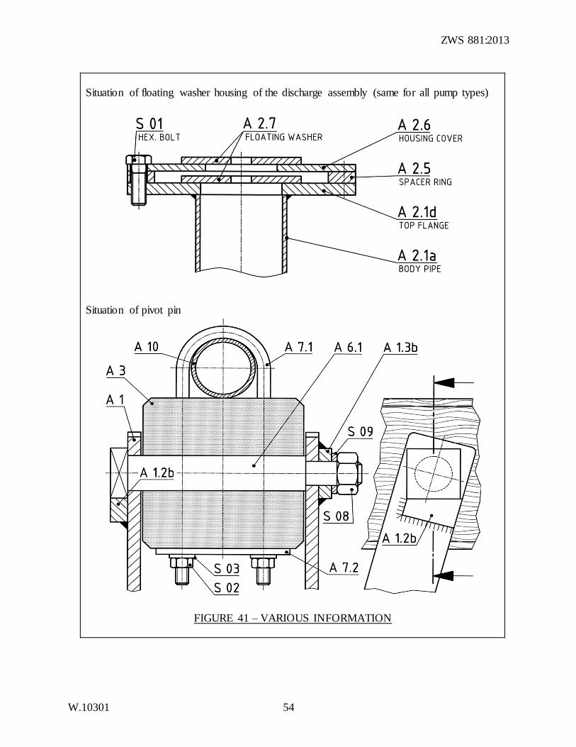
A 1.3b Special washer (Tool Steel, GT, ± 0,5 mm, hardened) A 1.3a Side plate right (Mild steel, GT ± 0,5 mm) A 1.3 Pump stand assembly (Side plate right)
A 1.2b Securing plate (Mild steel, GT ± 0,5 mm) A 1.2a Side plate left (Mild steel, GT ± 0,5 mm)
A 1.2 Pump stand assembly (Side plate left)
FIGURE 5 –PUMP STANDASSEMBLY
ZWS 881:2013
W.10301 19
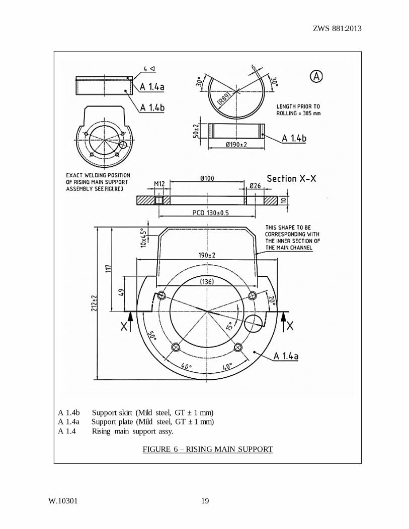
A 1.4b Support skirt (Mild steel, GT ± 1 mm) A 1.4a Support plate (Mild steel, GT ± 1 mm)
A 1.4 Rising main support assy.
FIGURE 6 – RISING MAIN SUPPORT
ZWS 881:2013
W.10301 20
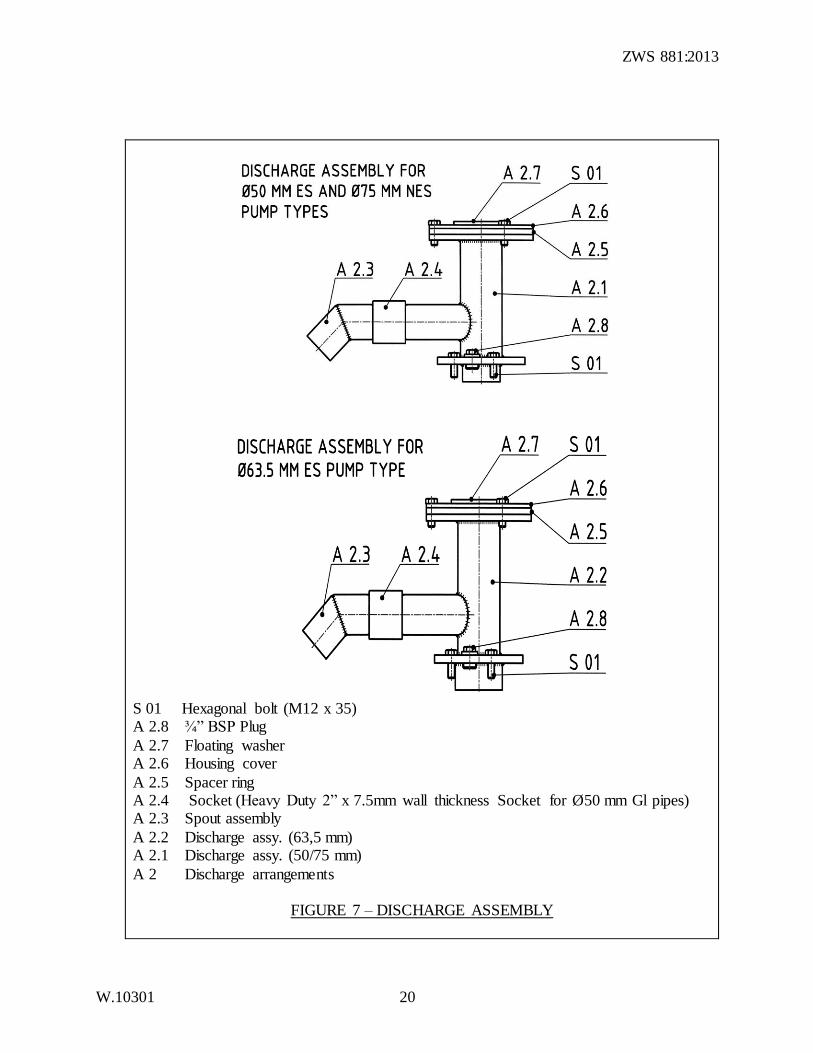
S 01 Hexagonal bolt (M12 x 35) A 2.8 ¾” BSP Plug
A 2.7 Floating washer A 2.6 Housing cover
A 2.5 Spacer ring A 2.4 Socket (Heavy Duty 2” x 7.5mm wall thickness Socket for Ø50 mm Gl pipes) A 2.3 Spout assembly
A 2.2 Discharge assy. (63,5 mm) A 2.1 Discharge assy. (50/75 mm)
A 2 Discharge arrangements
FIGURE 7 – DISCHARGE ASSEMBLY
ZWS 881:2013
W.10301 21
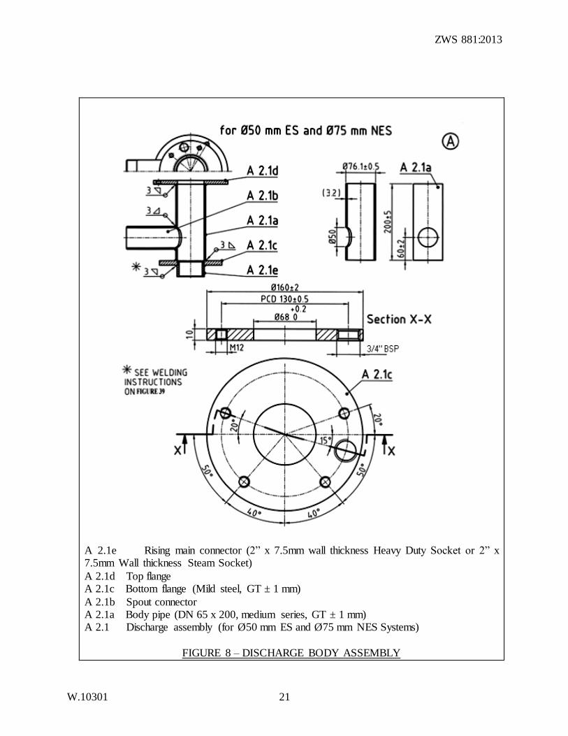
A 2.1e Rising main connector (2” x 7.5mm wall thickness Heavy Duty Socket or 2” x 7.5mm Wall thickness Steam Socket)
A 2.1d Top flange A 2.1c Bottom flange (Mild steel, GT ± 1 mm)
A 2.1b Spout connector A 2.1a Body pipe (DN 65 x 200, medium series, GT ± 1 mm) A 2.1 Discharge assembly (for Ø50 mm ES and Ø75 mm NES Systems)
FIGURE 8 – DISCHARGE BODY ASSEMBLY
ZWS 881:2013
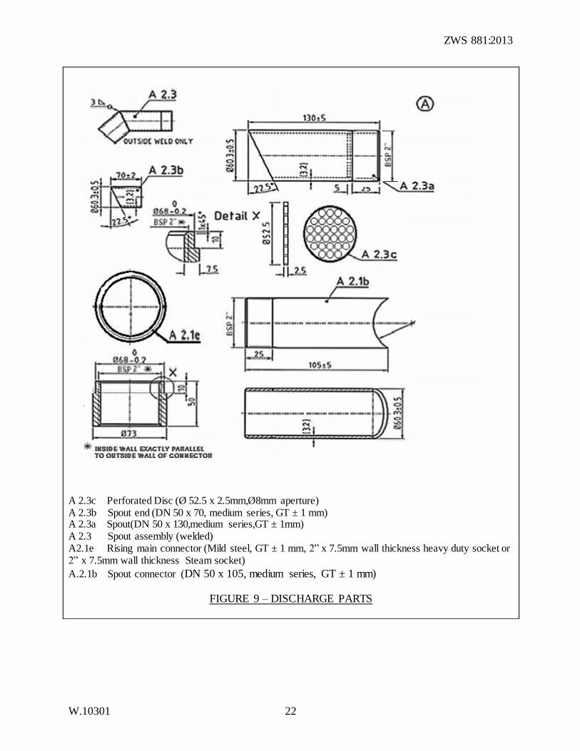
W.10301 22
A 2.3c Perforated Disc (Ø 52.5 x 2.5mm,Ø8mm aperture) A 2.3b Spout end (DN 50 x 70, medium series, GT ± 1 mm) A 2.3a Spout(DN 50 x 130,medium series,GT ± 1mm) A 2.3 Spout assembly (welded) A2.1e Rising main connector (Mild steel, GT ± 1 mm, 2” x 7.5mm wall thickness heavy duty socket or 2” x 7.5mm wall thickness Steam socket)
A.2.1b Spout connector (DN 50 x 105, medium series, GT ± 1 mm)
FIGURE 9 – DISCHARGE PARTS
ZWS 881:2013
W.10301 23
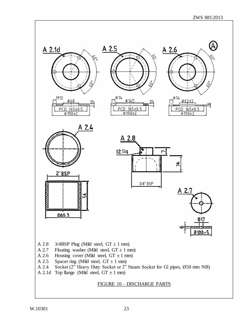
A 2.8 3/4BSP Plug (Mild steel, GT ± 1 mm)
A 2.7 Floating washer (Mild steel, GT ± 1 mm) A 2.6 Housing cover (Mild steel, GT ± 1 mm)
A 2.5 Spacer ring (Mild steel, GT ± 1 mm) A 2.4 Socket (2” Heavy Duty Socket or 2” Steam Socket for Gl pipes, Ø50 mm NB) A 2.1d Top flange (Mild steel, GT ± 1 mm)
FIGURE 10 – DISCHARGE PARTS
ZWS 881:2013
W.10301 24
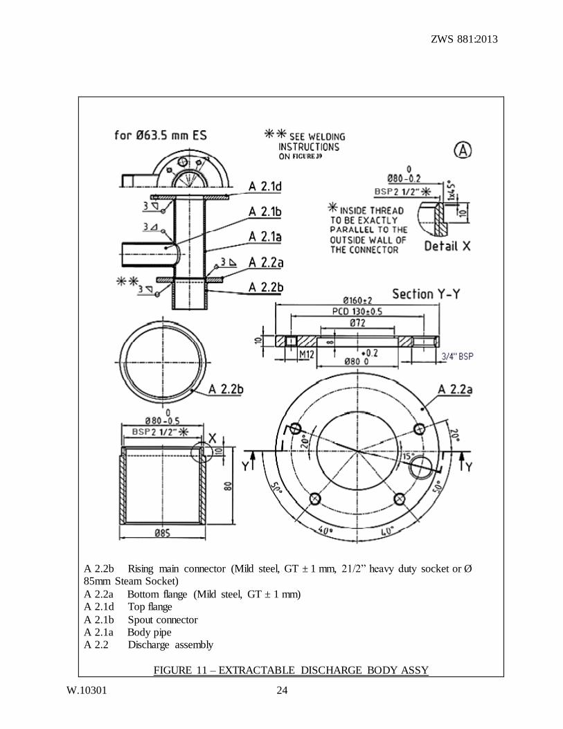
A 2.2b Rising main connector (Mild steel, GT ± 1 mm, 21/2” heavy duty socket or Ø 85mm Steam Socket)
A 2.2a Bottom flange (Mild steel, GT ± 1 mm) A 2.1d Top flange
A 2.1b Spout connector A 2.1a Body pipe A 2.2 Discharge assembly
FIGURE 11 – EXTRACTABLE DISCHARGE BODY ASSY
ZWS 881:2013
W.10301 25
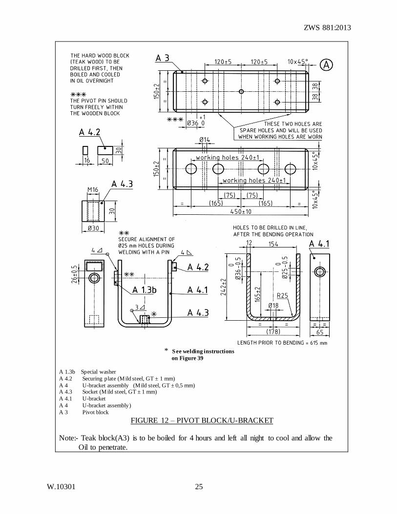
* See welding instructions
on Figure 39
A 1.3b Special washer
A 4.2 Securing plate (Mild steel, GT ± 1 mm)
A 4 U-bracket assembly (Mild steel, GT ± 0,5 mm) A 4.3 Socket (Mild steel, GT ± 1 mm) A 4.1 U-bracket
A 4 U-bracket assembly)
A 3 Pivot block FIGURE 12 – PIVOT BLOCK/U-BRACKET
Note:- Teak block(A3) is to be boiled for 4 hours and left all night to cool and allow the
Oil to penetrate.
ZWS 881:2013
W.10301 26
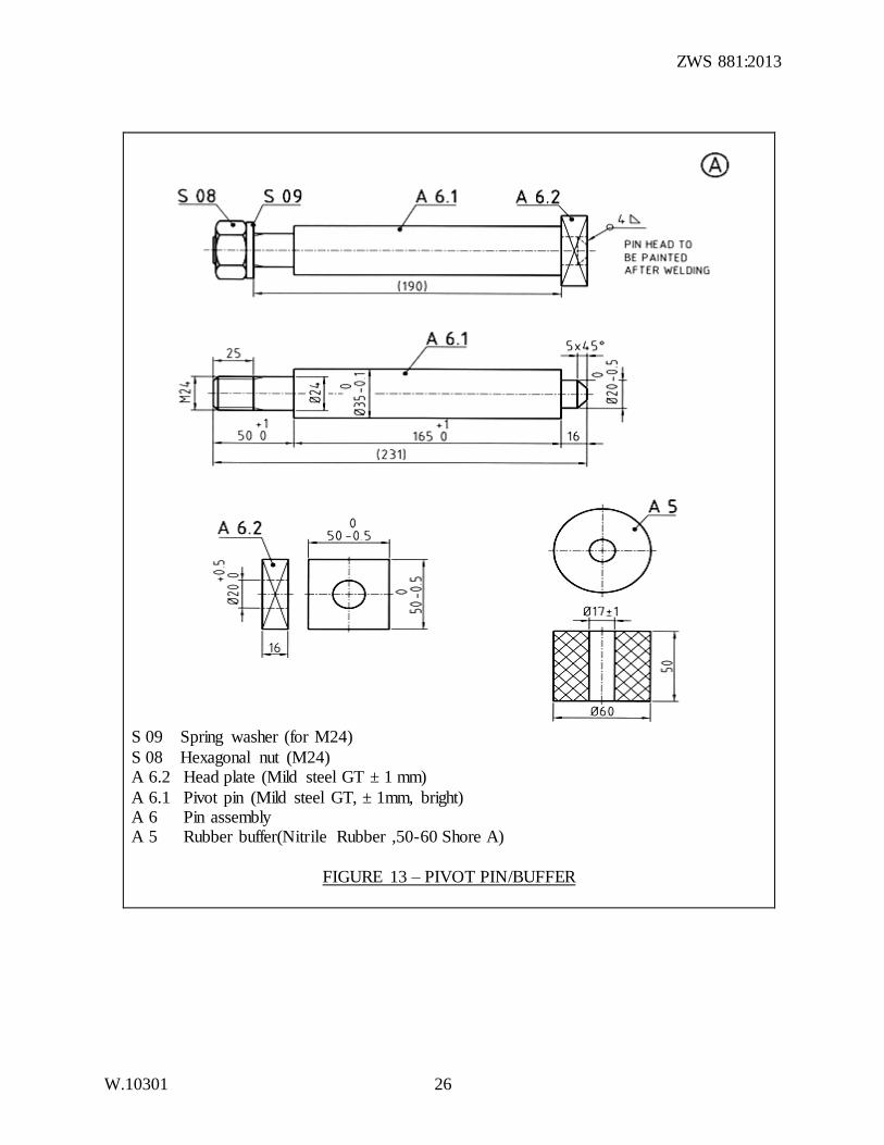
S 09 Spring washer (for M24)
S 08 Hexagonal nut (M24) A 6.2 Head plate (Mild steel GT ± 1 mm)
A 6.1 Pivot pin (Mild steel GT, ± 1mm, bright) A 6 Pin assembly A 5 Rubber buffer(Nitrile Rubber ,50-60 Shore A)
FIGURE 13 – PIVOT PIN/BUFFER
ZWS 881:2013
W.10301 27
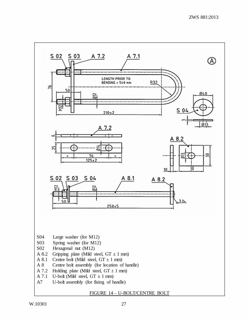
S04 Large washer (for M12)
S03 Spring washer (for M12) S02 Hexagonal nut (M12)
A 8.2 Gripping plate (Mild steel, GT ± 1 mm) A 8.1 Centre bolt (Mild steel, GT ± 1 mm) A 8 Centre bolt assembly (for location of handle)
A 7.2 Holding plate (Mild steel, GT ± 1 mm) A 7.1 U-bolt (Mild steel, GT ± 1 mm)
A7 U-bolt assembly (for fixing of handle)
FIGURE 14 – U-BOLT/CENTRE BOLT
ZWS 881:2013
W.10301 28
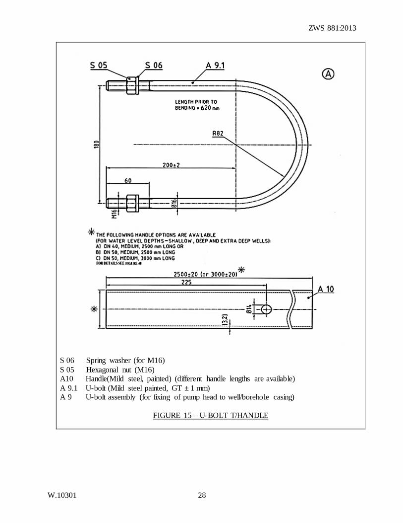
S 06 Spring washer (for M16)
S 05 Hexagonal nut (M16) A10 Handle(Mild steel, painted) (different handle lengths are available)
A 9.1 U-bolt (Mild steel painted, GT ± 1 mm) A 9 U-bolt assembly (for fixing of pump head to well/borehole casing)
FIGURE 15 – U-BOLT T/HANDLE
ZWS 881:2013
W.10301 29
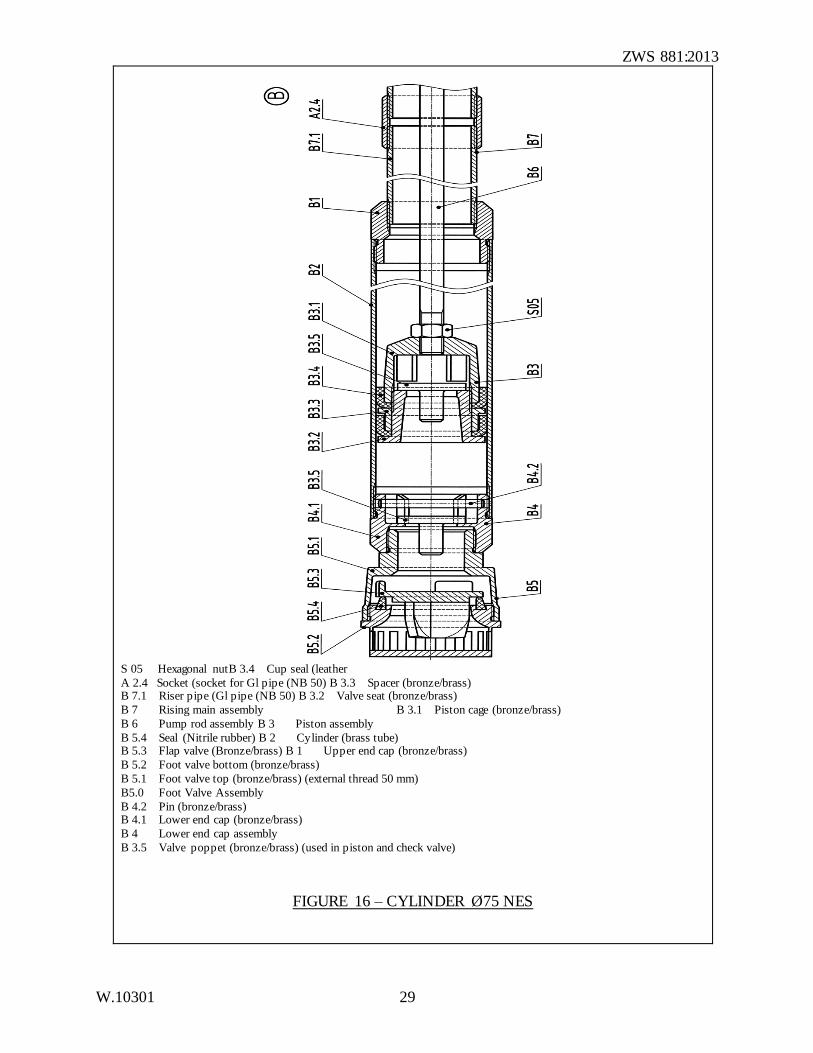
S 05 Hexagonal nutB 3.4 Cup seal (leather
A 2.4 Socket (socket for Gl pipe (NB 50) B 3.3 Spacer (bronze/brass) B 7.1 Riser pipe (Gl pipe (NB 50) B 3.2 Valve seat (bronze/brass)
B 7 Rising main assembly B 3.1 Piston cage (bronze/brass)
B 6 Pump rod assembly B 3 Piston assembly
B 5.4 Seal (Nitrile rubber) B 2 Cylinder (brass tube) B 5.3 Flap valve (Bronze/brass) B 1 Upper end cap (bronze/brass)
B 5.2 Foot valve bottom (bronze/brass)
B 5.1 Foot valve top (bronze/brass) (external thread 50 mm)
B5.0 Foot Valve Assembly
B 4.2 Pin (bronze/brass) B 4.1 Lower end cap (bronze/brass)
B 4 Lower end cap assembly
B 3.5 Valve poppet (bronze/brass) (used in piston and check valve)
FIGURE 16 – CYLINDER Ø75 NES
ZWS 881:2013
W.10301 30
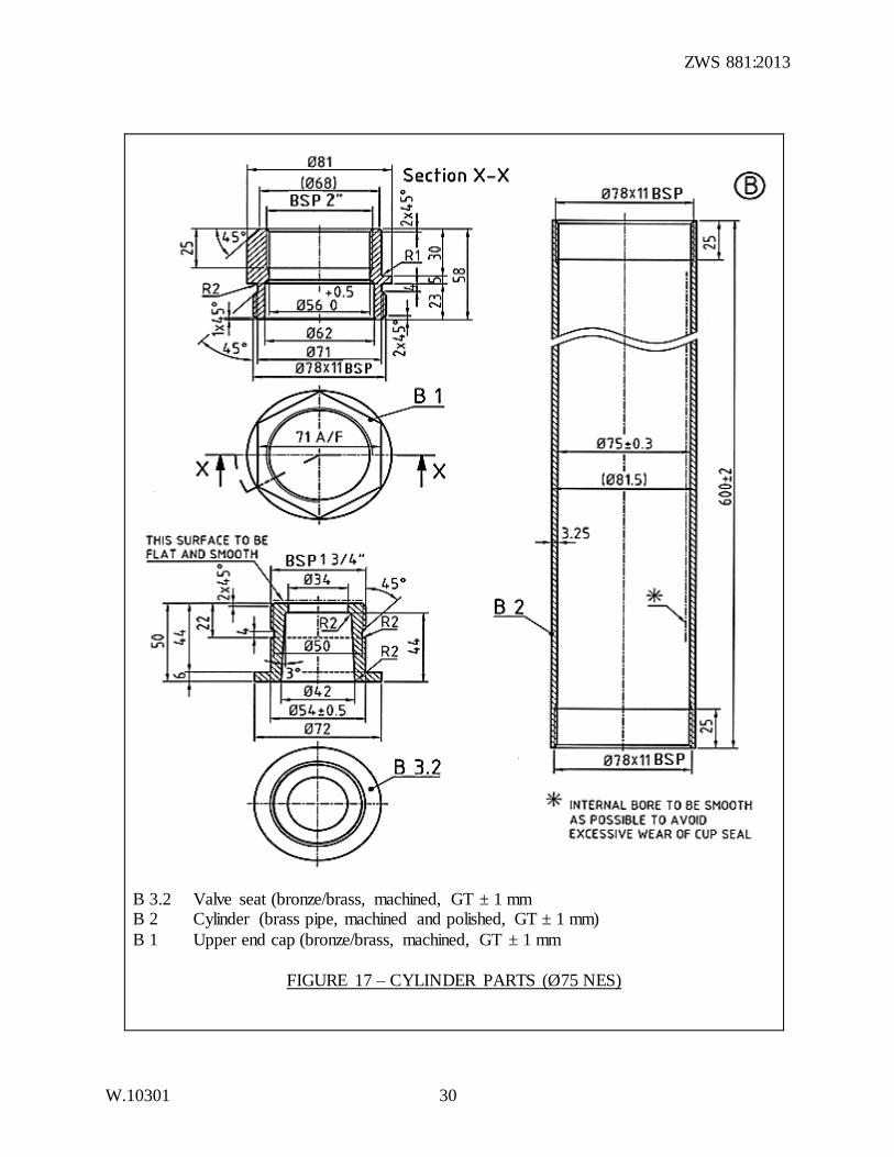
B 3.2 Valve seat (bronze/brass, machined, GT ± 1 mm B 2 Cylinder (brass pipe, machined and polished, GT ± 1 mm)
B 1 Upper end cap (bronze/brass, machined, GT ± 1 mm
FIGURE 17 – CYLINDER PARTS (Ø75 NES)
ZWS 881:2013
W.10301 31
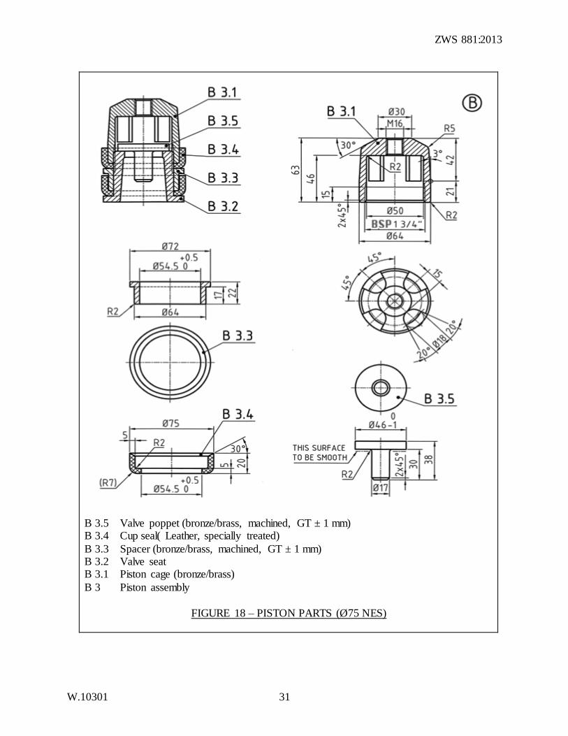
B 3.5 Valve poppet (bronze/brass, machined, GT ± 1 mm) B 3.4 Cup seal( Leather, specially treated)
B 3.3 Spacer (bronze/brass, machined, GT ± 1 mm) B 3.2 Valve seat B 3.1 Piston cage (bronze/brass)
B 3 Piston assembly
FIGURE 18 – PISTON PARTS (Ø75 NES)
ZWS 881:2013
W.10301 32
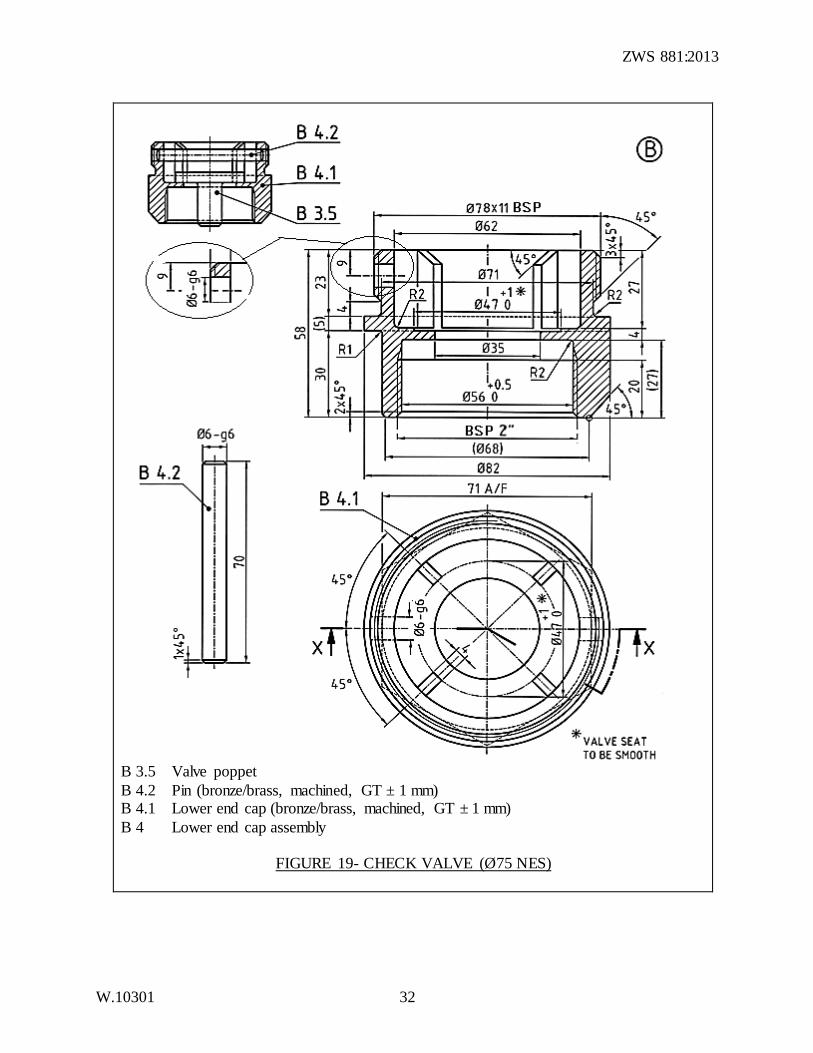
B 3.5 Valve poppet
B 4.2 Pin (bronze/brass, machined, GT ± 1 mm) B 4.1 Lower end cap (bronze/brass, machined, GT ± 1 mm)
B 4 Lower end cap assembly
FIGURE 19- CHECK VALVE (Ø75 NES)
ZWS 881:2013
W.10301 33
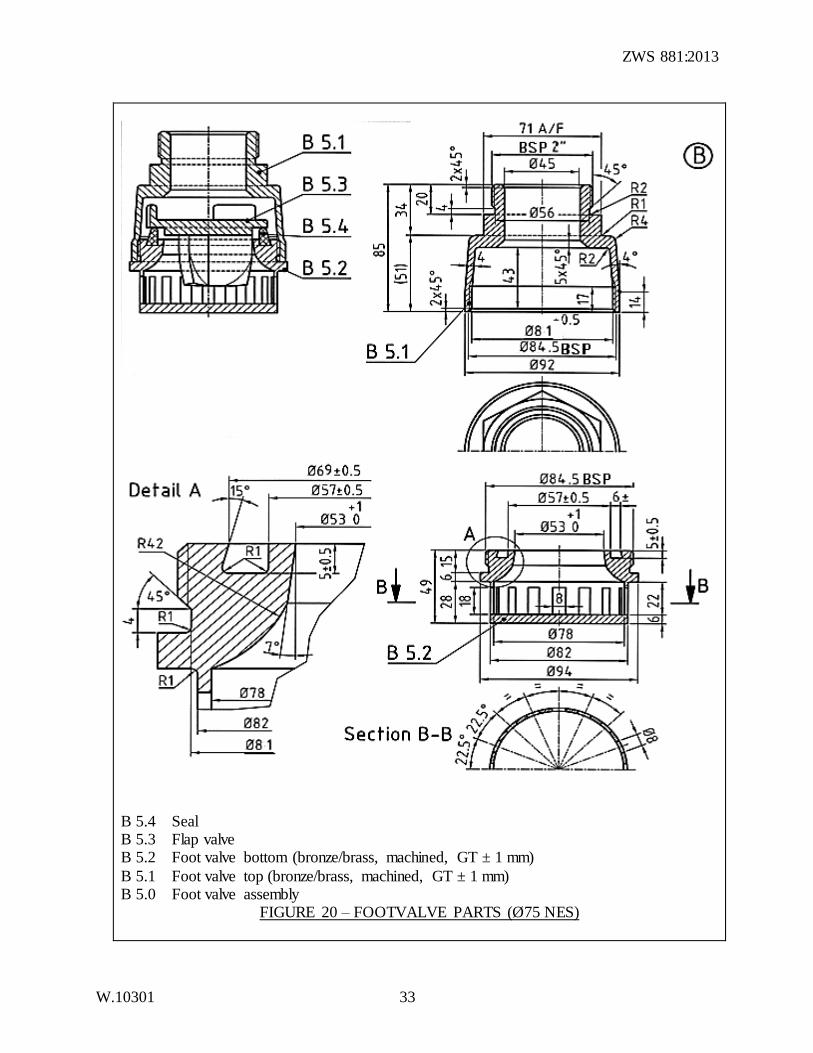
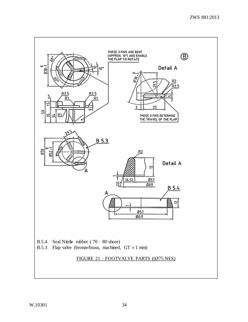
B 5.4 Seal B 5.3 Flap valve B 5.2 Foot valve bottom (bronze/brass, machined, GT ± 1 mm)
B 5.1 Foot valve top (bronze/brass, machined, GT ± 1 mm) B 5.0 Foot valve assembly
FIGURE 20 – FOOTVALVE PARTS (Ø75 NES)
ZWS 881:2013
W.10301 34
B.5.4 Seal Nitrile rubber ( 70 – 80 shore)
B.5.3 Flap valve (bronze/brass, machined, GT ± 1 mm)
FIGURE 21 – FOOTVALVE PARTS ((Ø75 NES)
ZWS 881:2013
W.10301 35
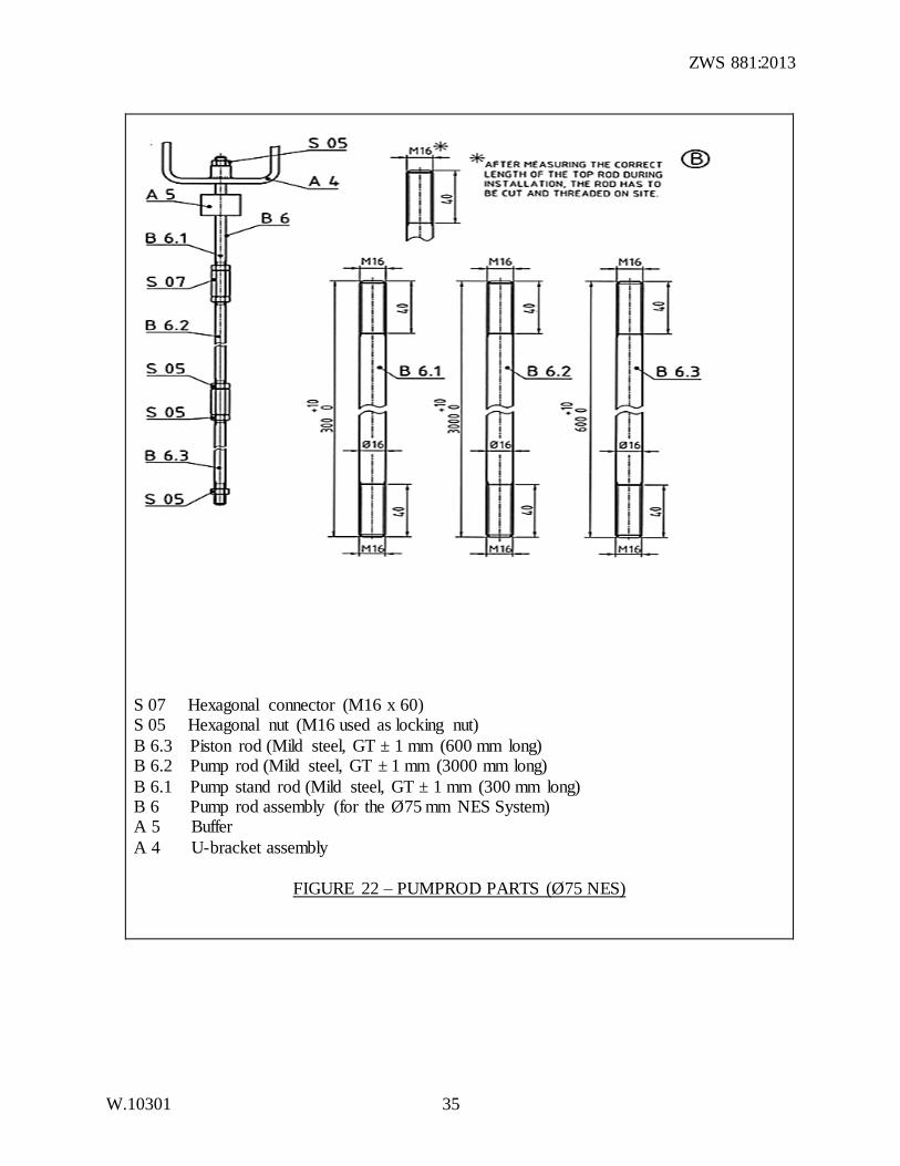
S 07 Hexagonal connector (M16 x 60) S 05 Hexagonal nut (M16 used as locking nut)
B 6.3 Piston rod (Mild steel, GT ± 1 mm (600 mm long) B 6.2 Pump rod (Mild steel, GT ± 1 mm (3000 mm long)
B 6.1 Pump stand rod (Mild steel, GT ± 1 mm (300 mm long) B 6 Pump rod assembly (for the Ø75 mm NES System) A 5 Buffer
A 4 U-bracket assembly
FIGURE 22 – PUMPROD PARTS (Ø75 NES)
ZWS 881:2013
W.10301 36
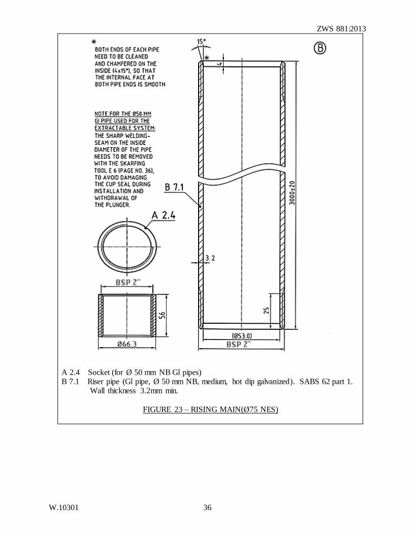
A 2.4 Socket (for Ø 50 mm NB Gl pipes) B 7.1 Riser pipe (Gl pipe, Ø 50 mm NB, medium, hot dip galvanized). SABS 62 part 1. Wall thickness 3.2mm min.
FIGURE 23 – RISING MAIN(Ø75 NES)
ZWS 881:2013
W.10301 37
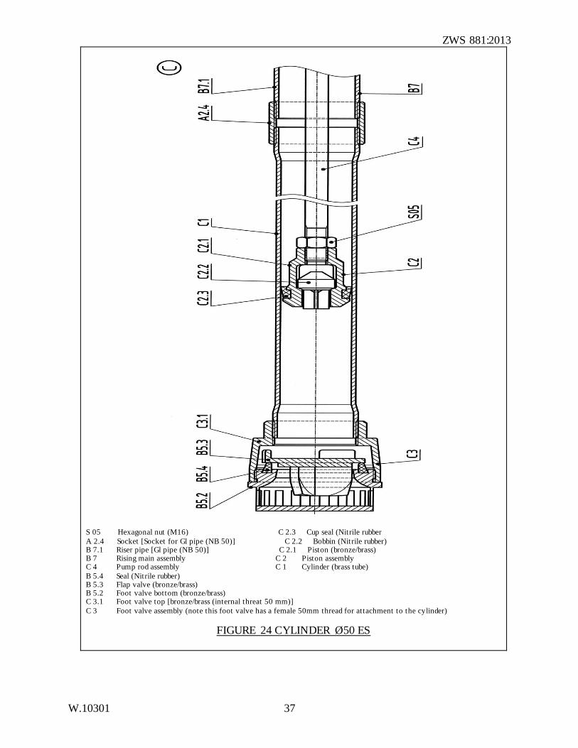
S 05 Hexagonal nut (M16) C 2.3 Cup seal (Nitrile rubber
A 2.4 Socket [Socket for Gl pipe (NB 50)] C 2.2 Bobbin (Nit rile rubber) B 7.1 Riser pipe [Gl pipe (NB 50)] C 2.1 Piston (bronze/brass) B 7 Rising main assembly C 2 Piston assembly C 4 Pump rod assembly C 1 Cylinder (brass tube)
B 5.4 Seal (Nitrile rubber) B 5.3 Flap valve (bronze/brass) B 5.2 Foot valve bottom (bronze/brass) C 3.1 Foot valve top [bronze/brass (internal threat 50 mm)]
C 3 Foot valve assembly (note this foot valve has a female 50mm thread for attachment to the cylinder)
FIGURE 24 CYLINDER Ø50 ES
ZWS 881:2013
W.10301 38
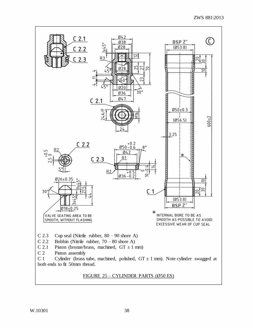
C 2.3 Cup seal (Nitrile rubber, 80 – 90 shore A)
C 2.2 Bobbin (Nitrile rubber, 70 – 80 shore A) C 2.1 Piston (bronze/brass, machined, GT ± 1 mm)
C 2 Piston assembly C 1 Cylinder (brass tube, machined, polished, GT ± 1 mm). Note cylinder swagged at both ends to fit 50mm thread.
FIGURE 25 – CYLINDER PARTS (Ø50 ES)
ZWS 881:2013
W.10301 39
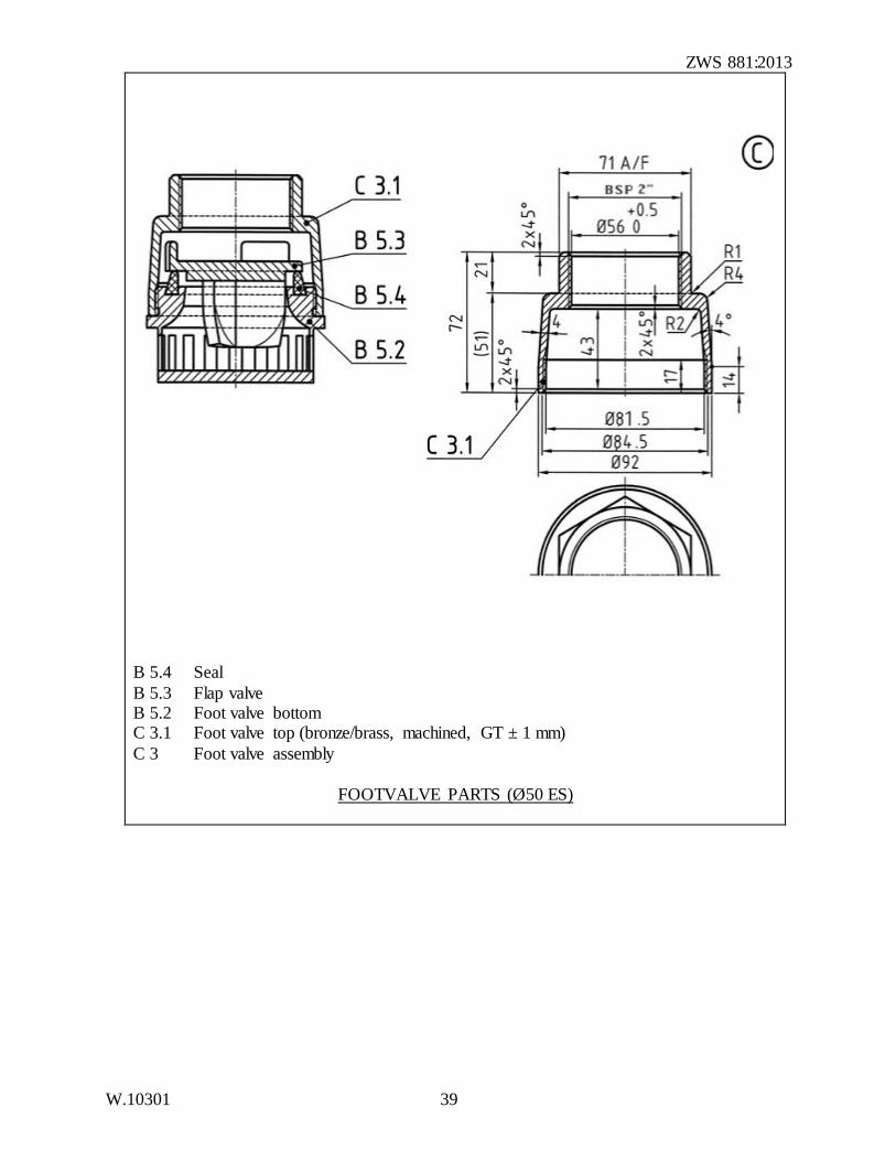
B 5.4 Seal
B 5.3 Flap valve B 5.2 Foot valve bottom C 3.1 Foot valve top (bronze/brass, machined, GT ± 1 mm)
C 3 Foot valve assembly
FOOTVALVE PARTS (Ø50 ES)
ZWS 881:2013
W.10301 40
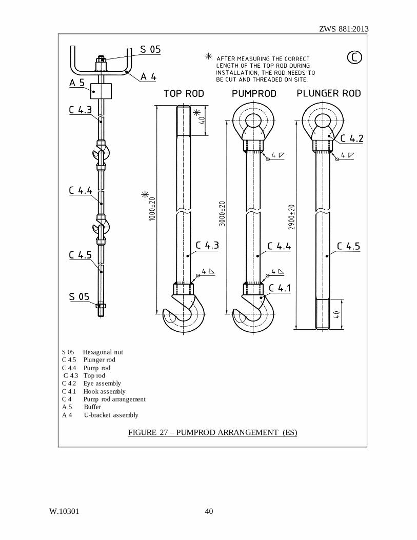
S 05 Hexagonal nut
C 4.5 Plunger rod
C 4.4 Pump rod
C 4.3 Top rod
C 4.2 Eye assembly
C 4.1 Hook assembly
C 4 Pump rod arrangement
A 5 Buffer
A 4 U-bracket assembly
FIGURE 27 – PUMPROD ARRANGEMENT (ES)
ZWS 881:2013
W.10301 41
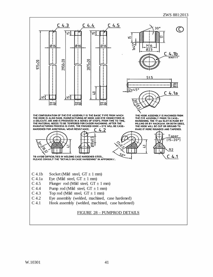
C 4.1b Socket (Mild steel, GT ± 1 mm) C 4.1a Eye (Mild steel, GT ± 1 mm) C 4.5 Plunger rod (Mild steel, GT ± 1 mm)
C 4.4 Pump rod (Mild steel, GT ± 1 mm) C 4.3 Top rod (Mild steel, GT ± 1 mm)
C 4.2 Eye assembly (welded, machined, case hardened) C 4.1 Hook assembly (welded, machined, case hardened)
FIGURE 28 – PUMPROD DETAILS
ZWS 881:2013
W.10301 42
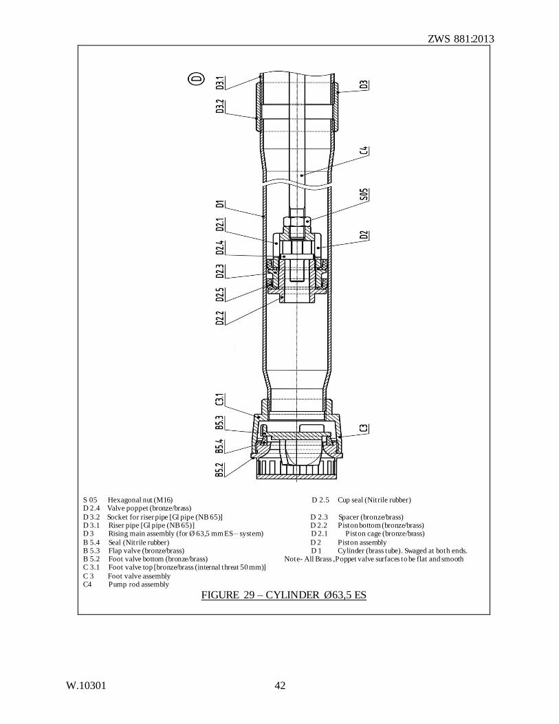
S 05 Hexagonal nut (M16) D 2.5 Cup seal (Nitrile rubber) D 2.4 Valve poppet (bronze/brass)
D 3.2 Socket for riser pipe [Gl pipe (NB 65)] D 2.3 Spacer (bronze/brass) D 3.1 Riser pipe [Gl pipe (NB 65)] D 2.2 Piston bottom (bronze/brass) D 3 Rising main assembly (for Ø 63,5 mm ES – system) D 2.1 Piston cage (bronze/brass)
B 5.4 Seal (Nitrile rubber) D 2 Piston assembly B 5.3 Flap valve (bronze/brass) D 1 Cylinder (brass tube). Swaged at both ends. B 5.2 Foot valve bottom (bronze/brass) Note- All Brass ,Poppet valve surfaces to be flat and smooth C 3.1 Foot valve top [bronze/brass (internal threat 50 mm)]
C 3 Foot valve assembly C4 Pump rod assembly
FIGURE 29 – CYLINDER Ø63,5 ES
ZWS 881:2013
W.10301 43
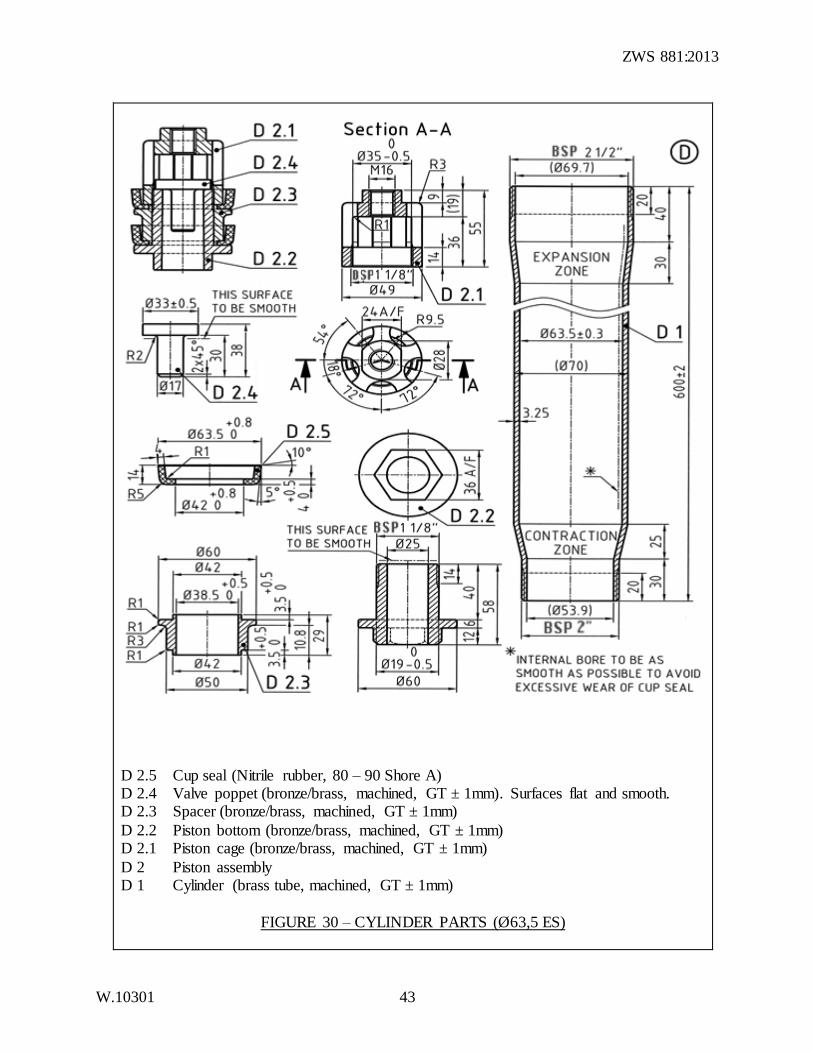
D 2.5 Cup seal (Nitrile rubber, 80 – 90 Shore A) D 2.4 Valve poppet (bronze/brass, machined, GT ± 1mm). Surfaces flat and smooth. D 2.3 Spacer (bronze/brass, machined, GT ± 1mm)
D 2.2 Piston bottom (bronze/brass, machined, GT ± 1mm) D 2.1 Piston cage (bronze/brass, machined, GT ± 1mm)
D 2 Piston assembly D 1 Cylinder (brass tube, machined, GT ± 1mm)
FIGURE 30 – CYLINDER PARTS (Ø63,5 ES)
ZWS 881:2013
W.10301 44
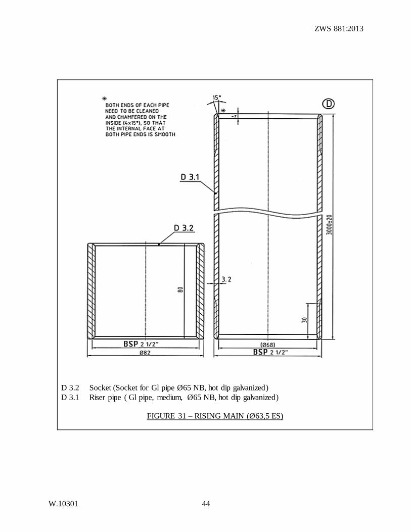
D 3.2 Socket (Socket for Gl pipe Ø65 NB, hot dip galvanized)
D 3.1 Riser pipe ( Gl pipe, medium, Ø65 NB, hot dip galvanized)
FIGURE 31 – RISING MAIN (Ø63,5 ES)
ZWS 881:2013
W.10301 45
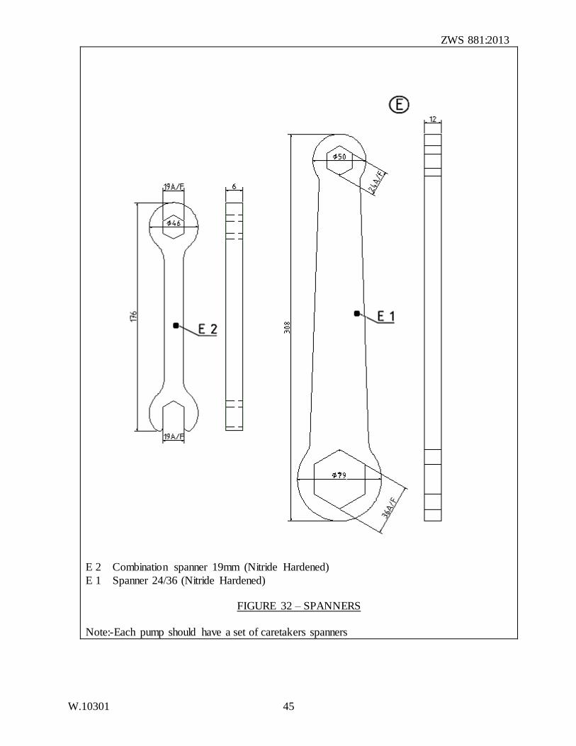
E 2 Combination spanner 19mm (Nitride Hardened)
E 1 Spanner 24/36 (Nitride Hardened)
FIGURE 32 – SPANNERS
Note:-Each pump should have a set of caretakers spanners
ZWS 881:2013
W.10301 46
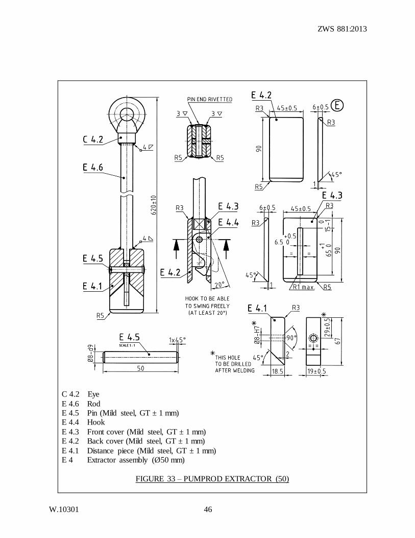
C 4.2 Eye
E 4.6 Rod E 4.5 Pin (Mild steel, GT ± 1 mm) E 4.4 Hook
E 4.3 Front cover (Mild steel, GT ± 1 mm) E 4.2 Back cover (Mild steel, GT ± 1 mm)
E 4.1 Distance piece (Mild steel, GT ± 1 mm) E 4 Extractor assembly (Ø50 mm)
FIGURE 33 – PUMPROD EXTRACTOR (50)
ZWS 881:2013
W.10301 47
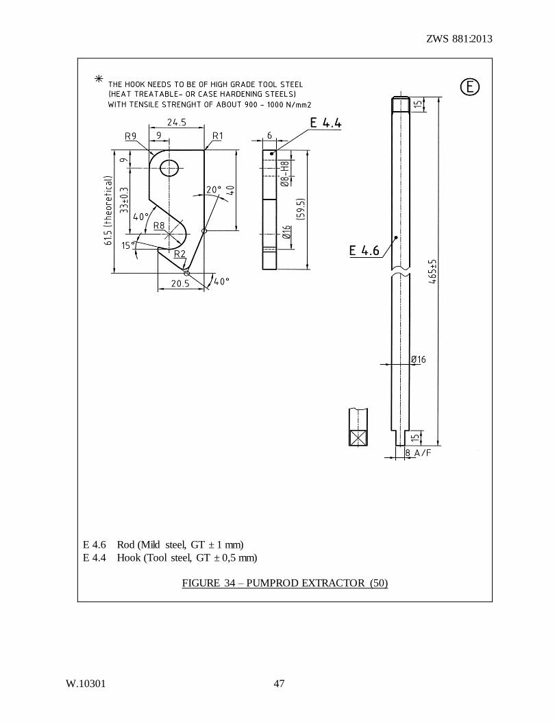
E 4.6 Rod (Mild steel, GT ± 1 mm)
E 4.4 Hook (Tool steel, GT ± 0,5 mm)
FIGURE 34 – PUMPROD EXTRACTOR (50)
ZWS 881:2013
W.10301 48
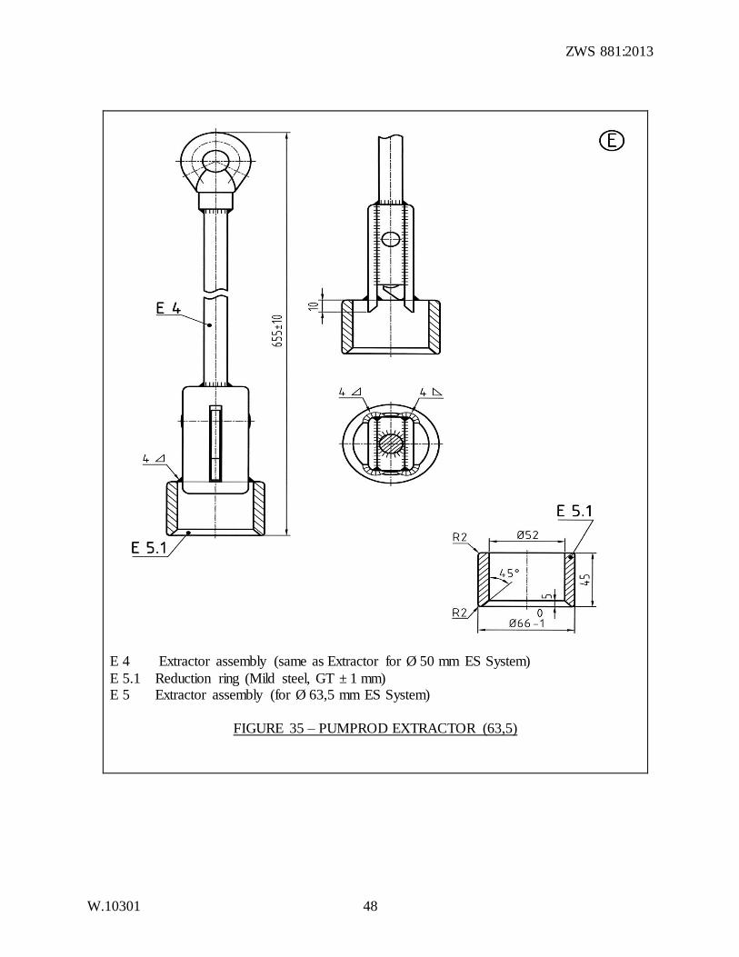
E 4 Extractor assembly (same as Extractor for Ø 50 mm ES System)
E 5.1 Reduction ring (Mild steel, GT ± 1 mm) E 5 Extractor assembly (for Ø 63,5 mm ES System)
FIGURE 35 – PUMPROD EXTRACTOR (63,5)
ZWS 881:2013
W.10301 49
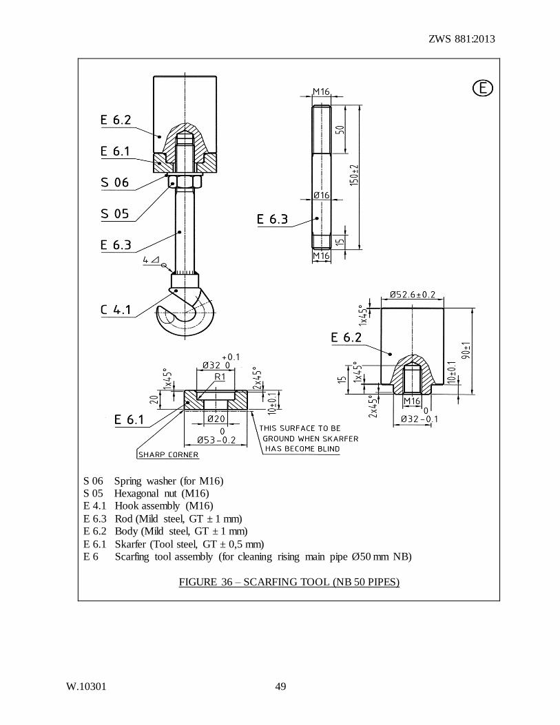
S 06 Spring washer (for M16) S 05 Hexagonal nut (M16) E 4.1 Hook assembly (M16)
E 6.3 Rod (Mild steel, GT ± 1 mm) E 6.2 Body (Mild steel, GT ± 1 mm)
E 6.1 Skarfer (Tool steel, GT ± 0,5 mm) E 6 Scarfing tool assembly (for cleaning rising main pipe Ø50 mm NB)
FIGURE 36 – SCARFING TOOL (NB 50 PIPES)
ZWS 881:2013
W.10301 50
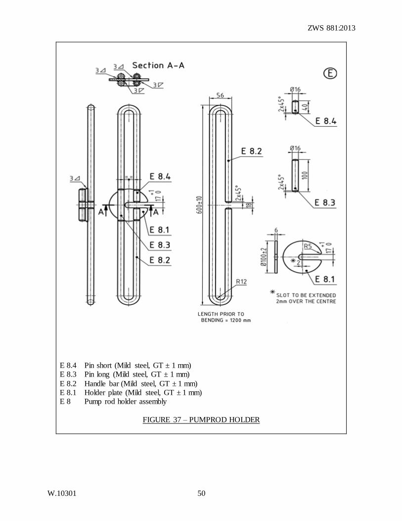
E 8.4 Pin short (Mild steel, GT ± 1 mm) E 8.3 Pin long (Mild steel, GT ± 1 mm)
E 8.2 Handle bar (Mild steel, GT ± 1 mm) E 8.1 Holder plate (Mild steel, GT ± 1 mm) E 8 Pump rod holder assembly
FIGURE 37 – PUMPROD HOLDER
ZWS 881:2013
W.10301 51
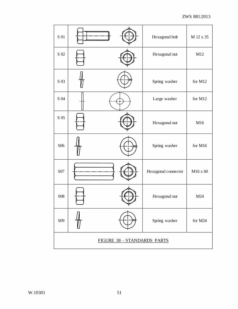
S 01
Hexagonal bolt
M 12 x 35
S 02
Hexagonal nut
M12
S 03
Spring washer
for M12
S 04
Large washer
for M12
S 05
Hexagonal nut
M16
S06
Spring washer
for M16
S07
Hexagonal connector
M16 x 60
S08
Hexagonal nut
M24
S09
Spring washer
for M24
FIGURE 38 – STANDARDS PARTS
ZWS 881:2013
W.10301 52
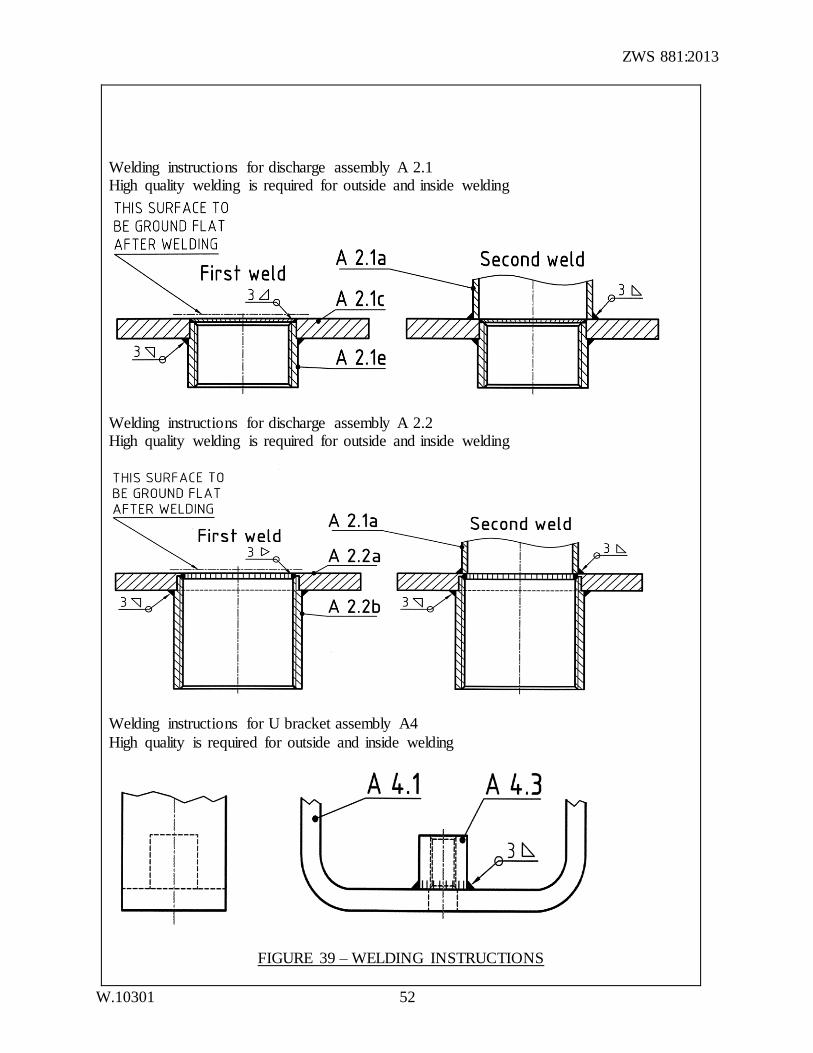
Welding instructions for discharge assembly A 2.1 High quality welding is required for outside and inside welding
Welding instructions for discharge assembly A 2.2 High quality welding is required for outside and inside welding
Welding instructions for U bracket assembly A4
High quality is required for outside and inside welding
FIGURE 39 – WELDING INSTRUCTIONS
ZWS 881:2013
W.10301 53
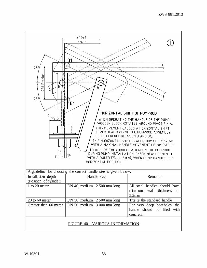
A guideline for choosing the correct handle size is given below:
Installation depth (Position of cylinder)
Handle size Remarks
1 to 20 meter DN 40, medium, 2 500 mm long All steel handles should have minimum wall thickness of
3.2mm
20 to 60 meter DN 50, medium, 2 500 mm long This is the standard handle
Greater than 60 meter DN 50, medium, 3 000 mm long For very deep boreholes, the handle should be filled with
concrete.
FIGURE 40 – VARIOUS INFORMATION
ZWS 881:2013
W.10301 54
Situation of floating washer housing of the discharge assembly (same for all pump types)
Situation of pivot pin
FIGURE 41 – VARIOUS INFORMATION
ZWS 881:2013
W.10301 55
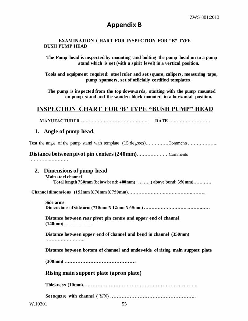
Appendix B
EXAMINATION CHART FOR INSPECTION FOR “B” TYPE
BUSH PUMP HEAD
The Pump head is inspected by mounting and bolting the pump head on to a pump
stand which is set (with a spirit level) in a vertical position.
Tools and equipment required: steel ruler and set square, calipers, measuring tape,
pump spanners, set of officially certified templates,
The pump is inspected from the top downwards, starting with the pump mounted
on pump stand and the wooden block mounted in a horizontal position.
INSPECTION CHART FOR ‘B’ TYPE “BUSH PUMP” HEAD
MANUFACTURER …………………………………….. DATE ………………………
1. Angle of pump head.
Test the angle of the pump stand with template (15 degrees)……………Comments………………..
Distance between pivot pin centers (240mm)…………………Comments …………..…………
2. Dimensions of pump head Main steel channel
Total length 750mm (below bend: 400mm) … …..( above bend: 350mm)………….
Channel dimensions (152mm X 76mm X 750mm)…………………………………………….
Side arms
Dimensions of side arm (720mm X 12mm X 65mm) ………………………..……………
Distance between rear pivot pin centre and upper end of channel
(140mm)…….................
Distance between upper end of channel and bend in channel (350mm) ……………………..
Distance between bottom of channel and under-side of rising main support plate
(300mm) ..……………………………………
Rising main support plate (apron plate)
Thickness (10mm)……………………………………………………………..
Set square with channel ( Y/N) ……………………………………………..
ZWS 881:2013
W.10301 56
3. Checking the alignment This is very critical. It can be tested by mounting the pump on a pump stand which is exactly vertical. (test with spirit level) and placing the wooden block in a horizontal position (test with spirit level) and the rod (and U bracket) set in the vertical position. Also check that the centers of the bolt holes in the wooden block are exactly 240 mm apart. When the pump head angle is correct the front surface of the descending rod should be 73 +/- 2mm mm behind the front edge of the floating washer housing. This is shown on the bush pump technical drawings. The distance between the centers of the two pivot pins should be exactly 240mm.This can be measured with set square and special template. Set the rod in vertical position and check position in relation to front edge of floating washer housing.
Distance between two pivot pin centers (240 mm) ……………………….
Distance between pump rod and front of floating washer housing (73 mm) +/-
2mm(use set square, steel rule or tape.)
COMMENTS: …………………………………………………………………………
Alignment of pump head (front to rear)
The head should not be twisted and the pump should stand exactly vertically on the borehole casing. Inspect the pump from front and side to see that the rod enters the floating washer housing centrally and not to one side.
COMMENTS: ………………………………………………………………………
NOW REMOVE WOODEN BLOCK AND PLACE ON ONE SIDE
4. Examination of pump stand
5a Thickness of pump standside arms
COMMENTS: Thickness (12 mm) ……………………………………….…………
5b Head bolt holes in pump stand These should be 36 mm (range 35, 5 – 36 mm) and 25 mm (range 24, 5 – 25 mm) respectively. The 25 mm hole should have a double thickness of 12 mm plate increased by a 12 mm thick washer welded to the pump stand to make a total thickness of 24 mm. NOTE: Head bolt securing plate should be below bolt head and horizontal (see drawings).
Large hole (36 mm) = …………………… Small hole (25 mm) = ………………..
12 mm thickness washer added (Y/N) ………………………………………………………….
Head bolt securing plate, below and horizontal (Y/N) ……………………………………………………………………………………………….
ZWS 881:2013
W.10301 57
6. Inspection of Pivot Pins
Ensure that the bolt is fitted securely and is fastened by a M24 nut and 4, 5 mm thick spring washer. There should be no play in the unit. The bolt should be made from a 35
mm diameter bright mild steel shaft and the overall bolt length should be 231 mm. The main working surface of the bolt is to be 165 mm long and should be 35 mm in diameter. One end of the bolt is reduced in thickness to 24 mm over a length of 50 mm. Half of
this (25 mm) is threaded for a M 24 nut. The remaining 25 mm length of 24 mm diameter shaft is unthreaded and is held within the U bracket or upper pump stand. The
other end of the bolt is reduced to 20 mm diameter over a 16 mm length for attachment by welding to the bolt head. The bolt head measures 50 x 50 mm and is 16 mm thick. The 16 mm securing plate is welded below the pivot pin head on the pump stand and
above the pivot pin head on the U bracket. The securing plates should make contact with the pivot pin head to stop rotation and not be distant from it. They are designed to
hold the bolt in place and stop it rotating. The securing plates should also be 16 mm thick. On the pump stand the securing plate should be horizontal (see pump drawings).
Head bolt main diameter (35 mm) …………Reduced diameter (24mm) ……….
Length of main shaft (165 mm) actual = ………………………………………….. Length of reduced diameter shaft (50 mm) actual = …………….…………………
Length of threaded section (25 mm) …………………………….…………………
Size of bolt head (50 x 50 x 16 mm) ……………………………………………….
OTHER COMMENTS: …………………………………………………………….
Spring washer
Check whether these are in place and are 4,5 mm - 5 mm in thickness ……………
COMMENTS: …………………………………………………………………….
ZWS 881:2013
W.10301 58
7. Inspection of Wooden Head block
This should be made of teak. Check size with drawings (450 x 150 x 150 mm). With
planing this may be reduced to 450mm X 145mmX 145mm which is acceptable. The critical measurement is the distance between the centers of each set of working holes.
This should be exactly 240 mm. This is important as it determines the correct entry of the rod into the floating washer housing. The block shall have been boiled in oil for 4 hours and cooled overnight for the oil to penetrate.
The head bolts should rotate easily within the block. Test for this. The bolt hole
diameter should lie between 36 and 37 mm but may require drilling to 38 mm if the wood is inclined to swell. The holes for the handle U bolts should also be correctly placed and should be 75 mm apart. The U bolt nuts should be tightened against a plate
125 x 25 mm held tight by spring washers.
COMMENTS
Size wooden block (450mm X 150mmX 150mm)…………………………………
Wood type (teak)……………………………………………………………………….
Treatment………………………………………………………………………………
Holes drilled square ……………………………………………………………………
Distance between forward working holes (240 mm) ………………………………
Distance between rear working holes (240 mm) …………………………………..
Hole diameter (36 mm – 37 mm) …………………………………………………..
Distance between U bolt holes (75 mm) = ………………………………………..
Handle U bolt securing plate (spring washer) ……………………………………...
8. Handle U Bolts
These should follow the specifications on the drawing (210 mm beyond bend) and not too long otherwise they foul other moving parts of the pump. They should be fitted with spring washers mounted against the securing plate (see above).
COMMENTS ……………………………………………………………………………..
ZWS 881:2013
W.10301 59
9. Inspection of floating washer housing
The floating washer housing forms part of the water discharge unit.
Floating washer housing
The overall outer diameter of the housing should be 190 mm, the lower plate is 10 mm thick and
the central spacer ring is 10 mm thick. The upper plate 6 mm thick. The central hole diameter in the upper plate should be 62 + - 2 mm.
Thickness of upper plate (6 mm) ……………………………………………………………
Thickness of lower plate (10 mm) …………………………………………………………..
Thickness of central spacer ring (10 mm) ………………………………………………… Diameter of upper plate (190 mm) ………………………………………………………………
Diameter of central hole (62mm+- 2mm) ………………………………………………….
Size of Floating Washers (2) These should have a diameter of 100 mm from a 6 mm thick plate with a central hole 17 mm in
diameter. They should move freely within the floating washer housing
Thickness of plate (6 mm) …………………………………………………………
Diameter of washer (100 mm) ……... Diameter of central hole (17 mm) ………
9. Water Discharge Assembly The height should be 200 mm (65 mm nominal bore GI pipe – outside diameter 76 +/-1 mm.
Diameter of dip plug hole should be 24 mm to suit M 24 plug.
Height (200 mm) = ………………………………………………………………... Size (65 mm NB) = ………………………………………………………………..
Exactly vertical mount on base plate (Y/N) ………………………….
Base Plate of Water Discharge Assembly
Diameter (160 mm) ……………………… Thickness (10 mm) …………………..
Diameter of dip plug hole (3/4” BSP to suit ¾”BSP plug) ………………………………………
Quality of 50 mm socket for attachment to rising main support plate
This should be a 2” x 7.5mm heavy duty socket or 2” x 7.5mm steam socket: COMMENTS ………………………………………………………
ZWS 881:2013
W.10301 60
10. Inspection of U Bracket
This should be 12 mm thick and follow all the measurements on the drawings. The uprights should rise 250mm above the top of the horizontal section. The uprights and the base section should be square (uprights 154 mm apart). The threaded socket, which secures the rod, should be of the right length (30 mm) and welded square to the U bracket. The rod should descend squarely from the U bracket. The rod should descend in a central line through the floating washer housing. The securing plate holding the pivot pin should be welded above the bolt head. The head bolt holes in the U bracket should be 36 mm and 25 mm in diameter for insertion of the forward pivot pin. The 25 mm hole should have a double thickness of 12 mm in diameter plate increased by a 12 mm thick washer welded to the U bracket to make a total thickness of 24 mm. Forward and rear pivot pins are identical. Distance between hole centers and upper surface of U bracket base should be 165 mm (177 mm to lower surface).
COMMENTS ON U BRACKET
Thickness plate (12 mm) = ………………………………………………………...
Height 16 mm rod socket (30 mm) = ………………………………………………
Position of bolt securing plate (above) …………………………………………….
Head bolt hole (large 36 mm) = ……………………………………………………
Head bolt hole (small 25 mm) = …………………………………………………...
12 mm thickness washer added (Y/N) ……………………………………………..
Distance between upper surface of U bracket base and hole centers (165 mm) …………
Distance between upper surface of U bracket base and top of uprights (250mm)………
Distance between uprights at top of U bracket. (154 mm) …………………………….
COMMENTS: ……………………………………………………………………………
11. Rubber Buffer
This should be about 50 mm high and 60 mm in diameter with a central 17 mm hole.
Height (50 mm) ………………………… Width (60 mm) ………………….…..
Central hole (17mm)…………………………………………………
12. Comparison with templates for rising main support plate and WDU base plate.
The template for the rising main support plate (apron plate) can be matched with the actual plate
once the water discharge unit (WDU) has been removed. These reveal the hole positions for retaining bolts and also the location of the dip plug hole as well as the dimensions of the plate. The rising main support plate has a length of 210mm and a width of 190mm. The template for
the base plate of the water discharge unit can also be compared with the unit being manufactured. The rising main support plate (apron plate) should be welded at exactly 90
degrees to the channel section of the pump stand.
Comments…………………………………………………………………..
ZWS 881:2013
W.10301 61
13. Pump handle
This should be 50 mm GI pipe, 2.5 m long unless otherwise specified. Wall thickness 3.5mm.
Diameter (50mm) ……………………………….. Length (2.5m)……………………….
Wall thickness (3.5mm) ………………………………………………………………….
NOTE. For pumps used down to about 20m a 40 mm handle is preferred. Deeper pumps require a 50 mm x 2.5 m handle which is standard. Very deep pumps (60 – 100 m) require a 50 mm x 3 m handle, the deepest filled with concrete. All handles should have a minimum wall thickness of 3.2mm.
14. Water Outlet Pipe This should follow drawings. Horizontal component about 264 mm. A 50 mm socket should be
fitted to allow for cattle trough takeoff. COMMENT: ………………………………………………………………………………
15 Quality of Welding
COMMENTS …………………………………………………………………………….
16 General Appearance (Painting etc.)
…………………………………………………………………………………………..
17. Metal Pump Makers Plate added (Y/N) ………………………………….
a) Pump Stand Serial Number.................................................................................
b) Discharge Unit Serial Number............................................................................
c) Brass cylinder Serial Number……………………………………………………
18. Caretakers Spanners 19mm combination (Y/N)……………………………………………………………… 24/36mm (Y/N)………………………………………………………………………
19. General Comments…………………………………………………………………
…………………………………………………………………………………………..
20. Recommendations………………………………………………………………….
………………………………………………………………………………………
Signed ………………………………… Date: …………………………………….
ZWS 881:2013
W.10301 62
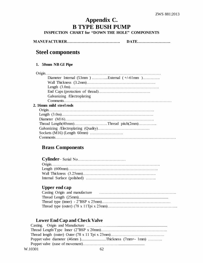
Appendix C.
B TYPE BUSH PUMP INSPECTION CHART for “DOWN THE HOLE” COMPONENTS
MANUFACTURER…………………………………. DATE…………………….
Steel components
1. 50mm NB GI Pipe
Origin…………………………………………………………………………… Diameter Internal (53mm ) ………....External ( +/-61mm )………….
Wall Thickness (3.2mm)……………………………………………. Length (3.0m)…………………………………………………………. End Caps (protection of thread)…………………………………
Galvanizing /Electroplating Comments………………………………………………………………………
2. 16mm mild steel rods
Origin…………………………………………………………………….. Length (3.0m)……………………………………………………………
Diameter (M16)…………………………………………………………. Thread Length(40mm)…………………….Thread pitch(2mm)…………..
Galvanizing /Electroplating (Quality)………………………………… Sockets (M16) (Length 60mm) ……………………. Comments……………………………………………………………….………………
Brass Components
Cylinder– Serial No………………………………
Origin………………………………………………………………………. Length (600mm)…………………………………………………………..
Wall Thickness (3.25mm)………………………………………………. Internal Surface (polished) ……………………………………………..
Upper end cap
Casting Origin and manufacture ………………………………………………….
Thread Length (25mm).......................................................................................... Thread type (inner) - 2”BSP x 25mm)………….………………………………… Thread type (outer) (78 x 11Tpi x 23mm)……………………………………………..
Lower End Cap and Check Valve Casting. Origin and Manufacture ……………............................................................. Thread Length/Type Inner (2”BSP x 20mm)…………………………………………..
Thread length (outer) Outer (78 x 11 Tpi x 23mm)…………………….…….……… Poppet valve diameter (46mm ).........................Thickness (7mm+- 1mm) ………..
Poppet valve (ease of movement)………………………..........................
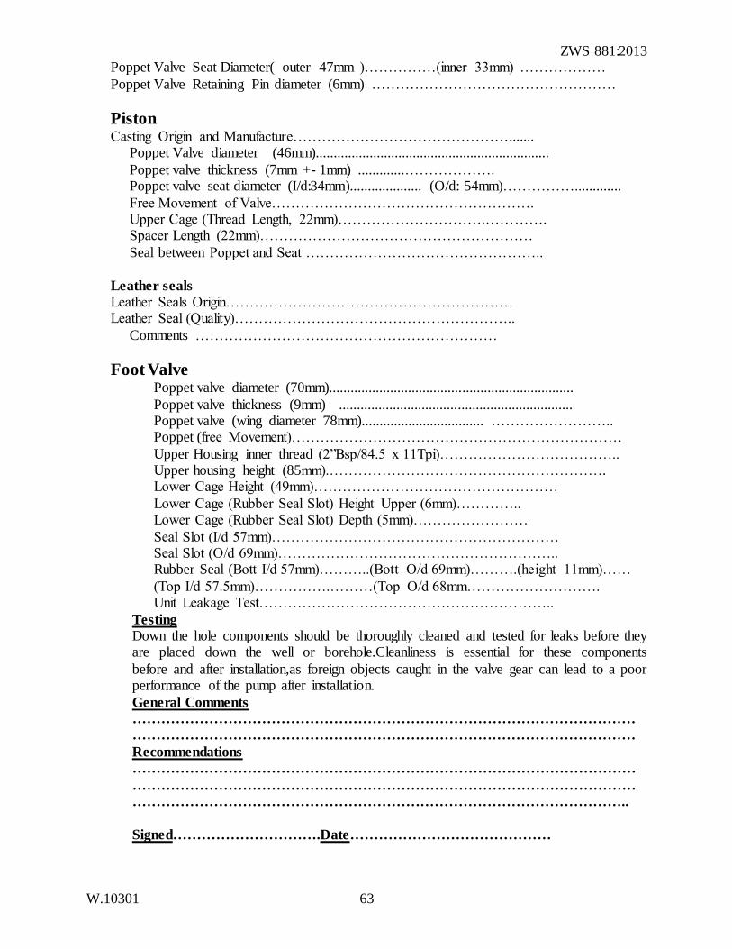
ZWS 881:2013
W.10301 63
Poppet Valve Seat Diameter( outer 47mm )……………(inner 33mm) ………………
Poppet Valve Retaining Pin diameter (6mm) ……………………………………………
Piston Casting Origin and Manufacture……………………………………….......
Poppet Valve diameter (46mm).................................................................
Poppet valve thickness (7mm +- 1mm) .............………………. Poppet valve seat diameter (I/d:34mm).................... (O/d: 54mm)…………….............
Free Movement of Valve………………………………………………. Upper Cage (Thread Length, 22mm)………………………….…………. Spacer Length (22mm)…………………………………………………
Seal between Poppet and Seat …………………………………………..
Leather seals
Leather Seals Origin…………………………………………………… Leather Seal (Quality)…………………………………………………..
Comments ………………………………………………………
Foot Valve Poppet valve diameter (70mm)....................................................................
Poppet valve thickness (9mm) ................................................................. Poppet valve (wing diameter 78mm).................................. …………………….. Poppet (free Movement)……………………………………………………………
Upper Housing inner thread (2”Bsp/84.5 x 11Tpi)……………………………….. Upper housing height (85mm).…………………………………………………. Lower Cage Height (49mm)……………………………………………
Lower Cage (Rubber Seal Slot) Height Upper (6mm)………….. Lower Cage (Rubber Seal Slot) Depth (5mm)……………………
Seal Slot (I/d 57mm)…………………………………………………… Seal Slot (O/d 69mm)………………………………………………….. Rubber Seal (Bott I/d 57mm)………..(Bott O/d 69mm)……….(height 11mm)……
(Top I/d 57.5mm)…………….………(Top O/d 68mm………………………. Unit Leakage Test……………………………………………………..
Testing
Down the hole components should be thoroughly cleaned and tested for leaks before they are placed down the well or borehole.Cleanliness is essential for these components
before and after installation,as foreign objects caught in the valve gear can lead to a poor performance of the pump after installation.
General Comments
……………………………………………………………………………………………
……………………………………………………………………………………………
Recommendations
……………………………………………………………………………………………
……………………………………………………………………………………………
…………………………………………………………………………………………..
Signed………………………….Date……………………………………
ZWS 881:2013
W.10301 64
NOTES FOR INSPECTION CHART OF ‘B’ TYPE “BUSH PUMP”
“DOWN THE HOLE” COMPONENTS”
Tools and equipment required :callipers, measuring tape, wrench spanners.
The “down the hole” components are an essential part of any Bush Pump installation. In the
standard design,they consist of both steel (ferrous) and brass (non ferrous ) components. The steel components consist of 3m long 50mm NB(nominal bore) galvanized steel (GI) pipes
which link the pump head to the cylinder.Running inside these are a series of 16mm galvanized steel pump rods.Both pipes and rods are linked by appropriate sockets or connectors.The series of pipes are known as “the rising main.”
The brass components in the standard Bush Pump consist of a 75mm cylinder,equipped with a piston and a heavy duty foot valve.The cylinder has an internal diameter of 75mm and is
600mm long.It is equipped with brass “end caps” at each end .Both upper and lower end caps are threaded to accept the 50mm pipe above and the heavy duty foot valve below.The brass piston which rises and falls within the cylinder is equipped with two high quality
leather seals.It has a circular brass “poppet valve” which rises and falls on to a brass seat.The lower end cap of the cylinder houses a “check valve” which is a backup for the primary foot
valve below.This also has a brass poppet valve, rising and falling on a brass seat.The foot valve is a heavy duty reliable unit which threads into the lower end of the cylinder.This is equipped with a lower cage,which prevents larger items entering the valve.The brass poppet
valve has “wings” which provides a circular movement to the valve during use.The poppet valve rises and falls on to a rubber seat which is tightly fitted into a slot in the lower part of
the foot valve housing.The upper part of the foot valve housing is equipped with a 50mm thread which screws into the lower end cap of the cylinder.
In order that the brass components serve their function properly,it is essential that the 3 poppet valves sit neatly on the respective seats and maintain a good seal.The internal wall of
the cylinder should be very smooth and highly polished. The two leather seals should be of the highest quality. All components should be thoroughly cleaned before assembly and after assembly of the foot valve, fitted to the cylinder, should be checked for leakage.
Another important aspect is that the steel pipes are of the correct quality and thickness to the
specifications for the pipes (SABS 62 part 1) with a minimum wall thickness of 3.2mm. Also with the brass tube used for the cylinder this should have a wall thickness of at least 3.25mm. This thickness provides sufficient support for the threads made at each end of the
cylinder to hold the end caps.
In the standard Bush Pump,the leather seals are the fastest wearing parts .Where the water quality is good,seals can last up to 3-5 years depending on use.In turbid water a seal life is reduced.Poor quality seals have a very short life and it is important that suppliers provide the
highest quality leather possible for this component.The cost of replacing seals is high,as it involves removing the rods and rising main to gain access to the cylinder and piston
arrangement .The cost of seals is low, even for the highest quality units. Pipe life can be extended by applying “plumber’s paste” or “plumber’s delight” to all
threaded components before assembly. This will provide a better seal at the joint and also help the dismantling operation when the pipes are lifted. Joints which are rusted together are
difficult to take apart and damage can be caused during this operation.
ZWS 881:2013
W.10301 65
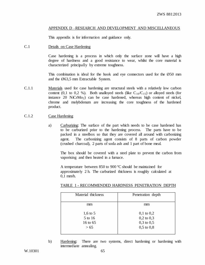
APPENDIX D –RESEARCH AND DEVELOPMENT AND MISCELLANEOUS
This appendix is for information and guidance only.
C.1 Details on Case Hardening
Case hardening is a process in which only the surface zone will have a high degree of hardness and a good resistance to wear, whilst the core material is characterized principally by extreme toughness.
This combination is ideal for the hook and eye connectors used for the Ø50 mm
and the Ø63,5 mm Extractable System. C.1.1 Materials used for case hardening are structural steels with a relatively low carbon
content (0,1 to 0,2 %). Both unalloyed steels (like C10/C15) or alloyed steels (for instance 20 NiCrMo2) can be case hardened, whereas high content of nickel,
chrome and molybdenum are increasing the core toughness of the hardened product.
C.1.2 Case Hardening
a) Carburizing: The surface of the part which needs to be case hardened has to be carburized prior to the hardening process. The parts have to be packed in a steelbox so that they are covered all around with carbonizing
agent. The carbonizing agent consists of 8 parts of carbon powder (crushed charcoal), 2 parts of soda ash and 1 part of bone meal.
The box should be covered with a steel plate to prevent the carbon from vaporising and then heated in a furnace.
A temperature between 850 to 900 ºC should be maintained for
approximately 2 h. The carburized thickness is roughly calculated at 0,1 mm/h.
TABLE 1 - RECOMMENDED HARDNESS PENETRATION DEPTH
Material thickness Penetration depth
mm
1,6 to 5
5 to 16 16 to 65
> 65
mm
0,1 to 0,2
0,2 to 0,3 0,3 to 0,5
0,5 to 0,8
b) Hardening: There are two systems, direct hardening or hardening with intermediate annealing.
ZWS 881:2013
W.10301 66
i) Direct hardening: After the carburizing time is over, the temperature of the furnace has to be reduced slowly between 780
to 840 ºC (Hardening Temperature). If this range of temperature is reached, the steelbox has to be opened and each processed steel part needs to be quenched in an oil bath with a temperature of
approximately 60 ºC.
ii) Hardening with intermediate-annealing: After the carburizing time is over, reduce the temperature of the furnace to 200 ºC. Then the box with the parts can be taken out of the furnace to cool down
completely.
After that, the box with the parts will be intermediate-annealed for 2 to 4 h in a temperature of 650 ºC and cooled down again.
For the hardening process, the parts still remaining in the box need to be heated up to 400 ºC for 1 to 2 h and then the temperature has
to be increased between 780 and 840 ºC (Hardening Temperature). Then the parts have to be taken from the box and be quenched as in the direct hardening process (see (i) above).
iii) Annealing: All hardened parts need to be annealed at a
temperature of 200 oC to a maximum of 250 ºC. The annealing
time takes at least 2 to 3 h. For extra large parts an addition of 1 h per each 20 mm wall thickness is required.
NOTE 1. All temperatures given above have to be adjusted to the requirements of the exact material type used. Required data are available from the material
supplier or from the heat treatment specialist.
NOTE 2. It is possible to case harden “Mild Steel” like St 37, the result is not comparable to the special case hardening steels, but the performance after the treatment is still satisfactory.
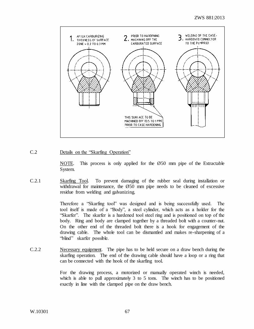
NOTE 3. If you have to weld case hardened part to soft material, it is advisable to
machine off the carburized surface on the welding spot prior to hardening. This part will remain soft and welding is not a problem any more (see Figure below).
It is also possible to grind off the surface after hardening, but one has to remember that the surface is extremely hard and a special grinding disc may be required.
NOTE 4. Further possibilities for heat treatment of case hardened steels are, for
example, nitrocarburizing and nitriding.
ZWS 881:2013
W.10301 67
C.2 Details on the “Skarfing Operation”
NOTE. This process is only applied for the Ø50 mm pipe of the Extractable
System.
C.2.1 Skarfing Tool. To prevent damaging of the rubber seal during installation or withdrawal for maintenance, the Ø50 mm pipe needs to be cleaned of excessive residue from welding and galvanizing.
Therefore a “Skarfing tool” was designed and is being successfully used. The
tool itself is made of a “Body”, a steel cylinder, which acts as a holder for the “Skarfer”. The skarfer is a hardened tool steel ring and is positioned on top of the body. Ring and body are clamped together by a threaded bolt with a counter-nut.
On the other end of the threaded bolt there is a hook for engagement of the drawing cable. The whole tool can be dismantled and makes re-sharpening of a
“blind” skarfer possible. C.2.2 Necessary equipment. The pipe has to be held secure on a draw bench during the
skarfing operation. The end of the drawing cable should have a loop or a ring that can be connected with the hook of the skarfing tool.
For the drawing process, a motorized or manually operated winch is needed, which is able to pull approximately 3 to 5 tons. The winch has to be positioned
exactly in line with the clamped pipe on the draw bench.
ZWS 881:2013
W.10301 68
C.2.3 Operation procedure
C.2.3.1 The far end of the fixed pipe needs to be ground internally for about 30 to 50 mm, in order to accommodate the skarfing tool centrally.
C.2.3.2 The cable end of the winch has to be put through the pipe and its loop has to be connected with the hook of the skarfing tool.
C.2.3.3 After positioning of the skarfing tool at the inside of the prepared pipe end, the
winch can be started to pull the tool through the whole pipe.
After this process, the inner diameter of the Ø50 mm pipe will be 53 mm for the
whole length. NOTE. It is unnecessary to clean out standard “off the shell” Ø65 mm and
Ø75 mm pipes as there is sufficient clearance between the inside pipe diameter and the cup seals of the plungers.
For skarfing tool drawings see Figure A3320.
C.3 Details on Leather Seals
Cup seals, if made of good leather are very hard wearing and will accept wide
tolerances with badly worn or pitted cylinders.
For the manufacturing of “leather cup seals” it is essential to find an experienced and reputable company which is capable to produce this kind of technical leather product .
C.3.1 Here are some general comments on how to manufacture vegetable-tanned cup
leathers:
a) The leather is from cattle and is tanned in brown vegetable tan. The leather
needs to be 1,0 mm thicker than the thickness of the finished cup seal. It has to be rough tanned leather, which means that it has not undergone any further
finishing processes. b) For the tool in which you form the cup seals you need a female mould, called
the DIE, and a punch, which is called the PLUG. The die is a ring with an inside diameter that is 1,0 mm larger than the outside diameter of the finished
cup seal. The thickness of the die should be 5 mm more than the height of the finished cup seal. The plug needs to have the exact diameter and radius of the inside shape of the finished product.
ZWS 881:2013
W.10301 69
c) Now cut a circle of leather, which has the diameter of the cup plus twice
the height of the finished cup.
An example; for the cup seal Figure C3346, you calculate 1x the outside diameter of 75 mm and 2x the height of 20 mm, which gives you a circle diameter of 115 mm.
d) This round leather disc has to be soaked in warm water until it is really
soft.
e) Afterwards place the disc in the die so that the smooth side of the leather
is up. Finally put the plug on top of the leather and fit the whole tool under a press.
f) In the press you force the plug right down so that the surplus leather can
be cut off with a knife, level with the upper surface of the die.
g) Then take the tool from the press to a bench, push the plug with the leather
cup through the die and knock out the plug. h) Place the wet leather cup in a warm room at approximately 25 to 27 ºC
until it is completely dry (more or less than 48 h).
i) Put the dried leather cup into a hot paraffin wax bath at 70 ºC until it is fully soaked.
j) Place the still hot waxed leather part back into the die and the punch, so that it keeps its shape and leave it until it has cooled down.
k) Then press it through the die and remove the part from the plug.
l) Now it is time to machine the final shape on a lathe machine. You place a piece of solid wood (ideal is elm wood) in the chuck of a lathe and turn
exactly the inside shape of the cup seal. The diameter of the wooden shape should be such that the cup has a tight grip on it.
a. First machining operation: turning the exact outside diameter and the base with a wood chisel (to be compared with a tool bit on a lathe
machine).
b. Second operation: mark and cut the height of the part with a pointed
chisel and machine the bevel shape (30º angle).
c. Third operation: now the finished cup seal needs to be polished on the outside to make it smooth and attractive.
d. Last operation: cut out the centre hole with a pointed chisel.
ZWS 881:2013
W.10301 70
Should you face problems with the tight grip of the cup seal on the shaped wood,
you may use an adjustable hose clamp or any other suitable device for securing the cup after finishing the first operation.
For shape details see drawing Figures C3248 and C3346.
NOTE 1. Only vegetable tanning agents are to be used for manufacturing of leather cup seals.
NOTE 2. The wax to be used for the impregnating process should have a melting point of not less than 55 to 60 ºC. The mixture contains usually paraffin or
stearine (candle wax).
NOTE 3. For softer cup seals use tallow (white beef fat) instead of paraffin wax.
APPENDIX E – QUALITY EVALUATION OF ‘B’ TYPE HAND-PUMPS
This appendix is for information only. When a purchaser requires ongoing verification of the quality of “bush pumps”, it
is suggested that, instead of concentrating solely on evaluation of the final product, he/she also directs his/her attention to the manufacturer’s quality system.
In this connection, it should be noted that ZWS ISO 9001 covers the provision of an integrated quality system.