Data Sheet Version 15.00
Specifications
R&S®RTB2000 OSCILLOSCOPE
year
Version 15.00, May 2021
2 Rohde & Schwarz R&S®RTB2000 Oscilloscope
CONTENTS Definitions ....................................................................................................................................................................... 3
Base unit .......................................................................................................................................................................... 4
Vertical system .................................................................................................................................................................................. 4
Horizontal system .............................................................................................................................................................................. 5
Acquisition system ............................................................................................................................................................................. 5
Trigger system ................................................................................................................................................................................... 6
Waveform measurements .................................................................................................................................................................. 7
Digital voltmeter ................................................................................................................................................................................. 8
Frequency counter ............................................................................................................................................................................. 8
Mask testing ...................................................................................................................................................................................... 8
Waveform maths ............................................................................................................................................................................... 8
Search function.................................................................................................................................................................................. 9
Display characteristics ....................................................................................................................................................................... 9
Protocol and logic .............................................................................................................................................................................. 9
Miscellaneous .................................................................................................................................................................................... 9
Input and outputs ............................................................................................................................................................................. 10
General data .................................................................................................................................................................. 11
Options .......................................................................................................................................................................... 12
R&S®RTB-B1 ................................................................................................................................................................................... 12
R&S®RTB-B6 ................................................................................................................................................................................... 13
R&S®RTB-Bxx bandwidth upgrades ................................................................................................................................................ 14
R&S®RTB-K1 ................................................................................................................................................................................... 14
R&S®RTB-K2 ................................................................................................................................................................................... 15
R&S®RTB-K3 ................................................................................................................................................................................... 15
R&S®RTB-K15 ................................................................................................................................................................................. 17
R&S®RTB-K36 ................................................................................................................................................................................. 17
Ordering information .................................................................................................................................................... 18
Version 15.00, May 2021
Rohde & Schwarz R&S®RTB2000 Oscilloscope 3
Definitions General
Product data applies under the following conditions:
• Three hours storage at ambient temperature followed by 30 minutes warm-up operation
• Specified environmental conditions met
• Recommended calibration interval adhered to
• All internal automatic adjustments performed, if applicable
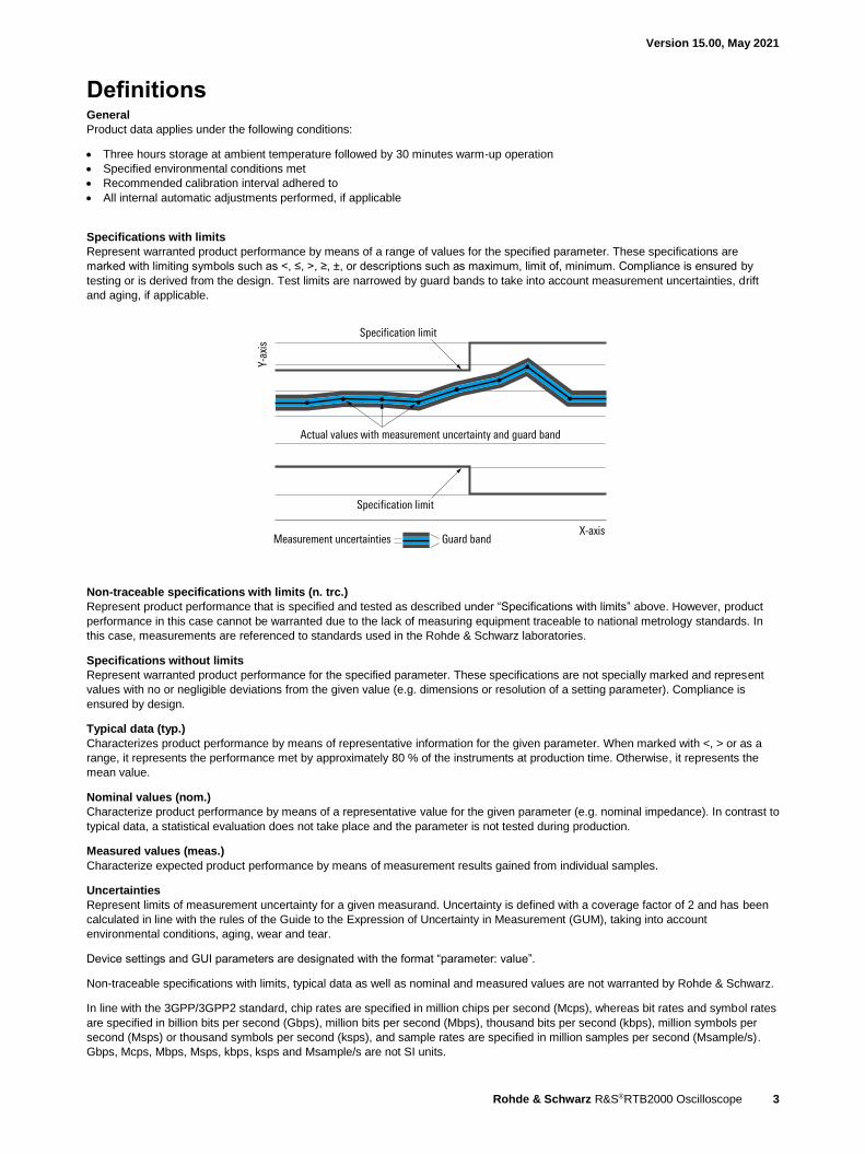
Specifications with limits
Represent warranted product performance by means of a range of values for the specified parameter. These specifications are
marked with limiting symbols such as <, ≤, >, ≥, ±, or descriptions such as maximum, limit of, minimum. Compliance is ensured by
testing or is derived from the design. Test limits are narrowed by guard bands to take into account measurement uncertainties, drift
and aging, if applicable.
Non-traceable specifications with limits (n. trc.)
Represent product performance that is specified and tested as described under “Specifications with limits” above. However, product
performance in this case cannot be warranted due to the lack of measuring equipment traceable to national metrology standards. In
this case, measurements are referenced to standards used in the Rohde & Schwarz laboratories.
Specifications without limits
Represent warranted product performance for the specified parameter. These specifications are not specially marked and represent
values with no or negligible deviations from the given value (e.g. dimensions or resolution of a setting parameter). Compliance is
ensured by design.
Typical data (typ.)
Characterizes product performance by means of representative information for the given parameter. When marked with <, > or as a
range, it represents the performance met by approximately 80 % of the instruments at production time. Otherwise, it represents the
mean value.
Nominal values (nom.)
Characterize product performance by means of a representative value for the given parameter (e.g. nominal impedance). In contrast to
typical data, a statistical evaluation does not take place and the parameter is not tested during production.
Measured values (meas.)
Characterize expected product performance by means of measurement results gained from individual samples.
Uncertainties
Represent limits of measurement uncertainty for a given measurand. Uncertainty is defined with a coverage factor of 2 and has been
calculated in line with the rules of the Guide to the Expression of Uncertainty in Measurement (GUM), taking into account
environmental conditions, aging, wear and tear.
Device settings and GUI parameters are designated with the format “parameter: value”.
Non-traceable specifications with limits, typical data as well as nominal and measured values are not warranted by Rohde & Schwarz.
In line with the 3GPP/3GPP2 standard, chip rates are specified in million chips per second (Mcps), whereas bit rates and symbol rates
are specified in billion bits per second (Gbps), million bits per second (Mbps), thousand bits per second (kbps), million symbols per
second (Msps) or thousand symbols per second (ksps), and sample rates are specified in million samples per second (Msample/s).
Gbps, Mcps, Mbps, Msps, kbps, ksps and Msample/s are not SI units.
X-axis
Y-ax
is
Specification limit
Actual values with measurement uncertainty and guard band
Specification limit
Measurement uncertainties Guard band

Version 15.00, May 2021
4 Rohde & Schwarz R&S®RTB2000 Oscilloscope
Base unit
Vertical system Input channels R&S®RTB2002 2 channels
R&S®RTB2004 4 channels
Input impedance R&S®RTB2002, R&S®RTB2004 1 MΩ ± 2 % with 9 pF ± 2 pF (meas.)
Analog bandwidth (–3 dB) R&S®RTB2002 and R&S®RTB2004 > 70 MHz
R&S®RTB2002 with -B221 option and
R&S®RTB2004 with -B241 option
> 100 MHz
R&S®RTB2002 with -B222 option and
R&S®RTB2004 with -B242 option
> 200 MHz
R&S®RTB2002 with -B223 option and
R&S®RTB2004 with -B243 option
> 300 MHz
Lower frequency limit (–3 dB) at AC coupling < 2 Hz (meas.)
Analog bandwidth limits
(max. –1.8 dB, min. –3.5 dB)
R&S®RTB2002 and R&S®RTB2004 20 MHz
Rise time (10 % to 90 %, calculated) R&S®RTB2002 and R&S®RTB2004 < 5 ns
R&S®RTB2002 with -B221 option and
R&S®RTB2004 with -B241 option
< 3.5 ns
R&S®RTB2002 with -B222 option and
R&S®RTB2004 with -B242 option
< 1.75 ns
R&S®RTB2002 with -B223 option and
R&S®RTB2004 with -B243 option
< 1.15 ns
Vertical resolution 10 bit, up to 16 bit with high-resolution
decimation mode
Invert signal yes
DC gain accuracy offset and position = 0,
maximum operating temperature change of ±5 °C after self-alignment
input sensitivity > 5 mV/div ±1.5 % of full scale
input sensitivity ≤ 5 mV/div ±2 % of full scale
Offset accuracy ±(0.5 % × |offset| +
0.1 div × input sensitivity + 1 mV)
DC measurement accuracy after adequate suppression of
measurement noise by using high-
resolution sampling mode or waveform
averaging
±(DC gain accuracy + offset accuracy)
Input coupling DC, AC, GND
Input sensitivity 1 mV/div to 5 V/div
Maximum input voltage 300 V (RMS), max. 400 V (Vp), derates at
20 dB/decade to 5 V (RMS) above
250 kHz
Position range ±5 div (depends on offset)
Offset range 1 input sensitivity
200 mV/div to ≤ 5 V/div ±(40 V – position × input sensitivity)
1 mV/div to < 200 mV/div ±(1.2 V – position × input sensitivity)
Channel-to-channel isolation
(each channel at same input sensitivity)
input frequency < analog bandwidth > 50 dB
1 Signals with non-destructive DC components that overdrive the ADC continually for long periods of time are not recommended, and may result in
instrument damage.
Version 15.00, May 2021
Rohde & Schwarz R&S®RTB2000 Oscilloscope 5
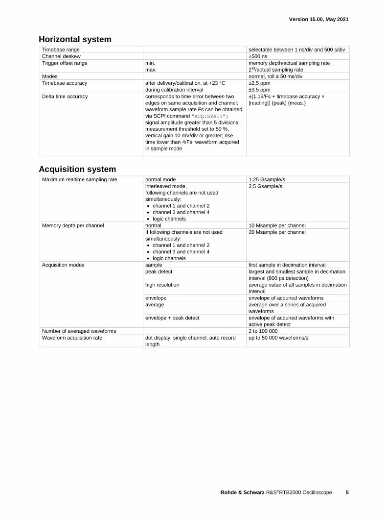
Horizontal system Timebase range selectable between 1 ns/div and 500 s/div
Channel deskew ±500 ns
Trigger offset range min. memory depth/actual sampling rate
max. 233/actual sampling rate
Modes normal, roll ≥ 50 ms/div
Timebase accuracy after delivery/calibration, at +23 °C ±2.5 ppm
during calibration interval ±3.5 ppm
Delta time accuracy corresponds to time error between two
edges on same acquisition and channel;
waveform sample rate Fs can be obtained
via SCPI command “ACQ:SRAT?”;
signal amplitude greater than 5 divisions,
measurement threshold set to 50 %,
vertical gain 10 mV/div or greater; rise
time lower than 4/Fs; waveform acquired
in sample mode
±(1.19/Fs + timebase accuracy ×
|reading|) (peak) (meas.)
Acquisition system Maximum realtime sampling rate normal mode 1.25 Gsample/s
interleaved mode,
following channels are not used
simultaneously:
• channel 1 and channel 2
• channel 3 and channel 4
• logic channels
2.5 Gsample/s
Memory depth per channel normal 10 Msample per channel
If following channels are not used
simultaneously:
• channel 1 and channel 2
• channel 3 and channel 4
• logic channels
20 Msample per channel
Acquisition modes sample first sample in decimation interval
peak detect largest and smallest sample in decimation
interval (800 ps detection)
high resolution average value of all samples in decimation
interval
envelope envelope of acquired waveforms
average average over a series of acquired
waveforms
envelope + peak detect envelope of acquired waveforms with
active peak detect
Number of averaged waveforms 2 to 100 000
Waveform acquisition rate dot display, single channel, auto record
length
up to 50 000 waveforms/s

Version 15.00, May 2021
6 Rohde & Schwarz R&S®RTB2000 Oscilloscope
Trigger system Trigger level range (min) ±5 div from center of screen
Trigger modes auto, normal, single,
n single with R&S®RTB-K15 option
Hold-off range time inactive or 50 ns to 10 s
Trigger types edge, width, video, pattern, serial bus,
timeout, line
Edge trigger trigger events rising edge, falling edge, both edges
sources
R&S®RTB2002 channel 1, channel 2, logic channels from
D0 to D15 (with R&S®RTB-B1 option),
external trigger input
R&S®RTB2004 channel 1, channel 2, channel 3,
channel 4, logic channels from D0 to D15
(with R&S®RTB-B1 option), external
trigger input
coupling (analog channels, external trigger
input)
DC, AC,
HF reject (attenuates > 50 kHz (meas.)),
LF reject (attenuates < 50 kHz (meas.)),
noise reject (enlarges trigger hysteresis)
Width trigger trigger events pulse width is smaller, greater, equal,
unequal, inside interval, outside interval
min. pulse width 6.4 ns
max. pulse width 13.5 s
polarity positive, negative
sources
R&S®RTB2002 channel 1, channel 2, logic channels from
D0 to D15 (with R&S®RTB-B1 option)
R&S®RTB2004 channel 1, channel 2, channel 3,
channel 4, logic channels from D0 to D15
(with R&S®RTB-B1 option)
Video trigger trigger events selectable line, all lines, even frame,
odd frame, all frames
supported standards PAL, NTSC, SECAM, PAL-M, SDTV 576i,
HDTV 720p, HDTV 1080i, HDTV 1080p
sources
R&S®RTB2002 channel 1, channel 2, external trigger input
R&S®RTB2004 channel 1, channel 2, channel 3,
channel 4, external trigger input
sync pulse polarity positive, negative
Pattern trigger trigger events logic condition between active channels
sources
R&S®RTB2002 channel 1, channel 2, logic channels from
D0 to D15 (with R&S®RTB-B1 option)
R&S®RTB2004 channel 1, channel 2, channel 3,
channel 4, logic channels from D0 to D15
(with R&S®RTB-B1 option)
state of channels high, low, don’t care
logic between channels and/or
condition true, false
duration condition smaller, greater, equal, unequal, inside
interval, outside interval, timeout
min. duration time 6.4 ns
max. duration time 13.5 s
Timeout trigger trigger events greater than timeout
minimum timeout 6.4 ns
maximum timeout 13.5 s
polarity stays high, stays low
sources
R&S®RTB2002 channel 1, channel 2, logic channels from
D15 to D0 (with R&S®RTB-B1 option)
R&S®RTB2004 channel 1, channel 2, channel 3,
channel 4, logic channels from D15 to D0
(with R&S®RTB-B1 option)
selectable trigger hysteresis small, medium, large
Version 15.00, May 2021
Rohde & Schwarz R&S®RTB2000 Oscilloscope 7
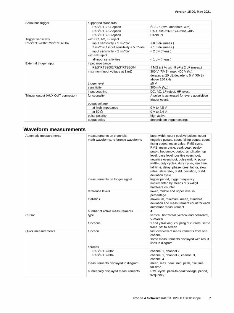
Serial bus trigger supported standards
R&S®RTB-K1 option I2C/SPI (two- and three-wire)
R&S®RTB-K2 option UART/RS-232/RS-422/RS-485
R&S®RTB-K3 option CAN/LIN
Trigger sensitivity
R&S®RTB2002/R&S®RTB2004
with DC, AC, LF reject
input sensitivity > 5 mV/div < 0.8 div (meas.)
2 mV/div ≤ input sensitivity < 5 mV/div < 1.5 div (meas.)
input sensitivity < 2 mV/div < 2 div (meas.)
with HF reject
all input sensitivities < 1 div (meas.)
External trigger input input impedance
R&S®RTB2002/R&S®RTB2004 1 MΩ ± 2 % with 9 pF ± 2 pF (meas.)
maximum input voltage at 1 mΩ 300 V (RMS), max. 400 V (Vp),
derates at 20 dB/decade to 5 V (RMS)
above 250 kHz
trigger level ±5 V
sensitivity 300 mV (Vpp)
input coupling DC, AC, LF reject, HF reject
Trigger output (AUX OUT connector) functionality A pulse is generated for every acquisition
trigger event.
output voltage
at high impedance 0 V to 4.8 V
at 50 Ω 0 V to 2.4 V
pulse polarity high active
output delay depends on trigger settings
Waveform measurements Automatic measurements measurements on channels,
math waveforms, reference waveforms
burst width, count positive pulses, count
negative pulses, count falling edges, count
rising edges, mean value, RMS cycle,
RMS, mean cycle, peak peak, peak+,
peak-, frequency, period, amplitude, top
level, base level, positive overshoot,
negative overshoot, pulse width+, pulse
width-, duty cycle+, duty cycle-, rise time,
fall time, delay, phase, crest factor, slew
rate+, slew rate-, σ.std. deviation, σ.std.
deviation cycle
measurements on trigger signal trigger period, trigger frequency
implemented by means of six-digit
hardware counter
reference levels lower, middle and upper level in
percentage
statistics maximum, minimum, mean, standard
deviation and measurement count for each
automatic measurement
number of active measurements 4
Cursor type vertical, horizontal, vertical and horizontal,
V-marker
functions x and y tracking, coupling of cursors, set to
trace, set to screen
Quick measurements function fast overview of measurements from one
channel,
some measurements displayed with result
lines in diagram
sources
R&S®RTB2002 channel 1, channel 2
R&S®RTB2004 channel 1, channel 2, channel 3,
channel 4
measurements displayed in diagram mean, max. peak, min. peak, rise time,
fall time
numerically displayed measurements RMS cycle, peak-to-peak voltage, period,
frequency
Version 15.00, May 2021
8 Rohde & Schwarz R&S®RTB2000 Oscilloscope
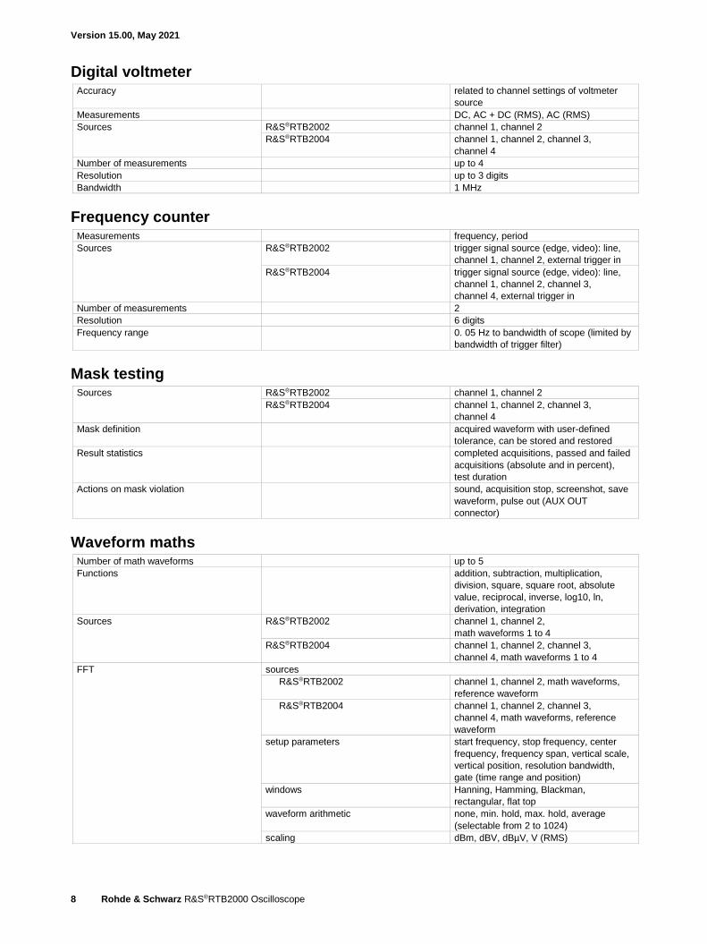
Digital voltmeter Accuracy related to channel settings of voltmeter
source
Measurements DC, AC + DC (RMS), AC (RMS)
Sources R&S®RTB2002 channel 1, channel 2
R&S®RTB2004 channel 1, channel 2, channel 3,
channel 4
Number of measurements up to 4
Resolution up to 3 digits
Bandwidth 1 MHz
Frequency counter Measurements frequency, period
Sources R&S®RTB2002 trigger signal source (edge, video): line,
channel 1, channel 2, external trigger in
R&S®RTB2004 trigger signal source (edge, video): line,
channel 1, channel 2, channel 3,
channel 4, external trigger in
Number of measurements 2
Resolution 6 digits
Frequency range 0. 05 Hz to bandwidth of scope (limited by
bandwidth of trigger filter)
Mask testing Sources R&S®RTB2002 channel 1, channel 2
R&S®RTB2004 channel 1, channel 2, channel 3,
channel 4
Mask definition acquired waveform with user-defined
tolerance, can be stored and restored
Result statistics completed acquisitions, passed and failed
acquisitions (absolute and in percent),
test duration
Actions on mask violation sound, acquisition stop, screenshot, save
waveform, pulse out (AUX OUT
connector)
Waveform maths Number of math waveforms up to 5
Functions addition, subtraction, multiplication,
division, square, square root, absolute
value, reciprocal, inverse, log10, ln,
derivation, integration
Sources R&S®RTB2002 channel 1, channel 2,
math waveforms 1 to 4
R&S®RTB2004 channel 1, channel 2, channel 3,
channel 4, math waveforms 1 to 4
FFT sources
R&S®RTB2002 channel 1, channel 2, math waveforms,
reference waveform
R&S®RTB2004 channel 1, channel 2, channel 3,
channel 4, math waveforms, reference
waveform
setup parameters start frequency, stop frequency, center
frequency, frequency span, vertical scale,
vertical position, resolution bandwidth,
gate (time range and position)
windows Hanning, Hamming, Blackman,
rectangular, flat top
waveform arithmetic none, min. hold, max. hold, average
(selectable from 2 to 1024)
scaling dBm, dBV, dBµV, V (RMS)

Version 15.00, May 2021
Rohde & Schwarz R&S®RTB2000 Oscilloscope 9
Search function Functions search types edge, width, peak, rise/fall time, runt,
data2clock, pattern, protocol (available
with R&S®RTB-K3 option)
configuration manual level setting, adjustable hysteresis
display of search events in diagram (markers) and in result table
Sources R&S®RTB2002 channel 1, channel 2,
math waveform, D0 to D15
(with R&S®RTB-B1 option)
R&S®RTB2004 channel 1, channel 2, channel 3,
channel 4, math waveform, D0 to D15
(with R&S®RTB-B1 option)
Display characteristics Diagram types manually changeable vertical window size Yt, XY, zoom, FFT
XY mode
parallel display of XY diagram and
Yt diagrams of input signals for X, Y
Zoom horizontal zoom with fast navigation, split
screen with overview signal and zoomed
signal
FFT mode split screen with Yt diagrams and
dedicated frequency diagram
Interpolation sin(x)/x, linear, sample & hold
Waveform display lines, dots only
Persistence 50 ms to 12.8 s, infinite
Special display mode
inverse brightness, waveform color modes
for analog channels (temperature, fire,
rainbow)
Diagram grid
lines, reticle, none, with annotation, track
grid
Reference signals up to 4 reference signals
Sources
analog and digital channels, math,
reference, spectrum
Protocol and logic Bus decode number of bus signals 2 2
bus types parallel, parallel clocked
R&S®RTB-K1 option SPI (2-wire, 3-wire, 4-wire 2), I2C
R&S®RTB-K2 option UART/RS-232/RS-422/RS-485
R&S®RTB-K3 option CAN, LIN
display types decoded bus, logical signal,
frame table (depends on decoded bus)
data format of decoded bus hex, decimal, binary
Miscellaneous Save/recall device settings save and recall on internal file system or
USB flash drive or on a PC via web
interface or USB-MTP (media transfer
protocol)
reference waveforms save and recall on internal file system or
USB flash drive or on a PC via web
interface or USB-MTP
waveforms save on USB flash drive or download and
save on a PC via web interface or
USB-MTP;
available file formats: BIN, CSV, TXT float
(MSB/LSB first)
screenshots save on USB flash drive or download and
save on a PC via web interface or
USB-MTP;
available file formats: BMP, PNG
2 If a bidirectional bus is used (e.g. UART RX/TX or SPI MOSI/MISO), two bus decoders are occupied.

Version 15.00, May 2021
10 Rohde & Schwarz R&S®RTB2000 Oscilloscope
Camera button (one touch) configurable button, actions on press:
• save device settings (setup)
• save waveforms
• save screenshot
• search/bus/statistic results
Instrument security secure erasure of internal file system and
all settings
Menu languages available menu languages:
• English
• German
• French
• Spanish
• Italian
• Portuguese
• Czech
• Polish
• Russian
• Simplified Chinese
• Traditional Chinese
• Korean
• Japanese
Help online help, available languages:
• English
Undo/redo undo/redo function
Input and outputs Front
Channel inputs BNC,
for details see Vertical system
External trigger input BNC, for details see Trigger system
AUX OUT (BNC) trigger out for details see Trigger system
reference frequency 10 MHz ± 3.5 ppm (meas.)
mask violation pulse
waveform generator (with R&S®RTB-B6
option only)
for details see Waveform generator
Probe compensation output signal shape rectangle Vlow = 0 V, Vhigh = 2.5 V (meas.)
frequency 1 kHz during probe adjust setup or manual
configurable
Pattern source (with R&S®RTB-B6 option
only)
P3 to P0 (with R&S®RTB-B6 option only) 4 lugs, for details see 4-bit pattern
generator
Digital channel inputs D15 to D8, D7 to D0 with R&S®RTB-B1 option only
Ground lug connected to ground
USB host interface 1 port, type A plug, version 2.0,
memory sticks only
Rear
USB device interface 1 port, type B plug, version 2.0
Ethernet interface 1 port, 1 Gbit
Security slot for standard Kensington style lock
Fixation loop for securing the instrument with a cable

Version 15.00, May 2021
Rohde & Schwarz R&S®RTB2000 Oscilloscope 11
General data Display
Type 10.1" WXGA display with capacitive touch
Resolution 1280 × 800 pixel (WXGA)
Temperature
Temperature loading operating temperature range 0 °C to +50 °C
storage temperature range –40 °C to +70 °C
Climatic loading +25 °C/+40 °C at 85 % rel. humidity cyclic,
in line with IEC 60068-2-30
Altitude
Operating up to 3000 m above sea level
Nonoperating up to 4600 m above sea level
Mechanical resistance
Vibration sinusoidal 5 Hz to 150 Hz, max. 1.8 g at 55 Hz;
0.5 g from 55 Hz to 150 Hz,
in line with EN 60068-2-6
MIL-PRF-28800F, 4.5.5.3.2 sinusoidal
vibration, class 3 and 4
random 10 Hz to 300 Hz,
acceleration 1.2 g (RMS),
in line with EN 60068-2-64,
MIL-PRF-28800F, 4.5.5.3.1 random
vibration, class 3 and 4
Shock 40 g shock spectrum,
in line with MIL-STD-810E, method
no. 516.4, procedure I,
MIL-PRF-28800F, 4.5.5.4.1 functional
shock, 30 g, 11 ms, halfsine
Maximum of sound pressure level 28.3/30.2 dB (A) at 1.0/0.8 m distance
(at +23 °C, 947 mbar (hPa), 20 % rel.
humidity), in line with ISO EN 3744
EMC
RF emission in line with CISPR 11/EN 55011 group 1
class A (for a shielded test setup);
the instrument complies with the emission
requirements stipulated by EN 55011,
EN 61326-1 and EN 61326-2-1 class A,
making the instrument suitable for use in
industrial environments
Immunity in line with IEC/EN 61326-1 table 2,
immunity test requirements for industrial
environments 3
Certifications VDE, CCSAUS
Calibration interval 1 year
Power supply
AC supply 100 V to 240 V at 50 Hz to 400 Hz,
0.95 A to 0.5 A
Power consumption max. 60 W
Safety in line with IEC 61010-1, EN 61010-1,
CAN/CSA-C22.2 No. 61010-1-04,
UL 61010-1
Power consumption in stand-by 0.5 W (meas.)
Mechanical data
Dimensions W × H × D 390 mm × 220 mm × 152 mm
(15.4 in × 8.66 in × 5.98 in)
Weight (nom.) 2.5 kg (5.5 lb)
3 Test criterion is displayed noise level within ±1 div for input sensitivity of 5 mV/div.

Version 15.00, May 2021
12 Rohde & Schwarz R&S®RTB2000 Oscilloscope
Options
R&S®RTB-B1 Mixed signal option, additional 16 logic channels
Vertical system
Input channels 16 logic channels (D15 to D0)
Arrangement of input channels arranged in two logic probes with
8 channels each, assignment of the logic
probes to the channels D15 to D8 and D7
to D0
Input impedance 100 kΩ ± 2 % || ~4 pF (meas.) at probe
tips
Maximum input frequency signal with minimum input voltage swing
and hysteresis setting: normal
300 MHz (meas.)
Maximum input voltage ±40 V (Vp)
Minimum input voltage swing hysteresis small 300 mV (Vpp) (meas.)
hysteresis medium 800 mV (Vpp) (meas.)
hysteresis large 1500 mV (Vpp) (meas.)
Threshold groups D15 to D8 and D7 to D0
Threshold level range –2 V to 8 V in 10 mV steps
predefined CMOS 5.0 V, CMOS 3.3 V, CMOS 2.5 V,
TTL, ECL
Threshold accuracy ±(100 mV + 3 % of threshold setting)
(meas.)
Comparator hysteresis small, medium, large
Horizontal system
Channel-to-channel skew max. 800 ps (meas.)
Acquisition system
Sampling rate 1.25 Gsample/s for every channel
Memory depth 10 Msample for every channel
Trigger system see Trigger system
Waveform measurements
Measurement sources all channels from D15 to D0
Automatic measurements positive pulse width, negative pulse width,
period, frequency, burst width, delay,
phase, positive duty cycle, negative duty
cycle, positive pulse count, negative pulse
count, rising edge count, falling edge
count, value at the cursor position
Additional cursor function display of decoded parallel bus value at
the cursor position
Display characteristics
Channel activity display independent of the scope acquisition, the
state (stays low, stays high or toggles) of
the channels from D15 to D0 is displayed

Version 15.00, May 2021
Rohde & Schwarz R&S®RTB2000 Oscilloscope 13
R&S®RTB-B6 Waveform generator and 4-bit pattern generator
Waveform generator
Resolution 14 bit
Sample rate 250 Msample/s
Amplitude level
high Z 20 mV to 5 V (Vpp)
50 Ω 10 mV to 2.5 V (Vpp)
accuracy (frequency ≤100 kHz) 3 %
DC offset level
high Z ±2.5 V
50 Ω ±1.25 V
accuracy 3 % or ± 5 mV whatever is greater
Sine frequency 0.1 Hz to 25 MHz
SFDR > 40 dBc (meas.)
THD > 40 dBc (meas.)
Rectangle frequency 0.1 Hz to 10 MHz
Pulse frequency 0.1 Hz to 10 MHz
edge time adjustable
duty cycle 1 % to 99 %
Ramp, triangle, sinc, exponential frequency 0.1 Hz to 1 MHz
Arbitrary sample rate max. 10 Msample/s
memory depth 16k points
Noise bandwidth max. 25 MHz
level 0 % to 100 % of signal amplitude
Modulation AM
function sine, rectangle, triangle, ramp
frequency 0.1 Hz to 1 MHz
depth 0 % to 100 %
FM
function sine, rectangle, triangle, ramp
frequency 0.1 Hz to 1 MHz
deviation depends on modulation frequency
ASK
function sine, rectangle, triangle, ramp
frequency 0.1 Hz to 1 MHz
ASK depth 0 % to 100 %
FSK
function sine, rectangle, triangle, ramp
frequency 0.1 Hz to 1 MHz
FSK rate 0.1 Hz to carrier frequency/2
Sweep start frequency 1 Hz to 25 MHz
stop frequency 1 Hz to 25 MHz
sweep time 1 ms to 10 s
sweep type linear, logarithmic, triangle
Burst number of cycle 1 to 1024
idle time 28 ns to 17 s
start phase 0° to 360°
trigger continuous, manually
4-bit pattern generator
Functions
probe adjust/square wave, bus signal
source 4-bit counter, programmable 4-bit
pattern
Probe adjust
1 kHz/1 MHz square wave signal
approx. 2.5 V (Vpp) (tr < 4 ns)
Bus signal source SPI, I2C, UART, CAN, LIN
bandwidth 9600 bit/s to 1 Mbit/s
4-bit counter frequency 1 mHz to 25 MHz
Programmable pattern sample rate 20 ns to 1 s, up/down
memory depth 2048 bit
pattern idle time 50 ns to 1 s
Version 15.00, May 2021
14 Rohde & Schwarz R&S®RTB2000 Oscilloscope
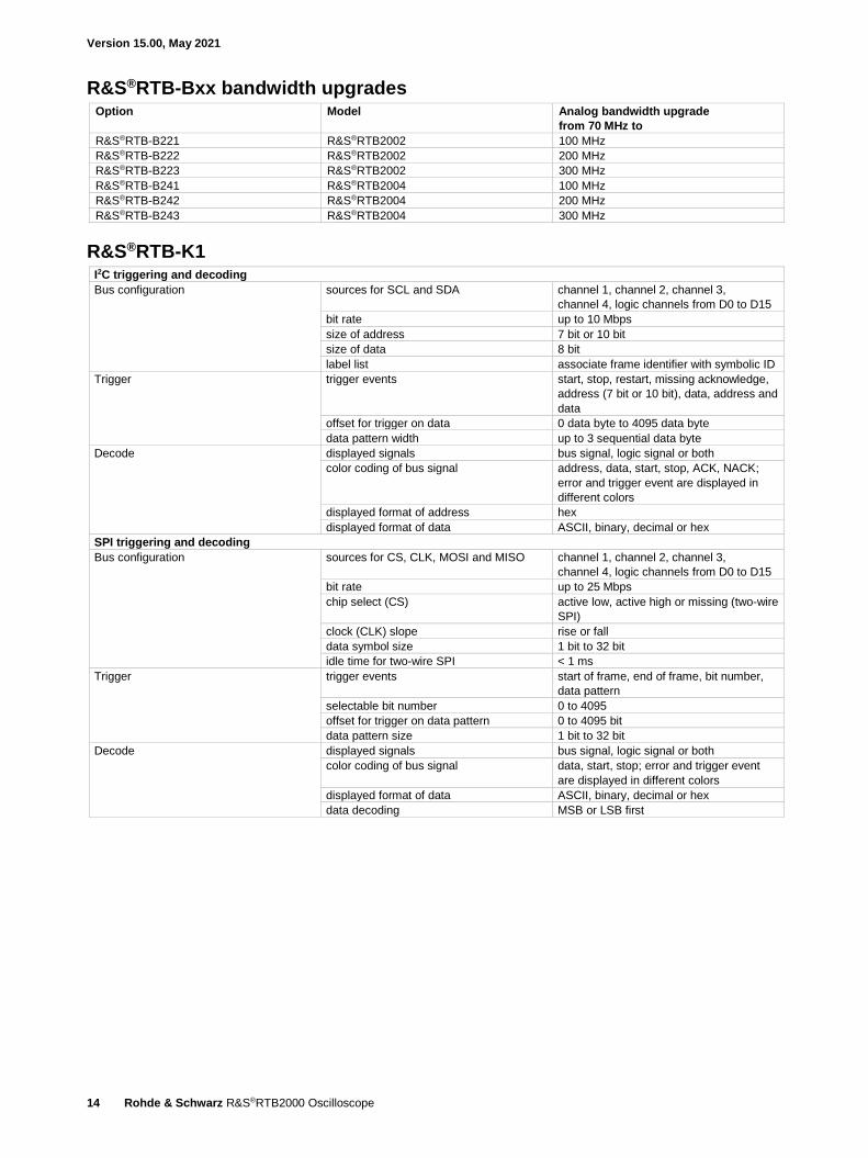
R&S®RTB-Bxx bandwidth upgrades Option Model Analog bandwidth upgrade
from 70 MHz to
R&S®RTB-B221 R&S®RTB2002 100 MHz
R&S®RTB-B222 R&S®RTB2002 200 MHz
R&S®RTB-B223 R&S®RTB2002 300 MHz
R&S®RTB-B241 R&S®RTB2004 100 MHz
R&S®RTB-B242 R&S®RTB2004 200 MHz
R&S®RTB-B243 R&S®RTB2004 300 MHz
R&S®RTB-K1 I2C triggering and decoding
Bus configuration sources for SCL and SDA channel 1, channel 2, channel 3,
channel 4, logic channels from D0 to D15
bit rate up to 10 Mbps
size of address 7 bit or 10 bit
size of data 8 bit
label list associate frame identifier with symbolic ID
Trigger trigger events start, stop, restart, missing acknowledge,
address (7 bit or 10 bit), data, address and
data
offset for trigger on data 0 data byte to 4095 data byte
data pattern width up to 3 sequential data byte
Decode displayed signals bus signal, logic signal or both
color coding of bus signal address, data, start, stop, ACK, NACK;
error and trigger event are displayed in
different colors
displayed format of address hex
displayed format of data ASCII, binary, decimal or hex
SPI triggering and decoding
Bus configuration sources for CS, CLK, MOSI and MISO channel 1, channel 2, channel 3,
channel 4, logic channels from D0 to D15
bit rate up to 25 Mbps
chip select (CS) active low, active high or missing (two-wire
SPI)
clock (CLK) slope rise or fall
data symbol size 1 bit to 32 bit
idle time for two-wire SPI < 1 ms
Trigger trigger events start of frame, end of frame, bit number,
data pattern
selectable bit number 0 to 4095
offset for trigger on data pattern 0 to 4095 bit
data pattern size 1 bit to 32 bit
Decode displayed signals bus signal, logic signal or both
color coding of bus signal data, start, stop; error and trigger event
are displayed in different colors
displayed format of data ASCII, binary, decimal or hex
data decoding MSB or LSB first

Version 15.00, May 2021
Rohde & Schwarz R&S®RTB2000 Oscilloscope 15
R&S®RTB-K2 UART/RS-232/RS-422/RS-485 triggering and decoding
Bus configuration source for RX and TX channel 1, channel 2, channel 3,
channel 4, logic channels from D0 to D15
bit rate 300/600/1200/2400/4800/9600/19200/
38400/57600/115200 bps or
user-selectable up to 3 Mbps
end of frame timeout, none
signal polarity idle low, idle high
data symbol size 5 bit to 9 bit
parity none, even or odd
stop bits 1, 1.5 or 2
Trigger trigger events start bit, start of frame, symbol number,
any symbol, pattern of symbols, parity
error, frame error, break
offset for trigger on data symbol 0 to 4095 symbols
data symbol pattern width 1 to floor (32/symbol size) symbols
Decode displayed signals bus signal, logic signal or both
color coding of bus signal data, start, stop; error and trigger event
are displayed in different colors
displayed format of data ASCII, binary, decimal or hex
R&S®RTB-K3 CAN triggering and decoding
Bus configuration signal type CAN_H, CAN_L
sources channel 1, channel 2, channel 3,
channel 4, logic channels from D0 to D15
bit rate 10/20/33.3/50/83.3/100/125/250/500/
1000 kbps or user-selectable in range
from 100 bps to 2 Mbps
sampling point 10 % to 90 % within bit period
label list associate frame identifier with symbolic ID
Trigger trigger events start of frame, frame type, identifier,
identifier + data, error condition (any
combination of CRC error, bit stuffing
error, form error and ACK error)
identifier setup frame type (data, remote or both),
identifier type (11 bit or 29 bit);
condition =, ≠, >, <; identifier selectable
from label list
data setup data pattern up to 8 byte (hex or binary);
condition =, ≠, >, <
Decode displayed signals bus signal, logic signal or both
color coding of bus signal start of frame, identifier, DLC, data
payload, CRC, ACK, end of frame, error
frame, overload frame, CRC error, bit
stuffing error, ACK error
displayed format of data hex, decimal, binary, ASCII
frame table decode results displayed as tabulated list,
errors highlighted in red; three table
positions (top, bottom, full screen); frame
navigation; data export as CSV file
Version 15.00, May 2021
16 Rohde & Schwarz R&S®RTB2000 Oscilloscope
Search search events frame, error, identifier, identifier + data,
identifier + error
frame event setup start of frame, end of frame, overload
frame, error frame, data ID 11 bit, data ID
29 bit, remote ID 11 bit, remote ID 29 bit
error event setup any combination of CRC error, bit stuffing
error, form error and ACK error
identifier setup frame type (data, remote or both),
identifier type (11 bit or 29 bit);
condition =, ≠, >, <; identifier selectable
from label list
data setup data pattern up to 8 byte (hex or binary);
condition =, ≠, >, <
event table search results displayed as tabulated list;
event navigation
LIN triggering and decoding
Bus configuration version 1.3, 2.x or SAE J2602; mixed traffic is
supported
bit rate 1.2/2.4/4.8/9.6/10.417/19.2 kbps or user-
selectable in range from 1 kbps to 2.5
Mbps
polarity active high or active low
label list associate frame identifier with symbolic ID
Trigger source any input channel
trigger events start of frame (sync break), identifier,
identifier + data, wakeup frame, error
condition (any combination of checksum
error, parity error and sync field error)
identifier setup range from 0d to 63d; condition =, ≠, >, <;
identifier selectable from label list
data setup data pattern up to 8 byte (hex or binary);
condition =, ≠, >, <
Decode displayed signals bus signal, logic signal or both
color coding of bus signal frame, frame identifier, parity, data
payload, checksum, error condition
displayed format of data hex, decimal, binary, ASCII
frame table decode results displayed as tabulated list,
errors highlighted in red; three table
positions (top, bottom, full screen); frame
navigation; data export as CSV file
Search search events frame, error, identifier, identifier + data,
identifier + error
frame event setup start of frame, wake up
error event setup any combination of checksum error, parity
error and sync field error
identifier setup range from 0d to 63d; condition =, ≠, >, <;
identifier selectable from label list
data setup data pattern up to 8 byte (hex or binary);
condition =, ≠, >, <
event table search results displayed as tabulated list;
event navigation

Version 15.00, May 2021
Rohde & Schwarz R&S®RTB2000 Oscilloscope 17
R&S®RTB-K15 History and segmented memory
Memory segmentation function additional memory segments for the
acquisition
number of segments 4 record
length
segments
(up to)
total memory
(per channel)
10 ksample 13 107 131 Msample
20 ksample 13 107 262 Msample
50 ksample 4 369 218 Msample
100
ksample
2 621 262 Msample
200
ksample
1 456 291 Msample
500
ksample
624 312 Msample
1 Msample 319 319 Msample
2 Msample 159 318 Msample
5 Msample 64 320 Msample
10 Msample 32 320 Msample
20 Msample 16 320 Msample
Segmentation is active on all analog and logic channels, protocol decoding and
spectrum analysis.
Fast-segmented mode continuous recording of waveforms in acquisition memory without interruption due to
visualization; blind time between consecutive acquisitions less than 2.5 µs
(up to 300 000 waveforms/s)
History mode function The history mode always provides access to
past acquisitions in the segmented memory.
timestamp resolution 6.4 ns
history player replays the recorded waveforms; start and
stop waveform could be set; repetition
possible
R&S®RTB-K36 Frequency response analysis – Bode plot (does not require R&S®RTB-B6 option)
Stimulus frequency mode single sweep or repeated sweep
frequency range 10 Hz to 25 MHz
amplitude mode fixed or amplitude profile
amplitude level 20 mV to 5 V into high Z
10 mV to 2.5 V into 50 Ω
Input and output sources R&S®RTB2002 channel 1, channel 2
R&S®RTB2004 channel 1, channel 2, channel 3, channel 4
Number of test points 10 points to 500 points per decade
Dynamic range typ. > 70 dB based on 0 dBm
(630 mV (Vpp) into 50 Ω,
gain noise < 1 dB, phase noise < 5°)
Measurement dual pair of tracking gain and phase cursors
Diagram types manually changeable vertical window size parallel display of result window and input
and output signal view
Result table navigation and export functions
Scaling during and after test auto-scale and manual scaling and
positioning
4 In interleaved mode.
Version 15.00, May 2021
18 Rohde & Schwarz R&S®RTB2000 Oscilloscope
Ordering information Designation Type Order No.
Choose your R&S®RTB2000 base model
Oscilloscope, 70 MHz, 2 channels R&S®RTB2002 1333.1005.02
Oscilloscope, 70 MHz, 4 channels R&S®RTB2004 1333.1005.04
Base unit (including standard accessories: R&S®RT-ZP03 passive probe per channel, power cord, getting started manual and safety
instructions)
Choose your bandwidth upgrade
Upgrade of R&S®RTB2002 oscilloscopes to 100 MHz bandwidth R&S®RTB-B221 1333.1163.02
Upgrade of R&S®RTB2002 oscilloscopes to 200 MHz bandwidth R&S®RTB-B222 1333.1170.02
Upgrade of R&S®RTB2002 oscilloscopes to 300 MHz bandwidth R&S®RTB-B223 1333.1186.02
Upgrade of R&S®RTB2004 oscilloscopes to 100 MHz bandwidth R&S®RTB-B241 1333.1257.02
Upgrade of R&S®RTB2004 oscilloscopes to 200 MHz bandwidth R&S®RTB-B242 1333.1263.02
Upgrade of R&S®RTB2004 oscilloscopes to 300 MHz bandwidth R&S®RTB-B243 1333.1270.02
Choose your options
Mixed signal option for non-MSO models, 300 MHz R&S®RTB-B1 1333.1105.02
Arbitrary waveform generator R&S®RTB-B6 1333.1111.02
I2C/SPI serial triggering and decoding R&S®RTB-K1 1333.1011.02
UART/RS-232/RS-422/RS-485 serial triggering and decoding R&S®RTB-K2 1333.1028.02
CAN/LIN serial triggering and decoding R&S®RTB-K3 1333.1034.02
History and segmented memory R&S®RTB-K15 1333.1040.02
Frequency response analysis (Bode plot) R&S®RTB-K36 1335.8007.02
Application bundle, consists of the following options:
R&S®RTB-K1, R&S®RTB-K2, R&S®RTB-K3, R&S®RTB-K15,
R&S®RTB-K36, R&S®RTB-B6
R&S®RTB-PK1 1333.1092.02
Choose your additional probes
Single-ended passive probes
300 MHz, 10 MHz, 10:1/1:1, 10 MΩ/1 MΩ, 400 V, 12 pF/82 pF R&S®RT-ZP03 3622.2817.02
500 MHz, 500 MHz, 10:1, 300 V (RMS), 10 pF R&S®RT-ZP05 3623.2927.02
500 MHz, 10 MΩ, 10:1, 400 V, 9.5 pF R&S®RT-ZP10 1409.7708.02
38 MHz, 1 MΩ, 1:1, 55 V, 39 pF R&S®RT-ZP1X 1333.1370.02
High-voltage single-ended passive probes
250 MHz, 100:1, 100 MΩ, 850 V, 6.5 pF R&S®RT-ZH03 1333.0873.02
400 MHz, 100:1, 50 MΩ, 1000 V, 7.5 pF R&S®RT-ZH10 1409.7720.02
400 MHz, 1000:1, 50 MΩ, 1000 V, 7.5 pF R&S®RT-ZH11 1409.7737.02
High voltage probes: passive
25 MHz, 8 MΩ, 2.75 pF, 10:1/100:1, ±700 V, 1000 V (RMS) CAT III R&S®RT-ZD002 1337.9700.02
25 MHz, 8 MΩ, 2.75 pF, 20:1/200:1, ±1400 V, 1000 V (RMS) CAT III R&S®RT-ZD003 1337.9800.02
Current probes
20 kHz, AC/DC, 10 A/1000 A R&S®RT-ZC02 1333.0850.02
100 kHz, AC/DC, 30 A R&S®RT-ZC03 1333.0844.02
10 MHz, AC/DC, 150 A R&S®RT-ZC10 1409.7750.02
100 MHz, AC/DC, 30 A R&S®RT-ZC20 1409.7766.02
120 MHz, AC/DC, 5 A R&S®RT-ZC30 1409.7772.02
Power supply for current probes R&S®RT-ZA13 1409.7789.02
Active differential probes
100 MHz, 1000:1/100:1, 8 MΩ, 1000 V (RMS), 3.5 pF R&S®RT-ZD01 1422.0703.02
200 MHz, 10:1, 1 MΩ, 20 V diff., 3.5 pF R&S®RT-ZD02 1333.0821.02
Logic probes
Active 8 channel logic probe R&S®RT-ZL03 1333.0715.02
Probe accessories
Feedthrough termination 50 Ω R&S®HZ22 3594.4015.02
Probe pouch R&S®RT-ZA19 1335.7875.02
Choose your accessories
Front cover R&S®RTB-Z1 1333.1728.02
Soft case R&S®RTB-Z3 1333.1734.02
Transit case R&S®RTB-Z4 1335.9290.02
Rackmount kit R&S®ZZA-RTB2K 1333.1711.02

Version 15.00, May 2021
Rohde & Schwarz R&S®RTB2000 Oscilloscope 19
Warranty
Base unit and passive probes that are included as standard accessories 3 years
All other items 5 1 year
Service options
Extended warranty, one year R&S®WE1 Please contact your
local Rohde & Schwarz
sales office.
Extended warranty, two years R&S®WE2
Extended warranty with calibration coverage, one year R&S®CW1
Extended warranty with calibration coverage, two years R&S®CW2
Extended warranty with accredited calibration coverage, one year R&S®AW1
Extended warranty with accredited calibration coverage, two years R&S®AW2
Extended warranty with a term of one and two years (WE1 and WE2) Repairs carried out during the contract term are free of charge 6. Necessary calibration and adjustments carried out during repairs are also covered. Extended warranty with calibration coverage (CW1 and CW2) Enhance your extended warranty by adding calibration coverage at a package price. This package ensures that your Rohde & Schwarz product is regularly calibrated, inspected and maintained during the term of the contract. It includes all repairs 6 and calibration at the recommended intervals as well as any calibration carried out during repairs or option upgrades.
Extended warranty with accredited calibration (AW1 and AW2)
Enhance your extended warranty by adding accredited calibration coverage at a package price. This package ensures that your
Rohde & Schwarz product is regularly calibrated under accreditation, inspected and maintained during the term of the contract. It
includes all repairs 6 and accredited calibration at the recommended intervals as well as any accredited calibration carried out during
repairs or option upgrades.
5 For options that are installed, the remaining base unit warranty applies if longer than 1 year. Exception: all batteries have a 1 year warranty. 6 Excluding defects caused by incorrect operation or handling and force majeure. Wear-and-tear parts are not included.
R&S® is a registered trademark of Rohde & Schwarz GmbH & Co. KG Trade names are trademarks of the owners PD 3607.4270.22 | Version 15.00 | May 2021 (sk) R&S®RTB2000 Oscilloscope Data without tolerance limits is not binding | Subject to change © 2017 - 2021 Rohde & Schwarz GmbH & Co. KG | 81671 Munich, Germany
Service that adds value Worldwide Local and personalized Customized and flexible Uncompromising quality Long-term dependability
3607
.427
0.22
15.
00 P
DP
/PD
W 1
en
Sustainable product design Environmental compatibility and eco-footprint Energy efficiency and low emissions Longevity and optimized total cost of ownership
Certified Quality Management
ISO 9001
Rohde & Schwarz customer supportwww.rohde-schwarz.com/support
Rohde & SchwarzThe Rohde & Schwarz electronics group offers innovative solutions in the following business fields: test and mea-surement, broadcast and media, secure communications, cybersecurity, monitoring and network testing. Founded more than 80 years ago, the independent company which is headquartered in Munich, Germany, has an extensive sales and service network with locations in more than 70 countries.
www.rohde-schwarz.com
Rohde & Schwarz trainingwww.training.rohde-schwarz.com
Certified Environmental Management
ISO 14001
3607427022
Recommended