Gp800 UPS Contents
- i -
Contents CONTENTS............................................................................................................ I
1 BRIEF INTRODUCTION.............................................................................1
1.1 PROLEGOMENON ......................................................................................1 1.2 FIVE DESIGN POINTS .................................................................................1 1.3 NOTE........................................................................................................1
2 CONFIGURATION AND FUNCTION .......................................................3
2.1 FRONT PANEL ...........................................................................................3 2.2 APPEARANCE............................................................................................4
3 PLACEMENT NOTES..................................................................................6
3.1 TRANSIT OR MOVE....................................................................................6 3.2 PLACEMENT .............................................................................................6
4 INSTALLATION ...........................................................................................9
4.1 INPUT .......................................................................................................9 4.2 OUTPUT..................................................................................................13
5 OPERATION PROCESS ............................................................................16
5.1 PREPARE BEFORE START-UP.....................................................................16 5.2 OPERATION PROCESS FOR FIRST START-UP ..............................................16 5.3 OPERATION PROCESS FOR ROUTINE TURN-OFF ........................................18 5.4 OPERATION PROCESS FOR LONG-TIME NO SWITCH ON/OFF ......................18
6 STATUS HANDLING..................................................................................19
6.1 SYMBOL SIGNIFICATION ..........................................................................19 6.2 UPS RUN STATUS INDICATION AND HANDLING WAYS WHEN NORMAL......19
7 MOVEMENT HANDLING ........................................................................28
7.1 UPS SYSTEM CONFIGURATION BLOCK FIGURE: FIGURE 32 .....................28
Contents MAKELSAN UPS
- ii -
7.2 UPS RUNNING WAY WHEN UPS RUNS NORMALLY...................................28 7.3 UPS RUNNING WAY WHEN UTILITY DISCONNECTED ................................29 7.4 UPS RUNNING WAY WHEN UPS RUNS ON BYPASS MODE .........................29 7.5 BATTERY AND CHARGE ...........................................................................30 7.6 DAILY MAINTENANCE.............................................................................31
8 COMMUNICATION INTERFACE...........................................................32
9 SPECIFICATION ........................................................................................34
10 SHIPPING LIST ..........................................................................................36
GP800 UPS BRIEF INTRODUCTION
- 1 -
1 BRIEF INTRODUCTION
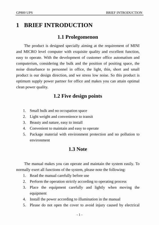
1.1 Prolegomenon The product is designed specially aiming at the requirement of MINI
and MICRO level computer with exquisite quality and excellent function, easy to operate. With the development of customer office automatism and computerism, considering the bulk and the position of positing space, the noise disturbance to personnel in office, the light, thin, short and small product is our design direction, and we stress low noise. So this product is optimum supply power partner for office and makes you can attain optimal clean power quality.
1.2 Five design points
1. Small bulk and no occupation space 2. Light weight and convenience to transit 3. Beauty and nature, easy to install 4. Convenient to maintain and easy to operate 5. Package material with environment protection and no pollution to
environment
1.3 Note
The manual makes you can operate and maintain the system easily. To normally exert all functions of the system, please note the following:
1. Read the manual carefully before use 2. Perform the operation strictly according to operating process 3. Place the equipment carefully and lightly when moving the
equipment 4. Install the power according to illumination in the manual 5. Please do not open the cover to avoid injury caused by electrical

BRIEF INTRODUCTION GP800 UPS
- 2 -
shock 6. Please charge batteries once every a period if no used for long time 7. Do not use UPS on the condition of overload to avoid UPS fault 8. Please carefully keep the manual for the future reference 9. Please handle the system according to “ABNORMITY HANDLING
PROCESS” if there presents any abnormal phenomenon in machine. 10. Please keep UPS neatness and cleanness
GP800 UPS CONFIGURATION AND FUNCTION
- 3 -
2 CONFIGURATION AND FUNCTION
2.1 Front panel
OUTINBATT
BYFAULT
O ff
Dow n
O nSw itch O N
Cycle display button
LCD
Fault indicatorBypass indicator
Output indicator
battery energy indicator
Input indicator
Switch OFF
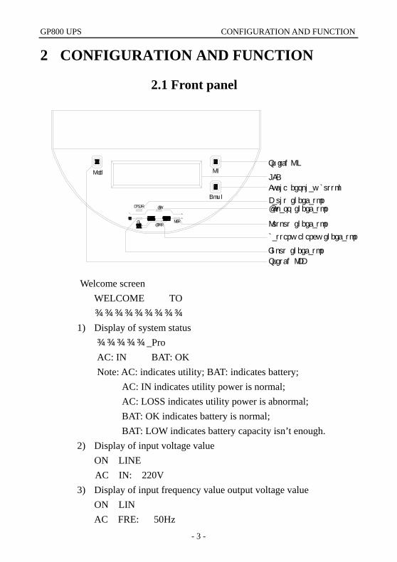
Welcome screen WELCOME TO
××××××××× 1) Display of system status ×××××_Pro AC: IN BAT: OK Note: AC: indicates utility; BAT: indicates battery; AC: IN indicates utility power is normal; AC: LOSS indicates utility power is abnormal; BAT: OK indicates battery is normal; BAT: LOW indicates battery capacity isn’t enough.
2) Display of input voltage value ON LINE AC IN: 220V
3) Display of input frequency value output voltage value ON LIN AC FRE: 50Hz
CONFIGURATION AND FUNCTION GP800 UPS
- 4 -
4) Display of input frequency value ON LINE OUTPUT: 220V
5) Display of output frequency value ON LINE OUTPUT FRE: 50HZ
6) Display of output power Percent ON LINE LOAD: 100%
7) Display of battery voltage value ON LINE BATTERY: 218V
8) Temperature display in machine ON LINE
TEMP: 33℃ *These parameters vary with machine model. 9) LCD cycle display switch button: digital signal display items
switch button. 10) UPS switch button: UPS general switch button.
(1) Turn on UPS inverter by pressing the “ON” key. UPS convert to UPS inverter power output 20s later, UPS pure AC output power is supplied by UPS internal power supply equipment.
(2) Turn off UPS inverter by pressing the “OFF” button. UPS convert to utility bypass.
The button acts as general switch mainly.
2.2 Appearance
GP800 UPS CONFIGURATION AND FUNCTION
- 5 -
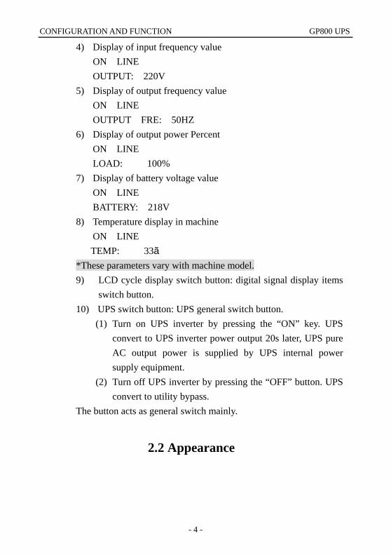
Figure 2 Front panel Figure 3 Front panel
① Emission heat ventilation hole: The ventilation hole and other small long elliptic ventilation holes should be kept good ventilation. ② Wiring inlet/outlet hole: Wiring inlet/outlet hole of input, output and battery pack. ③ RS232 communication interface receptacle Standard communication interface between UPS and computer. ④ Power switch: Power switch controls input, output and battery power switch at the same time. ⑤ Wiring Terminal support Power wiring Terminal support of input, output and battery. ⑥ Active wheel: There are four hidden movement wheel, in favor to move.
PLACEMENT NOTES GP800 UPS
- 6 -
3 PLACEMENT NOTES
3.1 Transit or move 1. Please dismantle all barge connection firstly. (First turn off before
performing) 2. Place lightly and carefully, forbid to hit. 3. Please do not move UPS inverted.
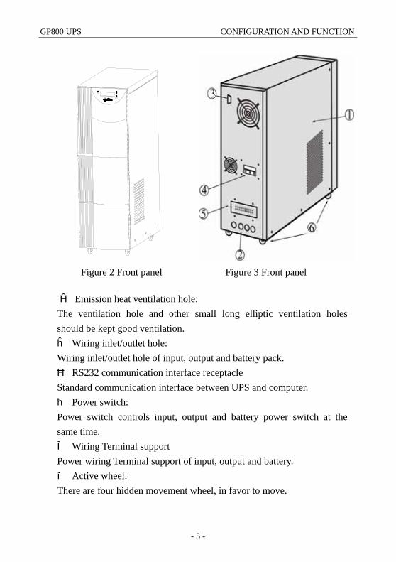
3.2 Placement 1. Do not place the UPS on the slope or scraggy land. (Figure 4)
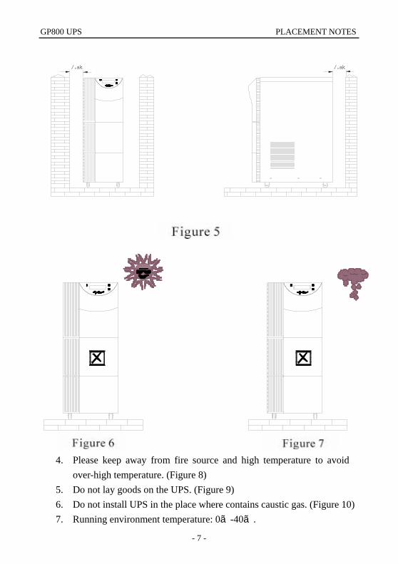
2. Please place the UPS in the place where keeps good ventilation, rear
panel of UPS and two side faces should keep more than 10cm away from the wall. (Figure 5)
3. Do not install UPS under sunlight, drain and damp place. (Figure 6, 7)
GP800 UPS PLACEMENT NOTES
- 7 -
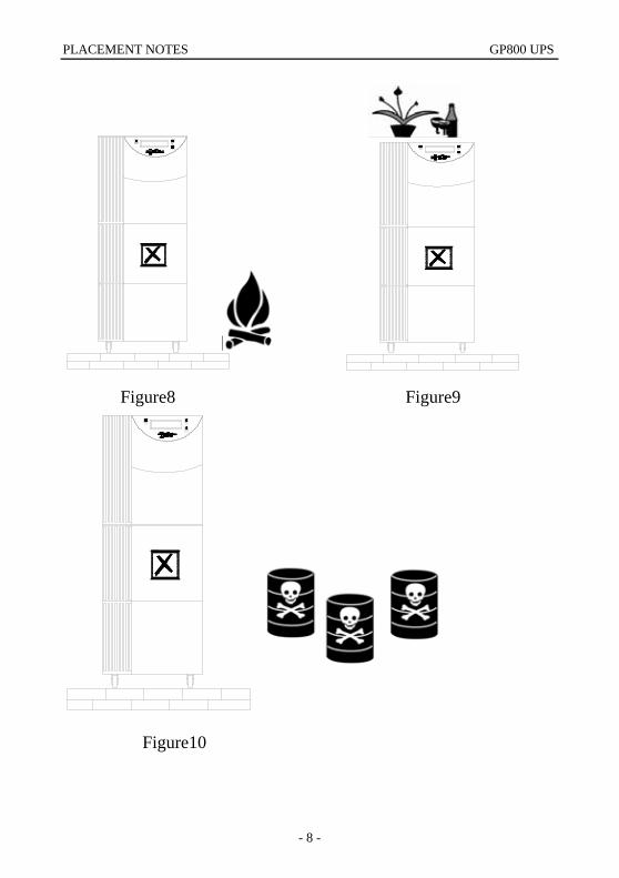
4. Please keep away from fire source and high temperature to avoid
over-high temperature. (Figure 8) 5. Do not lay goods on the UPS. (Figure 9) 6. Do not install UPS in the place where contains caustic gas. (Figure 10) 7. Running environment temperature: 0℃-40℃.
10cm10cm
PLACEMENT NOTES GP800 UPS
- 8 -
Figure8 Figure9
Figure10
GP800 UPS INSTALLATION
- 9 -
4 INSTALLATION
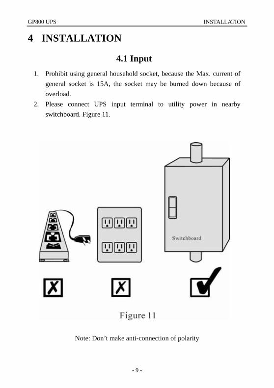
4.1 Input 1. Prohibit using general household socket, because the Max. current of
general socket is 15A, the socket may be burned down because of overload.
2. Please connect UPS input terminal to utility power in nearby switchboard. Figure 11.
Note: Don’t make anti-connection of polarity
INSTALLATION GP800 UPS
- 10 -
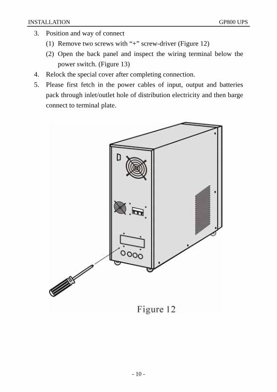
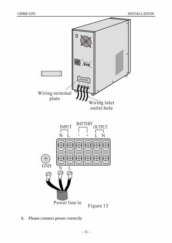
3. Position and way of connect (1) Remove two screws with “+” screw-driver (Figure 12) (2) Open the back panel and inspect the wiring terminal below the
power switch. (Figure 13) 4. Relock the special cover after completing connection. 5. Please first fetch in the power cables of input, output and batteries
pack through inlet/outlet hole of distribution electricity and then barge connect to terminal plate.
GP800 UPS INSTALLATION
- 11 -
6. Please connect power correctly
INSTALLATION GP800 UPS
- 12 -
Simple identification way to power polarity: (1) Line (L): There is 220V relative to other two holes. (2) Neutral (N): there is 220V relative to the Line, there is 0.5-2V
relative to the ground. (Load current circulate through neutral)
(3) Ground (G): Please find out correct connecting point to the ground in the switchboard.
7. If the difference between the neutral and the ground is more than 5V or it can’t meet the requirement of system, please reinstall good grounding system to keep safety of system operation.
8. The comparison list of input current rating and input cable size is as follows: Model Max. input current Input wire Terminal specification
GP801 5A 12AWG 5.5~6
GP802 10A 10AWG 5.5~6
GP803 15A 10AWG 5.5~6
GP804 20A 10AWG 5.5~6
GP805 25A 10AWG 5.5~6
GP806 30A 10AWG 5.5~6
GP808 40A 8AWG 8.5~9
GP810 50A 8AWG 8.5~9
GP812 60A 8AWG 8.5~9
9. The power cable and the impaction terminal must be first grade product manufactured by authentic manufacturer. Prohibit use spent and inferior product.
10. The power cable must be impacted by impaction terminal of authentic manufacturer, prohibit directly wrapping power cable to the terminal plate.
11. After fastening input cable, please see if the input cable contacts with protection cover and avoid short-circuit.
12. Please turn off power when connecting cable, prohibit operation on live and keep safety.
GP800 UPS INSTALLATION
- 13 -
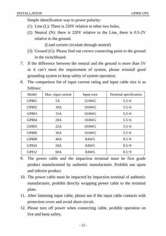
13. Please follow the electrician law when installation. 14. Avoid using the same switch with other equipment when connect to
switchboard, try to connect cable to utility terminal. Figure 14. 15. In 3Ø4W system,
please respect-Tively measure the voltage between R/N,S/N, T/N with ammeter firstly and see if they are close to 220V, then connect L cable of UPS to the cable whose voltage measured is the highest (means supply power of this phase is lighter than that of other two phase), the N cable of UPS is connected to utility neutral cable N, the UPS-GND is connected to grounding club.
16. If the model of the unit you purchase is input voltage of 110V, please connect UPS-L cable into line, connect N cable into neutral cable, and connect UPS-GND cable to grounding club.
Please note that this equipment is a system of 220V or 110V, do not connect 380V, and avoid causing any fault.
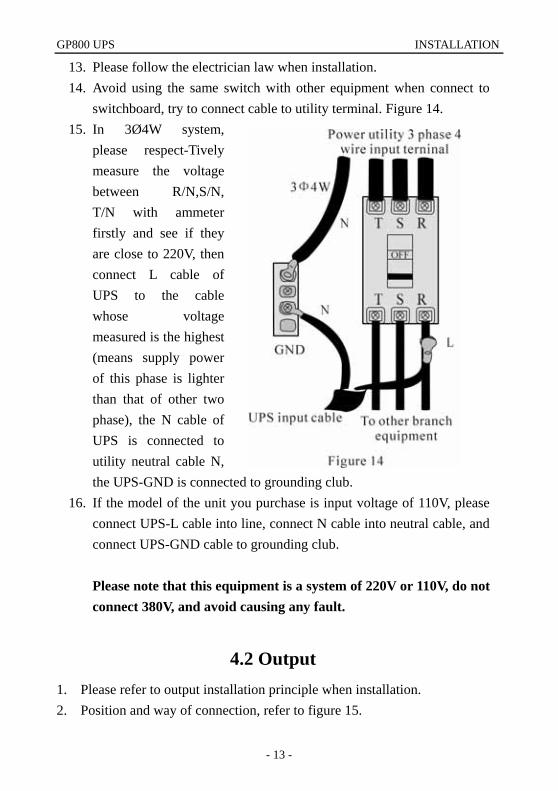
4.2 Output 1. Please refer to output installation principle when installation. 2. Position and way of connection, refer to figure 15.
INSTALLATION GP800 UPS
- 14 -
3. Output power cable is designed according to load current, do not use
over-thin cable. Please refer to Table 2 Model Max. output current Output cable Terminal specification
GP801 4A 12AWG 5.5~6
GP802 8A 10AWG 5.5~6
GP803 12A 10AWG 5.5~6
GP804 16A 10AWG 5.5~6
GP805 20A 10AWG 5.5~6
GP806 24A 10AWG 5.5~6
GP808 32A 8AWG 8.5~9
GP810 40A 8AWG 8.5~9
GP812 48A 8AWG 8.5~9
Table 2 4. Avoid short-circuit and overload. 5. The comparison between output current rating and output cable size is
listed in Table 2. 6. The ground to this unit only acts as reference point, if the ground isn’t
good, that may cause disturbance and false datum management, and affect UPS and computer, please ask professional personnel for handling immediately.
7. User offers a good grounding system.
GP800 UPS INSTALLATION
- 15 -
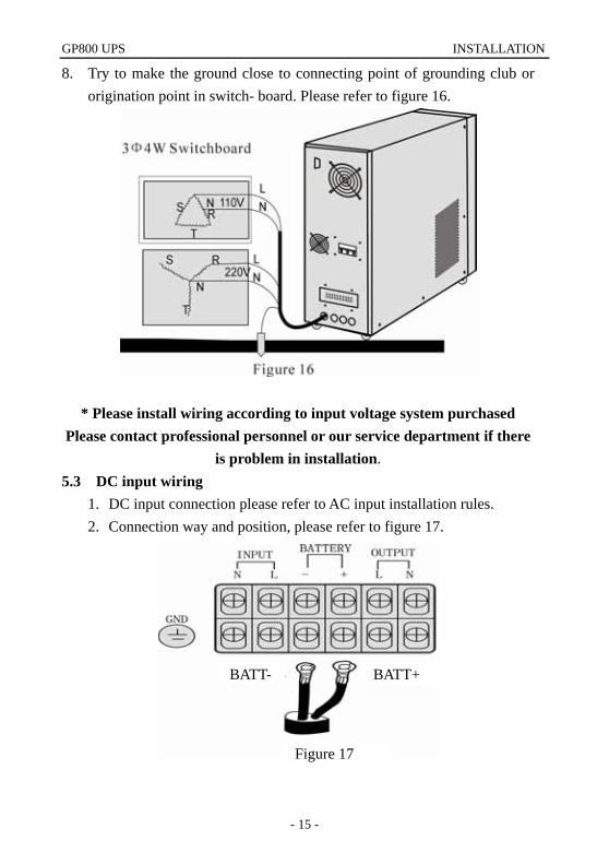
8. Try to make the ground close to connecting point of grounding club or origination point in switch- board. Please refer to figure 16.
* Please install wiring according to input voltage system purchased Please contact professional personnel or our service department if there
is problem in installation. 5.3 DC input wiring
1. DC input connection please refer to AC input installation rules. 2. Connection way and position, please refer to figure 17.
BATT- BATT+
Figure 17
OPERATION PROCESS GP800 UPS
- 16 -
OUTINBATT
BYFAULT
O ff
Dow n
O nSw itch O N
Cycle display button
LCD
Fault indicatorBypass indicator
Output indicator
battery energy indicator
Input indicator
Switch OFF
5 OPERATION PROCESS
5.1 Prepare before start-up. To make UPS normally and correctly run, please confirm the following
items. (Refer to figure 2) 3. Verify power switch on back panel is on the “OFF” position. 4. Verify the installation position again. (Figure 4 to 10) 5. Rock power cable by hand and see if there is any looseness, retighten
them if looseness. 6. Do not connect load. 7. Inspect if input voltage meet the demand of UPS (220V±10%) with
ammeter.
5.2 Operation process for first start-up After verify the above items are correct, please turn on UPS according to the following ways:(Please refer to figure 1, figure 2, figure 3)
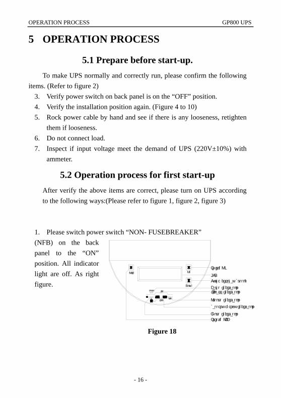
1. Please switch power switch “NON- FUSEBREAKER” (NFB) on the back panel to the “ON” position. All indicator light are off. As right figure.
Figure 18
GP800 UPS OPERATION PROCESS
- 17 -
Figure 21
Welcome to xxxxxx
Switch OFF
Input indicator
battery energy indicator
Output indicator
Bypass indicatorFault indicator
LCD
Cycle display button
Sw itch O NO n
Dow n
O ff
FAULT BY
BATTIN OUT
Welcome to xxxxxx
Switch OFF
Input indicator
battery energy indicator
Output indicator
Bypass indicatorFault indicator
LCD
Cycle display button
Sw itch O NO n
Dow n
O ff
FAULT BY
BATTIN OUT
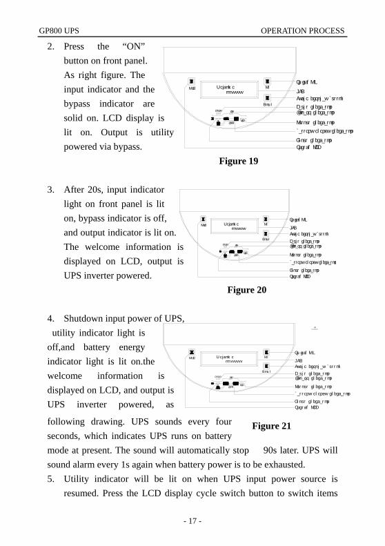
2. Press the “ON” button on front panel. As right figure. The input indicator and the bypass indicator are solid on. LCD display is lit on. Output is utility powered via bypass.
3. After 20s, input indicator light on front panel is lit on, bypass indicator is off, and output indicator is lit on. The welcome information is displayed on LCD, output is UPS inverter powered.
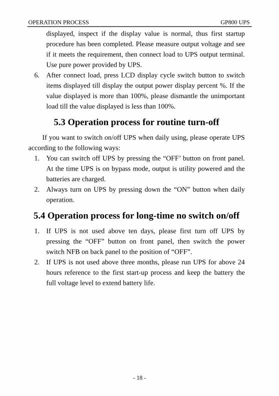
4. Shutdown input power of UPS, utility indicator light is off,and battery energy indicator light is lit on.the welcome information is displayed on LCD, and output is UPS inverter powered, as
following drawing. UPS sounds every four seconds, which indicates UPS runs on battery mode at present. The sound will automatically stop 90s later. UPS will sound alarm every 1s again when battery power is to be exhausted. 5. Utility indicator will be lit on when UPS input power source is
resumed. Press the LCD display cycle switch button to switch items
Figure 19
Figure 20
BZ
Welcome to xxxxxx
Switch OFF
Input indicator
battery energy indicator
Output indicator
Bypass indicatorFault indicator
LCD
Cycle display button
Sw itch O NO n
D ow n
O ff
FAULT BY
BATTIN OUT
OPERATION PROCESS GP800 UPS
- 18 -
displayed, inspect if the display value is normal, thus first startup procedure has been completed. Please measure output voltage and see if it meets the requirement, then connect load to UPS output terminal. Use pure power provided by UPS.
6. After connect load, press LCD display cycle switch button to switch items displayed till display the output power display percent %. If the value displayed is more than 100%, please dismantle the unimportant load till the value displayed is less than 100%.
5.3 Operation process for routine turn-off If you want to switch on/off UPS when daily using, please operate UPS
according to the following ways: 1. You can switch off UPS by pressing the “OFF’ button on front panel.
At the time UPS is on bypass mode, output is utility powered and the batteries are charged.
2. Always turn on UPS by pressing down the “ON” button when daily operation.
5.4 Operation process for long-time no switch on/off 1. If UPS is not used above ten days, please first turn off UPS by
pressing the “OFF” button on front panel, then switch the power switch NFB on back panel to the position of “OFF”.
2. If UPS is not used above three months, please run UPS for above 24 hours reference to the first start-up process and keep the battery the full voltage level to extend battery life.
GP800 UPS STATUS HANDLING
- 19 -
6 STATUS HANDLING
6.1 symbol signification Note: If indicator light flash, the flash period is synchronal with that of
buzzer sounds
Lit on crush out Flash Buzzer beep continously
BZ BZ
Buzzer beepevery four seconds every one second
Buzzer beep
BZ BZ
Buzzer
not beep
6.2 UPS run status indication and handling ways
when normal Please refer to indicator on UPS panel, LCD indicator value and buzzer sound, you can know if UPS running is normal, if abnormal, please refer to the handling way according to panel indicator status.
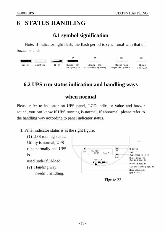
1. Panel indicator status is as the right figure:
(1) UPS running status: Utility is normal, UPS runs normally and UPS is used under full-load. (2) Handing way:
needn’t handling. Figure 22
BZ
ON LINE lOAD: 100.0%
OUTINBATT
BYFAULT
O ff
D ow n
O nSw itch O N
Cycle display button
LCD
Fault indicatorBypass indicator
Output indicator
battery energy indicator
Input indicator
Switch OFF
STATUS HANDLING GP800 UPS
- 20 -
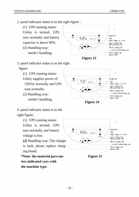
2. panel indicator status is as the right figure :
(1) UPS running status: Utility is normal, UPS runs normally and battery capacitor is above 90%. (2) Handling way:
needn’t handling.
3. panel indicator status is as the right figure:
(1) UPS running status: Utility supplies power of 220Vac normally and UPS runs normally. (2) Handling way:
needn’t handling.
4. panel indicator status is as the right figure:
(1) UPS running status: Utility is normal, UPS runs normally and battery voltage is low. (2) Handling way: The charger is fault, please replace charg- ing board.
*Note: the material para me- ters indicated vary with the machine type.
Figure 25
Figure 24
Figure 23
BZ
ON LINE BATTERY: 217.9V
Switch OFF
Input indicator
battery energy indicator
Output indicator
Bypass indicatorFault indicator
LCD
Cycle display button
Sw itch O NO n
D ow n
O ff
FAULT BY
BATTIN OUT
BZ
ON LINE AC IN: 225.0V
OUTINBATT
BYFAULT
O ff
D ow n
O nSw itch O N
Cycle display button
LCD
Fault indicatorBypass indicator
Output indicator
battery energy indicator
Input indicator
Switch OFF
BZ
ON LINE BATTERY: 175.3V
Switch OFF
Input indicator
battery energy indicator
Output indicator
Bypass indicatorFault indicator
LCD
Cycle display button
Sw itch O NO n
D ow n
O ff
FAULT BY
BATTIN OUT
GP800 UPS STATUS HANDLING
- 21 -
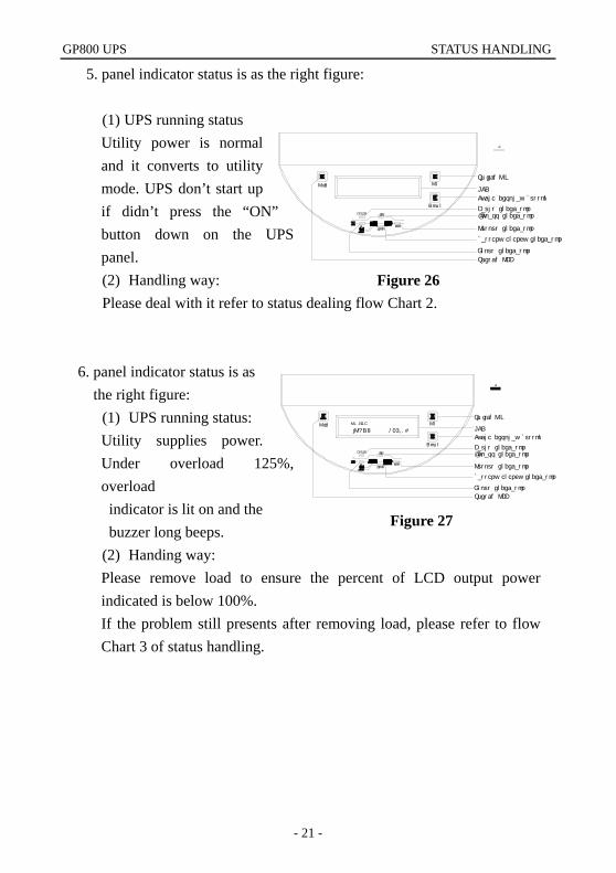
5. panel indicator status is as the right figure:
(1) UPS running status Utility power is normal and it converts to utility mode. UPS don’t start up if didn’t press the “ON” button down on the UPS panel. (2) Handling way: Please deal with it refer to status dealing flow Chart 2.
6. panel indicator status is as the right figure:
(1) UPS running status: Utility supplies power. Under overload 125%, overload indicator is lit on and the buzzer long beeps. (2) Handing way: Please remove load to ensure the percent of LCD output power indicated is below 100%. If the problem still presents after removing load, please refer to flow Chart 3 of status handling.
Figure 26
Figure 27
BZ
OUTINBATT
BYFAULT
O ff
D ow n
O nSw itch O N
LCD
Fault indicatorBypass indicator
Output indicator
Input indicator
Switch OFF
Cycle display button
battery energy indicator
BZ
ON LINE
lOAD: 125.0%
Switch OFF
Input indicator
battery energy indicator
Output indicator
Bypass indicatorFault indicator
LCD
Cycle display button
Sw itch O NO n
D ow n
O ff
FAULT BY
BATTIN OUT
STATUS HANDLING GP800 UPS
- 22 -
Figure 29
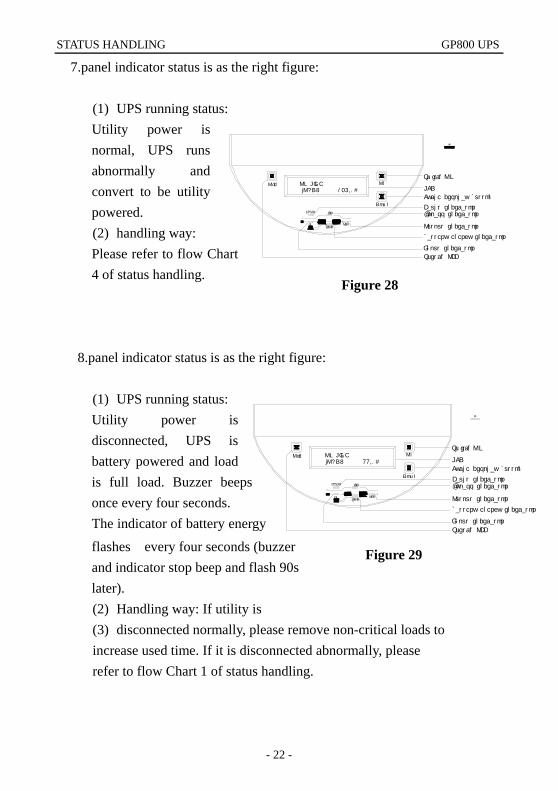
7.panel indicator status is as the right figure:
(1) UPS running status: Utility power is normal, UPS runs abnormally and convert to be utility powered. (2) handling way: Please refer to flow Chart 4 of status handling.
8.panel indicator status is as the right figure:
(1) UPS running status: Utility power is disconnected, UPS is battery powered and load is full load. Buzzer beeps once every four seconds. The indicator of battery energy
flashes every four seconds (buzzer and indicator stop beep and flash 90s later). (2) Handling way: If utility is (3) disconnected normally, please remove non-critical loads to increase used time. If it is disconnected abnormally, please refer to flow Chart 1 of status handling.
Figure 28
BZ
lOAD: 125.0%ON LINE
OUTINBATT
BYFAULT
O ff
D ow n
O nSw itch O N
Cycle display button
LCD
Fault indicatorBypass indicator
Output indicator
battery energy indicator
Input indicator
Switch OFF
BZ
ON LINE lOAD: 99.0%
Switch OFF
Input indicator
Output indicator
Bypass indicatorFault indicator
LCD
Sw itch O NO n
D ow n
O ff
FAULT BY
BATTIN OUT
battery energy indicator
Cycle display button
GP800 UPS STATUS HANDLING
- 23 -
Figure 30
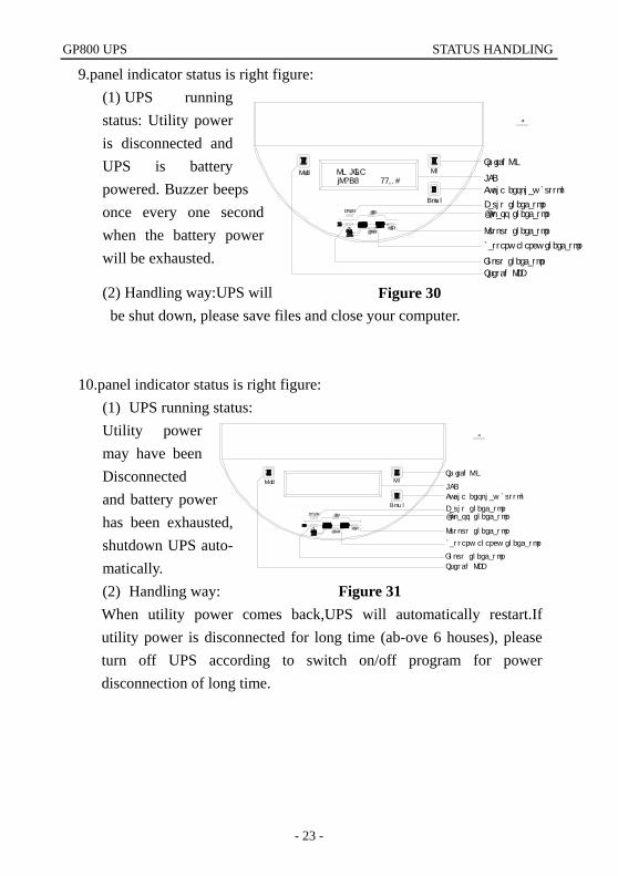
9.panel indicator status is right figure: (1) UPS running status: Utility power is disconnected and UPS is battery powered. Buzzer beeps once every one second when the battery power will be exhausted.
(2) Handling way:UPS will be shut down, please save files and close your computer.
10.panel indicator status is right figure: (1) UPS running status: Utility power may have been Disconnected and battery power has been exhausted, shutdown UPS auto- matically. (2) Handling way: When utility power comes back,UPS will automatically restart.If utility power is disconnected for long time (ab-ove 6 houses), please turn off UPS according to switch on/off program for power disconnection of long time.
Figure 31
BZ
OUTINBATT
BYFAULT
O ff
Dow n
O nSw itch O N
Cycle display button
LCD
Fault indicatorBypass indicator
Output indicator
battery energy indicator
Input indicator
Switch OFF
lOAD: 99.0%ON LINE
BZ
Switch OFF
Input indicator
battery energy indicator
Output indicator
Bypass indicatorFault indicator
LCD
Cycle display button
Sw itch O NO n
D ow n
O ff
FAULT BY
BATTIN OUT

STATUS HANDLING GP800 UPS
- 24 -
Flow chart 1 of status handing
GP800 UPS STATUS HANDLING
- 25 -
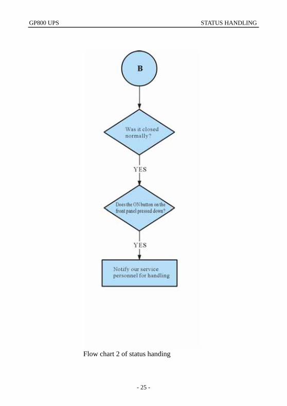
Flow chart 2 of status handing
STATUS HANDLING GP800 UPS
- 26 -
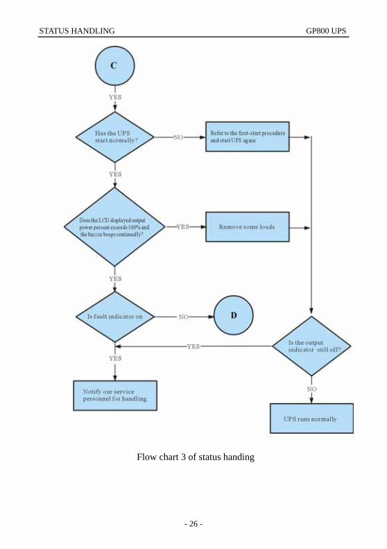
Flow chart 3 of status handing Flow chart 3 of status handing
GP800 UPS STATUS HANDLING
- 27 -
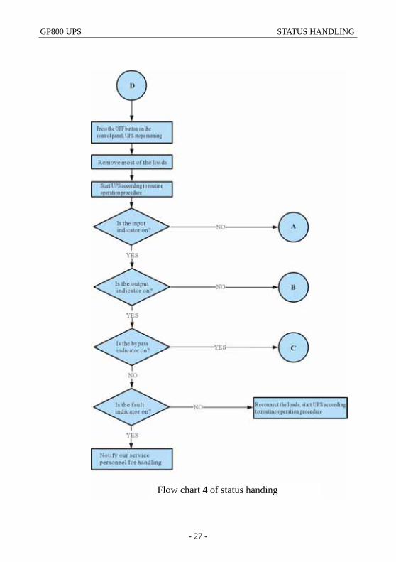
Flow chart 4 of status handing
Movement handling GP800 UPS
- 28 -
7 Movement handling
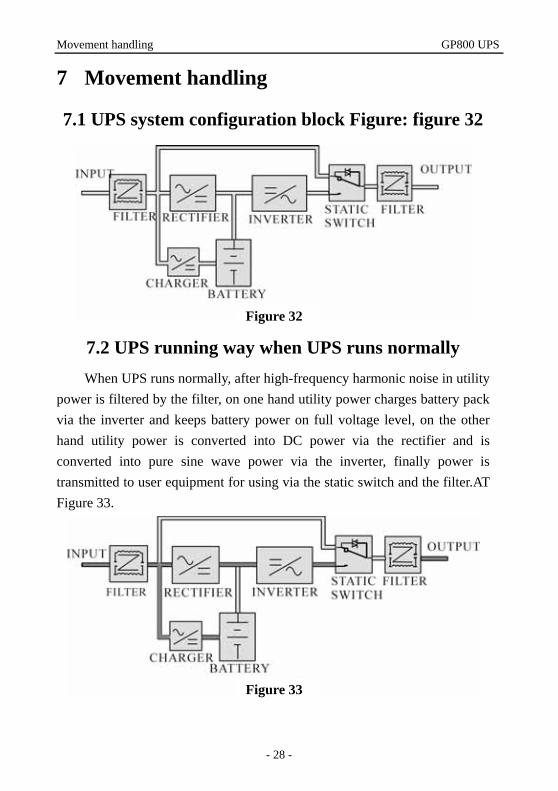
7.1 UPS system configuration block Figure: figure 32
7.2 UPS running way when UPS runs normally When UPS runs normally, after high-frequency harmonic noise in utility
power is filtered by the filter, on one hand utility power charges battery pack via the inverter and keeps battery power on full voltage level, on the other hand utility power is converted into DC power via the rectifier and is converted into pure sine wave power via the inverter, finally power is transmitted to user equipment for using via the static switch and the filter.AT Figure 33.
Figure 32
Figure 33
GP800 UPS Movement handling
- 29 -
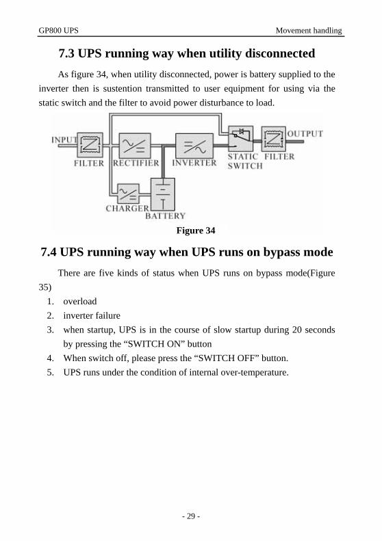
7.3 UPS running way when utility disconnected As figure 34, when utility disconnected, power is battery supplied to the
inverter then is sustention transmitted to user equipment for using via the static switch and the filter to avoid power disturbance to load.
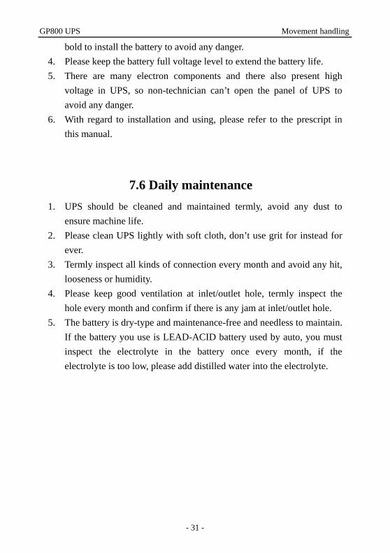
7.4 UPS running way when UPS runs on bypass mode There are five kinds of status when UPS runs on bypass mode(Figure
35) 1. overload 2. inverter failure 3. when startup, UPS is in the course of slow startup during 20 seconds
by pressing the “SWITCH ON” button 4. When switch off, please press the “SWITCH OFF” button. 5. UPS runs under the condition of internal over-temperature.
Figure 34
Movement handling GP800 UPS
- 30 -
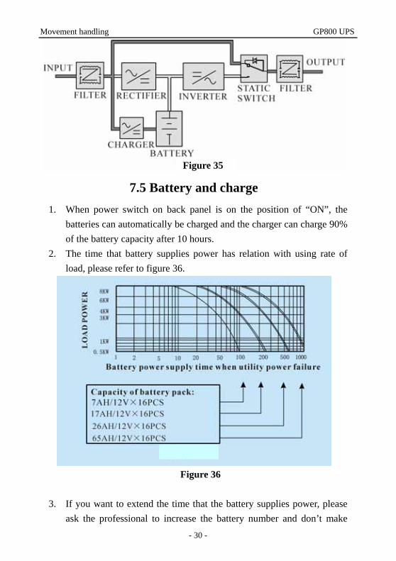
7.5 Battery and charge 1. When power switch on back panel is on the position of “ON”, the
batteries can automatically be charged and the charger can charge 90% of the battery capacity after 10 hours.
2. The time that battery supplies power has relation with using rate of load, please refer to figure 36.
Figure 36
3. If you want to extend the time that the battery supplies power, please
ask the professional to increase the battery number and don’t make
Figure 35
GP800 UPS Movement handling
- 31 -
bold to install the battery to avoid any danger. 4. Please keep the battery full voltage level to extend the battery life. 5. There are many electron components and there also present high
voltage in UPS, so non-technician can’t open the panel of UPS to avoid any danger.
6. With regard to installation and using, please refer to the prescript in this manual.
7.6 Daily maintenance 1. UPS should be cleaned and maintained termly, avoid any dust to
ensure machine life. 2. Please clean UPS lightly with soft cloth, don’t use grit for instead for
ever. 3. Termly inspect all kinds of connection every month and avoid any hit,
looseness or humidity. 4. Please keep good ventilation at inlet/outlet hole, termly inspect the
hole every month and confirm if there is any jam at inlet/outlet hole. 5. The battery is dry-type and maintenance-free and needless to maintain.
If the battery you use is LEAD-ACID battery used by auto, you must inspect the electrolyte in the battery once every month, if the electrolyte is too low, please add distilled water into the electrolyte.
Communication interface GP800 UPS
- 32 -
8 Communication interface 8.1 The great mass of computer system have equipped UPS to avoid system
failure and datum damage due to utility power fault, you can monitor and control the power status through the connection between the communication interface and UPS.
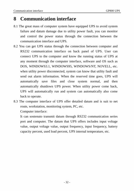
8.2 You can get UPS status through the connection between computer and RS232 communication interface on back panel of UPS. User can connect UPS to the computer and know the running status of UPS at any moment through the computer interface, software and OS such as DOS, WINDOWS3.1, WINDOWS95, WINDOWS/NT, NOVELL, etc. when utility power disconnected, system can know that utility fault and send out alarm information. When the reserved time goes, UPS will automatically save files and close system normal, and then automatically shutdown UPS power. When utility power come back, UPS will automatically run and system can automatically also come back to operate.
8.3 The computer interface of UPS offer detailed datum and is suit to net route, workstation, monitoring system, PC, etc. Computer interface: It can sostenuto transmit datum through RS232 communication series port and computer. The datum that UPS offers includes input voltage value, output voltage value, output frequency, input frequency, battery capacity percent, used load percent, UPS internal temperature, etc.
GP800 UPS Communication interface
- 33 -
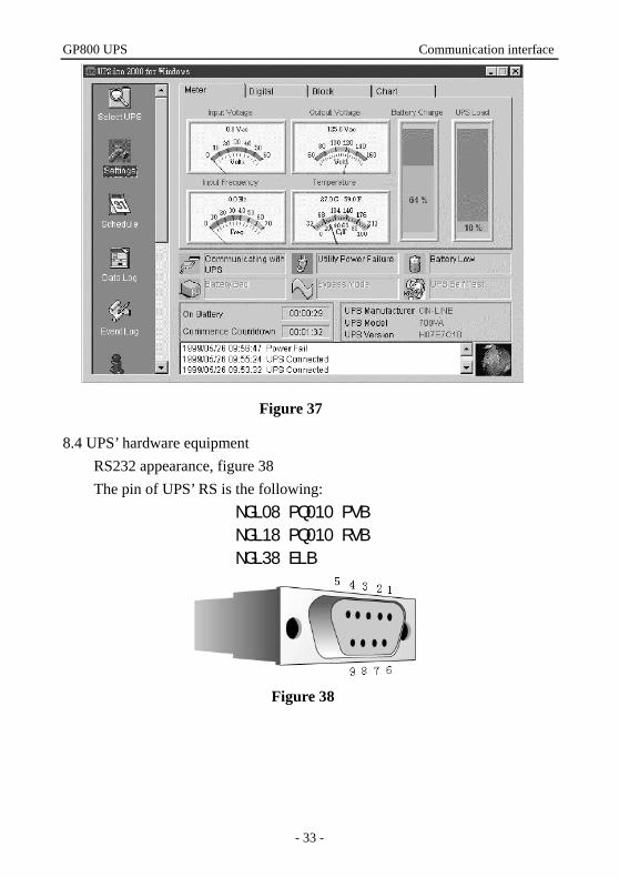
8.4 UPS’ hardware equipment
RS232 appearance, figure 38 The pin of UPS’ RS is the following:
PIN2: RS232 RXD
PIN3: RS232 TXD
PIN5: GND
Figure 38
Figure 37
SPECIFICATION GP800 UPS
- 34 -
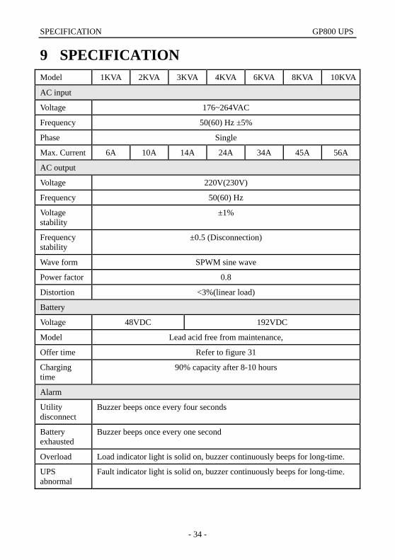
9 SPECIFICATION Model 1KVA 2KVA 3KVA 4KVA 6KVA 8KVA 10KVA
AC input
Voltage 176~264VAC
Frequency 50(60) Hz ±5%
Phase Single
Max. Current 6A 10A 14A 24A 34A 45A 56A
AC output
Voltage 220V(230V)
Frequency 50(60) Hz
Voltage stability
±1%
Frequency stability
±0.5 (Disconnection)
Wave form SPWM sine wave
Power factor 0.8
Distortion <3%(linear load)
Battery
Voltage 48VDC 192VDC
Model Lead acid free from maintenance,
Offer time Refer to figure 31
Charging time
90% capacity after 8-10 hours
Alarm
Utility disconnect
Buzzer beeps once every four seconds
Battery exhausted
Buzzer beeps once every one second
Overload Load indicator light is solid on, buzzer continuously beeps for long-time.
UPS abnormal
Fault indicator light is solid on, buzzer continuously beeps for long-time.
GP800 UPS SPECIFICATION
- 35 -
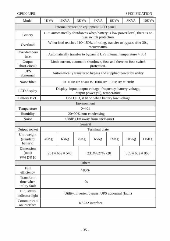
Model 1KVA 2KVA 3KVA 4KVA 6KVA 8KVA 10KVA
Internal protection equipment LCD panel
Battery UPS automatically shutdowns when battery is low power level, there is no fuse switch protection.
Overload When load reaches 110~150% of rating, transfer to bypass after 30s, recover auto.
Over-temperature Automatically transfer to bypass if UPS internal temperature > 85℃
Output short-circuit
Limit current, automatic shutdown, fuse and there no fuse switch protection.
UPS abnormal Automatically transfer to bypass and supplied power by utility
Noise filter 10~100KHz at 40Db; 100KHz~100MHz at 70dB
LCD display Display: input, output voltage, frequency, battery voltage, output power (%), temperature
Battery BVL One LED, it lit on when battery low voltage Environment
Temperature 0~40℃ Humidity 20~90% non-condensing
Noise <58dB (1m away from enclosure) General
Output socket Terminal plate Unit weight
(standard battery)
46Kg 63Kg 75Kg 65Kg 69Kg 105Kg 115Kg
Dimension (mm)
W×D×H 231×662×540 231×627×720 305×652×866
Others Full
efficiency >85%
Transform time when utility fault
0s
UPS status indicator light Utility, inverter, bypass, UPS abnormal (fault)
Communication interface RS232 interface

Shipping list GP800 UPS
- 36 -
10 Shipping list
Order Consent Number 1 UPS 1 2 «UPS user manual» 1 3 Intelligent monitoring software 1 4 RS232 Computer port cable 1
Recommended