A Subsidiary of
0
000
Most Widely Accepted and Trusted
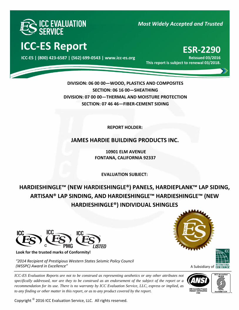
ICC-ES Report ESR-2290 Reissued 03/2016
This report is subject to renewal 03/2018.
ICC-ES | (800) 423-6587 | (562) 699-0543 | www.icc-es.org
ICC-ES Evaluation Reports are not to be construed as representing aesthetics or any other attributes not specifically addressed, nor are they to be construed as an endorsement of the subject of the report or a recommendation for its use. There is no warranty by ICC Evaluation Service, LLC, express or implied, as to any finding or other matter in this report, or as to any product covered by the report.
Copyright © 2016 ICC Evaluation Service, LLC. All rights reserved.
“2014 Recipient of Prestigious Western States Seismic Policy Council (WSSPC) Award in Excellence”
Look for the trusted marks of Conformity!
DIVISION: 06 00 00—WOOD, PLASTICS AND COMPOSITES SECTION: 06 16 00—SHEATHING
DIVISION: 07 00 00—THERMAL AND MOISTURE PROTECTION SECTION: 07 46 46—FIBER-CEMENT SIDING
REPORT HOLDER:
JAMES HARDIE BUILDING PRODUCTS INC.
10901 ELM AVENUE FONTANA, CALIFORNIA 92337
EVALUATION SUBJECT:
HARDIESHINGLE™ (NEW HARDIESHINGLE®) PANELS, HARDIEPLANK™ LAP SIDING, ARTISAN® LAP SINDING, AND HARDIESHINGLE™ HARDIESHINGLE™ (NEW
HARDIESHINGLE®) INDIVIDUAL SHINGLES
ICC-ES Evaluation Reports are not to be construed as representing aesthetics or any other attributes not specifically addressed, nor are they to be construed as an endorsement of the subject of the report or a recommendation for its use. There is no warranty by ICC Evaluation Service, LLC, express or implied, as to any finding or other matter in this report, or as to any product covered by the report.
Copyright © 2016 ICC Evaluation Service, LLC. All rights reserved. Page 1 of 25 1000
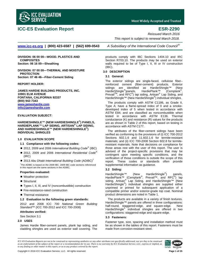
ICC-ES Evaluation Report ESR-2290 Reissued March 2016 This report is subject to renewal March 2018.
www.icc-es.org | (800) 423-6587 | (562) 699-0543 A Subsidiary of the International Code Council ®
DIVISION: 06 00 00—WOOD. PLASTICS AND COMPOSITES
Section: 06 16 00—Sheathing DIVISION: 07 00 00—THERMAL AND MOISTURE
PROTECTION Section: 07 46 46—Fiber-Cement Siding REPORT HOLDER: JAMES HARDIE BUILDING PRODUCTS, INC. 10901 ELM AVENUE FONTANA, CALIFORNIA 92337 (800) 942-7343 www.jameshardie.com [email protected]
EVALUATION SUBJECT: HARDIESHINGLE™ (NEW HARDIESHINGLE®) PANELS, HARDIEPLANK™ LAP SIDING, ARTISAN® LAP SIDING, AND HARDIESHINGLE™ (NEW HARDIESHINGLE®) INDIVIDUAL SHINGLES 1.0 EVALUATION SCOPE
1.1 Compliance with the following codes:
2012, 2009 and 2006 International Building Code® (IBC)
2012, 2009 and 2006 International Residential Code® (IRC)
2013 Abu Dhabi International Building Code (ADIBC)† †The ADIBC is based on the 2009 IBC. 2009 IBC code sections referenced in this report are the same sections in the ADIBC.
Properties evaluated:
Weather protection
Structural
Types I, II, III, and IV (noncombustible) construction
Fire-resistance-rated construction
Thermal resistance
1.2 Evaluation to the following green standards:
2012 and 2008 ICC 700 National Green Building Standard™ (ICC 700-2012 and ICC 700-2008)
Attributes verified:
See Section 3.1
2.0 USES
James Hardie fiber-cement panels, plank lap siding, and cladding shingles are used as exterior wall covering. The
products comply with IBC Sections 1404.10 and IRC Section R703.10. The products may be used on exterior walls required to be of Type I, II, III or IV construction (IBC).
3.0 DESCRIPTION
3.1 General:
The exterior sidings are single-faced, cellulose fiber–reinforced cement (fiber-cement) products. Exterior sidings are identified as HardieShingle™ (New HardieShingle®)panels, HardiePlank™ (Cemplank®, PrevailTM, and RFC®) lap siding, Artisan® Lap Siding, and HardieShingle™ (New HardieShingle®) individual shingles.
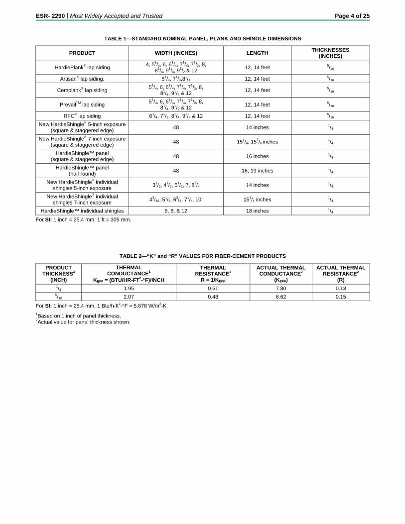
The products comply with ASTM C1186, as Grade II, Type A; have a flame-spread index of 0 and a smoke-developed index of 5 when tested in accordance with ASTM E84; and are classified as noncombustible when tested in accordance with ASTM E136. Thermal conductance (K) and resistance (R) values for the products are as shown in Table 2 of this report, based on testing in accordance with ASTM C177.
The attributes of the fiber-cement sidings have been verified as conforming to the provisions of (i) ICC 700-2012 Sections 602.1.6 and 11.602.1.6 for termite-resistant materials; and (ii) ICC 700-2008 Section 602.8 for termite-resistant materials. Note that decisions on compliance for those areas rest with the user of this report. The user is advised of the project-specific provisions that may be contingent upon meeting specific conditions, and the verification of those conditions is outside the scope of this report. These codes or standards often provide supplemental information as guidance.
3.2 Siding:
HardieShingle™ (New HardieShingle®) panels, HardiePlank™ (Cemplank®, Prevail™, and RFC®) lap siding, Artisan® Lap Siding, and HardieShingle™ (New HardieShingle®) individual shingles are supplied either unprimed or primed for subsequent application of a compatible primer and/or exterior-grade top coat. Nominal product dimensions are noted in Table 1.
The products are available in a variety of finish textures. HardieShingle™ panels are offered in three configurations: half-round, staggered-edge, and square-edge. New HardieShingle® individual shingles are offered in two configurations: staggered-edge and square-edge.
3.3 Fasteners:
Fastener type, size, spacing and installation method must be as shown in the tables of this report. Fasteners must be made from corrosion-resistant steel.
ESR- 2290 | Most Widely Accepted and Trusted Page 2 of 25 4.0 DESIGN AND INSTALLATION
4.1 Design:
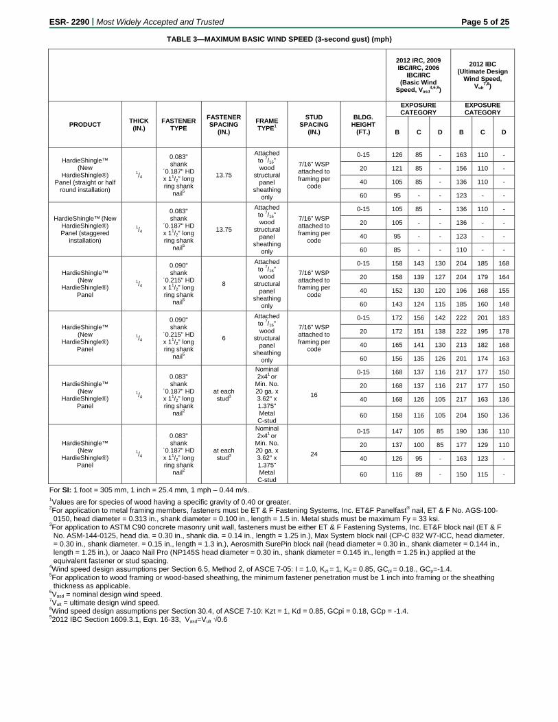
Walls: The maximum basic wind speeds for positive or negative transverse load resistance of HardieShingle™ (New HardieShingle®) panels, HardiePlank™ (Cemplank®, Prevail™, and RFC®) lap siding, Artisan® Lap Siding, and HardieShingle™ (New HardieShingle®) individual shingles are presented in Tables 3 through 13.
4.2 Installation:
4.2.1 General: Installation must comply with this report, and a copy of this report must be available at all times on the jobsite during installation. All products may be cut to shape on-site by the score-and-snap method using a score-and-snap knife, a hand guillotine or a handsaw utilizing a carbide blade. A clear distance of 6 inches (152 mm) must be maintained between the siding and the earth. Unless otherwise noted in this report, the products must be installed in accordance with 2012 IBC Section 1405.16; 2012 IRC Section R703.10; 2009 IBC Sections 1405.16; ; 2009 IRC Section R703.10; 2006 IBC Sections 1405.15 and 1405.16; or 2006 IRC Section R703.10, as applicable.
4.2.2 HardieShingle™ (New HardieShingle®) Panels: When installation is on wood or metal framing members, with or without wood structural panel sheathing, a water-resistive barrier must be applied over the wood or metal framing members or wood structural panel sheathing in accordance with the applicable code. The panels must be fastened in accordance with the provisions of Table 4 of this report.
A 1/8-inch (3.2 mm) gap must be left at locations where the siding butts against door and window trim and at internal or external corners; such gaps must be flashed in accordance with the applicable code, then caulked. Vertical joints must occur over framing members and must be sealed with caulking or covered with battens. Horizontal joints must be flashed with metal Z-flashing and occur over solid blocking or wood structural panel sheathing.
4.2.3 HardiePlank™ (Cemplank®, PrevailTM, and RFC®) Lap Siding: When installation is on wood or metal framing members, with or without wood structural panel sheathing, the lap siding must be fastened either through the overlapping planks (face nailed) or through the top edge of single planks (blind nailed) in accordance with the provisions of Table 4 of this report. A water-resistive barrier must be applied over wood or metal framing members or wood structural panel sheathing in accordance with the applicable code. Lap siding installed over walls constructed of concrete masonry units complying with ASTM C90 must be applied in accordance with Tables 5 through 10. The lap siding requires the use of a starter strip to set the first course on the proper angle and to create a drip edge.
Vertical joints must occur over studs, except where the “off-stud splice device” is installed or where the planks are installed to wood structural panel sheathing complying with the applicable code, and must be staggered on subsequent courses. Where the “off-stud splice device” is installed, the splice device’s bottom lip must be placed over the adjacent solid course of planks. The plank must then be fastened to the framing with corrosion-resistant fasteners. The abutting plank must be positioned and fastened into place ensuring that the lower edges of the two planks align. The metal device must be located centrally over the vertical joint.
Vertical joints between planks must be lightly butted or gapped and must be protected by one of the following methods: (a) sealed with caulking in accordance with the
caulk manufacturer’s published gapping requirements and caulking application instructions; or (b) covered with an H-section joint cover; or (c) located over a strip of non-perforated flashing complying with ASTM D226, Type I felt, or other approved flashing. Trim and corners must be installed and the siding must be finished in accordance with the manufacturer’s application instructions. A 1/8-inch (3.2 mm) gap must be left at locations where the siding butts against door and window trim and at internal or external corners; such gaps must be flashed in accordance with the applicable code, then caulked. Horizontal joints must be flashed with Z-flashing and occur over solid blocking or wood structural panel sheathing.
4.2.4 Artisan® Lap Siding: When installation is on wood or metal framing members, with or without wood structural panel sheathing, the lap siding must be fastened through the top edge of single planks (blind nailed) in accordance with the provisions of Table 4 of this report. A water-resistive barrier must be applied over wood or metal framing or wood structural panel sheathing in accordance with the applicable code. Lap siding installed over walls constructed of concrete masonry units complying with ASTM C90 must be applied in accordance with Tables 5 through 10. The lap siding requires the use of a starter strip to set the first course on the proper angle and to create a drip edge.
Vertical joints must be made off-stud by means of the tongue and groove joint. Tongue and groove joints may be located centrally between studs but no closer than 4 inches (102 mm) from the edge of a stud. Nails must not be placed within 2 inches (51 mm) of the tongue and groove at the end of the planks. Vertical joints must be staggered on subsequent courses. The plank must then be fastened to the framing with corrosion-resistant fasteners.
Vertical joints between planks must be lightly butted and must be located over a strip of non-perforated flashing complying with ASTM D226, Type I felt, or other approved flashing. Trim and corners must be installed and the siding must be finished in accordance with the manufacturer’s application instructions. A 1/8-inch (3.2 mm) gap must be left at the locations where the siding butts against door and window trim and at internal or external corners; such gaps must be flashed in accordance with the applicable code, then caulked. Horizontal joints must be flashed with Z-flashing and must occur over solid blocking or wood structural panel sheathing.
4.2.5 HardieShingle™ (New HardieShingle®) Individual Shingles: When installed on wood structural panel sheathing, the cladding shingles are fastened in accordance with the provisions of either Table 11, 12, or 13 of this report. A water-resistive barrier in accordance with the applicable code must be applied over the wood-based sheathing substrate to which the shingles are attached.
The individual shingles require the use of a starter strip to set the first course on the proper angle and to create a drip edge. The nominally 11/4-inch-wide-by-1/4-inch-thick starter strip and a minimum 81/4-inch-wide (210 mm) HardiePlank™ (Cemplank®, PrevailTM, and RFC®) lap siding starter course are installed over the water-resistive barrier with the bottom of the starter strip and starter course even with the bottom of the bottom plate. Shingles are spaced a maximum of 1/4 inch (6.4 mm) apart, leaving a minimum side lap of 11/2 inches (38 mm) between the joints of successive courses. Fasteners must be spaced a minimum of 3/4 inch (19 mm) and a maximum of 1 inch (25.4 mm) from shingle edges and must be positioned to be covered a nominal 11/4 inches by the succeeding shingle course; for 12-inch-wide (305 mm) shingles, the
ESR- 2290 | Most Widely Accepted and Trusted Page 3 of 25
third nail (see Table 14) must be installed mid-span of the shingle. Nails must secure shingles but must not be over-driven. Trim and corners must be installed and the shingles must be finished in accordance with the manufacturer’s application instructions. A 1/8-inch (3.2 mm) gap must be left at locations where the shingle butts against door and window trim and at internal or external corners; such gaps must be flashed in accordance with the applicable code, then caulked. Horizontal joints must be flashed with Z-flashing.
4.3 Fire-resistance-rated Wall Assembly (HardiePlank™ Lap Siding):
The asymmetrical, load-bearing, one-hour fire-resistance-rated wall assembly must consist of nominally 2-by-4 wood studs spaced a maximum of 24 inches (610 mm) on center, with two top plates and a single bottom plate. One layer of 5/8-inch-thick (15.9), Type X, gypsum wallboard complying with ASTM C36 or ASTM C1396, 48 inches (1219 mm) wide, must be applied vertically to the interior face of the studs and secured with minimum 13/4-inch-long (44 mm) cup-head gypsum wallboard nails, spaced 7 inches (178 mm) on center at board edges and intermediate framing members. All board joints must be backed by framing. The 5/8-inch-thick (15.9 mm), Type X, gypsum wallboard joints and nail heads must be finished in accordance with ASTM C840 or GA216. The exterior face of the wall must be covered with one layer of 1/2-inch-thick (12.7 mm), Type X, water-resistant core treated gypsum sheathing complying with ASTM C36 or ASTM C1396 and one layer of maximum 12-inch-wide (305 mm) HardiePlank™ (Cemplank®, PrevailTM, and RFC®) lap siding lapped a minimum of 11/4 inches (32 mm). The 1/2-inch-thick (12.7 mm), Type X, water-resistant core-treated gypsum sheathing must be applied vertically to the exterior side of the framing members with vertical edges staggered 24 inches (610 mm) from the joints on the opposite side. All board joints must be backed by framing. The 1/2-inch-thick (12.7 mm), Type X, water-resistant core-treated gypsum sheathing must be fastened to the framing members with 13/4-inch-long (44 mm) roofing nails spaced 7 inches (178 mm) on center in the field and 4 inches (102 mm) on center along the perimeter of each board. The outer layer of 5/16-inch-thick (7.5 mm), minimum 12-inch-wide (305 mm) HardiePlank™ (Cemplank®, PrevailTM, and RFC®) lap siding must be applied over the 1/2-inch-thick (12.7 mm), Type X, water-resistant core-treated gypsum sheathing by attaching 11/2-inch-wide (38 mm) HardiePlank™ (Cemplank®, PrevailTM, and RFC®) starter strips through the gypsum sheathing into the bottom plate and 12-inch-wide (305 mm) HardiePlank™
(Cemplank®, PrevailTM, and RFC®) lap siding applied horizontally with a minimum nominally 11/4-inch head lap, and fastening with a single 6d corrosion-resistant common nail driven through the lapped planks into each stud.
The axial load must be the lesser of the following, provided structural consideration for axial, flexural and bearing perpendicular-to-grain stresses is in accordance with ANSI/AF&PA NDS-2010 for the 2012 IBC or IRC (-2005 for the 2009 and 2006 IBC or IRC):
1. Maximum 100 percent of full allowable axial compressive design load permitted for the wood species.
2. Maximum allowable wood axial stress of 0.78 F′c, which must not exceed 0.78 F′c at a slenderness ratio le/d of 33.
5.0 CONDITIONS OF USE
The HardieShingle™ (New HardieShingle®) panels, HardiePlank™ (Cemplank®, Prevail™, and RFC®) lap siding, Artisan® Lap Siding, and HardieShingle™ (New
HardieShingle®) individual shingles described in this report comply with, or are suitable alternatives to what is specified in, those codes listed in Section 1.0 of this report, subject to the following conditions:
5.1 James Hardie® Building Products, Inc, products listed in this report must be installed in accordance with this report and the manufacturer’s published installation instructions. In the event of a conflict between this report and the manufacturer’s instructions, this report governs.
5.2 HardieShingle™ (New HardieShingle®) panels, HardiePlank™ (Cemplank®, PrevailTM, and RFC®) lap siding, Artisan® Lap Siding, and HardieShingle™ (New HardieShingle®) individual shingles must be installed on exterior walls braced in accordance the applicable code.
5.3 Design wind speeds applied to James Hardie® sidings described in this report must be determined in accordance with the applicable code and must be less than those shown in the wind speed tables in this report.
5.4 The sidings must be installed over a code-complying water-resistive barrier and as noted in this report.
5.5 For use in fire-resistance-rated construction, installation must be in accordance with Section 4.3.
5.6 Flashing must be installed at all penetrations and terminations in accordance with the applicable code.
5.7 Under the 2012 IBC, Section 1403.5, installation on exterior walls of buildings of Type I, II, III, and IV construction is limited to buildings that are not greater than 40 feet in height above grade plane and that feature a combustible water-resistive barrier.
5.8 The products are manufactured at the following locations, with quality control inspections by ICC-ES:
Cleburne, Texas
Peru, Illinois
Plant City, Florida
Pulaski, Virginia
Sparks, Nevada
Tacoma, Washington
Waxahachie, Texas
Fontana, California
6.0 EVIDENCE SUBMITTED Data in accordance with the ICC-ES Acceptance Criteria for Fiber Cement Siding Used as Exterior Wall Siding (AC90), dated June 2012 (editorially revised November 2013).
7.0 IDENTIFICATION Pallets of the JamesHardie® Building Products, Inc., HardieShingle™ (New HardieShingle®) panels, HardiePlank™ (Cemplank®, PrevailTM, and RFC®) lap siding, Artisan® Lap Siding, and HardieShingle™ (New HardieShingle®) individual shingles must carry a label bearing the manufacturer’s name and telephone number, the product name, the name of the inspection agency, ICC-ES, and the evaluation report number (ESR-2290).
ESR- 2290 | Most Widely Accepted and Trusted Page 4 of 25
TABLE 1—STANDARD NOMINAL PANEL, PLANK AND SHINGLE DIMENSIONS
PRODUCT WIDTH (INCHES) LENGTH THICKNESSES
(INCHES)
HardiePlank® lap siding 4, 51/4, 6, 61/4, 7
1/4, 71/2, 8,
81/4, 91/4, 9
1/2 & 12 12, 14 feet 5/16
Artisan® lap siding, 51/4, 71/4,8
1/4 12, 14 feet 5/16
Cemplank® lap siding 51/4, 6, 61/4, 7
1/4, 71/2, 8,
81/4, 91/2 & 12
12, 14 feet 5/16
PrevailTM lap siding 51/4, 6, 61/4, 7
1/4, 71/2, 8,
81/4, 91/2 & 12
12, 14 feet 5/16
RFC® lap siding 61/4, 71/2, 8
1/4, 91/2 & 12 12, 14 feet 5/16
New HardieShingle® 5-inch exposure (square & staggered edge)
48 14 inches 1/4
New HardieShingle® 7-inch exposure (square & staggered edge)
48 151/4, 157/8 inches 1/4
HardieShingle™ panel (square & staggered edge)
48 16 inches 1/4
HardieShingle™ panel (half round)
48 16, 19 inches 1/4
New HardieShingle® individual shingles 5-inch exposure
31/2, 41/2, 5
1/2, 7, 83/4 14 inches 1/4
New HardieShingle® individual shingles 7-inch exposure
43/16, 51/2, 6
3/4, 71/4, 10, 151/4 inches 1/4
HardieShingle™ individual shingles 6, 8, & 12 18 inches 1/4
For SI: 1 inch = 25.4 mm, 1 ft = 305 mm.
TABLE 2—“K” and “R” VALUES FOR FIBER-CEMENT PRODUCTS
PRODUCT THICKNESS3
(INCH)
THERMAL CONDUCTANCE1
KEFF = (BTU/HR-FT2-F)/INCH
THERMAL RESISTANCE1
R = 1/KEFF
ACTUAL THERMAL CONDUCTANCE2
(KEFF)
ACTUAL THERMAL RESISTANCE2
(R) 1/4 1.95 0.51 7.80 0.13 5/16 2.07 0.48 6.62 0.15
For SI: 1 inch = 25.4 mm, 1 Btu/h-ft2-F = 5.678 W/m2-K.
1Based on 1 inch of panel thickness. 2Actual value for panel thickness shown.
ESR- 2290 | Most Widely Accepted and Trusted Page 5 of 25
TABLE 3—MAXIMUM BASIC WIND SPEED (3-second gust) (mph)
2012 IRC, 2009 IBC/IRC, 2006
IBC/IRC (Basic Wind
Speed, Vasd4,6,9)
2012 IBC (Ultimate Design
Wind Speed, Vult
7,8)
PRODUCT THICK
(IN.) FASTENER
TYPE
FASTENER SPACING
(IN.)
FRAME TYPE1
STUD SPACING
(IN.)
BLDG. HEIGHT
(FT.)
EXPOSURE CATEGORY
EXPOSURE CATEGORY
B C D B C D
HardieShingle™ (New
HardieShingle®) Panel (straight or half
round installation)
1/4
0.083" shank
´0.187" HD x 11/2” long ring shank
nail5
13.75
Attached to 7/16” wood
structural panel
sheathing only
7/16” WSP attached to framing per
code
0-15 126 85 - 163 110 -
20 121 85 - 156 110 -
40 105 85 - 136 110 -
60 95 - - 123 - -
HardieShingle™ (New HardieShingle®) Panel (staggered
installation)
1/4
0.083" shank
´0.187" HD x 11/2” long ring shank
nail5
13.75
Attached to 7/16” wood
structural panel
sheathing only
7/16” WSP attached to framing per
code
0-15 105 85 - 136 110 -
20 105 - - 136 - -
40 95 - - 123 - -
60 85 - - 110 - -
HardieShingle™ (New
HardieShingle®) Panel
1/4
0.090" shank
´0.215" HD x 11/2” long ring shank
nail5
8
Attached to 7/16” wood
structural panel
sheathing only
7/16” WSP attached to framing per
code
0-15 158 143 130 204 185 168
20 158 139 127 204 179 164
40 152 130 120 196 168 155
60 143 124 115 185 160 148
HardieShingle™ (New
HardieShingle®) Panel
1/4
0.090" shank
´0.215" HD x 11/2” long ring shank
nail5
6
Attached to 7/16” wood
structural panel
sheathing only
7/16” WSP attached to framing per
code
0-15 172 156 142 222 201 183
20 172 151 138 222 195 178
40 165 141 130 213 182 168
60 156 135 126 201 174 163
HardieShingle™ (New
HardieShingle®) Panel
1/4
0.083" shank
´0.187" HD x 11/2” long ring shank
nail2
at each stud3
Nominal 2x41 or
Min. No. 20 ga. x 3.62" x 1.375" Metal C-stud
16
0-15 168 137 116 217 177 150
20 168 137 116 217 177 150
40 168 126 105 217 163 136
60 158 116 105 204 150 136
HardieShingle™ (New
HardieShingle®) Panel
1/4
0.083" shank
´0.187" HD x 11/2” long ring shank
nail2
at each stud3
Nominal 2x41 or
Min. No. 20 ga. x 3.62" x 1.375" Metal C-stud
24
0-15 147 105 85 190 136 110
20 137 100 85 177 129 110
40 126 95 - 163 123 -
60 116 89 - 150 115 -
For SI: 1 foot = 305 mm, 1 inch = 25.4 mm, 1 mph – 0.44 m/s. 1Values are for species of wood having a specific gravity of 0.40 or greater. 2For application to metal framing members, fasteners must be ET & F Fastening Systems, Inc. ET&F Panelfast® nail, ET & F No. AGS-100-
0150, head diameter = 0.313 in., shank diameter = 0.100 in., length = 1.5 in. Metal studs must be maximum Fy = 33 ksi. 3For application to ASTM C90 concrete masonry unit wall, fasteners must be either ET & F Fastening Systems, Inc. ET&F block nail (ET & F
No. ASM-144-0125, head dia. = 0.30 in., shank dia. = 0.14 in., length = 1.25 in.), Max System block nail (CP-C 832 W7-ICC, head diameter. = 0.30 in., shank diameter. = 0.15 in., length = 1.3 in.), Aerosmith SurePin block nail (head diameter = 0.30 in., shank diameter = 0.144 in., length = 1.25 in.), or Jaaco Nail Pro (NP145S head diameter = 0.30 in., shank diameter = 0.145 in., length = 1.25 in.) applied at the equivalent fastener or stud spacing.
4Wind speed design assumptions per Section 6.5, Method 2, of ASCE 7-05: I = 1.0, Kzt = 1, Kd = 0.85, GCpi = 0.18., GCp=-1.4. 5For application to wood framing or wood-based sheathing, the minimum fastener penetration must be 1 inch into framing or the sheathing
thickness as applicable. 6Vasd = nominal design wind speed. 7Vult = ultimate design wind speed. 8Wind speed design assumptions per Section 30.4, of ASCE 7-10: Kzt = 1, Kd = 0.85, GCpi = 0.18, GCp = -1.4. 92012 IBC Section 1609.3.1, Eqn. 16-33, Vasd=Vult √0.6
ESR- 2290 | Most Widely Accepted and Trusted Page 6 of 25
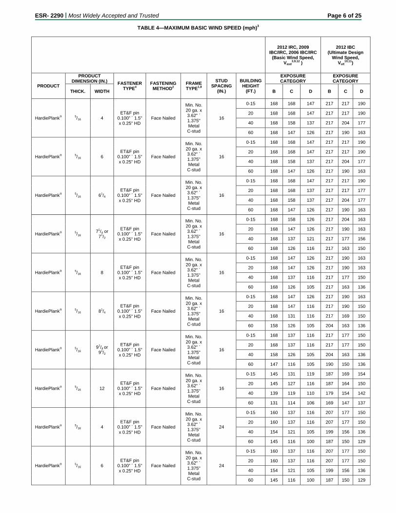
TABLE 4—MAXIMUM BASIC WIND SPEED (mph)3
2012 IRC, 2009 IBC/IRC, 2006 IBC/IRC
(Basic Wind Speed, Vasd
3,9,12 )
2012 IBC (Ultimate Design
Wind Speed, Vult
10,11)
PRODUCT
PRODUCT DIMENSION (IN.) FASTENER
TYPE4 FASTENING METHOD2
FRAME TYPE1,8
STUD SPACING
(IN.)
BUILDING HEIGHT
(FT.)
EXPOSURE CATEGORY
EXPOSURE CATEGORY
THICK. WIDTH B C D B C D
HardiePlank® 5/16 4 ET&F pin
0.100” ´ 1.5" x 0.25" HD
Face Nailed
Min. No. 20 ga. x 3.62" ´ 1.375" Metal C-stud
16
0-15 168 168 147 217 217 190
20 168 168 147 217 217 190
40 168 158 137 217 204 177
60 168 147 126 217 190 163
HardiePlank® 5/16 6 ET&F pin
0.100” ´ 1.5" x 0.25" HD
Face Nailed
Min. No. 20 ga. x 3.62" ´ 1.375" Metal C-stud
16
0-15 168 168 147 217 217 190
20 168 168 147 217 217 190
40 168 158 137 217 204 177
60 168 147 126 217 190 163
HardiePlank® 5/16 61/4 ET&F pin
0.100” ´ 1.5" x 0.25" HD
Face Nailed
Min. No. 20 ga. x 3.62" ´ 1.375" Metal C-stud
16
0-15 168 168 147 217 217 190
20 168 168 137 217 217 177
40 168 158 137 217 204 177
60 168 147 126 217 190 163
HardiePlank® 5/16 71/4 or
71/2
ET&F pin 0.100” ´ 1.5" x 0.25" HD
Face Nailed
Min. No. 20 ga. x 3.62" ´ 1.375" Metal C-stud
16
0-15 168 158 126 217 204 163
20 168 147 126 217 190 163
40 168 137 121 217 177 156
60 168 126 116 217 163 150
HardiePlank® 5/16 8 ET&F pin
0.100” ´ 1.5" x 0.25" HD
Face Nailed
Min. No. 20 ga. x 3.62" ´ 1.375" Metal C-stud
16
0-15 168 147 126 217 190 163
20 168 147 126 217 190 163
40 168 137 116 217 177 150
60 168 126 105 217 163 136
HardiePlank® 5/16 81/4 ET&F pin
0.100” ´ 1.5" x 0.25" HD
Face Nailed
Min. No. 20 ga. x 3.62" ´ 1.375" Metal C-stud
16
0-15 168 147 126 217 190 163
20 168 147 116 217 190 150
40 168 131 116 217 169 150
60 158 126 105 204 163 136
HardiePlank® 5/16 91/4 or 91/2
ET&F pin 0.100” ´ 1.5" x 0.25" HD
Face Nailed
Min. No. 20 ga. x 3.62" ´ 1.375" Metal C-stud
16
0-15 168 137 116 217 177 150
20 168 137 116 217 177 150
40 158 126 105 204 163 136
60 147 116 105 190 150 136
HardiePlank® 5/16 12 ET&F pin
0.100” ´ 1.5" x 0.25" HD
Face Nailed
Min. No. 20 ga. x 3.62" ´ 1.375" Metal C-stud
16
0-15 145 131 119 187 169 154
20 145 127 116 187 164 150
40 139 119 110 179 154 142
60 131 114 106 169 147 137
HardiePlank® 5/16 4 ET&F pin
0.100” ´ 1.5" x 0.25" HD
Face Nailed
Min. No. 20 ga. x 3.62" ´ 1.375" Metal C-stud
24
0-15 160 137 116 207 177 150
20 160 137 116 207 177 150
40 154 121 105 199 156 136
60 145 116 100 187 150 129
HardiePlank® 5/16 6 ET&F pin
0.100” ´ 1.5" x 0.25" HD
Face Nailed
Min. No. 20 ga. x 3.62" ´ 1.375" Metal C-stud
24
0-15 160 137 116 207 177 150
20 160 137 116 207 177 150
40 154 121 105 199 156 136
60 145 116 100 187 150 129
ESR- 2290 | Most Widely Accepted and Trusted Page 7 of 25
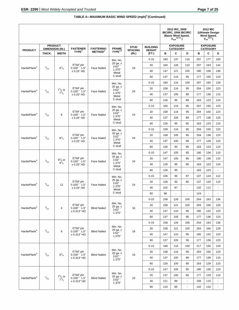
TABLE 4—MAXIMUM BASIC WIND SPEED (mph)3 (Continued)
2012 IRC, 2009 IBC/IRC, 2006 IBC/IRC
(Basic Wind Speed, Vasd
3,9,12 )
2012 IBC (Ultimate Design
Wind Speed, Vult
10,11)
PRODUCT
PRODUCT DIMENSION (IN.) FASTENER
TYPE4 FASTENING METHOD2
FRAME TYPE1,8
STUD SPACING
(IN.)
BUILDING HEIGHT
(FT.)
EXPOSURE CATEGORY
EXPOSURE CATEGORY
THICK. WIDTH B C D B C D
HardiePlank® 5/16 61/4 ET&F pin
0.100” ´ 1.5" x 0.25" HD
Face Nailed
Min. No. 20 ga. x 3.62" ´ 1.375" Metal C-stud
24
0-15 160 137 116 207 177 150
20 160 126 110 207 163 142
40 147 121 105 190 156 136
60 137 116 95 177 150 123
HardiePlank® 5/16 71/4 or
71/2
ET&F pin 0.100” ´ 1.5" x 0.25" HD
Face Nailed
Min. No. 20 ga. x 3.62" ´ 1.375" Metal C-stud
24
0-15 160 116 100 207 150 129
20 158 116 95 204 150 123
40 137 105 89 177 136 115
60 126 95 89 163 123 115
HardiePlank® 5/16 8 ET&F pin
0.100” ´ 1.5" x 0.25" HD
Face Nailed
Min. No. 20 ga. x 3.62" ´ 1.375" Metal C-stud
24
0-15 160 116 95 207 150 123
20 158 116 95 204 150 123
40 137 105 89 177 136 115
60 126 95 85 163 123 110
HardiePlank® 5/16 81/4 ET&F pin
0.100” ´ 1.5" x 0.25" HD
Face Nailed
Min. No. 20 ga. x 3.62" ´ 1.375" Metal C-stud
24
0-15 158 116 95 204 150 123
20 158 105 95 204 136 123
40 137 100 85 177 129 110
60 126 95 85 163 123 110
HardiePlank® 5/16 91/4 or 91/2
ET&F pin 0.100” ´ 1.5" x 0.25" HD
Face Nailed
Min. No. 20 ga. x 3.62" ´ 1.375" Metal C-stud
24
0-15 147 105 85 190 136 110
20 147 105 85 190 136 110
40 126 95 85 163 123 110
60 126 95 - 163 123 -
HardiePlank® 5/16 12 ET&F pin
0.100” ´ 1.5" x 0.25" HD
Face Nailed
Min. No. 20 ga. x 3.62" ´ 1.375" Metal C-stud
24
0-15 106 96 87 137 124 112
20 106 93 85 137 120 110
40 102 87 - 132 112 -
60 96 - - 124 - -
HardiePlank® 5/16 4 ET&F pin
0.100” ´ 1.5" x 0.313" HD
Blind Nailed
Min. No. 20 ga. x 3.62" ´ 1.375"
16
0-15 158 126 105 204 163 136
20 158 121 100 204 156 129
40 147 110 95 190 142 123
60 137 105 95 177 136 123
HardiePlank® 5/16 6 ET&F pin
0.100” ´ 1.5" x 0.313" HD
Blind Nailed
Min. No. 20 ga. x 3.62" ´ 1.375"
16
0-15 158 126 105 204 163 136
20 158 121 100 204 156 129
40 147 110 95 190 142 123
60 137 105 95 177 136 123
HardiePlank® 5/16 61/4 ET&F pin
0.100” ´ 1.5" x 0.313" HD
Blind Nailed
Min. No. 20 ga. x 3.62" ´ 1.375"
16
0-15 168 116 100 217 150 129
20 158 116 95 204 150 123
40 137 105 89 177 136 115
60 126 100 85 163 129 110
HardiePlank® 5/16 71/4 or
71/2
ET&F pin 0.100” ´ 1.5" x 0.313" HD
Blind Nailed
Min. No. 20 ga. x 3.62" ´ 1.375"
16
0-15 147 105 85 190 136 110
20 137 100 85 177 129 110
40 121 89 - 156 115 -
60 110 85 - 142 110 -
ESR- 2290 | Most Widely Accepted and Trusted Page 8 of 25
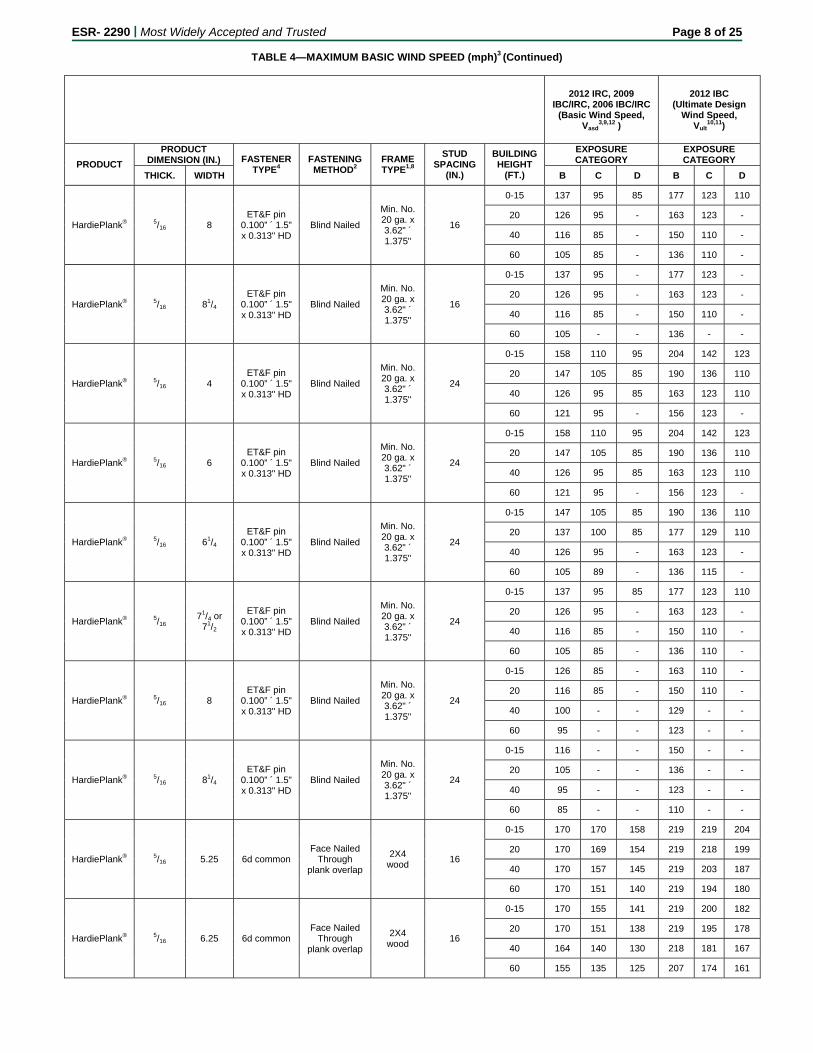
TABLE 4—MAXIMUM BASIC WIND SPEED (mph)3 (Continued)
2012 IRC, 2009 IBC/IRC, 2006 IBC/IRC
(Basic Wind Speed, Vasd
3,9,12 )
2012 IBC (Ultimate Design
Wind Speed, Vult
10,11)
PRODUCT
PRODUCT DIMENSION (IN.) FASTENER
TYPE4 FASTENING METHOD2
FRAME TYPE1,8
STUD SPACING
(IN.)
BUILDING HEIGHT
(FT.)
EXPOSURE CATEGORY
EXPOSURE CATEGORY
THICK. WIDTH B C D B C D
HardiePlank® 5/16 8 ET&F pin
0.100” ´ 1.5" x 0.313" HD
Blind Nailed
Min. No. 20 ga. x 3.62" ´ 1.375"
16
0-15 137 95 85 177 123 110
20 126 95 - 163 123 -
40 116 85 - 150 110 -
60 105 85 - 136 110 -
HardiePlank® 5/16 81/4 ET&F pin
0.100” ´ 1.5" x 0.313" HD
Blind Nailed
Min. No. 20 ga. x 3.62" ´ 1.375"
16
0-15 137 95 - 177 123 -
20 126 95 - 163 123 -
40 116 85 - 150 110 -
60 105 - - 136 - -
HardiePlank® 5/16 4 ET&F pin
0.100” ´ 1.5" x 0.313" HD
Blind Nailed
Min. No. 20 ga. x 3.62" ´ 1.375"
24
0-15 158 110 95 204 142 123
20 147 105 85 190 136 110
40 126 95 85 163 123 110
60 121 95 - 156 123 -
HardiePlank® 5/16 6 ET&F pin
0.100” ´ 1.5" x 0.313" HD
Blind Nailed
Min. No. 20 ga. x 3.62" ´ 1.375"
24
0-15 158 110 95 204 142 123
20 147 105 85 190 136 110
40 126 95 85 163 123 110
60 121 95 - 156 123 -
HardiePlank® 5/16 61/4 ET&F pin
0.100” ´ 1.5" x 0.313" HD
Blind Nailed
Min. No. 20 ga. x 3.62" ´ 1.375"
24
0-15 147 105 85 190 136 110
20 137 100 85 177 129 110
40 126 95 - 163 123 -
60 105 89 - 136 115 -
HardiePlank® 5/16 71/4 or
71/2
ET&F pin 0.100” ´ 1.5" x 0.313" HD
Blind Nailed
Min. No. 20 ga. x 3.62" ´ 1.375"
24
0-15 137 95 85 177 123 110
20 126 95 - 163 123 -
40 116 85 - 150 110 -
60 105 85 - 136 110 -
HardiePlank® 5/16 8 ET&F pin
0.100” ´ 1.5" x 0.313" HD
Blind Nailed
Min. No. 20 ga. x 3.62" ´ 1.375"
24
0-15 126 85 - 163 110 -
20 116 85 - 150 110 -
40 100 - - 129 - -
60 95 - - 123 - -
HardiePlank® 5/16 81/4 ET&F pin
0.100” ´ 1.5" x 0.313" HD
Blind Nailed
Min. No. 20 ga. x 3.62" ´ 1.375"
24
0-15 116 - - 150 - -
20 105 - - 136 - -
40 95 - - 123 - -
60 85 - - 110 - -
HardiePlank® 5/16 5.25 6d common Face Nailed
Through plank overlap
2X4 wood
16
0-15 170 170 158 219 219 204
20 170 169 154 219 218 199
40 170 157 145 219 203 187
60 170 151 140 219 194 180
HardiePlank® 5/16 6.25 6d common Face Nailed
Through plank overlap
2X4 wood
16
0-15 170 155 141 219 200 182
20 170 151 138 219 195 178
40 164 140 130 218 181 167
60 155 135 125 207 174 161
ESR- 2290 | Most Widely Accepted and Trusted Page 9 of 25
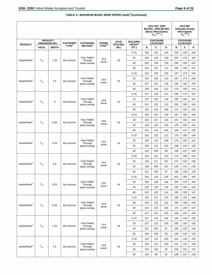
TABLE 4—MAXIMUM BASIC WIND SPEED (mph)3 (Continued)
2012 IRC, 2009 IBC/IRC, 2006 IBC/IRC
(Basic Wind Speed, Vasd
3,9,12 )
2012 IBC (Ultimate Design
Wind Speed, Vult
10,11)
PRODUCT
PRODUCT DIMENSION (IN.) FASTENER
TYPE4 FASTENING METHOD2
FRAME TYPE1,8
STUD SPACING
(IN.)
BUILDING HEIGHT
(FT.)
EXPOSURE CATEGORY
EXPOSURE CATEGORY
THICK. WIDTH B C D B C D
HardiePlank® 5/16 7.25 6d common Face Nailed
Through plank overlap
2X4 wood
16
0-15 156 142 129 202 183 166
20 156 138 126 202 178 162
40 150 128 118 193 165 153
60 142 123 114 183 159 147
HardiePlank® 5/16 7.5 6d common Face Nailed
Through plank overlap
2X4 wood
16
0-15 153 139 126 197 179 163
20 153 135 123 197 174 159
40 147 125 116 190 162 150
60 139 120 112 179 155 144
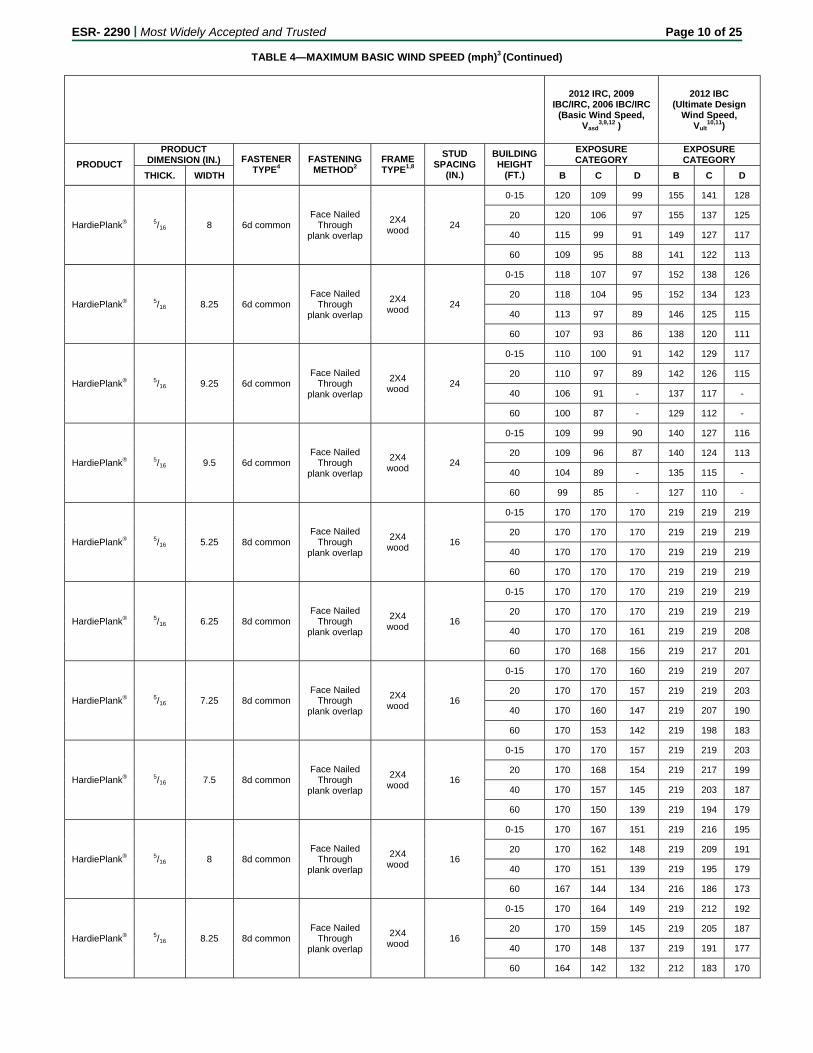
HardiePlank® 5/16 8 6d common Face Nailed
Through plank overlap
2X4 wood
16
0-15 147 134 121 190 172 157
20 147 130 118 190 168 153
40 141 121 111 182 156 144
60 134 116 108 172 150 139
HardiePlank® 5/16 8.25 6d common Face Nailed
Through plank overlap
2X4 wood
16
0-15 145 131 119 187 169 154
20 145 127 116 187 165 150
40 139 119 110 179 153 141
60 131 114 106 169 147 136
HardiePlank® 5/16 9.25 6d common Face Nailed
Through plank overlap
2X4 wood
16
0-15 135 123 111 175 158 144
20 135 119 109 175 154 141
40 130 111 102 168 143 132
60 123 106 99 158 137 128
HardiePlank® 5/16 9.5 6d common Face Nailed
Through plank overlap
2X4 wood
16
0-15 133 121 110 172 156 142
20 133 117 107 172 152 138
40 128 109 101 165 141 130
60 121 105 97 156 135 126
HardiePlank® 5/16 5.25 6d common Face Nailed
Through plank overlap
2X4 wood
24
0-15 156 142 129 201 183 166
20 156 138 126 201 178 162
40 150 128 118 193 165 153
60 142 123 114 183 159 147
HardiePlank® 5/16 6.25 6d common Face Nailed
Through plank overlap
2X4 wood
24
0-15 140 127 115 180 164 149
20 140 123 112 180 159 145
40 134 115 106 173 148 137
60 127 110 102 164 142 132
HardiePlank® 5/16 7.25 6d common Face Nailed
Through plank overlap
2X4 wood
24
0-15 127 116 105 165 149 136
20 127 112 103 165 145 132
40 122 105 97 158 135 125
60 116 100 93 149 130 120
HardiePlank® 5/16 7.5 6d common Face Nailed
Through plank overlap
2X4 wood
24
0-15 125 113 103 161 146 133
20 125 110 100 161 142 130
40 120 102 95 155 132 122
60 113 98 91 146 127 118
ESR- 2290 | Most Widely Accepted and Trusted Page 10 of 25
TABLE 4—MAXIMUM BASIC WIND SPEED (mph)3 (Continued)
2012 IRC, 2009 IBC/IRC, 2006 IBC/IRC
(Basic Wind Speed, Vasd
3,9,12 )
2012 IBC (Ultimate Design
Wind Speed, Vult
10,11)
PRODUCT
PRODUCT DIMENSION (IN.) FASTENER
TYPE4 FASTENING METHOD2
FRAME TYPE1,8
STUD SPACING
(IN.)
BUILDING HEIGHT
(FT.)
EXPOSURE CATEGORY
EXPOSURE CATEGORY
THICK. WIDTH B C D B C D
HardiePlank® 5/16 8 6d common Face Nailed
Through plank overlap
2X4 wood
24
0-15 120 109 99 155 141 128
20 120 106 97 155 137 125
40 115 99 91 149 127 117
60 109 95 88 141 122 113
HardiePlank® 5/16 8.25 6d common Face Nailed
Through plank overlap
2X4 wood
24
0-15 118 107 97 152 138 126
20 118 104 95 152 134 123
40 113 97 89 146 125 115
60 107 93 86 138 120 111
HardiePlank® 5/16 9.25 6d common Face Nailed
Through plank overlap
2X4 wood
24
0-15 110 100 91 142 129 117
20 110 97 89 142 126 115
40 106 91 - 137 117 -
60 100 87 - 129 112 -
HardiePlank® 5/16 9.5 6d common Face Nailed
Through plank overlap
2X4 wood
24
0-15 109 99 90 140 127 116
20 109 96 87 140 124 113
40 104 89 - 135 115 -
60 99 85 - 127 110 -
HardiePlank® 5/16 5.25 8d common Face Nailed
Through plank overlap
2X4 wood
16
0-15 170 170 170 219 219 219
20 170 170 170 219 219 219
40 170 170 170 219 219 219
60 170 170 170 219 219 219
HardiePlank® 5/16 6.25 8d common Face Nailed
Through plank overlap
2X4 wood
16
0-15 170 170 170 219 219 219
20 170 170 170 219 219 219
40 170 170 161 219 219 208
60 170 168 156 219 217 201
HardiePlank® 5/16 7.25 8d common Face Nailed
Through plank overlap
2X4 wood
16
0-15 170 170 160 219 219 207
20 170 170 157 219 219 203
40 170 160 147 219 207 190
60 170 153 142 219 198 183
HardiePlank® 5/16 7.5 8d common Face Nailed
Through plank overlap
2X4 wood
16
0-15 170 170 157 219 219 203
20 170 168 154 219 217 199
40 170 157 145 219 203 187
60 170 150 139 219 194 179
HardiePlank® 5/16 8 8d common Face Nailed
Through plank overlap
2X4 wood
16
0-15 170 167 151 219 216 195
20 170 162 148 219 209 191
40 170 151 139 219 195 179
60 167 144 134 216 186 173
HardiePlank® 5/16 8.25 8d common Face Nailed
Through plank overlap
2X4 wood
16
0-15 170 164 149 219 212 192
20 170 159 145 219 205 187
40 170 148 137 219 191 177
60 164 142 132 212 183 170
ESR- 2290 | Most Widely Accepted and Trusted Page 11 of 25
TABLE 4—MAXIMUM BASIC WIND SPEED (mph)3 (Continued)
2012 IRC, 2009 IBC/IRC, 2006 IBC/IRC
(Basic Wind Speed, Vasd
3,9,12 )
2012 IBC (Ultimate Design
Wind Speed, Vult
10,11)
PRODUCT
PRODUCT DIMENSION (IN.) FASTENER
TYPE4 FASTENING METHOD2
FRAME TYPE1,8
STUD SPACING
(IN.)
BUILDING HEIGHT
(FT.)
EXPOSURE CATEGORY
EXPOSURE CATEGORY
THICK. WIDTH B C D B C D
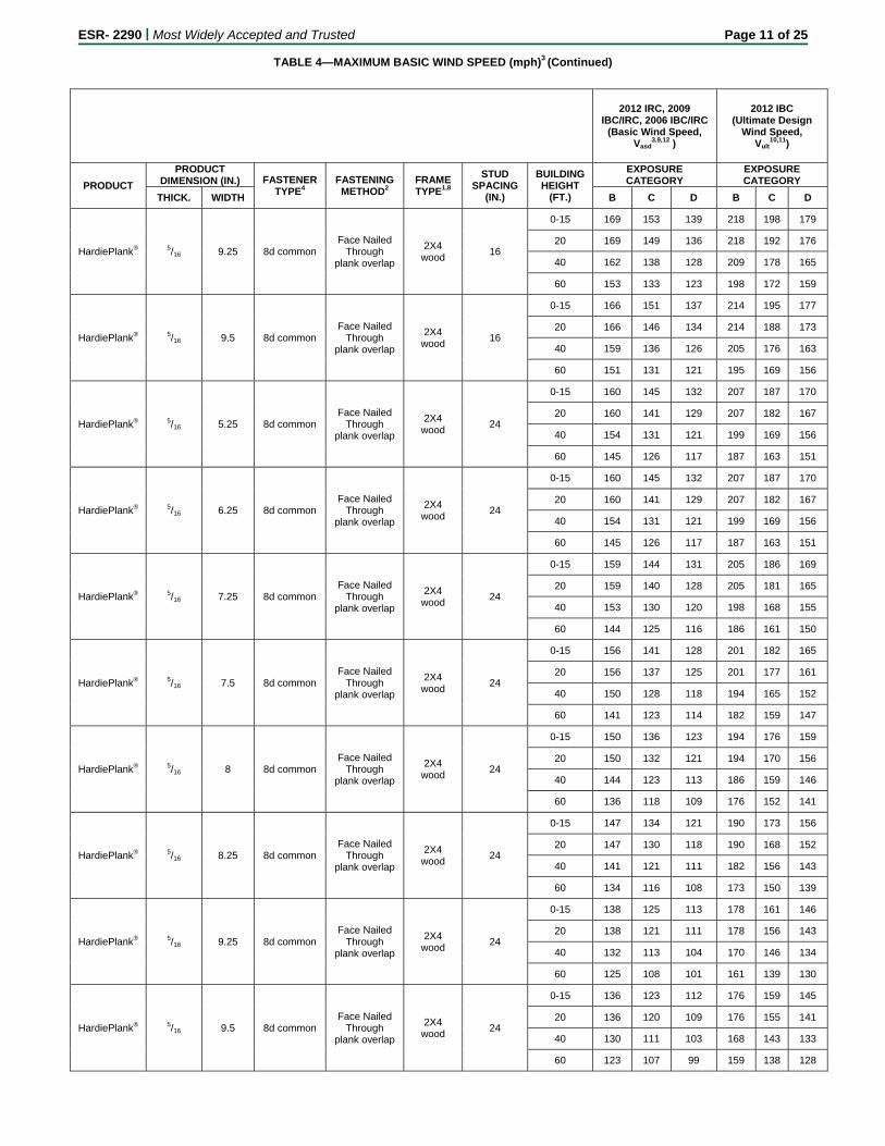
HardiePlank® 5/16 9.25 8d common Face Nailed
Through plank overlap
2X4 wood
16
0-15 169 153 139 218 198 179
20 169 149 136 218 192 176
40 162 138 128 209 178 165
60 153 133 123 198 172 159
HardiePlank® 5/16 9.5 8d common Face Nailed
Through plank overlap
2X4 wood
16
0-15 166 151 137 214 195 177
20 166 146 134 214 188 173
40 159 136 126 205 176 163
60 151 131 121 195 169 156
HardiePlank® 5/16 5.25 8d common Face Nailed
Through plank overlap
2X4 wood
24
0-15 160 145 132 207 187 170
20 160 141 129 207 182 167
40 154 131 121 199 169 156
60 145 126 117 187 163 151
HardiePlank® 5/16 6.25 8d common Face Nailed
Through plank overlap
2X4 wood
24
0-15 160 145 132 207 187 170
20 160 141 129 207 182 167
40 154 131 121 199 169 156
60 145 126 117 187 163 151
HardiePlank® 5/16 7.25 8d common Face Nailed
Through plank overlap
2X4 wood
24
0-15 159 144 131 205 186 169
20 159 140 128 205 181 165
40 153 130 120 198 168 155
60 144 125 116 186 161 150
HardiePlank® 5/16 7.5 8d common Face Nailed
Through plank overlap
2X4 wood
24
0-15 156 141 128 201 182 165
20 156 137 125 201 177 161
40 150 128 118 194 165 152
60 141 123 114 182 159 147
HardiePlank® 5/16 8 8d common Face Nailed
Through plank overlap
2X4 wood
24
0-15 150 136 123 194 176 159
20 150 132 121 194 170 156
40 144 123 113 186 159 146
60 136 118 109 176 152 141
HardiePlank® 5/16 8.25 8d common Face Nailed
Through plank overlap
2X4 wood
24
0-15 147 134 121 190 173 156
20 147 130 118 190 168 152
40 141 121 111 182 156 143
60 134 116 108 173 150 139
HardiePlank® 5/16 9.25 8d common Face Nailed
Through plank overlap
2X4 wood
24
0-15 138 125 113 178 161 146
20 138 121 111 178 156 143
40 132 113 104 170 146 134
60 125 108 101 161 139 130
HardiePlank® 5/16 9.5 8d common Face Nailed
Through plank overlap
2X4 wood
24
0-15 136 123 112 176 159 145
20 136 120 109 176 155 141
40 130 111 103 168 143 133
60 123 107 99 159 138 128
ESR- 2290 | Most Widely Accepted and Trusted Page 12 of 25
TABLE 4—MAXIMUM BASIC WIND SPEED (mph)3 (Continued)
2012 IRC, 2009 IBC/IRC, 2006 IBC/IRC
(Basic Wind Speed, Vasd
3,9,12 )
2012 IBC (Ultimate Design
Wind Speed, Vult
10,11)
PRODUCT
PRODUCT DIMENSION (IN.) FASTENER
TYPE4 FASTENING METHOD2
FRAME TYPE1,8
STUD SPACING
(IN.)
BUILDING HEIGHT
(FT.)
EXPOSURE CATEGORY
EXPOSURE CATEGORY
THICK. WIDTH B C D B C D
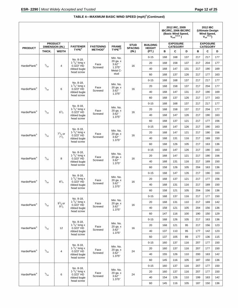
HardiePlank® 5/16 4
No. 8-18, 1-5/8" long x 0.323" HD
ribbed bugle head screw
Face Screwed
Min. No. 20 ga. x 3.62" ´ 1.375"
Metal C-stud
16
0-15 168 168 137 217 217 177
20 168 158 137 217 204 177
40 168 147 131 217 190 169
60 168 137 126 217 177 163
HardiePlank® 5/16 6
No. 8-18, 1-5/8" long x 0.323" HD
ribbed bugle head screw
Face Screwed
Min. No. 20 ga. x 3.62" ´ 1.375"
16
0-15 168 168 137 217 217 177
20 168 158 137 217 204 177
40 168 147 131 217 190 169
60 168 137 126 217 177 163
HardiePlank® 5/16 61/4
No. 8-18, 1-5/8" long x 0.323" HD
ribbed bugle head screw
Face Screwed
Min. No. 20 ga. x 3.62" ´ 1.375"
16
0-15 168 168 137 217 217 177
20 168 158 137 217 204 177
40 168 147 126 217 190 163
60 168 137 121 217 177 156
HardiePlank® 5/16 71/4 or
71/2
No. 8-18, 1-5/8" long x 0.323" HD
ribbed bugle head screw
Face Screwed
Min. No. 20 ga. x 3.62" ´ 1.375"
16
0-15 168 147 126 217 190 163
20 168 147 121 217 190 156
40 168 131 116 217 169 150
60 168 126 105 217 163 136
HardiePlank® 5/16 8
No. 8-18, 1-5/8" long x 0.323" HD
ribbed bugle head screw
Face Screwed
Min. No. 20 ga. x 3.62" ´ 1.375"
16
0-15 168 147 126 217 190 163
20 168 147 121 217 190 156
40 168 131 116 217 169 150
60 158 126 105 204 163 136
HardiePlank® 5/16 81/4
No. 8-18, 1-5/8" long x 0.323" HD
ribbed bugle head screw
Face Screwed
Min. No. 20 ga. x 3.62" ´ 1.375"
16
0-15 168 147 126 217 190 163
20 168 137 121 217 177 156
40 168 131 116 217 169 150
60 158 121 105 204 156 136
HardiePlank® 5/16 91/4 or 91/2
No. 8-18, 1-5/8" long x 0.323" HD
ribbed bugle head screw
Face Screwed
Min. No. 20 ga. x 3.62" ´ 1.375"
16
0-15 168 137 116 217 177 150
20 168 131 110 217 169 142
40 158 121 105 204 156 136
60 147 116 100 190 150 129
HardiePlank® 5/16 12
No. 8-18, 1-5/8" long x 0.323" HD
ribbed bugle head screw
Face Screwed
Min. No. 20 ga. x 3.62" ´ 1.375"
16
0-15 168 126 105 217 163 136
20 168 121 95 217 156 123
40 137 110 95 177 142 123
60 137 105 89 177 136 115
HardiePlank® 5/16 4
No. 8-18, 1-5/8" long x 0.323" HD
ribbed bugle head screw
Face Screwed
Min. No. 20 ga. x 3.62" ´ 1.375"
24
0-15 160 137 116 207 177 150
20 160 137 116 207 177 150
40 155 126 110 200 163 142
60 145 116 105 187 150 136
HardiePlank® 5/16 6
No. 8-18, 1-5/8" long x 0.323" HD
ribbed bugle head screw
Face Screwed
Min. No. 20 ga. x 3.62" ´ 1.375"
24
0-15 160 137 116 207 177 150
20 160 137 116 207 177 150
40 154 126 110 199 163 142
60 145 116 105 187 150 136
ESR- 2290 | Most Widely Accepted and Trusted Page 13 of 25
TABLE 4—MAXIMUM BASIC WIND SPEED (mph)3 (Continued)
2012 IRC, 2009 IBC/IRC, 2006 IBC/IRC
(Basic Wind Speed, Vasd
3,9,12 )
2012 IBC (Ultimate Design
Wind Speed, Vult
10,11)
PRODUCT
PRODUCT DIMENSION (IN.) FASTENER
TYPE4 FASTENING METHOD2
FRAME TYPE1,8
STUD SPACING
(IN.)
BUILDING HEIGHT
(FT.)
EXPOSURE CATEGORY
EXPOSURE CATEGORY
THICK. WIDTH B C D B C D
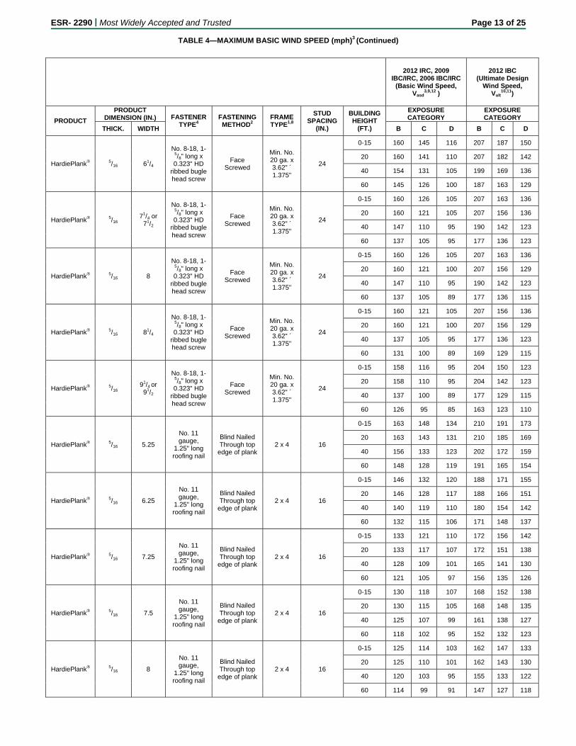
HardiePlank® 5/16 61/4
No. 8-18, 1-5/8" long x 0.323" HD
ribbed bugle head screw
Face Screwed
Min. No. 20 ga. x 3.62" ´ 1.375"
24
0-15 160 145 116 207 187 150
20 160 141 110 207 182 142
40 154 131 105 199 169 136
60 145 126 100 187 163 129
HardiePlank® 5/16 71/4 or
71/2
No. 8-18, 1-5/8" long x 0.323" HD
ribbed bugle head screw
Face Screwed
Min. No. 20 ga. x 3.62" ´ 1.375"
24
0-15 160 126 105 207 163 136
20 160 121 105 207 156 136
40 147 110 95 190 142 123
60 137 105 95 177 136 123
HardiePlank® 5/16 8
No. 8-18, 1-5/8" long x 0.323" HD
ribbed bugle head screw
Face Screwed
Min. No. 20 ga. x 3.62" ´ 1.375"
24
0-15 160 126 105 207 163 136
20 160 121 100 207 156 129
40 147 110 95 190 142 123
60 137 105 89 177 136 115
HardiePlank® 5/16 81/4
No. 8-18, 1-5/8" long x 0.323" HD
ribbed bugle head screw
Face Screwed
Min. No. 20 ga. x 3.62" ´ 1.375"
24
0-15 160 121 105 207 156 136
20 160 121 100 207 156 129
40 137 105 95 177 136 123
60 131 100 89 169 129 115
HardiePlank® 5/16 91/4 or 91/2
No. 8-18, 1-5/8" long x 0.323" HD
ribbed bugle head screw
Face Screwed
Min. No. 20 ga. x 3.62" ´ 1.375"
24
0-15 158 116 95 204 150 123
20 158 110 95 204 142 123
40 137 100 89 177 129 115
60 126 95 85 163 123 110
HardiePlank® 5/16 5.25
No. 11 gauge,
1.25" long roofing nail
Blind Nailed Through top
edge of plank 2 x 4 16
0-15 163 148 134 210 191 173
20 163 143 131 210 185 169
40 156 133 123 202 172 159
60 148 128 119 191 165 154
HardiePlank® 5/16 6.25
No. 11 gauge,
1.25" long roofing nail
Blind Nailed Through top
edge of plank 2 x 4 16
0-15 146 132 120 188 171 155
20 146 128 117 188 166 151
40 140 119 110 180 154 142
60 132 115 106 171 148 137
HardiePlank® 5/16 7.25
No. 11 gauge,
1.25" long roofing nail
Blind Nailed Through top
edge of plank 2 x 4 16
0-15 133 121 110 172 156 142
20 133 117 107 172 151 138
40 128 109 101 165 141 130
60 121 105 97 156 135 126
HardiePlank® 5/16 7.5
No. 11 gauge,
1.25" long roofing nail
Blind Nailed Through top
edge of plank 2 x 4 16
0-15 130 118 107 168 152 138
20 130 115 105 168 148 135
40 125 107 99 161 138 127
60 118 102 95 152 132 123
HardiePlank® 5/16 8
No. 11 gauge,
1.25" long roofing nail
Blind Nailed Through top
edge of plank 2 x 4 16
0-15 125 114 103 162 147 133
20 125 110 101 162 143 130
40 120 103 95 155 133 122
60 114 99 91 147 127 118
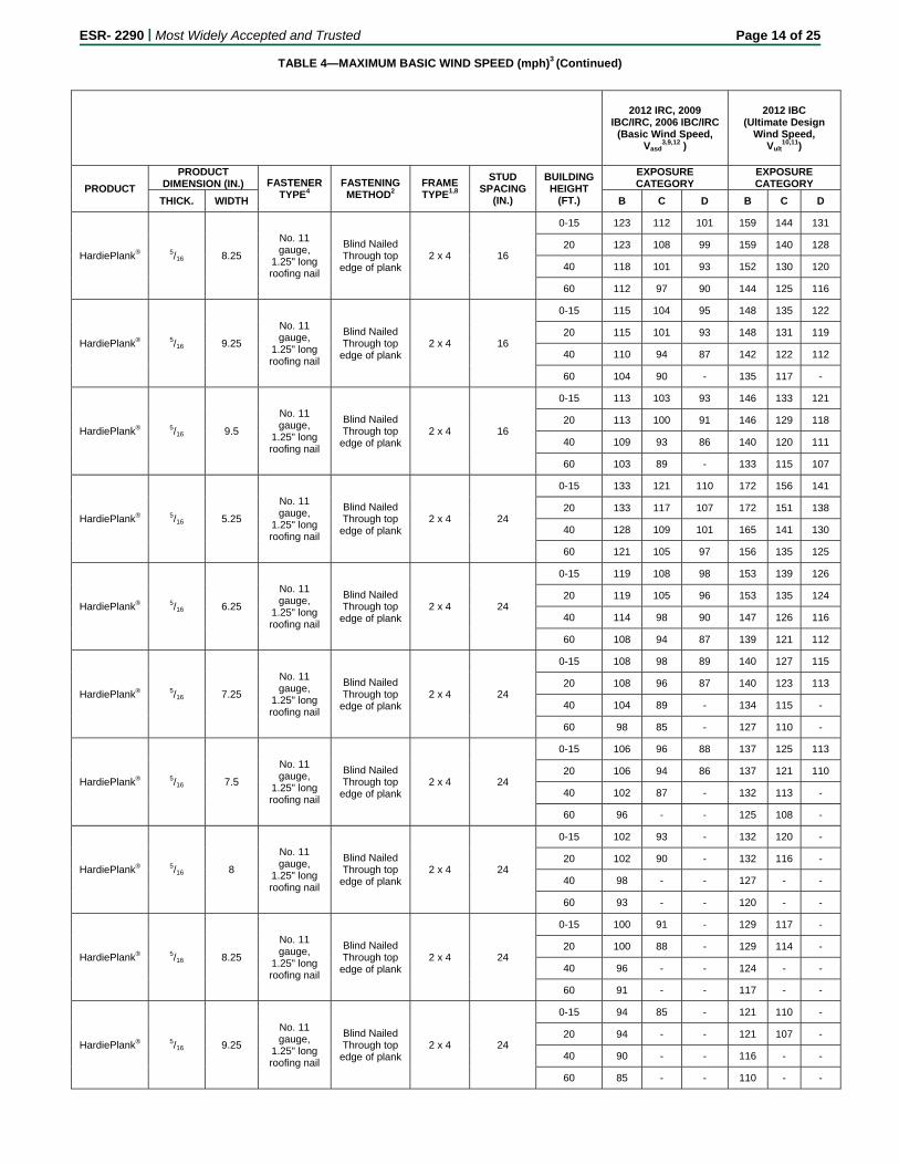
ESR- 2290 | Most Widely Accepted and Trusted Page 14 of 25
TABLE 4—MAXIMUM BASIC WIND SPEED (mph)3 (Continued)
2012 IRC, 2009 IBC/IRC, 2006 IBC/IRC
(Basic Wind Speed, Vasd
3,9,12 )
2012 IBC (Ultimate Design
Wind Speed, Vult
10,11)
PRODUCT
PRODUCT DIMENSION (IN.) FASTENER
TYPE4 FASTENING METHOD2
FRAME TYPE1,8
STUD SPACING
(IN.)
BUILDING HEIGHT
(FT.)
EXPOSURE CATEGORY
EXPOSURE CATEGORY
THICK. WIDTH B C D B C D
HardiePlank® 5/16 8.25
No. 11 gauge,
1.25" long roofing nail
Blind Nailed Through top
edge of plank 2 x 4 16
0-15 123 112 101 159 144 131
20 123 108 99 159 140 128
40 118 101 93 152 130 120
60 112 97 90 144 125 116
HardiePlank® 5/16 9.25
No. 11 gauge,
1.25" long roofing nail
Blind Nailed Through top
edge of plank 2 x 4 16
0-15 115 104 95 148 135 122
20 115 101 93 148 131 119
40 110 94 87 142 122 112
60 104 90 - 135 117 -
HardiePlank® 5/16 9.5
No. 11 gauge,
1.25" long roofing nail
Blind Nailed Through top
edge of plank 2 x 4 16
0-15 113 103 93 146 133 121
20 113 100 91 146 129 118
40 109 93 86 140 120 111
60 103 89 - 133 115 107
HardiePlank® 5/16 5.25
No. 11 gauge,
1.25" long roofing nail
Blind Nailed Through top
edge of plank 2 x 4 24
0-15 133 121 110 172 156 141
20 133 117 107 172 151 138
40 128 109 101 165 141 130
60 121 105 97 156 135 125
HardiePlank® 5/16 6.25
No. 11 gauge,
1.25" long roofing nail
Blind Nailed Through top
edge of plank 2 x 4 24
0-15 119 108 98 153 139 126
20 119 105 96 153 135 124
40 114 98 90 147 126 116
60 108 94 87 139 121 112
HardiePlank® 5/16 7.25
No. 11 gauge,
1.25" long roofing nail
Blind Nailed Through top
edge of plank 2 x 4 24
0-15 108 98 89 140 127 115
20 108 96 87 140 123 113
40 104 89 - 134 115 -
60 98 85 - 127 110 -
HardiePlank® 5/16 7.5
No. 11 gauge,
1.25" long roofing nail
Blind Nailed Through top
edge of plank 2 x 4 24
0-15 106 96 88 137 125 113
20 106 94 86 137 121 110
40 102 87 - 132 113 -
60 96 - - 125 108 -
HardiePlank® 5/16 8
No. 11 gauge,
1.25" long roofing nail
Blind Nailed Through top
edge of plank 2 x 4 24
0-15 102 93 - 132 120 -
20 102 90 - 132 116 -
40 98 - - 127 - -
60 93 - - 120 - -
HardiePlank® 5/16 8.25
No. 11 gauge,
1.25" long roofing nail
Blind Nailed Through top
edge of plank 2 x 4 24
0-15 100 91 - 129 117 -
20 100 88 - 129 114 -
40 96 - - 124 - -
60 91 - - 117 - -
HardiePlank® 5/16 9.25
No. 11 gauge,
1.25" long roofing nail
Blind Nailed Through top
edge of plank 2 x 4 24
0-15 94 85 - 121 110 -
20 94 - - 121 107 -
40 90 - - 116 - -
60 85 - - 110 - -

ESR- 2290 | Most Widely Accepted and Trusted Page 15 of 25
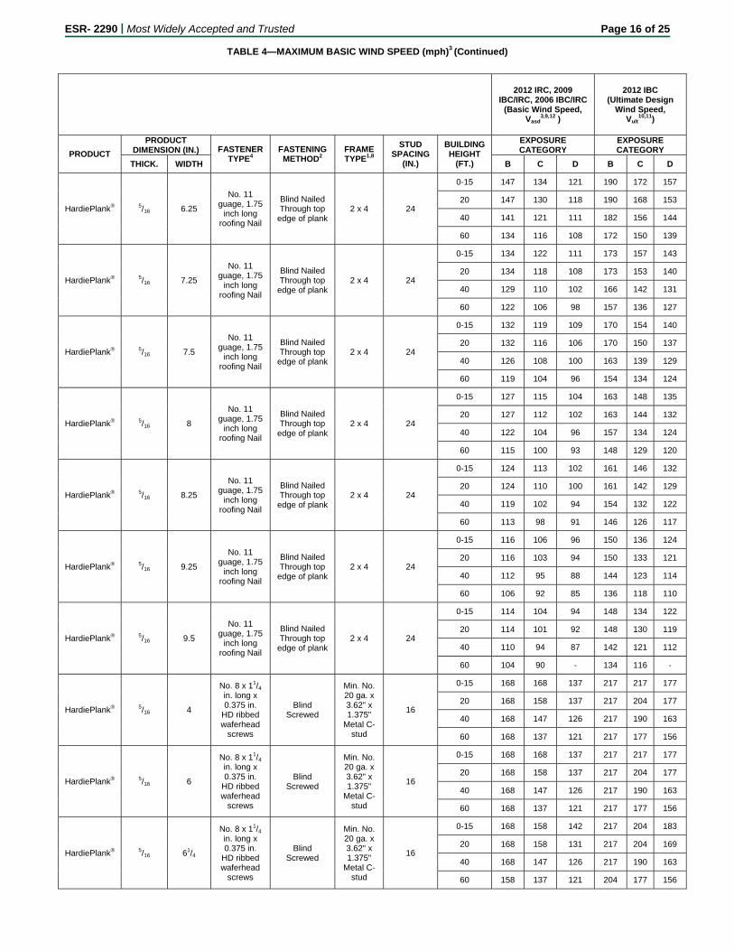
TABLE 4—MAXIMUM BASIC WIND SPEED (mph)3 (Continued)
2012 IRC, 2009 IBC/IRC, 2006 IBC/IRC
(Basic Wind Speed, Vasd
3,9,12 )
2012 IBC (Ultimate Design
Wind Speed, Vult
10,11)
PRODUCT
PRODUCT DIMENSION (IN.) FASTENER
TYPE4 FASTENING METHOD2
FRAME TYPE1,8
STUD SPACING
(IN.)
BUILDING HEIGHT
(FT.)
EXPOSURE CATEGORY
EXPOSURE CATEGORY
THICK. WIDTH B C D B C D
HardiePlank® 5/16 9.5
No. 11 gauge,
1.25" long roofing nail
Blind Nailed Through top
edge of plank 2 x 4 24
0-15 93 - - 119 - -
20 93 - - 119 - -
40 89 - - 115 - -
60 - - - - - -
HardiePlank® 5/16 5.25
No. 11 guage, 1.75
inch long roofing Nail
Blind Nailed Through top
edge of plank 2 x 4 16
0-15 170 170 166 219 219 214
20 170 170 162 219 219 209
40 170 165 153 219 213 197
60 170 158 147 219 205 190
HardiePlank® 5/16 6.25
No. 11 guage, 1.75
inch long roofing Nail
Blind Nailed Through top
edge of plank 2 x 4 16
0-15 170 164 149 219 211 192
20 170 159 145 219 205 187
40 170 148 137 219 191 176
60 164 142 132 211 183 170
HardiePlank® 5/16 7.25
No. 11 guage, 1.75
inch long roofing Nail
Blind Nailed Through top
edge of plank 2 x 4 16
0-15 164 149 136 212 193 175
20 164 145 132 212 187 171
40 158 135 125 204 174 161
60 149 129 120 193 167 155
HardiePlank® 5/16 7.5
No. 11 guage, 1.75
inch long roofing Nail
Blind Nailed Through top
edge of plank 2 x 4 16
0-15 161 146 133 208 189 172
20 161 142 130 208 183 167
40 155 132 122 200 171 158
60 146 127 118 189 164 152
HardiePlank® 5/16 8
No. 11 guage, 1.75
inch long roofing Nail
Blind Nailed Through top
edge of plank 2 x 4 16
0-15 155 141 128 200 182 165
20 155 137 125 200 176 161
40 149 127 117 192 164 152
60 141 122 113 182 157 146
HardiePlank® 5/16 8.25
No. 11 guage, 1.75
inch long roofing Nail
Blind Nailed Through top
edge of plank 2 x 4 16
0-15 152 138 126 197 178 162
20 152 134 123 197 173 158
40 146 125 115 189 161 149
60 138 120 111 178 155 144
HardiePlank® 5/16 9.25
No. 11 guage, 1.75
inch long roofing Nail
Blind Nailed Through top
edge of plank 2 x 4 16
0-15 142 129 117 184 167 152
20 142 126 115 184 162 148
40 137 117 108 176 151 139
60 129 112 104 167 145 134
HardiePlank® 5/16 9.5
No. 11 guage, 1.75
inch long roofing Nail
Blind Nailed Through top
edge of plank 2 x 4 16
0-15 140 127 116 181 164 149
20 140 124 113 181 160 146
40 135 115 106 174 148 137
60 127 110 102 164 142 132
HardiePlank® 5/16 5.25
No. 11 guage, 1.75
inch long roofing Nail
Blind Nailed Through top
edge of plank 2 x 4 24
0-15 164 149 136 212 193 175
20 164 145 132 212 187 171
40 158 135 125 204 147 161
60 149 129 120 193 167 155
ESR- 2290 | Most Widely Accepted and Trusted Page 16 of 25
TABLE 4—MAXIMUM BASIC WIND SPEED (mph)3 (Continued)
2012 IRC, 2009 IBC/IRC, 2006 IBC/IRC
(Basic Wind Speed, Vasd
3,9,12 )
2012 IBC (Ultimate Design
Wind Speed, Vult
10,11)
PRODUCT
PRODUCT DIMENSION (IN.) FASTENER
TYPE4 FASTENING METHOD2
FRAME TYPE1,8
STUD SPACING
(IN.)
BUILDING HEIGHT
(FT.)
EXPOSURE CATEGORY
EXPOSURE CATEGORY
THICK. WIDTH B C D B C D
HardiePlank® 5/16 6.25
No. 11 guage, 1.75
inch long roofing Nail
Blind Nailed Through top
edge of plank 2 x 4 24
0-15 147 134 121 190 172 157
20 147 130 118 190 168 153
40 141 121 111 182 156 144
60 134 116 108 172 150 139
HardiePlank® 5/16 7.25
No. 11 guage, 1.75
inch long roofing Nail
Blind Nailed Through top
edge of plank 2 x 4 24
0-15 134 122 111 173 157 143
20 134 118 108 173 153 140
40 129 110 102 166 142 131
60 122 106 98 157 136 127
HardiePlank® 5/16 7.5
No. 11 guage, 1.75
inch long roofing Nail
Blind Nailed Through top
edge of plank 2 x 4 24
0-15 132 119 109 170 154 140
20 132 116 106 170 150 137
40 126 108 100 163 139 129
60 119 104 96 154 134 124
HardiePlank® 5/16 8
No. 11 guage, 1.75
inch long roofing Nail
Blind Nailed Through top
edge of plank 2 x 4 24
0-15 127 115 104 163 148 135
20 127 112 102 163 144 132
40 122 104 96 157 134 124
60 115 100 93 148 129 120
HardiePlank® 5/16 8.25
No. 11 guage, 1.75
inch long roofing Nail
Blind Nailed Through top
edge of plank 2 x 4 24
0-15 124 113 102 161 146 132
20 124 110 100 161 142 129
40 119 102 94 154 132 122
60 113 98 91 146 126 117
HardiePlank® 5/16 9.25
No. 11 guage, 1.75
inch long roofing Nail
Blind Nailed Through top
edge of plank 2 x 4 24
0-15 116 106 96 150 136 124
20 116 103 94 150 133 121
40 112 95 88 144 123 114
60 106 92 85 136 118 110
HardiePlank® 5/16 9.5
No. 11 guage, 1.75
inch long roofing Nail
Blind Nailed Through top
edge of plank 2 x 4 24
0-15 114 104 94 148 134 122
20 114 101 92 148 130 119
40 110 94 87 142 121 112
60 104 90 - 134 116 -
HardiePlank® 5/16 4
No. 8 x 11/4 in. long x 0.375 in.
HD ribbed waferhead
screws
Blind Screwed
Min. No. 20 ga. x 3.62" x 1.375"
Metal C-stud
16
0-15 168 168 137 217 217 177
20 168 158 137 217 204 177
40 168 147 126 217 190 163
60 168 137 121 217 177 156
HardiePlank® 5/16 6
No. 8 x 11/4 in. long x 0.375 in.
HD ribbed waferhead
screws
Blind Screwed
Min. No. 20 ga. x 3.62" x 1.375"
Metal C-stud
16
0-15 168 168 137 217 217 177
20 168 158 137 217 204 177
40 168 147 126 217 190 163
60 168 137 121 217 177 156
HardiePlank® 5/16 61/4
No. 8 x 11/4 in. long x 0.375 in.
HD ribbed waferhead
screws
Blind Screwed
Min. No. 20 ga. x 3.62" x 1.375"
Metal C-stud
16
0-15 168 158 142 217 204 183
20 168 158 131 217 204 169
40 168 147 126 217 190 163
60 158 137 121 204 177 156
ESR- 2290 | Most Widely Accepted and Trusted Page 17 of 25
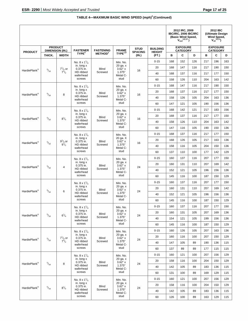
TABLE 4—MAXIMUM BASIC WIND SPEED (mph)3 (Continued)
2012 IRC, 2009 IBC/IRC, 2006 IBC/IRC
(Basic Wind Speed, Vasd
3,9,12 )
2012 IBC (Ultimate Design
Wind Speed, Vult
10,11)
PRODUCT
PRODUCT DIMENSION (IN.) FASTENER
TYPE4 FASTENING METHOD2
FRAME TYPE1,8
STUD SPACING
(IN.)
BUILDING HEIGHT
(FT.)
EXPOSURE CATEGORY
EXPOSURE CATEGORY
THICK. WIDTH B C D B C D
HardiePlank® 5/16 71/4 or
71/2
No. 8 x 11/4 in. long x 0.375 in.
HD ribbed waferhead
screws
Blind Screwed
Min. No. 20 ga. x 3.62" x 1.375"
Metal C-stud
16
0-15 168 152 126 217 196 163
20 168 147 116 217 190 150
40 168 137 116 217 177 150
60 158 126 110 204 163 142
HardiePlank® 5/16 8
No. 8 x 11/4 in. long x 0.375 in.
HD ribbed waferhead
screws
Blind Screwed
Min. No. 20 ga. x 3.62" x 1.375"
Metal C-stud
16
0-15 168 147 116 217 190 150
20 168 137 116 217 177 150
40 158 126 105 204 163 136
60 147 121 105 190 156 136
HardiePlank® 5/16 81/4
No. 8 x 11/4 in. long x 0.375 in.
HD ribbed waferhead
screws
Blind Screwed
Min. No. 20 ga. x 3.62" x 1.375"
Metal C-stud
16
0-15 168 142 121 217 183 156
20 168 137 116 217 177 150
40 158 126 110 204 163 142
60 147 116 105 190 150 136
HardiePlank® 5/16 91/4 or 91/2
No. 8 x 11/4 in. long x 0.375 in.
HD ribbed waferhead
screws
Blind Screwed
Min. No. 20 ga. X 3.62" x 1.375"
Metal C-stud
16
0-15 168 137 116 217 177 150
20 168 126 105 217 163 136
40 158 116 105 204 150 136
60 137 110 100 177 142 129
HardiePlank® 5/16 4
No. 8 x 11/4 in. long x 0.375 in.
HD ribbed waferhead
screws
Blind Screwed
Min. No. 20 ga. x 3.62" x 1.375"
Metal C-stud
24
0-15 160 137 116 207 177 150
20 160 131 110 207 169 142
40 152 121 105 196 156 136
60 145 116 100 187 150 129
HardiePlank® 5/16 6
No. 8 x 11/4 in. long x 0.375 in.
HD ribbed waferhead
screws
Blind Screwed
Min. No. 20 ga. x 3.62" x 1.375"
Metal C-stud
24
0-15 160 137 116 207 177 150
20 160 131 110 207 169 142
40 152 121 105 196 156 136
60 145 116 100 187 150 129
HardiePlank® 5/16 61/4
No. 8 x 11/4 in. long x 0.375 in.
HD ribbed waferhead
screws
Blind Screwed
Min. No. 20 ga. x 3.62" x 1.375"
Metal C-stud
24
0-15 160 137 116 207 177 150
20 160 131 105 207 169 136
40 154 121 105 199 156 136
60 145 116 100 187 150 129
HardiePlank® 5/16 71/4 or
71/2
No. 8 x 11/4 in. long x 0.375 in.
HD ribbed waferhead
screws
Blind Screwed
Min. No. 20 ga. x 3.62" x 1.375"
Metal C-stud
24
0-15 160 126 105 207 163 136
20 160 116 100 207 150 129
40 147 105 89 190 136 115
60 137 89 89 177 115 115
HardiePlank® 5/16 8
No. 8 x 11/4 in. long x 0.375 in.
HD ribbed waferhead
screws
Blind Screwed
Min. No. 20 ga. x 3.62" x 1.375"
Metal C-stud
24
0-15 160 121 100 207 156 129
20 158 116 100 204 150 129
40 142 105 89 183 136 115
60 131 100 89 169 129 115
HardiePlank® 5/16 81/4
No. 8 x 11/4 in. long x 0.375 in.
HD ribbed waferhead
screws
Blind Screwed
Min. No. 20 ga. x 3.62" x 1.375"
Metal C-stud
24
0-15 160 121 100 207 156 129
20 158 116 100 204 150 129
40 142 105 89 183 136 115
60 126 100 89 163 129 115
ESR- 2290 | Most Widely Accepted and Trusted Page 18 of 25
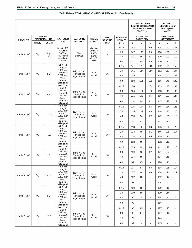
TABLE 4—MAXIMUM BASIC WIND SPEED (mph)3 (Continued)
2012 IRC, 2009 IBC/IRC, 2006 IBC/IRC
(Basic Wind Speed, Vasd
3,9,12 )
2012 IBC (Ultimate Design
Wind Speed, Vult
10,11)
PRODUCT
PRODUCT DIMENSION (IN.) FASTENER
TYPE4 FASTENING METHOD2
FRAME TYPE1,8
STUD SPACING
(IN.)
BUILDING HEIGHT
(FT.)
EXPOSURE CATEGORY
EXPOSURE CATEGORY
THICK. WIDTH B C D B C D
HardiePlank® 5/16 91/4 or 91/2
No. 8 x 11/4 in. long x 0.375 in.
HD ribbed waferhead
screws
Blind Screwed
Min. No. 20 ga. x 3.62" x 1.375"
Metal C-stud
24
0-15 158 116 95 204 150 123
20 147 105 89 190 136 115
40 131 95 85 169 123 110
60 121 89 85 156 115 110
HardiePlank® 5/16 5.25
6d-2 inch long X
0.093 inch shank X
0.222 inch head
diameter siding nail
Blind Nailed Through top
edge of plank
2 x 4 wood
16
0-15 141 128 116 182 165 150
20 141 124 114 182 160 147
40 135 116 107 174 150 138
60 128 111 103 165 143 133
HardiePlank® 5/16 6.25
6d-2 inch long X
0.093 inch shank X
0.222 inch head
diameter siding nail
Blind Nailed Through top
edge of plank
2 x 4 wood
16
0-15 126 114 104 163 147 134
20 126 111 102 163 143 132
40 121 103 96 156 133 124
60 114 99 92 147 128 119
HardiePlank® 5/16 7.25
6d-2 inch long X
0.093 inch shank X
0.222 inch head
diameter siding nail
Blind Nailed Through top
edge of plank
2 x 4 wood
16
0-15 115 104 95 148 134 123
20 115 102 93 148 132 120
40 110 94 87 142 121 112
60 104 91 - 134 117 -
HardiePlank® 5/16 7.5
6d-2 inch long X
0.093 inch shank X
0.222 inch head
diameter siding nail
Blind Nailed Through top
edge of plank
2 x 4 wood
16
0-15 113 102 93 146 132 120
20 113 99 91 146 128 117
40 108 93 85 139 120 110
60 102 89 - 132 115 -
HardiePlank® 5/16 8
6d-2 inch long X
0.093 inch shank X
0.222 inch head
diameter siding nail
Blind Nailed Through top
edge of plank
2 x 4 wood
16
0-15 109 99 90 141 128 116
20 109 96 87 141 124 112
40 104 89 - 134 115 -
60 99 85 - 128 110 -
HardiePlank® 5/16 8.25
6d-2 inch long X
0.093 inch shank X
0.222 inch head
diameter siding nail
Blind Nailed Through top
edge of plank
2 x 4 wood
16
0-15 107 97 88 138 125 114
20 107 94 86 138 121 111
40 102 88 - 132 114 -
60 97 - - 125 - -
HardiePlank® 5/16 9.25
6d-2 inch long X
0.093 inch shank X
0.222 inch head
diameter siding nail
Blind Nailed Through top
edge of plank
2 x 4 wood
16
0-15 100 90 - 129 116 -
20 100 88 - 129 114 -
40 96 - - 124 - -
60 90 - - 116 - -
HardiePlank® 5/16 9.5
6d-2 inch long X
0.093 inch shank X
0.222 inch head
diameter siding nail
Blind Nailed Through top
edge of plank
2 x 4 wood
16
0-15 98 89 - 127 115 -
20 98 87 - 127 112 -
40 94 - - 121 - -
60 89 - - 115 - -
ESR- 2290 | Most Widely Accepted and Trusted Page 19 of 25
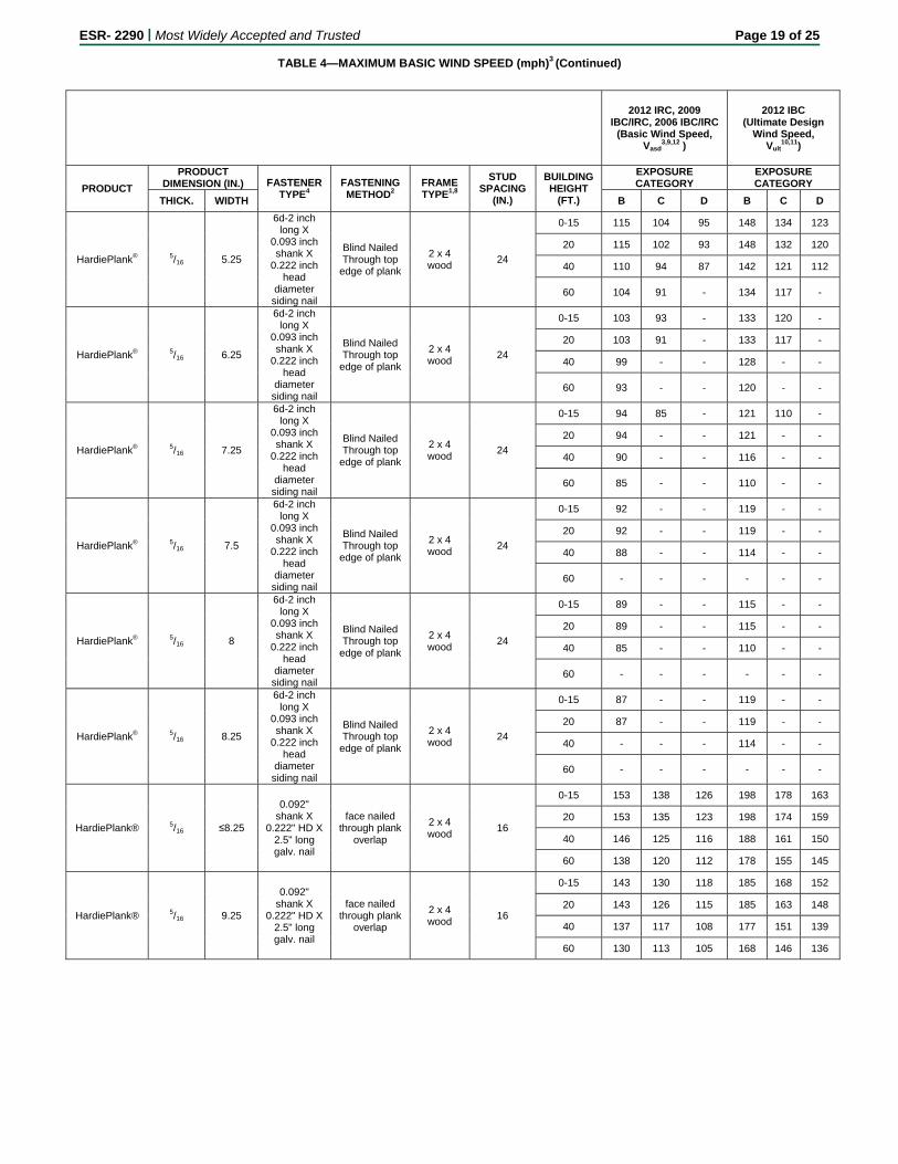
TABLE 4—MAXIMUM BASIC WIND SPEED (mph)3 (Continued)
2012 IRC, 2009 IBC/IRC, 2006 IBC/IRC
(Basic Wind Speed, Vasd
3,9,12 )
2012 IBC (Ultimate Design
Wind Speed, Vult
10,11)
PRODUCT
PRODUCT DIMENSION (IN.) FASTENER
TYPE4 FASTENING METHOD2
FRAME TYPE1,8
STUD SPACING
(IN.)
BUILDING HEIGHT
(FT.)
EXPOSURE CATEGORY
EXPOSURE CATEGORY
THICK. WIDTH B C D B C D
HardiePlank® 5/16 5.25
6d-2 inch long X
0.093 inch shank X
0.222 inch head
diameter siding nail
Blind Nailed Through top
edge of plank
2 x 4 wood
24
0-15 115 104 95 148 134 123
20 115 102 93 148 132 120
40 110 94 87 142 121 112
60 104 91 - 134 117 -
HardiePlank® 5/16 6.25
6d-2 inch long X
0.093 inch shank X
0.222 inch head
diameter siding nail
Blind Nailed Through top
edge of plank
2 x 4 wood
24
0-15 103 93 - 133 120 -
20 103 91 - 133 117 -
40 99 - - 128 - -
60 93 - - 120 - -
HardiePlank® 5/16 7.25
6d-2 inch long X
0.093 inch shank X
0.222 inch head
diameter siding nail
Blind Nailed Through top
edge of plank
2 x 4 wood
24
0-15 94 85 - 121 110 -
20 94 - - 121 - -
40 90 - - 116 - -
60 85 - - 110 - -
HardiePlank® 5/16 7.5
6d-2 inch long X
0.093 inch shank X
0.222 inch head
diameter siding nail
Blind Nailed Through top
edge of plank
2 x 4 wood
24
0-15 92 - - 119 - -
20 92 - - 119 - -
40 88 - - 114 - -
60 - - - - - -
HardiePlank® 5/16 8
6d-2 inch long X
0.093 inch shank X
0.222 inch head
diameter siding nail
Blind Nailed Through top
edge of plank
2 x 4 wood
24
0-15 89 - - 115 - -
20 89 - - 115 - -
40 85 - - 110 - -
60 - - - - - -
HardiePlank® 5/16 8.25
6d-2 inch long X
0.093 inch shank X
0.222 inch head
diameter siding nail
Blind Nailed Through top
edge of plank
2 x 4 wood
24
0-15 87 - - 119 - -
20 87 - - 119 - -
40 - - - 114 - -
60 - - - - - -
HardiePlank® 5/16 ≤8.25
0.092" shank X
0.222" HD X 2.5" long galv. nail
face nailed through plank
overlap
2 x 4 wood
16
0-15 153 138 126 198 178 163
20 153 135 123 198 174 159
40 146 125 116 188 161 150
60 138 120 112 178 155 145
HardiePlank® 5/16 9.25
0.092" shank X
0.222" HD X 2.5" long galv. nail
face nailed through plank
overlap
2 x 4 wood
16
0-15 143 130 118 185 168 152
20 143 126 115 185 163 148
40 137 117 108 177 151 139
60 130 113 105 168 146 136
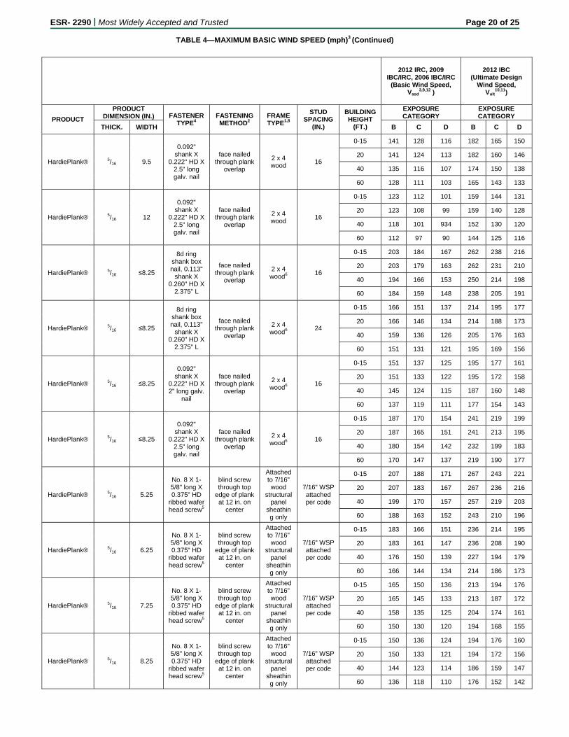
ESR- 2290 | Most Widely Accepted and Trusted Page 20 of 25
TABLE 4—MAXIMUM BASIC WIND SPEED (mph)3 (Continued)
2012 IRC, 2009 IBC/IRC, 2006 IBC/IRC
(Basic Wind Speed, Vasd
3,9,12 )
2012 IBC (Ultimate Design
Wind Speed, Vult
10,11)
PRODUCT
PRODUCT DIMENSION (IN.) FASTENER
TYPE4 FASTENING METHOD2
FRAME TYPE1,8
STUD SPACING
(IN.)
BUILDING HEIGHT
(FT.)
EXPOSURE CATEGORY
EXPOSURE CATEGORY
THICK. WIDTH B C D B C D
HardiePlank® 5/16 9.5
0.092" shank X
0.222" HD X 2.5" long galv. nail
face nailed through plank
overlap
2 x 4 wood
16
0-15 141 128 116 182 165 150
20 141 124 113 182 160 146
40 135 116 107 174 150 138
60 128 111 103 165 143 133
HardiePlank® 5/16 12
0.092" shank X
0.222" HD X 2.5" long galv. nail
face nailed through plank
overlap
2 x 4 wood
16
0-15 123 112 101 159 144 131
20 123 108 99 159 140 128
40 118 101 934 152 130 120
60 112 97 90 144 125 116
HardiePlank® 5/16 ≤8.25
8d ring shank box nail, 0.113"
shank X 0.260" HD X
2.375" L
face nailed through plank
overlap
2 x 4 wood6
16
0-15 203 184 167 262 238 216
20 203 179 163 262 231 210
40 194 166 153 250 214 198
60 184 159 148 238 205 191
HardiePlank® 5/16 ≤8.25
8d ring shank box nail, 0.113"
shank X 0.260" HD X
2.375" L
face nailed through plank
overlap
2 x 4 wood6
24
0-15 166 151 137 214 195 177
20 166 146 134 214 188 173
40 159 136 126 205 176 163
60 151 131 121 195 169 156
HardiePlank® 5/16 ≤8.25
0.092" shank X
0.222" HD X 2" long galv.
nail
face nailed through plank
overlap
2 x 4 wood6
16
0-15 151 137 125 195 177 161
20 151 133 122 195 172 158
40 145 124 115 187 160 148
60 137 119 111 177 154 143
HardiePlank® 5/16 ≤8.25
0.092" shank X
0.222" HD X 2.5" long galv. nail
face nailed through plank
overlap
2 x 4 wood6
16
0-15 187 170 154 241 219 199
20 187 165 151 241 213 195
40 180 154 142 232 199 183
60 170 147 137 219 190 177
HardiePlank® 5/16 5.25
No. 8 X 1-5/8" long X 0.375" HD
ribbed wafer head screw5
blind screw through top
edge of plank at 12 in. on
center
Attached to 7/16" wood
structural panel
sheathing only
7/16" WSP attached per code
0-15 207 188 171 267 243 221
20 207 183 167 267 236 216
40 199 170 157 257 219 203
60 188 163 152 243 210 196
HardiePlank® 5/16 6.25
No. 8 X 1-5/8" long X 0.375" HD
ribbed wafer head screw5
blind screw through top
edge of plank at 12 in. on
center
Attached to 7/16" wood
structural panel
sheathing only
7/16" WSP attached per code
0-15 183 166 151 236 214 195
20 183 161 147 236 208 190
40 176 150 139 227 194 179
60 166 144 134 214 186 173
HardiePlank® 5/16 7.25
No. 8 X 1-5/8" long X 0.375" HD
ribbed wafer head screw5
blind screw through top
edge of plank at 12 in. on
center
Attached to 7/16" wood
structural panel
sheathing only
7/16" WSP attached per code
0-15 165 150 136 213 194 176
20 165 145 133 213 187 172
40 158 135 125 204 174 161
60 150 130 120 194 168 155
HardiePlank® 5/16 8.25
No. 8 X 1-5/8" long X 0.375" HD
ribbed wafer head screw5
blind screw through top
edge of plank at 12 in. on
center
Attached to 7/16" wood
structural panel
sheathing only
7/16" WSP attached per code
0-15 150 136 124 194 176 160
20 150 133 121 194 172 156
40 144 123 114 186 159 147
60 136 118 110 176 152 142
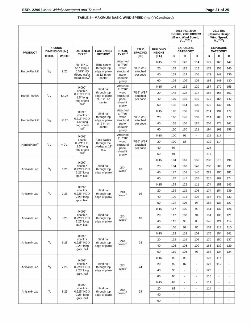
ESR- 2290 | Most Widely Accepted and Trusted Page 21 of 25
TABLE 4—MAXIMUM BASIC WIND SPEED (mph)3 (Continued)
2012 IRC, 2009 IBC/IRC, 2006 IBC/IRC
(Basic Wind Speed, Vasd
3,9,12 )
2012 IBC (Ultimate Design
Wind Speed, Vult
10,11)
PRODUCT
PRODUCT DIMENSION (IN.) FASTENER
TYPE4 FASTENING METHOD2
FRAME TYPE1,8
STUD SPACING
(IN.)
BUILDING HEIGHT
(FT.)
EXPOSURE CATEGORY
EXPOSURE CATEGORY
THICK. WIDTH B C D B C D
HardiePlank® 5/16 9.25
No. 8 X 1-5/8" long X 0.375" HD
ribbed wafer head screw5
blind screw through top
edge of plank at 12 in. on
center
Attached to 7/16" wood
structural panel
sheathing only
7/16" WSP attached per code
0-15 139 126 114 179 163 147
20 139 122 112 179 158 145
40 133 114 105 172 147 136
60 126 109 101 163 141 130
HardiePlank® 5/16 ≤8.25
0.090" shank X
0.215" HD X 1.5" long
ring shank nail5
blind nail through top
edge of plank at 8 in. on
center
Attached to 7/16" wood
structural panel
sheathing only
7/16" WSP attached per code
0-15 145 132 120 187 170 155
20 145 128 117 187 165 151
40 139 119 110 179 154 142
60 132 114 106 170 147 137
HardiePlank® 5/16 ≤8.25
0.090" shank X
0.215" HD X 1.5" long
ring shank nail5
blind nail through top
edge of plank at 6 in. on
center
Attached to 7/16" wood
structural panel
sheathing only
7/16" WSP attached per code
0-15 166 150 137 214 194 177
20 166 146 133 214 188 172
40 159 136 125 205 176 161
60 150 130 121 194 168 156
HardiePlank® 5/16 < 91/2
0.091" shank,
0.221" HD, 1.5" long
ring shank nail5
Face Nailed through the
overlap at 12" o.c.
Attached to 7/16" wood
structural panel
sheathing only
7/16" WSP attached per code
0-15 100 91 - 129 117 -
20 100 88 - 129 114 -
40 96 - - 124 - -
60 91 - - 117 - -
Artisan® Lap 5/8 5.25
0.092" shank X
0.225" HD X 2.25" long galv. Nail
blind nail through top
edge of plank
2X4 Wood7
16
0-15 184 167 152 238 216 196
20 184 162 148 238 209 191
40 177 151 140 229 195 181
60 167 145 135 216 187 174
Artisan® Lap 5/8 7.25
0.092" shank X
0.225" HD X 2.25" long galv. Nail
blind nail through top
edge of plank
2X4 Wood7
16
0-15 135 122 111 174 158 143
20 135 119 108 174 154 139
40 129 111 102 167 143 132
60 122 106 98 158 137 127
Artisan® Lap 5/8 8.25
0.092" shank X
0.225" HD X 2.25" long galv. Nail
blind nail through top
edge of plank
2X4 Wood7
16
0-15 117 106 96 151 137 124
20 117 103 94 151 133 121
40 112 96 88 145 124 114
60 106 92 85 137 119 110
Artisan® Lap 5/8 5.25
0.092" shank X
0.225" HD X 2.25" long galv. nail
blind nail through top
edge of plank
2X4 Wood7
24
0-15 132 119 109 170 154 141
20 132 116 106 170 150 137
40 126 108 100 163 139 129
60 119 104 96 154 134 124
Artisan® Lap 5/8 7.25
0.092" shank X
0.225" HD X 2.25" long galv. nail
blind nail through top
edge of plank
2X4 Wood7
24
0-15 99 90 - 128 116 -
20 99 87 - 128 112 -
40 95 - - 123 - -
60 90 - - 116 - -
Artisan® Lap 5/8 8.25
0.092" shank X
0.225" HD X 2.25" long galv. nail
blind nail through top
edge of plank
2X4 Wood7
24
0-15 88 - - 114 - -
20 88 - - 114 - -
40 - - - - - -
60 - - - - - -
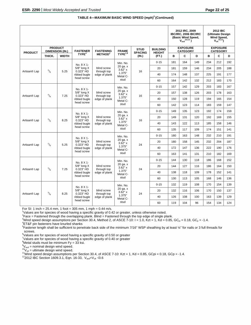
ESR- 2290 | Most Widely Accepted and Trusted Page 22 of 25
TABLE 4—MAXIMUM BASIC WIND SPEED (mph)3 (Continued)
2012 IRC, 2009 IBC/IRC, 2006 IBC/IRC
(Basic Wind Speed, Vasd
3,9,12 )
2012 IBC (Ultimate Design
Wind Speed, Vult
10,11)
PRODUCT
PRODUCT DIMENSION (IN.) FASTENER
TYPE4 FASTENING METHOD2
FRAME TYPE1,8
STUD SPACING
(IN.)
BUILDING HEIGHT
(FT.)
EXPOSURE CATEGORY
EXPOSURE CATEGORY
THICK. WIDTH B C D B C D
Artisan® Lap 5/8 5.25
No. 8 X 1-5/8" long X 0.323" HD
ribbed bugle head screw
blind screw through top
edge of plank
Min. No. 20 ga. x 3.62" x 1.375"
Metal C-stud
16
0-15 181 164 149 234 212 192
20 181 159 146 234 205 188
40 174 148 137 225 191 177
60 164 142 132 212 183 170
Artisan® Lap 5/8 7.25
No. 8 X 1-5/8" long X 0.323" HD
ribbed bugle head screw
blind screw through top
edge of plank
Min. No. 20 ga. x 3.62" x 1.375"
Metal C-stud
16
0-15 157 142 129 203 183 167
20 157 138 126 203 178 163
40 150 128 119 194 165 154
60 142 123 114 183 159 147
Artisan® Lap 5/8 8.25
No. 8 X 1-5/8" long X 0.323" HD
ribbed bugle head screw
blind screw through top
edge of plank
Min. No. 20 ga. x 3.62" x 1.375"
Metal C-stud
16
0-15 149 135 123 192 174 159
20 149 131 120 192 169 155
40 143 122 113 185 158 146
60 135 117 109 174 151 141
Artisan® Lap 5/8 5.25
No. 8 X 1-5/8" long X 0.323" HD
ribbed bugle head screw
blind screw through top
edge of plank
Min. No. 20 ga. x 3.62" x 1.375"
Metal C-stud
24
0-15 180 163 148 232 210 191
20 180 158 145 232 204 187
40 172 147 136 222 190 176
60 163 141 131 210 182 169
Artisan® Lap 5/8 7.25
No. 8 X 1-5/8" long X 0.323" HD
ribbed bugle head screw
blind screw through top
edge of plank
Min. No. 20 ga. x 3.62" x 1.375"
Metal C-stud
24
0-15 144 130 118 186 168 152
20 144 127 116 186 164 150
40 138 118 109 178 152 141
60 130 113 105 168 146 136
Artisan® Lap 5/8 8.25
No. 8 X 1-5/8" long X 0.323" HD
ribbed bugle head screw
blind screw through top
edge of plank
Min. No. 20 ga. x 3.62" x 1.375"
Metal C-stud
24
0-15 132 119 108 170 154 139
20 132 116 106 170 150 137
40 126 108 100 163 139 129
60 119 104 96 154 134 124
For SI: 1 inch = 25.4 mm, 1 foot = 305 mm, 1 mph = 0.44 m/s. 1Values are for species of wood having a specific gravity of 0.42 or greater, unless otherwise noted. 2Face = Fastened through the overlapping plank. Blind = Fastened through the top edge of single plank. 3Wind speed design assumptions per Section 30.4, Method 2, of ASCE 7-10: I = 1.0, Kzt = 1, Kd = 0.85, GCpi = 0.18, GCp = -1.4. 4ET&F pin fasteners have knurled shanks 5Fastener length shall be sufficient to penetrate back side of the minimum 7/16" WSP sheathing by at least ¼” for nails or 3 full threads for
screws. 6Values are for species of wood having a specific gravity of 0.50 or greater 7Values are for species of wood having a specific gravity of 0.40 or greater 8Metal studs must be minimum Fy = 33 ksi. 9Vasd = nominal design wind speed. 10Vult = ultimate design wind speed. 11Wind speed design assumptions per Section 30.4, of ASCE 7-10: Kzt = 1, Kd = 0.85, GCpi = 0.18, GCp = -1.4. 122012 IBC Section 1609.3.1, Eqn. 16-33, Vasd=Vult √0.6
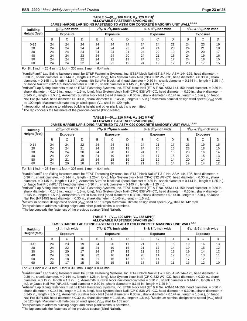
ESR- 2290 | Most Widely Accepted and Trusted Page 23 of 25
TABLE 5—(Vasd 100 MPH; Vult 129 MPH)3
ALLOWABLE FASTENER SPACING (IN.) JAMES HARDIE LAP SIDING FASTENED TO ASTM C90 CONCRETE MASONRY UNIT WALL1,2,,4,5
Building Height (feet)
<61/2-inch wide 71/4- & 71/2-inch wide 8- & 81/4-inch wide 91/4- & 91/2-inch wide
Exposure Exposure Exposure Exposure
B C D B C D B C D B C D
0-15 20 30 40 50 60
24 24 24 24 24 24
24 24 24 24 24 24
24 24 24 23 22 22
24 24 24 24 24 24
24 24 24 24 22 22
24 23 21 20 19 19
24 24 24 24 24 24
24 24 22 21 20 19
21 20 19 18 17 17
24 24 24 24 24 23
23 21 20 19 18 17
19 18 17 16 15 15
For SI: 1 inch = 25.4 mm, 1 foot = 305 mm, 1 mph = 0.44 m/s. 1HardiePlank® Lap Siding fasteners must be ET&F Fastening Systems, Inc. ET&F block Nail (ET & F No. ASM-144-125, head diameter. =
0.30 in., shank diameter. = 0.144 in., length = 1.25-in. long), Max System block Nail (CP-C 832 W7-ICC, head diameter. = 0.30 in., shank diameter. = 0.145 in., length = 1.3 in.), Aerosmith SurePin block nail (head diameter = 0.30 in., shank diameter = 0.144 in., length = 1.25 in.), or Jaaco Nail Pro (NP145S head diameter = 0.30 in., shank diameter = 0.145 in., length = 1.25 in.).
2Artisan® Lap Siding fasteners must be ET&F Fastening Systems, Inc. ET&F block Nail (ET & F No. ASM-144-150, head diameter. = 0.30 in., shank diameter. = 0.145 in., length = 1.5-in. long), Max System block Nail (CP-C 838 W7-ICC, head diameter. = 0.30 in., shank diameter. = 0.145 in., length = 1.5 in.), Aerosmith SurePin block Nail (head diameter = 0.30 in., shank diameter = 0.144 in., length = 1.5 in.), or Jaaco Nail Pro (NP145S head diameter = 0.30 in., shank diameter = 0.145 in., length = 1.5 in.).3 Maximum nominal design wind speed (Vasd) shall be 100 mph. Maximum ultimate design wind speed (Vult) shall be 129 mph.
4 Interpolation of spacing to address building height and other plank widths is permitted. 5 The lap conceals the fasteners of the previous course (Blind Nailed).
TABLE 6—(Vasd 110 MPH; Vult 142 MPH)3
ALLOWABLE FASTENER SPACING (IN.) JAMES HARDIE LAP SIDING FASTENED TO ASTM C90 CONCRETE MASONRY UNIT WALL1,2,4,5
Building Height (feet)
<61/2-inch wide 71/4- & 71/2-inch wide 8- & 81/4-inch wide 91/4- & 91/2-inch wide
Exposure Exposure Exposure Exposure
B C D B C D B C D B C D
0-15 20 30 40 50 60
24 24 24 24 24 24
24 24 24 22 21 20
22 21 20 19 18 18
24 24 24 24 24 23
24 22 20 19 18 18
19 18 17 16 16 15
24 24 24 24 22 21
21 20 18 17 16 16
17 16 15 15 14 14
23 23 23 21 20 19
19 18 16 15 14 14
15 15 14 13 12 12
For SI: 1 inch = 25.4 mm, 1 foot = 305 mm, 1 mph = 0.44 m/s. 1HardiePlank® Lap Siding fasteners must be ET&F Fastening Systems, Inc. ET&F block Nail (ET & F No. ASM-144-125, head diameter. =
0.30 in., shank diameter. = 0.144 in., length = 1.25-in. long), Max System block Nail (CP-C 832 W7-ICC, head diameter. = 0.30 in., shank diameter. = 0.145 in., length = 1.3 in.), Aerosmith SurePin block nail (head diameter = 0.30 in., shank diameter = 0.144 in., length = 1.25 in.), or Jaaco Nail Pro (NP145S head diameter = 0.30 in., shank diameter = 0.145 in., length = 1.25 in.).
2Artisan® Lap Siding fasteners must be ET&F Fastening Systems, Inc. ET&F block Nail (ET & F No. ASM-144-150, head diameter. = 0.30 in., shank diameter. = 0.145 in., length = 1.5-in. long), Max System block Nail (CP-C 838 W7-ICC, head diameter. = 0.30 in., shank diameter. = 0.145 in., length = 1.5 in.), Aerosmith SurePin block Nail (head diameter = 0.30 in., shank diameter = 0.144 in., length = 1.5 in.), or Jaaco Nail Pro (NP145S head diameter = 0.30 in., shank diameter = 0.145 in., length = 1.5 in.).
3Maximum nominal design wind speed (Vasd) shall be 110 mph Maximum ultimate design wind speed (Vult) shall be 142 mph. 4Interpolation to address building height and other plank widths is permitted. 5The lap conceals the fasteners of the previous course (Blind Nailed).
TABLE 7—( Vasd 120 MPH; Vult 155 MPH)3
ALLOWABLE FASTENER SPACING (IN.) JAMES HARDIE LAP SIDING FASTENED TO ASTM C90 CONCRETE MASONRY UNIT WALL1,3,4
Building Height (feet)
<61/2-inch wide 71/4- & 71/2-inch wide 8- & 81/4-inch wide 91/4- & 91/2-inch wide
Exposure Exposure Exposure Exposure
B C D B C D B C D B C D
0-15 20 30 40 50 60
24 24 24 24 24 23
23 22 20 19 18 17
19 18 17 16 16 15
24 24 24 22 21 20
20 19 17 16 16 15
17 16 15 14 13 13
21 21 21 20 18 18
18 17 15 14 14 13
15 14 13 12 12 11
19 19 19 18 17 16
16 15 14 13 12 12
13 12 12 11 11 10
For SI: 1 inch = 25.4 mm, 1 foot = 305 mm, 1 mph = 0.44 m/s. 1HardiePlank® Lap Siding fasteners must be ET&F Fastening Systems, Inc. ET&F block Nail (ET & F No. ASM-144-125, head diameter. =
0.30 in., shank diameter. = 0.144 in., length = 1.25-in. long), Max System block Nail (CP-C 832 W7-ICC, head diameter. = 0.30 in., shank diameter. = 0.15 in., length = 1.3 in.). .), Aerosmith SurePin block nail (head diameter = 0.30 in., shank diameter = 0.144 in., length = 1.25 in.), or Jaaco Nail Pro (NP145S head diameter = 0.30 in., shank diameter = 0.145 in., length = 1.25 in.).
2Artisan® Lap Siding fasteners must be ET&F Fastening Systems, Inc. ET&F block Nail (ET & F No. ASM-144-150, head diameter. = 0.30 in., shank diameter. = 0.145 in., length = 1.5-in. long), Max System block Nail (CP-C 838 W7-ICC, head diameter. = 0.30 in., shank diameter. = 0.145 in., length = 1.5 in.), Aerosmith SurePin block Nail (head diameter = 0.30 in., shank diameter = 0.144 in., length = 1.5 in.), or Jaaco Nail Pro (NP145S head diameter = 0.30 in., shank diameter = 0.145 in., length = 1.5 in.). 3Maximum nominal design wind speed (Vasd) shall be 120 mph. Maximum ultimate design wind speed (Vullt) shall be 155 mph.
4Interpolation to address building height and other plank widths is permitted. 5The lap conceals the fasteners of the previous course (Blind Nailed).
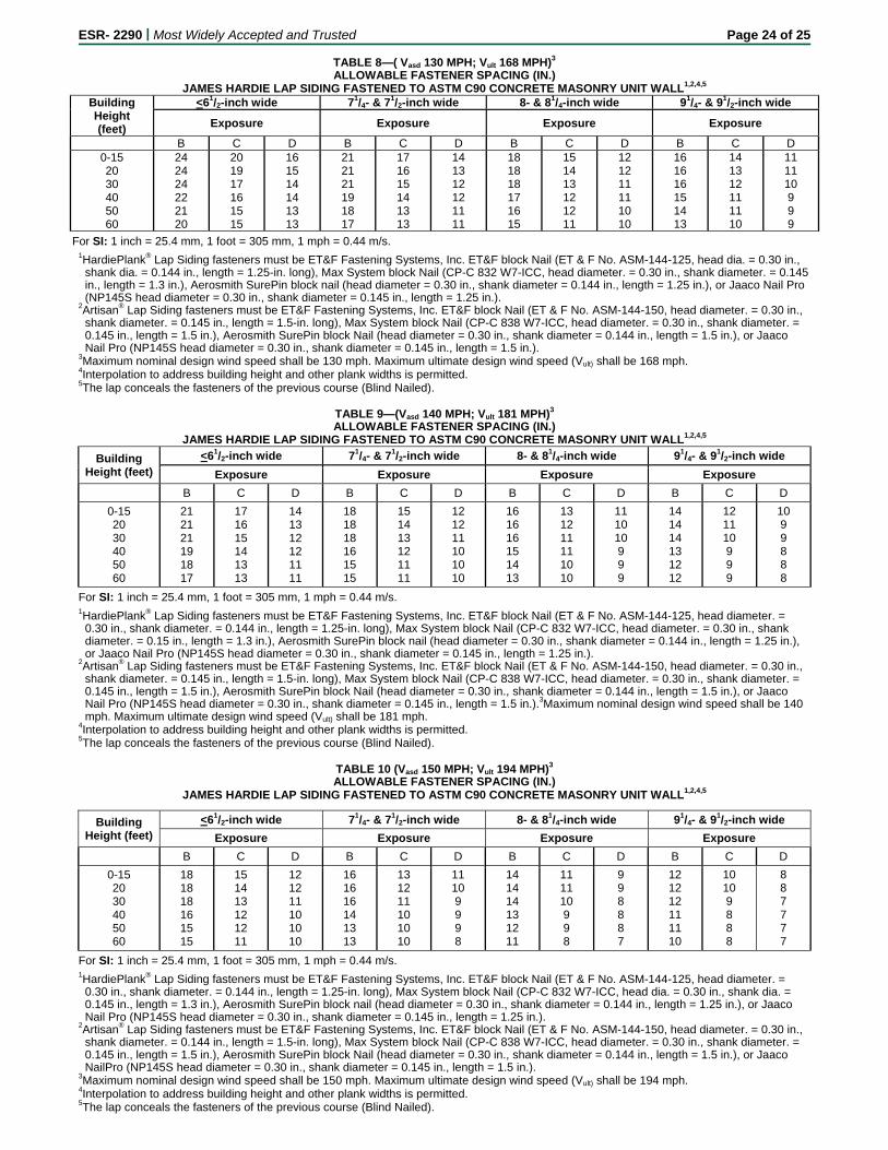
ESR- 2290 | Most Widely Accepted and Trusted Page 24 of 25
TABLE 8—( Vasd 130 MPH; Vult 168 MPH)3
ALLOWABLE FASTENER SPACING (IN.) JAMES HARDIE LAP SIDING FASTENED TO ASTM C90 CONCRETE MASONRY UNIT WALL1,2,4,5
Building Height (feet)
<61/2-inch wide 71/4- & 71/2-inch wide 8- & 81/4-inch wide 91/4- & 91/2-inch wide
Exposure Exposure Exposure Exposure
B C D B C D B C D B C D 0-15 20 30 40 50 60
24 24 24 22 21 20
20 19 17 16 15 15
16 15 14 14 13 13
21 21 21 19 18 17
17 16 15 14 13 13
14 13 12 12 11 11
18 18 18 17 16 15
15 14 13 12 12 11
12 12 11 11 10 10
16 16 16 15 14 13
14 13 12 11 11 10
11 11 10 9 9 9
For SI: 1 inch = 25.4 mm, 1 foot = 305 mm, 1 mph = 0.44 m/s. 1HardiePlank® Lap Siding fasteners must be ET&F Fastening Systems, Inc. ET&F block Nail (ET & F No. ASM-144-125, head dia. = 0.30 in.,
shank dia. = 0.144 in., length = 1.25-in. long), Max System block Nail (CP-C 832 W7-ICC, head diameter. = 0.30 in., shank diameter. = 0.145 in., length = 1.3 in.), Aerosmith SurePin block nail (head diameter = 0.30 in., shank diameter = 0.144 in., length = 1.25 in.), or Jaaco Nail Pro (NP145S head diameter = 0.30 in., shank diameter = 0.145 in., length = 1.25 in.).
2Artisan® Lap Siding fasteners must be ET&F Fastening Systems, Inc. ET&F block Nail (ET & F No. ASM-144-150, head diameter. = 0.30 in., shank diameter. = 0.145 in., length = 1.5-in. long), Max System block Nail (CP-C 838 W7-ICC, head diameter. = 0.30 in., shank diameter. = 0.145 in., length = 1.5 in.), Aerosmith SurePin block Nail (head diameter = 0.30 in., shank diameter = 0.144 in., length = 1.5 in.), or Jaaco Nail Pro (NP145S head diameter = 0.30 in., shank diameter = 0.145 in., length = 1.5 in.).
3Maximum nominal design wind speed shall be 130 mph. Maximum ultimate design wind speed (Vult) shall be 168 mph. 4Interpolation to address building height and other plank widths is permitted. 5The lap conceals the fasteners of the previous course (Blind Nailed).
TABLE 9—(Vasd 140 MPH; Vult 181 MPH)3
ALLOWABLE FASTENER SPACING (IN.) JAMES HARDIE LAP SIDING FASTENED TO ASTM C90 CONCRETE MASONRY UNIT WALL1,2,4,5
Building Height (feet)
<61/2-inch wide 71/4- & 71/2-inch wide 8- & 81/4-inch wide 91/4- & 91/2-inch wide
Exposure Exposure Exposure Exposure
B C D B C D B C D B C D
0-15 20 30 40 50 60
21 21 21 19 18 17
17 16 15 14 13 13
14 13 12 12 11 11
18 18 18 16 15 15
15 14 13 12 11 11
12 12 11 10 10 10
16 16 16 15 14 13
13 12 11 11 10 10
11 10 10 9 9 9
14 14 14 13 12 12
12 11 10 9 9 9
10 9 9 8 8 8
For SI: 1 inch = 25.4 mm, 1 foot = 305 mm, 1 mph = 0.44 m/s. 1HardiePlank® Lap Siding fasteners must be ET&F Fastening Systems, Inc. ET&F block Nail (ET & F No. ASM-144-125, head diameter. =
0.30 in., shank diameter. = 0.144 in., length = 1.25-in. long), Max System block Nail (CP-C 832 W7-ICC, head diameter. = 0.30 in., shank diameter. = 0.15 in., length = 1.3 in.), Aerosmith SurePin block nail (head diameter = 0.30 in., shank diameter = 0.144 in., length = 1.25 in.), or Jaaco Nail Pro (NP145S head diameter = 0.30 in., shank diameter = 0.145 in., length = 1.25 in.).
2Artisan® Lap Siding fasteners must be ET&F Fastening Systems, Inc. ET&F block Nail (ET & F No. ASM-144-150, head diameter. = 0.30 in., shank diameter. = 0.145 in., length = 1.5-in. long), Max System block Nail (CP-C 838 W7-ICC, head diameter. = 0.30 in., shank diameter. = 0.145 in., length = 1.5 in.), Aerosmith SurePin block Nail (head diameter = 0.30 in., shank diameter = 0.144 in., length = 1.5 in.), or Jaaco Nail Pro (NP145S head diameter = 0.30 in., shank diameter = 0.145 in., length = 1.5 in.).3Maximum nominal design wind speed shall be 140 mph. Maximum ultimate design wind speed (Vult) shall be 181 mph.
4Interpolation to address building height and other plank widths is permitted. 5The lap conceals the fasteners of the previous course (Blind Nailed).
TABLE 10 (Vasd 150 MPH; Vult 194 MPH)3
ALLOWABLE FASTENER SPACING (IN.) JAMES HARDIE LAP SIDING FASTENED TO ASTM C90 CONCRETE MASONRY UNIT WALL1,2,4,5
Building Height (feet)
<61/2-inch wide 71/4- & 71/2-inch wide 8- & 81/4-inch wide 91/4- & 91/2-inch wide
Exposure Exposure Exposure Exposure
B C D B C D B C D B C D
0-15 20 30 40 50 60
18 18 18 16 15 15
15 14 13 12 12 11
12 12 11 10 10 10
16 16 16 14 13 13
13 12 11 10 10 10
11 10 9 9 9 8
14 14 14 13 12 11
11 11 10 9 9 8
9 9 8 8 8 7
12 12 12 11 11 10
10 10 9 8 8 8
8 8 7 7 7 7
For SI: 1 inch = 25.4 mm, 1 foot = 305 mm, 1 mph = 0.44 m/s. 1HardiePlank® Lap Siding fasteners must be ET&F Fastening Systems, Inc. ET&F block Nail (ET & F No. ASM-144-125, head diameter. =
0.30 in., shank diameter. = 0.144 in., length = 1.25-in. long), Max System block Nail (CP-C 832 W7-ICC, head dia. = 0.30 in., shank dia. = 0.145 in., length = 1.3 in.), Aerosmith SurePin block nail (head diameter = 0.30 in., shank diameter = 0.144 in., length = 1.25 in.), or Jaaco Nail Pro (NP145S head diameter = 0.30 in., shank diameter = 0.145 in., length = 1.25 in.).
2Artisan® Lap Siding fasteners must be ET&F Fastening Systems, Inc. ET&F block Nail (ET & F No. ASM-144-150, head diameter. = 0.30 in., shank diameter. = 0.144 in., length = 1.5-in. long), Max System block Nail (CP-C 838 W7-ICC, head diameter. = 0.30 in., shank diameter. = 0.145 in., length = 1.5 in.), Aerosmith SurePin block Nail (head diameter = 0.30 in., shank diameter = 0.144 in., length = 1.5 in.), or Jaaco NailPro (NP145S head diameter = 0.30 in., shank diameter = 0.145 in., length = 1.5 in.).
3Maximum nominal design wind speed shall be 150 mph. Maximum ultimate design wind speed (Vult) shall be 194 mph. 4Interpolation to address building height and other plank widths is permitted. 5The lap conceals the fasteners of the previous course (Blind Nailed).
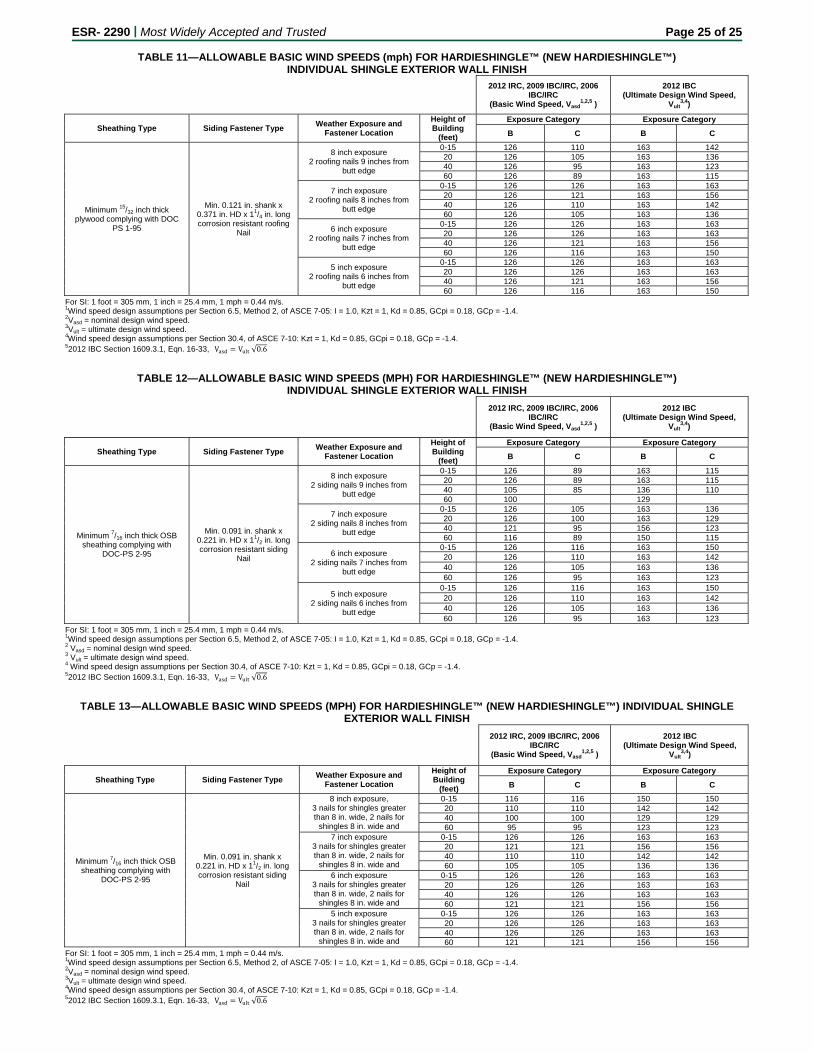
ESR- 2290 | Most Widely Accepted and Trusted Page 25 of 25
TABLE 11—ALLOWABLE BASIC WIND SPEEDS (mph) FOR HARDIESHINGLE™ (NEW HARDIESHINGLE™) INDIVIDUAL SHINGLE EXTERIOR WALL FINISH
2012 IRC, 2009 IBC/IRC, 2006 IBC/IRC
(Basic Wind Speed, Vasd1,2,5 )
2012 IBC (Ultimate Design Wind Speed,
Vult3,4)
Sheathing Type Siding Fastener Type Weather Exposure and
Fastener Location
Height of Building
(feet)
Exposure Category Exposure Category
B C B C
Minimum 15/32 inch thick plywood complying with DOC
PS 1-95
Min. 0.121 in. shank x 0.371 in. HD x 11/4 in. long corrosion resistant roofing
Nail
8 inch exposure 2 roofing nails 9 inches from
butt edge
0-15 126 110 163 14220 126 105 163 13640 126 95 163 12360 126 89 163 115
7 inch exposure 2 roofing nails 8 inches from
butt edge
0-15 126 126 163 16320 126 121 163 15640 126 110 163 14260 126 105 163 136
6 inch exposure 2 roofing nails 7 inches from
butt edge
0-15 126 126 163 16320 126 126 163 16340 126 121 163 15660 126 116 163 150
5 inch exposure 2 roofing nails 6 inches from
butt edge
0-15 126 126 163 16320 126 126 163 16340 126 121 163 15660 126 116 163 150
For SI: 1 foot = 305 mm, 1 inch = 25.4 mm, 1 mph = 0.44 m/s. 1Wind speed design assumptions per Section 6.5, Method 2, of ASCE 7-05: I = 1.0, Kzt = 1, Kd = 0.85, GCpi = 0.18, GCp = -1.4. 2Vasd = nominal design wind speed. 3Vult = ultimate design wind speed. 4Wind speed design assumptions per Section 30.4, of ASCE 7-10: Kzt = 1, Kd = 0.85, GCpi = 0.18, GCp = -1.4. 52012 IBC Section 1609.3.1, Eqn. 16-33,V V √0.6
TABLE 12—ALLOWABLE BASIC WIND SPEEDS (MPH) FOR HARDIESHINGLE™ (NEW HARDIESHINGLE™) INDIVIDUAL SHINGLE EXTERIOR WALL FINISH
2012 IRC, 2009 IBC/IRC, 2006 IBC/IRC
(Basic Wind Speed, Vasd1,2,5 )
2012 IBC (Ultimate Design Wind Speed,
Vult3,4)
Sheathing Type Siding Fastener Type Weather Exposure and
Fastener Location
Height of Building
(feet)
Exposure Category Exposure Category
B C B C
Minimum 7/16 inch thick OSB sheathing complying with
DOC-PS 2-95
Min. 0.091 in. shank x 0.221 in. HD x 11/2 in. long corrosion resistant siding
Nail
8 inch exposure 2 siding nails 9 inches from
butt edge
0-15 126 89 163 11520 126 89 163 11540 105 85 136 11060 100 129
7 inch exposure 2 siding nails 8 inches from
butt edge
0-15 126 105 163 13620 126 100 163 12940 121 95 156 12360 116 89 150 115
6 inch exposure 2 siding nails 7 inches from
butt edge
0-15 126 116 163 15020 126 110 163 142 40 126 105 163 136 60 126 95 163 123
5 inch exposure 2 siding nails 6 inches from
butt edge
0-15 126 116 163 150 20 126 110 163 142 40 126 105 163 136 60 126 95 163 123
For SI: 1 foot = 305 mm, 1 inch = 25.4 mm, 1 mph = 0.44 m/s. 1Wind speed design assumptions per Section 6.5, Method 2, of ASCE 7-05: I = 1.0, Kzt = 1, Kd = 0.85, GCpi = 0.18, GCp = -1.4. 2 Vasd = nominal design wind speed. 3 Vult = ultimate design wind speed. 4 Wind speed design assumptions per Section 30.4, of ASCE 7-10: Kzt = 1, Kd = 0.85, GCpi = 0.18, GCp = -1.4. 52012 IBC Section 1609.3.1, Eqn. 16-33,V V √0.6
TABLE 13—ALLOWABLE BASIC WIND SPEEDS (MPH) FOR HARDIESHINGLE™ (NEW HARDIESHINGLE™) INDIVIDUAL SHINGLE EXTERIOR WALL FINISH
2012 IRC, 2009 IBC/IRC, 2006 IBC/IRC
(Basic Wind Speed, Vasd1,2,5 )
2012 IBC (Ultimate Design Wind Speed,
Vult3,4)
Sheathing Type Siding Fastener Type Weather Exposure and
Fastener Location
Height of Building
(feet)
Exposure Category Exposure Category
B C B C
Minimum 7/16 inch thick OSB sheathing complying with
DOC-PS 2-95
Min. 0.091 in. shank x 0.221 in. HD x 11/2 in. long corrosion resistant siding
Nail
8 inch exposure, 3 nails for shingles greater than 8 in. wide, 2 nails for
shingles 8 in. wide and
0-15 116 116 150 15020 110 110 142 14240 100 100 129 12960 95 95 123 123
7 inch exposure 3 nails for shingles greater than 8 in. wide, 2 nails for
shingles 8 in. wide and
0-15 126 126 163 16320 121 121 156 15640 110 110 142 14260 105 105 136 136
6 inch exposure 3 nails for shingles greater than 8 in. wide, 2 nails for
shingles 8 in. wide and
0-15 126 126 163 16320 126 126 163 16340 126 126 163 16360 121 121 156 156
5 inch exposure 3 nails for shingles greater than 8 in. wide, 2 nails for
shingles 8 in. wide and
0-15 126 126 163 16320 126 126 163 16340 126 126 163 16360 121 121 156 156
For SI: 1 foot = 305 mm, 1 inch = 25.4 mm, 1 mph = 0.44 m/s. 1Wind speed design assumptions per Section 6.5, Method 2, of ASCE 7-05: I = 1.0, Kzt = 1, Kd = 0.85, GCpi = 0.18, GCp = -1.4. 2Vasd = nominal design wind speed. 3Vult = ultimate design wind speed. 4Wind speed design assumptions per Section 30.4, of ASCE 7-10: Kzt = 1, Kd = 0.85, GCpi = 0.18, GCp = -1.4. 52012 IBC Section 1609.3.1, Eqn. 16-33,V V √0.6
ICC-ES Evaluation Reports are not to be construed as representing aesthetics or any other attributes not specifically addressed, nor are they to be construed as an endorsement of the subject of the report or a recommendation for its use. There is no warranty by ICC Evaluation Service, LLC, express or implied, as to any finding or other matter in this report, or as to any product covered by the report.
Copyright © 2016 ICC Evaluation Service, LLC. All rights reserved. Page 1 of 2 1000
ICC-ES Evaluation Report ESR-2290 CBC and CRC Supplement Reissued March 2016 This report is subject to renewal March 2018.
www.icc-es.org | (800) 423-6587 | (562) 699-0543 A Subsidiary of the International Code Council ®
DIVISION: 06 00 00—WOOD. PLASTICS AND COMPOSITES Section: 06 16 00—Sheathing DIVISION: 07 00 00—THERMAL AND MOISTURE PROTECTION Section: 07 46 46—Fiber-Cement Siding REPORT HOLDER: JAMES HARDIE BUILDING PRODUCTS, INC. 10901 ELM AVENUE FONTANA, CALIFORNIA 92337 (800) 942-7343 www.jameshardie.com [email protected] EVALUATION SUBJECT: HARDIESHINGLETM (NEW HARDIESHINGLE®) PANELS, HARDIEPLANK TM LAP SIDING, ARTISAN® LAP SIDING, AND HARDIESHINGLETM (NEW HARDIESHINGLE®) INDIVIDUAL SHINGLES 1.0 REPORT PURPOSE AND SCOPE
Purpose:
The purpose of this evaluation report supplement is to indicate that HARDIESHINGLE™ (NEW HARDIESHINGLE®) PANELS, HARDIEPLANK™ LAP SIDING, ARTISAN® LAP SIDING, AND HARDIESHINGLE™ (NEW HARDIESHINGLE®) INDIVIDUAL SHINGLES, recognized in ICC-ES master evaluation report ESR-2290, have also been evaluated for compliance with Chapters 7A and 14 (CBC) and Chapters R3 and R7 (CRC) of the codes noted below.
2013 and 2010 California Building Code (CBC)
2013 and 2010 California Residential Code (CRC)
2.0 CONCLUSIONS
2.1 CBC:
The HARDIESHINGLE™ (NEW HARDIESHINGLE®) PANELS, HARDIEPLANK™ LAP SIDING, ARTISAN® LAP SIDING, and HARDIESHINGLE™ (NEW HARDIESHINGLE®) INDIVIDUAL SHINGLES described in Sections 2.0 through 7.0 of the master evaluation report ESR-2290, may be used where noncombustible or ignition-resistant exterior walls complying with Chapters 7A and 14 of the CBC are required, provided installation is in accordance with the master report and the additional requirements in Sections 1405.16 and 1405.17 of the CBC.
The use of the products in construction of new buildings located in any Fire Hazard Severity Zone within State Responsibility Areas or any Wildland–Urban Interface Area requires installation in accordance with the master report and the additional requirements of CBC Sections 701A.3, 704A.3 and 707A.3, as applicable.
The products recognized in this supplement have not been evaluated for compliance with the International Wildland–Urban Interface Code®.
2.2 CRC:
The HARDIESHINGLE™ (NEW HARDIESHINGLE®) PANELS, HARDIEPLANK™ LAP SIDING, ARTISAN® LAP SIDING, and HARDIESHINGLE™ (NEW HARDIESHINGLE®) INDIVIDUAL SHINGLES, described in Sections 2.0 through 7.0 of the master evaluation report ESR-2290, may be used where noncombustible or ignition-resistant exterior walls complying with Chapter R3 and R7 of the CRC are required, provided installation is in accordance with the master report and the additional requirements in Sections R703.10 of the CRC.

ESR-2290 | Most Widely Accepted and Trusted Page 2 of 2
The use of the products in construction of new buildings located in any Fire Hazard Severity Zone within State Responsibility Areas or any Wildland–Urban Interface Area requires installation in accordance with the master report and the additional requirements of CRC Sections R327.1.1.3.1, R327.4.3 and R327.7, as applicable.
The products recognized in this supplement have not been evaluated for compliance with the International Wildland–Urban Interface Code®.
This supplement expires concurrently with the master report reissued March 2016.
Recommended