1
2005/03/11(C) Herbert Haas
N-ISDN
"It still does nothing"

2
2(C) Herbert Haas 2005/03/11
Why ISDN?
� During the century, Telcos
�Created telephony networks
�Created separate digital data networks
� Today: Demand for various different
services
�Voice, fast signaling, data applications,
realtime applications, videostreaming and
videoconferences, music, Fax, ...
Why has ISDN been invented and what is its basic idea? Originally there were
two types of Telco networks: one for voice and one for data. Since both traffic
types are totally different in behavior it was reasonable to implement two
different technologies. Basically, synchronous techniques were used for voice
and asynchronous protocols (X.25) were used for data.
Later additional traffic types appeared, such as voice and video streaming,
various realtime applications, and so on. Today we call these traffic types
"services".
The inventors of ISDN proposed one single network to transport all these services
in order to reduce complexity, increase maintainability, improve scalability�and
basically to safe money.

3
3(C) Herbert Haas 2005/03/11
What it is...
� Integrated Services Digital Network
� ISDN is the digital unification of the
telecommunication networks for different
services
� ISDN ensures world wide interoperability
� All-digital interfaces at subscriber outlet
� This module describes N-ISDN (!)
� Narrowband ISDN (the "normal" ISDN)
N-ISDN means Narrowband-ISDN, but you can also think of "Normal-ISDN".
The planning of ISDN began already in 1976, but real-world applications became
available only with the mid-80's. Also Frame-Relay is regarded as part of the
ISDN family, because it can be transported upon the physical layer of ISDN,
which we will discuss soon.

4
4(C) Herbert Haas 2005/03/11
Technical Overview
� ISDN provides standardized UNI
� Basic Rate Interface (BRI)
� Primary Rate Interface (PRI)
� Synchronous and deterministic
multiplexing
� Constant delays
� Constant bandwidth
� Dynamic connection establishment
� User initiated
� Temporarily
ISDN specifies only a User to Network Interface (UNI)�quite similar than X.25
and Frame Relay. But the main difference is that ISDN relies on deterministic,
synchronized multiplexing.
Two data rates were defined: The Basic Rate Interface (BRI) and the Primary
Rate Interface (PRI). Both are explained on the next pages in more detail.
Synchronous and deterministic multiplexing provides constant delays and
bandwidth. Therefore, a user can able to put any type of traffic upon this layer�
it works fully transparent!
The connections are established dynamically by a signaling protocol. The user
dials a number and a temporary connection is created. The signaling protocol is
the famous "Q.931". It is explained later but you should try to memorize it even
by now.

5
5(C) Herbert Haas 2005/03/11
Basic Rate Interface (BRI)
� 2 Bearer (B) channels with 64 kbit/s each
� 1 Data (D) channel with 16 kbit/s � For outband signaling purposes
(mainly)
BRI2 ´ B
D
Telco or Provider
Network
144 kbit/s (plus overhead)
The picture above describes the BRI which might be installed in every household.
The BRI specifies three channels: 2 Bearer (B) channels providing 64 kbit/s each
and one signaling or Data (D) channel, providing only 16 kbit/s.
The dedicated timeslot for the Data (D) channel assures a reliable outband
signaling. In many cases the D channel is also used for other data traffic, for
example X.25 packets.
The total bandwidth of all three channels is 64+64+16=144 kbit/s, not regarding
the overhead information.
Note that the ISDN link is terminated at the switch of the Telco or provider
network. This termination is discussed in greater detail soon.
Unlike a normal telephone connection, an ISDN connection can have more than
one telephone number - each of these is called an MSN (Multiple Subscriber
Number).
6
6(C) Herbert Haas 2005/03/11
Primary Rate Interface (PRI)
� 30 Bearer (B) channels with 64 kbit/s each (USA: 23 B)
� 1 Data (D) channel with 64 kbit/s � For outband signaling purposes
(mainly)
30 ´ B
D
PRI 2.048 Mbit/s(E1 Frames)
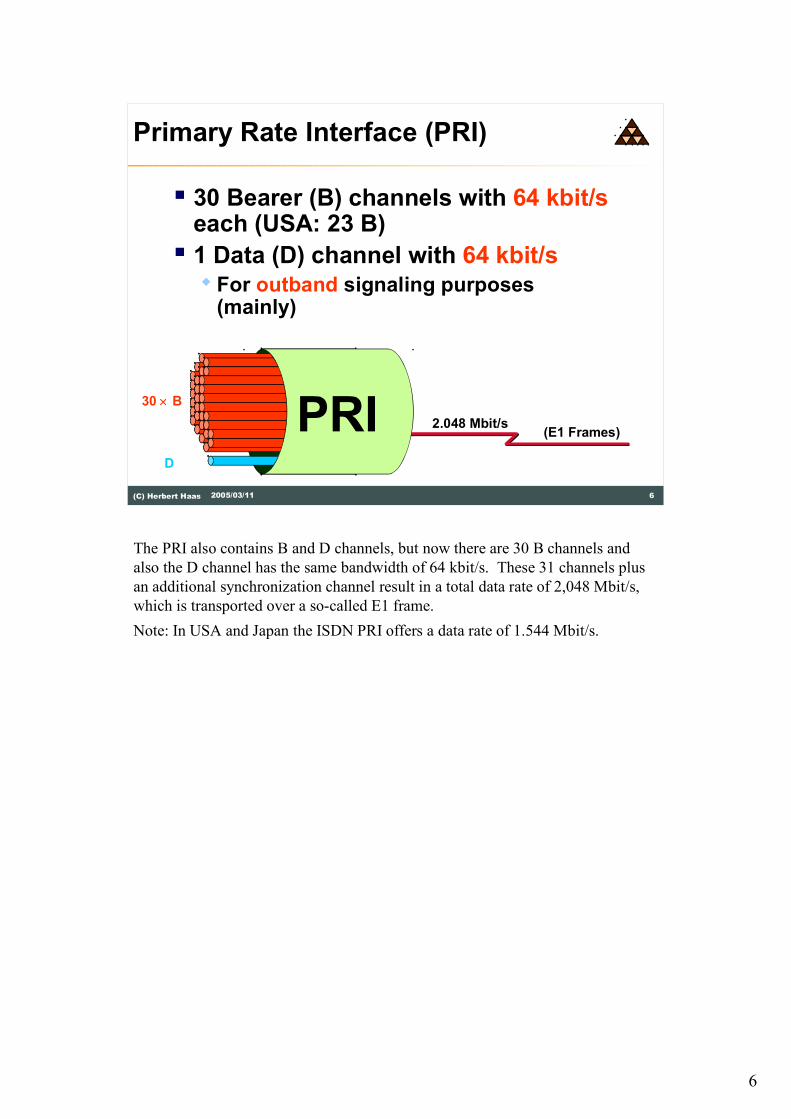
The PRI also contains B and D channels, but now there are 30 B channels and
also the D channel has the same bandwidth of 64 kbit/s. These 31 channels plus
an additional synchronization channel result in a total data rate of 2,048 Mbit/s,
which is transported over a so-called E1 frame.
Note: In USA and Japan the ISDN PRI offers a data rate of 1.544 Mbit/s.

7
7(C) Herbert Haas 2005/03/11
ISDN Services
� CCITT defined three services�Bearer services (Circuit or Packet)
� Teleservices (Telephony, Telefax, ...)
�Supplementary services
� Reverse charging
� Hunt groups
� etc...
The CCITT (today known as ITU-T) defined three services for ISDN..
Bearer services define transport of information in real time without alteration of
the content of the message. Both circuit mode and packet mode (virtual call and
permanent virtual circuit) is supported.
Teleservices combine transportation function with information-processing
functions, e.g. telephony, teletex, telefax, videotex, and telex.
Supplementary services can be used to enhance bearer or teleservices.
Examples for supplementary services are reverse charging, closed user group, line
hunting, call forwarding, calling-line-identification, multiple subscriber number
(MSN), and subaddressing.
8
8(C) Herbert Haas 2005/03/11
Functional Groups
� Terminal Equipment (TE)� TE1 is the native ISDN user device
(phone, PC-card, ...)
� TE2 is a non-ISDN user device(Analog telephone, modem, ...)
� Network Termination (NT)� NT1 connects TEs with ISDN
� NT2 provides concentration and supplemental services (PBX)
� Terminal Adapter (TA)� TA connects TE2 with NT1 or NT2
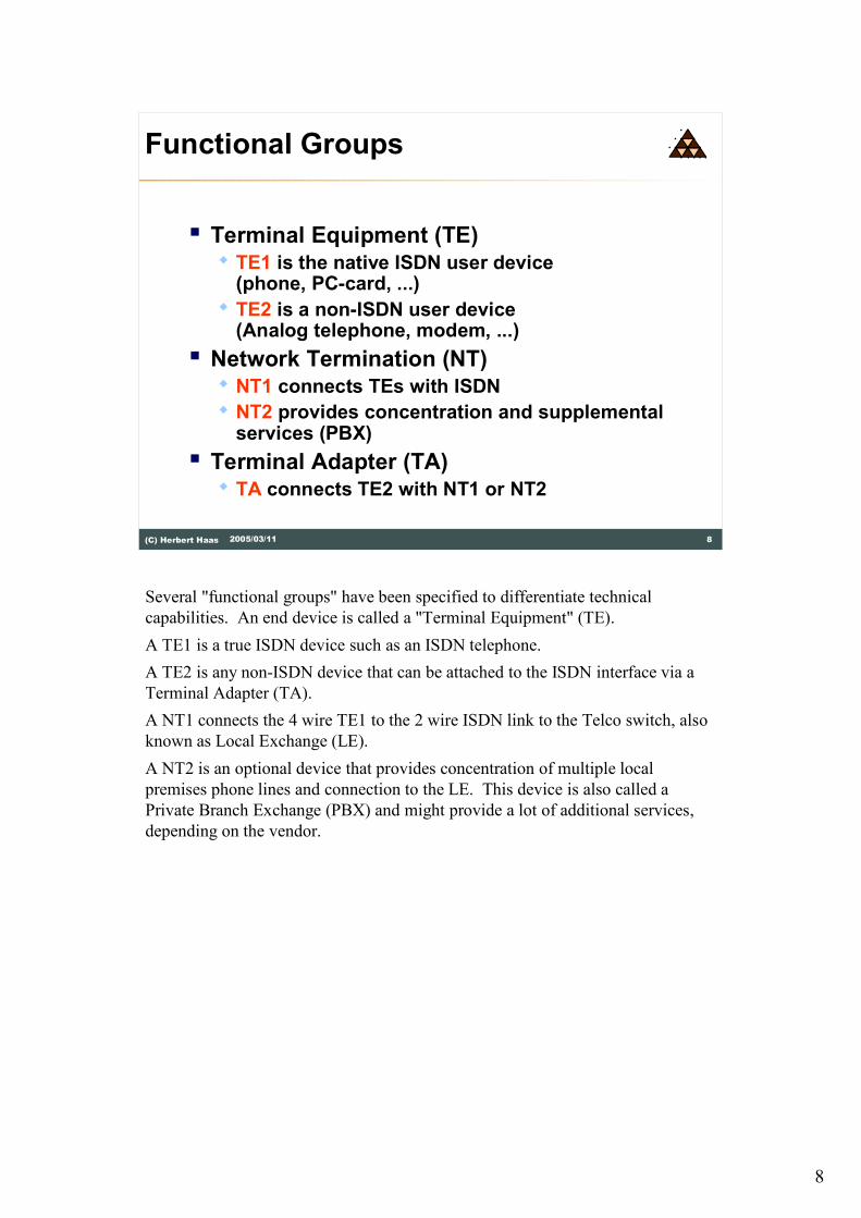
Several "functional groups" have been specified to differentiate technical
capabilities. An end device is called a "Terminal Equipment" (TE).
A TE1 is a true ISDN device such as an ISDN telephone.
A TE2 is any non-ISDN device that can be attached to the ISDN interface via a
Terminal Adapter (TA).
A NT1 connects the 4 wire TE1 to the 2 wire ISDN link to the Telco switch, also
known as Local Exchange (LE).
A NT2 is an optional device that provides concentration of multiple local
premises phone lines and connection to the LE. This device is also called a
Private Branch Exchange (PBX) and might provide a lot of additional services,
depending on the vendor.

9
9(C) Herbert Haas 2005/03/11
Reference Points
� Logical interfaces between functional
groups
�R connects PSTN equipment with TA
�S connects TEs with NT2
� T connects NT2 with NT1
�U connects NT1 with Exchange
Termination (ET)
Besides the Functional Groups, also "Reference Points" had been specified.
Reference Points identify logical interfaces between the previously mentioned
Funtional Groups.

10
10(C) Herbert Haas 2005/03/11
Reference Diagram (BRI)
TA
NT1
Up to 8 TEs
TE1
TE1
TE2
LT ET
ISDN Switch
VUS/T
R
Phone Company
Home
Termination point
in Europe
Termination point
in USA
LT Line Termination
ET Exchange Termination
TA Terminal Adapter
TE Terminal Equipment
NT Network Termination
2 Wires
4 Wires
A TE2 is for example a plain old telephone (POT) or an analog modem. The R
interface is typically a EIA/TIA-232-C, V.24, or V.35.
Basically, the NT1 converts the U to S/T interface: 2 wires to 4 wires, different
coding scheme, different bit-rates (160 to 192 bit/s). Furthermore the NT1 cares
for synchronisation, multiplexing of B and D channels, and optional power
provision for TEs. Some people just call it ISDN-modem. Never say that.

11
11(C) Herbert Haas 2005/03/11
Reference Diagram (PRI)
NT1 LT ET
ISDN Switch
VU
Phone Company
Company
NT2 TS
PBX
.
.
.
.
.
Can be a single device
The picture above shows the principle of a PRI installation, using a PBX (NT2)
which terminates all local telephones. Note that these telephones are not
necessarily ISDN compliant telephones. Rather vendor proprietary technologies
are used here.

12
12(C) Herbert Haas 2005/03/11
U-Interface
� Recommendation G.961
� 160 kbit/s (remaining capacity used for framing
and synchronization)
� Either echo cancellation or time
compression (ping-pong)
� 2B1Q (ANSI T1.601)
� -2.5 V, -0.833 V, +0.833 V, +2.5 V
� Requires half the BW of NRZ
� Plus scrambling for synchronization and
uniform PSD distribution
The U-interface is defined in CCITT "Recommendation G.961" and specifies a
160 kbit/s transmission method over two wires. Bidirectional communication is
provided either by echo cancellation or "ping-pong" transmission, i. e. alternating
sending and receiving of both sides within short time periods.
"Two Binary One Quaternary" (2B1Q) digital coding is used on this interface.

13
13(C) Herbert Haas 2005/03/11
ISDN Channels
� TEs just require one D
and 1 or 2 B channels
� High-speed PRI applications can be
connected with so-called H-channels
�H0 (6B = 384 kbit/s)
�H11 (24B = 1536 kbit/s)
�H12 (30B = 1920 kbit/s)
H channels are bundles of B channels to obtain a higher data rate.

14
14(C) Herbert Haas 2005/03/11
Layers
I.430 (BRI)
I.431 (PRI)
User
specified
Q.931
Q.921 (LAPD)
Control-Plane(D-Channel)
User-Plane(B or H channel)
The diagram above shows the ISDN layer model. There is one common physical
layer, which is either I.430 (the BRI) or I.431 (the PRI). Note the vertical
separation above the common physical layer�a clear sign of outband signaling!
On the left side the signaling protocol Q.931 can be identified in this diagram.
This "Control Plane" protocol carries the dial numbers and is itself carried by
Q.921, a HDLC variant providing a reliable delivery of data between two adjacent
interfaces�between TE and LE.
On the right side the "User Plane" is specified as an open interface. That is, the
user can put any service directly upon the synchronous physical layer.

15
15(C) Herbert Haas 2005/03/11
Additional Standards
� Q.920 (I.440)� Layer 2 UNI general aspects
� Q.921 (I.441)� Layer 2 UNI specification and LAPD
� Q.930 (I.450)� Layer 3 UNI general aspects
� Q.931 (I.451)� Layer 3 UNI specification and call
control procedures
Just for your interest�and to provide a complete description�the most important
standards are listed as summary.

16
16(C) Herbert Haas 2005/03/11
I.430 S/T-Bus
� S/T interface is implemented as bus�Point-to-point
� Maximum distance between TE and NT is 1km (!)
� Requires a PBX
�Multipoint � Up to 8 TEs can share the bus
� Maximum distance between TE and NT is 200 meters (short bus) or 500 meters (extended bus)
An ISDN interface can be configured either in multipoint mode or in point-to-
point mode.
The point-to-point mode is the normal connection mode for business ISDN users.
The user can attach only one single devices to the ISDN connection which will
have to handle all calls (typically a PBX will be used).
The ISDN provider will assign a range of numbers to the ISDN connection. Any
call within this number range will be sent to the user. The ISDN provider will
leave assignment of the last digits of the telephone number to the ISDN user. This
setup usually allows for additional features, but is also more expensive.

17
17(C) Herbert Haas 2005/03/11
Multipoint Configuration
� D channel is shared by all TEs
� To request usage of B channels
�Contention mode
� B channels are dynamically assigned
to TEs
�Exclusive usage only (!)
The multipoint configuration is typically used for private users. Here the D
channel is shared by up to 8 TEs. The D channel is used similarly as an Ethernet
bus medium�contention takes place! The winner gets a B channel for
communication. This B channel is dynamically assigned but immediately
released when the call is terminated.
18
18(C) Herbert Haas 2005/03/11
S/T Bus Details
� 192 kbit/s=
144 kbit/s (2B+D) + 48 kbit/s
for Framing, D-echoing, and DC
balancing
� 48 bit frames every 250 ms
�Modified AMI code (zero-modulation)
�Bit-stuffing
�Synchronization through code violation
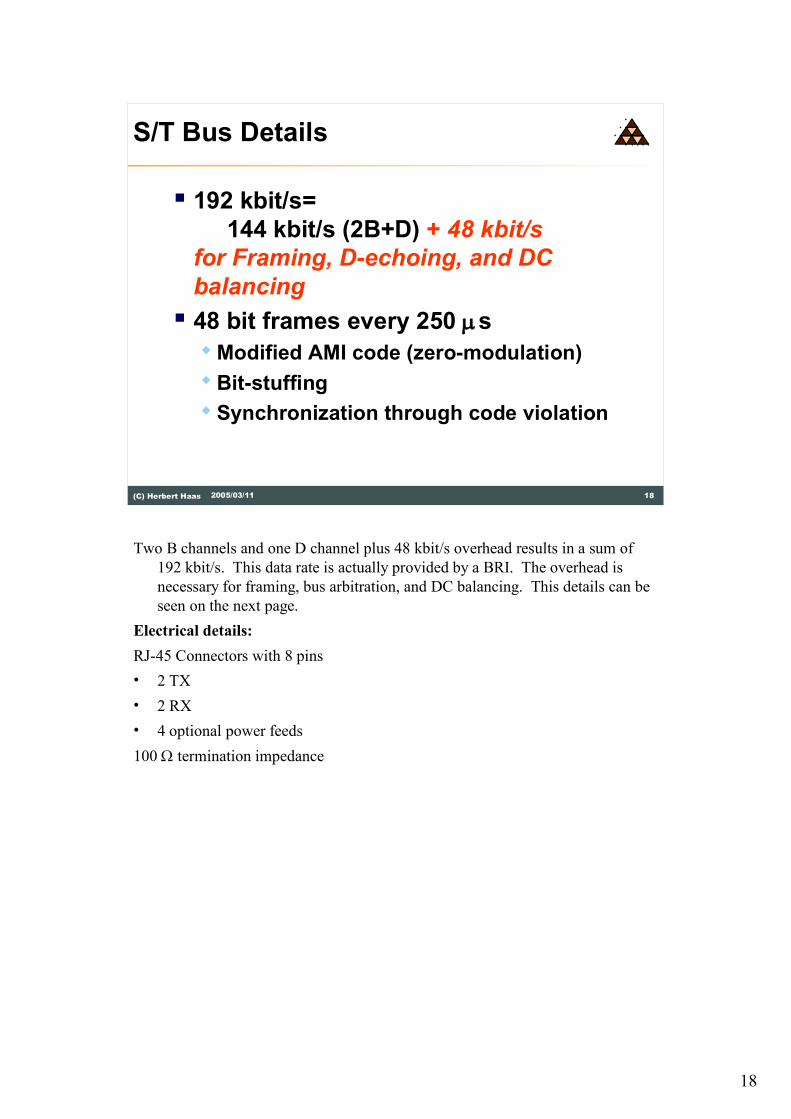
Two B channels and one D channel plus 48 kbit/s overhead results in a sum of
192 kbit/s. This data rate is actually provided by a BRI. The overhead is
necessary for framing, bus arbitration, and DC balancing. This details can be
seen on the next page.
Electrical details:
RJ-45 Connectors with 8 pins
� 2 TX
� 2 RX
� 4 optional power feeds
100 W termination impedance

19
19(C) Herbert Haas 2005/03/11
S/T-Bus
F B1L L D L FA L B2 L D L B1 L D L B2 L D L
48 bits in 250 ms
F B1L E D A FA N B2 E D M B1 E D S B2 E D L
TE to NT
NT to TEF... Framing bit
L... DC balancing bit
E... D-echo channel bit
A... Activation bit
FA.. Auxiliary framing bit
N... Set to opposite of FA
M... Multiframing bit
S.... Spare bits
8-bit
F (+) followed by L(-) marks start of frame. To prevent F in the bit stream, code
violations are used (normally alternate pulses (+, -) used for zeroes)
General rule: first logical zero to be transmitted uses a code violation symbol.
In case of "all-ones", the FA performs code violation. The auxiliary framing bit FA
is always set to 0; N = is always inverse of FA (=1 here).
L bits are used to guarantee DC balance:
� From NT to TE only one L bit is necessary
� From TE to NT every part of the frame (B1, B2 and D)
is balanced by individual L bits. Reason: every part of the frame (B1, B2, D)
may be sent by a different TE hence every TE must balance its own part.

20
20(C) Herbert Haas 2005/03/11
D � Channel Access Control (1)
� Before TE may use D channel:
Carrier Sense
� At least eight ones (no signal activity) in
sequence must be received
� Then TE may transmit on D channel:
Collision Detection
� If E bits unequal D bits TE will stop
transmission and wait for next eight
ones in sequences
In multipoint mode the S7T bus is used in contention mode similar to Ethernet.
Before a TE may use the D channel it must listen whether some TE is sending
�"carrier sense" is performed. Here at least eight "1" must be received in
sequence. Since the inverse AMI coding is used this means that nobody is
currently sending.
Then the TE may transmit data (e. g. a Q.931 packet within a Q.921 frame) on the
D channel. But during sending, this station must perform collision detection by
observing the echo bits which reflect all sent bits back from the NT.

21
21(C) Herbert Haas 2005/03/11
D � Channel Access Control (2)
� When using D channel
� Bit stuffing prevents sequence of eight
ones for the rest of the message
� Fairness
� TE must release D channel after
message was sent
� Next time, this TE must wait for a
sequence of nine ones
Of course measures must be implemented to avoid eight ones during sending�
another TE might assume that the S/T bus is empty! Thus bit stuffing is performed
in such cases (inserting a zero).
Furthermore, if a TE succeeded recently this TE must wait for nine ones before
grabbing the D channel. This method assures fairness among the TEs.

22
22(C) Herbert Haas 2005/03/11
PRI (I.431)
� Point-to-point configuration only
� Europe: E1
� 30 B channels
� 1 D channel (also 64 kbit/s)
� 1 Framing Channel
� USA: T1
� 23 B channels
� 1 D channel
The T1 frame synchronization is achieved using a single bit at the beginning of the
frame. Both E1 and T1 are explained in another module (Telco Backbones).

23
23(C) Herbert Haas 2005/03/11
LAPD (Q.921)
� Link Access Procedure D-Channel
� Based on HDLC ABM mode
� 2 byte address field (SAPI + TEI)
� Optionally extended sequence
numbering (0-127)
� Carries Q.931 packets
� May also be used to carry user traffic
� For example X.25 packets
Note that the D channel is empty in most of the time because its only needed when
establishing or closing a connection. Because of this, many providers allow to send
user data over the D channel, using for example X.25. Of course this is no free
service, because the provider network has to transport this data, so users have to
pay for it.

24
24(C) Herbert Haas 2005/03/11
Flag
SAPI C/R EA
TEI
Control
Information
FCSSAPI � Service Access Point Identifier TEI �.. Terminal Endpoint IdentifierEA �.. Address Field Extension BitC/R �. Command/Response Bit
LAPD Frame Format
EA
Flag
01234567
0
1
2
3
4
Address Information
The picture above shows the Q.921 or LAPD frame format. The Service Access
Point Identifier (SAPI) and the Terminal Endpoint Identifier (TEI) are described
next.
FYI: The SAPI and TEI is also called Data Link Connection Identifier (DLCI,
like in Frame Relay).

25
25(C) Herbert Haas 2005/03/11
TEI
� When TE occupies D channel, the ET
(switch) assigns a Terminal Endpoint
Identifier (TEI) to it
� LAPD frames carry TEI
� To identify source (TE � ET)
� To identify destination (ET � TE)
� Possible values: 0-127
A switch (LE) would not really know which TE is currently actice and has grabbed
the D channel. Therefore a Terminal Endpoint Identifier (TEI) is assigned to the
TEs. The LAPD frames carry the TEI which can be compared to an Ethernet
MAC address while the telephone number is similar to an IP address in this
context.

26
26(C) Herbert Haas 2005/03/11
TEI Management
� TEIs are either assigned automatically
� By switch (ET)
� TEI value range 64-126
� Or preconfigured
� Checking for duplicates necessary
� TEI value range 0-63
� TEI = 127 reserved for broadcasting
Note that the TEI is not used for primary rate interfaces (PRI) because PRI do not
support multipoint connections. Here the TEI is always set to zero.
The local switching station, or with an internal S0 the PBX, automatically or
permanently assigns each end device a Terminal End Identifier (TEI). This simply
allows the addressing of the D channels. TEIs have the following values: 0-63 =
permanent TEIs (e.g. 0 is used for point to point connections) 64-126 =
automatically assigned 127 = broadcast to all devices (e.g. an incoming call) .

27
27(C) Herbert Haas 2005/03/11
SAPI
� Service Access Point Identifier
(SAPI)
� OSI interface to layer 3
� �Identifies payload�
� 0 signaling information (s-type)
� 16 packet data (p-type)
� 63 management information
Additionally a Service Access Point Identifier (SAPI) is needed to identify the
content of this LAPD frame. Each SAPI number identifies a layer 3 service. For
example Q.931 services might be addressed or the SAPI might also indicate that
the LAPD payload is a X.25 data frame.

28
28(C) Herbert Haas 2005/03/11
TEI Management Messages
� UI frames with SAPI = 63 and TEI 127
� Information field contains
� Reference indicator (RI) to correlate
request and responses
� Action indicator (AI) to specify TEI in
question
� Message type
Also management messages are identifed by a special SAPI (63), combined with a
TEI of 127, which addresses all TEs (broadcast). These management messages are
used to assign TEIs to the TEs.
Examples for message types are:
ID_Request, ID_Check Response, ID_Verify (TE to NT) and
ID_Assigned, ID_Denied, ID_Check Request, ID_Remove (NT to TE)

29
29(C) Herbert Haas 2005/03/11
Q.931
� Carries signaling information
� Call control
� E. g. dial number and ring information
� Terminated by ET
� ET is real 7-layer gateway
� Translates Q.931 into Signaling System
7 (SS#7)
� Country-dependent versions (!)
Q.931 is a signaling protocol used by N-ISDN and also (slightly enhanced) by B-
ISDN. Using Q.931 the dial number is forwarded to the Telco switch, which
terminates the D channels and puts all signaling information on top of another
signaling protocol. Typically SS#7 is used in most Telco networks.
FYI: Some special features
CLIP (Calling Line Identification Presentation) can be offered by the ISDN provider. When you
call somebody, then your telephone number will be transmitted to the other phone. The opposite of
CLIP is CLIR: one can (from call to call) restrict the identification of one's own caller ID to the
other party.
COLP (Connected Line Identification Presentation) can also be offered by the ISDN provider.
COLP provides an extended dialing protocol. You will receive feedback from your
telecommunication company who picked up your outgoing call. Normally, you will get the same
number as you dialed beforehand; however, with call diversion this could also be a different
number.
30
30(C) Herbert Haas 2005/03/11
ISDN Switch Types
� BRI� Basic-net3 (Euro ISDN)
� 5ESS, DMS-100, NT1 (USA)
� NTT (Japan)
� Basic 1TR6 (Germany, old)
� VN2, VN3 (France)
� TS013 (Australia)
� PRI� primary-net5 (Euro ISDN)
� 4ESS, 5ESS, DMS-100 (USA)
� NTT (Japan)
� TS014
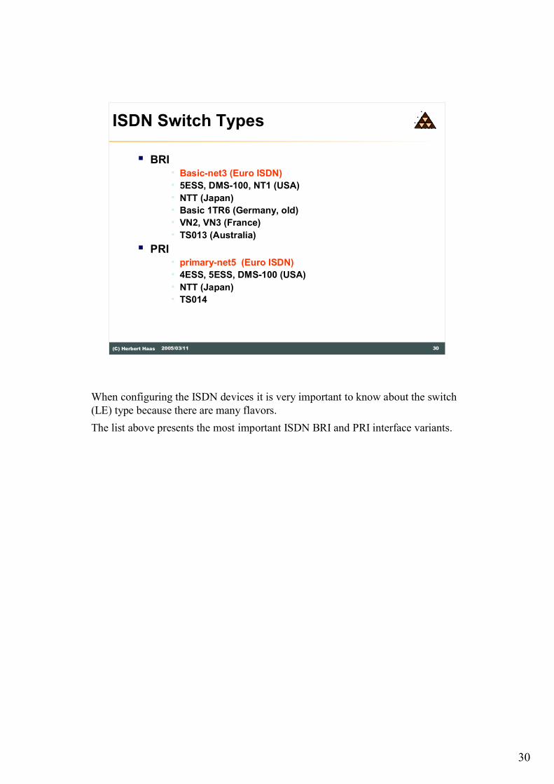
When configuring the ISDN devices it is very important to know about the switch
(LE) type because there are many flavors.
The list above presents the most important ISDN BRI and PRI interface variants.

31
31(C) Herbert Haas 2005/03/11
Q.931 Packet Format
Protocol Discriminator
0 0
Call Reference
Information Elements
Call Ref. Length
01234567
0
1
2
3
4
0 0
F
Message Type0
Call Information Phase
RESume
RESume ACKnowlegdeRESume REJect
SUSPend
SUSPend ACKnowledgeSUSPend REJect
USER INFOrmation
Miscellaneous
CANCelCONgestion CONtrol
FACility (Ack, Rej)INFOrmation
REGister (Ack, Rej)STATUS
Call Establishment
ALERTingCALL PROCeeding
CONNectCONNect ACKnowledge
SETUPSETUP ACKnowlegde
Call Clearing
DETatchDETach ACKnowledge
DISConnectRELease
RELease COMplete
REStartREStart ACKnowledge
Random
Number
Message Types:
The Q.931 packet format is given in the picture above only to provide a consistent
ISDN overview here. It is not necessary to memorize this structure in detail.
However it should be noticed that the actual information is carried in so-called
"Information Elements" (IE). Several Q.931 messages are listed in the right
hand side of the packet. Each message type is identified in the equivalent field in
the header and supports a specific set of IEs.
The protocol discriminator is set to 0x08 (except 1TR6: 0x41).

32
32(C) Herbert Haas 2005/03/11
Information Elements Examples
Bearer Capability (eg. 0x8890 .. dig. 64kb/s Circuit)0x04
0x08 Cause (reason codes for call disconnect)
Channel Identification0x18
0x1E Progress Indicator (check for 56kb/s connection)
Keypad0x2C
0x6C Calling Party Number
0x6D Calling Party Sub address
Called Party Number0x70
0x71 Called Party Subaddress
Low-Layer Compatibility0x7C
0x7D High-Layer Compatibility
In order to get a practical understanding of how Q.931 works, the table above
shows some examples of important Information Elements. The left column shows
the Information Element Identifier which is used at the beginning of each IE in
order to identify this IE. The IE structure is not shown in this chapter.

33
33(C) Herbert Haas 2005/03/11
Setup
Call Proceeding
Setup
Call Proceeding
Alerting
Progress
Alerting
Connect
Connect
Connect Ack
Connect Ack
Call Establishment
TE LE TE
Examples for Setup Information Elements are:
Bearer Capability IE
Voice/data call/fax, speed (64/56), transfer mode (packet/circuit),
user info L2 (I.441/X.25 L2), user info L3 (I.451/X.25 L3)
Channel Identification IE
Defines which B-channel is used
Called-Party number IE
Whom are you calling
Calling-Party number IE
Who is calling you (does not need to be delivered)
Keypad IE
Can be used instead of called-party number
High-Layer Compatibility IE
Used with the BC to check compatibility
Note: IEs vary among switch types (!)

34
34(C) Herbert Haas 2005/03/11
TE LE
Disconnect (cause)
Release
Release Complete
Disconnect (cause)
Release
Release Complete
OR
Call Release
At the end of this chapter we release the ISDN call with the messages shown
above.

35
35(C) Herbert Haas 2005/03/11
Summary
� Dynamical circuit switching
� BRI (2B+D) and PRI (30B+D)
� Bearer channels (B)
� Signaling channel (D)
� Q.921 (LAPD) and Q.931 on D channel
� Reference points (R, S, T, U)
� Function Groups
� TE1, TE2, TA, NT1, NT2, ET

36
36(C) Herbert Haas 2005/03/11
Quiz
� What voltage might be supplied for
power supply?
� The U interface is full-duplex but
there are only two wires...? How
does it work?
Recommended


![ISDN - Induteq1. schakeltechniek circuit switching packet switching frame relaying 2. transmissiesnelheid informatie-overdracht [Kbit/s] 64 2 x 64 384 1536 1920 N x 64 andere snelheid](https://img.pdfslide.net/doc/110x75/6050f45a0f33fb364021cbeb/isdn-induteq-1-schakeltechniek-circuit-switching-packet-switching-frame-relaying.jpg)
![Cis TelePresenCo Ce isDn link...ISDN PRI Interface 1 testShutdown ISDN BRI Interface [1..4] testLoopmode ISDN BRI Interface [1..4] testPattern Cisco telePresence ISDN Link Administrator](https://img.pdfslide.net/doc/110x75/6131c5191ecc51586944f1c2/cis-telepresenco-ce-isdn-link-isdn-pri-interface-1-testshutdown-isdn-bri-interface.jpg)