1
Chapter 4Internetworking
4.1 Simple Internetworking (IP) 4.2 Routing4.3 Global Internet4.4 Multicast4.5 Multiprotocol Label Switching (MPLS)

2
4.1 Simple Internetworking (IP)
Best Effort Service ModelGlobal Addressing SchemeARP (Address Resolution ProtocolICMP (Internet Message Control Protocol)
3
IP Internet Concatenation of Networks
Protocol Stack
R2
R1
H4
H5
H3H2H1
Network 2 (Ethernet)
Network 1 (Ethernet)
H6
Network 4(point-to-point)
H7 R3 H8
Network 3 (FDDI)
R1 R2 R3
H1 H8
ETH FDDI
IP
ETH
TCP
FDDI PPP PPP ETH
IP
ETH
TCP
IP IP IP

4
Service ModelConnectionless (datagram-based)Best-effort delivery (unreliable service)
packets are lostpackets are delivered out of orderduplicate copies of a packet are deliveredpackets can be delayed for a long time
Datagram formatVersion HLen TOS Length
Ident Flags Offset
TTL Protocol Checksum
SourceAddr
DestinationAddr
Options (variable) Pad(variable)
0 4 8 16 19 31
Data

5
Fragmentation and ReassemblyEach network has some MTUDesign decisions
fragment when necessary (MTU < Datagram)try to avoid fragmentation at source hostre-fragmentation is possible fragments are self-contained datagramsuse CS-PDU (not cells) for ATMdelay reassembly until destination hostdo not recover from lost fragments

6
Example
H1 R1 R2 R3 H8
ETH FDDI
PPP IP (376)
PPP IP (512)
PPP IP (512) (512)
ETH IP
ETH IP
(512)ETH IP
(376)
IP (1400) IP (1400)
R1 R2 R3
(a)
Ident = x
Start of header
Rest of header
1400 data bytes
Offset = 00
(b)
Ident = x
Start of header
Rest of header
512 data bytes
Offset = 01
Ident = x
Rest of header
512 data bytes
Offset = 641
Start of header
Ident = x
Start of header
Rest of header
376 data bytes
Offset = 1280

7
Global Addresses
Properties globally unique hierarchical: network + host
Dot Notation 10.3.2.4 128.96.33.81 192.12.69.77
Network Host
7 24
0(a)
Network Host
14 16
1 0(b)
Network Host
21 8
1 1 0(c)
8
Datagram Forwarding Strategy
every datagram contains destination’s address if connected to destination network, then forward to host if not directly connected, then forward to some router forwarding table maps network number into next hop each host has a default router each router maintains a forwarding table
Example (R2) Network Number Next Hop 1 R3 2 R1 3 interface 1 4 interface 0

9
Address Translation Map IP addresses into physical addresses
destination host next hop router
Techniques encode physical address in host part of IP address table-based
ARP table of IP to physical address bindings broadcast request if IP address not in table target machine responds with its physical address table entries are discarded if not refreshed

10
ARP Details
Request Format HardwareType: type of physical network (e.g., Ethernet) ProtocolType: type of higher layer protocol (e.g., IP) HLEN & PLEN: length of physical and protocol addresses Operation: request or response Source/Target-Physical/Protocol addresses
Notes table entries timeout in about 10 minutes update table with source when you are the target update table if already have an entry do not refresh table entries upon reference

11
ARP Packet Format
TargetHardwareAddr (bytes 2 - 5)
TargetProtocolAddr (bytes 0 3)
SourceProtocolAddr (bytes 2 3)
Hardware type = 1 ProtocolType = 0x0800
SourceHardwareAddr (bytes 4-5)
TargetHardwareAddr (bytes 0 – 1)
SourceProtocolAddr (bytes 0 -1)
HLen = 48 PLen = 32 Operation
SourceHardwareAddr (bytes 0― 3)
0 8 16 31
-
-

12
Internet Control Message Protocol (ICMP)Echo (ping)Redirect (from router to source host)Destination unreachable (protocol, port, or host)TTL exceeded (so datagrams don’t cycle forever)Checksum failed Reassembly failedCannot fragment

CS 461
Redirect
Network
G1
H2
Network
G2H1
Network
(1)
(2)
G2 finds that H1 is directly connected and will inform H1 to redirect the IP datagrams to G2.

14
4.2 Routing Forwarding vs Routing
forwarding: to select an output port based on destination address and routing table
routing: process by which routing table is built Network as a Graph
Problem: Find lowest cost path between two nodes Factors
static: topology dynamic: load
4
3
6
21
9
1
1D
A
FE
B
C

15
Distance VectorEach node maintains a set of triples
(Destination, Cost, NextHop)
Directly connected neighbors exchange updates periodically (on the order of several seconds) whenever table changes (called triggered update)
Each update is a list of pairs: (Destination, Cost)
Update local table if receive a “better” route smaller cost came from next-hop
Refresh existing routes; delete if they time out

16
Routing Table Example (Node B)
Destination Cost NextHop A 1 A C 1 C D 2 C E 2 A F 2 A G 3 A
D
G
A
F
E
B
C

17
Routing LoopsExample 1
F detects that link to G has failed F sets distance to G to infinity and sends update to A A sets distance to G to infinity since it uses F to reach G A receives periodic update from C with 2-hop path to G A sets distance to G to 3 and sends update to F F decides it can reach G in 4 hops via A
D
G
A
F
E
B
C

18
Routing LoopsExample 2
link from A to E fails A advertises distance of infinity to E B and C advertise a distance of 2 to E B decides it can reach E in 3 hops; advertises this to A A decides it can read E in 4 hops; advertises this to C C decides that it can reach E in 5 hops…
D
G
A
F
E
B
C

19
Distance Vector: link cost changesLink cost changes: node detects local link cost change updates routing info, recalculates
distance vector if DV changes, notify neighbors
“ goodnews travelsfast”
x z14
50
y1
At time t0, y detects the link-cost change, updates its DV, and informs its neighbors.
At time t1, z receives the update from y and updates its table. It computes a new least cost to x and sends its neighbors its DV.
At time t2, y receives z’s update and updates its distance table. y’s least costs do not change and hence y does not send any message to z.
20
algorithmterminates
x z14
50
y1
Distance Vector: link cost changes
“ good news Travels fast”
Dy
Dz

21
Distance Vector: link cost changesLink cost changes: bad news travels slow - “count to infinity” problem! 44 iterations before algorithm stabilizes z (y) does not know that the least distance from y (z)
to x that y (z) tells z (y) is the distance of the path y-z-y-x (z-y-x)
X Z14
50
Y60
algorithmcontinues
on!

22
Distance Vector: poisoned reverseIf Z routes through Y to get to X : Z tells Y its (Z’s) distance to X is infinite (so Y
won’t route to X via Z) will this completely solve count to infinity
problem? Loops involving three or more nodes cannot be
solved using the technique
X Z14
50
Y60
algorithmterminates

23
RIP ( Routing Information Protocol)
Distance vector algorithm Included in BSD-UNIX Distribution in 1982Distance metric: # of hops (max = 15 hops)
DC
BA
u v
w
x
yz
destination hops u 1 v 2 w 2 x 3 y 3 z 2
Source node: A

24
RIP advertisements
Distance vectors: exchanged among neighbors every 30 sec via Response Message (also called advertisement)
Each advertisement: a list of up to 25 destination subnets within AS
Address of net 2
Distance to net 2
Command Must be zero
Family of net 2 Address of net 2
Family of net 1 Address of net 1
Address of net 1
Distance to net 1
Version
0 8 16 31

25
RIP: Example
Destination Network Next Router Num. of hops to dest. w A 2
y B 2 z B 7
x -- 1…. …. ....
w x y
z
A
C
D B
Routing table in D

26
RIP: Example
Destination Network Next Router Num. of hops to dest. w A 2
y B 2 z B A 7 5
x -- 1…. …. ....Routing table in D
w x y
z
A
C
D B
Dest Next hops w - - x - - z C 4 …. … ...
Advertisementfrom A to D

27
RIP: Link Failure and Recovery
If no advertisement heard after 180 sec --> neighbor or link declared deadroutes via neighbor invalidatednew advertisements sent to neighborsneighbors in turn send out new advertisements (if
tables changed) link failure info quickly propagates to entire netpoison reverse used to prevent ping-pong loops
(infinite distance = 16 hops)

28
RIP Table processing
RIP routing tables managed by application-level process called route-d (daemon)
advertisements sent in UDP packets, periodically repeated
physical
link
network forwarding (IP) table
Transprt (UDP)
routed
physical
link
network (IP)
Transprt (UDP)
routed
forwardingtable
29
Link State
Strategysend to all nodes (not just neighbors) information
about directly connected links (not entire routing table)
Link State Packet (LSP) id of the node that created the LSPcost of link to each directly connected neighborsequence number (SEQNO) time-to-live (TTL) for this packet
30
Link State (cont)
Reliable floodingstore most recent LSP from each nodeforward LSP to all nodes but one that sent itgenerate new LSP periodically
increment SEQNOstart SEQNO at 0 when rebootdecrement TTL of each stored LSP
discard when TTL=0

31
Reliable Flooding
(a)
X A
C B D
(b)
X A
C B D
(c)
X A
C B D
(d)
X A
C B D
32
Route Calculation Dijkstra’s shortest path algorithm Let
N denotes set of nodes in the graph l (i, j) denotes non-negative cost (weight) for edge (i, j) s denotes this node M denotes the set of nodes incorporated so far C(n) denotes cost of the path from s to node n
M = {s}for each n in N - {s}
C(n) = l(s, n)while (N != M)
M = M union {w} such that C(w) is the minimum for all w in (N - M)
for each n in (N - M)C(n) = MIN(C(n), C (w) + l(w, n ))

33
A Link-State Routing Algorithm
Dijkstra’s algorithm net topology, link costs known to
all nodes accomplished via “link state
broadcast” all nodes have same info
computes least cost paths from one node (‘source”) to all other nodes gives forwarding table for that
node iterative: after k iterations, know
least cost path to k destinations
Notation: c(x,y): link cost from node x to
y; = ∞ if not direct neighbors
D(v): current value of cost of path from source to destination v
p(v): predecessor node along path from source to v
N': set of nodes whose least cost path definitively known

34
Dijsktra’s Algorithm
1 Initialization: 2 N' = {u} 3 for all nodes v 4 if v adjacent to u 5 then D(v) = c(u,v) 6 else D(v) = ∞ 7 8 Loop 9 find w not in N' such that D(w) is a minimum 10 add w to N' 11 update D(v) for all v adjacent to w and not in N' : 12 D(v) = min( D(v), D(w) + c(w,v) ) 13 /* new cost to v is either old cost to v or known 14 shortest path cost to w plus cost from w to v */ 15 until all nodes in N'
u: source node

35
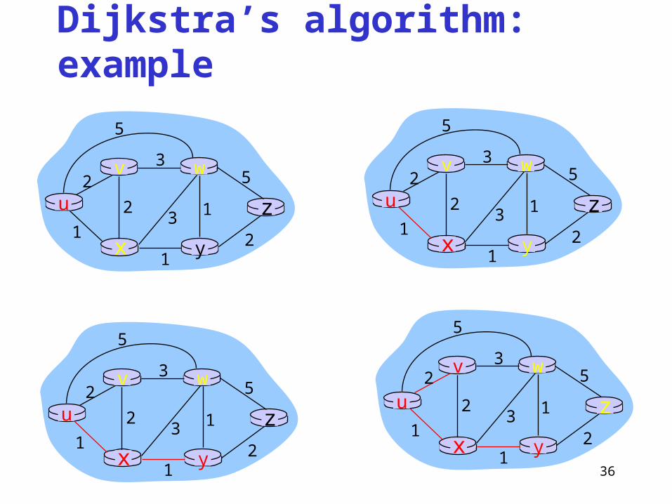
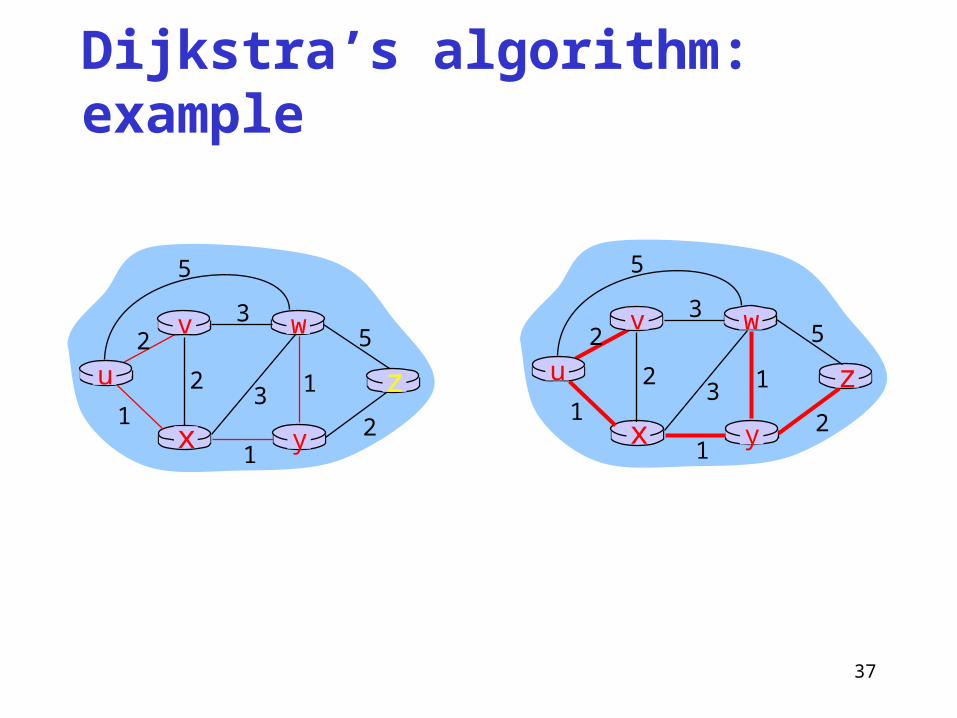
Dijkstra’s algorithm: example
Step012345
N'u
uxuxy
uxyvuxyvw
uxyvwz
D(v),p(v)2,u2,u2,u
D(w),p(w)5,u4,x3,y3,y
D(x),p(x)1,u
D(y),p(y)∞
2,x
D(z),p(z)∞ ∞
4,y4,y4,y
u
yx
wv
z2
2
13
1
1
2
53
5
36
Dijkstra’s algorithm: example
u
yx
wv
z2
2
13
1
1
2
53
5
u
yx
wv
z2
2
13
1
1
2
53
5
u
yx
wv
z2
2
13
1
1
2
53
5
u
yx
wv
z2
2
13
1
1
2
53
5
37
Dijkstra’s algorithm: example
u
yx
wv
z2
2
13
1
1
2
53
5
u
yx
wv
z2
2
13
1
1
2
53
5
38
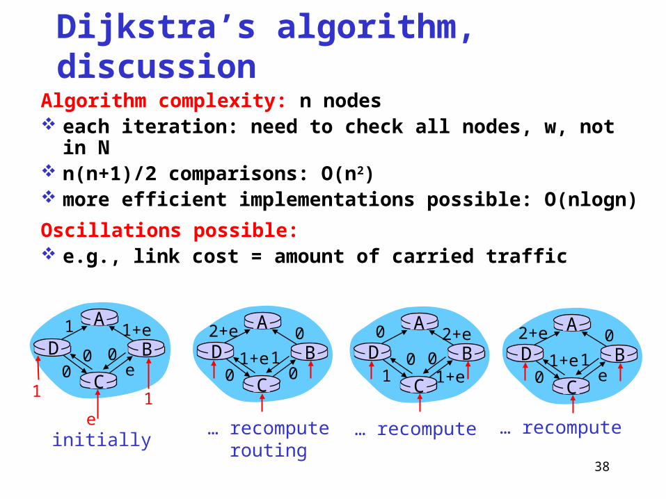
Dijkstra’s algorithm, discussion
Algorithm complexity: n nodes each iteration: need to check all nodes, w, not in N n(n+1)/2 comparisons: O(n2) more efficient implementations possible: O(nlogn)
Oscillations possible: e.g., link cost = amount of carried traffic
A
D
C
B1 1+e
e0
e
1 1
0 0
A
D
C
B2+e 0
001+e1
A
D
C
B0 2+e
1+e10 0
A
D
C
B2+e 0
e01+e1
initially… recompute
routing… recompute … recompute

39
OSPF (Open Shortest Path First)
“open”: publicly available – defined in RFC 2328Uses Link State algorithm
Link-State packet dissemination Topology map at each node Route computation using Dijkstra’s algorithm
OSPF advertisement carries one entry per neighbor router
Advertisements disseminated to entire AS (via flooding) Carried in OSPF messages directly over IP (rather than TCP
or UDP)

40
OSPF “advanced” features (not in RIP)
Security: all OSPF messages authenticated (to prevent malicious intrusion)
Load Balancing: Multiple same-cost paths allowed (only one path in RIP)
For each link, multiple cost metrics for different TOS (e.g., satellite link cost set “low” for best effort; high for real time)
Integrated uni- and multicast support: Multicast OSPF (MOSPF) uses same topology data
base as OSPF Hierarchical OSPF in large domains.

41
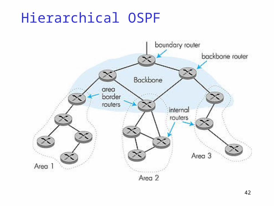
Hierarchical OSPF
An OSPF autonomous system (AS) can be configured into areas
Exactly one OSPF area in the AS is configured to be the backbone area
Each area runs its own OSPF link-state routing algorithm Two-level hierarchy: local area, backbone.
Link-state advertisements only in area each nodes has detailed area topology; only know
direction (shortest path) to nets in other areas.
42
Hierarchical OSPF

43
Hierarchical OSPF
Four types of routersInternal routers: perform only intra AS routingArea border routers: belong to both an area
and the backboneBackbone routers: run OSPF routing limited to
backbone.Boundary routers: connect to other AS’s.
44
OSPF Advertisement Format
Authentication
Version Type Message length
Checksum Authentication type
SourceAddr
AreaId
0 8 16 31LS Age Options Type=1
0 Flags 0 Number of links
Link type Num_TOS Metric
Link-state ID
Advertising router
LS sequence number
Link ID
Link data
Optional TOS information
More links
LS checksum Length
Header FormatLink-State Advertisement
45
Comparison of LS and DV algorithms
Message complexity LS: with n nodes, E links, O(nE)
messages sent DV: exchange between
neighbors only convergence time varies
Speed of Convergence LS: O(n2) algorithm requires
O(nE) messages may have oscillations
DV: convergence time varies may be routing loops count-to-infinity problem
Robustness: what happens if router malfunctions?
LS: node can advertise incorrect
link cost each node computes only its
own table
DV: DV node can advertise
incorrect path cost each node’s table used by
others error propagate thru
network
46
Metrics Original ARPANET metric
measures number of packets queued on each link took neither latency or bandwidth into consideration
New ARPANET metricstamp each incoming packet with its arrival time (AT)record departure time (DT)when link-level ACK arrives, compute
Delay = (DT - AT) + Transmit + Latency if timeout, reset DT to departure time for retransmission link cost = average delay over some time period

47
Metrics Still has problems
Under light load, it works well since the two static factors of delay dominated the cost.
Under heavy load, a congested link would start to advertise a very high cost. This caused all the traffic to move off that link, leaving it idle, so then it advertise a low cost,…
The range of link values was much too large.Fine Tuning
compressed dynamic rangereplaced Delay with link utilization

48
Revised ARPANET routing metric versus link utilization
225
140
907560
30
25% 50% 75% 100%
Utilization
9.6-Kbps satellite link
9.6-Kbps terrestrial link
56-Kbps satellite link
56-Kbps terrestrial link

49
Revised ARPANET routing metric versus link utilizationA highly loaded link never shows a cost of
more than three times its cost when idleThe most expensive link is only seven times
the cost of least expensiveA high-speed satellite link is more attractive
than a low-speed terrestrial linkCost is a function of link utilization only at
moderate to high loads.
50
Tree Structure of the Internet in 1990
NSFNET backboneStanford
BARRNETregional
BerkeleyPARC
NCAR
UA
UNM
Westnetregional
UNL KU
ISU
MidNetregional■ ■ ■
4.3 Global Internet Structure

51
Global Internet One of the salient features of this topology is that it consists of
“end user” sites (e.g, Stanford university) that connect to “service provider” networks (e.g, BARRNET)
Each provider and end user is likely to be an administratively independent entity – Autonomous System (AS).
Scalability problems Scalability of routing Address utilization
Subnetting – deals with address space utilization Classless routing or supernetting – tackles both address
utilization and routing scalability

52
Subnetting Inefficient use of Hierarchical Address Space
class C with 2 hosts (2/255 = 0.78% efficient) class B with 256 hosts (256/65535 = 0.39% efficient)
Still Too Many Networks routing tables do not scale route propagation protocols do not scale
Subnetting provides an elegantly simple way to reduce the total number of networks that are assigned
The idea is to take a single IP network number and allocate the IP addresses with that network number to several physical networks – subnets.
53
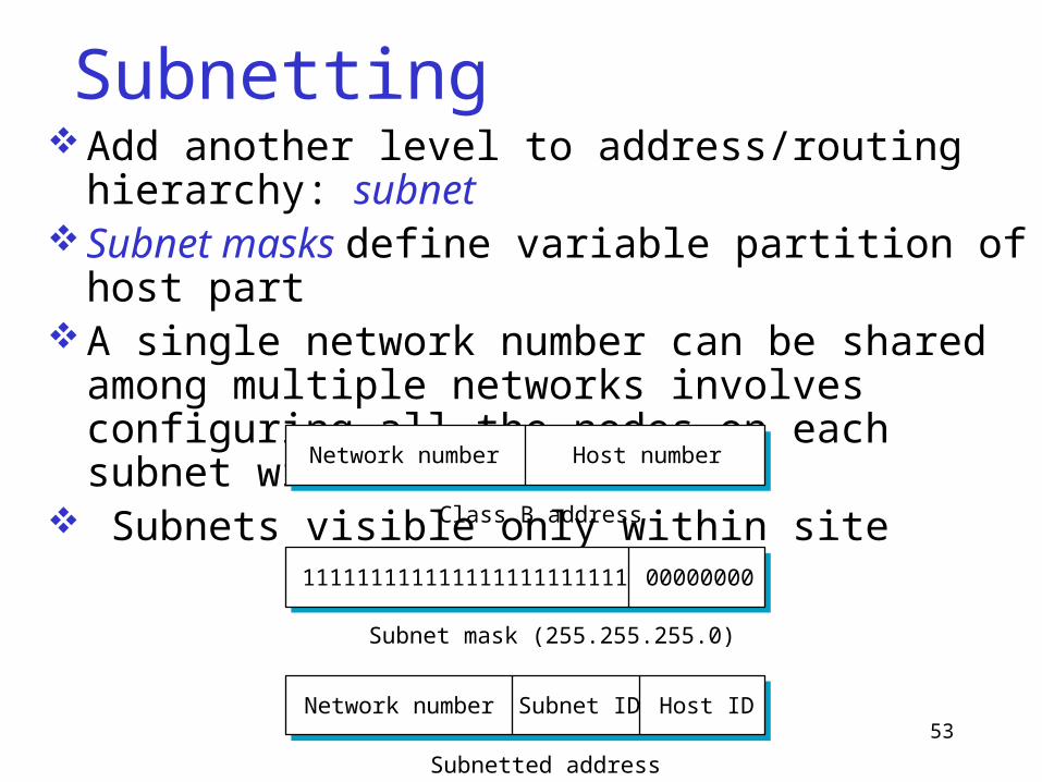
SubnettingAdd another level to address/routing hierarchy: subnetSubnet masks define variable partition of host partA single network number can be shared among multiple
networks involves configuring all the nodes on each subnet with a subnet mask.
Subnets visible only within siteNetwork number Host number
Class B address
Subnet mask (255.255.255.0)
Subnetted address
11111111111111111111111100000000
Network number Host IDSubnet ID
54
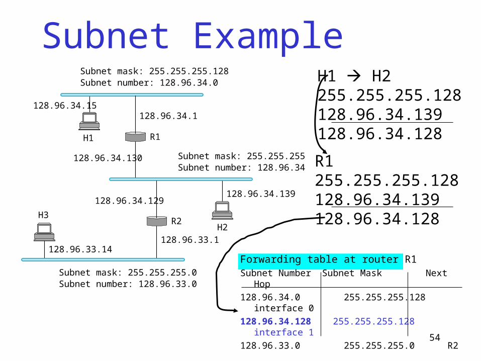
Subnet Example
Forwarding table at router R1Subnet Number Subnet Mask Next Hop
128.96.34.0 255.255.255.128 interface 0
128.96.34.128 255.255.255.128 interface 1
128.96.33.0 255.255.255.0 R2
Subnet mask: 255.255.255.128Subnet number: 128.96.34.0
128.96.34.15128.96.34.1
H1 R1
128.96.34.130 Subnet mask: 255.255.255.128Subnet number: 128.96.34.128
128.96.34.129128.96.34.139
R2H2
128.96.33.1128.96.33.14
Subnet mask: 255.255.255.0Subnet number: 128.96.33.0
H3
H1 H2255.255.255.128128.96.34.139128.96.34.128
R1 255.255.255.128128.96.34.139128.96.34.128
55
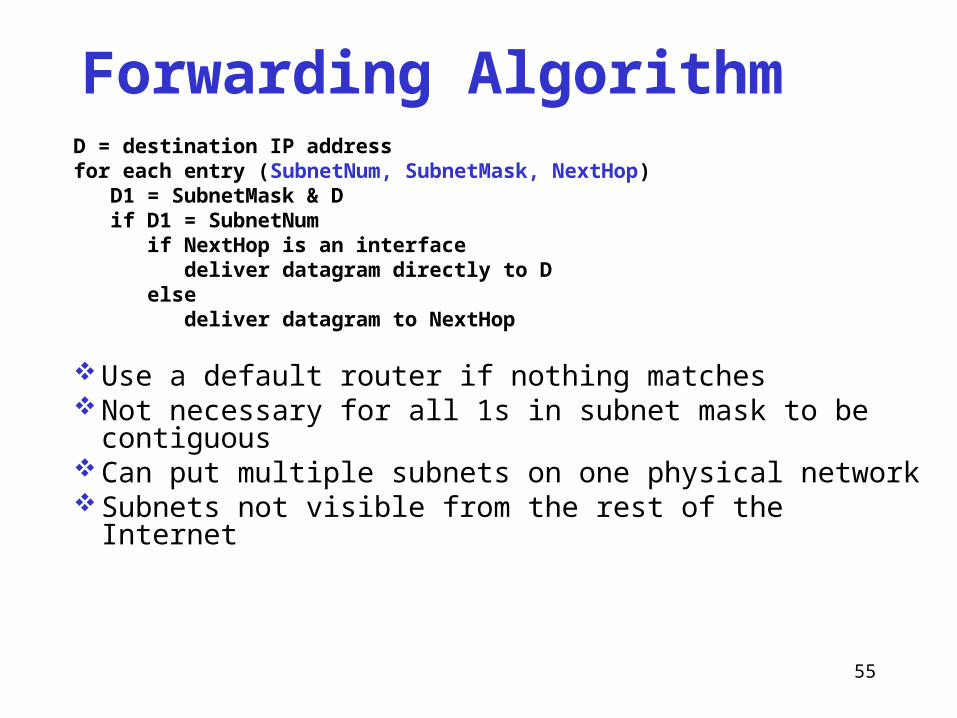
Forwarding AlgorithmD = destination IP addressfor each entry (SubnetNum, SubnetMask, NextHop) D1 = SubnetMask & D if D1 = SubnetNum if NextHop is an interface deliver datagram directly to D else deliver datagram to NextHop
Use a default router if nothing matches Not necessary for all 1s in subnet mask to be contiguous Can put multiple subnets on one physical network Subnets not visible from the rest of the Internet
56
Classless Routing (CIDR) Supernetting CIDR: Classless Inter-Domain Routing A technique that addresses two scaling concerns:
the growth of backbone routing tables, and the potential for the 32-bit IP address space to be exhausted
well before the 4 billionth host is attached to the Internet.Even though subnetting can help to assign addresses
carefully, it does not get around the fact that any AS with more than 255 hosts wants a class B address – exhaustion of IP address space.

57
Classless Routing (CIDR) Supernetting CIDR tries to balance the desire to minimize the
number of routes that a router needs to know against the need to hand out addresses efficiently
Assign block of contiguous network numbers to nearby networks
Represent blocks with a single pair (first_network_address, count)
Restrict block sizes to powers of 2Use a bit mask (CIDR mask) to identify block sizeAll routers must understand CIDR addressing

58
Route aggregation with CIDR
AdvertiseISP
128.112.128/24
128.112.135/24
128.112.128/21
Customers
...
Since all of the customers are reachable through the same Provider network, it can advertise a single route to all of Them by just advertising the common 21-bit prefix they share

59
IP Forwarding Revisited Find the network number in a packet and then lookup that number in a
forwarding table. Reexamine this assumption with CIDR Prefixes length 2-32 bits Prefixes may “overlap” Some addresses may match more than one prefix. Longest Prefix Matching (LPM) For example
171.69 (16-bit prefix) 171.69.10 (24-bit prefix) 171.69.10.5 matches both 171.69.20.5 only matches 171.69
60
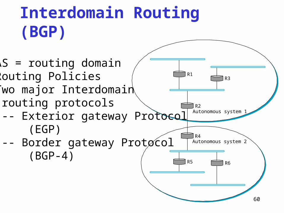
Interdomain Routing (BGP)
R1
Autonomous system 1R2
R3
Autonomous system 2R4
R5 R6
• AS = routing domain• Routing Policies• Two major Interdomain routing protocols -- Exterior gateway Protocol (EGP) -- Border gateway Protocol (BGP-4)

61
BGP-4: Border Gateway ProtocolAS Types
stub AS: has a single connection to one other AScarries local traffic only
multihomed AS: has connections to more than one ASrefuses to carry transit traffic
transit AS: has connections to more than one AScarries both transit and local traffic
Each AS has:one or more border routersone BGP speaker that advertises:
local networksother reachable networks (transit AS only)gives path information

62
Backbone service provider
Peeringpoint
Peeringpoint
Large corporation
Large corporation
Smallcorporation
“ Consumer” ISP
“ Consumer” ISP
“ Consumer” ISP
Today’s multibackbone Internet
63
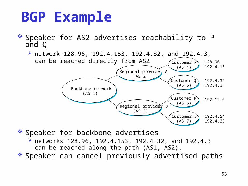
BGP Example Speaker for AS2 advertises reachability to P and Q
network 128.96, 192.4.153, 192.4.32, and 192.4.3, can be reached directly from AS2
Speaker for backbone advertises networks 128.96, 192.4.153, 192.4.32, and 192.4.3 can be reached
along the path (AS1, AS2). Speaker can cancel previously advertised paths
Regional provider A(AS 2)
Regional provider B(AS 3)
Customer P(AS 4)
Customer Q(AS 5)
Customer R(AS 6)
Customer S(AS 7)
128.96192.4.153
192.4.32192.4.3
192.12.69
192.4.54192.4.23
Backbone network(AS 1)
64
Internet inter-AS routing: BGP
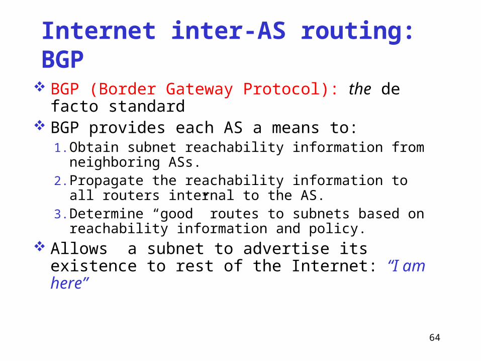
BGP (Border Gateway Protocol): the de facto standard
BGP provides each AS a means to:1. Obtain subnet reachability information from neighboring
ASs.2. Propagate the reachability information to all routers
internal to the AS.3. Determine “good” routes to subnets based on reachability
information and policy. Allows a subnet to advertise its existence to rest of
the Internet: “I am here”

65
BGP basics Pairs of routers (BGP peers) exchange routing information over
semi-permanent TCP connections: BGP sessions Note that BGP sessions do not correspond to physical links. When AS2 advertises a prefix to AS1, AS2 is promising it will
forward any datagrams destined to that prefix towards the prefix. AS2 can aggregate prefixes in its advertisement
3b
1d
3a
1c2aAS3
AS1
AS21a
2c
2b
1b
3c
External BGP (eBGP) session
Internal BGP (iBGP) session

66
Aggregation of prefixes
138.16.64/24
138.16.65/24
138.16.66/24 => 138.16.64/22
138.16.67/24
67
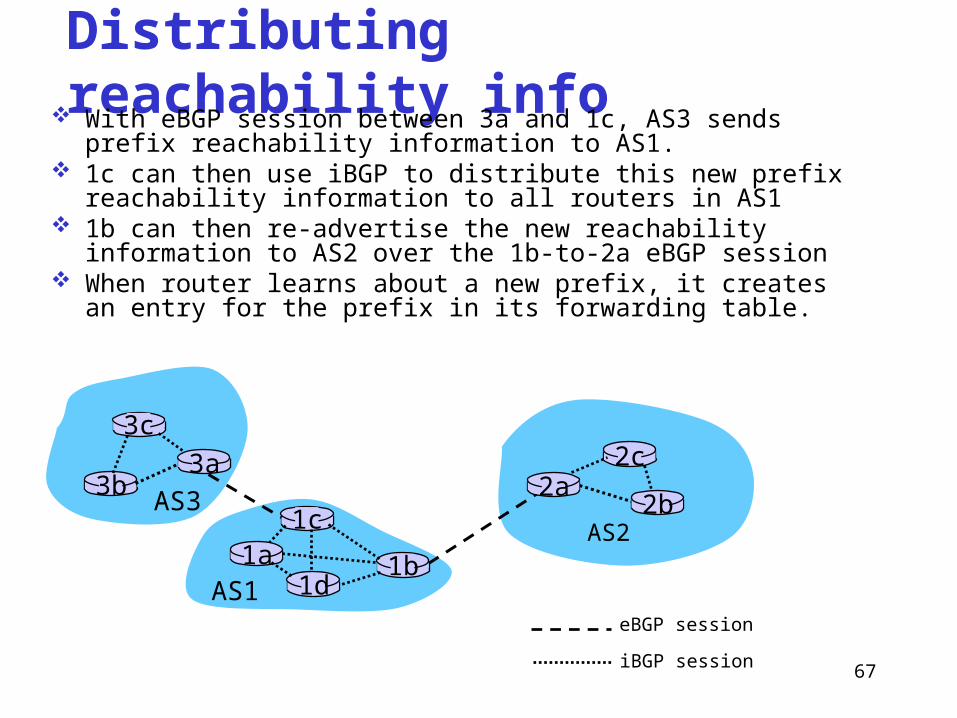
Distributing reachability info With eBGP session between 3a and 1c, AS3 sends prefix reachability
information to AS1. 1c can then use iBGP to distribute this new prefix reachability
information to all routers in AS1 1b can then re-advertise the new reachability information to AS2 over
the 1b-to-2a eBGP session When router learns about a new prefix, it creates an entry for the
prefix in its forwarding table.
3b
1d
3a
1c2aAS3
AS1
AS21a
2c
2b
1b
3c
eBGP session
iBGP session

68
Path attributes & BGP routes When advertising a prefix, advertisement includes BGP
attributes. prefix + attributes = “route”
Two important attributes: AS-PATH: contains the ASs through which the advertisement for
the prefix passed: AS 67 AS 17 used to detect and prevent looping advertisement also use in choosing among multiple path to the same prefix
NEXT-HOP: Indicates the specific internal-AS router to next-hop AS. (There may be multiple links from current AS to next-hop-AS.)
When gateway router receives route advertisement, uses import policy to accept/decline.
69
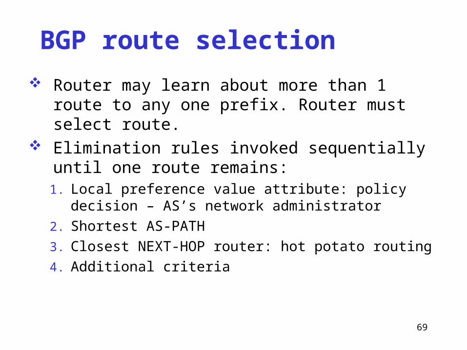
BGP route selection
Router may learn about more than 1 route to any one prefix. Router must select route.
Elimination rules invoked sequentially until one route remains:
1. Local preference value attribute: policy decision – AS’s network administrator
2. Shortest AS-PATH
3. Closest NEXT-HOP router: hot potato routing
4. Additional criteria
70
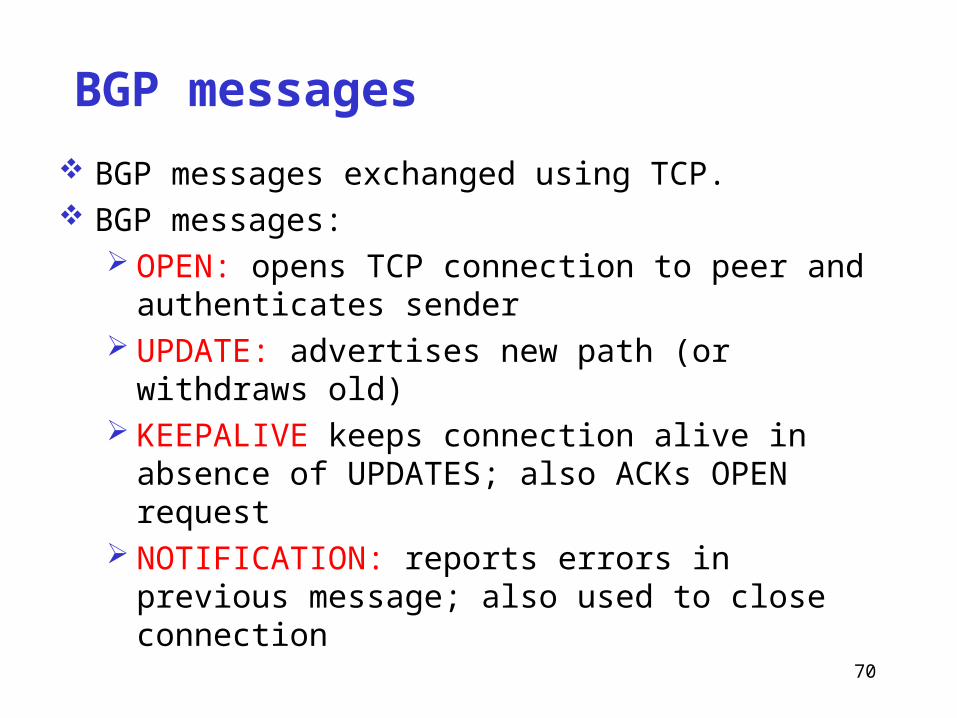
BGP messages
BGP messages exchanged using TCP. BGP messages:
OPEN: opens TCP connection to peer and authenticates sender
UPDATE: advertises new path (or withdraws old) KEEPALIVE keeps connection alive in absence of
UPDATES; also ACKs OPEN request NOTIFICATION: reports errors in previous message; also
used to close connection

71
BGP routing policy
Figure 4.5-BGPnew: a simple BGP scenario
A
B
C
W X
Y
legend:
customer network:
provider network
A,B,C are provider networks X,W,Y are customer (of provider networks) X is dual-homed: attached to two networks
X does not want to route from B via X to C .. so X will not advertise to B a route to C
72
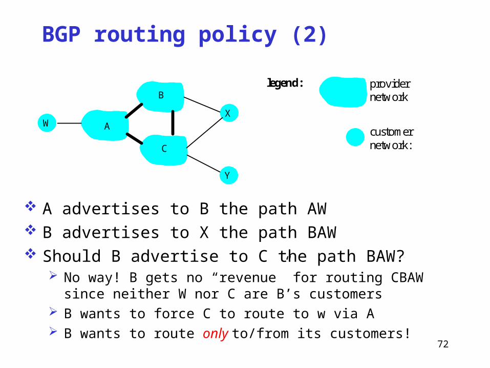
BGP routing policy (2)
Figure 4.5-BGPnew: a simple BGP scenario
A
B
C
W X
Y
legend:
customer network:
provider network
A advertises to B the path AW B advertises to X the path BAW Should B advertise to C the path BAW?
No way! B gets no “revenue” for routing CBAW since neither W nor C are B’s customers
B wants to force C to route to w via A B wants to route only to/from its customers!
73
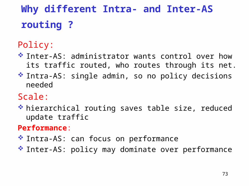
Why different Intra- and Inter-AS routing ?
Policy: Inter-AS: administrator wants control over how its traffic
routed, who routes through its net. Intra-AS: single admin, so no policy decisions needed
Scale: hierarchical routing saves table size, reduced update traffic
Performance: Intra-AS: can focus on performance Inter-AS: policy may dominate over performance

74
IP Version 6 Features
128-bit addresses (classless) multicast real-time service authentication and security autoconfiguration end-to-end fragmentation protocol extensions
Header 40-byte “base” header extension headers (fixed order, mostly fixed length)
fragmentationsource routingauthentication and securityother options

75
4.4 Broadcast/Multicast routing
Broadcast routing –- deliver a packet from a source node to all other nodes
Multicast routing – deliver a packet from a source node to a subset of other nodes

76
(a) source duplication, (b) in-network duplication
R1
R2
R3 R4
(a)
R1
R2
R3 R4
(b)
duplicatecreation/transmissionduplicate
duplicate
Source-duplication versus in-network duplication

77
Broadcast routing algorithms
Uncontrolled floodingControlled floodingSpanning-tree broadcast

78
Uncontrolled floodingThe source node sends a copy of the packet to all of its
neighborsWhen a node receives a broadcast packet, it duplicates
the packet and forwards it to all of its neighbors (except the neighbor from which it receives the packet)
Problems:If the graph has cycles, then one or more copies of each
broadcast packet will cycle indefinitelyBroadcast storm

79
Controlled floodingSequence-number-controlled flooding
Source node puts its address and a broadcast sequence number into a broadcast packet
Each node maintains a list of the source address and sequence number of each packet it has received
When a node receives a broadcast packetIf the packet is in the list, the packet is droppedOtherwise, the packet is duplicated and forwarded

80
A
B
G
DE
c
F
Controlled flooding
Packet will be forwarded
Packet not forwarded beyond receiving router
Reverse path forwardingWhen a router receives a broadcast packet, it duplicates and
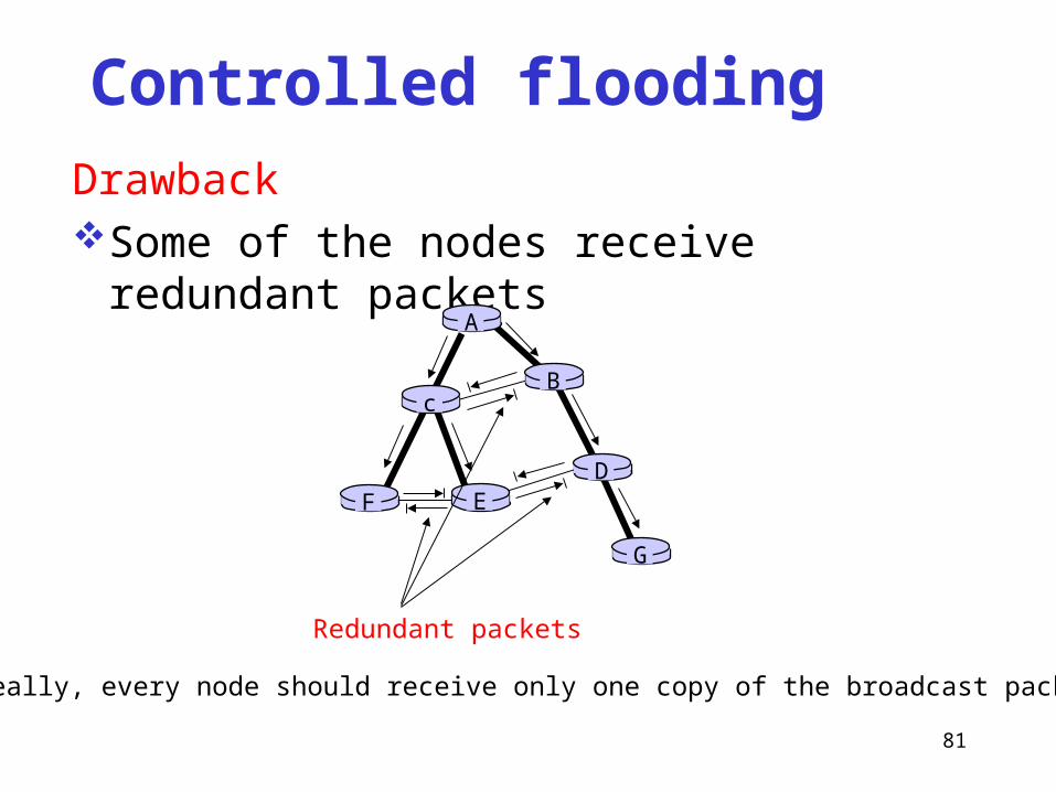
forwards the packet only if the packet arrives on the link that is on its own shortest unicast path back to the source
81
Controlled flooding
DrawbackSome of the nodes receive redundant packets
A
B
G
DE
c
F
Redundant packets
Ideally, every node should receive only one copy of the broadcast packet.

82
A
B
G
DE
c
F
A
B
G
DE
c
F
(a) Broadcast initiated at A (b) Broadcast initiated at D
Spanning-tree broadcastSpanning tree – a tree that contains all nodes in a graph
Minimum spanning tree – a spanning tree whose cost is the minimum among all the spanning trees of a graph
Broadcast along a spanning tree

83
(a) Stepwise construction of spanning tree
A
B
G
DE
c
F
(b) Constructed spanning tree
Construction of Spanning-treeMany algorithms have been developedCenter-based approach
Select a center node (rendezvous or core) Each node unicasts tree-join message to the center node
A
B
G
DE
c
F1
2
3
4
5Center node
84
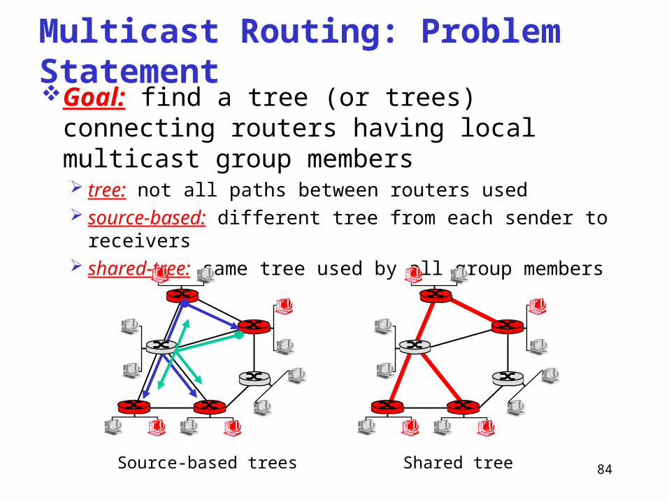
Multicast Routing: Problem StatementGoal: find a tree (or trees) connecting routers
having local multicast group members tree: not all paths between routers used source-based: different tree from each sender to receivers shared-tree: same tree used by all group members
Shared treeSource-based trees

85
Approaches for building multicast trees
source-based tree: one tree per sourceshortest path treesreverse path forwarding
group-shared tree: group uses one treeminimal spanning (Steiner) center-based trees
…we first look at basic approaches, then specific protocols adopting these approaches

86
Shortest Path Treemulticast forwarding tree: tree of shortest path
routes from source to all receiversDijkstra’s algorithm
R1
R2
R3
R4
R5
R6 R7
21
6
3 4
5
i
router with attachedgroup member
router with no attachedgroup member
link used for forwarding,i indicates order linkadded by algorithm
LEGENDS: source

87
Reverse Path Forwarding
if (multicast datagram received on incoming link on shortest path back to sender)
then flood datagram onto all outgoing links
else ignore datagram
rely on router’s knowledge of unicast shortest path from it to sender
each router has simple forwarding behavior:
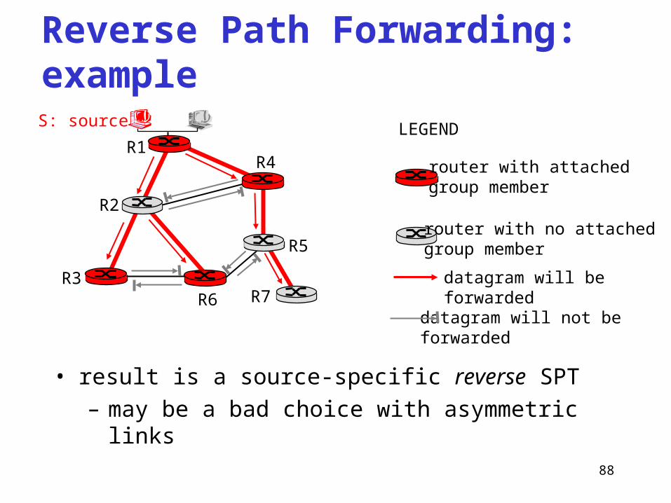
88
Reverse Path Forwarding: example
• result is a source-specific reverse SPT– may be a bad choice with asymmetric links
R1
R2
R3
R4
R5
R6 R7
router with attachedgroup member
router with no attachedgroup member
datagram will be forwarded
LEGENDS: source
datagram will not be forwarded

89
Reverse Path Forwarding: pruning forwarding tree contains subtrees with no multicast
group membersno need to forward datagrams down subtree“prune” messages sent upstream by router with
no downstream group members
R1
R2
R3
R4
R5
R6 R7
router with attachedgroup member
router with no attachedgroup member
prune message
LEGENDS: source
links with multicastforwarding
P
P
P

90
Shared-Tree: Steiner TreeSteiner Tree: minimum cost tree connecting all
routers with attached group membersproblem is NP-completeexcellent heuristics existsnot used in practice:
computational complexity information about entire network neededmonolithic: rerun whenever a router needs to join/leave

91
Center-based trees single delivery tree shared by allone router identified as “center” of tree to join:
edge router sends unicast join-message addressed to center router
join-message “processed” by intermediate routers and forwarded towards center
join-message either hits existing tree branch for this center, or arrives at center
path taken by join-message becomes new branch of tree for this router

92
Center-based trees: an example
Suppose R6 chosen as center:
R1
R2
R3
R4
R5
R6 R7
router with attachedgroup member
router with no attachedgroup member
path order in which join messages generated
LEGEND
21
3
1

93
Internet Multicasting Routing: DVMRP
DVMRP: distance vector multicast routing protocol, RFC1075
flood and prune: source-based tree, reverse path forwarding, RPF tree based on DVMRP’s own routing tables
constructed by communicating DVMRP routers no assumptions about underlying unicast initial datagram to multicast group flooded everywhere via
RPF routers not wanting group: send upstream prune messages

94
DVMRP: continued…
soft state: DVMRP router periodically (1 min.) “forgets” branches are pruned: multicast data again flows down unpruned branchdownstream router: reprune or else continue to receive
data
routers can quickly regraft to tree following IGMP join at leaf
odds and endscommonly implemented in commercial routersMbone routing done using DVMRP

95
Tunneling
Q: How to connect “islands” of multicast routers in a “sea” of unicast routers?
multicast datagram encapsulated inside “normal” (non-multicast-addressed) datagram
normal IP datagram sent thru “tunnel” via regular IP unicast to receiving multicast router
receiving multicast router decapsulates to get multicast datagram
physical topology logical topology
96
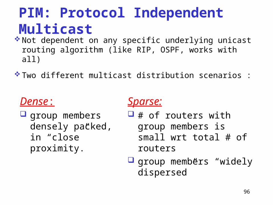
PIM: Protocol Independent MulticastNot dependent on any specific underlying unicast
routing algorithm (like RIP, OSPF, works with all)
Two different multicast distribution scenarios :
Dense: group members
densely packed, in “close” proximity.
Sparse: # of routers with group
members is small wrt total # of routers
group members “widely dispersed”

97
Consequences of Sparse-Dense Dichotomy: Dense group membership by
routers assumed until routers explicitly prune
data-driven construction of multicast tree (e.g., RPF)
bandwidth and non-group-router processing profligate
Sparse:no membership until
routers explicitly join receiver-driven
construction of multicast tree (e.g., center-based)
bandwidth and non-group-router processing conservative

98
PIM- Dense Mode
Flood-and-prune RPF, similar to DVMRP butunderlying unicast protocol provides RPF
information for incoming datagramless complicated (less efficient) downstream
flood than DVMRP reduces reliance on underlying routing
algorithmhas protocol mechanism for router to detect if
it is a leaf-node router

99
PIM - Sparse Mode
Center-based approachrouter sends join message
to rendezvous point (RP) intermediate routers update
state and forward join
after joining via RP, router can switch to source-specific tree
R1
R2
R3
R4
R5
R6R7
join
join
join
all data multicastfrom rendezvouspoint
rendezvouspoint

100
PIM - Sparse Mode
Sender(s):unicast data to RP, which
distributes down RP-rooted tree
RP can extend multicast tree upstream to source
RP can send stop message to the source if no attached receivers “no one is listening!”
R1
R2
R3
R4
R5
R6R7
join
join
join
all data multicastfrom rendezvouspoint
rendezvouspoint
CS 461
4.5 MultiProtocol Label Switching (MPLS)
Prior WorkMPLS OverviewMPLS Architecture

102
Prior Work
Tag Switching (Cisco)Aggregate Route-Based IP Switching (ARIS,
IBM)IP NavigatorIFMP-IP Switching (Ipsilon)Cell Switching Router (CSR, Toshiba)
103
Prior WorkTag switching is based on the control-driven approach. The set
up of LSPs (Label Switched Paths) closely follows control messages such as routing updates and RSVP messages.
Aggregate route-based IP switching (ARIS) is based on the control-driven approach. Very similar to tag switching. ARIS introduces the concept of an “egress identifier” (FECs) to express the granularity of LSPs.
IP Navigator is again a control-driven protocol. Use OSPF as the internal routing protocol used within a routing domain. Explicit routing is used to setting up the VCs.

104
Prior Work
Ipsilon Flow Management Protocol (IFMP) is a traffic driven protocol. When the number of packets from a flow exceeds a predetermined threshold, the controller uses IFMP to set up an LSP for the particular flow.
Cell switch router (CSR) proposal is similar to IP switching. CSR is primarily designed as a device for interconnecting ATM clouds. Within an LIS (logical IP subnet), ATM forum standards are used to connection hosts and switched together.
Multiple LISs are then interconnected with CSRs that are capable of running both IP forwarding and cell forwarding. The setup of LSPs is data-driven for best effort traffic and RSVP-driven for flows that require resource reservation.

CS 461
MPLS Overview
RFC 3812 The IETF MPLS working group is to standardize a
base technology that integrates the label swapping forwarding paradigm with network layer routing.
Cisco is the major contributor to the MPLS working group.substitute “Label” for “Tag” in Tag Switching MPLS

CS 461
Core mechanisms of MPLS
Semantics assigned to a stream labelLabels are associated with specific streams of data.
Forwarding MethodsForwarding is simplified by the use of the short
fixed length labels to identify streams.Forwarding may require simple functions such as
looking up a label in a table, swapping labels, and possibly decrementing and checking a TTL.
Label Distribution MethodsAllow nodes to determine which labels to use for
specific streams.
107
Native IP ForwardingIP routing: both the packet forwarding and
route determination process in an IP network.Native IP forwarding (NIF): hop-by-hop,
destination-based packet forwarding.Each packet’s next hop and output port are
determined by a longest-prefix-match forwarding table lookup.
Additional packet classification may also be performed to derive output port queuing and scheduling rules.

108
A Simplified NIF forwarding engine
IP Header IP payload
ForwardingTable
ForwardingTable
PacketClassification
PacketClassification
InputPorts
OutputPorts
Next hop + port
Queuing andScheduling rules
Longest Prefix Match lookup
Packet Classification keys: IP source and destination addresses, IP protocol type, DiffServ (DS) or TOS byte, and TCP/UDP port numbers.

109
Per-Hop classification, queuing, and scheduling
Queue
S
ClassifyPort 1
Port N
Port M

110
A Simplified LSR forwarding engine
MPLS label MPLS payload
SwitchingTable
SwitchingTable
InputPorts
OutputPorts
Next hop + portQueuing and
Scheduling rules

111
Traffic Engineering
Conventional IP routing attempts to find the shortest path between a packet’s current location and its intended destination.
“Hot spots” and packet loss rates, latency, and jitter increase as the average load on a router rises.
Solutions: (1) Faster routers, (2) Alternate routes.Routing policy may also require traffic engineering. For
example, the external link between R6 and A3 may have been funded solely by A2 and A3. Therefore, A1’s traffic must not be allowed to traverse it.

112
Traffic Engineering
R1
Access 3
Access 1
Access 2
IP Backbone
R2 R3
R4
R5
R6
Route from A2 to D
Desired route from A1 to D
Actual route from A1 to D
Destination D
-- Override the shortest path route

113
Signaling and ProvisioningSignaling: when network (re)configuration can be requested by
users at any time and achieved within milliseconds or seconds.Provisioning: When the reaction time for (re)configuration
becomes measured in minutes or hours.In either case, the (re)configuring action involves establishing
(or modifying) information used by routers or switches to control their forwarding actions, including forwarding (routing) information, classification rules, and/or queuing and scheduling parameters.
CS 461
Core MPLS ComponentsThe basic routing approach
Routing is accomplished through the use of standard L3 routing protocols (e.g. OSPF and BGP).
The information maintained by the L3 routing protocols is then used to distribute labels to neighboring nodes that are used in the forwarding of packets.
LabelsLabel semantics, Label granularity, Label assignment,
Label stack and forwarding operations.

CS 461
Label Semantics The label is nothing more than a shorthand for an
aggregate stream of user data. The meaning of the label is a strictly local issue between
two neighboring nodes. MPLS could be employed between any two neighboring
nodes, even if no other nodes in the network participate in MPLS.
When MPLS is used between more than two nodes, then the operation between any two neighboring nodes could be interpreted as independent of the operation between any other pair of nodes.

CS 461
Label Granularity The device uses the label to forward packets will
forward all packets with the same label in the same way.
A Forwarding Equivalence Class (FEC) is a set of L3 packets which are all forwarded in the same manner by a particular Label Switching Router (LSR).
For unicast IP traffic, the granularity of a label allows various levels of aggregation in a Label Information Base (LIB).
For IP multicast, the natural binding of a label would be to a multicast tree.

117
Label assignment
Label assignment involves allocating a label, and then binding a label to a route.
Label assignment can be driven by control traffic or data traffic. (discussed later.)
Label withdrawal is primarily a matter of garbage collection, that is collecting up unused labels so that they may be reassigned.

118
Routing Aggregation
R1
Access 1
Access 2 R2 R3
R4
R5
R6
Destination D
Access 3
1
2
35
4
CS 461
Forwarding ComponentLabel Stack and Forwarding Operations
label swap : looking up the incoming label to determine the outgoing label, encapsulation, port, and any additional information which may pertain to the stream such as a particular queue or other QoS related treatment.
label push : When a packet first enters an MPLS domain, the packet is associated with a label.
label pop : When a packet leaves an MPLS domain, the label is removed.
The label stack is useful within hierarchical routing domain.

CS 461
EncapsulationLabel-based forwarding makes use of various pieces of
information, including a label or stack of labels, and possibly additional information such as a TTL field.
“MPLS encapsulation” : encapsulate the label information and information used for label based forwarding.
An encapsulation scheme may make use of the following fields:label, TTL, class of service, stack indicator, next
header type indicator, and checksum

121
MPLS label stack encoding
Label(20 bits)
Exp(3 bits)
S(1 bit)
TTL(8 bits)
Label(20 bits)
Exp(3 bits)
S(1 bit)
TTL(8 bits)
Label(20 bits)
Exp(3 bits)
S(1 bit)
TTL(8 bits)
Original Packet
...
Stack top Stack bottom
MPLS frame delivered to link layer
COS

122
Label AssignmentTopology driven (Tag)
In response to normal processing of routing protocol control traffic Labels are pre-assigned; no label setup latency at forwarding time.
Request driven (RSVP)In response to normal processing of request based control trafficMay require a large number of labels to be assigned.
Traffic driven (Ipsilon)The arrival of data at an LSR triggers label assignment and
distribution.Label setup latency; potential for packet reordering.
123
Label Distribution
Explicit Label DistributionDownstream label allocation
label allocation is done by the downstream LSRmost natural mechanism for unicast traffic
Upstream label allocationlabel allocation is done by the upstream LSRmay be used for optimality for some multicast traffic
A unique label for an egress LSR within the MPLS domainAny stream to a particular MPLS egress node could use the label of
that node.

124
Label DistributionExplicit Label Distribution Protocol (LDP)
Reliability : by transport protocol or as part of LDP.Separate routing computation and label distribution.
Piggybacking on Other Control MessagesUse existing routing/control protocol for distributing routing/control and
label information.OSPF, BGP, RSVP, PIM
Combine routing and label distribution.Label purge mechanisms
By time outExchange of MPLS control packets

125
Label Distribution ProtocolLDP Peer:
Two LSRs that exchange label/stream mapping information via LDP
LDP messages Discovery messages (via UDP)
announce and maintain the presence of LSR Session messages
maintain session between LDP peers Advertisement message
label operation (Label distribution) Notification message
advisory information and signal error information Error notification: signal fatal errors Advisory notification: status of the LDP session or some previous message received from the peer.
126
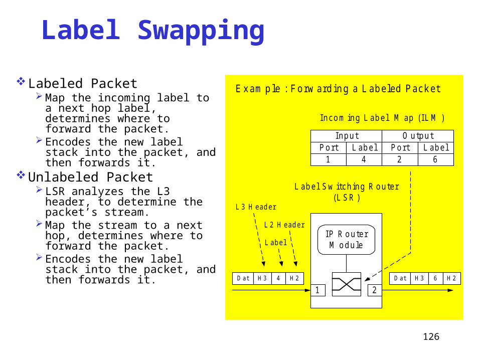
Label Swapping
Labeled Packet Map the incoming label to a next
hop label, determines where to forward the packet.
Encodes the new label stack into the packet, and then forwards it.
Unlabeled Packet LSR analyzes the L3 header, to
determine the packet’s stream. Map the stream to a next hop,
determines where to forward the packet.
Encodes the new label stack into the packet, and then forwards it.
L a b e l S w itc h in g R o u te r(L S R )
IP R o u te rM o d u le
1 2
L a b e l
L 3 H e a d e r
P o rt1
L a b e l4
P o rt2
L a b e l6
O u tp u tIn p u t
In c o m in g L a b e l M a p (IL M )
E xam p le : Fo rw ard in g a Lab eled P ack et
D at H 3 6 H 2D at H 3 4 H 2
L 2 H e a d e r

127
Use of MPLS in a Hierarchy
R 3R 2
R 6R 5R 4
R 1
D om ain 1 D om ain 2
O S P F
B G PL 1
P u shL 2
L 1
L 1S w a p
L 4
L 1P o p
L 3
L 1
S w a pL 3
L 1
L 2
L 1
O U T
L 2
IN
L 3
O U T
L 1
IN
L 1
O U T
L 4
IN
L 2
O U T
L 3

128
ConclusionMPLS improves the scalability of hop-by-hop
routing and forwarding, and provides traffic engineering capabilities for better network provisioning.
It decouples forwarding from routing and allows multi-protocol support without requiring changes to the basic forwarding paradigm.
Generalized MPLS (GMPLS)λMPLS (Optical wavelength-based)
Recommended