1
Electric Potential
Reading: Chapter 21
Chapter 21

2
If is an infinitesimal displacement of test charge, then the work done by electric force during the motion of the charge is given by
Electric Potential Energy
s
When a test charge is placed in an electric field, it experiences a force
E
q
F qE
s
FW s F
Fs

3
Electric Potential Energy
E
q
F qE
s This is the work done by electric field.
In this case work is positive.
Because the positive work is done, the potential energy of charge-field system should decrease. So the change of potential energy is
F FU s F q s E
minus sign
F mg g
s This is very similar to
gravitational force: the work done by force is
F Fs F mgs
The change of potential energy is
F FU s F mgs
F FW s F q s E

4
Electrical Potential Energy
E
q
F qE
s
A
B
B A ABU U Work
The electric force is conservative
For all paths:
B A ABU U U Work
Work is the same for all paths

5
Electric Potential
Electric potential is the potential energy per unit charge,
The potential is independent of the value of q.The potential has a value at every point in an electric fieldOnly the difference in potential is the meaningful quantity.
E
B A ABB A
U U WorkV V
q q q
UV
q
q
F qE
s
FsA
B

6
Electric Potential
To find the potential at every point 1. we assume that the potential is equal to 0 at some point, for example at point A, 2. we find the potential at any point B from the expression
E
AB ABB A
Work WorkV V
q q
0AV
B FV s E
q
F qE
s
FsA
B

7
Electric Potential: Example
Plane: Uniform electric field
E
0
σh
2εB AV V hE hE
A
σ 0
σ>0
h
0AV
h
s
E
s
0
σ
2εE
B
C
0
σh
2εC AV V hE hE

8
Electric Potential: Example
Plane: Uniform electric field
E
0
σh
2εBV
A
σ>0
h
hE
B
C
0
σh
2εCV
V
h0
σ 0
V
h0
σ 0
All points with the same h have the same potential

9
Electric Potential: Example
Plane: Uniform electric field
0
σh
2εV
0
σh
2εV
The same potential
equipotential lines

10
Electric Potential: Example
Point Charge
E
B e
QV k
r
0Q
0V
r
s
2
| |r e
QE k
rB
0V

11
Electric Potential: Example
Point Charge
r e
QV k
r0V
equipotential lines

12
Units
• Units of potential: 1 V = 1 J/C
– V is a volt
– It takes one joule (J) of work to move a 1-coulomb (C) charge through a potential difference of 1 volt (V)
Another unit of energy that is commonly used in atomic and nuclear physics is the electron-volt One electron-volt is defined as the energy a charge-field system gains or loses when a charge of magnitude e (an electron or a proton) is moved through a potential difference of 1 volt
1 eV = 1.60 x 10⁻¹⁹ J

13
Potential and Potential Energy
• If we know potential then the potential energy of point charge q is
U qV
(this is similar to the relation between electric force and electric field)
F qE
14
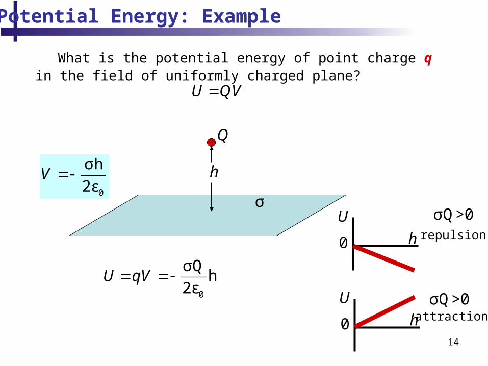
Potential Energy: Example
What is the potential energy of point charge q in the field of uniformly charged plane?
U QV
Q
h
σ
0
σh
2εV
0
σQh
2εU qV
U
h0
σQ>0repulsion
U
h0
σQ>0attraction

15
Potential Energy: Example
What is the potential energy of two point charges q and Q?
q QU qV
QQ e
QV k
rq
The potential energy of point charge q in the field of point charge Q
rq Q e
qQU qV k
r
This can be calculated by two methods:
A
Q qU QV
Qq e
qV k
rq
The potential energy of point charge Q in the field of point charge q
rQ q e
qQU QV k
r
B
In both cases we have the same expression for the energy. This expression gives us the energy of two point charges.
e
qQU k
r

16
Potential Energy: Example
Q q
r
Potential energy of two point charges:
e
qQU k
r
U
r0
σQ>0repulsion
U
r0
σQ<0attraction

17
Potential Energy: Example
1q 2q
12r
Find potential energy of three point charges:
1 212
12e
q qU k
r
3q
23r13r
12 13 23U U U U
1 313
13e
q qU k
r 2 3
2323
e
q qU k
r
1 3 2 31 212 13 23
12 13 23e e e
q q q qq qU U U U k k k
r r r

18
Potential Energy: Applications: Energy Conservation
1q 2q12,initialr
For a closed system: Energy Conservation:
The sum of potential energy and kinetic energy is constant
3q
23,initialr13r
12 13 23U U U U
1 3 2 31 212 13 23
12, 13 23,initial e e e
initial initial
q q q qq qE T U T U U U k k k
r r r
Example: Particle 2 is released from the rest. Find the speed of the particle when it will reach point P.2q
12,finalr
23,finalr2v
Initial Energy is the sum of kinetic energy and potential energy (velocity is zero – kinetic energy is zero)
2
2
mvT
- Potential energy
- Kinetic energy

19
Potential Energy: Applications: Energy Conservation
1q 2q12,initialr
For a closed system: Energy Conservation:
The sum of potential energy and kinetic energy is constant
3q
23,initialr13r
21 3 2 32 2 1 2
12 13 2312, 13 23,2final e e e
final final
q q q qm v q qE T U T U U U k k k
r r r
2q12,finalr
23,finalr2v
Final Energy is the sum of kinetic energy and potential energy (velocity of particle 2 is nonzero – kinetic energy)

20
Potential Energy: Applications: Energy Conservation
1q 2q12,initialrFor a closed system: Energy Conservation:
The sum of potential energy and kinetic energy is constant
3q
23,initialr13r
2q12,finalr
23,finalr2v
Final Energy = Initial Energy
21 3 2 3 1 3 2 31 2 2 2 1 2
12, 13 23, 12, 13 23,2e e e e e einitial initial final final
q q q q q q q qq q m v q qk k k k k k
r r r r r r
22 3 2 32 2 1 2 1 2
12, 12, 23, 23,2 e e e einitial final initial final
q q q qm v q q q qk k k k
r r r r
2 1 2 2 32 12, 12, 23, 23,
2 1 1 1 1e e
initial final initial final
v k q q k q qm r r r r

21
Electric Potential of Multiple Point Charge
r e
QV k
r
1q2q 3q
4q
P
31 2 41 2 3 4
1 2 3 4r e e e e
qq q qV V V V V k k k k
r r r r
The potential is a scalar sum.
The electric field is a vector sum.

22
Spherically Symmetric Charge Distribution
?V
Uniformly distributed charge
Q
Q
23
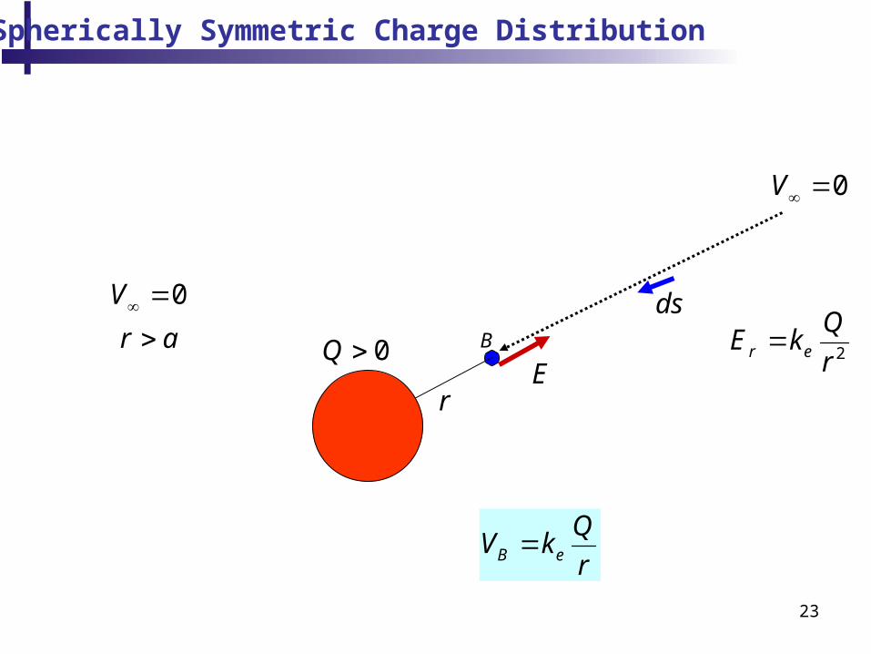
Spherically Symmetric Charge Distribution
2r e
QE k
r
E
B e
QV k
r
0Q
r
ds
B
0V
0V
r a

24
σ>0
Important Example: Capacitor
σ>0
σ<0
σ<0
E
0E
0
σ
εE
0E
?V

25
σ 0
Important Example
σ 0
E
0E
0
σ
εE
0E
0
σ
εV Eh h
0
σ
εV x
0V
x
0
σ
εh
V
x
h
x
x

26
Electric Potential: Charged Conductor
The potential difference between A and B is zero!!!!
Therefore V is constant everywhere on the surface of a charged conductor in equilibrium– ΔV = 0 between any two points on the
surface The surface of any charged conductor is an
equipotential surface Because the electric field is zero inside the
conductor, the electric potential is constant everywhere inside the conductor and equal to the value at the surface

27
Electric Potential: Conducting Sphere: Example
r e
QV k
r
sphere e
QV k
R
for r > R
for r < R
The potential of conducting sphere!!

28
Conducting Sphere: Example
69 10
9 10 900000.1sphere e
Q CV k V
R m
What is the potential of conducting sphere with radius 0.1 m and charge ?1μC

29
Capacitance
Chapter 21

30
Capacitors
Capacitors are devices that store electric charge• A capacitor consists of two conductors
– These conductors are called plates– When the conductor is charged, the plates carry
charges of equal magnitude and opposite directions• A potential difference exists between the plates due to
the charge
Q
Q
Q - the charge of capacitor
A
B
A
B A BV V V - a potential difference of capacitor

31
Capacitors
• A capacitor consists of two conductors
A
B
conductors (plates)
Plate A has the SAME potential at all points because this is a conductor .
A BV V V
Plate B has the SAME potential at all points.
So we can define the potential difference between the plates:

32
Capacitance of Capacitor
A
B
The SI unit of capacitance is the farad (F) = C/V.
Capacitance is always a positive quantity
The capacitance of a given capacitor is constant
and determined only by geometry of capacitor
The farad is a large unit, typically you will see
microfarads ( ) and picofarads (pF)
QC
V
μF

33
Capacitor: Parallel Plates
0ε SQC
V h
E
σ 0
σ 02
1
0
σ
εV x
0V
0
σ
εV h
0
σ
εE
0E
0E
E0Q
0Q
Qσ
S
The potential difference:
0 0
σ Qh= h
ε ε SV
The capacitance:
34
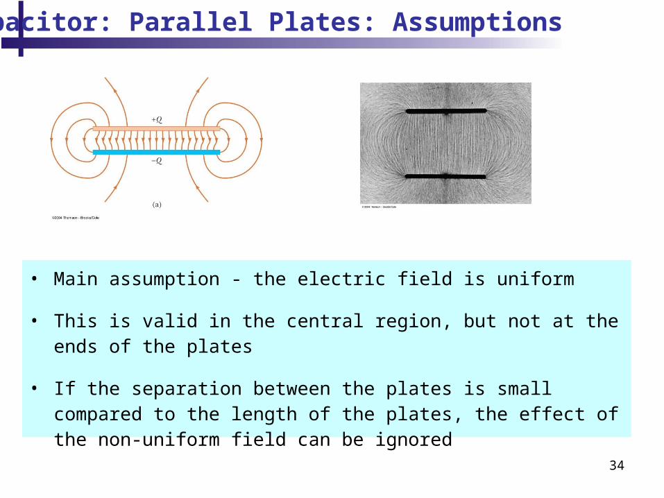
• Main assumption - the electric field is uniform
• This is valid in the central region, but not at the ends of the plates
• If the separation between the plates is small compared to the length of the plates, the effect of the non-uniform field can be ignored
Capacitor: Parallel Plates: Assumptions

Dielectric (insulator) inside capacitor. Capacitance = ?
Capacitors with Dielectric (Insulator)
Q
Q
Q C V
?C
dielectric
h

36
• The molecules that make up the dielectric are modeled as dipoles
• An electric dipole consists of two charges of equal magnitude and opposite signs
• The molecules are randomly oriented in the absence of an electric field
Dielectric (insulator)
37
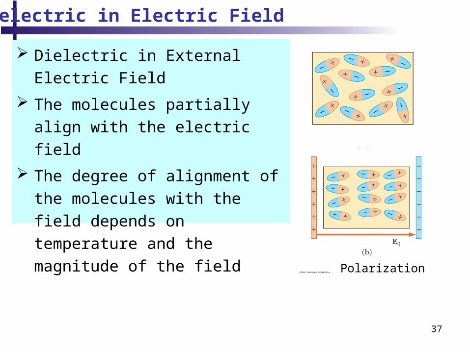
Dielectric in External Electric Field
The molecules partially align with
the electric field
The degree of alignment of the
molecules with the field depends on
temperature and the magnitude of
the field
Dielectric in Electric Field
Polarization

38
Dielectric inside capacitor. Capacitance = ?
Capacitors with Dielectric
Q
Q
Q C V
?C
dielectric
h
The electric field inside dielectric
0 indE E

39
Dielectric inside capacitor. Capacitance = ?
Capacitors with Dielectric
Q
Q
Q C V
?C
dielectric
h
Q Q
If we have the same charge as without dielectric then the potential difference is increased, since
0( )indV h E E
without dielectric it was
0 0V hE
0V V then 00
Q QC C
V V
Capacitance is increased.
40
Dielectric inside capacitor. Capacitance = ?
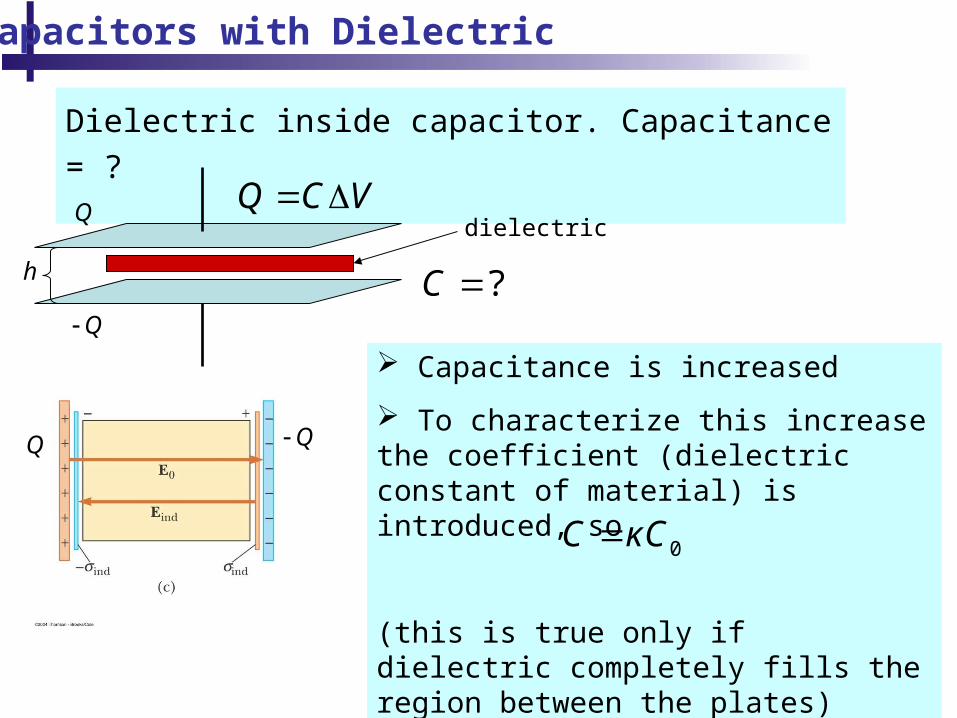
Capacitors with Dielectric
Q
Q
Q C V
?C
dielectric
h
Q Q
Capacitance is increased
To characterize this increase the coefficient (dielectric constant of material) is introduced, so
(this is true only if dielectric completely fills the region between the plates)
0C κC

41
42
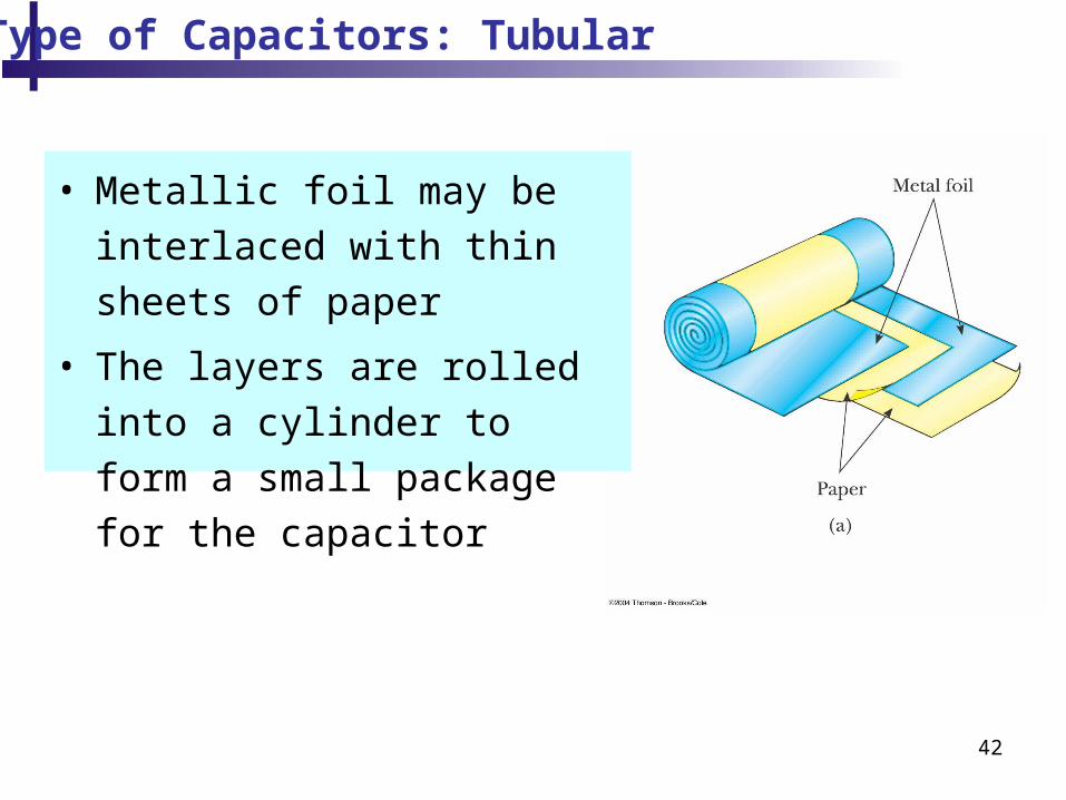
Type of Capacitors: Tubular
• Metallic foil may be interlaced
with thin sheets of paper
• The layers are rolled into a
cylinder to form a small
package for the capacitor

43
Type of Capacitors: Oil Filled
• Common for high- voltage
capacitors
• A number of interwoven
metallic plates are immersed
in silicon oil

44
Type of Capacitors: Electrolytes
• Used to store large amounts
of charge at relatively low
voltages
• The electrolyte is a solution
that conducts electricity by
virtue of motion of ions
contained in the solution
45
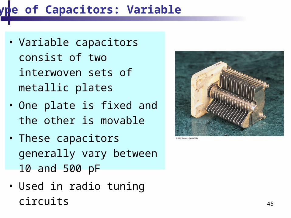
Type of Capacitors: Variable
• Variable capacitors consist of
two interwoven sets of metallic
plates
• One plate is fixed and the
other is movable
• These capacitors generally
vary between 10 and 500 pF
• Used in radio tuning circuits

46
Capacitor: Charging
Battery- produces the fixed voltage – the fixed potential difference
Each plate is connected to a terminal of the battery The battery establishes an electric field in the connecting wires This field applies a force on electrons in the wire just outside of the plates The force causes the electrons to move onto the negative plate This continues until equilibrium is achieved
The plate, the wire and the terminal are all at the same potential
At this point, there is no field present in the
wire and there is no motion of electrons

47
Capacitance and Electrical Circuit
Chapter 21
48
Electrical Circuit
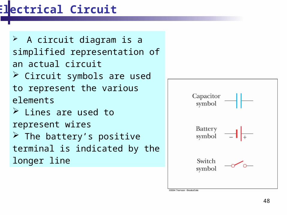
A circuit diagram is a simplified representation of an actual circuit Circuit symbols are used to represent the various elements Lines are used to represent wires The battery’s positive terminal is indicated by the longer line

49
Electrical Circuit
Conducting wires. In equilibrium all the points of the wires have the same potential
50
Electrical Circuit
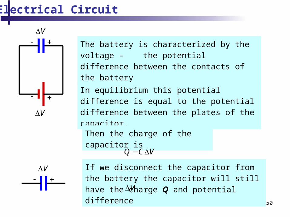
The battery is characterized by the voltage – the potential difference between the contacts of the battery
V
In equilibrium this potential difference is equal to the potential difference between the plates of the capacitor.
V
Then the charge of the capacitor is
Q C V
If we disconnect the capacitor from the battery the capacitor will still have the charge Q and potential differenceV
V

51
Electrical Circuit
V
VQ C V
If we connect the wires the charge will disappear and there will be no potential difference
V
0V

52
One of the main application of capacitor:
capacitors act as energy reservoirs that can be
slowly charged and then discharged quickly to
provide large amounts of energy in a short pulse
Energy Stored in a Capacitor: Application
Q
Q
221 1
( )2 2 2
QU Q V C V
C
Q C V

53
Electric Potential and Electric Field
Can we find electric field if we know electric potential?
E
x
B AV V x E
A B
B AV V V
Ex x
V
Ex
x

54
Electric Potential and Electric Field
V
Es
Equipotential lines are everywhere perpendicular to the electric field.
Equipotential lines
Recommended