AYXP9GHR
AYXP9GHR Service Manual CHAPTER 2. EXPLAMATION OF CIRCUIT AND OPERATION[1] BLOCK DIAGRAMS
1. Indoor unit
Louvre motor drive circuit(upper)
Louvre motor drive circuit(lower)
LED drive circuit
Flow direction control (louver motor upper)
Flow direction control (louver motor lower)
LED display
AC powerRectification circuit
CPU
SubCPU
3.15AFuse
Serial signals
2AFuse
DC power supply circuit
Fan motor PWM control circuit
Rotation pulse input circuit
AC clock circuit
Remote controller signal reception circuit
Buzzer drive circuit
CPU reset circuit
CPU oscillator circuit
Room temp. detect circuit
Heat exchanger pipe thermo circuit
EEPROM
Select circuit
Serial I/O circuit
Power supply relay drive circuit
Auto restart circuit
Test run circuit
Auxiliary mode
Power on circuit
Cluster generator drive circuit
Indoor fan motor
Fan motor pulse detect
Wireless remote control operation
Audible operation confirmation
Room temp. thermistor
Heat exchanger pipe thermistor
Louvre angle, fan speed
Wireless, preheat, Model select
Indoor/outdoor control signal I/O
Outdoor unit power supply on/off control
Test run (forced operation)
Auxiliary mode button ON/OFF
Self diagnostics, fault diagnosis
Cluster generator
Unit-unit wiring(AC power andserial signals)
2 – 1

AYXP9GHR
2. Outdoor unitCPU
20Aprotection
15Aprotection
Expansion valve drive circuit Expansion valve
Suction temp. thermo. circuit Suction pipe thermistor
2-way valve temp. thermo. circuit 2-way valve thermistor
3.15Aprotection
15Aprotection
Power supply circuit
CPU oscillator circuit
DC overvoltage detection circuit
Outdoor fan drive circuit
4-way valve relay drive circuit
Power transistor module drive circuit
Serial I/O circuit
CPU reset circuit
Position detection circuit
AC overcurrent detection circuit
Compressor thermo circuit
Heat exchanger pipe thermo circuit
Outdoor temp. thermo. circuit
LED drive circuit
Test mode circuit
Power factorconverter circuit
Filtercircuit
Smoothingcircuit
Pulse amplitube modulation circuit
EEPROM
AC clock circuit
DC overcurrent detection circuit
IGBT
Unit-unit wiring (AC powerand serial signals)
Outdoor fan
4-way valve
Power transistor module
Compressor
Current transformer
Compressor thermistor
Heat exchanger pipe thermistor
Outdoor temperature thermistor
LED
2 – 2
AYXP9GHR
[2] MICROCOMPUTER CONTROL SYSTEM1. Indoor unit
1.1. Electronic control circuit diagram
0.1μC 50
V
JPF
54
21
54
21
4.7KRN
2.4K5V 10.0KFR96
JPT
9 10 11 12
CIR
CU
ITD
IAG
RAM
DIS
PLAY
PWB
LOU
VER
MO
TOR
TOP
LOU
VER
MO
TOR
BOTT
OM
DR
AIN
PAN
ASS'
Y
MO
TOR
FAN
DC
AUX.
SW1
(TES
TR
UN
)
PIPE
THER
MO
TEM
PTH
ERM
O
POW
ERO
N
10K
R52
(HA
CIR
CU
IT)
AUTO
RES
TAR
T
PREH
EAT
WIR
ELES
S
HO
TKE
EP
FLAS
H
TEST
SUB
MIC
RO
CO
MPU
TER
PWB
REC
EIVE
RPW
B7
-SEG
LED
&
REM
OTE
CO
NTR
OLL
ER SIG
NAL
SER
IAL
SIG
NAL
S
OF
SER
IAL
ERR
OR
SIG
NAL
SUB
MIC
RO
CO
MPU
TER
POW
ERSU
PPLY
OF
12V
LIN
EG
ND
for
GN
Dfo
r5V
LIN
E
CO
NN
ECTO
RO
FJO
INT
(DR
AIN
PAN
)
CO
NN
ECTO
RO
FJO
INT
(FAN
MO
TOR
)
33
98
76
101
23
45
8
R4156k
5V
23 1
4 32
R38100k
C1835V100μ
R39
ZD2HZ24-2
41 4.7k
D1N60D7
R37 RD
4
21
30.
1μC42
25V
12V
R44
1.8k
1/4W
C2116V47μ
R70
Q3
KRC
108S
4.7k
4.7k
(SER
IAL
I/OC
IRC
UIT
)
KRA1
01S
Q11
5V
5VJP
H
R53
JPO
10K
ACC
LOC
K
25V
R90
R55
FU1
3.15
A-2
50V
C57
R85
10K
50V
1000
p
C20250V0.01μ
5V
JPS
470μ
D2S
6M
MQ
R27
10K
10k
R71 1k
1k
R336.8k
8.2k
680
PC5
R34
6.8k
89
5V
12V
87654321
86
75
43
21
1 3 5 7 9
2 4 6 8 10
1112
1 3
5VVs
VccPG
GN
DVm
3 12577 5 2 13
3 1257
PC3
BCN
5
BCN
1 PC81
716P
1210
111
23
45
67
89 9
87
65
43
21
1110
1210
111
23
45
67
899
87
65
43
21
1110
7654321
BCN
7
KRC
102S
Q15
PC1
PC81
7XP3
C16
50V
0.01
μ
10K
R16
275V
0.01
μ
C23
2.7K
RH
RE
R76
100
1W
SSR
12V
2W11K
2W11K
PC2
PC85
3HXP
2W680
680 2W
2W680
680 2W
2W680
D8
D1N
60R
GR
40R
BR
CR
A
C14275V0.1μ
NF1
NR1
200K
200K 39
K
D3
D1N
60
1/2WR26
1/2WR25 R24
C45275V0.1μ
E25
0V47
00p
C53
~C56
C54
C53
C56
C55
CN
801
23
4
BUSY
7654321 8
VPP
VCC
SCL
SDA
OE
RES
ET
9VS
S
5V
321
C90
HAJ
P
4
CN
90R
92
R91
100kR93
1000
p50
V
5V
5V
100μ
C350V
R95
4.7K
R69100K
R684.7K
100μ
DC
15V
D2S
BA60
5V
C2425V
0.1μR
46
DB1
C1
3.3
450V120μ
1M
R2 RF1/2W
1M1/2W
4 321
5V
PC81
7XP3
3.3KR66
100KR73
35VC46
25VC50
0.1μ
0.1μ50VC47
R28
R31
56k
2A-2
50V
142
3
14
5V
FU2
5WR1
47kR67
10kR50
0.1μC
5225
VC
37
0.1μ25
V
5V
JPW
JPP
R87
R86
10K
10K
C26
4.7μ
IC2
RES
ET
0V
ZD1
ST03
D-2
00
5V
1/4W
100
R561/4W
100
R51
C39
16V
0.01
μ
C36
0.01
μ16
V
10K
10K
10K
CN
4
R58
R54
R59
10.0KF
16V10μC31
R61
16V10μC30
R60
34TH
1
12TH
2
321
5V
21
4 3
D1F
S4
0.1μ50
VC4
C44
220μ
10V
C7
470μ
10V
25V
C43
12V IC9
10μHL1
D14 D
1
TR1
6 5 4 3 2 1 4
34
12
IC108
765
EEPR
OM
R97
5V
R47
3
3.3k 2
R29
PC4
R32
C17
0.01μ16V
IC1
64636261605958575655545352515049 P37
P36P35P34P33P32P31P30VCC
VRVSSP67P66P65P64P63
P00
P01
P02
P03
P04
P05
P06
P07
P10
P11
P12
P13
P14
P15
P16
P17
3348 47 46 45 44 43 42 41 40 39 38 37 36 35 34
P20P21P22P23P24P25P26P27VSSXOUXINP40P41RSTVSSP42
20212223242526272829303132
191817
P43
P44
P45
P46
P47
P50
P51
P52
P53
P54
P55
P56
P57
P60
P61
P62
161 2 3 4 15141312111098765
R35
10k 5V
R36
C22
PC81
7XP3
R30
16V0.01μ
4.7K
1000
p50
VC
32
5V
KRC
102S
Q19
C2510V
100μ
C27
16V
0.01
μ4.
7kR
45
R94
5V
10k
R48
C331
3
2OSC
1 8MH
z
KRC
108S
Q1
10.0KF
1 N1 3 65
N S
321
5 6
CN
A
3112
V
IN
RY1
(CLU
STER
)C
ON
NEC
TOR
OF
JOIN
TO
UT
N12
R191/2W470K
R19A1/2W470K
3W11
K3W 11K
C98
C99
1KV
1000
pC
98,C
99
KID
6500
4AF
12V
C1950V0.047μ
IC6
BZ
GEN
ERAT
OR
CLU
STER
4.7K
33p
2KV
RM
1500
p
10KF
15V
100p
F
15KF
1.5KR10
1000
0pM
R17
12
680
PC81
7XP3
PC9
4.7K
R4
3.3KR75
910
1/4WR20
1/4WR23
910
R22
R3
R65
R5
ZD5
C12
50VC5
50VC2
100μ
D2
D1F
L20U
D1F
L20U
C35
IC3
1 2
5 34
R7 10
00p
50VC40
10K
D1F
L20UD
15
D21
KRA1
06S
IC7
R57
D20
D1F
L20U
Q9
PC81
7XP3
1KR81
2.4K
FR8
2.4K
FR11
R80
PC6
1KR9
PC817XP3
R6
100K
PC81
7XP3
R13
100K
PJ43
1CT
250VC48
PC6
PC7
R17
1K
R984.7K
R89 1K
100V
1.2K
C49
11KF
30KF
L2KI
A781
5API
1SR
139D
2 – 3

AYXP9GHR
1.2. Display circuit diagram12V
KID
6500
4AF
M5V
M5V
M5V
M5V
7654321
10 111 2 3 4 5 6 7 8 9
12V
12V
5V
KID
6500
4AF
CN
103
CN
102
IC10
5
IC10
6
CN
101
IC10
4
13
28M
Hz
P30
19P3
120
P32
21P3
322
P34
23P3
524
P36
25P3
726
P00
27P0
128
P02
29P0
330
P04
31P0
532
P06
33P0
734
P10
35P1
136
Vss
18Xo
ut17161 2 3 4 15141312111098765
P12
P13
P14
P20
P21
P22
P23
P24
P25
P26
P27
Vref
RES
ETC
NVs
sVc
cXi
n
IC10
1M
3754
2
OSC
101
0.1μ25
VC
101
C10
2
4.7μ
IC10
2
0.1μ25V
C10
3
C10
416
V47
μ
IC10
3
KID
6578
3AF
R10
1
R10
2
R10
3
R10
4
R10
5
R10
6
R10
71W18
0*7
FLASH
4.7KR115
4.7K
R10
8
R11
810
KR
116
100K
KRA1
06S
KRC
106S
KRA1
06S
R109
R113R110
R114
1/4W
1.2K
*4
LED
LED
LED
LED
LED
LED
LED
LED
LED
LED
LED
101
102
103
104
105
106
107
108
109
110
PC
CN
105A
CN
104B
CN
104A
a b c d e f g
SG20
1
Q10
2Q
101
Q10
4
KRC
106S
Q10
3
CN
105B
CN
105C
1 2 3
25V
R20
147
IC20
1
REC
EIVE
RC
IRC
UIT
SUB
MIC
RO
CO
MPU
TER
PWB
CIR
CU
ITD
AIG
RAM
12345
LOU
VER
MO
TOR
BOTT
OM
LOU
VER
MO
TOR
TOP
SER
IAL
SIG
NAL
S
REM
OTE
CO
NTR
OLL
ERSI
GN
ALS
ERR
OR
SIG
NAL
OF
SER
IAL
POW
ERSU
PPLY
OF
SUB
MIC
RO
CO
MPU
TER
5VLI
NE
GN
Dfo
r
12V
LIN
EG
ND
for
7-S
EGLE
D&
REC
EIVE
RPW
B
GN
Dfo
r12
VLI
NE
GN
Dfo
r5V
LIN
E
12V
LIN
EG
ND
for
12V
LIN
EG
ND
for
GN
Dfo
r12
VLI
NE
12V
LIN
EG
ND
for
JP1
GN
Dfo
r5V
LIN
E
DIS
PLAY
PWB
( )B L U E
SIG
NAL
SR
EMO
TEC
ON
TRO
LLER
GP1
U26
1RK
111B
(COM)5
(COM)10
7(A1)
6(B1)
4(C1)
1(D1)
3(E1)
8(F1)
9(G1)
2(H1)
7(A2)
6(B2)
4(C2)
1(D2)
3(E2)
8(F2)
9(G2)
2(H2)
c d e f g
JP2
0.22
μ50
VC
105
KRC
106S
Q10
5
1K
5V
R11
9
25V
C20
247
μ16
VC
201 0.1μ
+
C2
C1
H2
H1
B2B1
F2F1
E2E1
D2
D1
G2
G1
A2A1
a
b
c
d
e
f
g
g
f
e
d
c
b
a
RES
ET
987654321 12111010 11 121 2 3 4 5 6 7 8 9
10 9 8 7 6 5 4 3 2 1
543211 2 3 4 5
KID
6500
4AF
12V
12V
8
7
6
5
4
3
2
1
9
1 2 3 4 5 6 7 8
12V
5V
2 – 4

AYXP9GHR
1.3. Printed wiring board2 – 5

AYXP9GHR
2. Outdoor unit2.1. Electronic control circuit diagram
9.53
KFR84
0V
Q10
0V
15V
0.01
μ
10V
47μ
6.8K
J
R85
C77
R86
C78
2A25
0VFU3
754321
0VC
N30.1μ40
0VC29
0V
5V
R83
10K
RY1
123456
0VIC
7
Ma
b
5V
10K
10K
0V
j
0V
JP1
JP2
c
JPF
0V10
0μ
C94
10V
C95 0.1μ
0.1μ
10K
R37
1K
R38
1K
R36
1K
0VUVW
C34C35C36
1000
Px
3
D7
D6
TR1
R29
4.7K
68
18V
-PC
850.
1μ
R82
680μ
C19
IC3
R27 1W
IC4
5V 0V
R22
25V
C20
R21
22K
R24
10K
R87
150μ
C84
D14
9
35V
0V-P
35V
R93
R94
R92
D20
C98
3
2
1R
78IC
5
C33
R77
50V
1μ
R79
100
0.1μ
C32
0V
QS
T
R
Q3
R S T9
Q
JP10
1 2 3 4 5 6 7 8
8
5 6 11 10
7
1K 10K
9
8
Q9
0V
2.2KR32R31
0V
R33
IC6
875 6
124 3
CN
E
5VR
30
4 3 12
4.7K
13V
CN
12
EXPA
NSI
ON
VALV
CO
IL
MR
Y1
13V
C38
0.1μ
24272322212818161315124 1079613
10K
R45
5V
100μC47
1000
PC
42
C48
10V
0.1μ
0V
IPM
330μ
25V
C37
100μ 25
VC
490.
1μ
25V
C51
0.1μ
C54
100μ 25
VC
530.
1μ
0.1μ
0.1μ
C55
0.1μC
57
C45
0.1μ
C56
D9
D10
100μC52D
8
C50
VWFB
VUFS
VUFB W
NVNUNWP
VPI
VWFSVP
I
VPI VP
VVFS
VVFBU
P
VNC F0VNI
C41
1000
P
1000
PC40
C43
1000
P
C44
1000
PC39
1000
P
1KR46
ZD4
16V
10μ
x5
C70
~74
10K
x5
R63
~67
0V
0VC
N8
1065432 7 980.
01μ
x5
C65
~69
5V
TH2
TH3
TH4
TH5
133
0KR
100
R10
7
PC4
330
Q7 KR
C10
5S
1000
PC
59
1/2W
R51
~53
IPM
c6 58
5WR49
2 3 TLP3
51
j
M
270K
DR
126
255K
F
250V
FU5
0.02
5V
15A
470K
Fx
3
CIN
CF0
262531
35
150
R11
0
250V
FU4
1Aj
1KV
C27
220P
FC
1550
V10
μ
R17
STR
-L47
2IC2
1/2W
1M
1/2W
1M
1/2W
1M
1
D5
1/2W
1M
1/2W
1M
1/2W
1M
R8
R9
R10
R11
R12
R13
3.3K
R20
2SA1
586G
Q1
ZD1
0V
470P
C17
R14
R18 1.5K
3300
PD
4
OC
P/FB
1~
48
710
96
Sour
ceG
ND
Dra
inVc
c
C18
680
R16
R15
C16
D15
1.6
1.6
3
D3
R19
15V
PC3
234
1
0.01
μC
81
R14
610
0K
e d 5V5V
FU2
R10
5
0V
22K
3.3K
R10
6
C83
1000
P
0.01
μC
82
Q6
KRC
102S
10V
C79
R91
R14
710
K
R90
D2 1.0K
F22
0μ
2.2K
R11
1
DB2
Q5
TER
MIN
ALBO
ARD N 1
WH
WH
GR
R89
0V
BLU
E
BRO
WN
YELL
OW
GR
EEN
/
T2 T1
1 2
L3L4
13
3 4
SA1
NR
1T4
R1
1/2W
1M
275V
1μF
275V
1μF C
2
42
1μF
275V
CT1
T6
510K
1/4W
R88
1/4W
510K
C1
C3
OU
TIN
PTC
MR
Y1G
RG
R
T5
DB1
18V
-P
4700pF250V
4700pF250V
4700pF250V
4700pF250V
R4
3.3K
D1
0.1μC13
1K2W2W 1K
1K2W
4700
P25
0VC
12
+42
0V42
0V+
3.15
A25
0V
R101
R102
R103
R104
1/2W
47K
x2
R10
1,10
2
1W47
Kx
2R
103,
104
T10
T11
PC81
716N
IP
5V
0VR
55
R56
R54
C60
0.1μ25
V
R99
100
0.1μC86
15K
R11
2
C61
50V
330P
330P
50V
C62
R57
100
R58
100
R59
100
C63
330P
50V
12
678910
0.1μC64
25V
114
35
IC8
KIA3
39
1
5V0V
0.01
μC
97
UV
NW5V
0VC88
1000
P
N1KR11
6
RY1
120
1/2W
0.03
3μ
NR
2
275V
CN
4
C26
R28
3 1de
D24
2R
EDT3
R12
910
K
T12 T13
250V 20A
FU1
R34
R35
JP16
5V
5V
0.1μC93
100μ10V
C30
5V
0V
JP9
JP8
JP7
32313029282726252423222120
1011
1213
1415
1617
1819
12
34
56
89
7
52535455565758596061626364
5150
4948
4746
4544
4342
4140
3938
3736
3534
33
P07
P10
P11
P12
P13
P14
P15
P16
P17
P20
P21
P22
P23
P24
P25
P26
P27
VSS
P30
(U)
P44
P45
P46
P50
P51
P52
P53
P54
P55
P56
P57
AVCC
AVR
AVSS
P60
P61
P62
P63
MD0
(B)
(O)
(Y)
(W)
IC1
RST
MD
1
MD
2
X1X0 VSS
P00
P01
P02
P03
P04
P05
P06
P31
P32
P33
P34
P35
VCC
CP36
P37
P40
P41
P42
P43
(X)
(V)
(Y)
(W)
(Z)
(U)
(V)
(W)
R13
310
0
R13
210
0
R13
710
0
R13
610
0
R13
510
0R
134
100
5V
5V
2.2K
R73
LED
1
10K
R15
510
KR
154
5V
(CN
)
41 2 3O
SC1
4MH
z
0V10
K10
K
20
JP17
N35
VNO
20.5
KF
20.5
KF
20.5
KF
0V
PS21
563
or21
564
FU6
250V
15A
1000
PC
46
0V
0V
C4A
C5A
C7A
C6A
R41
R42
R43
102W
2K
680P
6.8K
6.8K
270
270
15V
D11
6.8K
Fx
5R
68~
72
R47
,48
33x
21/
4W
1/4W
33x
2R
47A,
48A
5V
C (R)
S
(C)
R
FC3
FC4
YELL
OW
GR
EEN
/EA
RTH
U32
V33
W34
T7 T8 T9
N
FC1
FC2
FB
D12
D13
R611.8K
R601.8K
R621.8K
1.8KR115
R11
41M
14132
0V-P
D23
D22
D21
15V
0V0.
022μ
C58
ZD3
R50
1.8K
F
VALV
CO
IL
4-W
AY
PC1
PC81
7XP3
3 1
2.7K
R75
b
R74
a
1000
PC
75 0V
4.7K5V
R76
56K
41 2 4 3
2
PC85
3HXP
PC2
4.64
KFR26
R23
68K
C21
0.03
3μ
1.65
KFR25
1.5K
150μ
10K
10K
C23
0.1μ
7805
R81
10K
R14
4
C76
1000
P
5VQ
4
23.7
KF
23.7
KFR6
R7
R12
813
KFR
127
13KF
P0.
33μ
C14
630V
270K
D1/
2W
R12
51/
2WR
21/
2W 300K
F1/
2WR
5
750μ
C10
C9
750μ
(TH
ERM
ISTO
RC
IRC
UIT
)(T
HER
MIS
TOR
)
(SER
IAL
I/OC
IRC
UIT
)
(PAM
OVE
RC
UR
REN
TC
IRC
UIT
)
(EEP
RO
MC
IRC
UIT
)
(4-W
AYVA
LVE
CIR
CU
IT)
(FAN
MO
TOR
CIR
CU
IT)
(FAN
MO
TOR
)
(RES
ETC
IRC
UIT
)(S
WIT
CH
ING
POW
ERSU
PPLY
CIR
CU
IT)
KID
6500
4AP
PST9
93D
KRA1
06S
KRC
105S
KRC
105S
KRA1
06S
(DC
OVE
RC
UR
REN
TC
HEC
KC
IRC
UIT
)
MO
NIT
OR
(FO
RD
EBU
G)
CN
D
(FR
ASH
WR
ITER
CO
NN
ECTO
R)
(LED
CIR
CU
IT)
DET
ECT
CIR
CU
IT)
(RO
TOR
POSI
TIO
N
+
C4
C5
C7
C6
2.7k
F
6.8K
F
13V
0.1μC31
C
19.1
KFR
113
2 – 6

AYXP9GHR
2.2. Printed wiring board2 – 7

AYXP9GHR
[3] FUNCTION1. Function
1.1. Startup controlThe main relay remains off during the first 45 seconds (first safetytime) immediately after the power cord is plugged into an AC outlet inorder to disable outdoor unit operation and protect outdoor unit electriccomponents.
1.2. Restart controlOnce the compressor stops operating, it will not restart for 180 sec-onds to protect the compressor.
Therefore, if the operating compressor is shut down from the remotecontrol and then turned back on immediately after, the compressor willrestart after a preset delay time.
(The indoor unit will restart operation immediately after the ON switchis operated on the remote control.)
1.3. Cold air prevention controlWhen the air conditioner starts up in heating mode, the indoor unit fanwill not operate until the temperature of the indoor unit heat exchangerreaches about 23°C in order to prevent cold air from blowing into theroom.
Also, the indoor unit fan operates at low speed until the temperature ofthe indoor unit heat exchanger reaches about 38°C so that people inthe room will not feel chilly air flow.
1.4. Odor prevention controlWhen the air conditioner starts up in cooling mode, the discharged airtemperature is lowered slightly, and for the reduction of unpleasantodors the operation of the indoor unit fan is delayed 60 seconds if theautomatic fan speed mode in cooling mode is set.
1.5. Indoor unit heat exchanger freeze prevention controlIf the temperature of the indoor unit heat exchanger remains below0°C for 4 consecutive minutes during cooling or dehumidifying opera-tion, the compressor operation stops temporarily in order to preventfreezing.
When the temperature of the indoor unit heat exchanger rises to 2°Cor higher after about 180 seconds, the compressor restarts andresumes normal operation.
1.6. Outdoor unit 2-way valve freeze prevention controlIf the temperature of the outdoor unit 2-way valve remains below 0°Cfor 10 consecutive minutes during cooling or dehumidifying operation,the compressor operation stops temporarily in order to prevent freez-ing.
When the temperature of the 2-way valve rises to 10°C or higher afterabout 180 seconds, the compressor restarts and resumes normaloperation.
1.7. Indoor unit overheat prevention controlDuring heating operation, if the temperature of the indoor unit heatexchanger exceeds the indoor unit heat exchanger overheat preven-tion temperature (about 45 to 54°C) which is determined by the operat-ing frequency and operating status, the operating frequency isdecreased by about 4 to 15 Hz. Then, this operation is repeated every60 seconds until the temperature of the indoor unit heat exchangerdrops below the overheat protection temperature.
Once the temperature of the indoor unit heat exchanger drops belowthe overheat protection temperature, the operating frequency isincreased by about 4 to 10 Hz every 60 seconds until the normal oper-ation condition resumes.
If the temperature of the indoor unit heat exchanger exceeds the over-heat protection temperature for 60 seconds at minimum operating fre-quency, the compressor stops operating and then restarts after about180 seconds, and the abovementioned control is repeated.
1.8. Outdoor unit overheat prevention controlDuring cooling operation, if the temperature of the outdoor unit heatexchanger exceeds the outdoor unit heat exchanger overheat preven-tion temperature (about 55°C), the operating frequency is decreasedby about 4 to 15 Hz. Then, this operation is repeated every 60 sec-onds until the temperature of the outdoor unit heat exchanger drops toabout 54°C or lower.
Once the temperature of the outdoor unit heat exchanger drops toabout 54°C or lower, the operating frequency is increased by about 4to 10 Hz every 60 seconds until the normal operation conditionresumes.
If the temperature of the outdoor unit heat exchanger exceeds the out-door unit heat exchanger overheat protection temperature for (120 sec: outdoor temperature ≥ 40°C • 60 sec : outdoor temperature < 40°C)at minimum operating frequency, the compressor stops operating andthen restarts after about 180 seconds, and the abovementioned con-trol is repeated.
1.9. Compressor overheat prevention controlIf the temperature of the compressor exceeds the compressor over-heat prevention temperature (110°C), the operation frequency isdecreased by about 4 to 10 Hz. Then, this operation is repeated every60 seconds until the temperature of the compressor drops below theoverheat protection temperature (100°C).
Once the temperature of the compressor drops below the overheatprotection temperature, the operating frequency is increased by about4 to 10 Hz every 60 seconds until the normal operation conditionresumes.
If the temperature of the compressor exceeds the overheat protectiontemperature (for 120 seconds in cooling operation or 60 seconds inheating operation) at minimum operating frequency, the compressorstops operating and then restarts after about 180 seconds, and theabovementioned control is repeated.
Compressor operation
ON operation onremote control
OFF operation onremote control
Compressor ON
Compressor ON Compressor canturn ONCompressor remains OFF
for 180 seconds
Indoor unit heat exchanger temperature
38
23
35
21
Set fan speed
Indoor unit fan at low speed
Indoor unit fan in non-operation
2 – 8

AYXP9GHR
1.10. Startup controlWhen the air conditioner starts in the cooling or heating mode, if theroom temperature is 2°C higher than the set temperature (in coolingoperation) or 3.5°C lower (in heating operation), the air conditioneroperates with the operating frequency at maximum. Then, when theset temperature is reached, the air conditioner operates at the operat-ing frequency determined by fuzzy logic calculation, then enters thenormal control mode after a while.1.11. Peak controlIf the current flowing in the air conditioner exceeds the peak controlcurrent (see the table below), the operation frequency is decreaseduntil the current value drops below the peak control current regardlessof the frequency control demand issued from the indoor unit based onthe room temperature.
1.12. Outdoor unit fan delay controlThe compressor stops immediately after cooling, dehumidifying orheating operation is shut down, but the outdoor unit fan continuesoperation for 50 seconds before it stops.
1.13. Defrosting
1.13.1 Reverse defrostingThe defrost operation starts when the compressor operating timeexceeds 20 minutes during heating operation, as shown below, andthe outside air temperature and the outdoor unit heat exchanger tem-perature meet certain conditions. When the defrost operation starts,the indoor unit fan stops. The defrost operation stops when the out-door unit heat exchanger temperature rises to about 13C or higher orthe defrosting time exceeds 10 minutes.
1.14. ON timerThe ON timer can be activated by pressing the ON timer button. Whenthe ON timer is activated, the operation start time is adjusted based onfuzzy logic calculations 1 hour before the set time so that the roomtemperature reaches the set temperature at the set time.
1.15. OFF timerThe OFF timer can be activated by pressing the OFF timer button.When the OFF timer is set, the operation stops after the set time.
When this timer is set, the compressor operating frequency lowers forquieter operation, and the room temperature is gradually varied afterone hour (reduced 1°C three times (max. 3°C) in heating, or increased0.3°C three times (max. 1°C) in cooling or dehumidifying operation) sothat the room temperature remains suitable for comfortable sleeping.
1.16. Power ON startIf a jumper cable is inserted in the location marked with HAJP on theindoor unit control printed circuit board (control PCB), connecting thepower cord to an AC outlet starts the air conditioner in either cooling orheating mode, which is determined automatically by the room temper-ature sensor.
When a circuit breaker is used to control the ON/OFF operation,please insert a jumper as described above.
1.17. Self-diagnostic malfunction code display
1.17.1 Indoor unit1) When a malfunction is confirmed, all relays turn off and a flashing
malfunction code number is displayed to indicate the type of mal-function.
When the air conditioner is in non-operating condition, holdingdown AUX button for more than 5 seconds activates the malfunc-tion code display function.
The operation continues only in the case of a serial open-circuit,and the main relay turns off after 30 seconds if the open-circuit con-dition remains.
In the case of a serial short-circuit, the air conditioner continuesoperating without a malfunction code display, and the main relayturns off after 30 seconds if the short-circuit condition remains.
The malfunction information is stored in memory, and can berecalled later and shown on display.
2) The self-diagnostic memory can be recalled and shown on the dis-play by stopping the operation and holding down AUX button formore than 5 seconds.
3) The content of self-diagnosis (malfunction mode) is indicated by aflashing number.
(For details, refer to the troubleshooting section.)
1.17.2 Outdoor unitIf a malfunction occurs, LED1 on the outdoor unit flashes in 0.2-sec-ond intervals as shown below.
Model Peak control currentCooling operation Heating operation
AY-XP9GHR Approx. 3.8 A Approx. 6.4 AAY-XP12GHR Approx 6.4 A Approx. 7.5 A
20 min or more 20 min or more 20 min or more
DefrostingMax. 10 min
DefrostingMax. 10 min
Start ofheatingoperation
Heating operationSet temperature
Activation ofOFF timer
1 hourlater
Max.1.5 hourslater
Max.2 hourslater
Timer settingreached
1 hourlater
Max.1.5 hourslater
Max.2 hourslater
Timer settingreached
Activation ofOFF timer
Set temperature
-1O
C
-1O
C
-1O
C
0.3O
C0.3
O
C0.3
O
CCooling/dehumidifying operation
1 sec 1 sec 0.6 sec
ON
OFF
(Example) Compressor high temperature abnormality
2 – 9

AYXP9GHR
1.18. Information about auto modeIn the AUTO mode, the temperature setting and mode are automati-cally selected according to the room temperature and outdoor temper-ature when the unit is turned on.During operation, if the outdoor temperature changes, the temperaturesettings will automatically slide as shown in the chart.
1.19. Airflow controlThe airflow control holds the two upper and lower louvers at specialpositions during operation to prevent discharged air from directly blow-ing onto people in the room.
1.19.1 Cooling/dehumidifying operationWhen the airflow button is pressed the upper louver is set at anupward angle to send the air along the ceiling.
1.19.2 HeatingWhen the airflow button is pressed the lower louver is set at a down-ward angle to send the air directly toward the floor.
1.20. Difference of operation in Auto and Manual modesIn the Auto mode, the temperature setting is automatically determined based on the outside air temperature. In addition, the air conditioner operationdiffers from the operation in the Manual mode as explained below.
1.20.1 Difference relating to set temperature
1.21. Dehumidifying operation controlIf the room temperature is 26°C or higher when dehumidifying opera-tion starts, the dehumidifying operation provides a low cooling effect inaccordance with the room temperature setting automatically deter-mined based on the outside air operation. (The setting value is thesame as the set temperature for cooling operation in the auto mode.)
If the room temperature is lower than 26°C when dehumidifying opera-tion starts, the dehumidifying operation minimizes the lowering of theroom temperature.
1.22. Self Clean operationHeating or Fan operation and Cluster operation are performed simulta-neously.
The judgment of whether Heating or Fan operation is used is based onthe outside air temperature at 3 minutes after the start of internalcleaning.
The operation stops after 40 minutes. (The air conditioner shows theremaining minutes: 40 → 39 → 38 ... 3 → 2 → 1)
1.23. Plasmacluster Ion functionOperating the Plasmacluster Ion button while the air conditioner is inoperation or in non-operation allows the switching of the operationmode in the following sequence: “Air Clean operation” → “Stop”.
• “Self Clean operation” generates about equal amounts of (+)ionsand (-)ions from the cluster unit to provide clean air.
If the Plasmacluster Ion generation function is operated together withthe air conditioner operation, the indoor unit fan speed and louverdirection are in accordance with the air conditioner settings.
If the Plasmacluster Ion generation function is used without operatingthe air conditioning function, the indoor unit fan operates at a very lowspeed and the upper louver is angled upward and the lower louverremains horizontal. (The airflow volume and direction can be changedby using the remote control.)
1.24. Hot keepWhen the room temperature rises above the set temperature by 0.6°Cor more, the ON/OFF operation of the compressor and indoor unit fanis controlled in order to lower the room temperature.
(The values indicated below, such as "0.6°C" and "1.3°C," varydepending on the outside air temperature.)
1.24.1 Hot keep zone 1With the compressor frequency at the lowest, if the room temperatureis higher than the set temperature by 0.6°C but no more than 1.3°C,the following processes will be activated.
1) The compressor stops temporarily, and restarts after 2 minutes.
2) If the room temperature remains in the hot keep zone, the com-pressor is turned OFF and ON in 3-minute intervals.
3) The indoor unit fan turns OFF and ON with a delay of 30 secondsfrom the compressor OFF/ON.
4) After the above operation in 3-minute intervals is repeated fourtimes, the interval extends to 6 minutes.
1.24.2 Hot keep zone 2If the compressor ON/OFF in hot keep zone 1 fails to bring the roomtemperature within 1.3°C above the set temperature, the following pro-cesses will be activated.
1) The compressor repeats a cycle of 8-minute OFF and 6-minuteON.
2) After the second time, the compressor remains completely OFFand only the indoor unit fan repeats OFF-ON in set intervals.
3) While the compressor is completely OFF in 2), the louvers are sethorizontally to prevent cold air from blowing.
The zone transition and the end of hot keep operation (room tempera-ture lower than the set temperature) are judged when the compressorON period ends.
* This function cannot be repealed.
Modes and Temperature Settings
the figures in ( ) are temperature settings
Auto mode Manual modeCooling Heating Dehumidifying Cooling Heating Dehumidifying
Temperature setting method
Automatic temperature setting based on outside air tem-perature. Can be changed within ±2°C using remote con-trol.
Can be changed between 18 and 32°C using remote control.
Can be changed between 18 and 32°C using remote control.
Automatic setting. Can be changed within ±2°C.
Heating operation Fan operation
24OC Outside air temperature
1.3OC
0.6OC
Set temperature
2 – 10

AYXP9GHR
1.25. Winter coolCooling operation is available during the winter season by the built inwinter cool function.Lower limit of outdoor temperature range is -10°C DB.
When the outside air temperature is low, the outdoor unit fan operatesat slower speed.
NOTE: Built-in protect device may work when outdoor temperaturefalls below 21°C DB., depending on conditions.
1.26. Auto restartWhen power failure occures, after power is recovered, the unit willautomatically restart in the same setting which were active before thepower failure.
1.26.1 Operating mode (Cool, Heat, Dry)• Temperature adjustment (within 2°C range) automatic operation
• Temperature setting
• Fan setting
• Air flow direction
• Power ON/OFF
• Automatic operation mode setting
• Swing louvre
• Plasmacluster mode
1.26.2 Setting not memorized• Timer setting
• Full power setting
• Internal cleaning
1.26.3 Disabling auto restart functionBy removing (cutting) jumper J (JPJ) on the printed circuit board(PCB), the auto restart function can be disabled.
2. Explanation of cluster circuitThe cluster unit generates cluster ions, which are circulated throughout the room by the air flow created by the blower fan (indoor unit fan motor) inthe air conditioner unit.
1) When microcomputer output turns "H," the IC6 output changes to "Lo," turning ON the SSR and applying 230 V to the cluster unit for the genera-tion of cluster ions (positive and negative ions).
3. Outline of PAM circuit
3.1. PAM (Pulse Amplitude Modulation)The PAM circuit varies the compressor drive voltage and controls the rotation speed of the compressor.
The IGBT shown in the block diagram charges the energy (electromotive force) generated by the reactor to the electrolytic capacitor for the inverterby turning ON and OFF.
1
3
12V
SSRC23RE RH
R20
IC6AC230VMicrocomputer output
1
5
3
6
Cluster unitR23R75 R76
PAM drive circuit block diagram
Reactor L5
[PAM drive circuit]
+
Microcomputer (IC1)
AC230V CompressorReactor L6
Noisefilter
AC clockdetection
circuit
DB1
IPM
DB2
Compressorpositiondetector
IGBTdrivecircuit
IGBT
Overvoltagedetection
circuit
2 – 11

AYXP9GHR
When the IGBT is ON, an electric current flows to the IGBT via the reactor (L5), (L6) and diode bridge (DB2).When the IGBT turns OFF, the energy stored while the IGBT was ON is charged to the voltage doubler capacitor via the diode bridge (DB1).
As such, by varying the ON/OFF duty of the IGBT, the output voltage is varied.
3.2. High power factor control circuitThis circuit brings the operating current waveform closer to the waveform of commercial power supply voltage to maintain a high power factor.
Because of the capacitor input, when the PAM circuit is OFF, the phase of the current waveform deviates from the voltage waveform as shown below.
To prevent this deviation, a current is supplied during the periods indicated by "O" in the diagram.
To determine the length of period to supply a current, the zero-cross timing of the AC input voltage is input to the microcomputer via the clock circuit.
The power source frequency is also determined at the same time.
The IGBT turns ON after the time length determined by the zero-cross point to supply a current to the IGBT via the reactor.
This brings the current waveform closer to the voltage waveform in phase.
As described above, the ON/OFF operation of the IGBT controls the increase/decrease of the compressor power supply voltage (DC voltage) toimprove the compressor efficiency and maintain a high power factor by keeping the current phase closer to that of the supply voltage.
3.2.1 Detailed explanation of PAM drive circuit sequence
3.2.2 AC clock (zero-cross) judgment• The clock circuit determines the time from one rising point of the clock waveform to the next rising point.
The detected clock waveform is used to judge the power source frequency (50Hz).
• The zero-cross of the AC voltage is judged as the rising of the clock waveform, as shown in the diagram above.
3.2.3 IGBT ON start time (delay time B)• Based on the zero-cross of the AC voltage, the IGBT turns ON after a delay time set according to the power source frequency.
3.2.4 IGBT ON time (C)• After the above delay time, the IGBT turns ON to supply a current to the reactor.
• The ON time of the IGBT determines the amount of energy (level of DC voltage rise) supplied to the reactor.
DC voltage level in each operation mode (varies depending on external load conditions)
– Cooling operation --- 220 to 240 V
– Heating operation --- 220 to 280 V
Stored energyReactor
L5
L6
DB1
DB2
IGBT
IGBT ON
IGBT OFF
AC voltage waveform
AC voltage and current waveform when PAM is ON
AC current waveform
IGBT ON period
Zero-cross detection
AC voltage waveform
AC current waveform
AC voltage and current waveforms when PAM is OFF
AC voltage waveform
Clock
IGBT ON
A
B C
A
B
C
50Hz
1.2mS
0.85mS
0.25 2.1mS
2 – 12

AYXP9GHR
3.3. PAM protection circuitTo prevent excessive voltage of PAM output fromdamaging the IPM and electrolytic capacitor as wellas the control printed circuit board (PCB), this circuitmonitors the PAM output voltage and turns off thePAM control signal and PAM drive immediatelywhen an abnormal voltage output is generated. Atthe same time, it shuts off the compressor operation.
The PAM output voltage is distributed to pin (4) ofthe comparator (IC8). If this voltage exceeds the ref-erence voltage at pin (5) of the IC8, the output of thecomparator (IC8) reverses (from H to L) and it isinput to pin (38) of the microcomputer (IC1) to haltthe PAM drive.
The protection voltage level is as follows.
3.3.1 Details of troubleshooting procedure for PAM1) PAM shutdown due to error1) When the DC voltage detection circuit sends a signal exceeding the specified voltage to the microcomputer
DC voltage of 350 V or higher (detection circuit input voltage of about 9.2 V or higher) [IC8 pin (4)]
– When an error is detected
• PAM IGBT turns OFF.
• Compressor turns OFF.
• All units shut down completely when the error occurs four times.
2) When the outdoor unit clock waveform differs from the specified value immediately before the PAM IGBT turns ON
When there is no clock waveform input
When a clock signal of other than specified power source frequency (50/60 Hz) is input
– When an error is detected
• PAM IGBT does not turn ON.
• Compressor operates normally.
• Complete shutdown does not occur.
2) PAM error indicationIn case of error “1)”
– An error signal is sent to the indoor unit as soon as an error is generated.
• Malfunction No. 14-0 is indicated when the error code is called out by the indoor unit's self-diagnosis function.
– The LED on the outdoor unit flashes 14 times when an error is generated.
• The LED continues flashing in the 14-time cycle even after the compressor stops operating.
• The LED turns off (data is deleted from the memory) when the outdoor unit power is turned off.
In case of error “2)”
– An error signal is sent to the indoor unit as soon as an error is judged.
• Malfunction No. 14-1 is indicated when the error code is called out by the indoor unit's self-diagnosis function.
– The LED on the outdoor unit flashes 14 times when an error is judged.
• The LED on the outdoor unit flashes in normal pattern when the compressor stops operating.
(Compressor OFF or Thermostat OFF from remote control)
* When a user complains that the air conditioner does not provide sufficient cool air or warm air
In addition to conventional error-generating reasons, there is a possibility that the PAM IGBT does not turn ON even if the compressor is operating.
In that case, the DC voltage does not rise even though the compressor is operating, and lowers to the 180-VDC level.
– Check items
• Clock circuit check
• PAM IGBT check
• Fuse (Fu6) open-circuit check
R2255KC10C9420V
750uF R5300K
R723.7K
R823.7K
0V0V
0V
IC8
15V
R11319.1KF
R11215K
5VR1141M
R1151.8K R116
1K5
42
(Overvoltage detection)
During abnormal voltage output
IC138
2 – 13

AYXP9GHR
4. Explanation of IPM drive circuitThe IPM for compressor drive is made by Mitsubishi Electric.The power supply for the IPM drive, the shunt resistance for overcurrent detection, etc., are provided outside the IPM (control PCB).
4.1. IPM drive power supply circuitThe power supply for the upper-phase IGBT (HU, HV, HW) drive employs a bootstrap system, and provides power to the upper-phase IC.
The 15-V power supply for the lower-phase IC is provided by the control printed circuit board (PCB).
4.1.1 Brief explanation of bootstrap system (single power drive system)To supply power to the upper-phase IC, the microcomputer (IC1) turns ON the lower-phase IGBT (LU, LV, LW).
This results in a charging current that flows to the electrolytic capacitor of each upper-phase IC input and charges the bootstrap capacitor with a 15-Vcurrent.
The power supply for the subsequent stages is charged while the lower-phase IGBT is ON in ordinary compressor drive control.
P(Vcc)
U,V,W,
VD
VDB
VCIN(n)
N-sideIGBT
N(GND
Bootstrap capacitor
High-voltage-withstanding,high-speed recovery diode
LVIC(LU,LV,LW)
HVIC(HU,HV,HW)
Bootstrap circuit
Initial charge period
Charging current group
2 – 14
AYXP9GHR
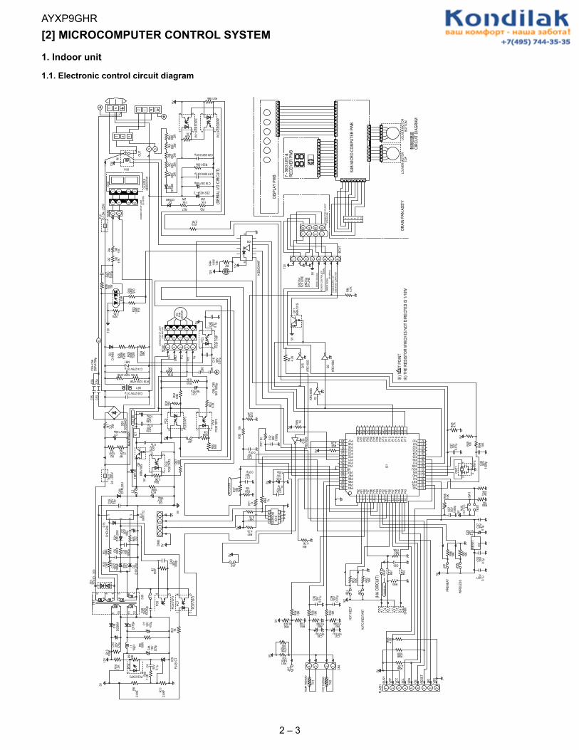
4.1.2 DC overcurrent detection circuitWhen a current of about 25 A or higher flows through the shunt resistance (R49) on the control printed circuit board (PCB), the voltage at this resis-tance is input to IPM CIN pin (26). Then, the gate voltage of the lower-phase IGBT (LU, LV, LW) inside the IPM turns OFF to cut off the overcurrent. Atthe same time, an L output of about 1.8 ms is generated from IPM Fo pin (24), and this results in an L input to overcurrent detection input pin (34) ofthe microcomputer (IC1) and turns OFF the PWM signal output (IC1 pins (51) through (56)) to the IGBT gate.SETRESET
(About 22 A)
SC
SC reference voltage
Delay by CR time constant circuit
About 1.8 ms
a1
Protection circuit status
Output current Ic (A)
Sense voltage relativeto shunt resistance
Error output Fo
(Lower phase)Internal IGBT gate
IPM overcurrentdetection circuit
5V
0V
IC1
R49Overcurrent
Shunt resistance
P
N
CiN
FO
24
26
34
2 – 15
AYXP9GHR
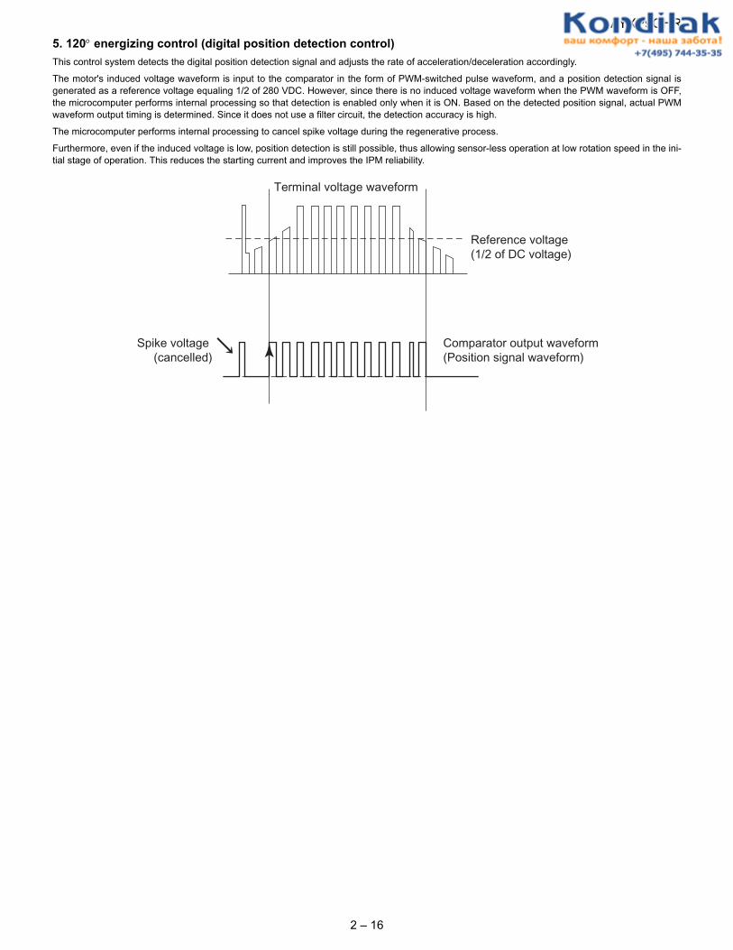
5. 120° energizing control (digital position detection control)This control system detects the digital position detection signal and adjusts the rate of acceleration/deceleration accordingly.The motor's induced voltage waveform is input to the comparator in the form of PWM-switched pulse waveform, and a position detection signal isgenerated as a reference voltage equaling 1/2 of 280 VDC. However, since there is no induced voltage waveform when the PWM waveform is OFF,the microcomputer performs internal processing so that detection is enabled only when it is ON. Based on the detected position signal, actual PWMwaveform output timing is determined. Since it does not use a filter circuit, the detection accuracy is high.
The microcomputer performs internal processing to cancel spike voltage during the regenerative process.
Furthermore, even if the induced voltage is low, position detection is still possible, thus allowing sensor-less operation at low rotation speed in the ini-tial stage of operation. This reduces the starting current and improves the IPM reliability.
Comparator output waveform(Position signal waveform)
Terminal voltage waveform
Reference voltage(1/2 of DC voltage)
Spike voltage(cancelled)
2 – 16
Recommended